JP2019190784A - Sound proof box for water removal device or dust collecting device - Google Patents
Sound proof box for water removal device or dust collecting device Download PDFInfo
- Publication number
- JP2019190784A JP2019190784A JP2018086480A JP2018086480A JP2019190784A JP 2019190784 A JP2019190784 A JP 2019190784A JP 2018086480 A JP2018086480 A JP 2018086480A JP 2018086480 A JP2018086480 A JP 2018086480A JP 2019190784 A JP2019190784 A JP 2019190784A
- Authority
- JP
- Japan
- Prior art keywords
- ceiling
- sound absorbing
- channel
- absorbing plate
- support portion
- Prior art date
- Legal status (The legal status is an assumption and is not a legal conclusion. Google has not performed a legal analysis and makes no representation as to the accuracy of the status listed.)
- Granted
Links
- XLYOFNOQVPJJNP-UHFFFAOYSA-N water Substances O XLYOFNOQVPJJNP-UHFFFAOYSA-N 0.000 title claims abstract description 38
- 239000000428 dust Substances 0.000 title claims abstract description 33
- 238000010521 absorption reaction Methods 0.000 claims abstract description 10
- 230000002093 peripheral effect Effects 0.000 claims abstract description 3
- 230000002265 prevention Effects 0.000 claims description 19
- 238000002347 injection Methods 0.000 claims description 15
- 239000007924 injection Substances 0.000 claims description 15
- 230000011218 segmentation Effects 0.000 claims 3
- 238000004140 cleaning Methods 0.000 description 8
- 238000005452 bending Methods 0.000 description 7
- 230000000694 effects Effects 0.000 description 6
- 239000000853 adhesive Substances 0.000 description 5
- 230000001070 adhesive effect Effects 0.000 description 5
- 238000013016 damping Methods 0.000 description 4
- 238000004519 manufacturing process Methods 0.000 description 4
- 239000000463 material Substances 0.000 description 4
- 239000002184 metal Substances 0.000 description 3
- 238000000034 method Methods 0.000 description 3
- 230000007423 decrease Effects 0.000 description 2
- 229910001220 stainless steel Inorganic materials 0.000 description 2
- 239000010935 stainless steel Substances 0.000 description 2
- 239000011358 absorbing material Substances 0.000 description 1
- 238000006243 chemical reaction Methods 0.000 description 1
- 238000001035 drying Methods 0.000 description 1
- 230000003670 easy-to-clean Effects 0.000 description 1
- 230000005802 health problem Effects 0.000 description 1
- 239000012466 permeate Substances 0.000 description 1
- 239000011347 resin Substances 0.000 description 1
- 229920005989 resin Polymers 0.000 description 1
- 238000009751 slip forming Methods 0.000 description 1
- 238000003466 welding Methods 0.000 description 1
Images


Landscapes
- Cleaning In General (AREA)
- Drying Of Solid Materials (AREA)
Abstract
Description
この発明は、圧縮エアによって処理対象物の表面に付着した水滴や塵などを吹き飛ばす、除水または除塵装置用の防音ボックスに関する。 The present invention relates to a soundproof box for a water removal or dust removal apparatus that blows off water droplets, dust, and the like attached to the surface of an object to be processed by compressed air.
従来から、圧縮エアの噴射力で処理対象物の表面の水滴や塵を吹き飛ばす装置が知られていた。
この種の装置として例えば図8に示す除水装置がある。
この除水装置は、装置本体1の上部にネットコンベア2を設け、このネットコンベアの搬送面2a上に処理対象物を乗せて搬送するようにしている。
また、装置本体1の上面には、ネットコンベア2の搬送面2aを覆ったり解放したりできるユニットカバー3を設け、このユニットカバー3内に、エア噴射ユニット4を装着している。このエア噴射ユニット4には、図示しない複数のエア噴射ノズルが取り付けられ、このエア噴射ノズルは、図示しない圧縮エア源から導かれる圧縮エアを噴射しながら、その噴射反力で噴射口が旋回する。
2. Description of the Related Art Conventionally, there has been known an apparatus that blows off water droplets and dust on the surface of an object to be processed with a jet force of compressed air.
An example of this type of apparatus is a water removal apparatus shown in FIG.
In this dewatering apparatus, a
A
また、ネットコンベア2の下方には、エア噴射ユニット5が設けられ、このエア噴射ユニット5にも、図示していないが複数のエア噴射ノズルが設けられている。
そして、ユニットカバー3を閉じた状態でこの装置を作動させれば、上下のエア噴射ユニット4,5のエア噴射ノズルから搬送面2a上の処理対象物に向かって圧縮エアが噴射され、処理対象物の表面に付着している水滴を吹き飛ばすことができる。
An
If this apparatus is operated with the
さらに、この除水装置の装置本体1には、防音ボックス6が開閉可能に取り付けられ、ユニットカバー3を覆ったり解放したりできるようにしている。
このような防音ボックス6が設けられているのは、次の理由による。
除水装置の運転中には、多数のエア噴射ノズルから圧縮エアが噴射される。そのため、圧縮エアの噴射音、噴射後の乱流音、処理対象物へのエアの衝突音、搬送面2a上での処理対象物の振動音などが発生し、それが騒音源となるからである。この騒音は除水装置の周囲で作業しなければならない作業者にとっては非常に不快なものであり、時には健康被害となることもあった。そこで、ユニットカバー3を上記防音ボックス6で覆うことによって周囲の騒音を低減するようにしていた。
Furthermore, a soundproof box 6 is attached to the apparatus
Such a soundproof box 6 is provided for the following reason.
During operation of the water removal apparatus, compressed air is injected from a number of air injection nozzles. For this reason, the injection sound of compressed air, the turbulent sound after injection, the collision sound of air against the object to be processed, the vibration sound of the object to be processed on the
上記騒音ボックス6は、例えば、ステンレスなどの金属製で、上記ユニットカバー3を覆う大きさと、処理対象物の出入り口を備えたボックス本体7の内側の面に図示しないスポンジ状の吸音板を接着剤で接着したものである。この吸音板によってユニットカバー3内で発生した騒音を吸収するようにしていた。
なお、上記エア噴射ユニット4,5から噴射される圧縮エアは、ネットコンベア2で搬送される物体の表面に付着した塵などを吹き飛ばすことができる。つまり、図8に示す除水装置と同様の構成は、除塵装置としても利用できる。このような除塵装置においても、除水装置と同様の騒音が発生するため、上記防音ボックス6を備えることで騒音を低減させていた。
The noise box 6 is made of, for example, a metal such as stainless steel, and has a size that covers the
The compressed air ejected from the
上記ボックス本体7は、除水装置のユニットカバー3を覆っているので、圧縮エアで吹き飛ばされ、ユニットカバー3の処理対象物の出入り口から飛び出した水滴や排気口8から排出された水蒸気が、ボックス本体7の内側に付着してしまうことがある。また、除塵装置では、圧縮エアで吹き飛ばされた塵が上記ボックス本体7の内側に付着することがある。
上記ボックス本体7内に付着した水滴や塵などは、清掃によって取り除かなければならないが、スポンジ状の吸音板に付着した水滴や塵などを十分に取り除く作業は手間がかかるものである。
また、吸音板はボックス本体7に接着剤で接着されているので、吸音板を洗浄することも困難であった。
Since the
Water droplets and dust adhering to the inside of the
Moreover, since the sound absorbing plate is bonded to the
さらに、吸音板への吸水量が多くなれば、吸音効果が低下してしまう。また、吸音板が水分を吸収したままにしておけば、カビの発生原因にもなり、衛生環境が保たれなくなってしまう。
ところが、ボックス本体7に接着剤で接着された吸音板は、乾燥させるのにも時間がかかってしまう。
また、除塵装置においても、防音ボックスのボックス本体7内に塵が付着し、それを放置すれば、蓄積した塵が搬送面2a上に落下してしまうことがある。これではせっかく除塵した処理対象物に異物が再付着してしまう。
そのため、特に、上記除水または除塵装置が食品製造ラインに組み込まれている場合には、ボックス本体7内を清掃して、常時清潔に保つことが必要である。
Furthermore, if the amount of water absorption to the sound absorbing plate is increased, the sound absorbing effect is reduced. Further, if the sound absorbing plate is left to absorb moisture, it may cause mold and the hygienic environment cannot be maintained.
However, it takes time to dry the sound absorbing plate bonded to the
Also in the dust removing device, dust adheres to the
Therefore, especially when the water removal or dust removal device is incorporated in the food production line, it is necessary to clean the inside of the
しかし、上記したように、ボックス本体7内には、スポンジ状の吸音板が接着されていて、この吸音板に付着した水滴や塵などを取り除く清掃には手間がかかっていた。
ボックス本体7は、除水装置や除塵装置の本体に取り付けられているので、それを開いて内側を清掃する際に、塵などを搬送面2a上に落としてしまうことがあった。もし、塵などを搬送面2aに落としてしまえば、せっかく除塵した処理対象物に異物が再付着してしまうことになるので、ボックス本体7内の清掃には十分な注意が必要である。このように、細心の注意が必要な清掃は、さらに作業性が悪いという問題があった。
However, as described above, a sponge-like sound absorbing plate is adhered to the inside of the
Since the box
その結果、防音ボックス内の清掃作業のために、除水や除塵工程を止める時間が長くなり、これらの工程を含んだ生産ラインでの生産効率が下がってしまうという問題もあった。
また、汚れた吸音板を交換しようとしても、接着剤で接着された吸音板をボックス本体7から強引に剥がさなければならず、接着剤が残ってしまえば、新たな吸音板をきれいに貼り付けることができないこともあった。
As a result, due to the cleaning work in the soundproof box, it takes a long time to stop the water removal and dust removal process, and there is a problem that the production efficiency in the production line including these processes decreases.
Moreover, even if it is going to replace the dirty sound absorbing plate, the sound absorbing plate bonded with the adhesive must be forcibly peeled off from the
この発明の目的は、吸音板の清掃及び交換作業を簡単にできる、除水または除塵装置用の防音ボックスを提供することである。 An object of the present invention is to provide a soundproof box for a water removal or dust removal device that can easily clean and replace a sound absorbing plate.
第1の発明は、装置本体に設けられた搬送手段の搬送面に対して開閉可能にされたユニットカバー内に、上記搬送手段で搬送される処理対象物に向かって圧縮エアを噴射するエア噴射ユニットを内蔵した除水または除塵装置に用いる防音ボックスを前提とする。
そして、上記ユニットカバーを覆ったり解放したりするボックス本体が、上記装置本体に開閉可能に取り付けられるとともに、このボックス本体が閉じた状態で起立する4つの内側面には、下端側開口縁に沿って設けられたチャネル状の重量支持部と、この重量支持部と平行もしくは直交する方向に伸びるチャネル状の倒れ防止支持部とが設けられ、上記重量支持部と倒れ防止支持部とのチャネル内に、各内側面を覆うスポンジ状の側面用吸音板がはめ込まれるとともに、ボックス本体の天井面には天井面の輪郭に沿ったチャネル状の天井用支持部が設けられ、この天井用支持部のチャネル内に天井面を覆うスポンジ状の天井用吸音板の外周端がはめ込まれている。
According to a first aspect of the present invention, there is provided an air injection for injecting compressed air toward a processing object conveyed by the conveying means in a unit cover that can be opened and closed with respect to a conveying surface of the conveying means provided in the apparatus main body. Assumes a soundproof box used for water removal or dust removal equipment with a built-in unit.
A box main body that covers and releases the unit cover is attached to the apparatus main body so as to be openable and closable, and four inner side surfaces that stand in a closed state of the box main body are provided along a lower end opening edge. A channel-shaped weight support portion and a channel-shaped collapse prevention support portion extending in a direction parallel or orthogonal to the weight support portion, and provided in the channel between the weight support portion and the fall prevention support portion. In addition, a sponge-like side sound absorbing plate that covers each inner side surface is fitted, and the ceiling surface of the box body is provided with a channel-like ceiling support portion that follows the outline of the ceiling surface. An outer peripheral end of a sponge-like sound absorbing plate for ceiling covering the ceiling surface is fitted inside.
第2の発明は、上記側面用吸音板が、ボックス本体が閉じた状態で、その上端と天井面との間に上記天井用吸音板の厚み相当の間隔が保持される高さ方向の寸法を備え、上記間隔が上記天井用支持部を構成する。 According to a second aspect of the present invention, in the state in which the sound absorbing plate for side faces is in a state in which the box body is closed, a dimension in the height direction is maintained between the upper end of the sound absorbing plate and the ceiling surface. Provided, and the spacing constitutes the ceiling support.
第3の発明は、上記側面用吸音板または天井用吸音板のうちいずれかが、複数の分割吸音板で構成されるとともに、上記分割吸音板で覆われる側面または天井面には、上記分割吸音板の外周がはめ込まれるチャネル状の支持部が設けられている。 According to a third aspect of the present invention, any one of the side-surface sound-absorbing plate and the ceiling-type sound-absorbing plate is constituted by a plurality of divided sound-absorbing plates. A channel-like support part into which the outer periphery of the plate is fitted is provided.
この発明によれば、側面及び天井面がスポンジ状の吸音板で覆われて、防音効果を発揮する。
そのうえで、スポンジ状の吸音板を撓ませながらチャネルに対して簡単に着脱することができるので、ボックス本体とは別にした吸音板を清掃したり、洗浄したり、乾燥させたりすることができる。
According to this invention, the side surface and the ceiling surface are covered with the sponge-like sound absorbing plate, and the soundproofing effect is exhibited.
In addition, since the sponge-like sound absorbing plate can be easily attached to and detached from the channel while being bent, the sound absorbing plate separate from the box body can be cleaned, washed, and dried.
そのため、ボックス本体の内側の清掃の作業性が良くなり、ボックス本体内の清掃や乾燥のために除水装置や除塵装置を長時間停止させ、生産効率を低下させることもない。
また、汚れた吸音板を新品の吸音板に交換することも簡単にできる。
したがって、ボックス本体内を清潔に保つことが容易になる。
さらに、吸音板を乾燥状態に保って、吸水による吸音効果の低下を防止することもできる。
Therefore, the workability of cleaning the inside of the box body is improved, and the water removal device and the dust removal device are stopped for a long time for cleaning and drying in the box body, and the production efficiency is not lowered.
It is also possible to easily replace a dirty sound absorbing plate with a new sound absorbing plate.
Therefore, it becomes easy to keep the inside of the box body clean.
Furthermore, the sound absorbing plate can be kept in a dry state to prevent a decrease in the sound absorbing effect due to water absorption.
また、吸音板はその外周をチャネル状の支持部で支持されるが、重量支持部によって側面用吸音板の重量を確実に支持し、倒れ防止支持部によって、起立した側面用吸音板が傾くことを防止できる。特に、吸水によって吸音板の重量バランスが崩れたとしても、それを確実に支持することができるので、側面用吸音板が振動して吸音効果が落ちることもない。
さらに、吸音板を取り付ける際にも、吸音板を撓ませながらチャネルに外周を挿入するだけで良く、取り付け作業も簡単である。
このように、吸音板の着脱を容易にしながら、確実な支持が実現できる。
Further, the outer periphery of the sound absorbing plate is supported by a channel-shaped support portion, but the weight of the side sound absorbing plate is surely supported by the weight support portion, and the standing side sound absorbing plate is inclined by the fall prevention support portion. Can be prevented. In particular, even if the weight balance of the sound absorbing plate is lost due to water absorption, it can be reliably supported, so that the side sound absorbing plate does not vibrate and the sound absorbing effect is not reduced.
Furthermore, when attaching the sound absorbing plate, it is only necessary to insert the outer periphery into the channel while bending the sound absorbing plate, and the attaching operation is also simple.
In this way, reliable support can be realized while making it easy to attach and detach the sound absorbing plate.
第2の発明によれば、側面用吸音板の上端と天井面との間の間隔がチャネル状の天井用支持部として機能し、この間隔に天井用吸音板を差し込んで吸音板を支持させることができる。したがって、天井用支持部を構成するためにチャネル状の別部材を用いなくても、天井面全体を天井用吸音板で覆うことができる。また、天井用支持部のために別部材を必要としない分、部品点数を減らすことができる。 According to the second invention, the space between the upper end of the side-surface sound absorbing plate and the ceiling surface functions as a channel-like ceiling support portion, and the sound-absorbing plate is supported by inserting the sound-absorbing plate for ceiling into this space. Can do. Therefore, the entire ceiling surface can be covered with the ceiling sound absorbing plate without using a separate channel-shaped member to form the ceiling support section. In addition, the number of parts can be reduced because no separate member is required for the ceiling support.
第3の発明によれば、ボックス本体の各面を覆う吸音板を分割吸音板として個々のサイズを小さくすることができる。吸音板は小さい方が取り扱い易く、ボックス本体に対する着脱作業の作業性が良くなる。
また、吸音板はその外周が支持部で支持されるが、面積が小さい分割吸音板の外周を支持すれば、面積が大きい吸音板よりも確実な支持が可能になる。
According to the third aspect of the present invention, the individual size can be reduced by using the sound absorbing plate that covers each surface of the box body as a divided sound absorbing plate. Smaller sound absorbing plates are easier to handle, and workability of attaching / detaching work to / from the box body is improved.
Further, the outer periphery of the sound absorbing plate is supported by the support portion. However, if the outer periphery of the divided sound absorbing plate having a small area is supported, the sound absorbing plate can be supported more reliably than the sound absorbing plate having a large area.
図1〜7に示すこの発明の実施形態における防音ボックスが取り付けられる除水装置は従来と同じなので、以下の説明では図8も参照しながら、この実施形態のボックス本体9を中心に説明する。
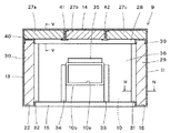
図1に示すボックス本体9は、例えばステンレスの板金加工で形成されたもので、ボックス本体9を閉じた状態で、搬送面2aに対して起立する4つの側面10,11,12,13と天井面14とで囲まれている。
Since the water removal apparatus to which the soundproof box in the embodiment of the present invention shown in FIGS. 1 to 7 is attached is the same as the conventional one, in the following description, the
The
装置本体1の正面側となるボックス本体の側面10にはユニットカバー3内の処理対象物の様子を見るための、のぞき窓10aが形成され、ネットコンベア2の搬送方向に直交する側面11,13には処理対象物の出入り口11a,13aが形成されている。
また、天井面14には図示しないファンを取り付ける排気窓14a,14bを開口させている。
On the
Further,
このようなボックス本体9の内側は、後で説明するスポンジ状の吸音板で覆われているが、この吸音板は、上記各面10,11,12,13,14に設けられた、後で説明する支持部によって支持されている。
なお、この実施形態では、上記側面10,11,12,13及び天井面14とは、特にことわらない限り、ボックス本体9の内側面を指すことにする。
The inside of the
In the present embodiment, the side surfaces 10, 11, 12, 13 and the
図2は、ボックス本体9の下端側の開口付近のみを実線で表わしたもので、この図2では吸音板を省略している。
図示のように、上記側面10,11,12,13の下端側には、各側面10,11,12,13を構成する板材を内側に折り曲げてチャネル状の支持部が形成されている。
具体的には、側面10の下端には側面10の幅方向に長さを有する支持部15(図2,3,7参照)が形成され、側面11には上記出入り口11aを避けて側面11の下端に沿った支持部16(図3参照),17と、出入り口11aの上側に沿った支持部18が形成されている(図7参照)。
さらに、出入り口11aの両脇には、図2,7に示すように、上下方向に伸びる支持部19,20が形成されている。これら支持部19,20も、側面11を構成する板材を折り曲げて形成されたものである。
FIG. 2 shows only the vicinity of the opening on the lower end side of the
As shown in the figure, on the lower end side of the side surfaces 10, 11, 12, and 13, a channel-shaped support portion is formed by bending inward the plate material constituting each of the side surfaces 10, 11, 12, and 13.
Specifically, a support portion 15 (see FIGS. 2, 3, and 7) having a length in the width direction of the
Furthermore, as shown in FIGS. 2 and 7,
また、上記側面10に対向する側面12には、上記支持部15に対向する位置に、上記支持部15と同様にしてチャネル状の支持部21(図2,7参照)が形成されている。
さらに、側面13には、上記側面11の支持部16(図3参照),17,18,19,20それぞれと対向する位置に、側面13を構成する板材を折り曲げることによって、チャネル状の支持部22(図3参照),23,24,25,26が形成されている(図2参照)。
このように各面を構成する板材を折り曲げて形成された支持部のチャネルには吸音板がはめ込まれるようにしている。
Further, on the
Further, a channel-shaped support portion is formed on the
In this way, the sound absorbing plate is fitted into the channel of the support portion formed by bending the plate material constituting each surface.
そして、各側面10,11,12,13及び天井面14には、上記以外にもチャネル状の支持部が設けられているが、各面の支持部について図3〜7を用いてさらに説明する。
図3は、図1のIII-III線断面図であり、ボックス本体9の中から側面10の方向を見たものである。ただし、側面10は側面用吸音板36で覆われていて、図3においては側面用吸音板36の裏側に位置している。
In addition to the above, channel-like support portions are provided on the side surfaces 10, 11, 12, 13 and the
FIG. 3 is a cross-sectional view taken along the line III-III in FIG. 1 and shows the direction of the
また、図7は、図1のVII-VII線断面図であり、ボックス本体9の中から側面11の方向を見たものである。この側面11は、側面用吸音板29の裏側に位置している。
なお、側面11と側面13とは互いに対称形なので、図7には側面11側の構成要素の符号とともに、側面13側において側面11側の各部材と正対する部材の符号を、丸かっこ( )内に示している。
FIG. 7 is a cross-sectional view taken along the line VII-VII in FIG. The
In addition, since the
まず、側面10について説明する。側面10には、図3に示すように、天井面14との間に天井用吸音板27a,27b,27cの厚み相当の間隔を保った位置に、開口を上記支持部15の開口と対向させ、支持部15と平行に伸びるチャネル部材28(図3,5,7参照)が固定されている。このチャネル部材28の長手方向両端は、側面11,13との間に、これら側面11,13を覆う、側面用吸音板29,30の厚み相当の間隔を保つようにしている。
First, the
また、上記チャネル部材28の両端付近には、側面11,13との間に側面用吸音板29,30の厚み相当の間隔を保った位置に、上下に伸びるチャネル部材31,32(図3,4参照)が固定されている。これらチャネル部材31,32はその開口を互いに対向させている。
さらに、のぞき窓10aの周囲には、チャネル部材33,34,35が固定されている。これらチャネル部材33,34,35は、その開口をそれぞれ上記チャネル部材31,32,28の開口に対向させている。
なお、上記のぞき窓10aは一点鎖線で示した樹脂製の透明板10bで閉鎖され、上記チャネル部材33,34,35は、この透明板10bの外側を囲むようにして側面10に固定されている。
Further, in the vicinity of both ends of the
Further,
The
上記のように側面10には、チャネル部材28,31,32,33,34,35が固定されている。そして、これらのチャネル部材28,31,32,33,34,35と、支持部15とのチャネル内に外周を嵌めこまれて支持された門型の側面用防音板36が、側面10を覆っている。なお、上記側面用吸音板36は、のぞき窓10aの部分を除いた形状で、この実施形態では、のぞき窓10aの両側に固定されたチャネル部材33,34間には側面用吸音板36が設けられていない。
As described above, the
この側面10におけるチャネル部材28,31,32,33,34,35及び支持部15のうち、ボックス本体9の下端開口縁に沿って設けられた支持部15が、側面用吸音板36の重量を下方で支えるこの発明の重量支持部である。
また、その他のチャネル部材28,31,32,33,34,35が上記重量支持部で支持された側面用吸音板36の倒れを防止する倒れ防止支持部を構成している。
そして、チャネル部材28,35が重量支持部と平行な倒れ防止支持部であり、チャネル部材31,32,33,34が重量支持部と直交する方向に伸びる倒れ防止支持部である。
なお、倒れ防止支持部は、重量支持部と平行に伸びるもの、もしくは直交する方向に伸びるもののいずれか一方のみでも構わない。
Of the
Further, the
The
Note that the fall prevention support portion may be either one that extends in parallel with the weight support portion or one that extends in a direction orthogonal to the weight support portion.
次に、側面12側について説明する。図1に示すように、側面12は上記側面10と対向し、上記のぞき窓10aなどが形成されていない長方形の面である。下端には上記したチャネル状の支持部21が形成されている(図2参照)。
この側面12にも、側面10のチャネル部材28と同様のチャネル部材37(図7参照)が、上記チャネル部材28と対向する位置に固定され、支持部21と平行に伸びる倒れ防止支持部を構成している。
すなわち、このチャネル部材37も、天井面14との間に天井用吸音板27a,27b,27cの厚み相当の間隔を保った位置で、開口を上記支持部21の開口と対向させ、支持部21と平行に伸びる部材である。そして、このチャネル部材37の長手方向両端は、側面11,13との間に、これら側面11,13を覆う、側面用吸音板29,30の厚み相当の間隔を保つようにしている。
Next, the
A channel member 37 (see FIG. 7) similar to the
That is, the
さらに、この側面12にも、支持部21と直交する方向に伸びる一対の図示しないチャネル部材が固定され、倒れ防止支持部を構成している。この一対のチャネル部材は、側面10に固定された上記チャネル部材31,32(図3参照)と対向し、これらチャネル部材31,32と同様に、側面11,13との間に側面用吸音板29,30の厚み相当の間隔を保持して側面12に固定されている。
そして、長方形の側面用吸音板38が、図7に示すように、上記支持部21と、チャネル部材37及び上記図示しない一対のチャネル部材のチャネル内に嵌め込まれて支持され、側面12を覆っている。
Further, a pair of channel members (not shown) extending in a direction perpendicular to the
Then, as shown in FIG. 7, a rectangular side-surface
次に、側面11について説明する。側面11には、先に説明したように側面11を構成する板部材を折り曲げて形成されたチャネル状の支持部16,17,18,19,20が設けられている。
さらに、図3,7に示すように、側面11の上方には天井用吸音板27cの厚み相当の間隔を保持して、開口を支持部16の開口に対向させたチャネル部材39が固定されている。このチャネル部材39は側面11の幅方向ほぼ全長に亘る長さを備えている。
Next, the
Further, as shown in FIGS. 3 and 7, a
そして、側面11上では、上記支持部16,17,18,19とチャネル部材39と、側面10,12とで囲まれた門形の側面用吸音板29が、その外周をチャネル内に嵌め込まれて支持されている。
なお、上記側面用吸音板29の下端を支持する支持部16,17,18が、ボックス本体9の下端開口縁に沿った、この発明の重量支持部であり、上下に伸びる支持部19,20及び上方のチャネル部材39が倒れ防止支持部を構成している。
On the
The
また、この実施形態では、側面10を覆う側面用吸音板36の幅方向の一方の端面を支持するために側面10に固定されたチャネル部材31、及び側面12を覆う側面用吸音板38の幅方向の一方の端面を支持するために側面12に固定された図示しないチャネル部材と、側面11との間隔に上記側面用吸音板29がはめ込まれる構成にしている(図3参照)。したがって、上記側面用吸音板36,38を支持するチャネル部材と側面11との間隔が、側面用吸音板29を支持するチャネル状の倒れ防止支持部として機能する。
In this embodiment, the
また、上記側面11と対向する側面13は、上記側面11と対称形なので、上記側面11に設けられた部材と同様の部材によって、側面13を覆う側面用吸音板30が支持されている。
具体的には、側面11のチャネル部材39と正対する位置、すなわち天井面14との間に天井用吸音板27aの厚み相当の間隔を保った位置に、開口を支持部22の開口と対向させ、支持部22と平行に伸びるチャネル部材40(図3,7参照)が固定されている。このチャネル部材40は、側面13の幅方向ほぼ全長に亘る長さを備えている。
Further, since the
Specifically, the opening is made to face the opening of the
このチャネル部材40と、下端側で重量支持部となる支持部22,23,24と、倒れ防止支持部となる支持部25,26とで、門型の側面用吸音板30が支持されている。
なお、この側面13側においても、側面用吸音板36,38の幅方向の端面を支持するためのチャネル部材32及び側面13に固定された図示しないチャネル部材と、側面13との間隔が、側面用吸音板30を支持する、チャネル状の倒れ防止支持部として機能する。
The channel-shaped side
Also on the
上記のように、この実施形態のボックス本体9の4側面を覆う側面用吸音板29,30,36,38がいずれも、その外周が支持部のチャネル内に嵌め込まれることによって支持されている。
したがって、側面用吸音板29,30,36,38は、全体を撓ませることによってその外周をチャネルから取りだすことができるとともに、チャンネル内に嵌め込むこともできる。
As described above, the sound absorbing plates for side surfaces 29, 30, 36, and 38 that cover the four side surfaces of the
Accordingly, the outer side of the
次に、天井面14を覆う天井用吸音板27a,27b,27cの支持について説明する。
この実施形態では、天井面14を三等分した面積の天井用吸音板27a,27b,27cで天井面14を覆うようにしている。上記各天井用吸音板27a,27b,27cがこの発明の分割吸音板である。
そして、各側面10,11,12,13には、上記したように天井面14との間に、天井用吸音板27a,27b,27cの厚み相当の間隔を保ってチャネル部材28,37,39,40が固定されている。このように4側面に固定されたチャネル部材28,37,39,40は、天井面14の輪郭に沿って設けられ、これら4つのチャネル部材28,37,39,40が矩形の枠を構成している。
Next, support for the ceiling
In this embodiment, the
Further, as described above, the
これらチャネル部材28,37,39,40と天井面14との間に天井用吸音板27a,27b,27cを嵌め込み、チャネル状の天井支持部として機能させることができる。要するに、チャネル部材28,37,39,40と天井面14とが相まってチャネル状の天井支持部が構成され、天井用吸音板27a,27b,27cを、チャネル部材28,37,39,40で構成された枠と天井面14との間に押し込むことができる。
このように天井用吸音板27a,27b,27cを上記枠と天井面14との間に押し込めば、天井用吸音板27a,27b,27cの縁を、上記側面10,11,12,13に密着させることができる。
The
Thus, if the
なお、この実施形態では、各側面10,11,12,13を覆う側面吸音板29,30、36,38が、その上端と天井面14との間に上記天井用吸音板の厚み相当の間隔が保持される高さ方向の寸法を備えた側面用吸音板である。
したがって、この実施形態では、上記チャネル部材28,37,39,40が、それぞれ側面用吸音板の倒れ防止支持部の機能と天井用支持部の機能とを兼ねることになる。
In this embodiment, the side surface
Therefore, in this embodiment, the
また、この実施形態では、天井用吸音板として分割吸音板を用いているので、分割吸音板ごとにその外周を支持するための支持部として、棒状の支持部材41,42を天井面14に固定している。これら支持部材41,42は図6に示すように天井面14に固定したとき両側にチャネルが形成される金属製の部材である。
そして、支持部材41と上記チャネル部材40との間に天井用吸音板27aが架け渡され、支持部材41,42間に天井用吸音板27bが、支持部材42と上記チャネル部材39との間に天井用吸音板27cが架け渡されることになる。
In this embodiment, since the divided sound absorbing plate is used as the sound absorbing plate for the ceiling, the rod-
Then, a ceiling
このように、天井用吸音板27,27b,27cも、チャネル状の支持部に嵌め込むことによって支持されるので、支持部のチャネルから簡単に取り外したり、嵌めたりすることができる。
また、3枚の天井用吸音板27a,27b,27cのうち中央に位置する天井用吸音板27bには、天井面14に形成された排気窓14a,14bに対応する開口を形成し、排気窓14a,14bに取り付けたファンによってボックス本体9内の蒸気などを排出するようにしている。
As described above, the
The ceiling
上記したように、この実施形態の防音ボックスは、ボックス本体9の内側を覆う側面用吸音板及び天井用吸音板を、支持部のチャネルに対して簡単に着脱することができるものである。したがって、ボックス本体9内の清掃時には、吸音板を取り外し、ボックス本体9と吸音板とを別々に清掃することができる。ボックス本体から吸音板を取り外すことができるので、吸音材を洗浄したり、乾燥させたり、新しい吸音板と交換したりすることも容易である。
そのため、清掃や交換に手間を掛けずに、ボックス本体9内を清潔に保つことができる。
As described above, in the soundproof box of this embodiment, the sound absorbing plate for side surface and the sound absorbing plate for ceiling covering the inside of the
Therefore, the inside of the
また、この実施形態では、重量支持部と倒れ防止支持部とによって、側面用吸音板を確実に支持するようにしている。そのため、側面用吸音板を着脱可能にしながら、除水または除塵装置の使用時には、吸音板がずれたりすることを防止できる。特に、除水装置に用いた場合には、吸音板が吸水して重量が大きくなったり重量バランスが崩れてしまったりする可能性があるが、そのようなときにも、重量支持部だけでなく倒れ防止支持部を設けたことによって側面用吸音板の倒れやずれが発生しないようにできる。 In this embodiment, the side-surface sound absorbing plate is reliably supported by the weight support portion and the fall prevention support portion. For this reason, it is possible to prevent the sound absorbing plate from shifting when the water removing or dust removing device is used while making the side sound absorbing plate detachable. In particular, when used in a water removal device, there is a possibility that the sound absorbing plate absorbs water and the weight increases or the weight balance is lost. By providing the fall prevention support portion, it is possible to prevent the side sound absorbing plate from falling down or shifting.
なお、上記ボックス本体9は、各面10,11,12,13,14を構成する板材に上記支持部を設けてから、ボックス状に組み合わせ、接合部を溶接して構成するようにしている。
そして、上記各支持部は、吸音板の全周を支える必要はない。支持部は、各吸音板がずれたり倒れたりしない範囲で支持できる長さを備えていればよいし、長手方向に分割された複数の部材で構成されてもよい。
The
And each said support part does not need to support the perimeter of a sound-absorbing board. The support part should just be provided with the length which can be supported in the range in which each sound-absorbing board does not slip | deviate or fall down, and may be comprised with the some member divided | segmented into the longitudinal direction.
また、この実施形態では、天井用吸音板を3つの分割吸音板によって構成しているが、天井用吸音板の分割数はいくつでもよいし、1部材で構成してもよい。
さらに、側面用吸音板を複数の分割吸音板で構成してもよい。
天井用吸音板または壁面用吸音板が、複数の分割吸音板で構成された場合には、一部材で構成される場合と比べて、個々の部材の重量が小さくなるため、着脱時の取り扱いが容易になるというメリットがある。一方、着脱すべき部材の数が多くなり、その分、手間がかかることもある。したがって、分割吸音板の数は、側面や天井面の面積や吸音板の重量などに応じて、決定することが好ましい。
In this embodiment, the ceiling sound-absorbing plate is constituted by three divided sound-absorbing plates, but the number of divisions of the ceiling sound-absorbing plate may be any number and may be constituted by one member.
Further, the side sound absorbing plate may be constituted by a plurality of divided sound absorbing plates.
When the sound absorbing plate for ceiling or the sound absorbing plate for wall surface is composed of a plurality of divided sound absorbing plates, the weight of each member is smaller compared to the case where it is composed of one member. There is an advantage that it becomes easy. On the other hand, the number of members to be attached and detached increases, which may take time. Therefore, the number of divided sound absorbing plates is preferably determined according to the area of the side surface or ceiling surface, the weight of the sound absorbing plate, and the like.
また、吸音板の下端を支持する重量支持部は、上記のように側面を構成する板部材を折り曲げて形成するのではなく、側面とは別のチャネル部材を取り付けて構成してもよい。
さらに、重量支持部には、その長手方向に連続的に水抜き孔を形成して、吸音板が吸収した水分を外部に排出させるようにしてもよい。
なお、上記実施形態では除水装置に取り付けられる防音ボックスについて説明したが、上記ボックス本体9は除塵装置用の防音ボックスとして用いることができ、その場合も上記と同様の効果が得られる。
Further, the weight support portion that supports the lower end of the sound absorbing plate may be formed by attaching a channel member different from the side surface, instead of bending the plate member forming the side surface as described above.
Further, the weight support portion may be continuously formed with drain holes in the longitudinal direction so that the moisture absorbed by the sound absorbing plate is discharged to the outside.
In addition, although the said embodiment demonstrated the soundproof box attached to a water removal apparatus, the said box
また、上記吸音板と各面と間に制振板を介在させて、防音効果をさらに上げるようにしてもよい。
上記制振板は、上記各支持部を避けて側面10,11,12,13及び天井面14に接着剤などで固定することができる。この制振板は、吸音板で覆われるので、水滴や塵などが直接付着することはないし、吸音板のようにスポンジ状ではないので、水分がしみ込むこともない。かりに、この制振板の表面に、水分や塵が付着したとても、上記吸音板を取り外せば、それらを簡単にふき取ることができる。
Further, a sound-damping plate may be interposed between the sound-absorbing plate and each surface to further enhance the soundproofing effect.
The damping plate can be fixed to the side surfaces 10, 11, 12, 13 and the
食品工程など、衛生管理が厳しい工程で用いられる除水または除塵装置用として最適である。 Ideal for water removal or dust removal equipment used in strict hygiene processes such as food processing.
1 装置本体
2 (搬送手段)ネットコンベア
2a 搬送面
3 ユニットカバー
4,5 エア噴射ユニット
9 ボックス本体
10,11,12,13 側面
14 天井面
15,16,17,18,21,22,23,24 (重量)支持部
19,20,25,26(倒れ防止)支持部
28,31,32,33,34,35,37,39,40 (倒れ防止支持部)チャネル部材
41,42 (天井用支持部)支持部材
29,30,36,38 側面用吸音板
27a,27b,27c 天井用吸音板
DESCRIPTION OF
Claims (3)
上記ユニットカバーを覆ったり解放したりするボックス本体が、上記装置本体に開閉可能に取り付けられるとともに、
このボックス本体が閉じた状態で起立する4つの内側面には、
下端側開口縁に沿って設けられたチャネル状の重量支持部と、この重量支持部と平行もしくは直交する方向に伸びるチャネル状の倒れ防止支持部とが設けられ、
上記重量支持部と倒れ防止支持部とのチャネル内に、各内側面を覆うスポンジ状の側面用吸音板がはめ込まれるとともに、
ボックス本体の天井面には天井面の輪郭に沿ったチャネル状の天井用支持部が設けられ、この天井用支持部のチャネル内に天井面を覆うスポンジ状の天井用吸音板の外周端がはめ込まれた
除水または除塵装置用の防音ボックス。 A water removal unit incorporating an air injection unit for injecting compressed air toward a processing object conveyed by the conveying means in a unit cover that can be opened and closed with respect to the conveying surface of the conveying means provided in the apparatus main body. Or a soundproof box used in a dust removing device,
A box body that covers and releases the unit cover is attached to the apparatus body so as to be openable and closable,
On the four inner surfaces that stand with the box body closed,
A channel-shaped weight support portion provided along the lower end side opening edge, and a channel-shaped falling prevention support portion extending in a direction parallel or orthogonal to the weight support portion are provided,
In the channel of the weight support part and the fall prevention support part, a sponge-like side sound absorbing plate covering each inner side surface is fitted,
The ceiling of the box body is provided with a channel-shaped ceiling support section that follows the outline of the ceiling surface, and the outer peripheral edge of the sponge-like sound absorbing plate for the ceiling that covers the ceiling surface is fitted into the channel of the ceiling support section. Soundproof box for water removal or dust removal equipment.
上記間隔が上記天井用支持部を構成する請求項1に記載の除水または除塵装置用の防音ボックス。 The side sound absorbing plate has a height dimension in which a space corresponding to the thickness of the ceiling sound absorbing plate is maintained between the upper end and the ceiling surface in a state where the box body is closed,
The soundproof box for a water removal or dust removal apparatus according to claim 1, wherein the interval constitutes the ceiling support section.
複数の分割吸音板で構成されるとともに、上記分割吸音板で覆われる側面または天井面には、上記分割吸音板の外周がはめ込まれるチャネル状の支持部が設けられた
請求項1または2に記載の除水または除塵装置用の防音ボックス。 Either of the above-mentioned sound absorbing plate for side surface or sound absorbing plate for ceiling,
The channel-shaped support part which the outer periphery of the said division | segmentation sound-absorbing board is engage | inserted was provided in the side surface or ceiling surface covered with the said division | segmentation sound-absorption board while being comprised with a some division | segmentation sound-absorption board. Soundproof box for water removal or dust removal equipment.
Priority Applications (1)
| Application Number | Priority Date | Filing Date | Title |
|---|---|---|---|
| JP2018086480A JP7049653B2 (en) | 2018-04-27 | 2018-04-27 | Soundproof box for water remover |
Applications Claiming Priority (1)
| Application Number | Priority Date | Filing Date | Title |
|---|---|---|---|
| JP2018086480A JP7049653B2 (en) | 2018-04-27 | 2018-04-27 | Soundproof box for water remover |
Publications (2)
| Publication Number | Publication Date |
|---|---|
| JP2019190784A true JP2019190784A (en) | 2019-10-31 |
| JP7049653B2 JP7049653B2 (en) | 2022-04-07 |
Family
ID=68389522
Family Applications (1)
| Application Number | Title | Priority Date | Filing Date |
|---|---|---|---|
| JP2018086480A Active JP7049653B2 (en) | 2018-04-27 | 2018-04-27 | Soundproof box for water remover |
Country Status (1)
| Country | Link |
|---|---|
| JP (1) | JP7049653B2 (en) |
Cited By (2)
| Publication number | Priority date | Publication date | Assignee | Title |
|---|---|---|---|---|
| JP2020180761A (en) * | 2019-04-26 | 2020-11-05 | 春日電機株式会社 | Sound proofing device |
| DE112020005068T5 (en) | 2019-10-18 | 2022-07-21 | Denso Corp. | Liquid spray nozzle and vehicle sensor washing device |
Citations (7)
| Publication number | Priority date | Publication date | Assignee | Title |
|---|---|---|---|---|
| JPH05231124A (en) * | 1992-02-25 | 1993-09-07 | Mitsubishi Heavy Ind Ltd | Sound absorbing body of silencer |
| JPH06107320A (en) * | 1992-09-30 | 1994-04-19 | Ntn Corp | Soundproof unit parts feeder |
| JPH0863171A (en) * | 1994-08-22 | 1996-03-08 | Bridgestone Cycle Co | Soundproof device for wire twisting machine |
| JP2005345018A (en) * | 2004-06-03 | 2005-12-15 | Kasuga Electric Works Ltd | Water removal machine |
| JP2008121374A (en) * | 2006-11-15 | 2008-05-29 | Juichi Yamauchi | Structure for embedding expansion joint in highway bridge |
| JP2016108930A (en) * | 2014-12-02 | 2016-06-20 | Jfe建材株式会社 | Sound proof panel and sound proof wall |
| JP2017115572A (en) * | 2015-12-18 | 2017-06-29 | 中日本高速道路株式会社 | Sound-proof panel and sound insulating wall |
-
2018
- 2018-04-27 JP JP2018086480A patent/JP7049653B2/en active Active
Patent Citations (7)
| Publication number | Priority date | Publication date | Assignee | Title |
|---|---|---|---|---|
| JPH05231124A (en) * | 1992-02-25 | 1993-09-07 | Mitsubishi Heavy Ind Ltd | Sound absorbing body of silencer |
| JPH06107320A (en) * | 1992-09-30 | 1994-04-19 | Ntn Corp | Soundproof unit parts feeder |
| JPH0863171A (en) * | 1994-08-22 | 1996-03-08 | Bridgestone Cycle Co | Soundproof device for wire twisting machine |
| JP2005345018A (en) * | 2004-06-03 | 2005-12-15 | Kasuga Electric Works Ltd | Water removal machine |
| JP2008121374A (en) * | 2006-11-15 | 2008-05-29 | Juichi Yamauchi | Structure for embedding expansion joint in highway bridge |
| JP2016108930A (en) * | 2014-12-02 | 2016-06-20 | Jfe建材株式会社 | Sound proof panel and sound proof wall |
| JP2017115572A (en) * | 2015-12-18 | 2017-06-29 | 中日本高速道路株式会社 | Sound-proof panel and sound insulating wall |
Cited By (2)
| Publication number | Priority date | Publication date | Assignee | Title |
|---|---|---|---|---|
| JP2020180761A (en) * | 2019-04-26 | 2020-11-05 | 春日電機株式会社 | Sound proofing device |
| DE112020005068T5 (en) | 2019-10-18 | 2022-07-21 | Denso Corp. | Liquid spray nozzle and vehicle sensor washing device |
Also Published As
| Publication number | Publication date |
|---|---|
| JP7049653B2 (en) | 2022-04-07 |
Similar Documents
| Publication | Publication Date | Title |
|---|---|---|
| JP2019190784A (en) | Sound proof box for water removal device or dust collecting device | |
| KR100941942B1 (en) | A dust collecting table | |
| KR101432192B1 (en) | Track carriage system | |
| JP4180643B1 (en) | Waste reduction methods in waste treatment | |
| CN208994915U (en) | A kind of elevator ventilation device | |
| JP5860334B2 (en) | Animal rearing safety cabinet | |
| JP2020180761A (en) | Sound proofing device | |
| JP6602015B2 (en) | Work dust remover | |
| JP4579196B2 (en) | Hand dryer | |
| JP2011051673A (en) | Car platform cleaning device of elevator | |
| US4949512A (en) | Cage for reconditioning building facades | |
| JP2017164676A (en) | Foreign matter removal device | |
| JP6044464B2 (en) | Cotton processing equipment in the electronic opening device of a loom | |
| JPH0798318B2 (en) | Dust collector | |
| TW201932185A (en) | Bathroom dryer | |
| CN209998074U (en) | Movable dust hood for unloading bulk and packed grain | |
| JP2004331395A5 (en) | ||
| JP5583108B2 (en) | Breeding device and dust collection method | |
| JPH05116863A (en) | Cleaner for interior of elevator cage | |
| EP0709636B1 (en) | A method and a device for cleaning a drying tunnel | |
| JPS61109533A (en) | Hand drying apparatus | |
| JP4340362B2 (en) | Air shower equipment | |
| JP2005230723A (en) | Substrate processing apparatus, and washing chamber and drying chamber composing the same | |
| JPH07305240A (en) | Apparatus for preventing filter from being clogged with fly waste in cleaner of spinning frame | |
| JP3125669U (en) | Pet brushing equipment |
Legal Events
| Date | Code | Title | Description |
|---|---|---|---|
| RD02 | Notification of acceptance of power of attorney |
Free format text: JAPANESE INTERMEDIATE CODE: A7422 Effective date: 20201023 |
|
| A621 | Written request for application examination |
Free format text: JAPANESE INTERMEDIATE CODE: A621 Effective date: 20201207 |
|
| A977 | Report on retrieval |
Free format text: JAPANESE INTERMEDIATE CODE: A971007 Effective date: 20210910 |
|
| A131 | Notification of reasons for refusal |
Free format text: JAPANESE INTERMEDIATE CODE: A131 Effective date: 20210928 |
|
| A521 | Request for written amendment filed |
Free format text: JAPANESE INTERMEDIATE CODE: A523 Effective date: 20211129 |
|
| TRDD | Decision of grant or rejection written | ||
| A01 | Written decision to grant a patent or to grant a registration (utility model) |
Free format text: JAPANESE INTERMEDIATE CODE: A01 Effective date: 20220301 |
|
| A61 | First payment of annual fees (during grant procedure) |
Free format text: JAPANESE INTERMEDIATE CODE: A61 Effective date: 20220318 |
|
| R150 | Certificate of patent or registration of utility model |
Ref document number: 7049653 Country of ref document: JP Free format text: JAPANESE INTERMEDIATE CODE: R150 |