JP2019172267A - Vehicular air-conditioner - Google Patents

Vehicular air-conditioner Download PDF

Info

Publication number
JP2019172267A
JP2019172267A JP2019135319A JP2019135319A JP2019172267A JP 2019172267 A JP2019172267 A JP 2019172267A JP 2019135319 A JP2019135319 A JP 2019135319A JP 2019135319 A JP2019135319 A JP 2019135319A JP 2019172267 A JP2019172267 A JP 2019172267A
Authority
JP
Japan
Prior art keywords
refrigerant
heat medium
heat
battery
temperature
Prior art date
Legal status (The legal status is an assumption and is not a legal conclusion. Google has not performed a legal analysis and makes no representation as to the accuracy of the status listed.)
Pending
Application number
JP2019135319A
Other languages
Japanese (ja)
Other versions
JP2019172267A5 (en
Inventor
徹也 石関
Tetsuya Ishizeki
徹也 石関
岡本 佳之
Yoshiyuki Okamoto
佳之 岡本
Current Assignee (The listed assignees may be inaccurate. Google has not performed a legal analysis and makes no representation or warranty as to the accuracy of the list.)
Sanden Automotive Climate Systems Corp
Original Assignee
Sanden Automotive Climate Systems Corp
Priority date (The priority date is an assumption and is not a legal conclusion. Google has not performed a legal analysis and makes no representation as to the accuracy of the date listed.)
Filing date
Publication date
Application filed by Sanden Automotive Climate Systems Corp filed Critical Sanden Automotive Climate Systems Corp
Priority to JP2019135319A priority Critical patent/JP2019172267A/en
Publication of JP2019172267A publication Critical patent/JP2019172267A/en
Publication of JP2019172267A5 publication Critical patent/JP2019172267A5/ja
Pending legal-status Critical Current

Links

Images

Abstract

To positively convey heat of a heater to refrigerant through a heat medium in a vehicular air-conditioner capable of adjusting the temperature of a battery.SOLUTION: A vehicular air-conditioner includes a battery temperature adjustment device 61 for circulating a heat medium in a battery 55 mounted in a vehicle and adjusting the temperature of the battery. The battery temperature adjustment device has a refrigerant-heat medium heat exchanger 64 for exchanging heat between the refrigerant and the heat medium, a heat medium heating heater 66 for heating the heat medium, and a circulation pump 62 for circulating the heat medium. The battery temperature adjustment device makes the heat medium passing through the heat medium heating heater flow to the refrigerant-heat medium heat exchanger, and makes the heat medium discharged from the refrigerant-heat medium heat exchanger flow to the battery.SELECTED DRAWING: Figure 11

Description

本発明は、車両の車室内を空調するヒートポンプ方式の空気調和装置、特にバッテリを備えたハイブリッド自動車や電気自動車に好適な車両用空気調和装置に関するものである。   The present invention relates to a heat pump type air conditioner that air-conditions a passenger compartment of a vehicle, and more particularly to a vehicle air conditioner suitable for a hybrid vehicle or an electric vehicle equipped with a battery.

近年の環境問題の顕在化から、バッテリから供給される電力で走行用モータを駆動するハイブリッド自動車や電気自動車が普及するに至っている。そして、このような車両に適用することができる空気調和装置として、冷媒を圧縮して吐出する圧縮機と、車室内側に設けられて冷媒を放熱させる放熱器と、車室内側に設けられて冷媒を吸熱させる吸熱器と、車室外側に設けられて外気が通風されると共に、冷媒を吸熱又は放熱させる室外熱交換器が接続された冷媒回路を備え、圧縮機から吐出された冷媒を放熱器において放熱させ、この放熱器において放熱した冷媒を室外熱交換器において吸熱させる暖房モード(暖房運転)と、圧縮機から吐出された冷媒を室外熱交換器において放熱させ、吸熱器において吸熱させる冷房モード(冷房運転)を切り換えて実行するものが開発されている(例えば、特許文献1参照)。   With the recent emergence of environmental problems, hybrid vehicles and electric vehicles that drive a traction motor with electric power supplied from a battery have become widespread. As an air conditioner that can be applied to such a vehicle, a compressor that compresses and discharges the refrigerant, a radiator that is provided on the vehicle interior side and dissipates the refrigerant, and is provided on the vehicle interior side. A heat sink that absorbs the refrigerant and a refrigerant circuit that is provided outside the passenger compartment and vents the outside air and that is connected to an outdoor heat exchanger that absorbs or dissipates the refrigerant, and dissipates the refrigerant discharged from the compressor. A heating mode (heating operation) in which heat is radiated in the radiator, and the refrigerant radiated in the radiator is absorbed in the outdoor heat exchanger, and cooling in which the refrigerant discharged from the compressor is radiated in the outdoor heat exchanger and absorbed in the heat absorber One that switches and executes a mode (cooling operation) has been developed (see, for example, Patent Document 1).

一方、バッテリは低温環境下では充放電性能が低下する。また、自己発熱等で高温となった環境下で充放電を行うと、劣化が進行し、やがては作動不良を起こして破損する危険性もある。そこで、冷媒回路を循環する冷媒と熱交換する冷却水(熱媒体)をバッテリに循環させることでバッテリの温度を調整することができるようにしたものも開発されている(例えば、特許文献2参照)。   On the other hand, the charge / discharge performance of the battery is lowered in a low temperature environment. In addition, when charging / discharging is performed in an environment where the temperature is high due to self-heating or the like, the deterioration proceeds, and there is a risk of causing malfunction and eventually damaging. In view of this, a battery that can adjust the temperature of the battery by circulating cooling water (heat medium) that exchanges heat with the refrigerant circulating in the refrigerant circuit to the battery has been developed (for example, see Patent Document 2). ).

特開2014−213765号公報JP 2014-213765 A 特許第5440426号公報Japanese Patent No. 54042626

ここで、特許文献2の図15ではバッテリ11等の廃熱を水−冷媒熱交換器143により冷媒に搬送して暖房に寄与する制御をしている。そこで、加熱装置131も発熱させて暖房に寄与させることが考えられるが、加熱装置131を経た冷却水(熱媒体)はバッテリ11等を経た後、水−冷媒熱交換器143に流れるため、加熱装置131の熱を十分に冷媒に搬送することができないという欠点があった。   Here, in FIG. 15 of Patent Document 2, waste heat from the battery 11 or the like is transferred to the refrigerant by the water-refrigerant heat exchanger 143 so as to contribute to heating. Therefore, it is conceivable that the heating device 131 also generates heat and contributes to heating. However, since the cooling water (heat medium) that has passed through the heating device 131 passes through the battery 11 and the like and then flows to the water-refrigerant heat exchanger 143, heating is performed. There is a drawback that the heat of the device 131 cannot be sufficiently transferred to the refrigerant.

本発明は、係る従来の技術的課題を解決するために成されたものであり、バッテリの温度を調整可能とした車両用空気調和装置において、加熱装置の熱を、熱媒体を介して冷媒に積極的に搬送することができるようにすることを目的とする。   The present invention has been made to solve the conventional technical problem, and in a vehicle air conditioner capable of adjusting the temperature of a battery, heat of the heating device is converted into a refrigerant through a heat medium. The purpose is to enable positive transport.

本発明の車両用空気調和装置は、冷媒を圧縮する圧縮機と、冷媒を放熱させて車室内に供給する空気を加熱するための放熱器と、車室外に設けられた室外熱交換器と、制御装置を備えて車室内を空調するものであって、車両に搭載されたバッテリに熱媒体を循環させて当該バッテリの温度を調整するためのバッテリ温度調整装置を備え、このバッテリ温度調整装置は、冷媒と熱媒体とを熱交換させるための冷媒−熱媒体熱交換器と、熱媒体を加熱する加熱装置と、熱媒体を循環させる循環装置を有し、加熱装置を経た熱媒体を冷媒−熱媒体熱交換器に流し、この冷媒−熱媒体熱交換器を出た熱媒体をバッテリに流すことを特徴とする。   The vehicle air conditioner of the present invention includes a compressor that compresses a refrigerant, a radiator that heats the air that dissipates the refrigerant and that is supplied to the passenger compartment, an outdoor heat exchanger that is provided outside the passenger compartment, A control device is provided to air-condition the vehicle interior, and includes a battery temperature adjusting device for adjusting the temperature of the battery by circulating a heat medium through a battery mounted on the vehicle. A refrigerant for exchanging heat between the refrigerant and the heat medium, a heat medium heat exchanger, a heating device for heating the heat medium, and a circulation device for circulating the heat medium, and the heat medium passed through the heating device as the refrigerant It is made to flow into a heat medium heat exchanger, and the heat medium which left this refrigerant | coolant-heat medium heat exchanger is poured into a battery, It is characterized by the above-mentioned.

請求項2の発明の車両用空気調和装置は、上記発明において制御装置は、圧縮機から吐出された冷媒を放熱器にて放熱させることで車室内を暖房し、加熱装置を発熱させ、冷媒を冷媒−熱媒体熱交換器にて吸熱させる運転モードを有することを特徴とする。   According to a second aspect of the present invention, there is provided the vehicle air conditioner according to the first aspect, wherein the control device heats the vehicle interior by causing the refrigerant discharged from the compressor to dissipate heat with a radiator, and causes the heating device to generate heat. It has an operation mode in which heat is absorbed by a refrigerant-heat medium heat exchanger.

請求項3の発明の車両用空気調和装置は、上記各発明において制御装置は、圧縮機から吐出された冷媒を室外熱交換器にて放熱させて当該室外熱交換器を除霜し、加熱装置を発熱させ、冷媒を冷媒−熱媒体熱交換器にて吸熱させる運転モードを有することを特徴とする。   According to a third aspect of the present invention, there is provided the vehicle air conditioner according to the first aspect, wherein the controller defrosts the outdoor heat exchanger by radiating the refrigerant discharged from the compressor with the outdoor heat exchanger. And an operation mode in which the refrigerant absorbs heat by the refrigerant-heat medium heat exchanger.

本発明によれば、冷媒を圧縮する圧縮機と、冷媒を放熱させて車室内に供給する空気を加熱するための放熱器と、車室外に設けられた室外熱交換器と、制御装置を備えて車室内を空調する車両用空気調和装置において、車両に搭載されたバッテリに熱媒体を循環させて当該バッテリの温度を調整するためのバッテリ温度調整装置を備え、このバッテリ温度調整装置が、冷媒と熱媒体とを熱交換させるための冷媒−熱媒体熱交換器と、熱媒体を加熱する加熱装置と、熱媒体を循環させる循環装置を有し、加熱装置を経た熱媒体を冷媒−熱媒体熱交換器に流し、この冷媒−熱媒体熱交換器を出た熱媒体をバッテリに流すようにしたので、加熱装置により熱媒体を加熱し、この加熱された熱媒体によりバッテリを加熱することができるようになり、バッテリが低温とならないようにその温度を調整することが可能となる。   According to the present invention, a compressor for compressing a refrigerant, a radiator for heating the air that radiates the refrigerant to be supplied to the vehicle interior, an outdoor heat exchanger provided outside the vehicle interior, and a control device are provided. An air conditioner for a vehicle that air-conditions a vehicle interior includes a battery temperature adjusting device for adjusting a temperature of the battery by circulating a heat medium through a battery mounted on the vehicle, and the battery temperature adjusting device includes a refrigerant. A heat exchanger that heats the heat medium, a heating device that heats the heat medium, and a circulation device that circulates the heat medium. Since the heat medium flowing through the heat exchanger and flowing out of the refrigerant-heat medium heat exchanger flows into the battery, the heat medium is heated by the heating device, and the battery can be heated by the heated heat medium. You can Tteri it is possible to adjust the temperature so as not to low temperature.

また、請求項2の発明の如く制御装置に、圧縮機から吐出された冷媒を放熱器にて放熱させることで車室内を暖房し、加熱装置を発熱させ、冷媒を冷媒−熱媒体熱交換器にて吸熱させる運転モードを設けることで、バッテリや加熱装置の熱を冷媒に搬送して、効率の良い車室内の暖房を実現することができるようになると共に、室外熱交換器に着霜した場合や着霜が生じ易い環境となった場合にも、室外熱交換器に着霜が生じ難くし、或いは、着霜の進行を遅らせることができるようになる。   According to a second aspect of the present invention, the control device causes the refrigerant discharged from the compressor to dissipate heat by the radiator, thereby heating the vehicle interior, generating heat in the heating device, and supplying the refrigerant to the refrigerant-heat medium heat exchanger. By providing an operation mode that absorbs heat in the vehicle, heat from the battery and the heating device can be transferred to the refrigerant so that efficient heating of the interior of the vehicle can be realized, and the outdoor heat exchanger is frosted. In this case, even in an environment where frost formation is likely to occur, frost formation is less likely to occur in the outdoor heat exchanger, or the progress of frost formation can be delayed.

更に、請求項3の発明の如く制御装置に、圧縮機から吐出された冷媒を室外熱交換器にて放熱させて当該室外熱交換器を除霜し、加熱装置を発熱させ、冷媒を冷媒−熱媒体熱交換器にて吸熱させる運転モードを設けることで、バッテリや加熱装置の熱を冷媒に搬送して迅速に室外熱交換器を除霜を行うことができるようになる。   Furthermore, the refrigerant discharged from the compressor is radiated by the outdoor heat exchanger to defrost the outdoor heat exchanger, the heating device generates heat, and the refrigerant is supplied to the control device. By providing an operation mode in which heat is absorbed by the heat medium heat exchanger, the heat of the battery and the heating device can be transferred to the refrigerant and the outdoor heat exchanger can be quickly defrosted.

特に、本発明では加熱装置を経た熱媒体を冷媒−熱媒体熱交換器に流し、この冷媒−熱媒体熱交換器を出た熱媒体をバッテリに流すようにしているので、加熱装置の熱を積極的に冷媒に搬送して、暖房や除霜の促進を図ることができるようになるものである。   In particular, in the present invention, the heat medium that has passed through the heating device is caused to flow to the refrigerant-heat medium heat exchanger, and the heat medium that has exited the refrigerant-heat medium heat exchanger is caused to flow to the battery. It can be positively transported to a refrigerant to promote heating and defrosting.

本発明を適用した一実施形態の車両用空気調和装置の構成図である。It is a block diagram of the air conditioning apparatus for vehicles of one Embodiment to which this invention is applied. 図1の車両用空気調和装置のコントローラの電気回路のブロック図である。It is a block diagram of the electric circuit of the controller of the vehicle air conditioner of FIG. 図2のコントローラによる暖房/バッテリ冷却モードを説明する図である。It is a figure explaining the heating / battery cooling mode by the controller of FIG. 図2のコントローラによる第1のバッテリ冷却単独モードを説明する図である。It is a figure explaining the 1st battery cooling single mode by the controller of FIG. 図2のコントローラによる第2のバッテリ冷却単独モードを説明する図である。It is a figure explaining the 2nd battery cooling single mode by the controller of FIG. 図2のコントローラによる第1の冷房/バッテリ冷却モードを説明する図である。It is a figure explaining the 1st air_conditioning | cooling / battery cooling mode by the controller of FIG. 図2のコントローラによる第2の冷房/バッテリ冷却モードを説明する図である。It is a figure explaining the 2nd air_conditioning | cooling / battery cooling mode by the controller of FIG. 図2のコントローラによる冷房/バッテリ加熱モードを説明する図である。It is a figure explaining the cooling / battery heating mode by the controller of FIG. 図2のコントローラによる暖房/バッテリ加熱モードを説明する図である。It is a figure explaining the heating / battery heating mode by the controller of FIG. 図2のコントローラによるバッテリ加熱単独モードを説明する図である。It is a figure explaining the battery heating single mode by the controller of FIG. 図2のコントローラによる暖房/バッテリ熱HP利用モードを説明する図である。It is a figure explaining the heating / battery heat HP utilization mode by the controller of FIG. 図2のコントローラによる除霜/バッテリ冷却/加熱モードを説明する図である。It is a figure explaining the defrosting / battery cooling / heating mode by the controller of FIG.

以下、本発明の実施の形態について、図面に基づき詳細に説明する。   Hereinafter, embodiments of the present invention will be described in detail with reference to the drawings.

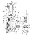
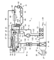
図1は本発明の一実施例の車両用空気調和装置1の構成図を示している。本発明を適用する実施例の車両は、エンジン(内燃機関)が搭載されていない電気自動車(EV)であって、車両にバッテリ55が設けられ、このバッテリ55に充電された電力を走行用の電動モータ(図示せず)に供給することで駆動し、走行するものであり、本発明の車両用空気調和装置1も、バッテリ55の電力で駆動されるものとする。   FIG. 1 shows a configuration diagram of a vehicle air conditioner 1 according to an embodiment of the present invention. A vehicle according to an embodiment to which the present invention is applied is an electric vehicle (EV) in which an engine (internal combustion engine) is not mounted. The vehicle is provided with a battery 55, and electric power charged in the battery 55 is used for traveling. The vehicle air conditioner 1 according to the present invention is driven by the electric power of the battery 55. The vehicle air conditioner 1 of the present invention is also driven by being supplied to an electric motor (not shown).

即ち、実施例の車両用空気調和装置1は、エンジン廃熱による暖房ができない電気自動車において、冷媒回路Rを用いたヒートポンプ運転により暖房運転を行い、更に、除湿暖房運転や内部サイクル運転、除湿冷房運転、冷房運転の各空調運転を選択的に実行することで車室内の空調を行うものである。   That is, the vehicle air conditioner 1 of the embodiment performs heating operation by heat pump operation using the refrigerant circuit R in an electric vehicle that cannot be heated by engine waste heat, and further performs dehumidification heating operation, internal cycle operation, and dehumidification cooling. Air conditioning of the passenger compartment is performed by selectively executing each air conditioning operation of the operation and the cooling operation.

尚、車両として電気自動車に限らず、エンジンと走行用の電動モータを供用する所謂ハイブリッド自動車にも本発明は有効であり、更には、エンジンで走行する通常の自動車にも適用可能であることは云うまでもない。   The present invention is effective not only for electric vehicles but also for so-called hybrid vehicles that use an engine and an electric motor for traveling, and is also applicable to ordinary vehicles that run on an engine. Needless to say.

実施例の車両用空気調和装置1は、電気自動車の車室内の空調(暖房、冷房、除湿、及び、換気)を行うものであり、冷媒を圧縮する電動式の圧縮機2と、車室内空気が通気循環されるHVACユニット10の空気流通路3内に設けられ、圧縮機2から吐出された高温高圧の冷媒が冷媒配管13Gを介して流入し、この冷媒を車室内に放熱させる放熱器4と、暖房時に冷媒を減圧膨張させる電動弁から成る室外膨張弁6と、冷房時には放熱器として機能し、暖房時には蒸発器として機能すべく冷媒と外気との間で熱交換を行わせる室外熱交換器7と、冷媒を減圧膨張させる電動弁(機械式膨張弁でも良い)から成る室内膨張弁8と、空気流通路3内に設けられて冷房時及び除湿時に車室内外から冷媒に吸熱させる吸熱器9と、アキュムレータ12等が冷媒配管13により順次接続され、冷媒回路Rが構成されている。   The vehicle air conditioner 1 according to the embodiment performs air conditioning (heating, cooling, dehumidification, and ventilation) in a vehicle interior of an electric vehicle, and includes an electric compressor 2 that compresses refrigerant and vehicle interior air. Is provided in the air flow passage 3 of the HVAC unit 10 through which air is circulated, and the high-temperature and high-pressure refrigerant discharged from the compressor 2 flows in through the refrigerant pipe 13G, and dissipates the refrigerant into the vehicle compartment. And an outdoor expansion valve 6 composed of an electric valve that decompresses and expands the refrigerant during heating, and an outdoor heat exchange that functions as a radiator during cooling and performs heat exchange between the refrigerant and the outside air so as to function as an evaporator during heating. And an indoor expansion valve 8 composed of an electric valve (or a mechanical expansion valve) that decompresses and expands the refrigerant, and heat absorption that is provided in the air flow passage 3 and absorbs heat from outside and inside the vehicle compartment during cooling and dehumidification. Device 9 and accumulator 2 and the like are sequentially connected by a refrigerant pipe 13, the refrigerant circuit R is formed.

尚、室外熱交換器7には、室外送風機15が設けられている。この室外送風機15は、室外熱交換器7に外気を強制的に通風することにより、外気と冷媒とを熱交換させるものであり、これにより停車中(即ち、車速が0km/h)にも室外熱交換器7に外気が通風されるよう構成されている。   The outdoor heat exchanger 7 is provided with an outdoor blower 15. The outdoor blower 15 exchanges heat between the outside air and the refrigerant by forcibly passing outside air through the outdoor heat exchanger 7, so that the outdoor air blower 15 can also be used outdoors even when the vehicle is stopped (that is, the vehicle speed is 0 km / h). It is comprised so that external air may be ventilated by the heat exchanger 7. FIG.

また、室外熱交換器7は冷媒下流側にレシーバドライヤ部14と過冷却部16を順次有し、室外熱交換器7の冷媒出口側に接続された冷媒配管13Aは冷房時に開放される開閉弁としての電磁弁17を介してレシーバドライヤ部14に接続され、過冷却部16の出口が逆止弁18を介して室内膨張弁8に接続されている。尚、レシーバドライヤ部14及び過冷却部16は構造的に室外熱交換器7の一部を構成しており、逆止弁18は室内膨張弁8側が順方向とされている。   The outdoor heat exchanger 7 has a receiver dryer section 14 and a supercooling section 16 sequentially on the downstream side of the refrigerant, and the refrigerant pipe 13A connected to the refrigerant outlet side of the outdoor heat exchanger 7 is an open / close valve that is opened during cooling. Is connected to the receiver dryer section 14 through an electromagnetic valve 17, and the outlet of the supercooling section 16 is connected to the indoor expansion valve 8 through a check valve 18. The receiver dryer section 14 and the supercooling section 16 structurally constitute a part of the outdoor heat exchanger 7, and the check valve 18 has a forward direction on the indoor expansion valve 8 side.

また、逆止弁18と室内膨張弁8間の冷媒配管13Bは、吸熱器9の出口側に位置する冷媒配管13Cと熱交換関係に設けられ、両者で内部熱交換器19を構成している。これにより、冷媒配管13Bを経て室内膨張弁8に流入する冷媒は、吸熱器9を出た低温の冷媒により冷却(過冷却)される構成とされている。   Further, the refrigerant pipe 13B between the check valve 18 and the indoor expansion valve 8 is provided in a heat exchange relationship with the refrigerant pipe 13C located on the outlet side of the heat absorber 9, and constitutes an internal heat exchanger 19 together. . Thus, the refrigerant flowing into the indoor expansion valve 8 through the refrigerant pipe 13B is cooled (supercooled) by the low-temperature refrigerant that has exited the heat absorber 9.

また、室外熱交換器7から出た冷媒配管13Aは分岐しており、この分岐した冷媒配管13Dは、暖房時に開放される開閉弁としての電磁弁21を介して内部熱交換器19の下流側における冷媒配管13Cに連通接続されている。この冷媒配管13Cがアキュムレータ12に接続され、アキュムレータ12は圧縮機2の冷媒吸込側に接続されている。   Further, the refrigerant pipe 13A exiting from the outdoor heat exchanger 7 is branched, and this branched refrigerant pipe 13D is downstream of the internal heat exchanger 19 via an electromagnetic valve 21 as an on-off valve that is opened during heating. The refrigerant pipe 13C is connected in communication. The refrigerant pipe 13 </ b> C is connected to the accumulator 12, and the accumulator 12 is connected to the refrigerant suction side of the compressor 2.

更に、放熱器4の出口側の冷媒配管13Eは室外膨張弁6の手前で冷媒配管13Jと冷媒配管13Fに分岐しており、分岐した一方の冷媒配管13Jが室外膨張弁6を介して室外熱交換器7の冷媒入口に接続されている。また、分岐した他方の冷媒配管13Fは除湿時に開放される開閉弁としての電磁弁22を介して逆止弁18の下流側の冷媒配管13Bに連通接続されている。これにより、冷媒配管13Fは室外膨張弁6と室外熱交換器7の直列回路に対して並列に接続されたかたちとなる。また、室外膨張弁6にはバイパス用の開閉弁としての電磁弁20が並列に接続されている。   Furthermore, the refrigerant pipe 13E on the outlet side of the radiator 4 is branched into a refrigerant pipe 13J and a refrigerant pipe 13F before the outdoor expansion valve 6, and one of the branched refrigerant pipes 13J passes through the outdoor expansion valve 6 to heat outside. It is connected to the refrigerant inlet of the exchanger 7. The other branched refrigerant pipe 13F is connected to a refrigerant pipe 13B on the downstream side of the check valve 18 via an electromagnetic valve 22 as an on-off valve that is opened during dehumidification. Thus, the refrigerant pipe 13F is connected in parallel to the series circuit of the outdoor expansion valve 6 and the outdoor heat exchanger 7. The outdoor expansion valve 6 is connected in parallel with a solenoid valve 20 as an on-off valve for bypass.

また、吸熱器9の空気上流側における空気流通路3には、外気吸込口と内気吸込口の各吸込口が形成されており(図1では吸込口25で代表して示す)、この吸込口25には空気流通路3内に導入する空気を車室内の空気である内気(内気循環)と、車室外の空気である外気(外気導入)とに切り換える吸込切換ダンパ26が設けられている。更に、この吸込切換ダンパ26の空気下流側には、導入した内気や外気を空気流通路3に送給するための室内送風機(ブロワファン)27が設けられている。   The air flow passage 3 on the air upstream side of the heat absorber 9 is formed with each of an outside air inlet and an inside air inlet (represented by the inlet 25 in FIG. 1). 25 is provided with a suction switching damper 26 for switching the air introduced into the air flow passage 3 between the inside air (inside air circulation) which is air inside the vehicle compartment and the outside air (outside air introduction) which is outside the vehicle compartment. Furthermore, an indoor blower (blower fan) 27 for supplying the introduced inside air or outside air to the air flow passage 3 is provided on the air downstream side of the suction switching damper 26.

また、図1において23は実施例の車両用空気調和装置1に設けられた補助加熱装置としての補助ヒータである。この補助ヒータ23は実施例ではPTCヒータ(電気ヒータ)から構成されており、空気流通路3の空気の流れに対して、放熱器4の空気下流側となる空気流通路3内に設けられている。そして、補助ヒータ23が通電されて発熱すると、これが所謂ヒータコアとなり、車室内の暖房を補完する。   Moreover, in FIG. 1, 23 is an auxiliary heater as an auxiliary heating device provided in the vehicle air conditioner 1 of the embodiment. The auxiliary heater 23 is composed of a PTC heater (electric heater) in the embodiment, and is provided in the air flow passage 3 on the air downstream side of the radiator 4 with respect to the air flow in the air flow passage 3. Yes. When the auxiliary heater 23 is energized and generates heat, this becomes a so-called heater core, which complements the heating in the passenger compartment.

また、放熱器4の空気上流側における空気流通路3内には、当該空気流通路3内に流入し、吸熱器9を通過した後の空気流通路3内の空気(内気や外気)を放熱器4に通風する割合を調整するエアミックスダンパ28が設けられている。更に、補助ヒータ23の空気下流側における空気流通路3には、FOOT(フット)、VENT(ベント)、DEF(デフ)の各吹出口(図1では代表して吹出口29で示す)が形成されており、この吹出口29には上記各吹出口から空気の吹き出しを切換制御する吹出口切換ダンパ31が設けられている。   Further, the air (inside air and outside air) in the air flow passage 3 after flowing into the air flow passage 3 and passing through the heat absorber 9 is radiated into the air flow passage 3 on the air upstream side of the radiator 4. An air mix damper 28 that adjusts the rate of ventilation through the vessel 4 is provided. Further, in the air flow passage 3 on the air downstream side of the auxiliary heater 23, FOOT (foot), VENT (def), and DEF (def) outlets (represented by the outlet 29 as representative in FIG. 1) are formed. The air outlet 29 is provided with an air outlet switching damper 31 that performs switching control of air blowing from the air outlets.

更に、本発明の車両用空気調和装置1は、バッテリ55の温度を調整するバッテリ温度調整装置61を備えている。このバッテリ温度調整装置61は、バッテリ55に熱媒体を循環させてその温度を調整するための循環装置としての循環ポンプ62と、流路切換装置としての三方弁63(電磁弁二個で構成しても良い)と、冷媒−熱媒体熱交換器64と、加熱装置としての熱媒体加熱ヒータ66と、空気−熱媒体熱交換器67を備え、それらが熱媒体配管68、69、71にて接続されている。   Furthermore, the vehicle air conditioner 1 of the present invention includes a battery temperature adjusting device 61 that adjusts the temperature of the battery 55. The battery temperature adjusting device 61 is composed of a circulation pump 62 as a circulation device for circulating a heat medium through the battery 55 and adjusting the temperature thereof, and a three-way valve 63 (two solenoid valves) as a flow path switching device. And a refrigerant-heat medium heat exchanger 64, a heat medium heater 66 as a heating device, and an air-heat medium heat exchanger 67, which are provided by heat medium pipes 68, 69, 71. It is connected.

この実施例の場合、循環ポンプ62の吐出側に三方弁63の入口が接続され、この三方弁63の一方の出口に冷媒−熱媒体熱交換器64の熱媒体流路64Aの入口が接続され、この熱媒体流路64Aの出口に熱媒体加熱ヒータ66が接続され、熱媒体加熱ヒータ66の出口にバッテリ55の入口が接続され、バッテリ55の出口が循環ポンプ62の吸込側に接続されている。   In this embodiment, the inlet of the three-way valve 63 is connected to the discharge side of the circulation pump 62, and the inlet of the heat medium flow path 64 </ b> A of the refrigerant-heat medium heat exchanger 64 is connected to one outlet of the three-way valve 63. The heat medium heater 66 is connected to the outlet of the heat medium flow path 64A, the inlet of the battery 55 is connected to the outlet of the heat medium heater 66, and the outlet of the battery 55 is connected to the suction side of the circulation pump 62. Yes.

また、三方弁63の他方の出口には熱媒体配管69の一端が接続され、この熱媒体配管69の他端は空気−熱媒体熱交換器67の入口に接続されている。空気−熱媒体熱交換器67の出口には熱媒体配管71の一端が接続され、この熱媒体配管71の他端は三方弁63の一方の出口と冷媒−熱媒体熱交換器64との間の熱媒体配管68に接続されている。   One end of the heat medium pipe 69 is connected to the other outlet of the three-way valve 63, and the other end of the heat medium pipe 69 is connected to the inlet of the air-heat medium heat exchanger 67. One end of a heat medium pipe 71 is connected to the outlet of the air-heat medium heat exchanger 67, and the other end of the heat medium pipe 71 is between one outlet of the three-way valve 63 and the refrigerant-heat medium heat exchanger 64. Connected to the heat medium pipe 68.

このバッテリ温度調整装置61で使用される熱媒体としては、例えば水、HFO−1234fのような冷媒、クーラント等が採用される。また、熱媒体加熱ヒータ66はPCTヒータ等の電気ヒータから構成されており、接続される位置はこの実施例に限らず、図1に破線で示すように三方弁63の一方の出口と冷媒−熱媒体熱交換器64の間でも良い。更に、バッテリ55の周囲には例えば熱媒体が当該バッテリ55と熱交換関係で流通可能なジャケット構造が施されているものとする。そして、本発明では空気−熱媒体熱交換器67が、室外送風機15で通風される外気(空気)の流れ(風路)に対して、室外熱交換器7の風下側に配置されている。   As the heat medium used in the battery temperature adjusting device 61, for example, water, a refrigerant such as HFO-1234f, a coolant, or the like is employed. Further, the heat medium heater 66 is composed of an electric heater such as a PCT heater, and the connection position is not limited to this embodiment, and as shown by a broken line in FIG. It may be between the heat medium heat exchangers 64. Furthermore, it is assumed that a jacket structure is provided around the battery 55 so that the heat medium can circulate with the battery 55 in a heat exchange relationship. And in this invention, the air-heat-medium heat exchanger 67 is arrange | positioned in the leeward side of the outdoor heat exchanger 7 with respect to the flow (air path) of the external air (air) ventilated with the outdoor air blower 15.

三方弁63の一方の出口が開放されている状態で、循環ポンプ62が運転されると、循環ポンプ62から吐出された熱媒体は三方弁63を経て冷媒−熱媒体熱交換器64の熱媒体流路64Aに流入する。この冷媒−熱媒体熱交換器64の熱媒体流路64Aを出た熱媒体は、次に熱媒体加熱ヒータ66に至り、熱媒体加熱ヒータ66が発熱されている場合にはそこで加熱された後、バッテリ55に至る。熱媒体はそこでバッテリ55と熱交換した後、循環ポンプ62に吸い込まれることで熱媒体配管68内を循環される。   When the circulation pump 62 is operated in a state where one outlet of the three-way valve 63 is opened, the heat medium discharged from the circulation pump 62 passes through the three-way valve 63 and the heat medium of the refrigerant-heat medium heat exchanger 64. It flows into the flow path 64A. The heat medium that has exited the heat medium flow path 64A of the refrigerant-heat medium heat exchanger 64 then reaches the heat medium heater 66. If the heat medium heater 66 generates heat, it is heated there. To the battery 55. The heat medium exchanges heat therewith with the battery 55 and is then circulated through the heat medium pipe 68 by being sucked into the circulation pump 62.

尚、熱媒体加熱ヒータ66が図1の破線の位置に設けられている場合には、熱媒体加熱ヒータ66を経て冷媒−熱媒体熱交換器64に入る。従って、熱媒体加熱ヒータ66が発熱されている場合には、冷媒−熱媒体熱交換器64に入る前に熱媒体は熱媒体加熱ヒータ66で加熱されることになる。   When the heat medium heater 66 is provided at the position of the broken line in FIG. 1, the heat medium heater 66 enters the refrigerant-heat medium heat exchanger 64 via the heat medium heater 66. Therefore, when the heat medium heater 66 generates heat, the heat medium is heated by the heat medium heater 66 before entering the refrigerant-heat medium heat exchanger 64.

三方弁63の他方の出口が開放された場合には、循環ポンプ62から吐出された熱媒体は三方弁63から熱媒体配管69を経て空気−熱媒体熱交換器67に入り、そこで室外熱交換器7を経た後の外気と熱交換する。この空気−熱媒体熱交換器67を出た熱媒体は熱媒体配管71を経て冷媒−熱媒体熱交換器64の入口側の熱媒体配管68に至り、そこを経て冷媒−熱媒体熱交換器64の熱媒体流路64Aに流入する。その後、前述同様に熱媒体加熱ヒータ66、バッテリ55を経て循環ポンプ62に吸い込まれる循環を繰り返す。   When the other outlet of the three-way valve 63 is opened, the heat medium discharged from the circulation pump 62 enters the air-heat medium heat exchanger 67 through the heat medium pipe 69 from the three-way valve 63, where outdoor heat exchange is performed. Heat exchange with outside air after passing through the vessel 7. The heat medium exiting the air-heat medium heat exchanger 67 passes through the heat medium pipe 71 to the heat medium pipe 68 on the inlet side of the refrigerant-heat medium heat exchanger 64, and passes there through the refrigerant-heat medium heat exchanger. 64 heat medium flow paths 64A. Thereafter, as described above, the circulation sucked into the circulation pump 62 through the heat medium heater 66 and the battery 55 is repeated.

一方、冷媒回路Rの室外熱交換器7の冷媒出口側の冷媒配管13Aには、電磁弁17及び電磁弁21に至る前の部分に分岐配管72の一端が接続されており、この分岐配管72の他端は電動弁から構成された本発明の膨張弁としての補助膨張弁73の入口に接続されている。補助膨張弁73は冷媒を減圧膨張させると共に全閉も可能とされている。この補助膨張弁73の出口は冷媒−熱媒体熱交換器64の冷媒流路64Bに接続されており、この冷媒流路64Bの出口には冷媒配管74の一端が接続され、冷媒配管74の他端はアキュムレータ12の手前(冷媒上流側)の冷媒配管13Cに接続されている。そして、これら補助膨張弁73等もバッテリ温度調整装置61の一部を構成することになる。   On the other hand, one end of a branch pipe 72 is connected to the refrigerant pipe 13A on the refrigerant outlet side of the outdoor heat exchanger 7 of the refrigerant circuit R before the electromagnetic valve 17 and the electromagnetic valve 21 are reached. The other end is connected to the inlet of an auxiliary expansion valve 73 as an expansion valve according to the present invention, which is an electric valve. The auxiliary expansion valve 73 expands the refrigerant under reduced pressure and can be fully closed. The outlet of the auxiliary expansion valve 73 is connected to the refrigerant flow path 64B of the refrigerant-heat medium heat exchanger 64, and one end of the refrigerant pipe 74 is connected to the outlet of the refrigerant flow path 64B. The end is connected to the refrigerant pipe 13 </ b> C in front of the accumulator 12 (the refrigerant upstream side). The auxiliary expansion valve 73 and the like also constitute a part of the battery temperature adjusting device 61.

補助膨張弁73が開いている場合、室外熱交換器7を出た冷媒(一部又は全ての冷媒)はこの補助膨張弁73で減圧された後、冷媒−熱媒体熱交換器64の冷媒流路64Bに流入し、そこで蒸発する。冷媒は冷媒流路64Bを流れる過程で熱媒体流路64Aを流れる熱媒体から吸熱した後、アキュムレータ12を経て圧縮機2に吸い込まれることになる。   When the auxiliary expansion valve 73 is open, the refrigerant (a part or all of the refrigerant) exiting the outdoor heat exchanger 7 is decompressed by the auxiliary expansion valve 73 and then flows through the refrigerant-heat medium heat exchanger 64. It flows into the path 64B and evaporates there. The refrigerant absorbs heat from the heat medium flowing through the heat medium flow path 64A in the process of flowing through the refrigerant flow path 64B, and then is sucked into the compressor 2 through the accumulator 12.

次に、図2において32は制御装置であるコントローラ(ECU)である。このコントローラ32は、プロセッサを備えたコンピュータの一例としてのマイクロコンピュータから構成されており、その入力には車両の外気温度(Tam)を検出する外気温度センサ33と、外気湿度を検出する外気湿度センサ34と、吸込口25から空気流通路3に吸い込まれる空気の温度を検出するHVAC吸込温度センサ36と、車室内の空気(内気)の温度を検出する内気温度センサ37と、車室内の空気の湿度を検出する内気湿度センサ38と、車室内の二酸化炭素濃度を検出する室内CO2濃度センサ39と、吹出口29から車室内に吹き出される空気の温度を検出する吹出温度センサ41と、圧縮機2の吐出冷媒圧力(吐出圧力Pd)を検出する吐出圧力センサ42と、圧縮機2の吐出冷媒温度を検出する吐出温度センサ43と、圧縮機2の吸込冷媒温度を検出する吸込温度センサ44と、放熱器4の温度(放熱器4を経た空気の温度、又は、放熱器4自体の温度:放熱器温度TCI)を検出する放熱器温度センサ46と、放熱器4の冷媒圧力(放熱器4内、又は、放熱器4を出た直後の冷媒の圧力:放熱器圧力PCI)を検出する放熱器圧力センサ47と、吸熱器9の温度(吸熱器9を経た空気の温度、又は、吸熱器9自体の温度:吸熱器温度Te)を検出する吸熱器温度センサ48と、吸熱器9の冷媒圧力(吸熱器9内、又は、吸熱器9を出た直後の冷媒の圧力)を検出する吸熱器圧力センサ49と、車室内への日射量を検出するための例えばフォトセンサ式の日射センサ51と、車両の移動速度(車速)を検出するための車速センサ52と、設定温度や空調運転の切り換えを設定するための空調(エアコン)操作部53と、室外熱交換器7の温度(室外熱交換器7から出た直後の冷媒の温度、又は、室外熱交換器7自体の温度:室外熱交換器温度TXO。室外熱交換器7が蒸発器として機能するとき、室外熱交換器温度TXOは室外熱交換器7における冷媒の蒸発温度となる)を検出する室外熱交換器温度センサ54と、室外熱交換器7の冷媒圧力(室外熱交換器7内、又は、室外熱交換器7から出た直後の冷媒の圧力)を検出する室外熱交換器圧力センサ56の各出力が接続されている。 Next, in FIG. 2, 32 is a controller (ECU) which is a control device. The controller 32 includes a microcomputer as an example of a computer having a processor, and inputs include an outside air temperature sensor 33 that detects the outside air temperature (Tam) of the vehicle and an outside air humidity sensor that detects the outside air humidity. 34, an HVAC suction temperature sensor 36 for detecting the temperature of the air sucked into the air flow passage 3 from the suction port 25, an inside air temperature sensor 37 for detecting the temperature of the air (inside air) in the passenger compartment, and the air in the passenger compartment An inside air humidity sensor 38 that detects humidity, an indoor CO 2 concentration sensor 39 that detects the carbon dioxide concentration in the passenger compartment, a blowout temperature sensor 41 that detects the temperature of air blown into the passenger compartment from the outlet 29, and a compression A discharge pressure sensor 42 for detecting the discharge refrigerant pressure (discharge pressure Pd) of the compressor 2 and a discharge temperature sensor for detecting the discharge refrigerant temperature of the compressor 2 3, a suction temperature sensor 44 for detecting the suction refrigerant temperature of the compressor 2, and the temperature of the radiator 4 (the temperature of the air passing through the radiator 4 or the temperature of the radiator 4 itself: the radiator temperature TCI) A radiator temperature sensor 46, a refrigerant pressure sensor 47 for detecting a refrigerant pressure of the radiator 4 (a pressure of the refrigerant in the radiator 4 or immediately after leaving the radiator 4: a radiator pressure PCI), an endothermic A heat absorber temperature sensor 48 for detecting the temperature of the heat sink 9 (the temperature of the air passing through the heat sink 9 or the temperature of the heat sink 9 itself: the heat sink temperature Te), and the refrigerant pressure of the heat sink 9 (in the heat sink 9, Alternatively, a heat absorber pressure sensor 49 for detecting the refrigerant pressure immediately after exiting the heat absorber 9, a photosensor type solar radiation sensor 51 for detecting the amount of solar radiation into the vehicle interior, and a vehicle moving speed ( Vehicle speed sensor 52 for detecting vehicle speed), set temperature and air conditioning Air conditioning (air conditioner) operation unit 53 for setting the operation switching and the temperature of the outdoor heat exchanger 7 (the temperature of the refrigerant immediately after coming out of the outdoor heat exchanger 7 or the temperature of the outdoor heat exchanger 7 itself: Outdoor heat exchanger temperature TXO. When the outdoor heat exchanger 7 functions as an evaporator, the outdoor heat exchanger temperature TXO detects the refrigerant evaporation temperature in the outdoor heat exchanger 7). And each output of the outdoor heat exchanger pressure sensor 56 for detecting the refrigerant pressure of the outdoor heat exchanger 7 (the pressure of the refrigerant in the outdoor heat exchanger 7 or just after the refrigerant is discharged from the outdoor heat exchanger 7). ing.

また、コントローラ32の入力には更に、補助ヒータ23の温度(補助ヒータ23を経た空気の温度、又は、補助ヒータ23自体の温度:補助ヒータ温度TSH)を検出する補助ヒータ温度センサ50と、バッテリ55の温度(バッテリ55自体の温度、又は、バッテリ55を出た熱媒体の温度)を検出するバッテリ温度センサ76と、熱媒体加熱ヒータ66の温度(熱媒体加熱ヒータ66自体の温度、熱媒体加熱ヒータ66を出た熱媒体の温度)を検出する熱媒体加熱ヒータ温度センサ77と、冷媒−熱媒体熱交換器64の熱媒体流路64Aを出た熱媒体の温度を検出する第1出口温度センサ78と、冷媒流路64Bを出た冷媒の温度を検出する第2の出口温度センサ79の各出力も接続されている。   Further, the input of the controller 32 further includes an auxiliary heater temperature sensor 50 that detects the temperature of the auxiliary heater 23 (the temperature of the air that has passed through the auxiliary heater 23 or the temperature of the auxiliary heater 23 itself: the auxiliary heater temperature TSH), and a battery. 55 (the temperature of the battery 55 itself or the temperature of the heat medium exiting the battery 55) and the temperature of the heat medium heater 66 (the temperature of the heat medium heater 66 itself, the heat medium) A heat medium heater temperature sensor 77 that detects the temperature of the heat medium that has exited the heater 66, and a first outlet that detects the temperature of the heat medium that has exited the heat medium flow path 64A of the refrigerant-heat medium heat exchanger 64. The outputs of the temperature sensor 78 and the second outlet temperature sensor 79 that detects the temperature of the refrigerant that has exited the refrigerant flow path 64B are also connected.

一方、コントローラ32の出力には、前記圧縮機2と、室外送風機15と、室内送風機(ブロワファン)27と、吸込切換ダンパ26と、エアミックスダンパ28と、吹出口切換ダンパ31と、室外膨張弁6、室内膨張弁8と、電磁弁22(除湿)、電磁弁17(冷房)、電磁弁21(暖房)、電磁弁20(バイパス)の各電磁弁と、補助ヒータ23、循環ポンプ62、熱媒体加熱ヒータ66、補助膨張弁73が接続されている。そして、コントローラ32は各センサの出力と空調操作部53にて入力された設定に基づいてこれらを制御するものである。   On the other hand, the output of the controller 32 includes the compressor 2, the outdoor blower 15, the indoor blower (blower fan) 27, the suction switching damper 26, the air mix damper 28, the outlet switching damper 31, and the outdoor expansion. Solenoid valve 22 (dehumidification), solenoid valve 17 (cooling), solenoid valve 21 (heating), solenoid valve 20 (bypass) solenoid valves, auxiliary heater 23, circulation pump 62, A heat medium heater 66 and an auxiliary expansion valve 73 are connected. And the controller 32 controls these based on the output of each sensor and the setting input in the air-conditioning operation part 53. FIG.

以上の構成で、次に実施例の車両用空気調和装置1の動作を説明する。コントローラ32は実施例では暖房運転と、除湿暖房運転と、内部サイクル運転と、除湿冷房運転と、冷房運転の各空調運転を切り換えて実行すると共に、バッテリ55の温度を所定の適温範囲内に調整する。先ず、冷媒回路Rの各空調運転について説明する。   Next, the operation of the vehicle air conditioner 1 having the above-described configuration will be described. In the embodiment, the controller 32 switches between the air-conditioning operation of the heating operation, the dehumidifying heating operation, the internal cycle operation, the dehumidifying and cooling operation, and the cooling operation, and adjusts the temperature of the battery 55 within a predetermined appropriate temperature range. To do. First, each air conditioning operation of the refrigerant circuit R will be described.

(1)暖房運転
コントローラ32により(オートモード)、或いは、空調操作部53へのマニュアル操作(マニュアルモード)により暖房運転が選択されると、コントローラ32は電磁弁21(暖房用)を開放し、電磁弁17(冷房用)を閉じる。また、電磁弁22(除湿用)、電磁弁20(バイパス用)を閉じる。
(1) Heating operation When the heating operation is selected by the controller 32 (auto mode) or by the manual operation (manual mode) to the air conditioning operation unit 53, the controller 32 opens the solenoid valve 21 (for heating), The electromagnetic valve 17 (for cooling) is closed. Further, the solenoid valve 22 (for dehumidification) and the solenoid valve 20 (for bypass) are closed.

そして、圧縮機2、及び、各送風機15、27を運転し、エアミックスダンパ28は室内送風機27から吹き出された空気が放熱器4及び補助ヒータ23に通風される割合を調整する状態とする。これにより、圧縮機2から吐出された高温高圧のガス冷媒は放熱器4に流入する。放熱器4には空気流通路3内の空気が通風されるので、空気流通路3内の空気は放熱器4内の高温冷媒(補助ヒータ23が動作するときは放熱器4及び補助ヒータ23)により加熱され、一方、放熱器4内の冷媒は空気に熱を奪われて冷却され、凝縮液化する。   Then, the compressor 2 and the blowers 15 and 27 are operated, and the air mix damper 28 is in a state of adjusting the ratio of the air blown out from the indoor blower 27 to the heat radiator 4 and the auxiliary heater 23. Thereby, the high-temperature and high-pressure gas refrigerant discharged from the compressor 2 flows into the radiator 4. Since the air in the air flow passage 3 is passed through the radiator 4, the air in the air flow passage 3 is a high-temperature refrigerant in the radiator 4 (when the auxiliary heater 23 operates, the radiator 4 and the auxiliary heater 23). On the other hand, the refrigerant in the radiator 4 is deprived of heat by the air and cooled to be condensed and liquefied.

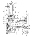
放熱器4内で液化した冷媒は放熱器4を出た後、冷媒配管13E、13Jを経て室外膨張弁6に至る。室外膨張弁6に流入した冷媒はそこで減圧された後、室外熱交換器7に流入する。室外熱交換器7に流入した冷媒は蒸発し、走行により、或いは、室外送風機15にて通風される外気中から熱を汲み上げる(吸熱)。即ち、冷媒回路Rがヒートポンプとなる。そして、室外熱交換器7を出た低温の冷媒は冷媒配管13A及び電磁弁21及び冷媒配管13Dを経て冷媒配管13Cからアキュムレータ12に入り、そこで気液分離された後、ガス冷媒が圧縮機2に吸い込まれる循環を繰り返す(例えば、図3に実線矢印で示す)。放熱器4にて加熱された空気は補助ヒータ23を経て吹出口29から吹き出されるので、これにより車室内の暖房が行われることになる。   The refrigerant liquefied in the radiator 4 exits the radiator 4 and then reaches the outdoor expansion valve 6 through the refrigerant pipes 13E and 13J. The refrigerant flowing into the outdoor expansion valve 6 is decompressed there and then flows into the outdoor heat exchanger 7. The refrigerant flowing into the outdoor heat exchanger 7 evaporates, and pumps up heat from the outside air that is ventilated by traveling or by the outdoor blower 15 (heat absorption). That is, the refrigerant circuit R becomes a heat pump. Then, the low-temperature refrigerant exiting the outdoor heat exchanger 7 enters the accumulator 12 from the refrigerant pipe 13C through the refrigerant pipe 13A, the electromagnetic valve 21 and the refrigerant pipe 13D, and is separated into gas and liquid there. The circulation sucked in is repeated (for example, indicated by a solid arrow in FIG. 3). Since the air heated by the radiator 4 is blown out from the outlet 29 through the auxiliary heater 23, the vehicle interior is thereby heated.

コントローラ32は、後述する目標吹出温度TAOから算出される目標放熱器温度TCO(放熱器4の温度TCIの目標値)から目標放熱器圧力PCO(放熱器4の圧力PCIの目標値)を算出し、この目標放熱器圧力PCOと、放熱器圧力センサ47が検出する放熱器4の冷媒圧力(放熱器圧力PCI。冷媒回路Rの高圧圧力)に基づいて圧縮機2の回転数を制御すると共に、放熱器温度センサ46が検出する放熱器4の温度(放熱器温度TCI)及び放熱器圧力センサ47が検出する放熱器圧力PCIに基づいて室外膨張弁6の弁開度を制御し、放熱器4の出口における冷媒の過冷却度を制御する。前記目標放熱器温度TCOは基本的にはTCO=TAOとされるが、制御上の所定の制限が設けられる。   The controller 32 calculates a target radiator pressure PCO (target value of the pressure PCI of the radiator 4) from a target radiator temperature TCO (target value of the temperature TCI of the radiator 4) calculated from a target outlet temperature TAO described later. The number of revolutions of the compressor 2 is controlled based on the target radiator pressure PCO and the refrigerant pressure of the radiator 4 (radiator pressure PCI. High pressure of the refrigerant circuit R) detected by the radiator pressure sensor 47, Based on the temperature of the radiator 4 (the radiator temperature TCI) detected by the radiator temperature sensor 46 and the radiator pressure PCI detected by the radiator pressure sensor 47, the valve opening degree of the outdoor expansion valve 6 is controlled. The degree of supercooling of the refrigerant at the outlet of the refrigerant is controlled. The target radiator temperature TCO is basically set to TCO = TAO, but a predetermined restriction on control is provided.

また、コントローラ32は、この暖房運転において放熱器4による暖房能力が不足すると判断した場合、補助ヒータ23に通電して発熱させることにより、補助ヒータ23による加熱を実行する。補助ヒータ23が発熱すると空気流通路3の放熱器4を通過した空気をこの補助ヒータ23で更に加熱することになる。これにより、要求される暖房能力(後述する目標吹出温度TAOから得られる目標放熱器温度TCOと吸熱器温度Teとの差から算出される)に対して放熱器4が発生可能な暖房能力が不足する場合に、この不足する分の暖房能力を補助ヒータ23にて補完することになる。   Further, when the controller 32 determines that the heating capacity of the radiator 4 is insufficient in this heating operation, the controller 32 performs heating by the auxiliary heater 23 by energizing the auxiliary heater 23 to generate heat. When the auxiliary heater 23 generates heat, the air that has passed through the radiator 4 in the air flow passage 3 is further heated by the auxiliary heater 23. As a result, the heating capacity that the radiator 4 can generate is insufficient for the required heating capacity (calculated from the difference between the target radiator temperature TCO and the heat absorber temperature Te obtained from the target outlet temperature TAO described later). In this case, the auxiliary heater 23 supplements the insufficient heating capacity.

(2)除湿暖房運転
次に、除湿暖房運転では、コントローラ32は上記暖房運転の状態において電磁弁22を開放する。これにより、放熱器4を経て冷媒配管13Eを流れる凝縮冷媒の一部が分流され、この一部が電磁弁22を経て冷媒配管13Fに流入し、冷媒配管13Bから内部熱交換器19を経て室内膨張弁8に流れ、残りが室外膨張弁6に流れるようになる。即ち、分流された一部の冷媒が室内膨張弁8にて減圧された後、吸熱器9に流入して蒸発する。
(2) Dehumidifying heating operation Next, in the dehumidifying heating operation, the controller 32 opens the electromagnetic valve 22 in the heating operation state. As a result, a part of the condensed refrigerant flowing through the refrigerant pipe 13E via the radiator 4 is divided, and a part of the condensed refrigerant flows into the refrigerant pipe 13F via the electromagnetic valve 22, and passes through the internal heat exchanger 19 from the refrigerant pipe 13B to the room. It flows to the expansion valve 8 and the rest flows to the outdoor expansion valve 6. That is, a part of the divided refrigerant is decompressed by the indoor expansion valve 8 and then flows into the heat absorber 9 to evaporate.

コントローラ32は吸熱器9の出口における冷媒の過熱度(SH)を所定値に維持するように室内膨張弁8の弁開度を制御するが、このときに吸熱器9で生じる冷媒の吸熱作用で室内送風機27から吹き出された空気中の水分が吸熱器9に凝結して付着するので、空気は冷却され、且つ、除湿される。分流されて冷媒配管13Jに流入した残りの冷媒は、室外膨張弁6で減圧された後、室外熱交換器7で蒸発することになる。   The controller 32 controls the opening degree of the indoor expansion valve 8 so that the degree of superheat (SH) of the refrigerant at the outlet of the heat absorber 9 is maintained at a predetermined value. Since moisture in the air blown out from the indoor blower 27 condenses and adheres to the heat absorber 9, the air is cooled and dehumidified. The remaining refrigerant that is divided and flows into the refrigerant pipe 13J is depressurized by the outdoor expansion valve 6 and then evaporated by the outdoor heat exchanger 7.

吸熱器9で蒸発した冷媒は、内部熱交換器19を経て冷媒配管13Cにて冷媒配管13Dからの冷媒(室外熱交換器7からの冷媒)と合流した後、アキュムレータ12を経て圧縮機2に吸い込まれる循環を繰り返す。吸熱器9にて除湿された空気は放熱器4(補助ヒータ23が発熱するときは放熱器4及び補助ヒータ23)を通過する過程で再加熱されるので、これにより車室内の除湿暖房が行われることになる。   The refrigerant evaporated in the heat absorber 9 merges with the refrigerant from the refrigerant pipe 13D (refrigerant from the outdoor heat exchanger 7) in the refrigerant pipe 13C through the internal heat exchanger 19 and then into the compressor 2 through the accumulator 12. Repeated circulation. The air dehumidified by the heat absorber 9 is reheated in the process of passing through the radiator 4 (when the auxiliary heater 23 generates heat, the radiator 4 and the auxiliary heater 23). It will be.

コントローラ32は目標放熱器温度TCOから算出される目標放熱器圧力PCOと放熱器圧力センサ47が検出する放熱器圧力PCI(冷媒回路Rの高圧圧力)に基づいて圧縮機2の回転数を制御すると共に、吸熱器温度センサ48が検出する吸熱器9の温度(吸熱器温度Te)に基づいて室外膨張弁6の弁開度を制御する。   The controller 32 controls the rotational speed of the compressor 2 based on the target radiator pressure PCO calculated from the target radiator temperature TCO and the radiator pressure PCI (high pressure of the refrigerant circuit R) detected by the radiator pressure sensor 47. At the same time, the valve opening degree of the outdoor expansion valve 6 is controlled based on the temperature of the heat absorber 9 (heat absorber temperature Te) detected by the heat absorber temperature sensor 48.

(3)内部サイクル運転
次に、内部サイクル運転では、コントローラ32は上記除湿暖房運転の状態において室外膨張弁6を全閉とする(全閉位置)と共に、電磁弁21を閉じる。即ち、この内部サイクル運転は除湿暖房運転における室外膨張弁6の制御で当該室外膨張弁6を全閉とした状態であるので、この内部サイクル運転も除湿暖房運転の一部と捉えることができる。
(3) Internal cycle operation Next, in the internal cycle operation, the controller 32 fully closes the outdoor expansion valve 6 (fully closed position) and closes the electromagnetic valve 21 in the dehumidifying and heating operation state. That is, since this internal cycle operation is a state in which the outdoor expansion valve 6 is fully closed by the control of the outdoor expansion valve 6 in the dehumidifying and heating operation, this internal cycle operation can also be regarded as a part of the dehumidifying and heating operation.

但し、室外膨張弁6と電磁弁21が閉じられることにより、室外熱交換器7への冷媒の流入、及び、室外熱交換器7からの冷媒の流出は阻止されることになるので、放熱器4を経て冷媒配管13Eを流れる凝縮冷媒は電磁弁22を経て冷媒配管13Fに全て流れるようになる。そして、冷媒配管13Fを流れる冷媒は冷媒配管13Bより内部熱交換器19を経て室内膨張弁8に至る。室内膨張弁8にて冷媒は減圧された後、吸熱器9に流入して蒸発する。このときの吸熱作用で室内送風機27から吹き出された空気中の水分が吸熱器9に凝結して付着するので、空気は冷却され、且つ、除湿される。   However, since the outdoor expansion valve 6 and the electromagnetic valve 21 are closed, the inflow of refrigerant to the outdoor heat exchanger 7 and the outflow of refrigerant from the outdoor heat exchanger 7 are prevented. 4, the condensed refrigerant flowing through the refrigerant pipe 13E flows through the electromagnetic valve 22 to the refrigerant pipe 13F. And the refrigerant | coolant which flows through the refrigerant | coolant piping 13F reaches the indoor expansion valve 8 through the internal heat exchanger 19 from the refrigerant | coolant piping 13B. After the refrigerant is depressurized by the indoor expansion valve 8, it flows into the heat absorber 9 and evaporates. Since the moisture in the air blown out from the indoor blower 27 by the heat absorption action at this time condenses and adheres to the heat absorber 9, the air is cooled and dehumidified.

吸熱器9で蒸発した冷媒は内部熱交換器19を経て冷媒配管13Cを流れ、アキュムレータ12を経て圧縮機2に吸い込まれる循環を繰り返す。吸熱器9にて除湿された空気は放熱器4を通過する過程で再加熱されるので、これにより、車室内の除湿暖房が行われることになるが、この内部サイクル運転では室内側の空気流通路3内にある放熱器4(放熱)と吸熱器9(吸熱)の間で冷媒が循環されることになるので、外気からの熱の汲み上げは行われず、圧縮機2の消費動力分の暖房能力が発揮される。除湿作用を発揮する吸熱器9には冷媒の全量が流れるので、上記除湿暖房運転に比較すると除湿能力は高いが、暖房能力は低くなる。   The refrigerant evaporated in the heat absorber 9 flows through the refrigerant pipe 13C through the internal heat exchanger 19 and repeats circulation sucked into the compressor 2 through the accumulator 12. Since the air dehumidified by the heat absorber 9 is reheated in the process of passing through the radiator 4, dehumidifying heating in the passenger compartment is thereby performed. Since the refrigerant is circulated between the radiator 4 (radiation) and the heat absorber 9 (heat absorption) in the passage 3, heat from the outside air is not pumped up, and heating for the consumed power of the compressor 2 is performed. Ability is demonstrated. Since the entire amount of the refrigerant flows through the heat absorber 9 that exhibits the dehumidifying action, the dehumidifying capacity is higher than the dehumidifying and heating operation, but the heating capacity is lowered.

コントローラ32は吸熱器9の温度、又は、前述した放熱器圧力PCI(冷媒回路Rの高圧圧力)に基づいて圧縮機2の回転数を制御する。このとき、コントローラ32は吸熱器9の温度によるか放熱器圧力PCIによるか、何れかの演算から得られる圧縮機目標回転数の低い方を選択して圧縮機2を制御する。   The controller 32 controls the rotation speed of the compressor 2 based on the temperature of the heat absorber 9 or the above-described radiator pressure PCI (high pressure of the refrigerant circuit R). At this time, the controller 32 controls the compressor 2 by selecting the lower one of the compressor target rotational speeds obtained from either calculation, depending on the temperature of the heat absorber 9 or the radiator pressure PCI.

(4)除湿冷房運転
次に、除湿冷房運転では、コントローラ32は電磁弁17を開放し、電磁弁21を閉じる。また、電磁弁22、電磁弁20を閉じる。そして、圧縮機2、及び、各送風機15、27を運転し、エアミックスダンパ28は室内送風機27から吹き出された空気が放熱器4に通風される割合を調整する状態とする。これにより、圧縮機2から吐出された高温高圧のガス冷媒は放熱器4に流入する。放熱器4には空気流通路3内の空気が通風されるので、空気流通路3内の空気は放熱器4内の高温冷媒により加熱され、一方、放熱器4内の冷媒は空気に熱を奪われて冷却され、凝縮液化していく。
(4) Dehumidifying and Cooling Operation Next, in the dehumidifying and cooling operation, the controller 32 opens the electromagnetic valve 17 and closes the electromagnetic valve 21. Further, the electromagnetic valve 22 and the electromagnetic valve 20 are closed. And the compressor 2 and each air blower 15 and 27 are drive | operated, and the air mix damper 28 sets it as the state which adjusts the ratio by which the air blown out from the indoor air blower 27 is ventilated by the heat radiator 4. FIG. Thereby, the high-temperature and high-pressure gas refrigerant discharged from the compressor 2 flows into the radiator 4. Since the air in the air flow passage 3 is passed through the radiator 4, the air in the air flow passage 3 is heated by the high-temperature refrigerant in the radiator 4, while the refrigerant in the radiator 4 heats the air. It is deprived and cooled, and condensates.

放熱器4を出た冷媒は冷媒配管13Eを経て室外膨張弁6に至り、開き気味で制御される室外膨張弁6を経て室外熱交換器7に流入する。室外熱交換器7に流入した冷媒はそこで走行により、或いは、室外送風機15にて通風される外気により空冷され、凝縮する。室外熱交換器7を出た冷媒は冷媒配管13Aから電磁弁17を経てレシーバドライヤ部14、過冷却部16と順次流入する。ここで冷媒は過冷却される。   The refrigerant that has exited the radiator 4 reaches the outdoor expansion valve 6 through the refrigerant pipe 13E, and flows into the outdoor heat exchanger 7 through the outdoor expansion valve 6 that is controlled to open. The refrigerant flowing into the outdoor heat exchanger 7 is cooled and condensed by running there or by the outside air ventilated by the outdoor blower 15. The refrigerant that has exited the outdoor heat exchanger 7 sequentially flows from the refrigerant pipe 13 </ b> A through the electromagnetic valve 17 into the receiver dryer unit 14 and the supercooling unit 16. Here, the refrigerant is supercooled.

室外熱交換器7の過冷却部16を出た冷媒は逆止弁18を経て冷媒配管13Bに入り、内部熱交換器19を経て室内膨張弁8に至る。室内膨張弁8にて冷媒は減圧された後、吸熱器9に流入して蒸発する。このときの吸熱作用で室内送風機27から吹き出された空気中の水分が吸熱器9に凝結して付着するので、空気は冷却され、且つ、除湿される。   The refrigerant that has exited the supercooling section 16 of the outdoor heat exchanger 7 enters the refrigerant pipe 13 </ b> B through the check valve 18, and reaches the indoor expansion valve 8 through the internal heat exchanger 19. After the refrigerant is depressurized by the indoor expansion valve 8, it flows into the heat absorber 9 and evaporates. Since the moisture in the air blown out from the indoor blower 27 by the heat absorption action at this time condenses and adheres to the heat absorber 9, the air is cooled and dehumidified.

吸熱器9で蒸発した冷媒は内部熱交換器19を経て冷媒配管13Cを介し、アキュムレータ12に至り、そこを経て圧縮機2に吸い込まれる循環を繰り返す。吸熱器9にて冷却され、除湿された空気は放熱器4を通過する過程で再加熱(暖房時よりも放熱能力は低い)されるので、これにより車室内の除湿冷房が行われることになる。   The refrigerant evaporated in the heat absorber 9 reaches the accumulator 12 through the refrigerant pipe 13C through the internal heat exchanger 19, and repeats circulation that is sucked into the compressor 2 there through. The air cooled and dehumidified by the heat absorber 9 is reheated (having a lower heat dissipation capacity than that during heating) in the process of passing through the radiator 4, thereby dehumidifying and cooling the vehicle interior. .

コントローラ32は吸熱器温度センサ48が検出する吸熱器9の温度(吸熱器温度Te)に基づいて圧縮機2の回転数を制御すると共に、前述した冷媒回路Rの高圧圧力に基づいて室外膨張弁6の弁開度を制御し、放熱器4の冷媒圧力(放熱器圧力PCI)を制御する。   The controller 32 controls the rotational speed of the compressor 2 based on the temperature of the heat absorber 9 (heat absorber temperature Te) detected by the heat absorber temperature sensor 48, and also uses the outdoor expansion valve based on the high pressure of the refrigerant circuit R described above. 6 is controlled to control the refrigerant pressure of the radiator 4 (radiator pressure PCI).

(5)冷房運転
次に、冷房運転では、コントローラ32は上記除湿冷房運転の状態において電磁弁20を開く(室外膨張弁6の弁開度は自由)。尚、エアミックスダンパ28は放熱器4に空気が通風される割合を調整する状態とする。補助ヒータ23には通電されない。
(5) Cooling operation Next, in the cooling operation, the controller 32 opens the electromagnetic valve 20 in the dehumidifying and cooling operation state (the opening degree of the outdoor expansion valve 6 is free). Note that the air mix damper 28 is in a state of adjusting the ratio of air passing through the radiator 4. The auxiliary heater 23 is not energized.

これにより、圧縮機2から吐出された高温高圧のガス冷媒は放熱器4に流入する。放熱器4には空気流通路3内の空気は通風されるものの、その割合は小さくなるので(冷房時のリヒートのみのため)、ここは殆ど通過するのみとなり、放熱器4を出た冷媒は冷媒配管13Eを経て室外膨張弁6に至る。このとき電磁弁20は開放されているので冷媒は電磁弁20を経て冷媒配管13Jを通過し、そのまま室外熱交換器7に流入し、そこで走行により、或いは、室外送風機15にて通風される外気により空冷され、凝縮液化する。室外熱交換器7を出た冷媒は冷媒配管13Aから電磁弁17を経てレシーバドライヤ部14、過冷却部16と順次流入する。ここで冷媒は過冷却される。   Thereby, the high-temperature and high-pressure gas refrigerant discharged from the compressor 2 flows into the radiator 4. Although the air in the air flow passage 3 is ventilated to the radiator 4, the ratio is small (because of only reheating during cooling), so this almost passes through, and the refrigerant exiting the radiator 4 is The refrigerant reaches the outdoor expansion valve 6 through the refrigerant pipe 13E. At this time, since the solenoid valve 20 is opened, the refrigerant passes through the refrigerant pipe 13J through the solenoid valve 20 and flows into the outdoor heat exchanger 7 as it is, and is then circulated by the outdoor air blower 15 by running or by the outdoor blower 15. It is cooled by air and condensed into liquid. The refrigerant that has exited the outdoor heat exchanger 7 sequentially flows from the refrigerant pipe 13 </ b> A through the electromagnetic valve 17 into the receiver dryer unit 14 and the supercooling unit 16. Here, the refrigerant is supercooled.

室外熱交換器7の過冷却部16を出た冷媒は逆止弁18を経て冷媒配管13Bに入り、内部熱交換器19を経て室内膨張弁8に至る。室内膨張弁8にて冷媒は減圧された後、吸熱器9に流入して蒸発する。このときの吸熱作用で室内送風機27から吹き出された空気中の水分が吸熱器9に凝結して付着するので、空気は冷却される。   The refrigerant that has exited the supercooling section 16 of the outdoor heat exchanger 7 enters the refrigerant pipe 13 </ b> B through the check valve 18, and reaches the indoor expansion valve 8 through the internal heat exchanger 19. After the refrigerant is depressurized by the indoor expansion valve 8, it flows into the heat absorber 9 and evaporates. Since the moisture in the air blown out from the indoor blower 27 by the heat absorption action at this time condenses and adheres to the heat absorber 9, the air is cooled.

吸熱器9で蒸発した冷媒は内部熱交換器19を経て冷媒配管13Cを介し、アキュムレータ12に至り、そこを経て圧縮機2に吸い込まれる循環を繰り返す(例えば、図6に実線矢印で示す)。吸熱器9にて冷却され、除湿された空気は放熱器4を通過すること無く吹出口29から車室内に吹き出されるので、これにより車室内の冷房が行われることになる。この冷房運転においては、コントローラ32は吸熱器温度センサ48が検出する吸熱器9の温度(吸熱器温度Te)に基づいて圧縮機2の回転数を制御する。   The refrigerant evaporated in the heat absorber 9 passes through the internal heat exchanger 19 and reaches the accumulator 12 through the refrigerant pipe 13C, and repeats circulation sucked into the compressor 2 through the refrigerant pipe (for example, indicated by a solid arrow in FIG. 6). The air that has been cooled and dehumidified by the heat absorber 9 is blown into the vehicle interior from the outlet 29 without passing through the radiator 4, thereby cooling the vehicle interior. In this cooling operation, the controller 32 controls the rotational speed of the compressor 2 based on the temperature of the heat absorber 9 (heat absorber temperature Te) detected by the heat absorber temperature sensor 48.

(6)空調運転の切り換え
コントローラ32は下記式(I)から前述した目標吹出温度TAOを算出する。この目標吹出温度TAOは、吹出口29から車室内に吹き出される空気の温度の目標値である。
TAO=(Tset−Tin)×K+Tbal(f(Tset、SUN、Tam))
・・(I)
ここで、Tsetは空調操作部53で設定された車室内の設定温度、Tinは内気温度センサ37が検出する車室内空気の温度、Kは係数、Tbalは設定温度Tsetや、日射センサ51が検出する日射量SUN、外気温度センサ33が検出する外気温度Tamから算出されるバランス値である。そして、一般的に、この目標吹出温度TAOは外気温度Tamが低い程高く、外気温度Tamが上昇するに伴って低下する。
(6) Switching of air conditioning operation The controller 32 calculates the target blowing temperature TAO described above from the following formula (I). This target blowing temperature TAO is a target value of the temperature of the air blown out from the blowout port 29 into the vehicle interior.
TAO = (Tset−Tin) × K + Tbal (f (Tset, SUN, Tam))
.. (I)
Here, Tset is the set temperature in the passenger compartment set by the air conditioning operation unit 53, Tin is the temperature of the passenger compartment air detected by the inside air temperature sensor 37, K is a coefficient, Tbal is the set temperature Tset, and the solar radiation sensor 51 detects This is a balance value calculated from the amount of solar radiation SUN to be performed and the outside air temperature Tam detected by the outside air temperature sensor 33. And generally this target blowing temperature TAO is so high that the outside temperature Tam is low, and it falls as the outside temperature Tam rises.

そして、コントローラ32は起動時には外気温度センサ33が検出する外気温度Tamと目標吹出温度TAOとに基づいて上記各空調運転のうちの何れかの空調運転を選択する。また、起動後は外気温度Tamや目標吹出温度TAO等の環境や設定条件の変化に応じて前記各空調運転を選択し、切り換えていくものである。   The controller 32 selects one of the air conditioning operations based on the outside air temperature Tam detected by the outside air temperature sensor 33 and the target outlet temperature TAO at the time of activation. In addition, after the activation, the air conditioning operations are selected and switched in accordance with changes in the environment and setting conditions such as the outside air temperature Tam and the target blowing temperature TAO.

(7)バッテリ55の温度調整
次に、図3〜図12を参照しながらコントローラ32によるバッテリ55の温度調整制御について説明する。前述した如くバッテリ55は低温環境下では充放電性能が低下すると共に、高温環境下で充放電を行うと、劣化が進行する。そこで、本発明の車両用空気調和装置1のコントローラ32は、上記の如き空調運転を実行しながら、バッテリ温度調整装置61により、バッテリ55の温度を適温範囲内に調整する。このバッテリ55の適温範囲は一般的には+25℃以上+45℃以下とされているため、実施例ではこの適温範囲内に所定の下限温度BTLと上限温度BTHを設定するものとする。
(7) Temperature Adjustment of Battery 55 Next, temperature adjustment control of the battery 55 by the controller 32 will be described with reference to FIGS. As described above, the charging / discharging performance of the battery 55 is lowered under a low temperature environment, and the deterioration proceeds when charging / discharging is performed under a high temperature environment. Therefore, the controller 32 of the vehicle air conditioner 1 of the present invention adjusts the temperature of the battery 55 within the appropriate temperature range by the battery temperature adjusting device 61 while performing the air conditioning operation as described above. Since the appropriate temperature range of the battery 55 is generally + 25 ° C. or higher and + 45 ° C. or lower, in the embodiment, a predetermined lower limit temperature BTL and upper limit temperature BTH are set within the appropriate temperature range.

(7−1)暖房/バッテリ冷却モード
前述した暖房運転を実行しているときに、バッテリ温度センサ76が検出するバッテリ55の温度がその自己発熱等により上限温度BTHまで上昇した場合、コントローラ32は暖房/バッテリ冷却モードを実行する(図3)。この暖房/バッテリ冷却モードでは、コントローラ32は循環ポンプ62を運転すると共に、三方弁63の他方の出口を開く。また、熱媒体加熱ヒータ66には通電せず、補助膨張弁73は全閉とする。
(7-1) Heating / Battery Cooling Mode When the above-described heating operation is being executed, if the temperature of the battery 55 detected by the battery temperature sensor 76 rises to the upper limit temperature BTH due to its own heat generation, the controller 32 The heating / battery cooling mode is executed (FIG. 3). In this heating / battery cooling mode, the controller 32 operates the circulation pump 62 and opens the other outlet of the three-way valve 63. Further, the heat medium heater 66 is not energized, and the auxiliary expansion valve 73 is fully closed.

これにより、図3に破線矢印で示す如く循環ポンプ62から吐出された熱媒体は三方弁63、熱媒体配管69を経て空気−熱媒体熱交換器67に流入し、そこで室外熱交換器7を経た外気と熱交換する。この室外熱交換器7内では冷媒が蒸発し、外気から吸熱しているので、低温の外気と熱媒体は熱交換することになり、この空気−熱媒体熱交換器67内で熱媒体は室外熱交換器7を熱交換した後の外気により冷却される。   As a result, the heat medium discharged from the circulation pump 62 flows into the air-heat medium heat exchanger 67 through the three-way valve 63 and the heat medium pipe 69 as shown by broken line arrows in FIG. Exchange heat with the outside air. Since the refrigerant evaporates in the outdoor heat exchanger 7 and absorbs heat from the outside air, the low temperature outside air and the heat medium exchange heat. In the air-heat medium heat exchanger 67, the heat medium is outside the outdoor heat exchanger 67. The heat exchanger 7 is cooled by outside air after heat exchange.

空気−熱媒体熱交換器67内で冷却された低温の熱媒体は熱媒体配管71を経て冷媒−熱媒体熱交換器64の熱媒体流路64Aに入る。このとき、補助膨張弁73は全閉とされているので、熱媒体はそのまま冷媒−熱媒体熱交換器64を出て熱媒体加熱ヒータ66に至る。この熱媒体加熱ヒータ66も通電されず発熱していないので、低温の熱媒体がそのまま熱媒体加熱ヒータ66を出てバッテリ55に至り、当該バッテリ55を冷却した後、循環ポンプ62に吸い込まれる循環を繰り返す。   The low-temperature heat medium cooled in the air-heat medium heat exchanger 67 enters the heat medium flow path 64 </ b> A of the refrigerant-heat medium heat exchanger 64 through the heat medium pipe 71. At this time, since the auxiliary expansion valve 73 is fully closed, the heat medium leaves the refrigerant-heat medium heat exchanger 64 and reaches the heat medium heater 66 as it is. Since the heat medium heater 66 is not energized and does not generate heat, the low-temperature heat medium leaves the heat medium heater 66 as it is, reaches the battery 55, cools the battery 55, and then is circulated by the circulation pump 62. repeat.

コントローラ32は、例えばバッテリ温度センサ76が検出するバッテリ55の温度に基づいて循環ポンプ62の運転を制御することにより、バッテリ55の温度を上限温度BTH以下の温度に調整する。この場合、コントローラ32は例えばバッテリ55の温度が上限温度BTHより所定のヒステリシス分低い温度まで低下した場合、循環ポンプ62を停止して暖房/バッテリ冷却モードを終了する。   The controller 32 adjusts the temperature of the battery 55 to a temperature equal to or lower than the upper limit temperature BTH by controlling the operation of the circulation pump 62 based on the temperature of the battery 55 detected by the battery temperature sensor 76, for example. In this case, for example, when the temperature of the battery 55 is lowered to a temperature lower than the upper limit temperature BTH by a predetermined hysteresis, the controller 32 stops the circulation pump 62 and ends the heating / battery cooling mode.

このように、本発明では空気−熱媒体熱交換器67を室外熱交換器7の風下側に配置ことにより、三方弁63によって空気−熱媒体熱交換器67に熱媒体が循環される状態では、室外熱交換器7を経た外気と空気−熱媒体熱交換器67に循環される熱媒体とを熱交換させることが可能となる。   As described above, in the present invention, the air-heat medium heat exchanger 67 is arranged on the leeward side of the outdoor heat exchanger 7 so that the heat medium is circulated to the air-heat medium heat exchanger 67 by the three-way valve 63. It becomes possible to exchange heat between the outside air that has passed through the outdoor heat exchanger 7 and the heat medium circulated in the air-heat medium heat exchanger 67.

これにより、図3に示す如くコンプレッサ32が暖房運転を実行しているときに、バッテリ55の温度が上限温度BTHまで上昇した場合には、三方弁63により熱媒体を空気−熱媒体熱交換器67に循環させることで室外熱交換器7と熱交換した後の外気により熱媒体を冷却し、当該熱媒体によりバッテリ55を冷却する暖房/バッテリ冷却モードを実行することで、暖房運転時に冷媒により吸熱されて温度が低下した外気により熱媒体を冷却し、この熱媒体によりバッテリ55を冷却することができるようになり、自己発熱等でバッテリ55が必要以上に高温とならないようにその温度を調整することが可能となる。   Accordingly, when the temperature of the battery 55 rises to the upper limit temperature BTH when the compressor 32 is performing the heating operation as shown in FIG. 3, the heat medium is transferred to the air-heat medium heat exchanger by the three-way valve 63. The heat medium is cooled by the outside air after exchanging heat with the outdoor heat exchanger 7 by being circulated to 67, and the heating / battery cooling mode is performed in which the battery 55 is cooled by the heat medium. The heat medium is cooled by the outside air that has absorbed heat and the temperature is lowered, and the battery 55 can be cooled by the heat medium, and the temperature is adjusted so that the battery 55 does not become higher than necessary due to self-heating. It becomes possible to do.

(7−2)第1のバッテリ冷却単独モード
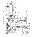
一方、例えば外気温度Tamが低い環境下で車両を停車し、室外熱交換器温度センサ54が検出する室外熱交換器7の温度である室外熱交換器温度TXOが低い(少なくとも上限温度BTHより低い)状況下でバッテリ55を充電しているとき等に、バッテリ55の温度が自己発熱等で上限温度BTHまで上昇した場合、コントローラ32は第1のバッテリ冷却単独モードを実行する(図4)。この第1のバッテリ冷却単独モードでは、車室内に搭乗者がおらず、空調する必要はないので圧縮機2は停止している。但し、コントローラ32は室外送風機15は運転する。また、コントローラ32は循環ポンプ62を運転すると共に、三方弁63の他方の出口を開き、熱媒体加熱ヒータ66には通電しない(圧縮機2は停止しているので、補助膨張弁73は自由である)。
(7-2) First Battery Cooling Single Mode On the other hand, for example, the vehicle is stopped under an environment where the outside air temperature Tam is low, and the outdoor heat exchange that is the temperature of the outdoor heat exchanger 7 detected by the outdoor heat exchanger temperature sensor 54 is performed. When the temperature of the battery 55 rises to the upper limit temperature BTH due to self-heating or the like, such as when the battery 55 is being charged under the condition that the temperature of the vessel TXO is low (at least lower than the upper limit temperature BTH), the controller 32 The battery cooling single mode is executed (FIG. 4). In this first battery cooling single mode, there is no passenger in the passenger compartment and air conditioning is not required, so the compressor 2 is stopped. However, the controller 32 operates the outdoor blower 15. In addition, the controller 32 operates the circulation pump 62 and opens the other outlet of the three-way valve 63 so that the heat medium heater 66 is not energized (the compressor 2 is stopped, so the auxiliary expansion valve 73 is free. is there).

これにより、図4に破線矢印で示す如く循環ポンプ62から吐出された熱媒体は三方弁63、熱媒体配管69を経て空気−熱媒体熱交換器67に流入し、そこで室外熱交換器7を経た外気と熱交換する。このとき外気温度Tam及び室外熱交換器温度TXOは低いので、この室外熱交換器7を経た外気の温度も低く、空気−熱媒体熱交換器67内で熱媒体はこの低温の外気と熱交換して冷却される。   As a result, the heat medium discharged from the circulation pump 62 flows into the air-heat medium heat exchanger 67 through the three-way valve 63 and the heat medium pipe 69 as shown by broken line arrows in FIG. Exchange heat with the outside air. At this time, since the outside air temperature Tam and the outdoor heat exchanger temperature TXO are low, the temperature of the outside air that has passed through the outdoor heat exchanger 7 is also low, and the heat medium exchanges heat with this low temperature outside air in the air-heat medium heat exchanger 67. And cooled.

空気−熱媒体熱交換器67内で冷却された低温の熱媒体は熱媒体配管71を経て冷媒−熱媒体熱交換器64の熱媒体流路64Aに入る。このとき、冷媒−熱媒体熱交換器64には冷媒は流れていないので、熱媒体はそのまま冷媒−熱媒体熱交換器64を出て熱媒体加熱ヒータ66に至る。この熱媒体加熱ヒータ66も通電されず発熱していないので、低温の熱媒体がそのまま熱媒体加熱ヒータ66を出てバッテリ55に至り、当該バッテリ55を冷却した後、循環ポンプ62に吸い込まれる循環を繰り返す。   The low-temperature heat medium cooled in the air-heat medium heat exchanger 67 enters the heat medium flow path 64 </ b> A of the refrigerant-heat medium heat exchanger 64 through the heat medium pipe 71. At this time, since the refrigerant does not flow through the refrigerant-heat medium heat exchanger 64, the heat medium leaves the refrigerant-heat medium heat exchanger 64 as it is and reaches the heat medium heater 66. Since the heat medium heater 66 is not energized and does not generate heat, the low-temperature heat medium leaves the heat medium heater 66 as it is, reaches the battery 55, cools the battery 55, and then is circulated by the circulation pump 62. repeat.

コントローラ32は、この場合も例えばバッテリ温度センサ76が検出するバッテリ55の温度に基づいて循環ポンプ62の運転を制御することにより、バッテリ55の温度を上限温度BTH以下の温度に調整する。この場合もコントローラ32は、例えばバッテリ55の温度が上限温度BTHより所定のヒステリシス分低い温度まで低下した場合、循環ポンプ62及び室外送風機15を停止して第1のバッテリ冷却単独モードを終了する。   Also in this case, the controller 32 adjusts the temperature of the battery 55 to a temperature equal to or lower than the upper limit temperature BTH by controlling the operation of the circulation pump 62 based on the temperature of the battery 55 detected by the battery temperature sensor 76, for example. Also in this case, for example, when the temperature of the battery 55 is lowered to a temperature lower than the upper limit temperature BTH by a predetermined hysteresis, the controller 32 stops the circulation pump 62 and the outdoor blower 15 and ends the first battery cooling single mode.

このように、例えば外気温度Tamが低い環境下で停車し、バッテリ55を充電している際等に、室外熱交換器温度TXOが低い場合、コントローラ32により圧縮機2を停止した状態で室外送風機15を運転すると共に、三方弁63により熱媒体を空気−熱媒体熱交換器67に循環させることで室外送風機15により通風される外気によって熱媒体を冷却し、当該熱媒体によりバッテリ55を冷却する第1のバッテリ冷却単独モードを実行することで、温度が低い室外熱交換器7を通過した外気により熱媒体を冷却し、バッテリ55を冷却することができるようになり、圧縮機2を停止している状態でも、バッテリ55が必要以上に高温とならないようにその温度を調整することが可能となる。   Thus, for example, when the outdoor heat exchanger temperature TXO is low when the vehicle 55 is stopped in an environment where the outdoor temperature Tam is low and the battery 55 is being charged, the outdoor blower with the compressor 2 stopped by the controller 32 15, the heat medium is circulated to the air-heat medium heat exchanger 67 by the three-way valve 63 to cool the heat medium by the outside air ventilated by the outdoor blower 15, and the battery 55 is cooled by the heat medium. By executing the first battery cooling single mode, the heat medium can be cooled by the outside air that has passed through the outdoor heat exchanger 7 having a low temperature, the battery 55 can be cooled, and the compressor 2 is stopped. Even in this state, the temperature of the battery 55 can be adjusted so that it does not become higher than necessary.

(7−3)第2のバッテリ冷却単独モード
尚、上記第1のバッテリ冷却単独モードを実行している状態で例えば外気温度Tamが上昇して室外熱交換器温度TXOが高くなった場合、或いは、外気温度Tamが高い環境下で車両を停車し、バッテリ55を充電している際等に室外熱交換器温度TXOが高い場合には、コントローラ32は第2のバッテリ冷却単独モードを実行する(図5)。この第2のバッテリ冷却単独モードでも車室内に搭乗者はいないので、車室内を空調する必要はないが、コントローラ32は圧縮機2を運転し、室外送風機15も運転する。また、電磁弁20を開き、補助膨張弁73も開いて冷媒を減圧する。
(7-3) Second battery cooling single mode When the first battery cooling single mode is being executed, for example, when the outdoor air temperature Tam rises and the outdoor heat exchanger temperature TXO becomes high, or When the outdoor heat exchanger temperature TXO is high when the vehicle is stopped in an environment where the outside air temperature Tam is high and the battery 55 is being charged, the controller 32 executes the second battery cooling single mode ( FIG. 5). Even in the second battery cooling single mode, there is no passenger in the vehicle interior, so there is no need to air-condition the vehicle interior, but the controller 32 operates the compressor 2 and also operates the outdoor blower 15. Further, the electromagnetic valve 20 is opened, and the auxiliary expansion valve 73 is also opened to decompress the refrigerant.

更に、コントローラ32は電磁弁17、電磁弁21、電磁弁22を閉じ、室内送風機26も停止する。更にまた、エアミックスダンパ28は放熱器4に通風されない状態とする。そして、コントローラ32は循環ポンプ62を運転すると共に、三方弁63の一方の出口を開き、熱媒体加熱ヒータ66には通電しない。   Furthermore, the controller 32 closes the solenoid valve 17, the solenoid valve 21, and the solenoid valve 22, and also stops the indoor blower 26. Further, the air mix damper 28 is not vented to the radiator 4. The controller 32 operates the circulation pump 62 and opens one outlet of the three-way valve 63 so that the heat medium heater 66 is not energized.

これにより、圧縮機2から吐出された高温高圧のガス冷媒は放熱器4に流入する。放熱器4には通風されないので冷媒は通過するのみとなり、放熱器4を出た冷媒は冷媒配管13Eを経て室外膨張弁6に至る。このとき電磁弁20は開放されているので冷媒は電磁弁20を経て冷媒配管13Jを通過し、そのまま室外熱交換器7に流入し、室外送風機15にて通風される外気により空冷され、凝縮液化する。室外熱交換器7に着霜が成長していた場合は、このときの放熱作用で室外熱交換器7は除霜されることになる。   Thereby, the high-temperature and high-pressure gas refrigerant discharged from the compressor 2 flows into the radiator 4. Since the air is not ventilated through the radiator 4, only the refrigerant passes through, and the refrigerant exiting the radiator 4 reaches the outdoor expansion valve 6 through the refrigerant pipe 13 </ b> E. At this time, since the solenoid valve 20 is opened, the refrigerant passes through the refrigerant pipe 13J through the solenoid valve 20, flows into the outdoor heat exchanger 7 as it is, is cooled by the outside air ventilated by the outdoor blower 15, and is condensed and liquefied. To do. In the case where frost has grown on the outdoor heat exchanger 7, the outdoor heat exchanger 7 is defrosted by the heat dissipation action at this time.

室外熱交換器7を出た冷媒は冷媒配管13Aに入るが、このとき電磁弁17及び電磁弁21は閉じているので、室外熱交換器7を出た全ての冷媒は分岐配管72を経て補助膨張弁73に至る。冷媒はこの補助膨張弁73で減圧された後、冷媒−熱媒体熱交換器64の冷媒流路64Bに流入して蒸発する。このときに吸熱作用を発揮する。この冷媒流路64Bで蒸発した冷媒は冷媒配管74、冷媒配管13C、及び、アキュムレータ12を順次経て圧縮機2に吸い込まれる循環を繰り返す(図5に実線矢印で示す)。   The refrigerant exiting the outdoor heat exchanger 7 enters the refrigerant pipe 13A. At this time, since the solenoid valve 17 and the solenoid valve 21 are closed, all the refrigerant exiting the outdoor heat exchanger 7 is supplemented via the branch pipe 72. It reaches the expansion valve 73. The refrigerant is decompressed by the auxiliary expansion valve 73 and then flows into the refrigerant flow path 64B of the refrigerant-heat medium heat exchanger 64 to evaporate. At this time, an endothermic effect is exhibited. The refrigerant evaporated in the refrigerant flow path 64B repeatedly circulates through the refrigerant pipe 74, the refrigerant pipe 13C, and the accumulator 12 and then sucked into the compressor 2 (indicated by solid arrows in FIG. 5).

一方、循環ポンプ62から吐出された熱媒体は三方弁63を経て熱媒体配管68内を冷媒−熱媒体熱交換器64の熱媒体流路64Aに至り、そこで冷媒流路64B内で蒸発する冷媒により吸熱され、熱媒体は冷却される。冷媒の吸熱作用で冷却された熱媒体は冷媒−熱媒体熱交換器64を出て熱媒体加熱ヒータ66に至る。この熱媒体加熱ヒータ66も通電されず発熱していないので、低温の熱媒体がそのまま熱媒体加熱ヒータ66を出てバッテリ55に至り、当該バッテリ55を冷却した後、循環ポンプ62に吸い込まれる循環を繰り返す。   On the other hand, the heat medium discharged from the circulation pump 62 passes through the three-way valve 63 to reach the heat medium flow path 64A of the refrigerant-heat medium heat exchanger 64 through the heat medium pipe 68, where the refrigerant evaporates in the refrigerant flow path 64B. The heat medium is absorbed, and the heat medium is cooled. The heat medium cooled by the heat absorption action of the refrigerant leaves the refrigerant-heat medium heat exchanger 64 and reaches the heat medium heater 66. Since the heat medium heater 66 is not energized and does not generate heat, the low-temperature heat medium leaves the heat medium heater 66 as it is, reaches the battery 55, cools the battery 55, and then is circulated by the circulation pump 62. repeat.

コントローラ32は、例えばバッテリ温度センサ76が検出するバッテリ55の温度に基づいて循環ポンプ62の運転を制御する。また、例えば第1出口温度センサ78が検出する冷媒−熱媒体熱交換器64を出た熱媒体の温度に基づいて圧縮機2の運転(回転数)を制御すると共に、第2出口温度センサ79が検出する冷媒−熱媒体熱交換器64を出た冷媒の温度に基づいて補助膨張弁73の弁開度を制御し、冷媒−熱媒体熱交換器64における冷媒の過熱度を調整することにより、バッテリ55の温度を上限温度BTH以下の温度に調整する。この場合もコントローラ32は、例えばバッテリ55の温度が上限温度BTHより所定のヒステリシス分低い温度まで低下した場合、循環ポンプ62,圧縮機2及び室外送風機15を停止して第2のバッテリ冷却単独モードを終了する。   For example, the controller 32 controls the operation of the circulation pump 62 based on the temperature of the battery 55 detected by the battery temperature sensor 76. Further, for example, the operation (number of rotations) of the compressor 2 is controlled based on the temperature of the heat medium that has exited the refrigerant-heat medium heat exchanger 64 detected by the first outlet temperature sensor 78, and the second outlet temperature sensor 79. By controlling the opening degree of the auxiliary expansion valve 73 on the basis of the temperature of the refrigerant that has exited the refrigerant-heat medium heat exchanger 64 detected by the refrigerant and adjusting the degree of superheat of the refrigerant in the refrigerant-heat medium heat exchanger 64. Then, the temperature of the battery 55 is adjusted to a temperature equal to or lower than the upper limit temperature BTH. Also in this case, the controller 32 stops the circulation pump 62, the compressor 2 and the outdoor blower 15 when the temperature of the battery 55 is lowered to a temperature lower than the upper limit temperature BTH by a predetermined hysteresis, for example, and the second battery cooling single mode. Exit.

このように、外気温度Tamが上昇して室外熱交換器温度TXOが高くなった場合、或いは、外気温度Tamが高い環境下で停車し、バッテリ55を充電している際等に室外熱交換器温度TXOが高い場合には、コントローラ32により圧縮機2を運転して当該圧縮機2から吐出された冷媒を室外熱交換器7にて放熱させると共に、三方弁63により熱媒体を空気−熱媒体熱交換器67に循環させること無く、室外熱交換器7から出た全ての冷媒を補助膨張弁73により減圧した後、冷媒−熱媒体熱交換器64の冷媒流路64Bに流入させ、熱媒体流路64Aを流れる熱媒体から吸熱させることで当該熱媒体を冷却し、この熱媒体によりバッテリ55を冷却する第2のバッテリ冷却単独モードを実行することで、冷媒の吸熱作用により熱媒体を冷却し、この冷却された熱媒体によりバッテリ55を冷却することができるようになる。これにより、室外熱交換器7の温度が高い場合にも、冷媒によって熱媒体を冷却し、バッテリ55が必要以上に高温とならないようにその温度を調整することが可能となる。   As described above, when the outdoor air temperature Tam rises and the outdoor heat exchanger temperature TXO becomes high, or when the vehicle 55 is stopped in an environment where the outdoor air temperature Tam is high and the battery 55 is being charged, the outdoor heat exchanger is When the temperature TXO is high, the controller 32 is operated by the controller 32 so that the refrigerant discharged from the compressor 2 is radiated by the outdoor heat exchanger 7, and the heat medium is air-heat medium by the three-way valve 63. Without circulating through the heat exchanger 67, all the refrigerant that has flowed out of the outdoor heat exchanger 7 is decompressed by the auxiliary expansion valve 73, and then flows into the refrigerant flow path 64 </ b> B of the refrigerant-heat medium heat exchanger 64. The heat medium is cooled by absorbing heat from the heat medium flowing through the flow path 64A, and the second battery cooling single mode is performed in which the battery 55 is cooled by the heat medium. Cooled, it is possible to cool the battery 55 by the cooled heat medium. Thereby, even when the temperature of the outdoor heat exchanger 7 is high, the heat medium is cooled by the refrigerant, and the temperature can be adjusted so that the battery 55 does not become unnecessarily high.

(7−4)第1の冷房/バッテリ冷却モード
次に、前述した冷房運転を実行しているときに、外気温度Tamが比較的低く、室外熱交換器温度TXOも低い(バッテリ55の温度より低い)環境下で、バッテリ温度センサ76が検出するバッテリ55の温度が上限温度BTHまで上昇した場合、コントローラ32は第1の冷房/バッテリ冷却モードを実行する(図6)。この第1の冷房/バッテリ冷却モードでは、コントローラ32は循環ポンプ62を運転すると共に、三方弁63の他方の出口を開く。また、熱媒体加熱ヒータ66には通電せず、補助膨張弁73は全閉又は冷媒を減圧する状態で開く。
(7-4) First Cooling / Battery Cooling Mode Next, when the above-described cooling operation is performed, the outside air temperature Tam is relatively low and the outdoor heat exchanger temperature TXO is also low (below the temperature of the battery 55). When the temperature of the battery 55 detected by the battery temperature sensor 76 rises to the upper limit temperature BTH in a low environment, the controller 32 executes the first cooling / battery cooling mode (FIG. 6). In the first cooling / battery cooling mode, the controller 32 operates the circulation pump 62 and opens the other outlet of the three-way valve 63. In addition, the heat medium heater 66 is not energized, and the auxiliary expansion valve 73 is fully closed or opened in a state where the refrigerant is depressurized.

これにより、図6に破線矢印で示す如く循環ポンプ62から吐出された熱媒体は三方弁63、熱媒体配管69を経て空気−熱媒体熱交換器67に流入し、そこで室外熱交換器7を経た外気と熱交換する。このとき室外熱交換器温度TXOは低いので、室外熱交換器7を経た温度が低い外気と熱媒体は熱交換することになり、この空気−熱媒体熱交換器67内で熱媒体は外気により冷却される。   As a result, the heat medium discharged from the circulation pump 62 flows into the air-heat medium heat exchanger 67 through the three-way valve 63 and the heat medium pipe 69 as shown by the broken line arrows in FIG. Exchange heat with the outside air. At this time, since the outdoor heat exchanger temperature TXO is low, the outdoor air having a low temperature passed through the outdoor heat exchanger 7 and the heat medium exchange heat, and the heat medium is exchanged by the outside air in the air-heat medium heat exchanger 67. To be cooled.

空気−熱媒体熱交換器67内で冷却された低温の熱媒体は熱媒体配管71を経て冷媒−熱媒体熱交換器64の熱媒体流路64Aに入る。このとき、補助膨張弁73が全閉とされているときは、熱媒体はそのまま冷媒−熱媒体熱交換器64を出て熱媒体加熱ヒータ66に至る。この熱媒体加熱ヒータ66も通電されず発熱していないので、低温の熱媒体がそのまま熱媒体加熱ヒータ66を出てバッテリ55に至り、当該バッテリ55を冷却した後、循環ポンプ62に吸い込まれる循環を繰り返す。   The low-temperature heat medium cooled in the air-heat medium heat exchanger 67 enters the heat medium flow path 64 </ b> A of the refrigerant-heat medium heat exchanger 64 through the heat medium pipe 71. At this time, when the auxiliary expansion valve 73 is fully closed, the heat medium leaves the refrigerant-heat medium heat exchanger 64 as it is and reaches the heat medium heater 66. Since the heat medium heater 66 is not energized and does not generate heat, the low-temperature heat medium leaves the heat medium heater 66 as it is, reaches the battery 55, cools the battery 55, and then is circulated by the circulation pump 62. repeat.

コントローラ32は、例えばバッテリ温度センサ76が検出するバッテリ55の温度に基づいて循環ポンプ62の運転を制御する。この場合、外気による冷却のみではバッテリ温度センサ76が検出するバッテリ55の温度が下がらないとき、コントローラ32は補助膨張弁73を開いて室外熱交換器7を出た冷媒の一部を分岐配管72に分流させ、減圧した後、冷媒−熱媒体熱交換器64の冷媒流路64Bに流入させて蒸発させることで、熱媒体流路64Aを流れる熱媒体から吸熱する。   For example, the controller 32 controls the operation of the circulation pump 62 based on the temperature of the battery 55 detected by the battery temperature sensor 76. In this case, when the temperature of the battery 55 detected by the battery temperature sensor 76 does not drop only by cooling with the outside air, the controller 32 opens the auxiliary expansion valve 73 and branches a part of the refrigerant exiting the outdoor heat exchanger 7 to the branch pipe 72. Then, after the pressure is reduced, the refrigerant flows into the refrigerant flow path 64B of the refrigerant-heat medium heat exchanger 64 and evaporates to absorb heat from the heat medium flowing through the heat medium flow path 64A.

これにより、外気による冷却に加えて冷媒によっても熱媒体を冷却することで、バッテリ55の温度を上限温度BTH以下の温度に調整する。コントローラ32は、例えば第1出口温度センサ78が検出する冷媒−熱媒体熱交換器64を出た熱媒体の温度により補助膨張弁73の弁開度を制御することで、分岐配管72への分流量を制御し、冷媒による熱媒体の冷却作用を調整するものである。また、コントローラ32はこの場合も例えばバッテリ55の温度が上限温度BTHより所定のヒステリシス分低い温度まで低下した場合、循環ポンプ62を停止し、補助膨張弁73を全閉として第1の冷房/バッテリ冷却モードを終了する。   Thereby, the temperature of the battery 55 is adjusted to a temperature equal to or lower than the upper limit temperature BTH by cooling the heat medium with the refrigerant in addition to the cooling with the outside air. For example, the controller 32 controls the valve opening degree of the auxiliary expansion valve 73 based on the temperature of the heat medium that has exited the refrigerant-heat medium heat exchanger 64 detected by the first outlet temperature sensor 78, thereby dividing the branch pipe 72. The flow rate is controlled to adjust the cooling effect of the heat medium by the refrigerant. Also in this case, for example, when the temperature of the battery 55 is lowered to a temperature lower than the upper limit temperature BTH by a predetermined hysteresis, the controller 32 stops the circulation pump 62, fully closes the auxiliary expansion valve 73, and the first cooling / battery. Exit cooling mode.

このように、冷房運転を実行しているときにおいても、室外熱交換器温度TXOが低い場合には、コントローラ32が三方弁63により熱媒体を空気−熱媒体熱交換器67に循環させることで室外送風機15により通風される外気によって熱媒体を冷却し、当該熱媒体によりバッテリ55を冷却する第1の冷房/バッテリ冷却モードを実行することで、温度が低い室外熱交換器7を経た外気により熱媒体を冷却し、この冷却された熱媒体によってバッテリ55を冷却することができるようになり、冷房運転中でも室外熱交換器温度TXOが低い場合には外気により熱媒体を冷却し、バッテリ55が必要以上に高温とならないようにその温度を調整することが可能となる。   As described above, even when the cooling operation is being performed, if the outdoor heat exchanger temperature TXO is low, the controller 32 causes the three-way valve 63 to circulate the heat medium to the air-heat medium heat exchanger 67. By performing the first cooling / battery cooling mode in which the heat medium is cooled by the outside air ventilated by the outdoor blower 15 and the battery 55 is cooled by the heat medium, the outside air passes through the outdoor heat exchanger 7 having a low temperature. The heat medium is cooled, and the battery 55 can be cooled by the cooled heat medium. When the outdoor heat exchanger temperature TXO is low even during the cooling operation, the heat medium is cooled by the outside air. The temperature can be adjusted so as not to be higher than necessary.

(7−5)第2の冷房/バッテリ冷却モード
尚、上記第1の冷房/バッテリ冷却モードを実行している状態で例えば外気温度Tamが上昇し、室外熱交換器温度TXOが高くなった場合、或いは、外気温度Tamが高い環境下で冷房運転を実行していて室外熱交換器温度TXOが高い場合には、第2の冷房/バッテリ冷却モードを実行する(図7)。この第2の冷房/バッテリ冷却モードでは、コントローラ32は循環ポンプ62を運転すると共に、三方弁63の一方の出口を開く。また、熱媒体加熱ヒータ66には通電せず、補助膨張弁73は開いて冷媒を減圧する状態とする。
(7-5) Second cooling / battery cooling mode When the first cooling / battery cooling mode is being executed, for example, the outside air temperature Tam increases and the outdoor heat exchanger temperature TXO increases. Alternatively, when the cooling operation is executed in an environment where the outside air temperature Tam is high and the outdoor heat exchanger temperature TXO is high, the second cooling / battery cooling mode is executed (FIG. 7). In the second cooling / battery cooling mode, the controller 32 operates the circulation pump 62 and opens one outlet of the three-way valve 63. In addition, the heat medium heater 66 is not energized, and the auxiliary expansion valve 73 is opened to depressurize the refrigerant.

これにより、図7に破線矢印で示す如く循環ポンプ62から吐出された熱媒体は三方弁63、熱媒体配管68を経て冷媒−熱媒体熱交換器64の熱媒体流路64Aに入る。このとき、補助膨張弁73は開くので室外熱交換器7を出た冷媒の一部は分岐配管72に分流され、補助膨張弁73で減圧された後、冷媒−熱媒体熱交換器64の冷媒流路64Bに流入して蒸発するので、冷媒は熱媒体流路64Aを流れる熱媒体から吸熱する。   As a result, the heat medium discharged from the circulation pump 62 enters the heat medium flow path 64 </ b> A of the refrigerant-heat medium heat exchanger 64 through the three-way valve 63 and the heat medium pipe 68 as indicated by broken line arrows in FIG. 7. At this time, since the auxiliary expansion valve 73 is opened, a part of the refrigerant exiting the outdoor heat exchanger 7 is diverted to the branch pipe 72 and decompressed by the auxiliary expansion valve 73, and then the refrigerant of the refrigerant-heat medium heat exchanger 64. Since the refrigerant flows into the flow path 64B and evaporates, the refrigerant absorbs heat from the heat medium flowing through the heat medium flow path 64A.

このように、冷媒によって冷却された熱媒体は冷媒−熱媒体熱交換器64を出て熱媒体加熱ヒータ66に至る。この熱媒体加熱ヒータ66も通電されず発熱していないので、低温の熱媒体がそのまま熱媒体加熱ヒータ66を出てバッテリ55に至り、当該バッテリ55を冷却した後、循環ポンプ62に吸い込まれる循環を繰り返す。また、冷媒−熱媒体熱交換器64を出た冷媒は冷媒配管74を経て冷媒配管13Cに入り、吸熱器9からの冷媒と合流してアキュムレータ12に入り、アキュムレータ12から出て圧縮機2に吸い込まれる循環を繰り返す。このように冷媒によって熱媒体を冷却することで、バッテリ55の温度を上限温度BTH以下の温度に調整する。   Thus, the heat medium cooled by the refrigerant leaves the refrigerant-heat medium heat exchanger 64 and reaches the heat medium heater 66. Since the heat medium heater 66 is not energized and does not generate heat, the low-temperature heat medium leaves the heat medium heater 66 as it is, reaches the battery 55, cools the battery 55, and then is circulated by the circulation pump 62. repeat. The refrigerant that has exited the refrigerant-heat medium heat exchanger 64 enters the refrigerant pipe 13C via the refrigerant pipe 74, merges with the refrigerant from the heat absorber 9, enters the accumulator 12, exits from the accumulator 12, and enters the compressor 2. Repeated circulation. Thus, the temperature of the battery 55 is adjusted to a temperature equal to or lower than the upper limit temperature BTH by cooling the heat medium with the refrigerant.

コントローラ32は、例えばバッテリ温度センサ76が検出するバッテリ55の温度に基づいて循環ポンプ62の運転を制御する。また、コントローラ32は、例えば第1出口温度センサ78が検出する冷媒−熱媒体熱交換器64を出た熱媒体の温度により補助膨張弁73の弁開度を制御することで、分岐配管72への分流量を制御し、冷媒による熱媒体の冷却作用を調整する。また、コントローラ32はこの場合も例えばバッテリ55の温度が上限温度BTHより所定のヒステリシス分低い温度まで低下した場合、循環ポンプ62を停止し、補助膨張弁73を全閉として第2の冷房/バッテリ冷却モードを終了する。   For example, the controller 32 controls the operation of the circulation pump 62 based on the temperature of the battery 55 detected by the battery temperature sensor 76. Further, the controller 32 controls the valve opening degree of the auxiliary expansion valve 73 based on the temperature of the heat medium exiting the refrigerant-heat medium heat exchanger 64 detected by the first outlet temperature sensor 78, for example, to the branch pipe 72. Is controlled to adjust the cooling effect of the heat medium by the refrigerant. Also in this case, for example, when the temperature of the battery 55 is lowered to a temperature lower than the upper limit temperature BTH by a predetermined hysteresis, the controller 32 stops the circulation pump 62 and fully closes the auxiliary expansion valve 73 to make the second cooling / battery. Exit cooling mode.

このように、第1の冷房/バッテリ冷却モードを実行している状態で例えば外気温度Tamが上昇して室外熱交換器温度TXOが高くなった場合、或いは、外気温度Tamが高い環境下で冷房運転を実行していて室外熱交換器温度TXOが高い場合には、コントローラ32が三方弁63により熱媒体を空気−熱媒体熱交換器67に循環させること無く、室外熱交換器7から出た冷媒の一部を補助膨張弁73により減圧した後、冷媒−熱媒体熱交換器に流入させ、熱媒体から吸熱させることで当該熱媒体を冷却し、この熱媒体によりバッテリ55を冷却する第2の冷房/バッテリ冷却モードを実行することにより、室外熱交換器7を出た冷媒の一部による吸熱作用で熱媒体を冷却し、この冷却された熱媒体によりバッテリ55を冷却することができるようになる。これにより、室外熱交換器温度TXOが高い場合にも、車室内の冷房運転を実行しながら、冷媒によって熱媒体を冷却し、バッテリ55が必要以上に高温とならないようにその温度を調整することが可能となる。   As described above, for example, when the outdoor air temperature Tam rises and the outdoor heat exchanger temperature TXO becomes high while the first cooling / battery cooling mode is being executed, or in an environment where the outdoor air temperature Tam is high, the cooling is performed. When the operation is performed and the outdoor heat exchanger temperature TXO is high, the controller 32 leaves the outdoor heat exchanger 7 without circulating the heat medium to the air-heat medium heat exchanger 67 by the three-way valve 63. A part of the refrigerant is depressurized by the auxiliary expansion valve 73, and then flows into the refrigerant-heat medium heat exchanger, and the heat medium is cooled by absorbing heat from the heat medium, and the battery 55 is cooled by the heat medium. By executing the cooling / battery cooling mode, the heat medium is cooled by the endothermic action of a part of the refrigerant that has exited the outdoor heat exchanger 7, and the battery 55 is cooled by the cooled heat medium. Kill as to become. Thus, even when the outdoor heat exchanger temperature TXO is high, the heat medium is cooled by the refrigerant while the cooling operation in the passenger compartment is performed, and the temperature is adjusted so that the battery 55 does not become unnecessarily high. Is possible.

(7−6)冷房/バッテリ加熱モード
次に、前述した冷房運転を実行しているときに、バッテリ温度センサ76が検出するバッテリ55の温度が下限温度BTLまで低下した場合、コントローラ32はバッテリ加熱モードの一つとしての冷房/バッテリ加熱モードを実行する(図8)。この冷房/バッテリ加熱モードでは、コントローラ32は循環ポンプ62を運転すると共に、三方弁63の一方の出口を開く。また、熱媒体加熱ヒータ66に通電し、補助膨張弁73は全閉とする。
(7-6) Cooling / Battery Heating Mode Next, when the temperature of the battery 55 detected by the battery temperature sensor 76 is lowered to the lower limit temperature BTL during the above-described cooling operation, the controller 32 performs battery heating. A cooling / battery heating mode is executed as one of the modes (FIG. 8). In this cooling / battery heating mode, the controller 32 operates the circulation pump 62 and opens one outlet of the three-way valve 63. Further, the heat medium heater 66 is energized, and the auxiliary expansion valve 73 is fully closed.

これにより、図8に破線矢印で示す如く循環ポンプ62から吐出された熱媒体は三方弁63、熱媒体配管68を経て冷媒−熱媒体熱交換器64の熱媒体流路64Aに入る。このとき、補助膨張弁73は全閉とされているので、熱媒体はそのまま冷媒−熱媒体熱交換器64を出て熱媒体加熱ヒータ66に至る。この冷房/バッテリ加熱モードでは、熱媒体加熱ヒータ66は通電されて発熱するので、加熱されて高温となった熱媒体は熱媒体加熱ヒータ66を出てバッテリ55に至り、当該バッテリ55を加熱した後、循環ポンプ62に吸い込まれる循環を繰り返す。   As a result, the heat medium discharged from the circulation pump 62 enters the heat medium flow path 64 </ b> A of the refrigerant-heat medium heat exchanger 64 through the three-way valve 63 and the heat medium pipe 68 as indicated by broken line arrows in FIG. 8. At this time, since the auxiliary expansion valve 73 is fully closed, the heat medium leaves the refrigerant-heat medium heat exchanger 64 and reaches the heat medium heater 66 as it is. In this cooling / battery heating mode, the heat medium heater 66 is energized to generate heat, so that the heat medium heated to a high temperature exits the heat medium heater 66 and reaches the battery 55 to heat the battery 55. Thereafter, the circulation sucked into the circulation pump 62 is repeated.

コントローラ32は熱媒体加熱ヒータ66によって熱媒体を加熱することで、バッテリ55の温度を下限温度BTL以上の温度に調整する。この場合、コントローラ32は、例えばバッテリ温度センサ76が検出するバッテリ55の温度が下限温度BTLより所定のヒステリシス分高い温度まで上昇した場合、熱媒体加熱ヒータ66を非通電とし、循環ポンプ62を停止して冷房/バッテリ加熱モードを終了する。   The controller 32 adjusts the temperature of the battery 55 to a temperature equal to or higher than the lower limit temperature BTL by heating the heat medium with the heat medium heater 66. In this case, for example, when the temperature of the battery 55 detected by the battery temperature sensor 76 rises to a temperature higher than the lower limit temperature BTL by a predetermined hysteresis, the controller 32 deenergizes the heat medium heater 66 and stops the circulation pump 62. Then, the cooling / battery heating mode ends.

このように、車室内を冷房しているときにバッテリ55の温度が下限温度BTLに低下した場合、コントローラ32が三方弁63により熱媒体を空気−熱媒体熱交換器67に循環させること無く、補助膨張弁73により冷媒−熱媒体熱交換器64への冷媒の流入を阻止し、熱媒体加熱ヒータ66により熱媒体を加熱することで、当該熱媒体によりバッテリ55を加熱する冷房/バッテリ加熱モードを実行することにより、車室内を冷房しているときにも、熱媒体加熱ヒータ66により熱媒体を加熱し、この加熱された熱媒体によりバッテリ55を加熱することができるようになり、バッテリ55が低温とならないようにその温度を調整することが可能となる。   Thus, when the temperature of the battery 55 decreases to the lower limit temperature BTL while the vehicle interior is being cooled, the controller 32 does not circulate the heat medium to the air-heat medium heat exchanger 67 by the three-way valve 63, Cooling / battery heating mode in which the auxiliary expansion valve 73 prevents the refrigerant from flowing into the refrigerant-heat medium heat exchanger 64 and the heat medium is heated by the heat medium heater 66 to heat the battery 55 with the heat medium. By performing the above, the heat medium can be heated by the heat medium heater 66 even when the vehicle interior is being cooled, and the battery 55 can be heated by the heated heat medium. The temperature can be adjusted so that the temperature does not become low.

(7−7)暖房/バッテリ加熱モード
次に、前述した暖房運転を実行しているときに、バッテリ温度センサ76が検出するバッテリ55の温度が下限温度BTLまで低下した場合、コントローラ32はもう一つのバッテリ加熱モードの一つとしての暖房/バッテリ加熱モードを実行する(図9)。この暖房/バッテリ加熱モードでも、コントローラ32は循環ポンプ62を運転すると共に、三方弁63の一方の出口を開く。また、熱媒体加熱ヒータ66に通電し、補助膨張弁73は全閉とする。
(7-7) Heating / Battery Heating Mode Next, when the temperature of the battery 55 detected by the battery temperature sensor 76 is lowered to the lower limit temperature BTL during the above-described heating operation, the controller 32 performs another operation. The heating / battery heating mode is executed as one of the two battery heating modes (FIG. 9). Even in this heating / battery heating mode, the controller 32 operates the circulation pump 62 and opens one outlet of the three-way valve 63. Further, the heat medium heater 66 is energized, and the auxiliary expansion valve 73 is fully closed.

これにより、図9に破線矢印で示す如く循環ポンプ62から吐出された熱媒体は三方弁63、熱媒体配管68を経て冷媒−熱媒体熱交換器64の熱媒体流路64Aに入る。このとき、補助膨張弁73は全閉とされているので、熱媒体はそのまま冷媒−熱媒体熱交換器64を出て熱媒体加熱ヒータ66に至る。この暖房/バッテリ加熱モードでは、熱媒体加熱ヒータ66は通電されて発熱するので、加熱されて高温となった熱媒体は熱媒体加熱ヒータ66を出てバッテリ55に至り、当該バッテリ55を加熱した後、循環ポンプ62に吸い込まれる循環を繰り返す。   As a result, the heat medium discharged from the circulation pump 62 enters the heat medium flow path 64 </ b> A of the refrigerant-heat medium heat exchanger 64 through the three-way valve 63 and the heat medium pipe 68, as indicated by broken line arrows in FIG. 9. At this time, since the auxiliary expansion valve 73 is fully closed, the heat medium leaves the refrigerant-heat medium heat exchanger 64 and reaches the heat medium heater 66 as it is. In this heating / battery heating mode, the heat medium heater 66 is energized and generates heat, so that the heat medium heated to a high temperature exits the heat medium heater 66 and reaches the battery 55 to heat the battery 55. Thereafter, the circulation sucked into the circulation pump 62 is repeated.

コントローラ32は熱媒体加熱ヒータ66によって熱媒体を加熱することで、バッテリ55の温度を下限温度BTL以上の温度に調整する。この場合も、コントローラ32は、例えばバッテリ温度センサ76が検出するバッテリ55の温度が下限温度BTLより所定のヒステリシス分高い温度まで上昇した場合、熱媒体加熱ヒータ66を非通電とし、循環ポンプ62を停止して暖房/バッテリ加熱モードを終了する。   The controller 32 adjusts the temperature of the battery 55 to a temperature equal to or higher than the lower limit temperature BTL by heating the heat medium with the heat medium heater 66. Also in this case, for example, when the temperature of the battery 55 detected by the battery temperature sensor 76 rises to a temperature higher than the lower limit temperature BTL by a predetermined hysteresis, the controller 32 deenergizes the heat medium heater 66 and turns on the circulation pump 62. Stop and end heating / battery heating mode.

このように、車室内を暖房しているときにバッテリ55の温度が下限温度BTLに低下した場合、コントローラ32が三方弁63により熱媒体を空気−熱媒体熱交換器67に循環させること無く、補助膨張弁73により冷媒−熱媒体熱交換器64への冷媒の流入を阻止し、熱媒体加熱ヒータ66により熱媒体を加熱することで、当該熱媒体によりバッテリ55を加熱する暖房/バッテリ加熱モードを実行することにより、車室内を暖房しているときにも、熱媒体加熱ヒータ66により熱媒体を加熱し、この加熱された熱媒体によりバッテリ55を加熱することができるようになり、バッテリ55が低温とならないようにその温度を調整することが可能となる。   Thus, when the temperature of the battery 55 decreases to the lower limit temperature BTL while heating the vehicle interior, the controller 32 does not circulate the heat medium to the air-heat medium heat exchanger 67 by the three-way valve 63, Heating / battery heating mode in which the auxiliary expansion valve 73 prevents the refrigerant from flowing into the refrigerant-heat medium heat exchanger 64 and heats the heat medium by the heat medium heater 66 to heat the battery 55 by the heat medium. By executing the above, even when the vehicle interior is heated, the heat medium can be heated by the heat medium heater 66, and the battery 55 can be heated by the heated heat medium. The temperature can be adjusted so that the temperature does not become low.

(7−8)バッテリ加熱単独モード
次に、車両を停車してバッテリ55に充電しているとき等に、バッテリ温度センサ76が検出するバッテリ55の温度が下限温度BTLまで低下した場合、コントローラ32は更にもう一つのバッテリ加熱モードの一つとしてのバッテリ加熱単独モードを実行する(図10)。このバッテリ加熱単独モードでも、コントローラ32は循環ポンプ62を運転すると共に、三方弁63の一方の出口を開く。また、熱媒体加熱ヒータ66に通電する。尚、圧縮機2、各送風機15、27は停止する(補助膨張弁73は自由とする)。
(7-8) Battery Heating Single Mode Next, when the temperature of the battery 55 detected by the battery temperature sensor 76 decreases to the lower limit temperature BTL when the vehicle is stopped and the battery 55 is charged, the controller 32 The battery heating single mode as one of the other battery heating modes is executed (FIG. 10). Even in this battery heating single mode, the controller 32 operates the circulation pump 62 and opens one outlet of the three-way valve 63. Further, the heat medium heater 66 is energized. The compressor 2 and the blowers 15 and 27 are stopped (the auxiliary expansion valve 73 is free).

これにより、図10に破線矢印で示す如く循環ポンプ62から吐出された熱媒体は三方弁63、熱媒体配管68を経て冷媒−熱媒体熱交換器64の熱媒体流路64Aに入る。このとき、冷媒流路64Bには冷媒は流れていないので、熱媒体はそのまま冷媒−熱媒体熱交換器64を出て熱媒体加熱ヒータ66に至る。このバッテリ加熱単独モードでは、熱媒体加熱ヒータ66は通電されて発熱するので、加熱されて高温となった熱媒体は熱媒体加熱ヒータ66を出てバッテリ55に至り、当該バッテリ55を加熱した後、循環ポンプ62に吸い込まれる循環を繰り返す。   As a result, the heat medium discharged from the circulation pump 62 enters the heat medium flow path 64 </ b> A of the refrigerant-heat medium heat exchanger 64 through the three-way valve 63 and the heat medium pipe 68 as indicated by broken line arrows in FIG. 10. At this time, since the refrigerant does not flow through the refrigerant flow path 64B, the heat medium leaves the refrigerant-heat medium heat exchanger 64 as it is and reaches the heat medium heater 66. In this battery heating only mode, the heat medium heater 66 is energized to generate heat, so that the heat medium heated to a high temperature exits the heat medium heater 66 and reaches the battery 55, after heating the battery 55. The circulation sucked into the circulation pump 62 is repeated.

コントローラ32は熱媒体加熱ヒータ66によって熱媒体を加熱することで、バッテリ55の温度を下限温度BTL以上の温度に調整する。この場合も、コントローラ32は、例えばバッテリ温度センサ76が検出するバッテリ55の温度が下限温度BTLより所定のヒステリシス分高い温度まで上昇した場合、熱媒体加熱ヒータ66を非通電とし、循環ポンプ62を停止してバッテリ加熱単独モードを終了する。   The controller 32 adjusts the temperature of the battery 55 to a temperature equal to or higher than the lower limit temperature BTL by heating the heat medium with the heat medium heater 66. Also in this case, for example, when the temperature of the battery 55 detected by the battery temperature sensor 76 rises to a temperature higher than the lower limit temperature BTL by a predetermined hysteresis, the controller 32 deenergizes the heat medium heater 66 and turns on the circulation pump 62. Stop and end the battery heating single mode.

このように、車両が停車していて圧縮機2が停止しているときにバッテリ55の温度が下限温度BTLに低下した場合、コントローラ32が三方弁63により熱媒体を空気−熱媒体熱交換器67に循環させること無く、熱媒体加熱ヒータ66により熱媒体を加熱することで、当該熱媒体によりバッテリ55を加熱するバッテリ加熱単独モードを実行することにより、車両を停車して使用されていないときにも、熱媒体加熱ヒータ66により熱媒体を加熱し、この加熱された熱媒体によりバッテリ55を加熱することができるようになり、バッテリ55が低温とならないようにその温度を調整することが可能となる。   As described above, when the temperature of the battery 55 decreases to the lower limit temperature BTL when the vehicle is stopped and the compressor 2 is stopped, the controller 32 causes the three-way valve 63 to transfer the heat medium to the air-heat medium heat exchanger. When the vehicle is stopped and not being used by executing the battery heating single mode in which the heating medium is heated by the heating medium heater 66 without being circulated to 67 and the battery 55 is heated by the heating medium. In addition, the heat medium can be heated by the heat medium heater 66, and the battery 55 can be heated by the heated heat medium, and the temperature can be adjusted so that the battery 55 does not become low temperature. It becomes.

(7−9)暖房/バッテリ熱HP利用モード
次に、暖房運転中に例えば室外熱交換器7に着霜が生じ、放熱器4による暖房能力が不足するようになった場合、或いは、室外熱交換器7に着霜が生じ易い環境(外気温度Tamが極めて低くなったとき等)となった場合、コントローラ32は暖房/バッテリ熱HP利用モードを実行する(図11)。この暖房/バッテリ熱HP利用モードでは、コントローラ32は循環ポンプ62を運転すると共に、三方弁63の一方の出口を開く。また、熱媒体加熱ヒータ66は通電制御を行う。
(7-9) Heating / battery heat HP utilization mode Next, for example, when the outdoor heat exchanger 7 is frosted during the heating operation and the heating capacity of the radiator 4 becomes insufficient, or the outdoor heat When the exchanger 7 is in an environment where frost formation is likely to occur (for example, when the outside air temperature Tam is extremely low), the controller 32 executes the heating / battery heat HP utilization mode (FIG. 11). In this heating / battery heat HP utilization mode, the controller 32 operates the circulation pump 62 and opens one outlet of the three-way valve 63. Further, the heat medium heater 66 performs energization control.

一方、コントローラ32は室外膨張弁6を中程度の弁開度(中開き)とし、電磁弁21を閉じる(電磁弁17、22、20も閉)。また、補助膨張弁73は開いて冷媒を減圧する状態とする。これにより、圧縮機2から吐出された高温高圧のガス冷媒は放熱器4に流入する。放熱器4には空気流通路3内の空気が通風されるので、空気流通路3内の空気は放熱器4内の高温冷媒(補助ヒータ23が動作するときは放熱器4及び補助ヒータ23)により加熱され、一方、放熱器4内の冷媒は空気に熱を奪われて冷却され、凝縮液化する。   On the other hand, the controller 32 sets the outdoor expansion valve 6 to a moderate valve opening (medium opening), and closes the electromagnetic valve 21 (also closes the electromagnetic valves 17, 22, and 20). Further, the auxiliary expansion valve 73 is opened to depressurize the refrigerant. Thereby, the high-temperature and high-pressure gas refrigerant discharged from the compressor 2 flows into the radiator 4. Since the air in the air flow passage 3 is passed through the radiator 4, the air in the air flow passage 3 is a high-temperature refrigerant in the radiator 4 (when the auxiliary heater 23 operates, the radiator 4 and the auxiliary heater 23). On the other hand, the refrigerant in the radiator 4 is deprived of heat by the air and cooled to be condensed and liquefied.

放熱器4内で液化した冷媒は放熱器4を出た後、冷媒配管13E、13Jを経て室外膨張弁6に至る。室外膨張弁6に流入した冷媒は中開きとされた当該室外膨張弁6で中程度に減圧された後、室外熱交換器7に流入する。室外熱交換器7に流入した冷媒は蒸発するが、蒸発温度は高くなる。そしてこの場合も、走行により、或いは、室外送風機15にて通風される外気中から熱を汲み上げる(吸熱)。また、電磁弁17、21は閉じているので、室外熱交換器7を出た全ての冷媒は冷媒配管13Aから分岐配管72に入り、補助膨張弁73に至る。   The refrigerant liquefied in the radiator 4 exits the radiator 4 and then reaches the outdoor expansion valve 6 through the refrigerant pipes 13E and 13J. The refrigerant that has flowed into the outdoor expansion valve 6 is reduced in pressure by the outdoor expansion valve 6 that is opened in the middle, and then flows into the outdoor heat exchanger 7. The refrigerant flowing into the outdoor heat exchanger 7 evaporates, but the evaporation temperature becomes high. Also in this case, heat is pumped up from the outside air that is ventilated by traveling or by the outdoor blower 15 (heat absorption). Further, since the solenoid valves 17 and 21 are closed, all the refrigerant that has exited the outdoor heat exchanger 7 enters the branch pipe 72 from the refrigerant pipe 13A and reaches the auxiliary expansion valve 73.

冷媒はそこで減圧された後、冷媒−熱媒体熱交換器64の冷媒流路64Bに流入して蒸発するので、吸熱作用を発揮する。そして、この冷媒−熱媒体熱交換器64を出た冷媒は冷媒配管74を経て冷媒配管13Cからアキュムレータ12に入り、そこで気液分離された後、ガス冷媒が圧縮機2に吸い込まれる循環を繰り返す(図11に実線矢印で示す)。放熱器4にて加熱された空気は補助ヒータ23を経て吹出口29から吹き出されるので、これにより車室内の暖房が行われる。   Since the refrigerant is decompressed there, it flows into the refrigerant flow path 64B of the refrigerant-heat medium heat exchanger 64 and evaporates, thereby exhibiting an endothermic effect. The refrigerant that has exited the refrigerant-heat medium heat exchanger 64 passes through the refrigerant pipe 74 and enters the accumulator 12 from the refrigerant pipe 13C where it is gas-liquid separated and then repeatedly circulates in which the gas refrigerant is sucked into the compressor 2. (Indicated by solid arrows in FIG. 11). Since the air heated by the radiator 4 is blown out from the outlet 29 through the auxiliary heater 23, the vehicle interior is thereby heated.

一方、図11に破線矢印で示す如く循環ポンプ62から吐出された熱媒体は三方弁63、熱媒体配管68を経て冷媒−熱媒体熱交換器64の熱媒体流路64Aに入る。このときに冷媒流路64Bを流れる冷媒により吸熱された後、熱媒体は冷媒−熱媒体熱交換器64を出て熱媒体加熱ヒータ66に至る。   On the other hand, the heat medium discharged from the circulation pump 62 enters the heat medium flow path 64 </ b> A of the refrigerant-heat medium heat exchanger 64 through the three-way valve 63 and the heat medium pipe 68 as indicated by broken line arrows in FIG. 11. At this time, after heat is absorbed by the refrigerant flowing through the refrigerant flow path 64B, the heat medium exits the refrigerant-heat medium heat exchanger 64 and reaches the heat medium heater 66.

この暖房/バッテリ熱HP利用モードでは、コントローラ32は熱媒体加熱ヒータ66をバッテリ55の温度が前述した下限温度BTL以上、上限温度BTH以下となる範囲で通電/非通電とする。即ち、コントローラ32は例えばバッテリ55の温度が下限温度BTLより高いときは熱媒体加熱ヒータ66を非通電とする。従って、その場合熱媒体は熱媒体加熱ヒータ66をそのまま通過してバッテリ55に至り、バッテリ55の熱を奪った後、循環ポンプ62に吸い込まれる循環を繰り返す。このときにバッテリ55は冷媒−熱媒体熱交換器64において冷媒により冷却された熱媒体で冷却されるかたちとなる。   In the heating / battery heat HP utilization mode, the controller 32 energizes / deenergizes the heat medium heater 66 in a range where the temperature of the battery 55 is not less than the lower limit temperature BTL and not more than the upper limit temperature BTH. That is, for example, when the temperature of the battery 55 is higher than the lower limit temperature BTL, the controller 32 deenergizes the heat medium heater 66. Therefore, in this case, the heat medium passes through the heat medium heater 66 as it is to reach the battery 55, and after the heat of the battery 55 is taken away, the circulation sucked into the circulation pump 62 is repeated. At this time, the battery 55 is cooled by the heat medium cooled by the refrigerant in the refrigerant-heat medium heat exchanger 64.

また、バッテリ55の温度が下限温度BTLまで低下した場合、コントローラ32は熱媒体加熱ヒータ66に通電して発熱させる。従って、その場合熱媒体は熱媒体加熱ヒータ66で加熱された後、バッテリ55に至り、当該バッテリ55を加熱した後、循環ポンプ62に吸い込まれる循環を繰り返す。このように、バッテリ55の熱を奪い、或いは、熱媒体加熱ヒータ66で加熱された熱媒体は、冷媒−熱媒体熱交換器64において冷媒から吸熱されるので、バッテリ55や熱媒体加熱ヒータ66の熱が冷媒回路Rの冷媒に搬送されるかたちとなり、放熱器4による暖房能力が補完され、室外熱交換器7における冷媒の蒸発温度を下げる必要がなくなり、着霜も進行し難くなる。   Further, when the temperature of the battery 55 decreases to the lower limit temperature BTL, the controller 32 energizes the heat medium heater 66 to generate heat. Accordingly, in this case, the heat medium is heated by the heat medium heater 66 and then reaches the battery 55. After the battery 55 is heated, the circulation sucked into the circulation pump 62 is repeated. In this way, the heat medium that takes away the heat of the battery 55 or is heated by the heat medium heater 66 is absorbed by the refrigerant in the refrigerant-heat medium heat exchanger 64, and thus the battery 55 and the heat medium heater 66. Heat is transferred to the refrigerant in the refrigerant circuit R, the heating capacity of the radiator 4 is supplemented, it is not necessary to lower the evaporation temperature of the refrigerant in the outdoor heat exchanger 7, and frost formation does not proceed easily.

尚、熱媒体加熱ヒータ66の熱を冷媒回路Rに積極的に搬送したいときには、図11中に破線で示す位置に熱媒体加熱ヒータ66を設け、熱媒体加熱ヒータ66で加熱された直後の熱媒体が冷媒−熱媒体熱交換器64に流入するようにした方が制御は容易となる   When it is desired to positively convey the heat of the heat medium heater 66 to the refrigerant circuit R, the heat medium heater 66 is provided at a position indicated by a broken line in FIG. 11, and the heat immediately after being heated by the heat medium heater 66 is provided. Control is easier if the medium flows into the refrigerant-heat medium heat exchanger 64.

コントローラ32は室外熱交換器温度TXOに基づき、外気温度Tamと同等となるように室外膨張弁6と補助膨張弁73の弁開度を制御する。そして、暖房能力の不足状態が解消された等の条件が成立した場合、循環ポンプ62を停止し、熱媒体加熱ヒータ66も非通電とし、補助膨張弁73も全閉として暖房/バッテリ熱HP利用モードを終了する。   Based on the outdoor heat exchanger temperature TXO, the controller 32 controls the valve openings of the outdoor expansion valve 6 and the auxiliary expansion valve 73 so as to be equal to the outdoor air temperature Tam. When the condition such as the lack of the heating capacity is satisfied, the circulation pump 62 is stopped, the heat medium heater 66 is turned off, the auxiliary expansion valve 73 is also fully closed, and the heating / battery heat HP is used. Exit mode.

このように、コントローラ32が暖房運転において、三方弁63により熱媒体を空気−熱媒体熱交換器67に循環させること無く、室外熱交換器7から出た全ての冷媒を補助膨張弁73により減圧した後、冷媒−熱媒体熱交換器64に流入させ、熱媒体から吸熱させることでバッテリ55や熱媒体加熱ヒータ66の熱を冷媒に搬送する暖房/バッテリ熱HP利用モードを実行することで、バッテリ55や熱媒体加熱ヒータ66の熱を冷媒に搬送して効率の良い暖房運転を実現しなら、バッテリ55が必要以上に高温とならないようにその温度を調整することが可能となる。   In this way, in the heating operation, the controller 32 reduces the pressure of all the refrigerant that has exited the outdoor heat exchanger 7 by the auxiliary expansion valve 73 without circulating the heat medium to the air-heat medium heat exchanger 67 by the three-way valve 63. After that, by executing the heating / battery heat HP utilization mode in which the heat of the battery 55 and the heat medium heater 66 is transferred to the refrigerant by flowing into the refrigerant-heat medium heat exchanger 64 and absorbing heat from the heat medium, If the heat of the battery 55 and the heat medium heater 66 is transferred to the refrigerant to realize an efficient heating operation, the temperature of the battery 55 can be adjusted so as not to become higher than necessary.

また、実施例の如く室外熱交換器7に着霜した場合や着霜が生じ易い環境となった場合にも、暖房/バッテリ熱HP利用モードを実行することにより、暖房運転時に室外熱交換器7に着霜が生じ難くし、或いは、着霜の進行を遅らせることができるようになる。   Further, when the outdoor heat exchanger 7 is frosted or an environment where frost formation is likely to occur as in the embodiment, the outdoor heat exchanger is operated during the heating operation by executing the heating / battery heat HP utilization mode. 7 is less likely to form frost, or the progress of frost formation can be delayed.

(7−10)逆サイクル除霜/バッテリ冷却/加熱モード
次に、コントローラ32による室外熱交換器7の逆サイクル除霜時の制御について説明する。暖房運転中には前述した如く室外熱交換器7は蒸発器として機能するため、室外熱交換器7には外気中の水分が霜となって成長し、熱交換効率が低下して来る。コントローラ32は、例えば外気温度Tamや圧縮機2の回転数等から算出される無着霜時の室外熱交換器温度TXObaseを算出し、この無着霜時の室外熱交換器温度TXObaseと室外熱交換器温度センサ54が検出する室外熱交換器温度TXOとを常時比較しており、室外熱交換器温度TXOが無着霜時の室外熱交換器温度TXObaseより低下してその差が所定値以上となった場合、室外熱交換器7の逆サイクル除霜/バッテリ冷却/加熱モードを実行する(図12)。
(7-10) Reverse cycle defrost / battery cooling / heating mode Next, the control at the time of reverse cycle defrost of the outdoor heat exchanger 7 by the controller 32 will be described. Since the outdoor heat exchanger 7 functions as an evaporator during the heating operation as described above, moisture in the outdoor air grows as frost in the outdoor heat exchanger 7 and the heat exchange efficiency decreases. The controller 32 calculates, for example, the outdoor heat exchanger temperature TXObase at the time of no frosting calculated from the outside air temperature Tam, the rotation speed of the compressor 2, etc., and the outdoor heat exchanger temperature TXObase at the time of no frosting and the outdoor heat. The outdoor heat exchanger temperature TXO detected by the exchanger temperature sensor 54 is constantly compared. The outdoor heat exchanger temperature TXO is lower than the outdoor heat exchanger temperature TXObase when there is no frost, and the difference is equal to or greater than a predetermined value. When it becomes, reverse cycle defrosting / battery cooling / heating mode of the outdoor heat exchanger 7 is executed (FIG. 12).

この逆サイクル除霜/バッテリ冷却/加熱モードでは、コントローラ32は循環ポンプ62を運転すると共に、三方弁63の一方の出口を開く。また、熱媒体加熱ヒータ66は通電制御を行う。一方、コントローラ32は電磁弁20を開き(室外膨張弁6は自由)電磁弁21、17、22を閉じる。また、補助膨張弁73は開いて冷媒を減圧する状態とする。また、室外送風機15は停止し、圧縮機2を運転する。エアミックスダンパ28は放熱器4に通風されない状態とする。   In this reverse cycle defrost / battery cooling / heating mode, the controller 32 operates the circulation pump 62 and opens one outlet of the three-way valve 63. Further, the heat medium heater 66 performs energization control. On the other hand, the controller 32 opens the electromagnetic valve 20 (the outdoor expansion valve 6 is free) and closes the electromagnetic valves 21, 17 and 22. Further, the auxiliary expansion valve 73 is opened to depressurize the refrigerant. Further, the outdoor blower 15 is stopped and the compressor 2 is operated. The air mix damper 28 is not vented to the radiator 4.

これにより、圧縮機2から吐出された高温高圧のガス冷媒は放熱器4に流入し、そこを通過した後、電磁弁20を経て室外熱交換器7に流入する。この室外熱交換器7に流入した高温のガス冷媒によって室外熱交換器7は除霜されていく。冷媒は放熱して凝縮液化した後、室外熱交換器7から出るが、このとき電磁弁17及び21は閉じているので全ての冷媒が分岐配管72から補助膨張弁73に至る。   As a result, the high-temperature and high-pressure gas refrigerant discharged from the compressor 2 flows into the radiator 4, passes through the radiator 4, and then flows into the outdoor heat exchanger 7 through the electromagnetic valve 20. The outdoor heat exchanger 7 is defrosted by the high-temperature gas refrigerant that has flowed into the outdoor heat exchanger 7. The refrigerant dissipates heat and condenses and exits the outdoor heat exchanger 7. At this time, since the solenoid valves 17 and 21 are closed, all the refrigerant reaches the auxiliary expansion valve 73 from the branch pipe 72.

冷媒はそこで減圧された後、冷媒−熱媒体熱交換器64の冷媒流路64Bに流入して蒸発するので、吸熱作用を発揮する。そして、この冷媒−熱媒体熱交換器64を出た冷媒は冷媒配管74を経て冷媒配管13Cからアキュムレータ12に入り、そこで気液分離された後、ガス冷媒が圧縮機2に吸い込まれる循環を繰り返す(図12に実線矢印で示す)。   Since the refrigerant is decompressed there, it flows into the refrigerant flow path 64B of the refrigerant-heat medium heat exchanger 64 and evaporates, thereby exhibiting an endothermic effect. The refrigerant that has exited the refrigerant-heat medium heat exchanger 64 passes through the refrigerant pipe 74 and enters the accumulator 12 from the refrigerant pipe 13C where it is gas-liquid separated and then repeatedly circulates in which the gas refrigerant is sucked into the compressor 2. (Indicated by solid arrows in FIG. 12).

一方、図12に破線矢印で示す如く循環ポンプ62から吐出された熱媒体は三方弁63、熱媒体配管68を経て冷媒−熱媒体熱交換器64の熱媒体流路64Aに入る。このときに冷媒流路64Bを流れる冷媒により吸熱された後、熱媒体は冷媒−熱媒体熱交換器64を出て熱媒体加熱ヒータ66に至る。   On the other hand, the heat medium discharged from the circulation pump 62 enters the heat medium flow path 64 </ b> A of the refrigerant-heat medium heat exchanger 64 through the three-way valve 63 and the heat medium pipe 68 as indicated by broken line arrows in FIG. 12. At this time, after heat is absorbed by the refrigerant flowing through the refrigerant flow path 64B, the heat medium exits the refrigerant-heat medium heat exchanger 64 and reaches the heat medium heater 66.

この逆サイクル除霜/バッテリ冷却/加熱モードでも、コントローラ32は熱媒体加熱ヒータ66をバッテリ55の温度が前述した下限温度BTL以上、上限温度BTH以下となる範囲で通電/非通電とする。即ち、コントローラ32は例えばバッテリ55の温度が下限温度BTLより高いときは熱媒体加熱ヒータ66を非通電とする。従って、その場合熱媒体は熱媒体加熱ヒータ66をそのまま通過してバッテリ55に至り、バッテリ55の熱を奪った後、循環ポンプ62に吸い込まれる循環を繰り返す。このときにバッテリ55は冷媒−熱媒体熱交換器64において冷媒により冷却された熱媒体で冷却されるかたちとなる。   Even in this reverse cycle defrosting / battery cooling / heating mode, the controller 32 energizes / de-energizes the heat medium heater 66 within a range where the temperature of the battery 55 is not less than the above-described lower limit temperature BTL and not more than the upper limit temperature BTH. That is, for example, when the temperature of the battery 55 is higher than the lower limit temperature BTL, the controller 32 deenergizes the heat medium heater 66. Therefore, in this case, the heat medium passes through the heat medium heater 66 as it is to reach the battery 55, and after the heat of the battery 55 is taken away, the circulation sucked into the circulation pump 62 is repeated. At this time, the battery 55 is cooled by the heat medium cooled by the refrigerant in the refrigerant-heat medium heat exchanger 64.

また、バッテリ55の温度が下限温度BTLまで低下した場合、コントローラ32は熱媒体加熱ヒータ66に通電して発熱させる。従って、その場合熱媒体は熱媒体加熱ヒータ66で加熱された後、バッテリ55に至り、当該バッテリ55を加熱した後、循環ポンプ62に吸い込まれる循環を繰り返す。このように、バッテリ55の熱を奪い、或いは、熱媒体加熱ヒータ66で加熱された熱媒体は、冷媒−熱媒体熱交換器64において冷媒から吸熱されるので、バッテリ55や熱媒体加熱ヒータ66の熱が冷媒回路Rの冷媒に搬送されるかたちとなり、室外熱交換器7の除霜が迅速に進行するようになる。   Further, when the temperature of the battery 55 decreases to the lower limit temperature BTL, the controller 32 energizes the heat medium heater 66 to generate heat. Accordingly, in this case, the heat medium is heated by the heat medium heater 66 and then reaches the battery 55. After the battery 55 is heated, the circulation sucked into the circulation pump 62 is repeated. In this way, the heat medium that takes away the heat of the battery 55 or is heated by the heat medium heater 66 is absorbed by the refrigerant in the refrigerant-heat medium heat exchanger 64, and thus the battery 55 and the heat medium heater 66. Is transferred to the refrigerant in the refrigerant circuit R, and the defrosting of the outdoor heat exchanger 7 proceeds quickly.

尚、この場合も熱媒体加熱ヒータ66の熱を冷媒回路Rに積極的に搬送したいときには、図12中に破線で示す位置に熱媒体加熱ヒータ66を設け、熱媒体加熱ヒータ66で加熱された直後の熱媒体が冷媒−熱媒体熱交換器64に流入するようにした方が除霜促進効果は向上する。   In this case as well, when it is desired to positively convey the heat of the heat medium heater 66 to the refrigerant circuit R, the heat medium heater 66 is provided at a position indicated by a broken line in FIG. The effect of promoting defrosting is improved when the immediately following heat medium flows into the refrigerant-heat medium heat exchanger 64.

コントローラ32は室外熱交換器温度TXOに基づき、無着霜時の室外熱交換器温度TXObaseまで上昇したときには、圧縮機2、循環ポンプ62を停止し、熱媒体加熱ヒータ66も非通電とし、補助膨張弁73も全閉として除霜/バッテリ冷却/加熱モードを終了する。   Based on the outdoor heat exchanger temperature TXO, the controller 32 stops the compressor 2 and the circulation pump 62 when the temperature rises to the outdoor heat exchanger temperature TXObase when there is no frost formation, and the heat medium heater 66 is also de-energized. The expansion valve 73 is also fully closed, and the defrost / battery cooling / heating mode is terminated.

このように、コントローラ32が圧縮機2から吐出された冷媒を室外熱交換器7にて放熱させて当該室外熱交換器7を逆サイクル除霜する際、三方弁63により熱媒体を空気−熱媒体熱交換器67に循環させること無く、室外熱交換器7から出た全ての冷媒を補助膨張弁73により減圧した後、冷媒−熱媒体熱交換器64に流入させ、熱媒体から吸熱させることでバッテリ55や熱媒体加熱ヒータ66の熱を冷媒に搬送する除霜/バッテリ冷却/加熱モードを実行することで、バッテリ55や熱媒体加熱ヒータ66の熱を冷媒に搬送して迅速に室外熱交換器7を除霜を行うことができるようになる。   As described above, when the controller 32 dissipates the refrigerant discharged from the compressor 2 in the outdoor heat exchanger 7 and reverse-cycle defrosts the outdoor heat exchanger 7, the heat medium is air-heated by the three-way valve 63. Without circulating through the medium heat exchanger 67, all the refrigerant that has flowed out of the outdoor heat exchanger 7 is decompressed by the auxiliary expansion valve 73, and then flows into the refrigerant-heat medium heat exchanger 64 to absorb heat from the heat medium. By executing the defrosting / battery cooling / heating mode in which the heat of the battery 55 and the heat medium heater 66 is transferred to the refrigerant, the heat of the battery 55 and the heat medium heater 66 is transferred to the refrigerant and the outdoor heat is quickly generated. The exchanger 7 can be defrosted.

この場合、実施例のようにバッテリ55の温度が高いときには熱媒体加熱ヒータ66を発熱させず、バッテリ55の温度が低いときに熱媒体加熱ヒータ66を発熱させることで、バッテリ55の温度を調整しながら、室外熱交換器7の除霜を迅速化することが可能となる。   In this case, the temperature of the battery 55 is adjusted by not causing the heat medium heater 66 to generate heat when the temperature of the battery 55 is high as in the embodiment, and causing the heat medium heater 66 to generate heat when the temperature of the battery 55 is low. However, the defrosting of the outdoor heat exchanger 7 can be speeded up.

ここで、冷媒回路Rにおいて室外熱交換器7の冷媒出口側に、暖房運転時に開放される暖房用の電磁弁21が設けられ、室外熱交換器7の冷媒出口側に、冷房運転時に開放される冷房用の電磁弁17が設けられている場合、上記実施例のように室外熱交換器7から出て各電磁弁17、21に至る前の冷媒を冷媒−熱媒体熱交換器64に流すようにすれば、上記の如き各モードを実行する際に、暖房用の電磁弁21や冷房用の電磁弁17の動作に拘わらず、補助膨張弁73のみで冷媒−熱媒体熱交換器64への冷媒の流通を制御することができるようになり、冷媒回路Rの配管構成を簡素化し、無用な電磁弁等の増加も防止することができるようになる。   Here, in the refrigerant circuit R, a heating solenoid valve 21 that is opened during heating operation is provided on the refrigerant outlet side of the outdoor heat exchanger 7, and is opened on the refrigerant outlet side of the outdoor heat exchanger 7 during cooling operation. When the cooling electromagnetic valve 17 is provided, the refrigerant that has flowed out of the outdoor heat exchanger 7 and reaches the electromagnetic valves 17 and 21 is caused to flow to the refrigerant-heat medium heat exchanger 64 as in the above embodiment. By doing so, when each of the above modes is executed, the auxiliary expansion valve 73 alone is used to move to the refrigerant-heat medium heat exchanger 64 regardless of the operation of the heating solenoid valve 21 or the cooling solenoid valve 17. This makes it possible to control the circulation of the refrigerant, simplify the piping configuration of the refrigerant circuit R, and prevent an increase in unnecessary electromagnetic valves and the like.

(8)室外熱交換器7の三角サイクル除霜
尚、室外熱交換器7の除霜方法としては前述した逆サイクル除霜に限らず、圧縮機2を運転し、電磁弁21を開放し、電磁弁17、20、22を閉じ、室外膨張弁6は開け気味として圧縮機2を運転する三角サイクル除霜と称される除霜方法でもよい。この場合には、圧縮機2から吐出された冷媒は放熱器4で放熱するので車室内の暖房は可能となる。一方、室外熱交換器7には開き気味の室外膨張弁6を経た冷媒が流入するので、室外熱交換器7でも冷媒は放熱するかたちとなり、除霜が実行されることになる。
(8) Triangular cycle defrosting of the outdoor heat exchanger 7 Note that the defrosting method of the outdoor heat exchanger 7 is not limited to the reverse cycle defrosting described above, the compressor 2 is operated, the electromagnetic valve 21 is opened, The defrosting method called the triangular cycle defrosting which closes the solenoid valves 17, 20 and 22 and operates the compressor 2 as if the outdoor expansion valve 6 is open may be used. In this case, since the refrigerant discharged from the compressor 2 dissipates heat in the radiator 4, the vehicle interior can be heated. On the other hand, since the refrigerant that has passed through the outdoor expansion valve 6 that appears to open flows into the outdoor heat exchanger 7, the refrigerant also radiates heat in the outdoor heat exchanger 7, and defrosting is executed.

また、上記各実施例で説明した冷媒回路Rやバッテリ温度調整装置61の構成はそれに限定されるものでは無く、本発明の趣旨を逸脱しない範囲で変更可能であることは云うまでもない。   The configurations of the refrigerant circuit R and the battery temperature adjusting device 61 described in the above embodiments are not limited thereto, and it goes without saying that they can be changed without departing from the spirit of the present invention.

1 車両用空気調和装置
2 圧縮機
3 空気流通路
4 放熱器
6 室外膨張弁
7 室外熱交換器
8 室内膨張弁
9 吸熱器
15 室外送風機
17、20、21、22 電磁弁(開閉弁)
32 コントローラ(制御装置)
55 バッテリ
61 バッテリ温度調整装置
62 循環ポンプ(循環装置)
63 三方弁(流路切換装置)
64 冷媒−熱媒体熱交換器
66 熱媒体加熱ヒータ(加熱装置)
67 空気−熱媒体熱交換器
73 補助膨張弁(膨張弁)
R 冷媒回路
DESCRIPTION OF SYMBOLS 1 Vehicle air conditioner 2 Compressor 3 Air flow path 4 Radiator 6 Outdoor expansion valve 7 Outdoor heat exchanger 8 Indoor expansion valve 9 Heat absorber 15 Outdoor blower 17, 20, 21, 22 Solenoid valve (open / close valve)
32 Controller (Control device)
55 Battery 61 Battery temperature adjustment device 62 Circulation pump (circulation device)
63 Three-way valve (flow path switching device)
64 Refrigerant-heat medium heat exchanger 66 Heat medium heater (heating device)
67 Air-heat medium heat exchanger 73 Auxiliary expansion valve (expansion valve)
R refrigerant circuit

Claims (3)

冷媒を圧縮する圧縮機と、
前記冷媒を放熱させて車室内に供給する空気を加熱するための放熱器と、
車室外に設けられた室外熱交換器と、
制御装置を備えて前記車室内を空調する車両用空気調和装置において、
車両に搭載されたバッテリに熱媒体を循環させて当該バッテリの温度を調整するためのバッテリ温度調整装置を備え、
該バッテリ温度調整装置は、
前記冷媒と前記熱媒体とを熱交換させるための冷媒−熱媒体熱交換器と、
前記熱媒体を加熱する加熱装置と、
前記熱媒体を循環させる循環装置を有し、
前記加熱装置を経た前記熱媒体を前記冷媒−熱媒体熱交換器に流し、該冷媒−熱媒体熱交換器を出た前記熱媒体を前記バッテリに流すことを特徴とする車両用空気調和装置。
A compressor for compressing the refrigerant;
A radiator for heating the air supplied to the passenger compartment by dissipating the refrigerant;
An outdoor heat exchanger installed outside the passenger compartment,
In a vehicle air conditioner that includes a control device to air-condition the vehicle interior,
A battery temperature adjusting device for adjusting a temperature of the battery by circulating a heat medium to a battery mounted on the vehicle;
The battery temperature adjusting device includes:
A refrigerant-heat medium heat exchanger for exchanging heat between the refrigerant and the heat medium;
A heating device for heating the heat medium;
A circulation device for circulating the heat medium;
The vehicle air conditioner characterized by flowing the heat medium that has passed through the heating device to the refrigerant-heat medium heat exchanger, and flowing the heat medium that has exited the refrigerant-heat medium heat exchanger to the battery.
前記制御装置は、
前記圧縮機から吐出された前記冷媒を前記放熱器にて放熱させることで前記車室内を暖房し、前記加熱装置を発熱させ、前記冷媒を前記冷媒−熱媒体熱交換器にて吸熱させる運転モードを有することを特徴とする請求項1に記載の車両用空気調和装置。
The control device includes:
An operation mode in which the refrigerant discharged from the compressor is radiated by the radiator to heat the vehicle interior, the heating device is heated, and the refrigerant is absorbed by the refrigerant-heat medium heat exchanger. The vehicle air conditioner according to claim 1, comprising:
前記制御装置は、
前記圧縮機から吐出された前記冷媒を前記室外熱交換器にて放熱させて当該室外熱交換器を除霜し、前記加熱装置を発熱させ、前記冷媒を前記冷媒−熱媒体熱交換器にて吸熱させる運転モードを有することを特徴とする請求項1又は請求項2に記載の車両用空気調和装置。
The control device includes:
The refrigerant discharged from the compressor is radiated by the outdoor heat exchanger to defrost the outdoor heat exchanger, the heating device is heated, and the refrigerant is heated by the refrigerant-heat medium heat exchanger. The vehicle air conditioner according to claim 1 or 2, further comprising an operation mode for absorbing heat.
JP2019135319A 2019-07-23 2019-07-23 Vehicular air-conditioner Pending JP2019172267A (en)

Priority Applications (1)

Application Number Priority Date Filing Date Title
JP2019135319A JP2019172267A (en) 2019-07-23 2019-07-23 Vehicular air-conditioner

Applications Claiming Priority (1)

Application Number Priority Date Filing Date Title
JP2019135319A JP2019172267A (en) 2019-07-23 2019-07-23 Vehicular air-conditioner

Related Parent Applications (1)

Application Number Title Priority Date Filing Date
JP2017036422A Division JP6855281B2 (en) 2017-02-28 2017-02-28 Vehicle air conditioner

Publications (2)

Publication Number Publication Date
JP2019172267A true JP2019172267A (en) 2019-10-10
JP2019172267A5 JP2019172267A5 (en) 2020-03-19

Family

ID=68170463

Family Applications (1)

Application Number Title Priority Date Filing Date
JP2019135319A Pending JP2019172267A (en) 2019-07-23 2019-07-23 Vehicular air-conditioner

Country Status (1)

Country Link
JP (1) JP2019172267A (en)

Cited By (2)

* Cited by examiner, † Cited by third party
Publication number Priority date Publication date Assignee Title
JP7053906B1 (en) 2021-01-29 2022-04-12 マレリ株式会社 Temperature control system
JP7079354B1 (en) 2021-01-29 2022-06-01 マレリ株式会社 Temperature control system

Citations (2)

* Cited by examiner, † Cited by third party
Publication number Priority date Publication date Assignee Title
JP2002005532A (en) * 1999-10-20 2002-01-09 Denso Corp Freezing cycle apparatus
JP2010111269A (en) * 2008-11-06 2010-05-20 Mitsubishi Heavy Ind Ltd Vehicular air-conditioning system, and method for operation control threrefor

Patent Citations (2)

* Cited by examiner, † Cited by third party
Publication number Priority date Publication date Assignee Title
JP2002005532A (en) * 1999-10-20 2002-01-09 Denso Corp Freezing cycle apparatus
JP2010111269A (en) * 2008-11-06 2010-05-20 Mitsubishi Heavy Ind Ltd Vehicular air-conditioning system, and method for operation control threrefor

Cited By (5)

* Cited by examiner, † Cited by third party
Publication number Priority date Publication date Assignee Title
JP7053906B1 (en) 2021-01-29 2022-04-12 マレリ株式会社 Temperature control system
JP7079354B1 (en) 2021-01-29 2022-06-01 マレリ株式会社 Temperature control system
WO2022163712A1 (en) * 2021-01-29 2022-08-04 マレリ株式会社 Temperature control system
JP2022117351A (en) * 2021-01-29 2022-08-10 マレリ株式会社 temperature control system
JP2022117350A (en) * 2021-01-29 2022-08-10 マレリ株式会社 temperature control system

Similar Documents

Publication Publication Date Title
JP6855281B2 (en) Vehicle air conditioner
JP7095848B2 (en) Vehicle air conditioner
WO2018193770A1 (en) Vehicular air conditioning device
JP6963405B2 (en) Vehicle air conditioner
JP2019038352A (en) Air conditioner for vehicle
WO2014192741A1 (en) Vehicular air-conditioning device
JP2019023023A (en) Vehicle air conditioner
WO2014192740A1 (en) Vehicular air-conditioning device
WO2020066719A1 (en) Vehicle air conditioner
JP6571430B2 (en) Air conditioner for vehicles
JP6680601B2 (en) Vehicle air conditioner
WO2019181311A1 (en) Control system for vehicle
WO2019163398A1 (en) Vehicle control system
JP7031105B2 (en) Vehicle control system
JP2019172267A (en) Vehicular air-conditioner
JP6997567B2 (en) Vehicle air conditioner
CN112384392B (en) Air conditioning device for vehicle
JP6738156B2 (en) Vehicle air conditioner
WO2019181312A1 (en) Vehicle air conditioner
WO2019181310A1 (en) Vehicle air conditioner
CN113811727A (en) Air conditioner for vehicle
JP7280770B2 (en) Vehicle air conditioner
WO2021044873A1 (en) Vehicle air conditioner
WO2019150832A1 (en) Air conditioning device for vehicle

Legal Events

Date Code Title Description
A521 Request for written amendment filed

Free format text: JAPANESE INTERMEDIATE CODE: A523

Effective date: 20200206

A621 Written request for application examination

Free format text: JAPANESE INTERMEDIATE CODE: A621

Effective date: 20200221

A521 Request for written amendment filed

Free format text: JAPANESE INTERMEDIATE CODE: A523

Effective date: 20200415

A977 Report on retrieval

Free format text: JAPANESE INTERMEDIATE CODE: A971007

Effective date: 20201221

A131 Notification of reasons for refusal

Free format text: JAPANESE INTERMEDIATE CODE: A131

Effective date: 20210105

A02 Decision of refusal

Free format text: JAPANESE INTERMEDIATE CODE: A02

Effective date: 20210803