JP2019170767A - Game machine - Google Patents
Game machine Download PDFInfo
- Publication number
- JP2019170767A JP2019170767A JP2018063695A JP2018063695A JP2019170767A JP 2019170767 A JP2019170767 A JP 2019170767A JP 2018063695 A JP2018063695 A JP 2018063695A JP 2018063695 A JP2018063695 A JP 2018063695A JP 2019170767 A JP2019170767 A JP 2019170767A
- Authority
- JP
- Japan
- Prior art keywords
- effect
- special
- symbol
- big hit
- game
- Prior art date
- Legal status (The legal status is an assumption and is not a legal conclusion. Google has not performed a legal analysis and makes no representation as to the accuracy of the status listed.)
- Pending
Links
- 230000000694 effects Effects 0.000 claims description 1062
- 238000011161 development Methods 0.000 abstract description 45
- 238000000034 method Methods 0.000 description 335
- 230000008569 process Effects 0.000 description 332
- 238000004519 manufacturing process Methods 0.000 description 138
- 238000012545 processing Methods 0.000 description 113
- 230000000875 corresponding effect Effects 0.000 description 91
- 238000003860 storage Methods 0.000 description 78
- 230000006870 function Effects 0.000 description 58
- 230000008859 change Effects 0.000 description 52
- 230000009467 reduction Effects 0.000 description 31
- 238000001514 detection method Methods 0.000 description 25
- 238000013461 design Methods 0.000 description 24
- 230000029087 digestion Effects 0.000 description 15
- 230000005540 biological transmission Effects 0.000 description 12
- 230000015654 memory Effects 0.000 description 11
- 230000007423 decrease Effects 0.000 description 9
- 238000010304 firing Methods 0.000 description 9
- 238000004904 shortening Methods 0.000 description 9
- 238000010586 diagram Methods 0.000 description 7
- 230000033001 locomotion Effects 0.000 description 7
- 238000012544 monitoring process Methods 0.000 description 7
- 230000001276 controlling effect Effects 0.000 description 6
- 230000004044 response Effects 0.000 description 6
- 238000012790 confirmation Methods 0.000 description 5
- 230000001795 light effect Effects 0.000 description 5
- 238000005034 decoration Methods 0.000 description 4
- 239000004973 liquid crystal related substance Substances 0.000 description 4
- 238000003825 pressing Methods 0.000 description 4
- 239000000725 suspension Substances 0.000 description 4
- 230000008901 benefit Effects 0.000 description 3
- 238000009826 distribution Methods 0.000 description 3
- 238000009877 rendering Methods 0.000 description 3
- 230000008033 biological extinction Effects 0.000 description 2
- 239000003086 colorant Substances 0.000 description 2
- 238000004891 communication Methods 0.000 description 2
- 230000002265 prevention Effects 0.000 description 2
- 230000003252 repetitive effect Effects 0.000 description 2
- 230000000717 retained effect Effects 0.000 description 2
- 238000005096 rolling process Methods 0.000 description 2
- 241000283070 Equus zebra Species 0.000 description 1
- 101150064138 MAP1 gene Proteins 0.000 description 1
- 241001465754 Metazoa Species 0.000 description 1
- 206010034719 Personality change Diseases 0.000 description 1
- 230000001133 acceleration Effects 0.000 description 1
- 230000004913 activation Effects 0.000 description 1
- 230000004397 blinking Effects 0.000 description 1
- 230000003247 decreasing effect Effects 0.000 description 1
- 238000012423 maintenance Methods 0.000 description 1
- 239000011159 matrix material Substances 0.000 description 1
- 238000005259 measurement Methods 0.000 description 1
- 230000001151 other effect Effects 0.000 description 1
- 230000001737 promoting effect Effects 0.000 description 1
- 238000011084 recovery Methods 0.000 description 1
- 230000001105 regulatory effect Effects 0.000 description 1
- 230000001550 time effect Effects 0.000 description 1
- 230000007704 transition Effects 0.000 description 1
- 230000001960 triggered effect Effects 0.000 description 1
Images


Abstract
Description
本発明は、遊技機に関し、特にパチンコ遊技機等に適用することができる。 The present invention relates to a gaming machine, and is particularly applicable to a pachinko gaming machine or the like.
従来、識別情報の変動表示の表示結果が特定表示結果となることに基づいて、遊技者にとって有利な特別遊技が実行可能となる遊技機が広く知られている。この種の遊技機において、遊技者が操作可能な演出ボタンを備え、所定の操作時期に演出ボタンが操作されることに基づいて、これに応じた演出を実行するように構成されたものが存在する(例えば特許文献1を参照)。 2. Description of the Related Art Conventionally, a gaming machine that can execute a special game advantageous to a player based on a display result of a variation display of identification information being a specific display result is widely known. Some gaming machines of this type have a production button that can be operated by the player, and are configured to perform a production according to the production button being operated at a predetermined operation time. (For example, refer to Patent Document 1).
演出ボタンを備えた遊技機は、演出ボタンの操作を通じて遊技(演出)に参加する機会を遊技者に与えることにより興趣の向上を図れるという利点がある。しかしながら、今では演出ボタンを搭載することは当然となっており、演出ボタンを用いた演出も画一的になりがちであることから、遊技興趣を向上させることが難しくなってきている。 A gaming machine provided with a production button has an advantage that it can be improved by giving the player an opportunity to participate in the game (production) through operation of the production button. However, now it is natural to mount the production buttons, and the production using the production buttons tends to be uniform, so it is difficult to improve the game entertainment.
本発明は、上記事情に鑑みてなされたものであり、その目的とするところは、演出ボタン等の入力手段を備えた遊技機の遊技興趣を向上させることにある。 The present invention has been made in view of the above circumstances, and an object of the present invention is to improve the gaming interest of a gaming machine provided with input means such as a production button.
前述の課題を解決するために、本発明は以下の構成を採用した。
すなわち、本発明の遊技機は、
所定の遊技媒体を用いて遊技を行う遊技機であって、
遊技者が入力可能な入力手段と、
前記入力手段による入力を受け付ける受付期間を報知可能な報知手段と、
前記報知手段により報知される受付期間内での前記入力手段による入力に基づいて所定演出を実行可能な所定演出実行手段と、を備え、
前記報知手段は、予め定められた複数の受付期間の中から選択された受付期間を報知可能である
ことを要旨とする。
In order to solve the above-described problems, the present invention employs the following configuration.
That is, the gaming machine of the present invention is
A gaming machine that performs a game using a predetermined game medium,
Input means that the player can input;
An informing means capable of informing a reception period for accepting an input by the input means;
Predetermined effect execution means capable of executing a predetermined effect based on an input by the input means within a reception period notified by the notification means,
The gist of the present invention is that the notification means can notify a reception period selected from a plurality of predetermined reception periods.
以上の本発明によれば、演出ボタン等の入力手段を備えた遊技機の遊技興趣を向上させることが可能となる。 According to the present invention described above, it is possible to improve the gaming interest of a gaming machine provided with input means such as effect buttons.
次に、本発明の実施の形態を、実施例を用いて説明する。以下の実施例では、遊技に用いる遊技媒体が遊技球とされ、当該遊技球を遊技盤面に向けて発射することで遊技を進行させることが可能なパチンコ遊技機(弾球遊技機)に、本発明を適用したものについて説明する。具体的には、始動口への遊技球の入球に基づいて識別情報(特別図柄等)の変動表示を行い、当該変動表示の終了に伴い変動表示の表示結果として特定表示結果(大当り図柄等)が導出されると、遊技者に所定量の遊技利益(例えば、賞球)が付与され得る特別遊技(大当り遊技等)が実行可能となる所謂「1種タイプ」のパチンコ遊技機を例に説明する。 Next, embodiments of the present invention will be described using examples. In the following embodiments, a game medium used for a game is a game ball, and a pachinko game machine (bullet ball game machine) capable of proceeding with a game by launching the game ball toward a game board surface, What applied the invention is described. Specifically, identification information (special symbol, etc.) is displayed in a variable manner based on the game ball entering the starting port, and a specific display result (a jackpot symbol, etc.) is displayed as the display result of the variable display at the end of the variable display. ) Is derived, a so-called “single type” pachinko gaming machine in which a special game (such as a big hit game) in which a predetermined amount of game profit (for example, a prize ball) can be given to the player can be executed is taken as an example explain.
尚、以下の説明において、単に前側(前方)とは、遊技機を正面視した場合の手前側(遊技時に遊技者が位置する側)のことであり、単に後側(後方)とは、遊技機を正面視した場合の背面側(裏側)のことである。また、単に上側(上方)、下側(下方)、左側(左方)、右側(右方)とは、遊技機を正面視した場合の上・下・左・右の各方向のことであり、例えば、図1や図3における上側、下側、左側、右側を指す。 In the following description, the front side (front) simply refers to the front side when the gaming machine is viewed from the front (the side where the player is located during the game), and the rear side (rear) simply refers to the game It is the back side (back side) when the machine is viewed from the front. Also, the upper side (upper), lower side (lower), left side (left side), and right side (right side) are the directions of up, down, left, and right when the gaming machine is viewed from the front. For example, the upper side, the lower side, the left side, and the right side in FIGS.
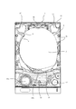
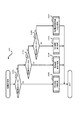
図1〜図3に示すように、本実施例のパチンコ遊技機1は、遊技機枠50と、遊技機枠50内に取り付けられた遊技盤2とを備えており、遊技盤2は遊技機枠50から着脱自在に構成されている。図3は、遊技盤2を遊技機枠50から取り外した状態のものを示す。遊技機枠50は、装飾面を有する前面枠51と、遊技盤2等を取り付ける本体枠52と、パチンコ遊技機1をホールの島設備に取り付けるための外枠53と、を有して構成されており、前面枠51、本体枠52及び外枠53は、一側端側で軸支され夫々開閉可能に構成されている。
As shown in FIGS. 1 to 3, the
また、前面枠51には、遊技者の操作量(回転角度)に応じた発射強度で遊技球を発射させるための発射ハンドル60、遊技球を貯留し貯留した遊技球を発射装置側に供給可能な打球供給皿(上皿)61、及び打球供給皿61に収容しきれない遊技球を貯留する余剰球受皿(下皿)62が設けられている。さらに、前面枠51には、遊技の進行に伴って実行される遊技演出の実行中などに遊技者が操作可能な第1演出ボタン63a、第2演出ボタン63b(これら2個の演出ボタンを総称して単に「演出ボタン63」ともいう。)や、遊技の状況に応じて様々な光を発することが可能な装飾用の枠ランプ66、遊技の状況に応じて様々な音(効果音)を発することが可能なスピーカ67等も設けられている。
In addition, the
演出ボタン63は、遊技者が入力可能な入力手段として機能するもので、遊技演出の種類に応じて使用する演出ボタンを使い分けることができる。例えば、遊技演出の実行中に第1演出ボタン63aまたは第2演出ボタン63bを操作すると、当該操作に基づいて所定の演出が行われる。尚、演出ボタン63の構成は本実施例の態様に限らず、遊技者が入力を行うことができるものであれば足り、例えば、遊技者が直接ボタン部に接触して入力を行う入力手段(例えば、出没式、タッチセンサ式等)であってもよいし、遊技者の身体の一部が近接したことを検知して入力を行う非接触式の入力手段(光電式等)であってもよい。また、演出ボタンが、上方や手前側に突出したり振動したりする等の演出動作を行うもの(可動式の演出操作手段)であってもよい。
The effect button 63 functions as an input means that can be input by the player, and the effect button to be used can be properly used according to the type of game effect. For example, when the
遊技盤2には、発射ハンドル60の操作により発射された遊技球が流下する遊技領域3が、レール部材4で囲まれて形成されている。遊技領域3には、遊技球を誘導する複数の遊技釘16が突設されており、レール部材4の先端には、球戻り防止片6が設けられている。球戻り防止片6は、一旦遊技領域へ誘導された遊技球を発射装置側へ戻るのを防止するためのものである。また、遊技盤2には、遊技の状況に応じて様々な光を発することが可能な装飾用の盤面ランプ5(図5を参照)も設けられている。
In the
遊技領域3の中央付近には、液晶表示装置からなる画像表示装置7(演出表示手段)が設けられている。画像表示装置7の表示画面7aには、演出図柄8L,8C,8R(単に「演出図柄8」ともいう。)が表示される演出図柄表示領域7b(「演出図柄表示部」ともいう。)が設けられており、当該演出図柄8L,8C,8Rは、後述の第1特別図柄の変動表示及び第2特別図柄の変動表示に伴って(同期して)変動表示を行う。変動表示の態様としては、例えば上下、左右、斜め方向等にスクロール表示する態様がある。演出図柄表示領域7bは、例えば「左」「中」「右」の3つの図柄表示エリアからなり、左の図柄表示エリアには左演出図柄8Lが表示され、中の図柄表示エリアには中演出図柄8Cが表示され、右の図柄表示エリアには右演出図柄8Rが表示される。尚、左・中・右の図柄表示エリアの位置は夫々区別して設ける必要はなく、左・中・右の演出図柄の表示エリアをそれぞれ図柄表示エリア(演出図柄表示領域7b)の全体としてもよい。
Near the center of the
本実施例の演出図柄8L,8C,8Rは、それぞれ「1」〜「9」までの数字を表した複数の図柄(演出識別情報)からなる。本実施例では、「1」〜「9」の図柄(演出図柄)のうち、奇数図柄である「3」と「7」を赤色の図柄(以下「赤図柄」ともいう。)としており、これ以外の奇数図柄である「1」、「5」、「9」を緑色の図柄(以下「緑図柄」ともいう。)としている。また、偶数図柄である「2」、「4」、「6」、「8」を青色の図柄(以下「青図柄」ともいう。)としている。つまり、本実施例では、演出図柄8の種類(図柄種)として、赤図柄、緑図柄、青図柄の3つの図柄種が存在する。尚、この図柄種は一例であり、これ以外の態様で演出図柄の図柄種を定めることも可能である。例えば、演出図柄が「数字」と人物・動物等を模した「キャラクタ」により構成される場合、そのキャラクタの種類(例えば男性キャラクタ、女性キャラクタ、味方キャラクタ、敵キャラクタ等)によって演出図柄の図柄種を定めることが可能である。
The
演出図柄表示領域7bに停止表示される左、中、右の演出図柄の組合せ(停止表示態様)によって、後述の第1特別図柄表示器41a(「第1特別図柄表示部」ともいう。)に表示される第1特別図柄の変動表示の結果や、第2特別図柄表示器41b(「第2特別図柄表示部」ともいう。)に表示される第2特別図柄の変動表示の結果、つまり、特別図柄当否判定(単に「当否判定」ともいう。)の結果を、遊技者が認識し易いように表示する。本実施例では、変動表示している3つの演出図柄8L,8C,8Rが停止表示する順序(停止順序)を、原則「左→右→中」としている。すなわち、停止順が1番目の停止図柄を左演出図柄8Lとし、停止順が2番目の停止図柄を右演出図柄8Rとし、停止順が3番目(最後)の停止図柄を中演出図柄8Cとしている。このうち、停止順が1番目の停止図柄のことを「第1停止図柄」ともいい、停止順が2番目の停止図柄のことを「第2停止図柄」ともいい、停止順が3番目の停止図柄のことを「第3停止図柄」や「最終停止図柄」ともいう。また、第1特別図柄、第2特別図柄、演出図柄のいずれかを指して単に「図柄」や「識別情報」ともいう。さらに、普通図柄のことを「普図」や「普通識別情報」、特別図柄のことを「特図」、第1特別図柄のことを「特図1」や「第1特図」、第2特別図柄のことを「特図2」や「第2特図」ともいう。また、演出図柄8を表示する画像表示装置7や第1特別図柄を表示する後述の第1特別図柄表示器41a、第2特別図柄を表示する第2特別図柄表示器41bのことを「識別情報表示手段」ともいう。
The first
例えば、特別図柄当否判定の結果が大当り(特定結果)となり、その大当りの種別が16R大当りや6R大当り等になった場合には、「222」や「777」などの3桁同一のゾロ目(特定態様)で演出図柄を停止表示することが可能である。また、特別図柄当否判定の結果が大当り(特定結果)となり、その大当りの種別が2R大当りになった場合には、「123」や「135」等のチャンス目(特別態様)で演出図柄を停止表示することが可能である。さらに、特別図柄当否判定の結果が外れとなった場合には「637」や「373」などの3つの図柄のうち少なくとも1つの図柄が異なるバラケ目(非特定態様)で演出図柄を停止表示することが可能である。これにより、遊技者は停止表示した演出図柄を見ることで、遊技の進行状況を容易に把握することが可能となる。つまり遊技者は、一般的には特別図柄当否判定の結果を第1特別図柄表示器41aや第2特別図柄表示器41bに表示される特別図柄を見て直接的に把握するのではなく、演出図柄表示領域7bに表示される演出図柄を見て把握する。尚、大当りのうち2R大当りについては、外れの場合と同じ態様(バラケ目)で演出図柄を停止表示することも可能である。
For example, if the result of the special symbol success / failure determination is a big hit (specific result) and the type of the big hit is a 16R big hit or a 6R big hit, etc., the same three digits such as “222” and “777” ( It is possible to stop and display the effect design in a specific mode. In addition, when the result of the special symbol success / failure determination is a big hit (specific result) and the type of the big hit is a 2R big hit, the effect design is stopped at the chance (special mode) such as “123” or “135”. It is possible to display. Furthermore, when the result of the special symbol success / failure determination is unsuccessful, at least one of the three symbols such as “637” and “373” is stopped and displayed in a different pattern (non-specific mode). It is possible. Thereby, the player can easily grasp the progress of the game by looking at the effect symbols that are stopped and displayed. That is, the player generally does not directly grasp the result of the special symbol success / failure determination by looking at the special symbol displayed on the first
ここで、演出図柄の停止表示態様のうち、特別図柄当否判定の結果が大当り(特定結果)の場合に対応する停止表示態様のことを「大当り態様」、「特定態様」または「特定表示結果」ということがあり、特別図柄当否判定の結果が外れ(非特定結果)の場合に対応する停止表示態様のことを「外れ態様」、「非特定態様」または「非特定表示結果」ということがある。 Here, among the stop display modes of the effect symbols, the stop display mode corresponding to the case where the result of the special symbol success / failure determination is a big hit (specific result) is “big hit mode”, “specific mode” or “specific display result”. In some cases, the stop display mode corresponding to the case where the result of the special symbol success / failure determination is out (non-specific result) may be referred to as “out-of-phase”, “non-specific mode” or “non-specific display result”. .
画像表示装置7の表示画面7a上では、前述のような演出図柄を用いた遊技演出(演出図柄遊技演出)を表示するほか、大当り遊技に伴って実行される大当り遊技演出(特別遊技演出)や、客待ち用のデモ演出などが表示される。演出図柄遊技演出や大当り遊技演出やデモ演出では、数字等の演出図柄のほか、背景画像やキャラクタ画像などの演出図柄以外の演出画像も表示される。尚、演出図柄遊技演出のことを「変動演出」ともいう。
On the
また、画像表示装置7の表示画面7aには、後述の第1特図保留の記憶数に応じて第1演出保留9aを表示する第1演出保留表示領域9c(第1演出保留表示部)と、後述の第2特図保留の記憶数に応じて第2演出保留9bを表示する第2演出保留表示領域9d(第2演出保留表示部)とが設けられている(図3を参照)。第1演出保留や第2演出保留の表示態様(表示数)により、後述の第1特図保留表示器43aにて表示される第1特図保留の記憶数や第2特図保留表示器43bにて表示される第2特図保留の記憶数を、遊技者にわかりやすく示すことができる。さらに、本実施例の画像表示装置7の表示画面7aには、現在変動している特別図柄(第1特別図柄または第2特別図柄)に対応する演出保留、すなわち、消化された特図保留に対応する演出保留(第1演出保留9aまたは第2演出保留9b)を表示する当該変動保留表示領域9eが設けられている(図3を参照)。
The
遊技領域3の中央付近であって画像表示装置7の前方には、演出図柄表示領域7bを取り囲むように、センター装飾体10が設けられている。センター装飾体10の下部には、遊技球が転動可能な遊技球転動面を有するステージ部11が設けられている。また、センター装飾体10の左部には、中空状のワープ部12が設けられている。ワープ部12にはワープ入口とワープ出口とが設けられており、遊技領域3を流下する遊技球をワープ入口から受け入れ、当該遊技球をワープ出口から排出しステージ部11へと誘導する。ステージ部11の転動面に誘導された遊技球は、ステージ部11に誘導されない遊技球と比して高い可能性で、後述の第1始動口20に入球可能とされている。さらに、センター装飾体10の上部には、LED等の電飾部材(盤面ランプ5)を有し遊技状態に応じて点灯・点滅等が可能であって、文字や図形等を象った装飾部材13が配されている。
A center
また、センター装飾体10の上部であって、装飾部材13の後方には、遊技演出に伴って動作可能な可動装飾部材14(可動役物)が設けられている。図3では、可動装飾部材14の一部分のみが視認可能となっているが、例えば、大当りの可能性が比較的高い遊技演出の実行に伴って、可動装飾部材14が下方に落下し、当該可動装飾部材14が表示画面7aの前面を覆い、その大部分が視認可能となる。これにより、遊技者は大当りへの期待感を高めることとなる。尚、可動装飾部材14の動作パターンには、落下以外にも、例えば、上下への微動(振動)を繰り返す動作や、下方へ段階的に移動する動作など、種々のパターンが設けられている。
In addition, a movable decorative member 14 (movable accessory) that can be operated in accordance with a game effect is provided on the center
ここで、特図保留に応じた演出保留9a,9bを表示することが可能な演出保留表示領域9c,9dのことを「演出保留表示手段」ともいい、遊技状況に応じた種々の演出画像を表示することで演出表示(表示演出)を行うことが可能な画像表示装置7のことを「演出表示手段」または「表示演出手段」ともいい、遊技演出に伴って動作することで可動演出を行うことが可能な可動装飾部材14のことを「可動演出手段」ともいう。尚、可動装飾部材14以外にも、例えば、演出ボタン63が遊技演出に伴って上下動や振動等する場合、演出ボタン63も「可動演出手段」といえる。また、遊技の状況に応じて様々な音(効果音)を発することで音演出を行うことが可能なスピーカ67のことを「音演出手段」ともいい、遊技の状況に応じて様々な光を発することで光演出を行うことが可能な盤面ランプ5、枠ランプ66および装飾部材13のことを「光演出手段」ともいう。尚、これら盤面ランプ5等以外にも、例えば、演出ボタン63や発射ハンドル60が、装飾部材13と同様にLED等の電飾部材を内蔵しており、電飾部材の作用により遊技の状況に応じて点灯・点滅等する場合、これら演出ボタン63や発射ハンドル60も「光演出手段」といえる。さらに、これら「演出保留表示手段」、「演出表示手段」(表示演出手段)、「可動演出手段」、「音演出手段」および「光演出手段」を総じて「演出手段」ともいう。
Here, the production
遊技領域3における画像表示装置7の下方には、遊技球の入球し易さが変化しない非可変式の第1始動口20を備える固定入賞装置19が設けられている。第1始動口20への遊技球の入球に基づいて、特別図柄当否判定用乱数等が取得され、予め定められた所定条件が成立すると第1特別図柄に係る当否判定(第1特別図柄当否判定)が実行されると共に第1特別図柄が変動表示され、当否判定の結果に基づいて停止表示される。
Below the
第1始動口20の下方には、遊技球の入球し易さが変化する可変式の第2始動口21を備える可変入賞装置22(「可変式始動口」ともいう。)が設けられている。第2始動口21への遊技球の入球に基づいて、特別図柄当否判定用乱数等が取得され、予め定められた所定条件が成立すると第2特別図柄の当否判定(第2特別図柄当否判定)が実行されると共に第2特別図柄が変動表示され、当否判定の結果に基づいて停止表示される。 Below the first start opening 20, there is provided a variable winning device 22 (also referred to as "variable start opening") having a variable second start opening 21 that changes the ease of entering a game ball. Yes. A random number for determining whether or not a special symbol is obtained based on the game ball entering the second starting port 21, and if a predetermined condition is established, whether or not the second special symbol is determined (second special symbol determination) ) Is executed, the second special symbol is variably displayed, and is stopped and displayed based on the determination result.
尚、特別図柄当否判定の結果が「大当り」であることに基づいて行われる特別図柄の変動表示や演出図柄の変動表示のことを「大当り変動」や「特定変動」ともいい、特別図柄当否判定の結果が「外れ」であることに基づいて行われる特別図柄の変動表示や演出図柄の変動表示のことを「外れ変動」や「非特定変動」ともいう。 Note that the special symbol variation display and the production symbol variation display based on the result of the special symbol success / failure determination result being “big hit” is also called “big hit variation” or “specific variation”. The special symbol variation display and the production symbol variation display performed based on the result of “out” is also referred to as “out-of-range variation” or “non-specific variation”.
可変入賞装置22は、可動部材23を備え、可動部材23の動作によって第2始動口21を開閉するものである。この開閉動作によって、第2始動口21は、第1の態様(閉状態)から当該第1の態様よりも遊技球の入球可能性が高い第2の態様(開状態)へと変化可能である。つまり、可動部材23は、所定の動作(開閉動作)を行うことで、第2始動口21への遊技球の入球可能性を変化させるものである。この可動部材23は、第2始動口ソレノイド24(図5参照)により駆動される。本実施例では、第2始動口21は、可動部材23が開状態にあるときだけ遊技球が入球可能とされ、可動部材23が閉状態にあるときには遊技球が入球不能となっている。尚、第2始動口21は、可動部材23が閉状態にあるときは開状態にあるときよりも遊技球が入球困難となるものであれば、可動部材23が閉状態にあるときに完全に入球不能となるものでなくてもよい。
The
遊技領域3における第1始動口20の右方には、第1大入賞口30(「第1可変入球口」ともいう。)を備えた第1大入賞装置31が設けられている。第1大入賞装置31は、開閉部材32を備え、開閉部材32の作動により第1大入賞口30を開閉するものである。開閉部材32は、第1大入賞口ソレノイド33(図5参照)により駆動される。第1大入賞口30は、開閉部材32が開状態にあるときだけ遊技球が入球可能となる。すなわち、第1大入賞装置31は、開閉部材32の開閉動作により、遊技球が入球不能な入球不能状態(閉状態)と遊技球が入球可能な入球可能状態(開状態)とに変化可能である。
On the right side of the first start opening 20 in the
また、遊技領域3における第1大入賞口30の上方であってセンター装飾体10の右下部には、第2大入賞口35(「第2可変入球口」ともいう。)を備えた第2大入賞装置36が設けられている。第2大入賞装置36は、開閉部材(羽根部材)37を備え、開閉部材37の作動により第2大入賞口35を開閉するものである。開閉部材37は、第2大入賞口ソレノイド38(図5参照)により駆動される。第2大入賞口35は、開閉部材37が開状態にあるときだけ遊技球が入球可能となる。すなわち、第2大入賞装置36は、開閉部材37の開閉動作により、遊技球が入球不能な入球不能状態(閉状態)と遊技球が入球可能な入球可能状態(開状態)とに変化可能である。
Further, in the
遊技領域3におけるセンター装飾体10の右側領域には、遊技球が通過可能なゲート28(遊技球通過口)が設けられている。ゲート28への遊技球の通過に基づいて、普通図柄当否判定用乱数等が取得され、予め定められた所定条件が成立すると、第2始動口21を開状態とするか否かを判定する普通図柄当否判定が実行されると共に普通図柄が変動表示され、普通図柄当否判定の結果に基づいて停止表示される。当り普通図柄が停止表示すると、第2始動口21は開状態となる。さらに、遊技領域3の下部には、複数の一般入賞口27が設けられている。本実施例では、一般入賞口27を4個設けてあり、そのうちの3個を第1始動口20の左方に設けられた左一般入賞口とし、1個を第1大入賞口30の右方に設けられた右一般入賞口としている。第1始動口20、第2始動口21、第1大入賞口30、第2大入賞口35および一般入賞口27は、それぞれ賞球の払い出し契機となる入球口であり、各入球口に遊技球が入球した場合には、夫々の入球口において予め定められた数の遊技球(賞球)が払い出される。具体的には、第1始動口20の賞球数は「5」、第2始動口21の賞球数は「3」、第1大入賞口20および第2大入賞口35の賞球数は「15」、一般入賞口27の賞球数は「10」としている。
A gate 28 (game ball passage opening) through which a game ball can pass is provided in the right region of the center
このように複数の入球口(第1始動口20、第2始動口21、第1大入賞口30、第2大入賞口35、一般入賞口27及びゲート28)等が配されている遊技領域3を、左右方向の中央より左側の左遊技領域(第1領域)3Aと、右側の右遊技領域(第2領域)3Bと、に分けることができる。左遊技領域3Aを遊技球が流下するように遊技球を発射する打方を「左打ち」といい、右遊技領域3Bを遊技球が流下するように遊技球を発射する打方を「右打ち」という。ここで、複数の入球口のうち、第1始動口20および3個の左一般入賞口27は、遊技領域3のうち左遊技領域3Aを流下する遊技球が入球可能となるように設けてあり、第2始動口21、第1大入賞口30、第2大入賞口35、右一般入賞口27およびゲート28は、遊技領域3のうち右遊技領域3Bを流下する遊技球が入球可能となるように設けてある。このため、本パチンコ遊技機1では、遊技開始の際には、原則、左打ちにて第1始動口20への入球を狙う。一方、第1始動口20への入球に基づく当否判定において大当りとなり遊技状態が変化した際には、原則、右打ちにてゲート28、第2始動口21、第1大入賞口30および第2大入賞口35への入球を狙うこととなる。
A game in which a plurality of entrances (the first start opening 20, the second start opening 21, the first
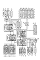
また、図3および図4に示すように、遊技盤2の右下部には主表示器40が配置されている。主表示器40には、第1特別図柄を変動表示および停止表示する第1特別図柄表示器41a(第1特別図柄表示部)と、第2特別図柄を変動表示および停止表示する第2特別図柄表示器41b(第2特別図柄表示部)と、普通図柄を変動表示および停止表示する普通図柄表示器42(普通図柄表示部)と、が含まれている。また、主表示器40には、第1特別図柄に係る当否判定情報(第1特図保留)の記憶数を表示する第1特図保留表示器43aと、第2特別図柄に係る当否判定情報(第2特図保留)の記憶数を表示する第2特図保留表示器43bと、普通図柄表示器42の作動保留(普図保留)の記憶数を表示する普図保留表示器44と、が含まれている。さらに、主表示器40には、第1特別図柄当否判定または第2特別図柄当否判定の結果が当りになったことを示す当り表示器48と、第1特別図柄当否判定または第2特別図柄当否判定の結果が大当りになった場合に実行される大当り遊技のラウンド数を示すラウンド表示器45と、確率変動機能が作動することを示す遊技状態表示器46と、遊技球の発射方向、すなわち右打ちを行うべき状態か左打ちを行うべき状態かを示す発射方向表示器47と、が含まれている。主表示器40に含まれるこれらの各種表示器は、後述の主制御部によって表示制御される。
As shown in FIGS. 3 and 4, a
第1特別図柄の変動表示は、第1始動口20への遊技球の入球に基づいて行われる。第2特別図柄の変動表示は、第2始動口21への遊技球の入球に基づいて行われる。尚、以下の説明では、第1特別図柄および第2特別図柄を総称して特別図柄ということがある。また、第1特別図柄表示器41aおよび第2特別図柄表示器41bを総称して特別図柄表示部41ということがある。また、第1特図保留表示器43aおよび第2特図保留表示器43bを総称して特図保留表示部43ということがある。
The variation display of the first special symbol is performed based on the game ball entering the
特別図柄表示部41では、特別図柄(識別情報)を所定時間変動表示した後に停止表示し、停止表示された特別図柄(停止図柄)によって第1始動口20または第2始動口21への入球に基づく抽選(特別図柄当否判定、大当り抽選)の結果を報知する。停止表示される特別図柄は、特別図柄当否判定によって複数種類の特別図柄の中から選択された一つの特別図柄である。停止図柄が予め定めた特定特別図柄(特定識別情報)である場合、すなわち、特別図柄の停止表示の態様(特別図柄の変動表示の表示結果)が大当りを示す特定態様(特定表示結果)である場合には、停止表示された大当り図柄の種類に応じた開放パターンにて第1大入賞口30または第2大入賞口35を開放させる大当り遊技(特別遊技)が行われる。尚、大当り遊技における大入賞口(第1大入賞口30及び第2大入賞口35)の開放パターンについては後述する。
In the special symbol display unit 41, the special symbol (identification information) is variably displayed for a predetermined time, and then stopped and displayed. The special symbol (stop symbol) that is stopped and displayed enters the
図4に示すとおり、第1特別図柄表示器41aは、「i〜p」で示す8個のLEDで構成されており、第1特別図柄当否判定の結果に応じた特別図柄を表示する。本実施例では、第1特別図柄当否判定の結果として「16R第1大当り」、「6R第2大当り」、「6R第3大当り」、「6R第4大当り」及び「6R第5大当り」の5種類の大当りが設けられており(図8を参照)、第1特別図柄表示器41aのLEDは、それら5種類の大当りの各々に応じた表示態様(特定態様、特定表示結果)を採ることが可能となっている。具体的には、第1特別図柄当否判定の結果が16R第1大当りとなった場合には「ijn」の3個のLEDを点灯させて残りを消灯させ(16R第1大当り図柄)、6R第2大当りとなった場合には「ino」の3個のLEDを点灯させて残りを消灯させ(6R第2大当り図柄)、6R第3大当りとなった場合には「inp」の3個のLEDを点灯させて残りを消灯させ(6R第3大当り図柄)、6R第4大当りとなった場合には「ijo」の3個のLEDを点灯させて残りを消灯させ(6R第4大当り図柄)、6R第5大当りとなった場合には「jno」の3個のLEDを点灯させて残りを消灯させる(6R第5大当り図柄)。また、外れとなった場合には、「lo」の2個のLEDを点灯させて残りを消灯させる(外れ図柄)。
As shown in FIG. 4, the first
また、第2特別図柄表示器41bは、「a〜h」で示す8個のLEDで構成されており、第2特別図柄当否判定の結果に応じた特別図柄を表示する。本実施例では、第2特別図柄当否判定の結果として「16R第6大当り」、「16第7大当り」、「12R第8大当り」、「6R第9大当り」、「2R第10大当り」、「16R第11大当り」及び「2R第12大当り」の7種類の大当りが設けられており(図8を参照)、第2特別図柄表示器41bのLEDは、それら2種類の大当りの各々に応じた表示態様(特定態様、特定表示結果)を採ることが可能となっている。具体的には、第2特別図柄当否判定の結果が16R第6大当りとなった場合には「abd」の3個のLEDを点灯させて残りを消灯させ(16R第6大当り図柄)、16R第7大当りとなった場合には「abg」の3個のLEDを点灯させて残りを消灯させ(16R第7大当り図柄)、12R第8大当りとなった場合には「abc」の3個のLEDを点灯させて残りを消灯させ(12R第8大当り図柄)、6R第9大当りとなった場合には「afg」の3個のLEDを点灯させて残りを消灯させ(6R第9大当り図柄)、2R第10大当りとなった場合には「abde」の4個のLEDを点灯させて残りを消灯させ(2R第10大当り図柄)、16R第11大当りとなった場合には「abe」の3個のLEDを点灯させて残りを消灯させ(16R第11大当り図柄)、2R第12大当りとなった場合には「abdh」の4個のLEDを点灯させて残りを消灯させる(2R第12大当り図柄)。また、外れとなった場合には、「eh」の2個のLEDを点灯させて残りを消灯させる(外れ図柄)。
The second
尚、特別図柄の停止表示態様(停止図柄)は、これらに限定されるものではなく、任意に設定することができる。また、特別図柄が停止表示される前には所定の変動時間にわたって特別図柄の変動表示がなされるが、その変動表示の態様は、例えば、予め定められた順序で光が左から右へ繰り返し流れるように各LEDを点灯させる態様とすることができる。 In addition, the stop display mode (stop symbol) of the special symbol is not limited to these, and can be arbitrarily set. Further, before the special symbol is stopped and displayed, the special symbol variation display is performed over a predetermined variation time. The variation display mode is, for example, that light repeatedly flows from left to right in a predetermined order. In this manner, each LED can be turned on.
本パチンコ遊技機1では、第1始動口20または第2始動口21への遊技球の入球があると、その入球に基づいて特別図柄当否判定用乱数等の各種情報(「取得情報」ともいう。)を取得し、取得した各種情報は、主制御部のRAMに形成される特図保留記憶部(図示せず)に一旦記憶される。詳細には、第1始動口20への入球であれば第1特図保留として第1特図保留記憶部(図示せず)に記憶され、第2始動口21への入球であれば第2特図保留として第2特図保留記憶部(図示せず)に記憶される。各々の特図保留記憶部に記憶可能な特図保留(取得情報)の数は所定数までとされており、本実施例におけるその上限値はそれぞれ「4」となっている。これら第1特図保留記憶部および第2特図保留記憶部を、夫々「第1取得情報記憶手段」および「第2取得情報記憶手段」ともいい、総じて「取得情報記憶手段」ともいう。
In this
特図保留記憶部に記憶された特図保留は、その特図保留に基づく特別図柄の変動表示が可能となったときに消化される。特図保留の消化とは、その特図保留に対応する特別図柄当否判定用乱数等を判定して、その判定結果を示すための特別図柄の変動表示を実行することをいう。従って、本パチンコ遊技機1では、第1始動口20または第2始動口21への遊技球の入球に基づく特別図柄の変動表示がその入球時にすぐに実行できない場合、すなわち特別図柄の変動表示の実行中や特別遊技の実行中である場合であっても、所定数(本実施例では4)を上限として、その入球に対する特別図柄当否判定の権利を留保することが可能となっている。
The special figure hold stored in the special figure hold storage unit is digested when the special symbol based on the special figure hold can be displayed. The digestion of the special symbol hold means that the special symbol determination random number or the like corresponding to the special symbol hold is determined, and the special symbol variable display for indicating the determination result is executed. Therefore, in this
特図保留記憶部に記憶された特図保留の数は、第1特図保留表示器43aおよび第2特図保留表示器43bに表示される。具体的には、第1特図保留表示器43aは「uv」の2個のLEDで構成されており、第1特図保留の数に応じてLEDを表示制御することにより、第1特図保留の数を表示するものとなっている。例えば、保留数が「0」の場合は「u□v□」(例えば、□:消灯、●:赤点灯、▲:緑点灯とする)というように両LEDを消灯する表示態様とし、保留数が「1」の場合は「u□v●」というように「u」のLEDを消灯し「v」のLEDを赤色で点灯させる表示態様とし、保留数が「2」の場合は「u●v□」というように「u」のLEDを赤色で点灯させ「v」のLEDを消灯する表示態様とし、保留数が「3」の場合は「u●v●」というように両方のLEDを赤色で点灯させる表示態様とし、保留数が「4(上限数)」の場合は「u▲v▲」というように両方のLEDを緑色で点灯させ表示態様とすることができる。
The number of special figure hold stored in the special figure hold storage unit is displayed on the first special
また、第2特図保留表示器43bは「wx」の2個のLEDで構成されており、第2特図保留の数に応じてLEDを表示制御することにより、第2特図保留の数を表示するものである。例えば、保留数が「0」の場合は「w□x□」(例えば、□:消灯、●:赤点灯、▲:緑点灯とする)というように両LEDを消灯する表示態様とし、保留数「1」〜「4」についても第1特図保留表示器43aと同様に定められている。
The second special
普通図柄の変動表示は、ゲート28への遊技球の通過を契機として行われる。普通図柄表示器42では、普通図柄を所定時間変動表示した後、停止表示し、停止表示された普通図柄(停止図柄)によって、ゲート28への遊技球の通過に基づく普通図柄当否判定の結果を報知する。停止表示される普通図柄は、普通図柄当否判定によって複数種類の普通図柄の中から選択された一つの普通図柄である。停止表示された普通図柄が予め定めた特定普通図柄(当り普通図柄)である場合には、現在の遊技状態に応じた開放パターンにて第2始動口21を開放させる補助遊技が行われる。尚、第2始動口21の開放パターンについては後述する。
The normal symbol variation display is triggered by the passage of the game ball to the
具体的には、図4に示す通り、普通図柄表示器42は「st」の2個のLEDから構成されており、その点灯態様によって普通図柄当否判定の結果に応じた普通図柄を表示するものである。例えば、判定結果が当りである場合には、「s■t■」(例えば、■:点灯、□:消灯とする)というように両LEDが点灯した当り普通図柄を停止表示する。また判定結果が外れである場合には、「s□t■」というように「t」のLEDのみが点灯した態様の外れ普通図柄を表示する。尚、外れ普通図柄は、特定普通図柄ではない。普通図柄が停止表示される前には予め定められた所定の変動時間にわたって普通図柄の変動表示が実行されるが、その変動表示の態様は、例えば両LEDが交互に点灯・消滅を繰り返す態様である。
Specifically, as shown in FIG. 4, the
本パチンコ遊技機1では、ゲート28への遊技球の通過があると、その通過に基づいて普通図柄当否判定用乱数等の各種情報(「取得情報」ともいう。)を取得し、取得した各種情報は主制御部のRAMに形成される普図保留記憶部(図示せず)に普図保留として一旦記憶される。普図保留記憶部に記憶可能な普図保留の数は所定数までとされており、本実施例におけるその上限値は「4」となっている。普図保留記憶部に記憶された普図保留は、その普図保留に基づく普通図柄の変動表示が可能となったときに消化される。普図保留の消化とは、その普図保留に対応する普通図柄当否判定用乱数を判定して、その判定結果を示すための普通図柄の変動表示を実行することをいう。従って、本パチンコ遊技機1では、ゲート28への遊技球の通過に基づく普通図柄の変動表示がその通過時にすぐ実行できない場合、すなわち普通図柄の変動表示の実行中や補助遊技の実行中である場合であっても、所定個数を上限として、その通過に対する普通図柄当否判定の権利を留保することが可能となっている。
In the
普図保留記憶部に記憶された普図保留の数は、普図保留表示器44に表示される。具体的には、普図保留表示器44は「qr」の2個のLEDで構成されており、普図保留の数に応じてLEDを点灯させることにより普図保留の数を表示するものである。例えば、保留数が「0」の場合は「q□r□」(例えば、□:消灯、●:赤点灯、▲:緑点灯とする)というように両LEDを消灯する表示態様とし、保留数が「1」の場合は「q□r●」というように「q」のLEDを消灯し「r」のLEDを赤色で点灯させる表示態様とすることができる。また、保留数「2」〜「4」についても第1特図保留表示器43aと同様に定められている。
The number of the general map reservation stored in the general map storage unit is displayed on the general
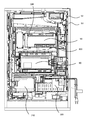
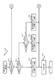
次に図2及び図5に基づいて、本パチンコ遊技機1における電気的な構成を説明する。本実施例のパチンコ遊技機1は、特別図柄当否判定や普通図柄当否判定や遊技状態の移行など、遊技進行や遊技利益に関する制御を行う主制御基板80(「主制御部」ともいい「遊技制御部」ともいう。)、遊技の進行に伴って実行する演出に関する制御を行うサブ制御基板90(「サブ制御部」ともいい「演出制御部」ともいう。)、遊技球の払い出しに関する制御を行う払出制御基板110(「払出制御部」ともいう。)、画像表示装置7や演出表示器102、演出第1特図保留表示器103aおよび演出第2特図保留表示器103b等の表示制御を行う画像制御基板100(「画像制御部」ともいう。)等を備えている。
Next, based on FIG.2 and FIG.5, the electrical structure in this
また、図2に示すように、パチンコ遊技機1の後面側(裏面側)の略中央部には主制御基板80を収納した主制御基板収納ケースが設けられ、この主制御基板ケースの上方には、音声制御基板106、ランプ制御基板107及び画像制御基板100を収納した画像制御基板等収納ケースが設けられ、その画像制御基板等収納ケース上にはサブ制御基板90を収納したサブ制御基板収納ケースが設けられている。また、主制御基板ケースの下方左側には、払出制御基板を収納する払出制御基板ケースが設けられ、その右側には、電源基板109を収納する電源基板ケースが設けられている。
Further, as shown in FIG. 2, a main control board storage case storing the
主制御基板80には、プログラムに従ってパチンコ遊技機1の遊技の進行を制御する遊技制御用ワンチップマイコン(以下「遊技制御用マイコン」)81が実装されている。遊技制御用マイコン81には、遊技の進行を制御するためのプログラム等を記憶したROM、ワークメモリとして使用されるRAM、ROMに記憶されたプログラムを実行するCPUが含まれている。遊技制御用マイコン81は、入出力回路87(I/Oポート部)を介して他の基板等とデータ(情報)の送受信を行う。入出力回路87は、遊技制御用マイコン81に内蔵されていてもよい。また、ROMは外付けであってもよい。遊技制御用マイコン81のRAMには、前述した特図保留記憶部(第1特図保留記憶部及び第2特図保留記憶部)と普図保留記憶部とが設けられている。また、主制御基板80(遊技制御用マイコン81)のRAM(主制御RAM)の所定アドレスには、各種フラグや各種計数カウンタに用いるための記憶領域が確保されている。
A game control one-chip microcomputer (hereinafter referred to as “game control microcomputer”) 81 that controls the progress of the game of the
主制御基板80には、中継基板88を介して各種センサやソレノイドが接続されている。そのため、主制御基板80には各センサから信号が入力され、各ソレノイドには主制御基板80から信号が出力される。具体的には、センサ類として、第1始動口センサ20a、第2始動口センサ21a、ゲートセンサ28a、第1大入賞口センサ30a、第2大入賞口センサ35aおよび一般入賞口センサ27aが接続されている。これら各種センサを「遊技球検知手段」ともいう。
Various sensors and solenoids are connected to the
第1始動口センサ20aは、第1始動口20内に設けられて第1始動口20に入球した遊技球を検知するものである。第2始動口センサ21aは、第2始動口21内に設けられて第2始動口21に入球した遊技球を検知するものである。ゲートセンサ28aは、ゲート28内に設けられてゲート28を通過した遊技球を検知するものである。第1大入賞口センサ30aは、第1大入賞口30内に設けられて第1大入賞口30に入球した遊技球を検知するものである。第2大入賞口センサ35aは、第2大入賞口35内に設けられて第2大入賞口35に入球した遊技球を検知するものである。一般入賞口センサ27aは、各一般入賞口27内にそれぞれ設けられて一般入賞口27に入球した遊技球を検知するものである。
The first
また、ソレノイド類としては、第2始動口ソレノイド24、第1大入賞口ソレノイド33および第2大入賞口ソレノイド38が接続されている。これら各種ソレノイドを「駆動手段」ともいう。第2始動口ソレノイド24は、可変入賞装置22の可動部材23を駆動するためのものである。第1大入賞口ソレノイド33は、第1大入賞装置31の開閉部材32を駆動するためのものである。第2大入賞口ソレノイド38は、第2大入賞装置36の開閉部材37を駆動するためのものである。
In addition, as the solenoids, a second
さらに、主制御基板80には、第1特別図柄表示器41a、第2特別図柄表示器41b、普通図柄表示器42、第1特図保留表示器43a、第2特図保留表示器43b、普図保留表示器44、ラウンド表示器45、遊技状態表示器46、発射方向表示器47および当り表示器48が接続されている。すなわち、これらの主表示器40の表示制御は、遊技制御用マイコン81によりなされる。
Further, the
また、主制御基板80は、払出制御基板110に各種コマンドを送信するとともに、払い出し監視のために払出制御基板110から信号を受信する。払出制御基板110には、賞球や貸球を払い出す払出装置120、及びカードユニット135(パチンコ遊技機1に隣接して設置され、挿入されたプリペイドカード(遊技価値記憶媒体)等に記憶されている情報に基づいて球貸しを可能にするもの)が接続されているとともに、発射制御基板111(「発射制御部」ともいう。)を介して発射装置112が接続されている。発射装置112には、発射ハンドル60(図1を参照)が含まれる。
The
払出制御基板110は、所定のプログラムに従って遊技球の払い出しを制御する払出制御用ワンチップマイコン116(「払出制御用マイコン」ともいう。)が実装されている。払出制御用マイコン116には、遊技球の払い出しを制御するためのプログラム等を記憶したROM、ワークメモリとして使用されるRAM、ROMに記憶されたプログラムを実行するCPUが含まれている。払出制御用マイコン116は、入出力回路117を介し、遊技制御用マイコン81からの信号やパチンコ遊技機1に接続されたカードユニット135からの信号に基づいて、払出装置120の払出モータ121を駆動して賞球の払い出しを行ったり貸球の払い出しを行ったりする。払い出される遊技球は、その計数のため払出センサ122、123により検知される。遊技者による発射装置112の発射ハンドル60の操作があった場合には、タッチスイッチ114が発射ハンドル60への遊技者の接触を検知し、発射ボリューム115が発射ハンドル60の回転量を検知する。そして、発射ボリューム115の検知信号の大きさに応じた強さで遊技球が発射されるよう発射モータ113が駆動制御されることとなる。尚、本実施例では、発射モータ113の駆動により発射装置112が連続して発射可能な遊技球の数は1分間で約100個となっている。
The
また、主制御基板80は、サブ制御基板90に対し各種コマンドを送信する。主制御基板80とサブ制御基板90との接続は、主制御基板80からサブ制御基板90への信号の送信のみが可能な単方向通信接続となっている。すなわち、主制御基板80とサブ制御基板90との間には、通信方向規制手段としての図示しない単方向性回路(例えばダイオードを用いた回路)が介在している。
The
図5に示すように、サブ制御基板90には、所定のプログラムに従ってパチンコ遊技機1の演出を制御する演出制御用ワンチップマイコン91(「演出制御用マイコン」ともいう。)が実装されている。演出制御用マイコン91(演出制御手段)には、遊技の進行に伴って演出を制御するためのプログラム等を記憶したROM、ワークメモリとして使用されるRAM、ROMに記憶されたプログラムを実行するCPUが含まれている。演出制御用マイコン91は、入出力回路95を介して他の基板等とデータの送受信を行う。尚、入出力回路95は演出制御用マイコン91に内蔵されていてもよく、ROMは外付けであってもよい。また、サブ制御基板90(演出制御用マイコン91)のRAM(演出制御RAM)の所定アドレスには、各種フラグや各種計数カウンタに用いるための記憶領域が確保されている。
As shown in FIG. 5, the
サブ制御基板90には、画像制御基板100、音声制御基板106、ランプ制御基板107が接続されている。尚、サブ制御基板90(サブ制御部)や画像制御基板100(画像制御部)、音声制御基板106(音声制御部)、ランプ制御基板107(ランプ制御部)は、遊技の状況に応じて表示演出や音演出、ランプ演出(光演出)等の各種演出を、対応する演出用の装置や部材等(演出手段)に実行させる演出実行手段として機能するものである。また、識別情報の変動表示に関する情報を示唆する種々の予告演出(示唆演出)を、対応する演出用の装置や部材等(演出手段)に実行させる予告演出実行手段としても機能する。
The
サブ制御基板90の演出制御用マイコン91は、主制御基板80から受信したコマンドに基づいて、画像制御基板100の画像制御用ワンチップマイコン101(「画像制御用マイコン」ともいう。)のCPUに、画像表示装置7、演出表示器102、演出第1特図保留表示器103aおよび演出第2保留表示器103bの表示制御を行わせる。画像制御基板100のRAMは、画像データを展開するためのメモリである。画像制御基板100のROMには、画像表示装置7に表示される静止画データや動画データ、具体的にはキャラクタ、アイテム、図形、文字、数字および記号等(演出図柄、保留図柄等を含む)や背景画像等の画像データが格納されている。画像制御用マイコン101は、演出制御用マイコン91からの指令に基づいてROMから画像データを読み出す。そして、読み出した画像データに基づいて表示制御を実行する。
Based on the command received from the
演出表示器102は、2個のLEDからなり、演出図柄8の変動表示および停止表示に合わせて変動表示および停止表示を行い、2個のLEDの点灯・消灯または色の組合せにより、演出図柄8の表示結果(特別図柄当否判定の結果)を示す表示態様で停止表示する。また、演出第1特図保留表示器103aおよび演出第2保留表示器103bも同様に2個のLEDからなる。そして、2個のLEDの点灯・消灯または色の組合せにより、演出第1特図保留表示器103aは第1演出保留表示領域9cに表示される保留個数および第1特図保留表示器43aで表示される保留個数と同じ保留個数を示す表示態様で表示制御される。また、演出第2特図保留表示器103bは第2演出保留表示領域9dに表示される保留個数および第2特図保留表示器43bで表示される保留個数と同じ保留個数を示す表示態様で表示制御される。これは、キャラクタ図柄を表示画面7a(演出図柄表示部)の略全体に表示したり、可動装飾部材14を動作させて表示画面7aの演出図柄表示領域7b(演出図柄表示部)の略全体を被覆したりすることで、演出図柄8や第1演出保留9a、第2演出保留9b等、表示画面7aに表示される各種画像の一部または全部が視認できない状態になることがあるため、この様な表示器が設けられている。尚、画像制御基板100の画像制御用ワンチップマイコン101に換えて、または加えて、VDP(Video Display Processor)を設けてもよい。
The
また、演出制御用マイコン91は、主制御基板80から受信したコマンドに基づいて、音声制御基板106を介してスピーカ67から音声、楽曲、効果音等を出力する。スピーカ67から出力する音声等の音データは、サブ制御基板90のROMに格納されている。尚、音声制御基板106にCPUを実装してもよく、その場合、そのCPUに音声制御を実行させてもよい。さらにこの場合、音声制御基板106にROMを実装してもよく、そのROMに音データを格納してもよい。また、スピーカ67を画像制御基板100に接続し、画像制御用マイコン101に音声制御を実行させてもよい。この場合、画像制御基板100のROMに音データを格納してもよい。
In addition, the
また、演出制御用マイコン91は、主制御基板80から受信したコマンドに基づいて、枠ランプ66や盤面ランプ5等のランプの発光態様を決める発光パターンデータ(点灯/消灯や発光色等を決めるデータ、ランプデータともいう。)を、ROMに格納されているデータから決定し、ランプ制御基板107を介して枠ランプ66や盤面ランプ5等のランプ(LED)の点灯制御を行う。
Further, the
さらに、演出制御用マイコン91は、主制御基板80から受信したコマンドに基づいて、ランプ制御基板107に中継基板108を介して接続された可動装飾部材14を動作させる。前述したように、可動装飾部材14は、センター装飾体10(装飾部材13の後方)に設けられた可動式のいわゆるギミックのことである。演出制御用マイコン91は、可動装飾部材14を所定の動作態様で動作させるための動作パターンデータ(「駆動データ」ともいう。)を、サブ制御基板90のROMに格納されているデータから決定し、決定した動作パターンデータに基づいて可動装飾部材14の動作を制御する。尚、ランプ制御基板107にCPUを実装してもよく、その場合、そのCPUにランプの点灯制御や可動装飾部材14の動作制御を実行させてもよい。さらにこの場合、ランプ制御基板107にROMを実装してもよく、そのROMに発光パターンや動作パターンに関するデータを格納してもよい。
Further, the
また、サブ制御基板90には、第1演出ボタン63aまたは第2演出ボタン63b(図1を参照)が操作(押す、回転、引く等)されたことを検知する第1演出ボタン検知スイッチ63cおよび第2演出ボタン検知スイッチ63dが接続されている。従って、第1演出ボタン63aまたは第2演出ボタン63bに対して遊技者が所定の入力操作を行うと、対応する演出ボタン検知スイッチからの信号がサブ制御基板90に入力される。尚、第1演出ボタン検知スイッチ63cおよび第2演出ボタン検知スイッチ63dを総称して単に「演出ボタン検知スイッチ」ともいう。
The
次に、本実施例のパチンコ遊技機1における当否判定に係る制御(取得情報判定手段)について説明する。本実施例では、特別図柄当否判定の結果として「大当り」と「外れ」がある。「大当り」のときには特別図柄表示部41に「大当り図柄」が停止表示され、「外れ」のときには特別図柄表示部41に「外れ図柄」が停止表示される。特別図柄当否判定で大当りと判定されると、停止表示された特別図柄の種類(大当り種別)に応じた開放パターンにて大入賞口(第1大入賞口30または第2大入賞口35)を開放する「特別遊技」が実行される。大当りとなって実行される特別遊技を「大当り遊技」という。
Next, the control (acquisition information determination means) relating to the determination of success / failure in the
本実施例の大当りには複数の種別がある。具体的には、図6に示すように、大当りとして「16R(ラウンド)第1大当り」、「6R第2〜第5大当り」、「16R第6大当り」、「16R第7大当り」、「12R第8大当り」、「6R第9大当り」、「2R第10大当り」、「16R第11大当り」及び「2R第12大当り」の計12種類を設けている。これらの大当りのうち、第1特別図柄に係る大当りである「16R第1大当り」及び「6R第2〜第5大当り」と、第2特別図柄に係る大当りである「16R第6大当り」及び「16R第11大当り」は、何れも、第1大入賞口30(下アタッカー)を用いた大当り遊技に係る大当りである。具体的には、「16R第1大当り」及び「16R第6大当り」は、第1大入賞口30の開放回数(ラウンド数)が16回で、開放時間が1回の開放(1ラウンド)につき25秒の大当りである。また、「16R第11大当り」は、第1大入賞口30の開放回数(ラウンド数)が16回で、そのうち1回目(1R)〜10回目(10R)の開放に係る開放時間が1回の開放(1ラウンド)につき25秒、11回目(11R)〜16回目(16R)の開放に係る開放時間が1回の開放(1ラウンド)につき0.1秒の大当りである。つまり、「16R第11大当り」は、第1大入賞口30の16回の開放のうち、1回目(1R)〜10回目(10R)の10回の開放(10ラウンド)は第1大入賞口30への遊技球の入球が容易(可能)となり、残りの11回目(11R)〜16回目(16R)の6回の開放(6ラウンド)は第1大入賞口30への遊技球の入球が困難(不可能)となる大当りである。このことから、「16R第11大当り」は実質的に「10R大当り」ともいえる。さらに、「6R第2〜第5大当り」は、何れも、第1大入賞口30の開放回数(ラウンド数)が6回で、開放時間が1回の開放(1ラウンド)につき25秒の大当りである。尚、ラウンドを、単に「R」ともいい、「ラウンド遊技」ともいう。
There are a plurality of types of jackpots in this embodiment. Specifically, as shown in FIG. 6, “16R (round) first big hit”, “6R second to fifth big hit”, “16R sixth big hit”, “16R seventh big hit”, “12R” There are a total of 12 types of "8th big hit", "6R 9th big hit", "2R 10th big hit", "16R 11th big hit" and "2R 12th big hit". Among these jackpots, “16R first jackpot” and “6R second to fifth jackpots” that are jackpots related to the first special symbol, and “16R sixth jackpot” that are jackpots related to the second special symbol and “ The “16R 11th big hit” is a big hit related to the big hit game using the first big winning opening 30 (lower attacker). Specifically, “16R first big hit” and “16R sixth big hit” are the number of opening (number of rounds) of the first big winning
一方、第2特別図柄に係る大当りである「16R第7大当り」、「12R第8大当り」、「6R第9大当り」、「2R第10大当り」及び「2R第12大当り」は、第2大入賞口35(上アタッカー)を用いた大当り遊技に係る大当りである。具体的には、「16R第7大当り」、「12R第8大当り」及び「6R第9大当り」は、第2大入賞口35の開放回数(ラウンド数)が夫々16回、12回、6回で、開放時間が何れも1回の開放(1ラウンド)につき25秒の大当りである。また、「2R第10大当り」及び「2R第12大当り」は、何れも、第2大入賞口35の開放回数(ラウンド数)が2回、開放時間が何れも1回の開放(1ラウンド)につき0.1秒の大当りである。特別図柄表示部41は、これらの大当り種別に応じた大当り図柄が停止表示される。
On the other hand, “
尚、16R第1大当り、16R第6大当り、16R第7大当り及び16R第11大当りのことを総じて「16R大当り」ともいい、16R第11大当りのことを「実質10R大当り」ともいい、6R第2〜第5大当りおよび6R第9大当りのことを総じて「6R大当り」ともいい、2R第10大当りおよび2R第12大当りのことを総じて「2R大当り」ともいう。また、12R第8大当りのことを単に「12R大当り」ともいう。
Note that
本実施例のパチンコ遊技機1では、発生(当選)した大当りの種別に応じて、その大当り遊技の終了後の遊技状態を、後述の高確率状態や時短状態、高ベース状態等に移行させる。すなわち、特別図柄当否判定の結果が大当りで、その大当りの種別が前述の16R第1大当り、6R第2大当り、16R第6大当り、16R第7大当り、12R第8大当り、6R第9大当り及び2R第10大当りの何れかとなった場合には、大当り遊技終了後の遊技状態を後述の「高確率状態かつ時短状態かつ高ベース状態」とする。これに対して、特別図柄当否判定の結果が大当りで、その大当りの種別が前述の6R第3〜第5大当り、16R第11大当り(実質10R大当り)及び2R第12大当りの何れかとなった場合には、大当り遊技終了後の遊技状態を後述の「低確率状態かつ時短状態かつ高ベース状態」とする。このことから、16R第1大当り、6R第2大当り、16R第6大当り、16R第7大当り、12R第8大当り、6R第9大当り及び2R第10大当りは「確変大当り」として捉えることができ、6R第3〜第5大当り、16R第11大当り(実質10R大当り)及び2R第12大当りは「非確変大当り」(通常大当り、時短大当り)として捉えることができる。また、2R大当り(2R第10大当り、2R第12大当り)は、前述したように第2大入賞口35を1ラウンドにつき0.1秒で開放(一瞬開閉)させる大当りであり、このように極短時間で開放する第2大入賞口35に遊技球が入球する可能性は低く、したがって、第2大入賞口35への入球に基づく賞球を獲得できる可能性も低い。このような2R大当りは、所謂「出球なし大当り」ともいい、そのうち2R第10大当りのことを「出球なし確変大当り」ともいい、2R第12大当りのことを「出球なし通常(時短)大当り」ともいう。尚、0.1秒の開放(一瞬開閉)は、16R第11大当り(実質10R大当り)の11ラウンド〜16ラウンドにおける第1大入賞口30の開放についても同様である。
In the
また、本実施例では、第2大入賞口35(上アタッカー)を開放させる大当りのうち、16R第7大当り、12R第8大当り及び6R第9大当りについては、大当りの発生や大当り遊技の開始の際、何れのラウンド数の大当り遊技が行われるのかを、遊技者にとって分かり難いものとしている。すなわち、これらの大当りについては、画像表示装置7(表示画面7a)に表示される演出図柄8の停止表示態様やその他の演出を通じて、これから行われる大当り遊技の正確なラウンド数を把握(判別)し難くしている。このため、これらの大当りは、ラウンドがどこまで続く分からない状況下でラウンドを消化しつつ、6ラウンドや12ラウンドの終了を迎えるタイミング(ラウンド分岐)で、ラウンドがさらに続くか否かに注目するといった遊技性となっている。このような大当りは、所謂「ランクアップボーナス」と呼ばれるもので、以下、この大当りのことを「RUB」と表記することもある。
Also, in this embodiment, among the big hits that open the second big winning opening 35 (upper attacker), for the 16R seventh big hit, the 12R eighth big hit, and the 6R ninth big hit, the occurrence of the big hit and the start of the big hit game At this time, it is difficult for the player to know which number of rounds the big hit game will be played. That is, for these jackpots, the exact number of rounds of the jackpot game to be played is determined (determined) through the stop display mode of the
第1特別図柄(特図1)の当否判定にて大当りとなった場合における各大当りへの振分確率は、16R第1大当りが5%、6R第2大当りが55%、6R第3大当りが5%、6R第4大当りが15%、6R第5大当りが20%となっている。これに対して、第2特別図柄(特図2)の当否判定にて大当りとなった場合における各大当りへの振分確率は、16R第6大当りが35%、16R第7大当り、12R第8大当り及び6R第9大当りがそれぞれ8%(つまり、RUBが24%)、2R第10大当りが1%、16R第11大当り(実質10R大当り)が20%、2R第12大当りが20%となっている。すなわち、後述の開放延長機能の作動(高ベース状態の発生)により入球容易となった第2始動口21への入球に基づく当否判定(特図2当否判定)により大当りとなった場合には、第1始動口20への入球に基づく当否判定(特図1当否判定)により大当りとなった場合に比べ、16R大当りの出現率(振分確率)が高くなっている。このように本パチンコ遊技機1では、第1始動口20に遊技球が入球して行われる当否判定(特図1当否判定)において大当りとなるよりも、第2始動口21に遊技球が入球して行われる当否判定(特図2当否判定)において大当りとなる方が、遊技者にとって有利となる可能性が高くなるように設定されている。このため、遊技者は、第2始動口21への入球を期待して遊技を行う。特に第2始動口21への入球頻度が高まる開放延長機能の作動中においては顕著である。
When the first special symbol (Special Figure 1) is a big hit, the distribution probability to each big hit is 5% for 16R first big hit, 55% for 6R second big hit, and 6R third big hit. 5%, 6R 4th big hit is 15%, 6R 5th big hit is 20%. On the other hand, the distribution probability to each big hit is 35% for 16R sixth big hit, 16R seventh big hit, 12R 8th when the second special symbol (special figure 2) is a big hit in the determination of success or failure. Big hit and
ここで、本パチンコ遊技機1では、大当りか外れかの判定(特別図柄の変動表示の表示結果が特定表示結果となるか否かの判定)は「特別図柄当否判定用乱数(「当否判定用情報」ともいう。)」に基づいて行われ、大当りとなった場合の大当りの種別の判定は「大当り種別決定用乱数(「図柄決定用乱数」、「図柄決定用情報」ともいう。)」に基づいて行われる。図7(A)に示すように、特別図柄当否判定用乱数は「0〜629」までの範囲で値をとり、大当り種別決定用乱数は「0〜99」までの範囲で値をとる。また、第1始動口20や第2始動口21への入球に基づいて取得される乱数(取得情報)には、特別図柄当否判定用乱数および大当り種別決定用乱数の他に「変動パターン乱数(「変動パターン情報」ともいう。)」がある。
Here, in this
変動パターン乱数は、変動時間を含む変動パターンを決めるための乱数であり、「0〜198」までの範囲で値をとる。また、ゲート28の通過に基づいて取得される乱数には、図7(B)に示す普通図柄当否判定用乱数がある。普通図柄当否判定用乱数は、第2始動口21を開放させる補助遊技を行うか否かの判定(普通図柄抽選)のための乱数であり、「0〜240」までの範囲で値をとる。
The variation pattern random number is a random number for determining a variation pattern including a variation time, and takes a value in a range of “0 to 198”. In addition, the random numbers acquired based on the passage through the
次に、本実施例のパチンコ遊技機1の遊技状態に関して説明する。パチンコ遊技機1は、特別図柄および普通図柄に対する確率変動機能、変動時間短縮機能および開放延長機能の各機能が作動状態または非作動状態となる組合せにより、複数の遊技状態を有している。特別図柄(第1特別図柄及び第2特別図柄)について確率変動機能が作動している状態を「高確率状態」や「確変状態」といい、作動していない状態を「低確率状態」や「通常状態」という。高確率状態では、特別図柄当否判定において大当りと判定される確率が通常状態よりも高くなっている。すなわち、通常状態では通常状態用の大当り判定テーブルを用いて当否判定を行うものの、高確率状態では、大当りと判定される特別図柄当否判定用乱数の値が多い高確率状態用の大当り判定テーブルを用いて、当否判定を行う(図8(A)を参照)。つまり、特別図柄の確率変動機能が作動すると、作動していないときに比して、特別図柄の変動表示の表示結果が特定表示結果(特定態様)となる(停止図柄が大当り図柄となる)確率が高くなる。
Next, the gaming state of the
また、特別図柄(第1特別図柄および第2特別図柄)について変動時間短縮機能が作動している状態を「時短状態」といい、作動していない状態を「非時短状態」という。時短状態では、特別図柄の変動時間(変動表示の開始時から確定表示時までの時間)の平均値が、非時短状態における特別図柄の変動時間の平均値よりも短くなっている。すなわち、時短状態においては、変動時間の短い変動パターンが選択されることが非時短状態よりも多くなるように定められた変動パターンテーブルを用いて、変動パターンの判定を行う(図9を参照)。その結果、時短状態では、特図保留の消化のペースが速くなり、始動口への有効な入球(特図保留として記憶され得る入球)が発生しやすくなる。そのため、スムーズな遊技の進行のもとで大当りを狙うことができる。 In addition, a state in which the variable time reduction function is activated for the special symbols (the first special symbol and the second special symbol) is referred to as a “time-short state”, and a state in which the variable time reduction function is not activated is referred to as a “non-time-short state”. In the short time state, the average value of the variation time of the special symbol (the time from the start of the variation display to the time of the fixed display) is shorter than the average value of the variation time of the special symbol in the non-short time state. That is, in the short-time state, the variation pattern is determined using a variation pattern table that is determined so that a variation pattern with a short variation time is selected more than in the non-time-short state (see FIG. 9). . As a result, in the short-time state, the digestion of the special figure hold is accelerated, and effective entry into the starting port (entrance that can be stored as special figure hold) is likely to occur. Therefore, it is possible to aim for a big hit with smooth progress of the game.
特別図柄(第1特別図柄および第2特別図柄)についての確率変動機能と変動時間短縮機能とは同時に作動することもあるし、片方のみが作動することもある。そして、普通図柄についての確率変動機能および変動時間短縮機能は、特別図柄の変動時間短縮機能に同期して作動するようになっている。すなわち、普通図柄の確率変動機能および変動時間短縮機能は、特別図柄の時短状態において作動し、非時短状態において作動しないものとなっている。このため、時短状態では、普通図柄当否判定における当り確率が非時短状態よりも高くなる。具体的に、時短状態では、当りと判定される普通図柄乱数(当り乱数)の値が非時短状態で用いる普通図柄当り判定テーブルよりも多い普通図柄当り判定テーブルを用いて、普通図柄当否判定(普通図柄の判定)を行う(図8(C)を参照)。 The probability variation function and the variation time shortening function for the special symbols (the first special symbol and the second special symbol) may be activated simultaneously, or only one of them may be activated. The probability variation function and the variation time shortening function for the normal symbol are operated in synchronization with the special symbol variation time shortening function. That is, the probability variation function and variation time shortening function of the normal symbol operate in the short time state of the special symbol, and do not operate in the non-short time state. For this reason, in the time reduction state, the hit probability in the normal symbol success / failure determination is higher than that in the non-time reduction state. Specifically, in the short-time state, the normal symbol random number determination table (normal random number) that is determined to be a hit is larger than the normal symbol-based determination table used in the non-time-short state, and the normal symbol per unit determination table ( Normal symbol determination) is performed (see FIG. 8C).
また時短状態では、普通図柄の変動時間が非時短状態よりも短くなっている。本実施例では、普通図柄の変動時間は非時短状態では30秒であるが、時短状態では1秒である(図8(D)を参照)。さらに時短状態では、可変入賞装置22(第2始動口21)の開放時間延長機能が作動し、補助遊技における第2始動口21の開放時間が、非時短状態よりも長くなっている。加えて時短状態では、可変入賞装置22の開放回数増加機能が作動し、補助遊技における第2始動口21の開放回数が非時短状態よりも多くなっている。具体的には、非時短状態において普通図柄当否判定の結果が当りになると、可変入賞装置22(第2始動口21)の可動部材23が0.2秒の開放動作を1回行い、時短状態において普通図柄当否判定の結果が当りになると、可変入賞装置22(第2始動口21)の可動部材23が2.0秒の開放動作を3回行うものとなっている。
In the short time state, the normal symbol fluctuation time is shorter than in the non-short time state. In this embodiment, the variation time of the normal symbol is 30 seconds in the non-short-time state, but is 1 second in the short-time state (see FIG. 8D). Furthermore, in the time-saving state, the opening time extension function of the variable winning device 22 (second starting port 21) is activated, and the opening time of the second starting port 21 in the auxiliary game is longer than that in the non-time-saving state. In addition, in the short-time state, the opening number increasing function of the variable winning
普通図柄についての確率変動機能および変動時間短縮機能、並びに、可変入賞装置22の開放時間延長機能および開放回数増加機能が作動している状況下では、これらの機能が作動していない場合に比して、第2始動口21が頻繁に開放され、第2始動口21へ遊技球の入球頻度が高くなる(「高頻度状態」ともいう。)。その結果、発射球数に対する賞球数の割合であるベースが高くなる。従って、これらの機能が作動している状態を「高ベース状態」といい、作動していない状態を「低ベース状態」という。高ベース状態では、手持ちの遊技球(持ち球)を大きく減らすことなく大当りを狙うことができる。
In the situation where the probability variation function and the variation time shortening function for the normal symbol, and the opening time extension function and the opening number increase function of the variable winning
高ベース状態(高頻度状態)は、上記の全ての機能が作動するものでなくてもよい。すなわち、普通図柄についての確率変動機能および変動時間短縮機能、並びに、可変入賞装置22の開放時間延長機能および開放回数増加機能のうち少なくとも一つの機能の作動によって、その機能が作動していないときよりも第2始動口21が開放され易く(入球頻度が高く)なっていればよい。また、高ベース状態は、特別図柄の時短状態に付随せずに独立して制御されるようにしてもよい。この様な高ベース状態を発生する機能を「高ベース発生機能」ということもできる。
In the high base state (high frequency state), all the above functions may not operate. That is, when the function is not activated by the activation of at least one of the probability variation function and the variation time shortening function for the normal symbol, and the opening time extending function and the opening number increasing function of the variable winning
本実施例のパチンコ遊技機1では、前述したように、16R第1大当り、6R第2大当り、16R第6大当り、16R第7大当り、12R第8大当り、6R第9大当り及び2R第10大当りの何れかの何れかになった場合の大当り遊技後(特別遊技後)の遊技状態は、特別図柄の高確率状態かつ特別図柄の時短状態かつ高ベース状態となる(図6を参照)。この遊技状態を特に「高確高ベース状態」という。高確高ベース状態は、予め定められた回数の特別図柄の変動表示が実行されるか、又は、大当りとなって大当り遊技が実行されることにより終了する。この高確高ベース状態は、高確率状態であることが遊技者にとって明らかな状態であり、遊技者にとってはいわゆる「確変状態」となる。
In the
また、6R第3〜第5大当り、16R第11大当り(実質10R大当り)及び2R第12大当りの何れかになった場合の大当り遊技後(特別遊技後)の遊技状態は、特別図柄の通常状態(低確率状態)になるとともに、特別図柄の時短状態かつ高ベース状態となる(図6を参照)。この遊技状態を特に「低確高ベース状態」という。低確高ベース状態は、所定回数(例えば100回)の特別図柄の変動表示が実行されるか、大当りに当選してその大当り遊技が実行されることにより終了する。 In addition, the game state after the big hit game (after special game) when any of the 6R third to fifth big hits, 16R 11th big hit (substantial 10R big hit) and 2R 12th big hit is the normal state of the special symbol (Low probability state) and a special symbol time-short state and high base state (see FIG. 6). This gaming state is particularly referred to as a “low probability and high base state”. The low-accuracy base state ends when a special symbol variation display is executed a predetermined number of times (for example, 100 times) or when a big hit is won and the big hit game is executed.
尚、本実施例のパチンコ遊技機1では、遊技状態として「低確低ベース状態」、「低確高ベース状態」、「高確高ベース状態」の3つの遊技状態を設定可能としているが、これに加え、特別図柄の高確率状態かつ特別図柄の非時短状態かつ低ベース状態、すなわち「高確低ベース状態」を設定可能としてもよい。
In the
高確高ベース状態や低確高ベース状態といった高ベース状態では、右打ちにより右遊技領域3Bへ遊技球を進入させた方が有利に遊技を進行できる。高ベース状態では、低ベース状態と比べて第2始動口21が開放されやすくなっており、第1始動口20への入球よりも第2始動口21への入球の方が容易となっているからである。このため、普通図柄当否判定の契機となるゲート28へ遊技球を通過させつつ、第2始動口21へ遊技球を入球させるべく右打ちを行う。これにより、左打ちを行う場合に比べ、多数の始動入球(特別図柄当否判定の機会)を得ることができる。この状態のとき、発射方向表示器47が所定の態様で点灯制御され、右遊技領域3Bを狙って遊技球を発射すべきことを報知する(右打ち指示報知)。
In a high base state such as a highly accurate high base state or a low accurate high base state, it is possible to advance the game more advantageously by making the right hand hit the game ball into the
これに対して、低ベース状態(例えば低確低ベース状態)では、左打ちにより左遊技領域3Aへ遊技球を進入させた方が有利に遊技を進行できる。低ベース状態では、高ベース状態と比べて第2始動口21が開放されにくくなっており、第2始動口21への入球よりも第1始動口20への入球の方が容易となっているからである。そのため、第1始動口20へ遊技球を入球させるべく左打ちを行う。これにより、右打ちを行う場合に比べ、多数の始動入球(特別図柄当否判定の機会)を得ることができる。この状態のとき、発射方向表示器47が所定の態様で点灯制御(表示制御)され、左遊技領域3Aを狙って遊技球を発射すべきことを報知する(左打ち指示報知)。
On the other hand, in the low base state (for example, the low probability low base state), it is possible to advance the game more advantageously by making the game ball enter the
発射方向表示器47は「yz」の2個のLEDで構成されており、遊技状態に応じてLEDを点灯させることにより発射方向を示すものである。例えば、低ベース状態では、「y□z□」(例えば、□:消灯、■:点灯とする)というように両LEDを消灯する表示態様として左遊技領域へ発射すべきことを報知することができる。また、高ベース状態では、「y■z■」(例えば、□:消灯、■:点灯とする)というように両LEDを点灯する表示態様として右遊技領域へ発射すべきことを報知することができる。
The firing
ここで、本実施例のパチンコ遊技機1においては、大当り遊技が行われていない低確低ベース状態を基準とすると、この低確低ベース状態を「通常遊技状態」もしくは「通常状態」として捉えることができ、当該状態で行う遊技を「通常遊技」として捉えることができる。これに対し、高確高ベース状態や低確高ベース状態は、低確低ベース状態に比べ遊技者にとって有利な状態であることから、これら高確高ベース状態や低確高ベース状態を「特別遊技状態」もしくは「特別状態」として捉えることができ、当該状態にて行う遊技を「特別遊技」として捉えることができる。
Here, in the
また、特別図柄当否判定の結果が大当りとなる確率(大当り確率)の点からみると、確率変動機能が作動する高確率状態(確変状態)は、確率変動機能が作動しない低確率状態(通常状態、非確変状態)に比べ遊技者にとって有利な状態であることから、高確率状態を「特別遊技状態」もしくは「特別状態」として捉えることができ、当該状態にて行う遊技(高確率遊技)を「特別遊技」として捉えることができる。 Also, from the point of view of the probability that the result of the special symbol success / failure determination is a big hit (hit probability), the high probability state (probability variation state) in which the probability variation function operates is the low probability state (normal state) in which the probability variation function does not operate Since this is an advantageous state for the player compared to the non-probable change state), the high probability state can be regarded as a “special game state” or “special state”, and a game (high probability game) to be performed in that state It can be understood as a “special game”.
さらに、第2始動口21への入球頻度の点からみると、高ベース発生機能が作動する高ベース状態は、高ベース発生機能が作動しない低ベース状態に比べ遊技者にとって有利な状態であることから、高ベース状態を「特別遊技状態」もしくは「特別状態」として捉えることができ、当該状態にて行う遊技(高ベース遊技)を「特別遊技」として捉えることができる。 Further, from the viewpoint of the frequency of entering the second starting port 21, the high base state in which the high base generating function is activated is more advantageous for the player than the low base state in which the high base generating function is not activated. Therefore, the high base state can be regarded as “special game state” or “special state”, and the game (high base game) performed in the state can be regarded as “special game”.
また、大当り遊技は、特別図柄を変動表示させて大当り図柄が停止表示されることで実行され得る遊技であって、遊技者にとっては、大入賞口(第1大入賞口30、第2大入賞口35)への遊技球の入球により多量の賞球を得ることが可能な有利な遊技であることから、大当り遊技を「特別遊技」として捉えることができ、当該大当り遊技が行われる遊技状態を「特別遊技状態」として捉えることができる。
The jackpot game is a game that can be executed by variably displaying a special symbol and stopping and displaying the jackpot symbol. For a player, a big winning prize (the first
さらに、低ベース状態は、前述のように左打ちによって遊技球を左遊技領域3Aに進入させて遊技を進行させる状態であることから「左打ち状態」ともいえる。一方、高ベース状態および大当り遊技が行われる状態は、前述のように右打ちによって遊技球を右遊技領域3Bに進入させて遊技を進行させる状態であることから「右打ち状態」ともいえる。そして、前述のように、高ベース状態(右打ち状態)では、低ベース状態(左打ち状態)に比べ第2始動口21が開放されやすく、第1始動口20よりも第2始動口21の方が遊技球の入球が容易となり、また、第1始動口20への入球に基づく第1特別図柄の当否判定で大当りとなるよりも、第2始動口21への入球に基づく第2特別図柄の当否判定で大当りとなる方が、遊技者にとって有利となる可能性が高くなっている。このことから、左打ち状態を「通常遊技状態」もしくは「通常状態」として捉えることができ、当該状態にて行う遊技を「通常遊技」として捉えることができる。また、右打ち状態を「特別遊技状態」もしくは「特別状態」として捉えることができ、当該状態にて行う遊技を「特別遊技」として捉えることができる。
Furthermore, since the low base state is a state in which the game ball is advanced by entering the
また、高確低ベース状態を備える場合、高確低ベース状態と低確低ベース状態との比較において、何れも低ベース状態である点で一致するものの、高確率状態では特別図柄の確率変動機能が作動して特別図柄の変動表示の結果が大当りとなる確率が低確率状態よりも高くなることから、高確低ベース状態を「特別遊技状態」もしくは「特別状態」として捉えることができ、当該状態にて行う遊技を「特別遊技」として捉えることができる。 In addition, when a high-accuracy low base state is provided, the comparison between the high-accuracy low base state and the low-accuracy low base state matches in that both are low base states, but the probability variation function of special symbols in the high probability state Since the probability that the result of the variation display of the special symbol will be a big hit is higher than the low probability state, the high probability low base state can be regarded as `` special gaming state '' or `` special state '' A game played in a state can be regarded as a “special game”.
以上のように、本パチンコ遊技機1にて実行可能な種々の遊技や遊技状態のうち、遊技者にとって相対的に有利となる遊技や遊技状態のことを「特別遊技」や「特別遊技状態」という。
As described above, among the various games and game states that can be executed by the
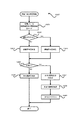
[主制御メイン処理]
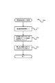
次に、図10〜図36に基づいて遊技制御用マイコン81の動作(主制御部80による制御処理)について説明する。尚、遊技制御用マイコン81の動作説明にて登場するカウンタ、フラグ、ステータス、バッファ等は、主制御基板80のRAMに設けられている。主制御基板80に備えられた遊技制御用マイコン81は、パチンコ遊技機1の電源がオンされると、主制御基板80のROMから図10に示す主制御メイン処理のプログラムを読み出して実行する。同図に示すように、主制御メイン処理では、まず、初期設定を行う(S101)。初期設定では、例えば、スタックの設定、定数設定、割り込み時間の設定、主制御基板80のCPUの設定、SIO、PIO、CTC(割り込み時間用コントローラ)の設定や、各種のフラグ、ステータス及びカウンタのリセット等を行う。フラグの初期値は「0」つまり「OFF」であり、ステータスの初期値は「1」であり、カウンタの初期値は「0」である。初期設定(S101)は、電源投入後に一度だけ実行され、それ以降は実行されない。
[Main control main processing]
Next, the operation of the game control microcomputer 81 (control processing by the main control unit 80) will be described with reference to FIGS. Note that the counter, flag, status, buffer, and the like that appear in the description of the operation of the
初期設定(S101)に次いで、割り込みを禁止し(S102)、普通図柄・特別図柄主要乱数更新処理(S103)を実行する。この普通図柄・特別図柄主要乱数更新処理(S103)では、図7に示した種々の乱数カウンタの値を1加算する更新を行う。各乱数カウンタの値は上限値に至ると「0」に戻って再び加算される。尚、各乱数カウンタの初期値は「0」以外の値であってもよく、ランダムに変更されるものであってもよい。更新された乱数カウンタ値は主制御基板80のRAMの所定の更新値記憶領域(図示せず)に逐次記憶される。
Subsequent to the initial setting (S101), interrupts are prohibited (S102), and normal symbol / special symbol main random number update processing (S103) is executed. In this normal symbol / special symbol main random number update process (S103), the value of the various random number counters shown in FIG. When the value of each random number counter reaches the upper limit value, it returns to “0” and is added again. The initial value of each random number counter may be a value other than “0” or may be changed randomly. The updated random number counter value is sequentially stored in a predetermined update value storage area (not shown) of the RAM of the
普通図柄・特別図柄主要乱数更新処理(S103)が終了すると、割り込みを許可する(S104)。割り込み許可中は、割り込み処理(S105)の実行が可能となる。この割り込み処理(S105)は、例えば4ms周期で主制御基板80のCPUに繰り返し入力される割り込みパルスに基づいて実行される。そして、割り込み処理(S105)が終了してから、次に割り込み処理(S105)が開始されるまでの間に、普通図柄・特別図柄主要乱数更新処理(S103)による各種カウンタ値の更新処理が繰り返し実行される。尚、割り込み禁止状態のときにCPUに割り込みパルスが入力された場合は、割り込み処理(S105)はすぐには開始されず、割り込み許可(S104)がされてから開始される。
When the normal symbol / special symbol main random number update process (S103) is completed, the interruption is permitted (S104). While the interrupt is permitted, the interrupt process (S105) can be executed. This interrupt process (S105) is executed based on an interrupt pulse repeatedly input to the CPU of the
[割り込み処理]
次に、割り込み処理(S105)について説明する。図11に示すように、割り込み処理(S105)では、まず、出力処理(S201)を実行する。出力処理(S201)では、以下に説明する各処理において主制御基板80のRAMに設けられた出力バッファにセットされたコマンド(制御信号)等を、サブ制御基板90や払出制御基板110等に出力する。ここで出力するコマンド等には、遊技状態、特別図柄当否判定の結果、大当り種別としての図柄、変動パターン等に関する情報等が挙げられる。尚、コマンドは、例えば2バイトの情報からなる。上位1バイトは、コマンドの種類に関する情報であり、下位1バイトはコマンドの内容に関する情報である。
[Interrupt processing]
Next, the interrupt process (S105) will be described. As shown in FIG. 11, in the interrupt process (S105), first, an output process (S201) is executed. In the output process (S201), commands (control signals) set in the output buffer provided in the RAM of the
出力処理(S201)に次いで行われる入力処理(S202)では、主にパチンコ遊技機1に取り付けられている各種センサ(第1始動口センサ20a、第2始動口センサ21a、第1大入賞口センサ30a、第2大入賞口センサ35a等(図5を参照))が検知した検知信号を読み込み、賞球情報としてRAMの出力バッファに記憶する。また、下皿62の満杯を検知する下皿満杯検知センサ(図示せず)からの検知信号も取り込み、下皿満杯データとしてRAMの出力バッファに記憶する。
In the input process (S202) performed after the output process (S201), various sensors (a first
次に行われる普通図柄・特別図柄主要乱数更新処理(S203)は、図10の主制御メイン処理で行う普通図柄・特別図柄主要乱数更新処理(S103)と同じである。即ち、図7に示した各種乱数カウンタ値(普通図柄乱数カウンタ値も含む)の更新処理は、タイマ割り込み処理(S105)の実行期間と、それ以外の期間(割り込み処理(S105)の終了後、次の割り込み処理(S105)が開始されるまでの期間)との両方で行われている。 The normal symbol / special symbol main random number update process (S203) performed next is the same as the normal symbol / special symbol main random number update process (S103) performed in the main control main process of FIG. That is, the update processing of various random number counter values (including normal symbol random number counter values) shown in FIG. 7 includes the execution period of the timer interrupt process (S105) and the other period (after the end of the interrupt process (S105), The period until the next interrupt process (S105) is started).
普通図柄・特別図柄主要乱数更新処理(S203)に次いで、後述する始動口センサ検知処理(S204)、始動入球時処理(S205)、普図動作処理(S206)、特図動作処理(S207)、保留球数処理(S208)および電源断監視処理(S209)を実行する。その後、本発明に深く関連しないその他の処理(S210)を実行して、割り込み処理(S105)を終了する。そして、次に主制御基板80のCPUに割り込みパルスが入力されるまでは主制御メイン処理のS102〜S104の処理が繰り返し実行され(図10を参照)、割り込みパルスが入力されると(約4ms後)、再び割り込み処理(S105)が実行される。再び実行された割り込み処理(S105)の出力処理(S201)においては、前回の割り込み処理(S105)にてRAMの出力バッファにセットされたコマンド等が出力される。
Following normal symbol / special symbol main random number update processing (S203), starting port sensor detection processing (S204), starting ball entering processing (S205), general drawing motion processing (S206), special symbol motion processing (S207) Then, the reserved ball number processing (S208) and the power-off monitoring processing (S209) are executed. Thereafter, other processing (S210) not closely related to the present invention is executed, and the interrupt processing (S105) is terminated. Then, until the next interrupt pulse is input to the CPU of the
[始動口センサ検知処理]
図12に示すように、始動口センサ検知処理(S204)では、まず、遊技球がゲート28を通過したか否か、即ち、ゲートセンサ28aによって遊技球が検知されたか否かを判定する(S301)。遊技球がゲート28を通過していなければ(S301でNO)、S305の処理に移行し、ゲート28を遊技球が通過していれば(S301でYES)、普通図柄保留球数(普図保留の数、具体的にはRAMに設けた普図保留の数をカウントするカウンタの値)が4未満であるか否か判定する(S302)。
[Starting port sensor detection processing]
As shown in FIG. 12, in the start port sensor detection process (S204), first, it is determined whether or not the game ball has passed through the
普通図柄保留球数が4未満でなければ(S302でNO)、S305の処理に移行する。一方、普通図柄保留球数が4未満であれば(S302でYES)、普通図柄保留球数に「1」を加算し(S303)、普通図柄乱数取得処理(S304)を行う。普通図柄乱数取得処理(S304)では、RAMの更新値記憶領域(図示せず)に記憶されている普通図柄当否判定用乱数カウンタの値(ラベル−TRND−H、図7(B))を取得し、その取得乱数値(取得情報)を、主制御基板80のRAMに設けられた普図保留記憶部のうち現在の普通図柄保留球数に応じたアドレス空間に格納する。
If the number of normal symbol reserved balls is not less than 4 (NO in S302), the process proceeds to S305. On the other hand, if the number of normal symbol reserved balls is less than 4 (YES in S302), “1” is added to the number of normal symbol reserved balls (S303), and the normal symbol random number acquisition process (S304) is performed. In the normal symbol random number acquisition process (S304), the value (label -TRND-H, Fig. 7 (B)) of the random symbol counter for determining whether or not the symbol is normal is stored in the update value storage area (not shown) of the RAM. Then, the obtained random number value (acquired information) is stored in an address space corresponding to the current number of normal symbol reserved balls in the general symbol reserved storage unit provided in the RAM of the
S305では、第2始動口21に遊技球が入球したか否か、即ち、第2始動口センサ21aによって遊技球が検知されたか否かを判定する(S305)。第2始動口21に遊技球が入球していない場合(S305でNO)には、S309の処理に移行し、第2始動口21に遊技球が入球した場合には(S305でYES)、特図2保留球数(第2特図保留の数、具体的には主制御部80のRAMに設けた第2特図保留の数をカウントするカウンタの数値)が4(上限数)未満であるか否か判定する(S306)。そして、特図2保留球数が4未満でない場合(S306でNO)には、S309の処理に移行し、特図2保留球数が4未満である場合には(S306でYES)、特図2保留球数に1を加算する(S307)。
In S305, it is determined whether or not a game ball has entered the second start port 21, that is, whether or not a game ball has been detected by the second
続いて特図2関係乱数取得処理(S308)を行う。特図2関係乱数取得処理(S308)では、RAMの更新値記憶領域(図示せず)に記憶されている特別図柄当否判定用乱数カウンタの値(ラベル−TRND−A)、大当り種別決定用乱数カウンタの値(ラベル−TRND−AS)及び変動パターン乱数カウンタの値(ラベル−TRND−T1)を取得し(つまり図7(A)に示す乱数の値を取得し)、それら取得乱数値(取得情報)を第2特図保留記憶部85bのうち現在の特図2保留球数に応じたアドレス空間に格納する。 Subsequently, special figure 2 related random number acquisition processing (S308) is performed. In the special figure 2 related random number acquisition process (S308), the value of the random symbol counter for determining whether or not the special symbol is stored in the update value storage area (not shown) of the RAM (label -TRND-A), the random number for determining the jackpot type The counter value (label-TRND-AS) and the fluctuation pattern random number counter value (label-TRND-T1) are acquired (that is, the random number value shown in FIG. 7A is acquired), and the acquired random value (acquired) Information) is stored in the address space corresponding to the current number of reserved special figure 2 balls in the second special figure reservation storage unit 85b.
続いて第1始動口20に遊技球が入球したか否か、即ち、第1始動口センサ20aによって遊技球が検知されたか否かを判定する(S309)。第1始動口20に遊技球が入球していない場合(S309でNO)には処理を終えるが、第1始動口20に遊技球が入球した場合には(S309でYES)、特図1保留球数(第1特図保留の数、具体的には主制御部80のRAMに設けた第1特図保留の数をカウントするカウンタの数値)が4(上限数)未満であるか否か判定する(S310)。そして、特図1保留球数が4未満でない場合(S310でNO)には、処理を終えるが、特図1保留球数が4未満である場合には(S310でYES)、特図1保留球数に「1」を加算する(S311)。
Subsequently, it is determined whether or not a game ball has entered the
続いて特図1関係乱数取得処理(S312)を行う。特図1関係乱数取得処理(S312)では、特図2関係乱数取得処理(S308)と同様に、RAMの更新値記憶領域(図示せず)に記憶されている特別図柄当否判定用カウンタの値(ラベル−TRND−A)、大当り種別決定用乱数カウンタの値(ラベル−TRND−AS)および変動パターン乱数カウンタの値(ラベル−TRND−T1)を取得し(つまり図7(A)に示す乱数値を取得し)、それら取得乱数値を第1特図保留記憶部のうち現在の特図1保留球数に応じたアドレス空間に格納する。 Subsequently, special figure 1 related random number acquisition processing (S312) is performed. In the special figure 1 related random number acquisition process (S312), as in the special figure 2 related random number acquisition process (S308), the value of the special symbol success / failure determination counter stored in the update value storage area (not shown) of the RAM. (Label-TRND-A), the value of the jackpot type determination random number counter (Label-TRND-AS), and the value of the fluctuation pattern random number counter (Label-TRND-T1) are obtained (that is, the disturbance shown in FIG. 7A). A numerical value is acquired), and these acquired random number values are stored in an address space corresponding to the current number of reserved figure 1 reserved balls in the first figure reserved storage unit.
[始動入球時処理]
図11に示すように遊技制御用マイコン81は、始動口センサ検知処理(S204)に次いで始動入球時処理(S205)を行う。図13に示すように、始動入球時処理(S205)では、まず、特図2保留球数が「1」増加したか否かを判定する(S315)。そして、特図2保留球数が「1」増加したと判定した場合(S315でYES)、S316の処理に移行する。これは、第2始動口に遊技球が入球したことに基づいて、始動口センサ検知処理(S204)におけるS307で特図2保留球数に「1」を加算した場合が該当する。一方、特図2保留球数が増加していないと判定した場合(S315でNO)、S319の処理に移行する。
[Processing at start-up]
As shown in FIG. 11, the
S316では、直前の始動口センサ検知処理(S204)における特図2関係乱数取得処理(S308)で取得して第2特図保留記憶部に記憶した最新の取得乱数値(取得情報)を読み出す(S316)。次いで、読み出した第2特別図柄に係る取得乱数値を判定する(S317)。S317では、読み出した取得乱数値のうち、特別図柄当否判定用乱数カウンタの値(特別図柄当否判定用乱数値)については、現在の遊技状態(低確率状態か高確率状態か)に応じて大当りか外れかを判定し、当該判定の結果が大当りである場合には、さらに大当りの種別を判定する。このS317による判定は、特図2保留についての当否判定(大当りか否かの判定)を、後述の特図2当否判定処理(S1202)における当否判定(S1303,S1304)に先立って行う事前判定(所謂「保留先読み」)に相当するものである。 In S316, the latest acquired random value (acquired information) acquired in the special figure 2 related random number acquisition process (S308) in the immediately preceding start port sensor detection process (S204) and stored in the second special figure reservation storage unit is read ( S316). Next, the acquired random number value related to the read second special symbol is determined (S317). In S317, the value of the random number counter for special symbol success / failure determination (random number value for special symbol success / failure determination) among the acquired random number values read out is a big hit according to the current gaming state (low probability state or high probability state) If the result of the determination is a big hit, the type of the big hit is further determined. In this determination by S317, a prior determination (S1303, S1304) is performed prior to the determination (S1303, S1304) in the special figure 2 determination process (S1202) described later. This corresponds to so-called “hold prefetching”).
尚、大当りか否かの事前判定は、大当り判定テーブル(図8(A)を参照)、すなわち、高確率状態であれば高確率状態用の大当り判定テーブル、通常状態(低確率状態)であれば通常状態用の大当り判定テーブルに基づいて、大当り判定値と一致するか否かを判定することが可能である。また、他の事前判定態様として、変動パターン情報を判定可能な変動パターン情報判定テーブルとして、通常状態用(低確率状態用)の変動パターン情報判定テーブルと、高確率状態用(高確率状態用)の変動パターン情報判定テーブルと、を有するものとする。そして、事前判定においては、取得乱数値(特別図柄当否判定用乱数カウンタの値等)と、遊技状態に応じた変動パターン情報判定テーブルと、に基づいて、所定の変動パターン情報を選択するものとすることが可能である。そして、この選択した変動パターン情報から、大当りかどうかや大当り種別、大当り信頼度の高い遊技演出が実行されるかどうか等を識別可能とすることができる。 It should be noted that the prior determination as to whether or not the jackpot is a jackpot determination table (see FIG. 8A), that is, a jackpot determination table for a high probability state if it is a high probability state, a normal state (low probability state). For example, it is possible to determine whether or not it matches the jackpot determination value based on the jackpot determination table for the normal state. In addition, as another prior determination mode, as a variation pattern information determination table capable of determining variation pattern information, a variation pattern information determination table for a normal state (for a low probability state) and a high probability state (for a high probability state) And a variation pattern information determination table. In advance determination, predetermined variation pattern information is selected based on an acquired random number value (a value of a random symbol counter for special symbol success / failure determination and the like) and a variation pattern information determination table corresponding to the gaming state. Is possible. Then, from the selected variation pattern information, it is possible to identify whether it is a big hit, a big hit type, a game effect with a high big hit reliability, or the like.
次いでS318では、S317による事前判定の結果に係る遊技情報(事前判定情報)、具体的には、特別図柄当否判定用乱数値が大当り判定値と一致するか否かを示す情報(当否情報)や、大当り種別決定用乱数カウンタの値(大当り種別決定用乱数値)を示す情報、変動パターン乱数カウンタの値(変動パターン乱数値)を示す情報等を含むコマンドデータを、特図2始動入球コマンドとして生成し、当該コマンドをRAMの出力バッファにセットする(S318)。尚、特図2始動入球コマンドとして、S316で読み出した特図2取得乱数の値の一部または全部を、そのままサブ制御基板に送信するようにしてもよいし、特図2取得乱数の値はそのまま送信せず、特図2取得乱数の値に基づいて取得した遊技情報(例えば、前述の変動パターン情報等)を送信するようにしてもよい。 Next, in S318, game information (preliminary determination information) related to the result of the preliminary determination in S317, specifically, information (whether or not information) indicating whether or not the random number value for determining whether or not the special symbol matches the jackpot determination value, Command data including information indicating the value of the jackpot type determining random number counter (random number for determining the jackpot type), information indicating the value of the fluctuation pattern random number counter (fluctuation pattern random number value), etc. And the command is set in the output buffer of the RAM (S318). It should be noted that as the special figure 2 start entering command, a part or all of the special figure 2 acquisition random number value read in S316 may be transmitted to the sub-control board as it is, or the special figure 2 acquisition random number value. The game information acquired based on the value of the special figure 2 acquisition random number (for example, the above-described variation pattern information) may be transmitted without transmitting as it is.
また、主制御部80から送信した特図2始動入球コマンドをサブ制御部90で解析することで、大当りに係る情報であるかどうか、大当り種別は何れであるか、変動パターンは何れであるか等を、サブ制御部90が識別できるものとされている。また、本実施例では、これに加えて、特図2始動入球コマンドを解析することで、取得した特図2取得乱数が高確率状態で判定した場合に大当りとなるかどうか、及び低確率状態で判定した場合に大当りとなるかどうか、を特定可能とされている。これにより、サブ制御部90は、受信した特図2始動入球コマンドを保留(演出保留情報)として記憶し、特定のタイミングで当該演出保留情報を事前判定し、低確率状態で当否判定した場合に大当りと判定される演出保留情報が記憶されているかどうかを判定することが可能となる。
In addition, the
尚、不正防止の観点から、S316で読み出した取得乱数値のうち特別図柄当否判定用乱数値を、そのままサブ制御部に送信することはせず、その他の大当り種別決定用乱数カウンタの値(大当り種別決定用乱数値)と変動パターン乱数カウンタの値(変動パターン乱数値)を示す情報と、事前判定の結果を示す情報とを含むコマンドデータを特図2始動入球コマンドとして生成し、これをセットすることが可能である。 For the purpose of preventing fraud, the random number value for determining whether or not the special symbol is determined is not directly transmitted to the sub-control unit among the acquired random number values read out in S316, and the value of the random number counter for determining the other big hit type (big hit value) The command data including the information indicating the type determination random number) and the variation pattern random number counter value (variation pattern random value) and the information indicating the result of the preliminary determination is generated as a special figure 2 start entry command. It is possible to set.
次いでS319では、前述の特図2に係る処理と同様に、特図1保留球数が「1」増加したか否かを判定する(S319)。そして、特図1保留球数が「1」増加したと判定した場合(S319でYES)、S320の処理に移行する。これは、第1始動口に遊技球が入球したことに基づいて、始動口センサ検知処理(S204)におけるS311で特図1保留球数に「1」を加算した場合が該当する。一方、S319で、特図1保留球数が増加していないと判定した場合(S319でNO)、そのまま処理を終える。 Next, in S319, it is determined whether or not the number of reserved balls in the special figure 1 has increased by “1” in the same manner as the process related to the special figure 2 described above (S319). If it is determined that the number of reserved balls in Special Figure 1 has increased by “1” (YES in S319), the process proceeds to S320. This corresponds to the case where “1” is added to the number of reserved balls in FIG. 1 in S311 in the start port sensor detection process (S204) based on the game ball entering the first start port. On the other hand, if it is determined in S319 that the number of reserved balls in Special Figure 1 has not increased (NO in S319), the process ends.
S320では、時短フラグがONであるか否かを判定し(S320)、時短フラグがONである、すなわち高ベース状態であると判定した場合(S320でYES)、そのまま処理を終える。一方、S320で時短フラグがOFFである、すなわち低ベース状態であると判定した場合(S320でNO)、S321以降の事前判定に係る処理に進む。ここで、時短フラグがONである場合、すなわち現在の遊技状態が高ベース状態である場合、第2始動口21への入球頻度が高まる開放延長機能が作動しており、特図2の当否判定(図8(B)を参照)が行われやすい状態となっている。また、本実施例では、後述するように特図2保留の消化(第2特別図柄の変動表示)を特図1保留の消化(第1特別図柄の変動表示)に優先して実行するもの(所謂特図2優先変動機)としている。このような構成において、例えば、特図1の事前判定を行い、その結果を予告等の演出により遊技者に報知し、その事前判定の結果が大当りであることが明示された場合、遊技者は、特図2保留消化の優先を利用して、任意のタイミングで特図2保留を意図的に無くして(「0」にして)、事前判定の結果が示された特図1に係る大当りを意図的に発生させるといった技術介入が可能となる。このように大当りの発生タイミングを遊技者が調整できることは、遊技の公平性の観点から好ましくない。このため、現在の遊技状態が低ベース状態でなく高ベース状態である場合には(S320でYES)、S321以降の特図1の事前判定に係る処理を行わず、本処理を終えることとしている。 In S320, it is determined whether or not the time reduction flag is ON (S320). If it is determined that the time reduction flag is ON, that is, it is in the high base state (YES in S320), the processing is ended as it is. On the other hand, if it is determined in S320 that the time reduction flag is OFF, that is, it is in the low base state (NO in S320), the process proceeds to the process related to the prior determination after S321. Here, when the time reduction flag is ON, that is, when the current gaming state is a high base state, the opening extension function that increases the frequency of entering the second start port 21 is activated, and whether or not the special figure 2 is successful or not. The determination (see FIG. 8B) is easily performed. Further, in this embodiment, as will be described later, the special figure 2 reserved digest (change display of the second special symbol) is executed in preference to the special figure 1 reserved digest (variable display of the first special symbol) ( The so-called special figure 2 priority variation machine). In such a configuration, for example, when the preliminary determination of FIG. 1 is performed, the result is notified to the player by an effect such as a notice, and it is clearly indicated that the result of the preliminary determination is a big hit, By using the priority of special figure 2 reserve digestion, special figure 2 hold is intentionally lost at any timing (set to “0”), and the jackpot related to special figure 1 in which the result of the prior determination is shown is Technical intervention such as intentional generation is possible. It is not preferable from the viewpoint of the fairness of the game that the player can adjust the occurrence timing of the big hit in this way. For this reason, when the current gaming state is not the low base state but the high base state (YES in S320), the process is terminated without performing the process related to the prior determination in FIG. .
S321〜S323の処理は、前述したS316〜S318と同様の処理を特図1について行うものである。すなわち、始動口センサ検知処理(S204)における特図1関係乱数取得処理(S312)で取得して第1特図保留記憶部に記憶した最新の取得乱数値(取得情報)を読み出し(S321)、読み出した取得乱数値について事前判定を行う(S322)。そして、この事前判定に係る遊技情報を含むコマンドデータを特図1始動入球コマンドとして生成し、当該コマンドをRAMの出力バッファにセットする(S323)。尚、S322の事前判定(保留先読み)は、後述の特図1当否判定処理(S1207)における当否判定(S1603,S1604)に先立って行うものである。 The processing of S321 to S323 is the same processing as that of S316 to S318 described above with reference to FIG. That is, the latest acquired random number value (acquired information) acquired in the special figure 1 related random number acquisition process (S312) in the start port sensor detection process (S204) and stored in the first special figure reservation storage unit is read (S321), Pre-determination is performed on the read acquired random number value (S322). Then, command data including game information related to this pre-determination is generated as a special FIG. 1 start entering command, and the command is set in the RAM output buffer (S323). The prior determination (holding prefetching) in S322 is performed prior to the determination (S1603, S1604) in the special figure 1 determination process (S1207) described later.
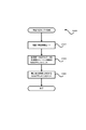
[普図動作処理]
遊技制御用マイコン81は、始動入球時処理(S205)に次いで、図14に示す普図動作処理(S206)を行う。普図動作処理(S206)では、普通図柄表示器42及び可変入賞装置22に関する処理を4つの段階に分け、それらの各段階に「普図動作ステータス1、2、3、4」を割り当てている。そして、「普図動作ステータス」が「1」である場合には(S401でYES)、普通図柄待機処理(S402)を行い、「普図動作ステータス」が「2」である場合には(S401でNO、S403でYES)、普通図柄変動中処理(S404)を行い、「普図動作ステータス」が「3」である場合には(S401、S403で共にNO、S405でYES)、普通図柄確定処理(S406)を行い、「普図動作ステータス」が「4」である場合には(S401、S403、S405の全てがNO)、普通電動役物処理(S407)を行う。尚、普図動作ステータスは、初期設定では「1」である。
[Usuzu movement process]
The
[普通図柄待機処理]
図15に示すように、普通図柄待機処理(S402)では、まず、普通図柄の保留球数が「0」であるか否かを判定し(S501)、「0」であれば(S501でYES)、この処理を終える。一方「0」でなければ(S501でNO)、後述の普通図柄当否判定処理を行い(S502)、次いで、普通図柄変動パターン選択処理を行う(S503)。普通図柄変動パターン選択処理では、図8(D)に示す普通図柄変動パターン選択テーブルを参照して、遊技状態が時短状態であれば、普通図柄の変動時間が1秒の普通図柄変動パターンを選択する。一方、遊技状態が非時短状態であれば、普通図柄の変動時間が30秒の普通図柄変動パターンを選択する。普通図柄変動パターン選択処理(S503)を終えたら、後述の普通図柄乱数シフト処理(S504)を行い、次いで、普通図柄変動開始処理(S505)を行い、処理を終える。普通図柄変動開始処理では、S503で選択した普通図柄変動パターンに基づいて普通図柄の変動表示を開始するとともに、普通動作ステータスを「2」にセットする。また、普通図柄変動開始処理では、サブ制御基板90に普通図柄の変動開始を知らせるため、普通図柄変動開始コマンドをセットする。
[Normal symbol standby processing]
As shown in FIG. 15, in the normal symbol standby process (S402), first, it is determined whether or not the number of reserved balls of the normal symbol is “0” (S501), and if it is “0” (YES in S501). ) And finish this process. On the other hand, if it is not “0” (NO in S501), a normal symbol success / failure determination process described later is performed (S502), and then a normal symbol variation pattern selection process is performed (S503). In the normal symbol variation pattern selection process, with reference to the ordinary symbol variation pattern selection table shown in FIG. 8 (D), if the gaming state is a short-time state, the ordinary symbol variation pattern with a 1 second variation time is selected. To do. On the other hand, if the gaming state is a non-time-short state, the normal symbol variation pattern with the normal symbol variation time of 30 seconds is selected. When the normal symbol variation pattern selection processing (S503) is completed, a normal symbol random number shift processing (S504) described later is performed, then a normal symbol variation start processing (S505) is performed, and the processing ends. In the normal symbol variation start process, the normal symbol variation display is started based on the normal symbol variation pattern selected in S503, and the normal operation status is set to “2”. In the normal symbol variation start process, a normal symbol variation start command is set in order to notify the
[普通図柄当否判定処理]
図16に示すように、普通図柄当否判定処理(S502)では、まず、普図保留記憶部に格納されている普通図柄当否判定用乱数カウンタの値(ラベル−TRND−H)を読み出す(S601)。次いで、時短フラグがONであるか否か(すなわち遊技状態が時短状態であるか否か)を判定する(S602)。S602で、時短フラグがONである、すなわち時短状態であると判定した場合(S602でYES)、図8(C)に示す普通図柄当り判定テーブルのうち時短状態用のテーブル(当り判定値が「0」〜「239」)に基づく高確率普図当否判定により、当りか否かを判定し(S604)、S605の処理に移行する。すなわち、読み出した普通図柄当否判定用乱数カウンタの値(ラベル−TRND−H)が当り判定値の何れかと一致するか否かを判定する。一方、S602で、時短フラグがONでない、すなわち、非時短状態であると判定した場合(S602でNO)、図8(C)に示す普通図柄当り判定テーブルのうち非時短状態用のテーブル(当り判定値が「0」、「1」)に基づく低確率普図当否判定により、当りか否かを判定し(S603)、S605の処理に移行する。そして、S605で、普図当否判定(S603、S604)の結果が、当り(普図当り)であるか否かを判定し(S605)、外れと判定された場合(S605でNO)、停止表示する外れ普通図柄(普図外れ図柄)を決定し(S606)、処理を終える。一方、S605で当り(普図当り)と判定された場合(S605でYES)、停止表示する当り普通図柄(普図当り図柄)を決定し(S607)、普図当りフラグをONにして(S608)、処理を終える。
[Normal symbol success / failure determination processing]
As shown in FIG. 16, in the normal symbol success / failure determination process (S502), first, the value (label -TRND-H) of the normal symbol success / failure determination random number counter stored in the general symbol hold storage unit is read (S601). . Next, it is determined whether or not the time reduction flag is ON (that is, whether or not the gaming state is a time reduction state) (S602). If it is determined in S602 that the time reduction flag is ON, that is, it is in the time reduction state (YES in S602), the table for the time reduction state (the hit determination value is “0” in the normal symbol hit determination table shown in FIG. 8C). 0 ”to“ 239 ”), it is determined whether or not the winning is based on the high-probability normal figure determination (S604), and the process proceeds to S605. That is, it is determined whether or not the value of the read random number counter for normal symbol appropriateness determination (label-TRND-H) matches any of the hit determination values. On the other hand, if it is determined in S602 that the time reduction flag is not ON, that is, it is in the non-time reduction state (NO in S602), the table for the non-time reduction state in the normal symbol determination table shown in FIG. It is determined whether or not it is a hit based on the low-probability normal-winning determination based on the determination values “0” and “1”) (S603), and the process proceeds to S605. Then, in S605, it is determined whether or not the result of the normal map win / fail determination (S603, S604) is a win (per normal map) (S605), and if it is determined to be out (NO in S605), a stop display is made. The normal symbol to be removed (ordinary symbol) is determined (S606), and the process ends. On the other hand, when it is determined that the winning (per normal map) is determined in S605 (YES in S605), the normal symbol per display to be stopped (per symbol in the general pattern) is determined (S607), and the per-normal symbol flag is turned ON (S608). ) Finish the process.
[普通図柄乱数シフト処理]
図17に示すように、普通図柄乱数シフト処理(S504)では、まず、普通図柄保留球数を1ディクリメントする(S701)。次いで、普図保留記憶部における各普図保留の格納場所を、現在の位置から読み出される側に一つシフトする(S702)。そして、普図保留記憶部における最上位の保留記憶の格納場所であるアドレス空間を空(「0」)にして、即ち普図保留の4個目に対応するRAM領域を0クリアして(S703)、処理を終える。このようにして、普図保留が保留順に消化されるようにしている。
[Normal design random number shift processing]
As shown in FIG. 17, in the normal symbol random number shift process (S504), first, the normal symbol holding ball number is decremented by 1 (S701). Next, the storage location of each general map hold in the general map storage unit is shifted by one to the side read from the current position (S702). Then, the address space, which is the storage location of the highest-order reserved storage in the ordinary figure storage area, is emptied (“0”), that is, the RAM area corresponding to the fourth ordinary figure storage area is cleared to 0 (S703). ) Finish the process. In this way, ordinary map suspension is digested in order of suspension.
[普通図柄変動中処理]
図18に示すように、普通図柄変動中処理(S404)では、まず、普通図柄の変動時間が経過したか否か判定し(S801)、経過していなければ(S801でNO)、処理を終える。一方、経過していれば(S801でYES)、普通図柄変動停止コマンドをセットする(S802)とともに、普図動作ステータスを「3」にセットする(S803)。そして、普通図柄の変動表示を、普通図柄当否判定用乱数の判定結果に応じた表示結果(当り普通図柄又は外れ普通図柄)で停止させる等のその他の処理を行って(S804)、この処理を終える。
[Normal symbol change processing]
As shown in FIG. 18, in the normal symbol changing process (S404), first, it is determined whether or not the normal symbol change time has passed (S801), and if it has not passed (NO in S801), the process ends. . On the other hand, if it has elapsed (YES in S801), the normal symbol fluctuation stop command is set (S802) and the normal symbol operation status is set to “3” (S803). Then, other processing such as stopping the normal symbol fluctuation display with the display result (winning normal symbol or off-normal symbol) according to the determination result of the random number for normal symbol success / failure determination is performed (S804). Finish.
[普通図柄確定処理]
図19に示すように、普通図柄確定処理(S406)では、まず、普図当りフラグがONであるか否かを判定する(S901)。普図当りフラグがONでなければ(S901でNO)、普図動作ステータスを「1」にセットして(S905)、この処理を終える。一方、普図当りフラグがONであれば(S901でYES)、続いて時短フラグがONであるか否か、すなわち時短状態中か否かを判定する(S902)。そして、時短状態中であれば(S902でYES)、可変入賞装置22(第2始動口21)の開放パターンとして時短状態中の開放パターンをセットする(S903)。時短状態中の開放パターンとは、前述の通り、2.0秒の開放を3回繰り返す開放パターンである。従って、第2始動口21の開放回数をカウントする第2始動口開放カウンタに「3」をセットする。
[Normal symbol confirmation processing]
As shown in FIG. 19, in the normal symbol determination process (S406), it is first determined whether or not the universal symbol flag is ON (S901). If the ordinary figure hit flag is not ON (NO in S901), the ordinary figure operation status is set to "1" (S905), and this process is terminated. On the other hand, if the normal hit flag is ON (YES in S901), it is subsequently determined whether or not the time reduction flag is ON, that is, whether or not the time reduction state is in effect (S902). If it is in the time-short state (YES in S902), the opening pattern in the time-short state is set as the opening pattern of the variable winning device 22 (second starting port 21) (S903). As described above, the release pattern in the short-time state is an release pattern in which the release for 2.0 seconds is repeated three times. Therefore, “3” is set in the second start port opening counter that counts the number of times the second start port 21 is opened.
これに対して、非時短状態中であれば(S902でNO)、可変入賞装置22(第2始動口21)の開放パターンとして非時短状態中の開放パターンをセットする(S906)。非時短状態中の開放パターンとは、前述の通り、0.2秒の開放を1回行う開放パターンである。従って、第2始動口開放カウンタに「1」をセットする。そして、開放パターンのセット(S903、S906)に続いて、普図動作ステータスを「4」にセットし(S904)、この処理を終える。 On the other hand, if it is in the non-short-time state (NO in S902), the open pattern in the non-time-short state is set as the open pattern of the variable winning device 22 (second starting port 21) (S906). The opening pattern in the non-time-short state is an opening pattern in which the opening for 0.2 seconds is performed once as described above. Accordingly, “1” is set in the second start port opening counter. Then, following the setting of the release pattern (S903, S906), the normal operation status is set to “4” (S904), and this process ends.
[普通電動役物処理]
図20に示すように、普通電動役物処理(S407)では、まず、普図当り終了フラグがONであるか否かを判定する(S1001)。普図当り終了フラグは、当りとなって実行された補助遊技において、第2始動口21の開放が終了したことを示すフラグである。
[Normal electric equipment processing]
As shown in FIG. 20, in the ordinary electric accessory processing (S407), first, it is determined whether or not the end-of-common-use flag is ON (S1001). The normal hit end flag is a flag indicating that the opening of the second start port 21 has ended in the auxiliary game executed as a win.
普図当り終了フラグがONでなければ(S1001でNO)、第2始動口21の開放中か否かを判定する(S1002)。開放中でなければ(S1002でNO)、第2始動口21を開放させる時期(タイミング)に至ったか否かを判定し(S1003)、至っていなければ(S1003でNO)、処理を終え、至っていれば(S1003でYES)、第2始動口21を開放させ(S1004)、処理を終える。一方、第2始動口21の開放中であれば(S1002でYES)、第2始動口21を閉鎖させる時期(タイミング)に至ったか否か(すなわち第2始動口21を開放してから予め定められた開放時間が経過したか否か)を判定し(S1005)、至っていなければ(S1005でNO)処理を終え、至っていれば(S1005でYES)、第2始動口21を閉状態(閉鎖)とする(S1006)。 If the normal hit end flag is not ON (NO in S1001), it is determined whether or not the second start port 21 is being opened (S1002). If it is not open (NO in S1002), it is determined whether or not the timing (timing) for opening the second starting port 21 has been reached (S1003). If so (YES in S1003), the second start port 21 is opened (S1004), and the process is terminated. On the other hand, if the second start port 21 is being opened (YES in S1002), it is determined in advance whether or not the timing (timing) for closing the second start port 21 has been reached (that is, after the second start port 21 is opened). (S1005), and if not reached (NO in S1005), the process is finished. If it has reached (YES in S1005), the second start port 21 is closed (closed). ) (S1006).
そして、第2始動口21の閉鎖処理(S1006)に次いで、第2始動口開放カウンタの値を1ディクリメントし(S1007)、第2始動口開放カウンタの値が「0」であるか否か判定する(S1008)。「0」でなければ(S1008でNO)、再び第2始動口21を開放させるためにそのまま処理を終える。一方「0」であれば(S1008でYES)、補助遊技を終了させる普図当り終了処理を行う(S1009)とともに、普図当り終了フラグをセットして(S1010)処理を終える。尚、第2始動口開放カウンタは、時短状態中であれば第2始動口21の開放(可動部材23の開放動作)が3回なされると「0」になり、非時短状態中であれば第2始動口21の開放が1回なされると「0」になる。 Then, following the closing process (S1006) of the second starting port 21, the value of the second starting port opening counter is decremented by 1 (S1007), and whether or not the value of the second starting port opening counter is “0”. Judgment is made (S1008). If it is not “0” (NO in S1008), the process is finished as it is to open the second start port 21 again. On the other hand, if it is “0” (YES in S1008), the base game end process for ending the auxiliary game is performed (S1009), and the base map end flag is set (S1010) to end the process. The second start port opening counter becomes “0” when the second start port 21 is opened (opening operation of the movable member 23) three times when the time is short, and when the second start port is not in the short time state. When the second start port 21 is opened once, it becomes “0”.
これに対して、S1001において普図当り終了フラグがONであれば(S1001でYES)、S903またはS906にてセットされた回数の第2始動口21の開放動作は終了しているので、普図当り終了フラグをOFFにするとともに(S1011)、普図当りフラグをOFFにし(S1012)、普図動作ステータスを「1」にセットして(S1013)処理を終える。これにより、次回の割り込み処理において、図13に示す普図動作処理(S206)として再び普通図柄待機処理(S402)が実行されることになる。 On the other hand, if the end-of-usage flag is ON in S1001 (YES in S1001), the opening operation of the second start port 21 for the number of times set in S903 or S906 has ended. The winning end flag is turned off (S1011), the ordinary figure hitting flag is turned off (S1012), the ordinary figure operation status is set to "1" (S1013), and the process ends. As a result, in the next interrupt process, the normal symbol standby process (S402) is executed again as the normal chart operation process (S206) shown in FIG.
[特図動作処理]
図11に示すように遊技制御用マイコン81は、普図動作処理(S206)に次いで特図動作処理(S207)を行う。特図動作処理(S207)では、図21に示すように、特別図柄表示器41および大入賞装置(第1大入賞装置31および第2大入賞装置36)に関する処理を4つの段階に分け、それらの各段階に「特図動作ステータス1、2、3、4」を割り当てている。そして、「特図動作ステータス」が「1」である場合には(S1101でYES)、特別図柄待機処理(S1102)を行い、「特図動作ステータス」が「2」である場合には(S1101でNO、S1103でYES)、特別図柄変動中処理(S1104)を行い、「特図動作ステータス」が「3」である場合には(S1101、S1103で共にNO、S1105でYES)、特別図柄確定処理(S1106)を行い、「特図動作ステータス」が「4」である場合には(S1101,S1103,S1105の全てがNO)、大当り遊技としての特別電動役物処理(S1107)を行う。尚、特図動作ステータスは、初期設定では「1」である。
[Special figure operation processing]
As shown in FIG. 11, the
[特別図柄待機処理]
図22に示すように、特別図柄待機処理(S1102)では、まず、第2始動口21の保留球数(即ち特図2保留球数)が「0」であるか否かを判定する(S1201)。特図2保留球数が「0」である場合(S1201でYES)、即ち、第2始動口21への入球に起因して取得した乱数カウンタ値の記憶がない場合には、第1始動口20の保留球数(即ち特図1保留球数)が「0」であるか否かを判定する(S1206)。そして、特図1保留球数も「0」である場合(S1206でYES)、即ち、第1始動口20への入球に起因して取得した乱数カウンタ値の記憶もない場合には、画像表示装置7の表示画面7aを待機画面とする処理中(客待ち用のデモ画面の実行中)であるか否かを判定し(S1211)、待機画面とする処理中であれば(S1211でYES)、処理を終え、待機画面とする処理中でなければ(S1211でNO)、待機画面を表示するために待機画面設定処理を実行する(S1212)。
[Special symbol standby processing]
As shown in FIG. 22, in the special symbol standby process (S1102), first, it is determined whether or not the number of reserved balls (that is, the number of reserved figures 2 reserved balls) at the second start port 21 is “0” (S1201). ). Special Figure 2 If the number of reserved balls is “0” (YES in S1201), that is, if there is no memory of the random number counter value obtained due to the ball entering the second start port 21, the first start It is determined whether or not the number of reserved balls in the mouth 20 (that is, the number of reserved balls in Special Figure 1) is “0” (S1206). If the special figure 1 reserved ball number is also “0” (YES in S1206), that is, if there is no storage of the random number counter value acquired due to the ball entering the
待機画面設定処理(S1212)では、特別図柄が変動表示していないことを条件に、待機画面(デモ画面、客待ち画面)の表示開始(客待ち開始)を指示する客待ち開始コマンドをRAMの出力バッファにセットするとともに、客待ち開始コマンドをセット済(送信済み)であることを示す不図示の客待ち開始フラグをONにする。客待ち開始コマンドが出力処理(S201)によってサブ制御基板90に出力(送信)されると、サブ制御基板90(演出制御用マイコン91)が所定のタイミング(例えば、客待ち開始コマンドの受信から所定時間経過)で画像制御基板100(画像制御用マイコン101)に対して待機画面の表示を指示し、これにより画像表示装置7の表示画面7aに待機画面(図示せず)が表示される。ここで、前述のS1211の処理では、この客待ち開始フラグを参照して待機画面とする処理中であるか否かを判定するものとなっており、客待ち開始フラグがONであれば、待機画面とする処理中であると判定する(S1211でYES)。また、待機画面設定処理(S1212)の実行に際し、特図2保留球数および特図1保留球数がともに「0」であっても(S1201でYES、S1206でYES)、未だ特別図柄が変動表示している場合、待機画面設定処理(S1212)では客待ち開始コマンドのセットや客待ちフラグのON設定を行うことなく、そのまま処理を終える。
In the standby screen setting process (S1212), on the condition that the special symbol is not variably displayed, a customer wait start command for instructing display start (customer wait start) of the standby screen (demo screen, customer wait screen) is stored in the RAM. In addition to being set in the output buffer, a customer waiting start flag (not shown) indicating that a customer waiting start command has been set (transmitted) is turned ON. When the customer waiting start command is output (transmitted) to the
S1201において特図2保留球数が「0」でない場合(S1201でNO)、即ち、第2始動口21への入球に起因して取得した乱数カウンタ値の記憶が1つ以上ある場合には、後述の特図2当否判定処理(S1202)、特図2変動パターン選択処理(S1203)、特図2乱数シフト処理(S1204)、特図2変動開始処理(S1205)をこの順に行う。また、特図2保留球数が「0」であるが特図1保留球数が「0」でない場合(S1201でYES、S1206でNO)、即ち、第2始動口21に係る乱数カウンタ値の記憶はないが、第1始動口20への入球に起因して取得した乱数カウンタ値の記憶が1つ以上ある場合には、後述の特図1当否判定処理(S1207)、特図1変動パターン選択処理(S1208)、特図1乱数シフト処理(S1209)、特図1変動開始処理(S1210)をこの順に行う。このように本実施例では、第1特図保留に基づく第1特別図柄の変動表示は、第2特図保留が「0」の場合(S1201でYES)に限って行われる。すなわち第2特図保留の消化(第2特別図柄の変動表示)は、第1特図保留の消化(第1特別図柄の変動表示)に優先して実行される。そして本実施例では、第2特図保留に基づく当否判定の方が、第1特図保留に基づく当否判定よりも、遊技者にとって利益の大きい大当りになりやすくなっている(図8(B))。
In S1201, if the special figure 2 reserved ball number is not “0” (NO in S1201), that is, if there is one or more random number counter values acquired due to the ball entering the second starting port 21 The special figure 2 success / failure determination process (S1202), the special figure 2 fluctuation pattern selection process (S1203), the special figure 2 random number shift process (S1204), and the special figure 2 fluctuation start process (S1205) described later are performed in this order. Also, when the special figure 2 reserved ball number is “0” but the special figure 1 reserved ball number is not “0” (YES in S1201, NO in S1206), that is, the random number counter value related to the second start port 21 If there is one or more random number counter values acquired due to entering the
[特図2当否判定処理]
図23に示すように、特図2当否判定処理(S1202)では、まず、判定値として、RAMの第2特図保留記憶部85bの最下位の領域(即ち第2特図保留の1個目に対応するRAM領域)に記憶されている(最も古い記憶の)特別図柄当否判定用乱数カウンタの値(ラベル−TRND−A)を読み出す(S1301)。次いで、確変フラグがONであるか否か、すなわち高確率状態であるか否かを判定する(S1302)。そして、高確率状態でなければ(S1302でNO)、すなわち通常状態であれば、大当り判定テーブル(図8(A))のうち通常状態用の大当り判定テーブル(大当り判定値が「3」及び「397」)に基づいて当否判定を行う(S1303)。一方、高確率状態であれば(S1302でYES)、大当り判定テーブル(図8(A))のうち高確率状態用の大当り判定テーブルに基づいて当否判定を行う(S1304)。高確率状態用の大当り判定テーブルでは、大当り判定値は、「3」、「53」、「113」、「173」、「227」、「281」、「337」、「397」、「449」、「503」とされている。
[Special Figure 2 Decision Processing]
As shown in FIG. 23, in the special figure 2 success / failure determination process (S1202), first, as the determination value, the lowest area of the second special figure reservation storage unit 85b of the RAM (that is, the first special figure reservation first piece). The value (label-TRND-A) of the special symbol adequacy determination random number counter (the oldest storage) stored in the (RAM area corresponding to) is read (S1301). Next, it is determined whether or not the probability variation flag is ON, that is, whether or not it is in a high probability state (S1302). And if it is not a high probability state (NO in S1302), that is, if it is a normal state, it is a big hit determination table (big hit determination value is “3” and “3” for the normal state in the big hit determination table (FIG. 8A)). 397 "), a determination is made as to whether it is correct (S1303). On the other hand, if the state is a high probability state (YES in S1302), the success / failure determination is performed based on the jackpot determination table for the high probability state in the jackpot determination table (FIG. 8A) (S1304). In the jackpot determination table for the high probability state, the jackpot determination values are “3”, “53”, “113”, “173”, “227”, “281”, “337”, “397”, “449”. , “503”.
大当り判定(S1303,S1304)の結果が「大当り」と判定した場合(S1305でYES)、大当り種別決定用乱数カウンタの値(ラベル−TRND−AS)を読み出して、図8(B)に示す大当り種別判定テーブルに基づいて大当り種別を判定し(S1307)、当該大当り種別決定用乱数の値に基づいて大当り図柄を決定し(S1308)、大当りフラグをONにして(S1309)、処理を終える。一方、大当り判定(S1303、S1304)の結果が「大当り」でないと判定した場合(S1305でNO)、外れ図柄を決定し(S1306)、処理を終える。尚、第1特別図柄に係る当否判定の場合は、第1特別図柄用の大当り種別判定テーブルを用いて大当り種別を判定し、第2特別図柄に係る当否判定の場合は、第2特別図柄用の大当り種別判定テーブルを用いて大当り種別を判定する。ここで、大当り判定(特別図柄当否判定)や大当り種別決定判定を、夫々「判定」といってもよいし、大当り判定を行い何れの大当り図柄となるかを含めて「判定」といってもよい。また、これらの結果を「判定結果」ということもある。 When the result of the big hit determination (S1303, S1304) is “big hit” (YES in S1305), the value of the big hit type determination random number counter (label-TRND-AS) is read and the big hit shown in FIG. The jackpot type is determined based on the type determination table (S1307), the jackpot symbol is determined based on the value of the jackpot type determination random number (S1308), the jackpot flag is turned ON (S1309), and the process ends. On the other hand, if it is determined that the result of the big hit determination (S1303, S1304) is not “big hit” (NO in S1305), the off symbol is determined (S1306), and the process is terminated. In the case of determination of success / failure related to the first special symbol, the jackpot type determination table is determined using the jackpot type determination table for the first special symbol, and in the case of determination of success / failure related to the second special symbol, it is for the second special symbol. The jackpot type is determined using the jackpot type determination table. Here, the jackpot determination (special symbol success / failure determination) and the jackpot type determination determination may be referred to as “determination”, respectively, or may be referred to as “determination” including which jackpot symbol will be obtained by performing the jackpot determination. Good. In addition, these results may be referred to as “determination results”.
ここで、ラウンド表示器45は、2R用ランプ、6R用ランプ、12R用ランプ及び16R用ランプの4個のLEDで構成されている(図4を参照)。そして、例えば2R大当りになると、対応する大当り図柄が確定表示するタイミングで、2R用ランプが点灯表示される。具体的には、「2R▲6△12△16R△」(例えば、▲:点灯、△:消灯とする)の様な表示態様となる。また、6R大当りになると、対応する大当り図柄が確定表示するタイミングで、6R用ランプが点灯表示される。具体的には、「2R△6▲12△16R△」の様な表示態様となる。また、12R大当りになると、対応する大当り図柄が確定表示するタイミングで、12R用ランプが点灯表示される。具体的には、「2R△6△12▲16R△」の様な表示態様となる。また、16R大当りになると、対応する大当り図柄が確定表示するタイミングで、16R用ランプが点灯表示される。具体的には、「2R△6△12△16R▲」の様な表示態様となる。
Here, the
[特図2変動パターン選択処理]
図22に示すように、特別図柄待機処理(S1102)では、特図2当否判定処理(S1202)に次いで、特図2変動パターン選択処理を行う(S1203)。図24及び図25に示すように、特図2変動パターン選択処理(S1203)では、まず、遊技状態が時短状態であるか否か(時短フラグがONであるか否か)を判定する(S1401)。S1401で、時短状態でないと判定した場合(S1401でNO)、すなわち非時短状態であれば、次いで、大当りフラグがONであるか否かを判定する(S1402)。S1402で、大当りフラグがONであると判定した場合(S1402でYES)、非時短状態大当り用テーブル(図9に示す変動パターンテーブルのうち非時短状態かつ大当りに該当する部分)を参照して、変動パターン乱数カウンタ値(ラベル−TRND−T1)に基づいて変動パターンを選択する(S1403)。本実施例では、変動パターンP1〜P3の何れかが選択される。尚、本実施例では、変動パターンが決まれば変動時間も決まるものとされている。次いで、S1404の処理に移行する。
[Special Figure 2 Variation Pattern Selection Processing]
As shown in FIG. 22, in the special symbol standby process (S1102), a special figure 2 variation pattern selection process is performed (S1203) following the special figure 2 determination process (S1202). As shown in FIGS. 24 and 25, in the special figure 2 variation pattern selection process (S1203), first, it is determined whether or not the gaming state is a time-short state (whether or not the time-short flag is ON) (S1401). ). If it is determined in S1401 that the time-short state is not set (NO in S1401), that is, if it is a non-time-short state, it is next determined whether or not the big hit flag is ON (S1402). If it is determined in S1402 that the big hit flag is ON (YES in S1402), refer to the non-time-short state big hit table (the portion corresponding to the non-time-short state and big hit in the variation pattern table shown in FIG. 9) A variation pattern is selected based on the variation pattern random number counter value (label-TRND-T1) (S1403). In this embodiment, any one of the fluctuation patterns P1 to P3 is selected. In this embodiment, if the variation pattern is determined, the variation time is also determined. Next, the process proceeds to S1404.
一方、S1402で、大当りフラグがONでないと判定した場合(S1402でNO)、次いで第2特別図柄の保留数が「1」又は「2」であるか否かを判定する(S1405)。ここでいう保留数とは、本処理により変動パターンを決定している情報も含めた記憶数であるので、保留記憶の数は「1」〜「4」の何れかの値とされる。そして、S1405で、保留数が「1」又は「2」であると判定した場合(S1405でYES)、第1保留数外れ用テーブル(図9に示す変動パターンテーブルのうち非時短状態かつ外れかつ保留球数「1,2」に該当する部分)を参照して、変動パターン乱数カウンタ値(ラベル−TRND−T1)に基づいて変動パターンを選択する(S1406)。本実施例では、変動パターンP4〜P7の何れかが選択される。一方、S1405で、保留数が「1」又は「2」でない、すなわち「3」又は「4」であると判定した場合(S1405でNO)、第2保留数外れ用テーブル(図9に示す変動パターンテーブルのうち非時短状態かつ外れかつ保留球数「3,4」に該当する部分)を参照して、変動パターン乱数カウンタ値(ラベル−TRND−T1)に基づいて変動パターンを選択する(S1407)。本実施例では、変動パターンP8〜P11の何れかが選択される。また、第1保留数外れ用テーブルは、第2保留数外れ用テーブルよりも、比較的長時間の変動時間の変動パターンを選択する可能性が高く設定されている。また、選択可能な最も短時間の変動時間(12000ms)も、第2保留数外れ用テーブルのもの(4000ms)よりも長い時間とされている。 On the other hand, if it is determined in S1402 that the big hit flag is not ON (NO in S1402), it is then determined whether or not the number of reserved special symbols is “1” or “2” (S1405). The reserved number here is the number of memories including the information for which the variation pattern is determined by this processing, so the number of reserved memories is any one of “1” to “4”. If it is determined in S1405 that the number of holds is “1” or “2” (YES in S1405), the first number-of-holds table (in the non-time-short state of the variation pattern table shown in FIG. The variation pattern is selected based on the variation pattern random number counter value (label-TRND-T1) with reference to the number of reserved balls “1, 2” (S1406). In this embodiment, any one of the variation patterns P4 to P7 is selected. On the other hand, if it is determined in S1405 that the number of holds is not “1” or “2”, that is, “3” or “4” (NO in S1405), the second number-of-holds table (the fluctuation shown in FIG. 9) A variation pattern is selected on the basis of the variation pattern random number counter value (label-TRND-T1) with reference to the non-time-short state and out of the pattern table and corresponding to the number of reserved balls “3, 4” (S1407). ). In this embodiment, any one of the variation patterns P8 to P11 is selected. Further, the first reserved number deviation table is set to have a higher possibility of selecting a fluctuation pattern of a relatively long fluctuation time than the second reserved number deviation table. The shortest change time (12000 ms) that can be selected is also set to be longer than that of the second reserved number removal table (4000 ms).
また、S1401で、時短状態であると判定した場合(S1401でYES)、大当りフラグがONであるか否かを判定する(S1408)。S1408で、大当りフラグがONであると判定した場合(S1408でYES)、時短状態大当り用テーブル(図9に示す変動パターンテーブルのうち時短状態かつ大当りに該当する部分)を参照して、変動パターン乱数カウンタ値(ラベル−TRND−T1)に基づいて変動パターンを選択する(S1409)。本実施例では、変動パターンP12〜P14の何れかが選択される。 If it is determined in S1401 that the time is short (YES in S1401), it is determined whether or not the big hit flag is ON (S1408). If it is determined in S1408 that the big hit flag is ON (YES in S1408), the fluctuation pattern is referenced with reference to the short-time state big hit table (the portion corresponding to the short-time state and big hit in the fluctuation pattern table shown in FIG. 9). A variation pattern is selected based on the random number counter value (label-TRND-T1) (S1409). In this embodiment, any one of the variation patterns P12 to P14 is selected.
一方、S1408で、大当りフラグがONでないと判定した場合(S1408でNO)、次いで保留数が「1」であるか否かを判定する(S1410)。ここでいう保留数も前述と同様であり、保留数は「1」〜「4」の何れかの値とされている。S1410で、保留数が「1」であると判定した場合(S1410でYES)、第3保留数外れ用テーブル(図9に示す変動パターンテーブルのうち時短状態かつ外れかつ保留球数「1」に該当する部分)を参照して、変動パターン乱数カウンタ値(ラベル−TRND−T1)に基づいて変動パターンを選択する(S1411)。本実施例では、変動パターンP15〜P18の何れかが選択される。また、S1410で、保留数が「1」でない、すなわち、保留数が「2」〜「4」の何れかであると判定した場合(S1410でNO)、第4保留数外れ用テーブル(図9に示す変動パターンテーブルのうち時短状態かつ外れかつ保留球数「2〜4」に該当する部分)を参照して、変動パターン乱数カウンタ値(ラベル−TRND−T1)に基づいて変動パターンを選択する(S1411)。本実施例では、変動パターンP19〜P22の何れかが選択される。ここで、時短状態でかつ外れの場合に選択される変動パターンは、非時短状態でかつ外れの場合に選択される変動パターンと比較して、短い変動パターンが選択される可能性が高くされている。これは、時短状態において変動時間の短い変動パターンがより多く選択されようにすることで、特図保留の消化スピードを早める(時短中の遊技を迅速に進行させる)ためである。 On the other hand, if it is determined in S1408 that the big hit flag is not ON (NO in S1408), it is then determined whether or not the number of holds is “1” (S1410). The number of reservations here is the same as described above, and the number of reservations is set to one of “1” to “4”. If it is determined in S1410 that the number of holdings is “1” (YES in S1410), the third holding number losing table (in the short time state of the variation pattern table shown in FIG. With reference to the corresponding part), the variation pattern is selected based on the variation pattern random number counter value (label-TRND-T1) (S1411). In this embodiment, any one of the fluctuation patterns P15 to P18 is selected. If it is determined in S1410 that the number of holds is not “1”, that is, the number of holds is any of “2” to “4” (NO in S1410), a fourth table for removing the number of holds (FIG. 9). A variation pattern is selected based on a variation pattern random number counter value (label-TRND-T1) with reference to a time-short state and a deviation and a portion corresponding to the number of reserved balls “2 to 4” in the variation pattern table shown in FIG. (S1411). In this embodiment, any one of the variation patterns P19 to P22 is selected. Here, the variation pattern selected in the short-time state and out-of-phase is more likely to be selected than the variation pattern selected in the non-time-short state and out-of-range. Yes. This is to speed up the digestion of the special figure reservation by making more variation patterns with a short variation time selected in the short-time state (the game in the short-time progresses rapidly).
前述のようにして変動パターンの選択を行った後は、図24に示すその他の処理を行い(S1404)、処理を終える。その他の処理(S1404)では、選択した変動パターンに応じた変動パターン指定コマンドをRAMの出力バッファにセットする等の処理を行う。また、この処理でセットされた変動パターン指定コマンドは、後述の変動開始コマンドに含められて、出力処理(S201)によりサブ制御部90に送信される。
After selecting the variation pattern as described above, other processing shown in FIG. 24 is performed (S1404), and the processing is terminated. In other processing (S1404), processing such as setting a variation pattern designation command corresponding to the selected variation pattern in the output buffer of the RAM is performed. Further, the variation pattern designation command set in this process is included in a variation start command described later, and is transmitted to the
[特図2乱数シフト処理]
図26に示すように、特図2乱数シフト処理(S1204)では、まず、特図2保留球数を1ディクリメントする(S1501)。次いで、第2特図保留記憶部85bにおける各種カウンタ値の格納場所を、1つ下位側(例えば第2特図保留記憶部85bがアドレス「0000」〜「0003」に対応するアドレス空間からなる場合、アドレス「0000」側)にシフトする(S1502)。そして、第2特図保留記憶部85bの最上位のアドレス空間に「0」をセットして、即ち、(上限数まで記憶されていた場合)第2特図保留の4個目に対応するRAM領域を0クリアして(S1503)、この処理を終える。
[Special figure 2 random number shift processing]
As shown in FIG. 26, in the special figure 2 random number shift process (S1204), first, the special figure 2 reserved ball number is decremented by 1 (S1501). Next, the storage location of the various counter values in the second special figure reservation storage unit 85b is one level lower (for example, the second special figure reservation storage unit 85b is composed of an address space corresponding to addresses "0000" to "0003"). , The address “0000” side) (S1502). Then, “0” is set in the uppermost address space of the second special figure holding storage unit 85b, that is, the RAM corresponding to the fourth special figure holding fourth (when the upper limit number is stored). The area is cleared to 0 (S1503), and this process ends.
特図2乱数シフト処理(S1204)を実行した後は、図22に示す特図2変動開始処理(S1205)を実行する。特図2変動開始処理(S1205)では、特図動作ステータスを「2」にセットすると共に、変動開始コマンドをRAMの出力バッファにセットして、第2特別図柄の変動表示を開始する。 After executing the special figure 2 random number shift process (S1204), the special figure 2 fluctuation start process (S1205) shown in FIG. 22 is executed. In the special figure 2 fluctuation start process (S1205), the special figure operation status is set to "2" and a fluctuation start command is set in the output buffer of the RAM to start the fluctuation display of the second special symbol.
図22の特別図柄待機処理(S1102)において、特図2保留球数が「0」であり、かつ、特図1保留球数が「0」でない場合(S1201でYES、S1206でNO)には、特図1当否判定処理(S1207)、特図1変動パターン選択処理(S1208)、特図1乱数シフト処理(S1209)、特図1変動開始処理(S1210)をこの順に行う。 In the special symbol waiting process (S1102) of FIG. 22, when the special figure 2 reserved ball number is “0” and the special figure 1 reserved ball number is not “0” (YES in S1201 and NO in S1206). The special figure 1 determination process (S1207), the special figure 1 fluctuation pattern selection process (S1208), the special figure 1 random number shift process (S1209), and the special figure 1 fluctuation start process (S1210) are performed in this order.
[特図1当否判定処理]
図27に示すように、特図1当否判定処理(S1207)では、図23に示した特図2当否判定処理(S1202)と同様の流れで処理(S1601〜S1609)を行う。従って、本処理の詳細な説明は省略する。但し、本処理は特図1に関する処理であるので、S1601では、RAMの第1特図保留記憶部85aの最下位の領域(即ち第1特図保留の1個目に対応するRAM領域)に記憶されている特別図柄当否判定用乱数カウンタ値(ラベル−TRND−A)を読み出して処理を行う。
[Special Figure 1 Win / Fail Decision Processing]
As shown in FIG. 27, in the special figure 1 success / failure determination process (S1207), the process (S1601 to S1609) is performed in the same flow as the special figure 2 success / failure determination process (S1202) shown in FIG. Therefore, detailed description of this process is omitted. However, since this process is related to the special figure 1, in S1601, the lowermost area of the first special figure reservation storage unit 85a of the RAM (ie, the RAM area corresponding to the first special figure reservation) is stored. The stored special symbol success / failure random number counter value (label-TRND-A) is read and processed.
[特図1変動パターン選択処理]
図28及び図29に示すように、特図1変動パターン選択処理(S1208)では、図24及び図25に示した特図2変動パターン選択処理(S1403)と同様の流れで処理(S1701〜S1712)を行う。従って本処理の詳細な説明は省略する。
[Special Figure 1 Variation Pattern Selection Processing]
As shown in FIGS. 28 and 29, in the special figure 1 fluctuation pattern selection process (S1208), the process (S1701 to S1712) is performed in the same flow as the special figure 2 fluctuation pattern selection process (S1403) shown in FIGS. )I do. Therefore, detailed description of this process is omitted.
[特図1乱数シフト処理]
図30に示すように、特図1乱数シフト処理(S1209)では、まず、特図1保留球数を1ディクリメントする(S1801)。次いで、第1特図保留記憶部における各種カウンタ値の格納場所を、1つ下位側にシフトする(S2002)。そして、第1特図保留記憶部の最上位のアドレス空間に「0」をセットして、即ち、(上限数まで記憶されていた場合)第1特図保留の4個目に対応するRAM領域を0クリアして(S1803)、この処理を終える。
[Special Figure 1 Random Number Shift Processing]
As shown in FIG. 30, in the special figure 1 random number shift process (S1209), first, the special figure 1 reserved ball number is decremented by 1 (S1801). Next, the storage location of the various counter values in the first special figure reservation storage unit is shifted down by one (S2002). Then, “0” is set in the highest address space of the first special figure reservation storage unit, that is, the RAM area corresponding to the fourth special figure reservation (when the maximum number is stored). Is cleared to 0 (S1803), and this process ends.
特図1乱数シフト処理(S1209)を実行した後は、図22に示す特図1変動開始処理(S1210)を実行する。特図1変動開始処理(S1210)では、特図動作ステータスを「2」にセットすると共に、変動開始コマンドをRAMの出力バッファにセットして、第1特別図柄の変動表示を開始する。 After executing the special figure 1 random number shift process (S1209), the special figure 1 fluctuation start process (S1210) shown in FIG. 22 is executed. In the special figure 1 fluctuation start process (S1210), the special figure operation status is set to "2" and a fluctuation start command is set in the output buffer of the RAM to start the fluctuation display of the first special symbol.
[特別図柄変動中処理]
図31に示すように、特別図柄変動中処理(S1104)では、まず、特別図柄の変動時間(図22のS1203又はS1208で選択された変動パターンに応じて決まる変動時間、図9を参照)が経過したか否かを判定する(S1901)。変動時間が経過していないと判定した場合(S1901でNO)、処理を終える。これにより特別図柄の変動表示が継続される。
[Special symbol change processing]
As shown in FIG. 31, in the special symbol variation processing (S1104), first, the variation time of the special symbol (variation time determined according to the variation pattern selected in S1203 or S1208 of FIG. 22, see FIG. 9). It is determined whether or not it has passed (S1901). If it is determined that the fluctuation time has not elapsed (NO in S1901), the process ends. Thereby, the variable display of the special symbol is continued.
一方、変動時間が経過したと判定した場合(S1901でYES)、変動停止コマンドをセットする(S1902)。そして、確変フラグがONであるか否か判定し(S1903)、ONであれば(S1903でYES)、確変カウンタを1減算し(S1904)、確変カウンタの値が「0」であるか否かを判定する(S1905)。S1905で確変カウンタが「0」であると判定した場合、確変フラグをOFFし、S1907の処理に移行する。一方、確変フラグがONでないと判定した場合と(S1903でNO)、確変カウンタが「0」でないと判定した場合には(S1905でNO)、S1907の処理に移行する。 On the other hand, if it is determined that the fluctuation time has elapsed (YES in S1901), a fluctuation stop command is set (S1902). Then, it is determined whether or not the probability variation flag is ON (S1903). If it is ON (YES in S1903), the probability variation counter is decremented by 1 (S1904), and whether or not the value of the probability variation counter is “0”. Is determined (S1905). If it is determined in S1905 that the probability variation counter is “0”, the probability variation flag is turned OFF, and the process proceeds to S1907. On the other hand, when it is determined that the probability variation flag is not ON (NO in S1903) and when it is determined that the probability variation counter is not “0” (NO in S1905), the process proceeds to S1907.
そしてS1907では、時短フラグがONであるか否かを判定し(S1907)、時短フラグがONであると判定した場合(S1907でYES)、時短状態中に実行した特別図柄の変動表示回数をカウントする時短カウンタの値を1減算し(S1908)、時短カウンタの値が「0」であるか否かを判定し(S1909)、「0」であれば(S1909でYES)、時短フラグをOFFにし(S1910)、S1911の処理に進む。また、時短フラグがONでないと判定した場合と(S1907でNO)時短カウンタの値が「0」でないと判定した場合には(S1909でNO)、S1911の処理に移行する。 Then, in S1907, it is determined whether or not the time reduction flag is ON (S1907). If it is determined that the time reduction flag is ON (YES in S1907), the number of times the special symbol is changed during the time reduction state is counted. 1 is subtracted from the value of the hour / hour counter (S1908), and it is determined whether or not the value of the hour / hour counter is “0” (S1909). (S1910), the process proceeds to S1911. If it is determined that the time reduction flag is not ON (NO in S1907) and if the value of the time reduction counter is not “0” (NO in S1909), the process proceeds to S1911.
S1911では、特図動作ステータスを「3」にセットする(S1911)。そして、特別図柄の変動表示を、特別図柄当否判定乱数及び大当り種別決定用乱数の判定結果に応じた結果で停止させる等のその他の処理を行い(S1912)、この処理を終える。 In S1911, the special figure operation status is set to “3” (S1911). Then, other processing such as stopping the special symbol variation display at a result corresponding to the determination result of the special symbol success / failure determination random number and the jackpot type determination random number is performed (S1912), and this processing is ended.
[特別図柄確定処理]
図32に示すように、特別図柄確定処理(S1106)では、まず、大当りフラグがONであるか否かを判定する(S2001)。大当りフラグがONであれば(S2001でYES)、次いで確定した大当りの種別が16R大当りであるか否かを判定し、16R大当りであると判定した場合(S2002でYES)、大当り遊技中に実行するラウンドの回数をカウントするラウンドカウンタの値に「16」をセットし(S2003)、S2009の処理に移行する。一方、S2002で、大当りの種別が16R大当りでないと判定した場合(S2002でNO)、確定した大当りの種別が12R大当りであるか否かを判定し(S2004)、12R大当りであると判定した場合(S2004でYES)、ラウンドカウンタの値に「12」をセットし(S2005)、S2009の処理に移行する。一方、S2004で、大当り種別が12R大当りでないと判定した場合(S2004でNO)、確定した大当りの種別が6R大当りであるか否かを判定し(S2006)、6R大当りであると判定した場合(S2006でYES)、ラウンドカウンタの値に「6」をセットし(S2007)、S2009の処理に移行する。一方、S2006で、大当りの種別が6R大当りでないと判定した場合(S2006でNO)、確定した大当りの種別は2R大当りであるため、ラウンドカウンタの値に「2」をセットし(S2008)、S2009の処理に移行する。
[Special symbol confirmation processing]
As shown in FIG. 32, in the special symbol confirmation process (S1106), it is first determined whether or not the big hit flag is ON (S2001). If the jackpot flag is ON (YES in S2001), it is then determined whether the determined jackpot type is a 16R jackpot, and if it is determined to be a 16R jackpot (YES in S2002), it is executed during the jackpot game. “16” is set to the value of the round counter for counting the number of rounds to be performed (S2003), and the process proceeds to S2009. On the other hand, if it is determined in S2002 that the type of jackpot is not 16R jackpot (NO in S2002), it is determined whether the determined jackpot type is 12R jackpot (S2004), and it is determined that it is 12R jackpot (YES in S2004), the value of the round counter is set to “12” (S2005), and the process proceeds to S2009. On the other hand, if it is determined in S2004 that the jackpot type is not 12R jackpot (NO in S2004), it is determined whether the confirmed jackpot type is 6R jackpot (S2006), and it is determined that it is 6R jackpot ( YES in S2006), the value of the round counter is set to “6” (S2007), and the process proceeds to S2009. On the other hand, if it is determined in S2006 that the type of jackpot is not 6R jackpot (NO in S2006), since the confirmed jackpot type is 2R jackpot, “2” is set to the value of the round counter (S2008), S2009 Move on to processing.
S2009では、確定した大当りの種別(種類)に応じた大入賞口開放パターンをセットし(S2009)、S2010の処理に移行する。ここで、前述したように、大入賞口の開放パターンは、大当りの種別に応じて定められているので、今回確定した大当りに対応する大入賞口開放パターンをセットする(図6を参照)。そして、夫々の大当り遊技において、S2009でセットした大入賞口開放パターンに基づく大入賞口(第1大入賞口30又は第2大入賞口35)の開放動作が実行される。
In S2009, a big winning opening opening pattern is set according to the determined type of jackpot (type) (S2009), and the process proceeds to S2010. Here, as described above, since the opening pattern of the big winning opening is determined according to the type of the big hit, the big winning opening opening pattern corresponding to the big hit determined this time is set (see FIG. 6). Then, in each of the big hit games, the opening operation of the big winning opening (the first big winning
S2010では、大当り遊技を開始するべく、大当りのオープニングコマンドをセットする(S2010)。本実施例では、オープニングコマンドとして、16R第1大当りに対応する第1オープニングコマンド、6R第2〜第5大当りに対応する第2オープニングコマンド、16R第6大当りに対応する第3オープニングコマンド、RUB(16R第7大当り、12R第8大当り、6R第9大当り)に対応する第4オープニングコマンド、2R大当り(2R第10大当り、2R第12大当り)に対応する第5オープニングコマンドおよび16R第11大当り(実質10R大当り)に対応する第6オープニングコマンドの計6種類が設けられている。S2010では、今回確定した大当り(開始する大当り)の種別に応じたオープニングコマンドがセットされる。そして、主制御部80(遊技制御用マイコン81)は、セットしたオープニングコマンドを、出力処理(S201)により、所定のタイミングでサブ制御部90に対して送信し、当該オープニングコマンドを受信したサブ制御部90は、当該オープニングコマンドに基づいて所定の遊技演出の実行処理を行う。
In S2010, a jackpot opening command is set to start the jackpot game (S2010). In this embodiment, as the opening command, the first opening command corresponding to the 16R first big hit, the second opening command corresponding to the 6R second to fifth big hits, the third opening command corresponding to the 16R sixth big hit, RUB ( 4R opening command corresponding to
オープニングコマンドをセットしたら、大当り遊技のオープニング期間を開始し(S2011)、特図動作ステータスを「4」にセットする(S2012)。また、S2001において大当りフラグがONでないと判定した場合(S2001でNO)、特図動作ステータスを「1」にセットし(S2013)、処理を終える。尚、オープニング期間は、大当り遊技における大入賞口の最初の開放動作を開始する前であって、特別図柄(演出図柄)の変動表示を実行不能とした後に設定される期間であり、「開始期間」ともいう。また、この「開始期間」において実行する演出を「開始演出(オープニング演出)」ともいう。本実施例では、確定した大当りの種別と、その大当りが確定したとき(つまり、大当り図柄が停止表示されたとき)の遊技状態とによって、オープニング期間(オープニング時間)が決まるものとなっており、前述のオープニングコマンドによってオープニング期間が特定可能となっている。よって、オープニングコマンドを受信したサブ制御部90は、当該オープニングコマンドにより特定される大当り種別およびオープニング期間に基づいて、オープニング演出を行うことが可能となっている。
If the opening command is set, the opening period of the jackpot game is started (S2011), and the special figure operation status is set to “4” (S2012). If it is determined in S2001 that the big hit flag is not ON (NO in S2001), the special figure operation status is set to "1" (S2013), and the process is terminated. The opening period is a period that is set before the first opening operation of the big prize winning game in the jackpot game is started, and after the change display of the special symbol (direction symbol) is disabled. Also called. In addition, the effect executed in the “start period” is also referred to as “start effect (opening effect)”. In this embodiment, the opening period (opening time) is determined according to the type of jackpot determined and the gaming state when the jackpot is confirmed (that is, when the jackpot symbol is stopped and displayed) The opening period can be specified by the above-described opening command. Therefore, the
[特別電動役物処理(大当り遊技処理)]
図33に示すように、特別電動役物処理(S1107)ではまず、確変フラグがONであるか否かを判定し(S2101)、確変フラグがONであると判定した場合(S2101でYES)、確変フラグをOFFにし(S2102)、次いで、時短フラグがONであるか否かを判定する(S2103)。S2103で、時短フラグがONであると判定した場合(S2103でYES)、時短フラグをOFFにし(S2104)、S2105の処理に移行する。尚、S2101で確変フラグがONでないと判定した場合(S2101でNO)、S2102の処理を行うことなくS2103の処理に進み、S2103で時短フラグがONでないと判定した場合(S2103でNO)、S2104の処理を行うことなくS2105の処理に進む。つまり、大当り遊技の実行中は、低確率状態かつ非時短状態に制御される。本実施例では、非時短状態中は常に低ベース状態であるので、大当り遊技の実行中は低ベース状態に制御されることにもなる。
[Special electric equipment processing (big hit game processing)]
As shown in FIG. 33, in the special electric accessory processing (S1107), first, it is determined whether or not the probability variation flag is ON (S2101). If it is determined that the probability variation flag is ON (YES in S2101), The probability variation flag is turned OFF (S2102), and then it is determined whether or not the time reduction flag is ON (S2103). If it is determined in S2103 that the time reduction flag is ON (YES in S2103), the time reduction flag is turned OFF (S2104), and the process proceeds to S2105. If it is determined in S2101 that the probability variation flag is not ON (NO in S2101), the process proceeds to S2103 without performing the process in S2102. If it is determined in S2103 that the time reduction flag is not ON (NO in S2103), S2104 The process proceeds to S2105 without performing the process. In other words, during the execution of the big hit game, the low probability state and the non-time-short state are controlled. In the present embodiment, since the low base state is always in the non-time saving state, the low base state is also controlled during the execution of the big hit game.
次に、大当り終了フラグがONであるか否かを判定する(S2105)。大当り終了フラグは、大当り遊技において大入賞装置(第1大入賞装置31および第2大入賞装置36)の開放処理が全て終了(大当り遊技が終了)したことを示すフラグである。大当り終了フラグがONでなければ(S2105でNO)、次いでラウンドの開始時期であるか否かを判定する(S2106)。これは、前述した大当り種別毎に設定した大入賞口開放パターンに基づいて判定する。例えば、1ラウンド目の開始前であれば、オープニング期間が終了して1ラウンド目の最初の開放処理を実行するタイミングであるか否かによって判定する。また、既に1ラウンド目を開始した後であれば、前のラウンドが終了し、かつ、所定のインターバル期間が終了している否かによって判定する。
Next, it is determined whether or not the big hit end flag is ON (S2105). The jackpot end flag is a flag indicating that all the opening processes of the big winning devices (the first big winning
S2106で、ラウンド開始時期であると判定した場合(S2106でYES)、対応するラウンドのラウンド開始コマンドをセットし(S2107)、大入賞口開放処理を行う(S2108)。これにより、大入賞口(第1大入賞口30又は第2大入賞口35)が開放状態となり所定のラウンドが開始することとなる。尚、S2107では、1ラウンド目の開始であれば「1R開始コマンド」、2ラウンド目の開始であれば「2R開始コマンド」のように、開始するラウンドを特定可能なラウンド開始コマンドがセットされる。セットされたラウンド開始コマンドは、S201の出力処理により、サブ制御部90に送信される。S2108の大入賞口開放処理では、実行される大当りの種別に応じて定められた大入賞口開放パターン、すなわち、前述のS2009でセットした大入賞口開放パターンに基づいて大入賞口(第1大入賞口30又は第2大入賞口35)を開放させるべく、開閉部材を動作(開動作)させる。
If it is determined in S2106 that it is the time to start a round (YES in S2106), a round start command for the corresponding round is set (S2107), and a big prize opening process is performed (S2108). As a result, the grand prize opening (the first
一方、S2106で、ラウンド開始時期でないと判定した場合(S2106でNO)、S2112の処理に移行する。ここで、ラウンド開始時期でないと判定する場合として、例えば、1ラウンド開始前のオープニング期間中やラウンド遊技中、ラウンド遊技終了後のインターバル期間中(大入賞口閉鎖処理中)等を挙げることができる。 On the other hand, if it is determined in S2106 that it is not the round start time (NO in S2106), the process proceeds to S2112. Here, as a case where it is determined that it is not the start time of the round, for example, during the opening period before the start of one round, during the round game, during the interval period after the end of the round game (during the big prize closing process), etc. can be mentioned. .
S2112では、大入賞口開放動作の実行中であるか否か、すなわち、S2108の処理によって開放された大入賞口が未だ開放中(ラウンド遊技中)であるか否かを判定する(S2112)。その結果、大入賞口開放動作の実行中(ラウンド遊技中)でないと判定した場合(S2112でNO)、S2116の処理に移行し、大入賞口開放動作の実行中(ラウンド遊技中)であると判定した場合(S2112でYES)、実行中のラウンド遊技の終了条件(ラウンド終了条件)が成立したか否かを判定する(S2113)。 In S2112, it is determined whether or not the big winning opening releasing operation is being executed, that is, whether or not the big winning opening opened by the processing of S2108 is still open (during round game) (S2112). As a result, if it is determined that the big prize opening operation is not being executed (in round game) (NO in S2112), the process proceeds to S2116, and the big prize opening operation is being executed (in round game). If it is determined (YES in S2112), it is determined whether or not the end condition (round end condition) of the currently executed round game is satisfied (S2113).
ここで、本実施例のラウンド終了条件として、(1)実行中のラウンド遊技において定められた大入賞口の開放時間(例えば、25s)、つまりラウンド遊技の実行時間が経過したこと、(2)実行中のラウンド遊技において大入賞口に予め定められた規定数(例えば、10球)の遊技球が入球したこと、の2つの条件が定められている。そして、何れか一方の条件が成立すると、当該先に成立した条件に基づいてラウンド終了条件が成立したこととなる。S2113で、ラウンド終了条件が成立していないと判定した場合(S2113でNO)、処理を終える。 Here, as the conditions for ending the round in this embodiment, (1) the opening time of the big prize opening determined in the round game being executed (for example, 25 s), that is, the execution time of the round game has elapsed, (2) Two conditions are defined, that a predetermined number (for example, 10 balls) of game balls have entered the big prize opening in the round game being executed. When either one of the conditions is satisfied, the round end condition is satisfied based on the previously satisfied condition. If it is determined in S2113 that the round end condition is not satisfied (NO in S2113), the process ends.
一方、S2113で、ラウンド終了条件が成立したと判定した場合(S2113でYES)、対応するラウンドのラウンド終了コマンドをセットし(S2114)、S2115の処理に移行する。S2114では、1ラウンド目の終了であれば「1R終了コマンド」、2ラウンド目の終了であれば「2R終了コマンド」のように、終了するラウンドを特定可能なラウンド終了コマンドがセットされる。セットされたラウンド終了コマンドは、S201の出力処理により、サブ制御部90に送信される。
On the other hand, if it is determined in S2113 that the round end condition is satisfied (YES in S2113), a round end command for the corresponding round is set (S2114), and the process proceeds to S2115. In S2114, a round end command capable of specifying a round to be ended is set, such as “1R end command” if the end of the first round and “2R end command” if the end of the second round. The set round end command is transmitted to the
S2115では、大入賞口閉鎖処理を行い(S2115)、大入賞口(第1大入賞口30又は第2大入賞口35)の開閉部材を動作(閉動作)させて、大入賞口(第1大入賞口30又は第2大入賞口35)を閉鎖状態とする。また、大入賞口閉鎖処理では、大入賞口(第1大入賞口30又は第2大入賞口35)を閉鎖状態に保つ閉鎖時間、すなわちインターバル時間をセットする。次いで、S2116でインターバル時間が経過したか否かを判定し(S2116)、経過していない(インターバル期間中である)と判定した場合(S2116でNO)、処理を終える。一方、S2116でインターバル時間が経過したと判定した場合(S2116でYES)、ラウンドカウンタの値を1ディクリメントし(S2117)、ラウンドカウンタの値が「0」であるか否かを判定する(S2118)。S2118で、ラウンドカウンタの値が「0」でないと判定した場合(S2118でNO)、処理を終える。一方、ラウンドカウンタの値が「0」であると判定した場合(S2118でYES)、大当り遊技を終了させる大当り終了処理として、大当りのエンディングコマンドをセットすると共に(S2119)、大当りのエンディング期間を開始し(S2120)、大当り終了フラグをONにし(S2121)、処理を終える。尚、ラウンドカウンタの値は、実行する大当り遊技における全てのラウンド遊技を終了すると「0」になる。
In S2115, a special prize opening closing process is performed (S2115), and the opening / closing member of the special prize opening (the first
S2119では、予め定められた複数のエンディングコマンドの中から、今回の大当り発生時の遊技状態や今回の大当りの種別、大当り遊技後の遊技状態等に応じたエンディングコマンドが選択され、当該選択されたコマンドがセットされる。こうしてセットされるエンディングコマンドの種類によって、実行される(設定される)エンディング期間(エンディング時間)が決まるものとなっている。エンディング期間は、大当り遊技における大入賞口(第1大入賞口30および第2大入賞口35)の全ての開放動作を終了した後であって、特別図柄(演出図柄)の変動表示を実行可能とする前に設定される期間であり、「終了期間」ともいう。エンディング期間(終了期間)では、第1大入賞口30および第2大入賞口35は閉鎖状態とされている。この「終了期間」に実行する演出を「終了演出(エンディング演出)」ともいう。
In S2119, an ending command is selected from a plurality of predetermined ending commands according to the gaming state at the time of the big hit, the type of the big hit, the gaming state after the big hit, and the like. A command is set. The ending period (ending time) to be executed (set) is determined by the type of ending command set in this way. During the ending period, after all the opening operations of the big prize opening (first
そして、主制御部80(遊技制御用マイコン81)は、S2119でセットしたエンディングコマンドを、出力処理(S201)により、所定のタイミングでサブ制御部90に対して送信し、当該エンディングコマンドを受信したサブ制御部90は、当該エンディングコマンドに基づいて所定のエンディング演出の実行処理を行う。
Then, the main control unit 80 (game control microcomputer 81) transmits the ending command set in S2119 to the
また、S2105において、大当り終了フラグがONであると判定した場合(S2105でYES)、大当り遊技における最終ラウンドが終了しているので、大当りのエンディング時間が経過したか否か、すなわち、前述のS2120の処理で開始したエンディング期間の終了タイミングか否かを判定し(S2122)、エンディング時間が経過していないと判定した場合(S2122でNO)、処理を終える。一方、エンディング時間が経過したと判定した場合(S2122でYES)、大当り終了フラグをOFFにし(S2123)、後述する遊技状態設定処理(S2124)を行う。次いで、大当りフラグをOFFにし(S2125)、特図動作ステータスを「1」にセットし(S2126)、処理を終える。これにより、次回の割り込み処理において、図21に示す特図動作処理(S207)として再び特別図柄待機処理(S1102)が実行されることになる。尚、以上の特別電動役物処理(S1108)を実行する遊技制御用マイコン81は、「特別遊技実行手段」として機能するものといえる。
If it is determined in S2105 that the big hit end flag is ON (YES in S2105), the final round in the big hit game has ended. It is determined whether it is the end timing of the ending period started in the process (S2122). If it is determined that the ending time has not elapsed (NO in S2122), the process ends. On the other hand, if it is determined that the ending time has elapsed (YES in S2122), the big hit end flag is turned OFF (S2123), and a game state setting process (S2124) described later is performed. Next, the big hit flag is turned off (S2125), the special figure operation status is set to "1" (S2126), and the process is terminated. Thereby, in the next interrupt process, the special symbol standby process (S1102) is executed again as the special figure operation process (S207) shown in FIG. It can be said that the
[遊技状態設定処理]
図34に示すように、遊技状態設定処理(S2124)ではまず、今回終了した大当り遊技が確変大当りに係るものであるか否かを判定する(S2201)。本実施例では、前述したように、16R第1大当り、6R第2大当り、16R第6大当り、16R第7大当り、12R第8大当り、6R第9大当りおよび2R第10大当りの7種類を確変大当りとしていることから、S2201では、それら7種類のうちの何れかに該当するか否かを判定する。そして、今回終了したのが確変大当りであると判定した場合(S2201でYES)、確変フラグをONにするとともに(S2202)、確変カウンタに「10,000」をセットし(S2203)、さらに時短フラグをONにするとともに(S2204)、時短カウンタに「10,000」をセットして(S2205)、処理を終える。
[Game state setting process]
As shown in FIG. 34, in the game state setting process (S2124), it is first determined whether or not the big hit game that has ended this time is related to a probable big hit (S2201). In this embodiment, as described above, 7 types of
ここで、確変カウンタにセットする値は、高確率における特別図柄当否判定を実行可能な回数である。本実施例においてセットする「10,000」という値(10,000回)は、高確率状態における大当り確率や遊技店の1日の営業時間、当該営業時間内に実行可能な特図当否判定の回数等を考慮すると、実質的には次回の大当りが発生するまで又は営業時間が終了するまで、高確率状態を保証しているのと同じことである。従って、遊技状態が高確率状態に設定された場合には、次回の大当りが発生するまで高確率状態が保証されるといってもよい(実質的に同義である)。また、確変フラグがONの場合には、時短カウンタにも同様に「10,000」がセットされるため、この高確率状態が設定されている間、時短状態(開放延長状態)も共に設定されるといってよい。尚、本実施例の様に、確変カウンタおよび時短カウンタに「10,000」の値を設定して、実質的に次回大当りまで高確高ベース状態を設定するようにしてもよいし、確変フラグおよび時短フラグがONの場合には、カウンタに値をセットすることなく、次回大当りが発生するまで高確高ベース状態を設定する様な制御を採用してもよい。 Here, the value set in the probability variation counter is the number of times that the special symbol success / failure determination with high probability can be executed. The value of “10,000” (10,000 times) set in the present embodiment is a jackpot probability in a high probability state, a business day of a game shop, a special figure determination judgment that can be executed within the business time. Considering the number of times, it is substantially the same as guaranteeing a high-probability state until the next big hit or the business hours end. Therefore, when the gaming state is set to a high probability state, it may be said that the high probability state is guaranteed until the next big hit occurs (substantially synonymous). In addition, when the probability variation flag is ON, “10,000” is similarly set to the hour / hour counter, so both the hour / short state (open extended state) are set while this high probability state is set. It can be said that. As in this embodiment, the value of “10,000” may be set to the probability variation counter and the hourly time counter, and the high accuracy and high base state may be set substantially until the next big hit. When the hour / short flag is ON, a control that sets the high-accuracy base state until the next big hit occurs may be employed without setting a value in the counter.
一方、S2201で、確変大当りでないと判定した場合(S2201でNO)、すなわち、今回終了したのが非確変大当り(通常大当り)に係る大当り遊技である場合、確変フラグをONにすることなく、時短フラグをONにするとともに(S2206)、時短カウンタに「100」をセットして(S2207)、処理を終える。本実施例では、前述したように、6R第3〜第5大当り、16R第11大当り(実質10R大当り)および2R第12大当りの5種類を非確変大当りとしているので、これら5種類のうちの何れかに係る大当り遊技が終了すると、遊技状態が、低確率状態かつ時短状態かつ高ベース状態(すなわち低確高ベース状態)となる。この低確高ベース状態は、特別図柄の変動表示が100回行われること(特別図柄当否判定が100回行われること)、及び次の大当りが発生すること、の何れかの条件の成立により終了する。尚、時短カウンタおよび確変カウンタは、第1特別図柄の変動表示回数と第2特別図柄の変動表示回数とを合算した回数を計数するものである。 On the other hand, if it is determined in S2201 that it is not a probable big hit (NO in S2201), that is, if it is a big hit game related to a non-probable big hit (normal big hit), the time is shortened without turning on the probability variable flag. The flag is turned ON (S2206), and the time reduction counter is set to “100” (S2207), and the process is terminated. In this embodiment, as described above, the 6R third to fifth big hits, the 16R 11th big hit (substantial 10R big hit), and the 2R 12th big hit are non-probable big hits. When the big hit game is over, the gaming state becomes a low probability state, a short time state, and a high base state (that is, a low probability high base state). This low-accuracy base state is terminated when one of the following conditions is met: special symbol variation display is performed 100 times (special symbol success / failure determination is performed 100 times) and the next big hit occurs. To do. The time reduction counter and the probability variation counter count the number of times that the number of fluctuation displays of the first special symbol and the number of fluctuation displays of the second special symbol are added together.
[保留球数処理]
図11に示すように遊技制御用マイコン81は、特図動作処理(S207)に次いで、保留球数処理(S208)を行う。図35に示すように、保留球数処理(S208)では、まず、主制御基板80のRAMに記憶されている特図1保留球数、特図2保留球数および普通図柄保留球数を読み出す(S2501)。次いで、その保留球数のデータ(その保留球数情報をサブ制御基板90等に送信するための保留球数コマンド)を、RAMの出力バッファにセットする(S2502)。この保留球数に係るデータ(保留球数コマンド)は、次回の割り込み処理(S105)での出力処理(S201)によって出力され、割り込み処理毎に、保留球数に係るデータ(保留球数コマンド)の出力バッファへのセット(S2502)と、出力処理(S201)とが順次行われる。当該保留球数コマンドを受信したサブ制御部90は、受信した保留球数コマンドに基づいて特図保留球数に増減が生じたと判断した場合、これに応じて、画像表示装置7の表示画面7aにおける演出保留表示領域(第1演出保留表示領域9c、第2演出保留表示領域9d)の表示内容を更新する。具体的には、例えば、特図1保留球数が「3」から「4」に1増加した場合、その増加した分の特図1保留球数「4」に対応する第1演出保留9aを第1演出保留表示領域9cに追加表示する。また、特図1保留球数が「2」から「1」に1減少した場合(つまり、第1特図保留が消化された場合)、第1演出保留表示領域9cの左端(特図1保留球数「1」に対応する箇所、図3を参照)に表示されている第1演出保留9aを当該変動保留表示領域9e(図3を参照)に移動するとともに、これに伴って第1演出保留表示領域9cに表示されている第1演出保留9aを左側に1つ移動(シフト)する。
[Reserved ball count processing]
As shown in FIG. 11, the
尚、特図保留球数が加算された際の特図保留球数のデータ、すなわち始動入球(始動入賞)の発生に伴う特図保留球数のデータについては、前述の始動入球コマンドに含めるか、加算後(始動入球後)の特図保留球数を示す保留球数コマンドを始動入球コマンドとともに出力バッファにセットするものとしてもよい。また、特図保留球数が減算された際の保留球数のデータ、すなわち特別図柄の変動開始(特図保留の消化)に伴う特図保留球数のデータについては、前述の変動開始コマンドに含めるか、減算後(特図保留消化後)の特図保留球数を示す保留球数コマンドを変動開始コマンドとともに出力バッファにセットするものとしてもよい。 For the data on the number of special figure reservation balls when the number of special figure reservation balls is added, that is, the data on the number of special figure reservation balls associated with the occurrence of a start entry (start prize), the start entry command described above is used. It is good also as what sets the reservation ball number command which shows the number of special figure reservation balls after addition or after addition (after start entry) to an output buffer with a start entry command. In addition, for the data on the number of reserved balls when the number of reserved special figure balls is subtracted, that is, the data on the number of special figure reserved balls accompanying the start of fluctuation of special symbols (digestion of special figure hold), the above-mentioned change start command is used. It is good also as what sets the reservation ball number command which shows the number of special figure reservation balls after inclusion or after subtraction (after special figure reservation digestion) with a change start command to an output buffer.
[電源断監視処理]
図11に示すように、遊技制御用マイコン81は、保留球数処理(S208)に次いで電源断監視処理(S209)を行う。図36に示すように、電源断監視処理(S209)では、まず、電源断信号の入力の有無を判定し(S2601)、入力がなければ(S2601でNO)、処理を終了する。一方、電源断信号の入力があれば(S2601でYES)、現在の遊技機の状態(確変か否か、当り遊技中か否か、保留球数はいくつか、確変・時短の残り変動回数はいくつか等)に関するデータをRAMに記憶するとともに(S2602)、電源断フラグをONにし(S2603)、その後は割り込み処理(S105)に戻ることなくループ処理をする。
[Power-off monitoring processing]
As shown in FIG. 11, the
[サブ制御メイン処理]
次に、図37〜図45に基づいて、演出制御用マイコン91の動作(サブ制御部90による制御処理)について説明する。尚、演出制御用マイコン91の動作説明にて登場するカウンタ、フラグ、ステータス、バッファ、タイマ等は、サブ制御基板90(サブ制御部)のRAMに設けられている。サブ制御基板90に備えられた演出制御用マイコン91は、パチンコ遊技機1の電源がオンされると、サブ制御基板90のROMから図37に示すサブ制御メイン処理のプログラムを読み出して実行する。同図に示すように、サブ制御メイン処理では、まず、CPU初期化処理を行う(S4001)。CPU初期化処理(S4001)では、スタックの設定、定数設定、CPU92の設定、SIO、PIO、CTC(割り込み時間用コントローラ)等の設定や各種のフラグ、ステータス及びカウンタのリセット等を行う。
[Sub control main processing]
Next, the operation of the effect control microcomputer 91 (control processing by the sub control unit 90) will be described with reference to FIGS. Note that the counter, flag, status, buffer, timer, and the like that appear in the description of the operation of the
続いて、S4002で、電源断信号がONでかつサブ制御基板90のRAMの内容が正常であるか否かを判定する(S4002)。そして、この判定結果がNOであれば(S4002でNO)、サブ制御基板90のRAMの初期化をし(S4003)、S4004に進む。一方、判定結果がYESであれば(S4002でYES)、サブ制御基板90のRAMを初期化することなくS4004に進む。すなわち、電源断信号がONでない場合、又は電源断信号がONであってもRAMの内容が正常でない場合には(S4002でNO)、サブ制御基板90のRAMを初期化するが、停電などで電源断信号がONとなったがRAMの内容が正常に保たれている場合には(S4002でYES)、RAMを初期化しない。RAMを初期化すれば、各種のフラグ、ステータス及びカウンタの値はリセットされる。尚、このS4001〜S4003は、電源投入後に(電源投入に際して)一度だけ実行され、それ以降は実行されない。また、本実施例では、演出制御用マイコン91においても、図11に示す遊技制御用マイコン81による電源断監視処理(S209)と同様の処理を行うこととしており、停電などで電源断信号がONになると、そのときの演出制御に係るデータがサブ制御基板90のRAMに記憶されるものとなっている。つまり、停電などの電源断発生時における演出制御に係るデータがバックアップされるものとなっている。このため、停電等の電源断から復帰した後の電源投入時(電断復帰時)に、サブ制御基板90のRAMの初期化(S4003)が行われない限り、演出制御用マイコン91による演出制御の状態は電源断発生前の状態に復帰する。
Subsequently, in S4002, it is determined whether the power-off signal is ON and the contents of the RAM of the
S4004では、割り込みを禁止する。次いで、乱数シード更新処理を実行する(S4005)。乱数シード更新処理(S4005)では、種々の演出決定用乱数カウンタの値を更新する。更新された乱数カウンタ値は、サブ制御基板90のRAMの所定の更新値記憶領域(図示せず)に逐次記憶される。演出決定用乱数には、実行する演出図柄遊技演出の態様(変動演出パターン)を決定する変動演出決定用乱数や、予告演出を決定する予告演出決定用乱数、演出図柄を決定する演出図柄決定用乱数等がある。乱数の更新方法は、前述の主制御基板80が行う乱数更新処理と同様の方法をとることができる。尚、乱数の更新に際して、乱数値を1ずつ加算するのではなく、2ずつ加算するなどしてもよい。演出決定用乱数は、予め定められたタイミングで取得される。このタイミングとしては、例えば主制御基板80から始動入球があった旨を通知する制御信号(始動入球コマンド)が送信されてきたときや、主制御基板80から変動開始を通知する制御信号(変動開始コマンド)が送信されてきたときや、後述の変動演出パターンを決定するときなどとすることができる。取得した演出決定用乱数の格納場所は、サブ制御基板90のRAMの所定の乱数カウンタ値記憶領域(図示せず)である。
In S4004, interrupts are prohibited. Next, random number seed update processing is executed (S4005). In the random number seed update process (S4005), the values of various effect determination random number counters are updated. The updated random number counter value is sequentially stored in a predetermined update value storage area (not shown) of the RAM of the
乱数シード更新処理(S4005)が終了すると、コマンド送信処理を実行する(S4006)。コマンド送信処理では、サブ制御基板90のRAM内の出力バッファ(「サブ出力バッファ」ともいう。)に格納されている各種のコマンド(制御信号)を、画像制御基板100、音声制御基板106およびランプ制御基板107のうち、対応するコマンド送信先となる制御基板に送信する。コマンドを受信した各制御基板(各制御部)は、受信したコマンドに従い各種の演出装置(画像表示装置7、スピーカ67、盤面ランプ5、枠ランプ66及び可動装飾部材14等)を用いて各種の演出(演出図柄遊技演出や、大当り遊技に係る特別遊技演出等)を実行する。演出制御用マイコン91は続いて、割り込みを許可する(S4007)。以降、S4004〜S4007をループさせる。割り込み許可中においては、受信割り込み処理(S4008)、2msタイマ割り込み処理(S4009)、及び10msタイマ割り込み処理(S4010)の実行が可能となる。これらの制御処理を実行することで、画像表示装置7の表示画面7a(演出図柄表示領域7b)上で実行される演出図柄等の表示制御や、各種ランプの点灯制御や、可動装飾部材の動作制御や、スピーカからの音声出力制御等を行うことが可能となる。
When the random number seed update process (S4005) is completed, a command transmission process is executed (S4006). In the command transmission process, various commands (control signals) stored in an output buffer (also referred to as “sub output buffer”) in the RAM of the
[受信割り込み処理]
受信割り込み処理(S4008)では、図38に示すように、ストローブ信号(STB信号)がONか否か、すなわち主制御基板80から送られたストローブ信号が演出制御用マイコン91の外部INT入力部に入力されたか否かを判定する(S4101)。そして、S4101で、ストローブ信号がONでないと判定した場合(S4101でNO)、処理を終える。一方、S4101で、ストローブ信号がONであると判定した場合(S4101でYES)、主制御基板80から送信されてきた各種のコマンドをサブ制御基板90のRAMに格納し(S4102)、処理を終える。この受信割り込み処理(S4008)は、他の割り込み処理(S4009、S4010)に優先して実行される処理である。
[Reception interrupt processing]
In the reception interrupt process (S4008), as shown in FIG. 38, whether or not the strobe signal (STB signal) is ON, that is, the strobe signal sent from the
[2msタイマ割り込み処理]
2msタイマ割り込み処理(S4009)は、サブ制御基板90に2msec周期の割り込みパルスが入力する度に実行する処理である。図39に示すように、2msタイマ割り込み処理(S4009)では、まず、演出ボタン検知スイッチ63c、63dからの検知信号(入力検知信号)に基づいてスイッチデータ(エッジデータ及びレベルデータ)を作成する入力処理を行う(S4201)。次いで、枠ランプ66や盤面ランプ5等のランプを発光させるためのランプデータを出力するランプデータ出力処理(S4202)と、可動装飾部材14(電気的駆動源)を駆動するための駆動データを出力する駆動データ出力処理(S4203)とを行う。尚、ランプデータおよび駆動データは、後述の10msタイマ割り込み処理で作成される。そして、ウォッチドッグタイマのリセット処理を行うウォッチドッグタイマ処理を行う(S4204)。
[2ms timer interrupt processing]
The 2 ms timer interrupt process (S4009) is a process executed whenever an interrupt pulse with a 2 msec period is input to the
[10msタイマ割り込み処理]
10msタイマ割り込み処理(S4010)は、サブ制御基板90に10msec周期の割り込みパルスが入力する度に実行する処理である。図40に示すように、10msタイマ割り込み処理(S4010)では、まず、後述する受信コマンド解析処理(S4302)を行う。次いで、2msタイマ割り込み処理で作成したスイッチデータを10msタイマ割り込み処理用のスイッチデータとしてサブ制御基板90のRAMに格納するスイッチ状態取得処理を行い(S4303)、後述する操作演出関連処理を行う(S4304)。その後、ランプデータ(盤面ランプ5や枠ランプ66の点灯を制御するデータ)を作成したり、演出決定用乱数を更新したりするなどのその他の処理を実行する(S4305)。
[10ms timer interrupt processing]
The 10 ms timer interrupt process (S4010) is a process executed every time an interrupt pulse with a 10 msec cycle is input to the
[受信コマンド解析処理]
図41に示すように、受信コマンド解析処理(S4302)では、まず、主制御基板80から始動入球コマンドを受信したか否かを判定し(S4395)、始動入球コマンドを受信していないと判定した場合(S4395でNO)、S4401の処理に移行し、始動入球コマンドを受信したと判定した場合(S4395でYES)、演出保留情報記憶処理(S4400)を行って、S4401の処理に移行する。演出保留情報記憶処理(S4400)は、S4395で受信した始動入球コマンド(特図1始動入球コマンド又は特図2始動入球コマンド)に含まれる各種情報を、特別図柄の種類(第1特別図柄、第2特別図柄)及び始動入球コマンドの送受信時(コマンド生成時)の特図保留球数に応じて、シフトメモリ形式でサブ制御基板90のRAMの所定の演出保留情報記憶領域に記憶する。前述したように、主制御基板80から送られてくる始動入球コマンド(特図1始動入球コマンド、特図2始動入球コマンド)には、始動入球に基づき事前判定が行われた場合の当該事前判定の結果に関する情報(保留先読み情報)、具体的には、特別図柄当否判定に係る当否情報や、大当り種別決定用乱数値を示す情報、変動パターン乱数値を示す情報等が含まれているので(図13を参照)、これらの情報を演出保留情報として記憶する。例えば、受信した始動入球コマンドが特図1の保留球数「4」に対応する特図1始動入球コマンドである場合、その特図1始動入球コマンドに含まれる事前判定結果や当り種別等の情報を、特図1演出保留情報記憶領域のうち保留数4に対応する領域に、特図1演出保留情報として記憶する。こうして記憶される演出保留情報は、後述する変動演出や予告演出、演出モード等の各種演出の実行に用いられる。サブ制御基板90における演出保留情報記憶領域の記憶内容(演出保留情報)は、前述の主制御基板(主制御部)80における特図保留記憶部(第1特図保留記憶部、第2特図保留記憶部)の記憶内容(取得情報)と一致するものである。このことから、サブ制御基板90の演出保留情報記憶領域も「取得情報記憶手段」といえる。
[Received command analysis processing]
As shown in FIG. 41, in the received command analysis process (S4302), first, it is determined whether or not a start ball entering command is received from the main control board 80 (S4395). If it is determined (NO in S4395), the process proceeds to S4401, and if it is determined that a start ball entering command has been received (YES in S4395), the production hold information storage process (S4400) is performed and the process proceeds to S4401. To do. In the production hold information storage process (S4400), the various types of information included in the start entry command (Special Figure 1 start entry command or Special Figure 2 start entry command) received in S4395 is used as the special symbol type (first special entry). In accordance with the number of special figure reservation balls at the time of transmission / reception (command generation) of the symbol, second special symbol) and start ball entering command, it is stored in a predetermined effect reservation information storage area in the RAM of the
次に、S4401では、主制御基板80から変動開始コマンドを受信したか否かを判定し(S4401)、変動開始コマンドを受信したと判定した場合(S4401でYES)、後述する変動演出開始処理(S4402)を行って、S4403の処理に移行し、変動開始コマンドを受信していないと判定した場合(S4401でNO)、変動演出開始処理を行うことなく、S4406の処理に移行する。S4403では、主制御基板80から変動停止コマンドを受信したか否かを判定し(S4403)、変動停止コマンドを受信したと判定した場合(S4403でYES)、演出図柄を停止表示して変動演出を終了させる変動演出終了処理を行う(S4404)。変動演出終了処理(S4404)では、演出図柄8を停止表示して変動演出を終了させるための変動演出終了コマンドをサブ出力バッファにセットする。セットした変動演出終了コマンドがコマンド送信処理(S4006)により画像制御基板100に送信されると、画像制御用マイコン101は、画像表示装置7の表示画面7a上で変動表示していた演出図柄8を停止表示して、変動演出(演出図柄遊技演出)を終了させる。一方、S4403で、変動停止コマンドを受信していないと判定した場合(S4403でNO)、変動演出終了処理を行うことなく、S4405の処理に移行する。尚、変動演出とは、演出図柄8の変動表示やリーチ演出など、特別図柄の変動表示に合わせて行われる種々の演出を指す。
Next, in S4401, it is determined whether or not a variation start command has been received from the main control board 80 (S4401). If it is determined that a variation start command has been received (YES in S4401), a variation effect start process (described later) ( S4402) is performed, and the process proceeds to S4403. If it is determined that the variation start command is not received (NO in S4401), the process proceeds to S4406 without performing the variation effect start process. In S4403, it is determined whether or not a variable stop command has been received from the main control board 80 (S4403). If it is determined that a variable stop command has been received (YES in S4403), the effect symbol is stopped and displayed. A variation effect end process to be ended is performed (S4404). In the variation effect end processing (S4404), a variation effect end command for stopping and displaying the
続いて、S4405では、主制御基板80から大当り遊技関連コマンドを受信したか否かを判定する(S4408)。ここで、大当り遊技関連コマンドとは、大当り遊技の実行にあたり主制御基板80から送信されるコマンドのことであり、具体的には、大当り遊技の開始(大当りの発生)に際して送信されるオープニングコマンド(S2010を参照)、ラウンドの開始に際して送信されるラウンド開始コマンド(S2107を参照)、ラウンドの終了に際して送信されるラウンド終了コマンド(S2114を参照)、大当り遊技の終了に際して送信されるエンディングコマンド(S2119を参照)等が該当する。S4405では、これらの大当り遊技関連コマンドの何れかを受信したか否かを判定し、受信していなければ(S4405でNO)、S4407の処理に移行し、受信していれば(S4405でYES)、当該受信したコマンドの種類に応じた演出の実行に係る処理を行う(S4406)。例えば、受信したコマンドがオープニングコマンドであれば、当該コマンドに基づき特定される大当りの種別に応じたオープニング演出を指定するオープニング演出コマンドをサブ出力バッファにセットし、ラウンド開始コマンドであれば、当該コマンドに基づき特定されるラウンドに応じたラウンド演出を指定するラウンド演出コマンドをサブ出力バッファにセットし、エンディングコマンドであれば、当該コマンドに基づき特定される大当りの種別に応じたエンディング演出を指定するエンディング演出コマンドをサブ出力バッファにセットする。これらのセットした大当りに係る各種の演出コマンドがコマンド送信処理(S4006)により画像制御基板100に送信されると、画像制御用マイコン101は、大当り遊技の進行状況に合わせて、オープニング演出やラウンド演出等の大当り遊技に関連する演出(「大当り遊技関連演出」ともいう。)を画像表示装置7の表示画面7a上で実行する。
Subsequently, in S4405, it is determined whether or not a jackpot game-related command is received from the main control board 80 (S4408). Here, the jackpot game-related command is a command transmitted from the
最後にS4407の処理を行い、本処理を終える。S4407では、その他の処理として、前述した各種コマンドを除いた他の受信コマンド(例えば、普通図柄変動開始コマンドや普通図柄変動停止コマンド、保留球数コマンド等)に基づく処理を行う(S4407)。 Finally, the process of S4407 is performed, and this process ends. In S4407, as other processing, processing based on other received commands excluding the above-described various commands (for example, a normal symbol variation start command, a normal symbol variation stop command, a retained ball number command, etc.) is performed (S4407).
[変動演出開始処理]
次に、受信コマンド解析処理(S4302)にて実行される変動演出開始処理(S4402)について説明する。図42に示すように、変動演出開始処理(S4402)では、まず、変動演出決定用乱数や予告演出決定用乱数、演出図柄決定用乱数等の各種演出決定用乱数を取得する演出決定用乱数処理(S4501)を行う。本実施例では、主制御部80から変動開始コマンドを受信したタイミングでS4501の処理を行い、夫々の乱数から所定の値(取得情報)を取得する。この取得した値(取得情報)に基づいて、実行する演出図柄遊技演出(変動演出)の態様や予告演出の態様、停止表示する演出図柄等を決定する。
[Variation production start processing]
Next, the variation effect start process (S4402) executed in the received command analysis process (S4302) will be described. As shown in FIG. 42, in the variation effect start process (S4402), first, an effect determination random number process for acquiring various effect determination random numbers such as a random effect determination random number, a notice effect determination random number, an effect symbol determination random number, and the like. (S4501) is performed. In this embodiment, the process of S4501 is performed at the timing when the variation start command is received from the
次いで、S4502では、受信した変動開始コマンドを解析する(S4502)。変動開始コマンドには、第1特別図柄または第2特別図柄の変動パターン選択処理で選択された変動パターンを指定する変動パターン指定コマンド(変動パターンを指定する情報)が含まれている。そして、変動パターンを指定する情報には、図9に示す変動パターン情報(P1〜P22)や、現在の遊技状態を指定する遊技状態情報や、第1特別図柄当否判定または第2特別図柄当否判定の判定結果や、大当り種別を指定する図柄情報等が含まれている(図8を参照)。また、変動パターン指定コマンドには、第1特別図柄に対応するものと第2特別図柄に対応するものとが存在することから、変動パターン指定コマンドを解析することで、今回開始する演出図柄遊技演出(演出図柄の変動表示)が特図1に係るものなのか特図2に係るものなのかを判別することが可能となる。尚、変動パターン情報や遊技状態情報や図柄情報等は、これ以降に実行する変動演出開始処理以外の他の処理においても利用可能である。 Next, in S4502, the received variation start command is analyzed (S4502). The variation start command includes a variation pattern designation command (information for designating the variation pattern) for designating the variation pattern selected in the variation pattern selection process of the first special symbol or the second special symbol. The information for designating the variation pattern includes the variation pattern information (P1 to P22) shown in FIG. 9, the game state information for designating the current gaming state, the first special symbol success determination or the second special symbol success determination. And the symbol information for designating the jackpot type are included (see FIG. 8). In addition, since there are a variation pattern designation command corresponding to the first special symbol and a variation corresponding to the second special symbol, by analyzing the variation pattern designation command, the effect symbol game effect to be started this time It is possible to determine whether the (variation display of the effect symbol) relates to the special figure 1 or the special figure 2. Note that the variation pattern information, the game state information, the symbol information, and the like can be used in processes other than the variation effect start process to be executed thereafter.
次いで、S4503では、演出制御用マイコン91が現在のモードステータスを参照する(S4503)。モードステータスは、実行する演出モードを決めるためのものである。モードステータスは「1」〜「5」までの何れかの値とされ、各値は演出モードA〜Eに対して割り当てられている。具体的には、モードステータス「1」が演出モードAに対応し、モードステータス「2」が演出モードBに対応し、モードステータス「3」が演出モードCに対応し、モードステータス「4」が演出モードDに対応し、モードステータス「5」が演出モードEに対応する。現在のモードステータスを参照することで、現在の演出モードを特定することが可能である。
Next, in S4503, the
ここで演出モードとは、画像表示装置7における演出の態様であり、演出モードが異なると、予告演出やリーチ演出等の遊技演出の演出態様の一部又は全部が異なるものとされる。具体的に、演出図柄8の表示態様(例えば、図柄デザイン、数字デザインなど。)が異なったり、登場するキャラクタ、アイテム、背景画像が異なったりする等、画像表示装置7に表示される画像が演出モードによって異なるものとされる。また、演出図柄遊技演出も演出モードに応じた態様で実行されるものとすることができ、複数の遊技演出(予告演出やリーチ演出等)を設ける場合に、演出モードによって異なる遊技演出を実行可能とすることができる。
Here, the effect mode is an aspect of the effect in the
本実施例では、演出モードAは低確低ベース状態に制御されているときに実行され、演出モードBは低確高ベース状態に制御されているときに実行され、演出モードCは高確高ベース状態に制御されているときに実行され、演出モードD,Eは低確高ベース状態および高確高ベース状態の何れかに制御されているときに実行される。従って、演出モードがA〜Cの何れかである場合、遊技者は演出モードを確認することで、現在の遊技状態が低確低ベース状態であるのか高確高ベース状態(確変遊技状態)であるのかを把握することができる。一方、演出モードがDまたはEである場合、遊技者は演出モードを確認しても、現在の遊技状態が低確高ベース状態(時短状態)であるのか高確高ベース状態(確変遊技状態)であるのかを把握することは困難である。その意味において演出モードD,Eは、確率非報知モードといえる。尚、本実施例では、16R第1大当り、16R第6大当りおよびRUBの何れかに係る大当り遊技の終了後は演出モードCとなり、6R第2〜第5大当りの何れかに係る大当り遊技の終了後は演出モードDとなり、16R第11大当り(実質10R大当り)に係る大当り遊技の終了後は演出モードBとなり、2R大当りに係る大当り遊技の終了後は演出モードEとなる。 In the present embodiment, the production mode A is executed when being controlled to the low accuracy low base state, the production mode B is executed when being controlled to the low accuracy high base state, and the production mode C is the high accuracy high accuracy. This is executed when the base state is controlled, and the rendering modes D and E are executed when the low-accuracy base state and the high-accuracy base state are controlled. Therefore, when the production mode is any one of A to C, the player confirms the production mode so that the current gaming state is a low probability low base state or a high probability high base state (probability varying gaming state). You can see if there is. On the other hand, when the production mode is D or E, even if the player confirms the production mode, whether the current gaming state is the low probability high base state (short time state) or the high probability high base state (probability variation gaming state) It is difficult to grasp whether it is. In that sense, the production modes D and E can be said to be probability non-notification modes. In this embodiment, after the big hit game related to any one of 16R first big hit, 16R sixth big hit and RUB, the effect mode C is entered, and the big hit game related to any one of the 6R second big hit to the fifth big hit is ended. After that, it becomes the production mode D, and after the end of the big hit game related to the 16R 11th big hit (substantially 10R big hit), it becomes the production mode B, and after the end of the big hit game related to the 2R big hit, it becomes the production mode E.
次いで、S4504では、画像表示装置7、盤面ランプ5、可動装飾部材14等を用いて行う変動演出のパターン(変動演出パターン)を決定するための図示しない変動演出パターン決定テーブルをセットする(S4504)。具体的には、S4503で参照したモードステータス(現在の演出モード)と主制御部80から受信した変動パターン指定コマンドに基づいて、使用する変動演出パターン決定テーブルをセットする。例えば、受信した変動パターン指定コマンドが指定する変動パターン情報が「P1(変動パターンP1)」(図9を参照)であった場合、変動演出パターン決定テーブルとして、現在の演出モードに対応した大当り時変動演出パターン決定テーブルがセットされる。変動演出パターン決定テーブルは、主に、演出図柄遊技演出の実行態様(演出図柄の変動態様等)を決定するためのもので、演出モード(モードステータス)に対応する複数の変動演出パターン決定テーブル(図示せず)がサブ制御基板90のROMに予め格納されている。S4504では、それらの変動演出パターン決定テーブルの中から、S4503で参照したモードステータス(現在の演出モード)に対応するテーブルが選択されてセットされる。
Next, in S4504, a variation effect pattern determination table (not shown) for determining a variation effect pattern (variation effect pattern) performed using the
次いで、S4505では、S4501において取得した変動演出決定用乱数およびS4504においてセットした変動演出パターン決定テーブルに基づいて、指定された変動パターンに適合した変動演出パターンを選択し、これを設定する(S4505)。変動演出パターンとしては、主に、演出図柄表示領域7bで表示される演出図柄8の変動態様(演出図柄遊技演出の実行態様)が設定される。これにより、演出図柄遊技演出(変動演出)において、リーチ演出を実行する場合(リーチ有り変動演出)や、特定のキャラクタを用いて行うキャラクタ演出を実行する場合(キャラクタ変動演出)、リーチ演出やキャラクタ演出を実行しない場合(リーチ無し変動演出)等が決定される。
Next, in S4505, based on the random effect determination random number acquired in S4501 and the variable effect pattern determination table set in S4504, a variable effect pattern suitable for the specified variation pattern is selected and set (S4505). . As the variation effect pattern, a variation mode of the
ここで、リーチ演出とは、例えば、特別図柄当否判定の結果が大当りであることを示す場合の演出図柄8の表示態様として、3個の演出図柄8L,8C,8Rがすべて同一(ゾロ目)となる態様(大当り態様、特定態様)を設けている場合において、3個の演出図柄8L,8C,8Rのうちの2個が大当り態様を構成する図柄で停止表示(仮停止)され、残り1個が変動表示を続けている状態(このような状態のことを「リーチ状態」ともいう。)で、残り1個の演出図柄が大当り態様を完成させる図柄で停止表示されるか否かを示す演出のことをいう。このようなリーチ演出のことを「特定演出」や「特定演出表示」ともいう。本実施例では、演出図柄8の変動表示(変動演出)の開始後、所定時間(例えば9秒)が経過したところで、左演出図柄8L(第1停止図柄)、右演出図柄8R(第2停止図柄)の順で演出図柄の停止表示(ここでは仮停止)が行われる。このとき、左演出図柄8L(第1停止図柄)と右演出図柄8R(第2停止図柄)が同じ数字の図柄(リーチ図柄)であればリーチ成立となり、これにより遊技者はリーチ演出の開始(発生)を認識することとなる。このリーチ成立までの流れは、ノーマルリーチやSPリーチ等のリーチ有り変動演出の種類(リーチ種別)を問わず、基本的に同様である。
Here, the reach effect is, for example, that all of the three
また、S4505では、S4501において取得した演出図柄決定用乱数および図示しない停止図柄決定テーブルに基づいて、停止表示する演出図柄8(「停止演出図柄」ともいう。)を決定し、これを設定する。ここで、停止表示の種類には、仮停止表示(仮停止)と確定停止表示(確定停止)とがある。仮停止とは、演出図柄のスクロール表示(変動表示)が一旦停止(一時停止)され、演出図柄が表示画面上の所定の停止位置(例えば演出図柄表示領域7b)にて、その数字やキャラクタ等を認識できる程度に僅かに動いた状態で表示されることを意味する。僅かに動いた状態のことを「揺れ変動」ともいう。一方、確定停止とは、演出図柄のスクロール表示(変動表示)が終了して、演出図柄が表示画面上の所定の停止位置(例えば演出図柄表示領域7b)にて、その数字やキャラクタ等を認識できる状態で完全に停止して表示されることを意味する。演出図柄が変動表示を経て確定停止されると、その変動表示の表示結果(変動演出の結果)が確定的に表示(確定表示)されること(導出表示されること)となる。したがって、演出図柄の仮停止は、確定停止に至るまで1回または複数回行うことが可能である。
Also, in S4505, based on the random number for determining the effect symbol acquired in S4501 and a stop symbol determination table (not shown), the
S4505において決定(選択)する停止演出図柄は、仮停止する図柄(以下「仮停止図柄」ともいう。)と、確定停止する図柄(以下「確定停止図柄」ともいう。)である。具体的に、演出図柄遊技演出(変動演出)の結果として停止表示(確定停止)される演出図柄8、すなわち確定停止図柄は、特別図柄当否判定の結果が外れであってリーチ有り外れの場合は、「787」等の3つの演出図柄8L,8C,8Rのうち1つの演出図柄が他の演出図柄と異なるバラケ目(リーチ外れ目、外れ態様)とされ、リーチ無し外れの場合は、「635」等の3つの演出図柄8L,8C,8Rのうち少なくとも1つの演出図柄が他の演出図柄が異なるバラケ目(完全外れ目、外れ態様)とされる。
The stop effect symbols to be determined (selected) in S4505 are a symbol to be temporarily stopped (hereinafter also referred to as “temporary stop symbol”) and a symbol to be confirmed and stopped (hereinafter also referred to as “fixed stop symbol”). Specifically, the
一方、特別図柄当否判定の結果が大当りである場合の停止演出図柄(確定停止図柄)は、大当りの種別が16R第1大当り及び16R第6大当りの何れかであれば「7」のゾロ目(777)とされ、6R第2〜第5大当り及び16R第11大当り(実質10R大当り)の何れかであれば、「7」以外の奇数図柄のゾロ目(111、333等)または偶数図柄(青図柄)のゾロ目(222、444等)とされ、RUBに相当する大当りであれば「3★3」や「4★4」等の専用図柄「★」を含むRUB専用出目とされ、2R大当りであれば「135」等の予め定めた出目(チャンス目)とされる。尚、RUB専用出目を構成する停止演出図柄(確定停止図柄)のうち、専用図柄「★」とされる中演出図柄8C以外の左右演出図柄8L,8R(第1停止図柄、第2停止図柄)については「7」以外の数字図柄とされる。また、「7」のゾロ目(777)は、16R第1大当り又は16R第6大当りでしか出現しない16R確変大当り(RUB除く)専用の停止演出図柄(停止表示態様)となっている。
On the other hand, the stop effect symbol (definite stop symbol) when the result of the special symbol success / failure determination is a big hit is “7” when the type of big hit is either 16R first big hit or 16R sixth big hit ( 777), and if any of 6R 2nd to 5th big hits and 16R 11th big hit (substantial 10R big hits), an odd symbol (111, 333, etc.) or even symbol (blue) other than “7” If it is a big hit equivalent to RUB, it will be an RUB-exclusive event that includes a special symbol “★” such as “3 ★ 3” or “4 ★ 4”. If it is a big hit, it will be a predetermined outcome (chance) such as “135”. Of the stop effect symbols (determined stop symbols) constituting the RUB exclusive event, the left and
また、確定停止に至る前の変動表示の途中で一旦仮停止される演出図柄8、すなわち仮停止図柄は、基本的には、前述のゾロ目(大当り態様)以外の出目(リーチ外れ目、完全外れ目等)とされる。但し、例えば、演出図柄8をゾロ目で停止した後に再度変動表示させる所謂「再抽選」を実行する変動演出パターンの場合には、仮停止図柄がゾロ目(大当り態様)とされる。この場合、仮停止図柄は、相対的に有利度合の低い大当り(例えば確変大当りよりも有利度合の低い通常大当り)に対応する出目とされる。さらに、演出図柄8は、変動表示が終了して確定停止する直前(間際)にも仮停止されることから、確定停止直前に仮停止する演出図柄8も仮停止図柄であるが、この場合の仮停止図柄は確定停止図柄と同じとなる。
In addition, the
ここで、演出モードA(低確率時短なし)は低ベース状態であり、低ベース状態では主として第1特別図柄の変動表示が行われる。このため、低ベース状態における特別図柄当否判定の結果として、16R第6大当り、RUB、16R第11大当り(実質10R大当り)等の第2特別図柄に対応する大当りが得られるのは稀である。また、演出モードB(低確率時短あり)、演出モードC(高確率時短あり)、演出モードD,E(低確率時短あり又は高確率時短あり)は何れも高ベース状態であり、高ベース状態では主として第2特別図柄の変動表示が行われる、このため、高ベース状態における特別図柄当否判定の結果として、16R第1大当りや6R第2〜第5大当り等の第1特別図柄に対応する当りが得られるのは稀である。さらに、本実施例で示す演出図柄8の停止表示態様(出目、図柄組合せ)はあくまでも一例であり、停止演出図柄(仮停止図柄、確定停止図柄)として何を停止表示するかは適宜設定可能である。
Here, the production mode A (low probability time is not short) is a low base state, and in the low base state, the first special symbol is mainly displayed in a variable manner. For this reason, as a result of the special symbol success / failure determination in the low base state, it is rare that the big hit corresponding to the second special symbol such as the 16R sixth big hit, the RUB, the 16R eleventh big hit (substantial 10R big hit) or the like is obtained. In addition, the production mode B (with a low probability of short time), the production mode C (with a high probability of short time), and the production modes D and E (with a low probability of short time or with a high probability of short time) are all in a high base state. In the second special symbol variation display is mainly performed. Therefore, as a result of the special symbol success / failure determination in the high base state, the hit corresponding to the first special symbol such as the 16R first big hit or the 6R second big hit to the fifth big hit is made. Is rarely obtained. Further, the stop display mode (outcome, symbol combination) of the
本実施例のパチンコ遊技機1には、演出図柄8の変動態様(変動演出パターン)として、リーチA、リーチB、リーチC、スーパーリーチ(「SPリーチ」ともいう。)A、スーパーリーチB、スーパーリーチC、キャラクタ演出等が設定されており、S4505で、変動演出パターン決定テーブルに基づいて、これらのうち何れの演出を行うか、又はこれらの演出を行わない(これを「ノーマル変動」ともいう。)かが決定される。そして、リーチ有り変動演出が実行される場合には、変動パターン指定コマンド及び変動演出パターン決定テーブルに基づいて、何れかのリーチ演出が設定される。ここで、演出図柄遊技演出としてSPリーチ演出が実行される場合には、ノーマルリーチ演出が実行される場合と比較して、大当りとなる可能性が高くなるように設定されている。すなわち、SPリーチ演出は、ノーマルリーチ演出と比較して大当り信頼度(大当りとなる可能性)の高い遊技演出であるといえる。尚、リーチ演出は、主として、変動時間が30000ms以上の変動パターン(図9を参照)を指定する変動パターン指定コマンドを受信した場合に設定(実行)され得る。そのうち、変動時間が45000ms以上の場合には、リーチ演出としてSPリーチ演出が設定(実行)される。
In the
ここで、演出図柄8の変動表示は、基本的に次のようにして行われる。すなわち、3つの演出図柄8L,8C,8Rが変動表示を開始した後、全図柄の変動速度が高速で略一定となり、その後、所定時間が経過したタイミングで、第1停止図柄(本例では左演出図柄8L)の変動速度が低下して第1停止図柄が停止(仮停止)する。これに次いで第2停止図柄(本例では右演出図柄8R)の変動速度が低下して第2停止図柄が停止(仮停止)し、最後に第3停止図柄(本例では中演出図柄8C)の変動速度が低下して第3停止図柄が停止(仮停止)する。この後、3つの演出図柄8L,8C,8Rが確定停止することで、変動表示の表示結果が導出表示され、これをもって1回の変動表示が終了する。このような変動表示の開始から終了までの流れをベースとして、ノーマル変動やリーチ演出等が行われる。
Here, the variable display of the
具体的に、例えば、特図保留球数や遊技状態に応じた特別図柄の変動時間短縮機能が作動していない場合(変動時間短縮機能非作動時)において、3つの演出図柄8L,8C,8Rが変動表示を開始した場合、当該変動開始から所定時間(例えば9秒)が経過したタイミングで左演出図柄8L(第1停止図柄)が停止(仮停止)し、これに続いて右演出図柄8R(第2停止図柄)が停止(仮停止)する。このとき、左右の演出図柄8L,8Rが同じ数字の図柄で停止してリーチが成立すればリーチ演出に発展し、リーチが成立しなければ(つまり、ノーマル変動であれば)、右演出図柄8R(第2停止図柄)の停止(仮停止)に続いて中演出図柄8C(第3停止図柄)が停止(仮停止)する。本実施例では、ノーマル変動にて、演出図柄8の変動開始から第3停止図柄(本例では中演出図柄8C)が停止(仮停止)するまでにかかる時間は11秒となっている。尚、特別図柄の変動時間短縮機能が作動している場合のノーマル変動では、変動表示の開始から左演出図柄8L(第1停止図柄)が停止(仮停止)するまでにかかる時間が通常(変動時間短縮機能非作動時)よりも短くなり、これに伴って、右演出図柄8R(第2停止図柄)および中演出図柄8C(第3停止図柄)が停止(仮停止)するまでにかかる時間も短くなる。
Specifically, for example, when the special symbol variation time shortening function according to the number of special figure reservation balls and the game state is not activated (when the variation time shortening function is not activated), the three
また、本実施例のパチンコ遊技機1は、S4505で決定(設定)可能な演出図柄8の変動演出パターンとして、演出図柄8の変動表示を複数回行うように見せる複数変動態様を備えている。複数変動態様のことを「再変動態様」や「疑似連態様」ともいう。再変動態様(「再変動パターン」ともいう)に基づく演出図柄8の変動表示(「再変動演出」や「疑似連演出」ともいう)では、演出図柄8を変動表示した後に一旦仮停止させるとともに該仮停止後に演出図柄8を再び変動させる再変動表示(単に「再変動」ともいう)が行われる。例えば、演出図柄8の変動表示を開始して当該変動表示の速度(変動速度)が高速で略一定となった後、3つの演出図柄8L,8C,8Rのうち最終停止図柄(第3停止図柄)である中演出図柄8Cを前述の再変動図柄として、演出図柄8の仮停止表示を行った後、演出図柄8を再び高速で変動表示(再変動)させる。こうした演出図柄8の再変動(および仮停止)の実行回数が、再変動パターンによって定められる。尚、再変動演出にて仮停止させる演出図柄の数は少なくとも1つであればよい。したがって、本実施例のように3つの演出図柄をすべて仮停止させた後に再変動させるだけでなく、2つの演出図柄(例えば左演出図柄8Lと右演出図柄8R)を仮停止させた後に3つの演出図柄をすべて再変動させたり、1つの演出図柄(例えば左演出図柄8L)を仮停止させた後に3つの演出図柄をすべて再変動させたりすることも可能である。
Further, the
次いで、S4506では、予告演出の設定に係る予告演出設定処理を行う(S4506)。本実施例では、事前判定結果(演出保留情報)に基づく予告演出(保留先読み予告)や、現在の特図変動表示(変動演出)に係る予告演出(当該変動予告)など、種々の予告演出が実行可能となっていることから、S4506では、各予告演出について、実行するか否か(実行有無)を含めた予告演出の実行パターン(予告演出パターン)を設定する。具体的には、S4501において取得した予告演出決定用乱数と、サブ制御基板90のROMに記憶された予告決定テーブルとに基づいて、予告演出パターンを、予告演出の実行有無を含めて決定し、この決定結果に基づいて予告演出パターンを設定する。
Next, in S4506, a notice effect setting process related to the setting of the notice effect is performed (S4506). In this embodiment, various notice effects such as a notice effect (holding pre-reading notice) based on a prior determination result (effect hold information) and a notice effect related to the current special figure change display (variable effect) (the change notice) are provided. Since it can be executed, in S4506, for each notice effect, an execution pattern (notice effect pattern) of the notice effect including whether to execute (execution presence / absence) is set. Specifically, based on the random number for determining the notice effect obtained in S4501 and the notice determination table stored in the ROM of the
尚、前述のS4502での変動開始コマンドの解析結果により特定可能な特別図柄当否判定の結果、すなわち今回の特図変動表示に係る当否判定(大当り判定)の結果(大当り又は外れ)や、同じく変動開始コマンドの解析結果により特定可能な特別図柄の変動パターン情報、すなわち今回の特図変動表示に係る変動パターン、さらには前述のS4400で記憶される演出保留情報により特定可能な事前判定結果、すなわち現在記憶されている特図保留の先読み結果等によって、S4506で設定する予告演出パターン、すなわち実行する予告演出の種類(予告種)や態様、予告演出の有無等は異なるものとなる。また、予告演出を実行する場合、複数の予告演出のうち、一の予告演出(一種類の予告演出)を行うこともあれば、二以上の予告演出(複数種の予告演出)を複合して行うこと、すなわち、一の変動表示中(変動演出中)に複数種の予告演出を各々の実行タイミングで行うこともある。 It should be noted that the result of the special symbol success / failure determination that can be identified by the analysis result of the fluctuation start command in S4502 described above, that is, the result of the success / failure determination (big hit determination) related to the current special figure fluctuation display (big hit or miss), and the same fluctuation Variation pattern information of special symbol that can be identified by analysis result of start command, that is, variation pattern related to current special diagram variation display, and further, pre-determination result that can be identified by presentation hold information stored in S4400 described above, that is, current The notice effect pattern set in S4506, that is, the type of notice effect to be executed (notice type), the form, the presence / absence of the notice effect, etc., differ depending on the stored pre-drawing prefetch result. Also, when executing a notice effect, one of the plurality of notice effects may be performed (one kind of notice effect), or two or more notice effects (multiple kinds of notice effects) may be combined. In other words, a plurality of types of notice effects may be performed at each execution timing during one variation display (during variation effects).
ここで、本実施例では、変動演出(演出図柄8の変動表示)の実行期間(変動開始から終了までの期間)を、(1)演出図柄8(演出図柄8L,8C,8R)が変動表示を開始してから、第1停止図柄(左演出図柄8L)または第2停止図柄(右演出図柄8R)が停止表示(仮停止)するまでの期間(以下「第1期間」ともいう。)と、(2)リーチ成立から3つ演出図柄8L,8C,8Rが停止表示(仮停止または確定停止)するまでの期間(以下「第2期間」ともいう。)と、(3)3つ演出図柄8L,8C,8Rが仮停止した後に変動表示を再開してから確定停止(確定停止表示)するまでの期間(以下「第3期間」ともいう。)との、3つの期間に分けて考えることとし、第1期間から第3期間のうち少なくとも1つの期間で、予告演出を実行することが可能となっている。また、第2期間および第3期間は、変動時間が30000ms以上の変動パターン(図9を参照)に対応する変動演出に設定される期間であり、そのうち第3期間は、変動時間が45000ms以上の変動パターン(図9を参照)に対応する変動演出に設定される期間である。つまり、第2期間にはノーマルリーチ演出の実行期間が含まれ、第3期間には、ノーマルリーチ演出(第2期間)から発展したSPリーチ演出(「発展演出」ともいう。)の実行期間が含まれる。
Here, in the present embodiment, the execution period (period from the start to the end of the change) of the change effect (change display of the effect symbol 8) is displayed as follows: (1) the effect symbol 8 (
尚、第1期間にて実行する予告演出のことを「第1期間予告」や「変動序盤予告」ともいい、第2期間にて実行する予告演出のことを「第2期間予告」や「変動中盤予告」ともいい、第3期間にて実行する予告演出のことを「第3期間予告」や「変動終盤予告」ともいう。 The notice effect performed in the first period is also called “first period notice” or “variable early notice”, and the notice effect executed in the second period is “second notice” or “variable”. Also referred to as “mid-stage notice”, the notice effect performed in the third period is also referred to as “third-period notice” or “variable end notice”.
また、本実施例では、予告演出の一種として、演出ボタン63を用いた演出(以下「操作演出」ともいう。)を備えており、S4506では、その操作演出の実行パターン(以下「操作演出パターン」ともいう。)を、操作演出の実行有無を含めて設定(決定)する。操作演出は、前述した第1期間〜第3期間のうち少なくとも1つの期間で実行することが可能となっており、各期間で実行可能な操作演出に係る複数の操作演出パターンを備えている(記憶している)。このため、S4506では、操作演出を実行する場合、当該操作演出を、どのタイミングで(いつ)、どのパターンで(どのように)実行するのかが決定される。すなわち、S4506では、先のS4505で決定(選択)した変動演出パターンに即した操作演出パターンが、操作演出決定用乱数(予告演出決定用乱数の一種)と、操作演出決定テーブル(図示せず)とに基づいて決定(選択)される。操作演出には、「保留先読み予告」として実行されるものや「当該変動予告」として実行されるものが含まれるが、本実施例で説明する操作演出は「当該変動予告」として実行されるものとする。尚、操作演出のことを「入力演出」ともいう。また、第1期間で実行可能な操作演出のことを「第1操作演出」や「第1入力演出」ともいい、第2期間で実行可能な操作演出のことを「第2操作演出」や「第2入力演出」ともいい、第3期間で実行可能な操作演出のことを「第3操作演出」や「第3入力演出」ともいう。 In this embodiment, an effect using the effect button 63 (hereinafter also referred to as “operation effect”) is provided as a kind of notice effect, and in S4506, an execution pattern of the operation effect (hereinafter referred to as “operation effect pattern”). Is also set (determined) including whether or not the operation effect is executed. The operation effect can be executed in at least one of the first period to the third period described above, and includes a plurality of operation effect patterns related to the operation effects that can be executed in each period ( Remember). For this reason, in S4506, when an operation effect is executed, it is determined at which timing (when) and in which pattern (how) the operation effect is executed. That is, in S4506, the operation effect pattern in accordance with the variation effect pattern determined (selected) in the previous S4505 is an operation effect determination random number (a kind of random number for notice effect determination) and an operation effect determination table (not shown). Is determined (selected). The operation effects include those that are executed as “pending pre-reading notice” and those that are executed as “the relevant change notice”, but the operation effects described in this embodiment are executed as “the relevant change notice”. And The operation effect is also referred to as “input effect”. The operation effects that can be executed in the first period are also referred to as “first operation effects” and “first input effects”, and the operation effects that can be executed in the second period are “second operation effects” and “ The operation effect that can be executed in the third period is also referred to as “third operation effect” or “third input effect”.
次いで、S4507では、S4505で設定した変動演出パターンおよびS4506で設定した予告演出パターン(操作演出パターンを含む)に基づいて演出図柄8の変動表示(変動演出)や予告演出等を開始するための変動演出開始コマンドをサブ出力バッファにセットし(S4507)、変動演出開始処理を終える。S4507でセットした変動演出開始コマンドが、コマンド送信処理(S4006)により画像制御基板100に送信されると、画像制御用マイコン101は、変動演出開始コマンドに基づき特定される変動演出パターン、すなわちS4505で設定された変動演出パターンに対応する所定の変動演出用画像データと、変動演出開始コマンドに基づき特定される予告演出パターン、すなわちS4506で設定された予告演出パターンに対応する所定の予告演出用画像データを画像制御基板100のROMから読み出して、該読み出した画像データによる演出表示(変動演出や予告演出等)を画像表示装置7の表示画面7a上で実行する。また、演出表示器102での2個のLEDによる変動表示(点滅表示)も実行する。
Next, in S4507, based on the variation effect pattern set in S4505 and the announcement effect pattern (including the operation effect pattern) set in S4506, the variation for starting the variation display (variation effect) of the
[操作演出パターン決定処理]
次に、前述の予告演出設定処理(S4506)にて操作演出(第1〜第3操作演出のうちの少なくとも1つ)を実行することを決定した場合に、当該実行する操作演出の実行パターン(操作演出パターン)を決定する操作演出パターン決定処理(S4600)について、図43に基づいて説明する。操作演出パターン決定処理(S4600)は、前述の変動演出開始処理(S4402)によって開始される演出図柄8の変動表示(変動演出)が操作演出を含むものである場合に、予告演出設定処理(S4506)の中で実行される処理である。
[Operation effect pattern determination processing]
Next, when it is determined that the operation effect (at least one of the first to third operation effects) is to be executed in the notice effect setting process (S4506) described above, the execution pattern of the operation effect to be executed ( The operation effect pattern determination process (S4600) for determining the operation effect pattern) will be described with reference to FIG. The operation effect pattern determination process (S4600) is performed in the notice effect setting process (S4506) when the variation display (variation effect) of the
前述したように、本実施例では、演出図柄8の変動表示の開始から終了までの期間、すなわち変動演出の実行期間を、大別して、変動序盤の「第1期間」、変動中盤の「第2期間」および変動終盤の「第3期間」の3つの期間としており、第1期間では第1操作演出、第2期間では第2操作演出、第3期間では第3操作演出をそれぞれ実行することが可能となっている。このことに対応して、図43に示すように、操作演出パターン決定処理(S4600)では、まず、実行する操作演出が第1操作演出であるか否かを判定し(S4601)、第1操作演出でないと判定した場合(S4601でNO)、S4602の処理を行うことなくS4603の処理に移行し、第1操作演出であると判定した場合(S4601でYES)、その実行パターンである第1操作演出パターンを決定する(S4602)。
As described above, in this embodiment, the period from the start to the end of the fluctuation display of the
本実施例では、第1期間中に発生する所定の操作受付期間内に第1演出ボタン63aが操作されることに基づいて第1操作演出を実行する。第1操作演出として、今回の変動表示(当該変動)においてリーチ演出(ノーマルリーチ、SPリーチ等)や大当り態様の停止表示等の実行可能性(期待度)を示唆する演出(以下「ボタン予告」ともいう。)を備えている。また、ボタン予告(第1操作演出)として、所定のキャラクタが期待度の示唆となるコメントを発する様子を表したコメント画像が画像表示装置7(表示画面7a)に表示される「コメント予告」(図示せず)と、期待度の示唆となるアイテムが出現する様子を表したアイテム画像が画像表示装置7(表示画面7a)に表示される「アイテム予告」(図示せず)と、を備えている。これらコメント予告とアイテム予告の夫々について、コメントやアイテムの内容、種類等が期待度に応じて異なる複数の実行パターンを備えており、S4602では、その複数の実行パターンのうちの何れかを、今回実行するボタン予告(第1操作演出)の実行パターン(第1操作演出パターン)として決定する。この決定は、前述のS4501にて取得される操作演出決定用乱数(図示せず)と、サブ制御基板90のROMに記憶された第1操作演出パターン決定テーブル(図示せず)とに基づいて行われ、今回の変動表示に係る特別図柄当否判定(大当り判定)の結果や特別図柄の変動パターンに応じて、複数の実行パターンのうちの何れかが選択(決定)される。尚、本実施例では、ボタン予告(第1操作演出)の実行契機となる第1演出ボタン63aの操作態様を、操作受付期間内に第1演出ボタン63aを1回だけ押下(ワンプッシュ)する「短押し」としている。また、操作受付期間とは、演出ボタン63の操作(入力手段による入力)を有効なものとして受け付ける期間(受付期間)のことであり、本実施例では、ボタン予告の実行に際しての操作受付期間を「5秒」としている。
In the present embodiment, the first operation effect is executed based on the operation of the
次いで、S4603では、実行する操作演出が第2操作演出であるか否かを判定し(S4603)、第2操作演出でないと判定した場合(S4603でNO)、S4604の処理を行うことなくS4605の処理に移行し、第2操作演出であると判定した場合(S4603でYES)、その実行パターンである第2操作演出パターンを決定する(S4604)。この決定は、前述のS4501にて取得される操作演出決定用乱数と、サブ制御基板90のROMに記憶された第2操作演出パターン決定テーブル(図46を参照)とに基づいて行われるもので、基本的には、前述した第1操作演出パターンの決定(S4602)と同様にして行われる。但し、第2操作演出の実行パターンは第1操作演出(ボタン予告)と異なっている。
Next, in S4603, it is determined whether or not the operation effect to be executed is the second operation effect (S4603). If it is determined that the operation effect is not the second operation effect (NO in S4603), the process of S4605 is not performed. When the process proceeds to the second operation effect (YES in S4603), the second operation effect pattern that is the execution pattern is determined (S4604). This determination is made based on the operation effect determination random number acquired in S4501 described above and the second operation effect pattern determination table (see FIG. 46) stored in the ROM of the
本実施例では、第2期間中に発生する所定の操作受付期間内に第1演出ボタン63aが操作されることに基づいて第2操作演出を実行する。第2操作演出として、当該変動にてSPリーチ演出に発展することへの期待感を煽る演出(以下「発展煽り予告」ともいう。)を備えている。また、発展煽り予告(第2操作演出)の実行契機となる第1演出ボタン63aの操作態様を、操作受付期間内に第1演出ボタン63aを繰り返し押下する「連打」としており、操作受付期間内での繰り返し押下回数(以下「連打回数」ともいう。)に応じた態様で発展煽り予告(第2操作演出)が実行される。具体的に、操作受付期間内での連打回数が所定回数に達した場合には、SPリーチ演出への発展の期待度がより高まる旨を示唆する態様(以下「第1発展煽り態様」ともいう。)で発展煽り予告が実行され、所定回数に達しなかった場合には、SPリーチ演出への発展の期待度が然程高くない旨を示唆する態様(以下「第2発展煽り態様」ともいう。)で発展煽り予告が実行される。
In the present embodiment, the second operation effect is executed based on the operation of the
本実施例では、一般に遊技者が出現(実行)を期待する「第1発展煽り態様」の発展煽り予告が実行されることとなる連打回数(以下「目標連打回数」ともいう。)を「40回」の固定回数としている。また、発展煽り予告(第2操作演出)の実行に際しての操作受付期間として、長さが異なる複数の操作受付期間を設けている。この操作受付期間の長さの違いによって発展煽り予告(第2操作演出)の実行パターン(第2操作演出パターン)が定められている。具体的に、図46に示すように、第2操作演出パターンとして「パターンA〜E」の5つのパターンを備えており、そのうちのパターンCの操作受付期間を基準として、当該基準よりも操作受付期間が短い2つのパターンA,Bと、当該基準よりも操作受付期間が長い2つのパターンD,Eとを備えている。各パターンの操作受付期間は、パターンAが「3秒」、パターンBが「4秒」、パターンCが「5秒」、パターンDが「7秒」、パターンEが「10秒」となっている。これら各パターンの操作受付期間と、発展煽り予告が第1発展煽り態様で実行されることとなる連打回数(本例では40回)との関係により、操作受付期間内での所定回数(本例では「40回」)の連打を達成できる可能性の高低(難易度)が定められる。本実施例の場合、1秒あたり「8回」のペースで第1演出ボタン63aを連打すると、5秒で「40回」の連打を行うことが可能であり、これを基準として第2操作演出パターン(パターンA〜E)を定めている。つまり、パターンCが基準のパターンとなっている。このため、40回の連打を達成できる可能性は、パターンA(3秒)が最も低く(略不可能)、パターンB(4秒)、パターンC(5秒)、パターンD(7秒)、パターンE(10秒)の順で高くなる。したがって、遊技者にとっては、基準よりも操作受付期間が長くなるほど、時間的な余裕を持って40回(目標連打回数)の連打を達成することが可能となる。尚、目標連打回数(所定回数)は「40回」である必要はなく、演出ボタンの操作性や仕様、操作(入力)の検知間隔(検知幅)、操作受付期間の長さ等に応じて、任意に定めることが可能である。
In the present embodiment, the number of consecutive strikes (hereinafter also referred to as “target repeated strikes”) at which the advance notice of the “first development strike mode” that the player generally expects (appears) to appear (execute) will be executed. The number of times is fixed. Further, a plurality of operation reception periods having different lengths are provided as the operation reception periods when executing the advance notice (second operation effect). An execution pattern (second operation effect pattern) of the advance notice (second operation effect) is determined by the difference in the length of the operation reception period. Specifically, as shown in FIG. 46, five patterns “patterns A to E” are provided as the second operation effect pattern, and the operation reception is performed from the reference with the operation reception period of the pattern C among them as the reference. Two patterns A and B having a short period and two patterns D and E having an operation reception period longer than the reference are provided. The operation acceptance period for each pattern is “3 seconds” for pattern A, “4 seconds” for pattern B, “5 seconds” for pattern C, “7 seconds” for pattern D, and “10 seconds” for pattern E. Yes. Depending on the relationship between the operation acceptance period of each pattern and the number of consecutive strikes (40 times in this example) that the advance notice will be executed in the first development manner, the predetermined number of times (in this example) In this case, the level (difficulty) of the possibility of achieving “40 times” consecutive hits is determined. In the case of the present embodiment, if the
また、本実施例の第2操作演出パターン決定テーブルは、パターンA〜Eのうちの何れかを、特別図柄当否判定の結果(大当り、外れ)に応じて決定(選択)することが可能なデータ構造となっている。すなわち、特別図柄当否判定の結果(大当り、外れ)に応じて、「0」〜「99」までの範囲からなる操作演出決定用乱数値をパターンA〜Eに割り当ててあり、大当りの場合には操作受付期間が相対的に長いパターンの選択率が高くなり、外れの場合には操作受付期間が相対的に短いパターンの選択率が高くなるデータ構造となっている。このため、第2期間における発展煽り予告では、SPリーチ演出への発展や大当りに対する期待度は、操作受付期間が最長の10秒となるパターンEが最も高く、以下、パターンD(7秒)、パターンC(5秒)、パターンB(4秒)、パターンA(3秒)の順で低くなる。S4604では、このような第2操作演出パターン決定テーブルを用いて、発展煽り予告の実行パターン(第2操作演出パターン)を決定(選択)する。尚、発展煽り予告の内容についての詳細は後述する。 Further, the second operation effect pattern determination table of the present embodiment is data that can determine (select) any one of the patterns A to E according to the result of the special symbol success / failure determination (big hit, miss). It has a structure. That is, according to the result of the special symbol success / failure determination (big hit, off), random numbers for determining the operation effects having a range from “0” to “99” are assigned to the patterns A to E. The data structure is such that the selection rate of a pattern having a relatively long operation reception period is high, and the selection ratio of a pattern having a relatively short operation reception period is high when the operation reception period is off. For this reason, in the advance notice in the second period, the expectation for the development to SP reach production and the big hit is the highest in the pattern E in which the operation reception period is the longest 10 seconds, and the following pattern D (7 seconds), Pattern C (5 seconds), pattern B (4 seconds), and pattern A (3 seconds) decrease in this order. In S4604, using such a second operation effect pattern determination table, the execution pattern (second operation effect pattern) of advance notice is determined (selected). The details of the advance notice will be described later.
次いで、S4605では、実行する操作演出が第3操作演出であるか否かを判定し(S4605)、第3操作演出でないと判定した場合(S4605でNO)、S4606の処理を行うことなく本処理を終え、第3操作演出であると判定した場合(S4605でYES)、その実行パターンである第3操作演出パターンを決定して(S4606)、本処理を終える。本実施例では、第3期間中に発生する所定の操作受付期間内に第2演出ボタン63bが操作されることに基づいて、第3操作演出を実行するものとしている。第3操作演出として、当該変動にて大当り態様が確定停止されることへの期待感を煽る演出(以下「確定煽り予告」ともいう。)を備えている。また、確定煽り予告(第3操作演出)として、大当り態様が確定停止される可能性が極めて高いことを示唆する「高期待度煽り予告」(第1確定煽り予告)と、大当り態様が確定停止される可能性がそれよりも低いことを示唆する「低期待度煽り予告」(第2確定煽り予告)とを備えている。図示は省略するが、高期待度煽り予告では、可動装飾部材14が表示画面7aの手前側に落下(出現)し、低期待度煽り予告では、可動装飾部材14が落下(出現)することなく表示画面7aに所定のカットイン画像が表示される。S4606では、それら2つの実行パターン(高期待度煽り予告、低期待度煽り予告)のうちの何れかを、今回実行する確定煽り予告の実行パターン(第3操作演出パターン)として決定する。この決定は、前述のS4501にて取得される操作演出決定用乱数(図示せず)と、サブ制御基板90のROMに記憶された第3操作演出パターン決定テーブル(図示せず)とに基づいて行われるもので、基本的には、前述した第1操作演出パターンの決定(S4602)や第2操作演出パターンの決定(S4604)と同様にして行われる。第3操作演出に関しては、当該変動に係る特別図柄当否判定の結果が大当りの場合には、「低期待度煽り予告」よりも「高期待度煽り予告」の方が実行(選択)される可能性が高くなっており、外れの場合には、「高期待度煽り予告」よりも「低期待度煽り予告」の方が実行(選択)される可能性が高くなっている。
Next, in S4605, it is determined whether or not the operation effect to be executed is the third operation effect (S4605). If it is determined that the operation effect is not the third operation effect (NO in S4605), this process is performed without performing the process of S4606. When it is determined that it is the third operation effect (YES in S4605), the third operation effect pattern that is the execution pattern is determined (S4606), and this process is ended. In the present embodiment, the third operation effect is executed based on the operation of the
また、確定煽り予告(第3操作演出)の実行契機となる第2演出ボタン63bの操作態様として、操作受付期間内に第2演出ボタン63bを1回押圧(ワンプッシュ)する「1回押し」と、操作受付期間内に第2演出ボタン63bを1回引っ張る「引っ張り」と、操作受付期間内に第2演出ボタン63bを左右何れかの方向(一方向)に回転させる「回転」と、を設けている。確定煽り予告の実行パターン(第3操作演出パターン)には、それらの第2演出ボタン63bの操作態様も含まれており、S4606では、確定煽り予告の実行パターンとともに、第2演出ボタン63bの操作態様(「1回押し」、「引っ張り」又は「回転」)も決定される。尚、確定煽り予告の実行に際しての操作受付期間は「5秒」としている。
In addition, as an operation mode of the
以上のS4601〜S4606からなる操作演出パターン決定処理(S4600)により操作演出パターン(第1〜第3操作演出パターンの少なくとも1つ)を決定すると、当該決定した操作演出パターンが前述のS4506の処理により設定される。尚、第1操作演出パターンは、変動時間が12000ms以上の変動パターン(図9を参照)に対応する変動演出にて設定され得る操作演出パターンである。また、第2操作演出パターンは、変動時間が30000ms以上の変動パターン(図9を参照)に対応する変動演出、すなわち、リーチ演出(第2期間)を含む変動演出にて設定され得る操作演出パターンであり、第3操作演出パターンは、変動時間が45000ms以上の変動パターン(図9を参照)に対応する変動演出、すなわち、SPリーチ演出(第3期間)を含む変動演出にて設定され得る操作演出パターンである。 When the operation effect pattern (at least one of the first to third operation effect patterns) is determined by the operation effect pattern determination process (S4600) including the above S4601 to S4606, the determined operation effect pattern is obtained by the process of S4506 described above. Is set. The first operation effect pattern is an operation effect pattern that can be set as a change effect corresponding to a change pattern (see FIG. 9) having a change time of 12000 ms or more. Further, the second operation effect pattern is an operation effect pattern that can be set by a variation effect corresponding to a variation pattern (see FIG. 9) having a variation time of 30000 ms or more, that is, a variation effect including a reach effect (second period). The third operation effect pattern is an operation that can be set with a variation effect corresponding to a variation pattern (see FIG. 9) having a variation time of 45000 ms or more, that is, an operation that can be set with a variation effect including an SP reach effect (third period). It is a production pattern.
[操作演出関連処理]
次に、10msタイマ割り込み処理(S4010)にて実行される操作演出関連処理(S4304)について説明する。操作演出関連処理(S4304)は、演出ボタン63(第1演出ボタン63a、第2演出ボタン63b)による演出(操作演出)の実行に係る処理である。図44に示すように、操作演出関連処理(S4304)では、まず、操作受付期間フラグがOFFであるか否かを判定し(S4701)、OFFでない(ONである)と判定した場合(S4701でNO)、後述するS4706の処理に移行する。一方、操作受付期間フラグがOFFであると判定した場合(S4701でYES)、操作受付期間の開始タイミングであるか否かを判定し(S4702)、開始タイミングでない場合(S4702でNO)、S4703以降の処理を行うことなく本処理(操作演出関連処理)を終え、開始タイミングである場合(S4702でYES)、操作受付期間フラグをONにする(S4703)。
[Operation effects related processing]
Next, the operation effect related process (S4304) executed in the 10 ms timer interrupt process (S4010) will be described. The operation effect related process (S4304) is a process related to the execution of the effect (operation effect) by the effect button 63 (
ここで、操作受付期間とは、前述したように、演出ボタン63の操作(入力手段による入力)を有効なものとして受け付ける期間(受付期間)のことである。前述のS4506にて操作演出パターンが設定された場合、これを受けて開始される変動演出は、その操作演出パターンに基づく演出を伴うもの(操作演出あり変動演出)となるが、当該変動演出の実行中に操作演出の実行タイミングが到来すると(S4702でYES)、これに伴って操作受付期間フラグをONにして(S4703)、操作受付期間を開始(発生)させるのである。したがって、操作受付期間フラグの設定状況(ON/OFF)に基づいて操作受付期間中であるか否かを特定することが可能であり(S4701)、このことから操作受付期間フラグは、操作受付期間中であるか否かを示すフラグであるといえる。このように操作受付期間フラグをONにする処理(S4703)を行う演出制御用マイコン91(サブ制御部)は「受付期間発生手段」として機能するものといえる。尚、変動演出中(演出図柄8の変動表示中)の操作演出の実行タイミングは、前述のS4505で設定される変動演出パターン及びS4506で設定される操作演出パターン(予告演出パターン)に基づくものであり、前述した「第1期間」、「第2期間」および「第3期間」の3つの期間のうち1又は複数の期間において発生し得るものである。
Here, as described above, the operation acceptance period is a period (acceptance period) in which the operation of the effect button 63 (input by the input means) is accepted as valid. When the operation effect pattern is set in S4506 described above, the variation effect started in response to this is accompanied by an effect based on the operation effect pattern (variation effect with operation effect). When the execution timing of the operation effect arrives during the execution (YES in S4702), the operation reception period flag is turned ON accordingly (S4703), and the operation reception period is started (generated). Therefore, it is possible to specify whether or not the operation reception period is in progress based on the setting status (ON / OFF) of the operation reception period flag (S4701). It can be said that it is a flag indicating whether or not it is in the middle. Thus, it can be said that the effect control microcomputer 91 (sub control unit) that performs the process of turning on the operation reception period flag (S4703) functions as a “reception period generation unit”. Note that the execution timing of the operation effect during the variation effect (while the
次いで、S4704では、操作受付期間タイマをセットする(S4704)。操作受付期間タイマは、操作受付期間の開始から終了までの時間、すなわち、操作受付期間の長さを規定するためのタイマである。本実施例では、操作受付期間タイマを減算式のタイマとしている。また、第1操作演出パターンに基づくボタン予告の実行に際しての操作受付期間と、第3操作演出パターンに基づく確定煽り予告の実行に際しての操作受付期間については、何れも一律「5秒」(固定時間)としている。さらに、第2操作演出パターンに基づく発展煽り予告の実行に際しての操作受付期間については、第2操作演出パターンのパターン種(パターンA〜E)によって異なるものとなっており、「3秒」〜「5秒」、「7秒」及び「10秒」の何れか(可変時間)となる(図46を参照)。このため、S4704でセットする操作受付期間タイマの値(設定値)は、今回実行することとなる操作演出(実行対象の操作演出)に係る操作演出パターンに応じて決まることとなる。例えば、操作演出パターンが「第1操作演出パターン」である場合と「第3操作演出パターン」である場合には、操作受付期間タイマに「5000ms」をセットする。また、操作演出パターンが「第2操作演出パターン」である場合には、そのパターン種が「パターンA」であれば「3000ms」、「パターンB」であれば「4000ms」、「パターンC」であれば「5000ms」、「パターンD」であれば「7000ms」、「パターンE」であれば「10000ms」を、それぞれ操作受付期間タイマにセットする。こうしてS4704でセットされる操作受付期間タイマは、後述の操作促進演出の開始に伴って作動(時間計測)を開始する。尚、操作受付期間は本実施例で示すものに限定されるものではなく、変動演出パターンや操作演出パターンに応じて適宜定めることが可能であり、操作受付期間タイマは加算式のタイマであってもよい。また、S4704の処理を実行する演出制御用マイコン91(サブ制御部)は、操作受付期間として所定時間を設定可能な設定手段として機能するといえる。 Next, in S4704, an operation acceptance period timer is set (S4704). The operation reception period timer is a timer for defining the time from the start to the end of the operation reception period, that is, the length of the operation reception period. In this embodiment, the operation reception period timer is a subtractive timer. In addition, the operation acceptance period when executing the button notice based on the first operation effect pattern and the operation acceptance period when executing the final announcement notice based on the third operation effect pattern are all “5 seconds” (fixed time). ). Furthermore, the operation acceptance period when executing the advance announcement based on the second operation effect pattern differs depending on the pattern type (patterns A to E) of the second operation effect pattern. It is one of “5 seconds”, “7 seconds”, and “10 seconds” (variable time) (see FIG. 46). For this reason, the value (setting value) of the operation reception period timer set in S4704 is determined according to the operation effect pattern related to the operation effect (operation effect to be executed) to be executed this time. For example, when the operation effect pattern is “first operation effect pattern” and “third operation effect pattern”, “5000 ms” is set in the operation reception period timer. When the operation effect pattern is “second operation effect pattern”, if the pattern type is “pattern A”, “3000 ms”, and if “pattern B”, “4000 ms”, “pattern C”. If there is “5000 ms”, “7000 ms” is set in the “pattern D”, and “10000 ms” is set in the operation reception period timer in the case of “pattern E”. Thus, the operation reception period timer set in S4704 starts operation (time measurement) with the start of an operation promotion effect described later. The operation reception period is not limited to the one shown in the present embodiment, and can be determined as appropriate according to the variation effect pattern or the operation effect pattern. The operation reception period timer is an addition type timer. Also good. Further, it can be said that the effect control microcomputer 91 (sub-control unit) that executes the process of S4704 functions as a setting unit capable of setting a predetermined time as the operation reception period.
次いで、S4705では、演出ボタン63の操作を遊技者に促すための操作促進演出(以下単に「促進演出」ともいう。)を開始するための促進演出開始コマンドをサブ出力バッファにセットする(S4705)。前述したように、本パチンコ遊技機1には、第1演出ボタン63aと第2演出ボタン63bの2種類の演出ボタンが設けられており(図1、図5等を参照)、操作演出で使用する演出ボタン(操作対象の演出ボタン)の種類、操作態様、操作受付期間の長さ等が、操作演出パターンによって定められている。このことに対応して、S4705でセットされる促進演出開始コマンドは、前述のS4506で設定された操作演出パターンに基づく操作演出、すなわち、今回の操作演出に係る操作対象の演出ボタン(第1演出ボタン63a又は第2演出ボタン63b)、その操作態様及び操作受付期間を特定可能な情報を含んでいる。この促進演出開始コマンドが、コマンド送信処理(S4006)により画像制御基板100に送信されると、画像制御用マイコン101は、受信した促進演出開始コマンドに基づき特定される演出ボタンの種類、その操作態様及び操作受付期間に対応する促進演出用画像データを画像制御基板100のROMから読み出して、該読み出した画像データによる促進演出を画像表示装置7の表示画面7a上で実行する。
Next, in S4705, a promotion effect start command for starting an operation promotion effect (hereinafter also simply referred to as “promotion effect”) for prompting the player to operate the effect button 63 is set in the sub output buffer (S4705). . As described above, the
ここで、促進演出は、例えば、図47(a)に示すように、演出ボタン(図示のものは第1演出ボタン63a)の外観を模した演出ボタン画像BGと、操作受付期間を示す操作受付期間画像KGを、変動演出を表示中の表示画面7aに表示することにより行われる。前述したように、本実施例では、演出ボタンとして第1演出ボタン63aと第2演出ボタン63bの2種類が存在し、各演出ボタンの操作態様として「短押し」、「連打」等の複数の態様が存在するものとなっている。このことに対応して、促進演出では、今回の操作演出の実行に係る操作対象の演出ボタンが、その操作態様に応じた態様で動く様子を表した画像(動画像)を、演出ボタン画像BGとして表示する。例えば、操作対象の演出ボタンが第1演出ボタン63aであり、その操作態様が「短押し」である場合、第1演出ボタン63aが上方に突出した状態から下降し、その後に元の突出した状態に戻る(上昇する)様子を表した画像(動画像)を表示する。また、図47(a)に示すように、演出ボタン画像BGの下方には、操作受付期間の残り時間をレベルゲージで表した画像(動画像)を、操作受付期間画像KGとして表示する。このような促進演出を通じて、遊技者は、操作すべき演出ボタン(操作対象の演出ボタン)やその操作態様、操作受付期間の長さ(残り時間)等を認識することが可能となる。
Here, for example, as shown in FIG. 47A, the promotion effect is an effect button image BG simulating the appearance of the effect button (the
尚、図47(a)に示す操作受付期間画像KGは、第1操作演出パターン(ボタン予告に対応するもの、すなわち、第1期間中に「5秒」の操作受付期間が発生した場合に対応するものであり、図中、操作受付期間画像KG(レベルゲージ)の黒色部分が残り時間を示すものとなっている。図47(a)では、操作受付期間が開始されてからの当該期間の進行中を示しており、操作受付期間の経過(進行)に伴って操作受付期間画像KG(レベルゲージ)の黒色部分が左から右へ減少していく態様で、操作受付期間の残り時間が表示される。また、第2操作演出パターン(発展煽り予告)に対応する操作受付期間画像KGについては、図47(b)に示すように、第2操作演出パターンのパターン種(パターンA〜E)に応じて操作受付期間の長さ(時間)が異なる5種類の操作受付期間画像を備えており、実行する第2操作演出パターンのパターン種に応じて、それら5種類のうちの何れかが表示される。さらに、図47(a)、(b)では第1演出ボタン63aの外観を模した演出ボタン画像BGを示しているが、操作対象の演出ボタンが第2演出ボタン63bである場合(第3操作演出パターンの場合)には、第2演出ボタン63bの外観を模した演出ボタン画像BGが、その操作態様(1回押し、引っ張り、回転等)に応じた動きを伴って表示される。第3操作演出パターンでは、第1操作演出パターンや第2操作演出パターンのパターンCと同様に、「5秒」の操作受付期間に対応する操作受付期間画像KGが表示される。
The operation reception period image KG shown in FIG. 47A corresponds to the first operation effect pattern (corresponding to the button notice, that is, when the operation reception period of “5 seconds” occurs during the first period. In the figure, the black portion of the operation reception period image KG (level gauge) indicates the remaining time.In Fig. 47 (a), the period of the period from the start of the operation reception period. The remaining time of the operation reception period is displayed in such a manner that the black portion of the operation reception period image KG (level gauge) decreases from left to right as the operation reception period elapses (progress). As for the operation reception period image KG corresponding to the second operation effect pattern (development advance notice), as shown in Fig. 47 (b), the pattern type (patterns A to E) of the second operation effect pattern. Depending on the operation acceptance period Five types of operation reception period images having different lengths (time) are provided, and any one of these five types is displayed according to the pattern type of the second operation effect pattern to be executed. Although (a) and (b) show the effect button image BG simulating the appearance of the
ここで、促進演出を構成する演出ボタン画像BGと操作受付期間画像KGの何れか一方または両方のことを「促進画像」や「操作促進画像」ともいう。また、こうした促進演出を実行するにあたり、促進演出開始コマンドをサブ出力バッファにセットして画像制御基板100に送信する処理を行う演出制御用マイコン91と、当該コマンドに基づいて促進画像(操作促進画像)を画像表示装置7(表示画面7a)に表示する処理を行う画像制御用マイコン101は、「促進画像表示手段」として機能するものといえる。さらに、操作受付期間画像KGを表示する画像表示装置7(表示画面7a)や、操作受付期間画像KGの表示(促進演出の実行)に係る処理を行う演出制御用マイコン91及び画像制御用マイコン101は、「報知手段」として機能するものといえる。
Here, one or both of the effect button image BG and the operation reception period image KG constituting the promotion effect are also referred to as “promotion image” or “operation promotion image”. Further, when executing such a promotion effect, an
次いで、S4706では、演出ボタン63(第1演出ボタン63a又は第2演出ボタン63b)が操作されたか否かを判定する(S4706)。このS4706の判定は、前述の2msタイマ割り込み処理(S4009)にて演出ボタン検知スイッチ63c、63dからの検知信号に基づいて作成されるスイッチデータ、すなわち、前述のスイッチ状態取得処理(S4303)にてRAMに格納されたスイッチデータを参照して行われる。その結果、演出ボタン63が操作されたと判定した場合(S4706でYES)、図45に示す後述のS4710以降の処理を行い、演出ボタン63が操作されていないと判定した場合(S4706でNO)、S4704でセットされた操作受付期間タイマが「0」(ゼロ)であるか否かを判定する(S4707)。前述したようにS4704では、操作演出パターンに応じた操作受付期間を定める時間がセットされ、該操作受付期間タイマが減算式とされていることから、S4707で操作受付期間タイマが「0」でないと判定されれば(S4707でNO)、操作受付期間は未だ残っていることとなり、「0」であると判定されれば(S4707でYES)、操作受付期間が経過(終了)したこととなる。そこで、操作受付期間タイマが「0」でないと判定した場合(S4707でNO)、S4708以降の処理を行うことなく本処理を終え、操作受付期間タイマが「0」であると判定した場合(S4707でYES)、促進演出終了コマンドをサブ出力バッファにセットするとともに(S4708)、操作受付期間フラグをOFFして(S4709)、本処理を終える。S4708でセットした促進演出終了コマンドが、コマンド送信処理(S4006)により画像制御基板100に送信されると、画像制御用マイコン101は、画像表示装置7の表示画面7a上で実行していた促進演出を終了する。これにより、それまで表示画面7aに表示されていたボタン画像BGおよび操作受付期間画像KGが画面上から消去される。
Next, in S4706, it is determined whether or not the effect button 63 (
これに対し、S4706にて演出ボタン63が操作されたと判定した場合(S4706でYES)、すなわち、操作有効期間内(促進演出の実行中)に操作対象の演出ボタンが所定の操作態様で操作された場合、図45に示すS4710にて、実行対象の操作演出が第2操作演出(発展煽り予告)であるか否かを判定する(S4710)。前述したように、本実施例では、変動演出の実行中における操作演出の実行可能なタイミングとして、「第1期間」、「第2期間」及び「第3期間」の3つの期間を定めており、第1期間で実行可能な操作演出を「第1操作演出」とし、第2期間で実行可能な操作演出を「第2操作演出」とし、第3期間で実行可能な操作演出を「第3操作演出」としている。そして、第1〜第3操作演出のうち、第2操作演出については、第1演出ボタン63aの複数回の操作(押下)を要する操作態様(連打)となっており、第1操作演出および第3操作演出については、第1演出ボタン63a又は第2演出ボタン63bの1回の操作で足る操作態様(押下、押圧、引っ張り、回転等)となっている。このことに対応して、S4710では、実行対象の操作演出(操作演出パターン)が第2操作演出(第2操作演出パターン)であるか否かを判定するのである。
On the other hand, if it is determined in S4706 that the effect button 63 has been operated (YES in S4706), that is, the operation target effect button is operated in a predetermined operation mode within the operation effective period (during execution of the promotion effect). In S4710 shown in FIG. 45, it is determined whether or not the operation effect to be executed is the second operation effect (development advance notice) (S4710). As described above, in this embodiment, three periods of “first period”, “second period”, and “third period” are defined as timings at which the operation effect can be executed during the execution of the variable effect. The operation effect that can be executed in the first period is “first operation effect”, the operation effect that can be executed in the second period is “second operation effect”, and the operation effect that can be executed in the third period is “third”. "Operation production". Of the first to third operation effects, the second operation effect is an operation mode (continuous hitting) that requires multiple operations (pressing) of the
S4710にて、実行対象の操作演出が第2操作演出(発展煽り予告)でないと判定した場合(S4710でNO)、すなわち、今回の実行対象の操作演出が第1操作演出(ボタン予告)又は第3操作演出(確定煽り予告)である場合、その第1操作演出または第3操作演出の実行を指示する操作演出コマンド(第1操作演出コマンド又は第3操作演出コマンド)をサブ出力バッファにセットするとともに(S4713)、操作受付期間フラグをOFFにして(図44のS4709)、本処理を終える。一方、今回の実行対象の操作演出が第2操作演出(発展煽り予告)であると判定した場合(S4710でYES)、連打回数カウンタのカウント値が「40」であるか否かを判定する(S4711)。ここで、連打回数カウンタとは、第1演出ボタン63aの連打回数を計数するカウンタ(計数手段)であり、実行対象の操作演出(操作演出パターン)が第2操作演出(第2操作演出パターン)である場合、第1演出ボタン63aが操作される毎、すなわち、第1演出ボタン検知スイッチ63cが第1演出ボタン63aの押下を検知する毎に、1加算されるものである。S4711にて連打回数カウンタのカウント値が「40」であると判定した場合(S4711でYES)、連打回数カウンタを初期化(リセット)して(S4712)、第2操作演出(ここでは「第1発展煽り態様の発展煽り予告」)の実行を指示する操作演出コマンド(第2操作演出コマンド)をサブ出力バッファにセットするとともに(S4713)、操作受付期間フラグをOFFにして(図44のS4709)、本処理を終える。尚、「第1発展煽り態様の発展煽り予告」は、前述のように、操作受付期間内での連打回数が目標連打回数(本例では「40回」)に達した場合の第2操作演出である。
If it is determined in S4710 that the operation effect to be executed is not the second operation effect (development advance notice) (NO in S4710), that is, the operation effect to be executed this time is the first operation effect (button notice) or the second In the case of a three-operation effect (a final announcement notice), an operation effect command (first operation effect command or third operation effect command) instructing execution of the first operation effect or the third operation effect is set in the sub output buffer. At the same time (S4713), the operation acceptance period flag is set to OFF (S4709 in FIG. 44), and this process ends. On the other hand, when it is determined that the operation effect to be executed this time is the second operation effect (development advance notice) (YES in S4710), it is determined whether or not the count value of the repeated hit counter is “40” ( S4711). Here, the counter-counting counter is a counter (counting unit) that counts the number of times the
S4713でセットされた操作演出コマンドがコマンド送信処理(S4006)により画像制御基板100に送信されると、画像制御用マイコン101は、操作演出コマンドの受信に基づいて、今回実行する操作演出に対応する操作演出用画像データを画像制御基板100のROMから読み出し、これまで実行していた促進演出を終了(ボタン画像等を消去)して、読み出した画像データによる操作演出、すなわち「ボタン予告」、「第1発展煽り態様の発展煽り予告」または「確定煽り予告」を、画像表示装置7の表示画面7a上で実行する。こうして実行される操作演出の態様(実行態様)は、前述のS4506で設定された操作演出パターンに基づくものであり、ここでの操作演出は何れも「当該変動予告」として実行されるものとしている。したがって、遊技者は、画像表示装置7の表示画面7aに表示される操作演出を通じて、現在実行中の演出図柄8の変動表示(変動演出)に係るSPリーチ発展や大当りの期待度(信頼度)を予測することが可能となる。
When the operation effect command set in S4713 is transmitted to the
これに対し、S4711にて連打回数カウンタのカウント値が「40」でないと判定した場合(S4711でNO)、連打回数カウンタを1加算し(S4714)、連打演出の実行を指示する連打演出コマンドをサブ出力バッファにセットする(S4715)。このセットされた連打演出コマンドがコマンド送信処理(S4006)により画像制御基板100に送信されると、画像制御用マイコン101は、連打演出コマンドの受信に基づいて、後述する連打回数カウント演出用の画像データを画像制御基板100のROMから読み出し、読み出した画像データによる連打回数カウント演出を画像表示装置7の表示画面7a上で実行する。連打回数カウント演出は、第2操作演出パターンに基づく第2操作演出(発展煽り予告)の実行に先立ち、遊技者により第1演出ボタン63aが押下される毎に、その押下回数(連打回数)をリアルタイムで表示画面7aに表示する演出である。遊技者は、画像表示装置7の表示画面7aに表示される連打回数カウント演出を通じて、現在の連打回数(連打の進捗状況)を確認することが可能となる。
On the other hand, if it is determined in S4711 that the count value of the repeated hit counter is not “40” (NO in S4711), the repeated hit counter is incremented by 1 (S4714), and a repeated hit effect command for instructing execution of the repeated hit effect is issued. Set to the sub output buffer (S4715). When the set continuous hit effect command is transmitted to the
次いで、S4716にて、操作受付期間タイマが「0」(ゼロ)であるか否かを判定する(S4716)。この判定処理は、前述のS4707と同様の処理であり、S4704でセットされた操作受付期間タイマを対象とするものである。操作受付期間タイマが「0」でないと判定した場合(S4716でNO)、S4717,S4718,S4709の処理を行うことなく本処理を終え(図44を参照)、操作受付期間タイマが「0」であると判定した場合(S4716でYES)、連打回数カウンタを初期化(リセット)して(S4717)、連打未達演出コマンド(第2操作演出コマンド)をサブ出力バッファにセットするとともに(S4718)、操作受付期間フラグをOFFして(図44のS4709)、本処理を終える。S4718でセットされた連打未達演出コマンド(第2操作演出コマンド)が、コマンド送信処理(S4006)により画像制御基板100に送信されると、画像制御用マイコン101は、連打未達演出コマンドの受信に基づいて、連打回数未達時の操作演出(ここでは「第2発展煽り態様の発展煽り予告」)に対応する操作演出用画像データを画像制御基板100のROMから読み出し、これまで実行していた促進演出を終了(ボタン画像等を消去)して、読み出した画像データによる操作演出(第2発展煽り態様の発展煽り予告)を画像表示装置7の表示画面7a上で実行する。尚、「第2発展煽り態様の発展煽り予告」は、前述のように、操作受付期間内での連打回数が目標連打回数(本例では「40回」)に達しなかった場合の第2操作演出である。こうして実行される「第2発展煽り態様の発展煽り予告」(第2操作演出)も、前述のS4506で設定された操作演出パターンに基づくものであり、「当該変動予告」として実行されるものである。
Next, in S4716, it is determined whether or not the operation reception period timer is “0” (zero) (S4716). This determination process is the same process as S4707 described above, and targets the operation reception period timer set in S4704. If it is determined that the operation reception period timer is not “0” (NO in S4716), the process ends without performing the processes of S4717, S4718, and S4709 (see FIG. 44), and the operation reception period timer is “0”. If it is determined (YES in S4716), the repeated hit counter is initialized (reset) (S4717), and the repeated hit unachieved effect command (second operation effect command) is set in the sub output buffer (S4718). The operation acceptance period flag is turned off (S4709 in FIG. 44), and this process is terminated. When the consecutive hit non-achieving effect command (second operation effect command) set in S4718 is transmitted to the
以上のような各種の操作演出(第1〜第3操作演出)を実行するにあたり、各種の演出コマンド(操作演出コマンド、連打未達演出コマンド等)をサブ出力バッファにセットして画像制御基板100に送信する処理を行う演出制御用マイコン91と、当該コマンドに基づいて操作演出用の画像を画像表示装置7(表示画面7a)に表示する処理を行う画像制御用マイコン101は、「所定演出実行手段」として機能するものといえる。
In executing the above various operation effects (first to third operation effects), various effect commands (operation effect commands, unsuccessful hit effect commands, etc.) are set in the sub output buffer, and the
[発展煽り予告]
次に、演出図柄8の変動表示中(変動演出の実行中)であって第2期間(リーチ成立後)に実行可能な「発展煽り予告」(第2操作演出)について説明する。前述のように、演出図柄8の変動表示の開始から終了までの期間(変動演出の実行期間)は、大別して「第1期間」、「第2期間」及び「第3期間」の3つの期間に分けることができるところ、このうち第2期間は、リーチ成立から演出図柄8停止(仮停止)するまでの期間、すなわち「リーチ成立後、SPリーチ演出に発展する前までの期間」となる。このような第2期間中に、第2操作演出パターンに基づく操作受付期間(図46を参照)を発生させ、当該受付期間中での第1演出ボタン63aの連打を遊技者に促すことで、SPリーチ演出発展に対する遊技者の期待感を煽ることが可能となっている。
[Development notice]
Next, the “development advance notice” (second operation effect) that can be executed during the second period (after the reach is established) during the variation display of the effect symbol 8 (during execution of the variation effect) will be described. As described above, the period from the start to the end of the variable display of the production symbol 8 (the execution period of the fluctuation production) is roughly divided into three periods of “first period”, “second period”, and “third period”. Of these, the second period is a period from the reach establishment to the stop of the effect symbol 8 (temporary stop), that is, “a period from the reach establishment to the development of the SP reach effect”. By generating an operation reception period (see FIG. 46) based on the second operation effect pattern during such a second period, and prompting the player to repeatedly hit the
具体的には、予告演出設定処理(S4506)による第2操作演出パターンの設定を受けて画像表示装置7の表示画面7a上で演出図柄8の変動表示(変動演出)が開始されると、当該変動中の第1期間が経過するタイミングでリーチ成立となり、これに続く第2期間にてリーチ演出(ノーマルリーチ)が行われる。その後、第2期間中(リーチ中)の所定時期に、リーチ状態にある演出図柄8が表示画面7aの左上に縮小表示されるとともに、制限時間内(操作受付期間内)での目標連打回数(所定回数)の連打を遊技者に指示する演出(以下「指示演出」ともいう。)が表示画面7aにて実行される(図48(a)を参照)。当該指示演出は、前述のS4506で設定された第2操作演出パターン、すなわち、前述の操作演出パターン決定処理(S4600)で決定された第2操作演出パターン(図46を参照)に準じた内容で、操作受付期間の開始前に実行されるものであり、例えば、図48(a)に示すように「○秒以内に40回以上連打しろ!」といった文字を表示することにより行われる。この場合、指示演出の内容は、例えば、第2操作演出パターンが「パターンA」であれば「3秒以内に40回以上連打しろ!」となり、「パターンC」であれば「5秒以内に40回以上連打しろ!」となり、「パターンE」であれば「10秒以内に40回以上連打しろ!」となる。
Specifically, when the display of the second operation effect pattern by the notice effect setting process (S4506) is received and the variation display (variation effect) of the
その後、図48(b)に示すように、表示画面7aでは、前述の指示演出に続いて、操作受付期間の開始タイミング(連打開始タイミング)の到来に合わせて、操作受付期間が間もなく開始される旨を示す演出(以下「開始報知演出」ともいう。)が実行され、次いで、操作受付期間の開始に伴って、図48(c)に示すように促進演出が実行(開始)される。前述したように、促進演出は、演出ボタン画像BG及び操作受付期間画像KGを表示することにより行われるものであり、そのうちの操作受付期間画像KGについては、S4506で設定された第2操作演出パターン(S4600で決定された第2操作演出パターン)に準じた態様の画像(図47(b)を参照)が表示される。また、表示画面7aでは、促進演出の実行中、すなわち操作受付期間中、第1演出ボタン63aが連打されることに基づいて、その連打の実行回数をリアルタイムで示す連打回数カウント演出が行われる(図48(c)を参照)。この連打回数カウント演出は、前述したサブ制御基板90から画像制御基板100へ送信される連打演出コマンドに基づいて行われるもので、連打回数を更新(加算)して示すことが可能な連打回数画像RGを表示画面7aに表示することにより行われる。連打回数カウント演出により示される連打回数は、連打回数カウンタ(図45を参照)のカウント値に等しく、当該カウント値を示すともいえる。
Thereafter, as shown in FIG. 48 (b), on the
そして、操作受付期間画像KGによって示される操作受付期間内での第1演出ボタン63aの連打回数が所定の目標連打回数(本例では「40回」)に達した場合、表示画面7aでは、図48(d1)に示すように、SPリーチ演出発展の期待度が高まる旨を示唆する「第1発展煽り態様」で発展煽り予告が実行される。本実施例では、第1発展煽り態様の発展煽り予告として、SPリーチ演出で登場する所定の味方キャラクタのカットイン画像CGを表示するものとしている。一方、操作受付期間画像KGによって示される操作受付期間内での第1演出ボタン63aの連打回数が目標連打回数(本例では「40回」)に達しなかった場合、表示画面7aでは、図48(d2)に示すように、SPリーチ演出発展の期待度が然程高くない旨を示唆する「第2発展煽り態様」で発展煽り予告が実行される。本実施例では、第2発展煽り態様の発展煽り予告として、所定の敵キャラクタと「・・・」の文字を表した背景画像HGを表示するものとしている。
When the number of consecutive strikes of the
以上の「指示演出」から「発展煽り予告」まで(図48(a)〜(d1)又は(d2)まで)の演出表示が、リーチ成立後、SPリーチ演出に発展する前までの間に行われる。そして、発展煽り予告(第1発展煽り態様又は第2発展煽り態様)は、第3期間に移行するか否かの分岐タイミングに合わせて実行されるものとなっており、発展煽り予告の後、実行中の変動演出が第3期間に進んでSPリーチ演出(発展演出)に発展するか、第3期間に進むことなく(SPリーチ演出に発展することなく)変動演出が終了することとなる。尚、「指示演出」から「発展煽り予告」までの一連の演出を総じて「発展煽り演出」として捉えることも可能である。 The above-described production display from “instruction production” to “development advance notice” (from FIG. 48 (a) to (d1) or (d2)) is performed after the reach is established and before it is developed into the SP reach production. Is called. Further, the advance notice of development (first advancement aspect or second advancement aspect) is executed in accordance with the branch timing of whether or not to shift to the third period. The variation effect being executed progresses to the third period and develops into the SP reach effect (development effect), or the variation effect ends without proceeding to the third period (without developing into the SP reach effect). It should be noted that a series of productions from “instruction production” to “development advance notice” can be collectively regarded as “development production production”.
[実施例1の作用効果]
以上に説明した本実施例のパチンコ遊技機1では、演出図柄8の変動表示の開始から終了までのうち、大別すると、(1)左演出図柄8L(第1停止図柄)が停止(仮停止)するまでの第1期間と、(2)右演出図柄8R(第2停止図柄)が停止(仮停止)してリーチ成立となってから3つ演出図柄8L,8C,8Rが停止(仮停止または確定停止)するまでの第2期間と、(3)3つ演出図柄8L,8C,8Rが仮停止した後に再変動を開始してから確定停止するまでの第3期間と、の3つの期間において、演出ボタン63(入力手段)による操作演出(入力演出)が実行可能となっている。そして、それら3つの期間のうち、第2期間にて実行可能な操作演出(第2操作演出)として、操作受付期間内での第1演出ボタン63aの連打回数に応じた発展煽り予告(第1発展煽り態様、第2発展煽り態様)を実行することが可能となっており、当該発展煽り予告の実行にあたっての操作受付期間は、変動演出の開始に際して設定される第2操作演出パターンの種類によって変動し得るものとなっている(図46を参照)。このため、遊技者にしてみれば、操作受付期間画像KGによって示される操作受付期間の長さ(図47(b)を参照)によっては、時間的余裕を持って所定回数(本例では「40回」)の連打を行える場合もあれば、そうでない場合もある。つまり、所定回数(目標連打回数)の連打を操作受付期間内に終わらせるのが容易となる場合もあれば、難しくなったり不可能となったりする場合もある。これにより、促進演出として画像表示装置7(表示画面7a)に表示される操作受付期間画像KGによって示される(報知される)操作受付期間(残り時間)に遊技者を注目させて、遊技興趣を向上させることが可能となる。特に、本実施例では、第1発展煽り態様での発展煽り予告の実行に必要な目標連打回数(所定回数)を固定の回数としているので、発展煽り予告が第1発展煽り態様と第2発展煽り態様の何れで実行されるかは、操作受付期間の長短により左右されることとなる。したがって、操作受付期間画像KGによって示される(報知される)操作受付期間に遊技者の関心を集めやすいものとなる。
[Effects of Example 1]
In the
また、本実施例のパチンコ遊技機1では、第2操作演出を実行するにあたっての操作受付期間(受付時間)を、第2操作演出パターンの種類に応じて複数設けており(図46を参照)、変動演出の開始に際して設定される第2操作演出パターンに基づいて操作受付期間タイマをセットし(図44のS4704を参照)、これに応じた操作受付期間画像KGを表示するものとなっている。このように、操作受付期間を操作演出パターンの種類に応じて時間により管理可能とすることで、操作受付期間の多様化を図るのが容易となる。これにより、操作受付期間のバリエーションを増やして、遊技興趣を向上させることが可能となる。
Further, in the
また、本実施例のパチンコ遊技機1では、操作受付期間の長さが互いに異なる複数の第2操作演出パターンのうちの何れかを、特別図柄当否判定の結果に基づいて選択(決定)することが可能となっており、特別図柄当否判定結果の結果が大当りの場合には操作受付期間が相対的に長いパターンの選択率が高くなっており、外れの場合には操作受付期間が相対的に短いパターンの選択率が高くなっている(図46を参照)。このような選択条件にしたがって選択(決定)される第2操作演出パターンに基づいて、第2操作演出(発展煽り予告)の実行に際しての操作受付期間が設定され、これに応じた操作受付期間画像KGが表示されるものとなっている。このため、画像表示装置7(表示画面7a)に表示される操作受付期間画像KGによって示される(報知される)操作受付期間の長さ(長短)によって、変動演出の結果(変動表示の表示結果)が大当り(特定表示結果)となる可能性(大当り信頼度)を示唆することが可能となる。これにより、操作受付期間画像KGによって示される(報知される)操作受付期間に遊技者を注目させて、遊技興趣を向上させることが可能となる。
Moreover, in the
次に、本発明の実施例2のパチンコ遊技機1について説明する。本実施例は、主として、第2操作演出(発展煽り予告)を含む変動演出の態様と、第2操作演出の実行に際しての促進演出の態様が、前述した実施例1と異なるものとなっている。以下では、実施例1と異なる点(構成、作用効果等)を中心に説明し、実施例1と共通する点(構成、作用効果等)についての説明は省略する。
Next, a
前述の実施例1では、第2操作演出パターンの設定(S4506,S4600)を受けて実行される変動演出において、第2期間に入ってからの「指示演出」を起点として発展煽り予告(第2操作演出)の実行に繋がるものとなっていた(図48を参照)。これに対し、本実施例では、発展煽り予告(第2操作演出)の実行に繋がる演出を第1期間中(リーチ成立前)から実行(開始)するものとしている。 In the above-described first embodiment, in the variation effect executed in response to the setting of the second operation effect pattern (S4506, S4600), the advance notice is given starting from the “instruction effect” after the second period is entered (second This led to execution of the operation effect (see FIG. 48). On the other hand, in the present embodiment, an effect that leads to execution of the advance notice (second operation effect) is executed (started) from the first period (before the reach is established).
すなわち、予告演出設定処理(S4506)での第2操作演出パターンの設定を受けて画像表示装置7の表示画面7a上で演出図柄8の変動表示(変動演出)が開始されて間もなくすると、図49(a)に示すように、変動表示中の演出図柄8が表示画面7aの左上に縮小表示されるとともに、連打タイム獲得演出が開始される。連打タイム獲得演出は、当該変動演出において後に第1演出ボタン63aを連打する際の当該連打が可能となる時間をどれだけ(何秒)獲得できるかを示す演出であり、S4506で設定された第2操作演出パターン(S4600で決定された第2操作演出パターン)に基づいて行われる。具体的に、連打タイム獲得演出は、主として、表示画面7aに、連打タイム獲得演出中であることを示す「連打タイム獲得中」の文字を表示するとともに、今回の変動演出で第1演出ボタン63aを連打することが可能となる時間を段階的に示すレベルメーター画像MG及びレベルメーター画像MGへの注目を促す矢印画像を表示することにより行われる(図49(a)を参照)。その後、変動時間(演出時間)の経過に伴ってレベルメーター画像MGのメーター表示が徐々に(段階的に)上昇していき、これにより連打可能な時間がどれだけ(何秒)になるのかを示すものとなっている。このレベルメーター画像MGによって示される(報知される)連打可能な時間は、S4506で設定された第2操作演出パターン(S4600で決定された第2操作演出パターン)に対応する操作受付期間に準じたものとなる(図46を参照)。したがって、例えば、設定(決定)された第2操作演出パターンが「パターンA」であれば、レベルメーター画像MGのメーター表示は「3」の目盛りまで上昇し、「パターンC」であれば、レベルメーター画像MGのメーター表示は「5」の目盛りまで上昇し、「パターンE」であれば、レベルメーター画像MGのメーター表示は「MAX」まで上昇することとなる。尚、連打が可能となる時間(つまり、操作受付期間の長さ)をレベルメーター画像MGの表示によって段階的に示していく連打タイム獲得演出のことを「段階演出」ともいう。また、連打タイム獲得演出の実行に係る処理を行う演出制御用マイコン91や画像制御用マイコン101は「段階演出実行手段」として機能するものといえる。
In other words, when the second operation effect pattern is set in the notice effect setting process (S4506) and the display of the
本実施例では、このような連打タイム獲得演出を、変動演出の開始早々、3つの演出図柄8L,8C,8Rが変動表示している第1期間中から開始し(図49(a)を参照)、その後、リーチ成立を経て第2期間中の指示演出(制限時間内での所定回数の連打を遊技者に指示する演出)が開始されるまで実行することが可能となっている。図49(a)〜(c)は、第1期間での連打タイム獲得演出の開始から、第2期間での連打タイム獲得演出の終了までを示している。また、ここでは、S4506で設定された第2操作演出パターン(S4600で決定された第2操作演出パターン)が「パターンE」である場合の連打タイム獲得演出、すなわち、この後に発生する操作受付期間が「10秒」であることに対応してレベルメーター画像MGのメーター表示が「MAX」まで到達した場合を例示している。
In the present embodiment, such repeated hitting time effect is started from the first period in which the three
連打タイム獲得演出の後、表示画面7aでは、図50(a)に示すように、連打タイム獲得演出でのレベルメーター画像MGを表示したまま指示演出が実行される。本実施例の指示演出の内容は、レベルメーター画像MGが表示される点を除いて前述の実施例1と基本的に同様であり、S4506で設定された第2操作演出パターン(S4600で決定された第2操作演出パターン)に準じた内容となる。先の連打タイム獲得演出の説明では第2操作演出パターンが「パターンE」である場合を例示したので(図49(a)〜(c)を参照)、ここでの指示演出の内容は「10秒以内に40回以上連打しろ!」となっている。この後、表示画面7aでは、図50(b)に示すように、操作受付期間の開始タイミング(連打開始タイミング)の到来に合わせて開始報知演出が実行される。この開始報知演出が実行される際にもレベルメーター画像MGは表示したままである。そして、操作受付期間の開始に伴って、図50(c)に示すように促進演出が実行(開始)される。
After the consecutive hit time acquisition effect, as shown in FIG. 50 (a), the instruction effect is executed while the level meter image MG in the consecutive hit time acquisition effect is displayed on the
本実施例の促進演出では、前述の実施例1と同様に演出ボタン画像BGを表示するものの、操作受付期間を示す(報知する)画像については、実施例1の操作受付期間画像KGに換えて、レベルメーター画像MGを用いるものとなっている。つまり、連打タイム獲得演出で表示したレベルメーター画像MGを、そのまま継続して促進演出でも表示し、促進演出では、先の連打タイム獲得演出で上昇したレベルメーター画像MGのメーター表示が、操作受付期間の経過に伴って下降していくものとなっている。このレベルメーター画像MGのメーター表示の下降により、操作受付期間の残り時間が示される(報知される)ものとなっている(図50(c)を参照)。そして、レベルメーター画像MGによって示される操作受付期間内での第1演出ボタン63aの連打回数が所定回数(本例では「40回」)に達したか否かによって、「第1発展煽り態様の発展煽り予告」または「第2発展煽り態様の発展煽り予告」が実行される(図48(d1)、(d2)を参照。)
In the promotion effect of the present embodiment, the effect button image BG is displayed in the same manner as in the first embodiment, but the image indicating the operation reception period (notifying) is changed to the operation reception period image KG of the first embodiment. The level meter image MG is used. That is, the level meter image MG displayed in the continuous hit time acquisition effect is continuously displayed in the promotion effect as it is, and in the promotion effect, the meter display of the level meter image MG that has increased in the previous hit time acquisition effect is displayed in the operation reception period. It goes down with the passage of time. The remaining time of the operation reception period is indicated (notified) by the lowering of the meter display of the level meter image MG (see FIG. 50C). Then, depending on whether or not the number of consecutive strikes of the
[実施例2の作用効果]
以上に説明した本実施例(実施例2)のパチンコ遊技機1では、第2操作演出(発展煽り予告)を含む変動演出が実行される場合、当該変動演出中の第2期間にて実行される発展煽り予告に繋がる演出である「連打タイム獲得演出」(段階演出)を、第1期間から開始することが可能となっている。連打タイム獲得演出ではレベルメーター画像MGを表示するものとなっており、後に発生することとなる操作受付期間が何秒になるのかを、レベルメーター画像MGの表示態様の変化(メーター表示の上昇)によって段階的に示すものとなっている。そして、連打タイム獲得演出の後、これに続く促進演出では、遊技者に連打を促す演出ボタン画像BGを表示するととともに、先の連打タイム獲得演出で表示したレベルメーター画像MGをそのまま継続して表示し、当該レベルメーター画像MGにより今回の操作受付期間を示す(報知する)ものとなっている。つまり、先の連打タイム獲得演出においてレベルメーター画像MGにより示した連打可能な時間(獲得した連打可能時間)を、その後の促進演出において操作受付期間としてそのままレベルメーター画像MGにより表示し、当該レベルメーター画像MGの表示態様の変化(メーター表示の下降)により、操作受付期間の残り時間を示す(報知する)ものとなっている。このため、遊技者が演出ボタンの連打を開始するよりも前、すなわち、促進演出が開始されるよりも前に、今回の操作受付期間(連打可能な時間)の長さを段階的に示すことが可能となる。これにより、促進演出よりも前に実行される連打タイム獲得演出にも遊技者を注目させて、遊技興趣を向上させることが可能となる。
[Effects of Example 2]
In the
特に、本実施例では、変動演出の実行中、第1期間から第2期間中の所定時期(操作受付期間の開始前)にかけて連打タイム獲得演出を行うこととし、当該連打タイム獲得演出では、変動表示中の演出図柄8を縮小表示しつつ、当該演出図柄8の表示サイズよりも大きいサイズでレベルメーター画像MGを表示するものとしている(図49を参照)。そして、そのレベルメーター画像MGを、連打タイム獲得演出後の促進演出においても、操作受付期間を示す画像(操作受付期間画像)として表示するものとしている(図50を参照)。このため、変動演出の開始当初(第1期間)から、演出ボタンの連打に基づく発展煽り予告(第2操作演出)の実行タイミング(第2期間の終盤)にかけて表示されるレベルメーター画像MGに遊技者の関心を集めることが可能となる。これにより、レベルメーター画像MGの表示を主としたインパクトのある演出(連打タイム獲得演出〜促進演出)を実現することが可能となり、変動演出の開始当初から興趣を高めることが可能となる。
In particular, in the present embodiment, during the execution of the fluctuation effect, the continuous hit time acquisition effect is performed from the first period to the predetermined period (before the start of the operation reception period) during the second period. The level meter image MG is displayed in a size larger than the display size of the
以上、本発明の実施形態として実施例1及び2を説明したが、本発明はこれに限定されるものではなく、各請求項に記載した範囲を逸脱しない限り、各請求項の記載文言に限定されず、当業者がそれらから容易に置き換えられる範囲にも及び、かつ、当業者が通常有する知識に基づく改良を適宜付加することが可能である。 As mentioned above, although Example 1 and 2 was demonstrated as embodiment of this invention, this invention is not limited to this, Unless it deviates from the range described in each claim, it limits to the description word of each claim. However, it is possible to appropriately add improvements based on the knowledge that a person skilled in the art normally has, and to the extent that those skilled in the art can easily replace them.
例えば、前述の実施例では、変動演出の開始から終了までの期間(実行期間)を第1期間、第2期間及び第3期間の3つに区別して、第1期間で実行可能な第1操作演出および第3期間で実行可能な第3操作演出については操作受付期間を一律(固定)とし、第2期間で実行可能な第2操作演出については、操作受付期間が異なる複数の第2操作演出パターンを設け、変動演出の開始に際して設定される第2操作演出パターンの種類によって操作受付期間が変動し得るものとしていた。これに対し、第1操作演出や第3操作演出についても、操作受付期間が異なる複数の操作演出パターンを設け、変動演出の開始に際して設定される操作演出パターンの種類によって操作受付期間が変動し得るものとしてもよい。例えば、第1演出ボタン63aの「短押し」により実行される第1操作演出(ボタン予告)に係る操作受付期間として、極端に短い時間(例えば「0.1秒」等)を含めた複数の操作受付期間を第1操作演出パターンによって定めることが可能である。この場合、操作受付期間が極端に短ければ、第1演出ボタン63aの一瞬の操作(短押し)がボタン予告の実行に繋がることとなり、これとは逆に、操作受付期間が長ければ、時間的余裕を持って演出ボタンを操作(短押し)してボタン予告を出現させることが可能となる。これにより、演出ボタンを用いた演出のバリエーションを増やすことが可能となる。
For example, in the above-described embodiment, the first operation that can be executed in the first period by distinguishing the period (execution period) from the start to the end of the variation effect into three periods of the first period, the second period, and the third period. For the third operation effect that can be executed in the effect and the third period, the operation reception period is made uniform (fixed), and for the second operation effect that can be executed in the second period, a plurality of second operation effects that have different operation reception periods A pattern is provided, and the operation reception period can vary depending on the type of the second operation effect pattern set at the start of the change effect. In contrast, for the first operation effect and the third operation effect, a plurality of operation effect patterns having different operation reception periods are provided, and the operation reception period may vary depending on the type of operation effect pattern set at the start of the variable effect. It may be a thing. For example, a plurality of operations including an extremely short time (for example, “0.1 second”) as the operation reception period related to the first operation effect (button advance notice) executed by “short press” of the
また、前述の実施例では、第1演出ボタン63aの操作態様として「短押し」及び「連打」を設定し、第2演出ボタン63bの操作態様として「1回押し」、「引っ張り」及び「回転」を設定したものを例示したが、この他にも、例えば、操作受付期間中の所定時間が経過するまで演出ボタンを押し続ける「長押し」等、他の操作態様を設定することが可能である。さらに、例えば、複数のボタン(操作スイッチ)を互いに近傍に並べて配置したものを演出用の操作手段(入力手段)として用いたり、十字キーを演出用の操作手段(入力手段)として用いたりすることも可能である。この場合、複数のボタンや十字キー等の複数の操作手段の操作順序(押し順)を複数パターン設けて、それら複数の操作順序と複数の操作受付期間との関係により、操作演出パターンを定めることが可能である。この場合、例えば、促進演出(操作受付期間画像)によって示された操作受付期間内(制限時間内)に、当該促進演出によって示された操作順序(操作態様)での操作を完了させることができれば、これに対応する成功演出(操作演出)が実行され、完了させることができなければ、これに対応する失敗演出(操作演出)が実行されるといった操作演出を得ることが可能である。これにより、操作受付期間の変動を利用した興趣のある操作演出を実現することが可能となる。
In the above-described embodiment, “short press” and “continuous hit” are set as the operation mode of the
また、前述の実施例では、第2操作演出パターンのパターン種(パターンA〜E)に応じて操作受付期間の長さ(時間)が異なる5種類の操作受付期間画像KGを備えるものとし、促進演出の際に何れかの操作受付期間画像KGを表示することで、遊技者に操作受付期間を示す(報知)するものとしていた(図47を参照)。つまり、促進演出の実行に際して表示画面に表示される操作受付期間画像KGの長さによって、今回の操作受付期間が何秒であるのかを遊技者に知らせることが可能となっていた。これに対し、操作受付期間画像KGを1種類とし、促進演出の実行中、操作受付期間の経過(進行)に伴って操作受付期間画像KGのレベルゲージ(図47に示す黒色部分)が減少していく際の減少の速さ(減少速度)によって、操作受付期間の長さ(残り時間)を示す(報知する)ことも可能である。この場合、遊技者にとっては、促進演出の開始に際して操作受付期間画像KGが表示された当初、今回の操作受付期間が何秒であるのかが一見して分からないものとなるため、操作受付期間画像KGによって示される(報知される)操作受付期間をより注視するようになる。これにより、演出ボタンを用いた演出の演出効果を高めて、遊技興趣を向上させることが可能となる。 Further, in the above-described embodiment, the operation reception period images KG having different operation reception period lengths (times) according to the pattern types (patterns A to E) of the second operation effect pattern are provided and promoted. By displaying one of the operation reception period images KG at the time of production, the operation reception period is indicated (notified) to the player (see FIG. 47). That is, the player can be informed of how many seconds this operation reception period is based on the length of the operation reception period image KG displayed on the display screen when executing the promotion effect. On the other hand, the operation reception period image KG is one type, and the level gauge (black portion shown in FIG. 47) of the operation reception period image KG decreases as the operation reception period elapses (progresses) during execution of the promotion effect. It is also possible to indicate (notify) the length of the operation reception period (remaining time) based on the speed of decrease (decrease speed) during the operation. In this case, since the player cannot understand at a glance how many seconds this operation reception period is at the beginning when the operation reception period image KG is displayed at the start of the promotion effect, the operation reception period image More attention is paid to the operation reception period indicated (notified) by KG. Thereby, it is possible to enhance the effect of the effect using the effect button and improve the game entertainment.
また、前述の実施例では、第2操作演出パターンのパターン種(パターンA〜E)によって操作受付期間の長さが変動し得る一方、操作受付期間内での目標連打回数(所定回数)は固定の回数(実施例では「40回」)となっていたが、目標連打回数(所定回数)も変動し得るように構成することが可能である。こうすれば、操作受付期間の長さと連打回数との関係についてより細かい条件設定が可能となるため、演出ボタンの連打に基づいて実行される操作演出を多様化することが可能となる。これにより遊技興趣を向上させることが可能となる。 Further, in the above-described embodiment, the length of the operation reception period may vary depending on the pattern type (patterns A to E) of the second operation effect pattern, while the target number of consecutive hits (predetermined number) within the operation reception period is fixed. However, the target number of repeated hits (predetermined number of times) can also be varied. This makes it possible to set more detailed conditions for the relationship between the length of the operation reception period and the number of consecutive hits, and thus it is possible to diversify the operation effects that are executed based on the repeated hits of the effect buttons. This makes it possible to improve the gaming interest.
また、前述の実施例2では、連打タイム獲得演出から促進演出にかけてレベルメーター画像MGを表示し、連打タイム獲得演出にてメーター表示を段階的に上昇させて連打可能な時間(操作受付期間)を示すとともに、操作受付期間の開始に伴い促進演出にてメーター表示を下降させて操作受付期間の残り時間を示すものとしていた。このようなレベルメーター画像MGによる連打タイム獲得演出での連打可能な時間の表示や促進演出での操作受付期間の表示に関し、実施例以外の態様で表示することも可能である。例えば、連打タイム獲得演出においてレベルメーター画像MGにより示す連打可能な時間を、S4506で設定された第2操作演出パターン(S4600で決定された第2操作演出パターン)に基づく操作受付期間よりも短い時間(実際よりも短い時間)としておき、その後の促進演出でレベルメーター画像MGにより示す操作受付期間を、当該促進演出の途中で(連打中に)上乗せする態様を設けることが可能である。こうすれば、先の連打タイム獲得演出で確定的に示された連打可能な時間、すなわち操作受付期間が、遊技者が演出ボタンを連打している最中に上乗せ(延長)されるといった遊技性を得ることが可能となる。これにより、演出ボタンを用いた演出の演出効果を高めて、遊技興趣を向上させることが可能となる。 Further, in the above-described second embodiment, the level meter image MG is displayed from the repeated hitting time acquisition effect to the promotion effect, and the meter display is gradually raised in the repeated hitting time acquisition effect to indicate the time (operation acceptance period) during which continuous hitting is possible. In addition, the meter display is lowered in the promotion effect with the start of the operation reception period to indicate the remaining time of the operation reception period. It is also possible to display in a manner other than the embodiment with respect to the display of the time that can be repeatedly hit by the continuous time acquisition effect by the level meter image MG and the display of the operation reception period by the promotion effect. For example, the continuous hitting time indicated by the level meter image MG in the continuous hit time acquisition effect is shorter than the operation reception period based on the second operation effect pattern (second operation effect pattern determined in S4600) set in S4506. It is possible to provide a mode in which the operation reception period indicated by the level meter image MG in the subsequent promotion effect is added during the promotion effect (during consecutive hits). In this way, the gameability such that the time that can be repeatedly hit, that is, the operation acceptance period, which is definitely shown in the previous striking time acquisition effect, is added (extended) while the player repeatedly hits the effect button. Can be obtained. Thereby, it is possible to enhance the effect of the effect using the effect button and improve the game entertainment.
また、前述の実施例2では、連打タイム獲得演出で表示を開始したレベルメーター画像MGを、その後の促進演出において操作受付期間を示す画像として兼用するものとしていたが、連打タイム獲得演出でのレベルメーター画像MGを兼用することなく、促進演出ではレベルメーター画像MGとは別の画像を用いて操作受付期間を示す(報知する)ことも可能である。例えば、連打タイム獲得演出後の促進演出において、実施例1で例示した操作受付期間画像KG(図47(b)を参照)を用いることとしてもよい。この場合、連打タイム獲得演出でのレベルメーター画像MGによって示された連打可能な時間に対応する操作受付期間画像KGを、その後の促進演出で表示すればよく、例えば、連打タイム獲得演出でレベルメーター画像MGにより示された連打可能な時間が「5秒」(パターンC)である場合、その後の促進演出では操作受付期間「5秒」に対応する操作受付期間画像KGを演出ボタン画像BGとともに表示すればよい。(図47(b)のパターンCの欄を参照)。 In the above-described second embodiment, the level meter image MG started to be displayed in the consecutive hit time production effect is also used as an image indicating the operation reception period in the subsequent promotion effect. Without using the meter image MG, it is also possible to indicate (notify) the operation reception period using an image different from the level meter image MG in the promotion effect. For example, the operation reception period image KG exemplified in the first embodiment (see FIG. 47B) may be used in the promotion effect after the continuous hit time acquisition effect. In this case, the operation reception period image KG corresponding to the continuous hitting time indicated by the level meter image MG in the continuous hit time acquisition effect may be displayed in the subsequent promotion effect. When the continuous hitting time indicated by the image MG is “5 seconds” (pattern C), in the subsequent promotion effect, the operation reception period image KG corresponding to the operation reception period “5 seconds” is displayed together with the effect button image BG. do it. (See the pattern C column in FIG. 47B).
また、前述の実施例では、促進演出の実行中、画像表示装置(表示画面)に表示される操作受付期間画像KG(ゲージ表示)やレベルメーター画像MG(メーター表示)によって操作受付期間を示す(報知する)ものとしていたが、操作受付期間の報知態様は実施例に限定されるものではなく、例えば、操作受付期間の残り時間を示すタイマ画像(タイマ表示)を画像表示装置に表示したり、画像表示装置とは別に7セグメント表示器やドットマトリクス表示器等を設け当該表示器に操作受付期間を表示したりしてもよい。 In the above-described embodiment, the operation reception period is indicated by the operation reception period image KG (gauge display) and the level meter image MG (meter display) displayed on the image display device (display screen) during the execution of the promotion effect ( The notification mode of the operation reception period is not limited to the embodiment. For example, a timer image (timer display) indicating the remaining time of the operation reception period is displayed on the image display device. In addition to the image display device, a 7-segment display, a dot matrix display, or the like may be provided to display the operation reception period on the display.
また、前述の実施例では、変動演出中(識別情報の変動表示中)の演出ボタンの操作に基づく操作演出について本発明を適用したものを例示したが、この他にも、例えば大当り遊技演出(ラウンド演出等)の実行中に演出ボタンの操作に基づく演出(例えば確変昇格報知演出、ラウンド昇格報知演出等)を実行することが可能である場合、大当り遊技演出中の演出ボタンの操作に基づく演出について、本発明を適用することも可能である。 In the above-described embodiment, the present invention is applied to the operation effect based on the operation of the effect button during the change effect (during the variation display of the identification information), but other than this, for example, the big hit game effect ( When it is possible to execute an effect based on the operation of the effect button (for example, a probability change promotion notification effect, a round promotion notification effect, etc.) during execution of the round effect, etc., an effect based on the operation of the effect button during the jackpot game effect It is also possible to apply the present invention.
また、前述の実施例で示した操作演出の内容、操作演出パターンの種類、数等はあくまでも一例であり、実施例と異なる操作演出を採用したり、実施例に比して多くの種類や数の操作演出パターンを設けたりすることが可能である。 In addition, the contents of operation effects, the types and number of operation effect patterns shown in the above-described examples are merely examples, and operation effects different from the examples may be adopted, or more types and numbers than the examples. It is possible to provide an operation effect pattern.
また、前述の実施例では、各種演出画像を表示する表示手段として、液晶表示装置からなる1つの画像表示装置7を備えるものとしていたが、演出画像を表示する表示手段を複数備えるものであってもよい。例えば、前述の実施例で示した画像表示装置(液晶表示装置)の他に、これよりも表示画面のサイズが小さい画像表示装置(液晶表示装置)を1又は複数備え、画面サイズの大きい画像表示装置を主表示装置(主表示手段)とし、画面サイズの小さい画像表示装置を副表示装置(副表示手段)とした構成に、本発明を適用することも可能である。この場合、例えば、促進演出を副表示装置で実行し、演出ボタンの操作に基づく操作演出(入力演出)を主表示装置で実行するように構成することが可能である。
In the above-described embodiment, the display means for displaying various effect images is provided with one
また、前述の実施例では、始動入球に基づく事前判定について、特図保留記憶部に記憶した最新の取得乱数値(取得情報)を読み出して、当該読み出した取得乱数値(取得情報)を判定(事前判定)するものとしていたが(始動入球時処理(S205)を参照)、事前判定の手法はこれに限定されるものではない。例えば、特図保留記憶部に加え、事前判定の対象となる取得情報(つまり、始動入球に基づいて取得された取得情報)を記憶する領域(取得情報記憶手段)を主制御部やサブ制御部のRAMに設け、当該記憶領域(事前判定用記憶部)に記憶した取得情報を判定(事前判定)するものとしてもよい。この場合、事前判定の結果を主制御部やサブ制御部のRAMに記憶することで、事前判定に用いた取得情報(別の記憶領域に記憶した取得情報)を消去することも可能である。あるいは、特図保留記憶部に記憶した取得情報について事前判定するのではなく、始動入球に基づいて取得された取得情報について事前判定するものとしてもよい。つまり、取得情報を特図保留記憶部に記憶する前に事前判定するようにしてもよい。この場合、特図保留記憶部と別に、事前判定の対象となる取得情報を記憶する領域を設ける必要はなく、また、特図保留記憶部に記憶した取得情報を事前判定のために読み出す必要もない。 Further, in the above-described embodiment, the latest acquired random number value (acquired information) stored in the special figure holding storage unit is read and the read acquired random number value (acquired information) is determined for the prior determination based on the starting entrance. Although (pre-determination) is to be performed (see the process at the time of starting and entering (S205)), the pre-determination method is not limited to this. For example, in addition to the special figure holding storage unit, an area (acquisition information storage means) for storing acquisition information (that is, acquisition information acquired based on starting entry) to be subjected to prior determination is stored in the main control unit and sub-control. The acquired information stored in the storage area (preliminary determination storage unit) may be determined (preliminary determination). In this case, it is possible to erase the acquisition information (acquisition information stored in another storage area) used for the preliminary determination by storing the result of the preliminary determination in the RAM of the main control unit or the sub-control unit. Or it is good also as what pre-determines about the acquisition information acquired based on starting entrance instead of pre-determining about the acquisition information memorize | stored in the special figure holding | maintenance memory | storage part. That is, it may be determined in advance before the acquired information is stored in the special figure storage unit. In this case, it is not necessary to provide an area for storing the acquisition information to be subject to prior determination separately from the special figure storage unit, and it is also necessary to read out the acquisition information stored in the special figure storage unit for the preliminary determination. Absent.
また、前述の実施例では、第2特図保留を第1特図保留に優先して消化する制御処理、所謂特図2優先消化の制御処理としたが、これに限らず、第1特図保留を第2特図保留に優先して消化する制御処理、所謂特図1優先消化の制御処理としてもよい。また、第1特図保留の消化と第2特図保留の消化とに優先順位を設定せず、第1特図保留と第2特図保留のうち、最も古く記憶されたものから順に消化する制御処理、所謂入球順(記憶順)消化の制御処理としてもよい。また、第1特図保留の消化と第2特図保留の消化とを並行して実行可能な制御処理としてもよい。 In the above-described embodiment, the control process for digesting the second special figure reservation with priority over the first special figure reservation, that is, the so-called special figure 2 priority digestion control process, is not limited to this. A control process for digesting the hold with priority over the second special figure hold, that is, a so-called special figure 1 priority digest control process may be used. In addition, priority is not set for the digestion of the first special figure hold and the digestion of the second special figure hold, and the first special figure hold and the second special figure hold are digested in order from the oldest stored one. Control processing, that is, control processing of so-called in-order (memory order) digestion may be used. Moreover, it is good also as a control process which can be performed in parallel with the digestion of the 1st special figure reservation and the digestion of the 2nd special figure reservation.
また、前述の実施例では、大当り図柄の種類に基づいて確率変動機能を作動させるか否かを決定する1種タイプのパチンコ遊技機に本発明を適用したものを例示したが、本発明はこれに限定されるものではない。例えば、大入賞口(Vアタッカー)に確変作動口としての特定領域(V領域)を備え、大当り遊技中に遊技球が特定領域を通過(V通過)したか否かに基づいて確率変動機能を作動させるか否かを決定する1種タイプのパチンコ遊技機(所謂「V確機」)にも本発明を適用することが可能である。あるいは、特別図柄当否判定の結果が小当りとなることで入球可能となる大入賞口に特定領域(V領域)を備え、小当り遊技の際にその大入賞口に入球した遊技球が特定領域を通過(V通過)すると大当りとなり、当該V通過に基づき大当り遊技が実行される1種2種タイプのパチンコ遊技機にも本発明を適用することも可能である。 In the above-described embodiment, the present invention is applied to one type of pachinko gaming machine that determines whether or not to operate the probability variation function based on the type of jackpot symbol. It is not limited to. For example, the special winning opening (V attacker) has a specific area (V area) as a probability changing operation opening, and the probability variation function is based on whether or not the game ball has passed the specific area (passed V) during the big hit game. The present invention can also be applied to one type of pachinko gaming machine (so-called “V accuracy machine”) that determines whether or not to operate. Alternatively, a special area (V area) is provided in the big winning opening that allows a winning when the result of the special symbol success / failure determination becomes a small hit, and a game ball that has entered the big winning opening at the time of the small winning game is The present invention can also be applied to one type and two types of pachinko gaming machines in which a big hit game is executed based on the V pass when passing through a specific area (V pass).
また、前述の実施例では、確率変動機能の非作動・作動により、大当り確率を低確率(第1確率)または高確率(第2確率)に設定可能としていたが、大当り確率の種類(数)はこれに限定されるものではなく、例えば、低確率(第1確率)よりも高く高確率(第2確率)よりも低い中確率(第3確率)等、3種類以上の確率を設定可能としてもよい。さらに、第1低確率と第1高確率(第1確率条件)、第2低確率と第2高確率(第2確率条件)、第3低確率と第3高確率(第3確率条件)など、低確率と高確率との関係を定めた複数種の確率条件を設け、当該複数種の確率条件のうちの何れかを、例えば、遊技機の電源投入時に任意に設定可能(選択可能)としてもよい。 In the above-described embodiment, the probability of hitting can be set to a low probability (first probability) or a high probability (second probability) by the non-operation / operation of the probability variation function. Is not limited to this. For example, three or more types of probabilities can be set, such as a medium probability (third probability) higher than a low probability (first probability) and lower than a high probability (second probability). Also good. Furthermore, the first low probability and the first high probability (first probability condition), the second low probability and the second high probability (second probability condition), the third low probability and the third high probability (third probability condition), etc. A plurality of types of probability conditions that define the relationship between a low probability and a high probability are provided, and any one of the plurality of types of probability conditions can be arbitrarily set (selectable), for example, when the gaming machine is turned on. Also good.
[その他]
以下、本明細書で開示した実施形態(実施例)に関連する発明を参考発明として開示しておく。
[Others]
Hereinafter, inventions related to the embodiments (examples) disclosed in this specification are disclosed as reference inventions.
参考発明1−1の遊技機は、
識別情報の変動表示の表示結果が特定表示結果となることに基づいて、遊技者にとって有利な特別遊技が実行可能となる遊技機であって、
遊技者が入力可能な入力手段と、
前記入力手段による入力を受け付ける受付期間を報知可能な報知手段と、
前記報知手段により報知される受付期間内での前記入力手段による入力に基づいて所定演出を実行可能な所定演出実行手段と、を備え、
前記報知手段により報知可能な受付期間が変動し得る
ことを特徴とするものである。
The gaming machine of Reference Invention 1-1 is
Based on the fact that the display result of the variation display of the identification information becomes the specific display result, a gaming machine capable of executing a special game advantageous to the player,
Input means that the player can input;
An informing means capable of informing a reception period for accepting input by the input means;
Predetermined effect execution means capable of executing a predetermined effect based on an input by the input means within a reception period notified by the notification means,
The reception period that can be notified by the notification means can vary.
参考発明1−1の遊技機では、報知手段により報知される受付期間内での入力手段による入力に基づいて所定演出を実行することが可能となっており、報知手段により報知可能な受付期間は変動し得るものとなっている。このため、遊技者にしてみれば、報知手段により報知される受付期間によっては、時間的余裕を持って入力手段による入力を行える場合もあれば、そうでない場合もある。これにより、報知手段により報知される受付期間に遊技者を注目させて、遊技興趣を向上させることが可能となる。 In the gaming machine of Reference Invention 1-1, it is possible to execute a predetermined effect based on the input by the input means within the reception period notified by the notification means, and the reception period that can be notified by the notification means is It can be fluctuating. For this reason, for the player, depending on the reception period notified by the notification means, there are cases where the input means can perform the input with sufficient time, and there are cases where the input is not possible. Thereby, it becomes possible to make a player pay attention to the reception period notified by an alerting | reporting means, and to improve game entertainment interest.
参考発明1−2の遊技機は、前述した参考発明1−1の遊技機において、
前記所定演出実行手段は、前記報知手段により報知される受付期間内での前記入力手段による入力の回数が所定回数になることに基づいて所定演出を実行可能である
ことを特徴とするものである。
The gaming machine of reference invention 1-2 is the gaming machine of reference invention 1-1 described above,
The predetermined effect executing means is capable of executing the predetermined effect based on the number of times of input by the input means within a reception period notified by the notification means being a predetermined number. .
参考発明1−2の遊技機では、報知手段により報知される受付期間内での入力手段による入力の回数が所定回数になることに基づいて所定演出を実行することが可能となっている。このため、遊技者にしてみれば、報知手段により報知される受付期間によっては、所定回数の入力を受付期間内に行う(終わらせる)のが容易となる場合もあれば、難しくなったり不可能となったりする場合もある。これにより、報知手段により報知される受付期間に遊技者を注目させて、遊技興趣を向上させることが可能となる。 In the gaming machine of the reference invention 1-2, it is possible to execute a predetermined effect based on the number of times of input by the input means within a reception period notified by the notification means being a predetermined number. For this reason, for the player, depending on the reception period notified by the notification means, it may be easy to make a predetermined number of inputs (end) within the reception period, or it may be difficult or impossible. It may become. Thereby, it becomes possible to make a player pay attention in the reception period notified by an alerting | reporting means, and to improve a game entertainment interest.
参考発明1−3の遊技機は、前述した参考発明1−1または参考発明1−2の遊技機において、
前記受付期間として所定時間を設定可能な設定手段を備え、
前記報知手段は、前記設定手段により設定された所定時間に基づいて受付期間を報知する
ことを特徴とするものである。
The gaming machine of Reference Invention 1-3 is the gaming machine of Reference Invention 1-1 or Reference Invention 1-2 described above,
A setting unit capable of setting a predetermined time as the reception period;
The notification means notifies the reception period based on a predetermined time set by the setting means.
参考発明1−3の遊技機では、受付期間として所定時間を設定する設定手段を備えており、当該設定手段により設定された所定時間に基づいて、報知手段による受付期間の報知が実行されるものとなっている。このため、受付期間を時間(所定時間)により管理することが可能となるので、受付期間の多様化を図るのが容易となる。これにより、受付期間のバリエーションを増やして、遊技興趣を向上させることが可能となる。 The gaming machine of Reference Invention 1-3 includes setting means for setting a predetermined time as the reception period, and the notification of the reception period by the notification means is executed based on the predetermined time set by the setting means. It has become. For this reason, since the reception period can be managed by time (predetermined time), it is easy to diversify the reception period. Thereby, it becomes possible to increase the variation of a reception period and to improve game entertainment.
参考発明1−4の遊技機は、前述した参考発明1−3の遊技機において、
前記識別情報の変動表示の表示結果が前記特定表示結果となるか否かを判定する判定手段を備え、
前記報知手段は、前記識別情報の変動表示中に前記受付期間を報知可能であり、
前記設定手段は、前記判定の結果に基づいて所定時間を設定可能であり、前記判定の結果として前記特定表示結果となる旨の結果が得られた場合には、前記特定表示結果とならない旨の結果が得られた場合に比べ、長い所定時間を設定する可能性が高い
ことを特徴とするものである。
The gaming machine of reference invention 1-4 is the gaming machine of reference invention 1-3 described above,
A determination means for determining whether or not the display result of the variation display of the identification information is the specific display result;
The notifying means can notify the reception period during a change display of the identification information,
The setting means can set a predetermined time based on the result of the determination, and when a result indicating that the specific display result is obtained as a result of the determination is that the specific display result is not obtained. Compared to the case where the result is obtained, there is a high possibility that a long predetermined time is set.
参考発明1−4の遊技機では、報知手段は、識別情報の変動表示中に受付期間を報知することが可能となっている。また、設定手段は、識別情報の変動表示の表示結果が特定表示結果となるか否かの判定の結果に基づいて所定時間を設定することが可能となっており、判定の結果として、特定表示結果となる旨の結果(特定結果)が得られた場合には、特定表示結果とならない旨の結果(非特定結果)が得られた場合に比べ、長い所定時間を設定する可能性が高いものとなっている。このため、報知手段により報知される受付期間の長さ(長短)によって、識別情報の変動表示の表示結果が特定表示結果となる可能性を示唆することが可能となる。これにより、報知手段により報知される受付期間に遊技者を注目させて、遊技興趣を向上させることが可能となる。 In the gaming machine of Reference Invention 1-4, the notification means can notify the reception period during the variation display of the identification information. Further, the setting means can set a predetermined time based on the determination result whether or not the display result of the variation display of the identification information becomes the specific display result. When a result (specific result) indicating that the result is obtained is obtained, there is a higher possibility of setting a longer predetermined time than when a result (non-specific result) indicating that the result is not a specific display result is obtained. It has become. For this reason, it becomes possible to suggest the possibility that the display result of the variation display of the identification information becomes the specific display result depending on the length (long or short) of the reception period notified by the notification means. Thereby, it becomes possible to make a player pay attention to the reception period notified by an alerting | reporting means, and to improve game entertainment interest.
参考発明1−5の遊技機は、前述した参考発明1−3または参考発明1−4の遊技機において、
前記設定手段により設定された所定時間に基づいて受付期間の長さを段階的に示していく段階演出を実行可能な段階演出実行手段を備え、
前記段階演出実行手段は、前記段階演出を、前記報知手段による報知よりも前に実行可能であり、
前記報知手段は、実行された前記段階演出の内容に応じた受付期間を報知可能である
ことを特徴とするものである。
The gaming machine of Reference Invention 1-5 is the gaming machine of Reference Invention 1-3 or Reference Invention 1-4 described above,
A stage effect execution means capable of executing a stage effect that indicates the length of the reception period in stages based on the predetermined time set by the setting means,
The stage effect execution means can execute the stage effect before the notification by the notification means,
The notification means can notify a reception period according to the content of the staged effect that has been executed.
参考発明1−5の遊技機では、受付期間の長さを段階的に示していく段階演出を実行可能な段階演出実行手段を備えており、当該段階演出を、報知手段による報知よりも前に実行することが可能となっている。そして、報知手段は、実行された段階演出の内容に応じた受付期間を報知することが可能となっている。このため、報知手段による受付期間の報知に先立って、当該報知される受付期間の長さを段階的に示すことが可能となる。これにより、報知手段により報知される受付期間に加え、当該報知よりも前に実行される段階演出にも遊技者を注目させて、遊技興趣を向上させることが可能となる。 In the gaming machine of Reference Invention 1-5, a stage effect execution means capable of executing a stage effect that indicates the length of the reception period in stages is provided, and the stage effect is displayed before notification by the notification means. It is possible to execute. And the alerting | reporting means can alert | report the reception period according to the content of the performed stage production. For this reason, prior to the notification of the reception period by the notification means, the length of the reception period to be notified can be indicated in stages. Thereby, in addition to the reception period notified by the notification means, it is possible to improve the gaming interest by making the player pay attention to the stage effect executed before the notification.
以上の参考発明1によれば、演出ボタン等の入力手段を備えた遊技機の遊技興趣を向上させることが可能となる。
According to the
1 パチンコ遊技機、2 遊技盤、5 盤面ランプ、7 画像表示装置(演出表示手段)、7a 表示画面(演出表示手段)、8 演出図柄、9a 第1演出保留、9b 第2演出保留、9c 第1演出保留表示領域(第1演出保留表示部)、9d 第2演出保留表示領域(第2演出保留表示部)、13 装飾部材、14 可動装飾部材、20 第1始動口、21 第2始動口、30 第1大入賞口、35 第2大入賞口、41a 第1特別図柄表示器(第1特別図柄表示部)、41b 第2特別図柄表示器(第2特別図柄表示部)、63a 第1演出ボタン、63b 第2演出ボタン、66 枠ランプ、67 スピーカ、80 主制御基板(主制御部)、81 遊技制御用マイコン(遊技制御手段)、90 サブ制御基板(サブ制御部)、91 演出制御用マイコン(演出制御手段)、100 画像制御基板(画像制御部)、101 画像制御用マイコン、106 音声制御基板、107 ランプ制御基板、BG 演出ボタン画像、KG 操作受付期間画像、RG 連打回数画像、CG カットイン画像、HG 背景画像 MG レベルメーター画像。
DESCRIPTION OF
Claims (1)
遊技者が入力可能な入力手段と、
前記入力手段による入力を受け付ける受付期間を報知可能な報知手段と、
前記報知手段により報知される受付期間内での前記入力手段による入力に基づいて所定演出を実行可能な所定演出実行手段と、を備え、
前記報知手段は、予め定められた複数の受付期間の中から選択された受付期間を報知可能である
ことを特徴とする遊技機。 A gaming machine that performs a game using a predetermined game medium,
Input means that the player can input;
An informing means capable of informing a reception period for accepting input by the input means;
Predetermined effect execution means capable of executing a predetermined effect based on an input by the input means within a reception period notified by the notification means,
The informing means is capable of informing a reception period selected from a plurality of predetermined reception periods.
Priority Applications (1)
| Application Number | Priority Date | Filing Date | Title |
|---|---|---|---|
| JP2018063695A JP2019170767A (en) | 2018-03-29 | 2018-03-29 | Game machine |
Applications Claiming Priority (1)
| Application Number | Priority Date | Filing Date | Title |
|---|---|---|---|
| JP2018063695A JP2019170767A (en) | 2018-03-29 | 2018-03-29 | Game machine |
Publications (2)
| Publication Number | Publication Date |
|---|---|
| JP2019170767A true JP2019170767A (en) | 2019-10-10 |
| JP2019170767A5 JP2019170767A5 (en) | 2021-05-06 |
Family
ID=68169014
Family Applications (1)
| Application Number | Title | Priority Date | Filing Date |
|---|---|---|---|
| JP2018063695A Pending JP2019170767A (en) | 2018-03-29 | 2018-03-29 | Game machine |
Country Status (1)
| Country | Link |
|---|---|
| JP (1) | JP2019170767A (en) |
Cited By (3)
| Publication number | Priority date | Publication date | Assignee | Title |
|---|---|---|---|---|
| JP2021083675A (en) * | 2019-11-27 | 2021-06-03 | 株式会社サンセイアールアンドディ | Game machine |
| JP2021119823A (en) * | 2020-01-30 | 2021-08-19 | 株式会社サンセイアールアンドディ | Game machine |
| JP2021182955A (en) * | 2020-05-20 | 2021-12-02 | 株式会社大一商会 | Game machine |
Citations (5)
| Publication number | Priority date | Publication date | Assignee | Title |
|---|---|---|---|---|
| JP2012239839A (en) * | 2011-05-24 | 2012-12-10 | Fujishoji Co Ltd | Game machine |
| JP2014151052A (en) * | 2013-02-12 | 2014-08-25 | Taiyo Elec Co Ltd | Game machine |
| JP2014188088A (en) * | 2013-03-26 | 2014-10-06 | Kyoraku Sangyo Co Ltd | Game machine |
| JP2015009000A (en) * | 2013-06-29 | 2015-01-19 | 株式会社三洋物産 | Game machine |
| JP2016097254A (en) * | 2014-11-26 | 2016-05-30 | 株式会社平和 | Game machine |
-
2018
- 2018-03-29 JP JP2018063695A patent/JP2019170767A/en active Pending
Patent Citations (5)
| Publication number | Priority date | Publication date | Assignee | Title |
|---|---|---|---|---|
| JP2012239839A (en) * | 2011-05-24 | 2012-12-10 | Fujishoji Co Ltd | Game machine |
| JP2014151052A (en) * | 2013-02-12 | 2014-08-25 | Taiyo Elec Co Ltd | Game machine |
| JP2014188088A (en) * | 2013-03-26 | 2014-10-06 | Kyoraku Sangyo Co Ltd | Game machine |
| JP2015009000A (en) * | 2013-06-29 | 2015-01-19 | 株式会社三洋物産 | Game machine |
| JP2016097254A (en) * | 2014-11-26 | 2016-05-30 | 株式会社平和 | Game machine |
Cited By (5)
| Publication number | Priority date | Publication date | Assignee | Title |
|---|---|---|---|---|
| JP2021083675A (en) * | 2019-11-27 | 2021-06-03 | 株式会社サンセイアールアンドディ | Game machine |
| JP7418790B2 (en) | 2019-11-27 | 2024-01-22 | 株式会社サンセイアールアンドディ | gaming machine |
| JP2021119823A (en) * | 2020-01-30 | 2021-08-19 | 株式会社サンセイアールアンドディ | Game machine |
| JP2021182955A (en) * | 2020-05-20 | 2021-12-02 | 株式会社大一商会 | Game machine |
| JP7197194B2 (en) | 2020-05-20 | 2022-12-27 | 株式会社大一商会 | game machine |
Similar Documents
| Publication | Publication Date | Title |
|---|---|---|
| JP6201273B1 (en) | Game machine | |
| JP6471376B2 (en) | Game machine | |
| JP2018023885A (en) | Game machine | |
| JP2018164499A (en) | Game machine | |
| JP2019022645A (en) | Game machine | |
| JP6586571B2 (en) | Game machine | |
| JP2018061633A (en) | Game machine | |
| JP2018023887A (en) | Game machine | |
| JP2019170767A (en) | Game machine | |
| JP6957001B2 (en) | Pachinko machine | |
| JP6418411B2 (en) | Game machine | |
| JP6707766B2 (en) | Amusement machine | |
| JP2019170772A (en) | Game machine | |
| JP6956999B2 (en) | Pachinko machine | |
| JP2019146820A (en) | Game machine | |
| JP6418654B2 (en) | Game machine | |
| JP6957000B2 (en) | Pachinko machine | |
| JP2019170771A (en) | Game machine | |
| JP2019022776A (en) | Game machine | |
| JP2018164501A (en) | Game machine | |
| JP2019170766A (en) | Game machine | |
| JP6839464B2 (en) | Game machine | |
| JP2018164502A (en) | Game machine | |
| JP2018050872A (en) | Game machine | |
| JP2018050877A (en) | Game machine |
Legal Events
| Date | Code | Title | Description |
|---|---|---|---|
| A521 | Request for written amendment filed |
Free format text: JAPANESE INTERMEDIATE CODE: A523 Effective date: 20210326 |
|
| A621 | Written request for application examination |
Free format text: JAPANESE INTERMEDIATE CODE: A621 Effective date: 20210326 |
|
| A977 | Report on retrieval |
Free format text: JAPANESE INTERMEDIATE CODE: A971007 Effective date: 20220119 |
|
| A131 | Notification of reasons for refusal |
Free format text: JAPANESE INTERMEDIATE CODE: A131 Effective date: 20220201 |
|
| A521 | Request for written amendment filed |
Free format text: JAPANESE INTERMEDIATE CODE: A523 Effective date: 20220401 |
|
| A131 | Notification of reasons for refusal |
Free format text: JAPANESE INTERMEDIATE CODE: A131 Effective date: 20220621 |
|
| A02 | Decision of refusal |
Free format text: JAPANESE INTERMEDIATE CODE: A02 Effective date: 20221213 |