JP2019161902A - Controller, air conditioner, control method and program - Google Patents
Controller, air conditioner, control method and program Download PDFInfo
- Publication number
- JP2019161902A JP2019161902A JP2018046996A JP2018046996A JP2019161902A JP 2019161902 A JP2019161902 A JP 2019161902A JP 2018046996 A JP2018046996 A JP 2018046996A JP 2018046996 A JP2018046996 A JP 2018046996A JP 2019161902 A JP2019161902 A JP 2019161902A
- Authority
- JP
- Japan
- Prior art keywords
- switching
- power
- control
- converter
- switching element
- Prior art date
- Legal status (The legal status is an assumption and is not a legal conclusion. Google has not performed a legal analysis and makes no representation as to the accuracy of the status listed.)
- Pending
Links
Images


Classifications
-
- H—ELECTRICITY
- H02—GENERATION; CONVERSION OR DISTRIBUTION OF ELECTRIC POWER
- H02M—APPARATUS FOR CONVERSION BETWEEN AC AND AC, BETWEEN AC AND DC, OR BETWEEN DC AND DC, AND FOR USE WITH MAINS OR SIMILAR POWER SUPPLY SYSTEMS; CONVERSION OF DC OR AC INPUT POWER INTO SURGE OUTPUT POWER; CONTROL OR REGULATION THEREOF
- H02M7/00—Conversion of ac power input into dc power output; Conversion of dc power input into ac power output
- H02M7/02—Conversion of ac power input into dc power output without possibility of reversal
- H02M7/04—Conversion of ac power input into dc power output without possibility of reversal by static converters
- H02M7/12—Conversion of ac power input into dc power output without possibility of reversal by static converters using discharge tubes with control electrode or semiconductor devices with control electrode
-
- H—ELECTRICITY
- H02—GENERATION; CONVERSION OR DISTRIBUTION OF ELECTRIC POWER
- H02M—APPARATUS FOR CONVERSION BETWEEN AC AND AC, BETWEEN AC AND DC, OR BETWEEN DC AND DC, AND FOR USE WITH MAINS OR SIMILAR POWER SUPPLY SYSTEMS; CONVERSION OF DC OR AC INPUT POWER INTO SURGE OUTPUT POWER; CONTROL OR REGULATION THEREOF
- H02M7/00—Conversion of ac power input into dc power output; Conversion of dc power input into ac power output
- H02M7/42—Conversion of dc power input into ac power output without possibility of reversal
- H02M7/44—Conversion of dc power input into ac power output without possibility of reversal by static converters
- H02M7/48—Conversion of dc power input into ac power output without possibility of reversal by static converters using discharge tubes with control electrode or semiconductor devices with control electrode
Landscapes
- Engineering & Computer Science (AREA)
- Power Engineering (AREA)
- Inverter Devices (AREA)
- Rectifiers (AREA)
- Control Of Ac Motors In General (AREA)
Abstract
Description
本発明は、制御装置、空気調和機、制御方法及びプログラムに関する。 The present invention relates to a control device, an air conditioner, a control method, and a program.
空気調和機などに接続された受電設備には、高調波電流の規制値が設定される。この規制値を超えないようにするため、例えば、特許文献1には、交流電源の電圧を直流に変換するコンバータと、コンバータの出力電圧を交流電圧に変換するインバータとを備える電力変換装置において、高調波電流の制限値に応じてコンバータの出力電圧を制御し、高調波電流を低減する制御方法が記載されている。 The regulated value of the harmonic current is set in the power receiving equipment connected to the air conditioner or the like. In order to prevent this regulation value from being exceeded, for example, Patent Document 1 discloses a power conversion device including a converter that converts the voltage of an AC power source into DC and an inverter that converts the output voltage of the converter into AC voltage. A control method is described in which the output voltage of the converter is controlled in accordance with the limit value of the harmonic current to reduce the harmonic current.
また、空気調和機などに搭載される圧縮機駆動用の電力変換装置では、力率改善や高調波対策等を目的にコンバータの出力部または入力部にリアクタが設けられることがある。このような電力変換装置では、リアクタの出力側にスイッチング素子を設け、このスイッチング素子のオンとオフを切り替えるスイッチング制御を実行することによって、インバータに供給する直流電圧を制御することがある。 Further, in a power converter for driving a compressor mounted on an air conditioner or the like, a reactor may be provided at the output section or the input section of the converter for the purpose of power factor improvement, harmonic countermeasures, and the like. In such a power conversion device, a DC voltage supplied to the inverter may be controlled by providing a switching element on the output side of the reactor and executing switching control for switching the switching element on and off.
上記のスイッチング制御を実行すると、リアクタでは、電力損失や騒音が生じる可能性がある。特許文献1には、リアクタでの電力損失や騒音を低減する技術の記載がない。 When the above switching control is executed, there is a possibility that power loss and noise occur in the reactor. Patent Document 1 does not describe a technique for reducing power loss and noise in the reactor.
そこでこの発明は、上述の課題を解決することのできる制御装置、空気調和機、制御方法及びプログラムを提供することを目的としている。 Then, this invention aims at providing the control apparatus, air conditioner, control method, and program which can solve the above-mentioned subject.
本発明の一態様によれば、制御装置は、整流回路と、リアクタと、スイッチング素子とを備え、交流電力を直流電力に変換するコンバータと、前記コンバータが変換した直流電力を交流電力に変換するインバータとを備える電力変換装置について、前記スイッチング素子のオンとオフを切り替えるスイッチング制御を実行する制御部、を備え、前記制御部が、前記スイッチング制御の実行中に前記スイッチング素子のオンとオフの切り替えを行わないスイッチング休止期間を設定する。 According to an aspect of the present invention, a control device includes a rectifier circuit, a reactor, and a switching element, converts a converter from AC power to DC power, and converts DC power converted by the converter into AC power. A power conversion device including an inverter, and a control unit that executes switching control for switching on and off the switching element, wherein the control unit switches the switching element on and off during the switching control. Sets the switching pause period during which no operation is performed.
本発明の一態様によれば、前記制御部は、所定の変調波と、所定のキャリアとに基づいて前記スイッチング素子のオンとオフの切り替えを指示するスイッチング制御信号を生成し、前記変調波の変調率を上昇させることにより前記スイッチング休止期間を設定する。 According to an aspect of the present invention, the control unit generates a switching control signal instructing switching of the switching element on and off based on a predetermined modulation wave and a predetermined carrier, and the modulation wave The switching pause period is set by increasing the modulation rate.
本発明の一態様によれば、前記制御部は、前記スイッチング休止期間における前記コンバータの入力電流の歪み率が所定の閾値以下となるよう前記変調率を設定する。 According to an aspect of the present invention, the control unit sets the modulation rate such that a distortion rate of the input current of the converter during the switching pause period is equal to or less than a predetermined threshold.
本発明の一態様によれば、前記制御部は、前記スイッチング休止期間における前記コンバータの入力電流に含まれる各次数の高調波の値が所定の閾値以下となるよう前記変調率を設定する。 According to an aspect of the present invention, the control unit sets the modulation rate such that the harmonic value of each order included in the input current of the converter during the switching pause period is equal to or less than a predetermined threshold value.
本発明の一態様によれば、前記制御部は、前記スイッチング休止期間における前記コンバータの入力電流を監視し、前記入力電流の歪み率または前記入力電流に含まれる各次数の高調波の値が、所定の閾値以下となるよう前記変調率をフィードバック制御する。 According to an aspect of the present invention, the control unit monitors the input current of the converter during the switching pause period, and the distortion rate of the input current or the harmonic value of each order included in the input current is The modulation rate is feedback-controlled so as to be below a predetermined threshold.
本発明の一態様によれば、前記制御部が、前記電力変換装置の負荷の大きさが所定の範囲内の場合に、前記スイッチング制御の実行中に前記スイッチング休止期間を設定する制御を行う。 According to an aspect of the present invention, the control unit performs control to set the switching pause period during execution of the switching control when the load of the power conversion device is within a predetermined range.
本発明の一態様によれば、空気調和機は、整流回路と、リアクタと、スイッチング素子とを備え、交流電力を直流電力に変換するコンバータと、前記コンバータが変換した直流電力を交流電力に変換するインバータとを備える電力変換装置と、上記の何れかの制御装置と、前記電力変換装置が制御するモータによって駆動する圧縮機とを備える。 According to one aspect of the present invention, an air conditioner includes a rectifier circuit, a reactor, and a switching element, converts a converter from AC power to DC power, and converts DC power converted by the converter into AC power. A power conversion device including an inverter that performs the above operation, one of the control devices described above, and a compressor driven by a motor controlled by the power conversion device.
本発明の一態様によれば、制御方法は、整流回路と、リアクタと、スイッチング素子とを備え、交流電力を直流電力に変換するコンバータと、前記コンバータが変換した直流電力を交流電力に変換するインバータとを備える電力変換装置について、前記スイッチング素子のオンとオフを切り替えるスイッチング制御の実行中に前記スイッチング素子のオンとオフの切り替えを行わないスイッチング休止期間を設定するステップを有する。 According to one aspect of the present invention, a control method includes a rectifier circuit, a reactor, and a switching element, and converts a converter that converts AC power into DC power, and converts the DC power converted by the converter into AC power. A power conversion device including an inverter includes a step of setting a switching pause period during which switching of the switching element is not switched on and off during execution of switching control for switching the switching element on and off.
本発明の一態様によれば、プログラムは、整流回路と、リアクタと、スイッチング素子とを備え、交流電力を直流電力に変換するコンバータと、前記コンバータが変換した直流電力を交流電力に変換するインバータとを備える電力変換装置を制御するコンピュータを、前記スイッチング素子のオンとオフを切り替えるスイッチング制御を実行する手段、前記スイッチング制御の実行中に前記スイッチング素子のオンとオフの切り替えを行わないスイッチング休止期間を設定する手段、として機能させる。 According to one aspect of the present invention, a program includes a rectifier circuit, a reactor, and a switching element, a converter that converts AC power into DC power, and an inverter that converts DC power converted by the converter into AC power. Means for executing switching control for switching on and off the switching element, a switching pause period during which switching of the switching element is not switched on and off during execution of the switching control It functions as a means for setting.
本発明によれば、リアクタとスイッチング素子が設けられたコンバータにおけるスイッチング制御によるリアクタでの電力損失、騒音を低減することができる。 ADVANTAGE OF THE INVENTION According to this invention, the power loss and noise in a reactor by switching control in the converter provided with the reactor and the switching element can be reduced.
<実施形態>
以下、本発明の一実施形態によるコンバータのスイッチング制御について図1〜図7を参照して説明する。
図1は、本発明の一実施形態における電力変換装置の一例を示す図である。
図1に空気調和機1に搭載された圧縮機2と、圧縮機2に電力を供給する電力変換装置3とを示す。図示するように圧縮機2は、電力変換装置3と、モータ4と、圧縮機構5と、を備える。電力変換装置3は、交流電源6から受電した交流電力を、三相交流電力に変換してモータ4に出力する。制御装置10は、電力変換装置3を制御し、モータ4を空気調和機1の負荷に応じた回転数で駆動する。モータ4が電力変換装置3からの印加によって回転駆動することにより、圧縮機構5が冷媒を圧縮し、空気調和機1が備える冷媒回路(図示せず)へ冷媒を供給する。
<Embodiment>
Hereinafter, switching control of a converter according to an embodiment of the present invention will be described with reference to FIGS.
FIG. 1 is a diagram illustrating an example of a power converter according to an embodiment of the present invention.
FIG. 1 shows a
電力変換装置3は、図1に示すように、コンバータ31と、インバータ37と、制御装置10と、入力電流検出部20と、ゼロクロス検出部21と、を備える。コンバータ31は、交流電源6からの交流電力を直流電力に変換してインバータ37に出力する装置である。コンバータ31は、整流回路320と、スイッチング回路330と、平滑コンデンサ36と、を備える。
整流回路320は、ダイオード32a〜32dによって構成される。 整流回路320は、交流電源6より入力された交流電力を直流電力に変換し、スイッチング回路330へ出力する。
As shown in FIG. 1, the
The
スイッチング回路330は、平滑コンデンサ36へ電流を流し、インバータ37に入力される電圧を生成する。スイッチング回路330は、リアクタ33と、ダイオード34と、スイッチング素子35と、を備える。リアクタ33は、第1端子と、第2端子と、を備える。ダイオード34は、アノード端子と、カソード端子と、を備える。スイッチング素子35は、第1端子と、第2端子と、第3端子と、を備える。スイッチング素子35は、第1端子が受ける信号に応じて、オン状態となる期間とオフ状態となる期間とが切り替わることにより、第2端子から第3端子に流れる電流を制御し、スイッチング回路330に流れる電流の値を変化させる。スイッチング素子35としては、電界効果トランジスタ(FET:Field Effect Transistor)、IGBT(Insulated Gate Bipolar Transistor)等が挙げられる。スイッチング素子35が例えばMOSFETである場合、スイッチング素子35の第1端子はゲート端子であり、第2端子はソース端子であり、第3端子はドレイン端子である。
The
平滑コンデンサ36は、第1端子と、第2端子と、を備える。平滑コンデンサ36は、スイッチング回路330から電流を取得する。
The
入力電流検出部20は、入力端子と、出力端子と、を備える。入力電流検出部20は、交流電源6へのリターン電流(以下、「入力電流」と記載)を検出する電流計である。入力電流検出部20は、検出した入力電流の情報を制御装置10へ出力する。
制御装置10は、複数の入力端子と、複数の出力端子とを備える。制御装置10は、例えば、第1入力端子を介して、入力電流検出部20から入力電流の情報を取得し、入力電流波形を観測する。制御装置10は、第1出力端子を介してスイッチング回路330の制御などを行う。
The input
The
交流電源6は、出力端子と、基準端子と、を備える。交流電源6は、コンバータ31に交流電力を供給する。
The
ゼロクロス検出部21は、第1入力端子と、第2入力端子と、出力端子と、を備える。
ゼロクロス検出部21は、第1入力端子と、第2入力端子とを介して、交流電源6が出力する電圧のゼロクロス点を検出する。ゼロクロス点は、交流電源6が出力する電圧がゼロボルトを交差する時刻を示す。ゼロクロス検出部21は、セロクロス点の情報を含むゼロクロス信号を生成する。ゼロクロス検出部21は、出力端子を介してゼロクロス信号を制御装置10に出力する。制御装置10は、その時刻を基準の時刻として、例えば、交流電源6の周期と同期するように後述する変調波P2,P2´を生成する。
The zero
The zero
インバータ37は、コンバータ31から出力された直流電力を三相交流電力に変換して圧縮機2のモータ4に出力する装置である。インバータ37は、スイッチング素子37a等を複数備え(図示せず)、複数のスイッチング素子37a等はブリッジ回路を構成する。制御装置10は、インバータ37が備えるブリッジ回路のスイッチング素子37a等のオンとオフを切り替えることにより、三相交流電力を生成し、生成した三相交流電力をモータ4に出力する。なお、インバータ制御の具体的な手法の例としては、ベクトル制御、センサレスベクトル制御、V/F(Variable Frequency)制御、過変調制御などが挙げられる。
The
整流回路320の入力端子(ダイオード32aのアノード端子)は、交流電源6の出力端子と、ゼロクロス検出部21の第1入力端子とに接続される。整流回路320の入力側の基準端子(ダイオード32bのアノード端子)は、交流電源6の基準端子と、ゼロクロス検出部21の第2入力端子と、入力電流検出部20の入力端子とに接続される。整流回路320の出力端子(ダイオード32a,32bのカソード端子)は、リアクタ33の第1端子に接続される。整流回路320の出力側の基準端子(ダイオード32c,32dのアノード端子)は、スイッチング素子35の第3端子と、平滑コンデンサ36の第2端子と、インバータ37の基準端子とに接続される。リアクタ33の第2端子は、ダイオード34のアノード端子と、スイッチング素子35の第2端子とに接続される。ダイオード34のカソード端子は、平滑コンデンサ36の第1端子と、インバータ37の入力端子とに接続される。
The input terminal of the rectifier circuit 320 (the anode terminal of the
スイッチング素子35の第1端子は、制御装置10の第1出力端子に接続される。制御装置10の第1入力端子は、入力電流検出部20の出力端子に接続される。制御装置10の第2入力端子は、ゼロクロス検出部21の出力端子に接続される。インバータ37のスイッチング素子37a等の第1端子は、制御装置10の第2出力端子に接続される。スイッチング素子37a等の第2端子はインバータ37が備える他のスイッチング素子、第3端子はモータ4の入力端子に接続される。
A first terminal of the switching
図2は、本発明の一実施形態における制御装置の一例を示すブロック図である。
制御装置10は、例えばマイコン等のCPU(Central Processing Unit)やMPU(Micro Processing Unit)を備えたコンピュータである。図示するように制御装置10は、制御部11と、記憶部16とを備えている。
FIG. 2 is a block diagram illustrating an example of a control device according to an embodiment of the present invention.
The
制御部11は、スイッチング素子35のオンとオフの切り替え(スイッチング制御)等によるコンバータ31の制御、インバータ37のスイッチング素子37a等のスイッチング制御等によるインバータ37の制御を行う。以下、スイッチング素子35のスイッチング制御に関する機能部を説明し、他の機能部の説明を省略する。制御部11は、波形観測部12と、制御信号生成部13と、判定部14と、制御方法決定部15とを備える。
The
波形観測部12は、ゼロクロス検出部21が検出した交流電源6のゼロクロス点を示すゼロクロス信号を、ゼロクロス検出部21から取得する。波形観測部12は、入力電流検出部20から入力電流波形を取得する。波形観測部12は、ゼロクロス点を基準として、入力電流波形を観測する。
制御信号生成部13は、スイッチング回路330を制御するためのスイッチング信号S1を生成する。ここで、スイッチング信号S1の生成について図3、図4を用いて説明する。
The
The control
図3は、本発明の一実施形態におけるスイッチング制御を説明する第1の図である。
図4は、本発明の一実施形態におけるスイッチング制御を説明する第2の図である。
図3(a)に一般的なスイッチング信号S1の生成方法を示す。制御信号生成部13は、図3(a)に示すように、所定のキャリアP1(三角波)と変調波P2とを生成する。所定のキャリアP1は、基準となる波形の信号である。変調波P2は、例えば、交流電源6から供給される電流に含まれる基本波に相当する正弦波を示す信号である。そして、制御信号生成部13は、キャリアP1と変調波P2とを比較し、その比較結果に基づいて、図3(b)に示すようなスイッチング素子35を制御するスイッチング信号S1を生成する(三角波比較方式)。具体的には、キャリアP1の値が変調波P2の値を上回る期間はオン状態、キャリアP1の値が変調波P2の値以下となる期間はオフ状態とするスイッチング信号S1を生成する。図3(b)に示すスイッチング信号S1に従って、スイッチング素子35のオン、オフを切り替えることにより、入力電流の波形を、変調波P2と同様の波形に制御することができる。図4(a)に、スイッチング信号S1によってスイッチング制御した結果得られる入力電流の波形の一例を示す。リアクタ33を流れる電流についても同様の波形となる。
FIG. 3 is a first diagram illustrating switching control according to an embodiment of the present invention.
FIG. 4 is a second diagram illustrating switching control according to an embodiment of the present invention.
FIG. 3A shows a general method for generating the switching signal S1. As shown in FIG. 3A, the control
ところで、スイッチング素子35のスイッチング制御を行うと、リアクタ33を流れる電流が高周波成分を含むようになる。高周波成分を含むと、リアクタ33の騒音およびリアクタ33で発生する電力損失(鉄損)が増加する。そこで、本実施形態では、スイッチング素子35のスイッチング回数を減らすことによって、リアクタ33に流れる電流に高周波成分が含まれない期間を設ける。より具体的には、上記で説明した方式によって、図3(b)に例示するスイッチング信号S1を生成するスイッチング制御の実行中に、スイッチングを行わないスイッチング休止期間を設定する。スイッチング休止期間中は、リアクタ33に流れる電流に高周波成分が含まれないため、この間のリアクタ損失や騒音の発生を低減することができる。
By the way, when the switching control of the switching
図3(c)に本実施形態に特有のスイッチング信号S1の生成方法を示す。制御信号生成部13は、図3(c)に示すように、所定のキャリアP1と変調波P2´とを生成する。変調波P2´の変調率は、100%より大きな値に設定されている。変調率は、キャリアP1の振幅と同じ大きさに設定された変調波P2´の振幅を100%とした場合の変調波P2´の振幅の大きさを示す。つまり、変調波P2´の振幅は、キャリアP1の振幅より大きな値となる。そして、制御信号生成部13は、キャリアP1と変調波P2´とを比較し、その比較結果に基づいて、図3(d)に示すようなスイッチング素子35を制御するスイッチング信号S1を生成する。つまり、キャリアP1の値が変調波P2´の値を上回る期間はオン状態、キャリアP1の値が変調波P2´の値以下となる期間はオフ状態とするスイッチング信号S1を生成する。すると、変調波P2´の振幅が大きくなる期間T1では、変調波P2´の値がキャリアP1の値を上回るため、スイッチング信号S1の値は、連続してオフとなる。換言すれば、期間T1は、スイッチングが生じないスイッチング休止期間となる。スイッチングを行わなければ、リアクタ33での電力損失が低減する。また、リアクタ33の振動による騒音を抑制することができる。図4(b)に、100%を超える変調率を設定した変調波P2´とキャリアP1に基づいて生成されたスイッチング信号S1によるスイッチング制御の結果得られる入力電流の波形の一例を示す。
FIG. 3C shows a method for generating the switching signal S1 unique to this embodiment. As shown in FIG. 3C, the control
図4(b)に示すようにスイッチング休止期間T1における入力電流の波形は、図4(a)に示す入力電流の波形と比較して歪んでいる。これは、入力電流に含まれる高調波成分が増加したことを示している。入力電流の高調波成分には、規格等による規制がある。効率の向上を目的として変調率を上昇させすぎると高調波成分が増加し、この規制を守れなくなる可能性がある。そこで本実施形態では、入力電流に含まれる高調波成分の値を監視して、変調波P2´の変調率を調整する。 As shown in FIG. 4B, the waveform of the input current in the switching pause period T1 is distorted compared to the waveform of the input current shown in FIG. This indicates that the harmonic component included in the input current has increased. The harmonic component of the input current is regulated by standards. If the modulation rate is increased too much for the purpose of improving efficiency, harmonic components increase, and this regulation may not be observed. Therefore, in the present embodiment, the value of the harmonic component included in the input current is monitored to adjust the modulation factor of the modulated wave P2 ′.
判定部14は、入力電流に含まれる高調波成分の大きさに応じて、変調率が適切かどうかを判定する。例えば、判定部14は、波形観測部12が取得した入力電流波形をFFT(fast Fourier transform)等により解析し、基本波の他、2次〜40次までの高調波成分をそれぞれ抽出する。そして、判定部14は、各次数の高調波について規格等により定められた規制値と抽出結果とを比較し、何れかの次数の高調波の大きさが、規制値を超えていれば、変調率が過大であると判定する。あるいは、全ての次数の高調波の大きさが、各々の次数の規制値について当該規制値よりも低く設定された所定の閾値よりも小さければ変調率が過小(高調波規制値まで余裕がある)と判定してもよい。
The
また、入力電流に含まれる高調波成分の判定は、歪み率(THD:total harmonic distortion)によって行ってもよい。判定部14は、波形観測部12が取得した入力電流波形についてTHDを算出する。そして、判定部14は、算出したTHDと所定の閾値Aとを比較し、THDが閾値Aを超えていれば、変調率が過大であると判定する。あるいは、閾値Aより低く設定された所定の閾値Bよりも小さければ変調率が過小(高調波規制値まで余裕がある)と判定してもよい。THDの算出方法は公知であるが、例えば、より簡略化した方法として、入力電流波形から基本波(1次高調波)を抽出し、入力電流の実効値から基本波の実効値を減算した差を計算し、この差を基本波の実効値で除算することによって算出してもよい。このように簡略化した方法であれば、制御装置10の計算負担を抑えることができ、例えば、マイコン等でもリアルタイムな算出が可能である。
In addition, the harmonic component included in the input current may be determined based on a distortion rate (THD: total harmonic distortion). The
判定部14が、変調率が過大であると判定すると、制御信号生成部13は、変調率を低下させ、スイッチング信号S1を生成する。また、判定部14が、変調率が過小と判定すると、制御信号生成部13は、リアクタ損失を低減し効率を上げるために変調率を上昇させ、スイッチング信号S1を生成してもよい。判定部14が、変調率を過大とも過小とも判定しなかった場合には、制御信号生成部13は、変調波P2´の変調率を現在の値としたままスイッチング信号S1を生成する。このように制御信号生成部13は、判定部14の判定結果に基づいて、変調波P2´の変調率をフィードバック制御する。
When the
制御方法決定部15は、(1)スイッチング休止期間を設けることなくスイッチング制御を実行する一般的なスイッチング制御、(2)スイッチング制御の実行中にスイッチング休止期間を設ける本実施形態のスイッチング制御のうち、何れかの制御方法を選択する。例えば、空気調和機1の負荷に相当するモータ4の負荷(例えば、回転数の指令値)が所定の第1閾値以上であれば、制御方法決定部15は、「一般的なスイッチング制御」を選択する。例えば、モータ4の負荷が第2閾値より大きく、第1閾値未満であれば、制御方法決定部15は、「本実施形態のスイッチング制御」を選択する。第2閾値より大きく第1閾値未満とは、例えば、空気調和機1の空調対象となる空間の温度が、目標とする設定温度を達成した後の運転で生じる負荷の大きさである。また、制御方法決定部15は、空気調和機1の運転領域に応じて、スイッチング制御を上記の(1)、(2)の中から選択してもよい。例えば、制御装置10が、空気調和機1のコントローラ(図示せず)から現在の運転領域を示す情報を取得し、取得した運転領域に応じた制御方法を選択する。例えば、制御装置10が、現在の運転領域を示す情報として「高負荷運転領域」を取得した場合、制御方法決定部15は、「一般的なスイッチング制御」を選択する。例えば、制御装置10が、現在の運転領域を示す情報として「中間負荷運転領域」を取得した場合、制御方法決定部15は、「本実施形態のスイッチング制御」を選択する。
なお、上記の(1)、(2)の他に、(3)スイッチングを実行しない制御(スイッチング素子35はオフのままとなる)を加え、制御方法決定部15は、(1)〜(3)の中から制御方法を選択してもよい。例えばモータ4の負荷が第2閾値以下であれば、制御方法決定部15は、「スイッチングを実行しない制御」を選択してもよい。
The control
In addition to the above (1) and (2), (3) control that does not execute switching (the switching
次にスイッチング制御方法の切り替え処理の一例について図5を用いて説明する。
図5は、本発明の一実施形態におけるスイッチング制御の一例を示す第1のフローチャートである。
空気調和機1は運転中であるとする。制御方法決定部15は、制御部11のインバータ37を制御する機能部からモータ4の負荷を示す情報(例えば、回転数の指令値)を取得し、負荷の大きさを判定する(ステップS11)。例えば、負荷が第2閾値より大きく第1閾値未満であれば(ステップS11;Yes)、制御方法決定部15は、「本実施形態のスイッチング制御」を選択する。制御方法決定部15は、本実施形態のスイッチング制御の実行を制御信号生成部13へ指示する。制御信号生成部13は、変調波P2´の変調率を上昇してスイッチング制御を実行する(ステップS12)。例えば、変調率の初期値が記憶部16に登録されていて、制御信号生成部13は、変調率にこの初期値を設定する。変調率の初期値は、例えば110〜120%の間の値である。スイッチング休止期間T1を設けることにより、APF(通年エネルギー消費効率)への寄与度が高く、効率改善が望まれている中間負荷運転領域でのリアクタ損失を低減することができる。これにより、中間負荷運転領域での空気調和機1の運転効率が向上する。
Next, an example of switching processing of the switching control method will be described with reference to FIG.
FIG. 5 is a first flowchart illustrating an example of switching control according to an embodiment of the present invention.
It is assumed that the air conditioner 1 is in operation. The control
一方、負荷が上記の範囲外の場合(ステップS11;No)、制御方法決定部15は、「一般的なスイッチング制御」を選択する。制御方法決定部15は、一般的なスイッチング制御の実行を制御信号生成部13へ指示する。制御信号生成部13は、一般的なスイッチング制御を実行する(ステップS13)。制御信号生成部13は、変調波P2の変調率を100%に設定してスイッチング制御を実行する。
On the other hand, when the load is out of the above range (step S11; No), the control
なお、負荷が高い(入力電流が大きい)高負荷運転領域において変調率を上昇させると、高調波規制内に高調波を制御できなくなる可能性が高い。そのため、図5の例では、高負荷運転領域で一般的なスイッチング制御を実行することとしたが、モータ4の負荷が第1閾値以上であっても「本実施形態のスイッチング制御」を実行するように構成してもよい。また、負荷の大きさに関係なく全運転領域で「本実施形態のスイッチング制御」を実行するようにしてもよい。この場合、例えば、負荷の大きさに応じて変調率の初期値を予め記憶部16に登録しておき、制御信号生成部13は、モータ4の負荷に基づいて変調率を切り替えるようにしてもよい。
If the modulation rate is increased in a high load operation region where the load is high (the input current is large), there is a high possibility that the harmonics cannot be controlled within the harmonic regulation. Therefore, in the example of FIG. 5, general switching control is executed in the high load operation region, but “switching control of the present embodiment” is executed even when the load of the motor 4 is equal to or higher than the first threshold. You may comprise as follows. Further, the “switching control of the present embodiment” may be executed in the entire operation region regardless of the size of the load. In this case, for example, an initial value of the modulation rate is registered in advance in the
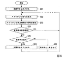
次に「本実施形態のスイッチング制御」の処理の流れについて図6を用いて説明する。
図6は、本発明の一実施形態におけるスイッチング制御の一例を示す第2のフローチャートである。
まず、制御方法決定部15が制御信号生成部13へ「本実施形態のスイッチング制御」の実行を指示する。すると、制御信号生成部13は、予め登録された所定の初期値へ変調波P2´の変調率を上昇させる(ステップS21)。制御信号生成部13は、図3(c)で説明した方法でスイッチング制御信号S1を生成する(ステップS22)。制御部11は、制御信号生成部13が生成したスイッチング制御信号S1をスイッチング素子35に出力する。これによりスイッチング素子35のオン状態とオフ状態が切り替わる。スイッチング休止期間T1には、スイッチング素子35はオフ状態となる。波形観測部12が観測する入力電流の波形は、図3(d)で示すような歪みを含んだ波形になる。判定部14は、波形観測部12が観測する入力電流に基づいて、スイッチング休止期間T1でのTHDまたは各次数の高調波の値を算出し、算出したTHDまたは各次数の高調波の値を監視する(ステップS23)。具体的には、判定部14は、例えば、算出したTHD等の値と所定の閾値(例えば、高周波規制に基づく、所定の上限値および下限値)とを比較する。判定部14は、THDの値が所定の上限値および下限値で規定される範囲内に収まっていれば、変調率は許容範囲内であると判定する。THDの値が所定の上限値を上回る場合、判定部14は、変調率は過大であると判定する。THDの値が所定の下限値に満たない場合、判定部14は、変調率は過小であると判定する。各次数の高周波の値に基づいて判定する場合も同様である。つまり、全次数の高周波の値が所定の範囲内であれば、判定部14は、変調率は許容範囲内であると判定する。一つの次数でも高周波の値が所定の上限値を上回る場合、判定部14は、変調率は過大であると判定する。一つの次数でも高周波の値が所定の下限値を下回る場合、判定部14は、変調率は過小であると判定する。判定部14は、判定結果を制御信号生成部13へ出力する。
Next, the flow of the “switching control of this embodiment” will be described with reference to FIG.
FIG. 6 is a second flowchart illustrating an example of switching control according to an embodiment of the present invention.
First, the control
判定部14が、変調率は許容範囲内であると判定した場合(ステップS24;Yes)、制御信号生成部13は、ステップS22からの処理を繰り返す。つまり、制御信号生成部13は、現在の変調率のままスイッチング制御信号S1を生成する。制御部11は、そのスイッチング制御信号S1をスイッチング素子35に出力する。
When the
変調率が許容範囲内ではない場合(ステップS24;No)、変調率が過大であれば(ステップS25;Yes)、制御信号生成部13は、変調波P2´の変調率を低下させる(ステップS26)。例えば、現在の変調率が120%であれば、制御信号生成部13は変調率を5%低下させ、115%に設定してもよい。変調率をどの程度低下させるかについては予め定められており、制御信号生成部13は、これに従って変調率を低下させる。最大限低下させた場合の変調率は100%である。変調率を低下させると、制御信号生成部13は、ステップS22からの処理を繰り返す。つまり、制御信号生成部13は、変調率低下後の変調波P2´とキャリアP1とに基づいてスイッチング制御信号S1を生成する。制御部11は、スイッチング制御信号S1をスイッチング素子35に出力する。変調率を低下させると、スイッチング休止期間T1は短くなる。これにより、入力電流に含まれる高調波成分は低減する。
If the modulation rate is not within the allowable range (step S24; No), if the modulation rate is excessive (step S25; Yes), the
また、変調率が過小の場合(ステップS25;No)、制御信号生成部13は、変調波P2´の変調率を上昇させる(ステップS27)。例えば、現在の変調率が110%であれば、制御信号生成部13は変調率を5%上昇させ、115%に設定してもよい。変調率をどの程度上昇させるかについては予め定められており、制御信号生成部13は、これに従って変調率を上昇させる。なお、変調率の上限値を定め、変調率がこの上限値以上とならないようにしてもよい。変調率を上昇させると、制御信号生成部13は、ステップS22からの処理を繰り返す。つまり、制御信号生成部13は、変調率上昇後の変調波P2´とキャリアP1とに基づいてスイッチング制御信号S1を生成する。変調率を上昇させると、スイッチング休止期間T1は長くなり、リアクタ損失や騒音を低減することができる。
このように、制御信号生成部13は、判定部14の判定に基づいて変調率の設定を入力電流の状態に合わせて調節するフィードバック制御を継続的に行う。
If the modulation rate is too small (step S25; No), the
As described above, the control
本実施形態によれば、整流回路320と、リアクタ33と、スイッチング素子35等を備えたスイッチング回路330と、平滑コンデンサ36と、を備えるコンバータ31について、スイッチング素子35のオンとオフを切り替えるスイッチング制御の実行中に、スイッチング素子35のオンとオフの切り替えを行わない(オフ状態とする)スイッチング休止期間を設ける。これにより、オンとオフの切り替えを継続して実行し続ける一般的なスイッチング制御と比較して、スイッチングにより生じるリアクタ33での電力損失や騒音を低減することができる。また、圧縮機2や空気調和機1の運転効率を向上することができる。また、本実施形態の制御装置10によれば、スイッチング休止期間中の入力電流に含まれる高調波や、入力電流の歪み率を監視することにより、変調率を調整してスイッチング休止期間の長さを調整するフィードバック制御を行う。これにより、高調波規制の範囲内でスイッチング損失の低減を図ることができる。また、フィードバック制御により、空気調和機1の運転条件や運転状態の変化による電力変換装置3の負荷変動にも動的に対応し、空気調和機1の運転効率の向上を実現することができる。
According to this embodiment, switching control for switching on and off the switching
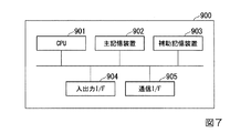
図7は、本発明の実施形態における制御装置のハードウェア構成の一例を示す図である。コンピュータ900は、CPU901、主記憶装置902、補助記憶装置903、入出力インタフェース904、通信インタフェース905を備える例えばマイコン、PC、サーバ端末装置である。コンピュータ900は、CPU901に代えて、MPU(Micro Processing Unit)やGPU(Graphics Processing Unit)などのプロセッサを備えていてもよい。上述の制御装置10は、コンピュータ900に実装される。そして、上述した各処理部の動作は、プログラムの形式で補助記憶装置903に記憶されている。CPU901は、プログラムを補助記憶装置903から読み出して主記憶装置902に展開し、当該プログラムに従って上記処理を実行する。また、CPU901は、プログラムに従って、記憶部16に対応する記憶領域を主記憶装置902に確保する。また、CPU901は、プログラムに従って、処理中のデータを記憶する記憶領域を補助記憶装置903に確保する。
FIG. 7 is a diagram illustrating an example of a hardware configuration of the control device according to the embodiment of the present invention. The
なお、少なくとも1つの実施形態において、補助記憶装置903は、一時的でない有形の媒体の一例である。一時的でない有形の媒体の他の例としては、入出力インタフェース904を介して接続される磁気ディスク、光磁気ディスク、CD−ROM、DVD−ROM、半導体メモリ等が挙げられる。また、このプログラムが通信回線によってコンピュータ900に配信される場合、配信を受けたコンピュータ900が当該プログラムを主記憶装置902に展開し、上記処理を実行しても良い。また、当該プログラムは、前述した機能の一部を実現するためのものであっても良い。さらに、当該プログラムは、前述した機能を補助記憶装置903に既に記憶されている他のプログラムとの組み合わせで実現するもの、いわゆる差分ファイル(差分プログラム)であっても良い。
In at least one embodiment, the
上記の波形観測部12と、制御信号生成部13と、判定部14と、制御方法決定部15と、記憶部16との全て又は一部は、マイコン、LSI(Large Scale Integration)、ASIC(Application Specific Integrated Circuit)、PLD(Programmable Logic Device)、FPGA(Field-Programmable Gate Array)等のハードウェアを用いて実現されてもよい。
The
その他、本発明の趣旨を逸脱しない範囲で、上記した実施の形態における構成要素を周知の構成要素に置き換えることは適宜可能である。また、この発明の技術範囲は上記の実施形態に限られるものではなく、本発明の趣旨を逸脱しない範囲において種々の変更を加えることが可能である。
なお、THDは歪み率の一例である。
In addition, it is possible to appropriately replace the components in the above-described embodiments with known components without departing from the spirit of the present invention. The technical scope of the present invention is not limited to the above-described embodiment, and various modifications can be made without departing from the spirit of the present invention.
THD is an example of a distortion rate.
1・・・空気調和機
2・・・圧縮機
3・・・電力変換装置
4・・・モータ
5・・・圧縮機構
6・・・交流電源
10・・・制御装置
11・・・制御部
12・・・波形観測部
13・・・制御信号生成部
14・・・判定部
15・・・制御方法決定部
16・・・記憶部
20・・・入力電流検出部
21・・・ゼロクロス検出部
320・・・整流回路
330・・・スイッチング回路
31・・・コンバータ
32a、32b、32c、32d・・・ダイオード
33・・・リアクタ
34・・・ダイオード
35・・・スイッチング素子
36・・・平滑コンデンサ
37・・・インバータ
37a・・・スイッチング素子
S1・・・スイッチング制御信号
P2,P2´・・・変調波
DESCRIPTION OF SYMBOLS 1 ...
Claims (9)
前記制御部が、前記スイッチング制御の実行中に、前記スイッチング素子のオンとオフの切り替えを行わないスイッチング休止期間を設定する、
制御装置。 A power conversion device comprising a rectifier circuit, a reactor, and a switching element, the converter converting AC power into DC power, and the inverter converting DC power converted by the converter into AC power. A control unit that performs switching control to switch on and off;
The control unit sets a switching pause period during which the switching element is not switched on and off during the switching control.
Control device.
請求項1に記載の制御装置。 The control unit generates a switching control signal that instructs on / off switching of the switching element based on a predetermined modulation wave and a predetermined carrier, and increases the modulation rate of the modulation wave to thereby switch the switching element. Set the rest period,
The control device according to claim 1.
請求項2に記載の制御装置。 The control unit sets the modulation rate so that a distortion rate of an input current of the converter in the switching pause period is equal to or less than a predetermined threshold;
The control device according to claim 2.
請求項2に記載の制御装置。 The control unit sets the modulation rate so that the harmonic value of each order included in the input current of the converter in the switching pause period is equal to or less than a predetermined threshold;
The control device according to claim 2.
請求項2に記載の制御装置。 The control unit monitors an input current of the converter during the switching pause period, and the modulation is performed so that a distortion rate of the input current or a harmonic value of each order included in the input current is equal to or less than a predetermined threshold value. Feedback control the rate,
The control device according to claim 2.
請求項1から請求項5の何れか1項に記載の制御装置。 The control unit performs control to set the switching pause period during execution of the switching control when the load of the power conversion device is within a predetermined range.
The control device according to any one of claims 1 to 5.
請求項1から請求項6の何れか1項に記載の制御装置と、
前記電力変換装置が制御するモータによって駆動する圧縮機と、
を備えた空気調和機。 A power converter comprising: a rectifier circuit; a reactor; a switching element; a converter that converts AC power into DC power; and an inverter that converts DC power converted by the converter into AC power;
The control device according to any one of claims 1 to 6,
A compressor driven by a motor controlled by the power converter;
Air conditioner equipped with.
制御方法。 A power conversion device comprising a rectifier circuit, a reactor, and a switching element, the converter converting AC power into DC power, and the inverter converting DC power converted by the converter into AC power. Setting a switching pause period during which switching of the switching element is not switched on and off during execution of switching control for switching on and off;
Control method.
前記スイッチング素子のオンとオフを切り替えるスイッチング制御を実行する手段、
前記スイッチング制御の実行中に、前記スイッチング素子のオンとオフの切り替えを行わないスイッチング休止期間を設定する手段、
として機能させるためのプログラム。 A computer that controls a power conversion device that includes a rectifier circuit, a reactor, and a switching element, the converter that converts AC power into DC power, and the inverter that converts DC power converted by the converter into AC power.
Means for performing switching control for switching on and off the switching element;
Means for setting a switching pause period during which the switching element is not switched on and off during the switching control;
Program to function as.
Priority Applications (2)
| Application Number | Priority Date | Filing Date | Title |
|---|---|---|---|
| JP2018046996A JP2019161902A (en) | 2018-03-14 | 2018-03-14 | Controller, air conditioner, control method and program |
| PCT/JP2019/002032 WO2019176304A1 (en) | 2018-03-14 | 2019-01-23 | Control device, air conditioner, control method and program |
Applications Claiming Priority (1)
| Application Number | Priority Date | Filing Date | Title |
|---|---|---|---|
| JP2018046996A JP2019161902A (en) | 2018-03-14 | 2018-03-14 | Controller, air conditioner, control method and program |
Publications (1)
| Publication Number | Publication Date |
|---|---|
| JP2019161902A true JP2019161902A (en) | 2019-09-19 |
Family
ID=67907648
Family Applications (1)
| Application Number | Title | Priority Date | Filing Date |
|---|---|---|---|
| JP2018046996A Pending JP2019161902A (en) | 2018-03-14 | 2018-03-14 | Controller, air conditioner, control method and program |
Country Status (2)
| Country | Link |
|---|---|
| JP (1) | JP2019161902A (en) |
| WO (1) | WO2019176304A1 (en) |
Family Cites Families (5)
| Publication number | Priority date | Publication date | Assignee | Title |
|---|---|---|---|---|
| JP3300683B2 (en) * | 1999-04-15 | 2002-07-08 | 松下電器産業株式会社 | Switching power supply |
| JP2007202370A (en) * | 2006-01-30 | 2007-08-09 | Mitsumi Electric Co Ltd | Power supply device |
| EP2750278A1 (en) * | 2008-09-01 | 2014-07-02 | Mitsubishi Electric Corporation | Converter circuit and motor drive control apparatus, air-conditioner, and refrigerator provided with the circuit |
| JP6327106B2 (en) * | 2014-01-10 | 2018-05-23 | 住友電気工業株式会社 | Conversion device |
| JP6528561B2 (en) * | 2015-06-26 | 2019-06-12 | 富士電機株式会社 | High efficiency power factor correction circuit and switching power supply |
-
2018
- 2018-03-14 JP JP2018046996A patent/JP2019161902A/en active Pending
-
2019
- 2019-01-23 WO PCT/JP2019/002032 patent/WO2019176304A1/en active Application Filing
Also Published As
| Publication number | Publication date |
|---|---|
| WO2019176304A1 (en) | 2019-09-19 |
Similar Documents
| Publication | Publication Date | Title |
|---|---|---|
| JP5892997B2 (en) | CONVERTER CIRCUIT, MOTOR DRIVE CONTROL DEVICE EQUIPPED WITH THE SAME, AIR CONDITIONER, AND Fridge | |
| JP4139852B1 (en) | Inverter control device | |
| US8432052B2 (en) | Wind power converter system with grid side reactive power control | |
| US9641121B2 (en) | Power conversion device and motor drive device including power conversion device | |
| US20120300519A1 (en) | Multi-phase active rectifier | |
| JP5304937B2 (en) | Power converter | |
| CN104508967B (en) | Converter control device, method, program and air regulator | |
| JP6731639B2 (en) | Power converter | |
| JP2009542171A (en) | Method for controlling a three-level converter | |
| KR20140066196A (en) | Vector control device for electric motor, electric motor, vehicle drive system, and vector control method for electric motor | |
| WO2019208325A1 (en) | Control device, air conditioner, control method, and program | |
| JP6158125B2 (en) | Power converter | |
| WO2019176304A1 (en) | Control device, air conditioner, control method and program | |
| WO2019176318A1 (en) | Control device, air conditioner, control method, and program | |
| JP6518693B2 (en) | POWER CONVERTER AND CONTROL METHOD OF POWER CONVERTER | |
| JP7063615B2 (en) | Control method and program of three-phase voltage doubler rectifier unit, inverter device, air conditioner, three-phase voltage doubler rectifier unit | |
| AU2018263420B2 (en) | Converter control device, converter provided with same, air conditioner, and converter control method and converter control program | |
| CN114520603A (en) | Method and device for generating a three-phase voltage | |
| EP3041121B1 (en) | Converter control device and control method, and air conditioner | |
| JP2006042579A (en) | Switching control method, rectifier and drive system | |
| WO2023095319A1 (en) | Power conversion device, power conversion system, and overcurrent protection method | |
| JP2013135516A (en) | Electric power conversion system and air conditioner | |
| JP7235531B2 (en) | Converter device, processing method and program | |
| JP2020171183A (en) | Converter device, air conditioner, and control method and program of converter device | |
| JP2020184848A (en) | Control device, power conversion device, control method, and program |