JP2019148601A - Automated histological treatment of biological sample and related technique - Google Patents
Automated histological treatment of biological sample and related technique Download PDFInfo
- Publication number
- JP2019148601A JP2019148601A JP2019094414A JP2019094414A JP2019148601A JP 2019148601 A JP2019148601 A JP 2019148601A JP 2019094414 A JP2019094414 A JP 2019094414A JP 2019094414 A JP2019094414 A JP 2019094414A JP 2019148601 A JP2019148601 A JP 2019148601A
- Authority
- JP
- Japan
- Prior art keywords
- slide
- liquid
- sample
- dispensing
- processing
- Prior art date
- Legal status (The legal status is an assumption and is not a legal conclusion. Google has not performed a legal analysis and makes no representation as to the accuracy of the status listed.)
- Granted
Links
- 238000000034 method Methods 0.000 title claims abstract description 357
- 239000012472 biological sample Substances 0.000 title abstract description 19
- 238000002360 preparation method Methods 0.000 claims abstract description 27
- 239000007788 liquid Substances 0.000 claims description 1065
- 238000012545 processing Methods 0.000 claims description 403
- 238000010186 staining Methods 0.000 claims description 237
- 239000012530 fluid Substances 0.000 claims description 207
- 239000003153 chemical reaction reagent Substances 0.000 claims description 164
- 241001510071 Pyrrhocoridae Species 0.000 claims description 143
- 239000012128 staining reagent Substances 0.000 claims description 106
- 238000012546 transfer Methods 0.000 claims description 104
- WZUVPPKBWHMQCE-UHFFFAOYSA-N Haematoxylin Chemical group C12=CC(O)=C(O)C=C2CC2(O)C1C1=CC=C(O)C(O)=C1OC2 WZUVPPKBWHMQCE-UHFFFAOYSA-N 0.000 claims description 90
- 230000007246 mechanism Effects 0.000 claims description 79
- 238000004140 cleaning Methods 0.000 claims description 68
- 230000008569 process Effects 0.000 claims description 67
- 230000000712 assembly Effects 0.000 claims description 59
- 238000000429 assembly Methods 0.000 claims description 59
- 238000009826 distribution Methods 0.000 claims description 49
- 230000004888 barrier function Effects 0.000 claims description 43
- 230000033001 locomotion Effects 0.000 claims description 42
- 238000004043 dyeing Methods 0.000 claims description 32
- 239000000463 material Substances 0.000 claims description 24
- 230000036961 partial effect Effects 0.000 claims description 20
- 230000002209 hydrophobic effect Effects 0.000 claims description 14
- 238000005507 spraying Methods 0.000 claims description 13
- YQGOJNYOYNNSMM-UHFFFAOYSA-N eosin Chemical group [Na+].OC(=O)C1=CC=CC=C1C1=C2C=C(Br)C(=O)C(Br)=C2OC2=C(Br)C(O)=C(Br)C=C21 YQGOJNYOYNNSMM-UHFFFAOYSA-N 0.000 claims description 12
- 239000007787 solid Substances 0.000 claims description 8
- 238000004891 communication Methods 0.000 claims description 6
- 238000007664 blowing Methods 0.000 claims description 4
- 230000002055 immunohistochemical effect Effects 0.000 claims description 3
- 238000013022 venting Methods 0.000 claims description 3
- 238000009736 wetting Methods 0.000 claims description 3
- 230000007723 transport mechanism Effects 0.000 claims 1
- 239000000523 sample Substances 0.000 abstract description 425
- 238000011109 contamination Methods 0.000 abstract description 10
- 230000000670 limiting effect Effects 0.000 abstract description 9
- 230000002708 enhancing effect Effects 0.000 abstract 1
- 239000007789 gas Substances 0.000 description 258
- 238000005516 engineering process Methods 0.000 description 175
- LFQSCWFLJHTTHZ-UHFFFAOYSA-N Ethanol Chemical compound CCO LFQSCWFLJHTTHZ-UHFFFAOYSA-N 0.000 description 110
- 239000000243 solution Substances 0.000 description 103
- 239000006059 cover glass Substances 0.000 description 60
- 238000010438 heat treatment Methods 0.000 description 58
- HLUCICHZHWJHLL-UHFFFAOYSA-N hematein Chemical compound C12=CC=C(O)C(O)=C2OCC2(O)C1=C1C=C(O)C(=O)C=C1C2 HLUCICHZHWJHLL-UHFFFAOYSA-N 0.000 description 46
- DNIAPMSPPWPWGF-UHFFFAOYSA-N Propylene glycol Chemical compound CC(O)CO DNIAPMSPPWPWGF-UHFFFAOYSA-N 0.000 description 44
- 239000003570 air Substances 0.000 description 44
- 230000003750 conditioning effect Effects 0.000 description 37
- 238000001035 drying Methods 0.000 description 36
- 239000000203 mixture Substances 0.000 description 35
- 239000002904 solvent Substances 0.000 description 34
- 238000005194 fractionation Methods 0.000 description 31
- XLYOFNOQVPJJNP-UHFFFAOYSA-N water Substances O XLYOFNOQVPJJNP-UHFFFAOYSA-N 0.000 description 31
- 239000002699 waste material Substances 0.000 description 27
- 150000005846 sugar alcohols Polymers 0.000 description 24
- 238000011534 incubation Methods 0.000 description 23
- LYCAIKOWRPUZTN-UHFFFAOYSA-N ethylene glycol Natural products OCCO LYCAIKOWRPUZTN-UHFFFAOYSA-N 0.000 description 22
- 238000001704 evaporation Methods 0.000 description 20
- 230000000875 corresponding effect Effects 0.000 description 19
- 230000008020 evaporation Effects 0.000 description 19
- 239000008096 xylene Substances 0.000 description 18
- CTQNGGLPUBDAKN-UHFFFAOYSA-N O-Xylene Chemical compound CC1=CC=CC=C1C CTQNGGLPUBDAKN-UHFFFAOYSA-N 0.000 description 17
- 229930003658 monoterpene Natural products 0.000 description 17
- 150000002773 monoterpene derivatives Chemical class 0.000 description 17
- 235000002577 monoterpenes Nutrition 0.000 description 17
- 150000001335 aliphatic alkanes Chemical class 0.000 description 16
- 239000003623 enhancer Substances 0.000 description 16
- 230000008901 benefit Effects 0.000 description 15
- 230000006870 function Effects 0.000 description 15
- 238000003672 processing method Methods 0.000 description 15
- 238000005406 washing Methods 0.000 description 15
- 239000012188 paraffin wax Substances 0.000 description 12
- 210000004027 cell Anatomy 0.000 description 11
- IJGRMHOSHXDMSA-UHFFFAOYSA-N Atomic nitrogen Chemical compound N#N IJGRMHOSHXDMSA-UHFFFAOYSA-N 0.000 description 10
- 230000009286 beneficial effect Effects 0.000 description 10
- 238000000576 coating method Methods 0.000 description 10
- 230000006378 damage Effects 0.000 description 10
- 239000008367 deionised water Substances 0.000 description 10
- 229910021641 deionized water Inorganic materials 0.000 description 10
- RTZKZFJDLAIYFH-UHFFFAOYSA-N ether Substances CCOCC RTZKZFJDLAIYFH-UHFFFAOYSA-N 0.000 description 10
- 239000010808 liquid waste Substances 0.000 description 10
- 239000000126 substance Substances 0.000 description 10
- 210000001519 tissue Anatomy 0.000 description 10
- 238000001816 cooling Methods 0.000 description 9
- 238000009472 formulation Methods 0.000 description 9
- 230000002829 reductive effect Effects 0.000 description 9
- 230000009471 action Effects 0.000 description 8
- 239000000853 adhesive Substances 0.000 description 8
- 230000001070 adhesive effect Effects 0.000 description 8
- 239000011248 coating agent Substances 0.000 description 8
- 239000000834 fixative Substances 0.000 description 8
- XMGQYMWWDOXHJM-UHFFFAOYSA-N limonene Chemical compound CC(=C)C1CCC(C)=CC1 XMGQYMWWDOXHJM-UHFFFAOYSA-N 0.000 description 8
- QTBSBXVTEAMEQO-UHFFFAOYSA-N Acetic acid Chemical compound CC(O)=O QTBSBXVTEAMEQO-UHFFFAOYSA-N 0.000 description 7
- 238000004458 analytical method Methods 0.000 description 7
- 238000006243 chemical reaction Methods 0.000 description 7
- 230000000694 effects Effects 0.000 description 7
- -1 isoalkanes Chemical class 0.000 description 7
- VEXZGXHMUGYJMC-UHFFFAOYSA-N Hydrochloric acid Chemical compound Cl VEXZGXHMUGYJMC-UHFFFAOYSA-N 0.000 description 6
- 230000002411 adverse Effects 0.000 description 6
- 230000008859 change Effects 0.000 description 6
- 230000007423 decrease Effects 0.000 description 6
- SZXQTJUDPRGNJN-UHFFFAOYSA-N dipropylene glycol Chemical compound OCCCOCCCO SZXQTJUDPRGNJN-UHFFFAOYSA-N 0.000 description 6
- 230000003993 interaction Effects 0.000 description 6
- 239000002244 precipitate Substances 0.000 description 6
- 238000003860 storage Methods 0.000 description 6
- 230000015572 biosynthetic process Effects 0.000 description 5
- 230000001419 dependent effect Effects 0.000 description 5
- 229910052757 nitrogen Inorganic materials 0.000 description 5
- 239000003973 paint Substances 0.000 description 5
- 239000003209 petroleum derivative Substances 0.000 description 5
- 239000004094 surface-active agent Substances 0.000 description 5
- QIGBRXMKCJKVMJ-UHFFFAOYSA-N Hydroquinone Chemical compound OC1=CC=C(O)C=C1 QIGBRXMKCJKVMJ-UHFFFAOYSA-N 0.000 description 4
- 239000002253 acid Substances 0.000 description 4
- 229910052782 aluminium Inorganic materials 0.000 description 4
- XAGFODPZIPBFFR-UHFFFAOYSA-N aluminium Chemical compound [Al] XAGFODPZIPBFFR-UHFFFAOYSA-N 0.000 description 4
- 238000003491 array Methods 0.000 description 4
- 239000000872 buffer Substances 0.000 description 4
- 210000003850 cellular structure Anatomy 0.000 description 4
- 238000012864 cross contamination Methods 0.000 description 4
- MTHSVFCYNBDYFN-UHFFFAOYSA-N diethylene glycol Chemical compound OCCOCCO MTHSVFCYNBDYFN-UHFFFAOYSA-N 0.000 description 4
- 230000005484 gravity Effects 0.000 description 4
- 235000001510 limonene Nutrition 0.000 description 4
- 229940087305 limonene Drugs 0.000 description 4
- 150000002632 lipids Chemical class 0.000 description 4
- 238000007726 management method Methods 0.000 description 4
- 239000012528 membrane Substances 0.000 description 4
- 239000003607 modifier Substances 0.000 description 4
- 150000007523 nucleic acids Chemical class 0.000 description 4
- 108020004707 nucleic acids Proteins 0.000 description 4
- 102000039446 nucleic acids Human genes 0.000 description 4
- 238000005192 partition Methods 0.000 description 4
- 230000001681 protective effect Effects 0.000 description 4
- 235000018102 proteins Nutrition 0.000 description 4
- 108090000623 proteins and genes Proteins 0.000 description 4
- 102000004169 proteins and genes Human genes 0.000 description 4
- 239000007921 spray Substances 0.000 description 4
- 239000000725 suspension Substances 0.000 description 4
- 150000003505 terpenes Chemical class 0.000 description 4
- 235000007586 terpenes Nutrition 0.000 description 4
- 230000009466 transformation Effects 0.000 description 4
- XYVAYAJYLWYJJN-UHFFFAOYSA-N 2-(2-propoxypropoxy)propan-1-ol Chemical compound CCCOC(C)COC(C)CO XYVAYAJYLWYJJN-UHFFFAOYSA-N 0.000 description 3
- LCZVSXRMYJUNFX-UHFFFAOYSA-N 2-[2-(2-hydroxypropoxy)propoxy]propan-1-ol Chemical compound CC(O)COC(C)COC(C)CO LCZVSXRMYJUNFX-UHFFFAOYSA-N 0.000 description 3
- 229920000858 Cyclodextrin Polymers 0.000 description 3
- 229960000583 acetic acid Drugs 0.000 description 3
- 239000003963 antioxidant agent Substances 0.000 description 3
- 239000007864 aqueous solution Substances 0.000 description 3
- 210000004369 blood Anatomy 0.000 description 3
- 239000008280 blood Substances 0.000 description 3
- 239000000969 carrier Substances 0.000 description 3
- 238000007796 conventional method Methods 0.000 description 3
- 210000000805 cytoplasm Anatomy 0.000 description 3
- 230000003247 decreasing effect Effects 0.000 description 3
- 238000009792 diffusion process Methods 0.000 description 3
- SEACYXSIPDVVMV-UHFFFAOYSA-L eosin Y Chemical compound [Na+].[Na+].[O-]C(=O)C1=CC=CC=C1C1=C2C=C(Br)C(=O)C(Br)=C2OC2=C(Br)C([O-])=C(Br)C=C21 SEACYXSIPDVVMV-UHFFFAOYSA-L 0.000 description 3
- 210000003743 erythrocyte Anatomy 0.000 description 3
- 239000010437 gem Substances 0.000 description 3
- 229910001751 gemstone Inorganic materials 0.000 description 3
- 238000011532 immunohistochemical staining Methods 0.000 description 3
- 230000006872 improvement Effects 0.000 description 3
- 239000002609 medium Substances 0.000 description 3
- 229910052751 metal Inorganic materials 0.000 description 3
- 239000002184 metal Substances 0.000 description 3
- 230000000877 morphologic effect Effects 0.000 description 3
- NALMPLUMOWIVJC-UHFFFAOYSA-N n,n,4-trimethylbenzeneamine oxide Chemical compound CC1=CC=C([N+](C)(C)[O-])C=C1 NALMPLUMOWIVJC-UHFFFAOYSA-N 0.000 description 3
- 230000003287 optical effect Effects 0.000 description 3
- 239000000047 product Substances 0.000 description 3
- 230000005855 radiation Effects 0.000 description 3
- 230000035945 sensitivity Effects 0.000 description 3
- 239000011697 sodium iodate Substances 0.000 description 3
- 229940032753 sodium iodate Drugs 0.000 description 3
- 235000015281 sodium iodate Nutrition 0.000 description 3
- 238000007447 staining method Methods 0.000 description 3
- 239000012192 staining solution Substances 0.000 description 3
- 239000001993 wax Substances 0.000 description 3
- XMGQYMWWDOXHJM-JTQLQIEISA-N (+)-α-limonene Chemical compound CC(=C)[C@@H]1CCC(C)=CC1 XMGQYMWWDOXHJM-JTQLQIEISA-N 0.000 description 2
- 239000001116 FEMA 4028 Substances 0.000 description 2
- DHMQDGOQFOQNFH-UHFFFAOYSA-N Glycine Chemical compound NCC(O)=O DHMQDGOQFOQNFH-UHFFFAOYSA-N 0.000 description 2
- XEEYBQQBJWHFJM-UHFFFAOYSA-N Iron Chemical compound [Fe] XEEYBQQBJWHFJM-UHFFFAOYSA-N 0.000 description 2
- PXHVJJICTQNCMI-UHFFFAOYSA-N Nickel Chemical compound [Ni] PXHVJJICTQNCMI-UHFFFAOYSA-N 0.000 description 2
- 150000001298 alcohols Chemical class 0.000 description 2
- 239000012670 alkaline solution Substances 0.000 description 2
- AZDRQVAHHNSJOQ-UHFFFAOYSA-N alumane Chemical class [AlH3] AZDRQVAHHNSJOQ-UHFFFAOYSA-N 0.000 description 2
- 238000013459 approach Methods 0.000 description 2
- WHGYBXFWUBPSRW-FOUAGVGXSA-N beta-cyclodextrin Chemical compound OC[C@H]([C@H]([C@@H]([C@H]1O)O)O[C@H]2O[C@@H]([C@@H](O[C@H]3O[C@H](CO)[C@H]([C@@H]([C@H]3O)O)O[C@H]3O[C@H](CO)[C@H]([C@@H]([C@H]3O)O)O[C@H]3O[C@H](CO)[C@H]([C@@H]([C@H]3O)O)O[C@H]3O[C@H](CO)[C@H]([C@@H]([C@H]3O)O)O3)[C@H](O)[C@H]2O)CO)O[C@@H]1O[C@H]1[C@H](O)[C@@H](O)[C@@H]3O[C@@H]1CO WHGYBXFWUBPSRW-FOUAGVGXSA-N 0.000 description 2
- 235000011175 beta-cyclodextrine Nutrition 0.000 description 2
- 229960004853 betadex Drugs 0.000 description 2
- 238000001574 biopsy Methods 0.000 description 2
- 238000009529 body temperature measurement Methods 0.000 description 2
- 230000015556 catabolic process Effects 0.000 description 2
- 230000000295 complement effect Effects 0.000 description 2
- 150000001875 compounds Chemical class 0.000 description 2
- 230000001143 conditioned effect Effects 0.000 description 2
- 239000004020 conductor Substances 0.000 description 2
- 238000004132 cross linking Methods 0.000 description 2
- 238000006731 degradation reaction Methods 0.000 description 2
- 238000013461 design Methods 0.000 description 2
- BUACSMWVFUNQET-UHFFFAOYSA-H dialuminum;trisulfate;hydrate Chemical compound O.[Al+3].[Al+3].[O-]S([O-])(=O)=O.[O-]S([O-])(=O)=O.[O-]S([O-])(=O)=O BUACSMWVFUNQET-UHFFFAOYSA-H 0.000 description 2
- 239000008393 encapsulating agent Substances 0.000 description 2
- 230000007613 environmental effect Effects 0.000 description 2
- LNTHITQWFMADLM-UHFFFAOYSA-N gallic acid Chemical compound OC(=O)C1=CC(O)=C(O)C(O)=C1 LNTHITQWFMADLM-UHFFFAOYSA-N 0.000 description 2
- 230000014509 gene expression Effects 0.000 description 2
- 239000012362 glacial acetic acid Substances 0.000 description 2
- 238000007490 hematoxylin and eosin (H&E) staining Methods 0.000 description 2
- 238000012735 histological processing Methods 0.000 description 2
- 238000009396 hybridization Methods 0.000 description 2
- WGCNASOHLSPBMP-UHFFFAOYSA-N hydroxyacetaldehyde Natural products OCC=O WGCNASOHLSPBMP-UHFFFAOYSA-N 0.000 description 2
- 238000012151 immunohistochemical method Methods 0.000 description 2
- 239000004615 ingredient Substances 0.000 description 2
- 238000009434 installation Methods 0.000 description 2
- 231100001231 less toxic Toxicity 0.000 description 2
- 238000004519 manufacturing process Methods 0.000 description 2
- 238000010208 microarray analysis Methods 0.000 description 2
- 238000002156 mixing Methods 0.000 description 2
- 238000012758 nuclear staining Methods 0.000 description 2
- 238000010422 painting Methods 0.000 description 2
- 239000002245 particle Substances 0.000 description 2
- 230000000737 periodic effect Effects 0.000 description 2
- XNGIFLGASWRNHJ-UHFFFAOYSA-N phthalic acid Chemical compound OC(=O)C1=CC=CC=C1C(O)=O XNGIFLGASWRNHJ-UHFFFAOYSA-N 0.000 description 2
- 230000000717 retained effect Effects 0.000 description 2
- 150000003839 salts Chemical class 0.000 description 2
- 239000000758 substrate Substances 0.000 description 2
- 239000000057 synthetic resin Substances 0.000 description 2
- 229920003002 synthetic resin Polymers 0.000 description 2
- 231100000419 toxicity Toxicity 0.000 description 2
- 230000001988 toxicity Effects 0.000 description 2
- 235000015112 vegetable and seed oil Nutrition 0.000 description 2
- 239000008158 vegetable oil Substances 0.000 description 2
- 238000010792 warming Methods 0.000 description 2
- CUDYYMUUJHLCGZ-UHFFFAOYSA-N 2-(2-methoxypropoxy)propan-1-ol Chemical compound COC(C)COC(C)CO CUDYYMUUJHLCGZ-UHFFFAOYSA-N 0.000 description 1
- JDSQBDGCMUXRBM-UHFFFAOYSA-N 2-[2-(2-butoxypropoxy)propoxy]propan-1-ol Chemical compound CCCCOC(C)COC(C)COC(C)CO JDSQBDGCMUXRBM-UHFFFAOYSA-N 0.000 description 1
- PRBXPAHXMGDVNQ-UHFFFAOYSA-N 2-[2-(2-hydroxyethoxy)ethoxy]acetic acid Chemical compound OCCOCCOCC(O)=O PRBXPAHXMGDVNQ-UHFFFAOYSA-N 0.000 description 1
- 241000894006 Bacteria Species 0.000 description 1
- 239000004322 Butylated hydroxytoluene Substances 0.000 description 1
- NLZUEZXRPGMBCV-UHFFFAOYSA-N Butylhydroxytoluene Chemical compound CC1=CC(C(C)(C)C)=C(O)C(C(C)(C)C)=C1 NLZUEZXRPGMBCV-UHFFFAOYSA-N 0.000 description 1
- 102000008186 Collagen Human genes 0.000 description 1
- 108010035532 Collagen Proteins 0.000 description 1
- RYGMFSIKBFXOCR-UHFFFAOYSA-N Copper Chemical compound [Cu] RYGMFSIKBFXOCR-UHFFFAOYSA-N 0.000 description 1
- 102000004190 Enzymes Human genes 0.000 description 1
- 108090000790 Enzymes Proteins 0.000 description 1
- IAYPIBMASNFSPL-UHFFFAOYSA-N Ethylene oxide Chemical compound C1CO1 IAYPIBMASNFSPL-UHFFFAOYSA-N 0.000 description 1
- 239000004471 Glycine Substances 0.000 description 1
- QNAYBMKLOCPYGJ-REOHCLBHSA-N L-alanine Chemical compound C[C@H](N)C(O)=O QNAYBMKLOCPYGJ-REOHCLBHSA-N 0.000 description 1
- PWHULOQIROXLJO-UHFFFAOYSA-N Manganese Chemical compound [Mn] PWHULOQIROXLJO-UHFFFAOYSA-N 0.000 description 1
- ZOKXTWBITQBERF-UHFFFAOYSA-N Molybdenum Chemical compound [Mo] ZOKXTWBITQBERF-UHFFFAOYSA-N 0.000 description 1
- 108020004711 Nucleic Acid Probes Proteins 0.000 description 1
- 235000019483 Peanut oil Nutrition 0.000 description 1
- 239000013614 RNA sample Substances 0.000 description 1
- 240000004808 Saccharomyces cerevisiae Species 0.000 description 1
- QAOWNCQODCNURD-UHFFFAOYSA-L Sulfate Chemical compound [O-]S([O-])(=O)=O QAOWNCQODCNURD-UHFFFAOYSA-L 0.000 description 1
- RNFAKTRFMQEEQE-UHFFFAOYSA-N Tripropylene glycol butyl ether Chemical compound CCCCOC(CC)OC(C)COC(O)CC RNFAKTRFMQEEQE-UHFFFAOYSA-N 0.000 description 1
- 241000700605 Viruses Species 0.000 description 1
- HCHKCACWOHOZIP-UHFFFAOYSA-N Zinc Chemical compound [Zn] HCHKCACWOHOZIP-UHFFFAOYSA-N 0.000 description 1
- 230000001133 acceleration Effects 0.000 description 1
- 238000005903 acid hydrolysis reaction Methods 0.000 description 1
- 230000002378 acidificating effect Effects 0.000 description 1
- 238000004378 air conditioning Methods 0.000 description 1
- 235000004279 alanine Nutrition 0.000 description 1
- 239000005456 alcohol based solvent Substances 0.000 description 1
- 238000010936 aqueous wash Methods 0.000 description 1
- 150000001491 aromatic compounds Chemical class 0.000 description 1
- 229910052788 barium Inorganic materials 0.000 description 1
- DSAJWYNOEDNPEQ-UHFFFAOYSA-N barium atom Chemical compound [Ba] DSAJWYNOEDNPEQ-UHFFFAOYSA-N 0.000 description 1
- 230000006399 behavior Effects 0.000 description 1
- 238000009739 binding Methods 0.000 description 1
- 230000005540 biological transmission Effects 0.000 description 1
- 230000003139 buffering effect Effects 0.000 description 1
- 229940095259 butylated hydroxytoluene Drugs 0.000 description 1
- 235000010354 butylated hydroxytoluene Nutrition 0.000 description 1
- 150000001720 carbohydrates Chemical class 0.000 description 1
- 230000003197 catalytic effect Effects 0.000 description 1
- 210000001175 cerebrospinal fluid Anatomy 0.000 description 1
- 230000000739 chaotic effect Effects 0.000 description 1
- FOCAUTSVDIKZOP-UHFFFAOYSA-M chloroacetate Chemical compound [O-]C(=O)CCl FOCAUTSVDIKZOP-UHFFFAOYSA-M 0.000 description 1
- 229940089960 chloroacetate Drugs 0.000 description 1
- 229910017052 cobalt Inorganic materials 0.000 description 1
- 239000010941 cobalt Substances 0.000 description 1
- GUTLYIVDDKVIGB-UHFFFAOYSA-N cobalt atom Chemical compound [Co] GUTLYIVDDKVIGB-UHFFFAOYSA-N 0.000 description 1
- 229920001436 collagen Polymers 0.000 description 1
- 210000002808 connective tissue Anatomy 0.000 description 1
- 239000000470 constituent Substances 0.000 description 1
- 230000001276 controlling effect Effects 0.000 description 1
- 229910052802 copper Inorganic materials 0.000 description 1
- 239000010949 copper Substances 0.000 description 1
- 230000002596 correlated effect Effects 0.000 description 1
- 125000004122 cyclic group Chemical group 0.000 description 1
- 210000004292 cytoskeleton Anatomy 0.000 description 1
- 210000000172 cytosol Anatomy 0.000 description 1
- 230000001086 cytosolic effect Effects 0.000 description 1
- 238000005202 decontamination Methods 0.000 description 1
- 230000003588 decontaminative effect Effects 0.000 description 1
- 230000003412 degenerative effect Effects 0.000 description 1
- 230000003111 delayed effect Effects 0.000 description 1
- 230000006866 deterioration Effects 0.000 description 1
- 238000010586 diagram Methods 0.000 description 1
- 238000010790 dilution Methods 0.000 description 1
- 239000012895 dilution Substances 0.000 description 1
- 239000000975 dye Substances 0.000 description 1
- 239000000839 emulsion Substances 0.000 description 1
- 210000002919 epithelial cell Anatomy 0.000 description 1
- 238000004880 explosion Methods 0.000 description 1
- 210000003722 extracellular fluid Anatomy 0.000 description 1
- 238000001125 extrusion Methods 0.000 description 1
- 230000002550 fecal effect Effects 0.000 description 1
- 230000009969 flowable effect Effects 0.000 description 1
- 230000008014 freezing Effects 0.000 description 1
- 238000007710 freezing Methods 0.000 description 1
- 229940074391 gallic acid Drugs 0.000 description 1
- 235000004515 gallic acid Nutrition 0.000 description 1
- 239000011521 glass Substances 0.000 description 1
- 239000003292 glue Substances 0.000 description 1
- 231100000086 high toxicity Toxicity 0.000 description 1
- 230000001744 histochemical effect Effects 0.000 description 1
- 235000020256 human milk Nutrition 0.000 description 1
- 210000004251 human milk Anatomy 0.000 description 1
- 229930195733 hydrocarbon Natural products 0.000 description 1
- 150000002430 hydrocarbons Chemical class 0.000 description 1
- 238000007901 in situ hybridization Methods 0.000 description 1
- 238000011065 in-situ storage Methods 0.000 description 1
- 229910052738 indium Inorganic materials 0.000 description 1
- APFVFJFRJDLVQX-UHFFFAOYSA-N indium atom Chemical compound [In] APFVFJFRJDLVQX-UHFFFAOYSA-N 0.000 description 1
- 238000009413 insulation Methods 0.000 description 1
- 230000002452 interceptive effect Effects 0.000 description 1
- 230000003834 intracellular effect Effects 0.000 description 1
- 238000011835 investigation Methods 0.000 description 1
- 229910052742 iron Inorganic materials 0.000 description 1
- 230000001788 irregular Effects 0.000 description 1
- 238000002386 leaching Methods 0.000 description 1
- 239000012669 liquid formulation Substances 0.000 description 1
- 238000011068 loading method Methods 0.000 description 1
- 230000002934 lysing effect Effects 0.000 description 1
- 238000012423 maintenance Methods 0.000 description 1
- 230000003211 malignant effect Effects 0.000 description 1
- 229910052748 manganese Inorganic materials 0.000 description 1
- 239000011572 manganese Substances 0.000 description 1
- 238000004949 mass spectrometry Methods 0.000 description 1
- 239000011159 matrix material Substances 0.000 description 1
- 238000005259 measurement Methods 0.000 description 1
- 238000002844 melting Methods 0.000 description 1
- 230000008018 melting Effects 0.000 description 1
- 150000002739 metals Chemical class 0.000 description 1
- 238000001531 micro-dissection Methods 0.000 description 1
- 238000000386 microscopy Methods 0.000 description 1
- 230000005012 migration Effects 0.000 description 1
- 238000013508 migration Methods 0.000 description 1
- 230000004048 modification Effects 0.000 description 1
- 238000012986 modification Methods 0.000 description 1
- 229910052750 molybdenum Inorganic materials 0.000 description 1
- 239000011733 molybdenum Substances 0.000 description 1
- 239000012120 mounting media Substances 0.000 description 1
- 210000003097 mucus Anatomy 0.000 description 1
- 210000000663 muscle cell Anatomy 0.000 description 1
- 238000013188 needle biopsy Methods 0.000 description 1
- 229910052759 nickel Inorganic materials 0.000 description 1
- 210000002445 nipple Anatomy 0.000 description 1
- 231100000989 no adverse effect Toxicity 0.000 description 1
- 239000002853 nucleic acid probe Substances 0.000 description 1
- 210000004940 nucleus Anatomy 0.000 description 1
- 235000019645 odor Nutrition 0.000 description 1
- 210000003463 organelle Anatomy 0.000 description 1
- 238000013021 overheating Methods 0.000 description 1
- 239000007800 oxidant agent Substances 0.000 description 1
- 230000003647 oxidation Effects 0.000 description 1
- 238000007254 oxidation reaction Methods 0.000 description 1
- 230000001590 oxidative effect Effects 0.000 description 1
- 238000010979 pH adjustment Methods 0.000 description 1
- 238000009595 pap smear Methods 0.000 description 1
- 239000000312 peanut oil Substances 0.000 description 1
- 239000002530 phenolic antioxidant Substances 0.000 description 1
- 229920001343 polytetrafluoroethylene Polymers 0.000 description 1
- 239000004810 polytetrafluoroethylene Substances 0.000 description 1
- 238000012805 post-processing Methods 0.000 description 1
- 230000002028 premature Effects 0.000 description 1
- 239000003755 preservative agent Substances 0.000 description 1
- 230000002335 preservative effect Effects 0.000 description 1
- 108090000765 processed proteins & peptides Proteins 0.000 description 1
- 230000000750 progressive effect Effects 0.000 description 1
- 238000003498 protein array Methods 0.000 description 1
- 238000005086 pumping Methods 0.000 description 1
- 210000004915 pus Anatomy 0.000 description 1
- 239000010453 quartz Substances 0.000 description 1
- 230000009467 reduction Effects 0.000 description 1
- 230000008439 repair process Effects 0.000 description 1
- 230000004044 response Effects 0.000 description 1
- 230000000284 resting effect Effects 0.000 description 1
- 230000002441 reversible effect Effects 0.000 description 1
- 230000005070 ripening Effects 0.000 description 1
- 239000010979 ruby Substances 0.000 description 1
- 229910001750 ruby Inorganic materials 0.000 description 1
- 210000003296 saliva Anatomy 0.000 description 1
- HFHDHCJBZVLPGP-UHFFFAOYSA-N schardinger α-dextrin Chemical compound O1C(C(C2O)O)C(CO)OC2OC(C(C2O)O)C(CO)OC2OC(C(C2O)O)C(CO)OC2OC(C(O)C2O)C(CO)OC2OC(C(C2O)O)C(CO)OC2OC2C(O)C(O)C1OC2CO HFHDHCJBZVLPGP-UHFFFAOYSA-N 0.000 description 1
- 210000000582 semen Anatomy 0.000 description 1
- 238000000926 separation method Methods 0.000 description 1
- 210000002966 serum Anatomy 0.000 description 1
- 239000010703 silicon Substances 0.000 description 1
- 229910052710 silicon Inorganic materials 0.000 description 1
- VYPSYNLAJGMNEJ-UHFFFAOYSA-N silicon dioxide Inorganic materials O=[Si]=O VYPSYNLAJGMNEJ-UHFFFAOYSA-N 0.000 description 1
- NLJMYIDDQXHKNR-UHFFFAOYSA-K sodium citrate Chemical compound O.O.[Na+].[Na+].[Na+].[O-]C(=O)CC(O)(CC([O-])=O)C([O-])=O NLJMYIDDQXHKNR-UHFFFAOYSA-K 0.000 description 1
- FVEFRICMTUKAML-UHFFFAOYSA-M sodium tetradecyl sulfate Chemical compound [Na+].CCCCC(CC)CCC(CC(C)C)OS([O-])(=O)=O FVEFRICMTUKAML-UHFFFAOYSA-M 0.000 description 1
- 239000003381 stabilizer Substances 0.000 description 1
- 229910001220 stainless steel Inorganic materials 0.000 description 1
- 239000010935 stainless steel Substances 0.000 description 1
- 230000002459 sustained effect Effects 0.000 description 1
- 210000004243 sweat Anatomy 0.000 description 1
- 230000002195 synergetic effect Effects 0.000 description 1
- 210000001138 tear Anatomy 0.000 description 1
- 230000002123 temporal effect Effects 0.000 description 1
- 230000003685 thermal hair damage Effects 0.000 description 1
- 231100000331 toxic Toxicity 0.000 description 1
- 230000002588 toxic effect Effects 0.000 description 1
- 230000001052 transient effect Effects 0.000 description 1
- 230000007704 transition Effects 0.000 description 1
- LENZDBCJOHFCAS-UHFFFAOYSA-N tris Chemical compound OCC(N)(CO)CO LENZDBCJOHFCAS-UHFFFAOYSA-N 0.000 description 1
- WFKWXMTUELFFGS-UHFFFAOYSA-N tungsten Chemical compound [W] WFKWXMTUELFFGS-UHFFFAOYSA-N 0.000 description 1
- 229910052721 tungsten Inorganic materials 0.000 description 1
- 239000010937 tungsten Substances 0.000 description 1
- 210000002700 urine Anatomy 0.000 description 1
- 229910052720 vanadium Inorganic materials 0.000 description 1
- GPPXJZIENCGNKB-UHFFFAOYSA-N vanadium Chemical compound [V]#[V] GPPXJZIENCGNKB-UHFFFAOYSA-N 0.000 description 1
- 230000000007 visual effect Effects 0.000 description 1
- 150000003738 xylenes Chemical class 0.000 description 1
- 229910052725 zinc Inorganic materials 0.000 description 1
- 239000011701 zinc Substances 0.000 description 1
Images


Classifications
-
- G—PHYSICS
- G01—MEASURING; TESTING
- G01N—INVESTIGATING OR ANALYSING MATERIALS BY DETERMINING THEIR CHEMICAL OR PHYSICAL PROPERTIES
- G01N1/00—Sampling; Preparing specimens for investigation
- G01N1/28—Preparing specimens for investigation including physical details of (bio-)chemical methods covered elsewhere, e.g. G01N33/50, C12Q
- G01N1/30—Staining; Impregnating ; Fixation; Dehydration; Multistep processes for preparing samples of tissue, cell or nucleic acid material and the like for analysis
- G01N1/31—Apparatus therefor
- G01N1/312—Apparatus therefor for samples mounted on planar substrates
-
- G—PHYSICS
- G01—MEASURING; TESTING
- G01N—INVESTIGATING OR ANALYSING MATERIALS BY DETERMINING THEIR CHEMICAL OR PHYSICAL PROPERTIES
- G01N35/00—Automatic analysis not limited to methods or materials provided for in any single one of groups G01N1/00 - G01N33/00; Handling materials therefor
- G01N35/00029—Automatic analysis not limited to methods or materials provided for in any single one of groups G01N1/00 - G01N33/00; Handling materials therefor provided with flat sample substrates, e.g. slides
-
- G—PHYSICS
- G01—MEASURING; TESTING
- G01N—INVESTIGATING OR ANALYSING MATERIALS BY DETERMINING THEIR CHEMICAL OR PHYSICAL PROPERTIES
- G01N35/00—Automatic analysis not limited to methods or materials provided for in any single one of groups G01N1/00 - G01N33/00; Handling materials therefor
- G01N35/10—Devices for transferring samples or any liquids to, in, or from, the analysis apparatus, e.g. suction devices, injection devices
-
- G—PHYSICS
- G01—MEASURING; TESTING
- G01N—INVESTIGATING OR ANALYSING MATERIALS BY DETERMINING THEIR CHEMICAL OR PHYSICAL PROPERTIES
- G01N35/00—Automatic analysis not limited to methods or materials provided for in any single one of groups G01N1/00 - G01N33/00; Handling materials therefor
- G01N35/00029—Automatic analysis not limited to methods or materials provided for in any single one of groups G01N1/00 - G01N33/00; Handling materials therefor provided with flat sample substrates, e.g. slides
- G01N2035/00099—Characterised by type of test elements
- G01N2035/00138—Slides
Abstract
Description
本技術は、一般に、生体試料(例えば、組織サンプル)の自動化された組織学的処理に関し、例えば、この処理の品質、精度、効率および/または他の側面を向上させるシステム、デバイス、方法、および組成物などに関する。 The present technology relates generally to automated histological processing of biological samples (eg, tissue samples), eg, systems, devices, methods, and methods that improve the quality, accuracy, efficiency, and / or other aspects of the processing. It relates to compositions and the like.
多種多様な技法が、生体試料を分析するために使用され得る。この文脈において有益な分析技法の例は、顕微鏡検査法、マイクロアレイ分析(例えば、タンパク質および核酸マイクロアレイ分析)、ならびに質量分析法を含む。これらの分析および他の種類の分析のために試料を準備することは、典型的には、一連の処理液を試料に接触させることを含む。これらの処理液のうちの一部(例えば、染色試薬および対比染色試薬)は、目に見えない試料成分、または、あまり目に見えない試料成分(例えば、少なくともいくつかの種類の細胞および細胞内構造)に色およびコントラストを加え、または、さもなければ、視覚特徴を変化させ得る。他の処理液(例えば、脱パラフィン液)が、他の処理目的を達成するために使用されてもよい。試料が複数の処理液を用いて処理される場合、各処理液の塗布とその後の除去との双方は、分析に適した試料を生成するために重要となり得る。いくつかの場合において、複数の処理液を用いて試料を処理することは、それぞれ試料を載せた顕微鏡スライドに対して処理液を手作業で塗布することを含む。試料処理に対するこのアプローチは、比較的労働集約的で、不正確になる傾向がある。 A wide variety of techniques can be used to analyze a biological sample. Examples of analytical techniques useful in this context include microscopy, microarray analysis (eg, protein and nucleic acid microarray analysis), and mass spectrometry. Preparing a sample for these and other types of analysis typically involves contacting the sample with a series of processing solutions. Some of these treatment solutions (eg, staining reagents and counterstaining reagents) may be invisible sample components or less visible sample components (eg, at least some types of cells and intracellular) Color and contrast can be added to the structure) or else visual features can be altered. Other processing liquids (eg, deparaffinized liquid) may be used to achieve other processing objectives. When a sample is processed using multiple processing solutions, both application and subsequent removal of each processing solution can be important to produce a sample suitable for analysis. In some cases, processing a sample using a plurality of processing solutions includes manually applying the processing solution to a microscope slide on which each sample is placed. This approach to sample processing is relatively labor intensive and tends to be inaccurate.
「ディップ・アンド・ダンク(Dip and dunk)」自動機械は、手作業の試料処理に対する代替案として使用され得る。こうした機械は、試料を載せたスライドのラックを処理液のオープンバスに沈めることによって、試料を自動的に処理する。残念ながら、ディップ・アンド・ダンク機械の動作は、ある浴槽から別の浴槽への処理液のキャリーオーバーを必然的に引き起こしてしまう。時間と共に、このキャリーオーバーは、処理液の劣化をもたらす。さらに、試料が共有浴槽に浸される場合には、二次汚染の可能性がある。例えば、細胞は、あるスライド上の試料から剥がれ落ち、かなり後に処理されるスライドであっても(例えば、細胞が浴槽内に浮遊する場合)、共有浴槽内で別のスライド上へと運ばれることがある。この形態の汚染は、ある種類の試料分析の正確さに悪影響を及ぼし得る。この問題を軽減し、キャリーオーバーに起因する処理液の劣化に対処するために、ディップ・アンド・ダンク機械内の処理液の浴槽は、典型的には、頻繁に取り換えられる必要がある。したがって、これらの機械は、比較的大量の処理液を消費する傾向があり、これは、これらの機械を動作させることに対して関連付けられる経済的コストおよび環境的コストを増加させる。処理液のオープンバスは、一部の処理液成分の蒸発損失および酸化劣化も起こしやすい。例えば、染色試薬の特定の成分の酸化は、これらの成分の染色性能を変化させ、それによって、染色動作の精度に悪影響を及ぼし得る。 A “Dip and dunk” automatic machine can be used as an alternative to manual sample processing. Such machines automatically process samples by sinking a rack of slides with samples in an open bath of processing liquid. Unfortunately, the operation of the dip-and-dunk machine inevitably causes a carry-over of processing liquid from one bathtub to another. Over time, this carry over results in degradation of the processing solution. Furthermore, if the sample is immersed in a shared bath, there is a possibility of secondary contamination. For example, cells may fall off a sample on one slide and be carried to another slide in a shared bath, even if the slide is processed much later (eg, if the cells float in the bath) There is. This form of contamination can adversely affect the accuracy of certain types of sample analysis. In order to alleviate this problem and deal with processing solution degradation due to carryover, the processing solution bath in a dip-and-dunk machine typically needs to be replaced frequently. Accordingly, these machines tend to consume a relatively large amount of processing liquid, which increases the economic and environmental costs associated with operating these machines. The open bath of the processing liquid is liable to cause evaporation loss and oxidative deterioration of some processing liquid components. For example, oxidation of certain components of the staining reagent can change the staining performance of these components, thereby adversely affecting the accuracy of the staining operation.
ディップ・アンド・ダンク機械の特定の不都合を回避する、従来の組織学的処理機械のいくつかの例が知られている。例えば、Edwardsらの米国特許第6,387,326号(’326特許)は、フレッシュな処理液を個々のスライド上へ直接送るための装置を説明する。スライドは、スライド保管デバイスからコンベアベルト上へ一度に1つずつ排出される。スライドによって運ばれる試料は、スライドがコンベアベルトに沿って移動するにつれて、様々なステーションにおいて個々に処理される。数ある不都合の中でも、’326特許において説明される装置および同様の機械は、これらをヘマトキシリン−エオシン(H&E:hematoxylin and eosin)染色適用例などの一次染色適用例に対して不適切なものにするスループット限界を有する傾向がある。例えば、一次染色を行う典型的な研究所は、一日当たり数百の試料または数千の試料すら処理する
ことがある。’326特許において説明される装置および同様の機械をこの処理に使用することは、許容し難いほどの遅延となり得る。さらに、これらの機械は、染色特性に対する制御を可能にしない。このような制御は、一次染色適用例において重要であり得る。
Several examples of conventional histological processing machines are known that avoid the particular disadvantages of dip and dunk machines. For example, Edwards et al., US Pat. No. 6,387,326 (the '326 patent) describes an apparatus for delivering fresh processing liquid directly onto individual slides. The slides are ejected one at a time from the slide storage device onto the conveyor belt. Samples carried by the slide are individually processed at various stations as the slide moves along the conveyor belt. Among other disadvantages, the apparatus and similar machines described in the '326 patent make them unsuitable for primary staining applications such as hematoxylin and eosin (H & E) staining applications. There is a tendency to have throughput limits. For example, a typical laboratory performing primary staining may process hundreds or even thousands of samples per day. Using the apparatus and similar machines described in the '326 patent for this process can be unacceptably slow. Furthermore, these machines do not allow control over the dyeing properties. Such control can be important in primary dyeing applications.
少なくともいくつかの実施形態は、生体試料を載せたスライドに対して1つまたは複数のスライド処理動作を行うように構成された、自動化システムである。本システムは、スライドの二次汚染の可能性を最小化し、または限定的なものにしつつ、高いサンプルスループットを提供することができる。自動化システムは、処理時間、および/または処理温度の一貫性、制御性を促進する特徴を含み得る。 At least some embodiments are automated systems configured to perform one or more slide processing operations on a slide loaded with a biological sample. The system can provide high sample throughput while minimizing or limiting the potential for slide cross-contamination. The automated system may include features that promote process time and / or process temperature consistency, controllability.
少なくともいくつかの実施形態は、複数の顕微鏡スライドによって運ばれる複数の試料を乾燥させるための方法である。本方法は、スライドキャリアが顕微鏡スライドを保持する間に、スライドキャリアを第1の位置に位置付けるステップを含む。試料の各々は、顕微鏡スライドのうちの1枚によって運ばれ得る。スライドキャリアは、加熱装置によって画定される循環流ループ内へスライドキャリアを移動させるために、ロボット制御で移動され得る。試料および/または顕微鏡スライドは、スライドキャリアが循環流ループ内に位置する間に加熱され得る。ある実施形態において、試料および/または顕微鏡スライドは、対流加熱され、導電加熱され、かつ/または放射加熱され得る。 At least some embodiments are methods for drying a plurality of samples carried by a plurality of microscope slides. The method includes positioning the slide carrier in a first position while the slide carrier holds the microscope slide. Each of the samples can be carried by one of the microscope slides. The slide carrier can be moved robotically to move the slide carrier into the circulating flow loop defined by the heating device. The sample and / or microscope slide can be heated while the slide carrier is located in the circulating flow loop. In certain embodiments, the sample and / or microscope slide can be convectively heated, conductively heated, and / or radiantly heated.
いくつかの実施形態において、複数の顕微鏡スライドによって運ばれる複数の試料を加熱するための加熱装置は、ハウジングと、ブロワと、扉組立体とを含む。ハウジングは、循環流ループを少なくとも部分的に画定し得る。ブロワは、循環流ループに沿った流体の流れを生成するように位置付けられ得る。扉組立体は、第1の位置と第2の位置との間で移動可能である。いくつかの実施形態において、本装置は、扉組立体が循環流ループに沿ってスライドキャリアを保持する場合に、流体の流れによって試料が対流加熱されるように、流体の流れを加熱するように構成された熱源を含む。 In some embodiments, a heating device for heating a plurality of samples carried by a plurality of microscope slides includes a housing, a blower, and a door assembly. The housing may at least partially define a circulation flow loop. The blower may be positioned to generate a fluid flow along the circulating flow loop. The door assembly is movable between a first position and a second position. In some embodiments, the apparatus heats the fluid flow such that when the door assembly holds the slide carrier along the circulating flow loop, the sample is convectively heated by the fluid flow. Includes a configured heat source.
本装置は、いくつかの実施形態において、導電加熱および/または放射加熱を提供するように構成され得る。導電加熱は、抵抗加熱器を有するプレートを介して提供され得る。1つまたは複数のランプは、放射加熱を提供することができる。本装置は、試料の温度を制御して上昇または下降させることができる。いくつかの実施形態において、扉組立体は、第1の位置にある場合、顕微鏡スライドを運ぶスライドキャリアを受け取るように構成され得る。扉組立体は、第2の位置にある場合、循環流ループに沿って垂直方向に向けられた位置においてスライドキャリアを保持するように構成され得る。扉組立体は、他の位置にも移動され得る。 The apparatus may be configured to provide conductive and / or radiant heating in some embodiments. Conductive heating can be provided through a plate having a resistance heater. One or more lamps can provide radiant heating. The apparatus can raise or lower the temperature of the sample by controlling it. In some embodiments, the door assembly may be configured to receive a slide carrier that carries a microscope slide when in the first position. When in the second position, the door assembly may be configured to hold the slide carrier in a vertically oriented position along the circulation flow loop. The door assembly can be moved to other locations.
いくつかの実施形態において、カバーガラスを熱処理するための方法が提供される。1つまたは複数の試料は、カバーガラスによって覆われ、複数の顕微鏡スライドのうちの1つによって運ばれ得る。本方法は、スライドキャリアが顕微鏡スライドを保持する間に、スライドキャリアを第1の位置に位置付けるステップを含む。スライドキャリアは、加熱装置によって画定される循環流ループ内の第2の位置にロボット制御で位置付けられ得る。いくつかの実施形態において、対流加熱は、循環流ループ内に位置付けられたカバーガラスおよび/または顕微鏡スライドを加熱するために使用される。導電加熱および/または放射加熱も使用され得る。例えば、導電加熱/冷却は、1つまたは複数の時間について使用され、放射加熱は、1つまたは複数の時間について使用されてもよい。 In some embodiments, a method for heat treating a cover glass is provided. One or more samples can be covered by a cover glass and carried by one of a plurality of microscope slides. The method includes positioning the slide carrier in a first position while the slide carrier holds the microscope slide. The slide carrier can be robotically positioned at a second position within the circulating flow loop defined by the heating device. In some embodiments, convective heating is used to heat cover slips and / or microscope slides positioned within the circulating flow loop. Conductive heating and / or radiant heating may also be used. For example, conductive heating / cooling may be used for one or more times and radiant heating may be used for one or more times.
少なくともいくつかの実施形態は、自動化された組織学的システム内でスライドによって運ばれる試料を処理するための方法であり得る。本方法は、スライド上に第1の液だま
り(puddle)を形成するために、第1の液体を自動的に分注するステップを含む。第1の液だまりは、表面張力によって少なくとも部分的に維持される形状を有し、染色試薬および対比染色試薬のうちの一方であり得る。試料が第1の液だまりと接触している間に、試料は、第1の液体で染色される。試料を1回目に少なくとも部分的に露出させるために、第1の液だまりの少なくとも一部が、試料から除去される。試料を1回目に少なくとも部分的に露出させた後に、試料は、中間液と接触させられる。中間液と試料とを接触させた後に、試料は、2回目に少なくとも部分的に露出させられる。スライド上に第2の液だまりを形成するために、第2の液体が自動的に分注される。第2の液だまりは、表面張力によって少なくとも部分的に維持される形状を有し、染色試薬および対比染色試薬のうちの他方であり得る。例えば、試料を2回目に少なくとも部分的に露出させた後に、試料が第2の液だまりと接触している間に、試料は、第2の液体で染色され得る。
At least some embodiments can be a method for processing a sample carried by a slide in an automated histological system. The method includes automatically dispensing a first liquid to form a first puddle on the slide. The first puddle has a shape that is at least partially maintained by surface tension and can be one of a staining reagent and a counterstaining reagent. While the sample is in contact with the first pool, the sample is stained with the first liquid. At least a portion of the first puddle is removed from the sample to at least partially expose the sample for the first time. After at least partially exposing the sample for the first time, the sample is contacted with an intermediate solution. After contacting the intermediate solution and the sample, the sample is at least partially exposed a second time. The second liquid is automatically dispensed to form a second liquid pool on the slide. The second puddle has a shape that is at least partially maintained by surface tension and can be the other of the staining reagent and the counterstaining reagent. For example, after at least partially exposing the sample a second time, the sample can be stained with the second liquid while the sample is in contact with the second puddle.
いくつかの実施形態において、自動化された組織学的システム内でスライドによって運ばれる試料を処理するための方法は、第1のスライド上に第1の液だまりを形成するために、液体を分注するステップを含む。液体は、染色試薬および対比染色試薬のうちの一方であり得る。第2のスライド上に第2の液だまりを形成するために、液体が分注され得る。第1の試料および第2の試料は、第1の試料および第2の試料がそれぞれ第1の液だまりおよび第2の液だまりと接触している間に染色され(例えば、非免疫組織化学的に染色され)得る。第1の液だまりを固形構造物に接触させることなく、および/または液体を用いて第1の液だまりを移動させることなく、第1の試料を少なくとも部分的に露出させるために、第1の試料から第1の液だまりの少なくとも一部が除去される。第2の液だまりを固形構造物に接触させることなく、または液体を用いて第2の液だまりを移動させることなく、第2の試料を少なくとも部分的に露出させるために、第2の試料から第2の液だまりの少なくとも一部が除去され得る。いくつかの実施形態において、第1の液だまりおよび第2の液だまりは、自立した(freestanding)液だまりである。 In some embodiments, a method for processing a sample carried by a slide in an automated histological system dispenses a liquid to form a first puddle on the first slide. Including the steps of: The liquid can be one of a staining reagent and a counterstaining reagent. Liquid can be dispensed to form a second puddle on the second slide. The first sample and the second sample are stained while the first sample and the second sample are in contact with the first puddle and the second puddle, respectively (eg, non-immunohistochemical Dyed). In order to at least partially expose the first sample without contacting the first puddle with the solid structure and / or without using the liquid to move the first puddle, At least a portion of the first puddle is removed from the sample. In order to at least partially expose the second sample without bringing the second puddle into contact with the solid structure or using the liquid to move the second puddle from the second sample At least a portion of the second puddle can be removed. In some embodiments, the first and second puddles are freezing puddles.
少なくともいくつかの実施形態は、流体分注機構から非飛散(anti−splatter)流体流出速度で液体を送るステップを含む方法である。液体は、非飛散流体流出速度で流れ、顕微鏡スライドが、収集された液体ボリュームを運ぶように、顕微鏡スライド(例えば、スライドの上面)に向けて方向づけられる。液体は、例えば表面張力によって、スライド上に少なくとも部分的に支持され得る。いくつかの実施形態において、非飛散流体流出速度は、方向づけられた液体において、収集されたボリュームの少なくとも一部が上面から飛散する傾向がある飛散流体流出速度よりも小さい速度である。いくつかの実施形態において、非飛散流体流出速度は、方向づけられた液体の少なくとも一部において、収集された液体ボリュームが表面から跳ね上がる(bounce off)傾向があるトランポリン(trampoline)流体流出速度よりも大きい。 At least some embodiments are methods that include delivering liquid at a non-sputter fluid outflow rate from a fluid dispensing mechanism. The liquid flows at a non-spray fluid outflow rate and the microscope slide is directed toward the microscope slide (eg, the top surface of the slide) to carry the collected liquid volume. The liquid may be at least partially supported on the slide, for example by surface tension. In some embodiments, the non-spraying fluid outflow rate is a velocity in the directed liquid that is less than a spattering fluid outflow rate at which at least a portion of the collected volume tends to scatter from the top surface. In some embodiments, the non-spray fluid outflow rate is greater than the trampoline fluid outflow rate in which the collected liquid volume tends to bounce off the surface in at least a portion of the directed liquid .
いくつかの実施形態において、1枚または複数枚の顕微鏡スライドを処理するための方法は、方向づけられた液体が、収集されたボリュームの少なくとも一部をスライド上に留まらせない傾向がある飛散流体流出速度未満である非飛散流体流出速度で液体を送るステップを含む。例えば、非飛散流体流出速度は、収集された液体の目立った飛散を防止するために、十分に遅くされ得る。いくつかの実施形態において、非飛散流出速度は、方向づけられた液体の少なくとも一部において、収集された液体ボリュームが表面から跳ね上がる傾向があるトランポリン流出速度よりも大きい。非飛散流出速度は、液体の特性に基づいて選択され得る。 In some embodiments, a method for processing one or more microscope slides is a splashed fluid effluent in which the directed liquid tends to not retain at least a portion of the collected volume on the slide. Sending the liquid at a non-spraying fluid outflow velocity that is less than the velocity. For example, the non-spraying fluid outflow rate can be slow enough to prevent noticeable splashing of the collected liquid. In some embodiments, the non-spray spill rate is greater than the trampoline spill rate at which at least a portion of the directed liquid tends to cause the collected liquid volume to jump off the surface. The non-scattering spill rate can be selected based on the characteristics of the liquid.
また他の実施形態において、顕微鏡スライドの上面上の試料を処理するための方法は、処理位置へ前記顕微鏡スライドを移動させるステップを含む。顕微鏡スライドのラベルの少なくとも一部に沿って液体障壁材料から成る障壁を形成するために、処理位置における顕微鏡スライド上へ液体障壁材料が分注され得る。障壁がラベルの少なくとも一部を覆う
間に、液体が試料と接触するように、液体(例えば、試薬)が顕微鏡スライド上へ送られ得る。いくつかの実施形態において、顕微鏡スライドは、移送機構などの自動化された機構を使用して、処理位置へロボット制御で移動され得る。
In yet another embodiment, a method for processing a sample on the top surface of a microscope slide includes moving the microscope slide to a processing position. Liquid barrier material can be dispensed onto the microscope slide at the processing location to form a barrier of liquid barrier material along at least a portion of the label of the microscope slide. Liquid (eg, a reagent) can be delivered onto the microscope slide so that the liquid contacts the sample while the barrier covers at least a portion of the label. In some embodiments, the microscope slide can be robotically moved to a processing position using an automated mechanism, such as a transfer mechanism.
またさらなる実施形態において、顕微鏡スライド上の試料を処理するための方法は、顕微鏡スライドの上面の幅と位置合わせされた、流体分注機構の流出口から試薬を分注するステップを含む。上面の幅は、顕微鏡スライドの縦軸に対して実質的に垂直であり得る。上面の載置領域に位置する試料と接触する試薬の層を形成するために、載置領域内の試薬を広げるために、スライドの縦軸に対して実質的に平行な方向に流出口が移動され得る。 In still further embodiments, a method for processing a sample on a microscope slide includes dispensing a reagent from an outlet of a fluid dispensing mechanism aligned with the width of the top surface of the microscope slide. The width of the top surface can be substantially perpendicular to the longitudinal axis of the microscope slide. The outlet moves in a direction substantially parallel to the longitudinal axis of the slide to widen the reagent in the mounting area to form a reagent layer that contacts the sample located in the upper mounting area Can be done.
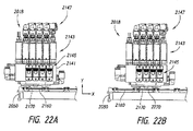
少なくともいくつかの実施形態は、移送デバイスと、自動化されたスライド処理モジュールと、分注組立体とを含む、顕微鏡スライド上の試料を処理するためのシステムである。自動化されたスライド処理モジュールは、移送デバイスからスライドキャリアを受け取るように位置付けられ、スライドキャリアが保持チャンバ内に位置する場合に、スライドキャリアによって保持される顕微鏡スライドに沿って移動可能な分注組立体を含み得る。分注組立体は、顕微鏡スライドの上面の幅と位置合わせされるように構成された複数の流出口を含み、それにより、流出口が、上面の幅の大部分または全部にわたって試薬を塗布する。 At least some embodiments are systems for processing samples on microscope slides that include a transfer device, an automated slide processing module, and a dispensing assembly. An automated slide processing module is positioned to receive a slide carrier from a transfer device and is movable along a microscope slide held by the slide carrier when the slide carrier is located in a holding chamber Can be included. The dispensing assembly includes a plurality of outlets configured to be aligned with the width of the top surface of the microscope slide so that the outlets apply the reagent over most or all of the width of the top surface.
いくつかの実施形態において、システムは、移送デバイスと、移送デバイスからスライドキャリアを受け取るように構成された染色器モジュールとを備える。ある実施形態において、染色器モジュールは、1つまたは複数の流体ラインと、スライドキャリアによって運ばれるスライドに沿って試薬を分注するために移動可能なヘッド組立体とを含む。ヘッド組立体は、流体ラインに連結され、流体ラインのうちの1つまたは全部から試薬を分注するように構成され得る。1つの実施形態において、ヘッド組立体のマニホールドは、分配チャンバと、分配チャンバ内へ通じている複数の流入口と、分配チャンバからの複数の流出口とを含む。流体は、マニホールドを通じて送られ、ヘッド組立体から分注され得る。 In some embodiments, the system comprises a transfer device and a stainer module configured to receive a slide carrier from the transfer device. In certain embodiments, the stainer module includes one or more fluid lines and a head assembly movable to dispense reagents along a slide carried by the slide carrier. The head assembly may be coupled to the fluid line and configured to dispense reagents from one or all of the fluid lines. In one embodiment, the head assembly manifold includes a distribution chamber, a plurality of inlets leading into the distribution chamber, and a plurality of outlets from the distribution chamber. Fluid can be routed through the manifold and dispensed from the head assembly.
またさらなる実施形態において、顕微鏡スライド処理システムは、移送デバイスと、移送デバイスからスライドキャリアを受け取るように構成された染色器モジュールとを備える。染色器モジュールは、複数のマニホールドと、これらのマニホールドに流体連通する複数のノズルとを含み得る。いくつかの実施形態において、染色器モジュールは、複数の第1の流体ラインと、複数の第2の流体ラインと、染色器モジュール内に位置付けられた、スライドキャリアがある場合にはそれに対して移動可能な分注ヘッドとを含む。分注ヘッドは、複数の第1のノズルと、第1の流体ラインの各々から第1のノズルへ流体を分配するように構成された第1のマニホールドと、複数の第2のノズルと、第2の流体ラインの各々から第2のノズルへ流体を分配するように構成された第2のマニホールドとを備え得る。分注ヘッドは、任意の数の流体ラインから液体を分配するために、さらなるマニホールドおよび/またはノズルを含んでもよい。 In yet a further embodiment, a microscope slide processing system comprises a transfer device and a stainer module configured to receive a slide carrier from the transfer device. The dyer module may include a plurality of manifolds and a plurality of nozzles in fluid communication with the manifolds. In some embodiments, the stainer module moves relative to a plurality of first fluid lines, a plurality of second fluid lines, and a slide carrier positioned in the stainer module, if any. Including possible dispensing heads. The dispensing head includes a plurality of first nozzles, a first manifold configured to distribute fluid from each of the first fluid lines to the first nozzle, a plurality of second nozzles, And a second manifold configured to distribute fluid from each of the two fluid lines to the second nozzle. The dispensing head may include additional manifolds and / or nozzles to dispense liquid from any number of fluid lines.
少なくともいくつかの実施形態は、自動化されたスライド処理装置内に位置する顕微鏡スライド上の試料を染色するための自動化されたスライド処理装置である。本スライド処理装置は、液体除去デバイスと、ガスナイフと、吸引要素とを含む。液体除去デバイスは、スライドに対して移動可能である。いくつかの実施形態において、ガスナイフは、液体除去を容易にするために、ガスカーテンおよび低圧領域を生成する。いくつかの実施形態において、ガスナイフは、液体除去デバイスがスライドに対して移動するにつれて、ガスカーテンによって少なくとも部分的に画定される収集ゾーンにおいて、スライドの上面上の液体を集めるように構成されたガスカーテンを生成するように構成される。吸引要素は、液体除去デバイスがスライドに対して移動するにつれて、収集ゾーンにおいて収集され
た液体を上面から除去するように位置付けられる。
At least some embodiments are automated slide processing devices for staining samples on microscope slides located within automated slide processing devices. The slide processing apparatus includes a liquid removal device, a gas knife, and a suction element. The liquid removal device is movable relative to the slide. In some embodiments, the gas knife creates a gas curtain and a low pressure region to facilitate liquid removal. In some embodiments, the gas knife is configured to collect liquid on the top surface of the slide in a collection zone at least partially defined by the gas curtain as the liquid removal device moves relative to the slide. Configured to produce a curtain. The suction element is positioned to remove the collected liquid from the top surface in the collection zone as the liquid removal device moves relative to the slide.
いくつかの実施形態において、スライド処理装置内に位置する顕微鏡スライド上の試料を染色するためのスライド処理装置は、スライドに対して移動可能な流体除去デバイスを備える。流体除去デバイスは、スライドの上面上の液体ボリュームを、上面上の収集ゾーンに向けて付勢するために、1つまたは複数の気体流を出力するように構成される。収集ゾーンは、1つまたは複数の気体流によって少なくとも部分的に画定され得る。ある実施形態において、収集ゾーンは、中央収集ゾーンである。他の実施形態において、収集ゾーンは、スライドに沿った他の位置にある。 In some embodiments, a slide processing apparatus for staining a sample on a microscope slide located within the slide processing apparatus comprises a fluid removal device that is movable relative to the slide. The fluid removal device is configured to output one or more gas streams to bias a liquid volume on the top surface of the slide toward a collection zone on the top surface. The collection zone may be at least partially defined by one or more gas streams. In certain embodiments, the collection zone is a central collection zone. In other embodiments, the collection zone is at other locations along the slide.
別の実施形態において、スライド処理装置は、吸引要素と、スライド上のある液体の少なくとも一部を捕集するために、顕微鏡スライドに対して移動可能な流体ナイフとを備える。吸引要素およびガスナイフは、液体の大部分または全部を吸引要素内へ引き込むように協働するように構成される。いくつかの実施形態において、スライド処理装置は、異なる位置において液体を引き込むための複数の吸引要素を含む。 In another embodiment, the slide processing apparatus comprises a suction element and a fluid knife movable with respect to the microscope slide to collect at least a portion of some liquid on the slide. The suction element and the gas knife are configured to cooperate to draw most or all of the liquid into the suction element. In some embodiments, the slide processing apparatus includes a plurality of suction elements for drawing liquid at different locations.
また別の実施形態において、顕微鏡スライド上の試料を処理するための方法は、液体で試料を覆うために、液体をスライド上へ塗布するステップを含む。閉じ込められた液体がスライドの長手方向の縁部から徐々に離間させられるように、塗布された液体を閉じ込めつつ、塗布された液体を上面に沿って移動させるために、スライドの上面に向けて気体流が送られる。閉じ込められた液体は、スライドの上面から除去される。 In yet another embodiment, a method for processing a sample on a microscope slide includes applying a liquid onto the slide to cover the sample with the liquid. A gas is directed toward the top surface of the slide to confine the applied liquid and move along the top surface so that the confined liquid is gradually separated from the longitudinal edge of the slide. A stream is sent. The trapped liquid is removed from the top surface of the slide.
いくつかの実施形態において、顕微鏡スライド上の試料を処理するための方法は、液体をスライド上へ塗布するステップと、非平面または多数面のガスカーテンをスライドの上面に向けて方向づけるステップを含む。ガスカーテンの頂点部は、塗布された液体をスライドの中心領域に向けて付勢するために、上面の中心領域に沿って、スライドの終端に向けて移動され得る。他の実施形態において、ガスカーテンの頂点部は、上面の他の領域に沿って移動されてもよい。 In some embodiments, a method for processing a sample on a microscope slide includes applying a liquid onto the slide and directing a non-planar or multi-sided gas curtain toward the top surface of the slide. The apex of the gas curtain can be moved toward the end of the slide along the center area of the top surface to urge the applied liquid toward the center area of the slide. In other embodiments, the apex of the gas curtain may be moved along other regions of the top surface.
特定の実施形態において、顕微鏡スライド上の試料を処理するための方法は、スライドを染色器モジュール内へ送るステップを含む。液体は、試料を液体に接触させるために、スライド上へ塗布される。液体は、スライドの上面に沿って風を吹き付けられ、スライドの上面から除去される。次いで、スライドは、染色器モジュールから除去され得る。いくつかの実施形態において、スライドは、染色器モジュール内へロボット制御で送られ、および/または、染色器モジュールからロボット制御で除去される。 In certain embodiments, a method for processing a sample on a microscope slide includes sending the slide into a stainer module. The liquid is applied onto the slide to bring the sample into contact with the liquid. The liquid is blown along the top surface of the slide and removed from the top surface of the slide. The slide can then be removed from the stainer module. In some embodiments, the slide is robotically sent into and / or removed from the stainer module robotically.
少なくともいくつかの実施形態は、1つまたは複数の試薬を第1の顕微鏡スライド上へ塗布するために、染色器モジュールのヘッド組立体を、染色器モジュール内の処理ゾーンに位置付けられる第1の顕微鏡スライドに対して移動させるステップを含む方法である。1つまたは複数の試薬を第1の顕微鏡スライド上へ塗布した後に、第1の顕微鏡スライドは、処理ゾーンから遠ざけられ、第2の顕微鏡スライドは、処理ゾーンへ移動される。1つまたは複数の試薬を第2の顕微鏡スライド上へ塗布するために、第2の顕微鏡スライドが処理ゾーンに位置付けられている間に、ヘッド組立体は、第2の顕微鏡スライドに対して移動される。 At least some embodiments include a first microscope positioned in a processing zone within a stainer module to apply a stainer module head assembly to apply one or more reagents onto a first microscope slide. It is a method including the step which moves with respect to a slide. After applying one or more reagents onto the first microscope slide, the first microscope slide is moved away from the processing zone and the second microscope slide is moved to the processing zone. In order to apply one or more reagents onto the second microscope slide, the head assembly is moved relative to the second microscope slide while the second microscope slide is positioned in the processing zone. The
いくつかの実施形態において、染色器モジュールを使用して、試料を運ぶ複数の顕微鏡スライドを処理するための方法は、顕微鏡スライドを運ぶスライドキャリアトレイを染色器モジュール内へ送るステップを含む。染色器モジュールは、ヘッド組立体を有する移動可能な分注装置を含む。スライドキャリアトレイが、ヘッド組立体の第1のセットからの垂直な送出経路の第1のセットを遮り、ヘッド組立体の第2のセットからの垂直な送出経
路の第2のセットを遮る間に、分注組立体から1つまたは複数の液体を送ることによって、顕微鏡スライドのうちの少なくとも1枚が処理される。スライドキャリアトレイは、ヘッド組立体の第1のセットによって出力された液体を収集皿が収集するように、垂直な送出経路の第1のセットを遮ることなく洗浄位置へ移動され得る。スライドキャリアトレイは、ヘッド組立体の第2のセットによって出力された液体を収集皿が収集するように、垂直な送出経路の第2のセットを遮ることなく第2の位置へ移動され得る。第1のセットは、第2のセットと異なり得る。
In some embodiments, a method for processing a plurality of microscope slides carrying a sample using a stainer module includes sending a slide carrier tray carrying a microscope slide into the stainer module. The dyer module includes a movable dispensing device having a head assembly. While the slide carrier tray blocks a first set of vertical delivery paths from the first set of head assemblies and blocks a second set of vertical delivery paths from the second set of head assemblies. , At least one of the microscope slides is processed by delivering one or more liquids from the dispensing assembly. The slide carrier tray can be moved to the wash position without obstructing the first set of vertical delivery paths so that the collection tray collects the liquid output by the first set of head assemblies. The slide carrier tray can be moved to the second position without obstructing the second set of vertical delivery paths so that the collection tray collects the liquid output by the second set of head assemblies. The first set may be different from the second set.
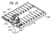
さらなる実施形態において、複数の顕微鏡スライドを処理するための装置は、少なくとも1つの染色器モジュールを含む。染色器モジュールは、トレイ保持器と、ヘッド組立体とを含み得る。トレイ保持器は、染色器モジュールのチャンバにおいて第1の顕微鏡スライドおよび第2の顕微鏡スライドを運ぶトレイを受け取り、保持するように構成され得る。ヘッド組立体は、染色器モジュールにおける処理ゾーンに対して移動可能であり、それにより、ヘッド組立体から出力された1つまたは複数の液体を、処理ゾーンに位置付けられた第1の顕微鏡スライドに沿って送る。いくつかの実施形態において、トレイ保持器は、第1の顕微鏡スライドを処理ゾーンから離れるように移送し、1つまたは複数の液体を第1の顕微鏡スライド上へ送った後に、第2の顕微鏡スライドを処理ゾーンへ移送するように移動可能である。 In a further embodiment, an apparatus for processing a plurality of microscope slides includes at least one stainer module. The stainer module may include a tray holder and a head assembly. The tray holder may be configured to receive and hold a tray carrying the first and second microscope slides in the chamber of the stainer module. The head assembly is movable with respect to the processing zone in the stainer module, thereby causing one or more liquids output from the head assembly to move along a first microscope slide positioned in the processing zone. Send. In some embodiments, the tray holder transfers the first microscope slide away from the processing zone and sends one or more liquids onto the first microscope slide before the second microscope slide. Can be transferred to the processing zone.
またさらなる実施形態において、複数の顕微鏡スライドを処理するための装置は、流体ラインと、トレイ保持器と、ヘッド組立体とを含む染色器モジュールを備える。トレイ保持器は、染色器モジュールにおいて第1の顕微鏡スライドおよび第2の顕微鏡スライドを運ぶトレイを受け取り、保持するように構成される。ヘッド組立体は、分注ヘッドと、分注ヘッドに備え付けられた1つまたは複数の弁とを含む。弁は、複数の流体ラインからのどの流体がヘッドを通じて、ヘッドの外へ流れるかを制御し得る。分注ヘッドは、弁を搭載し、分注ヘッドから出力された1つまたは複数の流体を顕微鏡スライドに沿って送るために、トレイ保持器に対して移動可能である。 In yet a further embodiment, an apparatus for processing a plurality of microscope slides comprises a stainer module that includes a fluid line, a tray holder, and a head assembly. The tray holder is configured to receive and hold a tray carrying the first microscope slide and the second microscope slide in the stainer module. The head assembly includes a dispensing head and one or more valves mounted on the dispensing head. The valve may control which fluid from multiple fluid lines flows through the head and out of the head. The dispensing head is mounted with a valve and is movable with respect to the tray holder to send one or more fluids output from the dispensing head along the microscope slide.
少なくともいくつかの実施形態は、自動化された組織学的染色システム内でスライドによって運ばれる試料を処理するための方法へ向けられる。本方法は、システム内の染色器の温度制御された内部環境に向けて、さらにその中へスライドキャリアを移動させるステップを含む。スライドキャリアは、第1のスライドおよび第2のスライドを運び、第1のスライドおよび第2のスライドは、それぞれ第1の試料および第2の試料を運び得る。第1の試料および第2の試料は、第1のスライドおよび第2のスライドが内部環境に存在し、内部環境の平均温度が気温よりも高い間に、染色試薬および対比染色試薬のうちの少なくとも1つで染色される。スライドキャリアは、試料の一方または双方を染色した後に、内部環境の外へ移動され得る。 At least some embodiments are directed to a method for processing a sample carried by a slide in an automated histological staining system. The method includes the step of moving the slide carrier further into the temperature controlled internal environment of the stainer in the system. The slide carrier carries a first slide and a second slide, and the first slide and the second slide can carry a first sample and a second sample, respectively. The first sample and the second sample are at least one of the staining reagent and the counter-staining reagent while the first slide and the second slide are present in the internal environment and the average temperature of the internal environment is higher than the air temperature. Stained with one. The slide carrier can be moved out of the internal environment after staining one or both of the samples.
いくつかの実施形態において、自動化された組織学的染色システムは、主ハウジングと、染色器とを備える。染色器は、染色器の内部環境を画定する染色器ハウジングと、染色器を内部で加熱するように構成された1つまたは複数の加熱器と、移送装置とを含む。移送装置は、主ハウジング内でスライドキャリアを染色器に向けてロボット制御で移動させるように構成され得る。1つの実施形態において、移送装置は、主ハウジング内の複数のモジュール間でスライドキャリアを移動させる。 In some embodiments, an automated histological staining system includes a main housing and a stainer. The stainer includes a stainer housing that defines an interior environment of the stainer, one or more heaters configured to heat the stainer therein, and a transfer device. The transfer device may be configured to robotically move the slide carrier toward the stainer within the main housing. In one embodiment, the transfer device moves the slide carrier between multiple modules in the main housing.
少なくともいくつかの実施形態は、自動化された組織学的染色システムにおいて試料を処理するための方法へ向けられる。本方法は、スライドキャリアをシステムの染色器内へロボット制御で移動させるステップを含む。スライドキャリアは、それぞれが試料を運ぶスライドを運び、試料は、パラフィン内に少なくとも部分的に埋め込まれる。液体は、試料を少なくとも脱パラフィン化し、染色し、対比染色するための所定のレシピに従って、
スライド上へ自動的に分注される。スライドキャリアは、液体を自動的に分注した後に、染色器の外へロボット制御で移動させられ得る。いくつかの実施形態において、スライドキャリアを染色器内へ移動させた後から、スライドキャリアを染色器の外へ移動させる前までの、スライド上へ分注された全液体の総量は、一価アルコールの体積濃度よりも高い体積濃度の多価アルコールを有する。
At least some embodiments are directed to a method for processing a sample in an automated histological staining system. The method includes the step of robotically moving the slide carrier into the stainer of the system. The slide carriers carry slides, each carrying a sample, and the sample is at least partially embedded in paraffin. The liquid is at least according to a predetermined recipe for deparaffinizing, staining, and counterstaining the sample
It is automatically dispensed onto the slide. The slide carrier can be moved robotically out of the stainer after automatically dispensing the liquid. In some embodiments, the total amount of all liquid dispensed on the slide after moving the slide carrier into the stainer and before moving the slide carrier out of the stainer is monohydric alcohol. Having a volume concentration of polyhydric alcohol higher than the volume concentration.
1つの実施形態において、自動化された組織学的染色システム内の試料を処理するための方法は、試料を染色試薬と接触させるステップを含む。試料は、試料から染色試薬を少なくとも部分的に除去するために、洗浄液によって接触され得る。試料は、試料と洗浄液とを接触させた後に、対比染色試薬と接触させられ得る。試料は、試料と対比染色試薬とを接触させた後に、試料の対比染色を分別するために、洗浄液と接触させられ得る。いくつかの実施形態において、染色試薬、洗浄液、および/または対比染色試薬のうちの1つまたは複数は、一価アルコールの体積濃度よりも高い体積濃度の多価アルコールを有する。1つの実施形態において、染色試薬、洗浄液、および対比染色試薬の各々は、一価アルコールの体積濃度よりも高い体積濃度の多価アルコールを有する。 In one embodiment, a method for processing a sample in an automated histological staining system includes contacting the sample with a staining reagent. The sample can be contacted with a wash solution to at least partially remove the staining reagent from the sample. The sample can be contacted with a counterstaining reagent after contacting the sample with a wash solution. The sample can be contacted with a wash solution to separate the counterstain of the sample after contacting the sample with a counterstain reagent. In some embodiments, one or more of the staining reagent, wash solution, and / or counterstaining reagent have a volume concentration of polyhydric alcohol that is higher than the volume concentration of the monohydric alcohol. In one embodiment, each of the staining reagent, wash solution, and counterstaining reagent has a volume concentration of polyhydric alcohol that is higher than the volume concentration of monohydric alcohol.
本開示の多くの態様は、下記の図面を参照することで、より良く理解され得る。図面における相対寸法は、いくつかの実施形態に関しては縮尺通りであり得る。他の実施形態に関して、図面は縮尺通りではないことがある。参照を容易にするために、本開示の全体を通じて、同一の参照符号は、同一の構成要素もしくは機能、または少なくとも概ね同様もしくは類似した構成要素もしくは特徴を識別するために使用され得る。 Many aspects of the disclosure can be better understood with reference to the following drawings. The relative dimensions in the drawings can be to scale for some embodiments. For other embodiments, the drawings may not be to scale. For ease of reference, throughout the present disclosure, identical reference signs may be used to identify identical components or functions, or at least generally similar or similar components or features.
組織学的に処理される試料のいくつかの属性(例えば、染色度)の一貫性および制御性を高めることは、多くの場合に望ましい。処理時間(すなわち、所与の組織学的工程の時間)および処理温度(すなわち、所与の組織学的工程が実行される温度)は、こうした属性の全てではないにしても、大部分に影響を及ぼす2つの変数である。本技術の少なくともいくつかの実施形態に従って構成された、自動化された組織学的システムは、処理時間および/または処理温度の一貫性および/または制御性を促進する機能を含む。例えば、これらのシステムのうちの少なくともいくつかは、正確に制御された液体分注動作および液体除去動作を実行することが可能な処理ヘッドを有する染色器を含む。これらの染色器は、高い基準温度に維持され得る内部環境も有し得る。本技術の実施形態に従って構成された、これらのシステムおよび他のシステムの(例えば、品質および/または多用途性に関する)性能は、従来の同等のシステムの性能をはるかに上回ることが期待される。さらに、本技術の少なくともいくつかの実施形態に従って構成されたシステムは、低減された処理コスト、低減された廃棄物生成、および増加したスループットなどの、他の望ましい向上を提供する特徴を含み得る。 Increasing the consistency and controllability of some attributes (eg, degree of staining) of histologically processed samples is often desirable. Processing time (ie, the time of a given histological process) and processing temperature (ie, the temperature at which a given histological process is performed) will affect most if not all of these attributes. Are two variables. An automated histological system configured in accordance with at least some embodiments of the present technology includes features that facilitate consistency and / or controllability of processing time and / or processing temperature. For example, at least some of these systems include a stainer having a processing head capable of performing precisely controlled liquid dispensing and liquid removal operations. These stainers may also have an internal environment that can be maintained at a high reference temperature. The performance of these and other systems (eg, in terms of quality and / or versatility) configured in accordance with embodiments of the present technology is expected to far exceed the performance of conventional comparable systems. Further, systems configured in accordance with at least some embodiments of the present technology may include features that provide other desirable improvements, such as reduced processing costs, reduced waste generation, and increased throughput.
本技術の少なくともいくつかの実施形態に従って選択または配合された処理液は、対応する従来の処理液とは異なり得る。例えば、本技術のいくつかの実施形態に従って選択または配合された処理液は、対応する従来の液体よりも揮発性が低い。この理由および/または他の理由により、これらの液体は、高い基準温度で維持される染色器における使用によく適合し得る。対照的に、対応する従来の液体は、これらの染色器において使用されると、許容し難い高い割合で蒸発する傾向があり得る。自動化された組織学的システムにおける処理液の蒸発は、一般に、望ましくない。さらに、本技術の実施形態に従って選択または配合された処理液は、対応する従来の処理液よりも毒性が低くなり得る。これは、処理液の処分を促進し、および/または、処理液が使用されるシステムからの有毒蒸気の放出を低減または消失させるであろう。少なくともいくつかの場合において、本技術の一実施形態に従って構成された、自動化された組織学的システムと共に使用される一部または全部の処理液は、比較的低い濃度の一価アルコール(例えば、エタノール)を有する。例えば、これらの処理液は、一価アルコールよりも高い体積濃度の多価アルコール(例えば、プロピレングリコール)を含み得る。これは、多くの利点の中でも特に、蒸発を低減し、試料処理のいくつかの側面を向上させ、処理複雑度を低下させ得る。さらに、本技術の実施形態に従って選択または配合された処理液は、これらの改善および/または他の望ましい改善を提供する他の特徴を含み得る。 The processing liquid selected or formulated according to at least some embodiments of the present technology may be different from the corresponding conventional processing liquid. For example, processing liquids selected or formulated according to some embodiments of the present technology are less volatile than corresponding conventional liquids. For this reason and / or other reasons, these liquids can be well adapted for use in a dyer maintained at a high reference temperature. In contrast, corresponding conventional liquids can tend to evaporate at unacceptably high rates when used in these stainers. Evaporation of the processing liquid in an automated histological system is generally undesirable. Furthermore, processing liquids selected or formulated according to embodiments of the present technology can be less toxic than corresponding conventional processing liquids. This will facilitate disposal of the processing liquid and / or reduce or eliminate toxic vapor emissions from the system in which the processing liquid is used. In at least some cases, some or all of the processing fluids used with an automated histological system configured in accordance with an embodiment of the present technology may have a relatively low concentration of monohydric alcohol (e.g., ethanol ). For example, these treatment liquids may contain a higher volume concentration of polyhydric alcohol (eg, propylene glycol) than the monohydric alcohol. This can, among other advantages, reduce evaporation, improve some aspects of sample processing, and reduce processing complexity. Further, processing liquids selected or formulated according to embodiments of the present technology may include other features that provide these and / or other desirable improvements.
本技術のいくつかの実施形態の具体的な詳細は、図1〜図93を参照しつつ、本明細書において開示される。本明細書において開示される実施形態に加えて、他の実施形態も本技術の範囲内であることが留意されるべきである。例えば、本技術の実施形態は、本明細書において図示または説明される構成、構成要素、および/または手順とは異なる構成、構成要素、および/または手順を有してもよい。また、当業者は、本技術の実施形態が、本明細書において図示または説明される構成、構成要素、および/または手順に加えた、構成、構成要素、および/または手順を有し得ること、ならびに、これらの実施形態および他の実施形態が、本技術から逸脱することなく、本明細書において図示または説明される構成、構成要素、および/または手順のうちのいくつかを有しなくてもよいことを理解するであろう。 Specific details of some embodiments of the technology are disclosed herein with reference to FIGS. It should be noted that in addition to the embodiments disclosed herein, other embodiments are within the scope of the present technology. For example, embodiments of the technology may have configurations, components, and / or procedures that are different from the configurations, components, and / or procedures illustrated or described herein. In addition, those skilled in the art can appreciate that embodiments of the technology may have configurations, components, and / or procedures in addition to the configurations, components, and / or procedures illustrated or described herein. And, these and other embodiments may not have some of the configurations, components, and / or procedures illustrated or described herein without departing from the technology. You will understand that good.
システムアーキテクチャの選択された例
図1は、本技術の一実施形態に係る、自動化されたスライド処理システム2(「システム2」)の立面図である。システム2は、アクセスポート3と、タッチスクリーン5の形態の入力デバイスとを含み得る。ユーザは、スライドを運ぶトレイ(「スライドトレイ」)をアクセスポート3内に置くなどして、スライドトレイをシステムに搭載(load)することができる。所与のスライドトレイは、処理されるべき試料をそれぞれ運ぶスライドを運ぶことができる。システムへの搭載前、搭載中、または搭載後に、ユーザは、タッチスクリーン5を使用して、試料に対して行われるべき工程(例えば、プロトコル、レシピ等)を選択する。次いで、システム2は、試料を自動的に処理し、スライドにカバーガラスを被せ、スライドトレイをアクセスポート3へ戻し得る。その後、カバーガラスを被せられたスライド(例えば、スライドに対して恒久的に結合されたカバーガラスを運ぶスライド)は、その後の分析、病理学者による解釈、および/または保存のためにアクセスポート3から取り出され得る。
Selected Example of System Architecture FIG. 1 is an elevation view of an automated slide processing system 2 (“
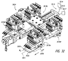
図2は、システム2の内部構成要素のうちの一部を示す、システム2の側立面図である。システム2は、ハウジング7と、このハウジング7内に配列されたモジュール(例えば、ワークステーション)4、6、8および10とを含み得る。ハウジング7内に、システム2は、移送装置12と、液体供給源14と、加圧装置16と、コントローラ18も含み得る。ハウジング7は、全体的に汚染のない内部環境を維持することができ、および/または、モジュール4、6、8、10のうちの1つもしくは複数を動作させることに適した所望の内部温度を維持するのを助けることができる。試料を載せたスライドを保持するス
ライドトレイは、モジュール4、6、8、10間を移送装置12によって運ばれて、試料を乾燥させ、試料を染色し、スライドにカバーガラスを被せ得る。試料は、処理液の共有浴槽を使用せずに、スライド上で個々に処理され得る。このようにして、二次汚染、処理液のキャリーオーバー、過剰な廃棄物(例えば、液体廃棄物)、一定しない処理液性能、およびディップ・アンド・ダンク機械の他の不都合が低減または回避され得る。さらに、試料の染色度および/または他の後処理属性は、制御性が高く、正確に実行可能となり得る。移送装置12ならびにモジュール4、6、8および10は、コントローラ18の制御下となり得る。コントローラ18は、ユーザによって、タッチスクリーン5(図1)を使用して制御され得る。
FIG. 2 is a side elevation view of the
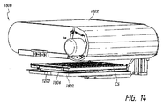
モジュール4は、乾燥器(「乾燥器4」)の形態の加熱装置とし、モジュール6は、染色器(「染色器6」)とし、モジュール8は、カバーガラス取り付け器(coverslipper)(「カバーガラス取り付け器8」)とし、モジュール10は、硬化ユニット(「硬化ユニット10」)の形態の加熱装置とし得る。モジュールは、乾燥器4および硬化ユニット10を染色器6よりも高く位置付けた状態で、垂直積層型に配置され得る。これは有益となり得る。なぜならば、例えば、乾燥器4および硬化ユニット10は、熱を生成することがあり、この熱が、ハウジング7の上部を通じて放出され得るためである。染色器6は、染色試薬(例えば、ヘマトキシリン試薬)および対比染色試薬(例えば、エオシン試薬)などの液体を液体供給源14から供給する流体マニホールド19へ接続され得る。流体マニホールド19は、1つまたは複数の管、弁、オリフィス、センサ、ポンプ、フィルタ、および/または液体を制御して送ることが可能な他の構成要素を含み得るが、これに限定されない。電子マニホールド(図示せず)は、モジュールをコントローラ18へ導通可能に連結して、モジュールの構成要素とコントローラ18の構成要素とに対して電力および制御を提供し得る。1つの実施形態において、個々のモジュールは、流体マニホールド19および電子マニホールドへ、それぞれ共通のインターフェースおよびプラグを通じて接続される。共通のインターフェースおよびプラグを使用することによって得られる適合性は、モジュールを迅速かつ簡単に追加または除去することを可能にし、それによって、システムの再構成、メンテナンス、および/または修理を容易にする。
移送装置12は、スライドトレイをモジュールからモジュールへロボット制御の効率的な手法で移動させて、システムスループットを向上させることができる。移送装置12は、1つまたは複数のエレベータ(例えば、レールおよび台車組立体)、ロボットアーム、モータ(例えば、ステッパモータ、駆動モータ等)、トレイインターフェースもしくはトレイホルダ(例えば、フォーク、クランプ等)、および/またはセンサ、ならびに運動を提供するための他の構成要素を備え得るが、これらに限定されない。少なくともいくつかの実施形態において、移送装置12は、X−Y−Z移送機構(例えば、X−−左右、Y−−前後、Z−−上下)として機能するためのエレベータおよび挿入部(例えば、X−Yシャトルテーブル)を含む。センサ(図示せず)は、移送装置12の位置を検出するために移送装置12に隣接して置かれ、正確なスライドトレイの位置決めを提供するために、検知位置において移送装置12にインデックスを付けるべく使用され得る。
The
センサは、移送装置12上、モジュール内、およびスライドトレイ上を含めて、システム2全体にわたる様々な位置に位置し得る。いくつかの実施形態において、センサ(ひずみゲージ、加速度計、接触センサ、光学センサ、または、いくつかの事象を検知することが可能な他の検知デバイスを含むが、これらに限定されない)は、衝突、衝撃、またはシステム2内の他の事象を検出するために使用され得る。センサが出力する1つまたは複数の信号は、コントローラ18によって受け取られ、コントローラ18は所与の事象がユーザ通知または他のアクションを必要とするかを決定することができる。例えば、予想外のスライドトレイへの衝撃が検出された場合、コントローラ18は、スライドがトレイ上に適正に位置付けられているかを決定するためにトレイを目視検証すべく、ハウジング7を
開くようにユーザに対して警告することができる。センサは、ハウジング7の天井13に備え付けられて、天井13とスライドトレイおよび/またはスライドとの間の接触を防止するのを助けてもよい。
The sensors can be located at various locations throughout the
垂直方向に離間した棚24(1つが特定されている)を有する保持ステーション23は、移送装置12の隣、および正面に位置付けられ得る。最上部の棚24は、乾燥器4の下に位置付けられ、最下部の棚は、アクセスポート3の上に位置付けられ得る。移送装置12は、スライドトレイを棚24から乾燥器4へロボット制御で移動させて、湿った生物試料を乾燥させ、生物試料をスライド上で固め、または、さもなければ試料を載せたスライドを熱処理し得る。いくつかの実施形態において、乾燥器4は、乾燥を促進させる向きにスライドを保持しつつ、試料を載せたスライドを対流加熱する。高い対流速度は、例えば、試料および/またはスライドトレイ内のスライドのそれぞれの位置に起因する、試料および/またはスライド間の温度差を低減する(例えば、最小限に抑える)ために、試料を載せたスライドの実質的に均一な加熱を提供するべく使用され得る。
A holding
コントローラ18は、例えば、付加的な自動化された染色システムへ接続され得る研究所情報管理システムの一部とすることができる。コントローラ18は、例えば、モジュールへの処理液の供給およびモジュール動作を制御する任意の数のマイクロプロセッサを含む、1つまたは複数の回路基板を含み得るが、これらに限定されない。付加的に、または代替的に、プリント基板、マイクロプロセッサ、電源、メモリ、リーダ(例えば、ラベルリーダ)が、個々のモジュールの一部となり、コントローラ18、またはリモートコントローラなどの別のコントローラと通信してもよい。コントローラ18は、システム構成要素に指示することができ、一般的には、1つまたは複数の中央処理装置、処理デバイス、マイクロプロセッサ、DSP(digital signal processor)、ASIC(application−specific integrated circuits)、リーダなどを含み得るが、これらに限定されない。情報を記憶するために、コントローラ18は、1つまたは複数の記憶要素21(点線で示される)、例えば、揮発性メモリ、不揮発性メモリ、ROM(read−only memory)、RAM(random access memory)などを含み得るが、これらに限定されない。記憶される情報は、加熱プログラム、染色プログラム、硬化プログラム、カバーガラス取り付けプログラム、最適化プログラム、試料処理プログラム(例えば、任意のユーザ定義される動作のセットおよび/もしくは予め定義された動作のセット)、校正プログラム、インデックス付けプログラム、洗浄/準備プログラム、または他の適切な実行可能なプログラムを含み得る。試料処理プログラムは、病理学者の嗜好などのユーザ嗜好に基づいて選択され得るレシピまたはプロトコルを含み得る。最適化プログラムは、性能を最適化する(例えば、加熱を強化する、過度な処理液消費を低減する、生産性を増加させる、処理一貫性を向上させるなど)ために実行され得る。システム処理は、例えば、(1)処理速度を増加させる、(2)乾燥器4および/もしくは硬化ユニット10における加熱サイクルの時間を低減する、(3)スループットを高める(例えば、ある長さの時間内で処理されるスライドの数を増加させる)、(4)染色の一貫性および/もしくは品質を改善する、ならびに/または(5)液体廃棄物を低減する、ための最適なスケジュールを決定することによって最適化され得る。
The
液体供給源14は、供給容器27(1つが特定されている)を保持するためのスロットを含み、供給容器27に関連付けられたRFIDタグを読み出すことができるRFIDアンテナの識別子などの容器識別子を含み得る。供給容器27は、1つまたは複数の、人間が読み取り可能なラベル、機械読み取り可能なラベル(例えば、システム2によって読み出されるべきバーコード)、または他の種類のラベルを含み得るが、これらに限定されない。例えば、供給容器27は、特定の処理液に関する情報(例えば、容器内容物情報、製造日、使用期限等)がエンコードされたRFIDタグを含んでもよい。容器の1つの例は
、図90および図91に関連して議論され、液体供給源の1つの例は、図89に関連して議論される。液体供給源14は、センサ(例えば、圧力センサ、温度センサ等)、ポンプ(例えば、空気ポンプ)、弁、フィルタ、管、および/または、例えば、染色器6へ液体を供給するように協働し得る他の流体構成要素も含み得るが、これらに限定されない。
The
加圧装置16は、液体供給源14の下に位置し、複数のポンプ、圧縮器、真空デバイス(例えば、ブロワ)、ならびに/または、液体を加圧し、および/もしくは真空(部分真空を含む)を提供することが可能な他のデバイスを含み得る。加圧された空気は、例えば、染色器6のエアナイフへ送られ、真空度圧力は、染色器6の液体除去デバイスによって使用され得る。
The
液体廃棄物は、管を通じて、廃棄物容器32、34へ送られ得る。この廃棄物は、システム2内で多様な源から生成され得る。例えば、スライドトレイにおいて収集された液体廃棄物は、除去され、廃棄物容器32、34へ導かれる。この液体廃棄物を定期的に除去することは、操作中に当該廃棄物がスライドトレイの外へこぼれないようにするために有益となり得る。乾燥器4において、スライドトレイは封入剤(mounting media;例えば、水)を収集し、封入剤はスライドトレイから吸い取られて廃棄物容器32、34のうちの1つへ送り込まれ得る。染色器6において、スライドトレイは、分注装置のノズルから意図せずに滴る液体だけでなく、スライドから落下する処理液も収集することができる。カバーガラス取り付け器8において、スライドトレイは、カバーガラスをスライドに被せるために使用されるカバーガラス液(coverslipping liquids)を収集することができる。封入剤、処理液、カバーガラス液、および任意の他の収集される廃液は、廃棄物容器32、34へ送り込まれ得る。ハウジング7の扉35(図1)は、廃棄物容器32、34にアクセスし、廃棄物容器32、34を空にするために開かれ得る。
Liquid waste can be sent through pipes to waste
動作時に、スライドトレイは、アクセスポート3を介してシステム2内へ搭載され得る。ここで、図2を参照すると、移送装置12は、スライドトレイをアクセスポート3から取り出し、スライドトレイを所望の位置へ移送することができる。システム2は、任意のユーザ定義された動作のセット、予め定義された動作のセット、または他の動作のセットに従って、特定の試料を載せたスライドおよび/またはスライドトレイを個々に処理することができる。スライドトレイは、トレイ内のスライドが検出器(例えば、光学センサ、カメラ等)によって分析される調査ステーションへ移送され得る。次いで、スライドトレイは、試料が乾燥され、および/またはスライドへ定着させられる乾燥器4へ移動され得る。いくつかの工程において、乾燥器4は、スライドの表面全体にわたってパラフィンを融解および拡散させることによって、パラフィン包埋試料からパラフィンを除去するのを助け得る。結果として得られる、スライド全体にわたって広げられたより大きな表面積を有するパラフィンの薄い層は、染色器6内でスライドに対して塗布される脱パラフィン液によって、より簡単に除去され得る。試料および/またはスライドが、少なくとも部分的に乾燥されると、スライドトレイは、生物試料が処理される染色器6のうちの1つへ移動され得る。染色器6は、フレッシュな液体を試料に個々に塗布することによって、脱パラフィン化、染色、調整(例えば、溶媒交換)、および他の試料処理動作を行うことができる。これは、試料の後処理特性に対する制御を促進することができる。染色器6は、フレッシュな処理液を、隣接するスライド上へ飛散させずに、スライド上へ制御して分注し、処理液をスライドから制御して除去することができる。制御された分注/除去は、例えば、スライドトレイによって収集される液体廃棄物の量を最小化し、または限定的なものにすることによって、液体廃棄物の量を低減しつつ、試料を有効に処理するために使用され得る。図示されるシステム2は、システムスループットを高めるために、それぞれが3つのスライドトレイの並行処理を提供する3つの染色器6を含むが、染色器6の動作に基づく当該システムのスループットの過度な制約を防止するために、より多くの数またはより
少ない数の染色器が使用されてもよい。
In operation, the slide tray can be loaded into the
本明細書において、「試薬」および「処理液」という用語は、スライドに液体または液体組成物を付加することに関与する試料処理動作において使用される任意の液体または液体組成物を指す。試薬および処理液の例は、溶液、乳剤、懸濁液、および溶媒(純粋またはそれらの混合のいずれか)を含む。これらの例および他の例は、水性または非水性とすることができる。さらなる例は、抗体の溶液または懸濁液、核酸プローブの溶液または懸濁液、および色素分子または染色分子の溶液または懸濁液(例えば、H&E染色溶液、Pap染色溶液等)を含む。またさらなる例は、パラフィン包埋生物試料を脱パラフィン化するための溶媒および/または溶液、水性洗浄液、ならびに炭化水素(例えば、アルカン、イソアルカン、およびキシレンなどの芳香族化合物)を含む。またさらなる例は、生物試料を脱水または再水和させるために使用される溶媒(およびそれらの混合物)を含む。染色器6は、幅広い試薬および処理液を容器27から受け取ることができる。
As used herein, the terms “reagent” and “treatment liquid” refer to any liquid or liquid composition used in a sample processing operation that involves adding a liquid or liquid composition to a slide. Examples of reagents and processing liquids include solutions, emulsions, suspensions, and solvents (either pure or mixtures thereof). These and other examples can be aqueous or non-aqueous. Further examples include antibody solutions or suspensions, nucleic acid probe solutions or suspensions, and dye molecules or staining molecules solutions or suspensions (eg, H & E staining solutions, Pap staining solutions, etc.). Still further examples include solvents and / or solutions for deparaffinizing paraffin-embedded biological samples, aqueous wash solutions, and hydrocarbons (eg, aromatic compounds such as alkanes, isoalkanes, and xylenes). Still further examples include solvents (and mixtures thereof) used to dehydrate or rehydrate biological samples. The
「染色」という用語は、本明細書において、一般に、生体試料内の特定の分子(例えば、脂質、タンパク質もしくは核酸など)または特定の構造(例えば、正常細胞もしくは悪性細胞、サイトゾル、核、ゴルジ装置、もしくは細胞骨格)の存在、位置、および/または量(濃度など)を検出し、および/または分別する、生体試料の任意の処理を指すために使用される。例えば、染色は、生体試料の特定の分子または特定の細胞構造と周囲部分との対比を提供することができ、染色度は、その試料内の特定の分子の量の基準を提供することができる。染色は、明視野顕微鏡だけでなく、位相差顕微鏡、電子顕微鏡、および蛍光顕微鏡などの他の観察ツールも用いた、分子、細胞構造および有機体の観察を助けるために使用され得る。システム2によって行われる染色には、細胞の輪郭を視覚化するために使用され得るものがある。システム2によって行われる染色には、他の細胞成分を染色することなく、または、他の細胞成分を比較的微小に染色しながら、いくつかの細胞成分(例えば、分子または構造など)が染色されることに依存し得るものもある。システム2によって行われる染色方法の種類の例は、組織化学的方法、免疫組織化学的方法、および、核酸分子間のハイブリダイゼーション反応などの、分子間の反応(非共有結合反応を含む)に基づく他の方法を含むが、これらに限定されない。特定の染色方法は、一次染色方法(例えば、H&E染色、Pap染色等)、酵素免疫組織化学的方法(enzyme−linked immunohistochemical method)、およびFISH(fluorescence in situ hybridization)などの原位置RNAおよびDNAハイブリダイゼーション方法を含むが、これらに限定されない。
The term “staining” as used herein generally refers to a specific molecule (eg, lipid, protein or nucleic acid, etc.) or a specific structure (eg, normal or malignant cell, cytosol, nucleus, Golgi, etc.) in a biological sample. Used to refer to any treatment of a biological sample that detects and / or separates the presence, location, and / or amount (such as concentration) of the device or cytoskeleton. For example, staining can provide a contrast between a specific molecule or a specific cellular structure of a biological sample and the surrounding portion, and the degree of staining can provide a measure of the amount of a specific molecule in that sample. . Staining can be used to aid in the observation of molecules, cell structures and organisms using not only bright field microscopes but also other observation tools such as phase contrast, electron, and fluorescence microscopes. Some of the staining performed by
試料を処理した後、移送装置12は、スライドトレイを染色器6からカバーガラス取り付け器8へ移送することができる。カバーガラス取り付け器8は、溶剤をスライドに塗布し、予め塗布された接着剤を有するカバーガラスをスライド上へ置くことができる。いくつかの実施形態において、スライドトレイは、複数のスライドを、例えば、実質的に水平な位置に保持し、カバーガラスは、スライドに対して個々に付加される。1つの実施形態において、カバーガラス取り付け器8は、実質的には、米国特許出願公開第2004/0092024A1号または米国特許第7,468,161号において説明されるようなものであり、当該特許出願および当該特許は、その全体が参照によって本明細書に組み込まれる。米国特許出願公開第2004/0092024A1号または米国特許第7,468,161号において説明されるカバーガラス取り付け器およびそれらの動作は、例えば、破損したカバーガラスを検出すること、単一のカバーガラスの取り出しを容易にすること、カバーガラス配置の正確さを高めること、および/または、システムスループットを高めることによって、カバーガラスの取扱いを向上させるために実装され得る。
After processing the sample, the
カバーガラスがスライド上に置かれると、移送装置12は、スライドトレイをカバーガ
ラス取り付け器8から硬化ユニット10へ移送することができる。硬化ユニット10において、カバーガラスは、スライド上で(少なくとも部分的に)硬化され、トレイが液体を収集した場合にはトレイ自体が(少なくとも部分的に)乾燥される。硬化中に、カバーガラスおよびスライドの表面領域を対流に曝すために、スライドは、実質的に水平な位置に保持され得る。これは、接着剤の迅速かつ効率的な硬化を促進させ得る。所与のカバーガラスの下のカバーガラス液が完全に除去されていない場合であっても、例えば、病理学者などの医療専門家による後続の取扱い中にカバーガラスを所定の位置に保持する接着剤の膜が、カバーガラスの周りに形成され得る。他の実施形態において、硬化ユニット10は、1つまたは複数の放射加熱器または導電性加熱器、および対流加熱器と放射加熱器または導電性加熱器との組み合わせを含み得る。スライドにカバーガラスが被せられると、スライドトレイは、取り出しのために、硬化ユニット10からアクセスポート3へ戻され得る。
Once the cover glass is placed on the slide, the
システム2は、互いに対して任意の適切な関係に配置された、任意の数のモジュールを有し得る。図示される実施形態において、3つの染色器6および硬化ユニット10は、垂直スタックにおいて互いに実質的に真上および真下に位置付けられる。付加的に、または代替的に、モジュールは、水平構成において隣り合わせで配置されてもよい(例えば、乾燥器4が硬化ユニット10の隣に位置付けられる)。モジュールは、傾斜したスタックにおいてワークステーションが任意の中間レベルで隣り合わせに配置された状態で、傾斜した垂直スタックにおいて配置されてもよい。開示される自動化されたスライド処理システムに含まれ得るモジュールの例は、加熱装置(例えば、対流加熱器または放射加熱器)、リーダ(例えば、コードリーダ)、染色モジュール、カバーガラス取り付けモジュール、および、組み合わせられた乾燥器と脱パラフィン器、組み合わせられた脱パラフィン器/染色器、組み合わせられた脱パラフィン器/染色器/溶媒交換器などの組み合わせモジュール、ならびに、単一のワークステーションにおいて1つまたは複数(例えば、2つ以上)のスライド処理動作を行うことができる他の種類のワークステーション(米国特許第7,468,161号に開示されるワークステーションを含む)を含むが、これらに限定されない。例示的な加熱装置は、図3〜図14に関連して議論され、例示的な染色器は、図15〜図88に関連して議論される。付加的なモジュールが、自動化されたスライド処理システム2に付加されて、通常動作中に最小限の人間の介入を伴う、または人間の介入を伴わない、試料の自動化された処理のための任意の数の機能性が提供され得る。
The
スライドトレイは、任意の適切な形状を有し、所与のスライドトレイ内に保持されるスライドは、任意の適切な数のスライド、例えば、5枚以上のスライド、10枚以上のスライド、20枚以上のスライド、または30枚以上のスライドを保持するために、任意の適切な手法で配置され得る。異なる形状および保持能力を有するスライドトレイのいくつかの例は、米国特許第7,468,161号に開示されており、この特許は、その全体が参照によって組み込まれる。いくつかの実施形態において、スライドトレイは、スライドの長手が当該トレイの中央長軸から外側へ配列されるように、スライドトレイの中央長軸の両側に隣り合わせで保持される2列のスライドを保持するように構成された、全体的に長方形のトレイである。長方形のトレイは、液体収集のための液溜めを画定する底面および側壁を有し得る。他の実施形態において、スライドトレイは、スライドの長手(または縦軸)がトレイの外縁からトレイの中心に向けて内向きに配列される、放射状位置にスライドを保持するように構成された円形のスライドトレイである。さらに他の実施形態において、トレイは、スライドを2列または3列に保持するように構成された、全体的に正方形のトレイであってもよい。スライドトレイの構成は、スライドの寸法、モジュールの寸法、および/または移送装置12の構成に基づいて選択され得る。
The slide tray can have any suitable shape, and the slides held in a given slide tray can be any suitable number of slides, eg, 5 or more slides, 10 or more slides, 20 sheets In order to hold the above slides, or more than 30 slides, they can be arranged in any suitable manner. Some examples of slide trays having different shapes and holding capabilities are disclosed in US Pat. No. 7,468,161, which is incorporated by reference in its entirety. In some embodiments, the slide tray holds two rows of slides that are held side by side on either side of the central long axis of the slide tray so that the length of the slide is aligned outward from the central long axis of the tray. It is a generally rectangular tray configured to The rectangular tray may have a bottom surface and sidewalls that define a reservoir for liquid collection. In other embodiments, the slide tray is a circular shape configured to hold the slide in a radial position with the slide length (or longitudinal axis) arranged inward from the outer edge of the tray toward the center of the tray. It is a slide tray. In yet other embodiments, the tray may be a generally square tray configured to hold the slides in two or three rows. The configuration of the slide tray may be selected based on the size of the slide, the size of the module, and / or the configuration of the
スライドトレイは、試料スライドを、離間させた配置において、かつ、実質的に水平な位置に保持することができる。全てのスライドを分離して実質的に同じ平面(例えば、染
色中の水平面)内に保持することで、例えば、乾燥中、脱パラフィン化中、染色中、洗浄中および溶媒交換中、ならびに液体をスライド表面上へ分注することに関与する他の行為中におけるスライドの二次汚染を制限または回避することができる。「スライドトレイ」または「トレイ」という用語は、本明細書において、スライドを運ぶ物体に簡単に言及するために使用されるが、文脈が他の意味を明確に指示しない限り、スライド配列を保持することが可能な他のスライド搬送体が利用されてもよい。システム2は、液体をトレイから除去するために使用されるスライドリテーナ(例えば、クランプ、吸引カップ等)、スライド支持棒(standoffs)、吸引デバイス(例えば、チューブ、ノズル等)、または、スライドを保持し、操作し、もしくは、さもなければ処理するための他の機能を有するが、これらに限定されない、多様なスライドキャリアと共に使用され得る。
The slide tray can hold the sample slide in a spaced apart arrangement and in a substantially horizontal position. Separate all slides and hold them in substantially the same plane (e.g., the horizontal plane during staining), e.g. during drying, deparaffinization, staining, washing and solvent exchange, and liquid Cross contamination of the slide during other actions involved in dispensing on the slide surface can be limited or avoided. The term “slide tray” or “tray” is used herein to briefly refer to the object carrying the slide, but retains the slide arrangement unless the context clearly dictates otherwise. Other slide carriers that are capable of doing so may be used.
「スライド」という用語は、生体試料が分析のために置かれる、任意の適切な寸法を有する任意の基板(例えば、全部または一部が、ガラス、石英、合成樹脂、シリコン等から作られる基板)を指し、より具体的には、標準的な7.62cm(3インチ)×2.54cm(1インチ)の顕微鏡スライド、または標準的な75mm×25mmの顕微鏡スライドなどの「顕微鏡スライド」を指す。スライド上に置かれ得る生体試料の例は、細胞診、(生検などからの)薄い組織切片、および生体試料配列、例えば、組織アレイ、DNAアレイ、RNAアレイ、タンパク質アレイ、または、これらの任意の組み合わせを含むが、これらに限定されない。したがって、1つの実施形態において、組織切片、DNAサンプル、RNAサンプル、および/またはタンパク質は、スライド上の特定の位置に置かれる。 The term “slide” refers to any substrate having any suitable dimensions on which a biological sample is placed for analysis (eg, a substrate made entirely or partially of glass, quartz, synthetic resin, silicon, etc.). And more specifically a “microscope slide” such as a standard 3 inch × 2.54 cm (1 inch) microscope slide or a standard 75 mm × 25 mm microscope slide. Examples of biological samples that can be placed on a slide include cytology, thin tissue sections (such as from a biopsy), and biological sample sequences, such as tissue arrays, DNA arrays, RNA arrays, protein arrays, or any of these The combination of, but not limited to. Thus, in one embodiment, tissue sections, DNA samples, RNA samples, and / or proteins are placed at specific locations on the slide.
「生体試料」という用語は、ウイルスを含む任意の有機体から得られる(または含む)生体分子(例えば、タンパク質、ペプチド、核酸、脂質、炭水化物、および、これらの組み合わせ)を含む任意の試料(例えば、サンプル)を指す。生体試料は、組織サンプル(例えば、組織切片)、細胞サンプル(例えば、顕微解剖によって得られた細胞のPap塗抹もしくは血液塗抹もしくはPapサンプルもしくは血液サンプルなどの細胞診)、有機体全体のサンプル(例えば、酵母、バクテリア等のサンプル)、または、細胞を溶解し、遠心分離もしくは別の方法でそれらの成分を分離することによって得られたものなどの、細胞分画、細胞片、細胞小器官を含み得る。生体試料の他の例は、血液、血清、尿、精液、糞便物質、脳脊髄液、間質液、粘液、涙、汗、膿、(例えば、外科生検もしくは針生検によって得られた)生検組織、乳頭吸引液、母乳、膣液、唾液、スワブ(例えば、頬スワブ)、または、これらに由来する生体分子を含有する任意の材料を含むが、これらに限定されない。 The term “biological sample” refers to any sample (eg, protein, peptide, nucleic acid, lipid, carbohydrate, and combinations thereof) obtained from (or containing) any organism that contains a virus (eg, a combination thereof). , Sample). A biological sample can be a tissue sample (eg, a tissue section), a cell sample (eg, a Pap smear or blood smear of cells obtained by microdissection or a cytology such as a Pap sample or blood sample), a sample of an entire organism (eg Samples, yeast, bacteria, etc.), or cell fractions, cell debris, organelles, such as those obtained by lysing cells and centrifuging or otherwise separating their components obtain. Other examples of biological samples are blood, serum, urine, semen, fecal material, cerebrospinal fluid, interstitial fluid, mucus, tears, sweat, pus, biopsy (eg, obtained by surgical or needle biopsy) Includes, but is not limited to, tissue examination, nipple aspirate, breast milk, vaginal fluid, saliva, swab (eg, cheek swab), or any material containing biomolecules derived therefrom.
乾燥炉および硬化炉ならびに関連付けられる方法の選択された例
図3は、本技術の一実施形態に従って構成されたスライドキャリア1200を保持する閉鎖構成における乾燥装置1100(「装置1100」)の形態における加熱装置の断面斜視図である。一般に、装置1100は、流れ全体にわたって全体的に均一な熱分布を促すための加熱された乱流気体となる、気体の流れを加熱することができる。乱気流は、スライドキャリア1200によって運ばれる、試料を載せたスライドS(1つが特定されている)全体にわたって流れ、加熱する層状気流へ変換され得る。試料を載せたスライドSは、スライドSから、残留する封入剤(例えば、水)などの液体の排出を促すために垂直方向に向けられ得る。上方へ方向づけられた層状気流は、例えば、試料が乾く間の重力に起因する、スライドSに対する試料の下方への動きを抑制し、制限し、または実質的に防止するために、試料全体にわたって流れ得る。
Selected Examples of Drying and Curing Furnace and Associated Methods FIG. 3 illustrates heating in the form of a drying device 1100 (“
装置1100は、ハウジング1122と、ブロワ1110と、加熱器1116とを含み得る。ハウジング1122は、内部空間1123を画定する、1つまたは複数の壁1119と扉組立体1101とを有し得る。内部空間1123は、ハウジング1122内で循環
流ループ1121を形成するように流体連通される後方チャンバ1142と、キャリア収容チャンバまたは前方チャンバ1140(「前方チャンバ1140」)とに隔壁1112によって分けられるチャンバとなり得る。前方チャンバ1140の断面面積(すなわち、気体流の方向に対して概ね垂直である面積)は、比較的低速の流れが後方チャンバ1142に沿って進む間に、比較的高速の流れがスライドS上を進むように、後方チャンバ1142の断面面積よりも小さくしてもよい。扉組立体1101は、試料を載せたスライドSを対流加熱するために、スライドキャリア1200を前方チャンバ1140内の垂直方向に向けられた位置へ移動させ得る。ブロワ1110は、1つまたは複数のファン、ポンプ、または強制対流に適した他の圧力デバイスを含み得るが、これらに限定されない。いくつかの実施形態において、ブロワ1110は、循環流ループ1121に沿って位置付けられ、気体流を加熱器1116に向けて方向づけるように構成される。
加熱器1116は、循環流ループ1121に沿って流れる気体の平均温度を上昇させるように構成され得る。気体が、加熱器1116に沿って流れるにつれて、加熱器1116は、熱エネルギーを気体流に伝達することができ、スライドSの上部列の加熱を改善するために、スライドの上部列とは(隔壁1112を隔てて)反対側の後方チャンバ1142内に位置付けられ得る。加熱器1116をこのように位置付けることで、スライドの下部列上の液体の蒸発によって引き起こされる、スライドの上部列上を通過する気体の温度における潜在的な低下を相殺することができる。いくつかの実施形態において、加熱器1116は、1つまたは複数の抵抗加熱器要素と、1つまたは複数の熱伝達要素(例えば、フィン、チューブ等)とを含み得るが、これらに限定されない。他の実施形態において、加熱器1116は、抵抗加熱器と、ペルチェ素子などの非抵抗加熱器との双方を含み得る。
The
装置1100は、循環流ループ1121の様々な部分に沿った気体流の特性を変えるように構成された流れ変更器を含み得る。例えば、図3に示されるように、装置1100は、加熱器1116の下流に位置付けられる乱流促進器1118の形態の流れ変更器を含み得る。乱流促進器1118は、1つまたは複数の調節板、多孔板、リブ、隆起部、溝、および/または、気体運動の渦、回旋、もしくは、他の全体的に乱流状態もしくは混沌状態を生成するように構成された任意の構造を含み得る。本明細書において、「乱流」とは、4,000よりも大きいレイノルズ数を有する気体流を指す。例として、流れの方向に対して垂直な断面領域の実質的にほとんどの部分(例えば、少なくとも90%、95%、または98%)に沿った乱流部分1143における気体流の大部分は、4,000よりも大きいレイノルズ数を有し得る。いくつかの実施形態において、乱流促進器1118は、隔壁1112と後壁1119との間で、後方チャンバ1142全体にわたって延在する。他の実施形態において、乱流促進器1118は、ハウジング1122の内部表面1151および/または隔壁1112の表面に沿って位置付けられ、循環流ループ1121内まで延在するが、必ずしも循環流ループ1121全体にわたって延在していなくてもよい。乱流促進器1118によって作り出される乱気流は、後方チャンバ1142の乱流部分1143に沿って気体の混合を誘発し、それによって、例えば、循環流ループ1121内の熱伝達効率を2倍または3倍にすることによって、熱伝達効率を改善することができる。いくつかの実施形態において、乱流促進器1118は、乱流部分1143から流出する気体流がその流れ全体にわたって実質的に均一な温度(すなわち、流れの方向に対して垂直な方向において実質的に均一な温度)を有するように、十分な乱流を生成するように構成される。他の実施形態において、流れ変更器は、例えば、気体流の混合を促すような他の構成を有してもよい。
The
また、装置1100は、乱流部分1143の下流に位置付けられる層流促進器1114の形態の流れ変更器を含み得る。層流促進器1114は、1つまたは複数の案内羽根、テーパー状の流路、弓型の表面、および/または実質的に層状の気体流を作り出すように構成された任意の構造を含み得る。本明細書において、「層流」または「実質的に層状の流
れ」とは、2,100未満のレイノルズ数を有する気体流を指す。循環流ループ1121は、1つまたは複数の層流部分1156を有し得る。いくつかの実施形態において、流れの方向に対して垂直な断面領域の大部分(例えば、少なくとも60%)に沿った気体流の大部分は、2,100未満のレイノルズ数を有する。例えば、層流促進器1114を含む(例えば、乱流部分1143と前方チャンバ1140との間の)循環流ループ1121の部分は、層流部分となり得る。また、前方チャンバ1140の少なくとも一部分(例えば、スライドSの試料を載せた面と隔壁1112との間)は、層流部分となり得る。いくつかの実施形態において、装置1100は、乱流部分および/または層流部分の少なくとも一部において、遷移的な気体流(例えば、2,100から4,000までのレイノルズ数を有する気体流)を有し得る。
The
図3に示されるように、層流促進器1114は、加熱された気体を乱流部分1143から前方チャンバ1140へ案内するために、循環流ループ1121内の屈曲部1153に位置付けられ得る。いくつかの実施形態において、層流促進器1114は、屈曲部1153の周囲におけるヘッド損失を低減することができる複数の離間された弓型部材1145a、1145b、1145cとすることができる。弓型部材1145a〜1145cの下流では、気体は、スライドSの長さに沿って上方へ(例えば、スライドS(1つが特定されている)の縦軸Asに対して実質的に平行に)流れて、例えば、スライドS上の液体を蒸発させ、試料を熱処理し(例えば、試料中のロウを融解させ)、かつ/または、(図6A〜図7を参照しつつ、下記において、より詳細に議論されるように)試料を乾燥させ得る。他の実施形態において、層流促進器1114は、循環流ループ1121に沿ったどの場所にも、例えば、循環流ループ1121の比較的まっすぐな区域に沿って位置付けられてもよい。
As shown in FIG. 3, a
いくつかの実施形態において、層流促進器1114は、気体流を加速して、比較的高速な層流を生成し、対流加熱速度および/または蒸発速度を増加させることもできる。例えば、特定の実施形態において、弓型部材1145a〜1145cは、下流方向において狭くなる流路1147(1つが特定されている)を画定し得る。気体が、流路1147を通じて流れるにつれて、この流れは、加速されて高速流を生成し得る。いくつかの実施形態において、後方チャンバ1142における流速に対する前方チャンバ1140における流速の比率は、2、3、4、5、または6以上である。この比率は、所望の試料加熱速度、蒸発速度などに基づいて選択され得る。
In some embodiments, the
1つの例示的な乾燥工程が、図4A〜図9を参照しつつ、下記において議論される。一般に、スライドキャリア1200は、スライドキャリア1200がスライドSを保持している間に、搭載位置へ移動され得る。スライドキャリア1200は、スライドキャリア1200を循環流ループ1121内へ移動させるために、搭載位置から処理位置へロボット制御で移動される。処理位置は、試料の乾燥を促進するために、搭載位置に対して角度がつけられ得る。試料を載せた顕微鏡スライドSは、スライドキャリア1200が処理位置において保持されている間に加熱される。乾燥工程の詳細は、下記において議論される。
One exemplary drying process is discussed below with reference to FIGS. 4A-9. In general, the
図4Aは、スライドキャリア1200(概略的に図示される)が移送装置12(概略的に図示される)によって扉組立体1101上に置かれる前の開放構成における装置1100の側面図であり、図4Bは、扉組立体1101の拡大上面斜視図である。図3〜図4Bをまとめて参照すると、扉組立体1101は、装置1100の正面部分1103に配列され、扉1102と、アクチュエータデバイス1108と、キネマティックマウント1104とを含み得る。扉1102は、閉鎖構成(例えば、図3)と開放構成(例えば、図4A〜図4B)との間で移動可能である。扉1102は、扉1102が閉鎖構成にある場合にハウジング1122の(循環流ループ1121内の)内部部分に面する内部表面1130と、扉1102が閉鎖構成にある場合に外側に面する外部表面1132(図4A)とを有
し得る。扉1102は、アクチュエータデバイス1108によって、閉鎖構成と開放構成との間で自動的に移動され得る。装置1100が、(例えば、停電中に)シャットダウンした場合、ユーザは、装置1100内の任意のスライドキャリアを取り出すために扉1102を手動で開けることができる。
4A is a side view of the
アクチュエータデバイス1108は、扉1102をハウジング1122に対して枢動可能に連結し得る。いくつかの実施形態において、アクチュエータデバイス1108は、マウント1111と、駆動デバイス1113(図4B)と、回転可能なアーム1107(図4A)とを含む。マウント1111は、駆動デバイス1113がアーム1107(図4A)をマウント1111のピン1109の回りに回転させることができるように、ハウジング1122に対して接続される。駆動デバイス1113は、例えば、1つまたは複数の駆動モータ、ステッパモータ、または、アーム1107を回転させることが可能な他のデバイスを含み得る。アクチュエータデバイス1108の構成は、扉1102の所望の動きに基づいて選択され得る。
キネマティックマウント1104は、扉1102に対して連結され、水平位置と(例えば、図3に示されるような)垂直方向に向けられた位置とを含む、幅広い位置においてスライドキャリア1200を保持および安定化させるように構成された支持体1106(1つが特定されている)を含み得る。キネマティックマウント1104は、スライドキャリア1200の存在および/または位置を検出するように構成された、1つまたは複数のキネマティックマウントセンサ1105も含み得る。いくつかの実施形態において、センサ1105は、スライドキャリア1200の存在および/または位置を検出し、スライドキャリア1200の移動を抑止または制限するのも助け得る。例えば、センサ1105は、磁力によってスライドキャリア1200の存在/位置を検出することが可能な磁気センサであってもよい。磁力は、キネマティックマウント1104に対するスライドキャリア1200の滑動を防止するのを助け得る。他の種類のマウントが、必要に応じて、または所望により、スライドキャリア1200を保持するために使用されてもよい。
ここで、図4Aを参照すると、扉1102が開放構成にある場合、扉1102は実質的に水平となり、移送装置12からスライドキャリア1200を受け取るように構成され得る。扉組立体1101に関連する「実質的に水平」という用語は、一般に、水平から約+/−2度以内の角度、例えば、水平から約+/−0.8度以内などの、水平から約+/−1度以内の角度を指す。扉1102が実質的に水平である場合、扉1102は、扉1102の内部表面1130および外部表面1132がそれぞれ全体的に上向きおよび下向きとなるような向きを有し得る。
Referring now to FIG. 4A, when the
移送装置12がスライドキャリア1200を装置1100の付近へ送ると、移送装置12は、スライドキャリア1200をキネマティックマウント1104上へ置くことができる。この時点において、移送装置12とキネマティックマウント1104との双方が、スライドキャリア1200に係合されていてもよい。必要に応じて、移送装置12は、キネマティックマウントセンサ1105および/または移送装置センサ(図示せず)から受け取られる信号に基づいて、扉1102および/またはキネマティックマウント1104に対してスライドキャリア1200を再配置し得る。所望の位置付けが達成されると、移送装置12は、図5に示されるように、スライドキャリア1200を扉組立体1101へ渡す。
When the
ここで、図5を参照すると、開放構成における扉1102は、スライド(総称して「S」と称される)の最も大きい表面が全体的に上向きおよび下向きとなるように、スライドキャリア1200を実質的に水平な位置において支持することができる。図示される実施形態において、スライドキャリア1200は、スライドS(1つが特定されている)の第
1の列1201と、スライドS(1つが特定されている)の第2の列1203とを含むものとして示される。ただし、他の実施形態において、スライドキャリア1200は、2列よりも多くの列または2列よりも少ない列(例えば、単一の列、3列等)を含んでもよく、および/または、各列は、任意の数(例えば、1枚、5枚、10枚、12枚等)のスライドを含んでもよい。
Referring now to FIG. 5, the
図6Aは、スライドキャリア1200を運ぶ扉1102が、垂直方向に向けられた閉鎖構成へと上方へ回転された後の装置1100の側断面図である。図6Bは、スライドキャリア1200を保持する扉組立体1101の一部分の拡大側断面図である。図6A〜図6Bをまとめて参照すると、スライドキャリア1200は、ハウジング1122内に封入され、循環流ループ1121の前方チャンバ1140内でスライドSを保持する。ブロワ1110は、気体(例えば、空気または他の適切な気体)を、加熱器1116上、乱流促進器1118を通じておよび/または乱流促進器1118上、層流促進器1114を通じておよび/または層流促進器1114上、および、スライドSの試料を載せた面に沿って上方へ押し出して、スライドS上の無関係な液体および/またはスライドSによって運ばれる試料を対流加熱する。気体が前方チャンバ1140を離れると、気体は、ブロワ1110によって再循環され得る。図示される実施形態において、気体流は、循環流ループ1121を通じて、全体的に反時計回りの方向へ流動する。ただし、他の実施形態において、気体流は、時計回りの方向であってもよい。スライドS上での流速は概して均一であり、1.8m毎秒から2.9m毎秒の間(例えば、2.8m毎秒)であり得る。層状気流は、試料をスライドSの外へ押し出すことなく、試料上を通過することができるため、比較的高い流速が使用できる。流速が低すぎる場合、無関係な液体がスライド上に残り、それにより、試料の移動(例えば、2mm以上の距離の移動)およびおそらくは染色を許してしまうことがある。流速が高すぎる場合、気体流は、試料の移動を引き起こし(例えば、気体が試料をスライドから2mm以上の距離だけ押し上げ得る)、または、いくつかの例では、試料に損傷を与えることがある。ブロワ1110は、試料の移動および/または損傷を抑制または防止しつつ、流速を選択的に増大または減少させて、目標処理(例えば、蒸発速度、排出速度等)を達成することができる。
FIG. 6A is a cross-sectional side view of the
議論されたように、試料および/またはスライドの乾燥は、加熱器1116およびブロワ1110を使用して、対流加熱によって達成される。一般に、循環流ループ1121内の気体流の温度は、所望の処理温度範囲内、例えば、約65℃から約80℃の範囲(例えば、約72〜73℃)などに維持され得る。そのため、乾燥工程中に、スライドSおよび/または試料は、乾燥工程中のいかなる時点においても、個々のスライドSの温度が互いに5℃以内となるように均一に加熱される(実質的に同じ温度であるスライドが存在しないこと、スライドの全部またはサブセットが実質的に同じ温度となることを含む)。適当な温度を達成することは、有利となり得る。なぜなら、例えば、温度が十分に低くない場合、スライドおよび/または試料は、乾燥工程に対して割り当てられた時間内に乾燥されないことがあり得るためである。さらに、65℃よりも高い平均温度を有する、加熱された気体流を送ることは、試料に関連付けられた任意のロウ、または他の材料の内部および/または下の液体が蒸発することを可能にする。
As discussed, sample and / or slide drying is accomplished by convection heating using a
ここで、図6Bを参照すると、スライドキャリア1200は、スライドキャリア1200の軸Aおよび/またはそれぞれのスライドSの縦軸As(1つが特定されている)が水平面Hに対して角度θだけ傾斜されるように、垂直方向に向けられ得る。本明細書において、「垂直方向に向けられる」は、傾斜した/角度をつけられた位置と、実質的に垂直な位置との双方を指し得る。本明細書において、「傾斜した」位置または「角度をつけられた」位置とは、スライドキャリア1200および/またはスライドSの縦軸As(1つが特定されている)が70度から90度まで(例えば、77度から84度、80度、90度等)の角度θをなして位置付けられる、スライドキャリア1200および/またはスライ
ドSの向きを指す。本明細書において、「実質的に垂直な」という用語は、スライドキャリア1200および/またはスライドSの縦軸Asが、90度の約+/−2度以内(90度を含む)、例えば、90度の約+/−0.8度以内などの、90度の約+/−1度以内である角度θをなして位置付けられる、スライドキャリア1200および/またはスライドSの向きを指す。いずれの位置においても、スライドの第1の列1201は、各スライドSの第1の端部(1201a、1205a)が同じスライドSの第2の端部(1201b、1205b)の垂直方向に上方となるように、スライドの第2の列1203の垂直方向に上方に位置付けられる。垂直方向に向けられたスライドキャリア1200および/またはスライドSは、無関係な液体をスライドSから取り去るために重力の影響を活用し、それにより、乾燥時間を早める。したがって、本技術の方法は、従来の水平スライド乾燥方法よりも高速で、かつ、より効果的である。例えば、乾燥時間(すなわち、扉1102がスライドキャリア1200を受け取った時から、移送装置12がスライドキャリア1200を除去する時までの時間)は、2分間から8分間まで(例えば、3分間、4分間、4.5分間、5分間等)となり得る。例えば、一実施形態において、乾燥時間は、4分52秒間であり得る。
6B, in the
上記で議論されたように、乾燥中に、スライドキャリア1200および/またはスライドSを垂直方向に向けられた位置に置くことは、重力を利用して、スライドSの載置面上の自立した(freestanding)液体を効果的に排出する。しかしながら、このような位置は、第1の列または上部列1201における試料の一部が落下し、第2の列または下部列1203におけるスライドSを汚染する可能性も上昇させる。このような二次汚染は、試料の後続の分析を害し得る。したがって、スライドキャリア1200の位置および構成は、スライドSの二次汚染を回避または制限しつつ、乾燥効率を増加させるように調整され得る。例えば、図6Bは、傾斜した位置にあるスライドキャリア1200およびスライドSを示す。スライドSのラベル付けされた端部は、試料がスライドの載置面に沿って摺動する場合に、ラベル(例えば、接着バーコードラベル)が試料の移動を抑止または制限し得るように、スライドSのラベル付けされていない端部よりも低くなり得る。したがって、ラベルは、試料をスライド上に維持するための物理的な障壁としての役割を果たし得る。図示される実施形態において、スライドキャリア1200は、スライドSをスライドキャリア1200の表面1204から分離する1つまたは複数の支持棒1202を含み、上部のスライドSと下部のスライドSとは、互いに水平方向に離間されている。そのため、上部列1201から滴る液体および/または試料(概略的に「D」として描かれる)は、スライドキャリア1200の傾斜した面1204上へ下方に直接落下し、それにより、下部スライドSの二次汚染を回避し得る。比較して、図7は、実質的に垂直な位置にあるスライドキャリア1200およびスライドSを示す。ここでは、スライドキャリア1200が、スライドSの隣接する列間に、1つまたは複数の障壁1602を含む。重力が、液体を試料および/またはスライドSから取り去るにつれて、液体Dは、障壁1602によって捉えられ、それにより、下部スライドSの二次汚染を防止し得る。図3〜図6の装置1100は、図7に示されるこのような垂直な向きにスライドキャリア1200を保持するように変形されてもよい。
As discussed above, placing the
図6Aおよび図6Bを再び参照すると、外気は、開口1606を介して循環流ループ1121へ入って、湿った試料を載せたスライドSの液体の蒸発に起因する、ハウジング1122内の高まった湿度を相殺し得る。外気は、比較的低い湿度を有して、ハウジング1122内の湿度水準を制限することを助け、それにより、循環流ループ1121に沿った気体流の湿度を制限し得る。いくつかの実施形態において、扉1102の開閉中には、気体および熱エネルギーが、外部環境と必然的に交換されるものの、ハウジング1122および/または側壁1119は、熱を保つように実質的に封止され得る。この交換は、内部空間1123(図6A)および/または循環流ループ1121内の相対湿度が適当な水準に平衡することを可能にし、湿った試料が導入されることに伴う湿気の増加を防止する。
Referring again to FIGS. 6A and 6B, the outside air enters the circulating
乾燥サイクルが完了すると、スライドキャリア1200は、図8に示されるように、実質的に水平な位置まで下方へ回転される。移送装置12は、それ自体を扉1102に隣接して位置付け、その後、スライドキャリア1200を扉組立体1101から除去し得る。いくつかの実施形態において、移送装置12は、スライドキャリア1200と扉1102の内部表面1130との間の空間内へ突出し、スライドキャリア1200の下向きの表面と係合する、1つまたは複数の延在部を有し得る。この段階において、移送装置12とキネマティックマウント1104との双方は、スライドキャリア1200との係合を確認してもよい。次いで、移送装置12は、スライドキャリア1200をキネマティックマウント1104から自動的に除去し、スライドキャリア1200を装置1100の近傍から除去し得る。キネマティックマウントセンサ1105および/または移送装置センサ(図示せず)からのフィードバックは、スライドキャリア除去工程を案内するのに役立ち得る。
When the drying cycle is complete, the
図9は、スライドキャリア1200が除去され、扉1102が閉められた後の、または移送装置12からスライドキャリア1200を受け取るために扉1102が開かれる前の、閉鎖構成における装置1100の側断面図である。いずれにせよ、装置1100が閉鎖構成にあり、スライドキャリア1200が存在しない場合、加熱器1116は、所望のスタンバイ温度を維持するために、連続的または間欠的に熱を生成し得る。したがって、後続のスライドキャリアが導入される場合、装置1100が所望の動作温度を回復するための遅延時間は少なくなる。
FIG. 9 is a cross-sectional side view of the
いくつかの実施形態において、装置1100は、付加的な機能を含み得る。例えば、いくつかの実施形態において、装置1100は、加熱器用の安全機能を含んでもよい。例えば、装置1100は、加熱器1116の温度を監視し、加熱器1116が特定の温度を超える場合に加熱器1116への電力を削減する熱センサ(図示せず)を加熱器1116上に含んでもよい。また、加熱器1116が特定の温度を超える場合に電力回路経路を遮断するスイッチ(例えば、機械スイッチ、電気機械スイッチ等)を、加熱器1116自体が含んでもよい。加熱器の温度が、適当な水準(例えば、特定の温度未満)に戻った場合、スイッチは回路を閉じ、それにより、加熱器1116への電力供給を可能にする。装置1100は、強力な乾燥を確保するための付加的な機能を含んでもよい。例えば、装置1100は、熱を保ち、適当な熱分布を維持するためにハウジング1122および/または壁1119を囲む、1つまたは複数の断熱層を含んでもよい。また、装置1100は、乾燥を強化するためにハウジング1122内の湿度を制限する、1つまたは複数の除湿要素を含んでもよい。
In some embodiments, the
図10は、本技術の一実施形態に係る、閉鎖構成における、硬化炉1800(「炉1800」)の形態の加熱装置の別の実施形態の斜視図である。炉1800は、下記に詳細に述べられる点を除いて、図3〜図9に関連して議論された装置1100と概ね同一である。炉1800は、試料を保護するためにカバーガラスをスライド上で硬化させるべく、カバーガラスを運ぶスライドを熱処理するように構成される。炉1800は、スライドおよび/またはスライドキャリアを加熱し、(もしあれば)不必要な液体を蒸発させることによって、任意の「キャリアの汚れ(messiness)」(例えば、スライドおよび/またはスライドキャリア上の自立した無関係な液体)を軽減することもできる。さらに、実質的に水平な位置は、スライド上へのカバーガラスの位置決めまたは配置を維持する(および、同様に、カバーガラスの移動を回避する)のを助ける上で有利となり得る。炉1800は、1つまたは複数の壁1819(図13)を有するハウジング1822と、扉組立体1801とを含み得る。扉組立体1801は、カバーガラスを被せられたスライドを実質的に水平な向きまたは他の適切な向きに維持するように、スライドキャリアを保持することができる。扉組立体1801のアクチュエータデバイス1808は、1つまたは複数のレール、台車、駆動機構、または、閉鎖構成(例えば、図10)と開放構成(例えば
、図11)との間で扉1802を垂直方向に移動させるための他の構成要素を含み得る。
FIG. 10 is a perspective view of another embodiment of a heating device in the form of a curing furnace 1800 (“
1つの例示的な硬化工程は、図11〜図14を参照しつつ、下記において議論される。一般に、スライドキャリア1200は、カバーガラスを被せられたスライドCSをスライドキャリア1200が保持する間に、扉組立体1801へ移動される。スライドキャリア1200は、扉組立体1801によって、スライドキャリア1200を循環流ループ内へ移動させるために、第1の位置(例えば、水平な下降位置)から第2の位置(例えば、水平な上昇位置)まで、ロボット制御で移動される。カバーガラスを被せられたスライドCSは、スライドキャリア1200が循環流ループ内に存在する間に加熱される。炉1800および硬化工程の詳細は、下記において議論される。
One exemplary curing process is discussed below with reference to FIGS. In general, the
図11は、スライドキャリア1200(概略的に示される)が移送装置12(概略的に示される)によって扉組立体1801上に置かれる前の開放構成における硬化炉1800の斜視図である。図11に示されるように、扉組立体1801は、炉1800の底部1803に配置され、扉1802と、アクチュエータデバイス1808とを含み得る。扉1802は、ハウジング1822の内部に面する内部表面1830と、外部に面する外部表面1832とを有し得る。図示される実施形態を含むいくつかの実施形態において、キネマティックマウント1804は、扉1802によって運ばれ、スライドキャリア1200を保持および安定化させるように構成される垂直方向に向けられた支持体1805(1つが特定されている)を含み得る。
FIG. 11 is a perspective view of the
扉1802が開放構成にある場合、扉1802は実質的に水平となり、スライドキャリア1200を移送装置12から受け取るように構成され得る。移送装置12が、スライドキャリア1200を硬化炉1800の付近へ送ると、移送装置12は、スライドキャリア1200をキネマティックマウント1804上へ置く。この時点において、移送装置12とキネマティックマウント1804との双方が、スライドキャリア1200と係合されていてもよい。所望の位置決めが達成されると、図12に示されるように、移送装置12は、スライドキャリア1200を扉1802へ渡す。
When the
図13は、スライドキャリア1200を運ぶ扉1802が閉鎖構成へ移動した後の硬化炉1800の側断面図である。スライドキャリア1200は、カバーガラスおよびスライド(まとめて「カバーガラスを被せられたスライドCS」と称される)が循環流ループ1821内の層流に曝されるように、ハウジング1822内に封入される。動作時に、ブロワ1810は、加熱器1816を越えて、垂直方向に向けられた乱流促進器1818を通過し、かつ/または越えて、層流促進器1814を通過し、かつ/または越えて、カバーガラスを被せられたスライドCSの試料を載せた面に沿って気体を押し、カバーガラスを被せられたスライドCSを対流加熱および/または硬化させる。カバーガラスを被せられたスライドCS上の流速は概して均一であり、平均して5m毎秒から7m毎秒まで(例えば、6m毎秒)とし得る。流速が低すぎる場合、この流速は、割り当てられた時間内に、効率的にカバーガラスを硬化させる(すなわち、カバーガラスによって運ばれる接着剤/糊を硬化させる)ことができず、ならびに/または、無関係な液体がスライドキャリア1200および/もしくはカバーガラスを被せられたスライドCS上に残ることがあり得る。非効率的な硬化および/または乾燥は、アーカイブ性(すなわち、試料が互いに密着することなく共通のスライド引き出し内に直立した状態で保管され、染色が残留し、カバーガラスが少なくとも10年間は試料に定着する)に影響を及ぼし得る。流速が高すぎる場合、この流速は、試料もしくはカバーガラスの移動を引き起こし、または、いくつかの場合には、試料に損傷を与えることがある。したがって、流速は、試料および/またはカバーガラスの移動を抑制または防止しつつ、所望の硬化時間に基づいて選択され得る。
FIG. 13 is a cross-sectional side view of the
適当な硬化温度を達成することは、有利となり得る。なぜなら、例えば、温度が特定の
閾値を超えて上昇する場合、この温度は、カバーガラスを被せられた材料の材料特性に影響を及ぼし得るためである。例えば、理論に拘束されることなく、ある温度を超えることは、カバーガラスを試料内へ深く埋め込ませて、脱染中にカバーガラスが試料内に留まり、その結果、再染色に悪影響を与えると考えられる。また、炉1800内の温度が高くなればなるほど、スライドキャリア1200の温度は高くなり、スライドキャリア1200は炉1800を出る際に許容可能な取扱い温度でなければならないという事実に起因して、おそらくは「冷却」時間(または、より長い冷却時間)が必要となる。長い冷却時間は、スループットに影響を与え得る。また、100℃未満の平均硬化温度を維持することは、試料および/またはスライドを燃焼させること、または恒久的に損傷を与えることを回避するために有利となり得る。温度が十分に低くない場合、スライドおよび/または試料は、硬化工程に対する割り当て時間内に乾燥されないことがあり得る。硬化工程中に、スライドキャリア1200は、カバーガラスを被せられたスライドCSが対流加熱されるように、循環流ループ1821内に封入され、または位置付けられ得る。したがって、本技術の方法は、従来の水平乾燥方法よりも高速で、かつ、より効果的となり得る。例えば、硬化時間(すなわち、扉1802がスライドキャリア1200を受け取る時から、移送装置12がスライドキャリア1200を除去する時までの時間)は、2分間から8分間まで(例えば、3分間、4分間、4.5分間、5分間等)であり得る。例えば、一実施形態において、硬化時間は、4分52秒間であり得る。一般に、循環流ループ1821内の気体流の平均温度は、90℃から110℃までであり得る。ただし、カバーガラスと共に使用される他の種類の接着剤を硬化するために、他の温度が達成されてもよい。
Achieving a suitable curing temperature can be advantageous. This is because, for example, if the temperature rises above a certain threshold, this temperature can affect the material properties of the material covered by the cover glass. For example, without being bound by theory, exceeding a certain temperature will cause the cover glass to be embedded deeply into the sample and the cover glass will remain in the sample during decontamination, resulting in adverse effects on re-staining. Conceivable. Also, the higher the temperature in the
硬化サイクルが完了すると、スライドキャリア1200は、図14に示されるように、移送装置12による除去のために下げられる。移送装置12は、移送装置12自体を扉1802に隣接して位置付け、その後、スライドキャリア1200を扉組立体1801から除去する。いくつかの実施形態において、移送装置12は、スライドキャリア1200と扉1802の内部表面1830との間の空間内へ突出してスライドキャリア1200の下向きの表面と係合する、1つまたは複数の延在部を有し得る。この段階において、移送装置12とキネマティックマウント1804との双方は、スライドキャリア1200との係合を確認してもよい。次いで、移送装置12は、スライドキャリア1200を扉組立体1801から自動的に除去し、スライドキャリア1200を炉1800の近傍から移送し得る。キネマティックマウントセンサおよび/または移送装置センサ(図示せず)からのフィードバックは、スライドキャリア除去工程を案内するのに役立ち得る。
When the curing cycle is complete, the
硬化炉1800は、強力な硬化を確保するための付加的な機能を含んでもよい。例えば、炉1800は、熱を保ち、適当な熱分布を維持するためにハウジング1822および/または側壁1819を囲む断熱層を含んでもよい。扉1802の開閉中に、気体は外部環境と必然的に交換されるものの、ハウジング1822および/または側壁1819は、熱を保つために実質的に封止される。この交換は、内部空間1823および/または循環流ループ1821内の相対湿度が適当な水準に平衡することを可能にし、湿った試料が導入されることに伴う湿気の増加を防止する。
Curing
染色器におけるトレイおよびスライドの取扱いの選択された例
図15は、本技術の一実施形態に係る、染色器モジュール2010の開放構成における等角図である。染色器モジュール2010は、トレイハンドラ2020と、ハウジング2022と、分注装置2024とを含み得る。トレイハンドラ2020は、ハウジング2022の開口2023を通して、可搬式トレイ(図15に図示せず)の形態のスライドキャリアを移動させ、当該トレイを分注装置2024の下に位置付けることができる。分注装置2024は、トレイによって運ばれる、試料を載せた顕微鏡スライド上へ、弁制御および加圧された液体送出を提供する、4つのヘッドまたはマニホールド組立体2018a、2018b、2018c、2018d(総称して「ヘッド組立体2018」)を含み得る
。高い処理スループットを維持するために、ヘッド組立体2018は、トレイが染色器モジュール2010内に位置付けられたままである間に、洗浄/準備され得る。分注工程において、ヘッド組立体2018は、所定の量のフレッシュな液体をスライド上へ個々に分注することができ、多段階染色プロトコルを実行するためにスライドから液体を除去することができる。スライドを処理した後、トレイハンドラ2020は、トレイをハウジング2022の外へ移動させることができる。
Selected Examples of Tray and Slide Handling in a Stainer FIG. 15 is an isometric view of an open configuration of a
トレイハンドラ2020は、トレイ保持器移送機構2030(「移送機構2030」)と、キネマティックマウント2040の形態のトレイ保持器とを含み得る。移送機構2030は、ホームフラグと、キネマティックマウント2040を正確に位置付けるために使用される相対エンコーダとを含み得るが、これらに限定されない。キネマティックマウント2040は、アーム2041a、2041b、2041c(総称して「アーム2041」)と、支持体2042a、2042b、2042c(総称して「支持体2042」)と、センサ2046とを含み得る。いくつかの実施形態において、支持体2042は、多次元制約(例えば、三次元制約)を提供するためにアーム2041の自由端に接続されるマウントボールである。支持体2042がトレイに接触した場合、センサ2046は、トレイの存在および/または位置を検出することができる。
The
移送機構2030およびキネマティックマウント2040は、スライドの上面とヘッド組立体2018との間の間隔に影響を及ぼすトレイの意図しない動きを最小化する、または限定的なものにすることができる。大きすぎる間隔が液体の飛散につながり得るのに対して、小さすぎる間隔はヘッド組立体2018と試料を載せたスライドとの物理的な接触をもたらし得る。飛散は、全体的な処理液廃棄物の増加、および試料の不十分な染色につながり得る。飛散した液体が隣接するスライドへ落下した場合、この隣接するスライド上の試料は、不適当に染色され得る。トレイが、著しいピッチ動作(例えば、図示されるX軸回りのピッチ動作)および/またはロール動作(例えば、図示されるY軸回りのロール動作)を経験する場合、ヘッド組立体2018は、スライドに接触および破壊し、ならびに/または試料を押しのけ得る。トレイの意図しないヨー動作(例えば、図示されるZ軸回りの回転)は、スライドの縁部とヘッド組立体2018との間の距離(例えば、X軸距離およびY軸距離)に影響を及ぼすことがあり、これは、処理液がトレイ内へ直接分注されることをもたらし得る。所望の量の処理液がスライド上へ送られないため、試料は不十分に染色され得る。移送機構2030およびキネマティックマウント2040は、下記の問題のうちの1つまたは複数を抑制し、限定的なものにし、または防止するために、トレイの意図しない動き(例えば、ピッチ動作、ロール動作、および/またはヨー動作)を抑制し、限定的なものにし、または実質的に防止すべく協働し得る:液体の飛散、ヘッド組立体2018と試料を載せたスライドとの物理的な接触、試料を押しのけること、および、スライドの位置がずれること。液体の全部(または実質的に全部)をスライド上へ直接分注することによって、液体を効率的に使用し、処理全体を通じて実質的にトレイに液体がかからないままにすることができる。そのため、染色器モジュール2010によって使用される処理液の量は、従来の自動化されたスライド染色器によって使用される液体の量よりも、著しく少なくなり得る。
The
図16は、トレイ移送器2052(点線で概略的に示される)がトレイ2050をキネマティックマウント2040上へ置いた後の染色器モジュール2010の等角図である。トレイ移送器2052は、センサ2046(図15)からの信号に基づいて、トレイ2050を再配置し得る。トレイ2050は、スライドの大きい面が全体的に上向きおよび下向きとなるように、スライドを実質的に水平な向きに保持することができる。「実質的に水平な」という用語は、一般に、水平の約+/−3度以内、例えば、水平の約+/−0.8度以内などの、水平の約+/−1度以内の角度を指す。実質的に水平とは、水平からの小さな角度の範囲、例えば、約0.2度から約1.2度までの角度、例えば、約0.3度
から約0.8度までの角度などの、水平から約0.1度から1.8度までの角度も指す。特定の実施形態において、ここでも、スライドの大きい面が全体的に上向きおよび下向きの状態で、仮想的な水平面に対する、実質的に水平なスライドの上面の角度は、その短軸に沿って約0度から約3度とし、仮想的な水平面に対する角度は、その長軸に沿って約0度から2度とし得る。図示されるトレイ2050は、20枚のスライドを保持することができるが、2枚のスライド2053、2054のみを保持した状態で示されている。
FIG. 16 is an isometric view of the
図17は、トレイ2050を保持する染色器モジュール2010の底面図である。トレイ2050は、それぞれの支持体2042a、2042b、2042c(図15)に接触する受け取り機構2092a、2092b、2092c(総称して「受け取り機構2092」)を含み得る。受け取り機構2092は、湾曲した機構、凹部、細長いスロット、または、支持体2042と係合する他の機構であり得る。一実施形態において、受け取り機構2092は、部分的に球状の面または弓型の溝であり、これに沿って、支持体2042が摺動して、トレイ2050のセルフレベリングを提供し、それにより、工程全体を通じてトレイ2050を実質的に水平に維持することができる。
FIG. 17 is a bottom view of the
移送機構2030は、1つまたは複数のモータ2088(例えば、駆動モータ、ステッパモータ等)と、駆動デバイス2089とを含み得るが、これらに限定されない。駆動デバイス2089は、単一の軸または複数の軸に沿った、トレイ2050の移送を提供するためのレール、台車、伸長可能なアーム、ベルト、チェーン、ギア機構、またはこれらの組み合わせを含み得るが、これらに限定されない。移送機構2030は、トレイ搭載/取り出し位置(図16および図17に図示)から、染色器モジュール2010のチャンバ2080(図16)の処理位置(図18に図示)へ、トレイ2050を移動させることができる。スライド表面とヘッド組立体2018との間の小さい隙間に起因して、スライドがトレイ2050内で位置をずらされた場合、またはトレイ2050がキネマティックマウント2040上で位置をずらされた場合、干渉が起こり得る。このような干渉は、シャットダウン事象をもたらし得る。染色器モジュール2010のシャットダウンの場合には、ユーザは、トレイ2050を手動で取り出し、および/または再配置するのに適したアクセス可能な位置にトレイ2050を位置付けるために、移送機構2030を手動で操作してもよい。
The
図18は、移送機構2030がトレイ2050を全体的に分注装置2024の下へ位置付けた後の染色器モジュール2010を示す。図19は、スライドを処理する準備ができた分注装置2024の等角図である。分注装置2024とトレイ2050とは、ヘッド組立体2018の進行パスに対してスライドを正確に位置付けるために、互いに直交する方向へ移動され得る。スライドを処理した後、分注装置2024は、動かないように保持され、または、トレイ2050がヘッド組立体2018に対してインデックスを付けられている間に、移動され得る。次の4枚のスライドが処理され得る。この工程は、トレイ2050によって運ばれる全てのスライドが処理されるまで、繰り返され得る。
FIG. 18 shows the
図19および図20を参照すると、分注駆動機構2128(「駆動機構2128」)は、分注装置2024をY軸方向(すなわち、図示されるY軸に対して平行な方向)に移動させることができる。ヘッド組立体2018の進行方向は、ヘッド組立体2018がスライドの長手に沿って通過するように、Y軸方向に延びるスライドの長軸と位置合わせされ得る。様々な実施形態において、駆動機構2128は、1つまたは複数のレール、台車、伸長可能なアーム、ギア機構、または、単一の軸に沿った移送を提供するための、これらの組み合わせを含み得るが、これらに限定されない。図示される実施形態を含む、いくつかの実施形態において、駆動機構2128は、モータ2131と、移送デバイス2132とを含む。移送デバイス2132は、レール2135と、このレール2135に沿って移動可能な台車2136(図19)とを含む。分注装置2024の枠2108は、ヘッド組
立体2018を運ぶことができ、台車2136に連結され得る。
19 and 20, the dispensing drive mechanism 2128 (“
ヘッド組立体2018b、2018cはプレート2124の開口2120の下に位置付けられるスライドに液体を塗布することができ、ヘッド組立体2018d、2018aはプレート2124の開口2122(図20)の下に位置付けられるスライドに液体を塗布することができる。移送機構2030は、トレイ2050をX軸方向(すなわち、図20において矢印2123、2125によって示される、図示されるX軸に対して平行な方向)に移動させて、ヘッド組立体2018の下にスライドを連続的に位置付け得る。トレイ2050の単一軸動作は、ヘッド組立体2018とスライドとの幅方向のアラインメントを容易にすることができる。図21は、トレイ2050の上に位置付けられたヘッド組立体2018c、2018dを示す。図22Aは、処理ゾーン2170においてスライド2160上に位置付けられたヘッド組立体2018の詳細図である。(染色器モジュールのホースおよび他の構成要素は、図における特徴を曖昧にすることを回避するために図示されない。)ヘッド組立体2018は、分注ヘッド2141と、弁2143、2145と、管2147とを含み得る。図22Bは、別のスライドを処理ゾーン2170に位置付けるために移動されたトレイ2050を示す。
The
図23〜図26は、物質を顕微鏡スライドに塗布する段階の図である。一般に、スライドは、ヘッド組立体2018の下に連続して位置付けられ、ヘッド組立体2018によって個々に処理され得る。スライド処理は、単一のヘッド組立体2018に関連して議論される。ただし、複数のヘッド組立体2018は、同様の手法でスライドを同時にまたは連続して処理し得る。図23は、2列に並べられた互いに離間する20枚のスライドを示す。トレイ2050が実質的に水平な向きにある場合、スライドの載置領域は上方を向く。しかしながら、スライドは、必要に応じて、または必要であれば、他の配置において異なる向きに保持されてもよい。
FIGS. 23-26 are diagrams of the steps of applying a substance to a microscope slide. In general, the slides are positioned sequentially under the
図22Aおよび図24を参照すると、ヘッド組立体2018は、処理ゾーン2170(点線で図示される)においてスライドを処理する準備ができている。各分配された分注は、準静的(quasi−static)モードなどの所望のモードを生成するために、スライド2160(図22A)上の任意の試料上に比較的厚膜(または液だまり)を形成し得る。各分注は、例えば、表面張力によって少なくとも部分的に形状が維持される液だまりを形成し得る。いくつかの実施形態において、ヘッド組立体2018は、約2.54cm(1インチ)毎秒から約38.1cm(15インチ)毎秒の範囲内の速度で固定されたスライド2160に沿って長手方向に移動することができ、最大254cm(100インチ)毎秒毎秒で加速され得る。分注動作または帰還動作のための液体が流れる時間/弁時間に一致させるために、他の速度が使用されてもよい。例えば、ヘッド組立体2018は、ホーム位置へのヘッド組立体2018の移動などの帰還動作中には、比較的低速(例えば2.54cm(1インチ)毎秒から約5.08cm(2インチ)毎秒)で移動されてもよい。他の実施形態において、ヘッド組立体2018は、スライド2160がX方向、Y方向、および/またはZ方向へ移動する間、スライド2160に沿って長手方向へ移動し得る。例えば、スライド2160は、分注工程中にスライド216を間欠的または連続的に幅方向へ再配置するために、X方向に移動させられてもよい。
Referring to FIGS. 22A and 24, the
図25は、スライド2160を処理した後のヘッド組立体2018を示す。次いで、ヘッド組立体2018は、処理ゾーン2170に位置付けられたスライド2210を処理することができる。スライド2210を処理した後に、トレイ2050は、スライド2270、2271を処理ゾーン2170へ移動させるために、X方向(矢印2192によって示される)に移動させられ得る。いくつかの実施形態において、トレイの移動は、干渉による影響の可能性を最小限に抑えるために、かつ/またはシステムスループットを高めるために、ヘッド組立体2018のY軸運動が開始または完了された後に発生し得る。ヘッ
ド組立体2018は、トレイ2050の経路から離間された干渉点を提供するための「安全な」位置へ移動され得る。トレイ2050は、制御された液体分配を損なうことなく、処理時間をできるだけ短く維持するように選択された速度で移動され得る。例えば、トレイ2050は、約12.7cm(5インチ)毎秒から約15.24cm(6インチ)毎秒の範囲内の速度で移動し得る。必要に応じて、または必要であれば、他の速度が使用されてもよい。図22Bおよび図26は、スライド2270を処理する準備ができたヘッド組立体2018のうちの1つを示す。液だまり2240は、スライド2160の表面上に分注された状態で示されている。ヘッド組立体2018の各々は、所与の象限内のスライドを連続して処理することができる。いくつかの実施形態において、トレイ2050は、分注工程中に移動される。例えば、ヘッド組立体2018が、例えば(上から見ると)ジグザグ形状の液だまり、蛇のような形状の液だまり、または他の形状の液だまりを形成するように液体を分注する間に、トレイ2050は、ヘッド組立体2018に対して移動され得る。トレイ2050およびヘッド組立体2018の移動は、幅広い異なる形状の液だまりを生成するように調整され得る。
FIG. 25 shows the
図27は、トレイが図示されない、図21の線27−27に沿った染色器モジュール2010の図である。図28は、図27の線28−28に沿った液体収集器2300の断面図、および2つのヘッド組立体2018d、2018cの正面図である。ここで、図27を参照すると、液体収集器2300は、ヘッド組立体2018a、2018b、2018c、2018dからそれぞれ液体を収集するように位置付けられた、離間された液溜め2310a、2310b、2310c、2310d(総称して「液溜め2310」)を有するトレイまたは受け皿とすることができる。1つの液溜め2310についての説明は、別段の指示がない限り、その他の液溜め2310に対して等しく当てはまる。
FIG. 27 is a view of the
ここで、図28を参照すると、液溜り2310dは、廃液管2314と、液体を廃液管2314へ向かわせるための傾斜面2330とを含み得る。廃液管2314は、廃棄物モジュール(もしくは廃棄物容器)または他の構成要素へ、1つまたは複数の管によって流体連結され得る。液体は、液溜り2310dから連続的または間欠的に排出され得る。いくつかの実施形態において、液溜り2310dは、円錐形状を有する。他の実施形態において、液溜り2310dは、円錐台形状を有するが、液溜り2310dは、他の構成を有してもよい。ヘッド組立体2018は、例えば、洗浄/準備サイクルを行うために、液体を液溜り2310d内へ直接分注してもよい。
Referring now to FIG. 28, the
図29A〜図29Bは、本技術の一実施形態に係る、洗浄/準備サイクルの段階を示す。一般に、ヘッド組立体2018のセットは、液体を液溜り2310内へ連続的に直接分注することができる。トレイ2050が、液溜り2310の約半分を露出させるように位置付けられる場合、1組のヘッド組立体2018は、露出された液溜り2310内へ液体を分注することができる。トレイ2050は、もう半分の液溜り2310を露出させるように移動され得る。別の1組のヘッド組立体2018は、それらの露出された液溜り2310内へ液体を分注することができる。オフライン時間、過度な取扱い、および/またはトレイの受け渡しを最小限に抑え、制限し、または回避するために、トレイ2050が染色器モジュール2010内に位置付けられている間に、ヘッド組立体2018は、液体を連続して分注することができる。そのため、多数の洗浄/準備サイクルが行われる場合でも、高度なスループットが維持され得る。また、移送トレイを染色器モジュール内外へ繰り返し移送することによって引き起こされる移送問題が回避され得る。洗浄工程において、液溜り2310は、液体が分注ヘッド2141を通じて送り込まれるときに生成されるヘッド組立体2018からの液体流を収集して、内部通路からの任意の気泡を取り除くことができる。準備工程において、液溜り2310は、分注されるべき処理液によってヘッド組立体2018が過充填される場合には、いかなる余分な液体も収集することができる。洗浄/準備工程を行った後に、トレイ2050は、ヘッド組立体の各々の下にスライド
を位置付けるために、スライド処理位置へ戻され得る。
29A-29B illustrate stages of a cleaning / preparation cycle, according to one embodiment of the present technology. In general, the set of
図29Aおよび図29Bは、スライド処理位置におけるトレイ2050を示す。図29Bを参照すると、トレイ2050が垂直な送出路2380のセットをヘッド組立体2018dから遮り、垂直な送出路2382をヘッド組立体2018cから遮る間に、処理液は、4枚のスライド上へ送られ得る。複数の送出路2380が、単一の破線として図示されているが、各送出路2380が、ヘッド組立体2018の1つのノズルから液溜り2310のうちの1つへ延在してもよい。トレイ2050は、スライドによって収集されない、分注された液体を収集することができる。例えば、トレイ2050は、スライドから落下する液体、またはヘッド組立体2018から落下する滴(例えば、トレイ2050がスライドにインデックスを付けるために移動される間に落下する滴)を捕らえることができる。
29A and 29B show the
トレイ2050は、送出路2380を遮らないように、スライド処理位置(図29Aおよび図29B)から洗浄/準備位置2404(図30Aおよび図30B)へ移動され得る。ヘッド組立体2018d、2018a(図30Bにおいて、ヘッド組立体2018aはヘッド組立体2018dの後ろに存在する)は、遮られない送出路2380に沿って、液体を出力することができる。液溜り2310a(図30A)、2310dは、液体を収集することができる。トレイ2050は、垂直な送出路2382のセットを遮らないように、洗浄/準備位置2404(図30Aおよび図30B)から別の洗浄/準備位置2410(図31Aおよび図31B)へ移動され得る。洗浄/準備サイクルは、ヘッド組立体2018b、2018c(図31Bにおいて、ヘッド組立体2018bはヘッド組立体2018cの後ろに存在する)によって行われ得る。いくつかの実施形態において、処理液の流れは、垂直な送出路2382に沿って送られる。
The
染色器における液体分注の選択された例
図32は、本技術の一実施形態に係る分注装置3024の等角図である。分注装置3024は、弁制御され、加圧された液体送出と、ヘッドまたはマニホールド組立体3018a、3018b、3018c、3018d(総称して「ヘッド組立体3018」)の制御された移動とを提供することができる。液体取扱いシステム3013は、液体を分注装置3024へ送ることができ、液体源3014と、導管または他の適切な液体運搬要素を含む液体運搬システム3015とを含み得るが、これらに限定されない。コントローラ3017は、分注装置3024に対して、処理ゾーン(すなわち、トレイの試料染色領域)上へプロトコル駆動型の(protocol−driven)液体を分注および分配するように指示することができる。制御された液体分配は、例えば、流動性の疎水性物質を用いて顕微鏡スライドのラベル領域を濡らすこと(例えば、スライドのラベル領域上に障壁を作り出すこと)、特定の液体流出速度(例えば、後だれしない液体流出速度)を採用すること、特定の量の液体(例えば、上限量未満の量の液体)を分注すること、トレイを目標速度および加速度で移動させること、スライドに沿った適当な分注位置に分注すること、および/または、目標分注高さ(例えば、液体の跳ね返り、飛散、跳ね上がり等を最小化する、または限定的なものにするのに適した高さ)から分注することによって、達成され得る。
Selected Example of Liquid Dispensing in Stainer FIG. 32 is an isometric view of a
ヘッド組立体3018aは、ヘッド組立体3018aが液体を分注する間に、トレイ(図示せず)によって保持されるスライド3020の縦軸3021に対して実質的に平行な方向に移動することができる。図33は、液体分注機構3019(「分注機構3019」)が液体3030を分注して、スライド3020の上面3044上に位置する試料3034を覆う開放された厚膜(open−thick film)を形成する状態における、ヘッド組立体3018aの側面図である。分注機構3019は、分注ヘッド3141と、ノズル配列3052、3054と、分注ヘッド3141内の共有マニホールドとを含み得
る。液体運搬システム3015の管3059は、液体源3058(例えば、それぞれが処理液を運ぶ複数の容器)から分注機構3019へ液体を送ることができる。液体は、分注ヘッド3141を通じて流れ、ノズル3052から流出する。図33Aは、液体流が流れるノズル3052のフラットな、または斜角をつけられていない端部を示す。図33の管3063は、液体源3062から分注機構3019へ液体を送ることができる。液体は、分注ヘッド3141を通じて流れ、ノズル3054から流出する。いくつかの実施形態において、分注ヘッド3141は、望ましくない液体相互作用を防止するために、混合できない液体を分離すべく、各々が複数の液体によって共有される2つの別個のマニホールドから成る内部共有マニホールドを有する。一実施形態において、一方のマニホールドは、ノズル3052を介して連続して分注される、最大で4種類の混合できる液体を共有し、他方のマニホールドは、ノズル3054を介して連続して分注される、最大で4種類の混合できる液体を共有する。
The
図34および図35は、それぞれヘッド組立体3018aの等角図および底面図である。ノズル配列3052についての説明は、別段の指示がある場合を除き、ノズル配列3054に対して等しく当てはまる。図35を参照すると、ノズル配列3052が全体的に顕微鏡スライド3020の幅Wと位置合わせされるように、ノズル配列3052は、スライド3020(点線で図示される)に沿った試料位置に対して横に(スライドの縁部からスライドの縁部まで)広がる一列でありうる。ノズル3052は、スライド幅Wに対して全体的に平行な方向(矢印3060によって示される)において均等に、または不均等に離間され得る。離間される方向とスライド幅Wとによって画定される角度は、もしあれば、約5度、3度、または2度未満とし得る。ノズル配列3052の長さLは、液体流の全部がスライド3020の上面3044に向けて方向づけられるように、スライド幅W未満とし得る。いくつかの実施形態において、アレイ長さLは、スライド幅Wの約70%、80%、90%、または95%である。ただし、スライド3020の縁部から液体を離間しておくために、スライド3020の内部領域に向けて液体流を方向づけるべく、他の配列長さが使用されてもよい。分注された液体が、スライド3020の縁部の近く(例えば、スライド3020の縁部から最大で約0.127cm(0.05インチ))の位置に到達する場合、表面張力が、スライド3020から液体が落下しないようにするのを助け得る。ノズル3052は、全体的に直線的な配置において離間される。他の実施形態において、ノズル3052は、U字型の配置、V字型の配置、(例えば、異なる大きさのノズル3052を有する)鋸歯状の配置、または、任意の所望の数のノズル3052および任意の所望のノズル形状を有する他の適切な配置において離間される。
34 and 35 are an isometric view and a bottom view, respectively, of the
図36〜図38は、本技術の一実施形態に従って液体を分注する段階を示す。一般に、分注機構3019は、非飛散液体流出速度で液体を送って、飛散を最小化するか、または限定的なものにして、試料を載せた顕微鏡スライドの近傍での誤処理を回避し得る。「塗装」分注(”painting” dispense)工程において、分注機構3019は、連続的な、切れ目のない液流を上面3044に対して生成することができる。「多段階」分注工程において、液体は、スライド3020に沿った特定の目標位置において、短いバーストで分注され得る。液体のラインまたは個別のボリュームは、試料3034を液体で覆うために、上面3044に沿って広がり得る。いくつかの実施形態において、分注された液体は、強化された膜(例えば、厚膜または液だまり)へ動的に変換することが可能な、液体量のマトリクスまたは液体量のレーンを形成し得る。スライド3020の長さに対する分注位置は、液体によって変わり得るため、長手方向の分注位置は、個々の液体特性、ならびに、スライドの寸法およびスライドの配置(例えば、スライドキャリア/トレイ内のスライドの配置)における変化に基づいて選択され得る。
36-38 show the steps of dispensing a liquid according to one embodiment of the present technology. In general,
図36および図36Aは、スライド3020のラベル領域の上に位置するノズル3052を示す。図36Aを参照すると、ノズル3052は、垂直方向に向けられて、流路31
02を画定する。流路3102は、スライド3020の上面3044に対して実質的に直角である。「実質的に直角」という用語は、一般に、90度から約+/−5度以内の角度を指す。例えば、流路3102と上面3044とによって画定される角度αは、90度から約+/−3度以内などの、90度から約+/−5度以内の角度とし得る。スライド3020が水平である場合、流路3102は、実質的に垂直な向きとなり得る。「実質的に垂直」という用語は、一般に、垂直から小さい角度の範囲、例えば、垂直から約2度未満の角度、例えば、垂直から1度未満の角度などの、垂直から約0度から3度までの角度を指す。ノズル3052の向きは、スライド3020上の液体との所望の液体相互作用に基づいて選択され得る。例として、ノズル3052は、例えば、スライド3020に沿って液体を押す液流を生成するために、非垂直な向きとされてもよい。いくつかの実施形態において、ノズル3052は、実質的に垂直な向きとされ、ノズル3054は、非垂直な向きとされてもよい。
36 and 36A show the
02 is defined. The
図36は、スライド3020を保持するトレイ(図示せず)のスライドリテーナ3110(「リテーナ3110」)を示す。液体がリテーナ3110と接触する場合、液体は、リテーナ3110に沿ってウィッキングする(wick)傾向があり得る。このウィッキングは、試料処理のために利用可能な液体を減少させ、および/または、望ましくない液体残渣の形成を引き起こし得る。ウィッキングに起因する、試料処理に利用可能な液体の減少量は比較的不安定であり、試料処理の精度に悪影響を及ぼし得る。ウィッキングを回避するために、分注機構3019は、ラベル3026上に液体3030aを分注することによって、その後に分注される液体がリテーナ3110と接触しないようにする障壁を形成してもよい。液体3030aは、疎水性物質、ロウ、脱パラフィン液、または、他の適切な物質を含み得るが、これらに限定されない。液体3030aは、後で分注される水性液体を疎水的に寄せ付けないように選択され得る。液体3030aの残渣は最終的に蒸発し、障壁が一時的なものであってもよい。あるいは、液体3030aは、分注された後に固まって、物理的な障壁を形成するように選択されてもよい。
FIG. 36 shows a slide retainer 3110 (“
図37は、液体3030aから成る障壁3104を示す。障壁3104は、ラベル3026の縁部3116を覆い、ラベル3026の幅WL(図32)のほとんどに沿って広がり得る。いくつかの実施形態において、障壁3104は、幅WLの大部分に沿って広がる。例えば、障壁3104は、幅WLの少なくとも約70%、80%、90%、または95%に沿って広がっていてもよい。一実施形態では、ラベル3026全体が障壁3104によって覆われてもよい。ラベル3026は、特定の試料の処置のために送られる液体の種類、順番、およびタイミングを特定する、エンコードされた命令を含む機械読取可能なコード(例えば、一次元バーコードもしくは多次元バーコードもしくはインフォグリフ、RFIDタグ、ブラッグ回折格子、磁気ストライプ、またはナノバーコード)を含み得る。いくつかの実施形態において、ラベル3026は、上面3044に貼着されたバーコードラベルである。
FIG. 37 shows a
分注機構3019は、飛散流出速度よりも遅い流出速度(すなわち、非飛散流出速度)で、液体3030b(例えば、染色試薬)を分注することができる。飛散流出速度では、液体3030bが、表面張力によって上面3044上に少なくとも部分的に支持される液膜または液だまりを飛散させる傾向がある。いくつかの実施形態において、液体3030bは、50cm毎秒よりも速い非飛散流出速度、57cm毎秒よりも速い非飛散流出速度、50cm毎秒から60cm毎秒までの範囲内の非飛散流出速度、54cm毎秒から57cm毎秒の範囲内の非飛散流出速度、別の適切な閾値を超える非飛散流出速度、または別の適切な範囲内の非飛散流出速度で送られる。対応する体積流量は、例えば0.9〜1.4mL毎秒、例えば1.1〜1.2mL毎秒などとし得る。一実施形態において、100μLから1500μLの液体3030bは、飛散することなく、約5秒未満で、上面3044に対して塗布され得る。いくつかの実施形態において、100μLの液体3030b
は、約0.1秒未満で上面3044上へ送られ、1500μLの液体3030bは、約1.5秒未満で上面3044上へ送られ得る。飛散を最小化する、または限定的なものにすることによって、分注された液体3030bの実質的に全てが上面3044上に収集される。例えば、分注された液体3030bの体積比で少なくとも約90%(例えば、少なくとも約99%)が、上面3044上で収集され得る。そうすると、分注された液体3030bの体積比で約10%未満がトレイ内に落下するか、または隣接するスライド上へ飛散する。特定の実施形態においては、分注された液体3030bの体積比で約99%から約99.9%、または100%が、上面3044上に収集される。
The
Can be delivered on
付加的に、または代替的に、液体3030bは、トランポリン液体流出速度よりも速い液体流出速度で送られてもよい。トランポリン液体流出速度は、流れ3130のかなりの部分がスライド3020上の膜または液だまりの表面3122から跳ね上がる傾向にある流速である。流れ3130の流出速度は、トランポリン効果を回避できる程度に速い一方で、目立った飛散を回避できる程度に遅いものでありうる。いくつかの実施形態において、液体3030bは、約0.24インチ(0.6mm)の内径を有するノズル3052から、約55cm毎秒から約60cm毎秒の範囲の流速で流出することができる。一実施形態において、液体3030bは、ノズル3052から約57cm毎秒に等しい流速で流出する。流れ3130の流出速度は、例えば、ノズルの数、ノズルの内径、液体圧、ノズルの向き、ノズルの高さ、液体3030bの特性(例えば、粘度、濃度、表面張力等)、スライド3020の表面特性、および/または環境特性(例えば、周囲の気流、温度、湿度等)に基づいて選択され得る。いくつかの実施形態において、少なくとも1つのノズル3052は、顕微鏡スライドの上面から、約5mmから約10mmの範囲の距離だけ離間される。
Additionally or alternatively, the
図38は、スライド3020の終端3150上へ液体3030bを分注するノズル3052と、載置領域または染色領域などの処理領域3098(図32)の長手方向の長さのほとんどを覆う液体3030bの膜とを示す。分注機構3019の速度、分注機構3019の経路、液体体積流量、および/または分注タイミングは、所望の液体被覆に基づいて選択され得る。分注機構3019は、所望の被覆を維持するために液体を連続的または間欠的に分注する間に、スライド3020に沿って前後に移動することができる。このような工程において、液体の分注された流れは、膜または液だまりと接触時に結び付き得る。
FIG. 38 shows a
図36〜図38の工程は、幅広い液体を分注するために使用され得る。脱パラフィン液(または他の油分の多い疎水性液体)を用いて意図的なオーバーウェッティングによって、例えばリテーナ3110(図36)に沿った意図的でない液体ウィッキングを軽減するために、障壁3104(図37および図38)を作り出すべく、十分な量の脱パラフィン液が処理領域3098(図32)において分注されて、適当な液体拡散が提供され得る。比較的多量の脱パラフィン液(例えば、0.92mL(+11%/−11%))が最初のラベルおよび組織領域を湿らせるために分注され、次に多い量の脱パラフィン(例えば、0.58mL(+20%/−20%))が第2の分注(主要な脱パラフィン化分注を含む)のために使用され、比較的少量の脱パラフィン液(例えば、0.44mL(+59%/−62%))が付加的な脱パラフィン化分注のために使用され得る。他の量の脱パラフィン液が、他の順番において分注されてもよい。調整液(例えば、転写液または架橋液)は、試料3034上で最低限の動的な液体の厚みを維持するように分注され得るが、調整液の量は、障壁3104に影響を及ぼし得るラベル領域への拡散を防止するように十分に小さくすることができる。いくつかの実施形態において、ジプロピレングリコールプロピルエーテルを含む調整液は、約0.4mL(+50%/−50%)の量を分注するために、約54cm毎秒に等しい液体流出速度で送られ得る。いくつかの実施形態において、洗浄液は、約1.0mL(+10%/−10%)、0.9mL(+22%/−22%)、または1.1mL(+10%/−10%)の量を分注するために、約57cm毎秒に等しい液
体流出速度で送られ得る。染色試薬(例えば、ヘマトキシリン試薬)の液体流出速度は、約1.05mL(+14%/−14%)の量を分注するために約57cm毎秒に等しくし得る。染色固定試薬の液体流出速度は、約1.2mL(+16%/−16%)の量を分注するために、約57cm毎秒に等しくし得る。対比染色試薬(例えば、エオシン試薬)の液体流出速度は、約1.35mL(+11%/−11%)の量を分注するために、約57cm毎秒に等しくし得る。他の液体流出速度が、例えば液体特性、スライド間の間隔、目標処理量、目標分注回数、目標処理時間、および/または他の処理パラメータに基づいて選択されてもよい。
The process of FIGS. 36-38 can be used to dispense a wide range of liquids. In order to mitigate unintentional liquid wicking, eg along the retainer 3110 (FIG. 36), by deliberate overwetting using deparaffinized liquid (or other oily hydrophobic liquid). A sufficient amount of deparaffinized liquid can be dispensed in the processing region 3098 (FIG. 32) to create the appropriate liquid diffusion to create FIGS. 37 and 38). A relatively large amount of deparaffinized liquid (eg, 0.92 mL (+11% / − 11%)) is dispensed to wet the first label and tissue area, followed by a large amount of deparaffinized (eg, 0.1%). 58 mL (+20% / − 20%)) is used for the second dispense (including the main deparaffinized dispense) and a relatively small amount of deparaffinized liquid (eg 0.44 mL (+ 59% / -62%)) can be used for additional deparaffinization dispensing. Other amounts of deparaffinized liquid may be dispensed in other orders. Conditioning liquid (eg, transfer liquid or cross-linking liquid) can be dispensed to maintain a minimum dynamic liquid thickness on
スライドの長さと幅との双方に沿った分注位置は、意図しない液体接触を抑制または防止しつつ、所望の被覆(例えば、処理領域の完全かつ均一な液体被覆)を達成するために、特定のスライド境界に関して登録され得る。ヘッド組立体3018の幅、ノズルの数(例えば、ノズル3052の数、ノズル3054の数等)、ノズル間の間隔(例えば、ノズル3052とノズル3054との間の間隔)、トレイの移動、および分注量は、分注されるボリュームの展延性およびトレイの取扱いによって影響を受ける位置公差に適応するように選択され得る。一般に、「塗装」分注ルーチンまたは「多段階」分注ルーチンの双方が、処理領域全体(または、図32の処理領域3098の面積の少なくとも約90%、95%、もしくは100%)の液体被覆を達成し得るが、塗装分注は、多段階分注よりも、跳ね返りの可能性が少なくなり得る。これは、塗装分注がノズルと分注される液体との間の液体流において、中断回数がより少ないためである。塗装分注は、ヘッド組立体3018の調整された比較的高速な移動に起因して、処理時間を短縮し、または制限することもできる。ヘッド組立体3018の移動に一致した液体流量/弁タイミングに依存する塗装分注と対照的に、多段階分注は、比較的短い弁時間を有する複数回の分注に依存し、一般に、ヘッド組立体3018の移動速度から独立して実装され得る。ヘマトキシリン染色およびエオシン染色の場合、塗装分注ルーチンと多段階分注ルーチンとの双方が、均一で一貫性のある染色品質を促すために使用される。多段階分注および液体移動アシスト(例えば、エアナイフによる液体移動アシスト)は、すすぎ(rinsing)(例えば、ヘマトキシリン塗布後のすすぎ)を強化することができる。分注および液体除去を遂行するための合計時間は、短いインキュベーション時間(例えば、2分間、1分間、30秒、20秒等)をサポートするための能力だけでなく、所望の総処理時間を達成するための能力にも影響を及ぼし得る。図36〜図38に関連して議論された分注工程は、処理時間を低減するように変更され得る。例えば、試料3034は、図36および図37に関連して議論された液体3030aを利用せずに処理されてもよい。分注機構3019は、ラベル3026(またはリテーナ3110)と液体3030bとの間の物理的な接触を防止するために、ラベル3026から離間した上面3044の領域上へ液体3030bを最初に分注してもよい(図37)。
Dispensing locations along both the length and width of the slide are specified to achieve the desired coating (eg, complete and uniform liquid coating of the processing area) while suppressing or preventing unintended liquid contact Can be registered with respect to the slide boundary.
図32を再び参照すると、コントローラ3017は、ラベル−終端の分注ルーチン(図36を参照して議論された)、終端−ラベルの分注ルーチン、終端−ラベル−中央の分注ルーチン、または他の分注ルーチンを使用して、最大で4枚のスライドを並行して処理するために、4つのヘッド組立体3018に指示するための命令を含み得るが、分注ルーチンは上記に限定されない。終端−ラベルの分注ルーチンにおいて、液体は、スライド3020の全長に対して塗布され得る。終端−ラベル−中央の分注ルーチンにおいて、液体は、ヘッド組立体3018をスライド3020の全長に沿って移動させる間に送られ得る。液体が、スライド3020の長さに沿って塗布された後、ヘッド組立体3018は、液体を分注し続けながら、スライドの中央へ戻され得る。コントローラ3017は、液体収集器(例えば、洗浄トレイもしくは洗浄皿)またはスライドトレイからのオーバーフローを検出するセンサ、ならびに、不適切な流速(例えば、汚染に起因する遅い流速)、ノズルの詰まり、弁タイミング(例えば、処理の信頼性に影響を及ぼし得る弁タイミング)の変化、スライド固定機能(例えば、リテーナ3110、クリップもしくはトレイの支柱等)
に沿ったウィッキング、汚染(例えば、わずかではない(non−nominal)スライド面の汚染)、および/または、染色器モジュールが例えば洗浄サイクル、準備サイクル、これらの組み合わせ(例えば、洗浄/準備サイクル)などの分注ルーチンを使用して、流路に沿った泡/エアポケットを除去できないことを検出するセンサからの1つまたは複数の信号に基づいて、処理を調整することができるが、センサが検出することができるものは上記に限定されない。染色器モジュール3010がシャットダウンする場合、または液体のオーバーフローが検出された場合には、ヘッド組立体3018の全ての液体分注弁が止められ得る。
Referring again to FIG. 32, the
Wicking along, contamination (e.g. non-nominal slide surface contamination) and / or the stainer module is e.g. wash cycle, preparation cycle, combinations thereof (e.g. wash / preparation cycle) Can be adjusted based on one or more signals from a sensor that detects that bubbles / air pockets along the flow path cannot be removed using a dispensing routine such as What can be detected is not limited to the above. If the dyer module 3010 shuts down or if a liquid overflow is detected, all liquid dispensing valves of the
染色器モジュール3010は、トレイ内におけるスライドの位置内容から独立して、トレイを処理することができる。コントローラ3017は、スライドがヘッド組立体3018の下に存在するかとは無関係にヘッド組立体3018を移動させるための命令を実行することができる。液体を分注および除去するための移動および遅延は、トレイ間における一貫性のある処理のために全てのスライド位置に対して実行され得る。しかしながら、染色器モジュール3010は、スライドが位置付けられるスライド位置においてのみ液体を分注する。したがって、充填されたトレイ(すなわち、顕微鏡スライドによって完全に充填されたトレイ)についての処理時間は、部分的に充填されたトレイについての処理時間と同じとなり得る。
The stainer module 3010 can process the tray independent of the position content of the slide within the tray. The
分注装置3024は、異なる構成を有するヘッド組立体を有し得る。図39〜図48Cは、ヘッド組立体3018の1つの実施形態、ならびに、その構成要素および機能性を示す。弁および液体構成要素は、全体的に、図39〜図41に関連して議論される。マニホールドおよび吸引機能は、全体的に、図42A〜図48Cに関連して議論される。図49〜図53は、別のヘッド組立体、ならびに、その構成要素および機能性を示す。当業者は、図39〜図53を参照しつつ、下記に説明される機能のうちのいくつかを有しない、ヘッド組立体の他の実施形態を染色器モジュール3010が有し得ることを理解するであろう。
ここで、図39〜図41をまとめて参照すると、ヘッド組立体3018は、管配列3160a、3160b、3160c、3160d(総称して「管3160」)と、管配列3162a、3162b、3162c、3162d(総称して「管3162」)とを含み得る。管3160、3162は、制御された液体分注を容易にする1つまたは複数の流れ要素を含み得る。このような流れ要素は、分注ヘッド3141内において全体的に均一な液体圧を生成するように構成されたオリフィスであり得る。いくつかの実施形態において、オリフィスは、他のシステム形状(例えば、管の長さ、仰角、取り付け、弁等)から誘発される圧力変動を、もしあれば、最小化する、または限定的なものにするために、それぞれの管に沿って1つの位置で圧力低下(例えば、総圧力低下の少なくとも約80%)のほとんどを発生させるように構成され、変動が制御された/変動が小さい液体分注をもたらすことができる。一実施形態において、オリフィスは、宝石オリフィス(jewel orifice)と、この宝石オリフィスを保持するハウジングとを含む。宝石オリフィスは、約0.18インチ(0.3046mm)の内径を持つ開口を有するルビーオリフィスとし得る。異なる構成および直径を持つ他のオリフィスも使用され得る。
39 to 41, the
ヘッド組立体3018は、分注ヘッド3141における高いルーティング(routing)密度を実現するために交互に配置される、弁3170a、3170b、3170c、3170d(総称して「弁3170」)と、弁3172a、3172b、3172c、3172d(総称して「弁3172」)とを含み得るが、他の取り付け構成が使用されてもよい。弁3170、3172の構成は、例えば、材料の適合性、動作圧、目標応答時間等に基づいて選択される。弁3170、3172を分注ヘッド3141に対して直接取り付けることによって、ヘッド組立体3018の移動に由来する「ポンピング」アクション
によって引き起こされる液滴は、低減され、または回避され得る。弁3170、3172は、適当な流出速度で液体を分注し、スライド上への分注に先立って、ノズル3052、3054を準備するように動作させられてもよい。周期的な洗浄/準備サイクルは、例えば、ヘマトキシリン沈殿物または青みづけ(bluing)染色塩によって引き起こされるノズルの閉塞/詰まりを軽減するために行われ得る。単一液体分注状態において、ヘッド組立体3018は、管3160、3162のうちの1つのみから処理液を分注することができる。例えば、弁3170aは、管3160aから処理液を分注するために開放状態にあり得るのに対して、弁3170b、3170c、3170dおよび弁3172は閉鎖状態にある。処理液を分注した後、弁3170aは、開放状態から閉鎖状態へ切り替えられ、弁3170b、3170c、3170dのうちの1つが、別の液体を分注するために、閉鎖状態から開放状態へ切り替えられ得る。混合液体分注状態において、2つ以上の弁(例えば、2つ以上の弁3170、または2つ以上の弁3172)が、複数の液体を、当該液体が混合される単一のマニホールド内へ送るために開放状態となり得る。混合物は、マニホールドおよびヘッド組立体3018から流出し得る。いくつかの染色ルーチンにおいて、ヘッド組立体3018は、単一液体分注状態と混合液体分注状態との間で切り替えを行うことができる。
The
図42Aは、図41の線42A−42Aに沿ったヘッド組立体3018の断面図である。ヘッド組立体3018は、管3160からノズル3052へ液体を分配するためのマニホールド3166と、管3162からノズル3054へ液体を分配するためのマニホールド3164とを含む。管3160を通じて送られる液体は、管3162を通じて送られる液体と混合できないことがあり得る。2つのマニホールド3164、3166は、望ましくない相互作用を生じる可能性が高い液体を物理的に分離することができる。染色固定試薬(例えば、青みづけ)とヘマトキシリンとが互いに接触する場合、ヘマトキシリンは、比較的低い濃度であっても凝結し、ノズルを閉塞させ、または詰まらせることがあり得る。染色固定試薬が特定の洗浄液または調整液と接触する場合、意図しない染色アーチファクトがあり得る。これらの問題を回避するために、染色固定試薬がマニホールド3166を通じて流れ、ヘマトキシリン試薬、洗浄液、および調整液がマニホールド3164を通じて流れるようにすることができる。液体の割り当て(例えば、脱パラフィン液、調整液、洗浄液、およびヘマトキシリン試薬があるマニホールドを共有する一方で、エオシン試薬、染色固定試薬、および染色分別試薬が別のマニホールドを共有する)は、適当な液体が互いに分離されるようにするだけでなく、効率的な液体交換も可能にし得る。調整液、脱パラフィン液、洗浄液、およびヘマトキシリン試薬は、それぞれ管3162a、3162b、3162c、3162dを通じて送られ得る。染色固定試薬、エオシン試薬、洗浄液(例えば、青みづけと適合性のある洗浄液)、および染色分別試薬(例えば、酸洗浄)は、それぞれ管3160a、3160b、3160c、3160dを通じて送られ得る。管3160、3162に対する液体の他の割り当ては、所与の染色プロトコルにおける液体の適合性に基づいて選択され得る。
42A is a cross-sectional view of the
図42Bは、マニホールド3166の詳細図である。図43は、図40の線43−43に沿ったヘッド組立体3018の断面図である。マニホールド3166は、分配チャンバ3186と、流入口3188a〜d(総称して「流入口3188」)と、流出口3189とを含み得る。各弁3170は、それぞれの流入口3188を通じて液体流を制御することができる。流入口3188は、分配チャンバ3186内へ通じている。分配チャンバ3186の大きさ、形状、および構成は、例えば、マニホールド3166を通過する所望の液体流量に基づいて選択され得る。処理液は、それぞれの流入口3188を通じて分配チャンバ3186内へ個々に送られ得る。次に、分配チャンバ3186は、処理液を流出口3189へ分配する。流入口の数、流入口の位置、および流入口の寸法(例えば、直径)は、マニホールド3166を通過する所望の流量に基づいて選択され得る。
FIG. 42B is a detailed view of the
ここで、図42Aおよび図42Bを参照すると、管3059cは、液体源3058cから管3160cへ液体(矢印によって表される)を送ることができる。液体は、管3160cを通じて流れ、弁供給路3181cに沿って進む。弁3170cは、開放状態において、液体を弁流出路3182c内へ送る。ここで、図42Bを参照すると、液体は、弁流出路3182cに沿って、流入口3188cを通じて、分配チャンバ3186内へ流れる。液体は、分配チャンバ3186、流出口3189、およびチャネル3191を通じて流れ、列になったノズル出口3212から流出する。
Referring now to FIGS. 42A and 42B,
図42Bに示されるように、ノズル3052は、液体流を妨げ得るバリまたは他の特徴を軽減するために、分配チャンバ3186内へわずかに延在してもよく、金属(例えば、ステンレス鋼、アルミニウムなど)、合成樹脂、または処理液と接触するのに適した他の材料から全体または一部が作成されてもよく、約5mmから約25mmの範囲の長さを有し得る。例えば、ノズル3052は、中空の金属針であってもよい。また、ノズル3052は、性能を強化するために、1つまたは複数の被覆を備えてもよい。ノズル3052の内部表面および/または外部表面は、懸滴を回避するために、疎水性の被膜を含んでもよい。付着防止被覆(例えば、ポリテトラフルオロエチレン被覆)、低摩擦被覆、または他の種類の被覆が、分注サイクル間のキャリーオーバーを低減するために使用され得る。液体の種類ごとに所望の流出速度/流速を達成するために、ノズル3052、3054の内径を十分に小さくし、液体供給圧を十分に高くすることができる。いくつかの実施形態において、例えば、ノズル3052、3054の内径は、0.24インチ(0.6mm)とし得るが、所望の背圧に基づいて、他の内径が選択されてもよい。
As shown in FIG. 42B, the
ノズル3052は、懸滴が形成される傾向がある場所に影響を及ぼす製作公差に起因して、公差におけるいくらかの変動を有し得る。これは、最大の内径を有するノズル3052上で懸滴が形成される傾向があるためである。ノズル3052のうちの1つ(または、ノズル3052の群)は、より大きい内径のノズル3052において、もしあれば、懸滴を促すように、若干大きい内径を有し得る。いくつかの実施形態において、6つのノズル3052が、0.233インチ+/−0.005インチ(0.69mm+/−0.13mm)の内径を有し、別のノズル3052の内径は、0.263インチ+/−0.005インチ(0.69mm+/−0.13mm)としてもよい。それにより、その他全てのノズル3052がそれらの公差範囲の極値にあるとしても、0.69mm(0.263インチ)の直径のノズル3052が最大となる。最大内径のノズル3052は、液体流に対して最小の抵抗を有し、液滴は、もしあれば、そのノズル3052の流出口上に優先的に形成される。いくつかの実施形態において、最大内径のノズル3052は、懸摘がスライド上へ落下しないように位置付けられ、および/または、懸摘がスライド上へ落下しないような向きとされ得る。例えば、最大内径のノズル3052は、その流出口3212がスライドから(例えば、スライドの側方へ)離間されるような角度とされ得る。高流量時間中(例えば、分注時間中)に、液体は、スライドの上面に衝突し得るが、低流量時間中には、最大直径のノズル3052の流出口3212におけるいかなる滴も、スライドに接触せずに落下し、したがって、温置されている液に干渉しない。
図44Aは、図41の線44A−44Aに沿ったヘッド組立体3018の断面図である。図44Bは、マニホールド3164の詳細図である。図45は、図40の線45−45に沿ったヘッド組立体3018の断面図である。図44Bを参照すると、マニホールド3164は、分配チャンバ3196と、流入口3198a〜d(総称して、「流入口3198」)と、流出口3199とを含み得る。各弁3172は、それぞれの流入口3198を通じて液体流を制御することができる。それぞれの流入口3198は、分配チャンバ3196内へ通じている。ここで、図44Aおよび44Bを参照すると、管3162bは、液体(矢印によって表される)を弁供給路3190bへ送る。液体は、弁供給路3190bに沿って弁3172bへ進み、次に、弁3172bは、液体を弁流出路3192b内へ送
る。液体は、分配チャンバ3196内へ流れ、ノズル3054から流出する。
44A is a cross-sectional view of the
図46A〜図46Fは、ヘッド組立体3018の動作の段階を示す。一般に、新たな液体へ切り替える場合、真空弁3200、3202は、マニホールド3166から液体を除去するように駆動され(すなわち、開放され)る。管3160のうちの1つに接続された弁は、前の処理液を移動させ、マニホールド3166を新たな液体で満たすために開放され得る。デッドレッグは最小限に抑えられ、液体交換工程は二次汚染および/またはキャリーオーバーを抑止し、制限し、または実質的になくすように行われ得る。液体交換のための洗浄/準備量を低減するために、マニホールド3164、3166は、遅い流速のポケットを限定または除去し、液体の均一な流れを提供するように構成され得る。スライドの長手方向に分注し、マニホールドの大きさをスライドの幅に一致させることによって、マニホールド容積は、さらに低減され得る。単一の洗浄/準備サイクルは、一般に、(1)真空吸引、および/または分注されるべき次の液体を用いてマニホールドをすすぐことに関する洗浄工程、および(2)マニホールドおよびノズルを通して次の液体を分注することに関する準備サイクルを含む。液体交換は、複数の交換工程を含み得る。例えば、ヘマトキシリンから洗浄液への交換は、マニホールドをより効率的にきれいにするための待機時間を伴って、複数の交換(例えば、3つの小サイクル交換工程)を含み得る。2つの液体を連続して分注する段階は、図46A〜図46Fに関連して議論される。
46A-46F show the stages of operation of the
図46Aは、図40の線46−46に沿ったヘッド組立体3018の断面図である。弁3170c(図39)は、液体(矢印3221によって表される)をノズル3052から分注するために開放状態にあり得る。図46Bは、液体によって満たされたマニホールド3166、およびすべて閉鎖状態にある弁3170を示す。図46Cは、弁3200、3202を開放することによって、液体が分配チャンバ3186から排出される様子を示す。分配チャンバ3186を空にした後、弁3170b(図39)は、別の液体を分配チャンバ3196内へ送るために切り替えられ得る。図46Dは、液体3221と破線の矢印3222によって表される別の液体との交換を示す。液体3222は、マニホールド3166が液体3222によって完全に満たされるまで、弁3200、3202に向けて流れる。液体3222は、ノズル3052を通じても流れる。図46Eは、液体3222によって満たされたノズル3052、およびすべて閉鎖された弁3170を示す。ノズル3052が処理されるべきスライドの上に位置付けられると、図46Fに示されるように、弁3170bは、液体3221を分注するために開放され得る。図46A〜図46Fに関連して説明された液体交換工程は、管3160、3162のうちのいずれから液体を分注するためにも行われ得る。
46A is a cross-sectional view of the
図47は、図40の線47−47に沿ったヘッド組立体3018の断面図である。ヘッド組立体3018は、真空源3240と流体連通する真空チャンバ3230を含み得る。真空源3240は、真空チャンバ3230から流体を引き出すために、管3250を用いて真空吸引することができる。いくつかの実施形態において、真空源3240は、1つまたは複数の圧力デバイス、ポンプ、または、4L毎分の流速で−0.3psiよりも大きい真空圧を吸引することが可能な他の種類のデバイスを含み得るが、これらに限定されない。ただし、他の真空圧および流速が使用されてもよい。いくつかの実施形態において、真空は、ノズルの流出口から液体を引き離して、懸滴を軽減し得る。付加的に、または代替的に、真空は、例えば、すすぎ/洗浄サイクル、較正ルーチン等を行うために、ヘッド組立体3018から液体を除去するべく使用され得る。管3250は、1つまたは複数の弁(例えば、一方向弁、逆止弁等)、コネクタ、センサ、オリフィス、および/または他の流体構成要素を含み得るが、これらに限定されない。
47 is a cross-sectional view of the
図48Aは、図41の線48−48に沿ったヘッド組立体3018の断面図である。図48Bおよび図48Cは、2つの異なる排出状態におけるヘッド組立体3018の一部分
の詳細図である。図48Bに示される排出状態において、弁3202および弁3200(図47)は、マニホールド3166と真空チャンバ3230との間での液体流を可能にする。液体L1(矢印によって表される)は、ノズル3052を通じて上方へ引き出され、分配チャンバ3186内へ引き出される。L1は、流路3260を通じて、弁3200、3202内へ流れる。次いで、弁3200、3202は、L1を流路3262内へ送る。L1は、流路3262、真空チャンバ3230、および管3250(図47)を通じて流れ、それによって、マニホールド3166を空にする。図48Cに示される排出状態において、弁3202は、マニホールド3164と真空チャンバ3230との間の液体流を可能にするために開放されている。液体L2は、ノズル3054を通じて上方へ引き出され、分配チャンバ3196内へ引き出される。L2は、流路3264を通じて、弁3202内へ流れる。次いで、弁3202は、L2を流路3262内へ送る。L2は、流路3262、真空チャンバ3230、および管3250(図47)を通じて流れ、それによって、マニホールド3164を空にする。いくつかの動作モードにおいて、マニホールド3164、3166のうちの一方が空であり、真空下で維持されるのに対して、マニホールド3164、3166の他方が処理液で満たされてもよい。こうして、1つの処理液のみが、任意の所与の時間において分注される状態にあるであろう。真空は、染色に悪影響を与え得る懸滴または他の問題を回避する、または限定的なものにするために使用され得る。
48A is a cross-sectional view of the
2つのマニホールド3164、3166および真空チャンバ3230は、複雑度を最小化し、流体および配線のルーティング管理の信頼性、ならびにスライドトレイの象限間の流体特性差と染色器モジュールとの間の流体特性差を改善するのにも役立ち得る。マニホールド3164、3166、それらに関連付けられた弁(例えば、弁3170、3172)、電線、管(例えば、管3160、3162)、および流体接続は、プロトコル全体を通じて、スライドに沿って複数回移動して、スライド位置に関わらず、各スライドに沿って液体を一貫して分配することができる。エナジーチェーン曲げ半径、柔軟かつ材料適合性のあるチュービング、および流体設計は、各個別の分注管が上記で議論されたような精密な制限オリフィスによって画定されるような圧力低下の大部分を有し、共有される供給管ができる限り小さい圧力低下を有するように選択され得る。
The two
図49は、本技術の一実施形態に係るヘッド組立体3300の等角図である。図50は、ヘッド組立体3300の平面図である。図49および図50をまとめて参照すると、ヘッド組立体3300は、分注機構3310と、液体除去デバイス3320とを含み得る。分注機構3310は、分注ヘッド3330と、放射状の配置に位置付けられた弁3340a、3340b、3340c、3340d(総称して「弁3340」)とを含む。弁3340は、管3350a、3350b、3350c、3350d(総称して「管3350」)からの液体送出を制御する。分注ヘッド3330から液体を排出するために、真空は、管3362、3364を介して引かれ得る。ここで、図49および図51を参照すると、液体除去デバイス3320は、ノズル3387(図51)に対して流体連結される管3380(図49)と、V字型のエアナイフ3389(図51)に対してそれぞれ流体連結される管3382、3384とを有する。管3382、3384(図49)を介して送られる空気は、エアナイフ3389(図51)から流出する。
FIG. 49 is an isometric view of a
図52は、図50の線52−52に沿ったヘッド組立体3300の断面図である。マニホールド3420は、流入口3412と、分配チャンバ3430と、液体分配デバイス3440とを含む。分配チャンバ3430は、ヘッド組立体3300内の液体の量を最小化する、または限定的なものにするために、比較的小さい容積を有し得る。流入口3412は、分配チャンバ3430内の圧力が等しくなるように、分配チャンバ3430の周りに円周方向に位置付けられ得る。弁3340bが開放状態にある場合、管3350bからの液体は、流路3400、3410、および流入口3412を通じて流れる。液体は、分配チャンバ3430および液体分配デバイス3440を通じて流れ、ノズル3460から流
出する。
FIG. 52 is a cross-sectional view of the
図53は、本技術の一実施形態に係る液体分配デバイス3440の等角図である。液体分配デバイス3440は、管3492の束と、流れ分離器3490とを含み得る。いくつかの実施形態において、各管3492は、流れ分離器3490のうちの1つのマニホールドの流出口3432を1つのノズルに流体連結する。液体分配デバイス3440は、液体を他の種類のノズルへ分配するために、他の構成を有してもよい。
FIG. 53 is an isometric view of a
図54は、本技術の一実施形態に係るノズル装置3500の断面図である。ノズル装置3500は、本体3504と、この本体3504に連結されたノズル3506とを含み得る。ノズル装置3500は、全体的に均一な流れを生成するために、本明細書において開示されるヘッド組立体内に組み込まれ得る。液体は、主流路3510と、ノズル3506のノズルチャネル3512(1つが特定されている)を通じて流れ得る。いくつかの実施形態において、各管3492は、チャネル3512のうちの1つに位置付けられ得る。ただし、液体を分注するために、他の構成要素および構成が使用されてもよい。
FIG. 54 is a cross-sectional view of a
染色器における液体除去の選択された例
本技術の少なくともいくつかの実施形態に係る、自動化された組織学的システムは、液体ボリュームを他の液体に置換することなく、正確に制御された時間に、分注された液体ボリュームを除去するように構成された染色器を含む。例えば、本技術の特定の実施形態に従って構成された処理ヘッドは、エアナイフおよび関連付けられた真空ポートを使用して、分注された液体ボリュームをそれぞれ寄せ集め、除去する。液体ボリュームを分注および除去するこの手法は、洗浄動作、および、表面張力によって少なくとも部分的に維持される形状を有する固定された液だまりまたは厚膜を使用する他の試料処理動作を容易にし得る。試料を別の処理液と接触させる前に、先に分注された処理液を操作することによって試料を少なくとも部分的に露出させることで、処理時間の一貫性および制御性を高めることが期待される。本技術の範囲を限定するわけではなく、理論上、この利点は、直接的な液体から液体への交換中に発生する処理液の不正確な希釈に関連付けられる時間的な不正確さの低減に関連付けられ得る。代替的に、または付加的に、固定された液体プール内で試料を洗浄することで、流れる液体の中で試料が洗浄される場合よりも、試料から、残渣をより均一かつ精密に取り除くことができうる。他の機構も可能である。さらに、液体除去機能は、液体廃棄物を低減するなどの、異なる利点または付加的な利点を有することができる。
Selected examples of liquid removal in a stainer An automated histological system, according to at least some embodiments of the present technology, can be used to accurately control time without replacing the liquid volume with other liquids. A stainer configured to remove the dispensed liquid volume. For example, a processing head configured in accordance with certain embodiments of the present technology uses an air knife and associated vacuum port to gather and remove each dispensed liquid volume. This technique of dispensing and removing liquid volumes can facilitate cleaning operations and other sample processing operations that use a fixed puddle or thick film having a shape that is at least partially maintained by surface tension. . It is expected to increase the consistency and controllability of the processing time by exposing the sample at least partially by manipulating the previously dispensed processing solution before contacting the sample with another processing solution. The Without limiting the scope of this technology, in theory, this benefit is due to the reduction in temporal inaccuracy associated with inaccurate dilution of the processing liquid that occurs during direct liquid-to-liquid exchange. Can be associated. Alternatively or additionally, washing the sample in a fixed liquid pool removes residues from the sample more uniformly and precisely than when the sample is washed in a flowing liquid. It can be done. Other mechanisms are possible. Furthermore, the liquid removal function can have different or additional advantages, such as reducing liquid waste.
図55は、4つのヘッド組立体4018a、4018b、4018c、4018d(総称して「ヘッド組立体4018」)を含む分注装置4024の等角図である。図56〜図58は、ヘッド組立体4018aによって行われる液体除去工程の段階を図示する。図55〜図58をまとめて参照すると、ヘッド組立体4018aは、顕微鏡スライド4020(「スライド4020」)の上に位置付けられて、スライド4020の上面へ液体を分注することができる。液体が、所望の時間にわたって試料と接触した後、ヘッド組立体4018aは、液体をスライド4020に沿って(例えば、長手方向に)吹き飛ばすとともに、収集された液体をスライド4020から非接触で除去するために部分的な真空を吸引することができる。例えば、ヘッド組立体4018aは、液体を吹き飛ばすと同時に部分的な真空を吸引しつつ、スライド4020に対して(矢印によって示されるように)移動することができる。その後、付加的な液体が続いてスライド4020に対して塗布され、スライド4020から除去されてもよい。いくつかの場合において、後続の液体の分注は、先に分注された液体が除去されている間、例えば、スライド4020の長さ全体にわたる、ヘッド組立体4018aの同じパスの中で始まる。他の場合において、先に分注された液体の除去は、後続の液体の分注が始まるときには完了していてもよい。
FIG. 55 is an isometric view of a
図56を参照すると、試料と液体4340との間の接触のための目標時間(例えば、目標培養時間)の大部分または全部を通じて、所望の液体量(例えば、動的な(kinetic)液体量)を維持するために、十分な量の液体4340がスライド4020の上面4044に配置される。液体ボリューム4340は、所定の試料処理プロトコルの間に所望の手法で試料4034を全体的にまたは徐々に処理するための十分な質量を提供することができる。流れ生成器4352(例えば、ポンプ、空気圧縮器、ブロワ、ファン等)は、ヘッド組立体4018aの液体除去デバイス4330に送られるガス(例えば、空気、窒素、または他の気体)を加圧することができる。液体除去デバイス4330は、加圧されたガスを受け取り、ガスカーテン4360(矢印によって表される)を生成する。ヘッド組立体4018aが初期位置から離れる(矢印4025によって示される)と、ガスカーテン4360は、液体ボリューム4340(例えば、液体4340の液だまりまたは厚膜)を固定されたスライド4020の終端4143に向けて押し、液体4340を液体除去デバイス4330の吸引要素4370に向けて付勢することもできる。
Referring to FIG. 56, a desired liquid amount (eg, kinetic liquid amount) throughout most or all of a target time (eg, target incubation time) for contact between the sample and liquid 4340. A sufficient amount of liquid 4340 is placed on the
図57は、スライド終端4143、4366の間の概ね中ほどの中間位置における液体除去デバイス4330を示す。液体ボリューム4340は、ガスカーテン4360に対面する上面4044の区域上に含まれ、ガスカーテン4360の背後の載置領域の区域は、実質的に液体4340を含まなくなるであろう。吸引要素4370は、スライド4020から液体4340を吸引するために部分的な真空を吸引することができる。ヘッド組立体4018aは、液体ボリューム4340がスライド終端4143において捕らえられるとともに、および/または捕らえられるまで、スライド終端4143に向けて移動し続け得る。図58は、スライド終端4143に沿った縁部4147においてガスカーテン4360によって捕らえられた液体ボリューム4340を示す。液体4340は、スライド4020から、スライド4020を運ぶトレイ(図示せず)内へ落下する液体ボリューム4340を、もしあれば限定的なものにするために、吸引要素4370へと吸引され得る。いくつかの実施形態では、実質的に全ての処理液がスライド上に維持されるために、スライド4020から落下する液体4340は実質的に存在しない。
FIG. 57 shows the
図59、図60、および図61は、本技術の一実施形態に係るヘッド組立体4018aの等角図、底面図、および正面図である。ガスナイフ4350は、吸引要素4370を部分的に囲むようにV字型とし得る。ガスナイフ4350は、空気、窒素、空気/窒素混合物、または処理液および組織試料と適合性がある他の気体などの、多様な適切な気体と共に使用され得る。そのため、「エアナイフ」という用語は、本明細書において、参照を容易にするために使用され得るが、文脈が他の意味を明確に指示しない限り、この用語は、任意の適切な気体から成るガスカーテンを生成することが可能なガスナイフを指す。したがって、ガスナイフ4350は、エアカーテンを生成するために空気の流れを、窒素カーテンを生成するために窒素の流れを、または、他の種類のガスカーテンを生成するために他の気体の流れを出力することができる。
59, 60, and 61 are an isometric view, a bottom view, and a front view of a
ここで、図59を参照すると、ガスナイフ4350は、側部4390a、4390bおよび頂点部4392を有するマニホールドを含み得る。側部4390a、4390bは、全体的に互いに類似しており、したがって、一方の側部についての説明は、別段の指示がない限り、他方の側部に対しても等しく当てはまる。側部4390aは、例えば、ガスカーテン4360の所望の幅に基づいて選択された、多数の孔4400a(1つが特定されている)を有し得る。いくつかの実施形態において、側部4390aは、約10個から約20個の孔を有する。図示される実施形態でありうる一実施形態において、側部4390aは、16個の直線的に配置された孔4400aを有する。全体的に均一で実質的にV字型のガスカーテンを生成するために、孔4400a、4400b(総称して「孔4400」)は、全体的に均一なピッチ(すなわち、隣接する孔の中心間の距離)を有し得る。不均一なV字型のガスカーテンを生成するために、孔4400が不規則に離間されてもよい
。ガスカーテンの所望の構成および形状に基づいて、他の数、パターン、および間隔の孔4400が選択されてもよい。
Referring now to FIG. 59, the
ここで、図60を参照すると、角度βは、一連の孔4400aおよび一連の孔4400bによって画定され、対応するスライド面の幅、および孔4400と吸引要素4370との間の幾何学的関係などの幾何学的因子に基づいて選択され得る。付加的に、または代替的に、角度βは、収集されるべき液体の特性(例えば、粘度、展延性等)に基づいて選択され得る。いくつかの実施形態において、角度βは、約80度から約100度の範囲である。一実施形態において、角度βは、約90度(すなわち、90度+/−3度)である。他の実施形態において、角度βは、比較的大量の比較的低い粘度の液体を収集するために、100度よりも大きい。また他の実施形態において、角度βは、少量の比較的高い粘度の液体を収集するために、80度未満である。
Referring now to FIG. 60, the angle β is defined by a series of
孔4400のセットの幅Whは、使用中のヘッド組立体4018aの進行経路またはスライドの縦軸の方向のどちらかに対して概ね垂直な方向において測定される。いくつかの実施形態において、幅Whは、ガスカーテン4360がスライド4020の幅の大部分にわたるように選択される。例えば、幅Whは、25mm、30mm、40mm、50mmの幅を有するスライドについて、それぞれ約25mm、30mm、40mm、50mm以上とし得る。
The width W h of the set of holes 4400 is measured in a direction generally perpendicular to either the travel path of the
吸引要素4370は、ヘッド組立体4018aの分注ヘッド4141の中心線4413に概ね沿って位置付けられ得る。ただし、吸引要素4370は、必要に応じて、または所望により、他の位置にあってもよい。吸引要素4370は、管状体4410と、流入口ポート4412とを含み得る。管状体4410は、流入口ポート4412が2組の一連の孔4400a、4400bの間に直接位置付けられるように、ガスナイフ4350から離間される。いくつかの実施形態において、流入口4412は、ガスカーテンの先頭部分を生成する、遠位または前方の孔4400a、4400b(すなわち、図60において特定されている2つの孔4400a、4400b)の後方に位置付けられてもよい。流入口ポート4412は、約0.5mmから約2mm、約0.5mmから約4mm、約3.2mmから約4mmの範囲、または別の適切な範囲内の最大幅を有する円形の開口を有し得る。他の実施形態において、流入口ポート4412は、所望の真空レベルを達成するために、非円形の開口(例えば、楕円形の開口、多角形の開口等)を有し得る。さらに、流入口ポート4412の開口は、裾広になっていてもよく、または環状であってもよい。
The
図61は、孔4400a、4400bおよびガスナイフ4350の底面を越えて下方に延びる吸引要素4370を示す。管4357は、真空源4353を吸引要素4370に流体連結する。真空源4353は、吸引要素4370を通過する流速が目標流速(例えば、30リットル毎分、40リットル毎分、50リットル毎分)以上となるように、部分的な真空を吸引することが可能な1つまたは複数のポンプまたは圧力デバイスを含み得る。いくつかの実施形態において、真空源4353は、約37リットル毎分から50リットル毎分の範囲である、吸引要素4370を通過する流速を生成するために、約−10psiから約−0.5psi(例えば、−2.2psi+/−0.2psi)の範囲の真空圧を生成する。真空圧をヘッド組立体4018aに対して提供するために、他の構成(例えば、流体システム、真空源等)が使用されてもよい。
FIG. 61 shows a
図62および図63は、スライド4020の上に位置付けられた液体除去デバイス4330の部分側断面図である。ガスカーテン4360とスライド4020の上面4044との間の角度α(すなわち、ガスナイフ迎角)は、作動圧力、ヘッド組立体4018aの高さ、ヘッド組立体の進行速度、および/または液体4340の特性に基づいて選択され得るが、これらに限定されない。いくつかの実施形態において、ガスカーテン4360は、
スライド4020の上面4044に対して垂直ではない。例えば、角度αは、約70度から約80度の範囲とし得る。一実施形態において、ガスカーテン4360の先頭部分が、スライド4020の遠位終端4143を越えて移動した場合であっても、ガスカーテン4360が、目立った量の液体4340をスライド4020の外へ押し出すことなく、液体ボリューム4340を上面4044に沿って効果的に押すことができるように、角度αは、約75度(例えば、75度+/−2度)である。一実施形態において、角度αは、比較的高い粘度の液体の押し出しを強化するために、約70度(例えば、70度+/−2度)とし得る。全体的に均一な特性を有する液体ボリュームを押すために、スライド4020の幅に渡って一定な角度αが選択され得る。他の実施形態においては、不均一な特性を有する液体ボリュームを押すために、可変の角度αが選択され得る。例えば、比較的小さい角度αを画定するガスカーテンの一部分は低い粘度の液体を押すようによく適合され、比較的大きい角度αを画定するガスカーテンの一部分は高い粘度の液体を押すようによく適合されてもよい。他の迎角も使用され得る。なぜなら、スライド4020上の残液の分布は、スライド4020全体にわたるヘッド組立体の移動、およびスライド4020に対するヘッド組立体の高さだけでなく、ガスナイフ角度αによっても大きく影響を与えられ得るためである。
62 and 63 are partial cross-sectional side views of the
It is not perpendicular to the
図63は、ヘッド組立体の固形構造物が液体ボリューム4340および/またはスライド4020に接触することなく、流入口ポート4412を通じて液体4340を上方へ引き込むのに十分な部分的な真空を吸引する吸引要素4370を示す。ガスナイフの圧力は、オーバーウェッティングを最小化する、または限定的なものにできる程度に低く、かつ、残留量を目標レベル以下に維持できる程度に高いものであり得る。流入口ポート4412の高さHは、スライド4020上で比較的低い残留量レベルを達成するために、約0.8mmから約3mmとし得る。一実施形態において、高さHは、約1mmから約2mm(すなわち、1mmから2mm+/−0.5mm)の範囲であるが、真空レベルに基づいて、他の高さが選択されてもよい。いくつかの実施形態において、吸引要素4370を通過する流速は、約3mm以下の高さHについて、約1psiから約−0.2psi、例えば約−0.38〜約−0.3psiの動圧において、約37リットル毎分から約50リットル毎分の範囲とし得る。ただし、粘度、表面張力、濃度などの、流体挙動に影響を与える液体特性に基づいて、他の高さおよび圧力が使用されてもよい。いくつかの実施形態において、吸引要素4370は、約12mmHgから約35mmHgの範囲の真空レベルを生成するように構成される。真空源4353の動作は、そのような真空レベルまたは他の所望の真空レベルを達成するように調整され得る。
FIG. 63 illustrates a suction element that draws a partial vacuum sufficient to draw liquid 4340 upward through
図64A〜図66Bは、スライド4020から液体4340を除去する段階を図示する。液体4340が、試料4034に所望の時間にわたって接触した後、ガスナイフ4350は、ガスカーテン4360を生成するために、気体の1つまたは複数の流れをスライド4020に向けて送ることができる。ガスナイフ4350は、気体の1つの流れだけを使用して、または気体の2つ以上の流れを使用して、ガスカーテン4360を生成するように構成され得る。液体除去デバイス4330を移動させる前、移動されている間、および/または移動させた後に、ヘッド組立体4018は、吸引要素4370を使用して、スライド4020から液体4340を非接触で除去することができる。ガスナイフ4350がスライド4020に対して移動するにつれて、例えば、吸引要素4370が、スライド4020に物理的に接触することなくスライド4020から液体4340を除去するために部分的な真空を吸引する間に、ガスカーテン4360は、液体ボリューム4340を閉じ込め、スライド4020の長手方向の縁部4540、4542から遠ざけることができる。液体除去工程の様々な段階は、下記で議論される。
FIGS. 64A-66B illustrate removing liquid 4340 from
図64Aは、スライド4020に沿って位置付けられた液体除去デバイス4330および実質的にV字型のガスカーテン4360を示す。図64Bは、ガスカーテン4360お
よびスライド4020の上面図である。図64Aおよび図64Bをまとめて参照すると、液体除去デバイス4330は、初期位置にあり、ガスカーテン4360(図64Bに示される)を上面4044に向けて方向づける。液体ボリューム4340は、表面張力によって少なくとも部分的に維持される形状を有する膜(例えば、厚膜)または液だまりであり得る。初期位置におけるガスカーテン4360は、ラベル4026に沿って位置し得る。他の実施形態において、初期位置におけるガスカーテン4360の大部分または全部は、ラベル4026の大部分または全部からの液体除去を可能にするために、スライド4020のラベル終端4366を越えて位置してもよい。ただし、スライドトレイの保持機能内へ液体4340が積極的に引き込まれることを回避するように、真空収集は、スライド4020のラベル終端4364を保持する保持機能(例えば、スライド保持器、クリップ、クランプ等)を過ぎてから開始するように遅延されてもよい。さらに他の実施形態において、初期位置におけるガスカーテン4360はスライド4020の載置領域に沿って位置し、真空収集はガスカーテン4360をスライド4020に沿って移動させることに先立って、または移動させた後に始まってもよい。
FIG. 64A shows a
ガスナイフ4350のガス消費/流速は、約7psi+/−0.2psiの入力ガスナイフ圧力を提供するために、約8リットル毎分から約9リットル毎分の範囲、例えば、約8.6リットル毎分とし得る。過度に高いガスナイフ圧力および/または流速は除去された液体分配の損失(オーバーウェッティング)につながり、過度に低い圧力および/または流速は高い残留量につながり得る。ガスナイフ4350および吸引要素4370は、液体ボリューム4340の近位領域4580が長手方向の縁部4540、4542から遠ざかるように付勢するための圧力差を生成するように協調する。いくつかの実施形態において、ガスナイフ4350および吸引要素4370は、液体4340が集まる傾向にある収集ゾーン4550(点線で図示される)を少なくとも部分的に画定する低圧領域4380(図64A)を生成する。収集ゾーン4550は、吸引要素4370の流入口ポート4412の真下に位置付けられ得る。例えば、流入口ポート4412は、収集ゾーン4550の大部分が全体的に流入口ポート4412の下に位置付けられるように、ガスカーテン4360の頂点4596(図64B)の近くに位置付けられ得る。頂点4596は、とがっていてもよいし、丸みを帯びていてもよい。
The
ここで、図64Bを参照すると、ガスカーテン4360は、カーテン部分4590、4592と、頂点セクション4596とを有する。カーテン部分4590、4592は、約80度から約100度の範囲の角度ωで交差する仮想的な平面4594、4595に沿って位置付けられ得る。頂点セクション4596は、カーテン部分4590、4592が液体ボリューム4340の近位領域4580を閉じ込めるように、上面4044の中心領域4600に沿って移動させられ得る。液体除去デバイス4330がスライド4020に沿って長手方向に移動するにつれて、圧力差は、液体4340を収集ゾーン4550だけでなく、スライド4020の中心縦軸に向けて付勢し得る。いくつかの実施形態において、ガスカーテン4360は、スライド4020の幅W全体にわたって延びる、全体的に均一なガスカーテンとし得る。例えば、ガスカーテン4360は、長手方向の端部4540、4542の間に延びる、全体的に途切れることのない連続的なガスカーテンであってもよい。
Referring now to FIG. 64B, the
図65Aおよび図65Bは、スライド4020の縦軸4021に対して概ね平行な処理パス4551に沿って移動する液体除去デバイス4330を示す。吸引要素4370は、液体4340の吸引(流れ)が発生する収集ゾーン4550において低圧領域を生成するために、部分的な真空を提供し得る。低圧領域と周囲圧力との間の圧力勾配は、ガスナイフ4350と吸引要素4370との間の気体流の相互作用によって、液体4340を収集ゾーン4550に向けて付勢し得る。ガスカーテン4360の背後に位置する上面4044の領域4624は、実質的に液体4340を含まないようにされてもよい。しかしなが
ら、領域4624上に少量の残液が存在するものの、スライド4020上の液体4340の総量の大部分がガスカーテン4360とスライド4020の終端4143との間に位置するようにしてもよい。液体4340の特性(例えば、表面張力)に応じて、液体ボリューム4340の大部分または実質的に全部が、処理パス4551に沿って移動するガスカーテン4360の正面に維持され得る。ガスカーテン4360が遠位へ進むにつれて、液体4340は、カーテン部分4590、4592に沿って、それぞれ矢印4629によって示されるように流れる傾向があり、カーテン部分4590、4592は、液体4340の液だまりの外側部分4620、4622(図65B)がそれぞれ長手方向の縁部4540、4542から遠ざかるように促して、液体4340がスライド4020から落下する可能性を低減し得る。有利には、ガスカーテン4360の長手方向の移動および位置は、スライド4020上に液体ボリューム4340を維持しつつ、ヘッド組立体4018が比較的高速で移動させられることを可能にする。
65A and 65B show a
ガスナイフ4350および吸引要素4370は、液体4340がガスカーテン4360によって吸引要素4370に向けて効果的に方向づけられるように、スライド4020と位置合わせされ得る。なぜなら、スライド縁部4540、4542に対する液体除去デバイス4330の幅方向の位置は、残留量および残液分布に影響を与え得るためである。液体除去デバイス4330が、スライド4020に対して移動する間、収集ゾーン4550は、上面4044の中心領域4600に概ね沿って位置付けられ得る。いくつかの実施形態において、ガスカーテン4360および収集ゾーン4550は、スライド20の上で、縦軸4021の+/−0.05インチ(1.27mm)以内で中心を位置合わせされ得る。吸引要素4370が上面4044に対して十分に近くない場合、より大きい残留量ももたらされ得る。そのため、収集ゾーン4550の位置、ガスナイフ4350の高さ、吸引要素4370の高さは、所望の液体除去(残留量の総量および分布を含む)を達成するように選択され得る。
図66Aは、スライド4020の終端4143に位置付けられた液体除去デバイス4330を示す。図66Bは、図66Aのガスカーテン4360の上面図である。カーテン部分4590、4592は、液体ボリューム4340がガスカーテン4360およびスライド終端4147によって閉じ込められるように、それぞれ長手方向の縁部4540、4542および縁部4147を越えて外側へ延びる。液体がオーバーウェッティングによってスライド4020の裏側に回ったり、いくつかの実施形態では残留液滴(例えば、吸引要素4370の下の上面4044に沿った位置における小さい残留液滴)が残ったりすることを防止するために、ガスナイフ4350および真空吸引は、吸引要素4370がスライド4020の終端4143に到達したときにオフにされてもよい。残留液滴の大きさは、ガスナイフ4350の構成、ならびに、例えば、供給圧、流体設計、ガスナイフ4350と真空吸引との間の幾何学的関係、ならびに/または、上面4044に対する吸引要素4370およびガスナイフ4350の高さによって定義される真空特性によって最小化、または限定的なものにされ得る。吸引要素4370が、上面4044からあまりに遠い/離れている(または、縁部4147から遠い)場合、液体捕捉に影響が及ぼされ、いくつかの実施形態においては、より大きい残留量およびオーバーウェッティングの可能性につながり得る。したがって、吸引要素4370の終了位置は、残留ボリュームおよび/またはオーバーウェッティングに対して所望の液体除去を達成するように選択され得る。
FIG. 66A shows a
スライド4020の遠位終端4143において、流入口ポート4412とスライド4020の上面4044との間の間隔を最小化する、または限定的なものにするために、固定された公差(nominal)垂直(例えば、Z軸)方向の勾配がガスナイフによってアシストされる真空吸引の移動軸内に設計され、スライド終端4143ではラベル終端4366よりも吸引要素4370を上面4044に近くして、ヘッド組立体4018とスライドおよびトレイ機構との間の干渉を防止しつつ、比較的小さい間隔を達成する。いくつか
の実施形態において、終端4143における吸引要素4370の高さは、約2mm+1mm/−0.5mm以下とし得る。
In order to minimize or limit the spacing between the
図64A〜図66Bの液体除去工程は、液体ボリューム4340の大部分または実質的に全部を除去するために行われ得る。いくつかの実施形態において、液体除去デバイス4330は、上面4044上の液体ボリュームの少なくとも90%を除去することができる。他の実施形態において、吸引要素4370およびガスナイフ4350は、上面4044から液体4340を少なくとも体積比で95%、98%、または99%除去するために協働するように構成される。付加的に、または代替的に、液体除去工程は、目標最大残留量に基づいて制御され得る。いくつかの実施形態において、液体除去デバイス4330は、液体除去後の上面4044上の残留量が最大残留量未満となるように、十分な量の液体4340を除去することができる。1つの工程において、上面4044上の液体ボリューム4340は、約0.5mLから約0.9mLの処理液であり、液体除去デバイス4330は、上面4044上の液体4340の最大残留量が約50μL以下となるように、十分な量の液体を除去することができる。液体除去デバイス4330は、スライド4020上の液体の最大残留量を許容可能な量以下に維持するために、他の液体ボリューム、例えば、脱パラフィン液、調整液(例えば、架橋液)、洗浄液、および染色分別試薬については30μL、染色試薬(例えば、ヘマトキシリン試薬)、対比染色試薬(例えば、エオシン試薬)、および染色固定試薬(例えば、青みづけ)については20μL、後続の処理との干渉を制限または防止するためには10μLなどを除去することができる。例えば、調整液の最大残留量は、後続のカバーガラス取り付けとの干渉を防止し、操作性を向上させ、アーカイブ性要件を満たし、および/または、望ましくない蒸気の放出を制限できる程度に低く維持され得る。
The liquid removal process of FIGS. 64A-66B may be performed to remove most or substantially all of the
いくつかの実施形態において、ガスナイフ4350および吸引要素4370は、スライド4020から落下する液体の総量を、もしあれば、最大落下量以下に維持しつつ、スライド4020から液体4340を引き込むように協調する。落下量は、体積比で液体除去工程の開始前のスライド4020上の液体4340の総量の約5%、3%、または2%に等しくなり得る。そのため、ガスナイフ4350および吸引要素4370は、液体4340の自立したボリューム(すなわち、上面4044に沿って位置し、試料4034内へ組み込まれない液体4340)のうちの少なくとも約95%、97%、または98%を吸引要素4370内へ引き込むために協調するように構成され得る。
In some embodiments, the
図67〜図70は、液体4340を除去し、別の液体4652を分注する工程を図示する。一般に、ヘッド組立体4018aは、試料4034を少なくとも部分的に露出させるように、液体ボリューム4340のうちの少なくとも一部を試料4034から移動させ、および/または除去することができる。ヘッド組立体4018aは、露出された試料4034に接触する液体4652を分注することができる。この工程は、任意の数の液体を連続して除去および分注するために繰り返され得る。図67は、ヘッド組立体4018aが試料4034を露出させ始めた後の、試料を載せたスライド4020を示す。分注機構4019のノズル4052またはノズル4054が、スライド4020の上に位置付けられると、別の液体が分注され得る。ヘッド組立体4018aは、試料4034をさらに露出させるために、スライド4020に沿って移動することができる。図68は、試料4034の大部分が露出された後の、試料を載せたスライド4020を示す。ノズル4052はガスカーテン4360の背後に位置するスライド4020の載置領域に液体4652を分注し、ガスカーテン4360は液体ボリューム4340と液体ボリューム4652との間の接触を防止するための障壁としての機能を果たす。ヘッド組立体4018aが、スライド4020に沿って移動し、液体4652を連続的または断続的に分注するのとともに、液体除去デバイス4330は、スライド4020から液体4340を連続的または断続的に除去することができる。図69は、試料4034に接触する液体4652、およびスラ
イド4020の終端4143から液体4340を引き込む吸引要素4370を示す。ヘッド組立体4018aが、スライド4020の終端4143を越えて移動し続けると、分注機構4019は、液体4652を送ってスライド4020の載置領域の所望の長さを覆うことができる。図70は、スライド4020の終端4143の概ね上方に位置付けられたノズル4052を示す。上面4044の載置領域の大部分または全部は、液体ボリューム4340によって覆われ得る。
67-70 illustrate the process of removing liquid 4340 and dispensing another
図67〜図70の除去および分注工程は、染色試薬、対比染色試薬、および染色固定試薬の大部分を、連続的に流れる洗浄液を用いてこれらの試薬を移動させることなく除去するために使用され得る。これは、染色品質、対比染色品質、染色制御性、対比染色制御性、および/または試料処理の他の側面を改善し得る。例えば、染色試薬、対比染色試薬、および染色固定試薬の大部分が、連続的に流れる洗浄液を用いて移動される場合、試料の属性(例えば、染色度、対比染色度、染色色相、および/または対比染色色相)における小さな変化が発生し得る。大抵の場合はわずかであっても、交換時間中の属性変化は、不正確および/または不規則になる傾向があり得る。そのため、交換時間中の属性変化を低減し、またはなくすことは、望ましいことがある。少なくともいくつかの場合において、気体を用いて染色試薬、対比染色試薬、および染色固定試薬の大部分を除去し、次いで、これらの試薬の残留量を大抵は固定された洗浄液ボリュームを用いて除去することは、交換時間中の属性変化を低減し、またはなくすことが期待される。 The removal and dispensing steps of FIGS. 67-70 are used to remove most of the staining reagents, counterstaining reagents, and staining fixation reagents without moving these reagents using a continuously flowing wash solution. Can be done. This may improve staining quality, counterstaining quality, staining controllability, counterstaining controllability, and / or other aspects of sample processing. For example, if most of the staining reagent, counterstaining reagent, and staining fixation reagent are transferred using a continuously flowing wash, the sample attributes (e.g., staining intensity, counterstaining intensity, staining hue, and / or Small changes in counterstained hue can occur. Even in the slightest cases, attribute changes during the exchange time can tend to be inaccurate and / or irregular. Thus, it may be desirable to reduce or eliminate attribute changes during the exchange time. In at least some cases, gases are used to remove most of the staining reagents, counterstaining reagents, and staining fixation reagents, and then residual amounts of these reagents are removed, mostly using a fixed wash volume. That is expected to reduce or eliminate attribute changes during the exchange time.
図71は、線形(例えば、単一平面状(uniplanar)の)ガスナイフ4710および吸引要素4712を有する液体除去デバイス4700の等角図である。ガスナイフ4710は、ガスカーテン4720を生成するように構成された複数の離間された孔を有する。図示される線形ガスカーテン4720は、ガスカーテン4720がスライド4020の端部4540を超えて延びるように、スライド4020の幅W全体にわたって延びる。ガスナイフ4710は、スライド4020の中心線または中心長手軸4021に対して概ね平行な処理パス4729に沿って移動され得る。進行中のガスカーテン4720は、液体ボリューム4740を低圧収集ゾーン4742(点線で図示される)に向けて付勢するように構成されうる。低圧収集ゾーン4742は、スライド4020の端部4542の近くに位置付けられる。吸引要素4712は、収集ゾーン4742における液体(例えば、収集対象の液体)を引き込むように位置付けられた流入口ポート4752を有する入口ノズル4750を有する。
FIG. 71 is an isometric view of a
図72は、吸引要素4712が液体4740を吸引する間に、スライド4020に沿って液体4740を押す液体除去デバイス4700を示す。液体除去デバイス4700が、スライド4020の終端4143に向けて遠位に進行するにつれて、液体4740は、矢印4770によって示されるように、ガスカーテン4720に沿って流れる傾向がある。そのため、液体4740は、長手方向の縁部4540から遠ざけられ得る。液体4740が、縁部4147に到達する場合、表面張力が、液体4740をスライド4020の上面4044上に維持するのを助け得る。
FIG. 72 shows a
図73は、スライド4020の角部4780に位置付けられた流入口ポート4752を示す。液体4740は、縁部4147、4542の間に捕捉される。いくつかの実施形態において、流入口ポート4752の高さは、液体ボリューム4740を捕らえるのを助けるために、流入口ポート4752が角部4780に近付くにつれて減少し得る。
FIG. 73 shows the
本技術の液体除去デバイスは、異なる種類の流出口およびガスナイフを幅広く有し得る。図74は、本技術の一実施形態に係る、非線形(例えば、複数平面状(multiplanar)または非平面状(nonplanar)の)ガスナイフ4810と、吸引要素4814とを含む液体除去デバイス4800の底面図である。ガスナイフ4810は、V
字型とすることができ、ガスカーテンを生成するためにガスが流れる一連の細長いスロット4820を有する。他の実施形態において、ガスナイフ4810は、U字型のガスナイフであってもよい。細長いスロット4820の寸法(例えば、長さ、幅等)は、所望のガスカーテンを達成するように選択され得る。液体除去デバイスは、V字型構成、U字型構成、線形構成を含む、異なる構成を有する任意の数のガスナイフを有することができる。図75は、本技術の一実施形態に係る、2つのガスナイフ4842、4844を有する液体除去デバイス4840の底面図である。吸引要素4852は、ガスナイフ4842、4844間に位置し、吸引要素4845は、ガスナイフ4844の頂点部4846に近い。動作時に、先頭のガスナイフ4844および吸引要素4845は、顕微鏡スライド上の液体ボリュームの大部分を除去するように協働することができる。液体の残留ボリュームは、後ろ側のガスナイフ4842および吸引要素4852を使用して、続いて除去され得る。
Liquid removal devices of the present technology can have a wide variety of different types of outlets and gas knives. 74 is a bottom view of a
It can be letter-shaped and has a series of
本明細書において開示される液体除去デバイスは、顕微鏡スライドから液体を同時にまたは連続して除去することが可能な複数の吸引要素を含み得る。例として、複数の吸引要素は、1つのガスカーテンの両側間に位置付けられてもよい。吸引要素の数、位置、および間隔は、ガスカーテンの構成に基づいて選択され得る。例えば、2つの吸引要素は、W字型のガスカーテンを生成する、W字型のガスナイフと共に使用され得る。他の数の吸引要素が、他の構成を有するガスナイフについて利用され得る。 The liquid removal device disclosed herein may include a plurality of suction elements that can remove liquid from a microscope slide simultaneously or sequentially. As an example, a plurality of suction elements may be positioned between both sides of a gas curtain. The number, position, and spacing of the suction elements can be selected based on the configuration of the gas curtain. For example, two suction elements can be used with a W-shaped gas knife that produces a W-shaped gas curtain. Other numbers of suction elements can be utilized for gas knives having other configurations.
図76は、本技術の一実施形態に係る、2つのガスナイフ4910、4912の等角図である。図77および図78は、2つのガスナイフ4910、4912の側面図である。ここで、図76を参照すると、ガスナイフ4910、4912は、それぞれガスカーテン4920、4922を生成するために離間される。ガスカーテン4920、4922は、液体ボリューム4916(例えば、膜、液だまり等)を保持するための閉じ込め間隙4914を画定する。ガスナイフ4910、4912は、液体ボリューム4916をスライド4020に沿って移転させるために共に移動することができる。例えば、ガスナイフ4910、4912は、1つまたは複数の試料4930(図77および図78において1つが特定されている)を越えて液体ボリューム4916を移転させるために前後に移動することができる。図77は、1つの試料4930を部分的に覆う液体ボリューム4916を示し、図78は、3つの試料4930を覆う液体ボリューム4916を示す。ガスナイフ4910、4912間の距離Dは、間隙4914の大きさを減少または増加させるために、増加または減少され得る。
FIG. 76 is an isometric view of two
分注装置の具体的な実施形態およびその特徴が、本明細書において例示の目的のために説明されてきたが、明確さのために説明されなかった様々な特徴があり、本開示から逸脱することなく、数多くの変更が可能である。本技術の実施形態に係るヘッド組立体、液体除去デバイス、およびそれらの構成要素は、多様な真空システム、加圧ガスシステム、および染色器モジュールと共に使用され得る。例えば、図71〜図73に関連して議論された液体除去デバイス4700、図74および図75に関連して議論された液体除去デバイス4800、4840は、ならびに図76〜図78に関連して議論されたガスナイフ4910、4912は、幅広い異なる種類のヘッド組立体に組み込まれ、異なる種類の真空システム/加圧ガスシステム等と流体連通してもよい。
While specific embodiments of dispensing apparatus and features thereof have been described herein for illustrative purposes, there are various features that have not been described for clarity and depart from this disclosure. Many changes are possible without. Head assemblies, liquid removal devices, and components thereof according to embodiments of the present technology can be used with a variety of vacuum systems, pressurized gas systems, and dyer modules. For example, the
染色器における熱管理の選択された例
自動化された組織学的染色システムにおいて、処理温度の向上された一貫性および制御性を実装することは、多くの理由から技術的に困難であり得る。第一に、典型的な組織学研究所における温度は、典型的には、加熱機器および空調機器の運転ならびに/または他の要因に起因して時間と共に変化する。第二に、自動化された組織学的染色システムは、局所的な加熱および/または冷却を一貫性なく引き起こす他の機器(例えば、加圧滅菌器
、フード等)の近くに位置することが多い。第三に、自動化された組織学的染色システムの多様な構成要素間の温度感度、および自動化された組織学的染色システム内で行われる多様な動作間の温度感度は、著しく異なり得る。別の検討事項として、従来の自動化された組織学的染色システムにおいて使用される処理液は、揮発性が高い傾向があり、そのため、高温においては、許容し難い高い割合で蒸発し得る。蒸発は、一般に望ましくない。なぜなら、蒸発は、多くの問題の中でも特に、温度依存性の処理中の一貫性のない気化冷却、試料の早すぎる乾燥、ならびに関連付けられた乾燥アーチファクト、臭気、および爆発危険性の増大に関連付けられる傾向があるためである。さらに、一貫性のない気化冷却は、低温時よりも高温時に、比例的に問題となり得る。なぜなら、湿球温度降下は、ある相対湿度において、乾球温度と共に比例的に増加するためである。比較的低い温度における問題は、とりわけ、少なくともいくつかの染色反応についての劣った(例えば、許容し難いほど遅い)反応速度を含む。
Selected Examples of Thermal Management in a Stainer Implementing improved consistency and controllability of processing temperatures in an automated histological staining system can be technically difficult for a number of reasons. First, the temperature in a typical histology laboratory typically varies over time due to the operation of heating and air conditioning equipment and / or other factors. Second, automated histological staining systems are often located near other equipment (eg, autoclaves, hoods, etc.) that cause local heating and / or cooling inconsistently. Third, the temperature sensitivity between the various components of the automated histological staining system and the temperature sensitivity between the various operations performed within the automated histological staining system can vary significantly. As another consideration, processing liquids used in conventional automated histological staining systems tend to be highly volatile and therefore can evaporate at unacceptably high rates at high temperatures. Evaporation is generally undesirable. Because evaporation is associated with, among other problems, inconsistent evaporative cooling during temperature-dependent processing, premature drying of samples, and associated drying artifacts, odors, and increased explosion risk This is because there is a tendency. Furthermore, inconsistent evaporative cooling can be a problem proportionally at higher temperatures than at lower temperatures. This is because the wet bulb temperature drop increases proportionally with the dry bulb temperature at a certain relative humidity. Problems at relatively low temperatures include, among other things, inferior (eg, unacceptably slow) reaction rates for at least some staining reactions.
上述された関連する技術的課題の一部もしくは全部、および/または本明細書において述べられていない他の技術的課題の存在を考えると、自動化された組織学的染色システムにおける処理温度の一貫性および制御性を向上させるための戦略を選択することは些末なことではない。本技術の特定の実施形態に従って構成されたシステムにおいて、この戦略は、当該システムの染色器の内部環境を加熱して、内部環境の基準(例えば、設定点、定常状態、および/または平均)温度が周囲温度よりも高い範囲内になるようにすることを含む。例えば、降下させた温度ではなく上昇させた温度において試料を処理することは、有利となり得る。なぜなら、これにより、染色の反応速度および/または他の温度依存性の試料処理反応を過度に遅延させることなく、周囲の熱変動(すなわち、周囲の熱「雑音」)と処理とを十分に区別することができるためである。上昇させた温度で試料を処理することは、少なくともいくつかの試料処理反応の反応速度を実際に改善することができ、そのため、システムスループットを増加させ得る。別の潜在的な利点として、染色器の内部環境を周囲温度よりも高い範囲内の基準温度に維持することは、冷却を伴わない加熱によって達成可能であり得る。冷却システムの複雑度、体積、電力消費、および/または他の欠点を回避することは、著しい利益となり得る。上昇させた温度において試料が処理される実施形態において、蒸発および処理液の適合性の他の課題は、例えば、異なる(例えば、揮発性がより低い)処理液の選択によって対処され得る。この点および本技術の少なくともいくつかの実施形態に従って構成される、自動化された組織学的染色システムと共に使用される処理液の他の側面についてのより詳細な議論は、下記において、別のサブセクション内で提供される。 Considering some or all of the related technical issues described above and / or the presence of other technical issues not mentioned herein, consistency of processing temperature in an automated histological staining system And choosing a strategy to improve control is not trivial. In systems configured in accordance with certain embodiments of the present technology, this strategy heats the internal environment of the system's dyer to provide a reference (eg, set point, steady state, and / or average) temperature of the internal environment. In a range higher than ambient temperature. For example, it may be advantageous to process the sample at an elevated temperature rather than at a lowered temperature. This is because it sufficiently distinguishes ambient thermal fluctuations (ie ambient thermal “noise”) and processing without unduly delaying the kinetics of staining and / or other temperature-dependent sample processing reactions. This is because it can be done. Processing a sample at an elevated temperature can actually improve the reaction rate of at least some sample processing reactions, and thus can increase system throughput. As another potential advantage, maintaining the internal environment of the dyer at a reference temperature within a range above ambient temperature may be achievable by heating without cooling. Avoiding the complexity, volume, power consumption, and / or other drawbacks of the cooling system can be a significant benefit. In embodiments where the sample is processed at an elevated temperature, other issues of evaporation and processing solution compatibility can be addressed, for example, by selection of different (eg, less volatile) processing solutions. A more detailed discussion of this aspect and other aspects of processing fluids used in conjunction with automated histological staining systems configured in accordance with at least some embodiments of the present technology is described in another subsection below. Provided within.
試料処理のための適切な上昇された基準温度は、予期される周囲温度の上限値に適切なバッファを加えたものとして選択され得る。大部分の組織学研究所環境における持続温度は、15℃から32℃の範囲内に収まることが予期させる。こうした環境における自動化された組織学的染色システムの近くに通常位置する機器は、多くの場合において、当該システム周囲の局所温度を0℃から4℃だけ増加させることが予期される。適切なバッファは、例えば、1℃から14℃であり得る。少なくともいくつかの場合において、自動化された組織学的染色システムの染色器内または染色器近くのいくつかの構成要素(例えば、弁)の信頼性は、過度に低下し始めることがあり、および/または他の否定的な結果は、43℃、45℃、50℃を超える温度、または別の適切な閾値に関連付けられ得る。これらの検討事項および/または他の検討事項を念頭に置くと、本技術の少なくともいくつかの実施形態に係る試料処理(例えば、染色)は、37℃から43℃の範囲内の基準温度において実行される。特定の実施形態において、試料処理(例えば、染色)中の染色器内の内部環境の基準温度は、約40℃である。他の実施形態においては、35℃から50℃の範囲内の他の適切な基準温度などの、他の適切な基準温度が使用されてもよい。 A suitable elevated reference temperature for sample processing can be selected as the expected ambient temperature upper limit plus a suitable buffer. The sustained temperature in most histology laboratory environments is expected to fall within the range of 15 ° C to 32 ° C. Equipment normally located near an automated histological staining system in such an environment is often expected to increase the local temperature around the system by 0 ° C to 4 ° C. A suitable buffer may be, for example, 1 ° C to 14 ° C. In at least some cases, the reliability of some components (eg, valves) in or near the stainer of an automated histological staining system may begin to decline excessively, and / or Or other negative results may be associated with temperatures above 43 ° C., 45 ° C., 50 ° C., or another suitable threshold. With these considerations and / or other considerations in mind, sample processing (eg, staining) according to at least some embodiments of the present technology is performed at a reference temperature in the range of 37 ° C. to 43 ° C. Is done. In certain embodiments, the reference temperature of the internal environment within the stainer during sample processing (eg, staining) is about 40 ° C. In other embodiments, other suitable reference temperatures may be used, such as other suitable reference temperatures in the range of 35 ° C to 50 ° C.
本技術の少なくともいくつかの実施形態に従って構成されたシステム内の染色器は、様
々な種類の加熱器によって内部で加熱される。例えば、特定の実施形態に従って構成された染色器は、主に強制対流によって染色器の内部で加熱する1つまたは複数の加熱器と、主に自然対流および/または熱放射によって内部で加熱する1つまたは複数の加熱器とを含む。これらの加熱器は、同時にまたは非同時に動作し得る。存在する場合、主に、それぞれの異なる加熱様式によって加熱する加熱器は、互いに補完し得る。例えば、強制対流加熱器は、染色器の内部環境の温度を所望の基準温度へ比較的迅速に上昇させるのによく適合され得るが、内部環境内で使用される処理液の望ましくない蒸発を助長しやすくもある。対照的に、伝導的に加熱され、主に自然対流および/または熱放射によって染色器の内部環境に熱を伝達する有効質量(significant mass)を有する加熱器は、所望の基準温度に比較的ゆっくりと到達し得るが、内部環境内で使用される処理液の望ましくない蒸発を助長することなく、長い時間、基準温度を維持するのによく適合され得る。他の相乗効果も可能である。
Stainers in systems configured in accordance with at least some embodiments of the present technology are internally heated by various types of heaters. For example, a stainer configured in accordance with certain embodiments has one or more heaters that heat within the stainer, primarily by forced convection, and one that heats primarily by natural convection and / or heat radiation. One or more heaters. These heaters can operate simultaneously or non-simultaneously. When present, the heaters that are heated primarily by their different heating modes can complement each other. For example, forced convection heaters can be well adapted to raise the temperature of the internal environment of the dyer to the desired reference temperature relatively quickly, but facilitate undesired evaporation of the processing liquid used in the internal environment. It is also easy to do. In contrast, heaters that are conductively heated and have a significant mass that transfers heat to the interior of the dyer, primarily by natural convection and / or thermal radiation, are relatively slow to the desired reference temperature. But can be well adapted to maintain a reference temperature for a long time without encouraging unwanted evaporation of the processing liquid used in the internal environment. Other synergistic effects are possible.
図79は、本技術の一実施形態に従って構成された染色器5000の等角図である。図80〜図82は、染色器5000の内部環境5002内の構成要素を図示する断面図である。特に、図80は、図79の線80−80に沿った側断面図である。図81および図82は、それぞれ図80の線81−81および線82−82に沿った平断面図である。図79〜図82をまとめて参照すると、染色器5000は、内部環境5002を画定する染色器ハウジング5004を含み得る。図示される実施形態において、染色器5000は、内部環境5002内の中間の高さに水平に配列されたプレート5006を含む。プレート5006は、内部環境5002内の過渡温度の振幅および/または周波数の不均一性を調節するための十分な質量を有する熱質量として動作することができる。例えば、プレート5006は、1センチメートルよりも大きい均一または不均一な厚みなどの、0.5センチメートルよりも大きい均一または不均一な厚みを有し得る。さらに、プレート5006は、アルミニウムなどの熱伝導材料から作製され得る。これは、プレート5006と内部環境5002内の気体(例えば、空気)との間の熱伝達を早め得る。次いで、これは、内部環境5002内の温度不均一性の平衡を早め得る。他の実施形態において、プレート5006は、別の適切な形態、位置、および/または組成物を有する熱質量で置換または補完され得る。さらに他の実施形態において、染色器5000は、熱質量を有しなくてもよい。
FIG. 79 is an isometric view of a
プレート5006は、内部環境5002を上部領域5002aと下部領域5002bとに少なくとも部分的に区分し得る。例えば、プレート5006は、上部領域5002aと下部領域5002bとの間の平面的部分の面積の少なくとも50%を占め得る。代替的に、内部環境5002は、区分されなくてもよく、プレート5006以外の区分構造によって区分されてもよい。染色器5000は、スライドキャリア5009が下部領域5002b内へ受け入れられ得るポータル5008を含み得る。ポータル5008は、内部環境5002の外側へ傾くのではなく、内部環境5002の内側へ傾くことによって開くように構成された扉5010を含み得る。これは、例えば、扉5010が開いている場合に、ポータル5008のすぐ外側の受け渡し位置へのスライドキャリア5009の幅方向への移動を妨げることを防止するために有益となり得る。ポータル5008は、扉5010が開いているか、または閉じているかを検出するように構成された扉センサ5011も含み得る。例えば、扉センサ5011は、それぞれ開放構成および閉鎖構成において扉5010の存在を検出する、2つの別個のセンサを含み得る。扉センサ5011は、コントローラ(図示せず)に動作可能に接続され得る。コントローラは、扉センサ5011からの情報を使用して、スライドキャリア5009のロボットによる移動を管理することができる。
内部環境5002内に入ると、スライドキャリア5009は、プレート5006に形成された開口5012の対の下の下部領域5002b内に支持され得る。染色器5000は、上部領域5002a内に少なくとも主に配列される処理ヘッド5014(例えば、ヘッ
ド組立体)を含み得る。例えば、処理ヘッド5014は、一方の開口5012を通じて2つの処理ヘッド5014、他方の開口5012を通じて別の2つの処理ヘッド5014などのように、または別の適切な構成において、上部領域5002aから下部領域5002b内へ開口5012を通過してスライドキャリア5009に向かって延びてもよい。代替的に、処理ヘッド5014の全体が上部領域5002a内に配列されてもよい。プレート5006は、スライドキャリア5009に向けて下を向いた第1の主面5016と、上を向いた第2の主面5018とを有し得る。スライドキャリア5009上でスライド5020(1つが特定されている)によって運ばれる試料(図示せず)に対しては、プレート5006の第1の主面5016の比較的近くに存在し得る。例えば、個々のスライド5020は、試料が配列される主面を有し、スライド5020の主面は、プレート5006の第1の主面5016から2センチメートル未満、3センチメートル未満、および/または5センチメートル未満の距離でありうる。この近傍において、プレート5006の温度調節効果は、内部環境5002の他の部分よりも強くなり得る。
Upon entering the
染色器5000は、1つまたは複数の内部加熱器を含み得る。これらの加熱器は、主に、強制対流、自然対流、熱放射、または、これらの組み合わせによって、染色器5000の内部を加熱するように個々に構成され得る。例えば、染色器5000は、プレート5006に動作可能に連結される、1つまたは複数の伝導加熱要素5022を含み得る。図示される実施形態において、染色器5000は、プレート5006の第2の主面5018に沿って、プレート5006の幅方向に離間された部分と動作可能に連結される、4つの伝導加熱要素5022(伝導加熱要素5022a〜5022dとして個々に特定されている)を含む。他の実施形態において、染色器5000は、別の適切な数、種類、および/または位置の伝導加熱要素5022を含んでも、または、伝導加熱要素5022を含まなくてもよい。伝導加熱要素5022は、独立して制御され得る。例えば、染色器5000は、プレート5006のそれぞれ幅方向に離間された部分に動作可能に関連付けられる温度センサ(図示せず)を含み得る。これらの温度センサは、それぞれの伝導加熱要素5022の動作を制御する、それぞれのフィードバック制御ループに対する入力を提供することができる。付加的に、または代替的に、染色器5000は、内部環境5002内の気温を測定するように構成された温度センサ5023を含み得る。
染色器5000は、1つまたは複数の強制対流加熱器5024をさらに含み得る。図示される実施形態において、染色器5000は、下部領域5002b内に配列される、2つの強制対流加熱器5024(強制対流加熱器5024aおよび5024bとして個々に特定されている)を含む。他の実施形態において、染色器5000は、別の適切な数、種類、および/または位置の強制対流加熱器5024を含んでも、または強制対流加熱器5024を含まなくてもよい。個々の強制対流加熱器5024は、加熱要素(図示せず)と、この加熱要素に動作可能に(例えば、伝導可能に)連結されるヒートシンク5026と、ヒートシンク5026の表面上へ気体(例えば、空気)を押し出すように構成されたファン5028とを含み得る。ヒートシンク5026は、熱伝導材料(例えば、アルミニウム)から作製され、押し出された気体への熱伝達を促すために比較的大きい表面積を有する機構を含み得る。例えば、ヒートシンク5026は、上方へ延びる円筒状のアルミニウム製ウィスカ5029(1つが特定されている)配列をそれぞれ含んでもよい。ファン5028は、スライドキャリア5009から幅方向に離間され、斜め上方へ気体を送風するように構成され得る。例えば、ファン5028は、水平から20度から70度の角度、例えば、水平から30度から60度の角度などの主出力方向を有するような向きにされてもよい。この向きを有することで、ファン5028は、スライドキャリア5009とプレート5006の第1の主面5016との間の間隙に向けて気体を送風する傾向を有し得る。少なくともいくつかの場合において、この間隙を通じた気体の安定した移動は、間隙内の温度均一性を向上させる。
図83は、本技術の一実施形態に係る、染色器5000を動作させるための方法5100を図示するフローチャートである。図79〜図83をまとめて参照すると、方法5100は、休止状態にある染色器5000(ブロック5102)から始まり得る。この状態において、染色器5000は、電力をほとんど、または全く消費しないであろう。この休止状態から、染色器5000がウォームアップされ得る(ブロック5104)。染色器5000をウォームアップすることは、内部環境5002内の適切な基準温度を達成するために、伝導加熱要素5022および/または強制対流加熱器5024を動作させることを含み得る。少なくともいくつかの場合において、内部環境5002内での処理が予定されている試料が、乾燥炉(図示せず)内での処理など染色器5000の使用に関与しない処理を受ける間に、染色器5000はウォームアップされる。これは、試料の処理を遅延させることなく染色器5000をウォームアップすることを可能にし得る。染色器5000がウォームアップされた後、染色器5000を使用する試料の処理がまだ必要とされない場合、染色器5000は、スタンバイ状態に維持され得る(ブロック5016)。スタンバイ状態にある間、内部環境5002は空であり得るが、それでもなお、気温よりも高い範囲内の基準温度に維持され得る。いくつかの実施形態において、染色器5000は、染色器5000を含むシステムの電源がオンにされ、染色器5000が使用されていない場合には常に、またはほぼ常に、休止状態において維持される。これは、例えば、染色器5000が、許容可能な時間内に要求に応じて試料を処理することができる状態になるために、比較的低いワット数配分しか必要としないために有益となり得る。システムが複数の染色器5000を含む場合、および他の場合において、染色器5000が利用可能なワット数配分は、200ワット以下など、比較的小さくすることができる。
FIG. 83 is a flowchart illustrating a
染色器5000内で試料を処理することは、スライドキャリア5009が内部環境5002内へ導入された時に開始し得る(ブロック5108)。スライドキャリア5009を導入することは、ポータル5008を開くこと、スライドキャリア5009を内部環境5002に向けてその内部へ移動させること(例えば、ロボット制御で移動させること)、次いで、ポータル5008を閉じることを含み得る。内部環境5002内へ入ると、試料は処理され得る(ブロック5110)。本技術の少なくともいくつかの実施形態に係る試料処理の説明は、下記において図86を参照しつつ提供される。少なくともいくつかの場合において、試料が処理された後、スライドキャリア5009は、しばらくの間、染色器5000内に保持される(ブロック5112)。これは、例えば、スライドキャリア5009が染色器5000を出た後に送られるべき処理ステーションが、まだ利用可能ではない場合に当てはまり得る。このような処理ステーションが利用可能な場合、または別の適切な時に、スライドキャリア5009は、染色器5000から除去され得る(ブロック5114)。スライドキャリア5009を除去することは、ポータル5008を開くこと、スライドキャリア5009を内部環境5002の外へ移動させること(例えば、ロボット制御で移動させること)、次いで、ポータル5008を閉じることを含み得る。その後、方法5100は、染色器5000がシャットダウンされるべきか否かを決定することを含み得る。シャットダウンされるべきではない場合、染色器5000は、さらなる試料を処理するために必要とされるまで、スタンバイ状態に戻され得る。
Processing the sample in the
方法5100の全部または適切な部分の間に、染色器5000は、伝導加熱要素5022および/または強制対流加熱器5024を動作させることなどによって、内部で加熱され得る。これは、染色器5000を含むシステムの主ハウジング(図示せず)内の染色器ハウジング5004の外側周辺の平均環境温度などの、内部環境5002内の平均温度が気温よりも高くなることを引き起こし得る。伝導加熱要素5022および/または強制対流加熱器5024の動作は、内部環境5002内の温度を管理するために制御され得る。例えば、伝導加熱要素5022および/または強制対流加熱器5024は、1つまたは複数のフィードバックループを使用して、バイモーダルに、漸進的に、および/または別の適切な手法で動作させられてもよい。フィードバックループへの入力は、(例えば、温度
センサ5023からの)気温の測定値、(例えば、プレート5006に接続された1つもしくは複数の温度センサからの)固形物温度の測定値、ならびに/または、伝導加熱要素5022および/もしくは強制対流加熱器5024の動作に対応する他の適切な動的特性の測定値を含み得る。
During all or appropriate portions of
いくつかの実施形態において、伝導加熱要素5022および強制対流加熱器5024は、集合的(collectively)に動作する。他の実施形態では、伝導加熱要素5022が集合的に動作し、強制対流加熱器5024が伝導加熱要素5022からは独立して集合的に動作する。また他の実施形態において、個々の伝導加熱要素5022のうちの1つもしくは複数は独立して動作し、および/または、個々の強制対流加熱器5024のうちの1つもしくは複数は独立して動作する。個々の伝導加熱要素5022および/または強制対流加熱器5024のうちの少なくともいくつかの独立した動作は、内部環境5002内の温度不均一性の調節を容易にし得る。例えば、個々の伝導加熱要素5022は、プレート5006の幅方向に離間された異なる部分間の検出された温度不均一性を少なくとも部分的に補償するために、非同期的に動作させられ得る。代替的に、または付加的に、個々の伝導加熱要素5022および個々の強制対流加熱器5024は、いくつかの場合には独立して動作し、他の場合には集合的に動作することができる。例えば、内部環境5002内の気温が、設定された上限閾値を超える場合、伝導加熱要素5022および強制対流加熱器5024は全て、染色器5000が過熱することを防止するために電源を切られ得る。測定される温度が、別の閾値を超えて上昇し続ける場合、染色器5000への電源が切られ得る。これは、例えば、内部環境5002内の試料に熱損傷を与える危険性を低減し、またはなくすために有益となり得る。
In some embodiments, the conductive heating element 5022 and the forced convection heater 5024 operate collectively. In other embodiments, conductive heating element 5022 operates collectively and forced convection heater 5024 operates collectively independent of conductive heating element 5022. In still other embodiments, one or more of the individual conductive heating elements 5022 operate independently and / or one or more of the individual forced convection heaters 5024 operate independently. To do. Independent operation of at least some of the individual conductive heating elements 5022 and / or forced convection heaters 5024 may facilitate adjustment of temperature non-uniformities within the
図84は、方法5100の間の時間(x軸)に対する内部環境5002内の平均温度(y軸)のグラフ5200である。同様に、図85は、方法5100の間の時間(x軸)に対する内部環境5002内の平均気流速度(y軸)のグラフ5300である。図示を単純にするために、図84および図85における平均温度の目盛り、平均気流速度の目盛り、および時間の目盛りは任意である。図79〜図85をまとめて参照すると、染色器5000が休止している場合、平均温度は、気温と同じか、または気温に近い。この間に、強制対流加熱器5024はオフにされ、平均気流速度は遅くなりうる。対照的に、昇温時間中には、強制対流加熱器5024は積極的に動作させられ、平均気流速度は速くなり、平均温度は上昇し得る。平均温度が、スタンバイ状態についての適切な基準温度に到達すると、伝導加熱要素5022および強制対流加熱器5024の動作は、フィードバックに基づいて制御され得る。強制対流加熱器5024のデューティサイクルまたは他の同様の動作パラメータは、染色器5000が昇温中である場合よりも、染色器5000がスタンバイ状態にある場合に低くなり得る。したがって、図85に示されるように、染色器5000がスタンバイ状態にある場合の平均気流速度は、染色器5000が昇温中である場合よりも低くなり得る。
FIG. 84 is a
扉5010が開かれ、スライドキャリア5009が内部環境5002内へ導入されるすぐ前に、内部環境5002内における気体の積極的な循環は、ポータル5008を通じた熱損失を低減するために、一時停止または減速され得る。例えば、強制対流加熱器5024は、電源をオフにされるか、または比較的低いレベルで動作させられ得る。これは、スライドキャリア5009が内部環境5002内に完全に導入され、扉5010が再び閉じられるまで持続し得る。図85に示されるように、スライドキャリア5009が導入されている間の平均気流速度は、1秒当たり0.1メートル未満など、比較的遅くなり得る。スライドキャリア5009が導入されている間に、強制対流加熱器5024の電源がオフであっても、自然対流、残っている強制対流、および/または他の現象によって、染色器5000が休止している場合よりも平均気流速度は高くなりうる。図84に示されるように、強制対流加熱器5024からの加熱が少なく、ポータル5008を通じたいくらかの
熱損失があると、スライドキャリア5009が導入されている間に、平均温度は低下し得る。その後、スライドキャリア5009が内部環境5002内に存在し、試料が処理されている間に、平均温度は、約40℃、または上記で議論された試料処理温度の範囲のうちの1つに収まる別の適切な試料処理温度など、比較的高くされ得る。試料は、試料が処理されている間、内部環境5002と少なくとも実質的に熱平衡し得る。例えば、試料間の平均温度差は、試料が処理されている間は、3℃未満(例えば、2℃未満)であり得る。試料が処理されている間の平均温度および平均気流速度のより詳細な概要は、下記において図87および図88を参照しつつ提供される。
Immediately before the door 5010 is opened and the
試料が、処理後に内部環境5002内で保持されている間、内部環境5002内における気体の積極的な循環は、一時停止または減速され得る。例えば、強制対流加熱器5024は、電源をオフにされ、または比較的低いレベルで動作させられ得る。これは、例えば、試料が浸される液体(例えば、調整液)の不必要な蒸発を低減するために有益となり得る。スライドキャリア5009が、内部環境5002から除去される間、強制対流加熱器5024は、ポータル5008を通じた熱損失を低減するために、電源をオフにされたままであり、または比較的低いレベルで動作し得る。図85に示されるように、試料が保持されている間およびスライドキャリア5009が除去されている間の平均気流速度は、1秒当たり0.1メートル未満など、比較的遅くなり得る。図84に示されるように、強制対流加熱器5024からの加熱が少ないと、試料が保持されている間、平均温度は低下し得る。その後、ポータル5008を通じたいくらかの熱損失があると、平均温度は、さらに低下し得る。スライドキャリア5009が除去され、ポータル5008が閉じられた後、染色器5000がさらなる試料の処理のために必要とされるかに応じて、平均温度は、染色器5000が休止している場合の平均温度、または染色器5000がスタンバイ状態にある場合の平均温度へ進み得る。
While the sample is held in the
図86は、方法5100(図83)の試料処理部分に対応する試料処理方法5400を図示するフローチャートである。方法5400は、まず、試料を脱パラフィン化することを含み得る(ブロック5402)。次に、試料の疎水性を低減すること、および/または、さもなければ染色のために試料を化学的に準備することなどによって、試料は、1回目の調整を受け得る(ブロック5404)。次いで、試料は、1回目の洗浄を受け得る(ブロック5406)。1回目の洗浄の後、試料は染色され(ブロック5408)(例えば、非免疫組織化学的に染色され)、次いで、2回目の洗浄を受け得る(ブロック5410)。いくつかの場合において、染色は、そのときに分別(differentiating)および退行(regressing)され(ブロック5412)、試料は、その後に3回目の洗浄を受ける(ブロック5414)。3回目の洗浄の後、または、染色の分別および退行が行われない場合には2回目の洗浄の直後に、染色は固定され、青みづけまたは紫色への染色などによって、その色相が調整される(ブロック5416)。次いで、試料は、4回目の洗浄を受け得る(ブロック5418)。次に、試料は、対比染色され(ブロック5420)、次いで、5回目の洗浄を受け得る(ブロック5422)。5回目の洗浄は、対比染色を分別し、退行させる役割も果たし得る。最後に、試料は、試料の疎水性を増加させること、および/または、さもなければ、カバーガラス取り付けのために試料を化学的に準備することなどによって、2回目の調整を受け得る(ブロック5424)。
FIG. 86 is a flowchart illustrating a
図87は、方法5400の間の時間(x軸)に対する内部環境5002内の平均温度(y軸)のグラフ5500である。同様に、図88は、方法5400の間の時間(x軸)に対する内部環境5002内の平均気流速度(y軸)のグラフ5600である。図示を簡潔にするために、図87および図88における平均温度の目盛り、平均気流速度の目盛り、および時間の目盛りは任意である。図79〜図88をまとめて参照すると、脱パラフィン化中、1回目の変態(transfer)中、および1回目の洗浄中に、強制対流加熱器5024は積極的に動作させられ、平均気流速度は比較的高くなり、平均温度は安定的に
増加し得る。1回目の洗浄が完了するまでに、平均温度および平均気流速度は、それぞれの基準値において安定化し得る。脱パラフィン化、1回目の変態、および1回目の洗浄が、方法5400に含まれない場合(例えば、方法5400が「染色のみ」のレシピに基づく場合)、試料は基準温度に到達するまで保留され得る。
FIG. 87 is a
染色中に、内部環境5002内における気体の接触的な循環は、一時停止または減速され得る。例えば、強制対流加熱器5024は、電源をオフにされ、または比較的低いレベルで動作させられ得る。これは、例えば、比較的長い温置時間(incubation)で試料が浸される染色液の不必要な蒸発を低減するために有益であり得る。図88に示されるように、染色中の平均気流速度は、1秒当たり0.1メートル未満など、比較的遅くなり得る。図87に示されるように、強制対流加熱器5024からの加熱が少ないと、平均温度は低下し得る。2回目の洗浄中に、平均気流速度は比較的速くなり、平均温度は上昇し得る。その後、平均気流速度および平均温度は、2回目の変態まで、それぞれの基準値において安定化し得る。2回目の変態中に、強制対流加熱器5024の動作は、試料が保持されている間に、図84および図85を参照して上述された動作へと移行し得る。例えば、2回目の変態中に、強制対流加熱器5024は、電源をオフにされ、または比較的低いレベルで動作させられ得る。
During dyeing, the catalytic circulation of gas within the
いくつかの実施形態において、方法5400の異なる部分の間の平均温度は、染色器5000を使用して処理される試料の属性に影響を与えるために調節可能である。例えば、染色直前および/または染色中の平均温度は、結果として得られる染色度を制御するために選択され得る。同様に、対比染色直前および/または対比染色中の平均温度は、結果として得られる対比染色度を制御するために選択され得る。代替的に、または付加的に、これらの平均温度は、染色される試料の色バランスを制御するように、互いに関連して選択され得る。例えば、染色直前および/または染色中の平均温度は、対比染色直前および/または対比染色中の平均温度と同じになるように、または異なるように選択されてもよい。他の実施形態において、方法5400の異なる部分の間の平均温度は、調節不可能であってもよい。
In some embodiments, the average temperature during different parts of the
試料が処理される際に従うレシピは、1つまたは複数の温度成分を有し得る。例えば、所与のレシピは、染色のための平均温度と、対比染色のための平均温度とを特定し得る。試料がレシピに従って処理される場合、伝導加熱要素5022および強制対流加熱器5024の動作は、特定された温度を達成するように制御され得る。平均温度は、試料の所望の属性についてのユーザによる指示に基づいて自動的に計算され得る。例えば、ユーザは、試料属性(例えば、染色度のレベル)のリストから選択を行ってもよく、システムは、適当な温度を一回で、または、選択された属性を達成するために必要な適当な回数で計算し得る。属性は、例えば、染色度、染色色相、対比染色度、対比染色色相、および/または染色の色バランスを含み得る。他の実施形態において、平均温度は、手動で入力されてもよい。本システム内で実行される他の適切な動作と同様に、コントローラ(図示せず)は、処理回路(これも図示せず)を使用して、非一時的な形態でメモリ(これも図示せず)に記憶されたコンピュータ読取可能な命令を実行して、染色器5000内の加熱および関連する動作を制御することができる。
The recipe that is followed when the sample is processed may have one or more temperature components. For example, a given recipe may specify an average temperature for dyeing and an average temperature for counterstaining. When the sample is processed according to the recipe, the operation of the conductive heating element 5022 and forced convection heater 5024 can be controlled to achieve the specified temperature. The average temperature can be calculated automatically based on user instructions on the desired attributes of the sample. For example, the user may make a selection from a list of sample attributes (eg, level of staining) and the system may select the appropriate temperature at one time or as needed to achieve the selected attribute. It can be calculated in any number of times. Attributes may include, for example, staining intensity, staining hue, counter-staining degree, counter-staining hue, and / or color balance of staining. In other embodiments, the average temperature may be entered manually. As with other suitable operations performed within the system, a controller (not shown) uses a processing circuit (also not shown) to store memory (also shown) in a non-transitory form. Computer-readable instructions stored in the computer) may be executed to control heating and associated operations within the
試料処理液の選択された例
自動化された組織学的システムを使用する試料処理は、試料と一連の液体とを接触させることを含み得る。一連の液体は、例えば、脱パラフィン液、調整液、染色試薬、染色分別試薬、染色固定試薬、対比染色試薬、洗浄液、およびカバーガラス液を含み得る。図86を参照すると、試料が埋め込まれるパラフィン組成物は、試料をさらなる処理のために露出させるように、脱パラフィン化において少なくとも部分的に除去され得る。少なくともいくつかの場合において、脱パラフィン化は、それぞれが試料を運ぶスライド上へ脱パ
ラフィン液を反復して(例えば、4回、5回、6回、7回、8回、または別の適切な回数の反復)分注すること、(例えば、脱パラフィン液が、表面張力によって少なくとも部分的に維持される形状を有する液だまりの形態にある間)パラフィン組成物の一部を可溶化させるように、適切な時間の間、分注された脱パラフィン液を試料が埋め込まれるパラフィン組成物と接触したままにすること、次いで、分注された脱パラフィン液をパラフィン組成物の可溶化された部分と共に除去することを含む。分注された脱パラフィン液が試料と接触する時間は、例えば、15秒間から45秒間の範囲内とし得る。特定の例において、この時間は30秒間である。従来の脱パラフィン液は、少なくとも典型的には、キシレンを含む。キシレンは、比較的高い毒性および揮発性、ならびに比較的低い引火点を有する。キシレンの従来の代替物は、リモネンおよびピネンなどの、モノテルペンを含む。モノテルペンは、キシレンよりも毒性が低い傾向があるが、モノテルペンの他の特性は、キシレンの特性と非常に類似し得る。例えば、モノテルペンは、比較的高い揮発度および比較的低い引火点を有し得る。
Selected Examples of Sample Processing Solution Sample processing using an automated histological system can include contacting the sample with a series of liquids. The series of liquids can include, for example, a deparaffinization solution, a conditioning solution, a staining reagent, a staining fractionation reagent, a staining fixation reagent, a counterstaining reagent, a washing solution, and a cover glass solution. Referring to FIG. 86, the paraffin composition in which the sample is embedded can be at least partially removed in deparaffinization to expose the sample for further processing. In at least some cases, deparaffinization is performed by repeating the deparaffinization solution onto slides each carrying a sample (eg, 4, 5, 6, 7, 8, or another suitable So as to solubilize a portion of the paraffin composition (for example, while the deparaffinized liquid is in the form of a puddle having a shape that is at least partially maintained by surface tension). Leave the dispensed paraffin solution in contact with the paraffin composition in which the sample is embedded for an appropriate amount of time, and then dispense the dispensed paraffin solution with the solubilized portion of the paraffin composition. Including removing. The time for the dispensed deparaffinized liquid to contact the sample can be, for example, in the range of 15 seconds to 45 seconds. In a particular example, this time is 30 seconds. Conventional deparaffinization liquids at least typically contain xylene. Xylene has a relatively high toxicity and volatility, and a relatively low flash point. Conventional substitutes for xylene include monoterpenes, such as limonene and pinene. Monoterpenes tend to be less toxic than xylene, but other properties of monoterpenes can be very similar to those of xylene. For example, monoterpenes can have a relatively high volatility and a relatively low flash point.
自動化された組織学的システムの染色器を、上昇された基準温度で動作させることは、キシレン、モノテルペン、および他の従来の脱パラフィン液の使用を、これらの脱パラフィン液の問題のある蒸発を深刻化させることなどによって不能にし、または少なくとも困難なものにさせ得る。しかしながら、上昇された基準温度は、常温ではパラフィン組成物の溶媒として比較的低品質である脱パラフィン液のように、異なる脱パラフィン液の使用を容易にすることもできうる。キシレンまたはモノテルペンの代わりに、本技術の少なくともいくつかの実施形態に従って選択または配合された脱パラフィン液は、1つまたは複数の石油蒸留物アルカンなどの、1つまたは複数のアルカンを含む。これらの脱パラフィン液の毒性および揮発度は、キシレンおよびモノテルペンなどの、従来の脱パラフィン液の毒性および揮発度よりも低く、これらの脱パラフィン液の引火点は、従来の脱パラフィン液の引火点よりも高いものでありうる。これらの差異および/または他の差異に起因して、本技術の実施形態に従って選択または配合された脱パラフィン液は、上昇された基準温度において動作する染色器における使用に比較的よく適合し得る。 Operating an automated histological system stainer at an elevated reference temperature is the use of xylene, monoterpenes, and other conventional deparaffinization solutions, and the problematic evaporation of these deparaffinization solutions. Can be made impossible, or at least difficult by making it serious. However, the elevated reference temperature can also facilitate the use of different deparaffinization liquids, such as deparaffinization liquids that are of relatively poor quality as paraffin composition solvents at ambient temperatures. Instead of xylene or monoterpenes, the deparaffinized liquid selected or formulated according to at least some embodiments of the present technology includes one or more alkanes, such as one or more petroleum distillate alkanes. The toxicity and volatility of these deparaffins is lower than the toxicity and volatility of conventional deparaffins, such as xylene and monoterpenes, and the flash point of these deparaffins is that of conventional deparaffins. It can be higher than the point. Due to these and / or other differences, deparaffinized liquids selected or formulated according to embodiments of the present technology may be relatively well suited for use in a dyer operating at an elevated reference temperature.
上昇された基準温度において動作する染色器における使用に比較的よく適合することに加えて、またはその代わりに、本技術の少なくともいくつかの実施形態に従って選択または配合された脱パラフィン液は、キシレン、モノテルペン、および他の従来の脱パラフィン液があまりよく適合しないであろう他の使用法にもよく適合する。例として、本技術の少なくともいくつかの実施形態に従って選択または配合された脱パラフィン液は、スライドの試料を載せた面上の疎水性障壁を形成することによく適合し得る。こうした疎水性障壁は、脱パラフィン化に続く試料処理中に、疎水性が低い(例えば、親水性の)液体の望ましくない移動を少なくとも部分的に遮ることができる。スライドの試料を載せた面上のラベルの湿潤を低減するために疎水性障壁を形成することは、図36〜図38を参照して上記で議論された。疎水性障壁についての他の使用法も可能である。 In addition to or instead of being relatively well suited for use in a dyer operating at an elevated reference temperature, a deparaffinization liquid selected or formulated according to at least some embodiments of the present technology is xylene, Monoterpenes, and other uses where other conventional deparaffinization fluids may not fit well, are also well suited. By way of example, a deparaffinized liquid selected or formulated according to at least some embodiments of the present technology may be well suited to form a hydrophobic barrier on the surface of a slide that carries a sample. Such hydrophobic barriers can at least partially block unwanted migration of less hydrophobic (eg, hydrophilic) liquids during sample processing following deparaffinization. Forming a hydrophobic barrier to reduce the wetting of the label on the surface of the slide sample was discussed above with reference to FIGS. Other uses for the hydrophobic barrier are possible.
本技術の少なくともいくつかの実施形態に従って選択または配合された脱パラフィン液は、体積比で50%を超えるC9〜C18アルカン濃度、例えば、50%を超えるC10〜C16アルカン濃度などを有する。アルカン濃度は、単一のアルカンまたは複数のアルカンを含み得る。さらに、アルカンは、線形、分岐、環状、または別の適切な形態であってもよい。本技術の少なくともいくつかの実施形態に従って選択または配合された脱パラフィン液は、体積比で10%から30%のC14〜C16アルカン濃度と、体積比で70%から90%のC9〜C15アルカン濃度とを有する。例えば、本技術の特定の実施形態に従って選択または配合された脱パラフィン液は、体積比で20%のC14〜C16アルカン石油蒸留物、および体積比で80%のC9〜C15アルカン石油蒸留物を含む。適切なC14〜C16アルカン石油蒸留物は、例えば、Sasol Limited(南アフリカ、ヨハネスブルク)から入手可能なLinpar(登録商標)1416Vを含む。適
切なC9〜C15アルカン石油蒸留物は、例えば、Calumet Specialty
Products Partners,L.P.(インディアナ州インディアナポリス)から入手可能なDrakesol165ATを含む。本技術の実施形態に従って選択または配合された、これらの脱パラフィン液および他の脱パラフィン液の引火点は80℃よりも高く、例えば100℃を超え得る。
A deparaffinized liquid selected or formulated according to at least some embodiments of the present technology has a C9-C18 alkane concentration greater than 50% by volume, such as a C10-C16 alkane concentration greater than 50%. The alkane concentration can include a single alkane or multiple alkanes. Further, the alkane may be linear, branched, cyclic, or another suitable form. A deparaffinized liquid selected or formulated according to at least some embodiments of the present technology has a C14-C16 alkane concentration of 10% to 30% by volume and a C9-C15 alkane concentration of 70% to 90% by volume. And have. For example, a deparaffinized liquid selected or formulated in accordance with certain embodiments of the present technology includes 20% by volume C14-C16 alkane petroleum distillate and 80% by volume C9-C15 alkane petroleum distillate. . Suitable C14-C16 alkane petroleum distillates include, for example, Linpar® 1416V available from Sasol Limited (Johannesburg, South Africa). Suitable C9-C15 alkane petroleum distillates are, for example, Calumet Specialty
Products Partners, L.M. P. Includes Drakesol 165AT available from (Indianapolis, Ind.). The flash point of these and other deparaffinized liquids selected or formulated according to embodiments of the present technology is higher than 80 ° C., for example, can exceed 100 ° C.
テルペンを全く含まない代わりに、本技術のいくかの実施形態に従って選択または配合された脱パラフィン液は、モノテルペン(例えば、リモネンもしくはピネン)または別の適切なテルペンを、揮発性がより低い成分と共に含む。例えば、テルペンは、パラフィンを溶解させるのによく適合し、揮発性がより低い成分は、疎水性障壁を形成するのによく適合し得る。揮発性がより低い、適切な成分の例は、植物油(例えば、ピーナッツ油)などの脂質を含む。本技術の特定の実施形態に従って選択または配合された脱パラフィン液は、80%のリモネンと、20%の植物油とを含む。少なくともいくつかの場合において、これらの脱パラフィン液は生分解性であり得る。 Instead of containing no terpene, the deparaffinized liquid selected or formulated according to some embodiments of the present technology may contain a monoterpene (eg, limonene or pinene) or another suitable terpene with a less volatile component. Include with. For example, terpenes are well suited to dissolve paraffin, and less volatile components may be well suited to form a hydrophobic barrier. Examples of suitable ingredients that are less volatile include lipids such as vegetable oils (eg, peanut oil). The deparaffinized liquid selected or formulated according to certain embodiments of the present technology comprises 80% limonene and 20% vegetable oil. In at least some cases, these deparaffinization fluids can be biodegradable.
脱パラフィン化後に、試料は、染色と適合性がない残留疎水性を有し得る。脱パラフィン化後の試料の1回目の調整は、この疎水性を低減することを含み得る。少なくともいくつかの場合において、1回目の調整は、調整液をスライド上へ分注すること、(例えば、調整液が、表面張力によって少なくとも部分的に維持される形状を有する液だまりの形態にある間)試料を全体的にまたは徐々に調整するために、適切な時間の間、分注された調整液が試料と接触したままにすること、次いで、分注された調整液を除去することを含む。分注された調整液が試料と接触している時間は、例えば、5秒間から15秒間の範囲内の時間とし得る。特定の例において、この時間は10秒間である。調整液は、疎水性脱パラフィン液と水との双方に溶けやすい液体でありうる。 After deparaffinization, the sample may have residual hydrophobicity that is not compatible with staining. The first preparation of the sample after deparaffinization can include reducing this hydrophobicity. In at least some cases, the first adjustment is to dispense the adjustment liquid onto the slide (eg, in the form of a puddle having a shape in which the adjustment liquid is at least partially maintained by surface tension). In order to adjust the sample globally or gradually, leave the dispensed adjustment solution in contact with the sample for an appropriate time and then remove the dispensed adjustment solution. Including. The time during which the dispensed adjustment liquid is in contact with the sample may be, for example, a time within the range of 5 seconds to 15 seconds. In a particular example, this time is 10 seconds. The adjustment liquid may be a liquid that is easily soluble in both the hydrophobic deparaffinization liquid and water.
脱パラフィン化後かつ染色前に試料を調整するための従来の方法は、少なくとも典型的には、試料を無水エタノールと接触させ、次いで、段階的に低下するエタノール濃度と段階的に上昇する水濃度とを有するエタノールおよび水の混合液と接触させることを含む。例えば、従来の方法は、試料を無水エタノールと接触させ、次いで、95%のエタノールと5%の水との混合物と接触させ、次いで、90%のエタノールと10%の水との混合物と接触させることを含み得る。無水エタノールとの最初の接触は、脱パラフィン液を移動させることに役立ち得る。続く段階的なエタノールおよび水の混合物との接触は、水溶液との接触に向けて試料を準備することに役立ち得る。無水エタノールとの最初の接触がないと、残留脱パラフィン液が存続しやすい。段階的なエタノールおよび水の混合物との後続の接触がないと(すなわち、試料が、無水エタノールと接触させられた直後に、水溶液と接触させられる場合)、繊細な試料は損傷を受けやすい。 Conventional methods for preparing samples after deparaffinization and before staining are at least typically contacted with absolute ethanol, and then a step-down ethanol concentration and a step-up water concentration And contacting with a mixture of ethanol and water. For example, conventional methods contact a sample with absolute ethanol, then contact a mixture of 95% ethanol and 5% water, and then contact a mixture of 90% ethanol and 10% water. Can include. Initial contact with absolute ethanol can help to move the deparaffinized liquid. Subsequent contact with a mixture of ethanol and water can help prepare the sample for contact with an aqueous solution. Without the first contact with absolute ethanol, residual deparaffinized liquid tends to persist. Without subsequent contact with a graded ethanol and water mixture (ie, when the sample is contacted with an aqueous solution immediately after being contacted with absolute ethanol), the delicate sample is susceptible to damage.
従来の方法において、脱パラフィン化された試料を調整するために無水エタノールと段階的なエタノールおよび水の混合物とを使用することは、いくつかの理由により問題となる。エタノールは、キシレンおよびモノテルペンのように、比較的低い引火点および比較的高い揮発性を有する。これらの理由および/または他の理由により、エタノールは、上昇された基準温度における使用にあまりよく適合しないことがあり、これは、問題のある蒸発を深刻化させる傾向がある。エタノールの問題のある蒸発は、常温においても発生し得る。さらに、無水エタノールは、空気から水分を容易に吸収する。この理由により、無水エタノールの保管および使用に関連付けられたプロトコルは負担になる傾向がある。また別の欠点として、無水エタノールと、それぞれ異なる段階的なエタノールおよび水の混合物とのための別個の配管および/または他の別個の構成要素は、自動化された組織学的システムのコスト、複雑度、および/または体積を顕著に増加させ得る。 In conventional methods, the use of absolute ethanol and graded ethanol and water mixtures to prepare a deparaffinized sample is problematic for several reasons. Ethanol, like xylene and monoterpenes, has a relatively low flash point and relatively high volatility. For these and / or other reasons, ethanol may not be well suited for use at elevated reference temperatures, which tends to exacerbate problematic evaporation. The problematic evaporation of ethanol can also occur at room temperature. Furthermore, absolute ethanol readily absorbs moisture from the air. For this reason, protocols associated with the storage and use of absolute ethanol tend to be burdensome. Another disadvantage is that separate piping and / or other separate components for absolute ethanol and different graded ethanol and water mixtures can reduce the cost, complexity of automated histological systems. And / or the volume can be significantly increased.
無水エタノールと段階的なエタノールおよび水の混合物との代わりに、本技術の少なく
ともいくつかの実施形態に従って選択または配合された調整液は、1つまたは複数のグリコールエーテル、例えば、1つまたは複数のプロピレン系グリコールエーテル(例えば、プロピレングリコールエーテル、ジプロピレングリコールエーテル、およびトリプロピレングリコールエーテル、エチレン系グリコールエーテル(例えば、エチレングリコールエーテル、ジエチレングリコールエーテル、およびトリエチレングリコールエーテル))、ならびに、これらの機能的類似化合物などを含む。これらの調整液は、エタノールと段階的なエタノールおよび水の混合物などの従来の調整液の引火点および揮発度よりも、引火点は高く、揮発度は低くなり得る。これらの差異および/または他の差異に起因して、本技術の実施形態に従って選択または配合された調整液は、上昇された基準温度における使用に比較的よく適合し得る。さらに、無水アルコールに関連して、本技術の実施形態に従って選択または配合された調整液は、より長い保存期間を有することができ、特殊な保管要件および使用要件は、たとえあったとしても、ほとんど有しない。
Instead of absolute ethanol and a graded ethanol and water mixture, a conditioning liquid selected or formulated in accordance with at least some embodiments of the present technology may include one or more glycol ethers, such as one or more Propylene glycol ethers (eg, propylene glycol ether, dipropylene glycol ether, and tripropylene glycol ether, ethylene glycol ethers (eg, ethylene glycol ether, diethylene glycol ether, and triethylene glycol ether)), and their functionalities Including similar compounds. These adjustment liquids can have a higher flash point and lower volatility than the flash point and volatility of conventional adjustment liquids such as ethanol and graded ethanol and water mixtures. Due to these and / or other differences, the adjustment fluids selected or formulated according to embodiments of the present technology may be relatively well suited for use at elevated reference temperatures. In addition, in the context of absolute alcohol, conditioning solutions selected or formulated in accordance with embodiments of the present technology can have longer shelf life, and special storage requirements and usage requirements, if any, I don't have it.
少なくともいくつかの場合において、本技術の実施形態に従って選択または配合された調整液は、単一の配合における使用のために構成され得る。例えば、これらの場合において、試料を1つまたは複数のボリュームの単一配合の調整液と接触させて脱パラフィン液(例えば、C9〜C18アルカン)の残留ボリュームを移動させ、次いで試料と希釈された配合の上記調整液との間の接触に介入することなく試料と水溶性洗浄液とを接触させることが可能となり得るが、これに制限されない。これらの試料に損傷を与える危険性は、無視できる程度か、または、少なくとも、試料が無水エタノールと接触させられた直後に同じ水溶液と接触させられる場合よりも低くなり得る。さらに、本技術の実施形態に従って選択または配合された調整液を使用して試料を調整することに関与する操作の数は、従来の調整液を使用する場合よりも少なくなり得る。例えば、本技術の少なくともいくつかの実施形態に係る方法において試料を調整することは、それぞれ試料を載せたスライド上へ調整液を3回以下反復して分注すること、試料を全体的にまたは徐々に調整するために、適切な時間の間、分注された調整液が試料と接触したままにすること、次いで分注された調整液を除去することを含む。本技術の特定の実施形態に係る試料処理方法は、2回のそのような反復を含む。対照的に、典型的な従来の試料処理方法は、5回以上の対応する反復を含む。本技術の少なくともいくつかの実施形態に係る試料処理方法における調整に関連付けられる、比較的少ない回数の反復は、試料処理スループットを増加させ、および/または他の利点を有し得る。 In at least some cases, a conditioning liquid selected or formulated according to embodiments of the present technology may be configured for use in a single formulation. For example, in these cases, the sample was contacted with one or more volumes of a single formulation of conditioned liquid to displace the residual volume of deparaffinized liquid (eg, C9-C18 alkane) and then diluted with the sample. It may be possible to contact the sample and the aqueous cleaning solution without intervening in contact with the conditioning solution of the formulation, but is not limited thereto. The risk of damaging these samples can be negligible or at least less than if the sample was contacted with the same aqueous solution immediately after it was contacted with absolute ethanol. Furthermore, the number of operations involved in preparing a sample using a conditioning liquid selected or formulated according to embodiments of the present technology may be less than when using conventional conditioning liquids. For example, preparing a sample in a method according to at least some embodiments of the present technology can include dispensing each of the adjustment solutions repeatedly on a slide on which the sample is placed three times or less, For gradual adjustment, the dispensed adjustment liquid remains in contact with the sample for an appropriate time, and then the dispensed adjustment liquid is removed. A sample processing method according to certain embodiments of the present technology involves two such iterations. In contrast, a typical conventional sample processing method involves five or more corresponding iterations. A relatively small number of iterations associated with adjustments in a sample processing method according to at least some embodiments of the present technology may increase sample processing throughput and / or have other benefits.
本技術の少なくともいくつかの実施形態に従って選択または配合された調整液は、一価アルコールまたは水よりも大きい容積濃度の多価アルコールを有する。例えば、調整液は、非水系であってもよく、体積比で50%を超えるグリコールエーテル、例えば体積比で50%を超えるジプロピレングリコールエーテルおよび/またはトリプロピレングリコールエーテルなどを含んでもよい。特定の実施形態に従って選択または配合された非水系調整液は、少なくとも実質的に、ジプロピレングリコールメチルエーテルとジプロピレングリコールプロピルエーテルとの混合物のみを含む。本技術の別の実施形態に従って選択または配合された非水系調整液は、少なくとも実質的に、ジプロピレングリコールプロピルエーテルのみを含む。適切なグリコールエーテルは、例えば、Dow Chemical
Company(ミシガン州ミッドランド)から入手可能なDOWANOL(登録商標)製品を含む。本技術の実施形態に従って選択または配合される、これらの調整液および他の調整液は、70℃を超える引火点、例えば、80℃を超える引火点を有し得る。
The conditioning liquid selected or formulated according to at least some embodiments of the present technology has a higher concentration of polyhydric alcohol than monohydric alcohol or water. For example, the adjustment liquid may be non-aqueous, and may contain glycol ether exceeding 50% by volume, such as dipropylene glycol ether and / or tripropylene glycol ether exceeding 50% by volume. The non-aqueous conditioning liquid selected or formulated according to certain embodiments includes at least substantially only a mixture of dipropylene glycol methyl ether and dipropylene glycol propyl ether. The non-aqueous preparation selected or formulated according to another embodiment of the present technology includes at least substantially only dipropylene glycol propyl ether. Suitable glycol ethers are, for example, Dow Chemical
Includes DOWANOL (R) products available from Company (Midland, MI). These conditioning liquids and other conditioning liquids selected or formulated according to embodiments of the present technology may have a flash point above 70 ° C., for example, a flash point above 80 ° C.
脱パラフィン化および調整の後、1回目の洗浄は、スライド上へ洗浄液を反復して(例えば、2回、3回、または別の適切な回数の反復)分注すること、(例えば、洗浄液が、表面張力によって少なくとも部分的に維持される形状を有する液だまりの形態にある間)試料を全体的にまたは徐々に洗浄するために、適切な時間の間、分注された洗浄液が試料と接触したままにすること、次いで、分注された洗浄液を除去することを含み得る。分注
された洗浄液が試料と接触する時間は、例えば、5秒間から15秒間の範囲内の時間とし得る。本技術の特定の実施形態に係る試料処理方法において、この時間は10秒間である。従来は、純粋な脱イオン水が洗浄液として使用されていた。対照的に、本技術の実施形態に従って選択または配合された洗浄液は、脱イオン水を溶剤と共に含み得る。例えば、溶剤は、プロピレングリコールなどの多価アルコールとし得る。例えば、洗浄液は、体積比で40%から60%の多価アルコール、例えば、体積比で40%から60%のプロピレングリコールなどを含み得る。下記でさらに議論されるように、洗浄液中の溶剤は、1回目の洗浄の後に試料と接触する他の液体に含まれる溶剤と同じ、同じ化学分類内、または、さもなければ、機能的に類似したものとし得る。溶剤を洗浄液中に含めることは、こうした他の液体と接触させるために試料を調整することに有益となり得る。下記で議論されるように、少なくともいくつかの場合において、洗浄液は、洗浄することに加えて、対比染色分別および退行のために使用される。これらの場合において、洗浄液中の溶剤濃度は、対比染色分別および退行のために洗浄液の性能を促進させることと、他の試料処理液との適合性を促進させることとの双方のために選択され得る。
After deparaffinization and conditioning, the first wash can be done by repeatedly dispensing the wash solution onto the slide (eg, 2, 3, or another suitable number of repetitions), eg, The dispensed cleaning fluid contacts the sample for an appropriate amount of time to clean the sample entirely or gradually (while in the form of a puddle having a shape that is at least partially maintained by surface tension) And then removing the dispensed wash solution. The time for the dispensed cleaning solution to contact the sample can be, for example, a time within the range of 5 seconds to 15 seconds. In the sample processing method according to a specific embodiment of the present technology, this time is 10 seconds. In the past, pure deionized water has been used as the cleaning liquid. In contrast, a cleaning solution selected or formulated according to embodiments of the present technology may include deionized water with a solvent. For example, the solvent can be a polyhydric alcohol such as propylene glycol. For example, the cleaning liquid may contain 40% to 60% polyhydric alcohol by volume, such as 40% to 60% propylene glycol by volume. As discussed further below, the solvent in the wash solution is the same, within the same chemical class, or otherwise functionally similar to the solvent in other liquids that come into contact with the sample after the first wash. It can be assumed. Inclusion of a solvent in the cleaning liquid can be beneficial in preparing the sample for contact with such other liquids. As will be discussed below, in at least some cases, the wash solution is used for counterstain fractionation and regression in addition to washing. In these cases, the solvent concentration in the cleaning solution is selected to both promote the performance of the cleaning solution for counterstain fractionation and regression and to promote compatibility with other sample processing solutions. obtain.
本技術の少なくともいくつかの実施形態に従って選択または配合された洗浄液は、スライドの試料を載せた面全体にわたる洗浄液の拡散を促進するために界面活性剤を含む。界面活性剤は、1回目の洗浄に続く試料処理動作に対する悪影響がほとんどないか、全くないように選択され得る。例えば、界面活性剤は、望ましくないバッファリングを低減または防止するために非イオン性とし得る。少なくともいくつかの場合において、界面活性剤は、エトキシル化アルコールおよび/またはグリコールエーテルを含む。適切なエトキシル化アルコールは、例えば、Air Products and Chemicals,Inc.(ペンシルベニア州アレンタウン)から入手可能なTOMADOL900と、Stepan Company(イリノイ州ノースフィールド)から入手可能なMerpol SHとを含む。適切なグリコールエーテル界面活性剤は、例えば、Dow Chemical Company(ミシガン州ミッドランド)から入手可能なTERGITOL(登録商標)NP−9を含む。 A cleaning solution selected or formulated in accordance with at least some embodiments of the present technology includes a surfactant to facilitate the diffusion of the cleaning solution across the surface of the slide bearing the sample. The surfactant may be selected so that there is little or no adverse effect on the sample processing operation following the first wash. For example, the surfactant may be nonionic to reduce or prevent unwanted buffering. In at least some cases, the surfactant comprises an ethoxylated alcohol and / or glycol ether. Suitable ethoxylated alcohols are described, for example, in Air Products and Chemicals, Inc. TOMADOL 900 available from (Allentown, Pa.) And Merpol SH available from Stepan Company (Northfield, Ill.). Suitable glycol ether surfactants include, for example, TERGITOL® NP-9 available from Dow Chemical Company (Midland, MI).
1回目の洗浄の後、試料を染色することは、染色試薬をスライド上へ分注することと、(例えば、染色試薬が、表面張力によって少なくとも部分的に維持される形状を有する液だまりの形態にある間)試料を染色するために、適切な染色温置(staining incubation)時間の間、分注された染色試薬が試料と接触したままにすることと、次いで、分注された染色試薬を除去することとを含み得る。染色温置時間は、例えば、1分間から20分間の範囲内とし得る。本技術の特定の実施形態に係る試料処理方法において、染色温置時間は2分間である。染色試薬は、試料の非核成分の許容し難い染色、または他の形態の許容し難い非特異性の背景染色を引き起こすことなく、試料の核成分を適切に染色するように、選択または配合され得る。染色試薬は、ヘマトキシリン/ヘマテイン、媒染剤、および溶剤を含む非免疫組織化学的な染色試薬などの、非免疫組織化学的な染色試薬とし得る。溶剤は、ヘマテインおよびヘマテインと媒染剤との複合体(hematein−mordant complexes)を溶液中で維持するのに役立ち得る。従来の染色試薬において、溶剤は、多くの場合エタノールである。調整液に関連して上記で議論されたように、上昇された基準温度において動作するように構成された染色器を含む自動化された組織学的システムなどの、自動化された組織学的システムにおけるエタノールの使用は、問題となり得る。さらに、染色温置は、比較的長くなる傾向があり、これは、急速に蒸発するというエタノールの傾向の潜在的な悪影響を深刻化させ得る。 Staining the sample after the first wash involves dispensing the staining reagent onto the slide and (for example, in the form of a puddle having a shape in which the staining reagent is at least partially maintained by surface tension. In order to stain the sample, leave the dispensed staining reagent in contact with the sample for an appropriate staining incubation time and then remove the dispensed staining reagent. Removing. The staining incubation time can be, for example, in the range of 1 minute to 20 minutes. In the sample processing method according to a specific embodiment of the present technology, the staining incubation time is 2 minutes. Staining reagents may be selected or formulated to properly stain the nuclear components of the sample without causing unacceptable staining of the non-nuclear components of the sample or other forms of unacceptable non-specific background staining. . The staining reagent may be a non-immunohistochemical staining reagent, such as a non-immunohistochemical staining reagent including hematoxylin / hematein, mordant, and solvent. The solvent can help maintain hematein and the hematein-mordant complex in solution. In conventional staining reagents, the solvent is often ethanol. Ethanol in an automated histological system, such as an automated histological system that includes a stainer configured to operate at an elevated reference temperature, as discussed above in connection with the conditioning solution The use of can be problematic. Furthermore, staining incubations tend to be relatively long, which can exacerbate the potential adverse effects of the ethanol trend of rapidly evaporating.
エタノールの代わりに、本技術の少なくともいくつかの実施形態に従って選択または配合された染色試薬は、エチレングリコール、プロピレングリコール、または、これらの組み合わせなどの多価アルコールを含む。例えば、染色試薬は、体積比で10%を超える多価アルコール、例えば、体積比で10%から40%の多価アルコールなどを含み得る。下
記で議論されるように、本技術の少なくともいくつかの実施形態に従って選択または配合された染色試薬は、比較的低い濃度の媒染剤を含む。これは、体積比で20%を超える濃度などの、比較的高い濃度の溶剤の使用を可能にし得る。平均的媒染剤濃度または高い媒染剤濃度を有する従来の染色試薬において、こうした濃度の溶剤は、媒染剤が適切に溶解することを妨げ得る。
Instead of ethanol, the staining reagent selected or formulated according to at least some embodiments of the present technology comprises a polyhydric alcohol such as ethylene glycol, propylene glycol, or combinations thereof. For example, the staining reagent may contain a polyhydric alcohol having a volume ratio of more than 10%, such as a polyhydric alcohol having a volume ratio of 10% to 40%. As discussed below, the staining reagent selected or formulated according to at least some embodiments of the present technology includes a relatively low concentration of mordant. This may allow the use of relatively high concentrations of solvent, such as concentrations exceeding 20% by volume. In conventional staining reagents having an average mordant concentration or a high mordant concentration, such a concentration of solvent can prevent the mordant from dissolving properly.
ヘマトキシリン染色の度合いおよび選択性に影響を与え得る変数は、染色試薬のpH、染色試薬中の媒染剤の濃度、染色試薬中のヘマトキシリン/ヘマテインの濃度、および染色温置温度を含む。独立して、染色試薬のpH、染色試薬中のヘマトキシリン/ヘマテインの濃度、および染色温置温度は、染色度が増加する割合に正比例する傾向があるのに対して、染色試薬中の媒染剤の濃度は、染色度が増加する割合に反比例する傾向がある。一般に、染色度が増加する割合は、染色選択性と反比例する。したがって、独立して、染色試薬のpH、染色試薬中のヘマトキシリン/ヘマテインの濃度、および染色温置温度は、染色選択性に反比例する傾向があるのに対して、染色試薬中の媒染剤の濃度は、染色選択性に正比例する傾向がある。同じ相関関係は、保存期間に対する、染色試薬のpH、染色試薬中のヘマトキシリン/ヘマテインの濃度、および染色試薬中の媒染剤の濃度の効果にも当てはまる。 Variables that can affect the degree and selectivity of hematoxylin staining include the pH of the staining reagent, the concentration of mordant in the staining reagent, the concentration of hematoxylin / hematein in the staining reagent, and the staining incubation temperature. Independently, the pH of the staining reagent, the concentration of hematoxylin / hematein in the staining reagent, and the incubation temperature tend to be directly proportional to the rate at which the degree of staining increases, whereas the concentration of mordant in the staining reagent Tends to be inversely proportional to the rate at which the degree of staining increases. In general, the rate at which the degree of staining increases is inversely proportional to the staining selectivity. Thus, independently, the pH of the staining reagent, the concentration of hematoxylin / hematein in the staining reagent, and the staining incubation temperature tend to be inversely proportional to the staining selectivity, whereas the concentration of mordant in the staining reagent is , Tend to be directly proportional to staining selectivity. The same correlation applies to the effects of staining reagent pH, hematoxylin / hematein concentration in staining reagent, and mordant concentration in staining reagent on shelf life.
より高い染色度の増加割合、より高い染色選択性、および、より長い保存期間は全て、望ましい特性となる傾向がある。例えば、より高い染色度の増加割合は試料処理スループットを向上させ、より長い保存期間はユーザにとっての利便性を向上させ、より高い染色選択性は染色品質を向上させ得る。これらの特徴に影響を与える変数は、独立して考慮され得るが、当該変数は、強く相関し得る。本技術の実施形態に従って選択または配合された染色試薬の属性は、染色試薬がこれらの変数間の相互関係のうちの1つまたは複数を活用して、染色速度、染色選択性、および保存期間のバランスを向上させることを可能にし得る。さらに、本技術の少なくともいくつかの実施形態に従って選択または配合された染色試薬は、時間および/または温度を介した核染色の色相および/または度合いを調整することを容易にする特性を有する。これらの染色試薬は、本技術の実施形態に従って構成された自動化された組織学的システム内の、温度制御された内部環境を有する少なくともいくつかの染色器における使用によく適合し得る。 Higher staining intensity increases, higher dye selectivity, and longer shelf life all tend to be desirable properties. For example, a higher staining degree increase rate can improve sample processing throughput, a longer storage period can improve convenience for the user, and a higher staining selectivity can improve staining quality. Although variables that affect these features can be considered independently, the variables can be strongly correlated. The attributes of a staining reagent selected or formulated according to embodiments of the present technology can be used to determine staining rate, staining selectivity, and shelf life by utilizing one or more of the interrelationships between these variables. It may be possible to improve the balance. Further, staining reagents selected or formulated according to at least some embodiments of the present technology have properties that facilitate adjusting the hue and / or degree of nuclear staining via time and / or temperature. These staining reagents may be well suited for use in at least some stainers having a temperature-controlled internal environment within an automated histological system configured in accordance with embodiments of the present technology.
ヘマトキシリン染色中に、染色度は、平衡に到達するまで安定的に増加し得る。平衡時において、ヘマテイン−媒染剤複合体が染色試薬から試料上に堆積する速度と、ヘマテイン−媒染剤複合体が試料から染色試薬に放出される速度とは、ほぼ等しくなり得る。平衡時の染色度は、染色試薬中のヘマトキシリン/ヘマテイン濃度に大きく依存する傾向がある。比較的低いヘマトキシリン/ヘマテイン濃度を有する染色試薬は、比較的低い染色度において平衡に到達し得る。したがって、これらの染色試薬は、長い染色温置時間の後であっても、濃い染色を生成することができないことがある。これは、比較的高いヘマトキシリン/ヘマテイン濃度を有する染色試薬を使用して薄い染色を生成するための短い染色温置時間を制御することがあまりに困難であるという従来の仮定と相まって、あらゆる範囲のヘマトキシリン染色度を生成するために、2つ以上の異なる配合のヘマトキシリン/ヘマテイン染色試薬の従来の使用をする動機になった。例えば、あらゆる範囲のヘマトキシリン染色度を生成するための染色試薬の従来のセットは、少なくとも典型的には、比較的低いヘマトキシリン/ヘマテイン濃度を有する染色試薬を使用して生成されることができない濃い染色を生成するための比較的高いヘマトキシリン/ヘマテイン濃度を有する1つまたは複数の染色試薬、および比較的高いヘマトキシリン/ヘマテイン濃度を有する染色試薬を使用して生成することがあまりに困難であるとみなされる薄い染色を生成するための比較的低いヘマトキシリン/ヘマテイン濃度を有する1つまたは複数の染色試薬を含む。 During hematoxylin staining, the degree of staining can steadily increase until equilibrium is reached. At equilibrium, the rate at which hematein-mordant complex is deposited from the staining reagent onto the sample and the rate at which hematein-mordant complex is released from the sample to the staining reagent can be approximately equal. The degree of staining at equilibrium tends to be highly dependent on the hematoxylin / hematein concentration in the staining reagent. Staining reagents having a relatively low hematoxylin / hematein concentration can reach equilibrium at a relatively low degree of staining. Thus, these staining reagents may not be able to produce intense staining even after long staining incubation times. This is coupled with the conventional assumption that it is too difficult to control the short staining incubation time to produce a thin stain using a staining reagent having a relatively high hematoxylin / hematein concentration. It was motivated to use the conventional use of two or more different formulations of hematoxylin / hematein staining reagents to produce a degree of staining. For example, conventional sets of staining reagents to generate a full range of hematoxylin staining degrees are at least typically dark staining that cannot be generated using staining reagents with relatively low hematoxylin / hematein concentrations Is considered too difficult to produce using one or more staining reagents having a relatively high hematoxylin / hematein concentration and a staining reagent having a relatively high hematoxylin / hematein concentration One or more staining reagents having a relatively low hematoxylin / hematein concentration to produce staining are included.
本技術の実施形態に従って構成される、自動化された組織学的システム、および、こうしたシステムとの使用のために選択または配合される液体のセットは、単一のヘマトキシリン染色試薬配合を使用して、あらゆる範囲のヘマトキシリン染色度を確実に達成することができる。例えば、こうしたシステムにより達成可能な染色温置時間に対する制御は、比較的高いヘマトキシリン/ヘマテイン濃度を有する染色試薬を使用して、薄い染色を確実に達成することを可能にし得る。したがって、本技術の少なくともいくつかの実施形態に従って選択または配合された染色試薬は、1リットル当たり5〜6.5グラムの範囲内、1リットル当たり5.75〜6.3グラムの範囲内、または別の適切な範囲内のヘマトキシリン/ヘマテイン濃度のように、比較的高いヘマトキシリン/ヘマテイン濃度を有することができる。少なくともいくつかの場合において、沈殿物の形成に起因して保存期間が許容し難いほど短くならない範囲で、染色試薬のヘマトキシリン/ヘマテイン濃度はできるだけ高くなるように選択され得る。染色試薬は、ヨウ素酸ナトリウム、または、ヘマトキシリンからヘマテインへの熟成を化学的に加速するための別の適切な酸化剤をさらに含んでもよい。染色試薬中のヨウ素酸ナトリウムの濃度は、例えば、重量比で10%未満であってもよい。 An automated histological system configured according to embodiments of the present technology, and a set of liquids selected or formulated for use with such a system, uses a single hematoxylin staining reagent formulation, A full range of hematoxylin staining can be reliably achieved. For example, control over the staining incubation time achievable with such a system may allow a thin staining to be reliably achieved using a staining reagent having a relatively high hematoxylin / hematein concentration. Thus, a staining reagent selected or formulated according to at least some embodiments of the present technology is in the range of 5 to 6.5 grams per liter, in the range of 5.75 to 6.3 grams per liter, or It can have a relatively high hematoxylin / hematein concentration, such as a hematoxylin / hematein concentration within another suitable range. In at least some cases, the staining reagent hematoxylin / hematein concentration can be selected to be as high as possible, as long as the shelf life is not unacceptably shortened due to the formation of a precipitate. The staining reagent may further comprise sodium iodate or another suitable oxidizing agent for chemically accelerating ripening from hematoxylin to hematein. The concentration of sodium iodate in the staining reagent may be, for example, less than 10% by weight.
比較的高いヘマトキシリン/ヘマテイン濃度を有する染色試薬を使用することは、染色温置時間を有利に低減し、それによって、試料処理スループットを増加させることができる。この利点は、比較的低いpHを有する染色試薬についても存在することが期待される。したがって、染色速度を過度に犠牲にすることなく、染色選択性に対する、比較的低いpHの期待される利益を活用することが可能となり得る。比較的高いヘマトキシリン/ヘマテイン濃度を有する染色試薬、および本技術の実施形態に従って選択または配合された他の染色試薬のpHは、例えば、2.4から2.6の範囲内、2.45から2.54の範囲内、または別の適切な範囲内とし得る。少なくともいくつかの場合において、pHは、試料内の脂質の酸加水分解に起因する損傷などの試料に対する許容し難い損傷の危険を生じない範囲で、できるだけ低くなるように選択される。これらの染色試薬は、バッファリングされても、またはバッファリングされなくてもよい。バッファリングされる場合、染色試薬は、フタル酸、クロロアセテート、硫酸塩、グリシン、およびアラニンなどの適切なバッファ試薬を含み得る。 Using a staining reagent having a relatively high hematoxylin / hematein concentration can advantageously reduce staining incubation time, thereby increasing sample processing throughput. This advantage is expected to exist for staining reagents that have a relatively low pH. Thus, it may be possible to take advantage of the expected benefits of a relatively low pH for dye selectivity without unduly sacrificing dyeing speed. The pH of staining reagents having a relatively high hematoxylin / hematein concentration, and other staining reagents selected or formulated according to embodiments of the present technology, for example, in the range of 2.4 to 2.6, 2.45 to 2 .54, or another suitable range. In at least some cases, the pH is selected to be as low as possible without causing an unacceptable risk of damage to the sample, such as damage due to acid hydrolysis of lipids in the sample. These staining reagents may be buffered or unbuffered. If buffered, the staining reagent may include a suitable buffer reagent such as phthalic acid, chloroacetate, sulfate, glycine, and alanine.
本技術の少なくともいくつかの実施形態に従って選択または配合された染色試薬は、温度に対する向上された感度を有する。本技術の少なくともいくつかの実施形態に従って構成される、自動化された組織学的システムの温度制御される染色器において使用される場合、染色温置温度は、染色度を制御するために、単独で、または染色温置時間と共に利用され得る。一般に、より高い温度は染色速度を上昇させる一方で染色選択性を低下させ、より低い温度は染色速度を低下させる一方で染色選択性を増加させ得る。温度は、平衡時の染色度にも影響を与え得る。少なくともいくつかの場合において、本技術の実施形態に従って選択または配合された温度依存性の染色試薬は、比較的低い媒染剤濃度を有する。こうした染色試薬を使用した平衡時の染色度は、より高い媒染剤濃度を有する染色試薬を使用した平衡時の染色度よりも、温度に対して著しく敏感になり得る。 Staining reagents selected or formulated according to at least some embodiments of the present technology have improved sensitivity to temperature. When used in a temperature controlled stainer of an automated histological system configured in accordance with at least some embodiments of the present technology, the staining incubation temperature is used alone to control the degree of staining. Or can be utilized with staining incubation time. In general, higher temperatures can increase dyeing speed while decreasing dye selectivity, and lower temperatures can decrease dyeing speed while increasing dye selectivity. Temperature can also affect the degree of staining at equilibrium. In at least some cases, the temperature dependent staining reagent selected or formulated according to embodiments of the present technology has a relatively low mordant concentration. The degree of staining at equilibrium using such a staining reagent can be significantly more sensitive to temperature than the degree of staining at equilibrium using a staining reagent having a higher mordant concentration.
比較的低い媒染剤濃度を有する染色試薬を使用した染色は、あらゆる範囲の染色度を達成するために、異なる染色温置温度において平衡へ導かれ得ることが期待される。代替的に、これらの染色試薬を使用する染色は、平衡に到達する前に停止されてもよく、温度および時間は、あらゆる範囲の染色度内の一部または全部の度合いを達成するために共に利用されてもよい。少なくともいくつかの場合において、染色温置温度および時間は、容易に変更され得る。したがって、ユーザは、単一の染色試薬を使用し、状況に応じて、染色選択性をいくらか犠牲にして染色速度を優先するための、または、染色速度をいくらか犠牲にして染色選択性を優先するための温度を選択することが可能になり得る。本技術の実施形態に従って選択または配合された、温度依存性の染色試薬中の媒染剤の適切な濃度は
、染色試薬中のヘマトキシリン/ヘマテインの濃度の150%未満(例えば、125%未満または100%未満)とし得る。媒染剤は、硫酸アルミニウム水和物などのアルミニウム塩であってもよい。他の金属(例えば、鉄、銅、バナジウム、モリブデン、タングステン、インジウム、ニッケル、亜鉛、バリウム、コバルト、およびマンガン)の塩が、アルミニウム塩の代わりに使用されて、異なる染色色相および/または選択性が達成されてもよい。
It is expected that staining using a staining reagent having a relatively low mordant concentration can be brought to equilibrium at different staining incubation temperatures to achieve a full range of staining degrees. Alternatively, staining using these staining reagents may be stopped before reaching equilibrium, and the temperature and time may be combined to achieve some or all degrees within the full range of staining degrees. It may be used. In at least some cases, the staining incubation temperature and time can be easily changed. Thus, the user may use a single staining reagent and, depending on the situation, prioritize staining speed at the expense of staining selectivity, or prioritize staining selectivity at the expense of some staining speed. It may be possible to select a temperature for. A suitable concentration of mordant in the temperature-dependent staining reagent, selected or formulated according to embodiments of the present technology, is less than 150% (eg, less than 125% or less than 100%) of the concentration of hematoxylin / hematein in the staining reagent. ). The mordant may be an aluminum salt such as aluminum sulfate hydrate. Salts of other metals (eg, iron, copper, vanadium, molybdenum, tungsten, indium, nickel, zinc, barium, cobalt, and manganese) are used in place of aluminum salts to provide different dye hues and / or selectivities May be achieved.
本技術の実施形態に従って選択または配合された染色試薬は、溶剤、ヘマトキシリン/ヘマテイン、バッファ、および媒染剤に加えて、他の適切な成分を含み得る。例えば、染色試薬は、1つまたは複数の酸化防止剤を含み得る。酸化防止剤は、例えば、沈殿物の形成を低減し、それによって、染色試薬の保存期間を延長するために有益となり得る。存在する場合、適切な酸化防止剤は、とりわけ、没食子酸およびハイドロキノンなどの、フェノール系酸化防止剤を含む。別の例として、染色試薬は、βシクロデキストリンまたは他の適切なシクロデキストリンなどの、1つまたは複数の安定剤を含み得る。本技術の特定の実施形態に従って選択または配合された染色試薬は、747mLの脱イオン水、252.7mLのエチレングリコール、6.06グラムのヘマトキシリン、0.65グラムのヨウ素酸ナトリウム、26.67グラムの硫酸アルミニウム水和物、9.32グラムのハイドロキノン、および11.35グラムのβシクロデキストリンを含む。 Staining reagents selected or formulated according to embodiments of the present technology may include other suitable ingredients in addition to solvents, hematoxylin / hematein, buffers, and mordants. For example, the staining reagent can include one or more antioxidants. Antioxidants can be beneficial, for example, to reduce precipitate formation and thereby extend the shelf life of the staining reagent. When present, suitable antioxidants include phenolic antioxidants, such as gallic acid and hydroquinone, among others. As another example, the staining reagent may include one or more stabilizers such as beta cyclodextrin or other suitable cyclodextrin. The staining reagent selected or formulated according to certain embodiments of the present technology is 747 mL deionized water, 252.7 mL ethylene glycol, 6.06 grams hematoxylin, 0.65 grams sodium iodate, 26.67 grams Of aluminum sulfate hydrate, 9.32 grams of hydroquinone, and 11.35 grams of beta cyclodextrin.
染色後、2回目の洗浄は、試料から残留染色試薬を除去し、さらなる染色を阻止できる程度に試料の液体成分のpHを上昇させるために使用され得る。2回目の洗浄は、1回目の洗浄について上記で議論されたものと同じ洗浄液およびプロトコルの使用を含み得る。2回目の洗浄後に、試料のムチンおよび他の非核部分から染色を少なくとも部分的に除去するために、染色分別が行われ得る。少なくともいくつかの場合において、試料の核染色を薄くするための染色退行は、染色分別と共に発生する。染色分別および退行は、染色分別液をスライド上へ分注すること、(例えば、染色分別液が、表面張力によって少なくとも部分的に維持される形状を有する液だまりの形態にある間)十分な染色分別および退行を生じさせるために、適切な時間の間、分注された染色分別液を試料と接触したままにすること、次いで、分注された染色分別液を除去することを含み得る。分注された染色分別液が試料と接触する時間は、例えば、30〜120秒間の範囲内の時間とし得る。 A second wash after staining can be used to remove residual staining reagent from the sample and raise the pH of the liquid component of the sample to such an extent that further staining can be prevented. The second wash may involve the use of the same wash solution and protocol as discussed above for the first wash. After the second wash, staining fractionation can be performed to at least partially remove staining from mucin and other non-nuclear portions of the sample. In at least some cases, staining regression to lighten the nuclear staining of the sample occurs with staining fractionation. Staining fractionation and regression involves dispensing the staining fraction onto a slide, sufficient staining (eg, while the staining fraction is in the form of a puddle having a shape that is at least partially maintained by surface tension). To cause fractionation and regression, it may include leaving the dispensed stained fraction in contact with the sample for an appropriate amount of time, and then removing the dispensed stained fraction. The time for which the dispensed stained fractionation solution contacts the sample may be, for example, a time within the range of 30 to 120 seconds.
染色分別液は、酸性とすることができ、脱イオン水、酸(例えば、酢酸)、および溶剤を含み得る。洗浄液および染色試薬と同様に、溶剤は、エチレングリコール、プロピレングリコール、または、これらの組み合わせなどの多価アルコールとし得る。例えば、染色分別液は、体積比で10%を超える、例えば体積比で10%から40%の多価アルコールを含み得る。少なくともいくつかの従来の染色分別液を、特に、比較的長い染色分別温置を伴って使用することは、試料内の構造に対して形態的損傷を引き起こし得る。本技術の少なくともいくつかの実施形態に従って構成された染色分別液において多価アルコール溶剤を使用することは、こうした構造をこの種類の形態的損傷に対して整えるのに役立ち得る。付加的に、または代替的に、本技術の実施形態に従って構成された染色分別液は、試料内の構造に対して形態的損傷を引き起こす可能性をさらに低減するために、比較的低い濃度の酸を含み得る。例えば、これらの染色分別液のpHは、2.5よりも大きく、例えば2.7よりも大きくもよい。本技術の特定の実施形態に従って選択または配合された染色分別液は、約700mLの脱イオン水、4mLの氷酢酸、および250mLのプロピレングリコールを含む。染色分別液のpHは、例えば、2.9から3.1の範囲内とし得る。 The dye fraction can be acidic and can include deionized water, an acid (eg, acetic acid), and a solvent. Similar to the cleaning solution and staining reagent, the solvent may be a polyhydric alcohol such as ethylene glycol, propylene glycol, or combinations thereof. For example, the dyeing fraction may contain a polyhydric alcohol of greater than 10% by volume, such as 10% to 40% by volume. The use of at least some conventional staining fractions, especially with relatively long staining fraction incubations, can cause morphological damage to structures within the sample. The use of polyhydric alcohol solvents in dye fractions configured according to at least some embodiments of the present technology can help to arrange such structures against this type of morphological damage. Additionally or alternatively, a staining fraction configured in accordance with embodiments of the present technology can be used to reduce the possibility of relatively low acid concentrations to further reduce the possibility of causing morphological damage to structures in the sample Can be included. For example, the pH of these dye fractions may be greater than 2.5, for example greater than 2.7. A dye fraction selected or formulated according to certain embodiments of the present technology comprises about 700 mL deionized water, 4 mL glacial acetic acid, and 250 mL propylene glycol. The pH of the dye fraction can be, for example, in the range of 2.9 to 3.1.
少なくともいくつかの場合において、染色分別および退行のために使用されることに加えて、染色分別液は、自動化された組織学的システムの構成要素内のヘマトキシリン含有沈殿物の形成を除去および/または低減するために使用されてもよい。例えばこうした場
合において、染色分別液は、ヘマトキシリン含有沈殿物の形成を除去および/または低減するために、通常は染色試薬を運ぶ本システムの管および他の構成要素を通じて勢いよく流され得る。染色分別液を使用することに加えて、またはこれに代えて、本技術の実施形態に従って構成されたシステムは、1つまたは複数の他のクリーニング液を、この目的および/または他の目的のために使用することができる。本技術の特定の実施形態に従って選択または配合されたクリーニング液は、約480mLの脱イオン水、500mLのプロピレングリコール、および16.67mLの6N塩酸を含む。本技術の別の実施形態に従って選択または配合されたクリーニング液は、450mLの脱イオン水、500mLのプロピレングリコール、59グラムのクエン酸三ナトリウム二水和物、および50mLの1N塩酸を含む。
In at least some cases, in addition to being used for staining fractionation and regression, the staining fraction removes and / or removes the formation of hematoxylin-containing precipitates within the components of the automated histological system. It may be used to reduce. For example, in such cases, the staining fraction may be flushed through the system's tubes and other components that normally carry staining reagents to remove and / or reduce the formation of hematoxylin-containing precipitates. In addition to or instead of using a dye fractionation solution, a system configured in accordance with embodiments of the present technology may use one or more other cleaning fluids for this and / or other purposes. Can be used for The cleaning liquid selected or formulated according to certain embodiments of the present technology includes about 480 mL deionized water, 500 mL propylene glycol, and 16.67 mL 6N hydrochloric acid. A cleaning solution selected or formulated according to another embodiment of the technology includes 450 mL deionized water, 500 mL propylene glycol, 59 grams trisodium citrate dihydrate, and 50 mL 1N hydrochloric acid.
染色分別および退行の後に、3回目の洗浄は、試料から残留染色分別液を除去するために使用され得る。3回目の洗浄は、1回目の洗浄および2回目の洗浄の文脈において上記で議論されたものと同じ洗浄液およびプロトコルの使用を含み得る。3回目の洗浄の後に、染色固定および色相調整(例えば、青みづけまたは紫色への染色)は、ヘマトキシリン−媒染剤−DNA複合体を安定化させ、染色色相を変える傾向がある環境に対して試料を露出させることを含み得る。染色固定および色相調整は、染色固定試薬をスライド上へ分注すること、(例えば、染色固定試薬が、表面張力によって少なくとも部分的に維持される形状を有する液だまりの形態にある間)十分な染色固定および色相調整を生じさせるために、適切な時間の間、分注された染色固定試薬を試料に接触したままにすること、次いで、分注された染色固定試薬を除去することを含み得る。分注された染色固定液が試料と接触する時間は、例えば、約30秒間とし得る。染色固定液は、アルカリ性溶液(例えば、バッファリングされたアルカリ性溶液)および溶剤を含み得る。洗浄液、染色試薬、および染色分別液と同様に、溶剤は、エチレングリコール、プロピレングリコール、または、これらの組み合わせなどの多価アルコールとし得る。例えば、染色固定試薬は、体積比で10%を超える多価アルコール、例えば体積比で10%から60%の多価アルコールを含み得る。本技術の特定の実施形態に従って選択または配合された染色固定試薬は、約700mLの脱イオン水、12.1グラムのトリスヒドロキシメチルアミノメタン、28.4mLの塩酸、および250mLのプロピレングリコールを含む。 After staining fractionation and regression, a third wash can be used to remove residual staining fraction from the sample. The third wash may involve the use of the same wash solution and protocol discussed above in the context of the first and second wash. After the third wash, staining fixation and hue adjustment (eg, bluish or purple staining) stabilizes the hematoxylin-mordant-DNA complex and samples against an environment that tends to change the staining hue. Exposing. Staining fixation and hue adjustment are sufficient to dispense the staining fixation reagent onto the slide, eg while the staining fixation reagent is in the form of a puddle having a shape that is at least partially maintained by surface tension. To cause staining fixation and hue adjustment, may include leaving the dispensed staining fixation reagent in contact with the sample for an appropriate amount of time, and then removing the dispensed staining fixation reagent . The time for which the dispensed staining fixative is in contact with the sample may be, for example, about 30 seconds. The dye fixative may include an alkaline solution (eg, a buffered alkaline solution) and a solvent. Similar to the washing solution, staining reagent, and staining fractionation solution, the solvent can be a polyhydric alcohol such as ethylene glycol, propylene glycol, or combinations thereof. For example, the staining and fixing reagent may include a polyhydric alcohol exceeding 10% by volume, for example, 10% to 60% polyhydric alcohol by volume. A staining fixative selected or formulated according to certain embodiments of the present technology comprises about 700 mL deionized water, 12.1 grams trishydroxymethylaminomethane, 28.4 mL hydrochloric acid, and 250 mL propylene glycol.
染色固定試薬のpHは、染色の色相を変えるように選択され得る。例えば、より高いpHを有する染色固定試薬は、より低いpHを有する染色固定試薬よりも、青色へのより急速な進行を生じさせ得る。したがって、試料が染色固定試薬に対して露出される設定時間が与えられると、染色固定試薬が比較的高いpH(例えば、9を超える)を有する場合、結果として得られる染色は、青くなり得るのに対して、染色固定試薬が比較的低いpH(例えば、8未満)を有する場合、結果として得られる染色は、紫色になり得る。さらに、試料が染色固定試薬に対して露出される時間が比較的長く、染色固定試薬が比較的低いpH(例えば、8未満)を有する場合、染色固定および色相調整中の温度は、青みづけの相対的なレベルなどの染色色相を変えるために利用され得る。染色度を調整するために温度を変える文脈において上記で議論されたように、温度は、試料処理中に使用される液体の特性(例えば、pH)よりも調整しやすい。そのため、温度を介して色相を制御するための能力は、有益な特徴となり得る。温度調整は、所望のレベルの青みづけなどの所望の色相を達成するために、pH調整と共に使用されてもよい。 The pH of the dye fixing reagent can be selected to change the hue of the dye. For example, a staining and fixing reagent having a higher pH can cause a more rapid progression to blue than a staining and fixing reagent having a lower pH. Thus, given a set time that the sample is exposed to the staining fixative reagent, the resulting staining can be blue if the staining fixative reagent has a relatively high pH (eg, greater than 9). On the other hand, if the staining fixation reagent has a relatively low pH (eg, less than 8), the resulting staining can be purple. In addition, if the sample is exposed to the staining fixation reagent for a relatively long time and the staining fixation reagent has a relatively low pH (eg, less than 8), the temperature during staining fixation and hue adjustment is It can be used to change the dye hue such as relative level. As discussed above in the context of changing temperature to adjust the degree of staining, the temperature is easier to adjust than the properties (eg, pH) of the liquid used during sample processing. As such, the ability to control hue via temperature can be a useful feature. Temperature adjustment may be used in conjunction with pH adjustment to achieve a desired hue, such as a desired level of bluing.
染色固定および色相調整の後に、4回目の洗浄は、試料から残留染色固定試薬を除去するために使用され得る。4回目の洗浄は、1回目の洗浄、2回目の洗浄、および3回目の洗浄の文脈において上記で議論されたものと同じ洗浄液の使用を含み得る。少なくともいくつかの場合において、4回目の洗浄は、2回の代わりに3回など、1回目の洗浄、2回目の洗浄、および3回目の洗浄よりも多くの回数の反復を含む。4回目の洗浄の後に、試料を対比染色することは、対比染色試薬をスライド上へ分注すること、(例えば、対比染
色試薬が、表面張力によって少なくとも部分的に維持される形状を有する液だまりの形態にある間)試料を対比染色するために、適切な対比染色温置時間の間、分注された対比染色試薬が試料と接触したままにすること、次いで、分注された対比染色試薬を除去することを含み得る。対比染色温置時間は、例えば、30秒間から5分間の範囲内の時間とし得る。本技術の特定の実施形態に係る試料処理方法において、対比染色温置時間は2分間である。
After staining fixation and hue adjustment, a fourth wash can be used to remove residual staining fixation reagent from the sample. The fourth wash may involve the use of the same wash solution as discussed above in the context of the first wash, the second wash, and the third wash. In at least some cases, the fourth wash comprises a greater number of iterations than the first wash, the second wash, and the third wash, such as three instead of two. After the fourth wash, counterstaining the sample involves dispensing the counterstaining reagent onto the slide (eg, a puddle having a shape in which the counterstaining reagent is at least partially maintained by surface tension). In order to counterstain the sample, leave the dispensed counterstain reagent in contact with the sample for the appropriate counterstain incubation time, and then dispense the counterstain reagent. May be included. The counter staining incubation time may be, for example, a time within a range of 30 seconds to 5 minutes. In the sample processing method according to a specific embodiment of the present technology, the counterstaining incubation time is 2 minutes.
対比染色試薬は、細胞質組織と結合組織との間の適当な分別を可能にするなど、試料を適切に対比染色するように選択または配合され得る。さらに、対比染色試薬は、所望の染色色相を生じさせるpHを有するなど、所望の染色色相を達成するようにさらに選択または配合され得る。本技術の実施形態に従って選択または配合された対比染色試薬は、脱イオン水、対比染色染料(例えば、エオシン)、および溶液中に対比染色染料を保持するための溶剤を含み得る。洗浄液、染色試薬、染色分別液、および染色固定試薬と同様に、溶剤は、エチレングリコール、プロピレングリコール、または、これらの組み合わせなどの多価アルコールとし得る。例えば、対比染色試薬は、体積比で30%から70%の多価アルコール、いくつかの場合においては、40%から60%の多価アルコールなどの、体積比で30%を超える多価アルコールを含み得る。本技術の特定の実施形態に従って選択または配合された対比染色試薬は、約500mLの脱イオン水、750ミリグラムのエオシンY、1mLの氷酢酸、および500mLのプロピレングリコールを含む。対比染色試薬は、例えば、3.65から4.25の範囲内のpHを有し得る。このpHは、従来のエオシン対比染色試薬のpHよりも低くなり得る。例えば、エオシンYが、エタノールよりもプロピレングリコールにおいて、より低いpH値(例えば、4未満のpH値)で遊離酸へ変わることを防止することが可能であり得る。本技術の他の実施形態に従って選択または配合された対比染色試薬は、1リットル当たり5.4グラムのエオシンYの濃度などの、より高い濃度のエオシンを含み得る。これらの対比染色試薬は、例えば、所望の対比染色度を達成するために退行に大きく依存し得る。 A counterstain reagent can be selected or formulated to properly counterstain the sample, such as allowing for appropriate separation between cytoplasmic and connective tissue. Further, the counterstaining reagent can be further selected or formulated to achieve a desired staining hue, such as having a pH that produces a desired staining hue. The counterstain reagent selected or formulated according to embodiments of the present technology may include deionized water, a counterstain dye (eg, eosin), and a solvent to retain the counterstain dye in solution. Similar to the washing solution, staining reagent, staining fractionation solution, and staining fixation reagent, the solvent can be a polyhydric alcohol such as ethylene glycol, propylene glycol, or combinations thereof. For example, a counterstaining reagent may contain 30% to 70% polyhydric alcohol by volume, and in some cases 40% to 60% polyhydric alcohol, such as 40% to 60% polyhydric alcohol. May be included. The counterstaining reagent selected or formulated according to certain embodiments of the technology includes about 500 mL deionized water, 750 milligrams eosin Y, 1 mL glacial acetic acid, and 500 mL propylene glycol. The counterstaining reagent can have a pH in the range of 3.65 to 4.25, for example. This pH can be lower than that of conventional eosin counterstaining reagents. For example, it may be possible to prevent eosin Y from converting to a free acid at a lower pH value (eg, a pH value less than 4) in propylene glycol than ethanol. The counterstaining reagent selected or formulated according to other embodiments of the present technology may include higher concentrations of eosin, such as a concentration of 5.4 grams eosin Y per liter. These counterstaining reagents can rely heavily on regression, for example, to achieve the desired degree of counterstaining.
対比染色の後に、5回目の洗浄は、試料から残留対比染色試薬を除去するために使用され得る。5回目の洗浄は、対比染色を分別し、退行させるためにも使用され得る。対比染色がエオシン対比染色である場合、対比染色分別は、試料内の筋肉または上皮細胞の赤血球、コラーゲン、および細胞質を、細胞質が最も薄い色調を有し、赤血球が最も濃い色調を有し、コラーゲンが中間の色調を有した状態で、3つの異なる色調のピンク色に染色させる。従来の対比染色分別および退行は、少なくとも典型的には、試料を脱水させることと共に実行される。例えば、従来の対比染色分別および退行は、少なくとも典型的には、段階的に上昇するエタノール濃度と段階的に低下する水濃度とを有するエタノールおよび水の混合物と試料とを接触させ、次いで、無水アルコールと試料とを接触させることを含む。 After counterstaining, a fifth wash can be used to remove residual counterstaining reagent from the sample. The fifth wash can also be used to fractionate and reverse counterstain. When the counterstain is eosin counterstain, the counterstain fractionation is performed on the erythrocytes, collagen, and cytoplasm of muscle or epithelial cells in the sample, the cytoplasm has the lightest color tone, and the red blood cells have the darkest color tone. Is dyed in three different shades of pink, with an intermediate shade. Conventional counterstain fractionation and regression are performed at least typically in conjunction with dehydrating the sample. For example, conventional counterstain fractionation and regression at least typically involves contacting a sample with a mixture of ethanol and water having a stepwise increasing ethanol concentration and a stepwise decreasing water concentration, and then anhydrous Contacting the sample with alcohol.
5回目の洗浄は、1回目の洗浄、2回目の洗浄、3回目の洗浄、および4回目の洗浄の文脈において上記で議論されたものと同じ洗浄液の使用を含み得る。いくつかの場合において、5回目の洗浄の1回または複数回の反復の持続時間は、対比染色分別および退行のレベルを制御するために調整可能である。例えば、5回目の洗浄は、試料が洗浄液に対して約20秒間露出される1回目の反復と、その後の、試料が洗浄液に対して30〜80秒間の範囲内の時間露出される2回目の反復とを含み得る。本技術の特定の実施形態に係る試料処理方法において、2回目の反復中に試料が洗浄液に対して露出される時間は、50秒間である。1回目の反復は、主に、試料から残留対比染色試薬を除去するように機能し得る。2回目の反復は、主に、対比染色の可変の分別および退行を可能にするように機能し得る。エオシン染色は、対比染色分別および退行中の蒸発に関連付けられる不均質に対して比較的敏感になる傾向がある。したがって、少なくともいくつかの場合において、5回目の洗浄中に試料が洗浄液に接触する合計時間は、100秒未満である。対比染色分別
および退行についての洗浄液の性能は、その配合に影響し得る。例えば、洗浄液における50%よりも著しく高い水濃度は、試料の細胞質が試料の赤血球よりも濃いなどの、非標準的な対比染色分別を引き起こす傾向があり得る。洗浄液における50%よりも著しく低い水濃度は、不適切なレベルの対比染色分別および退行を生成する傾向があり得る。したがって、上述されたように、洗浄液は、約50%、例えば50%+/−3%などの水濃度を有し得る。
The fifth wash may include the use of the same wash solution discussed above in the context of the first wash, the second wash, the third wash, and the fourth wash. In some cases, the duration of one or more repeats of the fifth wash can be adjusted to control the level of counterstain fractionation and regression. For example, the fifth wash is a first iteration in which the sample is exposed to the cleaning solution for about 20 seconds, followed by a second time in which the sample is exposed to the cleaning solution for a time in the range of 30-80 seconds. Iterations. In the sample processing method according to a specific embodiment of the present technology, the time during which the sample is exposed to the cleaning liquid during the second iteration is 50 seconds. The first iteration can function primarily to remove residual counterstain reagent from the sample. The second iteration may function primarily to allow variable fractionation and regression of counterstaining. Eosin staining tends to be relatively sensitive to heterogeneity associated with counterstain fractionation and evaporation during regression. Thus, in at least some cases, the total time that the sample contacts the cleaning solution during the fifth wash is less than 100 seconds. The performance of the wash solution for counterstain fractionation and regression can affect its formulation. For example, a water concentration significantly higher than 50% in the wash solution may tend to cause non-standard counterstain fractionation, such as the sample cytoplasm being thicker than the sample red blood cells. Water concentrations significantly lower than 50% in the wash liquor can tend to produce inappropriate levels of counterstain fractionation and regression. Thus, as described above, the cleaning liquid may have a water concentration of about 50%, such as 50% + / − 3%.
5回目の洗浄の後に、試料は、カバーガラス取り付けと適合性のない残留親水性を有することがある。5回目の洗浄の後の試料の2回目の調整は、この親水性を低減することを含み得る。少なくともいくつかの場合において、2回目の調整は、調整液をスライド上へ分注することと、(例えば、調整液が、表面張力によって少なくとも部分的に維持される形状を有する液だまりの形態にある間)試料を全体的にまたは徐々に調整するために、適切な時間の間、分注された調整液が試料と接触したままにすることと、次いで、分注された調整液を除去することとを含む。分注された調整液が試料と接触する時間は、例えば、5秒間から15秒間の範囲内の時間とし得る。特定の例において、この時間は10秒間である。調整液は、1回目の調整中に使用されたものと同じ調整液としてもよい。少なくともいくつかの場合において、試料の疎水性/親水性を変えるのによく適合していることに加えて、調整液は、5回目の洗浄とカバーガラス取り付けとの間の時間に試料を保護することによく適合している。例えば、ジプロピレングリコールエーテルおよびトリプロピレングリコールエーテル(例えば、トリプロピレングリコールブチルエーテル)、ならびに、本技術の実施形態に従って選択または配合された他の調整液は、この時間中の、組織の潜在的に破壊的な乾燥を防止することについて、キシレンよりも優れていることがある。したがって、これらの調整液を使用することは、この時間の長さに対する制約を低減し、またはなくし得る。これは、例えば、ロックステップ工程管理における時間的制約を低減するために、および/または、付加的な動作が試料に対して行われ得る時間ウィンドウを提供するために有益となり得る。 After the fifth wash, the sample may have a residual hydrophilicity that is incompatible with the cover slip attachment. The second preparation of the sample after the fifth wash can include reducing this hydrophilicity. In at least some cases, the second adjustment involves dispensing the adjustment liquid onto the slide and (for example, in the form of a puddle having a shape in which the adjustment liquid is at least partially maintained by surface tension. For some time) to adjust the sample globally or gradually, leave the dispensed adjustment solution in contact with the sample for an appropriate amount of time and then remove the dispensed adjustment solution Including. The time for which the dispensed adjustment liquid comes into contact with the sample can be, for example, a time within a range of 5 seconds to 15 seconds. In a particular example, this time is 10 seconds. The adjustment liquid may be the same as that used during the first adjustment. In at least some cases, in addition to being well adapted to alter the hydrophobicity / hydrophilicity of the sample, the conditioning solution protects the sample during the time between the fifth wash and cover slip installation It fits well. For example, dipropylene glycol ether and tripropylene glycol ether (eg, tripropylene glycol butyl ether), as well as other conditioning fluids selected or formulated according to embodiments of the present technology, can potentially destroy tissue during this time. May be superior to xylene in preventing general drying. Thus, using these conditioning liquids may reduce or eliminate this length of time constraint. This can be beneficial, for example, to reduce time constraints in lockstep process management and / or to provide a time window in which additional operations can be performed on the sample.
上記で議論されたように、カバーガラス取り付けのための従来の試料の調整は、少なくとも典型的には、段階的なエタノールおよび水の混合物、およびその後に無水エタノールを使用する対比染色分別と共に実行される。その後、試料は、対比染色分別を停止し、カバーガラス取り付け接着剤との相互作用のために試料をさらに調整するために、少なくとも典型的には、キシレンと接触させられる。しかしながら、1回目の調整の文脈において上記で議論されたように、自動化された組織学的システムにおいてエタノールおよびキシレンを使用することは、特に、当該システムが上昇された基準温度において動作する場合に、問題となり得る。ジプロピレングリコールエーテルおよび本技術の実施形態に従って選択または配合された他の調整液は、エタノールの必要性を低減し、またはなくし得る。少なくともいくつかの場合において、調整液はカバーガラス取り付けのために試料を部分的に調整し、カバーガラス液は2回目の調整中の調整液の後にキシレンの代わりに使用されてカバーガラス取り付け接着剤との相互作用のために試料をさらに調整する。カバーガラス液は(例えば、保存される試料からの染料の浸出を低減し、またはなくすために)、水と混ざらないように、かつ、合理的な所要時間(例えば、5秒間)の乾燥工程中に適切に硬化するのに十分な揮発性を有するように、選択または配合され得る。 As discussed above, conventional sample preparation for cover slip attachment is at least typically performed with a stepwise ethanol and water mixture followed by counterstain fractionation using absolute ethanol. The The sample is then at least typically contacted with xylene to stop counterstain fractionation and further condition the sample for interaction with the coverglass mounting adhesive. However, as discussed above in the context of the first adjustment, the use of ethanol and xylene in an automated histological system is particularly useful when the system operates at an elevated reference temperature. It can be a problem. Dipropylene glycol ether and other conditioning liquids selected or formulated according to embodiments of the present technology may reduce or eliminate the need for ethanol. In at least some cases, the conditioning liquid partially adjusts the sample for coverglass attachment, and the coverglass liquid is used in place of xylene after the conditioning liquid during the second adjustment to coverglass mounting adhesive The sample is further conditioned for interaction with. Cover glass fluids (eg, to reduce or eliminate dye leaching from stored samples) should not mix with water and during the drying process for a reasonable time (eg, 5 seconds) Can be selected or formulated to have sufficient volatility to properly cure.
カバーガラス液は、モノテルペン(例えば、リモネン)などのテルペンを含み得る。本技術の特定の実施形態に従って選択または配合されたカバーガラス液は、約100%のd−リモネンを、500ppm(parts per million)のブチル化ヒドロキシトルエンなどの適切な保存料と共に含む。カバーガラス液中にモノテルペンを使用することは、調整液中にモノテルペンを使用することよりも、問題が著しく小さくなる傾向がある。例えば、ジプロピレングリコールエーテル調整液の使用に続いて、カバーガラス取り付けのために試料を準備するのに十分なモノテルペンカバーガラス液の量は、1回目
の調整および2回目の調整の初期フェーズ中に使用されるジプロピレングリコールエーテル調整液の量よりも、かなり少なくなり得る。少なくともいくつかの場合において、モノテルペンカバーガラス液の使用量は十分に少ないため、その使用後には、目立った有害噴霧を生じさせることなく完全に蒸発する。こうした場合においては、モノテルペンの液体廃棄物が存在しないことがあり得るため、こうした液体中のモノテルペンの存在に起因して発生しうる、システムの廃液の改質および/または取扱いのための特殊なプロトコルも、必要性がないことがあり得る。
The cover glass liquid may include a terpene such as a monoterpene (eg, limonene). Cover glass fluids selected or formulated according to certain embodiments of the present technology include about 100% d-limonene with a suitable preservative, such as 500 ppm (parts per million) butylated hydroxytoluene. The use of monoterpenes in the cover glass liquid tends to significantly reduce the problem than the use of monoterpenes in the adjustment liquid. For example, following the use of dipropylene glycol ether conditioning solution, the amount of monoterpene cover glass solution sufficient to prepare the sample for coverglass installation is during the initial phase of the first and second adjustments. Can be significantly less than the amount of dipropylene glycol ether conditioning solution used. In at least some cases, the amount of monoterpene cover glass liquid used is sufficiently low so that it evaporates completely after use without causing noticeable harmful spray. In such cases, there may be no monoterpene liquid waste, so there is a special for the modification and / or handling of the waste liquid of the system that may occur due to the presence of monoterpene in such liquid. Even a simple protocol may not be necessary.
本技術の実施形態に従って構成される、自動化された組織学的システムにおいて、カバーガラス液は、染色器内の試料、試料が染色器を出た後のカバーガラス内、または別の適切な位置において塗布され得る。カバーガラス液を使用することは、まず、カバーガラス液をスライド上へ分注することと、次いで、分注されたカバーガラス液を除去することとを含み得る。例えば、カバーガラス液は、スライドの縁部近くに分注され、エアナイフを使用してスライド全体にわたって一掃され得る。これは、スライド上に残るいかなる残留調整液も除去するのに役立ち得る。その後、カバーガラス液は、スライドの中心近くに、1回、2回、3回、または別の適切な回数分注され、カバーガラスがスライドに対して適用される間、所定の位置に残され得る。 In an automated histological system configured in accordance with embodiments of the present technology, the cover slip fluid is applied to the sample in the stainer, in the cover slip after the sample exits the stainer, or at another suitable location. Can be applied. Using the cover glass liquid may include first dispensing the cover glass liquid onto the slide and then removing the dispensed cover glass liquid. For example, cover slips can be dispensed near the edge of the slide and swept across the slide using an air knife. This can help to remove any residual conditioning solution remaining on the slide. The cover slip solution is then dispensed once, twice, three times, or another suitable number of times near the center of the slide and left in place while the cover slip is applied to the slide. obtain.
上記で議論されたように、本技術の実施形態に従って選択または配合された染色試薬および対比染色試薬は、溶液中の染色および対比染色をそれぞれ維持するために、非エタノール溶剤を含み得る。こうした溶剤にとって、同一である、同じ化学分類である、または、さもなければ機能的類似化合物であるなどして共通性を有することは、有利であり得る。さらに、所与の染色試薬および対比染色試薬と共に使用される1つまたは複数の他の液体が、染色試薬および対比染色試薬と同じ溶剤、これらと同じ化学分類内の溶剤、または、さもなければ、これらの共通の溶剤と機能的に類似する溶剤を含むことは、有利であり得る。この共通の溶剤の使用は、試料処理の一貫性および品質を向上させることが期待される。この利益は、例えば、液体が共通の溶剤を有する場合に、所与の液体が前に分注された液体の残留量を移動させる、向上された効率および/または一貫性に関連付けられ得る。他の補完的または代替的な利益および機構も可能である。 As discussed above, staining and counterstaining reagents selected or formulated according to embodiments of the present technology may include non-ethanol solvents to maintain staining and counterstaining in solution, respectively. It may be advantageous for such solvents to have commonality, such as being the same, the same chemical class, or being a functionally similar compound. Furthermore, the one or more other liquids used with a given staining reagent and counterstaining reagent may be the same solvent as the staining reagent and counterstaining reagent, a solvent within the same chemical class, or else It may be advantageous to include solvents that are functionally similar to these common solvents. The use of this common solvent is expected to improve sample processing consistency and quality. This benefit can be associated with improved efficiency and / or consistency, for example, where a given liquid moves the remaining amount of liquid previously dispensed when the liquids have a common solvent. Other complementary or alternative benefits and mechanisms are possible.
本技術の少なくともいくつかの実施形態に従って選択または配合された液体のセットにおいて、染色試薬、対比染色試薬、および洗浄液は、体積比で10%を超える多価アルコールを個々に含む。本技術の実施形態に従って選択または配合されたこれらの液体のセットおよび他の液体のセットのうちの少なくとも一部において、染色試薬、染色分別液、染色固定試薬、対比染色試薬、および洗浄液の全て、1つを除く全て、2つを除く全ては、体積比で10%を超える同じ多価アルコール、体積比で10%を超えるプロピレングリコールなどの、体積比で10%を超える多価アルコールを含む。本技術の少なくともいくつかの実施形態に係る試料処理方法において、スライドが染色器内(例えば、染色器の温度制御された内部環境内)へ移動された後から、スライドが染色器を出る前までの、スライド上へ分注された全液体の総量は、一価アルコールの体積濃度よりも高い体積濃度の多価アルコールを有する。少なくともいくつかの場合において、分注される全液体は、少なくとも実質的に一価アルコールを含まない、または少なくとも一価アルコールの体積濃度が3%未満である。さらに、分注される全液体が、少なくとも実質的にキシレンを含まないようにしてもよい。 In a set of liquids selected or formulated according to at least some embodiments of the present technology, the staining reagent, counterstaining reagent, and washing liquid individually comprise polyhydric alcohols that are greater than 10% by volume. In at least some of these liquid sets and other liquid sets selected or formulated according to embodiments of the present technology, all of the staining reagent, staining fractionation solution, staining fixation reagent, counterstaining reagent, and washing solution, All except one, but all two, contain the same polyhydric alcohol that exceeds 10% by volume, polyhydric alcohol that exceeds 10% by volume, such as propylene glycol that exceeds 10% by volume. In a sample processing method according to at least some embodiments of the present technology, after the slide is moved into the stainer (eg, within the temperature controlled internal environment of the stainer) and before the slide exits the stainer. The total amount of all liquid dispensed onto the slide has a volume concentration of polyhydric alcohol higher than that of the monohydric alcohol. In at least some cases, the total liquid dispensed is at least substantially free of monohydric alcohol, or at least the volume concentration of monohydric alcohol is less than 3%. Further, the total liquid dispensed may be at least substantially free of xylene.
本技術の実施形態に係る試料処理方法は、比較的少ない(例えば、1つの)調整液配合を使用すること、洗浄と対比染色分別との双方について同じ液体を使用すること、あらゆる範囲の染色度を比較的少ない(例えば、1つの)染色試薬配合を用いて達成できること、および/または他の要因に少なくとも部分的に起因して、従来の試料処理方法中で使用されるよりも少ない数の異なる種類の液体を使用することを含み得る。同様に、本技術の
実施形態に従って選択または配合された液体の完全なセットは、対応する機能性を有する従来のセットよりも少ない、構成要素となる液体を含み得る。本技術の実施形態に従って選択または配合された液体のセットに属する液体は、本技術の実施形態に従って構成される、自動化された組織学的システムの対応する異なる供給容器内にそれぞれ保持され、対応する異なる供給容器から抽出され得る。こうしたシステムは、流体的に自立することができ、対応する機能性を持つ従来のシステムに含まれるよりも少ない数の供給容器、配管、および/または他の液体取扱い構成要素を用いて動作可能である。他の潜在的な利益の中でも特に、これは、本技術の少なくともいくつかの実施形態に従って構成される、自動化された組織学的システムのコスト、複雑度、および/または体積を低減することができる。
Sample processing methods according to embodiments of the present technology use relatively few (e.g., one) conditioning liquid formulations, use the same liquid for both washing and counterstaining fractionation, and a range of staining degrees. Can be achieved with relatively few (eg, one) staining reagent formulations and / or due to other factors, at least in part, a smaller number of different than used in conventional sample processing methods It may include using a type of liquid. Similarly, a complete set of liquids selected or formulated according to embodiments of the present technology may include fewer constituent liquids than a conventional set with corresponding functionality. Liquids belonging to a set of liquids selected or formulated according to embodiments of the present technology are respectively retained and corresponding in corresponding different supply containers of an automated histological system configured according to embodiments of the present technology. It can be extracted from different supply containers. Such systems can be fluid self-supporting and can be operated using fewer supply vessels, piping, and / or other liquid handling components than are included in conventional systems with corresponding functionality. is there. Among other potential benefits, this can reduce the cost, complexity, and / or volume of an automated histological system configured in accordance with at least some embodiments of the present technology. .
処理液の選択、選択された処理液が分注される順序、各処理液についての分注および除去の反復回数、ならびに、各反復についての液体と試料との接触の持続時間(例えば、温置時間)は、所定のレシピに基づき得る。少なくともいくつかの場合において、所与の液体量中に浸された試料は、同じ処理液である別の液体ボリューム(例えば、同じ処理動作を続けて反復する場合)または異なる処理液である別の液体ボリューム(例えば、新たな処理動作を開始するため)と接触させられる前に、少なくとも部分的に露出される。上記で議論されたように、これは、少なくともいくつかの試料処理動作の性能(例えば、精度)を向上させ得る。いくつかの場合において、これらの向上は、退行性染色の文脈よりも、進行性染色の文脈において、より顕著となる。そのため、従来の試料処理方法よりも、本技術の実施形態に係る少なくともいくつかの試料処理方法において、染色分別および退行の必要性が低くなり得る。 Selection of treatment liquid, the order in which the selected treatment liquid is dispensed, the number of repetitions of dispensing and removal for each treatment liquid, and the duration of liquid-sample contact for each repetition (eg, incubation) Time) may be based on a predetermined recipe. In at least some cases, a sample immersed in a given amount of liquid may be another liquid volume that is the same processing liquid (eg, if the same processing operation is repeated repeatedly) or another processing liquid that is a different processing liquid. It is at least partially exposed before being brought into contact with a liquid volume (eg, to initiate a new processing operation). As discussed above, this can improve the performance (eg, accuracy) of at least some sample processing operations. In some cases, these improvements are more pronounced in the context of progressive staining than in the context of degenerative staining. Thus, the need for staining fractionation and regression may be lower in at least some sample processing methods according to embodiments of the present technology than in conventional sample processing methods.
本技術の実施形態に係る試料処理方法は、染色器内で、スライドによって運ばれる試料を少なくとも脱パラフィン化し、染色し、染色固定し、対比染色し、対比染色分別するために、所定のレシピに従って、6つ以下の異なる配合の液体をスライド上へ自動的に分注することを含み得る。方法を実行するための液体の完全なセットは、脱パラフィン液、調整液、染色試薬、染色固定試薬、対比染色試薬、および洗浄液を含み得る。同様に、本技術の実施形態に係る試料処理方法は、染色器内で、スライドによって運ばれる試料を少なくとも脱パラフィン化し、染色し、染色固定し、対比染色し、対比染色分別するために、所定のレシピに従って、7つ以下の異なる配合の液体をスライド上へ自動的に分注することを含み得る。これらの方法を実行するための液体の完全なセットは、脱パラフィン液、調整液、染色試薬、染色分別試薬、染色固定試薬、対比染色試薬、および洗浄液を含み得る。これらのセット、および本技術の実施形態に従って選択または配合された液体の他のセットに含まれ得る他の液体は、例えば、カバーガラス液およびクリーニング液を含む。少なくともいくつかの場合において、本技術の特定の実施形態に従って選択または配合された液体の完全なセットの全ての構成要素は、無希釈の使用のために構成される。 A sample processing method according to an embodiment of the present technology is provided according to a predetermined recipe in order to at least deparaffinize, stain, fix, counterstain, and counterstain a sample carried by a slide in a stainer. , Automatically dispensing up to six different formulations of liquid onto the slide. A complete set of liquids for carrying out the method may include deparaffinization liquid, conditioning liquid, staining reagent, staining fixation reagent, counterstaining reagent, and washing liquid. Similarly, a sample processing method according to an embodiment of the present technology includes a predetermined method for deparaffinizing, staining, fixing, counterstaining, and counterstaining a sample carried by a slide in a stainer. Can automatically dispense up to seven different formulations of liquid onto the slides according to the recipe. A complete set of liquids for performing these methods can include deparaffinized liquid, conditioning liquid, staining reagent, staining fractionation reagent, staining fixation reagent, counterstaining reagent, and washing liquid. Other liquids that may be included in these sets and other sets of liquids selected or formulated according to embodiments of the present technology include, for example, cover glass liquids and cleaning liquids. In at least some cases, all components of the complete set of liquids selected or formulated according to certain embodiments of the technology are configured for undiluted use.
サポートシステムの選択された例
図89は、本技術の一実施形態に係る、液体供給源6100の斜視図である。液体供給源6100は、1つまたは複数のポンプ6110と、フィルタ6112(1つが特定されている)と、容器ベイ6120とを含み得る。容器ベイ6120は、容器を保持するための一連の容器スロット6122(1つが特定されている)を含み得る。処理液を保持するための容器は、スロット6122内に置かれ、様々なポンプ6110へ接続され得る。ポンプ6110は、処理液を染色器6へ送り込む。図89は、容器6130がスロット6122に位置し、別の容器6132が別のスロット6122内へ挿入されようとしている状態を示す。容器が空になると、液体供給源6100は、別の容器へ自動的に切り替えることができ、いくつかの実施形態においては、システムワークフローを中断せずに、空の容器が新たな容器と置換され得るように、ユーザに警告することができる。脱パラフィン液および洗浄液などの大量に使用される処理液は、大型の液体容器または複数の容器から供
給され得る。容器と液体供給源6100の流体構成要素とを流体連結するために、さまざまな異なる取り付け具が使用され得る。
Selected Example of Support System FIG. 89 is a perspective view of a
容器6132は、正しい液体が適当な構成要素内へ送り込まれることを確保するための1つまたは複数の機能を含み得る。ベイ6120は、各容器から処理液情報を取得するために位置付けられる1つまたは複数のリーダを含むことができ、このような処理液情報は、バーコード、磁気要素(例えば、磁気ストライプ)、またはRFIDタグの一部であり得る。RFIDタグが容器6132上に含まれる場合、ベイ6120は、適当な液体が適当なベイに設置されたことを確認するために、RFIDタグを読み取ることができる。図2および図89を参照すると、コントローラ18(図2)は、ベイ6120から情報を受け取って、(1)利用可能な処理液に基づいて、染色プロトコルを決定し、(2)処理液使用量を追跡して、スケジューリングされた容器交換を決定し、ならびに/または、(3)さもなければ、利用可能な処理液の数および種類に少なくとも部分的に基づいて、システム2の構成要素に指示することができる。
図90は、本技術の一実施形態に係る容器6132の分解等角図である。容器6132は、ハット組立体6200と、レセプタクル6202とを含み得る。ハット組立体6200は、アーム6210の弓形部材6220(1つが特定されている)がレセプタクル6202の受入機構6230(例えば、貫通孔、凹部等)に位置付けられたときに、レセプタクル6202を確実に掴むためのアーム6210を含み得る。アーム6210は、弓形部材6220を受入機構6230内に係止させるために内側へ向けて付勢され得る。ユーザは、弓形部材6220が受入機構6230の外へ移動されるまで、アーム6210を引き離し、次いでハット組立体6200をレセプタクル6202から取り去ることができる。
FIG. 90 is an exploded isometric view of a
図91は、容器6132の部分断面図である。ハット組立体6200およびレセプタクル6202は、それぞれ係合可能なハンドル6300、6302を有し得る。組み立てられると、ユーザは、ハンドル6300、6302を都合よく握って、容器6132を手で運搬することができる。必要に応じて、または所望により、他の種類のハンドル構成も使用され得る。ハット組立体6200は、レセプタクル6202のチャンバ6252を通じて下方へ延びる導管6250(例えば、管部材)を含み得る。導管6250の端部6254は、少なくともチャンバ6252の底部6256の近傍に、またはチャンバ6252内の任意の他の所望の位置に配置され得る。いくつかの実施形態において、端部6254は、底部6256の閾値距離(例えば、0.5インチ(1.3cm))内に位置付けられ得る。導管6250は、端部6254が側壁6260に隣接して位置し、チャンバ6252の最深領域に位置付けられて死容積を制限するために使用される、角度がついた部分6261を有してもよい。液体は、最小量の液体がレセプタクル6202によって保持されている場合でも、導管6250を通じて抽出され得る。図91に示されるように、チャンバ6252のより深くなった領域がある場合には、それをレセプタクル6202の側壁6260の近くに位置付けて死容積をさらに最小化してもよい。
FIG. 91 is a partial cross-sectional view of the
本明細書において開示されるシステムは、折り畳み式バッグ、バッグ内に封止された管、カバー、および箱を含むバッグインボックス容器を含む、他の種類の容器も使用することができるが、これらに限定されない。バッグインボックス容器の例示的な実施形態は、米国特許第7303725号明細書において開示されている。 The systems disclosed herein can also use other types of containers, including foldable bags, bag-in-box containers including tubes sealed within bags, covers, and boxes, but these It is not limited to. An exemplary embodiment of a bag-in-box container is disclosed in US Pat. No. 7,303,725.
図92は、1つの実施形態に係る廃棄物容器の等角図である。廃棄物容器7100は、チャンバ7111内の液体廃棄物の量を管理することが可能な1つまたは複数のセンサ組立体7110を含み得る。廃棄物は、供給管7113を通じてチャンバ7111内へ送られ得る。センサ組立体7110は、センサ7115と、案内ロッド7120とを含むことができ、センサ7115は、案内ロッド7120に沿って上下方向に移動する。廃棄物容
器7100は、廃棄物容器(例えば、図2の廃棄物容器32、34)の一部であってもよく、システム2内の任意の他の位置に存在してもよい。
FIG. 92 is an isometric view of a waste container according to one embodiment.
図93は、本技術の1つの実施形態に係るセンサ7115の断面図である。センサ7115は、チャンバ7111において保持される廃棄物の量を感知するために浮かべられ、フロートセンサ7142と、保護シールド7144とを含み得る。保護シールド7144は、粒子(例えば、染色試薬からの沈殿物)がセンサチャンバ7145へ入らないようにすることができる。保護シールド7144が、物質(例えば、センサ7142の動作に影響を及ぼし得る粒子)がチャンバ7145へ入ることを防止または制限する一方で、センサ7142および保護シールド7144は、ロッド7120に沿って共に摺動することができる。他の構成のセンサが利用されてもよい。
FIG. 93 is a cross-sectional view of a
結論
本開示は、包括的であること、または本明細書において開示された形態そのものに本技術を限定することを意図されない。具体的な実施形態が、例示の目的のために本明細書において開示されているが、当業者が認識するように、本技術から逸脱することなく、様々な均等な変形が可能である。いくつかの場合において、本技術の実施形態の説明を不必要に曖昧にすることを回避するために、周知の構造および機能は、詳細には図示または説明されていない。方法のステップは、本明細書において特定の順序で提示され得るが、代替的な実施形態において、ステップは、別の適切な順序を有してもよい。同様に、特定の実施形態の文脈において開示される本技術のいくつかの態様は、他の実施形態において組み合わされ、または除外され得る。さらに、いくつかの実施形態に関連付けられる利点は、それらの実施形態の文脈において開示されているが、他の実施形態も、そのような利点を提示することができ、全ての実施形態が、本技術の範囲内に収まるために、本明細書において開示されるそのような利点または他の利点を必ずしも提示する必要はない。例えば、本技術のいくつかの実施形態に従って選択または配合された処理液は、一価アルコール(例えば、エタノール)および/またはキシレンを含まないが、本技術の他の実施形態に従って選択または配合された処理液は、一価アルコール(例えば、エタノール)および/またはキシレンを含んでもよい。本開示および関連付けられる技術は、本明細書において明示的に図示または説明されない多様な実施形態を包含することができる。
CONCLUSION This disclosure is not intended to be exhaustive or to limit the technology to the precise forms disclosed herein. While specific embodiments are disclosed herein for purposes of illustration, various equivalent variations are possible without departing from the technology, as those skilled in the art will recognize. In some instances, well-known structures and functions have not been shown or described in detail to avoid unnecessarily obscuring the description of embodiments of the technology. The method steps may be presented herein in a particular order, but in alternative embodiments, the steps may have another suitable order. Similarly, some aspects of the technology disclosed in the context of particular embodiments may be combined or excluded in other embodiments. Furthermore, although the advantages associated with some embodiments are disclosed in the context of those embodiments, other embodiments can also present such advantages, and all embodiments can be It is not necessary to present such or other advantages disclosed herein to fall within the scope of the technology. For example, a processing solution selected or formulated according to some embodiments of the present technology does not include a monohydric alcohol (eg, ethanol) and / or xylene, but is selected or formulated according to other embodiments of the present technology. The treatment liquid may contain a monohydric alcohol (for example, ethanol) and / or xylene. The present disclosure and associated techniques may encompass various embodiments that are not explicitly illustrated or described herein.
本技術のいくつかの態様は、コントローラまたは他のデータプロセッサによって実行されるルーチンを含む、コンピュータ実行可能な命令の形態を取り得る。少なくともいくつかの実施形態において、コントローラまたは他のデータプロセッサは、こうしたコンピュータ実行可能な命令のうちの1つまたは複数を行うように具体的にプログラミングされ、構成され、および/または構築される。さらに、本技術のいくつかの態様は、磁気式または光学式の読取可能および/または取り出し可能なコンピュータディスク、ならびにネットワーク上で電気的に配信される媒体を含む、コンピュータ読取可能な媒体上に記憶または配信されるデータ(例えば、非一時的なデータ)の形態を取り得る。したがって、本技術の態様に特有なデータのデータ構造および送信は、本技術の範囲内に包含される。本技術は、特定のステップを行うためにコンピュータ読取可能な媒体をプログラミングすることと、そのステップを実行することとの双方の方法も包含する。 Some aspects of the technology may take the form of computer-executable instructions, including routines executed by a controller or other data processor. In at least some embodiments, the controller or other data processor is specifically programmed, configured and / or configured to perform one or more of these computer-executable instructions. Further, some aspects of the present technology may be stored on a computer readable medium, including a magnetic or optical readable and / or removable computer disk, and a medium that is electrically distributed over a network. Or it may take the form of distributed data (eg, non-temporary data). Accordingly, data structures and transmissions of data specific to aspects of the present technology are encompassed within the scope of the present technology. The technology also encompasses both methods of programming a computer readable medium to perform a particular step and performing that step.
本明細書において開示される方法は、本技術を実施する方法(例えば、開示されるデバイスおよびシステムを製造および使用する方法)に加えて、他の物に本技術を実施するように命令する方法を含み、包含する。例えば、特定の実施形態に係る方法は、スライドキャリアが複数の顕微鏡スライドを保持する間に、スライドキャリアを第1の位置に位置付けることと、加熱装置によって画定される循環流ループ内へスライドキャリアを移動させるために、スライドキャリアを第1の位置から第2の位置へロボット制御で移動させることと、スライドキャリアが第2の位置にある間に、スライドを対流加熱することとを含む
。別の実施形態に係る方法は、そのような方法を命令することを含む。
In addition to methods of implementing the present technology (eg, methods of making and using the disclosed devices and systems), the methods disclosed herein are directed to instructing others to perform the technology. Including and including. For example, a method according to certain embodiments includes positioning a slide carrier in a first position while the slide carrier holds a plurality of microscope slides and placing the slide carrier into a circulating flow loop defined by a heating device. Moving the slide carrier from the first position to the second position for movement is controlled by robot control and convection heating the slide while the slide carrier is in the second position. A method according to another embodiment includes instructing such a method.
本英文明細書全体を通じて、「a」、「an」、および「the」という単数形の用語は、文脈が他の意味を明確に指示しない限り、複数形の言及物を含む。同様に、「または(or)」という単語が、2つ以上のアイテムのリストへの言及において、その他のアイテムを排除した、単一のアイテムのみを意味するように明示的に限定されない限り、そのようなリストにおける「または」の使用は、(a)そのリスト内の任意の単一のアイテム、(b)そのリスト内の全てのアイテム、または(c)そのリスト内のアイテムの任意の組み合わせを含むものとして解釈されるべきである。また、「備える」などの用語は、任意のより多数の数の同じ特徴、および/または、1つもしくは複数の付加的な種類の特徴が排除されないように、本開示全体を通じて、少なくとも記載された特徴を含むことを意味するために使用される。「上方」、「下方」、「正面」、「背後」、「垂直」、および「水平」などの方向を示す用語は、本明細書において様々な要素間の関係を明示および明確にするために使用され得る。このような用語は絶対的な向きを表さないことが理解されるべきである。本明細書における、「1つの実施形態」、「一実施形態」、または同様の語句への言及は、その実施形態に関連して説明される特定の特徴、構造、動作、または特性が、本技術の少なくとも1つの実施形態に含まれ得ることを意味する。したがって、本明細書における、そのような表現または語句の出現は、必ずしも全て同じ実施形態に言及するものとは限らない。さらに、様々な特定の特徴、構造、動作、または特性は、1つまたは複数の実施形態において、任意の適切な手法で組み合わせられ得る。 Throughout this specification, the singular terms “a”, “an”, and “the” include plural references unless the context clearly dictates otherwise. Similarly, unless the word “or” is explicitly limited to a reference to a list of two or more items, it means that only a single item, excluding other items, is meant. The use of “or” in a list such as (a) any single item in the list, (b) all items in the list, or (c) any combination of items in the list Should be construed as including. Also, terms such as “comprising” have been described at least throughout this disclosure so that any higher number of the same features and / or one or more additional types of features are not excluded. Used to mean including features. Terms indicating directions such as “upper”, “lower”, “front”, “back”, “vertical”, and “horizontal” are used herein to clarify and clarify the relationship between the various elements. Can be used. It should be understood that such terms do not represent an absolute orientation. References herein to “one embodiment,” “one embodiment,” or similar phrases are intended to refer to specific features, structures, operations, or characteristics described in connection with that embodiment. It is meant to be included in at least one embodiment of the technology. Thus, the appearances of such expressions or phrases herein are not necessarily all referring to the same embodiment. Moreover, various specific features, structures, operations, or characteristics may be combined in any suitable manner in one or more embodiments.
本英文明細書全体を通じて、「a」、「an」、および「the」という単数形の用語は、文脈が他の意味を明確に指示しない限り、複数形の言及物を含む。同様に、「または(or)」という単語が、2つ以上のアイテムのリストへの言及において、その他のアイテムを排除した、単一のアイテムのみを意味するように明示的に限定されない限り、そのようなリストにおける「または」の使用は、(a)そのリスト内の任意の単一のアイテム、(b)そのリスト内の全てのアイテム、または(c)そのリスト内のアイテムの任意の組み合わせを含むものとして解釈されるべきである。また、「備える」などの用語は、任意のより多数の数の同じ特徴、および/または、1つもしくは複数の付加的な種類の特徴が排除されないように、本開示全体を通じて、少なくとも記載された特徴を含むことを意味するために使用される。「上方」、「下方」、「正面」、「背後」、「垂直」、および「水平」などの方向を示す用語は、本明細書において様々な要素間の関係を明示および明確にするために使用され得る。このような用語は絶対的な向きを表さないことが理解されるべきである。本明細書における、「1つの実施形態」、「一実施形態」、または同様の語句への言及は、その実施形態に関連して説明される特定の特徴、構造、動作、または特性が、本技術の少なくとも1つの実施形態に含まれ得ることを意味する。したがって、本明細書における、そのような表現または語句の出現は、必ずしも全て同じ実施形態に言及するものとは限らない。さらに、様々な特定の特徴、構造、動作、または特性は、1つまたは複数の実施形態において、任意の適切な手法で組み合わせられ得る。
上述の本明細書の記載から少なくとも以下の技術的思想が把握される。
[形態1]自動化された組織学的システム内でスライドによって運ばれる試料を処理するための方法であって、
前記スライド上に第1の液だまりを形成するために第1の液体を自動的に分注するステップであって、前記第1の液だまりは、表面張力によって少なくとも部分的に維持される形状を有し、前記第1の液体は、染色試薬および対比染色試薬のうちの一方である、第1の液体を自動的に分注するステップと、
前記試料が前記第1の液だまりと接触している間に、前記第1の液体で前記試料を染色するステップと、
前記試料を1回目に少なくとも部分的に露出させるために、前記試料から前記第1の液だまりの少なくとも一部を除去するステップと、
前記試料を前記1回目に少なくとも部分的に露出させた後に、中間液と前記試料とを接触させるステップと、
前記中間液と前記試料とを接触させた後に、前記試料を2回目に少なくとも部分的に露出させるステップと、
前記スライド上に第2の液だまりを形成するために、第2の液体を自動的に分注するステップであって、前記第2の液だまりは、表面張力によって少なくとも部分的に維持される形状を有し、前記第2の液体は、前記染色試薬および前記対比染色試薬のうちの他方である、第2の液体を自動的に分注するステップと、
前記試料を前記2回目に少なくとも部分的に露出させた後に、前記試料が前記第2の液だまりと接触している間に、前記第2の液体で前記試料を染色するステップと
を含む、方法。
[形態2]
前記第1の液だまりの少なくとも一部を除去するステップは、処理ヘッドが前記スライドの長手軸に対して少なくとも実質的に平行な処理パスに沿って前記スライドに対して移動するときに、前記処理ヘッドからの気体を前記第1の液だまりに向けて方向づけるステップを含み、
前記方法は、前記処理ヘッドが前記処理パスに沿って前記スライドに対して移動するときに、前記処理ヘッドの分注器から前記中間液を自動的に分注するステップをさらに含む、
形態1に記載の方法。
[形態3]
前記第1の液だまりの少なくとも一部を除去するステップと、前記中間液を自動的に分注するステップとが、少なくとも部分的に同時並行である、形態2に記載の方法。
[形態4]
前記第1の液だまりの少なくとも一部を除去するステップ、および前記中間液を自動的に分注するステップは、前記処理ヘッドが前記スライド上を1回通過する間に前記第1の液だまりの少なくとも一部を除去するとともに前記中間液を自動的に分注するステップを含む、形態2に記載の方法。
[形態5]
前記第1の液だまりの少なくとも一部を除去するステップは、前記スライドから前記第1の液体の少なくとも約99%を除去するステップを含む、形態1から4のいずれか一項に記載の方法。
[形態6]
前記第1の液だまりの少なくとも一部を除去するステップは、前記スライドから前記第1の液体の実質的に全部を除去するステップを含む、形態1から4のいずれか一項に記載の方法。
[形態7]
前記第1の液体を自動的に分注するステップは、前記第1の液体を前記試料上へ直接自動的に分注するステップを含む、形態1から6のいずれか一項に記載の方法。
[形態8]
前記第1の液体を自動的に分注するステップは、前記第1の液体を前記試料から離れた所に自動的に分注するステップを含み、
前記方法は、前記分注された第1の液体を前記試料上へ移動させるステップをさらに含む、
形態1から6のいずれか一項に記載の方法。
[形態9]
前記第1の液体で前記試料を染色するステップ、および前記第2の液体で前記試料を染色するステップのうちの少なくとも一方が、試料を非免疫組織化学的に染色するステップを含む、形態1から8のいずれか一項に記載の方法。
[形態10]
前記第1の液体で前記試料を染色するステップ、および前記第2の液体で前記試料を染色するステップのうちの少なくとも一方が、前記スライドの試料を載せた面が水平である間に前記試料を染色するステップを含む、形態1から9のいずれか一項に記載の方法。
[形態11]
前記染色試薬が、ヘマトキシリン試薬であり、
前記対比染色試薬が、エオシン試薬である、
形態1から10のいずれか一項に記載の方法。
[形態12]
前記第1の液だまりおよび前記第2の液だまりが、前記スライド上で少なくとも実質的に自立している、形態1から11のいずれか一項に記載の方法。
[形態13]
前記システムの主ハウジング内の前記スライドを、前記システムの主ハウジング内の染色器サブハウジングの温度制御された内部環境に向かってその内部へロボット制御で移動させるステップをさらに含み、前記第1の液体で前記試料を染色するステップは、前記スライドが前記内部環境内に存在し、前記内部環境の平均温度が常温よりも高くなるように制御される間に前記第1の液体で前記試料を染色するステップを含む、形態1から12のいずれか一項に記載の方法。
[形態14]
前記スライドは、第1のスライドであり、
前記試料は、第1の試料であり、
前記方法は、前記第1の試料を処理することと協調して、前記自動化された組織学的システム内で第2のスライドによって運ばれる第2の試料を処理するステップをさらに含む、
形態1から13のいずれか一項に記載の方法。
[形態15]
前記方法が、前記第1の試料および前記第2の試料が同じ液体ボリュームに同時並行で流体接触することなく実行される、形態14に記載の方法。
[形態16]
自動化された組織学的システム内でスライドによって運ばれる試料を処理するための方法であって、
第1のスライド上に自立した第1の液だまりを形成するために液体を自動的に分注するステップであって、前記液体は染色試薬および対比染色試薬のうちの一方である、液体を自動的に分注するステップと、
第2のスライド上に自立した第2の液だまりを形成するために前記液体を自動的に分注するステップと、
前記第1の試料および前記第2の試料がそれぞれ前記第1の液だまりおよび前記第2の液だまりに接触している間に、前記第1の試料および前記第2の試料を非免疫組織化学的に染色するステップと、
前記第1の液だまりを固形構造物に接触させることなく、または液体により前記第1の液だまりを移動させることなく、前記第1の試料を少なくとも部分的に露出させるために、前記第1の試料から前記第1の液だまりの少なくとも一部を除去するステップと、
前記第2の液だまりを固形構造物に接触させることなく、または液体により前記第2の液だまりを移動させることなく、前記第2の試料を少なくとも部分的に露出させるために、前記第2の試料から前記第2の液だまりの少なくとも一部を除去するステップと
を含む、方法。
[形態17]
前記第1の試料および前記第2の試料を非免疫組織化学的に染色するステップは、前記第1のスライドの試料を載せた面および前記第2のスライドの試料を載せた面が水平である間に、前記第1の試料および前記第2の試料を非免疫組織化学的に染色するステップを含む、形態16に記載の方法。
[形態18]
前記液体は、ヘマトキシリン試薬である、形態16または17に記載の方法。
[形態19]
前記方法は、前記第1の試料および前記第2の試料が同じ液体ボリュームに同時並行で流体接触することなく実行される、形態16から18のいずれか一項に記載の方法。
[形態20]
前記第1の液だまりの少なくとも一部を除去するステップは、第1の処理ヘッドが前記第1のスライドの長手軸に対して少なくとも実質的に平行な第1の処理パスに沿って前記第1のスライドに対して移動するにときに、前記第1の処理ヘッドからの気体を前記第1の液だまりに向けて方向づけるステップを含み、
前記第2の液だまりの少なくとも一部を除去するステップは、第2の処理ヘッドが前記第2のスライドの長手軸に対して少なくとも実質的に平行な第2の処理パスに沿って前記第2のスライドに対して移動するときに、前記第2の処理ヘッドからの気体を前記第2の液だまりに向けて方向づけるステップを含む、
形態16から19のいずれか一項に記載の方法。
[形態21]
前記第1の液だまりを形成するために前記液体を自動的に分注するステップは、前記第1の処理ヘッドの第1の分注器から前記液体を自動的に分注するステップを含み、
前記第2の液だまりを形成するために前記液体を自動的に分注するステップは、前記第2の処理ヘッドの第2の分注器から前記液体を自動的に分注するステップを含む、
形態20に記載の方法。
[形態22]
形態1から21に記載の方法のうちのいずれか1つを行うように構成された装置。
[形態23]
装置内に位置する顕微鏡スライド上の試料を染色するための自動化されたスライド処理装置であって、
前記スライドに対して移動可能な液体除去デバイスを備え、前記液体除去デバイスは、
前記液体除去デバイスが前記スライドに対して移動するときにガスカーテンを生成するように構成され、前記ガスカーテンは前記スライドの上面上の液体を前記ガスカーテンによって少なくとも部分的に画定される収集ゾーンに集めるように形成されるガスナイフと、
前記液体除去デバイスが前記スライドに対して移動するときに前記収集ゾーンに集められた液体を前記上面から除去するように配置された吸引要素と
を含む、自動化されたスライド処理装置。
[形態24]
前記ガスカーテンは、V字型である、形態23に記載の自動化されたスライド処理装置。
[形態25]
前記吸引要素は、少なくとも前記ガスカーテンの頂点部の近傍に位置付けられる流入口を含む、形態24に記載の自動化されたスライド処理装置。
[形態26]
前記液体除去デバイスは、前記スライドに沿って長手方向に移動可能であり、前記ガスナイフおよび前記吸引要素は前記液体を前記スライドの中心長手軸に向けて付勢するように協働する、形態23から25のいずれか一項に記載の自動化されたスライド処理装置。
[形態27]
前記ガスナイフおよび前記吸引要素は、前記ガスナイフが前記ガスカーテンを生成し前記吸引要素が部分的な真空を吸引するときに前記収集ゾーンを画定する低圧領域が生成されるように協働する、形態23から26のいずれか一項に記載の自動化されたスライド処理装置。
[形態28]
前記ガスナイフは複数の第1の流出口および複数の第2の流出口を含み、前記第1の流出口は前記収集ゾーンと前記スライドの第1の長手方向の縁部との間に延びる前記ガスカーテンの第1の部分を生成するように構成され、前記第2の流出口は前記収集ゾーンと前記スライドの第2の長手方向の縁部との間に延びる前記ガスカーテンの第2の部分を生成するように構成される、形態23から27のいずれか一項に記載の自動化されたスライド処理装置。
[形態29]
前記第1の部分と前記第2の部分とが角度をなす、形態28に記載の自動化されたスライド処理装置。
[形態30]
前記ガスカーテンが前記スライドの前記上面に対して垂直にならないように、前記ガスナイフが、前記スライドの前記上面に対して角度をなす、形態23から29のいずれか一項に記載の自動化されたスライド処理装置。
[形態31]
前記ガスカーテンは、前記スライドの前記上面との間に約70度から約80度の範囲の角度を画定する、形態30に記載の自動化されたスライド処理装置。
[形態32]
前記ガスカーテンは、単一平面状である、形態23から31のいずれか一項に記載の自動化されたスライド処理装置。
[形態33]
前記ガスカーテンは、複数平面状である、形態23から31のいずれか一項に記載の自動化されたスライド処理装置。
[形態34]
前記ガスカーテンは、非平面状である、形態23から31のいずれか一項に記載の自動化されたスライド処理装置。
[形態35]
装置内に位置する顕微鏡スライド上の試料を染色するためのスライド処理装置であって、
前記スライドに対して移動可能な液体除去デバイスを備え、前記液体除去デバイスは、前記スライドの上面上の液体ボリュームを前記上面の中心収集ゾーンに向けて付勢する1つまたは複数の気体流を出力するように構成されたガスナイフを含み、前記中心収集ゾーンは前記1つまたは複数の気体流によって少なくとも部分的に画定される、
スライド処理装置。
[形態36]
前記ガスナイフは、V字型のガスカーテンを生成するように構成される、形態35に記載のスライド処理装置。
[形態37]
前記ガスナイフが、第1の平面において第1のガスカーテンを形成するように位置付けられた第1のガス流出口群と、第2の平面において第2のガスカーテンを形成するように位置付けられた第2のガス流出口群とを含み、前記第1の平面と前記第2の平面とは、約80度から約100度の範囲の角度で交差する、形態35に記載のスライド処理装置。
[形態38]
スライド処理装置であって、
吸引要素と、
試料を覆う液体ボリュームの少なくとも一部を捕集するために、前記スライド処理装置において保持される前記試料を運ぶ顕微鏡スライドに対して移動可能なガスナイフと
を備え、
前記吸引要素および前記ガスナイフは、前記液体ボリュームの大部分または全部を前記吸引要素内へ引き込むように協働するように構成される、
スライド処理装置。
[形態39]
前記吸引要素および前記ガスナイフは、前記スライドの前記上面から前記液体ボリュームの大部分を引き込むように協働することで、前記スライドから落下する前記液体がある場合には前記ガスナイフを使用して該液体の総量を前記液体ボリュームが捕集される前に前記スライドの上面上に存在した前記液体の総量の5体積%未満に維持するように構成される、形態38に記載のスライド処理装置。
[形態40]
前記吸引要素および前記ガスナイフは、前記スライドの前記上面上の前記液体ボリュームの少なくとも95%を前記吸引要素内へ引き込むように協働するように構成される、形態38に記載のスライド処理装置。
[形態41]
前記ガスナイフおよび前記吸引要素の流入口は、共に移動することで前記液体ボリュームを前記吸引要素の前記流入口に向けて付勢するように構成される、形態38から40のいずれか一項に記載のスライド処理装置。
[形態42]
前記ガスナイフは、前記スライドに沿って長手方向に移動することで前記液体を前記吸引要素の流入口に向けて付勢するように位置付けられる、形態38から41のいずれか一項に記載のスライド処理装置。
[形態43]
前記吸引要素は、円形のオリフィスを有する流入口を含む、形態38から42のいずれか一項に記載のスライド処理装置。
[形態44]
前記吸引要素は、非円形のオリフィスを有する流入口を含む、形態38から42のいずれか一項に記載のスライド処理装置。
[形態45]
前記吸引要素は、前記液体を受け入れるためのオリフィスを含み、前記オリフィスは、約0.5mmから約4mmの範囲の最大直径を有する、形態38から44のいずれか一項に記載のスライド処理装置。
[形態46]
前記吸引要素は、前記液体が前記上面から除去されるときに前記上面の上の約0.8mmから約3mmの範囲に位置付けられる流入口ポートを有する、形態38から45のいずれか一項に記載のスライド処理装置。
[形態47]
前記吸引要素は、流入口ポートを有し、前記流入口ポートを通じて約30リットル毎分から約50リットル毎分の範囲の気体流を生成するように構成される、形態38から46のいずれか一項に記載のスライド処理装置。
[形態48]
前記吸引要素は、約−0.3psiから約−0.45psiの範囲の真空レベルを生成するように構成される、形態38から47のいずれか一項に記載のスライド処理装置。
[形態49]
顕微鏡スライド上の試料を処理するための方法であって、
液体を前記スライド上に塗布して前記試料を前記液体で覆うステップと、
前記スライドの上面に向けて気体流を送って前記塗布された液体を前記スライドの上面に沿って移動させながら、前記塗布された液体が前記スライドの長手方向の縁部から徐々に離間させられるように前記液体を閉じ込めるステップと、
前記スライドの前記上面から前記閉じ込められた液体を除去するステップと
を含む、方法。
[形態50]
前記上面に向けて前記気体流を送るステップは、
ガスカーテンを前記上面に向けて方向づけるステップと、
前記スライドに沿って前記ガスカーテンを移動させることで、前記塗布された液体の領域を前記スライドの前記長手方向の縁部から遠ざけるステップと
を含む、形態49に記載の方法。
[形態51]
前記ガスカーテンは、第1のガスカーテン部分と前記第1のガスカーテン部分に対して角度をなす第2のガスカーテン部分とを有する概ねV字型のガスカーテンであり、前記ガスカーテンを移動させるステップは、
前記V字型のガスカーテンの頂点部分を前記上面の中心領域に沿って前記スライドの終端に向けて移動させるステップ
を含む、形態50に記載の方法。
[形態52]
前記閉じ込められた液体を除去するステップは、前記スライド上の前記塗布された液体の自立したボリュームの少なくとも大部分を除去するステップを含む、形態49から51のいずれか一項に記載の方法。
[形態53]
前記閉じ込められた液体を除去するステップは、前記閉じ込められた液体の大部分を前記スライドから垂直方向に吸引し、前記スライドから落下する前記液体がある場合には該液体の総量が前記気体流を送るステップの前の前記スライド上の液体の総量の5体積%未満に維持されるステップを含む、形態49から52のいずれか一項に記載の方法。
[形態54]
前記気体流を送るステップは、ガスカーテンを生成するための1つ以下の気体流を送るステップを含む、形態49から53のいずれか一項に記載の方法。
[形態55]
前記気体流を送るステップは、ガスカーテンを生成するための2つ以上の気体流を送るステップを含む、形態49から53のいずれか一項に記載の方法。
[形態56]
顕微鏡スライド上の試料を処理するための方法であって、
前記スライド上に液体を塗布するステップと、
非平面状または複数平面状のガスカーテンを前記スライドの上面に向けて方向づけるステップと、
前記ガスカーテンの頂点部分を前記上面の前記中心領域に沿って前記スライドの終端に向けて移動させることで、前記塗布された液体を前記スライドの中心領域に向けて付勢するステップと、
を含む、方法。
[形態57]
前記ガスカーテンを前記スライドの前記上面に向けて方向づけている間に前記スライドの前記上面から前記液体を除去するステップをさらに含む、形態56に記載の方法。
[形態58]
前記液体を除去するステップは、前記ガスカーテンが前記液体を閉じ込める間に吸引要素を使用して前記上面から前記液体を引き込むステップを含む、形態57に記載の方法。
[形態59]
前記液体を除去するステップが、前記液体が前記ガスカーテンによって閉じ込められる間に、部分的な真空を用いて前記スライドの前記上面から前記液体を引き込むステップを含む、形態57に記載の方法。
[形態60]
前記液体を吸引要素に向けて流れさせる圧力差を生成するステップをさらに含む、形態56から59のいずれか一項に記載の方法。
[形態61]
前記頂点は、とがっている、形態56から60のいずれか一項に記載の方法。
[形態62]
前記頂点は、丸みを帯びている、形態56から60のいずれか一項に記載の方法。
[形態63]
顕微鏡スライド上の試料を処理するための方法であって、
前記スライドを染色器モジュール内へ送るステップと、
前記試料を液体に接触させるために、前記スライド上に前記液体を塗布するステップと、
前記スライドの上面に沿って前記液体に送風するステップと、
吸引要素を使用して、前記スライドの前記上面から前記液体を除去するステップと、
前記染色器モジュールから前記スライドを除去するステップと
を含む、方法。
[形態64]
前記液体を除去するステップが、前記液体を収集し、該収集された液体を前記吸引要素内に吸引するために、少なくとも部分的な真空を吸引するステップを含む、形態63に記載の方法。
[形態65]
前記スライドの前記上面に沿って前記液体に送風するステップが、前記塗布された液体ボリュームの部分を前記スライドの長手方向の縁部から遠ざかるように付勢するステップを含む、形態63または64に記載の方法。
[形態66]
前記液体を除去するステップが、前記スライド上の前記塗布された液体の自立したボリュームの少なくとも大部分を除去するステップを含む、形態63から65のいずれか一項に記載の方法。
[形態67]
前記液体を除去するステップは、前記塗布された液体の大部分を前記スライドから垂直方向に引き込むことで、前記スライドから落下する前記液体がある場合には該液体の総量を前記スライドの前記上面に沿って前記液体に送風するステップの前の前記スライド上の前記液体の総量の5体積%未満に維持するステップを含む、形態63から66のいずれか一項に記載の方法。
[形態68]
前記スライドの前記上面から前記液体を除去するステップは、約−1psiから約−0.2psiの範囲の真空圧を生成するステップを含む、形態63から67のいずれか一項に記載の方法。
[形態69]
1枚または複数枚の顕微鏡スライドを処理するための方法であって、
流体分注機構から非飛散流体流出速度で液体を送出するステップと、
前記顕微鏡スライドが、表面張力によって顕微鏡スライドの上面上に少なくとも部分的に支持される、収集された液体ボリュームを運ぶように、前記非飛散流体流出速度で流れる前記液体を前記顕微鏡スライドの前記上面に向けて方向づけるステップと
を含み、
前記非飛散流体流出速度は、前記方向づけられた液体が前記収集されたボリュームの少なくとも一部を前記上面から飛散させる傾向がある飛散流体流出速度よりも小さく、
前記非飛散流体流出速度は、前記方向づけられた液体の少なくとも一部が前記収集された量の液体の表面から跳ね上がる傾向があるトランポリン流体流出速度よりも大きい、
方法。
[形態70]
前記流体分注機構を備える染色器モジュール内へ前記顕微鏡スライドをロボット制御で送達するステップをさらに含み、
前記染色器モジュール内に前記顕微鏡スライドをロボット制御で送達した後に、前記流体分注機構から前記液体が送出される、
形態69に記載の方法。
[形態71]
約100μLから約1500μLの前記液体を、約0.1〜1.5秒未満で前記顕微鏡スライドの前記上面上へ送出するステップをさらに含む、形態69または70に記載の方法。
[形態72]
前記液体の流体流出速度は、約57cm毎秒以上である、形態69から71のいずれか一項に記載の方法。
[形態73]
前記液体を方向づけるステップは、前記液体の流れが前記収集されたボリュームとの接触時に前記収集されたボリュームと結合するように、前記収集されたボリュームに向けて前記流れを方向づけるステップを含む、形態69から72のいずれか一項に記載の方法。
[形態74]
前記液体を方向づけるステップは、前記液体の流れが前記収集されたボリュームの前記液体の表面張力を破壊するように、前記収集されたボリュームの前記液体に向けて前記流れを方向づけるステップを含む、形態69から72のいずれか一項に記載の方法。
[形態75]
前記顕微鏡スライドの前記上面から、約5mmから約10mmの範囲の距離だけ離間された、少なくとも1つの針状の流出口から前記液体を送出するステップをさらに含む、形態69から74のいずれか一項に記載の方法。
[形態76]
前記顕微鏡スライドに向けて方向づけられた前記液体の実質的に全部が、前記顕微鏡スライドの前記上面に収集される、形態69から75のいずれか一項に記載の方法。
[形態77]
前記顕微鏡スライドの前記上面に向けて送出された前記液体の少なくとも約95体積%が、前記上面に収集される、形態76に記載の方法。
[形態78]
前記上面に向けて方向づけられた前記液体の少なくとも約90体積%が、前記上面に収集されて前記上面上に膜を形成する、形態69から75のいずれか一項に記載の方法。
[形態79]
前記液体を方向づけるステップは、前記上面の上に位置付けられた1つまたは複数の垂直方向に向けられたノズルから前記液体を方向づけるステップを含む、形態69から78のいずれか一項に記載の方法。
[形態80]
前記1つまたは複数の垂直方向に向けられたノズルから流出する前記液体が、前記スライドの前記上面に対して実質的に垂直な方向に流れる、形態79に記載の方法。
[形態81]
前記流体分注機構の分注ヘッドから前記液体を方向づける間に前記分注ヘッドを前記顕微鏡スライドの縦軸に対して実質的に平行な方向に移動させるステップをさらに含む、形態69から80のいずれか一項に記載の方法。
[形態82]
前記流体分注機構から前記液体を送るステップの後に、少なくとも部分的な真空を吸引することで前記スライドから前記液体を除去するステップをさらに含む、形態69から81のいずれか一項に記載の方法。
[形態83]
顕微鏡スライドの上面上の試料を処理するための方法であって、
処理位置まで前記顕微鏡スライドをロボット制御で移動させるステップと、
前記顕微鏡スライドのラベルの少なくとも一部に沿って液体障壁材料から成る障壁を形成するために、流体分注機構から、前記処理位置における前記顕微鏡スライド上に前記液体障壁材料を分注するステップと、
前記障壁が前記ラベルの前記少なくとも一部を覆う間に試薬が前記試料と接触するように、前記顕微鏡スライド上へ前記試薬を送達するステップと
を含む、方法。
[形態84]
前記顕微鏡スライドをロボット制御で移動させるステップが、前記顕微鏡スライドを染色器モジュールのチャンバの内部へ移動させるステップを含む、形態83に記載の方法。
[形態85]
前記液体障壁材料が、疎水性である、形態83または84に記載の方法。
[形態86]
前記障壁は前記顕微鏡スライドの端部を保持するスライド保持器に向かう前記試薬の移動を抑制するように位置付けられ、前記ラベルは前記顕微鏡スライドの終端に位置する、形態83から85のいずれか一項に記載の方法。
[形態87]
前記顕微鏡スライド上に前記液体障壁材料を分注するステップが、前記顕微鏡スライドの長手軸に対して実質的に垂直な前記ラベルの幅の大部分または全部にわたって前記障壁が延びるように、前記ラベルの縁部を覆うステップを含む、形態83から86のいずれか一項に記載の方法。
[形態88]
前記顕微鏡スライド上に前記液体障壁材料を分注するステップが、前記試料の脱パラフィン化中に、脱パラフィン液で前記顕微鏡スライドのラベル領域を湿らせるステップを含む、形態83から87のいずれか一項に記載の方法。
[形態89]
前記障壁が前記ラベルの少なくとも一部を覆う間に染色プロトコルを実行するステップをさらに含む、形態83から88のいずれか一項に記載の方法。
[形態90]
顕微鏡スライド上の試料を処理するための方法であって、
処理位置まで顕微鏡スライドをロボット制御で送るステップと、
前記処理位置において前記顕微鏡スライドの上面の幅と位置合わせされた流体分注機構の複数の流出口から試薬を出力するステップであって、前記上面の前記幅は前記顕微鏡スライドの縦軸に対して実質的に垂直である、試薬を出力するステップと、
前記スライドの前記縦軸に対して実質的に平行な方向に前記流出口を移動させることで、前記載置領域内の前記試薬を広げて前記上面の載置領域に位置する試料と接触する前記試薬の層を形成するステップと、
を含む、方法。
[形態91]
前記流体分注機構が、前記流出口を画定するノズルの列を含み、前記のノズルの列は、前記上面の前記幅と平行である、形態90に記載の方法。
[形態92]
前記試薬の層が、前記載置領域の長さの大部分または全部にわたって広がるように前記試薬の前記層を形成するステップをさらに含む、形態90または91に記載の方法。
[形態93]
前記流出口を前記上面の長さの大部分または全部に沿って移動させる間に、前記流出口から前記試薬を出力するステップをさらに含む、形態90から92のいずれか一項に記載の方法。
[形態94]
前記顕微鏡スライドの第1の終端に向けて前記流出口を間欠的に移動させるステップと、
前記流出口を間欠的に移動させる間に、前記流出口から前記試薬を間欠的に出力するステップと
をさらに含む、形態90から93のいずれか一項に記載の方法。
[形態95]
形態69から94のいずれか一項に記載の方法を行うように構成されたシステムであって、
顕微鏡スライドを自動的に処理するための複数のモジュールを含み、前記複数のモジュールのうちの少なくとも1つは染色器モジュールである、
システム。
[形態96]
形態69から94のいずれか一項に記載の方法を行うために実行され得る命令が格納されるコントローラをさらに備える、形態95に記載のシステム。
[形態97]
顕微鏡スライド上の試料を処理するためのシステムであって、
移送デバイスと、
前記移送デバイスからスライドキャリアを受け取るように位置付けられる、自動化されたスライド処理モジュールと
を備え、前記自動化されたスライド処理モジュールは、
保持チャンバ、および、
前記スライドキャリアが前記保持チャンバ内に位置する場合に、前記スライドキャリアによって保持される顕微鏡スライドの上面の長さの少なくとも大部分に沿って移動可能な分注組立体を含み、前記分注組立体は、前記顕微鏡スライドの上面の幅と位置合わせされるように構成された複数の流出口を含み、前記流出口は前記上面の前記幅の大部分または全部にわたって試薬を塗布し、前記スライドの前記幅は前記スライドの前記長さに対して垂直である、
システム。
[形態98]
少なくとも1つの試薬容器と、前記分注組立体と、前記少なくとも1つの試薬容器を前記分注組立体に流体連結する流体システムとを含む流体分注機構をさらに備える、形態97に記載のシステム。
[形態99]
前記自動化されたスライド処理モジュールと通信し、前記自動化されたスライド処理モジュールに前記スライドの前記長さの大部分または全部に沿って前記試薬の層を形成するために前記試薬を送出するように指示するように構成されたコントローラをさらに備える、形態97または98に記載のシステム。
[形態100]
前記流出口が、前記上面の前記長さの方向に対して実質的に垂直な方向において互いに離間される、形態97から99のいずれか一項に記載のシステム。
[形態101]
前記分注組立体の分注ヘッドに、前記スライドキャリアによって保持される複数の顕微鏡スライドを同時に処理するように指示するための命令が格納されるコントローラ
をさらに備える、形態97、98および100のいずれか一項に記載のシステム。
[形態102]
前記分注組立体が、複数の分注ヘッドを含み、前記システムが、
前記自動化されたスライド処理モジュールが染色プロトコルを実行する間に、スライドが前記分注の各々の下に存在するか否かとは独立して、前記分注ヘッドの全部を移動させるように前記自動化されたスライド処理モジュールに指示するための命令が格納されるコントローラ
をさらに備える、形態97から101のいずれか一項に記載のシステム。
[形態103]
前記分注組立体を使用して、スライド終端からラベルまでの分注ルーチンを行うように、前記自動化されたスライド処理モジュールに指示するための命令が格納されるコントローラ
をさらに備える、形態97、98および100のいずれか一項に記載のシステム。
[形態104]
前記分注組立体を使用してスライド終端からラベルから中央までの分注ルーチンを行うように、前記自動化されたスライド処理モジュールに指示するための命令が格納されるコントローラ
をさらに備える、形態97、98および100のいずれか一項に記載のシステム。
[形態105]
前記試薬を塗布する間に、前記分注組立体を前記顕微鏡スライドのラベルから遠ざけるように、前記自動化されたスライド処理モジュールに指示するための命令が格納されるコントローラ
をさらに備える、形態97、98および100のいずれか一項に記載のシステム。
[形態106]
前記試薬を塗布する間に、前記分注組立体を前記顕微鏡スライドのラベルに向けて移動させるように、前記自動化されたスライド処理モジュールに指示するための命令が格納されるコントローラ
をさらに備える、形態97、98および100のいずれか一項に記載のシステム。
[形態107]
システムであって、
移送デバイスと、
前記移送デバイスからスライドキャリアを受け取るように構成された染色器モジュールと
を備え、前記染色器モジュールは、
複数の流体ライン、および、
前記スライドキャリアによって運ばれるスライドに沿って試薬を分注するために移動可能であり、マニホールドを含むヘッド組立体
を含み、前記マニホールドは、
分配チャンバ、
前記分配チャンバ内へ通じている複数の流入口、および、
前記分配チャンバからの複数の流出口
を含み、
前記ヘッド組立体は、前記複数の流体ラインに連結され、前記流体ラインの各々から試薬を個々に分注するように構成される、
システム。
[形態108]
前記複数の流体ラインは、第1の流体ラインと第2の流体ラインとを含み、前記複数の流入口は、第1の流入口と第2の流入口とを含み、前記第1の流入口は、第1の液体を前記第1の流体ラインから前記分配チャンバ内へ送り、前記第2の流入口は、第2の液体を前記第2の流体ラインから前記分配チャンバ内へ送る、形態107に記載のシステム。
[形態109]
前記ヘッド組立体が、前記第1の流体のみを分注するための第1の分注状態と、前記第2の液体のみを分注するための第2の分注状態とを有する、形態107または108に記載のシステム。
[形態110]
前記複数の流体ラインは、複数の第1の流体ラインと複数の第2の流体ラインとを含み、前記マニホールドは、前記第1の流体ラインのうちの1つからの液体が前記ヘッド組立体から流出するように、前記第1の流体ラインから液体を受け取るように構成された第1のマニホールドであり、前記ヘッド組立体は、前記第2の流体ラインのうちの1つからの液体が前記ヘッド組立体から流出するように前記第2の流体ラインからの液体を受け取るように構成された第2のマニホールドをさらに含む、形態107から109のいずれか一項に記載のシステム。
[形態111]
1つの試薬のみが前記分配チャンバおよび前記複数の流出口を通じて流れるように、前記ヘッド組立体が、個々の試薬をそれぞれの流体ラインからそれぞれの流入口を通じて順次送るように構成される、形態107から110のいずれか一項に記載のシステム。
[形態112]
前記ヘッド組立体は複数の中空ノズルを含み、前記マニホールドからの流体は前記複数の中空ノズルを通じて前記ヘッド組立体から流出する、形態107から111のいずれか一項に記載のシステム。
[形態113]
顕微鏡スライド処理システムであって、
移送デバイスと、
前記移送デバイスからスライドキャリアを受け取るように構成された染色器モジュールと
を備え、前記染色器モジュールは、
複数の第1の流体ライン、
複数の第2の流体ライン、および、
前記染色器モジュール内に位置付けられた、前記スライドキャリアがある場合には該スライドキャリアに対して移動可能な分注ヘッド
を含み、前記分注ヘッドは、
複数の第1のノズル、
前記第1の流体ラインの各々から前記第1のノズルへ液体を分配するように構成された第1のマニホールド、
複数の第2のノズル、および、
前記第2の流体ラインの各々から前記第2のノズルへ液体を分配するように構成された第2のマニホールド
を備える、顕微鏡スライド処理システム。
[形態114]
前記第1のマニホールドが、第1の分配チャンバと、前記第1の分配チャンバ内へ通じている複数の第1の流入口と、複数の第1のマニホールド流出口とを含み、前記第1の流体ラインからの個々の試薬が、前記それぞれの第1の流入口のうちの1つと、前記第1の分配チャンバと、前記第1のノズルのうちの2つ以上とを通じて流れて前記分注ヘッドから流出するように、前記第1のマニホールドが前記第1の流体ラインに流体連結され、
前記第2のマニホールドが、第2の分配チャンバと、前記第2の分配チャンバ内へ通じている複数の第2の流入口と、複数の第2のマニホールド流出口とを含み、前記第2の流体ラインからの個々の試薬が、前記それぞれの第2の流入口のうちの1つと、前記第2の分配チャンバと、前記第2のノズルとを通じて流れて前記分注ヘッドから流出するように、前記第2のマニホールドが前記第2の流体ラインに流体連結される、
形態113に記載のシステム。
[形態115]
前記分注ヘッドに連結される真空源をさらに備え、前記分注ヘッドが、前記第1のマニホールドおよび前記第2のマニホールドならびに前記真空源と流体連通する真空チャンバを含み、前記分注ヘッドが、前記第1のマニホールドから前記真空チャンバに流体を流すための第1の排出状態と、前記第2のマニホールドから前記真空チャンバに流体を流すための第2の排出状態とを有する、形態113または114に記載のシステム。
[形態116]
前記真空源は、前記分注ヘッドから流体を除去するために、前記真空チャンバから流体を引き出すように構成される、形態115に記載のシステム。
[形態117]
前記分注ヘッドは、分注された流体が前記第2の流体ラインからの流体と接触しないように、前記第1の流体ラインからスライド上へ流体を分注するように構成される、形態113から116のいずれか一項に記載のシステム。
[形態118]
前記第1のマニホールドおよび前記第2のマニホールドは、前記第1の流体ラインからの流体が前記第2の流体ラインからの流体と接触することを防止する、形態113から117のいずれか一項に記載のシステム。
[形態119]
前記分注ヘッドは、前記第2のマニホールドにおいて真空を吸引する間に前記第1のマニホールドを通じて流れる流体を分注するための第1の分注状態を有し、前記分注ヘッドは、前記第1のマニホールドにおいて真空を吸引する間に前記第2のマニホールドを通じて流れる流体を分注するための第2の分注状態を有する、形態113から118のいずれか一項に記載のシステム。
[形態120]
試料を運ぶ複数の顕微鏡スライドを処理するための方法であって、前記複数の顕微鏡スライドは、第1の顕微鏡スライドおよび第2の顕微鏡スライドを含み、前記方法は、
染色器モジュールのヘッド組立体を前記染色器モジュール内の処理ゾーンに位置付けられる前記第1の顕微鏡スライドに対して移動させることで、1つまたは複数の試薬を前記第1の顕微鏡スライド上へ塗布するステップと、
前記1つまたは複数の試薬を前記第1の顕微鏡スライド上へ塗布した後に、
前記第1の顕微鏡スライドを前記処理ゾーンから遠ざけ、前記第2の顕微鏡スライドを前記処理ゾーンへ移動させるステップと、
前記第2の顕微鏡スライドが前記処理ゾーンに位置付けられている間に前記ヘッド組立体を前記第2の顕微鏡スライドに対して移動させることで、1つまたは複数の試薬を前記第2の顕微鏡スライド上へ塗布するステップと
を含む、方法。
[形態121]
前記ヘッド組立体を移動させるステップが、前記ヘッド組立体をY軸方向に移動させるステップを含み、前記第1の顕微鏡スライドを前記処理ゾーンから遠ざけるステップが、前記第1の顕微鏡スライドをX軸方向に移動させるステップを含む、形態120に記載の方法。
[形態122]
前記ヘッド組立体を前記第1の顕微鏡スライドに対して移動させるステップが、前記ヘッド組立体を約1インチ(2.54cm)毎秒から約15インチ(38.1cm)毎秒の範囲の速度で移動させるステップを含む形態120または121に記載の方法。
[形態123]
前記第1の顕微鏡スライドおよび前記第2の顕微鏡スライドを移動させるステップが、トレイが前記顕微鏡スライドを運ぶ間に前記トレイを前記ヘッド組立体に対して移動させるステップを含む、形態120から122のいずれか一項に記載の方法。
[形態124]
前記染色器モジュールは分注組立体および収集皿を含み、前記顕微鏡スライドを運ぶ前記トレイは前記分注組立体のヘッド組立体の下に位置付けられ、前記方法は、
前記トレイを第1の洗浄位置へ移動させることで、前記ヘッド組立体の前記第1のセットからの遮られない垂直な経路を画定し、前記収集皿が前記ヘッド組立体の第1のセットによって出力された液体を収集するステップと、
前記トレイを第2の洗浄位置へ移動させることで、前記ヘッド組立体の前記第2のセットからの遮られない垂直な経路を画定し、前記収集皿が前記ヘッド組立体の第2のセットによって出力された液体を収集するステップであって、前記第1のセットは前記第2のセットとは異なるステップと
をさらに含む、形態120から123のいずれか一項に記載の方法。
[形態125]
前記トレイが前記第1の洗浄位置および/または前記第2の洗浄位置へ移動される間、前記収集皿を動かないように保持するステップをさらに含む、形態124に記載の方法。
[形態126]
前記トレイが前記第1の洗浄位置に存在する間に前記第1のセットの前記ヘッド組立体により第1の予備サイクルを行うステップであって、前記第1の予備サイクルは準備サイクルおよび/または洗浄サイクルを含むステップと、
前記トレイが前記第2の洗浄位置に存在する間に前記第2のセットの前記ヘッド組立体により第2の予備サイクルを行うステップであって、前記第1の予備サイクルは洗浄サイクルおよび/または準備サイクルを含むステップと
をさらに含む、形態124または125に記載の方法。
[形態127]
前記第1のセットが、前記分注組立体の前記ヘッド組立体の総数のうちの約半数を含む、形態124から126のいずれか一項に記載の方法。
[形態128]
前記第2のセットが、前記分注組立体のヘッド組立体の総数のうちの約半数を含む、形態124から127のいずれか一項に記載の方法。
[形態129]
前記染色器モジュールのキネマティックマウントの3つの支持体が前記スライドキャリアの対応する受け取り機構に接触するように、スライドキャリアを前記キネマティックマウントまでロボット制御で送達するステップをさらに含み、前記スライドキャリアは前記顕微鏡スライドを搬送する、形態120から128のいずれか一項に記載の方法。
[形態130]
前記受け取り機構の各々が、前記スライドキャリアの底部に位置する溝または部分的に球状の面を含む、形態129に記載の方法。
[形態131]
染色器モジュールを使用して試料を運ぶ複数の顕微鏡スライドを処理するための方法であって、
前記顕微鏡スライドを運ぶスライドキャリアトレイを前記染色器モジュール内に送達するステップであって、前記染色器モジュールはヘッド組立体を有する移動可能な分注装置を含むステップと、
前記スライドキャリアトレイが、前記ヘッド組立体の第1のセットからの垂直な送出経路の第1のセットを遮り、前記ヘッド組立体の第2のセットからの垂直な送出経路の第2のセットを遮る間に、前記分注組立体から1つまたは複数の液体を送ることによって、前記顕微鏡スライドのうちの少なくとも1枚を処理するステップと、
前記スライドキャリアトレイを前記垂直な送出経路の第1のセットを遮らない第1の洗浄位置まで移動させ、前記収集皿が前記ヘッド組立体の前記第1のセットによって出力された液体を収集するステップと、
前記スライドキャリアトレイを前記垂直な送出経路の第2のセットを遮らない第2の洗浄位置まで移動させ、前記収集皿が前記ヘッド組立体の前記第2のセットによって出力された液体を収集するステップであって、前記第1のセットは前記第2のセットと異なるステップと
を含む、方法。
[形態132]
前記顕微鏡スライドを処理する間に前記ヘッド組立体の第1のセットおよび第2のセットの下に前記スライドキャリアトレイを保持するステップをさらに含む、形態131に記載の方法。
[形態133]
前記顕微鏡スライドのうちの1枚または複数枚を処理する間、前記垂直な送出経路の第1のセットおよび第2のセットを遮るように、前記スライドキャリアトレイを保持するステップをさらに含む、形態131または132に記載の方法。
[形態134]
前記スライドキャリアトレイが前記第1の位置および/または前記第2の位置へ移動される間、前記収集皿を動かないように保持するステップをさらに含む、形態131から133のいずれか一項に記載の方法。
[形態135]
前記スライドキャリアトレイが前記第1の洗浄位置に存在する間に前記第1のセットの前記ヘッド組立体により第1の洗浄サイクルを行うステップと、
前記スライドキャリアトレイが前記第2の洗浄位置に存在する間に前記第2のセットの前記ヘッド組立体により第2の洗浄サイクルを行うステップと
をさらに含む、形態131から134のいずれか一項に記載の方法。
[形態136]
(a)前記顕微鏡スライドを処理する間、(b)前記スライドキャリアトレイを前記第1の洗浄位置へ移動させる間、および(c)前記スライドキャリアトレイを前記第2の洗浄位置へ移動させる間に、前記染色器モジュール内で前記スライドキャリアトレイを保持するステップをさらに含む、形態131から135のいずれか一項に記載の方法。
[形態137]
前記第1のセットが、前記分注組立体のヘッド組立体の総数の約半数を含む、形態131から136のいずれか一項に記載の方法。
[形態138]
前記第2のセットが、前記分注組立体のヘッド組立体の総数の約半数を含む、形態131から137のいずれか一項に記載の方法。
[形態139]
前記収集皿は複数の液体収集器を含み、各液体収集器は前記ヘッド組立体のうちの1つから分注される液体ボリュームを受け取り保持するように位置付けられる、形態131から138のいずれか一項に記載の方法。
[形態140]
形態121から139に記載された方法のうちのいずれか1つを行うように構成された装置。
[形態141]
複数の顕微鏡スライドを処理するための装置であって、
染色器モジュールであって、
前記染色器モジュールのチャンバにおいて第1の顕微鏡スライドおよび第2の顕微鏡スライドを運ぶトレイを受け取り、保持するように構成されたトレイ保持器と、
ヘッド組立体であって、該ヘッド組立体から出力された1つまたは複数の液体を前記染色器モジュールにおける処理ゾーンに位置付けられた前記第1の顕微鏡スライドに沿って送達するために前記処理ゾーンに対して移動可能な前記ヘッド組立体と
を含む染色器モジュール
を備え、
前記トレイ保持器は移動可能であり、それによって前記第1の顕微鏡スライドを前記処理ゾーンから離れるように移送し、前記1つまたは複数の液体を前記第1の顕微鏡スライド上へ送った後に前記第2の顕微鏡スライドを前記処理ゾーンへ移送する、
装置。
[形態142]
1つまたは複数のトレイを前記染色器モジュールまで、および前記染色器モジュールから、ロボット制御で移送するように移動可能なトレイ移送機構をさらに備える、形態141に記載の装置。
[形態143]
前記染色器モジュールは、
前記ヘッド組立体に連結され、前記ヘッド組立体をY軸方向に移動させるように動作可能な分注駆動機構と、
前記トレイ保持器に連結され、前記トレイ保持器をX軸方向に移動させるように動作可能なトレイ保持器移送機構と
をさらに含む、形態141または142に記載の装置。
[形態144]
前記トレイ保持器は、前記トレイを支持するように構成されたキネマティックマウントを含む、形態141から143のいずれか一項に記載の装置。
[形態145]
複数の顕微鏡スライドを処理するための装置であって、
染色器モジュールであって、
複数の流体ラインと、
前記染色器モジュールにおいて第1の顕微鏡スライドおよび第2の顕微鏡スライドを運ぶトレイを受け取り、保持するように構成されたトレイ保持器と、
分注ヘッドおよび前記分注ヘッドに備え付けられた複数の弁を含むヘッド組立体と
を含む染色器モジュールを備え、前記弁は前記複数の流体ラインからのどの流体が前記ヘッドを通じて前記ヘッドの外へ流れるかを制御し、前記分注ヘッドは前記弁を搭載するとともに、前記トレイ保持器に対して移動可能であることによって前記分注ヘッドから出力された1つまたは複数の液体を前記第1の顕微鏡スライドに沿って送る、
装置。
[形態146]
前記弁の各々は、前記ラインのうちの1つからの流体の流れを制御する、形態145に記載の装置。
[形態147]
前記複数の弁および前記分注ヘッドは、前記1つまたは複数の流体を送る間に共に移動するように構成される、形態145または146に記載の装置。
[形態148]
前記分注ヘッドは、前記弁によって送られる流体を分注するために、前記ラインからの流体を前記弁へ送るように構成される、形態145から147のいずれか一項に記載の装置。
Throughout this specification, the singular terms “a”, “an”, and “the” include plural references unless the context clearly dictates otherwise. Similarly, unless the word “or” is explicitly limited to a reference to a list of two or more items, it means that only a single item, excluding other items, is meant. The use of “or” in a list such as (a) any single item in the list, (b) all items in the list, or (c) any combination of items in the list Should be construed as including. Also, terms such as “comprising” have been described at least throughout this disclosure so that any higher number of the same features and / or one or more additional types of features are not excluded. Used to mean including features. Terms indicating directions such as “upper”, “lower”, “front”, “back”, “vertical”, and “horizontal” are used herein to clarify and clarify the relationship between the various elements. Can be used. It should be understood that such terms do not represent an absolute orientation. References herein to “one embodiment,” “one embodiment,” or similar phrases are intended to refer to specific features, structures, operations, or characteristics described in connection with that embodiment. It is meant to be included in at least one embodiment of the technology. Thus, the appearances of such expressions or phrases herein are not necessarily all referring to the same embodiment. Moreover, various specific features, structures, operations, or characteristics may be combined in any suitable manner in one or more embodiments.
At least the following technical ideas can be understood from the description of the present specification.
[Mode 1] A method for processing a sample carried by a slide in an automated histological system comprising:
Automatically dispensing a first liquid to form a first puddle on the slide, wherein the first puddle has a shape that is at least partially maintained by surface tension; Automatically dispensing the first liquid, wherein the first liquid is one of a staining reagent and a counterstaining reagent;
Staining the sample with the first liquid while the sample is in contact with the first liquid pool;
Removing at least a portion of the first puddle from the sample to at least partially expose the sample for the first time;
Contacting the sample with an intermediate solution after at least partially exposing the sample for the first time;
Exposing the sample at least partially a second time after contacting the intermediate solution and the sample;
Automatically dispensing a second liquid to form a second puddle on the slide, wherein the second puddle is at least partially maintained by surface tension Automatically dispensing the second liquid, wherein the second liquid is the other of the staining reagent and the counterstaining reagent;
Staining the sample with the second liquid while the sample is in contact with the second pool after the sample has been at least partially exposed for the second time;
Including a method.
[Form 2]
The step of removing at least a portion of the first puddle is characterized in that the processing head moves when the processing head moves relative to the slide along a processing path at least substantially parallel to the longitudinal axis of the slide. Directing gas from a head toward the first pool of fluids;
The method further includes automatically dispensing the intermediate liquid from a dispenser of the processing head as the processing head moves relative to the slide along the processing path.
The method according to aspect 1.
[Form 3]
The method of
[Form 4]
The step of removing at least a part of the first liquid pool and the step of automatically dispensing the intermediate liquid include the step of removing the first liquid pool while the processing head passes once on the slide. The method of
[Form 5]
The method of any one of aspects 1 to 4, wherein removing at least a portion of the first liquid puddle comprises removing at least about 99% of the first liquid from the slide.
[Form 6]
The method of any one of aspects 1 to 4, wherein the step of removing at least a portion of the first puddle includes removing substantially all of the first liquid from the slide.
[Form 7]
The method according to any one of aspects 1 to 6, wherein automatically dispensing the first liquid comprises automatically dispensing the first liquid directly onto the sample.
[Form 8]
Automatically dispensing the first liquid comprises automatically dispensing the first liquid away from the sample;
The method further comprises moving the dispensed first liquid onto the sample;
The method according to any one of Forms 1 to 6.
[Form 9]
From Form 1, wherein at least one of the step of staining the sample with the first liquid and the step of staining the sample with the second liquid comprises staining the
[Mode 10]
At least one of the step of staining the sample with the first liquid and the step of staining the sample with the second liquid is performed while the surface on which the sample of the slide is placed is horizontal. 10. A method according to any one of forms 1 to 9, comprising the step of staining.
[Form 11]
The staining reagent is a hematoxylin reagent;
The counterstaining reagent is an eosin reagent;
The method according to any one of Forms 1 to 10.
[Form 12]
12. The method of any one of aspects 1 to 11, wherein the first and second puddles are at least substantially self-supporting on the slide.
[Form 13]
Further comprising robotically moving the slide in the main housing of the system into a temperature controlled internal environment of a dyer sub-housing in the main housing of the system; Staining the sample with the first liquid while the slide is present in the internal environment and the average temperature of the internal environment is controlled to be higher than room temperature. The method according to any one of aspects 1 to 12, comprising a step.
[Form 14]
The slide is a first slide;
The sample is a first sample;
The method further includes processing a second sample carried by a second slide in the automated histological system in cooperation with processing the first sample;
The method according to any one of Forms 1 to 13.
[Form 15]
15. The method of
[Form 16]
A method for processing a sample carried by a slide in an automated histological system comprising:
Automatically dispensing a liquid to form a freestanding first puddle on a first slide, the liquid being one of a staining reagent and a counterstaining reagent, Dispensing step,
Automatically dispensing the liquid to form a second free-standing liquid pool on the second slide;
While the first sample and the second sample are in contact with the first pool and the second pool, respectively, the first sample and the second sample are non-immunohistochemical. Dyeing step,
In order to at least partially expose the first sample without contacting the first puddle with a solid structure or without moving the first puddle with a liquid, Removing at least a portion of the first puddle from a sample;
In order to at least partially expose the second sample without contacting the second puddle with a solid structure or without moving the second puddle with liquid. Removing at least a portion of the second puddle from the sample;
Including a method.
[Form 17]
In the step of staining the first sample and the second sample non-immunohistochemically, the surface on which the sample of the first slide is placed and the surface on which the sample of the second slide is placed are horizontal. 17. The method of
[Form 18]
18. A method according to
[Form 19]
19. The method of any one of
[Mode 20]
The step of removing at least a portion of the first puddle includes the first processing head along a first processing path at least substantially parallel to a longitudinal axis of the first slide. Directing the gas from the first processing head toward the first pool when moving relative to the slide;
The step of removing at least a portion of the second puddle includes the second processing head along a second processing path at least substantially parallel to a longitudinal axis of the second slide. Directing gas from the second processing head toward the second pool when moving relative to the slide;
20. A method according to any one of forms 16-19.
[Form 21]
Automatically dispensing the liquid to form the first liquid pool includes automatically dispensing the liquid from a first dispenser of the first processing head;
Automatically dispensing the liquid to form the second puddle includes automatically dispensing the liquid from a second dispenser of the second processing head;
The method according to form 20.
[Form 22]
22. An apparatus configured to perform any one of the methods according to aspects 1 to 21.
[Form 23]
An automated slide processing device for staining a sample on a microscope slide located in the device,
A liquid removal device movable relative to the slide, the liquid removal device comprising:
The liquid removal device is configured to generate a gas curtain as it moves relative to the slide, wherein the gas curtain directs liquid on the top surface of the slide to a collection zone at least partially defined by the gas curtain. A gas knife formed to collect;
A suction element arranged to remove liquid collected in the collection zone from the top surface as the liquid removal device moves relative to the slide;
An automated slide processing device comprising:
[Form 24]
24. The automated slide processing apparatus according to
[Form 25]
25. An automated slide processing apparatus according to
[Form 26]
From
[Form 27]
The gas knife and the suction element cooperate to form a low pressure region that defines the collection zone when the gas knife creates the gas curtain and the suction element sucks a partial vacuum. 27. An automated slide processing apparatus according to any one of 1 to 26.
[Form 28]
The gas knife includes a plurality of first outlets and a plurality of second outlets, wherein the first outlet extends between the collection zone and a first longitudinal edge of the slide. A second portion of the gas curtain extending between the collection zone and the second longitudinal edge of the slide, the second outlet being configured to generate a first portion of the curtain. 28. An automated slide processing apparatus according to any one of
[Form 29]
The automated slide processing apparatus according to
[Form 30]
30. The automated slide of any one of
[Form 31]
The automated slide processing apparatus according to aspect 30, wherein the gas curtain defines an angle in a range of about 70 degrees to about 80 degrees with the top surface of the slide.
[Form 32]
32. The automated slide processing apparatus according to any one of
[Form 33]
32. The automated slide processing apparatus according to any one of
[Form 34]
32. The automated slide processing apparatus according to any one of
[Form 35]
A slide processing apparatus for staining a sample on a microscope slide located in the apparatus,
A liquid removal device movable relative to the slide, the liquid removal device outputting one or more gas streams that bias a liquid volume on the upper surface of the slide toward a central collection zone on the upper surface; A gas knife configured to, wherein the central collection zone is defined at least in part by the one or more gas flows;
Slide processing device.
[Form 36]
The slide processing apparatus according to
[Form 37]
The gas knife is positioned to form a first gas curtain in a first plane and a second gas outlet group positioned to form a second gas curtain in a second plane. 36. The slide processing apparatus according to
[Form 38]
A slide processing device,
A suction element;
A gas knife movable relative to a microscope slide carrying the sample held in the slide processing device to collect at least a portion of a liquid volume covering the sample;
With
The suction element and the gas knife are configured to cooperate to draw most or all of the liquid volume into the suction element;
Slide processing device.
[Form 39]
The suction element and the gas knife cooperate to draw the majority of the liquid volume from the upper surface of the slide so that if there is the liquid falling from the slide, the liquid can be used using the gas knife. A slide processing apparatus according to aspect 38, configured to maintain a total amount of less than 5% by volume of a total amount of the liquid present on the top surface of the slide before the liquid volume is collected.
[Form 40]
The slide processing apparatus according to aspect 38, wherein the suction element and the gas knife are configured to cooperate to draw at least 95% of the liquid volume on the upper surface of the slide into the suction element.
[Form 41]
41. The form of any one of aspects 38 to 40, wherein the gas knife and the inlet of the suction element are configured to move together to bias the liquid volume toward the inlet of the suction element. Slide processing device.
[Form 42]
42. A slide process according to any one of aspects 38 to 41, wherein the gas knife is positioned to urge the liquid toward the inlet of the suction element by moving longitudinally along the slide. apparatus.
[Form 43]
43. A slide processing apparatus according to any one of aspects 38 to 42, wherein the suction element includes an inlet having a circular orifice.
[Form 44]
43. A slide processing apparatus according to any one of aspects 38 to 42, wherein the suction element includes an inlet having a non-circular orifice.
[Form 45]
45. A slide processing apparatus according to any one of aspects 38 to 44, wherein the suction element includes an orifice for receiving the liquid, the orifice having a maximum diameter in the range of about 0.5 mm to about 4 mm.
[Form 46]
46. The form of any one of aspects 38 to 45, wherein the suction element has an inlet port positioned in the range of about 0.8 mm to about 3 mm above the top surface when the liquid is removed from the top surface. Slide processing device.
[Form 47]
47. Any one of configurations 38 to 46, wherein the suction element has an inlet port and is configured to generate a gas flow in the range of about 30 liters per minute to about 50 liters per minute through the inlet port. The slide processing apparatus according to 1.
[Form 48]
48. A slide processing apparatus according to any one of aspects 38 to 47, wherein the suction element is configured to generate a vacuum level in the range of about −0.3 psi to about −0.45 psi.
[Form 49]
A method for processing a sample on a microscope slide, comprising:
Applying a liquid on the slide and covering the sample with the liquid;
The applied liquid is gradually separated from the longitudinal edge of the slide while a gas flow is sent toward the upper surface of the slide to move the applied liquid along the upper surface of the slide. Confining the liquid in
Removing the confined liquid from the upper surface of the slide;
Including a method.
[Form 50]
Sending the gas stream toward the top surface comprises:
Directing the gas curtain toward the top surface;
Moving the area of the applied liquid away from the longitudinal edge of the slide by moving the gas curtain along the slide; and
50. The method of embodiment 49, comprising:
[Form 51]
The gas curtain is a generally V-shaped gas curtain having a first gas curtain portion and a second gas curtain portion that forms an angle with respect to the first gas curtain portion, and moves the gas curtain. The steps are
Moving the apex portion of the V-shaped gas curtain along the central region of the upper surface toward the end of the slide;
The method of claim 50, comprising:
[Form 52]
52. A method according to any one of aspects 49 to 51, wherein removing the entrapped liquid comprises removing at least a majority of the free-standing volume of the applied liquid on the slide.
[Form 53]
The step of removing the entrapped liquid includes sucking a large part of the entrapped liquid vertically from the slide and, if there is the liquid falling from the slide, the total amount of the liquid 53. A method according to any one of forms 49 to 52, comprising maintaining less than 5% by volume of the total amount of liquid on the slide prior to the sending step.
[Form 54]
54. The method of any one of aspects 49 to 53, wherein sending the gas stream comprises sending no more than one gas stream to create a gas curtain.
[Form 55]
54. The method of any one of aspects 49 to 53, wherein sending the gas stream comprises sending two or more gas streams to create a gas curtain.
[Form 56]
A method for processing a sample on a microscope slide, comprising:
Applying a liquid on the slide;
Directing a non-planar or multi-planar gas curtain toward the top surface of the slide;
Urging the applied liquid toward the center region of the slide by moving the apex portion of the gas curtain along the center region of the upper surface toward the end of the slide;
Including a method.
[Form 57]
The method of embodiment 56, further comprising removing the liquid from the upper surface of the slide while directing the gas curtain toward the upper surface of the slide.
[Form 58]
58. The method of aspect 57, wherein removing the liquid comprises drawing the liquid from the top surface using a suction element while the gas curtain confines the liquid.
[Form 59]
58. The method of embodiment 57, wherein removing the liquid comprises drawing the liquid from the top surface of the slide using a partial vacuum while the liquid is confined by the gas curtain.
[Form 60]
60. The method of any one of aspects 56 to 59, further comprising generating a pressure differential that causes the liquid to flow toward the suction element.
[Form 61]
61. The method of any one of features 56-60, wherein the vertex is pointed.
[Form 62]
61. A method according to any one of features 56-60, wherein the vertices are rounded.
[Form 63]
A method for processing a sample on a microscope slide, comprising:
Sending the slide into a dyer module;
Applying the liquid on the slide to bring the sample into contact with the liquid;
Venting the liquid along the top surface of the slide;
Removing the liquid from the top surface of the slide using a suction element;
Removing the slide from the stainer module;
Including a method.
[Form 64]
64. The method of aspect 63, wherein removing the liquid comprises aspirating at least a partial vacuum to collect the liquid and aspirate the collected liquid into the aspiration element.
[Form 65]
The form 63 or 64, wherein blowing the liquid along the top surface of the slide comprises urging a portion of the applied liquid volume away from a longitudinal edge of the slide. the method of.
[Form 66]
66. The method of any one of aspects 63 to 65, wherein removing the liquid comprises removing at least a majority of the free-standing volume of the applied liquid on the slide.
[Form 67]
The step of removing the liquid includes drawing a large part of the applied liquid vertically from the slide, so that when there is the liquid falling from the slide, the total amount of the liquid is transferred to the upper surface of the slide A method according to any one of aspects 63 to 66, comprising maintaining less than 5% by volume of the total amount of the liquid on the slide prior to the step of blowing the liquid along.
[Form 68]
68. The method of any one of aspects 63 to 67, wherein removing the liquid from the top surface of the slide comprises generating a vacuum pressure in the range of about -1 psi to about -0.2 psi.
[Form 69]
A method for processing one or more microscope slides, comprising:
Delivering liquid from the fluid dispensing mechanism at a non-spraying fluid outflow rate;
The liquid flowing at the non-spraying fluid flow rate is transferred to the upper surface of the microscope slide so that the microscope slide carries a collected liquid volume that is at least partially supported on the upper surface of the microscope slide by surface tension. Steps to orient
Including
The non-spraying fluid outflow rate is less than a spattering fluid outflow rate where the directed liquid tends to scatter at least a portion of the collected volume from the top surface;
The non-spraying fluid outflow rate is greater than a trampoline fluid outflow rate at which at least a portion of the directed liquid tends to jump from the surface of the collected amount of liquid;
Method.
[Form 70]
Robotically delivering the microscope slide into a stainer module comprising the fluid dispensing mechanism;
After delivering the microscope slide into the stainer module under robotic control, the fluid is dispensed from the fluid dispensing mechanism.
70. The method of embodiment 69.
[Form 71]
The method of embodiment 69 or 70, further comprising delivering about 100 μL to about 1500 μL of the liquid onto the top surface of the microscope slide in less than about 0.1 to 1.5 seconds.
[Form 72]
72. A method according to any one of features 69 to 71, wherein the fluid flow rate of the liquid is about 57 cm or more.
[Form 73]
Directing the liquid comprises directing the flow toward the collected volume such that the liquid flow combines with the collected volume upon contact with the collected volume. 75. The method according to any one of 1 to 72.
[Form 74]
Directing the liquid comprises directing the flow toward the liquid in the collected volume such that the liquid flow breaks the surface tension of the liquid in the collected volume. 75. The method according to any one of 1 to 72.
[Form 75]
75. Any one of features 69 to 74, further comprising delivering the liquid from at least one needle-shaped outlet that is spaced from the top surface of the microscope slide by a distance in the range of about 5 mm to about 10 mm. The method described in 1.
[Form 76]
76. A method according to any one of aspects 69 to 75, wherein substantially all of the liquid directed towards the microscope slide is collected on the top surface of the microscope slide.
[Form 77]
The method of embodiment 76, wherein at least about 95% by volume of the liquid delivered toward the top surface of the microscope slide is collected on the top surface.
[Form 78]
The method of any one of features 69 to 75, wherein at least about 90% by volume of the liquid directed toward the top surface is collected on the top surface to form a film on the top surface.
[Form 79]
79. The method of any one of aspects 69 to 78, wherein directing the liquid comprises directing the liquid from one or more vertically oriented nozzles positioned on the top surface.
[Form 80]
80. The method of embodiment 79, wherein the liquid exiting from the one or more vertically oriented nozzles flows in a direction substantially perpendicular to the top surface of the slide.
[Form 81]
Any of aspects 69-80, further comprising moving the dispensing head in a direction substantially parallel to the longitudinal axis of the microscope slide while directing the liquid from the dispensing head of the fluid dispensing mechanism. The method according to claim 1.
[Form 82]
82. A method according to any one of aspects 69 to 81, further comprising the step of removing the liquid from the slide by aspirating at least a partial vacuum after delivering the liquid from the fluid dispensing mechanism. .
[Form 83]
A method for processing a sample on an upper surface of a microscope slide, comprising:
Moving the microscope slide to a processing position by robot control;
Dispensing the liquid barrier material onto the microscope slide at the processing location from a fluid dispensing mechanism to form a barrier of liquid barrier material along at least a portion of the label of the microscope slide;
Delivering the reagent onto the microscope slide such that the reagent contacts the sample while the barrier covers the at least part of the label;
Including a method.
[Form 84]
84. The method of aspect 83, wherein moving the microscope slide robotically includes moving the microscope slide into a chamber of a stainer module.
[Form 85]
85. A method according to form 83 or 84, wherein the liquid barrier material is hydrophobic.
[Form 86]
86. Any one of aspects 83 to 85, wherein the barrier is positioned to inhibit movement of the reagent toward a slide holder that holds an end of the microscope slide, and the label is located at the end of the microscope slide. The method described in 1.
[Form 87]
Dispensing the liquid barrier material onto the microscope slide such that the barrier extends over most or all of the width of the label substantially perpendicular to the longitudinal axis of the microscope slide. 89. A method according to any one of aspects 83 to 86, comprising the step of covering the edge.
[Form 88]
Any of aspects 83 to 87, wherein dispensing the liquid barrier material onto the microscope slide comprises wetting a label area of the microscope slide with a deparaffinization liquid during deparaffinization of the sample. The method according to item.
[Form 89]
89. The method of any one of aspects 83 to 88, further comprising performing a staining protocol while the barrier covers at least a portion of the label.
[Form 90]
A method for processing a sample on a microscope slide, comprising:
Sending the microscope slide to the processing position by robot control;
Outputting a reagent from a plurality of outlets of a fluid dispensing mechanism aligned with the width of the upper surface of the microscope slide at the processing position, wherein the width of the upper surface is relative to the longitudinal axis of the microscope slide Outputting a reagent that is substantially vertical;
By moving the outlet in a direction substantially parallel to the longitudinal axis of the slide, the reagent in the mounting area is expanded to come into contact with the sample located in the mounting area on the upper surface Forming a reagent layer;
Including a method.
[Form 91]
The method of embodiment 90, wherein the fluid dispensing mechanism includes a row of nozzles defining the outlet, the row of nozzles being parallel to the width of the top surface.
[Form 92]
92. A method according to form 90 or 91, further comprising forming the layer of reagent such that the layer of reagent extends over most or all of the length of the placement area.
[Form 93]
93. The method of any one of aspects 90 to 92, further comprising outputting the reagent from the outlet while moving the outlet along most or all of the length of the top surface.
[Form 94]
Intermittently moving the outlet toward the first end of the microscope slide;
Intermittently outputting the reagent from the outlet while moving the outlet intermittently;
94. The method of any one of aspects 90 to 93, further comprising:
[Form 95]
A system configured to perform the method of any one of aspects 69 to 94, comprising:
Including a plurality of modules for automatically processing microscope slides, at least one of the plurality of modules being a stainer module;
system.
[Form 96]
96. The system of aspect 95, further comprising a controller that stores instructions that can be executed to perform the method of any one of aspects 69-94.
[Form 97]
A system for processing a sample on a microscope slide,
A transfer device;
An automated slide processing module positioned to receive a slide carrier from the transfer device;
The automated slide processing module comprises:
A holding chamber; and
A dispensing assembly that is movable along at least a majority of the length of the upper surface of a microscope slide held by the slide carrier when the slide carrier is located in the holding chamber; Comprises a plurality of outlets configured to be aligned with the width of the upper surface of the microscope slide, the outlet applying a reagent over most or all of the width of the upper surface, The width is perpendicular to the length of the slide;
system.
[Form 98]
98. The system of aspect 97, further comprising a fluid dispensing mechanism that includes at least one reagent container, the dispensing assembly, and a fluid system that fluidly connects the at least one reagent container to the dispensing assembly.
[Form 99]
Communicating with the automated slide processing module and instructing the automated slide processing module to deliver the reagent to form a layer of the reagent along most or all of the length of the slide 99. The system according to aspect 97 or 98, further comprising a controller configured to:
[Form 100]
100. A system according to any one of features 97 to 99, wherein the outlets are spaced from one another in a direction substantially perpendicular to the length direction of the top surface.
[Form 101]
A controller that stores instructions for instructing the dispensing head of the dispensing assembly to simultaneously process a plurality of microscope slides held by the slide carrier
101. The system of any one of aspects 97, 98, and 100, further comprising:
[Form 102]
The dispensing assembly includes a plurality of dispensing heads, and the system includes:
While the automated slide processing module performs a staining protocol, the automated slide processing module moves the entire dispensing head independent of whether slides are present under each of the dispenses. Controller for storing instructions to instruct the slide processing module
102. The system according to any one of aspects 97 to 101, further comprising:
[Form 103]
A controller that stores instructions for instructing the automated slide processing module to perform a dispensing routine from the slide end to the label using the dispensing assembly.
101. The system of any one of aspects 97, 98, and 100, further comprising:
[Form 104]
A controller that stores instructions for instructing the automated slide processing module to perform a dispensing routine from the end of the slide to the center of the label using the dispensing assembly.
101. The system of any one of aspects 97, 98, and 100, further comprising:
[Form 105]
A controller that stores instructions for instructing the automated slide processing module to move the dispenser assembly away from the label on the microscope slide while applying the reagent.
101. The system of any one of aspects 97, 98, and 100, further comprising:
[Form 106]
A controller that stores instructions for instructing the automated slide processing module to move the dispensing assembly toward the microscope slide label while applying the reagent
101. The system of any one of aspects 97, 98, and 100, further comprising:
[Form 107]
A system,
A transfer device;
A stainer module configured to receive a slide carrier from the transfer device;
The dyeing module includes:
Multiple fluid lines, and
A head assembly that is movable to dispense reagents along a slide carried by the slide carrier and includes a manifold
The manifold includes:
Distribution chamber,
A plurality of inlets leading into the distribution chamber; and
A plurality of outlets from the distribution chamber;
Including
The head assembly is coupled to the plurality of fluid lines and is configured to individually dispense reagents from each of the fluid lines.
system.
[Form 108]
The plurality of fluid lines include a first fluid line and a second fluid line, and the plurality of inlets include a first inlet and a second inlet, and the first inlet Delivers a first liquid from the first fluid line into the distribution chamber and the second inlet delivers a second liquid from the second fluid line into the distribution chamber. 107 The system described in.
[Form 109]
Form 107, wherein the head assembly has a first dispensing state for dispensing only the first fluid and a second dispensing state for dispensing only the second liquid. Or the system according to 108.
[Form 110]
The plurality of fluid lines include a plurality of first fluid lines and a plurality of second fluid lines, and the manifold receives liquid from one of the first fluid lines from the head assembly. A first manifold configured to receive liquid from the first fluid line so that the liquid flows from one of the second fluid lines so as to flow out of the head. 110. The system of any one of aspects 107 to 109, further comprising a second manifold configured to receive liquid from the second fluid line to flow out of the assembly.
[Form 111]
From Form 107, the head assembly is configured to sequentially deliver individual reagents from each fluid line through each inlet so that only one reagent flows through the distribution chamber and the plurality of outlets. 110. The system according to any one of 110.
[Form 112]
112. The system according to any one of features 107 to 111, wherein the head assembly includes a plurality of hollow nozzles and fluid from the manifold flows out of the head assembly through the plurality of hollow nozzles.
[Form 113]
A microscope slide processing system,
A transfer device;
A stainer module configured to receive a slide carrier from the transfer device;
The dyeing module includes:
A plurality of first fluid lines;
A plurality of second fluid lines; and
Dispensing head positioned in the dyer module and movable with respect to the slide carrier when there is the slide carrier
The dispensing head comprises:
A plurality of first nozzles;
A first manifold configured to distribute liquid from each of the first fluid lines to the first nozzle;
A plurality of second nozzles; and
A second manifold configured to distribute liquid from each of the second fluid lines to the second nozzle;
A microscope slide processing system.
[Form 114]
The first manifold includes a first distribution chamber, a plurality of first inlets leading into the first distribution chamber, and a plurality of first manifold outlets, Individual reagents from a fluid line flow through one of the respective first inlets, the first dispensing chamber, and two or more of the first nozzles to cause the dispensing head. The first manifold is fluidly connected to the first fluid line so as to flow out of
The second manifold includes a second distribution chamber, a plurality of second inlets leading into the second distribution chamber, and a plurality of second manifold outlets, the second manifold Individual reagents from a fluid line flow through one of the respective second inlets, the second distribution chamber, and the second nozzle to exit the dispensing head. The second manifold is fluidly coupled to the second fluid line;
The system according to embodiment 113.
[Form 115]
The dispensing head further comprises a vacuum source coupled to the dispensing head, the dispensing head including a vacuum chamber in fluid communication with the first manifold and the second manifold and the vacuum source, the dispensing head comprising: Form 113 or 114 having a first discharge state for flowing a fluid from the first manifold to the vacuum chamber and a second discharge state for flowing a fluid from the second manifold to the vacuum chamber. The system described in.
[Form 116]
116. The system of aspect 115, wherein the vacuum source is configured to draw fluid from the vacuum chamber to remove fluid from the dispensing head.
[Form 117]
The dispensing head is configured to dispense fluid from the first fluid line onto the slide so that the dispensed fluid does not contact the fluid from the second fluid line. 116. The system according to any one of 1 to 116.
[Form 118]
119. In any one of features 113 to 117, the first manifold and the second manifold prevent fluid from the first fluid line from contacting fluid from the second fluid line. The system described.
[Form 119]
The dispensing head has a first dispensing state for dispensing a fluid flowing through the first manifold while suctioning a vacuum in the second manifold, and the dispensing head has the first dispensing state. 119. The system of any one of features 113 to 118, having a second dispensing state for dispensing fluid flowing through the second manifold while a vacuum is being drawn in one manifold.
[Form 120]
A method for processing a plurality of microscope slides carrying a sample, wherein the plurality of microscope slides includes a first microscope slide and a second microscope slide, the method comprising:
One or more reagents are applied onto the first microscope slide by moving a head assembly of the stainer module relative to the first microscope slide positioned in a processing zone within the stainer module. Steps,
After applying the one or more reagents onto the first microscope slide,
Moving the first microscope slide away from the processing zone and moving the second microscope slide to the processing zone;
Moving one or more reagents onto the second microscope slide by moving the head assembly relative to the second microscope slide while the second microscope slide is positioned in the processing zone Applying to and
Including a method.
[Form 121]
Moving the head assembly includes moving the head assembly in a Y-axis direction, and moving the first microscope slide away from the processing zone moves the first microscope slide in the X-axis direction. The method of aspect 120, comprising the step of:
[Form 122]
Moving the head assembly relative to the first microscope slide moves the head assembly at a speed ranging from about 1 inch (2.54 cm) per second to about 15 inches (38.1 cm) per second. 122. The method according to form 120 or 121, comprising steps.
[Form 123]
Any of aspects 120-122, wherein moving the first microscope slide and the second microscope slide includes moving the tray relative to the head assembly while the tray carries the microscope slide. The method according to claim 1.
[Form 124]
The stainer module includes a dispensing assembly and a collection dish, and the tray carrying the microscope slide is positioned under a head assembly of the dispensing assembly, the method comprising:
Moving the tray to a first wash position defines an unobstructed vertical path from the first set of head assemblies, and the collection tray is moved by the first set of head assemblies. Collecting the output liquid;
Moving the tray to a second cleaning position defines an unobstructed vertical path from the second set of head assemblies, and the collection dish is moved by the second set of head assemblies. Collecting the output liquid, wherein the first set is different from the second set;
The method of any one of aspects 120 to 123, further comprising:
[Form 125]
125. The method of aspect 124, further comprising holding the collection dish stationary while the tray is moved to the first cleaning position and / or the second cleaning position.
[Form 126]
Performing a first preliminary cycle with the first set of the head assemblies while the tray is in the first cleaning position, wherein the first preliminary cycle is a preparatory cycle and / or cleaning. A step including a cycle;
Performing a second preliminary cycle with the second set of head assemblies while the tray is in the second cleaning position, wherein the first preliminary cycle is a cleaning cycle and / or preparation. Steps including cycles and
The method according to form 124 or 125, further comprising:
[Form 127]
129. The method of any one of features 124 to 126, wherein the first set comprises about half of the total number of the head assemblies of the dispensing assembly.
[Form 128]
128. The method of any one of features 124 to 127, wherein the second set comprises about half of the total number of head assemblies of the dispensing assembly.
[Form 129]
Robotically delivering the slide carrier to the kinematic mount such that the three supports of the kinematic mount of the stainer module contact the corresponding receiving mechanism of the slide carrier, the slide carrier comprising: 129. A method according to any one of aspects 120 to 128, wherein the microscope slide is conveyed.
[Form 130]
129. The method of embodiment 129, wherein each of the receiving mechanisms includes a groove or a partially spherical surface located at the bottom of the slide carrier.
[Form 131]
A method for processing a plurality of microscope slides carrying a sample using a stainer module comprising:
Delivering a slide carrier tray carrying the microscope slide into the stainer module, the stainer module including a movable dispensing device having a head assembly;
The slide carrier tray blocks a first set of vertical delivery paths from the first set of head assemblies, and a second set of vertical delivery paths from the second set of head assemblies. Processing at least one of the microscope slides by delivering one or more liquids from the dispensing assembly during obstruction;
Moving the slide carrier tray to a first wash position that does not obstruct the first set of vertical delivery paths, and the collection pan collects the liquid output by the first set of head assemblies. When,
Moving the slide carrier tray to a second wash position that does not obstruct the second set of vertical delivery paths, and the collection pan collects the liquid output by the second set of head assemblies. Wherein the first set is different from the second set.
Including a method.
[Form 132]
134. The method of aspect 131, further comprising holding the slide carrier tray under a first set and a second set of the head assembly while processing the microscope slide.
[Form 133]
Form 131 further comprising holding the slide carrier tray so as to block the first set and the second set of vertical delivery paths while processing one or more of the microscope slides. Or the method according to 132.
[Form 134]
138. Any one of features 131 to 133, further comprising holding the collection dish stationary while the slide carrier tray is moved to the first position and / or the second position. the method of.
[Form 135]
Performing a first cleaning cycle with the head assembly of the first set while the slide carrier tray is in the first cleaning position;
Performing a second cleaning cycle with the second set of head assemblies while the slide carrier tray is in the second cleaning position;
135. The method of any one of aspects 131 to 134, further comprising:
[Form 136]
(A) While processing the microscope slide, (b) while moving the slide carrier tray to the first cleaning position, and (c) while moving the slide carrier tray to the second cleaning position. 138. The method of any one of aspects 131 to 135, further comprising holding the slide carrier tray within the stainer module.
[Form 137]
138. The method of any one of features 131 to 136, wherein the first set comprises about half of the total number of head assemblies of the dispensing assembly.
[Form 138]
138. The method of any one of features 131 to 137, wherein the second set comprises about half of the total number of head assemblies of the dispensing assembly.
[Form 139]
Any of aspects 131-138, wherein the collection dish includes a plurality of liquid collectors, each liquid collector being positioned to receive and hold a liquid volume dispensed from one of the head assemblies. The method according to item.
[Form 140]
An apparatus configured to perform any one of the methods described in aspects 121 to 139.
[Form 141]
An apparatus for processing a plurality of microscope slides,
A dyeing module,
A tray holder configured to receive and hold a tray carrying a first microscope slide and a second microscope slide in the chamber of the stainer module;
A head assembly to the processing zone for delivering one or more liquids output from the head assembly along the first microscope slide positioned in the processing zone in the stainer module Said head assembly movable relative to said
Including dyer module
With
The tray holder is movable, thereby transporting the first microscope slide away from the processing zone and delivering the one or more liquids onto the first microscope slide. 2 microscope slides to the processing zone,
apparatus.
[Form 142]
The apparatus of aspect 141, further comprising a tray transfer mechanism movable to robotically control one or more trays to and from the dyer module.
[Form 143]
The dye module is
A dispensing drive mechanism coupled to the head assembly and operable to move the head assembly in a Y-axis direction;
A tray holder transfer mechanism coupled to the tray holder and operable to move the tray holder in the X-axis direction;
142. The apparatus according to form 141 or 142, further comprising:
[Form 144]
145. Apparatus according to any one of aspects 141-143, wherein the tray holder includes a kinematic mount configured to support the tray.
[Form 145]
An apparatus for processing a plurality of microscope slides,
A dyeing module,
Multiple fluid lines;
A tray holder configured to receive and hold a tray carrying a first microscope slide and a second microscope slide in the stainer module;
A head assembly including a dispensing head and a plurality of valves mounted on the dispensing head;
And the valve controls which fluid from the plurality of fluid lines flows out of the head through the head, the dispensing head carries the valve and holds the tray One or more liquids output from the dispensing head by being movable relative to the vessel along the first microscope slide;
apparatus.
[Form 146]
146. The apparatus of configuration 145, wherein each of the valves controls fluid flow from one of the lines.
[Form 147]
148. The apparatus of configuration 145 or 146, wherein the plurality of valves and the dispensing head are configured to move together while delivering the one or more fluids.
[Form 148]
148. Apparatus according to any one of aspects 145 to 147, wherein the dispensing head is configured to deliver fluid from the line to the valve to dispense fluid delivered by the valve.
Claims (148)
前記スライド上に第1の液だまりを形成するために第1の液体を自動的に分注するステップであって、前記第1の液だまりは、表面張力によって少なくとも部分的に維持される形状を有し、前記第1の液体は、染色試薬および対比染色試薬のうちの一方である、第1の液体を自動的に分注するステップと、
前記試料が前記第1の液だまりと接触している間に、前記第1の液体で前記試料を染色するステップと、
前記試料を1回目に少なくとも部分的に露出させるために、前記試料から前記第1の液だまりの少なくとも一部を除去するステップと、
前記試料を前記1回目に少なくとも部分的に露出させた後に、中間液と前記試料とを接触させるステップと、
前記中間液と前記試料とを接触させた後に、前記試料を2回目に少なくとも部分的に露出させるステップと、
前記スライド上に第2の液だまりを形成するために、第2の液体を自動的に分注するステップであって、前記第2の液だまりは、表面張力によって少なくとも部分的に維持される形状を有し、前記第2の液体は、前記染色試薬および前記対比染色試薬のうちの他方である、第2の液体を自動的に分注するステップと、
前記試料を前記2回目に少なくとも部分的に露出させた後に、前記試料が前記第2の液だまりと接触している間に、前記第2の液体で前記試料を染色するステップと
を含む、方法。 A method for processing a sample carried by a slide in an automated histological system comprising:
Automatically dispensing a first liquid to form a first puddle on the slide, wherein the first puddle has a shape that is at least partially maintained by surface tension; Automatically dispensing the first liquid, wherein the first liquid is one of a staining reagent and a counterstaining reagent;
Staining the sample with the first liquid while the sample is in contact with the first liquid pool;
Removing at least a portion of the first puddle from the sample to at least partially expose the sample for the first time;
Contacting the sample with an intermediate solution after at least partially exposing the sample for the first time;
Exposing the sample at least partially a second time after contacting the intermediate solution and the sample;
Automatically dispensing a second liquid to form a second puddle on the slide, wherein the second puddle is at least partially maintained by surface tension Automatically dispensing the second liquid, wherein the second liquid is the other of the staining reagent and the counterstaining reagent;
Staining the sample with the second liquid while the sample is in contact with the second pool after the sample is at least partially exposed for the second time. .
前記方法は、前記処理ヘッドが前記処理パスに沿って前記スライドに対して移動するときに、前記処理ヘッドの分注器から前記中間液を自動的に分注するステップをさらに含む、
請求項1に記載の方法。 The step of removing at least a portion of the first puddle is characterized in that the processing head moves when the processing head moves relative to the slide along a processing path that is at least substantially parallel to the longitudinal axis of the slide. Directing gas from a head toward the first pool of fluids;
The method further includes automatically dispensing the intermediate liquid from a dispenser of the processing head as the processing head moves relative to the slide along the processing path.
The method of claim 1.
動的に分注するステップを含む、請求項1から6のいずれか一項に記載の方法。 The method according to any one of claims 1 to 6, wherein automatically dispensing the first liquid comprises automatically dispensing the first liquid directly onto the sample. .
前記方法は、前記分注された第1の液体を前記試料上へ移動させるステップをさらに含む、
請求項1から6のいずれか一項に記載の方法。 Automatically dispensing the first liquid comprises automatically dispensing the first liquid away from the sample;
The method further comprises moving the dispensed first liquid onto the sample;
The method according to any one of claims 1 to 6.
前記対比染色試薬が、エオシン試薬である、
請求項1から10のいずれか一項に記載の方法。 The staining reagent is a hematoxylin reagent;
The counterstaining reagent is an eosin reagent;
11. A method according to any one of claims 1 to 10.
前記試料は、第1の試料であり、
前記方法は、前記第1の試料を処理することと協調して、前記自動化された組織学的システム内で第2のスライドによって運ばれる第2の試料を処理するステップをさらに含む、
請求項1から13のいずれか一項に記載の方法。 The slide is a first slide;
The sample is a first sample;
The method further includes processing a second sample carried by a second slide in the automated histological system in cooperation with processing the first sample;
14. A method according to any one of claims 1 to 13.
第1のスライド上に自立した第1の液だまりを形成するために液体を自動的に分注するステップであって、前記液体は染色試薬および対比染色試薬のうちの一方である、液体を自動的に分注するステップと、
第2のスライド上に自立した第2の液だまりを形成するために前記液体を自動的に分注するステップと、
前記第1の試料および前記第2の試料がそれぞれ前記第1の液だまりおよび前記第2の液だまりに接触している間に、前記第1の試料および前記第2の試料を非免疫組織化学的に染色するステップと、
前記第1の液だまりを固形構造物に接触させることなく、または液体により前記第1の液だまりを移動させることなく、前記第1の試料を少なくとも部分的に露出させるために、前記第1の試料から前記第1の液だまりの少なくとも一部を除去するステップと、
前記第2の液だまりを固形構造物に接触させることなく、または液体により前記第2の液だまりを移動させることなく、前記第2の試料を少なくとも部分的に露出させるために、前記第2の試料から前記第2の液だまりの少なくとも一部を除去するステップと
を含む、方法。 A method for processing a sample carried by a slide in an automated histological system comprising:
Automatically dispensing a liquid to form a freestanding first puddle on a first slide, the liquid being one of a staining reagent and a counterstaining reagent, Dispensing step,
Automatically dispensing the liquid to form a second free-standing liquid pool on the second slide;
While the first sample and the second sample are in contact with the first pool and the second pool, respectively, the first sample and the second sample are non-immunohistochemical. Dyeing step,
In order to at least partially expose the first sample without contacting the first puddle with a solid structure or without moving the first puddle with a liquid, Removing at least a portion of the first puddle from a sample;
In order to at least partially expose the second sample without contacting the second puddle with a solid structure or without moving the second puddle with liquid. Removing at least a portion of the second puddle from the sample.
前記第2の液だまりの少なくとも一部を除去するステップは、第2の処理ヘッドが前記第2のスライドの長手軸に対して少なくとも実質的に平行な第2の処理パスに沿って前記第2のスライドに対して移動するときに、前記第2の処理ヘッドからの気体を前記第2の液だまりに向けて方向づけるステップを含む、
請求項16から19のいずれか一項に記載の方法。 The step of removing at least a portion of the first puddle includes the first processing head along a first processing path at least substantially parallel to a longitudinal axis of the first slide. Directing the gas from the first processing head toward the first pool when moving relative to the slide;
The step of removing at least a portion of the second puddle includes the second processing head along a second processing path at least substantially parallel to a longitudinal axis of the second slide. Directing gas from the second processing head toward the second pool when moving relative to the slide;
20. A method according to any one of claims 16-19.
前記第2の液だまりを形成するために前記液体を自動的に分注するステップは、前記第2の処理ヘッドの第2の分注器から前記液体を自動的に分注するステップを含む、
請求項20に記載の方法。 Automatically dispensing the liquid to form the first liquid pool includes automatically dispensing the liquid from a first dispenser of the first processing head;
Automatically dispensing the liquid to form the second puddle includes automatically dispensing the liquid from a second dispenser of the second processing head;
The method of claim 20.
前記スライドに対して移動可能な液体除去デバイスを備え、前記液体除去デバイスは、
前記液体除去デバイスが前記スライドに対して移動するときにガスカーテンを生成するように構成され、前記ガスカーテンは前記スライドの上面上の液体を前記ガスカーテンによって少なくとも部分的に画定される収集ゾーンに集めるように形成されるガスナイフと、
前記液体除去デバイスが前記スライドに対して移動するときに前記収集ゾーンに集められた液体を前記上面から除去するように配置された吸引要素と
を含む、自動化されたスライド処理装置。 An automated slide processing device for staining a sample on a microscope slide located in the device,
A liquid removal device movable relative to the slide, the liquid removal device comprising:
The liquid removal device is configured to generate a gas curtain as it moves relative to the slide, wherein the gas curtain directs liquid on the top surface of the slide to a collection zone at least partially defined by the gas curtain. A gas knife formed to collect;
An automated slide processing apparatus, comprising: a suction element arranged to remove liquid collected in the collection zone from the top surface as the liquid removal device moves relative to the slide.
前記スライドに対して移動可能な液体除去デバイスを備え、前記液体除去デバイスは、前記スライドの上面上の液体ボリュームを前記上面の中心収集ゾーンに向けて付勢する1つまたは複数の気体流を出力するように構成されたガスナイフを含み、前記中心収集ゾーンは前記1つまたは複数の気体流によって少なくとも部分的に画定される、
スライド処理装置。 A slide processing apparatus for staining a sample on a microscope slide located in the apparatus,
A liquid removal device movable relative to the slide, the liquid removal device outputting one or more gas streams that bias a liquid volume on the upper surface of the slide toward a central collection zone on the upper surface; A gas knife configured to, wherein the central collection zone is defined at least in part by the one or more gas flows;
Slide processing device.
吸引要素と、
試料を覆う液体ボリュームの少なくとも一部を捕集するために、前記スライド処理装置において保持される前記試料を運ぶ顕微鏡スライドに対して移動可能なガスナイフと
を備え、
前記吸引要素および前記ガスナイフは、前記液体ボリュームの大部分または全部を前記吸引要素内へ引き込むように協働するように構成される、
スライド処理装置。 A slide processing device,
A suction element;
A gas knife movable with respect to a microscope slide carrying the sample held in the slide processing device to collect at least a portion of a liquid volume covering the sample;
The suction element and the gas knife are configured to cooperate to draw most or all of the liquid volume into the suction element;
Slide processing device.
液体を前記スライド上に塗布して前記試料を前記液体で覆うステップと、
前記スライドの上面に向けて気体流を送って前記塗布された液体を前記スライドの上面に沿って移動させながら、前記塗布された液体が前記スライドの長手方向の縁部から徐々に離間させられるように前記液体を閉じ込めるステップと、
前記スライドの前記上面から前記閉じ込められた液体を除去するステップと
を含む、方法。 A method for processing a sample on a microscope slide, comprising:
Applying a liquid on the slide and covering the sample with the liquid;
The applied liquid is gradually separated from the longitudinal edge of the slide while a gas flow is sent toward the upper surface of the slide to move the applied liquid along the upper surface of the slide. Confining the liquid in
Removing the trapped liquid from the top surface of the slide.
ガスカーテンを前記上面に向けて方向づけるステップと、
前記スライドに沿って前記ガスカーテンを移動させることで、前記塗布された液体の領域を前記スライドの前記長手方向の縁部から遠ざけるステップと
を含む、請求項49に記載の方法。 Sending the gas stream toward the top surface comprises:
Directing the gas curtain toward the top surface;
50. The method of claim 49, comprising moving the gas curtain along the slide to move the area of applied liquid away from the longitudinal edge of the slide.
前記V字型のガスカーテンの頂点部分を前記上面の中心領域に沿って前記スライドの終端に向けて移動させるステップ
を含む、請求項50に記載の方法。 The gas curtain is a generally V-shaped gas curtain having a first gas curtain portion and a second gas curtain portion that forms an angle with respect to the first gas curtain portion, and moves the gas curtain. The steps are
51. The method of claim 50, comprising moving the apex portion of the V-shaped gas curtain along the central region of the upper surface toward the end of the slide.
前記スライド上に液体を塗布するステップと、
非平面状または複数平面状のガスカーテンを前記スライドの上面に向けて方向づけるステップと、
前記ガスカーテンの頂点部分を前記上面の前記中心領域に沿って前記スライドの終端に向けて移動させることで、前記塗布された液体を前記スライドの中心領域に向けて付勢するステップと、
を含む、方法。 A method for processing a sample on a microscope slide, comprising:
Applying a liquid on the slide;
Directing a non-planar or multi-planar gas curtain toward the top surface of the slide;
Urging the applied liquid toward the center region of the slide by moving the apex portion of the gas curtain along the center region of the upper surface toward the end of the slide;
Including a method.
前記スライドを染色器モジュール内へ送るステップと、
前記試料を液体に接触させるために、前記スライド上に前記液体を塗布するステップと、
前記スライドの上面に沿って前記液体に送風するステップと、
吸引要素を使用して、前記スライドの前記上面から前記液体を除去するステップと、
前記染色器モジュールから前記スライドを除去するステップと
を含む、方法。 A method for processing a sample on a microscope slide, comprising:
Sending the slide into a dyer module;
Applying the liquid on the slide to bring the sample into contact with the liquid;
Venting the liquid along the top surface of the slide;
Removing the liquid from the top surface of the slide using a suction element;
Removing the slide from the stainer module.
流体分注機構から非飛散流体流出速度で液体を送出するステップと、
前記顕微鏡スライドが、表面張力によって顕微鏡スライドの上面上に少なくとも部分的
に支持される、収集された液体ボリュームを運ぶように、前記非飛散流体流出速度で流れる前記液体を前記顕微鏡スライドの前記上面に向けて方向づけるステップと
を含み、
前記非飛散流体流出速度は、前記方向づけられた液体が前記収集されたボリュームの少なくとも一部を前記上面から飛散させる傾向がある飛散流体流出速度よりも小さく、
前記非飛散流体流出速度は、前記方向づけられた液体の少なくとも一部が前記収集された量の液体の表面から跳ね上がる傾向があるトランポリン流体流出速度よりも大きい、
方法。 A method for processing one or more microscope slides, comprising:
Delivering liquid from the fluid dispensing mechanism at a non-spraying fluid outflow rate;
The liquid flowing at the non-spraying fluid flow rate is transferred to the upper surface of the microscope slide so that the microscope slide carries a collected liquid volume that is at least partially supported on the upper surface of the microscope slide by surface tension. The step of directing and
The non-spraying fluid outflow rate is less than a spattering fluid outflow rate where the directed liquid tends to scatter at least a portion of the collected volume from the top surface;
The non-spraying fluid outflow rate is greater than a trampoline fluid outflow rate at which at least a portion of the directed liquid tends to jump from the surface of the collected amount of liquid;
Method.
前記染色器モジュール内に前記顕微鏡スライドをロボット制御で送達した後に、前記流体分注機構から前記液体が送出される、
請求項69に記載の方法。 Robotically delivering the microscope slide into a stainer module comprising the fluid dispensing mechanism;
After delivering the microscope slide into the stainer module under robotic control, the fluid is dispensed from the fluid dispensing mechanism.
70. The method of claim 69.
処理位置まで前記顕微鏡スライドをロボット制御で移動させるステップと、
前記顕微鏡スライドのラベルの少なくとも一部に沿って液体障壁材料から成る障壁を形成するために、流体分注機構から、前記処理位置における前記顕微鏡スライド上に前記液体障壁材料を分注するステップと、
前記障壁が前記ラベルの前記少なくとも一部を覆う間に試薬が前記試料と接触するように、前記顕微鏡スライド上へ前記試薬を送達するステップと
を含む、方法。 A method for processing a sample on an upper surface of a microscope slide, comprising:
Moving the microscope slide to a processing position by robot control;
Dispensing the liquid barrier material onto the microscope slide at the processing location from a fluid dispensing mechanism to form a barrier of liquid barrier material along at least a portion of the label of the microscope slide;
Delivering the reagent onto the microscope slide such that the reagent contacts the sample while the barrier covers the at least part of the label.
処理位置まで顕微鏡スライドをロボット制御で送るステップと、
前記処理位置において前記顕微鏡スライドの上面の幅と位置合わせされた流体分注機構の複数の流出口から試薬を出力するステップであって、前記上面の前記幅は前記顕微鏡スライドの縦軸に対して実質的に垂直である、試薬を出力するステップと、
前記スライドの前記縦軸に対して実質的に平行な方向に前記流出口を移動させることで、前記載置領域内の前記試薬を広げて前記上面の載置領域に位置する試料と接触する前記試薬の層を形成するステップと、
を含む、方法。 A method for processing a sample on a microscope slide, comprising:
Sending the microscope slide to the processing position by robot control;
Outputting a reagent from a plurality of outlets of a fluid dispensing mechanism aligned with the width of the upper surface of the microscope slide at the processing position, wherein the width of the upper surface is relative to the longitudinal axis of the microscope slide Outputting a reagent that is substantially vertical;
By moving the outlet in a direction substantially parallel to the longitudinal axis of the slide, the reagent in the mounting area is expanded to come into contact with the sample located in the mounting area on the upper surface Forming a reagent layer;
Including a method.
前記流出口を間欠的に移動させる間に、前記流出口から前記試薬を間欠的に出力するステップと
をさらに含む、請求項90から93のいずれか一項に記載の方法。 Intermittently moving the outlet toward the first end of the microscope slide;
The method according to claim 90, further comprising: intermittently outputting the reagent from the outlet while moving the outlet intermittently.
顕微鏡スライドを自動的に処理するための複数のモジュールを含み、前記複数のモジュールのうちの少なくとも1つは染色器モジュールである、
システム。 95. A system configured to perform the method of any one of claims 69 to 94, comprising:
Including a plurality of modules for automatically processing microscope slides, at least one of the plurality of modules being a stainer module;
system.
移送デバイスと、
前記移送デバイスからスライドキャリアを受け取るように位置付けられる、自動化されたスライド処理モジュールと
を備え、前記自動化されたスライド処理モジュールは、
保持チャンバ、および、
前記スライドキャリアが前記保持チャンバ内に位置する場合に、前記スライドキャリアによって保持される顕微鏡スライドの上面の長さの少なくとも大部分に沿って移動可能な分注組立体を含み、前記分注組立体は、前記顕微鏡スライドの上面の幅と位置合わせされるように構成された複数の流出口を含み、前記流出口は前記上面の前記幅の大部分または全部にわたって試薬を塗布し、前記スライドの前記幅は前記スライドの前記長さに対して垂直である、
システム。 A system for processing a sample on a microscope slide,
A transfer device;
An automated slide processing module positioned to receive a slide carrier from the transfer device, the automated slide processing module comprising:
A holding chamber; and
A dispensing assembly that is movable along at least a majority of the length of the upper surface of a microscope slide held by the slide carrier when the slide carrier is located in the holding chamber; Comprises a plurality of outlets configured to be aligned with the width of the upper surface of the microscope slide, the outlet applying a reagent over most or all of the width of the upper surface, The width is perpendicular to the length of the slide;
system.
をさらに備える、請求項97、98および100のいずれか一項に記載のシステム。 101. The controller of claim 97, 98 and 100, further comprising a controller storing instructions for directing a dispensing head of the dispensing assembly to simultaneously process a plurality of microscope slides held by the slide carrier. The system according to any one of the above.
前記自動化されたスライド処理モジュールが染色プロトコルを実行する間に、スライドが前記分注の各々の下に存在するか否かとは独立して、前記分注ヘッドの全部を移動させるように前記自動化されたスライド処理モジュールに指示するための命令が格納されるコントローラ
をさらに備える、請求項97から101のいずれか一項に記載のシステム。 The dispensing assembly includes a plurality of dispensing heads, and the system includes:
While the automated slide processing module performs a staining protocol, the automated slide processing module moves the entire dispensing head independent of whether slides are present under each of the dispenses. 102. The system according to any one of claims 97 to 101, further comprising a controller in which instructions for instructing the slide processing module are stored.
をさらに備える、請求項97、98および100のいずれか一項に記載のシステム。 98. A controller, further comprising instructions for instructing the automated slide processing module to perform a slide routine from a slide end to a label using the dispense assembly. 100. The system of any one of 98 and 100.
をさらに備える、請求項97、98および100のいずれか一項に記載のシステム。 98. A controller, further comprising instructions for instructing the automated slide processing module to perform a slide routine from a slide end to a label to center using the dispense assembly. , 98 and 100.
をさらに備える、請求項97、98および100のいずれか一項に記載のシステム。 98. The controller further comprising instructions for instructing the automated slide processing module to move the dispenser assembly away from the microscope slide label while applying the reagent. 100. The system of any one of 98 and 100.
をさらに備える、請求項97、98および100のいずれか一項に記載のシステム。 A controller storing instructions for instructing the automated slide processing module to move the dispensing assembly toward a label on the microscope slide while applying the reagent. Item 100. The system according to any one of Items 97, 98 and 100.
移送デバイスと、
前記移送デバイスからスライドキャリアを受け取るように構成された染色器モジュールと
を備え、前記染色器モジュールは、
複数の流体ライン、および、
前記スライドキャリアによって運ばれるスライドに沿って試薬を分注するために移動可能であり、マニホールドを含むヘッド組立体
を含み、前記マニホールドは、
分配チャンバ、
前記分配チャンバ内へ通じている複数の流入口、および、
前記分配チャンバからの複数の流出口
を含み、
前記ヘッド組立体は、前記複数の流体ラインに連結され、前記流体ラインの各々から試薬を個々に分注するように構成される、
システム。 A system,
A transfer device;
A stainer module configured to receive a slide carrier from the transfer device, the stainer module comprising:
Multiple fluid lines, and
A head assembly that is movable to dispense reagents along a slide carried by the slide carrier and includes a manifold, the manifold comprising:
Distribution chamber,
A plurality of inlets leading into the distribution chamber; and
A plurality of outlets from the distribution chamber;
The head assembly is coupled to the plurality of fluid lines and is configured to individually dispense reagents from each of the fluid lines.
system.
流入口は、第1の流入口と第2の流入口とを含み、前記第1の流入口は、第1の液体を前記第1の流体ラインから前記分配チャンバ内へ送り、前記第2の流入口は、第2の液体を前記第2の流体ラインから前記分配チャンバ内へ送る、請求項107に記載のシステム。 The plurality of fluid lines include a first fluid line and a second fluid line, and the plurality of inlets include a first inlet and a second inlet, and the first inlet Delivering a first liquid from the first fluid line into the distribution chamber, and the second inlet delivers a second liquid from the second fluid line into the distribution chamber. 107. The system according to 107.
移送デバイスと、
前記移送デバイスからスライドキャリアを受け取るように構成された染色器モジュールと
を備え、前記染色器モジュールは、
複数の第1の流体ライン、
複数の第2の流体ライン、および、
前記染色器モジュール内に位置付けられた、前記スライドキャリアがある場合には該スライドキャリアに対して移動可能な分注ヘッド
を含み、前記分注ヘッドは、
複数の第1のノズル、
前記第1の流体ラインの各々から前記第1のノズルへ液体を分配するように構成された第1のマニホールド、
複数の第2のノズル、および、
前記第2の流体ラインの各々から前記第2のノズルへ液体を分配するように構成された第2のマニホールド
を備える、顕微鏡スライド処理システム。 A microscope slide processing system,
A transfer device;
A stainer module configured to receive a slide carrier from the transfer device, the stainer module comprising:
A plurality of first fluid lines;
A plurality of second fluid lines; and
A dispensing head positioned in the dyer module, which is movable relative to the slide carrier, if present, the dispensing head comprising:
A plurality of first nozzles;
A first manifold configured to distribute liquid from each of the first fluid lines to the first nozzle;
A plurality of second nozzles; and
A microscope slide processing system comprising: a second manifold configured to distribute liquid from each of the second fluid lines to the second nozzle.
前記第2のマニホールドが、第2の分配チャンバと、前記第2の分配チャンバ内へ通じている複数の第2の流入口と、複数の第2のマニホールド流出口とを含み、前記第2の流体ラインからの個々の試薬が、前記それぞれの第2の流入口のうちの1つと、前記第2の
分配チャンバと、前記第2のノズルとを通じて流れて前記分注ヘッドから流出するように、前記第2のマニホールドが前記第2の流体ラインに流体連結される、
請求項113に記載のシステム。 The first manifold includes a first distribution chamber, a plurality of first inlets leading into the first distribution chamber, and a plurality of first manifold outlets, Individual reagents from a fluid line flow through one of the respective first inlets, the first dispensing chamber, and two or more of the first nozzles to cause the dispensing head. The first manifold is fluidly connected to the first fluid line so as to flow out of
The second manifold includes a second distribution chamber, a plurality of second inlets leading into the second distribution chamber, and a plurality of second manifold outlets, the second manifold Individual reagents from a fluid line flow through one of the respective second inlets, the second distribution chamber, and the second nozzle to exit the dispensing head. The second manifold is fluidly coupled to the second fluid line;
114. The system of claim 113.
染色器モジュールのヘッド組立体を前記染色器モジュール内の処理ゾーンに位置付けられる前記第1の顕微鏡スライドに対して移動させることで、1つまたは複数の試薬を前記第1の顕微鏡スライド上へ塗布するステップと、
前記1つまたは複数の試薬を前記第1の顕微鏡スライド上へ塗布した後に、
前記第1の顕微鏡スライドを前記処理ゾーンから遠ざけ、前記第2の顕微鏡スライドを前記処理ゾーンへ移動させるステップと、
前記第2の顕微鏡スライドが前記処理ゾーンに位置付けられている間に前記ヘッド組立体を前記第2の顕微鏡スライドに対して移動させることで、1つまたは複数の試薬を前記第2の顕微鏡スライド上へ塗布するステップと
を含む、方法。 A method for processing a plurality of microscope slides carrying a sample, wherein the plurality of microscope slides includes a first microscope slide and a second microscope slide, the method comprising:
One or more reagents are applied onto the first microscope slide by moving a head assembly of the stainer module relative to the first microscope slide positioned in a processing zone within the stainer module. Steps,
After applying the one or more reagents onto the first microscope slide,
Moving the first microscope slide away from the processing zone and moving the second microscope slide to the processing zone;
Moving one or more reagents onto the second microscope slide by moving the head assembly relative to the second microscope slide while the second microscope slide is positioned in the processing zone Applying to the method.
トレイが前記顕微鏡スライドを運ぶ間に前記トレイを前記ヘッド組立体に対して移動させるステップを含む、請求項120から122のいずれか一項に記載の方法。 Moving the first microscope slide and the second microscope slide;
123. A method according to any one of claims 120 to 122, comprising moving the tray relative to the head assembly while the tray carries the microscope slide.
前記トレイを第1の洗浄位置へ移動させることで、前記ヘッド組立体の前記第1のセットからの遮られない垂直な経路を画定し、前記収集皿が前記ヘッド組立体の第1のセットによって出力された液体を収集するステップと、
前記トレイを第2の洗浄位置へ移動させることで、前記ヘッド組立体の前記第2のセットからの遮られない垂直な経路を画定し、前記収集皿が前記ヘッド組立体の第2のセットによって出力された液体を収集するステップであって、前記第1のセットは前記第2のセットとは異なるステップと
をさらに含む、請求項120から123のいずれか一項に記載の方法。 The stainer module includes a dispensing assembly and a collection dish, and the tray carrying the microscope slide is positioned under a head assembly of the dispensing assembly, the method comprising:
Moving the tray to a first wash position defines an unobstructed vertical path from the first set of head assemblies, and the collection tray is moved by the first set of head assemblies. Collecting the output liquid;
Moving the tray to a second cleaning position defines an unobstructed vertical path from the second set of head assemblies, and the collection dish is moved by the second set of head assemblies. 124. A method according to any one of claims 120 to 123, further comprising the step of collecting output liquid, wherein the first set is different from the second set.
前記トレイが前記第2の洗浄位置に存在する間に前記第2のセットの前記ヘッド組立体により第2の予備サイクルを行うステップであって、前記第1の予備サイクルは洗浄サイクルおよび/または準備サイクルを含むステップと
をさらに含む、請求項124または125に記載の方法。 Performing a first preliminary cycle with the first set of the head assemblies while the tray is in the first cleaning position, wherein the first preliminary cycle is a preparatory cycle and / or cleaning. A step including a cycle;
Performing a second preliminary cycle with the second set of head assemblies while the tray is in the second cleaning position, wherein the first preliminary cycle is a cleaning cycle and / or preparation. 126. The method of claim 124 or 125, further comprising the step of including a cycle.
前記顕微鏡スライドを運ぶスライドキャリアトレイを前記染色器モジュール内に送達するステップであって、前記染色器モジュールはヘッド組立体を有する移動可能な分注装置を含むステップと、
前記スライドキャリアトレイが、前記ヘッド組立体の第1のセットからの垂直な送出経路の第1のセットを遮り、前記ヘッド組立体の第2のセットからの垂直な送出経路の第2のセットを遮る間に、前記分注組立体から1つまたは複数の液体を送ることによって、前記顕微鏡スライドのうちの少なくとも1枚を処理するステップと、
前記スライドキャリアトレイを前記垂直な送出経路の第1のセットを遮らない第1の洗
浄位置まで移動させ、前記収集皿が前記ヘッド組立体の前記第1のセットによって出力された液体を収集するステップと、
前記スライドキャリアトレイを前記垂直な送出経路の第2のセットを遮らない第2の洗浄位置まで移動させ、前記収集皿が前記ヘッド組立体の前記第2のセットによって出力された液体を収集するステップであって、前記第1のセットは前記第2のセットと異なるステップと
を含む、方法。 A method for processing a plurality of microscope slides carrying a sample using a stainer module comprising:
Delivering a slide carrier tray carrying the microscope slide into the stainer module, the stainer module including a movable dispensing device having a head assembly;
The slide carrier tray blocks a first set of vertical delivery paths from the first set of head assemblies, and a second set of vertical delivery paths from the second set of head assemblies. Processing at least one of the microscope slides by delivering one or more liquids from the dispensing assembly during obstruction;
Moving the slide carrier tray to a first wash position that does not obstruct the first set of vertical delivery paths, and the collection pan collects the liquid output by the first set of head assemblies. When,
Moving the slide carrier tray to a second wash position that does not obstruct the second set of vertical delivery paths, and the collection pan collects the liquid output by the second set of head assemblies. The first set includes steps different from the second set.
前記スライドキャリアトレイが前記第2の洗浄位置に存在する間に前記第2のセットの前記ヘッド組立体により第2の洗浄サイクルを行うステップと
をさらに含む、請求項131から134のいずれか一項に記載の方法。 Performing a first cleaning cycle with the head assembly of the first set while the slide carrier tray is in the first cleaning position;
135. performing a second wash cycle with the second set of head assemblies while the slide carrier tray is in the second wash position. The method described in 1.
染色器モジュールであって、
前記染色器モジュールのチャンバにおいて第1の顕微鏡スライドおよび第2の顕微鏡スライドを運ぶトレイを受け取り、保持するように構成されたトレイ保持器と、
ヘッド組立体であって、該ヘッド組立体から出力された1つまたは複数の液体を前記染色器モジュールにおける処理ゾーンに位置付けられた前記第1の顕微鏡スライドに沿っ
て送達するために前記処理ゾーンに対して移動可能な前記ヘッド組立体と
を含む染色器モジュール
を備え、
前記トレイ保持器は移動可能であり、それによって前記第1の顕微鏡スライドを前記処理ゾーンから離れるように移送し、前記1つまたは複数の液体を前記第1の顕微鏡スライド上へ送った後に前記第2の顕微鏡スライドを前記処理ゾーンへ移送する、
装置。 An apparatus for processing a plurality of microscope slides,
A dyeing module,
A tray holder configured to receive and hold a tray carrying a first microscope slide and a second microscope slide in the chamber of the stainer module;
A head assembly to the processing zone for delivering one or more liquids output from the head assembly along the first microscope slide positioned in the processing zone in the stainer module A dyer module comprising the head assembly movable relative to the
The tray holder is movable, thereby transporting the first microscope slide away from the processing zone and delivering the one or more liquids onto the first microscope slide. 2 microscope slides to the processing zone,
apparatus.
前記ヘッド組立体に連結され、前記ヘッド組立体をY軸方向に移動させるように動作可能な分注駆動機構と、
前記トレイ保持器に連結され、前記トレイ保持器をX軸方向に移動させるように動作可能なトレイ保持器移送機構と
をさらに含む、請求項141または142に記載の装置。 The dye module is
A dispensing drive mechanism coupled to the head assembly and operable to move the head assembly in a Y-axis direction;
143. The apparatus of claim 141 or 142, further comprising: a tray holder transport mechanism coupled to the tray holder and operable to move the tray holder in the X-axis direction.
染色器モジュールであって、
複数の流体ラインと、
前記染色器モジュールにおいて第1の顕微鏡スライドおよび第2の顕微鏡スライドを運ぶトレイを受け取り、保持するように構成されたトレイ保持器と、
分注ヘッドおよび前記分注ヘッドに備え付けられた複数の弁を含むヘッド組立体と
を含む染色器モジュールを備え、前記弁は前記複数の流体ラインからのどの流体が前記ヘッドを通じて前記ヘッドの外へ流れるかを制御し、前記分注ヘッドは前記弁を搭載するとともに、前記トレイ保持器に対して移動可能であることによって前記分注ヘッドから出力された1つまたは複数の液体を前記第1の顕微鏡スライドに沿って送る、
装置。 An apparatus for processing a plurality of microscope slides,
A dyeing module,
Multiple fluid lines;
A tray holder configured to receive and hold a tray carrying a first microscope slide and a second microscope slide in the stainer module;
A stainer module comprising: a dispensing head; and a head assembly including a plurality of valves mounted on the dispensing head, wherein the valve has fluid from the plurality of fluid lines out of the head through the head. The dispensing head is mounted with the valve and is movable relative to the tray holder so that the one or more liquids output from the dispensing head are transferred to the first Send along the microscope slide,
apparatus.
Applications Claiming Priority (8)
| Application Number | Priority Date | Filing Date | Title |
|---|---|---|---|
| US201361916125P | 2013-12-13 | 2013-12-13 | |
| US201361916127P | 2013-12-13 | 2013-12-13 | |
| US201361916111P | 2013-12-13 | 2013-12-13 | |
| US201361916120P | 2013-12-13 | 2013-12-13 | |
| US61/916,127 | 2013-12-13 | ||
| US61/916,111 | 2013-12-13 | ||
| US61/916,120 | 2013-12-13 | ||
| US61/916,125 | 2013-12-13 |
Related Parent Applications (1)
| Application Number | Title | Priority Date | Filing Date |
|---|---|---|---|
| JP2018019182A Division JP6532559B2 (en) | 2013-12-13 | 2018-02-06 | Automated histological processing of biological samples and associated techniques |
Publications (2)
| Publication Number | Publication Date |
|---|---|
| JP2019148601A true JP2019148601A (en) | 2019-09-05 |
| JP6731095B2 JP6731095B2 (en) | 2020-07-29 |
Family
ID=52014101
Family Applications (3)
| Application Number | Title | Priority Date | Filing Date |
|---|---|---|---|
| JP2016537476A Active JP6302067B2 (en) | 2013-12-13 | 2014-12-08 | Automated histological processing of biological samples and associated techniques |
| JP2018019182A Active JP6532559B2 (en) | 2013-12-13 | 2018-02-06 | Automated histological processing of biological samples and associated techniques |
| JP2019094414A Active JP6731095B2 (en) | 2013-12-13 | 2019-05-20 | Automated histological processing of biological samples and associated techniques |
Family Applications Before (2)
| Application Number | Title | Priority Date | Filing Date |
|---|---|---|---|
| JP2016537476A Active JP6302067B2 (en) | 2013-12-13 | 2014-12-08 | Automated histological processing of biological samples and associated techniques |
| JP2018019182A Active JP6532559B2 (en) | 2013-12-13 | 2018-02-06 | Automated histological processing of biological samples and associated techniques |
Country Status (8)
| Country | Link |
|---|---|
| US (4) | US10254202B2 (en) |
| EP (2) | EP4095509A1 (en) |
| JP (3) | JP6302067B2 (en) |
| CN (3) | CN111089980B (en) |
| AU (4) | AU2014363717B2 (en) |
| CA (1) | CA2928900C (en) |
| ES (1) | ES2927378T3 (en) |
| WO (1) | WO2015086484A1 (en) |
Cited By (1)
| Publication number | Priority date | Publication date | Assignee | Title |
|---|---|---|---|---|
| WO2022191336A1 (en) * | 2021-03-12 | 2022-09-15 | 国立大学法人京都大学 | Transparentizing reagent and transparentizing method |
Families Citing this family (25)
| Publication number | Priority date | Publication date | Assignee | Title |
|---|---|---|---|---|
| EP3080580B1 (en) | 2013-12-13 | 2021-05-05 | Ventana Medical Systems, Inc. | Staining reagents and other liquids for histological processing of biological specimens and associated technology |
| EP3080577B1 (en) | 2013-12-13 | 2021-07-28 | Ventana Medical Systems, Inc. | Thermal management in the context of automated histological processing of biological specimens and associated technology |
| AU2014363675B2 (en) | 2013-12-13 | 2016-12-22 | Ventana Medical Systems, Inc. | Automated processing systems and methods of thermally processing microscope slides |
| EP4095509A1 (en) | 2013-12-13 | 2022-11-30 | Ventana Medical Systems, Inc. | Automated histological processing of biological specimens and associated technology |
| CN107923823A (en) * | 2015-07-29 | 2018-04-17 | 奥林巴斯株式会社 | Specimen staining system |
| DE102015121929A1 (en) * | 2015-12-16 | 2017-06-22 | Bit Analytical Instruments Gmbh | A method of removing liquid from a slide, and a slide transport rack and automation system therefor |
| EP3449234B1 (en) * | 2016-04-27 | 2020-09-02 | Ventana Medical Systems, Inc. | System and method for real-time volume control on microscope slides |
| JP6389919B2 (en) * | 2017-04-27 | 2018-09-12 | シスメックス株式会社 | Smear preparation apparatus, blood sample processing system, and method for cleaning a blood processing section in a smear preparation apparatus |
| EP3631409A2 (en) * | 2017-05-24 | 2020-04-08 | Ventana Medical Systems, Inc. | Gas knife using parallelogram flow |
| JP7100670B2 (en) | 2017-05-26 | 2022-07-13 | ベンタナ メディカル システムズ, インコーポレイテッド | Fluid mixing on non-contact slides |
| CN111801871A (en) | 2018-03-01 | 2020-10-20 | 徕卡生物系统成像股份有限公司 | Power-off delay system and method |
| CN108776235A (en) * | 2018-07-27 | 2018-11-09 | 山东见微生物科技有限公司 | Microscope carrier transport establishment and sample processing device |
| WO2020124155A1 (en) * | 2018-12-20 | 2020-06-25 | Leica Biosystems Melbourne Pty Ltd | Bulk fluid wash module |
| US10893154B2 (en) | 2019-05-29 | 2021-01-12 | Alicia Kline | Personalized souvenir producing interactive kiosk system |
| JP6995099B2 (en) * | 2019-09-30 | 2022-01-14 | 日本電子株式会社 | Sample mounting device |
| JP2023510189A (en) * | 2019-12-31 | 2023-03-13 | サクラ ファインテック ユー.エス.エー., インコーポレイテッド | Automated staining system and reaction chamber |
| MX2020007710A (en) * | 2020-07-20 | 2022-01-21 | Jesus Raul Beltran Ramirez | Automated device for staining multiple histological samples. |
| CN112710527B (en) * | 2020-12-11 | 2023-06-20 | 广东金泉医疗科技有限公司 | Automatic dyeing device for biological tissue sample slices |
| CN112781962B (en) * | 2020-12-29 | 2023-06-20 | 广东金泉医疗科技有限公司 | Automatic drip dyeing and sealing piece equipment with integrated machine structure |
| CN112730000B (en) * | 2020-12-29 | 2023-06-20 | 广东金泉医疗科技有限公司 | Automatic change drop dyeing sealing piece equipment |
| CN112881737A (en) * | 2021-01-27 | 2021-06-01 | 湖南索莱智能科技有限公司 | Full-automatic biological sample analysis integrated equipment and control method |
| CN113515077A (en) * | 2021-04-23 | 2021-10-19 | 重庆德方信息技术有限公司 | System and method for monitoring human body cell staining process |
| CN114152496A (en) * | 2021-12-31 | 2022-03-08 | 河南赛诺特生物技术有限公司 | Automatic immunohistochemical dyeing machine |
| CN115218967B (en) * | 2022-09-21 | 2022-12-13 | 深圳市森盈智能科技有限公司 | Intelligent temperature and moisture control method and intelligent temperature and moisture control device for reagent reaction |
| CN117142094B (en) * | 2023-11-01 | 2023-12-29 | 山东仕达思生物产业有限公司 | Slide conveying assembly and dyeing device |
Citations (6)
| Publication number | Priority date | Publication date | Assignee | Title |
|---|---|---|---|---|
| JP2002505419A (en) * | 1998-02-27 | 2002-02-19 | サイトロジックス・コーポレーション | Random access slide staining device with waste liquid separation function |
| JP2003098183A (en) * | 2001-09-25 | 2003-04-03 | Ngk Insulators Ltd | Droplet-discharging method |
| US20030099573A1 (en) * | 2001-11-26 | 2003-05-29 | Lab Vision Corporation | Automated tissue staining system and reagent container |
| US20040009098A1 (en) * | 2002-06-14 | 2004-01-15 | Torre-Bueno Jose De La | Automated slide staining apparatus |
| US20050186114A1 (en) * | 2002-04-15 | 2005-08-25 | Kurt Reinhardt | Automated high volume slide processing system |
| JP2006141265A (en) * | 2004-11-18 | 2006-06-08 | Olympus Corp | Cover for culture container, culture container and apparatus for culture treatment |
Family Cites Families (320)
| Publication number | Priority date | Publication date | Assignee | Title |
|---|---|---|---|---|
| US3219416A (en) | 1962-10-30 | 1965-11-23 | Scientific Industries | Apparatus for the automatic chemical sequential treatment and analysis of small quantities of material |
| NL135275C (en) | 1964-07-02 | |||
| US3574064A (en) | 1968-05-09 | 1971-04-06 | Aerojet General Co | Automated biological reaction instrument |
| US3650437A (en) | 1968-05-09 | 1972-03-21 | Aerojet General Co | Automated biological reaction instrument |
| US3695281A (en) | 1970-11-16 | 1972-10-03 | Technicon Instr | Method and apparatus for fluid injection |
| US3665148A (en) | 1971-04-07 | 1972-05-23 | Gen Motors Corp | Six-axis manipulator |
| BE788877A (en) | 1971-09-17 | 1973-01-02 | Vickers Ltd | AGITATION OF LIQUID SAMPLES TO OBTAIN HOMOGENOUS MIXTURES |
| SE373963B (en) | 1973-06-14 | 1975-02-17 | Janson Sven Olof | |
| US3853092A (en) | 1973-10-25 | 1974-12-10 | Corning Glass Works | Apparatus for nutating and staining a microscope slide |
| USRE30730E (en) | 1975-06-11 | 1981-09-01 | National Research Development Corporation | Apparatus for use in investigating specimens |
| US4043292A (en) | 1975-07-21 | 1977-08-23 | Corning Glass Works | Microscope slide staining apparatus having temperature control |
| US4013038A (en) | 1975-07-21 | 1977-03-22 | Corning Glass Works | Apparatus for controlling the temperature of a liquid body |
| US4058367A (en) | 1976-05-19 | 1977-11-15 | Gilford Instrument Laboratories Inc. | Automatic asynchronous fluid processing apparatus |
| US4298571A (en) | 1976-12-17 | 1981-11-03 | Eastman Kodak Company | Incubator including cover means for an analysis slide |
| US4092952A (en) | 1977-08-19 | 1978-06-06 | Wilkie Ronald N | Automatic slide stainer |
| FR2403465A2 (en) | 1977-09-16 | 1979-04-13 | Valois Sa | MANUAL PISTON PUMP FOR DISTRIBUTION OR SPRAYING |
| SE7801564L (en) | 1978-02-10 | 1979-08-11 | Lkb Produkter Ab | DEVICE FOR INSERTING BIOLOGICAL PRODUCTS |
| US4413584A (en) | 1978-04-19 | 1983-11-08 | A.J.P. Scientific, Inc. | Biological slide staining apparatus |
| US4286637A (en) | 1978-11-09 | 1981-09-01 | Connaught Laboratories Limited | Apparatus for dispensing liquids into tubes |
| JPS55136958A (en) | 1979-04-14 | 1980-10-25 | Olympus Optical Co Ltd | Automatic analyzer |
| DE2915248C3 (en) | 1979-04-14 | 1982-01-14 | Gise, Frhr. von, Hardo, Dr.med., 7400 Tübingen | Device for automatic selective and exact treatment of specimens |
| US4406547A (en) | 1979-08-07 | 1983-09-27 | Olympus Optical Company Limited | Apparatus for effecting automatic analysis |
| US4346056A (en) | 1979-08-15 | 1982-08-24 | Olympus Optical Company Limited | Automatic analyzing apparatus |
| US4647431A (en) | 1980-05-31 | 1987-03-03 | Fuji Photo Film Co., Ltd. | Device for maintaining a constant temperature for chemical analysis |
| DE3133191C2 (en) | 1980-08-22 | 1986-01-16 | Olympus Optical Co., Ltd., Tokio/Tokyo | Automatic chemical analyzer |
| JPH0217341Y2 (en) | 1981-02-10 | 1990-05-15 | ||
| IT1144709B (en) | 1981-05-15 | 1986-10-29 | Dea Spa | DIMENSIONAL MEASUREMENT SYSTEM SERVED BY A MULTIPLE OF OPERATING ARMS AND CONTROLLED BY A CALCULATOR SYSTEM |
| US4384193A (en) | 1981-06-09 | 1983-05-17 | Immulok, Inc. | Incubating device for specimen mounted on glass slides in immunoassays |
| US4453807A (en) | 1981-06-17 | 1984-06-12 | Smithkline Beckman Corp | System for handling slides |
| US4430299A (en) | 1981-06-18 | 1984-02-07 | Coulter Electronics, Inc. | Apparatus for monitoring chemical reactions |
| WO1983000296A1 (en) | 1981-07-20 | 1983-02-03 | American Hospital Supply Corp | Cuvette system for automated chemical analyzer |
| JPS5821566A (en) | 1981-07-31 | 1983-02-08 | Fuji Photo Film Co Ltd | Incubator |
| US4447395A (en) | 1982-02-12 | 1984-05-08 | The United States Of America As Represented By The Secretary Of The Army | Sampling device |
| US4727409A (en) | 1982-04-12 | 1988-02-23 | Signetics Corporation | Programmable read-only memory formed with opposing PN diodes |
| US4477287A (en) | 1983-02-08 | 1984-10-16 | Kaiser Aluminum & Chemical Corporation | Liquid removal device |
| US4629862A (en) | 1984-03-28 | 1986-12-16 | Olympus Optical Company Ltd. | Sample heater for use in microscopes |
| US4577514A (en) | 1984-04-09 | 1986-03-25 | Vanderbilt University | Method and apparatus for sampling liquid phase components from a liquid-semisolid fluid |
| US4961906A (en) | 1984-04-12 | 1990-10-09 | Fisher Scientific Company | Liquid handling |
| US4539855A (en) | 1984-05-03 | 1985-09-10 | Eastman Kodak Company | Apparatus for transferring liquid out of a capped container, and analyzer utilizing same |
| JPS6111293A (en) | 1984-06-27 | 1986-01-18 | Kanzaki Paper Mfg Co Ltd | Image receiving sheet for thermal transfer recording |
| JPS6149205A (en) | 1984-08-16 | 1986-03-11 | Seiko Instr & Electronics Ltd | Robot control system |
| JPH0690211B2 (en) | 1984-09-21 | 1994-11-14 | オリンパス光学工業株式会社 | Immunological analyzer and method thereof |
| US4727494A (en) | 1985-01-01 | 1988-02-23 | Zymark Corporation | Computerized robot control system with scheduling feature |
| US4708886A (en) | 1985-02-27 | 1987-11-24 | Fisher Scientific Company | Analysis system |
| US4764342A (en) | 1985-02-27 | 1988-08-16 | Fisher Scientific Company | Reagent handling |
| US4720463A (en) | 1985-03-01 | 1988-01-19 | Sherwood Medical Company | Automated microbiological testing apparatus |
| US5656493A (en) | 1985-03-28 | 1997-08-12 | The Perkin-Elmer Corporation | System for automated performance of the polymerase chain reaction |
| US4648023A (en) | 1985-05-23 | 1987-03-03 | Powell Roger A | Method for resource allocation for the manufacture of a product |
| JPH0786509B2 (en) | 1985-06-18 | 1995-09-20 | 株式会社東芝 | Automatic chemical analyzer |
| JPH076992B2 (en) | 1985-06-21 | 1995-01-30 | 富士写真フイルム株式会社 | Chemical analyzer |
| DE3683573D1 (en) | 1985-06-26 | 1992-03-05 | Japan Tectron Instr Corp | AUTOMATIC ANALYZER. |
| US4681741A (en) | 1985-07-01 | 1987-07-21 | American Hospital Supply Corporation | Reagent dispenser for an analyzing system |
| US4643879A (en) | 1985-07-01 | 1987-02-17 | American Hospital Supply Corporation | Tower for analyzing system |
| US4676951A (en) | 1985-07-01 | 1987-06-30 | American Hospital Supply Corp. | Automatic specimen analyzing system |
| US4729661A (en) | 1985-07-29 | 1988-03-08 | Specialty Medical Industries, Inc. | Asynchronous serial cuvette reader |
| US5023187A (en) | 1985-09-13 | 1991-06-11 | Fisher Scientific Company | Method and device for accelerated treatment of thin sample on surface |
| US4731335A (en) | 1985-09-13 | 1988-03-15 | Fisher Scientific Company | Method for treating thin samples on a surface employing capillary flow |
| US4695430A (en) | 1985-10-31 | 1987-09-22 | Bio/Data Corporation | Analytical apparatus |
| US4670974A (en) | 1985-11-06 | 1987-06-09 | Westinghouse Electric Corp. | Windshield insertion system for a vehicle on a moving conveyor apparatus |
| US4678752A (en) | 1985-11-18 | 1987-07-07 | Becton, Dickinson And Company | Automatic random access analyzer |
| US4858155A (en) | 1985-12-24 | 1989-08-15 | Beckman Instruments, Inc. | Reaction temperature control system |
| EP0231951B1 (en) | 1986-02-07 | 1993-06-09 | Fuji Photo Film Co., Ltd. | Chemical analysis apparatus |
| GB8605324D0 (en) | 1986-03-04 | 1986-04-09 | Rank Taylor Hobson Ltd | Metrological apparatus |
| US4843566A (en) | 1986-03-07 | 1989-06-27 | Hewlett-Packard Company | Robot motion control system |
| US5104621A (en) | 1986-03-26 | 1992-04-14 | Beckman Instruments, Inc. | Automated multi-purpose analytical chemistry processing center and laboratory work station |
| US4815978A (en) | 1986-04-30 | 1989-03-28 | Baxter Travenol Laboratories, Inc. | Clinical analysis methods and systems |
| US4835711A (en) | 1986-05-30 | 1989-05-30 | Zymark Corporation | Quickly reconfigurable robotic system |
| FR2600166B1 (en) | 1986-06-17 | 1988-10-07 | Rhone Poulenc Rech | PROCESS AND DEVICE FOR AUTOMATICALLY SUPPORTING AND ANALYZING SAMPLES OF PRODUCTS RANDOMIZED |
| US4933146A (en) | 1986-07-11 | 1990-06-12 | Beckman Instruments, Inc. | Temperature control apparatus for automated clinical analyzer |
| US4965049A (en) | 1986-07-11 | 1990-10-23 | Beckman Instruments, Inc. | Modular analyzer system |
| JP2533495B2 (en) | 1986-07-25 | 1996-09-11 | 株式会社日立製作所 | Work scheduling method and apparatus |
| US5154889A (en) | 1986-08-07 | 1992-10-13 | Fuji Photo Film Co., Ltd. | Chemical analysis apparatus |
| ATE85709T1 (en) | 1986-09-16 | 1993-02-15 | Mitsubishi Corp | AUTOMATIC ANALYZER. |
| FR2605105B1 (en) | 1986-10-14 | 1989-08-04 | Tiyoda Seisakusho Kk | SAMPLE COLORING APPARATUS FOR MICROSCOPE EXAMINATION |
| US4895706A (en) | 1986-10-28 | 1990-01-23 | Costar Corporation | Multi-well filter strip and composite assemblies |
| GR871619B (en) | 1986-10-31 | 1988-03-03 | Genetic Systems Corp | Automated patient sample analysis instrument |
| US5002736A (en) | 1987-03-31 | 1991-03-26 | Fisher Scientific Co. | Microscope slide and slide assembly |
| US5148370A (en) | 1987-06-17 | 1992-09-15 | The Standard Oil Company | Expert system and method for batch production scheduling and planning |
| JPS645779A (en) | 1987-06-29 | 1989-01-10 | Fanuc Ltd | Robot arrangement examination system |
| US4979093A (en) | 1987-07-16 | 1990-12-18 | Cavro Scientific Instruments | XYZ positioner |
| US4847208A (en) | 1987-07-29 | 1989-07-11 | Bogen Steven A | Apparatus for immunohistochemical staining and method of rinsing a plurality of slides |
| JPS6480864A (en) | 1987-09-24 | 1989-03-27 | Fuji Photo Film Co Ltd | Biochemical analyzer |
| GB8722902D0 (en) | 1987-09-30 | 1987-11-04 | Shandon Southern Prod | Tissue &c processing |
| US4911915A (en) | 1987-10-13 | 1990-03-27 | Richard-Allan Medical Industries | Method of processing tissue specimens and dehydrant solvent for use therein |
| US5051238A (en) | 1987-11-20 | 1991-09-24 | Hitachi, Ltd. | Automatic analyzing system |
| US4935875A (en) | 1987-12-02 | 1990-06-19 | Data Chem, Inc. | Chemical analyzer |
| US4902481A (en) | 1987-12-11 | 1990-02-20 | Millipore Corporation | Multi-well filtration test apparatus |
| US4911098A (en) | 1987-12-28 | 1990-03-27 | Shiraimatsu & Co., Ltd. | Automatic straining apparatus for slide specimens |
| JP2546701B2 (en) | 1988-01-18 | 1996-10-23 | 富士写真フイルム株式会社 | Blood supply method |
| US5035866A (en) | 1988-02-16 | 1991-07-30 | Wannlund Jon C | Luminescence reaction test apparatus |
| US4795710A (en) | 1988-02-26 | 1989-01-03 | Eastman Kodak Company | Mounting of analyzer sample tray |
| US4896269A (en) | 1988-02-29 | 1990-01-23 | General Electric Company | Job shop scheduling and production method and apparatus |
| GB8816982D0 (en) | 1988-07-16 | 1988-08-17 | Probus Biomedical Ltd | Bio-fluid assay apparatus |
| US5229074A (en) | 1988-07-25 | 1993-07-20 | Precision Systems, Inc. | Automatic multiple-sample multiple-reagent chemical analyzer |
| EP0353589B1 (en) | 1988-08-02 | 1996-02-07 | Abbott Laboratories | Apparatus and method for providing assay calibration data |
| US4964544A (en) | 1988-08-16 | 1990-10-23 | Bobrick Washroom Equipment, Inc. | Push up dispenser with capsule valve |
| US4865986A (en) | 1988-10-06 | 1989-09-12 | Coy Corporation | Temperature control apparatus |
| US5122959A (en) | 1988-10-28 | 1992-06-16 | Automated Dispatch Services, Inc. | Transportation dispatch and delivery tracking system |
| FR2641436A1 (en) | 1988-12-30 | 1990-07-06 | Labo Electronique Physique | |
| JPH02284885A (en) | 1989-04-27 | 1990-11-22 | Nissan Motor Co Ltd | Position teaching method for workpiece positioning device |
| US5180606A (en) | 1989-05-09 | 1993-01-19 | Wescor, Inc. | Apparatus for applying a controlled amount of reagent to a microscope slide or the like |
| US5093557A (en) | 1989-05-16 | 1992-03-03 | Microscience, Inc. | Substrate heater and heating element |
| US4975250A (en) | 1989-08-21 | 1990-12-04 | Fisher Scientific Co. | Aligned slideholder and assembly |
| GB8919145D0 (en) | 1989-08-23 | 1989-10-04 | Royal Postgrad Med School | Apparatus for the in situ hybridisation of slide-mounted cell samples |
| US5209903A (en) | 1989-09-06 | 1993-05-11 | Toa Medical Electronics, Co., Ltd. | Synthetic apparatus for inspection of blood |
| US5040123A (en) | 1989-09-08 | 1991-08-13 | General Motors Corporation | Expert system scheduler |
| FR2654661B1 (en) | 1989-11-17 | 1994-06-10 | Lorraine Laminage | POCKET FOR THE PREPARATION OF A METAL PROVIDED WITH A BOTTOM REFRACTORY COATING AND METHOD FOR PRODUCING SUCH A BOTTOM REFRACTORY COATING. |
| US5089229A (en) | 1989-11-22 | 1992-02-18 | Vettest S.A. | Chemical analyzer |
| US5646046A (en) | 1989-12-01 | 1997-07-08 | Akzo Nobel N.V. | Method and instrument for automatically performing analysis relating to thrombosis and hemostasis |
| US5233533A (en) | 1989-12-19 | 1993-08-03 | Symmetrix, Inc. | Scheduling method and apparatus |
| US5595707A (en) | 1990-03-02 | 1997-01-21 | Ventana Medical Systems, Inc. | Automated biological reaction apparatus |
| DK0517835T3 (en) * | 1990-03-02 | 1996-06-10 | Ventana Med Syst Inc | Automatic biological reactor |
| US6472217B1 (en) | 1990-03-02 | 2002-10-29 | Ventana Medical Systems, Inc. | Slide aqueous volume controlling apparatus |
| CA2076370A1 (en) | 1990-03-02 | 1991-09-03 | Thomas B. Green | Analyzer transport device |
| US5207987A (en) | 1990-05-21 | 1993-05-04 | Pb Diagnostic Systems Inc. | Temperature controlled chamber for diagnostic analyzer |
| US5075079A (en) | 1990-05-21 | 1991-12-24 | Technicon Instruments Corporation | Slide analysis system |
| JPH06504115A (en) * | 1990-07-18 | 1994-05-12 | ヴィジョン インストゥルメンツ リミテッド | Automatic tissue staining for immunohistochemistry |
| US5425918A (en) * | 1990-07-18 | 1995-06-20 | Australian Biomedical Corporation | Apparatus for automatic tissue staining for immunohistochemistry |
| US5181259A (en) | 1990-09-25 | 1993-01-19 | The United States Of America As Represented By The Administrator Of The National Aeronautics And Space Administration | General method of pattern classification using the two domain theory |
| KR100236506B1 (en) | 1990-11-29 | 2000-01-15 | 퍼킨-엘머시터스인스트루먼츠 | Apparatus for polymerase chain reaction |
| EP0493089B1 (en) | 1990-12-25 | 1998-09-16 | Ngk Insulators, Ltd. | Wafer heating apparatus and method for producing the same |
| US5525302A (en) | 1991-02-01 | 1996-06-11 | Astle; Thomas W. | Method and device for simultaneously transferring plural samples |
| US5273905A (en) | 1991-02-22 | 1993-12-28 | Amoco Corporation | Processing of slide mounted material |
| US5116496A (en) | 1991-03-19 | 1992-05-26 | Minnesota Mining And Manufacturing Company | Membrane-containing wells for microtitration and microfiltration |
| US5218645A (en) | 1991-03-29 | 1993-06-08 | Cell Analysis Systems, Inc. | Method and apparatus for separating cell objects for analysis |
| US5246665A (en) | 1991-06-03 | 1993-09-21 | Abbott Laboratories | Heat and air flow control for assay carrier |
| US5282149A (en) | 1991-06-03 | 1994-01-25 | Abbott Laboratories | Adaptive scheduling system and method for a biological analyzer with reproducible operation time periods |
| US5576215A (en) | 1991-06-03 | 1996-11-19 | Abbott Laboratories | Adaptive scheduling system and method for operating a biological sample analyzer with variable interval periods |
| US5402350A (en) | 1991-06-28 | 1995-03-28 | Texas Instruments Incorporated | Scheduling for multi-task manufacturing equipment |
| US5232665A (en) | 1991-07-26 | 1993-08-03 | E. I. Du Pont De Nemours And Company | Multi-linear automatic apparatus for processing immunoassays |
| EP0596883A4 (en) | 1991-07-26 | 1994-12-07 | Cirrus Diagnostics Inc | Automated immunoassay analyzer. |
| US5355439A (en) | 1991-08-05 | 1994-10-11 | Bio Tek Instruments | Method and apparatus for automated tissue assay |
| US5696887A (en) | 1991-08-05 | 1997-12-09 | Biotek Solutions, Incorporated | Automated tissue assay using standardized chemicals and packages |
| US5232664A (en) | 1991-09-18 | 1993-08-03 | Ventana Medical Systems, Inc. | Liquid dispenser |
| AU656826B2 (en) | 1991-10-31 | 1995-02-16 | Microscan, Inc. | Specimen processing and analyzing systems with associated fluid dispensing apparatus |
| US5266272A (en) | 1991-10-31 | 1993-11-30 | Baxter Diagnostics Inc. | Specimen processing and analyzing systems with a station for holding specimen trays during processing |
| FI915731A0 (en) | 1991-12-05 | 1991-12-05 | Derek Henry Potter | FOERFARANDE OCH ANORDNING FOER REGLERING AV TEMPERATUREN I ETT FLERTAL PROV. |
| DE4203638A1 (en) | 1992-02-08 | 1993-08-12 | Boehringer Mannheim Gmbh | LIQUID TRANSFER DEVICE FOR AN ANALYZER |
| US5646049A (en) | 1992-03-27 | 1997-07-08 | Abbott Laboratories | Scheduling operation of an automated analytical system |
| US5376313A (en) | 1992-03-27 | 1994-12-27 | Abbott Laboratories | Injection molding a plastic assay cuvette having low birefringence |
| JP3193443B2 (en) | 1992-04-24 | 2001-07-30 | オリンパス光学工業株式会社 | Automatic analyzer |
| US5380487A (en) | 1992-05-05 | 1995-01-10 | Pasteur Sanofi Diagnostics | Device for automatic chemical analysis |
| US6180061B1 (en) | 1992-05-11 | 2001-01-30 | Cytologix Corporation | Moving platform slide stainer with heating elements |
| US5316452A (en) | 1992-05-11 | 1994-05-31 | Gilbert Corporation | Dispensing assembly with interchangeable cartridge pumps |
| US5947167A (en) | 1992-05-11 | 1999-09-07 | Cytologix Corporation | Dispensing assembly with interchangeable cartridge pumps |
| US5645114A (en) | 1992-05-11 | 1997-07-08 | Cytologix Corporation | Dispensing assembly with interchangeable cartridge pumps |
| US5573727A (en) | 1992-05-13 | 1996-11-12 | Australian Biomedical Corporation Ltd. | Automatic staining apparatus for slide specimens |
| NL9200909A (en) | 1992-05-22 | 1993-12-16 | Prolion Dev B V | DEVICE FOR PLACING A FLUID SAMPLE ON A NUTRITION. |
| US5332549A (en) | 1992-07-01 | 1994-07-26 | Pb Diagnostic Systems, Inc. | Assay module transport apparatus for use in an automated analytical instrument |
| US5314825A (en) | 1992-07-16 | 1994-05-24 | Schiapparelli Biosystems, Inc. | Chemical analyzer |
| US5428470A (en) | 1992-07-17 | 1995-06-27 | Beckman Instruments, Inc. | Modular system and method for an automatic analyzer |
| US5356814A (en) | 1992-09-29 | 1994-10-18 | Hoffmann-La Roche Inc. | Disaggregation device for cytological specimens |
| US5601141A (en) | 1992-10-13 | 1997-02-11 | Intelligent Automation Systems, Inc. | High throughput thermal cycler |
| US5355695A (en) | 1992-11-30 | 1994-10-18 | Mitsubishi Denki Kabushiki Kaisha | Refrigeration device using hydrofluorocarbon refrigerant |
| US5439645A (en) | 1993-01-25 | 1995-08-08 | Coulter Corporation | Apparatus for automatically, selectively handling multiple, randomly associated hematological samples |
| US5525515A (en) | 1993-02-03 | 1996-06-11 | Blattner; Frederick R. | Process of handling liquids in an automated liquid handling apparatus |
| US5334353A (en) | 1993-02-03 | 1994-08-02 | Blattner Frederick R | Micropipette device |
| US5352612A (en) | 1993-02-09 | 1994-10-04 | Baxter Diagnostics Inc. | Method and apparatus for the stepwise movement of items |
| US5578455A (en) | 1993-03-19 | 1996-11-26 | Tanabe Seiyaku Co., Ltd. | Method for determining endotoxin and apparatus therefor |
| US5446652A (en) | 1993-04-27 | 1995-08-29 | Ventana Systems, Inc. | Constraint knowledge in simulation modeling |
| US5439649A (en) * | 1993-09-29 | 1995-08-08 | Biogenex Laboratories | Automated staining apparatus |
| CA2102016C (en) | 1993-10-29 | 1995-08-15 | Heiner Ophardt | Liquid soap dispenser for simplified replacement of soap reservoir |
| US5512248A (en) | 1993-11-23 | 1996-04-30 | Van; Jack F. J. | Twin-probe blood sample diluting device |
| JP3051626B2 (en) | 1993-12-09 | 2000-06-12 | 富士写真フイルム株式会社 | incubator |
| US5479581A (en) | 1993-12-30 | 1995-12-26 | Storage Technology Corporation | Multiple library media exchange system and method |
| US6632598B1 (en) | 1994-03-11 | 2003-10-14 | Biogenex Laboratories | Deparaffinization compositions and methods for their use |
| US6451551B1 (en) | 1994-03-11 | 2002-09-17 | Biogenex Laboratories | Releasing embedding media from tissue specimens |
| JP2996860B2 (en) | 1994-03-18 | 2000-01-11 | 株式会社日立製作所 | Automatic analyzer |
| US5930461A (en) | 1994-03-24 | 1999-07-27 | Bernstein; Steven A. | Method and apparatus for automated tissue assay |
| US5523056A (en) | 1994-04-29 | 1996-06-04 | Johnson & Johnson Clinical Diagnostics, Inc. | Twin rotor incubator assembly |
| SE9402076D0 (en) | 1994-06-13 | 1994-06-13 | Vincenzo Vassarotti | Method for concentrating or washing macromolecules in a solution and device for carrying out said mehod |
| US6387326B1 (en) | 1994-07-19 | 2002-05-14 | Fisher Scientific Company L.L.C. | Automated slide staining system and method thereof |
| US6076583A (en) | 1994-07-19 | 2000-06-20 | Fisher Scientific Company | Automated slide staining system |
| US5700346A (en) | 1994-07-19 | 1997-12-23 | Edwards; Peter S. | Automated slide staining system |
| US5614376A (en) | 1994-10-20 | 1997-03-25 | Dicin Resources, Inc. | Method for facilitating tissue slide preparation |
| US5672512A (en) | 1994-12-12 | 1997-09-30 | Johnson & Johnson Clinical Diagnostics, Inc. | Chain incubator/conveyor and method of use |
| JP3571092B2 (en) | 1994-12-20 | 2004-09-29 | 富士写真フイルム株式会社 | Sample solution spotting method on dry analytical film piece |
| AUPN038995A0 (en) | 1995-01-05 | 1995-01-27 | Australian Biomedical Corporation Limited | Method and apparatus for human or animal cell sample treatment |
| US5676910A (en) | 1995-06-07 | 1997-10-14 | Alpha Scientific Corporation | Automatic blood film preparation device |
| US5737498A (en) | 1995-07-11 | 1998-04-07 | Beckman Instruments, Inc. | Process automation method and apparatus |
| US5690892A (en) | 1995-09-15 | 1997-11-25 | Accumed, Inc. | Cassette for use with automated specimen handling system |
| US5766549A (en) | 1995-11-14 | 1998-06-16 | Coulter International Corp. | Apparatus for drying blood smear slides |
| US5871696A (en) | 1995-11-14 | 1999-02-16 | Coulter International Corp. | Cassette for blood smear slides and cooperative slide ejection assembly |
| NO954650D0 (en) | 1995-11-17 | 1995-11-17 | Torstein Ljungmann | Color machine for staining tissue samples on slides |
| US6004512A (en) | 1995-12-08 | 1999-12-21 | Mj Research | Sample cartridge slide block |
| US6156565A (en) | 1996-02-21 | 2000-12-05 | Biomerieux, Inc. | Incubation station for test sample cards |
| US5674454A (en) | 1996-02-21 | 1997-10-07 | Bio Merieux Vitek, Inc. | Stacking disposal system for test sample cards or other similarly shaped objects |
| US5762873A (en) | 1996-02-21 | 1998-06-09 | Biomerieux Vitek, Inc. | Automatic sample testing machine |
| DE69733927T2 (en) | 1996-04-26 | 2006-05-24 | Dade Behring Inc., Deerfield | METHOD AND DEVICE FOR PRE-TREATING SAMPLE IN A CHEMICAL ANALYZER |
| US6054099A (en) | 1996-05-15 | 2000-04-25 | Levy; Abner | Urine specimen container |
| US5975740A (en) | 1996-05-28 | 1999-11-02 | Applied Materials, Inc. | Apparatus, method and medium for enhancing the throughput of a wafer processing facility using a multi-slot cool down chamber and a priority transfer scheme |
| US5874004A (en) | 1996-06-19 | 1999-02-23 | Sheila H. Dewitt | Phase separation filter device |
| US6080363A (en) | 1996-09-18 | 2000-06-27 | Kabushiki Kaisha Tiyoda Seisadusho | Liquid treating apparatus for biological sample |
| US6735531B2 (en) | 1996-10-07 | 2004-05-11 | Lab Vision Corporation | Method and apparatus for automatic tissue staining |
| US5839091A (en) | 1996-10-07 | 1998-11-17 | Lab Vision Corporation | Method and apparatus for automatic tissue staining |
| DE19652339A1 (en) | 1996-12-17 | 1998-06-18 | Microm Laborgeraete Gmbh | Device for treating objects |
| US6703247B1 (en) | 1996-12-23 | 2004-03-09 | American Registry Of Pathology | Apparatus and methods for efficient processing of biological samples on slides |
| US5958341A (en) | 1996-12-23 | 1999-09-28 | American Registry Of Pathology | Apparatus for efficient processing of tissue samples on slides |
| US5909674A (en) | 1996-12-23 | 1999-06-01 | Philips Electronics North America Corp. | Method for optimizing the layout and charge maps of a flowline of pick and place machines |
| AUPO439496A0 (en) | 1996-12-24 | 1997-01-23 | Australian Biomedical Corporation Pty. Ltd. | Smearer mechanism |
| US5948359A (en) | 1997-03-21 | 1999-09-07 | Biogenex Laboratories | Automated staining apparatus |
| US5861094A (en) | 1997-04-17 | 1999-01-19 | Goehde; Wolfgang | Filter for biological particle separation |
| US6489171B1 (en) | 1997-04-18 | 2002-12-03 | Cell Marque Corporation | Chemical dispensing system and method |
| US5985214A (en) | 1997-05-16 | 1999-11-16 | Aurora Biosciences Corporation | Systems and methods for rapidly identifying useful chemicals in liquid samples |
| KR100248512B1 (en) | 1997-06-30 | 2000-03-15 | 전주범 | Front loading mechanism of tape recorder |
| US6045759A (en) * | 1997-08-11 | 2000-04-04 | Ventana Medical Systems | Fluid dispenser |
| US20020110494A1 (en) | 2000-01-14 | 2002-08-15 | Ventana Medical Systems, Inc. | Method and apparatus for modifying pressure within a fluid dispenser |
| US6093574A (en) | 1997-08-11 | 2000-07-25 | Ventana Medical Systems | Method and apparatus for rinsing a microscope slide |
| NO306357B1 (en) | 1997-10-16 | 1999-10-25 | Torstein Ljungmann | Color machine for preparation of tissue samples placed on slides |
| DE19849591C2 (en) | 1997-10-27 | 2001-07-19 | Hitachi Ltd | Automatic analyzer |
| CA2307499C (en) | 1997-11-04 | 2006-08-01 | Raouf A. Guirguis | Method and apparatus for mixing and separating particulate matter from a liquid specimen |
| US6068393A (en) | 1997-11-05 | 2000-05-30 | Zymark Corporation | Robotic system for processing chemical products |
| US20030211630A1 (en) | 1998-02-27 | 2003-11-13 | Ventana Medical Systems, Inc. | Automated molecular pathology apparatus having independent slide heaters |
| US6405609B1 (en) | 1998-02-27 | 2002-06-18 | Ventana Medical Systems, Inc. | System and method of aspirating and dispensing reagent |
| US6183693B1 (en) | 1998-02-27 | 2001-02-06 | Cytologix Corporation | Random access slide stainer with independent slide heating regulation |
| US6582962B1 (en) | 1998-02-27 | 2003-06-24 | Ventana Medical Systems, Inc. | Automated molecular pathology apparatus having independent slide heaters |
| DE69942975D1 (en) | 1998-02-27 | 2011-01-05 | Ventana Med Syst Inc | AUTOMATED MOLECULAR PATHOLOGY APPARENT WITH INDEPENDENT OBJECT CARRIER WARMERS |
| US6471958B2 (en) | 1998-03-24 | 2002-10-29 | University Of North Texas Health Science Center | Non-contracting tissue equivalent |
| US6495106B1 (en) * | 1998-03-24 | 2002-12-17 | Biogenex Laboratories | Automated staining apparatus |
| US7410753B2 (en) | 1998-09-03 | 2008-08-12 | Ventana Medical Systems, Inc. | Removal of embedding media from biological samples and cell conditioning on automated staining instruments |
| US6649128B1 (en) | 1998-09-23 | 2003-11-18 | Randox Laboratories Ltd | Assay device processing instrument |
| EP1129346A2 (en) | 1998-10-16 | 2001-09-05 | Intelligent Automation Systems | Continuous processing automated workstation |
| US6110425A (en) | 1998-12-03 | 2000-08-29 | Coulter International Corp. | Blood smear slide outloader |
| NO986025D0 (en) | 1998-12-21 | 1998-12-21 | Torstein Ljungmann | Machine for automatic coating of coverslips on slides |
| JP2002533695A (en) | 1998-12-23 | 2002-10-08 | アメリカン・レジストリー・オブ・パソロジー | Apparatus and method for efficiently processing biological samples on slides |
| DE19918442B4 (en) | 1999-04-23 | 2005-04-14 | Leica Microsystems Nussloch Gmbh | Staining automat for staining objects for microscopic examination |
| US6818185B1 (en) | 1999-05-28 | 2004-11-16 | Cepheid | Cartridge for conducting a chemical reaction |
| WO2001004634A1 (en) | 1999-07-08 | 2001-01-18 | Lee Angros | Antigen recovery and/or staining apparatus and method |
| US6395554B1 (en) | 1999-09-03 | 2002-05-28 | Packard Instrument Company | Microarray loading/unloading system |
| US6291180B1 (en) | 1999-09-29 | 2001-09-18 | American Registry Of Pathology | Ultrasound-mediated high-speed biological reaction and tissue processing |
| US6979425B1 (en) | 1999-10-04 | 2005-12-27 | Robodesign International, Inc. | High capacity microarray dispensing |
| WO2001033190A2 (en) | 1999-11-04 | 2001-05-10 | Arcturus Engineering, Inc. | Automated laser capture microdissection |
| US6759011B1 (en) | 1999-11-22 | 2004-07-06 | Ventana Medical Systems, Inc. | Stackable non-stick coverslip |
| JP2001173820A (en) | 1999-12-20 | 2001-06-29 | Fuji Photo Film Co Ltd | Valve, sample extracting device and adding device |
| US7043082B2 (en) | 2000-01-06 | 2006-05-09 | Canon Kabushiki Kaisha | Demodulation and phase estimation of two-dimensional patterns |
| US6746851B1 (en) | 2000-01-14 | 2004-06-08 | Lab Vision Corporation | Method for automated staining of specimen slides |
| US20020064482A1 (en) | 2000-02-02 | 2002-05-30 | Tisone Thomas C. | Method and apparatus for developing DNA microarrays |
| DE10006084B4 (en) | 2000-02-11 | 2009-01-02 | Leica Biosystems Nussloch Gmbh | Stainer with a heating station |
| JP3750460B2 (en) | 2000-02-18 | 2006-03-01 | 日立工機株式会社 | Dispensing device and dispensing method |
| DE60138934D1 (en) | 2000-02-25 | 2009-07-23 | Hitachi Ltd | Mixing device for automatic analyzer |
| DE10010140A1 (en) | 2000-03-03 | 2001-09-13 | Leica Microsystems | Automatic system processing e.g. histological and cytological preparations, comprises slides with code identifying them and determining their handling and treatment |
| US20020022219A1 (en) | 2000-04-19 | 2002-02-21 | Clements James G. | Multi-well plate and method of manufacture |
| JP2002001092A (en) | 2000-06-22 | 2002-01-08 | Shimadzu Corp | Apparatus for discharging liquid |
| US6284543B1 (en) | 2000-08-08 | 2001-09-04 | Iliana I. Alvarez | Rapid papanicolaou staining method for cervico-vaginal specimens |
| US20040136868A1 (en) | 2000-08-11 | 2004-07-15 | Incyte Corporation | Microarray placer unit |
| DE10041226A1 (en) | 2000-08-22 | 2002-03-07 | Leica Microsystems | Method for treatment of cytological and histological specimens, selects shortest paths for distributing specimens to group of treatment stations |
| DE10041231A1 (en) | 2000-08-22 | 2002-03-07 | Leica Microsystems | Device for treating objects |
| US6368067B1 (en) | 2000-08-22 | 2002-04-09 | Chemand Corporation | Dual chamber liquid pump |
| WO2002023156A1 (en) | 2000-09-15 | 2002-03-21 | Biogenex Laboratories | Enhancement of in situ hybridization |
| JP4076048B2 (en) | 2000-09-22 | 2008-04-16 | 富士フイルム株式会社 | Metered suction device |
| US20030215936A1 (en) | 2000-12-13 | 2003-11-20 | Olli Kallioniemi | High-throughput tissue microarray technology and applications |
| JP2004532983A (en) | 2001-05-03 | 2004-10-28 | アフィメトリックス インコーポレイテッド | High throughput microarray spotting system and method |
| US6881579B2 (en) | 2001-07-30 | 2005-04-19 | Agilent Technologies, Inc. | Sample processing apparatus and methods |
| US7666661B2 (en) | 2001-08-27 | 2010-02-23 | Platypus Technologies, Llc | Substrates, devices, and methods for quantitative liquid crystal assays |
| US6998094B2 (en) | 2001-09-06 | 2006-02-14 | Genetix Limited | Apparatus for and methods of handling biological sample containers |
| DE10144048B4 (en) | 2001-09-07 | 2012-09-20 | Leica Mikrosysteme Gmbh | Apparatus and method for handling coverslips for slides |
| DE10144042B4 (en) | 2001-09-07 | 2006-04-13 | Leica Microsystems Nussloch Gmbh | Processing device for dyeing and covering slides |
| DE10144989B4 (en) | 2001-09-12 | 2007-11-08 | Leica Microsystems Nussloch Gmbh | System for dyeing and covering slides |
| US20030087292A1 (en) | 2001-10-04 | 2003-05-08 | Shiping Chen | Methods and systems for promoting interactions between probes and target molecules in fluid in microarrays |
| DE10149345B4 (en) | 2001-10-06 | 2007-11-15 | Leica Mikrosysteme Gmbh | Device for rapid tissue preparation for histological examinations |
| CN1571922A (en) | 2001-10-19 | 2005-01-26 | 蒙诺根有限公司 | Automated system and method for processing multiple liquid-based specimens |
| US7270785B1 (en) | 2001-11-02 | 2007-09-18 | Ventana Medical Systems, Inc. | Automated molecular pathology apparatus having fixed slide platforms |
| US7378058B2 (en) | 2002-01-30 | 2008-05-27 | Ventana Medical Systems, Inc. | Method and apparatus for modifying pressure within a fluid dispenser |
| US20030161761A1 (en) | 2002-02-28 | 2003-08-28 | Williams Roger O. | Apparatus and method for composing high density materials onto target substrates by a rapid sequence |
| EP1494808B1 (en) | 2002-04-15 | 2013-07-03 | Ventana Medical Systems, Inc. | Automated high volume slide staining system |
| US7271006B2 (en) | 2002-04-26 | 2007-09-18 | Ventana Medical Systems, Inc. | Method and apparatus for automated coverslipping |
| EP2420814B1 (en) | 2002-04-26 | 2015-08-26 | Ventana Medical Systems, Inc. | Automatic slide processing apparatus |
| WO2003098426A1 (en) | 2002-05-13 | 2003-11-27 | Scinomix | Automated processing system and method of using same |
| JP2003344565A (en) | 2002-05-29 | 2003-12-03 | Seiko Instruments Inc | Electronic clock |
| US7919308B2 (en) | 2002-06-14 | 2011-04-05 | Agilent Technologies, Inc. | Form in place gaskets for assays |
| JP2005530165A (en) | 2002-06-20 | 2005-10-06 | ビジョン・バイオシステムズ・リミテッド | Biological reaction device with fluid discharge mechanism |
| AUPS309002A0 (en) | 2002-06-20 | 2002-07-11 | Vision Biosystems Limited | A covertile for a substrate |
| US6585936B1 (en) | 2002-06-28 | 2003-07-01 | Preyas Sarabhai Shah | Slide stainer with controlled fluid flow |
| US7452712B2 (en) | 2002-07-30 | 2008-11-18 | Applied Biosystems Inc. | Sample block apparatus and method of maintaining a microcard on a sample block |
| US20040082058A1 (en) | 2002-10-29 | 2004-04-29 | Arthur Schleifer | Array hybridization apparatus and method for making uniform sample volumes |
| AR042344A1 (en) | 2002-12-11 | 2005-06-15 | Syngenta Participations Ag | DERIVATIVES OF 4- (3,3 - DIHALO - ALILOXI) PHENOL WITH PESTICIDE PROPERTIES |
| CN100347532C (en) | 2002-12-17 | 2007-11-07 | 荣技术公司 | A staining machine for treatment of tissue specimens |
| US7584019B2 (en) * | 2003-12-15 | 2009-09-01 | Dako Denmark A/S | Systems and methods for the automated pre-treatment and processing of biological samples |
| US7648678B2 (en) | 2002-12-20 | 2010-01-19 | Dako Denmark A/S | Method and system for pretreatment of tissue slides |
| US7850912B2 (en) * | 2003-05-14 | 2010-12-14 | Dako Denmark A/S | Method and apparatus for automated pre-treatment and processing of biological samples |
| WO2004083824A1 (en) | 2003-03-20 | 2004-09-30 | Dakocytomation Denmark A/S | System for establishing a sample cover on a substrate |
| US7250270B2 (en) | 2003-06-13 | 2007-07-31 | Ambion, Inc. | Methods and compositions for preparing tissue samples for RNA extraction |
| US8719053B2 (en) | 2003-07-17 | 2014-05-06 | Ventana Medical Systems, Inc. | Laboratory instrumentation information management and control network |
| US7860727B2 (en) | 2003-07-17 | 2010-12-28 | Ventana Medical Systems, Inc. | Laboratory instrumentation information management and control network |
| US7744817B2 (en) | 2003-08-11 | 2010-06-29 | Sakura Finetek U.S.A., Inc. | Manifold assembly |
| US7501283B2 (en) | 2003-08-11 | 2009-03-10 | Sakura Finetek U.S.A., Inc. | Fluid dispensing apparatus |
| US7273591B2 (en) | 2003-08-12 | 2007-09-25 | Idexx Laboratories, Inc. | Slide cartridge and reagent test slides for use with a chemical analyzer, and chemical analyzer for same |
| US7578978B2 (en) | 2003-10-28 | 2009-08-25 | BIOMéRIEUX, INC. | Carrier for holding test samples |
| KR20060118526A (en) * | 2003-12-19 | 2006-11-23 | 미쓰보시 다이야몬도 고교 가부시키가이샤 | Method of removing deposit from substrate and method of drying substrate, and device for removing deposit from substrate and device of drying substrate using these methods |
| EP1697719B1 (en) | 2003-12-23 | 2018-09-19 | Ventana Medical Systems, Inc. | Method and apparatus for efficient thin film fluid processing of flat surfaces |
| US7616383B2 (en) * | 2004-05-18 | 2009-11-10 | Asml Netherlands B.V. | Lithographic apparatus and device manufacturing method |
| AU2005267018B2 (en) | 2004-07-23 | 2008-10-23 | Ventana Medical Systems, Inc. | Method and apparatus for applying fluids to a biological sample |
| DE102004037848B4 (en) | 2004-08-04 | 2007-03-29 | Advalytix Ag | Sample carrier washing container, sample carrier washing station, system for washing sample carriers and method for washing sample carriers |
| US7481980B2 (en) | 2004-09-08 | 2009-01-27 | Intavis Bioanalytical Instruments Ag | Device for staining and hybridization reactions |
| US7300804B2 (en) | 2004-11-15 | 2007-11-27 | Beckman Coulter, Inc. | Method and apparatus for controlling the uniform smearing of a biological liquid over a substrate |
| US8236255B2 (en) | 2004-12-02 | 2012-08-07 | Lab Vision Corporation | Slide treatment apparatus and methods for use |
| EP2392908B1 (en) | 2004-12-17 | 2019-08-21 | Ventana Medical Systems, Inc. | Methods for preparing a paraffin-embedded biological sample for staining. |
| JP2008527330A (en) | 2004-12-30 | 2008-07-24 | ベンタナ・メデイカル・システムズ・インコーポレーテツド | Low temperature deparaffinization |
| US20060210443A1 (en) * | 2005-03-14 | 2006-09-21 | Stearns Richard G | Avoidance of bouncing and splashing in droplet-based fluid transport |
| EP1888739B1 (en) * | 2005-05-24 | 2021-08-11 | Lee H. Angros | Automated apparatus and method for treating biological specimens on slides |
| JP5490414B2 (en) | 2006-01-13 | 2014-05-14 | ベンタナ・メデイカル・システムズ・インコーポレーテツド | Biological sample processing composition and method |
| EP2013603A1 (en) | 2006-04-26 | 2009-01-14 | Quantifoil Instruments Gmbh | A sample handling device for and a method of handling a sample |
| US8144305B2 (en) * | 2006-05-18 | 2012-03-27 | Asml Netherlands B.V. | Lithographic apparatus and device manufacturing method |
| AU2007313756B2 (en) * | 2006-10-30 | 2012-08-16 | Ventana Medical Systems, Inc. | Thin film apparatus and method |
| WO2008112993A1 (en) | 2007-03-15 | 2008-09-18 | Ventana Medical Systems, Inc. | Stabilized hematoxylin |
| JP2008279356A (en) * | 2007-05-10 | 2008-11-20 | Toppan Printing Co Ltd | Air knife of glass substrate washing machine |
| US20090178298A1 (en) * | 2008-01-15 | 2009-07-16 | Anatoli Anatolyevich Abramov | Device for fluid removal after laser scoring |
| US20110217731A1 (en) | 2008-06-16 | 2011-09-08 | Mayo Foundation For Medical Education And Research | Pathology sample processing workstation |
| AU2009285551B2 (en) * | 2008-08-29 | 2015-10-29 | Lee H. Angros | Multiplexed microscope slide staining apparatus |
| IN2012DN03245A (en) | 2009-11-13 | 2015-10-23 | Ventana Med Syst Inc | |
| US9498791B2 (en) | 2009-11-13 | 2016-11-22 | Ventana Medical Systems, Inc. | Opposables and automated specimen processing systems with opposables |
| NL2005717A (en) * | 2009-12-18 | 2011-06-21 | Asml Netherlands Bv | A lithographic apparatus and a device manufacturing method. |
| WO2011139978A1 (en) * | 2010-05-04 | 2011-11-10 | Ventana Medical Systems, Inc. | Moving meniscus rinsing and mixing in cell staining |
| US8454908B2 (en) * | 2010-11-10 | 2013-06-04 | Constitution Medical, Inc. | Automated systems and methods for preparing biological specimens for examination |
| WO2013127990A1 (en) * | 2012-03-01 | 2013-09-06 | Victorious Medical Systems Aps | Method and system for distributing and agitating an amount of liquid over a microscope slide |
| WO2013139554A1 (en) | 2012-03-19 | 2013-09-26 | Ventana Medical Systems, Inc. | Gram staining method with improved decolorization of the crystal violet-iodine complex from gram negative bacteria |
| EP4095509A1 (en) | 2013-12-13 | 2022-11-30 | Ventana Medical Systems, Inc. | Automated histological processing of biological specimens and associated technology |
| EP3080577B1 (en) | 2013-12-13 | 2021-07-28 | Ventana Medical Systems, Inc. | Thermal management in the context of automated histological processing of biological specimens and associated technology |
| EP3080580B1 (en) | 2013-12-13 | 2021-05-05 | Ventana Medical Systems, Inc. | Staining reagents and other liquids for histological processing of biological specimens and associated technology |
| AU2014363675B2 (en) | 2013-12-13 | 2016-12-22 | Ventana Medical Systems, Inc. | Automated processing systems and methods of thermally processing microscope slides |
-
2014
- 2014-12-08 EP EP22184468.1A patent/EP4095509A1/en active Pending
- 2014-12-08 CA CA2928900A patent/CA2928900C/en active Active
- 2014-12-08 CN CN201911404441.7A patent/CN111089980B/en active Active
- 2014-12-08 CN CN201480066930.5A patent/CN105793690B/en active Active
- 2014-12-08 JP JP2016537476A patent/JP6302067B2/en active Active
- 2014-12-08 CN CN202310995524.8A patent/CN117054211A/en active Pending
- 2014-12-08 EP EP14809004.6A patent/EP3080579B1/en active Active
- 2014-12-08 AU AU2014363717A patent/AU2014363717B2/en active Active
- 2014-12-08 ES ES14809004T patent/ES2927378T3/en active Active
- 2014-12-08 WO PCT/EP2014/076813 patent/WO2015086484A1/en active Application Filing
-
2016
- 2016-06-10 US US15/179,784 patent/US10254202B2/en active Active
-
2017
- 2017-03-20 AU AU2017201886A patent/AU2017201886B2/en active Active
-
2018
- 2018-02-06 JP JP2018019182A patent/JP6532559B2/en active Active
- 2018-06-29 AU AU2018204789A patent/AU2018204789B2/en active Active
-
2019
- 2019-04-05 US US16/377,117 patent/US10794805B2/en active Active
- 2019-05-20 JP JP2019094414A patent/JP6731095B2/en active Active
-
2020
- 2020-01-10 AU AU2020200207A patent/AU2020200207B2/en active Active
- 2020-08-21 US US17/000,213 patent/US11614387B2/en active Active
-
2023
- 2023-02-22 US US18/113,029 patent/US20230194397A1/en active Pending
Patent Citations (8)
| Publication number | Priority date | Publication date | Assignee | Title |
|---|---|---|---|---|
| JP2002505419A (en) * | 1998-02-27 | 2002-02-19 | サイトロジックス・コーポレーション | Random access slide staining device with waste liquid separation function |
| JP2003098183A (en) * | 2001-09-25 | 2003-04-03 | Ngk Insulators Ltd | Droplet-discharging method |
| US20030080160A1 (en) * | 2001-09-25 | 2003-05-01 | Ngk Insulators, Ltd. | Liquid droplet ejecting method and a liquid droplet ejection apparatus |
| US20030099573A1 (en) * | 2001-11-26 | 2003-05-29 | Lab Vision Corporation | Automated tissue staining system and reagent container |
| US20050186114A1 (en) * | 2002-04-15 | 2005-08-25 | Kurt Reinhardt | Automated high volume slide processing system |
| US20040009098A1 (en) * | 2002-06-14 | 2004-01-15 | Torre-Bueno Jose De La | Automated slide staining apparatus |
| JP2006141265A (en) * | 2004-11-18 | 2006-06-08 | Olympus Corp | Cover for culture container, culture container and apparatus for culture treatment |
| JP2006308575A (en) * | 2005-04-27 | 2006-11-09 | Ventana Medical Systems Inc | Automatic system for processing large number of slides |
Cited By (1)
| Publication number | Priority date | Publication date | Assignee | Title |
|---|---|---|---|---|
| WO2022191336A1 (en) * | 2021-03-12 | 2022-09-15 | 国立大学法人京都大学 | Transparentizing reagent and transparentizing method |
Also Published As
| Publication number | Publication date |
|---|---|
| CN111089980B (en) | 2023-08-15 |
| US20190234843A1 (en) | 2019-08-01 |
| AU2020200207B2 (en) | 2022-01-13 |
| CN117054211A (en) | 2023-11-14 |
| JP6532559B2 (en) | 2019-06-19 |
| JP6731095B2 (en) | 2020-07-29 |
| AU2020200207A1 (en) | 2020-02-06 |
| US20230194397A1 (en) | 2023-06-22 |
| AU2018204789A1 (en) | 2018-07-19 |
| AU2017201886B2 (en) | 2018-06-14 |
| US11614387B2 (en) | 2023-03-28 |
| CA2928900C (en) | 2020-04-14 |
| CN105793690B (en) | 2020-01-03 |
| US10254202B2 (en) | 2019-04-09 |
| US10794805B2 (en) | 2020-10-06 |
| US20210080360A1 (en) | 2021-03-18 |
| ES2927378T3 (en) | 2022-11-04 |
| CN105793690A (en) | 2016-07-20 |
| WO2015086484A1 (en) | 2015-06-18 |
| JP2018097004A (en) | 2018-06-21 |
| EP3080579B1 (en) | 2022-07-27 |
| CA2928900A1 (en) | 2015-06-18 |
| EP3080579A1 (en) | 2016-10-19 |
| AU2014363717B2 (en) | 2016-12-22 |
| JP2016540216A (en) | 2016-12-22 |
| CN111089980A (en) | 2020-05-01 |
| EP4095509A1 (en) | 2022-11-30 |
| US20160282239A1 (en) | 2016-09-29 |
| AU2018204789B2 (en) | 2019-11-28 |
| JP6302067B2 (en) | 2018-03-28 |
| AU2017201886A1 (en) | 2017-04-06 |
Similar Documents
| Publication | Publication Date | Title |
|---|---|---|
| JP6302067B2 (en) | Automated histological processing of biological samples and associated techniques | |
| JP6302066B2 (en) | Automated processing system and method for heat treating a microscope slide | |
| JP6232138B2 (en) | Staining reagents and other liquids and related techniques for histological processing of biological samples | |
| JP6378770B2 (en) | Thermal management and related techniques in the context of automated histological processing of biological samples | |
| AU2014363717A1 (en) | Automated histological processing of biological specimens and associated technology |
Legal Events
| Date | Code | Title | Description |
|---|---|---|---|
| A521 | Request for written amendment filed |
Free format text: JAPANESE INTERMEDIATE CODE: A523 Effective date: 20190520 |
|
| A621 | Written request for application examination |
Free format text: JAPANESE INTERMEDIATE CODE: A621 Effective date: 20190520 |
|
| A977 | Report on retrieval |
Free format text: JAPANESE INTERMEDIATE CODE: A971007 Effective date: 20200228 |
|
| A131 | Notification of reasons for refusal |
Free format text: JAPANESE INTERMEDIATE CODE: A131 Effective date: 20200304 |
|
| A521 | Request for written amendment filed |
Free format text: JAPANESE INTERMEDIATE CODE: A523 Effective date: 20200515 |
|
| TRDD | Decision of grant or rejection written | ||
| A01 | Written decision to grant a patent or to grant a registration (utility model) |
Free format text: JAPANESE INTERMEDIATE CODE: A01 Effective date: 20200615 |
|
| A61 | First payment of annual fees (during grant procedure) |
Free format text: JAPANESE INTERMEDIATE CODE: A61 Effective date: 20200703 |
|
| R150 | Certificate of patent or registration of utility model |
Ref document number: 6731095 Country of ref document: JP Free format text: JAPANESE INTERMEDIATE CODE: R150 |
|
| R250 | Receipt of annual fees |
Free format text: JAPANESE INTERMEDIATE CODE: R250 |