JP2019103406A - Combine - Google Patents
Combine Download PDFInfo
- Publication number
- JP2019103406A JP2019103406A JP2017236470A JP2017236470A JP2019103406A JP 2019103406 A JP2019103406 A JP 2019103406A JP 2017236470 A JP2017236470 A JP 2017236470A JP 2017236470 A JP2017236470 A JP 2017236470A JP 2019103406 A JP2019103406 A JP 2019103406A
- Authority
- JP
- Japan
- Prior art keywords
- reaper
- cutting
- raising
- state
- drive shaft
- Prior art date
- Legal status (The legal status is an assumption and is not a legal conclusion. Google has not performed a legal analysis and makes no representation as to the accuracy of the status listed.)
- Pending
Links
- 238000005520 cutting process Methods 0.000 claims description 146
- 235000013339 cereals Nutrition 0.000 claims description 51
- 230000009471 action Effects 0.000 claims description 17
- 210000000078 claw Anatomy 0.000 claims description 13
- 235000007164 Oryza sativa Nutrition 0.000 claims description 5
- 235000009566 rice Nutrition 0.000 claims description 5
- 240000007594 Oryza sativa Species 0.000 claims 1
- 240000008042 Zea mays Species 0.000 claims 1
- 235000005824 Zea mays ssp. parviglumis Nutrition 0.000 claims 1
- 235000002017 Zea mays subsp mays Nutrition 0.000 claims 1
- 235000005822 corn Nutrition 0.000 claims 1
- 230000005540 biological transmission Effects 0.000 description 53
- 230000007246 mechanism Effects 0.000 description 44
- 238000007790 scraping Methods 0.000 description 32
- 230000032258 transport Effects 0.000 description 30
- 238000003780 insertion Methods 0.000 description 20
- 230000037431 insertion Effects 0.000 description 20
- 238000009826 distribution Methods 0.000 description 13
- 238000003306 harvesting Methods 0.000 description 11
- 230000008878 coupling Effects 0.000 description 9
- 238000010168 coupling process Methods 0.000 description 9
- 238000005859 coupling reaction Methods 0.000 description 9
- 238000005303 weighing Methods 0.000 description 6
- 230000014759 maintenance of location Effects 0.000 description 5
- 241000209094 Oryza Species 0.000 description 4
- 230000008859 change Effects 0.000 description 4
- 230000005570 vertical transmission Effects 0.000 description 4
- 239000000428 dust Substances 0.000 description 3
- 238000000034 method Methods 0.000 description 3
- 230000000630 rising effect Effects 0.000 description 3
- 239000010902 straw Substances 0.000 description 3
- 208000019300 CLIPPERS Diseases 0.000 description 2
- 239000004464 cereal grain Substances 0.000 description 2
- 208000021930 chronic lymphocytic inflammation with pontine perivascular enhancement responsive to steroids Diseases 0.000 description 2
- 210000000959 ear middle Anatomy 0.000 description 2
- 238000005304 joining Methods 0.000 description 2
- 230000008569 process Effects 0.000 description 2
- 240000001980 Cucurbita pepo Species 0.000 description 1
- 235000009852 Cucurbita pepo Nutrition 0.000 description 1
- 244000273256 Phragmites communis Species 0.000 description 1
- 235000014676 Phragmites communis Nutrition 0.000 description 1
- 238000005452 bending Methods 0.000 description 1
- 230000033228 biological regulation Effects 0.000 description 1
- 238000010276 construction Methods 0.000 description 1
- 230000008602 contraction Effects 0.000 description 1
- 230000003028 elevating effect Effects 0.000 description 1
- 238000007667 floating Methods 0.000 description 1
- 210000003128 head Anatomy 0.000 description 1
- 230000035515 penetration Effects 0.000 description 1
- 230000002265 prevention Effects 0.000 description 1
- 230000009467 reduction Effects 0.000 description 1
- 239000002699 waste material Substances 0.000 description 1
Images


Abstract
Description
本発明は、コンバインに関し、詳しくは、機体の前部に複数条の植立穀稈を刈り取る刈取部が備えられ、前記機体に左右の走行装置が備えられたコンバインに関する。 BACKGROUND OF THE INVENTION Field of the Invention The present invention relates to a combine, and more particularly, to a combine equipped with a reaper for harvesting a plurality of rows of planted grain weirs at the front of an airframe, and wherein the airframe is equipped with left and right traveling devices.
八条刈り等の刈取条数の多いコンバインは、刈取部による刈幅(横幅)が大きくなり、道路を走行するときの規制幅を超えてしまうので、例えば、運搬車両に積載して運搬するような場合に、そのままでは路上走行することができない等の問題がある。 A combine with a large number of cutting lines such as eight-row cutting has a large cutting width (width) by the cutting section and exceeds the regulation width when traveling on the road, so for example, it can be loaded and transported on a transport vehicle In this case, there are problems such as being unable to travel on the road as it is.
従来では、刈取部の複数の分草具を支持するために機体の前後方向に延びる複数の前後向きフレームのうち刈幅方向の両端部に位置する両側の前後向きフレームを取り外すとともに、刈幅方向の全幅に亘る長尺の刈刃を取り外して、横幅を所定幅内に収めることができるように構成したものがあった(例えば、特許文献1参照)。 In the prior art, in order to support a plurality of wedging tools of a reaper section, the front and back direction frames located on both ends of the cutting width direction among a plurality of front and back direction frames extending in the front and back direction of the machine are removed There has been a configuration in which a long cutting blade extending across the entire width of the above is removed so that the width can be contained within a predetermined width (see, for example, Patent Document 1).
このようなコンバインは、複数条を一度に刈り取ることができる幅広状態であっても、数条分が取り外されたコンパクトな幅狭状態であっても、刈り取り作業が可能に構成されている。 Such a combine is configured to be capable of cutting work, even in a wide state where multiple lines can be cut at once, or in a compact narrow state where several lines are removed.
本発明は上記実情に鑑みてなされたものであって、刈取条数を変更しても植立穀稈を踏んでしまうことがないコンバインを提供することを目的とする。 The present invention has been made in view of the above-described circumstances, and an object of the present invention is to provide a combine that does not step on a grain casket even if the number of cutting lines is changed.
上述の目的を達成するための、本発明に係るコンバインの特徴構成は、機体の前部に複数条の植立穀稈を刈り取る刈取部が備えられ、前記機体に左右の走行装置が備えられたコンバインであって、前記刈取部に、少なくとも刈取条数に対応した複数の引起し装置、植立穀稈の株元を切断する切断装置及び刈取穀稈を機体後方に向けて搬送する搬送装置が備えられ、複数の前記引起し装置に、引起爪が突出する状態で移動する引起し作用経路、及び前記引起爪が引退した状態で移動する非作用戻り経路が備えられ、前記刈取部は、複数の前記引起し装置のうち前記非作用戻り経路どうしが近接する状態で隣り合う引起し装置どうしの境界において、第一刈取部及び第二刈取部に分けられ、前記刈取部は、前記第二刈取部が、前記第一刈取部に対して着脱可能に構成されるとともに、前記第二刈取部が前記第一刈取部に取り付けられた幅広状態及び前記第二刈取部が前記第一刈取部から取り外された幅狭状態のいずれの状態であっても刈り取り作業が可能に構成され、前記幅広状態及び前記幅狭状態のいずれの刈幅も、前記左右の走行装置の走行幅よりも広く構成されるとともに、前記刈取部は前記機体に対して、前記左右の走行装置の前記走行幅が前記刈幅内に収まるような位置に備えられている点にある。 In order to achieve the above-mentioned object, the characteristic configuration of the combine according to the present invention is provided with a reaping section for reaping a plurality of rows of planted grain weirs at the front of the airframe, and the airframe is provided with left and right traveling devices. A combine device, wherein a plurality of raising devices corresponding to at least the number of cutting lines, a cutting device for cutting the origin of the planted rice straw, and a conveying device for carrying the harvested rice grain toward the rear of the machine A plurality of the protracting devices, a protracting action path for moving in a state where the propelling claw protrudes, and a non-acting return path for moving in a state in which the propelling claw retracts; In the boundary between the raising devices adjacent to each other in the state where the non-operation return paths are close to each other among the raising devices, the first cutting unit and the second cutting unit are divided, and the cutting unit is the second cutting unit Unit is paired with the first reaper In a wide state where the second reaper is attached to the first reaper and in a narrow state where the second reaper is removed from the first reaper The cutting operation is possible even if there is any, and the cutting width of both the wide state and the narrow state is wider than the traveling width of the left and right traveling devices, and the cutting portion is relative to the machine body Therefore, the travel width of the left and right travel devices is provided at a position where the travel width falls within the cutting width.
上述の構成によれば、幅広状態及び幅狭状態のいずれの刈幅も、左右の走行装置の走行幅よりも広く構成されるとともに、刈取部は機体に対して、左右の走行装置の走行幅が刈幅内に収まるような位置に備えられていることから、第二刈取部が第一刈取部に取り付けられた幅広状態であっても、第二刈取部が第一刈取部から取り外された幅狭状態であっても、刈り取り作業時に、走行装置によって刈り取り前の植立穀稈を踏んでしまうことがない。 According to the above-described configuration, the cutting width in both the wide state and the narrow state is wider than the traveling width of the left and right traveling devices, and the cutting part is the traveling width of the left and right traveling devices with respect to the airframe. The second reaper is removed from the first reaper even when the second reaper is attached to the first reaper because the second reaper is attached to the first reaper. Even in the narrow state, the traveling device does not step on the pre-harvested grained weir during the reaping operation.
本発明においては、前記機体に設けられた動力源からの動力を前記刈取部に伝達する前下がりの駆動軸が設けられ、前記駆動軸は、前記幅広状態であるときの前記刈取部の左右方向の中央に配置されていると好適である。 In the present invention, a forward and downward drive shaft for transmitting power from a power source provided to the machine body to the reaper is provided, and the drive shaft is in the lateral direction of the reaper when in the wide state. It is preferable to be disposed at the center of the
機体に設けられている動力源からの動力は、前下がりの駆動軸を介して刈取部に伝達される。該動力は、分配機構によって刈取部の左右方向に分配されて、刈取部に設けられている各引起し装置、切断装置及び搬送装置の装置群に伝達される。その際、動力伝達の効率の観点からは、分配機構から左端の装置群までの距離、及び分配機構から右端の装置群までの距離の差は、なるべく小さいことが好ましい。 The motive power from the motive power source provided in the airframe is transmitted to the reaper via the front lower drive shaft. The power is distributed in the left-right direction of the reaper by the distribution mechanism, and transmitted to each group of raising devices, cutting devices, and transfer devices provided in the reaper. At that time, from the viewpoint of the efficiency of power transmission, it is preferable that the difference between the distance from the distribution mechanism to the leftmost device group and the distance from the distribution mechanism to the rightmost device group be as small as possible.
ところで、刈取部は、第二刈取部が第一刈取部に取り付けられた幅広状態であるときと、刈取部が第一刈取部から取り外された幅狭状態であるときとでは、分配機構から左端の装置群までの距離、及び分配機構から右端の装置群までの距離が異なってしまう。 By the way, the reaper is at the left end from the distribution mechanism between the wide state where the second reaper is attached to the first reaper and the narrow state where the reaper is removed from the first reaper The distance to the group of devices and the distance from the distribution mechanism to the group of devices on the right end are different.
例えば、分配機構を幅狭状態であるときの刈取部の左右方向の中央に配置すると、幅広状態であるときに、分配機構から左端の装置群までの距離、及び分配機構から右端の装置群までの距離が、第二刈取部の大きさに応じて、大きく異なってしまう。 For example, when the distribution mechanism is disposed at the center in the left-right direction of the reaper in the narrow state, the distance from the distribution mechanism to the leftmost device group and the distribution mechanism to the rightmost device group in the wide state The distance of d varies greatly depending on the size of the second reaper.
一方、分配機構を幅広状態であるときの刈取部の左右方向の中央に配置すると、幅狭状態であるときに、分配機構から左端の装置群までの距離、及び分配機構から右端の装置群までの距離が異なってしまうが、これは、幅狭状態であるときの刈取部の左右方向の中央に分配機構を配置したときよりも、距離の差が小さい。駆動軸を、幅広状態であるときの刈取部の左右方向の中央に配置することによって、駆動軸から伝達される動力を左右に分配する分配機構を左右方向の中央に配置することができるので、動力伝達の効率の低下を少なくすることができる。 On the other hand, when the distribution mechanism is disposed at the center in the horizontal direction of the reaper in the wide state, the distance from the distribution mechanism to the leftmost device group and the distribution mechanism to the rightmost device group in the narrow width state The difference in distance is smaller than when the distribution mechanism is disposed at the center in the left-right direction of the reaper in the narrow state. By arranging the drive shaft at the center in the left-right direction of the reaper when in the wide state, the distribution mechanism that distributes the power transmitted from the drive shaft to the left and right can be arranged at the center in the left-right direction. A reduction in the efficiency of power transmission can be reduced.
本発明においては、前記駆動軸からの動力を、前記引起し装置、前記切断装置及び前記搬送装置に伝達する刈取駆動軸が、前記駆動軸の前端部において前記刈取部の刈幅方向に延びるように、前記駆動軸に連動連結され、前記刈取駆動軸からの動力を、前記引起し装置に伝達する引起し駆動軸が上下方向に延びるように、前記刈取駆動軸に連動連結され、前記引起し駆動軸は、前記第一刈取部の前記第二刈取部との境界側の端部において、前記引起し装置の後方に設けられていると好適である。 In the present invention, the cutting drive shaft for transmitting the power from the driving shaft to the raising device, the cutting device and the conveying device extends in the cutting width direction of the cutting portion at the front end of the driving shaft. A lift drive shaft, which is interlocked with the drive shaft and transmits power from the reaper drive shaft to the lift device, is interlocked with the reaper drive shaft so as to extend in the vertical direction. Preferably, the drive shaft is provided at the rear of the raising device at an end portion of the first cutting portion at the side of the boundary with the second cutting portion.
上述の構成によると、刈取駆動軸や、引起し駆動軸の配置を工夫したことによって、刈取部の内部空間を刈取穀稈の搬送経路として利用することができる。 According to the above-described configuration, by devising the arrangement of the cutting drive shaft and the raising drive shaft, it is possible to use the internal space of the cutting unit as a transportation route for the cutting grain basket.
本発明においては、前記刈取部は、前記第二刈取部が、左右方向へ移動させることによって前記第一刈取部に対して着脱可能に構成されていると好適である。 In the present invention, preferably, the second reaper is configured to be removable from the first reaper by moving the second reaper in the left-right direction.
刈取条数を変更するために、第二刈取部を第一刈取部に対して上方に移動させて取り外すような構成である場合には、第二刈取部を吊り上げるクレーンや、持ち上げるジャッキのような装置が必要であり煩雑である。これに対して、上述の構成によれば、第二刈取部は左右方向へ移動させることによって第一刈取部に対して容易に着脱することができるため、クレーンやジャッキのような装置が不要である。 If the second reaper is moved upward with respect to the first reaper to remove it in order to change the number of reaming strips, such as a crane for lifting the second reaper or a lifting jack The device is necessary and complicated. On the other hand, according to the above-mentioned configuration, the second reaper can be easily attached to and detached from the first reaper by moving in the left-right direction, so that a device such as a crane or a jack is unnecessary. is there.
以下、本発明に係るコンバインの実施形態を図面に基づいて説明する。 Hereinafter, an embodiment of a combine according to the present invention will be described based on the drawings.
〔全体構成〕
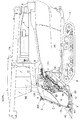
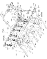
図1及び図2に示すように、本発明に係るコンバインは、機体1と、複数条(本実施形態においては八条)の植立穀稈を刈り取る刈取部2とを備えている。刈取部2は、機体1の前部において、機体1の支持台90(図4参照)に、横軸心P1まわりに揺動自在に連結され、機体1に備えられた昇降機構としてのリフトシリンダ3の伸縮によって圃場に対する仰俯角が変更可能に構成されている。
〔overall structure〕
As shown in FIG. 1 and FIG. 2, the combine according to the present invention comprises an
本実施形態においては、機体1の前後方向について、図1及び図2において刈取部2が備えられている側が前であり、その反対側が後である。したがって、機体1の縦幅方向が機体1の前後方向に対応している。機体1の左右方向について、機体1の前方側に進行する前進走行状態において、進行方向を目視する運転者の右手側が右であり、左手側が左である。したがって、機体1の横幅方向が機体1の左右方向に対応している。
In the present embodiment, the side on which the
機体1は、左右一対のクローラ式の走行装置4を備えるとともに、前部の右側に運転部5を備え、その後方に刈取部2により刈り取られた穀稈を脱穀処理する脱穀装置6と、脱穀処理によって得られた穀粒を貯留する穀粒タンク7とを、機体1の左右方向に並ぶ状態で備えている。
The
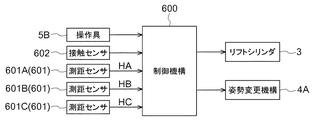
走行装置4は姿勢変更機構4Aを備え、この姿勢変更機構4Aによって機体1に対する上下方向位置が可変に構成され、前後ないし左右で上下方向位置を異ならせることによって、機体1の前後ないし左右の傾斜姿勢が変更可能に構成されている。なお、姿勢変更機構4Aは、制御機構600(図27参照)によって制御される。
The traveling
運転部5はキャビン5Aによって覆われている。運転部5には、コンバインの各部の操作に係る操作具5Bが備えられている。
The driving
脱穀装置6は、刈取部2から搬送される刈取穀稈の株元を脱穀フィードチェーン8により挟持して搬送しながら、扱室内部で穂先側を扱き処理し、扱室の下部に備えられた選別部によって穀粒と塵埃に選別処理するように構成されている。なお、穀粒は穀粒タンク7に貯留され、塵埃は機外に排出される。穀粒タンク7に貯留された穀粒は排出装置7Aによって外部に排出可能である。脱穀処理後の排ワラは細断装置9によって細断したのちに機外に排出される。
The threshing
〔刈取部〕
図1、図2、図3及び図6に示すように、刈取部2は、刈取対象条の植立穀稈を分草案内する複数(本実施形態においては刈取条数が八条であることから九個)の分草具10を刈取部2の前端部に備えており、その後方に刈取条数に対応した複数(すなわち八個)の引起し装置11と、植立穀稈の株元を切断する切断装置12と、刈取穀稈を機体1の後方に向けて搬送する搬送装置13と、これらを支持する刈取フレームFとを備えている。
[Mowing section]
As shown in FIG. 1, FIG. 2, FIG. 3 and FIG. 6, the
刈取部2は、左側(未刈側)の走行装置4よりも大きく左側に突出する状態となっている。これにより、未刈穀稈を左側の走行装置4により踏み倒すおそれがなく、良好に刈取作業を行うことができる(図6参照)。なお、踏み代は、右側(右踏み代TR)に165mm程度が設けられ、左側(左踏み代TL)に650mm程度が設けられる。右踏み代TRが十分にとられていることによって、圃場の右端において、例えば畦際であっても、刈り取り作業がしやすい。
The
本実施形態においては、刈取部2のうち、右側六条分に対応する部分が第一刈取部2Rを構成し、左側二条分に対応する部分が第二刈取部2Lを構成している。
In the present embodiment, in the
刈取部2の第二刈取部2Lは、八個の引起し装置11のうち、刈取部2は、右端から六番目の引起し装置11と七番目の引起し装置11との間の境界Lにおいて、第一刈取部2Rに対して着脱可能に構成されている。
The
図4及び図6に、第二刈取部2Lが第一刈取部2Rに対して取り付けられた幅広状態にある刈取部2の様子が示され、図30及び図31に、第二刈取部2Lが、第一刈取部2Rから取り外された幅狭状態にある刈取部2の様子が示されている。ただし、図4及び図5においては、刈取部2の前方側面を覆うカバーC(図1及び図2参照)の記載が省略されている。
FIGS. 4 and 6 show the state of the
〔引起し装置〕
図1及び図4に示すように、引起し装置11は、下端側ほど機体1の前方側に位置し且つ上端側ほど機体1の後方側に位置する後倒れ傾斜した起立姿勢で備えられている。そして、図9に示すように、引起し装置11は、刈取フレームFの一部を構成する引起しケース14の内部に、上側に位置する駆動スプロケット15と緊張用スプロケット16、及び、下側に位置する従動スプロケット17のそれぞれに亘って巻回される無端回動チェーン18が備えられ、その無端回動チェーン18に、長手方向に沿って所定間隔をあけて複数の引起爪19が備えられている。引起爪19は、起立姿勢と倒伏姿勢とに姿勢変更自在に無端回動チェーン18に支持されている。
[Trigger]
As shown in FIG. 1 and FIG. 4, the raising
図9に示すように、八個の引起し装置11の上部どうしに亘って左右方向に延びる引起し駆動軸20が備えられている。この引起し駆動軸20からの動力が、中継伝動ケース21の内部に備えられた中継伝動軸22を介して駆動スプロケット15に伝達される。引起し駆動軸20は断面形状が六角形であり、角形嵌合状態で動力を伝達するように構成されている。
As shown in FIG. 9, a raising
〔分草具〕
九個の分草具10のうち、機体1の左右方向において最も外側に位置する二個の分草具10は、植立穀稈を刈取対象と対象外とに分草し、刈取対象穀稈をその分草具10に隣接する引起し経路に導入し、対象外の穀稈をその引起し経路の横外側に案内する。その他の分草具10は、二つの植付条に植立する穀稈をその分草具10の両横側に分草して分草具10の両横側の引起し経路に導入する。
[Scissors]
Of the nine branching
〔引起し作用経路、及び非作用戻り経路〕
引起し装置11は、引起爪19が横向きに突出する状態で移動する引起し作用経路H1と、引起爪19が引退した状態で移動する非作用戻し経路H2とを備えている。つまり、無端回動チェーン18の左右両側の上下移動経路のうちの一方が引起し作用経路H1として設定され、他方が非作用戻し経路H2として設定されている。引起し作用経路H1においては、無端回動チェーン18が通過する箇所に引起爪19を起立案内するガイド板(図示せず)が備えられている。
[Proceding action route and non-action return route]
The raising
複数の引起し装置11は、引起し作用経路H1どうしが近接するとともに、非作用戻し経路H2どうしが近接する状態で、左右方向に並ぶように配置されている。そして、各引起し装置11は、引起し作用経路H1において引起爪19が上向きに移動するように回動方向が設定されている。つまり、離接する引起し装置11どうしは、無端回動チェーン18の回動方向が互いに逆向きに設定されている。
The plurality of raising
このような構成の引起し装置11は、引起し作用経路H1においては、横向きに突出する引起爪19が穀稈に梳き上げ作用しながら上昇移動し、上昇終端に到達すると、穀稈から外れて引起しケース14の非作用戻し経路H2を下降して引起し作用経路H1側に戻っていく。これにより、各引起し装置11は、引起し経路に導入された植立穀稈を、上昇移動する引起爪19によって引起し処理して切断装置12に供給する。
In the
〔切断装置〕
図4、図10及び図11に示すように、切断装置12は、全ての刈取対象条(八条)の植立穀稈に作用するように左右方向(刈幅方向に対応する)の全幅に亘る長尺状に形成され、周知構造のバリカン型刈刃から構成されている。
[Cutting device]
As shown in FIG. 4, FIG. 10 and FIG. 11, the cutting
切断装置12は、八条の刈取条のうち、右側六条の刈取条に作用する右側切断部12R(第一刈取部2R側の切断部である。)と、左側二条の刈取条に作用する左側切断部12L(第二刈取部2L側の切断部である。)とに分割されて構成されている。
The cutting
右側切断部12Rについて説明する。
図10及び図11に示すように、右側切断部12Rは、左右方向に並設した二分割された二組のバリカン型の刈刃25と、二組の刈刃25をそれぞれ駆動する左右の刈刃駆動機構26とを備えている。
The right
As shown in FIG. 10 and FIG. 11, the right
図12に示すように、左右の刈刃25は、それぞれ左右方向に多数の歯27Aが並設された固定刃27と、この固定刃27の上側に摺接する状態で多数の歯28Aが並設された可動刃28と、固定刃27を受止め支持する受け台29と、可動刃28の浮き上がりを防止する複数のナイフクリップ30とを備えている。
As shown in FIG. 12, the left and right cutting
図10に示すように、左右の各可動刃28の外側寄り近くに可動刃操作体31が備えられ、この可動刃操作体31に作用する刈刃駆動機構26の駆動によって、可動刃28を固定刃27に対して左右方向に沿って左右往復駆動するように構成されている。
As shown in FIG. 10, the movable
可動刃操作体31には平面視U字状の係入溝32を備えている。刈刃駆動機構26は、可動刃操作体31の係入溝32に係入する操作ローラ33を一端部に備えたアーム34、このアーム34の他端部に一端側が連結された連動ロッド35、この連動ロッド35の他端側に連結されたクランクアームとして機能する駆動回転体36を備えている。そして、駆動回転体36の回転駆動力を往復動力に変換して可動刃28を左右往復駆動する。
The movable
可動刃28が左右方向に往復スライド駆動することによって、可動刃28と固定刃27とにより植立穀稈が切断される。左右両側の刈刃25におけるそれぞれの可動刃28は、互いに逆向きにスライド移動するように構成され、可動刃28のスライド操作に伴う振動をできるだけ少なくするようにしている。
The
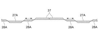
図12及び図13に示すように、左右両側の刈刃25における左右中間の突き合わせ部には、左右両側の可動刃28の上側に位置する上部側の固定刃37が備えられている。このように突き合わせ部では、固定刃37が上側に位置することで、突き合わせ箇所において、塵埃が固定刃37と可動刃28との間に噛み込まれることを防止している。上部側の固定刃37は、左右の刈刃25にそれぞれ各別に備えられている。
As shown in FIG. 12 and FIG. 13, the upper left fixed
左側切断部12Lについて説明する。
図10に示すように、左側切断部12Lは、右側切断部12Rにおける刈刃25と同様な構成のバリカン型の刈刃38と、その刈刃38を駆動する刈刃駆動機構39とを備えている。刈刃38は、刈取条数が異なる点以外は、右側切断部12Rの刈刃25と同じであるから詳細な説明は省略する。刈刃駆動機構39についても、右側切断部12Rの刈刃駆動機構26と同じであるから詳細な説明は省略する。このように、右側切断部12R及び左側切断部12Lは、それぞれ各別に、刈刃駆動機構26,39を備えている。
The left
As shown in FIG. 10, the left
右側切断部12Rにおける刈刃25と、左側切断部12Lの刈刃38との突き合わせ部には、右側切断部12Rにおける突き合わせ部と同様に、可動刃28の上側に位置する上部側の固定刃37が備えられている。この上部側の固定刃37は、右側切断部12Rにおける刈刃25と左側切断部12Lの刈刃38とにそれぞれ各別に備えられている。左側切断部12Lの刈刃38における可動刃28は、右側切断部12Rにおける刈刃25における可動刃28のスライド移動方向と逆向きにスライド移動するように構成されている。
At the butt between the cutting
右側切断部12R及び左側切断部12Lは、可動刃28、固定刃27、受け台29のそれぞれが、各別に分離可能に形成されており、突き合わせ状態では近接して並ぶ状態で備えられる。
The
〔搬送装置〕
図4及び図6に示すように、搬送装置13は、刈取穀稈を二条分ずつ寄せ集めながら後方に掻き込む複数の掻き込み部40、右側から一番目の条と二番目の条の二条分の刈取穀稈を左後方側の合流箇所に搬送する第一中間搬送部41、右側から三番目の条と四番目の条の二条分の刈取穀稈を後方側の合流箇所に搬送する第二中間搬送部42、右側から五番目の条と六番目の条の二条分の刈取穀稈を合流箇所に搬送する第三中間搬送部43、右側から七番目の条と八番目の条の二条分、すなわち左側端部二条分の刈取穀稈を後方に搬送する第四中間搬送部44、第四中間搬送部44により搬送される刈取穀稈を受け継いで合流箇所に搬送する左側合流搬送部45、合流箇所において合流した八条の刈取穀稈を脱穀フィードチェーン8の始端部にまで搬送する供給搬送部46、第一中間搬送部41によって搬送される刈取穀稈並びに合流箇所において合流された刈取穀稈の穂先側に作用して穂先側を係止案内する穂先係止搬送装置47を備えている。
[Conveying device]
As shown in FIG. 4 and FIG. 6, the transport device 13 is provided with a plurality of scraping portions 40 for scraping backward while collecting harvest grain clumps by two streaks, and two streaks of the first and second streaks from the right side The first intermediate conveyance unit 41 that conveys the reaping grain casket to the left rear side joining point, and the second line conveying the reaping grain crest of the second line from the right to the third line and the fourth line to the backward side joining point The middle conveyance part 42, the third middle conveyance part 43 which conveys the reaping grain weirs of the fifth row and the sixth row from the right to the joining location, the second row of the seventh row and the eighth row from the right In other words, the fourth intermediate transport unit 44 that transports the left end two rows of reaping grain pods backward, the left junction transport part 45 that inherits the reaping grain pods transported by the fourth intermediate transport portion 44, and transports them to the merging point, At the beginning of the threshing feed chain 8 the Hachijo reaping grain weirs joined at the meeting point The feeding and conveying unit 46 for conveying by, the harvesting grain weir conveyed by the first intermediate conveying unit 41, and the ear tip retention conveying device that acts on the ear tip side of the harvesting grain weir joined at the merging point to hold and guide the ear tip side It has 47.
図6に示すように、掻き込み部40は、切断装置12の上方近くに機体1の左右方向に並んで位置して噛み合い回動する一対の穀稈掻き込み用の回転式のパッカー48,49(外形が略星形に形成された掻き込み回転体である。)からなる下側掻き込み装置50と、その下側掻き込み装置50よりも上方に位置する一対の突起付きの無端回動ベルト51からなる上側掻き込み装置52とを備える。そして、このような掻き込み部40が、左右方向(刈幅方向)に並ぶ状態で四組(掻き込み部40A〜40D)備えられている。
As shown in FIG. 6, the scraping
下側掻き込み装置50は、切断装置12で刈り取り処理された二条分の刈取穀稈の株元側を一対のパッカー48,49の間に掻き込んでパッカー間から機体1の後方に向けて送り出す。この下側掻き込み装置50は、一対のパッカー48,49のうちのいずれか一方のパッカー48は、動力が伝達される駆動側パッカーとして構成され、他方のパッカー49は、パッカー48に噛み合って従動する従動側パッカーとして構成されている。
The lower
上側掻き込み装置52における一対の無端回動ベルト51は、左右のパッカー48,49からそれぞれ動力が伝達されて回動するように構成され、二条分の刈取穀稈の株元側を係止搬送により掻き込み後方に送り出す。
The pair of endless
図11に示すように、右側に位置する三組の下側掻き込み装置50(50A〜50C)は、各パッカー48,49が同一の上下高さに位置するように配置してあり、左側端部に位置する一組の下側掻き込み装置50(50D)は、下側掻き込み装置50(50A〜50C)よりも低い高さに位置するように配置している。
As shown in FIG. 11, the three sets of lower scraping devices 50 (50A to 50C) located on the right side are arranged such that the
伝動構造については後述するが、右側に位置する三組の掻き込み部40(40A〜40C)は、同一の伝動軸からの動力によって駆動されるので、それらは同期回転する。したがって、隣り合う下側掻き込み装置50(50A〜50C)のパッカー48,49どうしが平面視で一部重なり合うことがあっても良好な噛み合い状態を維持できる。
Although the transmission structure will be described later, since the three sets of scraping portions 40 (40A to 40C) located on the right side are driven by power from the same transmission shaft, they rotate in synchronization. Therefore, even if the
図6及び図8に示すように、第一中間搬送部41は、最右側の掻き込み部40(40A)により掻き込まれた二条分の刈取穀稈の株元を挟持しながら左後方側の合流箇所に向けて搬送する第一株元挟持搬送装置53と、穂先係止搬送装置47の前半部分である前部側無端回動体47Fとから構成される。
As shown in FIG. 6 and FIG. 8, the first
第一株元挟持搬送装置53は、複数のスプロケットに亘って巻回された無端回動チェーンを備えている。無端回動チェーンに対向して挟持レール(図示せず)が備えられ、無端回動チェーンと挟持レールとにより刈取穀稈の株元を挟持して後方に搬送する。
The first stock origin sandwiching and conveying
穂先係止搬送装置47は、複数のスプロケットに亘って巻回された係止突起付きの無端回動チェーン57と、刈取穀稈の穂先部を載置しながら案内する穂先案内板58(図4及び図5参照)とを備えている。無端回動チェーン57に所定ピッチをあけて係止突起59が備えられ、無端回動チェーン57が回動することで刈取穀稈の穂先側を係止しながら、且つ、刈取穀稈の穂先部を穂先案内板58によって載置案内しながら左後方に搬送するように構成されている。この穂先係止搬送装置47の後半部分である後部側無端回動体47Bは、合流箇所において合流された八条分の刈取穀稈に対する穂先側の係止搬送を行うように構成されている。
The ear tip locking and conveying
第二中間搬送部42は、右端から二番目の掻き込み部40(40B)により掻き込まれた二条分の刈取穀稈の株元を挟持しながら後方側の合流箇所に向けて搬送する第二中間株元挟持搬送装置61と、二条分の刈取穀稈の穂先側を係止搬送しながら後方側の合流箇所に向けて搬送する第二中間穂先係止搬送装置62とを備えている。
The second
第二中間株元挟持搬送装置61は、第一株元挟持搬送装置53と同様に構成されている。第二中間穂先係止搬送装置62は、複数のスプロケットに亘って巻回された係止突起付きの無端回動チェーンを備え、無端回動チェーンが回動することで刈取穀稈の穂先側を係止しながら後方に搬送する。
The second intermediate stock origin holding
第三中間搬送部43は、右端から三番目の掻き込み部40(40C)により掻き込まれた二条分の刈取穀稈の株元を挟持しながら後方側の合流箇所に向けて搬送する第三中間株元挟持搬送装置67と、二条分の刈取穀稈の穂先側を係止搬送しながら後方側に向けて搬送する第三中間穂先係止搬送装置68とを備えている。
The third
第三中間株元挟持搬送装置67は、第一株元挟持搬送装置53と同様に構成されている。第三中間穂先係止搬送装置68は、第二中間穂先係止搬送装置62と同様に構成されている。
The third intermediate stock origin holding
第四中間搬送部44は、最左側の掻き込み部40(40D)により掻き込まれた二条分の刈取穀稈の株元を挟持しながら後方側の合流箇所に向けて搬送する第四中間株元挟持搬送装置74を備えている。この第四中間株元挟持搬送装置74は、第一株元挟持搬送装置53と同様に構成されている。
The fourth
左側合流搬送部45は、第四中間搬送部44により搬送される刈取穀稈を受け継いで、株元を挟持しながら後方側の合流箇所に向けて搬送する左側合流用株元挟持搬送装置77と、刈取穀稈の穂先側を係止搬送しながら後方側の合流箇所に向けて搬送する左側合流用穂先係止搬送装置78とを備えている。
The left side
左側合流用株元挟持搬送装置77は、第一株元挟持搬送装置53と同様に構成されている。左側合流用穂先係止搬送装置78は、第二中間穂先係止搬送装置62と同様に構成されている。
The left-hand side merging stock holding and conveying apparatus 77 is configured in the same manner as the first stock holding and conveying
第二刈取部2L側の合流用搬送体である第四中間搬送部44と、第一刈取部2R側の合流用搬送体である左側合流搬送部45とにより、第二刈取部2Lによって刈り取られた刈取穀稈を合流箇所まで搬送する合流用搬送部120が構成される。
The
供給搬送部46は、第一中間搬送部41、第二中間搬送部42、第三中間搬送部43、及び、左側合流搬送部45により搬送されて、合流箇所において合流した刈取穀稈の株元を挟持して脱穀フィードチェーン8に向けて搬送する扱深さ用搬送装置84と、その扱深さ用搬送装置84から脱穀フィードチェーン8の始端部に刈取穀稈を受け渡す受け渡し供給装置85とを備えている。
The feeding and conveying
扱深さ用搬送装置84及び受け渡し供給装置85は、ともに、第一株元挟持搬送装置53と同様に構成されている。
The handling
図示はしないが、扱深さ用搬送装置84は、搬送始端側を支点にして搬送終端側が稈長方向に移動するように揺動自在に支持され、合流箇所から受け継いだ刈取穀稈を稈長方向(上下方向)に位置変更して、脱穀装置6に対する入り込み深さを変更調整できるように構成されている。
Although not shown, the threshing
搬送装置13は、第一刈取部2Rに設けられた右側搬送部13Rと、第二刈取部2Lに設けられた左側搬送部13Lとに分けられ、図6に示すように、右側に位置する三組の掻き込み部40、第一中間搬送部41、第二中間搬送部42、第三中間搬送部43、左側合流搬送部45、供給搬送部46のそれぞれが右側搬送部13Rに対応し、第四中間搬送部44及び最左側の掻き込み部40が左側搬送部13Lに対応している。
The
〔刈取フレーム〕
次に、刈取フレームFについて説明する。
図14から図19に示すように、刈取フレームFは、以下に説明するような複数のフレームが連結されて構成されている。なお、刈取フレームFのうち、第一刈取部2Rに属する部分が第一フレームFRであり、第二刈取部2Lに属する部分が第二フレームFLである。
[Mowing frame]
Next, the mowing frame F will be described.
As shown in FIGS. 14 to 19, the cutting frame F is configured by connecting a plurality of frames as described below. In the reaper frame F, a portion belonging to the
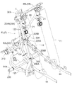
刈取フレームFは、刈取部2の全体を支持する前後向きの円筒状の支持フレーム91が備えられている。この支持フレーム91は、後上部の基端側に備えられた横向きの枢支部92が、機体側の支持台90に横軸心P1まわりに回動自在に支持されている。支持フレーム91は、支持台90から機体1の前方下方に向けて延びている。なお、支持フレーム91は、刈取フレームFの左右方向の略中央に配置されている。
The reaper frame F is provided with a
支持フレーム91の前端部に左右方向すなわち刈幅方向に延びる円筒状の下部横向きフレーム93が連結されている。この下部横向きフレーム93の両端部のそれぞれに機体1の前方に向けて延びる円筒状の分草フレーム94が連結されている。これら二本の分草フレーム94の前後途中部どうしに亘って、刈幅方向に延びる角筒状の刈刃支持フレーム95が架設されている。この刈刃支持フレーム95に切断装置12が支持される。
A cylindrical lower
二本の分草フレーム94の間に、間隔をあけて七本の分草フレーム94が備えられている。これら間隔をあけて備えられた複数の分草フレーム94は、後端部が刈刃支持フレーム95に連結された片持ち姿勢に配置されている。これら九本の分草フレーム94の前端部に分草具10が備えられる。
Between the two branching
下部横向きフレーム93の右端部に、概して機体1の前方上に向けて延びる円筒状の右部縦向きフレーム97が連結され、下部横向きフレーム93の左端部に、概して機体1の前方上に向けて延びる円筒状の左部縦向きフレーム96が連結されている。
At the right end of the lower
これら二本の縦向きフレーム96,97の上端部どうしに亘って、刈幅方向に延びる上部横向きフレーム98が連結されている。この上部横向きフレーム98は、八個の引起し装置11のそれぞれの上端部どうしに亘って左右方向に沿って延びている。
An upper
図17及び図18に示すように、下部横向きフレーム93のうち第一フレームFR側に属する右側部分93Rの左端側から上方に向けて円筒状の中間縦向きフレーム99が延設されている。中間縦向きフレーム99は、刈取部2に備えられる搬送装置13を迂回し得る高さまで立ち上がり、そこから水平右方へ屈曲した後、前方上方へと屈曲し、上部横向きフレーム98に連結されている。なお、中間縦向きフレーム99のうち前方上方へと屈曲した部分にギア変速機構111が備えられる。
As shown in FIGS. 17 and 18, a cylindrical middle
八個の引起し装置11はそれぞれ、上端部が上部横向きフレーム98に連結され、下端部が分草フレーム94に連結される。したがって、各引起し装置11は、連結された状態では、上部横向きフレーム98と分草フレーム94とを連結するフレーム部材としても機能する。
Each of the eight
各引起し装置11は、上部横向きフレーム98に対して、中継伝動ケース21と一体的に、横向き軸心まわりに相対回動自在に支持されている。したがって、分草フレーム94に対する連結を解除すると、引起し装置11全体を横向き軸心まわりに回動させて、刈取部2の前部を大きく開放させることができる。
Each raising
この刈取部2の前部の開放状態であるときには、上部横向きフレーム98に荷重が掛かる。そこで、刈取部2の剛性を確保するために、図17から図19に示すように、上部横向きフレーム98と分草フレーム94とを連結する縦向きの補助連結杆100が複数備えられている。
When the front portion of the
さらに、刈取部2の剛性を確保するために、搬送装置13の上方を迂回する状態で、支持フレーム91の上端部と上部横向きフレーム98の左右方向中間部とを連結する上部迂回フレーム101が備えられ、中間縦向きフレーム99の中間縦向きフレーム99の立ち上がり部の上端近傍と上部横向きフレーム98の左右方向の中央やや左とを連結する引起し支えフレーム102が備えられている。
Furthermore, in order to ensure the rigidity of the
引起し支えフレーム102は、中間縦向きフレーム99の立ち上がり部の上端近傍に備えられたブラケットから後方上方へ延びた後、そこから立ち上がり、側面視において上部迂回フレーム101と同じように前方へ延び、その先端が上部横向きフレーム98に連結されている。
The raising
上述したような複数種のフレームが連結されて刈取フレームFが構成されている。この刈取フレームFは、左右方向における両端部に位置する分草フレーム94と、左右の縦向きフレーム96,97と、左右方向における両端部に位置する引起し装置11とが、機体1の側面視で略三角形状に配置され連結されている。その結果、左右方向における両端部において強固な支持構造が形成されている。
The cutting frame F is configured by connecting a plurality of types of frames as described above. In this cutting frame F, a side view of the
〔刈取部着脱構造〕
第二刈取部2Lを第一刈取部2Rに対して着脱可能とするために、刈取フレームFは、下部横向きフレーム93、刈刃支持フレーム95及び上部横向きフレーム98が、境界Lにおいて、互いに分離可能に構成されている。
[Mowing section attachment and detachment structure]
In order to make the
図14から図19に示すように、第一刈取部2R側の第一フレームFR及び第二刈取部2L側の第二フレームFLのそれぞれにおいて、境界Lの近傍に、上部横向きフレーム98と分草フレーム94とに亘って上下方向に延びる角筒状の連結用フレーム121,122が備えられている。
As shown in FIG. 14 to FIG. 19, in each of the first frame FR on the side of the
図17及び図18に示すように、第一刈取部2R側の第一フレームFRに設けられた連結用フレーム121は、上部横向きフレーム98のうち右側部分98Rの左端部と、右端から七番目の分草フレーム94とに亘って連結されている。連結用フレーム121は、側面視において概して引起し装置11の引起しケース14の前面に略平行な後上がりに傾斜した形状であるが、下方は、分草具10を迂回するように屈曲して後退した形状となっている。
As shown in FIGS. 17 and 18, the connecting
図14、図15及び図16に示すように、第二刈取部2L側の第二フレームFLに設けられた連結用フレーム122は、上部横向きフレーム98のうち左側部分98Lの右端部と、下部横向きフレーム93から機体1の前方に向けて延設され、かつ植立穀稈を踏み倒さないように、右端から七番目の分草フレーム94に対して少し上方に位置する前後向き支持杆123とに亘って連結されている。前後向き支持杆123の前端部及び上部横向きフレーム98は、縦向きの補助連結杆124により、連結用フレーム122に対する支持強度が補強されている。
As shown in FIG. 14, FIG. 15 and FIG. 16, the connecting
連結用フレーム122も、連結用フレーム121と同様に、側面視において概して引起し装置11の引起しケース14の前面に略平行な後上がりに傾斜した形状であるが、下方は、分草具10を迂回するように屈曲して後退した形状となっている。
Similarly to the
〔前部連結部〕
連結用フレーム121,122には、境界Lにおいて、第一刈取部2Rと第二刈取部2Lとを分離可能に連結する前部連結部200が備えられている。
[Front connection part]
The coupling frames 121 and 122 are provided with a
図17、図18及び図22に示すように、第一フレームFR側に属する連結用フレーム121には、上中下の三箇所に右側上方ボス部201、右側中央ボス部202及び右側下方ボス部203が備えられている。
As shown in FIG. 17, FIG. 18 and FIG. 22, in the connecting
右側上方ボス部201は、連結用フレーム121の前方に配置された一つの円筒部材201Aの周囲が、一枚の平板部201Bによって巻回された形状に構成されている。
The right
右側中央ボス部202は、連結用フレーム121の前方において、後述する左側中央ボス部205の円筒部材205Aを適度な遊びをもって挟んで配置し得るだけの間隔を上下にあけて配置された二つの円筒部材202Aの周囲が、一枚の平板部材202Bによって巻回された形状に構成されている。平板部材202Bは、上下の円筒部材202Aの間に対応する部分が切り欠かれた形状に構成されている。右側下方ボス部203は、右側中央ボス部202と同様に構成されている。
The right
なお、円筒部材201A,202A,203Aは、それぞれが有する貫通孔201C,202C,203Cの軸心が一致するように配置されている。
The
図14、図15、図16及び図22に示すように、第二フレームFL側に属する連結用フレーム122には、右側上方ボス部201に対応する位置に、左側上方ボス部204が備えられ、右側中央ボス部202に対応する位置に左側中央ボス部205が備えられ、右側下方ボス部203に対応する位置に、左側下方ボス部206が備えられている。
As shown in FIG. 14, FIG. 15, FIG. 16 and FIG. 22, the
左側上方ボス部204は、後述する従動部材303に備えられた円筒部材204Aから構成されている。
The left
左側中央ボス部205は、連結用フレーム122の前方右側において、一つの円筒部材205Aを正面視においてL字形状のブラケット205Bによって支える形状に構成されている。左側下方ボス部206は、左側中央ボス部205と同様に構成されている。
The left
なお、円筒部材204A,205A,206Aは、それぞれが有する貫通孔204C,205C,206Cの軸心が一致するように配置されるとともに、第一フレームFR及び第二フレームFLを互いに連結するための所定位置に配置したときに、円筒部材201A,202A,203Aの貫通孔201C,202C,203Cの軸心とも一致するように配置されている。
The
図22に示すように、右側上方ボス部201の円筒部材201Aの上に、左側上方ボス部204の円筒部材204Aを配置し、貫通孔201C及び貫通孔204Cを貫くように、挿込部材としてのボルト207を挿通し、ボルト207の先端にナット208を螺合することによって、右側上方ボス部201と左側上方ボス部204とが連結される。
As shown in FIG. 22, the
右側中央ボス部202の二つの円筒部材202A間に、左側中央ボス部205の円筒部材205Aを配置し、貫通孔202C及び貫通孔205Cを貫くように、ボルト207の先端にナット208を螺合することによって、右側中央ボス部202と左側中央ボス部205とが連結される。
The
同様に、右側下方ボス部203の二つの円筒部材203A間に、左側下方ボス部206の円筒部材206Aを配置し、貫通孔203C及び貫通孔206Cを貫くように、ボルト207の先端にナット208を螺合することによって、右側下方ボス部203と左側下方ボス部206とが連結される。
Similarly, a
ただし、従動部材303は第二刈取部2Lを第一刈取部2Rに対して着脱可能とする構成には必須の構成ではなく、同様に、右側上方ボス部201及び左側上方ボス部204は必須の構成ではない。したがって、少なくとも右側中央ボス部202及び右側下方ボス部203が、本発明に係る第一ボス部であり、左側中央ボス部205及び左側下方ボス部206が、本発明に係る第二ボス部であり、これら第一ボス部、第二ボス部及び挿込部材としてのボルト207が前部連結部を構成する。連結用フレーム121及び連結用フレーム122の連結によって、刈取部2の前方において、第二刈取部2Lの第一刈取部2Rに対する分離が不可能となる。
However, the driven
なお、上述した実施形態においては、ボルト207に抜止のためのナット208が螺合される場合について説明したが、挿込部材として頭部を有する軸状部材を用い、この先端に割りピンを取り付ける構成であってもよい。
In the embodiment described above, although the case where the
〔後部連結部〕
図23から図25に示すように、下部横向きフレーム93は、境界Lにおいて、第一フレームFR側に属する右側部分93Rと、第二フレームFL側に属する左側部分93Lとに分割形成され、右側部分93R及び左側部分93Lには、第一刈取部2Rと第二刈取部2Lとを分離可能に連結する後部連結部210が備えられている。
[Rear connection part]
As shown in FIGS. 23 to 25, the lower
右側部分93Rの左端部の後方には、右側後方ボス部211が備えられている。右側後方ボス部211は、後述する左側後方ボス部212の平板部材212Aを適度な遊びをもって挟んで配置し得るだけの間隔を上下にあけて平行に配置された二枚の平板部材211Aから構成され、それぞれが有する貫通孔211Cの軸心が一致するように配置されている。貫通孔211Cの軸心は、例えば円筒部材202Aの貫通孔202Cの軸心と平行に設けられている。
Behind the left end of the
左側部分93Lの右端部の後方から右方に突出した左側後方ボス部212が備えられている。左側後方ボス部212は、右側後方ボス部211の上下二枚の平板部材211A間に挟入され得る平板部材212Aから構成されている。平板部材212Aには平板部材211A間に挟入さたときに、貫通孔211Cと同一軸心となる貫通孔212Cが備えられている。
A left
図23に示すように、貫通孔211Cと貫通孔212Cとを貫くように挿込部材213の軸状部213Aを挿通することによって、右側部分93R及び左側部分93Lが連結される。
As shown in FIG. 23, the
すなわち、右側後方ボス部211及び左側後方ボス部212、並びに挿込部材213が、後部連結部を構成する。右側部分93R及び左側部分93Lの連結によって、刈取部2の後方において、第二刈取部2Lの第一刈取部2Rに対する分離が不可能となる。
That is, the right
なお、挿込部材213は、軸状部213Aの右側後方ボス部211及び左側後方ボス部212に対する挿通方向と交差する方向に操作部213Bが延設されている。
In the
抜止部材214は、左側部分93Lの右端部に螺子止めされた平板部材から構成され、該平板部材は、螺子止め部分から後方に伸び、後端が下方に幾らか屈曲した形状に形成されている。
The retaining
抜止部材214は、操作部213Bのうち軸状部213Aの挿通方向とは反対側の面に当接し、挿込部材213は軸状部213Aの右側後方ボス部211及び左側後方ボス部212に対する挿通方向とは反対方向に移動することが容易に規制される。
The retaining
なお、挿込部材213は、右側後方ボス部211及び左側後方ボス部212への取り付けに際して、右側後方ボス部211と操作部213Bとの間に、付勢手段としてのコイルバネ215が挟設されている。挿込部材213は、このコイルバネ215によって操作部213Bが抜止部材214に当接する方向へ付勢されていることから、挿通方向とは反対方向へ付勢される。
When the
したがって、挿込部材213の操作部213Bを軸状部213Aの軸心まわりに回動させて、抜止部材214に当接した抜止規制位置から、抜止部材214に当接しない抜止解除位置に移動させようとしても、操作部213Bが抜止部材214の後端の屈曲箇所において引っかかる。このように、操作部213Bが抜止規制位置から抜止解除位置へと意図せず移動してしまうことが防止されている。
Therefore, the
操作部213Bを抜止規制位置から抜止解除位置へと位置変更するためには、操作部213Bをコイルバネ215の付勢力に抗して軸状部213Aの挿通方向へ移動させる。これにより、操作部213Bを、抜止部材214の後端の屈曲箇所に引っかけることなく、抜止規制位置から抜止解除位置へと移動させることができ、挿込部材213の軸状部213Aを、右側後方ボス部211及び左側後方ボス部212から抜き出すことができ、右側部分93Rと左側部分93Lとの連結が解除される。
In order to change the position of the operating
なお、刈取部2の刈取フレームFは、左右方向における両端部に位置する分草フレーム94と、左右の縦向きフレーム96,97と、左右方向における両端部に位置する引起し装置11とが、機体1の側面視で略三角形状に配置され連結されていることから、刈取部2を、境界Lにおいて分離しても、第一刈取部2R及び第二刈取部2Lのそれぞれにおいて、強固なフレーム構造体が形成され、支持強度を有する構成となっている。
The reaping frame F of the reaping
〔下部連結部〕
図23から図25に示すように、刈刃支持フレーム95は、境界Lにおいて、第一フレームFR側に属する右側部分95Rと、第二フレームFL側に属する左側部分95Lとに分割形成され、右側部分95R及び左側部分95Lに下部連結部220が備えられている。
[Lower connecting part]
As shown in FIG. 23 to FIG. 25, the cutting
下部連結部220として、本実施形態においては、左側部分95Lに右側部分95Rに対して挿し込み可能な円柱部材95Aが備えられている。円柱部材95Aは、概して右側部分95Rの内面に外接し得る外径を有しており、右側部分95Rに対する挿し込み先端側がやや縮径した形状に構成されている。
As the lower connecting
第一刈取部2Rと第二刈取部2Lとが分離されているときは、左側部分95Lの離間とともに円柱部材95Aは右側部分95Rから引き抜かれ、第一刈取部2Rと第二刈取部2Lとが連結されるときは、左側部分95Lの近接とともに円柱部材95Aは右側部分95Rから挿し込まれる。円柱部材95Aが右側部分95Rに挿し込まれることによって、右側部分95R及び左側部分95Lは一体的に荷重を支えることができる。
When the
なお、下部連結部220は、上述の構成に限らず、円柱部材95Aにかえて、角柱部材が備えられてもよい。
The lower connecting
上述のように、刈取部2は、前部連結部200及び後部連結部210における連結を解除することによって、第二刈取部2Lを第一刈取部2Rから取り外すことが可能である。
As described above, the
第二刈取部2Lの取り外しに際しては、第二刈取部2Lの底部に台車を配置し、前部連結部200及び後部連結部210における連結を解除する。これによって、第二刈取部2Lと第一刈取部2Rとの連結が解除され、台車を移動させることによって第二刈取部2Lを取り外すことができる。第二刈取部2Lの第一刈取部2Rへの取り付けは逆の手順で行われる。このように、刈取部2の第二刈取部2Lは、左右方向へ移動させることによって第一刈取部2Rに対して着脱可能である。
When removing the
なお、第二刈取部2Lを支持する構成として、台車にかえて、ジャッキや専用のスタンドを用いることも可能である。この場合は、コンバインを移動させて、第一刈取部2Rに対して、第二刈取部2Lを相対的に左右方向へ移動させる。
In addition, it is also possible to change to a trolley | bogie and to use a jack and an exclusive stand as a structure which supports the
左右方向とは、第一刈取部2R及び第二刈取部2Lが並ぶ方向であることから、コンバインが水平な圃場にあるときは、水平方向である。なお、第二刈取部2Lは第一刈取部2Rに対して、前方連結部200及び後部連結部210が有する遊び、例えば右側中央ボス部202の二つの円筒部材202Aと、左側中央ボス部205の円筒部材205Aとの遊びの分だけ上下方向にも移動させ得る。したがって、第二刈取部2Lが移動する左右方向とは、斜め方向を含む。
The left-right direction is a direction in which the
なお、刈取部2は第二刈取部2Lが第一刈取部2Rに取り付けられた幅広状態(図6参照)であっても、第二刈取部2Lが第一刈取部2Rから取り外された幅狭状態(図31参照)であっても刈り取り作業が可能に構成されている。
In addition, even if the
刈取部2は、幅広状態(図6参照)であっても、幅狭状態(図31参照)であっても、刈幅が左右の走行装置4の走行幅Wよりも広く構成されるとともに、機体1に対して、左右の走行装置4の走行幅Wが刈幅内に収まるような位置に備えられている。なお、刈幅は、右踏み代TR、走行幅W及び左踏み代TLの合計である。
Even if the
なお、刈取部2が幅狭状態であるとき、右踏み代TRは上述のとおり165mm程度である一方、左踏み代TLは5mm程度である。このように幅狭状態であるときであっても、走行装置4の左側にも踏み代として左踏み代TLを確保することにより、未刈穀稈を左側の走行装置4により踏み倒すおそれがない。
When the
〔伝動構造〕
次に、図8に基づいて、刈取部2における動力の伝動構造について説明する。
機体1は、動力源としてのエンジン(図示せず)を備えており、エンジンから出力された動力が刈取用の無段変速装置(図示せず)によって変速された後に、支持フレーム91の枢支部92の内部に備えられた横向き伝動軸103に伝達される。そして、横向き伝動軸103から支持フレーム91の内部に備えられた前下がりの駆動軸としての動力伝達軸104を介して刈取部2の下部横向きフレーム93の内部に備えられた横向きの入力軸105に伝達される。なお、図9及び図10に示すように、動力伝達軸104は、刈取部2の左右方向の略中央に配置され、動力伝達軸104から伝達された動力は、入力軸105の左右方向の略中央に入力される。
[Transmission structure]
Next, based on FIG. 8, the power transmission structure of the
The
入力軸105に伝達された動力は、入力軸105において左右両端部及び下部横向きフレーム93の右側部分93Rの左端近傍に設けられた分岐部106を介して、切断装置12のうち右側切断部12Rに属する二組の刈刃25と、左側切断部12Lに属する一組の刈刃38とにそれぞれ伝達される。
The power transmitted to the
入力軸105に伝達された動力は、入力軸105において下部横向きフレーム93の右側部分93Rの左端近傍に設けられた分岐部107を介して、縦向きフレーム96の内部に備えられた縦向き伝動軸109に伝達される。縦向き伝動軸109に伝達された動力は、縦向き伝動軸109において、途中に設けられた分岐部108を介して左側合流搬送部45に伝達される。
The power transmitted to the
入力軸105に伝達された動力は、入力軸105において、左端側に備えられた分岐部110を介して第四中間搬送部44に伝達され、第四中間搬送部44を介して最左側の掻き込み部40(40D)に伝達される。
The power transmitted to the
右側に位置する三組の掻き込み部40(40A〜40C)、第一中間搬送部41、第二中間搬送部42、第三中間搬送部43、供給搬送部46のそれぞれには、動力伝達軸104の伝動途中部から動力が伝達される。
A power transmission shaft is provided for each of the three sets of scraping portions 40 (40A to 40C) located on the right side, the first
図8に示すように、動力伝達軸104の伝動途中部に設けられた第二分岐部117において第三分岐伝動軸118と第四分岐伝動軸119に動力が分岐伝達され、第三分岐伝動軸118から第一中間搬送部41の第一株元挟持搬送装置53に動力が伝達され、第一株元挟持搬送装置53の動力が最右側の掻き込み部40(40A)に伝達される。なお、穂先係止搬送装置47における無端回動チェーン57には、横向き伝動軸103から動力伝達され、扱深さ用搬送装置84には、第四分岐伝動軸119から動力が伝達される。
As shown in FIG. 8, power is split and transmitted to the third
動力伝達軸104の伝動途中部に設けられた第一分岐部112において第一分岐伝動軸113に動力が分岐伝達され、その第一分岐伝動軸113から第二中間搬送部42の第二中間株元挟持搬送装置61及び第二中間穂先係止搬送装置62に動力が伝達される。そして、第二中間株元挟持搬送装置61の動力が右側から二番目の掻き込み部40(40B)に伝達される。
Power is branched and transmitted to the first
第一分岐伝動軸113の途中部から第二分岐伝動軸114に動力が分岐伝達され、第二分岐伝動軸114から第三中間搬送部43の第三中間株元挟持搬送装置67及び第三中間穂先係止搬送装置68に動力が伝達される。そして、第三中間株元挟持搬送装置67の動力が右端から三番目の掻き込み部40(40C)に伝達される。
Power is split and transmitted from an intermediate portion of the first
したがって、右側に位置する三組の掻き込み部40(40A〜40C)は、同一の伝動軸である動力伝達軸104からの動力によって駆動されることになり、最左側の一組の掻き込み部40(40D)は、動力伝達軸104から入力軸105を経由して伝達される動力によって駆動されることになる。
Therefore, the three sets of scraping portions 40 (40A to 40C) located on the right side are driven by the power from the
上部横向きフレーム98には、左右方向の全幅に亘る状態で、各引起し装置11に動力を伝達する引起し駆動軸20が備えられている。縦向き伝動軸109からの動力が、ギア変速機構111により変速されたのち、引起し駆動軸20に伝達される。引起し駆動軸20から、八個の引起し装置11のそれぞれに動力が伝達される。
The upper
〔伝動軸連結構造〕
次に、伝動軸連結構造について説明する。
図8に示すように、下部横向きフレーム93の内部に備えられる入力軸105と、上部横向きフレーム98の下部に備えられている引起し駆動軸20は、それぞれ、動力源からの動力を、第一刈取部2Rに備えられた引起し装置11等に伝達する第一動力伝達機構DRに属する部分と、第二刈取部2Lに備えられた引起し装置11等に伝達する第二動力伝達機構DLに属する部分とに分割され、それぞれ、分割箇所において接続分離自在な継手機構105C、20Cを介して動力伝達可能に構成されている。
[Drive shaft connection structure]
Next, the transmission shaft connection structure will be described.
As shown in FIG. 8, the
図23、図24及び図25に示すように、継手機構105Cは、左側部分105Rと右側部分105Lとを突き合わせたときに突き合わせ方向に嵌り合い動力伝達状態となり、左側部分105Rと右側部分105Lとを引き離したときに嵌め合いが引き離され非動力伝達状態となる、公知の構造の噛み合い式クラッチから構成されている。
As shown in FIG. 23, FIG. 24 and FIG. 25, when the
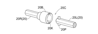
図26に示すように、引起し駆動軸20は、第一動力伝達機構DRに属する右側部分20R(以下、動力伝達軸20Rと記す。)と、第二動力伝達機構DLに属する左側部分20L(以下、動力被伝達軸20Lと記す。)とが、接続分離自在な継手機構20Cを介して動力伝達可能に構成されている。
As shown in FIG. 26, the raising
継手機構20Cは、断面形状が六角形の動力伝達軸20Rの左端部に備えられた雌ネジに対して螺子止めされ、動力被伝達軸20Lの右端部を受け入れ可能に構成された有底筒状の受入部20Bと、同じく断面形状が六角形の動力被伝達軸20Lの右端部に、動力被伝達軸20Lから、径方向に突設された二本の挿込部20Pとを備えている。
The
受入部20Bには、動力被伝達軸20L側に備えられた挿込部20Pを、動力被伝達軸20Lの軸心に沿って嵌め入れ可能な切欠部20Kが備えられ、受入部20B及び挿込部20Pは、動力伝達軸20Rと動力被伝達軸20Lとを突き合わせたときに、挿込部20Pが受入部20Bの切欠部20Kに嵌り合って動力伝達状態となり、動力伝達軸20Rと動力被伝達軸20Lとを引き離したときに嵌め合いが引き離され非動力伝達状態となる。
The receiving
したがって、第二刈取部2Lを第一刈取部2Rから取り外すのに際して、下部横向きフレーム93と上部横向きフレーム98とを連結箇所において分離させるのに伴って、入力軸105及び引起し駆動軸20は継手機構105C,20Cによって自動的に分離され非動力伝達状態となる。第二刈取部2Lを第一刈取部2Rに取り付けると、入力軸105及び引起し駆動軸20は継手機構105C,20Cによって自動的に接続され動力伝達状態となる。
Accordingly, when the
〔別実施形態〕
(1)上述した実施形態においては、八条刈りのコンバインにおいて、刈取部2における左二条分に対応する第二刈取部2Lと、残り六条分に対応する他の第一刈取部2Rとに分割したが、このような構成に限らず、左側の二条分と右端の二条分とをそれぞれ第二刈取部2Lとし、両第二刈取部2Lを、中間に位置する四条分に対応する第一刈取部2Rに対して着脱可能な構成としてもよい。第二刈取部2Lは、二条分に限らず、非作用戻し経路H2どうしが近接する状態で隣り合うものであれば、一条あるいは三条以上に構成してもよい。
[Another embodiment]
(1) In the embodiment described above, in the combine with eight-rows, the
(2)上述した実施形態においては、八条刈りコンバインを示したが、七条刈りや八条刈り等でもよく、刈取条数は八条に限るものではない。 (2) In the embodiment mentioned above, although the eight-row cutting combine was shown, seven-row cutting, eight-row cutting, etc. may be sufficient, and the number of cutting lines is not limited to eight.
本発明は、八条刈り等の刈取条数の多いコンバインに適用できる。 The present invention can be applied to a combine having a large number of cutting lines such as eight-row cutting.
1 :機体
2 :刈取部
2L :第二刈取部
2R :第一刈取部
4 :走行装置
11 :引起し装置
12 :切断装置
13 :搬送装置
19 :引起爪
20 :引起し駆動軸
H1 :引起し作用経路
L :境界
W :走行幅
DESCRIPTION OF SYMBOLS 1: Aircraft body 2:
Claims (4)
前記刈取部に、少なくとも刈取条数に対応した複数の引起し装置、植立穀稈の株元を切断する切断装置及び刈取穀稈を機体後方に向けて搬送する搬送装置が備えられ、
複数の前記引起し装置に、引起爪が突出する状態で移動する引起し作用経路、及び前記引起爪が引退した状態で移動する非作用戻り経路が備えられ、
前記刈取部は、複数の前記引起し装置のうち前記非作用戻り経路どうしが近接する状態で隣り合う引起し装置どうしの境界において、第一刈取部及び第二刈取部に分けられ、
前記刈取部は、前記第二刈取部が、前記第一刈取部に対して着脱可能に構成されるとともに、前記第二刈取部が前記第一刈取部に取り付けられた幅広状態及び前記第二刈取部が前記第一刈取部から取り外された幅狭状態のいずれの状態であっても刈り取り作業が可能に構成され、
前記幅広状態及び前記幅狭状態のいずれの刈幅も、前記左右の走行装置の走行幅よりも広く構成されるとともに、
前記刈取部は前記機体に対して、前記左右の走行装置の前記走行幅が前記刈幅内に収まるような位置に備えられているコンバイン。 It is a combine equipped with a reaper for reaping a plurality of rows of planted grain weirs at the front of the vehicle body, and the vehicle body is equipped with left and right traveling devices,
The reaper is provided with a plurality of raising devices corresponding to at least the number of reapering strips, a cutting device for cutting the stock origin of the planted rice bran, and a transport device for transporting the reaped corn kernel toward the rear of the machine;
A plurality of the raising devices provided with a raising action path in which the raising claws move in a projecting state, and a non-action return path in which the raising claws move in a withdrawn state;
The reaper is divided into a first reaper and a second reaper at a boundary between adjacent ones of the plurality of raising devices adjacent to each other in a state where the non-operation return paths are close to each other.
In the widening state in which the second reaper is attached to the first reaper while the second reaper is configured to be attachable to and detachable from the first reaper Mowing work is possible even in any state of the narrow state where the part is removed from the first mowing part,
Both the cutting width in the wide state and the narrowing state are wider than the traveling widths of the left and right traveling devices,
The combine harvester is provided at a position where the travel width of the left and right travel devices falls within the cutting width with respect to the machine body.
前記駆動軸は、前記幅広状態であるときの前記刈取部の左右方向の中央に配置されている請求項1に記載のコンバイン。 A forward and downward drive shaft is provided for transmitting power from a power source provided to the machine body to the reaper;
2. The combine according to claim 1, wherein the drive shaft is disposed at the center of the reaper in the lateral direction when in the wide state.
前記刈取駆動軸からの動力を、前記引起し装置に伝達する引起し駆動軸が上下方向に延びるように、前記刈取駆動軸に連動連結され、
前記引起し駆動軸は、前記第一刈取部の前記第二刈取部との境界側の端部において、前記引起し装置の後方に設けられている請求項2に記載のコンバイン。 The drive shaft is configured to transmit a power from the drive shaft to the raising device, the cutting device, and the transport device, and the cutting drive shaft extends in the cutting width direction of the cutting portion at the front end of the drive shaft. Interlocked with
The lift drive shaft is interlockingly connected to the reaper drive shaft such that a lift drive shaft for transmitting power from the reaper drive shaft to the lift device extends vertically.
3. The combine according to claim 2, wherein the raising drive shaft is provided at the rear of the raising device at an end of the first cutting unit on the side of the boundary with the second cutting unit.
Priority Applications (3)
| Application Number | Priority Date | Filing Date | Title |
|---|---|---|---|
| JP2017236470A JP2019103406A (en) | 2017-12-08 | 2017-12-08 | Combine |
| KR1020180151936A KR20190068437A (en) | 2017-12-08 | 2018-11-30 | Combine |
| CN201811513325.4A CN109906752A (en) | 2017-12-08 | 2018-12-07 | Combine harvester |
Applications Claiming Priority (1)
| Application Number | Priority Date | Filing Date | Title |
|---|---|---|---|
| JP2017236470A JP2019103406A (en) | 2017-12-08 | 2017-12-08 | Combine |
Publications (1)
| Publication Number | Publication Date |
|---|---|
| JP2019103406A true JP2019103406A (en) | 2019-06-27 |
Family
ID=67060595
Family Applications (1)
| Application Number | Title | Priority Date | Filing Date |
|---|---|---|---|
| JP2017236470A Pending JP2019103406A (en) | 2017-12-08 | 2017-12-08 | Combine |
Country Status (1)
| Country | Link |
|---|---|
| JP (1) | JP2019103406A (en) |
Citations (9)
| Publication number | Priority date | Publication date | Assignee | Title |
|---|---|---|---|---|
| JPH0722622U (en) * | 1993-09-29 | 1995-04-25 | ヤンマー農機株式会社 | General combine harvester structure |
| JP2004353396A (en) * | 2003-05-30 | 2004-12-16 | Hitachi Constr Mach Co Ltd | Front device for work machine, and work machine |
| JP2005030500A (en) * | 2003-07-14 | 2005-02-03 | Hitachi Constr Mach Co Ltd | Bearing device and construction machinery equipped therewith |
| JP2009106252A (en) * | 2007-11-01 | 2009-05-21 | Mitsubishi Agricult Mach Co Ltd | Combine harvester |
| US20090266044A1 (en) * | 2008-04-25 | 2009-10-29 | Coers Bruce A | Integrated draper belt support and skid shoe in an agricultural harvesting machine |
| JP2012187114A (en) * | 2012-06-07 | 2012-10-04 | Kubota Corp | Pick-up structure of combine harvester |
| JP2016185108A (en) * | 2015-03-27 | 2016-10-27 | 株式会社クボタ | Combine-harvester |
| JP2016185109A (en) * | 2015-03-27 | 2016-10-27 | 株式会社クボタ | Combine-harvester |
| JP2016185110A (en) * | 2015-03-27 | 2016-10-27 | 株式会社クボタ | combine |
-
2017
- 2017-12-08 JP JP2017236470A patent/JP2019103406A/en active Pending
Patent Citations (9)
| Publication number | Priority date | Publication date | Assignee | Title |
|---|---|---|---|---|
| JPH0722622U (en) * | 1993-09-29 | 1995-04-25 | ヤンマー農機株式会社 | General combine harvester structure |
| JP2004353396A (en) * | 2003-05-30 | 2004-12-16 | Hitachi Constr Mach Co Ltd | Front device for work machine, and work machine |
| JP2005030500A (en) * | 2003-07-14 | 2005-02-03 | Hitachi Constr Mach Co Ltd | Bearing device and construction machinery equipped therewith |
| JP2009106252A (en) * | 2007-11-01 | 2009-05-21 | Mitsubishi Agricult Mach Co Ltd | Combine harvester |
| US20090266044A1 (en) * | 2008-04-25 | 2009-10-29 | Coers Bruce A | Integrated draper belt support and skid shoe in an agricultural harvesting machine |
| JP2012187114A (en) * | 2012-06-07 | 2012-10-04 | Kubota Corp | Pick-up structure of combine harvester |
| JP2016185108A (en) * | 2015-03-27 | 2016-10-27 | 株式会社クボタ | Combine-harvester |
| JP2016185109A (en) * | 2015-03-27 | 2016-10-27 | 株式会社クボタ | Combine-harvester |
| JP2016185110A (en) * | 2015-03-27 | 2016-10-27 | 株式会社クボタ | combine |
Similar Documents
| Publication | Publication Date | Title |
|---|---|---|
| JP6437359B2 (en) | Combine | |
| JP6437361B2 (en) | Combine | |
| JP4551286B2 (en) | Combine | |
| US7165384B1 (en) | Crop picking head with road travel support device | |
| JP4546893B2 (en) | Combine | |
| JP2019103406A (en) | Combine | |
| JP2019103404A (en) | Combine | |
| JP2006304652A (en) | Combine harvester | |
| JP2019103405A (en) | Combine-harvester | |
| JP2019103403A (en) | Combine | |
| JP2007117015A (en) | Grass-dividing apparatus of combine harvester | |
| JP2019103407A (en) | Combine harvester | |
| WO2016035545A1 (en) | Harvester | |
| JP5572302B2 (en) | Combine harvesting and conveying structure | |
| JP6246170B2 (en) | Combine harvesting and conveying structure | |
| JP6437360B2 (en) | Combine | |
| JP5341475B2 (en) | Combine harvesting and conveying structure | |
| JP5313567B2 (en) | Self-removing combine | |
| JP2010119368A (en) | Vehicle body structure for combine harvester | |
| JP5231945B2 (en) | Combine weed structure | |
| JP2887912B2 (en) | Combine harvester attachment / detachment device | |
| JP6740030B2 (en) | combine | |
| JP5813182B2 (en) | Combine | |
| JP5341476B2 (en) | Combine harvesting and conveying structure | |
| JP2010104346A (en) | Reaping and conveying structure of combine harvester |
Legal Events
| Date | Code | Title | Description |
|---|---|---|---|
| A621 | Written request for application examination |
Free format text: JAPANESE INTERMEDIATE CODE: A621 Effective date: 20191225 |
|
| A977 | Report on retrieval |
Free format text: JAPANESE INTERMEDIATE CODE: A971007 Effective date: 20210222 |
|
| A131 | Notification of reasons for refusal |
Free format text: JAPANESE INTERMEDIATE CODE: A131 Effective date: 20210302 |
|
| A521 | Request for written amendment filed |
Free format text: JAPANESE INTERMEDIATE CODE: A523 Effective date: 20210430 |
|
| A131 | Notification of reasons for refusal |
Free format text: JAPANESE INTERMEDIATE CODE: A131 Effective date: 20210914 |
|
| A02 | Decision of refusal |
Free format text: JAPANESE INTERMEDIATE CODE: A02 Effective date: 20220329 |