JP2019072141A - Reel type game machine - Google Patents
Reel type game machine Download PDFInfo
- Publication number
- JP2019072141A JP2019072141A JP2017199927A JP2017199927A JP2019072141A JP 2019072141 A JP2019072141 A JP 2019072141A JP 2017199927 A JP2017199927 A JP 2017199927A JP 2017199927 A JP2017199927 A JP 2017199927A JP 2019072141 A JP2019072141 A JP 2019072141A
- Authority
- JP
- Japan
- Prior art keywords
- reel
- machine according
- control board
- game
- main control
- Prior art date
- Legal status (The legal status is an assumption and is not a legal conclusion. Google has not performed a legal analysis and makes no representation as to the accuracy of the status listed.)
- Pending
Links
Images


Abstract
Description
回胴式遊技機に関する。 The present invention relates to a drum-type game machine.
回胴式遊技機(スロットマシン)は、所定数の遊技メダルを投入後に遊技開始指示装置(スタートレバー)が操作されたことを契機として1ゲームが開始されて、複数の図柄が外周上に配置された複数列の回胴(リール)が回転動作し、当該回転動作を停止させるための回胴停止装置(ストップボタン)を駆使して回胴を停止させた結果、有効ライン上に所定の図柄の組合せ(例えば「777」等の入賞役)が並んだ場合には、通常遊技状態よりも遊技者にとって利益状態の高い特別遊技状態(通常時よりも小役等の抽選確率が上昇する遊技状態)に移行するタイプのものが一般的である。ここで、回胴式遊技機においては、遊技の興趣性を高めるための演出用の画像等が、リールの回転動作及び停止動作とシンクロした形で、液晶等のディスプレイ上にて表示される場合があり、回胴停止装置等を操作した際に、回胴上に表示された図柄とディスプレイ上に表示された演出用の画像等とを見比べながら、遊技の結果を予測して楽しむよう構成されているものが多い。 One game is started when a game start instruction device (start lever) is operated after inserting a predetermined number of game medals, and a plurality of symbols are arranged on the outer periphery of the torso type gaming machine (slot machine) As a result of stopping the rotating drum by making full use of the rotating drum stop device (stop button) for stopping the rotating operation, the predetermined pattern on the effective line is performed. When a combination of winning combinations such as “777” is lined up, a gaming state in which the special gaming state (a small winning combination such as a small winning combination or the like increases) is higher for the player than the normal gaming state The type of transition to) is common. Here, in the case of the roll-to-roll type gaming machine, an image or the like for presentation for enhancing the interest of the game is displayed on a display such as liquid crystal in synchronization with the rotating operation and the stopping operation of the reels. When the spinning stop device etc. are operated, it is configured to predict and enjoy the game result while comparing the symbol displayed on the spinning drum with the effect image etc. displayed on the display. There are many things that
また、近年の回胴式遊技機においては、回胴停止装置の操作態様(操作順番や操作タイミング)に応じて、入賞役の入賞有無や入賞役の種類が変化するよう構成され、遊技者にとって有利な入賞役が入賞するよう操作指示(ナビゲーション)を発してアシストするもの(いわゆるAT機)も多く登場している。このAT機においては、操作指示を発する状態(AT状態)と操作指示を発しない状態(非AT状態)とを有しており、AT状態が継続すればするほど、遊技者にとって有利となるような遊技性を備えている。 Also, in recent drum-type gaming machines, the presence or absence of a winning combination and the type of winning combination are changed according to the operation mode (operation order and operation timing) of the rotation stop device. A number of devices (so-called AT machines) that assist by issuing operation instructions (navigation) so as to win advantageous winning combinations have also appeared. The AT machine has a state for issuing an operation instruction (AT state) and a state for not issuing an operation instruction (non-AT state), and the more the AT state continues, the more advantageous it is for the player. It has a good gameplay.
遊技者に著しく不利益な状態での遊技を継続させないことが望まれている。 It is desirable not to allow the player to continue the game in a significantly disadvantageous state.
本態様に係る回胴式遊技機は、
精算スイッチと、
遊技価値情報を表示可能な総得点表示手段と、
抽選を行う抽選手段と、を備え、
前記抽選手段により所定の抽選結果が決定され、所定数の遊技価値を付与する図柄組合せが停止表示された遊技において、前記総得点表示手段に表示されている遊技価値情報に前記所定数の遊技価値に対応する情報を加算している最中に前記精算スイッチが操作されたときには、前記総得点表示手段に表示されている遊技価値情報に前記所定数の遊技価値に対応する情報を加算し終えた後に、精算に関する処理を実行可能とする
ことを特徴とする。
The drum-type gaming machine according to this aspect is:
Settlement switch,
Total score display means capable of displaying game value information;
Providing lottery means for performing a lottery,
In the game in which a predetermined lottery result is determined by the lottery means and symbol combinations for giving a predetermined number of game values are stopped and displayed, the predetermined number of game values are displayed in the total score display means. When the settlement switch is operated while adding the information corresponding to, the information corresponding to the predetermined number of game values is added to the game value information displayed on the total score display It is characterized in that the processing relating to the settlement can be performed later.
本態様に係る回胴式遊技機によれば、遊技者に著しく不利益な状態での遊技を継続させないことができる、という効果を奏する。 According to the reel-type game machine according to the present aspect, it is possible to prevent the player from continuing the game in a remarkably disadvantageous state.
はじめに、本明細書における各用語の意義について説明する。「乱数」とは、回胴式遊技機において何らかの遊技内容を決定するための抽選(電子計算機によるくじ)に使用される乱数であり、狭義の乱数の他に擬似乱数も含む(例えば、乱数としてはハード乱数、CPUを含む主制御チップによって生成された内蔵乱数、擬似乱数としてはソフト乱数)。例えば、遊技の結果に影響を与えるいわゆる「基本乱数」、具体的には、特別遊技に移行するための特別役や入賞役(小役、再遊技役)と関連した「当選乱数」、等を挙げることができる。「CPU」とは、当業界において周知であるものと同義であり、使用されているアーキテクチャ(CISC、RISC、ビット数等)や処理性能等には何ら限定されない。「電断(電源断)」とは、遊技機に設けられた電源スイッチの操作実行有無に係らず、遊技機に供給される電源電圧が一定レベル以下となったことを指し、例えば、電源供給ユニットの破損や停電等による不測の事態による電源供給の遮断をも包含する。「ROM」とは、当業界において周知であるものと同義であり、情報を物理的に保持する(例えば、データ読み出し用の電流を与えた場合、導通する素子構成であれば「1」、導通しない素子構成であれば「0」となる)。RAMとは、当業界において周知であるものと同義であり、情報を電気的に保持する(例えば、データ読み出し用の電流を与えた場合、蓄電されていれば「1」、蓄電されていなければ「0」となる。尚、RAM内で保持されているデータの一部又はすべてに対して、電断時にはバックアップ電源が供給されるよう構成されていることが一般的である)。「遊技状態」とは、例えば、遊技メダルが獲得容易であり遊技者にとって有利な特別遊技状態(いわゆる大当り遊技であり、ボーナス遊技や第1種BB・第2種BB等と呼ばれるものが該当する)、再遊技役の当選率があらかじめ定められた値である通常遊技状態よりも再遊技役の当選率が高い(又は低い)状態である再遊技確率変動遊技状態(RT状態)、当選した役を入賞させるためのリールの停止順、停止位置を報知し得るAT(アシストタイム)中状態、前記RT状態とAT中状態とが複合したART(アシストリプレイタイム)状態、等が挙げられる。また、通常遊技状態においても、RT状態、AT中状態、ART中状態への移行抽選確率が異なる、高確率通常遊技状態、低確率通常遊技状態、等(本例では、抽選状態と称している)が挙げられる。また、遊技状態は複合しても問題ない{更に、これらの遊技状態や機能(例えば、AT中状態への移行抽選や、リールの停止順に係る報知指示の出力等)は、遊技進行を制御する主制御基板側ですべて実装してしまっても問題ない}。また、本例においては、ATに関する状態とRT状態とを個別に記載し、RT状態が「RT1」且つATに関する状態が「通常遊技状態」等と称しているが、RT状態とATに関する状態とを纏めてARTに関する状態としてARTに関する状態が「通常遊技状態」等と称してもよい。「当選役」とは、内部抽選により当選した条件装置の種類(又は、条件装置番号)である。「報知状態」とは、後述する押し順ナビを実行可能なATに関する状態であり、リール停止順によって入賞する役が相違しないために押し順ナビが実行されない条件装置が当選したゲームであっても、ATに関する状態が押し順ナビを実行可能な状態であれば「報知状態」とするよう構成している。「カウンタ値」とは「報知遊技実行可能数」とも称し、後述する、AT残りゲーム数もしくはATカウンタM60のカウンタ値である。例えば、「報知遊技実行可能数」が1以上(「0」となった当該遊技も含めても良い)である場合には後述する押し順ナビが実行され得る。また、「報知遊技実行可能数」として、小役(主に、押し順ベル役)が当選したことに基づいて得られる遊技媒体の差枚数(払出し枚数から投入枚数を引いた枚数)や、押し順ベル役の当選回数、を採用しても良い。また、「特殊報知状態」とは、ATに関する状態のうち遊技者に最も有利となる状態であり、本例では、「上乗せ特化状態」と称している。また、「特定条件」とは、ATカウンタ値を減算し得る条件であり、例えば、1ゲームが終了した、所定役(例えば、押し順ベル役)が当選した、等が特定条件となる。「第1種特別役物」とは、規定数ごとの入賞に係る図柄の組合せの数を増加させ、又は規定数ごとの入賞に係る条件装置が作動する確率を上昇させる役物で、あらかじめ定められた場合に作動し12回を超えない回数の遊技の結果が得られるまで作動を継続することができるものであり、RB(レギュラーボーナス)と称することがある。「第1種特別役物連続作動装置」とは、第1種特別役物を連続して作動させることができる装置で、特定の図柄の組合せが表示された場合に作動しあらかじめ定められた場合に作動を終了するものであり、BB(ビッグボーナス)や第1種BBと称することがある。「第2種特別役物」とは、役抽選の結果に拘らず入賞に係る条件装置を作動させることとなる役物で、あらかじめ定められた場合に作動し1回の遊技の結果が得られた場合に作動を終了するものであり、CB(チャレンジボーナス)と称することがある。「第2種特別役物連続作動装置」とは、第2種特別役物を連続して作動させることができる装置で、特定の図柄の組合せが表示された場合に作動しあらかじめ定められた場合に作動を終了するものであり、MB(ミドルボーナス)や第2種BBと称することがある。「普通役物」とは、規定数毎の入賞に係る図柄の組合せの数を増加させ、又は、規定数毎の入賞に係る条件装置が作動する確率を上昇させる役物で、特定の図柄の組合せが表示された場合に作動し1回の遊技の結果が得られた場合に作動を終了することとされているものであり、SB(シングルボーナス)と称することがある。「オールJACINタイプ」とは、第1種BB役が入賞した場合にJACINしたものとみなし、第1種BBの実行中においては常にRB中とする構成である。より具体的には、1種BBの図柄組合せが停止表示した場合に、RBの図柄組合せが停止表示することなくRBが作動する。そしてRBの終了条件を満たした場合にはRBを終了させる。但し、1種BBの終了条件を満たしていない場合には、次遊技における賭け設定がなされる前に、再度、(RBの図柄組合せが停止表示することなく)RBが作動する。このように、RBを連続して作動させることができる1種BBを「オールJACINタイプ」と称する。尚、「オールJACINタイプ」では、RBの終了条件を満たす前に、1種BBの終了条件を満たした場合には、1種BBを終了させるとともに、RBも終了させる。また、「JACIN抽選タイプ」とは、第1種BBの実行時にて非RB中とRB中とを繰り返し実行する構成である。また、「無制御リール」とは、停止操作を行った後に実行され得る引込み制御が実行されない状態のリールであり、停止操作を受け付けたリール位置から停止し得る最も近いリール位置にて停止する状態のリールである。「オールCBタイプ」とは、第2種BBの実行時にて常にCB中となる構成である。より具体的には、2種BBの図柄組合せが停止表示した場合に、CBの図柄組合せが停止表示することなくCBが作動する。そしてCBの終了条件(1遊技の実行)を満たした場合にはCBを終了させる。但し、2種BBの終了条件を満たしていない場合には、次遊技における賭け設定がなされる前に、再度、(CBの図柄組合せが停止表示することなく)CBが作動する。このように、CBを連続して作動させることができる2種BBを「オールCBタイプ」と称する。尚、「オールCBタイプ」では、2種BBの終了条件を満たした場合には、2種BBを終了させるとともに、CBも終了させる。「CB移行抽選タイプ」とは、第2種BBの実行時にて非CB中とCB中とを繰り返し実行する構成である。「画像」とは、限定した場合を除き、静止画像および動画像を含むものであり、例えば、演出表示装置S40に表示される情報である。また、回胴式遊技機におけるBBやRB等を特別遊技と称することがあり、ぱちんこ遊技機における大当りや小当りを特別遊技と称することがある。また、ぱちんこ遊技機における特別図柄(主遊技図柄と称することがある)を識別情報と称することがあり、回胴式遊技機における停止表示する図柄組み合わせを停止表示した識別情報と称することがある。また、回胴式遊技機におけるリールの回転を識別情報の変動表示と称することがあり、ぱちんこ遊技機における特別図柄(主遊技図柄と称することがある)の変動表示を識別情報の変動表示と称することがある。
First, the meaning of each term in the present specification will be described. "Random number" is a random number used in a lottery (lottery by an electronic computer) for determining some game contents in a revolving type gaming machine, and includes pseudo random numbers in addition to random numbers in a narrow sense (for example, as random numbers Are hard random numbers, built-in random numbers generated by the main control chip including the CPU, and soft random numbers as pseudo random numbers). For example, so-called "basic random numbers" that affect the outcome of the game, specifically, "winning random numbers" associated with a special part or a winning combination (small part, replay part) to shift to a special game, etc. It can be mentioned. The "CPU" is synonymous with what is known in the art, and is not limited at all to the used architecture (CISC, RISC, number of bits, etc.) or processing performance. "Power off (power off)" indicates that the power supply voltage supplied to the gaming machine has become equal to or lower than a predetermined level regardless of whether or not the power switch provided in the gaming machine is operated. It also includes the interruption of power supply due to unforeseen situations such as unit damage or blackout. "ROM" is synonymous with what is known in the industry, and physically holds information (for example, "1" for an element configuration that conducts when a current for reading data is given, conduction In the case of an element configuration that does not perform, it becomes "0"). RAM is synonymous with what is well known in the industry, and holds information electrically (for example, when a current for reading data is given, “1” if stored, if not stored. It becomes “0.” It is a general rule that the backup power is supplied to the part or all of the data stored in the RAM at the time of power interruption). The “playing state” is, for example, a special gaming state in which game medals are easily obtained and which is advantageous to the player (so-called a big hit game, which corresponds to what is called a bonus game, first type BB, second type BB, etc.) ), Replay probability fluctuation game state (RT state) in which the win rate of the replay player is higher (or lower) than that of the normal gaming state where the win rate of the replay role is a predetermined value, the winning role The reel stop order for winning a prize, AT (assist time) state in which the stop position can be notified, ART (assist replay time) state in which the RT state and the AT state are combined, and the like can be mentioned. Furthermore, even in the normal gaming state, the transition lottery probability to the RT state, the AT state, and the ART state differs, the high probability normal gaming state, the low probability normal gaming state, etc. (in this example, it is referred to as the lottery state) Can be mentioned. In addition, there is no problem even if the gaming state is combined {Furthermore, these gaming states and functions (for example, the transition lottery to the AT state, the output of the notification instruction according to the stop order of the reel, etc.) control the game progress There is no problem even if everything is mounted on the main control board side}. Also, in this example, the states relating to AT and RT state are described separately, and the state relating to RT state is “RT1” and the state relating to AT is referred to as “normal gaming state” etc. The state relating to the ART may be referred to as the “normal game state” or the like as a state relating to the ART. The "winning combination" is the type (or the condition device number) of the condition device which has won the internal lottery. The "informing state" is a state relating to an AT capable of executing push order navigation described later, and is a game in which a condition device in which push order navigation is not executed because the winning combinations are not different according to the reel stop order If the state relating to the AT is a state in which the push navigation can be performed, the "information state" is set. The "counter value" is also referred to as "informing game executable number", and is the number of remaining AT games or the counter value of the AT counter M60, which will be described later. For example, in the case where the “number of informing game executable numbers” is 1 or more (may include the game having become “0”), pushing order navigation described later may be executed. In addition, the difference number of game media (the number obtained by subtracting the insertion number from the number of payouts) obtained based on the fact that the small winning combination (mainly, the push order bell combination) is won as the "information game executable number", The number of wins of the order bell may be adopted. Further, the "special notification state" is a state that is most advantageous to the player among the states related to the AT, and in this example, is referred to as the "super specialization state". The “specific condition” is a condition under which the AT counter value can be subtracted, and, for example, the specific condition may be that one game is over, a predetermined combination (for example, pushing order bell combination) is won, or the like. The "
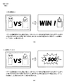
「特別遊技を実行可能な特別役に当選していることを示唆する演出」は、特別役に当選したことにより特別遊技を実行できることを示す演出であり、例えば、最終的に成功したことを示唆する演出などが挙げられる。具体的には、キャラクタが競い合うような対決演出などが実行されたときには、一方のキャラクタが勝利する画像が最終的に表示されて成功したことを示唆することができる。また、「特別遊技を実行可能な特別役に当選していないことを示唆する演出」は、特別役に当選していないことにより特別遊技を実行できないことを示す演出であり、例えば、最終的に失敗したことを示唆する演出などが挙げられる。具体的には、キャラクタが競い合うような対決演出などが実行されたときには、一方のキャラクタが敗北する画像が最終的に表示されて失敗したことを示唆することができる。 The "recommendation indicating that the special role can be executed special game is a effect that indicates that it is possible to execute the special game by winning the special role, for example, suggests that it has finally succeeded And the like. Specifically, when a confrontation effect or the like in which characters compete is performed, it can be suggested that an image won by one character is finally displayed and succeeded. In addition, “representation indicating that the special role that can execute the special game can not be won” is an effect that indicates that the special game can not be executed because the special role is not won, for example, finally There are effects that suggest that he failed. Specifically, when a confrontation effect or the like in which characters compete is performed, it can be suggested that an image in which one character is defeated is finally displayed and has failed.
尚、本実施形態は、あくまで一例であり、各手段が存在する場所や機能等、各種処理に関しての各ステップの順序、フラグのオン・オフのタイミング、各ステップの処理を担う手段名等に関し、以下の態様に限定されるものではない。また、上記した実施形態や変更例は、特定のものに対して適用されると限定的に解すべきでなく、どのような組み合わせであってもよい。例えば、ある実施形態についての変更例は、別の実施形態の変更例であると理解すべきであり、また、ある変更例と別の変更例が独立して記載されていたとしても、当該ある変更例と当該別の変更例を組み合わせたものも記載されていると理解すべきである。 Note that the present embodiment is merely an example, and relates to the order of each step regarding various processes such as the location and function of each means, the on / off timing of the flag, and the means name etc. It is not limited to the following aspects. In addition, the embodiments and modifications described above should not be construed as limiting as applied to specific ones, and may be any combination. For example, it should be understood that a modification of one embodiment is a modification of another embodiment, and even if one modification and another modification are independently described, It should be understood that a combination of the modification and the other modification is also described.
(本実施形態)
ここで、各構成要素について説明する前に、本実施形態に係る回胴式遊技機Pの特徴(概略)を説明する。以下、図面を参照しながら、各要素について詳述する。
(This embodiment)
Here, before describing each component, the feature (outline) of the reel-type gaming machine P according to the present embodiment will be described. Hereinafter, each element will be described in detail with reference to the drawings.
尚、以下の実施形態におけるステップ番号、符号、手段名等は、他の実施形態におけるステップ番号、符号、手段名等と同一である場合があるが、これらはそれぞれ単独の実施形態におけるステップ番号、符号、手段名等であることを示している(例えば、本実施形態におけるステップ3402と本実施形態からの変更例1におけるステップ3402は、別の実施形態におけるステップ3402であるため、それぞれ単独で機能する処理である)。
The step numbers, symbols, means names, etc. in the following embodiments may be the same as the step numbers, symbols, means names, etc. in the other embodiments. It indicates that it is a code, a means name, etc. (For example,
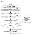
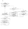
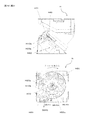
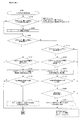
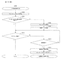
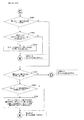
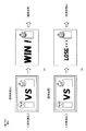
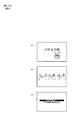
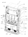
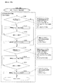
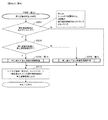
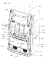
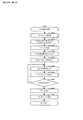
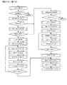
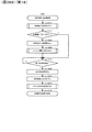
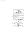
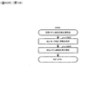
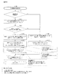
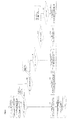
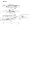
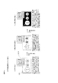
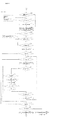
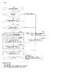
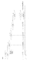
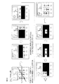
まず、図1(一部の構成については図2)を参照しながら、本実施形態に係る回胴式遊技機Pの前面側の基本構造を説明する。回胴式遊技機Pは、主に前扉(フロントドアとも称す)と、裏箱(キャビネット、基体とも称す)と裏箱内に設置されたリールユニット、ホッパ装置、電源供給ユニットE、主制御基板M(CPUMCを含む主制御チップCが搭載されている基板)、副制御基板S(CPUSCを含む副制御チップSCが搭載されている基板)で構成される。以下、これらを順に説明する。 First, the basic structure of the front side of the reel-to-play type gaming machine P according to this embodiment will be described with reference to FIG. 1 (FIG. 2 for a part of the configuration). The reel-type game machine P mainly includes a front door (also referred to as a front door), a back box (also referred to as a cabinet or a base), a reel unit installed in the back box, a hopper device, a power supply unit E, main control A substrate M (a substrate on which a main control chip C including a CPUMC is mounted) and a sub control substrate S (a substrate on which a sub control chip SC including a CPUSC is mounted) are formed. Hereinafter, these will be described in order.
<前扉DU>
前扉DUは、遊技状態を視認可能にするための機構、遊技媒体の入力を可能にするための機構、リールユニットを操作するための機構、その他の機構等を含む。具体的には、遊技状態を視認可能にするための機構として、リール窓D160、投入数表示灯D210、操作状態表示灯D180、特別遊技状態表示装置D250、クレジット数表示装置D200、払出数表示装置(押し順表示装置)D270(押し順表示装置D270と称することもある)、ATカウンタ値表示装置D280、有利区間表示器YH等が取り付けられている。また、遊技媒体の投入や賭け数(ベット数)の入力を可能にするための機構として、メダル投入口D170、ベットボタンD220、投入された遊技媒体の払い出しを可能にするための機構として、精算ボタンD60が取り付けられている。そして、リールを操作するための機構として、スタートレバーD50、停止ボタンD40が取り付けられている。なお、本実施形態における回胴式遊技機は、スタートレバーD50、停止ボタンD40、メダル投入口D170、ベットボタンD220、精算ボタンD60、サブ入力ボタンSB等が取り付けられている遊技者側にせり出した形状の操作卓を備えている。以下、各要素について詳述する。
<Front door DU>
The front door DU includes a mechanism for making a game state visible, a mechanism for enabling input of game media, a mechanism for operating a reel unit, and other mechanisms. Specifically, as a mechanism for making the gaming state visible, the reel window D160, the number-of-inputs indicator light D210, the operation state indicator light D180, the special gaming state display device D250, the number-of-credits display device D200, the number-of-payouts display device (Pressing order display device) D270 (sometimes referred to as pushing order display device D270), AT counter value display device D280, advantage zone indicator YH, etc. are attached. In addition, as a mechanism for enabling the insertion of game media and the input of the bet number (bet number), the medal insertion slot D170, the bet button D220, and the mechanism for enabling the payout of the inserted game media, the settlement The button D60 is attached. A start lever D50 and a stop button D40 are attached as a mechanism for operating the reel. In the drum-type gaming machine according to the present embodiment, the start lever D50, the stop button D40, the medal insertion slot D170, the bet button D220, the settlement button D60, the sub input button SB and the like are pointed out to the player side It has a shaped console. Each element will be described in detail below.
<遊技状態を視認可能にするための機構>
次に、遊技状態を視認可能にするための機構の要部について説明する。リール窓D160は、前扉DUの一部を構成する合成樹脂等によって形成された透明な部材であり、リール窓D160を通して遊技機枠内に設置されたリールユニットを視認可能に構成されている。また、投入数表示灯D210は、LEDによって構成されており、現在ベット(一の遊技を開始するために必要な遊技メダルを投入すること)されているメダル数と同数のLEDが点灯するよう構成されている。また、操作状態表示灯D180は、LEDによって構成されており、現在の操作状態(メダル受付可否状態、再遊技停止状態、遊技開始ウェイト状態等)に応じて点灯・消灯するよう構成されている。また、特別遊技状態表示装置D250は、7セグメントディスプレイによって構成されており、特別遊技中に払い出された払出数の総数が表示されるよう構成されている。尚、特別遊技状態表示装置D250を設けない構成としてもよく、そのように構成した場合には、後述する演出表示装置S40(第二情報表示部とも称することがある)にて当該払出数の総数を表示するよう構成することで遊技者は特別遊技中に払い出された払出数の総数を認識することができユーザーフレンドリーな遊技機とすることができる。また、クレジット数表示装置D200は、7セグメントディスプレイによって構成されており、遊技者の持ちメダルとして遊技機内に貯留されているメダル数の総数(クレジット数)が表示されるよう構成されている。また、払出数表示装置(押し順表示装置)D270は、7セグメントディスプレイによって構成されており、現在払出されている遊技メダル数及びリール停止順(左停止ボタンD41、中停止ボタンD42、右停止ボタンD43の停止順)によって入賞する役が相違し得る条件装置{いわゆる押し順役(押し順あり役とも称することがある)であるが、入賞する役や停止表示される図柄組合せが相違した場合には、遊技者に付される利益率(払出枚数、その後のRT状態等)が異なり得るよう構成されているものが一般的である}が成立したゲームにて、遊技者に最も有利となるリール停止順を報知し得るよう構成されている(当該報知を押し順ナビと称することがある)。このように、払出数表示装置(押し順表示装置)D270は、現在払出されている遊技メダル数と遊技者に最も高利益となるリール停止順との2つの表示を実行し得るよう構成されており、実行されている表示が2つの表示のうちいずれであるかを遊技者が誤認しないような表示態様となっており、当該表示態様の詳細は後述することとする。また、ATカウンタ値表示装置D280は、ATに関する状態(詳細は後述する)のうち、押し順表示装置D270(第一情報表示部とも称することがある)に表示された押し順ナビ表示に従って遊技を進行した場合に保障されることとなる遊技者にとって有利なATに関する状態(本例では、押し順ナビ状態、報知遊技とも称することがあり詳細は後述する)に滞在し得るゲーム数を表示し得るよう構成されている。尚、ATカウンタ値表示装置D280を設けない構成としてもよく、そのように構成した場合には、AT中状態に滞在し得るゲーム数を演出表示装置S40にて表示するよう構成することで遊技者は当該有利なATに関する状態が保障されているゲーム数を認識することができユーザーフレンドリーな遊技機とすることができる。尚、払出数表示装置(押し順表示装置)D270は、払出数表示装置と押し順表示装置との2つの装置に分けるよう構成してもよい。
<Mechanism for making the gaming state visible>
Next, the main parts of the mechanism for making the gaming state visible will be described. The reel window D160 is a transparent member formed of a synthetic resin or the like that constitutes a part of the front door DU, and is configured to allow visual recognition of the reel unit installed in the gaming machine frame through the reel window D160. Further, the number-of-inputs indicator light D210 is configured by LEDs, and is configured to light the same number of LEDs as the number of medals currently bet (to insert game medals necessary to start one game) It is done. In addition, the operation state
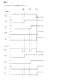
また、有利区間表示器YHは、LEDによって構成されており、「有利区間」である場合には点灯し、「有利区間」でない場合には消灯するよう構成されている(点灯及び消灯タイミングについては後述する)。ここで、本例に係る回胴式遊技機においては、従来の回胴式遊技機と同様に、遊技メダルが獲得容易であり遊技者にとって有利な特別遊技状態(いわゆる大当り遊技であり、ボーナス遊技や第1種BB・第2種BB等と呼ばれるものが該当する)、再遊技役の当選率があらかじめ定められた値である通常遊技状態よりも再遊技役の当選率が高い(又は低い)状態である再遊技確率変動遊技状態(RT状態)、当選した役を入賞させるためのリールの停止順、停止位置を報知し得るAT(アシストタイム)中状態、前記RT状態とAT中状態とが複合したART(アシストリプレイタイム)状態、等を採り得るが、これらの「遊技状態」とは別に、「通常区間」、「待機区間」及び「有利区間」という3つの「遊技区間」のいずれかを設定可能となっている。尚、本例においては「待機区間」は設定しておらず、「通常区間」と「有利区間」とのいずれかの遊技区間を設定している。このうち、「有利区間」が他の「遊技区間」よりも、遊技者にとって相対的に有利となるものとして位置付けられており、例えば、「遊技状態」がAT中状態やART状態であることと「有利区間」とが対応付けされている。即ち、「遊技状態」がAT中状態やART状態であると、有利区間表示器YHが点灯するのであるが、後述するように、「遊技区間」の設定制御も「遊技状態」の設定制御と同様に、遊技進行を制御する主制御基板側で行われるため、有利区間表示器YHの点灯/消灯状況によって、遊技進行状況が遊技者にとって相対的に有利なものとなっているか否かが、嘘偽りなく遊技者に対して伝達可能となっている。尚、後述するように、「有利区間」が所定の上限ゲーム数(例えば、1500ゲーム)に達するまで継続すると「通常区間」が強制的に設定されるのであるが、その際には、残存するATに関する状態も強制的に終了させられる(AT中状態を維持するための情報がクリア・初期化される)ため、設定される「遊技区間」の変更が「遊技状態」の移行にも影響を与え得るものとなっており、それにより比較的設計自由度の高いAT中状態やART状態等の「遊技状態」によって、著しく射幸性が高まってしまうことを自動的に抑制できるものとなっているのである。尚、上述したように、「有利区間」が所定の上限ゲーム数(例えば、1500ゲーム)に達するまで継続すると「通常区間」が強制的に設定される、即ち、「有利区間」が終了することとなるが、「有利区間」の終了条件はこれには限定されない。本例に係る回胴式遊技機における「有利区間」の終了条件は、「押し順役(押し順あり役)を構成する小役の中で、払出し枚数が最も多い小役を獲得可能な押し順ナビ1回の実行(例えば、押し順役を構成する小役として、7枚、3枚、1枚の小役がある場合、払出し枚数が最も多い7枚が獲得可能な押し順ナビであって、押し順により7枚、又は1枚が獲得可能な押し順役と、押し順により3枚が獲得可能な押し順役があれば、3枚が獲得可能な押し順ナビは、ここでいう押し順ナビには該当しない)」、又は、「BB、RB、MB、のいずれかに当選」を満たし、且つ、「任意の終了条件(40G1セットのループ抽選に非当選(AT)、固定32G経過(ガセ前兆)等)」、又は、「有利区間1500G」を満たすことが終了条件となっている。尚、押し順ベル役が存在しないような仕様(例:RT状態を移行するためのリプレイの押し順は存在するが、押し順によって払出し枚数が異なる小役が存在しない仕様)の場合には、「払出し枚数が最も多い小役を獲得可能な押し順ナビ1回」という有利区間を終了するための条件は除外される。また、本実施形態では、押し順役を構成する小役として11枚役に対応する小役と1枚役に対応する小役を含む小役により構成されているため、「払出し枚数が最も多い小役を獲得可能な押し順ナビ1回の実行」とは、11枚のメダルが獲得可能(11枚役が入賞可能)な押し順を報知することを指す。 Further, the advantageous section indicator YH is configured by an LED, and is turned on when it is an "advantageous section", and is turned off when it is not an "advantageous section" (the timing of turning on and off) Will be described later). Here, in the drum-type gaming machine according to the present embodiment, a special gaming state in which game medals are easily obtained and which is advantageous for the player (a so-called big hit game and a bonus game) as in the conventional drum-type gaming machine And those called first class BB and second class BB etc.), the winning rate of the replay role is higher (or lower) than that of the normal gaming state, which is a predetermined value. Reproduction probability fluctuation game state (RT state) which is the state, stop order of reels for winning the winning combination, AT (assist time) state in which the stop position can be notified, RT state and AT state Although it is possible to adopt a combined ART (assist replay time) state, etc., one of three "gaming areas" such as "normal section", "standby section" and "advantage section" separately from these "playing states". Can be set Going on. In the present example, the "standby section" is not set, and the game section of either the "normal section" or the "advantage section" is set. Among them, the "advantage zone" is positioned as being relatively advantageous to the player over other "game segments". For example, the "game status" is in the AT state or the ART state. It is associated with the "advantage zone". That is, the advantageous section indicator YH is turned on when the "gaming state" is in the AT state or the ART state, but as described later, the setting control of the "gaming section" is also the setting control of the "gaming state" Similarly, since it is performed on the main control board side that controls the game progress, whether the game progress status is relatively advantageous for the player depending on the on / off status of the advantageous section indicator YH, It can be transmitted to the player without a lie. As will be described later, if the "advantage zone" continues until the predetermined upper limit game number (for example, 1500 games) is reached, the "normal zone" is forcibly set, but at that time, it remains Because the state regarding AT is also forced to end (information for maintaining the state during AT is cleared / initialized), the change of "game section" to be set affects the transition of "playing state". It can be given, and it is possible to automatically suppress the increase of irritability by "gaming state" such as AT state or ART state with relatively high design freedom. It is Note that, as described above, when the "advantage zone" continues until the predetermined upper limit game number (for example, 1500 games) is reached, the "normal zone" is forcibly set, that is, the "advantage zone" ends. However, the ending condition of the "favorable section" is not limited to this. The termination condition of the “advantage zone” in the drum-type game machine according to the present embodiment is “pushed to be able to obtain the small winning combination with the largest number of payouts among the small winning combinations that make up the push-on combination. Execution of one order navigation (for example, when there are seven, three, or one small combination as a small combination that constitutes a push order, this is a push order navigation where seven sheets with the largest number of payouts can be obtained If there is a pressing order that can get 7 or 1 by pressing order and a pressing order that can get 3 by pressing order, the pressing order navigation that can get 3 can be said here "Not applicable to push order navigation" or "winning in any of BB, RB, MB" and "arbitrary termination conditions (40G1 set loop lottery not won (AT), fixed 32G It is an end condition that meeting “progress (Gasse prognostic) etc.” or “advantage section 1500 G” To have. In the case of a specification in which there is no push order bell combination (eg, there is a push order for replay to shift the RT state, but there is no small combination with the number of payouts depending on the push order). The condition for ending the advantageous section of "one push sequence navigation capable of acquiring the small winning combination with the largest number of payouts" is excluded. Further, in the present embodiment, since the small combination including the small combination corresponding to 11 combinations and the small combination corresponding to one combination is included as the small combination constituting the push combination, “the number of payouts is largest "Execution of one push order navigation capable of acquiring a small winning combination" refers to informing a push order that 11 medals can be acquired (11 sheet winnings can be won).
<遊技媒体の入力を可能にするための機構>
次に、遊技媒体の入力を可能にするための機構の要部について説明する。メダル投入口D170は、遊技メダルの投入口であり、メダル受付可能状態である状況下において当該投入口に投入された遊技メダルは遊技機内部へと誘導される。また、遊技機内部にはメダルの投入を検出するセンサとして、投入受付センサD10sと、第1投入センサD20sと、第2投入センサD30sと、が設けられており、遊技機内部へと誘導された遊技メダルが正常に投入されたと判断した場合に、投入されたメダルをベットされたメダルとして検出し得るよう構成されている。また、ベットボタンD220は、遊技者によって操作可能に構成されており、操作によって、貯留されているメダル(クレジットのメダル)をベットすることができるよう構成されている。また、精算ボタンD60は、遊技者によって操作可能に構成されており、操作によって、貯留されているメダル(クレジットのメダル)及び/又はベットされているメダルを遊技者に払い戻すことが可能となっている。尚、精算ボタンD60の操作によって払い戻された遊技メダルは、放出口D240に払い出されるよう構成されている。
<A mechanism for enabling input of gaming media>
Next, the main part of a mechanism for enabling input of game media will be described. The medal insertion slot D170 is an insertion slot for game medals, and the game medals inserted into the insertion slot under the situation where the medals can be received are guided into the gaming machine. Further, as a sensor for detecting the insertion of medals inside the gaming machine, an insertion acceptance sensor D10s, a first insertion sensor D20s, and a second insertion sensor D30s are provided, and are guided to the inside of the gaming machine When it is determined that the game medal has been inserted normally, the inserted medal can be detected as a betted medal. In addition, the bet button D220 is configured to be operable by the player, and is configured to be able to bet the stored medals (credit medals) by the operation. Further, the settlement button D60 is configured to be operable by the player, and it is possible to pay back the stored medals (credit medals) and / or the bet medals to the player by the operation. There is. The gaming medals paid back by the operation of the settlement button D60 are paid out to the outlet D240.
<リールユニットを操作するための機構>
次に、スタートレバーD50は、遊技者によって操作可能に構成されており、操作によってリールの動作を開始可能に構成されている。また、停止ボタンD40は、遊技者によって操作可能な左停止ボタンD41、中停止ボタンD42、右停止ボタンD43を備えており、夫々の停止ボタンを操作することによってリールの動作を順次停止可能に構成されている。
<Mechanism for Operating Reel Unit>
Next, the start lever D50 is configured to be operable by the player, and is configured to be able to start the operation of the reel by an operation. In addition, the stop button D40 includes a left stop button D41, a middle stop button D42, and a right stop button D43 which can be operated by the player, and the operation of the reels can be sequentially stopped by operating the respective stop buttons. It is done.
<前扉DUに設けられたその他の機構>
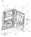
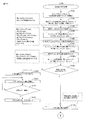
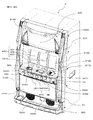
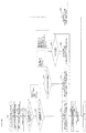
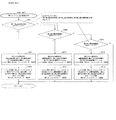
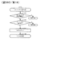
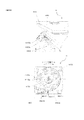
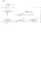
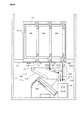
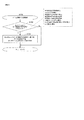
次に前扉DUに設けられたその他の機構の要部について図2の前扉DUを開いて回胴式遊技機Pの内部の構成を示した斜視図も参照しつつ説明する。前扉DUには、遊技の興趣性を高めるための機構として、予告演出や背景演出等の演出を表示するための演出表示装置S40、様々な点灯態様にて点灯し得る遊技効果ランプD26(不図示)、信号中継用の扉基板D、投入されたメダルの検出等を行なうメダルセレクタDS、サウンドを出力し得るスピーカS20、合成樹脂等によって形成された部材である、中パネル(中装飾パネル)、上パネルD130及び下パネルD140、等が設けられている。演出表示装置S40は、上パネルに形成された透視領域を介して演出等を表示する表示部が視認可能となるように前扉DUの裏面側上部に取り付けられている。また、装飾ランプユニットD150及びLEDランプユニットS10は、回胴式遊技機Pの遊技の進行に応じて発光する発光源を有しており、下パネルD140を挟んで右側及び左側の各々に装飾ランプユニットD150が設けられ、上パネルD130を挟んで右側及び左側の各々にLEDランプユニットS10が設けられている。また、前扉DUの背面におけるリール窓D160の下方には、扉基板Dが取り付けられており、この扉基板Dには、前述した停止ボタンD40や、スタートレバーD50、精算ボタンD60等の入力信号が入力され、入力された信号を直接或いは加工して後述する主制御基板Mに出力する中継基板の機能を有している。また、メダル投入口D170に対応し、前扉DUの背面における扉基板Dの付近には、詳細後述するメダルセレクタDSが設けられており、メダル投入口D170から投入されたメダルの検出並びに簡易的な真贋を行ない、適正なメダルを後述するホッパH40に案内し、不適正なメダルを後述するメダル受け皿D230に返却する機能を有している。更に、扉基板Dの下方の左右にスピーカS20が夫々1つずつ設けられている。中パネルは、操作卓の上側、上パネルD130の下側の部分であり、前述したリール窓を含むパネル部分である。また、前述した操作卓D190に取り付けられているサブ入力ボタンSBとは、ボタン連打演出等に用いる部材であり、遊技者のサブ入力ボタンSBの操作により、ミニゲーム(例えば、「AT中状態」への突入の成否の演出)等の進行を実行し得るよう構成された部材である。なお、回胴式遊技機Pの前扉DUには、放出口D240から放出された遊技メダル(或いは単にメダルと呼ぶことがある)を受けるメダル受け皿D230、前扉DUの開閉状態を検出可能な扉スイッチD80が設けられている。また、前扉DUには鍵穴D260が設けられており、鍵穴D260の形状と整合するキー(ドアキー)を鍵穴D260に差し込む{加えて、所定の方向(例えば、時計回り)に捻る}ことで、前扉DUを開放し得るよう構成されている。更に、本実施形態においては、ドアキーを鍵穴D260に差し込む{加えて、所定の方向(例えば、反時計回り)に捻る}ことで、エラー状態(ドア開放エラー等)を解除し得るよう構成されている。
<Other mechanisms provided in front door DU>
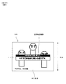
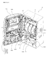
Next, the main parts of other mechanisms provided in the front door DU will be described with reference to a perspective view showing the internal structure of the reel-type gaming machine P with the front door DU in FIG. 2 opened. In the front door DU, a mechanism display device S40 for displaying effects such as a notice effect and a background effect as a mechanism for enhancing the interest of the game, and a game effect lamp D26 (not effective to light in various lighting modes Middle panel (middle decoration panel) which is a member formed of a door board D for signal relay, a medal selector DS for detecting an inserted medal, etc., a speaker S20 capable of outputting a sound, a synthetic resin etc. , An upper panel D130, a lower panel D140, and the like. The effect display device S40 is attached to the upper surface on the back side of the front door DU so that a display unit for displaying effects and the like can be viewed through a see-through area formed in the upper panel. Further, the decorative lamp unit D150 and the LED lamp unit S10 have a light emission source that emits light in accordance with the progress of the game of the coin-operated game machine P, and decorative lamps are provided on the right and left sides of the lower panel D140. A unit D150 is provided, and an LED lamp unit S10 is provided on each of the right and left sides of the upper panel D130. A door substrate D is attached below the reel window D160 on the back of the front door DU. On the door substrate D, input signals such as the stop button D40, the start lever D50, and the settlement button D60 described above are provided. , And has a function of a relay board that directly or processes the input signal and outputs the signal to a main control board M described later. A medal selector DS, which will be described in detail later, is provided in the vicinity of the door substrate D on the back of the front door DU corresponding to the medal insertion slot D170, and detection of medals inserted from the medal insertion slot D170 and simplification It has a function to perform true and false, to guide an appropriate medal to a hopper H40 to be described later, and to return an inappropriate medal to a medal receiver D230 to be described later. Further, one speaker S20 is provided on each side of the lower side of the door substrate D. The middle panel is an upper portion of the console, a lower portion of the upper panel D130, and a panel portion including the above-described reel window. In addition, the sub input button SB attached to the console D190 described above is a member used for button repeat effect etc., and a mini game (for example, “at AT state”) is performed by the player's operation of the sub input button SB. It is a member configured to be able to execute the progression of the success or failure of the rush). In the front door DU of the reeling type game machine P, the medal receiver D230 for receiving game medals (or may be simply called medals) discharged from the outlet D240 and the open / close state of the front door DU can be detected. A door switch D80 is provided. In addition, the front door DU is provided with a keyhole D260, and a key (door key) matching the shape of the keyhole D260 is inserted into the keyhole D260 {by adding it and twisting it in a predetermined direction (for example, clockwise)} The front door DU is configured to be openable. Furthermore, in the present embodiment, by inserting the door key into the keyhole D 260 (in addition and twisting in a predetermined direction (for example, counterclockwise)), an error state (door open error etc.) can be released. There is.
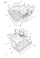
次に裏箱(キャビネット、基体とも称す)並びに、裏箱内に設置される各装置について説明する。裏箱の略中央には、リール窓D160を介してその一部が視認可能となるようにリールユニットが取付られている。リールユニットは、リールM50とリールM50の駆動源(ステッピングモータ等)とを備えている。また、リールM50は、左リールM51、中リールM52、右リールM53を備えている。ここで、夫々のリール部は合成樹脂等により形成され、リール部の外周上(リール帯上)には複数の図柄が描かれている。そして、スタートレバーD50及び停止ボタンD40における各停止ボタンの操作に基づき、夫々のリール部の回転動作及び停止動作を可能とするよう構成されている。また、図示しないが、左リールM51、中リールM52及び右リールM53の内部にはLED(以下、リールバックライトと呼ぶことがある)が設けられており、LEDが点灯した際にはリール部外周を透過した光によって、リール部外周が点灯したように視認できるよう構成されている。また、リールM50の上方には、各リール(左リールM51、中リールM52、右リールM53)を駆動するための後述する回胴基板Kが格納されている。 Next, a back box (also referred to as a cabinet or a base) and devices installed in the back box will be described. A reel unit is attached at substantially the center of the back box so that a portion thereof can be viewed through the reel window D160. The reel unit includes a reel M50 and a drive source (such as a stepping motor) of the reel M50. Further, the reel M50 includes a left reel M51, a middle reel M52, and a right reel M53. Here, each reel portion is formed of a synthetic resin or the like, and a plurality of symbols are drawn on the outer periphery (on the reel band) of the reel portion. And based on operation of each stop button in start lever D50 and stop button D40, it is constituted so that rotation operation and stop operation of each reel part are enabled. Although not shown, LEDs (hereinafter sometimes referred to as reel backlights) are provided inside the left reel M51, the middle reel M52 and the right reel M53, and when the LEDs are lit, the outer periphery of the reel portion It is configured that the light transmitted through can be viewed as if the outer periphery of the reel portion is lit. Further, above the reels M50, there is stored a later-described spinning base substrate K for driving the respective reels (the left reel M51, the middle reel M52, and the right reel M53).
また、リールM50の上方には、遊技全体の制御を司る後述する主制御基板Mが格納され、リールM50の左方には、図1に示した演出表示装置S40、LEDランプユニットS10、スピーカS20等を用いて行われる各種演出の制御を司る後述する副制御基板Sが格納されている。なお、主制御基板Mには、後述する設定変更装置制御処理を実行するため(設定変更を行うため)に使用する設定キースイッチM20、設定値の変更やエラー解除等を実行し得る設定/リセットボタンM30が接続されている。図2において、設定キースイッチM20、設定/リセットボタンM30については何れも不図示としているが、主制御基板Mの基板上等の適宜位置に設けられていればよい(即ち、前扉DUを開かなければ人為的なアクセスが困難な位置に設けられていればよい)。 Further, above the reel M50, a main control board M to be described later, which controls the entire game, is stored, and to the left of the reel M50, the effect display device S40, the LED lamp unit S10 and the speaker S20 shown in FIG. A sub control board S to be described later, which controls the control of various effects performed using E.I. In addition, on the main control board M, a setting key switch M20 used to execute setting change device control processing to be described later (to change the setting), setting / reset capable of executing setting value change, error cancellation, etc. The button M30 is connected. Although the setting key switch M20 and the setting / reset button M30 are not illustrated in FIG. 2, they may be provided at appropriate positions on the main control substrate M (ie, the front door DU is opened). If it does not exist, it should be provided at a position where artificial access is difficult).
リールM50の下方には、投入された遊技メダルが集められるホッパH40や、遊技メダルを払い出すメダル払出装置Hが設けられており、回胴式遊技機P全体に電源を供給するための電源基板Eが格納されている。メダル払出装置Hから払い出された遊技メダルは、コインシュータD90を通って、放出口D240から払い出されるようになっている。また、電源基板E(電源供給ユニットEとも称することがある)の前面には、回胴式遊技機Pの電源を投入するための電源スイッチE10も設けられている。なお、メダル払出装置Hの詳細については後述する。 Below the reel M50, a hopper H40 from which inserted game medals are collected, and a medal payout device H for paying out game medals are provided, and a power supply substrate for supplying power to the entire rotating game machine P E is stored. The game medals paid out from the medal payout device H are paid out from the outlet D240 through the coin shooter D90. In addition, on the front surface of the power supply substrate E (also referred to as a power supply unit E), a power switch E10 for turning on the power of the reel-type game machine P is also provided. The details of the medal payout device H will be described later.
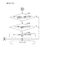
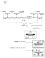
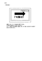
<メダルセレクタDS>
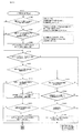
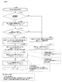
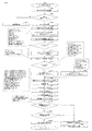
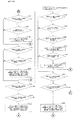
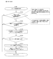
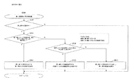
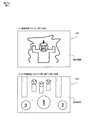
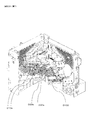
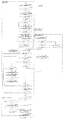
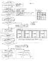
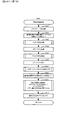
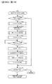
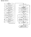
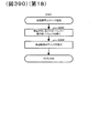
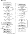
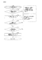
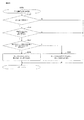
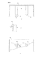
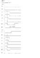
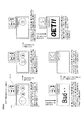
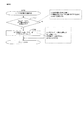
次に、メダルセレクタDSについて、図3を交えつつ詳細に説明する。図3は、回胴式遊技機P内部における、メダル投入口D170に投入された遊技メダルの経路(セレクタ)を示した斜視図である。メダルセレクタDSは、扉基板Dの付近にメダル投入口D170から投入された遊技メダルの通路となる投入受付センサD10sが設けられており、投入受付センサD10sの下方には、遊技メダルを放出口D240に導くためのコインシュータD90などが設けられている。投入受付センサD10sは、メダル投入口D170から投入された遊技メダルを主に寸法に基づいて選別し、規格寸法に適合した遊技メダルだけを受け入れる機能を有しており、この機能により適合しないと判断されたメダル(又は、その他の異物)は、ブロッカD100により放出口D240に払い戻されるよう構成されている。遊技者がスタートレバーD50を操作する前に(遊技メダルの投入が有効である状態にて)遊技メダルを投入すると、遊技メダルは投入受付センサD10sによって選別され、規格を満足しているものだけがホッパH40内に投入され、規格を満たしていないメダルは、コインシュータD90を通って、放出口D240に返却されるようになっている。これに対して、スタートレバーD50が操作された後に(遊技メダルの投入が有効でない状態にて)遊技メダルが投入された場合は、規格を満たしているか否かに拘らず、投入された遊技メダルはコインシュータD90を通って、放出口D240に返却される。また、投入受付センサD10sの内部(流路の奥)には、詳細後述するメダル投入に係るセンサが設けられており、寸法規格を満たして受け入れられた遊技メダルが通過すると、第1投入センサD20s及び第2投入センサD30sによって検出されて、その信号が後述する主制御基板Mに供給されるようになっている。
<Medal selector DS>
Next, the medal selector DS will be described in detail with reference to FIG. FIG. 3 is a perspective view showing a path (selector) of the game medal inserted into the medal insertion slot D170 in the reeling type gaming machine P. As shown in FIG. The medal selector DS is provided near the door substrate D with an insertion reception sensor D10s which is a passage for gaming medals inserted from the medal insertion slot D170, and below the insertion reception sensor D10s, the game medal is discharged from the opening D240. A coin shooter D90 or the like for guiding to the The insertion acceptance sensor D10s mainly has the function of sorting the game medals inserted from the medal insertion slot D170 based on the dimensions, and accepting only the game medals conforming to the standard dimensions, and it is determined that this function does not conform. The medal (or other foreign matter) that has been made is configured to be returned to the outlet D240 by the blocker D100. If the game medal is inserted before the player operates the start lever D50 (in a state where the insertion of the game medal is effective), the game medal is selected by the insertion reception sensor D10s, and only those which satisfy the standard The medals which are inserted into the hopper H40 and which do not meet the standard are to be returned to the outlet D240 through the coin shooter D90. On the other hand, when the game medal is inserted after the start lever D50 is operated (in a state where the insertion of the game medal is not effective), the inserted game medal regardless of whether the standard is satisfied or not. Is returned to the outlet D240 through the coin shooter D90. Further, a sensor relating to medal insertion described later in detail is provided in the inside (the back of the flow path) of the insertion acceptance sensor D10s, and when the accepted game medal that satisfies the dimensional standard passes, the first insertion sensor D20s The signal is detected by the second loading sensor D30s and supplied to the main control board M described later.
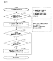
次に、メダル投入に係るセンサについて詳述する。メダル投入口D170に投入された遊技メダルは、まず投入受付センサD10sを通過する。投入受付センサD10sは機械式のダブルセンサになっており、遊技メダルが通過することによって、2つの突起した機構が押下されることによりオンとなり遊技メダルが正常に通路を通過することができることとなる。また、このような構成により、遊技メダルではない異物(規格を満足していない異物であり、例えば、遊技メダルよりも径が小さいもの)が投入された場合には、2つの突起した機構が押下されない。このようなメダルは、起立した状態をメダルが維持できないため、通路を通過できず(メダルが倒れこむ)、前述したようにコインシュータD90を通って放出口D240に払い戻されることとなる。そのほかにも、投入受付センサD10sは、オンとなっている時間が所定時間以上連続した場合等にも、エラーであると判定し得る(その結果、ブロッカD100がオフとなり得る)よう構成されている。 Next, a sensor related to medal insertion will be described in detail. The gaming medal inserted into the medal insertion slot D170 first passes through the insertion acceptance sensor D10s. The insertion acceptance sensor D10s is a mechanical double sensor, and when the game medal passes, the two projecting mechanisms are pressed to turn on and the game medal can normally pass through the passage. . In addition, with such a configuration, when a foreign object that is not a game medal (a foreign object that does not meet the standard, for example, having a diameter smaller than the game medal) is inserted, the two protruding mechanisms are pressed I will not. Since the medal can not maintain the standing state, the medal can not pass through the passage (the medal falls down), and is paid back to the discharge port D240 through the coin shooter D90 as described above. Besides, the insertion reception sensor D10s is configured to be able to determine that it is an error even when the on time continues for a predetermined time or more (as a result, the blocker D100 may be turned off). .
遊技メダルがブロッカD100を正常に通過した場合に、通過直後に第1投入センサD20s及び第2投入センサD30sを通過することとなる。この投入センサ(第1投入センサD20s及び第2投入センサD30s)は2つのセンサで構成されており(遊技メダルの規格上の直径よりも小さい間隔で隣接配置されており)、夫々のセンサのオン・オフ状況(第1投入センサD20s及び第2投入センサD30sのオン・オフの組み合わせの遷移していく順序、等)及びオン・オフとなっている時間を監視することにより様々なエラーを検出可能に構成されている。 When the game medal normally passes through the blocker D100, it passes the first insertion sensor D20s and the second insertion sensor D30s immediately after the passage. The input sensors (the first input sensor D20s and the second input sensor D30s) are composed of two sensors (arranged adjacent to each other at a distance smaller than the standard diameter of the game medals).・ Various errors can be detected by monitoring the OFF status (the transition sequence of the combination of ON and OFF of the first input sensor D20s and the second input sensor D30s, etc.) and the ON / OFF time. Is configured.
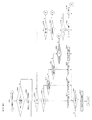
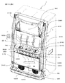
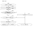
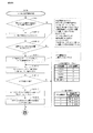
<メダル払出装置H>
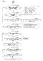
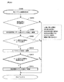
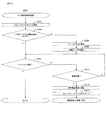
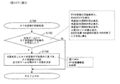
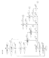
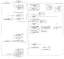
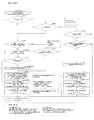
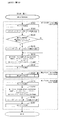
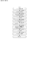
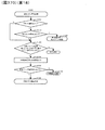
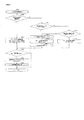
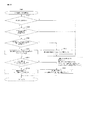
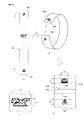
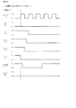
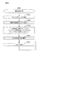
次に、図4のメダル払出装置Hの正面図及び上面図を用いてメダル払出装置Hを詳細に説明する。メダル払出装置Hは、クレジット(遊技機内部に電子的に貯留されている遊技メダル)又はベットされているメダル(遊技を開始するために投入されたメダル)が存在する状態で、精算ボタンが操作された、又は、入賞により遊技メダルが払い出される場合に作動することとなる。作動する場合には、まず、ホッパモータH80が駆動することにより、ディスク回転軸H50aを中心にディスクH50が回転する。回転によりメダル払出装置H内の遊技メダルは放出付勢手段H70を変位させて遊技メダル出口H60から放出口D240に向かって流下していくこととなる。尚、払出センサ(第1払出センサH10s及び第2払出センサH20s)は2つのセンサで構成されており、夫々のセンサのオン・オフ状況(第1払出センサH10s及び第2払出センサH20sのオン・オフの組み合わせの遷移していく順序、等)及びオン・オフとなっている時間を監視することにより様々なエラーを検出可能に構成されている。より具体的には、例えば、遊技メダル出口H60を正常に通過する際には、放出付勢手段H70の変位により、第1払出センサH10s=オフ・第2払出センサH20s=オフの状態から、第1払出センサH10s=オフ・第2払出センサH20s=オフ→第1払出センサH10s=オン・第2払出センサH20s=オフ→第1払出センサH10s=オン・第2払出センサH20s=オン→第1払出センサH10s=オフ・第2払出センサH20s=オン→第1払出センサH10s=オフ・第2払出センサH20s=オフ、というセンサ状態遷移となるため、このセンサ状態遷移と反する動きを検出した場合には、エラーとするよう構成することを例示することができる。
<Medal Dispensing Device H>
Next, the medal payout device H will be described in detail using the front view and the top view of the medal payout device H of FIG. 4. The medal payout device H operates the settlement button in a state where there is a credit (a game medal stored electronically in the gaming machine) or a bet (a medal inserted to start a game). It will be activated when the game medal is paid out by winning or winning. In operation, first, the hopper motor H80 is driven to rotate the disk H50 about the disk rotation axis H50a. By rotation, the game medals in the medal payout device H displace the discharge urging means H70 and flow downward from the game medal outlet H60 toward the discharge port D240. The payout sensors (the first payout sensor H10s and the second payout sensor H20s) are composed of two sensors, and the on / off states of the respective sensors (the first payout sensor H10s and the second payout sensor H20s are on). Various errors can be detected by monitoring the transition sequence of the combination of off, etc., and the on / off time. More specifically, for example, when the game medal outlet H60 is normally passed, the first payout sensor H10s = off, the second payout sensor H20s = off, and so on by the displacement of the discharge energizing means H70. 1 Dispensing sensor H10s = off Second dispensing sensor H20s = off → first dispensing sensor H10s = on second dispensing sensor H20s = off first dispensing sensor H10s = on second dispensing sensor H20s = on first dispensing Since sensor state transition such as sensor H10s = off second dispensing sensor H20s = on first dispensing sensor H10s = off second dispensing sensor H20s off is detected, a motion opposite to this sensor state transition is detected It can be exemplified to configure to make an error.
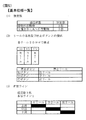
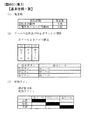
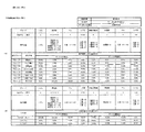
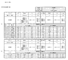
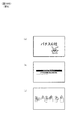
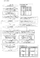
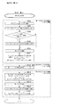
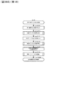
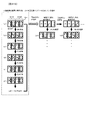
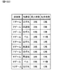
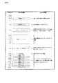
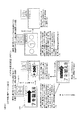
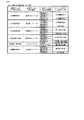
次に、図5は、本実施形態における、回胴式遊技機の基本仕様一覧である。本実施形態に係る回胴式遊技機は、規定数(1ゲームにてベットできる遊技メダルの最大枚数)が3枚、左リールM51、中リールM52及び右リールM53のコマ数はいずれも20コマ、入賞判定される有効ラインは「左リールM51上段、中リールM52中段、右リールM53下段」の1ラインとなっている。尚、最大払出枚数は11枚、最小払出枚数は1枚(入賞役と払出枚数との対応付けは後述)である。また、優先入賞順(引き込み優先順)は、「再遊技役→小役(ベル、スイカ、等)→ボーナス」となっており、例えば、再遊技役とボーナスが同時に成立している場合には、再遊技役となる図柄組み合わせが停止表示し且つボーナスは入賞不能である。また、ベルとスイカが成立している場合には、どちらも引き込める位置(入賞する停止位置まで4コマ以内の位置)で停止ボタンを押した場合には払出枚数が多い小役を優先して引きこむよう構成されている。尚、同図に示した構成はあくまで一例であり、各リールのコマ数を変更(例えば、21コマに変更)したり、有効ラインの構成を変更(例えば、横3ライン、斜め2ラインの5ラインに変更、左リールM51下段、中リールM52中段、右リールM53上段の1ラインに変更)しても何ら問題ない。また、特に押し順によって遊技者にとって異なる利益が付与される押し順小役が当選したときの引き込み制御としては、予め定められた正解の押し順で操作された場合には払出し枚数の多い小役を優先して引き込むように制御(枚数優先制御)しており、正解の押し順とは異なる不正解の押し順で操作された場合には停止表示可能な(停止操作から4コマ以内の位置に配置されている)図柄のうち入賞可能性を高める(入賞可能な複数図柄組合せのうち入賞する可能性が最も多くなる)図柄を引き込む制御(個数優先制御)を行っている。 Next, FIG. 5 is a list of basic specifications of the reel-type gaming machine according to the present embodiment. In the reeling type gaming machine according to the present embodiment, the defined number (the maximum number of game medals that can be betted in one game) is three, and the number of frames of the left reel M51, the middle reel M52 and the right reel M53 is all 20 The effective line determined to be winning is one line of "left reel M51 upper stage, middle reel M52 middle step, right reel M53 lower stage". The maximum payout number is 11 and the minimum payout number is 1 (the correspondence between the winning combination and the payout number will be described later). Also, the priority winning order (retraction priority order) is "replay role → small portion (bell, watermelon, etc.) → bonus", for example, when the replay role and the bonus are established at the same time The symbol combination to be a replay role is stopped and displayed, and the bonus can not be won. In addition, when the bell and watermelon are established, priority is given to the small winning combination with a large number of payouts when the stop button is pressed at a position where both can be drawn (position within 4 frames to the stop position where winning is achieved). It is configured to pull in. Note that the configuration shown in the figure is merely an example, and the number of frames of each reel is changed (for example, changed to 21 frames) or the configuration of effective lines is changed (for example, 5 horizontal 3 lines, 2 diagonal 2 lines) There is no problem even if the line is changed to one line of the lower left reel M51, the middle of the middle reel M52, and the upper line of the right reel M53. In addition, as the pull-in control when the pushing order small combination in which a different benefit is given to the player depending on the pushing order is won, the small combination with a large number of payouts when operated in the predetermined correct pushing order. Is controlled to draw in priority (number-of-sheets priority control), and it can be stopped and displayed if it is operated in the wrong order of pressing the answer which is different from the pressing order of the correct answer. Among the symbols arranged, the control (number priority control) is performed to increase the winning possibility (the probability of winning among the plural symbol combinations that can be won is the greatest).
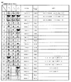
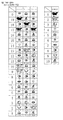
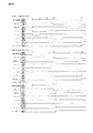
次に、図6は、本実施形態における、回胴式遊技機のリール配列一覧である。同図に示されるように、左リールM51、中リールM52及び右リールM53のコマ数はいずれも20コマ(0番〜19番)であり、図柄は「黒セブン」、「白セブン」、「羊」、「ブランク」、「ベル」、「リプレイA」、「リプレイB」、「スイカA」、「スイカB」、「チェリー」の10種類となっている。ここで、「ブランク」は、その他の図柄と同様に当選役を構成する図柄組み合わせに含まれる図柄であり、当選役を構成しない図柄という意味ではなく、「ブランク」を含む当選役を構成する図柄組み合わせとしては、例えば、「スイカB・リプレイA・ブランク」で再遊技02となっている。尚、同図に示した構成はあくまで一例であり、図柄の種類を増減・変更しても何ら問題ない。
Next, FIG. 6 is a reel arrangement list of the reel-type gaming machine in the present embodiment. As shown in the figure, the numbers of frames for the left reel M51, middle reel M52 and right reel M53 are all 20 (
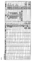
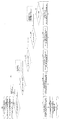
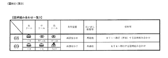
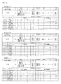
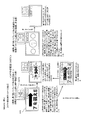
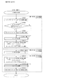
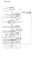
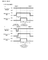
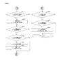
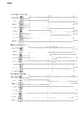
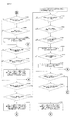
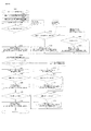
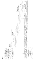
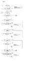
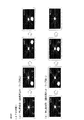
次に、図7〜図9は、本実施形態における図柄組み合わせ一覧1〜3である。本実施形態においては、夫々の条件装置に対して複数の図柄組み合わせが存在しており、後述するように、左リールM51、中リールM52及び右リールM53の停止順番や停止位置に応じて、いずれか一の図柄組み合わせが有効ライン(前述した1ライン)上に停止表示されるよう構成されている。尚、有効ライン上に同一種類の図柄が揃っていない場合にも遊技者から見ると有効ライン以外のライン上にて一列に同一の図柄が揃いやすく構成されている(スイカの場合には中段に横一直線に揃う等、リール上のいずれかに一直線にスイカ図柄が3つ揃うよう構成されている)。また、本実施形態においては、第1種BB役(いわゆる第1種特別役物に係る役物連続作動装置であるが、以下、単にBB役と呼ぶことがある)となる図柄組み合わせして、1種BB‐A(RB−Aを連続作動させ、264枚を超える払出で終了)となる「羊・羊・羊」と、1種BB‐B(RB−Bを連続作動させ、132枚を超える払出で終了)となる「黒セブン・黒セブン・黒セブン」と、1種BB‐C(RB−Bを連続作動させ、132枚を超える払出で終了)となる「白セブン・白セブン・白セブン」との3つの図柄組み合わせを有している。尚、本実施形態においては、第1種BB役が入賞し、BBが実行された(役物が作動した)場合には、当該BB実行中においては、BB中のすべてのゲームにおいて、1つの抽選テーブルを参照して、役物以外の当選役(小役、再遊技役)を抽選するよう構成されている(1回のBBの実行中において役抽選の際に参照するテーブルを切り替えない方式であり、以下、オールJACINタイプと呼ぶことがある)。尚、第1種BB役の形式に関しては、これには限定されず、1回のBBの実行中において役抽選の際に参照するテーブルを切り替え得るよう構成してもよい。また、RT状態が「RT1」である場合に14番〜16番に対応する再遊技04となる図柄組み合わせが停止表示されると、RT0に移行するよう構成されている(RT状態の詳細については後述する)。尚、「RT1」よりも「RT0」の方が遊技者に不利なRT状態であるため、「RT1」から「RT0」に移行することを転落すると称することがある。また、17番に対応する再遊技05となる図柄組み合わせが停止表示されると、左リールM51、中リールM52及び右リールM53の下段に「黒セブン」が停止表示され得ることとなり、18番に対応する再遊技05となる図柄組み合わせが停止表示されると、左リールM51、中リールM52及び右リールM53の下段に「白セブン」が停止表示され得ることとなる(詳細は後述することとする)。また、後述する「入賞‐A1」〜「入賞‐A6」の条件装置である押し順ベルが当選した場合には、遊技者にとって最も有利な押し順にてリールを停止させると、21番〜27番に対応する「入賞01」〜「入賞03」となる図柄組み合わせが停止表示され、11枚の遊技メダルが払い出される一方、遊技者にとって最も有利な押し順とは異なる押し順にてリールを停止させると、39番〜56番に対応する「入賞08」〜「入賞11」となる図柄組み合わせが停止表示され、1枚の遊技メダルが払い出されることとなる。尚、同図における「‐」はいずれの図柄が停止表示されてもよい旨を示しており、例えば、23番に対応する「ベル・‐・ベル」は左リールM51及び右リールM53の有効ライン上にベルが停止表示されれば中リールM52の有効ライン上にはどの図柄が停止表示されても11枚の遊技メダルが獲得できる。
Next, FIGS. 7-9 are symbol combination lists 1-3 in this embodiment. In this embodiment, a plurality of symbol combinations exist for each condition device, and as will be described later, depending on the stop order and stop position of the left reel M51, the middle reel M52, and the right reel M53, One symbol combination is configured to be stopped and displayed on the effective line (one line described above). It should be noted that even when symbols of the same kind are not aligned on the effective line, the same symbols are easily arranged in a line on lines other than the effective line when viewed from the player (in the case of watermelon, in the middle) Three watermelon patterns are arranged in a straight line in any one of the reels, such as being aligned in a horizontal straight line). Further, in the present embodiment, in combination with symbols serving as a first type BB role (which is a character continuous actuation device related to a so-called first type special role but may be hereinafter simply referred to as a BB role), One kind of BB-A (RB-A operated continuously and finished with over 264 pieces of delivery) "sheep, sheep, sheep" and one kind BB-B (RB-B operated continuously, 132 sheets "Black Seven · Black Seven · Black Seven" and "
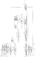
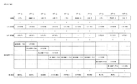
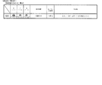
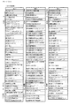
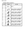
次に、図10は、本実施形態における条件装置一覧である。尚、同図においては、条件装置番号を当選番号と称しており、以降においても条件装置番号を当選番号と称することがある。本実施形態においては、再遊技役は再遊技‐A〜再遊技‐D3(当選番号1〜6)まで設けられており、左リールM51、中リールM52及び右リールM53の停止順番や停止位置に応じて、停止表示する再遊技役が相違し得るよう構成されている。ここで、本実施形態においては、最も右の列である「条件装置」の項目に図示されているように、左リールM51、中リールM52及び右リールM53の停止順番や停止位置に応じて複数種類の条件装置が停止表示され得るよう構成されており、当該複数種類の条件装置のうち同一の当選番号となる条件装置を纏めて、右から3番目の列である「条件装置(名称)」の項目にて図示している。具体的には、例えば、当選番号1に対応する条件装置である「再遊技‐A」においては、左リールM51、中リールM52及び右リールM53の停止順番や停止位置に応じて、「再遊技01」、「再遊技02」、「再遊技03」の3種類の条件装置が停止表示され得るよう構成されている。尚、「条件装置(名称)」を単に条件装置を称することがある。また、「再遊技01」等の再遊技に関する条件装置を再遊技役と称することがあり、「入賞01」等の入賞することで遊技メダルが払い出される条件装置を小役と称することがあり、「1種BB‐A」等の停止表示されることによりBBが開始することとなる条件装置をBB役と称することがある。また、当選番号21〜23及び25〜27に当選した場合には、BB役と小役とが重複して当選することとなり、そのような場合には、当選した小役に対応する図柄が停止表示し得る位置にて左停止ボタンD41、中停止ボタンD42及び右停止ボタンD43を操作するとBB役に対応する図柄が停止表示せずに小役に対応する図柄が停止表示する一方、小役に対応する図柄が停止表示しない(引き込めない)位置にて左停止ボタンD41、中停止ボタンD42及び右停止ボタンD43を操作すると小役に対応する図柄が停止表示せずにBB役に対応する図柄が停止表示するよう構成されている。具体的には、例えば、当選番号21の条件装置である「1種BB‐B+入賞‐C」に当選した場合には、「入賞12」又は「入賞13」であるチェリーと、「1種BB‐B」である黒セブンとのいずれかが停止表示し得ることとなる。より具体的には、左リールM51→中リールM52→右リールM53の順番にリールを停止させる場合において、(1)第1停止にて左リールM51の上段に図柄番号0〜4番(図6のリール配列を参照)が位置している操作タイミングにて左停止ボタンD41を操作した場合には、左リールM51の上段に「入賞12」に対応する図柄番号4番が停止し、中リールM52及び右リールM53の停止位置に拘らず、「入賞12」が停止表示される。(2)第1停止にて左リールM51の上段に図柄番号5〜12番が位置している操作タイミングにて左停止ボタンD41を操作した場合には、左リールM51の上段に「入賞13」に対応する図柄番号6番、11番、又は16番が停止し、中リールM52及び右リールM53の停止位置に拘らず、「入賞13」が停止表示される。(3‐1)第1停止にて左リールM51の上段に図柄番号13〜19番が位置している操作タイミングにて左停止ボタンD41を操作した場合には、左リールM51の上段に「1種BB‐B」に対応する図柄番号17番又は19番が停止する。(3‐2)第2停止にて中リールM52の中段に図柄番号14〜18番が位置している操作タイミングにて中停止ボタンD42を操作した場合には、中リールM52の中段に「1種BB‐B」に対応する図柄番号18番が停止し、その後、第3停止にて右リールM53の下段に図柄番号13〜17番が位置している操作タイミングにて右停止ボタンD43を操作した場合には、右リールM53の下段に「1種BB‐B」に対応する図柄番号17番が停止し、BB役が停止表示されることとなる。(3‐3)第2停止にて中リールM52の中段に図柄番号19〜13番が位置している操作タイミングにて中停止ボタンD42を操作した場合には、中リールM52の中段に「1種BB‐B」に対応する図柄番号18番が停止できず、いずれの条件装置も停止表示されないこととなる。
Next, FIG. 10 is a list of conditional devices in the present embodiment. In the figure, the condition device number is referred to as a winning number, and the condition device number may be referred to as a winning number also hereinafter. In the present embodiment, the replay role is provided from replay A to replay D 3 (winning
次に、「役割」の項目には、「条件装置(名称)」がどのような役割となっているかを図示しており、当選番号1に対応する「通常リプレイ」は、停止ボタンの押し順に拘らず、RT状態が移行しない再遊技役が停止表示される再遊技に係る条件装置であり、当選番号2に対応する「逆押し白7揃いリプレイ」は、停止ボタンの押し順に拘らず、RT状態が移行しない再遊技役が停止表示される再遊技に係る条件装置であるが、逆押し(右リールM53→中リールM52→左リールM51の順にリールを停止させること)にて、右リールM53の図柄番号18〜2番の範囲、中リールM52の図柄番号9〜13番の範囲、左リールM51の図柄番号5〜10番の範囲が各リールの下段に位置している操作タイミングにて停止ボタンを操作することにより、右リールM53、中リールM52及び左リールM51の下段に「白セブン」が停止表示され、遊技者から見ると白セブンが下段に揃っているように見えるよう構成されている。尚、再遊技‐Bに当選し、AT上乗せ抽選に当選したゲームにおいて、逆押しで「白セブン」を狙うよう指示する演出(詳細は後述する)を実行することにより、AT上乗せ抽選に当選した旨を遊技者に報知し得るよう構成されている。当選番号3に対応する「順押し黒7揃いリプレイ」は、停止ボタンの押し順に拘らず、RT状態が移行しない再遊技役が停止表示される再遊技に係る条件装置であるが、順押し(左リールM51→中リールM52→右リールM53の順にリールを停止させること)にて、左リールM51の図柄番号13〜19番の範囲、中リールM52の図柄番号14〜18番の範囲、右リールM53の図柄番号13〜17番の範囲が各リールの下段に位置している操作タイミングにて停止ボタンを操作することにより、左リールM51、中リールM52及び右リールM53の下段に「黒セブン」が停止表示され、遊技者から見ると黒セブンが下段に揃っているように見えるよう構成されている。尚、再遊技‐Cに当選し、AT上乗せ抽選に当選したゲームにおいて、順押しで「黒セブン」を狙うよう指示する演出(詳細は後述する)を実行することにより、AT上乗せ抽選に当選した旨を遊技者に報知し得るよう構成されている。
Next, the item "role" illustrates what role the "conditional apparatus (name)" is in, and the "normal replay" corresponding to the winning
また、当選番号4に対応する「RT維持RP1**(3択)」は第1停止リールを左リールM51と中リールM52と右リールM53とのいずれにするか(いずれの停止ボタンを操作するか)によって、停止表示される再遊技役が相違し得る条件装置であり、第1停止リールを左リールM51とした場合には、RT状態が移行しない再遊技01、再遊技02又は再遊技03が停止表示され、第1停止リールを中リールM52又は右リールM53とした場合には、RT状態が「RT1」から「RT0」に移行し得る再遊技04が停止表示される。また、当選番号5に対応する「RT維持RP*1*(3択)」は第1停止リールを左リールM51と中リールM52と右リールM53とのいずれにするか(いずれの停止ボタンを操作するか)によって、停止表示される再遊技役が相違し得る条件装置であり、第1停止リールを中リールM52とした場合には、RT状態が移行しない再遊技03が停止表示され、第1停止リールを左リールM51又は右リールM53とした場合には、RT状態が「RT1」から「RT0」に移行し得る再遊技04が停止表示される。また、当選番号6に対応する「RT維持RP**1(3択)」は第1停止リールを左リールM51と中リールM52と右リールM53とのいずれにするか(いずれの停止ボタンを操作するか)によって、停止表示される再遊技役が相違し得る条件装置であり、第1停止リールを右リールM53とした場合には、RT状態が移行しない再遊技01又は再遊技03が停止表示され、第1停止リールを左リールM51又は中リールM52とした場合には、RT状態が「RT1」から「RT0」に移行し得る再遊技04が停止表示される。
In addition, “
また、当選番号7〜12に対応する、「押し順ベル123」〜「押し順ベル321」は、リール停止順を6択のいずれとするかによって入賞する小役が相違し得る条件装置であり、例えば、「左リールM51:1、中リールM52:2、右リールM53:3」となっており「123」の場合「左リールM51→中リールM52→右リールM53」の押し順で停止させるという意味であり、例えば、「入賞A‐1」(当選番号7)の場合には、「123」=「左→中→右」の順に停止させる(押し順に正解する)と最大獲得枚数である11枚の遊技メダルが獲得できる「入賞01」となる図柄組み合わせが停止表示することとなる。尚、「押し順ベル123」の「123」等はその当選番号における最大獲得枚数を獲得可能な押し順(リール停止順)を示している。尚、最大獲得枚数を獲得可能な押し順以外の押し順にてリールを停止させた場合には、即ち、押し順に正解できないと1枚の払出となるよう構成されており、このように構成することで、「AT中状態」等のATに関する状態にて再遊技役の押し順やベルの押し順をナビ(押し順表示装置D270にて最高利益となる押し順を表示)し、「通常遊技状態」等のATに関する状態には押し順をナビしないという遊技者の利益率が異なる複数の遊技状態を創出することができる。尚、ATに関する状態については後述する。
Also, “pushing
また、当選番号13に対応する、「共通ベル」は、入賞04〜入賞07のいずれが停止しても最大獲得枚数である11枚の遊技メダルが獲得できる、即ち、押し順に拘らず最大利益が獲得できる条件装置であり、押し順不問ベルと称することがある。また、当選番号15に対応する、「スイカA」は、平行ラインにスイカ(スイカAとスイカBのいずれか)が3つ揃いし易いよう構成されており、例えば、図9における60番の入賞14は各リール中段にスイカAが3つ揃いすることとなる。また、当選番号16に対応する、「スイカB」は、斜めラインにスイカ(スイカAとスイカBのいずれか)が3つ揃いし易いよう構成されており、例えば、図9における66番の入賞16は左リールM51上段にスイカB、中リールM52中段にスイカB、右リールM53下段にスイカAのように、斜め右下がりにスイカが3つ揃いすることとなる。また、当選番号17に対応する、「BB中弱レア小役(斜めベル揃い)」は、有効ライン上にベルが3つ揃いし得る条件装置であり、詳細は後述するが、BB中に当選することによってAT上乗せ抽選が実行される条件装置である。また、当選番号18に対応する、「BB中強レア小役(V字ベル揃い)」は、左リールM51上段、中リールM52中段、右リールM53上段にベルが停止表示され得る条件装置であり、詳細は後述するが、BB中に当選することによってAT上乗せ抽選が実行される条件装置である。
In addition, “common bell” corresponding to the winning
次に、「ボーナス当選情報」の項目には、0〜3までの数値が当選番号毎に振り分けられている。本実施形態においては、ボーナス(BB役)が含まれない当選番号はボーナス当選情報を0とし、ボーナス(BB役)が含まれる当選番号として、1種BB‐Aが含まれる当選番号(19)のボーナス当選情報を1、1種BB‐Bが含まれる当選番号(20〜23)のボーナス当選情報を2、1種BB‐Cが含まれる当選番号(24〜27)のボーナス当選情報を3としている。ボーナス当選情報を主制御基板Mが記憶することによっていずれのBB成立の有無やいずれのBB役に当選したかに係る情報を記憶することができる。尚、ボーナス当選情報の詳細については後述する。 Next, in the item of "bonus winning information", numerical values from 0 to 3 are assigned to each winning number. In the present embodiment, the winning number not including the bonus (BB role) sets the bonus winning information to 0, and the winning number including one kind BB-A as the winning number including the bonus (BB role) (19) 1 for bonus winning information, 2 for bonus winning information for winning numbers (20 to 23) including one type BB-B, 3 for bonus winning information for winning numbers for one type BB-C (24 to 27) And When the main control board M stores the bonus winning information, it is possible to store information concerning which BB is established and which BB role is won. The details of the bonus winning information will be described later.
次に、「入賞・再遊技当選情報」の項目には、0〜18までの数値が当選番号毎に振り分けられている。本実施形態においては、再遊技役と小役とが含まれない当選番号(ハズレに対応する当選番号0とボーナスに対応する当選番号19・20・24)は入賞・再遊技当選情報を0とし、再遊技役又は小役が含まれる当選番号に対して1〜18入賞・再遊技当選情報を条件装置毎に振り分けている。入賞・再遊技当選情報を主制御基板Mが記憶することによっていずれの再遊技役又は小役に当選したかに係る情報を記憶することができる。尚、入賞・再遊技当選情報の詳細については後述する。
Next, numerical values from 0 to 18 are assigned to the items of “winning / replay winning information” for each winning number. In the present embodiment, the winning numbers not including the re-play role and the small portion (win
次に、「演出グループ番号」の項目には、0〜11までの数値が当選番号毎に振り分けられている。演出グループ番号を主制御基板M側から副制御基板S側に送信することによって、副制御基板S側が実行する演出を決定することができるよう構成されている。尚、演出グループ番号の詳細については後述する。 Next, numerical values from 0 to 11 are assigned to the items of “effect group number” for each winning number. By transmitting the effect group number from the main control board M side to the sub control board S side, it is possible to determine the effect to be executed by the sub control board S side. The details of the effect group number will be described later.
次に、「出玉グループ番号」の項目には、0〜13までの数値が当選番号毎に振り分けられている。出玉グループ番号を主制御基板Mが記憶し、当該記憶した出玉グループ番号をATに関する抽選(例えば、AT抽選、AT上乗せ抽選)を実行する際に使用することにより、ATに関する抽選処理を実行するためのプログラム、データ容量を削減することができる。尚、出玉グループ番号が0となる条件装置が当選してもAT抽選及びAT上乗せ抽選は実行されない。一方、出玉グループ番号が0でない条件装置が当選した場合には、AT抽選又はAT上乗せ抽選が実行され得ることとなる。尚、出玉グループ番号の詳細については後述する。また、出玉グループ番号が0となる条件装置が当選した場合にも、AT抽選又はAT上乗せ抽選が実行され得るよう構成してもよく、そのように構成した場合には、出玉グループ番号が0となる条件装置が当選してAT抽選又はAT上乗せ抽選が実行された場合には、当該抽選結果がかならずハズレ(非当選)となるよう構成することが好適である。 Next, numerical values from 0 to 13 are assigned to the items of “dispense group number” for each winning number. The main control board M stores the withdrawal ball group number, and uses the stored withdrawal group number when performing a lottery for AT (for example, AT lottery, AT addition lottery) to execute the lottery process for AT Programs and data capacity can be reduced. In addition, even if the condition device in which the payout group number becomes 0 is won, the AT lottery and the AT additional lottery are not executed. On the other hand, when the conditional device whose payout group number is not 0 is won, the AT lottery or the AT additional lottery can be executed. In addition, the detail of a withdrawal ball group number is mentioned later. In addition, the AT lottery or the AT additional lottery may be configured to be executed even when the conditional device in which the payout group number becomes 0 is selected, and in such a configuration, the payout group number is When the condition device which becomes 0 is won and the AT lottery or the AT additional lottery is executed, it is preferable that the lottery result is definitely lost (not won).
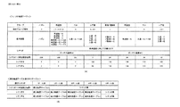
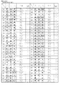
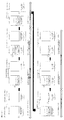
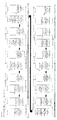
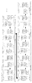
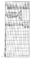
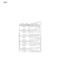
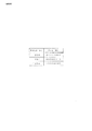
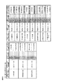
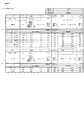
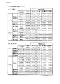
次に、図11は、本実施形態における小役、再遊技役に関する当選番号(条件装置番号、当選役とも称す)及びボーナス(BB、BB役とも称す)が役抽選手段により決定される抽選確率(当選率とも称する)を示す一覧である。同図においては、当選番号の当選率を図示している。 Next, FIG. 11 shows a lottery probability that the winning combination (also referred to as a conditional device number, also referred to as a winning combination) and a bonus (also referred to as a BB, BB combination) relating to the small winning combination and the replay role in the present embodiment It is a list showing (also referred to as a winning rate). In the same figure, the winning rate of the winning number is illustrated.
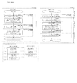
まず、BB未作動時である「RT0」、「RT1」及び「RT2」における抽選確率について詳述する。本実施形態においては、RT状態によって当選役(特に、再遊技役)の出現率(抽選確率)が相違し得るよう構成されており、「再遊技役」(すべての再遊技役を合計した出現率)は「RT1」の場合においてその他のRT状態よりも出現率が高くなっている。また、当選番号4〜6にて停止表示し得る「再遊技04」(いわゆる転落再遊技役であり、「RT1」であり且つボーナスが当選していない状況下において当該再遊技役に対応する図柄組合せが停止表示されると、以降「RT0」に移行することとなる)は「RT1」にて主に当選し、「RT0」においてはほぼ出現しないようになっている。尚、「RT2」においては、当選番号4〜6にて停止表示し得る「再遊技04」が出現し得ることとなるが、「再遊技04」が停止表示されてもRT状態は移行しない。尚、「RT1」において「再遊技04」が停止表示された場合には、「RT0」に移行した、即ち、RT状態が転落した旨を報知する演出である転落演出(例えば、演出表示装置S40に「残念」と表示)を実行し、「RT0」において「再遊技04」が停止表示された場合には、転落演出を実行しないよう構成してもよい。そのように構成することにより、「再遊技04」が停止表示されたにも拘らず、転落演出が実行されなかったことにより、BBに当選していることを認識することができ、遊技の興趣性を高めることができる。尚、そのように構成した場合には、「再遊技04」が停止表示されたことにより出力される効果音と「再遊技04」以外の再遊技役(例えば、RT状態が移行しない「再遊技01」)が停止表示されたことにより出力される効果音とが相違するよう構成してもよく、そのように構成することにより、「再遊技04」が停止表示されたことを遊技者が認識し易く構成することができる。また、押し順ナビが発生しないATに関する状態(例えば、「通常遊技状態」であり、非AT遊技状態と称することがある)である場合と押し順ナビが発生し得るATに関する状態(例えば、「AT中状態」であり、AT遊技状態と称することがある)である場合との両方の場合において「RT1」に滞在することがある。このとき、「RT1」から「RT0」へ移行(転落)する可能性がある当選番号が当選したとき、非AT遊技状態のときにはRT状態が転落する可能性があることを示す特殊な効果音をスタートレバーD50の操作に基づいて出力しないように構成されていても良い。これにより、非AT遊技状態においては「RT0」に転落する可能性があることを遊技者に悟らせることなく、遊技状態を移行させることが可能となる。一方、AT遊技状態のときにはRT状態が転落する可能性があることを示す特殊な効果音をスタートレバーの操作に基づいて出力する(且つ、RT状態が転落しない再遊技役が停止表示される押し順ナビを報知する)ように構成されていても良い。これにより、RT状態が転落しないよう遊技者は気を付けて、特殊な効果音が報知された以降の停止ボタンD40の操作を行なうことが可能となる。また、当選番号2又は3にて停止表示し得る「再遊技05」(AT状態にて停止表示された場合にAT上乗せ抽選に当選した旨を報知し得る再遊技役)は主に「RT1」で出現し、その他のRT状態ではほぼ出現しないようになっている。尚、これら再遊技役となる図柄組み合わせの停止表示に伴うRT状態に関する状態の遷移については後述する。また、後述するように、本実施形態においては、遊技者に最も有利となるリール停止順を報知する押し順ナビを押し順表示装置D270及び演出表示装置S40にて実行し得るよう構成されている。尚、当該抽選確率を適宜変更しても何ら問題ない。また、本実施形態においては、ボーナスは小役と重複し得るよう構成されており、スイカA、スイカB、チェリーの一部と重複している。具体的には、当選番号21〜23及び当選番号25〜27がボーナスと小役とが重複している条件装置となっている。
First, the lottery probability in “RT0”, “RT1” and “RT2” when the BB is not in operation will be described in detail. In the present embodiment, the appearance rate (lottery probability) of the winning combination (in particular, the re-playing combination) may be different depending on the RT state, and the “re-playing combination” (a total appearance of all the re-playing combinations) In the case of “RT1”, the rate of occurrence is higher than that of the other RT states. In addition, “
また、「RT2」である状況においては、BBに当選しており、且つ、BBが未作動である状況であるため、当選番号20及び24のBB役(小役とは重複していない単独のBB役であり、単独BB役、単独BBと称することがある)に当選した場合には、BB役の新たな当選は無効となり、小役の当選のみが有効となる。具体的には、例えば、「RT2」であり、且つ、1種BB‐Aに当選している(持ち越している)状況下、当選番号24の「1種BB‐C」に当選した場合には、当該当選番号24に係る1種BB‐Cは無効となる。即ち、当選番号0の「ハズレ」に当選した場合と同様の状況となる。尚、持ち越している1種BB‐Aは当選している状態が継続される。また、「RT2」である状況においては、BBに当選しており、且つ、BBが未作動である状況であるため、当選番号21〜23及び当選番号25〜27の小役とBB役とが重複している条件装置に当選した場合には、BB役の新たな当選は無効となり、小役の当選のみが有効となる。具体的には、例えば、「RT2」であり、且つ、1種BB‐Aに当選している(持ち越している)状況下、当選番号21の「1種BB‐B+入賞‐C」に当選した場合には、当該当選番号21に係る1種BB‐Bは無効となり、入賞‐Cのみが有効となる。即ち、当選番号14の「入賞‐C」に当選した場合と同様の状況となる。尚、持ち越している1種BB‐Aは当選している状態が継続される。尚、ボーナスとの重複は小役に限られるものでなく、再遊技役の一部とで重複していても良い。例えば、当選番号4〜6の再遊技役の一部でボーナス役と重複しても良い。このように、ボーナスがRT移行リプレイ(RT状態が移行し得る再遊技役)を含む条件装置とも重複するようにすることで、RT移行リプレイを含む条件装置が当選したときにもボーナスが当選する可能性があり、RT移行リプレイが停止表示されても、ボーナスの否定をしないこととなるため、遊技者に期待を持たせることが可能となる。なお、このように構成した場合には、RT移行リプレイが停止表示されてもRT状態は移行しないように制御する。これにより、遊技者はRT状態が移行(リプレイ確率が相対的に低いRT状態に移行)しているはずであるのにリプレイ確率が低確率になっていない(頻繁にリプレイに当選する)こと等から、ボーナスに当選している可能性が高いかもしれないといった遊技に関する興趣を高めることが可能となる。
In addition, in the situation of “RT2”, since BB is won and BB is in a non-operation situation, BB roles of winning
次に、BB作動時である「1種BB‐A,B,C」における抽選確率について詳述する。本実施形態においては、BB作動中においては、当選番号13の「共通ベル」と当選番号17の「BB中弱レア小役(斜めベル揃い)」と当選番号18の「BB中強レア小役(V字ベル揃い)」との3つの小役が当選し得るよう構成されており、「AT中状態」にて当選したBBの作動中において「BB中弱レア小役(斜めベル揃い)」又は「BB中強レア小役(V字ベル揃い)」に当選した場合にはAT上乗せ抽選が実行されるよう構成されている(詳細は後述することとする)。
Next, the lottery probability in “1 type BB-A, B, C” at the time of BB operation will be described in detail. In the present embodiment, during BB operation, the “common bell” of the winning
また、同図上段においては、設定値が1である場合の小役出現率を例示しており、共通ベル(当選番号13)においては、RT状態に拘らず出現率が一律となっているが、同図下段に示すように、共通ベルの出現率は設定値(本例では、6段階)によって相違するよう構成されている。具体的には、設定1における置数が3204、設定2における置数が3404、設定3における置数が3604、設定4における置数が3904、設定5における置数が4204、設定6における置数が4504、となっており、設定値が高くなる程出現率が高くなるよう構成されている。このように構成することにより、例えば、遊技者が共通ベルの出現回数(当選回数)を計測しながら遊技を進行した場合、共通ベルに頻繁に当選することにより、遊技している遊技機に係る設定値が相対的に高い設定値であることに期待を抱きながら遊技を進行することができる。また、設定値が高くなるほど1遊技当たりにおける期待値が高くなり、設定値が高くなるほど出玉率が高くなるように構成されている。なお、共通ベルの出現率は設定値によって相違するよう構成されているが、当該共通ベルの当選によっては、後述するAT抽選、AT上乗せ抽選、及び、高確率状態移行抽選は実行されないので、ATに関する状態の移行抽選(ATに関する抽選とも称する。)には影響を及ぼさないよう構成されている。 In the upper part of the figure, the small winning combination appearance rate when the setting value is 1 is illustrated, and in the common bell (winning number 13), the appearance ratio is uniform regardless of the RT status. As shown in the lower part of the figure, the appearance rate of the common bell is configured to be different depending on the set value (in this example, six steps). Specifically, the setting number in setting 1 is 3204, the setting number in setting 2 is 3404, the setting number in setting 3 is 3604, the setting number in setting 4 is 3904, the setting number in setting 5 is 4204, and the setting number in setting 6 Is 4504, and the appearance rate becomes higher as the set value becomes higher. By configuring in this manner, for example, when the player proceeds with playing the game while measuring the number of occurrences (number of wins) of the common bell, the game may be related to the gaming machine playing the game by winning the common bell frequently. The game can be progressed with expectation that the set value is a relatively high set value. Further, the higher the set value, the higher the expected value per game, and the higher the set value, the higher the payout rate. Although the appearance rate of the common bell is configured to differ depending on the set value, the AT lottery, the AT added lottery, and the high probability state transition lottery to be described later are not executed depending on the winning of the common bell. It is configured so as not to affect the state transition lottery regarding to (also referred to as the lottery for AT).
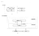
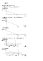
また、同図中段は、押し順ナビあり時における期待値一覧である。同図においては、「AT中状態」等の押し順表示装置D270及び演出表示装置S40にて押し順ナビが実行され得る状態において押し順ナビが実行された場合に、当該ナビに従ってリールを停止させた場合の1遊技あたりの平均払出数(入賞した小役によって払い出される平均のメダルの枚数であり、1ゲームで得られる遊技媒体の期待数とも称する)と、1遊技あたりのメダル増減期待値(3枚ベットにて遊技した場合のメダル投入枚数に対するメダル払出枚数の比率であり、1より大きい場合には期待値がプラスとなりメダルが増加していくこととなる一方、1より小さい場合には期待値がマイナスとなりメダルが減少していくこととなる)とを図示している。尚、1遊技あたりの平均払出数は、「再遊技役の置数の総和(当選番号1〜6についての置数の総和)×再遊技役における払出枚数(3枚)+小役(11枚役)の置数(小役出現率)の総和(当選番号7〜16についての置数の総和)×小役(11枚役)における払出枚数(11枚)/すべての置数の総和(65536)」のようにして算出することができる。また、1遊技あたりのメダル増減期待値は、「1遊技あたりの平均払出数/1遊技あたりのメダル投入枚数(3枚)」のようにして算出することができる。尚、1ゲームあたりのメダル投入数(1ゲームを行う際の遊技媒体の投入数)は3枚となっており、1遊技あたりの平均払出数が3より大きい場合に1遊技あたりのメダル増減期待値が1より大きくなるよう構成されている。同図に示されるように、本実施形態においては、「RT1」が1遊技あたりのメダル増減期待値が相対的に最も大きくなっている。尚、同図における数値はボーナスによるメダルの増減は考慮していない。即ち、押し順ナビが発生する状況において遊技を進行した場合(最適操作態様で操作された場合、有利操作態様で操作された場合とも称す)、「RT1」ではメダルが増えていくこととなる。尚、「RT0」及び「RT2」においては、不図示であるが、押し順ナビが発生していない状況下においては、1遊技あたりのメダル増減期待値は1より小さい値となっており、メダルが減少していくこととなる。尚、本実施形態においては、「RT0」又は「RT2」においても押し順ナビあり時においては1遊技あたりのメダル増減期待値が1より大きくなっているが、これには限定されず、「RT0」又は「RT2」における押し順ナビあり時の1遊技あたりのメダル増減期待値が1より小さくなるよう構成してもよい。尚、再遊技役となる図柄組み合わせが停止表示した場合には実際には前回遊技における賭け枚数(3枚)が自動ベットされるが、本実施形態におけるメダル増減期待値を算出するにあたっては、メダル3枚の払出しと仮定して算出している。尚、1遊技を1ゲームと称することがある。
The middle part of the figure is a list of expected values when there is push order navigation. In the figure, when push order navigation is executed in a state where push order navigation can be performed by push order
また、各RT状態における、1遊技あたりの平均払出数は、RT状態が「RT0」の場合には3.511291504であり、RT状態が「RT1」の場合には4.737915039であり、RT状態が「RT2」の場合には3.67137146となっている。また、各RT状態における、1遊技あたりのメダル増減期待値は、RT状態が「RT0」の場合には1.170430501であり、RT状態が「RT1」の場合には1.579305013でありRT状態が「RT2」の場合には1.223790487となっており、押し順ナビあり時においては、RT状態が「RT1」の場合が遊技者にとって最も有利なRT状態となっている。尚、当該数値は設定1である場合の値となっている。尚、上記小役、再遊技役に関する当選番号及びボーナスの抽選確率はあくまで一例であり、例えば、BBが内部成立中となる「RT2」における1遊技あたりのメダル増減期待値(押し順ナビあり時のメダル増減期待値)が1未満となるよう構成してもよい。そのように構成することにより、押し順ナビが発生する状況且つ「RT2」である場合(BBが内部成立中である場合)に、ボーナスを揃えることができるゲームにてボーナスを揃えなかった場合にも、徐々に持ちメダルが減少していくこととなり、押し順ナビが発生する状況且つ「RT2」である場合(BBが内部成立中である場合)に、ボーナスを揃えることができるゲームにて故意にボーナスを揃えないことにより持ちメダルを増加させていくような攻略を防止することができる。具体的には、「RT2」においてハズレとなる確率を、「RT2」において当選する全ての小役(入賞−A1〜入賞−I)の当選確率よりも高くなるように設計することが好ましく、そのように設計されるように再遊技役の当選確率を定めることが好ましい(再遊技役の当選確率を高く設計するとその分ハズレとなる確率が低くなってしまうため、再遊技役の当選確率が高くなり過ぎないように設計することが好ましい)。尚、本例の「RT2」においては、すべての小役を合算した当選確率は18784/65536であり、すべての再遊技の合算した当選確率は、12501/65536であり、ハズレとなる確率は、34251/65536となっており(図11参照)、ハズレとなる確率の方がすべての小役を合算した当選確率よりも高くなるように設計されている。 In addition, the average payout number per game in each RT state is 3.511291504 when the RT state is "RT0", and 4.737915039 when the RT state is "RT1", and the RT state is In the case of “RT2”, it is 3.67137146. In addition, the medal increase / decrease expected value per game in each RT state is 1.170430501 when the RT state is “RT0”, and 1.579305013 when the RT state is “RT1”, which is the RT state. In the case of “RT2”, it is 1.223790487, and when there is push order navigation, the RT state that is “RT1” is the most advantageous RT state for the player. The numerical value is a value in the case of setting 1. The above-mentioned small winning combination, winning number concerning the re-playing combination and lottery probability of bonus are just one example, for example, medal increase / decrease expectation value per game in “RT2” where BB is established inside (when push order navigation is available) The expected value of medal increase / decrease) may be configured to be less than 1. By configuring in this manner, when the bonus navigation can not be arranged in the game where the bonuses can be arranged in the case where push order navigation occurs and "RT2" (when BB is internally established) Also, the medals will gradually decrease, and in the game where the bonus can be made uniform in the case where push order navigation occurs and "RT2" (when BB is established internally) By not aligning the bonus, it is possible to prevent such a capture that the number of medals is increased. Specifically, it is preferable to design the probability of losing in "RT2" to be higher than the winning probability of all the small winning combinations (prize-A1 to prize-I) winning in "RT2", It is preferable to determine the winning probability of the re-playing part so that it is designed as such (if the winning probability of the re-playing part is designed high, the probability of becoming a loss will be low, so the winning probability of the re-playing part is high It is preferable not to design too much). In this case, in the “RT2” of this example, the winning probability obtained by adding all the small winning combinations is 18784/65536, the winning probability obtained by adding all the replays is 12501/65536, and the probability of losing is It is 34251/65536 (see FIG. 11), and is designed such that the probability of losing is higher than the probability of winning combining all the small roles.
また、図11に示すように、本実施形態においては、1種BB‐Aの出現率は、設定1〜設定6の全てについて同一の置数である40が割り当てられている。また、1種BB‐Cの出現率は、設定1〜設定6の全てについて同一の置数である160が割り当てられている。これに対して、1種BB‐Bの出現率は、設定1に対して160が割り当てられ、設定2に対して180が割り当てられ、設定3に対して200が割り当てられ、設定4に対して220が割り当てられ、設定5に対して240が割り当てられ、設定6に対して270が割り当てられている。即ち、1種BB‐Bの出現率は、設定値によって割り当てられている置数が異なっている。このように、1種BB‐A及び1種BB‐Cは、設定差のないBB(1種BB‐A、1種BB‐Cを設定差なしBB、設定差なしボーナスと称することがある)として機能し、1種BB‐Bは、設定差のあるBB(1種BB‐Bを設定差ありBB、設定差ありボーナスと称することがある)として機能する。また、1種BB‐A、1種BB‐Bと1種BB‐CのいずれもRT状態に拘らず(「RT0」と「RT1」とで)出現率は一律である。尚、1種BB‐A及び1種BB‐C(合算)の出現率は設定値に拘らず同一であるが、1種BB‐B(合算)の出現率は設定値によって相違する。尚、1種BB‐Bの出現率として合算した出現率は設定値が相違しても同一であるが、当選番号毎の出現率が設定値によって相違するよう構成してもよく、そのように構成した場合にも1種BB‐Bを設定差ありBBと称してもよい。
Further, as shown in FIG. 11, in the present embodiment, the appearance rate of one type of BB-A is 40, which is the same prefix for all of setting 1 to setting 6. Further, as the appearance rate of one type BB-C, 160, which is the same prefix, is assigned to all of
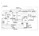
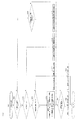
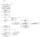
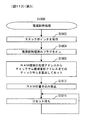
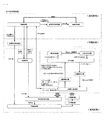
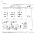
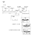
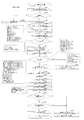
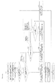
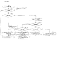
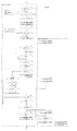
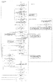
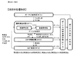
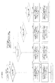
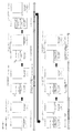
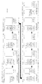
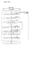
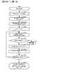
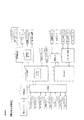
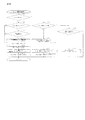
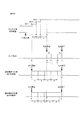
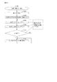
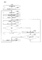
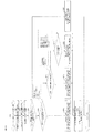
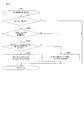
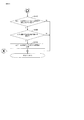
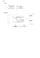
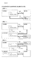
次に、図12のブロック図を参照しながら、本実施形態に係る回胴式遊技機Pの電気的な概略構成を説明する。はじめに、本実施形態に係る回胴式遊技機は、遊技の進行を制御する主制御基板Mを中心として、副制御基板S、扉基板D、回胴基板K、電源基板E、中継基板IN、設定キースイッチM20、設定/リセットボタンM30等がデータをやり取り可能に接続されて構成されている。尚、図中の実線部がデータのやり取りに関する動きを示したものであり、図中の破線部が電源供給ルートを示したものである。尚、電源供給ルートはこれに限られたものではなく、例えば電源基板Eから主制御基板を介さずに中継基板INや扉基板Dに電源を供給しても良い。 Next, referring to the block diagram of FIG. 12, an electrical schematic configuration of the reel-to-play type gaming machine P according to the present embodiment will be described. First, the drum-type gaming machine according to the present embodiment mainly includes the sub control board S, the door board D, the rotating body board K, the power supply board E, the relay board IN, centering on the main control board M for controlling the progress of the game. A setting key switch M20, a setting / reset button M30 and the like are connected to be able to exchange data. The solid line in the figure shows the movement related to the exchange of data, and the broken line in the figure shows the power supply route. The power supply route is not limited to this. For example, power may be supplied from the power supply substrate E to the relay substrate IN or the door substrate D without intervention of the main control substrate.
主制御基板(主制御手段、主基板、メイン制御手段、メイン基板、主遊技部と称することがある)Mは、回胴式遊技機Pで行われる遊技全体の進行を司る基板である。主制御基板Mには、主制御チップCが搭載されており、主制御チップCには、CPUC100、内蔵ROMC110、内蔵RAMC120等がバスによって互いにデータをやり取り可能に接続されて搭載されている。そして、主制御基板Mは、前扉DUに搭載された扉基板Dから、スタートレバーD50等が操作されたことを示す信号等を受け取って、副制御基板Sや、扉基板D、回胴基板K等に向かって制御コマンド(あるいは制御信号)を出力することにより、これら各種基板の動作を制御している{例えば、副制御基板Sに向かって指示番号(押し順番号、指示情報、操作情報とも称する)を出力することにより、副制御基板Sは演出表示装置S40上で押し順ナビを実行することが可能となっている}。
A main control board (which may be referred to as main control means, main board, main control means, main board, or main game unit) M is a board that controls the progress of the entire game played in the reel-type game machine P. A main control chip C is mounted on the main control board M, and a
また、副制御基板(副制御手段、副基板、サブ制御手段、サブ基板、副遊技部と称することがある)Sにも、前述した主制御基板Mと同様に、副制御チップSCが搭載されており、副制御チップSCには、CPUSC100や、ROM、RAM等が設けられていて、バスによって互いにデータをやり取り可能に接続されて構成されている。また、副制御基板Sには、各種LEDランプS10、スピーカS20、演出表示装置S40、回胴バックライト(バックランプとも称する)S30等が接続されている。ここで回胴バックライトS30とは、左リールM51、中リールM52、右リールM53夫々の内部に設けられ、リールの表面に描かれた図柄を裏側から照らすライトである。副制御基板Sは、主制御基板Mから受け取った制御コマンドを解析して、各種LEDランプS10、スピーカS20、演出表示装置S40、回胴バックライトS30等にそれぞれ駆動信号を出力することにより、各種の演出を行っている。
In addition, a sub control chip SC is also mounted on a sub control board (sometimes referred to as a sub control means, a sub board, a sub control means, a sub board, and a sub game unit) S in the same manner as the main control board M described above. The sub control chip SC is provided with a
扉基板Dには、前述した投入受付センサD10s、第1投入センサD20s、第2投入センサD30s、回転しているリールM50を停止するための停止ボタンD40、リールM50の回転を開始するためのスタートレバーD50、貯留されている遊技メダル(クレジット)や投入された遊技メダルを払い出して遊技を終了するための精算ボタンD60、遊技の状態を表示する各種の表示パネルD70{不図示であるが、前述した、投入数表示灯D210、操作状態表示灯D180、特別遊技状態表示装置D250、払出数表示装置(押し順表示装置)D270は、クレジット数表示装置D200、有利区間表示器YH、等の表示装置の集合体}、前扉の開閉判定やエラーの解除や設定値の変更を実行するための扉スイッチD80、投入された後に適合しないと判断された遊技メダル(又は、その他の異物)を放出口D240に払い戻すためのブロッカD100等が接続されている。また、この扉基板Dは、前述した主制御基板Mとデータをやり取り可能に接続されている。このため、前扉DUに設けられたスタートレバーD50や、停止ボタンD40、精算ボタンD60等を操作すると、扉基板Dを介して、操作に係る信号が主制御基板Mに供給されるようになっている。また、投入受付センサD10sが遊技メダルの通過を検出した信号も、扉基板Dを介して主制御基板Mに供給される。 On the door substrate D, the above-described closing acceptance sensor D10s, first closing sensor D20s, second closing sensor D30s, stop button D40 for stopping the rotating reel M50, and start for starting the rotation of the reel M50 A lever D50, a payment button D60 for paying out stored game medals (credits) and inserted game medals and ending the game, various display panels D70 for displaying the state of the game {not shown, but Displayed devices such as the number-of-credits indicator D200, the number-of-credits indicator D200, the number-of-credits indicator D200, the advantage zone indicator YH, etc. Group of objects, door switch D80 for executing open / close judgment of front door, cancellation of error and change of set value Game medals is determined to be incompatible (or other foreign) blocker D100 like to reimburse the outlet D240 and is connected after. Further, the door substrate D is connected so as to be able to exchange data with the main control substrate M described above. Therefore, when the start lever D50, the stop button D40, the settlement button D60, etc. provided on the front door DU are operated, the signal relating to the operation is supplied to the main control board M via the door board D. ing. Further, a signal that the insertion acceptance sensor D10s detects the passage of the game medal is also supplied to the main control board M via the door board D.
また、回胴基板Kには、リールM50を回転させるための回胴モータK10と、リールM50の回転位置を検出するための回胴センサK20等が接続されている。回胴基板Kは、当該回胴センサK20によって、リールM50の回転位置を検出しながら回胴モータK10を駆動することにより、リールM50を、決定された停止位置で停止させることが可能となっている。また、本実施形態の回胴式遊技機においては、回胴モータK10には、所謂ステップモータ(ステッピングモータ)が使用されている。尚、ステップモータは、リールM50が1回転するステップ数として、480ステップが設定されている。また、各リール(左リールM51、中リールM52、右リールM53)には略均一の大きさで所定数(例えば、20個)の図柄が設定されており、1図柄分に相当するステップ数としては、24ステップ(=480/20)が設定されている。尚、ステップ数、リール1周あたりの図柄の数は変更しても何ら問題ない。 Further, to the spinning drum substrate K, a spinning drum motor K10 for rotating the reel M50, a spinning drum sensor K20 for detecting the rotational position of the reel M50, and the like are connected. The spinning drum substrate K can stop the reel M50 at the determined stop position by driving the spinning drum motor K10 while detecting the rotational position of the reel M50 by the spinning drum sensor K20. There is. Further, in the reel-type gaming machine of the present embodiment, a so-called step motor (stepping motor) is used for the reel-in motor K10. In the step motor, 480 steps are set as the number of steps for one rotation of the reel M50. In addition, a predetermined number (for example, 20 pieces) of symbols of substantially uniform size are set on each reel (left reel M51, middle reel M52, right reel M53), and the number of steps corresponds to one symbol. There are 24 steps (= 480/20) set. There is no problem in changing the number of steps and the number of symbols per revolution of the reel.
また、メダル払出装置Hは、中継基板INを介して、主制御基板Mに接続されており、主制御基板Mからの制御信号に基づいて、所定枚数(例えば、10枚)の遊技メダルを払い出す動作を行う。尚、メダル払出装置Hにはメダルが正常に払い出されたか否かの判定や払い出された遊技メダルの数の計測を実行する第1払出センサH10s及び第2払出センサH20sと、ディスクH50を回転させるためのホッパモータH80と、が接続されている。 The medal payout device H is connected to the main control board M via the relay board IN, and pays a predetermined number (for example, 10) of game medals based on a control signal from the main control board M. Do the action to put out. The first payout sensor H10s and the second payout sensor H20s, which execute determination of whether or not the medals have been normally paid out, and measurement of the number of gaming medals, are provided to the medal payout device H, and the disc H50. A hopper motor H80 for rotating is connected.
これら各種制御基板、及び基板で消費される電力は、電源基板E(電源スイッチE10により電源供給の有無を制御する基板)から供給されている。図12では、電源基板Eから電力が供給される様子を破線の矢印で表している。図示されているように、主制御基板Mおよび副制御基板Sには、電源基板Eから電力が直接供給されており、各種基板(扉基板D、回胴基板K、中継基板IN)には、主制御基板Mを介して電力が供給されている。電源基板Eには所定量(例えば、100V)の交流電圧が供給されており、この電力を規定電圧の直流電圧に変換した後、夫々の制御基板及び基板に供給している。 The power consumed by these various control boards and boards is supplied from a power supply board E (a board for controlling the presence or absence of power supply by a power switch E10). In FIG. 12, a state in which power is supplied from the power supply substrate E is indicated by a broken arrow. As illustrated, power is directly supplied from the power supply substrate E to the main control substrate M and the sub control substrate S, and various substrates (the door substrate D, the rotating drum substrate K, the relay substrate IN) Power is supplied via the main control board M. An AC voltage of a predetermined amount (for example, 100 V) is supplied to the power supply substrate E, and the power is converted to a DC voltage of a specified voltage and then supplied to each control substrate and substrate.
また、主制御基板Mには、後述する設定変更装置制御処理を実行するため(設定変更を行うため)に使用する設定キースイッチM20、設定値の変更やエラー解除等を実行し得る設定/リセットボタンM30、が接続されている。また、主制御基板Mは、リールM50(左リールM51、中リールM52、右リールM53)の回転や停止を制御するリール制御手段と、遊技者にとって有利なATに関する状態である「AT中状態」に移行するためのAT移行抽選を実行するAT抽選手段と、「AT中状態」に滞在可能なゲーム数であるAT残りゲーム数(又は、ATカウンタM60のカウンタ値)を増加させるAT上乗せ抽選を実行するAT上乗せ抽選手段と、を有している。 In addition, on the main control board M, a setting key switch M20 used to execute setting change device control processing to be described later (for setting change), setting / reset capable of executing setting value change, error cancellation, etc. The button M30 is connected. In addition, the main control board M includes a reel control means for controlling rotation and stop of the reel M50 (left reel M51, middle reel M52, right reel M53), and a state related to AT which is advantageous for the player. AT lottery means for executing AT transition lottery for transitioning to AT, and AT addition lottery for increasing the number of remaining AT games (or the counter value of AT counter M60) which is the number of games that can stay in the "at-AT state" And AT additional lottery means to be executed.
次に、図13〜33は、本実施形態における、主制御基板Mが行う一般的な処理の流れを示したフローチャートである。 Next, FIGS. 13 to 33 are flowcharts showing a flow of general processing performed by the main control substrate M in the present embodiment.
尚、フローチャートは主に、処理ステップ(長方形にて図示)、判断(ひし形にて図示)、流れ線(矢印)、開始・終了・復帰等を示す端子(角丸長方形にて図示)によって構成されている。また、処理ステップの内、別のフローチャートにて詳細を図示している場合、当該別のフローチャートを参照するものをサブルーチン(左右の線が二重線である長方形にて図示)として図示している。ここで、遊技機の開発段階においては、スペック違いの遊技機を同時に開発することも行われているが、本例においては、メイン側の処理内に、スペック違いの遊技機で実行するサブルーチン(通常は使用しないサブルーチン)を残さないよう構成しており、ノイズや不正行為によって、通常時には実行されない未使用サブルーチンに係る処理が実行されることを防止している。 The flowchart mainly includes processing steps (shown as rectangles), judgments (shown as diamonds), flow lines (arrows), and terminals (shown as rounded rectangles) indicating start / end / return etc. ing. Also, in the case where the details of the processing steps are illustrated in another flowchart, those referring to the other flowchart are illustrated as a subroutine (shown as a rectangle in which the left and right lines are double lines). . Here, at the development stage of the gaming machine, it is also carried out to simultaneously develop gaming machines with different specifications, but in this example, the subroutine executed by the gaming machines with different specifications in the processing on the main side ( It is configured so as not to leave a subroutine not normally used, and prevents processing relating to an unused subroutine that is not normally executed due to noise or cheating.
まず、図13は、回胴式遊技機Pの電源を投入した後(或いはシステムリセットやユーザリセット時において)、主制御基板MのCPUC100にて初めて実行される処理の流れを示したフローチャートである。まず、ステップ1000で、回胴式遊技機Pの電源を投入した後、ステップ1002で、主制御基板MのCPUC100は、タイマ割り込みの初期設定を実行する(ここでは、タイマ割り込みが開始されるのではなくタイマ割り込みの種類をセットするのみであり、以降の処理において、タイマ割り込みが開始されると定期的に後述するタイマ割り込み時処理に係るフローチャートが実行される)。次に、ステップ1004で、主制御基板MのCPUC100は、主制御チップCの機能設定としてシリアル通信の設定(速度、データの長さ、データ送信方法の設定)等を実行する。次に、ステップ1006で、主制御基板MのCPUC100は、RAM領域の先頭アドレスからチェックサム領域直前のアドレスまでのチェックサムを算出する。次に、ステップ1008で、主制御基板MのCPUC100は、RAM領域をチェックし(例えば、当該算出したチェックサムとチェックサム領域に保持されているチェックサムデータとに基づき、電源断・電源断復帰により内蔵RAMC120に格納されているデータが正しく保持されているか否かをチェックし)、電源断復帰データを生成する。次に、ステップ1010で、主制御基板MのCPUC100は、設定キースイッチM20のスイッチ状態を確認する。次に、ステップ1014で、主制御基板MのCPUC100は、設定キースイッチM20がオフであるか否かを判定する。
First, FIG. 13 is a flow chart showing a flow of processing executed for the first time by the
ステップ1014でYesの場合、ステップ1016で、主制御基板MのCPUC100は、RAM内の電源断処理済みフラグのオン・オフ(ステップ1904でオンとなる)及び全RAMのチェックサム状態(ステップ1006でのチェック結果)を参照し、RAM内の電源断復帰データは正常であるか否かを判定する。ステップ1016でYesの場合、ステップ1020で、主制御基板MのCPUC100は、決定された初期化範囲で、RAM領域の初期化を実行する。次に、ステップ1022で、主制御基板MのCPUC100は、電源断時の処理(ステップ1902)にて保存したスタックポインタに係るデータに基づき、スタックポインタを復帰する。次に、ステップ1036で、主制御基板MのCPUC100は、RAM領域内を参照し、RAM領域内の設定値に係るデータは正常範囲内(本例では、0〜5)であるか否かを判定する。ステップ1036でYesの場合、ステップ1038で、主制御基板MのCPUC100は、入力ポートの読み込みを実行する。次に、ステップ1040で、主制御基板MのCPUC100は、ステップ1002にてセットしたタイマ割り込みを開始する。次に、ステップ1042で、主制御基板MのCPUC100は、電源断処理済みフラグをオフにし、復帰したスタックポインタに従い電源断時の処理に復帰する。
If YES in
また、ステップ1016でNoの場合、ステップ1024で、主制御基板MのCPUC100は、バックアップエラー表示をセットする(例えば、レジスタ領域内にエラー番号をセットする)。次に、ステップ1300で、主制御基板MのCPUC100は、後述する、復帰不可能エラー処理を実行する。
If NO in
また、ステップ1036でNoの場合、ステップ1046で、主制御基板MのCPUC100は、設定値エラー表示(例えば、払出数表示装置D270に表示されることとなる)をセットする(例えば、レジスタ領域内にセットする)。次に、ステップ1300で、主制御基板MのCPUC100は、後述する復帰不可能エラー処理を実行する。
In the case of No at
また、ステップ1014でNoの場合、ステップ1028で、主制御基板MのCPUC100は、RAM内の電源断処理済みフラグのオン・オフ(ステップ1904でオンとなる)及び全RAMのチェックサム状態(ステップ1006でのチェック結果)を参照し、RAM内の電源断復帰データは正常であるか否かを判定する。ステップ1028でYesの場合、ステップ1030で、主制御基板MのCPUC100は、RAMの初期化範囲をRAM内の設定値(設定値データ)を記憶する記憶領域を除く所定範囲に決定してセット(例えば、レジスタ領域内にセット)し、ステップ1034に移行する。RAMの初期化範囲に含まれない範囲は、設定値(設定値データ)を記憶する記憶領域のみには限定されず、「有利区間」の総累計ゲーム数、遊技区間の総累計(有利区間+通常区間)ゲーム数、「有利区間」の滞在割合を算出した結果、等もRAMの初期化範囲に含まれない範囲となっている。このように構成することにより、遊技における「有利区間」に滞在している比率(有利区間比率)を算出及び表示することができることとなる。また、有利区間比率の算出処理は、単位遊技が終了するタイミングで算出するよう構成されている。また、有利区間比率は、遊技機の電源が投入されると表示される(例えば、4桁の7セグメントディスプレイに表示される)。具体的な表示態様としては、「有利区間比率→6000ゲームあたりの連続役物比率→6000ゲームあたりの役物比率→累積の連続役物比率→累積の役物比率」の順に5秒間隔で繰り返し表示される。尚、連続役物比率とは「RBが作動している状態での払出し数/総払出し数」であり、役物比率とは「RB、CB、又はSBが作動している状態での払出し数/総払出し数」である。他方、ステップ1028でNoの場合、ステップ1032で、主制御基板MのCPUC100は、RAMの初期化範囲をRAM内の設定値(設定値データ)を記憶する記憶領域を含む特定範囲に決定してセット(例えば、レジスタ領域内にセット)し、ステップ1034に移行する。次に、ステップ1034で、主制御基板MのCPUC100は、ステップ1030又はステップ1032にて決定された初期化範囲で、RAM領域の初期化を実行する。次に、ステップ1100で、主制御基板MのCPUC100は、後述する、設定変更装置制御処理を実行する。
If No at
尚、不図示ではあるが、主制御基板Mが搭載する一時記憶領域(RAM領域等)の初期値(処理開始時の値)は、特別遊技が実行される値とならないよう構成することが好適である(プログラムの処理開始直後に、ノイズや不正行為により、特別遊技の実行判定を行う処理を実行してしまった場合に特別遊技が誤って実行されることを防止するため)。また、不図示ではあるが、主制御基板MのRAM領域内に当選乱数等の乱数を記憶する場合には、専用の記憶領域を確保し、乱数に係る情報を記憶しているバイト内には当該乱数に係る情報のみを記憶する(各種タイマ値等、その他の情報を記憶しない)よう構成することが好適である(同じ1バイト内に記憶した別のデータを操作する際に、ノイズ等によって乱数に係る情報が書き換わってしまうことを防止するため)。 Although not shown, it is preferable that the initial value (value at the start of processing) of the temporary storage area (RAM area etc.) mounted on the main control board M is configured not to be a value at which the special game is executed. (In order to prevent the special game from being erroneously executed when the process for judging the execution of the special game has been executed immediately after the start of the processing of the program, due to noise or cheating. Further, although not shown, when storing random numbers such as winning random numbers in the RAM area of the main control board M, a dedicated storage area is secured, and in the byte storing information related to the random numbers. It is preferable to be configured to store only the information related to the random number (do not store other information such as various timer values) (by noise or the like when operating another data stored in the same 1 byte) To prevent information related to random numbers from being rewritten).
次に、図14は、図13におけるステップ1100のサブルーチンに係る、設定変更装置制御処理のフローチャートであり、設定変更モードとも称する。まず、ステップ1102で、主制御基板MのCPUC100は、スタックポインタをセットする(当該処理の先頭アドレスで初期化する)。次に、ステップ1104で、主制御基板MのCPUC100は、タイマ割り込みを起動する。次に、ステップ1106で、主制御基板MのCPUC100は、RAM領域内の設定値(設定値データ)は正常範囲内(本例では、0〜5)ではないか否かを判定する。尚、設定値(設定値データ)を1〜6で管理していた場合、RAMの初期化を実行し設定値が「0」となったときに「1」に戻す処理が必要となる。そこで、本例においては、設定値(設定値データ)の正常範囲を0〜5として管理することにより、RAMの初期化を実行した後の設定値(設定値データ)の補正処理(ステップ1106及びステップ1108の処理)を不要とすることができ、処理時間を短縮することや処理の容量を削減することが可能となる。ステップ1106でYesの場合、ステップ1108で、主制御基板MのCPUC100は、設定値(設定値データ)に所定値(例えば、0=遊技者にとって最も不利となる値)をセットし、ステップ1110に移行する。他方、ステップ1106でNoの場合にもステップ1110に移行する。次に、ステップ1110で、主制御基板MのCPUC100は、エラー表示LED(例えば、払出数表示装置D270)に設定変更装置作動(所謂、設定変更モード)中である旨(例えば、全セグメントを点灯させる「88」)を表示し、設定表示LED(不図示)に設定値を表示(設定値に係る表示はRAM内で保持している設定値(設定値データ)に1を加算した数値となっている)し、ステップ1112に移行する。尚、前述したように、払出数表示装置D270は押し順を報知する際にも使用される。そのように構成されているため、例えば、7セグLEDの一部に故障が発生している(点灯できないセグがある)ような場合において押し順を報知する際、誤った情報を報知することがあり得る。このような事態を防止するため、設定変更装置作動中において払出数表示装置D270に7セグメントを全点灯「88」させることにより、7セグメントが故障しているか否かが確認でき、遊技者に不利益等を与えることを防止できる。また、設定値(設定値データ)の表示に係る構成として、設定値を記憶する記憶領域における設定値(設定値データ)に1を加算したデータを記憶しておく設定値表示用のRAMの記憶領域を有し、当該記憶領域を参照して設定値を表示するよう構成しても良い。尚、不図示であるが、ステップ1110の処理を実行した後、副制御基板S側に設定変更モードに移行していることを示すコマンドを送信するための処理を実行している。
Next, FIG. 14 is a flowchart of setting change device control processing according to the subroutine of
次に、ステップ1112で、主制御基板MのCPUC100は、設定/リセットボタンM30がオフからオンに切り替わったか否かを判定する。ステップ1112でYesの場合、ステップ1114で、主制御基板MのCPUC100は、現在の設定値(設定値データ)に1を加算し(加算した結果設定値(設定値データ)が5を超過した場合には、設定値(設定値データ)は0となる)、ステップ1116に移行する。尚、ステップ1112でNoの場合にも、ステップ1116に移行する。次に、ステップ1116で、主制御基板MのCPUC100は、スタートレバーD50がオフからオンに切り替わったか否かを判定する。ステップ1116でNoの場合には、ステップ1112に移行し、ステップ1112〜ステップ1116の処理をループする。ステップ1116でYesの場合、ステップ1118で、主制御基板MのCPUC100は、設定キースイッチM20がオンからオフに切り替わったか否かを判定する。ステップ1118でNoの場合には、ステップ1118の処理をループする。他方、ステップ1118でYesの場合、ステップ1120で、主制御基板MのCPUC100は、エラー表示LED(不図示)に設定変更装置の作動が終了した旨を表示し、設定表示LED(不図示)の設定値(設定値データ)の表示を消去し、ステップ1200の遊技進行制御処理に移行する。尚、不図示であるが、ステップ1120の処理を実行した後、副制御基板S側に設定変更モードを終了することを示すコマンドを送信するための処理を実行している。
Next, in step 1112, the
次に、図15は、図13におけるステップ1300の(及び他のフローチャートにおいて呼び出された)サブルーチンに係る、復帰不可能エラー処理のフローチャートである。まず、ステップ1302で、主制御基板MのCPUC100は、割り込みを禁止する(以降は、後述するタイマ割り込み時処理に係るフローチャートが実行されない)。次に、ステップ1304で、主制御基板MのCPUC100は、出力ポートアドレス及び出力ポート数をセットする。次に、ステップ1306で、主制御基板MのCPUC100は、出力ポート(本例では、0〜6であり、各種LEDへの表示出力や各種モータへの駆動出力)をオフにする。次に、ステップ1308で、主制御基板MのCPUC100は、次のポート出力アドレスをセットする(この繰り返しにより、各種LEDへの表示出力や各種モータへの駆動出力が順次停止される)。次に、ステップ1310で、主制御基板MのCPUC100は、各出力ポートへの出力が終了したか否かを判定する。ステップ1310でYesの場合には、ステップ1312で、主制御基板MのCPUC100は、セットされているエラー表示を実行し(本処理を実行する際には何らかのエラーが発生している)、当該処理の実行を繰り返し、電源電圧が低下することでリセット信号が入力されて終了する。(即ち、無限ループに突入するので、復帰を促す一切の操作を受け付けない)。尚、ステップ1310でNoの場合には、ステップ1306に移行する。尚、ステップ1306〜ステップ1310の処理は、LED・モータへの出力をクリアする処理である(但し、外部出力信号はクリアしないので、エラーに関する情報やエラー発生時における遊技進行状況等をホールコンピュータ側へ出力することは可能である)。
Next, FIG. 15 is a flowchart of non-returnable error processing according to the subroutine (called in the other flowcharts) of
次に、図16は、図14におけるステップ1200のサブルーチンに係る、遊技進行制御処理(1枚目)のフローチャートである。まず、ステップ1202で、主制御基板MのCPUC100は、スタックポインタをセットする(当該処理の先頭アドレスで初期化する)。次に、ステップ1203で、主制御基板MのCPUC100は、当該ゲームに必要なRAM領域内のデータ(例えば、ベット上限数、入賞の有効ライン、等)をセットする。尚、ステップ1203は、前回の遊技で使用したデータ{例えば、条件装置番号(当選番号)、演出グループ番号、指示情報}をクリアするためのデータ(RAMのアドレスをクリアするための「0」のデータ)をRAMにセットする処理も含まれる。尚、条件装置番号、演出グループ番号、指示情報等はクリアせずに、次遊技が実行された際に選択された番号を上書きするように構成するようにしても良い。次に、ステップ1204で、主制御基板MのCPUC100は、当該ゲームにおけるRT状態(例えば、「RT0」等)をセットする(図27のステップ1704で決定したRT状態をセットする)。次に、ステップ1205で、主制御基板MのCPUC100は、ステップ1204でセットしたRT状態に関するコマンド(サブ側へのコマンド)をセットする。尚、RT状態をセットする処理は、図27のステップ1704にて実行してもよい。また、ステップ1704にてRT状態に関するコマンド(サブ側へのコマンド)をセットしても良い。また、RT状態をサブ側に送信する場合には常時送信する必要はなく、遊技区間が「有利区間」である場合にのみRT状態をサブ側に送信するよう構成してもよい。次に、ステップ1206で、主制御基板MのCPUC100は、当該ゲームにおけるATに関する状態(例えば、「AT中状態」等)をセットする(図21のステップ1420、ステップ1429、図22のステップ1435、ステップ1439、ステップ1443、図23のステップ1444‐3、ステップ1444‐4で決定したATに関する状態をセットする)。次に、ステップ1207で、主制御基板MのCPUC100は、ステップ1206でセットしたATに関する状態に関するコマンド(サブ側へのコマンド)をセットする。また、ATに関する状態をセットする処理は、図21のステップ1416、ステップ1428、図22のステップ1438、図23のステップ1444‐1にて実行してもよい。また、ATに関する状態をサブ側に送信する場合には常時送信する必要はなく、遊技区間が「有利区間」である場合にのみATに関する状態をサブ側に送信するよう構成してもよい。次に、ステップ1208で、主制御基板MのCPUC100は、当該ゲームにおける遊技区間(例えば、「有利区間」等)をセットする(図31のステップ3510、ステップ3516、ステップ3520で決定した遊技区間をセットする)。次に、ステップ1208‐1で、主制御基板MのCPUC100は、ステップ1208でセットした遊技区間に関するコマンド(サブ側へのコマンド)をセットする。次に、ステップ1209で、主制御基板MのCPUC100は、メダル払出装置Hが遊技メダルで満杯ではないか否かを判定する。具体的には、メダル払出装置Hから溢れ出たメダルを格納するサブタンク(不図示)を備え、サブタンクに設けられた複数の満杯検知センサによる電流の導通/非導通にて判定する(メダルを介して電流が導通した場合には、満杯と判定する)。ステップ1209でYesの場合、ステップ1218に移行する。
Next, FIG. 16 is a flowchart of the game progression control process (first sheet) according to the subroutine of
他方、ステップ1209でNoの場合、ステップ1210で、主制御基板MのCPUC100は、メダル満杯エラーフラグをオンにする(例えば、RAM領域のメダル満杯エラーフラグ領域内をオンに相当する値で更新する)。次に、ステップ1212で、主制御基板MのCPUC100は、メダル満杯エラーに対応したエラー番号の表示を7セグLED(例えば、貯留表示LED又は獲得枚数LED)で実行する。次に、ステップ1214で、主制御基板MのCPUC100は、メダル満杯エラーが解除されたか否か(例えば、サブタンクによる電流が非導通、且つ、設定/リセットボタンM30が押下されたか否か)を判定する。ステップ1214でYesの場合、ステップ1216で、主制御基板MのCPUC100は、メダル満杯エラーフラグをオフにし(例えば、RAM領域のメダル満杯エラーフラグ領域内をオフに相当する値で更新し)、ステップ1218に移行する。他方、ステップ1214でNoの場合には、ステップ1212に移行する。次に、ステップ1218で、主制御基板MのCPUC100は、メダル投入受付を許可し(再遊技役の次ゲームにおいては自動にて投入動作が実行されることとなる)、次の処理(ステップ1220の処理)に移行する。ここで、ステップ1218では、ブロッカD100のオン処理(メダル流路が形成する処理)を行う。具体的には、前回遊技で再遊技役が成立した場合には、現在の貯留数(クレジット)が所定値(本例では、50枚)未満であることを条件として、ブロッカD100のオン処理を実行する。換言すると、現在の貯留数(クレジット)が所定値である場合には、ブロッカD100のオン処理を実行しない。一方、前回遊技で再遊技役が成立しなかった場合には、一律にブロッカD100のオン処理を実行するようにしている。このように構成することにより、再遊技役が成立した場合であっても貯留数(クレジット)が所定値に達していない場合には、遊技メダルが投入できるように構成され、「RT1」等のRT状態よりも再遊技役の当選確率の高いRT状態(例えば、「RT1」)に滞在しているときや、見た目では再遊技役とは分かり辛い再遊技役(小役に見せかけた再遊技:無効ライン上にベル−ベル−ベルや、左リールにチェリーが停止した図柄組合せ)が停止した場合であっても、遊技者はリズム良く(違和感なく)遊技を行うことができる。
On the other hand, if No in
次に、図17は、図16におけるステップ1200のサブルーチンに係る、遊技進行制御処理(2枚目)のフローチャートである。まず、ステップ1220で、主制御基板MのCPUC100は、遊技メダルがベットされていない、又は貯蓄されていない(クレジットが存在していない)か否かを判定する。ステップ1220でYesの場合、ステップ1221で、主制御基板MのCPUC100は、設定値表示条件を充足している(例えば、扉スイッチD80、設定キースイッチM20がすべてオンとなると当該条件を充足する)か否かを判定する。ステップ1221でYesの場合、ステップ1222で、主制御基板MのCPUC100は、設定表示LED(不図示だが、払出数表示装置D270、クレジット数表示装置D200、投入数表示灯D210としてもよい)に設定値を表示し(設定確認モードに移行し)、設定キースイッチM20がオフとなったことを条件にステップ1221に移行する。尚、設定変更モードの移行条件を満たしたときには、副制御基板S側に設定変更モードを開始することを示すコマンドを送信するための処理、設定変更モードの終了条件を満たしたときに設定変更モードを終了することを示すコマンドを送信するための処理を実行している。ステップ1220又はステップ1221でNoの場合、ステップ1224で、主制御基板MのCPUC100は、遊技メダルの投入及び精算に係る管理を実行する。次に、ステップ1225で、主制御基板MのCPUC100は、遊技メダルの受付可能枚数を確認する。次に、ステップ1226で、主制御基板MのCPUC100は、ブロッカD100がオンか否かを判定する。ステップ1226でYesの場合、ステップ1227で、主制御基板MのCPUC100は、第1投入センサD20s又は第2投入センサD30sがオンであるか否かを判定する(本実施形態においてはメダルの投入を検出するための投入センサを2つ有しており、第1投入センサD20s又は第2投入センサD30sがオンとなると、遊技メダルを1枚受け付けたと判定する)。ステップ1227でYesの場合、ステップ1230で、主制御基板MのCPUC100は、第1投入センサD20s及び第2投入センサD30sがオフであるか否かを判定する(第1投入センサD20s又は第2投入センサD30sがオンとなった後、第1投入センサD20s及び第2投入センサD30sがオフとなると、受け付けた1枚の遊技メダルが第1投入センサD20s及び第2投入センサD30sを通過したと判定する)。ステップ1230でYesの場合、ステップ1231で、主制御基板MのCPUC100は、1枚の正常な遊技メダルの投入を受け付けたと判定する。不図示であるが、ステップ1231の後、主制御基板MのCPUC100は、クレジットが上限数(本例では、50)、且つ、ベット数が最大数(本例では、3)であるか否かを判定し、Yesと判定した場合にはブロッカD100をオフ(メダル流路を形成しない状態)に制御する。尚、ステップ1230でNoの場合には、ステップ1230の処理を繰り返し、ステップ1226またはステップ1227でNoの場合には、ステップ1232に移行する。
Next, FIG. 17 is a flowchart of the game progression control process (second sheet) according to the subroutine of
次に、ステップ1232で、主制御基板MのCPUC100は、精算ボタンD60の操作があったか否かを判定する。ステップ1232でYesの場合、ステップ1233で、主制御基板MのCPUC100は、クレジットの残り枚数又はベットされている遊技メダルが存在するか否かを判定する。ステップ1233でYesの場合、ステップ1234で、主制御基板MのCPUC100は、ホッパ駆動フラグ(RAM領域内のフラグであり、ホッパモータH80を駆動している際にオンとするフラグ)をオンにし、遊技メダル1枚の払出を実行する。次に、ステップ1236で、主制御基板MのCPUC100は、第1払出センサH10s又は第2払出センサH20sがオンであるか否かを判定する(本実施形態においてはメダルの払出を検出するための払出センサを2つ有しており、第1払出センサH10s又は第2払出センサH20sがオンとなると、遊技メダル1枚の払出動作が行われていると判定する)。ステップ1236でYesの場合、ステップ1247に移行する。ここで、フローチャート上には明記してはいないが、前回遊技が再遊技役であった場合にはクレジットの残り枚数のみが精算の対象となる。
Next, in
他方、ステップ1236でNoの場合、ステップ1241で、主制御基板MのCPUC100は、ホッパ駆動後(ステップ1234の処理のタイミング後)から所定時間(例えば、5秒)経過したか否かを判定する。具体的には、ホッパ駆動信号をホッパモータH80に送信している(ホッパモータH80が回転している)のにもかかわらず、メダルが払い出されていないと判定している状況が所定時間継続したか否かを判定する。ステップ1241でYesの場合、ステップ1242で、主制御基板MのCPUC100は、メダル空エラーフラグをオンにする(例えば、メダル空エラーフラグ領域内をオンに相当する値で更新する)。次に、ステップ1244で、主制御基板MのCPUC100は、メダル空エラー表示を実行する。次に、ステップ1245で、主制御基板MのCPUC100は、メダル空エラーが解除されたか否か(例えば、設定/リセットボタンM30が押下されたか否か)を判定する。ステップ1245でYesの場合、ステップ1246で、主制御基板MのCPUC100は、メダル空エラーフラグをオフにし(例えば、RAM領域のメダル空エラーフラグ領域内をオフに相当する値で更新し)、ステップ1247に移行する。他方、ステップ1245でNoの場合、ステップ1244に移行する。
On the other hand, if No in
次に、ステップ1247で、主制御基板MのCPUC100は、第1払出センサH10s及び第2払出センサH20sがオフであるか否かを判定する(第1払出センサH10s又は第2払出センサH20sがオンとなった後、第1払出センサH10s及び第2払出センサH20sがオフとなると、払出動作が行われていた1枚の遊技メダルの払出動作が完了したと判定する)。ステップ1247でYesの場合、ステップ1248で、主制御基板MのCPUC100は、ホッパ駆動フラグをオフにし、ステップ1233に移行する。尚、ステップ1241又はステップ1247でNoの場合には、ステップ1236に移行する。
Next, in
他方、ステップ1232又はステップ1233でNoの場合、ステップ1251で、主制御基板MのCPUC100は、スタートレバーD50が有効であり(例えば、ゲームを開始するための規定枚数の遊技メダルが投入された等)、且つ、当該スタートレバーD50の操作があったか否かを判定する。ステップ1251でYesの場合、ステップ1253で、主制御基板MのCPUC100は、RAM領域内の設定値は正常範囲内(本例では、0〜5)であるか否かを判定する。ステップ1253でYesの場合、ステップ1254で、主制御基板MのCPUC100は、乱数の取得、ブロッカD100をオフにする処理を実行した後に、次の処理(ステップ3600の処理)に移行する。他方、ステップ1253でNoの場合、ステップ1256で、主制御基板MのCPUC100は、設定値エラー表示をセットする(例えば、レジスタ領域内にエラー番号をセットする)。次に、ステップ1300で、主制御基板MのCPUC100は、復帰不可能エラー処理を実行する。尚、ステップ1251でNoの場合には、ステップ1220に移行する。
On the other hand, if No in
次に、図18は、図16におけるステップ1200のサブルーチンに係る、遊技進行制御処理(3枚目)のフローチャートである。まず、ステップ3600で、主制御基板MのCPUC100は、後述する、内部抽選実行処理を実行する。次に、ステップ1259で、主制御基板MのCPUC100は、現在のATに関する状態はAT上乗せ抽選可能な状態であるか否かを判定する。ここで、本例においては、AT上乗せ抽選を実行可能なATに関する状態は、「AT中状態」、「上乗せ特化状態」、「特化前兆状態」、「有利BB状態」となっており、「有利BB内部中遊技」においては、ATカウンタ値が0より大きい状態となり得るがAT上乗せ抽選は実行しないよう構成されている。これは、「有利BB内部中遊技」において、遊技者が敢えてBBの図柄組合せを揃えさせないことの方が、遊技者にとって有利となってしまうことを防止するためである。尚、「有利BB内部中遊技」にてAT上乗せ抽選を実行し得るよう構成してもよく、そのように構成した場合には、「有利BB内部中遊技」にてAT上乗せ抽選に当選してもすぐには報知せずに、その後BBが終了したタイミングでAT上乗せ抽選に当選した旨、又は、ATゲーム数が上乗せされた後のAT残りゲーム数を報知するよう構成してもよい。
Next, FIG. 18 is a flowchart of the gaming progress control process (third sheet) according to the subroutine of
ステップ1259でYesの場合、ステップ1500で、主制御基板MのCPUC100は、後述する、ゲーム数上乗せ実行処理を実行し、ステップ1400に移行する。他方、ステップ1259でNoの場合にもステップ1400に移行する。このゲーム数上乗せ実行処理は、ATに関する状態に応じて異なる抽選テーブルを用いて抽選を実行することも可能であるが、設定値に応じては抽選確率が異ならない(同一の抽選テーブルを用いて抽選を実行する)ことが好適である。次に、ステップ1400で、主制御基板MのCPUC100は、後述する、AT状態移行制御処理を実行する。次に、ステップ1450で、主制御基板MのCPUC100は、後述する、条件装置番号管理処理を実行する。
In the case of Yes in
ここで、本例におけるATに関する状態を列挙し詳述する(図30のAT状態遷移図でも示されている)。(1)「低確率状態」とは、ATに当選していない(「AT中状態」に移行する権利を獲得していない)状態であり、且つ、ボーナス役に当選していない状態である。尚、「低確率状態」とは、所謂「通常状態」であるため、「通常状態」と称することもある。(2)「通常BB内部中遊技」とは、「低確率状態」においてBB役に当選した、且つ、BB役が入賞していない、且つ、AT抽選に当選していない状態である。(3)「通常BB状態」とは、「低確率状態」においてBB役に当選し、且つ、AT抽選に当選していない状況にて、BB役に対応する図柄組合せが停止表示されたとき、又は、「通常BB内部中遊技」においてBB役に対応する図柄組合せが停止表示されたときに実行される状態である。(4)「高確率状態」とは、AT抽選に当選していない(「AT中状態」に移行する権利を獲得していない)状態であり、且つ、ボーナス役に当選していない状態であり、前述した「低確率状態」よりもATに当選し易い状態である。尚、後述するように、新たに「高確率状態」に移行した場合には高確保障ゲーム数が経過するまでは「低確率状態」に移行しないよう構成されている(5)「AT中状態」とは、AT(押し順ナビ)を行い、且つ、AT残りゲーム数(ATカウンタ値)の減算を行う状態である。尚、ATカウンタ値が0となっても、後述する継続抽選に当選した場合には、ATカウンタに所定値がセットされ、「AT中状態」が継続する(6)「特化前兆状態」とは、「AT中状態」よりもATゲーム数が相対的に上乗せされ易い状態である「上乗せ特化状態」に移行する権利を獲得している状態である。(7)「上乗せ特化状態」とは、「AT中状態」よりもATゲーム数が相対的に上乗せされ易い状態である。(8)「有利BB内部中遊技」とは、「高確率状態」、「AT中状態」、「特化前兆状態」又は「上乗せ特化状態」においてBB役に当選し、且つ、BB役が入賞していない状態である。(9)「待機BB内部中遊技」とは、「低確率状態」においてBB役に当選し、且つ、BB役によってAT抽選に当選しており、且つ、BB役が入賞していない状態である。(10)「有利BB状態」とは、「高確率状態」、「AT中状態」、「特化前兆状態」又は「上乗せ特化状態」においてBB役に当選しBB役に対応する図柄組合せが停止表示されたとき、又は、「有利BB内部中遊技」においてBB役に対応する図柄組合せが停止表示されたときに実行される状態、又は、「低確率状態」においてBB役に当選し、且つ、BB役によってAT抽選に当選しており、且つ、BB役に対応する図柄組合せが停止表示されたとき、又は、「待機BB内部中遊技」においてBB役に対応する図柄組み合わせが停止表示された時に実行される状態である。(12)「復活可否演出用状態」とは、ATカウンタ値が0となり、かつ、後述する継続抽選に非当選となった場合に移行するATに関する状態であり。「復活可否演出用状態」においては、後述する復活抽選が実行され、復活抽選に当選した場合には「AT中状態」に移行(ATカウンタに所定値がセットされる)し、復活抽選に非当選となった場合には「低確率状態」に移行することとなる。 Here, the states relating to the AT in this example will be listed and described in detail (also shown in the AT state transition diagram of FIG. 30). (1) The "low probability state" is a state in which the AT has not been won (the right to shift to the "AT in progress" state has not been acquired) and a bonus combination has not been won. In addition, since a "low probability state" is what is called a "normal state", it may be called a "normal state." (2) The “normal BB internal game” is a state in which the BB role has been won in the “low probability state”, and the BB role has not won and the AT lottery has not been won. (3) The “normal BB state” means that the BB combination is won in the “low probability state” and the symbol combination corresponding to the BB combination is stopped and displayed in a situation where the AT lottery has not been won, Or, it is the state executed when the symbol combination corresponding to the BB combination is stopped and displayed in the “normal BB internal game”. (4) The "high probability state" is a state in which the AT lottery has not been won (does not acquire the right to shift to the "in AT state"), and a state in which the bonus combination has not been won. The AT is more likely to be won than the "low probability state" described above. In addition, as described later, when newly shifting to the "high probability state", it is configured not to shift to the "low probability state" until the number of high secured obstacle games elapses (5) "AT in progress state" "Is a state in which AT (pushed order navigation) is performed and the AT remaining game number (AT counter value) is subtracted. In addition, even if the AT counter value becomes 0, when winning in the continuation lottery described later, a predetermined value is set in the AT counter, and the "in AT state" continues (6) "specialization precursor state" Is a state where it has acquired the right to shift to the "superimposed specialization state", which is a state in which the number of AT games is relatively easy to be added compared to the "AT in progress state". (7) The "superimposed specialization state" is a state in which the number of AT games is more easily added than in the "AT in progress state". (8) The “Best BB internal game” wins the BB part in the “high probability state”, “AT in state”, “specialization omen state” or “over specialization state”, and the BB part is It is in the state of not winning a prize. (9) In the "standby BB internal game", the player is elected to the BB role in the "low probability state", and has been elected to the AT lottery by the BB role, and the BB role has not been won . (10) In the "advantage BB status", the symbol combination winning for the BB role in the "high probability status", "at AT status", "specialization omen status" or "super special status" is selected. The condition to be executed when the symbol combination corresponding to the BB combination is stopped and displayed in the "advanced BB internal game" or the BB combination is won in the "low probability condition", , When winning the AT lottery by the BB role, and when the symbol combination corresponding to the BB role is stopped and displayed, or in the "standby BB internal game", the symbol combination corresponding to the BB role is stopped and displayed It is a state to be executed at the same time. (12) The "state for revival possibility effect" is a state relating to AT that shifts when the AT counter value is 0 and the continuous lottery described later is not won. In the "state for revival possibility effect", a revival lottery to be described later is executed, and when the revival lottery is won, the state is shifted to the "at AT state" (a predetermined value is set in the AT counter), and the revival lottery is not performed. When it is won, it will shift to the "low probability state".
次に、ステップ1550で、主制御基板MのCPUC100は、後述する、リール回転開始準備処理を実行する。次に、ステップ1260で、主制御基板MのCPUC100は、全リールの回転を開始し、ステップ1261‐1に移行する。次に、ステップ1261‐1で、主制御基板MのCPUC100は、引き込みポイント作成要求(回転している左リールM51、中リールM52、右リールM53の停止位置を決定するために要求され、停止順番や他のリールの停止位置に応じて適宜要求される)があったか否かを判定する。ステップ1261‐1でYesの場合、ステップ1262で、主制御基板MのCPUC100は、引き込みポイントを作成し、ステップ1263に移行する。他方、ステップ1261‐1でNoの場合にも、ステップ1263に移行する。このように、「BB内部中遊技」においては、押し順ベルに当選したゲームにおいて、停止ボタンを11枚の払出となる正解の押し順にて停止させなかった(例えば、入賞‐A1の場合には停止ボタンを「左→中→右」の順で停止させなかった)場合(不正解の押し順にてリールを停止させた場合)にも、リールの停止制御によって11枚の払出となる図柄組み合わせが入賞するよう構成されている。次に、ステップ1263で、主制御基板MのCPUC100は、リール停止受付可否チェックを実行する。次に、ステップ1264で、主制御基板MのCPUC100は、いずれかの停止ボタン(左停止ボタンD41、中停止ボタンD42、右停止ボタンD43)の操作があったか否かを判定する。ステップ1264でYesの場合、ステップ1265で、主制御基板MのCPUC100は、操作があった停止ボタンに対応したリール(例えば、左停止ボタンD41には左リールM51が対応)の停止位置を決定し、ステップ1266に移行する。他方、ステップ1264でNoの場合にも、ステップ1266に移行する。次に、ステップ1266で、主制御基板MのCPUC100は、全リール停止チェック処理を実行する。次に、ステップ1267で、主制御基板MのCPUC100は、すべてのリール(左リールM51、中リールM52、右リールM53)が停止したか否かを判定する。ステップ1267でYesの場合、ステップ1268で、主制御基板MのCPUC100は、RAM内の図柄停止位置データと、内部当選役停止可能位置データとを比較する。次に、ステップ1269で、主制御基板MのCPUC100は、表示された図柄の組み合わせが正常であるか否かを判定する(内部抽選によって決定された入賞可能となる役と一致していなければ異常であると判定される)。ステップ1269でYesの場合にはステップ1274に移行する。他方、ステップ1269でNoの場合、ステップ1270で、主制御基板MのCPUC100は、表示判定エラー表示をセットする(例えば、レジスタ領域内にセットする)。次に、ステップ1300で、主制御基板MのCPUC100は、復帰不可能エラー処理を実行する。他方、ステップ1267でNoの場合、ステップ1261‐1に移行する。
Next, in
尚、本例に係る回胴式遊技機においては、リールの駆動状態に関する情報を記憶可能に構成されており、左リールM51、中リールM52、右リールM53のそれぞれに対する、加速状態中、定速回転中、停止中、減速状態中、等のリールの駆動状態に関する情報を記憶可能に構成されている。なお、停止中を示す情報は「0」、加速状態中を示す情報は「1」、定速回転中を示す情報は「2」、減速状態中を示す情報は「3」として記憶する。 The reel-type gaming machine according to the present embodiment is configured to be able to store information on the driving state of the reels, and accelerates constant speeds to the left reel M51, the middle reel M52, and the right reel M53. It is configured to be able to store information on the drive state of the reel, such as during rotation, during stop, during deceleration, etc. The information indicating that the vehicle is stopping is stored as “0”, the information indicating that the vehicle is in the accelerating state is “1”, the information indicating that the motor is rotating at a constant speed is “2”, and the information indicating the in-speed condition is “3”.
次に、ステップ1274で、主制御基板MのCPUC100は、入賞による遊技メダルの払出処理を実行する。次に、ステップ1275で、主制御基板MのCPUC100は、遊技メダルを払い出す入賞があったか否かを判定する{入賞によって獲得した遊技メダルが、クレジットの最大数(本例では、50)を超過した場合に、遊技メダルの払出が実行される}。ステップ1275でYesの場合、ステップ1276で、主制御基板MのCPUC100は、ホッパ駆動フラグ(ホッパモータH80を駆動している際にオンとするフラグ)をオンにし、遊技メダル1枚の払出を実行する。次に、ステップ1277で、主制御基板MのCPUC100は、第1払出センサH10s又は第2払出センサH20sがオンであるか否かを判定する(第1払出センサH10s又は第2払出センサH20sがオンとなると、遊技メダル1枚の払出動作が行われていると判定する)。ステップ1277でYesの場合にはステップ1286に移行する。
Next, at
他方、ステップ1277でNoの場合、ステップ1279で、主制御基板MのCPUC100は、ホッパ駆動後(ステップ1276の処理のタイミング後)から所定時間(例えば、5秒)経過したか否かを判定する。ステップ1279でYesの場合、ステップ1280で、主制御基板MのCPUC100は、メダル空エラーフラグをオンにする(例えば、RAM領域のメダル空エラーフラグ領域内をオンに相当する値で更新する)。次に、ステップ1281で、主制御基板MのCPUC100は、メダル空エラー表示を7セグLEDで実行する。次に、ステップ1282で、主制御基板MのCPUC100は、メダル空エラーが解除されたか否か(例えば、設定/リセットボタンM30が押下されたか否か)を判定する。ステップ1282でYesの場合、ステップ1283で、主制御基板MのCPUC100は、メダル空エラーフラグをオフにし(例えば、RAM領域のメダル空エラーフラグ領域内をオフに相当する値で更新し)、ステップ1286に移行する。他方、ステップ1282でNoの場合、ステップ1281に移行する。
On the other hand, if No in
次に、ステップ1286で、主制御基板MのCPUC100は、第1払出センサH10s及び第2払出センサH20sがオフであるか否かを判定する(第1払出センサH10s又は第2払出センサH20sがオンとなった後、第1払出センサH10s及び第2払出センサH20sがオフとなると、払出動作が行われていた1枚の遊技メダルの払出動作が完了したと判定する)。ステップ1286でYesの場合、ステップ1288で、主制御基板MのCPUC100は、ホッパ駆動フラグをオフにし、ステップ1290に移行する。尚、ステップ1279又はステップ1286でNoの場合には、ステップ1277に移行する。次に、ステップ1290で、主制御基板MのCPUC100は、当該入賞(ステップ1275でYesとなった入賞)に対応した払出が完了したか否かを判定する。ステップ1290でYesの場合にはステップ3400に移行する。尚、ステップ1286でNoの場合には、ステップ1277に移行し、ステップ1275でNoの場合には、ステップ3400に移行し、ステップ1290でNoの場合には、ステップ1276に移行する。
Next, in
次に、ステップ3400で、主制御基板MのCPUC100は、後述する、残りゲーム数管理処理を実行する。次に、ステップ1700で、主制御基板MのCPUC100は、後述する、RT状態移行制御処理を実行する。次に、ステップ1750で、主制御基板MのCPUC100は、後述する、AT状態開始制御処理を実行する。次に、ステップ3500で、主制御基板MのCPUC100は、後述する、遊技区間移行制御処理を実行する。次に、ステップ1293で、主制御基板MのCPUC100は、遊技終了処理(例えば、ベット数のクリア、遊技状態の移行処理等)を実行し、次の処理(ステップ1202の処理)に移行する。
Next, in
次に、図19は、本実施形態における、図18のステップ3600のサブルーチンに係る、内部抽選実行処理のフローチャートである。まず、ステップ3602で、主制御基板MのCPUC100は、内部抽選テーブル(当選番号や取得した乱数と比較するための置数等が記憶されている、内部抽選を実行する際に用いるテーブル)をセットし、ステップ3604に移行する。次に、ステップ3604で、主制御基板MのCPUC100は、セットされている内部抽選テーブルアドレスに係る当選番号を取得する。尚、当選番号から入賞・再遊技当選情報を生成することができる。また、ボーナスと小役とが重複して当選したり、ボーナスと再遊技役とが重複して当選したりした場合には、当選番号から入賞・再遊技当選情報とボーナス当選情報との双方の当選情報を生成することができる。具体的な生成の処理については、後述する。次に、ステップ3606で、主制御基板MのCPUC100は、セットされている内部抽選テーブルアドレスに係る繰り返し回数を取得する。ここで、繰り返し回数とは、出玉グループ番号が同一であり、且つ、取得した乱数と比較するための置数が同一である連続した当選番号の数であり、主制御基板MのROMに予め記憶されている。例えば、出玉グループ番号2は、当選番号4〜12の9個の当選番号が含まれており、押し順再遊技役である当選番号4〜6の連続する3個については前記置数が同一となっており、押し順ベル役である当選番号7〜12の連続する6個については前記置数が同一となっているため、押し順再遊技役に係る繰り返し回数は3となり、押し順ベル役に係る繰り返し回数は6となる。尚、押し順再遊技役である当選番号4〜6を取得した際に用いる抽選テーブルと押し順ベル役である当選番号7〜12を取得した際に用いる抽選テーブルとは単一の抽選テーブルとして構成されている。次に、ステップ3608で、主制御基板MのCPUC100は、セットされている内部抽選テーブルアドレスに係る出玉グループ番号を取得し、ステップ3610に移行する。
Next, FIG. 19 is a flowchart of internal lottery execution processing according to the subroutine of
次に、ステップ3610で、主制御基板MのCPUC100は、設定値データを取得する。次に、ステップ3612で、主制御基板MのCPUC100は、指定アドレスデータを取得する。次に、ステップ3614で、主制御基板MのCPUC100は、内部抽選に当選したか否か(取得した乱数が今回検索した内部抽選テーブル内に存在したか否か)を判定する。ステップ3614でYesの場合には、内部抽選に当選したと判定したため、その後の内部抽選テーブルアドレスに関しては判定(抽選)を実行せずに、次の処理(ステップ1259の処理)に移行する。他方、ステップ3614でNoの場合、ステップ3616で、主制御基板MのCPUC100は、繰り返し回数を更新する。次に、ステップ3618で、主制御基板MのCPUC100は、残っている繰り返し回数があるか否かを判定する。ステップ3618でYesの場合、ステップ3610に移行し、残っている繰り返し回数がなくなる又は内部抽選に当選するまで、ステップ3610〜ステップ3618の処理を繰り返し実行する。尚、ステップ3618でNoの場合、ステップ3620で、主制御基板MのCPUC100は、内部抽選テーブルアドレスを更新(次の出玉グループ番号に係るアドレスに更新)し、ステップ3604に移行してステップ3604以降の処理を実行する。尚、内部抽選の具体的な処理については後述することとなる。
Next, in
次に、図20は、本実施形態における、図18のステップ1500のサブルーチンに係る、ゲーム数上乗せ実行処理のフローチャートである。まず、ステップ1502で、主制御基板MのCPUC100は、ATに関する状態は「AT中状態」、「特化前兆状態」又は「上乗せ特化状態」であるか否かを判定する。ステップ1502でYesの場合、ステップ1504で、主制御基板MのCPUC100は、当該ゲームに係る出玉グループ番号はAT中上乗せ役(「AT中状態」において、残りATゲーム数を上乗せし得る当選番号であり、本例では、再遊技‐B、再遊技‐C、入賞‐Dとなっている)に関する出玉グループ番号(本例では、1、3)であるか否かを判定する。ステップ1504でYesの場合にはステップ1514に移行する。また、ステップ1502でNoの場合、換言すると、ATに関する状態が有利BB状態であった場合、ステップ1512で、主制御基板MのCPUC100は、当該ゲームに関する出玉グループ番号はBB中上乗せ役(「有利BB状態」において、残りATゲーム数を上乗せし得る当選番号であり、本例では、入賞‐H、入賞‐I)に関する出玉グループ番号(本例では、5、6)であるか否かを判定する。ステップ1512でYesの場合には、ステップ1514に移行し、ステップ1512でNoの場合には、ステップ1518に移行する。また、ステップ1504でNoの場合、ステップ1506で、主制御基板MのCPUC100は、ATに関する状態は「上乗せ特化状態」であるか否かを判定する。ステップ1506でYesの場合、ステップ1508で、主制御基板MのCPUC100は、当該ゲームに関する出玉グループ番号は特化中上乗せ役(「上乗せ特化状態」において、残りATゲーム数を上乗せし得る且つ「AT中状態」においては残りATゲーム数を上乗せしない当選番号であり、本例では、再遊技‐A、再遊技‐D1〜D3、入賞‐A1〜A6となっている)に関する出玉グループ番号(本例では、2、13)であるか否かを判定する。ステップ1508でYesの場合、ステップ1514に移行する。尚、ステップ1506又はステップ1508でNoの場合にはステップ1518に移行する。
Next, FIG. 20 is a flowchart of the number-of-games addition execution process according to the subroutine of
次に、ステップ1514で、主制御基板MのCPUC100は、当選時上乗せゲーム数抽選テーブルを参照し、当該ゲームに係る出玉グループ番号に基づいてAT上乗せゲーム数を決定する(例えば、欄外にて示す抽選テーブルにおいて、ラッチした乱数値がいずれの範囲内に収まっているか否かで判定する)。尚、AT上乗せゲーム数を決定することを、AT上乗せ抽選を実行するとも称する。次に、ステップ1516で、主制御基板MのCPUC100は、当該決定したAT上乗せゲーム数をATカウンタM60のカウンタ値に加算し、当該加算後のATカウンタ値をATカウンタM60にセットする。次に、ステップ1517で、主制御基板MのCPUC100は、当該決定したAT上乗せゲーム数に係るコマンド(副制御基板S側へのコマンドであり、副制御基板Sは当該コマンドを受信することにより、ATゲーム数上乗せが実行されたか否かと上乗せゲーム数が何ゲームであるかを認識することができる)をセットし、ステップ1518に移行する。尚、ボーナスが含まれる当選番号(当選番号19〜27)に係る出玉グループ番号である、出玉グループ番号7〜11の場合にもATに関する抽選(AT抽選、AT上乗せ抽選)が実行され得る。
Next, in
ここで、同図欄外にて示す抽選テーブルは、当選時上乗せゲーム数抽選テーブルの一例であり、本実施形態においては、押し順ナビが実行されるATに関する状態の一部(本例では、「AT中状態」、「特化前兆状態」、「上乗せ特化状態」、「有利BB状態」)にて当選時上乗せ役が当選した場合には、当該ゲームに係る出玉グループ番号に基づいて、AT上乗せゲーム数は「0」〜「300」が抽選によって決定され、当該決定された値がATカウンタM60のカウンタ値に加算されることとなる。尚、「0」が決定された場合にはAT残りゲーム数は増加しないこととなる(「0」が決定された場合には、AT上乗せ抽選に非当選と称することがある)。 Here, the lottery table shown outside the figure is an example of an additional game number lottery table at the time of winning, and in the present embodiment, a part of the state related to the AT for which push order navigation is executed (in this example, If the winning combination when winning is won in the at-AT state, in the special sign state, in the special special state, and in the advantageous BB state), based on the payout group number according to the game, The number of AT-added games is randomly determined from “0” to “300”, and the determined value is added to the counter value of the AT counter M60. The number of AT remaining games will not increase if "0" is determined (if "0" is determined, the AT addition lottery may be referred to as not winning).
また、当選時上乗せ役に当選した場合のAT上乗せゲーム数の平均値(期待値)は、図示されるような値となっており、具体的な算出方法としては、当選役がスイカAである場合には、{置数(600)×AT上乗せゲーム数(0)+置数(100)×AT上乗せゲーム数(10)+置数(300)×AT上乗せゲーム数(30)+置数(24)×AT上乗せゲーム数(100)}/置数の総数(1024)=12.1(ゲーム)、のようにして算出することができる。 In addition, the average value (expected value) of the AT added game numbers when winning in winning combination is a value as shown in the figure, and as a specific calculation method, the winning combination is watermelon A In the case, {number (600) × number of AT added games (0) + number of stored (100) × number of AT added games (10) + number of stored (300) × number of AT added games (30) + number of stored (30) 24) × AT added game number (100)} / total number of set numbers (1024) = 12. 1 (game), etc., it can be calculated.
次に、当選役が再遊技‐B又は再遊技‐Cである場合には、{置数(500)×AT上乗せゲーム数(0)+置数(200)×AT上乗せゲーム数(50)+置数(300)×AT上乗せゲーム数(100)+置数(24)×AT上乗せゲーム数(300)}/置数の総数(1024)=46.1(ゲーム)、のようにして算出することができる。 Next, if the winning combination is replay-B or replay-C, {{number (500) × number of AT-added games (0) + number of (200) × number of AT-added games (50) + Calculated as (300) × AT added game number (100) + placed number (24) × AT added game number (300)} / total number of set numbers (1024) = 46.1 (games), be able to.
次に、当選役が再遊技‐A又は再遊技‐D1〜D3、入賞‐A1〜A6である場合には、{置数(300)×AT上乗せゲーム数(10)+置数(600)×AT上乗せゲーム数(30)+置数(124)×AT上乗せゲーム数(50)}/置数の総数(1024)=26.61(ゲーム)、のようにして算出することができる。尚、当選役が再遊技‐A又は再遊技‐D1〜D3、入賞‐A1〜A6である場合にATゲーム数が上乗せされるのはATに関する状態が「上乗せ特化状態」である場合のみとなっている。 Next, in the case where the winning combination is replay-A or replay-D1 to D3 and prize-A1 to A6, {number (300) × number of AT-added games (10) + number (600) × It can be calculated as AT-added game number (30) + set number (124) × AT added game number (50)} / total number of set numbers (1024) = 26.61 (game). If the winning combination is replay-A or replay-D1 to D3 and prize-A1 to A6, the AT game number is added only when the state relating to AT is "additional specialization state". It has become.
次に、当選役がBB中弱レア役である場合には、{置数(800)×AT上乗せゲーム数(0)+置数(100)×AT上乗せゲーム数(10)+置数(100)×AT上乗せゲーム数(30)+置数(24)×AT上乗せゲーム数(100)}/置数の総数(1024)=6.3(ゲーム)、のようにして算出することができる。 Next, if the winning combination is a BB in a weak rare role, {{number (800) × number of AT-added games (0) + number of (100) × number of AT-added games (10) + number of (100) The game can be calculated as follows: AT number of added games (30) + set number (24) x number of added AT games (100) / total number of set numbers (1024) = 6.3 (games).
次に、当選役がBB中強レア役である場合には、{置数(300)×AT上乗せゲーム数(0)+置数(300)×AT上乗せゲーム数(30)+置数(400)×AT上乗せゲーム数(50)+置数(24)×AT上乗せゲーム数(300)}/置数の総数(1024)=35.4(ゲーム)、のようにして算出することができる。 Next, if the winning combination is a BB middle strong rare combination, {number (300) × number of AT-added games (0) + number (300) × number of AT-added games (30) + number (400) The game can be calculated as follows:) AT number of added games (50) + set number (24) × AT added number of games (300)} / total number of set numbers (1024) = 35.4 (games).
尚、本実施形態においては、AT上乗せ抽選を実行した場合には、当選役の種類によってAT上乗せゲーム数の平均値が相違し得るよう構成されているが、設定値によってはAT上乗せゲーム数の平均値は相違しないよう構成されている。ここで、当選番号に基づいてAT上乗せ抽選を実行するよう構成する場合には、例えば、当選番号7と当選番号8とでAT上乗せ抽選として同一の処理を実行する場合、当選番号が7であるか8であるかを判断する処理を実行しなければならないが、本実施形態のように、出玉グループ番号に基づいてAT上乗せ抽選を実行するよう構成することにより、当選番号7と当選番号8とでAT上乗せ抽選として同一の処理を実行する場合には、出玉グループ番号が2であるかを判断するのみで当選番号7と当選番号8とのいずれのAT上乗せ抽選に関する処理も実行することができることとなる。
In this embodiment, when the AT addition lottery is executed, the average value of the AT addition game number may be different depending on the type of the winning combination, but depending on the setting value, the AT addition game number may be different. The mean values are configured not to differ. Here, when the AT additional lottery is to be executed based on the winning number, for example, when the same process as the AT additional lottery is executed with the winning
フローチャートの説明に戻ると、次に、ステップ1518で、主制御基板MのCPUC100は、当該ゲームに係る当選番号(又は入賞・再遊技当選情報、又は出玉グループ番号、等で判断してもよい)は再遊技‐B(逆押しで停止させることによって無効ラインに白セブンが一直線になり得る再遊技である逆押し白7リプレイ)に関する当選番号であるか否かを判定する。ステップ1518でYesの場合、ステップ1520で、主制御基板MのCPUC100は、再遊技‐BによるATゲーム数上乗せがあったか否か、換言すると、再遊技‐Bに当選したことによるAT上乗せゲーム数は0ではなかったか否かを判定する。ステップ1520でYesの場合、ステップ1522で、主制御基板MのCPUC100は、逆押し指示コマンド(副制御基板S側へのコマンドであり、逆押し(「右→中→左」)にて無効ラインに白セブンを揃えるよう指示する演出を実行することとなる)をセットし、ステップ1526に移行する。他方、ステップ1520でNoの場合、ステップ1524で、主制御基板MのCPUC100は、逆押し回避コマンド(副制御基板S側へのコマンドであり、逆押し(「右→中→左」)以外の押し順を指示し、無効ラインに白セブンを揃えないようにする演出を実行することとなる)をセットし、ステップ1526に移行する。尚、ステップ1518でNoの場合にも、ステップ1526に移行する。次に、ステップ1526で、主制御基板MのCPUC100は、当該ゲームに係る当選番号(又は入賞・再遊技当選情報、又は出玉グループ番号、等で判断してもよい)は再遊技‐C(順押しで停止させることによって無効ラインに黒セブンが一直線になり得る再遊技である順押し黒7リプレイ)であるか否かを判定する。ステップ1526でYesの場合、ステップ1528で、主制御基板MのCPUC100は、再遊技‐CによるATゲーム数上乗せがあったか否か、換言すると、再遊技‐Cに当選したことによるAT上乗せゲーム数は0ではなかったか否かを判定する。ステップ1528でYesの場合、ステップ1530で、主制御基板MのCPUC100は、順押し指示コマンド(副制御基板S側へのコマンドであり、順押し(「左→中→右」)にて無効ラインに黒セブンを揃えるよう指示する演出を実行することとなる)をセットし、次の処理(ステップ1400の処理)に移行する。他方、ステップ1528でNoの場合、ステップ1532で、主制御基板MのCPUC100は、順押し回避コマンド(副制御基板S側へのコマンドであり、順押し(「左→中→右」)以外の押し順を指示し、無効ラインに黒セブンを揃えないようにする演出を実行することとなる)をセットし、次の処理(ステップ1400の処理)に移行する。尚、ステップ1526でNoの場合にも、次の処理(ステップ1400の処理)に移行する。尚、本実施形態においては、逆押し指示コマンド、逆押し回避コマンド、順押し指示コマンド、順押し回避コマンドを副制御基板Sに送信し、副制御基板Sがこれらコマンドを受信することによって、副制御基板S側にて押し順ナビに関する演出を実行し得るよう構成したが、これには限定されず、AT上乗せ抽選に当選した場合に、AT上乗せ抽選に当選した旨及びAT上乗せゲーム数に係るコマンド(例えば、ステップ1517の処理に係るAT上乗せゲーム数に係るコマンド)を副制御基板S側に送信し、副制御基板S側が当該コマンドを受信した場合に、副制御基板S側で押し順ナビに関する演出の実行タイミングや演出態様を決定するよう構成してもよい。一例としては、再遊技‐Bが当選した遊技であって、副制御基板S側で前記コマンドを受信したゲーム(ATゲーム数上乗せがあるゲーム)にて逆押しを指示する演出態様を選択して実行するよう構成してもよいし、副制御基板S側で前記コマンドを受信したゲームでは逆押しを指示する演出を実行せず、その後の所定条件(例えば、特定の再遊技役(例えば、再遊技‐B又はC)に当選した)を充足したゲームにて無効ラインにて7揃いが可能な押し順を指示する演出を実行するよう構成してもよい。又は、再遊技‐Bが当選した遊技であって、副制御基板S側で前記コマンドを受信したゲーム(ATゲーム数の上乗せがあるゲーム)では、逆押しを指示する演出を実行せず、その後の所定条件(例えば、所定ゲーム数後(同時に連続演出を実行しても良く、その場合には連続演出の最終ゲーム)を充足したゲームにてATゲーム数上乗せ演出(演出表示装置S40にて表示されるAT残りゲーム数に係る表示が増加する演出であり、例えば、「+30G」と表示)を実行しても良い。尚、本例においては、演出表示装置S40においても、AT残りゲーム数に係る表示を表示し得るよう構成されており、当該表示と主制御基板側で記憶しているAT残りゲーム数とは同一であってもよいし、相違していてもよい。尚、再遊技‐Bが当選した遊技であって、副制御基板S側で前記コマンドを受信したゲーム(ATゲーム数の上乗せがあるゲーム)で、逆押しを指示する演出を実行せず、その後の所定条件を充足したゲームにてATゲーム数上乗せ演出を実行する場合の例としては、副制御基板S側でボーナスの当選を煽る特別な演出(例えば、所定の連続演出)を実行しているとき(ボーナス内部中では再遊技‐Bの当選確率が低い(0%も含む)ため、7揃いが可能な押し順を報知してしまうとボーナス当選していないことが遊技者に認識されてしまう)等、副制御基板S側が特別な演出を実行しているときが挙げられる。尚、主制御基板M側にてAT上乗せ抽選に当選し、AT残りゲーム数の上乗せがあったことを副制御基板S側が判断する情報としては、(1)AT残りゲーム数に関する情報をAT上乗せ抽選後に主制御基板M側から副制御基板S側に送信する。その後、副制御基板S側で、前回送信されたAT残りゲーム数に関する情報と今回送信されたAT残りゲーム数に関する情報との差分を算出し、AT上乗せ抽選で当選したAT上乗せゲーム数を把握する、(2)主制御基板M側のAT上乗せ抽選の結果として得られたAT上乗せゲーム数に関するコマンドを副制御基板S側に送信する。また、AT上乗せ抽選に当選しなかった場合には、AT上乗せ抽選に当選しなかった旨に係るコマンドを副制御基板S側に送信し、副制御基板S側が当該コマンドを受信した場合に、副制御基板S側で押し順ナビに関する演出の演出態様を決定するよう構成してもよい。一例としては、再遊技‐Bが当選した遊技であって、副制御基板S側で前記コマンドを受信したゲーム(ATゲーム数上乗せがなかったゲーム)にて中押し(第1停止として中停止ボタンを操作することであり、7揃いを回避する押し順)を指示する演出態様を選択して実行するよう構成してもよい。尚、主制御基板M側にてAT上乗せ抽選が実行されたが、AT残りゲーム数の上乗せがなかったことを副制御基板S側が判断する情報としては、(1)AT残りゲーム数に関する情報をAT上乗せ抽選後に主制御基板M側から副制御基板S側に送信する。その後、副制御基板S側で、前回送信されたAT残りゲーム数に関する情報と今回送信されたAT残りゲーム数に関する情報との差分を算出し、AT上乗せ抽選で当選したAT上乗せゲーム数を把握する(前回送信されたAT残りゲーム数に関する情報から今回送信されたAT残りゲーム数に関する情報を減算した値が1である場合にAT上乗せ抽選に当選しなかったと判断する)、(2)主制御基板M側のAT上乗せ抽選の結果としてAT上乗せゲーム数が0ゲームである旨に関するコマンドを副制御基板S側に送信する。
Returning to the description of the flowchart, next, in
次に、図21は、本実施形態における、図18のステップ1400のサブルーチンに係る、AT状態移行制御処理のフローチャート(1枚目)である。まず、ステップ1402で、主制御基板MのCPUC100は、現在のATに関する状態は、AT抽選を実行可能なATに関する状態であるか否かを判定する。尚、本実施形態においては、AT抽選を実行可能なATに関する状態は、「高確率状態」のみとなっており、「高確率状態」にてBBに当選することにより「有利BB内部中遊技」に移行し、その後BB役が入賞することにより、「有利BB状態」に移行し、実行されたBBが終了することにより、「AT中状態」に移行すると共に、ATカウンタにATゲーム数の初期値である50回がセットされることとなる。尚、「低確率状態」にてBBに当選しても、「通常BB内部中遊技」に移行して、その後「AT中状態」には移行しない。尚、これには限定されず、「通常遊技状態」にてBBに当選した場合にBB役を契機としてAT抽選に当選し得るよう構成してもよい。そのように構成した場合には、「通常遊技状態」にてBBに当選した場合にBB役を契機としてAT抽選に当選した場合には、「有利BB内部中遊技」に移行し、その後BBを揃えることで「有利BB状態」に移行することとなる。尚、「通常遊技状態」にてBBに当選し、且つ、BBを揃えていない内部中の状態においては、遊技区間を「有利区間」としてもよいし、「待機区間」としてもよい。ステップ1402でYesの場合、ステップ1404で、主制御基板MのCPUC100は、当該ゲームに係る条件装置はAT抽選役(本例では、設定差なしBB役である第1種BB‐A又は第1種BB‐C)であるか否かを判定する。尚、本実施形態においては、設定差なしBB単独の当選番号(当選番号19、24)と設定差なしBBと小役が重複している当選番号(当選番号、25、26、27)とのいずれもがAT抽選役となっている。ステップ1404でYesの場合、ステップ1406で、主制御基板MのCPUC100は、次ゲーム以降のATに関する状態を「有利BB内部中遊技」に決定し、ステップ1410に移行する。また、ステップ1402又はステップ1404でNoの場合にも、ステップ1410に移行する。尚、本実施形態においてはATに関する状態が相違した場合にAT抽選に係るAT当選率(当選し得るか当選しないか)が相違するよう構成されているが、ATに関する状態が同一である場合には、設定値が相違してもAT抽選に係るAT当選率は同一となっている(「高確率状態」にてBBに当選した場合には設定値に拘らず必ずATに当選する=その後「AT中状態」に移行する)。
Next, FIG. 21 is a flowchart (first sheet) of AT state transition control processing according to the subroutine of
次に、ステップ1410で、主制御基板MのCPUC100は、次ゲーム以降のATに関する状態が決定されていないか否かを判定する。ステップ1410でYesの場合、ステップ1412で、主制御基板MのCPUC100は、現在のATに関する状態は「低確率状態」であるか否かを判定する。ステップ1412でYesの場合、ステップ1414で、主制御基板MのCPUC100は、当該ゲームに係る条件装置は状態昇格役(当選することによって「低確率状態」から「高確率状態」に移行し得る小役であり、本例では、チェリー)であるか否かを判定する。ステップ1414でYesの場合、ステップ1416で、主制御基板MのCPUC100は、所定確率(本例では、1/2であり、設定値によって相違していなければ変更しても問題ない)にて当選する高確率状態移行抽選を実行する。次に、ステップ1418で、主制御基板MのCPUC100は、当該実行した高確率状態移行抽選に当選したか否かを判定する。ステップ1418でYesの場合、ステップ1420で、主制御基板MのCPUC100は、次ゲーム以降のATに関する状態を「高確率状態」に決定し、ステップ1430に移行する。
Next, in
また、ステップ1412でNoの場合、ステップ1424で、主制御基板MのCPUC100は、現在のATに関する状態は「高確率状態」であるか否かを判定する。ステップ1424でYesの場合、ステップ1426で、主制御基板MのCPUC100は、高確保障カウンタKHcのカウンタ値が1(高確保障最終ゲームであり、「高確率状態」となってから10ゲーム目)であるか否かを判定する。ステップ1426でYesの場合、ステップ1428で、主制御基板MのCPUC100は、低確率移行条件を充足しているか否かを判定する。ここで、本実施形態においては、ATに関する状態が「高確率状態」である場合には遊技区間が「有利区間」となっており、遊技区間が「有利区間」である場合には、押し順ナビが1回以上実行される、又は、所定ゲーム数(本例では、1500ゲーム)「有利区間」が継続することを充足しなければ「有利区間」が終了しないよう構成されている(即ち、低確率状態移行抽選に当選したとしても、押し順ナビが1回以上実行されていない等により低確率移行条件を充足していない場合には、「高確率状態」が終了しないよう構成されている)。尚、「有利区間」中にBB役が当選し、BBを実行した場合には、「有利区間」にて押し順ナビを1回も実行していなくても「有利区間」を任意のタイミングで終了し得るように構成されていてもよい。ステップ1428でYesの場合、ステップ1429で、主制御基板MのCPUC100は、次ゲーム以降のATに関する状態を「低確率状態」に決定し、ステップ1430に移行する。ここで、低確率移行条件は、押し順ナビが1回実行されたことで充足する。尚、押し順役(リール停止順によって入賞する役が相違し、遊技者の利益率が相違する当選番号)として、最大払出枚数が8枚の役と最大払出枚数が11枚の役とを設けた場合には、最大払出枚数が多い最大払出枚数が11枚の役の押し順ナビが1回実行されたことを低確率移行条件としてもよい。尚、ステップ1410、ステップ1414、ステップ1418、ステップ1424、ステップ1426又はステップ1428でNoの場合にもステップ1430に移行する。このように、本実施形態においては、新たに「高確率状態」に移行した場合には、高確保障カウンタKHcに高確保障ゲームである10ゲームをセットし、当該カウンタ値が0となるまでは「低確率状態」に移行しないよう構成されている。尚、このような抽選方式はあくまで一例であり、例えば、「高確率状態」に移行してから10ゲーム間は低確率状態移行抽選を実行せず(「高確率状態」の滞在が保障される)、当該10ゲーム経過後から毎ゲームで所定の確率(例えば、1/20)で「高確率状態」から「低確率状態」に移行する抽選を実行するよう構成してもよい。尚、AT抽選役(低確AT抽選役、高確AT抽選役)、状態昇格役は、全設定値において同一の当選確率となっている。
If NO in
次に、図22は、本実施形態における、図18のステップ1400のサブルーチンに係る、AT状態移行制御処理のフローチャート(2枚目)である。まず、ステップ1430で、主制御基板MのCPUC100は、現在のATに関する状態は「AT中状態」であるか否かを判定する。ステップ1430でYesの場合、ステップ1431で、主制御基板MのCPUC100は、ATカウンタM60のカウンタ値は所定値(本例では、4)以上であるか否か判定する。ここで、本実施形態においては、ATに関する状態が「AT中状態」である場合において、ATカウンタ値が4以上である、換言するとAT残りゲーム数が4ゲーム以上である場合においては、スイカBに当選した際の1/2の確率で「上乗せ特化状態」への移行権利を獲得し、「特化前兆状態」に移行し得る一方、ATに関する状態が「AT中状態」である場合において、ATカウンタ値が3以下である、換言するとAT残りゲーム数が3ゲーム以下である場合においては、スイカBに当選しても「上乗せ特化状態」への移行権利を獲得する抽選(特化状態移行抽選とも称することがある)を実行せず、「特化前兆状態」及び「上乗せ特化状態」に移行しないよう構成されている。尚、これには限定されず、ATカウンタ値が3以下である場合であっても、スイカBに当選して「上乗せ特化状態」への移行権利を獲得する抽選(特化状態移行抽選とも称することがある)を実行し得るよう構成してもよく、そのように構成し、ATカウンタ値が3以下である状況にてスイカBに当選して「上乗せ特化状態」への移行権利を獲得する抽選に当選した場合には、当該抽選に当選した次ゲームから「特化前兆状態」又は「上乗せ特化状態」となり得る(に移行し得る)よう構成してもよいし、ATカウンタ値が所定値(例えば、1又は0)となったときに「特化前兆状態」又は「上乗せ特化状態」となり得る(に移行し得る)よう構成してもよいし、当該抽選に当選した遊技から所定数の遊技の実行後に「特化前兆状態」又は「上乗せ特化状態」となり得る(に移行し得る)よう構成してもよい。また、「上乗せ特化状態」に移行する場合には、必ずしも「特化前兆状態」を経由する必要はなく、例えば、「AT中状態」から「上乗せ特化状態」に直接移行し得るよう構成してもよい。ステップ1431でYesの場合、ステップ1432で、主制御基板MのCPUC100は、当該ゲームに係る条件装置は特化移行役(「上乗せ特化状態」への移行権利を獲得する抽選を実行し得る小役であり、本例では、スイカB)であるか否かを判定する。ステップ1432でYesの場合、ステップ1433で、主制御基板MのCPUC100は、所定確率(本例では、1/2)で当選する特化状態移行抽選を実行する。次に、ステップ1434で、主制御基板MのCPUC100は、当該実行した特化状態移行抽選に当選したか否かを判定する。ステップ1434でYesの場合、ステップ1435で、主制御基板MのCPUC100は、次ゲーム以降のATに関する状態を「特化前兆状態」に決定し、ステップ1444‐1に移行する。他方、ステップ1431でNoの場合、ステップ1436で、主制御基板MのCPUC100は、ATカウンタM60のカウンタ値が1(ATカウンタ値が1の場合はAT最終ゲームとなる)であるか否かを判定する。ステップ1436でYesの場合、ステップ1437で、主制御基板MのCPUC100は、所定確率(本例では、2/3)で当選する継続抽選を実行する。次に、ステップ1438で、主制御基板MのCPUC100は、当該実行した継続抽選に当選したか否かを判定する。ステップ1438でYesの場合、ステップ1439で、主制御基板MのCPUC100は、次ゲーム以降のATに関する状態を「AT中状態」に決定し、ステップ1444‐1に移行する(AT状態移行可能条件を充足するためATカウンタにAT初期ゲーム数(本例では、50)がセットされることになる)。他方、ステップ1438でNoの場合、ステップ1443で、主制御基板MのCPUC100は、次ゲーム以降のATに関する状態を「復活可否演出用状態」に決定し、ステップ1444‐1に移行する。尚、ステップ1430、ステップ1432、ステップ1434又はステップ1436でNoの場合にも、ステップ1444‐1に移行する。このように、本実施形態においては、AT最終ゲームにて継続抽選を実行し、継続抽選に当選した場合には、再度ATカウンタM60に初期値である50ゲームがセットされる。即ち、ATゲーム数上乗せを考慮しない場合、1セットあたり50ゲームのATが2/3でループし続ける遊技性となっている。尚、継続抽選の実行タイミングはAT最終ゲームには限定されず、例えば、ATの最初のゲーム(新たに「AT中状態」となった最初のゲームやATカウンタM60に初期値がセットされてから最初のゲーム)に継続抽選を実行するよう構成してもよい。そのように構成することにより、「AT中状態」にてすでに次回のセット(継続抽選の当選に係るAT)が実行されるか否か(ATが継続するか否か)が決定されているため、継続抽選に当選している場合と継続抽選に当選しなかった場合とでAT中の演出を相違させることができ、例えば、継続抽選に当選している場合には、ATカウンタM60のカウンタ値が1以上の状況(ATの実行途中)にてBGMを変更(歌が流れる、等)したり、継続抽選に当選していることが確定的となる演出を実行することができる。
Next, FIG. 22 is a flowchart (second sheet) of AT state transition control processing according to the subroutine of
次に、図23は、本実施形態における、図18のステップ1400のサブルーチンに係る、AT状態移行制御処理のフローチャート(3枚目)である。まず、ステップ1444‐1で、主制御基板MのCPUC100は、現在のATに関する状態は復活可否演出用状態であるか否かを判定する。ステップ1444‐1でYesの場合、ステップ1444‐2で、主制御基板MのCPUC100は、当該ゲームに関する条件装置は復活役(「復活可否演出用状態」にて当選することにより次回のゲームにて「AT中状態」に移行可能となる役、換言すると、ATを引き戻せる役)であるか否かを判定する。ここで、本実施形態においては復活役は、スイカA、スイカB、チェリー、ボーナス役(設定差なしBB役のみであり、設定差ありBB役は含まない)のいずれかが含まれている役となっており、当該ゲームに関する条件装置が復活役となった場合を、復活抽選に当選すると称している。ステップ1444‐2でYesの場合、ステップ1444‐3で、主制御基板MのCPUC100は、次ゲーム以降のATに関する状態を「AT中状態」に決定し、ステップ1445に移行する。ここで、AT状態移行可能条件を充足するためATカウンタにAT初期ゲーム数(本例では、50)がセットされることとなる。他方、ステップ1444‐2でNoの場合、ステップ1444‐4で、主制御基板MのCPUC100は、次ゲーム以降のATに関する状態を「低確率状態」に決定し、ステップ1445に移行する。尚、ステップ1441‐1でNoの場合にも、ステップ1445に移行する。このように、本実施形態においては、AT最終ゲームとなり、かつ、継続抽選に非当選となった場合においても「復活可否演出用状態」に移行し、当該「復活可否演出用状態」にて復活抽選に当選することができれば、次回のゲームから「AT中状態」に移行するよう構成されている。尚、「復活可否演出用状態」は「有利区間」となっているが、「AT中状態」におけるATに関する抽選(AT上乗せ抽選、継続抽選、等)は実行されず、復活抽選を実行可能に構成されており、「AT中状態」と「復活可否演出用状態」とではATに関する抽選の実行態様が相違している。
Next, FIG. 23 is a flowchart (third sheet) of AT state transition control processing according to the subroutine of
次に、ステップ1445で、主制御基板MのCPUC100は、次ゲーム以降のATに関する状態が決定されていないか否かを判定する。ステップ1445でYesの場合、ステップ1446で、主制御基板MのCPUC100は、ATに関する状態の移行条件を充足したか否かを判定する(例えば、図30にて示されるように、「特化前兆状態」にて前兆ゲーム数である10ゲームを消化した場合に充足する)。ステップ1446でYesの場合、ステップ1447で、主制御基板MのCPUC100は、次ゲーム以降のATに関する状態を決定し、ステップ1448に移行する(例えば、図30にて示されるように、「特化前兆状態」にて前兆ゲーム数を消化した場合には「上乗せ特化状態」に決定)。尚、ステップ1445又はステップ1446でNoの場合にも、ステップ1448に移行する。次に、ステップ1448で、主制御基板MのCPUC100は、高確保障カウンタ値コマンド(本例では、サブ側へのコマンドであり、現在の高確保障カウンタ値、換言すると、高確率状態が保障されている残りのゲーム数に係るコマンド)をセットし、ステップ1449‐1に移行する。次に、ステップ1449‐1で、主制御基板MのCPUC100は、次ゲーム以降のATに関する状態は「有利BB内部中遊技」に決定するか否かを判定する。ステップ1449‐1でYesの場合、ステップ1449‐2で、主制御基板MのCPUC100は、高確保障カウンタKHcのカウンタ値をゼロクリアし、次の処理(ステップ1450の処理)に移行する。尚、ステップ1499‐1でNoの場合にも、次の処理(ステップ1450の処理)に移行する。
Next, in step 1445, the
尚、本実施形態においては、抽選状態によってAT当選率が相違するよう構成されており、「低確率状態」にてBB役(設定差なしBB役)に当選した場合にはAT移行抽選に当選しない(その後「AT中状態」に移行しない)一方、「高確率状態」にてBB役(設定差なしBB役)に当選した場合にはAT移行抽選に当選する(その後「AT中状態」に移行する)よう構成したが、これには限定されず、所定の条件装置である条件装置AをAT抽選役とし、「有利区間」であるATに関する状態として「高確率状態A」と「高確率状態B」とを有するよう構成した場合に、「高確率状態A」にて条件装置Aに当選した場合には1/10でAT移行抽選に当選し、「高確率状態B」にて条件装置Aに当選した場合には1/2でAT移行抽選に当選するよう構成してもよい。尚、AT移行抽選に当選した場合には、ATに関する状態として「AT中状態」へ移行するまでの準備状態である「AT準備状態」に移行し、その後所定の終了条件(例えば、「AT準備状態」に移行してから10ゲーム経過)を充足した場合に「AT中状態」に移行するよう構成してもよい。 In the present embodiment, the AT winning rate is configured to be different depending on the lottery state, and the AT transition lottery is won when the BB role (BB role with no setting difference) is won in the “low probability state”. No (it does not shift to "in AT state") On the other hand, in the "high probability state", if it wins the BB role (BB role with no setting difference), it wins the AT transition lottery (then it becomes "in AT state" Although it is configured to transition), the condition device A which is a predetermined condition device is not limited to this, and the condition device A is set as the AT lottery character, and the "high probability state A" and the "high probability state" When it is configured to have the state B ", if the condition device A is won in the" high probability state A ", the AT transition lottery is won in 1/10, and the condition device in the" high probability state B " In case of winning A, it is 1⁄2 for AT transition lottery It may be configured so as to be selected. When the AT transition lottery is won, it shifts to the "AT preparation state" which is a preparation state until transitioning to the "AT in progress state" as a state relating to the AT, and thereafter a predetermined termination condition (for example, "AT preparation The system may be configured to transition to the "AT in progress state" when 10 games have passed since the transition to the state.
次に、図24は、本実施形態における、図18のステップ1450のサブルーチンに係る、条件装置番号管理処理のフローチャートである。まず、ステップ1451で、主制御基板MのCPUC100は、現在の遊技区間は「有利区間」であるか否かを判定する。ステップ1451でYesの場合、ステップ1452で、主制御基板MのCPUC100は、入賞・再遊技当選情報に係るコマンド(副制御基板S側のコマンドであり、例えば、当該ゲームに係る入賞・再遊技当選情報に係るコマンド)をセットする。次に、ステップ1454で、主制御基板MのCPUC100は、当該ゲームに係る条件装置は押し順あり役(押し順によって入賞する役が相違する条件装置であり、例えば、入賞‐A1等)であるか否かを判定する。ステップ1454でYesの場合、ステップ1458で、主制御基板MのCPUC100は、当該ゲームに係る入賞・再遊技当選情報に基づき、当該ゲーム中における指示番号(押し順番号とも称す)を決定し、指示番号を記憶するためのRAMアドレス(押し順ナビを表示するためRAMアドレスとは異なるアドレス)に記憶する。尚、指示番号とは押し順に係る情報であり、本例においては、主制御基板Mが決定し、副制御基板Sに送信されることとなる(詳細は後述する)。また、副制御基板Sは当該指示番号を受信することにより演出表示装置S40上で押し順ナビを表示することができることとなる。尚、押し順ナビを実行しない場合にも指示番号が決定(不図示であるが指示番号をクリアすることに基づいて指示番号が初期値となる)されるよう構成されている。尚、押し順当てゲームを実行する場合には、押し順当てゲーム専用の所定の指示番号(例えば、AX)を決定するよう構成してもよい。次に、ステップ1460で、主制御基板MのCPUC100は、当該ゲームに係る指示番号に基づいて押し順表示装置D270にて押し順ナビ表示を実行する(主制御基板側の押し順ナビ表示の表示イメージは図34を参照)。次に、ステップ1466で、主制御基板MのCPUC100は、ステップ1458で決定した指示番号に係るコマンド(サブ側へのコマンド)をセット(例えば、レジスタ領域内にセット)し、ステップ1472に移行する(副制御基板側の押し順ナビ表示の表示イメージは図34を参照)。尚、本例では、押し順表示装置D270及び演出表示装置S40にて遊技者に最も高利益となるリールの停止順を表示することを押し順ナビ、押し順ナビ表示を表示する、等と称している。尚、本実施形態においては指示番号に基づいて押し順ナビを表示しており、例えば、「左→中→右」の押し順は押し順表示装置D270にて「=1」で表示するよう構成されており、押し順ベルの場合も押し順再遊技の場合もいずれも「=1」で表示するよう構成している。尚、これには限定されず、押し順ベルに係るゲームにて「左→中→右」の押し順ナビを押し順表示装置D270に表示する場合と、押し順再遊技に係るゲームにて「左→中→右」の押し順ナビを押し順表示装置D270に表示する場合とで異なる表示態様となるよう構成してもよい。即ち、押し順表示装置D270に表示される押し順ナビの表示態様の種類数は入賞・再遊技当選情報の種類数と同数となるよう構成してもよい。
Next, FIG. 24 is a flowchart of the conditional device number management process according to the subroutine of
また、ステップ1451又はステップ1454でNoの場合、ステップ1468で、主制御基板MのCPUC100は、当該ゲームの入賞・再遊技当選情報にマスク処理を実行し、マスク処理をした情報をRAMの所定アドレスに記憶する。ここで、当該ゲームに係る入賞・再遊技当選情報を副制御基板S側に送信した場合に、不正な行為により当該入賞・再遊技当選情報が認識されてしまうと、当該ゲームに係る高利益となる押し順(リール停止順)が認識されてしまうこととなる。そこで、本例においては、当該ゲームに係る入賞・再遊技当選情報にマスク処理{入賞・再遊技当選情報(特に押し順に係る情報)を秘匿的にする処理}を実行してから副制御基板Sに送信するよう構成することにより、高利益な押し順が認識できないよう構成している。尚、本実施形態における、マスク処理の方法としては、複数の入賞・再遊技当選情報(同様の役割を持った入賞・再遊技当選情報が好適であり、例えば、押し順によってRT状態が移行する再遊技役となる図柄組み合わせが停止表示し得る複数の入賞・再遊技当選情報)を1つの演出グループ番号(例えば、入賞・再遊技当選情報4〜6を演出グループ4とする等)として、演出グループ番号を副制御基板S側に送信するよう構成している。尚、マスク処理の方法としては、これには限定されず、例えば、設けられている入賞・再遊技当選情報(本例では、0〜18)の後に、新たにマスク処理後の入賞・再遊技当選情報を設けるよう構成してもよい。また、そのような場合にも、演出グループ番号のように既存の入賞・再遊技当選情報のうち複数の入賞・再遊技当選情報を1つの入賞・再遊技当選情報としてマスク処理後の入賞・再遊技当選情報を設けるよう構成することが望ましい(例えば、入賞・再遊技当選情報4〜6を、マスク処理後の入賞・再遊技当選情報である入賞・再遊技当選情報19(新たに設けた入賞・再遊技当選情報)とする等)。尚、主制御基板MにおけるATに関する状態等に基づき、操作情報(押し順ナビ)を報知する遊技であると判断した場合には、副制御基板S側に入賞・再遊技当選情報を送信し、操作情報を報知しない遊技では副制御基板S側に演出グループ番号を送信するようにしても良い。このように構成した場合、指示番号に係るコマンドを副制御基板S側に送信しても良いし、送信しないように構成しても良い。
If NO in
次に、ステップ1470で、主制御基板MのCPUC100は、当該マスク処理を実行した後の演出グループ番号に係るコマンド(サブ側へのコマンド)をセット(例えば、レジスタ領域内にセット)し、ステップ1472に移行する。次に、ステップ1472で、主制御基板MのCPUC100は、ボーナス当選情報(ボーナスに当選したか否かがサブ側で認識できることとなる)に係るコマンド(サブ側へのコマンド)をセット(例えば、レジスタ領域内にセット)し、次の処理(ステップ1550の処理)に移行する。尚、本実施形態においては、当選番号から入賞・再遊技当選情報とボーナス当選情報とを導出するよう構成されているが、当該導出方法については後述することとする。また、同図下段に示すように、押し順ナビの表示例としては、「AT中状態」の場合には、(1)転落再遊技役が含まれる場合→転落再遊技役が停止表示されない押し順をナビ、(2)ベル(1枚役・11枚役)の場合→最も払出枚数が多くなる押し順をナビ、等のように構成されている。このように、本実施形態においては、遊技区間が「有利区間」である場合には、副制御基板S側に入賞・再遊技当選情報(当選役の種類と遊技者にとって最も有利な押し順とを特定できる番号)や指示番号(遊技者にとって最も有利な押し順を特定できる番号)を送信し得るよう構成されている一方、遊技区間が「通常区間」である場合には、副制御基板S側に演出グループ番号(当選役の概要のみ特定できる番号)を送信し得るよう構成されている。即ち、「有利区間」においては、押し順によって遊技の結果及び遊技者の利益が相違する入賞・再遊技当選情報を含めた、当該ゲームに係る入賞・再遊技当選情報をそのまま副制御基板S側に送信し得る一方、「有利区間」でない遊技区間においては、当該ゲームに係る入賞・再遊技当選情報は送信せずに、押し順によって遊技の結果及び遊技者の利益が相違する入賞・再遊技当選情報の場合には押し順に係る情報を秘匿した演出グループ番号を副制御基板S側に送信するよう構成されている。
Next, in
尚、遊技区間が「有利区間」でない場合等においては、主制御基板Mで決定された入賞・再遊技当選情報を副制御基板Sに送信する際にマスク処理を実行して演出グループ番号を決定し、当該演出グループ番号を副制御基板Sに送信するよう構成している。尚、演出グループ番号とは入賞・再遊技当選情報を、同様の役割となる当選役(例えば、転落再遊技役が含まれる再遊技役、押し順ベル、等)に係る入賞・再遊技当選情報をグループ化して、番号を振り分けたものである。当該ゲームに係る入賞・再遊技当選情報にマスク処理{入賞・再遊技当選情報(特に押し順に係る情報)を秘匿的にする処理}を実行してから副制御基板Sに送信するよう構成することにより、不正な行為により当該入賞・再遊技当選情報に係る情報が認識され、当該ゲームに係る高利益となる押し順(リール停止順)が認識されてしまう事態を防止している。 In addition, when the game section is not an "advantage section", etc., when the winning / replay winning information determined on the main control board M is transmitted to the sub control board S, mask processing is executed to determine the effect group number. And the effect group number is transmitted to the sub control board S. In addition, the effect group number is the winning / replay winning information, the winning / replaying winning information pertaining to the winning combination (for example, the replaying combination including the fall replaying combination, pushing order bell, etc.) having the same role. Are grouped and numbered. The configuration is to transmit to the sub control board S after executing the mask processing {the processing to conceal the winning / replay winning information (especially the information relating to the pressing order) to the winning / replaying win information related to the game. Thus, it is possible to prevent the situation in which the information related to the winning / replay winning information is recognized by an illegal act, and the pushing order (reel stop order) to be a high profit related to the game is recognized.
次に、図25は、本実施形態における、図18のステップ1550のサブルーチンに係る、リール回転開始準備処理のフローチャートである。まず、ステップ1552で、主制御基板MのCPUC100は、遊技間隔最小時間タイマM70(減算タイマ)のタイマ値が0であるか否かを判定する。ここで、遊技間隔最小時間タイマM70は、あるゲーム開始タイミング(リール回転開始タイミング)から次のゲーム開始タイミング(リール回転開始タイミング)までに担保されるべき時間(本例では、4.1秒)を計測するタイマである。ステップ1552でYesの場合、ステップ1554で、主制御基板MのCPUC100は、遊技間隔最小時間タイマM70のタイマ値に新たに最小時間(本例では、4.1秒)をセットしてスタートする。他方、ステップ1552でNoの場合、主制御基板MのCPUC100は、無限ループ処理を実行する。次に、ステップ1556で、主制御基板MのCPUC100は、終了したゲームに係るリール停止順に係る情報及び押し順に係る情報をクリアする。次に、ステップ1558で、主制御基板MのCPUC100は、終了したゲームに係るリール停止中に係る情報及び引き込みポイント作成要求をクリアする。次に、ステップ1560で、主制御基板MのCPUC100は、終了したゲームに係る図柄停止位置データを初期化する。次に、ステップ1562で、主制御基板MのCPUC100は、当該ゲームに係るリール回転開始待機時の出力要求をセットする。次に、ステップ1564で、主制御基板MのCPUC100は、当該ゲームに係るリール制御コマンドをセットする。換言すると、ステップ1562及びステップ1564の処理によって、副制御基板Sにリールが回転開始することを示すためのコマンドが送信可能となる。次に、ステップ1566で、主制御基板MのCPUC100は、RAM領域内に記憶されているリール駆動状態をリール停止状態からリール回転開始待機状態に更新し、次の処理(ステップ1260の処理)に移行する。
Next, FIG. 25 is a flowchart of reel rotation start preparation processing according to the subroutine of
次に、図26は、本実施形態における、図18のステップ3400のサブルーチンに係る、残りゲーム数管理処理のフローチャートである。まず、ステップ3402で、主制御基板MのCPUC100は、現在の遊技区間は「有利区間」であるか否かを判定する。尚、詳細は後述することとなるが、「有利区間」とは遊技区間のうちの1つであり、ATに関する状態が「AT中状態」である場合などの遊技者にとって有利である遊技の状況にてセットされ易い遊技区間となっている。ステップ3402でYesの場合、ステップ3404で、主制御基板MのCPUC100は、有利区間残りゲーム数カウンタYKc‐1(デクリメントカウンタであり、「有利区間」に滞在し得る最大ゲーム数である1500が初期値としてセットされ、「有利区間」である期間にて毎ゲーム減算され得るカウンタ)のカウンタ値を1減算する。
Next, FIG. 26 is a flowchart of remaining game number management processing according to the subroutine of
次に、ステップ3408で、主制御基板MのCPUC100は、現在のATに関する状態は「AT中状態」であるか否かを判定する。ステップ3408でYesの場合、ステップ3410で、主制御基板MのCPUC100は、ATカウンタ値を1減算する。次に、ステップ3412で、主制御基板MのCPUC100は、ATに関する状態が高確率状態であるか否かを判定する。ステップ3412でYesの場合、ステップ3414で、主制御基板MのCPUC100は、高確保障カウンタKHcのカウンタ値を1減算し、次の処理(ステップ1700の処理)に移行する。尚、ステップ3402、ステップ3408又はステップ3412でNoの場合にも、次の処理(ステップ1700の処理)に移行する。このように、本実施形態においては、押し順ナビが表示し得るATに関する状態として「AT中状態」である場合には、毎ゲームATカウンタ値が減算されるが、「有利BB状態」、「有利BB内部中遊技」、「特化前兆状態」又は「上乗せ特化状態」である場合には、ゲームが実行されてもATカウンタ値は減算されないよう構成されている。即ち、ATカウンタ値が残存している(1以上残っている)状況にて「AT中状態」から「特化前兆状態」に移行した場合には、ATカウンタ値を維持したまま、「AT中状態」→「特化前兆状態」→「上乗せ特化状態」と遷移(移行)することができるよう構成されている。尚、ATに関する状態が「AT中状態」であっても、その遊技でボーナス役を含む当選番号が決定された場合に、ATカウンタ値を1減算しないようにすることができる。このとき、例えば、主制御基板MのRAMに記憶されるATカウンタ値は減算しないが、副制御基板Sによって制御される演出表示装置S40に表示される残りATゲーム数は減算するように表示を制御しても良い。例えば、ATカウンタ値が「30」で、演出表示装置S40に表示されている残りAT残りゲーム数が「30」のときに遊技が実行され且つボーナスが当選した場合、ATカウンタ値は「30」を維持、又は当該遊技に係るAT上乗せ抽選により得られた値「α」を加算した値である「30+α」を記憶するが、スタートレバーD50の操作を契機に、演出表示装置S40に表示されているAT残りゲーム数として「29」、又はAT上乗せ抽選により得られた値「α」を加算した値である「29+α」を表示しても良い(尚、上乗せ抽選により得られた「α」は、当該遊技で報知せずに、当該遊技以降の特定の遊技(ボーナス遊技開始時、ボーナス遊技中、ボーナス遊技終了時、又はボーナス遊技終了後から所定の条件を満たした遊技)において「α」を報知しても良い)。そして、演出表示装置S40に表示されているAT残りゲーム数は、「有利BB内部中遊技」においても遊技毎に1ずつ減算し、ボーナス確定を示唆する演出(例えば、ボーナス確定画面)を出力するまでAT残りゲーム数が遊技毎に減算されるように構成することができる。このように構成することによって、「AT中状態」等の押し順ナビが実行され得る状態にてボーナスに当選した場合において、ボーナス当選を遊技者に直ぐに把握されないようにすることができる。つまり、ボーナス役を含む当選番号が決定された後に、ボーナスに当選したか否かを煽る複数遊技に亘る連続演出を演出表示装置S40等を用いて実行し、遊技の興趣を高めることができる。尚、ボーナス遊技が終了した後に演出表示装置S40に表示されるATの残りゲーム数は「30」又はAT上乗せ抽選の結果上乗せに当選し上乗せした結果を報知する場合は、「30」以上の値を表示するように制御するようにすることができる。尚、ATカウンタ値が「1」で、且つ演出表示装置S40に表示されている残りATゲーム数が「1」のときに遊技が実行されボーナスが当選した場合、演出表示装置S40に表示されているAT残りゲーム数に係る表示は「0」となるが、この状態を維持したまま、ボーナスに当選したか否かを煽る複数遊技に亘る連続演出を実行し、ATカウンタ値が「1」で、演出表示装置S40に表示されているAT残りゲーム数が「1」のときに遊技が実行され且つAT上乗せ抽選が実行され得る当選番号(又は入賞・再遊技当選情報、又は出玉グループ番号)が当選し、且つ、AT上乗せ抽選に当選しなかった場合には、ATゲーム数が「0」となるとともに演出表示装置S40に表示されているATゲーム数は「0」となる。また、AT残りゲーム数が少ない場合には、AT残りゲーム数が多い場合よりも連続演出を実行する確率を低く(0%も含む)設定するように構成しても良い。
Next, in
次に、図27は、本実施形態における、図18のステップ1700のサブルーチンに係る、RT状態移行制御処理のフローチャートである。まず、ステップ1702で、主制御基板MのCPUC100は、当該ゲームにてRT状態移行可能条件が充足したか否かを判定する。ここで、本実施形態においては、RT状態移行可能条件は、RAMクリアの実行(RAMの初期化)、再遊技の停止表示(本例では、再遊技04の停止表示)、BBの当選・開始・終了にて充足し得るよう構成されている。ステップ1702でYesの場合、ステップ1704で、主制御基板MのCPUC100は、当該充足したRT状態移行可能条件に基づきRT状態移行可否及び次ゲーム以降のRT状態を決定し(図28のRT状態遷移図を参照)、次の処理(ステップ1750の処理)に移行する。尚、ステップ1702でNoの場合にも次の処理(ステップ1750の処理)に移行する。尚、本実施形態においては、全リールの停止後にRT状態移行制御処理を実行しているが、「RT1」に移行する場合には当該移行タイミングはレバーオン時に移行しても良い。RT状態を移行する(RT番号をRAMに記憶する)タイミングは、適宜定めることができる。
Next, FIG. 27 is a flowchart of RT state transition control processing according to the subroutine of
次に、図28は、本実施形態における、RT状態遷移図である。本実施形態においては、「RT0」〜「RT2」及び「1種BB‐A,B,C」の4つのRT状態が存在しており、図中の矢印に示される条件を満たすことによってRT状態が移行することとなる。RT状態の具体的な移行例としては、RT状態が「RT1」である場合に、RAM初期化が実行される、又は、再遊技04が停止表示された場合に「RT0」に移行する。再遊技04が停止表示とは、具体的には、RT状態が「RT1」である状況にて「再遊技‐D1」に当選した場合に、第一停止として左停止ボタンを操作した場合には、再遊技01〜03が停止表示し、RT状態として「RT1」が維持される。一方、RT状態が「RT1」である状況にて「再遊技‐D1」に当選した場合に、第一停止として中停止ボタン又は右停止ボタンを操作した場合には、再遊技04が停止表示し、RT状態は「RT1」から「RT0」に移行する。
Next, FIG. 28 is an RT state transition diagram in the present embodiment. In the present embodiment, there are four RT states of “RT0” to “RT2” and “1 kind BB-A, B, C”, and the RT state is realized by satisfying the conditions shown by the arrows in the figure. Will migrate. As a specific transition example of the RT state, when the RT state is "RT1", RAM initialization is executed, or when the
また、RT状態が「RT0」又は「RT1」の場合に、BB役に当選し、当該当選したゲームにてBB役を入賞させない(1種BB‐A〜Cに係る条件装置が作動する)とRT状態が「RT2」に移行する。また、「RT2」にてBB役を入賞させる(1種BB‐A〜Cが作動する)と「1種BB‐A,B,C」に移行する。また、「1種BB‐A,B,C」にてBBが終了(1種BB‐A〜Cの作動が終了)すると「RT1」に移行する。尚、ATに関する状態が「低確率状態」である場合にBBに当選し、BBが終了した場合には、RT状態は遊技者にとって高利益な「RT1」に移行することとなるが、ATに関する状態は押し順ナビが発生しない状態であるため、「再遊技‐D1〜D3」に当選した際に不正解の押し順(第1停止が左ボタン、中ボタン、右ボタンの3択であり、3択のうち1つが正解の押し順であり再遊技04以外の再遊技が停止表示され、3択のうち2つが不正解の押し順であり再遊技04が停止表示される)にてリールを停止させることにより再遊技04が停止表示してしまい、「RT1」から「RT0」に移行することとなる。また、ATに関する状態が「高確率状態」、「AT中状態」、「特化前兆状態」又は「上乗せ特化状態」である場合にBBに当選し、BBが終了した場合には、RT状態は遊技者にとって高利益な「RT1」に移行することとなると共に、ATに関する状態は押し順ナビが発生する状態であり、「再遊技‐D1〜D3」に当選した際にも、再遊技04が停止表示しない正解の押し順をナビしてくれるため、「RT1」を維持することができることとなる。
In addition, when the RT state is “RT0” or “RT1”, the BB role is won, and the BB role is not won in the won game (the conditional device according to the type BB-A to C operates). The RT state shifts to "RT2". In addition, the BB part is won in “RT2” (
次に、図29は、本実施形態における、図18のステップ1750のサブルーチンに係る、AT状態開始制御処理のフローチャートである。まず、ステップ1752で、主制御基板MのCPUC100は、当該ゲームにてAT状態移行可能条件が充足したか否かを判定する。尚、AT状態移行可能条件とは、例えば、(1)「高確率状態」にて当選した設定差なしBBが終了した場合、(2)継続抽選に当選した場合、(3)復活抽選に当選した場合に充足する。ステップ1752でYesの場合、ステップ1754で、主制御基板MのCPUC100は、新たに「AT前兆状態」に移行したことを契機として、AT初期ゲーム数(本例では、50であり、「AT中状態」に移行した後から減算が開始されるゲーム数)をATカウンタM60にセットし、ステップ1756に移行する。尚、ステップ1752でNoの場合にも、ステップ1756に移行する。次にステップ1756で、主制御基板MのCPUC100は、現在のATに関する状態は高確率状態ではないか否かを判定する。ステップ1756でYesの場合、ステップ1758で、主制御基板MのCPUC100は、次のゲームのATに関する状態は高確率状態であるか否かを判定する。ステップ1758でYesの場合、ステップ1760で、主制御基板MのCPUC100は、高確保障ゲーム数(本例では、10)を高確保障カウンタにセットし、次の処理(ステップ3500の処理)に移行する。尚、ステップ1756又はステップ1758でNoの場合にも、次の処理(ステップ3500の処理)に移行する。尚、「高確率状態」にてBBに当選し「有利BB内部中遊技」に移行した後、BBを入賞させることにより「有利BB状態」に移行し、当該「有利BB状態」にてATゲーム数が上乗せされた場合には、BBが終了し「有利BB状態」から「AT中状態」に移行した時点で、ATカウンタにセットされる初期値は50を超過していることとなる。具体的には、「有利BB状態」でATゲーム数が30ゲーム上乗せされた後、「AT中状態」に移行した場合には、ATカウンタに80(初期値50+上乗せ30)がセットされることになる。このとき、「有利BB状態」において30ゲーム上乗せされたことを遊技者に報知する演出を行った場合、「AT中状態」の開始時に、AT初期ゲーム数として80ゲームである旨を遊技者に報知するのが望ましいが、別の報知方法として、あえて、「有利BB状態」において30ゲーム上乗せされたことを遊技者に報知する演出を行わずに、「AT中状態」の開始時に初期値である50ゲームを遊技者に提示した後、AT中(例えば、「AT中状態」の開始直後や、演出表示装置S40におけるAT残りゲーム数が少ない状態)に30ゲーム上乗せされたことを遊技者に報知する演出を行う報知方法も考えられる。このようにすることで、遊技者は「有利BB状態」でATゲーム数上乗せが行われたのか、または、何ゲームのゲーム数上乗せが行われたのか、を明確に把握することができないため、AT中(押し順ナビが発生し得る状態)にて原因不明で突如発生する上乗せ演出に対する興趣を高めることができる。尚、本例においては、ステップ1754にてAT初期ゲーム数をATカウンタM60にセットするよう構成しているが、AT初期ゲーム数をセットする処理の実行タイミングは本例のものには限定されず、前述したステップ1400のAT状態移行制御処理を実行するタイミングにAT初期ゲーム数をATカウンタM60にセットするよう構成してもよい。また、ATカウンタM60にセットされたゲーム数(AT初期ゲーム数)は、BBが終了した後の遊技(ATに関する状態が「AT中状態」)になったときから減算されるよう構成されている(BB中には減算開始しない)。また、ATカウンタM60のカウンタ値は主制御基板MのRAMの記憶領域に記憶されるよう構成されている。
Next, FIG. 29 is a flowchart of AT state start control processing according to the subroutine of
次に、図30は、本実施形態における、AT状態遷移図である。本実施形態においては、「低確率状態」、「通常BB内部中遊技」、「通常BB状態」、「高確率状態」、「AT中状態」、「特化前兆状態」、「上乗せ特化状態」、「有利BB内部中遊技」、「有利BB状態」、「復活可否演出用状態」の10個のATに関する状態が存在しており、図中の矢印に示される条件を満たすことによってATに関する状態が移行することとなる。例えば、「AT中状態」にてスイカBに当選し、1/2で当選する特化状態移行抽選に当選した場合には「特化前兆状態」に移行する。また、「特化前兆状態」に移行してから10ゲームが経過(消化)した場合には「上乗せ特化状態」に移行するよう構成されている。尚、遊技区間としては、「低確率状態」、「通常BB内部中遊技」、「通常BB状態」の3つのATに関する状態が「通常区間」に設定され、「高確率状態」、「AT中状態」、「特化前兆状態」、「上乗せ特化状態」、「有利BB内部中遊技」、「有利BB状態」、「復活可否演出用状態」の7つのATに関する状態が「有利区間」に設定される。即ち、「有利区間」となる7つのATに関する状態を遷移(移行)していても、「通常区間」に設定せずに1500ゲーム経過した場合には「有利区間」は強制的に終了して「通常区間」に設定される。また、押し順ナビが表示される報知遊技状態である「AT中状態」、「特化前兆状態」又は「上乗せ特化状態」である場合に、再遊技04が停止表示された場合であっても、遊技状態は維持される。
Next, FIG. 30 is an AT state transition diagram in the present embodiment. In the present embodiment, "low probability state", "normal BB internal game", "normal BB state", "high probability state", "AT middle state", "specialization precursor state", "super special state" There are states related to 10 ATs such as “Available BB internal middle game”, “Advantive BB state”, and “state for revival possibility effect”, and relates to the AT by satisfying the conditions shown by the arrows in the figure. The state will transition. For example, when the watermelon B is won in the "at-AT state" and the special-state transition lottery is won at one-half, the transition to the "specialization precursor state" is made. In addition, when 10 games have passed (digested) since the transition to the "specialization precursor state", it is configured to shift to the "additional specialization state". In addition, as a game section, the state regarding three ATs of “low probability state”, “normal BB internal game”, and “normal BB state” is set to “normal section”, “high probability state”, “at AT” The state related to the 7 ATs of "state", "specialization omen state", "additional specialization state", "advantage BB internal middle game", "advantage BB state", "state for revival possibility effect" is "advantage zone" It is set. That is, even if the state related to the seven ATs, which are the "interested section", is transitioned (transitioned), the "advantage section" is forcibly ended if 1500 games have passed without setting the "normal section". It is set to the "normal interval". In addition, in the case of “at play state”, “specialization sign state” or “super specialization state” which is a notification gaming state in which push order navigation is displayed, the
尚、前述したように、「AT中状態」である場合に、ATカウンタM60のカウンタ値が0であり且つ継続抽選非当選の場合には、「復活可否演出用状態」となる。「復活可否演出用状態」で復活抽選に当選した場合には、再び「AT中状態」に戻ることができる。一方、「復活可否演出用状態」で復活抽選に当選しなかった場合には、「低確率状態」に移行し、「有利区間」から「通常区間」になる。 As described above, in the case of the "AT in progress state", in the case where the counter value of the AT counter M60 is 0 and the continuous lottery is not won, the "state for revival possibility effect" is set. When the player is elected to the resurrection lottery in the "state for resurrection possibility effect", it can return to the "at-AT state" again. On the other hand, when the player does not win the resurrection lottery in the "state for revival possibility effect", it shifts to the "low probability state" and changes from the "favorable section" to the "normal section".
「高確率状態」にて設定差なしBB(1種BB‐A又は1種BB‐C)に当選し、設定差なしBBが作動し、「有利BB状態」が終了したときには、「AT中状態」に移行する。また、「AT中状態」に設定差なしBB(1種BB‐A又は1種BB‐C)に当選し、設定差なしBBが作動し、「有利BB状態」が終了したときにも、「AT中状態」に移行する。尚、「復活可否演出用状態」にて設定差なしBB(1種BB‐A又は1種BB‐C)に当選し、設定差なしBBが作動し、「有利BB状態」が終了したときにも「AT中状態」に移行する(復活抽選に当選するため)。尚、「復活可否演出用状態」にて設定差ありBB(1種BB‐B)に当選し、設定差ありBBが作動し、「有利BB状態」が終了したときには、設定差ありBBが単独のBB役に係る当選番号(当選番号20)であった場合にはBB終了後に「低確率状態」となり(設定差ありBB役を契機として復活抽選に当選しないため)、設定差ありBBがレア役と重複している当選番号(当選番号21〜23)であった場合にはBB終了後に「AT中状態」となる(レア役を契機として復活抽選に当選するため)。
When in the "high probability state" won the setting difference no BB (
また、「有利区間」で且つ「高確率状態」である場合に設定差ありBB(1種BB‐B)に当選し、設定差ありBBが作動し、「有利BB状態」が終了したときには、「高確率状態」に移行する。
In addition, when it is in the “favorable section” and in the “high probability state”, it wins the setting difference BB (
また、「有利BB状態」の終了後に移行するATに関する状態は、AT中(「AT中状態」、「特化前兆状態」、「上乗せ特化状態」)にて当選したBB終了後(設定差ありBBと設定差なしBBとのいずれも)には「AT中状態」、「特化前兆状態」又は「上乗せ特化状態」のうちBB当選時のATに関する状態に移行し、非AT中(「高確率状態」)にて当選した設定差なしBB終了後には、「AT中状態」に移行する。また、非AT中(「高確率状態」)にて当選した設定差ありBB終了後には、「高確率状態」に移行する。 In addition, the state regarding the AT that shifts after the end of the “advantage BB state” is after the end of the BB won during the AT (“during AT state”, “specialization precursor state”, “over specialization state”) (setting difference There is a transition to the state related to AT at the time of BB winning out of "in AT state", "specialized omen state" or "super special state" in both "Yes in BB and no setting difference BB" After completion of the setting difference BB which is won in the "high probability state"), the state shifts to the "AT in progress state". In addition, when there is a setting difference BB that is won during non-AT ("high probability state"), it shifts to the "high probability state".
尚、ATに関する状態は本実施形態のものには限定されず、例えば、「低確率状態」又は「高確率状態」にて所定の当選番号に当選することによってAT抽選が実行され、当該AT抽選に当選することにより「前兆状態」に移行し、16〜32ゲーム経過後に「AT中状態」に移行するよう構成してもよいし、そのように構成した場合には、前記所定の条件装置に当選することによってAT抽選が実行され、当該AT抽選に当選しなかった場合には、「ガセ前兆状態」に移行し、16〜32ゲーム経過後に「低確率状態」又は「高確率状態」に移行するよう構成してもよい。また、遊技区間として「有利区間」とも「通常区間」とも異なる「待機区間」を設けてもよく、例えば、「チェリー」に当選することによってAT抽選が実行される遊技性とした場合に、BBとチェリーが重複した「BB+チェリー」に当選し、AT抽選に当選した場合には、「BB+チェリー」の「BB」が入賞するまでのBB内部中の状態を「待機区間」とするよう構成してもよい。このように、「待機区間」を設けることにより、「低確率状態」にてBBに当選、且つ、AT抽選に非当選である場合と、「低確率状態」にてBBに当選、且つ、AT抽選に当選している場合とで、BBの図柄組合せが揃うまで(有利区間表示器が点灯するまで)の期間においては、有利区間表示器YHが消灯しているため、AT抽選に当選しているか否かを遊技者に対して煽ることができる。また、「上乗せ特化状態」においてBBが当選した場合には、当該BB終了後に「上乗せ特化状態」が再開するよう構成してもよく、そのように構成した場合には、当該BB中は「上乗せ特化状態」において当選したBBとして「AT中状態」にて当選したBBとは異なるAT上乗せ抽選を実行する(例えば、「AT中状態」にて当選したBBよりもAT上乗せ抽選に当選し易い、ATゲーム数上乗せ1回あたりのゲーム数が相対的に多い)よう構成してもよい。また、「特化前兆状態」においてBBが当選した場合には、当該BB終了後に「上乗せ特化状態」に移行するよう構成してもよく、そのように構成した場合には、当該BB中は「上乗せ特化状態」において当選したBBと同様にAT上乗せ抽選が実行されるよう構成してもよい。 In addition, the state regarding AT is not limited to the thing of this embodiment, For example, AT lottery is performed by winning a predetermined | prescribed winning number in a "low probability state" or a "high probability state", The said AT lottery It may be configured to shift to the "predictive status" by winning the game, and to shift to the "in AT status" after 16 to 32 games have passed, and in such a configuration, the predetermined condition device may be configured. If the AT lottery is executed by winning and the AT lottery is not won, the game shifts to the "preliminary state", and shifts to the "low probability state" or the "high probability state" after 16 to 32 games have passed. It may be configured to In addition, a "standby section" different from the "advantage section" and the "normal section" may be provided as a game section, for example, in the case where the AT lottery is executed as a game characteristic by winning "cherry", BB When "BB + cherries" where "and cherries overlap" is won and AT lottery is elected, it is constituted so that the state inside BB until "BB" of "BB + cherries" wins will be "standby section" May be Thus, by providing the "standby section", the BB is won in the "low probability state" and the AT lottery is not won, and the BB is won in the "low probability state" and the AT Since the advantageous section indicator YH is turned off in the period until the symbol combination of BB is aligned (until the advantageous section indicator is lit) when the lottery is won, the AT lottery is won. It is possible to ask the player whether or not it is present. In addition, when the BB is won in the "specialized special status", the "specialized special status" may be resumed after the end of the BB, and when it is configured as such, during the BB Execute the AT extra lottery different from the BB winning in the "at status" as the BB won in the "super specific status" (for example, win the AT overlay lottery than the BB winning in the "at status") In addition, the number of AT games may be increased and the number of games per one game may be relatively large. Moreover, when BB is won in the “specialization omen state”, it may be configured to shift to the “super specialization state” after the end of the BB, and when it is configured as such, during the BB The AT addition lottery may be configured to be executed in the same manner as BB which is won in the "addition specialization state".
次に、図31は、本実施形態における、図18のステップ3500のサブルーチンに係る、遊技区間移行制御処理のフローチャートである。はじめに、本実施形態においては、遊技の状態に係る区間として遊技区間を有しており、遊技区間としては、相対的に遊技者にとって低利益な「通常区間」と、相対的に遊技者にとって高利益な区間である「有利区間」と、の2つの遊技区間を有している。フローチャートの説明としては、まず、ステップ3508で、主制御基板MのCPUC100は、当該ゲームに係る遊技区間は「通常区間」であるか否かを判定する。ステップ3508でYesの場合、ステップ3510で、主制御基板MのCPUC100は、次ゲーム以降の遊技区間を現在のATに関する状態及び現在の遊技の状況に対応する遊技区間に決定し、ステップ3528に移行する。他方、ステップ3508でNoの場合、換言すると遊技区間が「有利区間」である場合、ステップ3514で、主制御基板MのCPUC100は、有利区間残りゲーム数カウンタYKc‐1のカウンタ値が0であるか否か、換言すると、「有利区間」が継続可能な最大ゲーム数に到達したか否かを判定する。ステップ3514でYesの場合、ステップ3515で、主制御基板MのCPUC100は、ATに関連する情報をすべてクリアする(それにより、ATカウンタ値が0となり、「特化前兆状態」の滞在ゲーム数といったものも0となる)。他方、ステップ3514でNoの場合、ステップ3518で、主制御基板MのCPUC100は、任意の有利区間終了条件を充足していないか否かを判定する。ここで、任意の有利区間終了条件とは、有利区間残りゲーム数カウンタYKc‐1のカウンタ値が0となった場合以外の「有利区間」の終了条件であり、例えば、ATカウンタ値が0となった場合や、押し順ナビが所定回数実行された場合等となっている。ステップ3518でNoの場合、即ち、任意の有利区間終了条件を充足した場合にはステップ3515に移行する。このように、本実施形態においては、「有利区間」が終了して次ゲーム以降に「通常区間」に設定する場合には、ATに関連する情報(AT継続ゲーム数、AT残りゲーム数、等に係る情報)をすべてクリアするので、以降の「通常区間」において再度「有利区間」となる際の条件が緩和されることがなくなる。尚、ステップ3515の処理(有利区間終了時の処理)によりクリアするATに関連する情報としては、有利区間残りゲーム数カウンタYKc‐1のカウンタ値、遊技状態を示すフラグ等がある。また、これらの情報は設定変更時のRAMクリアによってもクリアされることとなるが、設定変更時のRAMクリアによっては、「役物連続作動装置(BB)に係る条件装置」や「RT状態」、「貯留枚数」等に係る情報もクリアするのに対し、ステップ3515の処理(有利区間終了時の処理)によっては、「役物連続作動装置(BB)に係る条件装置」や「RT状態」、「貯留枚数」等に係る情報はクリアされない。このように、設定変更時のRAMクリア範囲と「有利区間」終了時(例えば、ステップ3515の処理実行時)のクリア範囲は相違している。尚、設定変更時のRAMクリアによって、「役物連続作動装置(BB)に係る条件装置」や「RT状態」を保持するように構成していても良い。また、「有利区間」終了時にクリアする範囲のアドレスは連続している。このように「有利区間」終了時にクリアする範囲のアドレスを連続させることにより、クリア処理時にクリアする先頭アドレスと、クリアするアドレスの範囲を指定するという簡易的な処理でクリアすることができる。また、「有利区間」が終了した場合には、「有利区間」が終了した旨に係るコマンドを主制御基板Mから副制御基板Sに送信する。但し、副制御基板S側は当該コマンドを受信しても、「有利区間」であった旨や、「AT中状態」を何ゲーム実行したかに係る情報等の遊技履歴は消去しないよう構成されている。但し、設定変更時のRAMクリアを実行した場合には、副制御基板S側における、「有利区間」であった旨や、「AT中状態」を何ゲーム実行したかに係る情報等の遊技履歴も消去されることとなる。
Next, FIG. 31 is a flowchart of the game section transition control process according to the subroutine of
尚、有利区間残りゲーム数カウンタYKc‐1のカウンタ値が0となったために「有利区間」が終了した場合には、(1)現在のATに関する状態が「高確率状態」であった場合には、次ゲームにてATに関する状態が「低確率状態」となる、(2)現在のATに関する状態が「有利BB内部中遊技」であった場合には、次ゲームにてATに関する状態が「通常BB内部中遊技」となる、(3)現在のATに関する状態が「有利BB状態」であった場合には、次ゲームにてATに関する状態が「通常BB状態」となる、(4)現在のATに関する状態が「AT中状態」、「特化前兆状態」、「上乗せ特化状態」又は「復活可否演出用状態」であった場合には、次ゲームにてATに関する状態が「低確率状態」となるよう構成されている(ATに関連する情報がクリアされるため)。 If the "interesting area" ends because the counter value of the advantageous area remaining game number counter YKc-1 becomes 0, (1) if the state regarding the current AT is "high probability state". In the next game, when the state regarding AT becomes "low probability state", and (2) the state regarding the current AT is "playing inside advantageous BB", the state regarding AT during the next game is " If the state regarding the current AT is "advantage BB state", then the state regarding the AT becomes "normal BB state" in the next game, (4) current If the AT status is "AT in progress", "specialization precursor status", "additional specialization status", or "status for revival possibility", the status regarding AT in the next game is "low probability" Is configured to be "state" (AT For relevant information is cleared).
次に、ステップ3516で、主制御基板MのCPUC100は、次ゲーム以降の遊技区間を「通常区間」に設定する。次に、ステップ3517で、主制御基板MのCPUC100は、「有利区間」が終了したため有利区間表示器YHを消灯し、ステップ3528に移行する。尚、「有利区間」が終了して「通常区間」に設定する際に有利区間表示器YHを消灯するよう構成されているが、詳細な消灯のタイミングは本実施形態のタイミングには限定されず、例えば、「有利区間」が終了して「通常区間」となるゲームに係る遊技メダル投入時に有利区間表示器YHを消灯するよう構成してもよい。換言すると、次遊技が開始可能となるスタートレバーD50が操作される前に有利区間表示器YHを消灯するように構成していれば良い。他方、ステップ3518でYesの場合、ステップ3520で、主制御基板MのCPUC100は、次ゲーム以降の遊技区間を「有利区間」に決定し、ステップ3528に移行する。
Next, in
次に、ステップ3528で、主制御基板MのCPUC100は、次ゲームにて新たに「有利区間」に設定することが決定した(「通常区間」から「有利区間」に設定することが決定した)か否かを判定する。ステップ3528でYesの場合、ステップ3530で、主制御基板MのCPUC100は、有利区間残りゲーム数カウンタYKc‐1に所定値をセットする。尚、当該有利区間残りゲーム数カウンタYKc‐1にセットする所定値は、すべての設定値において共通する固定の数値(本例では、1500)となっている。次に、ステップ3534で、主制御基板MのCPUC100は、有利区間表示器YHを点灯し、次の処理(ステップ1293の処理)に移行する。尚、ステップ3528でNoの場合にも、次の処理(ステップ1293の処理)に移行する。尚、本実施形態においては、ステップ3534のタイミングにて有利区間表示器YHの点灯処理を実行したが、有利区間表示器YHの点灯タイミングはこれには限定されず、有利区間表示器YHの点灯タイミングは新たに「有利区間」となる前のゲーム(「通常区間」のゲーム)におけるスタートレバーの操作タイミングから新たに「有利区間」となるゲームにおける遊技メダル投入可能となるタイミングまで(新たに「有利区間」となる前のゲームが再遊技に係るゲームであった場合には、新たに「有利区間」となるゲームにおけるスタートレバーの操作が有効となるタイミングまで)の期間にて適宜設定してもよい。
Next, at
次に、図32は、本実施形態におけるステップ1600のサブルーチンに係る、タイマ割り込み時処理のフローチャートである。当該サブルーチンの処理は、ステップ1040又はステップ1104の処理にて、タイマ割り込みが開始された場合に実行開始され、以降、所定時間(本例では、Tとしているが、例えば、2ms程度の時間が設定される)を周期として定期的に実行されるよう構成されている。
Next, FIG. 32 is a flowchart of timer interrupt processing according to the subroutine of
まず、ステップ1602で、主制御基板MのCPUC100は、割り込み開始時の処理(例えば、CPUC100内のレジスタで保持されているデータの退避、電源断検知信号の入力ポートチェック等)を実行する。次に、ステップ1604で、主制御基板MのCPUC100は、現在(今回の割り込み処理にて)電源断を検知していないか否かを判定する。ステップ1604でNoの場合、ステップ1900で、主制御基板MのCPUC100は、後述する、電源断時処理を実行する。他方、ステップ1604でYesの場合、ステップ1606で、主制御基板MのCPUC100は、タイマ計測(ソフトウエアで管理する各種タイマの更新処理)を開始する。次に、ステップ1608で、主制御基板MのCPUC100は、入力ポートデータを生成して、当該データを記憶する(RAM領域内の各入力ポートデータの格納領域を更新する)。ここで、入力ポートデータとは、精算ボタンD60、スタートレバーD50、停止ボタンD40、扉スイッチD80、設定キースイッチM20、設定/リセットボタンM30、電源断検知信号、投入受付センサD10s、第1投入センサD20s、第2投入センサD30s、第1払出センサH10s、第2払出センサH20s、等の検出に係る情報である(即ち、これらの操作部材での操作有無やセンサ検知状態が、割り込み間隔Tでサンプリングされる)。
First, in
次に、ステップ1610で、主制御基板MのCPUC100は、RAM領域内の入力ポートデータを参照し、各入力ポートデータのサンプリング結果に応じて、扉スイッチフラグ、設定キースイッチフラグのオン・オフを切り替える(例えば、扉スイッチD80のスイッチ状態が複数回のサンプリングに亘って連続してオンである場合に、扉スイッチフラグをオンとすることで、ノイズの影響を受けることなく前扉DUが開状態であることを検出することもできる)。次に、ステップ1611で、主制御基板MのCPUC100は、全リール(左リールM51、中リールM52、右リールM53)の回胴駆動制御処理(リールM50の駆動の制御に係る処理)を実行する。次に、ステップ1612で、主制御基板MのCPUC100は、ATカウンタM60を参照し、当該カウンタ値が0より大きいか否かを判定する。ステップ1612でYesの場合、ステップ1613で、主制御基板MのCPUC100は、ATカウンタ値表示装置D280にてAT残りゲーム数(ATゲーム数)を表示し、ステップ1614に移行する。尚、ステップ1612でNoの場合にもステップ1614に移行する。尚、主制御基板Mで制御されるATカウンタ値表示装置D280を備えていない場合には、ステップ1612及びステップ1613の処理は不要である。次に、ステップ1614で、主制御基板MのCPUC100は、出力データを出力ポートに出力する。ここで、出力データとは、リールM50、ブロッカD100、等を駆動するためのデータである。次に、ステップ1616で、主制御基板MのCPUC100は、すべてのエラーフラグがオフ(不図示であるが、投入メダル逆流エラーフラグ、投入枚数エラーフラグ、投入メダル滞留エラーフラグ、投入異常エラーフラグ、払出異常エラーフラグ、払出メダル滞留エラーフラグ、扉スイッチフラグ、等のエラーに係るフラグが全てオフ)であるか否かを判定する。ステップ1616でYesの場合、ステップ1618で、主制御基板MのCPUC100は、エラー未検出コマンド(サブ側へのコマンドであり、エラーが検出されていない旨に係るコマンド)をセットし(例えば、レジスタ領域内にセットし)、ステップ1622に移行する。他方、ステップ1616でNoの場合、ステップ1620で、主制御基板MのCPUC100は、エラー検出コマンド(サブ側へのコマンドであり、エラーが検出されている旨に係るコマンド)をセットし(例えば、レジスタ領域内にセットし)、ステップ1622に移行する。尚、ステップ1620においては、オンとなっているエラーフラグに対応したエラー(現在発生しているエラー)に係る情報がサブ側に送信されるよう構成されている。また、エラー未検出コマンドはエラーが発生していた状態からエラーが解除された場合にのみ(フラグがオフになったと判定された場合にのみ)セットしても良いし、エラー未検出のときには当該情報のセット処理を実行しなくても良い(ステップ1618が無くても良い)。更に、エラー検出コマンドはエラーが発生していない状態からエラーが発生した場合にのみセット処理を実行しても良いし、第1のエラー(例えば、投入メダル滞留エラー)が発生している状態から第2のエラー(例えば、払出メダル滞留エラー)のようにエラーの種類が変わった場合にセット処理を実行してもよい。
Next, in
次に、ステップ1622で、主制御基板MのCPUC100は、制御コマンド(サブ側のコマンド)を送信する(例えば、ステップ1618やステップ1620でレジスタ領域内にセットされている場合には、そのセットされた制御コマンドを送信することとなる)。ここで、副制御基板Sに送信するコマンドとして、スタートレバー操作タイミングに係るコマンド(スタートレバー操作直後に送信される)、第1リール停止受付タイミングに係るコマンド(第1停止として停止ボタンを操作した直後に送信される)、第2リール停止受付タイミングに係るコマンド(第2停止として停止ボタンを操作した直後に送信される)、第3リール停止受付タイミングに係るコマンド(第3停止として停止ボタンを操作した直後に送信される)、全リールが停止した直後に送信される)、停止表示図柄の停止タイミングに係るコマンド(表示図柄停止として停止ボタンを操作した直後に送信される)、入賞・再遊技当選情報に係るコマンド(スタートレバー操作直後に送信される(有利区間中に限る))、ボーナス当選情報に係るコマンド(スタートレバー操作直後に送信される)、RT状態に係るコマンド(全リールが停止してから次のゲームが開始されるまでの間に送信される)、ATに関する状態に係るコマンド(全リールが停止してから次のゲームが開始されるまでの間に送信される)、高確保障カウンタ値コマンド(スタートレバー操作直後に送信される)、AT残りゲーム数に係るコマンド(全リールが停止してから次のゲームが開始されるまでの間、又は、スタートレバー操作直後に送信される)、遊技区間に関するコマンド(全リールが停止してから次のゲームが開始されるまでの間に送信される)、等がある。次に、ステップ1624で、主制御基板MのCPUC100は、外部端子信号(回胴式遊技機Pから外部のホールコンピュータ等へ情報伝達するための信号であり、試験信号とも称することがある)を出力する。尚、当該外部信号にて出力されるエラーに係る情報としては、不図示であるが、ドア開放エラー、投入異常エラー、払出異常エラー、投入受付センサ滞留エラー、等が出力される。尚、ドア開放エラーは、前扉DUが開放されドアスイッチフラグがオンとなった場合にエラーとなるよう構成されており、投入受付センサ滞留エラーは投入受付センサが遊技メダルの滞留を検出した場合にエラーとなるよう構成されている。次に、ステップ1626で、主制御基板MのCPUC100は、LED(7セグLEDランプ、等)の出力データ(例えば、複数の7セグLEDユニットのうち、所定の7セグLEDユニットを点灯させ、7セグの所定のセグメントを点灯させる)を出力する(所謂、ダイナミック点灯)。次に、ステップ1628で、主制御基板MのCPUC100は、LEDの点灯態様(例えば、LEDの点灯色を変更)を実行する。尚、ステップ1628は実行されなくてもよい。次に、ステップ1630で、主制御基板MのCPUC100は、ソフト乱数管理処理(ソフトウエアで管理する乱数値の更新処理等)を実行する。次に、ステップ1632で、主制御基板MのCPUC100は、内部情報レジスタデータを取得する(内部情報レジスタには、乱数発生回路に異常が出ると異常フラグ用ビットが立つ領域が存在している)。次に、ステップ1634で、主制御基板MのCPUC100は、乱数更新用クロックの周波数は正常であるか否か(当該周波数異常を示す異常フラグ用ビットが立っていないか否か)を判定する。具体的には、乱数更新用クロックの周波数が所定値を下回った場合に異常用フラグビットが立つ。ステップ1634でYesの場合、ステップ1636で、主制御基板MのCPUC100は、内蔵乱数の更新状態は正常であるか否か(当該更新状態異常を示す異常フラグ用ビットが立っていないか否か)を判定する。ステップ1636でYesの場合、ステップ1638で、主制御基板MのCPUC100は、割り込み終了処理を実行し、次の処理(ステップ1602の処理)に移行する。他方、ステップ1634又はステップ1636でNoの場合には、ステップ1640で、主制御基板MのCPUC100は、内蔵乱数エラー表示をセットする(例えば、レジスタ領域内にエラー番号をセットする)。次に、ステップ1300で、主制御基板MのCPUC100は、前述した、復帰不可能エラー処理を実行する。
Next, at
次に、図33は、図32におけるステップ1900のサブルーチンに係る、電源断時処理のフローチャートである。まず、ステップ1902で、主制御基板MのCPUC100は、スタックポインタを保存する。次に、ステップ1904で、主制御基板MのCPUC100は、電源断処理済みフラグをオンにする(例えば、RAM領域の電源断処理済みフラグ領域内をオンに相当する値で更新する)。次に、ステップ1906で、主制御基板MのCPUC100は、RAM領域の先頭アドレスからチェックサム領域直前アドレスまでのチェックサムを算出し、当該算出したチェックサムに基づく誤り検出用情報(例えば、当該算出したチェックサムにおける下位1バイト、或いは、その補数となるもの)をチェックサム領域にてセットする。次に、ステップ1912で、主制御基板MのCPUC100は、RAMの書き込みを禁止し、ステップ1914に移行する。次に、ステップ1914で、主制御基板MのCPUC100は、リセットを待機するための無限ループ処理を実行する。
Next, FIG. 33 is a flowchart of the power-off process according to the subroutine of
次に、図34は、本例に係る回胴式遊技機の押し順表示のイメージ図の一例を示したものである。図上の表は、実行される押し順ナビが示すリール停止順と指示番号(押し順に係る情報であり、本例においては、主制御基板Mが決定し、副制御基板Sに送信される)との対応を示す表である。例えば、押し順として、「中→右→左」を報知する場合の指示番号は、「A5」であることを示している。次に、図中左側は、押し順が「左→中→右」である場合(対応する指示番号は、「A1」)の押し順表示装置D270、有利区間表示器YH、及び演出表示装置S40に表示されるイメージを図示している。ここで、本例の押し順表示装置D270は、7セグメントの表示方式であり、払出数表示装置を兼ねている。また、メダルの払出が実行された場合に、当該払い出されたメダルの枚数は押し順表示装置D270にて2桁の数字で表示される。ここで、押し順ナビを実行する際にも、押し順表示装置D270の表示を2桁の数値で表示してしまうと、押し順表示装置D270における表示が、メダルの払出枚数であるか押し順ナビ表示であるかが判別困難になってしまう。そのため、メダルの払出枚数であるか押し順ナビ表示であるかの区別がつくように、押し順表示装置D270には、「=1」のように左側の桁には「=」を表示するよう構成することにより、押し順表示装置D270の表示が2桁の数値であった場合にはメダルの払出枚数の表示であり、押し順表示装置D270の表示として左側が「=」、右側が数字であった場合には押し順ナビの表示であると判別可能に構成し、遊技者の誤認を防ぐことができるように構成している。更に、押し順表示装置D270の右下部に備えられた、有利区間表示器YHにおいて、現在の遊技区間が、「有利区間」であることを示すランプが点灯している。同時に当該「有利区間」(又は、「AT中状態」)の残りゲーム数を示す「残り40ゲーム」の表示が演出表示装置S40上にて表示されている。また、図中右側が、押し順が「中→左→右」である場合(対応する指示番号は「A3」)の押し順表示装置D270及び演出表示装置S40に表示されるイメージを図示している。加えて、現在の遊技区間が「有利区間」であるため、有利区間表示器YHが点灯し、当該「有利区間」の残りゲーム数を示す「残り25ゲーム」の表示が演出表示装置S40上にて表示されている。尚、押し順あり役(リール停止順によって停止表示される役が相違する条件装置のうち、メダルの払出を伴う条件装置であり、例えば、ベル)と押し順あり再遊技役(リール停止順によって停止表示される役が相違する条件装置のうち、再遊技役に係る条件装置)の指示番号のセグメント表示を異なるものとしてもよいし、押し順表示装置D270の表示方式は7セグメントに限定されるものではなく、例えば、LED表示器を用いて、指示番号に対応する点灯パターンに従い、複数のLEDを点灯させることで、指示を行うように構成してもよい。尚、クレジット数表示装置D200の右下部に、有利区間表示器YHを備える構成としてもよい。この場合の有利区間表示器YHを点灯させるタイミングは、精算ボタンD60の操作が有効となるまで、であることが好ましい。遊技者が遊技をやめる際は、クレジット数表示装置D200を視認してメダルが残っていないかを確認することになる。そして、メダルが残っていれば、精算ボタンD60が操作される。即ち、精算ボタンD60が有効となるまでに点灯させることで、次遊技から「有利区間」であるのに、誤って遊技をやめてしまうことを防止することができる、というユーザフレンドリーな遊技機とすることができる。
Next, FIG. 34 shows an example of an image view of the pushing order display of the reel type gaming machine according to the present embodiment. The table on the figure shows the reel stop order and the instruction number indicated by the push order navigation to be executed (information related to the push order, and in this example, the main control board M is determined and transmitted to the sub control board S) It is a table showing correspondence with. For example, as the pressing order, the instruction number in the case of informing “middle → right → left” indicates that it is “A5”. Next, on the left side in the figure, the push order display device D270, the advantageous section display YH, and the effect display device S40 when the push order is "left → middle → right" (corresponding instruction number is "A1"). The image displayed on is illustrated. Here, the push order
また、有利区間表示器YHにおける遊技区間の報知態様は、本例には限定されず、2つの7セグメント両方の右下に有利区間表示器YHと同様の区間表示器を備える(区間表示器を2つ備える)構成としてもよく、そのように構成した場合には、左側の区間表示器が点灯した場合には、現在の遊技区間が「通常区間」である旨を報知し、他方、右側の区間表示器が点灯した場合には、現在の遊技区間が「有利区間」である旨を報知するよう構成してもよい。更に、区間表示器の点灯時における色彩や点灯態様によって、「通常区間」と「有利区間」を区別する(例えば、「通常区間」においては「緑」、「有利区間」においては「赤」としたり、「通常区間」においては点灯、「有利区間」においては「点滅」とする)よう構成してもよい。更には、「有利区間」における「AT中BB内部中遊技」、「AT中BB状態」、「AT前兆状態」、「AT中状態」等によって、区間表示器の表示態様を変更するよう構成してもよい。更に、現在の遊技区間が「待機区間」であることを、「通常区間」及び、「有利区間」と区別して認識できるよう構成してもよい。但し、「通常区間」と「有利区間」の区別については使用する区間表示器を異ならせる等、区別し易い態様とし、遊技者が現在の遊技区間が「有利区間」であるか否かを認識し易くすることが好ましい。 Further, the notification mode of the game section in the advantageous section indicator YH is not limited to this example, and a section indicator similar to the advantageous section indicator YH is provided at the lower right of both of the two 7 segments (a section indicator If it is configured as such, if the left section indicator lights up, it notifies that the current game section is the "normal section", while the right one When the section indicator is lighted, it may be configured to notify that the current game section is the "favorable section". Furthermore, the "normal section" and the "favorable section" are distinguished according to the color and lighting mode when the section indicator is lit (for example, "green" in the "normal section" and "red" in the "preferred section") Alternatively, it may be configured to light in the "normal section" and to "flash" in the "advantage section". Furthermore, it is configured to change the display mode of the section indicator according to "AT during BB internal game", "AT during BB status", "AT precursor status", "AT during status" etc. in the "advantage zone". May be Furthermore, it may be configured to be able to recognize that the current game section is the "standby section" by distinguishing it from the "normal section" and the "advantage section". However, the distinction between the “normal section” and the “advantage section” is made easy to distinguish, such as using different section indicators, and the player recognizes whether or not the current game section is the “advantage section”. It is preferable to make it easy to do.
また、「有利区間」の残りゲーム数を示す演出表示装置S40上の表示については、例えば、「AT前兆状態」や「AT準備中」においては、当該「有利区間」の残りゲーム数を表示しない構成(遊技者にとって相対的に低利益な状態において、「有利区間」の残りゲーム数が減算されていくという、遊技者にとっての不利益を報知しない)としてもよい。但し、このように構成した場合であっても、区間表示器は点灯させ、遊技者に「有利区間」中である旨を報知することが好適である。同時に、区間表示器は、主制御基板M側が制御するよう構成すると共に、当該表示が、遊技者にとって視認容易な位置に区間表示器を設置するよう構成することが好ましい。 In addition, for display on effect display device S40 indicating the number of remaining games of "interesting segment", for example, the number of remaining games of "the advantageous segment" is not displayed in "at predictive condition" or "at preparation for AT". The configuration may be such that the disadvantage for the player is not notified that the number of remaining games in the “favored zone” is reduced in a relatively low profit state for the player. However, even in the case of such a configuration, it is preferable to turn on the section indicator to notify the player that it is in the "advantageous section". At the same time, it is preferable that the section indicator be configured to be controlled by the main control board M side, and that the section indicator be installed at a position where the display is easy for the player to visually recognize.
次に、図35〜図52を参照して、副制御基板S側で実行される制御処理を説明する。 Next, control processing executed on the side of the sub control substrate S will be described with reference to FIGS.
<サブ側プログラム開始処理>
はじめに、図35は、サブ側プログラム開始処理を示すサブルーチンである。このサブ側プログラム開始処理は、電源が投入されたことにより呼び出されて実行される。
<Sub program start processing>
First, FIG. 35 is a subroutine showing the sub-side program start process. The sub program start processing is called and executed when the power is turned on.
まず、ステップ2002で、副制御基板SのCPUSCは、割り込みを禁止する。次に、ステップ2004で、副制御基板SのCPUSCは、CPUやRAMの初期化、チェックサムの算出等の各種の初期化処理を実行する。
First, at
次に、ステップ2008で、副制御基板SのCPUSCは、電源投入時に算出したチェックサム値と、電源断時に算出して記憶しているチェックサム値とが一致するか否かを判断する。ステップ2008でYesの場合、換言すると、ステップ2008の判断処理で、双方のチェックサム値が一致すると判別した場合には、ステップ2010で、副制御基板SのCPUSCは、後述する1コマンド処理の実行中に電源断が発生した状態から復帰した状態であるか否か、すなわち、完全復帰した状態であるか否かを判断する。
Next, in
ステップ2010でYesの場合、換言すると、完全復帰であると判別した場合には、ステップ2012で、副制御基板SのCPUSCは、割り込みを許可し、電源断が発生したときに実行をしていた1コマンド処理に処理を戻す。
In the case of Yes in
一方、ステップ2008でNoの場合、換言すると、前述したステップ2008の判断処理で、双方のチェックサム値が一致しないと判別した場合には、ステップ2014で、副制御基板SのCPUSCは、RAMクリアを実行する。尚、ステップ2014の処理を実行した後、又は、ステップ2010でNoの場合には、処理をサブメインループ処理に移行させる。
On the other hand, if No in
<サブメインループ処理>
次に、図36は、サブメインループ処理を示すサブルーチンである。サブメインループ処理は、図35に示すサブ側プログラム開始処理が実行された後に、呼び出されて実行される。
<Sub main loop processing>
Next, FIG. 36 is a subroutine showing a sub main loop process. The sub main loop process is called and executed after the sub side program start process shown in FIG. 35 is executed.
まず、ステップ2102で、副制御基板SのCPUSCは、ウォッチドッグタイマをクリアする。次に、ステップ2104で、副制御基板SのCPUSCは、ウォッチドッグタイマの作動を開始する。次に、ステップ2106で、副制御基板SのCPUSCは、割り込みを許可する。次に、ステップ2108で、副制御基板SのCPUSCは、コマンド受信処理を実行する。このコマンド受信処理は、主制御基板Mから送信された各種のコマンドを受信する処理である。
First, in
次に、ステップ2250で、副制御基板SのCPUSCは、後述する、1コマンド処理を実行する。この1コマンド処理は、主制御手段100からの制御コマンドに基づいて実行される処理である。具体的な処理は後述する。ステップ2110で、副制御基板SのCPUSCは、所定時間、例えば16msが経過したか否かを判断し、経過していないと判別したときには、ステップ2108に処理を戻す。一方、所定時間が経過していると判別したときには、ステップ2102に処理を戻す。なお、所定時間は、16msに限られず、処理に応じて適宜に変更することができる。
Next, in
<サブ側電源断処理>
次に、図37は、副制御基板S側で実行されるサブ側電源断処理を示すサブルーチンである。サブ側電源断処理は、副制御基板Sが電源断を検知したことにより開始される処理である。
<Sub-side power off process>
Next, FIG. 37 is a subroutine showing a sub-side power-off process performed on the sub control substrate S side. The sub-side power-off process is a process that is started when the secondary control board S detects the power-off.
まず、ステップ2202で、副制御基板SのCPUSCは、ウォッチドッグタイマを停止する。ステップ2204で、副制御基板SのCPUSCは、サブ側プログラム開始処理の実行中であるか否かを判定する。ステップ2204でYesの場合にはステップ2210に移行する。他方、ステップ2204でNoの場合、ステップ2206で、副制御基板SのCPUSCは、チェックサムを算出する。次に、ステップ2208で、副制御基板SのCPUSCは、各種データ(チェックサムの算出結果や、実行していたプログラムの番地等)を退避させ、ステップ2210に移行する。
First, at
次に、ステップ2210で、副制御基板SのCPUSCは、500msが経過したか否かを判定する。ここで、500msが経過していると判別したときには、電源断処理を終了する。他方、ステップ2210でNoの場合、ステップ2212で、副制御基板SのCPUSCは、電源が復帰したか否かを判定する。ステップ2212でYesの場合、ステップ2214で、副制御基板SのCPUSCは、瞬断発生回数を更新する。次に、ステップ2216で、副制御基板SのCPUSCは、ウォッチドッグタイマの作動を開始し、電源断時に実行していた処理に戻す。尚、ステップ2212の判断処理で、電源が復帰していないと判別した場合には、前述したステップ2210に処理を戻す。
Next, in step 2210, the CPUSC of the sub control board S determines whether 500 ms has elapsed. Here, when it is determined that 500 ms has elapsed, the power-off process ends. On the other hand, if No in step 2210, the CPUSC of the sub control board S determines in
<1コマンド処理>
次に、図38は、図36のステップ2250の処理で呼び出されて実行される1コマンド処理を示すサブルーチンである。
<1 command processing>
Next, FIG. 38 is a subroutine showing one-command processing called and executed in the processing of
次に、ステップ2252で、副制御基板SのCPUSCは、スタートレバーの操作タイミングではないか否かを判定する。ステップ2252でNoの場合、換言すると、スタートレバーの操作タイミングであると判別したときには、ステップ3000で、副制御基板SのCPUSCは、後述するスタートレバー操作時演出関連決定処理のサブルーチンを呼び出して実行する。次に、ステップ2300で、副制御基板SのCPUSCは、後述するスタートレバー操作時処理を実行し、次の処理(ステップ2110の処理)に移行する。
Next, at
次に、ステップ2252でYesの場合、換言すると、スタートレバーの操作タイミングでない場合には、副制御基板SのCPUSCは、ステップ2254で、第1リール停止受付タイミングではないか否かを判定する。ステップ2254でNoの場合、換言すると、第1リール停止受付タイミングである場合には、ステップ2500で、副制御基板SのCPUSCは、後述する第1回胴停止受付時処理のサブルーチンを呼び出して実行し、次の処理(ステップ2110の処理)に移行させる。
Next, in the case of Yes in
次に、ステップ2254でYesの場合、換言すると、第1リール停止受付タイミングでない場合には、ステップ2258で、副制御基板SのCPUSCは、第2リール停止受付タイミングではないか否かを判定する。ステップ2258でNoの場合、換言すると、第2リール停止受付タイミングである場合には、ステップ2550で、副制御基板SのCPUSCは、後述する第2回胴停止受付時処理のサブルーチンを呼び出して実行し、次の処理(ステップ2110の処理)に移行させる。
Next, if Yes in
次に、ステップ2258でYesの場合、換言すると、第2リール停止受付タイミングでない場合には、ステップ2262で、副制御基板SのCPUSCは、第3リール停止受付タイミングではないか否かを判定する。ステップ2262でNoの場合、換言すると、第3リール停止受付タイミングである場合には、ステップ3200で、副制御基板SのCPUSCは、後述する第3回胴停止時演出関連決定処理のサブルーチンを呼び出して実行する。次に、ステップ2600で、副制御基板SのCPUSCは、後述する第3回胴停止受付時処理を実行し、次の処理(ステップ2110の処理)に移行させる。
Next, in the case of Yes at
次に、ステップ2262でYesの場合、換言すると、第3リール停止受付タイミングでない場合には、ステップ2266で、副制御基板SのCPUSCは、停止表示図柄の停止タイミングであるか否かを判定する。ステップ2266でYesの場合、換言すると、停止表示図柄の停止タイミングである場合には、ステップ2268で、副制御基板SのCPUSCは、停止表示図柄時処理(図示せず)を実行し、次の処理(ステップ2110の処理)に移行させる。他方、ステップ2266でNoの場合、換言すると、停止表示図柄の停止タイミングでない場合には、副制御基板SのCPUSCは、直ちに、次の処理(ステップ2110の処理)に移行させる。
Next, in the case of Yes in step 2262, in other words, when it is not the third reel stop acceptance timing, the CPUSC of the sub control board S determines in
次に、図39は、図38のステップ3000の処理で呼び出されて実行されるスタートレバー操作時演出関連決定処理を示すサブルーチンである。まず、ステップ3002で、副制御基板SのCPUSCは、当該ゲームのATに関する状態は「高確率状態」であるか否かを判定する。ステップ3002でYesの場合、ステップ3004で、副制御基板SのCPUSCは、主制御基板M側から受信した高確保障カウンタ値コマンドに基づき、現時点で残っている高確保障ゲーム数(高確率状態があと何ゲーム保障されているか)を確認する。次に、ステップ3050で、副制御基板SのCPUSCは、後述するバトル演出実行可否決定処理のサブルーチンを呼び出して実行し、ステップ3006に移行する。次に、ステップ3006で、副制御基板SのCPUSCは、当該ゲームにおいてはバトル演出が実行されことが決定されているか否かを判定する。ステップ3006でYesの場合、ステップ3008で、副制御基板SのCPUSCは、現在の滞在ステージと、当該ゲームのATに関する状態と、次ゲームのATに関する状態と、現在の高確保障ゲーム数とに基づき、滞在ステージ決定テーブル(図41参照)を参照して、滞在ステージ移行抽選(滞在ステージを変更するか否かの抽選)を実行し、次の処理(ステップ2300の処理)に移行する。尚、ステップ3006でNoの場合にも、次の処理(ステップ2300の処理)に移行する。他方、ステップ3002でNoの場合、ステップ3010で、副制御基板SのCPUSCは、当該ゲームのATに関する状態は「低確率状態」であるか否かを判定する。ステップ3010でYesの場合、ステップ3012で、副制御基板SのCPUSCは、現在の滞在ステージと、当該ゲームのATに関する状態と、次ゲームのATに関する状態とに基づき、滞在ステージ決定テーブル(図41参照)を参照して、滞在ステージ移行抽選を実行し、次の処理(ステップ2300の処理)に移行する。他方、ステップ3010でNoの場合、ステップ3014で、副制御基板SのCPUSCは、当該ゲームのATに関する状態は「AT中状態」であるか否かを判定する。ステップ3014でYesの場合、ステップ3100で、副制御基板SのCPUSCは、後述するAT中演出決定処理のサブルーチンを呼び出して実行し、次の処理(ステップ2300の処理)に移行する。他方、ステップ3014でNoの場合、ステップ3016で、副制御基板SのCPUSCは、当該ゲームのATに関する状態は「復活可否演出用状態」であるか否かを判定する。ステップ3016でYesの場合、ステップ3150で、副制御基板SのCPUSCは、後述する復活可否演出決定処理のサブルーチンを呼び出して実行し、次の処理(ステップ2300の処理)に移行する。他方、ステップ3016でNoの場合、ステップ3018で、副制御基板SのCPUSCは、現在の滞在ステージと当該ゲームのATに関する状態と、次ゲームのATに関する状態とに基づき、予告演出及び滞在ステージを決定し、次の処理(ステップ2300の処理)に移行する。尚、滞在ステージとは演出表示装置S40にて表示される背景演出を主とした演出のことであり、常にいずれかの滞在ステージが設定されるよう構成されている。尚、滞在ステージが異なると、背景演出、予告演出、等の各種演出の傾向が相違することとなる。
Next, FIG. 39 is a subroutine showing a start lever operation stage effect related determination process called and executed in the process of
次に、図40は、図39のステップ3050の処理で呼び出されて実行されるバトル演出実行可否決定処理を示すサブルーチンである。まず、ステップ3052で、副制御基板SのCPUSCは、高確保障ゲーム数は4以上であるか否かを判定する。ステップ3052でYesの場合、ステップ3054で、副制御基板SのCPUSCは、当該ゲームに係る条件装置はBB役であるか否かを判定する。ステップ3054でYesの場合、ステップ3056で、副制御基板SのCPUSCは、所定確率(本例では、1/2)で当選するバトル演出実行可否抽選(バトル演出(勝利)を実行するか否かの抽選)を実行する。次に、ステップ3058で、副制御基板SのCPUSCは、ステップ3056で実行したバトル演出実行可否抽選に当選したか否かを判定する。ステップ3058でYesの場合、ステップ3060で、副制御基板SのCPUSCは、当該ゲームに係る演出をバトル演出(勝利)に決定し、次の処理(ステップ3006の処理)に移行する。他方、ステップ3058でNoの場合、ステップ3062で、副制御基板SのCPUSCは、当該ゲームに係る演出をバトル演出以外の演出に決定し、次の処理(ステップ3006の処理)に移行する。ここで、バトル演出とは、複数ゲームに亘って実行される連続演出であり、バトル演出に勝利する、即ち、バトル演出(勝利)が実行されることにより、BB役に当選した且つAT抽選に当選したことが確定的となるよう構成されている。尚、バトル演出に関する構成はこれには限定されず、AT抽選には当選していなくともBB役に当選している場合(BB終了後には「低確率状態」又は「高確率状態」に移行する)にバトル演出(勝利)を実行し得るよう構成してもよい。
Next, FIG. 40 is a subroutine showing a battle effect executability determining process called and executed in the process of
また、ステップ3054でNoの場合、副制御基板SのCPUSCは、当該ゲームに係る条件装置はレア役であるか否かを判定する。ここで、本例においては、レア役は、入賞-C(チェリー)、入賞-D(スイカA)及び入賞-E(スイカB)となっており、BB役と重複して当選し得る役となっている。即ち、遊技者はレア役が停止表示されることにより、BB役と同時当選していることに期待感を抱くこととなるステップ3064でYesの場合、ステップ3066で、副制御基板SのCPUSCは、所定確率(本例では、1/3であり、ステップ3056における所定確率よりも低い確率となっている)で当選するガセバトル演出実行可否抽選(バトル演出(敗北)を実行するか否かの抽選)を実行する。次に、ステップ3068で、副制御基板SのCPUSCは、ステップ3066で実行したガセバトル演出実行可否抽選に当選したか否かを判定する。ステップ3068でYesの場合、ステップ3070で、副制御基板SのCPUSCは、当該ゲームに係る演出をバトル演出(敗北)に決定し、次の処理(ステップ3006の処理)に移行する。また、ステップ3052、ステップ3064又はステップ3068でNoの場合、ステップ3072で、副制御基板SのCPUSCは、当該ゲームに係る演出をバトル演出以外の演出に決定し、次の処理(ステップ3006の処理)に移行する。ここで、バトル演出(敗北)は「通常区間」であっても実行し得るよう構成してもよい。
In addition, in the case of No at
このように、高確保障ゲーム数が所定数以上である場合、例えば4以上である場合に、複数ゲームに亘ってバトル演出のような連続演出を実行し得る一方、高確保障ゲーム数が所定数未満である場合、例えば、4未満である場合に、バトル演出のような連続演出を実行しないよう構成されているため、連続演出の実行途中であるにもかかわらず、「低確率状態」への移行(「通常区間」が設定されること)によって有利区間表示器YHが消灯することを防止でき、バトル演出が終了するまでの有利区間表示器YHの点灯を確保できる場合にのみバトル演出を実行することにより、遊技者のBB当選への期待感を損なうことがなく、ユーザーフレンドリーな遊技機とすることができる。 As described above, when the number of high secured obstacle games is equal to or greater than a predetermined number, for example, 4 or more, continuous effects such as battle effects can be executed over a plurality of games, while the number of high secured obstacle games is predetermined. If it is less than the number, for example, if it is less than 4, it is configured not to execute continuous effects such as battle effects, so even though the continuous effects are being executed, the state is switched to the "low probability state" Of the advantageous section indicator YH can be prevented from turning off (by setting the “normal section”), and battle representation is only required when lighting of the advantageous section indicator YH can be secured until the battle effect is over. By executing the game machine, it is possible to provide a user-friendly gaming machine without losing the player's expectation for BB winning.
また、レア役に当選しているときには、バトル演出(敗北)などの連続演出を実行し得るよう構成されているので、バトル演出の実行頻度を担保でき常に期待感を持って遊技を進行することができる。 In addition, since it is configured to be able to execute continuous effects such as battle effects (defeat) when winning the role of rare, it is possible to secure the execution frequency of battle effects and to advance the game with a sense of expectation at all times. Can.
次に、図41は、滞在ステージ決定テーブルの一例である。尚、図41に示す滞在ステージ決定テーブルは、一部のみを抜粋したものである。図41に示す滞在ステージ決定テーブルは、当該ゲームが「低確率状態」であるときに使用するテーブルと、当該ゲームが「高確率状態」且つ高確保障ゲーム数が4以上であるときに使用するテーブルと、当該ゲームが「高確率状態」且つ高確保障ゲーム数が3以下であるときに使用するテーブルとの3種類からなる。 Next, FIG. 41 is an example of a stay stage determination table. In addition, the stay stage determination table shown in FIG. 41 extracts only a part. The stay stage determination table shown in FIG. 41 is used when the game is in the “low probability state” and when the game is in the “high probability state” and the number of high secured obstacle games is four or more. There are three types of tables: tables and tables used when the game is in the “high probability state” and the number of high secured failure games is 3 or less.
当該ゲームが「低確率状態」であるときに使用する滞在ステージ決定テーブルでは、現在の滞在ステージと、次ゲームのATに関する状態と、当骸ゲームの滞在ステージと、対応する置数との関係が規定されている。「低確率状態」である場合には、現在の滞在ステージとして、砂漠ステージと街ステージとの2種類の演出ステージからなり、移行するステージとしては、砂漠ステージと街ステージと会議室ステージと洞窟ステージとの4種類の演出ステージからなる。次ゲームのATに関する状態として、「低確率状態」、「通常BB内部中遊技」と、「高確率状態」との3つの状態がある。 In the stay stage determination table used when the game is in the “low probability state”, the relationship between the current stay stage, the state regarding the AT of the next game, the stay stage of the winning game, and the corresponding number is It is prescribed. In the case of the "low probability state", the present stay stage consists of two types of production stages of the desert stage and the city stage, and the transition stage includes the desert stage, the city stage, the conference room stage and the cave stage It consists of 4 kinds of stage with. There are three states related to the AT of the next game, "low probability state", "normal BB internal middle game", and "high probability state".
現在の滞在ステージが砂漠ステージであり次ゲームで「低確率状態」又は「通常BB内部中遊技」に移行する場合に当該ゲームで砂漠ステージが維持される場合の置数として0〜979が割り当てられている。また、現在の滞在ステージが砂漠ステージであり次ゲームで「低確率状態」又は「通常BB内部中遊技」に移行する場合に当該ゲームで砂漠ステージから街ステージに移行する場合の置数として980〜999が割り当てられている。 If the current stay stage is a desert stage and the game transitions to the "low probability state" or "normal BB internal game" in the next game, 0 to 979 is assigned as a prefix when the desert stage is maintained in the game ing. In addition, when the current stay stage is a desert stage, and the game transitions to the “low probability state” or “normal BB internal game” in the next game, 980 to 980 as a storage when transitioning from the desert stage to the city stage in the game. 999 is assigned.
さらに、現在の滞在ステージが街ステージであり次ゲームで「低確率状態」又は「通常BB内部中遊技」に移行する場合に当該ゲームで街ステージから砂漠ステージに移行する場合の置数として0〜19が割り当てられている。現在の滞在ステージが街ステージであり次ゲームで「低確率状態」又は「通常BB内部中遊技」に移行する場合に当該ゲームで街ステージが維持される場合の置数として20〜999が割り当てられている。
Furthermore, when the current stay stage is a town stage and the game is shifted to the “low probability state” or “normal BB internal game” in the next game, 0 to 0 as a storage when the game is shifted from the town stage to the desert stage in the
また、現在の滞在ステージが砂漠ステージであり次ゲームで「高確率状態」に移行する場合に当該ゲームで砂漠ステージが維持される場合の置数として0〜249が割り当てられている。現在の滞在ステージが砂漠ステージであり次ゲームで「高確率状態」に移行する場合に当該ゲームで砂漠ステージから街ステージに移行する場合の置数として250〜499が割り当てられている。現在の滞在ステージが砂漠ステージであり次ゲームで「高確率状態」に移行する場合に当該ゲームで砂漠ステージから会議室ステージに移行する場合の置数として500〜749が割り当てられている。現在の滞在ステージが砂漠ステージであり次ゲームで「高確率状態」に移行する場合に当該ゲームで砂漠ステージから洞窟ステージに移行する場合の置数として750〜999が割り当てられている。 In addition, when the current stay stage is a desert stage and the game transitions to the “high probability state” in the next game, 0 to 249 is assigned as a prefix when the desert stage is maintained in the game. When the current stay stage is a desert stage and the game transitions to the “high probability state” in the next game, 250 to 499 is assigned as a prefix for transition from the desert stage to the city stage in the game. When the current stay stage is a desert stage and the game transitions to the “high probability state” in the next game, 500 to 749 are allocated as a prefix for transition from the desert stage to the conference room stage in the game. When the current stay stage is a desert stage and the game transitions to the “high probability state” in the next game, 750 to 999 are assigned as a prefix for transition from the desert stage to the cave stage in the game.
現在の滞在ステージが街ステージであり次ゲームで「高確率状態」に移行する場合に当該ゲームで街ステージから砂漠ステージに移行する場合の置数として0〜249が割り当てられている。現在の滞在ステージが街ステージであり次ゲームで「高確率状態」に移行する場合に当該ゲームで街ステージが維持される場合の置数として250〜499が割り当てられている。現在の滞在ステージが街ステージであり次ゲームで「高確率状態」に移行する場合に当該ゲームで街ステージから会議室ステージに移行する場合の置数として500〜749が割り当てられている。現在の滞在ステージが街ステージであり次ゲームで「高確率状態」に移行する場合に当該ゲームで街ステージから洞窟ステージに移行する場合の置数として750〜999が割り当てられている。 When the current stay stage is a town stage and the game transitions to the “high probability state” in the next game, 0 to 249 is assigned as a prefix for transition from the town stage to the desert stage in the game. When the current stay stage is a town stage and the game transitions to the “high probability state” in the next game, 250 to 499 are allocated as a prefix when the town stage is maintained in the game. When the current stay stage is a town stage and the game transitions to the “high probability state” in the next game, 500 to 749 are allocated as a prefix for transition from the town stage to the conference room stage in the game. When the current stay stage is a town stage and the game transitions to the “high probability state” in the next game, 750 to 999 are allocated as a prefix for transition from the town stage to the cave stage in the game.
当該ゲームが「高確率状態」且つ高確保障ゲーム数が4以上であるときに使用する滞在ステージ決定テーブルでは、現在の滞在ステージと、当骸ゲームの滞在ステージと、置数との関係が規定されている。現在の滞在ステージ及び移行するステージとして、砂漠ステージと街ステージと会議室ステージと洞窟ステージとの4種類の演出ステージからなる。 In the stay stage determination table used when the game is “high probability state” and the number of high secured obstacle games is 4 or more, the relationship between the current stay stage, the stay stage of the winning game, and the number is defined. It is done. The current stay stage and the transition stage are composed of 4 types of production stages: desert stage, town stage, conference room stage and cave stage.
現在の滞在ステージが砂漠ステージであり当該ゲームで砂漠ステージが維持される場合の置数として0〜879が割り当てられている。現在の滞在ステージが砂漠ステージであり当該ゲームで砂漠ステージから街ステージに移行する場合の置数として880〜929が割り当てられている。現在の滞在ステージが砂漠ステージであり当該ゲームで砂漠ステージから会議室ステージに移行する場合の置数として930〜959が割り当てられている。現在の滞在ステージが砂漠ステージであり当該ゲームで砂漠ステージから洞窟ステージに移行する場合の置数として960〜999が割り当てられている。 The current stay stage is a desert stage, and 0 to 879 is assigned as a unit when the desert stage is maintained in the game. The current stay stage is a desert stage, and 880 to 929 are assigned as a prefix when transitioning from the desert stage to the city stage in the game. The present stay stage is a desert stage, and 930 to 959 are assigned as a unit when transitioning from the desert stage to the conference room stage in the game. The current stay stage is a desert stage, and 960 to 999 are assigned as a unit when transitioning from the desert stage to the cave stage in the game.
現在の滞在ステージが街ステージであり当該ゲームで街ステージから砂漠ステージに移行する場合の置数として0〜879が割り当てられている。現在の滞在ステージが街ステージであり当該ゲームで街ステージが維持される場合の置数として880〜929が割り当てられている。現在の滞在ステージが街ステージであり当該ゲームで街ステージから会議室ステージに移行する場合の置数として930〜959が割り当てられている。現在の滞在ステージが街ステージであり当該ゲームで街ステージから洞窟ステージに移行する場合の置数として960〜999が割り当てられている。 The current stay stage is a town stage, and 0 to 879 is assigned as a prefix when transitioning from the town stage to the desert stage in the game. The current stay stage is a town stage, and 880 to 929 are assigned as a unit when the town stage is maintained in the game. The current stay stage is a town stage, and 930 to 959 are assigned as a prefix when transitioning from the town stage to the conference room stage in the game. The current stay stage is a town stage, and 960 to 999 are assigned as a prefix when transitioning from the town stage to the cave stage in the game.
現在の滞在ステージが会議室ステージであり当該ゲームで会議室ステージから砂漠ステージに移行する場合の置数として0〜49が割り当てられている。現在の滞在ステージが会議室ステージであり当該ゲームで会議室ステージから街ステージに移行する場合の置数として50〜99が割り当てられている。現在の滞在ステージが会議室ステージであり当該ゲームで会議室ステージが維持される場合の置数として100〜949が割り当てられている。現在の滞在ステージが会議室ステージであり当該ゲームで会議室ステージから洞窟ステージに移行する場合の置数として950〜999が割り当てられている。 The current stay stage is a conference room stage, and 0 to 49 is assigned as a prefix when transitioning from the conference room stage to the desert stage in the game. The present stay stage is a conference room stage, and 50 to 99 is assigned as a prefix when transitioning from the conference room stage to the city stage in the game. The present stay stage is a meeting room stage, and 100 to 949 are assigned as a unit when the meeting room stage is maintained in the game. The current stay stage is a conference room stage, and 950 to 999 are assigned as a prefix when transitioning from the conference room stage to the cave stage in the game.
現在の滞在ステージが洞窟ステージであり当該ゲームで洞窟ステージから砂漠ステージに移行する場合の置数として0〜49が割り当てられている。現在の滞在ステージが洞窟ステージであり当該ゲームで洞窟ステージから街ステージに移行する場合の置数として50〜99が割り当てられている。現在の滞在ステージが洞窟ステージであり当該ゲームで洞窟ステージから会議室ステージに移行する場合の置数として100〜199が割り当てられている。現在の滞在ステージが洞窟ステージであり当該ゲームで洞窟ステージが維持される場合の置数として200〜999が割り当てられている。 The current stay stage is a cave stage, and 0 to 49 is assigned as a unit when transitioning from the cave stage to the desert stage in the game. The present stay stage is a cave stage, and 50 to 99 is assigned as a prefix when transitioning from the cave stage to the city stage in the game. The current stay stage is a cave stage, and 100 to 199 is assigned as a prefix when transitioning from the cave stage to the conference room stage in the game. If the current stay stage is a cave stage and the cave stage is maintained in the game, 200 to 999 are assigned as a unit.
当該ゲームが「高確率状態」且つ高確保障ゲーム数が3以下であるときに使用する滞在ステージ決定テーブルでは、現在の滞在ステージと、次ゲームのATに関する状態と、当骸ゲームの滞在ステージと、置数との関係が規定されている。現在の滞在ステージ及び移行するステージとして、砂漠ステージと街ステージと会議室ステージと洞窟ステージとの4種類の演出ステージからなる。次ゲームのATに関する状態として、「高確率状態」、「有利BB内部中遊技」と、「低確率状態」との3つの状態がある。 In the stay stage determination table used when the game is “high probability state” and the number of high secured obstacle games is 3 or less, the current stay stage, the state regarding the AT of the next game, and the stay stage of the winning game , And the relationship with the number. The current stay stage and the transition stage are composed of 4 types of production stages: desert stage, town stage, conference room stage and cave stage. There are three states related to the AT of the next game, "high probability state", "advantage BB internal middle game", and "low probability state".
現在の滞在ステージが砂漠ステージであり次ゲームで「高確率状態」又は「有利BB内部中遊技」に移行する場合に当該ゲームで砂漠ステージが維持される場合の置数として0〜979が割り当てられている。現在の滞在ステージが砂漠ステージであり次ゲームで「高確率状態」又は「有利BB内部中遊技」に移行する場合に当該ゲームで砂漠ステージから街ステージに移行する場合の置数として980〜999が割り当てられている。 When the current stay stage is a desert stage and it shifts to the "high probability state" or "advancing BB internal game" in the next game, 0 to 979 is assigned as a unit when the desert stage is maintained in the game ing. The present stay stage is a desert stage, and when it shifts to the "high probability state" or "advancing BB internal middle game" in the next game, 980 to 999 is given as a storage when transitioning from the desert stage to the city stage in the game. It is assigned.
現在の滞在ステージが街ステージであり次ゲームで「高確率状態」又は「有利BB内部中遊技」に移行する場合に当該ゲームで街ステージから砂漠ステージに移行する場合の置数として0〜19が割り当てられている。現在の滞在ステージが街ステージであり次ゲームで「高確率状態」又は「有利BB内部中遊技」に移行する場合に当該ゲームで街ステージが維持される場合の置数として20〜999が割り当てられている。 When the current stay stage is a town stage and it shifts to the "high probability state" or "advancing BB internal middle game" in the next game, 0 to 19 are given as a storage when the stage is shifted to the desert stage in the game It is assigned. If the current stay stage is a city stage and the game transitions to the "high probability state" or "advancing BB internal game" in the next game, 20 to 999 is assigned as a prefix when the city stage is maintained in the game ing.
現在の滞在ステージが会議室ステージであり次ゲームで「高確率状態」又は「有利BB内部中遊技」に移行する場合に当該ゲームで会議室ステージから砂漠ステージに移行する場合の置数として0〜29が割り当てられている。現在の滞在ステージが会議室ステージであり次ゲームで「高確率状態」又は「有利BB内部中遊技」に移行する場合に当該ゲームで会議室ステージから街ステージに移行する場合の置数として30〜59が割り当てられている。現在の滞在ステージが会議室ステージであり次ゲームで「高確率状態」又は「有利BB内部中遊技」に移行する場合に当該ゲームで会議室ステージが維持される場合の置数として60〜999が割り当てられている。
When the current stay stage is a meeting room stage and it shifts to the “high probability state” or “advancing BB internal middle game” in the next game, 0 to 0 as a storage when moving from the meeting room stage to the desert stage in the
現在の滞在ステージが洞窟ステージであり次ゲームで「高確率状態」又は「有利BB内部中遊技」に移行する場合に当該ゲームで洞窟ステージから砂漠ステージに移行する場合の置数として0〜29が割り当てられている。現在の滞在ステージが洞窟ステージであり次ゲームで「高確率状態」又は「有利BB内部中遊技」に移行する場合に当該ゲームで洞窟ステージから街ステージに移行する場合の置数として30〜59が割り当てられている。現在の滞在ステージが洞窟ステージであり次ゲームで「高確率状態」又は「有利BB内部中遊技」に移行する場合に当該ゲームで洞窟ステージから会議室ステージに移行する場合の置数として60〜99が割り当てられている。現在の滞在ステージが洞窟ステージであり次ゲームで「高確率状態」又は「有利BB内部中遊技」に移行する場合に当該ゲームで洞窟ステージが維持される場合の置数として100〜999が割り当てられている。 If the current stay stage is a cave stage, and the game transitions to the “high probability state” or “advancing BB internal game” in the next game, 0 to 29 is given as a prefix when transitioning from the cave stage to the desert stage in the game It is assigned. When the current stay stage is a cave stage and it shifts to the "high probability state" or "advancing BB internal middle game" in the next game, 30 to 59 is given as a prefix when it shifts from the cave stage to the town stage in the game. It is assigned. If the current stay stage is a cave stage, and the game transitions to the "high probability state" or "advancing BB internal game" in the next game, 60 to 99 as a storage when transitioning from the cave stage to the conference room stage in the game Is assigned. If the current stay stage is a cave stage, and the game transitions to "high probability state" or "advancing BB internal middle game" in the next game, 100 to 999 are allocated as a unit when the cave stage is maintained in the game ing.
現在の滞在ステージが砂漠ステージであり次ゲームで「低確率状態」に移行する場合に当該ゲームで砂漠ステージが維持される場合の置数として0〜499が割り当てられている。現在の滞在ステージが砂漠ステージであり次ゲームで「低確率状態」に移行する場合に当該ゲームで砂漠ステージから街ステージに移行する場合の置数として500〜999が割り当てられている。 When the current stay stage is a desert stage and the game transitions to the “low probability state” in the next game, 0 to 499 is assigned as a unit when the desert stage is maintained in the game. When the current stay stage is a desert stage and the game transitions to the “low probability state” in the next game, 500 to 999 are allocated as a prefix for transition from the desert stage to the city stage in the game.
現在の滞在ステージが街ステージであり次ゲームで「低確率状態」に移行する場合に当該ゲームで街ステージから砂漠ステージに移行する場合の置数として0〜499が割り当てられている。現在の滞在ステージが街ステージであり次ゲームで「低確率状態」に移行する場合に当該ゲームで街ステージが維持される場合の置数として500〜999が割り当てられている。 When the current stay stage is a town stage and the game transitions to the “low probability state” in the next game, 0 to 499 is assigned as a prefix for transition from the town stage to the desert stage in the game. When the current stay stage is a town stage and the game transitions to the “low probability state” in the next game, 500 to 999 are allocated as a prefix when the town stage is maintained in the game.
現在の滞在ステージが会議室ステージであり次ゲームで「低確率状態」に移行する場合に当該ゲームで会議室ステージから砂漠ステージに移行する場合の置数として0〜499が割り当てられている。現在の滞在ステージが会議室ステージであり次ゲームで「低確率状態」に移行する場合に当該ゲームで会議室ステージから街ステージに移行する場合の置数として500〜999が割り当てられている。 When the current stay stage is a meeting room stage and the game transitions to the “low probability state” in the next game, 0 to 499 is assigned as a prefix when moving from the meeting room stage to the desert stage in the game. When the current stay stage is a meeting room stage and the game transitions to the “low probability state” in the next game, 500 to 999 are assigned as a prefix when moving from the meeting room stage to the town stage in the game.
現在の滞在ステージが洞窟ステージであり次ゲームで「低確率状態」に移行する場合に当該ゲームで洞窟ステージから砂漠ステージに移行する場合の置数として0〜499が割り当てられている。現在の滞在ステージが洞窟ステージであり次ゲームで低確率状態に移行する場合に当該ゲームで洞窟ステージから街ステージに移行する場合の置数として500〜999が割り当てられている。 When the current stay stage is a cave stage and the game transitions to the “low probability state” in the next game, 0 to 499 is assigned as a prefix for transition from the cave stage to the desert stage in the game. When the current stay stage is a cave stage and it shifts to the low probability state in the next game, 500 to 999 are allocated as a prefix for transition from the cave stage to the town stage in the game.
このように、「低確率状態」であるときには、砂漠ステージ又は街ステージの2つのステージが選択され得る(図39のステップ3012)。一方、「高確率状態」であるときには、砂漠ステージ、街ステージ、会議室ステージ、洞窟ステージの4つのステージが選択され得る(図39のステップ3008)。換言すると、「有利区間」である場合には4つの滞在ステージが選択され得る一方、「通常区間」においては2つの滞在ステージが選択され得るよう構成されており、「通常区間」において選択され得る2の滞在ステージは、「有利区間」においても選択され得る。このように構成することで、AT抽選の当選に期待が持てない「通常区間」においても、「有利区間」における滞在ステージとなり得る滞在ステージを選択することにより、「通常区間」においても飽きることなく遊技機を進行することができる。また、「高確率状態」から「低確率状態」に移行する場合、即ち、「有利区間」から「通常区間」となる場合に、「有利区間」の段階で、「通常区間」で選択される演出ステージを選択しておくことで、「有利区間」から「通常区間」に移行することを遊技者に判別しにくくし、期待感を保って遊技を継続させることができる。
Thus, when in the "low probability state", two stages of the desert stage or the city stage may be selected (
尚、「通常区間」で選択される演出ステージの一部が、「有利区間」で選択される演出ステージと重複する(「通常区間」において選択され得るが「有利区間」では選択されない演出ステージを有する)ようにしてもよい。 In addition, a part of the production stages selected in the "normal section" overlaps with the production stages selected in the "interest section" (a production stage which can be selected in the "normal section" but is not selected in the "interest section" ).
また、高確保障ゲーム数が4以上であるときに使用する滞在ステージ決定テーブルと、高確保障ゲーム数が3以下であるときに使用する滞在ステージ決定テーブルとを相違させ、高確保障ゲーム数が少なくなった(3ゲーム以下になった)場合には、現在の滞在ステージよりも「有利区間」である期待度の高い滞在ステージへの移行(例えば、砂漠ステージ→会議室ステージ)をしないよう構成することにより、より期待度の高い滞在ステージに移行したにもかかわらず、少ないゲーム数にて「通常区間」なってしまい遊技者を落胆させることを防止することができる。尚、滞在ステージは「有利区間」である期待度が低い(「有利区間」にて選択され難い)ものから「砂漠ステージ、街ステージ、洞窟ステージ、会議室ステージ」の順になっている。 In addition, the number of high secured obstacle games is made different from the stay stage determination table used when the number of high secured obstacle games is 4 or more and the stay stage determination table used when the number of high secured obstacle games is 3 or less. If there is less (3 games or less), do not shift to a stay stage with a high degree of expectation (for example, desert stage → meeting room stage) that is a “favorable zone” than the current stay stage By configuring, it is possible to prevent the player from being discouraged by becoming a “normal section” with a small number of games despite the transition to the stay stage having a higher degree of expectation. The stay stages are in the order of "desert stage, town stage, cave stage, meeting room stage" from those with a low degree of expectation (it is difficult to be selected in the "advantage zone") which is "advantage zone".
尚、滞在ステージの構成は本例のものには限定されず、滞在ステージによって示唆され得るものを、「有利区間」である期待度とAT抽選に当選している期待度とBBに当選している期待度を示唆し得るよう構成してもよい。一例としては、BB役やレア役に当選したゲームにて滞在ステージが移行し得るよう構成し(BB役によってAT抽選に当選した場合と単独レア役に当選してAT抽選が実行されていない場合とを含む)、移行した滞在ステージによってAT抽選に当選している期待度が相違するよう構成し、期待度が低い順に「砂漠ステージ、街ステージ、洞窟ステージ、会議室ステージ」の順に構成してもよいし、移行した滞在ステージによってBB役に当選している期待度が相違するよう構成し、期待度が低い順に「砂漠ステージ、街ステージ、洞窟ステージ、会議室ステージ」の順に構成してもよい(例えば、会議室ステージに移行した場合には、BB内部当選中又はAT抽選に当選していることが確定的となる、等)。 The composition of the stay stage is not limited to that of the present example, and what can be suggested by the stay stage is elected as an “interested section”, an expectation and an expectation degree and an BB winning AT lottery. It may be configured to indicate a certain degree of expectation. As an example, the stay stage can be shifted in the game in which the BB role or the rare role is won (when the AT role is won by the BB role or when the AT lottery is not executed by the single rare role). And, including the transition stage, the AT lottery draw a different degree of expectation, organized in the order of "the desert stage, the city stage, the cave stage, the conference room stage" It is also good that the expected level of winning the BB role is different depending on the transition stage of the stay, and it may be configured in the order of "desert stage, town stage, cave stage, meeting room stage" in ascending order of expectation. Good (for example, when it moves to the conference room stage, it becomes definite that the BB internal winning or the AT lottery is winning, etc.).
次に、図42は、図39のステップ3100の処理で呼び出されて実行されるAT中演出決定処理を示すサブルーチンである。まず、ステップ3102で、副制御基板SのCPUSCは、AT残りゲーム数は3ゲーム以下であるか否かを判定する。ステップ3102でYesの場合、ステップ3104で、副制御基板SのCPUSCは、AT最終ゲームであるか否かを判定する。ステップ3104でYesの場合、ステップ3106で、副制御基板SのCPUSCは、継続抽選に当選しているか否かを判定する。ステップ3106でYesの場合、ステップ3108で、副制御基板SのCPUSCは、当該ゲームに係る演出をAT継続煽り演出(成功)(ATが継続してATカウンタM60に初期値がセットされる、換言すると、次ゲームのATに関する状態が「AT中状態」となることを報知する演出)又はAT継続煽り演出(失敗)(ATが継続してATカウンタM60に初期値がセットされることが確定的とならず、次ゲームのATに関する状態が「AT中状態」又は「復活可否演出用状態」となることを報知する演出)に決定し、ステップ3126に移行する。ここで、継続抽選に当選している場合には、AT継続煽り演出(成功)対AT継続煽り演出(失敗)は、4対1の割合で決定する。即ち、本実施形態においては、継続抽選に当選している場合においても、AT継続煽り演出(失敗)が実行される場合があり、そのような場合には、次回のセットの最初のゲームに該当する次ゲームにおいて、復活演出(成功)が実行されることとなり、遊技者は恰も復活抽選に当選したかのように感じるよう構成されている(実際は継続抽選に当選しており、主制御基板M側の制御としてはAT継続煽り演出(成功)が実行された場合と同様)。このように構成することにより、「復活可否演出用状態」において復活抽選に当選することは稀であるが{1ゲームで2320/65536(設定1の場合)の抽選に当選}、継続演出に当選した場合にも復活演出(成功)を実行し得るよう構成することにより、復活演出が実行された場合に復活演出(成功)が実行される割合を高めることができ、遊技者は復活演出に期待感を高めることができる。
Next, FIG. 42 is a subroutine showing the during-AT effect determination process called and executed in the process of
また、ステップ3106でNoの場合、ステップ3110で、副制御基板SのCPUSCは、当該ゲームに係る演出をAT継続煽り演出(失敗)に決定し、ステップ3126に移行する。また、ステップ3104でNoの場合、ステップ3112で、副制御基板SのCPUSCは、当該ゲームに係る演出をAT終盤演出に決定し、ステップ3126に移行する。また、ステップ3102でNoの場合、ステップ3114で、副制御基板SのCPUSCは、AT継続煽り演出(失敗)が実行された次ゲームであるか否かを判定する。ステップ3114でYesの場合、ステップ3116で、副制御基板SのCPUSCは、当該ゲームに係る演出を復活演出(成功)(「復活可否演出用状態」にて実行される復活演出(成功)と同様の演出態様であり、本処理では「AT中状態」が継続していた旨に係る演出)に決定し、ステップ3126に移行する。他方、ステップ3114でNoの場合にも、ステップ3126に移行する。
In the case of No at
次に、ステップ3126で、副制御基板SのCPUSCは、当該ゲームにてATゲーム数上乗せがあったか否かを判定する。ステップ3126でYesの場合、ステップ3028で、副制御基板SのCPUSCは、当該ゲームに係る演出を上乗せ演出(AT残りゲーム数が上乗せされた旨を報知する演出であり、例えば、「+50GET」等)に決定し、次の処理(ステップ2300の処理)に移行する。他方、ステップ3126でNoの場合、副制御基板SのCPUSCは、当該ゲームに係る演出をAT中演出(「AT中状態」等のAT中に実行される演出)に決定し、次の処理(ステップ2300の処理)に移行する。
Next, in
次に、図43は、図39のステップ3150の処理で呼び出されて実行される復活可否演出決定処理を示すサブルーチンである。まず、ステップ3152で、副制御基板SのCPUSCは、復活抽選に当選したか否かを判定する。ステップ3152でYesの場合、ステップ3154で、副制御基板SのCPUSCは、当該ゲームに係る演出を復活演出(成功)(前述した、ステップ3116にて実行される演出と同様の演出態様であり、「復活可否演出用状態」にて復活抽選に当選した旨を報知する演出であり、次ゲームにて「AT中状態」に移行し、ATカウンタM60に初期値がセットされることとなる)に決定し、次の処理(ステップ2300の処理)に移行する。他方、ステップ3152でNoの場合、ステップ3156で、副制御基板SのCPUSCは、当該ゲームに係る演出を復活演出(失敗)(「復活可否演出用状態」にて復活抽選に非当選であった旨を報知する演出であり、次ゲームにて「低確率状態」に移行することとなる)に決定し、次の処理(ステップ2300の処理)に移行する。
Next, FIG. 43 is a subroutine showing the revival possibility determination process called and executed in the process of
尚、前述したように、「復活可否演出用状態」も有利区間となっている、即ち、「有利区間」であるAT最終ゲーム(「AT中状態」の最終ゲーム)にて継続抽選に当選しなかった場合にも、次ゲームである「復活可否演出用状態」においても「有利区間」を延長するよう構成されているため、遊技者は有利区間表示器YHが点灯しているか否かを確認しただけでは、復活演出が成功するか否かを判別することが困難となり、復活演出の結果に注目することとなる。また、前述したように「AT中状態」と「復活可否演出用状態」とではATに関する抽選の実行態様が相違している。即ち、復活演出(成功)が実行される継続抽選に当選した次ゲームと、復活演出(成功)が実行される復活抽選に当選したゲームと、ではATに関する抽選の実行態様が相違することとなる。 In addition, as mentioned above, the "state for revival possibility effect" is also an advantageous section, that is, the winning lottery is continued in the AT final game (the final game in the "at AT state") which is the "advantageous section". Even in the case where it is not, since the "advantage zone" is extended also in the next game "state for revival possibility", the player confirms whether or not the advantage zone indicator YH is on. It will be difficult to determine whether or not the resurrection production will be successful, and the result of the resurrection production will be noted. Further, as described above, the execution mode of the lottery related to the AT is different between the "AT in progress state" and the "state for revival possibility effect". That is, the execution mode of the lottery related to the AT is different between the next game which has won the continuation lottery in which the resurrection effect (success) is executed and the game which is won in the resurrection lottery in which the resurrection effect (success) is executed .
尚、本実施形態においては、AT中状態が終了した次のゲームにて1ゲームの「復活可否演出用状態」に移行し、当該「復活可否演出用状態」にて復活抽選を実行するよう構成することで、復活演出(成功)の実行ゲームと復活演出(失敗)の実行ゲームとのいずれも「有利区間」とする、即ち、有利区間表示器YHを点灯するよう構成することで、演出の結果を確認せずともATが終了するか否かを判別できてしまうことを防止したが、このような構成としては、以下のように構成してもよい。
(1)復活抽選を実行する1ゲームにおいてもATに関する状態を「AT中状態」とし、復活抽選を実行する1ゲームにおいては復活フラグをオンにし、復活抽選を実行するゲーム以前のゲームにおいては復活フラグをオフにすることにより、ATに関する異なる抽選態様とする。
(2)復活抽選を実行しないよう構成し、主制御基板M側の制御ではあくまで継続抽選に当選するか否かで「AT中状態」が終了するか否かが決定するよう構成し、かつ、継続抽選の実行タイミングをAT最終ゲームよりも前のゲーム(AT最終ゲームの1ゲーム前、実行中のセットの最初のゲーム、等)とする。そのように構成し、AT最終ゲームにて副制御基板S側の演出として復活演出(成功)と復活演出(失敗)とが実行され得る。演出の一例としては、「AT最終ゲームの前ゲーム:AT継続煽り演出(成功)→AT最終ゲーム:次セットのATが開始される旨の演出」、「AT最終ゲームの前ゲーム:AT継続煽り演出(次ゲームに継続)→AT最終ゲーム:AT継続煽り演出(成功)」、「AT最終ゲームの前ゲーム:AT継続煽り演出(失敗)→AT最終ゲーム:復活演出(成功)」、「AT最終ゲームの前ゲーム:AT継続煽り演出(失敗)→AT最終ゲーム:復活演出(失敗)」、等が実行するよう構成してもよい。即ち、主制御基板M側では継続抽選に当選するか否かによって「AT中状態」が継続する(次セットが実行される)か否かを決定しており、副制御基板S側の演出にてAT継続煽り演出や復活演出を実行するよう構成してもよい。
(3)復活演出(成功)が実行されるゲームにて、所定のタイミングまで復活演出(失敗)と同様の演出態様にて演出を実行し、当該所定のタイミングから復活演出(成功)である旨を報知する、即ち、当該所定のタイミングにて遊技者にATが継続する旨を報知するよう構成してもよい。そのように構成した場合における、前記所定のタイミングとしては、
(1)復活演出(成功)が実行されるゲームに係るベットボタン操作タイミング(遊技メダル投入タイミング)であり、継続抽選に当選している場合に実行可能となる、
(2)復活演出(成功)が実行されるゲームに係るスタートレバー操作タイミングであり、スタートレバー操作タイミングとなった場合には復活演出(敗北)と同様の演出態様となる演出は実行されない、
(3)復活演出(成功)が実行されるゲームに係る第1停止となる停止ボタンを押下したタイミング(第1停止オンとなったタイミング)、
(4)復活演出(成功)が実行されるゲームに係る第1停止となる停止ボタンを押下した後停止ボタンを離したタイミング(第1停止オン→オフとなったタイミング)、
(5)復活演出(成功)が実行されるゲームに係る第2停止となる停止ボタンを押下したタイミング(第2停止オンとなったタイミング)、
(6)復活演出(成功)が実行されるゲームに係る第2停止となる停止ボタンを押下した後停止ボタンを離したタイミング(第2停止オン→オフとなったタイミング)、
(7)復活演出(成功)が実行されるゲームに係る第3停止となる停止ボタンを押下したタイミング(第3停止オンとなったタイミング)、
(8)復活演出(成功)が実行されるゲームに係る第3停止となる停止ボタンを押下した後停止ボタンを離したタイミング(第3停止オン→オフとなったタイミング)、
等としてもよいし、
(9)復活演出(成功)が実行されるゲームの次ゲームに係るベットボタン操作タイミング(遊技メダル投入タイミング)、
(10)復活演出(成功)が実行されるゲームの次ゲームに係るスタートレバー操作タイミング、
等としてもよい。また、上記の(1)〜(10)のような様々なタイミングのうちいずれのタイミングとするかを抽選によって決定するよう構成した場合には、第1停止となる停止ボタンを押下したタイミング以降において、継続抽選と復活抽選とのいずれにも当選していない場合にも有利区間表示器YHが継続して点灯しているため、遊技者は、第3停止となる停止ボタンを押下した後停止ボタンを離したタイミング、又は、復活演出が実行されるゲームの次ゲームに係るスタートレバー操作タイミングまで、ATが継続することに期待感を抱きながら遊技をすることができる。
In the present embodiment, in the next game after the AT state has ended, the game is shifted to the "state for revival possibility effect" of one game, and the revival lottery is executed in the "state for revival possibility effect". In this way, both the execution game of the resurrection effect (success) and the execution game of the resurrection effect (failure) are set as “advantage zone”, that is, by configuring the advantageous interval indicator YH to light, Although it has been prevented that it is possible to determine whether the AT is ended without confirming the result, such a configuration may be configured as follows.
(1) Even in one game for executing the return lottery, the state regarding the AT is set to “at AT state”, and in the one game for executing the return lottery, the revival flag is turned on, and in the game before the game for executing the revival lottery By turning off the flag, a different lottery mode for AT can be obtained.
(2) It is configured not to execute the revival lottery, and the control on the main control board M side is configured to determine whether or not the "at-AT state" is ended depending on whether or not to win the continuous lottery. The execution timing of the continuous lottery is a game prior to the AT final game (one game before the AT final game, the first game in the set being played, etc.). With such a configuration, a resurrection effect (success) and a resurrection effect (failure) can be executed as effects on the side of the sub control board S in the AT final game. As an example of the effect, "previous game of AT final game: AT continuous turn effect (success) → AT final game: effect of starting next set of AT", "previous game of AT final game: AT continuous turn Production (continuation to the next game) → AT final game: AT continuous turn production (success), "previous game of AT final game: AT continuous turn production (failure) → AT final game: revival effect (success)," AT The previous game of the final game: AT continuous turning effect (failure) → AT final game: revival effect (failure) may be configured to be executed. That is, the main control board M side determines whether or not the "in AT state" is continued (the next set is executed) depending on whether or not to win the continuous lottery, and the effect of the sub control board S is selected. You may be comprised so that AT continuation turning presentation and a revival presentation may be performed.
(3) In the game where the resurrection effect (success) is executed, the effect is executed in the same effect mode as the resurrection effect (failure) until the predetermined timing, and from the predetermined timing the resurrection effect (success) May be notified, that is, the player may be notified at the predetermined timing that the AT is to be continued. As the predetermined timing when configured as such,
(1) It is a bet button operation timing (game medal insertion timing) related to a game for which a resurrection effect (success) is executed, and can be performed when a continuous lottery is won,
(2) The start lever operation timing according to the game in which the resurrection effect (success) is executed, and when the start lever operation timing comes, the effect having the same effect mode as the resurrection effect (defeat) is not executed.
(3) timing when the stop button to be the first stop according to the game in which the resurrection effect (success) is executed is pressed (the timing when the first stop is turned on),
(4) The timing at which the stop button is released after pressing the stop button to be the first stop related to the game in which the resurrection effect (success) is executed (the timing when the first stop is turned on → off),
(5) timing when the stop button to be the second stop according to the game in which the resurrection effect (success) is executed is pressed (the timing when the second stop is turned on),
(6) The timing at which the stop button is released after pressing the stop button for the second stop according to the game in which the resurrection effect (success) is executed (the timing at which the second stop is turned on → off),
(7) Timing at which the third stop button corresponding to the game in which the resurrection effect (success) is executed is pressed (timing at which the third stop is turned on),
(8) The timing at which the stop button is released after pressing the stop button for the third stop according to the game in which the resurrection effect (success) is executed (the timing when the third stop is on → off),
Etc. may be
(9) Bet button operation timing (game medal insertion timing) according to the next game of the game in which the resurrection effect (success) is executed.
(10) Start lever operation timing according to the next game of the game in which the resurrection production (success) is executed,
It may be as well. In addition, if it is configured to determine which one of various timings as described in (1) to (10) above by a lottery, after the timing when the stop button for the first stop is pressed. Since the advantageous section indicator YH is continuously lit even when neither the continuation lottery nor the return lottery is won, the player presses the third stop button and then the stop button is pressed. The game can be played with a sense of expectation that the AT will continue until the timing of releasing the key or the start lever operation timing relating to the next game of the game in which the resurrection effect is executed.
<スタートレバー操作時処理>
次に、図44は、図38のステップ2300の処理で呼び出されて実行されるスタートレバー操作時処理を示すサブルーチンである。
<Process at start lever operation>
Next, FIG. 44 is a subroutine showing a start lever operation time process called and executed in the process of
次に、ステップ2302で、副制御基板SのCPUSCは、ATに関する状態がAT中状態であるか否かを判定する。ステップ2302でYesの場合、換言すれば、ATに関する状態がAT中状態である場合には、ステップ2350で、副制御基板SのCPUSCは、後述するスタートレバー操作時AT中処理を読み出して実行し、次の処理(ステップ2110の処理)に移行させる。
Next, in
次に、ステップ2302でNoの場合、換言すれば、ATに関する状態がAT中状態でない場合には、ステップ2304で、副制御基板SのCPUSCは、ATに関する状態が特化前兆状態であるか否かを判定する。ステップ2304でYesの場合、換言すれば、ATに関する状態が特化前兆状態である場合には、ステップ2400で、副制御基板SのCPUSCは、後述するスタートレバー操作時特化前兆処理を読み出して実行し、次の処理(ステップ2110の処理)に移行させる。
Next, if No in
次に、ステップ2304でNoの場合、換言すれば、ATに関する状態が「特化前兆状態」でない場合には、ステップ2306で、副制御基板SのCPUSCは、ATに関する状態が「上乗せ特化状態」であるか否かを判定する。ステップ2306でYesの場合、換言すれば、ATに関する状態が「上乗せ特化状態」である場合には、ステップ2450で、副制御基板SのCPUSCは、後述するスタートレバー操作時上乗せ特化処理を読み出して実行し、次の処理(ステップ2110の処理)に移行させる。
Next, in the case of No in
次に、ステップ2306でNoの場合、換言すれば、ATに関する状態が「上乗せ特化状態」でない場合には、ステップ2307で、副制御基板SのCPUSCは、ATに関する状態は「有利BB内部中遊技」であるか否かを判定する。ステップ2307でYesの場合、換言すると、ATに関する状態は「有利BB内部中遊技」である場合には、ステップ2700で、副制御基板SのCPUSCは、スタートレバー操作時有利BB内部中処理のサブルーチンを呼び出して実行し、次の処理(ステップ2110の処理)に移行させる。
Next, in the case of No in
ステップ2307でNoの場合、換言すると、ATに関する状態は「有利BB内部中遊技」でない場合には、ステップ2308で、副制御基板SのCPUSCは、RT状態は、「RT1」であるか否かを判定する。ステップ2308でYesの場合、換言すれば、RT状態は、「RT1」である場合には、ステップ2310で、副制御基板SのCPUSCは、ATに関する状態は、押し順ナビなし(押し順ナビが発生しないATに関する状態であり、「低確率状態」、「通常BB内部中遊技」、「通常BB状態」等となっている)であるか否かを判定する。ステップ2310でYesの場合、換言すれば、ATに関する状態が押し順ナビなしである場合には、ステップ2312で、副制御基板SのCPUSCは、回避コマンドを受信したか否かを判定する。尚、前述したように、逆押し指示コマンド、逆押し回避コマンド、順押し指示コマンド、順押し回避コマンドを副制御基板S側が受信したことにより、押し順ナビに関する演出を実行し得る構成ではなく、AT上乗せ抽選に当選した場合に、主制御基板M側がAT上乗せ抽選に当選した旨及びAT上乗せゲーム数に係るコマンドを副制御基板S側に送信し、副制御基板S側が当該コマンドを受信した場合に、副制御基板S側で押し順ナビに関する演出の実行タイミングや演出態様を決定するよう構成してもよい。
In the case of No in
ステップ2312でYesの場合、換言すれば、回避コマンドを受信した場合には、ステップ2314で、副制御基板SのCPUSCは、押し順ナビ表示として成立を回避する画像を第1の数字表示態様グループで演出表示装置S40に表示し、次の処理(ステップ2110の処理)に移行させる。このように、本実施形態においては、「RT1」且つ「AT中状態」である状況からゲーム数が経過してATカウンタ値が0となることにより「RT1」且つ「低確率状態」に移行した場合に(再遊技04が停止表示される前に)、逆押し白7揃いリプレイ又は順押し黒7揃いリプレイに当選した場合には、ATゲーム数上乗せが発生しないため、白セブン又は黒セブンが一直線とならない押し順がナビされるよう構成されている。また、「RT1」且つ「AT中状態」である状況からゲーム数が経過してATカウンタ値が0となることにより「RT1」且つ「低確率状態」に移行した場合には、まだ「有利区間」とし、押し順ベルは押し順ナビは発生するが、押し順再遊技は押し順ナビが発生しないよう構成してもよい。
In the case of Yes in
副制御基板SのCPUSCは、ステップ2308でNoの場合、ステップ2310でNoの場合、ステップ2312でNoの場合には、ステップ2316で、ATに関する状態に基づき演出画像及び背景画像を表示し、次の処理(ステップ2110の処理)に移行させる。
The CPUSC of the sub control board S displays the effect image and the background image based on the state relating to AT in
<スタートレバー操作時AT中処理>
次に、図45は、図44のステップ2350の処理で呼び出されて実行されるスタートレバー操作時AT中処理を示すサブルーチンである。
<Process during AT at start lever operation>
Next, FIG. 45 is a subroutine showing a process during AT at the time of start lever operation called and executed in the process of
次に、副制御基板SのCPUSCは、ステップ2352で、当該ゲームに係る条件装置に関する情報を読出し、ステップ2354で、当該ゲームに係る入賞・再遊技当選情報を確認し、ステップ2356で、指示番号に係るコマンドを確認する。このように、「AT中状態」等の押し順ナビが実行され得るATに関する状態においては、主制御基板Mが入賞・再遊技当選情報に係るコマンドを副制御基板S側に送信し、「低確率状態」等の押し順ナビが実行されないATに関する状態(遊技区間が「通常区間」の場合も該当する)において演出グループ番号を送信する場合には、指示番号に係るコマンドを送信しなくても良い。さらにまた、主制御基板Mは、押し順ナビが実行され得るATに関する状態であっても押し順ナビが実行されないATに関する状態と同様に演出グループ番号を送信し、演出グループ番号と、指示番号に係るコマンドとに基づいて、押し順ベル(又は、押し順再遊技)が当選したこと、及び正解の押し順が把握できるように構成されていても良い。例えば、押し順ベル実行時の押し順ナビ表示と押し順再遊技の押し順ナビ表示とを同一の表示態様グループ(例えば、数字にて押し順を報知し、且つ、数字に係る表示色が同一)にて表示するように構成した場合に適用することができる。また、そのように構成した場合には、演出表示装置S40にて押し順ナビ実行時に、押し順ナビ表示とは異なる演出用画像(例えば、キャラクタ画像)を表示するよう構成し、押し順ベルに係る押し順ナビ実行時と押し順再遊技に係る押し順ナビ実行時とで異なる演出用画像を表示するよう構成してもよい。
Next, the CPUSC of the sub control board S reads out the information on the condition device related to the game in
次に、ステップ2358で、副制御基板SのCPUSCは、当該ゲームの条件装置は押し順ベルであるか否かを判定する。ここで、押し順ベルは、前述した入賞‐A1〜入賞‐A6のいずれかとなっている。
Next, in
ステップ2358でYesの場合、換言すれば、当該ゲームの条件装置は押し順ベルである場合には、ステップ2360で、副制御基板SのCPUSCは、押し順ナビ表示として、押し順ベルの6択の押し順のうちの正解の押し順を示唆する画像を第1の数字表示態様グループで演出表示装置S40に表示する。押し順は、第一停止ボタン、第二停止ボタン及び第三停止ボタンの各々を、左停止ボタンD41、中停止ボタンD42及び右停止ボタンD43に対応させた情報である。例えば、押し順ベルである入賞‐A1に当選した場合には、最大払出枚数を獲得可能な押し順である「左→中→右」に対応する押し順を示唆する数字を、円で囲った表示態様で表示する。
In the case of Yes in
次に、ステップ2358でNoの場合、換言すれば、当該ゲームの条件装置は押し順ベルでない場合には、ステップ2362で、副制御基板SのCPUSCは、当該ゲームの条件装置は押し順再遊技であるか否かを判定する。ここで、押し順再遊技は、再遊技‐D1〜D3のいずれかとなっている。
Next, in the case of No at
ステップ2362でYesの場合、換言すれば、当該ゲームの条件装置は押し順再遊技である場合には、ステップ2364で、副制御基板SのCPUSCは、押し順ナビ表示として、押し順再遊技の3択の押し順のうちの正解の押し順を示唆する画像を演出表示装置S40に表示する。ここで、押し順は、3択であるので、第一停止ボタンを、左停止ボタンD41、中停止ボタンD42又は右停止ボタンD43のいずれかに対応させる情報である。例えば、第一停止ボタンが左停止ボタンD41である場合には、数字の1のみが、押し順ナビ表示として表示される。
In the case of Yes in
ステップ2362でNoの場合、換言すれば、当該ゲームの条件装置は押し順再遊技である場合には、ステップ2366で、副制御基板SのCPUSCは、回避コマンドを受信したか否かを判定する。ここで、順押し回避コマンドと逆押し回避コマンドとを総称して回避コマンドと称している。ステップ2366でYesの場合、換言すれば、回避コマンドを受信した場合には、ステップ2368で、副制御基板SのCPUSCは、押し順ナビ表示として、成立を回避する画像を第1の数字表示態様グループで演出表示装置S40に表示する。
In the case of No in
次に、副制御基板SのCPUSCは、ステップ2366でNoの場合、前述したステップ2360、2364又は2368の処理を実行した後、ステップ2370で、AT中背景画像を演出表示装置S40に表示する。
Next, in the case of No at
次に、ステップ2372で、副制御基板SのCPUSCは、AT残りゲーム数が3ゲーム以下であるか否かを判定する。ステップ2372でYesの場合、換言すれば、AT残りゲーム数が3ゲーム以下である場合には、ステップS2374で、副制御基板SのCPUSCは、AT残りゲーム数を表示態様B(後述する表示態様Aよりも目立たない表示態様)で演出表示装置S40に表示する。
Next, in
次に、ステップ2376で、副制御基板SのCPUSCは、順押し指示コマンドを受信したか否かを判定する。ステップ2376で、Yesの場合、換言すれば、順押し指示コマンドを受信した場合には、ステップ2378で、副制御基板SのCPUSCは、押し順ナビ表示として、成立を回避する画像を第1の数字表示態様グループで演出表示装置S40に表示する。
Next, in
ステップ2376で、Noの場合、又はステップ2378の処理を実行した場合には、ステップ2380で、副制御基板SのCPUSCは、逆押し指示コマンドを受信したか否かを判定する。ステップ2380で、Yesの場合、換言すれば、逆押し指示コマンドを受信した場合には、ステップ2382で、副制御基板SのCPUSCは、押し順ナビ表示として、成立を回避する画像を第1の数字表示態様グループで演出表示装置S40に表示する。
If the result of
副制御基板SのCPUSCは、ステップ2380で、Noの場合、又はステップ2382の処理実行した場合には、次の処理(ステップ2110の処理)に移行させる。
If the result of
ステップ2372でNoの場合、換言すれば、AT残りゲーム数が4ゲーム以上である場合には、ステップS2384で、副制御基板SのCPUSCは、AT残りゲーム数を表示態様A(前述した表示態様Bよりも目立つ表示態様)で演出表示装置S40に表示する。ここで、4ゲーム以上である場合には、表示態様Aで表示し、3ゲーム以下である場合には、表示態様Bで表示する。
If No in
次に、ステップ2386で、副制御基板SのCPUSCは、順押し指示コマンドを受信したか否かを判定する。ステップ2386で、Yesの場合、換言すれば、順押し指示コマンドを受信した場合には、ステップ2388で、副制御基板SのCPUSCは、押し順ナビ表示として、「左→中→右」に対応する押し順を示唆する画像を矢印の画像で演出表示装置S40に表示する。
Next, in
ステップ2386で、Noの場合、又はステップ2388の処理実行した場合には、ステップ2390で、副制御基板SのCPUSCは、逆押し指示コマンドを受信したか否かを判定する。ステップ2390で、Yesの場合、換言すれば、逆押し指示コマンドを受信した場合には、ステップ2392で、副制御基板SのCPUSCは、押し順ナビ表示として、「右→中→左」に対応する押し順を示唆する画像を矢印の画像で演出表示装置S40に表示する。
If the result of
副制御基板SのCPUSCは、ステップ2390で、Noの場合、又はステップ2392の処理実行した場合には、次の処理(ステップ2110の処理)に移行させる。このように、AT残りゲーム数が少ない場合、換言するとAT残りゲーム数の表示を表示態様Aよりも目立つ表示態様である表示態様Bにて表示している場合には、順押し指示コマンド又は逆押し指示コマンドを受信しても矢印の画像と共に「7を狙え!」と表示する演出を実行せず、白セブン及び黒セブンが無効ラインに停止表示しない押し順である中リールを第1停止リールとする押し順ナビを実行するよう構成した。このように構成することにより、AT残りゲーム数が少ない状況において、AT残りゲーム数が少ないことを遊技者に対して煽る表示態様である表示態様BにてAT残りゲーム数を表示している場合には、矢印の画像や「7を狙え!」の表示によって当該表示態様BのAT残りゲーム数の表示の視認性を妨げないよう構成することができる。同様に、演出表示装置S40に表示されているAT残りゲーム数が少ない状況にて「AT中状態」(押し順ナビが実行され得るATに関する状態)が継続するか否かを煽る連続演出(例えば、バトル演出)を実行するよう構成した場合にも、バトル演出の実行中は矢印の画像や「7を狙え!」が表示されないよう構成することで、バトル演出の視認性を妨げないよう構成することができる。また、このように構成することにより、演出表示装置S40におけるAT残りゲーム数が0となり且つバトル演出に敗北して「AT中状態」が終了する旨が表示された場合にも、当該バトル演出中に順押し指示コマンド又は逆押し指示コマンドを受信していた場合には、「AT中状態」が終了する旨が表示された以降のベットボタンD220の操作タイミング等にて順押し指示コマンド又は逆押し指示コマンドに基づく(順押し黒7リプレイ又は逆押し白7リプレイの当選に基づく)AT上乗せゲーム数を報知する、即ち、AT上乗せ抽選に当選したゲームではATゲーム数が上乗せされたことを報知せず、以降のタイミングにて当該ATゲーム数が上乗せされたことを報知するよう構成することができ、遊技の興趣性が高まることとなる。
In the case of No at
<スタートレバー操作時特化前兆処理>
次に、図46は、図44のステップ2400の処理で呼び出されて実行されるスタートレバー操作時特化前兆処理を示すサブルーチンである。
<Specialized precursor processing at start lever operation>
Next, FIG. 46 is a subroutine indicating the start lever operation specialization precursor process called and executed in the process of
次に、副制御基板SのCPUSCは、ステップ2402で、当該ゲームに係る条件装置に関する情報を読出し、ステップ2404で、当該ゲームに係る入賞・再遊技当選情報を確認し、ステップ2406で、指示番号に係るコマンドを確認する。このように、「AT中状態」等の押し順ナビが実行され得るATに関する状態においては、主制御基板Mが入賞・再遊技当選情報に係るコマンドを副制御基板S側に送信し、「低確率状態」等の押し順ナビが実行されないATに関する状態(遊技区間が「通常区間」の場合も該当する)において演出グループ番号を送信する場合には、指示番号に係るコマンドを送信しなくても良い。さらにまた、主制御基板Mは、押し順ナビが実行され得るATに関する状態であっても押し順ナビが実行されないATに関する状態と同様に演出グループ番号を送信し、演出グループ番号と、指示番号に係るコマンドとに基づいて、押し順ベル(又は、押し順再遊技)が当選したこと、及び正解の押し順が把握できるように構成されていても良い。
Next, the CPUSC of the sub control board S reads out the information on the condition device related to the game in
次に、ステップ2408で、副制御基板SのCPUSCは、当該ゲームの条件装置は押し順ベルであるか否かを判定する。ここで、押し順ベルは、前述した入賞‐A1〜入賞‐A6のいずれかとなっている。
Next, in
ステップ2408でYesの場合、換言すれば、当該ゲームの条件装置は押し順ベルである場合には、ステップ2410で、副制御基板SのCPUSCは、押し順ナビ表示として、押し順ベルの6択の押し順のうちの正解の押し順を示唆する画像を第2の数字表示態様グループで演出表示装置S40に表示する。押し順は、第一停止ボタン、第二停止ボタン及び第三停止ボタンの各々を、左停止ボタンD41、中停止ボタンD42及び右停止ボタンD43に対応させた情報である。例えば、押し順ベルである入賞‐A2に当選した場合には、最大払出枚数を獲得可能な押し順である「左→右→中」に対応する押し順を示唆する数字を星印で囲った表示態様で表示する。前述した第1の数字表示態様グループ及び第2の数字表示態様グループは、押し順を示唆する数値を、互いに異なる表示態様グループで表示すればよく、例えば、第1の数字表示態様グループは、数字を青色で表示し、第2の数字表示態様グループは、数字を赤色で表示するなどにすることができる。
In the case of Yes in
次に、ステップ2408でNoの場合、換言すれば、当該ゲームの条件装置は押し順ベルでない場合には、副制御基板SのCPUSCは、ステップ2412で、当該ゲームの条件装置は押し順再遊技であるか否かを判定する。ここで、押し順再遊技は、再遊技‐D1〜D3のいずれかとなっている。
Next, in the case of No at
ステップ2412でYesの場合、換言すれば、当該ゲームの条件装置は押し順再遊技である場合には、ステップ2414で、副制御基板SのCPUSCは、押し順ナビ表示として、押し順再遊技の3択の押し順のうちの正解の押し順を示唆する画像を第2の数字表示態様グループで演出表示装置S40に表示する。ここで、押し順は、3択であるので、第一停止ボタンを、左停止ボタンD41、中停止ボタンD42又は右停止ボタンD43のいずれかに対応させる情報である。例えば、正解の押し順として第一停止ボタンが左停止ボタンD41である場合には、演出表示装置S40の中央より左下側に数字の「1」が表示され、第一停止ボタンが中停止ボタンD42である場合には、演出表示装置S40の中央下側に数字の「1」が表示され、第一停止ボタンが右停止ボタンD43である場合には、演出表示装置S40の中央より右下側に数字の「1」が、押し順ナビ表示として表示される。換言すると、演出表示装置S40における停止すべきリールに対応する停止ボタンD40に近い位置に押し順の情報が表示される。
In the case of Yes in
次に、ステップ2412でNoの場合、換言すれば、当該ゲームの条件装置は押し順再遊技でない場合には、ステップ2416で、副制御基板SのCPUSCは、順押し指示コマンドを受信したか否かを判断する。ステップ2416でYesの場合、換言すれば、順押し指示コマンドを受信した場合には、ステップ2418で、副制御基板SのCPUSCは、押し順ナビ表示として、「左→中→右」に対応する押し順を示唆する画像を矢印の画像で演出表示装置S40に表示する。
Next, in the case of No in
次に、ステップ2416でNoの場合、換言すれば、順押し指示コマンドを受信していない場合には、ステップ2420で、副制御基板SのCPUSCは、逆押し指示コマンドを受信したか否かを判断する。ステップ2420でYesの場合、換言すれば、逆押し指示コマンドを受信した場合には、ステップ2422で、副制御基板SのCPUSCは、押し順ナビ表示として、「右→中→左」に対応する押し順を示唆する画像を矢印の画像で演出表示装置S40に表示する。
Next, if No in
次に、ステップ2420でNoの場合、換言すれば、逆押し指示コマンドを受信していない場合には、ステップ2424で、副制御基板SのCPUSCは、回避コマンドを受信したか否かを判断する。ここで、順押し回避コマンドと、逆押し回避コマンドとを総称して回避コマンドを称している。ステップ2424でYesの場合、換言すれば、回避コマンドを受信した場合には、ステップ2426で、副制御基板SのCPUSCは、押し順ナビ表示として、成立を回避する画像を第2の数字表示態様グループで演出表示装置S40に表示する。
Next, in the case of No in
次に、副制御基板SのCPUSCは、ステップ2410、2414、2418、2422、2426の処理を実行した場合、又は、ステップ2424でNoの場合には、ステップ2428で、AT中背景画像を演出表示装置S40に表示し、ステップS2430で、AT残りゲーム数を表示態様Aで演出表示装置S40に表示し、次の処理(ステップ2110の処理)に移行させる。
Next, if the CPUSC of the sub control board S executes the processing of
<スタートレバー操作時上乗せ特化処理>
次に、図47は、図44のステップ2450の処理で呼び出されて実行されるスタートレバー操作時上乗せ特化処理を示すサブルーチンである。
<Additional special processing at start lever operation>
Next, FIG. 47 is a subroutine showing the start lever operation addition specialization process called and executed in the process of
次に、副制御基板SのCPUSCは、ステップ2452で、当該ゲームに係る条件装置に関する情報を読出し、ステップ2454で、当該ゲームに係る入賞・再遊技当選情報を確認し、ステップ2456で、指示番号に係るコマンドを確認する。このように、「AT中状態」等の押し順ナビが実行され得るATに関する状態においては、主制御基板Mが入賞・再遊技当選情報に係るコマンドを副制御基板S側に送信し、「低確率状態」等の押し順ナビが実行されないATに関する状態(遊技区間が「通常区間」の場合も該当する)において演出グループ番号を送信する場合には、指示番号に係るコマンドを送信しなくても良い。さらにまた、主制御基板Mは、押し順ナビが実行され得るATに関する状態であっても押し順ナビが実行されないATに関する状態と同様に演出グループ番号を送信し、演出グループ番号と、指示番号に係るコマンドとに基づいて、押し順ベル(又は、押し順再遊技)が当選したこと、及び正解の押し順が把握できるように構成されていても良い。
Next, the CPUSC of the sub control board S reads out information on the condition device related to the game in step 2452, confirms the winning / replay winning information related to the game in
次に、ステップ2458で、副制御基板SのCPUSCは、当該ゲームの条件装置は押し順ベル又は共通ベルであるか否かを判定する。ここで、押し順ベルは、前述した入賞‐A1〜入賞‐A6、入賞‐Bのいずれかとなっている。
Next, in
ステップ2458でYesの場合、換言すれば、当該ゲームの条件装置は押し順ベル又は共通ベルである場合には、ステップ2460で、副制御基板SのCPUSCは、押し順ナビ表示として、押し順ベルの6択の押し順のうちの正解の押し順を示唆する画像を第1の数字表示態様グループで演出表示装置S40に表示する。押し順は、第一停止ボタン、第二停止ボタン及び第三停止ボタンの各々を、左停止ボタンD41、中停止ボタンD42及び右停止ボタンD43に対応させた情報である。例えば、押し順ベルである入賞‐A4に当選した場合には、最大払出枚数を獲得可能な押し順である「右→左→中」に対応する押し順を示唆する数字を、星印で囲った表示態様で表示する。前述した第1の数字表示態様グループ及び第2の数字表示態様グループは、押し順を示唆する数値を、互いに異なる表示態様グループで表示すればよく、例えば、第1の数字表示態様グループは、数字を青色で表示し、第2の数字表示態様グループは、数字を赤色で表示するなどにすることができる。
In the case of Yes in
次に、前述したステップ2458でNoの場合、換言すれば、当該ゲームの条件装置は押し順ベルでも共通ベルでもない場合には、ステップ2462で、副制御基板SのCPUSCは、当該ゲームの条件装置は押し順再遊技であるか否かを判定する。ここで、押し順再遊技は、再遊技‐D1〜D3のいずれかとなっている。
Next, in the case of No at
ステップ2462でYesの場合、換言すれば、当該ゲームの条件装置は押し順再遊技である場合には、ステップ2464で、副制御基板SのCPUSCは、押し順ナビ表示として、押し順再遊技の3択の押し順のうちの正解の押し順を示唆する画像を第1の数字表示態様グループで演出表示装置S40に表示する。ここで、押し順は、3択であるので、第一停止ボタンを、左停止ボタンD41、中停止ボタンD42又は右停止ボタンD43のいずれかに対応させた情報である。例えば、正解の押し順として第一停止ボタンが左停止ボタンD41である場合には、演出表示装置S40の中央より左下側に数字の「1」が表示され、第一停止ボタンが中停止ボタンD42である場合には、演出表示装置S40の中央下側に数字の「1」が表示され、第一停止ボタンが右停止ボタンD43である場合には、演出表示装置S40の中央より右下側に数字の「1」が、押し順ナビ表示として表示される。換言すると、停止すべきリールに対応するストップスイッチに近い位置に押し順の情報が表示される。
In the case of Yes in
次に、前述したステップ2462でNoの場合、換言すれば、当該ゲームの条件装置は押し順再遊技でない場合には、ステップ2466で、副制御基板SのCPUSCは、順押し指示コマンドを受信したか否かを判定する。ステップ2466でYesの場合、換言すれば、順押し指示コマンドを受信した場合には、ステップ2468で、副制御基板SのCPUSCは、押し順ナビ表示として、「左→中→右」に対応する押し順を示唆する画像を矢印の画像で演出表示装置S40に表示する。すなわち、押し順は、順押しであるので、第一停止ボタン、第二停止ボタン及び第三停止ボタンは、順に、左停止ボタンD41、中停止ボタンD42及び右停止ボタンD43であり、左から右に向く矢印の画像によって押し順を示唆することができる。
Next, in the case of No in
次に、前述したステップ2466でNoの場合、換言すれば、順押し指示コマンドを受信していない場合には、ステップ2470で、副制御基板SのCPUSCは、逆押し指示コマンドを受信したか否かを判定する。ステップ2470でYesの場合、換言すれば、逆押し指示コマンドを受信した場合には、ステップ2472で、副制御基板SのCPUSCは、押し順ナビ表示として、「右→中→左」に対応する押し順を示唆する画像を矢印の画像で演出表示装置S40に表示する。すなわち、押し順は、逆押しであるので、第一停止ボタン、第二停止ボタン及び第三停止ボタンは、順に、右停止ボタンD43、中停止ボタンD42及び左停止ボタンD41であり、右から左に向く矢印の画像によって押し順を示唆することができる。
Next, in the case of No in
次に、前述したステップ2470でNoの場合、換言すれば、逆押し指示コマンドを受信していない場合には、ステップ2474で、副制御基板SのCPUSCは、回避コマンドを受信したか否かを判定する。ステップ2474でYesの場合、換言すれば、回避コマンドを受信した場合には、ステップ2476で、副制御基板SのCPUSCは、押し順ナビ表示として、成立を回避する画像を第1の数字表示態様グループで演出表示装置S40に表示する。ここで、回避コマンドは、順押し回避コマンドと逆押し回避コマンドとの双方のコマンドを総称する。したがって、順押し回避コマンドを受信した場合でも、逆押し回避コマンドを受信した場合でも、ステップ2476の処理が実行される。例えば、順押し回避コマンドを受信した場合には、順押し「左→中→右」を回避するために、演出表示装置S40の中央より右下側に数字の「1」を表示して、第一停止ボタンが右停止ボタンD43であるかのような情報を、押し順ナビ表示として表示する。
Next, in the case of No at
次に、副制御基板SのCPUSCは、前述したステップ2460、2464、2468、2472、2476の処理を実行した場合、又は2474でNoの場合には、ステップ2480で、AT中背景画像を演出表示装置S40に表示し、ステップ2482で、AT残りゲーム数を表示態様Aで演出表示装置S40に表示し、次の処理(ステップ2110の処理)に移行させる。
Next, if the CPUSC of the sub control board S executes the processing of
<スタートレバー操作時有利BB内部中処理>
次に、図48は、図44のステップ2700の処理で呼び出されて実行されるスタートレバー操作時有利BB内部中処理を示すサブルーチンである。
<Intermediate BB internal processing during start lever operation>
Next, FIG. 48 is a subroutine showing a start lever operation advantageous BB internal middle process which is called and executed in the process of
次に、副制御基板SのCPUSCは、ステップ2702で、当該ゲームに係る条件装置に関する情報を読出し、ステップ2704で、当該ゲームに係る入賞・再遊技当選情報を確認し、ステップ2706で、指示番号に係るコマンドを確認する。このように、「AT中状態」等の押し順ナビが実行され得るATに関する状態においては、主制御基板Mが入賞・再遊技当選情報に係るコマンドを副制御基板S側に送信し、「低確率状態」等の押し順ナビが実行されないATに関する状態(遊技区間が「通常区間」の場合も該当する)において演出グループ番号を送信する場合には、指示番号に係るコマンドを送信しなくても良い。さらにまた、主制御基板Mは、押し順ナビが実行され得るATに関する状態であっても押し順ナビが実行されないATに関する状態と同様に演出グループ番号を送信し、演出グループ番号と、指示番号に係るコマンドとに基づいて、押し順ベル(又は、押し順再遊技)が当選したこと、及び正解の押し順が把握できるように構成されていても良い。
Next, the CPUSC of the sub control board S reads out the information on the condition device related to the game in
次に、ステップ2708で、副制御基板SのCPUSCは、有利BB内部中遊技に移行してから所定ゲーム(5ゲーム)が経過していないか否かを判定する。ステップ2708でYesの場合、換言すれば、有利BB内部中遊技に移行してから所定ゲーム(5ゲーム)が経過していない場合には、ステップ2710で、副制御基板SのCPUSCは、当該ゲームの条件装置は押し順ベル又は共通ベルであるか否かを判定する。ここで、押し順ベルは、前述した入賞‐A1〜入賞‐A6、入賞‐Bのいずれかとなっている。
Next, in
ステップ2710でYesの場合、換言すれば、当該ゲームの条件装置は押し順ベル又は共通ベルである場合には、ステップ2712で、副制御基板SのCPUSCは、押し順ナビ表示として、押し順ベルの6択の押し順のうちの正解の押し順を示唆する画像を第1の数字表示態様グループで演出表示装置S40に表示する。押し順は、第一停止ボタン、第二停止ボタン及び第三停止ボタンの各々を、左停止ボタンD41、中停止ボタンD42及び右停止ボタンD43に対応させた情報である。例えば、押し順ベルである入賞‐A4に当選した場合には、最大払出枚数を獲得可能な押し順である「右→左→中」に対応する押し順を示唆する数字を、星印で囲った表示態様で表示する。前述した第1の数字表示態様グループ及び第2の数字表示態様グループは、押し順を示唆する数値を、互いに異なる表示態様グループで表示すればよく、例えば、第1の数字表示態様グループは、数字を青色で表示し、第2の数字表示態様グループは、数字を赤色で表示するなどにすることができる。
In the case of Yes in
次に、前述したステップ2710でNoの場合、換言すれば、当該ゲームの条件装置は押し順ベルでも共通ベルでもない場合には、ステップ2714で、副制御基板SのCPUSCは、当該ゲームの条件装置は押し順再遊技であるか否かを判定する。ここで、押し順再遊技は、再遊技‐D1〜D3のいずれかとなっている。
Next, in the case of No at
ステップ2714でYesの場合、換言すれば、当該ゲームの条件装置は押し順再遊技である場合には、ステップ2716で、副制御基板SのCPUSCは、押し順ナビ表示として、押し順再遊技の3択の押し順のうちの正解の押し順を示唆する画像を第1の数字表示態様グループで演出表示装置S40に表示する。ここで、押し順は、3択であるので、第一停止ボタンを、左停止ボタンD41、中停止ボタンD42又は右停止ボタンD43のいずれかに対応させた情報である。例えば、正解の押し順として第一停止ボタンが左停止ボタンD41である場合には、演出表示装置S40の中央より左下側に数字の「1」が表示され、第一停止ボタンが中停止ボタンD42である場合には、演出表示装置S40の中央下側に数字の「1」が表示され、第一停止ボタンが右停止ボタンD43である場合には、演出表示装置S40の中央より右下側に数字の「1」が、押し順ナビ表示として表示される。換言すると、停止すべきリールに対応するストップスイッチに近い位置に押し順の情報が表示される。
In the case of Yes in
次に、前述したステップ2714でNoの場合、換言すれば、当該ゲームの条件装置は押し順再遊技でない場合には、ステップ2718で、副制御基板SのCPUSCは、7リプレイに関するコマンドを受信したか否かを判定する。ここで、順押し指示コマンドと逆押し指示コマンドと順押し回避コマンドと逆押し回避コマンドとを総称して7リプレイコマンドと称する。ステップ2718でYesの場合、換言すれば、7リプレイに関するコマンドを受信した場合には、ステップ2720で、副制御基板SのCPUSCは、押し順ナビ表示として、成立を回避する画像を第1の数字表示態様グループで演出表示装置S40に表示する。
Next, in the case of No in
次に、副制御基板SのCPUSCは、前述したステップ2712、2716、2720の処理を実行した場合、又はステップ2718でNoの場合には、ステップ2722で、AT中背景画像を演出表示装置S40に表示し、ステップS2724で、AT残りゲーム数を表示態様Aで演出表示装置S40に表示し、次の処理(ステップ2110の処理)に移行させる。
Next, when the CPUSC of the sub control board S executes the processing of
ステップ2708でNoの場合、換言すれば、有利BB内部中遊技に移行してから所定ゲーム(5ゲーム)が経過した場合には、ステップ2726で、副制御基板SのCPUSCは、演出表示装置S40にて、BBに当選していることを報知し(この処理では、押し順ナビは表示しない)、次の処理(ステップ2110の処理)に移行させる。
In the case of No at
<第1回胴停止受付時処理>
次に、図49は、図38のステップ2500の処理で呼び出されて実行される第1回胴停止受付時処理を示すサブルーチンである。
<Process at the time of the 1st trunk stop acceptance>
Next, FIG. 49 is a subroutine showing a process for accepting the first toll stop that is called and executed in the process of
次に、ステップ2502で、副制御基板SのCPUSCは、当該ゲームにおいて押し順ナビが表示中であるか否かを判定する。ステップ2502でYesの場合、換言すれば、押し順ナビが表示中である場合には、ステップ2504で、副制御基板SのCPUSCは、第1停止として正解の押し順に基づく停止ボタンの操作があるか否かを判定する。
Next, in
次に、ステップ2504でYesの場合、換言すれば、第1停止として正解の押し順に基づく停止ボタンの操作がある場合には、ステップ2506で、副制御基板SのCPUSCは、押し順ナビ表示における第1停止に係る表示を消去し、次の処理(ステップ2110の処理)に移行させる。
Next, in the case of Yes in
次に、ステップ2504でNoの場合、換言すれば、第1停止として正解の押し順に基づく停止ボタンの操作がない場合には、ステップ2508で、副制御基板SのCPUSCは、順押しナビ又は逆押しナビに係る押し順ナビの表示中であるか否かを判定する。ここで、7リプレイとは、順押し黒7揃いリプレイと逆押し白7揃いリプレイとの総称である。ステップ2508で、Yesの場合には、ステップ2510で、副制御基板SのCPUSCは、押し順ナビを暗転表示し(当該ゲーム中では暗転表示され続ける)、次の処理(ステップ2110の処理)に移行させる。
Next, if No in
ステップ2508でNoの場合、換言すれば、7リプレイに係る押し順ナビの表示中でない場合には、ステップ2512で、副制御基板SのCPUSCは、押し順ナビ表示を全て消去し、押し順失敗演出を実行し、次の処理(ステップ2110の処理)に移行させる。
In the case of No in
<第2回胴停止受付時処理>
次に、図50は、図38のステップ2550の処理で呼び出されて実行される第2回胴停止受付時処理を示すサブルーチンである。
<Process at the time of 2nd trunk stop acceptance>
Next, FIG. 50 is a subroutine showing a second cylinder stop acceptance process which is called and executed in the process of
次に、ステップ2552で、副制御基板SのCPUSCは、当該ゲームにおいて押し順ナビが表示中であるか否かを判定する。ステップ2552でYesの場合、換言すると、押し順ナビが表示中である場合には、ステップ2554で、副制御基板SのCPUSCは、当該ゲームに係る条件装置は押し順ベルであるか否かを判定する。ステップ2554でYesの場合、換言すると、当該ゲームに係る条件装置は押し順ベルである場合には、ステップ2556で、副制御基板SのCPUSCは、第2停止として正解の押し順に基づく停止ボタンの操作があるか否かを判定する。
Next, in
次に、ステップ2556でYesの場合、換言すると、第2停止として正解の押し順に基づく停止ボタンの操作がある場合には、ステップ2558で、副制御基板SのCPUSCは、押し順ナビ表示における第2停止に係る表示を消去し、次の処理(ステップ2110の処理)に移行させる。
Next, in the case of Yes in
次に、ステップ2556でNoの場合、換言すると、第2停止として正解の押し順に基づく停止ボタンの操作がない場合には、ステップ2560で、副制御基板SのCPUSCは、押し順ナビ表示をすべて消去し、押し順失敗演出を実行し、次の処理(ステップ2110の処理)に移行させる。
Next, if No in
次に、ステップ2552でNoの場合、換言すると、押し順ナビが表示中でない場合、又は、ステップ2554でNoの場合、換言すると、当該ゲームに係る条件装置は押し順ベルでない場合には、直ちに、次の処理(ステップ2110の処理)に移行させる。
Next, in the case of No at
<第3回胴停止時演出関連決定処理>
次に、図51は、図38のステップ3200の処理で呼び出されて実行される第3回胴停止時演出関連決定処理を示すサブルーチンである。
<3rd toll stop time production related decision processing>
Next, FIG. 51 is a sub-routine showing the third trunk stoppage effect relation determining process called and executed in the process of
次に、ステップ3202で、副制御基板SのCPUSCは、BB役が入賞したか否かを判定する。ステップ3202でYesの場合、換言すると、BB役が入賞した場合には、ステップ3204で、副制御基板SのCPUSCは、非AT中(「低確率状態」又は「高確率状態」)に当選したBB役であるか否かを判定する。ステップ3204でYesの場合、換言すると、非AT中に当選したBB役である場合、ステップ3206で、副制御基板SのCPUSCは、非AT中BB開始演出決定テーブルを参照し、当該ゲームのATに関する状態及びBB役に基づき、BB開始演出(BB役を入賞させると実行される演出)を決定して実行し、次の処理(ステップ2600の処理)に移行する。
Next, in
次に、ステップ3204でNoの場合、換言すると、AT中(「AT中状態」、「上乗せ特化状態」、「特化準備状態」又は「復活可否演出用状態」)に当選したBB役である場合、ステップ3208で、副制御基板SのCPUSCは、AT中BB開始演出決定テーブルを参照し、当該ゲームのATに関する状態及びBB役に基づき、BB開始演出を決定して実行し、次の処理(ステップ2600の処理)に移行させる。
Next, in the case of No in
次に、ステップ3202でNoの場合、換言すると、BB役が入賞しない場合、ステップ3210で、副制御基板SのCPUSCは、当該ゲームにて実行された演出に基づき演出を決定して実行し、次の処理(ステップ2600の処理)に移行させる。
Next, in the case of No in
図51の下左に示す非AT中BB開始演出決定テーブルは、非AT状態におけるBBの開始時点の演出を決定するためのテーブルである。非AT中BB開始演出決定テーブルは、BB役の種類とATに関する状態とBB開始演出の種類と確率(振分)との関係を規定するためのテーブルである。BB役の種類は、設定差ありBB(1種BB‐B)と、設定差なしBB(1種BB‐A及び1種BB‐C)との2種類である。ATに関する状態は、「通常BB内部中遊技」と、「有利BB内部中遊技」との2種類である。BB開始演出は、通常演出と高期待度演出とプレミア演出との3種類である(図54参照)。尚、非AT中にて当選したBBにおける、BB開始演出の種類によって、BB終了後に「AT中状態」に移行する期待度が相違するよう構成されており、期待度の低いものから「通常演出→高期待度演出→プレミア演出」の順になっている。
The non-AT medium BB start effect determination table shown on the lower left of FIG. 51 is a table for determining the effect at the start time of BB in the non-AT state. The non-AT middle BB start effect determination table is a table for defining the relationship between the type of BB role, the state regarding AT, the type of BB start effect, and the probability (distribution). There are two types of BB roles: set difference BB (
BB役が設定差ありBB(1種BB−B)であり、当該ゲームのATに関する状態が通常BB内部中遊技である場合に、BB開始演出が通常演出となる確率は、179/256である。BB役が設定差ありBB(1種BB−B)であり、当該ゲームのATに関する状態が「通常BB内部中遊技」である場合に、BB開始演出が高期待度演出となる確率は、77/256である。BB役が設定差ありBB(1種BB−B)であり、当該ゲームのATに関する状態が「通常BB内部中遊技」である場合に、BB開始演出がプレミア演出となる確率は、0/256である。
The probability that BB start effect becomes normal effect is 179/256 when the role of BB is BB with setting difference and it is BB (
BB役が設定差ありBB(1種BB‐B)であり、当該ゲームのATに関する状態が「有利BB内部中遊技」である場合に、BB開始演出が通常演出となる確率は、179/256である。BB役が設定差ありBB(1種BB‐B)であり、当該ゲームのATに関する状態が「有利BB内部中遊技」である場合に、BB開始演出が高期待度演出となる確率は、77/256である。BB役が設定差ありBB(1種BB‐B)であり、当該ゲームのATに関する状態が「有利BB内部中遊技」である場合に、BB開始演出がプレミア演出となる確率は、0/256である。
The probability that the BB start effect will be the normal effect is 179/256 when the role of BB is BB with a setting difference (
BB役が設定差なしBB(1種BB‐A及び1種BB‐C)であり、当該ゲームのATに関する状態が「通常BB内部中遊技」である場合に、BB開始演出が通常演出となる確率は、179/256である。BB役が設定差なしBB(1種BB‐A及び1種BB‐C)であり、当該ゲームのATに関する状態が「通常BB内部中遊技」である場合に、BB開始演出が高期待度演出となる確率は、77/256である。BB役が設定差なしBB(1種BB‐A及び1種BB‐C)であり、当該ゲームのATに関する状態が「通常BB内部中遊技」である場合に、BB開始演出がプレミア演出となる確率は、0/256である。
When the role of BB is BB with no setting difference (
BB役が設定差なしBB(1種BB−A及び1種BB‐C)であり、当該ゲームのATに関する状態が「有利BB内部中遊技」である場合に、BB開始演出が通常演出となる確率は、67/256である。BB役が設定差なしBB(1種BB‐A及び1種BB‐C)であり、当該ゲームのATに関する状態が「有利BB内部中遊技」である場合に、BB開始演出が高期待度演出となる確率は、157/256である。BB役が設定差なしBB(1種BB‐A及び1種BB‐C)であり、当該ゲームのATに関する状態が「有利BB内部中遊技」である場合に、BB開始演出がプレミア演出となる確率は、32/256である。
When the role of BB is BB with no setting difference (
「通常区間」であるときには、設定差なしBB(1種BB‐A及び1種BB‐C)に当選した場合でも、設定差ありBB(1種BB‐B)に当選した場合でも、プレミア演出が選択されることはなく、高期待度演出よりも通常演出が選択される可能性が高くなるように定められている。
When it is a "normal section", even if it is won in the setting difference BB (
有利区間であっても、設定差ありBB(1種BB‐B)に当選した場合には、プレミア演出が選択されることはなく、高期待度演出よりも通常演出が選択される可能性が高くなるように定められている。
Even if it is an advantageous section, there is no possibility that the premiere effect will be selected and the normal effect will be selected rather than the high expectation degree effect when it is won in the setting difference BB (
「有利区間」であり、設定差なしBB(1種BB‐A及び1種BB‐C)に当選した場合には、プレミア演出が選択される可能性がある。このように構成したことにより、プレミア演出が選択されることで、設定差なしBBに当選したことで、設定差なしBBが終了した後に「AT中状態」に移行することが確定していることを遊技者に示すことができる。また、「有利区間」であり、設定差なしBB(1種BB‐A及び1種BB‐C)に当選した場合には、通常演出よりも高期待度演出が選択される可能性が高くなる(通常演出が選択される可能性が低くなる)ように定められている。このようにすることで、遊技者は、BB開始演出を確認することによって、BB終了後にATが開始されるのか否かを推測することができ、ATの当選に期待感を抱くことができる。尚、「通常BB内部中遊技」にて入賞した設定差ありBB(1種BB‐B)に係るBB開始演出の振分と、「通常BB内部中遊技」にて入賞した設定差なしBB(1種BB‐A及び1種BB‐C)に係るBB開始演出の振分とは同一の振分となっている。尚、これには限定されず、「通常BB内部中遊技」にて入賞した設定差ありBB(1種BB‐B)に係るBB開始演出の振分と、「通常BB内部中遊技」にて入賞した設定差なしBB(1種BB‐A及び1種BB‐C)に係るBB開始演出の振分とを相違させてもよく、そのように構成することにより、設定差ありBBに関するBB開始演出であるか設定差なしBBに関するBB開始演出であるかによって振分が相違するよう構成することができる。
If it is an "advantage section" and a BB with no setting difference (
図51の下右に示すAT中BB開始演出決定テーブルは、AT中におけるBBの開始時点の演出を決定するためのテーブルである。AT中BB開始演出決定テーブルも、BB役の種類とATに関する状態とBB開始演出の種類と確率(振分)との関係を規定するためのテーブルである。BB役の種類は、設定差ありBB(1種BB‐B)と、設定差なしBB(1種BB‐A及び1種BB‐C)との2種類である。ATに関する状態は、「有利BB内部中遊技」との1種類である。BB開始演出は、上乗せ可能演出と上乗せ不可演出との2種類である。上乗せ可能演出はBBの実行中にAT上乗せ抽選が実行され得ることを示唆する演出であり、上乗せ不可演出はBBの実行中にAT上乗せ抽選が実行されないことを示唆する演出である。AT中に当選したBBについては、AT抽選に当選するか否かという要素がなく、BBの種類によってはAT上乗せ抽選が実行されるか否かが相違し得ることとなる。また、AT中においては、AT上乗せ抽選が実行されない設定差ありBBにおいても、遊技メダルが獲得できることとBB終了後には遊技者に有利なAT中となることにより、実行されるBBがAT上乗せ抽選が実行されるか否かを明確に報知するよう構成されている。以下、具体例を詳述する。
The AT middle BB start effect determination table shown on the lower right of FIG. The during-AT BB start effect determination table is also a table for defining the relationship between the type of BB role, the state regarding AT, the type of BB start effect, and the probability (allocation). There are two types of BB roles: set difference BB (
BB役が設定差ありBB(1種BB‐B)であり、当該ゲームのATに関する状態が「有利BB内部中遊技」である場合に、BB開始演出が上乗せ可能演出となる確率は、0/256であり、上乗せ可能演出が実行されることはない。BB役が設定差ありBB(1種BB‐B)であり、当該ゲームのATに関する状態が「有利BB内部中遊技」である場合に、BB開始演出が上乗せ不可演出となる確率は、256/256であり、必ず上乗せ不可演出が実行される。BB役が設定差なしBB(1種BB‐A及び1種BB‐C)であり、当該ゲームのATに関する状態が「有利BB内部中遊技」である場合に、BB開始演出が上乗せ可能演出となる確率は、256/256であり、必ず上乗せ可能演出が実行される。BB役が設定差なしBB(1種BB‐A及び1種BB‐C)であり、当該ゲームのATに関する状態が「有利BB内部中遊技」である場合に、BB開始演出が上乗せ不可演出となる確率は、0/256であり、上乗せ不可演出が実行されることはない。
The probability that the BB start effect can be added can be 0/0 if the BB role is a setting difference BB (
<第3回胴停止受付時処理>
次に、図52は、図38のステップ2600の処理で呼び出されて実行される第3回胴停止受付時処理を示すサブルーチンである。
<Process at the time of the 3rd trunk stop acceptance>
Next, FIG. 52 is a sub-routine showing the third cylinder stop acceptance process called and executed in the process of
次に、ステップ2602で、副制御基板SのCPUSCは、当該ゲームにおいて押し順ナビが表示中であるか否かを判定する。ステップ2602でYesの場合、換言すると、押し順ナビが表示中である場合には、ステップ2604で、副制御基板SのCPUSCは、当該ゲームに係る条件装置は押し順ベルであるか否かを判定する。ステップ2604でYesの場合、換言すると、当該ゲームに係る条件装置は押し順ベルである場合には、ステップ2606で、副制御基板SのCPUSCは、第3停止として正解の押し順に基づく停止ボタンの操作があるか否かを判定する。
Next, in
次に、ステップ2606でYesの場合、換言すると、第3停止として正解の押し順に基づく停止ボタンの操作がある場合には、ステップ2608で、副制御基板SのCPUSCは、押し順成功演出として演出表示装置S40にて「GET!」を表示する。他方、ステップ2606でNoの場合、換言すると、第3停止として正解の押し順に基づく停止ボタンの操作がない場合には、ステップ2610で、副制御基板SのCPUSCは、押し順成功演出の「GET!」を表示しない。
Next, in the case of Yes in
前述したステップ2602でNoの場合、換言すると、押し順ナビが表示中でない場合、ステップ2604でNoの場合、換言すると、当該ゲームに係る条件装置は押し順ベルでない場合、又は、ステップ2608若しくは2610の処理を実行した場合には、ステップ2612で、副制御基板SのCPUSCは、メイン側からAT上乗せゲーム数に係るコマンド(ステップ1517にてセットしたコマンド)を受信したか否かを判定する。尚、前述したように、主制御基板MがAT残りゲーム数を示すコマンドを副制御基板Sに送信し、副制御基板Sは前回受信したAT残りゲーム数を示すコマンドとの差分を算出することによりATゲーム数の上乗せが実行されたか否か及びAT上乗せゲーム数を判断し、AT上乗せゲーム数を表示可能に構成してもよい。
In the case of No in
次に、ステップ2612でYesの場合、換言すると、メイン側からATゲーム数に係るコマンドを受信した場合には、ステップ2614で、副制御基板SのCPUSCは、演出表示装置S40にてAT上乗せゲーム数を表示し、次の処理(ステップ2110の処理)に移行させる。他方、ステップ2612でNoの場合、換言すると、メイン側からATゲーム数に係るコマンドを受信していない場合には、ステップ2616で、副制御基板SのCPUSCは、演出表示装置S40にてAT上乗せゲーム数を表示せずに、次の処理(ステップ2110の処理)に移行させる。また、AT上乗せゲーム数の報知方法として、(1)上乗せゲーム数の全てを当該遊技で報知する、(2)上乗せゲーム数の一部を当該遊技で報知し、残りの遊技数を当該遊技以降の遊技で報知する、(3)当該遊技では上乗せゲーム数を報知せず、当該遊技以降の遊技(例えば、7リプレイ当選時や、共通ベル当選時(本来上乗せされない役の当選時)や、複数遊技(連続演出)を実行した後や、演出表示装置S40の残り遊技数が「0」となった遊技、又は「0」となった遊技の次遊技のベットボタンD220操作、スタートレバーD50の操作)で報知したりすることができる。
Next, in the case of Yes in
なお、「上乗せ特化状態」にて共通ベルに当選した場合には、押し順ナビに従って停止させた場合であっても、AT上乗せゲーム数に関する表示をしない(共通ベルではAT上乗せ抽選をしていない)。 In addition, when the common bell is won in the "superimposed specialization state", even if it is stopped according to the push order navigation, the display on the number of AT added games is not displayed (in the common bell, the AT added lottery is performed) Absent).
次に、図53は、本例に係る回胴式遊技機の復活演出イメージ図の一例を示したものである。 Next, FIG. 53 shows an example of a revival effect image of the roll-to-roll type gaming machine according to this embodiment.
継続抽選に当選し且つAT継続煽り演出(成功を示す演出)は、図53の上段に示すように変化する。まず、AT残りゲーム数が3ゲーム以下となったときに、AT終盤演出が発生する(図53の上段の左)。この例では、2種類のキャラクタがバトルする画像が演出として表示される。 The winning of the continuation lottery and the AT continuation turning effect (effect indicating success) change as shown in the upper part of FIG. First, when the number of remaining AT games becomes three or less, an AT late stage effect occurs (the upper left of FIG. 53). In this example, an image in which two types of characters battle is displayed as an effect.
次いでゲームが続き、AT最終ゲームとなり、継続抽選に当選しているため、AT継続煽り演出(成功)が実行される(図53の上段の中)。この例では、2種類のキャラクタのうちの主人公のキャラクタが勝利する画像が演出として表示される。次のゲームにて、次セットのATが開始される(図53の上段の右)。 Subsequently, the game continues, and the AT final game is played, and since the continuous lottery is won, the AT continuous turning effect (success) is executed (in the upper part of FIG. 53). In this example, an image in which the main character of the two types of characters wins is displayed as an effect. In the next game, the next set of AT is started (the upper right of FIG. 53).
また、継続演出に当選せず且つ復活抽選に当選する場合、又は、継続抽選に当選し且つAT継続煽り演出(失敗)が実行される場合は、図53の中段に示すように変化する。まず、AT残りゲーム数が3ゲーム以下となったときに、AT終盤演出が発生する(図53の中段の左)。この例では、2種類のキャラクタがバトルする画像が演出として表示される。 Further, when the player does not win the continuation effect and wins the resurrection lottery, or when the continuous lottery wins and the AT continuation turn effect (failure) is executed, it changes as shown in the middle part of FIG. First, when the number of remaining AT games decreases to three or less, an AT late stage effect occurs (left in the middle of FIG. 53). In this example, an image in which two types of characters battle is displayed as an effect.
さらにゲームが続き、AT最終ゲームとなり、(1)継続抽選に当選しなかった場合には、AT継続煽り演出(失敗)が実行される(図53の中段の中)。この例では、2種類のキャラクタのうちの主人公のキャラクタが敗北する画像が演出として表示される。その後、AT最終ゲームの次のゲームにおいては、復活演出(成功)が実行される。尚、主制御基板M側の制御においては、継続抽選に当選したため、当該ゲームにおいては次回のセットが開始されており、次回のセットの最初のゲームとなっている。(2)継続抽選に非当選であった場合には、AT継続煽り演出(失敗)が実行され、その後、AT最終ゲームの次のゲームにおいては、継続抽選に当選していないため「復活可否演出用状態」となっており、復活抽選に当選したために復活演出(成功)が実行されることとなる。 Further, the game continues, and the AT final game is attained, and (1) when the continuous lottery is not won, the AT continuous turning effect (failure) is executed (in the middle of FIG. 53). In this example, an image in which the main character of the two types of characters loses is displayed as an effect. Thereafter, in the next game of the AT final game, a resurrection effect (success) is executed. In the control of the main control board M, since the player has won the continuous lottery, the next set is started in the game, which is the first game of the next set. (2) In the case where the continuation lottery is not won, the AT continuation turning effect (failure) is executed, and thereafter, in the next game of the AT final game, since the continuation lottery is not won, Since the player has won the resurrection lottery, the resurrection effect (success) will be executed.
さらにまた、継続抽選に当選せず且つAT継続煽り演出(失敗)は、図53の下段に示すように変化する。まず、AT残りゲーム数が3ゲーム以下となったときに、AT終盤演出が発生する(図53の下段の左)。この例では、2種類のキャラクタがバトルする画像が演出として表示される。 Furthermore, the continuous lottery effect (failure) does not win the continuous lottery and changes as shown in the lower part of FIG. First, when the number of remaining AT games becomes three or less, an AT late stage effect occurs (the lower left of FIG. 53). In this example, an image in which two types of characters battle is displayed as an effect.
AT最終ゲームとなり継続抽選に当選しなかった場合には、AT継続煽り演出(失敗)が発生する。この例では、2種類のキャラクタのうちの主人公のキャラクタが敗北する画像が演出として表示される。AT最終ゲームの次のゲームでは復活演出(失敗)が発生する。 If it becomes the AT final game and the continuous lottery is not won, the AT continuous turning effect (failure) occurs. In this example, an image in which the main character of the two types of characters loses is displayed as an effect. A resurrection effect (failure) occurs in the game following the AT final game.
次に、図54は、本例に係る回胴式遊技機のBB開始演出イメージ図の一例を示したものである。 Next, FIG. 54 shows an example of a BB start effect image of the roll-type game machine according to this embodiment.
BBが終了した後にAT中となる期待度が通常のとき(BBが終了した後に非AT中となる場合よりもAT中となる場合に実行され難い)には、「BB開始」という通常の演出が実行される(図54の左)。BBが終了した後にAT中となる期待度が高い場合(BBが終了した後に非AT中となる場合よりもAT中となる場合に実行され易い)には、「Super BB開始」という高期待度の演出が実行され得る(図54の中)。BBが終了した後にAT中となることが確定している場合には、「Congratulations!!」というプレミア演出が実行され得る(図54の右)。 When the expectation for becoming AT during BB after the end of BB is normal (it is difficult to be performed when becoming AT during after the end of BB rather than being non-AT), the normal effect of "BB start" Is executed (left of FIG. 54). High expectation of "Super BB start" if the degree of expectation of becoming AT during BB after the end of BB is high (it is easier to execute during AT than after becoming of BB after the end of BB) Can be performed (in FIG. 54). If it is determined that the AT will be in progress after the BB has ended, the premier effect of “Congratulations !!” may be executed (right in FIG. 54).
このようにBBが開始された時点で、BB終了後にAT中となる期待度を示すことで、BB遊技中における遊技者の期待感を高めることができる。特に、AT中となることが確定している場合にプレミア演出が実行されることで、期待感をさらに高めることができる。尚、このようなBB終了後にAT中となるか非AT中となるかを示唆する演出はBB役の入賞時に実行する態様には限定されず、例えば、BBの当選を演出表示装置S40にて報知してからBB役が入賞するまでの期間にて実行するよう構成してもよい。そのように構成することにより、BB役が入賞した際にどのBB役が入賞したか(停止表示態様)を確認することにより、BB終了後にAT中となるか否かを判別できてしまうことを防止することができる。 As described above, when BB is started, by indicating the degree of expectation that AT will be in progress after the end of BB, it is possible to enhance the player's sense of expectation during the BB game. In particular, by performing the premiere effect when it is determined that the AT is in progress, the sense of expectation can be further enhanced. In addition, the effect which suggests whether it will be in AT or in non-AT after such BB end is not limited to the mode executed at the time of the winning of the BB combination, for example, the winning of BB is performed by the effect display device S40 It may be configured to execute in a period from the notification to the BB combination winning. By configuring in this way, it is possible to determine whether or not to become AT after the end of BB by confirming which BB combination has won when the BB combination has won (stop display mode). It can be prevented.
以上のように構成することにより、本実施形態に係る回胴式遊技機によれば、「有利区間」において有利区間表示器YHが点灯するよう構成した遊技機において、遊技者にとって有利である期間を適切に報知可能に構成することができる。また、「復活可否演出用状態」を設けることにより、継続演出に当選し、その後復活演出(成功)が実行される場合においては、当該復活演出(成功)が実行されるゲームのATに関する状態は「AT中状態」であるため有利区間表示器YHが点灯しており、一方、継続演出に非当選となり、その後復活演出(失敗)が実行される場合においても、当該復活演出(失敗)が実行されるゲームのATに関する状態を「復活可否演出用状態」とし、当該ATに関する状態を「有利区間」とすることにより、有利区間表示器YHは点灯することとなる。このように構成することにより、復活演出を実行するゲームにて有利区間表示器YHを視認することにより、復活演出が成功するのか失敗するのかを認識し難いよう構成することができることとなり、遊技者にとって有利である期間を適切に報知可能に構成された遊技機において、興趣性の高い遊技機を担保することができる。 By configuring as described above, in the gaming machine according to the present embodiment, the advantage zone indicator YH is turned on in the "advantage zone", and a period during which the player is advantageous Can be appropriately notified. In addition, when the recurrent effect (success) is won by providing the "state for resurrection possibility effect", the state relating to the AT of the game for which the resurrection effect (success) is executed is Since the advantageous section indicator YH is on because it is in the "at AT state", the resurrection effect (failure) is performed even when the continuation effect is not won and the resurrection effect (failure) is subsequently performed. By setting the state related to the AT of the played game as the “state for revival possibility” and the state related to the AT as the “favored section”, the advantageous section indicator YH is lit. By configuring in this manner, it is possible to configure it so that it is difficult to recognize whether the resurrection production succeeds or fails by visually recognizing the advantageous segment display YH in the game that executes the resurrection production. A gaming machine having high interest can be secured in a gaming machine configured to be able to appropriately notify a period that is advantageous for the game.
尚、本例においては「高確率状態」にてBB役に当選した場合にAT抽選に当選し得るよう構成し、当該BB終了後には「AT中状態」に移行し得るよう構成したが、ATに関する構成は本例のものには限定されず、例えば、チェリー等のレア役にてAT抽選に当選し得る(BB役でなくとも当選し得る)よう構成し、AT抽選に当選した場合にはATに関する状態として「AT前兆状態」に移行し、「AT前兆状態」にて所定ゲーム数(例えば、10ゲーム)遊技をすることで「AT中状態」に移行するよう構成してもよい。 In this example, the AT lottery is configured to be able to win when the BB role is won in the “high probability state”, and it is configured to be able to shift to the “at AT state” after the BB is completed. The configuration of the present invention is not limited to that of this example. For example, if it is configured to be able to win the AT lottery with the role of rare such as cherry (can be won even if it is not the role BB) It may be configured to shift to "AT precursor state" as a state relating to AT, and to shift to "AT in progress state" by playing a predetermined number of games (for example, 10 games) in "AT precursor state".
(本実施形態からの変更例1)
本実施形態においては「有利区間」において有利区間表示器YHが点灯するよう構成した遊技機において、遊技の興趣性を担保する構成を例示したが、そのような構成は本実施形態の構成には限定されない。そこで、遊技の興趣性を担保する本実施形態とは異なる構成を本実施形態からの変更例1とし、以下、本実施形態からの変更点についてのみ詳述する。
(
In the present embodiment, in the gaming machine configured such that the advantageous section indicator YH is turned on in the “advantage section”, the configuration for securing the interest of the game is illustrated, but such a configuration is not limited to the configuration of the present embodiment. It is not limited. Therefore, a configuration different from the present embodiment for securing the interest of the game is referred to as a first modification example of the present embodiment, and only the changes from the present embodiment will be described in detail below.
尚、以下の実施形態におけるステップ番号、符号、手段名等は、他の実施形態におけるステップ番号、符号、手段名等と同一である場合があるが、これらはそれぞれ単独の実施形態におけるステップ番号、符号、手段名等であることを示している(例えば、本実施形態におけるステップ3402と本実施形態からの変更例1におけるステップ3402は、別の実施形態におけるステップ3402であるため、それぞれ単独で機能する処理である)。
The step numbers, symbols, means names, etc. in the following embodiments may be the same as the step numbers, symbols, means names, etc. in the other embodiments. It indicates that it is a code, a means name, etc. (For example,
はじめに、図55は、本実施形態からの変更例1における、図柄組み合わせ一覧4である。本実施形態からの変更例1では、本実施形態の図柄組み合わせ1〜67(図7〜図9参照)の他に68及び69の図柄組み合わせが加えられる。
First, FIG. 55 shows a
68の図柄組み合わせは、「ブランク−羊−ブランク」である。この図柄組み合わせに対応する条件装置は、入賞18であり、払い出し枚数は、1枚であり、図柄組み合わせが揃うことで転落役として機能する。尚、左リールのブランクと、中リールの羊と、右リールのブランクと、は各リールに1つしか設けられていないため、入賞18が停止表示し得る条件装置に当選していても停止ボタンを操作する停止位置によっては入賞18が入賞しないことがある。具体的には、左リールは上段に10〜14番のときに左停止ボタンを操作すればブランクが停止し、中リールは中段に19〜3番のときに中停止ボタンを操作すれば羊が停止し、右リールは下段に3〜7番のときに右停止ボタンを操作すればブランクが停止して、入賞18が入賞することとなる。いずれかの停止ボタンを上記位置以外で操作した時点で入賞18は入賞しないこととなる。69の図柄組み合わせは、ベル−リプレイA−リプレイAである。この図柄組み合わせに対応する条件装置は、再遊技06であり、再遊技役として機能し、停止表示することで「RT1」へ移行(昇格)し得る。
The 68 graphic combinations are "blank-sheep-blank". The condition device corresponding to this symbol combination is the winning 18, the number of payouts is one, and functions as a falling combination by the symbol combinations being aligned. In addition, since there is only one blank for the left reel, the sheep for the middle reel, and the blank for the right reel on each reel, the stop button is provided even if the condition device in which the
次に、図56は、本実施形態からの変更例1における、条件装置一覧である。尚、本実施形態の条件装置(図10参照)に対して、当選番号28〜31のみが相違する。以下では、本実施形態の条件装置と相違する当選番号28〜31について説明する。
Next, FIG. 56 is a condition device list in the first modification from the present embodiment. Only the winning
当選番号28については、ボーナス当選情報は0であり、入賞・再遊技当選情報は18であり、演出グループ番号は12であり、出玉グループ番号14であり、条件装置(名称)は入賞−Jであり、前述したように役割は転落役であり、条件装置は入賞18である。当選番号29については、ボーナス当選情報は0であり、入賞・再遊技当選情報は19であり、演出グループ番号は13であり、出玉グループ番号は15であり、条件装置(名称)は再遊技−E1であり、役割はRT昇格の3択(左)リプレイ役であり、条件装置は再遊技04、06である(左リールを第1停止とすることで再遊技06が停止表示することとなる)。当選番号30については、ボーナス当選情報は0であり、入賞・再遊技当選情報は20であり、演出グループ番号は13であり、出玉グループ番号は15であり、条件装置(名称)は再遊技−E2であり、役割はRT昇格の3択(中)リプレイ役であり、条件装置は再遊技01、04、06である(中リールを第1停止とすることで再遊技06が停止表示することとなる)。当選番号31については、ボーナス当選情報は0であり、入賞・再遊技当選情報は21であり、演出グループ番号は13であり、出玉グループ番号は15であり、条件装置(名称)は再遊技−E3であり、役割はRT昇格の3択(右)リプレイ役であり、条件装置は再遊技01、02、04、06である(右リールを第1停止とすることで再遊技06が停止表示することとなる)。
For the winning
次に、図57は、本実施形態からの変更例1における、本実施形態における小役、再遊技役に関する当選番号(条件装置番号、当選役とも称す)及びボーナス(BB、BB役とも称す)が役抽選手段により決定される抽選確率(当選率とも称する)を示す一覧である。同図においては、当選番号の当選率を図示している。 Next, FIG. 57 shows the small winning combination, the winning numbers (regarding the condition device number, also referred to as winning combination) and the bonus (also referred to as BB, BB combination) in the present embodiment in the first modification from this embodiment. Is a list showing the lottery probability (also referred to as the winning rate) determined by the role lottery means. In the same figure, the winning rate of the winning number is illustrated.
本実施形態の抽選確率(図11参照)に対して、当選番号28〜31が追加されている点、「RT3」が追加されている点が相違する。以下では、本実施形態の抽選確率と相違する点について説明する。
A difference is that winning
「RT3」では、再遊技D1〜D3の置数は1000であり、「RT1」では、再遊技D1〜D3の置数は10000であり、「RT3」における再遊技D1〜D3の当選確率は、「RT1」よりも低く規定されている。また、再遊技−E1〜E3は、「RT0」での置数が1であり、「RT1」では規定されておらず、「RT2」での置数が100である。このように、再遊技−E1〜E3は、「RT3」においてのみ当選し易くなっている。尚、「RT2」にて再遊技−E1〜E3に当選し、再遊技06が停止表示した場合にはRT状態は移行しないこととなるが、当該RT状態が移行しないことを認識した遊技者はボーナスに当選することを確信することとなる。
In “RT3”, the number of replays D1 to D3 is 1000, and in “RT1”, the number of replays D1 to D3 is 10000, and the winning probability of replays D1 to D3 in “RT3” is It is specified lower than "RT1". In addition, the replayed games E1 to E3 have a number of 1 in “RT0”, are not defined in “RT1”, and have a number of 100 in “RT2”. Thus, the re-games-E1 to E3 are easy to win only in "RT3". In addition, although the RT state does not shift when the replay is won by “RT2” and the
尚、「RT3」は、設定差ありBB(1種BB−B)の作動終了後に移行するRT状態である(図60参照)。これに対して、設定差なしBB(1種BB−A及び1種BB−C)は、本実施形態と同様に、設定差なしBBの作動終了後に「RT1」に移行する。このように、設定差ありBBと設定差なしBBと作動終了後に移行する遊技状態を変えることによって、BBの種類によってATに関して異なる処理を実行することができる。例えば、設定差なしBBの作動終了後に直ちに「AT中状態」に移行するのに対し、設定差ありBBの作動終了後に、一旦、「RT3」且つ「AT準備状態」に移行し、その後に、再遊技06が停止表示することによって「AT中状態」に移行するよう構成されている。
Note that "RT3" is an RT state in which transition is made after the operation of the setting difference BB (
次に、図58は、本実施形態からの変更例1における、図18のステップ1500のサブルーチンに係るゲーム数上乗せ実行処理に係るフローチャートである。本実施形態(図20参照)からの変更点は、ステップ1534(変1)、ステップ1535(変1)及びステップ1536(変1)であり、即ち、ステップ1502でATに関する状態は、有利BB状態又はAT準備状態である場合、ステップ1534(変1)で、主制御基板MのCPUC100は、ATに関する状態は有利BB状態であるか否かを判定する。ステップ1534(変1)でYesの場合、ステップ1535(変1)で、主制御基板MのCPUC100は、実行中のBBは第1種BB‐A又は第1種BB‐C(設定差なしBB)であるか否かを判定する。ステップ1535(変1)でYesの場合にはステップ1512に移行する。他方、ステップ1534(変1)又はステップ1535(変1)でNoの場合、ステップ1536(変1)で、主制御基板MのCPUC100は、当該ゲームに関する出玉グループ番号は準備中上乗せ役に関する出玉グループ番号であるか否かを判定する。ここで、AT中上乗せ役は、本例では、再遊技‐B、再遊技‐C、再遊技‐E1〜E3、入賞‐Dとなっている。ステップ1536(変1)でYesの場合、ステップ1514に移行する。他方、ステップ1536(変1)でNoの場合には、ステップ1518に移行する。このように、本実施形態からの変更例1においては、ATに関する状態が「有利BB状態」である場合においては、実行中のBBが設定差なしBBである場合にはBBの実行中にATゲーム数の上乗せが実行され得る一方、実行中のBBが設定差ありBBである場合にはBBの実行中にATゲーム数の上乗せが実行されないよう構成されている。
Next, FIG. 58 is a flowchart according to the game number addition execution process according to the subroutine of
図58に示す当選時上乗せゲーム数抽選テーブルでは、再遊技−E1〜E3(出玉グループ番号15)が加えられている。乱数値が、0〜299に含まれる場合には、AT上乗せゲーム数として30ゲームが決定され、乱数値が、300〜989に含まれる場合には、AT上乗せゲーム数として50ゲームが決定され、乱数値が、990〜1023に含まれる場合には、AT上乗せゲーム数として300ゲームが決定される。このように、本実施形態からの変更例1においては、押し順ナビが発生する遊技状態において設定差ありBBに当選し、その後設定差ありBBの終了後に移行するRT状態である「RT3」において当選し易い再遊技役である再遊技―E1〜E3に当選し、正解の押し順にて停止ボタンを操作することにより再遊技06が停止表示された場合にはATゲーム数上乗せが実行されることとなり、このように構成することにより、設定差ありBBの当選を契機としてATゲーム数上乗せを発生させることができる。
In the winning additional game number lottery table shown in FIG. 58, re-plays E1 to E3 (with-out ball group number 15) are added. If the random number value is included in 0 to 299, 30 games are determined as the AT added game number, and if the random value is included in 300 to 989, 50 games are determined as the AT added game number, When the random value is included in 990 to 1023, 300 games are determined as the number of AT-added games. As described above, in the first modification from the present embodiment, in the gaming state in which push order navigation occurs, the setting difference BB is won, and thereafter “RT3” which is the RT state transitioning after the setting difference BB ends. The AT game number increase is executed when the
次に、図59は、本実施形態からの変更例1における、図21のステップ1400のAT状態移行制御処理に係るフローチャート(3枚目)である。本実施形態からの変更点は、ステップ1444‐1(変1)〜ステップ1444‐4(変1)であり、即ち、ステップ1430で現在のATに関する状態はAT中状態ではない場合、ステップ1432で当該ゲームに係る条件装置は特化移行役(本例では、スイカB)ではない場合、ステップ1434で当該特化状態移行抽選に当選しなかった場合、ステップ1436でATカウンタ値が1(AT最終ゲーム)ではない場合、又はステップ1435、ステップ1439、ステップ1443の処理の後、ステップ1444‐1(変1)で、主制御基板MのCPUC100は、当該ゲームは有利BB状態の最終ゲームであるか否かを判定する。ステップ1444‐1(変1)でYesの場合、ステップ1444‐2(変1)で、主制御基板MのCPUC100は、実行中のBBは第1種BB‐B(設定差ありBB)であるか否かを判定する。ステップ1444‐2(変1)でYesの場合、ステップ1444‐3(変1)で、主制御基板MのCPUC100は、次ゲーム以降のATに関する状態を「AT準備状態」(押し順ナビが発生するATに関する状態にて設定差ありBBに当選した場合のBB終了後(有利BB状態となるBB終了後)に移行するATに関する状態)に決定し、ステップ1445に移行する。他方、ステップ1444‐2(変1)でNoの場合、換言すると、第1種BB‐A又はCの場合、ステップ1444‐4(変1)で、主制御基板MのCPUC100は、次ゲーム以降のATに関する状態を「AT中状態」に決定し、ステップ1445に移行する。このように、本実施形態からの変更例1においては、「有利BB状態」の終了後に移行するATに関する状態は、BBが設定差ありBBであるか設定差なしBBであるかによって相違し得るよう構成されている。
Next, FIG. 59 is a flowchart (third sheet) according to the AT state transition control process of
次に、図60は、本実施形態からの変更例1における、RT状態遷移図である。本実施形態からの変更例1においては、「RT0」〜「RT3」及び「1種BB‐A,B,C」の6つのRT状態が存在しており、図中の矢印に示される条件を満たすことによってRT状態が移行することとなる。本実施形態との違いは、「RT3」が存在することである。 Next, FIG. 60 is an RT state transition diagram in the first modification from the present embodiment. In the first modification from the present embodiment, there are six RT states “RT0” to “RT3” and “1 type BB-A, B, C”, and the conditions shown by the arrows in the figure are By filling, the RT state will shift. The difference from the present embodiment is that "RT3" exists.
RT状態が「RT0」、「RT1」又は「RT3」の場合に、BB役に当選し、当該当選したゲームにてBB役を入賞させない(1種BB‐A〜Cに係る条件装置が作動する)とRT状態が「RT2」に移行する。また、「RT2」にて1種BB‐A又は1種BB‐C(設定なしBB)が作動すると「1種BB‐A,C」に移行する。一方、「RT2」にて1種BB‐B(設定ありBB)が作動すると「1種BB‐B」に移行する。 If the RT status is “RT0”, “RT1” or “RT3”, the BB role is won, and the BB role is not won in the won game (the condition device according to BB-A to C operates And the RT state shifts to "RT2". In addition, when one kind of BB-A or one kind of BB-C (no setting BB) is activated at "RT2", the state shifts to "one kind of BB-A, C". On the other hand, when 1 type BB-B (with setting BB) operates in "RT2", it shifts to "1 type BB-B".
また、「1種BB‐B」に係るBBが終了(1種BB‐Bの作動が終了)すると「RT3」に移行する。RT状態が「RT3」の場合に、再遊技04図柄が表示されると「RT0」に移行する。また、RT状態が「RT3」の場合に、再遊技06図柄が表示されると「RT1」に移行する。
In addition, when BB related to “
RT状態が、「RT1」又は「RT3」の場合に、転落役である入賞18が停止表示すると「RT0」に移行する。
When the RT state is “RT1” or “RT3”, the transition to “RT0” is made when the winning
尚、ATに関する状態が「低確率状態」である場合にBBに当選し、BBが終了した場合には、RT状態は遊技者にとって高利益な「RT1」に移行することとなるが、ATに関する状態は押し順ナビが発生しない状態であるため、「再遊技‐D1〜D3」に当選した際に不正解の押し順(第1停止が左ボタン、中ボタン、右ボタンの3択であり、3択のうち1つが正解の押し順であり再遊技04以外の再遊技が停止表示され、3択のうち2つが不正解の押し順であり再遊技04が停止表示される)にてリールを停止させることにより再遊技04が停止表示してしまい、「RT1」から「RT0」に移行することとなる。また、ATに関する状態が「高確率状態」、「AT中状態」、「特化前兆状態」又は「上乗せ特化状態」である場合にBBに当選し、BBが終了した場合には、RT状態は遊技者にとって高利益な「RT1」に移行することとなると共に、ATに関する状態は押し順ナビが発生する状態であり、「再遊技‐D1〜D3」に当選した際にも、再遊技04が停止表示しない正解の押し順をナビしてくれるため、「RT1」を維持することができることとなる。
It should be noted that if the state regarding the AT is a "low probability state", the BB is won, and if the BB ends, the RT state will shift to "
次に、図61は、本実施形態からの変更例1における、AT状態遷移図である。本実施形態においては、「低確率状態」、「通常BB内部中遊技」、「通常BB状態」、「高確率状態」、「AT中状態」、「特化前兆状態」、「上乗せ特化状態」、「有利BB内部中遊技」、「有利BB状態」、「AT準備状態」の10個のATに関する状態が存在しており、図中の矢印に示される条件を満たすことによってATに関する状態が移行することとなる。なお、本実施形態におけるAT状態遷移図とは異なり「復活可否演出用状態」は、存在しない。例えば、「AT中状態」にてスイカBに当選し、1/2で当選する特化状態移行抽選に当選した場合には「特化前兆状態」に移行する。また、「特化前兆状態」に移行してから10ゲームが経過(消化)した場合には「上乗せ特化状態」に移行するよう構成されている。尚、遊技区間としては、「低確率状態」、「通常BB内部中遊技」、「通常BB状態」の3つのATに関する状態が「通常区間」に設定され、「高確率状態」、「AT中状態」、「特化前兆状態」、「上乗せ特化状態」、「有利BB内部中遊技」、「有利BB状態」、「AT準備状態」の7つのATに関する状態が「有利区間」に設定される。即ち、「有利区間」となる6つのATに関する状態を遷移(移行)していても、「通常区間」に設定せずに1500ゲーム経過した場合には「有利区間」は強制的に終了して「通常区間」に設定される。また、押し順ナビが表示される報知遊技状態である「AT中状態」、「特化前兆状態」又は「上乗せ特化状態」である場合に、再遊技04が停止表示された場合であっても、遊技状態は維持される。
Next, FIG. 61 is an AT state transition diagram in the first modification from the present embodiment. In the present embodiment, "low probability state", "normal BB internal game", "normal BB state", "high probability state", "AT middle state", "specialization precursor state", "super special state" There are 10 AT states related to "advantage BB internal game", "advantage BB state", and "AT ready state", and the condition related to AT is satisfied by the conditions shown by the arrows in the figure. It will be migrated. Unlike the AT state transition diagram in the present embodiment, there is no "state for revival possibility effect". For example, when the watermelon B is won in the "at-AT state" and the special-state transition lottery is won at one-half, the transition to the "specialization precursor state" is made. In addition, when 10 games have passed (digested) since the transition to the "specialization precursor state", it is configured to shift to the "additional specialization state". In addition, as a game section, the state regarding three ATs of “low probability state”, “normal BB internal game”, and “normal BB state” is set to “normal section”, “high probability state”, “at AT” The states related to the 7 ATs of “state”, “specialization omen state”, “additional specialization state”, “advantage BB internal middle game”, “advantage BB state”, and “AT ready state” are set as “advantage zone” Ru. That is, even if the state related to the six ATs, which are the "favorable zone", is transitioned (transitioned), the "favorable zone" is forcibly ended if 1500 games have passed without setting the "normal zone". It is set to the "normal interval". In addition, in the case of “at play state”, “specialization sign state” or “super specialization state” which is a notification gaming state in which push order navigation is displayed, the
尚、ATに関する状態は本実施形態のものには限定されず、例えば、「低確率状態」又は「高確率状態」にて所定の当選番号に当選することによってAT抽選が実行され、当該AT抽選に当選することにより「前兆状態」に移行し、16〜32ゲーム経過後に「AT中状態」に移行するよう構成してもよいし、そのように構成した場合には、前記所定の条件装置に当選することによってAT抽選が実行され、当該AT抽選に当選しなかった場合には、「ガセ前兆状態」に移行し、16〜32ゲーム経過後に「低確率状態」又は「高確率状態」に移行するよう構成してもよい。また、遊技区間として「有利区間」とも「通常区間」とも異なる「待機区間」を設けてもよく、例えば、「チェリー」に当選することによってAT抽選が実行される遊技性とした場合に、BBとチェリーが重複した「BB+チェリー」に当選し、AT抽選に当選した場合には、「BB+チェリー」の「BB」が入賞するまでのBB内部中の状態を「待機区間」とするよう構成してもよい。このように、「待機区間」を設けることにより、「低確率状態」にてBBに当選、且つ、AT抽選に非当選である場合と、「低確率状態」にてBBに当選、且つ、AT抽選に当選している場合とで、BBの図柄組合せが揃うまで(有利区間表示器が点灯するまで)の期間においては、有利区間表示器YHが消灯しているため、AT抽選に当選しているか否かを遊技者に対して煽ることができる。また、「上乗せ特化状態」においてBBが当選した場合には、当該BB終了後に「上乗せ特化状態」が再開するよう構成してもよく、そのように構成した場合には、当該BB中は「上乗せ特化状態」において当選したBBとして「AT中状態」にて当選したBBとは異なるAT上乗せ抽選を実行する(例えば、「AT中状態」にて当選したBBよりもAT上乗せ抽選に当選し易い、ATゲーム数上乗せ1回あたりのゲーム数が相対的に多い)よう構成してもよい。また、「特化前兆状態」においてBBが当選した場合には、当該BB終了後に「上乗せ特化状態」に移行するよう構成してもよく、そのように構成した場合には、当該BB中は「上乗せ特化状態」において当選したBBと同様にAT上乗せ抽選が実行されるよう構成してもよい。 In addition, the state regarding AT is not limited to the thing of this embodiment, For example, AT lottery is performed by winning a predetermined | prescribed winning number in a "low probability state" or a "high probability state", The said AT lottery It may be configured to shift to the "predictive status" by winning the game, and to shift to the "in AT status" after 16 to 32 games have passed, and in such a configuration, the predetermined condition device may be configured. If the AT lottery is executed by winning and the AT lottery is not won, the game shifts to the "preliminary state", and shifts to the "low probability state" or the "high probability state" after 16 to 32 games have passed. It may be configured to In addition, a "standby section" different from the "advantage section" and the "normal section" may be provided as a game section, for example, in the case where the AT lottery is executed as a game characteristic by winning "cherry", BB When "BB + cherries" where "and cherries overlap" is won and AT lottery is elected, it is constituted so that the state inside BB until "BB" of "BB + cherries" wins will be "standby section" May be Thus, by providing the "standby section", the BB is won in the "low probability state" and the AT lottery is not won, and the BB is won in the "low probability state" and the AT Since the advantageous section indicator YH is turned off in the period until the symbol combination of BB is aligned (until the advantageous section indicator is lit) when the lottery is won, the AT lottery is won. It is possible to ask the player whether or not it is present. In addition, when the BB is won in the "specialized special status", the "specialized special status" may be resumed after the end of the BB, and when it is configured as such, during the BB Execute the AT extra lottery different from the BB winning in the "at status" as the BB won in the "super specific status" (for example, win the AT overlay lottery than the BB winning in the "at status") In addition, the number of AT games may be increased and the number of games per one game may be relatively large. Moreover, when BB is won in the “specialization omen state”, it may be configured to shift to the “super specialization state” after the end of the BB, and when it is configured as such, during the BB The AT addition lottery may be configured to be executed in the same manner as BB which is won in the "addition specialization state".
また、「AT中状態」で設定差ありBB(1種BB‐B)に当選して、設定差ありBBが作動し、その後「有利BB状態」が終了したときには、「RT3」且つ「AT準備状態」に移行する。「AT準備状態」で再遊技‐E1〜E3のいずれかに当選し昇格再遊技(再遊技06)が停止表示した場合には、「AT中状態」に移行する。このように、本実施形態からの変更例1においては、設定差ありBBの終了後と設定差なしBBの終了後とでは移行するRT状態が相違するよう構成されている。
In addition, when there is a setting difference BB (
次に、図62は、本実施形態からの変更例1における、図36のステップ2250のサブルーチンに係る1コマンド処理のフローチャートである。本実施形態からの変更点は、ステップ3000(変1)、ステップ3300(変1)、ステップ3350(変1)及びステップ3400(変1)であり、即ち、ステップ2252で副制御基板SのCPUSCはスタートレバー操作タイミングである場合、ステップ3000(変1)で、副制御基板SのCPUSCは、スタートレバー操作時演出関連決定処理を実行する。また、ステップ2254で副制御基板SのCPUSCは第1リール停止受付タイミングである場合、ステップ3300(変1)で、副制御基板SのCPUSCは、第1回胴停止時転落示唆表示処理を実行する。また、ステップ2258で副制御基板SのCPUSCは第2リール停止受付タイミングである場合、ステップ3350(変1)で、副制御基板SのCPUSCは、第2回胴停止時転落示唆表示処理を実行する。また、ステップ2262で副制御基板SのCPUSCは第3リール停止受付タイミングである場合、ステップ3400(変1)で、副制御基板SのCPUSCは、第3回胴停止時AT準備中演出決定処理を実行する。
Next, FIG. 62 is a flowchart of one command processing according to the subroutine of
次に、図63は、本実施形態からの変更例1における、図62(変1)のステップ3000(変1)のサブルーチンに係るスタートレバー操作時演出関連決定処理のフローチャートである。まず、ステップ3019で、副制御基板SのCPUSCは、当該ゲームのATに関する状態は押し順ナビを実行する状態であるか否かを判定する。ここで、押し順ナビありのATに関する状態とは、「AT中状態」、「特化前兆状態」、「上乗せ特化状態」、「AT前兆状態」、となっている。ステップ3019でYesの場合、ステップ3020で、副制御基板SのCPUSCは、当該ゲームに係る条件装置は転落役(入賞18が停止表示され得る条件装置である入賞‐J)ではないか否かを判定する。ステップ3020でYesの場合、ステップ3021で、副制御基板SのCPUSCは、当該ゲームのATに関する状態は「AT準備状態」であるか否かを判定する。ステップ3021でYesの場合、ステップ3250(変1)で、副制御基板SのCPUSCは、後述するレバー操作時AT準備中演出決定処理を実行し、次の処理(ステップ2300の処理)に移行する。他方、ステップ3019でNoの場合、ステップ3023で、副制御基板SのCPUSCは、当該ゲームのATに関する状態は有利BB状態であるか否かを判定する。ステップ3023でYesの場合、ステップ3024で、副制御基板SのCPUSCは、設定差ありBB(1種BB‐B)を実行中であるか否かを判定する。ステップ3024でYesの場合、ステップ3025で、副制御基板SのCPUSCは、当該ゲームはBBにおける1ゲーム目であるか否かを判定する。ステップ3025でYesの場合、ステップ3026で、副制御基板SのCPUSCは、当該ゲームにて実行する演出を宝箱獲得演出(BB終了後に移行するRT状態にてATゲーム数上乗せが実行されることを示唆する演出)に決定し、次の処理(ステップ2300の処理)に移行させる。他方、ステップ3023、ステップ3024、ステップ3025、ステップ3021でNoの場合、ステップ3027で、副制御基板SのCPUSCは、現在の滞在ステージと当該ゲームのATに関する状態と次ゲームのATに関する状態とに基づき、予告演出及び滞在ステージを決定し、次の処理(ステップ2300の処理)に移行させる。他方、ステップ3020でNoの場合、ステップ3022で、副制御基板SのCPUSCは、当該ゲームにて実行する演出を転落回避示唆表示(入賞18が停止表示した場合にRT状態が不利な状態に移行する旨を報知する表示)を表示する演出に決定し、次の処理(ステップ2300の処理)に移行させる。
Next, FIG. 63 is a flowchart of start lever operation effect related determination processing according to the subroutine of step 3000 (variation 1) in FIG. 62 (variation 1) in the first modification from the present embodiment. First, in
尚、宝箱獲得演出は、以降のゲームにてATゲーム数上乗せが実行されることを示唆する演出であるが、BB終了後の「RT3」にて遊技者が押し順ナビを無視したことにより再遊技04が停止表示して「RT0」となる場合もあるため、宝箱獲得演出においては「○○ゲーム上乗せ!」等の具体的なATゲーム数上乗せが実行される旨は報知しないことが好適である。
The treasure box acquisition effect is an effect that suggests that the AT game number addition will be executed in the subsequent games, but it is re-represented by the player ignoring the pushing order navigation in “RT3” after the BB end. Since the
次に、図64は、本実施形態からの変更例1における、図63(変1)のステップ3250(変1)のサブルーチンに係るレバー操作時AT準備中演出決定処理のフローチャートである。まず、ステップ3252で、副制御基板SのCPUSCは、当該ゲームに係る条件装置は再遊技E1〜E3であるか否かを判定する。ステップ3252でYesの場合、ステップ3254で、副制御基板SのCPUSCは、当該ゲームに係る演出を宝箱開放演出(ATゲーム数上乗せが実行されることを報知する演出)に決定し、次の処理(ステップ2300の処理)に移行する。他方、ステップ3252でNoの場合、ステップ3256で、副制御基板SのCPUSCは、当該ゲームに係る条件装置に基づき、当該ゲームに係る演出(「AT準備状態」における演出が適宜実行される)を決定し、次の処理(ステップ2300の処理)に移行する。
Next, FIG. 64 is a flowchart of a process for determining effect preparation during AT preparation during lever operation according to the subroutine of step 3250 (variation 1) in FIG. 63 (variation 1) in the first modification from this embodiment. First, in
次に、図65は、本実施形態からの変更例1における、図62(変1)のステップ3300(変1)のサブルーチンに係る第1回胴停止時転落示唆表示処理のフローチャートである。まず、ステップ3302で、副制御基板SのCPUSCは、転落回避示唆表示は表示中であるか否かを判定する。ステップ3302でYesの場合、ステップ3304で、副制御基板SのCPUSCは、第1停止となるリールが停止した時点で転落役がその後停止表示され得るか否かを判定する。例えば、第1停止が左リールである場合、有効ライン上に該当する上段に入賞18を構成するブランクが停止表示されているか否かを判定している(第1停止が中リールの場合には中段に羊が停止表示されているか、第1停止が右リールの場合には下段にブランクが停止表示されているかを判定する)。ステップ3304でYesの場合、ステップ3306で、主制御基板MのCPUC100は、転落回避示唆表示を継続して表示し、次の処理(ステップ2500の処理)に移行させる。他方、ステップ3304でNoの場合、ステップ3308で、主制御基板MのCPUC100は、転落回避示唆表示を消去し、次の処理(ステップ2500の処理)に移行する。尚、ステップ3302でNoの場合にも、次の処理(ステップ2500の処理)に移行する。このように、第1停止となるリールが停止した時点で、その後転落役が停止表示する可能性が無い場合には転落回避示唆表示はゲームの終了を待たずに消去されるよう構成されている。
Next, FIG. 65 is a flowchart of a first trunk stoppage falling suggestion display process according to the subroutine of step 3300 (modification 1) in FIG. 62 (modification 1) in the first modification from the present embodiment. First, in step 3302, the CPUSC of the sub control board S determines whether or not the fall avoidance suggestion display is being displayed. In the case of Yes in step 3302, the CPUSC of the sub control board S determines in step 3304 whether or not the falling combination can be stopped and displayed when the first stop reel is stopped. For example, when the first stop is the left reel, it is determined whether or not the blank constituting the winning 18 is stopped and displayed in the upper row corresponding to the valid line (in the case where the first stop is the middle reel) It is determined whether the sheep is stopped and displayed in the middle, or if the first stop is the right reel, whether the blank is stopped and displayed in the lower). In the case of Yes in step 3304, in step 3306, the
次に、図66は、本実施形態からの変更例1における、図62(変1)のステップ3350(変1)のサブルーチンに係る第2回胴停止時転落示唆表示処理のフローチャートである。まず、ステップ3352で、副制御基板SのCPUSCは、転落回避示唆表示は表示中であるか否かを判定する。ステップ3352でYesの場合、ステップ3304で、副制御基板SのCPUSCは、第2停止となるリールが停止した時点で転落役がその後停止表示され得るか否かを判定する。例えば、回転中のリールが左リールである場合、有効ライン上に該当する上段に入賞18を構成するブランクが第3停止として停止表示されることで入賞18が停止表示されるかを判定している(回転中のリールが中リールの場合には中段に羊が停止表示されることで入賞18が停止表示するか、回転中のリールが右リールの場合には下段にブランクが停止表示されることで入賞18が停止表示するかを判定する)。ステップ3354でYesの場合、ステップ3356で、副制御基板SのCPUSCは、転落回避示唆表示を継続して表示し、次の処理(ステップ2550の処理)に移行させる。他方、ステップ3354でNoの場合、ステップ3358で、副制御基板SのCPUSCは、転落回避示唆表示を消去し、次の処理(ステップ2550の処理)に移行する。尚、ステップ3352でNoの場合にも、次の処理(ステップ2550の処理)に移行する。このように、第2停止となるリールが停止した時点で、その後転落役が停止表示する可能性が無い場合には転落回避示唆表示はゲームの終了を待たずに消去されるよう構成されている。このように、本実施形態からの変更例1においては、転落役が停止表示し得る入賞‐Jに当選した場合には、転落回避示唆表示が表示され得るよう構成されており、転落回避表示が表示されたゲームにおいては、第1停止又は第2停止の時点で転落役が停止表示しないことが確定的となった時点で転落回避示唆表示を消去するよう構成されている。
Next, FIG. 66 is a flowchart of a second trunk stoppage falling suggestion display process according to the subroutine of step 3350 (modification 1) in FIG. 62 (modification 1) in the first modification from the present embodiment. First, in
次に、図67は、本実施形態からの変更例1における、図62(変1)のステップ3400(変1)のサブルーチンに係る第3回胴停止時AT準備中演出決定処理のフローチャートである。まず、ステップ3402で、副制御基板SのCPUSCは、当該ゲームに係る条件装置は再遊技D1〜D3であるか否かを判定する。ステップ3402でYesの場合、ステップ3404で、副制御基板SのCPUSCは、再遊技04が停止表示したか否かを判定する。ステップ3404でYesの場合、ステップ3406で、副制御基板SのCPUSCは、宝箱紛失演出(昇格再遊技が停止表示し難いRT状態(「RT0」)に移行する旨を報知する演出)を実行し、次の処理(ステップ2600の処理)に移行する。他方、ステップ3402でNoの場合、ステップ3410で、副制御基板SのCPUSCは、当該ゲームに係る条件装置は再遊技E1〜E3であるか否かを判定する。ステップ3410でYesの場合、ステップ3412で、副制御基板SのCPUSCは、再遊技06が停止表示したか否かを判定する。ステップ3412でYesの場合、ステップ3414で、副制御基板SのCPUSCは、宝箱開放上乗せ演出(再遊技‐E1〜E3が当選したゲームにて再遊技06が停止表示したことによりATゲーム数上乗せが実行されたことを報知する演出)を実行し、次の処理(ステップ2600の処理)に移行する。他方、ステップ3412でNoの場合、換言すると、再遊技04が停止表示した場合、ステップ3416で、副制御基板SのCPUSCは、宝箱爆発演出(再遊技‐E1〜E3が当選したことによりATゲーム数上乗せが実行されるが、RT状態が転落する(「RT0」に移行する)旨を報知する演出)を実行し、次の処理(ステップ2600の処理)に移行させる。尚、ステップ3404、又はステップ3410でNoの場合、ステップ3408で、副制御基板SのCPUSCは、停止表示結果に基づいて適宜演出を実行し、次の処理(ステップ2600の処理)に移行させる。
Next, FIG. 67 is a flowchart of a process of determining effects under preparation for the third AT according to a subroutine of step 3400 (variation 1) of FIG. 62 (variation 1) in the first modification from this embodiment. . First, in
次に、図68は、本実施形態からの変更例1における、設定差ありBB入賞演出イメージ図である。 Next, FIG. 68 is an illustration of a BB winning effect image with a setting difference in the first modification from the present embodiment.
最初に、設定差ありBBが開始したことにより設定差ありBB開始演出として、宝箱を獲得したことを示す演出が実行される(図68の上段の左)。ここでは、「BB開始!!」、「お宝 GET!!」という文字と、宝箱を示す画像とが表示される。 First, an effect indicating that the treasure box has been acquired is executed as the setting difference BB start effect due to the start of the setting difference BB (the upper left of FIG. 68). Here, the characters “BB start !!”, “treasure GET !!”, and an image showing a treasure box are displayed.
次に、設定差ありBBに係るBBが終了することで、RT状態は「RT3」となり、「RT3」にて再遊技‐E1に当選することで、宝箱開放演出が実行される(図68の上段の中)。ここでは、宝箱から剣が出現する画像が表示される。さらに、本例では、第1停止として左リールをナビする画像も表示される。 Next, when the BB related to the setting difference BB is ended, the RT state becomes “RT3”, and by winning the replay-E1 at “RT3”, the treasure box opening effect is executed (FIG. In the upper row). Here, an image in which a sword appears from a treasure box is displayed. Furthermore, in this example, an image for navigating the left reel is also displayed as the first stop.
さらに、第1停止として左リールをナビする画像に従って操作することで、第1停止として左リールが停止し、再遊技06が停止表示された場合には、宝箱開放上乗せ演出が実行される(図68の上段の右)。ここでは、ATゲーム数が50ゲーム上乗せされたことを示す画像が表示される。その後、再遊技06が停止表示したことにより「AT中状態」且つ「RT1」へ移行する。ナビに従った操作をしたことで、遊技者に有利な「RT1」に移行させることができる。
Furthermore, by operating according to the image for navigating the left reel as the first stop, the left reel is stopped as the first stop, and when the
一方、第1停止として左リールをナビする画像に従わずに操作することで、第1停止として左リール以外が停止し、再遊技04が停止表示された場合には、宝箱爆発演出が実行される(図68の中段の右)。ここでは、宝箱が爆発する画像が表示される。その後、「AT中状態」且つ「RT0」へ移行する。ナビに従わない操作をしたことで、ATゲーム数上乗せは実行されるが、RT状態は「RT1」よりも遊技者に不利な「RT0」に移行することになる。
On the other hand, when the operation other than the left reel is stopped as the first stop by operating the left reel as the first stop without following the image, the treasure box explosion effect is executed when the
さらに、「AT準備状態」且つ「RT3」にて、再遊技06が停止表示するよりも前に再遊技D1〜D3に当選し再遊技04が停止表示した場合には、宝箱紛失演出が発生する(図68の下段の中)。ここでは、宝箱が消える画像が表示される。このように、押し順ナビに従って遊技を進行していた場合には、再遊技‐E1〜E3に当選したゲームにて再遊技06が停止表示してATゲーム数上乗せが実行されると共に宝箱開放上乗せ演出が実行されることとなるが、ATゲーム数上乗せが実行される予定であったにも拘らず、押し順ナビに従わずに再遊技04が停止表示した場合には、宝箱紛失演出を実行して、その後のATゲーム数上乗せが実行されない旨を報知するよう構成されている。
Furthermore, in the "AT ready state" and "RT3", when the player wins the replay D1 to D3 and the
以上のように構成することにより、本実施形態からの変更例1においては、「有利BB状態」となる設定差ありBB役に係るBBの実行中にはATに関する抽選(特に、AT上乗せ抽選)は実行されないよう構成されているが、設定差ありBBの終了後に「RT3」に移行するよう構成し、「RT3」にて当選し易い再遊技E1〜E3の当選時に停止表示し得る昇格再遊技役である再遊技06が停止表示することにより、ATゲーム数上乗せが実行されるよう構成することにより、押し順ナビに従って遊技を進行すれば、「有利BB状態」となる設定差ありBBに当選する=昇格再遊技にてATゲーム数上乗せが実行される、という遊技性を実現でき、遊技の興趣性が高まることとなる。
By configuring as described above, in the first modification from the present embodiment, a lottery concerning AT (in particular, an AT-added lottery) is executed during execution of the BB pertaining to the BB role with the setting difference to be in the “advantage BB state”. Is configured not to be executed, but it is configured to shift to “RT3” after the end of the setting difference BB, and may be stopped and displayed at the time of winning of replays E1 to E3 that are easy to win at “RT3”. If the game is advanced according to the push order navigation by configuring the AT game number addition to be executed by the stop display of the
また、本実施形態からの変更例1においては、設定差なしBBの実行中においては入賞‐H又は入賞‐Iに当選することによりATゲーム数が上乗せされるよう構成されており、ATゲーム数の上乗せに当選した場合には、当該当選したゲームの第3停止となる停止ボタンの操作時にAT上乗せゲーム数を表示する、換言すると、ATゲーム数の上乗せが決定したタイミングよりも後のタイミングにてATゲーム数の上乗せに係る演出を実行するよう構成されている。他方、設定差ありBBの実行中においてはATゲーム数が上乗せされないよう構成されていると共に、ATゲーム数の上乗せに係る演出として宝箱獲得演出を実行するよう構成されている。また、設定差なしBBの終了後に移行する「AT準備状態」にて再遊技‐Eに当選することによってATゲーム数の上乗せに当選する、換言すると、ATゲーム数の上乗せに係る演出の実行よりも後のタイミングにてATゲーム数の上乗せが決定するよう構成されている。尚、上記のATゲーム数の上乗せに係る演出とは、遊技者がATゲーム数の上乗せが実行される又はATゲーム数の上乗せが実行されたことをはじめて認識する演出となっている。 In addition, in the first modification from the present embodiment, the number of AT games is increased by winning a prize-H or a prize-I during execution of the setting difference BB, and the number of AT games is increased. If the player wins the addition of the AT, the AT addition game number is displayed when the stop button serving as the third stop of the selected game is operated. In other words, at a timing later than the timing when the AT game number addition is determined. It is configured to execute an effect relating to the addition of the number of AT games. On the other hand, during execution of the setting difference BB, the number of AT games is not added, and a treasure box acquisition effect is performed as an effect relating to the addition of the number of AT games. Also, after the end of the setting difference BB, transition to the "AT ready state" to win the replay of the AT game number E by winning the re-game E, in other words, from the execution of the effect according to the AT game number addition The number of AT games is determined to be added at a later timing. The effect relating to the addition of the number of AT games described above is an effect that the player recognizes for the first time that the addition of the number of AT games is performed or the addition of the number of AT games is performed.
(本実施形態からの変更例2)
本実施形態においてはBB開始演出として、BB終了後の「AT中状態」に移行する期待度を示唆する演出を実行し得るよう構成したが、BB開始演出として実行可能な演出態様は本実施形態のものには限定されない。そこで、本実施形態とは異なるBB開始演出の実行態様を本実施形態からの変更例2とし、以下、本実施形態からの変更点についてのみ詳述する。
(
In this embodiment, as BB start effect, it is constituted to be able to execute the effect which suggests the degree of expectation to shift to "the state in AT" after the end of BB. It is not limited to Therefore, the execution mode of the BB start effect different from the present embodiment is taken as a second modification example from the present embodiment, and only the changed points from the present embodiment will be described in detail below.
尚、以下の実施形態におけるステップ番号、符号、手段名等は、他の実施形態におけるステップ番号、符号、手段名等と同一である場合があるが、これらはそれぞれ単独の実施形態におけるステップ番号、符号、手段名等であることを示している(例えば、本実施形態におけるステップ3402と本実施形態からの変更例1におけるステップ3402は、別の実施形態におけるステップ3402であるため、それぞれ単独で機能する処理である)。
The step numbers, symbols, means names, etc. in the following embodiments may be the same as the step numbers, symbols, means names, etc. in the other embodiments. It indicates that it is a code, a means name, etc. (For example,
はじめに、図69は、本実施形態からの変更例2における、図38のステップ3200のサブルーチンに係る第3回胴停止時演出関連決定処理のフローチャートである。まず、ステップ3212で、副制御基板SのCPUSCは、設定差ありBB役が入賞したか否かを判定する。ステップ3212でYesの場合、ステップ3214で、副制御基板SのCPUSCは、当該入賞した設定差ありBB役は非AT中に当選したBB役であるか否かを判定する。ステップ3214でYesの場合、ステップ3216で、副制御基板SのCPUSCは、設定値示唆演出決定テーブルを参照し、設定値に基づき、BB開始演出(BB役が入賞することで実行される演出)を決定して実行し、次の処理(ステップ2600の処理)に移行する。尚、ステップ3214でNo(すなわち、AT中)の場合、ステップ3218で、副制御基板SのCPUSCは、BB開始演出を祝福演出(AT中に当選した旨とBB中にAT上乗せ抽選が実行されない旨とを報知する演出)に決定して実行し、次の処理(ステップ2600の処理)に移行する。
First, FIG. 69 is a flow chart of the third trunk stoppage effect related decision process according to the subroutine of
他方、ステップ3212でNoの場合、ステップ3220で、副制御基板SのCPUSCは、非AT中に当選したBB役であるか否かを判定する。ステップ3220でYesの場合、ステップ3222で、副制御基板SのCPUSCは、BB開始演出をAT当選煽り演出(BB中にAT抽選が実行され得ることを報知する演出)に決定して実行し、次の処理(ステップ2600の処理)に移行する。他方、ステップ3220でNo(すなわち、AT中)の場合、ステップ3224で、副制御基板SのCPUSCは、BB開始演出をゲーム数上乗せ煽り演出(BB中にAT上乗せ抽選が実行され得ることを報知する演出)に決定して実行し、次の処理(ステップ2600の処理)に移行する。
On the other hand, in the case of No in step 3212, in
ここで、同図下段は、設定値示唆演出決定テーブルの構成図であり、設定値毎のBB開始演出としていずれの演出が実行されるかに係る置数振分を例示している。設定値示唆演出決定テーブルは、ボーナスが開始されるとき実行される演出(BB開始演出)の内容によって、設定されている設定値を遊技者に示唆できるようにするために規定されたテーブルであり、演出の内容毎に確率(振分)が規定されたテーブルである。 Here, the lower part of the same figure is a block diagram of the setting value suggestion effect determination table, and illustrates the assignment of numbers relating to which effect is executed as the BB start effect for each setting value. The set value suggestion effect determination table is a table defined to enable the player to be able to suggest the set value that has been set according to the contents of the effect (BB start effect) to be executed when the bonus is started. It is a table in which the probability (distribution) is defined for each content of the effect.
設定1の場合には、演出内容は、羊とライオンと主人公と敵キャラとの4種類である。羊に対する当選確率は、50/256であり、ライオンに対する当選確率は、60/256であり、主人公に対する当選確率は、70/256であり、敵キャラに対する当選確率は、76/256である。このように規定することにより、設定1の場合には、羊、ライオン、主人公、敵キャラの順で実行される可能性が高くなる。 In the case of setting 1, the effect contents are four types of sheep, a lion, a main character, and an enemy character. The winning probability for the sheep is 50/256, the winning probability for the lion is 60/256, the winning probability for the main character is 70/256, and the winning probability for the enemy character is 76/256. By defining in this way, in the case of setting 1, the possibility of being executed in the order of the sheep, the lion, the main character, and the enemy character becomes high.
設定2の場合も、演出内容は、羊とライオンと主人公と敵キャラとの4種類である。羊に対する当選確率は、55/256であり、ライオンに対する当選確率は、65/256であり、主人公に対する当選確率は、65/256であり、敵キャラに対する当選確率は、71/256である。設定2の場合には、羊、ライオン及び主人公、敵キャラの順で実行される可能性が高くなる。特に、設定2の場合には、ライオン及び主人公が実行される可能性が等しくなる。 Also in the case of setting 2, there are four types of effect contents: a sheep, a lion, a main character, and an enemy character. The winning probability for the sheep is 55/256, the winning probability for the lion is 65/256, the winning probability for the main character is 65/256, and the winning probability for the enemy character is 71/256. In the case of setting 2, the possibility of being executed in the order of the sheep, the lion and the main character, and the enemy character is high. In particular, in the case of setting 2, the possibility that the lion and the main character will be executed is equal.
設定3の場合も、演出内容は、羊とライオンと主人公と敵キャラとの4種類である。羊に対する当選確率は、60/256であり、ライオンに対する当選確率は、68/256であり、主人公に対する当選確率は、60/256であり、敵キャラに対する当選確率は、68/256である。設定3の場合には、羊及び主人公、ライオン及び敵キャラの順で実行される可能性が高くなる。特に、設定3の場合には、羊及び主人公が実行される可能性が等しく、ライオン及び敵キャラが実行される可能性が等しくなる。 Also in the case of setting 3, the effect contents are four types of sheep, a lion, a main character, and an enemy character. The winning probability for the sheep is 60/256, the winning probability for the lion is 68/256, the winning probability for the main character is 60/256, and the winning probability for the enemy character is 68/256. In the case of setting 3, the possibility of being executed in the order of the sheep and the protagonist, the lion and the enemy character becomes high. In particular, in case of setting 3, the sheep and the protagonist are equally likely to be executed, and the lion and the enemy character are equally likely to be executed.
設定4の場合も、演出内容は、羊とライオンと主人公と敵キャラとの4種類である。羊に対する当選確率は、65/256であり、ライオンに対する当選確率は、73/256であり、主人公に対する当選確率は、55/256であり、敵キャラに対する当選確率は、63/256である。このように規定することにより、設定4の場合には、主人公、敵キャラ、羊、ライオンの順で実行される可能性が高くなる。 Also in the case of setting 4, the effect contents are four types of sheep, a lion, a main character, and an enemy character. The probability of winning the sheep is 65/256, the probability of winning the lion is 73/256, the probability of winning the main character is 55/256, and the probability of winning the enemy character is 63/256. By defining in this manner, in the case of setting 4, the possibility of being executed in the order of the main character, the enemy character, the sheep, and the lion is increased.
設定5の場合も、演出内容は、羊とライオンと主人公と敵キャラとの4種類である。羊に対する当選確率は、70/256であり、ライオンに対する当選確率は、80/256であり、主人公に対する当選確率は、50/256であり、敵キャラに対する当選確率は、56/256である。このように規定することにより、設定5の場合には、主人公、敵キャラ、羊、ライオンの順で実行される可能性が高くなる。 Also in the case of setting 5, there are four types of effect contents: sheep, a lion, a main character, and an enemy character. The winning probability for the sheep is 70/256, the winning probability for the lion is 80/256, the winning probability for the main character is 50/256, and the winning probability for the enemy character is 56/256. By defining in this way, in the case of setting 5, the possibility of being executed in the order of the main character, the enemy character, the sheep, and the lion becomes high.
設定6の場合には、演出内容は、羊とライオンと主人公と敵キャラとの他に、宇宙人を含めた5種類である。羊に対する当選確率は、80/256であり、ライオンに対する当選確率は、90/256であり、主人公に対する当選確率は、40/256であり、敵キャラに対する当選確率は、44/256であり、宇宙人に対する当選確率は、2/256である。 In the case of setting 6, the effect contents are five types including an alien in addition to the sheep, the lion, the main character, and the enemy character. The probability of winning the sheep is 80/256, the probability of winning the lion is 90/256, the probability of winning the main character is 40/256, and the probability of winning the enemy character is 44/256. The probability of winning against people is 2/256.
このように、BB開始演出として実行された場合の設定値が高い期待度は、期待度が低い順に「敵キャラ→主人公→ライオン→羊」の順になっており、設定6のみ宇宙人が表示され得るよう構成されている。このように構成することにより,BB開始演出として、宇宙人が表示された場合には設定6であることが確定的となる。 Thus, the expectation with a high set value when executed as a BB start effect is in the order of "enemy character → main character → lion → sheep" in ascending order of expectation, and only the setting 6 is displayed as an alien. It is configured to earn. By configuring in this manner, it is definite that setting 6 is made when an alien is displayed as the BB start effect.
以上のように構成することにより、本実施形態からの変更例2に係る遊技機によれば、非AT中に当選した設定差なしBBが実行された場合には、BB終了後のATに関する状態として「AT中状態」に移行することがないため遊技者にとっては、せっかくBBに当選したにも拘らず恩恵が少ないため物足りなさを感じやすい。そこで、非AT中に当選した設定差なしBBに係るBB開始演出として設定値を示唆する演出を実行することにより、遊技者はどの状態でどのBBに当選しても損をした気分になり難くユーザーフレンドリーな遊技機とすることができる。 By configuring as described above, according to the gaming machine according to the second modification from this embodiment, when the setting difference no BB won during the non-AT is executed, the state regarding the AT after the end of the BB As the player does not shift to the "AT in progress" state, it is easy for the player to feel inadequate because there is little benefit despite having won BB. Therefore, by performing an effect that suggests a setting value as a BB start effect relating to a setting difference BB won during non-AT, it is difficult for the player to feel lost in any state regardless of which BB is won. It can be a user-friendly game machine.
尚、設定値を示唆する演出はBB役の入賞時以外のタイミングにて実行するよう構成してもよく、BBの実行途中、BBの終了時、AT中状態の開始時(AT1セットの開始時)、AT終了時、BBの当選を報知してからBB役入賞まで期間、等にて実行するよう構成してもよい。 In addition, the effect suggesting the set value may be configured to be executed at a timing other than the winning of the BB combination, or during execution of BB, at the end of BB, at the start of the AT state (at the start of one set of AT) ), Or at the end of the AT, may be configured to be executed in a period from notifying the BB winning to the BB winning combination, and the like.
(本実施形態からの変更例3)
本実施形態からの変更例2においてはBB開始演出として、設定値を示唆する演出を実行し得るよう構成したが、このような演出の実行タイミングや演出態様は本実施形態からの変更例2の態様には限定されない、そこで、本実施形態からの変更例2とは異なる設定値を示唆する演出の実行態様を本実施形態からの変更例3とし、以下、本実施形態からの変更例2からの変更点についてのみ詳述する。
(
In the second modification from the present embodiment, as the BB start effect, it is configured to be able to execute the effect suggesting the set value, but the execution timing and effect mode of such a effect is the change example of the second modification from the present embodiment There is no limitation to the mode, and therefore, an execution mode of an effect that suggests setting values different from the second modification from the present embodiment is referred to as a third modification from the present embodiment, and from the second modification to the second embodiment below. Only the changes in
尚、以下の実施形態におけるステップ番号、符号、手段名等は、他の実施形態におけるステップ番号、符号、手段名等と同一である場合があるが、これらはそれぞれ単独の実施形態におけるステップ番号、符号、手段名等であることを示している(例えば、本実施形態におけるステップ3402と本実施形態からの変更例1におけるステップ3402は、別の実施形態におけるステップ3402であるため、それぞれ単独で機能する処理である)。
The step numbers, symbols, means names, etc. in the following embodiments may be the same as the step numbers, symbols, means names, etc. in the other embodiments. It indicates that it is a code, a means name, etc. (For example,
はじめに、図70は、本実施形態からの変更例3における、図16におけるステップ1200のサブルーチンに係る、遊技進行制御処理(3枚目)のフローチャートである。本実施形態からの変更例2からの変更点は、ステップ3700(変3)であり、即ち、ステップ1500で、ゲーム数上乗せ実行処理を実行した後、又は、ステップ1259で現在のATに関する状態はAT上乗せ抽選可能な状態(「AT中状態」、「上乗せ特化状態」、「特化前兆状態」、「有利BB状態」)でなかった場合、ステップ3700(変3)で、主制御基板MのCPUMCは、後述するフリーズ抽選実行処理を実行し、ステップ1400に移行する。
First, FIG. 70 is a flowchart of the game progression control process (third sheet) according to the subroutine of
次に、図71は、本実施形態からの変更例3における、図70におけるステップ3700(変3)のサブルーチンに係る、フリーズ抽選実行処理のフローチャートである。本フローチャートはフリーズ演出のうち特定のフリーズ演出の実行を決定するための処理を示しており、フリーズ演出が同図において示している演出のみであるということではなく、あくまでフリーズ演出の一例として図示している。 Next, FIG. 71 is a flowchart of the freeze lottery execution process according to the subroutine of step 3700 (modification 3) in FIG. 70 in the third modification example from the present embodiment. This flow chart shows a process for determining the execution of a specific freeze effect in the freeze effect, and is not merely that the freeze effect is the effect shown in the figure, but is illustrated as an example of the freeze effect ing.
まず、ステップ3702で、主制御基板MのCPUMCは、当該ゲームの遊技区間は「通常区間」であるか否かを判定する。ステップ3702でYesの場合、ステップ3704で、主制御基板MのCPUMCは、当該ゲームに係る条件装置は共通ベルであるか否かを判定する。尚、本例における共通ベルはATに関する抽選が実行されず、かつ、設定値によって当選率が相違し得る条件装置となっている。ステップ3704でYesの場合、ステップ3706で、主制御基板MのCPUMCは、設定別フリーズ実行抽選テーブルを参照し、設定値に基づいて特定フリーズ実行抽選を実行し、ステップ3708の処理に移行する。次に、ステップ3708で、主制御基板MのCPUMCは、特定フリーズ実行抽選に当選したか否かを判定する。ステップ3708でYesの場合、ステップ3710で、主制御基板MのCPUMCは、フリーズ実行フラグ(オンとなることによりフリーズ演出が実行されるフラグ)をオンにする。次に、ステップ3712で、主制御基板MのCPUMCは、特定フリーズ実行コマンド(副制御基板S側へのコマンド)をセットし、次の処理(ステップ1400の処理)に移行する。尚、ステップ3702、ステップ3704、又はステップ3708でNoの場合にも、次の処理(ステップ1400の処理)に移行する。
First, in step 3702, the CPU MC of the main control board M determines whether or not the game section of the game is a "normal section". If Yes in step 3702, in step 3704, the CPU MC of the main control board M determines whether or not the condition device related to the game is a common bell. The common bell in this example is a condition device in which the lottery concerning AT is not executed, and the winning rate may differ depending on the set value. In the case of Yes in step 3704, in
図71の右側に示す設定別フリーズ実行抽選テーブルは、設定値毎に対応してフリーズが実行され得る当選確率を示すテーブルである。設定別フリーズ実行抽選テーブルは、図71のステップ3706の処理で参照されるテーブルである。
The setting-specific freeze execution lottery table shown on the right side of FIG. 71 is a table indicating the winning probability that freezing may be executed corresponding to each setting value. The setting-based freeze execution lottery table is a table referred to in the process of
設定値が設定1に設定されているときの当選確率は10/100であり、設定値が設定2に設定されているときの当選確率は12/100であり、設定値が設定3に設定されているときの当選確率は14/100であり、設定値が設定4に設定されているときの当選確率は16/100であり、設定値が設定5に設定されているときの当選確率は18/100であり、設定値が設定6に設定されているときの当選確率は20/100である。 The winning probability when the setting value is set to setting 1 is 10/100, the winning probability when the setting value is set to setting 2 is 12/100, and the setting value is set to setting 3 The winning probability is 14/100, and the winning probability when the set value is set to 4 is 16/100, and the winning probability when the set value is set to 5 is 18 The winning probability when the setting value is set to setting 6 is 20/100.
このように当選確率を定めることにより、設定値が大きくなるに従ってフリーズ演出が実行されやすくなるように定められている。また、共通ベルが当選した場合のフリーズ演出の実行確率と、共通ベルの当選率とのいずれも設定値が高くなるほど高くなるよう構成されている。遊技者は、フリーズ演出が実行される傾向によって、設定値を推測することができる。特に、ステップ3702の判断処理によって、遊技区間が「通常区間」である場合にフリーズ演出が実行されるようにしている。このようにすることで、遊技者が所望する設定値の情報を演出によって提供できるようにして、遊技区間が「通常区間」である場合でも遊技に関心を持たせて遊技が単調になることを防止することができる。尚、本例においては、共通ベルの当選時にフリーズ演出が発生し得るよう構成したが、これには限定されず、他の条件装置の当選時にフリーズ演出が発生し得るよう構成してもよい。 By determining the winning probability in this manner, it is determined that the freeze effect is more easily performed as the set value becomes larger. Further, both the execution probability of the freeze effect when the common bell is won and the selection rate of the common bell are configured to be higher as the set value becomes higher. The player can estimate the set value according to the tendency for the freeze effect to be executed. In particular, when the game section is the "normal section", the freeze effect is performed by the determination processing of step 3702. By doing this, it is possible to provide information of the setting value desired by the player by effect, and even if the game section is a "normal section", interest in the game is given and the game becomes monotonous. It can be prevented. In the present embodiment, the freeze effect may be generated when the common bell is won, but the present invention is not limited to this. The freeze effect may be generated when the other condition device is elected.
尚、本実施形態からの変更例3においては特定のフリーズ演出として「通常区間」においてのみ実行されるフリーズ演出を例示しているが、フリーズ演出の実行態様はこれには限定されず、特定のフリーズ演出とは異なるフリーズ演出を、「有利区間」にて実行し得るよう構成してもよいし、特定のフリーズ演出が「有利区間」においても実行され得る、かつ、特定のフリーズ演出は「有利区間」以外の遊技区間(「通常区間」)よりも「有利区間」の方が実行され易い(実行される確率が高い)よう構成してもよい。即ち、フリーズ演出として複数種類のフリーズ演出を実行可能に構成してもよいし、所定のフリーズ演出が複数種類の遊技区間にて実行され得るよう構成してもよいし、所定のフリーズ演出が複数種類の遊技区間にて実行され得るよう構成した場合における遊技区間毎の(所定のフリーズ演出の)実行確率を相違させてもよい。また、所定のフリーズ演出が複数種類のATに関する状態にて実行され得るよう構成した場合におけるATに関する状態毎の(所定のフリーズ演出の)実行確率を相違させてもよいし、所定のフリーズ演出が複数種類のRT状態にて実行され得るよう構成した場合におけるRT状態毎の(所定のフリーズ演出の)実行確率を相違させてもよい。また、フリーズ演出の実行態様としては、リールが回転開始可能となる最小時間経過から0.2秒間のみフリーズする演出態様(遅れと称することがある)としてもよいし、10秒間フリーズ(3秒間フリーズした後、リールが小刻みに震えたり逆方向に回転したりする)する演出態様としてもよい。 In addition, although the freeze production performed only in a "normal section" is illustrated as a specific freeze production in the third modification from the present embodiment, the execution mode of the freeze production is not limited to this, and a specific freeze A freeze effect different from the freeze effect may be configured to be performed in the "favored section", or a specific freeze effect may be executed in the "favored section", and the particular freeze effect is "favored" The "advantage zone" may be configured to be more easily executed (the probability of being executed is higher) than the game zone ("normal zone") other than the zone. That is, a plurality of types of freeze effects may be configured to be executable as a freeze effect, or a predetermined freeze effect may be configured to be executed in a plurality of types of game sections, or a plurality of predetermined freeze effects may be performed. The execution probability (of a predetermined freeze effect) may be made different for each game section when configured to be executed in a type of game section. Also, when predetermined freeze effects are configured to be executed in a state related to a plurality of types of ATs, the execution probability for each state (of a predetermined freeze effect) with respect to the AT may be made different, or the predetermined freeze effect is When configured to be able to be executed in a plurality of types of RT states, the execution probabilities (of predetermined freeze effects) for each RT state may be made different. Also, as an execution mode of the freeze effect, it may be an effect mode (which may be referred to as a delay) that freezes for only 0.2 seconds from the minimum time lapse when the reel can start to rotate, or freeze for 10 seconds (freeze for 3 seconds) After that, the reel may be swayed in a small step or rotated in the reverse direction).
次に、図72には、本実施形態からの変更例3における、図70のステップ1550のサブルーチンに係るリール回転開始準備処理のフローチャートである。本実施形態からの変更点は、ステップ1568(変3)〜ステップ1574(変3)であり、即ち、ステップ1568(変3)で、主制御基板MのCPUMCは、フリーズ実行フラグがオンであるか否かを判定する。ステップ1568でYesの場合、ステップ1570(変3)で、主制御基板MのCPUMCは、フリーズ実行フラグをオフにする。次に、ステップ1572(変3)で、主制御基板MのCPUMCは、フリーズ実行タイマFZt(減算タイマ)に、フリーズ実行時間(本例では、2秒)をセットしてスタートし、ステップ1574(変3)に移行する。次に、ステップ1574(変3)で、主制御基板MのCPUMCは、フリーズ実行タイマFZtのタイマ値が0であるか否かを判定する。ステップ1574でYesの場合、次の処理(ステップ1552の処理)に移行する。他方、ステップ1568(変3)でNoの場合にも、次の処理(ステップ1552の処理)に移行する。尚、ステップ1574(変3)でNoの場合、主制御基板MのCPUMCは、無限ループ処理を実行する。
Next, FIG. 72 is a flowchart of reel rotation start preparation processing according to the subroutine of
以上のように構成することにより、本実施形態からの変更例3においては、「通常区間」にてATに関する抽選を実行しない条件装置である共通ベルに当選することによってフリーズ演出が実行され得るよう構成した。そのように構成することにより、有利区間表示器YHが点灯しておらず、AT中となる期待度が相対的に低い「通常区間」においても、フリーズ演出の発生頻度によって設定されている設定値を推測することができ、「通常区間」における遊技に倦怠感を抱かずに遊技を進行することができることとなる。 By configuring as described above, in the third modification example from the present embodiment, the freeze effect can be executed by winning the common bell which is a condition device that does not execute the lottery related to the AT in the "normal section". Configured. By configuring in this way, the advantageous section indicator YH is not on, and the setting value set by the occurrence frequency of the freeze effect even in the "normal section" where the degree of expectation during AT is relatively low It is possible to predict the game and to proceed with the game in the "normal section" without feeling tired.
(第2実施形態)
本実施形態においては、遊技区間として「有利区間」と「通常区間」との2つの遊技区間を有するよう構成したが、遊技区間に関する構成は本実施形態の構成には限定されない。そこで、遊技区間の構成として本実施形態とは異なる構成を第2実施形態とし、以下本実施形態との相違点についてのみ詳述する。
Second Embodiment
In the present embodiment, two game segments of "advantage segment" and "normal segment" are provided as the game segments, but the configuration regarding the game segment is not limited to the configuration of the present embodiment. Therefore, the second embodiment is a configuration different from the present embodiment as the configuration of the game section, and only differences from the present embodiment will be described in detail.
尚、以下の実施形態におけるステップ番号、符号、手段名等は、他の実施形態におけるステップ番号、符号、手段名等と同一である場合があるが、これらはそれぞれ単独の実施形態におけるステップ番号、符号、手段名等であることを示している(例えば、本実施形態におけるステップ3402と本実施形態からの変更例1におけるステップ3402は、別の実施形態におけるステップ3402であるため、それぞれ単独で機能する処理である)。
The step numbers, symbols, means names, etc. in the following embodiments may be the same as the step numbers, symbols, means names, etc. in the other embodiments. It indicates that it is a code, a means name, etc. (For example,
尚、第2実施形態においては、小役としてチェリーAとチェリーBとを有しており、チェリーAは設定値によって当選確率が相違し得る小役であり、チェリーAが入賞し得る条当選番号として、BB役と重複していない「チェリーA」と、BB役と重複している「チェリーA+1種BB‐B」とを有している。尚、チェリーAを設定差ありレア役と称することがある。また、チェリーBは設定値によって当選確率が相違しない小役であり、チェリーBが入賞し得る条当選番号として、BB役と重複していない「チェリーB」と、BB役と重複している「チェリーB+1種BB‐A」と「チェリーB+1種BB‐C」とを有している。また、チェリーBに当選した場合には高確率状態移行抽選が実行され得るよう構成されている。尚、チェリーBを設定差なしレア役と称することがある。 In the second embodiment, the small part has Cherry A and Cherry B, and Cherry A is a small part whose winning probability may differ depending on the set value, and an article winning number in which Cherry A may be a prize. As "B", they have "Cherry A" not overlapping with the BB part and "Cherry A + 1 type BB-B" overlapping with the BB part. In addition, there is a setting difference, and cherry A may be called a rare role. Also, Cherry B is a small part whose winning probability does not differ depending on the set value, and "Cherry B" not overlapping with the BB part and the BB part overlap as the section winning number that Cherry B can win. It has "Cherry B + 1 species BB-A" and "Cherry B + 1 species BB-C". Further, when Cherry B is won, a high probability state transition lottery can be executed. In addition, Cherry B may be called a rare role without a setting difference.
まず、図73は、第2実施形態における、AT状態遷移図である。第2実施形態においては、「低確率状態」、「通常BB内部中遊技」、「通常BB状態」、「待機BB内部中遊技」、「高確率状態」、「AT中状態」、「特化前兆状態」、「上乗せ特化状態」、「有利BB内部中遊技」、「有利BB状態」の10個のATに関する状態が存在しており、図中の矢印に示される条件を満たすことによってATに関する状態が移行することとなる。例えば、「AT中状態」にてスイカBに当選し、1/2で当選する特化状態移行抽選に当選した場合には「特化前兆状態」に移行する。また、「特化前兆状態」に移行してから10ゲームが経過(消化)した場合には「上乗せ特化状態」に移行するよう構成されている。尚、遊技区間としては、「低確率状態」、「通常BB内部中遊技」、「通常BB状態」の3つのATに関する状態が「通常区間」に設定され、「待機BB内部中遊技」が「待機区間」に設定され、「高確率状態」、「AT中状態」、「特化前兆状態」、「上乗せ特化状態」、「有利BB内部中遊技」、「有利BB状態」の6つのATに関する状態が「有利区間」に設定される。即ち、「有利区間」となる6つのATに関する状態を遷移(移行)していても、「通常区間」に設定せずに1500ゲーム経過した場合には「有利区間」は強制的に終了して「通常区間」に設定される。また、押し順ナビが表示される報知遊技状態である「AT中状態」、「特化前兆状態」又は「上乗せ特化状態」である場合に、再遊技04が停止表示された場合であっても、遊技状態は維持される。このように、第2実施形態においては、遊技区間として「待機区間」が新たに設けられている。
First, FIG. 73 is an AT state transition diagram in the second embodiment. In the second embodiment, "low probability state", "normal BB internal game", "normal BB state", "standby BB internal game", "high probability state", "AT state", "specialization There are states related to 10 ATs of a omen state, an additional special state, an advantageous BB internal game, and an advantageous BB state, and the AT by satisfying the conditions indicated by the arrows in the figure. The state of For example, when the watermelon B is won in the "at-AT state" and the special-state transition lottery is won at one-half, the transition to the "specialization precursor state" is made. In addition, when 10 games have passed (digested) since the transition to the "specialization precursor state", it is configured to shift to the "additional specialization state". In addition, as a game section, the state regarding three ATs of "low probability state", "normal BB internal game", and "normal BB state" is set as "normal section", and "wait BB internal game" is " It is set to "waiting interval", and six ATs of "high probability state", "at AT state", "specialized omen state", "super special state", "advantage BB internal middle game", "advantage BB state" Is set to the "favorable section". That is, even if the state related to the six ATs, which are the "favorable zone", is transitioned (transitioned), the "favorable zone" is forcibly ended if 1500 games have passed without setting the "normal zone". It is set to the "normal interval". In addition, in the case of “at play state”, “specialization sign state” or “super specialization state” which is a notification gaming state in which push order navigation is displayed, the
「低確率状態」で、1種BB‐Cが当選した場合の1/5で、「待機BB内部中遊技」に移行する。「待機BB内部中遊技」で1種BB‐Cが作動することで、「有利BB状態」に移行する。また、「低確率状態」で、1種BB‐Aが当選した場合1/5で、「有利BB内部中遊技」に移行する。このように、「低確率状態」にて設定差なしBBに当選し、かつ、1/5で当選するAT抽選に当選した場合には、AT抽選に当選にかかるBB役が1種BB‐Aであるか1種BB‐Cであるかによって、移行するATに関する状態及び設定される遊技区間が相違するよう構成されている。 In the "low probability state", it shifts to "waiting BB internal game" at 1/5 of the case where one type BB-C is won. The 1 type BB-C is activated in the "standby BB internal game" to shift to the "advantage BB state". Also, in the "low probability state", when 1 type BB-A is won, it shifts to "advanced BB internal middle game" on 1/5. As described above, when the player wins BB with no setting difference in the "low probability state" and wins the AT lottery that wins 1/5, the BB role for winning the AT lottery is one type BB-A Depending on whether it is one or BB-C, the state regarding the transitioning AT and the game section to be set are configured to be different.
尚、ATに関する状態は本実施形態のものには限定されず、例えば、「低確率状態」又は「高確率状態」にて所定の当選番号に当選することによってAT抽選が実行され、当該AT抽選に当選することにより「前兆状態」に移行し、16〜32ゲーム経過後に「AT中状態」に移行するよう構成してもよいし、そのように構成した場合には、前記所定の条件装置に当選することによってAT抽選が実行され、当該AT抽選に当選しなかった場合には、「ガセ前兆状態」に移行し、16〜32ゲーム経過後に「低確率状態」又は「高確率状態」に移行するよう構成してもよい。また、遊技区間として「有利区間」とも「通常区間」とも異なる「待機区間」として、例えば、「チェリー」に当選することによってAT抽選が実行される遊技性とした場合に、BBとチェリーが重複した「BB+チェリー」に当選し、AT抽選に当選した場合には、「BB+チェリー」の「BB」が入賞するまでのBB内部中の状態を「待機区間」とするよう構成してもよい。このように、「待機区間」を設けることにより、「低確率状態」にてBBに当選、且つ、AT抽選に非当選である場合と、「低確率状態」にてBBに当選、且つ、AT抽選に当選している場合とで、BBの図柄組合せが揃うまで(有利区間表示器が点灯するまで)の期間においては、有利区間表示器YHが消灯しているため、AT抽選に当選しているか否かを遊技者に対して煽ることができる。また、「上乗せ特化状態」においてBBが当選した場合には、当該BB終了後に「上乗せ特化状態」が再開するよう構成してもよく、そのように構成した場合には、当該BB中は「上乗せ特化状態」において当選したBBとして「AT中状態」にて当選したBBとは異なるAT上乗せ抽選を実行する(例えば、「AT中状態」にて当選したBBよりもAT上乗せ抽選に当選し易い、ATゲーム数上乗せ1回あたりのゲーム数が相対的に多い)よう構成してもよい。また、「特化前兆状態」においてBBが当選した場合には、当該BB終了後に「上乗せ特化状態」に移行するよう構成してもよく、そのように構成した場合には、当該BB中は「上乗せ特化状態」において当選したBBと同様にAT上乗せ抽選が実行されるよう構成してもよい。 In addition, the state regarding AT is not limited to the thing of this embodiment, For example, AT lottery is performed by winning a predetermined | prescribed winning number in a "low probability state" or a "high probability state", The said AT lottery It may be configured to shift to the "predictive status" by winning the game, and to shift to the "in AT status" after 16 to 32 games have passed, and in such a configuration, the predetermined condition device may be configured. If the AT lottery is executed by winning and the AT lottery is not won, the game shifts to the "preliminary state", and shifts to the "low probability state" or the "high probability state" after 16 to 32 games have passed. It may be configured to In addition, BB and cherries are overlapped when it is considered as the game characteristic where AT pulling out selection is executed by winning in “cherry” as “waiting section” which is different from “advantage section” and “normal section” as a game section. If the player has won the "BB + cherries" and has won the AT lottery, the "BB" in the "BB + cherries" may be configured to be in the "standby zone" for the internal state of the BB until the "BB" wins. Thus, by providing the "standby section", the BB is won in the "low probability state" and the AT lottery is not won, and the BB is won in the "low probability state" and the AT Since the advantageous section indicator YH is turned off in the period until the symbol combination of BB is aligned (until the advantageous section indicator is lit) when the lottery is won, the AT lottery is won. It is possible to ask the player whether or not it is present. In addition, when the BB is won in the "specialized special status", the "specialized special status" may be resumed after the end of the BB, and when it is configured as such, during the BB Execute the AT extra lottery different from the BB winning in the "at status" as the BB won in the "super specific status" (for example, win the AT overlay lottery than the BB winning in the "at status") In addition, the number of AT games may be increased and the number of games per one game may be relatively large. Moreover, when BB is won in the “specialization omen state”, it may be configured to shift to the “super specialization state” after the end of the BB, and when it is configured as such, during the BB The AT addition lottery may be configured to be executed in the same manner as BB which is won in the "addition specialization state".
図74は、第2実施形態における、図18のステップ3500のサブルーチンに係る遊技区間移行制御処理のフローチャートである。まず、ステップ3535で、主制御基板MのCPUMCは、当該ゲームに係る遊技区間は「通常区間」であるか否かを判定する。ステップ3535でYesの場合、ステップ3536で、主制御基板MのCPUMCは、当該ゲームにて1種BB‐Aに当選したか否かを判定する。ステップ3536でYesの場合、ステップ3537で、主制御基板MのCPUMCは、次ゲーム以降の遊技区間を「通常区間」に決定し、ステップ3554の処理に移行する。
FIG. 74 is a flowchart of gaming zone transition control processing according to the subroutine of
また、ステップ3536でNoの場合、ステップ3538で、主制御基板MのCPUMCは、当該ゲームにて1種BB‐Cに当選したか否かを判定する。ステップ3538でYesの場合、ステップ3539で、主制御基板MのCPUMCは、次ゲーム以降の遊技区間を「待機区間」に決定し、ステップ3554の処理に移行する。尚、ステップ3538でNoの場合、ステップ3540で、主制御基板MのCPUMCは、次ゲーム以降の遊技区間を決定しているATに関する状態及び現在の遊技の状況に基づいて決定し、ステップ3554の処理に移行する。
If No in
他方、ステップ3535でNoの場合、ステップ3541で、主制御基板MのCPUMCは、当該ゲームに係る遊技区間は「待機区間」であるか否かを判定する。ステップ3541でYesの場合、ステップ3542で、主制御基板MのCPUMCは、BB作動したか否かを判定する。ステップ3542でYesの場合、ステップ3543で、主制御基板MのCPUMCは、次ゲーム以降の遊技区間を「有利区間」に決定し、ステップ3554の処理に移行する。尚、ステップ3542でNoの場合に、ステップ3544で、主制御基板MのCPUMCは、次ゲーム以降の遊技区間を「待機区間」に決定し、ステップ3554の処理に移行する。
On the other hand, in the case of No at step 3535, the CPUMC of the main control board M determines whether or not the game section related to the game is the "standby section" at
他方、ステップ3541でNoの場合、ステップ3545で、主制御基板MのCPUMCは、有利区間残りゲーム数カウンタYKc‐1のカウンタ値が0であるか否かを判定する。ステップ3545でYesの場合、ステップ3546に移行する。他方、ステップ3545でNoの場合、ステップ3549で、主制御基板MのCPUMCは、任意の有利区間終了条件を充足していないか否かを判定する。ステップ3549でNoの場合、ステップ3546に移行する。次に、ステップ3546で、主制御基板MのCPUMCは、ATに関連する情報をすべてクリアする。次に、ステップ3547で、主制御基板MのCPUMCは、次ゲーム以降の遊技区間を通常区間に決定する。次に、ステップ3548で、主制御基板MのCPUMCは、有利区間表示器YHを消灯し、ステップ3554の処理に移行する。他方、ステップ3549でYesの場合、ステップ3552で、主制御基板MのCPUMCは、次ゲーム以降の遊技区間を有利区間に決定し、ステップ3554の処理に移行する。
On the other hand, if No in
次に、ステップ3554で、主制御基板MのCPUMCは、次ゲームにて新たに「有利区間」に移行したか否かを判定する。ステップ3554でYesの場合、ステップ3556で、主制御基板MのCPUMCは、有利区間残りゲーム数カウンタYKc‐1に所定値(本例では、1500)をセットする。次に、ステップ3558で、主制御基板MのCPUMCは、有利区間表示器YHを点灯させて、次の処理(ステップ1293の処理)に移行する。尚、ステップ3554でNoの場合にも、次の処理(ステップ1293の処理)に移行する。
Next, in
次に、図75は、第2実施形態における、連続演出実行イメージ図である。 Next, FIG. 75 is an illustration of continuous effect execution in the second embodiment.
図75は、第2実施形態に係る回胴式遊技機における、主制御基板側での遊技演出実行イメージ図である。 FIG. 75 is a game production execution image diagram on the main control board side in the reel-to-play type gaming machine according to the second embodiment.
図75の第1段は、チェリーB(設定差なしレア役)と1種BB‐A(設定差なしボーナス)とに同時当選したときに演出表示装置S40に表示される演出の変化と、有利区間表示器YHの点灯及び消灯の変化を示すイメージ図である。尚、1種BB‐Aの当選によりAT抽選に当選した状態となる。尚、「低確率状態」にてチェリーBに当選することにより「高確率状態」に移行し得るよう構成されている。 The first row in FIG. 75 shows a change in the effect displayed on the effect display device S40 when the player B is simultaneously elected to Cherry B (a set difference rare role) and 1 type BB-A (a set difference bonus). It is an image figure showing change of lighting and extinguishing of area indicator YH. In addition, it will be in the state elected by AT lottery by selection of 1 type BB-A. In addition, it is comprised so that it can transfer to a "high probability state" by winning Cherry B in a "low probability state."
最初に、チェリーBと1種BB‐Aとに同時当選したことにより、ステージチェンジ演出として画面全体に稲妻が表示される演出が演出表示装置S40に表示されるとともに、有利区間表示器YHが点灯した状態となる(図75の第1段の最左の図)。
First, by simultaneously winning Cherry B and
次に、ステージチェンジ演出が実行されたことにより滞在ステージとして「高確率状態」を示唆する夜ステージが設定され、主人公が歩いている画像が演出表示装置S40に表示されるとともに、有利区間表示器YHは点灯した状態を維持する(図75の第1段の左から2番目の図)。 Next, the night stage that suggests the "high probability state" is set as the stay stage by the stage change effect being executed, and the image that the main character is walking is displayed on the effect display device S40, and the advantageous section indicator YH remains lit (the second diagram from the left of the first stage in FIG. 75).
次に、滞在ステージが夜ステージのまま、主人公がライオンに出会ってボーナスに当選している旨が報知されるとともに、有利区間表示器YHは点灯した状態を維持する(図75の第1段の右から2番目の図)。 Next, while the stay stage is a night stage, it is informed that the main character meets a lion and a bonus is won, and the advantageous segment display YH is kept lit (the first stage in FIG. 75). The second figure from the right).
最後に、1種BB‐Aの図柄組み合わせを揃えたことにより、BBが開始される画像が演出表示装置S40に表示されるとともに、有利区間表示器YHは点灯した状態を維持する(図75の第1段の最右の図)。 Finally, by aligning the symbol combinations of the 1 type BB-A, the image in which the BB is started is displayed on the effect display device S40, and the advantageous section display YH maintains the lighted state (FIG. 75). Rightmost figure of the first row).
図75の第2段は、チェリーB(設定差なしレア役)と1種BB‐C(設定差なしボーナス)とに同時当選したときに演出表示装置S40に表示される演出の変化と、有利区間表示器YHの点灯及び消灯の変化を示すイメージ図である。尚、1種BB‐Cの当選によりAT抽選に当選した状態となる。 The second row in FIG. 75 shows a change in the effect displayed on the effect display device S40 when the player B is simultaneously elected to Cherry B (a set difference rare role) and 1 type BB-C (a set difference bonus). It is an image figure showing change of lighting and extinguishing of area indicator YH. In addition, it will be in the state elected by AT lottery by selection of 1 type BB-C.
次に、2つのキャラクタがバトルを展開している画像が演出表示装置S40に表示されるとともに、有利区間表示器YHは消灯した状態が維持される(図75の第2段の左から2番目の図)。 Next, an image in which two characters are developing a battle is displayed on the effect display device S40, and the advantageous section display YH is maintained in the extinguished state (second from the left of the second row in FIG. 75). Figure).
次に、一方のキャラクタが勝利した画像が演出表示装置S40に表示されるとともに、有利区間表示器YHは消灯した状態が維持される(図75の第2段の右から2番目の図)。 Next, an image in which one character has won is displayed on the effect display device S40, and the advantageous section display YH is maintained in the extinguished state (second figure from the right of the second row in FIG. 75).
最後に、1種BB‐Cの図柄組み合わせを揃えたことにより、BBが開始される画像が演出表示装置S40に表示されるとともに、この時点で有利区間表示器YHは点灯した状態となる(図75の第2段の最右の図)。 Finally, by aligning the 1-type BB-C symbol combination, an image in which the BB is started is displayed on the effect display device S40, and at this time, the advantageous segment display YH is turned on (see FIG. Rightmost figure of the second row of 75).
チェリーBと1種BB‐Aとに同時当選した場合と、チェリーBと1種BB−Cとに同時当選した場合とで、有利区間表示器は、チェリーBと1種BB−Aとに同時当選した場合には、チェリーBと1種BB−Aとに同時当選した時点で点灯状態となり、「通常区間」(非有利区間)から「有利区間」となる。一方、チェリーBと1種BB−Cとに同時当選した場合には、チェリーBと1種BB−Cとに同時当選した時点では有利区間表示器は、消灯状態のままであり、1種BB−Cの図柄組み合わせを揃えたときに消灯状態から点灯状態に変化し、「待機区間」(非有利区間)から「有利区間」となる。
In the case of being simultaneously elected to Cherry B and
図75の第3段は、チェリーB(設定差なしレア役)の当選により「高確率状態」の移行抽選に当選したときに演出表示装置S40に表示される演出の変化と、有利区間表示器YHの点灯及び消灯の変化を示すイメージ図である。尚、「高確率状態」の移行抽選に当選することにより高確率状態に当選し「低確率状態」から「高確率状態」に移行することとなる。 The third row in FIG. 75 shows the change in the effect displayed on the effect display device S40 and the advantageous section indicator when the player has won the transition lottery of the “high probability state” by the winning of the cherry B (a setting difference rare role). It is an image figure which shows the change of lighting and extinguishing of YH. It should be noted that by winning the transition lottery of the "high probability state", the high probability state is won, and the "low probability state" is shifted to the "high probability state".
最初に、チェリーBに当選したことにより、ステージチェンジ演出として画面全体に稲妻が表示される演出が演出表示装置S40に表示されるとともに、有利区間表示器YHが点灯した状態となる(図75の第3段の最左の図)。 First, by having won Cherry B, the effect display device S40 displays an effect in which lightning is displayed on the entire screen as a stage change effect, and the advantageous section display YH is turned on (FIG. 75 Leftmost figure of the third row).
次に、ステージチェンジ演出が実行されたことにより滞在ステージとして高確率状態を示唆する夜ステージが設定され、主人公が歩いている画像が演出表示装置S40に表示されるとともに、有利区間表示器YHは点灯した状態を維持する(図75の第3段の左から2番目の図)。 Next, the night stage that suggests the high probability state is set as the stay stage by the stage change effect being executed, and the image that the main character is walking is displayed on the effect display device S40, and the advantageous section display YH is The lighted state is maintained (the second figure from the left in the third row of FIG. 75).
次に、滞在ステージとして高確率状態を示唆する夜ステージが設定されたまま、主人公が歩いている画像が演出表示装置S40に表示されるとともに、有利区間表示器YHは点灯した状態を維持する(図75の第3段の左から3番目の図)。 Next, while the night stage indicating the high probability state is set as the stay stage, the image in which the main character is walking is displayed on the effect display device S40, and the advantageous segment display YH maintains the lit state ( The third view from the left of the third row in FIG. 75).
次に、滞在ステージとして高確率状態を示唆する夜ステージが設定されたまま、主人公が歩いている画像が演出表示装置S40に表示されるとともに、有利区間表示器YHは点灯した状態を維持する(図75の第3段の左から4番目の図)。ボーナスに当選していないためボーナス当選に関する演出は実行されないこととなる。 Next, while the night stage indicating the high probability state is set as the stay stage, the image in which the main character is walking is displayed on the effect display device S40, and the advantageous segment display YH maintains the lit state ( The fourth view from the left of the third row in FIG. 75). Since the bonus is not won, the effect on the bonus is not executed.
図75の第4段は、チェリーA(設定差ありレア役)の当選により演出表示装置S40に表示される演出の変化と、有利区間表示器YHの点灯及び消灯の変化を示すイメージ図である。尚、チェリーAに当選した場合には「高確率状態」の移行抽選は実行されないため「低確率状態」が維持される。 The fourth row in FIG. 75 is an image diagram showing a change in the effect displayed on the effect display device S40 and a change in lighting and extinguishing of the advantageous section display YH when the cherry A (a set difference with rare role) is won. In addition, since the transition lottery of the "high probability state" is not executed when the cherry A is won, the "low probability state" is maintained.
最初に、チェリーAに当選したことにより、2つのキャラクタがバトルを開始する画像が表示されるとともに、有利区間表示器YHは消灯した状態となる(図75の第4段の最左の図)。 First, by winning Cherry A, an image in which two characters start a battle is displayed, and the advantageous segment display YH is turned off (the leftmost figure in the fourth row in FIG. 75). .
次に、2つのキャラクタがバトルを展開している画像が表示されるとともに、有利区間表示器YHは消灯した状態が維持される(図75の第4段の左から2番目の図)。 Next, an image in which two characters are developing a battle is displayed, and the advantageous section display YH is kept off (the second figure from the left in the fourth row of FIG. 75).
次に、主人公が敗北した画像が表示されるとともに、有利区間表示器YHは消灯した状態が維持される(図75の第4段の右から2番目の図)。 Next, an image in which the main character has been defeated is displayed, and the state in which the advantageous section indicator YH is turned off is maintained (the second diagram from the right in the fourth row of FIG. 75).
最後に、主人公が敗北したことにより、滞在ステージとしてバトルが開始される前と同様であり「低確率状態」を示唆する昼ステージが表示され、主人公が歩いている画像が演出表示装置S40に表示されるとともに、有利区間表示器YHは消灯した状態が維持される(図75の第4段の最右の図)。 Finally, as the main character is defeated, the daytime stage that indicates the “low probability state” is displayed as in the case where the battle is started as the stay stage, and the image that the main character is walking is displayed on the effect display device S40. At the same time, the advantageous zone indicator YH is kept in the extinguished state (rightmost drawing in the fourth row of FIG. 75).
このように、チェリーBの当選により「高確率状態」の移行抽選に当選した場合には、1ゲームで完結する演出であるステージチェンジ演出を実行して、チェリーが当選した時点で、有利区間表示器YHを点灯させる。また、1種BB‐Cが当選している場合には、バトル演出を実行して、BB役が入賞するまでは有利区間表示器YHを消灯させる。このように構成し、当選したとしても「高確率状態」に移行しない小役であるチェリーAに当選した場合にバトル演出を実行することにより、チェリーAの当選時にBB役と同時当選していることに期待感を持つことができる。しかしながら、以上の構成のみとした場合、チェリーBの当選時にステージチェンジ演出が実行された場合には、チェリーBがBB役と同時当選していないことが確定的となってしまう。そこで第2実施形態においては、1種BB‐A(チェリーBと同時当選している1種BB‐A)が当選している場合には、ステージチェンジ演出を実行し、次ゲーム以降(例えば、3ゲーム後)の夜ステージにおける演出によってBB役に当選している旨を報知するよう構成することによって、レア役に当選し、当該当選ゲームにて有利区間表示器が点灯した場合においても、BB役の当選に期待感を持つことができると共に、レア役に当選し、当該当選ゲームにて有利区間表示器が点灯し、その後BB役の当選が報知された場合には、BB役の当選とAT抽選当選とのどちらにも当選していることを認識できることとなり、より興趣性の高い遊技機とすることができる。尚、第2実施形態のような演出態様に構成する場合には、チェリーAとチェリーBとのどちらが入賞したのかを視覚的に判別し難いよう構成することが好適である(遊技者が視認した場合にチェリーAに当選した場合もチェリーBに当選した場合も同じチェリーに当選したと認識し易い)。尚、バトル演出をボーナス煽り演出と称することがあり、ステージチェンジ演出を報知状態煽り演出と称することがある。また、ボーナス煽り演出として1ゲームにてボーナスに当選しているか否かを報知する演出を実行してもよい。また、設定差なしレア役でATに当選し得るよう構成してもよく、そのように構成した場合には、「設定差なしレア役+BB役」に当選且つ設定差なしレア役にてAT抽選に当選したゲームにてステージチェンジ演出を実行し、その後ボーナスに当選している旨を報知するよう構成してもよい。 As described above, when the player wins the transition lottery of the “high probability state” by the winning of Cherry B, the stage change effect which is the effect to be completed in one game is executed, and when Cherry is won, the advantageous section display Turn on YH. Also, when one type BB-C is won, a battle effect is executed to turn off the advantageous section display YH until the BB combination is won. The player is simultaneously elected with the role of BB at the time of winning Cherry A by executing the battle effect when winning by Cherry A, which is a small combination that does not shift to the “high probability state” even if it is configured in this way. You can have a sense of expectation. However, in the case of only the above configuration, if the stage change effect is executed at the time of winning Cherry B, it will be determined that Cherry B is not simultaneously winning with the role of BB. Therefore, in the second embodiment, when one type BB-A (one type BB-A simultaneously winning with Cherry B) is won, stage change effect is executed, and the subsequent game (for example, By configuring to notify that the BB combination has been won by the effect on the night stage (after 3 games), the player is elected as the rare combination and the BB indicator is turned on in the winning game, BB When it is possible to have a sense of expectation for the winning of the role and winning the rare role, the advantageous segment indicator turns on in the winning game, and then it is notified that the BB role has been won, it is determined that the BB role has been won. It will be possible to recognize that both of the AT lottery winnings have been won, and a more interesting gaming machine can be made. In addition, when it comprises in the production | presentation aspect like 2nd Embodiment, it is suitable to comprise so that it may be difficult to discriminate visually which of Cherry A and Cherry B had won (It was recognized by the player. In this case, it is easy to recognize that the same cherry has been won regardless of whether the cherry A is won or the cherry B). The battle effect may be referred to as a bonus turn effect, and the stage change effect may be referred to as a notification state turn effect. In addition, an effect may be executed to notify whether or not a bonus is won in one game as a bonus turning effect. In addition, it may be configured to be able to win the AT in the setting difference rare role, if it is configured as such, it will be elected in the "setting difference no rare role + BB role" and in the setting difference rare role AT lottery The stage change effect may be executed in the game that has been won, and then it may be notified that the bonus has been won.
尚、本例においては、ボーナスの当選有無を煽るボーナス煽り演出として複数ゲームに亘って実行されるバトル演出を実行し、ATの当選有無を煽るAT煽り演出として1ゲームにて完結するステージチェンジ演出を実行するよう構成したが、演出の実行態様は本例のものには限定されず、ボーナス煽り演出を1ゲームにて完結する演出としてもよいし、AT煽り演出を複数ゲームに亘って実行される演出としてもよい。また、本例においては、ボーナス煽り演出をボーナス当選ゲームにて実行開始するよう構成したが、ボーナス当選ゲームではボーナス煽り演出を実行せずに、次ゲーム以降からボーナス煽り演出が実行開始され得るよう構成してもよい。AT煽り演出についても同様に、AT当選ゲーム(または、高確率状態移行抽選当選ゲーム)ではAT煽り演出を実行せずに、次ゲーム以降からAT煽り演出が実行開始され得るよう構成してもよい。尚、「通常区間」から「有利区間」となることが新たに決定した場合には、ボーナス煽り演出やAT煽り演出が実行開始されていなくとも、当該新たに決定したゲームにて有利区間表示器YHは点灯することとなる。 In this example, a battle effect which is executed over a plurality of games is executed as a bonus turn effect for asking for the presence or absence of a bonus, and a stage change effect which is completed in one game as an AT turn effect for asking the presence or absence of AT selection. However, the execution mode of the effect is not limited to that of this example, and the bonus effect may be an effect that is completed in one game, or the AT effect is performed over a plurality of games. It may be a stage effect. Further, in the present embodiment, the bonus kicking effect is started to be executed in the bonus winning game, but in the bonus winning game, the bonus kicking effect can be started from the next game onward without executing the bonus kicking effect. It may be configured. In the AT winning game (or the high probability state transition lottery winning game), the AT winning game may be started from the next game onward without performing the AT hitting game. . In addition, when it is newly decided that it becomes "the advantageous section" from the "normal section", the advantageous section indicator in the newly determined game, even if the bonus turning effect or AT turning effect is not started. YH will light up.
以上のように構成することにより、第2実施形態に係る遊技機によれば、低確率状態において設定差なしBBに当選することによりAT抽選に当選し得るよう構成すると共に、AT抽選の当選時やBB役の当選時に連続演出としてバトル演出を実行する場合と1ゲームで完結する演出としてステージチェンジ演出を実行する場合とを有するよう構成した。そのように構成し、「低確率状態」にてAT抽選に当選した際のBB役が1種BB‐Aの場合には「有利区間」となり、1種BB‐Cの場合には「待機区間」となるよう構成することにより、「低確率状態」にて「1種BB‐A+チェリーB」に当選し且つAT抽選に当選した場合には、ステージチェンジ演出を実行するとともに当選した次ゲームから有利区間表示器YHが点灯し、「低確率状態」にて「1種BB‐C+チェリーB」に当選し且つAT抽選に当選した場合には、バトル演出を実行するとともに1種BB‐CとなるBB役が入賞した後に有利区間表示器YHが点灯することとなる。そのように構成することにより、バトル演出中に有利区間表示器YHが点灯していなくとも、BBとAT抽選とのいずれにも当選している可能性がありバトル演出(連続演出)の実行中における遊技者の期待感を損ねない演出の実行態様とすることができる。また、ステージチェンジ演出が実行された場合においても、BBの当選に期待感を持ち続けることができ、興趣性の高い遊技機を創出することができる。
By configuring as described above, according to the gaming machine according to the second embodiment, it is possible to win the AT lottery by winning the setting difference BB in the low probability state, and at the time of winning the AT lottery The game is configured to have a case of executing a battle effect as a continuous effect at the time of winning the “BB” role and a case of executing a stage change effect as an effect to be completed in one game. In such a configuration, when the BB role when winning the AT lottery in the "low probability state" is
<その他の変更例>
尚、本例においては、入賞することによって第1BBが実行される第1BB役と、入賞することによって遊技者にとって第1BBよりも低利益な第2BBが実行される第2BB役と、を有するよう構成してもよく、さらに、第1BB役と第2BB役とが重複当選し得るよう構成してもよい(「第1BB+第2BB」の役を設ける)。そのように構成し、「第1BB+第2BB」に当選した場合、高利益な第1BBの実行に対応する図柄組合せ(第1BB役)を停止表示可能とし、第1BBの実行が終了した後に、第2BBに対応する図柄組合せ(第2BB役)を停止表示可能としてもよい(第1BBの実行中においても第2BBに当選していることを持ち越す)。尚、「第1BB+第2BB」に当選した場合に、高利益な第1BBを先に実行することによって、例えば、遊技場の閉店時間が迫っている状況にて、「第1BB+第2BB」に当選した場合に、低利益な第2BBが先に実行され、当該第2BBの実行中に遊技場の閉店時間となってしまい、高利益な第1BBを実行できずに遊技を終了しなければならない事態を防止することができる。
Other Modifications
In this example, the first BB is executed by winning a first BB, and the second BB is executed by winning a second BB lower than the first BB by the player. It may be configured, and furthermore, it may be configured such that the first BB role and the second BB role can be won in duplicate (providing the role of "first BB + second BB"). When configured as such, and winning the “1st BB + 2nd BB”, the symbol combination (1st BB combination) corresponding to the execution of the highly profitable 1st BB can be stopped and displayed, and after the 1st BB execution is finished, the 1st The symbol combination (the second BB combination) corresponding to 2BB may be displayed in a stopped state (it is carried over that the second BB is won even during the execution of the first BB). In addition, when “1st BB + 2nd BB” is won, the “1st BB + 2nd BB” is won, for example, in a situation where the closing time of the game arcade is approaching by executing the high profit 1st BB first. In such a case, the low profit second BB is executed first, and the closing time of the game arcade becomes during the execution of the second BB, and the game must be ended without being able to execute the high profit first BB. Can be prevented.
第1BBの作動が終了した後は、即時、第2BBの当選を報知してもよいし、潜伏させてから(報知しないまま所定ゲーム経過した後に)報知してもよい、当該潜伏させる構成を採用した場合には、第1BBの作動が終了した後の潜伏期間においては、再遊技の当選確率を高くするよう構成してもよい。また、潜伏させている時は、第2BBの当選可能性を示唆する演出を実行するよう構成してもよい(例えば、演出表示装置S40にて「BB連荘チャンスタイム!!」と表示する)。そのように構成した場合には、第1BBの終了後に第2BBが当選しない場合も設けなければ、演出発生=第2BBが当選していることが確定的となってしまうため、第1BBのみに当選し、その第1BBの作動が終了した後も、第2BBの当選可能性を示唆する演出を実行するよう構成することが好適である(第1BB終了後の演出態様は、上述したものと同様に、例えば、演出表示装置S40にて「BB連荘チャンスタイム!!」と表示する)。また、第1BBのみに当選し、その第1BBの作動が終了した後に、再度第1BBに当選した時であっても、第2BBの当選可能性を示唆する演出の実行を中止しないように構成してもよい。また、一旦、第2BBの当選をガセ報知した後、第1BBの当選を報知するよう構成してもよい(例えば、「BB連荘チャンスタイム!!」の表示→「残念」の表示→「第1BB当選中!!」等のように表示)。更に、AT中に重複当選し、第1BBの作動が終了した後に、第2BBを潜伏させている時は、演出表示装置S40では、AT準備中等を経てATに復帰させる(復帰後は演出上の残り遊技数の減少等を行う)が、内部的な残り遊技数の減少等は引き続き、中断しておくよう構成してもよい。尚、第1BBと第2BBとが重複当選した場合、第1BBの作動開始から第2BBの作動終了するまでの払出枚数を累計して演出表示装置S40等にて表示するよう構成してもよい。 After the operation of the first BB is finished, it is possible to immediately notify the second BB of winning or to make a latent and then notify (after a predetermined game elapses without notification), adopting the configuration to make the latent In such a case, in the latent period after the completion of the operation of the first BB, the probability of winning a replay may be increased. In addition, when hiding, it may be configured to execute the effect that suggests the winning possibility of the 2nd BB (for example, it is displayed as "BB continuous chance time !!" on the effect display device S40) . In such a configuration, if the second BB does not win after the end of the first BB unless the second BB is not provided, it is determined that the second BB has won, so only the first BB is won. It is preferable to configure so as to perform an effect that suggests the winning possibility of the second BB even after the operation of the first BB is finished (the effect mode after the end of the first BB is the same as that described above For example, “BB continuous chance time !!” is displayed on the effect display device S40). In addition, even if it is time to win only the first BB and win the first BB again after finishing the operation of the first BB, it is configured not to stop the execution of the effect that suggests the possibility of winning the second BB. May be In addition, it may be configured to notify that the first BB has been elected once the second BB has been broadcasted (for example, the display of “BB continuous chance time !!” → the display of “disappointment” → “the second It is displayed as “1BB winning!” And the like). Furthermore, when the second BB is made to hide after the dual BB is won during the AT and the operation of the first BB is finished, the effect display device S40 returns to the AT after the preparation of the AT, etc. Although the number of remaining games is reduced, etc.), the internal number of remaining games may be interrupted. If the first BB and the second BB are won in duplicate, the number of payouts from the start of the operation of the first BB to the end of the operation of the second BB may be accumulated and displayed on the effect display device S40 or the like.
尚、本例においては、
(1)第1BBと小役Aが重複当選した場合には、第1BBを優先して停止制御する。
(2)第1BBと小役Bが重複当選した場合には、小役Bを優先して停止制御する。
即ち、BB役よりも優先して停止制御する小役と、BB役の方が優先して停止制御する小役とを設けてもよい。
(3)第1BBと小役Aが重複当選した場合には、小役Aが入賞したとき、又は、小役Aに対応する図柄組合せのうち一部の図柄(例えば、第1停止時、第2停止時)が停止した場合には小役Aに対応する報知(小役Aが入賞できるような報知)を行う。
即ち、本来であれば小役Aよりも優先して停止制御する第1BB役を報知するものを、第1停止や第2停止の結果(第1停止や第2停止の実行後の停止態様)によって、第3停止をどの位置で停止させるかに拘らず第1BB役が入賞不可能である場合(小役Aは入賞可能である)には、小役Aに対応する報知を行う。また、遊技の結果として小役Aが入賞した場合には小役Aに対応する報知を行う。このように構成することによって、ゲームの途中で変化する様々な遊技の状況に応じて遊技者に最も有利な報知を実行することができると共に、演出表示装置S40等によって報知された内容と実際に入賞する役が矛盾してしまうことを防止することができる。
(4)第1BBと小役Bが重複当選した場合には、全リール回転中に小役Bに対応する報知を行う。
In this example,
(1) When the 1st BB and the small winning combination A are won in duplicate, the 1st BB is given priority and stop control is performed.
(2) When the first BB and the small winning combination B are double winning, the small winning combination B is prioritized and stopped.
That is, there may be provided a small combination in which the stop control is given priority over the BB combination, and a small combination in which the BB combination has the first stop control.
(3) When the first BB and the small winning combination A are double winning, the small winning combination A wins, or some symbols of the symbol combinations corresponding to the small winning combination A (for example, at the first stop, the first 2) When the stop is stopped, a notification corresponding to the small winning combination A (notice that the small winning combination A can be won) is performed.
That is, a notification of the first BB combination that is to be stop controlled prior to the small winning combination A if it is the result of the first stop or the second stop (stop mode after the execution of the first stop or the second stop) Thus, the notification corresponding to the small winning combination A is performed when the first BB combination can not be won regardless of the position at which the third stop is to be stopped (the small winning combination A can be won). In addition, when the small winning combination A is won as a result of the game, notification corresponding to the small winning combination A is performed. By configuring in this manner, it is possible to execute the notification that is most advantageous to the player according to various game conditions that change in the middle of the game, and the content and the information notified by the effect display device S40 etc. It is possible to prevent the winning combination from becoming contradictory.
(4) When the first BB and the small winning combination B are won in duplicate, a notification corresponding to the small winning combination B is performed while all the reels are rotating.
また、主制御基板Mにて制御する、停止表示された図柄(又は図柄組合せ)の番号を表示する表示器(7セグ等)を有するよう構成してもよい。そのように構成した場合に、演出表示装置S40では、停止表示された図柄(又は図柄組合せ)とは対応していない矛盾演出を行う。例えば、有効ライン上にリプレイ−リプレイ−リプレイの図柄組合せが停止しているときに、スイカが当選したときに出力される可能性が高い演出(例えば、ランプを緑色に光らせる)を実行する。 Moreover, you may comprise so that it may be comprised so that the main control board M may control and the indicator (7 segment etc.) which displays the number of the symbol (or symbol combination) by which the stop display was carried out. When configured as such, the effect display device S40 performs contradiction effects that do not correspond to the symbols (or symbol combinations) that have been stopped and displayed. For example, when the symbol combination of replay-replay-replay is stopped on the effective line, an effect (for example, lighting a lamp green) which is highly likely to be output when a watermelon is won is executed.
尚、本例においては、副制御基板S側から出力が可能な(入力はできない)イヤホンジャックを設け、以下のような特徴を有する構成としてもよい。
(1)遊技機のサブ入力ボタンによって、イヤホンジャックから出力される音量を複数段階から選択できる。
(2)イヤホンジャックを使用して遊技をしている場合においても、エラー発生時には、遊技機から予め定めた音量でエラー報知音が出力される(例えば、遊技機に設けたスピーカから出力される)。
(3)イヤホンジャックを使用して遊技をしている場合において、最大音量を選択しているときにおいても、イヤホンジャックから最大音量ではない所定の音量でエラー報知音が出力される。
In this embodiment, an earphone jack capable of outputting (cannot be input) from the side of the sub control substrate S may be provided to have the following features.
(1) The volume input from the earphone jack can be selected from a plurality of levels by the sub input button of the gaming machine.
(2) Even when playing a game using the earphone jack, when an error occurs, an error notification sound is output from the gaming machine at a predetermined volume (for example, output from a speaker provided in the gaming machine) ).
(3) When playing a game using the earphone jack, even when the maximum volume is selected, the error alerting sound is output from the earphone jack at a predetermined volume that is not the maximum volume.
また、AT中状態やBB実行中は、イヤホンジャックを使用して遊技をしている場合においても、遊技機から演出音が出力されるよう構成してもよい。また、イヤホンジャックを使用していない時用の音量と、イヤホンジャックを使用していない時用の音量を個別に記憶しておくよう構成してもよい。イヤホンが抜かれた場合であっても、すぐにはイヤホンジャックを使用している時用の音量はクリア(初期値に)しない構成としてもよい。例えば、10分間無操作であった時は、いずれの音量もクリア(初期値に)することとしてもよい。但し、イヤホンが挿されたままである時は、イヤホンジャックを使用している時用の音量はクリア(初期値に)しなくても良い。イヤホンジャックは、遊技の邪魔にならない箇所に設けられることが好ましい(例えば、イヤホンジャックにイヤホンを挿入している場合に、スタートレバーを操作しようとしてイヤホンコードが遊技者の腕に絡まないような箇所)。 In addition, during the AT state or during BB execution, even when playing a game using the earphone jack, the game sound may be output from the gaming machine. Further, the volume for when the earphone jack is not used and the volume for when the earphone jack is not used may be stored separately. Even when the earphone is removed, the volume for immediately using the earphone jack may not be cleared (initial value). For example, when there has been no operation for 10 minutes, any volume may be cleared (initial value). However, when the earphone is kept inserted, the volume for using the earphone jack may not be cleared (initial value). It is preferable that the earphone jack be provided at a place that does not get in the way of the game (for example, when the earphone is inserted in the earphone jack, a location where the earphone cord does not get tangled in the player's arm in an attempt to operate the start lever ).
尚、本例においては、
(1)BB実行時において特定の枚数以上の獲得であった場合のBB終了後と、特定の枚数以下の獲得であった場合のBB終了後とで、再遊技役の当選確率が変動できるよう構成してもよい。
(2)再遊技役の当選確率が相対的に高いRT状態(例えば、RT1)が終了した場合に移行するRT状態を複数有していてもよい。例えば、「RT1」終了後に「RT0」に移行するよう構成してもよいし「RT3」(新たに設けたRT状態)に移行するよう構成してもよい。
(3)所定の役が入賞した場合にRT状態を移行する。即ちRT状態の移行を入賞との1対1対応とせずに、条件装置や入賞に拘らず一定確率で移行する(例えば、毎ゲーム一定確率でRT移行抽選を実行する)。
(4)0枚のRT移行目の搭載、0枚役の重複当選、0枚役の重複入賞を可能にする。即ち、どの押し順にて停止したとしても、どの位置で停止操作をおこなったとしても1枚以上の役が入賞しない役である0枚役を設け、当該0枚役の入賞によりRT状態が移行し得る、0枚役と7枚役との重複当選や0枚役Aと0枚役Bとの重複当選を可能に構成してもよい。尚、0枚役の重複当選時は、押し順により、RT移行する0枚役とRT移行しない0枚役のいずれかを入賞させるように構成してもよい。0枚役とBB役とを重複当選させ、0枚役を優先させて入賞させることも可能である。
In this example,
(1) The probability of winning a replay player combination can be varied between after completion of BB in the case of acquisition of a specified number or more during execution of BB and after completion of BB in the case of acquisition of a specified number or less It may be configured.
(2) A plurality of RT states may be transitioned when an RT state (for example, RT1) having a relatively high winning probability of the replay player ends (for example, RT1). For example, it may be configured to shift to “RT0” after the end of “RT1”, or configured to shift to “RT3” (RT state newly provided).
(3) The RT state is shifted when a predetermined combination is won. That is, without making the transition of the RT state one-to-one correspondence with the winning, the transition is made with a certain probability regardless of the condition device and the winning (for example, the RT transition lottery is executed with a certain probability every game).
(4) It is possible to load 0 RT transition, get a double winning combination of 0 pieces, and get a double winning combination of 0 pieces. That is, regardless of the order of pressing and stopping, there is provided a 0-sheet combination in which one or more combinations do not win regardless of the position at which the stop operation is performed. It is also possible to configure to be able to obtain a dual winning combination of a 0-sheet combination and a 7-layer combination and a double winning combination of a 0-sheet combination A and a 0-layer combination B. Incidentally, when the 0-piece winning combination is won, it may be configured to win either the 0-piece winning to shift to RT or the 0-piece winning not to shift to RT depending on the pushing order. It is also possible to make the 0-sheet combination and the BB combination be double-wined, and to give priority to the 0-sheet combination for winning.
尚、本例のように、押し順ベルの押し順が6択(「左→中→右」、「左→右→中」、「中→左→右」、「中→右→左」、「右→左→中」、「右→中→左」の6択)であり、押し順再遊技の押し順が3択(第1停止が左、中、右の3択)であるよう構成した場合には、押し順表示装置D270における押し順表示として、押し順ベルに係る押し順ナビ表示と押し順再遊技に係る押し順ナビ表示とが相違する、換言すると、6択の押し順ナビ表示と3択の押し順ナビ表示とが相違するよう構成してもよい。一例としては、6択に係る押し順表示として、「左→中→右」の場合には「=1」、「左→右→中」の場合には「=2」、「中→左→右」の場合には「=3」、「中→右→左」の場合には「=4」、「右→左→中」の場合には「=5」、「右→中→左」の場合には「=6」のように表示し、3択に係る押し順表示として、第1停止が左の場合には「=7」、第1停止が中の場合には「=8」、第1停止が右の場合には「=9」、のように表示するよう構成してもよい。 In addition, as in this example, the push order of the push order bell is 6 options (“left → middle → right”, “left → right → middle”, “middle → left → right”, “middle → right → left”, It is configured as “right → left → middle” and “right → middle → left” 6 options), and the push order of the push order replay is 3 options (the first stop is 3 options of left, middle, right) In the case where a push order display on the push order display device D270 is performed, the push order navigation display according to the push order bell and the push order navigation display according to the push order replaying are different as the push order display in the push order display device D270. The display may be configured to be different from the push order navigation display of 3 options. As one example, as the push order display according to 6 options, "= 1" in the case of "left → middle → right", "= 2" in the case of "left → right → middle", and "middle → left → In the case of “right”, “= 3”, in the case of “middle → right → left”, “= 4”, in the case of “right → left → middle”, “= 5”, “right → middle → left” Is displayed as “= 6” in the case of “3”, “= 7” when the first stop is on the left, and “= 8” if the first stop is in the middle, as a push order display according to 3 options. If the first stop is on the right, "= 9" may be displayed.
尚、本例においては以下のように構成してもよい。
(1)「AT中状態」、「特化前兆状態」又は「上乗せ特化状態」にて連続して消化したゲーム数であるAT消化ゲーム数を演出表示装置にて表示可能に構成し、AT残りゲーム数が0となったことにより「AT中状態」から「通常遊技状態」に移行した後特定ゲーム以内に再度AT抽選に当選し「AT中状態」に移行した場合には、前回のAT消化ゲーム数を引き継いで加算していく一方、「有利区間」が所定ゲーム数(例えば、1500ゲーム)連続したことにより「AT中状態」から「通常遊技状態」に移行した後特定ゲーム以内に再度AT抽選に当選し「AT中状態」に移行した場合には、前回のAT消化ゲーム数を引き継がず、あらたに0ゲームからAT消化ゲーム数をカウントする。
(2)リールが回転を開始してから所定時間(例えば、30秒)停止ボタンを操作しなかった場合には、演出表示装置S40にてリールを停止することを促す表示(例えば、「リールを止めてください」と表示)するよう構成し、押し順ナビが発生しているゲームにてリールが回転を開始してから所定時間停止ボタンを操作しなかった場合には、(2‐1)演出表示装置S40における押し順ナビ表示とリールを停止することを促す表示との表示領域が重ならない、(2‐2)リールを停止することを促す表示が表示されない。
(3)押し順ナビが発生しているゲームにて電源を「オン→オフ→オン」とした場合には、リールの回転速度が定速となって停止ボタンの操作が有効となるよりも前のタイミングにて押し順ナビ(押し順表示装置D270における表示及び/又は演出表示装置S40における表示)が再表示される。
(4)或るATに関する状態と別のATに関する状態とでは、共通ベルが当選したゲームにて押し順ナビが発生する頻度が相違する、又は、押し順ナビが発生し得るATに関する状態である或るATに関する状態と、押し順ナビが発生し得るATに関する状態である別のATに関する状態とでは、共通ベルが当選したゲームにて押し順ナビが発生する頻度が相違する。
(5)最も再遊技の当選確率が高いRT状態(本例では「RT1」)である場合には、押し順ナビが発生するゲームの割合の方が押し順ナビが発生しないゲームの割合よりも高い。例えば、ベル役と再遊技役との合算当選率が1/2以上となっている。このように構成することにより、AT中に遊技者が飽きることなく遊技を進行することができる。
以上のように構成してもよい。
In this example, the following configuration may be made.
(1) Allowing the effect display device to display the number of AT-digested games, which is the number of games continuously digested in the "at-AT state", "specialized omen state" or "super-specialized state", When the number of remaining games has become 0 and the game has transitioned from the "AT in progress" to the "normal game state", the AT lottery is again won in the specific game and then shifts to the "AT in progress". While taking over the number of digested games and adding them up, the "advantageous section" continues from the "at-AT state" to the "normal gaming state" after the predetermined number of games (for example, 1,500 games) continue, and then again within the specific game. When the AT lottery is won and it shifts to the "AT in progress state", the number of AT-digested games is counted from 0 game anew without inheriting the previous number of AT-digested games.
(2) If the stop button is not operated for a predetermined time (for example, 30 seconds) after the reel starts rotating, a display for prompting the user to stop the reel on the effect display device S40 (for example, "reel" If the player does not operate the stop button for a predetermined time after the reel starts rotating in the game in which push order navigation is generated, (2-1) Effects (2-2) A display prompting to stop the reel is not displayed, because the display area of the push order navigation display on the display device S40 and the display area prompting to stop the reel do not overlap.
(3) In the game where push order navigation is generated, when the power is turned on, then on, the rotational speed of the reel becomes constant and before the operation of the stop button becomes effective. At the timing of (1), the push order navigation (display on the push order
(4) A state related to one AT and a state related to another AT differ in the frequency of occurrence of push order navigation in the game in which the common bell is won, or a state related to the AT in which push order navigation can occur. The frequency at which push order navigation occurs in a game in which a common bell is won differs between a state relating to a certain AT and a state relating to another AT that is a state relating to an AT at which push order navigation can occur.
(5) In the RT state (“RT1” in this example) where the probability of winning the replay is the highest, the percentage of games in which push order navigation occurs is greater than the percentage of games in which push order navigation does not occur. high. For example, the combined winning ratio of the Bell role and the replay role is 1/2 or more. By configuring in this manner, the player can proceed with the game without getting bored during AT.
You may comprise as mentioned above.
ここで、上述した遊技区間についての特徴点を以下に詳述することとする。 Here, feature points of the above-mentioned game section will be described in detail below.
≪通常区間≫
(1)押し順ナビが押し順表示装置D270にて表示されない。
(2)押し順ナビが演出表示装置S40にて表示されない。
(3)押し順によって遊技者の利益率に差異が生じる条件装置に係るコマンド(信号)を主制御基板M側から副制御基板S側に送信しない。
(4)BBの内部当選中とBBの実行中を除いて「有利区間」への移行抽選を実行可能である。
«Normal section»
(1) The push order navigation is not displayed on the push order display device D270.
(2) The pushing order navigation is not displayed on the effect display device S40.
(3) The main control board M does not transmit a command (signal) relating to the condition device causing a difference in the profit rate of the player due to the pushing order from the main control board M side to the sub control board S side.
(4) It is possible to execute a transfer lottery to the "favorable zone" except during internal winning of BB and during execution of BB.
≪待機区間≫
(1)押し順ナビが押し順表示装置D270にて表示されない。
(2)押し順ナビが演出表示装置S40にて表示されない。
(3)押し順によって遊技者の利益率に差異が生じる条件装置に係るコマンド(信号)を主制御基板M側から副制御基板S側に送信しない。
(4)「有利区間」への移行抽選が実行されない。
(5)「待機状態」にてBBが入賞した後は、次ゲームから「有利区間」となる。
«Standby section»
(1) The push order navigation is not displayed on the push order display device D270.
(2) The pushing order navigation is not displayed on the effect display device S40.
(3) The main control board M does not transmit a command (signal) relating to the condition device causing a difference in the profit rate of the player due to the pushing order from the main control board M side to the sub control board S side.
(4) The transition lottery to the "favorable section" is not executed.
(5) After BB has won in the "standby state", it becomes an "advantage zone" from the next game.
≪有利区間≫
(1)押し順ナビが押し順表示装置D270にて表示され得る。
(2)押し順ナビが演出表示装置S40にて表示され得る。
(3)押し順によって遊技者の利益率に差異が生じる条件装置に係るコマンド(信号)を主制御基板M側から副制御基板S側に送信され得る。
(4)「有利区間」の性能を変更する(例えば、ATに関する状態として「高確率状態」から「AT中状態」に移行する)抽選や、ATゲーム数上乗せ抽選等が実行され得る。
(5)「有利区間」中においては、有利区間表示器YHが常時点灯している。
(6)有利区間残りゲーム数カウンタYKc‐1のカウンタ値が0となった場合には、「有利区間」にてBB又は押し順ナビが1回以上実行されないと当該「有利区間」が基本的に終了しないよう構成されているが、例外として、「有利区間」が連続して所定ゲーム数(本例では、1500)継続した場合には「有利区間」にてBB及び押し順ナビが1回も実行されていなくとも当該「有利区間」が終了し得るよう構成されている。
(7)有利区間残りゲーム数カウンタYKc‐1の計測は「有利区間」におけるすべてのゲームにて実行される(例えば、BB実行中においても毎ゲームカウンタ値が加算されてゆく)。
<< advantageous section >>
(1) Push order navigation may be displayed on the push order
(2) Push order navigation may be displayed on the effect display device S40.
(3) A command (signal) relating to the condition device causing a difference in the profit rate of the player depending on the pushing order can be transmitted from the main control board M side to the sub control board S side.
(4) The performance of the "favored section" may be changed (for example, a transition from the "high probability state" to the "at AT state" as the state relating to AT) may be performed.
(5) In the "advantage zone", the advantage zone indicator YH is always on.
(6) If the counter value of the advantageous section remaining game number counter YKc-1 becomes 0, the "advantageous section" is basically not executed if BB or push order navigation is not executed once or more in the "advantageous section". However, as an exception, when the "preceding section" continues continuously for a predetermined number of games (in this example, 1500), BB and push order navigation are performed once in the "preferred section". Even if not executed, the "advantage zone" can be ended.
(7) Measurement of the Advantage Zone Remaining Game Counter YKc-1 is executed in all the games in the "zone of interest" (for example, every game counter value is added even during the execution of BB).
ここで、「有利区間」への設定抽選に係る特徴点を以下に詳述する。
(1)役抽選の結果に基づいて「有利区間」への設定の有無が決定され、ゲーム数の経過等では「有利区間」への設定の有無は決定されない。
(2)設定値によって抽選確率の異なる条件装置が成立した場合には、当該条件装置の成立では「有利区間」への設定抽選が実行されない。
(3)ある条件装置が成立して「有利区間」への設定抽選が実行される場合においては、設定値が相違しても当該抽選確率は同一となっている。
(4)設定値によって「有利区間」の性能が相違しない(例えば、強チェリーが成立した場合において、設定1では「高確率状態」に移行し、設定6では「AT中状態」に移行する、等、設定値によって相違することはない)。
(5)「有利区間」への設定抽選に当選した場合には、基本的に次ゲームから「有利区間」となる(「通常区間」にて成立したBB役にて「有利区間」への設定抽選に当選した場合には、次ゲームでは「待機区間」とすることができる)。
Here, the feature points relating to the setting lottery for the “favorable section” will be described in detail below.
(1) The presence or absence of the setting to the "interested segment" is determined based on the result of the part drawing, and the presence or absence of the setting to the "advantage segment" is not determined when the number of games elapses.
(2) When a condition device having a different lottery probability is satisfied by the set value, the setting lottery for the “favorable section” is not executed if the condition device is satisfied.
(3) In the case where a condition device is established and the setting lottery for the "interesting section" is executed, the drawing probability is the same even if the setting value is different.
(4) The performance of the "favorable section" does not differ depending on the set value (for example, when strong cherry is established, transition to the "high probability state" in setting 1 and transition to the "in AT state" in setting 6) Etc. There is no difference depending on the set value).
(5) Setting to the "Advantaged Zone" If you win the lottery, it will basically become the "Advantaged Zone" from the next game (setting to the "Advantaged Zone" with the BB combination established in the "Normal Zone" When the lottery is won, it can be a "standby zone" in the next game).
ここで、「有利区間」の性能の変更に係る特徴点を以下に詳述する。
(1)設定値を参照して「有利区間」の性能を変更する抽選が実行されない(全設定値共通の条件として、所定ゲーム数が経過、所定の条件装置が成立、を条件としてもよい)。
(2)設定値によって抽選確率の異なる条件装置が成立した場合には、当該条件装置の成立では「有利区間」の性能を変更する抽選が実行されない。ATゲーム数上乗せ抽選等も実行されない。
(3)BBが内部当選している場合には「有利区間」の性能を変更する抽選が実行されない。ATゲーム数上乗せ抽選等も実行されない。
(4)BB実行中において、当該実行されているBBの契機となったBB役の抽選確率が設定値によって相違する場合には、当該BB実行中においては「有利区間」の性能を変更する抽選が実行されない。ATゲーム数上乗せ抽選等も実行されない。
(5)BB実行中において、当該実行されているBBの契機となったBB役の抽選確率が設定値によって相違しない場合には、当該BB実行中においては「有利区間」の性能を変更する抽選が実行され得る。ATゲーム数上乗せ抽選等も実行され得る。
Here, the feature points relating to the change of the performance of the “favorable section” will be described in detail below.
(1) A lottery for changing the performance of the "favorable zone" with reference to the set value is not executed (a predetermined game number may be passed and a predetermined condition device may be established as a condition common to all set values) .
(2) When a condition device having a different lottery probability is established by the set value, a lottery for changing the performance of the “favorable section” is not executed if the condition device is established. The AT game number addition lottery is not executed.
(3) When BB is internally won, a lottery for changing the performance of the "favored zone" is not executed. The AT game number addition lottery is not executed.
(4) If, during the execution of BB, the drawing probability of the BB combination triggered by the BB being executed differs depending on the set value, the drawing of changing the performance of the “interested zone” during the execution of the BB Will not run. The AT game number addition lottery is not executed.
(5) If the lottery probability of the BB combination triggered by the BB being executed does not differ depending on the set value during BB execution, the lottery for changing the performance of the “interested zone” during the BB execution Can be performed. An AT game number addition lottery may also be executed.
また、本例に係る回胴式遊技機は以下の構成を適用してもよい。また、以下の構成を単独で適用してもよいし、複数の構成を組み合わせてもよい。 Further, the following configuration may be applied to the reel-type gaming machine according to the present embodiment. Also, the following configurations may be applied alone or a plurality of configurations may be combined.
<<ポイント1>>
(1)「有利区間」であるが「高確率状態」よりもAT抽選に当選し難いATに関する状態として「ガセ高確率状態」を有するよう構成する。
(2)連続演出は、少なくとも、所定G数以上の連続した遊技回数で構成する。
(3)AT抽選に100%で当選しない通常役とAT抽選に100%で当選する特殊役とを有しており、通常役を契機に連続演出を実行した場合且つAT抽選に当選していない場合に、当該連続演出中に特殊役に当選すると、連続演出途中であってもAT抽選に当選している旨を報知する演出を実行する(連続演出を差し替える)。
(4)高確保障ゲーム数の残りゲームが多い程、期待度(ボーナス当選の期待度、AT抽選当選の期待度)が高い連続演出を選択する確率が高く、高確保障ゲーム数の残りゲームが少ない程、期待度が低い連続演出を選択する確率が高い。
(5)高確保障ゲーム数の残りゲーム数が少ない程期待度(ボーナス当選の期待度、AT抽選当選の期待度)が高い1ゲーム完結の演出を選択する確率が高い。
(6)高確保障ゲーム数の残りゲーム数が所定値(例えば、4ゲーム)以下である場合、ハズレとなる連続演出は実行されないが、当りとなる連続演出(ボーナス当選、AT抽選当選)は実行され得る。換言すると、高確保障ゲーム数の残りゲーム数が所定値(例えば、4ゲーム)以下である場合、1ゲーム完結の演出はハズレの場合も当りの場合も実行され得るが、連続演出は当りの場合のみ実行され得る。
(7)有利区間の天井G数(1500ゲーム)まで所定値(4ゲーム)以下である場合、連続演出は実行されない。
(8)有利区間の天井G数まで所定値以下である場合と所定値より多い場合とで演出の選択傾向が相違する(連続演出の発生頻度、所定の演出の大当り期待度等)。
(9)「通常区間」におけるハズレの連続演出(例えば、敗北する演出)の途中で「有利区間」に新たに移行した場合、
(9‐1)連続演出を書き換える(「有利区間」移行ゲームにてステージチェンジ演出「振り向くとキャラがいてステチェン示唆セリフ」等)。連続演出(敗北)の途中にて演出が書き換えられる割合は、連続演出(勝利)の途中にて演出が書き換えられる割合よりも高い。
(9‐2)連続演出を最後まで実行した後に滞在ステージを変更する。連続演出の実行中に「有利区間」に移行した場合における、当該ゲームにて副制御基板S側で移行した旨を報知する割合と、連続演出を実行していない場合における、当該ゲームにて副制御基板S側で移行した旨を報知する割合とが相違する。
<<
(1) It is comprised so that it may have a "gasse high probability state" as a state regarding AT which is an "advantage zone" but is more difficult to win in the AT lottery than the "high probability state".
(2) The continuous effect is configured by at least the number of continuous game times equal to or more than a predetermined number G.
(3) It has a regular part not winning at 100% in the AT lottery and a special part winning at 100% in the AT lottery, and when continuous effects are executed triggered by the regular part and the AT lottery has not won In this case, when the special combination is won during the continuous effect, an effect of notifying that the AT lottery has been won even during the continuous effect is executed (replacement of the continuous effect).
(4) As the number of remaining games in the high securing failure game number increases, the probability of selecting continuous effects with high expectation (the expectation of bonus winning, the expectation of AT lottery winning) is high, and the remaining high winning failure games The smaller the, the higher the probability of selecting a continuous production with a lower degree of expectation.
(5) As the number of remaining games in the number of high secured obstacle games is smaller, the probability of selecting an effect of completing one game having a high degree of expectation (expected degree of bonus winning, expected degree of AT lottery winning) is high.
(6) If the number of remaining high secured obstacle games is equal to or less than a predetermined value (for example, 4 games), continuous effects for losing are not executed, but continuous effects for winning (bonus winning, AT lottery winning) are It can be implemented. In other words, when the number of remaining high secured obstacle games is equal to or less than a predetermined value (for example, 4 games), the effect of completing one game may be executed in the case of a loss or a hit, but the continuous effect is a hit. It can only be performed.
(7) If the number of ceilings G in the advantageous section (1500 games) is equal to or less than a predetermined value (4 games), continuous rendering is not performed.
(8) The selection tendency of the effect differs between the case where the number of ceilings G in the advantageous section is less than or equal to the predetermined value and the case where the number is more than the predetermined value (occurrence frequency of continuous effect, big hit expectation of predetermined effect, etc.).
(9) When newly transitioning to the "favored zone" in the middle of the continuous effect (for example, the defeated effect) of the loss in the "normal segment"
(9-1) Rewrite the continuous effect (stage change effect in the “advantage zone” transition game, such as “turn around when there is a character, and a stechen suggestion serif”). The rate at which the effect is rewritten in the middle of the continuous effect (defeat) is higher than the ratio at which the effect is rewritten in the middle of the continuous effect (win).
(9-2) Change the stay stage after executing the continuous production to the end. The ratio of notifying that the secondary control board S has shifted in the game when transitioning to the “favored zone” during execution of the continuous effect, and the secondary game in the game when the continuous effect is not executed The control board S side is different from the rate at which it is notified that it has shifted.
<<ポイント2>>
(1)「通常区間」にて設定され得る滞在ステージ(ステージA群とする)を遊技者が選択可能に構成する。例えば、サブ入力ボタンの操作によって選択可能とする。
(2)滞在ステージA群の1:「有利区間」となるか否かの抽選結果を、当該ゲームでのスタートレバーON時に先告知、
滞在ステージA群の2:「有利区間」となるか否かの抽選結果を、当該ゲームの終了時(又は次ゲームベット時(再遊技停止表示時はスタートレバー操作時))に後告知。
(3)「有利区間」且つ滞在ステージA群以外に滞在ステージである状態から、「通常区間」となった場合には、滞在ステージA群から滞在ステージを選択する。「有利区間」且つ演出A群以外に滞在ステージである状態から、「通常区間」となった場合には、滞在ステージを維持する。
(4)有利区間表示器が消灯且つ滞在ステージA群のときのAT期待度と、有利区間表示器が消灯且つ滞在ステージA群以外のときのAT期待度とが相違する。例えば、AT期待度の低いものから「有利区間表示器が消灯且つ滞在ステージA群→有利区間表示器が点灯且つ滞在ステージA群→有利区間表示器が点灯且つ滞在ステージA群以外」
(5)「通常区間」から「有利区間」となったゲームでの演出(1G完結の演出と連続演出とを含む)を契機として滞在ステージの移行(滞在ステージA群→滞在ステージB群)が発生する割合と、「有利区間」から「通常区間」となったゲームでの演出を契機として滞在ステージの移行が発生する割合とが相違する。
<<
(1) A player can select a stay stage (referred to as a stage A group) that can be set in the “normal section”. For example, it can be selected by the operation of the sub input button.
(2) Stay stage A group 1: The lottery result of whether or not to become an "advantage zone" is first notified when the start lever in the game is ON,
2. Stay stage A group 2: The lottery result of whether or not to be an "advantage zone" is notified later at the end of the game (or at the time of next game bet (at the time of display of re-play stop, at the time of start lever operation)).
(3) In the case of the “normal section” from the “advantage section” and the state of being a stay stage other than the stay stage group A, the stay stage is selected from the stay stage group A. If the "normal section" is obtained from the "advantage section" and the state of being a stay stage other than the effect group A, the stay stage is maintained.
(4) The AT expected degree when the advantageous zone indicator is off and the stay stage A group is different from the AT expected degree when the advantageous zone indicator is off and the stay stage A group is not. For example, from the one with the low degree of AT expectation, "advantageous zone indicator is off and stay stage group A → advantageous zone indicator is on and stay stage group A → advantage zone indicator is on and other than stay stage group"
(5) Transition of the stay stage (stay stage A group → stay stage B group) triggered by the effect (including 1 G complete rendition and continuous rendition) in the game from “normal section” to “favorable section” The rate of occurrence is different from the rate of occurrence of the transition of the stay stage triggered by the effect in the game in which the “favorable zone” changes to the “normal zone”.
<<ポイント3>>
(1)「有利区間」の保障ゲーム数(高確保障ゲーム数の残りゲーム数)が多い程、期待度(AT抽選に当選している期待度、ボーナスに当選している期待度)が高い滞在ステージを選択する確率が高く、「有利区間」の保障ゲーム数(高確保障ゲーム数の残りゲーム数)が少ない程、期待度(AT抽選に当選している期待度、ボーナスに当選している期待度)が高い滞在ステージを選択する確率が高い。
(2)「有利区間」の残り保障ゲームが所定値以下(4ゲーム以下)である場合、残り保障ゲーム数が少ない程、滞在ステージが移行する演出を選択する確率が低い。
(3)期待度(AT抽選に当選している期待度、ボーナスに当選している期待度)の高い滞在ステージに滞在していない状況で期待度の高い演出が選択された場合は、期待度(AT抽選に当選している期待度、ボーナスに当選している期待度)の高い滞在ステージに滞在している状況で期待度の高い演出が選択された場合よりも期待度(AT抽選に当選している期待度、ボーナスに当選している期待度)が高い。
<<
(1) The degree of expectation (the degree of expectation for winning the AT lottery, the degree of expectation for winning the bonus) is higher as the number of guaranteed games in the "advantage zone" (the number of remaining games with high secured failure number of games) increases. As the probability of selecting a stay stage is high and the number of guaranteed games in the “advantage zone” (the number of remaining games in the high secured failure number of games) is small, the expectation degree (the expectation degree for winning the AT lottery, the bonus degree wins There is a high probability of selecting a stay stage with a high degree of expectation).
(2) In the case where the remaining secured games of the “interested section” are less than or equal to a predetermined value (four or less), the smaller the number of the remaining secured games, the lower the probability of selecting an effect of transition of the stay stage.
(3) Expectation degree if a high expectation effect is selected in a situation where the user is not staying at the high stay stage of the expectation degree (expected degree at AT lottery, expectation degree at bonus bonus) Staying on a stay stage with high degree of expectation (expected degree of winning in AT lottery, expected degree of winning in bonus) Expectation degree (winning in AT lottery than when presentation with high expectation degree is selected in a situation staying at a high stage The degree of expectation, the degree of expectation that the bonus is won) is high.
<<ポイント4>>
(1)「復活可否演出用状態」にてBBに当選した場合には、
(1‐1)BB中にAT上乗せ抽選を実行してもよいし、実行しないようにしてもよい。
(1‐2)BB終了後に「AT中状態」に移行してもよいし、移行しないようにしてもよい。
(1‐3)BB中にAT上乗せ抽選を実行してもよいし、実行しないようにしてもよい。
(1‐4)BB終了後に「AT中状態」に移行した場合には、AT残りゲーム数を「復活可否演出用状態」における1ゲーム分減算してもよいし、減算しなくともよい。
(2)「復活可否演出用状態」にてAT上乗せ抽選を実行してもよいし、実行しないようにしてもよい。AT上乗せ抽選を実行した場合、
(3)「復活可否演出用状態」にて逆押し白7揃いリプレイ又は順押し黒7揃いリプレイに当選した場合には回避ナビが発生し、復活演出(成功)を実行した後のタイミングにて上乗せゲーム数を報知する。
(4)「復活可否演出用状態」にて「有利区間」に移行し得る役に当選した場合には、次ゲームの開始タイミングで有利区間表示器が消灯する一方、「復活可否演出用状態」にて復活抽選に当選しなかった場合の次ゲームで「有利区間」に移行し得る役に当選した場合には、次ゲームの開始タイミングで有利区間表示器が点灯し得る。
(5)「復活可否演出用状態」では有利区間ではあるがAT上乗せ抽選が行われない仕様の場合、
(5‐1)「復活可否演出用状態」にてAT上乗せ抽選を実行し得る役(例えば、スイカA)に当選してもATゲーム数は上乗せされないが、復活演出(成功)を実行する1G(「AT中状態」)で上乗せし得る役(例えば、スイカA)に当選した場合ATゲーム数は上乗せされ得る。
(6)AT終盤の演出として「バトル演出3G+復活演出(失敗)1G」を実行する予定の場合において、復活演出実行ゲームにてボーナスに当選して復活演出(成功)が実行された場合のボーナス中においてはATゲーム数上乗せが発生しないが、バトル演出実行ゲーム(3Gのいずれか)にてボーナスに当選して復活演出(成功)が実行された場合のボーナス中においてはATゲーム数上乗せが発生し得る。また、ボーナス中の演出傾向が相違していてもよい。
<<
(1) If BB is won in the "state for revival possibility effect",
(1-1) The AT addition lottery may be executed during BB or may not be executed.
(1-2) It may transition to the "AT in progress state" after the end of BB, or may not transition.
(1-3) The AT addition lottery may be executed during BB or may not be executed.
(1-4) When the state shifts to the "at AT state" after the end of the BB, the number of remaining AT games may be subtracted by one game in the "state for revival possibility", or may not be subtracted.
(2) The AT addition lottery may be executed in the "state for revival possibility effect", or may not be executed. If you execute the AT addition lottery,
(3) In the case of winning the reverse push white 7 match replay or the forward push black 7 match replay in the "state for revival possibility effect", the avoidance navigation occurs and at the timing after the revival effect (success) is executed. Report the number of added games.
(4) If the player is elected to be able to shift to the "favorable zone" in the "state for revival possibility effect", the advantage zone indicator turns off at the start timing of the next game, while the "state for revival possibility effect" In the next game when the player does not win the resurrection lottery, when the winning combination is won, the advantage segment indicator may light up at the start timing of the next game.
(5) In the case of a specification that is in an advantageous section in the "state for revival possibility effect" but AT addition lottery is not performed,
(5-1) The AT game number is not added even if winning a combination (for example, watermelon A) that can execute the AT addition lottery in the "state for revival possibility effect", but the revival effect (success) is executed 1G The number of AT games may be added when winning a combination (for example, watermelon A) that can be added in ("AT in progress state").
(6) When it is scheduled to execute "battle effect 3G + resurrection effect (failure) 1 G" as the AT late stage effect, a bonus when the resurrection effect (success) is executed by winning the bonus in the resurrection effect execution game The AT game number increase does not occur in the inside, but the AT game number increase occurs during the bonus when the bonus is won in the battle effect execution game (3G) and the resurrection effect (success) is executed It can. Also, the presentation tendency during the bonus may be different.
<<ポイント5>>
(1)「有利区間」であるATに関する状態として遊技状態Aと遊技状態Bとを有する場合、
(1‐1)AT上乗せ抽選の当選期待度は「遊技状態A>有利状態B」となる(遊技状態Aの方が遊技状態Bよりも相対的にATゲーム数が上乗せされ易い又はAT上乗せゲーム数が多い)。
(1‐2)遊技状態Aで役Xに当選したときに上乗せ可能な上乗せ数と、遊技状態Aで役Yに当選したときの上乗せ可能な上乗せ数は異なる。
(1‐3)遊技状態Bで役Xに当選したときに上乗せ可能な上乗せ数と、遊技状態Bで役Yに当選したときに上乗せ可能な上乗せ数は同じ。
<<
(1) In the case of having the gaming state A and the gaming state B as a state relating to the AT that is an "advantage zone",
(1-1) AT addition lottery winning expectation degree becomes "playing state A> advantageous state B" (playing state A is easier to be added to the number of AT games compared to playing state B or AT addition game a lot).
(1-2) The number of tops that can be added when winning in combination X in gaming state A and the number of tops that can be added when winning in combination Y in gaming state A are different.
(1-3) The number of additions that can be added when winning combination X in gaming state B and the number of additions that can be added when winning combination Y in gaming state B are the same.
<<ポイント6>>
(1)転落回避示唆表示の表示態様を、スタートレバー操作時(A)と、第1停止後〜第2停止する前(B)と、第2停止後〜第3停止する前(C)とで相違させる。
(1‐1)転落回避示唆表示の表示態様は遊技者にとって目立たないものから「A<B<C」の順になっている。
(2)「AT中状態」且つ「RT1」の状態からATが終了した「低確率状態」且つ「RT1」となった場合において、押し順役に当選した場合に、押し順表示装置にて押し順ナビを表示するが、演出表示装置においては押し順ナビを表示しない(「???」と表示する)。
(3)転落回避示唆表示が表示されるゲームにて第3停止にて入賞18(転落役)が入賞した場合には、第2停止後の表示態様と同一の表示態様にて表示を維持する。
(4)電源断から復帰した場合であり演出表示装置の表示に係る初期処理が完了していない状況にてスタートレバーを操作した場合には、演出表示装置の表示に係る初期処理の完了よりも前のタイミングにてスピーカからの音声(例えば、「左だっ!」)にて押し順ナビを実行する。
(5)「上乗せ特化状態」等の遊技者にとって高利益なATに関する状態であっても、転落役に当選した場合には、転落回避示唆演出が優先して表示される。
(6)「有利区間」にて転落役が入賞しても「有利区間」は維持される。
(7)転落役が押し順役(押し順によって停止表示するか否かが決定する)であるよう構成した場合において、転落役ではない押し順役(押し順ベル等)に当選し、押し順ナビが実行され、押し順ナビとは異なる押し順にて停止させた場合には、演出表示装置の表示が暗転し得る一方、転落役に当選した場合に押し順ナビとは異なる押し順にて停止させた場合には、演出表示装置の表示は暗転しない(もしくは、転落回避示唆演出の表示には暗転しない)。
<<
(1) When the start lever is operated (A), after the first stop to before the second stop (B), after the second stop to before the third stop (C) Make a difference.
(1-1) The display modes of the fall avoidance suggestion display are in the order of "A <B <C" from the one inconspicuous for the player.
(2) When the "low probability state" and "RT1" in which the AT has ended from the "at state in AT" and "RT1" states, if the winning order is won, the pressing order display device The order navigation is displayed, but the order display is not displayed on the effect display device (displayed as “???”).
(3) When the winning combination 18 (slipper) is won in the third stop in the game in which the fall avoidance suggestion display is displayed, the display is maintained in the same display mode as the display mode after the second stop. .
(4) When the start lever is operated in a situation where the power is turned off and the initial processing relating to the display of the effect display device is not completed, the completion of the initial processing relating to the display of the effect display device At the previous timing, the push navigation is performed by using the voice from the speaker (for example, "It's left!").
(5) Even if the player is in a state of high profit AT, such as "superimposed special state", when the winning combination is won, the fall avoidance suggestion effect is displayed with priority.
(6) Even if the falling combination is won in the "favorable zone", the "favorable zone" is maintained.
(7) When the fall combination is configured to be a push order (determination as to whether the stop display is made according to the push order), a push order (a push order bell or the like) that is not a fall combination is won When the navigation is performed, and it is stopped by pressing order different from the pushing order navigation, the display of the effect display device may be darkened, and when the winning combination is won, the pushing order different from the pushing order navigation is stopped and stopped When it does, the display of the effect display device does not darken (or does not darken to the display of fall avoidance suggestion effect).
<<ポイント7>>
(1)設定差ありBBに係るBB終了後に「RT3」且つ「AT準備状態」に移行するよう構成した場合(本実施形態からの変更例1と同様)。
(1‐1)「RT3」にて高確率で当選する役をに当選することによりAT上乗せ抽選に当選する(100%当選してもよいし、所定確率で当選してもよい)。
(1‐2)BB役の種類によってBB終了後に移行するRT状態を相違させ、いずれかのRT状態にて出現し易い役に応じてAT上乗せ抽選の実行態様(上乗せ抽選を実行する役、上乗せ抽選当選確率、AT上乗せゲーム数)を相違させる。
(1‐3)ボーナスA→RT1→昇格リプレイA→RT3(リプレイ確率高)、ボーナスB→RT2→昇格リプレイB→RT3、となるように構成し、昇格リプレイAと昇格リプレイBとで上乗せの当選率もしくは平均上乗せゲーム数が相違する。
(1‐4)ボーナスA→RT1、ボーナスB→RT2とし、且つ、昇格リプレイAと昇格リプレイBとを有している場合、RT1とRT2とで昇格リプレイAと昇格リプレイBとの当選確率が相違する。
(1‐5)ボーナスA→RT1、ボーナスB→RT2とし、夫々昇格リプレイと転落リプレイが当選し得るよう構成し、RT1とRT2で昇格リプレイと転落リプレイの当選確率が相違する。
(1‐6)設定差ありBB終了後に専用のRT状態に移行し(「RT3」且つ「AT準備状態」)、その後昇格リプレイを契機として「上乗せ特化状態」に移行する。
<<
(1) In the case where it is configured to shift to “RT3” and “AT ready state” after the end of BB relating to the setting difference BB (same as the first modification example from the present embodiment).
(1-1) Win an AT-added lottery by winning the winning combination with high probability in "RT3" (100% may be won or may be won with a predetermined probability).
(1-2) The RT state transitioning after the BB end is different according to the type of the BB role, and the execution mode of the AT addition lottery according to the role that is likely to appear in any of the RT states Make the lottery winning probability, the number of AT-added games different).
(1-3) Bonus A → RT1 → Promotion Replay A → RT3 (Replay Probability High), Bonus B → RT2 → Promotion Replay B → RT3 and so on, and Promotion Replay A and Promotion Replay B add The winning rate or the average number of added games is different.
(1-4) When bonus A → RT1 and bonus B → RT2 and promotion replay A and promotion replay B are included, the winning probability of promotion replay A and promotion replay B is RT1 and RT2 It is different.
(1-5) Bonus A.fwdarw.RT1 and bonus B.fwdarw.RT2 are configured to be able to win the promotion replay and the fall replay, respectively, and the winning probability of the promotion replay and the fall replay is different between RT1 and RT2.
(1-6) There is a setting difference. After the end of BB, the state shifts to a dedicated RT state ("RT3" and "AT ready state"), and then transitions to the "superimposed special state" triggered by promotion replay.
<<ポイント8>>
(1)1種BB‐B1と1種BB‐B2とを有しており、1種BB‐B1終了後には「RT3」に移行し、1種BB‐B2終了後には「RT4」に移行するよう構成した場合。
(1‐1)「RT3」と「RT4」とではAT上乗せ抽選の実行態様(上乗せ抽選を実行する役、上乗せ抽選当選確率、AT上乗せゲーム数)が相違する。
(1‐2)1種BB‐B1に係るBB開始演出と1種BB‐B2に係るBB開始演出とでは、演出傾向が異なる(期待度の高いBB開始演出の選択率が異なる)。
(2)「AT準備状態」且つ「RT3」にて再遊技06よりも先に再遊技04が停止表示した場合に「RT4」に移行し、宝箱紛失演出を実行しない。「RT4」においては「RT3」に昇格する再遊技役が当選する。また、「RT4」から「RT3」となった場合には、その後再遊技‐E1〜E3に当選しても宝箱開放上乗せ演出を実行しない。
(3)BB役を複数種類有しており、BB役を入賞させても遊技者からはどのBB役が入賞したかを見た目上判別し難いよう構成し、且つ、BBの種類によってBB終了後のRT状態を相違させ、昇格再遊技役に当選した際のAT上乗せ抽選の実行態様がRT状態によって相違する。そのように構成した場合には、BB中に実行される宝箱獲得演出の選択傾向をBBの種類によって相違させる(金の宝箱を獲得、銀の宝箱を獲得、銅の宝箱を獲得、等の置数振分が相違する)。
<<
(1) It has 1 type BB-B1 and 1 type BB-B2 and shifts to "RT3" after 1 type BB-B1 ends and shifts to "RT4" after 1 type BB-B2 ends If configured.
(1-1) The execution modes of the AT addition lottery (the role of executing the addition lottery, the probability of winning the addition lottery, the number of AT addition games) differ between “RT3” and “RT4”.
(1-2) The BB start effect according to the first type BB-B1 and the BB start effect according to the first type BB-B2 are different in the tendency of the effect (the selection rate of the BB start effect with high expectation is different).
(2) When “
(3) A plurality of BB roles are possessed, and even if the BB roles are won, it is difficult for the player to visually identify which BB role has won, and after the BB ends depending on the type of BB. The execution state of the AT addition lottery when the RT state is different and the player is elected as the promotion player is different depending on the RT state. In such a configuration, the selection tendency of the treasure chest acquisition presentation performed during the BB is differentiated depending on the type of BB (a gold treasure chest, a silver treasure chest, a copper treasure chest, etc. Distribution is different).
<<ポイント9>>
(1)AT中に当選した設定差ありBBに係るBB開始演出とAT中に当選した設定差なしBBに係る開始演出で同一の演出態様となる割合と、非AT中に当選した設定差ありBBに係るBB開始演出と非AT中に当選した設定差なしBBに係る開始演出で同一の演出態様となる割合とが相違する。
<<
(1) There is a setting difference between the BB start effect relating to the setting difference winning BB during the AT and the setting effect state relating to the setting difference BB not winning during the AT and the effect mode being the same There is a difference between the BB start effect relating to BB and the ratio of the same effect mode in the start effect relating to no setting difference BB won during non-AT.
<<ポイント10>>
(1)「有利区間」で設定差ありBBに当選したときに設定値を示唆する演出が選択される確率よりも、「通常区間」で設定差なしBBに当選したときに設定値を示唆する演出が選択される確率の方が高い。
(2)非AT中に当選したBBでは、設定差に応じて異なるBB開始演出を選択するが、AT中に当選したBBでは、設定差に拘らず同じBB開始演出を選択する。
(3)AT中に当選した設定差ありBBとAT中に当選した設定差なしBBとでBB開始演出が同一の演出態様となる割合と、非AT中に当選した設定差ありBBと非AT中に当選した設定差なしBBとでBB開始演出が同一の演出態様となる割合が相違する。
<< Point 10 >>
(1) The setting value is suggested when the selection difference BB is won in the "normal section" rather than the probability that the effect that suggests the setting value is selected when the setting difference BB is won in the "advantage section". The probability that a rendition is selected is higher.
(2) In BBs won during non-AT, different BB start effects are selected according to the setting difference, but in BBs winning during AT, the same BB start effects are selected regardless of the setting differences.
(3) There is a setting difference won in the AT and a setting difference BB won in the AT with a difference in the BB start effect being the same effect mode, and a setting difference won in the non-AT and the non-AT The ratio in which the BB start effect is the same effect mode differs from the setting difference BB which is won during the period.
<<ポイント11>>
(1)「設定差なし役(設定値によって当選率が相違しない役)+BB」当選時は、「設定差なし役」の当選時に実行可能な、「有利区間表示器点灯+演出B」を選択する確率よりも、「設定差あり役(設定値によって当選率が相違する役)」の当選時に実行可能な、「有利区間表示器消灯+演出A」を選択する確率の方が高い{「レア役+BB時」は、高確率状態への移行を煽る演出(例えば、高確率状態にて滞在し得る滞在ステージに移行する演出)よりも、BBの当選を煽う演出(例えば、バトル演出)の方が実行されやすい}。
(2)所定役(例えば、チェリー)に当選した場合に100%で高確率状態に移行するよう構成し、高確保障ゲーム数の振分を「50%→3G、40%→20G、10%→50G」のように振り分けて、3Gが選択された場合にはバトル敗北、その他の場合にはバトル勝利とする。また、バトル勝利した相手によって高確ゲーム数の長さ(20ゲームであるか50ゲームであるか)の期待度が異なる。また、上記の例の場合、高確20G目で継続可否を煽る演出(20ゲームであるか50ゲームであるかを煽る演出であり成功すると50ゲームであることが確定的となる)を実行する。
<< Point 11 >>
(1) When "No setting difference winning combination (setting value does not differ depending on the setting value) + BB" winning, select "advantage zone indicator lighting + effect B" that can be executed at the time of winning the "Setting difference no winning combination" There is a higher probability of selecting “Vasted zone indicator off + effect A” that can be executed at the time of winning “The set difference with a combination (a combination with different winning rates depending on the set value)” than the probability of Role + BB time "is the effect (for example, battle effect) to win the winning of BB rather than the effect (for example, the effect to shift to the stay stage that can stay in the high probability state) to beat the transition to the high probability state It is easier to be executed}.
(2) It is configured to shift to the high probability state by 100% when winning a predetermined role (for example, cherry), and distribution of the number of high secured obstacle games is “50% → 3 G, 40% → 20 G, 10% → 50G ”, and if 3G is selected, the battle is defeated, otherwise it is battle victory. Further, the degree of expectation of the length of the high probability game number (whether 20 games or 50 games) differs depending on the opponent who has won the battle. Also, in the case of the above example, the effect of asking whether or not to continue with high certainty 20G (a effect of asking whether it is 20 games or 50 games, and it is decided that it is 50 games if successful is executed) is executed .
<<ポイント12>>
(1)「通常区間」において実行され得る所定のフリーズ演出を有しており、当該フリーズ演出は設定値によって発生確率が相違する。
(1‐1)「有利区間」においては、所定のフリーズ演出が実行されない。
(1‐2)「有利区間」よりも「通常区間」の方が所定のフリーズ演出が実行され易い。
(1‐3)所定のフリーズ演出は設定差ありBB当選ゲームにて実行され得る。
(1‐4)所定のフリーズ演出は設定差ありBB入賞ゲームにて実行され得る。
(1‐5)所定のフリーズ演出はハズレ時に実行され得る。
<< Point 12 >>
(1) It has a predetermined freeze effect that can be executed in the "normal section", and the occurrence probability of the freeze effect differs depending on the set value.
(1-1) A predetermined freeze effect is not performed in the "advantage zone".
(1-2) The "normal section" is easier to perform a predetermined freeze effect than the "advantage section".
(1-3) A predetermined freeze effect can be executed in the BB winning game with a setting difference.
(1-4) A predetermined freeze effect can be executed in a BB winning game with a setting difference.
(1-5) A predetermined freeze effect can be executed at the time of losing.
(まとめ)
尚、以上の実施例において示した構成に基づき、以下のような概念を抽出(列記)することができる。但し、以下に列記する概念はあくまで一例であり、これら列記した概念の結合や分離(上位概念化)は勿論のこと、以上の実施例において示した更なる構成に基づく概念を、これら概念に付加してもよい。
(Summary)
The following concepts can be extracted (listed) based on the configurations shown in the above embodiments. However, the concepts listed below are merely examples, and the concepts based on the additional configurations shown in the above embodiments are of course added to these concepts, as well as the combination and separation (superordinate conceptization) of these listed concepts. May be
本態様(A1)に係る回胴式遊技機は、
演出を表示可能な演出表示部
を備え、
所定の開始条件を充足した後から所定ゲーム数を上限として継続可能な遊技区間である有利区間と、有利区間以外の遊技区間である非有利区間と、を少なくとも有し、
有利区間に設定される遊技状態として、第1遊技状態を少なくとも有し、
新たに第1遊技状態となってから保障ゲーム数分のゲームが実行されるまでは、当該第1遊技状態が終了しないよう構成されており、
複数のゲームに亘って実行される演出である連続演出を演出表示部にて表示可能であり、
第1遊技状態である状況において、前記保障ゲーム数分のゲームが実行されるまでの残りのゲーム数が所定数以上であるゲームにおいては、前記連続演出を表示開始可能に構成されており、
第1遊技状態である状況において、前記保障ゲーム数分のゲームが実行されるまでの残りゲーム数が前記所定数未満であるゲームにおいては、前記連続演出を表示開始しないよう構成されている
ことを特徴とする回胴式遊技機である。
The drum-type gaming machine according to this aspect (A1),
It has an effect display unit that can display effects,
After having satisfied a predetermined start condition, it has at least an advantageous section, which is a game section that can be continued with the predetermined number of games as the upper limit, and a non- advantageous section, which is a game section other than the advantageous section.
At least having the first gaming state as the gaming state set in the advantageous section,
The first gaming state is configured not to end until a game for the number of guaranteed games is executed after the first gaming state is newly entered.
The effect display unit can display a continuous effect which is an effect executed over a plurality of games,
In the first gaming state, in the game in which the number of remaining games until the game for the number of guaranteed games is executed is a predetermined number or more, the continuous effect can be started to be displayed,
In the first gaming state, in the game in which the number of remaining games until the game for the number of guaranteed games is executed is less than the predetermined number, the continuous effect is not started to be displayed. It is a roll-to-roll game machine characterized by the features.
本態様(A2)に係る回胴式遊技機は、
演出を表示可能な演出表示部
を備え、
所定の開始条件を充足した後から所定ゲーム数を上限として継続可能な遊技区間である有利区間と、有利区間以外の遊技区間である非有利区間と、を少なくとも有し、
演出表示部に表示可能な演出ステージとして、第1の演出ステージと、前記第1の演出ステージとは演出傾向が異なる第2の演出ステージと、を少なくとも有しており、いずれかの演出ステージが設定されるよう構成されており、
前記非有利区間においては、前記第1の演出ステージが設定され得る一方、前記第2の演出ステージは設定されないよう構成されており、
前記有利区間においては、前記第1の演出ステージと前記第2の演出ステージとのいずれも設定され得るよう構成されている
ことを特徴とする回胴式遊技機である。
The drum-type gaming machine according to this aspect (A2),
It has an effect display unit that can display effects,
After having satisfied a predetermined start condition, it has at least an advantageous section, which is a game section that can be continued with the predetermined number of games as the upper limit, and a non- advantageous section, which is a game section other than the advantageous section.
At least a first rendering stage and a second rendering stage having different rendering tendencies from the first rendering stage as at least one rendering stage that can be displayed on the rendering display unit, and any of the rendering stages is Configured to be set,
While the first effect stage may be set in the non-advantage section, the second effect stage is not set.
In the advantageous section, any one of the first effect stage and the second effect stage can be set.
本態様(A3)に係る回胴式遊技機は、
遊技の進行を制御する主遊技部と、
演出を表示可能な演出表示部と、
演出表示部への演出の表示制御を行う副遊技部と
を備え、
所定の開始条件を充足した後から所定ゲーム数を上限として継続可能な遊技区間である有利区間と、有利区間以外の遊技区間である非有利区間と、を少なくとも有し、
有利区間に設定される遊技状態として、第1遊技状態を少なくとも有し、
新たに第1遊技状態となってから保障ゲーム数分のゲームが実行されるまでは、当該第1遊技状態が終了しないよう構成されており、
演出表示部に表示可能な演出ステージとして、第1の演出ステージと、前記第1の演出ステージとは演出傾向が異なる第2の演出ステージと、を少なくとも有しており、いずれかの演出ステージが設定されるよう構成されており、
前記第1の演出ステージが設定されている場合よりも前記第2の演出ステージが設定されている場合の方が、遊技者にとって有利な遊技状態である期待度が高くなるよう構成されており、
前記第1遊技状態である状況且つ前記第1の演出ステージが設定されている状況において、前記保障ゲーム数分のゲームが実行されるまでの残りのゲーム数が所定数以上であるゲームにおいては、前記第2の演出ステージが新たに設定され得るよう構成されており、
前記第1遊技状態である状況且つ前記第1の演出ステージが設定されている状況において、前記保障ゲーム数分のゲームが実行されるまでの残りのゲーム数が所定数未満であるゲームにおいては、前記第2の演出ステージが新たに設定されないよう構成されている
ことを特徴とする回胴式遊技機である。
The drum-type gaming machine according to the present aspect (A3),
A main gaming unit that controls the progress of the game;
An effect display unit capable of displaying an effect;
And an auxiliary game unit that performs display control of effects on the effect display unit;
After having satisfied a predetermined start condition, it has at least an advantageous section, which is a game section that can be continued with the predetermined number of games as the upper limit, and a non- advantageous section, which is a game section other than the advantageous section.
At least having the first gaming state as the gaming state set in the advantageous section,
The first gaming state is configured not to end until a game for the number of guaranteed games is executed after the first gaming state is newly entered.
At least a first rendering stage and a second rendering stage having different rendering tendencies from the first rendering stage as at least one rendering stage that can be displayed on the rendering display unit, and any of the rendering stages is Configured to be set,
When the second effect stage is set, the expectation that is a game state advantageous to the player is configured to be higher than when the first effect stage is set,
In a situation where the first gaming state and the first effect stage are set, in a game in which the number of remaining games until the game for the number of guaranteed games is executed is a predetermined number or more, The second effect stage is configured to be newly set,
In the first gaming state and in the situation where the first effect stage is set, in a game in which the number of remaining games until the game for the number of guaranteed games is executed is less than a predetermined number, It is configured such that the second effect stage is not set anew.
本態様(A4)に係る回胴式遊技機は、
複数のリールと、
複数のストップスイッチと、
情報を表示可能な情報表示部として、第1情報表示部と、第2情報表示部と
を備え、
所定の開始条件を充足した後から所定ゲーム数を上限として継続可能な遊技区間である有利区間と、有利区間以外の遊技区間である非有利区間と、を少なくとも有し、
前記有利区間である旨と前記非有利区間である旨とのいずれかを第1情報表示部に表示するように構成されており、
所定の条件を満たすことにより、報知状態に制御可能であり、
前記報知状態に制御されている状況下において、少なくとも役抽選手段により所定役が当選した遊技で、前記所定役に対応するストップスイッチの操作態様を特定可能な情報を第2情報表示部に表示し得るよう構成されており、
第2情報表示部に表示可能な演出として、前記有利区間の継続を示唆する継続演出を少なくとも有しており、
前記継続演出を実行可能なゲームにおいては、前記継続演出の実行有無に関わらず、第1情報表示部に前記有利区間である旨を表示するよう構成されている
ことを特徴とする回胴式遊技機である。
The drum-type gaming machine according to this aspect (A4),
With multiple reels,
With multiple stop switches,
A first information display unit and a second information display unit as an information display unit capable of displaying information;
After having satisfied a predetermined start condition, it has at least an advantageous section, which is a game section that can be continued with the predetermined number of games as the upper limit, and a non- advantageous section, which is a game section other than the advantageous section.
The first information display unit is configured to display either the indication of the advantageous section or the indication of the non- advantageous section,
It is possible to control the notification state by satisfying a predetermined condition,
Under the situation where the notification state is controlled, the second information display unit displays information capable of specifying the operation mode of the stop switch corresponding to the predetermined combination in the game in which the predetermined combination is won at least by the combination lottery means. Configured to earn,
As effects that can be displayed on the second information display unit, they have at least a continuous effect that suggests the continuation of the advantageous section,
In a game capable of executing the continuation effect, the first information display section is configured to display the effect that the advantageous section is, regardless of whether or not the continuation effect is executed. Machine.
本態様(A5)に係る回胴式遊技機は、
複数のリールと、
複数のストップスイッチと、
情報を表示可能な情報表示部として、第1情報表示部と、第2情報表示部と
を備え、
所定の開始条件を充足した後から所定ゲーム数を上限として継続可能な遊技区間である有利区間と、有利区間以外の遊技区間である非有利区間と、を少なくとも有し、
前記有利区間である旨と前記非有利区間である旨とのいずれかを第1情報表示部に表示するように構成されており、
所定の条件を満たすことにより、報知状態に制御可能であり、
前記報知状態に制御されている状況下において、少なくとも役抽選手段により所定役が当選した遊技で、前記所定役に対応するストップスイッチの操作態様を特定可能な情報を第2情報表示部に表示し得るよう構成されており、
第2情報表示部に表示可能な演出として、前記有利区間の継続を示唆する継続演出を少なくとも有しており、
前記継続演出を実行可能なゲームと前記継続演出を実行可能なゲームの1回前のゲームとでは、報知状態に関する抽選態様が異なるよう構成されている
ことを特徴とする回胴式遊技機である。
The drum-type gaming machine according to this aspect (A5),
With multiple reels,
With multiple stop switches,
A first information display unit and a second information display unit as an information display unit capable of displaying information;
After having satisfied a predetermined start condition, it has at least an advantageous section, which is a game section that can be continued with the predetermined number of games as the upper limit, and a non- advantageous section, which is a game section other than the advantageous section.
The first information display unit is configured to display either the indication of the advantageous section or the indication of the non- advantageous section,
It is possible to control the notification state by satisfying a predetermined condition,
Under the situation where the notification state is controlled, the second information display unit displays information capable of specifying the operation mode of the stop switch corresponding to the predetermined combination in the game in which the predetermined combination is won at least by the combination lottery means. Configured to earn,
As effects that can be displayed on the second information display unit, they have at least a continuous effect that suggests the continuation of the advantageous section,
It is configured that the lottery mode relating to the notification state is different between the game in which the continuous effect can be executed and the game one time before the game in which the continuous effect can be executed. .
本態様(A6)に係る回胴式遊技機は、
複数のリールと、
複数のストップスイッチと、
役抽選を行う役抽選手段と、
遊技の進行を制御する主遊技部と、
演出を表示可能な演出表示部と、
演出表示部への演出の表示制御を行う副遊技部と
を備え、
所定の条件を満たすことにより、報知状態に制御可能であり、
前記報知状態に制御されている状況下において、少なくとも役抽選手段により所定役が当選した遊技で、前記所定役に対応するストップスイッチの操作態様を特定可能な情報を演出表示部に表示し得るよう構成されており、
再遊技に関する遊技状態として、第1の再遊技状態と、第1の再遊技状態よりも再遊技役の当選確率が相対的に高い第2の再遊技状態と、を少なくとも有し、
前記第2の再遊技状態である状況下で特定役に係る特定の図柄組合せが停止表示されることで、前記第1の再遊技状態に移行するように構成され、
前記報知状態で且つ前記第2の再遊技状態である状況下で、前記特定役に当選したゲームでは、前記第2の再遊技状態の終了の可能性を示唆する終了示唆表示が表示可能であり、
前記終了示唆表示が表示されているゲームにて、前記特定の図柄組合せが停止表示しないことが確定した時点で前記終了示唆表示の表示を消去する
ことを特徴とする回胴式遊技機である。
The drum-type gaming machine according to this aspect (A6),
With multiple reels,
With multiple stop switches,
Role lottery means for performing a role lottery,
A main gaming unit that controls the progress of the game;
An effect display unit capable of displaying an effect;
And an auxiliary game unit that performs display control of effects on the effect display unit;
It is possible to control the notification state by satisfying a predetermined condition,
Under the situation where the notification state is controlled, it is possible to display information capable of specifying the operation mode of the stop switch corresponding to the predetermined combination on the effect display unit in the game in which the predetermined combination is won at least by the combination lottery means Is configured and
At least having a first replaying state and a second replaying state in which the probability of winning the replaying part is relatively higher than the first replaying state as the gaming state relating to the replaying,
The specific symbol combination relating to the specific combination is stop-displayed under the second re-playing state, so that the first re-playing state is entered.
In the game in which the specific combination is won in the notification state and in the second replay state, an end indication display suggesting the possibility of the end of the second replay state can be displayed. ,
In the game in which the end suggestion display is displayed, the display of the end suggestion display is erased when it is determined that the specific symbol combination is not to be stopped and displayed.
本態様(A7)に係る回胴式遊技機は、
複数のリールと、
複数のストップスイッチと
情報を表示可能な情報表示部と、
役抽選を行う役抽選手段と
を備え、
所定の条件を満たすことにより、報知状態に制御可能であり、
前記報知状態に制御されている状況下において、少なくとも役抽選手段により所定役が当選した遊技で、前記所定役に対応するストップスイッチの操作態様を特定可能な情報を情報表示部に表示し得るよう構成されており、
所定の開始条件を充足した後から所定ゲーム数を上限として継続可能な遊技区間である有利区間と、有利区間以外の遊技区間である非有利区間とを有し、
複数の設定値から一の設定値を選択可能であり、
選択した設定値が異なる場合においても当選確率が同一となる第1の特別役に係る一の図柄組合せが停止表示されることで第1の特別遊技状態へ移行し、
選択した設定値が異なる場合には当選確率が異なり得るように構成された第2の特別役に係る一の図柄組合せが停止表示されることで第2の特別遊技状態へ移行し、
再遊技に関する遊技状態として、再遊技役の当選確率が相対的に異なる複数の再遊技状態を少なくとも有し、
前記報知状態に制御されている状況で、前記第1の特別役に当選したことに基づいて、前記報知状態にて実行可能なゲームの数を増加させ得るように構成され、
前記報知状態に制御されている状況で、前記第2の特別役に当選したことに基づいて、前記報知状態にて実行可能なゲームの数を増加させ得ないように構成され、
前記第2の特別遊技状態が終了した後に実行される所定の再遊技状態においては前記報知状態にて実行可能なゲームの数を増加させ得るように構成されている
ことを特徴とする回胴式遊技機である。
The drum-type gaming machine according to this aspect (A7) is
With multiple reels,
A plurality of stop switches and an information display unit capable of displaying information;
It has the role lottery means to do the role lottery,
It is possible to control the notification state by satisfying a predetermined condition,
Under the situation where the notification state is controlled, it is possible to display on the information display unit information capable of specifying the operation mode of the stop switch corresponding to the predetermined combination in the game in which the predetermined combination is won at least by the combination lottery means. Is configured and
After having satisfied a predetermined start condition, it has an advantageous section, which is a game section that can be continued with the predetermined number of games as the upper limit, and a non- advantageous section, which is a game section other than the advantageous section.
One setting value can be selected from multiple setting values,
When one symbol combination relating to the first special combination in which the winning probability is the same even when the selected setting value is different is stopped and displayed, it shifts to the first special gaming state,
When one symbol combination relating to the second special part configured so that the winning probability may be different when the selected setting value is different is stopped and displayed, the second special game state is entered,
At least having a plurality of re-playing states in which the winning probability of the re-playing part is relatively different as the gaming state regarding the re-playing,
It is configured to be able to increase the number of games that can be executed in the notification state based on the winning of the first special combination in a state controlled to the notification state,
It is configured such that the number of games that can be executed in the notification state can not be increased based on the winning of the second special combination in the state controlled to the notification state,
In a predetermined re-playing state to be executed after the second special game state is finished, the number of games that can be executed in the notification state can be increased. It is a gaming machine.
本態様(A8)に係る回胴式遊技機は、
複数のリールと、
複数のストップスイッチと
情報を表示可能な情報表示部と、
役抽選を行う役抽選手段と
を備え、
所定の条件を満たすことにより、報知状態に制御可能であり、
前記報知状態に制御されている状況下において、少なくとも役抽選手段により所定役が当選した遊技で、前記所定役に対応するストップスイッチの操作態様を特定可能な情報を情報表示部に表示し得るよう構成されており、
所定の開始条件を充足した後から所定ゲーム数を上限として継続可能な遊技区間である有利区間と、有利区間以外の遊技区間である非有利区間とを有し、
複数の設定値から一の設定値を選択可能であり、
選択した設定値が異なる場合においても当選確率が同一となる第1の特別役に係る一の図柄組合せが停止表示されることで第1の特別遊技状態へ移行し、
選択した設定値が異なる場合には当選確率が異なり得るように構成された第2の特別役に係る一の図柄組合せが停止表示されることで第2の特別遊技状態へ移行し、
再遊技に関する遊技状態として、再遊技役の当選確率が相対的に異なる複数の再遊技状態を少なくとも有し、
前記報知状態にて実行可能なゲームの数が増加することを示唆又は前記報知状態にて実行可能なゲームの数が増加したことを示唆する演出である報知状態増加示唆演出を実行可能に構成されており、
前記第1の特別遊技状態への移行に基づく報知状態増加示唆演出が実行される場合には、当該報知状態増加示唆演出の実行よりも前のタイミングにて、報知状態にて実行可能なゲームの数が増加することが決定されるよう構成されており、
前記第2の特別遊技状態への移行に基づく報知状態増加示唆演出が実行される場合には、当該報知状態増加示唆演出の実行よりも後のタイミングにて、報知状態にて実行可能なゲームの数が増加することが決定されるよう構成されている
ことを特徴とする回胴式遊技機である。
The drum-type gaming machine according to this aspect (A8),
With multiple reels,
A plurality of stop switches and an information display unit capable of displaying information;
It has the role lottery means to do the role lottery,
It is possible to control the notification state by satisfying a predetermined condition,
Under the situation where the notification state is controlled, it is possible to display on the information display unit information capable of specifying the operation mode of the stop switch corresponding to the predetermined combination in the game in which the predetermined combination is won at least by the combination lottery means. Is configured and
After having satisfied a predetermined start condition, it has an advantageous section, which is a game section that can be continued with the predetermined number of games as the upper limit, and a non- advantageous section, which is a game section other than the advantageous section.
One setting value can be selected from multiple setting values,
When one symbol combination relating to the first special combination in which the winning probability is the same even when the selected setting value is different is stopped and displayed, it shifts to the first special gaming state,
When one symbol combination relating to the second special part configured so that the winning probability may be different when the selected setting value is different is stopped and displayed, the second special game state is entered,
At least having a plurality of re-playing states in which the winning probability of the re-playing part is relatively different as the gaming state regarding the re-playing,
The notification state increase suggestion effect that is an effect that suggests that the number of games that can be executed in the notification state increases or suggests that the number of games that can be executed in the notification state has increased is configured to be executable Yes,
When the notification state increase indication effect based on the transition to the first special game state is executed, the game can be executed in the notification state at a timing prior to the execution of the notification state increase indication effect Configured to be determined to increase in number,
When the notification state increase indication effect based on the transition to the second special game state is executed, the game can be executed in the notification state at a timing later than the execution of the notification state increase indication effect It is configured to be determined to increase in number.
本態様(A9)に係る回胴式遊技機は、
複数のリールと、
複数のストップスイッチと
演出を表示可能な演出表示部と、
役抽選を行う役抽選手段と
を備え、
所定の条件を満たすことにより、報知状態に制御可能であり、
前記報知状態に制御されている状況下において、少なくとも役抽選手段により所定役が当選した遊技で、前記所定役に対応するストップスイッチの操作態様を特定可能な情報を演出表示部に表示し得るよう構成されており、
複数の設定値から一の設定値を選択可能であり、
選択した設定値が異なる場合においても当選確率が同一となる第1の特別役に係る一の図柄組合せが停止表示されることで第1の特別遊技状態へ移行するように構成され、
選択した設定値が異なる場合には当選確率が異なり得るように構成された第2の特別役に係る一の図柄組合せが停止表示されることで第2の特別遊技状態へ移行するように構成され、
特別遊技状態の終了後が報知状態となる期待度を示唆する演出である報知期待度示唆演出を、実行可能に構成されており、
前記報知期待度示唆演出の演出態様として、第1の演出態様と、前記第1の演出態様よりも特別遊技状態の終了後に報知状態となる期待度が相対的に高い第2の演出態様と、を少なくとも有しており、
前記第1の特別役に係る一の図柄組合せの停止表示に基づいて実行される前記報知期待度示唆演出と、前記第2の特別役に係る一の図柄組合せの停止表示に基づいて実行される前記報知期待度示唆演出とでは、前記第2の演出態様が実行される確率が相違するよう構成されている
ことを特徴とする回胴式遊技機である。
The drum-type gaming machine according to this aspect (A9),
With multiple reels,
A plurality of stop switches and an effect display unit capable of displaying effects;
It has the role lottery means to do the role lottery,
It is possible to control the notification state by satisfying a predetermined condition,
Under the situation where the notification state is controlled, it is possible to display information capable of specifying the operation mode of the stop switch corresponding to the predetermined combination on the effect display unit in the game in which the predetermined combination is won at least by the combination lottery means Is configured and
One setting value can be selected from multiple setting values,
It is configured to shift to the first special game state by stopping and displaying one symbol combination relating to the first special combination in which the winning probability is the same even when the selected setting values are different,
It is configured to shift to the second special game state by stopping and displaying one symbol combination relating to the second special part configured so that the winning probability may be different when the selected setting value is different. ,
It is configured to be able to execute notification expectation degree indication effects, which are effects that indicate an expectation degree that the notification state will be after the end of the special gaming state,
As a production mode of the notification expectation degree suggestion effect, a first production mode, and a second production mode in which the degree of expectation for becoming a notification state after the end of the special gaming state is relatively higher than that of the first production mode, Have at least
It is executed based on the notification expectation degree suggestion effect performed based on the stop display of the one symbol combination according to the first special combination and the stop display of the one symbol combination according to the second special combination In the notification expectation degree suggestion effect, the probability that the second effect mode is executed is configured to be different.
本態様(A10)に係る回胴式遊技機は、
複数のリールと、
情報を表示可能な情報表示部と
を備え、
複数の設定値から一の設定値を選択可能であり、
選択した設定値が異なる場合においても当選確率が同一となる第1の特別役に係る一の図柄組合せが停止表示されることで第1の特別遊技状態へ移行するように構成され、
選択した設定値が異なる場合には当選確率が異なり得るように構成された第2の特別役に係る一の図柄組合せが停止表示されることで第2の特別遊技状態へ移行するように構成され、
選択されている設定値を示唆する演出である設定値示唆演出を実行可能に構成されており、
前記第2の特別遊技状態である場合の方が前記第1の特別遊技状態である場合よりも前記設定値示唆演出が実行され易いよう構成されている
ことを特徴とする回胴式遊技機である。
The drum-type gaming machine according to this aspect (A10) is
With multiple reels,
And an information display unit capable of displaying information;
One setting value can be selected from multiple setting values,
It is configured to shift to the first special game state by stopping and displaying one symbol combination relating to the first special combination in which the winning probability is the same even when the selected setting values are different,
It is configured to shift to the second special game state by stopping and displaying one symbol combination relating to the second special part configured so that the winning probability may be different when the selected setting value is different. ,
It is configured to be able to execute a setting value indication effect that is an effect that suggests the selected setting value,
It is configured that the setting value suggestion effect is more easily executed when the second special gaming state is in the first special gaming state than in the first special gaming state. is there.
本態様(A11)に係る回胴式遊技機は、
役抽選を行う役抽選手段と、
情報を表示可能な情報表示部として、第1情報表示部と、第2情報表示部と
を備え、
所定の開始条件を充足した後から所定ゲーム数を上限として継続可能な遊技区間である有利区間と、有利区間以外の遊技区間である非有利区間と、を少なくとも有し、
前記有利区間である旨と前記非有利区間である旨とのいずれかを第1情報表示部に表示するように構成されており、
特定役の当選を契機として前記報知状態に新たに制御可能であり、
前記報知状態に制御されている状況下において、少なくとも役抽選手段により所定役が当選した遊技で、前記所定役に対応するストップスイッチの操作態様を特定可能な情報を第2情報表示部に表示し得るよう構成されており、
複数の設定値から一の設定値を選択可能であり、
前記役抽選手段は、選択した設定値が異なる場合においても当選確率が同一となる所定役の当選であり特別遊技を実行可能な特別役とは重複当選していない当選である第1当選と、前記特別役と前記所定役との重複当選である第2当選と、を少なくとも決定し、
第2情報表示部に1又は複数ゲームに亘って表示可能な演出として、特別遊技の実行有無を報知する特別遊技煽り演出と、新たな報知状態への移行有無を示唆する報知状態煽り演出と、を少なくとも有しており、
前記非有利区間である状況で前記第1当選に決定した場合には、
当該当選したゲームにて前記第1情報表示部における表示を前記非有利区間である旨から前記有利区間である旨に変更し且つ当該当選したゲーム以降のゲームにて報知状態煽り演出を表示開始可能に構成されており、
前記非有利区間である状況で前記第2当選に決定した場合には、
当該当選したゲームにて前記第1情報表示部における表示を前記非有利区間である旨から前記有利区間である旨に変更し且つ当該当選したゲーム以降のゲームにて報知状態煽り演出を表示開始可能、又は、前記特別遊技が実行開始したゲームにて前記第1情報表示部における表示を前記非有利区間である旨から前記有利区間である旨に変更し且つ当該当選したゲームから当該特別遊技が実行開始したゲームまでのゲームにて特別遊技煽り演出を表示開始可能に構成されている
ことを特徴とする回胴式遊技機である。
The drum-type gaming machine according to the present aspect (A11),
Role lottery means for performing a role lottery,
A first information display unit and a second information display unit as an information display unit capable of displaying information;
After having satisfied a predetermined start condition, it has at least an advantageous section, which is a game section that can be continued with the predetermined number of games as the upper limit, and a non- advantageous section, which is a game section other than the advantageous section.
The first information display unit is configured to display either the indication of the advantageous section or the indication of the non- advantageous section,
It is possible to newly control the notification state upon the winning of the specific part,
Under the situation where the notification state is controlled, the second information display unit displays information capable of specifying the operation mode of the stop switch corresponding to the predetermined combination in the game in which the predetermined combination is won at least by the combination lottery means. Configured to earn,
One setting value can be selected from multiple setting values,
The first lottery is a winning of a predetermined winning combination in which the winning probability is the same even when the selected set values are different, and a winning combination in which a special winning combination capable of executing a special game is not a double winning. Determine at least a second winning that is a double winning of the special part and the predetermined part,
As a play that can be displayed over one or a plurality of games in the second information display unit, a special game turning effect notifying the presence or absence of a special game and a notification state turning effect suggesting the presence or absence of transition to a new notification state, Have at least
When it is determined to be the first win in the situation where it is the non-advantage zone,
The display in the first information display section of the winning game is changed from the non-favorable section to the advantageous section, and the notification state turning effect can be started in the game after the winning game Is configured to
If it is determined to be the second win in the situation where it is the non-advantage zone,
The display in the first information display section of the winning game is changed from the non-favorable section to the advantageous section, and the notification state turning effect can be started in the game after the winning game Or, in the game in which the special game has been started, the display in the first information display section is changed from the non-favorable zone to the advantageous zone and the special game is executed from the won game It is configured to be able to start displaying a special game turning effect in the game up to the started game.
本態様(A12)に係る回胴式遊技機は、
遊技の進行を制御する主遊技部と、
演出の表示制御を行う副遊技部と
を備え、
主遊技部は、
フリーズ演出を含む特殊演出を実行する特殊演出実行手段を備え、
複数の設定値から一の設定値を選択可能であり、
所定の開始条件を充足した後から所定ゲーム数を上限として継続可能な遊技区間である有利区間と、有利区間以外の遊技区間である非有利区間と、を少なくとも有し、
遊技区間が前記非有利区間である場合には、選択されている設定値に応じて所定の特殊演出が実行される確率が相違し得るよう構成されている
ことを特徴とする回胴式遊技機である。
The drum-type gaming machine according to this aspect (A12),
A main gaming unit that controls the progress of the game;
And an auxiliary gaming unit that performs display control of effects;
The main game club is
It has a special effect execution means for executing special effects including freeze effects,
One setting value can be selected from multiple setting values,
After having satisfied a predetermined start condition, it has at least an advantageous section, which is a game section that can be continued with the predetermined number of games as the upper limit, and a non- advantageous section, which is a game section other than the advantageous section.
When the game section is the non-advantage section, the probability that a predetermined special effect will be executed may be different according to the selected setting value. It is.
<<<<第3実施形態>>>>
ここで、各構成要素について説明する前に、第3実施形態に係る回胴式遊技機Pの特徴(概略)を説明する。以下、図面を参照しながら、各要素について詳述する。
<<<< Third Embodiment >>
Here, before describing each component, the features (outline) of the reel-type gaming machine P according to the third embodiment will be described. Hereinafter, each element will be described in detail with reference to the drawings.
まず、図76(一部の構成については図77)を参照しながら、第3実施形態に係る回胴式遊技機Pの前面側の基本構造を説明する。回胴式遊技機Pは、主に前扉(フロントドアとも称す)と、裏箱(キャビネット、基体とも称す)と裏箱内に設置されたリールユニット、ホッパ装置、電源供給ユニットE、主制御基板M(CPUMCを含む主制御チップCが搭載されている基板)、副制御基板S(CPUSCを含む副制御チップSCが搭載されている基板)で構成される。以下、これらを順に説明する。 First, the basic structure of the front side of the reel-to-play type gaming machine P according to the third embodiment will be described with reference to FIG. 76 (FIG. 77 for a part of the configuration). The reel-type game machine P mainly includes a front door (also referred to as a front door), a back box (also referred to as a cabinet or a base), a reel unit installed in the back box, a hopper device, a power supply unit E, main control A substrate M (a substrate on which a main control chip C including a CPUMC is mounted) and a sub control substrate S (a substrate on which a sub control chip SC including a CPUSC is mounted) are formed. Hereinafter, these will be described in order.
尚、以下の実施形態におけるステップ番号、符号、手段名等は、他の実施形態におけるステップ番号、符号、手段名等と同一である場合があるが、これらはそれぞれ単独の実施形態におけるステップ番号、符号、手段名等であることを示している(例えば、本実施形態におけるステップ3402と本実施形態からの変更例1におけるステップ3402は、別の実施形態におけるステップ3402であるため、それぞれ単独で機能する処理である)。
The step numbers, symbols, means names, etc. in the following embodiments may be the same as the step numbers, symbols, means names, etc. in the other embodiments. It indicates that it is a code, a means name, etc. (For example,
<前扉DU>
前扉DUは、遊技状態を視認可能にするための機構、遊技媒体の入力を可能にするための機構、リールユニットを操作するための機構、その他の機構等を含む。具体的には、遊技状態を視認可能にするための機構として、リール窓D160、投入数表示灯D210、操作状態表示灯D180、特別遊技状態表示装置D250、クレジット数表示装置D200、払出数表示装置(押し順表示装置)D270(押し順表示装置D270と称することもある)、ATカウンタ値表示装置D280、有利区間表示器YH等が取り付けられている。また、遊技媒体の投入や賭け数(ベット数)の入力を可能にするための機構として、メダル投入口D170、ベットボタンD220、投入された遊技媒体の払い出しを可能にするための機構として、精算ボタンD60が取り付けられている。そして、リールを操作するための機構として、スタートレバーD50、停止ボタンD40が取り付けられている。なお、第3実施形態における回胴式遊技機は、スタートレバーD50、停止ボタンD40、メダル投入口D170、ベットボタンD220、精算ボタンD60、サブ入力ボタンSB等が取り付けられている遊技者側にせり出した形状の操作卓を備えている。以下、各要素について詳述する。
<Front door DU>
The front door DU includes a mechanism for making a game state visible, a mechanism for enabling input of game media, a mechanism for operating a reel unit, and other mechanisms. Specifically, as a mechanism for making the gaming state visible, the reel window D160, the number-of-inputs indicator light D210, the operation state indicator light D180, the special gaming state display device D250, the number-of-credits display device D200, the number-of-payouts display device (Pressing order display device) D270 (sometimes referred to as pushing order display device D270), AT counter value display device D280, advantage zone indicator YH, etc. are attached. In addition, as a mechanism for enabling the insertion of game media and the input of the bet number (bet number), the medal insertion slot D170, the bet button D220, and the mechanism for enabling the payout of the inserted game media, the settlement The button D60 is attached. A start lever D50 and a stop button D40 are attached as a mechanism for operating the reel. The drum-type gaming machine according to the third embodiment is pointed out to the player on which the start lever D50, the stop button D40, the medal insertion slot D170, the bet button D220, the settlement button D60, the sub input button SB, etc. are attached. It has a control console of a different shape. Each element will be described in detail below.
<遊技状態を視認可能にするための機構>
次に、遊技状態を視認可能にするための機構の要部について説明する。リール窓D160は、前扉DUの一部を構成する合成樹脂等によって形成された透明な部材であり、リール窓D160を通して遊技機枠内に設置されたリールユニットを視認可能に構成されている。また、投入数表示灯D210は、LEDによって構成されており、現在ベット(一の遊技を開始するために必要な遊技メダルを投入すること)されているメダル数と同数のLEDが点灯するよう構成されている。また、操作状態表示灯D180は、LEDによって構成されており、現在の操作状態(メダル受付可否状態、再遊技停止状態、遊技開始ウェイト状態等)に応じて点灯・消灯するよう構成されている。また、特別遊技状態表示装置D250は、7セグメントディスプレイによって構成されており、特別遊技中に払い出された払出数の総数が表示されるよう構成されている。尚、特別遊技状態表示装置D250を設けない構成としてもよく、そのように構成した場合には、後述する演出表示装置S40(第二情報表示部とも称することがある)にて当該払出数の総数を表示するよう構成することで遊技者は特別遊技中に払い出された払出数の総数を認識することができユーザーフレンドリーな遊技機とすることができる。また、クレジット数表示装置D200は、7セグメントディスプレイによって構成されており、遊技者の持ちメダルとして遊技機内に貯留されているメダル数の総数(クレジット数)が表示されるよう構成されている。また、払出数表示装置(押し順表示装置)D270は、7セグメントディスプレイによって構成されており、現在払出されている遊技メダル数及びリール停止順(左停止ボタンD41、中停止ボタンD42、右停止ボタンD43の停止順)によって入賞する役が相違し得る条件装置{いわゆる押し順役(押し順あり役とも称することがある)であるが、入賞する役や停止表示される図柄組合せが相違した場合には、遊技者に付される利益率(払出枚数、その後のRT状態等)が異なり得るよう構成されているものが一般的である}が成立したゲームにて、遊技者に最も有利となるリール停止順を報知し得るよう構成されている(当該報知を押し順ナビと称することがある)。このように、払出数表示装置(押し順表示装置)D270は、現在払出されている遊技メダル数と遊技者に最も高利益となるリール停止順との2つの表示を実行し得るよう構成されており、実行されている表示が2つの表示のうちいずれであるかを遊技者が誤認しないような表示態様となっており、当該表示態様の詳細は後述することとする。また、ATカウンタ値表示装置D280は、ATに関する状態(詳細は後述する)のうち、押し順表示装置D270(第一情報表示部とも称することがある)に表示された押し順ナビ表示に従って遊技を進行した場合に保障されることとなる遊技者にとって有利なATに関する状態(本例では、押し順ナビ状態、報知遊技とも称することがあり詳細は後述する)に滞在し得るゲーム数を表示し得るよう構成されている。尚、ATカウンタ値表示装置D280を設けない構成としてもよく、そのように構成した場合には、AT中状態に滞在し得るゲーム数を演出表示装置S40にて表示するよう構成することで遊技者は当該有利なATに関する状態が保障されているゲーム数を認識することができユーザーフレンドリーな遊技機とすることができる。尚、払出数表示装置(押し順表示装置)D270は、払出数表示装置と押し順表示装置との2つの装置に分けるよう構成してもよい。
<Mechanism for making the gaming state visible>
Next, the main parts of the mechanism for making the gaming state visible will be described. The reel window D160 is a transparent member formed of a synthetic resin or the like that constitutes a part of the front door DU, and is configured to allow visual recognition of the reel unit installed in the gaming machine frame through the reel window D160. Further, the number-of-inputs indicator light D210 is configured by LEDs, and is configured to light the same number of LEDs as the number of medals currently bet (to insert game medals necessary to start one game) It is done. In addition, the operation state
また、有利区間表示器YHは、LEDによって構成されており、「有利区間」である場合には点灯し、「有利区間」でない場合には消灯するよう構成されている(点灯及び消灯タイミングについては後述する)。ここで、本例に係る回胴式遊技機においては、従来の回胴式遊技機と同様に、遊技メダルが獲得容易であり遊技者にとって有利な特別遊技状態(いわゆる大当り遊技であり、ボーナス遊技や第1種BB・第2種BB等と呼ばれるものが該当する)、再遊技役の当選率があらかじめ定められた値である通常遊技状態よりも再遊技役の当選率が高い(又は低い)状態である再遊技確率変動遊技状態(RT状態)、当選した役を入賞させるためのリールの停止順、停止位置を報知し得るAT(アシストタイム)中状態、前記RT状態とAT中状態とが複合したART(アシストリプレイタイム)状態、等を採り得るが、これらの「遊技状態」とは別に、「通常区間」、「待機区間」及び「有利区間」という3つの「遊技区間」のいずれかを設定可能となっている。このうち、「有利区間」が他の「遊技区間」よりも、遊技者にとって相対的に有利となるものとして位置付けられており、例えば、「遊技状態」がAT中状態やART状態であることと「有利区間」とが対応付けされている。即ち、「遊技状態」がAT中状態やART状態であると、有利区間表示器YHが点灯するのであるが、後述するように、「遊技区間」の設定制御も「遊技状態」の設定制御と同様に、遊技進行を制御する主制御基板側で行われるため、有利区間表示器YHの点灯/消灯状況によって、遊技進行状況が遊技者にとって相対的に有利なものとなっているか否かが、嘘偽りなく遊技者に対して伝達可能となっている。尚、後述するように、「有利区間」が所定の上限ゲーム数(例えば、1500ゲーム)に達するまで継続すると「通常区間」が強制的に設定されるのであるが、その際には、残存するATに関する状態も強制的に終了させられる(AT中状態を維持するための情報がクリア・初期化される)ため、設定される「遊技区間」の変更が「遊技状態」の移行にも影響を与え得るものとなっており、それにより比較的設計自由度の高いAT中状態やART状態等の「遊技状態」によって、著しく射幸性が高まってしまうことを自動的に抑制できるものとなっているのである。尚、上述したように、「有利区間」が所定の上限ゲーム数(例えば、1500ゲーム)に達するまで継続すると「通常区間」が強制的に設定される、即ち、「有利区間」が終了することとなるが、「有利区間」の終了条件はこれには限定されない。本例に係る回胴式遊技機における「有利区間」の終了条件は、「押し順役(押し順あり役)を構成する小役の中で、払出し枚数が最も多い小役を獲得可能な押し順ナビ1回の実行(例えば、押し順役を構成する小役として、7枚、3枚、1枚の小役がある場合、払出し枚数が最も多い7枚が獲得可能な押し順ナビであって、押し順により7枚、又は1枚が獲得可能な押し順役と、押し順により3枚が獲得可能な押し順役があれば、3枚が獲得可能な押し順ナビは、ここでいう押し順ナビには該当しない)」、又は、「BB、RB、MB、のいずれかに当選」を満たし、且つ、「任意の終了条件(40G1セットのループ抽選に非当選(AT)、固定32G経過(ガセ前兆)等)」、又は、「有利区間1500G」を満たすことが終了条件となっている。尚、押し順ベル役が存在しないような仕様(例:RT状態を移行するためのリプレイの押し順は存在するが、押し順によって払出し枚数が異なる小役が存在しない仕様)の場合には、「払出し枚数が最も多い小役を獲得可能な押し順ナビ1回」という有利区間を終了するための条件は除外される。また、第3実施形態では、押し順役を構成する小役として11枚役に対応する小役と1枚役に対応する小役を含む小役により構成されているため、「払出し枚数が最も多い小役を獲得可能な押し順ナビ1回の実行」とは、11枚のメダルが獲得可能(11枚役が入賞可能)な押し順を報知することを指す。 Further, the advantageous section indicator YH is configured by an LED, and is turned on when it is an "advantageous section", and is turned off when it is not an "advantageous section" (the timing of turning on and off) Will be described later). Here, in the drum-type gaming machine according to the present embodiment, a special gaming state in which game medals are easily obtained and which is advantageous for the player (a so-called big hit game and a bonus game) as in the conventional drum-type gaming machine And those called first class BB and second class BB etc.), the winning rate of the replay role is higher (or lower) than that of the normal gaming state, which is a predetermined value. Reproduction probability fluctuation game state (RT state) which is the state, stop order of reels for winning the winning combination, AT (assist time) state in which the stop position can be notified, RT state and AT state Although it is possible to adopt a combined ART (assist replay time) state, etc., one of three "gaming areas" such as "normal section", "standby section" and "advantage section" separately from these "playing states". Can be set Going on. Among them, the "advantage zone" is positioned as being relatively advantageous to the player over other "game segments". For example, the "game status" is in the AT state or the ART state. It is associated with the "advantage zone". That is, the advantageous section indicator YH is turned on when the "gaming state" is in the AT state or the ART state, but as described later, the setting control of the "gaming section" is also the setting control of the "gaming state" Similarly, since it is performed on the main control board side that controls the game progress, whether the game progress status is relatively advantageous for the player depending on the on / off status of the advantageous section indicator YH, It can be transmitted to the player without a lie. As will be described later, if the "advantage zone" continues until the predetermined upper limit game number (for example, 1500 games) is reached, the "normal zone" is forcibly set, but at that time, it remains Because the state regarding AT is also forced to end (information for maintaining the state during AT is cleared / initialized), the change of "game section" to be set affects the transition of "playing state". It can be given, and it is possible to automatically suppress the increase of irritability by "gaming state" such as AT state or ART state with relatively high design freedom. It is Note that, as described above, when the "advantage zone" continues until the predetermined upper limit game number (for example, 1500 games) is reached, the "normal zone" is forcibly set, that is, the "advantage zone" ends. However, the ending condition of the "favorable section" is not limited to this. The termination condition of the “advantage zone” in the drum-type game machine according to the present embodiment is “pushed to be able to obtain the small winning combination with the largest number of payouts among the small winning combinations that make up the push-on combination. Execution of one order navigation (for example, when there are seven, three, or one small combination as a small combination that constitutes a push order, this is a push order navigation where seven sheets with the largest number of payouts can be obtained If there is a pressing order that can get 7 or 1 by pressing order and a pressing order that can get 3 by pressing order, the pressing order navigation that can get 3 can be said here "Not applicable to push order navigation" or "winning in any of BB, RB, MB" and "arbitrary termination conditions (40G1 set loop lottery not won (AT), fixed 32G It is an end condition that meeting “progress (Gasse prognostic) etc.” or “advantage section 1500 G” To have. In the case of a specification in which there is no push order bell combination (eg, there is a push order for replay to shift the RT state, but there is no small combination with the number of payouts depending on the push order). The condition for ending the advantageous section of "one push sequence navigation capable of acquiring the small winning combination with the largest number of payouts" is excluded. Further, in the third embodiment, since the small part corresponding to 11 sheets and the small part corresponding to 1 sheet are included as the small part constituting the pushing order, "the payout number is the largest. "Execution of one push order navigation capable of acquiring many small winnings" refers to notification of a push order in which eleven medals can be acquired (the eleven winning combinations can be won).
<遊技媒体の入力を可能にするための機構>
次に、遊技媒体の入力を可能にするための機構の要部について説明する。メダル投入口D170は、遊技メダルの投入口であり、メダル受付可能状態である状況下において当該投入口に投入された遊技メダルは遊技機内部へと誘導される。また、遊技機内部にはメダルの投入を検出するセンサとして、投入受付センサD10sと、第1投入センサD20sと、第2投入センサD30sと、が設けられており、遊技機内部へと誘導された遊技メダルが正常に投入されたと判断した場合に、投入されたメダルをベットされたメダルとして検出し得るよう構成されている。また、ベットボタンD220は、遊技者によって操作可能に構成されており、操作によって、貯留されているメダル(クレジットのメダル)をベットすることができるよう構成されている。また、精算ボタンD60は、遊技者によって操作可能に構成されており、操作によって、貯留されているメダル(クレジットのメダル)及び/又はベットされているメダルを遊技者に払い戻すことが可能となっている。尚、精算ボタンD60の操作によって払い戻された遊技メダルは、放出口D240に払い出されるよう構成されている。
<A mechanism for enabling input of gaming media>
Next, the main part of a mechanism for enabling input of game media will be described. The medal insertion slot D170 is an insertion slot for game medals, and the game medals inserted into the insertion slot under the situation where the medals can be received are guided into the gaming machine. Further, as a sensor for detecting the insertion of medals inside the gaming machine, an insertion acceptance sensor D10s, a first insertion sensor D20s, and a second insertion sensor D30s are provided, and are guided to the inside of the gaming machine When it is determined that the game medal has been inserted normally, the inserted medal can be detected as a betted medal. In addition, the bet button D220 is configured to be operable by the player, and is configured to be able to bet the stored medals (credit medals) by the operation. Further, the settlement button D60 is configured to be operable by the player, and it is possible to pay back the stored medals (credit medals) and / or the bet medals to the player by the operation. There is. The gaming medals paid back by the operation of the settlement button D60 are paid out to the outlet D240.
<リールユニットを操作するための機構>
次に、スタートレバーD50は、遊技者によって操作可能に構成されており、操作によってリールの動作を開始可能に構成されている。また、停止ボタンD40は、遊技者によって操作可能な左停止ボタンD41、中停止ボタンD42、右停止ボタンD43を備えており、夫々の停止ボタンを操作することによってリールの動作を順次停止可能に構成されている。
<Mechanism for Operating Reel Unit>
Next, the start lever D50 is configured to be operable by the player, and is configured to be able to start the operation of the reel by an operation. In addition, the stop button D40 includes a left stop button D41, a middle stop button D42, and a right stop button D43 which can be operated by the player, and the operation of the reels can be sequentially stopped by operating the respective stop buttons. It is done.
<前扉DUに設けられたその他の機構>
次に前扉DUに設けられたその他の機構の要部について図77の前扉DUを開いて回胴式遊技機Pの内部の構成を示した斜視図も参照しつつ説明する。前扉DUには、遊技の興趣性を高めるための機構として、予告演出や背景演出等の演出を表示するための演出表示装置S40、様々な点灯態様にて点灯し得る遊技効果ランプD26(不図示)、信号中継用の扉基板D、投入されたメダルの検出等を行なうメダルセレクタDS、サウンドを出力し得るスピーカS20、合成樹脂等によって形成された部材である、中パネル(中装飾パネル)、上パネルD130及び下パネルD140、等が設けられている。演出表示装置S40は、上パネルに形成された透視領域を介して演出等を表示する表示部が視認可能となるように前扉DUの裏面側上部に取り付けられている。また、装飾ランプユニットD150及びLEDランプS10は、回胴式遊技機Pの遊技の進行に応じて発光する発光源を有しており、下パネルD140を挟んで右側及び左側の各々に装飾ランプユニットD150が設けられ、上パネルD130を挟んで右側及び左側の各々にLEDランプS10が設けられている。また、前扉DUの背面におけるリール窓D160の下方には、扉基板Dが取り付けられており、この扉基板Dには、前述した停止ボタンD40や、スタートレバーD50、精算ボタンD60等の入力信号が入力され、入力された信号を直接或いは加工して後述する主制御基板Mに出力する中継基板の機能を有している。また、メダル投入口D170に対応し、前扉DUの背面における扉基板Dの付近には、詳細後述するメダルセレクタDSが設けられており、メダル投入口D170から投入されたメダルの検出並びに簡易的な真贋を行ない、適正なメダルを後述するホッパH40に案内し、不適正なメダルを後述するメダル受け皿D230に返却する機能を有している。更に、扉基板Dの下方の左右にスピーカS20が夫々1つずつ設けられている。中パネルは、操作卓の上側、上パネルD130の下側の部分であり、前述したリール窓を含むパネル部分である。また、前述した操作卓D190に取り付けられているサブ入力ボタンSBとは、ボタン連打演出等に用いる部材であり、遊技者のサブ入力ボタンSBの操作により、ミニゲーム(例えば、「AT中状態」への突入の成否の演出)等の進行を実行し得るよう構成された部材である。なお、回胴式遊技機Pの前扉DUには、放出口D240から放出された遊技メダル(或いは単にメダルと呼ぶことがある)を受けるメダル受け皿D230、前扉DUの開閉状態を検出可能な扉スイッチD80が設けられている。また、前扉DUには鍵穴D260が設けられており、鍵穴D260の形状と整合するキー(ドアキー)を鍵穴D260に差し込む{加えて、所定の方向(例えば、時計回り)に捻る}ことで、前扉DUを開放し得るよう構成されている。更に、第3実施形態においては、ドアキーを鍵穴D260に差し込む{加えて、所定の方向(例えば、反時計回り)に捻る}ことで、エラー状態(ドア開放エラー等)を解除し得るよう構成されている。
<Other mechanisms provided in front door DU>
Next, the main parts of other mechanisms provided in the front door DU will be described with reference to a perspective view showing the internal structure of the reel-type gaming machine P with the front door DU shown in FIG. 77 opened. In the front door DU, a mechanism display device S40 for displaying effects such as a notice effect and a background effect as a mechanism for enhancing the interest of the game, and a game effect lamp D26 (not effective to light in various lighting modes Middle panel (middle decoration panel) which is a member formed of a door board D for signal relay, a medal selector DS for detecting an inserted medal, etc., a speaker S20 capable of outputting a sound, a synthetic resin etc. , An upper panel D130, a lower panel D140, and the like. The effect display device S40 is attached to the upper surface on the back side of the front door DU so that a display unit for displaying effects and the like can be viewed through a see-through area formed in the upper panel. Also, the decorative lamp unit D150 and the LED lamp S10 have a light emission source that emits light in accordance with the progress of the game of the coin-operated game machine P, and the decorative lamp unit is provided on the right and left sides of the lower panel D140. D 150 is provided, and LED lamps S 10 are provided on the right and left sides of the upper panel D 130. A door substrate D is attached below the reel window D160 on the back of the front door DU. On the door substrate D, input signals such as the stop button D40, the start lever D50, and the settlement button D60 described above are provided. , And has a function of a relay board that directly or processes the input signal and outputs the signal to a main control board M described later. A medal selector DS, which will be described in detail later, is provided in the vicinity of the door substrate D on the back of the front door DU corresponding to the medal insertion slot D170, and detection of medals inserted from the medal insertion slot D170 and simplification It has a function to perform true and false, to guide an appropriate medal to a hopper H40 to be described later, and to return an inappropriate medal to a medal receiver D230 to be described later. Further, one speaker S20 is provided on each side of the lower side of the door substrate D. The middle panel is an upper portion of the console, a lower portion of the upper panel D130, and a panel portion including the above-described reel window. In addition, the sub input button SB attached to the console D190 described above is a member used for button repeat effect etc., and a mini game (for example, “at AT state”) is performed by the player's operation of the sub input button SB. It is a member configured to be able to execute the progression of the success or failure of the rush). In the front door DU of the reeling type game machine P, the medal receiver D230 for receiving game medals (or may be simply called medals) discharged from the outlet D240 and the open / close state of the front door DU can be detected. A door switch D80 is provided. In addition, the front door DU is provided with a keyhole D260, and a key (door key) matching the shape of the keyhole D260 is inserted into the keyhole D260 {by adding it and twisting it in a predetermined direction (for example, clockwise)} The front door DU is configured to be openable. Furthermore, in the third embodiment, by inserting the door key into the keyhole D 260 (in addition and twisting in a predetermined direction (for example, counterclockwise)), an error state (door opening error etc.) can be released. ing.
次に裏箱(キャビネット、基体とも称す)並びに、裏箱内に設置される各装置について説明する。裏箱の略中央には、リール窓D160を介してその一部が視認可能となるようにリールユニットが取り付けられている。リールユニットは、リールM50とリールM50の駆動源(ステッピングモータ等)とを備えている。また、リールM50は、左リールM51、中リールM52、右リールM53を備えている。ここで、夫々のリール部は合成樹脂等により形成され、リール部の外周上(リール帯上)には複数の図柄が描かれている。そして、スタートレバーD50及び停止ボタンD40における各停止ボタンの操作に基づき、夫々のリール部の回転動作及び停止動作を可能とするよう構成されている。また、図示しないが、左リールM51、中リールM52及び右リールM53の内部にはLED(以下、リールバックライトと呼ぶことがある)が設けられており、LEDが点灯した際にはリール部外周を透過した光によって、リール部外周が点灯したように視認できるよう構成されている。また、リールM50の上方には、各リール(左リールM51、中リールM52、右リールM53)を駆動するための後述する回胴基板Kが格納されている。 Next, a back box (also referred to as a cabinet or a base) and devices installed in the back box will be described. A reel unit is attached to the approximate center of the back box so that a part of the back box can be seen through the reel window D160. The reel unit includes a reel M50 and a drive source (such as a stepping motor) of the reel M50. Further, the reel M50 includes a left reel M51, a middle reel M52, and a right reel M53. Here, each reel portion is formed of a synthetic resin or the like, and a plurality of symbols are drawn on the outer periphery (on the reel band) of the reel portion. And based on operation of each stop button in start lever D50 and stop button D40, it is constituted so that rotation operation and stop operation of each reel part are enabled. Although not shown, LEDs (hereinafter sometimes referred to as reel backlights) are provided inside the left reel M51, the middle reel M52 and the right reel M53, and when the LEDs are lit, the outer periphery of the reel portion It is configured that the light transmitted through can be viewed as if the outer periphery of the reel portion is lit. Further, above the reels M50, there is stored a later-described spinning base substrate K for driving the respective reels (the left reel M51, the middle reel M52, and the right reel M53).
また、リールM50の上方には、遊技全体の制御を司る後述する主制御基板Mが格納され、リールM50の左方には、図76に示した演出表示装置S40、LEDランプS10、スピーカS20等を用いて行われる各種演出の制御を司る後述する副制御基板Sが格納されている。なお、主制御基板Mには、後述する設定変更装置制御処理を実行するため(設定変更を行うため)に使用する設定キースイッチM20、設定値の変更やエラー解除等を実行し得る設定/リセットボタンM30が接続されている。図77において、設定キースイッチM20、設定/リセットボタンM30については何れも不図示としているが、主制御基板Mの基板上等の適宜位置に設けられていればよい(即ち、前扉DUを開かなければ人為的なアクセスが困難な位置に設けられていればよい)。 Further, above the reel M50, a main control board M to be described later, which controls the entire game, is stored, and to the left of the reel M50, the effect display device S40 shown in FIG. 76, the LED lamp S10, the speaker S20, etc. A sub control board S described later, which controls the control of various effects performed by using the above, is stored. In addition, on the main control board M, a setting key switch M20 used to execute setting change device control processing to be described later (to change the setting), setting / reset capable of executing setting value change, error cancellation, etc. The button M30 is connected. In FIG. 77, although neither the setting key switch M20 nor the setting / reset button M30 is shown, it may be provided at an appropriate position on the main control substrate M or the like (ie, the front door DU is opened). If it does not exist, it should be provided at a position where artificial access is difficult).
リールM50の下方には、投入された遊技メダルが集められるホッパH40や、遊技メダルを払い出すメダル払出装置Hが設けられており、回胴式遊技機P全体に電源を供給するための電源基板Eが格納されている。メダル払出装置Hから払い出された遊技メダルは、コインシュータD90を通って、放出口D240から払い出されるようになっている。また、電源基板E(電源供給ユニットEとも称することがある)の前面には、回胴式遊技機Pの電源を投入するための電源スイッチE10も設けられている。なお、メダル払出装置Hの詳細については後述する。 Below the reel M50, a hopper H40 from which inserted game medals are collected, and a medal payout device H for paying out game medals are provided, and a power supply substrate for supplying power to the entire rotating game machine P E is stored. The game medals paid out from the medal payout device H are paid out from the outlet D240 through the coin shooter D90. In addition, on the front surface of the power supply substrate E (also referred to as a power supply unit E), a power switch E10 for turning on the power of the reel-type game machine P is also provided. The details of the medal payout device H will be described later.
<メダルセレクタDS>
次に、メダルセレクタDSについて、図78を交えつつ詳細に説明する。図78は、回胴式遊技機P内部における、メダル投入口D170に投入された遊技メダルの経路(セレクタ)を示した斜視図である。メダルセレクタDSは、扉基板Dの付近にメダル投入口D170から投入された遊技メダルの通路となる投入受付センサD10sが設けられており、投入受付センサD10sの下方には、遊技メダルを放出口D240に導くためのコインシュータD90などが設けられている。投入受付センサD10sは、メダル投入口D170から投入された遊技メダルを主に寸法に基づいて選別し、規格寸法に適合した遊技メダルだけを受け入れる機能を有しており、この機能により適合しないと判断されたメダル(又は、その他の異物)は、ブロッカD100により放出口D240に払い戻されるよう構成されている。遊技者がスタートレバーD50を操作する前に(遊技メダルの投入が有効である状態にて)遊技メダルを投入すると、遊技メダルは投入受付センサD10sによって選別され、規格を満足しているものだけがホッパH40内に投入され、規格を満たしていないメダルは、コインシュータD90を通って、放出口D240に返却されるようになっている。これに対して、スタートレバーD50が操作された後に(遊技メダルの投入が有効でない状態にて)遊技メダルが投入された場合は、規格を満たしているか否かに拘らず、投入された遊技メダルはコインシュータD90を通って、放出口D240に返却される。また、投入受付センサD10sの内部(流路の奥)には、詳細後述するメダル投入に係るセンサが設けられており、寸法規格を満たして受け入れられた遊技メダルが通過すると、第1投入センサD20s及び第2投入センサD30sによって検出されて、その信号が後述する主制御基板Mに供給されるようになっている。
<Medal selector DS>
Next, the medal selector DS will be described in detail with reference to FIG. FIG. 78 is a perspective view showing a path (selector) of the game medal inserted into the medal insertion slot D170 in the drum-type gaming machine P. As shown in FIG. The medal selector DS is provided near the door substrate D with an insertion reception sensor D10s which is a passage for gaming medals inserted from the medal insertion slot D170, and below the insertion reception sensor D10s, the game medal is discharged from the opening D240. A coin shooter D90 or the like for guiding to the The insertion acceptance sensor D10s mainly has the function of sorting the game medals inserted from the medal insertion slot D170 based on the dimensions, and accepting only the game medals conforming to the standard dimensions, and it is determined that this function does not conform. The medal (or other foreign matter) that has been made is configured to be returned to the outlet D240 by the blocker D100. If the game medal is inserted before the player operates the start lever D50 (in a state where the insertion of the game medal is effective), the game medal is selected by the insertion reception sensor D10s, and only those which satisfy the standard The medals which are inserted into the hopper H40 and which do not meet the standard are to be returned to the outlet D240 through the coin shooter D90. On the other hand, when the game medal is inserted after the start lever D50 is operated (in a state where the insertion of the game medal is not effective), the inserted game medal regardless of whether the standard is satisfied or not. Is returned to the outlet D240 through the coin shooter D90. Further, a sensor relating to medal insertion described later in detail is provided in the inside (the back of the flow path) of the insertion acceptance sensor D10s, and when the accepted game medal that satisfies the dimensional standard passes, the first insertion sensor D20s The signal is detected by the second loading sensor D30s and supplied to the main control board M described later.
次に、メダル投入に係るセンサについて詳述する。メダル投入口D170に投入された遊技メダルは、まず投入受付センサD10sを通過する。投入受付センサD10sは機械式のダブルセンサになっており、遊技メダルが通過することによって、2つの突起した機構が押下されることによりオンとなり遊技メダルが正常に通路を通過することができることとなる。また、このような構成により、遊技メダルではない異物(規格を満足していない異物であり、例えば、遊技メダルよりも径が小さいもの)が投入された場合には、2つの突起した機構が押下されない。このようなメダルは、起立した状態をメダルが維持できないため、通路を通過できず(メダルが倒れこむ)、前述したようにコインシュータD90を通って放出口D240に払い戻されることとなる。そのほかにも、投入受付センサD10sは、オンとなっている時間が所定時間以上連続した場合等にも、エラーであると判定し得る(その結果、ブロッカD100がオフとなり得る)よう構成されている。 Next, a sensor related to medal insertion will be described in detail. The gaming medal inserted into the medal insertion slot D170 first passes through the insertion acceptance sensor D10s. The insertion acceptance sensor D10s is a mechanical double sensor, and when the game medal passes, the two projecting mechanisms are pressed to turn on and the game medal can normally pass through the passage. . In addition, with such a configuration, when a foreign object that is not a game medal (a foreign object that does not meet the standard, for example, having a diameter smaller than the game medal) is inserted, the two protruding mechanisms are pressed I will not. Since the medal can not maintain the standing state, the medal can not pass through the passage (the medal falls down), and is paid back to the discharge port D240 through the coin shooter D90 as described above. Besides, the insertion reception sensor D10s is configured to be able to determine that it is an error even when the on time continues for a predetermined time or more (as a result, the blocker D100 may be turned off). .
遊技メダルがブロッカD100を正常に通過した場合に、通過直後に第1投入センサD20s及び第2投入センサD30sを通過することとなる。この投入センサ(第1投入センサD20s及び第2投入センサD30s)は2つのセンサで構成されており(遊技メダルの規格上の直径よりも小さい間隔で隣接配置されており)、夫々のセンサのオン・オフ状況(第1投入センサD20s及び第2投入センサD30sのオン・オフの組み合わせの遷移していく順序、等)及びオン・オフとなっている時間を監視することにより様々なエラーを検出可能に構成されている。 When the game medal normally passes through the blocker D100, it passes the first insertion sensor D20s and the second insertion sensor D30s immediately after the passage. The input sensors (the first input sensor D20s and the second input sensor D30s) are composed of two sensors (arranged adjacent to each other at a distance smaller than the standard diameter of the game medals).・ Various errors can be detected by monitoring the OFF status (the transition sequence of the combination of ON and OFF of the first input sensor D20s and the second input sensor D30s, etc.) and the ON / OFF time. Is configured.
<メダル払出装置H>
次に、図79のメダル払出装置Hの正面図及び上面図を用いてメダル払出装置Hを詳細に説明する。メダル払出装置Hは、クレジット(遊技機内部に電子的に貯留されている遊技メダル)又はベットされているメダル(遊技を開始するために投入されたメダル)が存在する状態で、精算ボタンが操作された、又は、入賞により遊技メダルが払い出される場合に作動することとなる。作動する場合には、まず、ホッパモータH80が駆動することにより、ディスク回転軸H50aを中心にディスクH50が回転する。回転によりメダル払出装置H内の遊技メダルは放出付勢手段H70を変位させて遊技メダル出口H60から放出口D240に向かって流下していくこととなる。尚、払出センサ(第1払出センサH10s及び第2払出センサH20s)は2つのセンサで構成されており、夫々のセンサのオン・オフ状況(第1払出センサH10s及び第2払出センサH20sのオン・オフの組み合わせの遷移していく順序、等)及びオン・オフとなっている時間を監視することにより様々なエラーを検出可能に構成されている。より具体的には、例えば、遊技メダル出口H60を正常に通過する際には、放出付勢手段H70の変位により、第1払出センサH10s=オフ・第2払出センサH20s=オフの状態から、第1払出センサH10s=オフ・第2払出センサH20s=オフ→第1払出センサH10s=オン・第2払出センサH20s=オフ→第1払出センサH10s=オン・第2払出センサH20s=オン→第1払出センサH10s=オフ・第2払出センサH20s=オン→第1払出センサH10s=オフ・第2払出センサH20s=オフ、というセンサ状態遷移となるため、このセンサ状態遷移と反する動きを検出した場合には、エラーとするよう構成することを例示することができる。
<Medal Dispensing Device H>
Next, the medal payout device H will be described in detail using the front view and the top view of the medal payout device H of FIG. The medal payout device H operates the settlement button in a state where there is a credit (a game medal stored electronically in the gaming machine) or a bet (a medal inserted to start a game). It will be activated when the game medal is paid out by winning or winning. In operation, first, the hopper motor H80 is driven to rotate the disk H50 about the disk rotation axis H50a. By rotation, the game medals in the medal payout device H displace the discharge urging means H70 and flow downward from the game medal outlet H60 toward the discharge port D240. The payout sensors (the first payout sensor H10s and the second payout sensor H20s) are composed of two sensors, and the on / off states of the respective sensors (the first payout sensor H10s and the second payout sensor H20s are on). Various errors can be detected by monitoring the transition sequence of the combination of off, etc., and the on / off time. More specifically, for example, when the game medal outlet H60 is normally passed, the first payout sensor H10s = off, the second payout sensor H20s = off, and so on by the displacement of the discharge energizing means H70. 1 Dispensing sensor H10s = off Second dispensing sensor H20s = off → first dispensing sensor H10s = on second dispensing sensor H20s = off first dispensing sensor H10s = on second dispensing sensor H20s = on first dispensing Since sensor state transition such as sensor H10s = off second dispensing sensor H20s = on first dispensing sensor H10s = off second dispensing sensor H20s off is detected, a motion opposite to this sensor state transition is detected It can be exemplified to configure to make an error.
次に、図80は、第3実施形態における、回胴式遊技機の基本仕様一覧である。第3実施形態に係る回胴式遊技機は、規定数(1ゲームにてベットできる遊技メダルの最大枚数)が3枚、左リールM51、中リールM52及び右リールM53のコマ数はいずれも20コマ、入賞判定される有効ラインは「左リールM51上段、中リールM52中段、右リールM53下段」の1ラインとなっている。尚、最大払出枚数は11枚、最小払出枚数は1枚(入賞役と払出枚数との対応付けは後述)である。また、優先入賞順(引き込み優先順)は、「再遊技役→小役(ベル、スイカ、等)→ボーナス」となっており、例えば、再遊技役とボーナスが同時に成立している場合には、再遊技役となる図柄組み合わせが停止表示し且つボーナスは入賞不能である。また、ベルとスイカが成立している場合には、どちらも引き込める位置(入賞する停止位置まで4コマ以内の位置)で停止ボタンを押した場合には払出枚数が多い小役を優先して引きこむよう構成されている。尚、同図に示した構成はあくまで一例であり、各リールのコマ数を変更(例えば、21コマに変更)したり、有効ラインの構成を変更(例えば、横3ライン、斜め2ラインの5ラインに変更、左リールM51下段、中リールM52中段、右リールM53上段の1ラインに変更)しても何ら問題ない。また、特に押し順によって遊技者にとって異なる利益が付与される押し順小役が当選したときの引き込み制御としては、予め定められた正解の押し順で操作された場合には払出し枚数の多い小役を優先して引き込むように制御(枚数優先制御)しており、正解の押し順とは異なる不正解の押し順で操作された場合には停止表示可能な(停止操作から4コマ以内の位置に配置されている)図柄のうち入賞可能性を高める(入賞可能な複数図柄組合せのうち入賞する可能性が最も多くなる)図柄を引き込む制御(個数優先制御)を行っている。 Next, FIG. 80 is a list of basic specifications of the reel-type gaming machine in the third embodiment. In the reeling type gaming machine according to the third embodiment, the defined number (the maximum number of game medals that can be bet in one game) is three, and the number of pieces of left reel M51, middle reel M52 and right reel M53 is all 20. The effective line determined to be the top and the winning is one line of "left reel M51 upper stage, middle reel M52 middle step, right reel M53 lower stage". The maximum payout number is 11 and the minimum payout number is 1 (the correspondence between the winning combination and the payout number will be described later). Also, the priority winning order (retraction priority order) is "replay role → small portion (bell, watermelon, etc.) → bonus", for example, when the replay role and the bonus are established at the same time The symbol combination to be a replay role is stopped and displayed, and the bonus can not be won. In addition, when the bell and watermelon are established, priority is given to the small winning combination with a large number of payouts when the stop button is pressed at a position where both can be drawn (position within 4 frames to the stop position where winning is achieved). It is configured to pull in. Note that the configuration shown in the figure is merely an example, and the number of frames of each reel is changed (for example, changed to 21 frames) or the configuration of effective lines is changed (for example, 5 horizontal 3 lines, 2 diagonal 2 lines) There is no problem even if the line is changed to one line of the lower left reel M51, the middle of the middle reel M52, and the upper line of the right reel M53. In addition, as the pull-in control when the pushing order small combination in which a different benefit is given to the player depending on the pushing order is won, the small combination with a large number of payouts when operated in the predetermined correct pushing order. Is controlled to draw in priority (number-of-sheets priority control), and it can be stopped and displayed if it is operated in the wrong order of pressing the answer which is different from the pressing order of the correct answer. Among the symbols arranged, the control (number priority control) is performed to increase the winning possibility (the probability of winning among the plural symbol combinations that can be won is the greatest).
次に、図81は、第3実施形態における、回胴式遊技機のリール配列一覧である。同図に示されるように、左リールM51、中リールM52及び右リールM53のコマ数はいずれも20コマ(0番〜19番)であり、図柄は「黒セブン」、「白セブン」、「羊」、「ブランク」、「ベル」、「リプレイA」、「リプレイB」、「スイカA」、「スイカB」、「チェリー」の10種類となっている。ここで、「ブランク」は、その他の図柄と同様に当選役を構成する図柄組み合わせに含まれる図柄であり、当選役を構成しない図柄という意味ではなく、「ブランク」を含む当選役を構成する図柄組み合わせとしては、例えば、「スイカB・リプレイA・ブランク」で再遊技02となっている。尚、同図に示した構成はあくまで一例であり、図柄の種類を増減・変更しても何ら問題ない。
Next, FIG. 81 is a reel arrangement list of the reel-type gaming machine in the third embodiment. As shown in the figure, the numbers of frames for the left reel M51, middle reel M52 and right reel M53 are all 20 (
次に、図82〜図85は、第3実施形態における図柄組み合わせ一覧1〜3である。第3実施形態においては、夫々の条件装置に対して複数の図柄組み合わせが存在しており、後述するように、左リールM51、中リールM52及び右リールM53の停止順番や停止位置に応じて、いずれか一の図柄組み合わせが有効ライン(前述した1ライン)上に停止表示されるよう構成されている。尚、有効ライン上に同一種類の図柄が揃っていない場合にも遊技者から見ると有効ライン以外のライン上にて一列に同一の図柄が揃いやすく構成されている(スイカの場合には中段に横一直線に揃う等、リール上のいずれかに一直線にスイカ図柄が3つ揃うよう構成されている)。また、第3実施形態においては、第1種BB役(いわゆる第1種特別役物に係る役物連続作動装置であるが、以下、単にBB役と呼ぶことがある)となる図柄組み合わせして、1種BB‐A(RB−Aを連続作動させ、264枚を超える払出で終了)となる「羊・羊・羊」と、1種BB‐B(RB−Bを連続作動させ、132枚を超える払出で終了)となる「黒セブン・黒セブン・黒セブン」と、1種BB‐C(RB−Bを連続作動させ、132枚を超える払出で終了)となる「白セブン・白セブン・白セブン」との3つの図柄組み合わせを有している。尚、第3実施形態においては、第1種BB役が入賞し、BBが実行された(役物が作動した)場合には、当該BB実行中においては、BB中のすべてのゲームにおいて、1つの抽選テーブルを参照して、役物以外の当選役(小役、再遊技役)を抽選するよう構成されている(1回のBBの実行中において役抽選の際に参照するテーブルを切り替えない方式であり、以下、オールJACINタイプと呼ぶことがある)。尚、第1種BB役の形式に関しては、これには限定されず、1回のBBの実行中において役抽選の際に参照するテーブルを切り替え得るよう構成してもよい。また、RT状態が「RT1」である場合に14番〜16番に対応する再遊技04となる図柄組み合わせが停止表示されると、RT0に移行するよう構成されている(RT状態の詳細については後述する)。尚、「RT1」よりも「RT0」の方が遊技者に不利なRT状態であるため、「RT1」から「RT0」に移行することを転落すると称することがある。また、17番に対応する再遊技05となる図柄組み合わせが停止表示されると、左リールM51、中リールM52及び右リールM53の下段に「黒セブン」が停止表示され得ることとなり、18番に対応する再遊技05となる図柄組み合わせが停止表示されると、左リールM51、中リールM52及び右リールM53の下段に「白セブン」が停止表示され得ることとなる(詳細は後述することとする)。また、後述する「入賞‐A1」〜「入賞‐A6」の条件装置である押し順ベルが当選した場合には、遊技者にとって最も有利な押し順にてリールを停止させると、21番〜27番に対応する「入賞01」〜「入賞03」となる図柄組み合わせが停止表示され、11枚の遊技メダルが払い出される一方、遊技者にとって最も有利な押し順とは異なる押し順にてリールを停止させると、39番〜56番に対応する「入賞08」〜「入賞11」となる図柄組み合わせが停止表示され、1枚の遊技メダルが払い出されることとなる。尚、同図における「‐」はいずれの図柄が停止表示されてもよい旨を示しており、例えば、23番に対応する「ベル・‐・ベル」は左リールM51及び右リールM53の有効ライン上にベルが停止表示されれば中リールM52の有効ライン上にはどの図柄が停止表示されても11枚の遊技メダルが獲得できる。また、39番〜56番に対応する「入賞08」〜「入賞11」は、「非RT」へ移行し得る図柄組み合わせ(押し順ベル溢し目やベル溢し役と称することがある)であり、RT状態が「RT0」、「RT1」、「RT3」又は「RT4」である場合に、「入賞08」〜「入賞11」となる図柄組み合わせが停止表示されると「非RT」へ移行する。
Next, FIGS. 82 to 85 show symbol combination lists 1 to 3 in the third embodiment. In the third embodiment, a plurality of symbol combinations exist for each condition device, and as described later, depending on the stop order and stop position of the left reel M51, the middle reel M52 and the right reel M53, Any one symbol combination is configured to be stopped and displayed on the effective line (one line described above). It should be noted that even when symbols of the same kind are not aligned on the effective line, the same symbols are easily arranged in a line on lines other than the effective line when viewed from the player (in the case of watermelon, in the middle) Three watermelon patterns are arranged in a straight line in any one of the reels, such as being aligned in a horizontal straight line). Further, in the third embodiment, a combination of symbols to be a first type BB combination (which is a character continuous actuation device related to a so-called first type special combination but may be simply referred to as a BB combination hereinafter) One kind of BB-A (RB-A operated continuously and finished with over 264 pieces of delivery) "sheep, sheep, sheep", and one kind BB-B (RB-B operated continuously, 132 sheets End with disbursements exceeding 1) and BB-C (types with continuous operation of RB-B and ends with disbursement of more than 132 pieces) and “
図85の68番に対応する「再遊技06」は、RT1へ移行(昇格)し得る図柄組み合わせであり、RT状態が「RT0」や「RT4」である場合に、「再遊技06」となる図柄組み合わせが停止表示されると「RT1」へ移行(昇格)する。また、69番に対応する「再遊技07」は、「RT4」へ移行し得る図柄組み合わせであり、RT状態が「RT1」である場合に、「再遊技07」となる図柄組み合わせが停止表示されると「RT4」へ移行する。
“
次に、図86は、第3実施形態における条件装置一覧である。尚、同図においては、条件装置番号を当選番号と称しており、以降においても条件装置番号を当選番号と称することがある。第3実施形態においては、再遊技役は再遊技‐A〜再遊技‐D3(当選番号1〜6)と再遊技‐E1〜E3(当選番号28〜30)と再遊技‐F1〜F3(当選番号31〜33)とが、設けられており、左リールM51、中リールM52及び右リールM53の停止順番や停止位置に応じて、停止表示する再遊技役が相違し得るよう構成されている。ここで、第3実施形態においては、最も右の列である「条件装置」の項目に図示されているように、左リールM51、中リールM52及び右リールM53の停止順番や停止位置に応じて複数種類の条件装置が停止表示され得るよう構成されており、当該複数種類の条件装置のうち同一の当選番号となる条件装置を纏めて、右から3番目の列である「条件装置(名称)」の項目にて図示している。具体的には、例えば、当選番号1に対応する条件装置である「再遊技‐A」においては、左リールM51、中リールM52及び右リールM53の停止順番や停止位置に応じて、「再遊技01」、「再遊技02」、「再遊技03」の3種類の条件装置が停止表示され得るよう構成されている。尚、「条件装置(名称)」を単に条件装置を称することがある。また、「再遊技01」等の再遊技に関する条件装置を再遊技役と称することがあり、「入賞01」等の入賞することで遊技メダルが払い出される条件装置を小役と称することがあり、「1種BB‐A」等の停止表示されることによりBBが開始することとなる条件装置をBB役と称することがある。また、当選番号21〜23及び25〜27に当選した場合には、BB役と小役とが重複して当選することとなり、そのような場合には、当選した小役に対応する図柄が停止表示し得る位置にて左停止ボタンD41、中停止ボタンD42及び右停止ボタンD43を操作するとBB役に対応する図柄が停止表示せずに小役に対応する図柄が停止表示する一方、小役に対応する図柄が停止表示しない(引き込めない)位置にて左停止ボタンD41、中停止ボタンD42及び右停止ボタンD43を操作すると小役に対応する図柄が停止表示せずにBB役に対応する図柄が停止表示するよう構成されている。具体的には、例えば、当選番号21の条件装置である「1種BB‐B+入賞‐C」に当選した場合には、「入賞12」又は「入賞13」であるチェリーと、「1種BB‐B」である黒セブンとのいずれかが停止表示し得ることとなる。より具体的には、左リールM51→中リールM52→右リールM53の順番にリールを停止させる場合において、(1)第1停止にて左リールM51の上段に図柄番号0〜4番(図81のリール配列を参照)が位置している操作タイミングにて左停止ボタンD41を操作した場合には、左リールM51の上段に「入賞12」に対応する図柄番号4番が停止し、中リールM52及び右リールM53の停止位置に拘らず、「入賞12」が停止表示される。(2)第1停止にて左リールM51の上段に図柄番号5〜12番が位置している操作タイミングにて左停止ボタンD41を操作した場合には、左リールM51の上段に「入賞13」に対応する図柄番号6番、11番、又は16番が停止し、中リールM52及び右リールM53の停止位置に拘らず、「入賞13」が停止表示される。(3‐1)第1停止にて左リールM51の上段に図柄番号13〜19番が位置している操作タイミングにて左停止ボタンD41を操作した場合には、左リールM51の上段に「1種BB‐B」に対応する図柄番号17番又は19番が停止する。(3‐2)第2停止にて中リールM52の中段に図柄番号14〜18番が位置している操作タイミングにて中停止ボタンD42を操作した場合には、中リールM52の中段に「1種BB‐B」に対応する図柄番号18番が停止し、その後、第3停止にて右リールM53の下段に図柄番号13〜17番が位置している操作タイミングにて右停止ボタンD43を操作した場合には、右リールM53の下段に「1種BB‐B」に対応する図柄番号17番が停止し、BB役が停止表示されることとなる。(3‐3)第2停止にて中リールM52の中段に図柄番号19〜13番が位置している操作タイミングにて中停止ボタンD42を操作した場合には、中リールM52の中段に「1種BB‐B」に対応する図柄番号18番が停止できず、いずれの条件装置も停止表示されないこととなる。
Next, FIG. 86 is a list of conditional devices in the third embodiment. In the figure, the condition device number is referred to as a winning number, and the condition device number may be referred to as a winning number also hereinafter. In the third embodiment, the replay players are replay-A to replay-D3 (winning
次に、「役割」の項目には、「条件装置(名称)」がどのような役割となっているかを図示しており、当選番号1に対応する「通常リプレイ」は、停止ボタンの押し順に拘らず、RT状態が移行しない再遊技役が停止表示される再遊技に係る条件装置であり、当選番号2に対応する「逆押し白7揃いリプレイ」は、停止ボタンの押し順に拘らず、RT状態が移行しない再遊技役が停止表示される再遊技に係る条件装置であるが、逆押し(右リールM53→中リールM52→左リールM51の順にリールを停止させること)にて、右リールM53の図柄番号18〜2番の範囲、中リールM52の図柄番号9〜13番の範囲、左リールM51の図柄番号5〜10番の範囲が各リールの下段に位置している操作タイミングにて停止ボタンを操作することにより、右リールM53、中リールM52及び左リールM51の下段に「白セブン」が停止表示され、遊技者から見ると白セブンが下段に揃っているように見えるよう構成されている。尚、再遊技‐Bに当選し、AT上乗せ抽選に当選したゲームにおいて、逆押しで「白セブン」を狙うよう指示する演出(詳細は後述する)を実行することにより、AT上乗せ抽選に当選した旨を遊技者に報知し得るよう構成されている。当選番号3に対応する「順押し黒7揃いリプレイ」は、停止ボタンの押し順に拘らず、RT状態が移行しない再遊技役が停止表示される再遊技に係る条件装置であるが、順押し(左リールM51→中リールM52→右リールM53の順にリールを停止させること)にて、左リールM51の図柄番号13〜19番の範囲、中リールM52の図柄番号14〜18番の範囲、右リールM53の図柄番号13〜17番の範囲が各リールの下段に位置している操作タイミングにて停止ボタンを操作することにより、左リールM51、中リールM52及び右リールM53の下段に「黒セブン」が停止表示され、遊技者から見ると黒セブンが下段に揃っているように見えるよう構成されている。尚、再遊技‐Cに当選し、AT上乗せ抽選に当選したゲームにおいて、順押しで「黒セブン」を狙うよう指示する演出(詳細は後述する)を実行することにより、AT上乗せ抽選に当選した旨を遊技者に報知し得るよう構成されている。
Next, the item "role" illustrates what role the "conditional apparatus (name)" is in, and the "normal replay" corresponding to the winning
また、当選番号4に対応する「RT維持RP1**(3択)」は第1停止リールを左リールM51と中リールM52と右リールM53とのいずれにするか(いずれの停止ボタンを操作するか)によって、停止表示される再遊技役が相違し得る条件装置であり、第1停止リールを左リールM51とした場合には、RT状態が移行しない「再遊技01」、「再遊技02」又は「再遊技03」が停止表示され、第1停止リールを中リールM52又は右リールM53とした場合には、RT状態が「非RT」、「RT1」又は「RT3」から「RT0」に移行し得る「再遊技04」が停止表示される。また、当選番号5に対応する「RT維持RP*1*(3択)」は第1停止リールを左リールM51と中リールM52と右リールM53とのいずれにするか(いずれの停止ボタンを操作するか)によって、停止表示される再遊技役が相違し得る条件装置であり、第1停止リールを中リールM52とした場合には、RT状態が移行しない「再遊技03」が停止表示され、第1停止リールを左リールM51又は右リールM53とした場合には、RT状態が「非RT」、「RT1」又は「RT3」から「RT0」に移行し得る「再遊技04」が停止表示される。また、当選番号6に対応する「RT維持RP**1(3択)」は第1停止リールを左リールM51と中リールM52と右リールM53とのいずれにするか(いずれの停止ボタンを操作するか)によって、停止表示される再遊技役が相違し得る条件装置であり、第1停止リールを右リールM53とした場合には、RT状態が移行しない「再遊技01」又は「再遊技03」が停止表示され、第1停止リールを左リールM51又は中リールM52とした場合には、RT状態が「非RT」、「RT1」又は「RT3」から「RT0」に移行し得る「再遊技04」が停止表示される。
In addition, “
また、当選番号7〜12及び35〜40に対応する、「押し順ベル123」〜「押し順ベル321」は、リール停止順を6択のいずれとするかによって入賞する小役が相違し得る条件装置であり、例えば、「左リールM51:1、中リールM52:2、右リールM53:3」となっており「123」の場合「左リールM51→中リールM52→右リールM53」の押し順で停止させるという意味であり、例えば、「入賞A‐1」(当選番号7)の場合には、「123」=「左→中→右」の順に停止させる(押し順に正解する)と最大獲得枚数である11枚の遊技メダルが獲得できる「入賞01」となる図柄組み合わせが停止表示することとなる。尚、「押し順ベル123」の「123」等はその当選番号における最大獲得枚数を獲得可能な押し順(リール停止順)を示している。尚、最大獲得枚数を獲得可能な押し順以外の押し順にてリールを停止させた場合には、即ち、押し順に正解できないと1枚の払出となるよう構成されており、このように構成することで、「AT中状態」等のATに関する状態にて再遊技役の押し順やベルの押し順をナビ(押し順表示装置D270にて最高利益となる押し順を表示)し、「通常遊技状態」等のATに関する状態には押し順をナビしないという遊技者の利益率が異なる複数の遊技状態を創出することができる。尚、ATに関する状態については後述する。
In addition, “pushing
また、当選番号13に対応する、「共通ベル」は、入賞04〜入賞07のいずれが停止しても最大獲得枚数である11枚の遊技メダルが獲得できる、即ち、押し順に拘らず最大利益が獲得できる条件装置であり、押し順不問ベルと称することがある。また、当選番号15に対応する、「スイカA」は、平行ラインにスイカ(スイカAとスイカBのいずれか)が3つ揃いし易いよう構成されており、例えば、図84における60番の入賞14は各リール中段にスイカAが3つ揃いすることとなる。また、当選番号16に対応する、「スイカB」は、斜めラインにスイカ(スイカAとスイカBのいずれか)が3つ揃いし易いよう構成されており、例えば、図84における66番の入賞16は左リールM51上段にスイカB、中リールM52中段にスイカB、右リールM53下段にスイカAのように、斜め右下がりにスイカが3つ揃いすることとなる。また、当選番号17に対応する、「BB中弱レア小役(斜めベル揃い)」は、有効ライン上にベルが3つ揃いし得る条件装置であり、詳細は後述するが、BB中に当選することによってAT上乗せ抽選が実行される条件装置である。また、当選番号18に対応する、「BB中強レア小役(V字ベル揃い)」は、左リールM51上段、中リールM52中段、右リールM53上段にベルが停止表示され得る条件装置であり、詳細は後述するが、BB中に当選することによってAT上乗せ抽選が実行される条件装置である。
In addition, “common bell” corresponding to the winning
また、当選番号28に対応する「RT昇格RP1**(3択)」は第1停止リールを左リールM51と中リールM52と右リールM53とのいずれにするか(いずれの停止ボタンを操作するか)によって、停止表示される再遊技役が相違し得る条件装置であり、第1停止リールを中リールM52又は右リールM53とした場合には、RT状態が移行しない「再遊技01」が停止表示され、第1停止リールを左リールM51とした場合には、RT状態が「RT0」又は「RT4」から「RT1」に移行し得る「再遊技06」が停止表示される。また、当選番号29に対応する「RT昇格RP*1*(3択)」は第1停止リールを左リールM51と中リールM52と右リールM53とのいずれにするか(いずれの停止ボタンを操作するか)によって、停止表示される再遊技役が相違し得る条件装置であり、第1停止リールを左リールM51又は右リールM53とした場合には、RT状態が移行しない「再遊技01」又は「再遊技02」が停止表示され、第1停止リールを中リールM52とした場合には、RT状態が「RT0」又は「RT4」から「RT1」に移行し得る「再遊技06」が停止表示される。また、当選番号30に対応する「RT昇格RP**1(3択)」は第1停止リールを左リールM51と中リールM52と右リールM53とのいずれにするか(いずれの停止ボタンを操作するか)によって、停止表示される再遊技役が相違し得る条件装置であり、第1停止リールを左リールM51又は中リールM52とした場合には、RT状態が移行しない「再遊技01」、「再遊技02」又は「再遊技03」が停止表示され、第1停止リールを右リールM53とした場合には、RT状態が「RT0」又は「RT4」から「RT1」に移行し得る「再遊技06」が停止表示される。
In addition, “RT promoted RP1 ** (3 options)” corresponding to the winning
また、当選番号31に対応する「特化用移行RP1**(3択)」は第1停止リールを左リールM51と中リールM52と右リールM53とのいずれにするか(いずれの停止ボタンを操作するか)によって、停止表示される再遊技役が相違し得る条件装置であり、第1停止リールを中リールM52又は右リールM53とした場合には、RT状態が移行しない「再遊技01」が停止表示され、第1停止リールを左リールM51とした場合には、RT状態が「RT1」から「RT4」に移行し得る「再遊技07」が停止表示される。また、当選番号32に対応する「特化用移行RP*1*(3択)」は第1停止リールを左リールM51と中リールM52と右リールM53とのいずれにするか(いずれの停止ボタンを操作するか)によって、停止表示される再遊技役が相違し得る条件装置であり、第1停止リールを左リールM51又は右リールM53とした場合には、RT状態が移行しない「再遊技01」又は「再遊技02」が停止表示され、第1停止リールを中リールM52とした場合には、RT状態が「RT1」から「RT4」に移行し得る「再遊技07」が停止表示される。また、当選番号33に対応する「特化用移行RP**1(3択)」は第1停止リールを左リールM51と中リールM52と右リールM53とのいずれにするか(いずれの停止ボタンを操作するか)によって、停止表示される再遊技役が相違し得る条件装置であり、第1停止リールを左リールM51又は中リールM52とした場合には、RT状態が移行しない「再遊技01」、「再遊技02」又は「再遊技03」が停止表示され、第1停止リールを右リールM53とした場合には、RT状態が「RT1」から「RT4」に移行し得る「再遊技07」が停止表示される。
In addition, “transfer for specialization RP1 ** (3 options)” corresponding to the winning
次に、「ボーナス当選情報」の項目には、0〜3までの数値が当選番号毎に振り分けられている。第3実施形態においては、ボーナス(BB役)が含まれない当選番号はボーナス当選情報を0とし、ボーナス(BB役)が含まれる当選番号として、1種BB‐Aが含まれる当選番号(19)のボーナス当選情報を1、1種BB‐Bが含まれる当選番号(20〜23)のボーナス当選情報を2、1種BB‐Cが含まれる当選番号(24〜27)のボーナス当選情報を3としている。ボーナス当選情報を主制御基板Mが記憶することによっていずれのBB成立の有無やいずれのBB役に当選したかに係る情報を記憶することができる。尚、ボーナス当選情報の詳細については後述する。
Next, in the item of "bonus winning information", numerical values from 0 to 3 are assigned to each winning number. In the third embodiment, the winning number not including the bonus (BB role) sets the bonus winning information to 0, and the winning number including one type BB-A as the winning number including the bonus (BB role) (19 1), 1
次に、「入賞・再遊技当選情報」の項目には、0〜24までの数値が当選番号毎に振り分けられている。第3実施形態においては、再遊技役と小役とが含まれない当選番号(ハズレに対応する当選番号0とボーナスに対応する当選番号19・20・24)は入賞・再遊技当選情報を0とし、再遊技役又は小役が含まれる当選番号に対して1〜24の入賞・再遊技当選情報を条件装置毎に振り分けている。入賞・再遊技当選情報を主制御基板Mが記憶することによっていずれの再遊技役又は小役に当選したかに係る情報を記憶することができる。尚、入賞・再遊技当選情報の詳細については後述する。
Next, numerical values from 0 to 24 are assigned to the items of “winning / replay winning information” for each winning number. In the third embodiment, the winning numbers not including the re-play role and the small portion (win
次に、「演出グループ番号」の項目には、0〜13までの数値が当選番号毎に振り分けられている。演出グループ番号を主制御基板M側から副制御基板S側に送信することによって、副制御基板S側が実行する演出を決定することができるよう構成されている。尚、演出グループ番号の詳細については後述する。 Next, numerical values from 0 to 13 are assigned to the items of “effect group number” for each winning number. By transmitting the effect group number from the main control board M side to the sub control board S side, it is possible to determine the effect to be executed by the sub control board S side. The details of the effect group number will be described later.
次に、「出玉グループ番号」の項目には、0〜17までの数値が当選番号毎に振り分けられている。出玉グループ番号を主制御基板Mが記憶し、当該記憶した出玉グループ番号をATに関する抽選(例えば、AT抽選、AT上乗せ抽選)を実行する際に使用することにより、ATに関する抽選処理を実行するためのプログラム、データ容量を削減することができる。尚、出玉グループ番号が0となる条件装置が当選してもAT抽選及びAT上乗せ抽選は実行されない。一方、出玉グループ番号が0でない条件装置が当選した場合には、AT抽選又はAT上乗せ抽選が実行され得ることとなる。尚、出玉グループ番号の詳細については後述する。また、出玉グループ番号が0となる条件装置が当選した場合にも、AT抽選又はAT上乗せ抽選が実行され得るよう構成してもよく、そのように構成した場合には、出玉グループ番号が0となる条件装置が当選してAT抽選又はAT上乗せ抽選が実行された場合には、当該抽選結果がかならずハズレ(非当選)となるよう構成することが好適である。 Next, numerical values from 0 to 17 are distributed to the items of “dispense group number” for each winning number. The main control board M stores the withdrawal ball group number, and uses the stored withdrawal group number when performing a lottery for AT (for example, AT lottery, AT addition lottery) to execute the lottery process for AT Programs and data capacity can be reduced. In addition, even if the condition device in which the payout group number becomes 0 is won, the AT lottery and the AT additional lottery are not executed. On the other hand, when the conditional device whose payout group number is not 0 is won, the AT lottery or the AT additional lottery can be executed. In addition, the detail of a withdrawal ball group number is mentioned later. In addition, the AT lottery or the AT additional lottery may be configured to be executed even when the conditional device in which the payout group number becomes 0 is selected, and in such a configuration, the payout group number is When the condition device which becomes 0 is won and the AT lottery or the AT additional lottery is executed, it is preferable that the lottery result is definitely lost (not won).
次に、図86は、第3実施形態における小役、再遊技役に関する当選番号(条件装置番号、当選役とも称す)及びボーナス(BB、BB役とも称す)が役抽選手段により決定される抽選確率(当選率とも称する)を示す一覧である。同図においては、当選番号の当選率を図示している。 Next, FIG. 86 shows a lottery in which the winning combination (also referred to as a conditional device number, also referred to as a winning combination) and bonus (also referred to as a BB, BB combination) relating to the small winning combination and the re-playing combination in the third embodiment It is a list showing probabilities (also referred to as winning rates). In the same figure, the winning rate of the winning number is illustrated.
まず、BB未作動時である「RT0」、「RT1」、「RT2」、「RT3」、「RT4」及び「非RT」における抽選確率について詳述する。第3実施形態においては、RT状態によって当選役(特に、再遊技役)の出現率(抽選確率)が相違し得るよう構成されており、「再遊技役」(すべての再遊技役を合計した出現率)は「RT1」の場合においてその他のRT状態よりも出現率が高くなっている。また、当選番号4〜6にて停止表示し得る「再遊技04」(いわゆる転落再遊技役であり、「RT1」であり且つボーナスが当選していない状況下において当該再遊技役に対応する図柄組合せが停止表示されると、以降「RT0」に移行することとなる)は、「RT1」で当選(出現)し易く、「RT0」、「RT2」及び「RT3」では、「RT1」よりも出現しにくく、「RT4」では、全く出現しないように構成されている。尚、「RT0」及び「RT2」においては、当選番号4〜6にて停止表示し得る「再遊技04」が出現し得ることとなるが、「再遊技04」が停止表示されてもRT状態は移行しない。尚、「RT1」において「再遊技04」が停止表示された場合には、「RT0」に移行した、即ち、RT状態が転落した旨を報知する演出である転落演出(例えば、演出表示装置S40に「残念」と表示)を実行し、「RT2」において「再遊技04」が停止表示された場合には、転落演出を実行しないよう構成してもよい。そのように構成することにより、「再遊技04」が停止表示されたにも拘らず、転落演出が実行されなかったことにより、BBに当選していることを認識することができ、遊技の興趣性を高めることができる。尚、そのように構成した場合には、「再遊技04」が停止表示されたことにより出力される効果音と「再遊技04」以外の再遊技役(例えば、RT状態が移行しない「再遊技01」)が停止表示されたことにより出力される効果音とが相違するよう構成してもよく、そのように構成することにより、「再遊技04」が停止表示されたことを遊技者が認識し易く構成することができる。また、押し順ナビが発生しないATに関する状態(例えば、「通常遊技状態」であり、非AT遊技状態と称することがある)である場合と押し順ナビが発生し得るATに関する状態(例えば、「AT中状態」であり、AT遊技状態と称することがある)である場合との両方の場合において「RT1」に滞在することがある。このとき、「RT1」から「RT0」へ移行(転落)する可能性がある当選番号が当選したとき、非AT遊技状態のときにはRT状態が転落する可能性があることを示す特殊な効果音をスタートレバーD50の操作に基づいて出力しないように構成されていても良い。これにより、非AT遊技状態においては「RT0」に転落する可能性があることを遊技者に悟らせることなく、RT状態を移行させることが可能となる。一方、AT遊技状態のときにはRT状態が転落する可能性があることを示す特殊な効果音をスタートレバーの操作に基づいて出力する(且つ、RT状態が転落しない再遊技役が停止表示される押し順ナビを報知する)ように構成されていても良い。これにより、RT状態が転落しないよう遊技者は気を付けて、特殊な効果音が報知された以降の停止ボタンD40の操作を行なうことが可能となる。また、当選番号2又は3にて停止表示し得る「再遊技05」(AT状態にて停止表示された場合にAT上乗せ抽選に当選した旨を報知し得る再遊技役)は「RT1」で出現するようになっている。尚、これら再遊技役となる図柄組み合わせの停止表示に伴うRT状態に関する状態の遷移については後述する。また、後述するように、第3実施形態においては、遊技者に最も有利となるリール停止順を報知する押し順ナビを押し順表示装置D270及び演出表示装置S40にて実行し得るよう構成されている。尚、当該抽選確率を適宜変更しても何ら問題ない。また、第3実施形態においては、ボーナスは小役と重複し得るよう構成されており、スイカA(入賞−D)、スイカB(入賞−E)、チェリー(入賞−C)、再遊技(再遊技‐A)、押し順ベル(入賞‐A1〜A6)の一部と重複している。具体的には、当選番号21〜23、当選番号25〜27及び当選番号34〜40がボーナスと小役又は再遊技役とが重複している条件装置となっている。尚、「RT0」と「非RT」とでは、再遊技役の当選確率や当選する再遊技役の種類が類似したり重複したりするように構成しても良く、そのように構成した場合には、副制御基板S側で実行される演出傾向も類似するよう構成することにより、RAMクリア実行後に「非RT」となり、その後、全遊技を通して最も滞在比率が高いRT状態である「RT0」に移行する場合にも、遊技者は常に「RT0」に滞在しているように感じ易く、違和感なく遊技を進行することができることとなる。
First, the lottery probability for “RT0”, “RT1”, “RT2”, “RT3”, “RT4” and “non-RT” when BB is not operated will be described in detail. In the third embodiment, the appearance rate (lottery probability) of the winning combination (in particular, the re-playing combination) may be different depending on the RT state, and the “re-playing combination” (all the re-playing combinations are totaled The appearance rate is higher in the case of “RT1” than in the other RT states. In addition, “
また、「RT2」である状況においては、BBに当選しており、且つ、BBが未作動である状況であるため、当選番号20及び24のBB役(小役とは重複していない単独のBB役であり、単独BB役、単独BBと称することがある)に当選した場合には、BB役の新たな当選は無効となり、小役の当選のみが有効となる。具体的には、例えば、「RT2」であり、且つ、1種BB‐Aに当選している(持ち越している)状況下、当選番号24の「1種BB‐C」に当選した場合には、当該当選番号24に係る1種BB‐Cは無効となる。即ち、当選番号0の「ハズレ」に当選した場合と同様の状況となる。尚、持ち越している1種BB‐Aは当選している状態が継続される。また、「RT2」である状況においては、BBに当選しており、且つ、BBが未作動である状況であるため、当選番号21〜23及び当選番号25〜27の小役とBB役とが重複している条件装置に当選した場合には、BB役の新たな当選は無効となり、小役の当選のみが有効となる。具体的には、例えば、「RT2」であり、且つ、1種BB‐Aに当選している(持ち越している)状況下、当選番号21の「1種BB‐B+入賞C」に当選した場合には、当該当選番号21に係る1種BB‐Bは無効となり、入賞Cのみが有効となる。即ち、当選番号14の「入賞‐C」に当選した場合と同様の状況となる。尚、持ち越している1種BB‐Aは当選している状態が継続される。尚、ボーナスとの重複は小役に限られるものでなく、再遊技役の一部とで重複していても良い。例えば、当選番号4〜6の再遊技役の一部でボーナスと重複しても良い。このように、ボーナスがRT移行リプレイ(RT状態が移行し得る再遊技役)を含む条件装置とも重複するようにすることで、RT移行リプレイを含む条件装置が当選したときにもボーナスが当選する可能性があり、RT移行リプレイが停止表示されても、ボーナスの否定をしないこととなるため、遊技者に期待を持たせることが可能となる。なお、このように構成した場合には、RT移行リプレイが停止表示されてもRT状態は移行しないように制御する。これにより、遊技者はRT状態が移行(リプレイ確率が相対的に低いRT状態に移行)しているはずであるのにリプレイ確率が低確率になっていない(頻繁にリプレイに当選する)こと等から、ボーナスに当選している可能性が高いかもしれないといった遊技に関する興趣を高めることが可能となる。
In addition, in the situation of “RT2”, since BB is won and BB is in a non-operation situation, BB roles of winning
また、「RT3」は、1種BB‐A〜1種BB‐Cが終了した後のRT状態である。AT抽選に当選していない場合には、押し順ナビが発生しないため、再遊技‐D1〜D3に当選して「再遊技04」が停止表示することによって「RT0」に移行することとなる(本例では、AT抽選に当選していない状況におけるBB終了後は「低確率状態」に移行するよう構成されている)。他方、AT抽選に当選している場合には、BB終了後のATに関する状態はAT準備状態1であり、AT準備状態1においては押し順ナビが発生するため、「AT準備状態1→AT準備状態2→AT中状態」と移行していくこととなる。「RT3」では、再遊技‐E1〜再遊技‐E3(当選番号28〜30)及び再遊技‐F1〜再遊技‐F3(当選番号31〜33)が当選しないように構成されている。一方、再遊技‐D1〜再遊技‐D3(当選番号4〜6)に含まれる「再遊技04」に対応する図柄組合せが停止表示されることで、「RT0」(AT準備状態2)に移行する。
Also, “RT3” is an RT state after the end of one kind of BB-A to one kind of BB-C. If the AT lottery has not won, since push order navigation does not occur, it will shift to "
さらに、「RT4」は、後述する特化前兆状態(RT1)であるときに、再遊技‐F1〜再遊技‐F3(当選番号31〜33)に含まれる「再遊技07」に対応する図柄組合せが停止表示されることで移行するRT状態である。具体的には、特化前兆状態(RT1)であるときに再遊技‐F1〜再遊技‐F3に当選し、押し順ナビに従って「再遊技07」に対応する図柄組合せを停止表示させたときには、上乗せ特化状態(RT4)に移行する。また、特化前兆状態(RT1)でないとき、換言すると、上乗せ特化状態に移行する権利を遊技者が有していないときに(例えば、AT中状態)、押し順ナビに従うことなく、「再遊技07」に対応する図柄組合せを停止表示させたときには、転落後特化状態(RT4)に移行する。「RT4」では、再遊技‐E1〜再遊技‐E3(当選番号28〜30)が当選するように構成されている。このため、上乗せ特化状態であっても、転落後特化状態であっても、再遊技‐E1〜再遊技‐E3(当選番号31〜33)に含まれる「再遊技06」に対応する図柄組合せが停止表示されることでRT1に戻る。
Furthermore, "RT4" is a symbol combination corresponding to "Replay 07" included in Replay-F1 to Replay-F3 (winning
次に、BB作動時である「1種BB‐A,B,C」における抽選確率について詳述する。第3実施形態においては、BB作動中においては、当選番号13の「共通ベル」と当選番号17の「BB中弱レア小役(斜めベル揃い)」と当選番号18の「BB中強レア小役(V字ベル揃い)」との3つの小役が当選し得るよう構成されており、「AT中状態」にて当選したBBの作動中において「BB中弱レア小役(斜めベル揃い)」又は「BB中強レア小役(V字ベル揃い)」に当選した場合にはAT上乗せ抽選が実行されるよう構成されている(詳細は後述することとする)。
Next, the lottery probability in “1 type BB-A, B, C” at the time of BB operation will be described in detail. In the third embodiment, during BB operation, the “common bell” of the winning
また、図87の下側の図は、設定値が1である場合の小役出現率を例示しており、共通ベル(当選番号13)においては、RT状態に拘らず出現率が一律となっているが、同図下段に示すように、共通ベルの出現率は設定値(本例では、6段階)によって相違するよう構成されている。具体的には、設定1における置数が3204、設定2における置数が3404、設定3における置数が3604、設定4における置数が3904、設定5における置数が4204、設定6における置数が4504、となっており、設定値が高くなる程出現率が高くなるよう構成されている。このように構成することにより、例えば、遊技者が共通ベルの出現回数(当選回数)を計測しながら遊技を進行した場合、共通ベルに頻繁に当選することにより、遊技している遊技機に係る設定値が相対的に高い設定値であることに期待を抱きながら遊技を進行することができる。また、設定値が高くなるほど1遊技当たりにおける期待値が高くなり、設定値が高くなるほど出玉率が高くなるように構成されている。なお、共通ベルの出現率は設定値によって相違するよう構成されているが、当該共通ベルの当選によっては、後述するAT抽選、AT上乗せ抽選、及び、高確率状態移行抽選は実行されないので、ATに関する状態の移行抽選(ATに関する抽選とも称する。)には影響を及ぼさないよう構成されている。 The lower part of FIG. 87 exemplifies the small winning combination appearance rate when the setting value is 1. In the common bell (winning number 13), the appearance ratio is uniform regardless of the RT state. However, as shown in the lower part of the figure, the appearance rate of the common bell is configured to be different depending on the set value (in this example, six stages). Specifically, the setting number in setting 1 is 3204, the setting number in setting 2 is 3404, the setting number in setting 3 is 3604, the setting number in setting 4 is 3904, the setting number in setting 5 is 4204, and the setting number in setting 6 Is 4504, and the appearance rate becomes higher as the set value becomes higher. By configuring in this manner, for example, when the player proceeds with playing the game while measuring the number of occurrences (number of wins) of the common bell, the game may be related to the gaming machine playing the game by winning the common bell frequently. The game can be progressed with expectation that the set value is a relatively high set value. Further, the higher the set value, the higher the expected value per game, and the higher the set value, the higher the payout rate. Although the appearance rate of the common bell is configured to differ depending on the set value, the AT lottery, the AT added lottery, and the high probability state transition lottery to be described later are not executed depending on the winning of the common bell. It is configured so as not to affect the state transition lottery regarding to (also referred to as the lottery for AT).
次に、図88のブロック図を参照しながら、第3実施形態に係る回胴式遊技機Pの電気的な概略構成を説明する。はじめに、第3実施形態に係る回胴式遊技機は、遊技の進行を制御する主制御基板Mを中心として、副制御基板S、扉基板D、回胴基板K、電源基板E、中継基板IN、設定キースイッチM20、設定/リセットボタンM30等がデータをやり取り可能に接続されて構成されている。尚、図中の実線部がデータのやり取りに関する動きを示したものであり、図中の破線部が電源供給ルートを示したものである。尚、電源供給ルートはこれに限られたものではなく、例えば電源基板Eから主制御基板を介さずに中継基板INや扉基板Dに電源を供給しても良い。 Next, an electrical schematic configuration of a reel-to-play type gaming machine P according to the third embodiment will be described with reference to a block diagram of FIG. First, in the reel-type gaming machine according to the third embodiment, the sub control board S, the door board D, the rotating body board K, the power supply board E, and the relay board IN centering on the main control board M for controlling the progression of the game. A setting key switch M20, a setting / reset button M30 and the like are connected to be able to exchange data. The solid line in the figure shows the movement related to the exchange of data, and the broken line in the figure shows the power supply route. The power supply route is not limited to this. For example, power may be supplied from the power supply substrate E to the relay substrate IN or the door substrate D without intervention of the main control substrate.
主制御基板(主制御手段、主基板、メイン制御手段、メイン基板、主遊技部と称することがある)Mは、回胴式遊技機Pで行われる遊技全体の進行を司る基板である。主制御基板Mには、主制御チップCが搭載されており、主制御チップCには、CPUC100、内蔵ROMC110、内蔵RAMC120等がバスによって互いにデータをやり取り可能に接続されて搭載されている。そして、主制御基板Mは、前扉DUに搭載された扉基板Dから、スタートレバーD50等が操作されたことを示す信号等を受け取って、副制御基板Sや、扉基板D、回胴基板K等に向かって制御コマンド(あるいは制御信号)を出力することにより、これら各種基板の動作を制御している{例えば、副制御基板Sに向かって指示番号(押し順番号、指示情報、操作情報とも称する)を出力することにより、副制御基板Sは演出表示装置S40上で押し順ナビを実行することが可能となっている}。
A main control board (which may be referred to as main control means, main board, main control means, main board, or main game unit) M is a board that controls the progress of the entire game played in the reel-type game machine P. A main control chip C is mounted on the main control board M, and a
また、副制御基板(副制御手段、副基板、サブ制御手段、サブ基板、副遊技部と称することがある)Sにも、前述した主制御基板Mと同様に、副制御チップSCが搭載されており、副制御チップSCには、CPUSC100や、ROM、RAM等が設けられていて、バスによって互いにデータをやり取り可能に接続されて構成されている。また、副制御基板Sには、各種LEDランプS10、スピーカS20、演出表示装置S40、回胴バックライト(バックランプとも称する)S30等が接続されている。ここで回胴バックライトS30とは、左リールM51、中リールM52、右リールM53夫々の内部に設けられ、リールの表面に描かれた図柄を裏側から照らすライトである。副制御基板Sは、主制御基板Mから受け取った制御コマンドを解析して、各種LEDランプS10、スピーカS20、演出表示装置S40、回胴バックライトS30等にそれぞれ駆動信号を出力することにより、各種の演出を行っている。
In addition, a sub control chip SC is also mounted on a sub control board (sometimes referred to as a sub control means, a sub board, a sub control means, a sub board, and a sub game unit) S in the same manner as the main control board M described above. The sub control chip SC is provided with a
扉基板Dには、前述した投入受付センサD10s、第1投入センサD20s、第2投入センサD30s、回転しているリールM50を停止するための停止ボタンD40、リールM50の回転を開始するためのスタートレバーD50、貯留されている遊技メダル(クレジット)や投入された遊技メダルを払い出して遊技を終了するための精算ボタンD60、遊技の状態を表示する各種の表示パネルD70{不図示であるが、前述した、投入数表示灯D210、操作状態表示灯D180、特別遊技状態表示装置D250、払出数表示装置(押し順表示装置)D270は、クレジット数表示装置D200、有利区間表示器YH、等の表示装置の集合体}、前扉の開閉判定やエラーの解除や設定値の変更を実行するための扉スイッチD80、投入された後に適合しないと判断された遊技メダル(又は、その他の異物)を放出口D240に払い戻すためのブロッカD100等が接続されている。また、この扉基板Dは、前述した主制御基板Mとデータをやり取り可能に接続されている。このため、前扉DUに設けられたスタートレバーD50や、停止ボタンD40、精算ボタンD60等を操作すると、扉基板Dを介して、操作に係る信号が主制御基板Mに供給されるようになっている。また、投入受付センサD10sが遊技メダルの通過を検出した信号も、扉基板Dを介して主制御基板Mに供給される。 On the door substrate D, the above-described closing acceptance sensor D10s, first closing sensor D20s, second closing sensor D30s, stop button D40 for stopping the rotating reel M50, and start for starting the rotation of the reel M50 A lever D50, a payment button D60 for paying out stored game medals (credits) and inserted game medals and ending the game, various display panels D70 for displaying the state of the game {not shown, but Displayed devices such as the number-of-credits indicator D200, the number-of-credits indicator D200, the number-of-credits indicator D200, the advantage zone indicator YH, etc. Group of objects, door switch D80 for executing open / close judgment of front door, cancellation of error and change of set value Game medals is determined to be incompatible (or other foreign) blocker D100 like to reimburse the outlet D240 and is connected after. Further, the door substrate D is connected so as to be able to exchange data with the main control substrate M described above. Therefore, when the start lever D50, the stop button D40, the settlement button D60, etc. provided on the front door DU are operated, the signal relating to the operation is supplied to the main control board M via the door board D. ing. Further, a signal that the insertion acceptance sensor D10s detects the passage of the game medal is also supplied to the main control board M via the door board D.
また、回胴基板Kには、リールM50を回転させるための回胴モータK10と、リールM50の回転位置を検出するための回胴センサK20等が接続されている。回胴基板Kは、当該回胴センサK20によって、リールM50の回転位置を検出しながら回胴モータK10を駆動することにより、リールM50を、決定された停止位置で停止させることが可能となっている。また、第3実施形態の回胴式遊技機においては、回胴モータK10には、所謂ステップモータ(ステッピングモータ)が使用されている。尚、ステップモータは、リールM50が1回転するステップ数として、480ステップが設定されている。また、各リール(左リールM51、中リールM52、右リールM53)には略均一の大きさで所定数(例えば、20個)の図柄が設定されており、1図柄分に相当するステップ数としては、24ステップ(=480/20)が設定されている。尚、ステップ数、リール1周あたりの図柄の数は変更しても何ら問題ない。 Further, to the spinning drum substrate K, a spinning drum motor K10 for rotating the reel M50, a spinning drum sensor K20 for detecting the rotational position of the reel M50, and the like are connected. The spinning drum substrate K can stop the reel M50 at the determined stop position by driving the spinning drum motor K10 while detecting the rotational position of the reel M50 by the spinning drum sensor K20. There is. Further, in the reel-type gaming machine of the third embodiment, a so-called step motor (stepping motor) is used for the reel-in motor K10. In the step motor, 480 steps are set as the number of steps for one rotation of the reel M50. In addition, a predetermined number (for example, 20 pieces) of symbols of substantially uniform size are set on each reel (left reel M51, middle reel M52, right reel M53), and the number of steps corresponds to one symbol. There are 24 steps (= 480/20) set. There is no problem in changing the number of steps and the number of symbols per revolution of the reel.
また、メダル払出装置Hは、中継基板INを介して、主制御基板Mに接続されており、主制御基板Mからの制御信号に基づいて、所定枚数(例えば、10枚)の遊技メダルを払い出す動作を行う。尚、メダル払出装置Hにはメダルが正常に払い出されたか否かの判定や払い出された遊技メダルの数の計測を実行する第1払出センサH10s及び第2払出センサH20sと、ディスクH50を回転させるためのホッパモータH80と、が接続されている。 The medal payout device H is connected to the main control board M via the relay board IN, and pays a predetermined number (for example, 10) of game medals based on a control signal from the main control board M. Do the action to put out. The first payout sensor H10s and the second payout sensor H20s, which execute determination of whether or not the medals have been normally paid out, and measurement of the number of gaming medals, are provided to the medal payout device H, and the disc H50. A hopper motor H80 for rotating is connected.
これら各種制御基板、及び基板で消費される電力は、電源基板E(電源スイッチE10により電源供給の有無を制御する基板)から供給されている。図88では、電源基板Eから電力が供給される様子を破線の矢印で表している。図示されているように、主制御基板Mおよび副制御基板Sには、電源基板Eから電力が直接供給されており、各種基板(扉基板D、回胴基板K、中継基板IN)には、主制御基板Mを介して電力が供給されている。電源基板Eには所定量(例えば、100V)の交流電圧が供給されており、この電力を規定電圧の直流電圧に変換した後、夫々の制御基板及び基板に供給している。 The power consumed by these various control boards and boards is supplied from a power supply board E (a board for controlling the presence or absence of power supply by a power switch E10). In FIG. 88, a state where power is supplied from the power supply substrate E is indicated by a broken arrow. As illustrated, power is directly supplied from the power supply substrate E to the main control substrate M and the sub control substrate S, and various substrates (the door substrate D, the rotating drum substrate K, the relay substrate IN) Power is supplied via the main control board M. An AC voltage of a predetermined amount (for example, 100 V) is supplied to the power supply substrate E, and the power is converted to a DC voltage of a specified voltage and then supplied to each control substrate and substrate.
また、主制御基板Mには、後述する設定変更装置制御処理を実行するため(設定変更を行うため)に使用する設定キースイッチM20、設定値の変更やエラー解除等を実行し得る設定/リセットボタンM30、が接続されている。また、主制御基板Mは、リールM50(左リールM51、中リールM52、右リールM53)の回転や停止を制御するリール制御手段と、遊技者にとって有利なATに関する状態である「AT中状態」に移行するためのAT移行抽選を実行するAT抽選手段と、「AT中状態」に滞在可能なゲーム数であるAT残りゲーム数(又は、ATカウンタM60のカウンタ値)を増加させるAT上乗せ抽選を実行するAT上乗せ抽選手段と、を有している。 In addition, on the main control board M, a setting key switch M20 used to execute setting change device control processing to be described later (for setting change), setting / reset capable of executing setting value change, error cancellation, etc. The button M30 is connected. In addition, the main control board M includes a reel control means for controlling rotation and stop of the reel M50 (left reel M51, middle reel M52, right reel M53), and a state related to AT which is advantageous for the player. AT lottery means for executing AT transition lottery for transitioning to AT, and AT addition lottery for increasing the number of remaining AT games (or the counter value of AT counter M60) which is the number of games that can stay in the "at-AT state" And AT additional lottery means to be executed.
次に、図89〜図111は、第3実施形態における、主制御基板Mが行う一般的な処理の流れを示したフローチャートである。 Next, FIGS. 89 to 111 are flowcharts showing a flow of general processing performed by the main control board M in the third embodiment.
尚、フローチャートは主に、処理ステップ(長方形にて図示)、判断(ひし形にて図示)、流れ線(矢印)、開始・終了・復帰等を示す端子(角丸長方形にて図示)によって構成されている。また、処理ステップの内、別のフローチャートにて詳細を図示している場合、当該別のフローチャートを参照するものをサブルーチン(左右の線が二重線である長方形にて図示)として図示している。ここで、遊技機の開発段階においては、スペック違いの遊技機を同時に開発することも行われているが、本例においては、メイン側の処理内に、スペック違いの遊技機で実行するサブルーチン(通常は使用しないサブルーチン)を残さないよう構成しており、ノイズや不正行為によって、通常時には実行されない未使用サブルーチンに係る処理が実行されることを防止している。 The flowchart mainly includes processing steps (shown as rectangles), judgments (shown as diamonds), flow lines (arrows), and terminals (shown as rounded rectangles) indicating start / end / return etc. ing. Also, in the case where the details of the processing steps are illustrated in another flowchart, those referring to the other flowchart are illustrated as a subroutine (shown as a rectangle in which the left and right lines are double lines). . Here, at the development stage of the gaming machine, it is also carried out to simultaneously develop gaming machines with different specifications, but in this example, the subroutine executed by the gaming machines with different specifications in the processing on the main side ( It is configured so as not to leave a subroutine not normally used, and prevents processing relating to an unused subroutine that is not normally executed due to noise or cheating.
まず、図89は、回胴式遊技機Pの電源を投入した後(或いはシステムリセットやユーザリセット時において)、主制御基板MのCPUC100にて初めて実行される処理の流れを示したフローチャートである。まず、ステップ1000で、回胴式遊技機Pの電源を投入した後、ステップ1002で、主制御基板MのCPUC100は、タイマ割り込みをセットする(ここでは、タイマ割り込みが開始されるのではなくタイマ割り込みの種類をセットするのみであり、以降の処理において、タイマ割り込みが開始されると定期的に後述するタイマ割り込み時処理に係るフローチャートが実行される)。次に、ステップ1004で、主制御基板MのCPUC100は、主制御チップCの機能設定としてシリアル通信の設定(速度、データの長さ、データ送信方法の設定)等を実行する。次に、ステップ1006で、主制御基板MのCPUC100は、RAM領域の先頭アドレスからチェックサム領域直前のアドレスまでのチェックサムを算出する。次に、ステップ1008で、主制御基板MのCPUC100は、RAM領域をチェックし(例えば、当該算出したチェックサムとチェックサム領域に保持されているチェックサムデータとに基づき、電源断・電源断復帰により内蔵RAMC120に格納されているデータが正しく保持されているか否かをチェックし)、電源断復帰データを生成する。次に、ステップ1010で、主制御基板MのCPUC100は、設定キースイッチM20のスイッチ状態を確認する。次に、ステップ1014で、主制御基板MのCPUC100は、設定キースイッチM20がオフであるか否かを判定する。
First, FIG. 89 is a flow chart showing a flow of processing executed for the first time by the
ステップ1014でYesの場合、ステップ1016で、主制御基板MのCPUC100は、RAM内の電源断処理済みフラグのオン・オフ(ステップ1904でオンとなる)及び全RAMのチェックサム状態(ステップ1006でのチェック結果)を参照し、RAM内の電源断復帰データは正常であるか否かを判定する。ステップ1016でYesの場合、ステップ1020で、主制御基板MのCPUC100は、ステップ1018にて決定された初期化範囲で、RAM領域の初期化を実行する。次に、ステップ1022で、主制御基板MのCPUC100は、電源断時の処理(ステップ1902)にて保存したスタックポインタに係るデータに基づき、スタックポインタを復帰する。次に、ステップ1036で、主制御基板MのCPUC100は、RAM領域内を参照し、RAM領域内の設定値に係るデータは正常範囲内(本例では、0〜5)であるか否かを判定する。ステップ1036でYesの場合、ステップ1038で、主制御基板MのCPUC100は、入力ポートの読み込みを実行する。次に、ステップ1040で、主制御基板MのCPUC100は、ステップ1002にてセットしたタイマ割り込みを開始する。次に、ステップ1042で、主制御基板MのCPUC100は、電源断処理済みフラグをオフにし、復帰したスタックポインタに従い電源断時の処理に復帰する。
If YES in
また、ステップ1016でNoの場合、ステップ1024で、主制御基板MのCPUC100は、バックアップエラー表示をセットする(例えば、レジスタ領域内にエラー番号をセットする)。次に、ステップ1300で、主制御基板MのCPUC100は、後述する、復帰不可能エラー処理を実行する。
If NO in
また、ステップ1036でNoの場合、ステップ1046で、主制御基板MのCPUC100は、設定値エラー表示(例えば、払出数表示装置D270に表示されることとなる)をセットする(例えば、レジスタ領域内にセットする)。次に、ステップ1300で、主制御基板MのCPUC100は、後述する復帰不可能エラー処理を実行する。
In the case of No at
また、ステップ1014でNoの場合、ステップ1028で、主制御基板MのCPUC100は、RAM内の電源断処理済みフラグのオン・オフ(ステップ1904でオンとなる)及び全RAMのチェックサム状態(ステップ1006でのチェック結果)を参照し、RAM内の電源断復帰データは正常であるか否かを判定する。ステップ1028でYesの場合、ステップ1030で、主制御基板MのCPUC100は、RAMの初期化範囲をRAM内の設定値(設定値データ)を記憶する記憶領域を除く所定範囲に決定してセット(例えば、レジスタ領域内にセット)し、ステップ1034に移行する。RAMの初期化範囲に含まれない範囲は、設定値(設定値データ)を記憶する記憶領域のみには限定されず、「有利区間」の総累計ゲーム数、遊技区間の総累計(有利区間+通常区間+待機区間)ゲーム数、「有利区間」の滞在割合を算出した結果、等もRAMの初期化範囲に含まれない範囲となっている。このように構成することにより、遊技における「有利区間」に滞在している比率(有利区間比率)を算出及び表示することができることとなる。また、有利区間比率の算出処理は、単位遊技が終了するタイミングで算出するよう構成されている。また、有利区間比率は、遊技機の電源が投入されると表示される(例えば、4桁の7セグメントディスプレイに表示される)。具体的な表示態様としては、「有利区間比率→6000ゲームあたりの連続役物比率→6000ゲームあたりの役物比率→累積の連続役物比率→累積の役物比率」の順に5秒間隔で繰り返し表示される。尚、連続役物比率とは「RBが作動している状態での払出し数/総払出し数」であり、役物比率とは「RB、CB、又はSBが作動している状態での払出し数/総払出し数」である。他方、ステップ1028でNoの場合、ステップ1032で、主制御基板MのCPUC100は、RAMの初期化範囲をRAM内の設定値(設定値データ)を記憶する記憶領域を含む特定範囲に決定してセット(例えば、レジスタ領域内にセット)し、ステップ1034に移行する。次に、ステップ1034で、主制御基板MのCPUC100は、ステップ1030又はステップ1032にて決定された初期化範囲で、RAM領域の初期化を実行する。次に、ステップ1100で、主制御基板MのCPUC100は、後述する、設定変更装置制御処理を実行する。
If No at
尚、不図示ではあるが、主制御基板Mが搭載する一時記憶領域(RAM領域等)の初期値(処理開始時の値)は、特別遊技が実行される値とならないよう構成することが好適である(プログラムの処理開始直後に、ノイズや不正行為により、特別遊技の実行判定を行う処理を実行してしまった場合に特別遊技が誤って実行されることを防止するため)。また、不図示ではあるが、主制御基板MのRAM領域内に当選乱数等の乱数を記憶する場合には、専用の記憶領域を確保し、乱数に係る情報を記憶しているバイト内には当該乱数に係る情報のみを記憶する(各種タイマ値等、その他の情報を記憶しない)よう構成することが好適である(同じ1バイト内に記憶した別のデータを操作する際に、ノイズ等によって乱数に係る情報が書き換わってしまうことを防止するため)。 Although not shown, it is preferable that the initial value (value at the start of processing) of the temporary storage area (RAM area etc.) mounted on the main control board M is configured not to be a value at which the special game is executed. (In order to prevent the special game from being erroneously executed when the process for judging the execution of the special game has been executed immediately after the start of the processing of the program, due to noise or cheating. Further, although not shown, when storing random numbers such as winning random numbers in the RAM area of the main control board M, a dedicated storage area is secured, and in the byte storing information related to the random numbers. It is preferable to be configured to store only the information related to the random number (do not store other information such as various timer values) (by noise or the like when operating another data stored in the same 1 byte) To prevent information related to random numbers from being rewritten).
次に、図90は、図89におけるステップ1100のサブルーチンに係る、設定変更装置制御処理のフローチャートであり、設定変更モードとも称する。まず、ステップ1102で、主制御基板MのCPUC100は、スタックポインタをセットする(当該処理の先頭アドレスで初期化する)。次に、ステップ1104で、主制御基板MのCPUC100は、タイマ割り込みを起動する。次に、ステップ1106で、主制御基板MのCPUC100は、RAM領域内の設定値(設定値データ)は正常範囲内(本例では、0〜5)ではないか否かを判定する。尚、設定値(設定値データ)を1〜6で管理していた場合、RAMの初期化を実行し設定値が「0」となったときに「1」に戻す処理が必要となる。そこで、本例においては、設定値(設定値データ)の正常範囲を0〜5として管理することにより、RAMの初期化を実行した後の設定値(設定値データ)の補正処理(ステップ1106及びステップ1108の処理)を不要とすることができ、処理時間を短縮することや処理の容量を削減することが可能となる。ステップ1106でYesの場合、ステップ1108で、主制御基板MのCPUC100は、設定値(設定値データ)に所定値(例えば、0=遊技者にとって最も不利となる値)をセットし、ステップ1110に移行する。他方、ステップ1106でNoの場合にもステップ1110に移行する。次に、ステップ1110で、主制御基板MのCPUC100は、エラー表示LED(例えば、払出数表示装置D270)に設定変更装置作動中である旨(例えば、全セグメントを点灯させる「88」)を表示し、設定表示LED(不図示)に設定値を表示(設定値に係る表示はRAM内で保持している設定値(設定値データ)に1を加算した数値となっている)し、ステップ1112に移行する。尚、前述したように、払出数表示装置D270は押し順を報知する際にも使用される。そのように構成されているため、例えば、7セグLEDの一部に故障が発生している(点灯できないセグがある)ような場合において押し順を報知する際、誤った情報を報知することがあり得る。このような事態を防止するため、設定変更装置作動中において払出数表示装置D270に7セグメントを全点灯「88」させることにより、7セグメントが故障しているか否かが確認でき、遊技者に不利益等を与えることを防止できる。また、設定値の表示に係る構成として、設定値(設定値データ)を記憶する記憶領域における設定値(設定値データ)に1を加算したデータを記憶しておく設定値表示用のRAMの記憶領域を有し、当該記憶領域を参照して設定値を表示するよう構成しても良い。尚、不図示であるが、ステップ1110の処理を実行した後、副制御基板S側に設定変更モードに移行していることを示すコマンドを送信するための処理を実行している。
Next, FIG. 90 is a flowchart of setting change device control processing according to the subroutine of
次に、ステップ1112で、主制御基板MのCPUC100は、設定/リセットボタンM30がオフからオンに切り替わったか否かを判定する。ステップ1112でYesの場合、ステップ1114で、主制御基板MのCPUC100は、現在の設定値(設定値データ)に1を加算し(加算した結果設定値(設定値データ)が5を超過した場合には、設定値(設定値データ)は0となる)、ステップ1116に移行する。尚、ステップ1112でNoの場合にも、ステップ1116に移行する。次に、ステップ1116で、主制御基板MのCPUC100は、スタートレバーD50がオフからオンに切り替わったか否かを判定する。ステップ1116でNoの場合には、ステップ1112に移行し、ステップ1112〜ステップ1116の処理をループする。ステップ1116でYesの場合、ステップ1118で、主制御基板MのCPUC100は、設定キースイッチM20がオンからオフに切り替わったか否かを判定する。ステップ1118でNoの場合には、ステップ1118の処理をループする。他方、ステップ1118でYesの場合、ステップ1120で、主制御基板MのCPUC100は、エラー表示LED(不図示)に設定変更装置の作動が終了した旨を表示し、設定表示LED(不図示)の設定値(設定値データ)の表示を消去する。次に、ステップ1122で、主制御基板MのCPUC100は、次ゲーム以降のRT状態を「非RT」に決定する。尚、「非RT」とはRAMクリア実行後に移行することとなるRT状態であり、「非RT」である状況にて、押し順ベルの溢し目が停止表示されることにより「RT0」に移行することとなる(RT状態の移行については詳述することとする)。次に、ステップ1124で、主制御基板MのCPUC100は、次ゲーム以降のATに関する状態を「低確率状態」に決定する。次に、ステップ1126で、主制御基板MのCPUC100は、次ゲーム以降の遊技区間を通常区間に決定する。次に、ステップ1128で、主制御基板MのCPUC100は、有利区間表示器YHを消灯し(電源断の時点で消灯しており新たに点灯せずに消灯を維持する)、ステップ1200の遊技進行制御処理に移行する。このように、第3実施形態においては、設定変更装置制御処理が実行された場合、換言すると、RAMクリアが実行された場合には、RT状態が「非RT」、ATに関する状態が「低確率状態」、遊技区間が「通常区間」となるよう構成されている。
Next, in step 1112, the
ここで、ステップ1122、ステップ1124、ステップ1126及びステップ1128の処理を、前述した図89のステップ1034の処理(決定された初期化範囲でRAMの初期化を実行する処理)によって実行するよう構成してもよい。具体的には、ステップ1034の処理として、(1)RT状態を管理するアドレス(記憶領域)に「0」(「非RT」に対応するデータ)を記憶する、(2)ATに関する状態を管理するアドレス(記憶領域)に「0」(「低確率状態」に対応するデータ)を記憶、(3)遊技区間を管理するアドレス(記憶領域)に「0」(「通常区間」に対応するデータ)を記憶、(4)有利区間表示器YHの点灯・消灯を管理するアドレスに「0」(有利区間表示器YHの消灯に対応するデータ)を記憶、の4つの処理が含まれるよう構成してもよい。尚、RT状態を管理するアドレス(記憶領域)は、ステップ1028でYesと判定した場合の初期化範囲(所定範囲)とステップ1028でNoと判定した場合の初期化範囲(特定範囲)とのいずれにも含まれるよう構成してもよいし、ステップ1028でYesと判定した場合の初期化範囲(所定範囲)には含まれないがステップ1028でNoと判定した場合の初期化範囲(特定範囲)には含まれるよう構成してもよい。また、ステップ1034のRAM初期化の処理をステップ1118の後の処理にて実行するよう構成してもよく、具体的には、ステップ1028でYesの場合には、ステップ1102〜ステップ1118の処理を実行した後に設定値(設定値データ)を記憶する記憶領域を除く所定範囲に対してRAMの初期化を実行し、ステップ1028でNoの場合には、設定値(設定値データ)を記憶する記憶領域に対してRAMの初期化を実行し、その後ステップ1102〜ステップ1118の処理を実行した後に設定値(設定値データ)を記憶する記憶領域を除く所定範囲に対してRAMの初期化を実行するよう構成してもよい。
Here, the processing of
次に、図91は、図89におけるステップ1300の(及び他のフローチャートにおいて呼び出された)サブルーチンに係る、復帰不可能エラー処理のフローチャートである。まず、ステップ1302で、主制御基板MのCPUC100は、割り込みを禁止する(以降は、後述するタイマ割り込み時処理に係るフローチャートが実行されない)。次に、ステップ1304で、主制御基板MのCPUC100は、出力ポートアドレス及び出力ポート数をセットする。次に、ステップ1306で、主制御基板MのCPUC100は、出力ポート(本例では、0〜6であり、各種LEDへの表示出力や各種モータへの駆動出力)をオフにする。次に、ステップ1308で、主制御基板MのCPUC100は、次のポート出力アドレスをセットする(この繰り返しにより、各種LEDへの表示出力や各種モータへの駆動出力が順次停止される)。次に、ステップ1310で、主制御基板MのCPUC100は、各出力ポートへの出力が終了したか否かを判定する。ステップ1310でYesの場合には、ステップ1312で、主制御基板MのCPUC100は、セットされているエラー表示を実行し(本処理を実行する際には何らかのエラーが発生している)、当該処理の実行を繰り返し、電源電圧が低下することでリセット信号が入力されて終了する。(即ち、無限ループに突入するので、復帰を促す一切の操作を受け付けない)。尚、ステップ1310でNoの場合には、ステップ1306に移行する。尚、ステップ1306〜ステップ1310の処理は、LED・モータへの出力をクリアする処理である(但し、外部出力信号はクリアしないので、エラーに関する情報やエラー発生時における遊技進行状況等をホールコンピュータ側へ出力することは可能である)。
Next, FIG. 91 is a flowchart of non-returnable error processing according to the subroutine (called in the other flowcharts) of
次に、図92は、図90におけるステップ1200のサブルーチンに係る、遊技進行制御処理(1枚目)のフローチャートである。まず、ステップ1202で、主制御基板MのCPUC100は、スタックポインタをセットする(当該処理の先頭アドレスで初期化する)。次に、ステップ1203で、主制御基板MのCPUC100は、当該ゲームに必要なRAM領域内のデータ(例えば、ベット上限数、入賞の有効ライン、等)をセットする。尚、ステップ1203は、前回の遊技で使用したデータ{例えば、条件装置番号(当選番号)、演出グループ番号、指示情報}をクリアするためのデータ(RAMのアドレスをクリアするための「0」のデータ)をRAMにセットする処理も含まれる。尚、条件装置番号、演出グループ番号、指示情報等はクリアせずに、次遊技が実行された際に選択された番号を上書きするように構成するようにしても良い。次に、ステップ1204で、主制御基板MのCPUC100は、当該ゲームにおけるRT状態(例えば、「RT0」等)をセットする(図107のステップ1704で決定したRT状態をセットする)。なお、設定変更後(RAMクリア後)の最初の遊技におけるRT状態は、「非RT」である。次に、ステップ1205で、主制御基板MのCPUC100は、ステップ1204でセットしたRT状態に関するコマンド(サブ側へのコマンド)をセットする。尚、RT状態をセットする処理は、図107のステップ1704にて実行してもよい。また、ステップ1704にてRT状態に関するコマンド(サブ側へのコマンド)をセットしても良い。また、RT状態をサブ側に送信する場合には常時送信する必要はなく、遊技区間が「有利区間」である場合にのみRT状態をサブ側に送信するよう構成してもよい。次に、ステップ1206で、主制御基板MのCPUC100は、当該ゲームにおけるATに関する状態(例えば、「AT中状態」等)をセットする(図96のステップ1416、ステップ1428、図97のステップ1806、ステップ1812、ステップ1818、ステップ1830、ステップ1836、図98のステップ1844、ステップ1848、ステップ1854、ステップ1860、図99のステップ1444、ステップ1872、図101のステップ3006、ステップ3012、ステップ3014で決定したATに関する状態をセットする)。なお、設定変更後(RAMクリア後)の最初の遊技におけるATに関する状態は、「低確率状態」である。次に、ステップ1207で、主制御基板MのCPUC100は、ステップ1206でセットしたATに関する状態に関するコマンド(副制御基板S側へのコマンド)をセットする。また、ATに関する状態をセットする処理は、前述した各ステップで実行してもよい。また、ATに関する状態を副制御基板S側に送信する場合には常時送信する必要はなく、遊技区間が「有利区間」である場合にのみATに関する状態を副制御基板S側に送信するよう構成してもよい。次に、ステップ1208で、主制御基板MのCPUC100は、当該ゲームにおける遊技区間(例えば、「有利区間」等)をセットする(図111のステップ3504、ステップ3510、ステップ3512、ステップ3528、ステップ3532で決定した遊技区間をセットする)。なお、設定変更後(RAMクリア後)の最初の遊技における遊技区間は、「通常区間」である。次に、ステップ1208‐1で、主制御基板MのCPUC100は、ステップ1208でセットした遊技区間に関するコマンド(サブ側へのコマンド)をセットする。次に、ステップ1209で、主制御基板MのCPUC100は、メダル払出装置Hが遊技メダルで満杯ではないか否かを判定する。具体的には、メダル払出装置Hから溢れ出たメダルを格納するサブタンク(不図示)を備え、サブタンクに設けられた複数の満杯検知センサによる電流の導通/非導通にて判定する(メダルを介して電流が導通した場合には、満杯と判定する)。ステップ1209でYesの場合、ステップ1218に移行する。
Next, FIG. 92 is a flowchart of the game progression control process (first sheet) according to the subroutine of
他方、ステップ1209でNoの場合、ステップ1210で、主制御基板MのCPUC100は、メダル満杯エラーフラグをオンにする(例えば、RAM領域のメダル満杯エラーフラグ領域内をオンに相当する値で更新する)。次に、ステップ1212で、主制御基板MのCPUC100は、メダル満杯エラーに対応したエラー番号の表示を7セグLED(例えば、貯留表示LED又は獲得枚数LED)で実行する。次に、ステップ1214で、主制御基板MのCPUC100は、メダル満杯エラーが解除されたか否か(例えば、サブタンクによる電流が非導通、且つ、設定/リセットボタンM30が押下されたか否か)を判定する。ステップ1214でYesの場合、ステップ1216で、主制御基板MのCPUC100は、メダル満杯エラーフラグをオフにし(例えば、RAM領域のメダル満杯エラーフラグ領域内をオフに相当する値で更新し)、ステップ1218に移行する。他方、ステップ1214でNoの場合には、ステップ1212に移行する。次に、ステップ1218で、主制御基板MのCPUC100は、メダル投入受付を許可し(再遊技役の次ゲームにおいては自動にて投入動作が実行されることとなる)、次の処理(ステップ1220の処理)に移行する。ここで、ステップ1218では、ブロッカD100のオン処理(メダル流路が形成する処理)を行う。具体的には、前回遊技で再遊技役が成立した場合には、現在の貯留数(クレジット)が所定値(本例では、50枚)未満であることを条件として、ブロッカD100のオン処理を実行する。換言すると、現在の貯留数(クレジット)が所定値である場合には、ブロッカD100のオン処理を実行しない。一方、前回遊技で再遊技役が成立しなかった場合には、一律にブロッカD100のオン処理を実行するようにしている。このように構成することにより、再遊技役が成立した場合であっても貯留数(クレジット)が所定値に達していない場合には、遊技メダルが投入できるように構成され、「RT1」等のRT状態よりも再遊技役の当選確率の高いRT状態(例えば、「RT1」)に滞在しているときや、見た目では再遊技役とは分かり辛い再遊技役(小役に見せかけた再遊技:無効ライン上にベル−ベル−ベルや、左リールにチェリーが停止した図柄組合せ)が停止した場合であっても、遊技者はリズム良く(違和感なく)遊技を行うことができる。
On the other hand, if No in
次に、図92は、図90におけるステップ1200のサブルーチンに係る、遊技進行制御処理(2枚目)のフローチャートである。まず、ステップ1220で、主制御基板MのCPUC100は、遊技メダルがベットされていない、且つ、クレジットが存在していないか否かを判定する。ステップ1220でYesの場合、ステップ1221で、主制御基板MのCPUC100は、設定表示条件を充足している(例えば、扉スイッチD80、設定キースイッチM20がすべてオンとなると当該条件を充足する)か否かを判定する。ステップ1221でYesの場合、ステップ1222で、主制御基板MのCPUC100は、設定表示LED(不図示だが、払出数表示装置D270、クレジット数表示装置D200、投入数表示灯D210としてもよい)に設定値(設定値データ)を表示し(設定確認モードに移行し)、設定キースイッチM20がオフとなったことを条件にステップ1221に移行する。尚、設定変更モードの移行条件を満たしたときには、副制御基板S側に設定変更モードを開始することを示すコマンドを送信するための処理、設定変更モードの終了条件を満たしたときに設定変更モードを終了することを示すコマンドを送信するための処理を実行している。ステップ1220又はステップ1221でNoの場合、ステップ1224で、主制御基板MのCPUC100は、遊技メダルの投入及び精算に係る管理を実行する。次に、ステップ1225で、主制御基板MのCPUC100は、遊技メダルの受付可能枚数を確認する。次に、ステップ1226で、主制御基板MのCPUC100は、ブロッカD100がオンか否かを判定する。ステップ1226でYesの場合、ステップ1227で、主制御基板MのCPUC100は、第1投入センサD20s又は第2投入センサD30sがオンであるか否かを判定する(第3実施形態においてはメダルの投入を検出するための投入センサを2つ有しており、第1投入センサD20s又は第2投入センサD30sがオンとなると、遊技メダルを1枚受け付けたと判定する)。ステップ1227でYesの場合、ステップ1230で、主制御基板MのCPUC100は、第1投入センサD20s及び第2投入センサD30sがオフであるか否かを判定する(第1投入センサD20s又は第2投入センサD30sがオンとなった後、第1投入センサD20s及び第2投入センサD30sがオフとなると、受け付けた1枚の遊技メダルが第1投入センサD20s及び第2投入センサD30sを通過したと判定する)。ステップ1230でYesの場合、ステップ1231で、主制御基板MのCPUC100は、1枚の正常な遊技メダルの投入を受け付けたと判定する。不図示であるが、ステップ1231の後、主制御基板MのCPUC100は、クレジットが上限数(本例では、50)、且つ、ベット数が最大数(本例では、3)であるか否かを判定し、Yesと判定した場合にはブロッカD100をオフ(メダル流路を形成しない状態)に制御する。尚、ステップ1230でNoの場合には、ステップ1230の処理を繰り返し、ステップ1226またはステップ1227でNoの場合には、ステップ1232に移行する。
Next, FIG. 92 is a flowchart of the game progression control process (second sheet) according to the subroutine of
次に、ステップ1232で、主制御基板MのCPUC100は、精算ボタンD60の操作があったか否かを判定する。ステップ1232でYesの場合、ステップ1233で、主制御基板MのCPUC100は、クレジットの残り枚数又はベットされている遊技メダルが存在するか否かを判定する。ステップ1233でYesの場合、ステップ1234で、主制御基板MのCPUC100は、ホッパ駆動フラグ(RAM領域内のフラグであり、ホッパモータH80を駆動している際にオンとするフラグ)をオンにし、遊技メダル1枚の払出を実行する。次に、ステップ1236で、主制御基板MのCPUC100は、第1払出センサH10s又は第2払出センサH20sがオンであるか否かを判定する(第3実施形態においてはメダルの払出を検出するための払出センサを2つ有しており、第1払出センサH10s又は第2払出センサH20sがオンとなると、遊技メダル1枚の払出動作が行われていると判定する)。ステップ1236でYesの場合、ステップ1247に移行する。ここで、フローチャート上には明記してはいないが、前回遊技が再遊技役であった場合にはクレジットの残り枚数のみが精算の対象となる。
Next, in
他方、ステップ1236でNoの場合、ステップ1241で、主制御基板MのCPUC100は、ホッパ駆動後(ステップ1234の処理のタイミング後)から所定時間(例えば、5秒)経過したか否かを判定する。具体的には、ホッパ駆動信号をホッパモータH80に送信している(ホッパモータH80が回転している)のにもかかわらず、メダルが払い出されていないと判定している状況が所定時間継続したか否かを判定する。ステップ1241でYesの場合、ステップ1242で、主制御基板MのCPUC100は、メダル空エラーフラグをオンにする(例えば、メダル空エラーフラグ領域内をオンに相当する値で更新する)。次に、ステップ1244で、主制御基板MのCPUC100は、メダル空エラー表示を実行する。次に、ステップ1245で、主制御基板MのCPUC100は、メダル空エラーが解除されたか否か(例えば、設定/リセットボタンM30が押下されたか否か)を判定する。ステップ1245でYesの場合、ステップ1246で、主制御基板MのCPUC100は、メダル空エラーフラグをオフにし(例えば、RAM領域のメダル空エラーフラグ領域内をオフに相当する値で更新し)、ステップ1247に移行する。他方、ステップ1245でNoの場合、ステップ1244に移行する。
On the other hand, if No in
次に、ステップ1247で、主制御基板MのCPUC100は、第1払出センサH10s及び第2払出センサH20sがオフであるか否かを判定する(第1払出センサH10s又は第2払出センサH20sがオンとなった後、第1払出センサH10s及び第2払出センサH20sがオフとなると、払出動作が行われていた1枚の遊技メダルの払出動作が完了したと判定する)。ステップ1247でYesの場合、ステップ1248で、主制御基板MのCPUC100は、ホッパ駆動フラグをオフにし、ステップ1233に移行する。尚、ステップ1241又はステップ1247でNoの場合には、ステップ1236に移行する。
Next, in
他方、ステップ1232又はステップ1233でNoの場合、ステップ1251で、主制御基板MのCPUC100は、スタートレバーD50が有効であり(例えば、ゲームを開始するための規定枚数の遊技メダルが投入された等)、且つ、当該スタートレバーD50の操作があったか否かを判定する。ステップ1251でYesの場合、ステップ1253で、主制御基板MのCPUC100は、RAM領域内の設定値(設定値データ)は正常範囲内(本例では、0〜5)であるか否かを判定する。ステップ1253でYesの場合、ステップ1254で、主制御基板MのCPUC100は、乱数の取得、ブロッカD100をオフにする処理を実行した後に、次の処理(ステップ3600の処理)に移行する。他方、ステップ1253でNoの場合、ステップ1256で、主制御基板MのCPUC100は、設定値エラー表示をセットする(例えば、レジスタ領域内にエラー番号をセットする)。次に、ステップ1300で、主制御基板MのCPUC100は、復帰不可能エラー処理を実行する。尚、ステップ1251でNoの場合には、ステップ1220に移行する。
On the other hand, if No in
次に、図94は、図90におけるステップ1200のサブルーチンに係る、遊技進行制御処理(3枚目)のフローチャートである。まず、ステップ3600で、主制御基板MのCPUC100は、後述する、内部抽選実行処理を実行する。次に、ステップ1400で、主制御基板MのCPUC100は、後述する、AT状態移行制御処理を実行する。次に、ステップ1450で、主制御基板MのCPUC100は、後述する、条件装置番号管理処理を実行する。次に、ステップ1259で、主制御基板MのCPUC100は、現在のATに関する状態はAT上乗せ抽選可能な状態であるか否かを判定する。ここで、第3実施形態に係るAT上乗せ抽選を実行可能なATに関する状態は、「AT中状態」、「上乗せ特化状態」、「特化前兆状態」、「有利BB状態」となっており、「有利BB内部中遊技」においては、ATカウンタ値が0より大きい状態となり得るがAT上乗せ抽選は実行しないよう構成されている。これは、「有利BB内部中遊技」において、遊技者が敢えてBBの図柄組合せを揃えさせないことの方が、遊技者にとって有利となってしまうことを防止するためである。尚、「有利BB内部中遊技」にてAT上乗せ抽選を実行し得るよう構成してもよく、そのように構成した場合には、「有利BB内部中遊技」にてAT上乗せ抽選に当選してもすぐには報知せずに、その後BBが終了したタイミングでAT上乗せ抽選に当選した旨、又は、ATゲーム数が上乗せされた後のAT残りゲーム数を報知するよう構成してもよい。また、第3実施形態においては、「転落後特化状態」、「転落後AT中状態」及び「ベル溢し後状態」においても、AT上乗せ抽選を実行しないよう構成されている。「転落後特化状態」、「転落後AT中状態」及び「ベル溢し後状態」においてはATカウンタ値の減算が実行されないよう構成されているため、遊技者が押し順ナビを無視して、「転落後特化状態」、「転落後AT中状態」又は「ベル溢し後状態」に移行した場合に、AT上乗せ抽選を実行し得るよう構成してしまうと、押し順ナビに従わない方が従うよりも高利益になってしまう恐れがある。そのため、第3実施形態においては、「転落後特化状態」、「転落後AT中状態」及び「ベル溢し後状態」においてはAT上乗せ抽選を実行しないよう構成している。尚、第3実施形態においては、「転落後特化状態」、「転落後AT中状態」及び「ベル溢し後状態」においては、ATカウンタ値の減算を実行しないよう構成されているが、ゲームを実行する毎にATカウンタ値を減算するよう構成してもよい。尚、そのように構成した場合には、AT上乗せ抽選を実行し得るよう構成してもよい。ステップ1259でYesの場合、ステップ1500で、主制御基板MのCPUC100は、後述する、ゲーム数上乗せ実行処理を実行し、ステップ3100に移行する。他方、ステップ1259でNoの場合にもステップ3100に移行する。このゲーム数上乗せ実行処理は、ATに関する状態に応じて異なる抽選テーブルを用いて抽選を実行することも可能であるが、設定値に応じては抽選確率が異ならない(同一の抽選テーブルを用いて抽選を実行する)ことが好適である。次に、ステップ3100で、主制御基板MのCPUC100は、後述する、フリーズ抽選実行処理を実行し、ステップ1550に移行する。
Next, FIG. 94 is a flowchart of the gaming progress control process (third sheet) according to the subroutine of
ここで、本例におけるATに関する状態を列挙し詳述する(図105のAT状態遷移図でも示されている)。
(1)「低確率状態」とは、ATに当選していない(「AT中状態」に移行する権利を獲得していない)状態であり、且つ、ボーナス役に当選していない状態である。尚、「低確率状態」とは、所謂「通常状態」であるため、「通常状態」と称することもある。
(2)「通常BB内部中遊技」とは、「低確率状態」においてBB役に当選した、且つ、BB役が入賞していない、且つ、AT抽選に当選していない状態であるか、又は、「転落待ち状態」においてBB役に当選した、且つ、BB役が入賞していない(「転落待ち状態」においてはAT抽選には当選しない)状態である。
(3)「通常BB状態」とは、「低確率状態」においてBB役に当選し、且つ、AT抽選に当選していない状況にて、BB役に対応する図柄組合せが停止表示されたとき、「転落待ち状態」においてBB役に当選し、BB役に対応する図柄組合せが停止表示されたとき、又は、「通常BB内部中遊技」においてBB役に対応する図柄組合せが停止表示されたときに実行される状態である。
(4)「高確率状態」とは、AT抽選に当選していない(「AT中状態」に移行する権利を獲得していない)状態であり、且つ、ボーナス役に当選していない状態であり、前述した「低確率状態」よりもATに当選し易い状態である。
(5)「AT中状態」とは、AT(押し順ナビ)を行い、且つ、AT残りゲーム数(ATカウンタ値)の減算を行う状態である。
(6)「特化前兆状態」とは、「AT中状態」よりもATゲーム数が相対的に上乗せされ易い状態である「上乗せ特化状態」に移行する権利を獲得している状態である。
(7)「上乗せ特化状態」とは、「AT中状態」よりもATゲーム数が相対的に上乗せされ易い状態である。
(8)「有利BB内部中遊技」とは、「高確率状態」、「AT中状態」、「特化前兆状態」又は「上乗せ特化状態」においてBB役に当選し、且つ、BB役が入賞していない状態である。
(9)「待機BB内部中遊技」とは、「低確率状態」においてBB役に当選し、且つ、BB役によってAT抽選に当選しており、且つ、BB役が入賞していない状態である。
(10)「有利BB状態」とは、「高確率状態」、「AT中状態」、「特化前兆状態」又は「上乗せ特化状態」においてBB役に当選しBB役に対応する図柄組合せが停止表示されたとき、又は、「有利BB内部中遊技」においてBB役に対応する図柄組合せが停止表示されたときに実行される状態、又は、「低確率状態」においてBB役に当選し、且つ、BB役によってAT抽選に当選しており、且つ、BB役に対応する図柄組合せが停止表示されたとき、又は、「待機BB内部中遊技」においてBB役に対応する図柄組み合わせが停止表示された時に実行される状態である。
(11)「転落待ち状態」とは、「AT中状態」が終了した(例えば、ATカウンタ値が0となったときや、有利区間の遊技数をカウントするカウンタ値が上限値(1500ゲーム)に達したとき)後に移行することがある状態であり、RT状態は「RT1」が維持されている状態となっている。尚、「AT中状態」が終了したときのRT状態が「RT0」(滞在比率の最も高いRT)であったときには「転落待ち状態」ではなく、「低確率状態」に移行するようにしても良い。
Here, the states relating to the AT in this example are listed and described in detail (also shown in the AT state transition diagram of FIG. 105).
(1) The "low probability state" is a state in which the AT has not been won (the right to shift to the "AT in progress" state has not been acquired) and a bonus combination has not been won. In addition, since a "low probability state" is what is called a "normal state", it may be called a "normal state."
(2) In the “normal BB internal game”, the BB player is won in the “low probability state”, and the BB role is not winning, and is not in the AT lottery, or In the "falling wait state", the BB role is won and the BB role is not winning (in the "falling wait state", the AT lottery is not won).
(3) The “normal BB state” means that the BB combination is won in the “low probability state” and the symbol combination corresponding to the BB combination is stopped and displayed in a situation where the AT lottery has not been won, When the BB combination is won in "waiting for falling" and the symbol combination corresponding to the BB combination is stopped and displayed, or when the symbol combination corresponding to the BB combination is stopped and displayed in "normal BB internal game" It is in the state of being executed.
(4) The "high probability state" is a state in which the AT lottery has not been won (does not acquire the right to shift to the "in AT state"), and a state in which the bonus combination has not been won. The AT is more likely to be won than the "low probability state" described above.
(5) The "at-AT state" is a state in which AT (pushed order navigation) is performed and the AT remaining game number (AT counter value) is subtracted.
(6) The "specialization precursor state" is a state where it has acquired the right to shift to the "additional specialization state", which is a state in which the number of AT games is relatively easy to be increased compared to the "at AT state". .
(7) The "superimposed specialization state" is a state in which the number of AT games is more easily added than in the "AT in progress state".
(8) The “Best BB internal game” wins the BB part in the “high probability state”, “AT in state”, “specialization omen state” or “over specialization state”, and the BB part is It is in the state of not winning a prize.
(9) In the "standby BB internal game", the player is elected to the BB role in the "low probability state", and has been elected to the AT lottery by the BB role, and the BB role has not been won .
(10) In the "advantage BB status", the symbol combination winning for the BB role in the "high probability status", "at AT status", "specialization omen status" or "super special status" is selected. The condition to be executed when the symbol combination corresponding to the BB combination is stopped and displayed in the "advanced BB internal game" or the BB combination is won in the "low probability condition", , When winning the AT lottery by the BB role, and when the symbol combination corresponding to the BB role is stopped and displayed, or in the "standby BB internal game", the symbol combination corresponding to the BB role is stopped and displayed It is a state to be executed at the same time.
(11) The “falling wait state” means that “at AT state” has ended (for example, when the AT counter value becomes 0 or the counter value for counting the number of games in the advantageous section is the upper limit (1500 games) State), and the RT state is in a state where “RT1” is maintained. It should be noted that when the RT state at the end of the "at-AT state" is "
(12)「AT準備状態1」とは、有利BB状態が終了したことを条件に移行する状態であり、RT状態は「RT3」である。換言すると、AT抽選に当選している状況にてBBが終了すると「AT準備状態1」に移行する。
(13)「AT準備状態2」とは、AT準備状態1が終了したことを条件に移行する状態であり、RT状態は「RT0」である。
(14)「転落後AT中状態」とは、「AT中状態」であるときに、実行された押し順ナビとは異なる(無視した)押し順で停止操作した場合に移行し得る状態である。具体的には、「AT中状態」にて「再遊技‐D1」〜「再遊技‐D3」のいずれかに当選し、押し順ナビとは異なる押し順にて停止操作したために「再遊技04」が停止表示することによって移行する遊技状態であり、RT状態は、再遊技役の当選確率が「RT1」よりも相対的に低い「RT0」である。「転落後AT中状態」であるときに、「再遊技‐E1」〜「再遊技‐E3」のいずれかに当選した場合には、押し順ナビが実行され、当該押し順ナビに従って停止操作して「再遊技06」を停止表示させることによって、再び「AT中状態」に復帰することができる。
(15)「転落後特化状態」とは、「AT中状態」であるときに、実行された押し順ナビとは異なる(無視した)押し順で停止操作した場合に移行し得る状態である。具体的には、「AT中状態」にて「再遊技‐F1」〜「再遊技‐F3」のいずれかに当選し、押し順ナビとは異なる押し順にて停止操作したために「再遊技07」が停止表示することによって移行する遊技状態であり、RT状態は、「RT1」と同程度の再遊技役の当選確率となる「RT4」である。「転落後特化状態」であるときに、「再遊技‐E1」〜「再遊技‐E3」のいずれかに当選した場合には、押し順ナビが実行され、当該押し順ナビに従って停止操作を行い、「再遊技06」を停止表示させることによって、再び「AT中状態」に復帰させることができる。
(16)「ベル溢し後状態」とは、「AT中状態」、「特化前兆状態」又は「上乗せ特化状態」、「転落後AT中状態」又は「転落後特化状態」であるときに、実行された押し順ナビとは異なる(無視した)押し順で停止操作した場合に移行し得る状態である。具体的には、「AT中状態」、「特化前兆状態」、「上乗せ特化状態」、「転落後AT中状態」又は「転落後特化状態」にて「入賞‐A1」〜「入賞‐A6」のいずれかに当選し、押し順ナビとは異なる押し順にて停止操作したために「入賞08」〜「入賞11」のいずれかが停止表示することによって移行する遊技状態であり、RT状態は、「RT0」及び「RT3」と同程度の再遊技役の当選確率となる「非RT」である。「ベル溢し後状態」且つ「非RT」であるときに、再遊技‐D1」〜「再遊技‐D3」のいずれかに当選した場合には、押し順ナビが実行され、当該押し順ナビに従って停止操作を行い「再遊技04」を停止表示させることによって、「RT0」に移行する。また、「ベル溢し後状態」且つ「RT0」であるときに、再遊技‐E1」〜「再遊技‐E3」のいずれかに当選した場合には、押し順ナビが実行され、当該押し順ナビに従って停止操作を行い「再遊技06」を停止表示させることによって、「AT中状態」に移行(復帰)することができる。
(12) The “AT
(13) The “AT
(14) The “after-falling AT state” is a state that can be shifted when the stopping operation is performed in the pushing order different from (ignored) the pushing order navigation performed when the “at-AT state” is performed. . Specifically, the player is elected to "replay-
(15) The “post-fall specialization state” is a state that can shift when the stop operation is performed in a push order different from (ignored) the push order navigation performed when in the “AT in-state” . Specifically, it is won in any of "replay-F1"-"replay-F3" in "at AT state", and "
(16) The "post bell extravagant state" refers to the "AT in progress", "specialization omen", or "additional specialization", "post fall AT in progress" or "post fall specialization" When the stop operation is performed in a push order different from (ignored) the push order navigation performed, it is possible to shift. Specifically, in the "AT in progress", "specialization omen", "additional specialization", "post fall AT in progress" or "post fall specialization" in the "winning-A1" ~ "winning" It is a gaming state which is transitioned by displaying any one of "
次に、ステップ1550で、主制御基板MのCPUC100は、後述する、リール回転開始準備処理を実行する。次に、ステップ1260で、主制御基板MのCPUC100は、全リールの回転を開始する。次に、ステップ1261‐1で、主制御基板MのCPUC100は、引き込みポイント作成要求(回転している左リールM51、中リールM52、右リールM53の停止位置を決定するために要求され、停止順番や他のリールの停止位置に応じて適宜要求される)があったか否かを判定する。ステップ1261‐1でYesの場合、ステップ1261‐2で、主制御基板MのCPUC100は、「BB内部中遊技」ではないか否かを判定する。ここで、「BB内部中遊技」とは、「通常BB内部中遊技」と「有利BB内部中遊技」との総称であり、BB役に当選し、且つ、BBが入賞していない状態である。ステップ1261‐2でYesの場合にはステップ1262に移行する。他方、ステップ1261‐2でNoの場合、ステップ1261‐3で、主制御基板MのCPUC100は、当該ゲームに係る条件装置は押し順ベル(入賞‐A1〜入賞‐A6)であるか否かを判定する。ステップ1261‐3でYesの場合、ステップ1261‐4で、主制御基板MのCPUC100は、最大払出枚数(本例では、11枚)となる引き込みポイントを作成し、ステップ1263に移行する。尚、ステップ1261‐3でNoの場合には、ステップ1262に移行する。次に、ステップ1262で、主制御基板MのCPUC100は、引き込みポイントを作成し、ステップ1263に移行する。他方、ステップ1261‐1でNoの場合にも、ステップ1263に移行する。このように、「BB内部中遊技」においては、押し順ベルに当選したゲームにおいて、停止ボタンを11枚の払出となる正解の押し順にて停止させなかった(例えば、入賞‐A1の場合には停止ボタンを「左→中→右」の順で停止させなかった)場合(不正解の押し順にてリールを停止させた場合)にも、リールの停止制御によって11枚の払出となる図柄組み合わせが入賞するよう構成されている。次に、ステップ1263で、主制御基板MのCPUC100は、リール停止受付可否チェックを実行する。次に、ステップ1264で、主制御基板MのCPUC100は、いずれかの停止ボタン(左停止ボタンD41、中停止ボタンD42、右停止ボタンD43)の操作があったか否かを判定する。ステップ1264でYesの場合、ステップ1265で、主制御基板MのCPUC100は、操作があった停止ボタンに対応したリール(例えば、左停止ボタンD41には左リールM51が対応)の停止位置を決定し、ステップ1266に移行する。他方、ステップ1264でNoの場合にも、ステップ1266に移行する。次に、ステップ1266で、主制御基板MのCPUC100は、全リール停止チェック処理を実行する。次に、ステップ1267で、主制御基板MのCPUC100は、すべてのリール(左リールM51、中リールM52、右リールM53)が停止したか否かを判定する。ステップ1267でYesの場合、ステップ1268で、主制御基板MのCPUC100は、RAM内の図柄停止位置データと、内部当選役停止可能位置データとを比較する。次に、ステップ1269で、主制御基板MのCPUC100は、表示された図柄の組み合わせが正常であるか否かを判定する(内部抽選によって決定された入賞可能となる役と一致していなければ異常であると判定される)。ステップ1269でYesの場合にはステップ1274に移行する。他方、ステップ1269でNoの場合、ステップ1270で、主制御基板MのCPUC100は、表示判定エラー表示をセットする(例えば、レジスタ領域内にセットする)。次に、ステップ1300で、主制御基板MのCPUC100は、復帰不可能エラー処理を実行する。他方、ステップ1267でNoの場合、ステップ1261に移行する。
Next, in
次に、ステップ1274で、主制御基板MのCPUC100は、入賞による遊技メダルの払出処理を実行する。次に、ステップ1275で、主制御基板MのCPUC100は、遊技メダルを払い出す入賞があったか否かを判定する{入賞によって獲得した遊技メダルが、クレジットの最大数(本例では、50)を超過した場合に、遊技メダルの払出が実行される}。ステップ1275でYesの場合、ステップ1276で、主制御基板MのCPUC100は、ホッパ駆動フラグ(ホッパモータH80を駆動している際にオンとするフラグ)をオンにし、遊技メダル1枚の払出を実行する。次に、ステップ1277で、主制御基板MのCPUC100は、第1払出センサH10s又は第2払出センサH20sがオンであるか否かを判定する(第1払出センサH10s又は第2払出センサH20sがオンとなると、遊技メダル1枚の払出動作が行われていると判定する)。ステップ1277でYesの場合にはステップ1286に移行する。
Next, at
他方、ステップ1277でNoの場合、ステップ1279で、主制御基板MのCPUC100は、ホッパ駆動後(ステップ1276の処理のタイミング後)から所定時間(例えば、5秒)経過したか否かを判定する。ステップ1279でYesの場合、ステップ1280で、主制御基板MのCPUC100は、メダル空エラーフラグをオンにする(例えば、RAM領域のメダル空エラーフラグ領域内をオンに相当する値で更新する)。次に、ステップ1281で、主制御基板MのCPUC100は、メダル空エラー表示を7セグLEDで実行する。次に、ステップ1282で、主制御基板MのCPUC100は、メダル空エラーが解除されたか否か(例えば、設定/リセットボタンM30が押下されたか否か)を判定する。ステップ1282でYesの場合、ステップ1283で、主制御基板MのCPUC100は、メダル空エラーフラグをオフにし(例えば、RAM領域のメダル空エラーフラグ領域内をオフに相当する値で更新し)、ステップ1286に移行する。他方、ステップ1282でNoの場合、ステップ1281に移行する。
On the other hand, if No in
次に、ステップ1286で、主制御基板MのCPUC100は、第1払出センサH10s及び第2払出センサH20sがオフであるか否かを判定する(第1払出センサH10s又は第2払出センサH20sがオンとなった後、第1払出センサH10s及び第2払出センサH20sがオフとなると、払出動作が行われていた1枚の遊技メダルの払出動作が完了したと判定する)。ステップ1286でYesの場合、ステップ1288で、主制御基板MのCPUC100は、ホッパ駆動フラグをオフにし、ステップ1290に移行する。尚、ステップ1279又はステップ1286でNoの場合には、ステップ1277に移行する。次に、ステップ1290で、主制御基板MのCPUC100は、当該入賞(ステップ1275でYesとなった入賞)に対応した払出が完了したか否かを判定する。ステップ1290でYesの場合にはステップ3400に移行する。尚、ステップ1286でNoの場合には、ステップ1277に移行し、ステップ1275でNoの場合には、ステップ3400に移行し、ステップ1290でNoの場合には、ステップ1276に移行する。
Next, in
次に、ステップ3400で、主制御基板MのCPUC100は、後述する、残りゲーム数管理処理を実行する。次に、ステップ1700で、主制御基板MのCPUC100は、後述する、RT状態移行制御処理を実行する。次に、ステップ1750で、主制御基板MのCPUC100は、後述する、AT中状態開始制御処理を実行する。次に、ステップ3500で、主制御基板MのCPUC100は、後述する、遊技区間移行制御処理を実行する。次に、ステップ1293で、主制御基板MのCPUC100は、遊技終了処理(例えば、ベット数のクリア、遊技状態の移行処理等)を実行し、次の処理(ステップ1202の処理)に移行する。
Next, in
次に、図95は、第3実施形態における、図94のステップ3600のサブルーチンに係る、内部抽選実行処理のフローチャートである。まず、ステップ3602で、主制御基板MのCPUC100は、内部抽選テーブル(当選番号や取得した乱数と比較するための置数等が記憶されている、内部抽選を実行する際に用いるテーブル)をセットし、ステップ3604に移行する。次に、ステップ3604で、主制御基板MのCPUC100は、セットされている内部抽選テーブルアドレスに係る当選番号を取得する。尚、当選番号から入賞・再遊技当選情報を生成することができる。また、ボーナスと小役とが重複して当選したり、ボーナスと再遊技役とが重複して当選したりした場合には、当選番号から入賞・再遊技当選情報とボーナス当選情報との双方の当選情報を生成することができる。具体的な生成の処理については、後述する。次に、ステップ3606で、主制御基板MのCPUC100は、セットされている内部抽選テーブルアドレスに係る繰り返し回数を取得する。ここで、繰り返し回数とは、出玉グループ番号が同一であり、且つ、取得した乱数と比較するための置数が同一である連続した当選番号の数であり、主制御基板MのROMに予め記憶されている。例えば、出玉グループ番号2は、当選番号4〜12の9個の当選番号が含まれており、押し順再遊技役である当選番号4〜6の連続する3個については前記置数が同一となっており、押し順ベル役である当選番号7〜12の連続する6個については前記置数が同一となっているため、押し順再遊技役に係る繰り返し回数は3となり、押し順ベル役に係る繰り返し回数は6となる。尚、押し順再遊技役である当選番号4〜6を取得した際に用いる抽選テーブルと押し順ベル役である当選番号7〜12を取得した際に用いる抽選テーブルとは単一の抽選テーブルとして構成されている。次に、ステップ3608で、主制御基板MのCPUC100は、セットされている内部抽選テーブルアドレスに係る出玉グループ番号を取得し、ステップ3610に移行する。
Next, FIG. 95 is a flowchart of internal lottery execution processing according to the subroutine of
次に、ステップ3610で、主制御基板MのCPUC100は、設定値データを取得する。次に、ステップ3612で、主制御基板MのCPUC100は、指定アドレスデータを取得する。次に、ステップ3614で、主制御基板MのCPUC100は、内部抽選に当選したか否か(取得した乱数が今回検索した内部抽選テーブル内に存在したか否か)を判定する。ステップ3614でYesの場合には、内部抽選に当選したと判定したため、その後の内部抽選テーブルアドレスに関しては判定(抽選)を実行せずに、次の処理(ステップ1400の処理)に移行する。他方、ステップ3614でNoの場合、ステップ3616で、主制御基板MのCPUC100は、繰り返し回数を更新する。次に、ステップ3618で、主制御基板MのCPUC100は、残っている繰り返し回数があるか否かを判定する。ステップ3618でYesの場合、ステップ3610に移行し、残っている繰り返し回数がなくなる又は内部抽選に当選するまで、ステップ3610〜ステップ3618の処理を繰り返し実行する。尚、ステップ3618でNoの場合、ステップ3620で、主制御基板MのCPUC100は、内部抽選テーブルアドレスを更新(次の出玉グループ番号に係るアドレスに更新)し、ステップ3604に移行してステップ3604以降の処理を実行する。尚、内部抽選の具体的な処理については後述することとなる。
Next, in
次に、図96〜図99は、第3実施形態における、図94のステップ1400のサブルーチンに係る、AT状態移行制御処理のフローチャートである。まず、ステップ1402で、主制御基板MのCPUC100は、現在のATに関する状態は、AT抽選を実行可能なATに関する状態であるか否かを判定する。尚、第3実施形態においては、AT抽選を実行可能なATに関する状態は、「低確率状態」及び「高確率状態」となっている。「高確率状態」にてBBに当選した場合には「有利BB内部中遊技」に移行し、その後BB役が入賞することにより、「有利BB状態」に移行し、実行されたBBが終了することにより、「AT中状態」に移行すると共に、ATカウンタにATゲーム数の初期値である50回がセットされることとなる。また、「低確率状態」にてBBに当選した場合の1/5で、「待機BB内部中遊技」に移行して、その後BB役が入賞することにより、「有利BB状態」に移行し、実行されたBBが終了することにより、「AT中状態」に移行すると共に、ATカウンタにATゲーム数の初期値である50回がセットされることとなる。尚、「通常遊技状態」にてBBに当選すると共にAT抽選にも当選し、且つ、BBを揃えていない内部中の状態においては、遊技区間を「有利区間」としてもよいし、「待機区間」としてもよい。ステップ1402でYesの場合、ステップ3000で、主制御基板MのCPUC100は、後述する、AT抽選実行処理を実行し、ステップ1408に移行する。他方、ステップ1402でNoの場合にも、ステップ1408に移行する。尚、第3実施形態においてはATに関する状態が相違した場合にAT抽選に係るAT当選率(AT抽選に当選し易いか当選し難いか)が相違するよう構成されているが、ATに関する状態が同一である場合には、設定値が相違してもAT抽選に係るAT当選率は同一となっている(「高確率状態」にてBBに当選した場合には設定値に拘らず必ずATに当選する=その後「AT中状態」に移行する)。
Next, FIGS. 96 to 99 are flowcharts of AT state transition control processing according to the subroutine of
次に、ステップ1408で、主制御基板MのCPUC100は、現在のATに関する状態は「低確率状態」であるか否かを判定する。ステップ1408でYesの場合、ステップ1410で、主制御基板MのCPUC100は、当該ゲームに係る条件装置は状態昇格役(当選することによって「低確率状態」から「高確率状態」に移行し得る小役であり、本例では、チェリー)であるか否かを判定する。ステップ1410でYesの場合、ステップ1412で、主制御基板MのCPUC100は、所定確率(本例では、1/2であり、設定値によって相違していなければ変更しても問題ない)にて当選する高確率状態移行抽選を実行する。次に、ステップ1414で、主制御基板MのCPUC100は、当該実行した高確率状態移行抽選に当選したか否かを判定する。ステップ1414でYesの場合、ステップ1416で、主制御基板MのCPUC100は、次ゲーム以降のATに関する状態を「高確率状態」に決定し、ステップ1802に移行する。
Next, in
また、ステップ1408でNoの場合、ステップ1418で、主制御基板MのCPUC100は、現在のATに関する状態は「高確率状態」であるか否かを判定する。ステップ1418でYesの場合、ステップ1420で、主制御基板MのCPUC100は、当該ゲームに係る条件装置は状態転落役(当選することによって「高確率状態」から「低確率状態」に移行し得る役であり、本例では、再遊技-A)であるか否かを判定する。ステップ1420でYesの場合、ステップ1422で、主制御基板MのCPUC100は、所定確率(本例では、1/5であり、設定値によって相違していなければ変更しても問題ない)にて当選する低確率状態移行抽選を実行する。次に、ステップ1424で、主制御基板MのCPUC100は、当該実行した低確率状態移行抽選に当選したか否かを判定する。ステップ1424でYesの場合、ステップ1426で、主制御基板MのCPUC100は、低確率移行条件を充足しているか否かを判定する。ここで、第3実施形態においては、ATに関する状態が「高確率状態」である場合には遊技区間が「有利区間」となっており、遊技区間が「有利区間」である場合には、押し順ナビが1回以上実行される、又は、所定ゲーム数(本例では、1500ゲーム)「有利区間」が継続することを充足しなければ「有利区間」が終了しないよう構成されている(即ち、低確率状態移行抽選に当選したとしても、押し順ナビが1回以上実行されていない等により低確率移行条件を充足していない場合には、「高確率状態」が終了しないよう構成されている)。尚、「有利区間」中にBB役が当選し、BBを実行した場合には、「有利区間」にて押し順ナビを1回も実行していなくても「有利区間」を任意のタイミングで終了し得るように構成されていても良い。ステップ1426でYesの場合、ステップ1428で、主制御基板MのCPUC100は、次ゲーム以降のATに関する状態を「低確率状態」に決定し、ステップ1430に移行する。尚、ステップ1410、ステップ1414、ステップ1418、ステップ1420、ステップ1424又はステップ1426でNoの場合にもステップ1802に移行する。尚、このような抽選方式はあくまで一例であり、例えば、「高確率状態」に移行してから10ゲーム間は低確率状態移行抽選を実行せず(「高確率状態」の滞在が保障される)、当該10ゲーム経過後から毎ゲームで所定の確率(例えば、1/20)で「高確率状態」から「低確率状態」に移行する抽選を実行するよう構成してもよい。尚、AT抽選役(低確AT抽選役、高確AT抽選役)、状態昇格役は、全設定値において同一の当選確率となっている。
If NO in
次に、図97に示すステップ1802で、主制御基板MのCPUC100は、現在のATに関する状態が有利BB状態であるか否かを判定する。
Next, at
ステップ1802でYesの場合には、ステップ1804で、主制御基板MのCPUC100は、当該ゲームでBB終了条件を充足するか否かを判定する。ステップ1804でYesの場合には、ステップ1806で、主制御基板MのCPUC100は、次ゲーム以降のATに関する状態をAT準備状態1に決定し、本サブルーチンを終了する。
In the case of Yes at
前述したステップ1802でNoの場合、又はステップ1804でNoの場合には、ステップ1808で、主制御基板MのCPUC100は、現在のATに関する状態がAT準備状態1であるか否かを判定する。ステップ1808でYesの場合には、ステップ1810で、主制御基板MのCPUC100は、当該ゲームに係る条件装置は再遊技‐D1〜D3であるか否かを判定する。ステップ1810でYesの場合には、ステップ1812で、主制御基板MのCPUC100は、次ゲーム以降のATに関する状態の選択候補を、現在のATに関する状態と当選した条件装置とに基づいて決定し、本サブルーチンを終了する。
In the case of No in
ステップ1812の処理の次ゲーム以降のATに関する状態の選択候補には、AT準備状態2が含まれる。図100に示すように、当該ゲームのATに関する状態がAT準備状態1である場合には、選択候補として、AT準備状態1及びAT準備状態2の2つがある。「再遊技01」、「再遊技02」、「再遊技03」が停止表示された場合には、次ゲーム以降のATに関する状態として、AT準備状態1が選択され、「再遊技04」が停止表示された場合には、次ゲーム以降のATに関する状態として、AT準備状態2が選択される。
The
前述したステップ1808でNoの場合、又はステップ1810でNoの場合には、ステップ1814で、主制御基板MのCPUC100は、現在のATに関する状態はAT準備状態2であるか否かを判定する。ステップ1814でYesの場合には、ステップ1816で、主制御基板MのCPUC100は、当該ゲームに係る条件装置が再遊技‐E1〜E3であるか否かを判定する。ステップ1816でYesの場合には、ステップ1818で、主制御基板MのCPUC100は、次ゲーム以降のATに関する状態の選択候補を、現在のATに関する状態と当選した条件装置とに基づいて決定し、本サブルーチンを終了する。
If No in
ステップ1818の処理の次ゲーム以降のATに関する状態の選択候補には、AT中状態が含まれる。図100に示すように、当該ゲームのATに関する状態がAT準備状態2である場合には、選択候補として、AT準備状態2及びAT中状態の2つがある。「再遊技01」、「再遊技02」、「再遊技03」が停止表示された場合には、次ゲーム以降のATに関する状態として、AT準備状態2が選択され、「再遊技06」が停止表示された場合には、次ゲーム以降のATに関する状態として、AT中状態が選択される。
The selection candidate of the state relating to AT after the next game of the process of
前述したステップ1814でNoの場合、又はステップ1816でNoの場合には、ステップ1820で、主制御基板MのCPUC100は、現在のATに関する状態はAT中状態であるか否かを判定する。ステップ1820でYesの場合には、ステップ1822で、主制御基板MのCPUC100は、ATカウンタM60のカウンタ値は所定値(本例では、11)以上であるか否か判定する。ここで、第3実施形態においては、ATに関する状態が「AT中状態」である場合において、ATカウンタ値が11以上である、換言するとAT残りゲーム数が11ゲーム以上である場合においては、スイカBに当選した際の1/2の確率で「上乗せ特化状態」への移行権利を獲得し、「特化前兆状態」に移行し得る一方、ATに関する状態が「AT中状態」である場合において、ATカウンタ値が10以下である、換言するとAT残りゲーム数が10ゲーム以下である場合においては、スイカBに当選しても「上乗せ特化状態」への移行権利を獲得する抽選(特化状態移行抽選とも称することがある)を実行せず、「特化前兆状態」及び「上乗せ特化状態」に移行しないよう構成されている。尚、これには限定されず、ATカウンタ値が10以下である場合であっても、スイカBに当選して「上乗せ特化状態」への移行権利を獲得する抽選(特化状態移行抽選とも称することがある)を実行し得るよう構成してもよく、そのように構成し、ATカウンタ値が10以下である状況にてスイカBに当選して「上乗せ特化状態」への移行権利を獲得する抽選に当選した場合には、当該抽選に当選した次ゲームから「特化前兆状態」又は「上乗せ特化状態」となり得る(に移行し得る)よう構成してもよいし、ATカウンタ値が所定値(例えば、1又は0)となったときに「特化前兆状態」又は「上乗せ特化状態」となり得る(に移行し得る)よう構成してもよいし、当該抽選に当選した遊技から所定数の遊技の実行後に「特化前兆状態」又は「上乗せ特化状態」となり得る(に移行し得る)よう構成してもよい。また、「上乗せ特化状態」に移行する場合には、必ずしも「特化前兆状態」を経由する必要はなく、例えば、「AT中状態」から「上乗せ特化状態」に直接移行し得るよう構成してもよい。ステップ1822でYesの場合には、ステップ1824で、主制御基板MのCPUC100は、当該ゲームに係る条件装置は特化移行役(「上乗せ特化状態」への移行権利を獲得する抽選を実行し得る小役であり、本例では、スイカB)であるか否かを判定する。ステップ1824でYesの場合には、ステップ1826で、主制御基板MのCPUC100は、所定確率(本例では、1/2)で当選する特化状態移行抽選を実行する。次に、ステップ1828で、主制御基板MのCPUC100は、当該実行した特化状態移行抽選に当選したか否かを判定する。ステップ1828でYesの場合には、ステップ1830で、主制御基板MのCPUC100は、次ゲーム以降のATに関する状態を「特化前兆状態」に決定する。
In the case of No at step 1814 described above or No at
ステップ1830の処理の後、ステップ1820、ステップ1822、ステップ1824又はステップ1828でNoの場合には、ステップ1832に移行する。ステップ1832で、主制御基板MのCPUC100は、現在のATに関する状態が特化前兆状態であるか否かを判定する。ステップ1832でYesの場合には、ステップ1834で、主制御基板MのCPUC100は、当該ゲームに係る条件装置が再遊技‐F1〜F3であるか否かを判定する。ステップ1834でYesの場合には、ステップ1836で、主制御基板MのCPUC100は、次ゲーム以降のATに関する状態の選択候補を、現在のATに関する状態と当選した条件装置とに基づいて決定し、本サブルーチンを終了する。
After the process of
ステップ1836の処理の次ゲーム以降のATに関する状態の選択候補には、上乗せ特化状態が含まれる。図100に示すように、当該ゲームのATに関する状態が特化前兆状態である場合には、選択候補として、特化前兆状態及び上乗せ特化状態の2つがある。「再遊技01」、「再遊技02」、「再遊技03」が停止表示された場合には、次ゲーム以降のATに関する状態として、特化前兆状態が選択され、「再遊技07」が停止表示された場合には、次ゲーム以降のATに関する状態として、上乗せ特化状態が選択される。
The selection candidates of the state relating to the AT after the next game of the process of
前述したステップ1832でNoの場合、又はステップ1834でNoの場合には、ステップ1840で、主制御基板MのCPUC100は、現在のATに関する状態はAT中状態であるか否かを判定する。ステップ1840でYesの場合には、ステップ1842で、主制御基板MのCPUC100は、当該ゲームに係る条件装置が「再遊技‐F1」〜「再遊技‐F3」であるか否かを判定する。ステップ1842でYesの場合には、ステップ1844で、主制御基板MのCPUC100は、次ゲーム以降のATに関する状態の選択候補を、現在のATに関する状態と当選した条件装置とに基づいて決定し、本サブルーチンを終了する。
In the case of No in
ステップ1844の処理の次ゲーム以降のATに関する状態の選択候補には、転落後特化状態が含まれる。図100に示すように、当該ゲームのATに関する状態がAT中状態である場合には、選択候補として、AT中状態及び転落後特化状態の2つがある。「再遊技01」、「再遊技02」、「再遊技03」が停止表示された場合には、次ゲーム以降のATに関する状態として、AT中状態が選択され、「再遊技07」が停止表示された場合には、次ゲーム以降のATに関する状態として、転落後特化状態が選択される。
The state selection candidate for the AT after the game following the process of
前述したステップ1842でNoの場合には、ステップ1846で、主制御基板MのCPUC100は、当該ゲームに係る条件装置が「再遊技‐D1」〜「再遊技‐D3」であるか否かを判定する。ステップ1846でYesの場合には、ステップ1848で、主制御基板MのCPUC100は、次ゲーム以降のATに関する状態の選択候補を、現在のATに関する状態と当選した条件装置とに基づいて決定し、本サブルーチンを終了する。
In the case of No in
ステップ1848の処理の次ゲーム以降のATに関する状態の選択候補には、転落後AT中状態が含まれる。図100に示すように、当該ゲームのATに関する状態がAT中状態である場合には、選択候補として、AT中状態及び転落後AT中状態の2つがある。「再遊技01」、「再遊技02」、「再遊技03」が停止表示された場合には、次ゲーム以降のATに関する状態として、AT中状態が選択され、「再遊技04」が停止表示された場合には、次ゲーム以降のATに関する状態として、転落後AT中状態が選択される。
The selection candidate of the state regarding AT after the game following the processing of
前述したステップ1840でNoの場合には、ステップ1850で、主制御基板MのCPUC100は、現在のATに関する状態は上乗せ特化状態又は特化前兆状態であるか否かを判定する。ステップ1850でYesの場合、ステップ1846でNoの場合には、ステップ1852で、主制御基板MのCPUC100は、当該ゲームに係る条件装置は「入賞‐A1」〜「入賞‐A6」であるか否かを判定する。ステップ1852でYesの場合には、ステップ1854で、主制御基板MのCPUC100は、次ゲーム以降のATに関する状態の選択候補を、現在のATに関する状態と当選した条件装置とに基づいて決定し、本サブルーチンを終了する。
In the case of No at
ステップ1854の処理の次ゲーム以降のATに関する状態の選択候補には、ベル溢し後状態が含まれる。図100に示すように、当該ゲームのATに関する状態が、AT中状態である場合には、選択候補として、AT中状態及びベル溢し後状態の2つがある。「入賞01」〜「入賞03」が停止表示された場合には、次ゲーム以降のATに関する状態として、AT中状態が選択され、「入賞08」〜「入賞11」が停止表示された場合には、次ゲーム以降のATに関する状態として、ベル溢し後状態が選択される。また、当該ゲームのATに関する状態が、上乗せ特化状態である場合には、選択候補として、上乗せ特化状態及びベル溢し後状態の2つがある。「入賞01」〜「入賞03」が停止表示された場合には、次ゲーム以降のATに関する状態として、上乗せ特化状態が選択され、「入賞08」〜「入賞11」が停止表示された場合には、次ゲーム以降のATに関する状態として、ベル溢し後状態が選択される。さらに、当該ゲームのATに関する状態が、特化前兆状態である場合には、選択候補として、特化前兆状態及びベル溢し後状態の2つがある。「入賞01」〜「入賞03」が停止表示された場合には、次ゲーム以降のATに関する状態として、特化前兆状態が選択され、「入賞08」〜「入賞11」が停止表示された場合には、次ゲーム以降のATに関する状態として、ベル溢し後状態が選択される。
The selection candidate of the state relating to the AT after the game following the processing of
ステップ1850でNoの場合、ステップ1852でNoの場合には、ステップ1856で、主制御基板MのCPUC100は、現在のATに関する状態は転落後特化状態又は転落後AT中状態であるか否かを判定する。ステップ1856でNoの場合、ステップ1862で、主制御基板MのCPUC100は、現在のATに関する状態はベル溢し後状態であるか否かを判断する。ステップ1862でYesの場合、ステップ1864で、主制御基板MのCPUC100は、現在のRT状態はRT0であるか否かを判定する。
In the case of No in
ステップ1856でYesの場合、ステップ1864でYesの場合には、ステップ1858で、主制御基板MのCPUC100は、当該ゲームに係る条件装置は再遊技‐E1〜E3であるか否かを判定する。ステップ1858でYesの場合には、ステップ1860で、主制御基板MのCPUC100は、次ゲーム以降のATに関する状態の選択候補を、現在のATに関する状態と当選した条件装置とに基づいて決定し、本サブルーチンを終了する。
In the case of Yes in
ステップ1860の処理の次ゲーム以降のATに関する状態の選択候補には、AT中状態が含まれる。図100に示すように、当該ゲームのATに関する状態が転落後特化状態である場合には、選択候補として、転落後特化状態及びAT中状態の2つがある。「再遊技01」、「再遊技02」、「再遊技03」が停止表示された場合には、次ゲーム以降のATに関する状態として、転落後特化状態が選択され、「再遊技06」が停止表示された場合には、次ゲーム以降のATに関する状態として、AT中状態が選択される。
The selection candidate of the state regarding AT after the game following the processing of
また、当該ゲームのATに関する状態が転落後AT中状態である場合には、選択候補として、転落後AT中状態及びAT中状態の2つがある。「再遊技01」、「再遊技02」、「再遊技03」が停止表示された場合には、次ゲーム以降のATに関する状態として、転落後AT中状態が選択され、「再遊技06」が停止表示された場合には、次ゲーム以降のATに関する状態として、AT中状態が選択される。
In addition, when the state regarding the AT of the game is the after-fall AT state, there are two selection candidates, the after-fall AT state and the during AT state. When "
さらに、当該ゲームのATに関する状態がベル溢し後状態でありRT状態がRT0である場合(以下、ベル溢し後状態(RT0)と称する)には、選択候補として、ベル溢し後状態(RT0)及びAT中状態の2つがある。「再遊技01」、「再遊技02」、「再遊技03」が停止表示された場合には、次ゲーム以降のATに関する状態として、ベル溢し後状態(RT0)が選択され、「再遊技06」が停止表示された場合には、次ゲーム以降のATに関する状態として、AT中状態が選択される。
Furthermore, when the state regarding the AT of the game is the bell after state and the RT state is RT0 (hereinafter referred to as the after-bell state (RT0)), the after-bell state (as the selection candidate) There are two states, RT0) and AT-in-progress state. When "
前述したステップ1858でNoの場合、ステップ1862でNoの場合、ステップ1864でNoの場合には、ステップ1870で、主制御基板MのCPUC100は、当該ゲームにて転落待ち状態への移行条件を充足したか否かを判定する。ここで、現在のATに関する状態が、AT中状態であり、且つ、当該ゲームにてATカウンタ値が新たに0となる(AT残りゲーム数がなくなる)場合に、転落待ち状態への移行条件を充足する。ステップ1870でYesの場合には、ステップ1872で、主制御基板MのCPUC100は、次ゲーム以降のATに関する状態を転落待ち状態に決定する。
If No in
ステップ1872の後、又はステップ1870でNoの場合には、ステップ1440で、主制御基板MのCPUC100は、次ゲーム以降のATに関する状態が決定されていないか否かを判定する。ステップ1440でYesの場合、ステップ1442で、主制御基板MのCPUC100は、ATに関する状態の移行条件を充足したか否かを判定する(例えば、図110にて示されるように、「特化前兆状態」にて前兆ゲーム数である10ゲームを消化した場合に充足する)。ステップ1442でYesの場合、ステップ1444で、主制御基板MのCPUC100は、次ゲーム以降のATに関する状態を決定し、本サブルーチンを終了する。また、ステップ1440でNoの場合、ステップ1442でNoの場合には、直ちに本サブルーチンを終了する。
After
尚、第3実施形態においては、抽選状態によってAT当選率が相違するよう構成されており、「低確率状態」にてBB役に当選した場合には1/5でAT抽選に当選する(当選した場合にはその後「AT中状態」に移行する)一方、「高確率状態」にてBB役に当選した場合にはかならずAT移行抽選に当選する(その後「AT中状態」に移行する)よう構成したが、これには限定されず、所定の条件装置である条件装置AをAT抽選役とし、「有利区間」であるATに関する状態として「高確率状態A」と「高確率状態B」とを有するよう構成した場合に、「高確率状態A」にて条件装置Aに当選した場合には1/10でAT移行抽選に当選し、「高確率状態B」にて条件装置Aに当選した場合には1/2でAT移行抽選に当選するよう構成してもよい。尚、AT移行抽選に当選した場合には、ATに関する状態として「AT中状態」へ移行するまでの準備状態である「AT準備状態」に移行し、その後所定の終了条件(例えば、「AT準備状態」に移行してから10ゲーム経過)を充足した場合に「AT中状態」に移行するよう構成してもよい。 In the third embodiment, the AT winning rate is configured to be different depending on the lottery state, and the AT lottery is won by 1/5 when the BB role is won in the “low probability state” (winning If you win, then you will move to the "at-AT state"), but if you win the BB role in the "high-probability state", you will always win the AT transition lottery (then move to the "at-AT state") Although configured, the condition device A which is a predetermined condition device is not limited to this, and is designated as an AT lottery character, and "high probability state A" and "high probability state B" If the condition device A is elected in the “high probability state A”, the AT transition lottery is won in 1/10 and the condition device A is elected in the “high probability state B” In the case, it is decided to win the AT transition lottery in 1/2. It may be. When the AT transition lottery is won, it shifts to the "AT preparation state" which is a preparation state until transitioning to the "AT in progress state" as a state relating to the AT, and thereafter a predetermined termination condition (for example, "AT preparation The system may be configured to transition to the "AT in progress state" when 10 games have passed since the transition to the state.
次に、図101は、第3実施形態における、図96のステップ3000のサブルーチンに係る、AT抽選実行処理のフローチャートである。まず、ステップ3002で、主制御基板MのCPUC100は、当該ゲームに係る条件装置はAT抽選役(本例では、BB役)であるか否かを判定する。尚、小役とBB役が重複している条件装置も含まれている。ステップ3002でYesの場合、ステップ3004で、主制御基板MのCPUC100は、現在の遊技状態は高確率状態であるか否かを判定する。ステップ3004でYesの場合、ステップ3006で、主制御基板MのCPUC100は、次ゲーム以降のATに関する状態を有利BB内部中遊技に決定し、次の処理(ステップ1408の処理)に移行する。ここで、移行契機となったBBが終了するとATカウンタに初期値(本例では、50)がセットされAT中状態に移行する。他方、ステップ3004でNoの場合、ステップ3008で、主制御基板MのCPUC100は、所定確率(本例では、1/5)で当選するAT抽選を実行する。次に、ステップ3010で、主制御基板MのCPUC100は、AT抽選に当選したか否かを判定する。ステップ3010でYesの場合、ステップ3012で、主制御基板MのCPUC100は、次ゲーム以降のATに関する状態を待機BB内部中遊技に決定し、次の処理(ステップ1408の処理)に移行する。ここで、移行契機となったBBが終了するとATカウンタに初期値(本例では、50)がセットされAT中状態に移行する。他方、ステップ3010でNoの場合、主制御基板MのCPUC100は、次ゲーム以降のATに関する状態を通常BB内部中遊技に決定し、次の処理(ステップ1408の処理)に移行する。尚、ステップ3002でNoの場合にも、次の処理(ステップ1408の処理)に移行する。
Next, FIG. 101 is a flowchart of AT lottery execution processing according to the subroutine of
尚、AT中状態は、AT準備状態2状態が終了し、ATカウンタに初期値(50)がセットされてから開始される。また、AT準備状態1とAT準備状態2と上乗せ特化状態と特化前兆状態と有利BB内部中遊技と有利BB状態と転落後AT中状態と転落後特化状態とベル溢し後状態とではATカウンタ値は減算されない(図106参照)。
The in-AT state is started after the
次に、図102は、第3実施形態における、図94のステップ1450のサブルーチンに係る、条件装置番号管理処理のフローチャートである。まず、ステップ1451で、主制御基板MのCPUC100は、現在の遊技区間は「有利区間」であるか否かを判定する。ステップ1451でYesの場合、ステップ1452で、主制御基板MのCPUC100は、入賞・再遊技当選情報に係るコマンド(副制御基板S側のコマンドであり、例えば、当該ゲームに係る入賞・再遊技当選情報に係るコマンド)をセットする。次に、ステップ1454で、主制御基板MのCPUC100は、当該ゲームに係る条件装置は押し順あり役(押し順によって入賞する役が相違する条件装置であり、例えば、「入賞‐A1」等)であるか否かを判定する。ステップ1454でYesの場合、ステップ1458で、主制御基板MのCPUC100は、当該ゲームに係る入賞・再遊技当選情報に基づき、当該ゲーム中における指示番号(押し順番号とも称す)を決定し、指示番号を記憶するためのRAMアドレス(押し順ナビを表示するためRAMアドレスとは異なるアドレス)に記憶する。尚、指示番号とは押し順に係る情報であり、本例においては、主制御基板Mが決定し、副制御基板Sに送信されることとなる(詳細は後述する)。また、副制御基板Sは当該指示番号を受信することにより演出表示装置S40上で押し順ナビを表示することができることとなる。尚、押し順ナビを実行しない場合にも指示番号が決定(不図示であるが指示番号をクリアすることに基づいて指示番号が初期値となる)されるよう構成されている。尚、押し順当てゲームを実行する場合には、押し順当てゲーム専用の所定の指示番号(例えば、AX)を決定するよう構成してもよい。次に、ステップ1460で、主制御基板MのCPUC100は、当該ゲームに係る指示番号に基づいて押し順表示装置D270にて押し順ナビ表示を実行する。次に、ステップ1466で、主制御基板MのCPUC100は、ステップ1458で決定した指示番号に係るコマンド(サブ側へのコマンド)をセット(例えば、レジスタ領域内にセット)し、ステップ1472に移行する。尚、本例では、押し順表示装置D270及び演出表示装置S40にて遊技者に最も高利益となるリールの停止順を表示することを押し順ナビ、押し順ナビ表示を表示する、等と称している。尚、第3実施形態においては指示番号に基づいて押し順ナビを表示しており、例えば、「左→中→右」の押し順は押し順表示装置D270にて「=1」で表示するよう構成されており、押し順ベルの場合も押し順再遊技の場合もいずれも「=1」で表示するよう構成している。尚、これには限定されず、押し順ベルに係るゲームにて「左→中→右」の押し順ナビを押し順表示装置D270に表示する場合と、押し順再遊技に係るゲームにて「左→中→右」の押し順ナビを押し順表示装置D270に表示する場合とで異なる表示態様となるよう構成してもよい。即ち、押し順表示装置D270に表示される押し順ナビの表示態様の種類数は入賞・再遊技当選情報の種類数と同数となるよう構成してもよい。
Next, FIG. 102 is a flowchart of the conditional device number management process according to the subroutine of
また、ステップ1451でNoの場合、換言すると、遊技区間が「通常区間」又は「待機区間」である場合、又はステップ1454でNoの場合、ステップ1468で、主制御基板MのCPUC100は、当該ゲームの入賞・再遊技当選情報にマスク処理を実行し、マスク処理をした情報をRAMの所定アドレスに記憶する。ここで、当該ゲームに係る入賞・再遊技当選情報を副制御基板S側に送信した場合に、不正な行為により当該入賞・再遊技当選情報が認識されてしまうと、当該ゲームに係る高利益となる押し順(リール停止順)が認識されてしまうこととなる。そこで、本例においては、当該ゲームに係る入賞・再遊技当選情報にマスク処理{入賞・再遊技当選情報(特に押し順に係る情報)を秘匿的にする処理}を実行してから副制御基板Sに送信するよう構成することにより、高利益な押し順が認識できないよう構成している。尚、第3実施形態における、マスク処理の方法としては、複数の入賞・再遊技当選情報(同様の役割を持った入賞・再遊技当選情報が好適であり、例えば、押し順によってRT状態が移行する再遊技役となる図柄組み合わせが停止表示し得る複数の入賞・再遊技当選情報)を1つの演出グループ番号(例えば、入賞・再遊技当選情報4〜6を演出グループ4とする等)として、演出グループ番号を副制御基板S側に送信するよう構成している。尚、マスク処理の方法としては、これには限定されず、例えば、設けられている入賞・再遊技当選情報(本例では、0〜18)の後に、新たにマスク処理後の入賞・再遊技当選情報を設けるよう構成してもよい。また、そのような場合にも、演出グループ番号のように既存の入賞・再遊技当選情報のうち複数の入賞・再遊技当選情報を1つの入賞・再遊技当選情報としてマスク処理後の入賞・再遊技当選情報を設けるよう構成することが望ましい(例えば、入賞・再遊技当選情報4〜6を、マスク処理後の入賞・再遊技当選情報である入賞・再遊技当選情報19(新たに設けた入賞・再遊技当選情報)とする等)。尚、主制御基板MにおけるATに関する状態等に基づき、操作情報(押し順ナビ)を報知する遊技であると判断した場合には、副制御基板S側に入賞・再遊技当選情報を送信し、操作情報を報知しない遊技では副制御基板S側に演出グループ番号を送信するようにしても良い。このように構成した場合、指示番号に係るコマンドを副制御基板S側に送信しても良いし、送信しないように構成しても良い。
If No in
次に、ステップ1470で、主制御基板MのCPUC100は、当該マスク処理を実行した後の演出グループ番号に係るコマンド(副制御基板S側へのコマンド)をセット(例えば、レジスタ領域内にセット)し、ステップ1472に移行する。次に、ステップ1472で、主制御基板MのCPUC100は、ボーナス当選情報(ボーナスに当選したか否かがサブ側で認識できることとなる)に係るコマンド(副制御基板S側へのコマンド)をセット(例えば、レジスタ領域内にセット)し、次の処理(ステップ1259の処理)に移行する。尚、第3実施形態においては、当選番号から入賞・再遊技当選情報とボーナス当選情報とを導出するよう構成されているが、当該導出方法については後述することとする。また、同図下段に示すように、押し順ナビの表示例としては、「AT中状態」の場合には、(1)転落再遊技役が含まれる場合→転落再遊技役が停止表示されない押し順をナビ、(2)ベル(1枚役・11枚役)の場合→最も払出枚数が多くなる押し順をナビ、等のように構成されている。このように、第3実施形態においては、遊技区間が「有利区間」である場合には、副制御基板S側に入賞・再遊技当選情報(当選役の種類と遊技者にとって最も有利な押し順とを特定できる番号)や指示番号(遊技者にとって最も有利な押し順を特定できる番号)を送信し得るよう構成されている一方、遊技区間が「通常区間」である場合には、副制御基板S側に演出グループ番号(当選役の概要のみ特定できる番号)を送信し得るよう構成されている。即ち、「有利区間」においては、押し順によって遊技の結果及び遊技者の利益が相違する入賞・再遊技当選情報を含めた、当該ゲームに係る入賞・再遊技当選情報をそのまま副制御基板S側に送信し得る一方、「有利区間」でない遊技区間においては、当該ゲームに係る入賞・再遊技当選情報は送信せずに、押し順によって遊技の結果及び遊技者の利益が相違する入賞・再遊技当選情報の場合には押し順に係る情報を秘匿した演出グループ番号を副制御基板S側に送信するよう構成されている。
Next, in
尚、遊技区間が「有利区間」でない場合(「通常区間」又は「待機区間」)等においては、主制御基板Mで決定された入賞・再遊技当選情報を副制御基板Sに送信する際にマスク処理を実行して演出グループ番号を決定し、当該演出グループ番号を副制御基板Sに送信するよう構成している。尚、演出グループ番号とは入賞・再遊技当選情報を、同様の役割となる当選役(例えば、転落再遊技役が含まれる再遊技役、押し順ベル、等)に係る入賞・再遊技当選情報をグループ化して、番号を振り分けたものである。当該ゲームに係る入賞・再遊技当選情報にマスク処理{入賞・再遊技当選情報(特に押し順に係る情報)を秘匿的にする処理}を実行してから副制御基板Sに送信するよう構成することにより、不正な行為により当該入賞・再遊技当選情報に係る情報が認識され、当該ゲームに係る高利益となる押し順(リール停止順)が認識されてしまう事態を防止している。 When the game section is not an "advantage section" ("normal section" or "standby section"), etc., the winning / replay winning information determined by the main control board M is transmitted to the sub control board S. The mask processing is executed to determine the effect group number, and the effect group number is transmitted to the sub control board S. In addition, the effect group number is the winning / replay winning information, the winning / replaying winning information pertaining to the winning combination (for example, the replaying combination including the fall replaying combination, pushing order bell, etc.) having the same role. Are grouped and numbered. The configuration is to transmit to the sub control board S after executing the mask processing {the processing to conceal the winning / replay winning information (especially the information relating to the pressing order) to the winning / replaying win information related to the game. Thus, it is possible to prevent the situation in which the information related to the winning / replay winning information is recognized by an illegal act, and the pushing order (reel stop order) to be a high profit related to the game is recognized.
次に、図103は、第3実施形態における、図94のステップ1500のサブルーチンに係る、ゲーム数上乗せ実行処理のフローチャートである。まず、ステップ1502で、主制御基板MのCPUC100は、ATに関する状態は「AT中状態」、「特化前兆状態」又は「上乗せ特化状態」であるか否かを判定する。なお、転落後AT中状態、転落後特化状態、及びベル溢し後状態ではATゲーム数上乗せは実行しないよう構成している。ステップ1502でYesの場合、ステップ1504で、主制御基板MのCPUC100は、当該ゲームに係る出玉グループ番号はAT中上乗せ役(「AT中状態」において、残りATゲーム数を上乗せし得る当選番号であり、本例では、「再遊技‐B」、「再遊技‐C」、「入賞‐D」となっている)に関する出玉グループ番号(本例では、1、3)であるか否かを判定する。ステップ1504でYesの場合にはステップ1514に移行する。また、ステップ1502でNoの場合、換言すると、ATに関する状態が有利BB状態であった場合、ステップ1512で、主制御基板MのCPUC100は、当該ゲームに関する出玉グループ番号はBB中上乗せ役(「有利BB状態」において、残りATゲーム数を上乗せし得る当選番号であり、本例では、「入賞‐H」、「入賞‐I」)に関する出玉グループ番号(本例では、5、6)であるか否かを判定する。ステップ1512でYesの場合には、ステップ1514に移行し、ステップ1512でNoの場合には、ステップ1518に移行する。また、ステップ1504でNoの場合、ステップ1506で、主制御基板MのCPUC100は、ATに関する状態は「上乗せ特化状態」であるか否かを判定する。ステップ1506でYesの場合、ステップ1508で、主制御基板MのCPUC100は、当該ゲームに関する出玉グループ番号は特化中上乗せ役(「上乗せ特化状態」において、残りATゲーム数を上乗せし得る且つ「AT中状態」においては残りATゲーム数を上乗せしない当選番号であり、本例では、「再遊技‐A」、「再遊技‐D1」〜「再遊技‐D3」、「入賞‐A1」〜「入賞‐A6」となっている)に関する出玉グループ番号(本例では、2、13)であるか否かを判定する。ステップ1508でYesの場合、ステップ1514に移行する。尚、ステップ1506又はステップ1508でNoの場合にはステップ1518に移行する。
Next, FIG. 103 is a flowchart of the number-of-games addition execution process according to the subroutine of
次に、ステップ1514で、主制御基板MのCPUC100は、当選時上乗せゲーム数抽選テーブルを参照し、当該ゲームに係る出玉グループ番号に基づいてAT上乗せゲーム数を決定する(例えば、欄外にて示す抽選テーブルにおいて、ラッチした乱数値がいずれの範囲内に収まっているか否かで判定する)。尚、AT上乗せゲーム数を決定することをAT上乗せ抽選を実行するとも称する。次に、ステップ1516で、主制御基板MのCPUC100は、当該決定したAT上乗せゲーム数をATカウンタM60のカウンタ値に加算し、当該加算後のATカウンタ値をATカウンタM60にセットする。次に、ステップ1517で、主制御基板MのCPUC100は、当該決定したAT上乗せゲーム数に係るコマンド(副制御基板S側へのコマンドであり、副制御基板Sは当該コマンドを受信することにより、ATゲーム数上乗せが実行されたか否かと上乗せゲーム数が何ゲームであるかを認識することができる)をセットし、ステップ1518に移行する。尚、ボーナスが含まれる当選番号(当選番号19〜27)に係る出玉グループ番号である、出玉グループ番号7〜11の場合にもATに関する抽選(AT抽選、AT上乗せ抽選)が実行され得る。
Next, in
ここで、同図欄外にて示す抽選テーブルは、当選時上乗せゲーム数抽選テーブルの一例であり、第3実施形態においては、押し順ナビが実行されるATに関する状態の一部(本例では、「AT中状態」、「特化前兆状態」、「上乗せ特化状態」、「有利BB状態」)にて当選時上乗せ役が当選した場合には、当該ゲームに係る出玉グループ番号に基づいて、AT上乗せゲーム数は「0」〜「300」が抽選によって決定され、当該決定された値がATカウンタM60のカウンタ値に加算されることとなる。尚、「0」が決定された場合にはAT残りゲーム数は増加しないこととなる(「0」が決定された場合には、AT上乗せ抽選に非当選と称することがある)。 Here, the lottery table shown outside the figure is an example of an additional game number lottery table at the time of winning, and in the third embodiment, a part of the state related to the AT for which push order navigation is executed (in this example, If the winning combination when winning is won in "AT in progress", "specialization omen", "additional specialization", "advantage BB state"), based on the withdrawal group number according to the game The number of AT-added games is determined by lottery from “0” to “300”, and the determined value is added to the counter value of the AT counter M60. The number of AT remaining games will not increase if "0" is determined (if "0" is determined, the AT addition lottery may be referred to as not winning).
また、当選時上乗せ役に当選した場合のAT上乗せゲーム数の平均値(期待値)は、図示されるような値となっており、具体的な算出方法としては、当選役がスイカAである場合には、{置数(600)×AT上乗せゲーム数(0)+置数(100)×AT上乗せゲーム数(10)+置数(300)×AT上乗せゲーム数(30)+置数(24)×AT上乗せゲーム数(100)}/置数の総数(1024)=12.1(ゲーム)、のようにして算出することができる。 In addition, the average value (expected value) of the AT added game numbers when winning in winning combination is a value as shown in the figure, and as a specific calculation method, the winning combination is watermelon A In the case, {number (600) × number of AT added games (0) + number of stored (100) × number of AT added games (10) + number of stored (300) × number of AT added games (30) + number of stored (30) 24) × AT added game number (100)} / total number of set numbers (1024) = 12. 1 (game), etc., it can be calculated.
次に、当選役が再遊技‐B又は再遊技‐Cである場合には、{置数(500)×AT上乗せゲーム数(0)+置数(200)×AT上乗せゲーム数(50)+置数(300)×AT上乗せゲーム数(100)+置数(24)×AT上乗せゲーム数(300)}/置数の総数(1024)=46.1(ゲーム)、のようにして算出することができる。 Next, if the winning combination is replay-B or replay-C, {{number (500) × number of AT-added games (0) + number of (200) × number of AT-added games (50) + Calculated as (300) × AT added game number (100) + placed number (24) × AT added game number (300)} / total number of set numbers (1024) = 46.1 (games), be able to.
次に、当選役が「再遊技‐A」又は「再遊技‐D1」〜「再遊技‐D3」、「入賞‐A1」〜「入賞‐A6」である場合には、{置数(300)×AT上乗せゲーム数(10)+置数(600)×AT上乗せゲーム数(30)+置数(124)×AT上乗せゲーム数(50)}/置数の総数(1024)=26.61(ゲーム)、のようにして算出することができる。尚、当選役が「再遊技‐A」又は「再遊技‐D1」〜「再遊技‐D3」、「入賞‐A1」〜「入賞‐A6」である場合にATゲーム数が上乗せされるのはATに関する状態が「上乗せ特化状態」である場合のみとなっている。
Next, if the winning combination is "Replay-A" or "Replay-
次に、当選役がBB中弱レア役である場合には、{置数(800)×AT上乗せゲーム数(0)+置数(100)×AT上乗せゲーム数(10)+置数(100)×AT上乗せゲーム数(30)+置数(24)×AT上乗せゲーム数(100)}/置数の総数(1024)=6.3(ゲーム)、のようにして算出することができる。 Next, if the winning combination is a BB in a weak rare role, {{number (800) × number of AT-added games (0) + number of (100) × number of AT-added games (10) + number of (100) The game can be calculated as follows: AT number of added games (30) + set number (24) x number of added AT games (100) / total number of set numbers (1024) = 6.3 (games).
次に、当選役がBB中強レア役である場合には、{置数(300)×AT上乗せゲーム数(0)+置数(300)×AT上乗せゲーム数(30)+置数(400)×AT上乗せゲーム数(50)+置数(24)×AT上乗せゲーム数(300)}/置数の総数(1024)=35.4(ゲーム)、のようにして算出することができる。 Next, if the winning combination is a BB middle strong rare combination, {number (300) × number of AT-added games (0) + number (300) × number of AT-added games (30) + number (400) The game can be calculated as follows:) AT number of added games (50) + set number (24) × AT added number of games (300)} / total number of set numbers (1024) = 35.4 (games).
尚、第3実施形態においては、AT上乗せ抽選を実行した場合には、当選役の種類によってAT上乗せゲーム数の平均値が相違し得るよう構成されているが、設定値によってはAT上乗せゲーム数の平均値は相違しないよう構成されている。ここで、当選番号に基づいてAT上乗せ抽選を実行するよう構成する場合には、例えば、当選番号7と当選番号8とでAT上乗せ抽選として同一の処理を実行する場合、当選番号が7であるか8であるかを判断する処理を実行しなければならないが、第3実施形態のように、出玉グループ番号に基づいてAT上乗せ抽選を実行するよう構成することにより、当選番号7と当選番号8とでAT上乗せ抽選として同一の処理を実行する場合には、出玉グループ番号が2であるかを判断するのみで当選番号7と当選番号8とのいずれのAT上乗せ抽選に関する処理も実行することができることとなる。
In the third embodiment, when the AT addition lottery is executed, the average value of the AT addition game number may be different depending on the type of winning combination, but the AT addition game number may be set depending on the set value. The mean value of is configured not to differ. Here, when the AT additional lottery is to be executed based on the winning number, for example, when the same process as the AT additional lottery is executed with the winning
フローチャートの説明に戻ると、次に、ステップ1518で、主制御基板MのCPUC100は、当該ゲームに係る当選番号(又は入賞・再遊技当選情報、又は出玉グループ番号、等で判断してもよい)は再遊技‐B(逆押しで停止させることによって無効ラインに白セブンが一直線になり得る再遊技である逆押し白7リプレイ)に関する当選番号であるか否かを判定する。ステップ1518でYesの場合、ステップ1520で、主制御基板MのCPUC100は、再遊技‐BによるATゲーム数上乗せがあったか否か、換言すると、再遊技‐Bに当選したことによるAT上乗せゲーム数は0ではなかったか否かを判定する。ステップ1520でYesの場合、ステップ1522で、主制御基板MのCPUC100は、逆押し指示コマンド(副制御基板S側へのコマンドであり、逆押し(「右→中→左」)にて無効ラインに白セブンを揃えるよう指示する演出を実行することとなる)をセットし、ステップ1526に移行する。他方、ステップ1520でNoの場合、ステップ1524で、主制御基板MのCPUC100は、逆押し回避コマンド(副制御基板S側へのコマンドであり、逆押し(「右→中→左」)以外の押し順を指示し、無効ラインに白セブンを揃えないようにする演出を実行することとなる)をセットし、ステップ1526に移行する。尚、ステップ1518でNoの場合にも、ステップ1526に移行する。次に、ステップ1526で、主制御基板MのCPUC100は、当該ゲームに係る当選番号(又は入賞・再遊技当選情報、又は出玉グループ番号、等で判断してもよい)は再遊技‐C(順押しで停止させることによって無効ラインに黒セブンが一直線になり得る再遊技である順押し黒7リプレイ)であるか否かを判定する。ステップ1526でYesの場合、ステップ1528で、主制御基板MのCPUC100は、再遊技‐CによるATゲーム数上乗せがあったか否か、換言すると、再遊技‐Cに当選したことによるAT上乗せゲーム数は0ではなかったか否かを判定する。ステップ1528でYesの場合、ステップ1530で、主制御基板MのCPUC100は、順押し指示コマンド(副制御基板S側へのコマンドであり、順押し(「左→中→右」)にて無効ラインに黒セブンを揃えるよう指示する演出を実行することとなる)をセットし、次の処理(ステップ3100の処理)に移行する。他方、ステップ1528でNoの場合、ステップ1532で、主制御基板MのCPUC100は、順押し回避コマンド(副制御基板S側へのコマンドであり、順押し(「左→中→右」)以外の押し順を指示し、無効ラインに黒セブンを揃えないようにする演出を実行することとなる)をセットし、次の処理(ステップ3100の処理)に移行する。尚、ステップ1526でNoの場合にも、次の処理(ステップ3100の処理)に移行する。尚、第3実施形態においては、逆押し指示コマンド、逆押し回避コマンド、順押し指示コマンド、順押し回避コマンドを副制御基板Sに送信し、副制御基板Sがこれらコマンドを受信することによって、副制御基板S側にて押し順ナビに関する演出を実行し得るよう構成したが、これには限定されず、AT上乗せ抽選に当選した場合に、AT上乗せ抽選に当選した旨及びAT上乗せゲーム数に係るコマンド(例えば、ステップ1517の処理に係るAT上乗せゲーム数に係るコマンド)を副制御基板S側に送信し、副制御基板S側が当該コマンドを受信した場合に、副制御基板S側で押し順ナビに関する演出の実行タイミングや演出態様を決定するよう構成してもよい。一例としては、再遊技‐Bが当選した遊技であって、副制御基板S側で前記コマンドを受信したゲーム(ATゲーム数上乗せがあるゲーム)にて逆押しを指示する演出態様を選択して実行するよう構成してもよいし、副制御基板S側で前記コマンドを受信したゲームでは逆押しを指示する演出を実行せず、その後の所定条件(例えば、特定の再遊技役(例えば、再遊技‐B又はC)に当選した)を充足したゲームにて無効ラインにて7揃いが可能な押し順を指示する演出を実行するよう構成してもよい。又は、再遊技‐Bが当選した遊技であって、副制御基板S側で前記コマンドを受信したゲーム(ATゲーム数の上乗せがあるゲーム)では、逆押しを指示する演出を実行せず、その後の所定条件(例えば、所定ゲーム数後(同時に連続演出を実行しても良く、その場合には連続演出の最終ゲーム)を充足したゲームにてATゲーム数上乗せ演出(演出表示装置S40にて表示されるAT残りゲーム数に係る表示が増加する演出であり、例えば、「+30G」と表示)を実行しても良い。尚、本例においては、演出表示装置S40においても、AT残りゲーム数に係る表示を表示し得るよう構成されており、当該表示と主制御基板側で記憶しているAT残りゲーム数とは同一であってもよいし、相違していてもよい。尚、再遊技‐Bが当選した遊技であって、副制御基板S側で前記コマンドを受信したゲーム(ATゲーム数の上乗せがあるゲーム)で、逆押しを指示する演出を実行せず、その後の所定条件を充足したゲームにてATゲーム数上乗せ演出を実行する場合の例としては、副制御基板S側でボーナスの当選を煽る特別な演出(例えば、所定の連続演出)を実行しているとき(ボーナス内部中では再遊技‐Bの当選確率が低い(0%も含む)ため、7揃いが可能な押し順を報知してしまうとボーナス当選していないことが遊技者に認識されてしまう)等、副制御基板S側が特別な演出を実行しているときが挙げられる。尚、主制御基板M側にてAT上乗せ抽選に当選し、AT残りゲーム数の上乗せがあったことを副制御基板S側が判断する情報としては、(1)AT残りゲーム数に関する情報をAT上乗せ抽選後に主制御基板M側から副制御基板S側に送信する。その後、副制御基板S側で、前回送信されたAT残りゲーム数に関する情報と今回送信されたAT残りゲーム数に関する情報との差分を算出し、AT上乗せ抽選で当選したAT上乗せゲーム数を把握する、(2)主制御基板M側のAT上乗せ抽選の結果として得られたAT上乗せゲーム数に関するコマンドを副制御基板S側に送信する。また、AT上乗せ抽選に当選しなかった場合には、AT上乗せ抽選に当選しなかった旨に係るコマンドを副制御基板S側に送信し、副制御基板S側が当該コマンドを受信した場合に、副制御基板S側で押し順ナビに関する演出の演出態様を決定するよう構成してもよい。一例としては、再遊技‐Bが当選した遊技であって、副制御基板S側で前記コマンドを受信したゲーム(ATゲーム数上乗せがなかったゲーム)にて中押し(第1停止として中停止ボタンを操作することであり、7揃いを回避する押し順)を指示する演出態様を選択して実行するよう構成してもよい。尚、主制御基板M側にてAT上乗せ抽選が実行されたが、AT残りゲーム数の上乗せがなかったことを副制御基板S側が判断する情報としては、(1)AT残りゲーム数に関する情報をAT上乗せ抽選後に主制御基板M側から副制御基板S側に送信する。その後、副制御基板S側で、前回送信されたAT残りゲーム数に関する情報と今回送信されたAT残りゲーム数に関する情報との差分を算出し、AT上乗せ抽選で当選したAT上乗せゲーム数を把握する(前回送信されたAT残りゲーム数に関する情報から今回送信されたAT残りゲーム数に関する情報を減算した値が1である場合にAT上乗せ抽選に当選しなかったと判断する)、(2)主制御基板M側のAT上乗せ抽選の結果としてAT上乗せゲーム数が0ゲームである旨に関するコマンドを副制御基板S側に送信する。
Returning to the description of the flowchart, next, in
次に、図104は、第3実施形態における、図94のステップ3100のサブルーチンに係る、フリーズ抽選実行処理のフローチャートである。本フローチャートはフリーズ演出のうち特定のフリーズ演出の実行を決定するための処理を示しており、フリーズ演出が同図において示している演出のみであるということではなく、あくまでフリーズ演出の一例として図示している。まず、ステップ3102で、主制御基板MのCPUC100は、当該ゲームのATに関する状態は「高確率状態」であるか否かを判定する。このように、第3実施形態においては、特定のフリーズ演出は「有利区間」でのみ実行され、「通常区間」及び「待機区間」では実行されないよう構成されている。また、フリーズ演出とは、スタートレバーが操作されてから所定時間(本例では、60秒)が経過するまでは停止ボタンが操作可能とならない(ステップ1554以降の処理を実行しない)ようにする主制御基板M側にて制御する演出であり、フリーズ演出実行中においては、リールが停止したままとしてもよいし、全リールが低速回転したり高速回転したり逆回転したりするよう構成してもよい。尚、第3実施形態においては特定のフリーズ演出として「有利区間」においてのみ実行されるフリーズ演出を例示しているが、フリーズ演出の実行態様はこれには限定されず、特定のフリーズ演出とは異なるフリーズ演出を、「有利区間」以外の遊技区間にて実行し得るよう構成してもよいし、特定のフリーズ演出が「有利区間」以外の遊技区間においても実行され得る、かつ、特定のフリーズ演出は「有利区間」以外の遊技区間(「通常区間」及び「待機区間」)よりも「有利区間」の方が実行され易い(実行される確率が高い)よう構成してもよい。即ち、フリーズ演出として複数種類のフリーズ演出を実行可能に構成してもよいし、所定のフリーズ演出が複数種類の遊技区間にて実行され得るよう構成してもよいし、所定のフリーズ演出が複数種類の遊技区間にて実行され得るよう構成した場合における遊技区間毎の(所定のフリーズ演出の)実行確率を相違させてもよい。また、所定のフリーズ演出が複数種類のATに関する状態にて実行され得るよう構成した場合におけるATに関する状態毎の(所定のフリーズ演出の)実行確率を相違させてもよいし、所定のフリーズ演出が複数種類のRT状態にて実行され得るよう構成した場合におけるRT状態毎の(所定のフリーズ演出の)実行確率を相違させてもよい。また、第3実施形態にて例示したようなフリーズ演出は、遊技者にとって相対的に高利益となる遊技にて実行するよう構成することが好適であり、そのように構成することにより、フリーズ演出が終了して停止ボタンが操作可能となるまでの期間(フリーズ演出実行期間)にて当該ゲームの結果に期待感を抱くことができることとなる。フリーズ演出の実行態様としては第3実施形態の態様には限定されず、ボーナス終了時にフリーズし(次ゲーム開始に係るベットやスタートレバーを所定時間無効にし)、当該フリーズ中にボーナスにおける獲得メダル数(又は、ATによる獲得メダル数とボーナスによる獲得との合計)を演出表示装置S40にて表示するよう構成してもよいし、AT終了時、換言すると、ATカウンタ値が0となった場合にフリーズし、当該フリーズ中にATにおける獲得メダル数(又は、ATによる獲得メダル数とボーナスによる獲得との合計)を演出表示装置S40にて表示するよう構成してもよい。ステップ3102でYesの場合、ステップ3104で、主制御基板MのCPUC100は、当該ゲームに係る条件装置はAT抽選役(「AT中状態」に移行する権利を獲得し得る条件装置であり、本例では、BB役)であるか否かを判定する。ステップ3102とステップ3104とでは、「AT中状態」に移行する権利を獲得した場合(本例では、AT抽選に当選した場合)であるか否かを判定している。ステップ3104でYesの場合、ステップ3106で、主制御基板MのCPUC100は、所定確率(本例では、1/20)で当選するフリーズ実行抽選(フリーズ演出を実行するか否かの抽選)を実行する。次に、ステップ3108で、主制御基板MのCPUC100は、ステップ3106の処理にて実行したフリーズ実行抽選に当選したか否かを判定する。ステップ3108でYesの場合、ステップ3110で、主制御基板MのCPUC100は、フリーズ実行フラグ(当該フラグがオンとなることにより、当該ゲームにてフリーズ演出が実行されることとなる)をオンにする。次に、ステップ3112で、主制御基板MのCPUC100は、フリーズ実行コマンド(副制御基板S側へのコマンドであり、当該ゲームにてフリーズ演出を実行する旨に関するコマンド)をセットし、次の処理(ステップ1550の処理)に移行する。尚、ステップ3102、ステップ3104又はステップ3108でNoの場合にも、次の処理(ステップ1550の処理)に移行する。
Next, FIG. 104 is a flowchart of the freeze lottery execution process according to the subroutine of
次に、図105は、第3実施形態における、図94のステップ1550のサブルーチンに係る、リール回転開始準備処理のフローチャートである。まず、ステップ1568で、主制御基板MのCPUC100は、フリーズ実行フラグがオンであるか否かを判定する。ステップ1568でYesの場合、ステップ1570で、主制御基板MのCPUC100は、フリーズ実行フラグをオフにする。次に、ステップ1572で、主制御基板MのCPUC100は、フリーズ実行タイマFZt(フリーズ演出の実行期間を計測するためのタイマであり、デクリメントタイマ)に、フリーズ実行時間(本例では、60秒)をセットして当該タイマをスタートする。次に、ステップ1574で、主制御基板MのCPUC100は、フリーズ実行タイマFZtのタイマ値が0であるか否かを判定する。ステップ1574でYesの場合、ステップ1552に移行する。他方、ステップ1574でNoの場合にはフリーズ実行タイマFZtのタイマ値が0になるまで、ステップ1574の処理を繰り返し実行することとなる。尚、ステップ1568でNoの場合には、ステップ1552に移行する。次に、ステップ1552で、主制御基板MのCPUC100は、遊技間隔最小時間タイマM70(減算タイマ)のタイマ値が0であるか否かを判定する。ここで、遊技間隔最小時間タイマM70は、あるゲーム開始タイミング(リール回転開始タイミング)から次のゲーム開始タイミング(リール回転開始タイミング)までに担保されるべき時間(本例では、4.1秒)を計測するタイマである。ステップ1552でYesの場合、ステップ1554で、主制御基板MのCPUC100は、遊技間隔最小時間タイマM70のタイマ値に新たに最小時間(本例では、4.1秒)をセットしてスタートする。他方、ステップ1552でNoの場合、主制御基板MのCPUC100は、無限ループ処理を実行する。次に、ステップ1556で、主制御基板MのCPUC100は、終了したゲームに係るリール停止順に係る情報及び押し順に係る情報をクリアする。次に、ステップ1558で、主制御基板MのCPUC100は、終了したゲームに係るリール停止中に係る情報及び引き込みポイント作成要求をクリアする。次に、ステップ1560で、主制御基板MのCPUC100は、終了したゲームに係る図柄停止位置データを初期化する。次に、ステップ1562で、主制御基板MのCPUC100は、当該ゲームに係るリール回転開始待機時の出力要求をセットする。次に、ステップ1564で、主制御基板MのCPUC100は、当該ゲームに係るリール制御コマンドをセットする。換言すると、ステップ1562及びステップ1564の処理によって、副制御基板Sにリールが回転開始することを示すためのコマンドが送信可能となる。次に、ステップ1566で、主制御基板MのCPUC100は、RAM領域内に記憶されているリール駆動状態をリール停止状態からリール回転開始待機状態に更新し、次の処理(ステップ1260の処理)に移行する。
Next, FIG. 105 is a flowchart of reel rotation start preparation processing according to the subroutine of
次に、図106は、第3実施形態における、図94のステップ3400のサブルーチンに係る、残りゲーム数管理処理のフローチャートである。まず、ステップ3402で、主制御基板MのCPUC100は、現在の遊技区間は「有利区間」であるか否かを判定する。尚、詳細は後述することとなるが、「有利区間」とは遊技区間のうちの1つであり、ATに関する状態が「AT中状態」である場合などの遊技者にとって有利である遊技の状況にてセットされ易い遊技区間となっている。ステップ3402でYesの場合、ステップ3404で、主制御基板MのCPUC100は、有利区間残りゲーム数カウンタYKc‐1(デクリメントカウンタであり、「有利区間」に滞在し得る最大ゲーム数である1500が初期値としてセットされ、「有利区間」である期間にて毎ゲーム減算され得るカウンタ)のカウンタ値を1減算する。
Next, FIG. 106 is a flowchart of remaining game number management processing according to the subroutine of
次に、ステップ3408で、主制御基板MのCPUC100は、現在のATに関する状態は「AT中状態」であるか否かを判定する。ステップ3408でYesの場合、ステップ3410で、主制御基板MのCPUC100は、ATカウンタ値を1減算し、次の処理(ステップ1700の処理)に移行する。尚、ステップ3402又はステップ3408でNoの場合にも、次の処理(ステップ1700の処理)に移行する。このように、第3実施形態においては、押し順ナビが表示し得るATに関する状態として「AT中状態」である場合には、毎ゲームATカウンタ値が減算されるが、ATに関する状態が、「AT準備状態1」、「AT準備状態2」、「上乗せ特化状態」、「特化前兆状態」、「有利BB内部中遊技」、「有利BB状態」、「転落後AT中状態」、「転落後特化状態」、「ベル溢し後状態」である場合には、ゲームが実行されてもATカウンタ値は減算されないよう構成されている。一例としては、ATカウンタ値が残存している(1以上残っている)状況にて「AT中状態」から「特化前兆状態」に移行した場合には、ATカウンタ値を維持したまま、「AT中状態」→「特化前兆状態」→「上乗せ特化状態」と遷移(移行)することができるよう構成されている。尚、ATに関する状態が「AT中状態」であっても、その遊技でボーナス役を含む当選番号が決定された場合に、ATカウンタ値を1減算しないようにすることができる。このとき、例えば、主制御基板MのRAMに記憶されるATカウンタ値は減算しないが、副制御基板Sによって制御される演出表示装置S40に表示される残りATゲーム数は減算するように表示を制御しても良い。例えば、ATカウンタ値が「30」で、演出表示装置S40に表示されている残りAT残りゲーム数が「30」のときに遊技が実行され且つボーナスが当選した場合、ATカウンタ値は「30」を維持、又は当該遊技に係るAT上乗せ抽選により得られた値「α」を加算した値である「30+α」を記憶するが、スタートレバーD50の操作を契機に、演出表示装置S40に表示されているAT残りゲーム数として「29」、又はAT上乗せ抽選により得られた値「α」を加算した値である「29+α」を表示しても良い(尚、上乗せ抽選により得られた「α」は、当該遊技で報知せずに、当該遊技以降の特定の遊技(ボーナス遊技開始時、ボーナス遊技中、ボーナス遊技終了時、又はボーナス遊技終了後から所定の条件を満たした遊技)において「α」を報知しても良い)。そして、演出表示装置S40に表示されているAT残りゲーム数は、「有利BB内部中遊技」においても遊技毎に1ずつ減算し、ボーナス確定を示唆する演出(例えば、ボーナス確定画面)を出力するまでAT残りゲーム数が遊技毎に減算されるように構成することができる。このように構成することによって、「AT中状態」等の押し順ナビが実行され得る状態にてボーナスに当選した場合において、ボーナス当選を遊技者に直ぐに把握されないようにすることができる。つまり、ボーナス役を含む当選番号が決定された後に、ボーナスに当選したか否かを煽る複数遊技に亘る連続演出を演出表示装置S40等を用いて実行し、遊技の興趣を高めることができる。尚、ボーナス遊技が終了した後に演出表示装置S40に表示されるATの残りゲーム数は「30」又はAT上乗せ抽選の結果上乗せに当選し上乗せした結果を報知する場合は、「30」以上の値を表示するように制御するようにすることができる。尚、ATカウンタ値が「1」で、且つ演出表示装置S40に表示されている残りATゲーム数が「1」のときに遊技が実行されボーナスが当選した場合、演出表示装置S40に表示されているAT残りゲーム数に係る表示は「0」となるが、この状態を維持したまま、ボーナスに当選したか否かを煽る複数遊技に亘る連続演出を実行し、ATカウンタ値が「1」で、演出表示装置S40に表示されているAT残りゲーム数が「1」のときに遊技が実行され且つAT上乗せ抽選が実行され得る当選番号(又は入賞・再遊技当選情報、又は出玉グループ番号)が当選し、且つ、AT上乗せ抽選に当選しなかった場合には、ATゲーム数が「0」となるとともに演出表示装置S40に表示されているATゲーム数は「0」となる。また、AT残りゲーム数が少ない場合には、AT残りゲーム数が多い場合よりも連続演出を実行する確率を低く(0%も含む)設定するように構成しても良い。
Next, in
次に、図107は、第3実施形態における、図94のステップ1700のサブルーチンに係る、RT状態移行制御処理のフローチャートである。まず、ステップ1702で、主制御基板MのCPUC100は、当該ゲームにてRT状態移行可能条件が充足したか否かを判定する。ここで、第3実施形態においては、RT状態移行可能条件は、所定条件を満たしたとき(具体的には、電源がオフの状況下で設定キースイッチがオンとなり、その後電源がオンとなったときに実行される設定変更装置制御処理開始前、又は、設定変更装置制御処理終了時)のRAMクリアの実行(RAMの初期化)、停止表示(本例では、再遊技04、再遊技06及び再遊技07の停止表示並びに入賞08〜11の停止表示)、BBの当選・開始・終了にて充足し得るよう構成されている。ステップ1702でYesの場合、ステップ1704で、主制御基板MのCPUC100は、当該充足したRT移行可能条件に基づきRT状態移行可否及び次ゲーム以降のRT状態を決定(図108のRT状態遷移図を参照)し、次の処理(ステップ1750の処理)に移行する。尚、ステップ1702でNoの場合にも次の処理(ステップ1750の処理)に移行する。尚、第3実施形態においては、全リールの停止後にRT状態移行制御処理を実行しているが、「RT1」に移行する場合には当該移行タイミングはレバーオン時に移行しても良い。RT状態を移行する(RT番号をRAMに記憶する)タイミングは、適宜定めることができる。
Next, FIG. 107 is a flowchart of RT state transition control processing according to the subroutine of
次に、図108は、第3実施形態における、RT状態遷移図である。第3実施形態においては、「非RT」、「RT0」〜「RT4」及び「1種BB‐A,B,C」の7つのRT状態が存在しており、図中の矢印に示される条件を満たすことによってRT状態が移行する。RT状態の具体的な移行例としては、RAM初期化が実行された場合には「非RT」となる。また、RT状態が「非RT」である場合に、再遊技04図柄が停止表示されると「RT0」となる(図108のRT状態遷移図に示す(1)の矢印参照)。再遊技04の停止表示とは、一例としては、RT状態が「非RT」である状況にて「再遊技‐D1」に当選した場合に、第一停止として左停止ボタンを操作した場合には、再遊技01〜03が停止表示し、RT状態として「非RT」が維持される。一方、RT状態が「非RT」である状況にて「再遊技‐D1」に当選した場合に、第一停止として中停止ボタン又は右停止ボタンを操作した場合には、再遊技04が停止表示し、RT状態は「非RT」から「RT0」に移行する。
Next, FIG. 108 is an RT state transition diagram in the third embodiment. In the third embodiment, seven RT states of “non-RT”, “RT0” to “RT4” and “one kind of BB-A, B, C” exist, and the conditions shown by the arrows in the figure. The RT state shifts by satisfying. As a specific transition example of the RT state, when RAM initialization is performed, it becomes "non-RT". In addition, when the RT state is “non-RT”, when the
RT状態が「RT0」、「RT1」、「RT3」又は「RT4」である場合に、押し順ベル溢し目が停止表示されると、「非RT」に移行する(図108のRT状態遷移図に示す(2)の矢印参照)。押し順ベル溢し目とは、例えば、正解の押し順が「左→中→右」であるように構成された「入賞‐A1」に当選した場合に、正解の押し順以外の押し順(例えば、「中→左→右」)で停止操作された場合に停止表示される図柄の並びである。正解の押し順以外の押し順で停止操作されたときには、1枚の遊技メダルが払い出されることとなる(図83又は図85参照)。具体的には、入賞08〜入賞11の図柄組合せが押し順ベル溢し目に対応する。
When the RT status is “RT0”, “RT1”, “RT3” or “RT4”, when the push order bell overflow eyes are stopped and displayed, transition to “non-RT” (RT state transition in FIG. 108) See the arrow in (2) in the figure). The pushing order bell extra order is, for example, the pushing order other than the pushing order of the correct answer when winning in “winning-A1” configured such that the pushing order of the correct answer is “left → middle → right” For example, it is a sequence of symbols that are displayed in the stop state when the stop operation is performed in “middle → left → right”). When the stop operation is performed in a pushing order other than the pushing order of the correct answer, one game medal is paid out (see FIG. 83 or FIG. 85). Specifically, the symbol combination of the
RT状態が「RT0」又は「RT4」である場合に、再遊技06が停止表示された場合には「RT1」に移行する(図108のRT状態遷移図に示す(3)の矢印参照)。再遊技06の停止表示とは、一例としては、RT状態が「RT0」である状況において「再遊技‐E1」に当選した場合であって、第一停止として左停止ボタンを操作した場合には、再遊技06が停止表示し、RT状態は「RT0」から「RT1」に移行する。一方、RT状態が「RT0」である状況において「再遊技‐E1」に当選した場合であって、第一停止として中停止ボタン又は右停止ボタンを操作した場合には、再遊技01が停止表示し、RT状態として「RT0」が維持される。また、RT状態が「RT4」である状況において「再遊技‐E1」に当選した場合であって、第一停止として左停止ボタンを操作した場合には、再遊技06が停止表示し、RT状態は「RT4」から「RT1」に移行する。一方、RT状態が「RT4」である状況において「再遊技‐E1」に当選した場合であって、第一停止として中停止ボタン又は右停止ボタンを操作した場合には、再遊技01が停止表示し、RT状態として「RT4」が維持される。
If the
また、RT状態が「RT1」又は「RT3」である場合に、再遊技04が停止表示された場合には「RT0」に移行する(図108のRT状態遷移図に示す(1)の矢印参照)。
In addition, when the RT state is “RT1” or “RT3”, when “
さらに、RT状態が「RT1」である場合に、再遊技07が停止表示された場合には「RT4」に移行する(図108のRT状態遷移図に示す(7)の矢印参照)。再遊技07の停止表示とは、一例としては、RT状態が「RT1」である状況において「再遊技‐F1」に当選した場合であって、第一停止として左停止ボタンを操作した場合には、再遊技07が停止表示し、RT状態は「RT1」から「RT4」に移行する。一方、RT状態が「RT1」である状況において「再遊技‐E1」に当選した場合であって、第一停止として中停止ボタン又は右停止ボタンを操作した場合には、再遊技01が停止表示し、RT状態として「RT1」が維持される。尚、RT状態が「RT1」である状況において再遊技07が停止表示し、RT状態は「RT1」から「RT4」に移行する場合においては、RT状態が「RT1」のときのATに関する状態が「AT中状態」である場合には、「RT4」におけるATに関する状態は「転落後特化状態」となり、RT状態が「RT1」のときのATに関する状態が「特化前兆状態」である場合には、「RT4」におけるATに関する状態は「上乗せ特化状態」となる。
Furthermore, when the
また、RT状態が、「非RT」、「RT0」、「RT1」、「RT3」又は「RT4」である場合に、BB役に当選(1種BB‐A〜Cに係る条件装置が作動)し、当該当選したゲームにてBB役を入賞させないとRT状態が「RT2」に移行する(図108のRT状態遷移図に示す(4)の矢印参照)。また、「RT2」にてBB役を入賞させる(1種BB‐A〜Cが作動する)と「1種BB‐A,B,C」に移行する(図108のRT状態遷移図に示す(5)の矢印参照)。また、「1種BB‐A,B,C」にてBBが終了(1種BB‐A〜Cの作動が終了)すると、「RT3」に移行する。尚、本例における7つのRT状態のうち、全遊技を通して最も滞在比率が高いRT状態は「RT0」となっており、「AT中状態」が終了し、遊技区間が「有利区間」から「通常区間」に移行すると、最も滞在比率の高い「RT0」に滞在することになる。尚、「待機区間」においては、AT抽選(「AT中状態」に移行する権利を獲得するための抽選)には当選しない、且つ、ATゲーム数上乗せ抽選には当選しないよう構成されている。
In addition, when the RT status is “non-RT”, “RT0”, “RT1”, “RT3” or “RT4”, the BB role is won (the condition device according to BB-A to C operates) If the BB combination is not won in the selected game, the RT state shifts to "RT2" (see the arrow (4) shown in the RT state transition diagram of FIG. 108). Also, the BB part is won in “RT2” (
次に、図109は、第3実施形態における、図94のステップ1750のサブルーチンに係る、AT中状態開始制御処理のフローチャートである。まず、ステップ1752で、主制御基板MのCPUC100は、当該ゲームにてAT開始可能条件を充足したか否かを判定する。尚、このAT開始可能条件は、例えば、通常区間から有利区間に移行した後の有利BB状態が終了したことに基づいて充足可能であり、具体的には、AT準備状態1及びAT準備状態2を経て次回のゲームから「AT中状態」に移行する場合に充足する(図110参照)。ステップ1752でYesの場合、ステップ1760で、主制御基板MのCPUC100は、AT初期ゲーム数(本例では、50であり、「AT中状態」に移行した後から減算が開始されるゲーム数)をATカウンタM60にセットし、次の処理(ステップ3500の処理)に移行する。尚、ステップ1752でNoの場合にも、次の処理(ステップ3500の処理)に移行する。尚、「高確率状態」にてBB役に当選し「有利BB内部中遊技」に移行した後、BBを入賞させることにより「有利BB状態」に移行し、当該「有利BB状態」にてATゲーム数が上乗せされていた場合には、「AT中状態」に移行した時点で、ATカウンタにセットされる初期値は50を超過していることとなる。具体的には、「有利BB状態」でATゲーム数が30ゲーム上乗せされた後、「AT準備状態1」及び「AT準備状態2」を経由して「AT中状態」に移行した場合には、ATカウンタに80(初期値50+上乗せ30)がセットされていることになる。このとき、「有利BB状態」において30ゲーム上乗せされたことを遊技者に報知する演出を行った場合、「AT中状態」の開始時に、AT初期ゲーム数として80ゲームである旨を遊技者に報知するのが望ましいが、別の報知方法として、あえて、「有利BB状態」において30ゲーム上乗せされたことを遊技者に報知する演出を行わずに、「AT準備状態1」、「AT準備状態2」、「AT中状態」等の開始時に初期値である50ゲームを遊技者に提示した後、AT中状態(例えば、開始直後の状態や、演出表示装置S40におけるAT残りゲーム数が少ない状態)に30ゲーム上乗せされたことを遊技者に報知する演出を行う報知方法も考えられる。このようにすることで、遊技者は「有利BB状態」でATゲーム数上乗せが行われたのか、または、何ゲームのゲーム数上乗せが行われたのか、を明確に把握することができないため、AT中(押し順ナビが発生し得る状態)にて原因不明で突如発生する上乗せ演出に対する興趣を高めることができる。尚、本例においては、ステップ1760にてAT初期ゲーム数をATカウンタM60にセットするよう構成しているが、AT初期ゲーム数をセットする処理の実行タイミングは本例のものには限定されず、前述したステップ3000のAT抽選実行処理を実行するタイミングにAT初期ゲーム数をATカウンタM60にセットするよう構成してもよい。また、ATカウンタM60にセットされたゲーム数(AT初期ゲーム数)は、BBが終了した後に「AT準備状態1」及び「AT準備状態2」を経由して「AT中状態」になったときから減算されるよう構成されている。また、ATカウンタM60のカウンタ値は主制御基板MのRAMの記憶領域に記憶されるよう構成されている。
Next, FIG. 109 is a flowchart of mid-AT state start control processing according to the subroutine of
次に、図110は、第3実施形態における、AT状態遷移図である。第3実施形態においては、「低確率状態」、「通常BB内部中遊技」、「通常BB状態」、「高確率状態」、「AT中状態」、「特化前兆状態」、「上乗せ特化状態」、「有利BB内部中遊技」、「有利BB状態」、「待機BB内部中遊技」、「転落待ち状態」、「AT準備状態1」、「AT準備状態2」、「転落後AT中状態」、「転落後特化状態」、「ベル溢し後状態」の16のATに関する状態が存在しており、図中の矢印に示される条件を満たすことによってATに関する状態が移行することとなる。例えば、「AT中状態」にてスイカBに当選し、1/2で当選する特化状態移行抽選に当選した場合には「特化前兆状態」に移行する。また、「特化前兆状態」に移行してから10ゲームが経過(消化)した場合には「上乗せ特化状態」に移行するよう構成されている。尚、遊技区間としては、「低確率状態」、「通常BB内部中遊技」、「通常BB状態」、「転落待ち状態」の4つのATに関する状態が「通常区間」に設定され、「待機BB内部中遊技」が「待機区間」に設定され、「高確率状態」、「AT中状態」、「特化前兆状態」、「上乗せ特化状態」、「有利BB内部中遊技」、「有利BB状態」、「AT準備状態1」、「AT準備状態2」、「転落後AT中状態」、「転落後特化状態」及び「ベル溢し後状態」の11つのATに関する状態が「有利区間」に設定される。即ち、「有利区間」となる11個のATに関する状態を遷移(移行)していても(有利区間のある状態から有利区間の他の状態に遷移しても)、「通常区間」に設定せずに合計で1500ゲーム経過した場合には「有利区間」は強制的に終了して「通常区間」に設定される。
Next, FIG. 110 is an AT state transition diagram in the third embodiment. In the third embodiment, “low probability state”, “normal BB internal game”, “normal BB state”, “high probability state”, “AT middle state”, “specialization precursor state”, “addition specialization” State "," advantage BB internal game "," advantage BB state "," waiting BB internal game "," fall fall wait state "," AT
尚、ATに関する状態は第3実施形態のものには限定されず、例えば、「低確率状態」又は「高確率状態」にて所定の当選番号に当選することによってAT抽選が実行され、当該AT抽選に当選することにより「前兆状態」に移行し、16〜32ゲーム経過後に「AT中状態」に移行するよう構成してもよいし、そのように構成した場合には、前記所定の条件装置に当選することによってAT抽選が実行され、当該AT抽選に当選しなかった場合には、「ガセ前兆状態」に移行し、16〜32ゲーム経過後に「低確率状態」又は「高確率状態」に移行するよう構成してもよい。また、第3実施形態においては、遊技区間として「待機区間」が設けられており、「低確率状態」にてBBに当選し、当該BBに基づくAT抽選に当選した場合に「待機区間」となるよう構成されている。また、BB役以外の条件装置によってAT抽選に当選し得るよう構成してもよく、例えば、「チェリー」に当選することによってAT抽選が実行される遊技性とした場合に、BBとチェリーが重複した「BB+チェリー」に当選し、AT抽選に当選した場合には、「BB+チェリー」の「BB」が入賞するまでのBB内部中の状態を「待機区間」とするよう構成してもよい。このように、「待機区間」を設けることにより、「低確率状態」にてBBに当選、且つ、AT抽選に非当選である場合と、「低確率状態」にてBBに当選、且つ、AT抽選に当選している場合とのいずれの場合も、BBの図柄組合せが揃うまで(有利区間表示器が点灯するまで)の期間においては、有利区間表示器YHが消灯しているため、AT抽選に当選しているか否かを遊技者に期待させることで煽ることができる。尚、「待機区間」においても、有利区間表示器YHを点灯させるよう構成してもよいし、有利区間表示器YHが点灯する場合と消灯する場合のいずれも実行され得るよう構成してもよい(有利区間表示器YHの点灯・消灯に基づいて副制御基板Sにて実行する演出を決定するよう構成してもよい)。また、「上乗せ特化状態」においてBBが当選した場合には、当該BB終了後に「上乗せ特化状態」が再開するよう構成してもよく、そのように構成した場合には、当該BB中は「上乗せ特化状態」において当選したBBとして「AT中状態」にて当選したBBとは異なるAT上乗せ抽選を実行する(例えば、「AT中状態」にて当選したBBよりもAT上乗せ抽選に当選し易い、ATゲーム数上乗せ1回あたりのゲーム数が相対的に多い)よう構成してもよい。また、「特化前兆状態」においてBBが当選した場合には、当該BB終了後に「上乗せ特化状態」に移行するよう構成してもよく、そのように構成した場合には、当該BB中は「上乗せ特化状態」において当選したBBと同様にAT上乗せ抽選が実行されるよう構成してもよい。 The state relating to the AT is not limited to that of the third embodiment. For example, the AT lottery is executed by winning a predetermined winning number in the “low probability state” or the “high probability state”. It may be configured to shift to the "predictive status" by winning the lottery, and shift to the "in AT status" after 16 to 32 games have elapsed, and in such a configuration, the predetermined condition device If the AT lottery is executed by winning the AT and the AT lottery is not won, the game shifts to the "Gasses aura" state, and after 16 to 32 games have passed, the "low probability state" or "high probability state" It may be configured to migrate. Further, in the third embodiment, a "standby section" is provided as a game section, and a "standby section" is selected when an BB is won in the "low probability state" and an AT lottery based on the BB is won. It is configured to be In addition, it may be configured to be able to win the AT lottery by a condition device other than the role of BB. For example, when it is considered as a game property in which the AT lottery is executed by winning "Cherry", BB and Cherry overlap. If the player has won the "BB + cherries" and has won the AT lottery, the "BB" in the "BB + cherries" may be configured to be in the "standby zone" for the internal state of the BB until the "BB" wins. Thus, by providing the "standby section", the BB is won in the "low probability state" and the AT lottery is not won, and the BB is won in the "low probability state" and the AT In any of the cases where the lottery is won, since the advantageous section indicator YH is off during the period until the symbol combination of BB is aligned (until the advantageous section indicator is lit), the AT lottery It is possible to ask by asking the player whether or not the player is elected. In the "standby section", the advantageous section indicator YH may be configured to be lighted, or the configuration may be such that the advantageous section indicator YH may be turned on or off. (It may be configured to determine the effect to be performed on the sub control board S based on the lighting / lighting off of the advantageous section display YH). In addition, when the BB is won in the "specialized special status", the "specialized special status" may be resumed after the end of the BB, and when it is configured as such, during the BB Execute the AT extra lottery different from the BB winning in the "at status" as the BB won in the "super specific status" (for example, win the AT overlay lottery than the BB winning in the "at status") In addition, the number of AT games may be increased and the number of games per one game may be relatively large. Moreover, when BB is won in the “specialization omen state”, it may be configured to shift to the “super specialization state” after the end of the BB, and when it is configured as such, during the BB The AT addition lottery may be configured to be executed in the same manner as BB which is won in the "addition specialization state".
次に、図111は、第3実施形態における、図94のステップ3500のサブルーチンに係る、遊技区間移行制御処理のフローチャートである。はじめに、第3実施形態においては、遊技の状態に係る区間として遊技区間を有しており、遊技区間としては、相対的に遊技者にとって低利益な「通常区間」と、相対的に遊技者にとって高利益な区間である「有利区間」と、の2つの遊技区間を有している。フローチャートの説明としては、まず、ステップ3502で、主制御基板MのCPUC100は、当該ゲームに係る遊技区間は「通常区間」であるか否かを判定する。ステップ3502でYesの場合、ステップ3504で、主制御基板MのCPUC100は、次ゲーム以降の遊技区間を、決定しているATに関する状態及び現在の遊技の状況に基づいて決定し、ステップ3534に移行する。他方、ステップ3502でNoの場合、ステップ3506で、主制御基板MのCPUC100は、当該ゲームに係る遊技区間は「待機区間」であるか否かを判定する。ステップ3506でYesの場合、ステップ3508で、主制御基板MのCPUC100は、BBが作動したか否かを判定する。ステップ3508でYesの場合、ステップ3510で、主制御基板MのCPUC100は、次ゲーム以降の遊技区間を「有利区間」に決定し、ステップ3534に移行する。他方、ステップ3508でNoの場合、主制御基板MのCPUC100は、ステップ3506で、次ゲーム以降の遊技区間を「待機区間」に決定し、ステップ3534に移行する。他方、ステップ3506でNoの場合、ステップ3522で、主制御基板MのCPUC100は、有利区間残りゲーム数カウンタYKc‐1のカウンタ値が0であるか否か、換言すると、「有利区間」が継続可能な最大ゲーム数に到達したか否かを判定する。ステップ3522でYesの場合、ステップ3526で、主制御基板MのCPUC100は、ATに関連する情報をすべてクリアする(それにより、ATカウンタ値が0となり、「特化前兆状態」の滞在ゲーム数といったものも0となる)。他方、ステップ3522でNoの場合、ステップ3524で、主制御基板MのCPUC100は、任意の有利区間終了条件を充足していないか否かを判定する。ここで、任意の有利区間終了条件とは、有利区間残りゲーム数カウンタYKc‐1のカウンタ値が0となった場合以外の「有利区間」の終了条件であり、例えば、ATカウンタ値が0となった場合や、押し順ナビが所定回数実行された場合等となっている。ステップ3524でYesの場合、ステップ3532で、主制御基板MのCPUC100は、次ゲーム以降の遊技区間を「有利区間」に決定し、ステップ3534に移行する。他方、ステップ3524でNoの場合、即ち、任意の有利区間終了条件を充足した場合にはステップ3526に移行する。このように、第3実施形態においては、「有利区間」が終了して次ゲーム以降に「通常区間」に設定する場合には、ATに関連する情報(AT継続ゲーム数、AT残りゲーム数、等に係る情報)をすべてクリアするので、以降の「通常区間」において再度「有利区間」となる際の条件が緩和されることがなくなる。尚、ステップ3526の処理(有利区間終了時の処理)によりクリアするATに関連する情報としては、有利区間残りゲーム数カウンタYKc‐1のカウンタ値、遊技状態を示すフラグ等がある。また、これらの情報は設定変更時のRAMクリアによってもクリアされることとなるが、設定変更時のRAMクリアによっては、「役物連続作動装置(BB)に係る条件装置」や「RT状態」、「貯留枚数」等に係る情報もクリアするのに対し、ステップ3526の処理(有利区間終了時の処理)によっては、「役物連続作動装置(BB)に係る条件装置」や「RT状態」、「貯留枚数」等に係る情報はクリアされない。このように、設定変更時のRAMクリア範囲と「有利区間」終了時(例えば、ステップ3526の処理実行時)のクリア範囲は相違している。尚、設定変更時のRAMクリアによって、「役物連続作動装置(BB)に係る条件装置」や「RT状態」を保持するように構成していても良い。また、「有利区間」終了時にクリアする範囲のアドレスは連続している。このように「有利区間」終了時にクリアする範囲のアドレスを連続させることにより、クリア処理時にクリアする先頭アドレスと、クリアするアドレスの範囲を指定するという簡易的な処理でクリアすることができる。また、「有利区間」が終了した場合には、「有利区間」が終了した旨に係るコマンドを主制御基板Mから副制御装置Sに送信する。但し、副制御装置S側は当該コマンドを受信しても、「有利区間」であった旨や、「AT中状態」を何ゲーム実行したかに係る情報等の遊技履歴は消去しないよう構成されている。但し、設定変更時のRAMクリアを実行した場合には、副制御装置S側における、「有利区間」であった旨や、「AT中状態」を何ゲーム実行したかに係る情報等の遊技履歴も消去されることとなる。
Next, FIG. 111 is a flowchart of the game area transition control process according to the subroutine of
尚、有利区間残りゲーム数カウンタYKc‐1のカウンタ値が0となったために「有利区間」が終了した場合には、(1)現在のATに関する状態が「高確率状態」であった場合には、次ゲームにてATに関する状態が「低確率状態」となる、(2)現在のATに関する状態が「有利BB内部中遊技」であった場合には、次ゲームにてATに関する状態が「通常BB内部中遊技」となる、(3)現在のATに関する状態が「有利BB状態」であった場合には、次ゲームにてATに関する状態が「通常BB状態」となる、(4)現在のATに関する状態が「AT中状態」、「特化前兆状態」、「上乗せ特化状態」、「AT準備状態1」、「AT準備状態2」、「転落後AT中状態」、「転落後特化状態」又は「ベル溢し後状態」であった場合には、次ゲームにてATに関する状態が「低確率状態」又は「転落待ち状態」となるよう構成されている(ATに関連する情報がクリアされるため)。 If the "interesting area" ends because the counter value of the advantageous area remaining game number counter YKc-1 becomes 0, (1) if the state regarding the current AT is "high probability state". In the next game, when the state regarding AT becomes "low probability state", and (2) the state regarding the current AT is "playing inside advantageous BB", the state regarding AT during the next game is " If the state regarding the current AT is "advantage BB state", then the state regarding the AT becomes "normal BB state" in the next game, (4) current The states related to AT are "AT in progress", "specialization omen", "additional specialization", "AT ready 1", "AT ready 2", "after fall during AT", "after fall" In the case of being in the specialized state or in the post-bell overflow state , (For information related to the AT is cleared) state on the AT in the next game is configured so as to be "low probability state" or "fall waiting state".
次に、ステップ3528で、主制御基板MのCPUC100は、次ゲーム以降の遊技区間を「通常区間」に設定し、ステップ3530に移行する。次に、ステップ3530で、主制御基板MのCPUC100は、「有利区間」が終了したため有利区間表示器YHを消灯し、ステップ3534に移行する。尚、「有利区間」が終了して「通常区間」に設定する際に有利区間表示器YHを消灯するよう構成されているが、詳細な消灯のタイミングは第3実施形態のタイミングには限定されず、例えば、「有利区間」が終了して「通常区間」となるゲームに係る遊技メダル投入時に有利区間表示器YHを消灯するよう構成してもよい。換言すると、次遊技が開始可能となるスタートレバーD50が操作される前に有利区間表示器YHを消灯するように構成していれば良い。
Next, in
次に、ステップ3534で、主制御基板MのCPUC100は、次ゲームにて新たに「有利区間」に設定することが決定した(「通常区間」から「有利区間」に設定することが決定した)か否かを判定する。ステップ3534でYesの場合、ステップ3536で、主制御基板MのCPUC100は、有利区間残りゲーム数カウンタYKc‐1に所定値をセットする。尚、当該有利区間残りゲーム数カウンタYKc‐1にセットする所定値は、すべての設定値において共通する固定の数値(本例では、1500)となっている。次に、ステップ3538で、主制御基板MのCPUC100は、有利区間表示器YHを点灯し、次の処理(ステップ1293の処理)に移行する。尚、ステップ3534でNoの場合にも、次の処理(ステップ1293の処理)に移行する。尚、第3実施形態においては、ステップ3538のタイミングにて有利区間表示器YHの点灯処理を実行したが、有利区間表示器YHの点灯タイミングはこれには限定されず、有利区間表示器YHの点灯タイミングは新たに「有利区間」となる前のゲーム(「通常区間」のゲーム)におけるスタートレバーの操作タイミングから新たに「有利区間」となるゲームにおける遊技メダル投入可能となるタイミングまで(新たに「有利区間」となる前のゲームが再遊技に係るゲームであった場合には、新たに「有利区間」となるゲームにおけるスタートレバーの操作が有効となるタイミングまで)の期間にて適宜設定してもよい。
Next, at
尚、「有利区間」の継続ゲーム数が1500ゲームに近い場合にBBが実行された場合を例示すると、有利区間残りゲーム数カウンタYKc‐1のカウンタ値が5の場合(有利区間の継続ゲーム数が1495の場合)にBBが実行開始され、その後BBの実行中に有利区間残りゲーム数カウンタYKc‐1のカウンタ値が0(有利区間の継続ゲーム数が1500)となった時点で、「通常区間」となる。 In the case where BB is executed when the number of continuing games in the "interesting segment" is close to 1,500 games, for example, when the counter value of the advantageous segment remaining game counter YKc-1 is 5 (the number of continuing games in the advantageous segment) When BB starts being executed when 1 is 1495) and the counter value of the remaining game number counter YKc-1 becomes 0 (the number of continuing games in the advantageous area is 1500) during the execution of the BB, It becomes a section.
次に、図112は、第3実施形態におけるステップ1600のサブルーチンに係る、タイマ割り込み時処理のフローチャートである。当該サブルーチンの処理は、ステップ1040又はステップ1104の処理にて、タイマ割り込みが開始された場合に実行開始され、以降、所定時間(本例では、Tとしているが、例えば、2ms程度の時間が設定される)を周期として定期的に実行されるよう構成されている。
Next, FIG. 112 is a flowchart of timer interrupt processing according to the subroutine of
まず、ステップ1602で、主制御基板MのCPUC100は、割り込み開始時の処理(例えば、CPUC100内のレジスタで保持されているデータの退避、電源断検知信号の入力ポートチェック等)を実行する。次に、ステップ1604で、主制御基板MのCPUC100は、現在(今回の割り込み処理にて)電源断を検知していないか否かを判定する。ステップ1604でNoの場合、ステップ1900で、主制御基板MのCPUC100は、後述する、電源断時処理を実行する。他方、ステップ1604でYesの場合、ステップ1606で、主制御基板MのCPUC100は、タイマ計測(ソフトウエアで管理する各種タイマの更新処理)を開始する。次に、ステップ1608で、主制御基板MのCPUC100は、入力ポートデータを生成して、当該データを記憶する(RAM領域内の各入力ポートデータの格納領域を更新する)。ここで、入力ポートデータとは、精算ボタンD60、スタートレバーD50、停止ボタンD40、扉スイッチD80、設定キースイッチM20、設定/リセットボタンM30、電源断検知信号、投入受付センサD10s、第1投入センサD20s、第2投入センサD30s、第1払出センサH10s、第2払出センサH20s、等の検出に係る情報である(即ち、これらの操作部材での操作有無やセンサ検知状態が、割り込み間隔Tでサンプリングされる)。
First, in
次に、ステップ1610で、主制御基板MのCPUC100は、RAM領域内の入力ポートデータを参照し、各入力ポートデータのサンプリング結果に応じて、扉スイッチフラグ、設定キースイッチフラグのオン・オフを切り替える(例えば、扉スイッチD80のスイッチ状態が複数回のサンプリングに亘って連続してオンである場合に、扉スイッチフラグをオンとすることで、ノイズの影響を受けることなく前扉DUが開状態であることを検出することもできる)。次に、ステップ1611で、主制御基板MのCPUC100は、全リール(左リールM51、中リールM52、右リールM53)の回胴駆動制御処理(リールM50の駆動の制御に係る処理)を実行する。次に、ステップ1612で、主制御基板MのCPUC100は、ATカウンタM60を参照し、当該カウンタ値が0より大きいか否かを判定する。ステップ1612でYesの場合、ステップ1613で、主制御基板MのCPUC100は、ATカウンタ値表示装置D280にてAT残りゲーム数(ATゲーム数)を表示し、ステップ1614に移行する。尚、ステップ1612でNoの場合にもステップ1614に移行する。尚、主制御基板Mで制御されるATカウンタ値表示装置D280を備えていない場合には、ステップ1612及びステップ1613の処理は不要である。次に、ステップ1614で、主制御基板MのCPUC100は、出力データを出力ポートに出力する。ここで、出力データとは、リールM50、ブロッカD100、等を駆動するためのデータである。次に、ステップ1616で、主制御基板MのCPUC100は、すべてのエラーフラグがオフ(不図示であるが、投入メダル逆流エラーフラグ、投入枚数エラーフラグ、投入メダル滞留エラーフラグ、投入異常エラーフラグ、払出異常エラーフラグ、払出メダル滞留エラーフラグ、扉スイッチフラグ、等のエラーに係るフラグが全てオフ)であるか否かを判定する。ステップ1616でYesの場合、ステップ1618で、主制御基板MのCPUC100は、エラー未検出コマンド(サブ側へのコマンドであり、エラーが検出されていない旨に係るコマンド)をセットし(例えば、レジスタ領域内にセットし)、ステップ1622に移行する。他方、ステップ1616でNoの場合、ステップ1620で、主制御基板MのCPUC100は、エラー検出コマンド(サブ側へのコマンドであり、エラーが検出されている旨に係るコマンド)をセットし(例えば、レジスタ領域内にセットし)、ステップ1622に移行する。尚、ステップ1620においては、オンとなっているエラーフラグに対応したエラー(現在発生しているエラー)に係る情報がサブ側に送信されるよう構成されている。また、エラー未検出コマンドはエラーが発生していた状態からエラーが解除された場合にのみ(フラグがオフになったと判定された場合にのみ)セットしても良いし、エラー未検出のときには当該情報のセット処理を実行しなくても良い(ステップ1618が無くても良い)。更に、エラー検出コマンドはエラーが発生していない状態からエラーが発生した場合にのみセット処理を実行しても良いし、第1のエラー(例えば、投入メダル滞留エラー)が発生している状態から第2のエラー(例えば、払出メダル滞留エラー)のようにエラーの種類が変わった場合にセット処理を実行してもよい。
Next, in
次に、ステップ1622で、主制御基板MのCPUC100は、制御コマンド(サブ側のコマンド)を送信する(例えば、ステップ1618やステップ1620でレジスタ領域内にセットされている場合には、そのセットされた制御コマンドを送信することとなる)。ここで、副制御基板Sに送信するコマンドとして、スタートレバー操作タイミングに係るコマンド(スタートレバー操作直後に送信される)、第1リール停止受付タイミングに係るコマンド(第1停止として停止ボタンを操作した直後に送信される)、第2リール停止受付タイミングに係るコマンド(第2停止として停止ボタンを操作した直後に送信される)、第3リール停止受付タイミングに係るコマンド(第3停止として停止ボタンを操作した直後に送信される)、全リールが停止した直後に送信される)、演出グループ番号に係るコマンド(スタートレバーD50の操作直後に送信される)、入賞・再遊技当選情報に係るコマンド(スタートレバー操作直後に送信される(有利区間中に限る))、ボーナス当選情報に係るコマンド(スタートレバー操作直後に送信される)、RT状態に係るコマンド(全リールが停止してから次のゲームが開始されるまでの間に送信される)、ATに関する状態に係るコマンド(全リールが停止してから次のゲームが開始されるまでの間に送信される)、AT残りゲーム数に係るコマンド(全リールが停止してから次のゲームが開始されるまでの間、又は、スタートレバー操作直後に送信される)、順押し指示コマンド(スタートレバー操作直後に送信される)、順押し回避コマンド(スタートレバー操作直後に送信される)、逆押し指示コマンド(スタートレバー操作直後に送信される)、逆押し回避コマンド(スタートレバー操作直後に送信される)、フリーズ実行コマンド(主制御基板M側でフリーズ演出が実行される旨に関するコマンドであり、スタートレバー操作力後に送信される)、遊技区間に関するコマンド(全リールが停止してから次のゲームが開始されるまでの間に送信される)、等がある。次に、ステップ1624で、主制御基板MのCPUC100は、外部端子信号(回胴式遊技機Pから外部のホールコンピュータ等へ情報伝達するための信号)を出力する。尚、当該外部信号にて出力されるエラーに係る情報としては、不図示であるが、ドア開放エラー、投入異常エラー、払出異常エラー、投入受付センサ滞留エラー、等が出力される。尚、ドア開放エラーは、前扉DUが開放されドアスイッチフラグがオンとなった場合にエラーとなるよう構成されており、投入受付センサ滞留エラーは投入受付センサが遊技メダルの滞留を検出した場合にエラーとなるよう構成されている。次に、ステップ1626で、主制御基板MのCPUC100は、LED(7セグLEDランプ、等)の出力データ(例えば、複数の7セグLEDユニットのうち、所定の7セグLEDユニットを点灯させ、7セグの所定のセグメントを点灯させる)を出力する(所謂、ダイナミック点灯)。次に、ステップ1628で、主制御基板MのCPUC100は、LEDの点灯態様(例えば、LEDの点灯色を変更)を実行する。尚、ステップ1628は実行されなくてもよい。次に、ステップ1630で、主制御基板MのCPUC100は、ソフト乱数管理処理(ソフトウエアで管理する乱数値の更新処理等)を実行する。次に、ステップ1632で、主制御基板MのCPUC100は、内部情報レジスタデータを取得する(内部情報レジスタには、乱数発生回路に異常が出ると異常フラグ用ビットが立つ領域が存在している)。次に、ステップ1634で、主制御基板MのCPUC100は、乱数更新用クロックの周波数は正常であるか否か(当該周波数異常を示す異常フラグ用ビットが立っていないか否か)を判定する。具体的には、乱数更新用クロックの周波数が所定値を下回った場合に異常用フラグビットが立つ。ステップ1634でYesの場合、ステップ1636で、主制御基板MのCPUC100は、内蔵乱数の更新状態は正常であるか否か(当該更新状態異常を示す異常フラグ用ビットが立っていないか否か)を判定する。ステップ1636でYesの場合、ステップ1638で、主制御基板MのCPUC100は、割り込み終了処理を実行し、次の処理(ステップ1602の処理)に移行する。他方、ステップ1634又はステップ1636でNoの場合には、ステップ1640で、主制御基板MのCPUC100は、内蔵乱数エラー表示をセットする(例えば、レジスタ領域内にエラー番号をセットする)。次に、ステップ1300で、主制御基板MのCPUC100は、前述した、復帰不可能エラー処理を実行する。
Next, at
次に、図113は、図112におけるステップ1900のサブルーチンに係る、電源断時処理のフローチャートである。まず、ステップ1902で、主制御基板MのCPUC100は、スタックポインタを保存する。次に、ステップ1904で、主制御基板MのCPUC100は、電源断処理済みフラグをオンにする(例えば、RAM領域の電源断処理済みフラグ領域内をオンに相当する値で更新する)。次に、ステップ1906で、主制御基板MのCPUC100は、RAM領域の先頭アドレスからチェックサム領域直前アドレスまでのチェックサムを算出し、当該算出したチェックサムに基づく誤り検出用情報(例えば、当該算出したチェックサムにおける下位1バイト、或いは、その補数となるもの)をチェックサム領域にてセットする。次に、ステップ1912で、主制御基板MのCPUC100は、RAMの書き込みを禁止し、ステップ1914に移行する。次に、ステップ1914で、主制御基板MのCPUC100は、リセットを待機するための無限ループ処理を実行する。
Next, FIG. 113 is a flowchart of a power-off process according to the subroutine of
次に、図114〜図128を参照して、副制御基板S側で実行される制御処理を説明する。 Next, control processing performed on the side of the sub control substrate S will be described with reference to FIGS. 114 to 128.
<サブ側プログラム開始処理>
はじめに、図114は、サブ側プログラム開始処理を示すサブルーチンである。このサブ側プログラム開始処理は、電源が投入されたことにより呼び出されて実行される。
<Sub program start processing>
First, FIG. 114 is a subroutine showing the sub-side program start process. The sub program start processing is called and executed when the power is turned on.
まず、ステップ2002で、副制御基板SのCPUSCは、割り込みを禁止する。次に、ステップ2004で、副制御基板SのCPUSCは、CPUやRAMの初期化、チェックサムの算出等の各種の初期化処理を実行する。
First, at
次に、ステップ2008で、副制御基板SのCPUSCは、電源投入時に算出したチェックサム値と、電源断時に算出して記憶しているチェックサム値とが一致するか否かを判断する。ステップ2008でYesの場合、換言すると、ステップ2008の判断処理で、双方のチェックサム値が一致すると判別した場合には、ステップ2010で、副制御基板SのCPUSCは、後述する1コマンド処理の実行中に電源断が発生した状態から復帰した状態であるか否か、すなわち、完全復帰した状態であるか否かを判断する。
Next, in
ステップ2010でYesの場合、換言すると、完全復帰であると判別した場合には、ステップ2012で、副制御基板SのCPUSCは、割り込みを許可し、電源断が発生したときに実行をしていた1コマンド処理に処理を戻す。
In the case of Yes in
一方、ステップ2008でNoの場合、換言すると、前述したステップ2008の判断処理で、双方のチェックサム値が一致しないと判別した場合には、ステップ2014で、副制御基板SのCPUSCは、RAMクリアを実行する。尚、ステップ2014の処理を実行した後、又は、ステップ2010でNoの場合には、処理をサブメインループ処理に移行させる。
On the other hand, if No in
<サブメインループ処理>
次に、図115は、サブメインループ処理を示すサブルーチンである。サブメインループ処理は、図114に示すサブ側プログラム開始処理が実行された後に、呼び出されて実行される。
<Sub main loop processing>
Next, FIG. 115 is a subroutine showing a sub main loop process. The sub main loop process is called and executed after the sub side program start process shown in FIG. 114 is executed.
まず、ステップ2102で、副制御基板SのCPUSCは、ウォッチドッグタイマをクリアする。次に、ステップ2104で、副制御基板SのCPUSCは、ウォッチドッグタイマの作動を開始する。次に、ステップ2106で、副制御基板SのCPUSCは、割り込みを許可する。次に、ステップ2108で、副制御基板SのCPUSCは、コマンド受信処理を実行する。このコマンド受信処理は、主制御基板Mから送信された各種のコマンドを受信する処理である。
First, in
次に、ステップ2250で、副制御基板SのCPUSCは、後述する、1コマンド処理を実行する。この1コマンド処理は、主制御手段100からの制御コマンドに基づいて実行される処理である。具体的な処理は後述する。ステップ2110で、副制御基板SのCPUSCは、所定時間、例えば16msが経過したか否かを判断し、経過していないと判別したときには、ステップ2250に処理を戻す。一方、所定時間が経過していると判別したときには、ステップ2102に処理を戻す。なお、所定時間は、16msに限られず、処理に応じて適宜に変更することができる。
Next, in
<サブ側電源断処理>
次に、図116は、副制御基板S側で実行されるサブ側電源断処理を示すサブルーチンである。サブ側電源断処理は、副制御基板Sが電源断を検知したことにより開始される処理である。
<Sub-side power off process>
Next, FIG. 116 is a subroutine showing a sub-side power-off process performed on the sub control substrate S side. The sub-side power-off process is a process that is started when the secondary control board S detects the power-off.
まず、ステップ2202で、副制御基板SのCPUSCは、ウォッチドッグタイマを停止する。ステップ2204で、副制御基板SのCPUSCは、サブ側プログラム開始処理の実行中であるか否かを判断する。ステップ2204でYesの場合にはステップ2210に移行する。他方、ステップ2204でNoの場合、ステップ2206で、副制御基板SのCPUSCは、チェックサムを算出する。次に、ステップ2208で、副制御基板SのCPUSCは、各種データ(チェックサムの算出結果や、実行していたプログラムの番地等)を退避させ、ステップ2210に移行する。
First, at
次に、ステップ2210で、副制御基板SのCPUSCは、500msが経過したか否かを判定する。ここで、500msが経過していると判別したときには、電源断処理を終了する。他方、ステップ2210でNoの場合、ステップ2212で、副制御基板SのCPUSCは、電源が復帰したか否かを判定する。ステップ2212でYesの場合、ステップ2214で、副制御基板SのCPUSCは、瞬断発生回数を更新する。次に、ステップ2216で、副制御基板SのCPUSCは、ウォッチドッグタイマの作動を開始し、電源断時に実行していた処理に戻す。尚、ステップ2212の判断処理で、電源が復帰していないと判別した場合には、前述したステップ2210に処理を戻す。
Next, in step 2210, the CPUSC of the sub control board S determines whether 500 ms has elapsed. Here, when it is determined that 500 ms has elapsed, the power-off process ends. On the other hand, if No in step 2210, the CPUSC of the sub control board S determines in
<1コマンド処理>
次に、図117は、図115のステップ2250の処理で呼び出されて実行される1コマンド処理を示すサブルーチンである。
<1 command processing>
Next, FIG. 117 is a subroutine showing one-command processing called and executed in the processing of
まず、ステップ2250で、副制御基板SのCPUSCは、ベットボタンの操作タイミングではないか否かを判断する。ステップ2250でNoの場合には、ステップ2251で、副制御基板SのCPUSCは、ベットボタン操作時処理を実行し、次の処理(図115のステップ2110の処理)に移行する。ステップ2251の処理によって、ベットボタンが操作されたことを契機にして、演出を開始したり切り替えたりすることができる。なお、ステップ2251の処理で実行される演出は、当該ゲーム又は当該ゲームよりも前の時点のゲームで実行された演出内容決定処理(後述するステップ2800の処理)で決定された内容に従って実行される。
First, in
ステップ2250でYesの場合には、ステップ2252で、副制御基板SのCPUSCは、スタートレバーの操作タイミングではないか否かを判断する。ステップ2252でYesの場合にはステップ2253に移行する。他方、ステップ2252でNoの場合、ステップ2300で、副制御基板SのCPUSCは、スタートレバー操作時処理を実行する。ステップ2300の処理によって、スタートレバーが操作されたことを契機にして、演出を開始したり切り替えたりすることができる。次に、ステップ2800で、副制御基板SのCPUSCは、後述する演出内容決定処理のサブルーチンを呼び出して実行し、次の処理(図115のステップ2110の処理)に移行する。
In the case of Yes at
次に、ステップ2253で、副制御基板SのCPUSCは、リール回転開始タイミングではないか否かを判定する。ステップ2253でYesの場合にはステップ2255に移行する。他方、ステップ2253でNoの場合、ステップ2254で、副制御基板SのCPUSCは、リール回転開始時処理を実行し、次の処理(図115のステップ2110の処理)に移行する。ステップ2254の処理によって、リール回転が開始されたことを契機にして、演出を開始したり切り替えたりすることができる。なお、ステップ2254の処理で実行される演出は、当該ゲーム又は当該ゲームよりも前の時点のゲームで実行された演出内容決定処理(後述するステップ2800の処理)で決定された内容に従って実行される。また、リール回転開始タイミングは、3つのリールのうち最初に回転開始したリールの回転開始タイミングとしてもよいし、3つのリールのうち最後に回転開始したリールの回転開始タイミングとしてもよい(3つのリールが同時に回転開始する場合には、当該回転開始タイミング)。
Next, in
次に、ステップ2255で、副制御基板SのCPUSCは、第1リール停止受付(第1停止操作)タイミングではないか否かを判定する。ステップ2255でNoの場合には、ステップ2500で、副制御基板SのCPUSCは、第1回胴停止受付時処理を実行し、次の処理(図115のステップ2110の処理)に移行させる。言い換えれば、ステップ2500の処理は、第1回胴停止のオンのタイミングを契機にして演出が実行される。尚、オンのタイミングについては後述する。ステップ2500の処理によって、第1回胴を停止するために停止ボタンが押動されたことを契機にして、演出を開始したり切り替えたりすることができる。
Next, in
次に、ステップ2254でYesの場合には、ステップ2258で、副制御基板SのCPUSCは、第2リール停止受付(第2停止操作)タイミングではないか否かを判定する。ステップ2258でNoの場合には、ステップ2550で、副制御基板SのCPUSCは、第2回胴停止受付時処理を実行し、次の処理(図115のステップ2110の処理)に移行させる。言い換えれば、ステップ2550の処理は、第2回胴リール停止のオンのタイミングを契機にして演出が実行される。ステップ2550の処理によって、第2回胴を停止するために停止ボタンが押動されたことを契機にして、演出を開始したり切り替えたりすることができる。
Next, in the case of Yes at
次に、ステップ2258でYesの場合には、ステップ2262で、副制御基板SのCPUSCは、第3リール停止受付(第3停止操作)タイミングではないか否かを判定する。ステップ2262でNoの場合には、ステップ2600で、副制御基板SのCPUSCは、第3回胴停止受付時処理を実行し、次の処理(図115のステップ2110の処理)に移行させる。言い換えれば、ステップ2600の処理は、第3回胴リール停止のオンのタイミングを契機にして演出が実行される。ステップ2600の処理によって、第3回胴を停止するために停止ボタンが押動されたことを契機にして、演出を開始したり切り替えたりすることができる。
Next, in the case of Yes in
次に、ステップ2262でYesの場合には、ステップ2266で、副制御基板SのCPUSCは、図柄の停止表示タイミングであるか否かを判定する。ステップ2266でYesの場合には、ステップ2268で、副制御基板SのCPUSCは、停止表示図柄時処理(図示せず)を実行し、次の処理(図115のステップ2110の処理)に移行させる。他方、ステップ2266でNoの場合には、副制御基板SのCPUSCは、直ちに、次の処理(図115のステップ2110の処理)に移行させる。ステップ2268の処理によって、第3回胴を停止するために押動された停止ボタンが解放されたことを契機にして、演出を開始したり切り替えたりすることができる。言い換えれば、ステップ2268の処理は、第3回胴リール停止のオフのタイミングを契機にして演出が実行される。尚、オフのタイミングについては後述する。
Next, in the case of Yes at step 2262, the CPUSC of the sub control board S determines at
<第3実施形態における演出の内容>
前述したように、第3実施形態では、ベットボタンの操作タイミングや、スタートレバーの操作タイミングや、第1リール停止受付タイミングや、第2リール停止受付タイミングや、第3リール停止受付タイミングや、図柄の停止表示タイミングを契機にして、演出の内容を決定する。以下で、第3実施形態における演出の種類を説明する。
<Contents of effects in the third embodiment>
As described above, in the third embodiment, the bet button operation timing, the start lever operation timing, the first reel stop reception timing, the second reel stop reception timing, the third reel stop reception timing, and the symbol The content of the effect is determined at the timing of the stop display of. Hereinafter, types of effects in the third embodiment will be described.
演出は、主に、ステージ演出(背景演出とも称することがある)、予告演出、押し順ナビ演出などがある。 The effects mainly include stage effects (sometimes referred to as background effects), advance notice effects, push order navigation effects and the like.
<ステージ演出>
ステージ演出は、主に、背景画像などを表示することによって行われる演出である。このステージ演出を実行し、予告演出を実行しない演出態様が、図130(A)〜図130(C)に示す演出グループ1の演出なしに対応する(演出なしにて押し順ナビ演出を実行しないこととしてもよいし、演出なしにおいても押し順ナビ演出を実行し得るよう構成してもよい)。即ち、本例においては、演出なし=予告演出の実行なしとしている。ここで、背景画像は、経時的に変化しない静的な画像だけでなく、経時的に変化する動的な画像も含む。また、一部のみが経時的に変化するものでも、全体的に変化するものでもよい。例えば、演出表示装置S40の画面(表示領域)の全体に、風景や室内など一定の視点からの画像が表示される。
<Stage production>
The stage effect is mainly an effect performed by displaying a background image or the like. This stage effect is executed, and the effect mode in which the advance effect is not executed corresponds to the effect of
ステージ演出は、主に、RT状態やATに関する状態などによって定まる遊技の状態によって決定され得るもので、遊技の全体的な状態を示唆可能に実行され得る。また、実行するステージ演出を変更するステージ移行抽選をゲーム毎に実行し得るよう構成されている。RT状態やATに関する状態によって決定され得るステージ演出の候補数やステージ移行抽選に関する置数が相違するよう構成してもよい。また、ステージ演出には、画像の表示によるものだけでなく、音楽やナレーションや効果音などの音声を背景画像の表示とともに出力したり、必要に応じて文字情報を背景画像とともに表示したりする態様も含まれる(例えば、ステージ演出が変更されたゲームにおいて、ステージ演出を説明するための音声が出力される)。また、ランプD26の点灯又は点滅などによる演出もステージ演出に含めることができる。 The stage rendition can be determined mainly by the state of the game determined by the RT state, the state relating to the AT, etc., and can be executed to suggest the overall state of the game. In addition, a stage transition lottery to change the stage effect to be executed can be executed for each game. The number of candidates for stage effects that can be determined depending on the RT state or the state relating to the AT or the number relating to the stage shift lottery may be different. In addition to the stage effect, in addition to the display of images, audio such as music, narration, and sound effects may be output together with the display of background images, and character information may be displayed together with the background images as needed. Are included (for example, in a game in which stage effects are changed, a sound for explaining stage effects is output). In addition, effects such as lighting or blinking of the lamp D26 can be included in the stage effects.
ステージ演出は、基本的に、当該ゲームのベットボタンD220の操作(メダル投入の検出も含む)又はスタートレバーD50の操作を契機にして開始され、次ゲーム以降のベットボタンD220(メダル投入の検出も含む)又はスタートレバーD50の操作を契機にして終了し得る。なお、ステージ演出の開始及び終了の契機は、これらに限られず、第1停止、第2停止、第3停止又はリール回転開始を契機にしてもよい。また、ベットボタンD220の操作、メダル投入の検出、スタートレバーD50の操作、第1停止、第2停止、第3停止又はリール回転開始と同時に開始したり終了したりする必要はなく、これらのタイミングから所定の時間だけ遅延して開始したり終了したりするようにしてもよい。演出の内容や示唆したい情報に応じて適宜に開始及び終了のタイミングを任意に定めることができる。 The stage effect basically starts with the operation of the bet button D220 of the game (including the detection of the medal input) or the operation of the start lever D50 as a trigger for the bet button D220 (the detection of the medal input of the next game and subsequent ones). Or may be terminated upon operation of the start lever D50. The trigger for the start and end of the stage effect is not limited to these, and may be triggered by a first stop, a second stop, a third stop, or a reel rotation start. In addition, there is no need to start or end the operation of the bet button D220, detection of medal insertion, operation of the start lever D50, first stop, second stop, third stop or reel rotation simultaneously with these timings. The start and end may be delayed by a predetermined time period. The start and end timings can be arbitrarily determined according to the content of the presentation and the information to be suggested.
<予告演出>
予告演出は、主に、当該ゲームで当選した条件装置やRT状態やATに関する状態や設定値などの遊技者が所望する詳細な状態を示唆可能に実行され得る。なお、予告演出には、これらの状態とは全く無関係の情報を報知する演出も含まれる。予告演出は、図130(A)〜図130(C)に示す演出グループ2の「キャラ演出」、演出グループ3の「会話演出」、演出グループ4の「カットイン演出」、演出グループ5の「対決演出」、演出グループ6の「上乗せバトル」、演出グループ7「共通ナビ演出」及び演出グループ8の「狙え演出」に対応する。
<Advance notice effect>
The advance notice effect may be executed mainly to indicate the detailed condition desired by the player, such as the condition device, the RT condition, the condition regarding the AT, the setting value, etc., which are won in the game. In addition, the effect which alert | reports the information completely irrelevant to these states is also included in advance production. The preliminary effects are shown in FIGS. 130 (A) to 130 (C), “character effect” of
予告演出の態様は、予告演出を示す画像が、演出表示装置S40に背景画像(ステージ演出)と重畳して表示されるものや、演出表示装置S40の画面の全体に単独で表示されるものなどがある。予告演出は、ステージ演出に対して、より動的で経時的な変化が多い画像によって構成され得る。予告演出は、ステージ演出と同様に、画像の表示によるものだけでなく、音楽やナレーションや効果音などの音声を背景画像の表示とともに出力したり、必要に応じて文字情報を背景画像とともに表示したりする態様も含まれる。また、ランプD26の点灯又は点滅や、可動体役物(図示せず)の動作などによる演出も含まれる。 The mode of the preview effect is that an image showing the preview effect is displayed superimposed on the background image (stage effect) on the effect display device S40, or that the image on the entire screen of the effect display device S40 is displayed alone, etc. There is. The preview effect can be configured by an image that is more dynamic and changes with time with respect to the stage effect. Similar to stage effects, preview effects are not only those by image display, but also sound such as music, narration and sound effects are output together with background image display, and character information is displayed together with background image as needed. And the manner in which the In addition, effects such as lighting or blinking of the lamp D26 and operation of a movable object (not shown) are also included.
予告演出の内容は、一般的に、1ゲーム内で変化したり切り替わったりする。例えば、ベットボタンD220の操作又はスタートレバーD50の操作を契機にして最初の演出が開始され、次に、第1停止や第2停止を契機にして途中の演出を開始することで内容を変化させたり切り替えたりし、第3停止を契機にして最終の演出を開始することで内容を変化させたり切り替えたりすることができる。このようにして、遊技者の操作に対応させた演出を展開させることで、様々な詳細な情報を示唆可能することができる。一例としては、ボーナスに当選しているか否かを遊技者に対して煽る予告演出を実行する場合には、スタートレバーD50の操作を契機にして当該ゲームにてボーナスが当選した期待度を示唆する演出を実行し、その後第3停止ボタン操作タイミングにて、当該ゲームにてボーナスが当選したか否かの結果を報知する演出を実行する演出態様を例示することができる。 The contents of the advance presentation effect generally change or switch within one game. For example, the first effect is started triggered by the operation of the bet button D220 or the operation of the start lever D50, and then the content is changed by starting the effect in the middle with the first stop or the second stop as a trigger. The content can be changed or switched by starting the final effect triggered by the third stop. In this way, various details can be suggested by expanding the effects corresponding to the player's operation. As an example, when performing a notice effect of asking the player whether or not a bonus is won, it suggests the degree of expectation that the bonus was won in the game triggered by the operation of the start lever D50. It is possible to illustrate an effect mode in which an effect is executed, and an effect of notifying of the result of whether or not the bonus is won in the game is executed at the third stop button operation timing thereafter.
予告演出を切り替える契機は、ベットボタンD220の操作、スタートレバーD50の操作、第1停止、第2停止、第3停止などであるが、必ずしもこれらの契機の全てを用いる必要はなく、演出の内容に応じた契機を任意に用いることができる。また、これらの契機と同時である必要もなく、操作されたタイミングから所定の時間だけ遅延させた後に演出を開始することができる。さらにまた、これらの契機と同時に演出を開始し所定の期間が経過するまで動的な態様で画像を表示し、その後に、静止した態様で画像を表示することもできる。 The trigger for switching the advance presentation effect is the operation of the bet button D220, the operation of the start lever D50, the first stop, the second stop, the third stop, etc., but it is not necessary to use all of these triggers. The timing according to can be used arbitrarily. Moreover, it is not necessary to be simultaneous with these timings, and it is possible to start rendering after being delayed by a predetermined time from the operated timing. Furthermore, it is also possible to start rendering simultaneously with these triggers and display the image in a dynamic manner until a predetermined period has elapsed, and then display the image in a stationary manner.
また、遊技者の各種の操作には、遊技者が力を加えてボタンやレバーを変位させるタイミング(オフ→オンとなるタイミング)と、遊技者がボタンやレバーから手を離して復帰させるタイミング(オン→オフとなるタイミング)との双方がある。これらのうちのいずれか一方のタイミングを契機としても、双方のタイミングを契機にしても、いずれのタイミングも契機としなくてもよい。オンのタイミングとオフのタイミングとを用いることにより、演出を切り替えることが可能なタイミングを増やすことができ、演出を多様に展開させて進行させることができる。 Also, for various operations of the player, the timing at which the player applies a force to displace the button or lever (the timing at which the button turns on) and the timing at which the player releases the button or lever and returns There is both of the timing of turning on and turning off. Either one of these timings may be used as a trigger, or both timings may be used as a trigger, or any timing may not be used as a trigger. By using the on timing and the off timing, it is possible to increase the timing at which it is possible to switch the effect, and the effect can be developed and advanced in various ways.
例えば、ベットボタンD220の操作又はスタートレバーD50の操作のオンのタイミングでステージ演出としての画像表示を開始するとともに効果音を出力し、第1停止のオンのタイミングで予告演出としての画像表示を開始し、次いで第2停止で効果音を出力するとともにランプを点灯させ、第3停止のオンのタイミングで予告演出としての画像を切り替え、第3停止のオフのタイミングで更なる効果音を出力し、次ゲームのベットボタンD220の操作又はスタートレバーD50の操作のオンのタイミングまで、予告演出としての画像を表示し続けるなどのような演出をすることができる。 For example, the image display as a stage effect is started at the on timing of the operation of the bet button D220 or the operation of the start lever D50, and the sound effect is output and the image display as the advance effect is started at the timing of the first stop. Then, the sound effect is output at the second stop and the lamp is turned on, the image as the advance notice effect is switched at the on timing of the third stop, and the further sound effect is output at the off timing of the third stop, It is possible to produce effects such as continuing to display the image as the advance notice effect until the timing of the operation of the bet button D220 of the next game or the operation of the start lever D50.
前述したように、予告演出は、主に、当該ゲームで当選した条件装置やRT状態やATに関する状態の他に、設定値などの詳細な状態を示唆できるように実行されるものであり、演出の内容の切り替えや展開などは、これらの情報を示唆し得るように任意に定めることができる。 As described above, the advance notice effect is mainly executed to be able to suggest a detailed state such as a setting value, in addition to the condition device, the RT state, and the state related to the AT, which are won in the game. The switching, expansion, etc. of the contents of can be arbitrarily determined so as to suggest such information.
例えば、予告演出では、登場人物(キャラクタ)、アイテム、グッズなどの色、数、変化の程度などの表示態様などによって、当選した条件装置やRT状態やATに関する状態などの状態を示唆することができる。一例としては、当選した小役をアイテムやグッズなどの色によって報知することができる(赤色の場合にはチェリーを示唆し、緑色の場合にはスイカを示唆する等)。 For example, in the notice effect production, it is possible to suggest the condition apparatus such as the condition apparatus or the condition related to the RT condition or AT by the display mode such as the color of the character (character), item, goods etc., number, and degree of change. it can. As an example, it is possible to report the winning combination of the winning by the color of the item or goods (in the case of red, suggest cherry, in the case of green suggest watermelon, etc.).
<押し順ナビ演出>
第3実施形態では、押し順ナビ演出は、前述した再遊技−B、再遊技−C、再遊技−D1〜再遊技−D3、入賞−A1〜入賞−A6、再遊技−E1〜再遊技−E3、再遊技−F1〜再遊技−F3などの押し順によって停止表示する役が相違し得る条件装置(押し順役とも称することがある)が当選したときに、その押し順を画像や文字で演出表示装置S40に表示したり(例えば、第1停止が左リールの場合には、演出表示装置S40における左リールの上方の領域に「1」と表示する等)、スピーカS20から音声で出力したり(例えば、「左だっ!」と出力)する演出である。
<Push order navigation effect>
In the third embodiment, the pushing order navi effect is the aforementioned replay A-B, replay A-C, replay A-D 1-replay A-D 3, prize A-A 1 to prize A-A 6, replay A-E 1-replay A When the condition device (sometimes referred to as pushing order) that may be different in the part to be stopped and displayed depending on the pushing order such as E3, Replay-F1 to Replay-F3 etc. wins, the pushing order is displayed by image or letter It is displayed on the effect display device S40 (for example, when the first stop is the left reel, “1” is displayed in the area above the left reel in the effect display device S40, etc.), and sound is output from the speaker S20. It is an effect that is output (for example, "It's left!").
遊技者は、演出表示装置S40に表示されたりスピーカS20から出力されたりする情報に従って停止ボタンD40を操作することで、図柄を停止表示させることができる。尚、停止表示することにより遊技メダルが払い出される押し順役の場合には、停止表示することによって最も払出し枚数が多くなる押し順を指示するよう構成されている。ステージ演出や予告演出は、主に、遊技状態などを示唆したり暗示したりする間接的な報知演出が多いのに対し、押し順ナビ演出は、押し順を表示する直接的な報知演出が多い。尚、押し順ナビ演出においても、押し順を示唆したり暗示したりするような間接的な情報を表示するようにしてもよい。 The player can stop and display the symbol by operating the stop button D40 in accordance with the information displayed on the effect display device S40 or output from the speaker S20. Note that, in the case of a pressing order in which game medals are paid out by displaying a stop, it is configured to instruct a pressing order in which the number of payouts is increased most by displaying a stop. While there are many indirect notification effects that indicate or imply the gaming state etc. mainly for stage effects and advance notice effects, there are many direct notification effects for displaying push order, while push-direction navigation effects . Incidentally, also in the pushing order navigation effect, indirect information may be displayed which suggests or implies pushing order.
以下では、図130(A)〜図130(C)に示す各演出グループについて説明する。 Below, each effect group shown to FIG. 130 (A)-FIG. 130 (C) is demonstrated.
<演出グループ1の「演出なし」>
第3実施形態では、グループ1の「演出なし」は、全く演出が実行されないという意味ではなく、前述した予告演出が実行されないという意味であり、ステージ演出や押し順ナビ演出は実行される場合がある。すなわち、演出グループ1の「演出」は、前述した予告演出を意味し、演出グループ1の「演出」には、ステージ演出や押し順ナビ演出は含まれない。したがって、グループ1の「演出なし」が選択された場合であっても、ステージ演出や押し順ナビは実行され、ステージ演出や押し順ナビとして、画像の表示や音声の出力やランプの点灯などが実行される。
<No production for
In the third embodiment, "no effect" in
<演出グループ2の「キャラ演出」>
グループ2の「キャラ演出」は、演出表示装置S40に背景画像とともにキャラクタを表示する演出である(図138(A)参照)。具体的には、当該ゲームでのベットボタンD220の操作又はスタートレバーD50の操作から、次ゲームでのベットボタンD220の操作又はスタートレバーD50の操作までの間に、演出表示装置S40に表示されたキャラクタが所定の動作をする演出である(図138(A)参照)。
<Character production of
The “character effect” of
例えば、ベットボタンD220の操作又はスタートレバーD50の操作を契機にして背景画像が表示され(ステージ演出の開始)、次に、第1停止や第2停止を契機にしてキャラクタの移動などの様々な動作をし、第3停止を契機にして、キャラクタの最終的な動作をする(例えば、消えるなど)などがある。 For example, a background image is displayed triggered by the operation of the bet button D220 or the operation of the start lever D50 (start of stage effect), and then various movements such as movement of the character triggered by the first stop and the second stop. There is a movement and a final movement of the character (eg, disappears) triggered by the third stop.
キャラ演出は、演出表示装置S40に背景画像(ステージ演出と称することがある)とともに表示されるものであればよく、通常の背景画像に対して付加的に装飾するものであればよい。付加的に装飾するように表示することで、遊技者を飽きさせにくくすることができる。キャラクタを登場させるか否かや登場させるキャラクタの種類などは、当該ゲームで当選した条件装置に基づいて決定しても条件装置とは無関係に決定してもよい。さらにまた、キャラクタが表示される位置や数や色などの各種の表示態様を当選した条件装置に基づいて異ならしめてもよい。キャラクタの表示態様は、遊技者に視認可能に相違する態様であればよい。 The character effect may be displayed on the effect display device S40 together with the background image (sometimes referred to as stage effect), as long as it can be added to the normal background image. By displaying to additionally decorate, it is possible to make it difficult for the player to get bored. Whether or not the character appears, the type of the character to appear, etc. may be determined based on the condition device winning in the game or may be determined independently of the condition device. Furthermore, the various display modes such as the position, the number, and the color in which the character is displayed may be differentiated based on the selected condition device. The display mode of the character may be any mode that is different from the player so as to be visible.
なお、ここで、キャラクタは、人間、動物等の生命体のほか、ロボット等の人口生命体や擬似生命体のような何らかの意思をもって行動すると遊技者が視認できる動体物のみならず、無機質な物体、例えば、車両や戦艦や武器等のオブジェクトもキャラクタに含めることができる。 Here, the character is not only a moving object that can be viewed by the player when it acts with some intention such as a human being, a living creature such as a human being, an artificial living creature such as a robot etc., as well as an inorganic object. For example, objects such as vehicles, battleships and weapons can also be included in the character.
<演出グループ3の「会話演出」>
演出表示装置S40に背景画像とともに下部などの一部に表示枠(ウインドウとも称することがある)などを表示し、その表示枠の内側の領域に遊技の状態や物語などに関する文字情報を表示する演出である。例えば、表示する文字情報は、当該ゲームで当選した条件装置に基づいて決定しても条件装置とは無関係に決定してもよい。なお、表示情報の色や文字の色や、表示されるタイミング等で期待度を示唆してもよい。
<Conversational production of
The effect display device S40 displays a display frame (sometimes referred to as a window) or the like in part of the lower portion and the like together with the background image, and displays character information regarding the gaming state and the story in the area inside the display frame. It is. For example, the character information to be displayed may be determined based on the condition device winning the game or may be determined independently of the condition device. The degree of expectation may be suggested by the color of display information, the color of characters, the timing of display, or the like.
会話演出も、演出表示装置S40に背景画像とともに表示されるものであればよく、通常の背景画像に対して付加的に装飾するものであればよい。付加的に装飾するように表示することで、遊技者を飽きさせにくくすることができる。また、表示のみならず、遊技性等を説明する文字情報をスピーカS20から音声で出力したり、効果音を表示とともにスピーカS20から出力したりすることもできる(図138(B)参照)。 The conversational effect may be any as long as it is displayed on the effect display device S40 together with the background image, and it may be an additional decoration to the normal background image. By displaying to additionally decorate, it is possible to make it difficult for the player to get bored. Not only the display but also character information for explaining the game characteristics and the like can be output as sound from the speaker S20, and sound effects can be output as well as displayed from the speaker S20 (see FIG. 138 (B)).
例えば、リールの回転開始を契機にして、背景画像とともに(ステージ演出の開始)、表示枠を重畳して演出表示装置S40に表示し、次に、第1停止や第2停止を契機にして文字情報を次々に表示し、第3停止を契機にして、最終的な文字情報を表示するなどがある。一例としては、リールの回転開始を契機にしてキャラクタAの画像、表示枠及び文字情報(セリフ)が表示され、その後、第1停止にて、キャラクタBの画像、表示枠及び文字情報(セリフ)が表示されることにより、キャラクタAとキャラクタBとが会話をしている演出態様を例示することができる。 For example, a display frame is superimposed and displayed on the effect display device S40 together with the background image (start of stage effect) with the start of rotation of the reel as a trigger, and then a character is triggered by the first stop or the second stop. Information may be displayed one after another, and final character information may be displayed upon the third stop. As an example, the image of character A, display frame and character information (serif) are displayed triggered by the start of rotation of the reel, and then the image of character B, display frame and character information (serif) at the first stop By displaying, it is possible to illustrate the effect mode in which the character A and the character B are in conversation.
なお、表示枠などを表示せずに、演出表示装置S40の表示領域の端などの所定の領域に文字情報を表示してもよい。 Note that the character information may be displayed in a predetermined area such as an end of the display area of the effect display device S40 without displaying the display frame or the like.
<演出グループ4の「カットイン演出」>
「カットイン演出」は、演出表示装置S40に予め表示されていた背景画像(前述したステージ演出)などから、割り込むようにしてカットイン演出用画像を表示する演出である(図138(C)参照)。例えば、スタートレバーD50の操作を契機にして、通常表示される背景画像とは全く異なるカットイン演出用画像を演出表示装置S40の全体に所定時間表示し、その後、当該ゲームにて当選した条件装置を示唆する演出を実行する。尚、カットイン演出を実行せずに、前述したカットイン演出を実行する場合のカットイン演出以外の演出と同様の演出態様の演出を実行し得るよう構成してもよい。即ち、スタートレバーD50の操作を契機として、当該ゲームにて当選した条件装置を示唆する演出を実行するよう構成してもよい。尚、カットイン演出は演出グループ4に該当する演出の一例であり、演出グループ4に該当する演出はカットイン演出には限定されない。また、演出グループ4に該当する演出は、スタートレバーD50の操作を契機にして演出が実行されるようになっており、当該ゲームにて当選した条件装置の種類を示唆したり、当該ゲームにて当選した条件装置がボーナス役を含んでいるか否かを示唆したり、AT抽選に当選しているか否かを示唆したりするよう構成されている。
<Cut-in effect of
"Cut-in effect" is an effect of displaying a cut-in effect image by interrupting the background image (the stage effect described above) previously displayed on the effect display device S40 (see FIG. 138C). ). For example, triggered by the operation of the start lever D50, a cut-in effect image that is completely different from the normally displayed background image is displayed on the entire effect display device S40 for a predetermined time, and then the condition device is selected in the game Perform the effect that suggests. In addition, you may comprise so that the production | presentation of the production | presentation aspect similar to production | presentation other than the cut-in production in the case of performing the cut-in production mentioned above can be performed, without performing cut-in production. That is, it may be configured to perform an effect suggesting a condition device that has won in the game, triggered by the operation of the start lever D50. The cut-in effect is an example of the effect corresponding to the
尚、前述したグループ2の「キャラ演出」やグループ3の「会話演出」は、通常の背景画像に対して付加的に装飾するものであったが、この「カットイン演出」は、基本的に、通常の背景画像とは別個に独立した画像によって構成される(背景画像から画面全体が切り替わる)。
In addition, although the "character effect" of the
カットイン演出用画像の表示は、スタートレバーD50の操作を契機にして、突然、カットイン演出用画像を演出表示装置S40の全体に表示するように切り替える態様の他に、演出表示装置S40に予め表示されていた背景画像の一部に割って入るような形でカットイン演出用画像が挿入され、元々表示されていた背景画面とカットイン演出用画像とが一時的に共存して表示される態様(カットイン画像が演出表示装置S40の表示領域の一部のみに表示される態様)でもよい。 The display of the image for cut-in effect is triggered by the operation of the start lever D50 and suddenly switched to display the image for cut-in effect on the entire effect display device S40, in advance to the effect display device S40. The cut-in effect image is inserted in such a way as to be divided into a part of the displayed background image, and the originally displayed background screen and the cut-in effect image are displayed together temporarily A mode (a mode in which the cut-in image is displayed only in a part of the display area of the effect display device S40) may be adopted.
このようなカットイン演出用画像を表示することで、カットイン演出用画像の内容によって当該ゲームで当選した条件装置などを示唆することができる。例えば、カットイン演出用画像に登場する人物(キャラクタ)や、アイテムや、グッズなどの色、数、変化の程度などの表示態様などによって、当選した条件装置やRT状態やATに関する状態などの状態を示唆することができる。 By displaying such a cut-in effect image, it is possible to suggest a condition device or the like that has won the game according to the content of the cut-in effect image. For example, conditions such as a condition device or a state related to an RT state or an AT that has been won according to a person (character) appearing in a cut-in effect image, an item, a color, a number of the item, etc. Can be suggested.
<演出グループ5の「対決演出」>
「対決演出」は、少なくとも2種類のキャラクタが、競い合う画像を演出表示装置S40に表示する演出であり、1ゲームで競い合いの結果(勝敗、成功失敗など)が決定される演出である(図139(A)参照)。例えば、ベットボタンD220の操作又はスタートレバーD50の操作を契機にして、2種類のキャラクタが対決を開始する前の画像を演出表示装置S40に表示し、次に、第1停止を契機にして、2種類のキャラクタが対決を開始する画像を表示し、第2停止を契機にして対決の途中経過を表示し、第3停止を契機にして最終的な勝敗等を示す画像を表示する。
<Confrontation production of
The "confrontation effect" is an effect in which at least two types of characters display competing images on the effect display device S40, and is an effect in which the result (competition, success or failure, etc.) of the competition in one game is determined (FIG. 139). (A)). For example, triggered by the operation of the bet button D220 or the operation of the start lever D50, an image before the two types of characters start confrontation is displayed on the effect display device S40, and then, triggered by the first stop, An image in which two types of characters start confrontation is displayed, a progress of confrontation is displayed with the second stop as a trigger, and an image showing final victory and defeat etc. is displayed with a third suspension as a trigger.
尚、この対決は、格闘や闘争などに限られず、スポーツや早食いなど、必ずしも対立しあう2つ以上のキャラクタ(グループやチームなども含む)が競い合うものだけでなく、少なくとも1つのキャラクタの動作によって、そのキャラクタの勝敗等が定まるものであればよい。例えば、1ゲームで競い合いの勝敗が完結する演出であり、一のキャラクタが勝利することで、勝ったキャラクタの種類によって、ボーナス当選やAT当選の期待度などを示唆することができる。また、当選した条件装置やRT状態や設定値などを示唆するようにしてもよい。なお、1ゲームの最後には、「WIN!」などのような文字情報が表示される。尚、対決演出の結果として、勝利、成功等となった場合には当該ゲームの結果が遊技者にとって有利である旨を示唆することとなり、当該ゲームにてボーナス役に当選したことを報知したり、次ゲーム以降からAT中状態に移行する旨を報知したりする。他方、対決演出の結果として、敗北、失敗等となった場合には当該ゲームの結果が遊技者にとって有利でない旨を示唆することとなり、当該ゲームにてボーナス役に当選しなかったことを報知したり、次ゲーム以降もAT中状態に移行しない旨を報知したりする。尚、対決演出を実行する場合、対決演出の結果が勝利・成功等となる演出態様と、対決演出の結果が敗北・失敗等となる演出態様とは、演出開始から結果報知直前(例えば、第3停止ボタンを操作する前)までは同様の演出態様とし、結果報知タイミングにて(例えば、第3停止操作タイミング)対決演出の結果が勝利・成功であるか敗北・失敗等であるかによって演出態様を相違させるよう構成してもよい。 Note that this confrontation is not limited to fighting and fighting, and it is not limited to fighting between two or more characters (including groups and teams) that necessarily compete, such as sports and quick eating, and at least one character's action. It is sufficient if the character's outcome is determined. For example, it is an effect that the winning and losing of a competition is completed in one game, and when one character wins, it is possible to suggest the degree of expectation of a bonus winning or AT winning depending on the type of the winning character. In addition, the condition apparatus which has won, the RT state, the set value or the like may be indicated. At the end of one game, character information such as "WIN!" Is displayed. It should be noted that, as a result of the confrontation effect, when it becomes a victory, success, etc., it indicates that the result of the game is advantageous to the player, and notifies that the bonus combination is won in the game or Informing that it shifts to the AT state from the next game onward. On the other hand, if defeat or failure occurs as a result of the confrontation effect, it indicates that the result of the game is not advantageous for the player, and informs that the player has not won the bonus combination in the game. In addition, it notifies that it does not shift to the AT state also after the next game. In addition, when the confrontation effect is performed, the effect mode in which the result of the confrontation effect is victory / success etc. and the effect mode in which the result of the confrontation effect is defeat / failure etc. is immediately before the result notification from the effect start (for example, The same effect mode is used until 3) the stop button is operated, and the effect notification timing (for example, the third stop operation timing) is the effect depending on whether the result of the confrontation effect is victory / success or defeat / failure, etc. You may comprise so that an aspect may be changed.
<演出グループ6の「上乗せバトル(ART中専用)」>
「上乗せバトル(ART中専用)」は、「対決演出」と同様に、少なくとも2種類のキャラクタが、競い合う画像を演出表示装置S40に表示する演出であり、1ゲームで競い合いの結果(勝敗など)が決定される演出である(図139(B)参照)。対決演出と同様に、格闘や闘争などに限られず、スポーツや早食いなど、必ずしも対立しあう2つ以上のキャラクタ(グループやチームなども含む)が競い合うものだけでなく、少なくとも1つのキャラクタの動作によって、そのキャラクタの勝敗が定まるものであればよい。
<Superior battle (for ART only)> of
"Superimposed battle (only during ART)" is an effect in which at least two types of characters display competing images on the effect display device S40, as in "confrontation effect", and the result of competition in one game (e.g. Is an effect to be determined (see FIG. 139 (B)). As in the case of confrontation production, it is not limited to fighting or fighting, but it is not limited to those in which two or more characters (including groups, teams, etc.) that compete with each other, such as sports and quick eating As long as the character can determine the outcome of the character.
特に、ベットボタンD220の操作又はスタートレバーD50の操作を契機にして、2種類のキャラクタが対決を開始する前の画像を演出表示装置S40に表示し、次に、第1停止を契機にして、2種類のキャラクタが対決を開始する画像を表示し、第2停止を契機にして対決の途中経過を表示し、第3停止を契機にして最終的な勝敗を示す画像とともに、上乗せされるATゲーム数を示す情報が表示される。尚、上乗せバトル(ART中専用)の結果として、勝利、成功等となった場合には当該ゲームの結果が遊技者にとって有利である旨を示唆することとなり、当該ゲームにてATゲーム数上乗せに当選したことを報知したりする。他方、上乗せバトル(ART中専用)の結果として、敗北、失敗等となった場合には当該ゲームにてATゲーム数上乗せに当選しなかったことを報知することとなるが、当該ゲームにてATゲーム数上乗せに当選しているが、上乗せバトル(ART中専用)の結果として、敗北、失敗等を報知し、その後所定の条件(次回の上乗せバトル(ART中専用)が実行される、所定ゲーム数経過、次ゲームのためのベットボタンD220の操作等)を充足することによりATゲーム数上乗せに当選していることを報知することがある。
In particular, triggered by the operation of the bet button D220 or the operation of the start lever D50, an image before the two types of characters start confrontation is displayed on the effect display device S40, and then, triggered by the first stop, An AT game in which two types of characters display an image that starts confrontation, displays the progress of confrontation triggered by the second stop, and an image showing the final outcome after the third halt. Information indicating the number is displayed. As a result of the extra battle (only during ART), if victory, success, etc. result, it indicates that the result of the game is advantageous for the player, and the number of AT games in the game is increased. It reports that it has won. On the other hand, when defeat, failure, etc. occur as a result of the extra battle (only during ART), it will be informed that it has not won the AT game number increase in the game, but the AT It is elected to the game number addition, but announces defeat, failure etc. as a result of the addition battle (only during ART), and then a predetermined condition (the next addition battle (only during ART) is executed, the predetermined game It may be notified that the player has won the AT game number increase by satisfying the several progress, the operation of the
なお、「対決演出」においても、「上乗せバトル(ART中専用)」においても、「キャラ演出」と同様に、キャラクタは、人間、動物等の生命体のほか、ロボット等の人口生命体や擬似生命体のような何らかの意思をもって行動すると遊技者が視認できる動体物のみならず、無機質な物体、例えば、車両や戦艦や武器等の物もキャラクタに含めることができる。 In addition, in the "confrontation effect" and in the "super battle (only during ART)", the character is a human being, a living creature such as an animal, a human being, an artificial creature such as a robot, or a simulated character as well as a living creature such as a human being. Not only moving objects that can be viewed by the player when acting with a certain intention such as a living entity, but also inorganic objects such as vehicles, battleships, weapons, etc. can be included in the character.
<演出グループ7の「共通ナビ演出」>
「共通ナビ演出」は、演出表示装置S40に予め表示されていた背景画像(前述したステージ演出)などが表示されたまま、共通ナビ演出用画像を表示する演出である。例えば、スタートレバーD50の操作を契機にして、共通ナビ演出用画像を演出表示装置S40の一部の領域に所定時間表示し、その後、当該ゲームにてレア役に当選している旨を示唆する演出を実行する。詳細は後述するが、共通ナビ演出はAT準備状態1やAT準備状態2等にてレア役に当選した場合に実行され得る演出である。AT準備状態1やAT準備状態2においては、遊技者はAT中状態に移行した後の出玉に期待感を抱いているため、AT準備状態1やAT準備状態2にて過度に遊技者を煽る演出を実行すると遊技意欲が削がれる恐れがある。そのため、AT準備状態1やAT準備状態2においては、レア役が当選した場合には、当該レア役に当選した旨は報知するが、AT中状態のようにATゲーム数上乗せが発生していない場合にも上乗せバトルを実行してATゲーム数上乗せの当否を煽るような演出態様としていない。
<"Common navigation effect" of
The “common navigation effect” is an effect that displays the common navigation effect image while the background image (the stage effect described above) and the like previously displayed on the effect display device S40 is displayed. For example, triggered by the operation of the start lever D50, a common navigation effect image is displayed in a partial area of the effect display device S40 for a predetermined time, and then it is suggested that the player is elected to the rare role in the game. Perform the production. Although details will be described later, the common navigation effect is an effect that can be executed when the player is elected to the rare role in the
<演出グループ8の「狙え演出」>
「狙え演出」は、例えば、逆押し7揃いリプレイ(再遊技−B)や順押し7揃いリプレイ(再遊技−C)が当選したときに、文字情報や画像情報などを演出表示装置S40に表示することによって実行される演出である(図140参照)。例えば、スタートレバーD50の操作を契機にして、図柄7を揃えるよう促す画像を演出表示装置S40に表示する。遊技者は、画像に従って図柄7を狙って停止操作をし、図柄7を有効ラインではないラインに(無効ラインとも称することがある)揃えることができる。ATに関する状態がAT中状態であるとき等のATゲーム数上乗せ抽選が実行され得る遊技状態にて、遊技者が「狙え演出」に従って図柄7を揃えることができた場合には、ATゲーム数上乗せに当選したことを報知するよう構成されている。尚、逆押し7揃いリプレイ(再遊技−B)や順押し7揃いリプレイ(再遊技−C)は、押し順によって遊技者の利益が相違しない再遊技である(押し順再遊技ではない)ため、逆押し7揃いリプレイ(再遊技−B)や順押し7揃いリプレイ(再遊技−C)に当選したときに狙え演出が発生し、当該狙え演出が示唆する押し順にて遊技を実行しなかった場合には、ATゲーム数上乗せに当選したことを報知はしないがATゲーム数上乗せには当選しているため、その後所定の条件を充足したタイミングにて上乗せしたゲーム数を報知することとなる。また、狙え演出の別の演出態様として、押し順ベル役や押し順再遊技役に当選した場合に、最も高利益となる押し順を報知せずに、「?・?・?」等の画像を表示して、遊技者に正解の押し順(最も高利益となる押し順)を自力で当てさせる押し順当てゲームを実行する演出態様が挙げられる。このような場合においては、例えば、低確率状態で遊技者が正解の押し順にて遊技を実行した場合には、遊技者にとって高利益であるAT中状態に移行するよう構成し、遊技者にとって高利益となる旨を報知する一方、遊技者が不正解の押し順にて遊技を実行した場合には、遊技者にとって高利益とならない低確率状態を維持するよう構成し、遊技者にとって高利益とならない旨を報知するよう構成してもよい。
<
For example, when the
<「押し順ナビ演出」>
また、詳細は後述することとなるが、「押し順ナビ演出」は、前述したように、再遊技−B、再遊技−C、再遊技−D1〜再遊技−D3、入賞−A1〜入賞−A6、再遊技−E1〜再遊技−E3、再遊技−F1〜再遊技−F3などの押し順によって停止表示する役が相違し得る条件装置が当選したときに、遊技の状況に応じた遊技者に最も有利な役が停止表示する押し順を画像や文字で表示したり音声で出力したりする演出である。遊技者は、表示されたり出力されたりした情報に従って停止ボタンD40を操作することで、最も有利となる図柄を停止表示させ、規定されている数のメダルを獲得したり有利な遊技状態に移行したりすることができる。尚、前述した再遊技−B、再遊技−C等の押し順によって遊技者の利益が相違しない再遊技(押し順再遊技ではない再遊技)に当選した場合にも、押し順ナビ演出が実行され得るよう構成してもよい。
<"Push order navigation effect">
In addition, although the details will be described later, the "push order navigation effect" is, as described above, replay A-B, replay A-C, replay A-D1-replay A-D3, win-A1-win- A6, Replay-E1-Replay-E3, Replay-F1-Replay-F3 etc. A player according to the situation of the game when a conditional device that may be different in the part to be stopped and displayed is won It is an effect of displaying the pressing order in which the most advantageous part to the stop display is displayed in the form of images or characters or in the form of voice. The player operates the stop button D40 in accordance with the displayed or output information to cause the most advantageous symbol to be displayed in a stopped state, acquire a prescribed number of medals, or shift to an advantageous gaming state. Can be It should be noted that even when the player wins a replay (the replay not being a replay order is not a replay order) in which the player's profit is not different due to the replay order of Replay-B, Replay-C etc. It may be configured to be able to
尚、前述したように、演出グループ1の「演出なし」の「演出」には、ステージ演出や押し順ナビ演出は含まれず、グループ1の「演出なし」が選択された場合であっても、ステージ演出や押し順ナビ演出は実行される。また、押し順ナビ演出は、ステージ演出や予告演出とともに実行することができる。例えば、ステージ演出とともに押し順ナビ演出を実行したり、カットイン演出とともに、押し順ナビ演出を実行したりすることができる。
In addition, as described above, stage effects and pushing order navigation effects are not included in the “effect” of “no effect” of
<<演出の種類と、演出の動作(再生)開始タイミングとの関係>>
図118は、演出の種類と、演出の動作(再生)開始タイミングとの関係を示すテーブルである。図118に示すように、演出の動作(再生)開始タイミングには、スタートレバーの操作タイミングと、回胴(リール)回転開始タイミングと、第1リール停止受付タイミングと、第2リール停止受付タイミングと、第3リール停止受付タイミングと、ベットボタンの操作タイミングとがある。尚、回胴(リール)回転開始タイミングも、主制御基板Mからの信号を受信することで、副制御基板Sで判断することができる。
<< Relationship between kind of effect and operation (reproduction) start timing of effect >>
FIG. 118 is a table showing the relationship between the type of effect and the operation (reproduction) start timing of the effect. As shown in FIG. 118, at the operation (reproduction) start timing of the effect, the operation timing of the start lever, the rotation start timing of the turning drum (reel), the first reel stop acceptance timing, and the second reel stop acceptance timing , The third reel stop acceptance timing, and the operation timing of the bet button. The rotation start timing of the rotating drum (reel) can also be determined by the sub control board S by receiving a signal from the main control board M.
また、演出の種類には、演出グループ1の「演出なし」と、演出グループ2の「キャラ演出」と、演出グループ3の「会話演出」と、演出グループ4の「カットイン演出」と、演出グループ5の「対決演出」と、演出グループ6の「上乗せバトル」と、演出グループ7の「共通ナビ演出」と、演出グループ8の「狙え演出」とがある。
In addition, the types of effects include “no effect” in
<演出グループ1の「演出なし」>
演出グループ1の「演出なし」では、スタートレバーの操作タイミングから、次ゲームのベットボタンの操作タイミングまでに亘って、背景画像(ステージ演出)が継続的に表示される。即ち、背景画像はゲーム全体に亘って表示され続けているが、その他に新たな予告演出用画像等は表示されない。
<No production for
In "no effect" of
<演出グループ2の「キャラ演出」>
演出グループ2の「キャラ演出」では、スタートレバーの操作タイミングで演出を実行することなく、その後のリール回転開始タイミングにて背景画像に重畳するようにキャラクタの画像を表示させる。前述したように、キャラクタの画像の表示は、背景画像に対して付加的に装飾するものであればよく、リール回転開始タイミングから次ゲームのベットボタンの操作タイミングまでのいずれかのタイミングで、キャラクタの画像が表示される又は予め表示されているキャラクタの画像がアクションを実行すればよい。なお、第1リール停止受付タイミングや、第2リール停止受付タイミングや、第3リール停止受付タイミングのいずれかのタイミングでキャラクタの動作が変化するように表示してもよい。これらのタイミング毎にキャラクタの動作を変化させる必要はなく、いずれかのタイミングでキャラクタの動作を変化させることができる。
<Character production of
In the "character effect" of the
この場合には、次ゲームのベットボタンの操作タイミングでは、対決演出(上乗せバトル)へは発展することがない。なお、次ゲームのベットボタンの操作タイミングで対決演出(上乗せバトル)へ発展するように構成してもよい。 In this case, at the operation timing of the bet button of the next game, the game does not progress to the confrontation effect (superimposed battle). The game may be configured to develop into a confrontation effect (superimposed battle) at the operation timing of the bet button of the next game.
<演出グループ3の「会話演出」>
演出グループ3の「会話演出」では、スタートレバーD50の操作タイミングでは演出を実行せず、その後のリール回転開始タイミングで背景画像に重畳するように表示枠の画像を表示させることで開始される。「会話演出」は、当該ゲームのリール回転開始タイミングから次ゲームのベットボタンの操作タイミングまでのいずれかのタイミングで、遊技の状態や演出の物語などに関する文字情報が表示枠の内側の領域に表示されればよい。なお、第1リール停止受付タイミングや、第2リール停止受付タイミングや、第3リール停止受付タイミングで文字情報の内容が変化するように表示してもよい。これらのタイミング毎に文字情報の内容を変化させる必要はなく、いずれかのタイミングで文字情報の内容を変化させることができる。文字情報の表示は、背景画像に対して付加的に装飾するものであればよい。文字情報の内容が変化する具体例としては、リール回転開始タイミングにてセリフ枠の画像が表示され、第1停止タイミングにてキャラAの画像と共にキャラAに対応するセリフが表示される。その後、第3停止タイミングにて、新たなセリフ枠、キャラBの画像及びキャラBに対応するセリフが表示されるように構成してもよい。
<Conversational production of
In the "conversation effect" of
この場合には、次ゲームのベットボタンの操作タイミングでは、対決演出(上乗せバトル)へは発展することがない。なお、次ゲームのベットボタンの操作タイミングで対決演出(上乗せバトル)へ発展するように構成してもよい。 In this case, at the operation timing of the bet button of the next game, the game does not progress to the confrontation effect (superimposed battle). The game may be configured to develop into a confrontation effect (superimposed battle) at the operation timing of the bet button of the next game.
<演出グループ4の「カットイン演出」>
演出グループ4の「カットイン演出」では、スタートレバーD50の操作タイミングで、演出が実行される(例えば、カットイン予告音や、カットイン画像など)。次に、回胴(リール)回転開始のタイミングとともに、背景画像から小役告知用の演出画像に切り替えられる。さらに、第1リール停止受付タイミング〜第3リール停止受付タイミングで、小役告知用の演出画像を用いて、当該ゲームで当選した条件装置を表示する。なお、第1リール停止受付タイミング〜第3リール停止受付タイミング毎に、小役告知用の演出画像を順次切り替えて表示することもできる。
<Cut-in effect of
In the "cut-in effect" of the
この場合には、次ゲームのベットボタンの操作タイミングで、対決演出(上乗せバトル)へ発展する場合がある。このように、カットイン演出の実行時においては、スタートレバーの操作タイミングにて演出を実行し、前述した、キャラ演出や会話演出ではスタートレバーの操作タイミングにて演出を実行しないよう構成すると共に、カットイン演出を実行するゲームの方が、キャラ演出や会話演出を実行するゲームよりも遊技者にとって高利益となる割合が高いよう構成することによって、遊技者はスタートレバーの操作タイミングにて演出が実行された場合に、高利益な事象が発生することに期待感を抱くことができる。尚、キャラ演出や会話演出を実行したゲームにおいては、高利益な事象が発生しない(ボーナス当選ゲームでは発生しない、AT抽選当選ゲームでは発生しない、レア役当選ゲームでは発生しない等)よう構成してもよい。 In this case, the game may develop into a confrontation effect (superimposed battle) at the operation timing of the bet button of the next game. As described above, when the cut-in effect is performed, the effect is performed at the operation timing of the start lever, and in the character effect and the conversation effect described above, the effect is not performed at the operation timing of the start lever. By configuring the game in which the cut-in effect is to be performed at a higher rate for the player than in the game in which the character effect or the conversation effect is performed, the player can perform the effect at the operation timing of the start lever. When implemented, it can be hopeful that a highly profitable event will occur. In the game in which the character effect and the conversation effect are executed, a high profit event does not occur (does not occur in the bonus winning game, does not occur in the AT lottery winning game, does not occur in the rare combination winning game, etc.) It is also good.
<演出グループ5の「対決演出」及びグループ6の「上乗せバトル(ART中専用)」>
演出グループ5の「対決演出」及びグループ6の「上乗せバトル(ART中専用)」では、スタートレバーの操作タイミングから次ゲームのベットボタンの操作タイミングまでの間に、少なくとも2種類のキャラクタが、対決する画像が表示される。尚、直前のゲームにてレア役に当選し、且つ、カットイン演出が実行された場合等においては、当該直前のゲーム終了後のベットボタンの操作により、「対決演出」又は「上乗せバトル(ART中専用)」が開始される旨が報知され、当該ゲームのスタートレバーの操作タイミングから「対決演出」又は「上乗せバトル(ART中専用)」が開始されるような演出態様としてもよい。尚、演出グループ5の「対決演出」は、主にボーナス告知用に用いられ、上乗せバトル(ART中専用)は、主にATゲーム数の上乗せ告知用に用いられる。また、第1リール停止受付タイミング〜第3リール停止受付タイミング毎に、対決の状態が徐々に変化するように表示することができる。例えば、第1リール停止受付タイミング〜第3リール停止受付タイミング毎に、対決のターンが変わるような画像を表示することができる。また、「対決演出」は、連続した複数回のゲームで実行することができる。複数回のゲーム毎に暫定的な勝敗が決まり、最後のゲームで最終的な勝敗が決まるような画像を表示することができる。このようにすることで、連続した複数回のゲームに亘って遊技者の期待感を持続させたり高めたりすることができる。
<Confrontation production of
In the "confrontation effect" of the
<グループ7の「共通ナビ演出」>
グループ7の「共通ナビ演出」では、前述したように、スタートレバーD50の操作を契機にして、共通ナビ演出用画像が表示される。
<
As described above, in the “common navigation effect of
この場合には、次ゲームのベットボタンの操作タイミングで、対決演出(上乗せバトル)へ発展する場合がある。 In this case, the game may develop into a confrontation effect (superimposed battle) at the operation timing of the bet button of the next game.
<グループ8の「狙え演出」>
グループ8の「狙え演出」では、前述したように、逆押し7揃いリプレイ(再遊技−B)や順押し7揃いリプレイ(再遊技−C)が当選したときに、7を揃える旨の情報が表示される。または、押し順ベル役や押し順再遊技役に当選した場合に、最も高利益となる押し順を報知せずに、「?・?・?」等の画像を表示して、遊技者に正解の押し順(最も高利益となる押し順)を自力で当てさせる押し順当てゲームを実行するようにすることもできる。
As described above, in the
この場合には、次ゲームのベットボタンの操作タイミングで、所定役を停止表示させることができたか否かに応じて背景画像(ステージ演出)を切り替えることもできる。 In this case, it is also possible to switch the background image (stage effect) depending on whether or not the predetermined combination has been stopped and displayed at the operation timing of the bet button of the next game.
<「押し順ナビ演出」>
「押し順ナビ演出」では、前述したように、第1リール停止受付タイミング〜第3リール停止受付タイミング毎に、押し順を画像や文字で表示したり音声で出力したりする。
<"Push order navigation effect">
In the "push order navigation effect", as described above, the push order is displayed as an image or a character, or output as a sound at each of the first reel stop acceptance timing to the third reel stop acceptance timing.
この場合には、次ゲームのベットボタンの操作タイミングで、対決演出(上乗せバトル)へ発展する場合がある。 In this case, the game may develop into a confrontation effect (superimposed battle) at the operation timing of the bet button of the next game.
<スタートレバー操作時処理>
次に、図119は、図117のステップ2300の処理で呼び出されて実行されるスタートレバー操作時処理を示すサブルーチンである。
<Process at start lever operation>
Next, FIG. 119 is a subroutine showing a start lever operation time process called and executed in the process of
まず、ステップ2302で、副制御基板SのCPUSCは、ATに関する状態がAT中状態であるか否かを判定する。ステップ2302でYesの場合、換言すれば、ATに関する状態がAT中状態である場合には、ステップ2350で、副制御基板SのCPUSCは、後述するスタートレバー操作時AT中処理を読み出して実行し、次の処理(ステップ2800の処理)に移行させる。尚、ステップ2302の判断処理は、ATに関する状態が「AT中状態」である場合だけでなく、「転落後AT中状態」、「転落後特化状態」、「ベル溢し後状態」である場合にもYESと判定される。
First, in
次に、ステップ2302でNoの場合、換言すれば、ATに関する状態がAT中状態でない場合には、ステップ2304で、副制御基板SのCPUSCは、ATに関する状態が特化前兆状態であるか否かを判定する。ステップ2304でYesの場合、換言すれば、ATに関する状態が特化前兆状態である場合には、ステップ2400で、副制御基板SのCPUSCは、後述するスタートレバー操作時特化前兆処理を読み出して実行し、次の処理(ステップ2800の処理)に移行させる。
Next, if No in
次に、ステップ2304でNoの場合、換言すれば、ATに関する状態が「特化前兆状態」でない場合には、ステップ2306で、副制御基板SのCPUSCは、ATに関する状態が「上乗せ特化状態」であるか否かを判定する。ステップ2306でYesの場合、換言すれば、ATに関する状態が「上乗せ特化状態」である場合には、ステップ2450で、副制御基板SのCPUSCは、後述するスタートレバー操作時上乗せ特化処理を読み出して実行し、次の処理(ステップ2800の処理)に移行させる。
Next, in the case of No in
次に、ステップ2306でNoの場合、換言すれば、ATに関する状態が「上乗せ特化状態」でない場合には、ステップ2307で、副制御基板SのCPUSCは、ATに関する状態は「有利BB内部中遊技」であるか否かを判定する。ステップ2307でYesの場合、換言すると、ATに関する状態は「有利BB内部中遊技」である場合には、ステップ2700で、副制御基板SのCPUSCは、スタートレバー操作時有利BB内部中処理のサブルーチンを呼び出して実行し、次の処理(ステップ2800の処理)に移行させる。
Next, in the case of No in
ステップ2307でNoの場合、換言すると、ATに関する状態は「有利BB内部中遊技」でない場合には、ステップ2308で、副制御基板SのCPUSCは、RT状態は、「RT1」であるか否かを判定する。ステップ2308でYesの場合、換言すれば、RT状態は、「RT1」である場合には、ステップ2310で、副制御基板SのCPUSCは、ATに関する状態は、押し順ナビなし(押し順ナビが発生しないATに関する状態であり、「低確率状態」、「通常BB内部中遊技」、「通常BB状態」等となっている)であるか否かを判定する。ステップ2310でYesの場合、換言すれば、ATに関する状態が押し順ナビなしである場合には、ステップ2312で、副制御基板SのCPUSCは、回避コマンドを受信したか否かを判定する。尚、前述したように、逆押し指示コマンド、逆押し回避コマンド、順押し指示コマンド、順押し回避コマンドを副制御基板S側が受信したことにより、押し順ナビに関する演出を実行し得る構成ではなく、AT上乗せ抽選に当選した場合に、主制御基板M側がAT上乗せ抽選に当選した旨及びAT上乗せゲーム数に係るコマンドを副制御基板S側に送信し、副制御基板S側が当該コマンドを受信した場合に、副制御基板S側で押し順ナビに関する演出の実行タイミングや演出態様を決定するよう構成してもよい。
In the case of No in
ステップ2312でYesの場合、換言すれば、回避コマンドを受信した場合には、ステップ2314で、副制御基板SのCPUSCは、押し順ナビ表示として成立を回避する画像を第1の数字表示態様グループで演出表示装置S40に表示し、次の処理(ステップ2110の処理)に移行させる。このように、第3実施形態においては、「RT1」且つ「AT中状態」である状況からゲーム数が経過してATカウンタ値が0となることにより「RT1」且つ「低確率状態」に移行した場合に(再遊技04が停止表示される前に)、逆押し白7揃いリプレイ又は順押し黒7揃いリプレイに当選した場合には、ATゲーム数上乗せが発生しないため、白セブン又は黒セブンが一直線とならない押し順がナビされるよう構成されている。また、「RT1」且つ「AT中状態」である状況からゲーム数が経過してATカウンタ値が0となることにより「RT1」且つ「低確率状態」に移行した場合には、まだ「有利区間」とし、押し順ベルに対しては押し順ナビは発生するが、押し順再遊技に対しては押し順ナビが発生しないよう構成してもよい。
In the case of Yes in
副制御基板SのCPUSCは、ステップ2308でNoの場合、ステップ2310でNoの場合、ステップ2312でNoの場合には、ステップ2316で、ATに関する状態に基づき演出画像及び背景画像を表示し、次の処理(ステップ2800の処理)に移行させる。
The CPUSC of the sub control board S displays the effect image and the background image based on the state relating to AT in
<スタートレバー操作時AT中処理>
次に、図120は、図119のステップ2350の処理で呼び出されて実行されるスタートレバー操作時AT中処理を示すサブルーチンである。
<Process during AT at start lever operation>
Next, FIG. 120 is a subroutine showing a process during AT at the time of start lever operation called and executed in the process of
まず、副制御基板SのCPUSCは、ステップ2352で、当該ゲームに係る条件装置に関する情報を読出し、ステップ2354で、当該ゲームに係る入賞・再遊技当選情報を確認し、ステップ2356で、指示番号に係るコマンドを確認する。このように、「AT中状態」等の押し順ナビが実行され得るATに関する状態においては、主制御基板Mが入賞・再遊技当選情報に係るコマンドを副制御基板S側に送信し、「低確率状態」等の押し順ナビが実行されないATに関する状態(遊技区間が「通常区間」の場合も該当する)において演出グループ番号を送信する場合には、指示番号に係るコマンドを送信しなくても良い。さらにまた、主制御基板Mは、押し順ナビが実行され得るATに関する状態であっても押し順ナビが実行されないATに関する状態と同様に演出グループ番号を送信し、演出グループ番号と、指示番号に係るコマンドとに基づいて、押し順ベル(又は、押し順再遊技)が当選したこと、及び正解の押し順が把握できるように構成されていても良い。例えば、押し順ベル実行時の押し順ナビ表示と押し順再遊技の押し順ナビ表示とを同一の表示態様グループ(例えば、数字にて押し順を報知し、且つ、数字に係る表示色が同一)にて表示するように構成した場合に適用することができる。また、そのように構成した場合には、演出表示装置S40にて押し順ナビ実行時に、押し順ナビ表示とは異なる演出用画像(例えば、キャラクタ画像)を表示するよう構成し、押し順ベルに係る押し順ナビ実行時と押し順再遊技に係る押し順ナビ実行時とで異なる演出用画像を表示するよう構成してもよい。
First, the CPUSC of the sub control board S reads out information on the condition device related to the game in
次に、ステップ2358で、副制御基板SのCPUSCは、当該ゲームの条件装置は押し順ベルであるか否かを判定する。ここで、押し順ベルは、前述した入賞‐A1〜入賞‐A6のいずれかとなっている。
Next, in
ステップ2358でYesの場合、換言すれば、当該ゲームの条件装置は押し順ベルである場合には、ステップ2360で、副制御基板SのCPUSCは、押し順ナビ表示として、押し順ベルの6択の押し順のうちの正解の押し順を示唆する画像を第1の数字表示態様グループで演出表示装置S40に表示する。押し順は、第一停止ボタン、第二停止ボタン及び第三停止ボタンの各々を、左停止ボタンD41、中停止ボタンD42及び右停止ボタンD43に対応させた情報である。例えば、押し順ベルである入賞‐A1に当選した場合には、最大払出枚数を獲得可能な押し順である「左→中→右」に対応する押し順を示唆する数字を、円で囲った表示態様で表示する。
In the case of Yes in
次に、ステップ2358でNoの場合、換言すれば、当該ゲームの条件装置は押し順ベルでない場合には、ステップ2362で、副制御基板SのCPUSCは、当該ゲームの条件装置は押し順再遊技であるか否かを判定する。ここで、押し順再遊技は、再遊技‐A、再遊技‐D1〜D3のいずれかとなっている。
Next, in the case of No at
ステップ2362でYesの場合、換言すれば、当該ゲームの条件装置は押し順再遊技である場合には、ステップ2364で、副制御基板SのCPUSCは、押し順ナビ表示として、押し順再遊技の3択の押し順のうちの正解の押し順を示唆する画像を演出表示装置S40に表示する。ここで、押し順は、3択であるので、第一停止ボタンを、左停止ボタンD41、中停止ボタンD42又は右停止ボタンD43のいずれかに対応させる情報である。例えば、第一停止ボタンが左停止ボタンD41である場合には、数字の1のみが、押し順ナビ表示として表示される。
In the case of Yes in
ステップ2362でNoの場合、換言すれば、当該ゲームの条件装置は押し順再遊技である場合には、ステップ2366で、副制御基板SのCPUSCは、回避コマンドを受信したか否かを判定する。ステップ2366でYesの場合、換言すれば、回避コマンドを受信した場合には、ステップ2368で、副制御基板SのCPUSCは、押し順ナビ表示として、成立を回避する画像を第1の数字表示態様グループで演出表示装置S40に表示する。
In the case of No in
次に、副制御基板SのCPUSCは、ステップ2366でNoの場合、前述したステップ2360、2364又は2368の処理を実行した後、ステップ2370で、AT中背景画像を演出表示装置S40に表示する。
Next, in the case of No at
次に、ステップ2372で、副制御基板SのCPUSCは、AT残りゲーム数が10ゲーム以下であるか否かを判定する。ステップ2372でYesの場合、換言すれば、AT残りゲーム数が10ゲーム以下である場合には、ステップ2374で、副制御基板SのCPUSCは、AT残りゲーム数を表示態様B(後述する表示態様Aよりも目立たない表示態様)で演出表示装置S40に表示する。
Next, in
次に、ステップ2376で、副制御基板SのCPUSCは、順押し指示コマンドを受信したか否かを判定する。ステップ2376で、Yesの場合、換言すれば、順押し指示コマンドを受信した場合には、ステップ2378で、副制御基板SのCPUSCは、押し順ナビ表示として、成立を回避する画像を第1の数字表示態様グループで演出表示装置S40に表示する。
Next, in
ステップ2376で、Noの場合、又はステップ2378の処理を実行した場合には、ステップ2380で、副制御基板SのCPUSCは、逆押し指示コマンドを受信したか否かを判定する。ステップ2380で、Yesの場合、換言すれば、逆押し指示コマンドを受信した場合には、ステップ2382で、副制御基板SのCPUSCは、押し順ナビ表示として、成立を回避する画像を第1の数字表示態様グループで演出表示装置S40に表示する。
If the result of
副制御基板SのCPUSCは、ステップ2380で、Noの場合、又はステップ2382の処理実行した場合には、次の処理(ステップ2800の処理)に移行させる。
If the result of
ステップ2372でNoの場合、換言すれば、AT残りゲーム数が11ゲーム以上である場合には、ステップ2384で、副制御基板SのCPUSCは、AT残りゲーム数を表示態様A(前述した表示態様Bよりも目立つ表示態様)で演出表示装置S40に表示する。
If No in
次に、ステップ2386で、副制御基板SのCPUSCは、順押し指示コマンドを受信したか否かを判定する。ステップ2386で、Yesの場合、換言すれば、順押し指示コマンドを受信した場合には、ステップ2388で、副制御基板SのCPUSCは、押し順ナビ表示として、「左→中→右」に対応する押し順を示唆する画像を矢印の画像で演出表示装置S40に表示する。
Next, in
ステップ2386で、Noの場合、又はステップ2388の処理実行した場合には、ステップ2390で、副制御基板SのCPUSCは、逆押し指示コマンドを受信したか否かを判定する。ステップ2390で、Yesの場合、換言すれば、逆押し指示コマンドを受信した場合には、ステップ2392で、副制御基板SのCPUSCは、押し順ナビ表示として、「右→中→左」に対応する押し順を示唆する画像を矢印の画像で演出表示装置S40に表示する。
If the result of
副制御基板SのCPUSCは、ステップ2390で、Noの場合、又はステップ2392の処理実行した場合には、次の処理(ステップ2800の処理)に移行させる。このように、AT残りゲーム数が少ない場合、換言するとAT残りゲーム数の表示を表示態様Aよりも目立つ表示態様である表示態様Bにて表示している場合には、順押し指示コマンド又は逆押し指示コマンドを受信しても矢印の画像と共に「7を狙え!」と表示する演出を実行せず、白セブン及び黒セブンが無効ラインに停止表示しない押し順である中リールを第1停止リールとする押し順ナビを実行するよう構成した。このように構成することにより、AT残りゲーム数が少ない状況において、AT残りゲーム数が少ないことを遊技者に対して煽る表示態様である表示態様BにてAT残りゲーム数を表示している場合には、矢印の画像や「7を狙え!」の表示によって当該表示態様BのAT残りゲーム数の表示の視認性を妨げないよう構成することができる。同様に、演出表示装置S40に表示されているAT残りゲーム数が少ない状況にて「AT中状態」(押し順ナビが実行され得るATに関する状態)が継続するか否かを煽る連続演出(例えば、バトル演出)を実行するよう構成した場合にも、バトル演出の実行中は矢印の画像や「7を狙え!」が表示されないよう構成することで、バトル演出の視認性を妨げないよう構成することができる。また、このように構成することにより、演出表示装置S40におけるAT残りゲーム数が0となり且つバトル演出に敗北して「AT中状態」が終了する旨が表示された場合にも、当該バトル演出中に順押し指示コマンド又は逆押し指示コマンドを受信していた場合には、「AT中状態」が終了する旨が表示された以降のベットボタンD220の操作タイミング等にて順押し指示コマンド又は逆押し指示コマンドに基づく(順押し黒7リプレイ又は逆押し白7リプレイの当選に基づく)AT上乗せゲーム数を報知する、即ち、AT上乗せ抽選に当選したゲームではATゲーム数が上乗せされたことを報知せず、以降のタイミングにて当該ATゲーム数が上乗せされたことを報知するよう構成することができ、遊技の興趣性が高まることとなる。
If the result of
<スタートレバー操作時特化前兆処理>
次に、図121は、図119のステップ2400の処理で呼び出されて実行されるスタートレバー操作時特化前兆処理を示すサブルーチンである。
<Specialized precursor processing at start lever operation>
Next, FIG. 121 is a subroutine showing the start lever operation specialization precursor process called and executed in the process of
まず、副制御基板SのCPUSCは、ステップ2402で、当該ゲームに係る条件装置に関する情報を読出し、ステップ2404で、当該ゲームに係る入賞・再遊技当選情報を確認し、ステップ2406で、指示番号に係るコマンドを確認する。このように、「AT中状態」等の押し順ナビが実行され得るATに関する状態においては、主制御基板Mが入賞・再遊技当選情報に係るコマンドを副制御基板S側に送信し、「低確率状態」等の押し順ナビが実行されないATに関する状態(遊技区間が「通常区間」の場合も該当する)において演出グループ番号を送信する場合には、指示番号に係るコマンドを送信しなくても良い。さらにまた、主制御基板Mは、押し順ナビが実行され得るATに関する状態であっても押し順ナビが実行されないATに関する状態と同様に演出グループ番号を送信し、演出グループ番号と、指示番号に係るコマンドとに基づいて、押し順ベル(又は、押し順再遊技)が当選したこと、及び正解の押し順が把握できるように構成されていても良い。
First, the CPUSC of the sub control board S reads out the information on the condition device related to the game in
次に、ステップ2408で、副制御基板SのCPUSCは、当該ゲームの条件装置は押し順ベルであるか否かを判定する。ここで、押し順ベルは、前述した入賞‐A1〜入賞‐A6のいずれかとなっている。
Next, in
ステップ2408でYesの場合、換言すれば、当該ゲームの条件装置は押し順ベルである場合には、ステップ2410で、副制御基板SのCPUSCは、押し順ナビ表示として、押し順ベルの6択の押し順のうちの正解の押し順を示唆する画像を第2の数字表示態様グループで演出表示装置S40に表示する。押し順は、第一停止ボタン、第二停止ボタン及び第三停止ボタンの各々を、左停止ボタンD41、中停止ボタンD42及び右停止ボタンD43に対応させた情報である。例えば、押し順ベルである入賞‐A2に当選した場合には、最大払出枚数を獲得可能な押し順である「左→右→中」に対応する押し順を示唆する数字を星印で囲った表示態様で表示する。前述した第1の数字表示態様グループ及び第2の数字表示態様グループは、押し順を示唆する数値を、互いに異なる表示態様グループで表示すればよく、例えば、第1の数字表示態様グループは、数字を青色で表示し、第2の数字表示態様グループは、数字を赤色で表示するなどにすることができる。
In the case of Yes in
次に、ステップ2408でNoの場合、換言すれば、当該ゲームの条件装置は押し順ベルでない場合には、副制御基板SのCPUSCは、ステップ2412で、当該ゲームの条件装置は押し順再遊技であるか否かを判定する。ここで、押し順再遊技は、再遊技‐A、再遊技‐D1〜D3のいずれかとなっている。
Next, in the case of No at
ステップ2412でYesの場合、換言すれば、当該ゲームの条件装置は押し順再遊技である場合には、ステップ2414で、副制御基板SのCPUSCは、押し順ナビ表示として、押し順再遊技の3択の押し順のうちの正解の押し順を示唆する画像を演出表示装置S40に表示する。ここで、押し順は、3択であるので、第一停止ボタンを、左停止ボタンD41、中停止ボタンD42又は右停止ボタンD43のいずれかに対応させる情報である。例えば、正解の押し順として第一停止ボタンが左停止ボタンD41である場合には、演出表示装置S40の中央より左下側に数字の「1」が表示され、第一停止ボタンが中停止ボタンD42である場合には、演出表示装置S40の中央下側に数字の「1」が表示され、第一停止ボタンが右停止ボタンD43である場合には、演出表示装置S40の中央より右下側に数字の「1」が、押し順ナビ表示として表示される。換言すると、演出表示装置S40における停止すべきリールに対応する停止ボタンD40に近い位置に押し順の情報が表示される。
In the case of Yes in
次に、ステップ2412でNoの場合、換言すれば、当該ゲームの条件装置は押し順再遊技でない場合には、ステップ2416で、副制御基板SのCPUSCは、順押し指示コマンドを受信したか否かを判断する。ステップ2416でYesの場合、換言すれば、順押し指示コマンドを受信した場合には、ステップ2418で、副制御基板SのCPUSCは、押し順ナビ表示として、「左→中→右」に対応する押し順を示唆する画像を矢印の画像で演出表示装置S40に表示する。
Next, in the case of No in
次に、ステップ2416でNoの場合、換言すれば、順押し指示コマンドを受信していない場合には、ステップ2420で、副制御基板SのCPUSCは、逆押し指示コマンドを受信したか否かを判断する。ステップ2420でYesの場合、換言すれば、逆押し指示コマンドを受信した場合には、ステップ2422で、副制御基板SのCPUSCは、押し順ナビ表示として、「右→中→左」に対応する押し順を示唆する画像を矢印の画像で演出表示装置S40に表示する。
Next, if No in
次に、ステップ2420でNoの場合、換言すれば、逆押し指示コマンドを受信していない場合には、ステップ2424で、副制御基板SのCPUSCは、回避コマンドを受信したか否かを判断する。ステップ2424でYesの場合、換言すれば、回避コマンドを受信した場合には、ステップ2426で、副制御基板SのCPUSCは、押し順ナビ表示として、成立を回避する画像を第2の数字表示態様グループで演出表示装置S40に表示する。
Next, in the case of No in
次に、副制御基板SのCPUSCは、ステップ2410、2414、2418、2422、2426の処理を実行した場合、又は、ステップ2424でNoの場合には、ステップ2428で、AT中背景画像を演出表示装置S40に表示し、ステップ2430で、AT残りゲーム数を表示態様Aで演出表示装置S40に表示し、次の処理(ステップ2800の処理)に移行させる。
Next, if the CPUSC of the sub control board S executes the processing of
<スタートレバー操作時上乗せ特化処理>
次に、図122は、図119のステップ2450の処理で呼び出されて実行されるスタートレバー操作時上乗せ特化処理を示すサブルーチンである。
<Additional special processing at start lever operation>
Next, FIG. 122 is a subroutine showing the start lever operation addition specialization process called and executed in the process of
まず、副制御基板SのCPUSCは、ステップ2452で、当該ゲームに係る条件装置に関する情報を読出し、ステップ2454で、当該ゲームに係る入賞・再遊技当選情報を確認し、ステップ2456で、指示番号に係るコマンドを確認する。このように、「AT中状態」等の押し順ナビが実行され得るATに関する状態においては、主制御基板Mが入賞・再遊技当選情報に係るコマンドを副制御基板S側に送信し、「低確率状態」等の押し順ナビが実行されないATに関する状態(遊技区間が「通常区間」の場合も該当する)において演出グループ番号を送信する場合には、指示番号に係るコマンドを送信しなくても良い。さらにまた、主制御基板Mは、押し順ナビが実行され得るATに関する状態であっても押し順ナビが実行されないATに関する状態と同様に演出グループ番号を送信し、演出グループ番号と、指示番号に係るコマンドとに基づいて、押し順ベル(又は、押し順再遊技)が当選したこと、及び正解の押し順が把握できるように構成されていても良い。
First, the CPUSC of the sub control board S reads out the information on the condition device related to the game in step 2452, confirms the winning / replay winning information related to the game in
次に、ステップ2458で、副制御基板SのCPUSCは、当該ゲームの条件装置は押し順ベル又は共通ベルであるか否かを判定する。ここで、押し順ベルは、前述した入賞‐A1〜入賞‐A6のいずれかとなっている。
Next, in
ステップ2458でYesの場合、換言すれば、当該ゲームの条件装置は押し順ベル又は共通ベルである場合には、ステップ2460で、副制御基板SのCPUSCは、押し順ナビ表示として、押し順ベルの6択の押し順のうちの正解の押し順を示唆する画像を第2の数字表示態様グループで演出表示装置S40に表示する。押し順は、第一停止ボタン、第二停止ボタン及び第三停止ボタンの各々を、左停止ボタンD41、中停止ボタンD42及び右停止ボタンD43に対応させた情報である。例えば、押し順ベルである入賞‐A4に当選した場合には、最大払出枚数を獲得可能な押し順である「右→左→中」に対応する押し順を示唆する数字を、星印で囲った表示態様で表示する。前述した第1の数字表示態様グループ及び第2の数字表示態様グループは、押し順を示唆する数値を、互いに異なる表示態様グループで表示すればよく、例えば、第1の数字表示態様グループは、数字を青色で表示し、第2の数字表示態様グループは、数字を赤色で表示するなどにすることができる。
In the case of Yes in
次に、前述したステップ2458でNoの場合、換言すれば、当該ゲームの条件装置は押し順ベルでも共通ベルでもない場合には、ステップ2462で、副制御基板SのCPUSCは、当該ゲームの条件装置は押し順再遊技であるか否かを判定する。ここで、押し順再遊技は、再遊技‐A、再遊技‐D1〜D3のいずれかとなっている。
Next, in the case of No at
ステップ2462でYesの場合、換言すれば、当該ゲームの条件装置は押し順再遊技である場合には、ステップ2464で、副制御基板SのCPUSCは、押し順ナビ表示として、押し順再遊技の3択の押し順のうちの正解の押し順を示唆する画像を演出表示装置S40に表示する。ここで、押し順は、3択であるので、第一停止ボタンを、左停止ボタンD41、中停止ボタンD42又は右停止ボタンD43のいずれかに対応させた情報である。例えば、正解の押し順として第一停止ボタンが左停止ボタンD41である場合には、演出表示装置S40の中央より左下側に数字の「1」が表示され、第一停止ボタンが中停止ボタンD42である場合には、演出表示装置S40の中央下側に数字の「1」が表示され、第一停止ボタンが右停止ボタンD43である場合には、演出表示装置S40の中央より右下側に数字の「1」が、押し順ナビ表示として表示される。換言すると、停止すべきリールに対応するストップスイッチに近い位置に押し順の情報が表示される。
In the case of Yes in
次に、前述したステップ2462でNoの場合、換言すれば、当該ゲームの条件装置は押し順再遊技でない場合には、ステップ2466で、副制御基板SのCPUSCは、順押し指示コマンドを受信したか否かを判定する。ステップ2466でYesの場合、換言すれば、順押し指示コマンドを受信した場合には、ステップ2468で、副制御基板SのCPUSCは、押し順ナビ表示として、「左→中→右」に対応する押し順を示唆する画像を矢印の画像で演出表示装置S40に表示する。すなわち、押し順は、順押しであるので、第一停止ボタン、第二停止ボタン及び第三停止ボタンは、順に、左停止ボタンD41、中停止ボタンD42及び右停止ボタンD43であり、左から右に向く矢印の画像によって押し順を示唆することができる。
Next, in the case of No in
次に、前述したステップ2466でNoの場合、換言すれば、順押し指示コマンドを受信していない場合には、ステップ2470で、副制御基板SのCPUSCは、逆押し指示コマンドを受信したか否かを判定する。ステップ2470でYesの場合、換言すれば、逆押し指示コマンドを受信した場合には、ステップ2472で、副制御基板SのCPUSCは、逆押しナビ表示として、「右→中→左」に対応する押し順を示唆する画像を矢印の画像で演出表示装置S40に表示する。すなわち、押し順は、逆押しであるので、第一停止ボタン、第二停止ボタン及び第三停止ボタンは、順に、右停止ボタンD43、中停止ボタンD42及び左停止ボタンD41であり、右から左に向く矢印の画像によって押し順を示唆することができる。
Next, in the case of No in
次に、前述したステップ2470でNoの場合、換言すれば、逆押し指示コマンドを受信していない場合には、ステップ2474で、副制御基板SのCPUSCは、回避コマンドを受信したか否かを判定する。ステップ2474でYesの場合、換言すれば、回避コマンドを受信した場合には、ステップ2476で、副制御基板SのCPUSCは、押し順ナビ表示として、成立を回避する画像を第1の数字表示態様グループで演出表示装置S40に表示する。ここで、回避コマンドは、順押し回避コマンドと逆押し回避コマンドとの双方のコマンドを総称する。したがって、順押し回避コマンドを受信した場合でも、逆押し回避コマンドを受信した場合でも、ステップ2476の処理が実行される。例えば、順押し回避コマンドを受信した場合には、順押し「左→中→右」を回避するために、演出表示装置S40の中央より右下側に数字の「1」を表示して、第一停止ボタンが右停止ボタンD43であるかのような情報を、押し順ナビ表示として表示する。
Next, in the case of No at
次に、前述したステップ2474でNoの場合、換言すれば、回避コマンドを受信していない場合には、ステップ2478で、副制御基板SのCPUSCは、押し順ナビ表示はしない。
Next, in the case of No in
次に、副制御基板SのCPUSCは、前述したステップ2460、2464、2468、2472、2476又は2478の処理を実行した場合には、ステップ2480で、AT中背景画像を演出表示装置S40に表示し、ステップ2482で、AT残りゲーム数を表示態様Aで演出表示装置S40に表示し、次の処理(ステップ2800の処理)に移行させる。
Next, when the CPUSC of the sub control board S executes the process of
<スタートレバー操作時有利BB内部中処理>
次に、図123は、図119のステップ2700の処理で呼び出されて実行されるスタートレバー操作時上乗せ特化処理を示すサブルーチンである。
<Intermediate BB internal processing during start lever operation>
Next, FIG. 123 is a subroutine showing the start lever operation addition specialization process called and executed in the process of
まず、副制御基板SのCPUSCは、ステップ2702で、当該ゲームに係る条件装置に関する情報を読出し、ステップ2704で、当該ゲームに係る入賞・再遊技当選情報を確認し、ステップ2706で、指示番号に係るコマンドを確認する。このように、「AT中状態」等の押し順ナビが実行され得るATに関する状態においては、主制御基板Mが入賞・再遊技当選情報に係るコマンドを副制御基板S側に送信し、「低確率状態」等の押し順ナビが実行されないATに関する状態(遊技区間が「通常区間」の場合も該当する)において演出グループ番号を送信する場合には、指示番号に係るコマンドを送信しなくても良い。さらにまた、主制御基板Mは、押し順ナビが実行され得るATに関する状態であっても押し順ナビが実行されないATに関する状態と同様に演出グループ番号を送信し、演出グループ番号と、指示番号に係るコマンドとに基づいて、押し順ベル(又は、押し順再遊技)が当選したこと、及び正解の押し順が把握できるように構成されていても良い。
First, the CPUSC of the sub control board S reads out the information on the condition device related to the game in
次に、ステップ2708で、副制御基板SのCPUSCは、有利BB内部中遊技に移行してから所定ゲーム(5ゲーム)が経過していないか否かを判定する。ステップ2708でYesの場合、換言すれば、有利BB内部中遊技に移行してから所定ゲーム(5ゲーム)が経過していない場合には、ステップ2710で、副制御基板SのCPUSCは、当該ゲームの条件装置は押し順ベル又は共通ベルであるか否かを判定する。ここで、押し順ベルは、前述した入賞‐A1〜入賞‐A6のいずれかとなっている。
Next, in
ステップ2710でYesの場合、換言すれば、当該ゲームの条件装置は押し順ベル又は共通ベルである場合には、ステップ2712で、副制御基板SのCPUSCは、押し順ナビ表示として、押し順ベルの6択の押し順のうちの正解の押し順を示唆する画像を第1の数字表示態様グループで演出表示装置S40に表示する。押し順は、第一停止ボタン、第二停止ボタン及び第三停止ボタンの各々を、左停止ボタンD41、中停止ボタンD42及び右停止ボタンD43に対応させた情報である。例えば、押し順ベルである入賞‐A4に当選した場合には、最大払出枚数を獲得可能な押し順である「右→左→中」に対応する押し順を示唆する数字を、星印で囲った表示態様で表示する。前述した第1の数字表示態様グループ及び第2の数字表示態様グループは、押し順を示唆する数値を、互いに異なる表示態様グループで表示すればよく、例えば、第1の数字表示態様グループは、数字を青色で表示し、第2の数字表示態様グループは、数字を赤色で表示するなどにすることができる。
In the case of Yes in
次に、前述したステップ2710でNoの場合、換言すれば、当該ゲームの条件装置は押し順ベルでも共通ベルでもない場合には、ステップ2714で、副制御基板SのCPUSCは、当該ゲームの条件装置は押し順再遊技であるか否かを判定する。ここで、押し順再遊技は、再遊技‐A、再遊技‐D1〜D3のいずれかとなっている。
Next, in the case of No at
ステップ2714でYesの場合、換言すれば、当該ゲームの条件装置は押し順再遊技である場合には、ステップ2716で、副制御基板SのCPUSCは、押し順ナビ表示として、押し順再遊技の3択の押し順のうちの正解の押し順を示唆する画像を第1の数字表示態様グループで演出表示装置S40に表示する。ここで、押し順は、3択であるので、第一停止ボタンを、左停止ボタンD41、中停止ボタンD42又は右停止ボタンD43のいずれかに対応させた情報である。例えば、正解の押し順として第一停止ボタンが左停止ボタンD41である場合には、演出表示装置S40の中央より左下側に数字の「1」が表示され、第一停止ボタンが中停止ボタンD42である場合には、演出表示装置S40の中央下側に数字の「1」が表示され、第一停止ボタンが右停止ボタンD43である場合には、演出表示装置S40の中央より右下側に数字の「1」が、押し順ナビ表示として表示される。換言すると、停止すべきリールに対応するストップスイッチに近い位置に押し順の情報が表示される。
In the case of Yes in
次に、前述したステップ2714でNoの場合、換言すれば、当該ゲームの条件装置は押し順再遊技でない場合には、ステップ2718で、副制御基板SのCPUSCは、7リプレイに関するコマンドを受信したか否かを判定する。ここで、順押し指示コマンドと逆押し指示コマンドと順押し回避コマンドと逆押し回避コマンドとを総称して7リプレイコマンドと称する。ステップ2718でYesの場合、換言すれば、7リプレイに関するコマンドを受信した場合には、ステップ2720で、副制御基板SのCPUSCは、押し順ナビ表示として、成立を回避する画像を第1の数字表示態様グループで演出表示装置S40に表示する。
Next, in the case of No in
次に、副制御基板SのCPUSCは、前述したステップ2712、2716、2720の処理を実行した場合、又はステップ2718でNoの場合には、ステップ2722で、AT中背景画像を演出表示装置S40に表示し、ステップ2724で、AT残りゲーム数を表示態様Aで演出表示装置S40に表示し、次の処理(ステップ2800の処理)に移行させる。
Next, when the CPUSC of the sub control board S executes the processing of
ステップ2708でNoの場合、換言すれば、有利BB内部中遊技に移行してから所定ゲーム(5ゲーム)が経過した場合には、ステップ2726で、副制御基板SのCPUSCは、演出表示装置S40にて、BBに当選していることを報知し(この処理では、押し順ナビは表示しない)、次の処理(ステップ2110の処理)に移行させる。
In the case of No at
<第1回胴停止受付時処理>
次に、図124は、図117のステップ2500の処理で呼び出されて実行される第1回胴停止受付時処理を示すサブルーチンである。
<Process at the time of the 1st trunk stop acceptance>
Next, FIG. 124 is a subroutine showing a process for accepting the first toll stop that is called and executed in the process of
次に、ステップ2502で、副制御基板SのCPUSCは、当該ゲームにおいて押し順ナビが表示中であるか否かを判定する。ステップ2502でYesの場合、換言すれば、押し順ナビが表示中である場合には、ステップ2504で、副制御基板SのCPUSCは、第1停止として正解の押し順に基づく停止ボタンの操作があるか否かを判定する。
Next, in
次に、ステップ2504でYesの場合、換言すれば、第1停止として正解の押し順に基づく停止ボタンの操作がある場合には、ステップ2506で、副制御基板SのCPUSCは、押し順ナビ表示における第1停止に係る表示を消去し、次の処理(ステップ2110の処理)に移行させる。
Next, in the case of Yes in
次に、ステップ2504でNoの場合、換言すれば、第1停止として正解の押し順に基づく停止ボタンの操作がない場合には、ステップ2508で、副制御基板SのCPUSCは、順押しナビ又は逆押しナビ(順押し黒リプレイ又は逆押し白7リプレイを無効ラインに揃えるよう指示する押し順ナビ)に係る押し順ナビの表示中であるか否かを判定する。ステップ2508で、Yesの場合には、ステップ2510で、副制御基板SのCPUSCは、押し順ナビを暗転表示し(当該ゲーム中では暗転表示され続ける)、次の処理(ステップ2110の処理)に移行させる。
Next, if No in
ステップ2508でNoの場合、換言すれば、7リプレイに係る押し順ナビの表示中でない場合には、ステップ2512で、副制御基板SのCPUSCは、押し順ナビ表示を全て消去し、押し順失敗演出を実行し、次の処理(ステップ2110の処理)に移行させる。
In the case of No in
尚、第3実施形態では転落後AT中状態、ベル溢し後状態、転落後特化状態の場合にも、押し順ナビの表示をすることができ、この第1回胴停止受付時処理によって表示を消去したり、暗転表示したりすることができる。 In the third embodiment, the push order navigation can be displayed even in the after-at-AT state, after the bell overflowing state, and in the after-fall special state, and the processing at the time of accepting the first stop of the trunk The display can be erased or dimmed.
<第2回胴停止受付時処理>
次に、図125は、図117のステップ2550の処理で呼び出されて実行される第2回胴停止受付時処理を示すサブルーチンである。
<Process at the time of 2nd trunk stop acceptance>
Next, FIG. 125 is a subroutine showing a second cylinder stop acceptance process which is called and executed in the process of
次に、ステップ2552で、副制御基板SのCPUSCは、当該ゲームにおいて押し順ナビが表示中であるか否かを判定する。ステップ2552でYesの場合、換言すると、押し順ナビが表示中である場合には、ステップ2554で、副制御基板SのCPUSCは、当該ゲームに係る条件装置は押し順ベルであるか否かを判定する。ステップ2554でYesの場合、換言すると、当該ゲームに係る条件装置は押し順ベルである場合には、ステップ2556で、副制御基板SのCPUSCは、第2停止として正解の押し順に基づく停止ボタンの操作があるか否かを判定する。
Next, in
次に、ステップ2556でYesの場合、換言すると、第2停止として正解の押し順に基づく停止ボタンの操作がある場合には、ステップ2558で、副制御基板SのCPUSCは、押し順ナビ表示における第2停止に係る表示を消去し、次の処理(ステップ2110の処理)に移行させる。
Next, in the case of Yes in
次に、ステップ2556でNoの場合、換言すると、第2停止として正解の押し順に基づく停止ボタンの操作がない場合には、ステップ2560で、副制御基板SのCPUSCは、押し順ナビ表示をすべて消去し、押し順失敗演出を実行し、次の処理(ステップ2110の処理)に移行させる。
Next, if No in
次に、ステップ2552でNoの場合、換言すると、押し順ナビが表示中でない場合、又は、ステップ2554でNoの場合、換言すると、当該ゲームに係る条件装置は押し順ベルでない場合には、直ちに、次の処理(ステップ2110の処理)に移行させる。
Next, in the case of No at
尚、第3実施形態では、転落後AT中状態、ベル溢し後状態、転落後特化状態の場合にも、押し順ナビの表示をすることができ、この第2回胴停止受付時処理によって表示を消去したりすることができる。 In the third embodiment, the push order navigation can be displayed even in the after-fall AT state, after the bell overflow state, and in the after-fall specialization state. Can erase the display.
<第3回胴停止受付時処理>
次に、図126は、図117のステップ2600の処理で呼び出されて実行される第3回胴停止受付時処理を示すサブルーチンである。
<Process at the time of the 3rd trunk stop acceptance>
Next, FIG. 126 is a sub-routine showing the third cylinder stop acceptance processing which is called and executed in the processing of
次に、ステップ2602で、副制御基板SのCPUSCは、当該ゲームにおいて押し順ナビが表示中であるか否かを判定する。ステップ2602でYesの場合、換言すると、押し順ナビが表示中である場合には、ステップ2604で、副制御基板SのCPUSCは、当該ゲームに係る条件装置は押し順ベルであるか否かを判定する。ステップ2604でYesの場合、換言すると、当該ゲームに係る条件装置は押し順ベルである場合には、ステップ2606で、副制御基板SのCPUSCは、第3停止として正解の押し順に基づく停止ボタンの操作があるか否かを判定する。
Next, in
次に、ステップ2606でYesの場合、換言すると、第3停止として正解の押し順に基づく停止ボタンの操作がある場合には、ステップ2608で、副制御基板SのCPUSCは、押し順成功演出として演出表示装置S40にて「GET!」を表示する。他方、ステップ2606でNoの場合、換言すると、第3停止として正解の押し順に基づく停止ボタンの操作がない場合には、ステップ2610で、副制御基板SのCPUSCは、押し順成功演出の「GET!」を表示しない。
Next, in the case of Yes in
前述したステップ2602でNoの場合、換言すると、押し順ナビが表示中でない場合、ステップ2604でNoの場合、換言すると、当該ゲームに係る条件装置は押し順ベルでない場合、又は、ステップ2608若しくは2610の処理を実行した場合には、ステップ2612で、副制御基板SのCPUSCは、メイン側からAT上乗せゲーム数に係るコマンド(ステップ1517にてセットしたコマンド)を受信したか否かを判定する。尚、前述したように、主制御基板MがAT残りゲーム数を示すコマンドを副制御基板Sに送信し、副制御基板Sは前回受信したAT残りゲーム数を示すコマンドとの差分を算出することによりATゲーム数の上乗せが実行されたか否か及びAT上乗せゲーム数を判断し、AT上乗せゲーム数を表示可能に構成してもよい。
In the case of No in
次に、ステップ2612でYesの場合、換言すると、メイン側からATゲーム数に係るコマンドを受信した場合には、ステップ2614で、副制御基板SのCPUSCは、演出表示装置S40にてAT上乗せゲーム数を表示し、次の処理(ステップ2110の処理)に移行させる。他方、ステップ2612でNoの場合、換言すると、メイン側からATゲーム数に係るコマンドを受信していない場合には、ステップ2616で、副制御基板SのCPUSCは、演出表示装置S40にてAT上乗せゲーム数を表示せずに、次の処理(ステップ2110の処理)に移行させる。また、AT上乗せゲーム数の報知方法として、(1)上乗せゲーム数の全てを当該遊技で報知する、(2)上乗せゲーム数の一部を当該遊技で報知し、残りの遊技数を当該遊技以降の遊技で報知する、(3)当該遊技では上乗せゲーム数を報知せず、当該遊技以降の遊技(例えば、7リプレイ当選時や、共通ベル当選時(本来上乗せされない役の当選時)や、複数遊技(連続演出)を実行した後や、演出表示装置S40の残り遊技数が「0」となった遊技、又は「0」となった遊技の次遊技のベットボタンD220操作、スタートレバーD50の操作)で報知したりすることができる。
Next, in the case of Yes in
尚、第3実施形態では、転落後AT中状態、ベル溢し後状態、転落後特化状態の場合にも、押し順ナビの表示をすることができ、この第3回胴停止受付時処理によって押し順成功演出を実行することができる。 In the third embodiment, the push order navigation can be displayed even in the after-fall AT state, after the bell overflow state, and in the after-fall specialization state. It is possible to execute the push order success rendition by.
なお、上乗せ特化状態における共通ベルは、押し順ナビに従って停止させた場合であっても、AT上乗せゲーム数に関する表示をしない(共通ベルではAT上乗せ抽選をしていない)。 The common bell in the special addition state does not display the number of AT-added games even if the common bell is stopped in accordance with the push order navigation (in the common bell, the AT addition lottery is not performed).
<<演出内容決定処理>>
<シナリオの決定及び演出の決定の概要>
シナリオの決定及び演出の決定の概要は、以下の通りである。第3実施形態では、シナリオ抽選テーブルとして、T1、T2、T3、T6、T7、T8の6つのシナリオ抽選テーブルが規定されている。そして、シナリオ抽選テーブルの各々には、選択され得る3つのシナリオ(シナリオ1〜3)と、その選択確率が規定されている。まず、ATに関する状態とRT状態とに基づいて、6つのシナリオ抽選テーブルから1つのシナリオ抽選テーブルを選択する。このシナリオ抽選テーブルは、シナリオ1〜3のうちから1つのシナリオを抽選処理によって選択するためのテーブルである。
<< Production content determination process >>
<Outline of scenario determination and presentation determination>
The outline of the decision of the scenario and the decision of the presentation is as follows. In the third embodiment, six scenario lottery tables T1, T2, T3, T6, T7 and T8 are defined as scenario lottery tables. Then, in each of the scenario lottery tables, three scenarios (
次いで、選択した1つのシナリオ抽選テーブルを用いて、当該ゲームで当選した条件装置に基づいて、3つのシナリオから1つのシナリオを選択する。シナリオの各々には、使用される演出抽選テーブルと、その順序が規定されている。演出抽選テーブルは、複数の演出のうちから1つの演出を抽選処理によって選択するためのテーブルである。決定されたシナリオによって、演出抽選テーブルの順序が決定され、決定された順序に従い演出抽選テーブルを用いた抽選処理によって、各ゲームの演出の内容(演出グループ)が決定される。すなわち、シナリオにより、連続した複数回のゲームにおける演出の流れを定めることができる。 Then, using one selected scenario lottery table, one scenario is selected from three scenarios based on the condition device won in the game. In each of the scenarios, an effect drawing table to be used and an order thereof are defined. The effect lottery table is a table for selecting one effect among the plurality of effects by the lottery process. The order of the effect lottery table is determined according to the determined scenario, and the contents (effect group) of the effects of each game are determined by the lottery process using the effect lottery table in accordance with the determined order. That is, the scenario can determine the flow of effects in a plurality of consecutive games.
なお、第3実施形態では、図129(B)のシナリオ1に示すように、1ゲーム目(当該ゲーム)で使用する演出抽選テーブルのみを規定するシナリオがある。シナリオ1の2ゲーム目以降は、「シナリオ無(なし)」と規定されている。このため、1ゲーム目にシナリオ1が選択された場合には、シナリオ1の2ゲーム目は、「シナリオなし」であるので、2ゲーム目の後述するステップ4002の判断処理で、シナリオを実行していないと判断されて、ステップ4006の処理でシナリオを抽選する処理が実行され、新たなシナリオが選択される。このように、当該ゲームでシナリオ1が選択されている場合には、次のゲームにおいて、抽選処理によって、新たなシナリオが選択されることになる。このように構成することで、シナリオ1が選択される場合には、1ゲームで完結する演出を実行することができる。
In the third embodiment, as shown in
一方、図129(B)のシナリオ2及びシナリオ3に示すように、複数回(例えば、1ゲーム目〜4ゲーム目)のゲームの各々で使用する演出抽選テーブルを規定するシナリオもある。シナリオ2又は3が選択された場合には、シナリオ2又は3で規定されている複数回のゲームの各々に割り当てられている演出抽選テーブルが各ゲームで選択されて、各ゲームの演出の内容が決定される。このように構成することで、シナリオ2又は3が選択される場合には、複数回のゲームに亘って継続する演出を実行することができる。シナリオ2又は3の場合には、5ゲーム目が「シナリオなし」であるので、5ゲーム目まで、後述するステップ4002の判断処理ではシナリオを実行していると判断され、ステップ4006の処理でシナリオを抽選する処理が実行されることはない。
On the other hand, as shown in
第3実施形態では、6つのシナリオ抽選テーブルの各々が3つのシナリオを選択し得る例を示すが、シナリオ抽選テーブルの数や各々のシナリオ抽選テーブルが選択し得るシナリオの数は、これらに限られるものではない。シナリオ抽選テーブルやシナリオの数を増やすことによって、ゲームの進行に伴って実行される演出の内容を多様化させることができる。一方、シナリオ抽選テーブルやシナリオの数を減らすことによって、処理を軽くしたり、必要とするシナリオ抽選テーブルの記憶容量を減らすことができ、処理を簡素にしたり迅速にしたりすることができる。以下では、具体的な処理について詳述する。 In the third embodiment, an example is shown in which each of the six scenario lottery tables may select three scenarios, but the number of scenario lottery tables and the number of scenarios each scenario lottery table may select are limited to these. It is not a thing. By increasing the number of scenario lottery tables and scenarios, it is possible to diversify the contents of the effects to be executed as the game progresses. On the other hand, by reducing the number of scenario lottery tables and scenarios, the processing can be lightened, and the storage capacity of the required scenario lottery table can be reduced, and the processing can be simplified or speeded up. The specific processing will be described in detail below.
<シナリオの決定及び演出の決定の詳細>
図127は、図117のステップ2800の処理で呼び出されて実行される演出内容決定処理を示すサブルーチンである。
<Details of scenario determination and presentation determination>
FIG. 127 is a subroutine showing an effect content determination process called and executed in the process of
最初に、ステップ4002で、副制御基板SのCPUSCは、当該ゲームでシナリオを実行しているか否か(シナリオ実行途中であり、シナリオなしに該当していないか否か)を判定する。前述したように、シナリオは、1回又は連続した複数回のゲームの各々で実行される演出の内容を決定するために使用する演出抽選テーブルの順序が規定されている。第3実施形態では、図129(A)に示すように、シナリオ抽選テーブルには、3つのシナリオ1〜3が規定されている。シナリオ1〜3の各々は、条件装置の種類毎に置数が規定されており、当該ゲームで当選した条件装置の種類によって選択され易さが異なる。図129(A)に示したテーブルの置数は、分母の値を256とした場合の例を示したものであるが、分母の値は、この値に限られず、65536などの他の値でもよく、条件装置の種類や演出の種類などのほか、処理などに応じて適宜に定めることができる。
First, in
なお、図129(A)に示したシナリオ抽選テーブルは、遊技区間が通常区間であり且つRT状態がRT0である遊技状態のときに選択されるシナリオ抽選テーブルを一例として示した。他の遊技状態で選択されるシナリオ抽選テーブルも、遊技区間(通常区間又は有利区間など)や、RT状態(RT0、RT1など)に対応して同様に規定されているが、ここでは省略した。以下では、遊技区間が通常区間であり且つRT状態がRT0であるときを一例として説明する。また、以下では、レア役は、共通ベル(入賞−B)、チェリー(入賞−C)、スイカA(入賞−D)、スイカB(入賞−E)であり、非レア役は、レア役以外の役である。尚、レア役はあくまで一例であり、共通ベル(入賞−B)を非レア役としてもよいし、再遊技‐Bや再遊技−Cをレア役としてもよい。 The scenario lottery table shown in FIG. 129A shows, as an example, a scenario lottery table selected when the gaming section is a normal section and the RT state is a game state of RT0. The scenario lottery tables selected in other gaming states are also defined correspondingly to the game section (normal section or advantageous section etc.) and the RT state (RT0, RT1 etc.), but are omitted here. In the following, the case where the game section is a normal section and the RT state is RT0 will be described as an example. Also, in the following, the rare character is common bell (prize-B), cherry (prize-C), watermelon A (prize-D), watermelon B (prize-E), and the non rare role is other than the rare role The role of The rare character is merely an example, and the common bell (prize-B) may be used as the non-rare character, and the replay-B and replay-C may be used as the rare.
図129(A)に示した例では、シナリオ1は、条件装置がハズレ又はボーナス非重複(ボーナスと重複していない条件装置)であり非レア役である場合に最も選択されやすい(置数の値が250)。また、シナリオ1は、条件装置がボーナス重複である場合にも選択される可能性があり(置数の値が24又は12)、条件装置がレア役(置数の値が12)よりも非レア役(置数の値が24)である場合に選択されやすい。尚、シナリオ1は、条件装置がボーナス非重複でありレア役である場合には選択されることはない(置数の値が0)。
In the example shown in FIG. 129 (A),
また、図129(A)に示した例のシナリオ2は、条件装置がボーナス非重複でありレア役である場合に最も選択されやすい(置数の値が192)。次いで、シナリオ2は、条件装置がボーナス重複である場合に選択されやすく(置数の値が116又は122)、条件装置が非レア役(置数の値が116)よりもレア役(置数の値が122)である場合に若干選択されやすい。さらに、シナリオ2は、条件装置がハズレ又はボーナス非重複であり非レア役である場合には、最も選択されにくい(置数の値が4)。
Further,
さらに、図129(A)に示した例のシナリオ3は、条件装置がボーナス重複である場合最も選択されやすく(置数の値が116又は122)、条件装置が非レア役(置数の値が116)よりもレア役(置数の値が122)である場合に若干選択されやすい。次いで、シナリオ3は、条件装置がボーナス非重複でありレア役である場合に選択されやすく(置数の値が64)、条件装置がハズレ又はボーナス非重複であり非レア役である場合(置数の値が2)には、最も選択されにくい。
Furthermore,
図129(B)に示すように、シナリオ1は、1ゲーム目(当該ゲーム)では演出抽選テーブルAが割り当てられている。シナリオ1では、2ゲーム目以降(当該ゲームの次のゲーム以降)のゲームでは、演出抽選テーブルは割り当てられていない。すなわち、シナリオ1は、当該ゲームにおける演出の内容のみを決定するためのシナリオであり、連続する複数回のゲームにおける演出の内容を決定するためのものではない。
As shown in FIG. 129 (B), in the
また、シナリオ2では、1ゲーム目(当該ゲーム)では、演出抽選テーブルAが割り当てられ、2ゲーム目及び3ゲーム目では、演出抽選テーブルBが割り当てられ、4ゲーム目では、演出抽選テーブルCが割り当てられ、5ゲーム目では、演出抽選テーブルは割り当てられていない。このように、シナリオ2は、当該ゲームを含む連続する4回のゲームにおける演出の内容を決定するためのものである。
In
さらに、シナリオ3では、1ゲーム目(当該ゲーム)では、演出抽選テーブルAが割り当てられ、2ゲーム目及び3ゲーム目では、演出抽選テーブルDが割り当てられ、4ゲーム目では、演出抽選テーブルEが割り当てられ、5ゲーム目では、演出抽選テーブルは割り当てられていない。このように、シナリオ3は、当該ゲームを含む連続する4回のゲームにおける演出の内容を決定するためのものである。
Furthermore, in
このように第3実施形態では、シナリオ2及び3は、当該ゲームを含む連続する4回のゲームにおける演出の内容を決定するためものであるが、連続するゲームの数は、4回に限られるものではなく、これよりも多くても少なくてもよい。多くした場合には、物語性を感じさせるような演出を実行することができ、少なくした場合には、当選した条件装置などに対応させて演出の内容を機敏に切り替えることができる。このように、シナリオを決定する際に参照する条件装置がレア役である場合と、シナリオを決定する際に参照する条件装置がボーナスを含んでいる(単独ボーナス又はボーナスと重複している条件装置)場合に、シナリオ2又はシナリオ3に決定されやすいよう構成されている。換言すると、シナリオを決定する際に参照する条件装置がレア役である場合と、シナリオを決定する際に参照する条件装置がボーナスを含んでいる(単独ボーナス又はボーナスと重複している条件装置)場合に、複数ゲームに亘って同一のシナリオに基づく演出が実行されやすいよう構成されている。このように構成することによって、ボーナスやAT抽選への当選の期待度が相対的に高いレア役当選時等の遊技者にとって高利益となる可能性が生じる場合にシナリオ2又はシナリオ3を決定し、複数ゲームに亘って高利益となるか否かを煽りやすいよう構成することができる。
Thus, in the third embodiment, the
ステップ4002でNoの場合には、ステップ4004で、副制御基板SのCPUSCは、後述するシナリオ抽選テーブル決定処理(図128)を呼び出して実行する。前述したように、第3実施形態では、シナリオ抽選テーブルとして、T1、T2、T3、T6、T7、T8の6つのシナリオ抽選テーブルが規定されており、シナリオ抽選テーブル決定処理によって、1つのシナリオ抽選テーブルが決定される。
In the case of No at
次に、ステップ4006で、副制御基板SのCPUSCは、ステップ4004で決定したシナリオ抽選テーブルを用いて、シナリオ1〜3のうちの1つのシナリオを決定する。
Next, in step 4006, the CPUSC of the sub control board S determines one of the
ステップ4002でYesの場合、又は、ステップ4006の処理を実行したときには、ステップ4008で、副制御基板SのCPUSCは、演出抽選テーブルを決定する。ステップ4008の処理は、ステップ4006の処理で決定したシナリオに規定されている演出抽選テーブルを決定する。ステップ4008の処理によって、当該ゲームで用いる演出抽選テーブルを決定することができる。
If the result of
次に、ステップ4010で、副制御基板SのCPUSCは、ステップ4008で決定された演出抽選テーブルを用いて、具体的な1つの演出の内容を抽選処理によって決定し、本サブルーチンを終了する。このステップ4010の処理によって、当該ゲームの具体的な演出の内容を決定することができる。具体的には、ステップ4010の処理によって、図130(A)〜図130(C)に示す演出グループ1〜演出グループ8のいずれか1つの演出グループ(演出の内容)が、ステップ4008で決定された演出抽選テーブルによって決定される。
Next, in
尚、第3実施形態では、演出内容の決定と演出グループの決定は同義であり、図130(A)〜図130(C)に示す演出グループ1〜演出グループ8の各々は、演出グループ1には「演出なし」が属し、演出グループ2には「キャラ演出」が属し、演出グループ3には「会話演出」が属し、演出グループ4には「カットイン演出」が属し、演出グループ5には「対決演出」が属し、演出グループ6には「上乗せバトル」が属し、演出グループ7には「共通ナビ演出」が属し、演出グループ8には「狙え演出」が属する。したがって、第3実施形態では、演出グループ1〜演出グループ8のいずれか1つの演出グループを決定することによって、演出グループに属する1つの具体的な演出内容が決定される。
In the third embodiment, the determination of the effect content and the determination of the effect group are synonymous, and each of the
また、図129に示したように、以下では、条件装置をグループ化して示す場合ある。グループ「ハズレ」には、図86及び図87に示す条件装置の「ハズレ」が属する。グループ「再遊技」には、図86及び図87に示す条件装置の「再遊技−A」、「再遊技−B」、「再遊技−C」、「再遊技−D1〜D3」、「再遊技−E1〜E3」、「再遊技−F1〜F3」が属する。グループ「ベル」には、図86及び図87に示す条件装置の「入賞−A1〜A6」、「入賞−H」、「入賞−I」が属する。グループ「レア役」には、図86及び図87に示す条件装置の「入賞−B」、「入賞−C」、「入賞−D」、「入賞−E」が属する。グループ「1種BB」には、図86及び図87に示す条件装置の「1種BB−A」、「1種BB−B」、「1種BB−C」が属する。 Further, as shown in FIG. 129, there are cases where the conditional devices are grouped and shown below. The “losing” of the condition device shown in FIGS. 86 and 87 belongs to the group “losing”. In the group "replay", the condition devices "replay-A", "replay-B", "replay-C", "replay-D1 to D3", "replay" in the condition device shown in Figs. 86 and 87 Game-E1-E3 "," replay-F1-F3 "belongs. In the group "bell", "winning-A1 to A6", "winning-H", and "winning-I" of the condition devices shown in FIGS. 86 and 87 belong. The winning combination-B, winning-C, winning-D, and winning-E of the condition devices shown in FIGS. 86 and 87 belong to the group "role combination". The group “1 type BB” includes “1 type BB-A”, “1 type BB-B”, and “1 type BB-C” of the condition devices shown in FIGS. 86 and 87.
また、図129に示すように、グループ化した条件装置の各々には、演出グループ番号が対応する(図86参照)。ボーナス重複なしのグループ「ハズレ」には、演出グループ番号0が対応する。ボーナス重複なしのグループ「再遊技」には、演出グループ番号1、2、3、4、12、13が対応する。ボーナス重複なしのグループ「ベル」には、演出グループ番号5が対応する。ボーナス重複なしのグループ「レア役」には、演出グループ番号6、7、8、9が対応する。また、ボーナス重複ありのグループ「1種BB」には、演出グループ番号0が対応し、ボーナス重複ありのグループ「再遊技」には、演出グループ番号2が対応し、ボーナス重複ありのグループ「ベル」には、演出グループ番号5が対応し、ボーナス重複ありのグループ「レア役」には、演出グループ番号7、8、9が対応する。
Further, as shown in FIG. 129, effect group numbers correspond to each of the grouped condition devices (see FIG. 86). The
さらにまた、以下では、グループ「レア役」に属する条件装置を、単にレア役と総称し、グループ「再遊技」及びグループ「ベル」に属する条件装置を、単に非レア役と総称する場合がある。 Furthermore, in the following, the condition device belonging to the group "rea role" may be collectively referred to simply as the "rea role", and the condition device belonging to the group "replay" and the group "bell" may be collectively referred to simply as the non-rea role. .
前述したように、当該ゲームに係る入賞・再遊技当選情報を主制御基板Mから副制御基板S側に送信する際に、不正な行為によって当該入賞・再遊技当選情報を取得できた場合には、当該ゲームに係る押し順(リール停止順)が認識される可能性が高くなり、不当に高利益を得ることができる。そのため、有利区間であり、且つ、条件装置が押し順あり役である場合には、入賞・再遊技当選情報を副制御基板S側に送信する(図102のステップ1458、1466参照)が、通常区間や待機区間である場合や、有利区間であり、且つ、条件装置が押し順あり役でない場合には、入賞・再遊技当選情報をマスク処理した演出グループ番号を副制御基板S側に送信する(図102のステップ1468、1470参照)構成としている。尚、ボーナス当選情報は、有利区間でも、通常区間でも、待機区間でも同様に副制御基板S側に送信される(図102のステップ1472参照)。このため、副制御基板Sは、主制御基板Mから送信された入賞・再遊技当選情報又は演出グループ番号のいずれかとボーナス当選情報を遊技の状況に基づいて参照することで演出の内容を決定することができる。
As described above, when the winning / replay winning information related to the game is transmitted from the main control board M to the sub control board S, if the winning / replay winning information can be acquired by an illegal act, The possibility of recognition of the push order (reel stop order) relating to the game is high, and a high profit can be obtained unreasonably. Therefore, if it is an advantageous section and the condition device is a winning order combination, the winning / replaying game winning information is transmitted to the secondary control board S side (see
<シナリオ抽選テーブル決定処理>
図128は、図127のステップ4004の処理で呼び出されて実行されるシナリオ抽選テーブル決定処理を示すサブルーチンである。
<Scenario lottery table determination processing>
FIG. 128 is a subroutine showing a scenario lottery table determination process called and executed in the process of
最初に、ステップ4102で、副制御基板SのCPUSCは、主制御基板Mから送信された特定のフリーズ実行コマンドを受信したか否かを判定する。
First, in
ステップ4102でYesの場合には、ステップ4104で、副制御基板SのCPUSCは、特定のフリーズ時テーブルを選択し、本サブルーチンを終了する。尚、第3実施形態では、フリーズ演出とは、主制御基板Mにおいて、スタートレバーが操作されてから所定時間が経過するまで停止ボタンの操作を無効にしている間に、副制御基板Sにおいて実行される演出のことであり、特定のフリーズ演出は「有利区間」でのみ実行されるように構成されている。このステップ4104によって、当該ゲームで実行するための特定のフリーズ演出を決定することができる。また、同図に示すように、特定のフリーズが発生した場合には、遊技状態(ATに関する状態、RT状態)がいずれであるかに拘らず、専用の特定のフリーズ時テーブルを参照して、当該ゲームにおける演出の内容を決定するよう構成されている。
If Yes in
ステップ4102でNoの場合には、ステップ4106で、副制御基板SのCPUSCは、遊技区間が有利区間であるか否かを判定する。
In the case of No at
ステップ4106でYesの場合には、ステップ4108で、副制御基板SのCPUSCは、ATに関する状態がAT中状態であるか否かを判定する。ステップ4108でYesの場合、すなわち、ATに関する状態がAT中状態である場合には、ステップ4110で、副制御基板SのCPUSCは、シナリオ演出テーブルT3を選択する。
In the case of Yes in
次に、ステップ4112で、副制御基板SのCPUSCは、他のシナリオ抽選テーブル選択条件が成立したか否かを判定する。ステップ4112の判定処理は、遊技区間やRT状態やATに関する状態などに応じて、他のシナリオ抽選テーブルを選択するための条件を充足したか否かを判定する処理である。なお、第3実施形態では、他のシナリオ抽選テーブルは省略した。ステップ4112でYesの場合には、ステップ4114で、副制御基板SのCPUSCは、他のシナリオ抽選テーブルを選択し、本サブルーチンを終了する。
Next, in
ステップ4108でNoの場合には、ステップ4116で、副制御基板SのCPUSCは、ATに関する状態がAT準備状態1中又はAT準備状態2中であるか否かを判定する。ステップ4116でYesの場合には、ステップ4118で、副制御基板SのCPUSCは、シナリオ演出テーブルT2を選択する。
If No in
ステップ4116でNoの場合には、ステップ4120で、副制御基板SのCPUSCは、ATに関する状態がAT中転落状態又は特化転落状態であるか否かを判定する。ステップ4120でYesの場合には、ステップ4122で、副制御基板SのCPUSCは、シナリオ演出テーブルT8を選択する。
If No in
ステップ4120でNoの場合には、副制御基板SのCPUSCは、処理をステップ4112に移す。
In the case of No at
ステップ4106でNoの場合には、ステップ4124で、副制御基板SのCPUSCは、遊技区間が通常区間であるか否かを判定する。
In the case of No at
ステップ4124でYesの場合には、ステップ4126で、副制御基板SのCPUSCは、ATに関する状態が転落待ち状態であるか否かを判定する。
If Yes in
ステップ4126でYesの場合には、ステップ4128で、副制御基板SのCPUSCは、シナリオ演出テーブルT6を選択する。
In the case of Yes in
ステップ4126でNoの場合には、ステップ4130で、副制御基板SのCPUSCは、ATに関する状態が低確率状態であるか否かを判定する。
In the case of No at
ステップ4130でYesの場合には、ステップ4132で、副制御基板SのCPUSCは、RT状態がRT1であるか否かを判定する。
In the case of Yes at
ステップ4132でYesの場合には、ステップ4134で、副制御基板SのCPUSCは、シナリオ演出テーブルT7を選択する。
In the case of Yes at
ステップ4132でNoの場合には、ステップ4136で、副制御基板SのCPUSCは、シナリオ演出テーブルT1を選択する。
In the case of No at
ステップ4124でNoの場合、ステップ4130でNoの場合には、ステップ4112に処理を移す。
In the case of No in
このシナリオ抽選テーブル決定処理によって、シナリオ演出テーブルT1、T2、T3、T6、T7、T8の6つから1つのシナリオ演出テーブルが、遊技区間やRT状態やATに関する状態などに応じて決定される。 By this scenario lottery table determination processing, one of six scenario effect tables from scenario effect tables T1, T2, T3, T6, T7, and T8 is determined according to the game section, the state of RT, the state of AT, and the like.
<<演出抽選テーブルの例>>
図130(A)〜図130(C)は、演出抽選テーブルの例を示すテーブルである。前述したシナリオ1〜3の各々は、連続した複数回のゲームの各々で実行する演出の内容を決定するために使用する演出抽選テーブルの時系列の順序を定めたデータである(図129(B)参照)。図130に示すように、演出抽選テーブルは、各種の演出内容と、その選択確率が規定されている。演出内容の各々は、条件装置の種類毎に置数が規定されており、当該ゲームで当選した条件装置の種類によって選択され易さが異なる。図130(A)〜図130(C)に示したテーブルの置数は、分母の値を256とした場合の例を示したものであるが、分母の値は、この値に限られず、65536などの他の値でもよく、条件装置の種類や演出の種類などのほか、処理などに応じて適宜に定めることができる。
<< example of effect lottery table >>
FIG. 130 (A) to FIG. 130 (C) are tables showing an example of the effect lottery table. Each of the
図130(A)は、演出抽選テーブルAを示し、図130(B)は、演出抽選テーブルBを示し、図130(C)は、演出抽選テーブルCを示す。図129(B)に示したように、シナリオ2及び3には、演出抽選テーブルD及びEも規定されているが、図130では、演出抽選テーブルA〜Cの3つのみを示した。これらの演出抽選テーブルA〜Eは、いずれも、遊技区間が通常区間であり且つRT状態がRT0である遊技状態のときに選択され得るテーブルであり、他の遊技状態で選択される演出抽選テーブルもあるが、ここでは省略した。なお、演出抽選テーブルA〜Eの少なくとも1つは他の遊技状態でも選択され得るように構成してもよいし、構成しなくてもよい。
FIG. 130 (A) shows the effect lottery table A, FIG. 130 (B) shows the effect lottery table B, and FIG. 130 (C) shows the effect lottery table C. As shown in FIG. 129 (B), although the effect drawing tables D and E are also defined in the
図130(A)〜図130(C)は、演出グループ1の「演出なし」を含む複数の具体的な演出内容を、抽選処理によって選択するための演出抽選テーブルである。図130(A)〜図130(C)に示すように、具体的な演出内容として、演出グループ1の「演出なし」、演出グループ2の「キャラ演出」、演出グループ3の「会話演出」、演出グループ4の「カットイン演出」、演出グループ5の「対決演出」、演出グループ6の「上乗せバトル」、演出グループ7の「共通ナビ演出」及び演出グループ8の「狙え演出」の8種類の演出内容が規定されている。なお、ここで、「キャラ演出」などの名称は、その演出グループに属する演出内容の代表的名称を示している。即ち、演出グループの夫々に対応する演出内容は1つずつではなく、一例としては、演出グループ2に該当する演出内容はキャラ演出のみには限定されない。
FIGS. 130 (A) to 130 (C) are effect lottery tables for selecting a plurality of specific effect contents including “no effect” of
尚、第3実施形態では、演出グループ1〜演出グループ8の各々には、図130(A)〜図130(C)に示す1つの具体的な演出内容のみが属するように構成されている例を示すが、演出グループの各々に複数の具体的な演出内容が属するように構成してもよい。このように構成した場合には、まず、図127のステップ4010で抽選処理によって演出グループを決定し、次いで、その演出グループに属する1つの具体的な演出内容を抽選処理によって決定すればよい(図示せず)。
In the third embodiment, an example in which only one specific effect content shown in FIGS. 130 (A) to 130 (C) belongs to each of the
<その他の演出内容>
さらに、図130(A)〜図130(C)に示した演出内容に限られることなく、演出内容(ステージ演出、予告演出、押し順ナビ演出)には、「W告知」、「小役告知(色)」、「曖昧告知」、「連続演出」、「サブ入力ボタン」、「ステージチェンジ」、「エピソード演出」、「ムービー演出」、「BGM変化」、「当り告知」、「発展告知」、「上乗せ告知」、「予告音・レバー音」などもある。
<Other production contents>
Further, without being limited to the effect contents shown in FIG. 130 (A) to FIG. 130 (C), in the effect contents (stage effect, advance notice effect, push order navigation effect), “W notification”, “small part notification (Color), "fuzzy notification", "continuous effect", "sub input button", "stage change", "episode effect", "movie effect", "BGM change", "hit notification", "development notification" , "Additional notice", "preliminary sound, lever sound" and so on.
<W告知>
「W告知」は、主に、当該ゲームで当選した条件装置などを示唆するための演出であり、当該ゲームで当選した条件装置と、それ以外の条件装置との少なくとも2つの条件装置を示す情報を演出表示装置S40に表示する演出である。「W告知」は、予告演出であり、演出グループ4の「カットイン演出」などに属する。例えば、ベットボタンD220の操作又はスタートレバーD50の操作を契機にして、当該ゲームで当選した条件装置と、それ以外の条件装置との少なくとも2つの条件装置を示す情報を演出表示装置S40に表示する。遊技者は、いずれの条件装置であるのかを想像しながら、第1停止及び第2停止をし、第3停止を契機にして、当該ゲームで当選した条件装置を示す情報を演出表示装置S40に表示する。一例としては、スタートレバーの操作を契機として、演出表示装置S40に赤色の服を着たキャラAと黄色の服を着たキャラBとが表示される画像(動画像)が表示され、当該演出によって当該ゲームにて当選した条件装置がチェリー又はベル(押し順ベル又は共通ベル)であることを示唆する。尚、このような演出を実行する場合には、キャラAが着ている服に対応する条件装置が当選していた場合よりもキャラBが着ている服に対応する条件装置が当選していた場合の方が、遊技者にとって高利益となる(ボーナス又はAT抽選に当選する確率が高い)よう構成してもよいし、W告知にて表示する条件装置に対応した情報(色)が2つとも同一となる演出態様にてW告知を実行し得るよう構成してもよく、このような演出態様にてW告知が実行された場合には、すべてのW告知が実行される場合において相対的に遊技者にとって高利益となるよう構成してもよい。
<W notice>
“W notification” is an effect mainly for suggesting a condition device etc. winning in the game, and information indicating at least two condition devices of the condition device winning in the game and other condition devices. Is displayed on the effect display device S40. “W notification” is a notice effect and belongs to the “cut in effect” of the
<小役告知(色)>
「小役告知(色)」は、当該ゲームで当選した条件装置を色によって示唆する演出であり、「小役告知(色)」は、予告演出であり、演出グループ4の「カットイン演出」などに属する。前述したように、予告演出では、演出表示装置S40に表示するアイテム、グッズなどの色などの表示態様などによって、当選した条件装置やRT状態やATに関する状態などの状態を示唆することができる。例えば、ベットボタンD220の操作又はスタートレバーD50の操作を契機にしてキャラクタが表示され、第1停止を契機にしてキャラクタが所有しているグッズなどが表示される。このときに表示されたグッズの色によって、当選した条件装置を示唆したり、このときに表示されたグッズ数やグッズが表示されるタイミング(第3停止等)によってRT状態やATに関する状態やAT抽選に当選しているか否か等を示唆することができる。
<Small part announcement (color)>
"Small part notification (color)" is an effect that suggests the condition device winning in the game by color, and "small part notification (color)" is a preliminary effect, "cut-in effect" of the
<曖昧告知>
曖昧告知は、ベットボタンD220の操作又はスタートレバーD50の操作などを契機にして、演出表示装置S40で前述した会話演出を実行したり、装飾ランプユニットD150を点灯させたり、バックライトS30を消灯させたりする演出である。この曖昧演出は、当選した条件装置や現在の遊技状態などを必ずしも示唆するものではなく、当該ゲームで当選している条件装置や現在のRT状態や現在のATに関する状態などとは無関係に演出態様が決定される場合もある。したがって、遊技者は、当選した条件装置や現在の遊技状態に関する情報を曖昧告知によって必ずしも取得できるわけではない。一方、前述したW告知や後述する小役告知などは、当該ゲームで当選した条件装置などを遊技者に示唆するための演出であり、遊技者にとって知得したい情報を示唆できる演出である。これに対して、曖昧演出は、前述したように、当該ゲームで当選した条件装置や現在の遊技状態などを必ずしも示唆するものでない点で相違する。
<Fuzzy notice>
The vague notice is triggered by the operation of the bet button D220 or the operation of the start lever D50 to execute the above-mentioned conversational effect on the effect display device S40, turn on the decoration lamp unit D150, or turn off the backlight S30. It is an effect that This ambiguous effect does not necessarily indicate the condition device that has won, the current gaming state, etc., and the effect mode regardless of the condition device that has won the game, the current RT state, the current AT state, etc. May be determined. Therefore, the player can not necessarily obtain information about the winning condition device and the current gaming state by the vague notice. On the other hand, the W notification described above, the small part notification to be described later, and the like are effects for suggesting the player the condition device or the like that has won the game, and are effects that can suggest information that the player wants to know. On the other hand, the vague effect differs in that it does not necessarily indicate the condition device won in the game or the current gaming state, as described above.
<連続演出>
「連続演出」は、複数回のゲームに亘って継続的に実行される演出であり、ゲームが進行するに従って演出の内容が進化したり変化したりする演出が好ましい。「連続演出」は、演出グループ5の「対決演出」や演出グループ6の「上乗せバトル」等が複数ゲームに亘って実行され、連続演出最終ゲームにて結果(ボーナス当選可否、AT抽選当選可否等)を報知する。また、前述したシナリオ2又はシナリオ3が決定されている場合にも、連続演出が実行され得るよう構成されており、例えば、最初のゲーム(当該ゲーム)では、ベットボタンD220の操作又はスタートレバーD50の操作を契機にして、第1の効果音を出力する。次のゲームでは、ベットボタンD220の操作又はスタートレバーD50の操作を契機にして、第1の効果音とは異なる音程や異なる長さの第2の効果音を出力する。さらに、次のゲームでは、ベットボタンD220の操作又はスタートレバーD50の操作を契機にして、第1の効果音及び第2の効果音とは異なる音程や異なる長さの第3の効果音を出力する。このように、複数回のゲームが漸次に進むに従って変化する演出を実行することによって、通常とは異なる違和感を遊技者に感じさせ、何らかの遊技状態が発生していると認識させることができる。具体的には、連続するゲームの回数や効果音の違いなどによって、ボーナス当選やAT抽選当選への期待度などを示唆することができる。
<Continuous production>
The "continuous effect" is an effect which is continuously executed over a plurality of games, and is preferably an effect in which the content of the effect evolves or changes as the game progresses. “Continuous effect” is executed in a plurality of games such as “Confrontation effect” of
<サブ入力ボタン>
「サブ入力ボタン」は、遊技者が操作できる演出用のボタンであるサブ入力ボタンSBの操作を促す演出であり、遊技者がサブ入力ボタンSBを操作(例えば、単発押しや連打や長押しなどの操作)することで、演出表示装置S40に画像情報や文字情報などを表示し(サブ入力ボタンSBに対する所定の操作がなかった場合と異なる表示態様にて演出を表示し)、演出の途中のタイミングや最終結果を報知する直前のタイミングにてボーナス当選やAT当選の期待度などを示唆することができる。例えば、ベットボタンD220の操作又はスタートレバーD50の操作後、第3停止を契機にしてサブボタンの操作を促す画像や文字情報などを演出表示装置S40に表示する。遊技者がサブボタンを操作することで、ボーナス当選やAT当選の期待度などを示唆する情報が演出表示装置S40に表示される。
<Sub input button>
The "sub input button" is an effect that prompts the player to operate the sub input button SB, which is a button for effect that can be operated by the player, and the player operates the sub input button SB (for example, single hit, continuous hit, long press, etc. Image information and character information etc. on the effect display device S 40 (displaying effects in a display mode different from that in the case where there is no predetermined operation on the sub input button SB), and in the middle of the effect It is possible to indicate the degree of expectation of the bonus winning or AT winning at the timing or timing immediately before notifying the final result. For example, after the operation of the bet button D220 or the operation of the start lever D50, an image or character information prompting the operation of the sub button triggered by the third stop is displayed on the effect display device S40. When the player operates the sub-button, information indicating the degree of expectation of the bonus winning or AT winning is displayed on the effect display device S40.
また、サブ入力ボタンSBは、遊技者の操作を検出する検出装置だけでなく、駆動装置(モータやソレノイドなど)を有するように構成してもよい。例えば、遊技者がサブ入力ボタンSBを操作すると、駆動装置によってサブ入力ボタンSBが振動するようにし、振動の大きさや長さなどでボーナス当選やAT当選の期待度などを示唆することもできる(振動した時点でなんらかの高利益な事象が確定的となるよう構成してもよい)。さらに、所定の契機、例えば、第3停止操作終了などの契機で、サブ入力ボタンSBを遊技者が視認することで認識可能である態様にて振動させることで、遊技者にサブ入力ボタンSBの操作を促すようにすることもできる。即ち、演出表示装置S40にサブ入力ボタンSBの操作を促す画像を表示してもよいし、サブ入力ボタンSB自体が振動することにより遊技者にサブ入力ボタンSBの操作を促すよう構成してもよい。尚、サブ入力ボタンSBの位置や構成は本例ものには限定されず、例えば、下パネルD140をサブ入力ボタンSBとして操作可能に構成してもよい(ボタン有効期間になると操作可能状態に駆動する)。 Further, the sub input button SB may be configured to have not only a detection device for detecting the operation of the player but also a drive device (a motor, a solenoid or the like). For example, when the player operates the sub input button SB, the driver can cause the sub input button SB to vibrate by the driving device, and can also indicate the degree of expectation of a bonus winning or AT winning by the magnitude and length of vibration. It may be configured such that any high profit event becomes definite when it vibrates). Furthermore, the player can vibrate the sub-input button SB by vibrating the sub-input button SB in such a manner that the player can recognize the sub-input button SB in response to a predetermined trigger, for example, the end of the third stop operation. It is also possible to prompt the operation. That is, an image prompting the user to operate the sub input button SB may be displayed on the effect display device S40, or the player may be prompted to operate the sub input button SB by vibrating the sub input button SB itself. Good. The position and configuration of the sub input button SB are not limited to those in this example. For example, the lower panel D 140 may be configured to be operable as the sub input button SB. To do).
さら、サブ入力ボタンSBに、ランプなどを内蔵させてもよい。ランプの発光色や明るさや点滅の態様などによってボーナス当選やAT抽選当選の期待度などを示唆することもできる。 Furthermore, a lamp or the like may be built in the sub input button SB. It is also possible to suggest the degree of expectation of the bonus winning or the AT lottery winning by the light emitting color, the brightness and the manner of blinking of the lamp.
<ステージチェンジ>
「ステージチェンジ」は、前述したステージ演出の背景画像などを変更する演出である。前述したように、ステージ演出は、主に、背景画像などを表示することによって行われる演出である。予め定められている複数の背景画像から、RT状態やATに関する情報などによって1つの背景画像を決定することで、ステージチェンジを行うことができる。例えば、ベットボタンD220の操作又はスタートレバーD50の操作後に、RT状態やATに関する状態に基づいて背景画像を決定し、その背景画像を演出表示装置S40の画面に表示する。RT状態やATに関する状態に基づいて背景画像を決定するので、RT状態やATに関する状態に応じて、背景画像が変更される場合がある。なお、当該ゲームで当選した条件装置に基づいて決定するように構成してもよい。
<Stage change>
"Stage change" is an effect of changing the background image of the stage effect described above. As described above, stage effect is mainly an effect performed by displaying a background image or the like. Stage change can be performed by determining one background image from a plurality of predetermined background images according to information on the RT state and the AT, and the like. For example, after the operation of the bet button D220 or the operation of the start lever D50, a background image is determined based on the state of the RT state or the AT, and the background image is displayed on the screen of the effect display device S40. Since the background image is determined based on the RT state and the state related to the AT, the background image may be changed according to the state related to the RT state and the AT. In addition, you may comprise so that it may determine based on the condition apparatus won by the said game.
また、当該ゲームの第3停止から次ゲームのベットボタンD220の操作又はスタートレバーD50の操作までの間に、前述した「対決演出」が実行され、対決演出の結果が敗北となった次ゲームのベットボタンD220の操作又はスタートレバーD50の操作を契機にして、RT状態やATに関する状態に基づいて背景画像を決定してステージを変更することができる。このように演出することで、物語性を持たせて円滑にステージを変更することができる。 In addition, between the third stop of the game and the operation of the bet button D220 of the next game or the operation of the start lever D50, the aforementioned "confrontation effect" is executed, and the result of the confrontation effect is the defeat of the next game. In response to the operation of the bet button D220 or the operation of the start lever D50, the stage can be changed by determining the background image based on the RT state and the state related to the AT. By directing in this manner, the stage can be smoothly changed with narrative.
<エピソード演出>
「エピソード演出」は、演出として採用されている物語を示す文字情報を演出表示装置S40の画面に表示する演出である。例えば、ベットボタンD220の操作又はスタートレバーD50の操作後に、RT状態やATに関する状態に基づいて背景画像を決定し、背景画像とともにエピソードを演出表示装置S40の画面に表示する。尚、「エピソード演出」は、1ゲーム内で終了するものの他、連続した複数回のゲームに亘って実行するものでもよい。連続する回数が多いほど、ボーナス当選やAT当選などの期待度が高くなるようにすることで、遊技者の期待感を高めることができる。また、ボーナスの間に亘って、画像とともに物語を示す文字情報を演出表示装置S40の画面に表示してもよい。
Episode production
"Episode effect" is an effect of displaying character information indicating a story adopted as an effect on the screen of the effect display device S40. For example, after the operation of the bet button D220 or the operation of the start lever D50, a background image is determined based on the state of the RT state or AT, and the episode is displayed on the screen of the effect display device S40 together with the background image. Note that “episode effect” may be executed over a plurality of consecutive games in addition to one that ends in one game. The expectation of the player can be enhanced by making the degree of expectation such as the bonus winning or AT winning higher as the number of consecutive times increases. In addition, the character information indicating the story may be displayed on the screen of the effect display device S40 along with the image over the bonus.
<ムービー演出>
「ムービー演出」は、1回のゲームに実行される演出であり、演出として採用されている物語などの概要やキャラクタの紹介などを示すムービーを演出表示装置S40の画面に表示する演出である。例えば、当該ゲームのベットボタンD220の操作又はスタートレバーD50の操作から、次ゲームのベットボタンD220の操作又はスタートレバーD50の操作までの間に亘って所定のムービーを演出表示装置S40の画面に表示することができる。例えば、予め定められている複数のムービーから、RT状態やATに関する情報などによって1つのムービーを決定して演出表示装置S40の画面に表示することができる。
<Movie production>
The “movie effect” is an effect to be executed in one game, and is an effect that displays a movie indicating an outline of a story or the like adopted as an effect, an introduction of a character, or the like on the screen of the effect display device S40. For example, a predetermined movie is displayed on the screen of the effect display device S40 from the operation of the bet button D220 of the game or the operation of the start lever D50 to the operation of the bet button D220 of the next game or the operation of the start lever D50. can do. For example, it is possible to determine one movie from a plurality of predetermined movies according to the RT state and information on AT, and display it on the screen of the effect display device S40.
<BGM変化>
「BGM変化」は、スピーカS20から出力するBGMを変化させる演出である。1ゲームで用いるBGMでも、連続する複数回のゲームで用いるBGMでもよい。ベットボタンD220の操作又はスタートレバーD50の操作を契機にして、当該ゲームで決定されている条件装置やRT状態やATに関する状態に基づいてBGMを決定し、決定されたBGMをスピーカS20から出力する。当該ゲームで決定されている条件装置やRT状態やATに関する状態に基づいてBGMを決定するため、当該ゲームで決定されている条件装置やRT状態やATに関する状態によって決定されるBGMが変わる場合がある。また、歌なしのBGMと歌有りのBGMとを準備しておき、残存するATゲーム数が多い場合(例えば、50以上の場合)には、歌有りのBGMが選択され得るよう構成することができ、このように構成することで、遊技者が歌ありのBGMが出力されていることを認識した場合に、ATゲーム数が多数残存していることを認識することができる。
<BGM change>
"BGM change" is an effect of changing the BGM output from the speaker S20. It may be BGM used in one game or BGM used in a plurality of consecutive games. In response to the operation of the bet button D220 or the operation of the start lever D50, the BGM is determined based on the condition device determined in the game, the RT state, and the state related to the AT, and the determined BGM is output from the speaker S20. . Since the BGM is determined based on the condition device determined in the game, the RT condition, and the condition related to the AT, the BGM determined by the condition device determined in the game and the condition related to the RT condition or AT may change. is there. In addition, BGM without song and BGM with song are prepared, and when there are a large number of remaining AT games (for example, 50 or more), BGM with song can be selected. This configuration allows the player to recognize that a large number of AT games remain when the player recognizes that a BGM with songs is being output.
<当り告知>
「当り告知」は、ボーナス当選やAT当選の期待度などを示唆する画像を演出表示装置S40に表示したり、これらの期待度を示唆する効果音をスピーカS20から出力したりする演出である。特に、ボーナス当選やAT当選が確定した場合には、他の画像や効果音とは異なる画像(虹色のアイテムやグッズ等)や効果音(「キュイン」等の効果音)を用いることで、遊技者を満足させることができる。
<Hit notification>
The “hit notification” is an effect of displaying on the effect
<発展告知>
「発展告知」は、連続した複数回のゲームに亘って連続演出が実行された後等に実行される演出であり、一例としては、レア役に当選したことを契機として、当該レア役に当選したゲームから連続演出が実行され、数ゲーム後の第3停止操作タイミングにて「発展!!」と演出表示装置S40に表示され、次ゲームから対決演出等が実行される演出態様が例示できる。
<Development notice>
"Development notice" is an effect to be executed after continuous effects are executed over a plurality of consecutive games, and as an example, when the player is elected as a winner, the player is elected as the winner. A continuous effect is executed from the played game, and “develop !!” is displayed on the effect display device S40 at the third stop operation timing after several games, and it is possible to illustrate an effect mode in which a confrontation effect or the like is executed from the next game.
「上乗せ告知」は、ATに関する状態がAT中状態等のATゲーム数上乗せが発生し得る遊技状態であるときに、ATゲーム数上乗せが決定したことに基づいて実行される演出である。例えば、ATゲーム数上乗せに当選したゲームにおける第3停止後に、上乗せされるゲーム数とともにゲーム数の上乗せが決定したことを示す情報を演出表示装置S40に表示する。また、前述した「サブ入力ボタンSB」とともに行うことができる。例えば、10ゲームが上乗せされる場合には、ゲーム数をそのまま演出表示装置S40に表示し、50ゲームが上乗せされる場合には、第3停止ボタン操作後に「サブ入力ボタンSB」を操作を促す情報を演出表示装置S40に表示し、遊技者が「サブ入力ボタンSB」を操作した場合には、ゲーム数を演出表示装置S40に表示する等のように、遊技者にとって高利益である場合(相対的に上乗せゲーム数が多い場合)にはサブ入力ボタンSBの操作を促すよう構成してもよい。 The “additional notification” is an effect that is executed based on the determination of the AT game number addition when the state regarding the AT is a gaming state in which an AT game number addition such as an AT state may occur. For example, after the third stop in the game winning the AT game number addition, information indicating that the addition of the game number is determined is displayed on the effect display device S40 together with the game number to be added. Also, it can be performed together with the above-mentioned "sub input button SB". For example, when 10 games are added, the number of games is displayed as it is on the effect display device S40, and when 50 games are added, the user is prompted to operate the "sub input button SB" after the third stop button is operated. When information is displayed on the effect display device S40, and the player operates the "sub input button SB", the case of high profit for the player such as displaying the number of games on the effect display device S40 In the case where the number of added games is relatively large), operation of the sub input button SB may be prompted.
「レバー予告音」は、スタートレバーD50の操作を契機にしてリール回転時に音声を出力する演出である。スタートレバーD50の操作を契機にして、当該ゲームで決定されている条件装置やRT状態やATに関する状態に基づいてレバー予告音の種類を決定し、リール回転時にレバー予告音を出力する。尚、レバー予告音の出力タイミングを通常のタイミングよりも所定時間(例えば、0.2秒)遅いタイミングで出力し得るよう構成してもよく、そのように構成した場合には、当該遅いタイミングにてレバー予告音を出力した場合には、通常のタイミングにてレバー予告音を出力した場合よりも相対的に高利益となる期待度が高くなるよう構成してもよい。 The "lever preview sound" is an effect of outputting a sound when the reel rotates with the operation of the start lever D50 as a trigger. In response to the operation of the start lever D50, the type of the lever warning sound is determined based on the condition device determined in the game, the RT state, and the state relating to the AT, and the lever warning sound is output when the reel rotates. Note that the output timing of the lever preview sound may be configured to be able to be output at a timing that is later than the normal timing by a predetermined time (for example, 0.2 seconds). When the lever warning sound is output, the expectation for relatively higher profit may be higher than when the lever warning sound is output at the normal timing.
特に、RT状態やATに関する状態によって、出力する音色や、出力されるまでの遅延時間などを決定することで、遊技者の期待感を高めることができる。 In particular, the player's sense of expectation can be enhanced by determining the tone color to be output, the delay time until it is output, and the like depending on the RT state and the state regarding the AT.
図130(A)に示す演出抽選テーブルAで規定されている演出内容の選択は、以下のように構成されている。 Selection of the effect contents defined in the effect lottery table A shown in FIG. 130 (A) is configured as follows.
条件装置がボーナス非重複である場合でありハズレ又は非レア役である場合には、「演出なし」が最も選択されやすく(置数の値が128)、次いで、「キャラ演出」(置数の値が64)、「会話演出」(置数の値が62)の順に選択されやすく、その他の演出は、選択されることはない(置数の値が0)。 If the condition device is a bonus non-overlap and it is a lose or non-rare role, “no effect” is most likely to be selected (the value of the decimal number is 128), and then “character effect” (the decimal number). The values are easy to be selected in the order of “64” and “conversational effect” (value of the numerical value is 62), and other effects are not selected (value of the numerical value is 0).
また、条件装置がボーナス非重複でありレア役である場合には、「カットイン演出」が最も選択されやすく(置数の値が128)、次いで、「キャラ演出」及び「会話演出」(置数の値が64)が選択されやすく、その他の演出は、選択されることはない(置数の値が0)。 Also, if the condition device is a bonus non-overlap and a rare role, “cut-in effect” is most likely to be selected (the value of the decimal number is 128), and then “character effect” and “conversation effect” The value of the number is easy to select 64), and the other effects are not selected (the value of the digit is 0).
条件装置がボーナス重複である場合であり非レア役である場合には、「会話演出」が最も選択されやすく(置数の値が192)、次いで、「カットイン演出」(置数の値が32)、「キャラ演出」(置数の値が16)及び「演出なし」の順に選択されやすく、その他の演出は、選択されることはない(置数の値が0)。 If the condition device is a bonus duplication and a non-rare role, "conversational effect" is most likely to be selected (number value is 192), and then "cut-in effect" (number value is 32) It is easy to be selected in the order of “character effect” (value of the digit is 16) and “no effect”, and other effects are not selected (value of the number is 0).
条件装置がボーナス重複である場合でありレア役である場合には、「カットイン演出」が最も選択されやすく(置数の値が192)、次いで、「会話演出」(置数の値が32)、「キャラ演出」(置数の値が16)及び「演出なし」の順に選択されやすく、その他の演出は、選択されることはない(置数の値が0)。 If the condition device is a bonus overlap and is a rare combination, "cut-in effect" is most likely to be selected (number value is 192), and then "conversation effect" (number value is 32) ), “Character effect” (value of digit 16) and “no effect” are easily selected in this order, and no other effects are selected (value of number 0).
このように、図130(A)に示す演出抽選テーブルAが選択された場合には、ボーナス重複であれば、「会話演出」又は「カットイン演出」のいずれかが最もされやすい(置数の値が192)。「会話演出」が選択された場合には、条件装置がボーナス重複であり非レア役である可能が高い。また、「カットイン演出」が選択された場合には、条件装置がボーナス重複でありレア役である可能が高い。 Thus, when the effect drawing table A shown in FIG. 130 (A) is selected, if it is a bonus overlap, either “conversation effect” or “cut-in effect” is most likely to be performed (the number The value is 192). When "conversation effect" is selected, it is highly possible that the condition device is a bonus duplication and a non-rare role. In addition, when “cut-in effect” is selected, it is highly possible that the condition device is a bonus duplication and a rare role.
次に、ボーナス非重複であれば、「演出なし」又は「カットイン演出」のいずれかが最もされやすい(置数の値が128)。「演出なし」が選択された場合には、条件装置がボーナス非重複であり非レア役である可能が高い。また、「カットイン演出」が選択された場合には、条件装置がボーナス非重複でありレア役である可能が高い。 Next, in the case of bonus non-overlap, either "no effect" or "cut-in effect" is most likely to be performed (the value of the numeral is 128). If "no effect" is selected, it is highly possible that the condition device is a bonus non-overlapping and non-rare role. In addition, when “cut-in effect” is selected, it is highly possible that the condition device is a bonus non-overlapping role and a rare role.
このように、図130(A)に示す演出抽選テーブルAが選択された場合であり、「カットイン演出」が選択された場合には、条件装置がボーナス非重複又はボーナス重複のいずれかのレア役である可能が高い。 As described above, when the effect drawing table A shown in FIG. 130A is selected and the “cut-in effect” is selected, the condition device is either a bonus non-overlap or a bonus overlap. There is a high possibility of playing a role.
また、図130(B)に示す演出抽選テーブルBで規定されている演出の選択は、以下のように構成されている。 Further, the selection of effects specified in the effect lottery table B shown in FIG. 130 (B) is configured as follows.
条件装置がボーナス重複である場合及びボーナス非重複である場合の全てで、「キャラ演出」(置数の値が256)のみが選択され、その他の演出は、選択されることはない(置数の値が0)。 In all cases where the condition device is a bonus overlap and a bonus non-overlap, only "character effect" (value of the digit is 256) is selected, and no other effect is selected (number) The value of is 0).
また、図130(C)に示す演出抽選テーブルCで規定されている演出の選択は、以下のように構成されている。 Further, the selection of effects specified in the effect lottery table C shown in FIG. 130 (C) is configured as follows.
条件装置がボーナス重複である場合及びボーナス非重複である場合の全てで、「対決演出」(置数の値が256)のみが選択され、その他の演出は、選択されることはない(置数の値が0)。 In all cases where the condition device is a bonus overlap and a bonus non-overlap, only "confrontation effect" (value of the digit is 256) is selected, and other effects are not selected (number) The value of is 0).
<<演出の進行の具体例>>
図131は、上述した演出内容決定処理によって進行する演出の例を示す概略図である。
<< specific example of progression of production >>
FIG. 131 is a schematic view showing an example of an effect advancing by the effect content determination process described above.
<1ゲーム目>
図131に示すように、まず、1ゲーム目では、抽選処理の結果はハズレである。また、1ゲーム目では、未だ、シナリオが選択されておらず(図131のシナリオ有無の段)、図127のステップ4002ではシナリオを実行していないと判断され、図127のステップ4004では、ATに関する状態及びRT状態に応じたシナリオ抽選テーブルが選択され、図127のステップ4006では、シナリオ抽選テーブルからシナリオ1が選択される(図131のシナリオ抽選の段)。次いで、図127のステップ4008では、演出抽選テーブルAが選択され(図131の演出抽選テーブルの段)、図127のステップ4010では、演出抽選テーブルAを用いた抽選処理によって、1ゲーム目では演出なしと決定される(図131の演出抽選の段)。尚、この1ゲーム目では、シナリオ1が選択されているので、2ゲーム目は、シナリオ無し(図131の演出抽選テーブルの段)と決定される(図129(B)参照)。
<First game>
As shown in FIG. 131, first, in the first game, the result of the lottery process is a loss. Also, in the first game, no scenario has been selected (the stage with or without the scenario in FIG. 131), and it is determined in
<2ゲーム目>
2ゲーム目では、抽選処理の結果は再遊技−Aである。また、2ゲーム目でも、未だ、シナリオが選択されておらず(図131のシナリオ有無の段)、図127のステップ4002ではシナリオを実行していないと判断され、図127のステップ4004では、ATに関する状態及びRT状態に応じたシナリオ抽選テーブルが選択され、図127のステップ4006では、シナリオ抽選テーブルからシナリオ1が再び選択される(図131のシナリオ抽選の段)。次いで、図127のステップ4008では、演出抽選テーブルAが選択され(図131の演出抽選テーブルの段)、図127のステップ4010では、演出抽選テーブルAを用いた抽選処理によって、2ゲーム目では演出なしと決定される(図131の演出抽選の段)。尚、この2ゲーム目でも、シナリオ1が選択されているので、3ゲーム目もシナリオ無し(図131の演出抽選テーブルの段)と決定される(図129(B)参照)。
<Second game>
In the second game, the result of the lottery process is Replay-A. Also, even in the second game, no scenario has been selected (the stage with or without the scenario in FIG. 131), and it is determined in
<3ゲーム目>
3ゲーム目では、抽選処理の結果は入賞−A1である。また、3ゲーム目でも、未だ、シナリオが選択されておらず(図131のシナリオ有無の段)、図127のステップ4002ではシナリオを実行していないと判断され、図127のステップ4004では、ATに関する状態及びRT状態に応じたシナリオ抽選テーブルが選択され、図127のステップ4006では、シナリオ抽選テーブルからシナリオ1が選択される(図131のシナリオ抽選の段)。次いで、図127のステップ4008では、演出抽選テーブルAが選択され(図131の演出抽選テーブルの段)、図127のステップ4010では、演出抽選テーブルAを用いた抽選処理によって、3ゲーム目では会話演出と決定される(図131の演出抽選の段)。尚、この3ゲーム目でも、シナリオ1が選択されているので、4ゲーム目もシナリオ無し(図131の演出抽選テーブルの段)と決定される(図129(B)参照)。
<Third game>
In the third game, the result of the lottery process is a prize-A1. Further, even in the third game, no scenario has been selected (the stage with or without the scenario in FIG. 131), and it is determined that no scenario is being executed in
<4ゲーム目>
4ゲーム目では、抽選処理の結果は入賞−Cである。また、4ゲーム目でも、未だ、シナリオが選択されておらず(図131のシナリオ有無の段)、図127のステップ4002ではシナリオを実行していないと判断され、図127のステップ4004では、ATに関する状態及びRT状態に応じたシナリオ抽選テーブルが選択され、図127のステップ4006では、シナリオ抽選テーブルからシナリオ2が選択される(図131のシナリオ抽選の段)。次いで、図127のステップ4008では、演出抽選テーブルAが選択され(図131の演出抽選テーブルの段)、図127のステップ4010では、演出抽選テーブルAを用いた抽選処理によって、3ゲーム目ではカットイン演出と決定される(図131の演出抽選の段)。尚、この4ゲーム目では、シナリオ2が選択されたことにより、5ゲーム目は演出抽選テーブルBと決定され、6ゲーム目は演出抽選テーブルBと決定され、7ゲーム目は演出抽選テーブルCと決定され、8ゲーム目はシナリオ無しと決定される(図131の演出抽選テーブルの段)(図129(B)参照)。
<4th game>
In the fourth game, the result of the lottery process is a prize-C. In addition, even in the fourth game, no scenario has been selected (the stage with or without the scenario in FIG. 131), and it is determined in
<5ゲーム目>
5ゲーム目では、抽選処理の結果はハズレである。また、5ゲーム目では、シナリオ2が既に選択されているので(図131のシナリオ有無の段)、図127のステップ4002ではシナリオを実行していると判断され、図127のステップ4004及び4006の処理は実行されず、図127のステップ4008では、演出抽選テーブルBが選択され(図131の演出抽選テーブルの段)、図127のステップ4010では、演出抽選テーブルBを用いた抽選処理によって、5ゲーム目ではキャラ演出と決定される(図131の演出抽選の段)。尚、この5ゲーム目では、4ゲーム目でシナリオ2が選択されているので、7ゲーム目までの演出抽選テーブルは決定されている(図131の演出抽選テーブルの段)(図129(B)参照)。
<5 games>
In the fifth game, the result of the lottery process is a loss. Since
<6ゲーム目>
6ゲーム目では、抽選処理の結果は再遊技−Aである。また、6ゲーム目では、シナリオ2が既に選択されているので(図131のシナリオ有無の段)、図127のステップ4002ではシナリオを実行していると判断され、図127のステップ4004及び4006の処理は実行されず、図127のステップ4008では、演出抽選テーブルBが選択され(図131の演出抽選テーブルの段)、図127のステップ4010では、演出抽選テーブルBを用いた抽選処理によって、6ゲーム目ではキャラ演出と決定される(図131の演出抽選の段)。尚、この6ゲーム目でも、4ゲーム目でシナリオ2が選択されているので、7ゲーム目までの演出抽選テーブルは決定されている(図131の演出抽選テーブルの段)(図129(B)参照)。
<Sixth game>
In the sixth game, the result of the lottery process is Replay-A. Since
<7ゲーム目>
7ゲーム目では、抽選処理の結果は入賞−Bである。また、7ゲーム目では、シナリオ2が既に選択されているので(図131のシナリオ有無の段)、図127のステップ4002ではシナリオを実行していると判断され、図127のステップ4004及び4006の処理は実行されず、図127のステップ4008では、演出抽選テーブルCが選択され(図131の演出抽選テーブルの段)、図127のステップ4010では、演出抽選テーブルCを用いた抽選処理によって、7ゲーム目では対決演出と決定される(図131の演出抽選の段)。尚、この7ゲーム目でも、4ゲーム目でシナリオ2が選択されているので、7ゲーム目までの演出抽選テーブルは決定されている(図131の演出抽選テーブルの段)(図129(B)参照)。
<7th game>
In the seventh game, the result of the lottery process is a prize-B. Since
<8ゲーム目>
8ゲーム目では、抽選処理の結果はハズレである。また、8ゲーム目では、シナリオ2が既に選択されているが、8ゲーム目はシナリオ無し(図129(B)のシナリオ2の5ゲーム目参照)となるため(図131のシナリオ有無の段)、図127のステップ4002ではシナリオを実行していないと判断され、図127のステップ4004では、ATに関する状態及びRT状態に応じたシナリオ抽選テーブルが選択され、図127のステップ4006では、シナリオ抽選テーブルからシナリオ1が選択される(図131のシナリオ抽選の段)。図127のステップ4008では、演出抽選テーブルAが選択され(図131の演出抽選テーブルの段)、図127のステップ4010では、演出抽選テーブルAを用いた抽選処理によって、8ゲーム目では演出なしと決定される(図131の演出抽選の段)。尚、この8ゲーム目では、シナリオ1が選択されているので、9ゲーム目もシナリオ無し(図131の演出抽選テーブルの段)と決定される(図129(B)参照)。
<Eighth game>
In the eighth game, the result of the lottery process is a loss. In addition,
<9ゲーム目>
9ゲーム目では、抽選処理の結果は再遊技−Aである。また、9ゲーム目では、シナリオが選択されておらず(図131のシナリオ有無の段)、図127のステップ4002ではシナリオを実行していないと判断され、図127のステップ4004では、ATに関する状態及びRT状態に応じたシナリオ抽選テーブルが選択され、図127のステップ4006では、シナリオ抽選テーブルからシナリオ1が選択される(図131のシナリオ抽選の段)。次いで、図127のステップ4008では、演出抽選テーブルAが選択され(図131の演出抽選テーブルの段)、図127のステップ4010では、演出抽選テーブルAを用いた抽選処理によって、9ゲーム目では演出なしと決定される(図131の演出抽選の段)。尚、この9ゲーム目でも、シナリオ1が選択されているので、10ゲーム目もシナリオ無し(図131の演出抽選テーブルの段)と決定される(図129(B)参照)。
<9th game>
In the ninth game, the result of the lottery process is Replay-A. Also, in the ninth game, no scenario is selected (the stage with or without the scenario in FIG. 131), it is determined in
<10ゲーム目>
10ゲーム目では、抽選処理の結果は入賞−A1である。また、10ゲーム目では、シナリオが選択されておらず(図131のシナリオ有無の段)、図127のステップ4002ではシナリオを実行していないと判断され、図127のステップ4004では、ATに関する状態及びRT状態に応じたシナリオ抽選テーブルが選択され、図127のステップ4006では、シナリオ抽選テーブルからシナリオ1が選択される(図131のシナリオ抽選の段)。次いで、図127のステップ4008で、演出抽選テーブルAが選択され、図127のステップ4010で、演出抽選テーブルAを用いた抽選処理によっていずれかの演出内容が決定される。
<10 games>
In the 10th game, the result of the lottery process is a prize-A1. Also, in the tenth game, no scenario is selected (the stage with or without the scenario in FIG. 131), it is determined in
<<<演出選択結果の例>>>
図132(A)〜図137(A)は、前述した8種類の「演出なし」、「キャラ演出」、「会話演出」、「カットイン演出」、「対決演出」、「上乗せバトル(ART中専用)」、「共通ナビ演出」及び「狙え演出」の演出が、条件装置の各々に対応して選択される確率を示す演出選択確率テーブルである。
また、図132(B)〜図137(B)は、前述した3つのシナリオが、条件装置の各々に対応して選択される確率を示すシナリオ選択確率テーブルである。図132(A)及び図132(B)〜図137(A)及び図137(B)は、遊技区間と、RT状態と、ATに関する状態とについて、代表的な6種類について着目して示したテーブルである。以下では、設定1に設定されているものとする。
<<< example of effect selection result >>>
FIGS. 132 (A) to 137 (A) show the eight types of “no effect”, “character effect”, “conversation effect”, “cut-in effect”, “confrontation effect”, “superposed battle (during ART) Dedicated selection) is an effect selection probability table indicating the probability that the effects of “common navigation effect” and “target effect” are selected corresponding to each of the condition devices.
FIGS. 132 (B) to 137 (B) are scenario selection probability tables showing the probability that the above three scenarios are selected corresponding to each of the condition devices. FIGS. 132 (A) and 132 (B) to 137 (A) and 137 (B) show the representative six types of the game section, the RT state, and the state relating to the AT. It is a table. In the following, it is assumed that setting 1 is set.
図132(A)及び(B)は、遊技区間が通常区間であり、RT状態がRT0であり、ATに関する状態が低確率状態である場合(以下、第1の対象遊技状態と称する)の演出選択確率テーブルとシナリオ選択確率テーブルである。図133(A)及び(B)は、遊技区間が有利区間であり、RT状態がRT0であり、ATに関する状態がAT準備状態2である場合(以下、第2の対象遊技状態と称する)の演出選択確率テーブルとシナリオ選択確率テーブルである。図134(A)及び(B)は、遊技区間が有利区間であり、RT状態がRT1であり、ATに関する状態がAT中状態である場合(以下、第3の対象遊技状態と称する)の演出選択確率テーブルとシナリオ選択確率テーブルである。図135(A)及び(B)は、遊技区間が通常区間であり、RT状態がRT1であり、ATに関する状態が転落待ち状態である場合(以下、第4の対象遊技状態と称する)の演出選択確率テーブルとシナリオ選択確率テーブルである。図136(A)及び(B)は、遊技区間が通常区間であり、RT状態がRT1であり(自力でRT1に移行させた状態)、ATに関する状態が低確率状態である場合(以下、第5の対象遊技状態と称する)の演出選択確率テーブルとシナリオ選択確率テーブルである。図137(A)及び(B)は、遊技区間が有利区間であり、RT状態がRT0であり、ATに関する状態が転落後AT中状態である場合(以下、第6の対象遊技状態と称する)の演出選択確率テーブルとシナリオ選択確率テーブルである。 132A and 132B show effects when the gaming section is a normal section, the RT state is RT0, and the state regarding AT is a low probability state (hereinafter referred to as the first target gaming state). It is a selection probability table and a scenario selection probability table. FIGS. 133A and 133B show that the game section is an advantageous section, the RT state is RT0, and the state relating to the AT is an AT ready state 2 (hereinafter referred to as a second target game state). It is a presentation selection probability table and a scenario selection probability table. 134 (A) and (B) show the effects when the game section is the advantageous section, the RT state is RT1, and the state relating to AT is the AT state (hereinafter referred to as the third target gaming state). It is a selection probability table and a scenario selection probability table. 135A and 135B show effects when the game section is a normal section, the RT state is RT1, and the state relating to AT is a fall-to-drop state (hereinafter referred to as the fourth target gaming state). It is a selection probability table and a scenario selection probability table. 136 (A) and (B), when the game section is a normal section, the RT state is RT1 (a state in which it is shifted to RT1 by itself), and the state related to AT is a low probability state (hereinafter referred to as 5) the game selection probability table and the scenario selection probability table. FIGS. 137 (A) and 137 (B) show that the game section is an advantageous section, the RT state is RT0, and the state relating to the AT is an after-fall AT state (hereinafter referred to as the sixth target gaming state) The presentation selection probability table and the scenario selection probability table of FIG.
図132(A)及び(B)〜図137(A)及び(B)の各々に示した確率を示す数値は、設定1に設定され、且つ、前述した第1の対象遊技状態〜第6の対象遊技状態の各々について集計した結果を示す値である。 The numerical value indicating the probability shown in each of FIGS. 132 (A) and (B) to FIGS. 137 (A) and 137 (B) is set to setting 1, and the first target gaming state to the sixth mentioned above This is a value indicating the result of counting for each of the target gaming states.
<<第1の対象遊技状態>>
前述したように、第1の対象遊技状態は、遊技区間が通常区間であり、RT状態がRT0であり、ATに関する状態が低確率状態である。図132(A)は、第1の対象遊技状態である場合の演出選択確率テーブルである。また、図132(B)は、第1の対象遊技状態である場合のシナリオ選択確率テーブルである。
<< first target gaming state >>
As described above, in the first target gaming state, the gaming section is the normal section, the RT state is RT0, and the state relating to the AT is the low probability state. FIG. 132A is a presentation selection probability table in the case of the first target gaming state. FIG. 132 (B) is a scenario selection probability table in the case of the first target gaming state.
図132(B)に示すように、
条件装置が、ボーナス非重複であり、ハズレ又は非レア役である場合には、シナリオ1が最も選択されやすく、シナリオ2及び3が選択される場合もある。また、条件装置が、ボーナス非重複でありレア役である場合には、シナリオ2が最も選択されやすく、次いで、シナリオ3が選択されやすいが、シナリオ1が選択されることはない。条件装置が、ボーナス重複であり非レア役である場合には、シナリオ2又は3のいずれかが最も選択されやすく、次いで、シナリオ1が選択されやすい。条件装置が、ボーナス重複でありレア役である場合には、シナリオ2が最も選択されやすく、次いで、シナリオ3が選択されやすく、シナリオ1が選択される場合もある。
As shown in FIG. 132 (B),
If the condition device is a bonus non-overlap and a lose or non-relay role,
図132(A)に示すように、条件装置が、ボーナス非重複であり、ハズレ又は非レア役である場合には、「演出なし」が最も選択されやすく、次いで、「キャラ演出」、「会話演出」の順で選択されやすく、「対決演出」が選択される場合もあるが、その他の演出が選択されることはない。条件装置が、ボーナス非重複でありレア役である場合には、「キャラ演出」、「会話演出」、「カットイン演出」、「対決演出」のいずれかが同確率で選択されるが、他の演出が選択されることはない。条件装置が、ボーナス重複であり、ハズレ又は非レア役である場合には、「対決演出」が最も選択されやすく、次いで、「会話演出」が選択されやすく、「演出なし」又は「キャラ演出」が選択される場合もあるが、他の演出が選択されることはない。条件装置が、ボーナス重複でありレア役である場合には、「カットイン演出」又は「対決演出」が最も選択されやすく、次いで、「会話演出」が選択されやすく、「演出なし」又は「キャラ演出」が選択される場合もあるが、他の演出が選択されることはない。 As shown in FIG. 132 (A), when the conditional device is a bonus non-overlap and is a lose or non-rare role, “no effect” is most easily selected, and then “character effect”, “conversation” It is easy to be selected in the order of "effect" and "confrontation effect" may be selected, but other effects are not selected. If the condition device is a bonus non-overlap and a rare role, one of “character production”, “conversation production”, “cut-in production”, and “confrontation production” is selected with the same probability, The rendition of is not selected. If the condition device is a bonus overlap and is a lose or non-rare part, "confrontation effect" is most easily selected, then "conversation effect" is easily selected, "no effect" or "character effect" May be selected, but no other effect is selected. If the condition device is a bonus overlap and a rare combination, "cut-in effect" or "confrontation effect" is most easily selected, then "conversation effect" is easily selected, and "no effect" or "character There is a case where the effect is selected, but no other effect is selected.
<<第2の対象遊技状態>>
前述したように、第2の対象遊技状態は、遊技区間が有利区間であり、RT状態がRT0であり、ATに関する状態がAT準備状態2である。図133(A)は、第2の対象遊技状態である場合の演出選択確率テーブルである。また、図133(B)は、第2の対象遊技状態である場合のシナリオ選択確率テーブルである。
<< second target game state >>
As described above, in the second target gaming state, the game section is the advantageous section, the RT state is RT0, and the state relating to the AT is the AT
図133(B)に示すように、条件装置が、ボーナス非重複であり、ハズレ、非レア役及びレア役である場合には、シナリオ1のみが選択され、他のシナリオ2及び3が選択される場合はない。条件装置が、ボーナス重複であり、ハズレ、非レア役及びレア役である場合には、シナリオ1が最も選択されやすく、次いで、シナリオ2又は3が選択されやすい。
As shown in FIG. 133 (B), when the conditional device is bonus non-overlapping and is losing, non-rare and rare roles,
図133(A)に示すように、条件装置が、ボーナス非重複であり、ハズレ又は非レア役である場合には、「演出なし」のみが選択され、その他の演出が選択されることはない。条件装置が、ボーナス非重複であり、レア役である場合には、「共通ナビ演出」のみが選択され、他の演出が選択されることはない。条件装置が、ボーナス重複であり、ハズレ又は非レア役である場合には、「演出なし」のみが選択され、その他の演出が選択されることはない。条件装置が、ボーナス重複であり、レア役である場合には、「共通ナビ演出」のみが選択され、他の演出が選択されることはない。 As shown in FIG. 133 (A), when the conditional device is a bonus non-overlapping and is a lose or non-rare role, only “no effect” is selected, and other effects are not selected. . If the condition device is a bonus non-overlap and is a rare combination, only "common navigation effect" is selected and no other effect is selected. If the condition device is a bonus overlap and is a lose or non-rare role, only "no effect" is selected and no other effect is selected. If the condition device is a bonus overlap and is a rare combination, only "common navigation effect" is selected, and no other effect is selected.
<<第3の対象遊技状態>>
前述したように、第3の対象遊技状態は、遊技区間が有利区間であり、RT状態がRT1であり、ATに関する状態がAT中状態である。図134(A)は、第3の対象遊技状態である場合の演出選択確率テーブルである。また、図134(B)は、第3の対象遊技状態である場合のシナリオ選択確率テーブルである。
<< Third Target Game State >>
As described above, in the third target gaming state, the game section is the advantageous section, the RT state is RT1, and the state relating to the AT is the AT state. FIG. 134A is a presentation selection probability table in the case of the third target gaming state. Further, FIG. 134 (B) is a scenario selection probability table in the case of the third target gaming state.
図134(B)に示すように、条件装置が、ボーナス非重複であり、ハズレ又は非レア役である場合には、シナリオ1が最も選択されやすく、次いで、シナリオ2、シナリオ3の順で選択されやすい。また、条件装置が、ボーナス非重複でありレア役である場合には、シナリオ2が最も選択されやすく、次いで、シナリオ3が選択されやすいが、シナリオ1が選択されることはない。条件装置が、ボーナス重複でありハズレ又は非レア役及びレア役である場合には、シナリオ2が最も選択されやすく、次いで、シナリオ3が選択されやく、シナリオ1が選択される場合もある。
As shown in FIG. 134 (B), when the conditional device is a bonus non-overlap and is a lose or non-relay role,
図134(A)に示すように、条件装置が、ボーナス非重複であり、ハズレ又は非レア役である場合には、「演出なし」が最も選択されやすく、次いで、「会話演出」が選択されやすく、「対決演出」が選択される場合もあるが、その他の演出が選択されることはない。条件装置が、ボーナス非重複でありレア役である場合には、「カットイン演出」、「対決演出」、「上乗せバトル(ART中専用)」のいずれかが同確率で選択され、「会話演出」が選択される場合もあるが、他の演出が選択されることはない。条件装置が、ボーナス重複であり、ハズレ又は非レア役である場合には、「演出なし」が最も選択されやすく、次いで、「会話演出」、カットイン演出」、「対決演出」の順で選択されやすいが、他の演出が選択されることはない。条件装置が、ボーナス重複でありレア役である場合には、「カットイン演出」、「対決演出」、「上乗せバトル(ART中専用)」のいずれかが同確率で選択され、次いで、「演出なし」、「会話演出」のいずれかが同確率で選択されやすいが、他の演出が選択されることはない。 As shown in FIG. 134 (A), when the conditional device is a bonus non-overlap and is a lose or non-rare role, “no effect” is most easily selected, and then “conversation effect” is selected. Although it is easy to select "confrontation effect", other effects are not selected. If the condition device is a bonus non-overlap and rare role, one of "cut-in effect", "confrontation effect", and "super battle (only during ART)" is selected with the same probability, and "conversation effect" "" May be selected, but other effects are not selected. If the condition device is a bonus overlap and is a lose or non-rare role, “no effect” is most easily selected, and then “conversation effect”, “cut-in effect”, and “confrontation effect” are selected in this order It is easy to do, but no other effects are selected. If the condition device is a bonus duplication and a rare role, one of "cut-in effect", "confrontation effect", and "super battle (only during ART)" is selected with the same probability, and then "production" Although "None" or "Conversational production" is easily selected with the same probability, no other production is selected.
<<第4の対象遊技状態>>
前述したように、第4の対象遊技状態は、遊技区間が通常区間であり、RT状態がRT1であり、ATに関する状態が転落待ち状態である。図135(A)は、第6の対象遊技状態である場合の演出選択確率テーブルである。また、図135(B)は、第6の対象遊技状態である場合のシナリオ選択確率テーブルである。
<< 4th target game state >>
As described above, in the fourth target gaming state, the game section is the normal section, the RT state is RT1, and the state relating to the AT is the fall-waiting state. FIG. 135A is a presentation selection probability table in the case of the sixth target gaming state. Further, FIG. 135 (B) is a scenario selection probability table in the case of the sixth target gaming state.
図135(B)に示すように、条件装置が、ボーナス非重複であり、ハズレ、非レア役及びレア役である場合には、シナリオ1のみが選択され、他のシナリオ2及び3が選択される場合はない。条件装置が、ボーナス重複であり、ハズレ、非レア役及びレア役である場合には、シナリオ2が最も選択されやすく、次いで、シナリオ1又は3のいずれかが同確率で選択されやすい。
As shown in FIG. 135 (B), when the conditional device is a bonus non-overlap and is a lose, non-rare and rare role,
図135(A)に示すように、条件装置が、ボーナス非重複であり、ハズレ又は非レア役である場合には、「演出なし」が最も選択されやすく、次いで、「キャラ演出」又は「会話演出」のいずれかが同確率で選択されやすいが、その他の演出が選択されることはない。条件装置が、ボーナス非重複でありレア役である場合、又は、ボーナス重複でありハズレ非レア役、若しくはレア役である場合には、「カットイン演出」が最も選択されやすく、次いで、「キャラ演出」又は「会話演出」のいずれかが同確率で選択されやすいが、その他の演出が選択されることはない。 As shown in FIG. 135 (A), when the conditional device is a bonus non-overlap and is a lose or non-rare role, “no effect” is most easily selected, and then “character effect” or “conversation” It is easy to select one of the effects "with the same probability, but no other effect is selected. If the condition device is a bonus non-overlap and rare role, or if it is a bonus overlap and a lost non-rare role or a rare role, “cut-in effect” is most easily selected, and then “character Although either "directive" or "conversational direct" is likely to be selected with the same probability, no other direct effects are selected.
<<第5の対象遊技状態>>
前述したように、第5の対象遊技状態は、遊技区間が通常区間であり、RT状態がRT1であり(自力でRT1に移行させた状態)、ATに関する状態が低確率状態である。図136(A)は、第5の対象遊技状態である場合の演出選択確率テーブルである。また、図136(B)は、第5の対象遊技状態である場合のシナリオ選択確率テーブルである。
<< fifth target gaming state >>
As described above, in the fifth target gaming state, the game section is a normal section, the RT state is RT1 (a state in which the game state is shifted to RT1 by itself), and the state relating to AT is a low probability state. FIG. 136A is a presentation selection probability table in the case of the fifth target gaming state. Further, FIG. 136 (B) is a scenario selection probability table in the case of the fifth target gaming state.
図136(B)に示すように、条件装置が、ボーナス非重複であり、ハズレ又は非レア役である場合には、シナリオ1のみが選択され、シナリオ2及び3が選択される場合はない。条件装置が、ボーナス重複でありハズレ又は非レア役である場合には、シナリオ2又は3のいずれかが最も選択されやすく、次いで、シナリオ1が選択されやすい。条件装置が、ボーナス重複でありレア役である場合には、シナリオ2が最も選択されやすく、次いで、シナリオ3が選択されやすく、シナリオ1が選択される場合もある。
As shown in FIG. 136 (B), when the conditional device is a bonus non-overlap and is a lose or non-rare role,
図136(A)に示すように、条件装置が、ボーナス非重複であり、ハズレである場合には、「演出なし」が最も選択されやすく、次いで、「キャラ演出」、「会話演出」の順で選択されやすく、「対決演出」が選択される場合もあるが、その他の演出が選択されることはない。条件装置が、ボーナス非重複であり、非レア役である場合には、「狙え演出」のみが選択され、その他の演出が選択されることはない。条件装置が、ボーナス非重複でありレア役である場合には、「キャラ演出」、「会話演出」、「カットイン演出」、「対決演出」のいずれかが同確率で選択されるが、他の演出が選択されることはない。条件装置が、ボーナス重複であり、ハズレ又は非レア役である場合には、「対決演出」が最も選択されやすく、次いで、「会話演出」が選択されやすく、「演出なし」又は「キャラ演出」が選択される場合もあるが、他の演出が選択されることはない。条件装置が、ボーナス重複でありレア役である場合には、「カットイン演出」又は「対決演出」が最も選択されやすく、次いで、「会話演出」が選択されやすく、「演出なし」又は「キャラ演出」が選択される場合もあるが、他の演出が選択されることはない。 As shown in FIG. 136 (A), when the condition device is bonus non-overlap and loss, "no effect" is most easily selected, and then "character effect" and "conversation effect" in this order It is easy to be selected in, and "confrontation effect" may be selected, but other effects are not selected. If the condition device is a bonus non-overlapping role and a non-rare role, only "targeting effect" is selected, and no other effect is selected. If the condition device is a bonus non-overlap and a rare role, one of “character production”, “conversation production”, “cut-in production”, and “confrontation production” is selected with the same probability, The rendition of is not selected. If the condition device is a bonus overlap and is a lose or non-rare part, "confrontation effect" is most easily selected, then "conversation effect" is easily selected, "no effect" or "character effect" May be selected, but no other effect is selected. If the condition device is a bonus overlap and a rare combination, "cut-in effect" or "confrontation effect" is most easily selected, then "conversation effect" is easily selected, and "no effect" or "character There is a case where the effect is selected, but no other effect is selected.
<<第6の対象遊技状態>>
前述したように、第6の対象遊技状態は、遊技区間が有利区間であり、RT状態がRT0であり、ATに関する状態が転落後AT中状態である。図137(A)は、第6の対象遊技状態である場合の演出選択確率テーブルである。また、図137(B)は、第6の対象遊技状態である場合のシナリオ選択確率テーブルである。
<< sixth target gaming state >>
As described above, in the sixth target gaming state, the game section is the advantageous section, the RT state is RT0, and the state relating to the AT is the state during AT after falling. FIG. 137A is a presentation selection probability table in the case of the sixth target gaming state. Further, FIG. 137 (B) is a scenario selection probability table in the case of the sixth target gaming state.
図137(B)に示すように、条件装置が、ボーナス非重複及びボーナス重複であり、ハズレ、非レア役及びレア役である場合には、シナリオ1のみが選択され、他のシナリオ2及び3が選択される場合はない。
As shown in FIG. 137 (B), when the condition device is bonus non-overlap and bonus overlap, and it is a lost, non-rare and rare role,
図137(A)に示すように、条件装置が、ボーナス非重複であり、ハズレ又は非レア役である場合には、「演出なし」のみが選択され、その他の演出が選択されることはない。条件装置が、ボーナス非重複であり、レア役である場合には、「上乗せバトル(ART中専用)」が最も選択されやすく、次いで、「カットイン演出」又は「対決演出」のいずれかが同確率で選択されやすく、次いで、「会話演出」が選択されやすいが、他の演出が選択されることはない。条件装置が、ボーナス重複であり、ハズレ又は非レア役である場合には、「演出なし」が最も選択されやすく、次いで、「会話演出」、「対決演出」、カットイン演出」の順で選択されやすいが、他の演出が選択されることはない。条件装置が、ボーナス重複であり、レア役である場合には、「カットイン演出」又は「対決演出」のいずれかが同確率で選択されやすく、次いで、「演出なし」又は「会話演出」のいずれかが同確率で選択されやすいが、他の演出が選択されることはない。 As shown in FIG. 137 (A), when the conditional device is a bonus non-overlap and is a lose or non-rare role, only “no effect” is selected, and other effects are not selected. . If the condition device is a bonus non-overlapping role and is a rare role, "superimposed battle (only during ART)" is most likely to be selected, and then either "cut-in effect" or "confronted effect" is the same. It is easy to be selected by probability, and then "conversation effect" is easy to be selected, but no other effect is selected. If the condition device is a bonus overlap and is a lose or non-rare role, “no effect” is most easily selected, and then “conversation effect”, “confrontation effect”, and cut-in effect are selected in this order It is easy to do, but no other effects are selected. If the condition device is a bonus overlap and is a rare combination, either "cut-in effect" or "confrontation effect" is likely to be selected with the same probability, then "no effect" or "conversation effect" Either is likely to be selected with the same probability, but no other effect is selected.
<<<対象遊技状態の比較>>>
以下では、
(比較1)第1の対象遊技状態と第2の対象遊技状態
(比較2)第2の対象遊技状態と第3の対象遊技状態
(比較3)第1の対象遊技状態と第4の対象遊技状態
(比較4)第3の対象遊技状態と第6の対象遊技状態
の5通りの対象遊技状態の組合せについて演出が実行される確率を比較する。尚、ここでの比較においては、BB中を除くとともに、設定1に設定されているものとする。また、前述したように、グループ「レア役」に属する条件装置を、単に「レア役」と称し、グループ「再遊技」及びグループ「ベル」に属する条件装置を、単に「非レア役」と称し、グループ「1種BB」に属する条件装置を、単に「1種BB」や「単独1種BB」と称する場合がある。グループ「1種BB」は、「1種BB−A」と、「1種BB−B」と、「1種BB−C」とからなり、「単独ボーナス」と称する場合もある。
<<< comparison of target gaming state >>>
Below,
(Comparison 1) first target gaming state and second target gaming state (comparison 2) second target gaming state and third target gaming state (comparison 3) first target gaming state and fourth target gaming State (Comparison 4) The probability of the effect being executed is compared for the combination of the five target gaming states of the third target gaming state and the sixth target gaming state. In addition, in comparison here, it is set as setting 1 while excluding BB. Also, as described above, the condition device belonging to the group "rea role" is simply referred to as the "rea role", and the condition device belonging to the group "replay" and the group "bell" is referred to simply as the "non-rea role". Condition devices belonging to the group “1 type BB” may be simply referred to as “1 type BB” or “single 1 type BB”. The group “1 type BB” is composed of “1 type BB-A”, “1 type BB-B”, and “1 type BB-C”, and may be referred to as a “single bonus”.
<<(比較1)第1の対象遊技状態と第2の対象遊技状態>>
<第1の対象遊技状態>
まず、第1の対象遊技状態において演出が実行される確率を、
(a)条件装置がボーナス非重複で「レア役」である場合
(b)条件装置がボーナス非重複で「ハズレ」及び「非レア役」である場合
(c)条件装置がボーナスと重複し「レア役」である場合
(d)条件装置がボーナスと重複し「1種BB」及び「非レア役」である場合
との各々について算出する。なお、前述したように、第1の対象遊技状態は、遊技区間が通常区間であり、RT状態がRT0であり、ATに関する状態が低確率状態である。
<< (comparison 1) first target gaming state and second target gaming state >>
<First target gaming state>
First, the probability that a rendering will be performed in the first target gaming state,
(A) When the condition device is a bonus non-overlap and is a "rare role" (b) When the condition device is a bonus non-overlap and is a "loss" and a "non-rare role" (c) the condition device overlaps with the bonus In the case of “rare” (d) Calculated for each of the cases where the condition device overlaps with the bonus and is “
<(a)条件装置がボーナス非重複で「レア役」である場合>
第1の対象遊技状態で遊技を実行した場合の条件装置がボーナス非重複で「レア役」となる当選率は、ボーナス非重複のグループ「レア役」に属する全ての条件装置の置数を加算することで得られる。具体的には、
(3204+1000+700+300)/65536
=5204/65536 式(1−1)
となる(図87のRT0の列の置数参照)。尚、式(1−1)において、「入賞−B」の置数3204と、「入賞−C」の置数1000と、「入賞−D」の置数700と、「入賞−E」の置数300とを用いた(図87のRT0の列の置数参照)。
<(A) When the condition device is a bonus non-overlapping and is a "rare role">
If the condition device when the game is executed in the first target gaming state is a bonus non-overlap, the bonus rate for becoming a "lea role" is calculated by adding the number of all the condition devices belonging to the bonus non-overlapping group "rea role" It is obtained by doing. In particular,
(3204 + 1000 + 700 + 300) / 65536
= 5204/65536 formula (1-1)
(See the column number of RT0 in FIG. 87). In the equation (1-1), the
また、第1の対象遊技状態で条件装置がボーナス非重複で「レア役」である場合には、「演出なし」が選択されることはなく、演出は100%の確率で実行される(図132のボーナス非重複で「レア役」の欄参照)。図132に示すように、具体的には、ボーナス非重複の場合には、「キャラ演出」(25%)、「会話演出」(25%)、「カットイン演出」(25%)、「対決演出」(25%)のいずれかの演出が選択される。したがって、第1の対象遊技状態で条件装置がボーナス非重複で「レア役」である場合に何らかの演出が実行される確率は、
5204/65536×100/100
=5204/65536 式(1−2)
となる。ここで、式(1−1)の結果(「5204/65536」)を利用した。
Also, in the first target gaming state, when the condition device is a bonus non-overlap and is a "rare role", "no effect" is not selected, and the effect is executed with a probability of 100% (Fig. 132 bonus non-duplicate, see "Rear" column). Specifically, as shown in FIG. 132, in the case of bonus non-overlap, “character effect” (25%), “conversation effect” (25%), “cut-in effect” (25%), “opposition” One of the effects ("25%") is selected. Therefore, in the first target gaming state, when the condition device is the bonus non-overlap and is the "rare role", the probability that some effect is executed is
5204/65536 × 100/100
= 5204/65536 formula (1-2)
It becomes. Here, the result (“5204/65536”) of Formula (1-1) was used.
<(b)条件装置がボーナス非重複で「ハズレ」及び「非レア役」である場合>
第1の対象遊技状態で遊技を実行した場合の条件装置がボーナス非重複で「ハズレ」及び「非レア役」となる当選率は、グループ「ハズレ」及びグループ「非レア役」に属する全ての条件装置の置数を加算することで得られる。具体的には、
(65536−367−5204)/65536
=59965/65536 式(1−3)
となる。ここで、式(1−3)における数値「367」は、単独ボーナスとなる条件装置が当選する置数と、ボーナスと重複した条件装置が当選する置数との和である。
<(B) When the condition device is bonus non-overlapping and is "losing" and "non-rare role">
When the game is executed in the first target gaming state, the bonus device that the bonus device becomes a bonus non-overlap and becomes a "loss" and a "non-rare role" is all the groups belonging to the group "losing" and the group "non-rare role" It can be obtained by adding the conditions of the condition device. In particular,
(65536-367-5204) / 65536
= 59965/65536 Formula (1-3)
It becomes. Here, the numerical value “367” in the equation (1-3) is the sum of the storage number at which the condition device serving as the single bonus wins and the storage number at which the conditional device overlapping the bonus wins.
単独ボーナスとなる条件装置が当選する置数の和は、「1種BB−A」の置数40と、「1種BB−B」の置数40と、「1種BB−C」の置数40との和であり、120(=40+40+40)である(図87のRT0の列の置数参照)。
The sum of the suffixes for which the condition device to be a single bonus wins is the
また、ボーナスと重複した条件装置が当選する置数は、「1種BB−B+入賞−C」の置数40と、「1種BB−B+入賞−D」の置数40と、「1種BB−B+入賞−E」の置数40と、「1種BB−C+入賞−C」の置数40と、「1種BB−C+入賞−D」の置数40と、「1種BB−C+入賞−E」の置数40との置数の和240(=40+40+40+40+40+40)(図87のRT0の列の置数参照)と、「1種BB−B+再遊技−A」の置数1と、「1種BB−B+入賞−A1」の置数1と、「1種BB−B+入賞−A2」の置数1と、「1種BB−B+入賞−A3」の置数1と、「1種BB−B+入賞−A4」の置数1と、「1種BB−B+入賞−A5」の置数1と、「1種BB−B+入賞−A6」の置数1との和7(=1+1+1+1+1+1+1)(図87のRT0の列の置数参照)との和247(=240+7)となる。 In addition, the condition number on which the condition device overlapped with the bonus is elected is 40 in the "1 class BB-B + prize-C", 40 in the "1 class BB-B + prize-D", and "1 class Number 40 of BB-B + prize-E, number 40 of "type 1 BB-C + prize-C", number 40 of "type 1 BB-C + prize-D", "type 1 BB- The sum 240 (= 40 + 40 + 40 + 40 + 40 + 40) of C + winning-E with a prefix 40 (refer to the suffix of the column RT0 in Figure 87) and the digit 1 of "one kind BB-B + replay-A" , 1 type of "1 type BB-B + prize-A1", 1 type number of "1 type BB-B + prize-A2", 1 number of "1 type BB-B + prize-A3", " Sum 7 of the number 1 of 1 class BB-B + prize-A4, the number 1 of "type 1 BB-B + prize-A5", and the number 1 of "type 1 BB-B + prize-A6" 1 + 1 + 1 + 1 + 1 + 1 + 1) becomes (sum 247 (= 240 + 7 with reference numeral input columns of RT0 in Fig. 87)).
したがって、単独ボーナスとなる条件装置が当選する置数120とボーナスと重複した条件装置が当選する置数247との和によって、式(1−3)の数値「367」を算出することができる。また、式(1−3)の数値「5204」は、式(1−1)の結果である。式(1−3)に示すように、「65536−367−5204」を算出することで、単独ボーナスとなる条件装置が当選する置数と、ボーナスと重複した条件装置が当選する置数と、「レア役」の置数とを除くことができ、条件装置がボーナス非重複で「ハズレ」及び「非レア役」である場合の置数を算出することができる。
Therefore, the numerical value "367" of the equation (1-3) can be calculated by the sum of the
また、第1の対象遊技状態で条件装置がボーナス非重複で「ハズレ」及び「非レア役」である場合には、演出は、いずれも50%の確率で実行される(図132のボーナス非重複で「ハズレ」及び「非レア役」の欄参照)。図132に示すように、グループ「ハズレ」、グループ「再遊技」、グループ「ベル」の各々の「演出なし」の確率は、いずれも50%であり、何らかの演出が実行される確率は、100−50=50となる。具体的には、図132に示すように、グループ「ハズレ」、グループ「再遊技」、グループ「ベル」のいずれも「キャラ演出」(25%)、「会話演出」(24%)、「対決演出」(1%)のいずれかの演出が選択される。 Further, in the first target gaming state, when the condition device is a bonus non-overlap and is a "losing" and a "non-rare role", the effects are all executed with a 50% probability (bonus non-Fig. 132). Refer to the "missing" and "non-rare role" columns in duplicate). As shown in FIG. 132, the probability of “no effect” for each of the group “losing”, the group “replay”, and the group “bell” is 50%, and the probability that some effect is executed is 100 It becomes -50 = 50. Specifically, as shown in FIG. 132, all of the group "losing", the group "replay" and the group "bell" are "character effect" (25%), "conversation effect" (24%), "confrontation" One of the effects of "1%" is selected.
したがって、第1の対象遊技状態で条件装置がボーナス非重複で「ハズレ」及び「非レア役」である場合に何らかの演出が実行される確率は、
59965/65536×50/100
≒29983/65536 式(1−4)
となる。ここで、式(1−3)の結果(「59965/65536」)を利用した。
Therefore, in the first target gaming state, when the condition device is bonus non-overlap and is "losing" and "non-rare role", the probability that some effect is executed is
59965/65536 × 50/100
29929983/65536 Equation (1-4)
It becomes. Here, the result ("59965/65536") of Formula (1-3) was utilized.
<条件装置がボーナス非重複である場合に何らかの演出が実行される確率>
以上から、第1の対象遊技状態で条件装置がボーナス非重複である場合に何らかの演出が実行される確率は、式(1−2)及び式(1−4)から
5204/65536+29983/65536
=35187/65536 式(1−5)
となる。
<Probability of performing some effect when the condition device is bonus non-overlapping>
From the above, in the first target gaming state, when the condition device is bonus non-overlapping, the probability that some effect is executed is expressed by Equation (1-2) and Equation (1-4) from 5204/65536 + 29983/65536.
= 35187/65536 Formula (1-5)
It becomes.
<(c)条件装置がボーナスと重複し「レア役」である場合>
第1の対象遊技状態で遊技を実行した場合の条件装置がボーナスと重複し「レア役」となる当選率は、ボーナス重複のグループ「レア役」に属する全ての条件装置の置数を加算することで得られる。具体的には、
(80+80+80)/65536
=240/65536 式(1−6)
となる。尚、式(1−6)において、最初の「80」は、「1種BB−B+入賞−C」の置数40と「1種BB−C+入賞−C」の置数40との和であり、次の「80」は、「1種BB−B+入賞−D」の置数40と「1種BB−C+入賞−D」の置数40との和であり、最後の「80」は、「1種BB−B+入賞−E」の置数40と「1種BB−C+入賞−E」の置数40との和である(図87のRT0の列の置数参照)。
<(C) When the condition device overlaps with the bonus and is the “rare role”>
The condition device when the game is executed in the first target gaming state overlaps with the bonus, and the winning rate that becomes the “ra role” is the addition of the storage numbers of all the condition devices belonging to the bonus duplication group “ra role” It is obtained by In particular,
(80 + 80 + 80) / 65536
= 240/65536 formula (1-6)
It becomes. In the formula (1-6), the first "80" is the sum of the
また、第1の対象遊技状態で条件装置がボーナスと重複し「レア役」である場合には、演出は、93.75%の確率で実行される。すなわち、図132に示すように、グループ「レア役」で「演出なし」の確率は、6.25%であり、何らかの演出が実行される確率は、100−6.25=93.75となる。具体的には、図132のボーナス重複で「レア役」の欄に示すように、「キャラ演出」(6.25%)、「会話演出」(12.5%)、「カットイン演出」(37.5%)、「対決演出」(37.5%)のいずれかの演出が選択される。 Further, in the first target gaming state, when the condition device overlaps with the bonus and is the "rare role", the effect is executed with a probability of 93.75%. That is, as shown in FIG. 132, the probability of "no effect" in the group "ra" is 6.25%, and the probability that some effect is executed is 100-6.25 = 93.75. . Specifically, as shown in the column of "Rear part" in the bonus duplication in Fig. 132, "Character production" (6.25%), "Conversation production" (12.5%), "Cut-in production" Either 37.5%) or "confrontation effect" (37.5%) is selected.
したがって、第1の対象遊技状態で条件装置がボーナスと重複し「レア役」である場合に何らかの演出が実行される確率は、式(1−6)を用いて、
240/65536×93.75/100
=225/65536 式(1−7)
となる。
Therefore, in the first target gaming state, the probability that a certain effect is executed when the condition device overlaps with the bonus and is the "rare role" is the formula (1-6).
240/65536 × 93.75 / 100
= 225/65536 formula (1-7)
It becomes.
<(d)条件装置がボーナスと重複し「1種BB」及び「非レア役」である場合>
第1の対象遊技状態で遊技を実行した場合の条件装置がボーナスと重複し「1種BB」及び「非レア役」となる当選率は、グループ「1種BB」及びグループ「非レア役」に属する全ての条件装置の置数を加算することで得られる。具体的には、
(120+1+6)/65536
=127/65536 式(1−8)
となる。尚、式(1−8)において、最初の「120」は、「1種BB−A」の置数40と、「1種BB−B」の置数40と、「1種BB−C」の置数40との和であり、次の「1」は、「1種BB−B+再遊技−A」の置数1であり、最後の「6」は、「1種BB−B+入賞A1」の置数1〜「1種BB−B+入賞A6」の置数1の和6である(図87のRT0の列の置数参照)。
<(D) When the condition device overlaps with the bonus and is "
When the game is executed in the first target gaming state, the winning ratio that the condition device when playing a game overlaps with the bonus and becomes "
(120 + 1 + 6) / 65536
= 127/65536 Equation (1-8)
It becomes. In the formula (1-8), the first “120” is “one kind BB-A” and “one kind BB-B” and “one kind BB-C”. The sum of “1” is the sum of “1 kind BB-B + replay-A” and the last “6” is “1 kind BB-B + prize A1. “1” of “1 kind of BB-B + wining A6” is the
また、第1の対象遊技状態で条件装置がボーナスと重複し「1種BB」及び「非レア役」である場合には、演出は、いずれも93.75%の確率で実行される。すなわち、図132に示すように、グループ「1種BB」の「演出なし」の確率、グループ「再遊技」の「演出なし」の確率、グループ「ベル」の「演出なし」の確率は、いずれも6.25%であり、何らかの演出が実行される確率は、100−6.25=93.75となる。具体的には、図132のボーナス重複で「1種BB」及び「非レア役」の欄に示すように、グループ「1種BB」、グループ「再遊技」、グループ「ベル」のいずれも「キャラ演出」(6.25%)、「会話演出」(12.5%)、「対決演出」(75%)のいずれかの演出が選択される。 Further, in the first target gaming state, when the condition device overlaps with the bonus and is "one kind BB" and "non-rare role", the effects are all executed with a probability of 93.75%. That is, as shown in FIG. 132, the probability of "no effect" of the group "1 type BB", the probability of "no effect" of the group "replay", and the probability of "no effect" of the group "bell" Is 6.25%, and the probability that some effect is executed is 100-6.25 = 93.75. Specifically, as shown in the column of “1 type BB” and “non-rare part” in the bonus duplication of FIG. 132, all of the group “1 type BB”, the group “replay”, and the group “Bell” One of “Chara production” (6.25%), “Conversation production” (12.5%), and “Confrontation production” (75%) is selected.
したがって、第1の対象遊技状態で条件装置がボーナスと重複し「1種BB」及び「非レア役」である場合に何らかの演出が実行される確率は、
127/65536×93.75/100
≒119/65536 式(1−9)
となる。
Therefore, in the first target gaming state, when the condition device overlaps with the bonus and is "one kind BB" and "non-rare role", the probability that some effect is executed is
127/65536 × 93.75 / 100
119 119/65536 formula (1-9)
It becomes.
<条件装置がボーナスと重複する場合に何らかの演出が実行される確率>
以上から、第1の対象遊技状態で条件装置がボーナスと重複する場合に何らかの演出が実行される確率は、式(1−7)及び式(1−9)から
225/65536+119/65536
=344/65536 式(1−10)
となる。
<Probability of performing some effect when the condition device overlaps with the bonus>
From the above, when the condition device overlaps with the bonus in the first target gaming state, the probability that some effect will be executed is 225/65536 + 119/65536 from the equations (1-7) and (1-9).
= 344/65536 formula (1-10)
It becomes.
<第1の対象遊技状態で演出が実行される確率>
以上より、第1の対象遊技状態で何らかの演出が実行される確率は、式(1−5)及び式(1−10)から、
35187/65536+344/65536
=35531/65536 式(1−11)
となる。
<Probability of being executed in the first target gaming state>
From the above, the probability that some effect will be executed in the first target gaming state can be determined from the expressions (1-5) and (1-10),
35187/65536 + 344/65536
= 35531/65536 formula (1-11)
It becomes.
<第2の対象遊技状態>
次に、第2の対象遊技状態において演出が実行される確率を、第1の対象遊技状態と同様に、
(a)条件装置がボーナス非重複で「レア役」である場合
(b)条件装置がボーナス非重複で「ハズレ」及び「非レア役」である場合
(c)条件装置がボーナスと重複し「レア役」である場合
(d)条件装置がボーナスと重複し「1種BB」及び「非レア役」である場合
との各々について算出する。なお、前述したように、第2の対象遊技状態は、遊技区間が有利区間であり、RT状態がRT0であり、ATに関する状態がAT準備状態2である。
<Second target gaming state>
Next, the probability that the effect is executed in the second target gaming state is the same as in the first target gaming state,
(A) When the condition device is a bonus non-overlap and is a "rare role" (b) When the condition device is a bonus non-overlap and is a "loss" and a "non-rare role" (c) the condition device overlaps with the bonus In the case of “rare” (d) Calculated for each of the cases where the condition device overlaps with the bonus and is “
<(a)条件装置がボーナス非重複で「レア役」である場合>
第2の対象遊技状態で遊技を実行した場合の条件装置がボーナス非重複で「レア役」となる当選率は、ボーナス非重複のグループ「レア役」に属する全ての条件装置の置数を加算することで得られる。具体的には、
(3204+1000+700+300)/65536
=5204/65536 式(2−1)
となる(図87のRT0の列の置数参照)。尚、式(2−1)において、式(1−1)と同様に、「入賞−B」の置数3204と、「入賞−C」の置数1000と、「入賞−D」の置数700と、「入賞−E」の置数300とを用いた(図87のRT0の列の置数参照)。
<(A) When the condition device is a bonus non-overlapping and is a "rare role">
If the condition device when playing a game in the second target gaming state is bonus non-overlapping and the bonus rate is "ra", add the number of all the condition devices belonging to the bonus non-overlapping group "rea)" It is obtained by doing. In particular,
(3204 + 1000 + 700 + 300) / 65536
= 5204/65536 formula (2-1)
(See the column number of RT0 in FIG. 87). In the equation (2-1), as in the equation (1-1), the
また、第2の対象遊技状態で条件装置がボーナス非重複で「レア役」である場合には、「演出なし」が選択されることはなく、演出は100%の確率で実行される(図133のボーナス非重複で「レア役」の欄参照)。図133に示すように、具体的には、ボーナス非重複の場合には、「共通ナビ演出」が必ず選択される。したがって、第2の対象遊技状態で条件装置がボーナス非重複で「レア役」である場合に何らかの演出が実行される確率は、
5204/65536×100/100
=5204/65536 式(2−2)
となる。ここで、式(2−1)の結果(「5204/65536」)を利用した。
Further, in the second target gaming state, when the condition device is a bonus non-overlap and is a "rare role", "no effect" is not selected, and the effect is executed with a probability of 100% (Fig. 133 bonus non-duplicate, see "Rea Role" column). Specifically, as shown in FIG. 133, in the case of bonus non-overlap, "common navigation effect" is always selected. Therefore, in the second target gaming state, when the condition device is the bonus non-overlap and is the "rare role", the probability that some effect is executed is
5204/65536 × 100/100
= 5204/65536 formula (2-2)
It becomes. Here, the result ("5204/65536") of Formula (2-1) was utilized.
<(b)条件装置がボーナス非重複で「ハズレ」及び「非レア役」である場合>
第2の対象遊技状態で遊技を実行した場合の条件装置がボーナス非重複で「ハズレ」及び「非レア役」の当選率は、グループ「ハズレ」及びグループ「非レア役」に属する全ての条件装置の置数を加算することで得られる。具体的には、
(65536−367−5204)/65536
=59965/65536 式(2−3)
となる。ここで、式(2−3)における数値「367」は、単独ボーナスとなる条件装置が当選する置数と、ボーナスと重複した条件装置が当選する置数との和である。尚、数値「367」は、第1の対象遊技状態の式(1−3)と同様にして算出することができる(図87のRT0の列の置数参照)。
<(B) When the condition device is bonus non-overlapping and is "losing" and "non-rare role">
The condition device when the game is executed in the second target gaming state is bonus non-overlap, the winning rate of "losing" and "non-rare role" is all the conditions that belong to the group "losing" and the group "non-rare role" It can be obtained by adding the device numbers. In particular,
(65536-367-5204) / 65536
= 59965/65536 formula (2-3)
It becomes. Here, the numerical value “367” in the equation (2-3) is the sum of the storage number on which the condition device serving as the single bonus wins and the storage number on which the conditional device overlapping the bonus wins. Incidentally, the numerical value "367" can be calculated in the same manner as the formula (1-3) of the first target gaming state (refer to the number in the column RT0 in FIG. 87).
また、第2の対象遊技状態で条件装置がボーナス非重複で「ハズレ」及び「非レア役」である場合には、全てに対して「演出なし」の確率が100%であり(図133のボーナス非重複で「ハズレ」及び「非レア役」の欄参照)、演出が実行される場合はない。 Further, in the second target gaming state, when the condition device is bonus non-overlapping and is "losing" and "non rare role", the probability of "no effect" is 100% with respect to all (see FIG. 133). In the bonus non-overlap case (refer to the columns of "Loss" and "Non-rare role"), there is no case where the effect is executed.
したがって、第2の対象遊技状態で条件装置がボーナス非重複で「ハズレ」及び「非レア役」である場合に何らかの演出が実行される確率は、
59965/65536×0/100
=0/65536 式(2−4)
となる。
Therefore, in the second target gaming state, when the condition device is bonus non-overlap and is "losing" and "non-rare role", the probability that some effect is executed is
59965/65536 × 0/100
= 0/65536 formula (2-4)
It becomes.
<条件装置がボーナス非重複である場合に何らかの演出が実行される確率>
以上から、第2の対象遊技状態で条件装置がボーナス非重複である場合に何らかの演出が実行される確率は、式(2−2)及び式(2−4)から
5204/65536+0/65536
=5204/65536 式(2−5)
となる。
<Probability of performing some effect when the condition device is bonus non-overlapping>
From the above, the probability that any effect is executed when the condition device is bonus non-overlapping in the second target gaming state is 5204/65536 + 0/65536 from the formula (2-2) and the formula (2-4)
= 5204/65536 formula (2-5)
It becomes.
<(c)条件装置がボーナスと重複し「レア役」である場合>
第2の対象遊技状態で遊技を実行した場合の条件装置がボーナスと重複し「レア役」となる当選率は、ボーナス重複のグループ「レア役」に属する全ての条件装置の置数を加算することで得られる。具体的には、
(80+80+80)/65536
=240/65536 式(2−6)
となる。尚、この式(2−6)は、第1の対象遊技状態の式(1−6)と同様に算出することができる(図87のRT0の列の置数参照)。
<(C) When the condition device overlaps with the bonus and is the “rare role”>
The condition device when playing a game in the second target gaming state overlaps with the bonus, and the winning rate to be the "rare role" is the addition number of all the condition devices belonging to the bonus duplication group "rare role" It is obtained by In particular,
(80 + 80 + 80) / 65536
= 240/65536 formula (2-6)
It becomes. Incidentally, this formula (2-6) can be calculated in the same manner as the formula (1-6) of the first target gaming state (refer to the number in the column RT0 of FIG. 87).
また、第2の対象遊技状態で条件装置がボーナスと重複し「レア役」である場合には、「演出なし」が選択されることはなく、演出は100%の確率で実行される(図133のボーナス重複で「レア役」の欄参照)。具体的には、条件装置がボーナスと重複する場合には、「共通ナビ演出」のみが選択される。したがって、第2の対象遊技状態で条件装置がボーナスと重複し「レア役」である場合に何らかの演出が実行される確率は、
240/65536×100/100
=240/65536 式(2−7)
となる。ここで、式(2−6)の結果(「240/65536」)を利用した。
Further, in the second target gaming state, when the condition device overlaps with the bonus and is a "rare role", "no effect" is not selected, and the effect is executed with a probability of 100% (Fig. Refer to the "Rears" column for 133 bonus duplications). Specifically, when the condition device overlaps with the bonus, only "common navigation effect" is selected. Therefore, in the second target gaming state, when the condition device overlaps with the bonus and is the "rare role", the probability that any effect is executed is
240/65536 × 100/100
= 240/65536 formula (2-7)
It becomes. Here, the result ("240/65536") of Formula (2-6) was utilized.
<(d)条件装置がボーナスと重複し「1種BB」及び「非レア役」である場合>
第2の対象遊技状態で遊技を実行した場合の条件装置がボーナスと重複し「1種BB」及び「非レア役」となる当選率は、グループ「1種BB」及びグループ「非レア役」に属する全ての条件装置の置数を加算することで得られる。具体的には、
(120+1+6)/65536
=127/65536 式(2−8)
となる。尚、この式(2−8)は、第1の対象遊技状態の式(1−8)と同様に算出することができる(図87のRT0の列の置数参照)。
<(D) When the condition device overlaps with the bonus and is "
In the second target gaming state, the condition device when playing a game overlaps with the bonus, and the winning rate to become "
(120 + 1 + 6) / 65536
= 127/65536 formula (2-8)
It becomes. Incidentally, this formula (2-8) can be calculated in the same manner as the formula (1-8) of the first target gaming state (refer to the number in the column RT0 of FIG. 87).
また、第2の対象遊技状態で条件装置がボーナスと重複し「1種BB」及び「非レア役」である場合には、演出は、いずれも0%の確率で実行される(図133参照)。 Further, in the second target gaming state, when the condition device overlaps with the bonus and is "one kind BB" and "non-rare role", the effects are all executed with a probability of 0% (see FIG. 133). ).
したがって、第2の対象遊技状態で条件装置がボーナスと重複し「1種BB」及び「非レア役」である場合に何らかの演出が実行される確率は、
127/65536×0/100
=0/65536 式(2−9)
となる。ここで、式(2−8)の結果(「127/65536」)を利用した。
Therefore, in the second target gaming state, when the condition device overlaps with the bonus and is "one kind BB" and "non-rare role", the probability that some effect is executed is
127/65536 × 0/100
= 0/65536 formula (2-9)
It becomes. Here, the result ("127/65536") of Formula (2-8) was utilized.
<条件装置がボーナスと重複する場合に何らかの演出が実行される確率>
以上から、第2の対象遊技状態で条件装置がボーナスと重複する場合に何らかの演出が実行される確率は、式(2−7)及び式(2−9)から
240/65536+0/65536
=240/65536 式(2−10)
となる。
<Probability of performing some effect when the condition device overlaps with the bonus>
From the above, when the condition device overlaps with the bonus in the second target gaming state, the probability that some effect is executed is 240/65536 + 0/65536 from the equations (2-7) and (2-9).
= 240/65536 formula (2-10)
It becomes.
<第2の対象遊技状態で演出が実行される確率>
以上より、第2の対象遊技状態で何らかの演出が実行される確率は、式(2−5)及び式(2−10)から、
5204/65536+240/65536
=5444/65536 式(2−11)
となる。
<Probability of performing an effect in the second target gaming state>
From the above, the probability that some effect will be executed in the second target gaming state can be determined from Expression (2-5) and Expression (2-10),
5204/65536 + 240/65536
= 5444/65536 formula (2-11)
It becomes.
<第1の対象遊技状態と第2の対象遊技状態との比較結果>
第1の対象遊技状態で何らかの演出を実行する確率は、式(1−11)より、
35531/65536
である。また、第2の対象遊技状態で何らかの演出を実行する確率は、式(2−11)より、
5444/65536
である。
<Comparison result of first target gaming state and second target gaming state>
From the formula (1-11), the probability of executing some effect in the first target gaming state is
35531/65536
It is. In addition, the probability of executing some effect in the second target gaming state is from equation (2-11),
5444/65536
It is.
したがって、
35531/65536>5444/65536 式(2−12)
が成立し、第1の対象遊技状態と第2の対象遊技状態と比較すると、第1の対象遊技状態で何らかの演出を実行する確率は、第2の対象遊技状態で何らかの演出を実行する確率よりも高くなるよう構成されている。
前述したように、第1の対象遊技状態は、遊技区間が通常区間であり、RT状態がRT0であり、ATに関する状態が低確率状態である。一方、第2の対象遊技状態は、遊技区間が有利区間であり、RT状態がRT0であり、ATに関する状態がAT準備状態2である。したがって、対象遊技状態のRT状態がともにRT0である状況であるときには、通常区間である場合の方が有利区間である場合よりも演出が実行され易いよう構成されている。遊技者が有利区間表示器YHをみれば、現在、遊技区間が有利区間であるか否かを判別することできる。このため、遊技区間が通常区間であると認識できてしまった場合には、遊技への意欲が低下してしまうため、通常区間のときには、様々な演出を頻繁に実行することによって、有利区間への移行に対する期待感を高めることができるため、第1の対象遊技状態で何らかの演出を実行する確率を高めている。尚、第1の対象遊技状態においては、第2の対象遊技状態よりも現在の設定値を示唆する演出が実行されやすいよう構成してもよい。例えば、ボーナスやAT抽選に当選していないハズレに係る遊技において、通常区間においてのみ実行され得る演出を設け、当該演出を設定値が高い程発生率を高くするよう構成してもよい。このように構成することにより遊技者は通常区間においても遊技を進行する意欲が向上することとなる。
Therefore,
35531/65536> 5444/65536 Formula (2-12)
As compared with the first target gaming state and the second target gaming state, the probability of executing some effect in the first target gaming state is from the probability of executing some effect in the second target gaming state. Is also configured to be high.
As described above, in the first target gaming state, the gaming section is the normal section, the RT state is RT0, and the state relating to the AT is the low probability state. On the other hand, in the second target gaming state, the game section is the advantageous section, the RT state is RT0, and the state relating to the AT is the
<<(比較2)第2の対象遊技状態と第3の対象遊技状態>> << (comparison 2) second target gaming state and third target gaming state >>
<第2の対象遊技状態>
前述したように、第2の対象遊技状態において、何らかの演出を実行する確率は、式(2−11)より、
5444/65536
である。
<Second target gaming state>
As described above, in the second target gaming state, the probability of executing some effect is given by equation (2-11):
5444/65536
It is.
<第3の対象遊技状態>
まず、第3の対象遊技状態において演出が実行される確率を、
(a)条件装置がボーナス非重複で「レア役」である場合
(b)条件装置がボーナス非重複で「ハズレ」及び「非レア役」である場合
(c)条件装置がボーナスと重複し「レア役」である場合
(d)条件装置がボーナスと重複し「1種BB」及び「非レア役」である場合
との各々について算出する。なお、前述したように、第3の対象遊技状態は、遊技区間が有利区間であり、RT状態がRT1であり、ATに関する状態がAT中状態である。
<Third target gaming state>
First, the probability that the effect is executed in the third target gaming state,
(A) When the condition device is a bonus non-overlap and is a "rare role" (b) When the condition device is a bonus non-overlap and is a "loss" and a "non-rare role" (c) the condition device overlaps with the bonus In the case of “rare” (d) Calculated for each of the cases where the condition device overlaps with the bonus and is “
<(a)条件装置がボーナス非重複で「レア役」である場合>
第3の対象遊技状態で遊技を実行した場合の条件装置がボーナス非重複で「レア役」となる当選率は、ボーナス非重複のグループ「レア役」に属する全ての条件装置の置数を加算することで得られる。具体的には、
(3204+1000+700+300)/65536
=5204/65536 式(3−1)
となる(図87のRT1の列の置数参照)。尚、式(3−1)において、「入賞−B」の置数3204と、「入賞−C」の置数1000と、「入賞−D」の置数700と、「入賞−E」の置数300とを用いた(図87のRT1の列の置数参照)。
<(A) When the condition device is a bonus non-overlapping and is a "rare role">
If the condition device when the game is executed in the third target gaming state is bonus non-overlap and the bonus rate becomes "ra", add the number of all the condition devices belonging to the bonus non-overlap group "rea)" It is obtained by doing. In particular,
(3204 + 1000 + 700 + 300) / 65536
= 5204/65536 formula (3-1)
(See the column number of RT1 in FIG. 87). In the equation (3-1), the
また、第3の対象遊技状態で条件装置がボーナス非重複で「レア役」である場合には、「演出なし」が選択されることはなく、演出は100%の確率で実行される(図134のボーナス非重複で「レア役」の欄参照)。図134に示すように、具体的には、ボーナス非重複の場合には、「会話演出」(12.5%)、「カットイン演出」(25%)、「対決演出」(25%)、「上乗せバトル(ART中専用)」(37.5%)のいずれかの演出が選択される。したがって、第3の対象遊技状態で条件装置がボーナス非重複で「レア役」である場合に何らかの演出が実行される確率は、
5204/65536×100/100
=5204/65536 式(3−2)
となる。ここで、式(3−1)の結果(「5204/65536」)を利用した。
Further, in the third target gaming state, when the condition device is a bonus non-overlap and is a "rare role", "no effect" is not selected, and the effect is executed with a probability of 100% (Fig. See the column "Rear" in the bonus non-overlapping 134)). Specifically, as shown in FIG. 134, in the case of bonus non-overlap, “conversation effect” (12.5%), “cut-in effect” (25%), “confrontation effect” (25%), One of the effects of "Additional battle (only during ART)" (37.5%) is selected. Therefore, in the third target gaming state, when the condition device is the bonus non-overlapping and is the "rare role", the probability that some effect is executed is
5204/65536 × 100/100
= 5204/65536 formula (3-2)
It becomes. Here, the result ("5204/65536") of Formula (3-1) was utilized.
<(b)条件装置がボーナス非重複で「ハズレ」及び「非レア役」である場合>
第3の対象遊技状態で遊技を実行した場合の条件装置がボーナス非重複で「ハズレ」及び「非レア役」となる当選率は、グループ「ハズレ」及びグループ「非レア役」に属する全ての条件装置の置数を加算することで得られる。具体的には、
(65536−367−5204)/65536
=59965/65536 式(3−3)
となる。ここで、式(3−3)における数値「367」は、単独ボーナスとなる条件装置が当選する置数とボーナスと重複した条件装置が当選する置数との和である。
<(B) When the condition device is bonus non-overlapping and is "losing" and "non-rare role">
When the game is executed in the third target gaming state, the bonus device that the bonus device is bonus non-overlapping and becomes “losing” and “non-rare role” is all the groups belonging to the group “losing” and the group “non-rare role” It can be obtained by adding the conditions of the condition device. In particular,
(65536-367-5204) / 65536
= 59965/65536 formula (3-3)
It becomes. Here, the numerical value “367” in the equation (3-3) is the sum of the storage number on which the conditional device serving as the single bonus is elected and the storage number on which the conditional device overlapping the bonus is won.
単独ボーナスとなる条件装置が当選する置数の和は、「1種BB−A」の置数40と、「1種BB−B」の置数40と、「1種BB−C」の置数40との和であり、120(=40+40+40)である(図87のRT1の列の置数参照)。
The sum of the suffixes for which the condition device to be a single bonus wins is the
また、ボーナスと重複した条件装置が当選する置数は、「1種BB−B+入賞−C」の置数40と、「1種BB−B+入賞−D」の置数40と、「1種BB−B+入賞−E」の置数40と、「1種BB−C+入賞−C」の置数40と、「1種BB−C+入賞−D」の置数40と、「1種BB−C+入賞−E」の置数40との置数の和240(=40+40+40+40+40+40)(図87のRT1の列の置数参照)と、「1種BB−B+再遊技−A」の置数1と、「1種BB−B+入賞−A1」の置数1と、「1種BB−B+入賞−A2」の置数1と、「1種BB−B+入賞−A3」の置数1と、「1種BB−B+入賞−A4」の置数1と、「1種BB−B+入賞−A5」の置数1と、「1種BB−B+入賞−A6」の置数1との和7(=1+1+1+1+1+1+1)(図87のRT1の列の置数参照)との和247(=240+7)となる。 In addition, the condition number on which the condition device overlapped with the bonus is elected is 40 in the "1 class BB-B + prize-C", 40 in the "1 class BB-B + prize-D", and "1 class Number 40 of BB-B + prize-E, number 40 of "type 1 BB-C + prize-C", number 40 of "type 1 BB-C + prize-D", "type 1 BB- The sum 240 (= 40 + 40 + 40 + 40 + 40 + 40) of C + winning-E with the prefix 40 (refer to the suffix of the column RT1 in Figure 87), and the token number 1 of "1 kind BB-B + replay-A" , 1 type of "1 type BB-B + prize-A1", 1 type number of "1 type BB-B + prize-A2", 1 number of "1 type BB-B + prize-A3", " Sum 7 of the number 1 of 1 class BB-B + prize-A4, the number 1 of "type 1 BB-B + prize-A5", and the number 1 of "type 1 BB-B + prize-A6" 1 + 1 + 1 + 1 + 1 + 1 + 1) becomes (sum 247 (= 240 + 7 with reference numeral input columns of RT1 in FIG. 87)).
したがって、単独ボーナスとなる条件装置が当選する置数120とボーナスと重複した条件装置が当選する置数247との和によって、式(3−3)の数値「367」を算出することができる。また、式(3−3)の数値「5204」は、式(3−1)の結果である。式(3−3)に示すように、「65536−367−5204」を算出することで、単独ボーナスとなる条件装置が当選する置数と、ボーナスと重複した条件装置が当選する置数と、「レア役」の置数とを除くことができ、条件装置がボーナス非重複で「ハズレ」及び「非レア役」である場合の置数を算出することができる。
Therefore, the numerical value "367" of the equation (3-3) can be calculated by the sum of the
また、第3の対象遊技状態で条件装置がボーナス非重複で「ハズレ」及び「非レア役」である場合には、演出は、いずれも13.5%の確率で実行される(図134のボーナス非重複で「ハズレ」及び「非レア役」の欄参照)。図134に示すように、グループ「ハズレ」、グループ「再遊技」、グループ「ベル」の各々の「演出なし」の確率は、いずれも86.5%であり、何らかの演出が実行される確率は、100−86.5=13.5となる。なお、具体的には、図134に示すように、グループ「ハズレ」、グループ「再遊技」、グループ「ベル」のいずれも「会話演出」(12.5%)、「対決演出」(1%)のいずれかの演出が選択される。 Further, in the third target gaming state, when the condition device is bonus non-overlapping and is "losing" and "non-rare role", the effects are all executed with a probability of 13.5% (see FIG. 134). In the bonus non-overlap "see" column of "losing" and "non-rare role"). As shown in FIG. 134, the probability of “no effect” for each of the group “losing”, the group “replay” and the group “bell” is 86.5% in all cases, and the probability that some effect is executed is , 100-86.5 = 13.5. Specifically, as shown in FIG. 134, all of the group "losing", the group "replay" and the group "bell" are "conversation effects" (12.5%) and "confrontation effects" (1% Any of the effects of) is selected.
したがって、第3の対象遊技状態で条件装置がボーナス非重複で「ハズレ」及び「非レア役」である場合に何らかの演出が実行される確率は、
59965/65536×13.5/100
≒8095/65536 式(3−4)
となる。ここで、式(3−3)の結果(「59965/65536」)を利用した。
Therefore, in the third target gaming state, when the condition device is bonus non-overlap and is "losing" and "non-rare role", the probability that some effect is executed is
59965/65536 × 13.5 / 100
80 8095/65536 formula (3-4)
It becomes. Here, the result ("59965/65536") of Formula (3-3) was utilized.
<条件装置がボーナス非重複である場合に何らかの演出が実行される確率>
以上から、第3の対象遊技状態で条件装置がボーナス非重複である場合に何らかの演出が実行される確率は、式(3−2)及び式(3−4)から
5204/65536+8095/65536
=13299/65536 式(3−5)
となる。
<Probability of performing some effect when the condition device is bonus non-overlapping>
From the above, in the third target gaming state, when the condition device is bonus non-overlapping, the probability that some effect is executed is calculated from the equation (3-2) and the equation (3-4) from 5204/65536 + 8095/65536.
= 13299/65536 Formula (3-5)
It becomes.
<(c)条件装置がボーナスと重複し「レア役」である場合>
第3の対象遊技状態で遊技を実行した場合の条件装置がボーナスと重複し「レア役」となる当選率は、ボーナス重複のグループ「レア役」に属する全ての条件装置の置数を加算することで得られる。具体的には、
(80+80+80)/65536
=240/65536 式(3−6)
となる。尚、式(3−6)において、最初の「80」は、「1種BB−B+入賞−C」の置数40と「1種BB−C+入賞−C」の置数40との和であり、次の「80」は、「1種BB−B+入賞−D」の置数40と「1種BB−C+入賞−D」の置数40との和であり、最後の「80」は、「1種BB−B+入賞−E」の置数40と「1種BB−C+入賞−E」の置数40との和である(図87のRT1の列の置数参照)。
<(C) When the condition device overlaps with the bonus and is the “rare role”>
The condition device when the game is executed in the third target gaming state overlaps with the bonus, and the winning rate to become the "rare role" is the addition number of all the condition devices belonging to the bonus duplication group "rare role" It is obtained by In particular,
(80 + 80 + 80) / 65536
= 240/65536 formula (3-6)
It becomes. In the formula (3-6), the first "80" is the sum of the
また、第3の対象遊技状態で条件装置がボーナスと重複し「レア役」である場合には、演出は、87.5%の確率で実行される。すなわち、図134に示すように、グループ「レア役」で「演出なし」の確率は、12.5%であり、何らかの演出が実行される確率は、100−12.5=87.5となる。具体的には、図134のボーナスと重複し「レア役」の欄に示すように、「会話演出」(12.5%)、「カットイン演出」(25%)、「対決演出」(25%)、「上乗せバトル(ART中専用)」(25%)のいずれかの演出が選択される。 Further, in the third target gaming state, when the condition device overlaps with the bonus and is the "rare role", the effect is executed with a probability of 87.5%. That is, as shown in FIG. 134, the probability of "no effect" in the group "ra" is 12.5%, and the probability that some effect is executed is 100-12.5 = 87.5. . Specifically, as shown in the column of "Rearer" overlapping with the bonus in Fig. 134, "Conversational production" (12.5%), "Cut-in performance" (25%), "Confrontation production" (25 %) Or "Super battle (only during ART)" (25%).
したがって、第3の対象遊技状態で条件装置がボーナスと重複し「レア役」である場合に何らかの演出が実行される確率は、式(3−6)を用いて、
240/65536×87.5/100
=210/65536 式(3−7)
となる。
Therefore, in the third target gaming state, the probability that a certain effect is executed when the condition device overlaps with the bonus and is the "rare role" is the formula (3-6).
240/65536 × 87.5 / 100
= 210/65536 formula (3-7)
It becomes.
<(d)条件装置がボーナスと重複し「1種BB」及び「非レア役」である場合>
第3の対象遊技状態で遊技を実行した場合の条件装置がボーナスと重複し「1種BB」及び「非レア役」となる当選率は、グループ「1種BB」及びグループ「非レア役」に属する全ての条件装置の置数を加算することで得られる。具体的には、
(120+1+6)/65536
=127/65536 式(3−8)
となる。尚、式(3−8)において、最初の「120」は、「1種BB−A」の置数40と、「1種BB−B」の置数40と、「1種BB−C」の置数40との和であり、次の「1」は、「1種BB−B+再遊技−A」の置数1であり、最後の「6」は、「1種BB−B+入賞A1」の置数1〜「1種BB−B+入賞A6」の置数1の和6である(図87のRT1の列の置数参照)。
<(D) When the condition device overlaps with the bonus and is "
If the condition device when playing a game in the third target gaming state is overlapped with the bonus, the winning rate that becomes "one kind BB" and "non-rare role", the group "one kind BB" and the group "non-rare role" Is obtained by adding up the numbers of all the conditional devices belonging to. In particular,
(120 + 1 + 6) / 65536
= 127/65536 Equation (3-8)
It becomes. In the formula (3-8), the first “120” is “one kind BB-A” and “one kind BB-B” and “one kind BB-C”. The sum of “1” is the sum of “1 kind BB-B + replay-A” and the last “6” is “1 kind BB-B + prize A1. The
また、第3の対象遊技状態で条件装置がボーナスと重複し「1種BB」及び「非レア役」である場合には、演出は、いずれも43.75%の確率で実行される。すなわち、図134に示すように、グループ「1種BB」の「演出なし」の確率、グループ「再遊技」の「演出なし」の確率、グループ「ベル」の「演出なし」の確率は、いずれも56.25%であり、何らかの演出が実行される確率は、100−56.25=43.75となる。具体的には、図134のボーナスと重複し「1種BB」及び「非レア役」の欄に示すように、グループ「1種BB」、グループ「再遊技」、グループ「ベル」のいずれも「会話演出」(25%)、「カットイン演出」(6.25%)、「対決演出」(12.5%)のいずれかの演出が選択される。
Further, in the third target gaming state, when the condition device overlaps with the bonus and is "one kind BB" and "non-rare role", the effects are all executed with a probability of 43.75%. That is, as shown in FIG. 134, the probability of "no effect" of the group "1 type BB", the probability of "no effect" of the group "replay", and the probability of "no effect" of the group "bell" 56.25%, and the probability that some effect is executed is 100-56.25 = 43.75. Specifically, as shown in the column of "
したがって、第3の対象遊技状態で条件装置がボーナスと重複し「1種BB」及び「非レア役」である場合に何らかの演出が実行される確率は、
127/65536×43.75/100
≒56/65536 式(3−9)
となる。
Therefore, in the third target gaming state, when the condition device overlaps with the bonus and is "one kind BB" and "non-rare role", the probability that some effect is executed is
127/65536 × 43.75 / 100
56 56/65536 equation (3-9)
It becomes.
<条件装置がボーナスと重複する場合に何らかの演出が実行される確率>
以上から、第3の対象遊技状態で条件装置がボーナスと重複する場合に何らかの演出が実行される確率は、式(3−7)及び式(3−9)から
210/65536+56/65536
=266/65536 式(3−10)
となる。
<Probability of performing some effect when the condition device overlaps with the bonus>
From the above, when the condition device overlaps with the bonus in the third target gaming state, the probability that some effect will be executed is 210/65536 + 56/65536 from the equations (3-7) and (3-9).
= 266/65536 Equation (3-10)
It becomes.
<第3の対象遊技状態で演出が実行される確率>
以上より、第3の対象遊技状態で何らかの演出が実行される確率は、式(3−5)及び式(3−10)から、
13299/65536+266/65536
=13565/65536 式(3−11)
となる。
<Probability of performing an effect in the third target gaming state>
From the above, the probability that some effect will be executed in the third target gaming state can be determined from Formula (3-5) and Formula (3-10),
13299/65536 + 266/65536
= 13565/65536 formula (3-11)
It becomes.
<第2の対象遊技状態と第3の対象遊技状態との比較結果>
第2の対象遊技状態で何らかの演出を実行する確率は、式(2−11)より、
5444/65536
である。また、第3の対象遊技状態で何らかの演出を実行する確率は、式(3−11)より、
13565/65536
である。
<Comparison result of second target gaming state and third target gaming state>
From the formula (2-11), the probability of executing some effect in the second target gaming state is
5444/65536
It is. In addition, the probability of executing some effect in the third target gaming state is from equation (3-11),
13565/65536
It is.
したがって、
5444/65536<13565/65536 式(3−12)
が成立し、第2の対象遊技状態と第3の対象遊技状態と比較すると、第3の対象遊技状態で何らかの演出を実行する確率は、第2の対象遊技状態で何らかの演出を実行する確率よりも高くなるよう構成されている。
Therefore,
5444/65536 <13565/65536 formula (3-12)
As compared with the second target gaming state and the third target gaming state, the probability of executing some effect in the third target gaming state is from the probability of executing some effect in the second target gaming state. Is also configured to be high.
前述したように、第2の対象遊技状態は、遊技区間が有利区間であり、RT状態がRT0であり、ATに関する状態がAT準備状態2である。一方、第3の対象遊技状態は、遊技区間が有利区間であり、RT状態がRT1であり、ATに関する状態がAT中状態である。したがって、対象遊技状態の遊技区間がともに有利区間である状況であるときには、RT状態がRT1である場合の方が、RT状態がRT0である場合よりも演出が実行され易いよう構成されている。第2の対象遊技状態は、AT準備状態2であり、第3の対象遊技状態に移行することが確定的であるため、遊技者は、第3の対象遊技状態に移行することに期待感を持っており、演出による期待感を感じさせる必要はない(演出によって過剰に遊技者を煽る必要がない)ので、なるべく簡素な演出にして第2の対象遊技状態を終了させるのが好ましいため、第2の対象遊技状態で何らかの演出を実行する確率を低くしている。
As described above, in the second target gaming state, the game section is the advantageous section, the RT state is RT0, and the state relating to the AT is the AT
<<(比較3)第1の対象遊技状態と第4の対象遊技状態>> << (comparison 3) first target gaming state and fourth target gaming state >>
<第1の対象遊技状態>
前述したように、第1の対象遊技状態において、何らかの演出を実行する確率は、式(1−11)より、
35531/65536
である。
<First target gaming state>
As described above, in the first target gaming state, the probability of executing some effect is given by equation (1-11):
35531/65536
It is.
<第4の対象遊技状態>
まず、第4の対象遊技状態において演出が実行される確率を、
(a)条件装置がボーナス非重複で「レア役」である場合
(b)条件装置がボーナス非重複で「ハズレ」及び「非レア」役である場合
(c)条件装置がボーナスと重複し「レア役」である場合
(d)条件装置がボーナスと重複し「1種BB」及び「非レア役」である場合
との各々について算出する。なお、前述したように、第4の対象遊技状態は、遊技区間が通常区間であり、RT状態がRT1であり、ATに関する状態が転落待ち状態である。
<Fourth target gaming state>
First, the probability that the effect is executed in the fourth target gaming state,
(A) When the condition device is a bonus non-overlap and is a "rare role" (b) When the condition device is a bonus non-overlap and is a "loss" and "non-rare" role (c) the condition device overlaps with a bonus In the case of “rare” (d) Calculated for each of the cases where the condition device overlaps with the bonus and is “
<(a)条件装置がボーナス非重複で「レア役」である場合>
第4の対象遊技状態で遊技を実行した場合の条件装置がボーナス非重複で「レア役」となる当選率は、ボーナス非重複のグループ「レア役」に属する全ての条件装置の置数を加算することで得られる。具体的には、
(3204+1000+700+300)/65536
=5204/65536 式(4−1)
となる(図87のRT1の列の置数参照)。尚、式(4−1)において、「入賞−B」の置数3204と、「入賞−C」の置数1000と、「入賞−D」の置数700と、「入賞−E」の置数300とを用いた(図87のRT1の列の置数参照)。
<(A) When the condition device is a bonus non-overlapping and is a "rare role">
If the condition device when playing a game in the fourth target gaming state is a bonus non-overlap and "ra" is the winning rate, the bonus non-overlap group "rea" to add all the conditions of the condition device belonging to the group "ra" It is obtained by doing. In particular,
(3204 + 1000 + 700 + 300) / 65536
= 5204/65536 formula (4-1)
(See the column number of RT1 in FIG. 87). In the equation (4-1), the
また、第4の対象遊技状態で条件装置がボーナス非重複で「レア役」である場合には、「演出なし」が選択されることはなく、演出は100%の確率で実行される(図135のボーナス非重複で「レア役」の欄参照)。図135に示すように、具体的には、ボーナス非重複の場合には、「キャラ演出」(5%)、「会話演出」(5%)、「カットイン演出」(90%)のいずれかの演出が選択される。したがって、第4の対象遊技状態で条件装置がボーナス非重複で「レア役」である場合に何らかの演出が実行される確率は、
5204/65536×100/100
=5204/65536 式(4−2)
となる。ここで、式(4−1)の結果(「5204/65536」)を利用した。
Also, in the fourth target gaming state, when the condition device is a bonus non-overlap and "rare role", "no effect" is not selected, and the effect is executed with a probability of 100% (Fig. 135 bonus non-duplicate (see role of "ra")). Specifically, as shown in FIG. 135, in the case of bonus non-overlap, one of “character effect” (5%), “conversation effect” (5%), and “cut-in effect” (90%) The effect of is selected. Therefore, in the fourth target gaming state, when the condition device is the bonus non-overlap and is the "rare role", the probability that some effect is executed is
5204/65536 × 100/100
= 5204/65536 formula (4-2)
It becomes. Here, the result ("5204/65536") of Formula (4-1) was utilized.
<(b)条件装置がボーナス非重複で「ハズレ」及び「非レア役」である場合>
第4の対象遊技状態で遊技を実行した場合の条件装置がボーナス非重複で「ハズレ」及び「非レア役」となる当選率は、グループ「ハズレ」及びグループ「非レア役」に属する全ての条件装置の置数を加算することで得られる(図87のRT1の列の置数参照)。具体的には、
(65536−367−5204)/65536
=59965/65536 式(4−3)
となる。ここで、第4の対象遊技状態のRT状態はRT1であり、式(4−3)は、式(3−3)と同様にして算出することができる。
<(B) When the condition device is bonus non-overlapping and is "losing" and "non-rare role">
When the game is executed in the fourth target gaming state, the bonus device that the condition device becomes bonus non-overlap and becomes “losing” and “non-rare role” is all the groups belonging to the group “losing” and the group “non-rare role” It can be obtained by adding the numbers of conditional devices (see the numbers of columns of RT1 in FIG. 87). In particular,
(65536-367-5204) / 65536
= 59965/65536 formula (4-3)
It becomes. Here, the RT state of the fourth target gaming state is RT1, and the formula (4-3) can be calculated in the same manner as the formula (3-3).
また、第4の対象遊技状態で条件装置がボーナス非重複で「ハズレ」及び「非レア役」である場合には、演出は、いずれも5%の確率で実行される(図135のボーナス非重複で「ハズレ」及び「非レア役」の欄参照)。図135に示すように、グループ「ハズレ」、グループ「再遊技」、グループ「ベル」の各々の「演出なし」の確率は、いずれも95%であり、何らかの演出が実行される確率は、100−95=5となる。なお、具体的には、図135に示すように、グループ「ハズレ」、グループ「再遊技」、グループ「ベル」のいずれも、「キャラ演出」(2.5%)、「会話演出」(2.5%)のいずれかの演出が選択される。 Further, in the fourth target gaming state, when the condition device is a bonus non-overlap and is a "loss" and a "non-rare role", both effects are executed with a probability of 5% (bonus non-Fig. 135). Refer to the "missing" and "non-rare role" columns in duplicate). As shown in FIG. 135, the probability of “no effect” for each of the group “losing”, the group “replay”, and the group “bell” is 95%, and the probability that some effect is executed is 100 It becomes -95 = 5. Specifically, as shown in FIG. 135, all of the group "losing", the group "replay" and the group "bell" are "character effect" (2.5%) and "conversation effect" (2 .5%) is selected.
したがって、第4の対象遊技状態で条件装置がボーナス非重複で「ハズレ」及び「非レア役」である場合に何らかの演出が実行される確率は、
59965/65536×5/100
≒2998/65536 式(4−4)
となる。ここで、式(4−3)の結果(「59965/65536」)を利用した。
Therefore, in the fourth target gaming state, when the condition device is bonus non-overlap and is "losing" and "non-rare role", the probability that some effect is executed is
59965/65536 × 5/100
29 2998/65536 Equation (4-4)
It becomes. Here, the result ("59965/65536") of Formula (4-3) was utilized.
<条件装置がボーナス非重複である場合に何らかの演出が実行される確率>
以上から、第4の対象遊技状態で条件装置がボーナス非重複である場合に何らかの演出が実行される確率は、式(4−2)及び式(4−4)から
5204/65536+2998/65536
=8202/65536 式(4−5)
となる。
<Probability of performing some effect when the condition device is bonus non-overlapping>
From the above, in the fourth target gaming state, when the condition device is bonus non-overlapping, the probability that any effect is executed is calculated from the equation (4-2) and the equation (4-4) from 5204/65536 + 2998/65536.
= 8202/65536 formula (4-5)
It becomes.
<(c)条件装置がボーナスと重複し「レア役」である場合>
第4の対象遊技状態で遊技を実行した場合の条件装置がボーナスと重複し「レア役」となる当選率は、ボーナス重複のグループ「レア役」に属する全ての条件装置の置数を加算することで得られる。具体的には、
(80+80+80)/65536
=240/65536 式(4−6)
となる。尚、式(4−6)は、式(3−6)と同様にして算出することができる(図87のRT1の列の置数参照)。
<(C) When the condition device overlaps with the bonus and is the “rare role”>
If the condition device when playing a game in the fourth target gaming state overlaps with the bonus, and the winning rate that becomes the "ra role", add the number of all the condition devices that belong to the bonus duplication group "ra role" It is obtained by In particular,
(80 + 80 + 80) / 65536
= 240/65536 formula (4-6)
It becomes. The equation (4-6) can be calculated in the same manner as the equation (3-6) (see the column number of RT1 in FIG. 87).
また、第4の対象遊技状態で条件装置がボーナスと重複し「レア役」である場合には、「演出なし」が選択されることはなく、演出は100%の確率で実行される(図135のボーナスと重複し「レア役」の欄参照)。図135に示すように、具体的には、ボーナス非重複の場合には、「キャラ演出」(5%)、「会話演出」(5%)、「カットイン演出」(90%)のいずれかの演出が選択される。 Further, in the fourth target gaming state, when the condition device overlaps with the bonus and is a "rare role", "no effect" is not selected, and the effect is executed with a probability of 100% (Fig. Duplicate with the bonus of 135, see the column "Rear". Specifically, as shown in FIG. 135, in the case of bonus non-overlap, one of “character effect” (5%), “conversation effect” (5%), and “cut-in effect” (90%) The effect of is selected.
したがって、第3の対象遊技状態で条件装置がボーナスと重複し「レア役」である場合に何らかの演出が実行される確率は、
240/65536×100/100
=240/65536 式(4−7)
となる。ここで、式(4−6)の結果(「240/65536」)を利用した。
Therefore, in the third target gaming state, when the condition device overlaps with the bonus and is the "rare role", the probability that some effect is executed is
240/65536 × 100/100
= 240/65536 formula (4-7)
It becomes. Here, the result ("240/65536") of Formula (4-6) was utilized.
<(d)条件装置がボーナスと重複し「1種BB」及び「非レア役」である場合>
第4の対象遊技状態で遊技を実行した場合の条件装置がボーナスと重複し「1種BB」及び「非レア役」となる当選率は、グループ「1種BB」及びグループ「非レア役」に属する全ての条件装置の置数を加算することで得られる。具体的には、
(120+1+6)/65536
=127/65536 式(4−8)
となる。尚、式(4−8)は、式(3−8)と同様にして算出することができる(図87のRT1の列の置数参照)。
<(D) When the condition device overlaps with the bonus and is "
In the fourth target gaming state, the condition device for playing a game overlaps with the bonus, and the winning rate to become "
(120 + 1 + 6) / 65536
= 127/65536 formula (4-8)
It becomes. The equation (4-8) can be calculated in the same manner as the equation (3-8) (see the column number of RT1 in FIG. 87).
また、第4の対象遊技状態で条件装置がボーナスと重複し「1種BB」及び「非レア役」である場合には、「演出なし」が選択されることはなく、演出は100%の確率で実行される(図135のボーナス重複で「1種BB」及び「非レア役」の欄参照)。図135に示すように、具体的には、ボーナスと重複する場合には、「キャラ演出」(5%)、「会話演出」(5%)、「カットイン演出」(90%)のいずれかの演出が選択される。
Further, in the fourth target gaming state, when the condition device overlaps with the bonus and is "one kind BB" and "non-rare role", "no effect" is not selected and the effect is 100%. It is performed by probability (refer to the column of “
したがって、第4の対象遊技状態で条件装置がボーナスと重複し「1種BB」及び「非レア役」である場合に何らかの演出が実行される確率は、
127/65536×100/100
=127/65536 式(4−9)
となる。
Therefore, in the fourth target gaming state, when the condition device overlaps with the bonus and is "one kind BB" and "non-rare role", the probability that some effect is executed is
127/65536 × 100/100
= 127/65536 formula (4-9)
It becomes.
<条件装置がボーナスと重複する場合に何らかの演出が実行される確率>
以上から、第4の対象遊技状態で条件装置がボーナスと重複する場合に何らかの演出が実行される確率は、式(4−7)及び式(4−9)から
240/65536+127/65536
=367/65536 式(4−10)
となる。
<Probability of performing some effect when the condition device overlaps with the bonus>
From the above, the probability that a certain effect will be executed when the condition device overlaps with the bonus in the fourth target gaming state is 240/65536 + 127/65536 from the expressions (4-7) and (4-9).
= 367/65536 formula (4-10)
It becomes.
<第4の対象遊技状態で演出が実行される確率>
以上より、第4の対象遊技状態で何らかの演出が実行される確率は、式(4−5)及び式(4−10)から、
8202/65536+367/65536
=8569/65536 式(4−11)
となる。
<Probability of performing an effect in the fourth target gaming state>
From the above, the probability that some effect will be executed in the fourth target gaming state can be determined from the expressions (4-5) and (4-10),
8202/65536 + 367/65536
= 8569/65536 formula (4-11)
It becomes.
<第1の対象遊技状態と第4の対象遊技状態との比較結果>
第1の対象遊技状態で何らかの演出を実行する確率は、式(1−11)より、
35531/65536
である。また、第4の対象遊技状態で何らかの演出を実行する確率は、式(4−11)より、
8569/65536
である。
<Comparison result of first target gaming state and fourth target gaming state>
From the formula (1-11), the probability of executing some effect in the first target gaming state is
35531/65536
It is. In addition, the probability of executing some effect in the fourth target gaming state is from equation (4-11),
8569/65536
It is.
したがって、
35531/65536>8569/65536 式(4−12)
が成立し、第1の対象遊技状態と第4の対象遊技状態と比較すると、第1の対象遊技状態で何らかの演出を実行する確率は、第4の対象遊技状態で何らかの演出を実行する確率よりも高くなるよう構成されている。
Therefore,
35531/65536> 8569/65536 formula (4-12)
As compared with the first target gaming state and the fourth target gaming state, the probability of executing any effect in the first target gaming state is from the probability of executing some effect in the fourth target gaming state. Is also configured to be high.
前述したように、第1の対象遊技状態は、遊技区間が通常区間であり、RT状態がRT0であり、ATに関する状態が低確率状態である。一方、第4の対象遊技状態は、遊技区間が通常区間であり、RT状態がRT1であり、ATに関する状態が転落待ち状態である。したがって、対象遊技状態の遊技区間がともに通常区間である状況であるときには、RT状態がRT0である場合の方がRT状態がRT1である場合よりも演出が実行され易いよう構成されている。この場合には、第4の対象遊技状態は、有利区間から通常区間に移行し、低確率状態に移行するまでの転落待ち状態となっており、少しでも早く低確率状態に移行して、次に再び有利区間に移行させるのが好ましく、演出をすることで期待感を持たせる必要はなく、また、いまだに有利区間であるかのように感じさせる必要もないので、第4の対象遊技状態で何らかの演出を実行する確率を低くしている。即ち、転落待ち状態においては、遊技者に対してART状態が終了した=高利益な状態が終了したため、次回のAT当選を目指して遊技を進行することを促したい、且つ、有利区間に関する情報が全てクリアされたことを明確にするため演出の発生頻度が相対的に低くなるように構成されている。 As described above, in the first target gaming state, the gaming section is the normal section, the RT state is RT0, and the state relating to the AT is the low probability state. On the other hand, in the fourth target gaming state, the game section is a normal section, the RT state is RT1, and the state relating to the AT is a fall-waiting state. Therefore, when the gaming sections of the target gaming state are both normal sections, the effect is more easily executed when the RT state is RT0 than when the RT state is RT1. In this case, the fourth target gaming state is transitioning from the advantageous section to the normal section, and is in the drop waiting state until the transition to the low probability state, and the transition to the low probability state is made as soon as possible. In the fourth target game state, it is preferable to shift to the advantageous section again, and it is not necessary to give a sense of expectation by giving a presentation, nor is it necessary to feel as if it is still the advantageous section. It lowers the probability of performing any effects. That is, in the fall waiting state, since the ART state has ended = the high profit state has ended, the player wants to urge the player to proceed with the game aiming for the next AT winning, and the information regarding the advantageous section is In order to clarify that all has been cleared, the frequency of occurrence of the rendition is configured to be relatively low.
<<(比較4)第3の対象遊技状態と第6の対象遊技状態>> << (comparison 4) third target gaming state and sixth target gaming state >>
<第3の対象遊技状態>
前述したように、第3の対象遊技状態で何らかの演出を実行する確率は、式(3−11)より、
13565/65536
である。
<Third target gaming state>
As described above, the probability of executing some effect in the third target gaming state is from equation (3-11),
13565/65536
It is.
<第6の対象遊技状態>
まず、第6の対象遊技状態において演出が実行される確率を、
(a)条件装置がボーナス非重複で「レア役」である場合
(b)条件装置がボーナス非重複で「ハズレ」及び「非レア役」である場合
(c)条件装置がボーナスと重複し「レア役」である場合
(d)条件装置がボーナスと重複し「1種BB」及び「非レア役」である場合
との各々について算出する。なお、前述したように、第6の対象遊技状態は、遊技区間が有利区間であり、RT状態がRT0であり、ATに関する状態が転落後AT中状態である。
<Sixth target gaming state>
First, the probability that the effect is executed in the sixth target gaming state,
(A) When the condition device is a bonus non-overlap and is a "rare role" (b) When the condition device is a bonus non-overlap and is a "loss" and a "non-rare role" (c) the condition device overlaps with the bonus In the case of “rare” (d) Calculated for each of the cases where the condition device overlaps with the bonus and is “
<(a)条件装置がボーナス非重複で「レア役」である場合>
第6の対象遊技状態で遊技を実行した場合の条件装置がボーナス非重複で「レア役」となる当選率は、ボーナス非重複のグループ「レア役」に属する全ての条件装置の置数を加算することで得られる。具体的には、
(3204+1000+700+300)/65536
=5204/65536 式(6−1)
となる(図87のRT0の列の置数参照)。尚、式(2−1)は、式(1−1)と同様にして算出することができる(図87のRT0の列の置数参照)。
<(A) When the condition device is a bonus non-overlapping and is a "rare role">
If the condition device when the game is executed in the sixth target gaming state is bonus non-overlapping and the bonus rate is "ra", add the number of all the condition devices belonging to the bonus non-overlapping group "rea)" It is obtained by doing. In particular,
(3204 + 1000 + 700 + 300) / 65536
= 5204/65536 formula (6-1)
(See the column number of RT0 in FIG. 87). Formula (2-1) can be calculated in the same manner as formula (1-1) (see the number of columns of RT0 in FIG. 87).
また、第6の対象遊技状態で条件装置がボーナス非重複で「レア役」である場合には、「演出なし」が選択されることはなく、演出は100%の確率で実行される(図137のボーナス非重複で「レア役」の欄参照)。図137に示すように、具体的には、ボーナス非重複の場合には、「会話演出」(12.5%)、「カットイン演出」(25%)、「対決演出」(25%)、「上乗せバトル(ART中専用)」(37.5%)のいずれかの演出が必ず選択される。したがって、第6の対象遊技状態で条件装置がボーナス非重複で「レア役」である場合に何らかの演出が実行される確率は、
5204/65536×100/100
=5204/65536 式(6−2)
となる。ここで、式(6−1)の結果(「5204/65536」)を利用した。
Also, in the sixth target gaming state, when the condition device is a bonus non-overlap and "rare role", "no effect" is not selected, and the effect is executed with a probability of 100% (Fig. Refer to the "Rare Role" column for the bonus non-duplication of 137). Specifically, as shown in FIG. 137, in the case of bonus non-overlap, “conversation effect” (12.5%), “cut-in effect” (25%), “confrontation effect” (25%), One of the effects of "Super battle (only during ART)" (37.5%) is selected. Therefore, in the sixth target gaming state, when the condition device is the bonus non-overlap and is the "rare role", the probability that some effect is executed is
5204/65536 × 100/100
= 5204/65536 formula (6-2)
It becomes. Here, the result ("5204/65536") of Formula (6-1) was utilized.
<(b)条件装置がボーナス非重複で「ハズレ」及び「非レア役」である場合>
第6の対象遊技状態で遊技を実行した場合の条件装置がボーナス非重複で「ハズレ」及び「非レア役」となる当選率は、グループ「ハズレ」及びグループ「非レア役」に属する全ての条件装置の置数を加算することで得られる。具体的には、
(65536−367−5204)/65536
=59965/65536 式(6−3)
となる。ここで、式(6−3)における数値「367」は、単独ボーナス当選の置数とボーナス重複当選の置数との和である。尚、数値「367」は、第1の対象遊技状態の式(1−3)と同様にして算出することができる。
<(B) When the condition device is bonus non-overlapping and is "losing" and "non-rare role">
When the game is executed in the sixth target gaming state, the bonus device that the bonus device is bonus non-overlapping and becomes “losing” and “non-rare role” is all the groups belonging to the group “losing” and the group “non-rare role” It can be obtained by adding the conditions of the condition device. In particular,
(65536-367-5204) / 65536
= 59965/65536 formula (6-3)
It becomes. Here, the numerical value “367” in the equation (6-3) is the sum of the number of single bonus winnings and the number of bonus overlapping winnings. The numerical value "367" can be calculated in the same manner as the formula (1-3) for the first target gaming state.
また、第6の対象遊技状態で条件装置がボーナス非重複で「ハズレ」及び「非レア役」である場合には、全てに対して「演出なし」の確率が100%であり(図133のボーナス非重複で「ハズレ」及び「非レア役」の欄参照)、演出が実行される場合はない。 Further, in the sixth target gaming state, when the condition device is bonus non-overlapping and is "losing" and "non-rare role", the probability of "no effect" is 100% with respect to all (see FIG. 133). In the bonus non-overlap case (refer to the columns of "Loss" and "Non-rare role"), there is no case where the effect is executed.
したがって、第2の対象遊技状態で条件装置がボーナス非重複で「ハズレ」及び「非レア役」である場合に何らかの演出が実行される確率は、
59965/65536×0/100
=0/65536 式(6−4)
となる。
Therefore, in the second target gaming state, when the condition device is bonus non-overlap and is "losing" and "non-rare role", the probability that some effect is executed is
59965/65536 × 0/100
= 0/65536 formula (6-4)
It becomes.
<条件装置がボーナス非重複である場合に何らかの演出が実行される確率>
以上から、第6の対象遊技状態で条件装置がボーナス非重複である場合に何らかの演出が実行される確率は、式(6−2)及び式(6−4)から
5204/65536+0/65536
=5204/65536 式(6−5)
となる。
<Probability of performing some effect when the condition device is bonus non-overlapping>
From the above, in the sixth target gaming state, when the condition device is bonus non-overlapping, the probability that some effect is executed is calculated from the equations (6-2) and (6-4) from 5204/65536 + 0/65536.
= 5204/65536 formula (6-5)
It becomes.
<(c)条件装置がボーナスと重複し「レア役」である場合>
第6の対象遊技状態で遊技を実行した場合の条件装置がボーナスと重複し「レア役」となる当選率は、ボーナス重複のグループ「レア役」に属する全ての条件装置の置数を加算することで得られる。具体的には、
(80+80+80)/65536
=240/65536 式(6−6)
となる。尚、この式(6−6)は、第1の対象遊技状態の式(1−6)と同様に算出することができる。
<(C) When the condition device overlaps with the bonus and is the “rare role”>
The condition device when the game is executed in the sixth target gaming state overlaps with the bonus, and the winning rate to become the "raa role" is the addition number of all the condition devices belonging to the bonus duplication group "raa role" It is obtained by In particular,
(80 + 80 + 80) / 65536
= 240/65536 formula (6-6)
It becomes. This equation (6-6) can be calculated in the same manner as the equation (1-6) of the first target gaming state.
また、第6の対象遊技状態で条件装置がボーナスと重複し「レア役」である場合には、演出は、いずれも12.5%の確率で実行される(図137のボーナス重複で「レア役」の欄参照)。何らかの演出が実行される確率は、100−12.5=87.5となる。なお、具体的には、図137に示すように、「会話演出」(12.5%)、「カットイン演出」(37.5%)、「対決演出」(37.5%)のいずれかの演出が選択される。 Further, in the sixth target gaming state, when the condition device overlaps with the bonus and is the “rare role”, the effects are all executed with a probability of 12.5% (“rare in the bonus overlap of FIG. 137 Role column)). The probability that some effect is executed is 100-12.5 = 87.5. Specifically, as shown in FIG. 137, one of “conversation effect” (12.5%), “cut-in effect” (37.5%), and “confrontation effect” (37.5%) The effect of is selected.
したがって、第6の対象遊技状態で条件装置がボーナスと重複し「レア役」である場合に何らかの演出が実行される確率は、式(6−6)を用いて、
240/65536×87.5/100
=210/65536 式(6−7)
となる。ここで、式(6−6)の結果(「240/65536」)を利用した。
Therefore, in the sixth target gaming state, the probability that a certain effect is executed when the condition device overlaps with the bonus and is the "rare role" is the equation (6-6).
240/65536 × 87.5 / 100
= 210/65536 Equation (6-7)
It becomes. Here, the result ("240/65536") of Formula (6-6) was utilized.
<(d)条件装置がボーナスと重複し「1種BB」及び「非レア役」である場合>
第6の対象遊技状態で遊技を実行した場合の条件装置がボーナスと重複し「1種BB」及び「非レア役」となる当選率は、グループ「1種BB」及びグループ「非レア役」に属する全ての条件装置の置数を加算することで得られる。具体的には、
(120+1+6)/65536
=127/65536 式(6−8)
となる。尚、この式(6−8)は、第1の対象遊技状態の式(1−8)と同様に算出することができる。
<(D) When the condition device overlaps with the bonus and is "
If the condition device when playing a game in the sixth target gaming state is overlapped with the bonus, the winning rate that becomes "one kind BB" and "non-rare role", the group "one kind BB" and the group "non-rare role" Is obtained by adding up the numbers of all the conditional devices belonging to. In particular,
(120 + 1 + 6) / 65536
= 127/65536 formula (6-8)
It becomes. Incidentally, this formula (6-8) can be calculated in the same manner as the formula (1-8) of the first target gaming state.
また、第6の対象遊技状態で条件装置がボーナスと重複し「1種BB」及び「非レア役」である場合には、演出は、いずれも43.75%の確率で実行される(図137のボーナスと重複し「レア役」の欄参照)。何らかの演出が実行される確率は、100−56.25=43.75となる。なお、具体的には、図137に示すように、「会話演出」(25%)、「カットイン演出」(6.25%)、「対決演出」(12.5%)のいずれかの演出が選択される。 Further, in the sixth target gaming state, when the condition device overlaps with the bonus and is "one kind BB" and "non-rare role", the effects are all executed with a probability of 43.75% (Fig. Duplicate with the bonus of 137, please refer to the column of "Lea Role"). The probability that some effect is executed is 100-56.25 = 43.75. In addition, specifically, as shown in FIG. 137, any of the effects of "conversation effect" (25%), "cut-in effect" (6.25%), and "confrontation effect" (12.5%) Is selected.
したがって、第6の対象遊技状態で条件装置がボーナスと重複し「1種BB」及び「非レア役」である場合に何らかの演出が実行される確率は、
127/65536×43.75/100
=56/65536 式(6−9)
となる。ここで、式(6−8)の結果(「127/65536」)を利用した。
Therefore, in the sixth target gaming state, when the condition device overlaps with the bonus and is "one kind BB" and "non-rare role", the probability that some effect is executed is
127/65536 × 43.75 / 100
= 56/65536 formula (6-9)
It becomes. Here, the result ("127/65536") of Formula (6-8) was utilized.
<条件装置がボーナスと重複する場合に何らかの演出が実行される確率>
以上から、第6の対象遊技状態で条件装置がボーナスと重複する場合に何らかの演出が実行される確率は、式(6−7)及び式(6−9)から
210/65536+56/65536
=266/65536 式(6−10)
となる。
<Probability of performing some effect when the condition device overlaps with the bonus>
From the above, when the condition device overlaps with the bonus in the sixth target gaming state, the probability that some effect will be executed is 210/65536 + 56/65536 from the equations (6-7) and (6-9).
= 266/65536 formula (6-10)
It becomes.
<第6の対象遊技状態で演出が実行される確率>
以上より、第2の対象遊技状態で何らかの演出が実行される確率は、式(6−5)及び式(6−10)から、
5204/65536+266/65536
=5470/65536 式(6−11)
<Probability of performing an effect in the sixth target gaming state>
From the above, the probability that some effect will be executed in the second target gaming state can be determined from the expressions (6-5) and (6-10),
5204/65536 + 266/65536
= 5470/65536 formula (6-11)
<第3の対象遊技状態と第6の対象遊技状態との比較結果>
第3の対象遊技状態で何らかの演出を実行する確率は、式(3−11)より、
13565/65536
である。また、第6の対象遊技状態で何らかの演出を実行する確率は、式(6−11)より、
5470/65536
である。
<Comparison result of third target gaming state and sixth target gaming state>
From the formula (3-11), the probability of executing some effect in the third target gaming state is
13565/65536
It is. In addition, the probability of executing some effect in the sixth target gaming state is from equation (6-11),
5470/65536
It is.
したがって、
5470/65536<13565/65536 式(6−12)
が成立し、第3の対象遊技状態と第6の対象遊技状態と比較すると、第3の対象遊技状態で何らかの演出を実行する確率は、第6の対象遊技状態で何らかの演出を実行する確率よりも高くなるよう構成されている。
Therefore,
5470/65536 <13565/65536 formula (6-12)
As compared with the third target gaming state and the sixth target gaming state, the probability of executing some effect in the third target gaming state is from the probability of executing some effect in the sixth target gaming state. Is also configured to be high.
前述したように、第3の対象遊技状態は、遊技区間が有利区間であり、RT状態がRT1であり、ATに関する状態がAT中状態である。一方、第6の対象遊技状態は、遊技区間が有利区間であり、RT状態がRT0であり、ATに関する状態が転落後AT中状態である。したがって、遊技区間がともに有利区間である状況であるときには、RT状態がRT1である場合の方が、RT状態がRT0である場合よりも演出が実行され易いよう構成されている。この傾向は、比較2の同様であり、遊技区間が有利区間である場合には、RT状態がRT1であるときに演出が実行されやすい。この場合は、AT中状態であるにもかかわらず、RT状態がRT1からRT0に移行してしまった場合であり、RT状態がRT0である状態で演出による期待感を高めるよりも、少しでも早くRT状態をRT1に戻るのが好ましいため、第6の対象遊技状態で何らかの演出が実行される確率を低くしている。また、この状態における専用の演出を設けることで、処理が煩雑になったり、演出用の画像データを確保したりすることを防止することができる。
As described above, in the third target gaming state, the game section is the advantageous section, the RT state is RT1, and the state relating to the AT is the AT state. On the other hand, in the sixth target gaming state, the game section is the advantageous section, the RT state is RT0, and the state relating to the AT is the state during AT after falling. Therefore, when the game sections are both in the advantageous section, the effect is more easily performed when the RT state is RT1 than when the RT state is RT0. This tendency is the same as in
<<<変形例1−1>>>
前述した第3実施形態では、ATに関する状態がAT中状態であるときにATカウンタを減算し、ATカウンタの値が0になったことを条件に、ATに関する状態を転落待ち状態に移行させ、ATに関する状態が転落待ち状態であるときにRT状態がRT1からRT0に移行したことを条件に、ATに関する状態を低確率状態に移行させるように構成していた。
<<< Modification Example 1-1 >>>
In the third embodiment described above, the AT counter is decremented when the state relating to the AT is in the state of AT, and the state relating to the AT is shifted to the fall waiting state on condition that the value of the AT counter becomes 0, The state related to the AT is configured to be transitioned to the low probability state on condition that the RT state has transitioned from RT1 to RT0 when the state relating to the AT is in the fall waiting state.
図141は、変形例1−1のAT状態遷移図を示すブロック図である。変形例1−1では、図141に示すように、遊技区間が有利区間である状況で、ATカウンタの値が0になったときには、AT転落待ち状態に移行させ、ナビがされないためにRT状態がRT1からRT0になったときには、ATに関する状態を引き戻し(弱)状態に移行させる。このように、変形例1−1は、遊技区間が有利区間であり、RT状態がRT0であり、ATに関する状態が引き戻し(弱)状態である遊技状態(以下、第7の対象遊技状態と称する)を設ける。 FIG. 141 is a block diagram showing an AT state transition diagram of the modified example 1-1. In the modification 1-1, as shown in FIG. 141, when the value of the AT counter becomes 0 in a situation where the gaming section is the advantageous section, the state is shifted to the AT fall waiting state, and the navigation is not performed. When the state changes from RT1 to RT0, the state relating to the AT is moved back to the (weak) state. Thus, in the modification 1-1, the gaming section is an advantageous section, the RT state is RT0, and the state relating to the AT is a pullback (weak) state. )).
そして、この引き戻し(弱)状態であるとき(10ゲームの間)に、レア役(入賞−C、入賞−D、入賞−E)に当選した場合には、ATに関する状態を引き戻し(弱)状態から復帰前兆状態に移行させる。さらに、復帰前兆状態であるときに、ナビによって再遊技06図柄を停止表示させることができた場合には、AT中状態に戻ることができる。尚、引き戻し(弱)状態であるときに、レア役(入賞−C、入賞−D、入賞−E)に当選しなかった場合には、有利区間を終了し、低確率状態に移行する。
And when it is in this pulling back (weak) state (during 10 games), if it wins the rare role (winning-C, winning-D, winning-E), the state relating to AT is pulled back (weakly) Transition to the return sign state. Furthermore, when it is possible to stop and display the
<<AT状態移行制御処理>>
図142及び図143は、変形例1−1におけるAT状態移行制御処理の一部を示すフローチャートである。変形例1−1では、第3実施形態の図96の処理は、同様に実行される。図142は、第3実施形態の図98に対応する処理であり、図97のステップ1832又は1834でNoの場合に図142に示す処理が実行される。また、図143は、第3実施形態の図99に対応する処理であり、図99と同様の処理をするステップについては、同一の符号を付した。このように、変形例1−1では、先ず、第3実施形態の図96及び図97の処理が実行され、その後、図142及び図143の処理が実行される。
<< AT state transition control processing >>
FIGS. 142 and 143 are flowcharts showing a part of the AT state transition control process in the modification 1-1. In the modification 1-1, the process of FIG. 96 of the third embodiment is performed in the same manner. FIG. 142 is a process corresponding to FIG. 98 of the third embodiment, and in the case of No at
まず、図97のステップ1832又は1834でNoの場合には、図142のステップ1952で、主制御基板MのCPUC100は、現在のATに関する状態はAT中状態であるか否かを判定する。ステップ1952でYesの場合には、ステップ1954で、主制御基板MのCPUC100は、当該ゲームでATカウンタ値が0でなるか否かを判定する。ステップ1954でYesの場合には、ステップ1956で、主制御基板MのCPUC100は、次ゲーム以降のATに関する状態をAT転落待ち状態に決定し、本サブルーチンを終了する。ステップ1954でNoの場合には、直ちに、本サブルーチンを終了する。
First, in the case of No in
ステップ1952でNoの場合には、ステップ1958で、主制御基板MのCPUC100は、現在のATに関する状態はAT転落待ち状態であるか否かを判定する。ステップ1958でYesの場合には、ステップ1960で、主制御基板MのCPUC100は、当該ゲームに係る条件装置は再遊技‐D1〜D3であるか否かを判定する。ステップ1960でYesの場合には、ステップ1962で、主制御基板MのCPUC100は、次ゲーム以降のATに関する状態の選択候補を、現在のATに関する状態と、当選した条件装置とに基づいて決定し、本サブルーチンを終了する。ステップ1960でNoの場合には、直ちに、本サブルーチンを終了する。
In the case of No in
ステップ1962の処理の次ゲーム以降のATに関する状態の選択候補には、引き戻し(弱)状態が含まれる。図144に示すように、当該ゲームのATに関する状態がAT転落待ち状態である場合には、選択候補として、AT転落待ち状態及び引き戻し(弱)状態の2つがある。再遊技01、再遊技02、再遊技03が停止表示された場合には、次ゲーム以降のATに関する状態として、AT転落待ち状態が選択され、再遊技04が停止表示された場合には、次ゲーム以降のATに関する状態として、引き戻し(弱)状態が選択される。
The selection candidate of the state regarding AT after the game following the processing of
ステップ1958でNoの場合には、ステップ1964で、主制御基板MのCPUC100は、現在のATに関する状態が引き戻し(弱)状態であるか否かを判定する。ステップ1964でYesの場合には、ステップ1966で、主制御基板MのCPUC100は、引き戻し(弱)状態で10ゲームを実行したか否かを判定する。ステップ1966でYesの場合には、ステップ1968で、主制御基板MのCPUC100は、次ゲーム以降のATに関する状態を低確率状態に決定し、本サブルーチンを終了する。
In the case of No in
ステップ1966でNoの場合には、ステップ1970で、主制御基板MのCPUC100は、入賞−C、入賞−D、入賞−Eに当選したか否かを判定する。ステップ1970でYesの場合には、ステップ1972で、主制御基板MのCPUC100は、次ゲーム以降のATに関する状態を復帰前兆状態に決定し、本サブルーチンを終了する。ステップ1970でNoの場合には、直ちに、本サブルーチンを終了する。
If No in
ステップ1964でNoの場合には、ステップ1974で、主制御基板MのCPUC100は、現在のATに関する状態は復帰前兆状態であるか否かを判定する。ステップ1974でYesの場合には、ステップ1976で、主制御基板MのCPUC100は、当該ゲームに係る条件装置は再遊技‐E1〜E3であるか否かを判定する。ステップ1976でYesの場合には、ステップ1978で、主制御基板MのCPUC100は、次ゲーム以降のATに関する状態の選択候補を、現在のATに関する状態と、当選した条件装置とに基づいて決定し、本サブルーチンを終了する。
If No in
ステップ1978の処理の次ゲーム以降のATに関する状態の選択候補には、AT中状態が含まれる。図144に示すように、当該ゲームのATに関する状態が復帰前兆状態である場合には、選択候補として、復帰前兆状態及びAT中状態の2つがある。再遊技01、再遊技02、再遊技03が停止表示された場合には、次ゲーム以降のATに関する状態として、復帰前兆状態が選択され、再遊技06が停止表示された場合には、次ゲーム以降のATに関する状態として、AT中状態が選択される。
The selection candidate of the state regarding AT after the next game of the processing of
ステップ1974又はステップ1976でNoの場合には、図143のステップ1440に処理を移す。図143のステップ1440、1442及び1444は、図99に示した処理と同様のものである。
If No in
<<シナリオ抽選テーブル決定処理>>
図145は、変形例1−1におけるシナリオ抽選テーブル決定処理を示すフローチャートである。前述したように、変形例1−1では、ATに関する状態に引き戻し(弱)状態が含まれ、引き戻し(弱)状態であるときに対応するシナリオ演出テーブルが選択される。尚、図145に示すフローチャートにおいて、第3実施形態と同様の処理をするステップについては、同一の符号を付した。
<< Scenario lottery table determination process >>
FIG. 145 is a flowchart showing a scenario lottery table determination process in the modification 1-1. As described above, in the modification 1-1, the scenario related to the AT includes the pullback (weak) state and the pullback (weak) state is selected, and the corresponding scenario effect table is selected. In the flowchart shown in FIG. 145, the steps performing the same processing as in the third embodiment are assigned the same reference numerals.
まず、ステップ4120でNoの場合には、ステップ4152で、副制御基板SのCPUSCは、ATに関する状態が引き戻し(弱)であるか否かを判定する。
First, in the case of No at
ステップ4152でYesの場合には、ステップ4154で、副制御基板SのCPUSCは、シナリオ演出テーブルT4を選択する。このようにして、引き戻し(弱)状態であるときに対応するシナリオ演出テーブルとして、シナリオ演出テーブルT4が選択される。
In the case of Yes in
尚、ステップ4152でNoの場合には、副制御基板SのCPUSCは、ステップ4112に処理を移す。
In the case of No at
また、図141のAT状態遷移図に示すように、変形例1−1では、ATに関する状態として転落待ち状態を有していない。このため、ステップ4124でYesの場合には、ステップ4130で、副制御基板SのCPUSCは、ATに関する状態が低確率状態であるか否かを判定する。ステップ4130でYesの場合には、ステップ4132で、副制御基板SのCPUSCは、RT状態がRT1であるか否かを判定する。
Further, as shown in the AT state transition diagram of FIG. 141, in the modification example 1-1, the state relating to the AT does not have a fall waiting state. Therefore, in the case of Yes in
ステップ4132でYesの場合には、ステップ4134で、副制御基板SのCPUSCは、シナリオ演出テーブルT7を選択する。
In the case of Yes at
ステップ4132でNoの場合には、ステップ4136で、副制御基板SのCPUSCは、シナリオ演出テーブルT1を選択する。
In the case of No at
ステップ4124でNoの場合、ステップ4130でNoの場合には、副制御基板SのCPUSCは、ステップ4112に処理を移す。
In the case of No in
<<第7の対象遊技状態>>
前述したように、第7の対象遊技状態は、遊技区間が有利区間であり、RT状態がRT0であり、ATに関する状態が引き戻し(弱)状態である。図146(A)は、第7の対象遊技状態である場合の演出選択確率テーブルである。また、図146(B)は、第7の対象遊技状態である場合のシナリオ選択確率テーブルである。
<< 7th target game state >>
As described above, in the seventh target gaming state, the game section is the advantageous section, the RT state is RT0, and the state relating to the AT is a pullback (weak) state. FIG. 146 (A) is an effect selection probability table in the case of the seventh target gaming state. Further, FIG. 146 (B) is a scenario selection probability table in the case of the seventh target gaming state.
図146(B)に示すように、条件装置が、ボーナス非重複及びボーナス重複であり、ハズレ、非レア役及びレア役である場合には、シナリオ1のみが選択され、他のシナリオ2及び3が選択される場合はない。
As shown in FIG. 146 (B), when the condition device is bonus non-overlap and bonus overlap, and it is a losing, non-rare and rare role,
図146(A)に示すように、条件装置が、ボーナス非重複であり、ハズレ又は非レア役である場合には、「演出なし」のみが選択され、その他の演出が選択されることはない。条件装置が、ボーナス非重複でありレア役である場合、又は、ボーナス重複でありハズレ非レア役、若しくはレア役である場合には、「カットイン演出」のみが選択され、他の演出が選択されることはない。 As shown in FIG. 146 (A), when the conditional device is a bonus non-overlap and is a lose or non-rare role, only “no effect” is selected, and other effects are not selected. . If the condition device is a bonus non-overlap and rare role, or if it is a bonus overlap and missing non-rare role or rare role, only “cut-in effect” is selected, and other effects are selected. It will not be done.
次に、第7の対象遊技状態において演出が実行される確率を、
(a)条件装置がボーナス非重複で「レア役」である場合
(b)条件装置がボーナス非重複で「ハズレ」及び「非レア役」である場合
(c)条件装置がボーナスと重複し「レア役」である場合
(d)条件装置がボーナスと重複し「1種BB」及び「非レア役」である場合
との各々について算出する。なお、前述したように、第7の対象遊技状態は、遊技区間が有利区間であり、RT状態がRT0であり、ATに関する状態が引き戻し(弱)状態である。
Next, the probability that the effect is executed in the seventh target gaming state,
(A) When the condition device is a bonus non-overlap and is a "rare role" (b) When the condition device is a bonus non-overlap and is a "loss" and a "non-rare role" (c) the condition device overlaps with the bonus In the case of “rare” (d) Calculated for each of the cases where the condition device overlaps with the bonus and is “
<(a)条件装置がボーナス非重複で「レア役」である場合>
第7の対象遊技状態で遊技を実行した場合の条件装置がボーナス非重複で「レア役」となる当選率は、ボーナス非重複のグループ「レア役」に属する全ての条件装置の置数を加算することで得られる。具体的には、
(3204+1000+700+300)/65536
=5204/65536 式(7−1)
となる(図87のRT0の列の置数参照)。尚、式(7−1)において、式(2−1)と同様に、「入賞−B」の置数3204と、「入賞−C」の置数1000と、「入賞−D」の置数700と、「入賞−E」の置数300とを用いた(図87のRT0の列の置数参照)。
<(A) When the condition device is a bonus non-overlapping and is a "rare role">
If the condition device when the game is executed in the seventh target gaming state is bonus non-overlap and the bonus rate becomes "ra", the storage rate of all the condition devices belonging to the bonus non-overlap group "rea)" is added. It is obtained by doing. In particular,
(3204 + 1000 + 700 + 300) / 65536
= 5204/65536 formula (7-1)
(See the column number of RT0 in FIG. 87). In the equation (7-1), as in the case of the equation (2-1), the
また、第7の対象遊技状態で条件装置がボーナス非重複で「レア役」である場合には、「演出なし」が選択されることはなく、演出は100%の確率で実行される(図146のボーナス非重複で「レア役」の欄参照)。図146に示すように、具体的には、ボーナス非重複の場合には、「カットイン演出」が必ず選択される。したがって、第2の対象遊技状態で条件装置がボーナス非重複で「レア役」である場合に何らかの演出が実行される確率は、
5204/65536×100/100
=5204/65536 式(7−2)
となる。ここで、式(7−1)の結果(「5204/65536」)を利用した。
Further, in the seventh target gaming state, when the condition device is a bonus non-overlap and is a "rare role", "no effect" is not selected, and the effect is executed with a probability of 100% (Fig. 146 bonus non-duplicate, see "Rear" column). Specifically, as shown in FIG. 146, in the case of bonus non-overlap, “cut-in effect” is always selected. Therefore, in the second target gaming state, when the condition device is the bonus non-overlap and is the "rare role", the probability that some effect is executed is
5204/65536 × 100/100
= 5204/65536 formula (7-2)
It becomes. Here, the result ("5204/65536") of Formula (7-1) was utilized.
<(b)条件装置がボーナス非重複で「ハズレ」及び「非レア役」である場合>
第7の対象遊技状態で遊技を実行した場合の条件装置がボーナス非重複で「ハズレ」及び「非レア役」の当選率は、グループ「ハズレ」及びグループ「非レア役」に属する全ての条件装置の置数を加算することで得られる。具体的には、
(65536−367−5204)/65536
=59965/65536 式(7−3)
となる。ここで、式(7−3)における数値「367」は、単独ボーナスとなる条件装置が当選する置数と、ボーナスと重複した条件装置が当選する置数との和である。尚、数値「367」は、第2の対象遊技状態の式(2−3)と同様にして算出することができる(図87のRT0の列の置数参照)。
<(B) When the condition device is bonus non-overlapping and is "losing" and "non-rare role">
The condition device when the game is executed in the seventh target gaming state is bonus non-overlap, the winning rate of "losing" and "non rare role" is all the conditions that belong to the group "losing" and the group "non rare role" It can be obtained by adding the device numbers. In particular,
(65536-367-5204) / 65536
= 59965/65536 formula (7-3)
It becomes. Here, the numerical value “367” in the equation (7-3) is the sum of the storage number at which the condition device serving as the single bonus wins and the storage number at which the conditional device overlapping the bonus wins. Incidentally, the numerical value "367" can be calculated in the same manner as the expression (2-3) of the second target gaming state (refer to the number in the column RT0 in FIG. 87).
また、第7の対象遊技状態で条件装置がボーナス非重複で「ハズレ」及び「非レア役」である場合には、全てに対して「演出なし」の確率が100%であり(図146のボーナス非重複で「ハズレ」及び「非レア役」の欄参照)、演出が実行される場合はない。 Further, in the seventh target gaming state, when the condition device is bonus non-overlapping and is "losing" and "non-rare role", the probability of "no effect" is 100% with respect to all (see FIG. 146). In the bonus non-overlap case (refer to the columns of "Loss" and "Non-rare role"), there is no case where the effect is executed.
したがって、第7の対象遊技状態で条件装置がボーナス非重複で「ハズレ」及び「非レア役」である場合に何らかの演出が実行される確率は、
59965/65536×0/100
=0/65536 式(7−4)
となる。
Therefore, in the seventh target gaming state, when the condition device is bonus non-overlap and is "losing" and "non-rare role", the probability that some effect is executed is
59965/65536 × 0/100
= 0/65536 formula (7-4)
It becomes.
<条件装置がボーナス非重複である場合に何らかの演出が実行される確率>
以上から、第7の対象遊技状態で条件装置がボーナス非重複である場合に何らかの演出が実行される確率は、式(7−2)及び式(7−4)から
5204/65536+0/65536
=5204/65536 式(7−5)
となる。
<Probability of performing some effect when the condition device is bonus non-overlapping>
From the above, in the seventh target gaming state, when the condition device is bonus non-overlapping, the probability that some effect is executed is 5204/65536 + 0/65536 from the formula (7-2) and the formula (7-4).
= 5204/65536 formula (7-5)
It becomes.
<(c)条件装置がボーナスと重複し「レア役」である場合>
第7の対象遊技状態で遊技を実行した場合の条件装置がボーナスと重複し「レア役」となる当選率は、ボーナス重複のグループ「レア役」に属する全ての条件装置の置数を加算することで得られる。具体的には、
(80+80+80)/65536
=240/65536 式(7−6)
となる。尚、この式(7−6)は、第2の対象遊技状態の式(2−6)と同様に算出することができる(図87のRT0の列の置数参照)。
<(C) When the condition device overlaps with the bonus and is the “rare role”>
The condition device when playing a game in the seventh target gaming state overlaps with the bonus, and the winning rate that becomes the "raa role" is the addition number of all the condition devices that belong to the bonus duplication group "raa role" It is obtained by In particular,
(80 + 80 + 80) / 65536
= 240/65536 formula (7-6)
It becomes. Incidentally, this formula (7-6) can be calculated in the same manner as the formula (2-6) of the second target gaming state (refer to the number in the column RT0 of FIG. 87).
また、第7の対象遊技状態で条件装置がボーナスと重複し「レア役」である場合には、「演出なし」が選択されることはなく、演出は100%の確率で実行される(図146のボーナス重複で「レア役」の欄参照)。具体的には、条件装置がボーナスと重複する場合には、「カットイン演出」のみが選択される。したがって、第7の対象遊技状態で条件装置がボーナスと重複し「レア役」である場合に何らかの演出が実行される確率は、
240/65536×100/100
=240/65536 式(7−7)
となる。ここで、式(7−6)の結果(「240/65536」)を利用した。
Further, in the seventh target gaming state, when the condition device overlaps with the bonus and is a "rare role", "no effect" is not selected, and the effect is executed with a probability of 100% (Fig. Refer to the "Rare Part" column for the 146 bonus duplicates). Specifically, when the condition device overlaps with the bonus, only the "cut-in effect" is selected. Therefore, in the seventh target gaming state, when the condition device overlaps with the bonus and is the "rare role", the probability that any effect is executed is
240/65536 × 100/100
= 240/65536 formula (7-7)
It becomes. Here, the result ("240/65536") of Formula (7-6) was utilized.
<(d)条件装置がボーナスと重複し「1種BB」及び「非レア役」である場合>
第2の対象遊技状態で遊技を実行した場合の条件装置がボーナスと重複し「1種BB」及び「非レア役」となる当選率は、グループ「1種BB」及びグループ「非レア役」に属する全ての条件装置の置数を加算することで得られる。具体的には、
(120+1+6)/65536
=127/65536 式(7−8)
となる。尚、この式(7−8)は、第2の対象遊技状態の式(2−8)と同様に算出することができる(図87のRT0の列の置数参照)。
<(D) When the condition device overlaps with the bonus and is "
In the second target gaming state, the condition device when playing a game overlaps with the bonus, and the winning rate to become "
(120 + 1 + 6) / 65536
= 127/65536 Equation (7-8)
It becomes. Incidentally, this formula (7-8) can be calculated in the same manner as the formula (2-8) of the second target gaming state (refer to the number in the column RT0 of FIG. 87).
また、第7の対象遊技状態で条件装置がボーナスと重複し「1種BB」及び「非レア役」である場合には、演出は、いずれも100%の確率で実行される(図146のボーナス重複の「1種BB」及び「非レア役」の欄参照)。具体的には、条件装置がボーナスと重複する場合には、「カットイン演出」のみが選択される。
Further, in the seventh target gaming state, when the condition device overlaps with the bonus and is "one kind BB" and "non-rare role", the effects are all executed with 100% probability (Fig. 146 Refer to the column of "
したがって、第7の対象遊技状態で条件装置がボーナスと重複し「1種BB」及び「非レア役」である場合に何らかの演出が実行される確率は、
127/65536×100/100
=127/65536 式(7−9)
となる。ここで、式(7−8)の結果(「127/65536」)を利用した。
Therefore, in the seventh target gaming state, when the condition device overlaps with the bonus and is "one kind BB" and "non-rare role", the probability that some effect is executed is
127/65536 × 100/100
= 127/65536 Equation (7-9)
It becomes. Here, the result (“127/65536”) of Formula (7-8) was used.
<条件装置がボーナスと重複する場合に何らかの演出が実行される確率>
以上から、第7の対象遊技状態で条件装置がボーナスと重複する場合に何らかの演出が実行される確率は、式(7−7)及び式(7−9)から
240/65536+127/65536
=367/65536 式(7−10)
となる。
<Probability of performing some effect when the condition device overlaps with the bonus>
From the above, in the seventh target gaming state, the probability that a certain effect is executed when the condition device overlaps with the bonus is 240/65536 + 127/65536 from the equations (7-7) and (7-9).
= 367/65536 formula (7-10)
It becomes.
<第7の対象遊技状態で演出が実行される確率>
以上より、第7の対象遊技状態で何らかの演出が実行される確率は、式(7−5)及び式(7−10)から、
5204/65536+367/65536
=5571/65536 式(7−11)
となる。
<Probability of performing an effect in the seventh target gaming state>
From the above, the probability that a certain effect is executed in the seventh target gaming state can be determined from the expressions (7-5) and (7-10),
5204/65536 + 367/65536
= 5571/65536 Formula (7-11)
It becomes.
<第1の対象遊技状態と第7の対象遊技状態との比較結果>
第1の対象遊技状態で何らかの演出を実行する確率は、式(1−11)より、
35531/65536
である。また、第7の対象遊技状態で何らかの演出を実行する確率は、式(7−11)より、
5571/65536
である。
<Comparison result of first target gaming state and seventh target gaming state>
From the formula (1-11), the probability of executing some effect in the first target gaming state is
35531/65536
It is. In addition, the probability of executing some effects in the seventh target gaming state is from the formula (7-11),
5571/65536
It is.
したがって、
35531/65536>5571/65536 式(7−12)
が成立し、第1の対象遊技状態と第7の対象遊技状態と比較すると、第1の対象遊技状態で何らかの演出を実行する確率は、第7の対象遊技状態で何らかの演出を実行する確率よりも高くなるよう構成されている。
Therefore,
35531/65536> 5571/65536 formula (7-12)
As compared with the first target gaming state and the seventh target gaming state, the probability of executing some effect in the first target gaming state is from the probability of executing some effect in the seventh target gaming state. Is also configured to be high.
前述したように、第1の対象遊技状態は、遊技区間が通常区間であり、RT状態がRT0であり、ATに関する状態が低確率状態である。一方、第7の対象遊技状態は、遊技区間が有利区間であり、RT状態がRT0であり、ATに関する状態が引き戻し(弱)状態である。したがって、対象遊技状態のRT状態がともにRT0である状況であるときには、通常区間である場合の方が有利区間である場合よりも演出が実行され易いよう構成されている。第7の対象遊技状態は、AT中状態が終了した後に、復帰前兆状態を経てAT中状態に戻れる可能性を有する状態ではあるが、基本的には、遊技区間が通常区間に戻る過程の状態である。このため、AT中状態に戻れる期待感を感じさせるよりも、簡素な演出によって、通常区間に戻ることを示唆するのが好ましい。また、第7の対象遊技状態は10ゲーム経過すると終了する、換言すると、滞在期間が短期間であるため、演出が発生するとAT中状態に復帰(引き戻し)する期待度が高くなるよう演出の発生頻度を抑えるよう構成することが遊技の興趣性を向上させるために好適である。 As described above, in the first target gaming state, the gaming section is the normal section, the RT state is RT0, and the state relating to the AT is the low probability state. On the other hand, in the seventh target gaming state, the game section is an advantageous section, the RT state is RT0, and the state relating to the AT is a pullback (weak) state. Therefore, when the RT state of the target gaming state is both RT0, the effect is more easily performed in the normal section than in the advantageous section. The seventh target gaming state is a state in which there is a possibility that it can return to the AT state after returning to the AT state after the AT state ends, but basically, the state of the process in which the game section returns to the normal section It is. For this reason, it is preferable to suggest returning to the normal section by a simple effect rather than giving the feeling of anticipation that the state can be returned to the AT state. In addition, the seventh target gaming state ends when 10 games have passed, in other words, since the stay period is a short period, the occurrence of the effect is such that the expectation to return to the AT state (pull back) becomes high when the effect is generated It is preferable to configure to suppress the frequency in order to improve the interest of the game.
<<<変形例1−2>>>
前述したように、第3実施形態では、ATに関する状態がAT中状態であるときにATカウンタを減算し、ATカウンタの値が0になったことを条件に、ATに関する状態をAT中状態から転落待ち状態に移行させ、ATに関する状態が転落待ち状態であるときにRT状態がRT1からRT0に移行したことを条件に、ATに関する状態を低確率状態に移行させる。
<<< Modification 1-2 >>>
As described above, in the third embodiment, the AT counter is decremented when the state relating to AT is in the state of AT, and the state relating to AT is changed from the state in AT under the condition that the value of the AT counter becomes 0. The state of AT is transitioned to the low probability state on condition that the RT state is transitioned from RT1 to RT0 when the state of AT is in the state of fall waiting state.
図147は、変形例1−2のAT状態遷移図を示すブロック図である。変形例1−2では、図147に示すように、ATに関する状態がAT中状態であるときにATカウンタの値が0になった場合でも、ATに関する状態を転落待ち状態には移行させずに引き戻し(強)状態に移行させる。このように、変形例1−2は、遊技区間が有利区間であり、RT状態がRT1であり、ATに関する状態が引き戻し(強)状態である遊技状態(以下、第8の対象遊技状態と称する)を設ける。 FIG. 147 is a block diagram showing an AT state transition diagram of modification 1-2. In the modification 1-2, as shown in FIG. 147, even when the value of the AT counter becomes 0 when the state relating to the AT is in the AT state, the state relating to the AT is not shifted to the fall waiting state. Move to pullback (strong) state. As described above, in the modification 1-2, the gaming section is the advantageous section, the RT state is the RT1, and the state relating to the AT is the pullback (strong) state. The gaming state (hereinafter referred to as the eighth target gaming state) )).
この引き戻し(強)状態では、RT状態がRT1であるので、AT中状態のRT状態と同じ状態を維持している。このため、引き戻し(強)状態で所定の条件を満たしたことを条件にAT中状態に戻すことで、ナビの実行によって利益をさらに増やすことができるという期待感を高めることができる。 In the pullback (strong) state, since the RT state is RT1, the same state as the RT state in the AT state is maintained. Therefore, by returning to the AT state on the condition that the predetermined condition is satisfied in the pullback (strong) state, an expectation that the profit can be further increased by the execution of the navigation can be enhanced.
<<AT状態移行制御処理>>
図148は、変形例1−2におけるAT状態移行制御処理の一部を示すフローチャートである。変形例1−2でも、第3実施形態の図96の処理及び変形例1−1の図143の処理は、同様に実行される。図148は、第3実施形態の図98に対応する処理であり、図98のステップ1832又は1834でNoの場合に図148に示す処理が実行される。また、図148に示す処理を終了した後には、変形例1−1の図143の処理に移る。このように、変形例1−2では、先ず、第3実施形態の図96及び図97の処理が実行され、その後、図148及び図143の処理が実行される。
<< AT state transition control processing >>
FIG. 148 is a flowchart showing a part of the AT state transition control process in the modification 1-2. Also in the modification 1-2, the process of FIG. 96 of the third embodiment and the processing of FIG. 143 of the modification 1-1 are performed in the same manner. FIG. 148 is a process corresponding to FIG. 98 of the third embodiment, and in the case of No at
まず、図97のステップ1832又は1834でNoの場合には、図148のステップ2952で、主制御基板MのCPUC100は、現在のATに関する状態はAT中状態であるか否かを判定する。ステップ2952でYesの場合には、ステップ2954で、主制御基板MのCPUC100は、当該ゲームでATカウンタ値が0となり、且つRT状態がRT1であるか否かを判定する。ステップ2954でYesの場合には、ステップ2956で、主制御基板MのCPUC100は、次ゲーム以降のATに関する状態を次ゲーム以降のATに関する状態を引き戻し(強)状態に決定し、本サブルーチンを終了する。ステップ2954でNoの場合には、直ちに、本サブルーチンを終了する。
First, in the case of No at
ステップ2952でNoの場合には、ステップ2958で、主制御基板MのCPUC100は、現在のATに関する状態は引き戻し(強)状態であるか否かを判定する。ステップ2958でYesの場合には、ステップ2960で、主制御基板MのCPUC100は、当該ゲームに係る条件装置は再遊技‐D1〜D3であるか否かを判定する。ステップ2960でYesの場合には、ステップ2962で、主制御基板MのCPUC100は、次ゲーム以降のATに関する状態の選択候補を、現在のATに関する状態と、当選した条件装置とに基づいて決定し、本サブルーチンを終了する。ステップ2960でNoの場合には、直ちに、本サブルーチンを終了する。
If No in step 2952, the
ステップ2962の処理の次ゲーム以降のATに関する状態の選択候補には、AT中状態が含まれる。図149に示すように、当該ゲームのATに関する状態が引き戻し(強)状態である場合には、選択候補として、AT中状態及び低確率状態の2つがある。再遊技01、再遊技02、再遊技03が停止表示された場合には、次ゲーム以降のATに関する状態として、AT中状態が選択され、再遊技04が停止表示された場合には、次ゲーム以降のATに関する状態として、低確率状態が選択される。
The selection candidate of the state regarding AT after the next game of the process of
<<シナリオ抽選テーブル決定処理>>
図150は、変形例1−2におけるシナリオ抽選テーブル決定処理を示すフローチャートである。前述したように、変形例1−2では、ATに関する状態に引き戻し(強)状態が含まれ、引き戻し(強)状態であるときに対応するシナリオ演出テーブルが選択される。尚、図150に示すフローチャートにおいて、第3実施形態と同様の処理をするステップについては、同一の符号を付した。
<< Scenario lottery table determination process >>
FIG. 150 is a flowchart showing a scenario lottery table determination process in the modification 1-2. As described above, in the modification 1-2, the state relating to the AT includes the pullback (strong) state, and the scenario effect table corresponding to the state of being in the pullback (strong) state is selected. In the flowchart shown in FIG. 150, the same reference numerals are given to steps performing the same processing as in the third embodiment.
まず、ステップ4108でNoの場合には、ステップ4162で、副制御基板SのCPUSCは、ATに関する状態が引き戻し(強)であるか否かを判定する。ステップ4162でYesの場合には、ステップ4164で、副制御基板SのCPUSCは、シナリオ演出テーブルT5を選択する。このようにして、引き戻し(強)状態であるときに対応するシナリオ演出テーブルとして、シナリオ演出テーブルT5が選択される。
First, in the case of No at
尚、ステップ4162でNoの場合には、ステップ4116で、副制御基板SのCPUSCは、ATに関する状態がAT準備状態2であるか否かを判定する。ステップ4116でYesの場合には、ステップ4118で、副制御基板SのCPUSCは、シナリオ演出テーブルT2を選択する。
If NO in
また、図148のAT状態遷移図に示すように、変形例1−2では、ATに関する状態として転落待ち状態を有していない。このため、ステップ4124でYesの場合には、ステップ4130で、副制御基板SのCPUSCは、ATに関する状態が低確率状態であるか否かを判定する。ステップ4130でYesの場合には、ステップ4132で、副制御基板SのCPUSCは、RT状態がRT1であるか否かを判定する。
Further, as shown in the AT state transition diagram of FIG. 148, in the modification example 1-2, the state relating to the AT does not have a fall waiting state. Therefore, in the case of Yes in
ステップ4132でYesの場合には、ステップ4134で、副制御基板SのCPUSCは、シナリオ演出テーブルT7を選択する。
In the case of Yes at
ステップ4132でNoの場合には、ステップ4136で、副制御基板SのCPUSCは、シナリオ演出テーブルT1を選択する。
In the case of No at
ステップ4124でNoの場合、ステップ4130でNoの場合には、副制御基板SのCPUSCは、ステップ4112に処理を移す。
In the case of No in
<<第8の対象遊技状態>>
前述したように、第8の対象遊技状態は、遊技区間が有利区間であり、RT状態がRT1であり、ATに関する状態が引き戻し(強)状態である。図151(A)は、第8の対象遊技状態である場合の演出選択確率テーブルである。また、図151(B)は、第8の対象遊技状態である場合のシナリオ選択確率テーブルである。
<< 8th target game state >>
As described above, in the eighth target gaming state, the game section is the advantageous section, the RT state is RT1, and the state related to the AT is a pullback (strong) state. FIG. 151A is a presentation selection probability table in the case of the eighth target gaming state. Further, FIG. 151 (B) is a scenario selection probability table in the case of the eighth target gaming state.
図151(B)に示すように、条件装置が、ボーナス非重複であり、ハズレ、非レア役及びレア役である場合には、シナリオ1のみが選択され、他のシナリオ2及び3が選択される場合はない。条件装置が、ボーナス重複であり、ハズレ、非レア役及びレア役である場合には、シナリオ1が最も選択されやすく、次いで、シナリオ2及び3のいずれかが同確率で選択されやすい。
As shown in FIG. 151 (B), when the conditional device is bonus non-overlapping and is losing, non-rare and rare roles,
図151(A)に示すように、条件装置が、ボーナス非重複であり、ハズレである場合には、「演出なし」のみが選択され、その他の演出が選択されることはない。条件装置が、ボーナス非重複であり、非レア役である場合には、「狙え演出」のみが選択され、その他の演出が選択されることはない。条件装置が、ボーナス非重複でありレア役である場合、又は、ボーナス重複でありハズレ非レア役、若しくはレア役である場合には、「カットイン演出」のみが選択され、他の演出が選択されることはない。 As shown in FIG. 151 (A), when the condition device is bonus non-overlapping and losing, only “no effect” is selected, and other effects are not selected. If the condition device is a bonus non-overlapping role and a non-rare role, only "targeting effect" is selected, and no other effect is selected. If the condition device is a bonus non-overlap and rare role, or if it is a bonus overlap and missing non-rare role or rare role, only “cut-in effect” is selected, and other effects are selected. It will not be done.
<第8の対象遊技状態>
第8の対象遊技状態において演出が実行される確率を、
(a)条件装置がボーナス非重複で「レア役」である場合
(b)条件装置がボーナス非重複で「ハズレ」及び「非レア役」である場合
(c)条件装置がボーナスと重複し「レア役」である場合
(d)条件装置がボーナスと重複し「1種BB」及び「非レア役」である場合
との各々について算出する。なお、前述したように、第8の対象遊技状態は、遊技区間が有利区間であり、RT状態がRT1であり、ATに関する状態が引き戻し(強)状態である。
<Eighth target gaming state>
The probability that the effect is executed in the eighth target gaming state,
(A) When the condition device is a bonus non-overlap and is a "rare role" (b) When the condition device is a bonus non-overlap and is a "loss" and a "non-rare role" (c) the condition device overlaps with the bonus In the case of “rare” (d) Calculated for each of the cases where the condition device overlaps with the bonus and is “
<(a)条件装置がボーナス非重複で「レア役」である場合>
第8の対象遊技状態で遊技を実行した場合の条件装置がボーナス非重複で「レア役」となる当選率は、ボーナス非重複のグループ「レア役」に属する全ての条件装置の置数を加算することで得られる。具体的には、
(3204+1000+700+300)/65536
=5204/65536 式(8−1)
となる(図87のRT1の列の置数参照)。尚、式(8−1)において、「入賞−B」の置数3204と、「入賞−C」の置数1000と、「入賞−D」の置数700と、「入賞−E」の置数300とを用いた(図87のRT1の列の置数参照)。
<(A) When the condition device is a bonus non-overlapping and is a "rare role">
If the condition device when playing a game in the eighth target gaming state is a bonus non-overlap and "ra" will be winning rate, add the number of all the condition devices belonging to the bonus non-overlap group "ra" It is obtained by doing. In particular,
(3204 + 1000 + 700 + 300) / 65536
= 5204/65536 formula (8-1)
(See the column number of RT1 in FIG. 87). In the equation (8-1), the
また、第8の対象遊技状態で条件装置がボーナス非重複で「レア役」である場合には、「演出なし」が選択されることはなく、演出は100%の確率で実行される(図151のボーナス非重複で「レア役」の欄参照)。図151に示すように、具体的には、ボーナス非重複の場合には、「カットイン演出」が選択される。したがって、第8の対象遊技状態で条件装置がボーナス非重複で「レア役」である場合に何らかの演出が実行される確率は、
5204/65536×100/100
=5204/65536 式(8−2)
となる。ここで、式(8−1)の結果(「5204/65536」)を利用した。
Further, in the eighth target gaming state, when the condition device is a bonus non-overlap and is a "rare role", "no effect" is not selected, and the effect is executed with a probability of 100% (Fig. Refer to the column of "Rear" in the bonus non-overlapping of 151). Specifically, as shown in FIG. 151, in the case of bonus non-overlap, “cut-in effect” is selected. Therefore, in the eighth target gaming state, when the condition device is the bonus non-overlapping and is the "rare role", the probability that some effect is executed is
5204/65536 × 100/100
= 5204/65536 formula (8-2)
It becomes. Here, the result ("5204/65536") of Formula (8-1) was utilized.
<(b)条件装置がボーナス非重複で「ハズレ」及び「非レア役」である場合>
第8の対象遊技状態で遊技を実行した場合の条件装置がボーナス非重複で「ハズレ」及び「非レア役」となる当選率は、グループ「ハズレ」及びグループ「非レア役」に属する全ての条件装置の置数を加算することで得られる。具体的には、
(65536−367−5204)/65536
=59965/65536 式(8−3)
となる。ここで、式(8−3)における数値「367」は、単独ボーナスとなる条件装置が当選する置数とボーナスと重複した条件装置が当選する置数との和である。
<(B) When the condition device is bonus non-overlapping and is "losing" and "non-rare role">
When the game is executed in the eighth target gaming state, the bonus devices with bonus non-overlapping condition devices that become "missing" and "non-rare role" are all groups belonging to the group "losing" and the group "non-rare role" It can be obtained by adding the conditions of the condition device. In particular,
(65536-367-5204) / 65536
= 59965/65536 formula (8-3)
It becomes. Here, the numerical value “367” in the equation (8-3) is the sum of the storage number at which the condition device serving as the single bonus wins and the storage number at which the conditional device overlapping the bonus wins.
単独ボーナスとなる条件装置が当選する置数の和は、「1種BB−A」の置数40と、「1種BB−B」の置数40と、「1種BB−C」の置数40との和であり、120(=40+40+40)である(図87のRT1の列の置数参照)。
The sum of the suffixes for which the condition device to be a single bonus wins is the
また、ボーナスと重複した条件装置が当選する置数は、「1種BB−B+入賞−C」の置数40と、「1種BB−B+入賞−D」の置数40と、「1種BB−B+入賞−E」の置数40と、「1種BB−C+入賞−C」の置数40と、「1種BB−C+入賞−D」の置数40と、「1種BB−C+入賞−E」の置数40との置数の和240(=40+40+40+40+40+40)(図87のRT1の列の置数参照)と、「1種BB−B+再遊技−A」の置数1と、「1種BB−B+入賞−A1」の置数1と、「1種BB−B+入賞−A2」の置数1と、「1種BB−B+入賞−A3」の置数1と、「1種BB−B+入賞−A4」の置数1と、「1種BB−B+入賞−A5」の置数1と、「1種BB−B+入賞−A6」の置数1との和7(=1+1+1+1+1+1+1)(図87のRT1の列の置数参照)との和247(=240+7)となる。 In addition, the condition number on which the condition device overlapped with the bonus is elected is 40 in the "1 class BB-B + prize-C", 40 in the "1 class BB-B + prize-D", and "1 class Number 40 of BB-B + prize-E, number 40 of "type 1 BB-C + prize-C", number 40 of "type 1 BB-C + prize-D", "type 1 BB- The sum 240 (= 40 + 40 + 40 + 40 + 40 + 40) of C + winning-E with the prefix 40 (refer to the suffix of the column RT1 in Figure 87), and the token number 1 of "1 kind BB-B + replay-A" , 1 type of "1 type BB-B + prize-A1", 1 type number of "1 type BB-B + prize-A2", 1 number of "1 type BB-B + prize-A3", " Sum 7 of the number 1 of 1 class BB-B + prize-A4, the number 1 of "type 1 BB-B + prize-A5", and the number 1 of "type 1 BB-B + prize-A6" 1 + 1 + 1 + 1 + 1 + 1 + 1) becomes (sum 247 (= 240 + 7 with reference numeral input columns of RT1 in FIG. 87)).
したがって、単独ボーナスとなる条件装置が当選する置数120とボーナスと重複した条件装置が当選する置数247との和によって、式(8−3)の数値「367」を算出することができる。また、式(8−3)の数値「5204」は、式(8−1)の結果である。式(8−3)に示すように、「65536−367−5204」を算出することで、単独ボーナスとなる条件装置が当選する置数と、ボーナスと重複した条件装置が当選する置数と、「レア役」の置数とを除くことができ、条件装置がボーナス非重複で「ハズレ」及び「非レア役」である場合の置数を算出することができる。
Therefore, it is possible to calculate the numerical value "367" of the equation (8-3) by the sum of the
また、第8の対象遊技状態で遊技を実行した場合の条件装置がボーナス非重複で「ハズレ」となる当選率は、
19827/65536 式(8−3−1)
である(図87のRT1の列の置数参照)。さらに、第8の対象遊技状態で遊技を実行した場合の条件装置がボーナス非重複で「非レア役」となる当選率は、
(59965−19827)/65536
=40138/65536 式(8−3−2)
である。
In addition, the winning rate at which the condition device in the case of executing the game in the eighth target gaming state is "bonus" due to bonus non-overlap,
19827/65536 formula (8-3-1)
(See the column designation of RT1 in FIG. 87). Furthermore, the winning rate at which the condition device in the case of executing the game in the eighth target gaming state is the bonus non-overlapping and the non-rare role is
(59965-19827) / 65536
= 40138/65536 Formula (8- 3-2)
It is.
また、第8の対象遊技状態で条件装置がボーナス非重複で「ハズレ」である場合に、「演出なし」の確率は、100%であり、演出が実行されることはない(図151のグループ「ハズレ」の欄参照)。 Also, in the eighth target gaming state, when the condition device is a bonus non-overlap and "loss", the probability of "no effect" is 100%, and the effect is not executed (group in FIG. 151) Refer to the "Loss" column).
さらに、第8の対象遊技状態で条件装置がボーナス非重複で「非レア役」である場合には、演出が実行される確率は、100%である。具体的には、図151のグループ「再遊技」及び「べル」の欄に示すように、「狙え演出」が必ず実行される。 Furthermore, in the eighth target gaming state, when the condition device is a bonus non-overlapping and "non-rare role", the probability that the effect is executed is 100%. Specifically, as shown in the column of "Replay" and "Bell" in FIG. 151, "Aim for Direction" is always executed.
したがって、第8の対象遊技状態で条件装置がボーナス非重複で「ハズレ」及び「非レア役」である場合に何らかの演出が実行される確率は、
19827/65536×0/100
+40138/65536×100/100
=0/65536+40138/65536
=40138/65536 式(8−4)
となる。ここで、式(8−3−1)及び式(8−3−2)の結果を利用した。
Therefore, in the eighth target gaming state, when the condition device is bonus non-overlap and is "losing" and "non-rare role", the probability that some effect is executed is
19827/65536 × 0/100
+ 40138/65536 x 100/100
= 0/65536 + 40138/65536
= 40138/65536 Formula (8-4)
It becomes. Here, the results of formulas (8-3-1) and (8-3-2) were used.
<条件装置がボーナス非重複である場合に何らかの演出が実行される確率>
以上から、第8の対象遊技状態で条件装置がボーナス非重複である場合に何らかの演出が実行される確率は、式(8−2)及び式(8−4)から
5204/65536+40138/65536
=45342/65536 式(8−5)
となる。
<Probability of performing some effect when the condition device is bonus non-overlapping>
From the above, in the eighth target gaming state, when the condition device is bonus non-overlapping, the probability that some effect will be executed is from Equation (8-2) and Equation (8-4) from 5204/65536 + 40138/65536
= 45342/65536 formula (8-5)
It becomes.
<(c)条件装置がボーナスと重複し「レア役」である場合>
第8の対象遊技状態で遊技を実行した場合の条件装置がボーナスと重複し「レア役」となる当選率は、ボーナス重複のグループ「レア役」に属する全ての条件装置の置数を加算することで得られる。具体的には、
(80+80+80)/65536
=240/65536 式(8−6)
となる。尚、式(8−6)において、最初の「80」は、「1種BB−B+入賞−C」の置数40と「1種BB−C+入賞−C」の置数40との和であり、次の「80」は、「1種BB−B+入賞−D」の置数40と「1種BB−C+入賞−D」の置数40との和であり、最後の「80」は、「1種BB−B+入賞−E」の置数40と「1種BB−C+入賞−E」の置数40との和である(図87のRT1の列の置数参照)。
<(C) When the condition device overlaps with the bonus and is the “rare role”>
The condition device when the game is executed in the eighth target gaming state overlaps with the bonus, and the winning rate to become the "rare role" is the addition rate of all the condition devices belonging to the bonus duplication group "rare role" It is obtained by In particular,
(80 + 80 + 80) / 65536
= 240/65536 formula (8-6)
It becomes. In the equation (8-6), the first "80" is the sum of the "one kind BB-B + prize-C" and the "one kind BB-C + prize-C". Yes, the next "80" is the sum of "
また、第8の対象遊技状態で条件装置がボーナスと重複し「レア役」である場合に、演出が実行される確率は、100%である。具体的には、図151のグループ「レア技」の欄に示すように、「カットイン演出」が必ず実行される。 Further, in the eighth target gaming state, in the case where the condition device overlaps with the bonus and is the “rare role”, the probability that the effect is executed is 100%. Specifically, as shown in the column of the group "rare technique" in FIG. 151, the "cut-in effect" is always executed.
したがって、第8の対象遊技状態で条件装置がボーナスと重複し「レア役」である場合に何らかの演出が実行される確率は、式(8−6)を用いて、
240/65536×100/100
=240/65536 式(8−7)
となる。
Therefore, in the eighth target gaming state, the probability that a certain effect is executed when the condition device overlaps with the bonus and is the "rare role" is the formula (8-6).
240/65536 × 100/100
= 240/65536 formula (8-7)
It becomes.
<(d)条件装置がボーナスと重複し「1種BB」及び「非レア役」である場合>
第8の対象遊技状態で遊技を実行した場合の条件装置がボーナスと重複し「1種BB」及び「非レア役」となる当選率は、グループ「1種BB」及びグループ「非レア役」に属する全ての条件装置の置数を加算することで得られる。具体的には、
(120+1+6)/65536
=127/65536 式(8−8)
となる。尚、式(3−8)において、最初の「120」は、「1種BB−A」の置数40と、「1種BB−B」の置数40と、「1種BB−C」の置数40との和であり、次の「1」は、「1種BB−B+再遊技−A」の置数1であり、最後の「6」は、「1種BB−B+入賞A1」の置数1〜「1種BB−B+入賞A6」の置数1の和6である(図87のRT1の列の置数参照)。
<(D) When the condition device overlaps with the bonus and is "
When the game is executed in the eighth target gaming state, the winning ratio for the condition device for overlapping the bonus with the bonus and becoming "one kind BB" and "non-rare role" is group "one kind BB" and group "non-rare role" Is obtained by adding up the numbers of all the conditional devices belonging to. In particular,
(120 + 1 + 6) / 65536
= 127/65536 formula (8-8)
It becomes. In the formula (3-8), the first “120” is “one kind BB-A” and “one kind BB-B” and “one kind BB-C”. The sum of “1” is the sum of “1 kind BB-B + replay-A” and the last “6” is “1 kind BB-B + prize A1. The
また、第8の対象遊技状態で条件装置がボーナスと重複し「1種BB」及び「非レア役」である場合に、演出が実行される確率は、100%である。具体的には、図151のグループ「1種BB」及び「非レア役」の欄に示すように、「カットイン演出」が必ず実行される。 Further, in the eighth target gaming state, when the condition device overlaps with the bonus and is “one kind BB” and “non-rare part”, the probability that the effect is executed is 100%. Specifically, as shown in the column of group “1 type BB” and “non-rare part” in FIG. 151, “cut-in effect” is always executed.
したがって、第8の対象遊技状態で条件装置がボーナスと重複し「1種BB」及び「非レア役」である場合に何らかの演出が実行される確率は、
127/65536×100/100
=127/65536 式(8−9)
となる。
Therefore, in the eighth target gaming state, when the condition device overlaps with the bonus and is "one kind BB" and "non-rare role", the probability that some effect is executed is
127/65536 × 100/100
= 127/65536 Equation (8-9)
It becomes.
<条件装置がボーナスと重複する場合に何らかの演出が実行される確率>
以上から、第8の対象遊技状態で条件装置がボーナスと重複する場合に何らかの演出が実行される確率は、式(8−7)及び式(3−9)から
240/65536+127/65536
=367/65536 式(8−10)
となる。
<Probability of performing some effect when the condition device overlaps with the bonus>
From the above, in the eighth target gaming state, when the condition device overlaps with the bonus, the probability that some effect is executed is 240/65536 + 127/65536 from the equations (8-7) and (3-9).
= 367/65536 formula (8-10)
It becomes.
<第8の対象遊技状態で演出が実行される確率>
以上より、第8の対象遊技状態で何らかの演出が実行される確率は、式(8−5)及び式(8−10)から、
45342/65536+367/65536
=45709/65536 式(8−11)
となる。
<Probability of performing an effect in the eighth target gaming state>
From the above, the probability that some effect will be executed in the eighth target gaming state can be determined from the expressions (8-5) and (8-10),
45342/65536 + 367/65536
= 45709/65536 Formula (8-11)
It becomes.
<第3の対象遊技状態と第8の対象遊技状態との比較結果>
第3の対象遊技状態で何らかの演出を実行する確率は、式(3−11)より、
13565/65536
である。また、第8の対象遊技状態で何らかの演出を実行する確率は、式(8−11)より、
45709/65536
である。
<Comparison result of third target gaming state and eighth target gaming state>
From the formula (3-11), the probability of executing some effect in the third target gaming state is
13565/65536
It is. In addition, the probability of executing some effect in the eighth target gaming state is from equation (8-11),
45709/65536
It is.
したがって、
13565/65536<45709/65536 式(8−12)
が成立し、第3の対象遊技状態と第8の対象遊技状態と比較すると、第8の対象遊技状態で何らかの演出を実行する確率は、第3の対象遊技状態で何らかの演出を実行する確率よりも高くなるよう構成されている。
Therefore,
13565/65536 <45709/65536 Formula (8-12)
As compared with the third target gaming state and the eighth target gaming state, the probability of executing any effect in the eighth target gaming state is from the probability of executing some effect in the third target gaming state. Is also configured to be high.
前述したように、第8の対象遊技状態は、遊技区間が有利区間であり、RT状態がRT1であり、ATに関する状態が引き戻し(強)状態である。一方、第3の対象遊技状態は、遊技区間が有利区間であり、RT状態がRT1であり、ATに関する状態がAT中状態である。第8の対象遊技状態は、RT状態がRT1を維持したままAT中状態を終了した場合に移行する引き戻し(強)状態であり、引き戻しの条件(本例においては、再遊技‐D1〜D3当選時に再遊技04以外が停止表示する)が成立した場合には、AT中状態に十分に戻れる可能性がある状態である。このため、AT中状態に戻れる可能性があるという期待感を遊技者に持せる演出が好ましく、第8の対象遊技状態では、何らかの演出を実行する確率を第3の対象遊技状態よりも高くしている。 As described above, in the eighth target gaming state, the game section is the advantageous section, the RT state is RT1, and the state related to the AT is a pullback (strong) state. On the other hand, in the third target gaming state, the game section is the advantageous section, the RT state is RT1, and the state relating to the AT is the AT state. The eighth target gaming state is a pullback (strong) state in which transition is made when the AT state is terminated while the RT state is maintained at RT1, and the condition of pullback (in this example, replay-D1 to D3 won) In the case where the display other than the re-game 04 is halted) is established at times, there is a possibility that the state can be sufficiently returned to the AT state. For this reason, it is preferable that the player can have an expectation that the player may return to the AT state, and in the eighth target gaming state, the probability of executing some kind of rendering is higher than in the third target gaming state. ing.
なお、第8の対象遊技状態で条件装置がボーナス非重複で「非レア役」である場合において、条件装置が再遊技の場合には「狙え演出」が必ず実行される一方、条件装置がベルの場合には「狙え演出」が実行されないよう構成してもよい。また、本例では、第8の対象遊技状態で何らかの演出を実行する確率が第3の対象遊技状態で何らかの演出を実行する確率よりも高くなるよう構成したが、これには限定されず、「狙え演出」の発生頻度や、ハズレ・ベル・再遊技等の抽選確率を調整することにより、第8の対象遊技状態で何らかの演出を実行する確率が第3の対象遊技状態で何らかの演出を実行する確率よりも低くなるよう構成してもよい。 In the eighth target gaming state, when the condition device is a bonus non-overlap and is a "non-rare role", when the condition device is a replay, "targeting effect" is always executed while the condition device is a bell. In the case of the above, "targeting effect" may not be executed. Further, in this example, the probability of executing some effects in the eighth target gaming state is configured to be higher than the probability of executing some effects in the third target gaming state, but is not limited thereto. By adjusting the frequency of occurrence of "targeting effect" and the lottery probability such as lost bell, replay, etc., the probability of executing some effect in the eighth target gaming state is performing some effect in the third target gaming state It may be configured to be lower than the probability.
<<<変形例1−3>>>
前述した第3実施形態における代表的な状態の流れでは、遊技区間が通常区間から有利区間に移行し、有利区間でのボーナスが終了した後に、ATに関する状態をAT中状態に移行させるものであった。
<<< Modification 1-3 >>>
In the flow of the representative state in the third embodiment described above, after the gaming section shifts from the normal section to the advantageous section and the bonus in the advantageous section ends, the state relating to the AT is shifted to the state during the AT The
図152(A)は、変形例1−3のRT状態遷移図を示すブロック図である。図152(B)は、AT状態遷移図を示すブロック図である。なお、図152(A)に示すRT状態遷移及び図152(B)に示すAT状態遷移は、代表的な状態を選択的に記載したものであり、その他のRT状態やATに関する状態を有することができる。 FIG. 152 (A) is a block diagram showing an RT state transition diagram of Modification 1-3. FIG. 152 (B) is a block diagram showing an AT state transition diagram. Note that the RT state transition shown in FIG. 152 (A) and the AT state transition shown in FIG. 152 (B) selectively represent representative states, and have other RT states and states relating to AT. Can.
図152(A)に示すように、変形例1−3では、RT状態として、「RT0」、「RT1」、「RT2」、「ボーナス内部当選中」と、「ボーナス」とを有する。「RT0」は、条件装置が再遊技に当選する確率が最も低いRT状態であり、「RT1」は、条件装置が再遊技に当選する確率が最も高いRT状態である。 As shown in FIG. 152 (A), in the modification 1-3, the RT state includes “RT0”, “RT1”, “RT2”, “on bonus internal winning”, and “bonus”. “RT0” is an RT state in which the condition device has the lowest probability of winning a replay, and “RT1” is an RT state in which the condition device has a highest probability of winning a replay.
例えば、RT状態が「RT0」であるときに、再遊技04図柄が停止表示されると「RT1」に移行する(矢印(1))。また、RT状態が「RT1」であるときに、再遊技06図柄が停止表示されると「RT2」に移行する(矢印(2))。RT状態が「RT1」又は「RT2」であるときに、入賞08〜11図柄が停止表示されると「RT0」に移行する(矢印(3))。
For example, when the
さらにまた、RT状態が「RT0」、「RT1」又は「RT2」であるときに、ボーナスに当選した場合には、「内部当選中」に移行し、「内部当選中」であるときに、ボーナスの図柄組み合わせを停止表示させることで「1種BB−A、B、C」に移行し、「1種BB−A、B、C」が終了すると元のRT状態に戻る。 Furthermore, when the RT state is “RT0”, “RT1” or “RT2”, if the bonus is won, the transition to “internal winning” is made, and the bonus is obtained when “internal winning” The stop and display of the symbol combination of "" shifts to "1 type BB-A, B, C", and when "1 type BB-A, B, C" ends, it returns to the original RT state.
また、図152(B)に示すように、遊技区間が通常区間であるときには、ATに関する状態は、通常状態である。この通常状態では、RT状態は、「RT0」又は「RT1」のいずれかとなる。また、ATに関する状態が通常状態であるときに、RT状態が「RT2」に移行することで、ATに関する状態は、AT中状態となる。AT中状態であるときに、所定の終了条件、例えば、ATカウンタがゼロになるなどの条件を充足することで、ATに関する状態は通常状態に戻る。尚、不図示であるが、変形例1−3では、自力でRT1に移行させた状態において、RT2に移行し得る押し順再遊技(例えば、3択の押し順再遊技であり、正解の押し順にて停止させるとRT1→RT2に移行する再遊技が停止表示し、不正解の押し順にて停止させるとRT1→RT0に移行する再遊技が停止表示する(RT1を維持する再遊技が停止表示するものであってもよい))に当選すると押し順当てゲームが発生し(演出表示装置S40に「?・?・?」と表示)、自力でRT2に移行する再遊技が停止表示する押し順を当てられた場合に、RT2に移行すると共にAT中状態に移行するよう構成されている。 Further, as shown in FIG. 152 (B), when the game section is a normal section, the state relating to the AT is the normal state. In this normal state, the RT state is either "RT0" or "RT1". Also, when the state regarding the AT is the normal state, the state regarding the AT becomes the state during the AT when the RT state transitions to “RT2”. When in the AT state, the state related to the AT returns to the normal state by satisfying a predetermined end condition, for example, a condition that the AT counter becomes zero. Although not shown, in the modification 1-3, in the state where it is shifted to RT1 by its own power, a push order replay that can shift to RT2 (for example, a push order replay of 3 options, a correct push When it is made to stop in order, the replay to shift to RT1 → RT2 is stopped display, and when it is stopped by pressing the incorrect answer, the replay to shift to RT1 → RT0 is stopped display (replay to maintain RT1 is stopped display ) May be generated)) and the pushing sequence game is generated (displayed as “? ·? ·?” On the effect display device S40), and the pushing order in which the replay to shift to RT2 by itself is stopped and displayed When applied, it is configured to transition to RT2 and transition to the AT state.
尚、遊技区間が通常区間又は有利区間のいずれの区間である場合でも、ボーナスに当選した場合には、「内部当選中」に移行し、「内部当選中」であるときに、ボーナスの図柄を停止表示させることで「1種BB−A、B、C」に移行し、「1種BB−A、B、C」が終了すると元のATに関する状態に戻る。 If the game section is a normal section or an advantageous section, if the bonus is won, the game proceeds to "internal winning", and if "internal winning", the bonus symbol is displayed. The stop display is performed to shift to “1 type BB-A, B, C”, and when “1 type BB-A, B, C” ends, the state related to the original AT returns.
変形例1−3は、遊技区間が通常区間であり、RT状態がRT1であり(自力でRT1に移行させた状態)、ATに関する状態が通常状態(低確率状態)である状態を第5の対象遊技状態と称する。 In the modification 1-3, the gaming section is a normal section, the RT state is RT1 (a state in which the game state is shifted to RT1 by itself), and the state relating to the AT is a normal state (low probability state) It is called a target gaming state.
<第5の対象遊技状態>
まず、第5の対象遊技状態において演出が実行される確率を、
(a)条件装置がボーナス非重複で「レア役」である場合
(b)条件装置がボーナス非重複で「ハズレ」及び「非レア役」である場合
(c)条件装置がボーナスと重複し「レア役」である場合
(d)条件装置がボーナスと重複し「1種BB」及び「非レア役」である場合
との各々について算出する。なお、前述したように、第5の対象遊技状態は、遊技区間が通常区間であり、RT状態がRT1であり、ATに関する状態が低確率状態である。
<Fifth target gaming state>
First, the probability that the effect is executed in the fifth target gaming state,
(A) When the condition device is a bonus non-overlap and is a "rare role" (b) When the condition device is a bonus non-overlap and is a "loss" and a "non-rare role" (c) the condition device overlaps with the bonus In the case of “rare” (d) Calculated for each of the cases where the condition device overlaps with the bonus and is “
<(a)条件装置がボーナス非重複で「レア役」である場合>
第5の対象遊技状態で遊技を実行した場合の条件装置がボーナス非重複で「レア役」となる当選率は、ボーナス非重複のグループ「レア役」に属する全ての条件装置の置数を加算することで得られる。具体的には、
(3204+1000+700+300)/65536
=5204/65536 式(5−1)
となる(図87のRT1の列の置数参照)。尚、式(5−1)は、式(3−1)と同様にして算出することができる(図87のRT1の列の置数参照)。
<(A) When the condition device is a bonus non-overlapping and is a "rare role">
If the condition device when the game is executed in the fifth target gaming state is a bonus non-overlap, the bonus rate for becoming a "lea role" is calculated by adding the number of all the condition devices belonging to the bonus non-overlapping group "rea role" It is obtained by doing. In particular,
(3204 + 1000 + 700 + 300) / 65536
= 5204/65536 formula (5-1)
(See the column number of RT1 in FIG. 87). Expression (5-1) can be calculated in the same manner as expression (3-1) (see the column number of RT1 in FIG. 87).
また、第5の対象遊技状態で条件装置がボーナス非重複で「レア役」である場合には、「演出なし」が選択されることはなく、演出は100%の確率で実行される(図136のボーナス非重複で「レア役」の欄参照)。図136に示すように、具体的には、ボーナス非重複の場合には、「キャラ演出」(25%)、「会話演出」(25%)、「カットイン演出」(25%)、「対決演出」(25%)のいずれかの演出が選択される。したがって、第5の対象遊技状態で条件装置がボーナス非重複で「レア役」である場合に何らかの演出が実行される確率は、
5204/65536×100/100
=5204/65536 式(5−2)
となる。ここで、式(5−1)の結果(「5204/65536」)を利用した。
Also, in the fifth target gaming state, when the condition device is a bonus non-overlap and is a "rare role", "no effect" is not selected, and the effect is executed with a probability of 100% (Fig. See the column "Rare" in the bonus non-overlapping 136)). Specifically, as shown in FIG. 136, in the case of bonus non-overlap, “character effect” (25%), “conversation effect” (25%), “cut-in effect” (25%), “opposition” One of the effects ("25%") is selected. Therefore, in the fifth target gaming state, when the condition device is the bonus non-overlapping and is the "rare role", the probability that some effect is executed is
5204/65536 × 100/100
= 5204/65536 formula (5-2)
It becomes. Here, the result ("5204/65536") of Formula (5-1) was utilized.
<(b)条件装置がボーナス非重複で「ハズレ」及び「非レア役」である場合>
第5の対象遊技状態で遊技を実行した場合の条件装置がボーナス非重複で「ハズレ」及び「非レア役」となる当選率は、グループ「ハズレ」及びグループ「非レア役」に属する全ての条件装置の置数を加算することで得られる(図87のRT1の列の置数参照)。具体的には、
(65536−367−5204)/65536
=59965/65536 式(5−3)
となる。ここで、第5の対象遊技状態のRT状態はRT1であり、式(5−3)は、式(3−3)と同様にして算出することができる。
<(B) When the condition device is bonus non-overlapping and is "losing" and "non-rare role">
When the game is executed in the fifth target gaming state, the bonus device that the bonus device is bonus non-overlapping and becomes "losing" and "non-rare role" is all the groups belonging to the group "losing" and the group "non-rare role" It can be obtained by adding the numbers of conditional devices (see the numbers of columns of RT1 in FIG. 87). In particular,
(65536-367-5204) / 65536
= 59965/65536 formula (5-3)
It becomes. Here, the RT state of the fifth target gaming state is RT1, and Formula (5-3) can be calculated in the same manner as Formula (3-3).
また、第5の対象遊技状態で遊技を実行した場合の条件装置がボーナス非重複で「ハズレ」となる当選率は、
19827/65536 式(5−3−1)
である(図87のRT1の列の置数参照)。さらに、第5の対象遊技状態で遊技を実行した場合の条件装置がボーナス非重複で「非レア役」となる当選率は、
(59965−19827)/65536
=40138/65536 式(5−3−2)
である。
In addition, the winning rate at which the condition device in the case of executing the game in the fifth target gaming state is "bonus" due to bonus non-overlap,
19827/65536 formula (5-3-1)
(See the column designation of RT1 in FIG. 87). Furthermore, the winning rate at which the condition device in the case where the game is executed in the fifth target gaming state is the bonus non-overlapping and the non-rare role is
(59965-19827) / 65536
= 40138/65536 Formula (5-3-2)
It is.
また、第5の対象遊技状態で条件装置がボーナス非重複で「ハズレ」である場合には、演出は50%の確率で実行される。「演出なし」の確率は、50%であり、何らかの演出が実行される確率は、100−50=50となる。具体的には、図136のグループ「ハズレ」の欄に示すように、「キャラ演出」(25%)、「会話演出」(24%)、「対決演出」(1%)のいずれかの演出が選択される。 Also, in the fifth target gaming state, when the condition device is a bonus non-overlap and is "loss", the effect is executed with a probability of 50%. The probability of “no effect” is 50%, and the probability that some effect is performed is 100−50 = 50. Specifically, as shown in the column of the group "losing" in FIG. 136, any of "Chara effect" (25%), "Conversation effect" (24%) and "Confrontation effect" (1%) Is selected.
さらに、第5の対象遊技状態で条件装置がボーナス非重複で「非レア役」である場合には、演出が実行される確率は、100%である。具体的には、図136のグループ「再遊技」及び「べル」の欄に示すように、「狙え演出」が必ず実行される。 Furthermore, in the fifth target gaming state, when the condition device is the bonus non-overlapping and "non-rare role", the probability that the effect is executed is 100%. Specifically, as shown in the column of "Replay" and "Bell" in FIG. 136, "Aim for Direction" is always executed.
したがって、第5の対象遊技状態で条件装置がボーナス非重複で「ハズレ」及び「非レア役」である場合に何らかの演出が実行される確率は、
19827/65536×50/100
+40138/65536×100/100
≒9914/65536+40138/65536
=50052/65536 式(5−4)
となる。ここで、式(5−3−1)及び式(5−3−2)の結果を利用した。
Therefore, in the fifth target gaming state, when the condition device is bonus non-overlap and is "losing" and "non-rare role", the probability that some effect is executed is
19827/65536 × 50/100
+ 40138/65536 x 100/100
999914/65536 + 40138/65536
= 50052/65536 formula (5-4)
It becomes. Here, the results of Formula (5-3-1) and Formula (5-3-2) were used.
<条件装置がボーナス非重複である場合に何らかの演出が実行される確率>
以上から、第5の対象遊技状態で条件装置がボーナス非重複である場合に何らかの演出が実行される確率は、式(5−2)及び式(5−4)から
5204/65536+50052/65536
=55256/65536 式(5−5)
となる。
<Probability of performing some effect when the condition device is bonus non-overlapping>
From the above, in the fifth target gaming state, when the condition device is bonus non-overlapping, the probability that some effect will be executed is from equations (5-2) and (5-4) from 5204/65536 + 50052/65536.
= 55256/65536 Formula (5-5)
It becomes.
<(c)条件装置がボーナスと重複し「レア役」である場合>
第5の対象遊技状態で遊技を実行した場合の条件装置がボーナスと重複し「レア役」となる当選率は、ボーナス重複のグループ「レア役」に属する全ての条件装置の置数を加算することで得られる。具体的には、
(80+80+80)/65536
=240/65536 式(5−6)
となる。尚、式(5−6)は、式(3−6)と同様にして算出することができる(図87のRT1の列の置数参照)。
<(C) When the condition device overlaps with the bonus and is the “rare role”>
The condition device when the game is executed in the fifth target gaming state overlaps with the bonus, and the winning rate that becomes the "raa role" is the addition number of all the condition devices that belong to the bonus duplication group "raa role" It is obtained by In particular,
(80 + 80 + 80) / 65536
= 240/65536 formula (5-6)
It becomes. The equation (5-6) can be calculated in the same manner as the equation (3-6) (see the column number of RT1 in FIG. 87).
また、第5の対象遊技状態で条件装置がボーナスと重複し「レア役」である場合には、演出は、93.75%の確率で実行される。すなわち、図136に示すように、グループ「レア役」で「演出なし」の確率は、6.25%であり、何らかの演出が実行される確率は、100−6.25=93.75となる。具体的には、図136のボーナスと重複し「レア役」の欄に示すように、「キャラ演出」(6.25%)、「会話演出」(12.5%)、「カットイン演出」(37.5%)、「対決演出」(37.5%)のいずれかの演出が選択される。 Further, in the fifth target gaming state, in the case where the condition device overlaps with the bonus and is the "rare role", the effect is executed with a probability of 93.75%. That is, as shown in FIG. 136, the probability of "no effect" in the group "ra" is 6.25%, and the probability that some effect is executed is 100-6.25 = 93.75. . Specifically, as shown in the column "Rear part", overlapping with the bonus in Fig. 136, "Character production" (6.25%), "Conversation production" (12.5%), "Cut-in production" Either (37.5%) or "confrontation effect" (37.5%) is selected.
したがって、第5の対象遊技状態で条件装置がボーナスと重複し「レア役」である場合に何らかの演出が実行される確率は、
240/65536×93.75/100
=225/65536 式(5−7)
となる。ここで、式(5−6)の結果(「240/65536」)を利用した。
Therefore, in the fifth target gaming state, when the condition device overlaps with the bonus and is the "rare role", the probability that some effect is executed is
240/65536 × 93.75 / 100
= 225/65536 formula (5-7)
It becomes. Here, the result ("240/65536") of Formula (5-6) was utilized.
<(d)条件装置がボーナスと重複し「1種BB」及び「非レア役」である場合>
第5の対象遊技状態で遊技を実行した場合の条件装置がボーナスと重複し「1種BB」及び「非レア役」となる当選率は、グループ「1種BB」及びグループ「非レア役」に属する全ての条件装置の置数を加算することで得られる。具体的には、
(120+1+6)/65536
=127/65536 式(5−8)
となる。尚、式(5−8)は、式(3−8)と同様にして算出することができる(図87のRT1の列の置数参照)。
<(D) When the condition device overlaps with the bonus and is "
In the fifth target gaming state, the condition device for playing a game overlaps with the bonus, and the winning rate to become "
(120 + 1 + 6) / 65536
= 127/65536 formula (5-8)
It becomes. The equation (5-8) can be calculated in the same manner as the equation (3-8) (see the column number of RT1 in FIG. 87).
また、第5の対象遊技状態で条件装置がボーナスと重複し「1種BB」及び「非レア役」である場合には、演出は、93.75%の確率で実行される。すなわち、図136に示すように、グループ「1種BB」及びグループ「非レア役」で「演出なし」の確率は、6.25%であり、何らかの演出が実行される確率は、100−6.25=93.75となる。具体的には、図136のボーナス重複でグループ「1種BB」及びグループ「非レア役」の役の欄に示すように、「キャラ演出」(6.25%)、「会話演出」(12.5%)、「対決演出」(75%)のいずれかの演出が選択される。
Further, in the fifth target gaming state, when the condition device overlaps with the bonus and is "one kind BB" and "non-rare part", the effect is executed with a probability of 93.75%. That is, as shown in FIG. 136, the probability of "no effect" is 6.25% in the group "
したがって、第5の対象遊技状態で条件装置がボーナスと重複し「1種BB」及び「非レア役」である場合に何らかの演出が実行される確率は、
127/65536×93.75/100
≒119/65536 式(5−9)
となる。
Therefore, in the fifth target gaming state, when the condition device overlaps with the bonus and is "one kind BB" and "non-rare role", the probability that some effect is executed is
127/65536 × 93.75 / 100
119 119/65536 formula (5-9)
It becomes.
<条件装置がボーナスと重複する場合に何らかの演出が実行される確率>
以上から、第5の対象遊技状態で条件装置がボーナスと重複する場合に何らかの演出が実行される確率は、式(5−7)及び式(5−9)から
225/65536+119/65536
=344/65536 式(5−10)
となる。
<Probability of performing some effect when the condition device overlaps with the bonus>
From the above, when the condition device overlaps with the bonus in the fifth target gaming state, the probability that some effect will be executed is 225/65536 + 119/65536 from the equations (5-7) and (5-9).
= 344/65536 formula (5-10)
It becomes.
<第5の対象遊技状態で演出が実行される確率>
以上より、第5の対象遊技状態で何らかの演出が実行される確率は、式(5−5)及び式(5−10)から、
55256/65536+344/65536
=55600/65536 式(5−11)
となる。
<Probability of performing an effect in the fifth target gaming state>
From the above, the probability that a certain effect is executed in the fifth target gaming state can be determined from the expressions (5-5) and (5-10),
55256/65536 + 344/65536
= 55600/65536 formula (5-11)
It becomes.
<第1の対象遊技状態と第5の対象遊技状態との比較結果>
第1の対象遊技状態で何らかの演出を実行する確率は、式(1−11)より、
35531/65536
である。また、第5の対象遊技状態で何らかの演出を実行する確率は、式(5−11)より、
55600/65536
である。
<Comparison result of first target gaming state and fifth target gaming state>
From the formula (1-11), the probability of executing some effect in the first target gaming state is
35531/65536
It is. In addition, the probability of executing some effects in the fifth target gaming state is from the formula (5-11),
55600/65536
It is.
したがって、
35531/65536<55600/65536 式(5−12)
が成立し、第1の対象遊技状態と第5の対象遊技状態と比較すると、第5の対象遊技状態で何らかの演出を実行する確率は、第1の対象遊技状態で何らかの演出を実行する確率よりも高くなるよう構成されている。
Therefore,
35531/65536 <55600/65536 formula (5-12)
As compared with the first target gaming state and the fifth target gaming state, the probability of executing any effect in the fifth target gaming state is from the probability of executing some effect in the first target gaming state. Is also configured to be high.
前述したように、第1の対象遊技状態は、遊技区間が通常区間であり、RT状態がRT0であり、ATに関する状態が通常状態(低確率状態)である。一方、第5の対象遊技状態は、遊技区間が通常区間であり、RT状態がRT1であり(自力でRT1に移行させた状態)、ATに関する状態が通常状態(低確率状態)である。したがって、対象遊技状態の遊技区間はともに通常区間である状況で共通するが、RT状態がRT1である場合の方が、RT状態がRT0である場合よりも演出が実行され易いよう構成されている。 As described above, in the first target gaming state, the game section is the normal section, the RT state is RT0, and the state relating to the AT is the normal state (low probability state). On the other hand, in the fifth target gaming state, the game section is a normal section, the RT state is RT1 (a state in which the game state is shifted to RT1 by itself), and the state related to AT is a normal state (low probability state). Therefore, although the game sections of the target gaming state are both common in the normal section state, the effect is more easily executed when the RT state is RT1 than when the RT state is RT0. .
前述したように、遊技者が有利区間表示器YHをみれば、現在、遊技区間が有利区間であるか否かを判別することできる。このため、遊技区間が通常区間であると認識できてしまった場合には、遊技への意欲が低下してしまうため、通常区間のときには、様々な演出を頻繁に実行することによって、有利区間への移行に対する期待感を高めることができる。さらに、RT状態が変化した場合には、演出の種類を変更できる契機にすることができ、演出が実行される頻度を高くするだけでなく、一定のものに絞り込んだ演出を実行することで、さらに期待感を高めることができるとともに、通常区間における演出を変化させることによって、遊技者が飽きにくくして、遊技を継続させる意欲を高めることができる。 As described above, if the player looks at the advantageous section indicator YH, it can be determined whether or not the game section is currently the advantageous section. For this reason, if it is possible to recognize that the game section is a normal section, the will to the game is reduced, so in the case of a normal section, by performing various effects frequently, to the advantageous section Expectations for the transition of Furthermore, when the RT state changes, it is possible to change the type of effect, and not only to increase the frequency at which the effect is executed, but also to execute effects that have been narrowed down to a certain amount. Further, the sense of expectation can be enhanced, and by changing the effect in the normal section, it is possible to make the player less likely to get bored and to increase the willingness to continue the game.
<<<変形例1−4>>>
前述した図127の演出内容決定処理では、まず、シナリオを決定してから、具体的な演出を決定する順序で行っていたが、これに限られず、シナリオに沿って演出を実行していない場合には、先ず、演出内容を抽選処理で決定し、次いで、シナリオが決定していない場合にはシナリオを抽選処理で決定するようにしてもよい。これにより、シナリオが決定されていないときには、具体的な演出を直ちに実行することができる。
<<< Modification 1-4 >>
In the effect content determination process of FIG. 127 described above, the scenario is first determined, and then the specific effect is determined in the order of determination. However, the present invention is not limited thereto. First, the contents of the effect may be determined by the lottery process, and then, if the scenario is not determined, the scenario may be determined by the lottery process. In this way, when a scenario is not determined, it is possible to immediately execute a specific effect.
<<<変形例1−5>>>
また、シナリオと演出内容とを同時に決定するように処理してもよい。例えば、演出内容毎に、シナリオの有無が対応付けられており、抽選処理で決定された演出内容が、シナリオ無しの場合には、シナリオ無しで演出を実行し、シナリオ有りの場合には、そのシナリオに沿って演出を実行する。
<<< Modification 1-5 >>>
Further, processing may be performed so as to simultaneously determine the scenario and the contents of the effect. For example, the presence or absence of a scenario is associated with each effect content, and if the effect content determined in the lottery process is without a scenario, the effect is executed without a scenario, and if a scenario is present, the effect is Perform the presentation according to the scenario.
例えば、演出内容の抽選処理の置数1〜99を、1ゲームの対決演出を実行するように割り当て、演出内容の抽選処理の置数100〜199を、1ゲームのキャラ演出を実行するように割り当て、演出内容の抽選処理の置数が200〜299を、4ゲームの対決演出を実行するように割り当てる。4ゲームの対決演出が決定された場合には、当該ゲームから4ゲーム目までは、対決演出が実行される。このような抽選処理を実行することで、シナリオと演出内容とを同時に決定することができ処理を簡素にすることができる。 For example, the 1 to 99 numbers of the lottery process of the effect contents are assigned to execute the confrontation effect of one game, and the 100 to 199 numbers of the lottery process of the effect contents are performed to perform the character effect of 1 game Allotment of 200 to 299 of the lottery process of the effect contents is allocated so as to execute the confrontation effect of 4 games. When the confrontation effect of the four games is determined, the confrontation effect is executed from the game to the fourth game. By executing such a lottery process, the scenario and the contents of the effect can be determined at the same time, and the process can be simplified.
<<<変形例1−6>>>
さらに、演出モードなどの他の要素(パラメータ)を導入してもよい。前述した例では、遊技区間、ATに関する状態及びRT状態で演出を決定するものであったため、これらが一致する場合には、全て同じ遊技状態と判断されて、演出内容が決定された。これらの遊技区間、ATに関する状態及びRT状態は、主制御基板Mで決定されるものであり、副制御基板で、演出モードなどの他の要素を用いて、演出内容を決定することで、演出内容の選択を広げることができる。例えば、現在のRT状態及び元のRT状態、並びに現在のATに関する状態及び元のATに関する状態などによって状態の変化の方向を含めることができ、これらに基づいて演出モードを決定することで、演出内容を決定するための抽選テーブルを異ならしめることができ、演出をさらに展開させることができる。
<<< Modification 1-6 >>>
Furthermore, other elements (parameters) such as a rendering mode may be introduced. In the example described above, the effects were determined by the game section, the state regarding the AT, and the RT state, so when they match, it is determined that all are the same game state, and the contents of the effect are determined. The game section, the state regarding the AT, and the RT state are determined by the main control board M, and by using the sub control board, other elements such as the effect mode, etc., to determine the content of the effect, effect You can broaden the choice of content. For example, the direction of change of the state can be included depending on the current RT state and the original RT state, and the state related to the current AT and the state related to the original AT, etc., and the rendering mode is determined based on these. The lottery table for determining the content can be made different, and the effect can be further developed.
例えば、通常区間の低確率状態において自力でRT1に移行した場合と、RT1を維持したまま有利区間から通常区間に戻って低確率状態である場合とでは、遊技区間、ATに関する状態及びRT状態は、同じであるが、状態の変化の方向は異なる。このような変化の方向を含めることで、演出を展開させやすくできる。 For example, in the low probability state of the normal section, the game state, the state and the RT state regarding the AT, between the advantageous section and the low probability state returning from the advantageous section to the normal section while maintaining RT1 , The same, but the direction of change of state is different. By including such a direction of change, it is possible to easily develop an effect.
<<<変形例1−7>>>
さらにまた、主制御基板M側でフリーズ演出を決定した場合には、副制御基板S側では、特定の演出抽選テーブルを参照するようにしてもよい。
<<< Modification 1-7 >>>
Furthermore, when the freeze effect is determined on the main control substrate M side, a specific effect lottery table may be referred to on the sub control substrate S side.
<<<第4実施形態>>>
前述したように、第3実施形態では、有利区間では、単一の有利BB状態を有するものであった。
<<< Fourth Embodiment>>>
As described above, in the third embodiment, the advantageous section has a single advantageous BB state.
尚、以下の実施形態におけるステップ番号、符号、手段名等は、他の実施形態におけるステップ番号、符号、手段名等と同一である場合があるが、これらはそれぞれ単独の実施形態におけるステップ番号、符号、手段名等であることを示している(例えば、本実施形態におけるステップ3402と本実施形態からの変更例1におけるステップ3402は、別の実施形態におけるステップ3402であるため、それぞれ単独で機能する処理である)。
The step numbers, symbols, means names, etc. in the following embodiments may be the same as the step numbers, symbols, means names, etc. in the other embodiments. It indicates that it is a code, a means name, etc. (For example,
図153は、第4実施形態のAT状態遷移図を示すブロック図である。第4実施形態では、図153に示すように、有利区間に状態A〜状態Dの4つの状態を有し、通常区間から状態A〜状態Dのいずれかに移行できるように構成されている。また、状態Dへは、通常区間からのみ移行できるように構成されている。 FIG. 153 is a block diagram showing an AT state transition diagram according to the fourth embodiment. In the fourth embodiment, as shown in FIG. 153, there are four states of state A to state D in the advantageous section, and transition from the normal section to any one of state A to state D is possible. Further, the state D is configured to be able to shift only from the normal section.
尚、第4実施形態では、条件装置としてチェリー1、チェリー2、チェリー3、チェリー4+1種BB−Cを含む。また、第4実施形態では、通常区間及び有利区間の状態A〜状態Cで主に滞在するRT状態は、RT0であり、有利区間の状態Dで主に滞在するRT状態は、RT0よりも有利な(再遊技の当選率が高い)RT1であり、BB内部中や有利BB内部中のRT状態は、RT0及びRT1と異なるRT2である。
In the fourth embodiment, the conditional device includes
<状態A>
ATに関する状態が低確率状態であるときに、抽選処理によってチェリー1に当選した場合には、有利区間の状態Aの「有利状態A」に移行する。「有利状態A」でBBに当選した場合には、「有利BB内部中遊技」に移行し、その後に、BB役の図柄を停止表示させることにより、「有利BB状態」に移行し、実行されたBBが終了することにより、有利状態Aに戻る。状態Aは、これらの「有利状態A」と「有利BB内部中遊技」と「有利BB状態」とからなる状態である。状態Aにおいて実行したゲーム数が所定のゲーム数Aに達したことを条件に、低確率状態に戻る。例えば、ゲーム数Aとして500ゲームなどにすることができる。
<State A>
When the state regarding AT is a low probability state and if
<状態B>
ATに関する状態が低確率状態であるときに、抽選処理によってチェリー2に当選した場合には、有利区間の状態Bの「有利状態B」に移行する。「有利状態B」でBBに当選した場合には、「有利BB内部中遊技」に移行し、その後に、BB役の図柄を停止表示させることにより、「有利BB状態」に移行し、実行されたBBが終了することにより、有利状態Bに戻る。状態Bは、これらの「有利状態B」と「有利BB内部中遊技」と「有利BB状態」とからなる状態である。状態Bにおいて実行したゲーム数が所定のゲーム数Bに達したことを条件に、低確率状態に戻る。例えば、ゲーム数Bとして300ゲームなどにすることができる。
<State B>
When the state regarding AT is a low probability state and if
<状態C>
ATに関する状態が低確率状態であるときに、抽選処理によってチェリー3に当選した場合には、有利区間の状態Cの「有利状態C」に移行する。「有利状態C」でBBに当選した場合には、「有利BB内部中遊技」に移行し、その後に、BB役の図柄を停止表示させることにより、「有利BB状態」に移行し、実行されたBBが終了することにより、有利状態Cに戻る。状態Cは、これらの「有利状態C」と「有利BB内部中遊技」と「有利BB状態」とからなる状態である。状態Bにおいて実行したゲーム数が所定のゲーム数Cに達したことを条件に、低確率状態に戻る。例えば、ゲーム数Cとして100ゲームなどにすることができる。このように、第4実施形態においては、「ゲーム数A>ゲーム数B>ゲーム数C」となっている。また、図153に示すように、状態A、状態B及び状態Cに移行した場合には、押し順ベルが初めて当選した場合には押し順ナビを実行し得るが、以降の押し順ベルに当選したゲーム(押し順再遊技に当選したゲームも同様)にておいては押し順ナビを実行しない。一方、後述する状態Dに移行した場合には、押し順ベルに当選したゲーム及び押し順再遊技に当選したゲームはすべて押し順ナビを実行するよう構成されており、状態Dは状態A〜Cよりも遊技者にとって有利な遊技状態となっている。
<State C>
When the state regarding AT is a low probability state and if
<状態D>
ATに関する状態が低確率状態であるときに、チェリー4+1種BB−Cの当選により、「状態D」に移行する。第4実施形態の「状態D」は、第3実施形態の有利区間と同様の構成である。
<State D>
When the state relating to AT is a low probability state, transition to “state D” is made by winning of
ATに関する状態が低確率状態であるときに、抽選処理によってチェリー4+1種BB−Cに当選した場合には、有利区間の状態Dの「有利BB内部中遊技」に移行する。「有利BB内部中遊技」でBB役の図柄を停止表示させることにより、「有利BB状態」に移行する。実行されたBBが終了することにより、AT準備状態1に移行し、AT準備状態2を経て「AT中状態」に移行する。「AT中状態」と「特化前兆状態」と「上乗せ特化状態」と「転落後特化状態」と「転落後AT中状態」と「ベル溢し後状態」との移行は、第3実施形態と同様である。
When the state regarding AT is a low probability state, when it is elected to
ATに関する状態が「AT中状態」である場合であって、ATカウンタ値が11以上である場合には、スイカBに当選した際の1/2の確率で「上乗せ特化状態」への移行権利を獲得し、「特化前兆状態」に移行し得る。一方、ATに関する状態が「AT中状態」である場合であって、ATカウンタ値が10以下である場合には、スイカBに当選しても「上乗せ特化状態」への移行権利を獲得する抽選(特化状態移行抽選とも称することがある)は実行されず、「特化前兆状態」及び「上乗せ特化状態」に移行しないよう構成されている。 When the state related to AT is "in AT state" and the AT counter value is 11 or more, transition to "super specific state" with a probability of 1/2 when winning watermelon B Acquires the right and can shift to "specialized omen". On the other hand, if the AT-related state is "at-AT state" and the AT counter value is 10 or less, even if the watermelon B is won, the right to "over-specialized state" is acquired. A lottery (sometimes referred to as a specialization state transition lottery) is not executed, and it is configured not to shift to the “specialization omen state” and the “additional specialization state”.
さらに、ATに関する状態が「特化前兆状態」であるときに、再遊技07図柄の停止表示を条件にATに関する状態は「上乗せ特化状態」に移行する。「上乗せ特化状態」で、再遊技06図柄の停止表示を条件に「AT中状態」に戻る。
Furthermore, when the state regarding AT is the "specialization omen state", the state regarding AT shifts to the "superimposed special state" on condition that the stop display of the
また、前述したように、第3実施形態と同様に、「転落後AT中状態」と「ベル溢し後状態」と「転落後特化状態」とを有しており、同様の移行条件で移行することができる。 Further, as described above, as in the third embodiment, the "after-fall AT state", the "after bell overflow state", and the "after-fall specialization state" are included, and under the same transition conditions. It can be migrated.
<<AT状態移行制御処理>>
図154及び図155は、第4実施形態におけるAT状態移行制御処理の一部を示すフローチャートである。
<< AT state transition control processing >>
FIGS. 154 and 155 are flowcharts showing a part of AT state transition control processing in the fourth embodiment.
図154は、第3実施形態の図97に対応する処理であり、図97と同様の処理をするステップについては、同一の符号を付した。 FIG. 154 is a process corresponding to FIG. 97 of the third embodiment, and the steps performing the same process as FIG. 97 are assigned the same reference numerals.
ステップ1402でNoの場合、ステップ3000の処理を実行したときには、ステップ5002で、副制御基板SのCPUSCは、現在のATに関する状態が低確率状態であるか否かを判定する。ステップ5002でYesの場合には、ステップ5004で、副制御基板SのCPUSCは、当該ゲームに係る条件装置は状態昇格役(チェリー1)であるか否かを判定する。ステップ5004でYesの場合には、ステップ5006で、副制御基板SのCPUSCは、次ゲーム以降のATに関する状態を有利状態Aに決定し、本サブルーチンを終了する。
In the case of No at
また、ステップ5002でNoの場合には、副制御基板SのCPUSCは、ステップ5020に移行させる。
In addition, in the case of No at
ステップ5004でNoの場合には、ステップ5008で、副制御基板SのCPUSCは、当該ゲームに係る条件装置は状態昇格役(チェリー2)であるか否かを判定する。ステップ5008でYesの場合には、ステップ5010で、副制御基板SのCPUSCは、次ゲーム以降のATに関する状態を有利状態Bに決定し、本サブルーチンを終了する。
In the case of No in
ステップ5008でNoの場合には、ステップ5012で、副制御基板SのCPUSCは、当該ゲームに係る条件装置は状態昇格役(チェリー3)であるか否かを判定する。ステップ5012でYesの場合には、ステップ5014で、副制御基板SのCPUSCは、次ゲーム以降のATに関する状態を有利状態Cに決定し、本サブルーチンを終了する。
In the case of No in
ステップ5012でNoの場合には、ステップ5016で、副制御基板SのCPUSCは、当該ゲームに係る条件装置は状態昇格役(チェリー4+1種BB−C)であるか否かを判定する。ステップ5016でYesの場合には、ステップ5018で、副制御基板SのCPUSCは、次ゲーム以降のATに関する状態を有利状態D(有利内部中遊技)に決定し、本サブルーチンを終了する。
In the case of No in
また、ステップ5016でNoの場合には、副制御基板SのCPUSCは、ステップ5020に移行させる。
Further, in the case of No at
ステップ5002又はステップ5016でNoの場合には、ステップ5020で、副制御基板SのCPUSCは、現在のATに関する状態は有利状態Aであるか否かを判定する。
If No in
ステップ5020でYesの場合には、ステップ5022で、副制御基板SのCPUSCは、当該ゲームで、ゲーム回数が所定のゲーム数Aに達したか否かを判定する。
In the case of Yes in
ステップ5022でYesの場合には、ステップ5024で、副制御基板SのCPUSCは、次ゲーム以降のATに関する状態を低確率状態に決定し、本サブルーチンを終了する。
In the case of Yes in
ステップ5020でNoの場合には、ステップ5026で、副制御基板SのCPUSCは、現在のATに関する状態は有利状態Bであるか否かを判定する。
If No in
ステップ5026でYesの場合には、ステップ5028で、副制御基板SのCPUSCは、当該ゲームで、ゲーム回数が所定のゲーム数Bに達したか否かを判定する。
In the case of Yes in
ステップ5028でYesの場合には、ステップ5030で、副制御基板SのCPUSCは、次ゲーム以降のATに関する状態を低確率状態に決定し、本サブルーチンを終了する。
If YES in
ステップ5026でNoの場合には、ステップ5032で、副制御基板SのCPUSCは、現在のATに関する状態は有利状態Cであるか否かを判定する。
In the case of No in
ステップ5032でYesの場合には、ステップ5034で、副制御基板SのCPUSCは、当該ゲームで、ゲーム回数が所定のゲーム数Cに達したか否かを判定する。
In the case of Yes in
ステップ5034でYesの場合には、ステップ5036で、副制御基板SのCPUSCは、次ゲーム以降のATに関する状態を低確率状態に決定し、本サブルーチンを終了する。
In the case of Yes in
ステップ5034でNoの場合にも、副制御基板SのCPUSCは、本サブルーチンを終了する。
Also in the case of No at
図156は、遊技状態が変化するときに実行される演出の例を示す図である。図156(A)は、有利状態Aから通常区間に移行するときに実行される演出である。有利状態Aであるときに対決演出が実行され、対決の結果として勝利(成功)する演出が実行されて、通常区間に移行する。一方、図156(B)は、通常区間から有利状態Aに移行するときに実行される演出である。通常区間であるときに対決演出が実行され、対決の結果として敗北(失敗)する演出が実行されて、有利状態Aに移行する。なお、図156(A)は、有利状態B又は有利状態Cから通常区間に移行するときに実行される演出でもあり、図156(B)は、通常区間から有利状態B又は有利状態Cに移行するときに実行される演出でもある。なお、有利状態A、有利状態B又は有利状態Cから通常区間に移行しないとき(いまだゲーム数が残っているとき)に、図156(B)の演出を実行するようにしてもよい。さらに、図156(A)は、通常区間から状態Dに移行するときに実行される演出でもある。ちなみに、有利状態A、有利状態B又は有利状態Cから状態Dに移行することはないので、有利状態A、有利状態B又は有利状態Cにおいて、図156(A)が実行されることはない。 FIG. 156 is a diagram showing an example of an effect to be executed when the gaming state changes. FIG. 156 (A) shows an effect that is executed when shifting from the advantageous state A to the normal section. In the advantageous state A, the confrontation effect is executed, and the effect of winning (success) as the result of the confrontation is performed, and the transition to the normal section is made. On the other hand, FIG. 156 (B) shows an effect to be executed when shifting from the normal section to the advantageous state A. When the section is a normal section, a confrontation effect is performed, and an effect of losing (failure) as an outcome of the confrontation is performed, and the transition to the advantageous state A is made. FIG. 156 (A) is also an effect executed when transitioning from the advantageous state B or the advantageous state C to the normal section, and FIG. 156 (B) is a transition from the normal section to the advantageous state B or the advantageous state C It is also an effect that is executed when you When the transition from the advantageous state A, the advantageous state B or the advantageous state C is not made to the normal section (when the number of games still remains), the effect of FIG. 156 (B) may be executed. Further, FIG. 156 (A) is also an effect executed when transitioning from the normal section to the state D. Incidentally, since there is no transition from the advantageous state A, the advantageous state B or the advantageous state C to the state D, FIG. 156 (A) is not executed in the advantageous state A, the advantageous state B or the advantageous state C.
<<<変形例2−1>>>
前述した例では、有利区間の状態A〜状態Cの終了条件は、所定のゲーム数A〜Cの消化によるものであったが、所定の条件装置、例えば、入賞−A1〜入賞−A6に当選した遊技で入賞01、入賞02又は入賞03の図柄を停止表示させたことを契機に通常区間に戻すようにしてもよい。所定のゲーム数A〜Cを消化する前に通常区間に戻ることができ、有利区間の状態Dに移行できるタイミングを早める可能性を生じさせて、有利区間の状態Dへの移行に期待させることができる。また、入賞−C、入賞−D又は入賞−Eに当選したことに基づいて、所定のゲーム数A〜Cを減算するようにしても、有利区間の状態Dに移行できるタイミングを早める可能性を生じさせて、有利区間の状態Dへの移行に期待させることができる。
<<< Modification Example 2-1 >>>
In the above-described example, the ending condition of the state A to the state C of the advantageous section is by the predetermined number of games A to C, but a predetermined condition device, for example, winning-A1 to winning-A6 is won It is also possible to return to the normal section in response to the stop display of the symbols of winning 01, winning 02 or winning 03 in the played game. It is possible to return to the normal section before digesting the predetermined number of games A to C, and to make the transition to the state D of the advantageous section possible, thereby making the transition to the state D of the advantageous section possible. Can. In addition, even if the predetermined number of games A to C is subtracted based on winning in prize-C, prize-D or prize-E, there is a possibility that the timing to shift to the state D of the advantageous section can be advanced. It can be generated and expected to transition to the state D of the advantageous section.
<<<変形例2−2>>>
また、前述した例では、有利区間の状態A〜状態Dへの移行は、通常区間を一旦介する必要があったが、有利区間の状態A〜状態Dのいずれかの状態から他の有利区間の状態に移行できるようにすることができる。特に、有利区間の状態A〜状態Cのいずれかの状態から状態Dに移行できるようにする。例えば、レア役(「入賞−B」、「入賞−C」、「入賞−D」、「入賞−E」)などの当選により、他の有利区間の状態に移行できるようにすることができる。このようにすることで、有利区間の状態A〜状態Cであっても、状態Dに直接に移行できることを期待させることができる。
<<< Modification 2-2 >>>
Further, in the above-described example, the transition from the state A to the state D of the advantageous section needs to be performed once through the normal section, but one of the states A to D of the advantageous section It can be made to transition to the state. In particular, it is possible to shift from the state A to the state C of the advantageous section to the state D. For example, it is possible to shift to the state of another advantageous section by winning a rare combination ("winning-B", "winning-C", "winning-D", "winning-E") and the like. By doing this, it can be expected that direct transition to the state D can be expected even in the states A to C of the advantageous section.
<<<変形例2−3>>>
さらにまた、前述した例では、有利区間の状態A〜状態Cの終了条件は、一定のゲーム数A〜Cの消化によるものであったが、これらのゲーム数A〜Cを抽選処理によって決定するようにしてもよい。例えば、有利区間の状態A〜状態Cの各々で置数が異なるテーブルを参照することでゲーム数A〜Cを決定することができる。具体的には、状態Aの場合には、10ゲームが10%、50ゲームが10%、100ゲームが10%、300ゲームが30%、500ゲームが40%となるように置数を定め、平均ゲーム数を306ゲームにすることができる。また、状態Bの場合には、10ゲームが20%、50ゲームが20%、100ゲームが20%、300ゲームが20%、500ゲームが20%となるように置数を定め、平均ゲーム数を192ゲームにすることができる。さらに、状態Cの場合には、10ゲームが50%、50ゲームが30%、100ゲームが20%、300ゲームが0%、500ゲームが0%となるように置数を定め、平均ゲーム数を40ゲームにすることができる。このようにすることで、有利区間の状態A〜状態Cに移行した場合であっても、少ないゲーム数で通常区間に戻れる可能性を生じさせて、遊技者の期待感を高めることができる。
<<< Modification 2-3 >>>
Furthermore, in the above-described example, the ending conditions of the state A to the state C of the advantageous section are due to the digestion of a fixed number of games A to C, but these numbers of games A to C are determined by lottery processing. You may do so. For example, it is possible to determine the number of games A to C by referring to a table with different numbers in each of the state A to the state C of the advantageous section. Specifically, in the case of state A, the number is determined so that 10 games will be 10%, 50
<<<変形例2−4>>>
また、前述したように、通常区間及び有利区間の状態A〜状態Cで主に滞在するRT状態は、いずれもRT0であるが、最も滞在率の高いRT状態として、有利区間の状態A〜状態Cにおける滞在率の高いRT状態をRT5(チェリー1〜3が停止表示することにより移行するRT状態)とし、通常区間における滞在率の高いRT状態をRT0とするよう構成してもよい。遊技の展開を多様にすることができる。また、RT0の方がRT5よりも再遊技の当選率が高くなるよう構成することにより、通常区間である方が有利区間の状態A〜状態Cである場合よりも再遊技の当選率が高くなるよう構成することができる。
<<< Modification Example 2-4 >>>
Further, as described above, the RT states mainly staying in the state A to the state C of the normal section and the advantageous section are all RT0, but the RT state having the highest staying ratio is the state A to the state of the advantageous section The RT state having a high staying rate in C may be set to RT5 (RT state transitioning by displaying a stop by
<<<第5実施形態>>>
のめり込み対策のメッセージの表示処理について、前述した実施形態とは異なる構成を第5実施形態とし、以下、第3実施形態との相違点について詳述する。
<<< Fifth Embodiment >>>
About the display processing of the message of the intrusion prevention measures, a configuration different from the above-described embodiment is taken as the fifth embodiment, and the differences from the third embodiment will be described in detail below.
尚、以下の実施形態におけるステップ番号、符号、手段名等は、他の実施形態におけるステップ番号、符号、手段名等と同一である場合があるが、これらはそれぞれ単独の実施形態におけるステップ番号、符号、手段名等であることを示している(例えば、本実施形態におけるステップ3402と本実施形態からの変更例1におけるステップ3402は、別の実施形態におけるステップ3402であるため、それぞれ単独で機能する処理である)。
The step numbers, symbols, means names, etc. in the following embodiments may be the same as the step numbers, symbols, means names, etc. in the other embodiments. It indicates that it is a code, a means name, etc. (For example,
遊技機では、従来からのめり込み対策(自身の資力を超えて遊技を行う遊技者を減らすための策)として、遊技待機中(所定期間で遊技を実行していない場合に移行する状態であり、待機デモ期間とも称することがある)に注意喚起を行っている。しかしながら、待機デモ期間で演出表示装置S40に表示される待機デモ画面を見ている遊技者の大半は、すでにのめり込んでいる(自身の資力を超えて遊技を行っている)遊技者ではなく、これから遊技を開始しようとしている遊技者であるため、のめり込み対策として期待されている効果を発揮することができず、自身の資力を超えて遊技を行う遊技者が減ることはなかった。 In the gaming machine, as a conventional countermeasure against stagnation (a measure for reducing the number of players who play a game beyond their own ability), the game is in a standby state (when the game is not being executed for a predetermined period of time). (It may also be referred to as a demonstration period). However, most of the players who are watching the standby demo screen displayed on the effect display device S40 in the standby demo period are not the players who are already absorbed (playing games beyond their own ability), but from now on Since the player is about to start playing a game, it is not possible to exert the effect expected as a measure against depression, and the number of players playing a game beyond their own ability has never decreased.
のめり込みは、遊技者が冷静な判断ができなくなった結果として生じると考えられる。冷静な判断ができなくなる可能性が高いタイミングとしては、以下のタイミングが挙げられる。
(1)AT中状態の終了等のタイミング
ATに関する状態がAT中状態であるときには、多くの遊技メダルが付与される場合があるため、遊技者の分別がつかなくなり、冷静な判断ができなくなる可能性が高いといえる。また、さらなるAT中状態が潜伏しているのではないか(AT抽選に当選しているのではないか)という期待を持ってしまい易く、冷静な判断ができなくなる可能性が高い状況といえる。さらに、AT中状態が終了するときには、AT中状態で付与された遊技メダルの総数などが演出表示装置S40に表示される。その際、その時点までに遊技をするために使用した金額に対応する遊技メダルの数よりもAT中状態で付与された遊技メダルの数が少なければ、取り返そう(AT抽選に当選させよう)という気持ちに陥り易く、冷静は判断ができなくなる可能性が高いといえる。尚、この現象は、AT中状態が実際に終了するときのみならず、ATカウンタ値が0となったとき場合や、押し順ナビが終了した場合や、AT中状態が実際に終了していない状態であるが、副制御基板Sの制御によってAT中状態が終了したかのように示唆する画面が演出表示装置S40に表示されるときなどにも発生する。
(2)ボーナス遊技が終了するタイミング
ボーナス遊技中は、多くの遊技メダルが付与される場合があるため、遊技者の分別がつかなくなり、冷静な判断ができなくなる可能性が高いといえる。また、遊技を開始してからその時点までの間にボーナス役に当選した回数が多ければ、高設定(例えば、設定値が5以上)ではないかという期待を持ってしまい易く、冷静な判断ができなくなる可能性が高いといえる。さらに、ボーナス遊技終了時には、ボーナス遊技中に付与された遊技メダルの総数などが演出表示装置S40に表示される。その際、遊技を開始してからその時点までに使った金額に対応する遊技メダルの数よりもボーナス遊技中に付与された遊技メダルの数が少なければ、取り返そう(ボーナス役に当選させよう)という気持ちに陥り易く、冷静は判断ができなくなる可能性が高いといえる。
The entanglement is considered to occur as a result of the player being unable to make a calm decision. The following timings may be mentioned as timings at which it is highly likely that a calm judgment can not be made.
(1) Timing such as end of AT state When a state related to AT is AT state, many game medals may be awarded, so the player can not be separated and a calm judgment can not be made. It can be said that the sex is high. In addition, it can be said that it is easy to have the expectation that the state during AT is hidden (it is not winning the AT lottery), and there is a high possibility that a calm judgment can not be made. Furthermore, when the in-AT state ends, the total number of game medals and the like given in the in-AT state is displayed on the effect display device S40. At that time, if the number of game medals awarded in the AT state is smaller than the number of game medals corresponding to the amount of money used to play the game, it is likely to be returned (let's try to win the AT lottery) It is easy to fall into a feeling, and it can be said that there is a high possibility that judgment can not be made. It should be noted that this phenomenon occurs not only when the in-AT state is actually ended, but also when the AT counter value becomes 0, when the push order navigation is ended, and the in-AT state is not actually ended. Although it is a state, it also occurs when a screen suggesting as if the state during AT has ended by the control of the sub control board S is displayed on the effect display device S40.
(2) Timing at which the bonus game ends Since a large number of game medals may be awarded during the bonus game, it can be said that there is a high possibility that the player can not be separated and a calm judgment can not be made. In addition, if the number of times the bonus combination has been won since the start of the game is high, it is likely to have an expectation that the setting is high (for example, the set value is 5 or more), and the determination is calm. It can be said that there is a high possibility that it will not be possible. Furthermore, at the end of the bonus game, the total number of game medals and the like given during the bonus game is displayed on the effect display device S40. At that time, if the number of game medals awarded during the bonus game is smaller than the number of game medals corresponding to the amount of money spent since the start of the game, it is likely to be returned (let's get the bonus role) It is easy to fall into the feeling that coldness is likely to be impossible to judge.
そこで、第5実施形態では、AT中状態やボーナス遊技といった多くの遊技メダルが付与され得る遊技者に有利な遊技(以下では、遊技者に有利な遊技を有利遊技と称することがある)が終了するタイミングにおいて、注意喚起を行うようにした。尚、以下では、有利遊技は、ボーナス遊技又はAT中状態のいずれ一方を意味する場合のほか、ボーナス遊技及びAT中状態の双方を意味する場合もある。 Therefore, in the fifth embodiment, a game advantageous to a player who can receive many game medals such as an AT state or a bonus game (hereinafter, a game advantageous to the player may be referred to as an advantageous game) is ended. At the timing of, it was made to call attention. In addition, in the following, the advantageous game may mean either a bonus game or an AT state, or may mean both a bonus game and an AT state.
次に、図157は、有利遊技の終了時において、演出表示装置S40で表示されるボーナス遊技の終了画面やAT中状態の終了画面と注意喚起を行うための画像(以下、「注意喚起画像」と称することがある)の一例である。終了画面は、少なくとも有利遊技中に付与された遊技メダルの総枚数(TOTAL XXX枚)と背景(・・・)を示す画像である。なお、有利遊技中に付与された遊技メダルの総枚数(TOTAL XXX枚)を示す画像を、背景を示す画像(以下、「背景画像」と称することがある)と別の画像として表示してもよい。また、注意喚起画像は、演出表示装置S40にて表示される、上述したのめり込みを防止するための画像であり、「のめり込みに注意しましょう。パチスロは適度に楽しむ遊びです。」と明記された画像である。 Next, FIG. 157 shows an end screen of the bonus game displayed on the effect display device S40 or an end screen of the AT state and an image for calling attention (hereinafter referred to as “alert image”) at the end of the advantageous game. May be referred to as The end screen is an image showing at least the total number (TOTAL XXX) of gaming medals awarded during the advantageous game and the background (...). Even if an image showing the total number (TOTAL XXX pieces) of gaming medals awarded during the advantageous game is displayed as an image different from an image showing the background (hereinafter sometimes referred to as "background image") Good. In addition, the alert image is an image displayed on the effect display device S40 for preventing the above-mentioned depression, and it is clearly described that “let's be careful about the depression. Pachislot is a play to be enjoyed moderately.” It is.
「注意喚起画像」は、遊技者に対して注意を喚起させるための画像であるが故に、遊技の画面よりも優先して演出表示装置S40に表示するのが好ましい。すなわち、演出用の画面よりも最前面となるように表示するのが好ましく、例えば、複数のグラフィックレイヤを重ね合わせて各種の画像を演出表示装置S40に表示する場合には、最表(最前面)のグラフィックレイヤに「注意喚起画像」に表示する。具体的には、最表のグラフィックレイヤに「注意喚起画像」に表示するようにし、押し順ナビ演出を「注意喚起画像」のグラフィックレイヤよりも背面側のグラフィックレイヤに表示するようにし、背景画像を押し順ナビ演出のグラフィックレイヤよりも背面側のグラフィックレイヤに表示するように構成するのが好ましい。このようにすることで、「注意喚起画像」は、常に、遊技者に向かった最前面側に表示されることになり、演出用の画面に妨げられることなく表示され、「注意喚起画像」を遊技者に視認させることができる。 Since the "attention awakening image" is an image for alerting the player, it is preferable to display it on the effect display device S40 prior to the game screen. That is, it is preferable to display so as to be in the forefront rather than the screen for the effect, for example, in the case where various graphics are displayed on the effect display device S40 by overlapping a plurality of graphic layers Displayed on the "reminder image" on the graphic layer of). Specifically, it is made to be displayed in the "attention awakening image" in the top graphic layer, and is made to display the push order navigation effect in the graphic layer on the back side of the "attention awakening image" graphic layer, and a background image It is preferable to configure to display on the graphic layer on the back side of the graphic layer of the order navigation effect by pushing. By doing this, the "attention awakening image" will always be displayed on the foremost side facing the player, and will be displayed without being disturbed by the effect screen, and the "attention awakening image" It can be made visible to the player.
次に、図158を参照し、有利遊技の終了時において、演出表示装置S40に表示する注意喚起画像の表示領域の大きさについて説明する。注意喚起画像は、表示領域が小さすぎると、遊技者が認識し難いためにのめり込み対策として期待されている効果を発揮できない。他方、表示領域が大きすぎると、演出表示装置S40における他の画像を視認する際の妨げになる可能 性がある。換言すると、注意喚起画像によって遊技者に不快感を与える可能性がある。そこで、第5実施形態では、注意喚起画像を表示する演出表示装置S40の表示領域の大きさが7インチ未満の場合には(換言すると、小型の演出表示装置の場合には)、注意喚起画像の大きさを縦が10,00mm以上とし、横が64,12mmとするのが好ましい。また、注意喚起画像を表示する演出表示装置S40の表示領域の大きさが7インチ以上の場合には(換言すると、大型の演出表示装置S40の場合には)、注意喚起画像の大きさを縦が30,00mm、横が192,37mmとしている。 Next, with reference to FIG. 158, the size of the display area of the alert image displayed on the effect display device S40 at the end of the advantageous game will be described. If the display area is too small, the attention-raising image can not exert the effect expected as a built-in countermeasure because it is difficult for the player to recognize. On the other hand, if the display area is too large, it may be a hindrance to viewing another image on the effect display device S40. In other words, the alert image may cause the player to feel uncomfortable. Therefore, in the fifth embodiment, when the size of the display area of the effect display device S40 displaying the alerting image is less than 7 inches (in other words, in the case of a small effect display device), the alerting image It is preferable that the size of the vertical axis be 10,00 mm or more and the width be 64,12 mm. In addition, when the size of the display area of the effect display device S40 for displaying the alerting image is 7 inches or more (in other words, in the case of a large effect display device S40), the size of the alerting image is vertical Is 30,00 mm and the side is 192, 37 mm.
次に、図159を参照して、演出表示装置S40に終了画面と注意喚起画像とを表示するタイミングについて説明する。図159における(a)及び(b)は、いずれも有利遊技の最終遊技について例示しており、有利遊技の最終遊技において遊技メダルが付与される場合(小役が入賞した場合)は、クレジット数として加算した後または遊技メダルを払い出した後に演出表示装置S40にて終了画面と注意喚起画像との双方を表示する(図159(a))。また、有利遊技の最終遊技において遊技メダルが付与されない場合(リプレイ役が入賞した場合など)は、有利遊技の最終遊技におけるすべてのリールM50の回転が停止した後に演出表示装置S40に終了画面と注意喚起画像との双方を表示する(図159(b))。 Next, with reference to FIG. 159, the timing for displaying the end screen and the alerting image on the effect display device S40 will be described. Both (a) and (b) in FIG. 159 illustrate the final game of the advantageous game, and when the game medal is awarded in the final game of the advantageous game (when the small winning combination is won), the number of credits is After adding the game medals or paying out the game medals, both the end screen and the alerting image are displayed on the effect display device S40 (FIG. 159 (a)). In addition, when the game medal is not awarded in the final game of the advantageous game (when the replay combination is won, etc.), after the rotation of all the reels M50 in the final game of the advantageous game is stopped Both the evoked image and the image are displayed (FIG. 159 (b)).
次に、演出表示装置S40にて終了画面を非表示とするタイミングについて説明する。終了画面を表示する理由の1つは、有利遊技中に付与された遊技メダルの総枚数を遊技者に報知するためである。すなわち、遊技者が有利遊技中に付与された遊技メダルの総枚数を認識するために十分な時間終了画面を表示していれば終了画面を非表示としても問題ないため、終了画面を非表示とするタイミングとしては、最終遊技の次ゲームに係るスタートレバーD50の操作タイミング、最終遊技の次ゲームに係る遊技メダル投入タイミング、採取遊技の次ゲームに係るベットボタン操作タイミング、等としてもよい。 Next, the timing at which the end screen is not displayed on the effect display device S40 will be described. One of the reasons for displaying the end screen is to notify the player of the total number of game medals awarded during the advantageous game. That is, as long as the end screen is displayed for a sufficient time for the player to recognize the total number of game medals awarded during the advantageous game, there is no problem if the end screen is not displayed, so the end screen is not displayed. The timing to be played may be the operation timing of the start lever D50 related to the next game of the final game, the gaming medal insertion timing related to the next game of the final game, the bet button operation timing related to the next game of the collected game,
また、第5実施形態では、スタートレバーD50が操作されたときに、そのときの遊技状況に応じた演出画面を演出表示装置S40で表示する。例えば、AT中状態が終了して遊技区間が通常区間となったときに、小役の1つであるチェリーに当選したのであれば、図160(a)に示すようなチェリー役に当選したことを示唆する演出画面が表示可能である。また、ボーナス遊技の終了後に、AT準備状態1に移行し、小役の1つである押し順ベル役に当選したのであれば、図160(b)に示すような如何なる順番で停止ボタンを操作すべきかを示す押し順画像(以下、「押し順ナビ演出」又は「押し順ナビ表示」とも称する)とAT準備状態1の演出画面が表示可能である(AT準備状態2についても同様)。
In the fifth embodiment, when the start lever D50 is operated, the effect display screen S40 displays an effect screen according to the game situation at that time. For example, when the AT section is over and the game section becomes a normal section, if the player wins a cherry as one of the small part, he has won a cherry role as shown in FIG. 160 (a). It is possible to display an effect screen that suggests. Also, after the end of the bonus game, if it shifts to
次に、注意喚起画像を表示し続ける時間について説明する。注意喚起画像を表示する時間が短すぎると、遊技者が注意喚起画像を十分に認識できずにのめり込み対策として期待されている効果を発揮できない。また、注意喚起画像を認識できたとしてもさほど気にかけずにのめり込み対策として期待されている効果を発揮できない。他方、注意喚起画像を表示する時間が長すぎると、他の画像を視認する際の妨げになる可能性がある。換言すると、遊技に対して気が削がれることによって、遊技者に不快感を与える可能性がある。そこで、第5実施形態では、のめり込み対策として期待されている効果(のめり込んでいると遊技者に自覚させる)を発揮でき、かつ遊技者に不快感を与えない時間だけ、注意喚起画像を表示し続けるようにしている。注意喚起画像を表示し続けるのに適当な時間については、以下、順を追って説明していく。 Next, the time to continue displaying the alerting image will be described. If the time for displaying the alerting image is too short, the player can not sufficiently recognize the alerting image, and the effect expected as the ingestion countermeasure can not be exhibited. In addition, even if a warning image can be recognized, it can not exert the effect expected as an anti-glare measure without much concern. On the other hand, if the time for displaying the alert image is too long, it may be an obstacle to viewing another image. In other words, there is a possibility that the player may feel uncomfortable by distracting from the game. Therefore, in the fifth embodiment, the alerting image is continuously displayed only for the time when the effect expected (as the player is made aware of the player) can be exhibited as a measure against the stagnation and the player does not feel uncomfortable. It is like that. The appropriate time for continuing to display the alert image will be described in order below.
まず、図161を参照して、遊技者が最短時間で遊技した場合に費やす時間について説明する。スタートレバーD50が操作された後、リールM50の回転が開始してからリールM50の回転速度が一定となるまでに費やす時間が約180msである。また、停止ボタンが操作されてからリールM50の回転が停止するまでに費やす時間が最大でも190msである(遊技機の認定及び型式の検討等に関する規則第六条(遊技機の型式に関する技術上の規格)に示された別表第五(1)イ(ト)において定められている)。さらに、付与される遊技メダルをクレジット数として加算するのに費やす時間又は実際に遊技メダルを払い出すのに費やす時間が1枚当たり約40msである。すなわち、遊技者が最短時間で遊技した場合に費やす時間は、付与される遊技メダルの枚数によって変化するものの、複数の停止ボタンが同時に操作できない(複数のリールM50を同時に停止制御できない)仕様であれば約750ms〜約1070ms(付与される遊技メダルが0枚〜8枚のとき)であり、複数の停止ボタンが同時に操作できる(複数のリールM50を同時に停止制御できる)仕様であれば約370ms〜約690ms(付与される遊技メダルが0枚〜8枚のとき)であるといえる。 First, with reference to FIG. 161, the time spent when the player plays a game in the shortest time will be described. After the start lever D50 is operated, the time it takes from when rotation of the reel M50 starts to when the rotational speed of the reel M50 becomes constant is about 180 ms. In addition, the time it takes from when the stop button is operated to when the rotation of the reel M50 stops is at most 190 ms. Specified in Annex 5) (5) (1) (e) in the attached table). Furthermore, the time spent for adding the game medals granted as the credit number or the time spent for actually paying out the game medals is about 40 ms per card. That is, although the time spent when the player plays the game in the shortest time changes depending on the number of game medals to be awarded, it may not be possible to simultaneously operate a plurality of stop buttons (a plurality of reels M50 can not be stopped simultaneously). For example, if it is about 750 ms to about 1070 ms (when there are 0 to 8 game medals to be awarded), and if it can be operated by a plurality of stop buttons simultaneously (the plurality of reels M50 can be simultaneously stopped), about 370 ms to It can be said that it is about 690 ms (when 0 to 8 game medals are awarded).
尚、遊技者が最短時間で遊技した場合であっても、最小遊技時間(第3実施形態にて前述したように1回の遊技に要する最小の時間は、4100ms以上)未満で1回の遊技を終了することはできない。これは、遊技機の認定及び型式の検討等に関する規則第六条(遊技機の型式に関する技術上の規格)に示された別表第五(1)リ(イ)とその技術上の規格の解釈基準において定められている。そこで、第5実施形態では、図162に示すように前回の遊技が最短時間で遊技され、且つ、前回の遊技終了直後に今回の遊技に係るスタートレバーD50が操作されたときであっても、今回の遊技に係るリールM50の回転が開始するのは、前回の遊技に係るリールM50の回転が開始したときから4100msが経過した後とすることで、最小遊技時間未満で1回の遊技が終了してしまうことがないようになっている。 Even if the player plays the game in the shortest time, the minimum game time (the minimum time required for one game as described in the third embodiment is 4100 ms or more) is one game. Can not finish. This is the separate table 5 (1) li (i) indicated in Article 6 (Technical standard for model of gaming machine) concerning the qualification of gaming machine and examination of model etc. and interpretation of the technical standard It is defined in the standard. Therefore, in the fifth embodiment, as shown in FIG. 162, even when the previous game is played in the shortest time and the start lever D50 related to the current game is operated immediately after the previous game is over, The rotation of the reel M50 related to the current game starts after 4100 ms have elapsed since the start of the rotation of the reel M50 related to the previous game, and one game ends in less than the minimum game time It does not have to do it.
一般的に、ボーナス遊技の1つであるBB遊技では、目押しが不要な小役(停止ボタンの操作タイミングに拘らず入賞可能な小役)が高確率で当選する(必ず当選する仕様としてもよい)。また、AT中状態では、停止ボタンを特定の順番で操作することが必要な押し順ベル(前述した入賞‐A1〜入賞‐A6のいずれか)や押し順再遊技(前述した再遊技‐D1〜D3、再遊技‐E1〜E3、再遊技‐F1〜F3)が当選した場合に、どの順番で操作すべきかを報知している。さらに、ボーナス遊技中やAT中状態は、遊技者は達成感を感じている状態にある。そのため、少なくともボーナス遊技中やAT中状態などの有利遊技中(遊技者にとって相対的に有利な遊技状態)は、多くの遊技者が有利遊技中でない場合よりも相対的に短時間で遊技を進行している。 Generally, in the BB game which is one of the bonus games, a small winning combination (a small winning combination which can be won regardless of the operation timing of the stop button) is not selected with a high probability (even as a specification which always wins) Good). In addition, in the AT state, it is necessary to operate the stop button in a specific order (one of the above-mentioned winning-A1-winning-A6) or pressing order replay (described above-replaying-D1- When D3, Replay-E1 to E3, Replay-F1 to F3) is won, it is informed in what order to operate. Furthermore, in the bonus game or in the AT state, the player feels a sense of achievement. Therefore, at least during an advantageous game such as a bonus game or an AT state (a game state relatively advantageous for a player), the game progresses in a relatively short time than when many players are not at the advantageous game doing.
尚、上述したように、遊技者が最短時間で遊技した場合であっても、最小遊技時間未満で1回の遊技を終了することはできない。すなわち、図163に示すように有利遊技の最終遊技が最短時間で遊技された場合、すぐにスタートレバーD50が操作されたとしても、リールM50の回転を開始するまでにはある程度の時間がある。また、リールM50の回転が開始してもリールM50の回転速度が一定となるまでにもある程度の時間がある。これらの時間は、遊技者による如何なる操作も無効であるため、注意喚起画像を表示し続けていても、遊技者に不快感を与えることはないが、これらの時間を超えても注意喚起画像を表示し続けていると、遊技者に不快感を与える可能性がある。なぜなら、これらの時間を超えると、少なくとも停止ボタンの操作は有効となるが、図160(a)に示すようなチェリー役に当選したことの示唆と注意喚起画像が重なっているせいで、停止ボタンD40を操作できなかったり(遊技者はどの役を狙えばよいのかを視認できないため)、注意喚起画像が最前面のグラフィックレイヤに表示されているため、停止ボタンD40を操作してはいけないのではないかという不安感が生じたりするからである。ゆえに、注意喚起画像を表示し続ける時間は、これらの時間を超えないことが好ましいといえる。 As described above, even when the player plays the game in the shortest time, it is impossible to end one game in less than the minimum game time. That is, as shown in FIG. 163, when the final game of the advantageous game is played in the shortest time, even if the start lever D50 is operated immediately, it takes some time to start the rotation of the reel M50. Also, even if the rotation of the reel M50 starts, it takes some time for the rotational speed of the reel M50 to become constant. Since any operation by the player is invalid during these times, even if the alerting image is continuously displayed, the player does not feel discomfort, but even if these times are exceeded, the alerting image is Continuing to display may cause the player to feel uncomfortable. This is because at least the operation of the stop button becomes effective when these times are exceeded, but the stop button is displayed because the indication of winning the cherry role as shown in FIG. 160 (a) and the warning image overlap. If you can not operate the stop button D40 because you can not operate the D40 (because the player can not see which role the player should aim for) or because the alerting image is displayed on the foreground graphic layer. It is because the feeling of uneasiness may arise. Therefore, it is preferable that the time to continue displaying the alerting image does not exceed these times.
そこで、第5実施形態では、注意喚起画像を表示し続けるのに適当な時間を3000ms以上、3210ms以下としている。なお、3000ms以上としているのは、注意喚起画像を表示し続ける時間が長ければ長い程注意喚起画像による注意喚起を遊技者がしっかりと認識し、のめり込み対策として期待されている効果を発揮できると考えられるからである。 Therefore, in the fifth embodiment, a time appropriate for continuing to display the alerting image is set to 3000 ms or more and 3210 ms or less. The reason for using 3000 ms or more is that the longer the time for which the alerting image is displayed, the longer the player recognizes the alerting by the alerting image, and the effect expected as a simmering measure can be realized. Because
図164に示すように、有利遊技中において、最短時間で遊技せずに時間をかけて遊技を行う遊技者も僅かながらいると思われる。その場合、注意喚起画像を3210ms表示し続けると、注意喚起画像の表示中に少なくとも有利遊技終了後のゲームに係る停止ボタンの操作が有効になるため、遊技者に不快感を与える可能性はある。ただし、有利遊技中も時間をかけて遊技を行う遊技者は、最短時間で遊技を行う遊技者よりは不快感に思わない可能性が高い。ちなみに、注意喚起画像を非表示とした後に最短時間で遊技を行えば、最小遊技時間が経過する前に1回の遊技を終了することができる。そのため、本来であれば最小遊技時間が経過する前に1回の遊技を終了することができるのに、注意喚起画像が表示され続けていたせいで、最小遊技時間が経過する前に1回の遊技を終了することができなかった(損をした)というような不満を遊技者に感じさせにくくすることができる。 As shown in FIG. 164, it is considered that during the advantageous game, there are only a few players who spend time playing without playing in the shortest time. In that case, if the alerting image is continuously displayed for 3210 ms, at least the operation of the stop button according to the game after the end of the advantageous game becomes effective while the alerting image is displayed, which may cause the player to feel uncomfortable. . However, a player who takes time to play during the advantageous game is more likely to feel uncomfortable than a player who plays in the shortest time. By the way, if the game is performed in the shortest time after hiding the alerting image, one game can be ended before the minimum game time has elapsed. Therefore, although it is possible to end the game once before the minimum game time has passed, the alerting image has been continuously displayed, so once before the minimum game time has elapsed. It is possible to make it difficult for the player to feel dissatisfaction such as not being able to end the game (loss).
次に、演出表示装置S40に注意喚起画像を表示する位置について説明する。基本的には、遊技者が認識し易い位置に表示されることが好ましい。遊技者が認識し易い位置の1つとして、筐体の中央より上側の位置が挙げられる。これは、遊技者の目の高さが筺体の中央より上側にあるからである。 Next, the position where the alert display image is displayed on the effect display device S40 will be described. Basically, it is preferably displayed at a position where the player can easily recognize. One of the positions that the player can easily recognize is a position above the center of the housing. This is because the player's eyes are above the center of the box.
第5実施形態では、第3実施形態の図1に示すように演出表示装置S40を筺体の中央より上側(遊技者から見た場合)に位置づけられており、図157に示すように演出表示装置S40の中央より上側に注意喚起画像を表示するようにしている。もちろん、演出表示装置S40が筺体の中央より上側に備えられているのであれば、演出表示装置S40の中央より上側、中央より上側右隅(遊技者から見た場合)、中央より上側左隅(遊技者から見た場合)、中央より下側(遊技者から見た場合)、中央より下側右隅(遊技者から見た場合)、中央より下側左隅(遊技者から見た場合)に注意喚起画像を表示してもよい。即ち、演出表示装置S40が配置された位置に応じて、注意喚起画像を遊技者に的確に視認させるべく、注意喚起画像の演出表示装置S40における表示位置を適宜に定めればよい。 In the fifth embodiment, as shown in FIG. 1 of the third embodiment, the effect display device S40 is positioned above the center of the housing (when viewed from the player), and as shown in FIG. 157, the effect display device A warning image is displayed above the center of S40. Of course, if the effect display device S40 is provided above the center of the box, the upper side of the center of the effect display device S40, the upper right corner above the center (when viewed from the player), the upper left corner above the center From the player), below the center (from the player), below the center right corner (from the player), and below the center left corner (from the player) An alerting image may be displayed. That is, in accordance with the position at which the effect display device S40 is arranged, the display position of the attention awakening image in the effect display device S40 may be appropriately determined in order to make the attention image accurately viewable to the player.
また、注意喚起画像以外の画像が表示される位置を考慮して、演出表示装置S40における注意喚起画像を表示する位置を決めることが好ましい。たとえば、有利遊技中に付与された遊技メダルの総枚数(TOTAL XXX枚)やチェリー役に当選したことの示唆などの画像とは、可能な限り重ならない位置に注意喚起画像を表示することが好ましい。また、押し順ナビ演出とは、可能な限り重ならない位置に注意喚起画像を表示することが好ましい。前述したように、最表のグラフィックレイヤに「注意喚起画像」に表示するのが好ましいが、演出用の画像を表示するためのグラフィックレイヤに「注意喚起画像」を表示する構成の場合には、押し順ナビ演出と重ならない位置に表示するのが好ましい。また、最表のグラフィックレイヤに「注意喚起画像」に表示する構成として場合であっても、押し順ナビ演出のタイミングと「注意喚起画像」に表示するタイミングとが重なることが想定される場合には、押し順ナビ演出と重ならない位置に「注意喚起画像」を表示するのが好ましい。 Moreover, it is preferable to determine the position which displays the alerting image in effect display apparatus S40 in consideration of the position where images other than an alerting image are displayed. For example, it is preferable to display an alerting image at a position that does not overlap as much as possible with an image such as the total number of game medals awarded during the advantageous game (TOTAL XXX pieces) or an indication of winning the cherry role. . Moreover, it is preferable to display a caution call-out image in the position which does not overlap as much as possible with pushing order navi effect. As described above, it is preferable to display "the alerting image" in the top graphic layer, but in the case of the configuration in which "the alerting image" is displayed in the graphic layer for displaying the image for presentation, It is preferable to display at a position not overlapping the push order navigation effect. In addition, even in the case where the graphic layer on the top surface is displayed in the "attention awakening image", it is assumed that the timing of pressing order navigation effect and the timing at which the "attention awakening image" is displayed overlap. It is preferable to display a "reminder image" at a position not overlapping the push order navigation effect.
更に、第5実施形態では、遊技待機中においても、注意喚起を行う(注意喚起画像を表示する)ようにしている。図165に、遊技待機中に演出表示装置S40で表示されるデモ画面の一例を示す。尚、前述したように、遊技待機中とは、所定期間で遊技を実行していない場合に移行する状態である。 Furthermore, in the fifth embodiment, even during the game standby, the alerting is performed (the alerting image is displayed). FIG. 165 shows an example of a demonstration screen displayed on the effect display device S40 while the game is on standby. As described above, in the game standby state is a state in which the game is shifted when the game is not executed in a predetermined period.
遊技待機中になると、最初に遊技機の製造業者を示す画像が表示される(図165(a))。そして、所定時間の経過後は、注意喚起画像が表示される(図165(b))。その後、所定時間が経過すると、回胴式遊技機の演出に登場するキャラクタやオブジェクトなどを含み、演出の主題や背景などを紹介する画像(以下、デモ画面と称する)が動画形式で表示される(図165(c))。このように、遊技待機中は、演出表示装置S40に図165(a)から図165(c)が繰り返し表示されるようになっている。 When in the game standby mode, an image showing the manufacturer of the gaming machine is first displayed (FIG. 165 (a)). Then, after the predetermined time has elapsed, the alert image is displayed (FIG. 165 (b)). After that, when a predetermined time passes, an image (hereinafter referred to as a demo screen) including characters and objects appearing in the effect of the torso type gaming machine and introducing the subject or background of the effect is displayed in a moving image format (FIG. 165 (c)). As described above, during the game standby mode, FIGS. 165 (a) to 165 (c) are repeatedly displayed on the effect display device S40.
上述したように、デモ画面を見ている遊技者の大半は、現にのめり込んでいる遊技者ではなく、これから遊技を始めようとしている遊技者である。のめり込み対策として、遊技を始めようとする遊技者に、予めのめり込んではいけないということを印象づけるという方法も考えられるが、過度な注意喚起を行ってしまうと、遊技意欲を低下させてしまう虞がある。そこで、第5実施形態では、遊技待機中に注意喚起を行うための画像(注意喚起画像)が表示され続ける時間を、有利遊技の終了時に注意喚起を行うための画像(注意喚起画像)が表示され続ける時間よりも短くしている。換言すると、3000ms未満としている。具体的には、最長でも2000ms以下とするのが好ましい。ただし、これに限られるものではない。 As described above, most of the players who are watching the demonstration screen are not the players who are really focused on, but are the players who are about to start playing games. Although it is conceivable to impress a player who is about to start playing a game in advance as a measure against depression, if excessive attention is given, there is a possibility that the game will be reduced. Therefore, in the fifth embodiment, the time for which the image for calling attention (alert calling image) continues to be displayed during the game standby is displayed, and the image for calling attention at the end of the advantageous game (call for attention image) is displayed It has been shorter than the time it has been. In other words, it is less than 3000 ms. Specifically, the maximum length is preferably 2000 ms or less. However, it is not limited to this.
尚、遊技待機中に注意喚起画像を表示する場合の注意喚起画像の位置及び大きさは、有利遊技の終了時に注意喚起画像を表示する場合の位置及び大きさと同一としている。これは、表示する位置を状況によって変更するようにすると、副制御基板Sの負担が増大する可能性があるためである。また、状況によって大きさを変更するようにすると、複数の画像を用意する必要があるためである。 The position and the size of the alerting image in the case of displaying the alerting image during the game standby are the same as the position and the size in the case of displaying the alerting image at the end of the advantageous game. This is because the burden on the sub control board S may increase if the display position is changed depending on the situation. In addition, when the size is changed depending on the situation, it is necessary to prepare a plurality of images.
尚、副制御基板Sの処理の負担に影響しない範囲で、演出表示装置S40に表示する注意喚起画像の大きさは、有利遊技終了時の大きさを待機デモ中における大きさよりも大きくしてもよい。待機デモ中よりも有利遊技終了時の方が、のめり込みを遊技者に自覚させる必要性が高くなっている可能性があるからである。 It should be noted that the size of the alerting image displayed on the effect display device S40 is such that the size at the end of the advantageous game is larger than the size during the waiting demonstration in a range that does not affect the processing load of the sub control board S Good. This is because there is a possibility that the need for the player to be aware of the stagnation is higher at the end of the advantageous game than during the waiting demonstration.
次に、図169を参照して、有利遊技の最終遊技でエラーが発生した場合について説明する。第5実施形態では、スタートレバーD50が操作されてからすべてのリールM50の回転が停止するまでの間にエラーが発生しても、すべてのリールM50の回転が停止するまでは、遊技の進行を停止しないようになっている。これは、スタートレバーD50が操作されてからすべてのリールM50の回転が停止するまでの間におけるエラー発生時に遊技の進行を停止してしまうと、遊技者の集中力が切れ、停止ボタンを操作する際に操作ミス(任意のタイミングで停止ボタンを操作できない等)が起きやすくなってしまう可能性があるからである。なお、遊技の進行が停止している間も、最小遊技時間(4100ms)の計測は行われるようになっている。 Next, with reference to FIG. 169, the case where an error occurs in the final game of the advantageous game will be described. In the fifth embodiment, even if an error occurs between the operation of the start lever D50 and the stop of the rotation of all the reels M50, the game is progressed until the rotation of all the reels M50 is stopped. It is supposed not to stop. This is because if the progress of the game is stopped when an error occurs between the time when the start lever D50 is operated and the rotation of all the reels M50 is stopped, the concentration of the player is lost and the stop button is operated. This is because there is a possibility that an operation mistake (inability to operate the stop button at an arbitrary timing, etc.) may easily occur. In addition, measurement of the minimum game time (4100 ms) is performed while the progress of the game is stopped.
その後、すべてのリールM50の回転が停止すると(遊技の進行が停止すると)、演出表示装置S40にエラー画像を表示する。これは、エラーが発生したときにエラー画像を表示してしまうと、遊技者が驚いた拍子に操作ミス(任意のタイミングで停止ボタンを操作できない等)をしてしまう可能性があるからである。その後、エラーが解除されると、遊技の進行が再開され(遊技メダルの付与がある場合は、付与される遊技メダルがクレジット数として加算または実際に遊技メダルが払い出される)、演出表示装置S40に終了画面と注意喚起画像が表示される。 Thereafter, when the rotation of all the reels M50 is stopped (when the progress of the game is stopped), an error image is displayed on the effect display device S40. This is because, if an error image is displayed when an error occurs, the player may make an operation mistake (for example, the stop button can not be operated at an arbitrary timing) in surprise. . Thereafter, when the error is canceled, the progress of the game is resumed (if the game medal is given, the game medal to be given is added as the number of credits or the game medal is actually paid out), and the effect display device S40 is displayed. The end screen and the alerting image are displayed.
エラーが解除されるまでにある程度の時間を費やすことになるが、予め定められた時間(3000ms以上、且つ、3210ms以下)は注意喚起画像を表示し続けるようにしている。もちろん、停止ボタンの操作が有効となった後も注意喚起画像は表示し続けることになるため、遊技者に不快感を与える可能性があるが、注意喚起画像を表示し続ける時間を短くすると、のめり込み対策として期待されている効果が発揮できなくなる虞が僅かながらもあるため停止ボタンの操作が有効となった後も注意喚起画像が表示し続けるよう構成している。また、エラーが解除されるまでにある程度の時間を費やすことになるので、停止ボタンの操作が有効になった後も注意喚起画像が表示され続けることぐらいでは、不快感があると思わない可能性が高いためである。 Although a certain amount of time will be spent before the error is released, the warning image is kept displayed for a predetermined time (more than 3000 ms and less than 3210 ms). Of course, since the alerting image will continue to be displayed even after the stop button operation becomes effective, there is a possibility that the player may feel uncomfortable, but if the time for which the alerting image is kept to be shortened, Since there is a slight possibility that the effect expected as the intruding measure can not be exhibited, the alerting image continues to be displayed even after the operation of the stop button becomes effective. In addition, it takes a certain amount of time before the error is cleared, so it may not be uncomfortable if the alerting image continues to be displayed even after the stop button operation is activated. Is high.
次に、図170を参照して、有利遊技の終了時に注意喚起画像が表示されている状況下でエラーが発生した場合について説明する。第5実施形態では、ある遊技が終了してから次回の遊技に係るスタートレバーD50が操作されるまでの間にエラーが発生した場合には遊技の進行が停止するようになっている。なお、エラーの発生によって遊技の進行が停止している間も、最小遊技時間(4100ms)の計測は行われるようになっている。 Next, with reference to FIG. 170, the case where an error occurs under the situation where the warning image is displayed at the end of the advantageous game will be described. In the fifth embodiment, when an error occurs between the end of a certain game and the operation of the start lever D50 related to the next game, the progress of the game is stopped. In addition, measurement of the minimum game time (4100 ms) is performed while the progress of the game is stopped due to the occurrence of an error.
また、エラーの発生によって遊技の進行が停止すると、演出表示装置S40では注意喚起画像に重ねてエラー画像を表示する。ちなみに、エラーが発生したことを速やかに遊技者や遊技店員などに報知する必要があるため、エラー画像は注意喚起画像よりも優先度が高く設定されている。尚、前述したように、最表のグラフィックレイヤに「注意喚起画像」に表示するようにしているが、最表のグラフィックレイヤにエラー画像を表示し、「注意喚起画像」をエラー画像よりも背面側のグラフィックレイヤに表示するようにすることができる。また、「注意喚起画像」とエラー画像とをともに最表のグラフィックレイヤに表示するように構成してもよい。その後、エラーが解除されると、遊技の進行が再開され(遊技メダルの付与がある場合は、付与される遊技メダルがクレジット数として加算または実際に遊技払い出される)、演出表示装置S40ではエラー画像を非表示とする。 Further, when the progress of the game is stopped due to the occurrence of an error, the effect display device S40 displays an error image superimposed on the alerting image. By the way, since it is necessary to promptly notify the player or a game clerk or the like that an error has occurred, the error image is set to have a higher priority than the warning image. In addition, as described above, although it is made to display in the "attention awakening image" on the top graphic layer, an error image is displayed on the top graphic layer, and the "attention awakening image" is behind the error image. It can be displayed on the graphic layer on the side. In addition, both the “attention awakening image” and the error image may be displayed on the top graphic layer. Thereafter, when the error is canceled, the progress of the game is resumed (if the game medal is given, the game medal to be given is added or actually paid out as the number of credits), and the error image is displayed on the effect display device S40. Hide the.
エラーが解除されるまでにある程度の時間を費やすことになるが、エラー画像を表示し続けている時間(エラーが解除されるまでに費やした時間)を含めず、予め定められた時間(3000ms以上、且つ、3210ms以下)は注意喚起画像を表示し続けるようにしている。なお、エラー画像を表示する(エラーが発生する)前に表示され続けていた時間は含めており、エラー解除後に残りの時間の分だけ注意喚起画像を表示する。もちろん、停止ボタンの操作が有効となった後も注意喚起画像は表示し続けることになるため、遊技者に不快感を与える可能性があるが、注意喚起画像を表示し続ける時間を短くすると、のめり込み対策として期待されている効果が発揮できなくなる虞が僅かながらもあるため停止ボタンの操作が有効となった後も注意喚起画像が表示し続けるよう構成している。また、エラーが解除されるまでにある程度の時間を費やすことになるので、停止ボタンの操作が有効になった後も注意喚起画像が表示され続けることぐらいでは、不快感があると思わない可能性が高いためである。 A certain amount of time will be spent before the error is cleared, but it will be a predetermined time (over 3000 ms) without including the time for which the error image is displayed (the time spent until the error is cleared). And 3210 ms or less) keeps displaying the alert image. Note that the time that has been displayed before the error image is displayed (an error occurs) is included, and a warning image is displayed for the remaining time after the error is canceled. Of course, since the alerting image will continue to be displayed even after the stop button operation becomes effective, there is a possibility that the player may feel uncomfortable, but if the time for which the alerting image is kept to be shortened, Since there is a slight possibility that the effect expected as the intruding measure can not be exhibited, the alerting image continues to be displayed even after the operation of the stop button becomes effective. In addition, it takes a certain amount of time before the error is cleared, so it may not be uncomfortable if the alerting image continues to be displayed even after the stop button operation is activated. Is high.
次に、図171を参照して、有利遊技の終了時に注意喚起画像が表示されている状況下で電力の供給が停止した場合について説明する。第5実施形態では、電力の供給が停止すると、最小遊技時間(4100ms)の計測も停止(一時停止)し、電力の供給が再開されると、最小遊技時間(4100ms)の計測も再開する。 Next, with reference to FIG. 171, a case will be described where the supply of power is stopped under the situation where the alerting image is displayed at the end of the advantageous game. In the fifth embodiment, when the supply of power is stopped, the measurement of the minimum game time (4100 ms) is also stopped (paused), and when the supply of power is resumed, the measurement of the minimum game time (4100 ms) is also restarted.
また、電力の供給が停止すると、演出表示装置S40における表示も停止し(非表示となり)、電力の供給が再開されると、演出表示装置S40における表示を再開する。なお、電力の供給が停止する前に表示され続けていた時間を含め、予め定められた時間(3000ms以上、且つ、3210ms以下)は注意喚起画像を表示し続けるようにしている。これにより、最短時間で遊技していれば、停止ボタンの操作が有効になった後も注意喚起画像が表示され続けることはなく、遊技者に不快感を与えることもない。 When the supply of power is stopped, the display on the effect display device S40 is also stopped (not displayed), and when the supply of power is resumed, the display on the effect display device S40 is resumed. Note that the warning image is kept displayed for a predetermined time (3000 ms or more and 3210 ms or less), including the time that has been displayed before the power supply is stopped. As a result, as long as the player plays the game in the shortest time, the alert image will not continue to be displayed even after the operation of the stop button is enabled, and the player will not feel uncomfortable.
電力の供給が再開されると、常に演出表示装置S40にデモ画面を表示するようにしてもよい。デモ画面においても、注意喚起画像を表示するようにしているため、問題がない。 When power supply is resumed, a demonstration screen may be displayed on the effect display device S40 at all times. Also on the demonstration screen, there is no problem because the alerting image is displayed.
次に、図172を参照して、有利遊技の終了時に注意喚起画像が表示されている状況下で演出スイッチが操作された場合について説明する。第5実施形態では、遊技メダルが付与される場合、付与される遊技メダルがクレジット数として加算または実際に払い出されてから遊技メダルが投入(ベットボタンが操作、投入口より投入)されるまでの間に、サブ入力ボタンが操作されると、演出表示装置S40にメニュー画面を表示するようにしている。また、演出表示装置S40にメニュー画面が表示されているときは、パスワード入力、QRコード表示、配当表といた項目が十字キーの操作によって選択できるようになっている。具体的には、十字キー及びサブ入力ボタンを操作することで、各項目を選択できるようになっている。 Next, with reference to FIG. 172, the case where the effect switch is operated in the situation where the alerting image is displayed at the end of the advantageous game will be described. In the fifth embodiment, when a game medal is awarded, it is from when the game medal to be granted is added or actually paid out as the credit number and then the game medal is inserted (the bet button is operated, it is inserted from the insertion slot) When the sub input button is operated during the period, the menu screen is displayed on the effect display device S40. Further, when the menu screen is displayed on the effect display device S40, items such as password input, QR code display, and payout table can be selected by operating the cross key. Specifically, each item can be selected by operating the cross key and the sub input button.
サブ入力ボタンが操作されてメニュー画面が表示されても、予め定められた時間(3000ms以上、且つ、3210ms以下)は注意喚起画像を表示し続けるようにしている。これは、メニュー画面が表示されたときに、注意喚起画像を非表示としてしまうと、のめり込み対策として期待されている効果が発揮できなくなる虞があるからである。 Even when the sub input button is operated and the menu screen is displayed, the warning image is continuously displayed for a predetermined time (3000 ms or more and 3210 ms or less). This is because if the alert screen is not displayed when the menu screen is displayed, there is a possibility that the effect expected as the anti-glare measure can not be exhibited.
ただし、メニュー画面が表示されている状況における注意喚起画像を表示する位置は、選択されている項目が分かるような位置(選択されている項目の視認性を妨げない位置)としている。換言すると、選択されている項目が分かる範囲であれば、重ねて表示してもよい。また、注意喚起画像を表示する位置は、QRコード表示が選択された際に表示されるQRコードと可能な限り重ならない位置としている。これは、注意喚起画像が表示され続けることにより、遊技を終えようとする遊技者が、すぐに遊技を終えることができなくなることを防止するためである。 However, the position where the alerting image is displayed in the situation where the menu screen is displayed is a position where the selected item can be recognized (a position that does not interfere with the visibility of the selected item). In other words, as long as the selected item is known, it may be displayed overlappingly. Further, the position at which the alert image is displayed is a position that does not overlap with the QR code displayed when the QR code display is selected as much as possible. This is to prevent the player who is about to finish the game from being unable to finish the game immediately by continuing to display the alerting image.
第5実施形態では、有利遊技の終了時において、終了画面とともに注意喚起画像を演出表示装置S40に表示するようにしたが、有利遊技中に付与された遊技メダルが極端に少ない場合は、有利遊技の終了時において、注意喚起画像を演出表示装置S40で表示しないようにしてもよい。 In the fifth embodiment, at the end of the advantageous game, the alert display image is displayed on the effect display device S40 together with the ending screen, but when there are extremely few game medals awarded during the advantageous game, the advantageous game At the end of the process, the alert display image may not be displayed on the effect display device S40.
これは、有利遊技中に付与される遊技メダルが極端に少なければ、遊技者の分別がつかなくなることもないし、これまでに使用した金額に対応する遊技メダルの数よりも有利遊技中に付与された遊技メダルの数が少なくても、取り返そうという気持ちに陥り難い(取り返すことが不可能に近いため)からである。 This is because if the number of game medals awarded during the advantageous game is extremely small, the player can not be separated, and is awarded during the advantageous game rather than the number of game medals corresponding to the amount of money used so far. Even if the number of game medals is small, it is difficult to fall back on remorse (because it is almost impossible to recoup).
有利遊技中に付与された遊技メダルが極端に少ない場合の一例としては、AT中状態であれば300枚未満の場合、ボーナス遊技中であれば50枚未満の場合などが挙げられる。 As an example when the number of game medals awarded during the advantageous game is extremely small, there are less than 300 in the AT state and less than 50 in the bonus game.
第5実施形態では、有利遊技の終了時において、終了画面とともに注意喚起画像を演出表示装置S40に表示するようにしたが、終了画面を表示しないときは、注意喚起画像も表示しないようにしてもよい。たとえば、AT中状態でゲームが20回連続で行われるときは、AT中状態の20回目のゲームに演出表示装置S40で動画像を表示するようになっている。そして、AT中状態の20回目のゲームでボーナス役が当選しても、ボーナス遊技中でも、ボーナス遊技の終了時にも、演出表示装置S40では動画像を表示し続けたいため、ボーナス遊技の終了時に演出表示装置S40で終了画面を表示しないようになっている。このようなときには、表示されている動画像を視認する際の妨げにもなるため、注意喚起画像も表示しないようにしてもよい。ただし、AT中状態の20回目のゲームの終了時には、演出表示装置S40で終了画面を表示するとともに注意喚起画像を表示することが好ましい。 In the fifth embodiment, at the end of the advantageous game, the alert display image is displayed on the effect display device S40 together with the end screen. However, when the end screen is not displayed, the alert display image is not displayed either. Good. For example, when the game is continuously performed twenty times in the AT state, a moving image is displayed on the effect display device S40 at the twentieth game in the AT state. Then, even if the bonus combination is won in the 20th game in the AT state, the effect display device S40 wants to keep displaying the moving image even during the bonus game or at the end of the bonus game, so the effect is produced at the end of the bonus game The end screen is not displayed on the display device S40. In such a case, the warning image may not be displayed because it also hinders viewing of the displayed moving image. However, at the end of the 20th game in the AT state, it is preferable to display an end screen on the effect display device S40 and display a warning image.
第5実施形態では、注意喚起画像の大きさを図158に示す大きさとしたが、のめり込み対策として期待されている効果を発揮できる大きさであればよく、図158に示す大きさよりも大きい注意喚起画像であってもよい。 In the fifth embodiment, the size of the alerting image is the size shown in FIG. 158, but the size may be any size that can achieve the effect expected as a measure against intruding, and the alerting is larger than the size shown in FIG. It may be an image.
また、有利遊技の終了時に表示する注意喚起画像の大きさを状況によって変更するようにしてもよい。たとえば、有利遊技の終了画面とともに表示するときの大きさと、演出画面とともに表示するときの大きさは異なる大きさであってもよい。例えば、有利区間においては多量の遊技メダルが付与された可能性があるため、遊技区間が有利区間から通常区間に戻るタイミングでは、注意喚起画像の大きさを最も大きく表示したり他のタイミングよりも長い時間で表示したりするのが好ましい。 Further, the size of the alerting image displayed at the end of the advantageous game may be changed according to the situation. For example, the size when displaying together with the end screen of the advantageous game and the size when displaying together with the effect screen may be different. For example, since there is a possibility that a large amount of game medals have been awarded in the advantageous section, the timing at which the gaming section returns from the advantageous section to the normal section displays the size of the alerting image the largest or other timings. It is preferable to display in a long time.
第5実施形態では、遊技メダルが付与される場合は、クレジット数として加算または遊技のメダルの払い出し後に演出表示装置S40で終了画面と注意喚起画像を表示するようにしたが、すべてのリールM50の回転が停止した後に演出表示装置S40で表示するようにしてもよいし、最後の停止ボタンD40が離されたときに演出表示装置S40で表示するようにしてもよい。また、遊技メダルが付与されない場合は、すべてのリールM50の回転が停止した後に演出表示装置S40で終了画面と注意喚起画像を表示するようにしたが、最後の停止ボタンD40が離されたとき演出表示装置S40で表示するようにしてもよい。 In the fifth embodiment, when a game medal is awarded, the end screen and the alerting image are displayed on the effect display device S40 after addition as the number of credits or payout of the game medal, but for all reels M50 It may be displayed on the effect display device S40 after the rotation is stopped, or may be displayed on the effect display device S40 when the final stop button D40 is released. In addition, when the game medal is not granted, after the rotation of all reels M50 is stopped, the end screen and the alerting image are displayed on the effect display device S40, but when the final stop button D40 is released You may make it display on display apparatus S40.
第5実施形態では、終了画面と注意喚起画像を同じタイミングで演出表示装置S40に表示するようにしたが、終了画面を表示した後に注意喚起画像を表示するようにしてもよい。さらには、終了画面を表示してから所定時間の経過後に注意喚起画像を表示するようにしてもよい。 In the fifth embodiment, the end screen and the alerting image are displayed on the effect display device S40 at the same timing, but the alerting image may be displayed after the end screen is displayed. Furthermore, the warning image may be displayed after a predetermined time has elapsed since the end screen was displayed.
第5実施形態では、最終遊技において遊技メダルが付与されるか否かに関わらず、次ゲームに係る遊技メダル投入後にスタートレバーD50が操作されたときに終了画面を非表示とするようにしたが、最終遊技において遊技メダルが付与される場合は、次ゲームに係る遊技メダルが投入(ベットボタンD220が操作されたときや、メダル投入口D170から遊技メダルが投入されたとき)されたときに終了画面を非表示としてもよい。 In the fifth embodiment, the end screen is not displayed when the start lever D50 is operated after the game medal is inserted according to the next game regardless of whether or not the game medal is awarded in the final game. When game medals are awarded in the final game, the game is ended when the game medals related to the next game are inserted (when the bet button D220 is operated or when the game medals are inserted from the medal insertion slot D170) The screen may be hidden.
また、終了画面を表示してから所定時間が経過したときに注意喚起画像を非表示としてもよい。これは、演出表示装置S40には、終了画面だけでなく注意喚起画像も表示されているため、不安を感じた遊技者がスタートレバーD50を操作しない可能性があるからである。 In addition, the alerting image may be hidden when a predetermined time has elapsed since the end screen was displayed. This is because not only the end screen but also the alerting image is displayed on the effect display device S40, there is a possibility that the player who feels uneasy may not operate the start lever D50.
第5実施形態では、演出表示装置S40を筺体の中央より上側に備えるようにしたが、演出表示装置S40は筺体の中央付近に備えてもよい。その場合、演出表示装置S40の中央より上側、中央より上側右隅、中央より上側左隅、又は中央に注意喚起画像を表示すれば、遊技者の目の高さに近い位置に表示されることになる。なお、1つの演出表示装置S40しか備えないのであれば、遊技者の視線はそこに集まるのだから、中央より下側、中央より下側右隅、又は中央より下側左隅に注意喚起画像を表示しても問題ない。 In the fifth embodiment, the effect display device S40 is provided above the center of the housing, but the effect display device S40 may be provided near the center of the housing. In that case, if the alerting image is displayed above the center of the effect display device S40, above the center right corner, above the center right corner, above the center left corner or at the center, it is displayed at a position close to the height of the player's eyes. Become. If only one effect display device S40 is provided, the line of sight of the player gathers there, so the alerting image is displayed at the lower center, the lower right corner from the center, or the lower left corner from the center. No problem.
また、筐体のデザインなどの影響により演出表示装置S40が筺体の中央より下側に備えられることがある。なお、1つの演出表示装置S40しか備えないのであれば、遊技者の視線はそこに集まるのだから、中央より上側、中央より上側右隅、中央より上側左隅、中央、中央より下側、中央より下側右隅、又は中央より下側左隅に注意喚起画像を表示してもよい。 In addition, the effect display device S40 may be provided below the center of the housing due to the influence of the design of the housing and the like. It should be noted that if only one effect display device S40 is provided, the player's gaze gathers there, so the upper right of the center, the upper right corner from the central, the upper left corner from the central, the lower central than the center, and the central The alerting image may be displayed in the lower right corner or the lower left corner from the center.
また、有利遊技の終了時に表示する注意喚起画像の位置を状況によって変更するようにしてもよい。たとえば、終了画面とともに注意喚起画像を表示するときの位置と、終了画面以外の演出画面(例えば、予告演出画面)とともに表示するときの位置は異なる位置であってもよい。 Further, the position of the alerting image displayed at the end of the advantageous game may be changed according to the situation. For example, the position when displaying the alerting image with the end screen and the position when displaying with the effect screen (for example, the advance effect screen) other than the end screen may be different positions.
第5実施形態では、遊技待機中に図165(a)から図165(c)が繰り返し表示されるようにしたが、表示する順番は入れ替えてもよい。たとえば、図166(a)から図166(c)が繰り返し表示されるようにしてもよい。遊技者が遊技を始める前にデモ画面を見るのは、遊技を始めようとする回胴式遊技機の題材が如何なるものであるかを確認するためである。第5実施形態のように回胴式遊技機の題材を紹介する画像が表示される前に、注意喚起を行うための画像が表示されることにより、遊技意欲が著しく低下する虞がある場合には、表示する順番を入れ替えることが好ましい。なお、入れ替える順番は、これに限られるものではない。 In the fifth embodiment, FIG. 165 (a) to FIG. 165 (c) are repeatedly displayed during the game standby, but the order of display may be changed. For example, FIG. 166 (a) to FIG. 166 (c) may be displayed repeatedly. The reason why the player sees the demonstration screen before starting the game is to confirm what kind of the subject of the roll-to-roll type gaming machine which is going to start the game. As in the fifth embodiment, when an image for calling attention is displayed before an image for introducing the subject of the torso type gaming machine is displayed, there is a possibility that the gaming intention may be significantly reduced. It is preferable to change the order of display. Note that the order of replacement is not limited to this.
第5実施形態では、遊技待機中に注意喚起画像を表示し続ける時間を3000ms未満にしたが、遊技を始めようとする遊技者にも、予めのめり込んではいけないということを印象づける必要があれば、3000ms以上表示し続けるようにしてもよい。 In the fifth embodiment, the time during which the alerting image is continuously displayed during the game standby time is less than 3000 ms, but if it is necessary to impress the player who is about to start the game as well, it is 3000 ms. The display may be continued as above.
第5実施形態では、遊技待機中に表示される注意喚起画像の位置と大きさを、有利遊技の終了時に表示されるときの位置と大きさと同じにしたが、表示する位置や大きさを状況によって、変更するようにしてもよい。たとえば、図167に示すように、遊技待機中に注意喚起画像を常時表示する場合には、演出表示装置S40の中央より上側右隅に小さく表示してもよい。これは、注意喚起画像が表示され続ける時間が長くなるため、少しでも過度な注意喚起とならないようにするための工夫である。なお、表示する位置と大きさは、これに限られるものではない。 In the fifth embodiment, the position and the size of the alerting image displayed during the game standby are the same as the position and the size when displayed at the end of the advantageous game, but the position and the size to be displayed are status It may be changed by For example, as shown in FIG. 167, in the case where a warning image is always displayed during game standby, it may be displayed smaller at the upper right corner than the center of the effect display device S40. This is a device for preventing an excessive warning from being generated because the time for which the warning image is displayed is extended. In addition, the position and magnitude | size which are displayed are not restricted to this.
第5実施形態では、スタートレバーD50が操作されてからすべてのリールM50の回転が停止するまでの間にエラーが発生しても、すべてのリールM50の回転が停止するまでは、遊技の進行を停止しないようにしたが、付与される遊技メダルがクレジット数として加算または実際に払い出されるまでは、遊技の進行を停止しないようにしてもよい(遊技メダルが付与されない場合は除く)。 In the fifth embodiment, even if an error occurs between the operation of the start lever D50 and the stop of the rotation of all the reels M50, the game is progressed until the rotation of all the reels M50 is stopped. Although the game is not stopped, the progress of the game may not be stopped until the game medal to be awarded is added or actually paid out as the number of credits (except when the game medal is not awarded).
第5実施形態では、スタートレバーD50が操作されてからすべてのリールM50の回転が停止するまでの間にエラーが発生した場合、遊技の進行が停止すると、演出表示装置S40にエラー画像を表示するようにしたが、エラーが発生したときにエラー画像を表示するようにしてもよい。これにより、遊技店員が駆けつけることができ、遊技の進行が停止後すぐにエラーを解除することができる。 In the fifth embodiment, when an error occurs between the time when the start lever D50 is operated and the rotation of all the reels M50 stops, when the progress of the game is stopped, an error image is displayed on the effect display device S40. Although an error image may be displayed when an error occurs. As a result, a game clerk can rush in, and the error can be canceled immediately after the progress of the game is stopped.
第5実施形態では、スタートレバーD50が操作されてからすべてのリールM50の回転が停止するまでの間にエラーが発生した場合、遊技の進行が停止している間も最小遊技時間(4100ms)の計測を続行するようにしたが、最小遊技時間の計測を一時的に停止させるようにしてもよい。これにより、最短時間で遊技していれば、停止ボタンの操作が有効になった後も注意喚起画像が表示され続けることはなく、遊技者に不快感を与えることもない。 In the fifth embodiment, when an error occurs between the time when the start lever D50 is operated and the rotation of all the reels M50 is stopped, the minimum game time (4100 ms) is maintained even while the progress of the game is stopped. Although the measurement is continued, the measurement of the minimum game time may be temporarily stopped. As a result, as long as the player plays the game in the shortest time, the alert image will not continue to be displayed even after the operation of the stop button is enabled, and the player will not feel uncomfortable.
第5実施形態では、スタートレバーD50が操作されてからすべてのリールM50の回転が停止するまでの間にエラーが発生した場合、エラーの解除までに費やした時間に関わらず、予め定められた時間(3000ms以上、且つ、3210ms以下)は注意喚起画像を表示し続けるようにしたが、エラーの解除までに費やした時間またはその時間に対応する時間だけ、注意喚起画像を表示し続ける時間を短くしてもよい。たとえば、エラーの解除までに60000ms以上費やしたときは、注意喚起画像を1000ms表示し続けるようにしてもよい。 In the fifth embodiment, when an error occurs between the time when the start lever D50 is operated and the rotation of all the reels M50 stops, a predetermined time is set regardless of the time taken to clear the error. (3000 ms or more and 3210 ms or less) continues to display the alerting image, but shortens the time to continue displaying the alerting image by the time spent to clear the error or the time corresponding to that time. May be For example, when it takes 60000 ms or more to clear the error, the alerting image may be continuously displayed for 1000 ms.
第5実施形態では、有利遊技の終了時に注意喚起画像が表示されている状況下でエラーが発生した場合、注意喚起画像に重ねてエラー画像を表示するようにしたが、有利遊技の終了時に注意喚起画像が表示されている状況下でエラーが発生した場合には、注意喚起画像を非表示とし、エラー画像を表示するようにしてもよい。そして、エラーが解除されたときは、エラー画像を非表示とし、注意喚起画像を表示するようにしてもよい(注意喚起画像を表示し続ける時間は予め定められた時間(3000ms以上、且つ、3210ms以下)としてもよい)。これは、エラー画像と注意喚起画像の優先度を同じにしたい場合に好適である。 In the fifth embodiment, when an error occurs under the situation where the alerting image is displayed at the end of the advantageous game, the error image is displayed superimposed on the alerting image, but it is noted at the end of the advantageous game When an error occurs under the situation where the awakening image is displayed, the alerting image may be hidden and the error image may be displayed. Then, when the error is canceled, the error image may be hidden and the alerting image may be displayed (the time for which the alerting image is continuously displayed is a predetermined time (more than 3000 ms and 3210 ms). Or less)). This is suitable when it is desired to make the error image and the alerting image have the same priority.
第5実施形態では、有利遊技の終了時に注意喚起画像が表示されている状況下でエラーが発生した場合、エラー画像を表示し続けている時間(エラーが解除されるまでに費やした時間)を含めず、予め定められた時間(3000ms以上、3210ms以下)は注意喚起画像を表示し続けるようにしたが、エラー画像を表示し続けている時間(エラーが解除されるまでに費やした時間)を含め、予め定められた時間(3000ms以上、3210ms以下)は注意喚起画像を表示し続けるようにしてもよい。エラー画像を表示しているか否か(エラーが発生したか否か)に関わらず、予め定められた時間(3000ms以上、3210ms以下)だけ注意喚起画像を表示し続ければよいので、副制御基板S側の負担を増大させなくて済む。 In the fifth embodiment, when an error occurs under the situation where the warning image is displayed at the end of the advantageous game, the time during which the error image is continuously displayed (the time spent until the error is canceled) The warning image is displayed continuously for a predetermined time (3000 ms or more and 3210 ms or less), but the time during which the error image is continuously displayed (the time spent until the error is canceled) is not included. In addition, the alerting image may be displayed continuously for a predetermined time (3000 ms or more and 3210 ms or less). Since it is sufficient to continue displaying the alerting image for a predetermined time (3000 ms or more and 3210 ms or less) regardless of whether the error image is displayed (whether or not an error occurs), the sub control board S It is not necessary to increase the burden on the side.
第5実施形態では、有利遊技の終了時に注意喚起画像が表示されている状況下でエラーが発生した場合、エラー画像を表示する(エラーが発生する)前に表示され続けていた時間を含めるようにしているが、エラー画像を表示する(エラーが発生する)前に表示され続けていた時間を含めないようにしてもよい。これは、エラー画像が表示されることにより、遊技者の意識が注意喚起画像から逸れる可能性が高い場合に好適である。 In the fifth embodiment, when an error occurs under the situation where the alerting image is displayed at the end of the advantageous game, the time that has been displayed before the error image is displayed (error occurs) is included However, it is possible not to include the time that has been displayed before displaying the error image (an error occurs). This is suitable in the case where the player's consciousness is likely to deviate from the alerting image by displaying the error image.
第5実施形態では、有利遊技の終了時に注意喚起画像が表示されている状況下でエラーが発生した場合、遊技の進行が停止している間も、最小遊技時間(4100ms)の計測は行われるようにしたが、最小遊技時間の計測を一時的に停止させるようにしてもよい。これにより、最短時間で遊技していれば、停止ボタンの操作が有効になった後も注意喚起画像が表示され続けることはなく、遊技者に不快感を与えることもない。 In the fifth embodiment, when an error occurs under the condition where the alerting image is displayed at the end of the advantageous game, the measurement of the minimum game time (4100 ms) is performed even while the progress of the game is stopped. However, the measurement of the minimum game time may be temporarily stopped. As a result, as long as the player plays the game in the shortest time, the alert image will not continue to be displayed even after the operation of the stop button is enabled, and the player will not feel uncomfortable.
第5実施形態では、有利遊技の終了時に注意喚起画像が表示されている状況下でエラーが発生した場合、エラー画像の優先度(表示優先度、表示プライオリティ、とも称する)を注意喚起画像よりも高く設定したが、注意喚起画像の優先度をエラー画像よりも高く設定してもよい。ただし、注意喚起画像によって、発生したエラーの種類が特定できなくなることは好ましくないため、注意喚起画像を表示する位置は、発生したエラーの種類が明記される位置と重ならない位置にすることが好ましい。なお、発生したエラーの種類が特定できる程度であれば、エラー画像と注意喚起画像とが重なっていても構わない。 In the fifth embodiment, when an error occurs under the situation where the alerting image is displayed at the end of the advantageous game, the priority (also referred to as display priority or display priority) of the error image is higher than that of the alerting image Although the setting is made high, the priority of the alerting image may be set higher than that of the error image. However, it is not preferable that the type of error that occurred can not be identified by the alerting image, so it is preferable to set the position where the alerting image is displayed to a position where the type of error that occurred does not overlap . Note that the error image and the alerting image may overlap, as long as the type of the generated error can be identified.
また、この場合は、エラー画像を表示し続けている時間(エラーが解除されるまでに費やした時間)を含め、予め定められた時間(3000ms以上、且つ、3210ms以下)は注意喚起画像を表示し続けるようにしてもよい。 Also, in this case, a warning image is displayed for a predetermined time (3000 ms or more and 3210 ms or less), including the time during which the error image is continuously displayed (the time spent until the error is canceled). You may keep doing so.
第5実施形態では、有利遊技の終了時に注意喚起画像が表示されている状況下で電力の供給が停止した場合、電力の供給が停止する前に表示され続けていた時間を含めるようにしているが、電力の供給が停止する前に表示され続けていた時間を含めず、電力の供給が再開した後に、再度予め定められた時間(3000ms以上、且つ、3210ms以下)注意喚起画像を表示し続けるようにしてもよい。これは、電力の供給が停止したことにより、遊技者の意識が注意喚起画像から逸れる可能性が高い場合に好適である。 In the fifth embodiment, when the supply of power is stopped under the situation where the alerting image is displayed at the end of the advantageous game, the time that has been displayed before the supply of power is stopped is included. But does not include the time that has been displayed before the power supply stops, and continues to display the alerting image again for a predetermined time (3000 ms or more and 3210 ms or less) after the power supply resumes. You may do so. This is suitable in the case where there is a high possibility that the player's consciousness deviates from the alerting image because the supply of power is stopped.
第5実施形態では、電力の供給が再開すると、すぐに起動(表示を再開)する演出表示装置S40を用いたが、起動するまでに時間がかかる演出表示装置S40を用いる場合も、電力の供給が停止する前に表示され続けていた時間を含め、予め定められた時間(3000ms以上、且つ、3210ms以下)は注意喚起画像を表示し続けるようにしてもよい。起動するまでの時間によっては、停止ボタンの操作が有効になった後も注意喚起画像が表示し続けることになるため、遊技者に不快感を与える可能性があるが、注意喚起画像を表示し続ける時間を短くすると、のめり込み対策として期待されている効果が発揮できなくなる虞が僅かながらもあるためである。ただし、遊技者に多大なる不快感を与える可能性があれば、起動するまでの時間またはその時間に対応する所定の時間だけ、注意喚起画像を表示し続ける時間を短くしてもよい。なお、電力の供給が停止する前に表示され続けていた時間を、注意喚起画像を表示し続ける時間に含めないようにしてもよい。 In the fifth embodiment, the effect display device S40 is activated (restarting display) as soon as power supply is resumed, but power is also supplied when the effect display device S40, which takes time to start, is used. The alerting image may be kept displayed for a predetermined time (3000 ms or more and 3210 ms or less), including the time that has been displayed before the stop. Depending on the time until activation, the alert image will continue to be displayed even after the stop button operation is enabled, which may cause the player to feel uncomfortable, but the alert image is displayed. If the time to continue is shortened, there is a slight risk that the effect expected as an intruding measure can not be exhibited. However, if there is a possibility of giving the player a great sense of discomfort, the time for which the alert image is kept displayed may be shortened by the time until activation or a predetermined time corresponding to that time. Note that the time which has been continuously displayed before the supply of power is stopped may not be included in the time of continuing to display the alerting image.
第5実施形態では、遊技メダルが付与される場合、付与される遊技メダルがクレジット数として加算または実際に払い出されてから遊技メダルが投入(ベットボタンD220が操作されたときや、メダル投入口D170から遊技メダルが投入されたとき)されるまでの間に、サブ入力ボタンSBが操作されると、演出表示装置S40にメニュー画面を表示するようにしたが、遊技メダルが付与されるか否かに関わらず、スタートレバーD50が操作されるまでの間に、サブ入力ボタンSBが操作されると、演出表示装置S40にメニュー画面を表示するようにしてもよい。尚、メニュー画面は、スピーカS20から出力される音量や演出表示装置S40の輝度などの遊技環境を遊技者の好みに合わせた設定をするための画面などである。 In the fifth embodiment, when the game medal is awarded, the game medal is added as the number of credits or is actually paid out, and then the game medal is inserted (when the bet button D220 is operated, or the medal insertion slot If the sub input button SB is operated while the game medal is inserted from D170), the menu screen is displayed on the effect display device S40. However, whether or not the game medal is awarded Regardless of whether the sub input button SB is operated before the start lever D50 is operated, the menu screen may be displayed on the effect display device S40. The menu screen is a screen for setting the gaming environment such as the volume output from the speaker S20 and the brightness of the effect display device S40 according to the preference of the player.
第5実施形態では、注意喚起画像を表示する位置を、前述したメニュー画面が表示されたときに、選択されている項目が分かるような位置にしたが、選択されている項目が分からなくなるような位置にしてもよい。このようにすることで、遊技者の意識を注意喚起画像に積極的に向けさせ、のめり込みを認識させることができる。 In the fifth embodiment, the position at which the alert image is displayed is such that the selected item can be recognized when the above-described menu screen is displayed, but the selected item can not be identified. It may be positioned. By doing this, it is possible to actively direct the player's consciousness to the alerting image and to recognize the instillation.
第5実施形態では、図163や図164に示すように、注意喚起画像が表示され続けていても、スタートレバーD50などの操作が有効となっている(遊技が進行する)が、これには限定されず、注意喚起画像が表示され続けている間は、前述したフリーズ演出と同様のフリーズを実行してもよい。換言すると、スタートレバーD50などの操作が無効となる(遊技の進行を停止させる)ようにしてもよい。遊技者に不快感を与えることになるが、のめり込み対策として期待される効果を最大限発揮することができる。具体的には、長時間に亘って遊技の進行が停止するため、遊技意欲をある程低下させることができる。この場合の注意喚起画像が表示され続ける時間は、遊技意欲をある程度低下させることができる時間であることが適当である。しかし、過度に長すぎる(たとえば、最小遊技時間以上の時間である)と、遊技者が遊技を終了する可能性がでてくる。ゆえに、注意喚起画像が表示され続ける時間は3000ms以上、且つ、4100ms未満であることが好ましい。 In the fifth embodiment, as shown in FIG. 163 and FIG. 164, even though the alerting image continues to be displayed, the operation of the start lever D50 etc. is effective (the game proceeds), Without being limited to this, while the alert image is being displayed, the same freeze as the freeze effect described above may be performed. In other words, the operation of the start lever D50 or the like may be invalidated (the progress of the game may be stopped). Although this will give the player a sense of discomfort, it is possible to maximize the effect expected as a measure against depression. Specifically, since the progress of the game is stopped for a long time, it is possible to lower the game intention to some extent. It is appropriate that the time for which the alerting image in this case continues to be displayed is a time at which the gaming intention can be reduced to some extent. However, if it is too long (for example, a time longer than the minimum game time), the player may end the game. Therefore, it is preferable that the time during which the alert image is displayed is 3000 ms or more and less than 4100 ms.
また、フリーズさせる場合であれば、図168に示すように、演出表示装置S40に終了画面を表示させた後、終了画面を非表示とするとともに注意喚起画像のみ表示するようにしてもよい。注意喚起画像のみ表示することで、遊技者の意識を確実に注意喚起画像に向けさせることができるため、のめり込み対策として期待される効果をより発揮することができる。なお、注意喚起画像を表示してから所定時間(3000ms以上、且つ、4100未満のうち、予め定めた時間)が経過した後、注意喚起画像を非表示とするとともに再び終了画面を表示するようにしてもよいし、注意喚起画像のみを表示し続けてもよい。 In the case of freezing, as shown in FIG. 168, after the ending screen is displayed on the effect display device S40, the ending screen may be hidden and only the warning image may be displayed. By displaying only the alerting image, the player's awareness can be directed to the alerting image with certainty, so that the effect expected as an intruding measure can be further exhibited. In addition, after a predetermined time (a predetermined time of 3000 ms or more and less than 4100) elapses after displaying the alert image, the alert image is not displayed and the end screen is displayed again. Or, it may continue to display only the alerting image.
まず、遊技待機中は図165(b)、図165(a)、図165(c)の順番で表示されるようにしたうえで、図168(b)を表示するタイミングのときに、図165(b)を表示し続けるようにしてもよい。これにより、図168(b)を表示するための画像を用意する必要がなくなる。 First, during the game standby time, the display is made in the order of FIG. 165 (b), FIG. 165 (a), and FIG. 165 (c), and at the time of FIG. (B) may be displayed continuously. This eliminates the need to prepare an image for displaying FIG. 168 (b).
第5実施形態では、演出表示装置S40で注意喚起を行うようにしたが、演出表示装置S40以外でも注意喚起を行うようにしてもよい。たとえば、遊技者が認識し易い位置にある筐体のパネル部分に注意喚起画像と同等の内容の画像を表示してもよい。 In the fifth embodiment, the alert display is performed by the effect display device S40. However, the alert may be performed by a device other than the effect display device S40. For example, an image having a content similar to that of the alerting image may be displayed on the panel portion of the case at a position where the player can easily recognize.
注意喚起画像は、例示したものに限られるものではない。たとえば、「パチンコ・パチスロは適度に楽しむ遊びです。のめり込みに注意しましょう。」や「のめり込みに注意しましょう。パチンコ・パチスロは適度に楽しむ遊びです。」が明記された画像(表示)であってもよい。 The alert image is not limited to the illustrated one. For example, it is an image (display) that clearly indicates "Pachinko / Pachislo is a modestly enjoyable game. Let's be careful with the entanglement." Or "Let's be careful with the entanglement. It is also good.
なお、文字の色やフォントは、遊技者が認識し難いものでなければ自由である。たとえば、注意喚起画像を表示する際の背景画像と色が似ていると、遊技者が認識し難くなる恐れがあるため、背景画像(演出表示装置S40の表示領域)の大部分を占める色とは異なる色である方が好ましい。特に、色相環で正反対に位置する色(以下、「反対色」とも称する)または反対色に近しい色である方が、色が引き立つため好ましい。 Note that the color and font of the characters are free as long as they are difficult for the player to recognize. For example, if the color is similar to the background image at the time of displaying the alerting image, it may be difficult for the player to recognize, so the color occupying most of the background image (display area of effect display device S40) Is preferably a different color. In particular, it is preferable to use a color that is located diametrically opposite in the hue circle (hereinafter, also referred to as "opposite color") or a color that is close to the opposite color, because the color is noticeable.
第5実施形態では、有利遊技中に付与される遊技メダルが最大で8枚のときを例に、注意喚起画像を表示し続けるのに適当な時間を算出したが、有利遊技中に付与される遊技メダルが最大で9枚以上15以下のときも、注意喚起画像を表示し続けるのに適当な時間は、3000ms以上、且つ、3210ms以下であることが好ましい。たしかに、15枚の遊技メダルが付与されるときは、8枚の遊技メダルが付与されるときよりも、払い出しに費やす時間が約280ms増えるため、その分だけ、注意喚起画像を表示し続けるのに適当な時間を短くすれば、停止ボタンの操作が有効になる前に、注意喚起画像を非表示とすることはできる。ただし、停止ボタンの操作が有効になってから約280ms後に、注意喚起画像を非表示としても、遊技者がそれに気づく可能性は著しく低いといえる。であれば、長ければ長い程、のめり込み対策として期待される効果を発揮することができるため、注意喚起画像を表示し続けるのに適当な時間は、3000ms以上、且つ、3210ms以下であることが好ましい。 In the fifth embodiment, an appropriate time for continuing displaying the alerting image is calculated, for example, when the number of game medals awarded during the advantageous game is at most eight, but it is awarded during the advantageous game Even when the number of game medals is 9 or more and 15 or less at maximum, it is preferable that the time suitable for continuing to display the alerting image is 3000 ms or more and 3210 ms or less. Certainly, when 15 game medals are awarded, the time spent for payout is about 280 ms longer than when 8 game medals are awarded, so it is possible to continue displaying the alerting image by that amount By shortening the appropriate time, the alerting image can be hidden before the operation of the stop button becomes effective. However, it can be said that the probability of the player noticing the warning image is extremely low even if the warning image is not displayed about 280 ms after the stop button operation is activated. If so, the longer it is, the effect expected as anti-glare measures can be exerted, so it is preferable that the time suitable for continuing to display the alerting image is 3000 ms or more and 3210 ms or less .
なお、上述した実施形態を適宜組み合わせることが可能であり、さらに各実施形態またはそれらの組み合わせに対して、上述した変形例を適宜組み合わせることも可能である。 In addition, it is possible to combine suitably the embodiment mentioned above, and it is also possible to combine the modification mentioned above with respect to each embodiment or those combination suitably.
(まとめ2)
尚、以上の実施例において示した構成に基づき、以下のような概念を抽出(列記)することができる。但し、以下に列記する概念はあくまで一例であり、これら列記した概念の結合や分離(上位概念化)は勿論のこと、以上の実施例において示した更なる構成に基づく概念を、これら概念に付加してもよい。
(Summary 2)
The following concepts can be extracted (listed) based on the configurations shown in the above embodiments. However, the concepts listed below are merely examples, and the concepts based on the additional configurations shown in the above embodiments are of course added to these concepts, as well as the combination and separation (superordinate conceptization) of these listed concepts. May be
本態様(B1)に係る回胴式遊技機は、
役抽選を行う役抽選手段と、
情報を表示可能な情報表示部(例えば、演出表示装置S40)と
を備え、
所定の条件を満たすことにより、報知状態に制御可能であり、
前記報知状態に制御されている状況下において、少なくとも役抽選手段により所定役が当選した遊技で、前記所定役に対応するストップスイッチ(例えば、停止ボタンD40)の操作態様を特定可能な情報を情報表示部(例えば、演出表示装置S40)に表示し得るよう構成されており、
遊技区間として、所定の開始条件を充足した後から所定ゲーム数を上限として継続可能な有利区間と、有利区間とは異なる非有利区間と、を少なくとも有し、
非有利区間においては報知状態に制御不可能であり、有利区間においては報知状態に制御可能であり、
役抽選に関する状態として、第1の役抽選状態と、第1の役抽選状態よりも再遊技役に当選する確率が相対的に高い第2の役抽選状態と、を少なくとも有し、
実行可能な演出として、役抽選手段の抽選結果に基づいて実行され得る予告演出を少なくとも有しており、
非有利区間であり且つ第1の役抽選状態である場合に実行される遊技において特定の予告演出が実行される確率は、有利区間であり且つ第1の役抽選状態である場合に実行される遊技において特定の予告演出が実行される確率よりも高くなるよう構成されている
ことを特徴とする回胴式遊技機である。
The drum-type gaming machine according to this aspect (B1),
Role lottery means for performing a role lottery,
And an information display unit (for example, effect display device S40) capable of displaying information;
It is possible to control the notification state by satisfying a predetermined condition,
Under the situation where the notification state is controlled, in the game in which the predetermined combination has been won by at least the combination lottery means, information capable of specifying the operation mode of the stop switch (for example, the stop button D40) corresponding to the predetermined combination It is comprised so that it can display on a display part (for example, effect display apparatus S40),
The game section has at least an advantageous section that can be continued with a predetermined number of games as an upper limit after satisfying a predetermined start condition, and a non- advantageous section different from the advantageous section.
In the non-favorable section, it can not be controlled to the informing state, and in the advantageous section it can be controlled to the informing state,
At least having a first combination lottery condition and a second combination lottery condition having a relatively higher probability of winning the replay player than the first combination lottery condition as the condition regarding the combination lottery,
At least an advance notice effect that can be executed based on the lottery result of the role lottery means, as an executable effect,
The probability that a specific advance notice effect is executed in the game executed in the non-favorable section and in the first winning lottery state is executed in the advantageous section and the first winning lottery state It is configured to be higher than the probability that a specific advance notice effect is executed in the game.
本態様(B2)に係る回胴式遊技機は、
役抽選を行う役抽選手段と、
情報を表示可能な情報表示部(例えば、演出表示装置S40)と
を備え、
所定の条件を満たすことにより、報知状態に制御可能であり、
前記報知状態に制御されている状況下において、少なくとも役抽選手段により所定役が当選した遊技で、前記所定役に対応するストップスイッチ(例えば、停止ボタンD40)の操作態様を特定可能な情報を情報表示部(例えば、演出表示装置S40)に表示し得るよう構成されており、
遊技区間として、所定の開始条件を充足した後から所定ゲーム数を上限として継続可能な有利区間と、有利区間とは異なる非有利区間と、を少なくとも有し、
非有利区間においては報知状態に制御不可能であり、有利区間においては報知状態に制御可能であり、
役抽選に関する状態として、第1の役抽選状態と、第1の役抽選状態よりも再遊技役に当選する確率が相対的に高い第2の役抽選状態と、を少なくとも有し、
実行可能な演出として、役抽選手段の抽選結果に基づいて実行され得る予告演出を少なくとも有しており、
有利区間であり且つ報知状態であり且つ第2の役抽選状態である場合に実行される遊技において特定の予告演出が実行される確率は、有利区間であり且つ報知状態であり且つ第1の役抽選状態である場合に実行される遊技において特定の予告演出が実行される確率よりも高くなるよう構成されている
ことを特徴とする回胴式遊技機である。
The drum-type gaming machine according to this aspect (B2),
Role lottery means for performing a role lottery,
And an information display unit (for example, effect display device S40) capable of displaying information;
It is possible to control the notification state by satisfying a predetermined condition,
Under the situation where the notification state is controlled, in the game in which the predetermined combination has been won by at least the combination lottery means, information capable of specifying the operation mode of the stop switch (for example, the stop button D40) corresponding to the predetermined combination It is comprised so that it can display on a display part (for example, effect display apparatus S40),
The game section has at least an advantageous section that can be continued with a predetermined number of games as an upper limit after satisfying a predetermined start condition, and a non- advantageous section different from the advantageous section.
In the non-favorable section, it can not be controlled to the informing state, and in the advantageous section it can be controlled to the informing state,
At least having a first combination lottery condition and a second combination lottery condition having a relatively higher probability of winning the replay player than the first combination lottery condition as the condition regarding the combination lottery,
At least an advance notice effect that can be executed based on the lottery result of the role lottery means, as an executable effect,
The probability that a specific advance notice effect is executed in the game executed when the advantageous section and the informing state and the second part drawing state is the advantageous section and the informing state and the first part It is configured to be higher than the probability that a specific advance notice effect is executed in the game executed when it is in the lottery state.
本態様(B3)に係る回胴式遊技機は、
役抽選を行う役抽選手段と、
情報を表示可能な情報表示部(例えば、演出表示装置S40)と
を備え、
所定の条件を満たすことにより、報知状態に制御可能であり、
前記報知状態に制御されている状況下において、少なくとも役抽選手段により所定役が当選した遊技で、前記所定役に対応するストップスイッチ(例えば、停止ボタンD40)の操作態様を特定可能な情報を情報表示部に表示し得るよう構成されており、
遊技区間として、所定の開始条件を充足した後から所定ゲーム数を上限として継続可能な有利区間と、有利区間とは異なる非有利区間と、を少なくとも有し、
非有利区間においては報知状態に制御不可能であり、有利区間においては報知状態に制御可能であり、
役抽選に関する状態として、第1の役抽選状態と、第1の役抽選状態よりも再遊技役に当選する確率が相対的に高い第2の役抽選状態と、を少なくとも有し、
実行可能な演出として、役抽選手段の抽選結果に基づいて実行され得る予告演出を少なくとも有しており、
有利区間であり且つ報知状態且つ第2の役抽選状態となった後、特定の条件を充足することによって有利区間であり且つ非報知状態であり且つ第1の役抽選状態である特定状態となるように構成されており、
通常区間であり且つ第1の役抽選状態である場合に実行される遊技において特定の予告演出が実行される確率は、前記特定状態である場合に実行される遊技において特定の予告演出が実行される確率よりも高くなるよう構成されている
ことを特徴とする回胴式遊技機である。
The drum-type gaming machine according to this aspect (B3),
Role lottery means for performing a role lottery,
And an information display unit (for example, effect display device S40) capable of displaying information;
It is possible to control the notification state by satisfying a predetermined condition,
Under the situation where the notification state is controlled, in the game in which the predetermined combination has been won by at least the combination lottery means, information capable of specifying the operation mode of the stop switch (e.g. Configured to be displayed on the display unit,
The game section has at least an advantageous section that can be continued with a predetermined number of games as an upper limit after satisfying a predetermined start condition, and a non- advantageous section different from the advantageous section.
In the non-favorable section, it can not be controlled to the informing state, and in the advantageous section it can be controlled to the informing state,
At least having a first combination lottery condition and a second combination lottery condition having a relatively higher probability of winning the replay player than the first combination lottery condition as the condition regarding the combination lottery,
At least an advance notice effect that can be executed based on the lottery result of the role lottery means, as an executable effect,
After being in an advantageous section and in an informing state and in a second part drawing state, by satisfying a specific condition, an advantageous section is in an uninforming state and in a specific state in which the first part drawing state Is configured as
The probability that a specific advance notice effect is executed in the game executed in the normal section and in the first combination lottery state is that the specific advance notice effect is executed in the game executed in the specified state Is configured to be higher than the probability of
本態様(B4)に係る回胴式遊技機は、
役抽選を行う役抽選手段と、
情報を表示可能な情報表示部(例えば、演出表示装置S40)と
を備え、
所定の条件を満たすことにより、報知状態に制御可能であり、
前記報知状態に制御されている状況下において、少なくとも役抽選手段により所定役が当選した遊技で、前記所定役に対応するストップスイッチ(例えば、停止ボタンD40)の操作態様を特定可能な情報を情報表示部(例えば、演出表示装置S40)に表示し得るよう構成されており、
遊技区間として、所定の開始条件を充足した後から所定ゲーム数を上限として継続可能な有利区間と、有利区間とは異なる非有利区間と、を少なくとも有し、
非有利区間においては報知状態に制御不可能であり、有利区間においては報知状態に制御可能であり、
役抽選に関する状態として、第1の役抽選状態と、第1の役抽選状態よりも再遊技役に当選する確率が相対的に高い第2の役抽選状態と、を少なくとも有し、
実行可能な演出として、役抽選手段の抽選結果に基づいて実行され得る予告演出を少なくとも有しており、
有利区間であり且つ報知状態且つ第2の役抽選状態となった後、特定の条件を充足することによって有利区間であり且つ非報知状態且つ第2の役抽選状態である特定状態となるよう構成されており、
有利区間であり且つ報知状態であり且つ第2の役抽選状態である場合に実行される遊技において特定の予告演出が実行される確率は、前記特定状態である場合に実行される遊技において特定の予告演出が実行される確率と異なるよう構成されている
ことを特徴とする回胴式遊技機である。
The drum-type gaming machine according to this aspect (B4),
Role lottery means for performing a role lottery,
And an information display unit (for example, effect display device S40) capable of displaying information;
It is possible to control the notification state by satisfying a predetermined condition,
Under the situation where the notification state is controlled, in the game in which the predetermined combination has been won by at least the combination lottery means, information capable of specifying the operation mode of the stop switch (for example, the stop button D40) corresponding to the predetermined combination It is comprised so that it can display on a display part (for example, effect display apparatus S40),
The game section has at least an advantageous section that can be continued with a predetermined number of games as an upper limit after satisfying a predetermined start condition, and a non- advantageous section different from the advantageous section.
In the non-favorable section, it can not be controlled to the informing state, and in the advantageous section it can be controlled to the informing state,
At least having a first combination lottery condition and a second combination lottery condition having a relatively higher probability of winning the replay player than the first combination lottery condition as the condition regarding the combination lottery,
At least an advance notice effect that can be executed based on the lottery result of the role lottery means, as an executable effect,
After being in the advantageous section and in the informing state and in the second part drawing state, by satisfying the specific condition, it is configured to be in the specific state in the advantageous section and in the non-informing state and the second part drawing state Has been
The probability that a specific advance notice effect is executed in the game executed when it is the advantageous section, the informing state, and the second winning lottery state is specified in the game executed when it is in the specific state. It is configured to be different from the probability that the advance presentation effect is executed.
本態様(B5)に係る回胴式遊技機は、
役抽選を行う役抽選手段と、
情報を表示可能な情報表示部(例えば、演出表示装置S40)と
を備え、
所定の条件を満たすことにより、報知状態に制御可能であり、
前記報知状態に制御されている状況下において、少なくとも役抽選手段により所定役が当選した遊技で、前記所定役に対応するストップスイッチ(例えば、停止ボタンD40)の操作態様を特定可能な情報を情報表示部(例えば、演出表示装置S40)に表示し得るよう構成されており、
遊技区間として、所定の開始条件を充足した後から所定ゲーム数を上限として継続可能な有利区間と、有利区間とは異なる非有利区間と、を少なくとも有し、
非有利区間においては報知状態に制御不可能であり、有利区間においては報知状態に制御可能であり、
役抽選に関する状態として、第1の役抽選状態と、第1の役抽選状態よりも再遊技役に当選する確率が相対的に高い第2の役抽選状態と、を少なくとも有し、
実行可能な演出として、役抽選手段の抽選結果に基づいて実行され得る予告演出を少なくとも有しており、
通常区間であり且つ第1の役抽選状態である場合に実行される遊技において特定の予告演出が実行される確率は、通常区間であり且つ第2の役抽選状態である場合に実行される遊技において特定の予告演出が実行される確率よりも高くなるよう構成されている
ことを特徴とする回胴式遊技機である。
The drum-type gaming machine according to this aspect (B5),
Role lottery means for performing a role lottery,
And an information display unit (for example, effect display device S40) capable of displaying information;
It is possible to control the notification state by satisfying a predetermined condition,
Under the situation where the notification state is controlled, in the game in which the predetermined combination has been won by at least the combination lottery means, information capable of specifying the operation mode of the stop switch (for example, the stop button D40) corresponding to the predetermined combination It is comprised so that it can display on a display part (for example, effect display apparatus S40),
The game section has at least an advantageous section that can be continued with a predetermined number of games as an upper limit after satisfying a predetermined start condition, and a non- advantageous section different from the advantageous section.
In the non-favorable section, it can not be controlled to the informing state, and in the advantageous section it can be controlled to the informing state,
At least having a first combination lottery condition and a second combination lottery condition having a relatively higher probability of winning the replay player than the first combination lottery condition as the condition regarding the combination lottery,
At least an advance notice effect that can be executed based on the lottery result of the role lottery means, as an executable effect,
The probability that a specific advance notice effect is executed in the game executed in the normal section and in the first part lottery state is the game executed in the normal section and the second part lottery state It is configured to be higher than the probability that a specific advance notice effect is executed in the game.
本態様(B6)に係る回胴式遊技機は、
役抽選を行う役抽選手段と、
情報を表示可能な情報表示部(例えば、演出表示装置S40)と
を備え、
所定の条件を満たすことにより、報知状態に制御可能であり、
前記報知状態に制御されている状況下において、少なくとも役抽選手段により所定役が当選した遊技で、前記所定役に対応するストップスイッチ(例えば、停止ボタンD40)の操作態様を特定可能な情報を情報表示部(例えば、演出表示装置S40)に表示し得るよう構成されており、
遊技区間として、所定の開始条件を充足した後から所定ゲーム数を上限として継続可能な有利区間と、有利区間とは異なる非有利区間と、を少なくとも有し、
非有利区間においては報知状態に制御不可能であり、有利区間においては報知状態に制御可能であり、
役抽選に関する状態として、第1の役抽選状態と、第1の役抽選状態よりも再遊技役に当選する確率が相対的に高い第2の役抽選状態と、を少なくとも有し、
実行可能な演出として、役抽選手段の抽選結果に基づいて実行され得る予告演出を少なくとも有しており、
有利区間であり且つ報知状態であり且つ第2の役抽選状態にて第1の役抽選状態への移行条件を充足することにより、有利区間であり且つ報知状態であり且つ第1の役抽選状態である特定状態となるように構成されており、
特定状態である場合に実行される遊技において特定の予告演出が実行される確率は、有利区間であり且つ報知状態であり且つ第2の役抽選状態である場合に実行される遊技において特定の予告演出が実行される確率よりも低くなるよう構成されている
ことを特徴とする回胴式遊技機である。
The drum-type gaming machine according to this aspect (B6),
Role lottery means for performing a role lottery,
And an information display unit (for example, effect display device S40) capable of displaying information;
It is possible to control the notification state by satisfying a predetermined condition,
Under the situation where the notification state is controlled, in the game in which the predetermined combination has been won by at least the combination lottery means, information capable of specifying the operation mode of the stop switch (for example, the stop button D40) corresponding to the predetermined combination It is comprised so that it can display on a display part (for example, effect display apparatus S40),
The game section has at least an advantageous section that can be continued with a predetermined number of games as an upper limit after satisfying a predetermined start condition, and a non- advantageous section different from the advantageous section.
In the non-favorable section, it can not be controlled to the informing state, and in the advantageous section it can be controlled to the informing state,
At least having a first combination lottery condition and a second combination lottery condition having a relatively higher probability of winning the replay player than the first combination lottery condition as the condition regarding the combination lottery,
At least an advance notice effect that can be executed based on the lottery result of the role lottery means, as an executable effect,
By satisfying the transition condition to the first combination drawing state in the second combination drawing state being the advantageous section and the notification state, the advantageous section and the notification state and the first combination drawing state Configured to be in a specific state,
The probability that the specific advance notice effect is executed in the game executed in the specific state is the advantageous section, the informing state, and the second notice of the specific winning in the game executed in the lottery state It is configured to be lower than the probability that a rendition is performed.
本態様(B7)に係る回胴式遊技機は、
役抽選を行う役抽選手段と、
情報を表示可能な情報表示部(例えば、演出表示装置S40)と
を備え、
所定の条件を満たすことにより、報知状態に制御可能であり、
前記報知状態に制御されている状況下において、少なくとも役抽選手段により所定役が当選した遊技で、前記所定役に対応するストップスイッチ(例えば、停止ボタンD40)の操作態様を特定可能な情報を情報表示部(例えば、演出表示装置S40)に表示し得るよう構成されており、
遊技区間として、所定の開始条件を充足した後から所定ゲーム数を上限として継続可能な有利区間と、有利区間とは異なる非有利区間と、を少なくとも有し、
非有利区間においては報知状態に制御不可能であり、有利区間においては報知状態に制御可能であり、
有利区間に設定される遊技状態として、第1の遊技状態と第2の遊技状態とを少なくとも有し、
非有利区間で第1条件を充足したことにより、第1の遊技状態となり得るよう構成されており、
非有利区間で第2条件を充足したことにより、第2の遊技状態となり得るよう構成されており、
第2の遊技状態に移行することを示唆する移行示唆演出を実行可能であり、
移行示唆演出は、第1の遊技状態よりも非有利区間で実行される確率が高い
ことを特徴とする回胴式遊技機である。
The drum-type gaming machine according to this aspect (B7),
Role lottery means for performing a role lottery,
And an information display unit (for example, effect display device S40) capable of displaying information;
It is possible to control the notification state by satisfying a predetermined condition,
Under the situation where the notification state is controlled, in the game in which the predetermined combination has been won by at least the combination lottery means, information capable of specifying the operation mode of the stop switch (for example, the stop button D40) corresponding to the predetermined combination It is comprised so that it can display on a display part (for example, effect display apparatus S40),
The game section has at least an advantageous section that can be continued with a predetermined number of games as an upper limit after satisfying a predetermined start condition, and a non- advantageous section different from the advantageous section.
In the non-favorable section, it can not be controlled to the informing state, and in the advantageous section it can be controlled to the informing state,
At least having a first gaming state and a second gaming state as gaming states set in the advantageous section,
By satisfying the first condition in the non-advantage zone, it is configured to be able to become the first gaming state,
By satisfying the second condition in the non-advantage zone, it is configured to be able to become a second gaming state,
It is possible to execute a transition suggestion effect that suggests transitioning to the second gaming state,
The transition suggestion effect is a roll-to-roll type gaming machine characterized in that the probability of being executed in the non-advantage zone is higher than in the first gaming state.
本態様(B8)に係る回胴式遊技機は、
役抽選を行う役抽選手段と、
情報を表示可能な情報表示部(例えば、演出表示装置S40)と
を備え、
所定の条件を満たすことにより、報知状態に制御可能であり、
前記報知状態に制御されている状況下において、少なくとも役抽選手段により所定役が当選した遊技で、前記所定役に対応するストップスイッチ(例えば、停止ボタンD40)の操作態様を特定可能な情報を情報表示部(例えば、演出表示装置S40)に表示し得るよう構成されており、
遊技区間として、所定の開始条件を充足した後から所定ゲーム数を上限として継続可能な有利区間と、有利区間とは異なる非有利区間と、を少なくとも有し、
非有利区間においては報知状態に制御不可能であり、有利区間においては報知状態に制御可能であり、
有利区間に設定される遊技状態として、第1の遊技状態と第1の遊技状態よりも報知状態に制御されるゲーム数が少ない第2の遊技状態とを少なくとも有し、
非有利区間で第1条件を充足したことにより、第1の遊技状態となり得るよう構成されており、
非有利区間で第2条件を充足したことにより、第2の遊技状態となり得るよう構成されており、
第1の遊技状態で第3条件を充足したことにより、非有利区間となり得るよう構成されており、
第2の遊技状態で第4条件を充足したことにより、非有利区間となり得るよう構成されており、
非有利区間で第1条件を充足したことにより、非有利区間から第1の遊技状態に移行することを示唆する第1の演出が実行され得るよう構成されており、
非有利区間で第2条件を充足したことにより、非有利区間から第2の遊技状態に移行することを示唆する第2の演出が実行され得るよう構成されており、
第1の遊技状態で第3条件を充足したことにより、第1の遊技状態から非有利区間に移行することを示唆する第3の演出が実行され得るよう構成されており、
第1の演出及び第2の演出は、冒頭部分が同じ且つ末尾部分が異なるよう構成されており、
第2の演出及び第3の演出は、同じ演出である
ことを特徴とする回胴式遊技機である。
The drum-type gaming machine according to this aspect (B8),
Role lottery means for performing a role lottery,
And an information display unit (for example, effect display device S40) capable of displaying information;
It is possible to control the notification state by satisfying a predetermined condition,
Under the situation where the notification state is controlled, in the game in which the predetermined combination has been won by at least the combination lottery means, information capable of specifying the operation mode of the stop switch (for example, the stop button D40) corresponding to the predetermined combination It is comprised so that it can display on a display part (for example, effect display apparatus S40),
The game section has at least an advantageous section that can be continued with a predetermined number of games as an upper limit after satisfying a predetermined start condition, and a non- advantageous section different from the advantageous section.
In the non-favorable section, it can not be controlled to the informing state, and in the advantageous section it can be controlled to the informing state,
At least having a first gaming state and a second gaming state in which the number of games controlled to be in the notification state is smaller than the first gaming state as the gaming state set in the advantageous section,
By satisfying the first condition in the non-advantage zone, it is configured to be able to become the first gaming state,
By satisfying the second condition in the non-advantage zone, it is configured to be able to become a second gaming state,
By satisfying the third condition in the first gaming state, it is configured to be a non-advantage zone,
By satisfying the fourth condition in the second gaming state, it is configured to be a non-advantage zone,
By satisfying the first condition in the non-advantage section, the first effect is suggested to be suggested to shift to the first gaming state from the non-advantage section,
By satisfying the second condition in the non-advantage section, a second effect is suggested to be suggested to shift to the second gaming state from the non-advantage section,
By satisfying the third condition in the first gaming state, a third effect that indicates transitioning from the first gaming state to the non-advantage zone can be executed,
The first effect and the second effect are configured such that the beginning portion is the same and the end portion is different,
The second effect and the third effect are the same effects, and they are the torso-type gaming machine characterized in that they are the same effect.
本態様(B9)に係る回胴式遊技機は、
役抽選を行う役抽選手段と、
情報を表示可能な情報表示部(例えば、演出表示装置S40)と
を備え、
所定の条件を満たすことにより、報知状態に制御可能であり、
前記報知状態に制御されている状況下において、少なくとも役抽選手段により所定役が当選した遊技で、前記所定役に対応するストップスイッチ(例えば、停止ボタンD40)の操作態様を特定可能な情報を情報表示部(例えば、演出表示装置S40)に表示し得るよう構成されており、
遊技区間として、所定の開始条件を充足した後から所定ゲーム数を上限として継続可能な有利区間と、有利区間とは異なる非有利区間と、を少なくとも有し、
非有利区間においては報知状態に制御不可能であり、有利区間においては報知状態に制御可能であり、
有利区間に設定される遊技状態として、第1の遊技状態と第1の遊技状態よりも報知状態に制御されるゲーム数が少ない第2の遊技状態とを少なくとも有し、
非有利区間で第1条件を充足したことにより、第1の遊技状態となり得るよう構成されており、
非有利区間で第2条件を充足したことにより、第2の遊技状態となり得るよう構成されており、
第1の遊技状態にて実行されたゲーム数が所定回数となった後は、非有利区間となり得るよう構成されており、
第2の遊技状態にて実行されたゲーム数が特定回数となった後は、非有利区間となり得るよう構成されている
ことを特徴とする回胴式遊技機である。
The drum-type gaming machine according to the present aspect (B9),
Role lottery means for performing a role lottery,
And an information display unit (for example, effect display device S40) capable of displaying information;
It is possible to control the notification state by satisfying a predetermined condition,
Under the situation where the notification state is controlled, in the game in which the predetermined combination has been won by at least the combination lottery means, information capable of specifying the operation mode of the stop switch (for example, the stop button D40) corresponding to the predetermined combination It is comprised so that it can display on a display part (for example, effect display apparatus S40),
The game section has at least an advantageous section that can be continued with a predetermined number of games as an upper limit after satisfying a predetermined start condition, and a non- advantageous section different from the advantageous section.
In the non-favorable section, it can not be controlled to the informing state, and in the advantageous section it can be controlled to the informing state,
At least having a first gaming state and a second gaming state in which the number of games controlled to be in the notification state is smaller than the first gaming state as the gaming state set in the advantageous section,
By satisfying the first condition in the non-advantage zone, it is configured to be able to become the first gaming state,
By satisfying the second condition in the non-advantage zone, it is configured to be able to become a second gaming state,
After the number of games executed in the first gaming state reaches a predetermined number, it is configured to be a non-advantage zone,
After the number of games executed in the second gaming state reaches a specific number, it is configured to be a non-advantage zone.
以上、遊技機として、回胴式遊技機を例示したが、ぱちんこ遊技機やゲーム機やカジノマシン等の様々な遊技用の機種に適用できる。 As mentioned above, although the drum-type game machine was illustrated as a game machine, it is applicable to various game models, such as a pachinko game machine, a game machine, and a casino machine.
(第6実施形態)
ここで、各構成要素について説明する前に、第6実施形態に係る回胴式遊技機Pの特徴(概略)を説明する。以下、図面を参照しながら、各要素について詳述する。
Sixth Embodiment
Here, before describing each component, the features (outline) of the reel-type gaming machine P according to the sixth embodiment will be described. Hereinafter, each element will be described in detail with reference to the drawings.
尚、以下の実施形態におけるステップ番号、符号、手段名等は、他の実施形態におけるステップ番号、符号、手段名等と同一である場合があるが、これらはそれぞれ単独の実施形態におけるステップ番号、符号、手段名等であることを示している(例えば、本実施形態におけるステップ3402と本実施形態からの変更例1におけるステップ3402は、別の実施形態におけるステップ3402であるため、それぞれ単独で機能する処理である)。
The step numbers, symbols, means names, etc. in the following embodiments may be the same as the step numbers, symbols, means names, etc. in the other embodiments. It indicates that it is a code, a means name, etc. (For example,
まず、図173(一部の構成については図174)を参照しながら、第6実施形態に係る回胴式遊技機Pの前面側の基本構造を説明する。回胴式遊技機Pは、主に前扉(フロントドアとも称す)と、裏箱(キャビネット、基体とも称す)と裏箱内に設置されたリールユニット、ホッパ装置、電源供給ユニットE、主制御基板M(CPUMCを含む主制御チップCが搭載されている基板)、副制御基板S(CPUSCを含む副制御チップSCが搭載されている基板)で構成される。以下、これらを順に説明する。 First, the basic structure of the front side of the reel-to-play type gaming machine P according to the sixth embodiment will be described with reference to FIG. 173 (for a part of the configuration, FIG. 174). The reel-type game machine P mainly includes a front door (also referred to as a front door), a back box (also referred to as a cabinet or a base), a reel unit installed in the back box, a hopper device, a power supply unit E, main control A substrate M (a substrate on which a main control chip C including a CPUMC is mounted) and a sub control substrate S (a substrate on which a sub control chip SC including a CPUSC is mounted) are formed. Hereinafter, these will be described in order.
<前扉DU>
前扉DUは、遊技状態を視認可能にするための機構、遊技媒体の入力を可能にするための機構、リールユニットを操作するための機構、その他の機構等を含む。具体的には、遊技状態を視認可能にするための機構として、リール窓D160、投入数表示灯D210、操作状態表示灯D180、特別遊技状態表示装置D250、クレジット数表示装置D200、払出数表示装置(押し順表示装置)D270(押し順表示装置D270と称することもある)、ATカウンタ値表示装置D280、有利区間表示器YH等が取り付けられている。また、遊技媒体の投入や賭け数(ベット数)の入力を可能にするための機構として、メダル投入口D170、ベットボタンD220、投入された遊技媒体の払い出しを可能にするための機構として、精算ボタンD60が取り付けられている。そして、リールを操作するための機構として、スタートレバーD50、停止ボタンD40が取り付けられている。なお、第6実施形態における回胴式遊技機は、スタートレバーD50、停止ボタンD40、メダル投入口D170、ベットボタンD220、精算ボタンD60、サブ入力ボタンSB等が取り付けられている遊技者側にせり出した形状の操作卓を備えている。以下、各要素について詳述する。
<Front door DU>
The front door DU includes a mechanism for making a game state visible, a mechanism for enabling input of game media, a mechanism for operating a reel unit, and other mechanisms. Specifically, as a mechanism for making the gaming state visible, the reel window D160, the number-of-inputs indicator light D210, the operation state indicator light D180, the special gaming state display device D250, the number-of-credits display device D200, the number-of-payouts display device (Pressing order display device) D270 (sometimes referred to as pushing order display device D270), AT counter value display device D280, advantage zone indicator YH, etc. are attached. In addition, as a mechanism for enabling the insertion of game media and the input of the bet number (bet number), the medal insertion slot D170, the bet button D220, and the mechanism for enabling the payout of the inserted game media, the settlement The button D60 is attached. A start lever D50 and a stop button D40 are attached as a mechanism for operating the reel. In the drum-type gaming machine according to the sixth embodiment, the start lever D50, the stop button D40, the medal insertion slot D170, the bet button D220, the settlement button D60, the sub input button SB and the like are pointed out to the player side It has a control console of a different shape. Each element will be described in detail below.
<遊技状態を視認可能にするための機構>
次に、遊技状態を視認可能にするための機構の要部について説明する。リール窓D160は、前扉DUの一部を構成する合成樹脂等によって形成された透明な部材であり、リール窓D160を通して遊技機枠内に設置されたリールユニットを視認可能に構成されている。また、投入数表示灯D210は、LEDによって構成されており、現在ベット(一の遊技を開始するために必要な遊技メダルを投入すること)されているメダル数と同数のLEDが点灯するよう構成されている。また、操作状態表示灯D180は、LEDによって構成されており、現在の操作状態(メダル受付可否状態、再遊技停止状態、遊技開始ウェイト状態等)に応じて点灯・消灯するよう構成されている。また、特別遊技状態表示装置D250は、7セグメントディスプレイによって構成されており、特別遊技中に払い出された払出数の総数が表示されるよう構成されている。尚、特別遊技状態表示装置D250を設けない構成としてもよく、そのように構成した場合には、後述する演出表示装置S40(第二情報表示部とも称することがある)にて当該払出数の総数を表示するよう構成することで遊技者は特別遊技中に払い出された払出数の総数を認識することができユーザーフレンドリーな遊技機とすることができる。また、クレジット数表示装置D200は、7セグメントディスプレイによって構成されており、遊技者の持ちメダルとして遊技機内に貯留されているメダル数の総数(クレジット数)が表示されるよう構成されている。また、払出数表示装置(押し順表示装置)D270は、7セグメントディスプレイによって構成されており、現在払出されている遊技メダル数及びリール停止順(左停止ボタンD41、中停止ボタンD42、右停止ボタンD43の停止順)によって入賞する役が相違し得る条件装置{いわゆる押し順役(押し順あり役とも称することがある)であるが、入賞する役や停止表示される図柄組合せが相違した場合には、遊技者に付される利益率(払出枚数、その後のRT状態等)が異なり得るよう構成されているものが一般的である}が成立したゲームにて、遊技者に最も有利となるリール停止順を報知し得るよう構成されている(当該報知を押し順ナビと称することがある)。このように、払出数表示装置(押し順表示装置)D270は、現在払出されている遊技メダル数と遊技者に最も高利益となるリール停止順との2つの表示を実行し得るよう構成されており、実行されている表示が2つの表示のうちいずれであるかを遊技者が誤認しないような表示態様となっており、当該表示態様の詳細は後述することとする。また、ATカウンタ値表示装置D280は、ATに関する状態(詳細は後述する)のうち、押し順表示装置D270(第一情報表示部とも称することがある)に表示された押し順ナビ表示に従って遊技を進行した場合に保障されることとなる遊技者にとって有利なATに関する状態(本例では、押し順ナビ状態、報知遊技とも称することがあり詳細は後述する)に滞在し得るゲーム数を表示し得るよう構成されている。尚、ATカウンタ値表示装置D280を設けない構成としてもよく、そのように構成した場合には、AT中状態に滞在し得るゲーム数を演出表示装置S40にて表示するよう構成することで遊技者は当該有利なATに関する状態が保障されているゲーム数を認識することができユーザーフレンドリーな遊技機とすることができる。尚、払出数表示装置(押し順表示装置)D270は、払出数表示装置と押し順表示装置との2つの装置に分けるよう構成してもよい。
<Mechanism for making the gaming state visible>
Next, the main parts of the mechanism for making the gaming state visible will be described. The reel window D160 is a transparent member formed of a synthetic resin or the like that constitutes a part of the front door DU, and is configured to allow visual recognition of the reel unit installed in the gaming machine frame through the reel window D160. Further, the number-of-inputs indicator light D210 is configured by LEDs, and is configured to light the same number of LEDs as the number of medals currently bet (to insert game medals necessary to start one game) It is done. In addition, the operation state
また、有利区間表示器YHは、LEDによって構成されており、「有利区間」である場合には点灯し、「有利区間」でない場合には消灯するよう構成されている(点灯及び消灯タイミングについては後述する)。ここで、本例に係る回胴式遊技機においては、従来の回胴式遊技機と同様に、遊技メダルが獲得容易であり遊技者にとって有利な特別遊技状態(いわゆる大当り遊技であり、ボーナス遊技や第1種BB・第2種BB等と呼ばれるものが該当する)、再遊技役の当選率があらかじめ定められた値である通常遊技状態よりも再遊技役の当選率が高い(又は低い)状態である再遊技確率変動遊技状態(RT状態)、当選した役を入賞させるためのリールの停止順、停止位置を報知し得るAT(アシストタイム)中状態、前記RT状態とAT中状態とが複合したART(アシストリプレイタイム)状態、等を採り得るが、これらの「遊技状態」とは別に、「通常区間」、「転落待ち区間」、「待機区間」及び「有利区間」という4つの「遊技区間」のいずれかを設定可能となっている。このうち、「有利区間」が他の「遊技区間」よりも、遊技者にとって相対的に有利となるものとして位置付けられており、例えば、「遊技状態」がAT中状態やART状態であることと「有利区間」とが対応付けされている。即ち、「遊技状態」がAT中状態やART状態であると、有利区間表示器YHが点灯するのであるが、後述するように、「遊技区間」の設定制御も「遊技状態」の設定制御と同様に、遊技進行を制御する主制御基板側で行われるため、有利区間表示器YHの点灯/消灯状況によって、遊技進行状況が遊技者にとって相対的に有利なものとなっているか否かが、嘘偽りなく遊技者に対して伝達可能となっている。尚、後述するように、「有利区間」が所定の上限ゲーム数(例えば、1500ゲーム)に達するまで継続すると「通常区間」が強制的に設定されるのであるが、その際には、残存するATに関する状態も強制的に終了させられる(AT中状態を維持するための情報がクリア・初期化される)ため、設定される「遊技区間」の変更が「遊技状態」の移行にも影響を与え得るものとなっており、それにより比較的設計自由度の高いAT中状態やART状態等の「遊技状態」によって、著しく射幸性が高まってしまうことを自動的に抑制できるものとなっているのである。尚、上述したように、「有利区間」が所定の上限ゲーム数(例えば、1500ゲーム)に達するまで継続すると「通常区間」が強制的に設定される、即ち、「有利区間」が終了することとなるが、「有利区間」の終了条件はこれには限定されない。本例に係る回胴式遊技機における「有利区間」の終了条件は、「押し順役(押し順あり役)を構成する小役の中で、払出し枚数が最も多い小役を獲得可能な押し順ナビ1回の実行(例えば、押し順役を構成する小役として、7枚、3枚、1枚の小役がある場合、払出し枚数が最も多い7枚が獲得可能な押し順ナビであって、押し順により7枚、又は1枚が獲得可能な押し順役と、押し順により3枚が獲得可能な押し順役があれば、3枚が獲得可能な押し順ナビは、ここでいう押し順ナビには該当しない)」、又は、「BB、RB、MB、のいずれかに当選」を満たし、且つ、「任意の終了条件(40G1セットのループ抽選に非当選(AT)、固定32G経過(ガセ前兆)等)」、又は、「有利区間1500G」を満たすことが終了条件となっている。尚、押し順ベル役が存在しないような仕様(例:RT状態を移行するためのリプレイの押し順は存在するが、押し順によって払出し枚数が異なる小役が存在しない仕様)の場合には、「払出し枚数が最も多い小役を獲得可能な押し順ナビ1回」という有利区間を終了するための条件は除外される。また、第6実施形態では、押し順役を構成する小役として11枚役に対応する小役と1枚役に対応する小役を含む小役により構成されているため、「払出し枚数が最も多い小役を獲得可能な押し順ナビ1回の実行」とは、11枚のメダルが獲得可能(11枚役が入賞可能)な押し順を報知することを指す。 Further, the advantageous section indicator YH is configured by an LED, and is turned on when it is an "advantageous section", and is turned off when it is not an "advantageous section" (the timing of turning on and off) Will be described later). Here, in the drum-type gaming machine according to the present embodiment, a special gaming state in which game medals are easily obtained and which is advantageous for the player (a so-called big hit game and a bonus game) as in the conventional drum-type gaming machine And those called first class BB and second class BB etc.), the winning rate of the replay role is higher (or lower) than that of the normal gaming state, which is a predetermined value. Reproduction probability fluctuation game state (RT state) which is the state, stop order of reels for winning the winning combination, AT (assist time) state in which the stop position can be notified, RT state and AT state It is possible to take combined ART (assist replay time) state, etc., but in addition to these "playing states", there are four "normal section", "fall fall section", "standby section" and "advantage section" Of the game section " It has become possible to set a Zureka. Among them, the "advantage zone" is positioned as being relatively advantageous to the player over other "game segments". For example, the "game status" is in the AT state or the ART state. It is associated with the "advantage zone". That is, the advantageous section indicator YH is turned on when the "gaming state" is in the AT state or the ART state, but as described later, the setting control of the "gaming section" is also the setting control of the "gaming state" Similarly, since it is performed on the main control board side that controls the game progress, whether the game progress status is relatively advantageous for the player depending on the on / off status of the advantageous section indicator YH, It can be transmitted to the player without a lie. As will be described later, if the "advantage zone" continues until the predetermined upper limit game number (for example, 1500 games) is reached, the "normal zone" is forcibly set, but at that time, it remains Because the state regarding AT is also forced to end (information for maintaining the state during AT is cleared / initialized), the change of "game section" to be set affects the transition of "playing state". It can be given, and it is possible to automatically suppress the increase of irritability by "gaming state" such as AT state or ART state with relatively high design freedom. It is Note that, as described above, when the "advantage zone" continues until the predetermined upper limit game number (for example, 1500 games) is reached, the "normal zone" is forcibly set, that is, the "advantage zone" ends. However, the ending condition of the "favorable section" is not limited to this. The termination condition of the “advantage zone” in the drum-type game machine according to the present embodiment is “pushed to be able to obtain the small winning combination with the largest number of payouts among the small winning combinations that make up the push-on combination. Execution of one order navigation (for example, when there are seven, three, or one small combination as a small combination that constitutes a push order, this is a push order navigation where seven sheets with the largest number of payouts can be obtained If there is a pressing order that can get 7 or 1 by pressing order and a pressing order that can get 3 by pressing order, the pressing order navigation that can get 3 can be said here "Not applicable to push order navigation" or "winning in any of BB, RB, MB" and "arbitrary termination conditions (40G1 set loop lottery not won (AT), fixed 32G It is an end condition that meeting “progress (Gasse prognostic) etc.” or “advantage section 1500 G” To have. In the case of a specification in which there is no push order bell combination (eg, there is a push order for replay to shift the RT state, but there is no small combination with the number of payouts depending on the push order). The condition for ending the advantageous section of "one push sequence navigation capable of acquiring the small winning combination with the largest number of payouts" is excluded. Further, in the sixth embodiment, since the small part corresponding to 11 sheets and the small part corresponding to one sheet are included as the small parts constituting the pushing order, "the payout number is the largest. "Execution of one push order navigation capable of acquiring many small winnings" refers to notification of a push order in which eleven medals can be acquired (the eleven winning combinations can be won).
<遊技媒体の入力を可能にするための機構>
次に、遊技媒体の入力を可能にするための機構の要部について説明する。メダル投入口D170は、遊技メダルの投入口であり、メダル受付可能状態である状況下において当該投入口に投入された遊技メダルは遊技機内部へと誘導される。また、遊技機内部にはメダルの投入を検出するセンサとして、投入受付センサD10sと、第1投入センサD20sと、第2投入センサD30sと、が設けられており、遊技機内部へと誘導された遊技メダルが正常に投入されたと判断した場合に、投入されたメダルをベットされたメダルとして検出し得るよう構成されている。また、ベットボタンD220は、遊技者によって操作可能に構成されており、操作によって、貯留されているメダル(クレジットのメダル)をベットすることができるよう構成されている。また、精算ボタンD60は、遊技者によって操作可能に構成されており、操作によって、貯留されているメダル(クレジットのメダル)及び/又はベットされているメダルを遊技者に払い戻すことが可能となっている。尚、精算ボタンD60の操作によって払い戻された遊技メダルは、放出口D240に払い出されるよう構成されている。
<A mechanism for enabling input of gaming media>
Next, the main part of a mechanism for enabling input of game media will be described. The medal insertion slot D170 is an insertion slot for game medals, and the game medals inserted into the insertion slot under the situation where the medals can be received are guided into the gaming machine. Further, as a sensor for detecting the insertion of medals inside the gaming machine, an insertion acceptance sensor D10s, a first insertion sensor D20s, and a second insertion sensor D30s are provided, and are guided to the inside of the gaming machine When it is determined that the game medal has been inserted normally, the inserted medal can be detected as a betted medal. In addition, the bet button D220 is configured to be operable by the player, and is configured to be able to bet the stored medals (credit medals) by the operation. Further, the settlement button D60 is configured to be operable by the player, and it is possible to pay back the stored medals (credit medals) and / or the bet medals to the player by the operation. There is. The gaming medals paid back by the operation of the settlement button D60 are paid out to the outlet D240.
<リールユニットを操作するための機構>
次に、スタートレバーD50は、遊技者によって操作可能に構成されており、操作によってリールの動作を開始可能に構成されている。また、停止ボタンD40は、遊技者によって操作可能な左停止ボタンD41、中停止ボタンD42、右停止ボタンD43を備えており、夫々の停止ボタンを操作することによってリールの動作を順次停止可能に構成されている。
<Mechanism for Operating Reel Unit>
Next, the start lever D50 is configured to be operable by the player, and is configured to be able to start the operation of the reel by an operation. In addition, the stop button D40 includes a left stop button D41, a middle stop button D42, and a right stop button D43 which can be operated by the player, and the operation of the reels can be sequentially stopped by operating the respective stop buttons. It is done.
<前扉DUに設けられたその他の機構>
次に前扉DUに設けられたその他の機構の要部について図174の前扉DUを開いて回胴式遊技機Pの内部の構成を示した斜視図も参照しつつ説明する。前扉DUには、遊技の興趣性を高めるための機構として、予告演出や背景演出等の演出を表示するための演出表示装置S40、様々な点灯態様にて点灯し得る遊技効果ランプD26(不図示)、信号中継用の扉基板D、投入されたメダルの検出等を行なうメダルセレクタDS、サウンドを出力し得るスピーカS20、合成樹脂等によって形成された部材である、中パネル(中装飾パネル)、上パネルD130及び下パネルD140、等が設けられている。演出表示装置S40は、上パネルに形成された透視領域を介して演出等を表示する表示部が視認可能となるように前扉DUの裏面側上部に取り付けられている。また、装飾ランプユニットD150及びLEDランプS10は、回胴式遊技機Pの遊技の進行に応じて発光する発光源を有しており、下パネルD140を挟んで右側及び左側の各々に装飾ランプユニットD150が設けられ、上パネルD130を挟んで右側及び左側の各々にLEDランプS10が設けられている。また、前扉DUの背面におけるリール窓D160の下方には、扉基板Dが取り付けられており、この扉基板Dには、前述した停止ボタンD40や、スタートレバーD50、精算ボタンD60等の入力信号が入力され、入力された信号を直接或いは加工して後述する主制御基板Mに出力する中継基板の機能を有している。また、メダル投入口D170に対応し、前扉DUの背面における扉基板Dの付近には、詳細後述するメダルセレクタDSが設けられており、メダル投入口D170から投入されたメダルの検出並びに簡易的な真贋を行ない、適正なメダルを後述するホッパH40に案内し、不適正なメダルを後述するメダル受け皿D230に返却する機能を有している。更に、扉基板Dの下方の左右にスピーカS20が夫々1つずつ設けられている。中パネルは、操作卓の上側、上パネルD130の下側の部分であり、前述したリール窓を含むパネル部分である。また、前述した操作卓D190に取り付けられているサブ入力ボタンSBとは、ボタン連打演出等に用いる部材であり、遊技者のサブ入力ボタンSBの操作により、ミニゲーム(例えば、「AT中状態」への突入の成否の演出)等の進行を実行し得るよう構成された部材である。なお、回胴式遊技機Pの前扉DUには、放出口D240から放出された遊技メダル(或いは単にメダルと呼ぶことがある)を受けるメダル受け皿D230、前扉DUの開閉状態を検出可能な扉スイッチD80が設けられている。また、前扉DUには鍵穴D260が設けられており、鍵穴D260の形状と整合するキー(ドアキー)を鍵穴D260に差し込む{加えて、所定の方向(例えば、時計回り)に捻る}ことで、前扉DUを開放し得るよう構成されている。更に、第6実施形態においては、ドアキーを鍵穴D260に差し込む{加えて、所定の方向(例えば、反時計回り)に捻る}ことで、エラー状態(ドア開放エラー等)を解除し得るよう構成されている。
<Other mechanisms provided in front door DU>
Next, the main parts of other mechanisms provided in the front door DU will be described with reference to a perspective view showing the internal configuration of the reel-type game machine P with the front door DU in FIG. 174 opened. In the front door DU, a mechanism display device S40 for displaying effects such as a notice effect and a background effect as a mechanism for enhancing the interest of the game, and a game effect lamp D26 (not effective to light in various lighting modes Middle panel (middle decoration panel) which is a member formed of a door board D for signal relay, a medal selector DS for detecting an inserted medal, etc., a speaker S20 capable of outputting a sound, a synthetic resin etc. , An upper panel D130, a lower panel D140, and the like. The effect display device S40 is attached to the upper surface on the back side of the front door DU so that a display unit for displaying effects and the like can be viewed through a see-through area formed in the upper panel. Also, the decorative lamp unit D150 and the LED lamp S10 have a light emission source that emits light in accordance with the progress of the game of the coin-operated game machine P, and the decorative lamp unit is provided on the right and left sides of the lower panel D140. D 150 is provided, and LED lamps S 10 are provided on the right and left sides of the upper panel D 130. A door substrate D is attached below the reel window D160 on the back of the front door DU. On the door substrate D, input signals such as the stop button D40, the start lever D50, and the settlement button D60 described above are provided. , And has a function of a relay board that directly or processes the input signal and outputs the signal to a main control board M described later. A medal selector DS, which will be described in detail later, is provided in the vicinity of the door substrate D on the back of the front door DU corresponding to the medal insertion slot D170, and detection of medals inserted from the medal insertion slot D170 and simplification It has a function to perform true and false, to guide an appropriate medal to a hopper H40 to be described later, and to return an inappropriate medal to a medal receiver D230 to be described later. Further, one speaker S20 is provided on each side of the lower side of the door substrate D. The middle panel is an upper portion of the console, a lower portion of the upper panel D130, and a panel portion including the above-described reel window. In addition, the sub input button SB attached to the console D190 described above is a member used for button repeat effect etc., and a mini game (for example, “at AT state”) is performed by the player's operation of the sub input button SB. It is a member configured to be able to execute the progression of the success or failure of the rush). In the front door DU of the reeling type game machine P, the medal receiver D230 for receiving game medals (or may be simply called medals) discharged from the outlet D240 and the open / close state of the front door DU can be detected. A door switch D80 is provided. In addition, the front door DU is provided with a keyhole D260, and a key (door key) matching the shape of the keyhole D260 is inserted into the keyhole D260 {by adding it and twisting it in a predetermined direction (for example, clockwise)} The front door DU is configured to be openable. Furthermore, in the sixth embodiment, by inserting the door key into the keyhole D 260 (in addition and twisting in a predetermined direction (for example, counterclockwise)), an error state (door open error etc.) can be released. ing.
次に裏箱(キャビネット、基体とも称す)並びに、裏箱内に設置される各装置について説明する。裏箱の略中央には、リール窓D160を介してその一部が視認可能となるようにリールユニットが取付られている。リールユニットは、リールM50とリールM50の駆動源(ステッピングモータ等)とを備えている。また、リールM50は、左リールM51、中リールM52、右リールM53を備えている。ここで、夫々のリール部は合成樹脂等により形成され、リール部の外周上(リール帯上)には複数の図柄が描かれている。そして、スタートレバーD50及び停止ボタンD40における各停止ボタンの操作に基づき、夫々のリール部の回転動作及び停止動作を可能とするよう構成されている。また、図示しないが、左リールM51、中リールM52及び右リールM53の内部にはLED(以下、リールバックライトと呼ぶことがある)が設けられており、LEDが点灯した際にはリール部外周を透過した光によって、リール部外周が点灯したように視認できるよう構成されている。また、リールM50の上方には、各リール(左リールM51、中リールM52、右リールM53)を駆動するための後述する回胴基板Kが格納されている。 Next, a back box (also referred to as a cabinet or a base) and devices installed in the back box will be described. A reel unit is attached at substantially the center of the back box so that a portion thereof can be viewed through the reel window D160. The reel unit includes a reel M50 and a drive source (such as a stepping motor) of the reel M50. Further, the reel M50 includes a left reel M51, a middle reel M52, and a right reel M53. Here, each reel portion is formed of a synthetic resin or the like, and a plurality of symbols are drawn on the outer periphery (on the reel band) of the reel portion. And based on operation of each stop button in start lever D50 and stop button D40, it is constituted so that rotation operation and stop operation of each reel part are enabled. Although not shown, LEDs (hereinafter sometimes referred to as reel backlights) are provided inside the left reel M51, the middle reel M52 and the right reel M53, and when the LEDs are lit, the outer periphery of the reel portion It is configured that the light transmitted through can be viewed as if the outer periphery of the reel portion is lit. Further, above the reels M50, there is stored a later-described spinning base substrate K for driving the respective reels (the left reel M51, the middle reel M52, and the right reel M53).
また、リールM50の上方には、遊技全体の制御を司る後述する主制御基板Mが格納され、リールM50の左方には、図173に示した演出表示装置S40、LEDランプS10、スピーカS20等を用いて行われる各種演出の制御を司る後述する副制御基板Sが格納されている。なお、主制御基板Mには、後述する設定変更装置制御処理を実行するため(設定変更を行うため)に使用する設定キースイッチM20、設定値の変更やエラー解除等を実行し得る設定/リセットボタンM30が接続されている。図174において、設定キースイッチM20、設定/リセットボタンM30については何れも不図示としているが、主制御基板Mの基板上等の適宜位置に設けられていればよい(即ち、前扉DUを開かなければ人為的なアクセスが困難な位置に設けられていればよい)。 Further, above the reel M50, a main control board M to be described later, which controls the entire game, is stored, and to the left of the reel M50, the effect display device S40, the LED lamp S10, the speaker S20, etc. A sub control board S described later, which controls the control of various effects performed by using the above, is stored. In addition, on the main control board M, a setting key switch M20 used to execute setting change device control processing to be described later (to change the setting), setting / reset capable of executing setting value change, error cancellation, etc. The button M30 is connected. In FIG. 174, although the setting key switch M20 and the setting / reset button M30 are not shown, they may be provided at appropriate positions on the main control substrate M etc. (ie, the front door DU is opened). If it does not exist, it should be provided at a position where artificial access is difficult).
リールM50の下方には、投入された遊技メダルが集められるホッパH40や、遊技メダルを払い出すメダル払出装置Hが設けられており、回胴式遊技機P全体に電源を供給するための電源基板Eが格納されている。メダル払出装置Hから払い出された遊技メダルは、コインシュータD90を通って、放出口D240から払い出されるようになっている。また、電源基板E(電源供給ユニットEとも称することがある)の前面には、回胴式遊技機Pの電源を投入するための電源スイッチE10も設けられている。なお、メダル払出装置Hの詳細については後述する。 Below the reel M50, a hopper H40 from which inserted game medals are collected, and a medal payout device H for paying out game medals are provided, and a power supply substrate for supplying power to the entire rotating game machine P E is stored. The game medals paid out from the medal payout device H are paid out from the outlet D240 through the coin shooter D90. In addition, on the front surface of the power supply substrate E (also referred to as a power supply unit E), a power switch E10 for turning on the power of the reel-type game machine P is also provided. The details of the medal payout device H will be described later.
<メダルセレクタDS>
次に、メダルセレクタDSについて、図175を交えつつ詳細に説明する。図175は、回胴式遊技機P内部における、メダル投入口D170に投入された遊技メダルの経路(セレクタ)を示した斜視図である。メダルセレクタDSは、扉基板Dの付近にメダル投入口D170から投入された遊技メダルの通路となる投入受付センサD10sが設けられており、投入受付センサD10sの下方には、遊技メダルを放出口D240に導くためのコインシュータD90などが設けられている。投入受付センサD10sは、メダル投入口D170から投入された遊技メダルを主に寸法に基づいて選別し、規格寸法に適合した遊技メダルだけを受け入れる機能を有しており、この機能により適合しないと判断されたメダル(又は、その他の異物)は、ブロッカD100により放出口D240に払い戻されるよう構成されている。遊技者がスタートレバーD50を操作する前に(遊技メダルの投入が有効である状態にて)遊技メダルを投入すると、遊技メダルは投入受付センサD10sによって選別され、規格を満足しているものだけがホッパH40内に投入され、規格を満たしていないメダルは、コインシュータD90を通って、放出口D240に返却されるようになっている。これに対して、スタートレバーD50が操作された後に(遊技メダルの投入が有効でない状態にて)遊技メダルが投入された場合は、規格を満たしているか否かに拘らず、投入された遊技メダルはコインシュータD90を通って、放出口D240に返却される。また、投入受付センサD10sの内部(流路の奥)には、詳細後述するメダル投入に係るセンサが設けられており、寸法規格を満たして受け入れられた遊技メダルが通過すると、第1投入センサD20s及び第2投入センサD30sによって検出されて、その信号が後述する主制御基板Mに供給されるようになっている。
<Medal selector DS>
Next, the medal selector DS will be described in detail with reference to FIG. FIG. 175 is a perspective view showing a path (selector) of the game medal inserted into the medal insertion slot D170 in the reeling-type gaming machine P. FIG. The medal selector DS is provided near the door substrate D with an insertion reception sensor D10s which is a passage for gaming medals inserted from the medal insertion slot D170, and below the insertion reception sensor D10s, the game medal is discharged from the opening D240. A coin shooter D90 or the like for guiding to the The insertion acceptance sensor D10s mainly has the function of sorting the game medals inserted from the medal insertion slot D170 based on the dimensions, and accepting only the game medals conforming to the standard dimensions, and it is determined that this function does not conform. The medal (or other foreign matter) that has been made is configured to be returned to the outlet D240 by the blocker D100. If the game medal is inserted before the player operates the start lever D50 (in a state where the insertion of the game medal is effective), the game medal is selected by the insertion reception sensor D10s, and only those which satisfy the standard The medals which are inserted into the hopper H40 and which do not meet the standard are to be returned to the outlet D240 through the coin shooter D90. On the other hand, when the game medal is inserted after the start lever D50 is operated (in a state where the insertion of the game medal is not effective), the inserted game medal regardless of whether the standard is satisfied or not. Is returned to the outlet D240 through the coin shooter D90. Further, a sensor relating to medal insertion described later in detail is provided in the inside (the back of the flow path) of the insertion acceptance sensor D10s, and when the accepted game medal that satisfies the dimensional standard passes, the first insertion sensor D20s The signal is detected by the second loading sensor D30s and supplied to the main control board M described later.
次に、メダル投入に係るセンサについて詳述する。メダル投入口D170に投入された遊技メダルは、まず投入受付センサD10sを通過する。投入受付センサD10sは機械式のダブルセンサになっており、遊技メダルが通過することによって、2つの突起した機構が押下されることによりオンとなり遊技メダルが正常に通路を通過することができることとなる。また、このような構成により、遊技メダルではない異物(規格を満足していない異物であり、例えば、遊技メダルよりも径が小さいもの)が投入された場合には、2つの突起した機構が押下されない。このようなメダルは、起立した状態をメダルが維持できないため、通路を通過できず(メダルが倒れこむ)、前述したようにコインシュータD90を通って放出口D240に払い戻されることとなる。そのほかにも、投入受付センサD10sは、オンとなっている時間が所定時間以上連続した場合等にも、エラーであると判定し得る(その結果、ブロッカD100がオフとなり得る)よう構成されている。 Next, a sensor related to medal insertion will be described in detail. The gaming medal inserted into the medal insertion slot D170 first passes through the insertion acceptance sensor D10s. The insertion acceptance sensor D10s is a mechanical double sensor, and when the game medal passes, the two projecting mechanisms are pressed to turn on and the game medal can normally pass through the passage. . In addition, with such a configuration, when a foreign object that is not a game medal (a foreign object that does not meet the standard, for example, having a diameter smaller than the game medal) is inserted, the two protruding mechanisms are pressed I will not. Since the medal can not maintain the standing state, the medal can not pass through the passage (the medal falls down), and is paid back to the discharge port D240 through the coin shooter D90 as described above. Besides, the insertion reception sensor D10s is configured to be able to determine that it is an error even when the on time continues for a predetermined time or more (as a result, the blocker D100 may be turned off). .
遊技メダルがブロッカD100を正常に通過した場合に、通過直後に第1投入センサD20s及び第2投入センサD30sを通過することとなる。この投入センサ(第1投入センサD20s及び第2投入センサD30s)は2つのセンサで構成されており(遊技メダルの規格上の直径よりも小さい間隔で隣接配置されており)、夫々のセンサのオン・オフ状況(第1投入センサD20s及び第2投入センサD30sのオン・オフの組み合わせの遷移していく順序、等)及びオン・オフとなっている時間を監視することにより様々なエラーを検出可能に構成されている。 When the game medal normally passes through the blocker D100, it passes the first insertion sensor D20s and the second insertion sensor D30s immediately after the passage. The input sensors (the first input sensor D20s and the second input sensor D30s) are composed of two sensors (arranged adjacent to each other at a distance smaller than the standard diameter of the game medals).・ Various errors can be detected by monitoring the OFF status (the transition sequence of the combination of ON and OFF of the first input sensor D20s and the second input sensor D30s, etc.) and the ON / OFF time. Is configured.
<メダル払出装置H>
次に、図176のメダル払出装置Hの正面図及び上面図を用いてメダル払出装置Hを詳細に説明する。メダル払出装置Hは、クレジット(遊技機内部に電子的に貯留されている遊技メダル)又はベットされているメダル(遊技を開始するために投入されたメダル)が存在する状態で、精算ボタンが操作された、又は、入賞により遊技メダルが払い出される場合に作動することとなる。作動する場合には、まず、ホッパモータH80が駆動することにより、ディスク回転軸H50aを中心にディスクH50が回転する。回転によりメダル払出装置H内の遊技メダルは放出付勢手段H70を変位させて遊技メダル出口H60から放出口D240に向かって流下していくこととなる。尚、払出センサ(第1払出センサH10s及び第2払出センサH20s)は2つのセンサで構成されており、夫々のセンサのオン・オフ状況(第1払出センサH10s及び第2払出センサH20sのオン・オフの組み合わせの遷移していく順序、等)及びオン・オフとなっている時間を監視することにより様々なエラーを検出可能に構成されている。より具体的には、例えば、遊技メダル出口H60を正常に通過する際には、放出付勢手段H70の変位により、第1払出センサH10s=オフ・第2払出センサH20s=オフの状態から、第1払出センサH10s=オフ・第2払出センサH20s=オフ→第1払出センサH10s=オン・第2払出センサH20s=オフ→第1払出センサH10s=オン・第2払出センサH20s=オン→第1払出センサH10s=オフ・第2払出センサH20s=オン→第1払出センサH10s=オフ・第2払出センサH20s=オフ、というセンサ状態遷移となるため、このセンサ状態遷移と反する動きを検出した場合には、エラーとするよう構成することを例示することができる。
<Medal Dispensing Device H>
Next, the medal payout device H will be described in detail using the front view and the top view of the medal payout device H of FIG. The medal payout device H operates the settlement button in a state where there is a credit (a game medal stored electronically in the gaming machine) or a bet (a medal inserted to start a game). It will be activated when the game medal is paid out by winning or winning. In operation, first, the hopper motor H80 is driven to rotate the disk H50 about the disk rotation axis H50a. By rotation, the game medals in the medal payout device H displace the discharge urging means H70 and flow downward from the game medal outlet H60 toward the discharge port D240. The payout sensors (the first payout sensor H10s and the second payout sensor H20s) are composed of two sensors, and the on / off states of the respective sensors (the first payout sensor H10s and the second payout sensor H20s are on). Various errors can be detected by monitoring the transition sequence of the combination of off, etc., and the on / off time. More specifically, for example, when the game medal outlet H60 is normally passed, the first payout sensor H10s = off, the second payout sensor H20s = off, and so on by the displacement of the discharge energizing means H70. 1 Dispensing sensor H10s = off Second dispensing sensor H20s = off → first dispensing sensor H10s = on second dispensing sensor H20s = off first dispensing sensor H10s = on second dispensing sensor H20s = on first dispensing Since sensor state transition such as sensor H10s = off second dispensing sensor H20s = on first dispensing sensor H10s = off second dispensing sensor H20s off is detected, a motion opposite to this sensor state transition is detected It can be exemplified to configure to make an error.
次に、図177は、第6実施形態における、回胴式遊技機の基本仕様一覧である。第6実施形態に係る回胴式遊技機は、規定数(1ゲームにてベットできる遊技メダルの最大枚数)が3枚、左リールM51、中リールM52及び右リールM53のコマ数はいずれも20コマ、入賞判定される有効ラインは「左リールM51上段、中リールM52中段、右リールM53下段」の1ラインとなっている。尚、最大払出枚数は11枚、最小払出枚数は1枚(入賞役と払出枚数との対応付けは後述)である。また、優先入賞順(引き込み優先順)は、「再遊技役→小役(ベル、スイカ、等)→ボーナス」となっており、例えば、再遊技役とボーナスが同時に成立している場合には、再遊技役となる図柄組み合わせが停止表示し且つボーナスは入賞不能である。また、ベルとスイカが成立している場合には、どちらも引き込める位置(入賞する停止位置まで4コマ以内の位置)で停止ボタンを押した場合には払出枚数が多い小役を優先して引きこむよう構成されている。尚、同図に示した構成はあくまで一例であり、各リールのコマ数を変更(例えば、21コマに変更)したり、有効ラインの構成を変更(例えば、横3ライン、斜め2ラインの5ラインに変更、左リールM51下段、中リールM52中段、右リールM53上段の1ラインに変更)しても何ら問題ない。また、特に押し順によって遊技者にとって異なる利益が付与される押し順小役が当選したときの引き込み制御としては、予め定められた正解の押し順で操作された場合には払出し枚数の多い小役を優先して引き込むように制御(枚数優先制御)しており、正解の押し順とは異なる不正解の押し順で操作された場合には停止表示可能な(停止操作から4コマ以内の位置に配置されている)図柄のうち入賞可能性を高める(入賞可能な複数図柄組合せのうち入賞する可能性が最も多くなる)図柄を引き込む制御(個数優先制御)を行っている。 Next, FIG. 177 is a basic specification list of the reel-type gaming machine according to the sixth embodiment. In the reeling type gaming machine according to the sixth embodiment, the defined number (the maximum number of game medals that can be bet in one game) is three, and the number of pieces of left reel M51, middle reel M52 and right reel M53 is all 20. The effective line determined to be the top and the winning is one line of "left reel M51 upper stage, middle reel M52 middle step, right reel M53 lower stage". The maximum payout number is 11 and the minimum payout number is 1 (the correspondence between the winning combination and the payout number will be described later). Also, the priority winning order (retraction priority order) is "replay role → small portion (bell, watermelon, etc.) → bonus", for example, when the replay role and the bonus are established at the same time The symbol combination to be a replay role is stopped and displayed, and the bonus can not be won. In addition, when the bell and watermelon are established, priority is given to the small winning combination with a large number of payouts when the stop button is pressed at a position where both can be drawn (position within 4 frames to the stop position where winning is achieved). It is configured to pull in. Note that the configuration shown in the figure is merely an example, and the number of frames of each reel is changed (for example, changed to 21 frames) or the configuration of effective lines is changed (for example, 5 horizontal 3 lines, 2 diagonal 2 lines) There is no problem even if the line is changed to one line of the lower left reel M51, the middle of the middle reel M52, and the upper line of the right reel M53. In addition, as the pull-in control when the pushing order small combination in which a different benefit is given to the player depending on the pushing order is won, the small combination with a large number of payouts when operated in the predetermined correct pushing order. Is controlled to draw in priority (number-of-sheets priority control), and it can be stopped and displayed if it is operated in the wrong order of pressing the answer which is different from the pressing order of the correct answer. Among the symbols arranged, the control (number priority control) is performed to increase the winning possibility (the probability of winning among the plural symbol combinations that can be won is the greatest).
次に、図178は、第6実施形態における、回胴式遊技機のリール配列一覧である。同図に示されるように、左リールM51、中リールM52及び右リールM53のコマ数はいずれも20コマ(0番〜19番)であり、図柄は「黒セブン」、「白セブン」、「羊」、「ブランク」、「ベル」、「リプレイA」、「リプレイB」、「スイカA」、「スイカB」、「チェリー」の10種類となっている。ここで、「ブランク」は、その他の図柄と同様に当選役を構成する図柄組み合わせに含まれる図柄であり、当選役を構成しない図柄という意味ではなく、「ブランク」を含む当選役を構成する図柄組み合わせとしては、例えば、「スイカB・リプレイA・ブランク」で再遊技02となっている。尚、同図に示した構成はあくまで一例であり、図柄の種類を増減・変更しても何ら問題ない。
Next, FIG. 178 is a reel arrangement list of the reel-type gaming machine in the sixth embodiment. As shown in the figure, the numbers of frames for the left reel M51, middle reel M52 and right reel M53 are all 20 (
次に、図179〜図181は、第6実施形態における図柄組み合わせ一覧1〜3である。第6実施形態においては、夫々の条件装置に対して複数の図柄組み合わせが存在しており、後述するように、左リールM51、中リールM52及び右リールM53の停止順番や停止位置に応じて、いずれか一の図柄組み合わせが有効ライン(前述した1ライン)上に停止表示されるよう構成されている。尚、有効ライン上に同一種類の図柄が揃っていない場合にも遊技者から見ると有効ライン以外のライン上にて一列に同一の図柄が揃いやすく構成されている(スイカの場合には中段に横一直線に揃う等、リール上のいずれかに一直線にスイカ図柄が3つ揃うよう構成されている)。また、第6実施形態においては、第1種BB役(いわゆる第1種特別役物に係る役物連続作動装置であるが、以下、単にBB役と呼ぶことがある)となる図柄組み合わせして、1種BB‐A(RB−Aを連続作動させ、264枚を超える払出で終了)となる「羊・羊・羊」と、1種BB‐B(RB−Bを連続作動させ、132枚を超える払出で終了)となる「黒セブン・黒セブン・黒セブン」と、1種BB‐C(RB−Bを連続作動させ、132枚を超える払出で終了)となる「白セブン・白セブン・白セブン」との3つの図柄組み合わせを有している。尚、第6実施形態においては、第1種BB役が入賞し、BBが実行された(役物が作動した)場合には、当該BB実行中においては、BB中のすべてのゲームにおいて、1つの抽選テーブルを参照して、役物以外の当選役(小役、再遊技役)を抽選するよう構成されている(1回のBBの実行中において役抽選の際に参照するテーブルを切り替えない方式であり、以下、オールJACINタイプと呼ぶことがある)。尚、第1種BB役の形式に関しては、これには限定されず、1回のBBの実行中において役抽選の際に参照するテーブルを切り替え得るよう構成してもよい。また、RT状態が「RT1」である場合に14番〜16番に対応する再遊技04となる図柄組み合わせが停止表示されると、RT0に移行するよう構成されている(RT状態の詳細については後述する)。尚、「RT1」よりも「RT0」の方が遊技者に不利なRT状態であるため、「RT1」から「RT0」に移行することを転落すると称することがある。また、17番に対応する再遊技05となる図柄組み合わせが停止表示されると、左リールM51、中リールM52及び右リールM53の下段に「黒セブン」が停止表示され得ることとなり、18番に対応する再遊技05となる図柄組み合わせが停止表示されると、左リールM51、中リールM52及び右リールM53の下段に「白セブン」が停止表示され得ることとなる(詳細は後述することとする)。また、後述する「入賞‐A1」〜「入賞‐A6」の条件装置である押し順ベルが当選した場合には、遊技者にとって最も有利な押し順にてリールを停止させると、21番〜27番に対応する「入賞01」〜「入賞03」となる図柄組み合わせが停止表示され、11枚の遊技メダルが払い出される一方、遊技者にとって最も有利な押し順とは異なる押し順にてリールを停止させると、39番〜56番に対応する「入賞08」〜「入賞11」となる図柄組み合わせが停止表示され、1枚の遊技メダルが払い出されることとなる。尚、同図における「‐」はいずれの図柄が停止表示されてもよい旨を示しており、例えば、23番に対応する「ベル・‐・ベル」は左リールM51及び右リールM53の有効ライン上にベルが停止表示されれば中リールM52の有効ライン上にはどの図柄が停止表示されても11枚の遊技メダルが獲得できる。
Next, FIGS. 179 to 181 show symbol combination lists 1 to 3 in the sixth embodiment. In the sixth embodiment, a plurality of symbol combinations exist for each condition device, and as described later, depending on the stop order and stop position of the left reel M51, the middle reel M52 and the right reel M53, Any one symbol combination is configured to be stopped and displayed on the effective line (one line described above). It should be noted that even when symbols of the same kind are not aligned on the effective line, the same symbols are easily arranged in a line on lines other than the effective line when viewed from the player (in the case of watermelon, in the middle) Three watermelon patterns are arranged in a straight line in any one of the reels, such as being aligned in a horizontal straight line). Further, in the sixth embodiment, a combination of symbols to be a first type BB role (which is a character product continuous operation device according to a so-called first type special character but may be hereinafter simply referred to as a BB role) One kind of BB-A (RB-A operated continuously and finished with over 264 pieces of delivery) "sheep, sheep, sheep", and one kind BB-B (RB-B operated continuously, 132 sheets End with disbursements exceeding 1) and BB-C (types with continuous operation of RB-B and ends with disbursement of more than 132 pieces) and “
次に、図182は、第6実施形態における条件装置一覧である。尚、同図においては、条件装置番号を当選番号と称しており、以降においても条件装置番号を当選番号と称することがある。第6実施形態においては、再遊技役は再遊技‐A〜再遊技‐D3(当選番号1〜6)まで設けられており、左リールM51、中リールM52及び右リールM53の停止順番や停止位置に応じて、停止表示する再遊技役が相違し得るよう構成されている。ここで、第6実施形態においては、最も右の列である「条件装置」の項目に図示されているように、左リールM51、中リールM52及び右リールM53の停止順番や停止位置に応じて複数種類の条件装置が停止表示され得るよう構成されており、当該複数種類の条件装置のうち同一の当選番号となる条件装置を纏めて、右から3番目の列である「条件装置(名称)」の項目にて図示している。具体的には、例えば、当選番号1に対応する条件装置である「再遊技‐A」においては、左リールM51、中リールM52及び右リールM53の停止順番や停止位置に応じて、「再遊技01」、「再遊技02」、「再遊技03」の3種類の条件装置が停止表示され得るよう構成されている。尚、「条件装置(名称)」を単に条件装置を称することがある。また、「再遊技01」等の再遊技に関する条件装置を再遊技役と称することがあり、「入賞01」等の入賞することで遊技メダルが払い出される条件装置を小役と称することがあり、「1種BB‐A」等の停止表示されることによりBBが開始することとなる条件装置をBB役と称することがある。また、当選番号21〜23及び25〜27に当選した場合には、BB役と小役とが重複して当選することとなり、そのような場合には、当選した小役に対応する図柄が停止表示し得る位置にて左停止ボタンD41、中停止ボタンD42及び右停止ボタンD43を操作するとBB役に対応する図柄が停止表示せずに小役に対応する図柄が停止表示する一方、小役に対応する図柄が停止表示しない(引き込めない)位置にて左停止ボタンD41、中停止ボタンD42及び右停止ボタンD43を操作すると小役に対応する図柄が停止表示せずにBB役に対応する図柄が停止表示するよう構成されている。具体的には、例えば、当選番号21の条件装置である「1種BB‐B+入賞‐C」に当選した場合には、「入賞12」又は「入賞13」であるチェリーと、「1種BB‐B」である黒セブンとのいずれかが停止表示し得ることとなる。より具体的には、左リールM51→中リールM52→右リールM53の順番にリールを停止させる場合において、(1)第1停止にて左リールM51の上段に図柄番号0〜4番(図178のリール配列を参照)が位置している操作タイミングにて左停止ボタンD41を操作した場合には、左リールM51の上段に「入賞12」に対応する図柄番号4番が停止し、中リールM52及び右リールM53の停止位置に拘らず、「入賞12」が停止表示される。(2)第1停止にて左リールM51の上段に図柄番号5〜12番が位置している操作タイミングにて左停止ボタンD41を操作した場合には、左リールM51の上段に「入賞13」に対応する図柄番号6番、11番、又は16番が停止し、中リールM52及び右リールM53の停止位置に拘らず、「入賞13」が停止表示される。(3‐1)第1停止にて左リールM51の上段に図柄番号13〜19番が位置している操作タイミングにて左停止ボタンD41を操作した場合には、左リールM51の上段に「1種BB‐B」に対応する図柄番号17番又は19番が停止する。(3‐2)第2停止にて中リールM52の中段に図柄番号14〜18番が位置している操作タイミングにて中停止ボタンD42を操作した場合には、中リールM52の中段に「1種BB‐B」に対応する図柄番号18番が停止し、その後、第3停止にて右リールM53の下段に図柄番号13〜17番が位置している操作タイミングにて右停止ボタンD43を操作した場合には、右リールM53の下段に「1種BB‐B」に対応する図柄番号17番が停止し、BB役が停止表示されることとなる。(3‐3)第2停止にて中リールM52の中段に図柄番号19〜13番が位置している操作タイミングにて中停止ボタンD42を操作した場合には、中リールM52の中段に「1種BB‐B」に対応する図柄番号18番が停止できず、いずれの条件装置も停止表示されないこととなる。
Next, FIG. 182 is a list of conditional devices in the sixth embodiment. In the figure, the condition device number is referred to as a winning number, and the condition device number may be referred to as a winning number also hereinafter. In the sixth embodiment, the replay role is provided from replay A to replay D 3 (winning
次に、「役割」の項目には、「条件装置(名称)」がどのような役割となっているかを図示しており、当選番号1に対応する「通常リプレイ」は、停止ボタンの押し順に拘らず、RT状態が移行しない再遊技役が停止表示される再遊技に係る条件装置であり、当選番号2に対応する「逆押し白7揃いリプレイ」は、停止ボタンの押し順に拘らず、RT状態が移行しない再遊技役が停止表示される再遊技に係る条件装置であるが、逆押し(右リールM53→中リールM52→左リールM51の順にリールを停止させること)にて、右リールM53の図柄番号18〜2番の範囲、中リールM52の図柄番号9〜13番の範囲、左リールM51の図柄番号5〜10番の範囲が各リールの下段に位置している操作タイミングにて停止ボタンを操作することにより、右リールM53、中リールM52及び左リールM51の下段に「白セブン」が停止表示され、遊技者から見ると白セブンが下段に揃っているように見えるよう構成されている。尚、再遊技‐Bに当選し、AT上乗せ抽選に当選したゲームにおいて、逆押しで「白セブン」を狙うよう指示する演出(詳細は後述する)を実行することにより、AT上乗せ抽選に当選した旨を遊技者に報知し得るよう構成されている。当選番号3に対応する「順押し黒7揃いリプレイ」は、停止ボタンの押し順に拘らず、RT状態が移行しない再遊技役が停止表示される再遊技に係る条件装置であるが、順押し(左リールM51→中リールM52→右リールM53の順にリールを停止させること)にて、左リールM51の図柄番号13〜19番の範囲、中リールM52の図柄番号14〜18番の範囲、右リールM53の図柄番号13〜17番の範囲が各リールの下段に位置している操作タイミングにて停止ボタンを操作することにより、左リールM51、中リールM52及び右リールM53の下段に「黒セブン」が停止表示され、遊技者から見ると黒セブンが下段に揃っているように見えるよう構成されている。尚、再遊技‐Cに当選し、AT上乗せ抽選に当選したゲームにおいて、順押しで「黒セブン」を狙うよう指示する演出(詳細は後述する)を実行することにより、AT上乗せ抽選に当選した旨を遊技者に報知し得るよう構成されている。
Next, the item "role" illustrates what role the "conditional apparatus (name)" is in, and the "normal replay" corresponding to the winning
また、当選番号4に対応する「RT維持RP1**(3択)」は第1停止リールを左リールM51と中リールM52と右リールM53とのいずれにするか(いずれの停止ボタンを操作するか)によって、停止表示される再遊技役が相違し得る条件装置であり、第1停止リールを左リールM51とした場合には、RT状態が移行しない再遊技01、再遊技02又は再遊技03が停止表示され、第1停止リールを中リールM52又は右リールM53とした場合には、RT状態が「RT1」から「RT0」に移行し得る再遊技04が停止表示される。また、当選番号5に対応する「RT維持RP*1*(3択)」は第1停止リールを左リールM51と中リールM52と右リールM53とのいずれにするか(いずれの停止ボタンを操作するか)によって、停止表示される再遊技役が相違し得る条件装置であり、第1停止リールを中リールM52とした場合には、RT状態が移行しない再遊技03が停止表示され、第1停止リールを左リールM51又は右リールM53とした場合には、RT状態が「RT1」から「RT0」に移行し得る再遊技04が停止表示される。また、当選番号6に対応する「RT維持RP**1(3択)」は第1停止リールを左リールM51と中リールM52と右リールM53とのいずれにするか(いずれの停止ボタンを操作するか)によって、停止表示される再遊技役が相違し得る条件装置であり、第1停止リールを右リールM53とした場合には、RT状態が移行しない再遊技01又は再遊技03が停止表示され、第1停止リールを左リールM51又は中リールM52とした場合には、RT状態が「RT1」から「RT0」に移行し得る再遊技04が停止表示される。
In addition, “
また、当選番号7〜12に対応する、「押し順ベル123」〜「押し順ベル321」は、リール停止順を6択のいずれとするかによって入賞する小役が相違し得る条件装置であり、例えば、「左リールM51:1、中リールM52:2、右リールM53:3」となっており「123」の場合「左リールM51→中リールM52→右リールM53」の押し順で停止させるという意味であり、例えば、「入賞A‐1」(当選番号7)の場合には、「123」=「左→中→右」の順に停止させる(押し順に正解する)と最大獲得枚数である11枚の遊技メダルが獲得できる「入賞01」となる図柄組み合わせが停止表示することとなる。尚、「押し順ベル123」の「123」等はその当選番号における最大獲得枚数を獲得可能な押し順(リール停止順)を示している。尚、最大獲得枚数を獲得可能な押し順以外の押し順にてリールを停止させた場合には、即ち、押し順に正解できないと1枚の払出となるよう構成されており、このように構成することで、「AT中状態」等のATに関する状態にて再遊技役の押し順やベルの押し順をナビ(押し順表示装置D270にて最高利益となる押し順を表示)し、「通常遊技状態」等のATに関する状態には押し順をナビしないという遊技者の利益率が異なる複数の遊技状態を創出することができる。尚、ATに関する状態については後述する。
Also, “pushing
また、当選番号13に対応する、「共通ベル」は、入賞04〜入賞07のいずれが停止しても最大獲得枚数である11枚の遊技メダルが獲得できる、即ち、押し順に拘らず最大利益が獲得できる条件装置であり、押し順不問ベルと称することがある。また、当選番号15に対応する、「スイカA」は、平行ラインにスイカ(スイカAとスイカBのいずれか)が3つ揃いし易いよう構成されており、例えば、図181における60番の入賞14は各リール中段にスイカAが3つ揃いすることとなる。また、当選番号16に対応する、「スイカB」は、斜めラインにスイカ(スイカAとスイカBのいずれか)が3つ揃いし易いよう構成されており、例えば、図181における66番の入賞16は左リールM51上段にスイカB、中リールM52中段にスイカB、右リールM53下段にスイカAのように、斜め右下がりにスイカが3つ揃いすることとなる。また、当選番号17に対応する、「BB中弱レア小役(斜めベル揃い)」は、有効ライン上にベルが3つ揃いし得る条件装置であり、詳細は後述するが、BB中に当選することによってAT上乗せ抽選が実行される条件装置である。また、当選番号18に対応する、「BB中強レア小役(V字ベル揃い)」は、左リールM51上段、中リールM52中段、右リールM53上段にベルが停止表示され得る条件装置であり、詳細は後述するが、BB中に当選することによってAT上乗せ抽選が実行される条件装置である。
In addition, “common bell” corresponding to the winning
次に、「ボーナス当選情報」の項目には、0〜3までの数値が当選番号毎に振り分けられている。第6実施形態においては、ボーナス(BB役)が含まれない当選番号はボーナス当選情報を0とし、ボーナス(BB役)が含まれる当選番号として、1種BB‐Aが含まれる当選番号(19)のボーナス当選情報を1、1種BB‐Bが含まれる当選番号(20〜23)のボーナス当選情報を2、1種BB‐Cが含まれる当選番号(24〜27)のボーナス当選情報を3としている。ボーナス当選情報を主制御基板Mが記憶することによっていずれのBB成立の有無やいずれのBB役に当選したかに係る情報を記憶することができる。尚、ボーナス当選情報の詳細については後述する。
Next, in the item of "bonus winning information", numerical values from 0 to 3 are assigned to each winning number. In the sixth embodiment, the winning number not including the bonus (BB role) sets the bonus winning information to 0, and the winning number including one type BB-A as the winning number including the bonus (BB role) (19 1), 1
次に、「入賞・再遊技当選情報」の項目には、0〜18までの数値が当選番号毎に振り分けられている。第6実施形態においては、再遊技役と小役とが含まれない当選番号(ハズレに対応する当選番号0とボーナスに対応する当選番号19・20・24)は入賞・再遊技当選情報を0とし、再遊技役又は小役が含まれる当選番号に対して1〜18入賞・再遊技当選情報を条件装置毎に振り分けている。入賞・再遊技当選情報を主制御基板Mが記憶することによっていずれの再遊技役又は小役に当選したかに係る情報を記憶することができる。尚、入賞・再遊技当選情報の詳細については後述する。
Next, numerical values from 0 to 18 are assigned to the items of “winning / replay winning information” for each winning number. In the sixth embodiment, the winning numbers not including the replaying part and the small part (winning
次に、「演出グループ番号」の項目には、0〜11までの数値が当選番号毎に振り分けられている。演出グループ番号を主制御基板M側から副制御基板S側に送信することによって、副制御基板S側が実行する演出を決定することができるよう構成されている。尚、演出グループ番号の詳細については後述する。 Next, numerical values from 0 to 11 are assigned to the items of “effect group number” for each winning number. By transmitting the effect group number from the main control board M side to the sub control board S side, it is possible to determine the effect to be executed by the sub control board S side. The details of the effect group number will be described later.
次に、「出玉グループ番号」の項目には、0〜13までの数値が当選番号毎に振り分けられている。出玉グループ番号を主制御基板Mが記憶し、当該記憶した出玉グループ番号をATに関する抽選(例えば、AT抽選、AT上乗せ抽選)を実行する際に使用することにより、ATに関する抽選処理を実行するためのプログラム、データ容量を削減することができる。尚、出玉グループ番号が0となる条件装置が当選してもAT抽選及びAT上乗せ抽選は実行されない。一方、出玉グループ番号が0でない条件装置が当選した場合には、AT抽選又はAT上乗せ抽選が実行され得ることとなる。尚、出玉グループ番号の詳細については後述する。また、出玉グループ番号が0となる条件装置が当選した場合にも、AT抽選又はAT上乗せ抽選が実行され得るよう構成してもよく、そのように構成した場合には、出玉グループ番号が0となる条件装置が当選してAT抽選又はAT上乗せ抽選が実行された場合には、当該抽選結果がかならずハズレ(非当選)となるよう構成することが好適である。 Next, numerical values from 0 to 13 are assigned to the items of “dispense group number” for each winning number. The main control board M stores the withdrawal ball group number, and uses the stored withdrawal group number when performing a lottery for AT (for example, AT lottery, AT addition lottery) to execute the lottery process for AT Programs and data capacity can be reduced. In addition, even if the condition device in which the payout group number becomes 0 is won, the AT lottery and the AT additional lottery are not executed. On the other hand, when the conditional device whose payout group number is not 0 is won, the AT lottery or the AT additional lottery can be executed. In addition, the detail of a withdrawal ball group number is mentioned later. In addition, the AT lottery or the AT additional lottery may be configured to be executed even when the conditional device in which the payout group number becomes 0 is selected, and in such a configuration, the payout group number is When the condition device which becomes 0 is won and the AT lottery or the AT additional lottery is executed, it is preferable that the lottery result is definitely lost (not won).
次に、図183は、第6実施形態における小役、再遊技役に関する当選番号(条件装置番号、当選役とも称す)及びボーナス(BB、BB役とも称す)が役抽選手段により決定される抽選確率(当選率とも称する)を示す一覧である。同図においては、当選番号の当選率を図示している。 Next, FIG. 183 shows a lottery in which the small winning combination in the sixth embodiment, the winning number (also referred to as a conditional device number, also referred to as a winning combination) and bonus (also referred to as a BB, BB combination) relating to a replay role are determined by the combination lottery means. It is a list showing probabilities (also referred to as winning rates). In the same figure, the winning rate of the winning number is illustrated.
まず、BB未作動時である「RT0」、「RT1」、「RT2」及び「RT3」における抽選確率について詳述する。第6実施形態においては、RT状態によって当選役(特に、再遊技役)の出現率(抽選確率)が相違し得るよう構成されており、「再遊技役」(すべての再遊技役を合計した出現率)は「RT1」の場合においてその他のRT状態よりも出現率が高くなっている。また、当選番号4〜6にて停止表示し得る「再遊技04」(いわゆる転落再遊技役であり、「RT1」であり且つボーナスが当選していない状況下において当該再遊技役に対応する図柄組合せが停止表示されると、以降「RT0」に移行することとなる)は「RT1」にて主に当選し、「RT0」及び「RT3」においてはほぼ出現しないようになっている。尚、「RT2」においては、当選番号4〜6にて停止表示し得る「再遊技04」が出現し得ることとなるが、「再遊技04」が停止表示されてもRT状態は移行しない。尚、「RT1」において「再遊技04」が停止表示された場合には、「RT0」に移行した、即ち、RT状態が転落した旨を報知する演出である転落演出(例えば、演出表示装置S40に「残念」と表示)を実行し、「RT0」において「再遊技04」が停止表示された場合には、転落演出を実行しないよう構成してもよい。そのように構成することにより、「再遊技04」が停止表示されたにも拘らず、転落演出が実行されなかったことにより、BBに当選していることを認識することができ、遊技の興趣性を高めることができる。尚、そのように構成した場合には、「再遊技04」が停止表示されたことにより出力される効果音と「再遊技04」以外の再遊技役(例えば、RT状態が移行しない「再遊技01」)が停止表示されたことにより出力される効果音とが相違するよう構成してもよく、そのように構成することにより、「再遊技04」が停止表示されたことを遊技者が認識し易く構成することができる。また、押し順ナビが発生しないATに関する状態(例えば、「通常遊技状態」であり、非AT遊技状態と称することがある)である場合と押し順ナビが発生し得るATに関する状態(例えば、「AT中状態」であり、AT遊技状態と称することがある)である場合との両方の場合において「RT1」に滞在することがある。このとき、「RT1」から「RT0」へ移行(転落)する可能性がある当選番号が当選したとき、非AT遊技状態のときにはRT状態が転落する可能性があることを示す特殊な効果音をスタートレバーD50の操作に基づいて出力しないように構成されていても良い。これにより、非AT遊技状態においては「RT0」に転落する可能性があることを遊技者に悟らせることなく、遊技状態を移行させることが可能となる。一方、AT遊技状態のときにはRT状態が転落する可能性があることを示す特殊な効果音をスタートレバーの操作に基づいて出力する(且つ、RT状態が転落しない再遊技役が停止表示される押し順ナビを報知する)ように構成されていても良い。これにより、RT状態が転落しないよう遊技者は気を付けて、特殊な効果音が報知された以降の停止ボタンD40の操作を行なうことが可能となる。また、当選番号2又は3にて停止表示し得る「再遊技05」(AT状態にて停止表示された場合にAT上乗せ抽選に当選した旨を報知し得る再遊技役)は主に「RT1」で出現し、その他のRT状態ではほぼ出現しないようになっている。尚、これら再遊技役となる図柄組み合わせの停止表示に伴うRT状態に関する状態の遷移については後述する。また、後述するように、第6実施形態においては、遊技者に最も有利となるリール停止順を報知する押し順ナビを押し順表示装置D270及び演出表示装置S40にて実行し得るよう構成されている。尚、当該抽選確率を適宜変更しても何ら問題ない。また、第6実施形態においては、ボーナスは小役と重複し得るよう構成されており、スイカA、スイカB、チェリーの一部と重複している。具体的には、当選番号21〜23及び当選番号25〜27がボーナスと小役とが重複している条件装置となっている。尚「RT0」と「RT3」とでは、再遊技役の当選確率や当選する再遊技役の種類が類似しており、副制御基板S側で実行される演出傾向も類似するよう構成することにより、RAMクリア実行後に「RT3」となり、その後、全遊技を通して最も滞在比率が高いRT状態である「RT0」に移行する場合にも、遊技者は常に「RT0」に滞在しているように感じ易く、違和感なく遊技を進行することができることとなる。
First, the lottery probability in “RT0”, “RT1”, “RT2” and “RT3” when the BB is not in operation will be described in detail. In the sixth embodiment, the appearance rate (lottery probability) of the winning combination (in particular, the re-playing combination) may be different depending on the RT state, and the “re-playing combination” (all the re-playing combinations are totaled The appearance rate is higher in the case of “RT1” than in the other RT states. In addition, “
また、「RT2」である状況においては、BBに当選しており、且つ、BBが未作動である状況であるため、当選番号20及び24のBB役(小役とは重複していない単独のBB役であり、単独BB役、単独BBと称することがある)に当選した場合には、BB役の新たな当選は無効となり、小役の当選のみが有効となる。具体的には、例えば、「RT2」であり、且つ、1種BB‐Aに当選している(持ち越している)状況下、当選番号24の「1種BB‐C」に当選した場合には、当該当選番号24に係る1種BB‐Cは無効となる。即ち、当選番号0の「ハズレ」に当選した場合と同様の状況となる。尚、持ち越している1種BB‐Aは当選している状態が継続される。また、「RT2」である状況においては、BBに当選しており、且つ、BBが未作動である状況であるため、当選番号21〜23及び当選番号25〜27の小役とBB役とが重複している条件装置に当選した場合には、BB役の新たな当選は無効となり、小役の当選のみが有効となる。具体的には、例えば、「RT2」であり、且つ、1種BB‐Aに当選している(持ち越している)状況下、当選番号21の「1種BB‐B+入賞C」に当選した場合には、当該当選番号21に係る1種BB‐Bは無効となり、入賞Cのみが有効となる。即ち、当選番号14の「入賞‐C」に当選した場合と同様の状況となる。尚、持ち越している1種BB‐Aは当選している状態が継続される。尚、ボーナスとの重複は小役に限られるものでなく、再遊技役の一部とで重複していても良い。例えば、当選番号4〜6の再遊技役の一部でボーナス役と重複しても良い。このように、ボーナスがRT移行リプレイ(RT状態が移行し得る再遊技役)を含む条件装置とも重複するようにすることで、RT移行リプレイを含む条件装置が当選したときにもボーナスが当選する可能性があり、RT移行リプレイが停止表示されても、ボーナスの否定をしないこととなるため、遊技者に期待を持たせることが可能となる。なお、このように構成した場合には、RT移行リプレイが停止表示されてもRT状態は移行しないように制御する。これにより、遊技者はRT状態が移行(リプレイ確率が相対的に低いRT状態に移行)しているはずであるのにリプレイ確率が低確率になっていない(頻繁にリプレイに当選する)こと等から、ボーナスに当選している可能性が高いかもしれないといった遊技に関する興趣を高めることが可能となる。
In addition, in the situation of “RT2”, since BB is won and BB is in a non-operation situation, BB roles of winning
次に、BB作動時である「1種BB‐A,B,C」における抽選確率について詳述する。第6実施形態においては、BB作動中においては、当選番号13の「共通ベル」と当選番号17の「BB中弱レア小役(斜めベル揃い)」と当選番号18の「BB中強レア小役(V字ベル揃い)」との3つの小役が当選し得るよう構成されており、「AT中状態」にて当選したBBの作動中において「BB中弱レア小役(斜めベル揃い)」又は「BB中強レア小役(V字ベル揃い)」に当選した場合にはAT上乗せ抽選が実行されるよう構成されている(詳細は後述することとする)。
Next, the lottery probability in “1 type BB-A, B, C” at the time of BB operation will be described in detail. In the sixth embodiment, during BB operation, the “common bell” of the winning
また、同図上段においては、設定値が1である場合の小役出現率を例示しており、共通ベル(当選番号13)においては、RT状態に拘らず出現率が一律となっているが、同図下段に示すように、共通ベルの出現率は設定値(本例では、6段階)によって相違するよう構成されている。具体的には、設定1における置数が3204、設定2における置数が3404、設定3における置数が3604、設定4における置数が3904、設定5における置数が4204、設定6における置数が4504、となっており、設定値が高くなる程出現率が高くなるよう構成されている。このように構成することにより、例えば、遊技者が共通ベルの出現回数(当選回数)を計測しながら遊技を進行した場合、共通ベルに頻繁に当選することにより、遊技している遊技機に係る設定値が相対的に高い設定値であることに期待を抱きながら遊技を進行することができる。また、設定値が高くなるほど1遊技当たりにおける期待値が高くなり、設定値が高くなるほど出玉率が高くなるように構成されている。なお、共通ベルの出現率は設定値によって相違するよう構成されているが、当該共通ベルの当選によっては、後述するAT抽選、AT上乗せ抽選、及び、高確率状態移行抽選は実行されないので、ATに関する状態の移行抽選(ATに関する抽選とも称する。)には影響を及ぼさないよう構成されている。 In the upper part of the figure, the small winning combination appearance rate when the setting value is 1 is illustrated, and in the common bell (winning number 13), the appearance ratio is uniform regardless of the RT status. As shown in the lower part of the figure, the appearance rate of the common bell is configured to be different depending on the set value (in this example, six steps). Specifically, the setting number in setting 1 is 3204, the setting number in setting 2 is 3404, the setting number in setting 3 is 3604, the setting number in setting 4 is 3904, the setting number in setting 5 is 4204, and the setting number in setting 6 Is 4504, and the appearance rate becomes higher as the set value becomes higher. By configuring in this manner, for example, when the player proceeds with playing the game while measuring the number of occurrences (number of wins) of the common bell, the game may be related to the gaming machine playing the game by winning the common bell frequently. The game can be progressed with expectation that the set value is a relatively high set value. Further, the higher the set value, the higher the expected value per game, and the higher the set value, the higher the payout rate. Although the appearance rate of the common bell is configured to differ depending on the set value, the AT lottery, the AT added lottery, and the high probability state transition lottery to be described later are not executed depending on the winning of the common bell. It is configured so as not to affect the state transition lottery regarding to (also referred to as the lottery for AT).
また、同図中段は、押し順ナビあり時における期待値一覧である。同図においては、「AT中状態」等の押し順表示装置D270及び演出表示装置S40にて押し順ナビが実行され得る状態において押し順ナビが実行された場合に、当該ナビに従ってリールを停止させた場合の1遊技あたりの平均払出数(入賞した小役によって払い出される平均のメダルの枚数であり、1ゲームで得られる遊技媒体の期待数とも称する)と、1遊技あたりのメダル増減期待値(3枚ベットにて遊技した場合のメダル投入枚数に対するメダル払出枚数の比率であり、1より大きい場合には期待値がプラスとなりメダルが増加していくこととなる一方、1より小さい場合には期待値がマイナスとなりメダルが減少していくこととなる)とを図示している。尚、1遊技あたりの平均払出数は、「再遊技役の置数の総和(当選番号1〜6についての置数の総和)×再遊技役における払出枚数(3枚)+小役(11枚役)の置数(小役出現率)の総和(当選番号7〜16についての置数の総和)×小役(11枚役)における払出枚数(11枚)/すべての置数の総和(65536)」のようにして算出することができる。また、1遊技あたりのメダル増減期待値は、「1遊技あたりの平均払出数/1遊技あたりのメダル投入枚数(3枚)」のようにして算出することができる。尚、1ゲームあたりのメダル投入数(1ゲームを行う際の遊技媒体の投入数)は3枚となっており、1遊技あたりの平均払出数が3より大きい場合に1遊技あたりのメダル増減期待値が1より大きくなるよう構成されている。同図に示されるように、第6実施形態においては、「RT1」が1遊技あたりのメダル増減期待値が相対的に最も大きくなっている。尚、同図における数値はボーナスによるメダルの増減は考慮していない。即ち、押し順ナビが発生する状況において遊技を進行した場合(最適操作態様で操作された場合、有利操作態様で操作された場合とも称す)、「RT1」ではメダルが増えていくこととなる。尚、「RT0」及び「RT2」においては、不図示であるが、押し順ナビが発生していない状況下においては、1遊技あたりのメダル増減期待値は1より小さい値となっており、メダルが減少していくこととなる。尚、第6実施形態においては、「RT0」又は「RT2」においても押し順ナビあり時においては1遊技あたりのメダル増減期待値が1より大きくなっているが、これには限定されず、「RT0」又は「RT2」における押し順ナビあり時の1遊技あたりのメダル増減期待値が1より小さくなるよう構成してもよい。尚、再遊技役となる図柄組み合わせが停止表示した場合には実際には前回遊技における賭け枚数(3枚)が自動ベットされるが、第6実施形態におけるメダル増減期待値を算出するにあたっては、メダル3枚の払出しと仮定して算出している。尚、1遊技を1ゲームと称することがある。
The middle part of the figure is a list of expected values when there is push order navigation. In the figure, when push order navigation is executed in a state where push order navigation can be performed by push order
また、各RT状態における、1遊技あたりの平均払出数は、RT状態が「RT0」の場合には3.511291504であり、RT状態が「RT1」の場合には4.737915039であり、RT状態が「RT2」の場合には3.67137146となっている。また、各RT状態における、1遊技あたりのメダル増減期待値は、RT状態が「RT0」の場合には1.170430501であり、RT状態が「RT1」の場合には1.579305013でありRT状態が「RT2」の場合には1.223790487となっており、押し順ナビあり時においては、RT状態が「RT1」の場合が遊技者にとって最も有利なRT状態となっている。尚、当該数値は設定1である場合の値となっている。尚、上記小役、再遊技役に関する当選番号及びボーナスの抽選確率はあくまで一例であり、例えば、BBが内部成立中となる「RT2」における1遊技あたりのメダル増減期待値(押し順ナビあり時のメダル増減期待値)が1未満となるよう構成してもよい。そのように構成することにより、押し順ナビが発生する状況且つ「RT2」である場合(BBが内部成立中である場合)に、ボーナスを揃えることができるゲームにてボーナスを揃えなかった場合にも、徐々に持ちメダルが減少していくこととなり、押し順ナビが発生する状況且つ「RT2」である場合(BBが内部成立中である場合)に、ボーナスを揃えることができるゲームにて故意にボーナスを揃えないことにより持ちメダルを増加させていくような攻略を防止することができる。具体的には、「RT2」においてハズレとなる確率を、「RT2」において当選する全ての小役(入賞−A1〜入賞−I)の当選確率よりも高くなるように設計することが好ましく、そのように設計されるように再遊技役の当選確率を定めるすることが好ましい(再遊技役の当選確率を高く設計するとその分ハズレとなる確率が低くなってしまうため、再遊技役の当選確率が高くなる過ぎないように設計することが好ましい)。尚、本例の「RT2」においては、すべての小役を合算した当選確率は18784/65536であり、すべての再遊技の合算した当選確率は、12501/65536であり、ハズレとなる確率は、34251/65536となっており(図183参照)、ハズレとなる確率の方がすべての小役を合算した当選確率よりも高くなるように設計されている。 In addition, the average payout number per game in each RT state is 3.511291504 when the RT state is "RT0", and 4.737915039 when the RT state is "RT1", and the RT state is In the case of “RT2”, it is 3.67137146. In addition, the medal increase / decrease expected value per game in each RT state is 1.170430501 when the RT state is “RT0”, and 1.579305013 when the RT state is “RT1”, which is the RT state. In the case of “RT2”, it is 1.223790487, and when there is push order navigation, the RT state that is “RT1” is the most advantageous RT state for the player. The numerical value is a value in the case of setting 1. The above-mentioned small winning combination, winning number concerning the re-playing combination and lottery probability of bonus are just one example, for example, medal increase / decrease expectation value per game in “RT2” where BB is established inside (when push order navigation is available) The expected value of medal increase / decrease) may be configured to be less than 1. By configuring in this manner, when the bonus navigation can not be arranged in the game where the bonuses can be arranged in the case where push order navigation occurs and "RT2" (when BB is internally established) Also, the medals will gradually decrease, and in the game where the bonus can be made uniform in the case where push order navigation occurs and "RT2" (when BB is established internally) By not aligning the bonus, it is possible to prevent such a capture that the number of medals is increased. Specifically, it is preferable to design the probability of losing in "RT2" to be higher than the winning probability of all the small winning combinations (prize-A1 to prize-I) winning in "RT2", It is preferable to determine the winning probability of the re-playing part so that it is designed as described above (designing the winning probability of the re-playing part high increases the probability of losing due to that amount) It is preferable to design not to be too high). In this case, in the “RT2” of this example, the winning probability obtained by adding all the small winning combinations is 18784/65536, the winning probability obtained by adding all the replays is 12501/65536, and the probability of losing 34251/65536 (see FIG. 183), and it is designed such that the probability of losing is higher than the probability of winning combining all the small roles.
次に、図184のブロック図を参照しながら、第6実施形態に係る回胴式遊技機Pの電気的な概略構成を説明する。はじめに、第6実施形態に係る回胴式遊技機は、遊技の進行を制御する主制御基板Mを中心として、副制御基板S、扉基板D、回胴基板K、電源基板E、中継基板IN、設定キースイッチM20、設定/リセットボタンM30等がデータをやり取り可能に接続されて構成されている。尚、図中の実線部がデータのやり取りに関する動きを示したものであり、図中の破線部が電源供給ルートを示したものである。尚、電源供給ルートはこれに限られたものではなく、例えば電源基板Eから主制御基板を介さずに中継基板INや扉基板Dに電源を供給しても良い。 Next, an electrical schematic configuration of a reel-to-play type gaming machine P according to the sixth embodiment will be described with reference to a block diagram of FIG. First of all, in the reel-type gaming machine according to the sixth embodiment, the sub control board S, the door board D, the rotating body board K, the power supply board E, the relay board IN centering on the main control board M for controlling the progression of the game. A setting key switch M20, a setting / reset button M30 and the like are connected to be able to exchange data. The solid line in the figure shows the movement related to the exchange of data, and the broken line in the figure shows the power supply route. The power supply route is not limited to this. For example, power may be supplied from the power supply substrate E to the relay substrate IN or the door substrate D without intervention of the main control substrate.
主制御基板(主制御手段、主基板、メイン制御手段、メイン基板、主遊技部と称することがある)Mは、回胴式遊技機Pで行われる遊技全体の進行を司る基板である。主制御基板Mには、主制御チップCが搭載されており、主制御チップCには、CPUC100、内蔵ROMC110、内蔵RAMC120等がバスによって互いにデータをやり取り可能に接続されて搭載されている。そして、主制御基板Mは、前扉DUに搭載された扉基板Dから、スタートレバーD50等が操作されたことを示す信号等を受け取って、副制御基板Sや、扉基板D、回胴基板K等に向かって制御コマンド(あるいは制御信号)を出力することにより、これら各種基板の動作を制御している{例えば、副制御基板Sに向かって指示番号(押し順番号、指示情報、操作情報とも称する)を出力することにより、副制御基板Sは演出表示装置S40上で押し順ナビを実行することが可能となっている}。
A main control board (which may be referred to as main control means, main board, main control means, main board, or main game unit) M is a board that controls the progress of the entire game played in the reel-type game machine P. A main control chip C is mounted on the main control board M, and a
また、副制御基板(副制御手段、副基板、サブ制御手段、サブ基板、副遊技部と称することがある)Sにも、前述した主制御基板Mと同様に、副制御チップSCが搭載されており、副制御チップSCには、CPUSC100や、ROM、RAM等が設けられていて、バスによって互いにデータをやり取り可能に接続されて構成されている。また、副制御基板Sには、各種LEDランプS10、スピーカS20、演出表示装置S40、回胴バックライト(バックランプとも称する)S30等が接続されている。ここで回胴バックライトS30とは、左リールM51、中リールM52、右リールM53夫々の内部に設けられ、リールの表面に描かれた図柄を裏側から照らすライトである。副制御基板Sは、主制御基板Mから受け取った制御コマンドを解析して、各種LEDランプS10、スピーカS20、演出表示装置S40、回胴バックライトS30等にそれぞれ駆動信号を出力することにより、各種の演出を行っている。
In addition, a sub control chip SC is also mounted on a sub control board (sometimes referred to as a sub control means, a sub board, a sub control means, a sub board, and a sub game unit) S in the same manner as the main control board M described above. The sub control chip SC is provided with a
扉基板Dには、前述した投入受付センサD10s、第1投入センサD20s、第2投入センサD30s、回転しているリールM50を停止するための停止ボタンD40、リールM50の回転を開始するためのスタートレバーD50、貯留されている遊技メダル(クレジット)や投入された遊技メダルを払い出して遊技を終了するための精算ボタンD60、遊技の状態を表示する各種の表示パネルD70{不図示であるが、前述した、投入数表示灯D210、操作状態表示灯D180、特別遊技状態表示装置D250、払出数表示装置(押し順表示装置)D270は、クレジット数表示装置D200、有利区間表示器YH、等の表示装置の集合体}、前扉の開閉判定やエラーの解除や設定値の変更を実行するための扉スイッチD80、投入された後に適合しないと判断された遊技メダル(又は、その他の異物)を放出口D240に払い戻すためのブロッカD100等が接続されている。また、この扉基板Dは、前述した主制御基板Mとデータをやり取り可能に接続されている。このため、前扉DUに設けられたスタートレバーD50や、停止ボタンD40、精算ボタンD60等を操作すると、扉基板Dを介して、操作に係る信号が主制御基板Mに供給されるようになっている。また、投入受付センサD10sが遊技メダルの通過を検出した信号も、扉基板Dを介して主制御基板Mに供給される。 On the door substrate D, the above-described closing acceptance sensor D10s, first closing sensor D20s, second closing sensor D30s, stop button D40 for stopping the rotating reel M50, and start for starting the rotation of the reel M50 A lever D50, a payment button D60 for paying out stored game medals (credits) and inserted game medals and ending the game, various display panels D70 for displaying the state of the game {not shown, but Displayed devices such as the number-of-credits indicator D200, the number-of-credits indicator D200, the number-of-credits indicator D200, the advantage zone indicator YH, etc. Group of objects, door switch D80 for executing open / close judgment of front door, cancellation of error and change of set value Game medals is determined to be incompatible (or other foreign) blocker D100 like to reimburse the outlet D240 and is connected after. Further, the door substrate D is connected so as to be able to exchange data with the main control substrate M described above. Therefore, when the start lever D50, the stop button D40, the settlement button D60, etc. provided on the front door DU are operated, the signal relating to the operation is supplied to the main control board M via the door board D. ing. Further, a signal that the insertion acceptance sensor D10s detects the passage of the game medal is also supplied to the main control board M via the door board D.
また、回胴基板Kには、リールM50を回転させるための回胴モータK10と、リールM50の回転位置を検出するための回胴センサK20等が接続されている。回胴基板Kは、当該回胴センサK20によって、リールM50の回転位置を検出しながら回胴モータK10を駆動することにより、リールM50を、決定された停止位置で停止させることが可能となっている。また、第6実施形態の回胴式遊技機においては、回胴モータK10には、所謂ステップモータ(ステッピングモータ)が使用されている。尚、ステップモータは、リールM50が1回転するステップ数として、480ステップが設定されている。また、各リール(左リールM51、中リールM52、右リールM53)には略均一の大きさで所定数(例えば、20個)の図柄が設定されており、1図柄分に相当するステップ数としては、24ステップ(=480/20)が設定されている。尚、ステップ数、リール1周あたりの図柄の数は変更しても何ら問題ない。 Further, to the spinning drum substrate K, a spinning drum motor K10 for rotating the reel M50, a spinning drum sensor K20 for detecting the rotational position of the reel M50, and the like are connected. The spinning drum substrate K can stop the reel M50 at the determined stop position by driving the spinning drum motor K10 while detecting the rotational position of the reel M50 by the spinning drum sensor K20. There is. Further, in the reel-type gaming machine of the sixth embodiment, a so-called step motor (stepping motor) is used for the reel-in motor K10. In the step motor, 480 steps are set as the number of steps for one rotation of the reel M50. In addition, a predetermined number (for example, 20 pieces) of symbols of substantially uniform size are set on each reel (left reel M51, middle reel M52, right reel M53), and the number of steps corresponds to one symbol. There are 24 steps (= 480/20) set. There is no problem in changing the number of steps and the number of symbols per revolution of the reel.
また、メダル払出装置Hは、中継基板INを介して、主制御基板Mに接続されており、主制御基板Mからの制御信号に基づいて、所定枚数(例えば、10枚)の遊技メダルを払い出す動作を行う。尚、メダル払出装置Hにはメダルが正常に払い出されたか否かの判定や払い出された遊技メダルの数の計測を実行する第1払出センサH10s及び第2払出センサH20sと、ディスクH50を回転させるためのホッパモータH80と、が接続されている。 The medal payout device H is connected to the main control board M via the relay board IN, and pays a predetermined number (for example, 10) of game medals based on a control signal from the main control board M. Do the action to put out. The first payout sensor H10s and the second payout sensor H20s, which execute determination of whether or not the medals have been normally paid out, and measurement of the number of gaming medals, are provided to the medal payout device H, and the disc H50. A hopper motor H80 for rotating is connected.
これら各種制御基板、及び基板で消費される電力は、電源基板E(電源スイッチE10により電源供給の有無を制御する基板)から供給されている。図184では、電源基板Eから電力が供給される様子を破線の矢印で表している。図示されているように、主制御基板Mおよび副制御基板Sには、電源基板Eから電力が直接供給されており、各種基板(扉基板D、回胴基板K、中継基板IN)には、主制御基板Mを介して電力が供給されている。電源基板Eには所定量(例えば、100V)の交流電圧が供給されており、この電力を規定電圧の直流電圧に変換した後、夫々の制御基板及び基板に供給している。 The power consumed by these various control boards and boards is supplied from a power supply board E (a board for controlling the presence or absence of power supply by a power switch E10). In FIG. 184, a state in which power is supplied from the power supply substrate E is indicated by a broken arrow. As illustrated, power is directly supplied from the power supply substrate E to the main control substrate M and the sub control substrate S, and various substrates (the door substrate D, the rotating drum substrate K, the relay substrate IN) Power is supplied via the main control board M. An AC voltage of a predetermined amount (for example, 100 V) is supplied to the power supply substrate E, and the power is converted to a DC voltage of a specified voltage and then supplied to each control substrate and substrate.
また、主制御基板Mには、後述する設定変更装置制御処理を実行するため(設定変更を行うため)に使用する設定キースイッチM20、設定値の変更やエラー解除等を実行し得る設定/リセットボタンM30、が接続されている。また、主制御基板Mは、リールM50(左リールM51、中リールM52、右リールM53)の回転や停止を制御するリール制御手段と、遊技者にとって有利なATに関する状態である「AT中状態」に移行するためのAT移行抽選を実行するAT抽選手段と、「AT中状態」に滞在可能なゲーム数であるAT残りゲーム数(又は、ATカウンタM60のカウンタ値)を増加させるAT上乗せ抽選を実行するAT上乗せ抽選手段と、を有している。 In addition, on the main control board M, a setting key switch M20 used to execute setting change device control processing to be described later (for setting change), setting / reset capable of executing setting value change, error cancellation, etc. The button M30 is connected. In addition, the main control board M includes a reel control means for controlling rotation and stop of the reel M50 (left reel M51, middle reel M52, right reel M53), and a state related to AT which is advantageous for the player. AT lottery means for executing AT transition lottery for transitioning to AT, and AT addition lottery for increasing the number of remaining AT games (or the counter value of AT counter M60) which is the number of games that can stay in the "at-AT state" And AT additional lottery means to be executed.
次に、図185〜203は、第6実施形態における、主制御基板Mが行う一般的な処理の流れを示したフローチャートである。 Next, FIGS. 185 to 203 are flowcharts showing a flow of general processing performed by the main control substrate M in the sixth embodiment.
尚、フローチャートは主に、処理ステップ(長方形にて図示)、判断(ひし形にて図示)、流れ線(矢印)、開始・終了・復帰等を示す端子(角丸長方形にて図示)によって構成されている。また、処理ステップの内、別のフローチャートにて詳細を図示している場合、当該別のフローチャートを参照するものをサブルーチン(左右の線が二重線である長方形にて図示)として図示している。ここで、遊技機の開発段階においては、スペック違いの遊技機を同時に開発することも行われているが、本例においては、メイン側の処理内に、スペック違いの遊技機で実行するサブルーチン(通常は使用しないサブルーチン)を残さないよう構成しており、ノイズや不正行為によって、通常時には実行されない未使用サブルーチンに係る処理が実行されることを防止している。 The flowchart mainly includes processing steps (shown as rectangles), judgments (shown as diamonds), flow lines (arrows), and terminals (shown as rounded rectangles) indicating start / end / return etc. ing. Also, in the case where the details of the processing steps are illustrated in another flowchart, those referring to the other flowchart are illustrated as a subroutine (shown as a rectangle in which the left and right lines are double lines). . Here, at the development stage of the gaming machine, it is also carried out to simultaneously develop gaming machines with different specifications, but in this example, the subroutine executed by the gaming machines with different specifications in the processing on the main side ( It is configured so as not to leave a subroutine not normally used, and prevents processing relating to an unused subroutine that is not normally executed due to noise or cheating.
まず、図185は、回胴式遊技機Pの電源を投入した後(或いはシステムリセットやユーザリセット時において)、主制御基板MのCPUC100にて初めて実行される処理の流れを示したフローチャートである。まず、ステップ1000で、回胴式遊技機Pの電源を投入した後、ステップ1002で、主制御基板MのCPUC100は、タイマ割り込みをセットする(ここでは、タイマ割り込みが開始されるのではなくタイマ割り込みの種類をセットするのみであり、以降の処理において、タイマ割り込みが開始されると定期的に後述するタイマ割り込み時処理に係るフローチャートが実行される)。次に、ステップ1004で、主制御基板MのCPUC100は、主制御チップCの機能設定としてシリアル通信の設定(速度、データの長さ、データ送信方法の設定)等を実行する。次に、ステップ1006で、主制御基板MのCPUC100は、RAM領域の先頭アドレスからチェックサム領域直前のアドレスまでのチェックサムを算出する。次に、ステップ1008で、主制御基板MのCPUC100は、RAM領域をチェックし(例えば、当該算出したチェックサムとチェックサム領域に保持されているチェックサムデータとに基づき、電源断・電源断復帰により内蔵RAMC120に格納されているデータが正しく保持されているか否かをチェックし)、電源断復帰データを生成する。次に、ステップ1010で、主制御基板MのCPUC100は、設定キースイッチM20のスイッチ状態を確認する。次に、ステップ1014で、主制御基板MのCPUC100は、設定キースイッチM20がオフであるか否かを判定する。
First, FIG. 185 is a flow chart showing the flow of processing executed for the first time by the
ステップ1014でYesの場合、ステップ1016で、主制御基板MのCPUC100は、RAM内の電源断処理済みフラグのオン・オフ(ステップ1904でオンとなる)及び全RAMのチェックサム状態(ステップ1006でのチェック結果)を参照し、RAM内の電源断復帰データは正常であるか否かを判定する。ステップ1016でYesの場合、ステップ1020で、主制御基板MのCPUC100は、ステップ1018にて決定された初期化範囲で、RAM領域の初期化を実行する。次に、ステップ1022で、主制御基板MのCPUC100は、電源断時の処理(ステップ1902)にて保存したスタックポインタに係るデータに基づき、スタックポインタを復帰する。次に、ステップ1036で、主制御基板MのCPUC100は、RAM領域内を参照し、RAM領域内の設定値に係るデータは正常範囲内(本例では、0〜5)であるか否かを判定する。ステップ1036でYesの場合、ステップ1038で、主制御基板MのCPUC100は、入力ポートの読み込みを実行する。次に、ステップ1040で、主制御基板MのCPUC100は、ステップ1002にてセットしたタイマ割り込みを開始する。次に、ステップ1042で、主制御基板MのCPUC100は、電源断処理済みフラグをオフにし、復帰したスタックポインタに従い電源断時の処理に復帰する。
If YES in
また、ステップ1016でNoの場合、ステップ1024で、主制御基板MのCPUC100は、バックアップエラー表示をセットする(例えば、レジスタ領域内にエラー番号をセットする)。次に、ステップ1300で、主制御基板MのCPUC100は、後述する、復帰不可能エラー処理を実行する。
If NO in
また、ステップ1036でNoの場合、ステップ1046で、主制御基板MのCPUC100は、設定値エラー表示(例えば、払出数表示装置D270に表示されることとなる)をセットする(例えば、レジスタ領域内にセットする)。次に、ステップ1300で、主制御基板MのCPUC100は、後述する復帰不可能エラー処理を実行する。
In the case of No at
また、ステップ1014でNoの場合、ステップ1028で、主制御基板MのCPUC100は、RAM内の電源断処理済みフラグのオン・オフ(ステップ1904でオンとなる)及び全RAMのチェックサム状態(ステップ1006でのチェック結果)を参照し、RAM内の電源断復帰データは正常であるか否かを判定する。ステップ1028でYesの場合、ステップ1030で、主制御基板MのCPUC100は、RAMの初期化範囲をRAM内の設定値(設定値データ)を記憶する記憶領域を除く所定範囲に決定してセット(例えば、レジスタ領域内にセット)し、ステップ1034に移行する。RAMの初期化範囲に含まれない範囲は、設定値(設定値データ)を記憶する記憶領域のみには限定されず、「有利区間」の総累計ゲーム数、遊技区間の総累計(有利区間+通常区間+待機区間+転落待ち区間)ゲーム数、「有利区間」の滞在割合を算出した結果、等もRAMの初期化範囲に含まれない範囲となっている。このように構成することにより、遊技における「有利区間」に滞在している比率(有利区間比率)を算出及び表示することができることとなる。また、有利区間比率の算出処理は、単位遊技が終了するタイミングで算出するよう構成されている。また、有利区間比率は、遊技機の電源が投入されると表示される(例えば、4桁の7セグメントディスプレイに表示される)。具体的な表示態様としては、「有利区間比率→6000ゲームあたりの連続役物比率→6000ゲームあたりの役物比率→累積の連続役物比率→累積の役物比率」の順に5秒間隔で繰り返し表示される。尚、連続役物比率とは「RBが作動している状態での払出し数/総払出し数」であり、役物比率とは「RB、CB、又はSBが作動している状態での払出し数/総払出し数」である。他方、ステップ1028でNoの場合、ステップ1032で、主制御基板MのCPUC100は、RAMの初期化範囲をRAM内の設定値(設定値データ)を記憶する記憶領域を含む特定範囲に決定してセット(例えば、レジスタ領域内にセット)し、ステップ1034に移行する。次に、ステップ1034で、主制御基板MのCPUC100は、ステップ1030又はステップ1032にて決定された初期化範囲で、RAM領域の初期化を実行する。次に、ステップ1100で、主制御基板MのCPUC100は、後述する、設定変更装置制御処理を実行する。
If No at
尚、不図示ではあるが、主制御基板Mが搭載する一時記憶領域(RAM領域等)の初期値(処理開始時の値)は、特別遊技が実行される値とならないよう構成することが好適である(プログラムの処理開始直後に、ノイズや不正行為により、特別遊技の実行判定を行う処理を実行してしまった場合に特別遊技が誤って実行されることを防止するため)。また、不図示ではあるが、主制御基板MのRAM領域内に当選乱数等の乱数を記憶する場合には、専用の記憶領域を確保し、乱数に係る情報を記憶しているバイト内には当該乱数に係る情報のみを記憶する(各種タイマ値等、その他の情報を記憶しない)よう構成することが好適である(同じ1バイト内に記憶した別のデータを操作する際に、ノイズ等によって乱数に係る情報が書き換わってしまうことを防止するため)。 Although not shown, it is preferable that the initial value (value at the start of processing) of the temporary storage area (RAM area etc.) mounted on the main control board M is configured not to be a value at which the special game is executed. (In order to prevent the special game from being erroneously executed when the process for judging the execution of the special game has been executed immediately after the start of the processing of the program, due to noise or cheating. Further, although not shown, when storing random numbers such as winning random numbers in the RAM area of the main control board M, a dedicated storage area is secured, and in the byte storing information related to the random numbers. It is preferable to be configured to store only the information related to the random number (do not store other information such as various timer values) (by noise or the like when operating another data stored in the same 1 byte) To prevent information related to random numbers from being rewritten).
次に、図186は、図185におけるステップ1100のサブルーチンに係る、設定変更装置制御処理のフローチャートであり、設定変更モードとも称する。まず、ステップ1102で、主制御基板MのCPUC100は、スタックポインタをセットする(当該処理の先頭アドレスで初期化する)。次に、ステップ1104で、主制御基板MのCPUC100は、タイマ割り込みを起動する。次に、ステップ1106で、主制御基板MのCPUC100は、RAM領域内の設定値(設定値データ)は正常範囲内(本例では、0〜5)ではないか否かを判定する。尚、設定値(設定値データ)を1〜6で管理していた場合、RAMの初期化を実行し設定値が「0」となったときに「1」に戻す処理が必要となる。そこで、本例においては、設定値(設定値データ)の正常範囲を0〜5として管理することにより、RAMの初期化を実行した後の設定値(設定値データ)の補正処理(ステップ1106及びステップ1108の処理)を不要とすることができ、処理時間を短縮することや処理の容量を削減することが可能となる。ステップ1106でYesの場合、ステップ1108で、主制御基板MのCPUC100は、設定値(設定値データ)に所定値(例えば、0=遊技者にとって最も不利となる値)をセットし、ステップ1110に移行する。他方、ステップ1106でNoの場合にもステップ1110に移行する。次に、ステップ1110で、主制御基板MのCPUC100は、エラー表示LED(例えば、払出数表示装置D270)に設定変更装置作動中である旨(例えば、全セグメントを点灯させる「88」)を表示し、設定表示LED(不図示)に設定値を表示(設定値に係る表示はRAM内で保持している設定値(設定値データ)に1を加算した数値となっている)し、ステップ1112に移行する。尚、前述したように、払出数表示装置D270は押し順を報知する際にも使用される。そのように構成されているため、例えば、7セグLEDの一部に故障が発生している(点灯できないセグがある)ような場合において押し順を報知する際、誤った情報を報知することがあり得る。このような事態を防止するため、設定変更装置作動中において払出数表示装置D270に7セグメントを全点灯「88」させることにより、7セグメントが故障しているか否かが確認でき、遊技者に不利益等を与えることを防止できる。また、設定値の表示に係る構成として、設定値(設定値データ)を記憶する記憶領域における設定値(設定値データ)に1を加算したデータを記憶しておく設定値表示用のRAMの記憶領域を有し、当該記憶領域を参照して設定値を表示するよう構成しても良い。尚、不図示であるが、ステップ1110の処理を実行した後、副制御基板S側に設定変更モードに移行していることを示すコマンドを送信するための処理を実行している。
Next, FIG. 186 is a flowchart of setting change device control processing according to the subroutine of
次に、ステップ1112で、主制御基板MのCPUC100は、設定/リセットボタンM30がオフからオンに切り替わったか否かを判定する。ステップ1112でYesの場合、ステップ1114で、主制御基板MのCPUC100は、現在の設定値(設定値データ)に1を加算し(加算した結果設定値(設定値データ)が5を超過した場合には、設定値(設定値データ)は0となる)、ステップ1116に移行する。尚、ステップ1112でNoの場合にも、ステップ1116に移行する。次に、ステップ1116で、主制御基板MのCPUC100は、スタートレバーD50がオフからオンに切り替わったか否かを判定する。ステップ1116でNoの場合には、ステップ1112に移行し、ステップ1112〜ステップ1116の処理をループする。ステップ1116でYesの場合、ステップ1118で、主制御基板MのCPUC100は、設定キースイッチM20がオンからオフに切り替わったか否かを判定する。ステップ1118でNoの場合には、ステップ1118の処理をループする。他方、ステップ1118でYesの場合、ステップ1120で、主制御基板MのCPUC100は、エラー表示LED(不図示)に設定変更装置の作動が終了した旨を表示し、設定表示LED(不図示)の設定値(設定値データ)の表示を消去する。次に、ステップ1122で、主制御基板MのCPUC100は、次ゲーム以降のRT状態を「RT3」に決定する。尚、「RT3」とはRAMクリア実行後に移行することとなるRT状態であり、「RT3」である状況にて、押し順ベルの溢し目が停止表示されることにより「RT0」に移行することとなる(RT状態の移行については詳述することとする)。次に、ステップ1124で、主制御基板MのCPUC100は、次ゲーム以降のATに関する状態を「低確率状態」に決定する。次に、ステップ1126で、主制御基板MのCPUC100は、次ゲーム以降の遊技区間を通常区間に決定する。次に、ステップ1128で、主制御基板MのCPUC100は、有利区間表示器YHを消灯し(電源断の時点で消灯しており新たに点灯せずに消灯を維持する)、ステップ1200の遊技進行制御処理に移行する。このように、第6実施形態においては、設定変更装置制御処理が実行された場合、換言すると、RAMクリアが実行された場合には、RT状態が「RT3」、ATに関する状態が「低確率状態」、遊技区間が「通常区間」となるよう構成されている。ここで、RT状態が「RT1」、ATに関する状態が「転落待ち状態」、遊技区間が「転落待ち区間」となっている状況にて、RT状態が「RT0」に移行する条件を充足した場合(再遊技04図柄が停止表示した場合)に、RT状態が「RT0」、ATに関する状態が「低確率状態」、遊技区間が「通常区間」となる、即ち、RT状態が「RT1」から「RT0」に移行する条件を充足することで、遊技区間が「転落待ち区間」から「通常区間」となるよう構成されているのだが、RT状態が「RT1」、ATに関する状態が「転落待ち状態」、遊技区間が「転落待ち区間」となっている状況にてRAMクリアを実行した場合、換言すると、RT状態が「RT1」、ATに関する状態が「転落待ち状態」、遊技区間が「転落待ち区間」である情報が主制御基板MのRAMの記憶領域に記憶されている状況にて電源をオフにし、その後電源をオンにする際にRAMクリアを実行した場合には、RT状態が「RT3」、ATに関する状態が「低確率状態」、遊技区間が「通常区間」となる、即ち、RAMクリア実行後は、RT状態が「RT1」から「RT0」に移行する条件(再遊技04図柄の停止表示)を充足していなくとも、遊技区間が「転落待ち区間」から「通常区間」となるよう構成されている。尚、不図示であるが、ステップ1128の処理を実行した後、副制御基板S側に設定変更モードを終了することを示すコマンドを送信するための処理を実行している。
Next, in step 1112, the
ここで、ステップ1122、ステップ1124、ステップ1126及びステップ1128の処理を、前述した図185のステップ1034の処理(決定された初期化範囲でRAMの初期化を実行する処理)によって実行するよう構成してもよい。具体的には、ステップ1034の処理として、(1)RT状態を管理するアドレス(記憶領域)に「0」(「RT3」に対応するデータ)を記憶する、(2)ATに関する状態を管理するアドレス(記憶領域)に「0」(「低確率状態」に対応するデータ)を記憶、(3)遊技区間を管理するアドレス(記憶領域)に「0」(「通常区間」に対応するデータ)を記憶、(4)有利区間表示器YHの点灯・消灯を管理するアドレスに「0」(有利区間表示器YHの消灯に対応するデータ)を記憶、の4つの処理が含まれるよう構成してもよい。尚、RT状態を管理するアドレス(記憶領域)は、ステップ1028でYesと判定した場合の初期化範囲(所定範囲)とステップ1028でNoと判定した場合の初期化範囲(特定範囲)とのいずれにも含まれるよう構成してもよいし、ステップ1028でYesと判定した場合の初期化範囲(所定範囲)には含まれないがステップ1028でNoと判定した場合の初期化範囲(特定範囲)には含まれるよう構成してもよい。また、ステップ1034のRAM初期化の処理をステップ1118の後の処理にて実行するよう構成してもよく、具体的には、ステップ1028でYesの場合には、ステップ1102〜ステップ1118の処理を実行した後に設定値(設定値データ)を記憶する記憶領域を除く所定範囲に対してRAMの初期化を実行し、ステップ1028でNoの場合には、設定値(設定値データ)を記憶する記憶領域に対してRAMの初期化を実行し、その後ステップ1102〜ステップ1118の処理を実行した後に設定値(設定値データ)を記憶する記憶領域を除く所定範囲に対してRAMの初期化を実行するよう構成してもよい。このように、設定変更時(設定キースイッチがオンの状態にて電源を投入した場合)に実行されるRAMクリアによってステップ1120〜ステップ1128と同様の処理を実行するよう構成した場合には、第6実施形態におけるステップ1120〜ステップ1128の処理を設けなくとも、遊技区間が「転落待ち区間」に設定されている状況にてRAMクリアを実行することによって「通常区間」が設定されるよう構成することができる。尚、RAMクリアによって「転落待ち区間」であり且つ「RT1」である状況にてRAMクリアを実行した場合には、「通常区間」且つ「RT3」となり、最も滞在比率の高い「RT0」を経由せずに「転落待ち区間」から「通常区間」となる。
Here, the processing of
なお、第6実施形態では、遊技区間を管理するアドレス(記憶領域)に「0」が記憶されているときが「通常区間」、「1」が記憶されているときが「有利区間」、「2」が記憶されているときが「待機区間」、「3」が記憶されているときが「転落待ち区間」に対応しているものとする。 In the sixth embodiment, when “0” is stored in the address (memory area) for managing the game section, “normal section” and “1” are stored as “favorable section” and “favorable section”. It is assumed that the time "2" is stored corresponds to the "standby section", and the time "3" is stored corresponds to the "falling section".
次に、図187は、図185におけるステップ1300の(及び他のフローチャートにおいて呼び出された)サブルーチンに係る、復帰不可能エラー処理のフローチャートである。まず、ステップ1302で、主制御基板MのCPUC100は、割り込みを禁止する(以降は、後述するタイマ割り込み時処理に係るフローチャートが実行されない)。次に、ステップ1304で、主制御基板MのCPUC100は、出力ポートアドレス及び出力ポート数をセットする。次に、ステップ1306で、主制御基板MのCPUC100は、出力ポート(本例では、0〜6であり、各種LEDへの表示出力や各種モータへの駆動出力)をオフにする。次に、ステップ1308で、主制御基板MのCPUC100は、次のポート出力アドレスをセットする(この繰り返しにより、各種LEDへの表示出力や各種モータへの駆動出力が順次停止される)。次に、ステップ1310で、主制御基板MのCPUC100は、各出力ポートへの出力が終了したか否かを判定する。ステップ1310でYesの場合には、ステップ1312で、主制御基板MのCPUC100は、セットされているエラー表示を実行し(本処理を実行する際には何らかのエラーが発生している)、当該処理の実行を繰り返し、電源電圧が低下することでリセット信号が入力されて終了する。(即ち、無限ループに突入するので、復帰を促す一切の操作を受け付けない)。尚、ステップ1310でNoの場合には、ステップ1306に移行する。尚、ステップ1306〜ステップ1310の処理は、LED・モータへの出力をクリアする処理である(但し、外部出力信号はクリアしないので、エラーに関する情報やエラー発生時における遊技進行状況等をホールコンピュータ側へ出力することは可能である)。
Next, FIG. 187 is a flowchart of non-returnable error processing related to the subroutine of step 1300 (and called in the other flowcharts) in FIG. First, at
次に、図188は、図186におけるステップ1200のサブルーチンに係る、遊技進行制御処理(1枚目)のフローチャートである。まず、ステップ1202で、主制御基板MのCPUC100は、スタックポインタをセットする(当該処理の先頭アドレスで初期化する)。次に、ステップ1203で、主制御基板MのCPUC100は、当該ゲームに必要なRAM領域内のデータ(例えば、ベット上限数、入賞の有効ライン、等)をセットする。尚、ステップ1203は、前回の遊技で使用したデータ{例えば、条件装置番号(当選番号)、演出グループ番号、指示情報}をクリアするためのデータ(RAMのアドレスをクリアするための「0」のデータ)をRAMにセットする処理も含まれる。尚、条件装置番号、演出グループ番号、指示情報等はクリアせずに、次遊技が実行された際に選択された番号を上書きするように構成するようにしても良い。次に、ステップ1204で、主制御基板MのCPUC100は、当該ゲームにおけるRT状態(例えば、「RT0」等)をセットする(図199のステップ1704で決定したRT状態をセットする)。なお、設定変更後(RAMクリア後)の最初の遊技におけるRT状態は、「RT3」である。次に、ステップ1205で、主制御基板MのCPUC100は、ステップ1204でセットしたRT状態に関するコマンド(サブ側へのコマンド)をセットする。尚、RT状態をセットする処理は、図197のステップ1704にて実行してもよい。また、ステップ1704にてRT状態に関するコマンド(サブ側へのコマンド)をセットしても良い。また、RT状態をサブ側に送信する場合には常時送信する必要はなく、遊技区間が「有利区間」である場合にのみRT状態をサブ側に送信するよう構成してもよい。次に、ステップ1206で、主制御基板MのCPUC100は、当該ゲームにおけるATに関する状態(例えば、「AT中状態」等)をセットする(図192のステップ1416、ステップ1428、ステップ1438、ステップ1444、及び、図193のステップ3006、ステップ3012、ステップ3014で決定したATに関する状態をセットする)。なお、設定変更後(RAMクリア後)の最初の遊技におけるATに関する状態は、「低確率状態」である。次に、ステップ1207で、主制御基板MのCPUC100は、ステップ1206でセットしたATに関する状態に関するコマンド(サブ側へのコマンド)をセットする。また、ATに関する状態をセットする処理は、図192のステップ1416、ステップ1428、ステップ1438、ステップ1444にて実行してもよい。また、ATに関する状態をサブ側に送信する場合には常時送信する必要はなく、遊技区間が「有利区間」である場合にのみATに関する状態をサブ側に送信するよう構成してもよい。次に、ステップ1208で、主制御基板MのCPUC100は、当該ゲームにおける遊技区間(例えば、「有利区間」等)をセットする(図203のステップ3504、ステップ3510、ステップ3512、ステップ3518、ステップ3520、ステップ3528、ステップ3532で決定した遊技区間をセットする)。なお、設定変更後(RAMクリア後)の最初の遊技における遊技区間は、「通常区間」である。次に、ステップ1208‐1で、主制御基板MのCPUC100は、ステップ1208でセットした遊技区間に関するコマンド(サブ側へのコマンド)をセットする。次に、ステップ1209で、主制御基板MのCPUC100は、メダル払出装置Hが遊技メダルで満杯ではないか否かを判定する。具体的には、メダル払出装置Hから溢れ出たメダルを格納するサブタンク(不図示)を備え、サブタンクに設けられた複数の満杯検知センサによる電流の導通/非導通にて判定する(メダルを介して電流が導通した場合には、満杯と判定する)。ステップ1209でYesの場合、ステップ1218に移行する。
Next, FIG. 188 is a flowchart of the game progression control process (first sheet) according to the subroutine of
他方、ステップ1209でNoの場合、ステップ1210で、主制御基板MのCPUC100は、メダル満杯エラーフラグをオンにする(例えば、RAM領域のメダル満杯エラーフラグ領域内をオンに相当する値で更新する)。次に、ステップ1212で、主制御基板MのCPUC100は、メダル満杯エラーに対応したエラー番号の表示を7セグLED(例えば、貯留表示LED又は獲得枚数LED)で実行する。次に、ステップ1214で、主制御基板MのCPUC100は、メダル満杯エラーが解除されたか否か(例えば、サブタンクによる電流が非導通、且つ、設定/リセットボタンM30が押下されたか否か)を判定する。ステップ1214でYesの場合、ステップ1216で、主制御基板MのCPUC100は、メダル満杯エラーフラグをオフにし(例えば、RAM領域のメダル満杯エラーフラグ領域内をオフに相当する値で更新し)、ステップ1218に移行する。他方、ステップ1214でNoの場合には、ステップ1212に移行する。次に、ステップ1218で、主制御基板MのCPUC100は、メダル投入受付を許可し(再遊技役の次ゲームにおいては自動にて投入動作が実行されることとなる)、次の処理(ステップ1220の処理)に移行する。ここで、ステップ1218では、ブロッカD100のオン処理(メダル流路が形成する処理)を行う。具体的には、前回遊技で再遊技役が成立した場合には、現在の貯留数(クレジット)が所定値(本例では、50枚)未満であることを条件として、ブロッカD100のオン処理を実行する。換言すると、現在の貯留数(クレジット)が所定値である場合には、ブロッカD100のオン処理を実行しない。一方、前回遊技で再遊技役が成立しなかった場合には、一律にブロッカD100のオン処理を実行するようにしている。このように構成することにより、再遊技役が成立した場合であっても貯留数(クレジット)が所定値に達していない場合には、遊技メダルが投入できるように構成され、「RT1」等のRT状態よりも再遊技役の当選確率の高いRT状態(例えば、「RT1」)に滞在しているときや、見た目では再遊技役とは分かり辛い再遊技役(小役に見せかけた再遊技:無効ライン上にベル−ベル−ベルや、左リールにチェリーが停止した図柄組合せ)が停止した場合であっても、遊技者はリズム良く(違和感なく)遊技を行うことができる。
On the other hand, if No in
次に、図189は、図186におけるステップ1200のサブルーチンに係る、遊技進行制御処理(2枚目)のフローチャートである。まず、ステップ1220で、主制御基板MのCPUC100は、遊技メダルがベットされていない、且つ、クレジットが存在していないか否かを判定する。ステップ1220でYesの場合、ステップ1221で、主制御基板MのCPUC100は、設定表示条件を充足している(例えば、扉スイッチD80、設定キースイッチM20がすべてオンとなると当該条件を充足する)か否かを判定する。ステップ1221でYesの場合、ステップ1222で、主制御基板MのCPUC100は、設定表示LED(不図示だが、払出数表示装置D270、クレジット数表示装置D200、投入数表示灯D210としてもよい)に設定値(設定値データ)を表示し(設定確認モードに移行し)、設定キースイッチM20がオフとなったことを条件にステップ1221に移行する。尚、設定変更モードの移行条件を満たしたときには、副制御基板S側に設定変更モードを開始することを示すコマンドを送信するための処理、設定変更モードの終了条件を満たしたときに設定変更モードを終了することを示すコマンドを送信するための処理を実行している。ステップ1220又はステップ1221でNoの場合、ステップ1224で、主制御基板MのCPUC100は、遊技メダルの投入及び精算に係る管理を実行する。次に、ステップ1225で、主制御基板MのCPUC100は、遊技メダルの受付可能枚数を確認する。次に、ステップ1226で、主制御基板MのCPUC100は、ブロッカD100がオンか否かを判定する。ステップ1226でYesの場合、ステップ1227で、主制御基板MのCPUC100は、第1投入センサD20s又は第2投入センサD30sがオンであるか否かを判定する(第6実施形態においてはメダルの投入を検出するための投入センサを2つ有しており、第1投入センサD20s又は第2投入センサD30sがオンとなると、遊技メダルを1枚受け付けたと判定する)。ステップ1227でYesの場合、ステップ1230で、主制御基板MのCPUC100は、第1投入センサD20s及び第2投入センサD30sがオフであるか否かを判定する(第1投入センサD20s又は第2投入センサD30sがオンとなった後、第1投入センサD20s及び第2投入センサD30sがオフとなると、受け付けた1枚の遊技メダルが第1投入センサD20s及び第2投入センサD30sを通過したと判定する)。ステップ1230でYesの場合、ステップ1231で、主制御基板MのCPUC100は、1枚の正常な遊技メダルの投入を受け付けたと判定する。不図示であるが、ステップ1231の後、主制御基板MのCPUC100は、クレジットが上限数(本例では、50)、且つ、ベット数が最大数(本例では、3)であるか否かを判定し、Yesと判定した場合にはブロッカD100をオフ(メダル流路を形成しない状態)に制御する。尚、ステップ1230でNoの場合には、ステップ1230の処理を繰り返し、ステップ1226またはステップ1227でNoの場合には、ステップ1232に移行する。
Next, FIG. 189 is a flowchart of gaming progress control processing (second sheet) according to the subroutine of
次に、ステップ1232で、主制御基板MのCPUC100は、精算ボタンD60の操作があったか否かを判定する。ステップ1232でYesの場合、ステップ1233で、主制御基板MのCPUC100は、クレジットの残り枚数又はベットされている遊技メダルが存在するか否かを判定する。ステップ1233でYesの場合、ステップ1234で、主制御基板MのCPUC100は、ホッパ駆動フラグ(RAM領域内のフラグであり、ホッパモータH80を駆動している際にオンとするフラグ)をオンにし、遊技メダル1枚の払出を実行する。次に、ステップ1236で、主制御基板MのCPUC100は、第1払出センサH10s又は第2払出センサH20sがオンであるか否かを判定する(第6実施形態においてはメダルの払出を検出するための払出センサを2つ有しており、第1払出センサH10s又は第2払出センサH20sがオンとなると、遊技メダル1枚の払出動作が行われていると判定する)。ステップ1236でYesの場合、ステップ1247に移行する。ここで、フローチャート上には明記してはいないが、前回遊技が再遊技役であった場合にはクレジットの残り枚数のみが精算の対象となる。
Next, in
他方、ステップ1236でNoの場合、ステップ1241で、主制御基板MのCPUC100は、ホッパ駆動後(ステップ1234の処理のタイミング後)から所定時間(例えば、5秒)経過したか否かを判定する。具体的には、ホッパ駆動信号をホッパモータH80に送信している(ホッパモータH80が回転している)のにもかかわらず、メダルが払い出されていないと判定している状況が所定時間継続したか否かを判定する。ステップ1241でYesの場合、ステップ1242で、主制御基板MのCPUC100は、メダル空エラーフラグをオンにする(例えば、メダル空エラーフラグ領域内をオンに相当する値で更新する)。次に、ステップ1244で、主制御基板MのCPUC100は、メダル空エラー表示を実行する。次に、ステップ1245で、主制御基板MのCPUC100は、メダル空エラーが解除されたか否か(例えば、設定/リセットボタンM30が押下されたか否か)を判定する。ステップ1245でYesの場合、ステップ1246で、主制御基板MのCPUC100は、メダル空エラーフラグをオフにし(例えば、RAM領域のメダル空エラーフラグ領域内をオフに相当する値で更新し)、ステップ1247に移行する。他方、ステップ1245でNoの場合、ステップ1244に移行する。
On the other hand, if No in
次に、ステップ1247で、主制御基板MのCPUC100は、第1払出センサH10s及び第2払出センサH20sがオフであるか否かを判定する(第1払出センサH10s又は第2払出センサH20sがオンとなった後、第1払出センサH10s及び第2払出センサH20sがオフとなると、払出動作が行われていた1枚の遊技メダルの払出動作が完了したと判定する)。ステップ1247でYesの場合、ステップ1248で、主制御基板MのCPUC100は、ホッパ駆動フラグをオフにし、ステップ1233に移行する。尚、ステップ1241又はステップ1247でNoの場合には、ステップ1236に移行する。
Next, in
他方、ステップ1232又はステップ1233でNoの場合、ステップ1251で、主制御基板MのCPUC100は、スタートレバーD50が有効であり(例えば、ゲームを開始するための規定枚数の遊技メダルが投入された等)、且つ、当該スタートレバーD50の操作があったか否かを判定する。ステップ1251でYesの場合、ステップ1253で、主制御基板MのCPUC100は、RAM領域内の設定値(設定値データ)は正常範囲内(本例では、0〜5)であるか否かを判定する。ステップ1253でYesの場合、ステップ1254で、主制御基板MのCPUC100は、乱数の取得、ブロッカD100をオフにする処理を実行した後に、次の処理(ステップ3600の処理)に移行する。他方、ステップ1253でNoの場合、ステップ1256で、主制御基板MのCPUC100は、設定値エラー表示をセットする(例えば、レジスタ領域内にエラー番号をセットする)。次に、ステップ1300で、主制御基板MのCPUC100は、復帰不可能エラー処理を実行する。尚、ステップ1251でNoの場合には、ステップ1220に移行する。
On the other hand, if No in
次に、図190は、図186におけるステップ1200のサブルーチンに係る、遊技進行制御処理(3枚目)のフローチャートである。まず、ステップ3600で、主制御基板MのCPUC100は、後述する、内部抽選実行処理を実行する。次に、ステップ1400で、主制御基板MのCPUC100は、後述する、AT状態移行制御処理を実行する。次に、ステップ1450で、主制御基板MのCPUC100は、後述する、条件装置番号管理処理を実行する。次に、ステップ1259で、主制御基板MのCPUC100は、現在のATに関する状態はAT上乗せ抽選可能な状態であるか否かを判定する。ここで、第6実施形態に係るAT上乗せ抽選を実行可能なATに関する状態は、「AT中状態」、「上乗せ特化状態」、「特化前兆状態」、「有利BB状態」となっており、「有利BB内部中遊技」においては、ATカウンタ値が0より大きい状態となり得るがAT上乗せ抽選は実行しないよう構成されている。これは、「有利BB内部中遊技」において、遊技者が敢えてBBの図柄組合せを揃えさせないことの方が、遊技者にとって有利となってしまうことを防止するためである。尚、「有利BB内部中遊技」にてAT上乗せ抽選を実行し得るよう構成してもよく、そのように構成した場合には、「有利BB内部中遊技」にてAT上乗せ抽選に当選してもすぐには報知せずに、その後BBが終了したタイミングでAT上乗せ抽選に当選した旨、又は、ATゲーム数が上乗せされた後のAT残りゲーム数を報知するよう構成してもよい。ステップ1259でYesの場合、ステップ1500で、主制御基板MのCPUC100は、後述する、ゲーム数上乗せ実行処理を実行し、ステップ3100に移行する。他方、ステップ1259でNoの場合にもステップ3100に移行する。このゲーム数上乗せ実行処理は、ATに関する状態に応じて異なる抽選テーブルを用いて抽選を実行することも可能であるが、設定値に応じては抽選確率が異ならない(同一の抽選テーブルを用いて抽選を実行する)ことが好適である。次に、ステップ3100で、主制御基板MのCPUC100は、後述する、フリーズ抽選実行処理を実行し、ステップ1550に移行する。
Next, FIG. 190 is a flowchart of the game progression control process (third sheet) according to the subroutine of
ここで、本例におけるATに関する状態を列挙し詳述する(図202のAT状態遷移図でも示されている)。(1)「低確率状態」とは、ATに当選していない(「AT中状態」に移行する権利を獲得していない)状態であり、且つ、ボーナス役に当選していない状態である。尚、「低確率状態」とは、所謂「通常状態」であるため、「通常状態」と称することもある。(2)「通常BB内部中遊技」とは、「低確率状態」においてBB役に当選した、且つ、BB役が入賞していない、且つ、AT抽選に当選していない状態であるか、又は、「転落待ち状態」においてBB役に当選した、且つ、BB役が入賞していない(「転落待ち状態」においてはAT抽選には当選しない)状態である。(3)「通常BB状態」とは、「低確率状態」においてBB役に当選し、且つ、AT抽選に当選していない状況にて、BB役に対応する図柄組合せが停止表示されたとき、「転落待ち状態」においてBB役に当選し、BB役に対応する図柄組合せが停止表示されたとき、又は、「通常BB内部中遊技」においてBB役に対応する図柄組合せが停止表示されたときに実行される状態である。(4)「高確率状態」とは、AT抽選に当選していない(「AT中状態」に移行する権利を獲得していない)状態であり、且つ、ボーナス役に当選していない状態であり、前述した「低確率状態」よりもATに当選し易い状態である。(5)「AT中状態」とは、AT(押し順ナビ)を行い、且つ、AT残りゲーム数(ATカウンタ値)の減算を行う状態である。(6)「特化前兆状態」とは、「AT中状態」よりもATゲーム数が相対的に上乗せされ易い状態である「上乗せ特化状態」に移行する権利を獲得している状態である。(7)「上乗せ特化状態」とは、「AT中状態」よりもATゲーム数が相対的に上乗せされ易い状態である。(8)「有利BB内部中遊技」とは、「高確率状態」、「AT中状態」、「特化前兆状態」又は「上乗せ特化状態」においてBB役に当選し、且つ、BB役が入賞していない状態である。(9)「待機BB内部中遊技」とは、「低確率状態」においてBB役に当選し、且つ、BB役によってAT抽選に当選しており、且つ、BB役が入賞していない状態である。(10)「有利BB状態」とは、「高確率状態」、「AT中状態」、「特化前兆状態」又は「上乗せ特化状態」においてBB役に当選しBB役に対応する図柄組合せが停止表示されたとき、又は、「有利BB内部中遊技」においてBB役に対応する図柄組合せが停止表示されたときに実行される状態、又は、「低確率状態」においてBB役に当選し、且つ、BB役によってAT抽選に当選しており、且つ、BB役に対応する図柄組合せが停止表示されたとき、又は、「待機BB内部中遊技」においてBB役に対応する図柄組み合わせが停止表示された時に実行される状態である。(12)「転落待ち状態」とは、「AT中状態」が終了した(例えば、ATカウンタ値が0となったときや、有利区間の遊技数をカウントするカウンタ値が上限値(1500ゲーム)に達したとき)後に移行することがある状態であり、RT状態は「RT1」が維持されている状態となっている。尚、「AT中状態」が終了したときのRT状態が「RT0」(滞在比率の最も高いRT)であったときには「転落待ち状態」ではなく、「低確率状態」に移行するようにしても良い。また、「AT中状態」が終了したときのRT状態が「RT1」であった場合にも、遊技区間を「転落待ち区間」に設定するよう構成すれば、ATに関する状態は「転落待ち状態」ではなく、「低確率状態」に移行するようにしてもよく、そのように構成した場合には、「転落待ち区間」においては、有利区間への移行抽選(ATに関する抽選)を実行しないよう構成することが好適である(「AT中状態」が終了した後「低確率状態」に移行しても、遊技区間が「転落待ち区間」であるため、ATに関する抽選が実行されない)。
Here, the states relating to the AT in this example will be listed and described in detail (also shown in the AT state transition diagram of FIG. 202). (1) The "low probability state" is a state in which the AT has not been won (the right to shift to the "AT in progress" state has not been acquired) and a bonus combination has not been won. In addition, since a "low probability state" is what is called a "normal state", it may be called a "normal state." (2) In the “normal BB internal game”, the BB player is won in the “low probability state”, and the BB role is not winning, and is not in the AT lottery, or In the "falling wait state", the BB role is won and the BB role is not winning (in the "falling wait state", the AT lottery is not won). (3) The “normal BB state” means that the BB combination is won in the “low probability state” and the symbol combination corresponding to the BB combination is stopped and displayed in a situation where the AT lottery has not been won, When the BB combination is won in "waiting for falling" and the symbol combination corresponding to the BB combination is stopped and displayed, or when the symbol combination corresponding to the BB combination is stopped and displayed in "normal BB internal game" It is in the state of being executed. (4) The "high probability state" is a state in which the AT lottery has not been won (does not acquire the right to shift to the "in AT state"), and a state in which the bonus combination has not been won. The AT is more likely to be won than the "low probability state" described above. (5) The "at-AT state" is a state in which AT (pushed order navigation) is performed and the AT remaining game number (AT counter value) is subtracted. (6) The "specialization precursor state" is a state where it has acquired the right to shift to the "additional specialization state", which is a state in which the number of AT games is relatively easy to be increased compared to the "at AT state". . (7) The "superimposed specialization state" is a state in which the number of AT games is more easily added than in the "AT in progress state". (8) The “Best BB internal game” wins the BB part in the “high probability state”, “AT in state”, “specialization omen state” or “over specialization state”, and the BB part is It is in the state of not winning a prize. (9) In the "standby BB internal game", the player is elected to the BB role in the "low probability state", and has been elected to the AT lottery by the BB role, and the BB role has not been won . (10) In the "advantage BB status", the symbol combination winning for the BB role in the "high probability status", "at AT status", "specialization omen status" or "super special status" is selected. The condition to be executed when the symbol combination corresponding to the BB combination is stopped and displayed in the "advanced BB internal game" or the BB combination is won in the "low probability condition", , When winning the AT lottery by the BB role, and when the symbol combination corresponding to the BB role is stopped and displayed, or in the "standby BB internal game", the symbol combination corresponding to the BB role is stopped and displayed It is a state to be executed at the same time. (12) The “falling wait state” means that “at AT state” has ended (for example, when the AT counter value becomes 0 or the counter value for counting the number of games in the advantageous section is the upper limit (1500 games) State), and the RT state is in a state where “RT1” is maintained. It should be noted that when the RT state at the end of the "at-AT state" is "
次に、ステップ1550で、主制御基板MのCPUC100は、後述する、リール回転開始準備処理を実行する。次に、ステップ1260で、主制御基板MのCPUC100は、全リールの回転を開始する。次に、ステップ1261‐1で、主制御基板MのCPUC100は、引き込みポイント作成要求(回転している左リールM51、中リールM52、右リールM53の停止位置を決定するために要求され、停止順番や他のリールの停止位置に応じて適宜要求される)があったか否かを判定する。ステップ1261‐1でYesの場合、ステップ1261‐2で、主制御基板MのCPUC100は、「BB内部中遊技」ではないか否かを判定する。ここで、「BB内部中遊技」とは、「通常BB内部中遊技」と「有利BB内部中遊技」との総称であり、BB役に当選し、且つ、BBが入賞していない状態である。ステップ1261‐2でYesの場合にはステップ1262に移行する。他方、ステップ1261‐2でNoの場合、ステップ1261‐3で、主制御基板MのCPUC100は、当該ゲームに係る条件装置は押し順ベル(入賞‐A1〜入賞‐A6)であるか否かを判定する。ステップ1261‐3でYesの場合、ステップ1261‐4で、主制御基板MのCPUC100は、最大払出枚数(本例では、11枚)となる引き込みポイントを作成し、ステップ1263に移行する。尚、ステップ1261‐3でNoの場合には、ステップ1262に移行する。次に、ステップ1262で、主制御基板MのCPUC100は、引き込みポイントを作成し、ステップ1263に移行する。他方、ステップ1261‐1でNoの場合にも、ステップ1263に移行する。このように、「BB内部中遊技」においては、押し順ベルに当選したゲームにおいて、停止ボタンを11枚の払出となる正解の押し順にて停止させなかった(例えば、入賞‐A1の場合には停止ボタンを「左→中→右」の順で停止させなかった)場合(不正解の押し順にてリールを停止させた場合)にも、リールの停止制御によって11枚の払出となる図柄組み合わせが入賞するよう構成されている。次に、ステップ1263で、主制御基板MのCPUC100は、リール停止受付可否チェックを実行する。次に、ステップ1264で、主制御基板MのCPUC100は、いずれかの停止ボタン(左停止ボタンD41、中停止ボタンD42、右停止ボタンD43)の操作があったか否かを判定する。ステップ1264でYesの場合、ステップ1265で、主制御基板MのCPUC100は、操作があった停止ボタンに対応したリール(例えば、左停止ボタンD41には左リールM51が対応)の停止位置を決定し、ステップ1266に移行する。他方、ステップ1264でNoの場合にも、ステップ1266に移行する。次に、ステップ1266で、主制御基板MのCPUC100は、全リール停止チェック処理を実行する。次に、ステップ1267で、主制御基板MのCPUC100は、すべてのリール(左リールM51、中リールM52、右リールM53)が停止したか否かを判定する。ステップ1267でYesの場合、ステップ1268で、主制御基板MのCPUC100は、RAM内の図柄停止位置データと、内部当選役停止可能位置データとを比較する。次に、ステップ1269で、主制御基板MのCPUC100は、表示された図柄の組み合わせが正常であるか否かを判定する(内部抽選によって決定された入賞可能となる役と一致していなければ異常であると判定される)。ステップ1269でYesの場合にはステップ1274に移行する。他方、ステップ1269でNoの場合、ステップ1270で、主制御基板MのCPUC100は、表示判定エラー表示をセットする(例えば、レジスタ領域内にセットする)。次に、ステップ1300で、主制御基板MのCPUC100は、復帰不可能エラー処理を実行する。他方、ステップ1267でNoの場合、ステップ1261に移行する。
Next, in
次に、ステップ1274で、主制御基板MのCPUC100は、入賞による遊技メダルの払出処理を実行する。次に、ステップ1275で、主制御基板MのCPUC100は、遊技メダルを払い出す入賞があったか否かを判定する{入賞によって獲得した遊技メダルが、クレジットの最大数(本例では、50)を超過した場合に、遊技メダルの払出が実行される}。ステップ1275でYesの場合、ステップ1276で、主制御基板MのCPUC100は、ホッパ駆動フラグ(ホッパモータH80を駆動している際にオンとするフラグ)をオンにし、遊技メダル1枚の払出を実行する。次に、ステップ1277で、主制御基板MのCPUC100は、第1払出センサH10s又は第2払出センサH20sがオンであるか否かを判定する(第1払出センサH10s又は第2払出センサH20sがオンとなると、遊技メダル1枚の払出動作が行われていると判定する)。ステップ1277でYesの場合にはステップ1286に移行する。
Next, at
他方、ステップ1277でNoの場合、ステップ1279で、主制御基板MのCPUC100は、ホッパ駆動後(ステップ1276の処理のタイミング後)から所定時間(例えば、5秒)経過したか否かを判定する。ステップ1279でYesの場合、ステップ1280で、主制御基板MのCPUC100は、メダル空エラーフラグをオンにする(例えば、RAM領域のメダル空エラーフラグ領域内をオンに相当する値で更新する)。次に、ステップ1281で、主制御基板MのCPUC100は、メダル空エラー表示を7セグLEDで実行する。次に、ステップ1282で、主制御基板MのCPUC100は、メダル空エラーが解除されたか否か(例えば、設定/リセットボタンM30が押下されたか否か)を判定する。ステップ1282でYesの場合、ステップ1283で、主制御基板MのCPUC100は、メダル空エラーフラグをオフにし(例えば、RAM領域のメダル空エラーフラグ領域内をオフに相当する値で更新し)、ステップ1286に移行する。他方、ステップ1282でNoの場合、ステップ1281に移行する。
On the other hand, if No in
次に、ステップ1286で、主制御基板MのCPUC100は、第1払出センサH10s及び第2払出センサH20sがオフであるか否かを判定する(第1払出センサH10s又は第2払出センサH20sがオンとなった後、第1払出センサH10s及び第2払出センサH20sがオフとなると、払出動作が行われていた1枚の遊技メダルの払出動作が完了したと判定する)。ステップ1286でYesの場合、ステップ1288で、主制御基板MのCPUC100は、ホッパ駆動フラグをオフにし、ステップ1290に移行する。尚、ステップ1279又はステップ1286でNoの場合には、ステップ1277に移行する。次に、ステップ1290で、主制御基板MのCPUC100は、当該入賞(ステップ1275でYesとなった入賞)に対応した払出が完了したか否かを判定する。ステップ1290でYesの場合にはステップ3400に移行する。尚、ステップ1286でNoの場合には、ステップ1277に移行し、ステップ1275でNoの場合には、ステップ3400に移行し、ステップ1290でNoの場合には、ステップ1276に移行する。
Next, in
次に、ステップ3400で、主制御基板MのCPUC100は、後述する、残りゲーム数管理処理を実行する。次に、ステップ1700で、主制御基板MのCPUC100は、後述する、RT状態移行制御処理を実行する。次に、ステップ1750で、主制御基板MのCPUC100は、後述する、AT中状態開始制御処理を実行する。次に、ステップ3500で、主制御基板MのCPUC100は、後述する、遊技区間移行制御処理を実行する。次に、ステップ1293で、主制御基板MのCPUC100は、遊技終了処理(例えば、ベット数のクリア、遊技状態の移行処理等)を実行し、次の処理(ステップ1202の処理)に移行する。
Next, in
次に、図191は、第6実施形態における、図190のステップ3600のサブルーチンに係る、内部抽選実行処理のフローチャートである。まず、ステップ3602で、主制御基板MのCPUC100は、内部抽選テーブル(当選番号や取得した乱数と比較するための置数等が記憶されている、内部抽選を実行する際に用いるテーブル)をセットし、ステップ3604に移行する。次に、ステップ3604で、主制御基板MのCPUC100は、セットされている内部抽選テーブルアドレスに係る当選番号を取得する。尚、当選番号から入賞・再遊技当選情報を生成することができる。また、ボーナスと小役とが重複して当選したり、ボーナスと再遊技役とが重複して当選したりした場合には、当選番号から入賞・再遊技当選情報とボーナス当選情報との双方の当選情報を生成することができる。具体的な生成の処理については、後述する。次に、ステップ3606で、主制御基板MのCPUC100は、セットされている内部抽選テーブルアドレスに係る繰り返し回数を取得する。ここで、繰り返し回数とは、出玉グループ番号が同一であり、且つ、取得した乱数と比較するための置数が同一である連続した当選番号の数であり、主制御基板MのROMに予め記憶されている。例えば、出玉グループ番号2は、当選番号4〜12の9個の当選番号が含まれており、押し順再遊技役である当選番号4〜6の連続する3個については前記置数が同一となっており、押し順ベル役である当選番号7〜12の連続する6個については前記置数が同一となっているため、押し順再遊技役に係る繰り返し回数は3となり、押し順ベル役に係る繰り返し回数は6となる。尚、押し順再遊技役である当選番号4〜6を取得した際に用いる抽選テーブルと押し順ベル役である当選番号7〜12を取得した際に用いる抽選テーブルとは単一の抽選テーブルとして構成されている。次に、ステップ3608で、主制御基板MのCPUC100は、セットされている内部抽選テーブルアドレスに係る出玉グループ番号を取得し、ステップ3610に移行する。
Next, FIG. 191 is a flowchart of internal lottery execution processing according to the subroutine of
次に、ステップ3610で、主制御基板MのCPUC100は、設定値データを取得する。次に、ステップ3612で、主制御基板MのCPUC100は、指定アドレスデータを取得する。次に、ステップ3614で、主制御基板MのCPUC100は、内部抽選に当選したか否か(取得した乱数が今回検索した内部抽選テーブル内に存在したか否か)を判定する。ステップ3614でYesの場合には、内部抽選に当選したと判定したため、その後の内部抽選テーブルアドレスに関しては判定(抽選)を実行せずに、次の処理(ステップ1400の処理)に移行する。他方、ステップ3614でNoの場合、ステップ3616で、主制御基板MのCPUC100は、繰り返し回数を更新する。次に、ステップ3618で、主制御基板MのCPUC100は、残っている繰り返し回数があるか否かを判定する。ステップ3618でYesの場合、ステップ3610に移行し、残っている繰り返し回数がなくなる又は内部抽選に当選するまで、ステップ3610〜ステップ3618の処理を繰り返し実行する。尚、ステップ3618でNoの場合、ステップ3620で、主制御基板MのCPUC100は、内部抽選テーブルアドレスを更新(次の出玉グループ番号に係るアドレスに更新)し、ステップ3604に移行してステップ3604以降の処理を実行する。尚、内部抽選の具体的な処理については後述することとなる。
Next, in
次に、図192は、第6実施形態における、図190のステップ1400のサブルーチンに係る、AT状態移行制御処理のフローチャートである。まず、ステップ1402で、主制御基板MのCPUC100は、現在のATに関する状態は、AT抽選を実行可能なATに関する状態であるか否かを判定する。尚、第6実施形態においては、AT抽選を実行可能なATに関する状態は、「低確率状態」及び「高確率状態」となっている。尚、遊技区間が「転落待ち区間」である場合には、ATに関する抽選(AT抽選、AT上乗せ抽選、高確率状態移行抽選等)は実行されない。換言すると、遊技区間が「転落待ち区間」である場合には、「有利区間」に関する移行抽選が実行されない(「転落待ち区間」から「有利区間」とはならない)。「高確率状態」にてBBに当選した場合には「有利BB内部中遊技」に移行し、その後BB役が入賞することにより、「有利BB状態」に移行し、実行されたBBが終了することにより、「AT中状態」に移行すると共に、ATカウンタにATゲーム数の初期値である50回がセットされることとなる。また、「低確率状態」にてBBに当選した場合の1/5で、「待機BB内部中遊技」に移行して、その後BB役が入賞することにより、「有利BB状態」に移行し、実行されたBBが終了することにより、「AT中状態」に移行すると共に、ATカウンタにATゲーム数の初期値である50回がセットされることとなる。尚、「通常遊技状態」にてBBに当選すると共にAT抽選にも当選し、且つ、BBを揃えていない内部中の状態においては、遊技区間を「有利区間」としてもよいし、「待機区間」としてもよい。ステップ1402でYesの場合、ステップ3000で、主制御基板MのCPUC100は、後述する、AT抽選実行処理を実行し、ステップ1408に移行する。他方、ステップ1402でNoの場合にも、ステップ1408に移行する。尚、第6実施形態においてはATに関する状態が相違した場合にAT抽選に係るAT当選率(AT抽選に当選し易いか当選し難いか)が相違するよう構成されているが、ATに関する状態が同一である場合には、設定値が相違してもAT抽選に係るAT当選率は同一となっている(「高確率状態」にてBBに当選した場合には設定値に拘らず必ずATに当選する=その後「AT中状態」に移行する)。
Next, FIG. 192 is a flowchart of AT state transition control processing according to the subroutine of
次に、ステップ1408で、主制御基板MのCPUC100は、現在のATに関する状態は「低確率状態」であるか否かを判定する。ステップ1408でYesの場合、ステップ1410で、主制御基板MのCPUC100は、当該ゲームに係る条件装置は状態昇格役(当選することによって「低確率状態」から「高確率状態」に移行し得る小役であり、本例では、チェリー)であるか否かを判定する。ステップ1410でYesの場合、ステップ1412で、主制御基板MのCPUC100は、所定確率(本例では、1/2であり、設定値によって相違していなければ変更しても問題ない)にて当選する高確率状態移行抽選を実行する。次に、ステップ1414で、主制御基板MのCPUC100は、当該実行した高確率状態移行抽選に当選したか否かを判定する。ステップ1414でYesの場合、ステップ1416で、主制御基板MのCPUC100は、次ゲーム以降のATに関する状態を「高確率状態」に決定し、ステップ1430に移行する。
Next, in
また、ステップ1408でNoの場合、ステップ1418で、主制御基板MのCPUC100は、現在のATに関する状態は「高確率状態」であるか否かを判定する。ステップ1418でYesの場合、ステップ1420で、主制御基板MのCPUC100は、当該ゲームに係る条件装置は状態転落役(当選することによって「高確率状態」から「低確率状態」に移行し得る役であり、本例では、再遊技-A)であるか否かを判定する。ステップ1420でYesの場合、ステップ1422で、主制御基板MのCPUC100は、所定確率(本例では、1/5であり、設定値によって相違していなければ変更しても問題ない)にて当選する低確率状態移行抽選を実行する。次に、ステップ1424で、主制御基板MのCPUC100は、当該実行した低確率状態移行抽選に当選したか否かを判定する。ステップ1424でYesの場合、ステップ1426で、主制御基板MのCPUC100は、低確率移行条件を充足しているか否かを判定する。ここで、第6実施形態においては、ATに関する状態が「高確率状態」である場合には遊技区間が「有利区間」となっており、遊技区間が「有利区間」である場合には、押し順ナビが1回以上実行される、又は、所定ゲーム数(本例では、1500ゲーム)「有利区間」が継続することを充足しなければ「有利区間」が終了しないよう構成されている(即ち、低確率状態移行抽選に当選したとしても、押し順ナビが1回以上実行されていない等により低確率移行条件を充足していない場合には、「高確率状態」が終了しないよう構成されている)。尚、「有利区間」中にBB役が当選し、BBを実行した場合には、「有利区間」にて押し順ナビを1回も実行していなくても「有利区間」を任意のタイミングで終了し得るように構成されていても良い。ステップ1426でYesの場合、ステップ1428で、主制御基板MのCPUC100は、次ゲーム以降のATに関する状態を「低確率状態」に決定し、ステップ1430に移行する。尚、ステップ1410、ステップ1414、ステップ1418、ステップ1420、ステップ1424又はステップ1426でNoの場合にもステップ1430に移行する。尚、このような抽選方式はあくまで一例であり、例えば、「高確率状態」に移行してから10ゲーム間は低確率状態移行抽選を実行せず(「高確率状態」の滞在が保障される)、当該10ゲーム経過後から毎ゲームで所定の確率(例えば、1/20)で「高確率状態」から「低確率状態」に移行する抽選を実行するよう構成してもよい。尚、AT抽選役(低確AT抽選役、高確AT抽選役)、状態昇格役は、全設定値において同一の当選確率となっている。
If NO in
次に、ステップ1430で、主制御基板MのCPUC100は、現在のATに関する状態は「AT中状態」であるか否かを判定する。ステップ1430でYesの場合、ステップ1431で、主制御基板MのCPUC100は、ATカウンタM60のカウンタ値は所定値(本例では、11)以上であるか否か判定する。ここで、第6実施形態においては、ATに関する状態が「AT中状態」である場合において、ATカウンタ値が11以上である、換言するとAT残りゲーム数が11ゲーム以上である場合においては、スイカBに当選した際の1/2の確率で「上乗せ特化状態」への移行権利を獲得し、「特化前兆状態」に移行し得る一方、ATに関する状態が「AT中状態」である場合において、ATカウンタ値が10以下である、換言するとAT残りゲーム数が10ゲーム以下である場合においては、スイカBに当選しても「上乗せ特化状態」への移行権利を獲得する抽選(特化状態移行抽選とも称することがある)を実行せず、「特化前兆状態」及び「上乗せ特化状態」に移行しないよう構成されている。尚、これには限定されず、ATカウンタ値が10以下である場合であっても、スイカBに当選して「上乗せ特化状態」への移行権利を獲得する抽選(特化状態移行抽選とも称することがある)を実行し得るよう構成してもよく、そのように構成し、ATカウンタ値が10以下である状況にてスイカBに当選して「上乗せ特化状態」への移行権利を獲得する抽選に当選した場合には、当該抽選に当選した次ゲームから「特化前兆状態」又は「上乗せ特化状態」となり得る(に移行し得る)よう構成してもよいし、ATカウンタ値が所定値(例えば、1又は0)となったときに「特化前兆状態」又は「上乗せ特化状態」となり得る(に移行し得る)よう構成してもよいし、当該抽選に当選した遊技から所定数の遊技の実行後に「特化前兆状態」又は「上乗せ特化状態」となり得る(に移行し得る)よう構成してもよい。また、「上乗せ特化状態」に移行する場合には、必ずしも「特化前兆状態」を経由する必要はなく、例えば、「AT中状態」から「上乗せ特化状態」に直接移行し得るよう構成してもよい。ステップ1431でYesの場合、ステップ1432で、主制御基板MのCPUC100は、当該ゲームに係る条件装置は特化移行役(「上乗せ特化状態」への移行権利を獲得する抽選を実行し得る小役であり、本例では、スイカB)であるか否かを判定する。ステップ1432でYesの場合、ステップ1434で、主制御基板MのCPUC100は、所定確率(本例では、1/2)で当選する特化状態移行抽選を実行する。次に、ステップ1436で、主制御基板MのCPUC100は、当該実行した特化状態移行抽選に当選したか否かを判定する。ステップ1436でYesの場合、ステップ1438で、主制御基板MのCPUC100は、次ゲーム以降のATに関する状態を「特化前兆状態」に決定し、ステップ1440に移行する。尚、ステップ1430、ステップ1431、ステップ1432又はステップ1436でNoの場合にも、ステップ1440に移行する。
Next, in
次に、ステップ1440で、主制御基板MのCPUC100は、次ゲーム以降のATに関する状態が決定されていないか否かを判定する。ステップ1440でYesの場合、ステップ1442で、主制御基板MのCPUC100は、ATに関する状態の移行条件を充足したか否かを判定する(例えば、図202にて示されるように、「特化前兆状態」にて前兆ゲーム数である10ゲームを消化した場合に充足する)。ステップ1442でYesの場合、ステップ1444で、主制御基板MのCPUC100は、次ゲーム以降のATに関する状態を決定し(例えば、図202にて示されるように、「特化前兆状態」にて前兆ゲーム数を消化した場合には「上乗せ特化状態」に決定)し、次の処理(ステップ1450の処理)に移行する。尚、ステップ1440でNoの場合にも、次の処理(ステップ1450の処理)に移行する。
Next, in step 1440, the
尚、第6実施形態においては、抽選状態によってAT当選率が相違するよう構成されており、「低確率状態」にてBB役に当選した場合には1/5でAT抽選に当選する(当選した場合にはその後「AT中状態」に移行する)一方、「高確率状態」にてBB役に当選した場合にはかならずAT移行抽選に当選する(その後「AT中状態」に移行する)よう構成したが、これには限定されず、所定の条件装置である条件装置AをAT抽選役とし、「有利区間」であるATに関する状態として「高確率状態A」と「高確率状態B」とを有するよう構成した場合に、「高確率状態A」にて条件装置Aに当選した場合には1/10でAT移行抽選に当選し、「高確率状態B」にて条件装置Aに当選した場合には1/2でAT移行抽選に当選するよう構成してもよい。尚、AT移行抽選に当選した場合には、ATに関する状態として「AT中状態」へ移行するまでの準備状態である「AT準備状態」に移行し、その後所定の終了条件(例えば、「AT準備状態」に移行してから10ゲーム経過)を充足した場合に「AT中状態」に移行するよう構成してもよい。 In the sixth embodiment, the AT winning rate is configured to be different depending on the lottery state, and the AT lottery is won by 1/5 when the BB role is won in the “low probability state” (winning If you win, then you will move to the "at-AT state"), but if you win the BB role in the "high-probability state", you will always win the AT transition lottery (then move to the "at-AT state") Although configured, the condition device A which is a predetermined condition device is not limited to this, and is designated as an AT lottery character, and "high probability state A" and "high probability state B" If the condition device A is elected in the “high probability state A”, the AT transition lottery is won in 1/10 and the condition device A is elected in the “high probability state B” In the case, it is decided to win the AT transition lottery in 1/2. It may be. When the AT transition lottery is won, it shifts to the "AT preparation state" which is a preparation state until transitioning to the "AT in progress state" as a state relating to the AT, and thereafter a predetermined termination condition (for example, "AT preparation The system may be configured to transition to the "AT in progress state" when 10 games have passed since the transition to the state.
次に、図193は、第6実施形態における、図192のステップ3000のサブルーチンに係る、AT抽選実行処理のフローチャートである。まず、ステップ3002で、主制御基板MのCPUC100は、当該ゲームに係る条件装置はAT抽選役(本例では、BB役)であるか否かを判定する。尚、小役とBB役が重複している条件装置も含まれている。ステップ3002でYesの場合、ステップ3004で、主制御基板MのCPUC100は、現在の遊技状態は高確率状態であるか否かを判定する。ステップ3004でYesの場合、ステップ3006で、主制御基板MのCPUC100は、次ゲーム以降のATに関する状態を有利BB内部中遊技に決定し、次の処理(ステップ1408の処理)に移行する。ここで、移行契機となったBBが終了するとATカウンタに初期値(本例では、50)がセットされAT中状態に移行する。他方、ステップ3004でNoの場合、ステップ3008で、主制御基板MのCPUC100は、所定確率(本例では、1/5)で当選するAT抽選を実行する。次に、ステップ3010で、主制御基板MのCPUC100は、AT抽選に当選したか否かを判定する。ステップ3010でYesの場合、ステップ3012で、主制御基板MのCPUC100は、次ゲーム以降のATに関する状態を待機BB内部中遊技に決定し、次の処理(ステップ1408の処理)に移行する。ここで、移行契機となったBBが終了するとATカウンタに初期値(本例では、50)がセットされAT中状態に移行する。他方、ステップ3010でNoの場合、主制御基板MのCPUC100は、次ゲーム以降のATに関する状態を通常BB内部中遊技に決定し、次の処理(ステップ1408の処理)に移行する。尚、ステップ3002でNoの場合にも、次の処理(ステップ1408の処理)に移行する。
Next, FIG. 193 is a flowchart of AT lottery execution processing according to the subroutine of
次に、図194は、第6実施形態における、図190のステップ1450のサブルーチンに係る、条件装置番号管理処理のフローチャートである。まず、ステップ1451で、主制御基板MのCPUC100は、現在の遊技区間は「有利区間」であるか否かを判定する。ステップ1451でYesの場合、ステップ1452で、主制御基板MのCPUC100は、入賞・再遊技当選情報に係るコマンド(副制御基板S側のコマンドであり、例えば、当該ゲームに係る入賞・再遊技当選情報に係るコマンド)をセットする。次に、ステップ1454で、主制御基板MのCPUC100は、当該ゲームに係る条件装置は押し順あり役(押し順によって入賞する役が相違する条件装置であり、例えば、入賞‐A1等)であるか否かを判定する。ステップ1454でYesの場合、ステップ1458で、主制御基板MのCPUC100は、当該ゲームに係る入賞・再遊技当選情報に基づき、当該ゲーム中における指示番号(押し順番号とも称す)を決定し、指示番号を記憶するためのRAMアドレス(押し順ナビを表示するためRAMアドレスとは異なるアドレス)に記憶する。尚、指示番号とは押し順に係る情報であり、本例においては、主制御基板Mが決定し、副制御基板Sに送信されることとなる(詳細は後述する)。また、副制御基板Sは当該指示番号を受信することにより演出表示装置S40上で押し順ナビを表示することができることとなる。尚、押し順ナビを実行しない場合にも指示番号が決定(不図示であるが指示番号をクリアすることに基づいて指示番号が初期値となる)されるよう構成されている。尚、押し順当てゲームを実行する場合には、押し順当てゲーム専用の所定の指示番号(例えば、AX)を決定するよう構成してもよい。次に、ステップ1460で、主制御基板MのCPUC100は、当該ゲームに係る指示番号に基づいて押し順表示装置D270にて押し順ナビ表示を実行する(主制御基板M側の押し順ナビ表示の表示イメージは図206を参照)。次に、ステップ1466で、主制御基板MのCPUC100は、ステップ1458で決定した指示番号に係るコマンド(サブ側へのコマンド)をセット(例えば、レジスタ領域内にセット)し、ステップ1472に移行する(副制御基板S側の押し順ナビ表示の表示イメージは図206を参照)。尚、本例では、押し順表示装置D270及び演出表示装置S40にて遊技者に最も高利益となるリールの停止順を表示することを押し順ナビ、押し順ナビ表示を表示する、等と称している。尚、第6実施形態においては指示番号に基づいて押し順ナビを表示しており、例えば、「左→中→右」の押し順は押し順表示装置D270にて「=1」で表示するよう構成されており、押し順ベルの場合も押し順再遊技の場合もいずれも「=1」で表示するよう構成している。尚、これには限定されず、押し順ベルに係るゲームにて「左→中→右」の押し順ナビを押し順表示装置D270に表示する場合と、押し順再遊技に係るゲームにて「左→中→右」の押し順ナビを押し順表示装置D270に表示する場合とで異なる表示態様となるよう構成してもよい。即ち、押し順表示装置D270に表示される押し順ナビの表示態様の種類数は入賞・再遊技当選情報の種類数と同数となるよう構成してもよい。
Next, FIG. 194 is a flowchart of the conditional device number management process according to the subroutine of
また、ステップ1451でNoの場合、換言すると、遊技区間が「通常区間」、「待機区間」又は「転落待ち区間」である場合、又はステップ1454でNoの場合、ステップ1468で、主制御基板MのCPUC100は、当該ゲームの入賞・再遊技当選情報にマスク処理を実行し、マスク処理をした情報をRAMの所定アドレスに記憶する。ここで、当該ゲームに係る入賞・再遊技当選情報を副制御基板S側に送信した場合に、不正な行為により当該入賞・再遊技当選情報が認識されてしまうと、当該ゲームに係る高利益となる押し順(リール停止順)が認識されてしまうこととなる。そこで、本例においては、当該ゲームに係る入賞・再遊技当選情報にマスク処理{入賞・再遊技当選情報(特に押し順に係る情報)を秘匿的にする処理}を実行してから副制御基板Sに送信するよう構成することにより、高利益な押し順が認識できないよう構成している。尚、第6実施形態における、マスク処理の方法としては、複数の入賞・再遊技当選情報(同様の役割を持った入賞・再遊技当選情報が好適であり、例えば、押し順によってRT状態が移行する再遊技役となる図柄組み合わせが停止表示し得る複数の入賞・再遊技当選情報)を1つの演出グループ番号(例えば、入賞・再遊技当選情報4〜6を演出グループ4とする等)として、演出グループ番号を副制御基板S側に送信するよう構成している。尚、マスク処理の方法としては、これには限定されず、例えば、設けられている入賞・再遊技当選情報(本例では、0〜18)の後に、新たにマスク処理後の入賞・再遊技当選情報を設けるよう構成してもよい。また、そのような場合にも、演出グループ番号のように既存の入賞・再遊技当選情報のうち複数の入賞・再遊技当選情報を1つの入賞・再遊技当選情報としてマスク処理後の入賞・再遊技当選情報を設けるよう構成することが望ましい(例えば、入賞・再遊技当選情報4〜6を、マスク処理後の入賞・再遊技当選情報である入賞・再遊技当選情報19(新たに設けた入賞・再遊技当選情報)とする等)。尚、主制御基板MにおけるATに関する状態等に基づき、操作情報(押し順ナビ)を報知する遊技であると判断した場合には、副制御基板S側に入賞・再遊技当選情報を送信し、操作情報を報知しない遊技では副制御基板S側に演出グループ番号を送信するようにしても良い。このように構成した場合、指示番号に係るコマンドを副制御基板S側に送信しても良いし、送信しないように構成しても良い。
Also, in the case of No in
次に、ステップ1470で、主制御基板MのCPUC100は、当該マスク処理を実行した後の演出グループ番号に係るコマンド(サブ側へのコマンド)をセット(例えば、レジスタ領域内にセット)し、ステップ1472に移行する。次に、ステップ1472で、主制御基板MのCPUC100は、ボーナス当選情報(ボーナスに当選したか否かがサブ側で認識できることとなる)に係るコマンド(サブ側へのコマンド)をセット(例えば、レジスタ領域内にセット)し、次の処理(ステップ1259の処理)に移行する。尚、第6実施形態においては、当選番号から入賞・再遊技当選情報とボーナス当選情報とを導出するよう構成されているが、当該導出方法については後述することとする。また、同図下段に示すように、押し順ナビの表示例としては、「AT中状態」の場合には、(1)転落再遊技役が含まれる場合→転落再遊技役が停止表示されない押し順をナビ、(2)ベル(1枚役・11枚役)の場合→最も払出枚数が多くなる押し順をナビ、等のように構成されている。このように、第6実施形態においては、遊技区間が「有利区間」である場合には、副制御基板S側に入賞・再遊技当選情報(当選役の種類と遊技者にとって最も有利な押し順とを特定できる番号)や指示番号(遊技者にとって最も有利な押し順を特定できる番号)を送信し得るよう構成されている一方、遊技区間が「通常区間」である場合には、副制御基板S側に演出グループ番号(当選役の概要のみ特定できる番号)を送信し得るよう構成されている。即ち、「有利区間」においては、押し順によって遊技の結果及び遊技者の利益が相違する入賞・再遊技当選情報を含めた、当該ゲームに係る入賞・再遊技当選情報をそのまま副制御基板S側に送信し得る一方、「有利区間」でない遊技区間においては、当該ゲームに係る入賞・再遊技当選情報は送信せずに、押し順によって遊技の結果及び遊技者の利益が相違する入賞・再遊技当選情報の場合には押し順に係る情報を秘匿した演出グループ番号を副制御基板S側に送信するよう構成されている。
Next, in
尚、遊技区間が「有利区間」でない場合(「通常区間」、「待機区間」、「転落待ち区間」)等においては、主制御基板Mで決定された入賞・再遊技当選情報を副制御基板Sに送信する際にマスク処理を実行して演出グループ番号を決定し、当該演出グループ番号を副制御基板Sに送信するよう構成している。尚、演出グループ番号とは入賞・再遊技当選情報を、同様の役割となる当選役(例えば、転落再遊技役が含まれる再遊技役、押し順ベル、等)に係る入賞・再遊技当選情報をグループ化して、番号を振り分けたものである。当該ゲームに係る入賞・再遊技当選情報にマスク処理{入賞・再遊技当選情報(特に押し順に係る情報)を秘匿的にする処理}を実行してから副制御基板Sに送信するよう構成することにより、不正な行為により当該入賞・再遊技当選情報に係る情報が認識され、当該ゲームに係る高利益となる押し順(リール停止順)が認識されてしまう事態を防止している。 In addition, when the game section is not the "advantage section" ("normal section", "standby section", "fall fall section"), etc., the winning / replay winning information determined by the main control board M is used as a secondary control board When transmitting to S, mask processing is performed to determine the effect group number, and the effect group number is transmitted to the sub control board S. In addition, the effect group number is the winning / replay winning information, the winning / replaying winning information pertaining to the winning combination (for example, the replaying combination including the fall replaying combination, pushing order bell, etc.) having the same role. Are grouped and numbered. The configuration is to transmit to the sub control board S after executing the mask processing {the processing to conceal the winning / replay winning information (especially the information relating to the pressing order) to the winning / replaying win information related to the game. Thus, it is possible to prevent the situation in which the information related to the winning / replay winning information is recognized by an illegal act, and the pushing order (reel stop order) to be a high profit related to the game is recognized.
次に、図195は、第6実施形態における、図190のステップ1500のサブルーチンに係る、ゲーム数上乗せ実行処理のフローチャートである。まず、ステップ1502で、主制御基板MのCPUC100は、ATに関する状態は「AT中状態」、「特化前兆状態」又は「上乗せ特化状態」であるか否かを判定する。ステップ1502でYesの場合、ステップ1504で、主制御基板MのCPUC100は、当該ゲームに係る出玉グループ番号はAT中上乗せ役(「AT中状態」において、残りATゲーム数を上乗せし得る当選番号であり、本例では、再遊技‐B、再遊技‐C、入賞‐Dとなっている)に関する出玉グループ番号(本例では、1、3)であるか否かを判定する。ステップ1504でYesの場合にはステップ1514に移行する。また、ステップ1502でNoの場合、換言すると、ATに関する状態が有利BB状態であった場合、ステップ1512で、主制御基板MのCPUC100は、当該ゲームに関する出玉グループ番号はBB中上乗せ役(「有利BB状態」において、残りATゲーム数を上乗せし得る当選番号であり、本例では、入賞‐H、入賞‐I)に関する出玉グループ番号(本例では、5、6)であるか否かを判定する。ステップ1512でYesの場合には、ステップ1514に移行し、ステップ1512でNoの場合には、ステップ1518に移行する。また、ステップ1504でNoの場合、ステップ1506で、主制御基板MのCPUC100は、ATに関する状態は「上乗せ特化状態」であるか否かを判定する。ステップ1506でYesの場合、ステップ1508で、主制御基板MのCPUC100は、当該ゲームに関する出玉グループ番号は特化中上乗せ役(「上乗せ特化状態」において、残りATゲーム数を上乗せし得る且つ「AT中状態」においては残りATゲーム数を上乗せしない当選番号であり、本例では、再遊技‐A、再遊技‐D1〜D3、入賞‐A1〜A6となっている)に関する出玉グループ番号(本例では、2、13)であるか否かを判定する。ステップ1508でYesの場合、ステップ1514に移行する。尚、ステップ1506又はステップ1508でNoの場合にはステップ1518に移行する。
Next, FIG. 195 is a flowchart of the number-of-games addition execution process according to the subroutine of
次に、ステップ1514で、主制御基板MのCPUC100は、当選時上乗せゲーム数抽選テーブルを参照し、当該ゲームに係る出玉グループ番号に基づいてAT上乗せゲーム数を決定する(例えば、欄外にて示す抽選テーブルにおいて、ラッチした乱数値がいずれの範囲内に収まっているか否かで判定する)。尚、AT上乗せゲーム数を決定することをAT上乗せ抽選を実行するとも称する。次に、ステップ1516で、主制御基板MのCPUC100は、当該決定したAT上乗せゲーム数をATカウンタM60のカウンタ値に加算し、当該加算後のATカウンタ値をATカウンタM60にセットする。次に、ステップ1517で、主制御基板MのCPUC100は、当該決定したAT上乗せゲーム数に係るコマンド(副制御基板S側へのコマンドであり、副制御基板Sは当該コマンドを受信することにより、ATゲーム数上乗せが実行されたか否かと上乗せゲーム数が何ゲームであるかを認識することができる)をセットし、ステップ1518に移行する。尚、ボーナスが含まれる当選番号(当選番号19〜27)に係る出玉グループ番号である、出玉グループ番号7〜11の場合にもATに関する抽選(AT抽選、AT上乗せ抽選)が実行され得る。
Next, in
ここで、同図欄外にて示す抽選テーブルは、当選時上乗せゲーム数抽選テーブルの一例であり、第6実施形態においては、押し順ナビが実行されるATに関する状態の一部(本例では、「AT中状態」、「特化前兆状態」、「上乗せ特化状態」、「有利BB状態」)にて当選時上乗せ役が当選した場合には、当該ゲームに係る出玉グループ番号に基づいて、AT上乗せゲーム数は「0」〜「300」が抽選によって決定され、当該決定された値がATカウンタM60のカウンタ値に加算されることとなる。尚、「0」が決定された場合にはAT残りゲーム数は増加しないこととなる(「0」が決定された場合には、AT上乗せ抽選に非当選と称することがある)。 Here, the lottery table shown outside the figure is an example of the winning game added lottery table at the time of winning, and in the sixth embodiment, a part of the state related to the AT for which push order navigation is executed (in this example, If the winning combination when winning is won in "AT in progress", "specialization omen", "additional specialization", "advantage BB state"), based on the withdrawal group number according to the game The number of AT-added games is determined by lottery from “0” to “300”, and the determined value is added to the counter value of the AT counter M60. The number of AT remaining games will not increase if "0" is determined (if "0" is determined, the AT addition lottery may be referred to as not winning).
また、当選時上乗せ役に当選した場合のAT上乗せゲーム数の平均値(期待値)は、図示されるような値となっており、具体的な算出方法としては、当選役がスイカAである場合には、{置数(600)×AT上乗せゲーム数(0)+置数(100)×AT上乗せゲーム数(10)+置数(300)×AT上乗せゲーム数(30)+置数(24)×AT上乗せゲーム数(100)}/置数の総数(1024)=12.1(ゲーム)、のようにして算出することができる。 In addition, the average value (expected value) of the AT added game numbers when winning in winning combination is a value as shown in the figure, and as a specific calculation method, the winning combination is watermelon A In the case, {number (600) × number of AT added games (0) + number of stored (100) × number of AT added games (10) + number of stored (300) × number of AT added games (30) + number of stored (30) 24) × AT added game number (100)} / total number of set numbers (1024) = 12. 1 (game), etc., it can be calculated.
次に、当選役が再遊技‐B又は再遊技‐Cである場合には、{置数(500)×AT上乗せゲーム数(0)+置数(200)×AT上乗せゲーム数(50)+置数(300)×AT上乗せゲーム数(100)+置数(24)×AT上乗せゲーム数(300)}/置数の総数(1024)=46.1(ゲーム)、のようにして算出することができる。 Next, if the winning combination is replay-B or replay-C, {{number (500) × number of AT-added games (0) + number of (200) × number of AT-added games (50) + Calculated as (300) × AT added game number (100) + placed number (24) × AT added game number (300)} / total number of set numbers (1024) = 46.1 (games), be able to.
次に、当選役が再遊技‐A又は再遊技‐D1〜D3、入賞‐A1〜A6である場合には、{置数(300)×AT上乗せゲーム数(10)+置数(600)×AT上乗せゲーム数(30)+置数(124)×AT上乗せゲーム数(50)}/置数の総数(1024)=26.61(ゲーム)、のようにして算出することができる。尚、当選役が再遊技‐A又は再遊技‐D1〜D3、入賞‐A1〜A6である場合にATゲーム数が上乗せされるのはATに関する状態が「上乗せ特化状態」である場合のみとなっている。 Next, in the case where the winning combination is replay-A or replay-D1 to D3 and prize-A1 to A6, {number (300) × number of AT-added games (10) + number (600) × It can be calculated as AT-added game number (30) + set number (124) × AT added game number (50)} / total number of set numbers (1024) = 26.61 (game). If the winning combination is replay-A or replay-D1 to D3 and prize-A1 to A6, the AT game number is added only when the state relating to AT is "additional specialization state". It has become.
次に、当選役がBB中弱レア役である場合には、{置数(800)×AT上乗せゲーム数(0)+置数(100)×AT上乗せゲーム数(10)+置数(100)×AT上乗せゲーム数(30)+置数(24)×AT上乗せゲーム数(100)}/置数の総数(1024)=6.3(ゲーム)、のようにして算出することができる。 Next, if the winning combination is a BB in a weak rare role, {{number (800) × number of AT-added games (0) + number of (100) × number of AT-added games (10) + number of (100) The game can be calculated as follows: AT number of added games (30) + set number (24) x number of added AT games (100) / total number of set numbers (1024) = 6.3 (games).
次に、当選役がBB中強レア役である場合には、{置数(300)×AT上乗せゲーム数(0)+置数(300)×AT上乗せゲーム数(30)+置数(400)×AT上乗せゲーム数(50)+置数(24)×AT上乗せゲーム数(300)}/置数の総数(1024)=35.4(ゲーム)、のようにして算出することができる。 Next, if the winning combination is a BB middle strong rare combination, {number (300) × number of AT-added games (0) + number (300) × number of AT-added games (30) + number (400) The game can be calculated as follows:) AT number of added games (50) + set number (24) × AT added number of games (300)} / total number of set numbers (1024) = 35.4 (games).
尚、第6実施形態においては、AT上乗せ抽選を実行した場合には、当選役の種類によってAT上乗せゲーム数の平均値が相違し得るよう構成されているが、設定値によってはAT上乗せゲーム数の平均値は相違しないよう構成されている。ここで、当選番号に基づいてAT上乗せ抽選を実行するよう構成する場合には、例えば、当選番号7と当選番号8とでAT上乗せ抽選として同一の処理を実行する場合、当選番号が7であるか8であるかを判断する処理を実行しなければならないが、第6実施形態のように、出玉グループ番号に基づいてAT上乗せ抽選を実行するよう構成することにより、当選番号7と当選番号8とでAT上乗せ抽選として同一の処理を実行する場合には、出玉グループ番号が2であるかを判断するのみで当選番号7と当選番号8とのいずれのAT上乗せ抽選に関する処理も実行することができることとなる。
In the sixth embodiment, when the AT addition lottery is executed, the average value of the AT addition game number may be different depending on the type of the winning combination, but the AT addition game number may be set depending on the set value. The mean value of is configured not to differ. Here, when the AT additional lottery is to be executed based on the winning number, for example, when the same process as the AT additional lottery is executed with the winning
フローチャートの説明に戻ると、次に、ステップ1518で、主制御基板MのCPUC100は、当該ゲームに係る当選番号(又は入賞・再遊技当選情報、又は出玉グループ番号、等で判断してもよい)は再遊技‐B(逆押しで停止させることによって無効ラインに白セブンが一直線になり得る再遊技である逆押し白7リプレイ)に関する当選番号であるか否かを判定する。ステップ1518でYesの場合、ステップ1520で、主制御基板MのCPUC100は、再遊技‐BによるATゲーム数上乗せがあったか否か、換言すると、再遊技‐Bに当選したことによるAT上乗せゲーム数は0ではなかったか否かを判定する。ステップ1520でYesの場合、ステップ1522で、主制御基板MのCPUC100は、逆押し指示コマンド(副制御基板S側へのコマンドであり、逆押し(「右→中→左」)にて無効ラインに白セブンを揃えるよう指示する演出を実行することとなる)をセットし、ステップ1526に移行する。他方、ステップ1520でNoの場合、ステップ1524で、主制御基板MのCPUC100は、逆押し回避コマンド(副制御基板S側へのコマンドであり、逆押し(「右→中→左」)以外の押し順を指示し、無効ラインに白セブンを揃えないようにする演出を実行することとなる)をセットし、ステップ1526に移行する。尚、ステップ1518でNoの場合にも、ステップ1526に移行する。次に、ステップ1526で、主制御基板MのCPUC100は、当該ゲームに係る当選番号(又は入賞・再遊技当選情報、又は出玉グループ番号、等で判断してもよい)は再遊技‐C(順押しで停止させることによって無効ラインに黒セブンが一直線になり得る再遊技である順押し黒7リプレイ)であるか否かを判定する。ステップ1526でYesの場合、ステップ1528で、主制御基板MのCPUC100は、再遊技‐CによるATゲーム数上乗せがあったか否か、換言すると、再遊技‐Cに当選したことによるAT上乗せゲーム数は0ではなかったか否かを判定する。ステップ1528でYesの場合、ステップ1530で、主制御基板MのCPUC100は、順押し指示コマンド(副制御基板S側へのコマンドであり、順押し(「左→中→右」)にて無効ラインに黒セブンを揃えるよう指示する演出を実行することとなる)をセットし、次の処理(ステップ3100の処理)に移行する。他方、ステップ1528でNoの場合、ステップ1532で、主制御基板MのCPUC100は、順押し回避コマンド(副制御基板S側へのコマンドであり、順押し(「左→中→右」)以外の押し順を指示し、無効ラインに黒セブンを揃えないようにする演出を実行することとなる)をセットし、次の処理(ステップ3100の処理)に移行する。尚、ステップ1526でNoの場合にも、次の処理(ステップ3100の処理)に移行する。尚、第6実施形態においては、逆押し指示コマンド、逆押し回避コマンド、順押し指示コマンド、順押し回避コマンドを副制御基板Sに送信し、副制御基板Sがこれらコマンドを受信することによって、副制御基板S側にて押し順ナビに関する演出を実行し得るよう構成したが、これには限定されず、AT上乗せ抽選に当選した場合に、AT上乗せ抽選に当選した旨及びAT上乗せゲーム数に係るコマンド(例えば、ステップ1517の処理に係るAT上乗せゲーム数に係るコマンド)を副制御基板S側に送信し、副制御基板S側が当該コマンドを受信した場合に、副制御基板S側で押し順ナビに関する演出の実行タイミングや演出態様を決定するよう構成してもよい。一例としては、再遊技‐Bが当選した遊技であって、副制御基板S側で前記コマンドを受信したゲーム(ATゲーム数上乗せがあるゲーム)にて逆押しを指示する演出態様を選択して実行するよう構成してもよいし、副制御基板S側で前記コマンドを受信したゲームでは逆押しを指示する演出を実行せず、その後の所定条件(例えば、特定の再遊技役(例えば、再遊技‐B又はC)に当選した)を充足したゲームにて無効ラインにて7揃いが可能な押し順を指示する演出を実行するよう構成してもよい。又は、再遊技‐Bが当選した遊技であって、副制御基板S側で前記コマンドを受信したゲーム(ATゲーム数の上乗せがあるゲーム)では、逆押しを指示する演出を実行せず、その後の所定条件(例えば、所定ゲーム数後(同時に連続演出を実行しても良く、その場合には連続演出の最終ゲーム)を充足したゲームにてATゲーム数上乗せ演出(演出表示装置S40にて表示されるAT残りゲーム数に係る表示が増加する演出であり、例えば、「+30G」と表示)を実行しても良い。尚、本例においては、演出表示装置S40においても、AT残りゲーム数に係る表示を表示し得るよう構成されており、当該表示と主制御基板側で記憶しているAT残りゲーム数とは同一であってもよいし、相違していてもよい。尚、再遊技‐Bが当選した遊技であって、副制御基板S側で前記コマンドを受信したゲーム(ATゲーム数の上乗せがあるゲーム)で、逆押しを指示する演出を実行せず、その後の所定条件を充足したゲームにてATゲーム数上乗せ演出を実行する場合の例としては、副制御基板S側でボーナスの当選を煽る特別な演出(例えば、所定の連続演出)を実行しているとき(ボーナス内部中では再遊技‐Bの当選確率が低い(0%も含む)ため、7揃いが可能な押し順を報知してしまうとボーナス当選していないことが遊技者に認識されてしまう)等、副制御基板S側が特別な演出を実行しているときが挙げられる。尚、主制御基板M側にてAT上乗せ抽選に当選し、AT残りゲーム数の上乗せがあったことを副制御基板S側が判断する情報としては、(1)AT残りゲーム数に関する情報をAT上乗せ抽選後に主制御基板M側から副制御基板S側に送信する。その後、副制御基板S側で、前回送信されたAT残りゲーム数に関する情報と今回送信されたAT残りゲーム数に関する情報との差分を算出し、AT上乗せ抽選で当選したAT上乗せゲーム数を把握する、(2)主制御基板M側のAT上乗せ抽選の結果として得られたAT上乗せゲーム数に関するコマンドを副制御基板S側に送信する。また、AT上乗せ抽選に当選しなかった場合には、AT上乗せ抽選に当選しなかった旨に係るコマンドを副制御基板S側に送信し、副制御基板S側が当該コマンドを受信した場合に、副制御基板S側で押し順ナビに関する演出の演出態様を決定するよう構成してもよい。一例としては、再遊技‐Bが当選した遊技であって、副制御基板S側で前記コマンドを受信したゲーム(ATゲーム数上乗せがなかったゲーム)にて中押し(第1停止として中停止ボタンを操作することであり、7揃いを回避する押し順)を指示する演出態様を選択して実行するよう構成してもよい。尚、主制御基板M側にてAT上乗せ抽選が実行されたが、AT残りゲーム数の上乗せがなかったことを副制御基板S側が判断する情報としては、(1)AT残りゲーム数に関する情報をAT上乗せ抽選後に主制御基板M側から副制御基板S側に送信する。その後、副制御基板S側で、前回送信されたAT残りゲーム数に関する情報と今回送信されたAT残りゲーム数に関する情報との差分を算出し、AT上乗せ抽選で当選したAT上乗せゲーム数を把握する(前回送信されたAT残りゲーム数に関する情報から今回送信されたAT残りゲーム数に関する情報を減算した値が1である場合にAT上乗せ抽選に当選しなかったと判断する)、(2)主制御基板M側のAT上乗せ抽選の結果としてAT上乗せゲーム数が0ゲームである旨に関するコマンドを副制御基板S側に送信する。
Returning to the description of the flowchart, next, in
次に、図196は、第6実施形態における、図190のステップ3100のサブルーチンに係る、フリーズ抽選実行処理のフローチャートである。本フローチャートはフリーズ演出のうち特定のフリーズ演出の実行を決定するための処理を示しており、フリーズ演出が同図において示している演出のみであるということではなく、あくまでフリーズ演出の一例として図示している。まず、ステップ3102で、主制御基板MのCPUC100は、当該ゲームのATに関する状態は「高確率状態」であるか否かを判定する。このように、第6実施形態においては、特定のフリーズ演出は「有利区間」でのみ実行され、「通常区間」、「待機区間」及び「転落待ち区間」では実行されないよう構成されている。また、フリーズ演出とは、スタートレバーが操作されてから所定時間(本例では、60秒)が経過するまでは停止ボタンが操作可能とならない(ステップ1554以降の処理を実行しない)ようにする主制御基板M側にて制御する演出であり、フリーズ演出実行中においては、リールが停止したままとしてもよいし、全リールが低速回転したり高速回転したり逆回転したりするよう構成してもよい。尚、第6実施形態においては特定のフリーズ演出として「有利区間」においてのみ実行されるフリーズ演出を例示しているが、フリーズ演出の実行態様はこれには限定されず、特定のフリーズ演出とは異なるフリーズ演出を、「有利区間」以外の遊技区間にて実行し得るよう構成してもよいし、特定のフリーズ演出が「有利区間」以外の遊技区間においても実行され得る、かつ、特定のフリーズ演出は「有利区間」以外の遊技区間(「通常区間」、「待機区間」、「転落待ち区間」)よりも「有利区間」の方が実行され易い(実行される確率が高い)よう構成してもよい。即ち、フリーズ演出として複数種類のフリーズ演出を実行可能に構成してもよいし、所定のフリーズ演出が複数種類の遊技区間にて実行され得るよう構成してもよいし、所定のフリーズ演出が複数種類の遊技区間にて実行され得るよう構成した場合における遊技区間毎の(所定のフリーズ演出の)実行確率を相違させてもよい。また、所定のフリーズ演出が複数種類のATに関する状態にて実行され得るよう構成した場合におけるATに関する状態毎の(所定のフリーズ演出の)実行確率を相違させてもよいし、所定のフリーズ演出が複数種類のRT状態にて実行され得るよう構成した場合におけるRT状態毎の(所定のフリーズ演出の)実行確率を相違させてもよい。また、フリーズ演出は、遊技者にとって相対的に高利益となる遊技にて実行するよう構成することが好適であり、そのように構成することにより、フリーズ演出が終了して停止ボタンが操作可能となるまでの期間(フリーズ演出実行期間)にて当該ゲームの結果に期待感を抱くことができることとなる。ステップ3102でYesの場合、ステップ3104で、主制御基板MのCPUC100は、当該ゲームに係る条件装置はAT抽選役(「AT中状態」に移行する権利を獲得し得る条件装置であり、本例では、BB役)であるか否かを判定する。ステップ3102とステップ3104とでは、「AT中状態」に移行する権利を獲得した場合(本例では、AT抽選に当選した場合)であるか否かを判定している。ステップ3104でYesの場合、ステップ3106で、主制御基板MのCPUC100は、所定確率(本例では、1/20)で当選するフリーズ実行抽選(フリーズ演出を実行するか否かの抽選)を実行する。次に、ステップ3108で、主制御基板MのCPUC100は、ステップ3106の処理にて実行したフリーズ実行抽選に当選したか否かを判定する。ステップ3108でYesの場合、ステップ3110で、主制御基板MのCPUC100は、フリーズ実行フラグ(当該フラグがオンとなることにより、当該ゲームにてフリーズ演出が実行されることとなる)をオンにする。次に、ステップ3112で、主制御基板MのCPUC100は、フリーズ実行コマンド(副制御基板S側へのコマンドであり、当該ゲームにてフリーズ演出を実行する旨に関するコマンド)をセットし、次の処理(ステップ1550の処理)に移行する。尚、ステップ3102、ステップ3104又はステップ3108でNoの場合にも、次の処理(ステップ1550の処理)に移行する。
Next, FIG. 196 is a flowchart of a freeze lottery execution process according to the subroutine of
次に、図197は、第6実施形態における、図190のステップ1550のサブルーチンに係る、リール回転開始準備処理のフローチャートである。まず、ステップ1568で、主制御基板MのCPUC100は、フリーズ実行フラグがオンであるか否かを判定する。ステップ1568でYesの場合、ステップ1570で、主制御基板MのCPUC100は、フリーズ実行フラグをオフにする。次に、ステップ1572で、主制御基板MのCPUC100は、フリーズ実行タイマFZt(フリーズ演出の実行期間を計測するためのタイマであり、デクリメントタイマ)に、フリーズ実行時間(本例では、60秒)をセットして当該タイマをスタートする。次に、ステップ1574で、主制御基板MのCPUC100は、フリーズ実行タイマFZtのタイマ値が0であるか否かを判定する。ステップ1574でYesの場合、ステップ1552に移行する。他方、ステップ1574でNoの場合にはフリーズ実行タイマFZtのタイマ値が0になるまで、ステップ1574の処理を繰り返し実行することとなる。尚、ステップ1568でNoの場合には、ステップ1552に移行する。次に、ステップ1552で、主制御基板MのCPUC100は、遊技間隔最小時間タイマM70(減算タイマ)のタイマ値が0であるか否かを判定する。ここで、遊技間隔最小時間タイマM70は、あるゲーム開始タイミング(リール回転開始タイミング)から次のゲーム開始タイミング(リール回転開始タイミング)までに担保されるべき時間(本例では、4.1秒)を計測するタイマである。ステップ1552でYesの場合、ステップ1554で、主制御基板MのCPUC100は、遊技間隔最小時間タイマM70のタイマ値に新たに最小時間(本例では、4.1秒)をセットしてスタートする。他方、ステップ1552でNoの場合、主制御基板MのCPUC100は、無限ループ処理を実行する。次に、ステップ1556で、主制御基板MのCPUC100は、終了したゲームに係るリール停止順に係る情報及び押し順に係る情報をクリアする。次に、ステップ1558で、主制御基板MのCPUC100は、終了したゲームに係るリール停止中に係る情報及び引き込みポイント作成要求をクリアする。次に、ステップ1560で、主制御基板MのCPUC100は、終了したゲームに係る図柄停止位置データを初期化する。次に、ステップ1562で、主制御基板MのCPUC100は、当該ゲームに係るリール回転開始待機時の出力要求をセットする。次に、ステップ1564で、主制御基板MのCPUC100は、当該ゲームに係るリール制御コマンドをセットする。換言すると、ステップ1562及びステップ1564の処理によって、副制御基板Sにリールが回転開始することを示すためのコマンドが送信可能となる。次に、ステップ1566で、主制御基板MのCPUC100は、RAM領域内に記憶されているリール駆動状態をリール停止状態からリール回転開始待機状態に更新し、次の処理(ステップ1260の処理)に移行する。
Next, FIG. 197 is a flowchart of reel rotation start preparation processing according to the subroutine of
次に、図198は、第6実施形態における、図190のステップ3400のサブルーチンに係る、残りゲーム数管理処理のフローチャートである。まず、ステップ3402で、主制御基板MのCPUC100は、現在の遊技区間は「有利区間」であるか否かを判定する。尚、詳細は後述することとなるが、「有利区間」とは遊技区間のうちの1つであり、ATに関する状態が「AT中状態」である場合などの遊技者にとって有利である遊技の状況にてセットされ易い遊技区間となっている。ステップ3402でYesの場合、ステップ3404で、主制御基板MのCPUC100は、有利区間残りゲーム数カウンタYKc‐1(デクリメントカウンタであり、「有利区間」に滞在し得る最大ゲーム数である1500が初期値としてセットされ、「有利区間」である期間にて毎ゲーム減算され得るカウンタ)のカウンタ値を1減算する。
Next, FIG. 198 is a flowchart of remaining game number management processing according to the subroutine of
次に、ステップ3408で、主制御基板MのCPUC100は、現在のATに関する状態は「AT中状態」であるか否かを判定する。ステップ3408でYesの場合、ステップ3410で、主制御基板MのCPUC100は、ATカウンタ値を1減算し、次の処理(ステップ1700の処理)に移行する。尚、ステップ3402又はステップ3408でNoの場合にも、次の処理(ステップ1700の処理)に移行する。このように、第6実施形態においては、押し順ナビが表示し得るATに関する状態として「AT中状態」である場合には、毎ゲームATカウンタ値が減算されるが、「有利BB状態」、「有利BB内部中遊技」、「特化前兆状態」又は「上乗せ特化状態」である場合には、ゲームが実行されてもATカウンタ値は減算されないよう構成されている。即ち、ATカウンタ値が残存している(1以上残っている)状況にて「AT中状態」から「特化前兆状態」に移行した場合には、ATカウンタ値を維持したまま、「AT中状態」→「特化前兆状態」→「上乗せ特化状態」と遷移(移行)することができるよう構成されている。尚、ATに関する状態が「AT中状態」であっても、その遊技でボーナス役を含む当選番号が決定された場合に、ATカウンタ値を1減算しないようにすることができる。このとき、例えば、主制御基板MのRAMに記憶されるATカウンタ値は減算しないが、副制御基板Sによって制御される演出表示装置S40に表示される残りATゲーム数は減算するように表示を制御しても良い。例えば、ATカウンタ値が「30」で、演出表示装置S40に表示されている残りAT残りゲーム数が「30」のときに遊技が実行され且つボーナスが当選した場合、ATカウンタ値は「30」を維持、又は当該遊技に係るAT上乗せ抽選により得られた値「α」を加算した値である「30+α」を記憶するが、スタートレバーD50の操作を契機に、演出表示装置S40に表示されているAT残りゲーム数として「29」、又はAT上乗せ抽選により得られた値「α」を加算した値である「29+α」を表示しても良い(尚、上乗せ抽選により得られた「α」は、当該遊技で報知せずに、当該遊技以降の特定の遊技(ボーナス遊技開始時、ボーナス遊技中、ボーナス遊技終了時、又はボーナス遊技終了後から所定の条件を満たした遊技)において「α」を報知しても良い)。そして、演出表示装置S40に表示されているAT残りゲーム数は、「有利BB内部中遊技」においても遊技毎に1ずつ減算し、ボーナス確定を示唆する演出(例えば、ボーナス確定画面)を出力するまでAT残りゲーム数が遊技毎に減算されるように構成することができる。このように構成することによって、「AT中状態」等の押し順ナビが実行され得る状態にてボーナスに当選した場合において、ボーナス当選を遊技者に直ぐに把握されないようにすることができる。つまり、ボーナス役を含む当選番号が決定された後に、ボーナスに当選したか否かを煽る複数遊技に亘る連続演出を演出表示装置S40等を用いて実行し、遊技の興趣を高めることができる。尚、ボーナス遊技が終了した後に演出表示装置S40に表示されるATの残りゲーム数は「30」又はAT上乗せ抽選の結果上乗せに当選し上乗せした結果を報知する場合は、「30」以上の値を表示するように制御するようにすることができる。尚、ATカウンタ値が「1」で、且つ演出表示装置S40に表示されている残りATゲーム数が「1」のときに遊技が実行されボーナスが当選した場合、演出表示装置S40に表示されているAT残りゲーム数に係る表示は「0」となるが、この状態を維持したまま、ボーナスに当選したか否かを煽る複数遊技に亘る連続演出を実行し、ATカウンタ値が「1」で、演出表示装置S40に表示されているAT残りゲーム数が「1」のときに遊技が実行され且つAT上乗せ抽選が実行され得る当選番号(又は入賞・再遊技当選情報、又は出玉グループ番号)が当選し、且つ、AT上乗せ抽選に当選しなかった場合には、ATゲーム数が「0」となるとともに演出表示装置S40に表示されているATゲーム数は「0」となる。また、AT残りゲーム数が少ない場合には、AT残りゲーム数が多い場合よりも連続演出を実行する確率を低く(0%も含む)設定するように構成しても良い。
Next, in
次に、図199は、第6実施形態における、図190のステップ1700のサブルーチンに係る、RT状態移行制御処理のフローチャートである。まず、ステップ1702で、主制御基板MのCPUC100は、当該ゲームにてRT状態移行可能条件が充足したか否かを判定する。ここで、第6実施形態においては、RT状態移行可能条件は、所定条件を満たしたとき(具体的には、電源がオフの状況下で設定キースイッチがオンとなり、その後電源がオンとなったときに実行される設定変更装置制御処理開始前、又は、設定変更装置制御処理終了時)のRAMクリアの実行(RAMの初期化)、再遊技の停止表示(本例では、再遊技04の停止表示)、BBの当選・開始・終了にて充足し得るよう構成されている。ステップ1702でYesの場合、ステップ1704で、主制御基板MのCPUC100は、当該充足したRT移行可能条件に基づきRT状態移行可否及び次ゲーム以降のRT状態を決定(図200のRT状態遷移図を参照)し、次の処理(ステップ1750の処理)に移行する。尚、ステップ1702でNoの場合にも次の処理(ステップ1750の処理)に移行する。尚、第6実施形態においては、全リールの停止後にRT状態移行制御処理を実行しているが、「RT1」に移行する場合には当該移行タイミングはレバーオン時に移行しても良い。RT状態を移行する(RT番号をRAMに記憶する)タイミングは、適宜定めることができる。
Next, FIG. 199 is a flowchart of RT state transition control processing according to the subroutine of
次に、図200は、第6実施形態における、RT状態遷移図である。第6実施形態においては、「RT0」〜「RT3」及び「1種BB‐A,B,C」の5つのRT状態が存在しており、図中の矢印に示される条件を満たすことによってRT状態が移行することとなる。RT状態の具体的な移行例としては、RAM初期化が実行された場合には「RT3」となる。また、RT状態が「RT3」である場合に、押し順ベル溢し目が停止表示されると「RT0」となる。押し順ベル溢し目とは、例えば、「入賞A‐1」(正解の押し順は、「左→中→右」)に当選した場合に、正解の押し順以外の押し順(例えば、「中→左→右」)にてリールを停止させた場合に停止表示され、1枚の遊技メダルが払い出されることとなる(図180又は図181参照)。具体的には、入賞08〜入賞11の図柄組合せが押し順ベル溢し目に対応する。
Next, FIG. 200 is an RT state transition diagram in the sixth embodiment. In the sixth embodiment, there are five RT states “RT0” to “RT3” and “1 type BB-A, B, C”, and RT is performed by satisfying the conditions shown by the arrows in the figure. The state will transition. As a specific transition example of the RT state, “RT3” is obtained when the RAM initialization is performed. In addition, when the RT state is "RT3", when the pushing order bell overflowing eye is stopped and displayed, it becomes "RT0". The pushing order bell extravagant order is, for example, the pushing order other than the pushing order of the correct answer (for example, “in the case of winning a prize A-1” (the pushing order of the correct answer is “left → middle → right”). When the reel is stopped in middle → left → right), the display is stopped and one game medal is paid out (see FIG. 180 or 181). Specifically, the symbol combination of the
また、RT状態が「RT1」である場合に、再遊技04が停止表示された場合には「RT0」に移行する。再遊技04が停止表示とは、一例としては、RT状態が「RT1」である状況にて「再遊技‐D1」に当選した場合に、第一停止として左停止ボタンを操作した場合には、再遊技01〜03が停止表示し、RT状態として「RT1」が維持される。一方、RT状態が「RT1」である状況にて「再遊技‐D1」に当選した場合に、第一停止として中停止ボタン又は右停止ボタンを操作した場合には、再遊技04が停止表示し、RT状態は「RT1」から「RT0」に移行する。また、先に記載した押し順ベル溢し目(入賞08〜11)が停止表示されると、「RT1」から「RT0」に移行する。
In addition, when the RT state is “RT1”, when the
また、RT状態が「RT0」、「RT1」又は「RT3」の場合に、BB役に当選し、当該当選したゲームにてBB役を入賞させない(1種BB‐A〜Cに係る条件装置が作動する)とRT状態が「RT2」に移行する。また、「RT2」にてBB役を入賞させる(1種BB‐A〜Cが作動する)と「1種BB‐A,B,C」に移行する。また、「1種BB‐A,B,C」にてBBが終了(1種BB‐A〜Cの作動が終了)すると「RT1」に移行する。尚、ATに関する状態が「低確率状態」である場合にBBに当選し、且つ、当該BBの当選に基づくAT抽選に当選せずに、BBが終了した場合には、RT状態は遊技者にとって高利益な「RT1」に移行することとなるが、ATに関する状態は押し順ナビが発生しない状態であるため、「再遊技‐D1〜D3」に当選した際に不正解の押し順(第1停止が左ボタン、中ボタン、右ボタンの3択であり、3択のうち1つが正解の押し順であり再遊技04以外の再遊技が停止表示され、3択のうち2つが不正解の押し順であり再遊技04が停止表示される)にてリールを停止させることにより再遊技04が停止表示してしまい、「RT1」から「RT0」に移行することとなる。また、ATに関する状態が「高確率状態」、「AT中状態」、「特化前兆状態」又は「上乗せ特化状態」である場合にBBに当選、又は、ATに関する状態が「低確率状態」である場合にBBに当選し、且つ、当該BBの当選に基づくAT抽選に当選し、BBが終了した場合には、RT状態は遊技者にとって高利益な「RT1」に移行することとなると共に、ATに関する状態は押し順ナビが発生する状態であり、「再遊技‐D1〜D3」に当選した際にも、再遊技04が停止表示しない正解の押し順をナビしてくれるため、「RT1」を維持することができることとなる。尚、本例における5つのRT状態のうち、全遊技を通して最も滞在比率が高いRT状態は「RT0」となっており、「AT中状態」が終了し、遊技区間が「有利区間」から「転落待ち区間」となった後、最も滞在比率の高い「RT0」に移行することにより、遊技区間が「転落待ち区間」から「通常区間」となるよう構成されている。尚、「転落待ち区間」においては、AT抽選(「AT中状態」に移行する権利を獲得するための抽選)には当選しない、且つ、ATゲーム数上乗せ抽選には当選しないよう構成されている、即ち、ATに関する抽選は実行されないよう構成されている。同様に、「待機区間」においても、ATに関する抽選は実行されないよう構成されている。
In addition, when the RT state is “RT0”, “RT1” or “RT3”, the BB part is won, and the BB part is not won in the won game (the condition device according to BB-A to C is Operates) and RT state shifts to “RT2”. In addition, the BB part is won in “RT2” (
次に、図201は、第6実施形態における、図190のステップ1750のサブルーチンに係る、AT中状態開始制御処理のフローチャートである。まず、ステップ1752で、主制御基板MのCPUC100は、当該ゲームにてAT状態移行可能条件が充足したか否かを判定する。尚、AT状態移行可能条件とは、例えば、「高確率状態」にて当選したBBが終了した場合、又は、「低確率状態」にてAT抽選に当選することとなったBBが終了した場合に充足し、次回のゲームから「AT中状態」に移行する場合に充足することとなる(図202参照)。ステップ1752でYesの場合、ステップ1760で、主制御基板MのCPUC100は、新たに「AT前兆状態」に移行したことを契機として、AT初期ゲーム数(本例では、50であり、「AT中状態」に移行した後から減算が開始されるゲーム数)をATカウンタM60にセットし、次の処理(ステップ3500の処理)に移行する。尚、ステップ1752でNoの場合にも、次の処理(ステップ3500の処理)に移行する。尚、「高確率状態」にてBBに当選し「有利BB内部中遊技」に移行した後、BBを入賞させることにより「有利BB状態」に移行し、当該「有利BB状態」にてATゲーム数が上乗せされた場合には、BBが終了し「有利BB状態」から「AT中状態」に移行した時点で、ATカウンタにセットされる初期値は50を超過していることとなる。具体的には、「有利BB状態」でATゲーム数が30ゲーム上乗せされた後、「AT中状態」に移行した場合には、ATカウンタに80(初期値50+上乗せ30)がセットされることになる。このとき、「有利BB状態」において30ゲーム上乗せされたことを遊技者に報知する演出を行った場合、「AT中状態」の開始時に、AT初期ゲーム数として80ゲームである旨を遊技者に報知するのが望ましいが、別の報知方法として、あえて、「有利BB状態」において30ゲーム上乗せされたことを遊技者に報知する演出を行わずに、「AT中状態」の開始時に初期値である50ゲームを遊技者に提示した後、AT中(例えば、「AT中状態」の開始直後や、演出表示装置S40におけるAT残りゲーム数が少ない状態)に30ゲーム上乗せされたことを遊技者に報知する演出を行う報知方法も考えられる。このようにすることで、遊技者は「有利BB状態」でATゲーム数上乗せが行われたのか、または、何ゲームのゲーム数上乗せが行われたのか、を明確に把握することができないため、AT中(押し順ナビが発生し得る状態)にて原因不明で突如発生する上乗せ演出に対する興趣を高めることができる。尚、本例においては、ステップ1760にてAT初期ゲーム数をATカウンタM60にセットするよう構成しているが、AT初期ゲーム数をセットする処理の実行タイミングは本例のものには限定されず、前述したステップ3000のAT抽選実行処理を実行するタイミングにAT初期ゲーム数をATカウンタM60にセットするよう構成してもよい。また、ATカウンタM60にセットされたゲーム数(AT初期ゲーム数)は、BBが終了した後の遊技(ATに関する状態が「AT中状態」)になったときから減算されるよう構成されている(BB中には減算開始しない)。また、ATカウンタM60のカウンタ値は主制御基板MのRAMの記憶領域に記憶されるよう構成されている。
Next, FIG. 201 is a flowchart of mid-AT state start control processing according to the subroutine of
次に、図202は、第6実施形態における、AT状態遷移図である。第6実施形態においては、「低確率状態」、「通常BB内部中遊技」、「通常BB状態」、「高確率状態」、「AT中状態」、「特化前兆状態」、「上乗せ特化状態」、「有利BB内部中遊技」、「有利BB状態」、「待機BB内部中遊技」、「転落待ち状態」の11つのATに関する状態が存在しており、図中の矢印に示される条件を満たすことによってATに関する状態が移行することとなる。例えば、「AT中状態」にてスイカBに当選し、1/2で当選する特化状態移行抽選に当選した場合には「特化前兆状態」に移行する。また、「特化前兆状態」に移行してから10ゲームが経過(消化)した場合には「上乗せ特化状態」に移行するよう構成されている。尚、遊技区間としては、「低確率状態」、「通常BB内部中遊技」、「通常BB状態」の3つのATに関する状態が「通常区間」に設定され、「転落待ち状態」が「転落待ち区間」に設定され、「待機BB内部中遊技」が「待機区間」に設定され、「高確率状態」、「AT中状態」、「特化前兆状態」、「上乗せ特化状態」、「有利BB内部中遊技」、「有利BB状態」の6つのATに関する状態が「有利区間」に設定される。即ち、「有利区間」となる6つのATに関する状態を遷移(移行)していても、「通常区間」に設定せずに1500ゲーム経過した場合には「有利区間」は強制的に終了して「通常区間」に設定される。また、押し順ナビが表示される報知遊技状態である「AT中状態」、「特化前兆状態」又は「上乗せ特化状態」である場合に、再遊技04が停止表示された場合であっても、遊技状態は維持される。また、「有利区間」となる6つのATに関する状態を遷移(移行)している合計のゲーム数が1500ゲーム経過していない状況から「転落待ち区間」となった場合であっても、「転落待ち区間」から「有利区間」とはならず、「転落待ち区間」の後には、かならず「通常区間」となるよう構成されているため、例えば、「有利区間」となる6つのATに関する状態を遷移(移行)している合計のゲーム数が1495ゲームとなり、次のゲームにて「転落待ち区間」となり、その後「有利区間」となることにより再度「有利区間」に1500ゲーム滞在可能となるような遊技性に設計して「有利区間」の滞在ゲーム数を意図的に増加させることを防止可能に構成されている。上述したように、「転落待ち区間」から「有利区間」とはならないよう構成されているため、「転落待ち区間」においてBBに当選してもBB終了後には「通常区間」となり、「転落待ち区間」においてAT抽選を実行し得る条件装置やAT上乗せ抽選を実行し得る条件装置や特化移行抽選を実行し得る条件装置に当選した場合にも上記抽選は実行されず、即ち、「転落待ち区間」から「有利区間」にはならないよう構成されている。尚、「有利区間」となる6つのATに関する状態を遷移(移行)している合計のゲーム数が1500ゲーム経過した場合には「有利区間」が終了することとなるが、その場合の「有利区間」終了後に設定される遊技区間は、1500ゲーム経過した時点でのRT状態に応じて「通常区間」と「転落待ち区間」とのいずれかに設定するよう構成してもよいし、RT状態に拘らず「通常区間」に設定するよう構成してもよい。
FIG. 202 is an AT state transition diagram in the sixth embodiment. In the sixth embodiment, “low probability state”, “normal BB internal game”, “normal BB state”, “high probability state”, “AT middle state”, “specialization precursor state”, “addition specialization” There are states related to 11 ATs, "advantage BB internal middle game", "advantage BB state", "standby BB internal middle game", and "fall fall wait state", and the conditions indicated by the arrows in the figure By satisfying the condition, the state regarding AT will be shifted. For example, when the watermelon B is won in the "at-AT state" and the special-state transition lottery is won at one-half, the transition to the "specialization precursor state" is made. In addition, when 10 games have passed (digested) since the transition to the "specialization precursor state", it is configured to shift to the "additional specialization state". In addition, as a game section, the state regarding three ATs of "low probability state", "normal BB internal game", and "normal BB state" is set as "normal section", and "fall fall wait state" is "fall fall wait" Set to "interval", "standby BB internal middle game" is set to "standby interval", "high probability state", "at AT state", "specialization omen state", "superimposed special state", "advantage" The states relating to the six ATs of “BB internal internal game” and “advantage BB state” are set as “advantage zone”. That is, even if the state related to the six ATs, which are the "favorable zone", is transitioned (transitioned), the "favorable zone" is forcibly ended if 1500 games have passed without setting the "normal zone". It is set to the "normal interval". In addition, in the case of “at play state”, “specialization sign state” or “super specialization state” which is a notification gaming state in which push order navigation is displayed, the
尚、「待機区間」においても「転落待ち区間」においても、AT抽選を実行し得る条件装置やAT上乗せ抽選を実行し得る条件装置や特化移行抽選を実行し得る条件装置に当選した場合にも上記抽選は実行されないよう構成されているが、「待機区間」の後には「有利区間」となる一方、「転落待ち区間」の後には「通常区間」となる点で相違している。尚、「待機区間」と「転落待ち区間」とでは副制御基板S側にて実行される演出の選択傾向が相違しているが詳細は後述することとする。 It should be noted that the condition device capable of executing the AT lottery, the condition device capable of executing the AT additional lottery, and the condition device capable of executing the specialization transition lottery are won in both the “standby zone” and the “fall waiting zone”. Also, although the above-mentioned lottery is configured not to be executed, it is different in that it becomes an "advantageous section" after the "standby section", but becomes a "normal section" after the "falling section". In addition, although the selection tendency of the effect performed by the sub control board S side is different between the "standby section" and the "falling section", the details will be described later.
尚、ATに関する状態は第6実施形態のものには限定されず、例えば、「低確率状態」又は「高確率状態」にて所定の当選番号に当選することによってAT抽選が実行され、当該AT抽選に当選することにより「前兆状態」に移行し、16〜32ゲーム経過後に「AT中状態」に移行するよう構成してもよいし、そのように構成した場合には、前記所定の条件装置に当選することによってAT抽選が実行され、当該AT抽選に当選しなかった場合には、「ガセ前兆状態」に移行し、16〜32ゲーム経過後に「低確率状態」又は「高確率状態」に移行するよう構成してもよい。また、第6実施形態においては、遊技区間として「待機区間」が設けられており、「低確率状態」にてBBに当選し、当該BBに基づくAT抽選に当選した場合に「待機区間」となるよう構成されている。また、BB役以外の条件装置によってAT抽選に当選し得るよう構成してもよく、例えば、「チェリー」に当選することによってAT抽選が実行される遊技性とした場合に、BBとチェリーが重複した「BB+チェリー」に当選し、AT抽選に当選した場合には、「BB+チェリー」の「BB」が入賞するまでのBB内部中の状態を「待機区間」とするよう構成してもよい。このように、「待機区間」を設けることにより、「低確率状態」にてBBに当選、且つ、AT抽選に非当選である場合と、「低確率状態」にてBBに当選、且つ、AT抽選に当選している場合とのいずれの場合も、BBの図柄組合せが揃うまで(有利区間表示器が点灯するまで)の期間においては、有利区間表示器YHが消灯しているため、AT抽選に当選しているか否かを遊技者に期待させることで煽ることができる。尚、「待機区間」においても、有利区間表示器YHを点灯させるよう構成してもよいし、有利区間表示器YHが点灯する場合と消灯する場合のいずれも実行され得るよう構成してもよい(有利区間表示器YHの点灯・消灯に基づいて副制御基板Sにて実行する演出を決定するよう構成してもよい)。また、「上乗せ特化状態」においてBBが当選した場合には、当該BB終了後に「上乗せ特化状態」が再開するよう構成してもよく、そのように構成した場合には、当該BB中は「上乗せ特化状態」において当選したBBとして「AT中状態」にて当選したBBとは異なるAT上乗せ抽選を実行する(例えば、「AT中状態」にて当選したBBよりもAT上乗せ抽選に当選し易い、ATゲーム数上乗せ1回あたりのゲーム数が相対的に多い)よう構成してもよい。また、「特化前兆状態」においてBBが当選した場合には、当該BB終了後に「上乗せ特化状態」に移行するよう構成してもよく、そのように構成した場合には、当該BB中は「上乗せ特化状態」において当選したBBと同様にAT上乗せ抽選が実行されるよう構成してもよい。 The state relating to the AT is not limited to that of the sixth embodiment. For example, the AT lottery is executed by winning a predetermined winning number in the “low probability state” or the “high probability state”. It may be configured to shift to the "predictive status" by winning the lottery, and shift to the "in AT status" after 16 to 32 games have elapsed, and in such a configuration, the predetermined condition device If the AT lottery is executed by winning the AT and the AT lottery is not won, the game shifts to the "Gasses aura" state, and after 16 to 32 games have passed, the "low probability state" or "high probability state" It may be configured to migrate. In the sixth embodiment, a "standby section" is provided as a game section, and when "BB" is won in the "low probability state" and an AT lottery based on the BB is selected, "standby section" It is configured to be In addition, it may be configured to be able to win the AT lottery by a condition device other than the role of BB. For example, when it is considered as a game property in which the AT lottery is executed by winning "Cherry", BB and Cherry overlap. If the player has won the "BB + cherries" and has won the AT lottery, the "BB" in the "BB + cherries" may be configured to be in the "standby zone" for the internal state of the BB until the "BB" wins. Thus, by providing the "standby section", the BB is won in the "low probability state" and the AT lottery is not won, and the BB is won in the "low probability state" and the AT In any of the cases where the lottery is won, since the advantageous section indicator YH is off during the period until the symbol combination of BB is aligned (until the advantageous section indicator is lit), the AT lottery It is possible to ask by asking the player whether or not the player is elected. In the "standby section", the advantageous section indicator YH may be configured to be lighted, or the configuration may be such that the advantageous section indicator YH may be turned on or off. (It may be configured to determine the effect to be performed on the sub control board S based on the lighting / lighting off of the advantageous section display YH). In addition, when the BB is won in the "specialized special status", the "specialized special status" may be resumed after the end of the BB, and when it is configured as such, during the BB Execute the AT extra lottery different from the BB winning in the "at status" as the BB won in the "super specific status" (for example, win the AT overlay lottery than the BB winning in the "at status") In addition, the number of AT games may be increased and the number of games per one game may be relatively large. Moreover, when BB is won in the “specialization omen state”, it may be configured to shift to the “super specialization state” after the end of the BB, and when it is configured as such, during the BB The AT addition lottery may be configured to be executed in the same manner as BB which is won in the "addition specialization state".
次に、図203は、第6実施形態における、図190のステップ3500のサブルーチンに係る、遊技区間移行制御処理のフローチャートである。はじめに、第6実施形態においては、遊技の状態に係る区間として遊技区間を有しており、遊技区間としては、相対的に遊技者にとって低利益な「通常区間」と、相対的に遊技者にとって高利益な区間である「有利区間」と、の2つの遊技区間を有している。フローチャートの説明としては、まず、ステップ3502で、主制御基板MのCPUC100は、当該ゲームに係る遊技区間は「通常区間」であるか否かを判定する。ステップ3502でYesの場合、ステップ3504で、主制御基板MのCPUC100は、次ゲーム以降の遊技区間を、決定しているATに関する状態及び現在の遊技の状況に基づいて決定し、ステップ3534に移行する。他方、ステップ3502でNoの場合、ステップ3506で、主制御基板MのCPUC100は、当該ゲームに係る遊技区間は「待機区間」であるか否かを判定する。ステップ3506でYesの場合、ステップ3508で、主制御基板MのCPUC100は、BBが作動したか否かを判定する。ステップ3508でYesの場合、ステップ3510で、主制御基板MのCPUC100は、次ゲーム以降の遊技区間を「有利区間」に決定し、ステップ3534に移行する。他方、ステップ3508でNoの場合、主制御基板MのCPUC100は、次ゲーム以降の遊技区間を「待機区間」に決定し、ステップ3534に移行する。他方、ステップ3506でNoの場合、ステップ3514で、主制御基板MのCPUC100は、当該ゲームに係る遊技区間は「転落待ち区間」であるか否かを判定する。ステップ3514でYesの場合、ステップ3516で、主制御基板MのCPUC100は、転落再遊技(停止表示することにより「RT1」から「RT0」に移行することとなる再遊技)が停止表示したか否かを判定する。ステップ3516でYesの場合、ステップ3518で、主制御基板MのCPUC100は、次ゲーム以降の遊技区間を「通常区間」に決定し、ステップ3534に移行する。このように、第6実施形態においては、「転落待ち区間」において転落再遊技が停止表示されて、最も滞在比率が高いRT状態である「RT0」に移行した場合に、「通常区間」となるよう構成されているが、「転落待ち区間」にてRAM初期化を実行した場合には、転落再遊技が停止表示されなくとも、換言すると、最も滞在比率が高いRT状態である「RT0」に移行することなく「通常区間」となるよう構成されている(RT状態は「RT3」となる)。このように、本例では、最も滞在比率が高いRT状態である「RT0」を経由せずに「通常区間」になる場合がある。他方、ステップ3516でNoの場合、ステップ3520で、主制御基板MのCPUC100は、次ゲーム以降の遊技区間を「転落待ち区間」に決定し、ステップ3534に移行する。
Next, FIG. 203 is a flowchart of gaming zone transition control processing according to the subroutine of
尚、「転落待ち区間」において、BB役に当選した場合には、BBの実行終了後に「通常区間」とするよう構成してもよいし、BBの実行終了後も「転落待ち区間」とするよう構成してもよい。尚、いずれの構成とした場合にも、当該BBの実行中においては、AT抽選やATゲーム数上乗せ抽選には当選しないよう構成することが好適である。 In the "falling section", if the player wins the BB role, the "normal section" may be set after the execution of the BB, or the "falling section" may be set after the execution of the BB. It may be configured as follows. In any of the configurations, it is preferable that the AT lottery or the AT game number-added lottery is not won during execution of the BB.
また、ステップ3514でNoの場合、ステップ3522で、主制御基板MのCPUC100は、有利区間残りゲーム数カウンタYKc‐1のカウンタ値が0であるか否か、換言すると、「有利区間」が継続可能な最大ゲーム数に到達したか否かを判定する。ステップ3522でYesの場合、ステップ3526で、主制御基板MのCPUC100は、ATに関連する情報をすべてクリアする(それにより、ATカウンタ値が0となり、「特化前兆状態」の滞在ゲーム数といったものも0となる)。他方、ステップ3522でNoの場合、ステップ3524で、主制御基板MのCPUC100は、任意の有利区間終了条件を充足していないか否かを判定する。ここで、任意の有利区間終了条件とは、有利区間残りゲーム数カウンタYKc‐1のカウンタ値が0となった場合以外の「有利区間」の終了条件であり、例えば、ATカウンタ値が0となった場合や、押し順ナビが所定回数実行された場合等となっている。ステップ3524でYesの場合、ステップ3532で、主制御基板MのCPUC100は、次ゲーム以降の遊技区間を「有利区間」に決定し、ステップ3534に移行する。他方、ステップ3524でNoの場合、即ち、任意の有利区間終了条件を充足した場合にはステップ3526に移行する。このように、第6実施形態においては、「有利区間」が終了して次ゲーム以降に「通常区間」又は「転落待ち区間」に設定する場合には、ATに関連する情報(AT継続ゲーム数、AT残りゲーム数、等に係る情報)をすべてクリアするので、以降の「通常区間」又は「転落待ち区間」において再度「有利区間」となる際の条件が緩和されることがなくなる。尚、ステップ3526の処理(有利区間終了時の処理)によりクリアするATに関連する情報としては、有利区間残りゲーム数カウンタYKc‐1のカウンタ値、遊技状態を示すフラグ等がある。また、これらの情報は設定変更時のRAMクリアによってもクリアされることとなるが、設定変更時のRAMクリアによっては、「役物連続作動装置(BB)に係る条件装置」や「RT状態」、「貯留枚数」等に係る情報もクリアするのに対し、ステップ3526の処理(有利区間終了時の処理)によっては、「役物連続作動装置(BB)に係る条件装置」や「RT状態」、「貯留枚数」等に係る情報はクリアされない。このように、設定変更時のRAMクリア範囲と「有利区間」終了時(例えば、ステップ3526の処理実行時)のクリア範囲は相違している。尚、設定変更時のRAMクリアによって、「役物連続作動装置(BB)に係る条件装置」や「RT状態」を保持するように構成していても良い。また、「有利区間」終了時にクリアする範囲のアドレスは連続している。このように「有利区間」終了時にクリアする範囲のアドレスを連続させることにより、クリア処理時にクリアする先頭アドレスと、クリアするアドレスの範囲を指定するという簡易的な処理でクリアすることができる。また、「有利区間」が終了した場合には、「有利区間」が終了した旨に係るコマンドを主制御基板Mから副制御基板Sに送信する。但し、副制御基板S側は当該コマンドを受信しても、「有利区間」であった旨や、「AT中状態」を何ゲーム実行したかに係る情報等の遊技履歴は消去しないよう構成されている。但し、設定変更時のRAMクリアを実行した場合には、副制御基板S側における、「有利区間」であった旨や、「AT中状態」を何ゲーム実行したかに係る情報等の遊技履歴も消去されることとなる。
If No in
尚、有利区間残りゲーム数カウンタYKc‐1のカウンタ値が0となったために「有利区間」が終了した場合には、(1)現在のATに関する状態が「高確率状態」であった場合には、次ゲームにてATに関する状態が「低確率状態」となる、(2)現在のATに関する状態が「有利BB内部中遊技」であった場合には、次ゲームにてATに関する状態が「通常BB内部中遊技」となる、(3)現在のATに関する状態が「有利BB状態」であった場合には、次ゲームにてATに関する状態が「通常BB状態」となる、(4)現在のATに関する状態が「AT中状態」、「特化前兆状態」又は「上乗せ特化状態」であった場合には、次ゲームにてATに関する状態が「低確率状態」となるよう構成されている(ATに関連する情報がクリアされるため)。 If the "interesting area" ends because the counter value of the advantageous area remaining game number counter YKc-1 becomes 0, (1) if the state regarding the current AT is "high probability state". In the next game, when the state regarding AT becomes "low probability state", and (2) the state regarding the current AT is "playing inside advantageous BB", the state regarding AT during the next game is " If the state regarding the current AT is "advantage BB state", then the state regarding the AT becomes "normal BB state" in the next game, (4) current If the state regarding the AT is "at medium state", "specialized omen state", or "superimposed special state", the state relating to the AT in the next game is configured to be "low probability state" Information related to the AT is cleared Order).
次に、ステップ3527で、主制御基板MのCPUC100は、「有利区間」が終了した際のRT状態は「RT1」であるか否かを判定する。ステップ3527でYesの場合、ステップ3528で、主制御基板MのCPUC100は、次ゲーム以降の遊技区間を「通常区間」に設定し、ステップ3520に移行する。他方、ステップ3527でNoの場合、換言すると、「有利区間」が終了した際のRT状態が「RT0」であった場合、ステップ3529で、主制御基板MのCPUC100は、次ゲーム以降の遊技区間を「転落待ち区間」に設定し、ステップ3520に移行する。このように、第6実施形態においては、「有利区間」の終了条件を充足した際のRT状態によって「通常区間」を設定するか「転落待ち区間」を設定するかが相違し得るよう構成されている。尚、BBの内部当選中(「RT2」)に「有利区間」の終了条件を充足した場合や、BBの実行中(「1種BB‐A,B,C」)に「有利区間」が終了したについては図示していないが、「通常区間」に設定してもよいし「転落待ち区間」に設定してもよい。尚、BBの内部当選中(「RT2」)に「有利区間」の終了条件を充足した場合に「転落待ち区間」に設定するよう構成した場合には、その後BBが入賞した際に「通常区間」としてもよいし、BBが終了した際に「通常区間」としてもよい(例えば、BB終了後に最も滞在比率の高いRT状態である「RT0」となるよう構成した場合)し、BBが終了した後に「RT0」となった際に「通常区間」としてもよい(例えば、BB終了後に「RT1」に移行し、その後所定の条件を充足することで最も滞在比率の高いRT状態である「RT0」に移行するよう構成した場合)。次に、ステップ3530で、主制御基板MのCPUC100は、「有利区間」が終了したため有利区間表示器YHを消灯し、ステップ3534に移行する。尚、「有利区間」が終了して「通常区間」に設定する際に有利区間表示器YHを消灯するよう構成されているが、詳細な消灯のタイミングは第6実施形態のタイミングには限定されず、例えば、「有利区間」が終了して「通常区間」となるゲームに係る遊技メダル投入時に有利区間表示器YHを消灯するよう構成してもよい。換言すると、次遊技が開始可能となるスタートレバーD50が操作される前に有利区間表示器YHを消灯するように構成していれば良い。他方、ステップ3518でYesの場合、ステップ3520で、主制御基板MのCPUC100は、次ゲーム以降の遊技区間を「有利区間」に決定し、ステップ3528に移行する。
Next, in
次に、ステップ3534で、主制御基板MのCPUC100は、次ゲームにて新たに「有利区間」に設定することが決定した(「通常区間」から「有利区間」に設定することが決定した)か否かを判定する。ステップ3534でYesの場合、ステップ3536で、主制御基板MのCPUC100は、有利区間残りゲーム数カウンタYKc‐1に所定値をセットする。尚、当該有利区間残りゲーム数カウンタYKc‐1にセットする所定値は、すべての設定値において共通する固定の数値(本例では、1500)となっている。次に、ステップ3538で、主制御基板MのCPUC100は、有利区間表示器YHを点灯し、次の処理(ステップ1293の処理)に移行する。尚、ステップ3534でNoの場合にも、次の処理(ステップ1293の処理)に移行する。尚、第6実施形態においては、ステップ3538のタイミングにて有利区間表示器YHの点灯処理を実行したが、有利区間表示器YHの点灯タイミングはこれには限定されず、有利区間表示器YHの点灯タイミングは新たに「有利区間」となる前のゲーム(「通常区間」のゲーム)におけるスタートレバーの操作タイミングから新たに「有利区間」となるゲームにおける遊技メダル投入可能となるタイミングまで(新たに「有利区間」となる前のゲームが再遊技に係るゲームであった場合には、新たに「有利区間」となるゲームにおけるスタートレバーの操作が有効となるタイミングまで)の期間にて適宜設定してもよい。
Next, at
尚、「有利区間」の継続ゲーム数が1500ゲームに近い場合にBBが実行された場合を例示すると、有利区間残りゲーム数カウンタYKc‐1のカウンタ値が5の場合(有利区間の継続ゲーム数が1495の場合)にBBが実行開始され、その後BBの実行中に有利区間残りゲーム数カウンタYKc‐1のカウンタ値が0(有利区間の継続ゲーム数が1500)となった時点で、「通常区間」となる。即ち、「有利区間」の後に「転落待ち」区間とならずに「通常区間」となるよう構成してもよい。 In the case where BB is executed when the number of continuing games in the "interesting segment" is close to 1,500 games, for example, when the counter value of the advantageous segment remaining game counter YKc-1 is 5 (the number of continuing games in the advantageous segment) When BB starts being executed when 1 is 1495) and the counter value of the remaining game number counter YKc-1 becomes 0 (the number of continuing games in the advantageous area is 1500) during the execution of the BB, It becomes a section. That is, it may be configured to be the "normal section" without being the "wait for fall" section after the "advantageous section.
次に、図204は、第6実施形態におけるステップ1600のサブルーチンに係る、タイマ割り込み時処理のフローチャートである。当該サブルーチンの処理は、ステップ1040又はステップ1104の処理にて、タイマ割り込みが開始された場合に実行開始され、以降、所定時間(本例では、Tとしているが、例えば、2ms程度の時間が設定される)を周期として定期的に実行されるよう構成されている。
FIG. 204 is a flowchart of timer interrupt processing according to the subroutine of
まず、ステップ1602で、主制御基板MのCPUC100は、割り込み開始時の処理(例えば、CPUC100内のレジスタで保持されているデータの退避、電源断検知信号の入力ポートチェック等)を実行する。次に、ステップ1604で、主制御基板MのCPUC100は、現在(今回の割り込み処理にて)電源断を検知していないか否かを判定する。ステップ1604でNoの場合、ステップ1900で、主制御基板MのCPUC100は、後述する、電源断時処理を実行する。他方、ステップ1604でYesの場合、ステップ1606で、主制御基板MのCPUC100は、タイマ計測(ソフトウエアで管理する各種タイマの更新処理)を開始する。次に、ステップ1608で、主制御基板MのCPUC100は、入力ポートデータを生成して、当該データを記憶する(RAM領域内の各入力ポートデータの格納領域を更新する)。ここで、入力ポートデータとは、精算ボタンD60、スタートレバーD50、停止ボタンD40、扉スイッチD80、設定キースイッチM20、設定/リセットボタンM30、電源断検知信号、投入受付センサD10s、第1投入センサD20s、第2投入センサD30s、第1払出センサH10s、第2払出センサH20s、等の検出に係る情報である(即ち、これらの操作部材での操作有無やセンサ検知状態が、割り込み間隔Tでサンプリングされる)。
First, in
次に、ステップ1610で、主制御基板MのCPUC100は、RAM領域内の入力ポートデータを参照し、各入力ポートデータのサンプリング結果に応じて、扉スイッチフラグ、設定キースイッチフラグのオン・オフを切り替える(例えば、扉スイッチD80のスイッチ状態が複数回のサンプリングに亘って連続してオンである場合に、扉スイッチフラグをオンとすることで、ノイズの影響を受けることなく前扉DUが開状態であることを検出することもできる)。次に、ステップ1611で、主制御基板MのCPUC100は、全リール(左リールM51、中リールM52、右リールM53)の回胴駆動制御処理(リールM50の駆動の制御に係る処理)を実行する。次に、ステップ1612で、主制御基板MのCPUC100は、ATカウンタM60を参照し、当該カウンタ値が0より大きいか否かを判定する。ステップ1612でYesの場合、ステップ1613で、主制御基板MのCPUC100は、ATカウンタ値表示装置D280にてAT残りゲーム数(ATゲーム数)を表示し、ステップ1614に移行する。尚、ステップ1612でNoの場合にもステップ1614に移行する。尚、主制御基板Mで制御されるATカウンタ値表示装置D280を備えていない場合には、ステップ1612及びステップ1613の処理は不要である。次に、ステップ1614で、主制御基板MのCPUC100は、出力データを出力ポートに出力する。ここで、出力データとは、リールM50、ブロッカD100、等を駆動するためのデータである。次に、ステップ1616で、主制御基板MのCPUC100は、すべてのエラーフラグがオフ(不図示であるが、投入メダル逆流エラーフラグ、投入枚数エラーフラグ、投入メダル滞留エラーフラグ、投入異常エラーフラグ、払出異常エラーフラグ、払出メダル滞留エラーフラグ、扉スイッチフラグ、等のエラーに係るフラグが全てオフ)であるか否かを判定する。ステップ1616でYesの場合、ステップ1618で、主制御基板MのCPUC100は、エラー未検出コマンド(サブ側へのコマンドであり、エラーが検出されていない旨に係るコマンド)をセットし(例えば、レジスタ領域内にセットし)、ステップ1622に移行する。他方、ステップ1616でNoの場合、ステップ1620で、主制御基板MのCPUC100は、エラー検出コマンド(サブ側へのコマンドであり、エラーが検出されている旨に係るコマンド)をセットし(例えば、レジスタ領域内にセットし)、ステップ1622に移行する。尚、ステップ1620においては、オンとなっているエラーフラグに対応したエラー(現在発生しているエラー)に係る情報がサブ側に送信されるよう構成されている。また、エラー未検出コマンドはエラーが発生していた状態からエラーが解除された場合にのみ(フラグがオフになったと判定された場合にのみ)セットしても良いし、エラー未検出のときには当該情報のセット処理を実行しなくても良い(ステップ1618が無くても良い)。更に、エラー検出コマンドはエラーが発生していない状態からエラーが発生した場合にのみセット処理を実行しても良いし、第1のエラー(例えば、投入メダル滞留エラー)が発生している状態から第2のエラー(例えば、払出メダル滞留エラー)のようにエラーの種類が変わった場合にセット処理を実行してもよい。
Next, in
次に、ステップ1622で、主制御基板MのCPUC100は、制御コマンド(サブ側のコマンド)を送信する(例えば、ステップ1618やステップ1620でレジスタ領域内にセットされている場合には、そのセットされた制御コマンドを送信することとなる)。ここで、副制御基板Sに送信するコマンドとして、スタートレバー操作タイミングに係るコマンド(スタートレバー操作直後に送信される)、第1リール停止受付タイミングに係るコマンド(第1停止として停止ボタンを操作した直後に送信される)、第2リール停止受付タイミングに係るコマンド(第2停止として停止ボタンを操作した直後に送信される)、第3リール停止受付タイミングに係るコマンド(第3停止として停止ボタンを操作した直後に送信される)、全リールが停止した直後に送信される)、演出グループ番号に係るコマンド(スタートレバーD50の操作直後に送信される)、入賞・再遊技当選情報に係るコマンド(スタートレバー操作直後に送信される(有利区間中に限る))、ボーナス当選情報に係るコマンド(スタートレバー操作直後に送信される)、RT状態に係るコマンド(全リールが停止してから次のゲームが開始されるまでの間に送信される)、ATに関する状態に係るコマンド(全リールが停止してから次のゲームが開始されるまでの間に送信される)、AT残りゲーム数に係るコマンド(全リールが停止してから次のゲームが開始されるまでの間、又は、スタートレバー操作直後に送信される)、順押し指示コマンド(スタートレバー操作直後に送信される)、順押し回避コマンド(スタートレバー操作直後に送信される)、逆押し指示コマンド(スタートレバー操作直後に送信される)、逆押し回避コマンド(スタートレバー操作直後に送信される)、フリーズ実行コマンド(主制御基板M側でフリーズ演出が実行される旨に関するコマンドであり、スタートレバー操作力後に送信される)、遊技区間に関するコマンド(全リールが停止してから次のゲームが開始されるまでの間に送信される)、等がある。次に、ステップ1624で、主制御基板MのCPUC100は、外部端子信号(回胴式遊技機Pから外部のホールコンピュータ等へ情報伝達するための信号)を出力する。尚、当該外部信号にて出力されるエラーに係る情報としては、不図示であるが、ドア開放エラー、投入異常エラー、払出異常エラー、投入受付センサ滞留エラー、等が出力される。尚、ドア開放エラーは、前扉DUが開放されドアスイッチフラグがオンとなった場合にエラーとなるよう構成されており、投入受付センサ滞留エラーは投入受付センサが遊技メダルの滞留を検出した場合にエラーとなるよう構成されている。次に、ステップ1626で、主制御基板MのCPUC100は、LED(7セグLEDランプ、等)の出力データ(例えば、複数の7セグLEDユニットのうち、所定の7セグLEDユニットを点灯させ、7セグの所定のセグメントを点灯させる)を出力する(所謂、ダイナミック点灯)。次に、ステップ1628で、主制御基板MのCPUC100は、LEDの点灯態様(例えば、LEDの点灯色を変更)を実行する。尚、ステップ1628は実行されなくてもよい。次に、ステップ1630で、主制御基板MのCPUC100は、ソフト乱数管理処理(ソフトウエアで管理する乱数値の更新処理等)を実行する。次に、ステップ1632で、主制御基板MのCPUC100は、内部情報レジスタデータを取得する(内部情報レジスタには、乱数発生回路に異常が出ると異常フラグ用ビットが立つ領域が存在している)。次に、ステップ1634で、主制御基板MのCPUC100は、乱数更新用クロックの周波数は正常であるか否か(当該周波数異常を示す異常フラグ用ビットが立っていないか否か)を判定する。具体的には、乱数更新用クロックの周波数が所定値を下回った場合に異常用フラグビットが立つ。ステップ1634でYesの場合、ステップ1636で、主制御基板MのCPUC100は、内蔵乱数の更新状態は正常であるか否か(当該更新状態異常を示す異常フラグ用ビットが立っていないか否か)を判定する。ステップ1636でYesの場合、ステップ1638で、主制御基板MのCPUC100は、割り込み終了処理を実行し、次の処理(ステップ1602の処理)に移行する。他方、ステップ1634又はステップ1636でNoの場合には、ステップ1640で、主制御基板MのCPUC100は、内蔵乱数エラー表示をセットする(例えば、レジスタ領域内にエラー番号をセットする)。次に、ステップ1300で、主制御基板MのCPUC100は、前述した、復帰不可能エラー処理を実行する。
Next, at
次に、図205は、図204におけるステップ1900のサブルーチンに係る、電源断時処理のフローチャートである。まず、ステップ1902で、主制御基板MのCPUC100は、スタックポインタを保存する。次に、ステップ1904で、主制御基板MのCPUC100は、電源断処理済みフラグをオンにする(例えば、RAM領域の電源断処理済みフラグ領域内をオンに相当する値で更新する)。次に、ステップ1906で、主制御基板MのCPUC100は、RAM領域の先頭アドレスからチェックサム領域直前アドレスまでのチェックサムを算出し、当該算出したチェックサムに基づく誤り検出用情報(例えば、当該算出したチェックサムにおける下位1バイト、或いは、その補数となるもの)をチェックサム領域にてセットする。次に、ステップ1912で、主制御基板MのCPUC100は、RAMの書き込みを禁止し、ステップ1914に移行する。次に、ステップ1914で、主制御基板MのCPUC100は、リセットを待機するための無限ループ処理を実行する。
Next, FIG. 205 is a flowchart of the power-off process according to the subroutine of
次に、図206は、本例に係る回胴式遊技機の押し順表示のイメージ図の一例を示したものである。図上の表は、実行される押し順ナビが示すリール停止順と指示番号(押し順に係る情報であり、本例においては、主制御基板Mが決定し、副制御基板Sに送信される)との対応を示す表である。例えば、押し順として、「中→右→左」を報知する場合の指示番号は、「A5」であることを示している。次に、図中左側は、押し順が「左→中→右」である場合(対応する指示番号は、「A1」)の押し順表示装置D270、有利区間表示器YH、及び演出表示装置S40に表示されるイメージを図示している。ここで、本例の押し順表示装置D270は、7セグメントの表示方式であり、払出数表示装置を兼ねている。また、メダルの払出が実行された場合に、当該払い出されたメダルの枚数は押し順表示装置D270にて2桁の数字で表示される。ここで、押し順ナビを実行する際にも、押し順表示装置D270の表示を2桁の数値で表示してしまうと、押し順表示装置D270における表示が、メダルの払出枚数であるか押し順ナビ表示であるかが判別困難になってしまう。そのため、メダルの払出枚数であるか押し順ナビ表示であるかの区別がつくように、押し順表示装置D270には、「=1」のように左側の桁には「=」を表示するよう構成することにより、押し順表示装置D270の表示が2桁の数値であった場合にはメダルの払出枚数の表示であり、押し順表示装置D270の表示として左側が「=」、右側が数字であった場合には押し順ナビの表示であると判別可能に構成し、遊技者の誤認を防ぐことができるように構成している。更に、押し順表示装置D270の右下部に備えられた、有利区間表示器YHにおいて、現在の遊技区間が、「有利区間」であることを示すランプが点灯している。同時に当該「有利区間」(又は、「AT中状態」)の残りゲーム数を示す「残り40ゲーム」の表示が演出表示装置S40上にて表示されている。また、図中右側が、押し順が「中→左→右」である場合(対応する指示番号は「A3」)の押し順表示装置D270及び演出表示装置S40に表示されるイメージを図示している。加えて、現在の遊技区間が「有利区間」であるため、有利区間表示器YHが点灯し、当該「有利区間」の残りゲーム数を示す「残り25ゲーム」の表示が演出表示装置S40上にて表示されている。尚、押し順あり役(リール停止順によって停止表示される役が相違する条件装置のうち、メダルの払出を伴う条件装置であり、例えば、ベル)と押し順あり再遊技役(リール停止順によって停止表示される役が相違する条件装置のうち、再遊技役に係る条件装置)の指示番号のセグメント表示を異なるものとしてもよいし、押し順表示装置D270の表示方式は7セグメントに限定されるものではなく、例えば、LED表示器を用いて、指示番号に対応する点灯パターンに従い、複数のLEDを点灯させることで、指示を行うように構成してもよい。尚、クレジット数表示装置D200の右下部に、有利区間表示器YHを備える構成としてもよい。この場合の有利区間表示器YHを点灯させるタイミングは、精算ボタンD60の操作が有効となるまで、であることが好ましい。遊技者が遊技をやめる際は、クレジット数表示装置D200を視認してメダルが残っていないかを確認することになる。そして、メダルが残っていれば、精算ボタンD60が操作される。即ち、精算ボタンD60が有効となるまでに点灯させることで、次遊技から「有利区間」であるのに、誤って遊技をやめてしまうことを防止することができる、というユーザフレンドリーな遊技機とすることができる。
Next, FIG. 206 shows an example of an image view of the pushing order display of the reel type gaming machine according to the present embodiment. The table on the figure shows the reel stop order and the instruction number indicated by the push order navigation to be executed (information related to the push order, and in this example, the main control board M is determined and transmitted to the sub control board S) It is a table showing correspondence with. For example, as the pressing order, the instruction number in the case of informing “middle → right → left” indicates that it is “A5”. Next, on the left side in the figure, the push order display device D270, the advantageous section display YH, and the effect display device S40 when the push order is "left → middle → right" (corresponding instruction number is "A1"). The image displayed on is illustrated. Here, the push order
また、有利区間表示器YHにおける遊技区間の報知態様は、本例には限定されず、2つの7セグメント両方の右下に有利区間表示器YHと同様の区間表示器を備える(区間表示器を2つ備える)構成としてもよく、そのように構成した場合には、左側の区間表示器が点灯した場合には、現在の遊技区間が「通常区間」である旨を報知し、他方、右側の区間表示器が点灯した場合には、現在の遊技区間が「有利区間」である旨を報知するよう構成してもよい。更に、区間表示器の点灯時における色彩や点灯態様によって、「通常区間」と「有利区間」を区別する(例えば、「通常区間」においては「緑」、「有利区間」においては「赤」としたり、「通常区間」においては点灯、「有利区間」においては「点滅」とする)よう構成してもよい。更には、「有利区間」における「AT中BB内部中遊技」、「AT中BB状態」、「AT前兆状態」、「AT中状態」等によって、区間表示器の表示態様を変更するよう構成してもよい。更に、現在の遊技区間が「待機区間」であることを、「通常区間」及び、「有利区間」と区別して認識できるよう構成してもよい。但し、「通常区間」と「有利区間」の区別については使用する区間表示器を異ならせる等、区別し易い態様とし、遊技者が現在の遊技区間が「有利区間」であるか否かを認識し易くすることが好ましい。 Further, the notification mode of the game section in the advantageous section indicator YH is not limited to this example, and a section indicator similar to the advantageous section indicator YH is provided at the lower right of both of the two 7 segments (a section indicator If it is configured as such, if the left section indicator lights up, it notifies that the current game section is the "normal section", while the right one When the section indicator is lighted, it may be configured to notify that the current game section is the "favorable section". Furthermore, the "normal section" and the "favorable section" are distinguished according to the color and lighting mode when the section indicator is lit (for example, "green" in the "normal section" and "red" in the "preferred section") Alternatively, it may be configured to light in the "normal section" and to "flash" in the "advantage section". Furthermore, it is configured to change the display mode of the section indicator according to "AT during BB internal game", "AT during BB status", "AT precursor status", "AT during status" etc. in the "advantage zone". May be Furthermore, it may be configured to be able to recognize that the current game section is the "standby section" by distinguishing it from the "normal section" and the "advantage section". However, the distinction between the “normal section” and the “advantage section” is made easy to distinguish, such as using different section indicators, and the player recognizes whether or not the current game section is the “advantage section”. It is preferable to make it easy to do.
また、「有利区間」の残りゲーム数を示す演出表示装置S40上の表示については、例えば、「AT前兆状態」や「AT準備中」においては、当該「有利区間」の残りゲーム数を表示しない構成(遊技者にとって相対的に低利益な状態において、「有利区間」の残りゲーム数が減算されていくという、遊技者にとっての不利益を報知しない)としてもよい。但し、このように構成した場合であっても、区間表示器は点灯させ、遊技者に「有利区間」中である旨を報知することが好適である。同時に、区間表示器は、主制御基板M側が制御するよう構成すると共に、当該表示が、遊技者にとって視認容易な位置に区間表示器を設置するよう構成することが好ましい。 In addition, for display on effect display device S40 indicating the number of remaining games of "interesting segment", for example, the number of remaining games of "the advantageous segment" is not displayed in "at predictive condition" or "at preparation for AT". The configuration may be such that the disadvantage for the player is not notified that the number of remaining games in the “favored zone” is reduced in a relatively low profit state for the player. However, even in the case of such a configuration, it is preferable to turn on the section indicator to notify the player that it is in the "advantageous section". At the same time, it is preferable that the section indicator be configured to be controlled by the main control board M side, and that the section indicator be installed at a position where the display is easy for the player to visually recognize.
次に、図207〜図220を参照して、副制御基板S側で実行される制御処理を説明する。 Next, control processing executed on the side of the sub control substrate S will be described with reference to FIGS.
<サブ側プログラム開始処理>
はじめに、図207は、サブ側プログラム開始処理を示すサブルーチンである。このサブ側プログラム開始処理は、電源が投入されたことにより呼び出されて実行される。
<Sub program start processing>
First, FIG. 207 is a subroutine showing the sub-side program start process. The sub program start processing is called and executed when the power is turned on.
まず、ステップ2002で、副制御基板SのCPUSCは、割り込みを禁止する。次に、ステップ2004で、副制御基板SのCPUSCは、CPUやRAMの初期化、チェックサムの算出等の各種の初期化処理を実行する。
First, at
次に、ステップ2008で、副制御基板SのCPUSCは、電源投入時に算出したチェックサム値と、電源断時に算出して記憶しているチェックサム値とが一致するか否かを判断する。ステップ2008でYesの場合、換言すると、ステップ2008の判断処理で、双方のチェックサム値が一致すると判別した場合には、ステップ2010で、副制御基板SのCPUSCは、後述する1コマンド処理の実行中に電源断が発生した状態から復帰した状態であるか否か、すなわち、完全復帰した状態であるか否かを判断する。
Next, in
ステップ2010でYesの場合、換言すると、完全復帰であると判別した場合には、ステップ2012で、副制御基板SのCPUSCは、割り込みを許可し、電源断が発生したときに実行をしていた1コマンド処理に処理を戻す。
In the case of Yes in
一方、ステップ2008でNoの場合、換言すると、前述したステップ2008の判断処理で、双方のチェックサム値が一致しないと判別した場合には、ステップ2014で、副制御基板SのCPUSCは、RAMクリアを実行する。尚、ステップ2014の処理を実行した後、又は、ステップ2010でNoの場合には、処理をサブメインループ処理に移行させる。
On the other hand, if No in
<サブメインループ処理>
次に、図208は、サブメインループ処理を示すサブルーチンである。サブメインループ処理は、図207に示すサブ側プログラム開始処理が実行された後に、呼び出されて実行される。
<Sub main loop processing>
Next, FIG. 208 is a subroutine showing a sub main loop process. The sub main loop process is called and executed after the sub side program start process shown in FIG. 207 is executed.
まず、ステップ2102で、副制御基板SのCPUSCは、ウォッチドッグタイマをクリアする。次に、ステップ2104で、副制御基板SのCPUSCは、ウォッチドッグタイマの作動を開始する。次に、ステップ2106で、副制御基板SのCPUSCは、割り込みを許可する。次に、ステップ2108で、副制御基板SのCPUSCは、コマンド受信処理を実行する。このコマンド受信処理は、主制御基板Mから送信された各種のコマンドを受信する処理である。
First, in
次に、ステップ2250で、副制御基板SのCPUSCは、後述する、1コマンド処理を実行する。この1コマンド処理は、主制御手段100からの制御コマンドに基づいて実行される処理である。具体的な処理は後述する。ステップ2110で、副制御基板SのCPUSCは、所定時間、例えば16msが経過したか否かを判断し、経過していないと判別したときには、ステップ2250に処理を戻す。一方、所定時間が経過していると判別したときには、ステップ2102に処理を戻す。なお、所定時間は、16msに限られず、処理に応じて適宜に変更することができる。
Next, in
<サブ側電源断処理>
次に、図209は、副制御基板S側で実行されるサブ側電源断処理を示すサブルーチンである。サブ側電源断処理は、副制御基板Sが電源断を検知したことにより開始される処理である。
<Sub-side power off process>
Next, FIG. 209 is a subroutine showing the sub-side power-off process performed on the sub control substrate S side. The sub-side power-off process is a process that is started when the secondary control board S detects the power-off.
まず、ステップ2202で、副制御基板SのCPUSCは、ウォッチドッグタイマを停止する。ステップ2204で、副制御基板SのCPUSCは、サブ側プログラム開始処理の実行中であるか否かを判断する。ステップ2204でYesの場合にはステップ2210に移行する。他方、ステップ2204でNoの場合、ステップ2206で、副制御基板SのCPUSCは、チェックサムを算出する。次に、ステップ2208で、副制御基板SのCPUSCは、各種データ(チェックサムの算出結果や、実行していたプログラムの番地等)を退避させ、ステップ2210に移行する。
First, at
次に、ステップ2210で、副制御基板SのCPUSCは、500msが経過したか否かを判定する。ここで、500msが経過していると判別したときには、電源断処理を終了する。他方、ステップ2210でNoの場合、ステップ2212で、副制御基板SのCPUSCは、電源が復帰したか否かを判定する。ステップ2212でYesの場合、ステップ2214で、副制御基板SのCPUSCは、瞬断発生回数を更新する。次に、ステップ2216で、副制御基板SのCPUSCは、ウォッチドッグタイマの作動を開始し、電源断時に実行していた処理に戻す。尚、ステップ2212の判断処理で、電源が復帰していないと判別した場合には、前述したステップ2210に処理を戻す。
Next, in step 2210, the CPUSC of the sub control board S determines whether 500 ms has elapsed. Here, when it is determined that 500 ms has elapsed, the power-off process ends. On the other hand, if No in step 2210, the CPUSC of the sub control board S determines in
<1コマンド処理>
次に、図210は、図208のステップ2250の処理で呼び出されて実行される1コマンド処理を示すサブルーチンである。
<1 command processing>
Next, FIG. 210 is a subroutine showing one-command processing called and executed in the processing of
まず、ステップ2252で、副制御基板SのCPUSCは、スタートレバーの操作タイミングではないか否かを判断する。ステップ2300でYesの場合、換言すると、スタートレバーの操作タイミングであると判別したときには、ステップ2300で、副制御基板SのCPUSCは、後述するスタートレバー操作時処理のサブルーチンを呼び出して実行する。次に、ステップ2800で、副制御基板SのCPUSCは、後述する演出内容決定処理のサブルーチンを呼び出して実行し、次の処理(ステップ2110の処理)に移行する。
First, at
次に、ステップ2252でYesの場合、換言すると、スタートレバーの操作タイミングでない場合には、副制御基板SのCPUSCは、ステップ2254で、第1リール停止受付タイミングではないか否かを判定する。ステップ2254でNoの場合、換言すると、第1リール停止受付タイミングである場合には、ステップ2500で、副制御基板SのCPUSCは、後述する第1回胴停止受付時処理のサブルーチンを呼び出して実行し、次の処理(ステップ2110の処理)に移行させる。
Next, in the case of Yes in
次に、ステップ2254でYesの場合、換言すると、第1リール停止受付タイミングでない場合には、ステップ2258で、副制御基板SのCPUSCは、第2リール停止受付タイミングではないか否かを判定する。ステップ2258でNoの場合、換言すると、第2リール停止受付タイミングである場合には、ステップ2550で、副制御基板SのCPUSCは、後述する第2回胴停止受付時処理のサブルーチンを呼び出して実行し、次の処理(ステップ2110の処理)に移行させる。
Next, if Yes in
次に、ステップ2258でYesの場合、換言すると、第2リール停止受付タイミングでない場合には、ステップ2262で、副制御基板SのCPUSCは、第3リール停止受付タイミングではないか否かを判定する。ステップ2262でNoの場合、換言すると、第3リール停止受付タイミングである場合には、ステップ2600で、副制御基板SのCPUSCは、後述する第3回胴停止受付時処理のサブルーチンを呼び出して実行し、次の処理(ステップ2110の処理)に移行させる。
Next, in the case of Yes at
次に、ステップ2262でYesの場合、換言すると、第3リール停止受付タイミングでない場合には、ステップ2266で、副制御基板SのCPUSCは、停止表示図柄の停止タイミングであるか否かを判定する。ステップ2266でYESの場合、換言すると、停止表示図柄の停止タイミングである場合には、ステップ2268で、副制御基板SのCPUSCは、停止表示図柄時処理(図示せず)を実行し、次の処理(ステップ2110の処理)に移行させる。他方、ステップ2266でNoの場合、換言すると、停止表示図柄の停止タイミングでない場合には、副制御基板SのCPUSCは、直ちに、次の処理(ステップ2110の処理)に移行させる。
Next, in the case of Yes in step 2262, in other words, when it is not the third reel stop acceptance timing, the CPUSC of the sub control board S determines in
<スタートレバー操作時処理>
次に、図211は、図210のステップ2300の処理で呼び出されて実行されるスタートレバー操作時処理を示すサブルーチンである。
<Process at start lever operation>
Next, FIG. 211 is a subroutine showing a start lever operation time process called and executed in the process of
まず、ステップ2302で、副制御基板SのCPUSCは、ATに関する状態がAT中状態であるか否かを判定する。ステップ2302でYesの場合、換言すれば、ATに関する状態がAT中状態である場合には、ステップ2350で、副制御基板SのCPUSCは、後述するスタートレバー操作時AT中処理を読み出して実行し、次の処理(ステップ2800の処理)に移行させる。
First, in
次に、ステップ2302でNoの場合、換言すれば、ATに関する状態がAT中状態でない場合には、ステップ2304で、副制御基板SのCPUSCは、ATに関する状態が特化前兆状態であるか否かを判定する。ステップ2304でYesの場合、換言すれば、ATに関する状態が特化前兆状態である場合には、ステップ2400で、副制御基板SのCPUSCは、後述するスタートレバー操作時特化前兆処理を読み出して実行し、次の処理(ステップ2800の処理)に移行させる。
Next, if No in
次に、ステップ2304でNoの場合、換言すれば、ATに関する状態が「特化前兆状態」でない場合には、ステップ2306で、副制御基板SのCPUSCは、ATに関する状態が「上乗せ特化状態」であるか否かを判定する。ステップ2306でYesの場合、換言すれば、ATに関する状態が「上乗せ特化状態」である場合には、ステップ2450で、副制御基板SのCPUSCは、後述するスタートレバー操作時上乗せ特化処理を読み出して実行し、次の処理(ステップ2800の処理)に移行させる。
Next, in the case of No in
次に、ステップ2306でNoの場合、換言すれば、ATに関する状態が「上乗せ特化状態」でない場合には、ステップ2307で、副制御基板SのCPUSCは、ATに関する状態は「有利BB内部中遊技」であるか否かを判定する。ステップ2307でYesの場合、換言すると、ATに関する状態は「有利BB内部中遊技」である場合には、ステップ2700で、副制御基板SのCPUSCは、スタートレバー操作時有利BB内部中処理のサブルーチンを呼び出して実行し、次の処理(ステップ2800の処理)に移行させる。
Next, in the case of No in
ステップ2307でNoの場合、換言すると、ATに関する状態は「有利BB内部中遊技」でない場合には、ステップ2308で、副制御基板SのCPUSCは、RT状態は、「RT1」であるか否かを判定する。ステップ2308でYesの場合、換言すれば、RT状態は、「RT1」である場合には、ステップ2310で、副制御基板SのCPUSCは、ATに関する状態は、押し順ナビなし(押し順ナビが発生しないATに関する状態であり、「低確率状態」、「通常BB内部中遊技」、「通常BB状態」等となっている)であるか否かを判定する。ステップ2310でYesの場合、換言すれば、ATに関する状態が押し順ナビなしである場合には、ステップ2312で、副制御基板SのCPUSCは、回避コマンドを受信したか否かを判定する。尚、前述したように、逆押し指示コマンド、逆押し回避コマンド、順押し指示コマンド、順押し回避コマンドを副制御基板S側が受信したことにより、押し順ナビに関する演出を実行し得る構成ではなく、AT上乗せ抽選に当選した場合に、主制御基板M側がAT上乗せ抽選に当選した旨及びAT上乗せゲーム数に係るコマンドを副制御基板S側に送信し、副制御基板S側が当該コマンドを受信した場合に、副制御基板S側で押し順ナビに関する演出の実行タイミングや演出態様を決定するよう構成してもよい。
In the case of No in
ステップ2312でYesの場合、換言すれば、回避コマンドを受信した場合には、ステップ2314で、副制御基板SのCPUSCは、押し順ナビ表示として成立を回避する画像を第1の数字表示態様グループで演出表示装置S40に表示し、次の処理(ステップ2110の処理)に移行させる。このように、第6実施形態においては、「RT1」且つ「AT中状態」である状況からゲーム数が経過してATカウンタ値が0となることにより「RT1」且つ「低確率状態」に移行した場合に(再遊技04が停止表示される前に)、逆押し白7揃いリプレイ又は順押し黒7揃いリプレイに当選した場合には、ATゲーム数上乗せが発生しないため、白セブン又は黒セブンが一直線とならない押し順がナビされるよう構成されている。また、「RT1」且つ「AT中状態」である状況からゲーム数が経過してATカウンタ値が0となることにより「RT1」且つ「低確率状態」に移行した場合には、まだ「有利区間」とし、押し順ベルは押し順ナビは発生するが、押し順再遊技は押し順ナビが発生しないよう構成してもよい。
In the case of Yes in
副制御基板SのCPUSCは、ステップ2308でNoの場合、ステップ2310でNoの場合、ステップ2312でNoの場合には、ステップ2316で、ATに関する状態に基づき演出画像及び背景画像を表示し、次の処理(ステップ2800の処理)に移行させる。
The CPUSC of the sub control board S displays the effect image and the background image based on the state relating to AT in
<スタートレバー操作時AT中処理>
次に、図212は、図211のステップ2350の処理で呼び出されて実行されるスタートレバー操作時AT中処理を示すサブルーチンである。
<Process during AT at start lever operation>
Next, FIG. 212 is a subroutine showing a process during AT at the time of start lever operation called and executed in the process of
まず、副制御基板SのCPUSCは、ステップ2352で、当該ゲームに係る条件装置に関する情報を読出し、ステップ2354で、当該ゲームに係る入賞・再遊技当選情報を確認し、ステップ2356で、指示番号に係るコマンドを確認する。このように、「AT中状態」等の押し順ナビが実行され得るATに関する状態においては、主制御基板Mが入賞・再遊技当選情報に係るコマンドを副制御基板S側に送信し、「低確率状態」等の押し順ナビが実行されないATに関する状態(遊技区間が「通常区間」、「転落待ち区間」の場合も該当する)において演出グループ番号を送信する場合には、指示番号に係るコマンドを送信しなくても良い。さらにまた、主制御基板Mは、押し順ナビが実行され得るATに関する状態であっても押し順ナビが実行されないATに関する状態と同様に演出グループ番号を送信し、演出グループ番号と、指示番号に係るコマンドとに基づいて、押し順ベル(又は、押し順再遊技)が当選したこと、及び正解の押し順が把握できるように構成されていても良い。例えば、押し順ベル実行時の押し順ナビ表示と押し順再遊技の押し順ナビ表示とを同一の表示態様グループ(例えば、数字にて押し順を報知し、且つ、数字に係る表示色が同一)にて表示するように構成した場合に適用することができる。また、そのように構成した場合には、演出表示装置S40にて押し順ナビ実行時に、押し順ナビ表示とは異なる演出用画像(例えば、キャラクタ画像)を表示するよう構成し、押し順ベルに係る押し順ナビ実行時と押し順再遊技に係る押し順ナビ実行時とで異なる演出用画像を表示するよう構成してもよい。
First, the CPUSC of the sub control board S reads out information on the condition device related to the game in
次に、ステップ2358で、副制御基板SのCPUSCは、当該ゲームの条件装置は押し順ベルであるか否かを判定する。ここで、押し順ベルは、前述した入賞‐A1〜入賞‐A6のいずれかとなっている。
Next, in
ステップ2358でYesの場合、換言すれば、当該ゲームの条件装置は押し順ベルである場合には、ステップ2360で、副制御基板SのCPUSCは、押し順ナビ表示として、押し順ベルの6択の押し順のうちの正解の押し順を示唆する画像を第1の数字表示態様グループで演出表示装置S40に表示する。押し順は、第一停止ボタン、第二停止ボタン及び第三停止ボタンの各々を、左停止ボタンD41、中停止ボタンD42及び右停止ボタンD43に対応させた情報である。例えば、押し順ベルである入賞‐A1に当選した場合には、最大払出枚数を獲得可能な押し順である「左→中→右」に対応する押し順を示唆する数字を、円で囲った表示態様で表示する。
In the case of Yes in
次に、ステップ2358でNoの場合、換言すれば、当該ゲームの条件装置は押し順ベルでない場合には、ステップ2362で、副制御基板SのCPUSCは、当該ゲームの条件装置は押し順再遊技であるか否かを判定する。ここで、押し順再遊技は、再遊技‐A、再遊技‐D1〜D3のいずれかとなっている。
Next, in the case of No at
ステップ2362でYesの場合、換言すれば、当該ゲームの条件装置は押し順再遊技である場合には、ステップ2364で、副制御基板SのCPUSCは、押し順ナビ表示として、押し順再遊技の3択の押し順のうちの正解の押し順を示唆する画像を演出表示装置S40に表示する。ここで、押し順は、3択であるので、第一停止ボタンを、左停止ボタンD41、中停止ボタンD42又は右停止ボタンD43のいずれかに対応させる情報である。例えば、第一停止ボタンが左停止ボタンD41である場合には、数字の1のみが、押し順ナビ表示として表示される。
In the case of Yes in
ステップ2362でNoの場合、換言すれば、当該ゲームの条件装置は押し順再遊技である場合には、ステップ2366で、副制御基板SのCPUSCは、回避コマンドを受信したか否かを判定する。ステップ2366でYesの場合、換言すれば、回避コマンドを受信した場合には、ステップ2368で、副制御基板SのCPUSCは、押し順ナビ表示として、成立を回避する画像を第1の数字表示態様グループで演出表示装置S40に表示する。
In the case of No in
次に、副制御基板SのCPUSCは、ステップ2366でNoの場合、前述したステップ2360、2364又は2368の処理を実行した後、ステップ2370で、AT中背景画像を演出表示装置S40に表示する。
Next, in the case of No at
次に、ステップ2372で、副制御基板SのCPUSCは、AT残りゲーム数が10ゲーム以下であるか否かを判定する。ステップ2372でYesの場合、換言すれば、AT残りゲーム数が10ゲーム以下である場合には、ステップS2374で、副制御基板SのCPUSCは、AT残りゲーム数を表示態様B(後述する表示態様Aよりも目立たない表示態様)で演出表示装置S40に表示する。
Next, in
次に、ステップ2376で、副制御基板SのCPUSCは、順押し指示コマンドを受信したか否かを判定する。ステップ2376で、Yesの場合、換言すれば、順押し指示コマンドを受信した場合には、ステップ2378で、副制御基板SのCPUSCは、押し順ナビ表示として、成立を回避する画像を第1の数字表示態様グループで演出表示装置S40に表示する。
Next, in
ステップ2376で、Noの場合、又はステップ2378の処理を実行した場合には、ステップ2380で、副制御基板SのCPUSCは、逆押し指示コマンドを受信したか否かを判定する。ステップ2380で、Yesの場合、換言すれば、逆押し指示コマンドを受信した場合には、ステップ2382で、副制御基板SのCPUSCは、押し順ナビ表示として、成立を回避する画像を第1の数字表示態様グループで演出表示装置S40に表示する。
If the result of
副制御基板SのCPUSCは、ステップ2380で、Noの場合、又はステップ2382の処理実行した場合には、次の処理(ステップ2800の処理)に移行させる。
If the result of
ステップ2372でNoの場合、換言すれば、AT残りゲーム数が11ゲーム以上である場合には、ステップS2384で、副制御基板SのCPUSCは、AT残りゲーム数を表示態様A(前述した表示態様Bよりも目立つ表示態様)で演出表示装置S40に表示する。
If No in
次に、ステップ2386で、副制御基板SのCPUSCは、順押し指示コマンドを受信したか否かを判定する。ステップ2386で、Yesの場合、換言すれば、順押し指示コマンドを受信した場合には、ステップ2388で、副制御基板SのCPUSCは、押し順ナビ表示として、「左→中→右」に対応する押し順を示唆する画像を矢印の画像で演出表示装置S40に表示する。
Next, in
ステップ2386で、Noの場合、又はステップ2388の処理実行した場合には、ステップ2390で、副制御基板SのCPUSCは、逆押し指示コマンドを受信したか否かを判定する。ステップ2390で、Yesの場合、換言すれば、逆押し指示コマンドを受信した場合には、ステップ2392で、副制御基板SのCPUSCは、押し順ナビ表示として、「右→中→左」に対応する押し順を示唆する画像を矢印の画像で演出表示装置S40に表示する。
If the result of
副制御基板SのCPUSCは、ステップ2390で、Noの場合、又はステップ2392の処理実行した場合には、次の処理(ステップ2800の処理)に移行させる。このように、AT残りゲーム数が少ない場合、換言するとAT残りゲーム数の表示を表示態様Aよりも目立つ表示態様である表示態様Bにて表示している場合には、順押し指示コマンド又は逆押し指示コマンドを受信しても矢印の画像と共に「7を狙え!」と表示する演出を実行せず、白セブン及び黒セブンが無効ラインに停止表示しない押し順である中リールを第1停止リールとする押し順ナビを実行するよう構成した。このように構成することにより、AT残りゲーム数が少ない状況において、AT残りゲーム数が少ないことを遊技者に対して煽る表示態様である表示態様BにてAT残りゲーム数を表示している場合には、矢印の画像や「7を狙え!」の表示によって当該表示態様BのAT残りゲーム数の表示の視認性を妨げないよう構成することができる。同様に、演出表示装置S40に表示されているAT残りゲーム数が少ない状況にて「AT中状態」(押し順ナビが実行され得るATに関する状態)が継続するか否かを煽る連続演出(例えば、バトル演出)を実行するよう構成した場合にも、バトル演出の実行中は矢印の画像や「7を狙え!」が表示されないよう構成することで、バトル演出の視認性を妨げないよう構成することができる。また、このように構成することにより、演出表示装置S40におけるAT残りゲーム数が0となり且つバトル演出に敗北して「AT中状態」が終了する旨が表示された場合にも、当該バトル演出中に順押し指示コマンド又は逆押し指示コマンドを受信していた場合には、「AT中状態」が終了する旨が表示された以降のベットボタンD220の操作タイミング等にて順押し指示コマンド又は逆押し指示コマンドに基づく(順押し黒7リプレイ又は逆押し白7リプレイの当選に基づく)AT上乗せゲーム数を報知する、即ち、AT上乗せ抽選に当選したゲームではATゲーム数が上乗せされたことを報知せず、以降のタイミングにて当該ATゲーム数が上乗せされたことを報知するよう構成することができ、遊技の興趣性が高まることとなる。
If the result of
<スタートレバー操作時特化前兆処理>
次に、図213は、図211のステップ2400の処理で呼び出されて実行されるスタートレバー操作時特化前兆処理を示すサブルーチンである。
<Specialized precursor processing at start lever operation>
Next, FIG. 213 is a subroutine showing start lever operation specialization precursor processing called and executed in the processing of
まず、副制御基板SのCPUSCは、ステップ2402で、当該ゲームに係る条件装置に関する情報を読出し、ステップ2404で、当該ゲームに係る入賞・再遊技当選情報を確認し、ステップ2406で、指示番号に係るコマンドを確認する。このように、「AT中状態」等の押し順ナビが実行され得るATに関する状態においては、主制御基板Mが入賞・再遊技当選情報に係るコマンドを副制御基板S側に送信し、「低確率状態」等の押し順ナビが実行されないATに関する状態(遊技区間が「通常区間」の場合も該当する)において演出グループ番号を送信する場合には、指示番号に係るコマンドを送信しなくても良い。さらにまた、主制御基板Mは、押し順ナビが実行され得るATに関する状態であっても押し順ナビが実行されないATに関する状態と同様に演出グループ番号を送信し、演出グループ番号と、指示番号に係るコマンドとに基づいて、押し順ベル(又は、押し順再遊技)が当選したこと、及び正解の押し順が把握できるように構成されていても良い。
First, the CPUSC of the sub control board S reads out the information on the condition device related to the game in
次に、ステップ2408で、副制御基板SのCPUSCは、当該ゲームの条件装置は押し順ベルであるか否かを判定する。ここで、押し順ベルは、前述した入賞‐A1〜入賞‐A6のいずれかとなっている。
Next, in
ステップ2408でYesの場合、換言すれば、当該ゲームの条件装置は押し順ベルである場合には、ステップ2410で、副制御基板SのCPUSCは、押し順ナビ表示として、押し順ベルの6択の押し順のうちの正解の押し順を示唆する画像を第2の数字表示態様グループで演出表示装置S40に表示する。押し順は、第一停止ボタン、第二停止ボタン及び第三停止ボタンの各々を、左停止ボタンD41、中停止ボタンD42及び右停止ボタンD43に対応させた情報である。例えば、押し順ベルである入賞‐A2に当選した場合には、最大払出枚数を獲得可能な押し順である「左→右→中」に対応する押し順を示唆する数字を星印で囲った表示態様で表示する。前述した第1の数字表示態様グループ及び第2の数字表示態様グループは、押し順を示唆する数値を、互いに異なる表示態様グループで表示すればよく、例えば、第1の数字表示態様グループは、数字を青色で表示し、第2の数字表示態様グループは、数字を赤色で表示するなどにすることができる。
In the case of Yes in
次に、ステップ2408でNoの場合、換言すれば、当該ゲームの条件装置は押し順ベルでない場合には、副制御基板SのCPUSCは、ステップ2412で、当該ゲームの条件装置は押し順再遊技であるか否かを判定する。ここで、押し順再遊技は、再遊技‐A、再遊技‐D1〜D3のいずれかとなっている。
Next, in the case of No at
ステップ2412でYesの場合、換言すれば、当該ゲームの条件装置は押し順再遊技である場合には、ステップ2414で、副制御基板SのCPUSCは、押し順ナビ表示として、押し順再遊技の3択の押し順のうちの正解の押し順を示唆する画像を演出表示装置S40に表示する。ここで、押し順は、3択であるので、第一停止ボタンを、左停止ボタンD41、中停止ボタンD42又は右停止ボタンD43のいずれかに対応させる情報である。例えば、正解の押し順として第一停止ボタンが左停止ボタンD41である場合には、演出表示装置S40の中央より左下側に数字の「1」が表示され、第一停止ボタンが中停止ボタンD42である場合には、演出表示装置S40の中央下側に数字の「1」が表示され、第一停止ボタンが右停止ボタンD43である場合には、演出表示装置S40の中央より右下側に数字の「1」が、押し順ナビ表示として表示される。換言すると、演出表示装置S40における停止すべきリールに対応する停止ボタンD40に近い位置に押し順の情報が表示される。
In the case of Yes in
次に、ステップ2412でNoの場合、換言すれば、当該ゲームの条件装置は押し順再遊技でない場合には、ステップ2416で、副制御基板SのCPUSCは、順押し指示コマンドを受信したか否かを判断する。ステップ2416でYesの場合、換言すれば、順押し指示コマンドを受信した場合には、ステップ2418で、副制御基板SのCPUSCは、押し順ナビ表示として、「左→中→右」に対応する押し順を示唆する画像を矢印の画像で演出表示装置S40に表示する。
Next, in the case of No in
次に、ステップ2416でNoの場合、換言すれば、順押し指示コマンドを受信していない場合には、ステップ2420で、副制御基板SのCPUSCは、逆押し指示コマンドを受信したか否かを判断する。ステップ2420でYesの場合、換言すれば、逆押し指示コマンドを受信した場合には、ステップ2422で、副制御基板SのCPUSCは、押し順ナビ表示として、「右→中→左」に対応する押し順を示唆する画像を矢印の画像で演出表示装置S40に表示する。
Next, if No in
次に、ステップ2420でNoの場合、換言すれば、逆押し指示コマンドを受信していない場合には、ステップ2424で、副制御基板SのCPUSCは、回避コマンドを受信したか否かを判断する。ステップ2424でYesの場合、換言すれば、回避コマンドを受信した場合には、ステップ2426で、副制御基板SのCPUSCは、押し順ナビ表示として、成立を回避する画像を第2の数字表示態様グループで演出表示装置S40に表示する。
Next, in the case of No in
次に、副制御基板SのCPUSCは、ステップ2410、2414、2418、2422、2426の処理を実行した場合、又は、ステップ2424でNoの場合には、ステップ2428で、AT中背景画像を演出表示装置S40に表示し、ステップS2430で、AT残りゲーム数を表示態様Aで演出表示装置S40に表示し、次の処理(ステップ2800の処理)に移行させる。
Next, if the CPUSC of the sub control board S executes the processing of
<スタートレバー操作時上乗せ特化処理>
次に、図214は、図211のステップ2450の処理で呼び出されて実行されるスタートレバー操作時上乗せ特化処理を示すサブルーチンである。
<Additional special processing at start lever operation>
Next, FIG. 214 is a subroutine showing the start lever operation addition specialization process called and executed in the process of
まず、副制御基板SのCPUSCは、ステップ2452で、当該ゲームに係る条件装置に関する情報を読出し、ステップ2454で、当該ゲームに係る入賞・再遊技当選情報を確認し、ステップ2456で、指示番号に係るコマンドを確認する。このように、「AT中状態」等の押し順ナビが実行され得るATに関する状態においては、主制御基板Mが入賞・再遊技当選情報に係るコマンドを副制御基板S側に送信し、「低確率状態」等の押し順ナビが実行されないATに関する状態(遊技区間が「通常区間」の場合も該当する)において演出グループ番号を送信する場合には、指示番号に係るコマンドを送信しなくても良い。さらにまた、主制御基板Mは、押し順ナビが実行され得るATに関する状態であっても押し順ナビが実行されないATに関する状態と同様に演出グループ番号を送信し、演出グループ番号と、指示番号に係るコマンドとに基づいて、押し順ベル(又は、押し順再遊技)が当選したこと、及び正解の押し順が把握できるように構成されていても良い。
First, the CPUSC of the sub control board S reads out the information on the condition device related to the game in step 2452, confirms the winning / replay winning information related to the game in
次に、ステップ2458で、副制御基板SのCPUSCは、当該ゲームの条件装置は押し順ベル又は共通ベルであるか否かを判定する。ここで、押し順ベルは、前述した入賞‐A1〜入賞‐A6のいずれかとなっている。
Next, in
ステップ2458でYesの場合、換言すれば、当該ゲームの条件装置は押し順ベル又は共通ベルである場合には、ステップ2460で、副制御基板SのCPUSCは、押し順ナビ表示として、押し順ベルの6択の押し順のうちの正解の押し順を示唆する画像を第2の数字表示態様グループで演出表示装置S40に表示する。押し順は、第一停止ボタン、第二停止ボタン及び第三停止ボタンの各々を、左停止ボタンD41、中停止ボタンD42及び右停止ボタンD43に対応させた情報である。例えば、押し順ベルである入賞‐A4に当選した場合には、最大払出枚数を獲得可能な押し順である「右→左→中」に対応する押し順を示唆する数字を、星印で囲った表示態様で表示する。前述した第1の数字表示態様グループ及び第2の数字表示態様グループは、押し順を示唆する数値を、互いに異なる表示態様グループで表示すればよく、例えば、第1の数字表示態様グループは、数字を青色で表示し、第2の数字表示態様グループは、数字を赤色で表示するなどにすることができる。
In the case of Yes in
次に、前述したステップ2458でNoの場合、換言すれば、当該ゲームの条件装置は押し順ベルでも共通ベルでもない場合には、ステップ2462で、副制御基板SのCPUSCは、当該ゲームの条件装置は押し順再遊技であるか否かを判定する。ここで、押し順再遊技は、再遊技‐A、再遊技‐D1〜D3のいずれかとなっている。
Next, in the case of No at
ステップ2462でYesの場合、換言すれば、当該ゲームの条件装置は押し順再遊技である場合には、ステップ2464で、副制御基板SのCPUSCは、押し順ナビ表示として、押し順再遊技の3択の押し順のうちの正解の押し順を示唆する画像を演出表示装置S40に表示する。ここで、押し順は、3択であるので、第一停止ボタンを、左停止ボタンD41、中停止ボタンD42又は右停止ボタンD43のいずれかに対応させた情報である。例えば、正解の押し順として第一停止ボタンが左停止ボタンD41である場合には、演出表示装置S40の中央より左下側に数字の「1」が表示され、第一停止ボタンが中停止ボタンD42である場合には、演出表示装置S40の中央下側に数字の「1」が表示され、第一停止ボタンが右停止ボタンD43である場合には、演出表示装置S40の中央より右下側に数字の「1」が、押し順ナビ表示として表示される。換言すると、停止すべきリールに対応するストップスイッチに近い位置に押し順の情報が表示される。
In the case of Yes in
次に、前述したステップ2462でNoの場合、換言すれば、当該ゲームの条件装置は押し順再遊技でない場合には、ステップ2466で、副制御基板SのCPUSCは、順押し指示コマンドを受信したか否かを判定する。ステップ2466でYesの場合、換言すれば、順押し指示コマンドを受信した場合には、ステップ2468で、副制御基板SのCPUSCは、押し順ナビ表示として、「左→中→右」に対応する押し順を示唆する画像を矢印の画像で演出表示装置S40に表示する。すなわち、押し順は、順押しであるので、第一停止ボタン、第二停止ボタン及び第三停止ボタンは、順に、左停止ボタンD41、中停止ボタンD42及び右停止ボタンD43であり、左から右に向く矢印の画像によって押し順を示唆することができる。
Next, in the case of No in
次に、前述したステップ2466でNoの場合、換言すれば、順押し指示コマンドを受信していない場合には、ステップ2470で、副制御基板SのCPUSCは、逆押し指示コマンドを受信したか否かを判定する。ステップ2470でYesの場合、換言すれば、逆押し指示コマンドを受信した場合には、ステップ2472で、副制御基板SのCPUSCは、逆押しナビ表示として、「右→中→左」に対応する押し順を示唆する画像を矢印の画像で演出表示装置S40に表示する。すなわち、押し順は、逆押しであるので、第一停止ボタン、第二停止ボタン及び第三停止ボタンは、順に、右停止ボタンD43、中停止ボタンD42及び左停止ボタンD41であり、右から左に向く矢印の画像によって押し順を示唆することができる。
Next, in the case of No in
次に、前述したステップ2470でNoの場合、換言すれば、逆押し指示コマンドを受信していない場合には、ステップ2474で、副制御基板SのCPUSCは、回避コマンドを受信したか否かを判定する。ステップ2474でYesの場合、換言すれば、回避コマンドを受信した場合には、ステップ2476で、副制御基板SのCPUSCは、押し順ナビ表示として、成立を回避する画像を第1の数字表示態様グループで演出表示装置S40に表示する。ここで、回避コマンドは、順押し回避コマンドと逆押し回避コマンドとの双方のコマンドを総称する。したがって、順押し回避コマンドを受信した場合でも、逆押し回避コマンドを受信した場合でも、ステップ2476の処理が実行される。例えば、順押し回避コマンドを受信した場合には、順押し「左→中→右」を回避するために、演出表示装置S40の中央より右下側に数字の「1」を表示して、第一停止ボタンが右停止ボタンD43であるかのような情報を、押し順ナビ表示として表示する。
Next, in the case of No at
次に、前述したステップ2474でNoの場合、換言すれば、回避コマンドを受信していない場合には、ステップ2478で、副制御基板SのCPUSCは、押し順ナビ表示はしない。
Next, in the case of No in
次に、副制御基板SのCPUSCは、前述したステップ2460、2464、2468、2472、2476又は2478の処理を実行した場合には、ステップ2480で、AT中背景画像を演出表示装置S40に表示し、ステップS2482で、AT残りゲーム数を表示態様Aで演出表示装置S40に表示し、次の処理(ステップ2800の処理)に移行させる。
Next, when the CPUSC of the sub control board S executes the process of
<スタートレバー操作時有利BB内部中処理>
次に、図215は、図211のステップ2700の処理で呼び出されて実行されるスタートレバー操作時上乗せ特化処理を示すサブルーチンである。
<Intermediate BB internal processing during start lever operation>
Next, FIG. 215 is a subroutine showing the start lever operation addition specialization process called and executed in the process of
まず、副制御基板SのCPUSCは、ステップ2702で、当該ゲームに係る条件装置に関する情報を読出し、ステップ2704で、当該ゲームに係る入賞・再遊技当選情報を確認し、ステップ2706で、指示番号に係るコマンドを確認する。このように、「AT中状態」等の押し順ナビが実行され得るATに関する状態においては、主制御基板Mが入賞・再遊技当選情報に係るコマンドを副制御基板S側に送信し、「低確率状態」等の押し順ナビが実行されないATに関する状態(遊技区間が「通常区間」の場合も該当する)において演出グループ番号を送信する場合には、指示番号に係るコマンドを送信しなくても良い。さらにまた、主制御基板Mは、押し順ナビが実行され得るATに関する状態であっても押し順ナビが実行されないATに関する状態と同様に演出グループ番号を送信し、演出グループ番号と、指示番号に係るコマンドとに基づいて、押し順ベル(又は、押し順再遊技)が当選したこと、及び正解の押し順が把握できるように構成されていても良い。
First, the CPUSC of the sub control board S reads out the information on the condition device related to the game in
次に、ステップ2708で、副制御基板SのCPUSCは、有利BB内部中遊技に移行してから所定ゲーム(5ゲーム)が経過していないか否かを判定する。ステップ2708でYesの場合、換言すれば、有利BB内部中遊技に移行してから所定ゲーム(5ゲーム)が経過していない場合には、ステップ2710で、副制御基板SのCPUSCは、当該ゲームの条件装置は押し順ベル又は共通ベルであるか否かを判定する。ここで、押し順ベルは、前述した入賞‐A1〜入賞‐A6のいずれかとなっている。
Next, in
ステップ2710でYesの場合、換言すれば、当該ゲームの条件装置は押し順ベル又は共通ベルである場合には、ステップ2712で、副制御基板SのCPUSCは、押し順ナビ表示として、押し順ベルの6択の押し順のうちの正解の押し順を示唆する画像を第1の数字表示態様グループで演出表示装置S40に表示する。押し順は、第一停止ボタン、第二停止ボタン及び第三停止ボタンの各々を、左停止ボタンD41、中停止ボタンD42及び右停止ボタンD43に対応させた情報である。例えば、押し順ベルである入賞‐A4に当選した場合には、最大払出枚数を獲得可能な押し順である「右→左→中」に対応する押し順を示唆する数字を、星印で囲った表示態様で表示する。前述した第1の数字表示態様グループ及び第2の数字表示態様グループは、押し順を示唆する数値を、互いに異なる表示態様グループで表示すればよく、例えば、第1の数字表示態様グループは、数字を青色で表示し、第2の数字表示態様グループは、数字を赤色で表示するなどにすることができる。
In the case of Yes in
次に、前述したステップ2710でNoの場合、換言すれば、当該ゲームの条件装置は押し順ベルでも共通ベルでもない場合には、ステップ2714で、副制御基板SのCPUSCは、当該ゲームの条件装置は押し順再遊技であるか否かを判定する。ここで、押し順再遊技は、再遊技‐A、再遊技‐D1〜D3のいずれかとなっている。
Next, in the case of No at
ステップ2714でYesの場合、換言すれば、当該ゲームの条件装置は押し順再遊技である場合には、ステップ2716で、副制御基板SのCPUSCは、押し順ナビ表示として、押し順再遊技の3択の押し順のうちの正解の押し順を示唆する画像を第1の数字表示態様グループで演出表示装置S40に表示する。ここで、押し順は、3択であるので、第一停止ボタンを、左停止ボタンD41、中停止ボタンD42又は右停止ボタンD43のいずれかに対応させた情報である。例えば、正解の押し順として第一停止ボタンが左停止ボタンD41である場合には、演出表示装置S40の中央より左下側に数字の「1」が表示され、第一停止ボタンが中停止ボタンD42である場合には、演出表示装置S40の中央下側に数字の「1」が表示され、第一停止ボタンが右停止ボタンD43である場合には、演出表示装置S40の中央より右下側に数字の「1」が、押し順ナビ表示として表示される。換言すると、停止すべきリールに対応するストップスイッチに近い位置に押し順の情報が表示される。
In the case of Yes in
次に、前述したステップ2714でNoの場合、換言すれば、当該ゲームの条件装置は押し順再遊技でない場合には、ステップ2718で、副制御基板SのCPUSCは、7リプレイに関するコマンドを受信したか否かを判定する。ここで、順押し指示コマンドと逆押し指示コマンドと順押し回避コマンドと逆押し回避コマンドとを総称して7リプレイコマンドと称する。ステップ2718でYesの場合、換言すれば、7リプレイに関するコマンドを受信した場合には、ステップ2720で、副制御基板SのCPUSCは、押し順ナビ表示として、成立を回避する画像を第1の数字表示態様グループで演出表示装置S40に表示する。
Next, in the case of No in
次に、副制御基板SのCPUSCは、前述したステップ2712、2716、2720の処理を実行した場合、又はステップ2718でNoの場合には、ステップ2722で、AT中背景画像を演出表示装置S40に表示し、ステップS2724で、AT残りゲーム数を表示態様Aで演出表示装置S40に表示し、次の処理(ステップ2800の処理)に移行させる。
Next, when the CPUSC of the sub control board S executes the processing of
ステップ2708でNoの場合、換言すれば、有利BB内部中遊技に移行してから所定ゲーム(5ゲーム)が経過した場合には、ステップ2726で、副制御基板SのCPUSCは、演出表示装置S40にて、BBに当選していることを報知し(この処理では、押し順ナビは表示しない)、次の処理(ステップ2110の処理)に移行させる。
In the case of No at
<演出内容決定処理>
次に、図216は、図210のステップ2800の処理で呼び出されて実行される演出内容決定処理を示すサブルーチンである。
<Determination content determination processing>
Next, FIG. 216 is a subroutine showing an effect content determination process called and executed in the process of
まず、ステップ2802で、副制御基板SのCPUSCは、主制御基板M側から特定フリーズ実行コマンドを受信したか否かを判定する。ステップ2802でYesの場合、副制御基板SのCPUSCは、特定フリーズ連動演出(副制御基板S側で制御される演出表示装置S40にて実行される演出であり、主制御基板M側で実行される特定のフリーズ演出と連動して実行される)をセットし、ステップ2804に移行する。ここで、第6実施形態においては、特定フリーズ連動演出が実行された場合には、主制御基板M側で特定のフリーズ演出が実行されているため、遊技者はAT中状態への移行権利の獲得(AT抽選に当選)とBBの当選とのいずれもが確定的となる、即ち、高確率状態にてBBに当選したことが確定的となる旨を認識することとなる。このように、第6実施形態における特定のフリーズ演出(及び特定フリーズ連動演出)は、高確率状態においてのみ実行され得る。尚、ステップ2802でNoの場合にも、ステップ2806に移行する。次に、ステップ2806で、副制御基板SのCPUSCは、当該ゲームに係る条件装置はレア役であるか否かを判定する。ここで、本例においては、チェリー、スイカA、スイカBをレア役となっている。尚、レア役の構成は本例のものには限定されず、(1)BB役と重複し得る役、(2)AT抽選を実行し得る役、(3)ATゲーム数上乗せ抽選を実行し得る役、(4)当選確率が相対的に低い役(BB役も含む)、等をレア役と称するよう構成してもよい。尚、前述したように、主制御基板M側にて複数種類のフリーズ演出を実行し得るよう構成した場合には、実行されるフリーズ演出の種類に応じて副制御基板S側で実行されるフリーズ連動演出の演出態様を相違させるよう構成してもよい。
First, in
ステップ2806でYesの場合、ステップ2808で、副制御基板SのCPUSCは、現在の遊技区間及びATに関する状態に基づき、レア役時演出内容決定テーブルを参照して、当該ゲームにおける演出内容を決定し、次の処理(ステップ2110の処理)に移行する。他方、ステップ2806でNoの場合、副制御基板SのCPUSCは、現在の遊技区間及びATに関する状態と、当該ゲームに係る入賞・再遊技当選情報及びボーナス当選情報、又は、当該ゲームに係る演出グループ番号とに基づき、当該ゲームにおける演出内容を決定し、次の処理(ステップ2110の処理)に移行する。
If Yes in
次に、図217は、第6実施形態に係る、レア役時演出内容決定テーブルの一例である。同図に示されるように、レア役に当選したゲームにて実行される演出は、現在の遊技区間とATに関する状態に基づいて決定されるよう構成されている。尚、図217のレア役時演出内容決定テーブルは、チェリー、スイカA、スイカBのうち何れかが決定されたときに選択される確率を示すテーブルであっても良いし、チェリー、スイカA、スイカBのうちの一つの当選役(当選番号)が決定されたとき(例えば、チェリーが当選したとき)に選択される確率を示すテーブルであっても良い。尚、以下では、チェリー、スイカA、スイカBのうち、何れかが当選したときを例に挙げてその際に選択される演出について説明する。 Next, FIG. 217 is an example of a rare combination effect content determination table according to the sixth embodiment. As shown in the figure, the effect to be executed in the game in which the player is elected as the player is configured to be determined based on the current game section and the state relating to the AT. In addition, the in-ear effect content determination table in FIG. 217 may be a table indicating the probability to be selected when any of cherry, watermelon A, and watermelon B is determined, or cherry, watermelon A, It may be a table indicating the probability of being selected when one winning combination (winning number) of watermelon B is determined (for example, when cherry is elected). In the following, when any one of cherry, watermelon A and watermelon B is won is taken as an example and effects selected at that time will be described.
遊技区間が「通常区間」である場合には、色告知、カットイン演出、バトル演出、ザコキャラ撃破演出の4種類の演出が実行され得るよう構成されており、図示されている置数振分に基づいて実行する演出を決定する。色告知とは、スタートレバー操作時に演出表示装置S40全体に当選したレア役に対応する色が表示される演出であり、チェリー当選時には赤、スイカA又はスイカB当選時には緑色に表示される。尚、スイカA当選時とスイカB当選時とで表示される色を相違させてもよく、例えば、スイカA当選時には黄緑色、スイカB当選時には深緑色に表示することにより、スタートレバー操作時にレア役に当選した旨のみではなく、チェリー、スイカA、スイカBのいずれのレア役に当選したことも認識できるよう構成することができる。カットイン演出とは、スタートレバー操作時に演出表示装置S40の一部にキャラクタの顔がアップになる等のカットイン表示が表示される演出であり、当該カットイン演出が表示されることにより、当該ゲームにてレア役に当選している期待度が高いことを示唆するが、カットイン演出が実行された場合であっても当該ゲームにてレア役ではなく再遊技や共通ベルに当選している場合も存在している。バトル演出は、当該ゲームにてボスキャラに遭遇して、次ゲーム以降の複数ゲームに亘ってボスキャラとのバトル演出が実行される等の演出態様となっており、スタートレバー操作時にはバトル演出が実行されるか否かは報知せずに、第1停止〜第3停止時にボスキャラが登場することによって、遊技者は当該ゲームに係る演出がバトル演出であった旨を認識することとなる。尚、バトル演出はレア役ではない場合にも実行され得るよう構成されており、レア役ではない場合にバトル演出が実行された場合には、当該ゲームにてBB役に当選している期待度が相対的に高いよう構成してもよい(例えば、「通常リプレイ+BB役」を設けて通常リプレイが停止表示し且つバトル演出が実行された場合には、BB役と重複していない通常リプレイではなくBB役と重複している通常リプレイである期待度が高いよう構成してもよい)。ザコキャラ撃破演出は、スタートレバー操作時にザコキャラが登場し、第1〜第3停止時に主人公がザコキャラを撃破し、その際に色やザコキャラのセリフにより当該ゲームにて当選している役を示唆する演出であり、「スイカ!」、「チェリー!」等の当選役を示唆する演出態様としてもよいし、「チャンス!」、「ゲキアツ!!」等のBB役に当選している期待度やAT抽選に当選している期待度を示唆するような演出態様としてもよい。このように、「通常区間」においてレア役に当選した場合には、スタートレバー操作時にレア役に当選していることが確定的となる演出とスタートレバー操作時にはレア役に当選しているか否かが判断し難い演出や、レア役以外の小役当選時にも実行され得る演出等が実行されることとなる。 When the game section is a "normal section", four types of effects such as color notification, cut-in effect, battle effect, and zakkora destruction effect can be executed, and the number distribution shown is Determine the effect to be performed based on it. The color notification is an effect in which the color corresponding to the rare combination winning the entire effect display device S40 is displayed when the start lever is operated, and is displayed in red when cherry is won, and in green when watermelon A or watermelon B is won. The displayed colors may be different between when the watermelon A is won and when the watermelon B is won. For example, when the watermelon A is won, it is displayed in yellow green, and when the watermelon B is won, it is displayed in dark green. It can be configured to recognize not only the winning of the winning combination but also the winning of the rare combination of cherry, watermelon A and watermelon B. The cut-in effect is an effect in which a cut-in display such as the character's face is up is displayed on a part of the effect display device S40 when the start lever is operated, and the cut-in effect is displayed. It suggests that the expectation for winning the rare role in the game is high, but even if the cut-in effect is executed, it is not the rare role in the game but the player is elected for replay and common bell The case also exists. The battle effect is such an effect mode that the boss character is encountered in the game and the battle effect with the boss character is executed over a plurality of games after the next game, and the battle effect is executed when the start lever is operated. In the first stop to the third stop, the boss character appears without notifying the player whether or not the effect relating to the game is a battle effect. In addition, battle production is constituted so that it may be performed also when it is not a rare character, and when battle production is performed when it is not a rare character, the degree of expectation that BB is won in the game concerned May be configured to be relatively high (for example, when “normal replay + BB combination” is provided and normal replay is stopped and displayed, and battle rendition is executed, normal replay not overlapping with the BB combination is performed. It may be configured to have a high degree of expectation that is a normal replay overlapping with the role of BB. Zako character defeat production is a production that suggests the role that Zako characters appeared at the time of the start lever operation, the main character defeated Zako characters at the first to third stops, and at that time, the combination of colors and Zako characters suggested the winning combination in the game It may be a presentation mode that suggests a winning combination such as "watermelon!" Or "Cherry!", Or an expectation or AT lottery where a BB role such as "Chance!" Or "Gekiatsu !!" It is good also as a presentation mode which suggests the degree of expectation which has been elected. As described above, when the player is elected as the player in the "normal section", it is determined whether or not the player is elected as the player when the start lever is operated, and whether the player is elected as the player when the start lever is operated. An effect that is difficult to determine, an effect that can be executed even when a minor combination other than the rare combination is won, and the like are executed.
遊技区間が「待機区間」である場合には、色告知のみが実行され得るよう構成されており、図示されている置数振分に基づいて実行する演出を決定する。このように、「待機区間」においては、BB役に当選し、BB役を入賞させることを待機している状況であり、且つ、ATゲーム数上乗せ抽選を実行しないため、レア役をスターとレバー操作時に完全告知して、入賞による遊技メダルの獲得を用意にさせ且つレア役に対する過度な期待感を抱かないように構成されている。 When the game section is the "standby section", only the color notification can be executed, and the effect to be executed is determined based on the illustrated distribution of numbers. As described above, in the "standby section", the player is elected to the BB role and is waiting to win the BB role, and since the AT game number addition lottery is not executed, the rare role is a star and a lever It is configured to be fully notified at the time of operation, to make it easy to obtain a game medal by winning, and not to have an excessive sense of expectation for the role of rare.
遊技区間が「転落待ち区間」である場合には、色告知、カットイン演出、バトル演出、ザコキャラ撃破演出の4種類の演出が実行され得るよう構成されており、図示されている置数振分に基づいて実行する演出を決定する。「通常区間」と同様に4種類の演出が実行され得るよう構成されているが、置数の振分は異なっており、「転落待ち区間」である場合には「通常区間」である場合よりも、色告知が実行され易いよう構成されている。これは、「通常区間」である場合には、レア役に当選することにより、「高確率状態」に移行する等現在よりも遊技な遊技状態に移行することを遊技者が期待していることに対して、「転落待ち区間」である場合には、「通常区間」となるまでは、ATに関する抽選(AT抽選、ATゲーム数上乗せ抽選、等)を実行しないため、「待機区間」と同様にスタートレバーの操作時にレア役に当選した旨を報知し易いよう構成されている。一方、「転落待ち区間」となった時点で「AT中状態」は終了しており、遊技者はARTは終了した(押し順ナビが発生する有利な状態は終了した)と認識しているため、「転落待ち区間」と「通常区間」とはいずれも演出の見た目上はさほど相違しないよう構成し、違和感なく遊技を進行させることが好適である。このような趣旨により、「転落待ち区間」は「待機区間」とは異なり、「通常区間」で実行される、カットイン演出、バトル演出、ザコキャラ撃破演出も実行され得るよう構成されている。 When the game section is a "fall awaiting section", four types of effects such as color notification, cut-in effect, battle effect, and zakkora character destruction effect can be executed, and are shown in FIG. Determine the effect to be performed based on. Although four types of effects can be executed in the same manner as in the "normal section", the distribution of the number is different, and in the case of the "falling section", the "normal section" is used. Also, the color notification is configured to be easily performed. In this case, when the player is in the "normal section", it is expected that the player is expected to shift to the gaming state more than the present, such as shifting to the "high probability state" by winning the rare role. On the other hand, in the case of the "falling section", the lottery related to AT is not executed until it becomes the "normal section", as in the "waiting section", since it is not executed. It is configured that it is easy to notify that the player has won the winning combination when the start lever is operated. On the other hand, the "at-AT state" has ended when the "dropping section" is reached, and the player recognizes that the ART has ended (the advantageous state in which push order navigation occurs has ended). It is preferable that the "falling section" and the "normal section" are both configured so that the appearances of the effects do not differ so much, and the game proceeds without a sense of discomfort. With such an effect, "a fall awaiting section" is different from a "standby section", and a cut-in effect, a battle effect, and a Zako character defeat effect which are executed in the "normal section" can also be executed.
遊技区間が「有利区間」であり、且つ、ATに関する状態が「高確率状態」(等の押し順ナビが発生しない状態)である場合には、色告知、カットイン演出、バトル演出、ザコキャラ撃破演出の4種類の演出が実行され得るよう構成されており、図示されている置数振分に基づいて実行する演出を決定する。遊技区間が「有利区間」であり、且つ、ATに関する状態が「高確率状態」である場合は、「通常区間」である場合と同様の演出が実行されることとなるが、置数の振分が相違している。このように構成することによって、「通常区間」にてBB役に当選した場合にはAT抽選に当選しない一方、「有利区間」にてBB役に当選した場合にはAT抽選に当選し得るために、演出の種類によるAT抽選への当選期待度を相違させることができる。図示しているように、第6実施形態においては、レア役当選時の演出としてAT抽選の当選期待度はバトル演出が実行された場合が最も高くなっている。 If the game section is "advantage section" and the state related to AT is "high probability state" (a state in which no push order navigation occurs, etc.), color notification, cut-in effect, battle effect, destruction of zakkora Four types of effects of effects are configured to be performed, and the effects to be performed are determined based on the illustrated distribution of numbers. If the game section is an "advantage section" and the state relating to the AT is a "high probability state", the same effect as in the case of the "normal section" will be executed. The minutes are different. By configuring in this manner, the AT lottery can not be won if the BB role is won in the "normal section", but the AT lottery can be won if the BB role is won in the "advantage section" In addition, it is possible to differ the expectation of winning in the AT lottery by the type of effect. As illustrated, in the sixth embodiment, the expectation for winning the AT lottery as the effect when the player is elected is the highest when the battle effect is executed.
遊技区間が「有利区間」であり、且つ、ATに関する状態が「AT中状態」(等の押し順ナビが発生する状態)である場合には、色告知、カットイン演出、ボタン演出、セリフ演出の4種類の演出が実行され得るよう構成されており、図示されている置数振分に基づいて実行する演出を決定する。ボタン演出は、サブ入力ボタンを操作することによってATゲーム数上乗せ抽選の当選期待度を示唆する演出であり、セリフ演出はセリフの種類、セリフが表示される枠の色、セリフの色、等により、ATゲーム数上乗せ抽選の当選期待度を示唆する演出である。このように、押し順ナビが発生する遊技状態においては押し順ナビが発生しない遊技状態とは異なる演出が実行され得ることとなる。 If the game section is "advantage section" and the state related to AT is "at-AT state" (state in which push order navigation occurs, etc.), color notification, cut-in effect, button effect, speech effect The four types of effects can be performed, and the effects to be performed are determined based on the illustrated distribution of numbers. The button effect is an effect that indicates the expectation for winning the AT game number increase lottery by operating the sub input button, and the speech effect is based on the type of the speech, the color of the frame in which the speech is displayed, the color of the speech, etc. This is an effect that suggests the expected degree of winning of the AT game number addition lottery. Thus, in the gaming state in which the pushing order navigation is generated, an effect different from the gaming state in which the pushing order navigation is not generated can be executed.
尚、同図における演出態様はあくまで一部を抜粋したものであり、図示していない遊技状態においても、様々な演出が実行されるよう構成されている。また実行され得る演出の種類な置数の振分等もあくまで一例であり、適宜変更しても問題ない。 In addition, the effect mode in the same figure extracts a part to the last, It is comprised so that various effects may be performed also in the game state which is not shown in figure. Also, the distribution of the type of effect that can be executed, etc. is just an example, and there is no problem even if it is changed appropriately.
<第1回胴停止受付時処理>
次に、図218は、図210のステップ2500の処理で呼び出されて実行される第1回胴停止受付時処理を示すサブルーチンである。
<Process at the time of the 1st trunk stop acceptance>
Next, FIG. 218 is a subroutine showing a process for accepting the first toll stop that is called and executed in the process of
次に、ステップ2502で、副制御基板SのCPUSCは、当該ゲームにおいて押し順ナビが表示中であるか否かを判定する。ステップ2502でYesの場合、換言すれば、押し順ナビが表示中である場合には、ステップ2504で、副制御基板SのCPUSCは、第1停止として正解の押し順に基づく停止ボタンの操作があるか否かを判定する。
Next, in
次に、ステップ2504でYesの場合、換言すれば、第1停止として正解の押し順に基づく停止ボタンの操作がある場合には、ステップ2506で、副制御基板SのCPUSCは、押し順ナビ表示における第1停止に係る表示を消去し、次の処理(ステップ2110の処理)に移行させる。
Next, in the case of Yes in
次に、ステップ2504でNoの場合、換言すれば、第1停止として正解の押し順に基づく停止ボタンの操作がない場合には、ステップ2508で、副制御基板SのCPUSCは、順押しナビ又は逆押しナビ(順押し黒リプレイ又は逆押し白7リプレイを無効ラインに揃えるよう指示する押し順ナビ)に係る押し順ナビの表示中であるか否かを判定する。ステップ2508で、Yesの場合には、ステップ2510で、副制御基板SのCPUSCは、押し順ナビを暗転表示し(当該ゲーム中では暗転表示され続ける)、次の処理(ステップ2110の処理)に移行させる。
Next, if No in
ステップ2508でNoの場合、換言すれば、7リプレイに係る押し順ナビの表示中でない場合には、ステップ2512で、副制御基板SのCPUSCは、押し順ナビ表示を全て消去し、押し順失敗演出を実行し、次の処理(ステップ2110の処理)に移行させる。
In the case of No in
<第2回胴停止受付時処理>
次に、図219は、図210のステップ2550の処理で呼び出されて実行される第2回胴停止受付時処理を示すサブルーチンである。
<Process at the time of 2nd trunk stop acceptance>
Next, FIG. 219 is a subroutine showing a second cylinder stop acceptance process which is called and executed in the process of
次に、ステップ2552で、副制御基板SのCPUSCは、当該ゲームにおいて押し順ナビが表示中であるか否かを判定する。ステップ2552でYesの場合、換言すると、押し順ナビが表示中である場合には、ステップ2554で、副制御基板SのCPUSCは、当該ゲームに係る条件装置は押し順ベルであるか否かを判定する。ステップ2554でYesの場合、換言すると、当該ゲームに係る条件装置は押し順ベルである場合には、ステップ2556で、副制御基板SのCPUSCは、第2停止として正解の押し順に基づく停止ボタンの操作があるか否かを判定する。
Next, in
次に、ステップ2556でYesの場合、換言すると、第2停止として正解の押し順に基づく停止ボタンの操作がある場合には、ステップ2558で、副制御基板SのCPUSCは、押し順ナビ表示における第2停止に係る表示を消去し、次の処理(ステップ2110の処理)に移行させる。
Next, in the case of Yes in
次に、ステップ2556でNoの場合、換言すると、第2停止として正解の押し順に基づく停止ボタンの操作がない場合には、ステップ2560で、副制御基板SのCPUSCは、押し順ナビ表示をすべて消去し、押し順失敗演出を実行し、次の処理(ステップ2110の処理)に移行させる。
Next, if No in
次に、ステップ2552でNoの場合、換言すると、押し順ナビが表示中でない場合、又は、ステップ2554でNoの場合、換言すると、当該ゲームに係る条件装置は押し順ベルでない場合には、直ちに、次の処理(ステップ2110の処理)に移行させる。
Next, in the case of No at
<第3回胴停止受付時処理>
次に、図220は、図210のステップ2600の処理で呼び出されて実行される第3回胴停止受付時処理を示すサブルーチンである。
<Process at the time of the 3rd trunk stop acceptance>
Next, FIG. 220 is a sub-routine showing the third cylinder stop acceptance process which is called and executed in the process of
次に、ステップ2602で、副制御基板SのCPUSCは、当該ゲームにおいて押し順ナビが表示中であるか否かを判定する。ステップ2602でYesの場合、換言すると、押し順ナビが表示中である場合には、ステップ2604で、副制御基板SのCPUSCは、当該ゲームに係る条件装置は押し順ベルであるか否かを判定する。ステップ2604でYesの場合、換言すると、当該ゲームに係る条件装置は押し順ベルである場合には、ステップ2606で、副制御基板SのCPUSCは、第3停止として正解の押し順に基づく停止ボタンの操作があるか否かを判定する。
Next, in
次に、ステップ2606でYesの場合、換言すると、第3停止として正解の押し順に基づく停止ボタンの操作がある場合には、ステップ2608で、副制御基板SのCPUSCは、押し順成功演出として演出表示装置S40にて「GET!」を表示する。他方、ステップ2606でNoの場合、換言すると、第3停止として正解の押し順に基づく停止ボタンの操作がない場合には、ステップ2610で、副制御基板SのCPUSCは、押し順成功演出の「GET!」を表示しない。
Next, in the case of Yes in
前述したステップ2602でNoの場合、換言すると、押し順ナビが表示中でない場合、ステップ2604でNoの場合、換言すると、当該ゲームに係る条件装置は押し順ベルでない場合、又は、ステップ2608若しくは2610の処理を実行した場合には、ステップ2612で、副制御基板SのCPUSCは、メイン側からAT上乗せゲーム数に係るコマンド(ステップ1517にてセットしたコマンド)を受信したか否かを判定する。尚、前述したように、主制御基板MがAT残りゲーム数を示すコマンドを副制御基板Sに送信し、副制御基板Sは前回受信したAT残りゲーム数を示すコマンドとの差分を算出することによりATゲーム数の上乗せが実行されたか否か及びAT上乗せゲーム数を判断し、AT上乗せゲーム数を表示可能に構成してもよい。
In the case of No in
次に、ステップ2612でYesの場合、換言すると、メイン側からATゲーム数に係るコマンドを受信した場合には、ステップ2614で、副制御基板SのCPUSCは、演出表示装置S40にてAT上乗せゲーム数を表示し、次の処理(ステップ2110の処理)に移行させる。他方、ステップ2612でNoの場合、換言すると、メイン側からATゲーム数に係るコマンドを受信していない場合には、ステップ2616で、副制御基板SのCPUSCは、演出表示装置S40にてAT上乗せゲーム数を表示せずに、次の処理(ステップ2110の処理)に移行させる。また、AT上乗せゲーム数の報知方法として、(1)上乗せゲーム数の全てを当該遊技で報知する、(2)上乗せゲーム数の一部を当該遊技で報知し、残りの遊技数を当該遊技以降の遊技で報知する、(3)当該遊技では上乗せゲーム数を報知せず、当該遊技以降の遊技(例えば、7リプレイ当選時や、共通ベル当選時(本来上乗せされない役の当選時)や、複数遊技(連続演出)を実行した後や、演出表示装置S40の残り遊技数が「0」となった遊技、又は「0」となった遊技の次遊技のベットボタンD220操作、スタートレバーD50の操作)で報知したりすることができる。
Next, in the case of Yes in
なお、上乗せ特化状態における共通ベルは、押し順ナビに従って停止させた場合であっても、AT上乗せゲーム数に関する表示をしない(共通ベルではAT上乗せ抽選をしていない)。 The common bell in the special addition state does not display the number of AT-added games even if the common bell is stopped in accordance with the push order navigation (in the common bell, the AT addition lottery is not performed).
次に、図221は、第6実施形態に係る、AT中演出実行イメージ図1である。まず、同図左は、ATに関する状態が「AT中状態」である状況下、演出表示装置S40にて、昼背景が表示されており、条件装置として「入賞‐A1」(押し順ベル)が当選し、「左→中→右」に対応する押し順ナビ表示が円状の図形内に数字(第1の数字表示態様グループ)にて表示されている。また、同図中央は、ATに関する状態が「特化前兆状態」である状況下、演出表示装置S40にて、昼背景が表示されており、条件装置として「入賞‐A1」(押し順ベル)が当選し、「左→中→右」に対応する押し順ナビ表示が星形状の図形内に数字(第2の数字表示態様グループ)にて表示されている。また、同図右は、ATに関する状態が「上乗せ特化状態」である状況下、演出表示装置S40にて、夜背景が表示されており、条件装置として「入賞‐A1」(押し順ベル)が当選し、「左→中→右」に対応する押し順ナビ表示が円状の図形内に数字(第1の数字表示態様グループ)として表示されている。このように、ATに関する状態が「AT中状態」である場合と「上乗せ特化状態」である場合とでは、背景演出は相違しているが、演出表示装置S40における押し順ナビの表示態様グループは同一となっている。また、ATに関する状態が「AT中状態」である場合と「特化前兆状態」である場合とでは、背景演出は同一であるが、演出表示装置S40における押し順ナビの表示態様グループは相違している。尚、同図においては、「左→中→右」の押し順ナビを一例として図示したが、その他の押し順ナビを表示する際にも同様の構成となっている。また、第6実施形態においては、「特化前兆状態」と「上乗せ特化状態」とではAT残りゲーム数がゲームの実行によって減算されないよう構成されている。
Next, FIG. 221 is a diagram of a representation effect during execution of
次に、図222は、第6実施形態に係る、AT中演出実行イメージ図2である。まず、同図上段左において、ATに関する状態が「AT中状態」である状況において、押し順ベル役である「入賞‐A1」に当選し、演出表示装置S40にて、円状の図形内部に描かれた数字(第1の数字表示態様グループ)により、停止ボタンD40を「左→中→右」の順に操作する旨の押し順ナビ表示がされ、同時に押し順表示装置D270に、「左→中→右」の停止ボタンD40の押し順に対応する表示である「=1」の表示がされている。遊技者により、第1停止として正しい押し順に基づく停止ボタンである左停止ボタンD41の操作がされると、第2停止として、中停止ボタンD42の操作を促す表示がされる(演出表示装置S40の押し順ナビ表示における「2」の表示が大きくなる)。次に、第2停止として正しい押し順に基づく停止ボタンである中停止ボタンD42の操作がされると、第3停止として、右停止ボタンD43の操作を促す表示がされる(演出表示装置S40の押し順ナビ表示における「3」の表示が大きくなる)。次に、右停止ボタンD43の操作がされると、全ての停止ボタンD40の操作が押し順ナビ通りに実行され、最大払出枚数である11枚の払出となるベルが入賞することにより、11枚の遊技メダルの払出が実行されると共に、演出表示装置S40には「GET!!」との表示がされる。
Next, FIG. 222 is a representation image during execution of
他方、同図上段左において、遊技者により、第1停止として正しい押し順に基づく停止ボタンである左停止ボタンD41とは異なる停止ボタンである中停止ボタンD42の操作がされると、演出表示装置S40における押し順ナビ表示がすべて消去されると共に、押し順失敗演出として「Bad・・」の文字が表示されることとなる。次に、右停止ボタンD43、左停止ボタンD41の順に操作がされ、全ての停止ボタンD40の操作が終了するが、不正解の押し順である「中→右→左」の順に停止ボタンD40が操作されたこととなり、条件装置「入賞08」〜「入賞10」のいずれかが入賞し、1枚の遊技メダルが払出される。尚、演出表示装置S40には、「GET!!」の文字は表示されない。即ち、押し順ナビの指示に従い、正解の押し順にて停止ボタンD40を操作した場合には、最大払出枚数となる払出がある(当選した条件装置における最も有利な払出枚数がある)と共に、遊技者を祝福する演出が演出表示装置S40にて表示されるのに対し、不正解である押し順にて停止ボタンD40が操作された場合には、不正解の停止ボタンが操作された時点で、押し順ナビに失敗した旨の表示がされ、全ての停止ボタンD40の操作が終了した場合も、演出表示装置S40にて遊技者を祝福する演出が表示されないよう構成されている。尚、最大払出枚数である11枚の払出となる押し順にてリールを停止させたことにより、「GET!」が表示されるわけではなく、演出表示装置S40にて表示されている押し順ナビに従ってリールを停止させたか否かによって「GET!」が表示されることとなる。即ち、押し順ナビとして演出表示装置S40に「左→中→右」の押し順が表示されている状況にて、リールを「中→右→左」の順番にて停止させ、最大払出枚数となるベルが入賞した場合には、演出表示装置S40にて「GET!」の表示はされないこととなる。尚、「通常遊技状態」等の押し順ナビが表示されないATに関する状態において、押し順ベルに当選し、遊技者が任意の押し順にてリールを停止させた場合に、たまたま6択の押し順に正解して11枚の払出を獲得した場合にも演出表示装置S40にて「GET!」の表示はされないよう構成されている。また、押し順失敗演出についても、同様に、最大払出枚数である11枚の払出とならない(1枚の払出となる)押し順にてリールを停止させたことにより、押し順失敗演出が表示されるわけではなく、演出表示装置S40にて表示されている押し順ナビに従わずにリールを停止させたか否かによって押し順失敗演出が表示されることとなる。即ち、押し順ナビとして演出表示装置S40に「左→中→右」の押し順が表示されている状況にて、リールを「中→右→左」の順番にて停止させ、最大払出枚数となるベルが入賞した場合にも、演出表示装置S40にて押し順失敗演出が実行されることとなる。尚、正解の押し順とは異なる押し順にて停止ボタンを操作した場合には、押し順表示装置D270における押し順ナビ表示を、(1)第3停止に係るリールが停止するまで、(2)正解の押し順とは異なる停止ボタンを操作するまで、(3)正解の押し順とは異なる停止ボタンを操作し当該停止ボタンに係るリールが停止するまで、(4)次ゲームに係るベットボタンが操作されるまで、(5)次ゲームに係るスタートレバーが操作されるまで、表示するよう構成してもよい。
On the other hand, in the upper left of the figure, when the player operates the middle stop button D42 which is a stop button different from the left stop button D41 which is the stop button based on the correct pressing order as the first stop, the effect display device S40. All the push order navigation display in is erased, and the letters “Bad ···” are displayed as a push order failure effect. Next, the right stop button D43 and the left stop button D41 are operated in this order, and the operation of all the stop buttons D40 ends, but the stop button D40 is in the order of "middle → right → left" which is the pressing order of incorrect answer. As a result, one of the condition devices “winning 08” to “winning 10” is won, and one game medal is paid out. The character "GET !!" is not displayed on the effect display device S40. That is, when the stop button D40 is operated in the correct push order in accordance with the instruction of the push order navigation, there is a payout which is the maximum payout number (there is the most advantageous payout number in the winning condition device). When the stop button D40 is operated in the incorrect order and the stop button D40 is operated while the effect blessing is displayed on the effect display device S40, the order is pressed when the incorrect button is operated. A message to the effect that navigation has failed is displayed, and even when the operation of all the stop buttons D40 is finished, the effect display device S40 is configured not to display an effect for blessing the player. Incidentally, since the reel is stopped by pressing the order of 11 pieces of payout, which is the maximum payout number, the message "GET!" Is not displayed, but the push order navigation displayed on the effect display device S40 is performed. “GET!” Will be displayed depending on whether the reel has been stopped. That is, the reel is stopped in the order of “middle → right → left” in the condition that “left → middle → right” is displayed on the effect display device S40 as the push order navigation, and the maximum payout number Will not be displayed on the effect display device S40. In addition, in the state regarding the AT in which the push order navigation such as "normal game state" is not displayed, when the push order bell is won and the player stops the reel by any push order, the accidental correct answer in the 6 push order Even when the payout of 11 sheets is obtained, "GET!" Is not displayed on the effect display device S40. Also, with regard to the pressing order failure effect, similarly, the pressing order failure effect is displayed by stopping the reels in the pushing order not to be the payout of the maximum payout number of 11 (one payout). Not necessarily, depending on whether or not the reel is stopped without following the push order navigation displayed on the effect display device S40, the push order failure effect is displayed. That is, the reel is stopped in the order of “middle → right → left” in the condition that “left → middle → right” is displayed on the effect display device S40 as the push order navigation, and the maximum payout number Even when the bell is won, the pressing order failure effect is executed in the effect display device S40. When the stop button is operated in a pressing order different from the pressing order of the correct answer, the pressing order navigation display on the pressing order
次に、図223は、第6実施形態に係る、AT中演出実行イメージ図175である。まず、同図左において、ATに関する状態が「上乗せ特化状態」であり、且つ、RTに関する状態が「RT1」である状況下、順押し黒7揃いリプレイである「再遊技‐C」に当選し且つATゲーム数上乗せ抽選に当選(1/2で当選する)し、演出表示装置S40にて、無効ライン(下段のライン)に黒セブンが揃い得る押し順である「左→中→右」に対応した押し順ナビ表示が矢印(矢印の画像による表示態様)にて表示されると共に、「7を狙え!!」のメッセージが表示される。尚、押し順表示装置D270は非表示(押し順ナビは表示されていない)となっている。このとき、同時に図1の装飾ランプユニットD150を利用して左から右にウェーブするような発光態様(例えば、左の装飾ランプは下から上に向かって流れるように点滅を行い、それに続くように、右の装飾ランプは上から下に向かって流れるように点滅を行うことで、左→右の流れを示唆することが可能。)を行うことで「左→中→右」を示唆等、装飾ランプユニットD150にて押し順ナビを実行してもよい。これにより、例えば、演出表示装置S40の不具合により押し順ナビが表示できない状況にある場合でも、当該ゲームが「左→中→右」の順に7を狙うゲームであることを示唆することができる。また、第6実施形態では7揃いを無効ラインに揃えるための役として再遊技を採用しているが、押し順によって枚数が変動する押し順ベルで代用する場合、演出表示装置S40の不具合は致命的な状況となり得るため、装飾ランプユニットD150を利用した押し順ナビの示唆は、より有効に作用する。なお、押し順ベルの場合、演出表示装置S40に不具合が発生したとしても、押し順表示装置D270により押し順ナビの表示は継続して行われるが、新規の遊技者の場合、押し順表示装置D270の表示態様が表す押し順を理解するのは容易でないため、視覚的に分かり易い装飾ランプユニットD150の点灯態様を利用することで、イレギュラーな事態に対する保険的な役割が期待できる。その後、「左→中→右」の順に停止ボタンD40が操作された場合には、演出表示装置S40にAT上乗せゲーム数として「50ゲーム」が上乗せされた旨の表示がされる。他方、「左→中→右」に対応した押し順ナビ表示が矢印(矢印の画像による表示態様)にて表示されると共に、「7を狙え!!」のメッセージが表示されたにも拘らず、第1停止で中停止ボタン(正解の停止ボタンである左停止ボタン以外の停止ボタン)を操作した場合、画面全体が暗転するが、「左→中→右」に対応した矢印の押し順ナビ表示及び「7を狙え!!」のメッセージの表示は消去されない。その後、すべてのリールを停止させると、演出表示装置S40にAT上乗せゲーム数として「50ゲーム」が上乗せされた旨の表示がされる。順押し黒7揃いリプレイ当選時にATゲーム数上乗せ抽選に当選しているので、押し順ナビに従うか否かに拘らず、ATゲーム数が上乗せされることとなる。また、同図右において、ATに関する状態が「上乗せ特化状態」であり、且つ、RTに関する状態が「RT1」である状況下、順押し黒7揃いリプレイである「再遊技‐C」に当選し且つATゲーム数上乗せ抽選に非当選(1/2で非当選となる)となった場合、演出表示装置S40にて、無効ライン(下段のライン)に黒セブンが揃わない押し順(「左→中→右」以外の押し順)に対応した押し順ナビ表示として、第1停止に係る停止ボタンとして中停止ボタンD42を指示する押し順ナビが表示される。尚、押し順表示装置D270は非表示となっている。次に、その後、第1停止ボタンとして、中停止ボタンD42が操作されたが、ゲーム数上乗せに係る演出は発生しない。このように、第6実施形態においては、「再遊技‐C1」は、押し順に拘らず遊技者にとっての利益が同一となる条件装置であり、スタートレバーの操作に基づき、AT上乗せ抽選が実行される、即ち、AT上乗せ抽選に当選するか否かはスタートレバーの操作に基づいて決定しており、押し順によってAT上乗せ抽選の当選有無は相違しないよう構成されていることとなるが、遊技者に見せるための演出として、「再遊技‐C」に当選且つAT上乗せ抽選に当選した場合には、黒セブンが無効ラインに揃うことが可能な押し順(「左→中→右」)を指示することにより、恰も遊技者が黒セブンを揃えたことによってATゲーム数上乗せが発生したかのように感じることができ遊技の興趣性が向上することとなる。一方、「再遊技‐C」に当選且つAT上乗せ抽選に非当選であった場合には、黒セブンが無効ラインに揃うことが不可能な押し順(「左→中→右」以外)を指示することにより、遊技者は黒セブンが無効ラインに揃うことが可能なリプレイに当選したことに気が付かず、即ち、ATゲーム数上乗せ抽選に非当選となったことに気が付かないため、余計なストレスを感じることがなく遊技を進行することができる。尚、黒セブンが無効ラインに揃うことが不可能な押し順にてリールを停止させた場合には、RT状態が移行しない通常リプレイ(例えば、再遊技01)が停止表示することとなるため、このことからも遊技者は違和感なく遊技を進行することができることとなる。また、ATゲーム数上乗せ抽選に非当選の場合に黒セブンが無効ラインに揃うことが不可能な押し順(「左→中→右」以外)を指示することにより、ATゲーム数上乗せが発生しないにも拘らず、黒セブンが無効ラインに揃うような遊技者が違和感を感じる事態の発生を防止することができる。また、「AT中状態」等の通常的に押し順ナビが発生し得るATに関する状態(AT中と称することがある)においては、特に高い効果を期待できるが、「通常遊技状態」等の押し順ナビが発生しないATに関する状態(非AT中と称することがある)に同様のことを行ってもよい。この場合、AT中と違い、通常的に押し順ナビが発生しているわけではないため、例えば、「再遊技‐C」に当選したときに、黒セブンが無効ラインに揃うことが不可能な押し順(「左→中→右」以外)が突発的に発生することで、遊技者に対して違和感を与えることに繋がるが、非AT中に偶発的に黒7が無効ラインに揃う可能性のある状況は、無効ラインにおける7揃いによって遊技者に何らかの特典を意識させてしまう懸念がある点からも、望ましくない。尚、同図においては、順押し黒7リプレイである「再遊技‐C」に当選し、且つ、AT上乗せ抽選に当選した場合におけるATゲーム数上乗せに関する演出の一例を例示しているが、ATゲーム数上乗せを報知する演出態様はこれには限定されず、例えば、あるゲームにてAT上乗せ抽選に当選してAT残りゲーム数が50ゲーム上乗せされた場合に、当該AT上乗せ抽選に当選したゲームにおいてはAT残りゲーム数が上乗せされた旨を報知せずに、その後のゲームにて順押し黒7リプレイである「再遊技‐C1」に当選した遊技にて、無効ライン(下段のライン)に黒セブンが揃い得る押し順である「左→中→右」に対応した押し順ナビ表示が矢印(矢印の画像による表示態様)にて表示されると共に、「7を狙え!!」のメッセージが表示し、無効ライン(下段のライン)に黒セブンが揃うことによって前記AT残りゲーム数が50ゲーム上乗せされた旨を報知するよう構成してもよい。また、逆押し白7リプレイである「再遊技‐B」についても同様に、例えば、あるゲームにてAT上乗せ抽選に当選してAT残りゲーム数が50ゲーム上乗せされた場合に、当該AT上乗せ抽選に当選したゲームにおいてはAT残りゲーム数が上乗せされた旨を報知せずに、その後のゲームにて逆押し白7リプレイである「再遊技‐B」に当選した遊技にて、無効ライン(下段のライン)に白セブンが揃い得る押し順である「右→中→左」に対応した押し順ナビ表示が矢印(矢印の画像による表示態様)にて表示されると共に、「7を狙え!!」のメッセージが表示し、無効ライン(下段のライン)に白セブンが揃うことによって前記AT残りゲーム数が50ゲーム上乗せされた旨を報知するよう構成してもよい。また、「再遊技‐C」や「再遊技‐B」に当選し且つATゲーム数上乗せ抽選に当選し、以前のゲームにて既にAT上乗せ抽選に当選し且つ当該当選に係るAT上乗せゲーム数を報知していない状況であった場合には、当該ゲームに係るAT上乗せゲーム数と以前のゲームに係るAT上乗せゲーム数とを合算して、当該ゲームにおける7リプレイが無効ラインに揃ったタイミングで当該合算したゲーム数を報知し得るよう構成してもよい。尚、同図においては、「左→中→右」の順に停止ボタンD40が操作された場合に、演出表示装置S40にAT上乗せゲーム数として「50ゲーム」が上乗せされた旨を表示する構成を例示したが、AT上乗せゲームを報知する演出態様はこれには限定されず、例えば、「左→中→右」の順に停止ボタンD40が操作された場合に、演出表示装置SGにサブ入力ボタン(副制御基板Sにて制御する操作部材であり、操作することによって演出が新たに実行される又はその後の演出態様が相違することとなる)の操作を促す演出が表示され(例えば、サブ入力ボタンの画像と共に「ボタンを押せ!」と表示)、サブ入力ボタンを押下(操作)することによって、AT上乗せゲーム数として「50ゲーム」が上乗せされた旨を表示するよう構成してもよい。尚、そのように構成した場合には、サブ入力ボタンの操作を促す演出が表示された後、所定時間サブ入力ボタンが操作されなかった場合には、ベットボタン又はスタートレバーを操作することによってAT上乗せゲーム数として「50ゲーム」が上乗せされた旨を表示するよう構成してもよい。
Next, FIG. 223 is a diagram of a rendering effect during
次に、図224は、第6実施形態に係る、AT中演出実行イメージ図176である。まず、同図上段左において、ATに関する状態が「上乗せ特化状態」且つRTに関する状態が「RT1」である状況下、押し順ベルである条件装置として、「入賞‐A1」が成立し、「左→中→右」に対応する押し順ナビ表示が演出表示装置S40に表示されると共に、「=1」が押し順表示装置D270に表示されている。その後、押し順ナビ表示に従い、停止ボタンD40が「左→中→右」で操作されると、ベルが入賞し11枚の払出がされると共に、ATゲーム数上乗せに成功した旨の表示「+10G」が演出表示装置S40にて表示される。尚、図200にて図示したように、10ゲーム消化するまで滞在可能な「上乗せ特化状態」(「上乗せ特化状態」は10ゲーム消化することで「AT中状態」に移行する)においては、押し順ベル及び押し順再遊技においてもATゲーム数抽選が実行されるよう構成されている。ここで、第6実施形態においては、押し順ベルの場合も押し順再遊技の場合もいずれもATゲーム数抽選において100%当選する(1ゲーム以上ATゲーム数の上乗せが実行される)ように構成されているが、これには限定されず、押し順ベルにおいては、ATゲーム数抽選において100%当選する(1ゲーム以上ATゲーム数の上乗せが実行される)ように構成されているが、押し順再遊技においては、AT上乗せ抽選に当選する確率70%当選する(1ゲーム以上ATゲーム数の上乗せが実行される)ように構成してもよい。また、同図上段右において、ATに関する状態が「上乗せ特化状態」且つRTに関する状態が「RT1」である状況下、共通ベルである条件装置として、「入賞‐B」が成立する。ここで、共通ベルは押し順に拘らず遊技者にとっての利益が共通であり、ATゲーム数上乗せ抽選も実行されない小役となっているが、「上乗せ特化状態」においては、「左→中→右」に対応する押し順ナビ表示が演出表示装置S40にされ、押し順表示装置D270は非表示となる。その後、演出表示装置S40における押し順ナビ表示に従い、停止ボタンD40が「左→中→右」で操作されるが、ゲーム上乗せに係る演出は表示されない。また、同図下段左において、ATに関する状態が「AT中状態」且つRTに関する状態が「RT1」である状況下、押し順ベルである条件装置として、「入賞‐A1」が成立し、「左→中→右」に対応する押し順ナビ表示が演出表示装置S40に表示されると共に、「=1」が押し順表示装置D270に表示されている。その後、押し順ナビ表示に従い、停止ボタンD40が「左→中→右」で操作されると、ベルが入賞し11枚の払出がされ、ATゲーム数上乗せに係る演出は表示されない。次に、同図下段右において、ATに関する状態が「AT中状態」且つRTに関する状態が「RT1」である状況下、共通ベルである条件装置として、「入賞‐B」が成立し、演出表示装置S40では押し順ナビは表示せず、また、押し順表示装置D270に非表示となっている。次に、3つの停止ボタンD40が操作されると、いずれの押し順による操作かに拘わらず、ベルが入賞すると共に、11枚の払出がされる。このように、共通ベル当選時においては、「AT中状態」である場合には演出表示装置S40及び押し順表示装置D270にて押し順ナビが表示されない一方、「上乗せ特化状態」である場合には押し順表示装置D270にて押し順ナビが表示されないが演出表示装置S40にて押し順ナビが表示されることとなる。このように構成することによって、「上乗せ特化状態」においては共通ベルに当選してもATゲーム数の上乗せは実行されないが、ATゲーム数の上乗せが実行され得る押し順ベルに当選した場合と同様の押し順ナビを実行することによって、リールを停止する前に、押し順ベルではなく共通ベルであることが判別できないようにする、即ち、リールを停止させる前のタイミングで当該ゲームにてATゲーム数の上乗せが実行されないことが判明してしまう事態を防止することができ、遊技の興趣性を高めることができる。また、共通ベル当選時に、押し順表示装置D270にて押し順ベルと同様の押し順ナビを表示させてもよい。この場合、演出表示装置S40による押し順ナビの表示に加えて、押し順表示装置D270でも押し順ナビが表示されるため、遊技者は当該ゲームのリール停止前のタイミングでは、押し順ナビに従った結果が押し順ベルなのか共通ベルなのか、完全に把握することができないため、より高い効果を発揮される。具体的な手段として、共通ベル当選時は、予め定めた特定の押し順を固定的に表示することもできるし、また、押し順ベルで表示し得るいずれかの押し順の中から選択的に表示することもできる。前者は、押し順を選択する処理を行わないため、処理負荷を軽減できるメリットを有し、後者では、押し順のばらつきがなくなることで、より自然な押し順ナビの表示が実行できるメリットを有する。また、「上乗せ特化状態」の終了条件としては、「再遊技‐A」が当選した場合の所定確率(例えば、30%)で終了するようにしても良いし、「上乗せ特化状態」を実行する(に滞在する)最低保障ゲーム数(例えば、5ゲーム)を有し最低保障ゲームが経過した後は、「再遊技‐A」が当選した場合の所定確率(例えば、30%)で終了するようにしても良いし、最低保障ゲーム数(例えば、5ゲーム)中にも「再遊技‐A」が当選した場合に「上乗せ特化状態」の終了抽選(例えば、毎ゲーム30%で当選する)を実行し、終了抽選に当選した場合であっても最低保障ゲームが経過するまでは「上乗せ特化状態」を終了せずに最低保障ゲーム数が経過した後に終了するようにしても良い。
Next, FIG. 224 is an illustration during execution of AT effect execution image diagram 176 according to the sixth embodiment. First, in the upper left part of the figure, under the condition that the state relating to AT is “superimposed special state” and the state relating to RT is “RT1”, “winning-A1” is established as a conditional device which is push order bell. While the pushing order navigation display corresponding to left → middle → right is displayed on the effect display device S40, “= 1” is displayed on the pushing order display device D270. Thereafter, according to the push order navigation display, when the stop button D40 is operated by "left → middle → right", the bell is won, and 11 sheets are paid out, and a display indicating that the AT game number addition is successful "+ 10 G Is displayed on the effect display device S40. In addition, as illustrated in FIG. 200, in the "superimposed specialization state" ("superimposed specialization state" transitions to the "AT in progress" state by digesting 10 games) which can stay until 10 games are digested. The AT game number lottery is also executed in the push order bell and the push order replay. Here, in the sixth embodiment, both in the case of pushing order bell and in the case of pushing order re-game, 100% is won in the AT game number lottery (one or more AT game number addition is executed) Although it is configured, the present invention is not limited to this, and in the push bell, it is configured to win 100% in the AT game number lottery (one or more AT game number addition is executed), In the pushing order re-game, the probability of winning in the AT addition lottery may be 70% won (one or more games may be executed to increase the number of AT games). Further, in the upper right part of the figure, under the condition that the state relating to the AT is "the additional specialization state" and the state relating to the RT is "RT1", "winning-B" is established as a condition device which is a common bell. Here, the common bell is a small part that benefits the players regardless of push order, and the AT game number addition lottery is not executed, but in the "specialization state of addition", "left → middle → The pushing order navigation display corresponding to “right” is displayed on the effect display device S40, and the pushing order display device D270 is not displayed. After that, the stop button D40 is operated by "left → middle → right" according to the push order navigation display on the effect display device S40, but the effect relating to the game addition is not displayed. Further, in the lower left of the figure, under the condition that the state regarding AT is “in-AT state” and the state regarding RT is “RT1”, “winning-A1” is established as a conditional device that is push order bell The push order navigation display corresponding to “middle → right” is displayed on the effect display device S40, and “= 1” is displayed on the push order display device D270. Thereafter, when the stop button D40 is operated as "left → middle → right" in accordance with the push order navigation display, the bell is won and 11 cards are paid out, and the effect relating to the increase in the number of AT games is not displayed. Next, in the lower right of the figure, under the condition that the state relating to AT is “in AT state” and the state relating to RT is “
次に、図225は、第6実施形態に係る、レア役時演出の一例である。図217にて前述したレア役当選時の演出の実行イメージを同図にて詳述する。まず、色告知としてチェリーに当選した場合を例示すると、スタートレバー操作時に演出表示装置S40の画面全体が赤色になると共に「レア役成立!」と表示され、チェリーに当選している旨が報知される(赤色がチェリーに対応している)。「待機区間」にてレア役に当選した場合にはすべてスタートレバーを操作した後でありすべてのリールが回転している状況にてレア役に当選している旨が報知される。次に、カットイン演出を例示すると、リール回転開始後(スタートレバー操作後としてもよい)全リール回転中にて、「CHANCE」と表示される。カットイン演出はレア役の場合とレア役ではない場合(押し順ベル等)とのいずれにおいても実行され得る演出であり、リール停止前にはいずれの役に当選したのかが判別し難いよう構成されている。前述したように「待機区間」以外の遊技区間にてレア役に当選した場合に実行され得る演出となっている。次に、バトル演出を例示すると、全リール停止後にバトル演出が開始される旨が報知され(スタートレバー操作時にはバトル演出が実行される旨は報知されていない)、その後の複数ゲームにてバトル演出が実行される。バトル演出が実行される場合にはいずれのレア役に当選したかは報知されない。また、バトル演出は「待機区間」以外の遊技区間にてレア役に当選した場合に実行され得る演出である。 Next, FIG. 225 is an example of a rare combination effect presentation according to the sixth embodiment. The execution image of the effect at the time of the rare character winning described above with reference to FIG. 217 will be described in detail with reference to FIG. First, to illustrate the case of winning cherry as a color notification, the entire screen of effect display device S40 becomes red at the time of operation of the start lever and "Rea role established!" Is displayed, and it is informed that the cherry has been won. Yes (red corresponds to cherries). When the player is elected to be the player in the "standby section", it is informed that the player has been elected to the player under the condition that all the reels have been rotated after operating the start lever. Next, to illustrate the cut-in effect, “CHANCE” is displayed during the rotation of all the reels after the start of the reel rotation (may be after the start lever operation). The cut-in effect is an effect that can be executed in any of the rare and non-rare roles (pushed bell etc.), and it is difficult to determine which combination has been won before the reel is stopped. It is done. As described above, this is an effect that can be executed when the player is elected as a rare in the game section other than the "standby section". Next, to illustrate battle rendition, it is informed that battle rendition is started after stopping all reels (during start lever operation, battle rendition is not reported), and battle rendition in a plurality of games thereafter Is executed. When a battle effect is executed, it is not notified which rare role has been won. Also, the battle effect is an effect that can be executed when the player is elected to the rare role in a game section other than the "standby section".
以上のように構成することにより、第6実施形態においては、遊技区間として「転落待ち区間」を設け、「有利区間」の後には「転落待ち区間」に設定され得るよう構成されている。また、「転落待ち区間」においては、AT抽選やATゲーム数上乗せ抽選を実行しないと共に、「転落待ち区間」の後には「通常区間」に設定されるよう構成することにより、「有利区間」が終了した場合には「有利区間」に関する情報をクリアすべきにも拘らず、一旦「通常区間」に設定した後に再度「有利区間」に設定して、実質的に1500ゲーム以上「有利区間」が継続する(合計で1500ゲーム以上継続する)ことがない公正な遊技機とすることができる。また、「転落待ち区間」において実行される演出を「通常区間」と同様の演出態様とし、且つ、AT抽選やATゲーム数上乗せ抽選が実行されないために遊技者に過度な期待感を抱かせないような演出態様とすることにより、遊技区間に対応した適切な演出を実行するユーザーフレンドリーな遊技機とすることができる。 By being configured as described above, in the sixth embodiment, the "fall awaiting section" is provided as the game section, and after the "advantage section", it can be set to the "fall awaiting section". In addition, in the "fall waiting section", the "advantage section" is configured by not performing the AT lottery or the AT game number addition lottery and being set to the "normal section" after the "fall falling section". When it ends, although it should clear the information about the "interested area", it will be set again as the "advantage area" after being once set as the "normal area", and the "advantage area" will be substantially 1500 games or more. It can be a fair gaming machine that does not continue (totally continues over 1,500 games). In addition, the effect performed in the "falling section" is the same effect mode as the "normal section", and the AT lottery and the number of AT games added are not performed, and the player can not have an excessive sense of expectation. By adopting such an effect mode, it is possible to provide a user-friendly game machine that executes an appropriate effect corresponding to the game section.
尚、本例においては、「待機区間」と「転落待ち区間」とはどちらもAT抽選やATゲーム数上乗せ抽選等のATに関する抽選は実行しないよう構成されているが、「待機区間」と「転落待ち区間」とではRT状態が相違している(「待機区間」はRT2と「転落待ち区間」はRT1)。また、「転落待ち区間」においてはBB役に当選し得るが、「待機区間」においては新たにBB役に当選しない。 In the present embodiment, the "standby section" and the "falling section" are both configured not to execute a lottery related to AT such as an AT lottery or AT game number addition lottery, but the "standby section" and the "standby zone" The RT state is different in the fall waiting section "(the" standby section "is RT2 and the" fall fall section "is RT1). In addition, although it is possible to be elected as the BB role in the “fall waiting section”, it is not newly elected as the BB role in the “standby section”.
また、本例においては、AT中状態等の「有利区間」における所定の期間(所定のATに関する状態)と「転落待ち区間」とではRT状態は同一の「RT1」となっているが、特定の再遊技が停止表示される頻度を相違させてもよいし、「有利区間」における所定の期間においては特定の再遊技役が停止表示され得るが「転落待ち区間」においては特定の再遊技役が停止表示されないよう構成してもよいし、「転落待ち区間」においては特定の再遊技役が停止表示され得るが「有利区間」における所定の期間においては特定の再遊技役が停止表示されないよう構成してもよい。 Also, in this example, the RT state is the same “RT1” in the predetermined period (state related to the predetermined AT) in the “advantage zone” such as the AT state, and in the “fall fall waiting zone”. The frequency at which the replay of the game is stopped may be different, or a specific replay player may be stopped during the predetermined period in the "advantage zone", but in the "falling section", the particular replay game may be stopped. It may be configured not to stop display, or a specific replay player may be stop displayed in the "fall fall section", but a specific replay role is not displayed in the predetermined period in the "advantage section". It may be configured.
尚、「転落待ち区間」においてレア役が成立した場合に実行される演出態様は本例の態様には限定されず、例えば、スタートレバー操作時にレア役に当選している旨のみを報知していずれのレア役に当選しているかについては報知しないような演出態様としてもよく、一例としては、スタートレバー操作時に演出表示装置S40にて「!!」と表示する等、遊技者が目押しせずに適当にリールを停止させてレア役を入賞させることができないといった損失が生じないように、現在のゲームにおいては目押しをするべきである旨を遊技者が認識できるような演出態様であれば問題ない。また、「転落待ち区間」と「待機区間」とではレア役に当選したゲーム以外においても実行される演出傾向が相違するよう構成してもよく、「転落待ち区間」においてはボーナスを煽るような演出を実行し得る一方、「待機区間」においてはボーナスを煽る演出は実行しないように構成してもよいし、「転落待ち区間」においては発生するが「待機区間」においては発生しない予告演出を有していてもよい。 In addition, the effect mode executed when the rare combination is established in the "falling section" is not limited to the embodiment of the present example, for example, only notifying that the rare combination has been won when the start lever is operated It is also possible to have an effect mode that does not inform about which rare role has been won, and as an example, the player makes an impression by displaying “!!” on the effect display device S40 when the start lever is operated. In such a presentation mode, the player can recognize that the player should hold his / her eyes in the current game so as not to cause a loss such as not being able to properly stop the reel and win the rare role. If there is no problem. In addition, the "downfall section" and the "standby section" may be configured to have different rendering tendencies to be executed in games other than the game winning the rare role, and a "bonus in the fall section" may receive a bonus. While the effect may be executed, the effect of winning a bonus may not be executed in the "standby section", or a preview effect which occurs in the "falling section" but not the "standby section" You may have.
(第6実施形態からの変更例1)
ここで、第6実施形態では、遊技区間として転落待ち区間を有する遊技の一例を詳述したが、ATに関する状態の遷移やRT状態の遷移は第6実施形態の態様には限定されない。そこで、第6実施形態とは異なる態様であるATに関する状態の遷移やRT状態の遷移となる構成を第6実施形態からの変更例1とし、以下、第6実施形態からの変更点についてのみ詳述する。
(
Here, in the sixth embodiment, an example of a game having a fall waiting section as a game section has been described in detail, but the transition of the state relating to the AT and the transition of the RT state are not limited to the aspect of the sixth embodiment. Therefore, the configuration that becomes the transition of the state regarding AT or the transition of the RT state, which is an aspect different from the sixth embodiment, is a modified example 1 from the sixth embodiment, and only the changes from the sixth embodiment will be detailed below. Describe.
尚、以下の実施形態におけるステップ番号、符号、手段名等は、他の実施形態におけるステップ番号、符号、手段名等と同一である場合があるが、これらはそれぞれ単独の実施形態におけるステップ番号、符号、手段名等であることを示している(例えば、本実施形態におけるステップ3402と本実施形態からの変更例1におけるステップ3402は、別の実施形態におけるステップ3402であるため、それぞれ単独で機能する処理である)。
The step numbers, symbols, means names, etc. in the following embodiments may be the same as the step numbers, symbols, means names, etc. in the other embodiments. It indicates that it is a code, a means name, etc. (For example,
はじめに、図226は、第6実施形態からの変更例1に係る図柄組み合わせ一覧4である。同図に示されるように、第6実施形態からの変更例1においては、再遊技となる条件装置として再遊技06が新たに設けられており、詳細は後述することとなるが、第6実施形態からの変更例1においては、「RT0」にて再遊技06が停止表示することにより「RT1」に移行するよう構成されている。
First, FIG. 226 shows a
次に、図227は、第6実施形態からの変更例1に係る条件装置一覧である。同図に示されるように、第6実施形態からの変更例1においては、当選番号28〜33が新たに設けられており、当選番号28〜30は、入賞‐J1〜J3に対応しており、入賞‐J1〜J3は入賞‐A1〜A6と同様に、正解の押し順(リール停止順)にてリールを停止させた場合には11枚のメダル払出(入賞‐A1〜A6は正解の押し順にてリールを停止させた場合9枚の払出となっている)となり、不正解の押し順にてリールを停止させた場合には1枚のメダル払出となる押し順ベル役である。また、入賞‐A1〜A6は6択の押し順であるため、押し順ナビが発生していない状況において任意の停止順でリールを停止させた場合には6分の1で正解の押し順に基づく11枚の払出となるのに対して、入賞‐J1〜J3は、第1停止の候補である左リール、中リール、右リールの3つのリールのうち2つが正解の押し順となるため、押し順ナビが発生していない状況において任意の停止順でリールを停止させた場合には3分の2で正解の押し順に基づく11枚の払出となる。一例としては、当選番号28の入賞‐J1に当選した場合において、第1停止として左リール又は中リールを停止させた場合には(第2停止及び第3停止に拘らず)11枚の払出(正解)となり、第1停止として右リールを停止させた場合には(第2停止及び第3停止に拘らず)1枚の払出(不正解)となるよう構成されている。このように構成する趣旨については後述することとする。
Next, FIG. 227 is a condition device list according to the first modification of the sixth embodiment. As shown in the figure, in the first modification of the sixth embodiment, the winning
また、当選番号31〜33は、再遊技E1〜E3に対応しており、再遊技‐E1〜E3は再遊技‐D1〜D3と同様に、第1停止としていずれのリールを停止させるかの3択の押し順となっており、再遊技‐E1は、正解の押し順にてリールを停止させると再遊技06が停止表示され、不正解の押し順にてリールを停止させると再遊技01が停止表示されることとなり、再遊技‐E2は、正解の押し順にてリールを停止させると再遊技06が停止表示され、不正解の押し順にてリールを停止させると再遊技01又は02が停止表示されることとなり、再遊技E‐3は、正解の押し順にてリールを停止させると再遊技06が停止表示され、不正解の押し順にてリールを停止させると再遊技01、02又は03が停止表示されることとなる。一例としては、当選番号31の再遊技‐E1に当選した場合には、第1停止として左リールを停止させた場合には(第2停止及び第3停止に拘らず)再遊技06が停止表示することとなり、第1停止として中リール又は右リールを停止させた場合には(第2停止及び第3停止に拘らず)再遊技01が停止表示することとなる。尚、再遊技06が停止表示することで「RT0」から「RT1」に移行するよう構成されているため、「RT0」である状況にて再遊技‐E1に当選した場合には、第1停止として左リールを停止させた場合には再遊技06が停止表示することにより「RT1」に移行し、第1停止として中リール又は右リールを停止させた場合には再遊技01が停止表示してRT状態は「RT0」のままとなる。尚、再遊技‐E1〜E3は「RT0」から「RT1」に移行させるための再遊技役であるため、いずれかの停止順にて停止した場合に再遊技06が停止表示すれば問題なく、再遊技06が停止表示される押し順以外で停止表示される再遊技は再遊技01〜03以外の再遊技に変更しても何ら問題ない(例えば、再遊技04等)。
In addition, the winning
また、入賞‐J1〜J3は前述した入賞‐A1〜A6と同様に、3つの当選番号がすべて同一の演出グループ番号である12となっており、出玉グループ番号もすべて同一の14となっている。また、再遊技‐E1〜E3は前述した再遊技‐D1〜D3と同様に、3つの当選番号がすべて同一の演出グループ番号である13となっており、出玉グループ番号もすべて同一の15となっている。また、入賞・再遊技当選情報は夫々異なる数字が割り振られており、入賞‐J1〜J3は19〜21、再遊技‐E1〜E3は22〜24となっている。
Further, in the same manner as the above-described prizes -A1 to A6, the prizes-J1 to J3 all have the same
次に、図228は、第6実施形態からの変更例1に係る小役、再遊技役及びボーナス出現率一覧である。同図に示されるように、第6実施形態からの変更例1においては、RT状態として、「RT0」、「非RT」、「RT1」、「RT2」、「RT3」、「1種BB‐A、B、C」の6つのRT状態を有している。尚、RT状態の遷移については後述することとする。BBの実行中(「1種BB‐A、B、C」)以外においては、入賞‐J1〜J3が夫々361/65536で当選し合計で1083/65536で当選するよう構成されている。尚、入賞‐A1〜A6は合計で4338/65536で当選するため、入賞‐J1〜J3よりも入賞‐A1〜A6の方が当選し易いよう構成されている(入賞‐J1〜J3の方が当選し易いよう構成してもよいし、入賞する役を相違させることで当選した際の平均のメダル払出枚数を相違させてもよい)。ここで、入賞‐A1〜A6に当選し且つ押し順ナビが発生せずに遊技者が任意の押し順にてリールを停止させた場合の払い出す遊技メダル枚数の期待値は、「11(枚)×1/6(正解の押し順)+1(枚)×5/6=2.67(枚)」となっており、入賞‐A1〜A6に当選し且つ押し順ナビが発生して遊技者が正解の押し順にてリールを停止させた場合の払い出す遊技メダル枚数の期待値は、「11(枚)×6/6(正解の押し順)=11(枚)」となっている。即ち、入賞‐A1〜A6に当選したゲームにて押し順ナビを発生させた場合、押し順ナビを発生させなかった場合と比較して、期待値として8.33(枚)多い遊技メダルが払い出されることとなる。また、入賞‐J1〜J3に当選し且つ押し順ナビが発生せずに遊技者が任意の押し順にてリールを停止させた場合の払い出す遊技メダル枚数の期待値は、「11(枚)×2/3(正解の押し順)+1(枚)×1/3=7.67(枚)」となっており、入賞‐J1〜J3に当選し且つ押し順ナビが発生して遊技者が正解の押し順にてリールを停止させた場合の払い出す遊技メダル枚数の期待値は、「11(枚)×3/3(正解の押し順)=11(枚)」となっている。即ち、入賞‐J1〜J3に当選したゲームにて押し順ナビを発生させた場合、押し順ナビを発生させなかった場合と比較して、期待値として3.33(枚)多い遊技メダルが払い出されることとなる。このように、押し順ナビが発生した場合と発生しなかった場合との遊技メダルの払出枚数の期待値の差分が、入賞‐A1〜A6よりも入賞‐J1〜J3の方が小さいため、押し順ナビを発生させる場合において、入賞‐A1〜A6当選時に押し順ナビを発生させた場合よりも、入賞‐J1〜J3当選時に押し順ナビを発生させた場合の方がベースが高くならない。詳細は後述することとなるが、第6実施形態からの変更例1のように入賞‐J1〜J3のような、押し順ナビが発生した場合と発生しなかった場合との遊技メダルの払出枚数の期待値の差分が相対的に小さい条件装置当選時に押し順ナビを発生させることにより、ベースが高くなり過ぎず、より自由に遊技機を設計することが可能となる。
Next, FIG. 228 is a list of a small winning combination, a replay role and a bonus appearance rate according to the first modification from the sixth embodiment. As shown in the figure, in the first modification from the sixth embodiment, as the RT state, “RT0”, “non-RT”, “RT1”, “RT2”, “RT3”, “
なお、入賞‐J1が当選したとき、遊技者にとって有利な操作態様(11枚払出しの図柄組合せを停止表示するための押し順)は左第1停止又は中第1停止であるが、押し順ナビとしては、「左第1停止」であることを示す押し順ナビを行うように構成されている。同様に、入賞‐J2が当選したとき、遊技者にとって有利な操作態様(11枚払出しの図柄組合せを停止表示するための押し順)は中第1停止又は右第1停止であるが、押し順ナビとしては、「中第1停止」であることを示す押し順ナビを行う。また、入賞‐J3が当選したとき、遊技者にとって有利な操作態様(11枚払出しの図柄組合せを停止表示するための押し順)は左第1停止又は右第1停止であるが、押し順ナビとしては、「右第1停止」であることを示す押し順ナビを行う。つまり、複数の押し順が正解である場合であったとしても、一方の押し順をナビする。このように構成することにより、複数の押し順が正解であったときに複数の押し順を報知する場合と比較して、遊技者が混乱することを防止することができる。例えば、入賞‐J1が当選したとき、演出表示装置S40に「1・1・−」のような表示がなされたとき、左を押して良いのか、中を押して良いのかが初心者には分かり辛い。一方、演出表示装置S40に「1・−・−」のような表示や「1・2・3」のような表示を行うことによって、遊技者はどの操作態様(押し順)で停止ボタンを操作すれば良いのかが分かり、ユーザーフレンドリーな遊技機を提供することができる。
It should be noted that when the winning-J1 is won, the operation mode (pushing order for stopping and displaying the symbol combination of 11 payouts) which is advantageous for the player is the left first stop or the middle first stop. Is configured to perform a push order navigation indicating "left first stop". Similarly, when the winning-
次に、図229は、第6実施形態からの変更例1における、図190のステップ1400のサブルーチンに係るAT状態移行制御処理のフローチャートである。第6実施形態からの変更点は、ステップ1408(変1)、ステップ1417(変1)及びステップ1418(変1)であり、即ち、ステップ3000でAT抽選実行処理を実行した後、又は、ステップ1402で現在のATに関する状態がAT抽選可能な状態(「低確率状態」、「ガセ高確率状態」又は「高確率状態」)ではなかった場合、ステップ1408(変1)で、主制御基板MのCPUC100は、現在のATに関する状態は「低確率状態」又は「ガセ高確率状態」であるか否かを判定する。ステップ1408(変1)でYesの場合、ステップ1410で、主制御基板MのCPUC100は、当該ゲームに係る条件装置は状態昇格役(第6実施形態と同様にチェリーとなっている)であるか否かを判定する。ステップ1410でYesの場合、ステップ1412で、主制御基板MのCPUC100は、所定確率(本例では、1/2)で当選する高確率状態移行抽選を実行する。次に、ステップ1414で、主制御基板MのCPUC100は、ステップ1412の処理で実行した高確率状態移行抽選に当選したか否かを判定する。ステップ1414でYesの場合、ステップ1416で、主制御基板MのCPUC100は、次ゲーム以降のATに関する状態を高確率状態に決定してステップ1418(変1)に移行する。他方、ステップ1414でNoの場合、ステップ1417(変1)で、主制御基板MのCPUC100は、次ゲーム以降のATに関する状態をガセ高確率状態に決定し、ステップ1418(変1)に移行する。尚、ステップ1408(変1)又はステップ1410でNoの場合にも、ステップ1418(変1)に移行する。
Next, FIG. 229 is a flowchart of AT state transition control processing according to the subroutine of
次に、ステップ1418(変1)で、主制御基板MのCPUC100は、現在のATに関する状態は「高確率状態」又は「ガセ高確率状態」であるか否かを判定する。ステップ1418(変1)でYesの場合、ステップ1420に移行して「低確率状態」への移行に係る処理を実行し、他方、ステップ1418(変1)でNoの場合には、ステップ1430に移行する。ここで、第6実施形態からの変更例1においては、ATに関する状態として「ガセ高確率状態」を新たに設けている、「ガセ高確率状態」は、「有利区間」に対応しているため、「ガセ高確率状態」に滞在中は有利区間表示器YHが点灯することとなる。また、「低確率状態」又は「ガセ高確率状態」である状況にて、チェリーに当選し、且つ、高確率状態移行抽選に当選しなかった場合に「ガセ高確率状態」に移行することとなる(「ガセ高確率状態」にて高確率状態移行抽選が実行されて当選しなかった場合には「ガセ高確率状態」が維持される)。このように、「低確率状態」(又は、「ガセ高確率状態」)にてチェリーに当選した場合には、「高確率状態」及び「ガセ高確率状態」のいずれかのATに関する状態に移行するよう構成され、且つ、「高確率状態」及び「ガセ高確率状態」のいずれにおいても有利区間表示器YHが点灯するため、「チェリー=高期待度」であると遊技者が認識し易くなるよう構成することができる。また、「ガセ高確率状態」の終了条件(「低確率状態」への移行条件)は、「高確率状態」と同一となっている。尚、「ガセ高確率状態」の終了条件は「高確率状態」と同一でなくてもよく、例えば、(1)「ガセ高確率状態」にて押し順ナビを1回実行したゲームにて終了する(次のゲームから「通常遊技状態」となる)、(2)「ガセ高確率状態」にて押し順ナビを1回実行し、かつ、「ガセ高確率状態」となってから所定のゲーム数が経過(所定の遊技が終了)した場合に終了する(次のゲームから「通常遊技状態」となる)、よう構成してもよい。尚、上記(2)の場合には、「ガセ高確率状態」となってから所定のゲーム数が経過しても押し順ナビが1回も実行されていなかった場合(入賞‐J1〜J3に当選しなかった場合)には、その後押し順ナビが1回実行されたゲーム(入賞‐J1〜J3に当選したゲーム)にて終了することとなる。
Next, in step 1418 (variation 1), the
次に、図230は、第6実施形態からの変更例1における、図229のステップ3000のサブルーチンに係るAT抽選実行処理のフローチャートである。第6実施形態からの変更点は、ステップ3009(変1)、ステップ3016(変1)及びステップ3018(変1)であり、即ち、ステップ3008で所定確率(本例では、1/5)で当選するAT抽選を実行した後、ステップ3009(変1)で、主制御基板MのCPUC100は、現在の遊技状態が「低確率状態」であるか否かを判定する。ステップ3009(変1)でYesの場合にはステップ3010に移行し、ステップ3009(変1)でNoの場合、換言すると、現在の遊技状態が「ガセ高確率状態」である場合、ステップ3016(変1)で、主制御基板MのCPUC100は、ステップ3008で実行したAT抽選に当選していないか否かを判定する。ステップ3016(変1)でYesの場合、ステップ3018(変1)で、主制御基板MのCPUC100は、次ゲーム以降のATに関する状態を「有利BB内部中遊技」(「有利区間」であるがAT抽選に当選していないため、BB終了後には「AT中状態」にはならない)に決定し、{次の処理ステップ1408(変1)の処理}に移行する。他方、ステップ3016(変1)でNoの場合、ステップ3006で、主制御基板MのCPUC100は、次ゲーム以降のATに関する状態を「有利BB内部中遊技」(「有利区間」でありAT抽選に当選しているため、BB終了後には「AT中状態」となる)に決定し、{次の処理ステップ1408(変1)の処理}に移行する。尚、ステップ3018(変1)の処理を実行し、その後のBB終了後に移行するATに関する状態は、「ガセ高確率状態」としてもよいし「低確率状態」としてもよい。また、同図においては、BBに当選した場合に、次ゲーム以降のATに関する状態を「有利BB内部中遊技」、「待機BB内部中遊技」又は「通常BB内部中遊技」のいずれかとするよう図示しているが、BB役が当選したゲームにてBB役を入賞させた場合にはその限りではなく、ステップ3006、ステップ3018(変1)又はステップ3012の処理を実行する場合には「有利BB状態」となり、ステップ3014の処理を実行する場合には「通常BB状態」となるよう構成されている。
Next, FIG. 230 is a flowchart of AT lottery execution processing according to the subroutine of
次に、図231は、第6実施形態からの変更例1における、図190のステップ1450のサブルーチンに係る条件装置番号管理処理のフローチャートである。第6実施形態からの変更点は、ステップ1476(変1)及びステップ1478(変1)であり、即ち、ステップ1454で、主制御基板MのCPUC100は、当該ゲームに係る条件装置は押し順あり役であったと判定した場合、ステップ1476(変1)で、主制御基板MのCPUC100は、当該ゲームに係るATに関する状態は押し順ナビありとなるATに関する状態であるか否かを判定する。ここで、第6実施形態からの変更例1に係る押し順ありとなるATに関する状態は、「AT中状態」、「上乗せ特化状態」、「特化前兆状態」となっている。ステップ1476(変1)でYesの場合、ステップ1458に移行する。他方、ステップ1476(変1)でNoの場合には、ステップ1478(変1)で、主制御基板MのCPUC100は、現在の「有利区間」における最初の入賞‐J1〜J3のいずれかの当選ゲームではないか否かを判定する。ステップ1478(変1)でYESの場合にはステップ1468に移行し、Noの場合にはステップ1458に移行する。このように、第6実施形態からの変更例1においては、押し順ナビありではないATに関する状態において「有利区間」が新たに設定されてから最初の入賞‐J1〜J3のいずれかに当選したゲームにおいては、押し順ナビを必ず実行するよう構成されており、2回目以降の入賞‐J1〜J3のいずれかに当選したゲームやその他の押し順役に当選した場合には押し順ナビを実行しないよう構成されている。このように構成することによって、「通常区間」に対応するATに関する状態から「高確率状態」や「ガセ高確率状態」に移行した場合(新たに「有利区間」が設定された場合)おいても押し順ナビを1回実行することにより、任意の条件で「有利区間」から「通常区間」となるよう設計することが容易となる。尚、第6実施形態からの変更例1のように、「ガセ高確率状態」等の遊技者に期待感を抱かせるための「有利区間」に対応するATに関する状態を設けるよう構成した場合には、新たに「有利区間」となることが頻繁に起こる。そこで、第6実施形態からの変更例1においては、新たに「有利区間」が設定された場合には、前述したように押し順ナビを実行した場合と押し順ナビを実行しなかった場合とで遊技メダルの払出枚数の期待値の差が相対的に少ない当選番号である入賞‐J1〜J3が最初に当選した場合に押し順ナビを実行するよう構成することによって、ベースが過剰に高くなってしまう事態を防止することができ、遊技者のAT抽選への期待感を頻繁に煽ることができ、且つ、設計し易い遊技機とすることができる。
Next, FIG. 231 is a flowchart of conditional device number management processing according to the subroutine of
次に、図232は、第6実施形態からの変更例1における、RT状態遷移図である。第6実施形態からの変更例1においては、RT状態として、「RT0」、「非RT」、「RT1」、「RT2」、「RT3」、「1種BB‐A、B、C」の6つのRT状態を有している。RT状態の具体的な移行例としては、RAM初期化が実行された場合には「非RT」となる。また、RT状態が「非RT」である場合に、再遊技04が停止表示されると「RT0」となる。また、RT状態が「RT1」又は「RT3」である場合に、再遊技04が停止表示された場合にも「RT0」に移行する。再遊技04が停止表示とは、一例としては、RT状態が「非RT」である状況にて「再遊技‐D1」に当選した場合に、第一停止として左停止ボタンを操作した場合には、再遊技01〜03が停止表示し、RT状態として「非RT」が維持される。一方、RT状態が「非RT」である状況にて「再遊技‐D1」に当選した場合に、第一停止として中停止ボタン又は右停止ボタンを操作した場合には、再遊技04が停止表示し、RT状態は「非RT」から「RT0」に移行する。
Next, FIG. 232 is an RT state transition diagram in the first modification from the sixth embodiment. In the first modification of the sixth embodiment, 6 of the RT states “RT0”, “non-RT”, “RT1”, “RT2”, “RT3”, “1 species BB-A, B, C” Have one RT state. As a specific transition example of the RT state, when RAM initialization is performed, it becomes "non-RT". In addition, when the RT state is “non-RT”, when the
また、RT状態が「非RT」、「RT0」、「RT1」又は「RT3」の場合に、BB役に当選し、当該当選したゲームにてBB役を入賞させない(1種BB‐A〜Cに係る条件装置が作動する)とRT状態が「RT2」に移行する。また、「RT2」にてBB役を入賞させる(1種BB‐A〜Cが作動する)と「1種BB‐A,B,C」に移行する。また、「1種BB‐A,B,C」にてBBが終了(1種BB‐A〜Cの作動が終了)すると「RT3」に移行する。
In addition, when the RT status is “non-RT”, “RT0”, “RT1” or “RT3”, the BB role is won and the BB role is not won in the won game (
また、RT状態が「RT0」の場合に、再遊技06(昇格再遊技)が停止表示すると「RT1」に移行する。尚、第6実施形態からの変更例1における6つのRT状態のうち、全遊技を通して最も滞在比率が高いRT状態は「RT0」となっており、「転落待ち区間」且つ「RT1」である状況にて再遊技04が停止表示し、「RT0」に移行する場合に遊技区間は「通常区間」となる。
In addition, when the RT state is “RT0”, when the replay 06 (promotional replay) is stopped and displayed, it shifts to “RT1”. Among the six RT states in the first modification from the sixth embodiment, the RT state having the highest stay ratio throughout all the games is “RT0”, and is a “dropping section” and “RT1” state. The game section becomes a "normal section" when the
このように、第6実施形態からの変更例1においては、「AT中状態」の場合に滞在し易いRT状態である「RT1」には「RT0」からのみ移行し得るよう構成されており、「RT3」及び「非RT」からは直接「RT1」には移行しないよう構成されている。尚、第6実施形態からの変更例1においては、BB終了後には「RT3」に移行するよう構成したが、これには限定されず、BB終了後においてもRAMクリア後を同様に「非RT」に移行するよう構成してもよい。 Thus, in the first modification from the sixth embodiment, it is configured to be able to shift only from “RT0” to “RT1” which is an RT state that is easy to stay in the “at-AT state”, It is configured not to shift directly to "RT1" from "RT3" and "non-RT". In the first modification of the sixth embodiment, although it is configured to shift to “RT3” after the end of BB, the present invention is not limited thereto. It may be configured to shift to
次に、図233は、第6実施形態からの変更例1における、AT状態遷移図である。第6実施形態からの変更点は、「有利区間」に対応するATに関する状態として「ガセ高確率状態」を新たに設けたことである。同図に示すように、低確率状態にてチェリーに当選した場合には、1/2で高確率移行抽選に当選し「高確率状態」に移行する一方、高確率移行抽選に非当選となった場合(1/2)においては「ガセ高確率状態」に移行するよう構成されている。また、「ガセ高確率状態」である場合にチェリーに当選すると再度高確率移行抽選が実行され、当該抽選に当選することで「高確率状態」に移行することとなる。尚、「高確率状態」と「ガセ高確率状態」と演出傾向(背景演出等)を同一(又は、類似)となるよう構成することにより、有利区間表示器YHも点灯していることから、遊技者は現在「高確率状態」に滞在しているのか「ガセ高確率状態」に滞在しているのかが判別し難くなると共に、遊技者がATに対して期待感を抱く頻度を増加させることができることとなる。また、そのように構成した場合には、常時押し順ナビが実行される遊技状態ではない「有利区間」に対応するATに関する状態(本例では、「高確率状態」、「ガセ高確率状態」)の滞在割合が高くなってしまうが、「有利区間」を終了させる条件である1回以上の押し順ナビの実行を、押し順ナビを実行した場合としなかった場合とで遊技メダルの払出枚数の期待値の差分が相対的に小さい入賞‐J1〜J3に当選したゲームにて実行するよう構成することにより、ベースが高くなり過ぎずに興趣性の高い遊技機を設計することができる。 Next, FIG. 233 is an AT state transition diagram in the first modification from the sixth embodiment. The point of change from the sixth embodiment is that a “case high probability state” is newly provided as a state relating to the AT corresponding to the “favorable section”. As shown in the figure, when cherries are elected in the low probability state, they are 1⁄2 in high probability transition lottery and shift to the “high probability state”, but are not elected in high probability transition lottery In the case (1/2), it is configured to shift to the "Gase high probability state". Further, when the cherry is won in the “case high probability state”, the high probability transition lottery is executed again, and by winning the lottery, the state is shifted to the “high probability state”. It should be noted that since the advantageous section indicator YH is also lit by configuring the "high probability state", the "high probability state", and the rendering tendency (such as background rendering) to be the same (or similar), It becomes difficult to determine whether the player is currently staying in the "high probability state" or the "gasse high probability state" and at the same time increasing the frequency with which the player has a sense of expectation for the AT Will be able to In addition, when configured as such, the state related to the AT corresponding to the "favorable zone" which is not the gaming state in which the push-through navigation is always executed (in this example, "high probability state", "Gasse high probability state") The percentage of stay in) will increase, but the number of game medals paid out depending on whether or not one or more push order navigations are executed, which is a condition to end the "interesting zone", with or without the push order navigations By configuring the game to be executed in the game winning prizes J1 to J3 in which the difference in the expected value is relatively small, it is possible to design a highly entertaining game machine without the base becoming too high.
尚、本例においては、遊技区間として「転落待ち区間」を設け、「有利区間」が終了し且つ「RT1」である場合には「転落待ち区間」となるよう構成したが、「転落待ち区間」を設けないよう構成してもよく、「有利区間」が終了した後はRT状態が最も滞在比率の高い「RT0」となるまでは新たに「有利区間」とならない(又は、なり難い)よう(「有利区間」への移行に関する抽選が実行されないよう)構成されていればよい。一例としては、「有利区間」且つ「RT1」の状況から、「有利区間」が終了し且つ「RT1」のままであった場合には、遊技区間は「通常区間」が設定され、当該「通常区間」においては「RT0」となるまでは新たに「有利区間」とならない(又は、なり難い)よう構成してもよい。 In this example, a "falling waiting section" is provided as a game section, and it is configured to be a "falling waiting section" when the "favorable section" ends and is "RT1", but the "falling waiting section" It may be configured not to provide "", and after "the advantageous section" is finished, it will not become "the advantageous section" again (or is not likely) until the RT state becomes "RT0" with the highest staying ratio. (It may be configured so as not to execute the lottery regarding the transition to the "advantage zone"). As an example, if the "favorable zone" is ended and remains "RT1" from the situation of "favorable zone" and "RT1", the game zone is set to the "normal zone", and the "normal" In the section, it may be configured such that it does not become (or is not likely to become) a new "interesting area" until it becomes "RT0".
さらにまた、「転落待ち区間」を設けないよう構成した場合、「有利区間」が終了した後はRT状態に関わらず一律「通常区間」に移行し、「通常区間」においては、RT状態に関わらず、「有利区間」に移行する確率が同じとなるように構成されていても良い。 Furthermore, if it is configured not to provide the "fall fall waiting section", after "the advantageous section" is finished, the transition to the "normal section" is made regardless of the RT state, and in the "normal section", the RT state is concerned. Instead, it may be configured to have the same probability of transitioning to the "favorable section".
尚、本例(第6実施形態及び第6実施形態からの変更例1)においては、AT中(「AT中状態」、「特化前兆状態」、「上乗せ特化状態」等の押し順ナビが発生するATに関する状態)は押し順ナビ通りに停止ボタンを操作していれば、原則「RT1」で遊技を実行することになり、AT中に押し順ナビ通りに停止ボタンを操作して遊技を進行してATが終了したときはRT状態は「RT1」であるが、AT中において押し順ナビ通りに操作しなかった場合等においては、ATが終了したときのRT状態は「RT1」以外のRT状態となる場合がある(例えば、「AT中状態」における再遊技‐D1に当選したゲームにて押し順ナビを無視して再遊技04が停止表示した場合等)。
In the present example (
<その他の変更例>
尚、本例においては、入賞することによって第1BBが実行される第1BB役と、入賞することによって遊技者にとって第1BBよりも低利益な第2BBが実行される第2BB役と、を有するよう構成してもよく、さらに、第1BB役と第2BB役とが重複当選し得るよう構成してもよい(「第1BB+第2BB」の役を設ける)。そのように構成し、「第1BB+第2BB」に当選した場合、高利益な第1BBの実行に対応する図柄組合せ(第1BB役)を停止表示可能とし、第1BBの実行が終了した後に、第2BBに対応する図柄組合せ(第2BB役)を停止表示可能としてもよい(第1BBの実行中においても第2BBに当選していることを持ち越す)。尚、「第1BB+第2BB」に当選した場合に、高利益な第1BBを先に実行することによって、例えば、遊技場の閉店時間が迫っている状況にて、「第1BB+第2BB」に当選した場合に、低利益な第2BBが先に実行され、当該第2BBの実行中に遊技場の閉店時間となってしまい、高利益な第1BBを実行できずに遊技を終了しなければならない事態を防止することができる。
Other Modifications
In this example, the first BB is executed by winning a first BB, and the second BB is executed by winning a second BB lower than the first BB by the player. It may be configured, and furthermore, it may be configured such that the first BB role and the second BB role can be won in duplicate (providing the role of "first BB + second BB"). When configured as such, and winning the “1st BB + 2nd BB”, the symbol combination (1st BB combination) corresponding to the execution of the highly profitable 1st BB can be stopped and displayed, and after the 1st BB execution is finished, the 1st The symbol combination (the second BB combination) corresponding to 2BB may be displayed in a stopped state (it is carried over that the second BB is won even during the execution of the first BB). In addition, when “1st BB + 2nd BB” is won, the “1st BB + 2nd BB” is won, for example, in a situation where the closing time of the game arcade is approaching by executing the high profit 1st BB first. In such a case, the low profit second BB is executed first, and the closing time of the game arcade becomes during the execution of the second BB, and the game must be ended without being able to execute the high profit first BB. Can be prevented.
第1BBの作動が終了した後は、即時、第2BBの当選を報知してもよいし、潜伏させてから(報知しないまま所定ゲーム経過した後に)報知してもよい、当該潜伏させる構成を採用した場合には、第1BBの作動が終了した後の潜伏期間においては、再遊技の当選確率を高くするよう構成してもよい。また、潜伏させている時は、第2BBの当選可能性を示唆する演出を実行するよう構成してもよい(例えば、演出表示装置S40にて「BB連荘チャンスタイム!!」と表示する)。そのように構成した場合には、第1BBの終了後に第2BBが当選しない場合も設けなければ、演出発生=第2BBが当選していることが確定的となってしまうため、第1BBのみに当選し、その第1BBの作動が終了した後も、第2BBの当選可能性を示唆する演出を実行するよう構成することが好適である(第1BB終了後の演出態様は、上述したものと同様に、例えば、演出表示装置S40にて「BB連荘チャンスタイム!!」と表示する)。また、第1BBのみに当選し、その第1BBの作動が終了した後に、再度第1BBに当選した時であっても、第2BBの当選可能性を示唆する演出の実行を中止しないように構成してもよい。また、一旦、第2BBの当選をガセ報知した後、第1BBの当選を報知するよう構成してもよい(例えば、「BB連荘チャンスタイム!!」の表示→「残念」の表示→「第1BB当選中!!」等のように表示)。更に、AT中に重複当選し、第1BBの作動が終了した後に、第2BBを潜伏させている時は、演出表示装置S40では、AT準備中等を経てATに復帰させる(復帰後は演出上の残り遊技数の減少等を行う)が、内部的な残り遊技数の減少等は引き続き、中断しておくよう構成してもよい。尚、第1BBと第2BBとが重複当選した場合、第1BBの作動開始から第2BBの作動終了するまでの払出枚数を累計して演出表示装置S40等にて表示するよう構成してもよい。 After the operation of the first BB is finished, it is possible to immediately notify the second BB of winning or to make a latent and then notify (after a predetermined game elapses without notification), adopting the configuration to make the latent In such a case, in the latent period after the completion of the operation of the first BB, the probability of winning a replay may be increased. In addition, when hiding, it may be configured to execute the effect that suggests the winning possibility of the 2nd BB (for example, it is displayed as "BB continuous chance time !!" on the effect display device S40) . In such a configuration, if the second BB does not win after the end of the first BB unless the second BB is not provided, it is determined that the second BB has won, so only the first BB is won. It is preferable to configure so as to perform an effect that suggests the winning possibility of the second BB even after the operation of the first BB is finished (the effect mode after the end of the first BB is the same as that described above For example, “BB continuous chance time !!” is displayed on the effect display device S40). In addition, even if it is time to win only the first BB and win the first BB again after finishing the operation of the first BB, it is configured not to stop the execution of the effect that suggests the possibility of winning the second BB. May be In addition, it may be configured to notify that the first BB has been elected once the second BB has been broadcasted (for example, the display of “BB continuous chance time !!” → the display of “disappointment” → “the second It is displayed as “1BB winning!” And the like). Furthermore, when the second BB is made to hide after the dual BB is won during the AT and the operation of the first BB is finished, the effect display device S40 returns to the AT after the preparation of the AT, etc. Although the number of remaining games is reduced, etc.), the internal number of remaining games may be interrupted. If the first BB and the second BB are won in duplicate, the number of payouts from the start of the operation of the first BB to the end of the operation of the second BB may be accumulated and displayed on the effect display device S40 or the like.
尚、本例においては、
(1)第1BBと小役Aが重複当選した場合には、第1BBを優先して停止制御する。
(2)第1BBと小役Bが重複当選した場合には、小役Bを優先して停止制御する。
即ち、BB役よりも優先して停止制御する小役と、BB役の方が優先して停止制御する小役とを設けてもよい。
(3)第1BBと小役Aが重複当選した場合には、小役Aが入賞したとき、又は、小役Aに対応する図柄組合せのうち一部の図柄(例えば、第1停止時、第2停止時)が停止した場合には小役Aに対応する報知(小役Aが入賞できるような報知)を行う。
即ち、本来であれば小役Aよりも優先して停止制御する第1BB役を報知するものを、第1停止や第2停止の結果(第1停止や第2停止の実行後の停止態様)によって、第3停止をどの位置で停止させるかに拘らず第1BB役が入賞不可能である場合(小役Aは入賞可能である)には、小役Aに対応する報知を行う。また、遊技の結果として小役Aが入賞した場合には小役Aに対応する報知を行う。このように構成することによって、ゲームの途中で変化する様々な遊技の状況に応じて遊技者に最も有利な報知を実行することができると共に、演出表示装置S40等によって報知された内容と実際に入賞する役が矛盾してしまうことを防止することができる。
(4)第1BBと小役Bが重複当選した場合には、全リール回転中に小役Bに対応する報知を行う。
In this example,
(1) When the 1st BB and the small winning combination A are won in duplicate, the 1st BB is given priority and stop control is performed.
(2) When the first BB and the small winning combination B are double winning, the small winning combination B is prioritized and stopped.
That is, there may be provided a small combination in which the stop control is given priority over the BB combination, and a small combination in which the BB combination has the first stop control.
(3) When the first BB and the small winning combination A are double winning, the small winning combination A wins, or some symbols of the symbol combinations corresponding to the small winning combination A (for example, at the first stop, the first 2) When the stop is stopped, a notification corresponding to the small winning combination A (notice that the small winning combination A can be won) is performed.
That is, a notification of the first BB combination that is to be stop controlled prior to the small winning combination A if it is the result of the first stop or the second stop (stop mode after the execution of the first stop or the second stop) Thus, the notification corresponding to the small winning combination A is performed when the first BB combination can not be won regardless of the position at which the third stop is to be stopped (the small winning combination A can be won). In addition, when the small winning combination A is won as a result of the game, notification corresponding to the small winning combination A is performed. By configuring in this manner, it is possible to execute the notification that is most advantageous to the player according to various game conditions that change in the middle of the game, and the content and the information notified by the effect display device S40 etc. It is possible to prevent the winning combination from becoming contradictory.
(4) When the first BB and the small winning combination B are won in duplicate, a notification corresponding to the small winning combination B is performed while all the reels are rotating.
また、主制御基板Mにて制御する、停止表示された図柄(又は図柄組合せ)の番号を表示する表示器(7セグ等)を有するよう構成してもよい。そのように構成した場合に、演出表示装置S40では、停止表示された図柄(又は図柄組合せ)とは対応していない矛盾演出を行う。例えば、有効ライン上にリプレイ−リプレイ−リプレイの図柄組合せが停止しているときに、スイカが当選したときに出力される可能性が高い演出(例えば、ランプを緑色に光らせる)を実行する。 Moreover, you may comprise so that it may be comprised so that the main control board M may control and the indicator (7 segment etc.) which displays the number of the symbol (or symbol combination) by which the stop display was carried out. When configured as such, the effect display device S40 performs contradiction effects that do not correspond to the symbols (or symbol combinations) that have been stopped and displayed. For example, when the symbol combination of replay-replay-replay is stopped on the effective line, an effect (for example, lighting a lamp green) which is highly likely to be output when a watermelon is won is executed.
尚、本例においては、副制御基板S側から出力が可能な(入力はできない)イヤホンジャックを設け、以下のような特徴を有する構成としてもよい。
(1)遊技機のサブ入力ボタンによって、イヤホンジャックから出力される音量を複数段階から選択できる。
(2)イヤホンジャックを使用して遊技をしている場合においても、エラー発生時には、遊技機から予め定めた音量でエラー報知音が出力される(例えば、遊技機に設けたスピーカから出力される)。
(3)イヤホンジャックを使用して遊技をしている場合において、最大音量を選択しているときにおいても、イヤホンジャックから最大音量ではない所定の音量でエラー報知音が出力される。
In this embodiment, an earphone jack capable of outputting (cannot be input) from the side of the sub control substrate S may be provided to have the following features.
(1) The volume input from the earphone jack can be selected from a plurality of levels by the sub input button of the gaming machine.
(2) Even when playing a game using the earphone jack, when an error occurs, an error notification sound is output from the gaming machine at a predetermined volume (for example, output from a speaker provided in the gaming machine) ).
(3) When playing a game using the earphone jack, even when the maximum volume is selected, the error alerting sound is output from the earphone jack at a predetermined volume that is not the maximum volume.
また、AT中状態やBB実行中は、イヤホンジャックを使用して遊技をしている場合においても、遊技機から演出音が出力されるよう構成してもよい。また、イヤホンジャックを使用していない時用の音量と、イヤホンジャックを使用していない時用の音量を個別に記憶しておくよう構成してもよい。イヤホンが抜かれた場合であっても、すぐにはイヤホンジャックを使用している時用の音量はクリア(初期値に)しない構成としてもよい。例えば、10分間無操作であった時は、いずれの音量もクリア(初期値に)することとしてもよい。但し、イヤホンが挿されたままである時は、イヤホンジャックを使用している時用の音量はクリア(初期値に)しなくても良い。イヤホンジャックは、遊技の邪魔にならない箇所に設けられることが好ましい(例えば、イヤホンジャックにイヤホンを挿入している場合に、スタートレバーを操作しようとしてイヤホンコードが遊技者の腕に絡まないような箇所)。 In addition, during the AT state or during BB execution, even when playing a game using the earphone jack, the game sound may be output from the gaming machine. Further, the volume for when the earphone jack is not used and the volume for when the earphone jack is not used may be stored separately. Even when the earphone is removed, the volume for immediately using the earphone jack may not be cleared (initial value). For example, when there has been no operation for 10 minutes, any volume may be cleared (initial value). However, when the earphone is kept inserted, the volume for using the earphone jack may not be cleared (initial value). It is preferable that the earphone jack be provided at a place that does not get in the way of the game (for example, when the earphone is inserted in the earphone jack, a location where the earphone cord does not get tangled in the player's arm in an attempt to operate the start lever ).
尚、本例においては、
(1)BB実行時において特定の枚数以上の獲得であった場合のBB終了後と、特定の枚数以下の獲得であった場合のBB終了後とで、再遊技役の当選確率が変動できるよう構成してもよい。
(2)再遊技役の当選確率が相対的に高いRT状態(例えば、RT1)が終了した場合に移行するRT状態を複数有していてもよい。例えば、「RT1」終了後に「RT0」に移行するよう構成してもよいし「RT3」(新たに設けたRT状態)に移行するよう構成してもよい。
(3)所定の役が入賞した場合にRT状態を移行する。即ちRT状態の移行を入賞との1対1対応とせずに、条件装置や入賞に拘らず一定確率で移行する(例えば、毎ゲーム一定確率でRT移行抽選を実行する)。
(4)0枚のRT移行目の搭載、0枚役の重複当選、0枚役の重複入賞を可能にする。即ち、どの押し順にて停止したとしても、どの位置で停止操作をおこなったとしても1枚以上の役が入賞しない役である0枚役を設け、当該0枚役の入賞によりRT状態が移行し得る、0枚役と7枚役との重複当選や0枚役Aと0枚役Bとの重複当選を可能に構成してもよい。尚、0枚役の重複当選時は、押し順により、RT移行する0枚役とRT移行しない0枚役のいずれかを入賞させるように構成してもよい。0枚役とBB役とを重複当選させ、0枚役を優先させて入賞させることも可能である。
In this example,
(1) The probability of winning a replay player combination can be varied between after completion of BB in the case of acquisition of a specified number or more during execution of BB and after completion of BB in the case of acquisition of a specified number or less It may be configured.
(2) A plurality of RT states may be transitioned when an RT state (for example, RT1) having a relatively high winning probability of the replay player ends (for example, RT1). For example, it may be configured to shift to “RT0” after the end of “RT1”, or configured to shift to “RT3” (RT state newly provided).
(3) The RT state is shifted when a predetermined combination is won. That is, without making the transition of the RT state one-to-one correspondence with the winning, the transition is made with a certain probability regardless of the condition device and the winning (for example, the RT transition lottery is executed with a certain probability every game).
(4) It is possible to load 0 RT transition, get a double winning combination of 0 pieces, and get a double winning combination of 0 pieces. That is, regardless of the order of pressing and stopping, there is provided a 0-sheet combination in which one or more combinations do not win regardless of the position at which the stop operation is performed. It is also possible to configure to be able to obtain a dual winning combination of a 0-sheet combination and a 7-layer combination and a double winning combination of a 0-sheet combination A and a 0-layer combination B. Incidentally, when the 0-piece winning combination is won, it may be configured to win either the 0-piece winning to shift to RT or the 0-piece winning not to shift to RT depending on the pushing order. It is also possible to make the 0-sheet combination and the BB combination be double-wined, and to give priority to the 0-sheet combination for winning.
尚、本例のように、押し順ベルの押し順が6択(「左→中→右」、「左→右→中」、「中→左→右」、「中→右→左」、「右→左→中」、「右→中→左」の6択)であり、押し順再遊技の押し順が3択(第1停止が左、中、右の3択)であるよう構成した場合には、押し順表示装置D270における押し順表示として、押し順ベルに係る押し順ナビ表示と押し順再遊技に係る押し順ナビ表示とが相違する、換言すると、6択の押し順ナビ表示と3択の押し順ナビ表示とが相違するよう構成してもよい。一例としては、6択に係る押し順表示として、「左→中→右」の場合には「=1」、「左→右→中」の場合には「=2」、「中→左→右」の場合には「=3」、「中→右→左」の場合には「=4」、「右→左→中」の場合には「=5」、「右→中→左」の場合には「=6」のように表示し、3択に係る押し順表示として、第1停止が左の場合には「=7」、第1停止が中の場合には「=8」、第1停止が右の場合には「=9」、のように表示するよう構成してもよい。 In addition, as in this example, the push order of the push order bell is 6 options (“left → middle → right”, “left → right → middle”, “middle → left → right”, “middle → right → left”, It is configured as “right → left → middle” and “right → middle → left” 6 options), and the push order of the push order replay is 3 options (the first stop is 3 options of left, middle, right) In the case where a push order display on the push order display device D270 is performed, the push order navigation display according to the push order bell and the push order navigation display according to the push order replaying are different as the push order display in the push order display device D270. The display may be configured to be different from the push order navigation display of 3 options. As one example, as the push order display according to 6 options, "= 1" in the case of "left → middle → right", "= 2" in the case of "left → right → middle", and "middle → left → In the case of “right”, “= 3”, in the case of “middle → right → left”, “= 4”, in the case of “right → left → middle”, “= 5”, “right → middle → left” Is displayed as “= 6” in the case of “3”, “= 7” when the first stop is on the left, and “= 8” if the first stop is in the middle, as a push order display according to 3 options. If the first stop is on the right, "= 9" may be displayed.
尚、本例においては以下のように構成してもよい。
(1)「AT中状態」、「特化前兆状態」又は「上乗せ特化状態」にて連続して消化したゲーム数であるAT消化ゲーム数を演出表示装置にて表示可能に構成し、AT残りゲーム数が0となったことにより「AT中状態」から「通常遊技状態」に移行した後特定ゲーム以内に再度AT抽選に当選し「AT中状態」に移行した場合には、前回のAT消化ゲーム数を引き継いで加算していく一方、「有利区間」が所定ゲーム数(例えば、1500ゲーム)連続したことにより「AT中状態」から「通常遊技状態」に移行した後特定ゲーム以内に再度AT抽選に当選し「AT中状態」に移行した場合には、前回のAT消化ゲーム数を引き継がず、あらたに0ゲームからAT消化ゲーム数をカウントする。
(2)リールが回転を開始してから所定時間(例えば、30秒)停止ボタンを操作しなかった場合には、演出表示装置S40にてリールを停止することを促す表示(例えば、「リールを止めてください」と表示)するよう構成し、押し順ナビが発生しているゲームにてリールが回転を開始してから所定時間停止ボタンを操作しなかった場合には、(2‐1)演出表示装置S40における押し順ナビ表示とリールを停止することを促す表示との表示領域が重ならない、(2‐2)リールを停止することを促す表示が表示されない。
(3)押し順ナビが発生しているゲームにて電源を「オン→オフ→オン」とした場合には、リールの回転速度が定速となって停止ボタンの操作が有効となるよりも前のタイミングにて押し順ナビ(押し順表示装置D270における表示及び/又は演出表示装置S40における表示)が再表示される。
(4)或るATに関する状態と別のATに関する状態とでは、共通ベルが当選したゲームにて押し順ナビが発生する頻度が相違する、又は、押し順ナビが発生し得るATに関する状態である或るATに関する状態と、押し順ナビが発生し得るATに関する状態である別のATに関する状態とでは、共通ベルが当選したゲームにて押し順ナビが発生する頻度が相違する。
(5)最も再遊技の当選確率が高いRT状態(本例では「RT1」)である場合には、押し順ナビが発生するゲームの割合の方が押し順ナビが発生しないゲームの割合よりも高い。例えば、ベル役と再遊技役との合算当選率が1/2以上となっている。このように構成することにより、AT中に遊技者が飽きることなく遊技を進行することができる。
以上のように構成してもよい。
In this example, the following configuration may be made.
(1) Allowing the effect display device to display the number of AT-digested games, which is the number of games continuously digested in the "at-AT state", "specialized omen state" or "super-specialized state", When the number of remaining games has become 0 and the game has transitioned from the "AT in progress" to the "normal game state", the AT lottery is again won in the specific game and then shifts to the "AT in progress". While taking over the number of digested games and adding them up, the "advantageous section" continues from the "at-AT state" to the "normal gaming state" after the predetermined number of games (for example, 1,500 games) continue, and then again within the specific game. When the AT lottery is won and it shifts to the "AT in progress state", the number of AT-digested games is counted from 0 game anew without inheriting the previous number of AT-digested games.
(2) If the stop button is not operated for a predetermined time (for example, 30 seconds) after the reel starts rotating, a display for prompting the user to stop the reel on the effect display device S40 (for example, "reel" If the player does not operate the stop button for a predetermined time after the reel starts rotating in the game in which push order navigation is generated, (2-1) Effects (2-2) A display prompting to stop the reel is not displayed, because the display area of the push order navigation display on the display device S40 and the display area prompting to stop the reel do not overlap.
(3) In the game where push order navigation is generated, when the power is turned on, then on, the rotational speed of the reel becomes constant and before the operation of the stop button becomes effective. At the timing of (1), the push order navigation (display on the push order
(4) A state related to one AT and a state related to another AT differ in the frequency of occurrence of push order navigation in the game in which the common bell is won, or a state related to the AT in which push order navigation can occur. The frequency at which push order navigation occurs in a game in which a common bell is won differs between a state relating to a certain AT and a state relating to another AT that is a state relating to an AT at which push order navigation can occur.
(5) In the RT state (“RT1” in this example) where the probability of winning the replay is the highest, the percentage of games in which push order navigation occurs is greater than the percentage of games in which push order navigation does not occur. high. For example, the combined winning ratio of the Bell role and the replay role is 1/2 or more. By configuring in this manner, the player can proceed with the game without getting bored during AT.
You may comprise as mentioned above.
また、本例においては、以下のように構成してもよい。
(1)遊技機外に出力する信号である試験信号(ステップ1624の処理にて出力される)として「転落待ち区間」である旨の信号を出力せずに、「有利区間」であるか否かに係る試験信号を出力する。一例としては、遊技機外には有利区間表示器YHが点灯しているか非点灯であるかに係る信号を出力し、有利区間表示器YHが消灯している場合の遊技区間が「転落待ち区間」であるか「待機区間」であるか「通常区間」であるかについての情報は出力しない。このように、試験信号としては、「有利区間」と「非有利区間」とのいずれであるかについての情報のみ出力するよう構成してもよい。
(2)「待機区間」(有利区間表示器YHが消灯)の後には「有利区間」(有利区間表示器YHが点灯)となるが、「転落待ち区間」(有利区間表示器YHが消灯)の後は「通常区間」(有利区間表示器YHが消灯)となる。
(3)「転落待ち区間」ではBBに当選且つAT抽選に当選したことが確定的となる演出(フリーズ演出等)は発生しないが、BBに当選したことが確定的となる演出(例えば、色演出として演出表示装置S40の画面全体が虹色となる)は発生し得る。
(4)「通常区間」における「RT1」(再遊技役の当選時に押し順ナビは発生していないが遊技者の任意で操作した押し順が偶発的にRT状態が移行する押し順であったためにRT状態が移行した場合等)ではATに関する抽選(AT抽選、高確率状態移行抽選、等)が実行され得る、且つ、新たに「有利区間」となり得るが、「転落待ち区間」における「RT1」ではATに関する抽選(AT抽選、高確率状態移行抽選、等)が実行されない、且つ、新たに「有利区間」とはならない。
(5)AT最終ゲーム(ATカウンタ値=1)にて再遊技に関する押し順ナビが発生した場合(押し順により転落再遊技が停止表示される)、押し順通りにリールを停止させるよりも押し順に逆らってリールを停止させた方が遊技者にとって相対的に有利となる場合がある。
(6)「転落待ち区間」とその他の遊技区間(「通常区間」、「有利区間」、「待機区間」のうち全ての遊技区間でも良いし、一部の遊技区間でも良い)とではストップスイッチの操作態様を報知するか否かの確率(0%、100%も含む)が異なるようにし、特定の再遊技の出現率(通常リプレイ、RT状態が移行するリプレイ、順押し黒7揃いリプレイ、逆押し白7揃いリプレイ、BB役と重複し得るリプレイ等)が相違する。
以上のように構成してもよい。
(7)AT最終ゲーム(ATカウンタ値=1)を実行した遊技後(ATカウンタ=0)も「有利区間」とし、当該「有利区間」では、転落再遊技役が停止表示される(滞在比率の高い「RT0」に移行するための図柄組合せが停止表示される)ストップスイッチの操作態様を報知し、転落再遊技役が停止表示されてから「有利区間」を終了するようにしても良い。このように構成することにより、ATに関する抽選が実行されない「転落待ち区間」を経ずに「通常区間」に設定することが可能となり、ユーザーフレンドリーな遊技機を提供することができる。
Moreover, in this example, you may comprise as follows.
(1) Whether or not it is an "advantage zone" without outputting a signal to the effect that it is a "fall-fall zone" as a test signal (output in the process of step 1624) which is a signal output to the outside of the gaming machine Output a test signal related to the heel. As an example, a signal relating to whether the advantageous section indicator YH is on or off is output to the outside of the gaming machine, and the game section in the case where the advantageous section indicator YH is off is “a fall waiting section No information is output as to whether it is "", "standby zone" or "normal zone". Thus, as the test signal, it may be configured to output only the information on which of the "preferred section" and the "non-preferred section".
(2) After the "standby zone" (the advantageous zone indicator YH goes off), it becomes "the advantageous zone" (the advantageous zone indicator YH lights up), but the "falling zone" (the advantageous zone indicator YH goes out) After the above, the "normal section" (the advantageous section indicator YH is turned off).
(3) In the "fall fall section", there is no effect (freeze effect etc.) in which it is determined that winning in BB and winning in AT lottery is decided (freeze effect etc.) As the effect, the entire screen of the effect display device S40 may be iridescent).
(4) “RT1” in the “normal section” (the push order navigation is not generated when the player is elected, but the push order operated by the player arbitrarily is the push order by which the RT state is accidentally shifted If the RT state has shifted to etc.), a lottery related to the AT (AT lottery, high probability state transition lottery, etc.) may be executed, and may newly become an "advantagement zone", but "RT1 in the fall waiting interval" In "", the lottery related to the AT (AT lottery, high probability state transition lottery, etc.) is not executed, and does not become an "interested zone" anew.
(5) When push order navigation concerning replay is generated in the AT final game (AT counter value = 1) (the fall replay is stopped by the push order), it is pushed rather than stopping the reels according to the push order It may be relatively advantageous for the player to stop the reels against the order.
(6) A stop switch is used between the "fall fall section" and other game sections (all game sections among "normal section", "advantage section", and "standby section" may be used or some game sections) The probability (incl. 0% and 100%) of whether or not to notify the operation mode is different, and the appearance rate of a specific replay (normal replay, replay in which the RT state shifts, forward-pressed black 7 sets replay, There is a difference between reverse pressed white 7 match replays, replays that can overlap with the BB role, etc.).
You may comprise as mentioned above.
(7) The AT final game (AT counter value = 1) after the game (AT counter = 0) after the game (AT counter = 0) is also "advantage zone", in the "advantage zone", falling re-player role is stopped and displayed (stay ratio The symbol combination for transitioning to the high “RT0” may be displayed in a stopped manner), and the “advantage zone” may be ended after the fall re-playing combination is stopped and displayed. By this configuration, it becomes possible to set the "normal section" without passing through the "falling section" where the lottery concerning AT is not executed, and it is possible to provide a user-friendly game machine.
また、本例においては、「転落待ち区間」においては、停止表示されることにより「通常区間」に設定されることとなる転落再遊技を停止表示させるための押し順ナビが発生し得るよう構成してもよく、そのように構成することにより、ATに関する抽選(AT抽選、AT上乗せ抽選、高確率状態移行抽選)が実行されない「転落待ち区間」をより早く終了させる(「通常区間」が設定されることとなる)ことができる、換言すると、遊技者にとって不利な遊技状態をより早く終了させることができ、ユーザーフレンドリーな遊技機とすることができる。 Further, in the present embodiment, in the "fall awaiting section", a push order navigation can be generated to stop and display a fall replay that will be set to the "normal section" by being stopped and displayed. By configuring in this way, the "fall waiting section" in which the lottery related to the AT (AT lottery, AT addition lottery, high probability state transition lottery) is not executed can be ended more quickly ("normal section" is set) It can be done, in other words, it is possible to end the disadvantaged game state for the player more quickly, and to make the game machine friendly to the user.
ここで、上述した遊技区間についての特徴点を以下に詳述することとする。 Here, feature points of the above-mentioned game section will be described in detail below.
≪通常区間≫
(1)押し順ナビが押し順表示装置D270にて表示されない。
(2)押し順ナビが演出表示装置S40にて表示されない。
(3)押し順によって遊技者の利益率に差異が生じる条件装置に係るコマンド(信号)を主制御基板M側から副制御基板S側に送信しない。
(4)BBの内部当選中とBBの実行中を除いて「有利区間」への移行抽選を実行可能である。
«Normal section»
(1) The push order navigation is not displayed on the push order display device D270.
(2) The pushing order navigation is not displayed on the effect display device S40.
(3) The main control board M does not transmit a command (signal) relating to the condition device causing a difference in the profit rate of the player due to the pushing order from the main control board M side to the sub control board S side.
(4) It is possible to execute a transfer lottery to the "favorable zone" except during internal winning of BB and during execution of BB.
≪待機区間≫
(1)押し順ナビが押し順表示装置D270にて表示されない。
(2)押し順ナビが演出表示装置S40にて表示されない。
(3)押し順によって遊技者の利益率に差異が生じる条件装置に係るコマンド(信号)を主制御基板M側から副制御基板S側に送信しない。
(4)「有利区間」への移行抽選が実行されない。
(5)「待機状態」にてBBが入賞した後は、次ゲームから「有利区間」となる。
«Standby section»
(1) The push order navigation is not displayed on the push order display device D270.
(2) The pushing order navigation is not displayed on the effect display device S40.
(3) The main control board M does not transmit a command (signal) relating to the condition device causing a difference in the profit rate of the player due to the pushing order from the main control board M side to the sub control board S side.
(4) The transition lottery to the "favorable section" is not executed.
(5) After BB has won in the "standby state", it becomes an "advantage zone" from the next game.
≪有利区間≫
(1)押し順ナビが押し順表示装置D270にて表示され得る。
(2)押し順ナビが演出表示装置S40にて表示され得る。
(3)押し順によって遊技者の利益率に差異が生じる条件装置に係るコマンド(信号)を主制御基板M側から副制御基板S側に送信され得る。
(4)「有利区間」の性能を変更する(例えば、ATに関する状態として「高確率状態」から「AT中状態」に移行する)抽選や、ATゲーム数上乗せ抽選等が実行され得る。
(5)「有利区間」中においては、有利区間表示器YHが常時点灯している。
(6)有利区間残りゲーム数カウンタYKc‐1のカウンタ値が0となった場合には、「有利区間」にてBB又は押し順ナビが1回以上実行されないと当該「有利区間」が基本的に終了しないよう構成されているが、例外として、「有利区間」が連続して所定ゲーム数(本例では、1500)継続した場合には「有利区間」にてBB及び押し順ナビが1回も実行されていなくとも当該「有利区間」が終了し得るよう構成されている。
(7)有利区間残りゲーム数カウンタYKc‐1の計測は「有利区間」におけるすべてのゲームにて実行される(例えば、BB実行中においても毎ゲームカウンタ値が加算されてゆく)。
<< advantageous section >>
(1) Push order navigation may be displayed on the push order
(2) Push order navigation may be displayed on the effect display device S40.
(3) A command (signal) relating to the condition device causing a difference in the profit rate of the player depending on the pushing order can be transmitted from the main control board M side to the sub control board S side.
(4) The performance of the "favored section" may be changed (for example, a transition from the "high probability state" to the "at AT state" as the state relating to AT) may be performed.
(5) In the "advantage zone", the advantage zone indicator YH is always on.
(6) If the counter value of the advantageous section remaining game number counter YKc-1 becomes 0, the "advantageous section" is basically not executed if BB or push order navigation is not executed once or more in the "advantageous section". However, as an exception, when the "preceding section" continues continuously for a predetermined number of games (in this example, 1500), BB and push order navigation are performed once in the "preferred section". Even if not executed, the "advantage zone" can be ended.
(7) Measurement of the Advantage Zone Remaining Game Counter YKc-1 is executed in all the games in the "zone of interest" (for example, every game counter value is added even during the execution of BB).
ここで、「有利区間」への設定抽選に係る特徴点を以下に詳述する。
(1)役抽選の結果に基づいて「有利区間」への設定の有無が決定され、ゲーム数の経過等では「有利区間」への設定の有無は決定されない。
(2)設定値によって抽選確率の異なる条件装置が成立した場合には、当該条件装置の成立では「有利区間」への設定抽選が実行されない。
(3)ある条件装置が成立して「有利区間」への設定抽選が実行される場合においては、設定値が相違しても当該抽選確率は同一となっている。
(4)設定値によって「有利区間」の性能が相違しない(例えば、強チェリーが成立した場合において、設定1では「高確率状態」に移行し、設定6では「AT中状態」に移行する、等、設定値によって相違することはない)。
(5)「有利区間」への設定抽選に当選した場合には、基本的に次ゲームから「有利区間」となる(「通常区間」にて成立したBB役にて「有利区間」への設定抽選に当選した場合には、次ゲームでは「待機区間」とすることができる)。
Here, the feature points relating to the setting lottery for the “favorable section” will be described in detail below.
(1) The presence or absence of the setting to the "interested segment" is determined based on the result of the part drawing, and the presence or absence of the setting to the "advantage segment" is not determined when the number of games elapses.
(2) When a condition device having a different lottery probability is satisfied by the set value, the setting lottery for the “favorable section” is not executed if the condition device is satisfied.
(3) In the case where a condition device is established and the setting lottery for the "interesting section" is executed, the drawing probability is the same even if the setting value is different.
(4) The performance of the "favorable section" does not differ depending on the set value (for example, when strong cherry is established, transition to the "high probability state" in setting 1 and transition to the "in AT state" in setting 6) Etc. There is no difference depending on the set value).
(5) Setting to the "Advantaged Zone" If you win the lottery, it will basically become the "Advantaged Zone" from the next game (setting to the "Advantaged Zone" with the BB combination established in the "Normal Zone" When the lottery is won, it can be a "standby zone" in the next game).
ここで、「有利区間」の性能の変更に係る特徴点を以下に詳述する。
(1)設定値を参照して「有利区間」の性能を変更する抽選が実行されない(全設定値共通の条件として、所定ゲーム数が経過、所定の条件装置が成立、を条件としてもよい)。
(2)設定値によって抽選確率の異なる条件装置が成立した場合には、当該条件装置の成立では「有利区間」の性能を変更する抽選が実行されない。ATゲーム数上乗せ抽選等も実行されない。
(3)BBが内部当選している場合には「有利区間」の性能を変更する抽選が実行されない。ATゲーム数上乗せ抽選等も実行されない。
(4)BB実行中において、当該実行されているBBの契機となったBB役の抽選確率が設定値によって相違する場合には、当該BB実行中においては「有利区間」の性能を変更する抽選が実行されない。ATゲーム数上乗せ抽選等も実行されない。
(5)BB実行中において、当該実行されているBBの契機となったBB役の抽選確率が設定値によって相違しない場合には、当該BB実行中においては「有利区間」の性能を変更する抽選が実行され得る。ATゲーム数上乗せ抽選等も実行され得る。
Here, the feature points relating to the change of the performance of the “favorable section” will be described in detail below.
(1) A lottery for changing the performance of the "favorable zone" with reference to the set value is not executed (a predetermined game number may be passed and a predetermined condition device may be established as a condition common to all set values) .
(2) When a condition device having a different lottery probability is established by the set value, a lottery for changing the performance of the “favorable section” is not executed if the condition device is established. The AT game number addition lottery is not executed.
(3) When BB is internally won, a lottery for changing the performance of the "favored zone" is not executed. The AT game number addition lottery is not executed.
(4) If, during the execution of BB, the drawing probability of the BB combination triggered by the BB being executed differs depending on the set value, the drawing of changing the performance of the “interested zone” during the execution of the BB Will not run. The AT game number addition lottery is not executed.
(5) If the lottery probability of the BB combination triggered by the BB being executed does not differ depending on the set value during BB execution, the lottery for changing the performance of the “interested zone” during the BB execution Can be performed. An AT game number addition lottery may also be executed.
≪転落待ち区間≫
(1)押し順ナビが押し順表示装置D270にて表示されない。
(2)押し順ナビが演出表示装置S40にて表示されない。
(3)押し順によって遊技者の利益率に差異が生じる条件装置に係るコマンド(信号)を主制御基板M側から副制御基板S側に送信しない。
(4)「有利区間」への移行抽選が実行されない。
(5)「転落待ち区間」にてBBが入賞した後は、次ゲームから「通常区間」となる(「転落待ち区間」と維持してもよいが「有利区間」とはならない)。
(6)「転落待ち区間」終了後には「通常区間」が設定される。
(7)「転落待ち区間」である状況にて最も滞在割合の高いRT状態に移行した場合には、「通常区間」が設定される。
«Falling section»
(1) The push order navigation is not displayed on the push order display device D270.
(2) The pushing order navigation is not displayed on the effect display device S40.
(3) The main control board M does not transmit a command (signal) relating to the condition device causing a difference in the profit rate of the player due to the pushing order from the main control board M side to the sub control board S side.
(4) The transition lottery to the "favorable section" is not executed.
(5) After BB wins in the "fall fall section", it becomes the "normal section" from the next game (it may be maintained as the "fall fall section" but not "the advantageous section").
(6) The "normal section" is set after the "falling section" end.
(7) In the case of transition to the RT state in which the rate of stay is the highest in the situation where the section is in the "fall awaiting section", the "normal section" is set.
(まとめ3)
尚、以上の実施例において示した構成に基づき、以下のような概念を抽出(列記)することができる。但し、以下に列記する概念はあくまで一例であり、これら列記した概念の結合や分離(上位概念化)は勿論のこと、以上の実施例において示した更なる構成に基づく概念を、これら概念に付加してもよい。
(Summary 3)
The following concepts can be extracted (listed) based on the configurations shown in the above embodiments. However, the concepts listed below are merely examples, and the concepts based on the additional configurations shown in the above embodiments are of course added to these concepts, as well as the combination and separation (superordinate conceptization) of these listed concepts. May be
本態様(C1)に係る回胴式遊技機は、
再遊技役の抽選に関する遊技状態として、第1遊技状態(例えば、RT0)と、第1遊技状態とは異なる第2遊技状態(例えば、RT1)と、を少なくとも有しており、
所定の開始条件を充足した後から所定ゲーム数を上限として継続可能な遊技区間である有利区間と、有利区間以外の遊技区間である非有利区間とを有し、
前記有利区間であり、かつ、前記第2遊技状態(例えば、RT1)である第1の遊技期間と、前記非有利区間であり、かつ、前記第2遊技状態(例えば、RT1)である第2の遊技期間と、を少なくとも有しており、
前記第1の遊技期間において前記有利区間の終了条件を満たした遊技の次の遊技から前記第2の遊技期間となり得るよう構成されており、
前記第1の遊技期間において前記有利区間の終了条件を満たした遊技の次の遊技から実行される前記第2の遊技期間では、当選役に基づいて前記有利区間とはならない
ことを特徴とする回胴式遊技機である。
The drum-type gaming machine according to this aspect (C1),
At least a first gaming state (e.g., RT0) and a second gaming state (e.g., RT1) different from the first gaming state are included as gaming states relating to the lottery of the replay role.
After having satisfied a predetermined start condition, it has an advantageous section, which is a game section that can be continued with the predetermined number of games as the upper limit, and a non- advantageous section, which is a game section other than the advantageous section.
The first gaming period which is the advantageous section and the second gaming state (for example, RT1), and the second gaming state which is the non-favorable section and which is the second gaming state (for example, RT1) At least have a game period of
It is configured to be able to become the second game period from the next game of the game that satisfies the termination condition of the advantageous section in the first game period,
In the second game period executed from the next game of the game satisfying the termination condition of the advantageous section in the first gaming period, the advantageous section does not become the advantageous section based on the winning combination. It is a torso-type game machine.
本態様(C2)に係る回胴式遊技機は、
再遊技役の抽選に関する遊技状態として、第1遊技状態(例えば、RT0)と、第1遊技状態とは異なる第2遊技状態(例えば、RT1)と、を少なくとも有しており、
所定の開始条件を充足した後から所定ゲーム数を上限として継続可能な遊技区間である有利区間と、有利区間以外の遊技区間である非有利区間とを有し、
前記非有利区間として、通常区間と、通常区間とは異なる遊技区間である転落待ち区間とを少なくとも有しており、
前記有利区間である状況かつ前記第2遊技状態(例えば、RT1)である状況において、前記有利区間の終了条件を満たした後は、前記転落待ち区間かつ前記第2遊技状態(例えば、RT1)となり得るよう構成されており、
前記転落待ち区間である状況かつ前記第2遊技状態(例えば、RT1)である状況において、所定の条件を満たした後は、前記通常区間かつ前記第1遊技状態(例えば、RT0)となり得るよう構成されており、
前記転落待ち区間では、当選役に基づいて前記有利区間とはならないよう構成されており、
前記転落待ち区間における特定の演出の発生率は、前記通常区間における特定の演出の発生率と異なる
ことを特徴とする回胴式遊技機である。
The drum-type gaming machine according to this aspect (C2),
At least a first gaming state (e.g., RT0) and a second gaming state (e.g., RT1) different from the first gaming state are included as gaming states relating to the lottery of the replay role.
After having satisfied a predetermined start condition, it has an advantageous section, which is a game section that can be continued with the predetermined number of games as the upper limit, and a non- advantageous section, which is a game section other than the advantageous section.
The non-favorable section includes at least a normal section and a fall waiting section which is a game section different from the normal section,
In the situation where it is the advantageous section and the situation where it is the second gaming state (for example, RT1), after the ending condition of the advantageous section is satisfied, it becomes the fall waiting section and the second gaming state (for example, RT1) Configured to earn,
In the situation where it is the fall awaiting section and the situation where it is the second gaming state (for example, RT1), after a predetermined condition is satisfied, the normal section and the first gaming state (for example, RT0) can be configured Has been
The fall waiting section is configured not to become the advantageous section based on the winning combination,
An occurrence rate of a specific effect in the fall awaiting section is different from an occurrence rate of a specific effect in the normal section.
本態様(C3)に係る回胴式遊技機は、
遊技に関する情報を記憶可能な記憶手段を備え、
再遊技役の抽選に関する遊技状態として、第1遊技状態(例えば、RT0)と、第2遊技状態(例えば、RT1)と、第3遊技状態(例えば、RT3)と、を少なくとも有しており、
所定の開始条件を充足した後から所定ゲーム数を上限として継続可能な遊技区間である有利区間と、有利区間以外の遊技区間である非有利区間とを有し、
前記非有利区間として、通常区間と、通常区間とは異なる遊技区間である転落待ち区間とを少なくとも有しており、
前記有利区間である状況かつ、前記第2遊技状態(例えば、RT1)である状況において、前記有利区間の終了条件を満たした後は、前記転落待ち区間かつ前記第2遊技状態(例えば、RT1)となり得るよう構成されており、
前記転落待ち区間では、当選役に基づいて前記有利区間とはならないよう構成されており、
前記転落待ち区間である状況にて前記第2遊技状態(例えば、RT1)から前記第1遊技状態(例えば、RT0)への移行条件を充足した場合に、前記通常区間かつ前記第1遊技状態(例えば、RT0)になるよう構成されており、
前記転落待ち区間である状況にて電源がオフとなり、その後電源がオンとなって所定条件を満たすことによって前記記憶手段の所定のクリア処理が実行された場合には、前記通常区間かつ前記第3遊技状態(例えば、RT3)となるよう構成されている
ことを特徴とする回胴式遊技機である。
The drum-type gaming machine according to this aspect (C3),
It is equipped with storage means capable of storing information about games,
As a game state related to the lottery of the re-play role, it has at least a first game state (for example, RT0), a second game state (for example, RT1), and a third game state (for example, RT3)
After having satisfied a predetermined start condition, it has an advantageous section, which is a game section that can be continued with the predetermined number of games as the upper limit, and a non- advantageous section, which is a game section other than the advantageous section.
The non-favorable section includes at least a normal section and a fall waiting section which is a game section different from the normal section,
In the situation where it is the advantageous section and the situation where it is the second gaming state (for example, RT1), after the ending condition of the advantageous section is satisfied, the fall waiting section and the second gaming state (for example, RT1) Configured to be
The fall waiting section is configured not to become the advantageous section based on the winning combination,
The normal section and the first gaming state (when the transition condition from the second gaming state (for example, RT1) to the first gaming state (for example, RT0) is satisfied in the situation which is the fall awaiting section, For example, it is configured to be RT0),
When the power is turned off in the situation where it is the fall awaiting section and the power is turned on thereafter and the predetermined clearing process of the storage means is executed by satisfying the predetermined condition, the normal section and the third section are performed. The game machine is configured to be in a gaming state (for example, RT3).
(第7実施形態)
ここで、各構成要素について説明する前に、第7実施形態に係る回胴式遊技機Pの特徴(概略)を説明する。以下、図面を参照しながら、各要素について詳述する。
Seventh Embodiment
Here, before describing each component, the characteristic (outline) of the reel-type gaming machine P according to the seventh embodiment will be described. Hereinafter, each element will be described in detail with reference to the drawings.
尚、以下の実施形態におけるステップ番号、符号、手段名等は、他の実施形態におけるステップ番号、符号、手段名等と同一である場合があるが、これらはそれぞれ単独の実施形態におけるステップ番号、符号、手段名等であることを示している(例えば、本実施形態におけるステップ3402と本実施形態からの変更例1におけるステップ3402は、別の実施形態におけるステップ3402であるため、それぞれ単独で機能する処理である)。
The step numbers, symbols, means names, etc. in the following embodiments may be the same as the step numbers, symbols, means names, etc. in the other embodiments. It indicates that it is a code, a means name, etc. (For example,
まず、図234(一部の構成については図235)を参照しながら、第7実施形態に係る回胴式遊技機の前面側の基本構造を説明する。まず、回胴式遊技機Pは、主に前扉(フロントドアとも称す)と、裏箱(キャビネット、基体とも称す)と裏箱内に設置されたリールユニット、ホッパ装置、電源ユニット、主制御基板M(主制御チップCが搭載されている基板)で構成される。以下、これらを順に説明する。 First, the basic structure on the front side of the roll-to-play gaming machine according to the seventh embodiment will be described with reference to FIG. First, the reel-type game machine P mainly includes a front door (also referred to as a front door), a back box (also referred to as a cabinet or a base), and a reel unit installed in the back box, a hopper unit, a power supply unit, and main control It comprises a substrate M (substrate on which the main control chip C is mounted). Hereinafter, these will be described in order.
次に、回胴式遊技機Pの前扉DUは、装飾ランプユニットD150、メダル受け皿D230、を含む。まず、装飾ランプユニットD150は、回胴式遊技機Pの遊技の進行に応じて発光する発光源を有したものである。また、前扉DUの開閉状態を検出可能な扉スイッチD80が設けられている。また、前扉DUには鍵穴D260が設けられており、鍵穴D260の形状と整合するキー(ドアキー)を鍵穴D260に差し込む{加えて、所定の方向(例えば、時計回り)に捻る}ことで、前扉DUを開放し得るよう構成されている。更に、第7実施形態においては、ドアキーを鍵穴D260に差し込む{加えて、所定の方向(例えば、反時計回り)に捻る}ことで、エラー状態(後述する、ドア開放エラー等)を解除し得るよう構成されている。次に、メダル受け皿D230は、放出口D240から放出された遊技メダル(或いは単にメダルと呼ぶことがある)の受け皿である。 Next, the front door DU of the reel-type game machine P includes a decoration lamp unit D150 and a medal receiver D230. First, the decoration lamp unit D150 has a light emission source that emits light in accordance with the progress of the game of the reel-type game machine P. Further, a door switch D80 capable of detecting the open / close state of the front door DU is provided. In addition, the front door DU is provided with a keyhole D260, and a key (door key) matching the shape of the keyhole D260 is inserted into the keyhole D260 {by adding it and twisting it in a predetermined direction (for example, clockwise)} The front door DU is configured to be openable. Furthermore, in the seventh embodiment, an error state (a door opening error or the like described later) can be canceled by inserting the door key into the keyhole D 260 (in addition and twisting it in a predetermined direction (for example, counterclockwise)). It is configured as follows. Next, the medal receiver D230 is a receiver for gaming medals (or may be simply referred to as medals) discharged from the outlet D240.
次に、前扉DUは、遊技状態を視認可能にするための機構、遊技媒体の入力を可能にするための機構、リールユニットを操作するための機構、等を含む。具体的には、遊技状態を視認可能にするための機構として、リール窓D160、投入数表示灯D210、操作状態表示灯D180、特別遊技状態表示装置D250、払出数表示装置D190、クレジット数表示装置D200、押し順表示装置D270、ARTカウンタ値表示装置D280等が取り付けられている。また、遊技媒体の投入や賭け数(ベット数)の入力を可能にするための機構として、メダル投入口D170、ベットボタンD220、投入された遊技媒体の払い出しを可能にするための機構として、精算ボタンD60が取り付けられている。そして、リールユニットを操作するための機構として、スタートレバーD50、停止ボタンD40が取り付けられている。以下、各要素について詳述する。 Next, the front door DU includes a mechanism for making the gaming state visible, a mechanism for enabling the input of game media, a mechanism for operating the reel unit, and the like. Specifically, as a mechanism for making the gaming state visible, the reel window D160, the number-of-inputs indicator light D210, the operation state indicator light D180, the special gaming state display device D250, the number-of-payouts display device D190, the number-of-credits display device D200, push order display device D270, ART counter value display device D280 and the like are attached. In addition, as a mechanism for enabling the insertion of game media and the input of the bet number (bet number), the medal insertion slot D170, the bet button D220, and the mechanism for enabling the payout of the inserted game media, the settlement The button D60 is attached. A start lever D50 and a stop button D40 are attached as a mechanism for operating the reel unit. Each element will be described in detail below.
<遊技状態を視認可能にするための機構>
次に、リール窓D160は、前扉DUの一部を構成する合成樹脂等によって形成された透明な部材であり、リール窓D160を通して遊技機枠内に設置されたリールユニットを視認可能に構成されている。また、投入数表示灯D210は、LEDによって構成されており、現在ベット(一の遊技を開始するために必要な遊技メダルを投入すること)されているメダル数と同数のLEDが点灯するよう構成されている。また、操作状態表示灯D180は、LEDによって構成されており、現在の操作状態(メダル受付可否状態、再遊技入賞状態、遊技開始ウェイト状態等)に応じて点灯・消灯するよう構成されている。また、特別遊技状態表示装置D250は、7セグメントディスプレイによって構成されており、特別遊技中に払い出された払出数の総数が表示されるよう構成されている。尚、特別遊技状態表示装置D250を設けない構成としてもよく、そのように構成した場合には、演出表示装置S40にて当該払出数の総数を表示するよう構成することで遊技者は特別遊技中に払い出された払出数の総数を認識することができユーザーフレンドリーな遊技機とすることができる。また、払出数表示装置D190は、7セグメントディスプレイによって構成されており、現在払出されている遊技メダル数が表示されるよう構成されている。また、クレジット数表示装置D200は、7セグメントディスプレイによって構成されており、遊技者の持ちメダルとして遊技機内に貯留されているメダル数の総数(クレジット数)が表示されるよう構成されている。また、押し順表示装置D270は、リール停止順(左停止ボタンD41、中停止ボタンD42、右停止ボタンD43の停止順)によって入賞する役が相違し得る条件装置{いわゆる押し順小役であるが、入賞する役が相違した場合には、遊技者に付される利益率(払出枚数、その後のRT状態等)が異なり得るよう構成されているものが一般的である}が成立したゲームにて、遊技者に最も有利となるリール停止順を報知し得るよう構成されている。また、ARTカウンタ値表示装置D280は、押し順表示装置D270に表示された押し順ナビ表示に従って遊技を進行した場合に保障されることとなるART状態(詳細は後述)に滞在し得るゲーム数を表示し得るよう構成されている。尚、押し順表示装置D270は、払出数表示装置D190と兼用してもよいし、兼用しない場合、払出数表示装置D190には、後述するART状態中における入賞によって払出されたメダルの合計枚数(又は純増枚数)が表示されるよう構成されていてもよい。
<Mechanism for making the gaming state visible>
Next, the reel window D160 is a transparent member formed of a synthetic resin or the like that constitutes a part of the front door DU, and is configured to allow visual recognition of the reel unit installed in the gaming machine frame through the reel window D160. ing. Further, the number-of-inputs indicator light D210 is configured by LEDs, and is configured to light the same number of LEDs as the number of medals currently bet (to insert game medals necessary to start one game) It is done. In addition, the operation state
<遊技媒体の入力を可能にするための機構>
次に、メダル投入口D170は、遊技メダルの投入口であり、メダル受付可能状態である状況下において当該投入口に投入された遊技メダルは遊技機枠内部へと誘導される。また、遊技機枠内部にはメダルの投入を検出するセンサとして、投入受付センサD10sと、第1投入センサD20sと、第2投入センサD30sと、が設けられており、当該遊技機枠内部へと誘導された遊技メダルが正常に投入されたと判断した場合に、当該投入されたメダルをベットされたメダルとして検出し得るよう構成されている。また、ベットボタンD220は、遊技者によって操作可能に構成されており、当該操作によって、貯留されているメダル(クレジットのメダル)をベットすることができるよう構成されている。また、精算ボタンD60は、遊技者によって操作可能に構成されており、当該操作によって、貯留されているメダル(クレジットのメダル)及び/又はベットされているメダルを遊技者に払い戻すことが可能となっている。尚、精算ボタンD60の操作によって払い戻された遊技メダルは、放出口D240に払い出されるよう構成されている。
<A mechanism for enabling input of gaming media>
Next, the medal insertion slot D170 is an insertion slot for game medals, and the game medals inserted into the insertion slot under the situation where the medals can be received are guided into the gaming machine frame. Further, an insertion acceptance sensor D10s, a first insertion sensor D20s, and a second insertion sensor D30s are provided in the gaming machine frame as sensors for detecting the insertion of medals, and the gaming machine frame When it is determined that the guided game medal has been inserted normally, the inserted medal can be detected as a betted medal. In addition, the bet button D220 is configured to be operable by the player, and is configured to be able to bet medals (credit medals) stored therein by the operation. Further, the settlement button D60 is configured to be operable by the player, and it becomes possible to pay back the stored medals (credit medals) and / or the bet medals to the player by the operation. ing. The gaming medals paid back by the operation of the settlement button D60 are paid out to the outlet D240.
<リールユニットを操作するための機構>
次に、スタートレバーD50は、遊技者によって操作可能に構成されており、当該操作によってリールユニットの動作を開始可能に構成されている。また、停止ボタンD40は、遊技者によって操作可能な左停止ボタンD41、中停止ボタンD42、右停止ボタンD43を備えており、夫々の停止ボタンを操作することによってリールユニットの動作を順次停止可能に構成されている。
<Mechanism for Operating Reel Unit>
Next, the start lever D50 is configured to be operable by the player, and is configured to be able to start the operation of the reel unit by the operation. The stop button D40 also has a left stop button D41, a middle stop button D42 and a right stop button D43 which can be operated by the player, and the operation of the reel unit can be sequentially stopped by operating the respective stop buttons. It is configured.
次に、回胴式遊技機Pのリールユニットは、リールM50とリールM50の駆動源(ステッピングモータ等)とを備えている。また、リールM50は、左リールM51、中リールM52、右リールM53を備えている。ここで、夫々のリール部は合成樹脂等により形成され、当該リール部の外周上(リール帯上)には複数の図柄が描かれている。そして、スタートレバーD50及び停止ボタンD40における各停止ボタンの操作に基づき、夫々のリール部の回転動作及び停止動作を可能とするよう構成されている。また、図示しないが、左リールM51、中リールM52及び右リールM53の内部にはLED(以下、リールバックライトと呼ぶことがある)が設けられており、当該LEDが点灯した際にはリール部外周を透過した光によって、リール部外周が点灯したように視認できるよう構成されている。 Next, the reel unit of the reel-type game machine P includes a reel M50 and a drive source (a stepping motor or the like) of the reel M50. Further, the reel M50 includes a left reel M51, a middle reel M52, and a right reel M53. Here, each reel portion is formed of a synthetic resin or the like, and a plurality of symbols are drawn on the outer periphery (on the reel band) of the reel portion. And based on operation of each stop button in start lever D50 and stop button D40, it is constituted so that rotation operation and stop operation of each reel part are enabled. Although not shown, LEDs (hereinafter sometimes referred to as reel backlights) are provided inside the left reel M51, the middle reel M52 and the right reel M53, and when the LEDs are lit, the reel portion The light transmitted through the outer periphery can be visually recognized as if the outer periphery of the reel portion was lit.
<その他の機構>
また、回胴式遊技機Pの遊技機枠の内外には、遊技の興趣性を高めるための機構として、予告演出や背景演出等の演出を表示するための演出表示装置S40、様々な点灯態様にて点灯し得るLEDランプS10、サウンドを出力し得るスピーカS20、合成樹脂等によって形成された部材である、上パネルD130及び下パネルD140、等が設けられている。
<Other mechanism>
In addition, inside and outside of the gaming machine frame of the revolving type gaming machine P, as a mechanism for enhancing the interest of the game, effect display device S40 for displaying effects such as advance notice effect and background effect, various lighting modes The upper panel D130 and the lower panel D140 which are members formed with LED lamp S10 which can be lighted, speaker S20 which can output a sound, and a synthetic resin etc. are provided.
次に、図235は、前扉DUを開いて回胴式遊技機Pの内部の構成を示した斜視図である。前扉DUの裏面側上部には、演出表示装置S40が取り付けられている。前扉DUのほぼ中央にはリール窓D160が設けられており、その下方には、後述する扉基板Dが設けられている。また、扉基板Dには、前述した停止ボタンD40や、スタートレバーD50、精算ボタンD60等の入力信号が入力される。また、扉基板Dの下方には、スピーカS20が設けられている。 Next, FIG. 235 is a perspective view showing the internal structure of the reel-type game machine P by opening the front door DU. The effect display device S40 is attached to the upper part on the back side of the front door DU. A reel window D160 is provided substantially at the center of the front door DU, and a door substrate D described later is provided below the reel window D160. Further, to the door substrate D, input signals such as the above-described stop button D40, start lever D50, and settlement button D60 are input. Further, below the door substrate D, a speaker S20 is provided.
また、詳細は後述するが、扉基板Dの付近には、メダル投入口D170から投入された遊技メダルの通路となる投入受付センサD10sが設けられており、当該投入受付センサD10sの下方には、遊技メダルを放出口D240に導くためのコインシュータD90などが設けられている。投入受付センサD10sは、メダル投入口D170から投入された遊技メダルを主に寸法に基づいて選別し、規格寸法に適合した遊技メダルだけを受け入れる機能を有しており、当該機能により適合しないと判断されたメダル(又は、その他の異物)は、ブロッカD100により放出口D240に払い戻されるよう構成されている。遊技者がスタートレバーD50を操作する前に(遊技メダルの投入が有効である状態にて)遊技メダルを投入すると、遊技メダルは投入受付センサD10sによって選別され、規格を満足しているものだけがホッパH40内に投入され、規格を満たしていないメダルは、コインシュータD90を通って、放出口D240に返却されるようになっている。これに対して、スタートレバーD50が操作された後に(遊技メダルの投入が有効でない状態にて)遊技メダルが投入された場合は、投入された遊技メダルはコインシュータD90を通って、放出口D240に返却される。また、投入受付センサD10sの内部(流路の奥)には、詳細後述するメダル投入に係るセンサが設けられており、寸法規格を満たして受け入れられた遊技メダルが通過すると、第1投入センサD20s及び第2投入センサD30sによって検出されて、その信号が後述する主制御基板Mに供給されるようになっている。 Further, although details will be described later, an insertion reception sensor D10s, which is a passage for game medals inserted from the medal insertion slot D170, is provided near the door substrate D, and below the insertion reception sensor D10s. A coin shooter D90 or the like is provided for guiding the gaming medals to the outlet D240. The insertion acceptance sensor D10s mainly has the function of sorting the game medals inserted from the medal insertion slot D170 based on the dimensions, and accepting only the game medals conforming to the standard dimensions, and it is determined that the functions do not conform. The medal (or other foreign matter) that has been made is configured to be returned to the outlet D240 by the blocker D100. If the game medal is inserted before the player operates the start lever D50 (in a state where the insertion of the game medal is effective), the game medal is selected by the insertion reception sensor D10s, and only those which satisfy the standard The medals which are inserted into the hopper H40 and which do not meet the standard are to be returned to the outlet D240 through the coin shooter D90. On the other hand, when the game medal is inserted after the start lever D50 is operated (in a state where the insertion of the game medal is not effective), the inserted game medal passes through the coin shooter D90 and the discharge port D240. Will be returned to Further, a sensor relating to medal insertion described later in detail is provided in the inside (the back of the flow path) of the insertion acceptance sensor D10s, and when the accepted game medal that satisfies the dimensional standard passes, the first insertion sensor D20s The signal is detected by the second loading sensor D30s and supplied to the main control board M described later.
リールM50の上方には、遊技全体の制御を司る後述する主制御基板Mが格納されており、リールM50の背後には、各リール(左リールM51、中リールM52、右リールM53)を駆動するための後述する回胴基板Kが格納されている。また、リールM50の左方には、図234に示した演出表示装置S40や、LEDランプS10、スピーカS20等を用いて行われる各種演出の制御を司る後述する副制御基板Sが格納されている。また、主制御基板Mには、後述する設定変更装置制御処理を実行するため(設定変更を行うため)に使用する設定キースイッチM20、設定値の変更やエラー解除等を実行し得る設定/リセットボタンM30、設定キースイッチM20や設定/リセットボタンM30等を保護するための設定扉(不図示)の開閉を判定する設定扉スイッチM10が接続されている。尚、設定キースイッチM20、設定/リセットボタンM30、設定扉スイッチM10については何れも不図示としているが、主制御基板Mの基板上等の適宜位置に設けられていればよい(即ち、前扉DUを開かなければ人為的なアクセスが困難な位置に設けられていればよい)。 Above the reel M50 is stored a main control board M described later which controls the entire game, and behind each reel M50 is driven each reel (left reel M51, middle reel M52, right reel M53) A later-described turning base substrate K is stored. In addition, on the left side of the reel M50, there is stored a sub control board S described later which controls various effects performed using the effect display device S40 shown in FIG. 234, the LED lamp S10, the speaker S20 and the like. . In addition, on the main control board M, a setting key switch M20 used to execute setting change device control processing to be described later (for setting change), setting / reset capable of executing setting value change, error cancellation, etc. A setting door switch M10 is connected which determines the opening and closing of a setting door (not shown) for protecting the button M30, the setting key switch M20, the setting / reset button M30 and the like. Although the setting key switch M20, the setting / reset button M30, and the setting door switch M10 are not illustrated, they may be provided at appropriate positions on the main control substrate M (ie, the front door) It should be provided at a position where artificial access is difficult if the DU is not opened).
リールM50の下方には、投入された遊技メダルが集められるホッパH40や、遊技メダルを払い出すメダル払出装置Hが設けられており、回胴式遊技機P全体に電源を供給するための電源基板Eが格納されている。メダル払出装置Hから払い出された遊技メダルは、コインシュータD90を通って、放出口D240から払い出されるようになっている。また、電源基板Eの前面には、回胴式遊技機Pの電源を投入するための電源スイッチE10も設けられている。 Below the reel M50, a hopper H40 from which inserted game medals are collected, and a medal payout device H for paying out game medals are provided, and a power supply substrate for supplying power to the entire rotating game machine P E is stored. The game medals paid out from the medal payout device H are paid out from the outlet D240 through the coin shooter D90. Further, on the front surface of the power supply substrate E, a power switch E10 for turning on the power of the reel-type game machine P is also provided.
次に、図236は、回胴式遊技機内部における、メダル投入口D170に投入された遊技メダルの経路(セレクタ)を示した斜視図である。メダル投入口D170に投入された遊技メダルは、まず投入受付センサD10sを通過する。当該投入受付センサD10sは機械式のダブルセンサになっており、遊技メダルが通過することによって、2つの突起した機構が押下されることによりオンとなり遊技メダルが正常に通路を通過することができることとなる。また、このような構成により、遊技メダルではない異物(例えば、遊技メダルよりも径が小さいもの)が投入された場合には、前記2つの突起した機構が押下されない。このようなメダルは、起立した状態をメダルが維持できないため、通路を通過できず(メダルが倒れこむ)放出口D240に払い戻されることとなる。そのほかにも、投入受付センサD10sは、オンとなっている時間が所定時間以上連続した場合等にも、エラーであると判定し得る(その結果、ブロッカD100がオフとなり得る)よう構成されている。 Next, FIG. 236 is a perspective view showing a path (selector) of the game medal inserted into the medal insertion slot D170 inside the reeling type gaming machine. The gaming medal inserted into the medal insertion slot D170 first passes through the insertion acceptance sensor D10s. The insertion acceptance sensor D10s is a mechanical double sensor, and when the game medal passes, two projecting mechanisms are pressed to turn on and the game medal can normally pass through the passage. Become. In addition, with such a configuration, when a foreign object (for example, one having a diameter smaller than the game medal) which is not a game medal is inserted, the two protruding mechanisms are not pressed. Since the medal can not maintain the standing state, the medal can not pass through the passage (the medal falls) and is paid back to the discharge port D240. Besides, the insertion reception sensor D10s is configured to be able to determine that it is an error even when the on time continues for a predetermined time or more (as a result, the blocker D100 may be turned off). .
遊技メダルがブロッカD100を正常に通過した場合に、当該通過直後に第1投入センサD20s及び第2投入センサD30sを通過することとなる。この投入センサ(第1投入センサD20s及び第2投入センサD30s)は2つのセンサで構成されており(遊技メダルの規格上の直径よりも小さい間隔で隣接配置されており)、夫々のセンサのオン・オフ状況(第1投入センサD20s及び第2投入センサD30sのオン・オフの組み合わせの遷移していく順序、等)及びオン・オフとなっている時間を監視することにより様々なエラー(後述する、投入メダル滞留エラー、投入メダル逆流エラー、等)を検出可能に構成されている。 When the gaming medal normally passes through the blocker D100, it passes through the first insertion sensor D20s and the second insertion sensor D30s immediately after the passage. The input sensors (the first input sensor D20s and the second input sensor D30s) are composed of two sensors (arranged adjacent to each other at a distance smaller than the standard diameter of the game medals).・ Various errors (to be described later) by monitoring the off state (the transition sequence of the combination of the on / off of the first closing sensor D20s and the second closing sensor D30s, etc.) and the on / off time , An insertion medal retention error, an insertion medal backflow error, etc.).
次に、図237は、回胴式遊技機における、メダル払出装置Hの正面図及び斜視図である。メダル払出装置Hは、クレジット(遊技機内部に電子的に貯留されている遊技メダル)又はベットされているメダル(遊技を開始するために投入されたメダル)が存在する状態で、精算ボタンが操作された、又は、入賞により遊技メダルが払い出される場合に作動することとなる。作動する場合には、まず、ホッパモータH80が駆動することにより、ディスク回転軸H50aを中心にディスクH50が回転する。当該回転によりメダル払出装置H内の遊技メダルは放出付勢手段H70を変位させて遊技メダル出口H60から放出口D240に向かって流下していくこととなる。尚、払出センサ(第1払出センサH10s及び第2払出センサH20s)は2つのセンサで構成されており、夫々のセンサのオン・オフ状況(第1払出センサH10s及び第2払出センサH20sのオン・オフの組み合わせの遷移していく順序、等)及びオン・オフとなっている時間を監視することにより様々なエラー(後述する、払出メダル滞留エラー、等)を検出可能に構成されている。より具体的には、例えば、遊技メダル出口H60を正常に通過する際には、放出付勢手段H70の変位により、第1払出センサH10s=オフ・第2払出センサH20s=オフの状態から、第1払出センサH10s=オフ・第2払出センサH20s=オフ→第1払出センサH10s=オン・第2払出センサH20s=オフ→第1払出センサH10s=オン・第2払出センサH20s=オン→第1払出センサH10s=オン・第2払出センサH20s=オフ→第1払出センサH10s=オフ・第2払出センサH20s=オフ、というセンサ状態遷移となるため、このセンサ状態遷移と反する動きを検出した場合には、エラーとするよう構成することを例示することができる。 Next, FIG. 237 is a front view and a perspective view of the medal payout device H in the reel-type game machine. The medal payout device H operates the settlement button in a state where there is a credit (a game medal stored electronically in the gaming machine) or a bet (a medal inserted to start a game). It will be activated when the game medal is paid out by winning or winning. In operation, first, the hopper motor H80 is driven to rotate the disk H50 about the disk rotation axis H50a. By the rotation, the game medal in the medal payout device H displaces the discharge urging means H70 and flows downward from the game medal outlet H60 toward the discharge port D240. The payout sensors (the first payout sensor H10s and the second payout sensor H20s) are composed of two sensors, and the on / off states of the respective sensors (the first payout sensor H10s and the second payout sensor H20s are on). It is configured to be able to detect various errors (disbursed medal retention errors, etc. described later) by monitoring the transition sequence of combinations of off, etc., and the on / off time. More specifically, for example, when the game medal outlet H60 is normally passed, the first payout sensor H10s = off, the second payout sensor H20s = off, and so on by the displacement of the discharge energizing means H70. 1 Dispensing sensor H10s = off Second dispensing sensor H20s = off → first dispensing sensor H10s = on second dispensing sensor H20s = off first dispensing sensor H10s = on second dispensing sensor H20s = on → first dispensing Since sensor state transition such as sensor H10s = on, second dispensing sensor H20s = off → first dispensing sensor H10s = off, second dispensing sensor H20s = off, the movement opposite to this sensor state transition is detected It can be exemplified to configure to make an error.
次に、図238のブロック図を参照しながら、第7実施形態に係る回胴式遊技機Pの電気的な概略構成を説明する。はじめに、第7実施形態に係る回胴式遊技機は、遊技の進行を制御する主制御基板Mを中心として、副制御基板S、扉基板D、回胴基板K、電源基板E、中継基板IN、設定扉スイッチM10、設定キースイッチM20、設定/リセットボタンM30等がデータをやり取り可能に接続されて構成されている。尚、図中の実線部がデータのやり取りに関する動きを示したものであり、図中の破線部が電源供給ルートを示したものである。尚、電源供給ルートはこれに限られたものではなく、例えば電源基板Eから主制御基板を介さずに中継基板INや扉基板Dに電源を供給しても良い。 Next, an electrical schematic configuration of a reel-to-play type gaming machine P according to the seventh embodiment will be described with reference to a block diagram of FIG. First, the reel-type gaming machine according to the seventh embodiment mainly uses the main control board M for controlling the progress of the game, the sub control board S, the door board D, the rotating body board K, the power supply board E, and the relay board IN. A setting door switch M10, a setting key switch M20, a setting / reset button M30, and the like are connected to be able to exchange data. The solid line in the figure shows the movement related to the exchange of data, and the broken line in the figure shows the power supply route. The power supply route is not limited to this. For example, power may be supplied from the power supply substrate E to the relay substrate IN or the door substrate D without intervention of the main control substrate.
主制御基板Mは、回胴式遊技機Pで行われる遊技全体の進行を司る基板である。当該主制御基板Mには、主制御チップCが搭載されており、主制御チップCには、CPUC100、内蔵ROMC110、内蔵RAMC120等がバスによって互いにデータをやり取り可能に接続されて搭載されている(図示及び詳細については後述する)。そして、主制御基板Mは、前扉DUに搭載された扉基板Dから、スタートレバーD50等が操作されたことを示す信号等を受け取って、副制御基板Sや、扉基板D、回胴基板K等に向かって制御コマンド(あるいは制御信号)を出力することにより、これら各種基板の動作を制御している。
The main control board M is a board that controls the progress of the entire game performed in the reel-type game machine P. The main control chip C is mounted on the main control board M, and the
また、副制御基板Sにも、前述した主制御基板Mと同様に、副制御チップSCが搭載されており、副制御チップSCには、CPUや、ROM、RAM等が設けられていて、バスによって互いにデータをやり取り可能に接続されて構成されている。また、副制御基板Sには、各種LEDランプS10、スピーカS20、演出表示装置S40、回胴バックライトS30等が接続されている。ここで回胴バックライトS30とは、左リールM51、中リールM52、右リールM53夫々の内部に設けられ、当該リールの表面に描かれた図柄を裏側から照らすライトである。副制御基板Sは、主制御基板Mから受け取った制御コマンドを解析して、各種LEDランプS10、スピーカS20、演出表示装置S40、回胴バックライトS30等にそれぞれ駆動信号を出力することにより、各種の演出を行っている。 Further, the sub control chip S is also mounted on the sub control substrate S as in the case of the main control substrate M described above, and the sub control chip SC is provided with a CPU, a ROM, a RAM, etc. Are mutually connected so as to be able to exchange data with each other. In addition, to the sub control substrate S, various LED lamps S10, speakers S20, effect display devices S40, a torso backlight S30, and the like are connected. Here, the rotating drum back light S30 is a light which is provided inside the left reel M51, the middle reel M52, and the right reel M53, and illuminates the design drawn on the surface of the reel from the back side. The sub control board S analyzes various control commands received from the main control board M, and outputs various driving signals to the various LED lamps S10, the speaker S20, the effect display device S40, the rotating drum back light S30, etc. We are directing.
扉基板Dには、前述した投入受付センサD10s、第1投入センサD20s、第2投入センサD30s、回転しているリールM50を停止するための停止ボタンD40、リールM50の回転を開始するためのスタートレバーD50、貯留されている遊技メダル(クレジット)や投入された遊技メダルを払い出して遊技を終了するための精算ボタンD60、遊技の状態を表示する各種の表示パネルD70(前述した、投入数表示灯D210、操作状態表示灯D180、特別遊技状態表示装置D250、払出数表示装置D190は、クレジット数表示装置D200、等の表示装置の集合体)、前扉の開閉の判定やエラーの解除や設定値の変更を実行するための扉スイッチD80、投入された後に適合しないと判断された遊技メダル(又は、その他の異物)を放出口D240に払い戻すためのブロッカD100等が接続されている。また、この扉基板Dは、前述した主制御基板Mとデータをやり取り可能に接続されている。このため、前扉DUに設けられたスタートレバーD50や、停止ボタンD40、精算ボタンD60等を操作すると、扉基板Dを介して、当該操作に係る信号が主制御基板Mに供給されるようになっている。また、投入受付センサD10sが遊技メダルの通過を検出した信号も、扉基板Dを介して主制御基板Mに供給される。 On the door substrate D, the above-described closing acceptance sensor D10s, first closing sensor D20s, second closing sensor D30s, stop button D40 for stopping the rotating reel M50, and start for starting the rotation of the reel M50 A lever D50, a payment button D60 for paying out stored game medals (credits) and inserted game medals and ending the game, various display panels D70 for displaying the state of the game D210, operation status indicator light D180, special gaming status display device D250, number-of-payouts display device D190 is a group of display devices such as a credit number display device D200, etc. Door switch D80 to execute the change of game, a game medal (or other Blocker D100 or the like for refund foreign matter) in the outlet D240 is connected. Further, the door substrate D is connected so as to be able to exchange data with the main control substrate M described above. Therefore, when the start lever D50, the stop button D40, the settlement button D60, etc. provided on the front door DU are operated, a signal relating to the operation is supplied to the main control board M via the door board D. It has become. Further, a signal that the insertion acceptance sensor D10s detects the passage of the game medal is also supplied to the main control board M via the door board D.
また、回胴基板Kには、リールM50を回転させるための回胴モータK10と、リールM50の回転位置を検出するための回胴センサK20等が接続されている。回胴基板Kは、当該回胴センサK20によって、リールM50の回転位置を検出しながら回胴モータK10を駆動することにより、リールM50を、決定された停止位置で停止させることが可能となっている。また、第7実施形態の回胴式遊技機においては、回胴モータK10には、所謂ステップモータ(ステッピングモータ)が使用されている。尚、ステップモータは、リールM50が1回転するステップ数として、504ステップが設定されている。また、各リール(左リールM51、中リールM52、右リールM53)には略均一の大きさで所定数(例えば、21個)の図柄が設定されており、1図柄分に相当するステップ数としては、24ステップ(=21/504)が設定されている。尚、ステップ数、リール1周あたりの図柄の数は変更しても何ら問題ない。 Further, to the spinning drum substrate K, a spinning drum motor K10 for rotating the reel M50, a spinning drum sensor K20 for detecting the rotational position of the reel M50, and the like are connected. The spinning drum substrate K can stop the reel M50 at the determined stop position by driving the spinning drum motor K10 while detecting the rotational position of the reel M50 by the spinning drum sensor K20. There is. Further, in the reel-type gaming machine of the seventh embodiment, a so-called step motor (stepping motor) is used for the reel-in motor K10. In the step motor, 504 steps are set as the number of steps for one rotation of the reel M50. In addition, a predetermined number (for example, 21 pieces) of symbols of substantially uniform size are set on each reel (left reel M51, middle reel M52, right reel M53), and the number of steps corresponds to one symbol. , 24 steps (= 21/504) are set. There is no problem in changing the number of steps and the number of symbols per revolution of the reel.
また、メダル払出装置Hは、中継基板INを介して、主制御基板Mに接続されており、主制御基板Mからの制御信号に基づいて、所定枚数(例えば、10枚)の遊技メダルを払い出す動作を行う。尚、メダル払出装置Hにはメダルが正常に払い出されたか否かの判定や払い出された遊技メダルの数の計測を実行する第1払出センサH10s及び第2払出センサH20sと、ディスクH50を回転させるためのホッパモータH80と、が接続されている。 The medal payout device H is connected to the main control board M via the relay board IN, and pays a predetermined number (for example, 10) of game medals based on a control signal from the main control board M. Do the action to put out. The first payout sensor H10s and the second payout sensor H20s, which execute determination of whether or not the medals have been normally paid out, and measurement of the number of gaming medals, are provided to the medal payout device H, and the disc H50. A hopper motor H80 for rotating is connected.
これら各種制御基板、及び基板で消費される電力は、電源基板E(電源スイッチE10により電源供給の有無を制御する基板)から供給されている。図238では、電源基板Eから電力が供給される様子を破線の矢印で表している。図示されているように、主制御基板Mおよび副制御基板Sには、電源基板Eから電力が直接供給されており、各種基板(扉基板D、回胴基板K、中継基板IN)には、主制御基板Mを介して電力が供給されている。電源基板Eには所定量(例えば、100V)の交流電圧が供給されており、この電力を規定電圧の直流電圧に変換した後、夫々の制御基板及び基板に供給している。 The power consumed by these various control boards and boards is supplied from a power supply board E (a board for controlling the presence or absence of power supply by a power switch E10). In FIG. 238, a state in which power is supplied from the power supply substrate E is represented by a broken arrow. As illustrated, power is directly supplied from the power supply substrate E to the main control substrate M and the sub control substrate S, and various substrates (the door substrate D, the rotating drum substrate K, the relay substrate IN) Power is supplied via the main control board M. An AC voltage of a predetermined amount (for example, 100 V) is supplied to the power supply substrate E, and the power is converted to a DC voltage of a specified voltage and then supplied to each control substrate and substrate.
また、主制御基板Mには、後述する設定変更装置制御処理を実行するため(設定変更を行うため)に使用する設定キースイッチM20、設定値の変更やエラー解除等を実行し得る設定/リセットボタンM30、設定キースイッチM20や設定/リセットボタンM30等を保護するための設定扉(不図示)の開閉を判定する設定扉スイッチM10が接続されている。 In addition, on the main control board M, a setting key switch M20 used to execute setting change device control processing to be described later (for setting change), setting / reset capable of executing setting value change, error cancellation, etc. A setting door switch M10 is connected which determines the opening and closing of a setting door (not shown) for protecting the button M30, the setting key switch M20, the setting / reset button M30 and the like.
<主制御部の基本回路の構成例>
次に、図239を用いて、主制御基板Mの主制御チップCの構成例について説明する。
<Configuration Example of Basic Circuit of Main Control Unit>
Next, a configuration example of the main control chip C of the main control substrate M will be described using FIG. 239.
まず、図239に示す主制御チップCには、CPUC100、内蔵ROMC110(第1ROM領域C111、第2ROM領域C112)、内蔵RAMC120(第1RAM領域C121、第2RAM領域C122)、外部バス制御回路C190、パラレル入力ポートC130、アドレスデコード回路C150、タイマ回路C170、カウンタ回路C180、リセット制御回路C220に加え、割込み制御回路C160、クロック回路C210、乱数生成回路C140、照合用ブロックC230、固有情報C240、演算回路C250が備えられており、これら全てが内部バスC200を介して互いに接続されている。
First, in the main control chip C shown in FIG. 239, the
以下、上記説明した各部の詳細について説明する。 The details of the above-described units will be described below.
まず、CPUC100は、内蔵ROMC110や内蔵RAMC120のプログラムやデータによって様々な数値計算や情報処理、制御処理などを実行する。内蔵ROMC110は、制御プログラムや各種データを記憶する。内蔵RAMC120は、一時的にデータを記憶する。また、内蔵ROMC110及び内蔵RAMC120はアドレスとデータとをセットとして保持しており、アドレス範囲で用途が区切られている。尚、当該用途として主なものは、プログラム領域とデータ領域であるが、この点の詳細については、後述するメモリマップの説明に譲る。
First, the
外部バス制御回路C190は、IOリクエスト端子(XIORQ端子)、メモリリクエスト端子(XMREQ端子)、リード信号端子(XRD端子)、ライト信号端子(XWR端子)、16ビット幅のアドレス出力端子(A0端子〜A15端子)、および8ビット幅の入出力端子であるデータ入出力端子(D0端子〜D7端子)を有する。第7実施形態では、このうちデータ入出力端子(D0端子〜D7端子)は、各駆動回路(例えば、中継基板INを介しての回胴基板K)へのデータ出力と、各周辺制御回路(例えば、扉基板Dを介しての各種センサや各種操作部材)からのデータ入力に用いられている。このデータ入出力端子(D0端子〜D7端子)によるデータの入出力先は、アドレス出力端子(A0端子〜A15端子)から出力されるアドレス信号、およびアドレスデコード回路C150から出力されるチップセレクト信号を用いて切り替えられる。 The external bus control circuit C190 has an IO request terminal (XIORQ terminal), a memory request terminal (XMREQ terminal), a read signal terminal (XRD terminal), a write signal terminal (XWR terminal), and a 16-bit address output terminal (A0 terminal to A15 terminal) and data input / output terminals (D0 terminal to D7 terminal) which are input / output terminals of 8-bit width. In the seventh embodiment, among the data input / output terminals (terminals D0 to D7), data output to each drive circuit (for example, the trunk substrate K via the relay substrate IN) and each peripheral control circuit (for example, For example, it is used for data input from various sensors and various operation members via the door substrate D. The data input / output destination by this data input / output terminal (terminal D0 to terminal D7) is the address signal output from the address output terminal (terminal A0 to terminal A15) and the chip select signal output from the address decoding circuit C150. It is switched by using.
パラレル入力ポートC130は、4つの入力端子(P0端子〜P3端子)を有する。これらの入力端子(P0端子〜P3端子)は、例えば、その入力端子のいずれかがスタートレバーD50に接続されており、乱数生成回路C140が生成する乱数をCPUC100に取得させるためのラッチ信号として、乱数生成回路C140に出力する。
The parallel input port C130 has four input terminals (terminal P0 to terminal P3). For example, one of the input terminals of these input terminals (terminal P0 to terminal P3) is connected to the start lever D50, and a latch signal for causing the
アドレスデコード回路C150は、所定数(例えば、14)の出力端子(XCS0端子〜XCS13端子)を有する。当該出力端子(XCS0端子〜XCS13端子)は、主制御チップCの外部にある周辺制御回路に接続されており、外部バス制御回路C190のデータ入出力端子(D0端子〜D7端子)から出力されるデータの送信先を切り替えるためのチップセレクト信号等の出力に用いられている。 The address decode circuit C150 has a predetermined number (for example, 14) of output terminals (XCS0 terminal to XCS13 terminal). The output terminals (terminals XCS0 to XCS13) are connected to a peripheral control circuit outside the main control chip C, and are output from data input / output terminals (terminal D0 to D7) of the external bus control circuit C190. It is used to output a chip select signal or the like for switching the data transmission destination.
タイマ回路C170は、時間の計測に用いられる。尚、タイマ回路C170は設定された計測時間を過ぎると、タイムアウト信号をカウンタ回路C180に出力する。一方、カウンタ回路C180は、各種信号の立ち上がり(あるいは立ち下がり)の回数の計測に用いられる。当該カウンタ回路で計測される信号には、主制御チップCのシステムクロックの他、前記タイマ回路からのタイムアウト信号、メモリの読み書き信号、メモリリクエスト信号、外部入出力の信号、割り込みに対する応答信号等も計測することができる。 The timer circuit C170 is used to measure time. The timer circuit C170 outputs a time-out signal to the counter circuit C180 when the set measurement time has passed. On the other hand, the counter circuit C180 is used to measure the number of times of rising (or falling) of various signals. As signals measured by the counter circuit, besides the system clock of the main control chip C, a timeout signal from the timer circuit, a memory read / write signal, a memory request signal, an external input / output signal, a response signal to an interrupt, etc. It can be measured.
リセット制御回路C220は、システムリセット入力端子(XSRST端子)と、リセット出力端子(XRSTO端子)の2つの端子を有する。このシステムリセット入力端子(XSRST端子)は電圧監視回路(電圧を監視するための回路であり、不図示となっている)に接続されている。当該システムリセット入力端子(XSRST端子)からシステムリセット信号(例えば一定時間Lレベルの信号)が入力されると、リセット制御回路C220は、主制御チップCの内部の回路に対してこのシステムリセット信号を出力するとともに、主制御チップCの外部にある周辺制御回路に対してリセット出力端子(XRSTO端子)からリセット信号(例えば、LレベルからHレベルへの立ち上がり信号)が出力される。この場合、主制御チップCでは、システムリセットと称する処理が実行され、各回路が初期化される。当該システムリセットが実行される一例として、電源投入時が挙げられる。 The reset control circuit C220 has two terminals of a system reset input terminal (XSRST terminal) and a reset output terminal (XRSTO terminal). The system reset input terminal (XSRST terminal) is connected to a voltage monitoring circuit (a circuit for monitoring a voltage, not shown). When a system reset signal (for example, a signal of L level for a predetermined time) is input from the system reset input terminal (XSRST terminal), the reset control circuit C220 transmits the system reset signal to the circuit inside the main control chip C. While outputting, a reset signal (for example, a rising signal from L level to H level) is output from the reset output terminal (XRSTO terminal) to the peripheral control circuit outside the main control chip C. In this case, in the main control chip C, a process called system reset is performed to initialize each circuit. One example of the system reset is performed at the time of power on.
また、リセット制御回路C220は、ウォッチドッグタイマC222と、指定エリア外走行禁止回路C221とを備えている。ウォッチドッグタイマC222がタイムアウトになった場合や、CPUC100が所定の範囲以外のアドレスを参照(指定エリア外走行)した場合には、リセット制御回路C220は、主制御チップCの内部の回路に対してシステムリセット信号およびユーザリセット信号のいずれかを出力する。尚、システムリセット信号およびユーザリセット信号のどちらを出力するかは、内蔵ROMC110内のプログラム領域(詳細は後述する)の設定に従う。また、主制御チップCの外部にある周辺制御回路に対しては、リセット出力端子(XRSTO端子)からリセット信号が出力される。
Further, the reset control circuit C220 includes a watchdog timer C222 and a designated area outside traveling inhibition circuit C221. When the
主制御チップCでは、設定によって上記のシステムリセットか、或いはユーザリセットと称する処理のいずれかを実行させることができる。 The main control chip C can execute either the above-described system reset or a process called user reset depending on the setting.
上記指定エリア外走行は、プログラムが想定外の動作をしていることを意味する。この場合、CPUC100が本来プログラムとして扱われるはずのないコードにより動作することになる。このような状況は、プログラムミスによる所謂暴走した状態の他に、何らかの不正によって生じている可能性がある。この場合、上記のシステムリセットおよびユーザリセットのいずれかの処理により、正常な動作に復帰させることができるようになっている。また、ウォッチドッグタイマC222がタイムアウトになった場合としては、プログラムミスによる暴走した状態や、電圧降下によりCPUC100が本来設計した動作を行うことができなくなった場合等がある。この場合にも、上記のシステムおよびユーザリセットのいずれかの処理により、正常な動作に復帰させることができるように構成されている。
Traveling outside the designated area means that the program is operating unexpectedly. In this case, the
割込み制御回路C160は、外部入力や内部状態の変化に応じて適宜処理を実行させるために割り込みを発生させる。この割り込み処理には、例えば外部からの入力(センサによる信号)を受け付けた場合に実行する処理がある。第7実施形態では、タイマ回路からの割り込み要求により実行されるタイマ割り込み処理を実行するようにしている。尚、割込み制御回路C160は、内部情報レジスタC161を備えており、当該内部情報レジスタC161には、乱数生成回路C140で乱数更新周期を決める外部クロック(カウントクロック)の周期の異常、および乱数の更新に関する異常、さらに、直前に発生したユーザリセットのリセット要因の情報等が格納される。 The interrupt control circuit C160 generates an interrupt in order to execute processing appropriately in accordance with the change of the external input or the internal state. The interrupt process includes, for example, a process that is executed when an external input (a signal from a sensor) is received. In the seventh embodiment, timer interrupt processing executed in response to an interrupt request from the timer circuit is executed. The interrupt control circuit C160 includes an internal information register C161, and the internal information register C161 includes an abnormality in the cycle of the external clock (count clock) that determines the random number update cycle in the random number generation circuit C140, and an update of the random number. , And information on the reset factor of the user reset that occurred immediately before are stored.
クロック回路C210は、水晶発振器(不図示)から外部クロック入力端子(EX端子)を介して入力される外部クロック(この例では、24MHzのクロック)を所定の分周比(例えば、1/2)で分周し、分周後のシステムクロック(この例では、12MHzのクロック)をこの主制御チップC内部の各回路に供給する。また、このシステムクロックをシステムクロック出力端子(CLKO端子)を介して主制御チップC外部の周辺制御回路に出力する。 The clock circuit C210 has a predetermined division ratio (for example, 1/2) of an external clock (in this example, a 24 MHz clock) input from a crystal oscillator (not shown) through an external clock input terminal (EX terminal). Then, the system clock after division (in this example, a clock of 12 MHz) is supplied to each circuit in the main control chip C. Also, the system clock is output to the peripheral control circuit outside the main control chip C via the system clock output terminal (CLKO terminal).
乱数生成回路C140は、乱数を更新するためのクロック信号(カウントクロック)を用いて、乱数のラッチ信号を受信したときにこの更新された乱数を乱数レジスタ内に保持するものである。第7実施形態では、水晶発振器から外部クロック入力端子(RCK端子)を介して入力される外部クロック信号を所定の分周比(例えば、1/2)で分周してこのカウントクロックに用いているが、主制御チップC内部のクロック信号を用いることもでき、この場合は水晶発振器は不要となる。乱数レジスタに保持された値は、乱数として読み出して使用することができる。尚、乱数レジスタから乱数を読み出すと、乱数レジスタが次の乱数をラッチすることを許容する許容状態とすることができる。 The random number generation circuit C 140 holds the updated random number in the random number register when the latch signal of the random number is received using a clock signal (count clock) for updating the random number. In the seventh embodiment, an external clock signal input from a crystal oscillator through an external clock input terminal (RCK terminal) is divided by a predetermined division ratio (for example, 1/2) and used as this count clock. However, a clock signal inside the main control chip C can be used, and in this case, a crystal oscillator is not necessary. The value held in the random number register can be read out and used as a random number. Incidentally, when the random number is read out from the random number register, the random number register can be made into an allowable state which allows the next random number to be latched.
照合用ブロックC230は、主制御チップCが型式認定で合格した正規のものかどうかの真贋検査であるセキュリティチェックを実行するものであり、SC端子及びBRC端子を介して当該セキュリティチェックに係る信号を外部端子板に送信又は外部端子板から受信し得るよう構成されている。 The verification block C230 is for executing a security check which is an authenticity inspection of whether or not the main control chip C is a legitimate one that has passed the type approval, and the signal related to the security check is transmitted via the SC terminal and the BRC terminal. The external terminal board is configured to be able to transmit or receive from the external terminal board.
固有情報C240には、主制御チップCの製造時に書き込まれた固有の識別番号が格納されており、当該識別番号は書き換えができないよう構成されている。また、演算回路C250は、四則演算や論理演算を実行する回路である。
The
<メモリマップ>
次に、図240を用いて、図239に示す主制御チップCのメモリマップの一例について説明する。当該メモリマップには、「0000H」から「FFFFH」までのアドレス空間が示されている。このうち、「0000H」から「27FFH」までの空間には内蔵ROMC110が割り当てられ、「2800H」から「28FFH」までの空間には主制御チップC内の各回路に内蔵されているレジスタ領域が割り当てられ、「F000H」から「F2FFH」までの空間には内蔵RAMC120が割り当てられ、「FDD0H」から「FDFBH」までの空間にはXCSデコードエリア(与えられた機械語を内部表現として解釈することであるデコードを実行する領域)が割り当てられている。CPUC100に、これらの番地に対してアクセスする命令を実行させることにより、対応するハードウェアに対するアクセスを実行させることができる。
<Memory map>
Next, an example of a memory map of the main control chip C shown in FIG. 239 will be described using FIG. In the memory map, address spaces from "0000H" to "FFFFH" are shown. Among these, the built-in
尚、内蔵ROMC110は、主として遊技の進行を制御する領域である第1ROM領域と、主としてエラー関連等の遊技の正常な進行とは異なる処理を制御する領域である第2ROM領域と、を有しており、「0000H」から「1FFFH」までの空間には第1ROM領域が割り当てられ、「2000H」から「27FFH」までの空間には第2ROM領域が割り当てられている。尚、第1ROM領域は、第2ROM領域よりも容量が大きくなるよう構成されている(換言すれば、第1ROM領域内に存在しCPUC100からアクセスされるデータ容量は、第2ROM領域内に存在しCPUC100からアクセスされるデータ容量よりも大きくなるよう構成されている)。
The built-in
また、第1ROM領域は、プログラムコード(CPUC100に対する命令コードセット)が格納されている第1制御領域と、プログラムが使用する(このプログラムコードに基づくCPUC100の処理によって読みだされる)プログラムデータが格納されている第1データ領域と、各種識別情報(会社名、製造日、型式名等)が格納される領域と、主制御チップCを動作させる際に用いられる各種設定(乱数生成回路C140の動作設定、ウォッチドッグタイマC222の動作設定等)が格納されているプログラム管理エリアとを有している。尚、同図にて、第1ROM領域におけるメモリマップイメージを図示しておくが、各領域のバイト数や未使用領域の有無はあくまでも一例である。
The first ROM area stores a first control area in which a program code (instruction code set for the CPUC 100) is stored, and program data used by the program (read by
また、第2ROM領域は、プログラムコード(CPUC100に対する命令コードセット)が格納されている第2制御領域と、プログラムが使用する(このプログラムコードに基づくCPUC100の処理によって読みだされる)プログラムデータが格納されている第2データ領域と、を有しており、第2制御領域は、第1制御領域よりも容量が小さくなるよう構成されており(換言すれば、第2制御領域内に存在しCPUC100からアクセスされるプログラムコード容量は、第1制御領域内に存在しCPUC100からアクセスされるプログラムコード容量よりも小さくなり)、第2データ領域は、第1データ領域よりも容量が小さくなるよう構成されている(換言すれば、第2データ領域内に存在しCPUC100からアクセスされるプログラムデータ容量は、第1データ領域内に存在しCPUC100からアクセスされるプログラムデータ容量よりも小さくなる)。
The second ROM area stores a second control area in which a program code (instruction code set for the CPUC 100) is stored, and program data used by the program (read by
他方、内蔵RAMC120は、主として遊技の進行に基づく情報を格納する領域である第1RAM領域と、主としてエラー関連等の遊技の正常な進行とは異なる処理に基づく情報を格納する領域である第2RAM領域と、プログラムが内部的にデータを保存しておく必要がある場合使用されるスタックエリアと、を有しており、「F000H」から「F1FFH」までの空間には第1RAM領域が割り当てられ、「F200H」から「F2C9H」までの空間には第2RAM領域が割り当てられ、「F2CAH」から「F2FFH」までの空間にはスタックエリアが割り当てられている(但し、各領域のバイト数はあくまでも一例である)。
On the other hand, the built-in
また、第1RAM領域は、主として遊技の進行に係る情報を一時記憶するための作業領域である第1作業領域を有しており、第2RAM領域は、主としてエラー関連等に係る情報を一時記憶するための作業領域である第2作業領域と、第1RAM領域及び第2RAM領域に一時記憶された情報の誤り検出を行うための作業領域であるチェックサム領域を有している。尚、第1RAM領域は、第2RAM領域よりも容量が大きくなるよう構成されている。また、第7実施形態においては、チェックサム領域は第2RAM領域のみが有しており(第1RAM領域は有しておらず)、当該チェックサム領域が第1RAM領域と第2RAM領域との双方の(双方に一時記憶された情報を通算した)チェックサムを管理するよう構成されている。また、第7実施形態においては、後述するように、チェックサムを算出する際、未使用領域をも含めて算出しているが、これには限定されず、未使用領域を除いた領域(第1作業領域及び第2作業領域)についてチェックサムを算出するよう構成してもよい。また、誤り検出を行う手法は、チェックサムチェックを行う手法に限らず、その他の手法(例えば、パリティチェック等)を行う手法を用いてもよく、その場合には、当該チェックサム領域が、これら手法を用いる際に必要となる誤り検出用の情報(例えば、パリティビット等)を格納する領域となる。 In addition, the first RAM area has a first work area which is a work area for temporarily storing information relating mainly to the progress of the game, and the second RAM area temporarily stores information relating mainly to an error relation and the like. And a checksum area, which is a work area for detecting an error of information temporarily stored in the first RAM area and the second RAM area. The first RAM area is configured to have a larger capacity than the second RAM area. Further, in the seventh embodiment, the checksum area includes only the second RAM area (does not include the first RAM area), and the checksum area is both the first RAM area and the second RAM area. It is configured to manage a checksum (summed information temporarily stored in both sides). Further, in the seventh embodiment, as described later, when calculating the checksum, calculation is performed including the unused area, but it is not limited to this, and the area excluding the unused area (the The checksum may be calculated for one work area and the second work area). Further, the method of error detection is not limited to the method of performing checksum check, but may use another method (e.g., parity check etc.), in which case the checksum area This is an area for storing information for error detection (for example, parity bits etc.) required when using the method.
尚、各種識別情報(会社名、製造日、型式名等)が格納される領域のアドレスは、内蔵RAMのアドレス以降としても何ら問題ない。また、未使用領域となっているアドレスも変更しても問題ないが、第1データ領域と第2制御領域との間(間のアドレス)には未使用領域を設けることが好適である。即ち、図240に示すようなメモリマップ構成である場合、第1制御領域内に存在しCPUC100からアクセスされるプログラムコードと、第2制御領域内に存在しCPUC100からアクセスされるプログラムコードとは、メモリマップ上において離隔して(アドレスが連続しない配置で)配置されており、未使用領域を間に挟んでいるため、プログラムソースコード上又はダンプリスト上において、双方のプログラムコードの配置位置を視覚上明確に切り分けることができる(その他、未使用領域を間に挟んでいる場合には、同様のことがいえる)。
The address of the area where various identification information (company name, manufacturing date, model name, etc.) is stored may be used as the address of the built-in RAM or later. Further, there is no problem even if the address which is an unused area is changed, but it is preferable to provide an unused area between (between) the first data area and the second control area. That is, in the case of the memory map configuration as shown in FIG. 240, the program code existing in the first control area and accessed by the
ここで、主制御基板Mが搭載するROMに関しては、不正行為によって改造されたプログラム等を書き込まれることを防止するため、未使用の領域(充填されていない領域)を設けないよう構成することが好適である(例えば、未使用領域を全て0によって充填、使用している領域を若い番地に詰めて書き込む、等)。また、第1制御領域及び第1データ領域には、ノイズや不正行為によって、通常時には参照しないデータを参照してしまうことを防止するため、未使用のデータ(例えば、スペック違いの遊技機において参照するデータや、開発段階でのテストにのみ使用するデータ等)を設けないよう構成することが好適である。また、第1制御領域、第1データ領域、第2制御領域、第2データ領域、第1作業領域及び第2作業領域は、若い番地に詰めて領域を使用し、当該領域内(当該領域内のアドレス)に未使用の領域を設けない(例えば、「0000H」〜「0FA7H」の範囲となっている第1制御領域内の、「0010H」〜「0050H」を未使用領域としない)よう構成することが好適である。尚、本例における、未使用領域は、すべてのビットが「0」となっており、当該未使用領域以外の領域は、いずれかのビットが「1」となっている(「0」ではなくなっている)。 Here, with respect to the ROM mounted on the main control board M, in order to prevent the program etc. modified by the fraudulent action being written, it is configured not to provide an unused area (area not filled with). It is preferable (for example, filling unused areas with all 0's, filling used areas at a young address, etc.). Also, in the first control area and the first data area, unused data (for example, reference in a gaming machine with a difference in specifications) is prevented to prevent reference to data that is not normally referred to due to noise or cheating. It is preferable not to provide data to be used or data used only for testing in the development stage. In addition, the first control area, the first data area, the second control area, the second data area, the first work area, and the second work area are packed in young addresses and used in the area (in the area No unused area (for example, "0010H" to "0050H" in the first control area in the range of "0000H" to "0FA7H" are not considered as unused areas). Is preferred. In this example, in the unused area, all bits are “0”, and in the area other than the unused area, any bit is “1” (not “0”. ing).
次に、図241〜31は、第7実施形態における、主制御基板Mが行う一般的な処理の流れを示したフローチャートである。はじめに、これら処理の流れを示したフローチャートにおいては、第1ROM領域にて配置されているプログラムコード及びプログラムデータに基づき、CPUC100が処理を実行する場合、もしくは、その処理結果をCPUC100内のレジスタ(レジスタ領域)や第1RAM領域へ格納(更新)したり、第1ROM領域にて配置されているプログラムコードに基づくCPUC100の処理にてその処理結果を参照する場合を、「第1ROM・RAM領域における処理」として点線で囲んで図示し、「第1ROM・RAM領域内のデータに基づき」CPUC100が処理を実行する旨を記載している。また、これら処理の流れを示したフローチャートにおいては、第2ROM領域にて配置されているプログラムコード及びプログラムデータに基づき、CPUC100が処理を実行する場合、もしくは、その処理結果をCPUC100内のレジスタ(レジスタ領域)や第2RAM領域へ格納(更新)したり、第2ROM領域にて配置されているプログラムコードに基づくCPUC100の処理にてその処理結果を参照する場合を、「第2ROM・RAM領域における処理」として点線で囲んで図示し、「第2ROM・RAM領域内のデータに基づき」CPUC100が処理を実行する旨を記載している。
Next, FIGS. 241 to 31 are flowcharts showing a flow of general processing performed by the main control board M in the seventh embodiment. First, in the flowchart showing the flow of these processes, when the
また、フローチャートは主に、処理ステップ(長方形にて図示)、判断(ひし形にて図示)、流れ線(矢印)、開始・終了・復帰等を示す端子(角丸長方形にて図示)によって構成されている。また、処理ステップの内、別のフローチャートにて詳細を図示している場合、当該別のフローチャートを参照するものをサブルーチン(左右の線が二重線である長方形にて図示)として図示している。ここで、遊技機の開発段階においては、スペック違いの遊技機を同時に開発することも行われているが、本例においては、メイン側の処理内に、スペック違いの遊技機で実行するサブルーチン(通常は使用しないサブルーチン)を残さないよう構成しており、ノイズや不正行為によって、通常時には実行されない未使用サブルーチンに係る処理が実行されることを防止している。 The flowchart is mainly composed of processing steps (shown as rectangles), judgments (shown as diamonds), flow lines (arrows), and terminals (shown as rounded rectangles) indicating start / end / return etc. ing. Also, in the case where the details of the processing steps are illustrated in another flowchart, those referring to the other flowchart are illustrated as a subroutine (shown as a rectangle in which the left and right lines are double lines). . Here, at the development stage of the gaming machine, it is also carried out to simultaneously develop gaming machines with different specifications, but in this example, the subroutine executed by the gaming machines with different specifications in the processing on the main side ( It is configured so as not to leave a subroutine not normally used, and prevents processing relating to an unused subroutine that is not normally executed due to noise or cheating.
そして、これらの動きに沿わない場合であり、例えば、第1ROM領域にて配置されているプログラムコードに基づくCPUC100の処理にて、第2RAM領域を更新又は参照する場合や、逆に、第2ROM領域にて配置されているプログラムコードに基づくCPUC100の処理にて、第1RAM領域を更新又は参照する場合には、その更新・参照先がいずれのものであるかを特記している(又は、これらの動きに沿う場合であっても、明確化のため必要に応じて特記している場合がある)。尚、以下に示す実施形態における処理の動きを概念的に纏めておくと、次のようなケースに分かれる。
Then, in the case of not following these movements, for example, when the second RAM area is updated or referred to by the processing of the
<動作1>第1ROM領域(特に、第1制御領域)にて配置されているプログラムコードに基づくCPUC100の処理によって、第1ROM領域(特に、第1データ領域)にて配置されているプログラムデータが読みだされる、又は、第2ROM領域(特に、第2制御領域)にて配置されているプログラムコードに基づくCPUC100の処理によって、第2ROM領域(特に、第2データ領域)にて配置されているプログラムデータが読みだされる。但し、第1ROM領域(特に、第1制御領域)にて配置されているプログラムコードに基づくCPUC100の処理によっては、第2ROM領域(特に、第2データ領域)にて配置されているプログラムデータが読みだされない、及び、第2ROM領域(特に、第2制御領域)にて配置されているプログラムコードに基づくCPUC100の処理によっては、第1ROM領域(特に、第1データ領域)にて配置されているプログラムデータが読みだされない。
<
<動作2>第1ROM領域にて配置されているプログラムコード及びプログラムデータに基づくCPUC100の処理にて、第1RAM領域を更新及び参照する。また、第2ROM領域にて配置されているプログラムコード及びプログラムデータに基づくCPUC100の処理にて、第2RAM領域を更新及び参照する。
<
<動作3>第1ROM領域にて配置されているプログラムコードにおける呼び出し命令(例えば、ニーモニックでいうCALL命令)によって、第2ROM領域にて配置されているプログラムコードに基づくCPUC100の処理が実行され得るが、第2ROM領域にて配置されているプログラムコードにおける呼び出し命令(例えば、ニーモニックでいうCALL命令)によって、第1ROM領域にて配置されているプログラムコードに基づくCPUC100の処理が実行され得ない。即ち、第1ROM領域にて配置されているプログラムコードと第2ROM領域にて配置されているプログラムコードとは、主従関係にあり、主となる第1ROM領域にて配置されているプログラムコードにおける呼び出し命令があってはじめて、従となる第2ROM領域にて配置されているプログラムコードに基づくCPUC100の処理が実行され得る状態となる。
<
<動作4>主となる第1ROM領域にて配置されているプログラムコードにおける呼び出し命令があって、従となる第2ROM領域にて配置されているプログラムコードに基づくCPUC100の処理が実行される場合、当該従となる第2ROM領域にて配置されているプログラムコードに基づくCPUC100の処理の実行時には、当該呼び出し命令があった時点で記憶されている情報(例えば、レジスタ領域内の情報)を参照する。或いは、当該従となる第2ROM領域にて配置されているプログラムコードに基づくCPUC100の処理が実行された後、当該主となる第1ROM領域にて配置されているプログラムコードに基づくCPUC100の処理に復帰する場合、当該主となる第1ROM領域にて配置されているプログラムコードに基づくCPUC100の処理の実行時には、当該復帰した時点で記憶されている情報(例えば、レジスタ領域内の情報)を参照する。
<
<動作5>前述の<動作4>において、レジスタ領域内の情報を参照しない場合には、<動作5−1>主となる第1ROM領域にて配置されているプログラムコードに基づくCPUC100の処理結果を、第1RAM領域に格納しておき、従となる第2ROM領域にて配置されているプログラムコードに基づくCPUC100の処理の実行時には、当該第1RAM領域に格納された処理結果を参照及び更新可能としておく(当該主となる第1ROM領域にて配置されているプログラムコードに基づくCPUC100の処理の復帰時には、当該更新された第1RAM領域を参照する)、<動作5−2>主となる第1ROM領域にて配置されているプログラムコードに基づくCPUC100の処理結果を、第1RAM領域に格納しておき、従となる第2ROM領域にて配置されているプログラムコードに基づくCPUC100の処理の実行時には、当該第1RAM領域に格納された処理結果を参照可能としておく、且つ、従となる第2ROM領域にて配置されているプログラムコードに基づくCPUC100の処理結果を、第2RAM領域に格納しておき、当該主となる第1ROM領域にて配置されているプログラムコードに基づくCPUC100の処理の復帰時には、当該第2RAM領域に格納された処理結果を参照可能としておく、のいずれかで動作する。
<
以上のような前提(説明を行う上での前提)に基づき、主制御基板Mが行う一般的な処理の流れについて説明を行っていくこととするが、上記した<動作1>乃至<動作3>は必須となる前提となる一方で、<動作4>と<動作5>とは、CPUC100での処理結果を主従関係にあるプログラムコード間で、如何にして引き継いでいくかの実装方法によって取捨選択できる前提であるため、以下の処理の流れにおいて、<動作4>及び<動作5>のいずれか一方のみで例示されていた場合であっても、他方で代替することが可能であることを予め補足しておく。
Although the flow of the general process performed by the main control board M will be described based on the above premise (the premise in the description), the above-described <
まず、図241は、回胴式遊技機Pの電源を投入した後(或いはシステムリセットやユーザリセット時において)、主制御基板MのCPUC100にて初めて実行される処理の流れを示したフローチャートである。この場合、一般的には、内蔵ROMC110の0000Hとなるアドレス(即ち、第1制御領域)に配置されているプログラムコードから順番に実行されていくこととなる。尚、主制御基板Mにおける主制御チップCの構成によっては、回胴式遊技機Pの電源を投入した後(或いはシステムリセットやユーザリセット時において)、前述したセキュリティチェックを実行するよう構成される場合があり、当該セキュリティチェックを実行するためのプログラムコードが先に実行されるよう構成される場合も想定できるが、そのような構成であっても、第7実施形態において示す第1制御領域に配置されているプログラムコードから順番に実行されていくことには変わりない(加えて、内蔵ROMC110の初期アドレスが、0000Hではない場合であっても、前述したメモリマップの全体構成に変わりない=各アドレスが適宜ずれるのみ)。また、第7実施形態においては、内蔵RAMC120に格納されているデータが電源断時においても保持されるよう、内蔵RAMC120に対してバックアップ電源が供給されるよう構成されているものとしている。
First, FIG. 241 is a flow chart showing the flow of processing executed for the first time by the
<第1ROM・RAM領域における処理>
まず、ステップ1000で、回胴式遊技機Pの電源を投入した後、ステップ1002で、CPUC100は、第1ROM・RAM領域内のデータに基づき、タイマ割り込みをセットする(ここでは、タイマ割り込みの種類をセットするのみであり、以降の処理において、タイマ割り込みが開始されると定期的に後述するタイマ割り込み時処理に係るフローチャートが実行される)。次に、ステップ1004で、CPUC100は、第1ROM・RAM領域内のデータに基づき、主制御チップCの機能設定を実行する。次に、ステップ1006で、CPUC100は、第2ROM領域の電源断復帰処理を呼び出す。
<Processing in the first ROM / RAM area>
First, after turning on the power supply of the reel-type gaming machine P at
<第2ROM・RAM領域における処理>
次に、ステップ1008で、CPUC100は、第1ROM・RAM領域内のデータに基づき、第1RAM領域の先頭アドレスからチェックサム領域直前のアドレスまでのチェックサムを算出する。次に、ステップ1010で、CPUC100は、第1ROM・RAM領域内のデータに基づき、第1RAM及び第2RAMをチェックし(例えば、当該算出したチェックサムとチェックサム領域に保持されているチェックサムデータとに基づき、電源断・電源断復帰により内蔵RAMC120に格納されているデータが正しく保持されているか否かをチェックし)、電源断復帰データを生成する(当該チェック結果やステップ1800の電源断時処理にて実行した処理に基づいて生成し、第2RAM領域内で保持する)。次に、ステップ1012で、CPUC100は、第2ROM・RAM領域内のデータに基づき、第1ROM領域の呼び出し元に復帰し、ステップ1014に移行する。
<Processing in Second ROM and RAM Area>
Next, in
<第1ROM・RAM領域における処理>
次に、ステップ1014で、CPUC100は、第1ROM・RAM領域内のデータに基づき、扉スイッチD80、設定扉スイッチM10及び設定キースイッチM20のスイッチ状態を確認する。次に、ステップ1016で、CPUC100は、第1ROM・RAM領域内のデータを参照し、扉スイッチD80、設定扉スイッチM10及び設定キースイッチM20のいずれかがオフであるか否かを判定する。ステップ1016でYesの場合、ステップ1018で、CPUC100は、第1ROM・RAM領域内のデータに基づき、第2ROM領域内の非設定変更時初期化処理を呼び出し、ステップ1022に移行する。他方、ステップ1016でNoの場合には、ステップ1020で、CPUC100は、第1ROM・RAM領域内のデータに基づき、第2ROM領域内の設定変更時初期化処理を呼び出し、ステップ1030に移行する。
<Processing in the first ROM / RAM area>
Next, in
<第2ROM・RAM領域における処理>
次に、ステップ1022で、CPUC100は、第2ROM・RAM領域内のデータに基づき、第1RAM内の電源断処理済みフラグのオン・オフ(ステップ1904でオンとなる)及び全RAMのチェックサム状態(ステップ1010でのチェック結果)を参照し、第2RAM内の電源断復帰データは正常ではないか否かを判定する。ステップ1022でYesの場合、ステップ1026で、CPUC100は、第2ROM・RAM領域内のデータに基づき、バックアップエラー表示をセットする(例えば、レジスタ領域内にエラー番号をセットする)。次に、ステップ1300で、CPUC100は、第2ROM・RAM領域内のデータに基づき、後述する、復帰不可能エラー処理を実行する。他方、ステップ1022でNoの場合、ステップ1028で、CPUC100は、第2ROM・RAM領域内のデータに基づき、第1RAM及び第2RAMの初期化範囲を未使用RAM範囲(図中欄外にて示す、第1RAM領域における未使用領域と第2RAM領域における未使用領域)に決定してセットし(例えば、レジスタ領域内にセットし)、ステップ1036に移行する。
<Processing in Second ROM and RAM Area>
Next, in
他方、ステップ1020の処理の後、ステップ1030で、CPUC100は、第2ROM・RAM領域内のデータに基づき、第1RAM内の電源断処理済みフラグのオン・オフ(ステップ1904でオンとなる)及び全RAMのチェックサム状態(ステップ1010でのチェック結果)を参照し、第2RAM内の電源断復帰データは正常であるか否かを判定する。ステップ1030でYesの場合、ステップ1032で、CPUC100は、第2ROM・RAM領域内のデータに基づき、第1RAM及び第2RAMの初期化範囲をRAM内における設定値を除くすべての範囲に決定してセットし(例えば、レジスタ領域内にセットし)、ステップ1036に移行する。尚、設定値は第1RAM領域の先頭アドレスに格納されている。他方、ステップ1030でNoの場合、ステップ1034で、CPUC100は、第2ROM・RAM領域内のデータに基づき、第1RAM及び第2RAMの初期化範囲をRAMのすべての範囲に決定してセットし(例えば、レジスタ領域内にセットし)、ステップ1036に移行する。
On the other hand, after the process of
次に、ステップ1036で、CPUC100は、第2ROM・RAM領域内のデータに基づき、決定された初期化範囲で第2RAM領域のみの初期化を実行する。次に、ステップ1038で、CPUC100は、第2ROM・RAM領域内のデータに基づき、第1ROM領域の呼び出し元に復帰し、ステップ1040に移行する。
Next, in
<第1ROM・RAM領域における処理>
次に、ステップ1040で、CPUC100は、第1ROM・RAM領域内のデータに基づき、ステップ1028、ステップ1032又はステップ1034にて決定された初期化範囲で、第1RAM領域のみの初期化を実行する。次に、ステップ1041で、CPUC100は、第1ROM・RAM領域内のデータに基づき、扉スイッチD80、設定扉スイッチM10及び設定キースイッチM20のいずれかがオフであるか否かを判定する。ステップ1041でYesの場合、ステップ1042で、CPUC100は、第1ROM・RAM領域内のデータに基づき、第2ROM領域内の設定値チェック処理を呼び出し、ステップ1044に移行する。他方、ステップ1041でNoの場合には、ステップ1100で、CPUC100は、第1ROM・RAM領域内のデータに基づき、後述する、設定変更装置制御処理(設定変更処理とも称す)を実行する。
<Processing in the first ROM / RAM area>
Next, in
<第2ROM・RAM領域における処理>
次に、ステップ1044で、CPUC100は、第2ROM・RAM領域内のデータに基づき、第1RAM領域内を参照し、第1RAM領域内の設定値に係るデータは正常範囲内(本例では、1〜6)であるか否かを判定する。ステップ1044でYesの場合、ステップ1046で、CPUC100は、第2ROM・RAM領域内のデータに基づき、第1ROM領域の呼び出し元に復帰し、ステップ1050に移行する。他方、ステップ1044でNoの場合、ステップ1048で、CPUC100は、第2ROM・RAM領域内のデータに基づき、設定値エラー表示(例えば、払出数表示装置D190に表示されることとなる)をセットする(例えば、レジスタ領域内にセットする)。次に、ステップ1300で、CPUC100は、第2ROM・RAM領域内のデータに基づき、後述する復帰不可能エラー処理を実行する。
<Processing in Second ROM and RAM Area>
Next, in step 1044, the
<第1ROM・RAM領域における処理>
次に、ステップ1050で、CPUC100は、第1ROM・RAM領域内のデータに基づき、電源断時の処理(ステップ1902)にて保存したスタックポインタに係るデータに基づき、スタックポインタを復帰する。次に、ステップ1052で、CPUC100は、第1ROM・RAM領域内のデータに基づき、入力ポートの読み込みを実行する。次に、ステップ1054で、CPUC100は、第1ROM・RAM領域内のデータに基づき、ステップ1002にてセットしたタイマ割り込みを開始する。次に、ステップ1056で、CPUC100は、第1ROM・RAM領域内のフラグエリア内にある電源断処理済みフラグをオフにし、復帰したスタックポインタに従い電源断時の処理に復帰する。
<Processing in the first ROM / RAM area>
Next, in
尚、不図示ではあるが、主制御基板Mが搭載する一時記憶領域(RAM領域等)の初期値(処理開始時の値)は、特別遊技が実行される値とならないよう構成することが好適である(プログラムの処理開始直後に、ノイズや不正行為により、特別遊技の実行判定を行う処理を実行してしまった場合に特別遊技が誤って実行されることを防止するため)。また、不図示ではあるが、主制御基板MのRAM領域内に当選乱数等の乱数を記憶する場合には、専用の記憶領域を確保し、乱数に係る情報を記憶しているバイト内には当該乱数に係る情報のみを記憶する(各種タイマ値等、その他の情報を記憶しない)よう構成することが好適である(同じ1バイト内に記憶した別のデータを操作する際に、ノイズ等によって乱数に係る情報が書き換わってしまうことを防止するため)。 Although not shown, it is preferable that the initial value (value at the start of processing) of the temporary storage area (RAM area etc.) mounted on the main control board M is configured not to be a value at which the special game is executed. (In order to prevent the special game from being erroneously executed when the process for judging the execution of the special game has been executed immediately after the start of the processing of the program, due to noise or cheating. Further, although not shown, when storing random numbers such as winning random numbers in the RAM area of the main control board M, a dedicated storage area is secured, and in the byte storing information related to the random numbers. It is preferable to be configured to store only the information related to the random number (do not store other information such as various timer values) (by noise or the like when operating another data stored in the same 1 byte) To prevent information related to random numbers from being rewritten).
<第1ROM・RAM領域における処理>
次に、図242は、図241におけるステップ1100のサブルーチンに係る、設定変更装置制御処理のフローチャートである。まず、ステップ1102で、CPUC100は、第1ROM・RAM領域内のデータに基づき、スタックポインタをセットする(当該処理の先頭アドレスで初期化する)。次に、ステップ1118で、CPUC100は、第1ROM・RAM領域内のデータに基づき、タイマ割り込みを開始する。次に、ステップ1120で、CPUC100は、第1ROM・RAM領域内のデータを参照し、第1RAM領域内の設定値は正常範囲内(本例では、1〜6)ではないか否かを判定する。ステップ1120でYesの場合、ステップ1122で、CPUC100は、第1ROM・RAM領域内のデータに基づき、設定値に所定値(例えば、1=遊技者にとって最も不利となる値)をセットし、ステップ1124に移行する。他方、ステップ1120でNoの場合にもステップ1124に移行する。次に、ステップ1124で、CPUC100は、第1ROM・RAM領域内のデータに基づき、エラー表示LED(不図示)に設定変更装置作動中である旨を表示し、設定表示LED(不図示)に設定値を表示し、ステップ1126に移行する。
<Processing in the first ROM / RAM area>
Next, FIG. 242 is a flowchart of setting change device control processing according to the subroutine of
次に、ステップ1126で、CPUC100は、第1ROM・RAM領域内のデータに基づき、設定/リセットボタンM30がオフからオンに切り替わったか否かを判定する。ステップ1126でYesの場合、ステップ1128で、CPUC100は、第1ROM・RAM領域内のデータに基づき、現在の設定値に1を加算し(加算した結果設定値が6を超過した場合には、設定値は1となる)、ステップ1130に移行する。尚、ステップ1126でNoの場合にも、ステップ1130に移行する。次に、ステップ1130で、CPUC100は、第1ROM・RAM領域内のデータに基づき、スタートレバーD50がオフからオンに切り替わったか否かを判定する。ステップ1130でYesの場合、ステップ1132で、CPUC100は、第1ROM・RAM領域内のデータに基づき、設定キースイッチM20がオンからオフに切り替わったか否かを判定する。ステップ1132でNoの場合には、ステップ1132の処理をループする。他方、ステップ1132でYesの場合、ステップ1134で、CPUC100は、第1ROM・RAM領域内のデータに基づき、エラー表示LED(不図示)に設定変更装置の作動が終了した旨を表示し、設定表示LED(不図示)の設定値の表示を消去し、ステップ1200の遊技進行制御処理に移行する。尚、ステップ1130でNoの場合には、ステップ1126に移行する。
Next, in
<第1ROM・RAM領域における処理>
次に、図243は、図242におけるステップ1200のサブルーチンに係る、遊技進行制御処理(1枚目)のフローチャートである。まず、ステップ1202で、CPUC100は、第1ROM・RAM領域内のデータに基づき、スタックポインタをセットする(当該処理の先頭アドレスで初期化する)。次に、ステップ1204で、CPUC100は、第1ROM・RAM領域内のデータに基づき、当該ゲームに必要な第1RAM領域内のデータ(例えば、ベット上限数、入賞の有効ライン、等)をセットする。次に、ステップ1206で、CPUC100は、第1ROM・RAM領域内のデータに基づき、当該ゲームにおける遊技状態(例えば、通常遊技中、大当り遊技中、再遊技確率変動遊技中、AT遊技中等)をセットする。次に、ステップ1208で、CPUC100は、第1ROM・RAM領域内のデータに基づき、メダル払出装置Hが遊技メダルで満杯ではないか否かを判定する。具体的には、メダル払出装置Hから溢れ出たメダルを格納するサブタンク(不図示)を備え、サブタンクに設けられた複数の満杯検知センサによる電流の導通/非導通にて判定する(メダルを介して電流が導通した場合には、満杯と判定する)。ステップ1208でYesの場合、ステップ1218に移行する。
<Processing in the first ROM / RAM area>
Next, FIG. 243 is a flowchart of gaming progress control processing (first sheet) according to the subroutine of
他方、ステップ1208でNoの場合、ステップ1210で、CPUC100は、第1ROM・RAM領域内のデータに基づき、メダル満杯エラーフラグをオンにする(例えば、第1RAM領域のメダル満杯エラーフラグ領域内をオンに相当する値で更新する)。次に、ステップ1212で、CPUC100は、第1ROM・RAM領域内のデータに基づき、メダル満杯エラーに対応したエラー番号の表示を7セグLED(例えば、貯留表示LED又は獲得枚数LED)で実行する。次に、ステップ1214で、CPUC100は、第1ROM・RAM領域内のデータを参照して、メダル満杯エラーが解除されたか否か(例えば、サブタンクによる電流が非導通、且つ、設定/リセットボタンM30が押下されたか否か)を判定する。ステップ1214でYesの場合、ステップ1216で、CPUC100は、第1ROM・RAM領域内のデータに基づき、メダル満杯エラーフラグをオフにし(例えば、第1RAM領域のメダル満杯エラーフラグ領域内をオフに相当する値で更新し)、ステップ1218に移行する。他方、ステップ1214でNoの場合には、ステップ1212に移行する。次に、ステップ1218で、CPUC100は、第1ROM・RAM領域内のデータに基づき、メダル投入受付を許可し(再遊技の次ゲームにおいては自動にて投入動作が実行されることとなる)、次の処理(ステップ1220の処理)に移行する。ここで、ステップ1218では、ブロッカD100のオン処理(メダル流路が形成する処理)を行う。具体的には、前回遊技で再遊技役が成立した場合には、現在の貯留数(クレジット)が所定値(本例では、50枚)未満であることを条件として、ブロッカD100のオン処理を実行する。換言すると、現在の貯留数(クレジット)が所定値である場合には、ブロッカD100のオン処理を実行しない。一方、前回遊技で再遊技役が成立しなかった場合には、一律にブロッカD100のオン処理を実行するようにしている。このように構成することにより、再遊技が成立した場合であっても貯留数(クレジット)が所定値に達していない場合には、遊技メダルが投入できるように構成され、通常遊技状態よりも再遊技確率の高いRT状態に滞在しているときや、見た目では再遊技とは分かり辛い再遊技(小役に見せかけた再遊技:無効ライン上にベル−ベル−ベルや、左リールにチェリーが停止した図柄組合せ)が停止した場合であっても、遊技者はリズム良く(違和感なく)遊技を行うことができる。
On the other hand, if No in
<第1ROM・RAM領域における処理>
次に、図244は、図242におけるステップ1200のサブルーチンに係る、遊技進行制御処理(2枚目)のフローチャートである。まず、ステップ1220で、CPUC100は、第1ROM・RAM領域内のデータに基づき、遊技メダルがベットされていない、且つ、クレジットが存在していないか否かを判定する。ステップ1220でYesの場合、ステップ1221で、CPUC100は、第1ROM・RAM領域内のデータに基づき、設定表示条件を充足している(例えば、扉スイッチD80、設定扉スイッチM10、設定キースイッチM20がすべてオンとなると当該条件を充足する)か否かを判定する。ステップ1221でYesの場合、ステップ1222で、CPUC100は、第1ROM・RAM領域内のデータに基づき、設定表示LED(不図示だが、払出数表示装置D190、クレジット数表示装置D200、投入数表示灯D210としてもよい)に設定値を表示し、ステップ1221に移行する。ステップ1220又はステップ1221でNoの場合、ステップ1224で、CPUC100は、第1ROM・RAM領域内のデータに基づき、遊技メダルの投入及び精算に係る管理を実行する。次に、ステップ1225で、CPUC100は、第1ROM・RAM領域内のデータに基づき、遊技メダルの受付可能枚数を確認する。次に、ステップ1226で、CPUC100は、第1ROM・RAM領域内のデータに基づき、ブロッカD100がオンか否かを判定する。ステップ1226でYesの場合、ステップ1227で、CPUC100は、第1ROM・RAM領域内のデータに基づき、第1投入センサD20s又は第2投入センサD30sがオンであるか否かを判定する(第1投入センサD20s又は第2投入センサD30sがオンとなると、遊技メダルを1枚受け付けたと判定する)。ステップ1227でYesの場合、ステップ1228で、CPUC100は、第1ROM・RAM領域内のデータに基づき、第2ROM領域のメダル投入エラー検出処理を呼び出し、ステップ1400に移行する。
<Processing in the first ROM / RAM area>
Next, FIG. 244 is a flowchart of the game progression control process (second sheet) according to the subroutine of
<第2ROM・RAM領域における処理>
次に、ステップ1400で、CPUC100は、第2ROM・RAM領域内のデータに基づき、後述する、メダル投入エラー検出処理を実行する。次に、ステップ1229で、CPUC100は、第2ROM・RAM領域内のデータに基づき、第1ROM領域の呼び出し元に復帰し、ステップ1230に移行する。
<Processing in Second ROM and RAM Area>
Next, in
<第1ROM・RAM領域における処理>
次に、ステップ1230で、CPUC100は、第1ROM・RAM領域内のデータに基づき、第1投入センサD20s及び第2投入センサD30sがオフであるか否かを判定する(第1投入センサD20s又は第2投入センサD30sがオンとなった後、第1投入センサD20s及び第2投入センサD30sがオフとなると、受け付けた1枚の遊技メダルが第1投入センサD20s及び第2投入センサD30sを通過したと判定する)。ステップ1230でYesの場合、ステップ1231で、CPUC100は、第1ROM・RAM領域内のデータに基づき、1枚の正常な遊技メダルの投入を受け付けたと判定する。不図示であるが、ステップ1231の後、CPUC100は、第1ROM・RAM領域内のデータに基づき、クレジットが上限数(本例では、50)、且つ、ベット数が最大数(本例では、3)ではないか否かを判定し、Yesと判定した場合にはブロッカD100をオフ(メダル流路を形成しない状態)に制御する。尚、ステップ1230でNoの場合には、ステップ1228に移行し、ステップ1226またはステップ1227でNoの場合には、ステップ1232に移行する。
<Processing in the first ROM / RAM area>
Next, in
次に、ステップ1232で、CPUC100は、第1ROM・RAM領域内のデータに基づき、精算ボタンD60の操作があったか否かを判定する。ステップ1232でYesの場合、ステップ1233で、CPUC100は、第1ROM・RAM領域内のデータに基づき、クレジットの残り枚数又はベットされている遊技メダルが存在するか否かを判定する。ステップ1233でYesの場合、ステップ1234で、CPUC100は、第1ROM・RAM領域内のデータに基づき、ホッパ駆動フラグ(第1RAM領域内のフラグであり、ホッパモータH80を駆動している際にオンとするフラグ)をオンにし、遊技メダル1枚の払出を実行する。次に、ステップ1236で、CPUC100は、第1ROM・RAM領域内のデータを参照し、第1払出センサH10s又は第2払出センサH20sがオンであるか否かを判定する(第1払出センサH10s又は第2払出センサH20sがオンとなると、遊技メダル1枚の払出動作が行われていると判定する)。ステップ1236でYesの場合、ステップ1238で、CPUC100は、第1ROM・RAM領域内のデータに基づき、第2ROM領域内のメダル払出エラー検出処理を呼び出し、ステップ1450に移行する。ここで、フローチャート上には明記してはいないが、前回遊技が再遊技役であった場合にはクレジットの残り枚数のみが精算の対象となる。
Next, in
<第2ROM・RAM領域における処理>
次に、ステップ1450で、CPUC100は、第2ROM・RAM領域内のデータに基づき、後述する、メダル払出エラー検出処理を実行する。次に、ステップ1240で、CPUC100は、第2ROM・RAM領域内のデータに基づき、第1ROM領域内の呼び出し元に復帰し、ステップ1247に移行する。
<Processing in Second ROM and RAM Area>
Next, in
<第1ROM・RAM領域における処理>
他方、ステップ1236でNoの場合、ステップ1241で、CPUC100は、第1ROM・RAM領域内のデータに基づき、ホッパ駆動後(ステップ1234の処理のタイミング後)から所定時間(例えば、5秒)経過したか否かを判定する。具体的には、ホッパ駆動信号をホッパモータH80に送信している(ホッパモータH80が回転している)のにもかかわらず、メダルが払い出されていないと判定している状況が所定時間継続したか否かを判定する。ステップ1241でYesの場合、ステップ1242で、CPUC100は、第1ROM・RAM領域内のデータに基づき、メダル空エラーフラグをオンにする(例えば、第1RAM領域のメダル空エラーフラグ領域内をオンに相当する値で更新する)。次に、ステップ1244で、CPUC100は、第1ROM・RAM領域内のデータに基づき、メダル空エラー表示を実行する。次に、ステップ1245で、CPUC100は、第1ROM・RAM領域内のデータに基づき、メダル空エラーが解除されたか否か(例えば、設定/リセットボタンM30が押下されたか否か)を判定する。ステップ1245でYesの場合、ステップ1246で、CPUC100は、第1ROM・RAM領域内のフラグエリア内にある、メダル空エラーフラグをオフにし(例えば、第1RAM領域のメダル空エラーフラグ領域内をオフに相当する値で更新し)、ステップ1247に移行する。他方、ステップ1245でNoの場合、ステップ1244に移行する。
<Processing in the first ROM / RAM area>
On the other hand, if No in
<第1ROM・RAM領域における処理>
次に、ステップ1247で、CPUC100は、第1ROM・RAM領域内のデータに基づき、第1払出センサH10s及び第2払出センサH20sがオフであるか否かを判定する(第1払出センサH10s又は第2払出センサH20sがオンとなった後、第1払出センサH10s及び第2払出センサH20sがオフとなると、払出動作が行われていた1枚の遊技メダルの払出動作が完了したと判定する)。ステップ1247でYesの場合、ステップ1248で、CPUC100は、第1ROM・RAM領域内のデータに基づき、ホッパ駆動フラグをオフにし、ステップ1233に移行する。尚、ステップ1241又はステップ1247でNoの場合には、ステップ1236に移行する。
<Processing in the first ROM / RAM area>
Next, in
他方、ステップ1232又はステップ1233でNoの場合、ステップ1249で、CPUC100は、第1ROM・RAM領域内のデータに基づき、第2ROM領域の投入・払出エラー検出処理を呼び出し、ステップ1500に移行する。
On the other hand, if No in
<第2ROM・RAM領域における処理>
次に、ステップ1500で、CPUC100は、第2ROM・RAM領域内のデータに基づき、後述する、投入・払出エラー検出処理を実行する。次に、ステップ1250で、CPUC100は、第2ROM・RAM領域内のデータに基づき、第1ROM領域の呼び出し元に復帰し、ステップ1251に移行する。
<Processing in Second ROM and RAM Area>
Next, in
<第1ROM・RAM領域における処理>
次に、ステップ1251で、CPUC100は、第1ROM・RAM領域内のデータに基づき、スタートレバーD50が有効であり(例えば、ゲームを開始するための規定枚数の遊技メダルが投入された等)、且つ、当該スタートレバーD50の操作があったか否かを判定する。ステップ1251でYesの場合、ステップ1252で、CPUC100は、第1ROM・RAM領域内のデータに基づき、乱数の取得、ブロッカD100をオフにする処理を実行した後に、第2ROM領域の設定値チェック処理を呼び出し、ステップ1253に移行する。
<Processing in the first ROM / RAM area>
Next, in
<第2ROM・RAM領域における処理>
次に、ステップ1253で、CPUC100は、第2ROM・RAM領域内のデータに基づき、第1RAM領域内の設定値は正常範囲内(本例では、1〜6)であるか否かを判定する。ステップ1253でYesの場合、ステップ1254で、CPUC100は、第2ROM・RAM領域内のデータに基づき、第1ROM領域の呼び出し元に復帰し、次の処理(ステップ1257の処理)に移行する。他方、ステップ1253でNoの場合、ステップ1256で、CPUC100は、第2ROM・RAM領域内のデータに基づき、設定値エラー表示をセットする(例えば、レジスタ領域内にエラー番号をセットする)。次に、ステップ1300で、CPUC100は、第2ROM・RAM領域内のデータに基づき、後述する、復帰不可能エラー処理を実行する。
<Processing in Second ROM and RAM Area>
Next, in
<第1ROM・RAM領域における処理>
次に、図245は、図242におけるステップ1200のサブルーチンに係る、遊技進行制御処理(3枚目)のフローチャートである。まず、ステップ1257で、CPUC100は、第1ROM・RAM領域内のデータに基づき、内部抽選(当該ゲームにおいて入賞可能となる役を決定するための抽選)を開始する。次に、ステップ1258で、CPUC100は、第1ROM・RAM領域内のデータに基づき、全リール(リールM50)の回転を開始し、ステップ1260に移行する。次に、ステップ1260で、CPUC100は、第1ROM・RAM領域内のデータに基づき、引き込みポイント作成要求(回転している左リールM51、中リールM52、右リールM53の停止位置を決定するために要求され、停止順番や他のリールの停止位置に応じて適宜要求される)があったか否かを判定する。ステップ1260でYesの場合、ステップ1261で、CPUC100は、第1ROM・RAM領域内のデータに基づき、引き込みポイントを作成し、ステップ1262に移行する。他方、ステップ1260でNoの場合にも、ステップ1262に移行する。次に、ステップ1262で、CPUC100は、第1ROM・RAM領域内のデータに基づき、リール停止受付可否チェックを実行する。次に、ステップ1263で、CPUC100は、第1ROM・RAM領域内のデータに基づき、いずれかの停止ボタン(左停止ボタンD41、中停止ボタンD42、右停止ボタンD43)の操作があったか否かを判定する。ステップ1263でYesの場合、ステップ1264で、CPUC100は、第1ROM・RAM領域内のデータに基づき、操作があった停止ボタンに対応したリール(例えば、左停止ボタンD41には左リールM51が対応)の停止位置を決定し、ステップ1265に移行する。他方、ステップ1263でNoの場合にも、ステップ1265に移行する。次に、ステップ1265で、CPUC100は、第1ROM・RAM領域内のデータに基づき、全リール停止チェック処理を実行する。次に、ステップ1266で、CPUC100は、第1ROM・RAM領域内のデータに基づき、すべてのリール(左リールM51、中リールM52、右リールM53)が停止したか否かを判定する。ステップ1266でYesの場合、ステップ1267で、CPUC100は、第1ROM・RAM領域内のデータに基づき、第2ROM領域の表示判定チェック処理を呼び出し、ステップ1268に移行する。尚、ステップ1266でNoの場合、ステップ1260に移行する。
<Processing in the first ROM / RAM area>
Next, FIG. 245 is a flowchart of gaming progress control processing (third sheet) according to the subroutine of
<第2ROM・RAM領域における処理>
次に、ステップ1268で、CPUC100は、第2ROM・RAM領域内のデータに基づき、第1RAM内の図柄停止位置データと、内部成立役停止可能位置データとを比較する。次に、ステップ1269で、CPUC100は、第2ROM・RAM領域内のデータを参照し、表示された図柄の組み合わせが正常であるか否かを判定する(内部抽選によって決定された入賞可能となる役と一致していなければ異常であると判定される)。ステップ1269でYesの場合、ステップ1500で、CPUC100は、第2ROM・RAM領域内のデータに基づき、後述する、投入・払出エラー検出処理を実行する。次に、ステップ1270で、CPUC100は、第2ROM・RAM領域内のデータに基づき、第1ROM領域の呼び出し元に復帰し、ステップ1274に移行する。他方、ステップ1269でNoの場合、ステップ1272で、CPUC100は、第2ROM・RAM領域内のデータに基づき、表示判定エラー表示をセットする(例えば、レジスタ領域内にセットする)。次に、ステップ1300で、CPUC100は、第2ROM・RAM領域内のデータに基づき、後述する、復帰不可能エラー処理を実行する。
<Processing in Second ROM and RAM Area>
Next, in
<第1ROM・RAM領域における処理>
次に、ステップ1274で、CPUC100は、第1ROM・RAM領域内のデータに基づき、入賞による遊技メダルの払出処理を実行する。次に、ステップ1275で、CPUC100は、第1ROM・RAM領域内のデータに基づき、遊技メダルを払い出す入賞があったか否かを判定する{入賞によって獲得した遊技メダルが、クレジットの最大数(本例では、50)を超過した場合に、遊技メダルの払出が実行される}。ステップ1275でYesの場合、ステップ1276で、CPUC100は、第1ROM・RAM領域内のデータに基づき、ホッパ駆動フラグ(第1RAM領域内のフラグであり、ホッパモータH80を駆動している際にオンとするフラグ)をオンにし、遊技メダル1枚の払出を実行する。次に、ステップ1277で、CPUC100は、第1ROM・RAM領域内のデータに基づき、第1払出センサH10s又は第2払出センサH20sがオンであるか否かを判定する(第1払出センサH10s又は第2払出センサH20sがオンとなると、遊技メダル1枚の払出動作が行われていると判定する)。ステップ1277でYesの場合、ステップ1278で、CPUC100は、第1ROM・RAM領域内のデータに基づき、第2ROM領域内のメダル払出エラー検出処理を呼び出し、ステップ1450に移行する。
<Processing in the first ROM / RAM area>
Next, in
<第2ROM・RAM領域における処理>
次に、ステップ1450で、CPUC100は、第2ROM・RAM領域内のデータに基づき、後述する、メダル払出エラー検出処理を実行する。次に、ステップ1284で、CPUC100は、第2ROM・RAM領域内のデータに基づき、第1ROM領域内に呼び出し元に復帰し、ステップ1286に移行する。
<Processing in Second ROM and RAM Area>
Next, in
<第1ROM・RAM領域における処理>
他方、ステップ1277でNoの場合、ステップ1279で、CPUC100は、第1ROM・RAM領域内のデータに基づき、ホッパ駆動後(ステップ1276の処理のタイミング後)から所定時間(例えば、5秒)経過したか否かを判定する。ステップ1279でYesの場合、ステップ1280で、CPUC100は、第1ROM・RAM領域内のデータに基づき、メダル空エラーフラグをオンにする(例えば、第1RAM領域のメダル空エラーフラグ領域内をオンに相当する値で更新する)。次に、ステップ1281で、CPUC100は、第1ROM・RAM領域内のデータに基づき、メダル空エラー表示を7セグLEDで実行する。次に、ステップ1282で、CPUC100は、第1ROM・RAM領域内のデータに基づき、メダル空エラーが解除されたか否か(例えば、設定/リセットボタンM30が押下されたか否か)を判定する。ステップ1282でYesの場合、ステップ1283で、CPUC100は、第1ROM・RAM領域内のデータに基づき、メダル空エラーフラグをオフにし(例えば、第1RAM領域のメダル空エラーフラグ領域内をオフに相当する値で更新し)、ステップ1286に移行する。他方、ステップ1282でNoの場合、ステップ1281に移行する。
<Processing in the first ROM / RAM area>
On the other hand, if No in
<第1ROM・RAM領域における処理>
次に、ステップ1286で、CPUC100は、第1ROM・RAM領域内のデータに基づき、第1払出センサH10s及び第2払出センサH20sがオフであるか否かを判定する(第1払出センサH10s又は第2払出センサH20sがオンとなった後、第1払出センサH10s及び第2払出センサH20sがオフとなると、払出動作が行われていた1枚の遊技メダルの払出動作が完了したと判定する)。ステップ1286でYesの場合、ステップ1288で、CPUC100は、第1ROM・RAM領域内のデータに基づき、ホッパ駆動フラグをオフにし、ステップ1290に移行する。尚、ステップ1279又はステップ1286でNoの場合には、ステップ1277に移行する。次に、ステップ1290で、CPUC100は、第1ROM・RAM領域内のデータに基づき、当該入賞(ステップ1275でYesとなった入賞)に対応した払出が完了したか否かを判定する。ステップ1290でYesの場合、ステップ1292で、CPUC100は、第1ROM・RAM領域内のデータに基づき、遊技終了処理(例えば、ベット数のクリア、遊技状態の移行処理等)を実行し、次の処理(ステップ1202の処理)に移行する。尚、ステップ1286でNoの場合には、ステップ1277に移行し、ステップ1275でNoの場合には、ステップ1292に移行する。
<Processing in the first ROM / RAM area>
Next, in
<第1ROM・RAM領域における処理>
次に、図246は、図241におけるステップ1300の(及び他のフローチャートにおいて呼び出された)サブルーチンに係る、復帰不可能エラー処理のフローチャートである。まず、ステップ1302で、CPUC100は、第1ROM・RAM領域内のデータに基づき、割り込みを禁止する(以降は、後述するタイマ割り込み時処理に係るフローチャートが実行されない)。次に、ステップ1304で、CPUC100は、第1ROM・RAM領域内のデータに基づき、出力ポートアドレス及び出力ポート数をセットする。次に、ステップ1306で、CPUC100は、第1ROM・RAM領域内のデータに基づき、出力ポート(本例では、0〜6であり、各種LEDへの表示出力や各種モータへの駆動出力)をオフにする。次に、ステップ1308で、CPUC100は、第1ROM・RAM領域内のデータに基づき、次のポート出力アドレスをセットする(この繰り返しにより、各種LEDへの表示出力や各種モータへの駆動出力が順次停止される)。次に、ステップ1310で、CPUC100は、第1ROM・RAM領域内のデータに基づき、各出力ポートへの出力が終了したか否かを判定する。ステップ1310でYesの場合には、ステップ1312で、CPUC100は、第1ROM・RAM領域内のデータに基づき、セットされているエラー表示を実行し(本処理を実行する際には何らかのエラーが発生している)、当該処理の実行を繰り返し、電源電圧が低下することでリセット信号が入力されて終了する。(即ち、無限ループに突入するので、復帰を促す一切の操作を受け付けない)。尚、ステップ1310でNoの場合には、ステップ1306に移行する。尚、ステップ1306〜ステップ1310の処理は、LED・モータへの出力をクリアする処理である(但し、外部出力信号はクリアしないので、エラーに関する情報やエラー発生時における遊技進行状況等をホールコンピュータ側へ出力することは可能である)。
<Processing in the first ROM / RAM area>
Next, FIG. 246 is a flowchart of non-returnable error processing according to the subroutine (called in the other flowcharts) of
<第2ROM・RAM領域における処理>
次に、図247は、図244におけるステップ1400のサブルーチンに係る、メダル投入エラー検出処理のフローチャートである。まず、ステップ1402で、CPUC100は、第2ROM・RAM領域内のデータに基づき、投入メダル逆流エラーフラグ(ステップ1706でオンとなるフラグであり、第7実施形態においては、第2RAM領域内のフラグ)がオンであるか否かを判定する。ステップ1402でYesの場合、ステップ1404で、CPUC100は、第2ROM・RAM領域内のデータに基づき、投入メダル逆流エラー(投入された遊技メダルが逆流したことによるエラーであり、例えば、第1投入センサD20sオフ且つ第2投入センサD30sオン→第1投入センサD20sオン且つ第2投入センサD30sオンとなった場合にエラーとなる)表示を実行する。次に、CPUC100は、第2ROM・RAM領域内のデータに基づき、投入メダルエラー逆流エラーが解除されたか否か(例えば、設定/リセットボタンM30が押下されたか否か)を判定する。ステップ1406でYesの場合、ステップ1408で、CPUC100は、第2ROM・RAM領域内のデータに基づき、投入メダル逆流エラーフラグをオフにし、次の処理(ステップ1229の処理)に移行する。
<Processing in Second ROM and RAM Area>
Next, FIG. 247 is a flowchart of medal insertion error detection processing according to the subroutine of
他方、ステップ1402でNoの場合、ステップ1410で、CPUC100は、第2ROM・RAM領域内のデータに基づき、投入メダル滞留エラーフラグ(ステップ1710でオンとなるフラグであり、第7実施形態においては、第2RAM領域内のフラグ)がオンであるか否かを判定する。ステップ1410でYesの場合、ステップ1412で、CPUC100は、第2ROM・RAM領域内のデータに基づき、投入メダル滞留エラー(投入された遊技メダルが滞留したことによるエラーであり、例えば、第1投入センサD20sオン且つ第2投入センサD30sオンである状態が所定時間継続した場合にエラーとなる)表示を実行する。次に、ステップ1414で、CPUC100は、第2ROM・RAM領域内のデータに基づき、投入メダル滞留エラーが解除されたか否か(例えば、設定/リセットボタンM30が押下されたか否か)を判定する。ステップ1414でYesの場合、ステップ1416で、CPUC100は、第2ROM・RAM領域内のデータに基づき、投入メダル滞留エラーフラグをオフにし、次の処理(ステップ1229の処理)に移行する。
On the other hand, if No in
他方、ステップ1410でNoの場合、ステップ1418で、CPUC100は、第2ROM・RAM領域内のデータに基づき、投入枚数エラーフラグ(ステップ1716でオンとなるフラグであり、第7実施形態においては、第2RAM領域内のフラグ)がオンであるか否かを判定する。ステップ1418でYesの場合、ステップ1420で、CPUC100は、第2ROM・RAM領域内のデータに基づき、投入枚数エラー(投入された遊技メダルの枚数と正常通過した遊技メダルの枚数とが一致しないことによるエラーであり、例えば、投入受付センサD10sが検知した遊技メダルの枚数と第2投入センサD30sが検知した遊技メダルの枚数とが一致しない場合又は所定の許容範囲外となった場合にエラーとなる)表示を実行する。次に、ステップ1422で、CPUC100は、第2ROM・RAM領域内のデータに基づき、投入枚数エラーが解除されたか否か(例えば、設定/リセットボタンM30が押下されたか否か)を判定する。ステップ1422でYesの場合、ステップ1424で、CPUC100は、第2ROM・RAM領域内のデータに基づき、投入枚数エラーフラグをオフにし、次の処理(ステップ1229の処理)に移行する。
On the other hand, if No in
<第2ROM・RAM領域における処理>
次に、図248は、図244及び図245におけるステップ1450のサブルーチンに係る、メダル払出エラー検出処理のフローチャートである。まず、ステップ1452で、CPUC100は、第2ROM・RAM領域内のデータに基づき、払出メダル滞留エラーフラグ(ステップ1756でオンとなるフラグであり、第7実施形態においては、第2RAM領域内のフラグ)がオンであるか否かを判定する。ステップ1452でYesの場合、ステップ1456で、CPUC100は、第2ROM・RAM領域内のデータに基づき、払出メダル滞留エラー(払い出された遊技メダルが滞留したことによるエラーであり、例えば、第1払出センサH10sオン且つ第2払出センサH20sオンである状態が所定時間継続した場合にエラーとなる)表示を実行する。次に、ステップ1458で、CPUC100は、第2ROM・RAM領域内のデータに基づき、払出メダル滞留エラーが解除されたか否か(例えば、設定/リセットボタンM30が押下されたか否か)を判定する。ステップ1458でYesの場合、ステップ1460で、CPUC100は、第2ROM・RAM領域内のデータに基づき、払出メダル滞留エラーフラグをオフにし、次の処理(ステップ1240又はステップ1284の処理)に移行する。
<Processing in Second ROM and RAM Area>
Next, FIG. 248 is a flowchart of medal payout error detection processing according to the subroutine of
<第2ROM・RAM領域における処理>
次に、図249は、図244及び図245におけるステップ1500のサブルーチンに係る、投入・払出エラー検出処理のフローチャートである。まず、ステップ1502で、CPUC100は、第2ROM・RAM領域内のデータに基づき、異常投入エラーフラグ(ステップ1806でオンとなるフラグであり、第7実施形態においては、第2RAM領域内のフラグ)がオンであるか否かを判定する。ステップ1502でYesの場合、ステップ1504で、CPUC100は、第2ROM・RAM領域内のデータに基づき、異常投入エラー(遊技メダルが投入されないはずのタイミングにて遊技メダルの投入を検出したことによるエラー)表示を実行する。次に、ステップ1506で、CPUC100は、第2ROM・RAM領域内のデータに基づき、異常投入エラーが解除されたか否か(例えば、設定/リセットボタンM30が押下されたか否か)を判定する。ステップ1506でYesの場合、ステップ1508で、CPUC100は、第2ROM・RAM領域内のデータに基づき、異常投入エラーフラグをオフにし、ステップ1510に移行する。尚、ステップ1502でNoの場合にも、ステップ1510に移行する。
<Processing in Second ROM and RAM Area>
Next, FIG. 249 is a flowchart of insertion / withdrawal error detection processing according to the subroutine of
次に、ステップ1510で、CPUC100は、第2ROM・RAM領域内のデータに基づき、異常払出エラーフラグ(ステップ1816でオンとなるフラグであり、第7実施形態においては、第2RAM領域内のフラグ)がオンであるか否かを判定する。ステップ1510でYesの場合、ステップ1514で、CPUC100は、第2ROM・RAM領域内のデータに基づき、異常払出エラー(遊技メダルが払い出されないはずのタイミングにて遊技メダルの払出を検出したことによるエラー)表示を実行する。次に、ステップ1516で、CPUC100は、第2ROM・RAM領域内のデータに基づき、異常払出エラーが解除されたか否か(例えば、設定/リセットボタンM30が押下されたか否か)を判定する。ステップ1516でYesの場合、ステップ1518で、CPUC100は、第2ROM・RAM領域内のデータに基づき、異常払出エラーフラグをオフにし、次の処理(ステップ1250又はステップ1270の処理)に移行する。尚、ステップ1510でNoの場合にも、次の処理(ステップ1250又はステップ1270の処理)に移行する。
Next, in
次に、図250は、第7実施形態におけるステップ1600のサブルーチンに係る、タイマ割り込み時処理のフローチャートである。当該サブルーチンの処理は、ステップ1054又はステップ1118の処理にて、タイマ割り込みが開始された場合に実行開始され、以降、所定時間(本例では、Tとしているが、例えば、2ms程度の時間が設定される)を周期として定期的に実行されるよう構成されている。
FIG. 250 is a flowchart of timer interrupt processing according to the subroutine of
<第1ROM・RAM領域における処理>
まず、ステップ1602で、CPUC100は、第1ROM・RAM領域内のデータに基づき、割り込み開始時の処理(例えば、CPUC100内のレジスタで保持されているデータの退避、電源断検知信号の入力ポートチェック等)を実行する。次に、ステップ1604で、CPUC100は、第1ROM・RAM領域内のデータに基づき、現在(今回の割り込み処理にて)電源断を検知していないか否かを判定する。ステップ1604でNoの場合、ステップ1900で、CPUC100は、第1ROM・RAM領域内のデータに基づき、後述する、電源断時処理を実行する。他方、ステップ1604でYesの場合、ステップ1606で、CPUC100は、第1ROM・RAM領域内のデータに基づき、タイマ計測(ソフトウエアで管理する各種タイマの更新処理)を開始する。次に、ステップ1608で、CPUC100は、第1ROM・RAM領域内のデータに基づき、入力ポートデータを生成して、当該データを記憶する(第1RAM領域内の各入力ポートデータの格納領域を更新する)。ここで、入力ポートデータとは、精算ボタンD60、スタートレバーD50、停止ボタンD40、扉スイッチD80、設定扉スイッチM10、設定キースイッチM20、設定/リセットボタンM30、電源断検知信号、投入受付センサD10s、第1投入センサD20s、第2投入センサD30s、第1払出センサH10s、第2払出センサH20s、等の検出に係る情報である(即ち、これらの操作部材での操作有無やセンサ検知状態が、割り込み間隔Tでサンプリングされる)。
<Processing in the first ROM / RAM area>
First, in
次に、ステップ1610で、CPUC100は、第1ROM・RAM領域内のデータに基づき、第1RAM領域内の入力ポートデータを参照し、各入力ポートデータのサンプリング結果に応じて、扉スイッチフラグ、設定扉スイッチフラグ、設定キースイッチフラグのオン・オフを切り替える(例えば、扉スイッチD80のスイッチ状態が複数回のサンプリングに亘って連続してオンである場合に、扉スイッチフラグをオンとすることで、ノイズの影響を受けることなく前扉DUが開状態であることを検出することもできる)。次に、ステップ1612で、CPUC100は、第1ROM・RAM領域内のデータに基づき、全リール(左リールM51、中リールM52、右リールM53)の回胴駆動制御処理(リールM50の駆動の制御に係る処理)を実行する。次に、ステップ1614で、CPUC100は、第1ROM・RAM領域内のデータに基づき、出力データを出力ポートに出力する。ここで、出力データとは、リールM50、ブロッカD100、等を駆動するためのデータである。ステップ1616で、CPUC100は、第1ROM・RAM領域内のデータに基づき、第2ROM領域のエラーチェック処理を呼び出し、ステップ1700に移行する。
Next, in
<第2ROM・RAM領域における処理>
次に、ステップ1700で、CPUC100は、第2ROM・RAM領域内のデータに基づき、後述する、メダル投入チェック処理を実行する。次に、ステップ1750で、CPUC100は、第2ROM・RAM領域内のデータに基づき、後述する、メダル払出チェックを実行する。次に、ステップ1800で、CPUC100は、第2ROM・RAM領域内のデータに基づき、後述する、投入・払出エラーチェック処理を実行する。次に、ステップ1618で、CPUC100は、第2ROM・RAM領域内のデータに基づき、すべてのエラーフラグがオフ(投入メダル逆流フラグ、投入枚数エラーフラグ、メダル滞留エラーフラグ、投入異常エラーフラグ、払出異常エラーフラグ、払出メダル滞留エラーフラグ、扉スイッチフラグ、等のエラーに係るフラグが全てオフ)であるか否かを判定する(但し、第7実施形態では、扉スイッチフラグに関しては、第1RAM領域内で格納されているため、第1RAM領域を参照して判定する)。ステップ1618でYesの場合、ステップ1620で、CPUC100は、第2ROM・RAM領域内のデータに基づき、エラー未検出コマンド(サブ側へのコマンドであり、エラーが検出されていない旨に係るコマンド)をセットし(例えば、レジスタ領域内にセットし)、ステップ1624に移行する。他方、ステップ1618でNoの場合、ステップ1622で、CPUC100は、第2ROM・RAM領域内のデータに基づき、エラー検出コマンド(サブ側へのコマンドであり、エラーが検出されている旨に係るコマンド)をセットし(例えば、レジスタ領域内にセットし)、ステップ1624に移行する。尚、ステップ1622においては、オンとなっているエラーフラグに対応したエラー(現在発生しているエラー)に係る情報がサブ側に送信されるよう構成されている。また、エラー未検出コマンドはエラーが発生していた状態からエラーが解除された場合にのみ(フラグがオフになったと判定された場合にのみ)セットしても良いし、エラー未検出のときには当該情報のセット処理を実行しなくても良い(S1620が無くても良い)。更に、エラー検出コマンドはエラーが発生していない状態からエラーが発生した場合にのみセット処理を実行しても良いし、第1のエラー(例えば、投入メダル滞留エラー)が発生している状態から第2のエラー(例えば、払出メダル滞留エラー)のようにエラーの種類が変わった場合にセット処理を実行しても良い。次に、ステップ1624で、CPUC100は、第2ROM・RAM領域内のデータに基づき、第1ROM領域の呼び出し元に復帰し、ステップ1626に移行する。
<Processing in Second ROM and RAM Area>
Next, in
<第1ROM・RAM領域における処理>
次に、ステップ1626で、CPUC100は、第1ROM・RAM領域内のデータに基づき、制御コマンド(サブ側のコマンド)を送信する(例えば、ステップ1620やステップ1622でレジスタ領域内にセットされている場合には、そのセットされた制御コマンドを引き継ぐこととなる)。次に、ステップ1628で、CPUC100は、第1ROM・RAM領域内のデータに基づき、外部信号(回胴式遊技機Pから外部のホールコンピュータ等へ情報伝達するための信号)を出力する。尚、当該外部信号にて出力されるエラーに係る情報としては、ドア開放エラー、投入異常エラー、払出異常エラー、設定扉開放エラー(不図示)、投入受付センサ滞留エラー(不図示)、等が出力される。尚、ドア開放エラーは、前扉DUが開放されドアスイッチフラグがオンとなった場合にエラーとなるよう構成されており、設定扉開放エラーは設定扉が開放され設定扉スイッチフラグがオンとなった場合にエラーとなるよう構成されており、投入受付センサ滞留エラーは投入受付センサが遊技メダルの滞留を検出した場合にエラーとなるよう構成されている。次に、ステップ1630で、CPUC100は、第1ROM・RAM領域内のデータに基づき、LED(7セグLEDランプ、等)の出力データ(例えば、複数の7セグLEDユニットのうち、所定の7セグLEDユニットを点灯させ、7セグの所定のセグメントを点灯させる)を出力する(所謂、ダイナミック点灯)。次に、ステップ1632で、CPUC100は、第1ROM・RAM領域内のデータに基づき、LEDの点灯態様(例えば、LEDの点灯色を変更)を実行する。尚、ステップ1632は実行されなくても良い。次に、ステップ1634で、CPUC100は、第1ROM・RAM領域内のデータに基づき、ソフト乱数管理処理(ソフトウエアで管理する乱数値の更新処理等)を実行する。次に、ステップ1636で、CPUC100は、第1ROM・RAM領域内のデータに基づき、第2ROM領域の乱数チェック処理を呼び出し、ステップ1638に移行する。
<Processing in the first ROM / RAM area>
Next, in
<第2ROM・RAM領域における処理>
次に、ステップ1638で、CPUC100は、第2ROM・RAM領域内のデータに基づき、内部情報レジスタデータを取得する(内部情報レジスタには、乱数発生回路に異常が出ると異常フラグ用ビットが立つ領域が存在している)。次に、ステップ1640で、CPUC100は、第2ROM・RAM領域内のデータに基づき、乱数更新用クロックの周波数は正常であるか否か(当該周波数異常を示す異常フラグ用ビットが立っていないか否か)を判定する。具体的には、乱数更新用クロックの周波数が所定値を下回った場合に異常用フラグビットが立つ。ステップ1640でYesの場合、ステップ1642で、CPUC100は、第2ROM・RAM領域内のデータに基づき、内蔵乱数の更新状態は正常であるか否か(当該更新状態異常を示す異常フラグ用ビットが立っていないか否か)を判定する。ステップ1642でYesの場合、ステップ1644で、CPUC100は、第2ROM・RAM領域内のデータに基づき、第1ROM領域の呼び出し元に復帰する。他方、ステップ1640又はステップ1642でNoの場合には、ステップ1646で、CPUC100は、第2ROM・RAM領域内のデータに基づき、内蔵乱数エラー表示をセットする(例えば、レジスタ領域内にエラー番号をセットする)。次に、ステップ1300で、CPUC100は、第2ROM・RAM領域内のデータに基づき、前述した、復帰不可能エラー処理を実行する。
<Processing in Second ROM and RAM Area>
Next, in
<第1ROM・RAM領域における処理>
次に、ステップ1648で、CPUC100は、第1ROM・RAM領域内のデータに基づき、割り込み終了処理を実行し、次の処理(ステップ1602の処理)に移行する。
<Processing in the first ROM / RAM area>
Next, in
<第2ROM・RAM領域における処理>
次に、図251は、図250におけるステップ1700のサブルーチンに係る、メダル投入チェック処理のフローチャートである。まず、ステップ1702で、CPUC100は、第2ROM・RAM領域内のデータに基づき、第1投入センサD20sがオンであるか否か(検出しているか否か)を判定する(但し、第1投入センサD20sの入力ポートデータ自体が、第1RAM領域内で格納されている場合には、第1RAM領域を参照して判定する)。ステップ1702でYesの場合、ステップ1704で、CPUC100は、第2ROM・RAM領域内のデータに基づき、第1投入センサD20s及び第2投入センサD30sが、投入された遊技メダルの逆流を検知している(例えば、第1投入センサD20sオフ、且つ、第2投入センサD30sオン→第1投入センサD20sオン、且つ、第2投入センサD30sオンとなった場合に検知するものであり、この検知状態の時系列データ自体は第2RAM領域内で保持されている)か否かを判定する。ステップ1704でYesの場合、ステップ1706で、CPUC100は、第2ROM・RAM領域内のデータに基づき、投入メダル逆流エラーフラグをオンにし(例えば、第2RAM領域の投入メダル逆流エラーフラグ領域内をオンに相当する値で更新し)、ステップ1708に移行する。他方、ステップ1704でNoの場合にも、ステップ1708に移行する。
<Processing in Second ROM and RAM Area>
Next, FIG. 251 is a flowchart of medal input check processing according to the subroutine of
次に、ステップ1708で、CPUC100は、第2ROM・RAM領域内のデータに基づき、第1投入センサD20s及び第2投入センサD30sが、投入されたメダルの滞留を検出している(例えば、第1投入センサD20sオンである状態が所定時間継続した場合、又は第2投入センサD30sオンである状態が所定時間継続した場合に検知するものであり、この検知状態のデータ自体は第2RAM領域内で保持されている)か否かを判定する。ステップ1708でYesの場合、ステップ1710で、CPUC100は、第2ROM・RAM領域内のデータに基づき、投入メダル滞留エラーフラグをオンにし(例えば、第2RAM領域の投入メダル滞留エラーフラグ領域内をオンに相当する値で更新し)、ステップ1712に移行する。他方、ステップ1708でNoの場合にも、ステップ1712に移行する。次に、ステップ1712で、CPUC100は、第2ROM・RAM領域内のデータに基づき、受付メダル枚数(遊技メダルの投入を受け付けた枚数)から正常通過枚数(正常に投入されたとみなされた遊技メダルの枚数)を減算した値が所定範囲内(例えば、0〜2枚)でないか否かを判定する。ステップ1712でYesの場合、ステップ1716で、CPUC100は、第2ROM・RAM領域内のデータに基づき、投入枚数エラーフラグをオンにし(例えば、第2RAM領域の投入枚数エラーフラグ領域内をオンに相当する値で更新し)、次の処理(ステップ1750の処理)に移行する。尚、ステップ1712でNoの場合にも、次の処理(ステップ1750の処理)に移行する。尚、所定時間(例えば、5秒)の投入枚数エラー監視期間を設けて、当該監視期間中に、受付メダル枚数から正常通過枚数を減算した値が所定範囲内(例えば、0〜2枚)ではなくなった場合に投入枚数エラーとなるよう構成してもよい。
Next, in step 1708, the
<第2ROM・RAM領域における処理>
次に、図252は、図250におけるステップ1750のサブルーチンに係る、メダル払出チェック処理のフローチャートである。まず、ステップ1752で、CPUC100は、第2ROM・RAM領域内のデータに基づき、ホッパ駆動フラグがオンであるか否か(検出しているか否か)を判定する(但し、ホッパ駆動フラグ自体が、第1RAM領域内で格納されている場合には、第1RAM領域を参照して判定する)。ステップ1752でYesの場合、ステップ1754で、CPUC100は、第2ROM・RAM領域内のデータに基づき、払い出されたメダルの滞留を検出(例えば、第1払出センサH10sオンである状態が所定時間継続した場合、且つ、第2払出センサH20sオンである状態が所定時間継続した場合に検知するものであり、この検知状態のデータ自体は第2RAM領域内で保持されている)しているか否かを判定する。ステップ1754でYesの場合、ステップ1756で、CPUC100は、第2ROM・RAM領域内のデータに基づき、払出メダル滞留エラーフラグをオンにし(例えば、第2RAM領域の払出メダル滞留エラーフラグ領域内をオンに相当する値で更新し)、次の処理(ステップ1800の処理)に移行する。尚、ステップ1752又はステップ1754でNoの場合も、次の処理(ステップ1800の処理)に移行する。
<Processing in Second ROM and RAM Area>
Next, FIG. 252 is a flowchart of the medal payout check process according to the subroutine of
<第2ROM・RAM領域における処理>
次に、図253は、図250におけるステップ1800のサブルーチンに係る、投入・払出エラーチェック処理のフローチャートである。まず、ステップ1802で、CPUC100は、第2ROM・RAM領域内のデータに基づき、ブロッカD100がオフであるか否かを判定する(但し、ブロッカD100の出力ポートデータ自体が、第1RAM領域内で格納されている場合には、第1RAM領域を参照して判定する)。ステップ1802でYesの場合、ステップ1804で、CPUC100は、第2ROM・RAM領域内のデータに基づき、投入センサの異常検出(第1投入センサD20s又は第2投入センサD30sが遊技メダルの検出をしないはずのタイミングにおける検出)があるか否かを判定する。ステップ1804でYesの場合、ステップ1806で、CPUC100は、第2ROM・RAM領域内のデータに基づき、異常投入エラーフラグをオンにし(例えば、第2RAM領域の異常投入エラーフラグ領域内をオンに相当する値で更新し)、ステップ1808に移行する。尚、ステップ1802又はステップ1804でNoの場合にも、ステップ1808に移行する。
<Processing in Second ROM and RAM Area>
Next, FIG. 253 is a flowchart of insertion / withdrawal error check processing according to the subroutine of
次に、ステップ1808で、CPUC100は、第2ROM・RAM領域内のデータに基づき、ホッパ駆動フラグがオフであるか否かを判定する(但し、ホッパ駆動フラグ自体が、第1RAM領域内で格納されている場合には、第1RAM領域を参照して判定する)。ステップ1808でYesの場合、ステップ1810で、CPUC100は、第2ROM・RAM領域内のデータに基づき、払出センサの異常検出(第1払出センサH10s又は第2払出センサH20sが遊技メダルの検出をしないはずのタイミングにおける検出)があるか否かを判定する。ステップ1810でYesの場合、ステップ1812で、CPUC100は、第2ROM・RAM領域内のデータに基づき、異常払出エラーフラグをオンにし(例えば、第2RAM領域の異常払出エラーフラグ領域内をオンに相当する値で更新し)、次の処理(ステップ1618の処理)に移行する。尚、ステップ1808又はステップ181でNoの場合にも、次の処理(ステップ1618の処理)に移行する。
Next, in
<第1ROM・RAM領域における処理>
次に、図254は、図250におけるステップ1900のサブルーチンに係る、電源断時処理のフローチャートである。まず、ステップ1902で、CPUC100は、第1ROM・RAM領域内のデータに基づき、スタックポインタを保存する。次に、ステップ1904で、CPUC100は、第1ROM・RAM領域内のデータに基づき、電源断処理済みフラグをオンにする(例えば、第1RAM領域の電源断処理済みフラグ領域内をオンに相当する値で更新する)。次に、ステップ1906で、CPUC100は、第1ROM・RAM領域内のデータに基づき、第2ROM領域のチェックサム算出処理を呼び出し、ステップ1908に移行する。
<Processing in the first ROM / RAM area>
Next, FIG. 254 is a flowchart of power-off processing according to the subroutine of
<第2ROM・RAM領域における処理>
次に、ステップ1908で、CPUC100は、第2ROM・RAM領域内のデータに基づき、第1RAM領域の先頭アドレスからチェックサム領域直前アドレスまでのチェックサムを算出し、当該算出したチェックサムに基づく誤り検出用情報(例えば、当該算出したチェックサムにおける下位1バイト、或いは、その補数となるもの)をチェックサム領域にてセットする(チェックサム領域に係るアドレスは同図下段の「RAMに係るメモリマップ」を参照)。次に、ステップ1910で、CPUC100は、第2ROM・RAM領域内のデータに基づき、第1ROM領域の呼び出し元に復帰し、ステップ1912に移行する。
<Processing in Second ROM and RAM Area>
Next, in
<第1ROM・RAM領域における処理>
次に、ステップ1912で、CPUC100は、第1ROM・RAM領域内のデータに基づき、第1RAM・第2RAMの書き込みを禁止し、ステップ1914に移行する。次に、ステップ1914で、CPUC100は、第1ROM・RAM領域内のデータに基づき、リセットを待機するための無限ループ処理を実行する。
<Processing in the first ROM / RAM area>
Next, in
以上のように構成することで、第7実施形態に係る回胴式遊技機によれば、第2ROM領域にて配置されているプログラムコードに基づくCPUC100の処理にて、第1RAM領域(又は、レジスタ領域)を更新及び参照可能に構成し、エラー検出、エラー表示等の遊技機に対して不正行為がなされる(例えば、遊技媒体の投入口や払出口に対して不正にアクセスして遊技媒体を不正な手段で得る、等)ことを防御するための不正行為防止用のプログラムを第2ROM・RAM領域における処理にて実行し得るよう構成することで、遊技の進行に係る処理と領域を明確に分けることができ、当該不正行為防止用のプログラムの正当性を検証することが容易となる。
By configuring as described above, according to the reel-to-play type gaming machine according to the seventh embodiment, the first RAM area (or the register) is processed by the processing of the
(第8実施形態)
尚、第7実施形態においては、エラー表示処理等も不正行為防止用のプログラムとして見做し、第2ROM領域にて配置されているプログラムコードとして実装するための一例を示したが、エラー表示処理等は遊技進行を制御する上でも必要不可欠な処理であるため、不正行為防止用のプログラムではなく遊技性仕様を実装するためのプログラムとして見做した方が、人為的な検証が容易になる可能性がある。そこで、このような事情に鑑み、第7実施形態で示した一例をベースとし、遊技性仕様を実装するためのプログラムとして見做した方が好適となり得る処理を、第1ROM領域にて配置されているプログラムコードとして実装するための一例を第8実施形態とし、以下、第7実施形態からの変更点について詳述していく。
Eighth Embodiment
In the seventh embodiment, an error display process or the like is also regarded as a program for preventing fraudulent activity, and an example for implementing it as a program code arranged in the second ROM area is shown. Etc. is an essential process to control game progression, so artificial verification can be easier if viewed as a program for implementing gameplay specifications rather than a program for preventing fraudulent acts There is sex. Therefore, in view of such circumstances, processing based on the example shown in the seventh embodiment, which can be suitably regarded as a program for implementing a game characteristic specification, is disposed in the first ROM area An example for implementing the present invention as a program code will be referred to as an eighth embodiment, and the changes from the seventh embodiment will be described in detail below.
尚、以下の実施形態におけるステップ番号、符号、手段名等は、他の実施形態におけるステップ番号、符号、手段名等と同一である場合があるが、これらはそれぞれ単独の実施形態におけるステップ番号、符号、手段名等であることを示している(例えば、本実施形態におけるステップ3402と本実施形態からの変更例1におけるステップ3402は、別の実施形態におけるステップ3402であるため、それぞれ単独で機能する処理である)。
The step numbers, symbols, means names, etc. in the following embodiments may be the same as the step numbers, symbols, means names, etc. in the other embodiments. It indicates that it is a code, a means name, etc. (For example,
<第1ROM・RAM領域における処理>
はじめに、図255は、第8実施形態に係る回胴式遊技機Pの電源を投入した後(或いはシステムリセットやユーザリセット時において)、主制御基板MのCPUC100にて初めて実行される処理の流れを示したフローチャート(1枚目)である。第7実施形態との相違点は、ステップ1005‐1(第2)、ステップ1005‐2(第2)、ステップ1009‐1(第2)、ステップ1009‐2(第2)、ステップ1017(第2)、ステップ1019‐1(第2)〜ステップ1019‐3(第2)、ステップ1021‐1(第2)、ステップ1021‐2(第2)、ステップ1027(第2)、ステップ1029(第2)、ステップ1035‐1(第2)及びステップ1035‐2(第2)であり、即ち、ステップ1004で、チップの機能設定を実行した後、ステップ1005‐1(第2)で、CPUC100は、第1ROM・RAM領域内のデータに基づき、第1RAM領域の先頭アドレスから第1チェックサム領域直前アドレスまでのチェックサムを算出する。ここで、同図右(RAMに係るメモリマップ)に示されるように、第8実施形態においては、第1RAM領域のチェックサム領域(第1チェックサム領域)と第2RAM領域のチェックサム領域(第2チェックサム領域)とが別々になっており、後述する第8実施形態における電源断時処理にて、第1RAM領域のチェックサム算出と第2RAM領域のチェックサム算出とが別々に行われ、夫々の算出結果に基づく誤り検出用情報が夫々の領域に格納される。次に、ステップ1005‐2で、CPUC100は、第1ROM・RAM領域内のデータに基づき、第1RAMをチェックし、第1RAM電源断復帰データ(第1RAMに係る電源断復帰データ)を生成し、ステップ1006に移行する。よって、ここでの「第1RAMをチェック」とは、第1RAM領域を対象としたチェックサムと、第1チェックサム領域に保持されている誤り検出用情報とに基づき、電源断・電源断復帰により内蔵RAMC120に格納されているデータが正しく保持されているか否かをチェックする処理となる。
<Processing in the first ROM / RAM area>
First, FIG. 255 shows the flow of processing that is executed by the
<第2ROM・RAM領域における処理>
他方、ステップ1006で電源断復帰処理を呼び出した後、ステップ1009‐1(第2)で、CPUC100は、第2ROM・RAM領域内のデータに基づき、第2RAM領域の先頭アドレスから、第2チェックサム領域を除く最終アドレスまでのチェックサムを算出する。次に、ステップ1009‐2(第2)で、CPUC100は、第2ROM・RAM領域内のデータに基づき、第2RAMをチェックし、第2RAM電源断復帰データ(第1RAMに係る電源断復帰データ)を生成し、ステップ1012に移行する。即ち、ここでの「第2RAMをチェック」とは、第2RAM領域を対象としたチェックサムと、第2チェックサム領域に保持されている誤り検出用情報とに基づき、電源断・電源断復帰により内蔵RAMC120に格納されているデータが正しく保持されているか否かをチェックする処理となる。
<Processing in Second ROM and RAM Area>
On the other hand, after calling the power failure recovery process in
<第1ROM・RAM領域における処理>
また、ステップ1016ですべてのスイッチがオンであった場合、ステップ1017(第2)で、CPUC100は、第1ROM・RAM領域内のデータに基づき、設定変更操作ありフラグをオンにし(例えば、第1RAM領域の設定変更操作ありフラグ領域内をオンに相当する値で更新し)、ステップ1018に移行する。
<Processing in the first ROM / RAM area>
If all the switches are on in
<第2ROM・RAM領域における処理>
また、ステップ1018で非設定変更時初期化処理を呼び出した後、ステップ1019‐1(第2)で、CPUC100は、第2ROM・RAM領域内のデータに基づき、第1RAM領域内の設定操作ありフラグがオフであるか否かを判定する。ステップ1019‐1(第2)でYesの場合、ステップ1019‐2(第2)で、CPUC100は、第2ROM・RAM領域内のデータに基づき、第1RAM領域内の電源断復帰データは正常であるか否か(特に、第1RAM領域を対象とした誤り検出結果が正常であるか否か)を判定する。ステップ1019‐2(第2)でYesの場合、ステップ1019‐3(第2)で、CPUC100は、第2ROM・RAM領域内のデータに基づき、第2RAM領域内の電源断復帰データは正常であるか否か(特に、第2RAM領域を対象とした誤り検出結果が正常であるか否か)を判定する。ステップ1019‐3(第2)でYesの場合、ステップ1028で、第1RAM領域及び第2RAM領域の初期化範囲を未使用RAM範囲に決定してセットし、ステップ1027(第2)で、第2RAM領域内の電源断異常フラグをオフにし、ステップ1036に移行する。他方、ステップ1019‐2(第2)又はステップ1019‐3(第2)でNoの場合、ステップ1029(第2)で、CPUC100は、第2ROM・RAM領域内のデータに基づき、第2RAM領域内の電源断異常フラグをオンにし、ステップ1036に移行する。
<Processing in Second ROM and RAM Area>
Further, after calling up initialization processing at non-setting change at
他方、ステップ1019‐1(第2)でNoの場合、ステップ1021‐1(第2)で、CPUC100は、第2ROM・RAM領域内のデータに基づき、第1RAM領域内の電源断復帰データは正常であるか否か(特に、第1RAM領域を対象とした誤り検出結果が正常であるか否か)を判定する。ステップ1021‐1(第2)でYesの場合、ステップ1021‐2(第2)で、CPUC100は、第2ROM・RAM領域内のデータに基づき、第2RAM領域内の電源断復帰データは正常であるか否か(特に、第2RAM領域を対象とした誤り検出結果が正常であるか否か)を判定する。ステップ1021‐2(第2)でYesの場合、ステップ1032で、CPUC100は、第2ROM・RAM領域内のデータに基づき、第1RAM領域及び第2RAM領域の初期化範囲を第1RAM領域内の設定値を除くすべての範囲に決定してセットし、ステップ1035‐1(第2)で、CPUC100は、第2ROM・RAM領域内のデータに基づき、第2RAM領域内の電源断異常フラグをオフにし、ステップ1036に移行する。他方、ステップ1021‐1(第2)又はステップ1021‐2(第2)でNoの場合、ステップ1034で、CPUC100は、第2ROM・RAM領域内のデータに基づき、第1RAM領域及び第2RAM領域の初期化範囲をすべての範囲に決定してセットし、ステップ1035‐2(第2)で、CPUC100は、第2ROM・RAM領域内のデータに基づき、第2RAM領域内の電源断異常フラグをオンにし、ステップ1036に移行する。
On the other hand, if No in step 1019-1 (second), the
<第1ROM・RAM領域における処理>
次に、図256は、第8実施形態に係る回胴式遊技機Pの電源を投入した後(或いはシステムリセットやユーザリセット時において)、主制御基板MのCPUC100にて初めて実行される処理の流れを示したフローチャート(2枚目)である。第7実施形態との相違点は、ステップ1039‐1(第2)、ステップ1039‐2(第2)、ステップ1026(第2)、ステップ1300(第2)、ステップ1045(第2)、ステップ1046(第2)及びステップ1047(第2)であり、即ち、ステップ1039‐1(第2)で、CPUC100は、第1ROM・RAM領域内のデータに基づき、第1RAM領域内の設定操作ありフラグがオフであるか否かを判定する。ステップ1039‐1(第2)でYesの場合、ステップ1039‐2(第2)で、CPUC100は、第1ROM・RAM領域内のデータに基づき、第2RAM領域内の電源断異常フラグがオフであるか否かを判定する。ステップ1039‐2(第2)でYesの場合又はステップ1039‐1(第2)でNoの場合には、ステップ1040に移行し(即ち、設定変更装置を作動させる場合か、設定変更装置を作動させない場合において第1RAM領域及び第2RAM領域を対象とした別個の誤り検出結果が正常であることを含め、正常に電源断復帰している場合には以降の処理を続行し)、ステップ1039‐2(第2)でNoの場合、ステップ1026(第2)で、CPUC100は、第1ROM・RAM領域内のデータに基づき、バックアップエラー表示をセットする(例えば、レジスタ領域内にエラー番号をセットする)。次に、ステップ1300(第2)で、CPUC100は、第1ROM・RAM領域内のデータに基づき、後述する、復帰不可能エラー処理をセットする(即ち、設定変更装置を作動させない場合において第1RAM領域及び第2RAM領域を対象とした別個の誤り検出結果が異常であることを含め、正常に電源断復帰していない場合には復帰不可能な状態へと移行する)。ここで、本例においては、設定変更装置を作動させない場合において第1RAM領域及び第2RAM領域を対象とした別個の誤り検出結果がいずれも正常である場合において以降の処理を続行するよう構成されているが、これには限定されず、例えば、第1RAM領域を対象とした誤り検出結果が正常であれば、第2RAM領域を対象とした誤り検出結果が異常であっても(第2RAM領域の全領域を初期化した上で)以降の処理を続行するよう構成してもよい。
<Processing in the first ROM / RAM area>
Next, FIG. 256 shows a process that is executed by the
<第2ROM・RAM領域における処理>
また、ステップ1044で、第1RAM領域内の設定値が正常範囲内であった場合、ステップ1045(第2)で、CPUC100は、第2ROM・RAM領域内のデータに基づき、第2RAM領域内の設定値異常フラグをオフにし、第1ROM領域の呼び出し元に復帰し、ステップ1047(第2)に移行する。他方、ステップ1044でNoの場合、ステップ1046(第2)で、CPUC100は、第2ROM・RAM領域内のデータに基づき、第2RAM領域内の設定値異常フラグをオンにし、第1ROM領域の呼び出し元に復帰し、ステップ1047(第2)に移行する。
<Processing in Second ROM and RAM Area>
If it is determined in step 1044 that the setting value in the first RAM area is within the normal range, the
<第1ROM・RAM領域における処理>
次に、ステップ1047(第2)で、CPUC100は、第1ROM・RAM領域内のデータに基づき、第2RAM領域内の設定値異常フラグがオフであるか否かを判定する。ステップ1047(第2)でYesの場合には、ステップ1050に移行し、Noの場合には、ステップ1048(第2)で、CPUC100は、第1ROM・RAM領域内のデータに基づき、設定値エラー表示をセットする(例えば、レジスタ領域内にエラー番号をセットする)。次に、ステップ1300(第2)で、CPUC100は、第1ROM・RAM領域内のデータに基づき、後述する、復帰不可能エラー処理をセットする。このように、第8実施形態においては、復帰不可能エラー処理及び発生している復帰不可能エラー表示(バックアップエラー表示、設定値エラー表示)のセット処理を、第1ROM・RAM領域にて実行するよう構成している。
<Processing in the first ROM / RAM area>
Next, in step 1047 (second), the
<第1ROM・RAM領域における処理>
次に、図257は、第8実施形態におけるステップ1200のサブルーチンに係る、遊技進行制御処理(2枚目)のフローチャートである。第7実施形態との相違点は、ステップ1228(第2)、ステップ1700(第2)、ステップ1400(第2)、ステップ1237(第2)、ステップ1750(第2)、ステップ1450(第2)、ステップ1249‐1(第2)、ステップ1800(第2)、ステップ1500(第2)、ステップ1254‐1(第2)〜ステップ1254‐3(第2)、ステップ1256(第2)及びステップ1300(第2)であり、即ち、ステップ1227で遊技メダルの投入を受け付けた後、又は、ステップ1230で第1投入センサD20s及び第2投入センサD30sがオフでなかった場合に、ステップ1228(第2)で、CPUC100は、第1ROM・RAM領域内のデータに基づき、第2ROM領域のメダル投入チェック処理を呼び出し、ステップ1700(第2)に移行する。
<Processing in the first ROM / RAM area>
Next, FIG. 257 is a flowchart of the game progression control processing (second sheet) according to the subroutine of
<第2ROM・RAM領域における処理>
次に、ステップ1700(第2)で、CPUC100は、第2ROM・RAM領域内のデータに基づき、メダル投入チェック処理を実行し、ステップ1229に移行する。尚、この第2ROM領域のメダル投入チェック処理の趣旨としては、第7実施形態において、遊技進行制御処理(ループ処理)とタイマ割り込み時処理(非ループ処理)とで分けて実装されていたメダル投入チェック関連の処理を、遊技進行制御処理(ループ処理)にて纏めて実装する方法の一例を示すことにある。
<Processing in Second ROM and RAM Area>
Next, in step 1700 (second), the
<第1ROM・RAM領域における処理>
また、ステップ1229で第1ROM領域の呼び出し元に復帰した後、ステップ1400(第2)で、CPUC100は、第1ROM・RAM領域内のデータに基づき、後述する、メダル投入エラー検出処理を実行し、ステップ1230に移行する。尚、第8実施形態においては、メダル投入エラー検出処理を、第1ROM・RAM領域にて実行するよう構成している。
<Processing in the first ROM / RAM area>
After returning to the caller of the first ROM area at
また、ステップ1236で第1払出センサH10s又は第2払出センサH20sがオンであった場合、ステップ1241でホッパ駆動後所定時間が経過していない場合、又は、ステップ1247で第1払出センサH10s及び第2払出センサH20sがオフでなかった場合に、ステップ1237(第2)で、CPUC100は、第1ROM・RAM領域内のデータに基づき、第2ROM領域のメダル払出チェック処理を呼び出し、ステップ1750(第2)に移行する。
Also, if the first dispensing sensor H10s or the second dispensing sensor H20s is on in
<第2ROM・RAM領域における処理>
次に、ステップ1750(第2)で、CPUC100は、第2ROM・RAM領域内のデータに基づき、メダル払出チェック処理を実行し、ステップ1240に移行する。尚、この第2ROM領域のメダル払出チェック処理の趣旨としては、第7実施形態において、遊技進行制御処理(ループ処理)とタイマ割り込み時処理(非ループ処理)とで分けて実装されていたメダル払出チェック関連の処理を、遊技進行制御処理(ループ処理)にて纏めて実装する方法の一例を示すことにある。
<Processing in Second ROM and RAM Area>
Next, in step 1750 (second), the
<第1ROM・RAM領域における処理>
また、ステップ1240で第1ROM領域の呼び出し元に復帰した後、ステップ1450(第2)で、CPUC100は、第1ROM・RAM領域内のデータに基づき、後述する、メダル払出エラー検出処理を実行し、ステップ1247に移行する。尚、第8実施形態においては、メダル払出エラー検出処理を、第1ROM・RAM領域にて実行するよう構成している。
<Processing in the first ROM / RAM area>
Also, after returning to the caller of the first ROM area at step 1240, at step 1450 (second), the
また、ステップ1232で精算ボタンD60の操作がなかった場合、又は、ステップ1233で残りクレジット及びベットメダルがなかった場合に、ステップ1249‐1(第2)で、CPUC100は、第1ROM・RAM領域内のデータに基づき、第2ROM領域の投入・払出エラーチェック処理を呼び出し、ステップ1800(第2)に移行する。
If there is no operation of the settlement button D60 at
<第2ROM・RAM領域における処理>
次に、ステップ1800(第2)で、CPUC100は、第2ROM・RAM領域内のデータに基づき、投入・払出エラーチェック処理を実行し、ステップ1250に移行する。尚、この第2ROM領域の投入・払出エラーチェック処理の趣旨としては、第7実施形態において、遊技進行制御処理(ループ処理)とタイマ割り込み時処理(非ループ処理)とで分けて実装されていた投入・払出エラーチェック関連の処理を、遊技進行制御処理(ループ処理)にて纏めて実装する方法の一例を示すことにある。
<Processing in Second ROM and RAM Area>
Next, in step 1800 (second), the
<第1ROM・RAM領域における処理>
また、ステップ1250で第1ROM領域の呼び出し元に復帰した後、ステップ1500(第2)で、CPUC100は、第1ROM・RAM領域内のデータに基づき、後述する、投入・払出エラー検出処理を実行し、ステップ1251に移行する。尚、第8実施形態においては、投入・払出エラー検出処理を、第1ROM・RAM領域にて実行するよう構成している。
<Processing in the first ROM / RAM area>
Also, after returning to the caller of the first ROM area at
<第2ROM・RAM領域における処理>
また、ステップ1253で第1RAM領域内の設定値が正常範囲内であった場合、ステップ1254‐2(第2)で、CPUC100は、第2ROM・RAM領域内のデータに基づき、第2RAM領域内の設定値異常フラグをオフにし、第1ROM領域の呼び出し元に復帰し、ステップ1254‐3(第2)に移行する。他方、ステップ1253で第1RAM領域内の設定値が正常範囲内でなかった場合、ステップ1254‐1(第2)で、CPUC100は、第2ROM・RAM領域内のデータに基づき、第2RAM領域内の設定値異常フラグをオンにし、第1ROM領域の呼び出し元に復帰し、ステップ1254‐3(第2)に移行する。
<Processing in Second ROM and RAM Area>
If it is determined in
<第1ROM・RAM領域における処理>
次に、ステップ1254‐3(第2)で、CPUC100は、第2ROM・RAM領域内のデータに基づき、第2RAM領域内の設定値異常フラグがオフであるか否かを判定する。ステップ1254‐3(第2)でYesの場合、次の処理(ステップ1257の処理)に移行し、Noの場合には、ステップ1256(第2)で、CPUC100は、第1ROM・RAM領域内のデータに基づき、設定値エラー表示をセットする(例えば、レジスタ領域内にエラー番号をセットする)。次に、ステップ1300(第2)で、CPUC100は、第1ROM・RAM領域内のデータに基づき、後述する、復帰不可能エラー処理をセットする。このように、第8実施形態においては、復帰不可能エラー処理及び発生している復帰不可能エラー表示(設定値エラー表示)のセット処理を、第1ROM・RAM領域にて実行するよう構成している。
<Processing in the first ROM / RAM area>
Next, in step 1254-3 (second), the
<第1ROM・RAM領域における処理>
次に、図258は、第8実施形態における、図257のステップ1400(第2)のサブルーチンに係る、メダル投入エラー検出処理のフローチャートである。第7実施形態との相違点は、本サブルーチンの処理を、第1ROM・RAM領域における処理としていることである。即ち、第7実施形態においては、メダル投入エラー関連のエラー表示処理を実行する場合、第2ROM領域において実装された当該処理を呼び出していたのであるが、第8実施形態においては、当該処理が第1ROM領域において実装されており、第2ROM・RAM領域における各種エラー検出処理にてエラーが検出された場合には、エラーが検出された旨の情報を第1ROM領域において実装された当該処理へ引き渡して実行しているのである。このように構成した場合、遊技進行を制御する上でも必要不可欠な処理であるエラー表示処理を、遊技性仕様を実装するためのプログラム(遊技進行を制御するためのプログラム)として実装することができ、換言すれば、従来から実装されているエラー表示処理プログラムを流用することが可能となる。尚、エラーが検出された旨の情報を第1ROM領域において実装されたエラー表示処理へと引き渡すための第2RAM領域内のフラグである、投入メダル逆流エラーフラグ、投入メダル滞留エラーフラグ及び投入枚数エラーフラグは、エラーが解除された場合には、本例のように第1ROM領域において実装されたエラー表示処理から直接オフとしてもよいし、第2ROM領域の処理であり当該フラグをオフとするための処理を呼び出してオフにするよう構成してもよい。
<Processing in the first ROM / RAM area>
Next, FIG. 258 is a flowchart of medal insertion error detection processing according to the subroutine of step 1400 (second) of FIG. 257 in the eighth embodiment. The difference with the seventh embodiment is that the processing of this subroutine is processing in the first ROM and RAM area. That is, in the seventh embodiment, when the error display process related to the medal insertion error is executed, the process implemented in the second ROM area is called, but in the eighth embodiment, the process is the eighth process. When an error is detected in various error detection processes in the second ROM and RAM area, the information indicating that the error is detected is handed over to the processing implemented in the first ROM area. It is running. When configured in this manner, error display processing, which is an essential processing even in controlling game progression, can be implemented as a program for implementing game specification (program for controlling game progression). In other words, it is possible to divert the conventionally implemented error display processing program. The inserted medal backflow error flag, the inserted medal retention error flag, and the inserted number error, which are flags in the second RAM area for transferring information indicating that an error has been detected to the error display processing implemented in the first ROM area. The flag may be directly turned off from the error display processing implemented in the first ROM area as in this example when the error is canceled, or the processing of the second ROM area, for turning off the flag. The process may be configured to be called and turned off.
<第1ROM・RAM領域における処理>
次に、図259は、第8実施形態における、図257のステップ1450(第2)のサブルーチンに係る、メダル払出エラー検出処理のフローチャートである。第7実施形態との相違点は、本サブルーチンの処理を、第1ROM・RAM領域における処理としていることである。即ち、第7実施形態においては、メダル払出エラー関連のエラー表示処理を実行する場合、第2ROM領域において実装された当該処理を呼び出していたのであるが、第8実施形態においては、当該処理が第1ROM領域において実装されており、第2ROM・RAM領域における各種エラー検出処理にてエラーが検出された場合には、エラーが検出された旨の情報を第1ROM領域において実装された当該処理へ引き渡して実行しているのである。このように構成した場合、遊技進行を制御する上でも必要不可欠な処理であるエラー表示処理を、遊技性仕様を実装するためのプログラム(遊技進行を制御するためのプログラム)として実装することができ、換言すれば、従来から実装されているエラー表示処理プログラムを流用することが可能となる。尚、エラーが検出された旨の情報を第1ROM領域において実装されたエラー表示処理へと引き渡すための第2RAM領域内のフラグである、払出メダル滞留エラーフラグは、エラーが解除された場合には、本例のように第1ROM領域において実装されたエラー表示処理から直接オフとしてもよいし、第2ROM領域の処理であり当該フラグをオフとするための処理を呼び出してオフにするよう構成してもよい。
<Processing in the first ROM / RAM area>
Next, FIG. 259 is a flowchart of medal payout error detection processing according to the subroutine of step 1450 (second) of FIG. 257 in the eighth embodiment. The difference with the seventh embodiment is that the processing of this subroutine is processing in the first ROM and RAM area. That is, in the seventh embodiment, when the error display process related to the medal payout error is executed, the process implemented in the second ROM area is called up, but in the eighth embodiment, the process is the eighth process. When an error is detected in various error detection processes in the second ROM and RAM area, the information indicating that the error is detected is handed over to the processing implemented in the first ROM area. It is running. When configured in this manner, error display processing, which is an essential processing even in controlling game progression, can be implemented as a program for implementing game specification (program for controlling game progression). In other words, it is possible to divert the conventionally implemented error display processing program. The payout medal retention error flag, which is a flag in the second RAM area for transferring information indicating that an error has been detected to the error display processing implemented in the first ROM area, is an error released. As in this example, the error display processing implemented in the first ROM area may be directly turned off, or the processing in the second ROM area may be configured to call the processing for turning off the flag and turn it off. It is also good.
<第1ROM・RAM領域における処理>
次に、図260は、第8実施形態における、図257のステップ1500(第2)のサブルーチンに係る、投入・払出エラー検出処理のフローチャートである。第7実施形態との相違点は、本サブルーチンの処理を、第1ROM・RAM領域における処理としていることである。即ち、第7実施形態においては、投入・払出エラー関連のエラー表示処理を実行する場合、第2ROM領域において実装された当該処理を呼び出していたのであるが、第8実施形態においては、当該処理が第1ROM領域において実装されており、第2ROM・RAM領域における各種エラー検出処理にてエラーが検出された場合には、エラーが検出された旨の情報を第1ROM領域において実装された当該処理へ引き渡して実行しているのである。このように構成した場合、遊技進行を制御する上でも必要不可欠な処理であるエラー表示処理を、遊技性仕様を実装するためのプログラム(遊技進行を制御するためのプログラム)として実装することができ、換言すれば、従来から実装されているエラー表示処理プログラムを流用することが可能となる。尚、エラーが検出された旨の情報を第1ROM領域において実装されたエラー表示処理へと引き渡すための第2RAM内のフラグである、異常投入エラーフラグ及び異常払出エラーフラグは、エラーが解除された場合には、本例のように第1ROM領域において実装されたエラー表示処理から直接オフとしてもよいし、第2ROM領域の処理であり当該フラグをオフとするための処理を呼び出してオフにするよう構成してもよい。
<Processing in the first ROM / RAM area>
Next, FIG. 260 is a flowchart of insertion / withdrawal error detection processing according to the subroutine of step 1500 (second) of FIG. 257 in the eighth embodiment. The difference with the seventh embodiment is that the processing of this subroutine is processing in the first ROM and RAM area. That is, in the seventh embodiment, when the error display process related to the insertion / withdrawal error is executed, the process implemented in the second ROM area is called up, but in the eighth embodiment, the process is performed. It is mounted in the first ROM area, and when an error is detected in various error detection processing in the second ROM / RAM area, information indicating that an error is detected is handed over to the processing mounted in the first ROM area. Is running. When configured in this manner, error display processing, which is an essential processing even in controlling game progression, can be implemented as a program for implementing game specification (program for controlling game progression). In other words, it is possible to divert the conventionally implemented error display processing program. The error input error flag and the abnormal payout error flag, which are flags in the second RAM for transferring information indicating that an error has been detected to the error display processing implemented in the first ROM area, have been cleared of errors. In this case, the error display processing implemented in the first ROM area may be directly turned off as in this example, or the processing for the second ROM area may be called to turn off the processing for turning off the flag. It may be configured.
<第2ROM・RAM領域における処理>
次に、図261は、第8実施形態における、遊技進行制御処理(3枚目)のフローチャートである。第7実施形態との相違点は、ステップ1269‐1(第2)〜ステップ1269‐4(第2)、ステップ1272(第2)、ステップ1300(第2)、ステップ1800(第2)、ステップ1500(第2)、ステップ1277‐1(第2)、ステップ1750(第2)及びステップ1450(第2)であり、即ち、ステップ1269で、表示された図柄の組み合わせが正常である場合、ステップ1269‐1(第2)で、CPUC100は、第2ROM・RAM領域内のデータに基づき、第2RAM領域内の表示判定異常フラグをオフにし、第1ROM領域の呼び出し元に復帰し、ステップ1269‐3(第2)に移行する。他方、ステップ1269で、表示された図柄の組み合わせが正常でない場合、ステップ1269‐2(第2)で、CPUC100は、第2ROM・RAM領域内のデータに基づき、第2RAM領域内の表示判定異常フラグをオンにし、第1ROM領域の呼び出し元に復帰し、ステップ1269‐3(第2)に移行する。
<Processing in Second ROM and RAM Area>
Next, FIG. 261 is a flowchart of gaming progress control processing (third sheet) in the eighth embodiment. The differences from the seventh embodiment are the steps 1269-1 (second) to the steps 1269-4 (second), the steps 1272 (second), the steps 1300 (second), the steps 1800 (second), and the steps 1500 (second), step 1277-1 (second), step 1750 (second) and step 1450 (second), that is, in
<第1ROM・RAM領域における処理>
次に、ステップ1269‐3(第2)で、CPUC100は、第1ROM・RAM領域内のデータに基づき、第2RAM領域内の表示判定異常フラグがオフであるか否かを判定する。ステップ1269‐3(第2)でYesの場合、ステップ1269‐4(第2)で、CPUC100は、第1ROM・RAM領域内のデータに基づき、第2ROM領域の投入・払出エラーチェック処理を呼び出し、ステップ1500(第2)に移行する。他方、ステップ1269‐3(第2)でNoの場合には、ステップ1272(第2)で、CPUC100は、第1ROM・RAM領域内のデータに基づき、表示判定エラー表示をセットする(例えば、レジスタ領域内にエラー番号をセットする)。次に、ステップ1300(第2)で、CPUC100は、第1ROM・RAM領域内のデータに基づき、前述した、復帰不可能エラー処理をセットする。このように、第8実施形態においては、復帰不可能エラー処理及び発生している復帰不可能エラー表示(表示判定エラー表示)のセット処理を、第1ROM・RAM領域にて実行するよう構成している。
<Processing in the first ROM / RAM area>
Next, in step 1269-3 (second), the
<第2ROM・RAM領域における処理>
次に、ステップ1800(第2)で、CPUC100は、第2ROM・RAM領域内のデータに基づき、投入・払出エラーチェック処理を実行し、ステップ1270に移行する。尚、この第2ROM領域の投入・払出エラーチェック処理の趣旨としては、第7実施形態において、遊技進行制御処理(ループ処理)とタイマ割り込み時処理(非ループ処理)とで分けて実装されていた投入・払出エラーチェック関連の処理を、遊技進行制御処理(ループ処理)にて纏めて実装する方法の一例を示すことにある。
<Processing in Second ROM and RAM Area>
Next, in step 1800 (second), the
<第1ROM・RAM領域における処理>
また、ステップ1270で第1ROM領域の呼び出し元に復帰した後、ステップ1500(第2)で、CPUC100は、第1ROM・RAM領域内のデータに基づき、前述した、投入・払出エラー検出処理を実行し、ステップ1274に移行する。尚、第8実施形態においては、投入・払出エラー検出処理を、第1ROM・RAM領域にて実行するよう構成している。
<Processing in the first ROM / RAM area>
In addition, after returning to the caller of the first ROM area at
他方、ステップ1277で第1払出センサH10s又は第2払出センサH20sがオンであった場合、ステップ1277‐1(第2)で、CPUC100は、第1ROM・RAM領域内のデータに基づき、第2ROM領域のメダル払出チェック処理を呼び出し、ステップ1750(第2)に移行する。
On the other hand, when the first dispensing sensor H10s or the second dispensing sensor H20s is on in
<第2ROM・RAM領域における処理>
次に、ステップ1750(第2)で、CPUC100は、第2ROM・RAM領域内のデータに基づき、メダル払出チェック処理を実行し、ステップ1284に移行する。尚、この第2ROM領域のメダル払出チェック処理の趣旨としては、第7実施形態において、遊技進行制御処理(ループ処理)とタイマ割り込み時処理(非ループ処理)とで分けて実装されていたメダル払出チェック関連の処理を、遊技進行制御処理(ループ処理)にて纏めて実装する方法の一例を示すことにある。
<Processing in Second ROM and RAM Area>
Next, in step 1750 (second), the
<第1ROM・RAM領域における処理>
また、ステップ1284で第1ROM領域の呼び出し元に復帰した後、ステップ1450(第2)で、CPUC100は、第1ROM・RAM領域内のデータに基づき、後述する、メダル払出エラー検出処理を実行し、ステップ1286に移行する。尚、第8実施形態においては、メダル払出エラー検出処理を、第1ROM・RAM領域にて実行するよう構成している。
<Processing in the first ROM / RAM area>
After returning to the caller of the first ROM area at step 1284, the
<第1ROM・RAM領域における処理>
次に、図262は、第8実施形態における、図256、図257、図261及び図263のステップ1300(第2)のサブルーチンに係る、復帰不可能エラー処理のフローチャートである。第7実施形態との相違点は、本サブルーチンの処理を、第1ROM・RAM領域における処理としていることである。即ち、第7実施形態においては、復帰不可能エラー処理を実行する場合、第2ROM領域において実装された当該処理を呼び出していたのであるが、第8実施形態においては、当該処理が第1ROM領域において実装されており、第2ROM・RAM領域における各種エラー検出処理にてエラーが検出された場合には、エラーが検出された旨の情報を第1ROM領域において実装された当該処理へ引き渡して実行しているのである。このように構成した場合、復帰不可能な(即ち、回胴式遊技機Pを動作不能とする)状態へと移行させるという強制力をもった処理を、遊技性仕様を実装するためのプログラム(遊技進行を制御するためのプログラム)として実装することができる。
<Processing in the first ROM / RAM area>
Next, FIG. 262 is a flowchart of non-returnable error processing according to the subroutine of step 1300 (second) of FIGS. 256, 257, 261 and 263 in the eighth embodiment. The difference with the seventh embodiment is that the processing of this subroutine is processing in the first ROM and RAM area. That is, in the seventh embodiment, when executing the non-returnable error process, the process mounted in the second ROM area is called, but in the eighth embodiment, the process is performed in the first ROM area. If an error is detected in the various error detection processes in the second ROM and RAM area, the information indicating that the error is detected is delivered to the process mounted in the first ROM area and executed. It is When configured in this manner, a program for implementing a game characteristic specification (for example, processing with a force to shift to a non-returnable state (that is, to make the reel-type game machine P inoperable) It can be implemented as a program for controlling the game progression.
<第2ROM・RAM領域における処理>
次に、図263は、第8実施形態におけるステップ1600のサブルーチンに係る、タイマ割り込み時処理のフローチャートである。第7実施形態との相違点は、ステップ1648(第2)、ステップ1650(第2)及びステップ1654(第2)であり、即ち、ステップ1642で、内蔵乱数の更新状態が正常であった場合、ステップ1648(第2)で、CPUC100は、第2ROM・RAM領域内のデータに基づき、第2RAM領域内の内蔵乱数異常フラグをオフにし、第1ROM領域の呼び出し元に復帰し、ステップ1654(第2)に移行する。他方、ステップ1640で、乱数更新用クロックの周波数が正常でなかった、又は、ステップ1642で、内蔵乱数の更新状態が正常でなかった場合に、ステップ1650(第2)で、CPUC100は、第2ROM・RAM領域内のデータに基づき、第2RAM領域内の内蔵乱数異常フラグをオンにし、第1ROM領域の呼び出し元に復帰し、ステップ1654(第2)に移行する。
<Processing in Second ROM and RAM Area>
Next, FIG. 263 is a flowchart of timer interrupt processing according to the subroutine of
<第1ROM・RAM領域における処理>
次に、ステップ1654(第2)で、CPUC100は、第1ROM・RAM領域内のデータに基づき、内蔵乱数異常フラグがオフであるか否かを判定する。ステップ1654(第2)でYesの場合には、ステップ1636に移行し、Noの場合には、ステップ1648(第2)で、CPUC100は、第1ROM・RAM領域内のデータに基づき、内蔵乱数エラー表示をセットする(例えば、レジスタ領域内にエラー番号をセットする)。次に、ステップ1300(第2)で、CPUC100は、第1ROM・RAM領域内のデータに基づき、前述した、復帰不可能エラー処理をセットする。このように、第8実施形態においては、復帰不可能エラー処理及び発生している復帰不可能エラー表示(内蔵乱数エラー表示)のセット処理を、第1ROM・RAM領域にて実行するよう構成している。
<Processing in the first ROM / RAM area>
Next, in step 1654 (second), the
<第1ROM・RAM領域における処理>
次に、図264は、第8実施形態における、図263のステップ1900のサブルーチンに係る、電源断時処理のフローチャートである。第7実施形態との相違点は、ステップ1905(第2)及びステップ1909(第2)であり、即ち、ステップ1904で、電源断処理済みフラグをオンにした後、ステップ1905(第2)で、CPUC100は、第1ROM・RAM領域内のデータに基づき、第1RAM領域の先頭アドレスから第1チェックサム領域直前アドレスまでのチェックサムを算出し、当該算出したチェックサムに基づく誤り検出用情報(例えば、当該算出したチェックサムにおける下位1バイト、或いは、その補数となるもの)を第1チェックサム領域にてセットする。次に、ステップ1906で、第2ROM領域のチェックサム算出処理を呼び出し、ステップ1909(第2)に移行する。
<Processing in the first ROM / RAM area>
Next, FIG. 264 is a flowchart of a power-off process according to the subroutine of
<第2ROM・RAM領域における処理>
次に、ステップ1909(第2)で、CPUC100は、第2ROM・RAM領域内のデータに基づき、第2RAM領域の先頭アドレスから第2チェックサム領域直前アドレスまでのチェックサムを算出し、当該算出したチェックサムに基づく誤り検出用情報(例えば、当該算出したチェックサムにおける下位1バイト、或いは、その補数となるもの)を第2チェックサム領域にてセットし、ステップ1910に移行する。前述したように、第8実施形態においては、チェックサム領域は第1チェックサム領域と第2チェックサム領域とに分かれており、同図下段に示されるように、第1チェックサム領域は第1RAM領域の最終アドレスに、第2チェックサム領域は第2RAM領域の最終アドレスに夫々存在している。また、第1RAM領域のチェックサム算出及びセットは第1ROM領域における処理が実行し、第2RAM領域のチェックサム算出及びセットは第2ROM領域における処理が実行するよう構成されている。
<Processing in Second ROM and RAM Area>
Next, in step 1909 (second), the
以上のように構成することで、第8実施形態に係る回胴式遊技機によれば、第1ROM領域にて配置されているプログラムコードに基づくCPUC100の処理にて、第2RAM領域を参照可能に構成し、且つ、第2ROM領域にて配置されているプログラムコードに基づくCPUC100の処理にて、第1RAM領域を参照可能に構成し、エラー検出等の遊技機に対して不正行為がなされる(例えば、遊技媒体の投入口や払出口に対して不正にアクセスして遊技媒体を不正な手段で得る、等)ことを防御するための不正行為防止用のプログラムを第2ROM・RAM領域における処理にて実行し得るよう構成することで、遊技の進行に係る処理と領域を明確に分けることができ、第7実施形態と同様に、当該不正行為防止用のプログラムの正当性を検証することが容易となる。
By configuring as described above, according to the reel-to-play type gaming machine according to the eighth embodiment, the second RAM area can be referred to by the processing of the
(第9実施形態)
尚、第7実施形態においては、エラー表示処理等も不正行為防止用のプログラムとして見做し、第2ROM領域にて配置されているプログラムコードとして実装するための一例を示したが、第2ROM領域にて配置されるべきプログラムは、エラー表示処理以外にも概念できる。特に、出玉試験(遊技者の射幸心を著しく煽るような社会的不適合機でないことを認定するための試験)のみに供される出玉試験用プログラムは、本来市場(量産時)では必要とされないプログラムであるため、第2ROM領域にて配置した方が好適となる場合がある。そこで、第7実施形態で示した一例をベースとし、さらなるプログラムを第2ROM領域にて実行するような構成の一例を第9実施形態とし、以下、第7実施形態からの相違点について詳述していく。
The ninth embodiment
In the seventh embodiment, an error display process or the like is also regarded as a program for preventing fraudulent activity, and an example for mounting it as a program code arranged in the second ROM area is shown. The program to be placed at can be conceptualized as well as error display processing. In particular, a program for the ball test to be provided only for the ball test (test for recognizing that it is not a social non-compliant machine that causes the player's crave feeling remarkably) is essentially necessary in the market (mass production) It may be preferable to arrange in the second ROM area because the program is not executed. Therefore, based on the example shown in the seventh embodiment, an example of a configuration that executes a further program in the second ROM area is taken as the ninth embodiment, and the differences from the seventh embodiment will be described in detail below. To go.
尚、以下の実施形態におけるステップ番号、符号、手段名等は、他の実施形態におけるステップ番号、符号、手段名等と同一である場合があるが、これらはそれぞれ単独の実施形態におけるステップ番号、符号、手段名等であることを示している(例えば、本実施形態におけるステップ3402と本実施形態からの変更例1におけるステップ3402は、別の実施形態におけるステップ3402であるため、それぞれ単独で機能する処理である)。
The step numbers, symbols, means names, etc. in the following embodiments may be the same as the step numbers, symbols, means names, etc. in the other embodiments. It indicates that it is a code, a means name, etc. (For example,
はじめに、図265は、第9実施形態における、回胴式遊技機の基本仕様一覧である。第9実施形態に係る回胴式遊技機は、規定数(1ゲームにてベットできる遊技メダルの最大枚数)が3枚、左リールM51、中リールM52及び右リールM53のコマ数はいずれも20コマ、入賞判定される有効ラインは「左リールM51中段、中リールM52中段、右リールM53中段」の1ライン、最大払出枚数は9枚、最小払出枚数は1枚であり(入賞役と払出枚数との対応付けは後述)、ボーナス図柄は「羊・羊・羊」(450枚を超える払出で終了)と「セブン・セブン・セブン」(300枚を超える払出で終了)とでありどちらも第1種BB(いわゆる第1種特別役物に係る役物連続作動装置)となっている。また、優先入賞順(引き込み優先順)は、「再遊技→小役(ベル、スイカ)→ボーナス」となっており、例えば、再遊技とボーナスが同時に成立している場合には、再遊技が入賞し且つボーナスは入賞不能である。また、ベルとスイカが成立している場合には、どちらも引き込める位置(入賞する停止位置まで4コマ以内の位置)で停止ボタンを押した場合には払出枚数が多い小役を優先して引きこむよう構成されている。尚、同図に示した構成はあくまで一例であり、各リールのコマ数を変更(例えば、21コマに変更)したり、有効ラインの構成を変更(例えば、横3ライン、斜め2ラインの5ラインに変更)しても何ら問題ない。 First, FIG. 265 is a list of basic specifications of the reel-type gaming machine according to the ninth embodiment. In the reeling type gaming machine according to the ninth embodiment, the defined number (the maximum number of game medals that can be bet in one game) is three, and the number of pieces of left reel M51, middle reel M52 and right reel M53 is all 20. The effective line determined to be topped and winning is one line of “left reel M51 middle, middle reel M52 middle, right reel M53 middle”, the maximum payout number is 9, and the minimum payout number is 1 (the winning combination and the payout number The bonus symbol is “sheep, sheep, sheep” (finished with more than 450 payouts) and “seven seven seven” (with more than 300 payouts), and both are the second It is 1 type BB (a feature continuous operating device related to a so-called first type special role). Also, the priority winning order (retention priority order) is "replay → small winning combination (bell, watermelon) → bonus", for example, when replay and bonus are established at the same time, replay Winning and bonus is not possible. In addition, when the bell and watermelon are established, priority is given to the small winning combination with a large number of payouts when the stop button is pressed at a position where both can be drawn (position within 4 frames to the stop position where winning is achieved). It is configured to pull in. Note that the configuration shown in the figure is merely an example, and the number of frames of each reel is changed (for example, changed to 21 frames) or the configuration of effective lines is changed (for example, 5 horizontal 3 lines, 2 diagonal 2 lines) There is no problem even if it changes to a line.
次に、図266は、第9実施形態における、回胴式遊技機のリール配列一覧である。同図に示されるように、左リールM51、中リールM52及び右リールM53のコマ数はいずれも20コマ(0番〜19番)であり、図柄は「セブン」、「羊」、「ブランクB」、「ベル」、「リプレイA」、「リプレイB」、「スイカ」、「チェリー」、「ブランクA」の9種類となっている。尚、同図に示した構成はあくまで一例であり、図柄の種類を増減・変更しても何ら問題ない。
Next, FIG. 266 is a reel arrangement list of the reel-type gaming machine in the ninth embodiment. As shown in the figure, the numbers of frames for the left reel M51, middle reel M52 and right reel M53 are all 20 (
次に、図267は、第9実施形態における小役出現率一覧である。同図に示すように第9実施形態においては、遊技状態によって小役(特に、再遊技)の出現率(抽選確率)が相違し得るよう構成されており、「再遊技01、02」はART準備状態及びART状態の場合において、ボーナス後状態及び通常状態よりも出現率が高くなっている。また、「再遊技03、04」(いわゆる転落再遊技であり、当該再遊技が入賞すると、以降通常遊技状態に移行することとなる)はボーナス後状態では出現せず、ART状態で最も出現し易くなっている。また、「再遊技05」(いわゆる準備状態移行再遊技であり、通常遊技状態にて当該再遊技が入賞すると、以降ART準備状態に移行することとなる)は通常遊技状態でのみ出現するよう構成されている。また、「再遊技06」(いわゆる昇格再遊技であり、ART準備状態にて当該再遊技が入賞すると、以降ART状態に移行することとなる)はART準備状態でのみ出現するよう構成されている。尚、これら再遊技役の入賞に伴う遊技状態遷移については別途、遊技状態遷移フローを示して後述する。また、同図に示した出現率はあくまで一例であり、実際の役抽選で当選する当選役は、図270〜図272に示す条件装置番号(当選番号、当選役とも称する)のように、例えば、「再遊技‐A、再遊技‐B1、・・・」のように構成されている。換言すると、図270〜図272に示すように、当選役の抽選確率と停止操作態様(停止操作位置、停止操作順序)に応じて停止表示される図柄組合せの出現率は変動し得るよう構成されている。尚、当該抽選確率を適宜変更しても何ら問題ない。
Next, FIG. 267 is a list of minor player appearance rate in the ninth embodiment. As shown in the figure, in the ninth embodiment, the appearance ratio (lottery probability) of the small winning combination (in particular, re-play) may be different depending on the gaming state, and “
次に、図268、図269は、第9実施形態における図柄組み合わせ一覧1、2である。第9実施形態においては、夫々の条件装置に対して複数の図柄組み合わせが存在しており、後述するように、左リールM51、中リールM52及び右リールM53の停止順番や停止位置に応じて、いずれか一の図柄組み合わせが有効ライン(前述した1ライン)上に停止表示されるよう構成されている。尚、有効ライン上に同一種類の図柄が揃っていない場合にも遊技者から見ると有効ライン以外のライン上にて一列に同一の図柄が揃いやすく構成されている(スイカの場合には上段に横一直線に揃う等、リール上のいずれかに一直線にスイカ図柄が3つ揃うよう構成されている)。 Next, FIGS. 268 and 269 show symbol combination lists 1 and 2 in the ninth embodiment. In the ninth embodiment, a plurality of symbol combinations exist for each condition device, and as described later, depending on the stop order and stop position of the left reel M51, the middle reel M52 and the right reel M53, Any one symbol combination is configured to be stopped and displayed on the effective line (one line described above). It should be noted that even when symbols of the same kind are not aligned on the effective line, the same symbols are easily arranged in a line on lines other than the effective line when viewed from the player (in the case of watermelon, in the upper row) Three watermelon patterns are arranged in a straight line in any one of the reels, such as being aligned in a horizontal straight line).
次に、図270〜図272は、第9実施形態における条件装置一覧1〜3である。第9実施形態においては、再遊技は再遊技‐A〜再遊技I3(条件装置番号1〜18)まで設けられており、左リールM51、中リールM52及び右リールM53の停止順番や停止位置に応じて、入賞する再遊技役が相違し得るよう構成されている。また、「押し順等」の項目には、停止順によって入賞することとなる再遊技の種類が記載されており、例えば、「左リールM51:1、中リールM52:2、右リールM53:3」となっており「123」の場合「左リールM51→中リールM52→右リールM53」の押し順で停止させるという意味であり、例えば、「再遊技C‐1」(条件装置番号7)の場合には、「123」=「左→中→右」の順に停止させると「再遊技06」が入賞することとなる。さらに、「左→右→中」の順に停止させると「再遊技04」が入賞し、中第1停止を行うと、第2停止及び第3停止のリールの種別によらず「再遊技04」が入賞し、右第1停止を行うと、第2停止及び第3停止のリールの種別によらず「再遊技03」が入賞することとなる。このように構成することによって、押し順に正解できれば遊技状態が昇格(遊技者にとって高利益な遊技状態へ移行)したり、押し順に正解できなければ遊技状態が転落(遊技者にとって低利益な遊技状態へ移行)するような遊技性を創出することができる。また、「入賞‐A1(ベル)」(条件装置番号19)の場合には、「123」=「左→中→右」の順で停止させる、即ち、押し順に正解すると9枚の払出となり、その他の押し順で停止させる、即ち、押し順に正解できないと1枚の払出となるよう構成されており、このように構成することで、ART状態及びART準備状態にてベルの押し順をナビ(押し順表示装置D270にて最高利益となる押し順を表示)し、通常遊技状態及びボーナス後状態には押し順をナビしないという遊技者の利益率が異なる複数の遊技状態を創出することができる。
Next, FIGS. 270 to 272 show condition device lists 1 to 3 in the ninth embodiment. In the ninth embodiment, replay is provided from replay A to replay I 3 (
<第1ROM・RAM領域における処理>
次に、図273は、第9実施形態における、図242におけるステップ1200のサブルーチンに係る、遊技進行制御処理(2枚目)のフローチャートである。第7実施形態との相違点は、ステップ1257‐1(第3)、ステップ1257‐2(第3)、ステップ3100(第3)、ステップ3150(第3)、ステップ3200(第3)、ステップ1291‐1(第3)〜ステップ1291‐3(第3)、ステップ3250(第3)、ステップ3300(第3)及びステップ3350(第3)であり、その目的は、従来の回胴式遊技機においては副制御基板S側で制御していた押し順ナビ機能を、主制御基板M側へ移行させることである。即ち、ステップ1257で内部抽選(条件装置番号の決定処理)を実行した後、ステップ1257‐1(第3)で、CPUC100は、第1ROM・RAM領域内のデータに基づき、当該実行した内部抽選の結果及び条件装置識別値(ボーナス識別値、小役識別値、等であり、図282の条件装置情報の一例を参照)を第1RAM領域に一時記憶する。尚、本例では、当該実行した内部抽選の結果に関して、当該決定された条件装置番号を、図282の条件装置情報の一例における「D0〜D5ビット」へセットする(小役に関しては小役状態情報としてセットし、ボーナスに関してはボーナス状態情報としてセットする)と共に、当該実行した内部抽選の結果が小役に関するものであるかボーナス(本例では、第一種BB)に関するものであるかを識別するためのビット列を「D6〜D7ビット」へセットする(小役に関しては「D6〜D7ビット」=「10」を小役状態情報としてセットし、ボーナスに関しては「D6〜D7ビット」=「01」ボーナス状態情報としてセットする)よう構成されている。次に、ステップ1257‐2(第3)で、CPUC100は、第1ROM・RAM領域内のデータに基づき、ARTカウンタM60(押し順表示装置D270に表示された押し順ナビ表示に従って遊技を進行した場合に保障されることとなるART状態に滞在し得るゲーム数の計測するカウンタ)のカウンタ値が0より大きい値であるか否かを判定する。ステップ1257‐2(第3)でYesの場合、換言すると、ART状態の場合、ステップ3100(第3)で、CPUC100は、第1ROM・RAM領域内のデータに基づき、後述する、当選時ゲーム数上乗せ実行処理を実行する。次に、ステップ3150(第3)で、CPUC100は、第1ROM・RAM領域内のデータに基づき、後述する、押し順ナビ制御処理を実行し、ステップ3200(第3)に移行する。他方、ステップ1257‐2(第3)でNoの場合にも、ステップ3200(第3)に移行する。次に、ステップ3200(第3)で、CPUC100は、第1ROM・RAM領域内のデータに基づき、後述する、リール回転開始準備処理を実行し、ステップ1258に移行する。
<Processing in the first ROM / RAM area>
Next, FIG. 273 is a flowchart of the game progression control process (second sheet) according to the subroutine of
<第1ROM・RAM領域における処理>
また、ステップ1290で、当該ゲームに係る条件装置の入賞に対応した払出が完了した後、ステップ1291‐1(第3)で、CPUC100は、第1ROM・RAM領域内のデータに基づき、現在の遊技状態が通常遊技状態中であるか否かを判定する。ステップ1291‐1(第3)でYesの場合、ステップ3250(第3)で、後述する、ART抽選実行制御処理を実行し、ステップ3350(第3)に移行する。他方、ステップ1291‐1(第3)でNoの場合、ステップ1291‐2(第3)で、CPUC100は、第1ROM・RAM領域内のデータに基づき、ARTカウンタM60のカウンタ値が0より大きいか否か、換言すると、現在の遊技状態がART状態であるか否かを判定する。ステップ1291‐2(第3)でYesの場合、ステップ3300(第3)で、CPUC100は、第1ROM・RAM領域内のデータに基づき、後述する、入賞時ゲーム数上乗せ実行処理を実行する。次に、ステップ1291‐3(第3)で、CPUC100は、第1ROM・RAM領域内のデータに基づき、ARTカウンタM60のカウンタ値を1減算し、ステップ3350(第3)に移行する。他方、ステップ1291‐2(第3)でNoの場合、換言すると、現在の遊技状態が通常遊技状態とART状態以外(例えば、ART準備状態、ボーナス後状態)である場合にもステップ3350(第3)に移行する。次に、ステップ3350(第3)で、CPUC100は、第1ROM・RAM領域内のデータに基づき、後述する、遊技状態移行制御処理を実行し、ステップ1292に移行する。
<Processing in the first ROM / RAM area>
In addition, after the payout corresponding to the winning of the condition device according to the game is completed in
<第1ROM・RAM領域における処理>
次に、図274は、第9実施形態における、図273におけるステップ3100(第3)のサブルーチンに係る、当選時ゲーム数上乗せ実行処理のフローチャートである。まず、ステップ3102で、CPUC100は、第1ROM・RAM領域内のデータ(例えば、条件装置番号)に基づき、当該ゲームに係る条件装置は当選時上乗せ役(入賞するか否かに拘らず、当選することによってARTゲーム数を上乗せし得る条件装置)であるか否かを判定する。尚、第9実施形態では、スイカ=条件装置番号25を当選時上乗せ役としているが、当選時上乗せ役はこれに限られるものではなく、再遊技役や押し順ベル役、また第9実施形態では図示していない他の小役等でも上乗せ抽選を実行しても問題ない。ステップ3102でYesの場合、ステップ3104で、CPUC100は、第1ROM・RAM領域内のデータ(例えば、第1ROM領域内の第1データ領域に設けられた抽選テーブル)に基づき、所定確率(1/4)で当選するARTゲーム数上乗せ抽選(ARTカウンタM60のカウンタ値を増加させるか否かの抽選)を実行する。尚、第9実施形態では、スイカのみを当選時上乗せ役としたが、再遊技役や押し順ベル役等も当選時上乗せ役として構成した場合には、当選した当選時上乗せ役の種類によってARTゲーム数上乗せ抽選の当選率(及び/又は、ART上乗せゲーム数の振分)を相違させてもよい。次に、ステップ3106で、CPUC100は、第1ROM・RAM領域内のデータに基づき、当該実行したARTゲーム数上乗せ抽選に当選したか否かを判定する(例えば、ラッチした乱数値が当選範囲内に収まっているか否かを判定する)。ステップ3106でYesの場合、ステップ3108で、CPUC100は、第1ROM・RAM領域内のデータに基づき、スイカ時上乗せゲーム数抽選テーブル(例えば、第1ROM領域内の第1データ領域に設けられた抽選テーブルであって、スイカの成立によりARTゲーム数が上乗せされる場合に参照されるテーブル)を参照し、ART上乗せゲーム数を決定する(例えば、欄外にて示す抽選テーブルにおいて、ラッチした乱数値がいずれの範囲内に収まっているか否かを判定する)。次に、ステップ3110で、CPUC100は、第1ROM・RAM領域内のデータに基づき、当該決定したART上乗せゲーム数をARTカウンタM60のカウンタ値に加算し、当該加算後のARTカウンタ値をARTカウンタにセットし、次の処理{ステップ3150(第3)の処理}に移行する。尚、ステップ3102又はステップ3106でNoの場合にも次の処理{ステップ3150(第3)の処理}に移行する。
<Processing in the first ROM / RAM area>
Next, FIG. 274 is a flowchart of the winning game number addition execution process according to the subroutine of step 3100 (third) in FIG. 273 in the ninth embodiment. First, in
ここで、同図欄外にて示す抽選テーブルは、スイカ時上乗せゲーム数抽選テーブルの一例であり、同図に示されるように、ART上乗せ抽選に当選した場合には、ART上乗せゲーム数は「10」〜「300」が抽選によって決定され、当該決定された値がARTカウンタM60のカウンタ値に加算されることとなる。尚、スイカ時のART上乗せ抽選に1回当選した場合の平均のART上乗せゲーム数は「28.9」となっている。尚、第9実施形態においては、ART上乗せゲーム数を決定する場合に、「ARTゲーム数上乗せ抽選に当選→当選した場合に上乗せゲーム数抽選テーブルに基づいてゲーム数を抽選により決定」、という2段階に分けた抽選を実行しているが、上乗せゲーム数抽選テーブルにハズレ領域(ART上乗せゲーム数=0)を設けることにより、一度の抽選によりART上乗せゲーム数(及びARTゲーム数上乗せの実行可否)を決定するよう構成しても良い。 Here, the lottery table shown outside the figure is an example of the watermelon-time-added game number lottery table, and as shown in the figure, when the ART-added lottery is won, the ART-added game number is “10 "~" "300" is determined by lottery, and the determined value is added to the counter value of ART counter M60. In addition, the average number of ART added games in the case of being won once in the ART added lottery at the time of watermelon is “28.9”. In the ninth embodiment, when the ART-added game number is determined, the ART game number-added lottery is selected, and the number of games is determined by lottery based on the added-game number lottery table when elected. A lottery divided into stages is being executed, but by adding a lost area (ART added game number = 0) to the added game number lottery table, the number of ART added games (and ART game number added executability can be executed or not by one drawing) ) May be determined.
<第1ROM・RAM領域における処理>
次に、図275は、第9実施形態における、図273におけるステップ3150(第3)のサブルーチンに係る、押し順ナビ制御処理のフローチャートである。まず、ステップ3152で、CPUC100は、第1ROM・RAM領域内のデータに基づき、ARTカウンタM60のカウンタ値が0より大きいか否か、換言すると、ART状態であるか否かを判定する。ステップ3152でYesの場合、ステップ3156に移行する。他方、ステップ3152でNoの場合、ステップ3154で、CPUC100は、第1ROM・RAM領域内のデータに基づき、現在ART準備状態中であるか否かを判定する。ステップ3154でYesの場合にも、ステップ3156に移行する。次に、ステップ3156で、CPUC100は、第1ROM・RAM領域内のデータに基づき、当該ゲームに係る条件装置は押し順あり上乗せ役(ART状態にて押し順に正解することによりARTゲーム数が上乗せされる条件装置であり、本例では、チェリー再遊技=条件装置番号16〜18)であるか否かを判定する。尚、本例における押し順とは、1回のゲームにおいてリールを停止させる順序のことである。ステップ3156でYesの場合、ステップ3158で、CPUC100は、第1ROM・RAM領域内のデータ(例えば、第1ROM領域内の第1データ領域に設けられた抽選テーブル)に基づき、所定確率(例えば、1/5)にて当選する押し順ナビ実行抽選を実行する。次に、ステップ3160で、CPUC100は、第1ROM・RAM領域内のデータに基づき、当該押し順ナビ実行抽選に当選したか否かを判定する(例えば、ラッチした乱数値が当選範囲内に収まっているか否かを判定する)。ステップ3160でYesの場合、ステップ3163に移行する。他方、ステップ3156でNoの場合、ステップ3162で、CPUC100は、第1ROM・RAM領域内のデータに基づき、当該ゲームに係る条件装置は押し順あり小役(押し順によって遊技者の利益率が相違する条件装置)であるか否かを判定する。ステップ3162でYesの場合、換言すると、当該ゲームの条件装置が再遊技03、04、06又はベルを含む(例えば、条件装置番号7〜14又は19〜24である)場合にはステップ3163に移行する。
<Processing in the first ROM / RAM area>
Next, FIG. 275 is a flowchart of push order navigation control processing according to the subroutine of step 3150 (third) in FIG. 273 in the ninth embodiment. First, in
<第1ROM・RAM領域における処理>
次に、ステップ3163で、CPUC100は、第1ROM・RAM領域内のデータに基づき、当該ゲームに係る条件装置情報に基づき、最高機械割押し順あり操作態様情報(第1〜第3停止操作態様情報)を生成し、第1RAM領域に一時記憶する。ここで、最高機械割押し順あり操作態様情報とは、押し順あり小役(押し順によって遊技者の利益率が相違する条件装置)が成立したゲームにおいて、最も遊技者にとって利益率の高いリール停止順及びリール停止位置に係る情報であり、第9実施形態においては、後述するように、主制御基板M側から回胴式遊技機外に当該情報を送信し得るよう構成されている(従来では、出玉試験機と回胴式遊技機との情報伝達を仲介する第2試験基板に対して、副制御基板S側から当該情報を送信している)。尚、最高機械割操作態様情報(最高機械割押し順あり操作態様情報、最高機械割押し順なし操作態様情報)は、最適操作態様情報、有利操作態様情報、高利益操作態様情報、等と称することもできる。次に、ステップ3164で、CPUC100は、第1ROM・RAM領域内のデータに基づき、第1RAM領域内の最高機械割押し順あり操作態様情報に基づき、当該ゲーム中において押し順表示装置D270にて押し順ナビ表示を実行(例えば、「2」の表示の場合、「左→中→右」の順、「7」の表示の場合、「左→フリー→フリー」の順にリール停止すると利益率が最高になる)する。次に、ステップ3165で、CPUC100は、第1ROM・RAM領域内のデータに基づき、最高機械割押し順あり操作態様情報に係るコマンド(サブ側へのコマンド)をセットし、次の処理{ステップ3200(第3)の処理}に移行する。
<Processing in the first ROM / RAM area>
Next, in
<第1ROM・RAM領域における処理>
他方、ステップ3154でNoの場合、ステップ3166で、CPUC100は、第1ROM・RAM領域内のデータに基づき、内部ART当選中フラグ(ART状態への移行が確定的になることでオンとなるフラグである)がオンであるか否かを判定する。ステップ3166でYesの場合、ステップ3168で、CPUC100は、第1ROM・RAM領域内のデータに基づき、当該ゲームに係る条件装置は準備状態移行再遊技(通常遊技状態からART準備状態に移行し得る再遊技であり、本例では、再遊技05を含む条件装置であって、例えば、条件装置番号2〜6)であるか否かを判定する。ステップ3168でYesの場合、ステップ3170で、CPUC100は、第1ROM・RAM領域内のデータに基づき、内部ART当選中フラグをオフにする。次に、ステップ3171で、CPUC100は、第1ROM・RAM領域内のデータに基づき、当該ゲームに係る条件装置情報に基づき、最高機械割押し順あり操作態様情報(第1〜第3停止操作態様情報)を生成し、第1RAM領域に一時記憶する。次に、ステップ3172で、CPUC100は、第1ROM・RAM領域内のデータに基づき、第1RAM領域内の最高機械割押し順あり操作態様情報に基づき、当該ゲーム中において押し順表示装置D270にて押し順ナビ表示を実行{例えば、条件装置番号が「2」の場合は、「2」の表示(「左→中→右」の順)、条件装置番号が「3」の場合は、「3」の表示(「左→右→中」の順)となり、表示に従ってリールを停止することによりART準備状態に移行することとなる}する。次に、ステップ3174で、CPUC100は、第1ROM・RAM領域内のデータに基づき、最高機械割押し順あり操作態様情報に係るコマンド(サブ側へのコマンド)をセットし、次の処理{ステップ3200(第3)の処理}に移行する。尚、ステップ3160、ステップ3162、ステップ3166又はステップ3168でNoの場合にも、次の処理{ステップ3200(第3)の処理}に移行する。
<Processing in the first ROM / RAM area>
On the other hand, if No in
<第1ROM・RAM領域における処理>
次に、図276は、第9実施形態における、図273におけるステップ3200(第3)のサブルーチンに係る、リール回転開始準備処理のフローチャートである。まず、ステップ3204で、CPUC100は、第1ROM・RAM領域内のデータに基づき、遊技間隔最小時間タイマM70(減算タイマ)のタイマ値が0であるか否かを判定する。ここで、遊技間隔最小時間タイマM70は、あるゲーム開始タイミング(リール回転開始タイミング)から次のゲーム開始タイミング(リール回転開始タイミング)までに担保されるべき時間(本例では、4.1秒)を計測するタイマである。ステップ3204でYesの場合、ステップ3206で、CPUC100は、第1ROM・RAM領域内のデータに基づき、遊技間隔最小時間タイマM70のタイマ値に新たに最小時間(本例では、4.1秒)をセットしてスタートする。次に、ステップ3208で、CPUC100は、第1ROM・RAM領域内のデータに基づき、出力時間タイマM80(減算タイマ)に、新たに条件装置情報出力時間(本例では、24割り込み)をセットし、ステップ3210に移行する。ここで、本例においては、詳細は後述することとなるが、ステップ3208にて条件装置情報出力時間をセットした後、出力時間タイマM80のタイマ値に応じて、主制御基板M側から回胴式遊技機外へ送信される情報の出力制御が行われるよう構成されている。尚、ステップ3204でNoの場合には、ステップ3204の処理を再度繰り返す。よって、第9実施形態においては、遊技間隔最小時間(本例では、4.1秒)が経過した後に条件装置出力時間をセットするよう構成されている。
<Processing in the first ROM / RAM area>
Next, FIG. 276 is a flowchart of reel rotation start preparation processing according to the subroutine of step 3200 (third) in FIG. 273 in the ninth embodiment. First, in
<第1ROM・RAM領域における処理>
次に、ステップ3210で、CPUC100は、第1ROM・RAM領域内のデータに基づき、終了したゲームに係るリール停止順に係る情報及び押し順に係る情報をクリアする。次に、ステップ3212で、CPUC100は、第1ROM・RAM領域内のデータに基づき、終了したゲームに係るリール停止中に係る情報及び引き込みポイント作成要求をクリアする。次に、ステップ3214で、CPUC100は、第1ROM・RAM領域内のデータに基づき、終了したゲームに係る図柄停止位置データを初期化する。次に、ステップ3218で、CPUC100は、第1ROM・RAM領域内のデータに基づき、当該ゲームに係るリール回転開始待機時の出力要求をセットする。次に、ステップ3220で、CPUC100は、第1ROM・RAM領域内のデータに基づき、当該ゲームに係るリール制御コマンドをセットする。換言すると、ステップ3218及びステップ3220の処理によって、副制御基板Sにリールが回転開始することを示すためのコマンドが送信可能となる。次に、ステップ3222で、CPUC100は、第1ROM・RAM領域内のデータに基づき、第1RAM領域内に記憶されているリール駆動状態をリール停止状態からリール回転開始待機状態に更新し、次の処理(ステップ1258の処理)に移行する。
<Processing in the first ROM / RAM area>
Next, in
<第1ROM・RAM領域における処理>
次に、図277は、第9実施形態における、図273におけるステップ3250(第3)のサブルーチンに係る、ART抽選実行制御処理のフローチャートである。まず、ステップ3252で、CPUC100は、第1ROM・RAM領域内のデータに基づき、内部ART当選中フラグがオフであるか否かを判定する。ステップ3252でYesの場合、ステップ3254で、CPUC100は、第1ROM・RAM領域内のデータに基づき、現在の遊技状態(低確率状態と高確率状態とのいずれの遊技状態であるか)を確認する。次に、ステップ3256で、CPUC100は、第1ROM・RAM領域内のデータに基づき、当該ゲームに係る条件装置はART抽選役{通常遊技状態においてART状態への移行が確定していない(内部ART中フラグがオフである)場合に、ART状態への移行抽選を実行し得る小役であり、本例では、スイカ=条件装置番号25}であるか否かを判定する。尚、ステップ3100(第3)の処理と同様に、ART抽選役は条件装置番号25(スイカ)に限られるものではなく、再遊技役や押し順ベル役、また第9実施形態では図示していない他の小役等をART抽選役としても問題ない。また、そのように構成した際には、当選したART抽選役の種類によって、ART移行抽選の当選率を相違させてもよい。ステップ3256でYesの場合、ステップ3258で、CPUC100は、第1ROM・RAM領域内のデータに基づき、現在の遊技状態は高確率状態であるか否かを判定する。ステップ3258でYesの場合、ステップ3260で、CPUC100は、第1ROM・RAM領域内のデータ(例えば、第1ROM領域内の第1データ領域に設けられた高確率状態用抽選テーブル)に基づき、所定確率A(1/3)にて当選するART移行抽選を実行し、ステップ3264に移行する。他方、ステップ3258でNoの場合、換言すると、現在の遊技状態が低確率状態の場合、ステップ3262で、CPUC100は、第1ROM・RAM領域内のデータ(例えば、第1ROM領域内の第1データ領域に設けられた低確率状態用抽選テーブル)に基づき、所定確率B(1/50)にて当選するART移行抽選を実行し、ステップ3264に移行する。このように、第9実施形態においては、低確率状態よりも高確率状態の方がART移行抽選に当選し難く構成されており、前記所定確率A及び/又は所定確率Bは変更しても問題ないが、「所定確率A>所定確率B」となるよう構成することが望ましい。
<Processing in the first ROM / RAM area>
Next, FIG. 277 is a flowchart of ART lottery execution control processing according to the subroutine of step 3250 (third) in FIG. 273 in the ninth embodiment. First, in
<第1ROM・RAM領域における処理>
次に、ステップ3264で、CPUC100は、第1ROM・RAM領域内のデータに基づき、当該実行されたART抽選に当選したか否かを判定する(例えば、ラッチした乱数値が当選範囲内に収まっているか否かを判定する)。ステップ3264でYesの場合、ステップ3266で、CPUC100は、第1ROM・RAM領域内のデータに基づき、内部ART当選中フラグをオンにし、次の処理{ステップ3350(第3)の処理}に移行する。尚、ステップ3252、ステップ3256又は、ステップ3264でNoの場合にも、次の処理{ステップ3350(第3)の処理}に移行する。尚、内部ART当選中フラグがオンとなることによって、その後、ART状態に移行することとなる。
<Processing in the first ROM / RAM area>
Next, in step 3264, the
<第1ROM・RAM領域における処理>
次に、図278は、第9実施形態における、図273におけるステップ3300(第3)のサブルーチンに係る、入賞時ゲーム数上乗せ実行処理のフローチャートである。まず、ステップ3302で、CPUC100は、第1ROM・RAM領域内のデータに基づき、当該ゲームに係る条件装置は押し順あり上乗せ役(本例では、チェリー再遊技=条件装置番号16〜18)であるか否かを判定する。ステップ3302でYesの場合、ステップ3306で、CPUC100は、第1ROM・RAM領域内のデータに基づき、チェリー再遊技の押し順に正解した(再遊技09、10、11のいずれかが入賞した)か否かを判定する。ステップ3306でYesの場合、ステップ3308で、CPUC100は、第1ROM・RAM領域内のデータ(例えば、第1ROM領域内の第1データ領域に設けられた抽選テーブル)に基づき、チェリー再遊技時上乗せゲーム数抽選テーブル(チェリー再遊技の入賞によりARTゲーム数が上乗せされた場合に参照されるテーブル)を参照し、ART上乗せゲーム数を決定する(例えば、欄外にて示す抽選テーブルにおいて、ラッチした乱数値がいずれの範囲内に収まっているか否かを判定する)。次に、ステップ3310で、CPUC100は、第1ROM・RAM領域内のデータに基づき、当該決定したART上乗せゲーム数をARTカウンタM60のカウンタ値に加算し、当該加算後のARTカウンタ値をARTカウンタM60にセットし、次の処理{ステップ1291‐3(第3)の処理}に移行する。尚、ステップ3302又はステップ3306でNoの場合にも次の処理{ステップ1291‐3(第3)の処理}に移行する。
<Processing in the first ROM / RAM area>
Next, FIG. 278 is a flowchart of a winning game number-of-money addition execution process according to the subroutine of step 3300 (third) in FIG. 273 in the ninth embodiment. First, in step 3302, the
ここで、同図欄外にて示す抽選テーブルは、チェリー再遊技時上乗せゲーム数抽選テーブルの一例であり、同図に示されるように、ART上乗せ抽選に当選した場合には、ART上乗せゲーム数は「30」〜「300」が抽選によって決定され、当該決定された値がARTカウンタM60のカウンタ値に加算されることとなる。尚、チェリー再遊技時のART上乗せ抽選に1回当選した場合の平均のART上乗せゲーム数は「57.8」となっており、スイカ時の平均のART上乗せゲーム数よりも大きい値となっている。 Here, the lottery table shown outside the figure is an example of a cherry-game-addition game number lottery table, and as shown in the figure, when the ART-addition lottery is won, the ART-added game number is "30" to "300" are determined by lottery, and the determined value is added to the counter value of ART counter M60. In addition, the average number of ART added games when winning once for ART added lottery at Cherry Replay is "57.8", which is a value larger than the average number of ART added games at watermelon. There is.
<第1ROM・RAM領域における処理>
次に、図279は、第9実施形態における、図273におけるステップ3350(第3)のサブルーチンに係る、遊技状態移行制御処理のフローチャートである。まず、ステップ3352で、CPUC100は、第1ROM・RAM領域内のデータに基づき、当該ゲームにてRT状態移行可能条件が充足した{ベルの取りこぼし(押し順不正解で9枚の払出が得られなかった場合)、再遊技の入賞にて充足し得る}か否かを判定する。ステップ3352でYesの場合、ステップ3353で、CPUC100は、第1ROM・RAM領域内のデータに基づき、当該充足したRT状態移行可能条件及び現在の遊技状態に基づき、遊技状態移行可否(図280の遊技状態移行遷移図にて詳述する)及び次ゲーム以降の遊技状態を決定する。次に、ステップ3354で、CPUC100は、第1ROM・RAM領域内のデータに基づき、ART状態に移行したか否かを判定する。ステップ3354でYesの場合、ステップ3355で、CPUC100は、第1ROM・RAM領域内のデータに基づき、ART初期ゲーム(本例では、50)をARTカウンタM60にセットし、ステップ3376に移行する。他方、ステップ3354でNoの場合にもステップ3376に移行する。
<Processing in the first ROM / RAM area>
Next, FIG. 279 is a flowchart of gaming state transition control processing according to the subroutine of step 3350 (third) in FIG. 273 in the ninth embodiment. First, at
<第1ROM・RAM領域における処理>
また、ステップ3352でNoの場合、ステップ3356で、CPUC100は、第1ROM・RAM領域内のデータに基づき、現在の遊技状態は低確率状態であるか否かを判定する。ステップ3356でYesの場合、ステップ3358で、CPUC100は、第1ROM・RAM領域内のデータに基づき、当該ゲームに係る条件装置は状態昇格役(当選することによって低確率状態から高確率状態に移行し得る小役であり、本例では、スイカ)であるか否かを判定する。ステップ3358でYesの場合、ステップ3360で、CPUC100は、第1ROM・RAM領域内のデータ(例えば、第1ROM領域内の第1データ領域に設けられた抽選テーブル)に基づき、所定確率(本例では、1/4)にて当選する高確率状態移行抽選を実行する。ステップ3360でYesの場合、ステップ3362で、CPUC100は、第1ROM・RAM領域内のデータに基づき、当該高確率移行抽選に当選したか否かを判定する(例えば、ラッチした乱数値が当選範囲内に収まっているか否かを判定する)。ステップ3362でYesの場合、ステップ3364で、CPUC100は、第1ROM・RAM領域内のデータに基づき、次ゲーム以降の遊技状態を高確率状態に決定し、ステップ3376に移行する。尚、ステップ3358又はステップ3362でNoの場合には、遊技状態は低確率状態のままとなり、ステップ3376に移行する。
<Processing in the first ROM / RAM area>
If NO in
<第1ROM・RAM領域における処理>
また、ステップ3356でNoの場合、ステップ3366で、CPUC100は、第1ROM・RAM領域内のデータに基づき、現在の遊技状態は高確率状態であるか否かを判定する。ステップ3366でYesの場合、ステップ3368で、CPUC100は、第1ROM・RAM領域内のデータに基づき、当該ゲームに係る条件装置は、状態転落役(入賞することによって高確率状態から低確率状態に移行し得る小役であり、本例では、チェリー再遊技と昇格再遊技を除いた再遊技)であるか否かを判定する。ステップ3368でYesの場合、ステップ3370で、CPUC100は、第1ROM・RAM領域内のデータ(例えば、第1ROM領域内の第1データ領域に設けられた抽選テーブル)に基づき、所定確率(本例では、1/7)にて当選する低確率状態移行抽選を実行する。ステップ3370でYesの場合、ステップ3372で、CPUC100は、第1ROM・RAM領域内のデータに基づき、当該低確率移行抽選に当選したか否かを判定する(例えば、ラッチした乱数値が当選範囲内に収まっているか否かを判定する)。ステップ3372でYesの場合、ステップ3374で、CPUC100は、第1ROM・RAM領域内のデータに基づき、次ゲーム以降の遊技状態を低確率状態に決定し、ステップ3376に移行する。尚、ステップ3366、ステップ3368又はステップ3372でNoの場合には、次ゲームの遊技状態は低確率状態以外となり、ステップ3376に移行する。
<Processing in the first ROM / RAM area>
If NO in step 3356, the
<第1ROM・RAM領域における処理>
次に、ステップ3376で、CPUC100は、第1ROM・RAM領域内のデータに基づき、現在の作動状態情報(再遊技役が入賞したか、ボーナス中であるか、ART状態であるか等の情報であり、図282の「作動状態情報の一例」を参照)を第1RAM領域に一時記憶し、次の処理(ステップ1292の処理)に移行する。即ち、今回のゲーム終了時において、再遊技役が入賞した場合には、図282の作動状態情報の一例における「D0ビット」へ「1」をセットする一方で、再遊技役が入賞しなかった場合には、図282の作動状態情報の一例における「D0ビット」へ「0」をセットする。また、今回のゲーム終了時において、第1種BB役が入賞した場合には、図282の作動状態情報の一例における「D1ビット」へ「1」をセットする一方で、第1種BBの終了条件を充足した(第1種BB役が入賞した後、所定枚数を超える払出しが完了した場合)場合には、図282の作動状態情報の一例における「D1ビット」へ「0」をセットする。また、今回のゲーム終了時において、ARTカウンタM60のカウンタ値が0より大きい場合(現在の遊技状態がART状態である場合)には、図282の作動状態情報の一例における「D2ビット」へ「1」をセットする一方で、ARTカウンタM60のカウンタ値が0である場合には、図282の作動状態情報の一例における「D2ビット」へ「0」をセットする。尚、第9実施形態にて示した遊技状態の移行態様はあくまで一例であり、変更しても何ら問題なく、例えば、RT状態移行可能条件を特定の小役の入賞により充足し得るよう構成してもよいし、状態昇格役や状態転落役を変更・追加してもよいし、移行し得る遊技状態の種類を変更・追加してもよい(高確率状態よりもART状態に移行し易い超高確率状態を設ける、等)。
<Processing in the first ROM / RAM area>
Next, in
次に、図280は、第9実施形態における、遊技状態遷移図(遊技状態遷移フロー)である、同図に示されるように、通常遊技状態には低確率状態と高確率状態とが存在しており、高確率状態は低確率状態よりも、ART状態に移行し易いよう構成されている(前述したように、高確率状態及び低確率状態は、主制御基板M側で管理されている)。尚、前述したように、低確率状態から高確率状態へは、スイカの入賞によって移行し得るよう構成されており、高確率状態から低確率状態へは、再遊技の入賞によって移行し得るよう構成されている。また、ボーナス終了後にはボーナス後状態に移行し、ベル成立ゲームにて押し順に正解できない(押し順不正解する)ことで、通常遊技状態に移行するよう構成されている。尚、ART状態又はART準備状態にてボーナスが成立した場合にも、当該ボーナス後には、ボーナス後状態に移行し、ベルの押し順不正解することで、通常遊技状態に移行した後に、「再遊技05」が成立することでART準備状態に再度移行するよう構成されている(ART状態にてボーナスが成立した場合には、その後「再遊技06」が成立することでART状態に再度移行する)。尚、通常遊技状態からART準備状態には「再遊技05」の入賞で移行し、ART準備状態からART状態には「再遊技06」の入賞で移行し、ART準備状態から通常遊技状態及びART状態から通常遊技状態には「再遊技03又は再遊技04」の入賞、又は、ベルの押し順不正解(9枚の払出とならなかった場合)で移行するよう構成されている。即ち、以上で示した遊技状態は、すべて主制御基板M側にて(特に、第1ROM・RAM領域内のデータに基づき)管理されており、従来の回胴式遊技機において副制御基板S側で制御していた、いわゆるAT機能(押し順ナビ機能を含む)が、すべて主制御基板M側へ移行されている(出玉に関する情報が、すべて主制御基板M側で管理されている)ことになる。
Next, FIG. 280 shows a game state transition diagram (game state transition flow) in the ninth embodiment, as shown in the figure, the low probability state and the high probability state exist in the normal game state. The high probability state is configured to shift to the ART state more easily than the low probability state (as described above, the high probability state and the low probability state are managed by the main control board M side) . As described above, the low probability state to the high probability state can be transitioned by winning a watermelon, and the high probability state to a low probability state can be transitioned by a replay game winning. It is done. Further, after the end of the bonus, the game is shifted to the post-bonus state, and it is configured to shift to the normal gaming state by not being able to make a correct answer (pushing order incorrect) in the bell formation game. In addition, even if a bonus is established in the ART state or the ART preparation state, after the bonus, the state shifts to the post-bonus state, and after changing to the normal gaming state by incorrect order of pushing the bell, It is configured to shift again to the ART preparation state when the
<第1ROM・RAM領域における処理>
次に、図281は、第9実施形態における、ステップ1600のサブルーチンに係る、タイマ割り込み時処理のフローチャートである。第7実施形態との相違点は、ステップ1656(第3)〜ステップ1660(第3)、ステップ3450(第3)、ステップ3500(第3)及びステップ1662(第3)であり、その目的は、主制御基板M側から回胴式遊技機外へ出玉に関する情報を送信可能とすることにある。即ち、ステップ1612で全リールの回胴駆動制御処理を実行した後、ステップ1656(第3)で、CPUC100は、第1ROM・RAM領域内のデータに基づき、ARTカウンタM60のカウンタ値が0より大きいか否かを判定する。ステップ1656(第3)でYesの場合、ステップ1658(第3)で、CPUC100は、第1ROM・RAM領域内のデータに基づき、ARTカウンタ値表示装置D280にてART残りゲーム数(ARTカウンタM60のカウンタ値)を表示し、ステップ1614に移行する。他方、ステップ1656(第3)でNoの場合にも、ステップ1614に移行する。尚、第9実施形態においては、ARTカウンタM60のカウンタ値が0より大きい場合にARTカウンタ値表示装置D280にてART残りゲーム数を表示するよう構成したが、ART状態中にのみART残りゲーム数を表示するよう構成してもよい。
<Processing in the first ROM / RAM area>
Next, FIG. 281 is a flowchart of timer interrupt processing according to the subroutine of
<第1ROM・RAM領域における処理>
また、ステップ1628で外部信号を出力した後(いわゆる外部出力端子板への信号出力であり、詳細後述する出玉試験用プログラムとは別個のものである)、ステップ1660(第3)で、CPUC100は、第1ROM・RAM領域内のデータに基づき、第2ROM領域の試験信号出力処理を呼び出し、ステップ3450(第3)に移行する。
<Processing in the first ROM / RAM area>
After an external signal is output in step 1628 (this is a signal output to a so-called external output terminal board, which is separate from the ball test program described later in detail), the
<第2ROM・RAM領域における処理>
次に、ステップ3450(第3)で、CPUC100は、第2ROM・RAM領域内のデータに基づき、後述する、第1試験信号出力処理を実行する。次に、ステップ3500(第3)で、CPUC100は、第2ROM・RAM領域内のデータに基づき、後述する、第2試験信号出力処理を実行する。次に、ステップ1662(第3)で、CPUC100は、第2ROM・RAM領域内のデータに基づき、第1ROM領域の呼び出し元に復帰し、ステップ1630に移行する。尚、第9実施形態においては、ステップ1606のタイマ計測を実行した場合に、ステップ3208にてセットされた出力時間タイマM80の条件装置出力時間が1減算されることとなる(即ち、タイマ割り込み間隔=約2msで、出力時間タイマM80のカウント値が1減算される)。
<Processing in Second ROM and RAM Area>
Next, in step 3450 (third), the
<第2ROM・RAM領域における処理>
次に、図282は、第9実施形態における、図281のステップ3450(第3)のサブルーチンに係る、第1試験信号出力処理のフローチャートである。はじめに、回胴式遊技機における出玉試験は、出玉試験申請した回胴式遊技機の実機と出玉試験機とを、中継基板(以下、試験基板)を介して相互に接続し、回胴式遊技機の実機での動作内容を出玉試験機にて抽出することで出玉試験が実施されている。また、従来では、内部抽選の結果や遊技状態に関する情報は、主制御基板M→第1試験基板→出玉試験機との伝達経路を採る一方で、押し順ナビに関する情報(特に、停止ボタンD40の操作順序や操作タイミングに係る情報)は、副制御基板S→第2試験基板→出玉試験機との伝達経路を採っている。そして、第9実施形態のように構成した場合には、前述したように、出玉に関する情報が、すべて主制御基板M側で管理されているため、この伝達経路を簡素化したり或いは出玉試験機へ送信する情報をより詳細化することも可能となる。そこで、第9実施形態のように構成した場合における出玉試験機(試験基板)への情報出力制御方法の一例を、以下、第1試験信号出力処理及び第2試験信号出力処理として示すこととする。尚、以下に示す態様においては、第1試験基板及び第2試験基板の双方において、これら基板はマイコン制御されないよう構成されており、即ち、出玉試験機側が認識できる情報出力内容及び情報出力タイミングにて、主制御基板Mから出力されるよう構成されている例示となる(但し、これら基板がマイコン制御される場合には、主制御基板Mから試験基板側に対して、出玉試験機側へ出力すべき情報の生データを一括して出力し、出玉試験機側が認識できる情報出力内容及び情報出力タイミングとなるよう試験基板側で調整して出力するよう構成してもよい)。
<Processing in Second ROM and RAM Area>
Next, FIG. 282 is a flowchart of first test signal output processing according to the subroutine of step 3450 (third) of FIG. 281 in the ninth embodiment. First of all, in the ball withdrawal test in the drum-type game machine, the actual machine for the drum-type game machine and the ball-out test machine for which the ball test was submitted are mutually connected via a relay board (hereinafter referred to as test board) A ball withdrawal test is carried out by extracting the operation content of the actual machine of the torso type game machine with a ball ejection tester. Also, conventionally, the information about the result of the internal lottery and the gaming state takes the transmission path from the main control board M → the first test board → the ball test machine, while the information about the push order navigation (especially, the stop button D40 The information regarding the operation order and operation timing of (1) takes the transmission path from the sub control board S → the second test board → the ball out ball tester. Then, in the case of the configuration as in the ninth embodiment, as described above, all the information on the dispensed balls is managed by the main control board M side, so this transmission path can be simplified or the dispensed ball test It is also possible to further refine the information to be sent to the aircraft. Therefore, an example of a method of controlling information output to the ball testing machine (test substrate) in the case of being configured as in the ninth embodiment will be hereinafter referred to as first test signal output processing and second test signal output processing. Do. In the embodiment described below, in both the first test substrate and the second test substrate, these substrates are configured not to be microcomputer-controlled, that is, the information output contents and information output timing that can be recognized by the ball testing machine side At the main control board M (however, when these boards are microcomputer-controlled, the main control board M to the test board side, the ball test machine side) Raw data of information to be output may be output at once, and the test substrate side may adjust and output information output contents and information output timing that can be recognized by the ball test machine side).
まず、ステップ3452で、CPUC100は、第2ROM・RAM領域内のデータに基づき、第1RAM内領域内の作動状態情報をレジスタ領域(例えば、Aレジスタ)に一時記憶する。次に、ステップ3454で、CPUC100は、第2ROM・RAM領域内のデータに基づき、レジスタ領域(例えば、Aレジスタ)に一時記憶されている作動状態情報を第1試験基板に出力する(例えば、主制御基板Mにおける第1試験基板への出力ポートである第1出力ポートにAレジスタの値をセットする)。ここで、同図右上段は作動状態情報の一例であり、同図に示されるように、「D0」〜「D7」が「1」(作動)であるか「0」(未作動)であるかによって遊技状態(作動状態)を管理可能としている。尚、作動状態情報は、これには限定されず、例えば、「2種BB」(いわゆる第2種特別役物に係る役物連続作動装置)、「CB」(いわゆる第2種特別役物)、「SB」(いわゆる普通役物)、「ART内部当選状態」(第9実施形態でいうところの内部ART当選中フラグのフラグ状態)、「ART作動状態」(第9実施形態でいうところのARTカウンタM60のカウンタ値が0より大きい状態)、「擬似遊技(演出としてのリールの駆動、等)」、等の第1試験基板に送信する様々な作動状態を設けてもよい。尚、第9実施形態においては、作動状態情報として、「RB」(いわゆる第1種特別役物)に係る情報を第1試験基板に送信するよう構成しているが、第9実施形態に係る回胴式遊技機は、「1種BB」が作動すると「RB」が自動的に作動する(いわゆる、1種BBのRB連続作動)よう構成されており、「1種BB」の図柄(本例では、「羊」、「セブン」)が表示されると、「RB」も作動し(「RB」に係る作動状態情報を「1」にし)、当該「RB」が作動した旨を試験信号として第1試験基板に送信するよう構成している。また、「RB」には終了条件{例えば8回の入賞、又は12回の遊技(ゲーム)の終了}が定められており、「RB」が終了した後に当該「RB」に係る作動状態情報を所定時間(例えば、6割り込み)の間「0」にしている。その後、「1種BB」の終了条件を満たしていない(「1種BB」が継続して作動している)場合には、「RB」に係る作動状態情報を再度「1」に設定する。このように構成することにより、第1試験基板に送信する試験信号を通じて、試験機が「RB」の終了条件に係る規則を満たしているか否かを判定することができることとなる。
First, in step 3452, the
<第2ROM・RAM領域における処理>
次に、ステップ3456で、CPUC100は、第2ROM・RAM領域内のデータに基づき、第1RAM領域内の出力時間タイマM80のタイマ値(条件装置情報の出力タイミングが終了した時点で0となるよう構成されている)をレジスタ領域(例えば、Aレジスタ)に一時記憶する。次に、ステップ3458で、CPUC100は、第2ROM・RAM領域内のデータに基づき、条件装置情報の出力タイミングであるか否かを判定する(出力時間タイマM80のタイマ値に基づく判定であり、Noの場合には、Aレジスタにはすべて「0」が入っていることになる)。ステップ3458でYesの場合、ステップ3460で、CPUC100は、第2ROM・RAM領域内のデータに基づき、条件装置情報として、ボーナス状態情報アドレス(本例では、2834)をレジスタ領域(例えば、HLレジスタ)に一時記憶する。次に、ステップ3462で、CPUC100は、第2ROM・RAM領域内のデータに基づき、ボーナス状態情報の出力タイミングであるか否かを判定する[例えば、Aレジスタの出力時間タイマ値情報に係る値から{(23/2)+1})を減算した値が0より大きいか否かを判定する]。ステップ3462でYesの場合、ステップ3466に移行する。他方、ステップ3462でNoの場合、ステップ3464で、CPUC100は、第2ROM・RAM領域内のデータに基づき、条件装置情報として、小役状態情報アドレス(本例では、2833)をレジスタ領域(例えば、HLレジスタ)に一時記憶し、ステップ3466に移行する(ボーナス状態情報の下位8ビットを「−1」した値が小役状態情報アドレスとなっている)。次に、ステップ3466で、CPUC100は、第2ROM・RAM領域内のデータに基づき、レジスタ領域(例えば、HLレジスタ)に一時記憶されているアドレスに対応する条件装置情報を別のレジスタ領域(例えば、Aレジスタ)に一時記憶し、ステップ3468に移行する。尚、ステップ3458でNoの場合にも、ステップ3468に移行する。次に、ステップ3468で、CPUC100は、第2ROM・RAM領域内のデータに基づき、レジスタ領域(例えば、Aレジスタ)に一時記憶されている条件装置情報を第1試験基板に出力し(例えば、主制御基板Mにおける第1試験基板への出力ポートである第2出力ポートにAレジスタの値をセットし)、次の処理{ステップ3500(第3)の処理}に移行する。ここで、同図右下段は、条件装置情報の一例であり、同図に示されるように、「D0」〜「D5」に関しては、前述した処理によって、当該ゲームにおける抽選結果となる条件装置番号がセットされている。また、小役状態情報の場合には「D6」が「1」、「D7」が「0」とセットされており、ボーナス状態情報の場合には「D7」が「0」、「D6」が「1」とセットされており、ステップ3468で出力される情報が、小役とボーナスとのどちらの条件装置情報であるかを(出玉試験機側が)判別可能に構成されている。尚、不図示であるが、第9実施形態においては、あるゲームにおいて、ボーナスが当該あるゲーム以前に当選している状態(内部中)である場合には、当該当選しているボーナスをボーナス状態情報として第1試験基板に出力するよう構成している。また、第9実施形態においては、ボーナス状態情報を格納しているアドレス(2834)と、小役状態情報を格納しているアドレス(2833)が隣合わせになるように構成されている。このため、第9実施形態では、ボーナス状態情報のアドレスをHLレジスタに記憶した後、小役状態情報を出力する場合には、HLレジスタの値を「−1」するだけで小役状態情報を出力することができる。尚、第9実施形態ではボーナス状態情報をHLレジスタに記憶しているが小役状態情報をHLレジスタに記憶するよう構成しても良いし、ボーナス状態情報のアドレスの次のアドレスに小役状態情報のアドレスとしても良い。このように構成することにより、少ない論理演算により、出力したい情報が格納されているアドレスを指定することができる。
<Processing in Second ROM and RAM Area>
Next, in step 3456, the
尚、出力時間タイマM80及び当該タイマ値に係る情報は、割り込み時処理であるステップ3468にて常に出力するよう構成されており、遊技進行制御処理において、前回のゲームに係るリールM50の回転開始から最小時間(あるゲームに係るリールM50の回転開始タイミングから、次のゲームに係るリールM50の回転開始タイミングまでに最低限担保されていなければならない時間であり、本例では、4.1秒)が経過したタイミング(条件装置情報の最適な出力開始タイミング)であるステップ3208にて出力時間タイマM80に条件装置情報出力時間(本例では、24割り込み)をセットすることにより、当該セットタイミング直後の割り込み時処理であるステップ3468の処理によって、適切なタイミングで第1試験基板に条件装置情報を出力可能に構成されている。また、ステップ3208にて出力時間タイマM80にセットされた条件装置情報出力時間(本例では、24割り込み)が1回の割り込み毎に1減算されていき、出力時間タイマM80のタイマ値から{(23/2)+1})を減算した値が0より大きい場合(当該タイマ値が「0」となるまでの期間の前半である場合)には、ボーナス状態情報を出力し、出力時間タイマM80のタイマ値から{(23/2)+1})を減算した値が0より小さい場合(当該タイマ値が「0」となるまでの期間の後半である場合)には、小役状態情報を出力するよう構成しており、小役状態情報の出力時間が終了(条件装置の出力時間が終了)すると、出力時間タイマM80のタイマ値が0となるよう構成されている。このように構成することで、条件装置情報の出力タイミングが終了して条件装置情報に係るOFF信号を出力する際に、出力時間タイマ値情報をAレジスタにセットすれば、Aレジスタにすべて「0」をセットするための固定値を持たずとも条件装置情報に係るOFF信号が出力できることとなり、簡素化された処理によって条件装置情報に係るOFF信号を出力できることとなる。また、条件装置情報出力時間(本例では、24割り込み)が出力時間タイマM80にセットされるのは、ステップ3204にて遊技間隔最小時間タイマ値が0となった直後、即ち、最小時間(あるゲームに係るリールM50の回転開始タイミングから、次のゲームに係るリールM50の回転開始タイミングまでに最低限担保されていなければならない時間であり、本例では、4.1秒)が経過した直後のタイミングであるよう構成されているため、最小時間を担保した信号を第1試験基板に出力するための手段を新たに設けずとも、出力時間タイマM80を用いた簡素化された処理によって最小遊技時間を担保した試験を実行することができることとなる。
The output time timer M80 and information related to the timer value are always output in
<第2ROM・RAM領域における処理>
次に、図283は、第9実施形態における、図281のステップ3500(第3)のサブルーチンに係る、第2試験信号出力処理のフローチャートである。まず、ステップ3508で、CPUC100は、第2ROM・RAM領域内のデータに基づき、操作態様情報の出力タイミング(例えば、リールM50の回転開始から2秒間)であるか否かを判定する。ステップ3508でYesの場合、ステップ3510で、CPUC100は、第2ROM・RAM領域内のデータに基づき、押し順表示装置D270に押し順情報が表示されているか否か(押し順表示装置D270に表示するための押し順に係る情報が第1RAM領域に格納されているか否か)を判定する(又は、押し順情報が第1RAM領域内に一時記憶されているのであれば、その押し順情報を参照する)。ステップ3510でYesの場合、ステップ3550(第3)で、CPUC100は、第2ROM・RAM領域内のデータに基づき、後述する、押し順ナビあり時信号制御処理を実行し、ステップ3512に移行する。他方、ステップ3510でNoの場合、ステップ3600(第3)で、CPUC100は、第2ROM・RAM領域内のデータに基づき、後述する、押し順ナビなし時信号制御処理を実行し、ステップ3512に移行する。尚、ステップ3508でNoの場合にも、ステップ3512に移行する。次に、ステップ3512で、CPUC100は、第2ROM・RAM領域内のデータに基づき、レジスタ領域(例えば、Aレジスタ)に一時記憶されている操作態様情報(後述する押し順ナビあり時信号制御処理又は押し順ナビなし時信号制御処理でセットされたもの)を第2試験基板に出力し(例えば、主制御基板Mにおける第2試験基板への出力ポートである第3出力ポートにAレジスタの値をセットし)、次の処理{ステップ1662(第3)の処理}に移行する。尚、主制御基板Mと第2試験基板との情報送受信方法(コマンド通信方法)は、パラレル通信であってもシリアル通信であっても問題ない。
<Processing in Second ROM and RAM Area>
Next, FIG. 283 is a flowchart of second test signal output processing according to the subroutine of step 3500 (third) in FIG. 281 in the ninth embodiment. First, in
<第2ROM・RAM領域における処理>
次に、図284は、第9実施形態における、図283のステップ3550(第3)のサブルーチンに係る、押し順ナビあり時信号制御処理のフローチャートである。まず、ステップ3552で、CPUC100は、第2ROM・RAM領域内のデータに基づき、現在第1停止操作態様情報出力タイミングであるか否かを判定する。ステップ3552でYesの場合、ステップ3554で、CPUC100は、第2ROM・RAM領域内のデータに基づき、第1RAM領域内の最高機械割押し順あり操作態様情報{押し順ナビが実行されるゲームにおける最も遊技者にとって利益率が高い操作態様(押し順、停止位置、等)}の第1停止操作態様情報(第1停止に係る操作態様情報)アドレスを、レジスタ領域(例えば、HLレジスタ)に一時記憶する。次に、ステップ3556で、CPUC100は、第2ROM・RAM領域内のデータに基づき、レジスタ領域(例えば、HLレジスタ)に一時記憶されている、最高機械割押し順あり操作態様情報の第1停止操作態様情報を、別のレジスタ領域(例えば、Aレジスタ)に一時記憶し、次の処理(ステップ3512の処理)に移行する。
<Processing in Second ROM and RAM Area>
Next, FIG. 284 is a flowchart of push order navigation presence signal control processing according to the subroutine of step 3550 (third) of FIG. 283 in the ninth embodiment. First, in
<第2ROM・RAM領域における処理>
他方、ステップ3552でNoの場合、ステップ3558で、CPUC100は、第2ROM・RAM領域内のデータに基づき、現在第2停止操作態様情報出力タイミングであるか否かを判定する。ステップ3558でYesの場合、ステップ3560で、CPUC100は、第2ROM・RAM領域内のデータに基づき、第1RAM領域内の最高機械割押し順あり操作態様情報{押し順ナビが実行されるゲームにおける最も遊技者にとって利益率が高い操作態様(押し順、停止位置、等)}の第2停止操作態様情報(第2停止に係る操作態様情報)アドレスを、レジスタ領域(例えば、HLレジスタ)に一時記憶する。次に、ステップ3562で、CPUC100は、第2ROM・RAM領域内のデータに基づき、レジスタ領域(例えば、HLレジスタ)に一時記憶されている、最高機械割押し順あり操作態様情報の第2停止操作態様情報を、別のレジスタ領域(例えば、Aレジスタ)に一時記憶し、次の処理(ステップ3512の処理)に移行する。
<Processing in Second ROM and RAM Area>
On the other hand, if No in
<第2ROM・RAM領域における処理>
他方、ステップ3558でNoの場合、ステップ3564で、CPUC100は、第2ROM・RAM領域内のデータに基づき、現在第3停止操作態様情報出力タイミングであるか否かを判定する。ステップ3564でYesの場合、ステップ3566で、CPUC100は、第2ROM・RAM領域内のデータに基づき、第1RAM領域内の最高機械割押し順あり操作態様情報{押し順ナビが実行されるゲームにおける最も遊技者にとって利益率が高い操作態様(押し順、停止位置、等)}の第3停止操作態様情報(第3停止に係る操作態様情報)アドレスを、レジスタ領域(例えば、HLレジスタ)に一時記憶する。次に、ステップ3568で、CPUC100は、第2ROM・RAM領域内のデータに基づき、レジスタ領域(例えば、HLレジスタ)に一時記憶されている、最高機械割押し順あり操作態様情報の第3停止操作態様情報を、別のレジスタ領域(例えば、Aレジスタ)に一時記憶し、次の処理(ステップ3512の処理)に移行する。尚、ステップ3564でNoの場合にも、次の処理(ステップ3512の処理)に移行する。ここで、第9実施形態においては、押し順ナビあり時における操作態様情報出力タイミングの順序は、「第1停止操作態様情報出力タイミング→第2停止操作態様情報出力タイミング→第3停止操作態様情報出力タイミング」の順となっている。
<Processing in Second ROM and RAM Area>
On the other hand, if No in
<第2ROM・RAM領域における処理>
次に、図285は、第9実施形態における、図283のステップ3600(第3)のサブルーチンに係る、押し順ナビなし時信号制御処理のフローチャートである。まず、ステップ3602で、CPUC100は、第2ROM・RAM領域内のデータに基づき、現在第1停止操作態様情報出力タイミングであるか否かを判定する。ステップ3602でYesの場合、ステップ3604で、CPUC100は、第2ROM・RAM領域内のデータに基づき、第2ROM領域内の最高機械割押し順なし操作態様情報{押し順ナビが実行されないゲームにおける最も遊技者にとって利益率が高い操作態様(押し順、停止位置、等)であるが、遊技者は押し順ナビが表示されていない場合には、成立している条件装置や押し順を判別できない状況にて最適な操作態様を実行することとなる}の第1停止操作態様情報(第1停止に係る操作態様情報)アドレスを、レジスタ領域(例えば、HLレジスタ)に一時記憶する。次に、ステップ3606で、CPUC100は、第2ROM・RAM領域内のデータに基づき、レジスタ領域(例えば、HLレジスタ)に一時記憶されている、最高機械割押し順なし操作態様情報の第1停止操作態様情報を、別のレジスタ領域(例えば、Aレジスタ)に一時記憶し、次の処理(ステップ3512の処理)に移行する。
<Processing in Second ROM and RAM Area>
Next, FIG. 285 is a flowchart of the signal control process at the time of push no navigation according to the subroutine of step 3600 (third) of FIG. 283 in the ninth embodiment. First, in
<第2ROM・RAM領域における処理>
他方、ステップ3602でNoの場合、ステップ3608で、CPUC100は、第2ROM・RAM領域内のデータに基づき、現在第2停止操作態様情報出力タイミングであるか否かを判定する。ステップ3608でYesの場合、ステップ3610で、CPUC100は、第2ROM・RAM領域内のデータに基づき、第2ROM領域内の最高機械割押し順なし操作態様情報{押し順ナビが実行されないゲームにおける最も遊技者にとって利益率が高い操作態様(押し順、停止位置、等)であるが、遊技者は押し順ナビが表示されていない場合には、成立している条件装置や押し順を判別できない状況にて最適な操作態様を実行することとなる}の第2停止操作態様情報(第2停止に係る操作態様情報)アドレスを、レジスタ領域(例えば、HLレジスタ)に一時記憶する。次に、ステップ3612で、CPUC100は、第2ROM・RAM領域内のデータに基づき、レジスタ領域(例えば、HLレジスタ)に一時記憶されている、最高機械割押し順なし操作態様情報の第2停止操作態様情報を、別のレジスタ領域(例えば、Aレジスタ)に一時記憶し、次の処理(ステップ3512の処理)に移行する。
<Processing in Second ROM and RAM Area>
On the other hand, if No in
<第2ROM・RAM領域における処理>
他方、ステップ3608でNoの場合、ステップ3614で、CPUC100は、第2ROM・RAM領域内のデータに基づき、現在第3停止操作態様情報出力タイミングであるか否かを判定する。ステップ3614でYesの場合、ステップ3616で、CPUC100は、第2ROM・RAM領域内のデータに基づき、第2ROM領域内の最高機械割押し順なし操作態様情報{押し順ナビが実行されないゲームにおける最も遊技者にとって利益率が高い操作態様(押し順、停止位置、等)であるが、遊技者は押し順ナビが表示されていない場合には、成立している条件装置や押し順を判別できない状況にて最適な操作態様を実行することとなる}の第3停止操作態様情報(第3停止に係る操作態様情報)アドレスを、レジスタ領域(例えば、HLレジスタ)に一時記憶する。次に、ステップ3616で、CPUC100は、第2ROM・RAM領域内のデータに基づき、レジスタ領域(例えば、HLレジスタ)に一時記憶されている、最高機械割押し順なし操作態様情報の第3停止操作態様情報を、別のレジスタ領域(例えば、Aレジスタ)に一時記憶し、次の処理(ステップ3512の処理)に移行する。尚、ステップ3614でNoの場合にも、次の処理(ステップ3512の処理)に移行する。ここで、第9実施形態においては、押し順ナビなし時における操作態様情報出力タイミングの順序は、「第1停止操作態様情報出力タイミング→第2停止操作態様情報出力タイミング→第3停止操作態様情報出力タイミング」の順となっている。尚、第9実施形態においては、第1試験基板に条件装置情報を出力した後のタイミングで、第2試験基板に操作態様情報を出力するよう構成したが、第2試験基板に操作態様情報を出力した後のタイミングで、第1試験基板に条件装置情報を出力するよう構成してもよい。
<Processing in Second ROM and RAM Area>
On the other hand, if No in
<第2ROM・RAM領域における処理>
次に、図286は、第9実施形態における、操作態様情報一覧である。第9実施形態においては、最高機械割押し順あり操作態様情報は、押し順表示装置D270に表示される押し順と同様の順にてフリー打ち(どの位置にて停止ボタンD40を操作するかが決められておらず、停止可能であれば停止ボタンD40を操作する打ち方)を実行するよう構成されている。また、最高機械割押し順なし操作態様情報は、すべて「左→中→右」の押し順となり、ボーナスが成立していない場合には、第1停止は「左19番」(左リールM51の19番が下段のタイミングにて左停止ボタンD41を操作する)となり、スイカが成立している場合には、第2停止は「中5番」(中リールM52の5番が下段のタイミングにて中停止ボタンD42を操作する)、第3停止は「右3番」(右リールM53の3番が下段のタイミングにて右停止ボタンD43を操作する)、となっており、スイカが成立していない場合には、第2停止は中リールM52をフリー打ち、第3停止は右リールM53をフリー打ちとなっている。他方、ボーナスが成立している場合には、成立しているボーナス図柄が上段のタイミングで停止ボタンD40を操作するよう構成されており、このように操作することで、ボーナスが成立した場合には、すぐに当該成立したボーナスを揃える(開始させる)よう構成されている。また、具体的に送信する操作態様情報の内容については、上位3ビットが停止させるリール(押し順)に係る情報であり、下位5ビットが停止させる位置に係る情報である。例えば、左リールは上位3ビットが「001」、「18番」が下段のタイミングで停止ボタンD40を操作する場合には、「10010」、フリー打ちの場合には「11111」となっている。また、1回のゲームに係る操作態様情報の出力例は、例えば、「左→右→中」の押し順ベルを揃える場合(ベルの場合は全リール停止位置に拘らずフリー打ちで入賞可能)には、第1停止用信号(第1停止操作態様情報):「00111111」、第2停止用信号(第2停止操作態様情報):「01111111」、第3停止用信号(第3停止操作態様情報):「01011111」となる。また、左リール第1停止のチェリー再遊技を揃える場合(チェリー再遊技の場合は全リール停止位置に拘らずフリー打ちで入賞可能)には、第1停止用信号(第1停止操作態様情報):「00111111」、第2停止用信号(第2停止操作態様情報):「01011111」、第3停止用信号(第3停止操作態様情報):「01111111」となる。尚、第9実施形態においては、上位3ビットにて停止リールの種別を示していたが、例えば「01」が「左リールM51」、「10」が「中リールM52」、「11」が「右リールM53」のように上位2ビットでも表現することが可能であり、その場合には、下位6ビットにて停止させる位置に係る情報を表現しても良い。
<Processing in Second ROM and RAM Area>
Next, FIG. 286 is a list of operation mode information in the ninth embodiment. In the ninth embodiment, the operation mode information with the highest mechanical order is in the same order as the pressing order displayed on the pressing order
以上のように構成することで、第9実施形態に係る回胴式遊技機によれば、第1試験基板及び第2試験基板に出力する信号を制御する処理を第2ROM・RAM領域における処理にて実行することにより、実際に遊技場に設置された遊技機を遊技者が遊技する際には必要のない処理、即ち、遊技の進行に差支えのない処理を第2プログラム領域に実装することができ、第1プログラム領域の使用容量の削減ができることとなる。 By configuring as described above, according to the reel-to-play type gaming machine according to the ninth embodiment, processing for controlling a signal to be output to the first test substrate and the second test substrate is processing in the second ROM and RAM area. Processing that is not necessary when the player plays the gaming machine actually installed in the game arcade, that is, processing that is compatible with the progress of the game can be implemented in the second program area As a result, the use capacity of the first program area can be reduced.
また、第9実施形態に係る回胴式遊技機によれば、遊技間隔最小時間(本例では、4.1秒)が経過した後に条件装置情報出力時間をセットするよう構成し、且つ、第1試験基板への出力時において、当該条件装置情報出力時間を参照して小役状態情報とボーナス状態情報との出力タイミングを判定し、出力時間タイマ値が0の場合にはAレジスタを「0」として出力することにより、第1試験基板によって型式試験を実行する際に、簡素化された処理によって最小遊技時間を担保した試験を実行することができるよう構成されている。 In addition, according to the revolving type gaming machine according to the ninth embodiment, the condition device information output time is set after the game interval minimum time (4.1 seconds in this example) has elapsed, and 1When outputting to the test board, refer to the condition device information output time to determine the output timing of the small winning combination status information and the bonus status information, and when the output time timer value is 0, set the A register By performing output as “1”, it is possible to execute a test that secures the minimum game time by a simplified process when performing a type test by the first test substrate.
また、第9実施形態においては、条件装置情報が第1RAM領域にセットされたタイミング以降の割り込み処理にてサブ側(副制御基板S側)に当該条件装置情報を送信可能になるのに対して、「遊技間隔最小時間の経過→遊技間隔最小時間を遊技間隔最小時間タイマM70にセット→条件装置情報出力時間を出力時間タイマM80にセット」を実行した以降の割り込み処理にて第1試験基板に当該条件装置情報を送信可能になるよう構成されており、副制御基板Sと第1試験基板とで条件装置情報送信可能タイミングが相違し得るよう構成されている。 In the ninth embodiment, the condition device information can be transmitted to the sub side (sub control board S side) in the interrupt process after the timing when the condition device information is set in the first RAM area. , "Elapse of game interval minimum time → Set game interval minimum time to game interval minimum time timer M70 → Set condition device information output time to output time timer M80" on the first test board in the interrupt process after execution The conditional device information can be transmitted, and the timing at which the conditional device information can be transmitted can be different between the sub control substrate S and the first test substrate.
(第9実施形態からの変更例1)
尚、第9実施形態においては、第1試験基板に出力する条件装置情報として、いずれの条件装置情報を出力するタイミングであるかに係る識別値(小役識別値、ボーナス識別値)を第1プログラム領域における処理によって、第1RAM領域に一時記憶し、且つ、第1プログラム領域にて実行された押し順表示装置D270による押し順ナビと対応する形で、第2試験基板への出力信号を制御するよう構成したが、第2プログラム領域にて第1試験基板及び第2試験基板に出力する信号を制御する構成はこれには限定されない。そこで、そのような処理の一例を第9実施形態からの変更例1とし、以下、第9実施形態からの変更点について詳述していく。
(
In the ninth embodiment, as the conditional device information to be output to the first test substrate, an identification value (small winning combination identification value, bonus identification value) relating to which one of the conditional device information is output is determined. The processing in the program area controls the output signal to the second test board in a form corresponding to the push order navigation by the push order
尚、以下の実施形態におけるステップ番号、符号、手段名等は、他の実施形態におけるステップ番号、符号、手段名等と同一である場合があるが、これらはそれぞれ単独の実施形態におけるステップ番号、符号、手段名等であることを示している(例えば、本実施形態におけるステップ3402と本実施形態からの変更例1におけるステップ3402は、別の実施形態におけるステップ3402であるため、それぞれ単独で機能する処理である)。
The step numbers, symbols, means names, etc. in the following embodiments may be the same as the step numbers, symbols, means names, etc. in the other embodiments. It indicates that it is a code, a means name, etc. (For example,
<第1ROM・RAM領域における処理>
はじめに、図287は、第9実施形態からの変更例1における、図242におけるステップ1200のサブルーチンに係る、遊技進行制御処理(2枚目)のフローチャートである。第3実施形からの変更点は、ステップ1294(第3変1)であり、即ち、ステップ3400(第3)で遊技状態移行制御処理を実行した後、ステップ1294(第3変1)で、CPUC100は、第1ROM・RAM領域内のデータに基づき、押し順ナビ{ステップ3176(第3変1)でオンとなるフラグである}当選フラグをオフにし、ステップ1292に移行する。
<Processing in the first ROM / RAM area>
First, FIG. 287 is a flowchart of a game progression control process (second sheet) according to the subroutine of
<第1ROM・RAM領域における処理>
次に、図288は、第9実施形態からの変更例1における、図287におけるステップ3150(第3)のサブルーチンに係る、押し順ナビ制御処理のフローチャートである。第3実施形からの変更点は、ステップ3176(第3変1)であり、即ち、ステップ3160で押し順ナビ抽選に当選した場合、ステップ3176(第3変1)で、CPUC100は、第1ROM・RAM領域内のデータに基づき、押し順ナビ当選フラグをオンにし、ステップ3163に移行する。このように構成することで、第9実施形態からの変更例1においては、押し順ナビ抽選に当選し、押し順ナビを実行する場合に、押し順表示装置D270を参照せずに第2試験基板に押し順に係る情報を送信することが可能となっている(詳細は後述する)。
<Processing in the first ROM / RAM area>
Next, FIG. 288 is a flowchart of push order navigation control processing according to the subroutine of step 3150 (third) in FIG. 287 in the first modification of the ninth embodiment. The change point from the third embodiment is step 3176 (third variation 1), that is, when the push order navigation lottery is won in
<第2ROM・RAM領域における処理>
次に、図289は、第9実施形態からの変更例1における、図281におけるステップ3450(第3)のサブルーチンに係る、第1試験信号出力処理のフローチャートである。第3実施形からの変更点は、ステップ3464(第3変1)、ステップ3470(第3変1)〜ステップ3476(第3変1)、であり、即ち、ステップ3462でボーナス状態情報の出力タイミングであった場合、ステップ3464(第3変1)で、CPUC100は、第2ROM・RAM領域内のデータに基づき、ボーナス状態情報の条件装置情報アドレスをレジスタ領域(例えば、HLレジスタ)に一時記憶する。次に、ステップ3466で、CPUC100は、第2ROM・RAM領域内のデータに基づき、レジスタ領域(例えば、HLレジスタ)に一時記憶されているボーナス状態情報の条件装置情報アドレスを、別のレジスタ領域(例えば、Aレジスタ)に一時記憶する。次に、ステップ3470(第3変1)で、CPUC100は、第2ROM・RAM領域内のデータに基づき、レジスタ領域(例えば、Aレジスタの「D6」及び「D7」)をボーナス識別値に書き換えて(「D6」を「0」、「D7」を「1」に書き換え)ステップ3468に移行する。
<Processing in Second ROM and RAM Area>
Next, FIG. 289 is a flowchart of a first test signal output process according to the subroutine of step 3450 (third) in FIG. 281 in the first modification from the ninth embodiment. The change from the third embodiment is step 3464 (third variation 1), step 3470 (third variation 1) to step 3476 (third variation 1), that is, the output of bonus status information at
<第2ROM・RAM領域における処理>
また、ステップ3462で、ボーナス状態情報の出力タイミングでなかった場合、ステップ3472(第3変1)で、CPUC100は、第2ROM・RAM領域内のデータに基づき、小役状態情報の条件装置情報アドレスをレジスタ領域(例えば、HLレジスタ)に一時記憶する。次に、ステップ3474(第3変1)で、CPUC100は、第2ROM・RAM領域内のデータに基づき、レジスタ領域(例えば、HLレジスタ)に一時記憶されている小役状態情報の条件装置情報アドレスを、別のレジスタ領域(例えば、Aレジスタ)に一時記憶する。次に、ステップ3476(第3変1)で、CPUC100は、第2ROM・RAM領域内のデータに基づき、レジスタ領域(例えば、Aレジスタの「D6」及び「D7」)を小役識別値に書き換えて(「D6」を「1」、「D7」を「0」に書き換え)ステップ3468に移行する。尚、遊技の進行に係る条件装置情報(内部抽選結果等)の記憶領域と、試験基板に出力するための条件装置情報の記憶領域とは別々に設けてもよいし、条件装置情報の記憶領域を兼用してもよい。このように構成することにより、第1RAM領域の記憶領域を削減することができる。
<Processing in Second ROM and RAM Area>
Also, if it is not the output timing of the bonus status information at
<第2ROM・RAM領域における処理>
次に、図290は、第9実施形態からの変更例1における、図281におけるステップ3500(第3)のサブルーチンに係る、第2試験信号出力処理のフローチャートである。第3実施形からの変更点は、ステップ3650(第3変1)であり、即ち、ステップ3508で操作態様情報の出力タイミングであった場合、ステップ3650(第3変1)で、後述する、操作態様情報制御処理を実行し、ステップ3512に移行する。
<Processing in Second ROM and RAM Area>
Next, FIG. 290 is a flowchart of second test signal output processing according to the subroutine of step 3500 (third) in FIG. 281 in the first modification of the ninth embodiment. The point of change from the third embodiment is step 3650 (third variation 1), that is, when output timing of the operation mode information in
<第2ROM・RAM領域における処理>
次に、図291は、第9実施形態からの変更例1における、図290におけるステップ3650(第3)のサブルーチンに係る、操作態様情報制御処理のフローチャートである。まず、ステップ3652で、CPUC100は、第2ROM・RAM領域内のデータに基づき、ARTカウンタM60のカウンタ値が0より大きいか否か、換言すると、ART状態であるか否かを判定する。ステップ3652でYesの場合、ステップ3656に移行する。他方、ステップ3652でNoの場合、ステップ3654で、CPUC100は、第2ROM・RAM領域内のデータに基づき、現在ART準備状態中であるか否かを判定する。ステップ3654でYesの場合、ステップ3656で、CPUC100は、第2ROM・RAM領域内のデータに基づき、当該ゲームに係る条件装置は押し順あり上乗せ役(ART状態にて押し順に正解することによりARTゲーム数が上乗せされる条件装置であり、本例では、チェリー再遊技)であるか否かを判定する。ステップ3656でYesの場合、ステップ3658で、CPUC100は、第2ROM・RAM領域内のデータに基づき、押し順ナビ当選フラグがオンであるか否かを判定する。ステップ3658でYesの場合、ステップ3550(第3変1)で、CPUC100は、第2ROM・RAM領域内のデータに基づき、後述する、押し順ナビあり時信号制御処理を実行し、次の処理(ステップ3512の処理)に移行する。他方、ステップ3656でNoの場合、ステップ3660で、CPUC100は、第2ROM・RAM領域内のデータに基づき、当該ゲームに係る条件装置は押し順あり小役(押し順によって遊技者の利益率が相違する条件装置)ではないか否かを判定する。ステップ3660でYesの場合、換言すると、当該ゲームの条件装置が再遊技03、04、06又はベルではない場合には、ステップ3600(第3変1)で、CPUC100は、第2ROM・RAM領域内のデータに基づき、後述する、押し順ナビなし時信号制御処理を実行し、次の処理(ステップ3512の処理)に移行する。尚、ステップ3658でNoの場合にもステップ3600(第3変1)に移行する。
<Processing in Second ROM and RAM Area>
Next, FIG. 291 is a flowchart of operation mode information control processing according to the subroutine of step 3650 (third) in FIG. 290 in the first modification from the ninth embodiment. First, in
<第2ROM・RAM領域における処理>
また、ステップ3654でNoの場合、ステップ3662で、CPUC100は、第2ROM・RAM領域内のデータに基づき、内部ART当選中フラグ(ステップ3166にてオンとなるフラグであり、ART状態への移行が確定的になることでオンとなるフラグである)がオンであるか否かを判定する。ステップ3662でYesの場合、ステップ3664で、CPUC100は、第2ROM・RAM領域内のデータに基づき、当該ゲームに係る条件装置は準備状態移行再遊技(通常遊技状態からART準備状態に移行し得る再遊技であり、本例では、再遊技05)であるか否かを判定する。ステップ3664でYesの場合、ステップ3550(第3変1)で、CPUC100は、第2ROM・RAM領域内のデータに基づき、後述する、押し順ナビあり時信号制御処理を実行し、次の処理(ステップ3512の処理)に移行する。尚、ステップ3660でNoの場合には、ステップ3550(第3変1)に移行する。また、ステップ3662又はステップ3664でNoの場合には、次の処理(ステップ3512の処理)に移行する。
<Processing in Second ROM and RAM Area>
If No in
<第2ROM・RAM領域における処理>
次に、図292は、第9実施形態からの変更例1における、図283のステップ3550(第3変1)のサブルーチンに係る、押し順ナビあり時信号制御処理のフローチャートである。まず、ステップ3570で、CPUC100は、第2ROM・RAM領域内のデータに基づき、現在第1停止リール情報出力タイミングであるか否かを判定する。ステップ3570でYesの場合、ステップ3572で、CPUC100は、第2ROM・RAM領域内のデータに基づき、第1RAM領域内の最高機械割押し順あり操作態様情報{押し順ナビが実行されるゲームにおける最も遊技者にとって利益率が高い操作態様(押し順、停止位置、等)}の第1停止リール情報(第1停止に係るリール情報)アドレスを、レジスタ領域(例えば、HLレジスタ)に一時記憶する。次に、ステップ3574で、CPUC100は、第2ROM・RAM領域内のデータに基づき、レジスタ領域(例えば、HLレジスタ)に一時記憶されている、最高機械割押し順あり操作態様情報の第1停止リール情報を、別のレジスタ領域(例えば、Aレジスタ)に一時記憶し、次の処理(ステップ3512の処理)に移行する。
<Processing in Second ROM and RAM Area>
Next, FIG. 292 is a flowchart of push order navigation presence signal control processing according to the subroutine of step 3550 (third modification 1) of FIG. 283 in the first modification from the ninth embodiment. First, at
<第2ROM・RAM領域における処理>
他方、ステップ3570でNoの場合、ステップ3576で、CPUC100は、第2ROM・RAM領域内のデータに基づき、現在第1停止ステップ情報出力タイミングであるか否かを判定する。ステップ3576でYesの場合、ステップ3578で、CPUC100は、第2ROM・RAM領域内のデータに基づき、第1RAM領域内の最高機械割押し順あり操作態様情報{押し順ナビが実行されるゲームにおける最も遊技者にとって利益率が高い操作態様(押し順、停止位置、等)}の第1停止ステップ情報(第1停止に係るステップ情報)アドレスを、レジスタ領域(例えば、HLレジスタ)に一時記憶する。次に、ステップ3580で、CPUC100は、第2ROM・RAM領域内のデータに基づき、レジスタ領域(例えば、HLレジスタ)に一時記憶されている、最高機械割押し順あり操作態様情報の第1停止ステップ情報を、別のレジスタ領域(例えば、Aレジスタ)に一時記憶し、次の処理(ステップ3512の処理)に移行する。
<Processing in Second ROM and RAM Area>
On the other hand, if No in
<第2ROM・RAM領域における処理>
他方、ステップ3576でNoの場合、ステップ3582で、CPUC100は、第2ROM・RAM領域内のデータに基づき、現在第2停止リール情報出力タイミングであるか否かを判定する。ステップ3582でYesの場合、ステップ3583で、CPUC100は、第2ROM・RAM領域内のデータに基づき、第1RAM領域内の最高機械割押し順あり操作態様情報{押し順ナビが実行されるゲームにおける最も遊技者にとって利益率が高い操作態様(押し順、停止位置、等)}の第2停止リール情報(第2停止に係るリール情報)アドレスを、レジスタ領域(例えば、HLレジスタ)に一時記憶する。次に、ステップ3584で、CPUC100は、第2ROM・RAM領域内のデータに基づき、レジスタ領域(例えば、HLレジスタ)に一時記憶されている、最高機械割押し順あり操作態様情報の第2停止リール情報を、別のレジスタ領域(例えば、Aレジスタ)に一時記憶し、次の処理(ステップ3512の処理)に移行する。
<Processing in Second ROM and RAM Area>
On the other hand, if No in
<第2ROM・RAM領域における処理>
他方、ステップ3582でNoの場合、ステップ3585で、CPUC100は、第2ROM・RAM領域内のデータに基づき、現在第2停止ステップ情報出力タイミングであるか否かを判定する。ステップ3585でYesの場合、ステップ3586で、CPUC100は、第2ROM・RAM領域内のデータに基づき、第1RAM領域内の最高機械割押し順あり操作態様情報{押し順ナビが実行されるゲームにおける最も遊技者にとって利益率が高い操作態様(押し順、停止位置、等)}の第2停止ステップ情報(第2停止に係るステップ情報)アドレスを、レジスタ領域(例えば、HLレジスタ)に一時記憶する。次に、ステップ3588で、CPUC100は、第2ROM・RAM領域内のデータに基づき、レジスタ領域(例えば、HLレジスタ)に一時記憶されている、最高機械割押し順あり操作態様情報の第2停止ステップ情報を、別のレジスタ領域(例えば、Aレジスタ)に一時記憶し、次の処理(ステップ3512の処理)に移行する。
<Processing in Second ROM and RAM Area>
On the other hand, if No in step 3582, the
<第2ROM・RAM領域における処理>
他方、ステップ3585でNoの場合、ステップ3589で、CPUC100は、第2ROM・RAM領域内のデータに基づき、現在第3停止リール情報出力タイミングであるか否かを判定する。ステップ3589でYesの場合、ステップ3590で、CPUC100は、第2ROM・RAM領域内のデータに基づき、第1RAM領域内の最高機械割押し順あり操作態様情報{押し順ナビが実行されるゲームにおける最も遊技者にとって利益率が高い操作態様(押し順、停止位置、等)}の第3停止リール情報(第3停止に係るリール情報)アドレスを、レジスタ領域(例えば、HLレジスタ)に一時記憶する。次に、ステップ3592で、CPUC100は、第2ROM・RAM領域内のデータに基づき、レジスタ領域(例えば、HLレジスタ)に一時記憶されている、最高機械割押し順あり操作態様情報の第3停止リール情報を、別のレジスタ領域(例えば、Aレジスタ)に一時記憶し、次の処理(ステップ3512の処理)に移行する。
<Processing in Second ROM and RAM Area>
On the other hand, in the case of No at
<第2ROM・RAM領域における処理>
他方、ステップ3589でNoの場合、ステップ3594で、CPUC100は、第2ROM・RAM領域内のデータに基づき、現在第3停止ステップ情報出力タイミングであるか否かを判定する。ステップ3594でYesの場合、ステップ3596で、CPUC100は、第2ROM・RAM領域内のデータに基づき、第1RAM領域内の最高機械割押し順あり操作態様情報{押し順ナビが実行されるゲームにおける最も遊技者にとって利益率が高い操作態様(押し順、停止位置、等)}の第3停止ステップ情報(第3停止に係るステップ情報)アドレスを、レジスタ領域(例えば、HLレジスタ)に一時記憶する。次に、ステップ3598で、CPUC100は、第2ROM・RAM領域内のデータに基づき、レジスタ領域(例えば、HLレジスタ)に一時記憶されている、最高機械割押し順あり操作態様情報の第3停止ステップ情報を、別のレジスタ領域(例えば、Aレジスタ)に一時記憶し、次の処理(ステップ3512の処理)に移行する。尚、ステップ3594でNoの場合にも、次の処理(ステップ3512の処理)に移行する。このように、第9実施形態からの変更例1においては、停止リールに関する情報と停止ステップ(停止位置)に関する情報とを別々に送信しており、出力タイミングは「第1停止リール情報→第1停止ステップ情報→第2停止リール情報→第2停止ステップ情報→第3停止リール情報→第3停止ステップ情報」の順となっている。
<Processing in Second ROM and RAM Area>
On the other hand, in the case of No at
<第2ROM・RAM領域における処理>
次に、図293は、第9実施形態からの変更例1における、図283のステップ3600(第3変1)のサブルーチンに係る、押し順ナビなし時信号制御処理のフローチャートである。まず、ステップ3620で、CPUC100は、第2ROM・RAM領域内のデータに基づき、現在第1停止リール情報出力タイミングであるか否かを判定する。ステップ3570でYesの場合、ステップ3622で、CPUC100は、第2ROM・RAM領域内のデータに基づき、第2ROM領域内の最高機械割押し順なし操作態様情報{押し順ナビが実行されないゲームにおける最も遊技者にとって利益率が高い操作態様(押し順、停止位置、等)}の第1停止リール情報(第1停止に係るリール情報)アドレスを、レジスタ領域(例えば、HLレジスタ)に一時記憶する。次に、ステップ3624で、CPUC100は、第2ROM・RAM領域内のデータに基づき、レジスタ領域(例えば、HLレジスタ)に一時記憶されている、最高機械割押し順なし操作態様情報の第1停止リール情報を、別のレジスタ領域(例えば、Aレジスタ)に一時記憶し、次の処理(ステップ3512の処理)に移行する。
<Processing in Second ROM and RAM Area>
Next, FIG. 293 is a flowchart of a signal control process during no push order navigation according to the subroutine of step 3600 (third modification 1) of FIG. 283 in the first modification from the ninth embodiment. First, at step 3620, the
<第2ROM・RAM領域における処理>
他方、ステップ3620でNoの場合、ステップ3626で、CPUC100は、第2ROM・RAM領域内のデータに基づき、現在第1停止ステップ情報出力タイミングであるか否かを判定する。ステップ3626でYesの場合、ステップ3628で、CPUC100は、第2ROM・RAM領域内のデータに基づき、第2ROM領域内の最高機械割押し順なし操作態様情報{押し順ナビが実行されないゲームにおける最も遊技者にとって利益率が高い操作態様(押し順、停止位置、等)}の第1停止ステップ情報(第1停止に係るステップ情報)アドレスを、レジスタ領域(例えば、HLレジスタ)に一時記憶する。次に、ステップ3630で、CPUC100は、第2ROM・RAM領域内のデータに基づき、レジスタ領域(例えば、HLレジスタ)に一時記憶されている、最高機械割押し順なし操作態様情報の第1停止ステップ情報を、別のレジスタ領域(例えば、Aレジスタ)に一時記憶し、次の処理(ステップ3512の処理)に移行する。
<Processing in Second ROM and RAM Area>
On the other hand, if No in step 3620, the
<第2ROM・RAM領域における処理>
他方、ステップ3626でNoの場合、ステップ3632で、CPUC100は、第2ROM・RAM領域内のデータに基づき、現在第2停止リール情報出力タイミングであるか否かを判定する。ステップ3632でYesの場合、ステップ3634で、CPUC100は、第2ROM・RAM領域内のデータに基づき、第2ROM領域内の最高機械割押し順なし操作態様情報{押し順ナビが実行されないゲームにおける最も遊技者にとって利益率が高い操作態様(押し順、停止位置、等)}の第2停止リール情報(第2停止に係るリール情報)アドレスを、レジスタ領域(例えば、HLレジスタ)に一時記憶する。次に、ステップ3636で、CPUC100は、第2ROM・RAM領域内のデータに基づき、レジスタ領域(例えば、HLレジスタ)に一時記憶されている、最高機械割押し順なし操作態様情報の第2停止リール情報を、別のレジスタ領域(例えば、Aレジスタ)に一時記憶し、次の処理(ステップ3512の処理)に移行する。
<Processing in Second ROM and RAM Area>
On the other hand, if No in
<第2ROM・RAM領域における処理>
他方、ステップ3632でNoの場合、ステップ3638で、CPUC100は、第2ROM・RAM領域内のデータに基づき、現在第2停止ステップ情報出力タイミングであるか否かを判定する。ステップ3638でYesの場合、ステップ3640で、CPUC100は、第2ROM・RAM領域内のデータに基づき、第2ROM領域内の最高機械割押し順なし操作態様情報{押し順ナビが実行されないゲームにおける最も遊技者にとって利益率が高い操作態様(押し順、停止位置、等)}の第2停止ステップ情報(第2停止に係るステップ情報)アドレスを、レジスタ領域(例えば、HLレジスタ)に一時記憶する。次に、ステップ3641で、CPUC100は、第2ROM・RAM領域内のデータに基づき、レジスタ領域(例えば、HLレジスタ)に一時記憶されている、最高機械割押し順なし操作態様情報の第2停止ステップ情報を、別のレジスタ領域(例えば、Aレジスタ)に一時記憶し、次の処理(ステップ3512の処理)に移行する。
<Processing in Second ROM and RAM Area>
On the other hand, if No in
<第2ROM・RAM領域における処理>
他方、ステップ3538でNoの場合、ステップ3642で、CPUC100は、第2ROM・RAM領域内のデータに基づき、現在第3停止リール情報出力タイミングであるか否かを判定する。ステップ3642でYesの場合、ステップ3643で、CPUC100は、第2ROM・RAM領域内のデータに基づき、第2ROM領域内の最高機械割押し順なし操作態様情報{押し順ナビが実行されないゲームにおける最も遊技者にとって利益率が高い操作態様(押し順、停止位置、等)}の第3停止リール情報(第3停止に係るリール情報)アドレスを、レジスタ領域(例えば、HLレジスタ)に一時記憶する。次に、ステップ3644で、CPUC100は、第2ROM・RAM領域内のデータに基づき、レジスタ領域(例えば、HLレジスタ)に一時記憶されている、最高機械割押し順なし操作態様情報の第3停止リール情報を、別のレジスタ領域(例えば、Aレジスタ)に一時記憶し、次の処理(ステップ3512の処理)に移行する。
<Processing in Second ROM and RAM Area>
On the other hand, if No in
<第2ROM・RAM領域における処理>
他方、ステップ3642でNoの場合、ステップ3645で、CPUC100は、第2ROM・RAM領域内のデータに基づき、現在第3停止ステップ情報出力タイミングであるか否かを判定する。ステップ3645でYesの場合、ステップ3646で、CPUC100は、第2ROM・RAM領域内のデータに基づき、第2ROM領域内の最高機械割押し順なし操作態様情報{押し順ナビが実行されないゲームにおける最も遊技者にとって利益率が高い操作態様(押し順、停止位置、等)}の第3停止ステップ情報(第3停止に係るステップ情報)アドレスを、レジスタ領域(例えば、HLレジスタ)に一時記憶する。次に、ステップ3648で、CPUC100は、第2ROM・RAM領域内のデータに基づき、レジスタ領域(例えば、HLレジスタ)に一時記憶されている、最高機械割押し順なし操作態様情報の第3停止ステップ情報を、別のレジスタ領域(例えば、Aレジスタ)に一時記憶し、次の処理(ステップ3512の処理)に移行する。尚、ステップ3645でNoの場合にも、次の処理(ステップ3512の処理)に移行する。このように、第9実施形態からの変更例1においては、停止リールに関する情報と停止ステップ(停止位置)に関する情報とを別々に送信しており、出力タイミングは「第1停止リール情報→第1停止ステップ情報→第2停止リール情報→第2停止ステップ情報→第3停止リール情報→第3停止ステップ情報」の順となっている。
<Processing in Second ROM and RAM Area>
On the other hand, if No in
<第2ROM・RAM領域における処理>
次に、図294は、第9実施形態からの変更例1における、操作態様情報一覧である。第9実施形態からの変更例1における、具体的に送信する操作態様情報の内容については、停止リール情報は3ビットからなる情報であり、例えば、左リールは「001」となっている。また、停止ステップ情報は9ビットからなる情報であり、例えば、リールM50の基準位置(例えば、0番と19番の境目の位置)が下段の最下部となる状態から65ステップ駆動したタイミングで停止ボタンを操作する場合には「001000001」、フリー打ちの場合には「111111111」となっている。尚、本例における停止ステップ情報についてはあくまで一例であり、当該停止ステップ情報によって、リールM50の停止位置が判別できれば問題なく、リールM50の基準位置(例えば、0番と19番の境目の位置)が下段の最下部となる状態から駆動した分に係るステップ情報には限定されず、リールM50の基準位置(例えば、0番と19番の境目の位置)が中段の最下部となる状態から駆動した分に係るステップ情報や、リールM50の基準位置(例えば、0番と19番の境目の位置)が上段の最下部となる状態から駆動した分に係るステップ情報としても問題ないし、リールM50の基準位置(例えば、0番と19番の境目の位置)が上段の最上部となる状態から駆動した分に係るステップ情報としても問題ない。また、1回のゲームに係る操作態様情報の出力例は、例えば、「右→左→中」の押し順ベルを揃える場合(ベルの場合は全リール停止位置に拘らずフリー打ちで入賞可能)には、押し順ナビありの場合には、第1停止リール情報に停止ステップ情報の最上位ビットを加えた:「01100001」、第1停止ステップ情報:「11111111」、第2停止リール情報に停止ステップ情報の最上位ビットを加えた:「00100001」、第2停止ステップ情報:「11111111」、第3停止リール情報に停止ステップ情報の最上位ビットを加えた:「01000001」、第3停止ステップ情報:「11111111」となり、押し順ナビなしの場合には、第1停止リール情報に停止ステップ情報の最上位ビットを加えた:「00100001」、第1停止ステップ情報:「11111111」、第2停止リール情報に停止ステップ情報の最上位ビットを加えた:「01000001」、第2停止ステップ情報:「11111111」、第3停止リール情報に停止ステップ情報の最上位ビットを加えた:「01100001」、第3停止ステップ情報:「11111111」となっている。このように、第9実施形態からの変更例1においては、「第1信号:上位3ビットを停止リールの種類、下位1ビットを上位のステップ番号」、「第2信号:8ビットが下位のステップ番号」として、1つのリールの停止に係る情報を送信することにより、停止リール及び停止ステップに係る情報を送信可能に構成されている。
<Processing in Second ROM and RAM Area>
Next, FIG. 294 is a list of operation mode information in the first modification of the ninth embodiment. As to the contents of the operation mode information to be specifically transmitted in the first modification from the ninth embodiment, the stop reel information is information consisting of 3 bits, and for example, the left reel is “001”. Further, the stop step information is information consisting of 9 bits, and for example, it is stopped at the timing when 65 steps are driven from the state where the reference position (for example, the position of the boundary between 0 and 19) of the reel M50 In the case of operating the button, it is "001000001", and in the case of free strike, it is "111111111". The stop step information in this example is merely an example, and there is no problem if the stop position of the reel M50 can be determined by the stop step information, and the reference position of the reel M50 (for example, the position of the boundary between 0 and 19) The step information is not limited to the step information related to driving from the state where the lowermost part of the lower part, and the drive is performed from the state where the reference position of the reel M50 (for example, the position of the boundary between 0 and 19) becomes the lowermost part of the middle. There is no problem as step information concerning the reel M50 or step information concerning the reel M50 when driving from a state where the reference position of the reel M50 (for example, the position of the boundary between No. 0 and No. 19) becomes the lowermost part of the upper row. There is no problem as step information relating to driving from the state where the reference position (for example, the position of the boundary between the 0th and the 19th) becomes the top of the upper row. In addition, in the output example of the operation mode information according to one game, for example, in the case of aligning the push order bell of "right → left → middle" (in the case of the bell, it is possible to win free hit regardless of all reel stop positions) In the case of push order navigation, the most significant bit of the stop step information is added to the first stop reel information: "01100001", the first stop step information: "11111111", and the second stop reel information is stopped. The most significant bit of the step information is added: "00100001", the second stop step information: "11111111", the most significant bit of the stop step information is added to the third stop reel information: "01000001", the third stop step information : "11111111", and in the case of no push order navigation, the most significant bit of the stop step information is added to the first stop reel information: "0010" 001 ′ ′, first stop step information: “11111111”, most significant bit of stop step information added to second stop reel information: “01000001”, second stop step information: “11111111”, third stop reel information The most significant bit of the stop step information is added: “01100001”, and the third stop step information: “11111111”. As described above, in the first modification of the ninth embodiment, “first signal: upper 3 bits stop type of reel, lower 1 bit upper step number”, and “second signal: lower 8 bits” By transmitting information on the stop of one reel as the step number, it is possible to transmit information on the stop reel and the stop step.
以上のように構成することで、第9実施形態からの変更例1に係る回胴式遊技機によれば、第1試験基板に出力する条件装置情報として、いずれの条件装置情報を出力するタイミングであるかに係る識別値(小役識別値、ボーナス識別値)を第2プログラム領域における処理によってレジスタ領域に一時記憶し、且つ、第1プログラム領域における押し順ナビに拘らず、第2プログラム領域にて第2試験基板への出力信号を制御するよう構成することにより、第9実施形態より多くの試験基板へ出力する信号に係る処理を第2プログラム領域にて実行することができ、より多くの第1プログラム領域の使用容量の削減ができることとなる。 By configuring as described above, according to the reel-to-play type gaming machine according to the first modification from the ninth embodiment, the timing at which any condition device information is output as the condition device information to be output to the first test substrate The second program area is temporarily stored in the register area by the processing in the second program area, and the second program area regardless of the pushing order navigation in the first program area. By controlling the output signal to the second test substrate at the time, processing concerning signals to be output to more test substrates than in the ninth embodiment can be executed in the second program area, and more The use capacity of the first program area can be reduced.
(第9実施形態からの変更例2)
尚、3実施形態からの変更例1においては、第2試験基板に出力する操作態様情報として、停止するリールに係る情報と当該リールの停止位置に係る情報をすべての停止(第1停止〜第3停止)について出力するよう構成したが、第2試験基板への操作態様情報の出力態様はこれには限定されない。また、副制御基板Sへ出力する情報と第1試験基板へ出力する情報とを相違させてもよい。そこで、第9実施形態及び/又は第9実施形態からの変更例1とは異なる第2試験基板への操作態様情報の出力態様及び副制御基板Sへの条件装置情報の出力態様である構成を第9実施形態からの変更例2とし、以下、第9実施形態、又は、第9実施形態からの変更例1からの変更点について詳述していく。
(
In the first modification from the third embodiment, as the operation mode information to be output to the second test substrate, information on the reel to be stopped and information on the stop position of the reel are all stopped (the first stop to the first stop) 3), but the output mode of the operation mode information to the second test substrate is not limited to this. In addition, the information output to the sub control substrate S may be different from the information output to the first test substrate. Therefore, the configuration is the output aspect of the operation aspect information to the second test substrate different from the ninth embodiment and / or the first modification from the ninth embodiment and the output aspect of the condition device information to the sub control substrate S. The second modification from the ninth embodiment will be described in detail, and the points different from the ninth embodiment or the first modification from the ninth embodiment will be described in detail below.
尚、以下の実施形態におけるステップ番号、符号、手段名等は、他の実施形態におけるステップ番号、符号、手段名等と同一である場合があるが、これらはそれぞれ単独の実施形態におけるステップ番号、符号、手段名等であることを示している(例えば、本実施形態におけるステップ3402と本実施形態からの変更例1におけるステップ3402は、別の実施形態におけるステップ3402であるため、それぞれ単独で機能する処理である)。
The step numbers, symbols, means names, etc. in the following embodiments may be the same as the step numbers, symbols, means names, etc. in the other embodiments. It indicates that it is a code, a means name, etc. (For example,
<第2ROM・RAM領域における処理>
はじめに、図295は、第9実施形態からの変更例2における、図242におけるステップ1200のサブルーチンに係る、遊技進行制御処理(2枚目)のフローチャートである。第9実施形態からの変更点は、ステップ1296(第3変2)及びステップ1257‐1(第3変2)であり、即ち、ステップ1257で内部抽選を実行した後、ステップ1296(第3変2)で、CPUC100は、第1ROM・RAM領域内のデータに基づき、内部抽選の抽選結果及び条件装置識別値(ボーナス識別値、小役識別値、等)に係るコマンド(サブ側へのコマンド)を第1RAM領域に一時記憶する。次に、ステップ1257‐1(第3変2)で、CPUC100は、第1ROM・RAM領域内のデータに基づき、第1試験基板への出力用の内部抽選の抽選結果及び条件装置識別値(ボーナス識別値、小役識別値、等)を第1RAM領域に一時記憶する。ここで、同図右上段はサブ側への出力用の条件装置情報の一例である。同図に示されるように、第9実施形態からの変更例2においては、第1試験基板への出力用の条件装置情報とサブ側への出力用の条件装置情報とは異なるアドレスに格納されている。また、第1試験基板への出力用の条件装置情報と第1試験基板への条件装置識別値(ボーナス識別値、小役識別値、等)とは同じアドレスに格納されている(「D0」〜「D5」に条件装置情報、「D6」〜「D7」に条件装置識別値となっている)ことに対し、サブ側への出力用の条件装置情報とサブ側への出力用の条件装置識別値(ボーナス識別値、小役識別値、等)とは異なるアドレスに格納されている。
<Processing in Second ROM and RAM Area>
First, FIG. 295 is a flowchart of the game progression control process (second sheet) according to the subroutine of
<第2ROM・RAM領域における処理>
次に、図296は、第9実施形態からの変更例2における、ステップ1600のサブルーチンに係る、タイマ割り込み時処理のフローチャートである。第9実施形態からの変更点は、ステップ1664(第3変2)であり、即ち、ステップ1626で制御コマンド(サブ側へのコマンド)を送信した後、ステップ1664(第3変2)で、CPUC100は、第1ROM・RAM領域内のデータに基づき、ステップ1296(第3変2)にてセットされた内部抽選の抽選結果及び条件装置識別値(ボーナス識別値、小役識別値、等)に係るコマンド(サブ側へのコマンド)を送信し、ステップ1628に移行する。尚、サブ側への内部抽選の抽選結果及び条件装置識別値(ボーナス識別値、小役識別値、等)に係るコマンドの送信タイミングは、ステップ1296(第3変2)の処理の実行直後のタイマ割り込み処理である一方、第1試験基板への内部抽選の抽選結果及び条件装置識別値(ボーナス識別値、小役識別値、等)に係るコマンドの送信タイミングは、ステップ3208の処理の実行直後のタイマ割り込み処理であり、あるゲームに係る内部抽選の抽選結果及び条件装置識別値(ボーナス識別値、小役識別値、等)に係るコマンドの送信タイミングは、サブ側への送信タイミングの方が第1試験基板への送信タイミングよりも早いタイミングとなっている。
<Processing in Second ROM and RAM Area>
FIG. 296 is a flowchart of timer interrupt processing according to the subroutine of
<第2ROM・RAM領域における処理>
次に、図297は、第9実施形態からの変更例2における、図283のステップ3550(第3変1)のサブルーチンに係る、押し順ナビあり時信号制御処理のフローチャートである。第9実施形態からの変更例1からの変更点は、ステップ3599‐1(第3変2)〜ステップ3599‐3(第3変2)であり、その目的は、第2試験基板に停止リール情報を出力せずに、リール停止順情報を出力して、一回の情報の出力により3回すべてのリール停止順を出力することであり、即ち、ステップ3599‐1(第3変2)で、CPUC100は、第2ROM・RAM領域内のデータに基づき、現在リール停止順情報出力タイミングであるか否かを判定する。ステップ3599‐1(第3変2)でYesの場合、ステップ3599‐2(第3変2)で、CPUC100は、第2ROM・RAM領域内のデータに基づき、第1RAM領域内の最高機械割押し順あり操作態様情報{押し順ナビが実行されるゲームにおける最も遊技者にとって利益率が高い操作態様(押し順、停止位置、等)}のリール停止順情報アドレスを、レジスタ領域(例えば、HLレジスタ)に一時記憶する。次に、ステップ3599‐3(第3変2)で、CPUC100は、第2ROM・RAM領域内のデータに基づき、レジスタ領域(例えば、HLレジスタ)に一時記憶されている、最高機械割押し順あり操作態様情報のリール停止順情報を、別のレジスタ領域(例えば、Aレジスタ)に一時記憶し、次の処理(ステップ3512の処理)に移行する。
<Processing in Second ROM and RAM Area>
Next, FIG. 297 is a flowchart of push order navigation mode signal control processing according to the subroutine of step 3550 (third modification 1) in FIG. 283 in the second modification from the ninth embodiment. The changes from the first modification to the ninth embodiment are steps 3599-1 (third modification 2) to 3599-3 (third modification 2), the purpose of which is to stop reels on the second test substrate. Output the reel stop order information without outputting the information, and output all the reel stop orders three times by one information output, that is, in step 3599-1 (third modification 2) The
<第2ROM・RAM領域における処理>
次に、図298は、第9実施形態からの変更例2における、図283のステップ3600(第3変1)のサブルーチンに係る、押し順ナビなし時信号制御処理のフローチャートである。第9実施形態からの変更例1からの変更点は、ステップ3649‐1(第3変2)〜ステップ3649‐3(第3変2)であり、その目的は、第2試験基板に停止リール情報を出力せずに、リール停止順情報を出力して、一回の情報の出力により3回すべてのリール停止順を出力することであり、即ち、ステップ3649‐1(第3変2)で、CPUC100は、第2ROM・RAM領域内のデータに基づき、現在リール停止順情報出力タイミングであるか否かを判定する。ステップ3649‐1(第3変2)でYesの場合、ステップ3649‐2(第3変2)で、CPUC100は、第2ROM・RAM領域内のデータに基づき、第2ROM領域内の最高機械割押し順なし操作態様情報{押し順ナビが実行されないゲームにおける最も遊技者にとって利益率が高い操作態様(押し順、停止位置、等)}のリール停止順情報アドレスを、レジスタ領域(例えば、HLレジスタ)に一時記憶する。次に、ステップ3649‐3(第3変2)で、CPUC100は、第2ROM・RAM領域内のデータに基づき、レジスタ領域(例えば、HLレジスタ)に一時記憶されている、最高機械割押し順なし操作態様情報のリール停止順情報を、別のレジスタ領域(例えば、Aレジスタ)に一時記憶し、次の処理(ステップ3512の処理)に移行する。
<Processing in Second ROM and RAM Area>
Next, FIG. 298 is a flow chart of the signal control process at the time of push no navigation according to the subroutine of step 3600 (third modification 1) of FIG. 283 in the second modification from the ninth embodiment. The changes from the first modification to the ninth embodiment are steps 3649-1 (third modification 2) to 3649-3 (third modification 2), the purpose of which is to stop the second test board and stop the reels. It is to output reel stop order information without outputting information, and output all the reel stop orders three times by one information output, that is, in step 3649-1 (third modification 2). The
<第2ROM・RAM領域における処理>
次に、図299は、第9実施形態からの変更例2における、操作態様情報一覧である。第9実施形態からの変更例2における、具体的に送信する操作態様情報の内容については、リール停止順情報は8ビットからなる情報であり、例えば、「中→左→右」の押し順の場合には、「00000010」、「左→中→右」の押し順の場合には、「00000000」となっている。また、停止ステップ情報は8ビットからなる情報であり、504ステップを2ステップ毎に区切って、252区切りのステップに係る情報を送信し得るよう構成されている。具体的には、リールM50の基準位置(例えば、0番と19番の境目の位置)が下段の最下部となる状態から2ステップ駆動したタイミングで停止ボタンを操作する場合には「00000001」(10進数で「1」)、リールM50の基準位置(例えば、0番と19番の境目の位置)が下段の最下部となる状態から64ステップ駆動したタイミングで停止ボタンを操作する場合には「00100000」(10進数で「32」)、リールM50の基準位置(例えば、0番と19番の境目の位置)が下段の最下部となる状態から504ステップ駆動したタイミングで停止ボタンを操作する場合には「11111100」(10進数で「252」)、フリー打ちの場合には「11111111」となっている。また、1回のゲームに係る操作態様情報の出力例は、例えば、「中→左→右」の押し順ベルを揃える場合(ベルの場合は全リール停止位置に拘らずフリー打ちで入賞可能)には、押し順ナビありの場合には、リール停止順情報:「00000010」、第1停止ステップ情報:「11111111」、第2停止ステップ情報:「11111111」、第3停止ステップ情報:「11111111」となり、押し順ナビなしの場合も同様に、リール停止順情報:「00000010」、第1停止ステップ情報:「11111111」、第2停止ステップ情報:「11111111」、第3停止ステップ情報:「11111111」となっている。
<Processing in Second ROM and RAM Area>
Next, FIG. 299 is a list of operation mode information in the
以上のように構成することで、第9実施形態からの変更例2に係る回胴式遊技機によれば、第2試験基板に出力する操作態様情報として、停止するリールに係る情報、即ちリール停止順に係る情報を一回の出力にて第2試験基板へ送信するよう構成することにより、第2試験基板へ出力する回数を減少させることができ、ノイズ等による送信情報化けといった不測の事態が発生する恐れを軽減することができることとなる。また、あるゲームに係る内部抽選の抽選結果及び条件装置識別値(ボーナス識別値、小役識別値、等)に係るコマンドの送信タイミングについて、サブ側への送信タイミングの方が第1試験基板への送信タイミングよりも早いタイミングとなるよう構成することにより、当該あるゲームに係る当選役(スタートレバーの操作)に基づいた演出の実行を遅延させないよう構成することができる。 By configuring as described above, according to the reel type gaming machine according to the second modification from the ninth embodiment, information relating to the reel to be stopped as operation mode information to be output to the second test substrate, ie, the reel By transmitting information relating to the stop order to the second test substrate with one output, the number of times of output to the second test substrate can be reduced, and an unexpected situation such as transmission information corruption due to noise etc. It is possible to reduce the risk of occurrence. In addition, for the transmission timing of the command related to the lottery result of the internal lottery for a certain game and the condition device identification value (bonus identification value, small winning combination identification value, etc.), the transmission timing to the sub side to the first test board By configuring the timing to be earlier than the transmission timing, it is possible to configure so as not to delay the execution of the effect based on the winning combination (the operation of the start lever) related to the certain game.
尚、本例においては、毎ゲームに関する操作態様情報の出力態様として、「左→中→右」の押し順に係る操作態様情報(停止位置に関する情報も含む)を出力し、その後、当該ゲームにおける最適な(最高機械割となる)操作態様情報を出力するよう構成してもよい。また、試験基板(第1試験基板、第2試験基板)への信号の出力態様としては、1回の割り込み処理にて、すべての情報を出力してもよいし、所定バイト(例えば、1バイト)毎に分割して出力するよう構成してもよい。 In this example, as the output mode of the operation mode information related to each game, the operation mode information (including the information related to the stop position) according to the pressing order of "left → middle → right" is output, and then the optimum in the game The operation mode information may be output. Moreover, as an output aspect of the signal to a test substrate (a 1st test substrate, a 2nd test substrate), you may output all the information by one interruption processing, and predetermined byte (for example, 1 byte) ) May be divided and output.
また、本例においては、操作態様情報の出力態様として、ステップ番号に関する情報を2回に分けて送信する構成として、例えば、「上位2ビットを、下位の識別情報(上位・下位のどちらのステップ番号の情報であるかの識別情報)とし、残りのビットを下位のステップ番号」、「上位2ビットを、上位の識別情報(上位・下位のどちらのステップ番号の情報であるかの識別情報)とし、残りのビットを上位のステップ番号」として送信してもよく、具体的には、「中→左→右」の押し順のベルの場合、押し順ナビあり時においては、「中→左→右」の押し順に係る情報:「00000011」→第1停止上位のステップ番号:「00000001」→第1停止下位のステップ番号:「11111111」(フリー打ち)→第2停止上位のステップ番号:「00000001」→第2停止下位のステップ番号:「11111111」(フリー打ち)→第3停止上位のステップ番号:「00000001」→第3停止下位のステップ番号:「11111111」(フリー打ち)のように送信してもよく、押し順ナビなし時においては、「左→中→右」の押し順に係る情報:「00000001」→第1停止上位のステップ番号:「00000000」→第1停止下位のステップ番号:「01000001」(65ステップ)→第2停止上位のステップ番号:「00000001」→第2停止下位のステップ番号:「11111111」(フリー打ち)→第3停止上位のステップ番号:「00000001」→第3停止下位のステップ番号:「11111111」(フリー打ち)のように送信してもよい。 Further, in the present embodiment, as the output mode of the operation mode information, for example, “upper 2 bits, lower order identification information (both upper and lower Identification information as to whether it is number information), the remaining bits as lower step number, "upper 2 bits", upper identification information (higher or lower step identification information) And the remaining bits may be transmitted as the upper step number. Specifically, in the case of the bell in the order of “middle → left → right”, in the case of the push order navigation, “middle → left → Information related to the pressing order of “right”: “00000011” → first stop upper step number: “00000001” → first stop lower step number: “11111111” (free strike) → second stop upper Step number: "00000001" → second stop lower step number: "11111111" (free strike) → third stop upper step number: "00000001" → third stop lower step number: "11111111" (free strike) If there is no push order navigation, the information related to the push order of "left → middle → right": "00000001" → step number of first stop upper step: "00000000" → first stop lower Step number of: “01000001” (step 65) → second stop upper step number: “00000001” → second stop lower step number: “11111111” (free strike) → third stop upper step number: “00000001” → the third stop lower step number: "11111111" (free strike) It may be sent to.
また、本例においては、押し順ナビあり時と押し順ナビなし時とで、第2試験基板への信号の出力態様(信号の制御処理)が相違し得るよう構成したが、当該出力態様(信号の制御処理)の分類方法はこれには限定されず、例えば、ART中(ART状態)であるか否かによって当該出力態様(信号の制御処理)が相違し得るよう構成してもよい。 Further, in this example, the output mode (signal control processing) of the signal to the second test substrate can be different between the push order navigation mode and the push order navigation mode, but the output mode The classification method of the control process of a signal is not limited to this, For example, you may comprise so that the said output aspect (control process of a signal) may differ by whether it is in ART (ART state).
また、本例における構成は、遊技メダルを用いて遊技する回胴式遊技機のみに限定される構成ではなく、例えば、ぱちんこ遊技機にて使用する遊技球を用いて遊技する回胴式遊技機(いわゆるパロット)や、遊技媒体を用いない封入式遊技機にも適用可能である。 In addition, the configuration in this example is not limited to the configuration which is limited to only the revolving type gaming machine which uses the gaming medals, for example, the revolving type gaming machine which uses the gaming ball used in the pachinko gaming machine The present invention is also applicable to a so-called parrot and an enclosed type gaming machine that does not use gaming media.
また、本例においては、ベルや再遊技等の小役の押し順(遊技者に最も高利益となる押し順)を押し順表示装置D270にて報知(ナビ)し得るようなART状態を設けるよう構成したが、これには限定されず、再遊技の当選率があらかじめ定められた値である通常遊技状態よりも再遊技当選率が高い(又は低い)状態である再遊技確率変動遊技状態(RT状態)や、当選した役を入賞させるためのリールの停止順を報知し得るAT(アシストタイム)状態を設けるよう構成してもよいし、前記AT状態又はART状態において、当該ゲームにて当選している小役の種類(又は、小役を入賞させるための停止位置)を報知し得る状態(いわゆる、目押し型AT状態、目押し型ART状態)を設けるよう構成してもよい。 Further, in this example, an ART state is provided in which the pushing order (the pushing order for achieving the highest profit to the player) of the bell, the replay and the like can be pushed and notified (navigated) by the order display device D270. Although configured as described above, the present invention is not limited thereto, and the re-game probability fluctuation gaming state (a state where the re-game winning rate is higher (or lower) than the normal gaming state where the re-winning rate is a predetermined value It may be configured to provide an AT (assist time) state capable of informing the stopping order of reels for winning a winning combination or an RT state), or winning in the game in the AT state or ART state. It may be configured to provide a state (so-called, a push-in type AT state, a push-in type ART state) in which the type of small winning combination (or the stop position for winning a small winning combination) can be notified.
(第10実施形態)
尚、第7実施形態から第9実施形態においては、第2ROM領域にて配置されているプログラムコードに基づくCPUC100の処理にて、第1RAM領域(又は、レジスタ領域)を更新及び参照可能に構成し、エラー検出、エラー表示等の遊技機に対して不正行為がなされる(例えば、遊技媒体の投入口や払出口に対して不正にアクセスして遊技媒体を不正な手段で得る、等)ことを防御するための不正行為防止用のプログラムを第2ROM・RAM領域における処理にて実行し得るよう構成したが、実際の回胴式遊技機にてこのような構成を適用する場合には、前述した構成とは異なる構成を適用する場合も考えられる。そこで、そのような構成を第10実施形態とし、以下、第9実施形態との相違点について詳述していく。
Tenth Embodiment
In the seventh to ninth embodiments, the first RAM area (or the register area) can be updated and referred to by the processing of the
尚、以下の実施形態におけるステップ番号、符号、手段名等は、他の実施形態におけるステップ番号、符号、手段名等と同一である場合があるが、これらはそれぞれ単独の実施形態におけるステップ番号、符号、手段名等であることを示している(例えば、本実施形態におけるステップ3402と本実施形態からの変更例1におけるステップ3402は、別の実施形態におけるステップ3402であるため、それぞれ単独で機能する処理である)。
The step numbers, symbols, means names, etc. in the following embodiments may be the same as the step numbers, symbols, means names, etc. in the other embodiments. It indicates that it is a code, a means name, etc. (For example,
<第1ROM・RAM領域における処理>
はじめに、図300は、第10実施形態における、ステップ1000(第4)のサブルーチンに係る、主制御装置メイン処理のフローチャートである。まず、ステップ1000(第4)で、回胴式遊技機Pの電源を投入した後、ステップ1057で、CPUC100は、第1ROM・RAM領域内のデータに基づき、タイマ割り込みをセットする(ここでは、タイマ割り込みの種類をセットするのみであり、以降の処理において、タイマ割り込みが開始されると定期的に後述するタイマ割り込み時処理に係るフローチャートが実行される)。次に、ステップ1058で、CPUC100は、第1ROM・RAM領域内のデータに基づき、主制御チップCの機能設定を実行する。次に、ステップ1060で、CPUC100は、第1RAM内の先頭アドレスからスタックエリアの最終アドレスまでを加算して(チェックサムを算出して)、電源断復帰データを生成する。次に、ステップ1061で、CPUC100は、第1ROM・RAM領域内のデータに基づき、扉スイッチD80、設定扉スイッチM10及び設定キースイッチM20のスイッチ状態を確認する。次に、ステップ1076で、CPUC100は、第1ROM・RAM領域内のデータを参照し、扉スイッチD80、設定扉スイッチM10及び設定キースイッチM20のいずれかがオフであるか否かを判定する。ステップ1076でYesの場合、ステップ3700(第4)で、CPUC100は、第1ROM・RAM領域内のデータに基づき、後述する、設定変更なしRAM初期化処理を実行する。次に、ステップ1077で、CPUC100は、第1ROM・RAM領域内のデータに基づき、第2ROM領域の設定値チェック処理を呼び出し、ステップ1078に移行する。他方、ステップ1076でNoの場合、ステップ1100で、CPUC100は、第1ROM・RAM領域内のデータに基づき、後述する設定変更装置制御処理を実行する。
<Processing in the first ROM / RAM area>
First, FIG. 300 is a flowchart of the main control apparatus main processing according to the subroutine of step 1000 (fourth) in the tenth embodiment. First, in step 1000 (fourth), after turning on the power supply of the reeling type gaming machine P, in step 1057, the
<第2ROM・RAM領域における処理>
次に、ステップ1078で、CPUC100は、第2ROM・RAM領域内のデータに基づき、第1RAM内の設定値は正常範囲内(本例では、1〜6)であるか否かを判定する。ステップ1078でYesの場合、ステップ1079で、CPUC100は、第2ROM・RAM領域内のデータに基づき、第1ROM領域の呼び出し元に復帰し、ステップ1081に移行する。他方、ステップ1078でNoの場合、ステップ1080で、CPUC100は、第2ROM・RAM領域内のデータに基づき、設定値エラー表示(例えば、払出数表示装置D190に表示されることとなる)をセットする(例えば、レジスタ領域内にセットする)。次に、ステップ1300で、CPUC100は、第2ROM・RAM領域内のデータに基づき、前述した、復帰不可能エラーを実行する。尚、第10実施形態においては、チェックサム領域は、第1RAM領域に存在しており、先頭アドレス以外なら当該チェックサム領域のアドレスを変更しても問題ない。換言すると、図300ではF102H番地にチェックサム領域を配置しているが、図300の第1作業領域内の所定のアドレスに記憶しても良く、また、チェックサム領域として1バイトデータを記憶するだけでなく2バイトデータを記憶するように構成してもよい。
<Processing in Second ROM and RAM Area>
Next, in
<第1ROM・RAM領域における処理>
次に、ステップ1081で、CPUC100は、第1ROM・RAM領域内のデータに基づき、入力ポートの読み込みを実行する。次に、ステップ1082で、CPUC100は、第1ROM・RAM領域内のデータに基づき、ステップ1057にてセットしたタイマ割り込みを開始する。次に、ステップ1083で、CPUC100は、第1ROM・RAM領域内のフラグエリア内にある電源断処理済みフラグをオフにし、復帰したスタックポインタに従い電源断時の処理に復帰する。
<Processing in the first ROM / RAM area>
Next, in step 1081, the
<第1ROM・RAM領域における処理>
次に、図301は、第10実施形態における、図300のステップ1100のサブルーチンに係る、設定変更装置制御処理のフローチャートである。第9実施形態との相違点は、ステップ3750(第4)であり、即ち、ステップ3750(第4)で、CPUC100は、第1ROM・RAM領域内のデータに基づき、後述する設定変更ありRAM初期化処理を実行し、ステップ1118に移行する。尚、ステップ1102で実行していたスタックポインタのセットは、ステップ3750(第4)のサブルーチン内の処理にて実行している。
<Processing in the first ROM / RAM area>
Next, FIG. 301 is a flowchart of setting change device control processing according to the subroutine of
<第1ROM・RAM領域における処理>
次に、図302は、第10実施形態における、図300のステップ3700(第4)のサブルーチンに係る、設定変更なしRAM初期化処理のフローチャートである。まず、ステップ3704で、CPUC100は、第1ROM・RAM領域内のデータに基づき、第1RAM内の電源断復帰データは正常ではないか否かを判定する。尚、第10実施形態においては、第1RAM領域の先頭アドレスからスタックエリアの最終アドレスまで(全RAM領域の先頭アドレスから最終アドレスまで)を加算した結果が0である場合に、電源断復帰データが正常であると判定するよう構成されている。ステップ3704でYesの場合、ステップ3706で、CPUC100は、第1ROM・RAM領域内のデータに基づき、バックアップエラー表示をセットする(例えば、レジスタ領域内にエラー番号をセットする)。次に、ステップ1300で、CPUC100は、第1ROM・RAM領域内のデータに基づき、前述した、復帰不可能エラー処理を実行する。尚、本処理における復帰不可能エラー処理は図262の処理と同様に、すべて第1ROM・RAM領域における処理となっている。このように、第1ROM・RAM領域内のデータに基づき、エラー(ここでは電源断復帰データの異常)と判断した場合には、第2ROM・RAM領域の処理を呼び出す(CALL、CALL命令、呼び出し命令とも称する)ことなく、エラー処理を行うように構成する。つまり、エラーの場合に複雑な処理を実行しないよう構成することにより、プログラム構成の簡素化(複雑化の防止、プログラムの暴走防止)につながる。
<Processing in the first ROM / RAM area>
Next, FIG. 302 is a flowchart of a setting change no RAM initialization process according to the subroutine of step 3700 (fourth) of FIG. 300 in the tenth embodiment. First, in step 3704, the
<第1ROM・RAM領域における処理>
他方、ステップ3704でNoの場合、ステップ3707で、CPUC100は、第1ROM・RAM領域内のデータに基づき、スタックポインタを復帰する。より詳細に説明すると、スタックポインタは所謂レジスタの一種であり、電源断によりクリアされるCPUに備えられた記憶領域である。そのため、図309のステップ1902により、電源断時に、第1RAM領域における所定アドレスにスタックポインタを記憶することにより、電源断前にスタックエリアに記憶していた、戻り番地や各種レジスタの値を復帰することができる。次に、ステップ3708で、CPUC100は、第1ROM・RAM領域内のデータに基づき、第1RAMの初期化範囲を第1RAM内の未使用RAM範囲に決定してセットする。次に、ステップ3710で、CPUC100は、第1ROM・RAM領域内のデータに基づき、当該決定された初期化範囲で第1RAMの初期化を実行する。次に、ステップ3712で、CPUC100は、第1ROM・RAM領域内のデータに基づき、第2ROM領域の第2RAM初期化処理を呼び出し、ステップ3713に移行する。
<Processing in the first ROM / RAM area>
On the other hand, if No in step 3704, the
<第2ROM・RAM領域における処理>
次に、ステップ3713で、CPUC100は、第2ROM・RAM領域内のデータに基づき、PUSH命令により、複数のレジスタ上のデータをスタックエリアに退避させる(退避する順序は、例えば、A、F、B、C、D、E、H、Lの順)。次に、ステップ3714で、CPUC100は、第2ROM・RAM領域内のデータに基づき、第2RAMの初期化範囲を、第2RAM内の未使用RAM範囲に決定してセットし、ステップ3736に移行する。ここで、PUSH命令とは、今までのレジスタをスタックエリアに退避(記憶)する命令をさす。具体的には、「PUSH GPR」という命令により、図302に記載の8個のレジスタを記憶する。このとき、各レジスタをスタックエリアに退避することから、実行前のスタックポインタから1(合計で8)を減算し、次にスタックポインタで指定されたアドレスに実効アドレスやレジスタを格納することとなる。また、POP命令は、スタックエリアに退避していたスタック領域の最上段(スタックポインタの示すアドレス)からデータを取り出し(復帰)する命令を指す。具体的には、「POP GPR」という命令により、図302に記載の8個のレジスタを復帰させ、スタックポインタの値に1(合計で8)を加算することである。
<Processing in Second ROM and RAM Area>
Next, in
<第2ROM・RAM領域における処理>
次に、ステップ3736で、CPUC100は、第2ROM・RAM領域内のデータに基づき、決定された初期化範囲で第2RAMの初期化を実行する。次に、ステップ3738で、CPUC100は、第2ROM・RAM領域内のデータに基づき、POP命令により、複数のレジスタ上のデータをスタックエリアから復帰させる(復帰する順序は、例えば、L、H、E、D、C、B、F、Aの順であり、退避させた順序と逆の順序にて復帰する)。次に、ステップ3740で、CPUC100は、第2ROM・RAM領域内のデータに基づき、第1RAMの呼び出し元に復帰し、次の処理(ステップ1077の処理)に移行する。このように、第10実施形態においては、第1RAM領域の初期化範囲の決定及び初期化の実行は第1ROM・RAM領域における処理によって実行し、第2RAM領域の初期化範囲の決定及び初期化の実行は第2ROM・RAM領域における処理によって実行するよう構成されている。尚、第10実施形態においては、電源投入直後の復帰不可能エラー処理は、第1ROM・RAM領域内の処理として実行している一方、他のタイミングにおける復帰不可能エラー処理は第1ROM・RAM領域内の処理として実行しているのだが、これは、電源投入直後に実行する復帰不可能エラー処理においては、第2ROM・RAM領域内の処理として実行する準備ができていないためスタックポインタの初期値をセットしてよいか否かの判断ができていないためである。尚、未使用領域に仮スタックエリアを設けて、電源投入時のチェックサム算出の際にのみ当該仮スタックエリアをスタックエリアとして使用するよう構成してもよい。
<Processing in Second ROM and RAM Area>
Next, in
<第1ROM・RAM領域における処理>
次に、図303は、第10実施形態における、図301のステップ3750(第4)のサブルーチンに係る、設定変更ありRAM初期化処理のフローチャートである。まず、ステップ3752で、CPUC100は、第1ROM・RAM領域内のデータに基づき、第1RAM内の電源断復帰データは正常であるか否かを判定する(電源断処理済みフラグ状態及び全RAMのチェックサムの状態を参照して判定している)。ステップ3752でYesの場合、ステップ3754で、CPUC100は、第1ROM・RAM領域内のデータに基づき、スタックエリアをクリアしてスタックポインタの初期値をセットする。次に、ステップ3756で、CPUC100は、第1ROM・RAM領域内のデータに基づき、第1RAMの初期化範囲を、第1RAM内の設定値を除くすべての範囲に決定してセットする。尚、設定値だけでなく、その他の範囲(例えば、ボーナスの持越しに関する持越し情報)を初期化範囲から除いてもよい。次に、ステップ3758で、CPUC100は、第1ROM・RAM領域内のデータに基づき、決定された初期化範囲で第1RAMの初期化を実行する。次に、ステップ3760で、CPUC100は、第1ROM・RAM領域内のデータに基づき、第2ROM領域の第2RAM初期化処理を呼び出し、ステップ3762に移行する。尚、初期化の順序は、スタックエリアのクリアの前に第1RAMの初期化範囲の決定及び初期化の実行をしてもよく、初期化の順序は図303の順序に限定されるものではない。
<Processing in the first ROM / RAM area>
Next, FIG. 303 is a flowchart of a setting-changed RAM initialization process according to the subroutine of step 3750 (fourth) of FIG. 301 in the tenth embodiment. First, in step 3752, the
<第2ROM・RAM領域における処理>
次に、ステップ3762で、CPUC100は、第2ROM・RAM領域内のデータに基づき、PUSH命令により、複数のレジスタ上のデータをスタックエリアに退避させる(退避する順序は、例えば、A、F、B、C、D、E、H、Lの順)。次に、ステップ3764で、CPUC100は、第2ROM・RAM領域内のデータに基づき、第2RAMの初期化範囲を、第2RAM内のすべての範囲に決定してセットし、ステップ3778に移行する。尚、本例においては、設定値に係る情報は第2RAM領域には格納されておらず、第1RAM領域にのみ格納されている。
<Processing in Second ROM and RAM Area>
Next, in step 3762, the
<第1ROM・RAM領域における処理>
他方、ステップ3752でNoの場合、ステップ3766で、CPUC100は、第1ROM・RAM領域内のデータに基づき、スタックエリアをクリアしてスタックポインタの初期値をセットする。次に、ステップ3768で、CPUC100は、第1ROM・RAM領域内のデータに基づき、第1RAMの初期化範囲を第1RAMのすべての範囲に決定してセットする。次に、ステップ3770で、CPUC100は、第1ROM・RAM領域内のデータに基づき、決定された初期化範囲で第1RAMの初期化を実行する。次に、ステップ3772で、CPUC100は、第1ROM・RAM領域内のデータに基づき、第2ROM領域の第2RAM初期化処理を呼び出し、ステップ3774に移行する。尚、初期化の順序は、スタックエリアのクリアの前に第1RAMの初期化範囲の決定及び初期化の実行をしてもよく、初期化の順序は図303の順序に限定されるものではない。
<Processing in the first ROM / RAM area>
On the other hand, if No in step 3752, in step 3766, the
<第2ROM・RAM領域における処理>
次に、ステップ3774で、CPUC100は、第2ROM・RAM領域内のデータに基づき、PUSH命令により、複数のレジスタ上のデータをスタックエリアに退避させる(退避する順序は、例えば、A、F、B、C、D、E、H、Lの順)。次に、ステップ3776で、CPUC100は、第2ROM・RAM領域内のデータに基づき、第2RAMの初期化範囲を、第2RAM内のすべての範囲に決定してセットし、ステップ3778に移行する。
<Processing in Second ROM and RAM Area>
Next, in step 3774, the
<第2ROM・RAM領域における処理>
次に、ステップ3778で、CPUC100は、第2ROM・RAM領域内のデータに基づき、決定された初期化範囲で第2RAMの初期化を実行する。次に、ステップ3780で、CPUC100は、第2ROM・RAM領域内のデータに基づき、POP命令により、複数のレジスタ上のデータをスタックエリアから復帰させる(復帰する順序は、例えば、L、H、E、D、C、B、F、Aの順であり、退避させた順序と逆の順序にて復帰する)。次に、ステップ3782で、CPUC100は、第2ROM・RAM領域内のデータに基づき、第1RAMの呼び出し元に復帰し(RETURN、RETURN命令、復帰命令とも称する)、次の処理(ステップ1118の処理)に移行する。
<Processing in Second ROM and RAM Area>
Next, in step 3778, the
<第1ROM・RAM領域における処理>
次に、図304は、第10実施形態における、遊技進行制御処理(1枚目)のフローチャートである。第9実施形態との相違点は、ステップ1206(第4)であり、即ち、ステップ1204で、当該ゲームに必要なRAMのデータをセットした後、ステップ1206(第4)で、CPUC100は、第1ROM・RAM領域内のデータに基づき、当該ゲームにおける遊技状態を第1RAM領域に一時記憶し、ステップ1208に移行する。尚、当該処理は、遊技状態に係る情報をサブ側に出力する場合と試験基板側に出力する場合とに用いられることとなる。
<Processing in the first ROM / RAM area>
Next, FIG. 304 is a flowchart of the game progression control process (first sheet) in the tenth embodiment. The difference from the ninth embodiment is in step 1206 (fourth), that is, after the data of the RAM necessary for the game is set in
<第1ROM・RAM領域における処理>
次に、図305は、第10実施形態における、遊技進行制御処理(3枚目)のフローチャートである。第9実施形態との相違点は、ステップ1293(第4)、ステップ3500(第4)、ステップ1294(第4)〜ステップ1296(第4)及びステップ1300であり、即ち、ステップ3150(第3)で押し順ナビ制御処理を実行した後、又は、ステップ1257‐2(第3)でARTカウンタ値が0であった場合、ステップ1293(第4)で、CPUC100は、第1ROM・RAM領域内のデータに基づき、第2ROM領域の第2試験信号出力処理を呼び出し、ステップ3500(第4)に移行する。
<Processing in the first ROM / RAM area>
Next, FIG. 305 is a flowchart of the game progression control process (third sheet) in the tenth embodiment. The difference from the ninth embodiment is step 1293 (fourth), step 3500 (fourth), step 1294 (fourth) to step 1296 (fourth) and
<第2ROM・RAM領域における処理>
次に、ステップ3500(第4)で、CPUC100は、第2ROM・RAM領域内のデータに基づき、後述する、第2試験信号出力処理を実行する。次に、ステップ1294(第4)で、CPUC100は、第2ROM・RAM領域内のデータに基づき、第1ROM領域の呼び出し元に復帰する。このように、第10実施形態においては、第2試験信号出力処理は、割り込み処理ではなくメインループの処理(遊技進行制御処理)として実行されるよう構成されている。
<Processing in Second ROM and RAM Area>
Next, in step 3500 (fourth), the
<第2ROM・RAM領域における処理>
また、ステップ1500で投入・払出エラー検出処理を実行した後、ステップ1295(第4)で、CPUC100は、第2ROM・RAM領域内のデータに基づき、第1RAM内の設定値は正常範囲内(本例では、1〜6)であるか否かを判定する。ステップ1295(第4)でYesの場合にはステップ1270に移行し、Noの場合には、ステップ1296(第4)で、CPUC100は、第2ROM・RAM領域内のデータに基づき、設定値エラー表示(例えば、払出数表示装置D190に表示されることとなる)をセットする(例えば、レジスタ領域内にセットする)。次に、ステップ1300で、CPUC100は、第2ROM・RAM領域内のデータに基づき、前述した、復帰不可能エラー処理を実行する。このように、第10実施形態においては、すべてのリールが停止したタイミングにおいても、設定値異常をチェックするよう構成されている。すべてのリールが停止したタイミングで設定値異常チェックを実行する理由としては、例えば、すべてのリールが停止したときの所定のタイミング(例えば、第3停止操作後)に停止表示された図柄の組み合わせの結果等に応じて、第1ROM・RAM領域内のデータに基づいて、ARTに関する抽選{ARTの当選/非当選、ARTの抽選に用いる抽選テーブル(低確率状態、高確率状態))を、設定値に基づいて実行する場合があるためである。換言すると、このときの設定値が「7」等の異常の設定値が選択されていた場合に意図しない抽選テーブルを用いてARTの抽選を実行してしまう可能性があり、このような事態を防止するために実行している。
<Processing in Second ROM and RAM Area>
Further, after executing the insertion / withdrawal error detection processing in
<第2ROM・RAM領域における処理>
次に、図306は、第10実施形態における、図303のステップ3500(第4)のサブルーチンに係る、第2試験基板信号出力処理のフローチャートである。まず、ステップ3518で、CPUC100は、第2ROM・RAM領域内のデータに基づき、第2ROM領域内の情報に基づきステップ数指定コマンド(各リールの有するステップ数に係るコマンド)を出力する。次に、ステップ3520で、CPUC100は、第2ROM・RAM領域内のデータに基づき、第2ROM領域内のコマ数指定コマンド(各リールの有するコマ数に係るコマンド)を出力する。このように構成することにより、試験機側に試験の対象となる遊技機で使用しているステップ数やコマ数を通知することができ、その他の試験信号とに基づいて当選役等に応じてどの位置で停止すればよいか等を把握することができる。このように、第10実施形態においては、ステップ数指定コマンドとコマ数指定コマンドとを第2試験基板側に出力するよう構成しているが、これには限定されず、例えば、生産する遊技機の種類によってステップ数及びコマ数に相違がない場合には、ステップ数情報とリールコマ数情報とは第2試験基板側に出力しないよう構成しても問題ない。
<Processing in Second ROM and RAM Area>
Next, FIG. 306 is a flowchart of second test substrate signal output processing according to the subroutine of step 3500 (fourth) of FIG. 303 in the tenth embodiment. First, at step 3518, the
<第2ROM・RAM領域における処理>
次に、ステップ3522で、CPUC100は、第2ROM・RAM領域内のデータに基づき、押し順指定コマンドを出力する。次に、ステップ3524で、CPUC100は、第2ROM・RAM領域内のデータに基づき、第1RAM領域内の左回胴受付位置指定コマンドを出力する。次に、ステップ3526で、CPUC100は、第2ROM・RAM領域内のデータに基づき、中回胴受付位置指定コマンドを出力する。次に、ステップ3528で、CPUC100は、第2ROM・RAM領域内のデータに基づき、右回胴受付位置指定コマンドを出力し、次の処理{ステップ1294(第4)の処理}に移行する。このように、第10実施形態においては、「ステップ数指定コマンド→コマ数指定コマンド→押し順指定コマンド→左回胴受付位置指定コマンド→中回胴受付位置指定コマンド→右回胴受付位置指定コマンド」の順に第2試験基板に出力するよう構成されている。また、押し順指定コマンド、左回胴受付位置指定コマンド、中回胴受付位置指定コマンド及び右回胴受付位置指定コマンドについては、押し順ナビありの場合には、ステップ3150(第3)にて生成された情報に基づいてコマンド内容を決定し、押し順ナビなしの場合には、ステップ3600(第3)にて生成された情報に基づいてコマンド内容を決定する。尚、押し順指定コマンドやコマ数指定コマンドの内容として、前述したような、最高機械割押し順あり情報、最高機械割押し順なし情報や、最も遊技者にとって不利益となる押し順である最低機械割押し順あり情報、最高機械割押し順あり情報等の同様の押し順、停止コマとなるような情報を出力するよう構成してもよい。尚、第10実施形態においては、不図示であるが、第2試験基板に出力された回胴受付位置指定コマンドは、第2試験基板によって停止ステップ数情報に変換(リール停止位置を指示する際の単位をコマ数からステップ数に変換)して出玉試験機に出力されるよう構成されており、第2試験基板によって停止ステップ数指定コマンドに変換しないよう構成する場合には、第2試験信号として停止ステップ数指定コマンドを第2試験基板に出力するよう構成してもよい。
<Processing in Second ROM and RAM Area>
Next, in
次に、図307は、第10実施形態における、第2試験信号出用情報の一例である。同図においては、第2試験基板に出力する信号(情報)の具体的な一例を示している。まず、ステップ数情報のコマンド名は「ステップ数指定」となっており、ステッピングモータのステップ数を実際のステップ数を8で除算した値を出力するよう構成されている。次に、リールコマ数情報のコマンド名は「コマ数指定」となっており、1リールあたりの図柄数を出力するよう構成されている。次に、リール停止順情報のコマンド名は「押し順指定」となっており、例えば、「左→中→右」の押し順の場合には「0」を出力するよう構成されている。次に、停止コマ情報のコマンド名は「回胴受付位置指定」(「左回胴受付位置指定」、「中回胴受付位置指定」、「右回胴受付位置指定」)となっており、停止受付位置として、「0〜20」を出力して押し位置を指定するか「127」を出力して押し順を指定しない(ランダムに停止されるよう指定する)よう構成されている。また、第10実施形態においては、1つのコマンドにつき「第1コマンド→第2コマンド→sumコマンド」の順に送信するよう構成されている。尚、sumコマンドは、第1コマンドと第2コマンドとをOR演算し、当該演算結果と「10000000」とをOR演算したものとなっている。また、同図下段に示すように、第1コマンド及び第2コマンドは先頭ビットが0である「0*******」の8ビット列で構成されており、sumコマンドは先頭ビットが1である「1*******」の8ビット列で構成されており、出力するコマンド内容に係る「0〜127」の10進数の数値を2進数に変換した数値が下位7ビットとなるよう構成されている。このように構成されていることにより、第2試験基板は、第1コマンドと第2コマンドとsumコマンドとは、最上位ビットの違いにより区別が可能となっている。そして、sumコマンドを送信することにより、1つの情報(例えば第1コマンドと第2コマンドで構成されたステップ数指定コマンド)が送信し終わったことを第2試験基板側で把握することができることとなる。また、試験機側で算出したsum値と受信したsumコマンドの値に相違があった場合には、予め定められた特定の操作順序で操作するように第2試験基板に送信しておいても良い。
Next, FIG. 307 is an example of second test signal output information in the tenth embodiment. In the drawing, a specific example of a signal (information) to be output to the second test substrate is shown. First, the command name of the step number information is "step number designation", and a value obtained by dividing the actual step number by 8 is output. Next, the command name of the reel frame number information is "specify frame number", and is configured to output the number of symbols per reel. Next, the command name of the reel stop order information is "pushing order designation". For example, in the case of pushing order of "left → middle → right", "0" is output. Next, the command name of the stop frame information is "rotation drum reception position designation" ("left rotation drum reception position specification", "middle rotation trunk reception position specification", "right rotation trunk reception position specification"), As the stop acceptance position, “0 to 20” is output to designate the push position or “127” is output to not designate the push order (designate to stop at random). In the tenth embodiment, one command is transmitted in the order of “first command → second command → sum command”. The sum command is an OR operation of the first command and the second command, and an OR operation of the operation result and "10000000". Also, as shown in the lower part of the figure, the first command and the second command are formed by an 8-bit string of "0 ******" in which the first bit is 0, and the sum command has the
<第1ROM・RAM領域における処理>
次に、図308は、第10実施形態におけるステップ1600のサブルーチンに係る、タイマ割り込み時処理のフローチャートである。第9実施形態との相違点はステップ1666(第4)〜ステップ1680(第4)であり、即ち、ステップ1614で出力ポートへ出力データを出力した後、ステップ1666(第4)で、CPUC100は、第1ROM・RAM領域内のデータに基づき、制御コマンド(サブ側のコマンド)を送信する{例えば、ステップ1672(第4)やステップ1674(第4)、ステップ1678(第4)、ステップ1680(第4)でレジスタ領域内にセットされている場合には、そのセットされた制御コマンドを引き継ぐこととなる}。次に、ステップ1667(第4)で、CPUC100は、第1ROM・RAM領域内のデータに基づき、セットされている内部抽選の結果、条件装置識別値及び遊技状態に係るコマンド(サブ側へのコマンド)を送信する。次に、ステップ1668(第4)で、CPUC100は、第1ROM・RAM領域内のデータに基づき、遊技進行に関するタイマ計測(遊技が正常に進行している場合に必要なタイマ計測であり、例えば、遊技間隔最小時間タイマM70等のタイマ計測。第1のタイマ計測とも称す)を実行し、ステップ1616に移行する。
<Processing in the first ROM / RAM area>
Next, FIG. 308 is a flowchart of timer interrupt processing according to the subroutine of
<第2ROM・RAM領域における処理>
また、ステップ1800で投入・払出エラーチェック処理を実行した後、ステップ1670(第4)で、CPUC100は、第2ROM・RAM領域内のデータに基づき、遊技進行に関係のないエラーフラグ(正常に遊技が進行した場合には発生し得ないエラーに係るフラグであり、例えば、投入メダル逆流エラーフラグ等)がオフであるか否かを判定する。ステップ1670(第4)でYesの場合、ステップ1672(第4)で、CPUC100は、第2ROM・RAM領域内のデータに基づき、第2エラー未検出コマンド(サブ側のコマンドであり、正常に遊技が進行していない場合に係るエラーが未検出であった場合に係るコマンド)をセットし、ステップ1638に移行する。他方、ステップ1670(第4)でNoの場合には、ステップ1674(第4)で、CPUC100は、第2ROM・RAM領域内のデータに基づき、第2エラー検出コマンド(サブ側のコマンドであり、正常に遊技が進行していない場合に係るエラーが検出された場合に係るコマンド)をセットし、ステップ1638に移行する。尚、ステップ1672(第4)に基づくコマンドはセットしないよう構成してもよい。また、ステップ1674(第4)に基づくコマンドはエラーを検出したときに1回だけコマンドをセットするように構成してもよい。
<Processing in Second ROM and RAM Area>
In addition, after executing the insertion and payout error check processing at
<第2ROM・RAM領域における処理>
また、ステップ1642で内蔵乱数の更新状態が正常であった場合、ステップ1675(第4)で、CPUC100は、第2ROM・RAM領域内のデータに基づき、遊技進行に関係のないタイマ計測{前述した遊技進行に関係のないエラー(例えば、セレクタ内のメダル滞留エラー等)に係るタイマ計測等。第2のタイマ計測とも称す。}を実行し、ステップ3450(第3)に移行する。
<Processing in Second ROM and RAM Area>
Also, if the update status of the built-in random number is normal at
<第1ROM・RAM領域における処理>
また、ステップ1644で第1ROM領域の呼び出し元に復帰した後、ステップ1676(第4)で、CPUC100は、第1ROM・RAM領域内のデータに基づき、遊技進行に関わるエラーフラグ{正常に遊技が進行した場合には発生し得るエラーに係るフラグであり、例えば、扉スイッチフラグ、ホッパエンプティエラー(ホッパH40のメダルが空になったことを示すエラー)フラグ}等がオフであるか否かを判定する。ステップ1676(第4)でYesの場合、ステップ1678(第4)で、CPUC100は、第1ROM・RAM領域内のデータに基づき、第1エラー未検出コマンド(サブ側のコマンドであり、正常に遊技が進行している場合に係るエラーが未検出であった場合に係るコマンド)をセットし、ステップ1628に移行する。他方、ステップ1676(第4)でNoの場合には、ステップ1680(第4)で、CPUC100は、第1ROM・RAM領域内のデータに基づき、第1エラー検出コマンド(サブ側のコマンドであり、正常に遊技が進行している場合に係るエラーが検出された場合に係るコマンド)をセットし、ステップ1628に移行する。このように、第10実施形態においては、エラーの発生有無に係るコマンドをセットする場合には、遊技の正常な進行時に発生し得るエラーに係るコマンドは第1ROM・RAM領域に係る処理によって実行する一方、遊技の正常な進行時に発生しないエラーに係るコマンドは第2ROM・RAM領域に係る処理によって実行するよう構成されている。
<Processing in the first ROM / RAM area>
In addition, after returning to the caller of the first ROM area in
<第1ROM・RAM領域における処理>
次に、図309は、第10実施形態における、図308のステップ1900のサブルーチンに係る、電源断時処理のフローチャートである。第9実施形態との相違点はステップ1918(第4)であり、即ち、ステップ1904で電源断処理済みフラグをオンにした後、ステップ1918(第4)で、CPUC100は、第1ROM・RAM領域内のデータに基づき、第1RAM領域の先頭アドレスから第2RAMアドレスの最終アドレスまでを加算した値の補数を算出し、当該補数を第1RAM領域のチェックサム領域に記憶する(当該補数はステップ1060の処理にて使用される)。換言すると、図309ではF102H番地にチェックサム領域を配置しているが、図309の第1作業領域内の所定のアドレスに記憶しても良く、また、チェックサム領域として1バイトデータを記憶するだけでなく2バイトデータを記憶するように構成してもよい。
<Processing in the first ROM / RAM area>
Next, FIG. 309 is a flowchart of power-off processing according to the subroutine of
<第2ROM・RAM領域における処理>
次に、図310は、第10実施形態におけるステップ3450(第3)のサブルーチンに係る、第1試験信号出力処理のフローチャートである。第9実施形態との相違点はステップ3469(第4)〜ステップ3476(第4)であり、即ち、ステップ3456で第1RAM領域内の出力時間タイマM80のタイマ値情報をレジスタ領域に一時記憶した後、ステップ3469(第4)で、CPUC100は、第2ROM・RAM領域内のデータに基づき、第1条件装置情報の出力タイミングであるか否かを判定する。ここで、第10実施形態においては、第1試験信号として、「第1ボーナス状態情報→第1小役状態情報→第2ボーナス状態情報→第2小役状態情報」の順に出力するよう構成されている。また、出力タイミングの判定方法としては、Aレジスタの出力時間タイマM80のタイマ値(初期値は48となっている)を12で除算した商が、(1)3の場合には第1ボーナス状態情報の出力タイミング、(2)2の場合には第1小役状態情報の出力タイミング、(3)1の場合には第2ボーナス状態情報の出力タイミング、(4)0且つ余りがある場合には第1小役状態情報の出力タイミングであると判定し、(5)0且つ余りがない場合にはボーナス状態情報及び小役状態情報の出力タイミングではないと判定するよう構成されている。尚、図面上の○で囲まれた数字が、当該記載の(1)〜(5)と対応している。ステップ3469(第4)でYesの場合、ステップ3470(第4)で、CPUC100は、第2ROM・RAM領域内のデータに基づき、条件装置情報として、第1ボーナス状態情報アドレスをレジスタ領域(例えば、HLレジスタ)に一時記憶する。次に、ステップ3471‐1(第4)で、CPUC100は、第2ROM・RAM領域内のデータに基づき、第1ボーナス状態情報の出力タイミングであるか否かを判定する。ステップ3471‐1(第4)でYesの場合にはステップ3466に移行し、Noの場合、即ち、1回目の小役状態情報である第1小役状態情報の出力タイミングである場合、ステップ3471‐2(第4)で、CPUC100は、第2ROM・RAM領域内のデータに基づき、条件装置情報として、第1小役状態情報アドレスをレジスタ領域(例えば、HLレジスタ)に一時記憶して、ステップ3466に移行する。
<Processing in Second ROM and RAM Area>
Next, FIG. 310 is a flowchart of first test signal output processing according to the subroutine of step 3450 (third) in the tenth embodiment. The difference from the ninth embodiment is step 4469 (fourth) to step 3476 (fourth), that is, timer value information of the output time timer M80 in the first RAM area is temporarily stored in the register area at step 3456 Thereafter, in step 3469 (fourth), the
<第2ROM・RAM領域における処理>
また、ステップ3466で条件装置情報を別のレジスタ領域(例えば、Aレジスタ)に一時記憶した後、又は、ステップ3469でNoの場合、ステップ3472(第4)で、CPUC100は、第2ROM・RAM領域内のデータに基づき、第2条件装置情報の出力タイミングであるか否かを判定する。ステップ3472(第4)でYesの場合、ステップ3473(第4)で、CPUC100は、第2ROM・RAM領域内のデータに基づき、条件装置情報として、第2ボーナス状態情報アドレスをレジスタ領域(例えば、HLレジスタ)に一時記憶する。次に、ステップ3474(第4)で、CPUC100は、第2ROM・RAM領域内のデータに基づき、第2ボーナス状態情報の出力タイミングであるか否かを判定する。ステップ3474(第4)でYesの場合にはステップ3476(第4)に移行し、Noの場合、即ち、2回目の小役状態情報である第2小役状態情報の出力タイミングである場合、ステップ3475(第4)で、CPUC100は、第2ROM・RAM領域内のデータに基づき、条件装置情報として、第2小役状態情報アドレスをレジスタ領域(例えば、HLレジスタ)に一時記憶して、ステップ3476(第4)に移行する。次に、ステップ3476(第4)で、CPUC100は、第2ROM・RAM領域内のデータに基づき、レジスタ領域(例えば、HLレジスタ)に一時記憶されている条件装置情報を別のレジスタ領域(例えば、Aレジスタ)に一時記憶しステップ3468に移行する。尚、ステップ3472(第4)でNoの場合にもステップ3468に移行する。尚、当該4つの条件装置情報の出力イメージとしては、同図右下段のようにボーナス状態情報と小役状態情報とが交互にオン・オフとなるよう構成されている。また、同図右中段に示されるように、第1小役状態情報の下位6ビット、第2小役情報の上位6ビットを結合して、12ビットの1つの小役状態情報、第1ボーナス状態情報の下位6ビット、第2ボーナス情報の上位6ビットのを結合して、12ビットの1つのボーナス状態情報としており、このように構成することにより、6ビット以上の種類、換言すると0〜63を超える数の種類で構成されるボーナス状態情報及び小役状態情報を出力することが可能となっている。尚、第7実施形態では、ボーナスに係る条件装置番号は0〜2、小役に係る情報装置番号は0〜25で構成されているが、遊技機の開発段階によって条件装置の数を変更した(増加した)場合にも対応が可能である。これは、プログラム容量の制限を受けない第2ROM領域に記憶されたプログラムであることからこそ可能なプログラム制御である。さらに、条件装置数が異なる別の遊技機を開発する場合にも条件装置の数に応じて別のプログラムにする必要もなく、どの遊技機においても万能に対応することができることとなる。
<Processing in Second ROM and RAM Area>
Also, after temporarily storing the conditional device information in another register area (for example, the A register) in
以上のように構成することで、第10実施形態に係る回胴式遊技機によれば、第1試験基板に出力する条件装置情報として、ボーナス状態情報と小役状態情報とを2回ずつ出力して、当該2回のコマンドを結合(第1ボーナス状態情報と第2ボーナス状態情報とを結合、又は、第1小役状態情報と第2小役状態情報とを結合)することにより、1回ずつの出力ではなし得なかった種類数の条件装置情報を出力可能に構成されている。また、設定変更キーをON(右方向に回した状態)にしたときの電源投入直後(設定変更装置制御処理)に実行されるRAM初期化処理を、第1RAM領域の初期化に関する処理は第1ROM・RAM領域における処理にて実行し、第2RAM領域の初期化に関する処理は第2ROM・RAM領域における処理にて実行するよう構成することにより、第2ROM・RAM領域における処理は遊技の進行に差支えのない処理のみであることを明確にすることができることとなる。 By configuring as described above, according to the reel-type gaming machine according to the tenth embodiment, the bonus status information and the small winning combination status information are output twice each as the condition device information to be output to the first test substrate. By combining the two commands (by combining the first bonus status information and the second bonus status information, or combining the first small winning combination status information and the second small winning combination status information); The system is configured to be able to output the number of types of conditional device information that could not be achieved by each time output. In addition, RAM initialization processing performed immediately after power on (setting change device control processing) when the setting change key is turned ON (state turned to the right) is the first ROM processing for the first RAM area initialization. -The processing in the second ROM area is executed by the processing in the RAM area, and the processing relating to the initialization of the second RAM area is executed in the processing in the second ROM area. It is possible to clarify that there is only no processing.
尚、第10実施形態に係る回胴式遊技機においては、試験信号を出力する際には、作動状態情報だけではなく、他のアドレスや、点灯したランプ(例えば、再遊技ランプ)から取得するよう構成してもよい。 In the case of outputting the test signal, in the case of the rotating-body-type gaming machine according to the tenth embodiment, not only the operating state information but also other addresses and the lighted lamp (for example, re-playing lamp) are acquired It may be configured as follows.
尚、第10実施形態に係る回胴式遊技機においては、割り込み処理により第1ROM・RAM領域の処理を実行する場合には、PUSH命令により複数のレジスタをスタックエリアに記憶し、第2ROM領域における処理を呼び出す場合には、さらにPUSH命令により複数のレジスタをスタックエリアに記憶するよう構成されている。 In the case of executing the processing of the first ROM and RAM area by interrupt processing in the reeling type gaming machine according to the tenth embodiment, a plurality of registers are stored in the stack area by the PUSH instruction, and the second ROM area is stored. When the process is called, the PUSH instruction is further configured to store a plurality of registers in the stack area.
(第11実施形態)
尚、第7実施形態から第10実施形態においては、遊技の進行に影響を及ぼす処理は第1ROM・RAM領域にて実行し、遊技の進行に影響を及ぼさない処理は第2ROM・RAM領域にて実行するよう構成したが、当該構成をより明確にするよう構成することも可能である。そこで、そのような構成を第11実施形態とし、以下、第9実施形態との相違点について詳述していく。尚、第11実施形態から第17実施形態では、主にスタックポインタについての詳細な説明を行う。その為、第1メイン処理で実行される処理や第2メイン処理で実行される処理、第1割り込み処理や第2割り込み処理で実際に実行される処理の詳細な説明は割愛している。
Eleventh Embodiment
In the seventh to tenth embodiments, the process affecting the progress of the game is executed in the first ROM and RAM area, and the process not affecting the progress of the game is performed in the second ROM and RAM area Although configured to be implemented, it may be configured to make the configuration more clear. Therefore, such a configuration is taken as an eleventh embodiment, and the differences from the ninth embodiment will be described in detail below. The eleventh to seventeenth embodiments mainly describe the stack pointer in detail. Therefore, detailed description of the process executed in the first main process, the process executed in the second main process, and the process actually executed in the first interrupt process or the second interrupt process is omitted.
尚、以下の実施形態におけるステップ番号、符号、手段名等は、他の実施形態におけるステップ番号、符号、手段名等と同一である場合があるが、これらはそれぞれ単独の実施形態におけるステップ番号、符号、手段名等であることを示している(例えば、本実施形態におけるステップ3402と本実施形態からの変更例1におけるステップ3402は、別の実施形態におけるステップ3402であるため、それぞれ単独で機能する処理である)。
The step numbers, symbols, means names, etc. in the following embodiments may be the same as the step numbers, symbols, means names, etc. in the other embodiments. It indicates that it is a code, a means name, etc. (For example,
<第1ROM・RAM領域における処理>
はじめに、図311は、第11実施形態における、第2ROM領域の処理を呼び出す際の処理の一例である。まず、ステップ4002で、CPUC100は、第1ROM・RAM領域内のデータに基づき、第1ROM・RAM領域の処理を実行している。次に、ステップ4004で、CPUC100は、第1ROM・RAM領域内のデータに基づき、第2ROM領域の処理を呼び出し、ステップ4006に移行する。
<Processing in the first ROM / RAM area>
First, FIG. 311 is an example of processing when calling processing of the second ROM area in the eleventh embodiment. First, in
<第2ROM・RAM領域における処理>
次に、ステップ4006で、CPUC100は、第2ROM・RAM領域内のデータに基づき、スタックポインタのアドレスを第2RAM領域の所定アドレスに一時記憶する。次に、ステップ4008で、CPUC100は、第2ROM・RAM領域内のデータに基づき、第2ROM・RAM領域における処理を実行する。次に、ステップ4010で、CPUC100は、第2ROM・RAM領域内のデータに基づき、スタックポインタのアドレスがステップ4006で所定アドレスに一時記憶したアドレスと一致しているか確認する。次に、ステップ4012で、CPUC100は、第2ROM・RAM領域内のデータに基づき、ステップ4010で確認したスタックポインタのアドレスは一致しているか否かを判定する。ステップ4012でYesの場合、ステップ4014で、CPUC100は、第2ROM・RAM領域内のデータに基づき、正常に第2ROM・RAM領域の処理が実行されたと判断し、第1ROM領域の呼び出し元に復帰し、ステップ4016に移行する。他方、ステップ4012でNoの場合、ステップ4018で、CPUC100は、第2ROM・RAM領域内のデータに基づき、エラー処理を実行する(例えば、音・ランプによりエラー報知及び遊技の中断)。
<Processing in Second ROM and RAM Area>
Next, in step 4006, the
<第1ROM・RAM領域における処理>
次に、ステップ4016で、CPUC100は、第1ROM・RAM領域内のデータに基づき、第1ROM・RAM領域における処理を実行してゆく。尚、ステップ4004で第2ROM領域の処理を呼び出す直前(第1ROM・RAM領域における処理)にてスタックポインタのアドレスを第1RAM領域の所定アドレスに一時記憶し、ステップ4014で第1ROM領域の呼び出し元に復帰した直後(第1ROM・RAM領域における処理)にてスタックポインタのアドレスが一致しているか確認するよう構成してもよいし、ステップ4004で第2ROM領域の処理を呼び出す直前(第1ROM・RAM領域における処理)にてスタックポインタのアドレスを第1RAM領域の所定アドレスに一時記憶し、ステップ4014で第1ROM領域の呼び出し元に復帰する直前(第2ROM・RAM領域における処理)にてスタックポインタのアドレスが一致しているか確認するよう構成してもよい。また、ステップ4012で、第2ROM・RAM領域における処理の実行開始時(第1ROM領域から呼び出された時)と実行終了時(第1ROM領域の呼び出し元に復帰する時)とでスタックポインタのアドレスが一致していた場合には、スタックエリア内におけるスタックポインタのアドレスより上に積まれている、当該第2ROM・RAM領域における処理の実行開始時から実行終了時までの処理に係るデータをクリアするよう構成してもよいし、スタックエリア内におけるスタックポインタのアドレスより上に積まれている第2ROM・RAM領域に係るすべての処理に係るデータを含むスタックエリア内のデータ{スタックポインタからスタックエリアにデータが最大に積まれたとき(番地としては最小)の番地までのデータ、もしくは、スタックポインタからスタックエリアの最小の番地(図309におけるF2CAH番地)までのデータ}をクリアするよう構成してもよい(例えば、「第1ROM・RAM領域に係る遊技進行制御処理が開始→第2ROM・RAM領域に係る遊技進行制御処理が開始→第1ROM・RAM領域に係る割り込み処理が開始→第2ROM・RAM領域に係る割り込み処理が開始→第2ROM・RAM領域に係る割り込み処理が終了→第1ROM・RAM領域に係る割り込み処理が終了→第2ROM・RAM領域に係る遊技進行制御処理が終了」のように処理が実行されてゆき、第2ROM・RAM領域に係る遊技進行制御処理の終了時と第2ROM・RAM領域に係る遊技進行制御処理の開始時とのアドレスの一致が確認できた場合に、第2ROM・RAM領域に係る遊技進行制御処理及び第2ROM・RAM領域に係る割り込み処理に係るデータをクリアする、等)。換言すると、第2ROM・RAM領域に基づいた処理によってスタックエリアを使用した範囲のデータは少なくともクリアするが、第1ROM・RAM領域に基づいた処理によってスタックエリアを使用した範囲のデータはクリアしないようにすることで、第2ROM・RAM領域に基づいた処理によってスタックエリアに記憶したデータを用いて、第1ROM・RAM領域に基づいた処理による不正行為等が実行されてしまう事態を防止することができると共に、第1ROM・RAM領域に基づいた処理を不具合なく再度実行することができる。
<Processing in the first ROM / RAM area>
Next, in step 4016, the
次に、図312は、第11実施形態における、スタックエリアイメージ図である。同図においては、第11実施形態における、第2ROM・RAM領域の処理を実行する際のスタックエリアの状況を示している。まず、第1ROM・RAM領域にて処理を実行しており、スタックエリアには第1ROM・RAM領域に係るデータが積まれている状況下、第2ROM・RAM領域の処理を呼び出す(CALL)と共に、戻りアドレスに係るデータがスタックエリアに積まれることとなる。次に、当該戻りアドレスに係るデータが積まれたタイミングのスタックポインタのアドレス(B)を第2RAM領域に一時記憶する。その後、第2ROM・RAM領域にて処理が実行されてゆき、第2ROM・RAM領域に係るデータがスタックエリアに積まれてゆく。次に、第2ROM・RAM領域における処理が終了し、スタックポインタのアドレス(B)が前記第2RAM領域に一時記憶したアドレスと一致しているか否かを確認する(第2ROM・RAM領域での処理が終了した時点のスタックポインタのアドレスと第2ROM・RAM領域での処理が開始した時点のスタックポインタのアドレスとが一致している場合に、第2ROM・RAM領域に係る正常な処理が実行されたと判定される)。当該確認により、アドレスが一致していた場合には第1ROM領域の呼び出し元に復帰し、一致しなかった場合にはエラー処理が実行されることとなる。 Next, FIG. 312 is a stack area conceptual diagram in the eleventh embodiment. This figure shows the status of the stack area when executing the processing of the second ROM / RAM area in the eleventh embodiment. First, processing is executed in the first ROM / RAM area, and processing in the second ROM / RAM area is called (CALL) in a situation where data relating to the first ROM / RAM area is stacked in the stack area. The data related to the return address will be stacked in the stack area. Next, the address (B) of the stack pointer at the timing when the data related to the return address is stacked is temporarily stored in the second RAM area. Thereafter, processing is executed in the second ROM / RAM area, and data relating to the second ROM / RAM area is accumulated in the stack area. Next, processing in the second ROM / RAM area is completed, and it is checked whether the address (B) of the stack pointer matches the address temporarily stored in the second RAM area (processing in the second ROM / RAM area) If the address of the stack pointer at the end of the command matches the address of the stack pointer at the start of the processing in the second ROM / RAM area, the normal processing related to the second ROM / RAM area is executed. Is determined). If the addresses match, the check returns to the caller of the first ROM area. If the addresses do not match, error processing is performed.
以上のように構成することで、第11実施形態に係る回胴式遊技機によれば、第1ROM領域の処理を実行中に第2ROM領域の処理を呼び出した場合のスタックポインタのアドレスと、第2ROM領域の処理を終了してから第1ROM領域の呼び出し元に復帰する場合のスタックポインタのアドレスとが一致しているか否かを判定して、一致していた場合にのみ、第2ROM領域における処理が正常に実行されたと判断することにより、前述した実施形態よりも、より明確に、第1ROM領域の処理と第2ROM領域の処理とを切り分けることができると共に、より公正な遊技機とすることができることとなる。 By configuring as described above, according to the reel-type game machine according to the eleventh embodiment, the address of the stack pointer when the process of the second ROM area is called while the process of the first ROM area is being executed, and (2) It is judged whether the address of the stack pointer in the case of returning to the caller of the first ROM area after finishing the processing of the ROM area matches the address of the stack pointer, and the process in the second ROM area only It is possible to more clearly separate the processing of the first ROM area and the processing of the second ROM area and to make the gaming machine more fair than the above-described embodiment by judging that the processing is properly executed. It will be possible.
(第12実施形態)
尚、第11実施形態においては、第1ROM領域の処理を実行中に第2ROM領域の処理を呼び出した場合のスタックポインタのアドレスと、第2ROM領域の処理を終了してから第1ROM領域の呼び出し元に復帰する場合のスタックポインタのアドレスとが一致していることによって、第1ROM領域の処理と第2ROM領域の処理とを切り分けるよう構成したが、これには限定されず、スタックエリアを2つ用いることによって第1ROM・RAM領域の処理と第2ROM・RAM領域の処理とを切り分けることが可能である。そのような構成を第12実施形態とし、以下、第11実施形態との相違点について詳述していく。尚、第12実施形態から第17実施形態について、例えば図面に記載されている「第1ROM・RAM領域のメイン処理を実行し、PUSH・CALL・POP・RETURNにより第1スタックエリアのデータの出し入れ」とは、第7実施形態〜第10実施形態等に記載されている主制御装置側メイン処理(第1ROM・RAM領域における処理)に記載されている複数のステップ(処理)、又は、何れかのステップ(処理)を指している。同様に「第2ROM・RAM領域のメイン処理を実行し、PUSH・CALL・POP・RETURNにより第2スタックエリアのデータの出し入れ」とは、第7実施形態〜第10実施形態等に記載されている主制御装置側メイン処理(第2ROM・RAM領域における処理)に記載されている複数のステップ(処理)、又は、何れかのステップ(処理)を指している。また、例えば「第1ROM・RAM領域の割り込み時の処理を実行し、PUSH・CALL・POP・RETURNにより第1スタックエリアのデータの出し入れ」とは、タイマ割り込み時処理の第1ROM・RAM領域における処理に記載されている複数のステップ(処理)、又は、何れかのステップ(処理)を指している。同様に、例えば「第2ROM・RAM領域の割り込み時の処理を実行し、PUSH・CALL・POP・RETURNにより第1スタックエリアのデータの出し入れ」とは、タイマ割り込み時処理の第2ROM・RAM領域における処理に記載されている複数のステップ(処理)、又は、何れかのステップ(処理)を指している。
(Twelfth embodiment)
In the eleventh embodiment, the address of the stack pointer in the case where the process of the second ROM area is called while the process of the first ROM area is being executed, and the caller of the first ROM area after the process of the second ROM area is completed. It is configured to separate the processing of the first ROM area and the processing of the second ROM area by matching the address of the stack pointer in the case of returning to step S. However, the present invention is not limited thereto. Two stack areas are used Thus, it is possible to separate the processing of the first ROM and RAM area from the processing of the second ROM and RAM area. Such a configuration is taken as the twelfth embodiment, and the differences from the eleventh embodiment will be described in detail below. In the twelfth to seventeenth embodiments, for example, "the main processing of the first ROM and RAM area is executed and the loading and unloading of data of the first stack area is performed by PUSH, CALL, POP, and RETURN" described in the drawings. Is a plurality of steps (processes) described in the main control unit-side main process (process in the first ROM and RAM area) described in the seventh embodiment to the tenth embodiment or the like, or any of them It points to a step (process). Similarly, “the main processing of the second ROM and RAM area is executed, and the data transfer to and from the second stack area by PUSH, CALL, POP, and RETURN is described in the seventh to tenth embodiments and the like. It indicates a plurality of steps (processes) or any steps (processes) described in the main control device side main process (process in the second ROM and RAM area). Also, for example, “perform processing at the time of interrupt of the first ROM and RAM area, and put data in and out of the first stack area by PUSH, CALL, POP, and RETURN” means processing in the first ROM and RAM area at timer interrupt processing. It refers to a plurality of steps (processes) described in or any one of the steps (processes). Similarly, for example, “perform processing at the time of interrupt in the second ROM and RAM area, and put data in and out of the first stack area by PUSH, CALL, POP, and RETURN” means in the second ROM and RAM area at timer interrupt processing. It refers to a plurality of steps (processes) described in the process, or any of the steps (processes).
尚、以下の実施形態におけるステップ番号、符号、手段名等は、他の実施形態におけるステップ番号、符号、手段名等と同一である場合があるが、これらはそれぞれ単独の実施形態におけるステップ番号、符号、手段名等であることを示している(例えば、本実施形態におけるステップ3402と本実施形態からの変更例1におけるステップ3402は、別の実施形態におけるステップ3402であるため、それぞれ単独で機能する処理である)。
The step numbers, symbols, means names, etc. in the following embodiments may be the same as the step numbers, symbols, means names, etc. in the other embodiments. It indicates that it is a code, a means name, etc. (For example,
はじめに、第12実施形態以降の実施形態においては、スタックエリアとして、第1ROM・RAM領域における処理を実行する際に主に使用することとなる第1スタックエリアと第2ROM・RAM領域における処理を実行する際に主に使用することとなる第2スタックエリアとを有している。 First, in the twelfth and subsequent embodiments, as the stack area, the processing in the first stack area and the second ROM / RAM area that is mainly used when the processing in the first ROM / RAM area is executed is performed. And a second stack area that is mainly used in
<第1ROM・RAM領域における処理>
まず、図313は、第12実施形態における、ステップ5000(第6)及び5050(第6)のサブルーチンに係る第1メイン処理及び第2メイン処理のフローチャートである。尚、本図以降のフローチャートにおける右部のスタックエリアの記載は、処理が実行されている場合にスタックポインタがセットされているスタックエリアを示している。まず、ステップ5000(第6)の第1メイン処理について詳述する。まず、ステップ5002で、CPUC100は、第1ROM・RAM領域内のデータに基づき、第1スタックエリアにスタックポインタ(アドレスをXとする)をセットする。このアドレスXは、第1スタックエリアの初期アドレス(例えば、F200H)を示す。次に、ステップ5004で、CPUC100は、第1ROM・RAM領域内のデータに基づき、第1ROM・RAM領域のメイン処理(遊技進行制御処理であり、割り込み処理とは異なる処理)を実行し、PUSH・CALL・POP・RETURN等を用いた所定の処理により第1スタックエリアのデータの出し入れを実行した後、第2ROM領域の処理を呼び出す。
<Processing in the first ROM / RAM area>
First, FIG. 313 is a flowchart of the first main process and the second main process according to the subroutines of steps 5000 (sixth) and 5050 (sixth) in the twelfth embodiment. Note that the description of the stack area on the right side in the flowcharts in the drawings and the subsequent figures indicates the stack area in which the stack pointer is set when processing is being performed. First, the first main process of step 5000 (sixth) will be described in detail. First, in
<第2ROM・RAM領域における処理>
次に、ステップ5050(第6)で、CPUC100は、第2ROM・RAM領域内のデータに基づき、第2メイン処理(第2ROM・RAM領域に係る遊技進行制御処理であり、割り込み処理とは異なる処理)を実行し、第1ROM領域の呼び出し元に復帰する。
<Processing in Second ROM and RAM Area>
Next, in step 5050 (sixth), the
<第1ROM・RAM領域における処理>
次に、ステップ5008で、CPUC100は、第1ROM・RAM領域内のデータに基づき、第1ROM・RAM領域のメイン処理(遊技進行制御処理であり、割り込み処理とは異なる処理)を実行し、PUSH・CALL・POP・RETURN等を用いた所定の処理により第1スタックエリアのデータの出し入れを実行してゆく。
<Processing in the first ROM / RAM area>
Next, in
<第2ROM・RAM領域における処理>
次に、ステップ5050(第6)の第2メイン処理について詳述する。まず、ステップ5052で、CPUC100は、第2ROM・RAM領域内のデータに基づき、全レジスタを第1スタックエリアに退避する。次に、ステップ5054で、CPUC100は、第2ROM・RAM領域内のデータに基づき、スタックポインタ(アドレスをBとする)を第2RAM領域の所定アドレス(βアドレスとも称する)に退避する。次に、ステップ5056で、CPUC100は、第2ROM・RAM領域内のデータに基づき、スタックポインタ(アドレスをYとする)をセットする。次に、ステップ5058で、CPUC100は、第2ROM・RAM領域内のデータに基づき、第2ROM・RAM領域のメイン処理(遊技進行制御処理であり、割り込み処理とは異なる処理)を実行し、PUSH・CALL・POP・RETURN等を用いた所定の処理により第2スタックエリアのデータの出し入れを実行する。次に、ステップ5060で、CPUC100は、第2ROM・RAM領域内のデータに基づき、スタックポインタ(アドレスをBとする)を第2RAM領域の所定アドレス(βアドレス)から復帰させる。次に、ステップ5062で、CPUC100は、第2ROM・RAM領域内のデータに基づき、第1スタックエリアに退避した全レジスタを復帰する。尚、図中下段に示されているように、第12実施形態(以降の実施形態も同様)においては、第1RAM領域に(第1RAM領域に隣接した領域という認識でもよい)第1スタックエリアが存在しており、第2RAM領域に(第2RAM領域に隣接した領域という認識でもよい)第2スタックエリアが存在している。尚、第12実施形態においては、第1スタックエリアをF1CAH番地からF200H番地とし、第2スタックエリアをF3CAH番地からF400H番地としているが、これには限定されず、第1スタックエリアを第1RAM領域の所定アドレスとしてもよいし、第2スタックエリアを第2RAM領域の所定アドレスとしてもよい。また、スタックポインタとは、CPUC100の所定の領域であり、1つのアドレスのみが記憶されるよう構成されている。第12実施形態以降においては、当該1つのスタックポインタのアドレスを第1スタックエリアのアドレスと第2スタックエリアのアドレスとに切り替えていくことによって(RAM領域に退避及びRAM領域から復帰を繰り返すことによって)、第1スタックエリアと第2スタックエリアとの2つのスタックエリアを使用する処理を実行可能に構成している。
<Processing in Second ROM and RAM Area>
Next, the second main process of step 5050 (sixth) will be described in detail. First, in
<第1ROM・RAM領域における処理>
次に、図314は、第12実施形態における、ステップ5100(第6)のサブルーチンに係る第1割り込み処理のフローチャートである。まず、ステップ5102で、CPUC100は、第1ROM・RAM領域内のデータに基づき、全レジスタを現在設定されているスタックエリアに退避する。次に、ステップ5104で、CPUC100は、第1ROM・RAM領域内のデータに基づき、スタックポインタ(アドレスをAとする)を第1RAM領域の所定アドレス(αアドレスとも称する)に退避する。次に、ステップ5106で、CPUC100は、第1ROM・RAM領域内のデータに基づき、割り込み処理発生時に設定中のスタックエリアは第2スタックエリアであるか否かを判定する。具体的には、第1スタックエリアの最終アドレスがF1**であり、第2スタックエリアの最終アドレスがF3**である場合に、第1RAM領域の所定アドレス(αアドレスとも称する)を参照し、当該アドレスに記憶されたデータがF1△△の場合には割り込み発生時は第1スタックエリアに設定されている場合であると判断し、当該アドレスに記憶されたデータがF3△△の場合には割り込み発生時は第2スタックエリアに設定されている場合であると判断する。さらに具体的には、HLレジスタに第1RAM領域の所定アドレス(αアドレス)に記憶されているデータを書き込む。仮にF1FDが記憶されていた場合、Hレジスタに「F1」、Lレジスタに「FD」を記憶する。このときHレジスタは「11110001」が記憶されていることとなる。一方、F3FDが記憶されていた場合、Hレジスタに「F3」、Lレジスタに「FD」を記憶する。このときHレジスタは「11110011」が記憶されていることとなる。ここでHレジスタのD1ビット目(下位から2番目のビット)を判断することにより、どちらのスタックエリアが設定されていたかを判断することができる(「0」のとき第1スタックエリア、「1」のとき第2スタックエリア)。ステップ5106でYesの場合、ステップ5108で、CPUC100は、第1ROM・RAM領域内のデータに基づき、スタックポインタ(アドレスをBとする)を第2RAM領域の所定アドレス(βアドレス)から復帰し、ステップ5110に移行する。他方、ステップ5106でNoの場合にもステップ5110に移行する。これらの処理により、ステップ5110で使用するスタックエリアを第1スタックエリアに設定する。次に、ステップ5110で、CPUC100は、第1ROM・RAM領域内のデータに基づき、第1ROM・RAM領域の割り込み時処理の所定処理を実行し、PUSH・CALL・POP・RETURN等を用いた処理により第1スタックエリアのデータの出し入れを実行した後、第2ROM領域の処理を呼び出す。
<Processing in the first ROM / RAM area>
Next, FIG. 314 is a flowchart of the first interrupt processing according to the subroutine of step 5100 (sixth) in the twelfth embodiment. First, in step 5102, the
<第2ROM・RAM領域における処理>
次に、ステップ5150(第6)で、CPUC100は、第2ROM・RAM領域内のデータに基づき、スタック設定中第2割り込み処理を実行し、第1ROM領域の呼び出し元に復帰する。
<Processing in Second ROM and RAM Area>
Next, in step 5150 (sixth), the
<第1ROM・RAM領域における処理>
次に、ステップ5114で、CPUC100は、第1ROM・RAM領域内のデータに基づき、第1ROM・RAM領域の割り込み時処理の所定処理を実行し、PUSH・CALL・POP・RETURN等を用いた処理により第1スタックエリアのデータの出し入れを実行する。次に、ステップ5116で、CPUC100は、第1ROM・RAM領域内のデータに基づき、スタックポインタAを第1RAM領域の所定アドレス(αアドレスとも称する)から復帰させる。次に、ステップ5118で、CPUC100は、第1ROM・RAM領域内のデータに基づき、ステップ5102で退避した全レジスタを復帰する。
<Processing in the first ROM / RAM area>
Next, in
<第2ROM・RAM領域における処理>
次に、図315は、第12実施形態における、ステップ5150(第6)のサブルーチンに係る第2割り込み処理のフローチャートである。まず、ステップ5152で、CPUC100は、第2ROM・RAM領域内のデータに基づき、現在設定されているスタックエリアに全レジスタを退避する。次に、ステップ5154で、CPUC100は、第2ROM・RAM領域内のデータに基づき、スタックポインタ(アドレスをCとする)を第2RAM領域の所定アドレス(γアドレスとも称する)に退避する。次に、ステップ5156で、CPUC100は、第2ROM・RAM領域内のデータに基づき、スタックポインタ(アドレスをYとする)をセットする。このアドレスYは、第2スタックエリアの初期アドレス(例えばF400H)を示す。次に、ステップ5158で、割り込み発生時のスタックエリアが第2スタックエリアであるか否かを判定する。具体的には、第1RAM領域の所定アドレス{スタックポインタの値(アドレスA)を記憶したアドレス}を参照し、当該アドレスに記憶されたデータがF1△△の場合には割り込み発生時は第1スタックエリアに設定されている場合であると判断し、当該アドレスに記憶されたデータがF3△△の場合には割り込み発生時は第2スタックエリアに設定されている場合であると判断する。ステップ5158でYesの場合、ステップ5160で、スタックポインタ(アドレスはAとする)を第1RAM領域の所定アドレス(αアドレス)から復帰し、ステップ5162に移行する。これにより、ステップ5156でセットした第2スタックエリアの初期値ではなく、第2スタックエリアで使用していたスタックポインタは破壊されることなく続きのスタックポインタを用いて、レジスタや戻り番地を退避することができる。他方、ステップ5158でNoの場合にもステップ5162に移行する。これらの処理により、ステップ5162で使用するスタックエリアを第2スタックエリアに設定する。ステップ5158でNoの場合は、ステップ5156でセットした第2スタックエリアの初期値を使用することとなる。換言すると、第2スタックエリアは使用していなかったため第2スタックエリアの最初の番地を示しても問題ない。次に、ステップ5162で、CPUC100は、第2ROM・RAM領域内のデータに基づき、第2ROM・RAM領域の割り込み時処理の所定処理を実行し、PUSH・CALL・POP・RETURN等を用いた処理により第1スタックエリアのデータの出し入れを実行する。次に、ステップ5164で、CPUC100は、第2ROM・RAM領域内のデータに基づき、スタックポインタ(アドレスはCとする)を第2RAM領域の所定アドレス(γアドレスとも称する)から復帰する。次に、ステップ5166で、ステップ5152で退避した全レジスタを復帰する。
<Processing in Second ROM and RAM Area>
Next, FIG. 315 is a flowchart of second interrupt processing according to the subroutine of step 5150 (sixth) in the twelfth embodiment. First, at step 5152, the
次に、図316は、第12実施形態における、メイン処理イメージ図Aである。本図以降のイメージ図においては、スタックエリアにデータが積まれてゆく様子を示しており、丸で囲まれたアドレスがセットされているスタックポインタを示している。また、≪ステップ****≫の表示は前述したフローチャートと対応しているステップを示している。また、内部が白い丸印はスタックポインタが指示しているアドレスとなっている。まず、第1ROM・RAM領域にて処理を実行しており、スタックポインタ(アドレスはX)をセット(第1スタックエリアのアドレスにセット)した後に、第1ROM・RAM領域にて処理を実行し、その後第2ROM領域を呼び出す。尚、第1スタックエリアには戻りアドレスに係るデータが積まれることとなる。次に、全レジスタA(全レジスタを退避する処理が複数出現するため本処理で退避するレジスタを全レジスタAとしており、同一の名称の全レジスタは同一の内容となっている)を第1スタックエリアに退避した後、スタックポインタBを第2RAM領域の所定アドレス(βアドレスとも称する)に退避する(スタックポインタのアドレスBを第2RAM領域に一時記憶する)。次に、スタックポインタ(アドレスはY)をセットする。本タイミングから第2スタックエリアを使用することとなる。その後、第2ROM・RAM領域による処理を実行し、スタックポインタがAとなり、その後、スタックポインタB(アドレスは第1スタックエリア)を第2RAM領域の所定アドレス(βアドレスとも称する)から復帰し、全レジスタAを第1スタックエリアから復帰して、第1ROM領域の呼び出し元に復帰する。 Next, FIG. 316 is a main processing image view A according to the twelfth embodiment. The image diagrams in the drawings and the subsequent figures show that data is being accumulated in the stack area, and indicate the stack pointer in which the circled address is set. Also, the display of << step **** >> indicates a step corresponding to the above-described flowchart. The white circle inside is the address pointed to by the stack pointer. First, processing is executed in the first ROM and RAM area, and after the stack pointer (address X) is set (set to the address of the first stack area), processing is executed in the first ROM and RAM area, Thereafter, the second ROM area is called. The first stack area is loaded with data relating to the return address. Next, all registers A (the registers to be saved in this processing are all registers A because multiple processing for saving all registers appear, and all registers with the same name have the same contents) on the first stack After saving to the area, the stack pointer B is saved to a predetermined address (also called β address) of the second RAM area (temporarily stores the address B of the stack pointer in the second RAM area). Next, the stack pointer (address is Y) is set. From this timing, the second stack area will be used. Thereafter, the processing in the second ROM / RAM area is executed, the stack pointer becomes A, and then the stack pointer B (address is the first stack area) is restored from the predetermined address (also called β address) of the second RAM area. The register A is returned from the first stack area and returned to the caller of the first ROM area.
次に、図317は、第12実施形態における、第1スタック設定中割り込みイメージ図Aである。まず、第1スタックエリアの設定中に割り込み処理が発生し、全レジスタAを第1スタックエリアに退避した後、スタックポインタAを第1RAM領域に退避する。尚、第1スタックエリアの設定中であるため、第1スタックエリアには第1ROM・RAM領域に係るデータ及び割り込み前の戻りアドレスに係るデータが積まれている。その後、第1ROM・RAM領域の処理を実行し、スタックポインタがDとなり、第2ROM領域の処理を呼び出す。次に、全レジスタBを第1スタックエリアに退避した後、スタックポインタCを第2RAM領域の所定アドレス(γアドレスとも称する)に退避し、第2スタックエリアのスタックポインタ(アドレスはY)をセットして、第2ROM・RAM領域の処理を実行してゆく。次に、スタックポインタCを第2RAM領域の所定アドレス(γアドレスとも称する)から復帰した後、全レジスタBを第1スタックエリアから復帰し、第1ROM・RAM領域の呼び出し元に復帰する。その後、第1ROM・RAM領域の処理を実行した後、スタックポインタAを第1RAM領域の所定アドレス(αアドレスとも称する)から復帰し、全レジスタAを第1スタックエリアから復帰し、割り込み処理を終了する。尚、同図に示されるように、第2ROM領域の処理を呼び出した際には、スタックエリアに戻りアドレスに係るデータが積まれることとなる。 Next, FIG. 317 is an interrupt image diagram A during setting of the first stack in the twelfth embodiment. First, interrupt processing occurs during setting of the first stack area, and after saving all the registers A to the first stack area, the stack pointer A is saved to the first RAM area. Since the first stack area is being set, data relating to the first ROM and RAM area and data relating to the return address before the interrupt are stacked in the first stack area. Thereafter, the processing of the first ROM / RAM area is executed, the stack pointer becomes D, and the processing of the second ROM area is called. Next, after all registers B are saved to the first stack area, stack pointer C is saved to a predetermined address (also referred to as γ address) of the second RAM area, and the stack pointer (address is Y) of the second stack area is set. Then, the processing of the second ROM and RAM area is performed. Next, the stack pointer C is restored from a predetermined address (also referred to as a γ address) of the second RAM area, and then all the registers B are restored from the first stack area, and the caller of the first ROM / RAM area is restored. Thereafter, after processing of the first ROM and RAM area is executed, the stack pointer A is restored from a predetermined address (also referred to as α address) of the first RAM area, all registers A are restored from the first stack area, and interrupt processing is completed. Do. As shown in the figure, when the processing of the second ROM area is called, the data related to the return address is accumulated in the stack area.
次に、図318は、第12実施形態における、第2スタック設定中割り込みイメージ図Aである。まず、第2スタックエリアの設定中に割り込み処理が発生し、全レジスタAを第2スタックエリアに退避した後、スタックポインタAを第1RAM領域に退避する。尚、第2スタックエリアの設定中であるため、第1スタックエリアには第1ROM・RAM領域に係るデータと割り込み前の戻りアドレスに係るデータと全レジスタCとが積まれており、第2スタックエリアには第2ROM・RAM領域に係るデータが積まれている。その後、スタックポインタB(第1スタックエリアのアドレスを示す)を第2RAM領域の所定アドレス(βアドレスとも称する)から復帰し、第1ROM・RAM領域の処理を実行し、第2ROM領域の処理を呼び出す(第2ROM領域を呼び出すタイミングではスタックポインタはDとなっている)。次に、全レジスタBを第1スタックエリアに退避した後、スタックポインタCを第2RAM領域の所定アドレス(γアドレスとも称する)に退避する。次に、第2スタックエリアのスタックポインタ(アドレスはY)をセットして、スタックポインタA(第2スタックエリアのアドレスを示す)を第1RAM領域から復帰し、第2ROM・RAM領域の処理を実行してゆく。次に、スタックポインタC(第1スタックエリアのアドレスを示す)を第2RAM領域の所定アドレス(γアドレスとも称する)から復帰した後、全レジスタBを第1スタックエリアから復帰し、第1ROM・RAM領域の呼び出し元に復帰して、第1ROM・RAM領域の処理を実行してゆく。その後、スタックポインタA(第2スタックエリアのアドレスを示す)を第1RAM領域の所定アドレス(αアドレスとも称する)から復帰した後、全レジスタAを第2スタックエリアから復帰し、割り込み処理を終了する。 Next, FIG. 318 is an interrupt image diagram A during setting of the second stack in the twelfth embodiment. First, interrupt processing occurs while setting the second stack area, and after all registers A are saved in the second stack area, the stack pointer A is saved in the first RAM area. Since the second stack area is being set, the first stack area has data for the first ROM and RAM area, data for the return address before the interrupt, and all registers C stacked. Data concerning the second ROM and RAM area is stacked in the area. Thereafter, the stack pointer B (indicating the address of the first stack area) is restored from the predetermined address (also referred to as .beta. Address) of the second RAM area, processing in the first ROM and RAM area is executed, and processing in the second ROM area is called (The stack pointer is D at the timing of calling up the second ROM area). Next, after saving all the registers B in the first stack area, the stack pointer C is saved in a predetermined address (also referred to as a γ address) in the second RAM area. Next, the stack pointer (address is Y) of the second stack area is set, stack pointer A (indicating the address of the second stack area) is restored from the first RAM area, and processing of the second ROM and RAM area is executed. I will continue. Next, the stack pointer C (indicating the address of the first stack area) is restored from the predetermined address (also referred to as the γ address) of the second RAM area, and then all the registers B are restored from the first stack area. It returns to the caller of the area and executes the processing of the first ROM and RAM area. Thereafter, the stack pointer A (indicating the address of the second stack area) is restored from the predetermined address (also referred to as α address) of the first RAM area, and then all the registers A are restored from the second stack area, and the interrupt processing is completed. .
以上のように構成することで、第12実施形態に係る回胴式遊技機によれば、スタックエリアとして第1スタックエリアと第2スタックエリアとの2つのスタックエリアを設けることによって、第1ROM・RAM領域の処理に係るデータと第2ROMRAM領域の処理に係るデータとが1つのスタックエリアに混在する事態を防止することができ、より明確に第1ROM・RAM領域の処理に係るデータと第2ROMRAM領域の処理とを切り分けることができることとなる。 By configuring as described above, according to the reel-type gaming machine according to the twelfth embodiment, by providing two stack areas of the first stack area and the second stack area as the stack area, the first ROM. It is possible to prevent the situation in which the data related to the processing of the RAM area and the data related to the processing of the second ROM RAM area coexist in one stack area, and the data related to the processing of the first ROM / RAM area more clearly and the second ROM RAM area Can be separated from the processing of
尚、第12実施形態においては、スタックポインタが第1スタックエリアのアドレスである場合に割り込み処理が実行された場合には、戻り番地を第1スタックエリアに記憶し、スタックポインタが第2スタックエリアのアドレスである場合に割り込み処理が実行された場合には、戻り番地を第2スタックエリアに記憶するよう構成されている。 In the twelfth embodiment, when the interrupt processing is executed when the stack pointer is the address of the first stack area, the return address is stored in the first stack area, and the stack pointer is the second stack area. When the interrupt processing is executed in the case of the address of (1), the return address is stored in the second stack area.
(第13実施形態)
尚、6実施形態においては、第1ROM・RAM領域による処理を実行中に第2ROM領域の処理を呼び出す場合には、第2ROM・RAM領域の処理によって、全レジスタを退避して第1ROM・RAM領域の処理に係るデータと第2ROM・RAM領域の処理とを切り分けるよう構成したが、その他の構成としても、同様に第1ROM・RAM領域の処理に係るデータと第2ROM・RAM領域の処理とを切り分けることができる。そこで、そのような構成を第13実施形態とし、以下、詳述していく。
(13th Embodiment)
In the sixth embodiment, when processing in the second ROM area is called while processing in the first ROM / RAM area is being executed, all registers are saved by processing in the second ROM / RAM area, and the first ROM / RAM area is saved. The data related to the processing of the second ROM and RAM area is separated, but the data related to the processing of the first ROM and RAM area and the processing of the second ROM and RAM area are similarly separated as other configurations. be able to. Therefore, such a configuration is taken as a thirteenth embodiment, which will be described in detail below.
尚、以下の実施形態におけるステップ番号、符号、手段名等は、他の実施形態におけるステップ番号、符号、手段名等と同一である場合があるが、これらはそれぞれ単独の実施形態におけるステップ番号、符号、手段名等であることを示している(例えば、本実施形態におけるステップ3402と本実施形態からの変更例1におけるステップ3402は、別の実施形態におけるステップ3402であるため、それぞれ単独で機能する処理である)。
The step numbers, symbols, means names, etc. in the following embodiments may be the same as the step numbers, symbols, means names, etc. in the other embodiments. It indicates that it is a code, a means name, etc. (For example,
<第1ROM・RAM領域における処理>
はじめに、図319は、第13実施形態における、ステップ5200(第7)及び5250(第7)のサブルーチンに係る第1メイン処理及び第2メイン処理のフローチャートである。尚、本図以降のフローチャートにおける右部のスタックエリアの記載は、処理が実行されている場合にスタックポインタがセットされているスタックエリアを示している。まず、ステップ5200(第7)の第1メイン処理について詳述する。まず、ステップ5202で、CPUC100は、第1ROM・RAM領域内のデータに基づき、第1スタックエリアにスタックポインタ(アドレスはX)をセットする。次に、ステップ5204で、CPUC100は、第1ROM・RAM領域内のデータに基づき、第1ROM・RAM領域のメイン処理(遊技進行制御処理であり、割り込み処理とは異なる処理)を実行し、PUSH・CALL・POP・RETURN等を用いた所定の処理により第1スタックエリアのデータの出し入れを実行する。次に、ステップ5206で、CPUC100は、第1ROM・RAM領域内のデータに基づき、全レジスタを第1スタックエリアに退避させて、第2ROM領域の処理を呼び出す。
<Processing in the first ROM / RAM area>
First, FIG. 319 is a flowchart of first main processing and second main processing according to the subroutines of steps 5200 (seventh) and 5250 (seventh) in the thirteenth embodiment. Note that the description of the stack area on the right side in the flowcharts in the drawings and the subsequent figures indicates the stack area in which the stack pointer is set when processing is being performed. First, the first main process of step 5200 (seventh) will be described in detail. First, in
<第2ROM・RAM領域における処理>
次に、ステップ5250(第7)で、CPUC100は、第2ROM・RAM領域内のデータに基づき、第2メイン処理(第2ROM・RAM領域に係る遊技進行制御処理であり、割り込み処理とは異なる処理)を実行し、第1ROM領域の呼び出し元に復帰する。
<Processing in Second ROM and RAM Area>
Next, in step 5250 (seventh), the
<第1ROM・RAM領域における処理>
次に、ステップ5210で、CPUC100は、第1ROM・RAM領域内のデータに基づき、ステップ5206にて第1スタックエリアに退避させた全レジスタを復帰する。次に、ステップ5212で、CPUC100は、第1ROM・RAM領域内のデータに基づき、第1ROM・RAM領域のメイン処理(遊技進行制御処理であり、割り込み処理とは異なる処理)を実行する。
<Processing in the first ROM / RAM area>
Next, in
<第2ROM・RAM領域における処理>
次に、ステップ5250(第7)の第2メイン処理について詳述する。まず、ステップ5252で、CPUC100は、第2ROM・RAM領域内のデータに基づき、スタックポインタ(アドレスをBとする)を第2RAM領域の所定アドレス(βアドレスとも称する)に退避する。このスタックポインタは、第1スタック領域のスタックポインタである。次に、ステップ5254で、CPUC100は、第2ROM・RAM領域内のデータに基づき、スタックポインタ(アドレスはYとする)をセットする。次に、ステップ5256で、CPUC100は、第2ROM・RAM領域内のデータに基づき、第2ROM・RAM領域のメイン処理(遊技進行制御処理であり、割り込み処理とは異なる処理)を実行し、PUSH・CALL・POP・RETURN等の所定の処理により第2スタックエリアのデータの出し入れを実行する。次に、ステップ5258で、CPUC100は、第2ROM・RAM領域内のデータに基づき、スタックポインタ(アドレスをBとする)を第2RAM領域の所定アドレス(βアドレスとも称する)から復帰させ、第1ROM領域の呼び出し元に復帰する。
<Processing in Second ROM and RAM Area>
Next, the second main process of step 5250 (seventh) will be described in detail. First, in
<第1ROM・RAM領域における処理>
次に、図320は、第13実施形態における、ステップ5300(第7)のサブルーチンに係る第1割り込み処理のフローチャートである。まず、ステップ5302で、CPUC100は、第1ROM・RAM領域内のデータに基づき、全レジスタを現在設定されているスタックエリアに退避する。次に、ステップ5304で、CPUC100は、第1ROM・RAM領域内のデータに基づき、スタックポインタ(アドレスをAとする)を第1RAM領域に退避する。次に、ステップ5306で、CPUC100は、第1ROM・RAM領域内のデータに基づき、割り込み発生時に割り込み発生時のスタックエリアが第2スタックエリアであるか否かを判定する。ステップ5306でYesの場合、ステップ5308で、CPUC100は、第1ROM・RAM領域内のデータに基づき、スタックポインタ(アドレスをBとする)を第2RAM領域の所定アドレス(βアドレスとも称する)から復帰し、ステップ5310に移行する。他方、ステップ5306でNoの場合にもステップ5310に移行する。これらの処理により、ステップ5310で使用するスタックエリアを第1スタックエリアに設定する。次に、ステップ5310で、CPUC100は、第1ROM・RAM領域内のデータに基づき、第1ROM・RAM領域の割り込み時の処理を実行し、PUSH・CALL・POP・RETURN等を用いた所定の処理により第1スタックエリアのデータの出し入れを実する。次に、ステップ5312で、CPUC100は、第1ROM・RAM領域内のデータに基づき、全レジスタを現在設定されているスタックエリア(第1スタックエリア)に退避し、第2ROM領域の処理を呼び出す。
<Processing in the first ROM / RAM area>
Next, FIG. 320 is a flowchart of the first interrupt processing according to the subroutine of step 5300 (the seventh) in the thirteenth embodiment. First, in
<第2ROM・RAM領域における処理>
次に、ステップ5350(第7)で、CPUC100は、第2ROM・RAM領域内のデータに基づき、第2割り込み処理を実行し、第1ROM領域の呼び出し元に復帰する。
<Processing in Second ROM and RAM Area>
Next, in step 5350 (seventh), the
<第1ROM・RAM領域における処理>
次に、ステップ5316で、CPUC100は、第1ROM・RAM領域内のデータに基づき、ステップ5312で退避した全レジスタを復帰する。次に、ステップ5318で、CPUC100は、第1ROM・RAM領域内のデータに基づき、第1ROM・RAM領域の割り込み時処理の所定処理を実行し、PUSH・CALL・POP・RETURN等を用いた所定の処理により第1スタックエリアのデータの出し入れを実行する。次に、ステップ5320で、CPUC100は、第1ROM・RAM領域内のデータに基づき、スタックポインタAを第1RAM領域の所定アドレス(αアドレスとも称する)から復帰させる。次に、ステップ5322で、CPUC100は、第1ROM・RAM領域内のデータに基づき、ステップ5302で退避した全レジスタを復帰する。
<Processing in the first ROM / RAM area>
Next, in
<第1ROM・RAM領域における処理>
次に、図321は、第13実施形態における、ステップ5350(第7)のサブルーチンに係る第2割り込み処理のフローチャートである。まず、ステップ5352で、CPUC100は、第2ROM・RAM領域内のデータに基づき、スタックポインタ(アドレスをCとする)を第2RAM領域の所定アドレス(γアドレスとも称する)に退避する。次に、ステップ5354で、CPUC100は、第2ROM・RAM領域内のデータに基づき、スタックポインタ(アドレスはYとする)をセットする。次に、ステップ5356で、割り込み発生時のスタックエリアが第2スタックエリアであるか否かを判定する。ステップ5356でYesの場合、ステップ5358で、スタックポインタ(アドレスはAとする)を第1RAM領域の所定アドレス(αアドレスとも称する)から復帰し、ステップ5360に移行する。他方、ステップ5356でNoの場合にもステップ5360に移行する。これらの処理により、ステップ5360で使用するスタックエリアを第2スタックエリアに設定する。次に、ステップ5360で、CPUC100は、第2ROM・RAM領域内のデータに基づき、第2ROM・RAM領域の割り込み時処理の所定処理を実行し、PUSH・CALL・POP・RETURN等を用いた所定の処理により第2スタックエリアのデータの出し入れを実行する。次に、ステップ5362で、CPUC100は、第2ROM・RAM領域内のデータに基づき、スタックポインタC(アドレスはCとする)を第2RAM領域の所定アドレス(γアドレスとも称する)から復帰する。
<Processing in the first ROM / RAM area>
Next, FIG. 321 is a flowchart of the second interrupt processing according to the subroutine of step 5350 (the seventh) in the thirteenth embodiment. First, in step 5352, the
次に、図322は、第13実施形態における、メイン処理イメージ図Bである。まず、第1スタックエリアにスタックポインタX(第1スタックエリアのアドレスを示す)をセットする。その後、第1ROM・RAM領域による処理を実行した後、全レジスタA(全レジスタを退避する処理が複数出現するため本処理で退避するレジスタを全レジスタAとしており、同一の名称の全レジスタは同一の内容となっている)を第1スタックエリアに退避し、第2ROM領域の処理を呼び出す。その後、スタックポインタBを第2RAM領域の所定アドレス(βアドレスとも称する)に退避して(スタックポインタのアドレスBを第2RAM領域に一時記憶して)、スタックポインタY(第2スタックエリアのアドレスを示す)を第2スタックエリアにセットして、第2ROM・RAM領域の処理を実行する。次に、スタックポインタBを第1スタックエリアにセットして第1ROM領域の呼び出し元に復帰する。その後、全レジスタAを第1スタックエリアから復帰し、第1ROM・RAM領域の処理を実行してゆく。 Next, FIG. 322 is a main processing image diagram B in the thirteenth embodiment. First, the stack pointer X (indicating the address of the first stack area) is set in the first stack area. Thereafter, after processing in the first ROM and RAM area is executed, all registers A (a plurality of processing for saving all the registers appear. Registers saved in this processing are all registers A, and all registers with the same name are the same. Content in the first stack area and call the processing of the second ROM area. Thereafter, the stack pointer B is saved to a predetermined address (also referred to as a β address) of the second RAM area (temporarily stores the address B of the stack pointer in the second RAM area), and the stack pointer Y (second stack area address) is stored. ) Is set to the second stack area to execute the processing of the second ROM and RAM area. Next, the stack pointer B is set to the first stack area and the caller of the first ROM area is returned. Thereafter, all the registers A are restored from the first stack area, and processing of the first ROM / RAM area is executed.
次に、図323は、第13実施形態における、第1スタック設定中割り込みイメージ図Bである。まず、第1スタックエリアの設定中に割り込み処理が発生し、全レジスタAを第1スタックエリアに退避した後、スタックポインタA(第1スタックエリアのアドレスを示す)を第1RAM領域の所定アドレス(αアドレスとも称する)に退避する。尚、第1スタックエリアの設定中であるため、第1スタックエリアには第1ROM・RAM領域に係るデータ及び割り込み前の戻りアドレスに係るデータが積まれている。その後、第1ROM・RAM領域の処理を実行し、スタックポインタがCとなり、全レジスタBを第1スタックエリアに退避して、第2ROM領域の処理を呼び出す。次に、スタックポインタCを第2RAM領域の所定アドレス(γアドレスとも称する)に退避し、第2スタックエリアのスタックポインタY(第2スタックエリアのアドレスを示す)をセットして、第2ROM・RAM領域の処理を実行してゆく。次に、スタックポインタC(第1スタックエリアのアドレスを示す)を第2RAM領域の所定アドレス(γアドレスとも称する)から復帰した後、第1ROM・RAM領域の呼び出し元に復帰して全レジスタBを第1スタックエリアから復帰し、第1ROM・RAM領域の処理を実行してゆく。その後、スタックポインタA(第1スタックエリアのアドレスを示す)を第1RAM領域の所定アドレス(αアドレスとも称する)から復帰した後、全レジスタAを第1スタックエリアから復帰し、割り込み処理を終了する。 Next, FIG. 323 is an interrupt image diagram B during setting of the first stack in the thirteenth embodiment. First, interrupt processing occurs during setting of the first stack area, and after saving all the registers A to the first stack area, the stack pointer A (indicating the address of the first stack area) is sent to the predetermined address of the first RAM area (also called α address). Since the first stack area is being set, data relating to the first ROM and RAM area and data relating to the return address before the interrupt are stacked in the first stack area. Thereafter, processing of the first ROM / RAM area is executed, the stack pointer becomes C, all registers B are saved in the first stack area, and processing of the second ROM area is called. Next, the stack pointer C is saved to a predetermined address (also referred to as γ address) of the second RAM area, and the stack pointer Y (indicating the address of the second stack area) of the second stack area is set. Execute processing of the area. Next, the stack pointer C (indicating the address of the first stack area) is restored from the predetermined address (also referred to as the γ address) of the second RAM area, and then the register ROM of the first ROM and RAM area is restored. After returning from the first stack area, processing of the first ROM / RAM area is performed. Thereafter, the stack pointer A (indicating the address of the first stack area) is restored from the predetermined address (also referred to as the α address) of the first RAM area, and then all the registers A are restored from the first stack area, and the interrupt processing is completed. .
次に、図324は、第13実施形態における、第2スタック設定中割り込みイメージ図Bである。まず、第2スタックエリアの設定中に割り込み処理が発生し、全レジスタAを第2スタックエリアに退避した後、スタックポインタA(第2スタックエリアのアドレスを示す)を第1RAM領域の所定アドレス(αアドレスとも称する)に退避する。尚、第2スタックエリアの設定中であるため、第1スタックエリアには第1ROM・RAM領域に係るデータ、全レジスタC及び割り込み前の戻りアドレスに係るデータが積まれており、第2スタックエリアには第2ROM・RAM領域に係るデータが積まれている。その後、スタックポインタB(第1スタックエリアのアドレスを示す)を第2RAM領域の所定アドレス(βアドレスとも称する)から復帰し、第1ROM・RAM領域の処理を実行し、全レジスタBを第2スタックエリアに退避した後、第2ROM領域の処理を呼び出す(第2ROM領域を呼び出すタイミングではスタックポインタはCとなっている)。次に、スタックポインタCを第2RAM領域の所定アドレス(γアドレスとも称する)に退避し、第2スタックエリアのスタックポインタ(Y)をセットして、スタックポインタA(第2スタックエリアのアドレスを示す)を第1RAM領域の所定アドレス(αアドレスとも称する)から復帰し、第2ROM・RAM領域の処理を実行してゆく。次に、スタックポインタCを第2RAM領域の所定アドレス(γアドレスとも称する)から復帰した後、第1ROM領域の呼び出し元に復帰して全レジスタBを第2スタックエリアから復帰し、第1ROM・RAM領域の処理を実行してゆく。その後、スタックポインタA(第2スタックエリアのアドレスを示す)を第1RAM領域の所定アドレス(αアドレスとも称する)から復帰した後、全レジスタAを第2スタックエリアから復帰し、割り込み処理を終了する。 Next, FIG. 324 is an interrupt image diagram B during setting of the second stack in the thirteenth embodiment. First, interrupt processing occurs during setting of the second stack area, and after saving all the registers A to the second stack area, the stack pointer A (indicating the address of the second stack area) is sent to the predetermined address of the first RAM area (also called α address). Since the second stack area is being set, the first stack area is stacked with data relating to the first ROM and RAM area, all registers C and data relating to the return address before the interrupt, and the second stack area The data pertaining to the second ROM and RAM area is stacked on the. Thereafter, the stack pointer B (indicating the address of the first stack area) is restored from the predetermined address (also referred to as the β address) of the second RAM area, processing of the first ROM and RAM area is executed, and all registers B are the second stack. After saving in the area, the processing of the second ROM area is called (the stack pointer is C at the timing of calling the second ROM area). Next, the stack pointer C is saved to a predetermined address (also referred to as a γ address) of the second RAM area, the stack pointer (Y) of the second stack area is set, and the address of the stack pointer A (the second stack area) is indicated. Is restored from a predetermined address (also referred to as .alpha. Address) of the first RAM area, and processing of the second ROM.RAM area is executed. Next, the stack pointer C is restored from a predetermined address (also referred to as a γ address) of the second RAM area, and then the caller of the first ROM area is restored to restore all registers B from the second stack area. Execute processing of the area. Thereafter, the stack pointer A (indicating the address of the second stack area) is restored from the predetermined address (also referred to as α address) of the first RAM area, and then all the registers A are restored from the second stack area, and the interrupt processing is completed. .
以上のように構成することで、第13実施形態に係る回胴式遊技機によれば、第1ROM・RAM領域による処理を実行中に第2ROM領域の処理を呼び出す場合には、全レジスタを退避してから第2ROM領域の処理を呼び出すよう構成し、スタックエリアとして第1スタックエリアと第2スタックエリアとの2つのスタックエリアを設けることによって、第1ROM・RAM領域の処理に係るデータと第2ROMRAM領域の処理に係るデータとが1つのスタックエリアに混在する事態を防止し、明確に第1ROM・RAM領域の処理に係るデータと第2ROM・RAM領域の処理とを切り分けることができることとなる。 By configuring as described above, according to the reel-type gaming machine according to the thirteenth embodiment, when processing in the second ROM area is called while processing by the first ROM / RAM area is being executed, all registers are saved. Then, the processing of the second ROM area is called up, and by providing two stack areas of the first stack area and the second stack area as stack areas, data relating to the processing of the first ROM / RAM area and the second ROM RAM It is possible to prevent the situation in which the data related to the processing of the area coexist in one stack area, and to clearly separate the data related to the processing of the first ROM and RAM area from the processing of the second ROM and RAM area.
(第14実施形態)
尚、第11実施形態においては、第1ROM・RAM領域による処理を実行中に第2ROM領域の処理を呼び出す場合には、第2ROM・RAM領域の処理によって、全レジスタを退避して第1ROM・RAM領域の処理に係るデータと第2ROM・RAM領域の処理とを切り分けるよう構成したが、その他の構成としても、同様に第1ROM・RAM領域の処理に係るデータと第2ROM・RAM領域の処理とを切り分けることができる。そこで、そのような構成を第14実施形態とし、以下、詳述していく。
Fourteenth Embodiment
In the eleventh embodiment, when processing of the second ROM area is called while processing by the first ROM and RAM area is being executed, all registers are saved by the processing of the second ROM and RAM area to execute the first ROM and RAM. Although data for processing the area and processing for the second ROM and RAM area are separated, data for processing the first ROM and RAM area and processing for the second ROM and RAM area are similarly processed as other configurations. It can be divided. Therefore, such a configuration is taken as a fourteenth embodiment, which will be described in detail below.
尚、以下の実施形態におけるステップ番号、符号、手段名等は、他の実施形態におけるステップ番号、符号、手段名等と同一である場合があるが、これらはそれぞれ単独の実施形態におけるステップ番号、符号、手段名等であることを示している(例えば、本実施形態におけるステップ3402と本実施形態からの変更例1におけるステップ3402は、別の実施形態におけるステップ3402であるため、それぞれ単独で機能する処理である)。
The step numbers, symbols, means names, etc. in the following embodiments may be the same as the step numbers, symbols, means names, etc. in the other embodiments. It indicates that it is a code, a means name, etc. (For example,
<第1ROM・RAM領域における処理>
はじめに、図325は、第14実施形態における、ステップ5400(第8)及び5450(第8)のサブルーチンに係る第1メイン処理及び第2メイン処理のフローチャートである。まず、ステップ5400(第8)の第1メイン処理について詳述する。まず、ステップ5402で、CPUC100は、第1ROM・RAM領域内のデータに基づき、第1スタックエリアにスタックポインタX(第1スタックエリアのアドレスを示す)をセットする。次に、ステップ5404で、CPUC100は、第1ROM・RAM領域内のデータに基づき、第1ROM・RAM領域のメイン処理(遊技進行制御処理であり、割り込み処理とは異なる処理)を実行し、PUSH・CALL・POP・RETURN等を用いた所定の処理により第1スタックエリアのデータの出し入れを実行する。次に、ステップ5406で、CPUC100は、第1ROM・RAM領域内のデータに基づき、割り込み処理を禁止(割り込みを禁止している場合には、割込み許可がなされるまでタイマ割り込み処理が実行できないこととなる)した後、第2ROM領域の処理を呼び出す。
<Processing in the first ROM / RAM area>
First, FIG. 325 is a flowchart of the first main process and the second main process according to the subroutines of steps 5400 (eighth) and 5450 (eighth) in the fourteenth embodiment. First, the first main process of step 5400 (eighth) will be described in detail. First, at
<第2ROM・RAM領域における処理>
次に、ステップ5450(第8)で、CPUC100は、第2ROM・RAM領域内のデータに基づき、第2メイン処理(第2ROM・RAM領域に係る所定の処理であり、遊技進行制御処理)を実行し、第1ROM領域の呼び出し元に復帰する。
<Processing in Second ROM and RAM Area>
Next, in step 5450 (eighth), the
<第1ROM・RAM領域における処理>
次に、ステップ5410で、CPUC100は、第1ROM・RAM領域内のデータに基づき、禁止していた割り込み処理を許可する。次に、ステップ5412で、CPUC100は、第1ROM・RAM領域内のデータに基づき、第1ROM・RAM領域のメイン処理(遊技進行制御処理であり、割り込み処理とは異なる処理)を実行し、PUSH・CALL・POP・RETURN等を用いた所定の処理により第1スタックエリアのデータの出し入れを実行してゆく。
<Processing in the first ROM / RAM area>
Next, in
<第2ROM・RAM領域における処理>
次に、ステップ5450(第8)の第2メイン処理について詳述する。まず、ステップ5452で、CPUC100は、第2ROM・RAM領域内のデータに基づき、スタックポインタ(アドレスをBとする)を第2RAM領域の所定アドレス(βアドレスとも称する)に退避する。次に、ステップ5454で、CPUC100は、第2ROM・RAM領域内のデータに基づき、スタックポインタ(アドレスはY)をセットする。次に、ステップ5456で、CPUC100は、第2ROM・RAM領域内のデータに基づき、全レジスタを第2スタックエリアに退避する。次に、ステップ5458で、CPUC100は、第2ROM・RAM領域内のデータに基づき、割り込みを許可する。次に、ステップ5460で、CPUC100は、第2ROM・RAM領域内のデータに基づき、第2ROM・RAM領域のメイン処理(遊技進行制御処理であり、割り込み処理とは異なる処理)を実行し、PUSH・CALL・POP・RETURN等を用いた所定の処理により第2スタックエリアのデータの出し入れを実行する。次に、ステップ5462で、CPUC100は、第2ROM・RAM領域内のデータに基づき、割り込みを禁止(割り込みを禁止している場合には、割込み許可がなされるまでタイマ割り込み処理が実行できないこととなる)する。次に、ステップ5464で、CPUC100は、第2ROM・RAM領域内のデータに基づき、全レジスタを第2スタックエリアから復帰する。次に、ステップ5466で、CPUC100は、第2ROM・RAM領域内のデータに基づき、スタックポインタ(アドレスをBとする)を第2RAM領域の所定アドレス(βアドレスとも称する)から復帰させる。尚、第14実施形態においては、スタックポインタを切り替える(例えば、第1スタックエリアのアドレスから第2スタックエリアのアドレスに切り替える)処理が複数のステップ(処理)に跨って実行され得るよう構成されており、当該切り替え処理実行途中に割り込み処理が発生すると、割り込み処理に基づく各種データが第1スタックエリアに記憶される場合と、第2スタックエリアに記憶される場合とのどちらの場合も発生し得ることとなり、そのような事態を発生させないために、スタックポインタの切り換えに要する処理の実行中には、割込み処理が発生しないように構成している。
<Processing in Second ROM and RAM Area>
Next, the second main process of step 5450 (eighth) will be described in detail. First, in
<第1ROM・RAM領域における処理>
次に、図326は、第14実施形態における、ステップ5500(第8)のサブルーチンに係る第1割り込み処理のフローチャートである。まず、ステップ5502で、CPUC100は、第1ROM・RAM領域内のデータに基づき、AFレジスタ(Aレジスタ)を裏レジスタに退避する。尚、裏レジスタとは、主に用いるレジスタのコピーを保持する別のレジスタであり、一瞬にしてアクセスするレジスタを当該主に用いるレジスタから裏レジスタに切り替え得るよう構成されている。また、Fレジスタとは、演算命令等が実行された場合に当該演算結果に従って、S、Z、H、P/V、N、Cの各フラグが「1」又は「0」に変化したり、変化しなかったりすることとなるレジスタであり、プログラムによってFレジスタの内容を変化させることができないよう構成されている。また、AFレジスタを退避させているのは、Fレジスタだけ退避できれば問題ないのだがFレジスタだけを退避することができないためAFレジスタを退避させている。このように構成することによって、直前の演算結果によって上書きされていくFレジスタが割り込み処理(例えば、ステップ5508の処理)によって上書きされてしまう(壊れてしまう)ことを回避することができることとなる。次に、ステップ5504で、CPUC100は、第1ROM・RAM領域内のデータに基づき、スタックポインタ(アドレスをAとする)を第1RAM領域に退避する。次に、ステップ5506で、CPUC100は、第1ROM・RAM領域内のデータに基づき、第2メイン処理(第2ROM・RAM領域のメイン処理)を実行中であるか否かを判定する{例えば、(1)当該退避したスタックポインタのアドレス(割り込み処理開始時のアドレスであり、Aとなっている)が第1スタックエリアのアドレスであるか第2スタックエリアのアドレスであるかによって判定する、(2)割り込み処理開始時にスタックエリアに格納されている戻り番地のアドレスが第1ROM・RAM領域のアドレスであるか第2ROM・RAM領域のアドレスであるかによって判定する、等}。ステップ5506でYesの場合、ステップ5508で、CPUC100は、第1ROM・RAM領域内のデータに基づき、スタックポインタ(アドレスをBとする)を第2RAM領域の所定アドレス(βアドレスとも称する)から復帰し、ステップ5510に移行する。他方、ステップ5506でNoの場合にもステップ5510に移行する。次に、ステップ5510で、CPUC100は、第1ROM・RAM領域内のデータに基づき、全レジスタを現在設定されているスタックエリアに退避する。次に、ステップ5512で、CPUC100は、第1ROM・RAM領域内のデータに基づき、第1ROM・RAM領域の割り込み時処理の所定処理(遊技進行制御処理)を実行し、PUSH・CALL・POP・RETURN等を用いた所定の処理により第1スタックエリアのデータの出し入れを実行した後、第2ROM領域の処理を呼び出す。
<Processing in the first ROM / RAM area>
FIG. 326 is a flowchart of the first interrupt processing according to the subroutine of step 5500 (eighth) in the fourteenth embodiment. First, at step 5502, the
<第2ROM・RAM領域における処理>
次に、ステップ5550(第8)で、CPUC100は、第2ROM・RAM領域内のデータに基づき、第2割り込み処理を実行し、第1ROM領域の呼び出し元に復帰する。
<Processing in Second ROM and RAM Area>
Next, in step 5550 (eighth), the
<第1ROM・RAM領域における処理>
次に、ステップ5516で、CPUC100は、第1ROM・RAM領域内のデータに基づき、第1ROM・RAM領域の割り込み時処理の所定処理(遊技進行制御処理)を実行し、PUSH・CALL・POP・RETURN等を用いた所定の処理により第1スタックエリアのデータの出し入れを実行する。次に、ステップ5518で、CPUC100は、第1ROM・RAM領域内のデータに基づき、ステップ5510で退避した全レジスタを復帰する。次に、ステップ5520で、CPUC100は、第1ROM・RAM領域内のデータに基づき、スタックポインタ(アドレスはA)を第1RAM領域の所定アドレス(αアドレスとも称する)から復帰させる。次に、ステップ5524で、CPUC100は、第1ROM・RAM領域内のデータに基づき、裏レジスタに退避したAFレジスタを復帰し、割り込み処理を終了する。
<Processing in the first ROM / RAM area>
Next, in
<第1ROM・RAM領域における処理>
次に、図327は、第14実施形態における、ステップ5550(第8)のサブルーチンに係る第2割り込み処理のフローチャートである。まず、ステップ5552で、CPUC100は、第2ROM・RAM領域内のデータに基づき、スタックポインタ(アドレスをCとする)を第2RAM領域の所定アドレス(γアドレスとも称する)に退避する。次に、ステップ5554で、CPUC100は、第2ROM・RAM領域内のデータに基づき、スタックポインタ(アドレスはY)をセットする。次に、ステップ5556で、割込み発生時に第2メイン処理(第2ROM・RAM領域のメイン処理)が実行中であったか否かを判定する{例えば、(1)当該退避したスタックポインタのアドレス(割り込み処理開始時のアドレスであり、Aとなっている)が第1スタックエリアのアドレスであるか第2スタックエリアのアドレスであるかによって判定する、(2)割り込み処理開始時にスタックエリアに格納されている戻り番地のアドレスが第1ROM・RAM領域のアドレスであるか第2ROM・RAM領域のアドレスであるかによって判定する、等}。ステップ5556でYesの場合、ステップ5558で、スタックポインタ(アドレスはAとする)を第1RAM領域の所定アドレス(αアドレスとも称する)から復帰し、ステップ5560に移行する。他方、ステップ5556でNoの場合にもステップ5560に移行する。次に、ステップ5560で、CPUC100は、第2ROM・RAM領域内のデータに基づき、全レジスタを現在設定されているスタックエリアに退避する。次に、ステップ5562で、CPUC100は、第2ROM・RAM領域内のデータに基づき、第2ROM・RAM領域の割り込み時処理の所定処理を実行し、PUSH・CALL・POP・RETURN等を用いた所定の処理により第2スタックエリアのデータの出し入れを実行する。次に、ステップ5564で、CPUC100は、第2ROM・RAM領域内のデータに基づき、ステップ5560で退避した全レジスタを復帰する。次に、ステップ5566で、CPUC100は、第2ROM・RAM領域内のデータに基づき、スタックポインタ(アドレスはCとする)を第2RAM領域の所定アドレス(γアドレスとも称する)から復帰する。
<Processing in the first ROM / RAM area>
Next, FIG. 327 is a flowchart of second interrupt processing according to the subroutine of step 5550 (eighth) in the fourteenth embodiment. First, in step 5552, the
次に、図328は、第14実施形態における、メイン処理イメージ図Cである。まず、第1スタックエリアにスタックポインタ(アドレスはX)をセットした後、第1ROM・RAM領域による処理を実行し、スタックポインタのアドレスがBとなっている状況下、割り込みを禁止(割り込みを禁止している場合には、割込み許可がなされるまでタイマ割り込み処理が実行できないこととなる)して第2ROM領域の処理を呼び出す。次に、スタックポインタBを第2RAM領域の所定アドレス(βアドレスとも称する)に退避し(スタックポインタのアドレスBを第2RAM領域に一時記憶し)、スタックポインタY(第2スタックエリアのアドレスを示す)をセットした後、全レジスタA(全レジスタを退避する処理が複数出現するため本処理で退避するレジスタを全レジスタAとしており、同一の名称の全レジスタは同一の内容となっている)を第2スタックエリアに退避した後、割り込みを許可する。その後、第2ROM領域の処理を呼び出して第2ROM・RAM領域の処理を実行した後、割り込みを禁止(割り込みを禁止している場合には、割込み許可がなされるまでタイマ割り込み処理が実行できないこととなる)にして全レジスタAを第2スタックエリアから復帰した後、スタックポインタBを第2RAM領域の所定アドレス(βアドレスとも称する)から復帰し、第1ROM・RAM領域の呼び出し元に復帰する。その後、割り込みを許可し、第1ROM・RAM領域の処理を実行してゆく。 Next, FIG. 328 is a main processing image diagram C in the fourteenth embodiment. First, after setting the stack pointer (address is X) in the first stack area, execute processing by the first ROM and RAM area, and disable interrupts under the condition that the address of the stack pointer is B (disable interrupts) If this is the case, the timer interrupt process can not be executed until the interrupt is permitted, and the process of the second ROM area is called. Next, the stack pointer B is saved to a predetermined address (also referred to as a β address) of the second RAM area (the address B of the stack pointer is temporarily stored in the second RAM area), and the stack pointer Y (the address of the second stack area) is indicated. After setting), all registers A (there are a plurality of processes for saving all registers appear, so the registers saved in this process are all registers A, and all registers with the same name have the same contents) After saving to the second stack area, enable interrupts. Thereafter, after processing of the second ROM area is called to execute processing of the second ROM and RAM area, interrupts are inhibited (if interrupts are inhibited, timer interrupt processing can not be executed until interrupt permission is made, and After all registers A are restored from the second stack area, the stack pointer B is restored from a predetermined address (also referred to as .beta. Address) of the second RAM area, and is returned to the caller of the first ROM.RAM area. Thereafter, the interrupt is permitted, and processing of the first ROM and RAM area is executed.
次に、図329は、第14実施形態における、第1メイン処理中割り込みイメージCである。まず、第1ROM・RAM領域のメイン処理実行中に割り込み処理が発生し、AFレジスタを裏レジスタに退避した後、スタックポインタA(第1スタックエリアのアドレスを示す)を第1RAM領域の所定アドレス(αアドレスとも称する)に退避する。尚、第1メイン処理中にて割り込み処理が発生しているため、第1スタックエリアには、第1ROM・RAM領域に係るデータ及び割り込み前の戻りアドレスに係るデータが積まれている。次に、全レジスタAを第1スタックエリアに退避する。その後、第1ROM・RAM領域の処理を実行してスタックポインタがC(第1スタックエリアのアドレスを示す)となり、第2ROM領域の処理を呼び出す。次に、スタックポインタC(第1スタックエリアのアドレスを示す)を第2RAM領域の所定アドレス(γアドレスとも称する)に退避し、第2スタックエリアのスタックポインタ(Y)をセットして、全レジスタBを第2スタックエリアに退避した後、第2ROM・RAM領域の処理を実行してゆく。次に、全レジスタBを第2スタックエリアから復帰し、スタックポインタC(第1スタックエリアのアドレスを示す)を第2RAM領域の所定アドレス(βアドレスとも称する)から復帰した後、第1ROM領域の呼び出し元に復帰して第1ROM・RAM領域の処理を実行してゆく。その後、全レジスタAを第1スタックエリアから復帰した後、スタックポインタAを第1RAM領域の所定アドレス(αアドレスとも称する)から復帰し、裏レジスタからAFレジスタを復帰して割り込み処理を終了する。 Next, FIG. 329 is an interruption image C during the first main processing in the fourteenth embodiment. First, interrupt processing occurs during execution of main processing in the first ROM and RAM area, and the AF register is saved to the back register, and then the stack pointer A (indicating the address of the first stack area) (also called α address). Since the interrupt process is generated during the first main process, data relating to the first ROM and RAM area and data relating to the return address before the interrupt are stacked in the first stack area. Next, all registers A are evacuated to the first stack area. Thereafter, the processing of the first ROM / RAM area is executed, the stack pointer becomes C (indicating the address of the first stack area), and the processing of the second ROM area is called. Next, save the stack pointer C (indicating the address of the first stack area) to a predetermined address (also called γ address) in the second RAM area, set the stack pointer (Y) in the second stack area, After saving B into the second stack area, processing of the second ROM and RAM area is executed. Next, all registers B are restored from the second stack area, and the stack pointer C (indicating the address of the first stack area) is restored from the predetermined address (also referred to as .beta. Address) in the second RAM area. It returns to the caller and executes processing of the first ROM and RAM area. Thereafter, after all the registers A are restored from the first stack area, the stack pointer A is restored from a predetermined address (also referred to as α address) of the first RAM area, the AF register is restored from the back register, and the interrupt processing is completed.
次に、図330は、第14実施形態における、第2メイン処理中割り込みイメージ図Cである。まず、第2ROM・RAM領域のメイン処理実行中に割り込み処理が発生し、AFレジスタを裏レジスタに退避し、スタックポインタA(第2スタックエリアのアドレスを示す)を第1RAM領域の所定アドレス(αアドレスとも称する)に退避する。尚、第2メイン処理中の割り込み処理であるため、第1スタックエリアには第1ROM・RAM領域に係るデータ及び割り込み前の戻りアドレスに係るデータが積まれており、第2スタックエリアには全レジスタB、第2ROM・RAM領域に係るデータ及び割り込み前の戻りアドレスに係るデータが積まれている。その後、スタックポインタB(第1スタックエリアのアドレスを示す)を第2RAM領域の所定アドレス(βアドレスとも称する)から復帰し、全レジスタAを第1スタックエリアに退避し、第1ROM・RAM領域の処理を実行する。その後、第2ROM領域の処理を呼び出し(第2ROM領域を呼び出すタイミングではスタックポインタはCとなっている)、スタックポインタC(第1スタックエリアのアドレスを示す)を第2RAM領域の所定アドレス(γアドレスとも称する)に退避し、第2スタックエリアのスタックポインタ(アドレスはY)をセットして、スタックポインタA(第2スタックエリアのアドレスを示す)を第1RAM領域の所定アドレス(αアドレスとも称する)から復帰する。その後、全レジスタBを第2スタックエリアに退避した後、第2ROM・RAM領域の処理を実行してゆく。その後、第2ROM・RAM領域の処理を終了し、全レジスタBを第2スタックエリアから復帰した後、スタックポインタC(第1スタックエリアのアドレスを示す)を第2RAM領域の所定アドレス(γアドレスとも称する)から復帰する。その後、第1ROM・RAM領域の呼び出し元に復帰して、第1ROM・RAM領域の処理を実行してゆく。その後、全レジスタAを第1スタックエリアから復帰した後、スタックポインタA(第2スタックエリアのアドレスを示す)を第1RAM領域の所定アドレス(αアドレスとも称する)から復帰し、AFレジスタを裏レジスタから復帰して、割り込み処理を終了する。 Next, FIG. 330 is an interrupt image diagram C in the second main processing in the fourteenth embodiment. First, interrupt processing occurs while the main processing of the second ROM and RAM area is being executed, the AF register is saved to the back register, and the stack pointer A (indicating the address of the second stack area) is used as the predetermined address (α of the first RAM area). (Also called an address). Since the interrupt process is being performed during the second main process, data relating to the first ROM and RAM area and data relating to the return address before interrupt are stacked in the first stack area, and all data is stored in the second stack area. The data related to the register B, the second ROM and RAM area, and the data related to the return address before the interrupt are stacked. Thereafter, the stack pointer B (indicating the address of the first stack area) is restored from the predetermined address (also referred to as a β address) of the second RAM area, all registers A are saved in the first stack area, Execute the process Thereafter, the processing of the second ROM area is called (the stack pointer is C at the timing of calling the second ROM area), and the stack pointer C (indicating the address of the first stack area) is used as the predetermined address (γ address of the second RAM area). ) And set the stack pointer (address is Y) of the second stack area, and the stack pointer A (indicating the address of the second stack area) is the predetermined address of the first RAM area (also called α address). Return from Thereafter, after saving all the registers B in the second stack area, processing of the second ROM and RAM area is executed. Thereafter, the processing of the second ROM and RAM area is completed, and after all the registers B are restored from the second stack area, the stack pointer C (indicating the address of the first stack area) is used as the predetermined address (gamma address) of the second RAM area. Return from the Thereafter, the processing returns to the caller of the first ROM / RAM area, and the processing of the first ROM / RAM area is executed. Thereafter, after all the registers A are restored from the first stack area, the stack pointer A (indicating the address of the second stack area) is restored from a predetermined address (also referred to as .alpha. Address) of the first RAM area, and the AF register is reverse register. It returns from and ends the interrupt processing.
以上のように構成することで、第14実施形態に係る回胴式遊技機によれば、第1ROM・RAM領域による処理を実行中に第2ROM領域の処理を呼び出す場合には、割り込み処理を禁止することによって、使用するROM・RAM領域及び使用するスタックエリアの切り替えを問題なく実行することができ、明確に第1ROM・RAM領域の処理に係るデータと第2ROM・RAM領域の処理とを切り分けることができることとなる。 By configuring as described above, according to the reel-type gaming machine according to the fourteenth embodiment, interrupt processing is prohibited when processing in the second ROM area is called while processing in the first ROM / RAM area is being executed. By doing this, switching between the ROM / RAM area to be used and the stack area to be used can be executed without any problem, and the data relating to the processing of the first ROM / RAM area and the processing of the second ROM / RAM area can be clearly separated. Will be able to
(第15実施形態)
尚、第14実施形態においては、第1ROM・RAM領域による処理を実行中に第2ROM領域の処理を呼び出す場合には、第2ROM・RAM領域の処理によって、割り込み処理を禁止することによって、第1ROM・RAM領域の処理に係るデータと第2ROM・RAM領域の処理とを切り分けるよう構成したが、割り込み禁止の構成を有するその他の構成としても、同様に第1ROM・RAM領域の処理に係るデータと第2ROM・RAM領域の処理とを切り分けることができる。そこで、そのような構成を第15実施形態とし、以下、詳述していく。
(Fifteenth embodiment)
In the fourteenth embodiment, when processing in the second ROM area is called while processing in the first ROM / RAM area is being executed, interrupt processing is inhibited by processing in the second ROM / RAM area, thereby preventing the first ROM. -Although the data related to the processing of the RAM area and the processing of the second ROM and RAM area are separated, the data and processing related to the first ROM and RAM area processing and The processing of the 2 ROM and RAM area can be separated. Therefore, such a configuration is set as a fifteenth embodiment, which will be described in detail below.
尚、以下の実施形態におけるステップ番号、符号、手段名等は、他の実施形態におけるステップ番号、符号、手段名等と同一である場合があるが、これらはそれぞれ単独の実施形態におけるステップ番号、符号、手段名等であることを示している(例えば、本実施形態におけるステップ3402と本実施形態からの変更例1におけるステップ3402は、別の実施形態におけるステップ3402であるため、それぞれ単独で機能する処理である)。
The step numbers, symbols, means names, etc. in the following embodiments may be the same as the step numbers, symbols, means names, etc. in the other embodiments. It indicates that it is a code, a means name, etc. (For example,
<第1ROM・RAM領域における処理>
はじめに、図331は、第15実施形態における、ステップ5600(第9)及び5650(第9)のサブルーチンに係る第1メイン処理及び第2メイン処理のフローチャートである。尚、本図以降のフローチャートにおける右部のスタックエリアの記載は、処理が実行されている場合にスタックポインタがセットされているスタックエリアを示している。まず、ステップ5600(第9)の第1メイン処理について詳述する。まず、ステップ5602で、CPUC100は、第1ROM・RAM領域内のデータに基づき、第1スタックエリアにスタックポインタ(アドレスはX)をセットする。次に、ステップ5604で、CPUC100は、第1ROM・RAM領域内のデータに基づき、第1ROM・RAM領域のメイン処理(遊技進行制御処理であり、割り込み処理とは異なる処理)を実行し、PUSH・CALL・POP・RETURN等を用いた所定の処理により第1スタックエリアのデータの出し入れを実行する。次に、ステップ5606で、CPUC100は、第1ROM・RAM領域内のデータに基づき、割り込み処理を禁止(割り込みを禁止している場合には、割込み許可がなされるまでタイマ割り込み処理が実行できないこととなる)する。次に、ステップ5608で、CPUC100は、第1ROM・RAM領域内のデータに基づき、全レジスタを第1スタックエリアに退避し、第2ROM領域の処理を呼び出す。
<Processing in the first ROM / RAM area>
First, FIG. 331 is a flowchart of first main processing and second main processing relating to the subroutines of steps 5600 (ninth) and 5650 (ninth) in the fifteenth embodiment. Note that the description of the stack area on the right side in the flowcharts in the drawings and the subsequent figures indicates the stack area in which the stack pointer is set when processing is being performed. First, the first main process of step 5600 (ninth) will be described in detail. First, in
<第2ROM・RAM領域における処理>
次に、ステップ5650(第9)で、CPUC100は、第2ROM・RAM領域内のデータに基づき、第2メイン処理(第2ROM・RAM領域に係る割り込み処理とは異なる処理であり、遊技進行制御処理)を実行し、第1ROM領域の呼び出し元に復帰する。
<Processing in Second ROM and RAM Area>
Next, in step 5650 (ninth), the
<第1ROM・RAM領域における処理>
次に、ステップ5612で、CPUC100は、第1ROM・RAM領域内のデータに基づき、全レジスタを第1スタックエリアから復帰する。次に、ステップ5614で、CPUC100は、第1ROM・RAM領域内のデータに基づき、禁止していた割り込み処理を許可する。次に、ステップ5616で、CPUC100は、第1ROM・RAM領域内のデータに基づき、第1ROM・RAM領域のメイン処理(遊技進行制御処理であり、割り込み処理とは異なる処理)を実行し、PUSH・CALL・POP・RETURN等を用いた所定の処理により第1スタックエリアのデータの出し入れを実行してゆく。
<Processing in the first ROM / RAM area>
Next, in
<第2ROM・RAM領域における処理>
次に、ステップ5650(第9)の第2メイン処理について詳述する。まず、ステップ5652で、CPUC100は、第2ROM・RAM領域内のデータに基づき、スタックポインタ(アドレスをBとする)を第2RAM領域の所定アドレス(βアドレスとも称する)に退避する。次に、ステップ5654で、CPUC100は、第2ROM・RAM領域内のデータに基づき、スタックポインタ(アドレスをYとする)をセットする。次に、ステップ5656で、CPUC100は、第2ROM・RAM領域内のデータに基づき、割り込み処理を許可する。次に、ステップ5658で、CPUC100は、第2ROM・RAM領域内のデータに基づき、第2ROM・RAM領域のメイン処理(遊技進行制御処理であり、割り込み処理とは異なる処理)を実行し、PUSH・CALL・POP・RETURN等を用いた所定の処理により第2スタックエリアのデータの出し入れを実行する。次に、ステップ5660で、CPUC100は、第2ROM・RAM領域内のデータに基づき、割り込みを禁止する。次に、ステップ5662で、CPUC100は、第2ROM・RAM領域内のデータに基づき、スタックポインタ(アドレスをBとする)を第2RAM領域の所定アドレス(βアドレスとも称する)から復帰させる。尚、第15実施形態においては、スタックポインタを切り替える(例えば、第1スタックエリアのアドレスから第2スタックエリアのアドレスに切り替える)処理が複数のステップ(処理)に跨って実行されるよう構成されており、当該切り替え処理実行途中に割り込み処理が発生すると、割り込み処理に基づく各種データが第1スタックエリアに記憶される場合と、第2スタックエリアに記憶される場合とのどちらの場合も発生し得ることとなり、そのような事態を発生させないために、スタックポインタの切り換えに要する処理の実行中には、割込み処理が発生しないように構成している。
<Processing in Second ROM and RAM Area>
Next, the second main processing of step 5650 (ninth) will be described in detail. First, at
<第1ROM・RAM領域における処理>
次に、図332は、第15実施形態における、ステップ5700(第9)のサブルーチンに係る第1割り込み処理のフローチャートである。まず、ステップ5702で、CPUC100は、第1ROM・RAM領域内のデータに基づき、AFレジスタ(Aレジスタ)を裏レジスタに退避する。次に、ステップ5704で、CPUC100は、第1ROM・RAM領域内のデータに基づき、スタックポインタ(アドレスをAとする)を第1RAM領域の所定アドレス(αアドレスとも称する)に退避する。次に、ステップ5706で、CPUC100は、第1ROM・RAM領域内のデータに基づき、第2メイン処理(第2ROM・RAM領域のメイン処理)を実行中であるか否かを判定する{例えば、(1)当該退避したスタックポインタのアドレス(割り込み処理開始時のアドレスであり、Aとなっている)が第1スタックエリアのアドレスであるか第2スタックエリアのアドレスであるかによって判定する、(2)割り込み処理開始時にスタックエリアに格納されている戻り番地のアドレスが第1ROM・RAM領域のアドレスであるか第2ROM・RAM領域のアドレスであるかによって判定する、等}。ステップ5706でYesの場合、ステップ5708で、CPUC100は、第1ROM・RAM領域内のデータに基づき、スタックポインタ(アドレスをBとする)を第2RAM領域の所定アドレス(βアドレスとも称する)から復帰し、ステップ5710に移行する。他方、ステップ5706でNoの場合にもステップ5710に移行する。次に、ステップ5710で、CPUC100は、第1ROM・RAM領域内のデータに基づき、全レジスタを現在設定されているスタックエリア(第1スタックエリア)に退避する。次に、ステップ5712で、CPUC100は、第1ROM・RAM領域内のデータに基づき、第1ROM・RAM領域の割り込み時処理の所定処理(遊技進行制御処理)を実行し、PUSH・CALL・POP・RETURN等を用いた所定の処理により第1スタックエリアのデータの出し入れを実行する。次に、ステップ5714で、CPUC100は、第1ROM・RAM領域内のデータに基づき、全レジスタを現在設定されているスタックエリア(第1スタックエリア)に退避した後、第2ROM領域の処理を呼び出す。
<Processing in the first ROM / RAM area>
Next, FIG. 332 is a flowchart of the first interrupt processing according to the subroutine of step 5700 (ninth) in the fifteenth embodiment. First, at
<第2ROM・RAM領域における処理>
次に、ステップ5750(第9)で、CPUC100は、第2ROM・RAM領域内のデータに基づき、第2割り込み処理を実行し、第1ROM領域の呼び出し元に復帰する。
<Processing in Second ROM and RAM Area>
Next, in step 5750 (ninth), the
<第1ROM・RAM領域における処理>
次に、ステップ5718で、CPUC100は、第1ROM・RAM領域内のデータに基づき、ステップ5714で退避した全レジスタを復帰する。次に、ステップ5720で、第1ROM・RAM領域の割り込み時処理の所定処理(遊技進行制御処理)を実行し、PUSH・CALL・POP・RETURN等を用いた所定の処理により第1スタックエリアのデータの出し入れを実行する。次に、ステップ5722で、CPUC100は、第1ROM・RAM領域内のデータに基づき、ステップ5710で退避した全レジスタを復帰する。次に、ステップ5724で、スタックポインタ(アドレスをAとする)を第1RAM領域の所定アドレス(αアドレスとも称する)から復帰する。次に、ステップ5726で、CPUC100は、第1ROM・RAM領域内のデータに基づき、裏レジスタに退避したAFレジスタを復帰し、割り込み処理を終了する。
<Processing in the first ROM / RAM area>
Next, at
<第2ROM・RAM領域における処理>
次に、図333は、第15実施形態における、ステップ5750(第9)のサブルーチンに係る第2割り込み処理のフローチャートである。まず、ステップ5752で、CPUC100は、第2ROM・RAM領域内のデータに基づき、スタックポインタ(アドレスをCとする)を第2RAM領域の所定アドレス(γアドレスとも称する)に退避する。次に、ステップ5754で、CPUC100は、第2ROM・RAM領域内のデータに基づき、スタックポインタ(アドレスはY)をセットする。次に、ステップ5756で、第2メイン処理(第2ROM・RAM領域のメイン処理)を実行中であるか否かを判定する{例えば、(1)当該退避したスタックポインタのアドレス(割り込み処理開始時のアドレスであり、Aとなっている)が第1スタックエリアのアドレスであるか第2スタックエリアのアドレスであるかによって判定する、(2)割り込み処理開始時にスタックエリアに格納されている戻り番地のアドレスが第1ROM・RAM領域のアドレスであるか第2ROM・RAM領域のアドレスであるかによって判定する、等}。ステップ5756でYesの場合、ステップ5758で、スタックポインタ(アドレスはAとする)を第1RAM領域の所定アドレス(αアドレスとも称する)から復帰し、ステップ5760に移行する。他方、ステップ5756でNoの場合にもステップ5760に移行する。次に、ステップ5760で、CPUC100は、第2ROM・RAM領域内のデータに基づき、第2ROM・RAM領域の割り込み時処理の所定処理(遊技進行制御処理)を実行し、PUSH・CALL・POP・RETURN等を用いた所定の処理により第1スタックエリアのデータの出し入れを実行する。次に、ステップ5762で、CPUC100は、第2ROM・RAM領域内のデータに基づき、スタックポインタ(アドレスはCとする)を第2RAM領域の所定アドレス(γアドレスとも称する)から復帰する。
<Processing in Second ROM and RAM Area>
Next, FIG. 333 is a flowchart of the second interrupt processing according to the subroutine of step 5750 (ninth) in the fifteenth embodiment. First, in step 5752, the
次に、図334は、第15実施形態における、メイン処理イメージ図Dである。まず、第1スタックエリアにスタックポインタ(アドレスはX)をセットした後、第1ROM・RAM領域による処理を実行し、スタックポインタのアドレスがBとなっている状況下、割り込みを禁止して全レジスタA(全レジスタを退避する処理が複数出現するため本処理で退避するレジスタを全レジスタAとしており、同一の名称の全レジスタは同一の内容となっている)を第1スタックエリアに退避した後、第2ROM領域の処理を呼び出す。次に、スタックポインタBを第2RAM領域の所定アドレス(βアドレスとも称する)に退避し(スタックポインタのアドレスBを第2RAM領域に一時記憶し)、スタックポインタY(第2スタックエリアのアドレスを示す)をセットした後、割り込みを許可する。その後、第2ROM領域の処理を呼び出して第2ROM・RAM領域の処理を実行した後、割り込みを禁止にしてスタックポインタBを第2RAM領域の所定アドレス(βアドレスとも称する)から復帰し、第1ROM・RAM領域の呼び出し元に復帰する。その後、割り込みを許可し、第1ROM・RAM領域の処理を実行してゆく。 Next, FIG. 334 is a main processing image diagram D according to the fifteenth embodiment. First, after setting the stack pointer (address is X) in the first stack area, execute processing by the first ROM and RAM area, and disable interrupts and register all registers under the condition that the address of the stack pointer is B. A (After all the registers with the same name have the same contents because all the registers with the same name have the same contents) are saved to the first stack area , Call the processing of the second ROM area. Next, the stack pointer B is saved to a predetermined address (also referred to as a β address) of the second RAM area (the address B of the stack pointer is temporarily stored in the second RAM area), and the stack pointer Y (the address of the second stack area) is indicated. After setting), enable interrupt. Then, after processing of the second ROM area is called to execute processing of the second ROM and RAM area, the interrupt is inhibited and the stack pointer B is restored from the predetermined address (also referred to as β address) of the second RAM area. Return to the caller of the RAM area. Thereafter, the interrupt is permitted, and processing of the first ROM and RAM area is executed.
次に、図335は、第15実施形態における、第1メイン処理中割り込みイメージDである。まず、第1ROM・RAM領域のメイン処理実行中に割り込み処理が発生し、AFレジスタを裏レジスタに退避した後、スタックポインタA(第1スタックエリアのアドレスを示す)を第1RAM領域に退避する。尚、第1メイン処理中にて割り込み処理が発生しているため、第1スタックエリアには、第1ROM・RAM領域に係るデータ及び割り込み前の戻りアドレスに係るデータが積まれている。次に、全レジスタAを第1スタックエリアに退避する。その後、第1ROM・RAM領域の処理を実行した後、全レジスタBを第1スタックエリアに退避してスタックポインタがC(第1スタックエリアのアドレスを示す)となり、第2ROM領域の処理を呼び出す。次に、スタックポインタC(第1スタックエリアのアドレスを示す)を第2RAM領域の所定アドレス(γアドレスとも称する)に退避し、第2スタックエリアのスタックポインタ(Y)をセットして、第2ROM・RAM領域の処理を実行してゆく。次に、スタックポインタC(第1スタックエリアのアドレスを示す)を第2RAM領域の所定アドレス(γアドレスとも称する)から復帰した後、第1ROM領域の呼び出し元に復帰する。次に、全レジスタBを第1スタックエリアから復帰した後第1ROM・RAM領域の処理を実行してゆく。その後、全レジスタAを第1スタックエリアから復帰した後、スタックポインタAを第1RAM領域の所定アドレス(αアドレスとも称する)から復帰し、裏レジスタからAFレジスタを復帰して割り込み処理を終了する。 Next, FIG. 335 is an interruption image D during the first main processing in the fifteenth embodiment. First, interrupt processing occurs while main processing of the first ROM and RAM area is being executed, and the AF register is saved in the back register, and then the stack pointer A (indicating the address of the first stack area) is saved in the first RAM area. Since the interrupt process is generated during the first main process, data relating to the first ROM and RAM area and data relating to the return address before the interrupt are stacked in the first stack area. Next, all registers A are evacuated to the first stack area. Thereafter, after processing of the first ROM / RAM area is executed, all registers B are saved to the first stack area, the stack pointer becomes C (indicating the address of the first stack area), and processing of the second ROM area is called. Next, the stack pointer C (indicating the address of the first stack area) is saved to a predetermined address (also referred to as a γ address) in the second RAM area, and the stack pointer (Y) in the second stack area is set. Execute processing of the RAM area. Next, the stack pointer C (indicating the address of the first stack area) is restored from the predetermined address (also referred to as the γ address) of the second RAM area, and then the caller of the first ROM area is restored. Next, after all the registers B are restored from the first stack area, the processing of the first ROM / RAM area is executed. Thereafter, after all the registers A are restored from the first stack area, the stack pointer A is restored from a predetermined address (also referred to as α address) of the first RAM area, the AF register is restored from the back register, and the interrupt processing is completed.
次に、図336は、第15実施形態における、第2メイン処理中割り込みイメージ図Dである。まず、第2ROM・RAM領域のメイン処理実行中に割り込み処理が発生し、AFレジスタを裏レジスタに退避し、スタックポインタAを第1RAM領域に退避する。尚、第2メイン処理中にて割り込みが発生しているため、第1スタックエリアには第1ROM・RAM領域に係るデータ及び割り込み前の戻りアドレスに係るデータが積まれており、第2スタックエリアには全レジスタC、第2ROM・RAM領域に係るデータ及び割り込み前の戻りアドレスに係るデータが積まれている。その後、スタックポインタB(第1スタックエリアのアドレスを示す)を第2RAM領域の所定アドレス(βアドレスとも称する)から復帰し、全レジスタAを第1スタックエリアに退避した後、第1ROM・RAM領域の処理を実行し、全レジスタBを第1スタックエリアに退避する。その後、第2ROM領域の処理を呼び出し(第2ROM領域を呼び出すタイミングではスタックポインタはCとなっている)、スタックポインタCを第2RAM領域の所定アドレス(γアドレスとも称する)に退避し、第2スタックエリアのスタックポインタ(アドレスはY)をセットした後、スタックポインタA(第2スタックエリアのアドレスを示す)を第1RAM領域の所定アドレス(αアドレスとも称する)から復帰する。その後、第2ROM・RAM領域の処理を実行し、スタックポインタCを第2RAM領域の所定アドレス(γアドレスとも称する)から復帰した後、全レジスタBを第1スタックエリアから復帰し、第1ROM・RAM領域の呼び出し元に復帰して、第1ROM・RAM領域の処理を実行してゆく。その後、全レジスタAを第1スタックエリアから復帰した後、スタックポインタA(第2スタックエリアのアドレスを示す)を第1RAM領域の所定アドレス(αアドレスとも称する)から復帰し、AFレジスタを裏レジスタから復帰して、割り込み処理を終了する。 Next, FIG. 336 is an interrupt image diagram D in the second main processing in the fifteenth embodiment. First, interrupt processing occurs while main processing of the second ROM and RAM area is being executed, the AF register is saved to the back register, and the stack pointer A is saved to the first RAM area. Since an interrupt is generated during the second main processing, the data related to the first ROM and RAM area and the data related to the return address before the interrupt are stacked in the first stack area, and the second stack area The data of the entire register C, the data of the second ROM and the RAM area, and the data of the return address before the interrupt are stacked in FIG. After that, the stack pointer B (indicating the address of the first stack area) is restored from the predetermined address (also referred to as the β address) of the second RAM area, and all registers A are saved in the first stack area. The process of (1) is executed to save all the registers B in the first stack area. Thereafter, the processing of the second ROM area is called (the stack pointer is C at the timing of calling the second ROM area), the stack pointer C is saved to a predetermined address (also referred to as a γ address) of the second RAM area, and the second stack After setting the area stack pointer (address is Y), the stack pointer A (indicating the address of the second stack area) is restored from a predetermined address (also referred to as an α address) of the first RAM area. Thereafter, processing of the second ROM / RAM area is executed, and the stack pointer C is restored from a predetermined address (also referred to as a γ address) of the second RAM area, and then all registers B are restored from the first stack area. It returns to the caller of the area and executes the processing of the first ROM and RAM area. Thereafter, after all the registers A are restored from the first stack area, the stack pointer A (indicating the address of the second stack area) is restored from a predetermined address (also referred to as .alpha. Address) of the first RAM area, and the AF register is reverse register. It returns from and ends the interrupt processing.
以上のように構成することで、第15実施形態に係る回胴式遊技機によれば、第14実施形態とはレジスタを退避させるタイミング及び処理を実行するROM・RAM領域が相違しても、第1ROM・RAM領域による処理を実行中に第2ROM領域の処理を呼び出す場合には、割り込み処理を禁止することによって、使用するROM・RAM領域及び使用するスタックエリアの切り替えを問題なく実行することができ、明確に第1ROM・RAM領域の処理に係るデータと第2ROM・RAM領域の処理とを切り分けることができることとなる。 By configuring as described above, according to the reel-to-play type gaming machine according to the fifteenth embodiment, even when the timing for evacuating the register and the ROM / RAM region for executing the process are different from the fourteenth embodiment, When calling processing in the second ROM area while processing in the first ROM / RAM area is being performed, switching between the ROM / RAM area to be used and the stack area to be used can be executed without problems by prohibiting interrupt processing. Thus, it is possible to clearly separate the data related to the processing of the first ROM and RAM area from the processing of the second ROM and RAM area.
(第16実施形態)
尚、第12実施形態においては、第1ROM・RAM領域による処理を実行中に第2ROM領域の処理を呼び出す場合には、第2ROM・RAM領域の処理によって、全レジスタを退避して第1ROM・RAM領域の処理に係るデータと第2ROM・RAM領域の処理とを切り分けるよう構成したが、その他の構成としても、同様に第1ROM・RAM領域の処理に係るデータと第2ROM・RAM領域の処理とを切り分けることができる。そこで、そのような構成を第16実施形態とし、第12実施形態との相違点について以下、詳述していく。
Sixteenth Embodiment
In the twelfth embodiment, when processing in the second ROM area is called while processing in the first ROM / RAM area is being executed, all registers are saved by processing in the second ROM / RAM area, and the first ROM / RAM is saved. Although data for processing the area and processing for the second ROM and RAM area are separated, data for processing the first ROM and RAM area and processing for the second ROM and RAM area are similarly processed as other configurations. It can be divided. Therefore, such a configuration is taken as a sixteenth embodiment, and the difference from the twelfth embodiment will be described in detail below.
尚、以下の実施形態におけるステップ番号、符号、手段名等は、他の実施形態におけるステップ番号、符号、手段名等と同一である場合があるが、これらはそれぞれ単独の実施形態におけるステップ番号、符号、手段名等であることを示している(例えば、本実施形態におけるステップ3402と本実施形態からの変更例1におけるステップ3402は、別の実施形態におけるステップ3402であるため、それぞれ単独で機能する処理である)。
The step numbers, symbols, means names, etc. in the following embodiments may be the same as the step numbers, symbols, means names, etc. in the other embodiments. It indicates that it is a code, a means name, etc. (For example,
<第1ROM・RAM領域における処理>
はじめに、図337は、第16実施形態における、ステップ5000(第6)及び5050(第6)のサブルーチンに係る第1メイン処理及び第2メイン処理のフローチャートである。第12実施形態との相違点は、ステップ5057(第10)及びステップ5059(第10)であり、即ち、ステップ5056で、スタックポインタY(第2スタックエリアのアドレスを示す)をセットした後、ステップ5057(第10)で、CPUC100は、第2ROM・RAM領域内のデータに基づき、全レジスタを第2スタックエリアに退避する。次に、ステップ5058で、CPUC100は、第1ROM・RAM領域内のデータに基づき、第2ROM・RAM領域のメイン処理(遊技進行制御処理であり、割り込み処理とは異なる処理)を実行し、PUSH・CALL・POP・RETURN等を用いた所定の処理により第1スタックエリアのデータの出し入れを実行する。次に、ステップ5059(第10)で、CPUC100は、第2ROM・RAM領域内のデータに基づき、全レジスタを第2スタックエリアから復帰し、ステップ5060に移行する。
<Processing in the first ROM / RAM area>
First, FIG. 337 is a flowchart of first main processing and second main processing according to the subroutines of steps 5000 (sixth) and 5050 (sixth) in the sixteenth embodiment. The difference with the twelfth embodiment is steps 5057 (tenth) and 5059 (tenth), that is, after setting the stack pointer Y (indicating the address of the second stack area) at
<第1ROM・RAM領域における処理>
次に、図338は、第16実施形態における、ステップ5100(第10)のサブルーチンに係る第1割り込み処理のフローチャートである。第12実施形態との相違点は、ステップ5109(第10)及びステップ5115(第10)であり、即ち、ステップ5108で、スタックポインタ(アドレスをBとする)を第2RAM領域の所定アドレス(βアドレスとも称する)から退避させた後、又は、ステップ5106で割り込み発生時のスタックエリアが第1スタックエリアであった場合に、ステップ5109(第10)で、CPUC100は、第1ROM・RAM領域内のデータに基づき、全レジスタを現在設定されているスタックエリアに退避し、ステップ5150(第6)に移行する。
<Processing in the first ROM / RAM area>
Next, FIG. 338 is a flowchart of the first interrupt processing according to the subroutine of step 5100 (tenth) in the sixteenth embodiment. The difference from the twelfth embodiment is steps 5109 (tenth) and 5115 (tenth), that is, in
<第1ROM・RAM領域における処理>
また、ステップ5114でPUSH・CALL・POP・RETURN等を用いた所定の処理により第1スタックエリアのデータの出し入れを実行した後、ステップ5115(第10)で、CPUC100は、第1ROM・RAM領域内のデータに基づき、ステップ5109(第10)で退避した全レジスタを復帰し、ステップ5116に移行する。
<Processing in the first ROM / RAM area>
Further, after executing data transfer in and out of the first stack area by predetermined processing using PUSH, CALL, POP, RETURN, etc. in
<第2ROM・RAM領域における処理>
次に、図339は、第16実施形態における、ステップ5150(第10)のサブルーチンに係る第2割り込み処理のフローチャートである。第12実施形態との相違点は、ステップ5161(第10)及びステップ5163(第10)であり、即ち、ステップ5160で、スタックポインタ(アドレスをAとする)を第1RAM領域の所定アドレス(αアドレスとも称する)から復帰させた後、又は、ステップ5158で割り込み発生時のスタックエリアが第1スタックエリアであった場合に、ステップ5161(第10)で、CPUC100は、第2ROM・RAM領域内のデータに基づき、全レジスタを現在設定されているスタックエリア(第2スタックエリア)に退避する。次に、ステップ5162で、CPUC100は、第2ROM・RAM領域内のデータに基づき、第2ROM・RAM領域の割り込み処理時の所定処理を実行し、PUSH・CALL・POP・RETURN等を用いた所定の処理により第2スタックエリアのデータの出し入れを実行する。次に、ステップ5163(第10)で、CPUC100は、第2ROM・RAM領域内のデータに基づき、ステップ5161(第10)で退避した全レジスタを復帰し、ステップ5164に移行する。
<Processing in Second ROM and RAM Area>
Next, FIG. 339 is a flowchart of the second interrupt processing according to the subroutine of step 5150 (tenth) in the sixteenth embodiment. The difference from the twelfth embodiment is steps 5161 (tenth) and 5163 (tenth), that is, in
以上のように構成することで、第16実施形態に係る回胴式遊技機によれば、第12実施形態とはレジスタを退避させるタイミング及び処理を実行するROM・RAM領域が相違しても、第12実施形態同様に明確に第1ROM・RAM領域の処理に係るデータと第2ROM・RAM領域の処理とを切り分けることができることとなる。 By configuring as described above, according to the reel-to-play type gaming machine according to the sixteenth embodiment, even when the timing for retracting the register and the ROM / RAM area for executing the processing are different from those of the twelfth embodiment, As in the twelfth embodiment, it is possible to clearly distinguish the data related to the processing of the first ROM and RAM area from the processing of the second ROM and RAM area.
(第17実施形態)
尚、第12実施形態においては、第1ROM・RAM領域による処理を実行中に第2ROM領域の処理を呼び出す場合には、第2ROM・RAM領域の処理によって、全レジスタを退避して第1ROM・RAM領域の処理に係るデータと第2ROM・RAM領域の処理とを切り分けるよう構成したが、その他の構成としても、同様に第1ROM・RAM領域の処理に係るデータと第2ROM・RAM領域の処理とを切り分けることができる。そこで、そのような構成を第17実施形態とし、第12実施形態との相違点について以下、詳述していく。
(Seventeenth embodiment)
In the twelfth embodiment, when processing in the second ROM area is called while processing in the first ROM / RAM area is being executed, all registers are saved by processing in the second ROM / RAM area, and the first ROM / RAM is saved. Although data for processing the area and processing for the second ROM and RAM area are separated, data for processing the first ROM and RAM area and processing for the second ROM and RAM area are similarly processed as other configurations. It can be divided. Therefore, such a configuration is taken as a seventeenth embodiment, and the difference from the twelfth embodiment will be described in detail below.
尚、以下の実施形態におけるステップ番号、符号、手段名等は、他の実施形態におけるステップ番号、符号、手段名等と同一である場合があるが、これらはそれぞれ単独の実施形態におけるステップ番号、符号、手段名等であることを示している(例えば、本実施形態におけるステップ3402と本実施形態からの変更例1におけるステップ3402は、別の実施形態におけるステップ3402であるため、それぞれ単独で機能する処理である)。
The step numbers, symbols, means names, etc. in the following embodiments may be the same as the step numbers, symbols, means names, etc. in the other embodiments. It indicates that it is a code, a means name, etc. (For example,
<第2ROM・RAM領域における処理>
はじめに、図340は、第17実施形態における、ステップ5000(第6)及び5050(第6)のサブルーチンに係る第1メイン処理及び第2メイン処理のフローチャートである。第12実施形態との相違点は、ステップ5051(第11)、ステップ5064(第11)、ステップ5066(第11)及びステップ5068(第11)であり、即ち、第2メイン処理が呼び出された後、ステップ5051(第11)で、CPUC100は、第2ROM・RAM領域内のデータに基づき、割り込みを禁止し、ステップ5052に移行する。
<Processing in Second ROM and RAM Area>
First, FIG. 340 is a flowchart of first main processing and second main processing according to the subroutines of steps 5000 (sixth) and 5050 (sixth) in the seventeenth embodiment. The differences with the twelfth embodiment are step 5051 (the eleventh), step 5064 (the eleventh), step 5066 (the eleventh) and step 5068 (the eleventh), that is, the second main process is called. Thereafter, in step 5051 (the 11th), the
<第2ROM・RAM領域における処理>
また、ステップ5056でスタックポインタ(アドレスをYとする)をセットした後、ステップ5064(第11)で、CPUC100は、第2ROM・RAM領域内のデータに基づき、割り込みを許可し、ステップ5058に移行する。
<Processing in Second ROM and RAM Area>
After setting the stack pointer (address is Y) in
<第2ROM・RAM領域における処理>
また、ステップ5058でPUSH・CALL・POP・RETURN等を用いた所定の処理により第1スタックエリアのデータの出し入れを実行した後、ステップ5066(第11)で、CPUC100は、第2ROM・RAM領域内のデータに基づき、割り込みを禁止し、ステップ5062に移行する。
<Processing in Second ROM and RAM Area>
Further, after executing data transfer in the first stack area by predetermined processing using PUSH, CALL, POP, RETURN, etc. in
<第2ROM・RAM領域における処理>
また、ステップ5062で全レジスタを第1スタックエリアから復帰した後、ステップ5068(第11)で、CPUC100は、第2ROM・RAM領域内のデータに基づき、割り込みを許可する。尚、第17実施形態においては、スタックポインタを切り替える(例えば、第1スタックエリアのアドレスから第2スタックエリアのアドレスに切り替える)処理が複数のステップ(処理)に跨って実行されるよう構成されており、当該切り替え処理実行途中に割り込み処理が発生すると、割り込み処理に基づく各種データが第1スタックエリアに記憶される場合と、第2スタックエリアに記憶される場合とのどちらの場合も発生し得ることとなり、そのような事態を発生させないために、スタックポインタの切り換えに要する処理の実行中には、割込み処理が発生しないように構成している。
<Processing in Second ROM and RAM Area>
Further, after all the registers are restored from the first stack area in
以上のように構成することで、第17実施形態に係る回胴式遊技機によれば、第12実施形態とはレジスタを退避させるタイミング及び処理を実行するROM・RAM領域が相違しても、第1ROM・RAM領域による処理を実行中に第2ROM領域の処理を呼び出す場合には、割り込み処理を禁止することによって、使用するROM・RAM領域及び使用するスタックエリアの切り替えを問題なく実行することができ、明確に第1ROM・RAM領域の処理に係るデータと第2ROM・RAM領域の処理とを切り分けることができることとなる。 By configuring as described above, according to the reel-to-play type gaming machine according to the seventeenth embodiment, even when the timing for evacuating the register and the ROM / RAM area for executing the processing are different from those of the twelfth embodiment, When calling processing in the second ROM area while processing in the first ROM / RAM area is being performed, switching between the ROM / RAM area to be used and the stack area to be used can be executed without problems by prohibiting interrupt processing. Thus, it is possible to clearly separate the data related to the processing of the first ROM and RAM area from the processing of the second ROM and RAM area.
尚、本例における回胴式遊技機においては、レジスタがスタック領域に格納される場所が予め定められていることにより、スタックエリアから各レジスタの値を復帰させることができるよう構成されている。 In the reel-type gaming machine according to the present embodiment, the location of the register stored in the stack area is determined in advance, so that the value of each register can be restored from the stack area.
(まとめ4)
尚、以上の実施例において示した構成に基づき、以下のような概念を抽出(列記)することができる。但し、以下に列記する概念はあくまで一例であり、これら列記した概念の結合や分離(上位概念化)は勿論のこと、以上の実施例において示した更なる構成に基づく概念を、これら概念に付加してもよい。
(Summary 4)
The following concepts can be extracted (listed) based on the configurations shown in the above embodiments. However, the concepts listed below are merely examples, and the concepts based on the additional configurations shown in the above embodiments are of course added to these concepts, as well as the combination and separation (superordinate conceptization) of these listed concepts. May be
はじめに、以上の実施例が解決しようとする課題について簡潔に述べる。遊技機の動作制御等を司るプログラム容量は、不正プログラムの混入防止(遊技機メーカーが提供するプログラムの正当性保障)の観点からその容量上限が厳しく規制されていると共に、遊技性仕様を実装するためのプログラムの他にも、遊技機に対して不正行為がなされる(例えば、遊技媒体の投入口や払出口に対して不正にアクセスして遊技媒体を不正な手段で得る、等)ことを防御するための不正行為防止用のプログラムも数多く実装されている。しかしながら、現状では、遊技性仕様を実装するためのプログラムと不正行為防止用のプログラムとが混在してROM上に配置されていることが多く、その結果これらプログラムの正当性を検証することが困難となっているという課題が存在する。 First, the problems to be solved by the above embodiments will be briefly described. The program capacity for controlling the operation control of the gaming machine is strictly regulated from the upper limit of its capacity from the viewpoint of prevention of mixture of illegal programs (guarantee of program legitimacy provided by the gaming machine manufacturer), and the game characteristic specification is implemented. In addition to the program for making an unauthorized act on the gaming machine (eg, illegally accessing the slot and outlet of the game medium to obtain the game medium by illegal means, etc.) There are also a number of anti-tamper programs implemented to protect. However, under the present circumstances, there are many cases where a program for implementing gameplay specifications and a program for preventing fraudulent actions are mixedly arranged on the ROM, and as a result, it is difficult to verify the legitimacy of these programs There is a problem that
本態様(D1−1)に係る回胴式遊技機は、
ROM(例えば、内蔵ROMC110)と、CPU(例えば、CPUC100)とを備えた遊技機であって、
前記ROMには、アドレスが割り当てられ、前記CPUに対する命令を司るプログラムと、前記プログラムに従い読みだされるデータとが記憶され、
前記ROM内における前記アドレス値が昇順にて連続しているメモリマップ上(例えば、実施例において<メモリマップ>として示した主制御チップCのメモリマップの一例)において、
第一の始点アドレス値から第一の終点アドレス値まで連続する前記アドレス値に対して前記プログラムが配置されている第一制御領域(例えば、第1ROM領域における第1制御領域)と、
前記第一の終点アドレス値よりも大きい第二の始点アドレス値から第二の終点アドレス値まで連続する前記アドレス値に対して前記データが配置されている第一データ領域(例えば、第1ROM領域における第1データ領域)と、
前記第二の終点アドレス値よりも大きい第三の始点アドレス値から第三の終点アドレス値まで連続する前記アドレス値に対して前記プログラムが配置されている第二制御領域(例えば、第2ROM領域における第2制御領域)と、
前記第三の終点アドレス値よりも大きい第四の始点アドレス値から第四の終点アドレス値まで連続する前記アドレス値に対して前記データが配置されている第二データ領域(例えば、第2ROM領域における第2データ領域)と
に少なくとも分かれるよう構成されている
ことを特徴とする遊技機である。
The drum-type gaming machine according to this aspect (D1-1),
A gaming machine comprising a ROM (for example, a built-in ROM C110) and a CPU (for example, CPUC 100),
An address is assigned to the ROM, and a program that manages an instruction to the CPU and data to be read according to the program are stored.
On a memory map in which the address values in the ROM are continuous in ascending order (for example, an example of a memory map of the main control chip C shown as <memory map> in the embodiment),
A first control area (for example, a first control area in a first ROM area) in which the program is arranged for the address values continuous from a first start point address value to a first end point address value;
A first data area (for example, in a first ROM area) in which the data is arranged for the address value continuing from a second start address value larger than the first end point address value to a second end point address value. The first data area),
A second control area (for example, in a second ROM area) in which the program is arranged for the address value continuing from the third start point address value to the third end point address value larger than the second end point address value. Second control area),
A second data area (for example, in the second ROM area) in which the data is arranged for the address value continuous from the fourth start address value to the fourth end address value larger than the third end address value It is a gaming machine characterized by being divided into at least a second data area).
本態様(D1−1)に係る回胴式遊技機によれば、第一制御領域内に存在しCPUからアクセスされるプログラムと、第二制御領域内に存在しCPUからアクセスされるプログラムとが、メモリマップ上において離隔して(アドレスが連続しない配置で)配置されているため、プログラムソースコード上又はダンプリスト上において、双方のプログラムの配置位置を視覚上明確に切り分けることができる。その結果、例えば、第一制御領域内に存在しCPUからアクセスされるプログラム=遊技性仕様を実装するためのプログラム、第二制御領域内に存在しCPUからアクセスされるプログラム=不正行為防止用のプログラムとして配置することで、遊技性仕様を実装するためのプログラムと不正行為防止用のプログラムとの配置位置を、プログラムソースコード上又はダンプリスト上において視覚上明確に切り分けることができるため、双方のプログラムの正当性を人為的に検証することが容易となる。また、第一制御領域内に存在しCPUからアクセスされるプログラムの方が、第二制御領域内に存在しCPUからアクセスされるプログラムよりも若いアドレスに配置されているため、CPUが最初に実行するプログラムを第一制御領域内に存在しCPUからアクセスされるプログラム(即ち、遊技性仕様を実装するためのプログラム)に限定することが容易となる。 According to the reeling type gaming machine according to this aspect (D1-1), the program existing in the first control area and accessed by the CPU, and the program existing in the second control area and accessed by the CPU Since the memory map is arranged separately (in a non-consecutive arrangement of addresses) on the memory map, the arrangement positions of both programs can be clearly distinguished visually on the program source code or dump list. As a result, for example, a program existing in the first control area and accessed by the CPU = a program for implementing the game characteristic specification, a program existing in the second control area and accessed by the CPU = for preventing fraud By arranging as a program, the arrangement position of the program for implementing the game characteristic specification and the program for preventing tampering can be clearly distinguished visually on the program source code or on the dump list. It becomes easy to artificially verify the legitimacy of the program. In addition, since the program existing in the first control area and accessed by the CPU is located at a smaller address than the program existing in the second control area and accessed by the CPU, the CPU is executed first. It becomes easy to limit the programs to be stored in the first control area to the programs accessed by the CPU (that is, the programs for implementing the game characteristic specification).
本態様(D1−2)に係る回胴式遊技機は、
前記第二の終点アドレス値よりも大きく且つ前記第三の始点アドレス値よりも小さい一又は複数の前記アドレス値が存在し、当該一又は複数の前記アドレス値に対して、前記プログラム及び前記データのいずれともならない特殊情報が配置されている、本態様(D1−1)の遊技機である。
The drum-type gaming machine according to this aspect (D1-2),
There is one or more address values larger than the second end point address value and smaller than the third start point address value, and for the one or more address values, the program and the data are It is a game machine of this mode (D1-1) in which special information which is not associated with anything is arranged.
本態様(D1−2)に係る回胴式遊技機によれば、前述した効果に加え、第一制御領域内に存在しCPUからアクセスされるプログラムと第一制御領域内に存在し読みだされるデータとを第一のブロックとし、第二制御領域内に存在しCPUからアクセスされるプログラムと第二制御領域内に存在し読みだされるデータとを第二のブロックとすると、第一のブロックと第二のブロックとの間には、CPUからアクセスされない特殊情報が配置されているので、プログラムソースコード上又はダンプリスト上において、この特殊情報が区切りとなって、双方のブロックの配置位置を視覚上明確に切り分けることができる。その結果、例えば、第一のブロック=遊技性仕様を実装するための制御ブロック、第二のブロック=不正行為防止用の制御ブロックとして配置することで、機能上性質の異なる双方の制御ブロックを、プログラムソースコード上又はダンプリスト上において視覚上明確に切り分けることができるため、双方の制御ブロックの正当性を人為的に検証することが容易となる。 According to the reel-type game machine according to this aspect (D1-2), in addition to the effects described above, the program which is present in the first control area and accessed by the CPU and which is present and read in the first control area The first block is the first block, and the second program is a program that is in the second control area and is accessed by the CPU and the second block is the data that is in the second control area and is read. Since special information not accessed by the CPU is placed between the block and the second block, the special information serves as a delimitation on the program source code or dump list, and the arrangement positions of both blocks are placed. Can be clearly separated visually. As a result, for example, by arranging as a first block = a control block for implementing a game characteristic specification, and a second block = a control block for preventing tampering, both control blocks having different functional properties are provided. Since visual separation can be clearly performed on the program source code or on the dump list, it becomes easy to artificially verify the legitimacy of both control blocks.
本態様(D1−3)に係る回胴式遊技機は、
前記特殊情報は、すべてのビットがゼロである、本態様(D1−2)の遊技機である。
The drum-type gaming machine according to this aspect (D1-3),
The special information is the gaming machine of the aspect (D1-2) in which all bits are zero.
本態様(D1−3)に係る回胴式遊技機によれば、前述した効果に加え、第一のブロックと第二のブロックとの間に、CPUからアクセスされない特殊情報を配置するに際し、この特殊情報のすべてのビットがゼロであるため、プログラムソースコード上又はダンプリスト上において、この特殊情報が区切りとなる役割を好適に果たし、双方のブロックの配置位置を視覚上より明確に切り分けることができる。 According to the reel-type game machine according to this aspect (D1-3), in addition to the above-mentioned effects, when arranging special information not accessed by the CPU between the first block and the second block, Since all bits of special information are zero, this special information preferably serves as a delimiter on the program source code or on the dump list, so as to visually separate the arrangement positions of both blocks more visually it can.
本態様(D1−4)に係る回胴式遊技機は、
前記特殊情報は、予め定められたコード化手法により遊技機に関する情報がコード化されたビット列となる、本態様(D1−2)の遊技機である。
The drum-type gaming machine according to this aspect (D1-4),
The special information is the gaming machine of this aspect (D1-2), which is a bit string in which information on the gaming machine is coded by a predetermined coding method.
本態様(D1−4)に係る回胴式遊技機によれば、前述した効果に加え、第一のブロックと第二のブロックとの間に、CPUからアクセスされない特殊情報を配置するに際し、この特殊情報が「遊技機に関する情報」となるため、プログラムソースコード上又はダンプリスト上において、この特殊情報が区切りとなる役割を果たすと共に、プログラムソースコードの出所を同時に示すことができるため、双方の制御ブロックの正当性を人為的に検証することが更に容易となる。 According to the reel-type game machine according to this aspect (D1-4), in addition to the above-described effects, when arranging special information not accessed by the CPU between the first block and the second block, Since the special information is "information about a gaming machine", the special information serves as a break on the program source code or dump list, and the source of the program source code can be simultaneously indicated. It becomes easier to artificially verify the legitimacy of the control block.
本態様(D1−5)に係る回胴式遊技機は、
前記第二制御領域にて配置されている全ての前記プログラムに係る総バイト数は、前記第一制御領域にて配置されている全ての前記プログラムに係る総バイト数よりも少なく、且つ、前記第二データ領域にて配置されている全ての前記データに係る総バイト数は、前記第一データ領域にて配置されている全ての前記データに係る総バイト数よりも少ない、本態様(D1−1)の遊技機である。
The drum-type gaming machine according to this aspect (D1-5),
The total number of bytes relating to all the programs arranged in the second control area is less than the total number of bytes relating to all the programs arranged in the first control area, and The total number of bytes related to all the data arranged in two data areas is smaller than the total number of bytes related to all the data arranged in the first data area (D1-1 Game machine).
本態様(D1−5)に係る回胴式遊技機によれば、前述した効果に加え、第一のブロック=遊技性仕様を実装するための制御ブロック、第二のブロック=不正行為防止用の制御ブロックとして配置するよう構成した場合において、遊技性仕様を実装するためのデータ容量よりも不正行為防止用のデータ容量の方が小さくなる。ここで、不正行為防止用のデータは、遊技機メーカー毎に仕様が相違し易いため、正当性を人為的に検証する必要性が高いものとなるが、そのデータ容量を相対的に小さくして制限しておけば、不正行為防止用のデータの正当性を人為的に検証する労力を低減することが可能となる。 According to the reel-type gaming machine according to the present aspect (D1-5), in addition to the above-described effects, the first block = a control block for implementing a game characteristic specification, and the second block = for tampering prevention When arranged as a control block, the data capacity for tampering prevention becomes smaller than the data capacity for implementing the game characteristic specification. Here, since data for preventing fraudulent acts are likely to differ in specification among gaming machine manufacturers, it is highly necessary to artificially verify the legitimacy, but the data capacity is made relatively small. By limiting it, it is possible to reduce the effort for artificially verifying the legitimacy of the data for preventing fraud.
本態様(D2)に係る回胴式遊技機は、
ROM(例えば、内蔵ROMC110)と、CPU(例えば、CPUC100)とを備えた遊技機であって、
前記ROMには、アドレスが割り当てられ、前記CPUに対する命令を司るプログラムと、前記プログラムに従い読みだされるデータとが記憶され、
前記ROM内における前記アドレス値が昇順にて連続しているメモリマップ上(例えば、実施例において<メモリマップ>として示した主制御チップCのメモリマップの一例)において、
第一の始点アドレス値から第一の終点アドレス値まで連続する前記アドレス値に対して前記プログラムが配置されている第一制御領域(例えば、第1ROM領域における第1制御領域)と、
前記第一の終点アドレス値よりも大きい第二の始点アドレス値から第二の終点アドレス値まで連続する前記アドレス値に対して前記データが配置されている第一データ領域(例えば、第1ROM領域における第1データ領域)と、
前記第二の終点アドレス値よりも大きい第三の始点アドレス値から第三の終点アドレス値まで連続する前記アドレス値に対して前記プログラムが配置されている第二制御領域(例えば、第2ROM領域における第2制御領域)と、
前記第三の終点アドレス値よりも大きい第四の始点アドレス値から第四の終点アドレス値まで連続する前記アドレス値に対して前記データが配置されている第二データ領域(例えば、第2ROM領域における第2データ領域)と
に少なくとも分かれるよう構成され、
前記第一制御領域にて配置されている前記プログラムに従い前記CPUが処理を実行する際には、前記第一データ領域にて配置されている前記データが読み出されることが可能に構成され、前記第二データ領域にて配置されている前記データは読み出されないように構成されており、
前記第二制御領域にて配置されている前記プログラムに従い前記CPUが処理を実行する際には、前記第二データ領域にて配置されている前記データが読み出されることが可能に構成され、前記第一データ領域にて配置されている前記データは読み出されないよう構成されている
ことを特徴とする遊技機である。
The drum-type gaming machine according to this aspect (D2),
A gaming machine comprising a ROM (for example, a built-in ROM C110) and a CPU (for example, CPUC 100),
An address is assigned to the ROM, and a program that manages an instruction to the CPU and data to be read according to the program are stored.
On a memory map in which the address values in the ROM are continuous in ascending order (for example, an example of a memory map of the main control chip C shown as <memory map> in the embodiment),
A first control area (for example, a first control area in a first ROM area) in which the program is arranged for the address values continuous from a first start point address value to a first end point address value;
A first data area (for example, in a first ROM area) in which the data is arranged for the address value continuing from a second start address value larger than the first end point address value to a second end point address value. The first data area),
A second control area (for example, in a second ROM area) in which the program is arranged for the address value continuing from the third start point address value to the third end point address value larger than the second end point address value. Second control area),
A second data area (for example, in the second ROM area) in which the data is arranged for the address value continuous from the fourth start address value to the fourth end address value larger than the third end address value And at least a second data area),
When the CPU executes a process according to the program arranged in the first control area, the data arranged in the first data area can be read out; The data arranged in the second data area is configured not to be read out,
When the CPU executes a process according to the program arranged in the second control area, the data arranged in the second data area can be read out; The gaming machine is characterized in that the data arranged in one data area is not read out.
本態様(D2)に係る回胴式遊技機によれば、第一制御領域内に存在しCPUからアクセスされるプログラムと、第二制御領域内に存在しCPUからアクセスされるプログラムとが、メモリマップ上において離隔して(アドレスが連続しない配置で)配置されているため、プログラムソースコード上又はダンプリスト上において、双方のプログラムの配置位置を視覚上明確に切り分けることができる。その結果、例えば、第一制御領域内に存在しCPUからアクセスされるプログラム=遊技性仕様を実装するためのプログラム、第二制御領域内に存在しCPUからアクセスされるプログラム=不正行為防止用のプログラムとして配置することで、遊技性仕様を実装するためのプログラムと不正行為防止用のプログラムとの配置位置を、プログラムソースコード上又はダンプリスト上において視覚上明確に切り分けることができるため、双方のプログラムの正当性を人為的に検証することが容易となる。また、第一制御領域内に存在しCPUからアクセスされるプログラムの方が、第二制御領域内に存在しCPUからアクセスされるプログラムよりも若いアドレスに配置されているため、CPUが最初に実行するプログラムを第一制御領域内に存在しCPUからアクセスされるプログラム(即ち、遊技性仕様を実装するためのプログラム)に限定することが容易となる。 According to the reeling type gaming machine according to the aspect (D2), the program existing in the first control area and accessed by the CPU, and the program existing in the second control area and accessed by the CPU are memory Since they are arranged at a distance (in a non-consecutive arrangement of addresses) on the map, the arrangement positions of both programs can be clearly distinguished visually on the program source code or dump list. As a result, for example, a program existing in the first control area and accessed by the CPU = a program for implementing the game characteristic specification, a program existing in the second control area and accessed by the CPU = for preventing fraud By arranging as a program, the arrangement position of the program for implementing the game characteristic specification and the program for preventing tampering can be clearly distinguished visually on the program source code or on the dump list. It becomes easy to artificially verify the legitimacy of the program. In addition, since the program existing in the first control area and accessed by the CPU is located at a smaller address than the program existing in the second control area and accessed by the CPU, the CPU is executed first. It becomes easy to limit the programs to be stored in the first control area to the programs accessed by the CPU (that is, the programs for implementing the game characteristic specification).
本態様(D2)に係る回胴式遊技機によれば、更に、第一制御領域内に存在しCPUからアクセスされるプログラムは、第一制御領域内に存在し読みだされるデータに対してしかアクセスできず、第二制御領域内に存在しCPUからアクセスされるプログラムは、第二制御領域内に存在し読みだされるデータに対してしかアクセスできないため、第一制御領域内に存在しCPUからアクセスされるプログラムと第一制御領域内に存在し読みだされるデータとを第一のブロックとし、第二制御領域内に存在しCPUからアクセスされるプログラムと第二制御領域内に存在し読みだされるデータとを第二のブロックとすると、第一のブロックと第二のブロックとが機能上性質の異なる制御ブロックであることを担保容易となり、双方の制御ブロックの正当性を人為的に検証することが容易となる。 According to the reel-type game machine according to this aspect (D2), the program which is present in the first control area and accessed by the CPU is for the data which is present and read in the first control area. Programs that are only accessible and are in the second control area and accessed by the CPU are in the first control area because they are only accessible to the data that are in the second control area and are read out. The program accessed by the CPU and the data present in and read from the first control area are regarded as a first block, and the program existing in the second control area and accessed by the CPU and the second control area Assuming that the data to be read out is the second block, it becomes easy to secure that the first block and the second block are control blocks having different functional properties, and both control blocks The artificially easy to verify the validity of the.
本態様(D3)に係る回胴式遊技機は、
ROM(例えば、内蔵ROMC110)と、CPU(例えば、CPUC100)とを備えた遊技機であって、
前記ROMには、アドレスが割り当てられ、前記CPUに対する命令を司るプログラムと、前記プログラムに従い読みだされるデータとが記憶され、
前記ROM内における前記アドレス値が昇順にて連続しているメモリマップ上(例えば、実施例において<メモリマップ>として示した主制御チップCのメモリマップの一例)において、
第一の始点アドレス値から第一の終点アドレス値まで連続する前記アドレス値に対して前記プログラムが配置されている第一制御領域(例えば、第1ROM領域における第1制御領域)と、
前記第一の終点アドレス値よりも大きい第二の始点アドレス値から第二の終点アドレス値まで連続する前記アドレス値に対して前記データが配置されている第一データ領域(例えば、第1ROM領域における第1データ領域)と、
前記第二の終点アドレス値よりも大きい第三の始点アドレス値から第三の終点アドレス値まで連続する前記アドレス値に対して前記プログラムが配置されている第二制御領域(例えば、第2ROM領域における第2制御領域)と、
前記第三の終点アドレス値よりも大きい第四の始点アドレス値から第四の終点アドレス値まで連続する前記アドレス値に対して前記データが配置されている第二データ領域(例えば、第2ROM領域における第2データ領域)と
に少なくとも分かれるよう構成され、
前記第二制御領域にて配置されている前記プログラムは、前記第一制御領域にて配置されている前記プログラムにおける呼び出し命令があった場合に前記CPUによる処理が実行可能となるよう構成されている、
ことを特徴とする遊技機である。
The drum-type gaming machine according to this aspect (D3),
A gaming machine comprising a ROM (for example, a built-in ROM C110) and a CPU (for example, CPUC 100),
An address is assigned to the ROM, and a program that manages an instruction to the CPU and data to be read according to the program are stored.
On a memory map in which the address values in the ROM are continuous in ascending order (for example, an example of a memory map of the main control chip C shown as <memory map> in the embodiment),
A first control area (for example, a first control area in a first ROM area) in which the program is arranged for the address values continuous from a first start point address value to a first end point address value;
A first data area (for example, in a first ROM area) in which the data is arranged for the address value continuing from a second start address value larger than the first end point address value to a second end point address value. The first data area),
A second control area (for example, in a second ROM area) in which the program is arranged for the address value continuing from the third start point address value to the third end point address value larger than the second end point address value. Second control area),
A second data area (for example, in the second ROM area) in which the data is arranged for the address value continuous from the fourth start address value to the fourth end address value larger than the third end address value And at least a second data area),
The program disposed in the second control area is configured to be able to execute processing by the CPU when there is a call instruction in the program disposed in the first control area. ,
It is a game machine characterized by.
本態様(D3)に係る回胴式遊技機によれば、第一制御領域内に存在しCPUからアクセスされるプログラムと、第二制御領域内に存在しCPUからアクセスされるプログラムとが、メモリマップ上において離隔して(アドレスが連続しない配置で)配置されているため、プログラムソースコード上又はダンプリスト上において、双方のプログラムの配置位置を視覚上明確に切り分けることができる。その結果、例えば、第一制御領域内に存在しCPUからアクセスされるプログラム=遊技性仕様を実装するためのプログラム、第二制御領域内に存在しCPUからアクセスされるプログラム=不正行為防止用のプログラムとして配置することで、遊技性仕様を実装するためのプログラムと不正行為防止用のプログラムとの配置位置を、プログラムソースコード上又はダンプリスト上において視覚上明確に切り分けることができるため、双方のプログラムの正当性を人為的に検証することが容易となる。また、第一制御領域内に存在しCPUからアクセスされるプログラムの方が、第二制御領域内に存在しCPUからアクセスされるプログラムよりも若いアドレスに配置されているため、CPUが最初に実行するプログラムを第一制御領域内に存在しCPUからアクセスされるプログラム(即ち、遊技性仕様を実装するためのプログラム)に限定することが容易となる。 According to the reeling type gaming machine according to the present aspect (D3), the program existing in the first control area and accessed by the CPU, and the program existing in the second control area and accessed by the CPU are memory Since they are arranged at a distance (in a non-consecutive arrangement of addresses) on the map, the arrangement positions of both programs can be clearly distinguished visually on the program source code or dump list. As a result, for example, a program existing in the first control area and accessed by the CPU = a program for implementing the game characteristic specification, a program existing in the second control area and accessed by the CPU = for preventing fraud By arranging as a program, the arrangement position of the program for implementing the game characteristic specification and the program for preventing tampering can be clearly distinguished visually on the program source code or on the dump list. It becomes easy to artificially verify the legitimacy of the program. In addition, since the program existing in the first control area and accessed by the CPU is located at a smaller address than the program existing in the second control area and accessed by the CPU, the CPU is executed first. It becomes easy to limit the programs to be stored in the first control area to the programs accessed by the CPU (that is, the programs for implementing the game characteristic specification).
本態様(D3)に係る回胴式遊技機によれば、更に、第二制御領域内に存在しCPUからアクセスされるプログラムは、第一制御領域内に存在しCPUからアクセスされるプログラムにおける呼び出し命令があった場合においてのみCPUによる処理が実行可能となる。その結果、例えば、第一制御領域内に存在しCPUからアクセスされるプログラム=遊技性仕様を実装するためのプログラム、第二制御領域内に存在しCPUからアクセスされるプログラム=不正行為防止用のプログラムとして配置した場合、不正行為防止用のプログラムの実行タイミングを、この呼び出し命令があった場合にのみ限定できるため、プログラムソースコード上又はダンプリスト上において、不正行為防止用のプログラムの実行タイミングが視覚上明確となり、特に、不正行為防止用のプログラムの正当性を人為的に検証することが容易となる。ここで、不正行為防止用のプログラムは、遊技機メーカー毎に仕様が相違し易いため、正当性を人為的に検証する必要性が高いものとなるが、このように構成しておくことで、不正行為防止用のプログラムについて検証するための労力を低減できる。 According to the reel-type game machine according to this aspect (D3), the program existing in the second control area and accessed by the CPU is further called a call in the program existing in the first control area and accessed by the CPU The processing by the CPU can be executed only when there is an instruction. As a result, for example, a program existing in the first control area and accessed by the CPU = a program for implementing the game characteristic specification, a program existing in the second control area and accessed by the CPU = for preventing fraud When arranged as a program, the execution timing of the cheating prevention program can be limited only when this call instruction is issued, so the cheating execution program execution timing is on the program source code or dump list. It becomes clear visually, and in particular, it becomes easy to artificially verify the legitimacy of a program for preventing fraud. Here, since the program for preventing fraudulent acts is likely to differ in specification among gaming machine manufacturers, it is highly necessary to artificially verify the legitimacy, but by configuring in this way, It is possible to reduce the effort for verifying a program for preventing fraud.
本態様(D4)に係る回胴式遊技機は、
ROM(例えば、内蔵ROMC110)と、CPU(例えば、CPUC100)とを備えた遊技機であって、
前記ROMには、アドレスが割り当てられ、前記CPUに対する命令を司るプログラムと、前記プログラムに従い読みだされるデータとが記憶され、
前記ROM内における前記アドレス値が昇順にて連続しているメモリマップ上(例えば、実施例において<メモリマップ>として示した主制御チップCのメモリマップの一例)において、
第一の始点アドレス値から第一の終点アドレス値まで連続する前記アドレス値に対して前記プログラムが配置されている第一制御領域(例えば、第1ROM領域における第1制御領域)と、
前記第一の終点アドレス値よりも大きい第二の始点アドレス値から第二の終点アドレス値まで連続する前記アドレス値に対して前記データが配置されている第一データ領域(例えば、第1ROM領域における第1データ領域)と、
前記第二の終点アドレス値よりも大きい第三の始点アドレス値から第三の終点アドレス値まで連続する前記アドレス値に対して前記プログラムが配置されている第二制御領域(例えば、第2ROM領域における第2制御領域)と、
前記第三の終点アドレス値よりも大きい第四の始点アドレス値から第四の終点アドレス値まで連続する前記アドレス値に対して前記データが配置されている第二データ領域(例えば、第2ROM領域における第2データ領域)と
に少なくとも分かれるよう構成され、
前記第一制御領域にて配置されている前記プログラムにおける呼び出し命令があった場合であって、前記第二制御領域にて配置されている前記プログラムに従い前記CPUが処理を実行する際においては、当該呼び出し命令があった時点で記憶されている情報(例えば、CPUC100内のレジスタで保持されている情報)を参照可能に構成されている
ことを特徴とする遊技機である。
The drum-type gaming machine according to this aspect (D4),
A gaming machine comprising a ROM (for example, a built-in ROM C110) and a CPU (for example, CPUC 100),
An address is assigned to the ROM, and a program that manages an instruction to the CPU and data to be read according to the program are stored.
On a memory map in which the address values in the ROM are continuous in ascending order (for example, an example of a memory map of the main control chip C shown as <memory map> in the embodiment),
A first control area (for example, a first control area in a first ROM area) in which the program is arranged for the address values continuous from a first start point address value to a first end point address value;
A first data area (for example, in a first ROM area) in which the data is arranged for the address value continuing from a second start address value larger than the first end point address value to a second end point address value. The first data area),
A second control area (for example, in a second ROM area) in which the program is arranged for the address value continuing from the third start point address value to the third end point address value larger than the second end point address value. Second control area),
A second data area (for example, in the second ROM area) in which the data is arranged for the address value continuous from the fourth start address value to the fourth end address value larger than the third end address value And at least a second data area),
In the case where there is a call instruction in the program arranged in the first control area, the CPU performs the processing according to the program arranged in the second control area. It is a gaming machine characterized in that it is configured to be able to refer to information (for example, information held in a register in the CPUC 100) stored when a call instruction is given.
本態様(D4)に係る回胴式遊技機によれば、第一制御領域内に存在しCPUからアクセスされるプログラムと、第二制御領域内に存在しCPUからアクセスされるプログラムとが、メモリマップ上において離隔して(アドレスが連続しない配置で)配置されているため、プログラムソースコード上又はダンプリスト上において、双方のプログラムの配置位置を視覚上明確に切り分けることができる。その結果、例えば、第一制御領域内に存在しCPUからアクセスされるプログラム=遊技性仕様を実装するためのプログラム、第二制御領域内に存在しCPUからアクセスされるプログラム=不正行為防止用のプログラムとして配置することで、遊技性仕様を実装するためのプログラムと不正行為防止用のプログラムとの配置位置を、プログラムソースコード上又はダンプリスト上において視覚上明確に切り分けることができるため、双方のプログラムの正当性を人為的に検証することが容易となる。また、第一制御領域内に存在しCPUからアクセスされるプログラムの方が、第二制御領域内に存在しCPUからアクセスされるプログラムよりも若いアドレスに配置されているため、CPUが最初に実行するプログラムを第一制御領域内に存在しCPUからアクセスされるプログラム(即ち、遊技性仕様を実装するためのプログラム)に限定することが容易となる。 According to the reeling type gaming machine according to the aspect (D4), the program existing in the first control area and accessed by the CPU, and the program existing in the second control area and accessed by the CPU are memory Since they are arranged at a distance (in a non-consecutive arrangement of addresses) on the map, the arrangement positions of both programs can be clearly distinguished visually on the program source code or dump list. As a result, for example, a program existing in the first control area and accessed by the CPU = a program for implementing the game characteristic specification, a program existing in the second control area and accessed by the CPU = for preventing fraud By arranging as a program, the arrangement position of the program for implementing the game characteristic specification and the program for preventing tampering can be clearly distinguished visually on the program source code or on the dump list. It becomes easy to artificially verify the legitimacy of the program. In addition, since the program existing in the first control area and accessed by the CPU is located at a smaller address than the program existing in the second control area and accessed by the CPU, the CPU is executed first. It becomes easy to limit the programs to be stored in the first control area to the programs accessed by the CPU (that is, the programs for implementing the game characteristic specification).
本態様(D4)に係る回胴式遊技機によれば、更に、第二制御領域内に存在しCPUからアクセスされるプログラムは、第一制御領域内に存在しCPUからアクセスされるプログラムにおける呼び出し命令があった場合においてCPUによる処理が実行可能となる。その際には、当該呼び出し命令があった時点で記憶されている情報として、例えば、CPU内のレジスタで保持されている情報(即ち、当該呼び出し命令がある直前に第一制御領域内に存在しCPUからアクセスされるプログラムで処理していた処理結果)を、第二制御領域内に存在しCPUからアクセスされるプログラムへと引き渡すことが可能となる。その結果、例えば、第一制御領域内に存在しCPUからアクセスされるプログラム=遊技性仕様を実装するためのプログラム、第二制御領域内に存在しCPUからアクセスされるプログラム=不正行為防止用のプログラムとして配置した場合、遊技性仕様を実装するためのプログラムと不正行為防止用のプログラムとの主従関係を構築でき、主となる遊技性仕様を実装するためのプログラムの処理結果を引き継いで、従となる不正行為防止用のプログラムを実行可能となる。ここで、主となる遊技性仕様を実装するためのプログラムの処理結果は、秘匿性の高い情報となり得るため、不正行為報知用の情報を外部出力し得る従となる不正行為防止用のプログラムへ無暗に引き渡してしまうと、セキュリティ性の低下に繋がってしまう恐れがあるが、不正行為防止用のプログラムの実行タイミングを、この呼び出し命令があった場合に限定できるため、プログラムソースコード上又はダンプリスト上において、不正行為防止用のプログラムの実行タイミングが視覚上明確となる結果、処理結果の引き渡しタイミングについても、プログラムソースコード上又はダンプリスト上において明確化されることにより、特に、(処理結果の引き渡しタイミングを含め)不正行為防止用のプログラムの正当性を人為的に検証することが容易となる。ここで、不正行為防止用のプログラムは、遊技機メーカー毎に仕様が相違し易いため、正当性を人為的に検証する必要性が高いものとなるが、このように構成しておくことで、不正行為防止用のプログラムについて検証するための労力を低減できる。 According to the reel-type game machine according to this aspect (D4), the program existing in the second control area and accessed by the CPU is further called a call in the program existing in the first control area and accessed by the CPU When there is an instruction, processing by the CPU becomes executable. In that case, for example, information held in a register in the CPU (that is, existing in the first control area immediately before the call instruction is present) as information stored at the time of the call instruction It becomes possible to deliver the processing result (which has been processed by the program accessed from the CPU) to the program that exists in the second control area and is accessed by the CPU. As a result, for example, a program existing in the first control area and accessed by the CPU = a program for implementing the game characteristic specification, a program existing in the second control area and accessed by the CPU = for preventing fraud When arranged as a program, it is possible to build a master-slave relationship between the program for implementing the gameplay specification and the program for preventing cheating, inheriting the processing result of the program for implementing the main gameplay specification, It becomes possible to execute a program for preventing cheating. Here, since the processing result of the program for implementing the main gameplay specification can be highly confidential information, it is possible to use a subordinated program for preventing cheating which can externally output information for notifying cheating. If delivered innocently, there is a risk that security may be degraded. However, since the execution timing of the program for preventing fraudulent activity can be limited to the case where this call instruction is issued, the program source code or dump may be generated. As a result of the execution timing of the program for preventing fraud becoming clear on the list as a result, the delivery timing of the processing result is also clarified on the program source code or on the dump list, in particular (processing result Artificially verify the legitimacy of the program for the prevention of Theft is facilitated. Here, since the program for preventing fraudulent acts is likely to differ in specification among gaming machine manufacturers, it is highly necessary to artificially verify the legitimacy, but by configuring in this way, It is possible to reduce the effort for verifying a program for preventing fraud.
本態様(D5)に係る回胴式遊技機は、
ROM(例えば、内蔵ROMC110)と、CPU(例えば、CPUC100)とを備えた遊技機であって、
前記ROMには、アドレスが割り当てられ、前記CPUに対する命令を司るプログラムと、前記プログラムに従い読みだされるデータとが記憶され、
前記ROM内における前記アドレス値が昇順にて連続しているメモリマップ上(例えば、実施例において<メモリマップ>として示した主制御チップCのメモリマップの一例)において、
第一の始点アドレス値から第一の終点アドレス値まで連続する前記アドレス値に対して前記プログラムが配置されている第一制御領域(例えば、第1ROM領域における第1制御領域)と、
前記第一の終点アドレス値よりも大きい第二の始点アドレス値から第二の終点アドレス値まで連続する前記アドレス値に対して前記データが配置されている第一データ領域(例えば、第1ROM領域における第1データ領域)と、
前記第二の終点アドレス値よりも大きい第三の始点アドレス値から第三の終点アドレス値まで連続する前記アドレス値に対して前記プログラムが配置されている第二制御領域(例えば、第2ROM領域における第2制御領域)と、
前記第三の終点アドレス値よりも大きい第四の始点アドレス値から第四の終点アドレス値まで連続する前記アドレス値に対して前記データが配置されている第二データ領域(例えば、第2ROM領域における第2データ領域)と
に少なくとも分かれるよう構成され、
前記第一制御領域にて配置されている前記プログラムにおける呼び出し命令があった場合であって、前記第二制御領域にて配置されている前記プログラムに従い前記CPUが処理を実行する際においては、当該呼び出し命令があった時点で記憶されている情報(例えば、CPUC100内のレジスタで保持されている情報)を当該呼び出し命令に基づく前記第二制御領域にて配置されている前記プログラムに従う前記CPUの処理で更新可能に構成されている
ことを特徴とする遊技機である。
The drum-type gaming machine according to this aspect (D5),
A gaming machine comprising a ROM (for example, a built-in ROM C110) and a CPU (for example, CPUC 100),
An address is assigned to the ROM, and a program that manages an instruction to the CPU and data to be read according to the program are stored.
On a memory map in which the address values in the ROM are continuous in ascending order (for example, an example of a memory map of the main control chip C shown as <memory map> in the embodiment),
A first control area (for example, a first control area in a first ROM area) in which the program is arranged for the address values continuous from a first start point address value to a first end point address value;
A first data area (for example, in a first ROM area) in which the data is arranged for the address value continuing from a second start address value larger than the first end point address value to a second end point address value. The first data area),
A second control area (for example, in a second ROM area) in which the program is arranged for the address value continuing from the third start point address value to the third end point address value larger than the second end point address value. Second control area),
A second data area (for example, in the second ROM area) in which the data is arranged for the address value continuous from the fourth start address value to the fourth end address value larger than the third end address value And at least a second data area),
In the case where there is a call instruction in the program arranged in the first control area, the CPU performs the processing according to the program arranged in the second control area. Processing of the CPU according to the program arranged in the second control area based on the call instruction based on information stored at the time of the call instruction (for example, information held in a register in the CPUC 100) The game machine is characterized in that it is configured to be updatable.
本態様(D5)に係る回胴式遊技機によれば、第一制御領域内に存在しCPUからアクセスされるプログラムと、第二制御領域内に存在しCPUからアクセスされるプログラムとが、メモリマップ上において離隔して(アドレスが連続しない配置で)配置されているため、プログラムソースコード上又はダンプリスト上において、双方のプログラムの配置位置を視覚上明確に切り分けることができる。その結果、例えば、第一制御領域内に存在しCPUからアクセスされるプログラム=遊技性仕様を実装するためのプログラム、第二制御領域内に存在しCPUからアクセスされるプログラム=不正行為防止用のプログラムとして配置することで、遊技性仕様を実装するためのプログラムと不正行為防止用のプログラムとの配置位置を、プログラムソースコード上又はダンプリスト上において視覚上明確に切り分けることができるため、双方のプログラムの正当性を人為的に検証することが容易となる。また、第一制御領域内に存在しCPUからアクセスされるプログラムの方が、第二制御領域内に存在しCPUからアクセスされるプログラムよりも若いアドレスに配置されているため、CPUが最初に実行するプログラムを第一制御領域内に存在しCPUからアクセスされるプログラム(即ち、遊技性仕様を実装するためのプログラム)に限定することが容易となる。 According to the reeling type gaming machine according to the aspect (D5), the program existing in the first control area and accessed by the CPU, and the program existing in the second control area and accessed by the CPU are memory Since they are arranged at a distance (in a non-consecutive arrangement of addresses) on the map, the arrangement positions of both programs can be clearly distinguished visually on the program source code or dump list. As a result, for example, a program existing in the first control area and accessed by the CPU = a program for implementing the game characteristic specification, a program existing in the second control area and accessed by the CPU = for preventing fraud By arranging as a program, the arrangement position of the program for implementing the game characteristic specification and the program for preventing tampering can be clearly distinguished visually on the program source code or on the dump list. It becomes easy to artificially verify the legitimacy of the program. In addition, since the program existing in the first control area and accessed by the CPU is located at a smaller address than the program existing in the second control area and accessed by the CPU, the CPU is executed first. It becomes easy to limit the programs to be stored in the first control area to the programs accessed by the CPU (that is, the programs for implementing the game characteristic specification).
本態様(D5)に係る回胴式遊技機によれば、更に、第二制御領域内に存在しCPUからアクセスされるプログラムは、第一制御領域内に存在しCPUからアクセスされるプログラムにおける呼び出し命令があった場合においてCPUによる処理が実行可能となる。その際には、当該呼び出し命令があった時点で記憶されている情報として、例えば、CPU内のレジスタで保持されている情報(即ち、当該呼び出し命令がある直前に第一制御領域内に存在しCPUからアクセスされるプログラムで処理していた処理結果)を、第二制御領域内に存在しCPUからアクセスされるプログラムで処理した処理結果で更新することが可能となる。その結果、例えば、第一制御領域内に存在しCPUからアクセスされるプログラム=遊技性仕様を実装するためのプログラム、第二制御領域内に存在しCPUからアクセスされるプログラム=不正行為防止用のプログラムとして配置した場合、遊技性仕様を実装するためのプログラムと不正行為防止用のプログラムとの主従関係を構築でき、従となる不正行為防止用のプログラムの処理結果を引き継いで、主となる遊技性仕様を実装するためのプログラムを実行可能となる。ここで、主となる遊技性仕様を実装するためのプログラムの処理結果は、秘匿性の高い情報となり得るため、不正行為報知用の情報を外部出力し得る従となる不正行為防止用のプログラムから無暗に更新してしまうと、セキュリティ性の低下に繋がってしまう恐れがあるが、不正行為防止用のプログラムの実行タイミングを、この呼び出し命令があった場合に限定できるため、プログラムソースコード上又はダンプリスト上において、不正行為防止用のプログラムの実行タイミングが視覚上明確となる結果、処理結果の更新タイミングについても、プログラムソースコード上又はダンプリスト上において明確化されることにより、特に、(処理結果の更新タイミングを含め)不正行為防止用のプログラムの正当性を人為的に検証することが容易となる。ここで、不正行為防止用のプログラムは、遊技機メーカー毎に仕様が相違し易いため、正当性を人為的に検証する必要性が高いものとなるが、このように構成しておくことで、不正行為防止用のプログラムについて検証するための労力を低減できる。 According to the reel-type game machine according to this aspect (D5), the program existing in the second control area and accessed by the CPU is a call in the program existing in the first control area and accessed by the CPU When there is an instruction, processing by the CPU becomes executable. In that case, for example, information held in a register in the CPU (that is, existing in the first control area immediately before the call instruction is present) as information stored at the time of the call instruction It is possible to update the processing result (processed by the program accessed by the CPU) with the processing result processed by the program which is present in the second control area and accessed by the CPU. As a result, for example, a program existing in the first control area and accessed by the CPU = a program for implementing the game characteristic specification, a program existing in the second control area and accessed by the CPU = for preventing fraud When arranged as a program, it is possible to build a master-slave relationship between the program for implementing the gameplay specification and the program for preventing cheating, and inheriting the processing result of the cheating program to be subordinate, the main game It is possible to execute a program for implementing the sex specification. Here, since the processing result of the program for implementing the main game characteristic specification can be highly confidential information, from the subordinate anti-tampering program which can externally output the information for notifying the illegitimate activity. If it is updated silently, there is a risk that the security will be reduced, but since the execution timing of the program for preventing fraudulent activity can be limited to the case where this call instruction is issued, the program source code or As a result of the execution timing of the program for preventing fraud becoming clear on the dump list as a result, the update timing of the processing result is also clarified on the program source code or on the dump list, in particular (processing It is possible to artificially verify the legitimacy of the program for the prevention of To become. Here, since the program for preventing fraudulent acts is likely to differ in specification among gaming machine manufacturers, it is highly necessary to artificially verify the legitimacy, but by configuring in this way, It is possible to reduce the effort for verifying a program for preventing fraud.
本態様(D6)に係る回胴式遊技機は、
ROM(例えば、内蔵ROMC110)と、CPU(例えば、CPUC100)とを備えた遊技機であって、
前記ROMには、アドレスが割り当てられ、前記CPUに対する命令を司るプログラムと、前記プログラムに従い読みだされるデータとが記憶され、
前記ROM内における前記アドレス値が昇順にて連続しているメモリマップ上(例えば、実施例において<メモリマップ>として示した主制御チップCのメモリマップの一例)において、
第一の始点アドレス値から第一の終点アドレス値まで連続する前記アドレス値に対して前記プログラムが配置されている第一制御領域(例えば、第1ROM領域における第1制御領域)と、
前記第一の終点アドレス値よりも大きい第二の始点アドレス値から第二の終点アドレス値まで連続する前記アドレス値に対して前記データが配置されている第一データ領域(例えば、第1ROM領域における第1データ領域)と、
前記第二の終点アドレス値よりも大きい第三の始点アドレス値から第三の終点アドレス値まで連続する前記アドレス値に対して前記プログラムが配置されている第二制御領域(例えば、第2ROM領域における第2制御領域)と、
前記第三の終点アドレス値よりも大きい第四の始点アドレス値から第四の終点アドレス値まで連続する前記アドレス値に対して前記データが配置されている第二データ領域(例えば、第2ROM領域における第2データ領域)と
に少なくとも分かれるよう構成され、
前記第一制御領域にて配置されている前記プログラムにおける呼び出し命令があった場合であって、前記第二制御領域にて配置されている前記プログラムに従い前記CPUが処理を実行する際においては、当該呼び出し命令に基づく前記第二制御領域にて配置されている前記プログラムに従う前記CPUの処理結果を、当該呼び出し命令から復帰した後で前記第一制御領域にて配置されている前記プログラムに従い前記CPUが処理を実行する際において参照可能に構成されている
ことを特徴とする遊技機である。
The drum-type gaming machine according to this aspect (D6),
A gaming machine comprising a ROM (for example, a built-in ROM C110) and a CPU (for example, CPUC 100),
An address is assigned to the ROM, and a program that manages an instruction to the CPU and data to be read according to the program are stored.
On a memory map in which the address values in the ROM are continuous in ascending order (for example, an example of a memory map of the main control chip C shown as <memory map> in the embodiment),
A first control area (for example, a first control area in a first ROM area) in which the program is arranged for the address values continuous from a first start point address value to a first end point address value;
A first data area (for example, in a first ROM area) in which the data is arranged for the address value continuing from a second start address value larger than the first end point address value to a second end point address value. The first data area),
A second control area (for example, in a second ROM area) in which the program is arranged for the address value continuing from the third start point address value to the third end point address value larger than the second end point address value. Second control area),
A second data area (for example, in the second ROM area) in which the data is arranged for the address value continuous from the fourth start address value to the fourth end address value larger than the third end address value And at least a second data area),
In the case where there is a call instruction in the program arranged in the first control area, the CPU performs the processing according to the program arranged in the second control area. After the processing result of the CPU according to the program arranged in the second control area based on the call instruction is returned from the call instruction, the CPU follows the program arranged in the first control area. A gaming machine characterized in that it is configured to be able to refer to when performing processing.
本態様(D6)に係る回胴式遊技機によれば、第一制御領域内に存在しCPUからアクセスされるプログラムと、第二制御領域内に存在しCPUからアクセスされるプログラムとが、メモリマップ上において離隔して(アドレスが連続しない配置で)配置されているため、プログラムソースコード上又はダンプリスト上において、双方のプログラムの配置位置を視覚上明確に切り分けることができる。その結果、例えば、第一制御領域内に存在しCPUからアクセスされるプログラム=遊技性仕様を実装するためのプログラム、第二制御領域内に存在しCPUからアクセスされるプログラム=不正行為防止用のプログラムとして配置することで、遊技性仕様を実装するためのプログラムと不正行為防止用のプログラムとの配置位置を、プログラムソースコード上又はダンプリスト上において視覚上明確に切り分けることができるため、双方のプログラムの正当性を人為的に検証することが容易となる。また、第一制御領域内に存在しCPUからアクセスされるプログラムの方が、第二制御領域内に存在しCPUからアクセスされるプログラムよりも若いアドレスに配置されているため、CPUが最初に実行するプログラムを第一制御領域内に存在しCPUからアクセスされるプログラム(即ち、遊技性仕様を実装するためのプログラム)に限定することが容易となる。 According to the reeling type gaming machine according to the present aspect (D6), the program existing in the first control area and accessed by the CPU, and the program existing in the second control area and accessed by the CPU are memory Since they are arranged at a distance (in a non-consecutive arrangement of addresses) on the map, the arrangement positions of both programs can be clearly distinguished visually on the program source code or dump list. As a result, for example, a program existing in the first control area and accessed by the CPU = a program for implementing the game characteristic specification, a program existing in the second control area and accessed by the CPU = for preventing fraud By arranging as a program, the arrangement position of the program for implementing the game characteristic specification and the program for preventing tampering can be clearly distinguished visually on the program source code or on the dump list. It becomes easy to artificially verify the legitimacy of the program. In addition, since the program existing in the first control area and accessed by the CPU is located at a smaller address than the program existing in the second control area and accessed by the CPU, the CPU is executed first. It becomes easy to limit the programs to be stored in the first control area to the programs accessed by the CPU (that is, the programs for implementing the game characteristic specification).
本態様(D6)に係る回胴式遊技機によれば、更に、第二制御領域内に存在しCPUからアクセスされるプログラムは、第一制御領域内に存在しCPUからアクセスされるプログラムにおける呼び出し命令があった場合においてCPUによる処理が実行可能となる。その際には、当該呼び出し命令から復帰した時点で記憶されている情報として、例えば、CPU内のレジスタで保持されている情報(即ち、当該呼び出し命令から復帰する直前に第二制御領域内に存在しCPUからアクセスされるプログラムで処理していた処理結果)を、第一制御領域内に存在しCPUからアクセスされるプログラムへ引き渡すことが可能となる。その結果、例えば、第一制御領域内に存在しCPUからアクセスされるプログラム=遊技性仕様を実装するためのプログラム、第二制御領域内に存在しCPUからアクセスされるプログラム=不正行為防止用のプログラムとして配置した場合、遊技性仕様を実装するためのプログラムと不正行為防止用のプログラムとの主従関係を構築でき、従となる不正行為防止用のプログラムの処理結果を引き継いで、主となる遊技性仕様を実装するためのプログラムを実行可能となる。ここで、主となる遊技性仕様を実装するためのプログラムは、秘匿性の高い情報を処理し得るため、不正行為防止用の情報を外部から取り込み得る従となる不正行為防止用のプログラムの処理結果を無暗に引き渡してしまうと、セキュリティ性の低下に繋がってしまう恐れがあるが、不正行為防止用のプログラムの実行タイミングを、この呼び出し命令があった場合に限定できるため、プログラムソースコード上又はダンプリスト上において、不正行為防止用のプログラムの実行タイミングが視覚上明確となる結果、処理結果の引き渡しタイミングについても、プログラムソースコード上又はダンプリスト上において明確化されることにより、特に、(処理結果の引き渡しタイミングを含め)不正行為防止用のプログラムの正当性を人為的に検証することが容易となる。ここで、不正行為防止用のプログラムは、遊技機メーカー毎に仕様が相違し易いため、正当性を人為的に検証する必要性が高いものとなるが、このように構成しておくことで、不正行為防止用のプログラムについて検証するための労力を低減できる。 According to the reel-type game machine according to this aspect (D6), the program existing in the second control area and accessed by the CPU is further called a call in the program existing in the first control area and accessed by the CPU When there is an instruction, processing by the CPU becomes executable. In that case, for example, information stored in a register in the CPU (that is, existing in the second control area immediately before returning from the call instruction) as information stored when returning from the call instruction It is possible to deliver the processing result (which has been processed by the program accessed from the CPU) to the program that exists in the first control area and is accessed by the CPU. As a result, for example, a program existing in the first control area and accessed by the CPU = a program for implementing the game characteristic specification, a program existing in the second control area and accessed by the CPU = for preventing fraud When arranged as a program, it is possible to build a master-slave relationship between the program for implementing the gameplay specification and the program for preventing cheating, and inheriting the processing result of the cheating program to be subordinate, the main game It is possible to execute a program for implementing the sex specification. Here, since the program for implementing the main game characteristic specification can process highly confidential information, the processing of a subordinate cheating program that can acquire information for preventing cheating from the outside If the result is handed over silently, there is a risk that the security will be degraded. However, since the execution timing of the program for preventing fraudulent activity can be limited to this call instruction, it is possible to Or as a result of the execution timing of the program for preventing fraud becoming clear on the dump list, the delivery timing of the processing result is also clarified on the program source code or dump list, in particular ( Artificially correct the program's fraud prevention program, including the delivery It becomes easy to testify. Here, since the program for preventing fraudulent acts is likely to differ in specification among gaming machine manufacturers, it is highly necessary to artificially verify the legitimacy, but by configuring in this way, It is possible to reduce the effort for verifying a program for preventing fraud.
本態様(D7)に係る回胴式遊技機は、
ROM(例えば、内蔵ROMC110)と、CPU(例えば、CPUC100)とを備えた遊技機であって、
前記ROMには、アドレスが割り当てられ、前記CPUに対する命令を司るプログラムと、前記プログラムに従い読みだされるデータとが記憶され、
前記ROM内における前記アドレス値が昇順にて連続しているメモリマップ上(例えば、実施例において<メモリマップ>として示した主制御チップCのメモリマップの一例)において、
第一の始点アドレス値から第一の終点アドレス値まで連続する前記アドレス値に対して前記プログラムが配置されている第一制御領域(例えば、第1ROM領域における第1制御領域)と、
前記第一の終点アドレス値よりも大きい第二の始点アドレス値から第二の終点アドレス値まで連続する前記アドレス値に対して前記データが配置されている第一データ領域(例えば、第1ROM領域における第1データ領域)と、
前記第二の終点アドレス値よりも大きい第三の始点アドレス値から第三の終点アドレス値まで連続する前記アドレス値に対して前記プログラムが配置されている第二制御領域(例えば、第2ROM領域における第2制御領域)と、
前記第三の終点アドレス値よりも大きい第四の始点アドレス値から第四の終点アドレス値まで連続する前記アドレス値に対して前記データが配置されている第二データ領域(例えば、第2ROM領域における第2データ領域)と
に少なくとも分かれるよう構成され、
前記第一制御領域にて配置されている前記プログラムに従う前記CPUの処理によって、第1エラー(例えば、ステップ1208に示される、メダル払出装置Hが遊技メダルで満杯となった事象)を検出した場合に第1エラーに伴うエラー処理(例えば、ステップ1210に示される、メダル満杯エラー状態の制御処理)を実行可能に構成され、
前記第二制御領域にて配置されている前記プログラムに従う前記CPUの処理によって、第2エラー(例えば、ステップ1044に示される、設定値に係るデータが正常範囲内でない事象)を検出した場合に第2エラーに伴うエラー処理(例えば、ステップ1048及びステップ1300に示される、復帰不可能エラー処理)を実行可能に構成されている
ことを特徴とする遊技機である。
The drum-type gaming machine according to this aspect (D7) is
A gaming machine comprising a ROM (for example, a built-in ROM C110) and a CPU (for example, CPUC 100),
An address is assigned to the ROM, and a program that manages an instruction to the CPU and data to be read according to the program are stored.
On a memory map in which the address values in the ROM are continuous in ascending order (for example, an example of a memory map of the main control chip C shown as <memory map> in the embodiment),
A first control area (for example, a first control area in a first ROM area) in which the program is arranged for the address values continuous from a first start point address value to a first end point address value;
A first data area (for example, in a first ROM area) in which the data is arranged for the address value continuing from a second start address value larger than the first end point address value to a second end point address value. The first data area),
A second control area (for example, in a second ROM area) in which the program is arranged for the address value continuing from the third start point address value to the third end point address value larger than the second end point address value. Second control area),
A second data area (for example, in the second ROM area) in which the data is arranged for the address value continuous from the fourth start address value to the fourth end address value larger than the third end address value And at least a second data area),
When a first error (for example, the event that the medal payout device H becomes full with game medals shown in step 1208) is detected by the processing of the CPU according to the program arranged in the first control area To be able to execute an error process (for example, the control process for a medal full error state shown in step 1210) associated with the first error,
When a second error (for example, an event shown in step 1044, data relating to a set value is not within the normal range) is detected by the processing of the CPU according to the program arranged in the second control area (2) A gaming machine characterized in that it is configured to be able to execute error processing (for example, non-returnable error processing shown in
本態様(D7)に係る回胴式遊技機によれば、第一制御領域内に存在しCPUからアクセスされるプログラムと、第二制御領域内に存在しCPUからアクセスされるプログラムとが、メモリマップ上において離隔して(アドレスが連続しない配置で)配置されているため、プログラムソースコード上又はダンプリスト上において、双方のプログラムの配置位置を視覚上明確に切り分けることができる。その結果、例えば、第一制御領域内に存在しCPUからアクセスされるプログラム=遊技性仕様を実装するためのプログラム、第二制御領域内に存在しCPUからアクセスされるプログラム=不正行為防止用のプログラムとして配置することで、遊技性仕様を実装するためのプログラムと不正行為防止用のプログラムとの配置位置を、プログラムソースコード上又はダンプリスト上において視覚上明確に切り分けることができるため、双方のプログラムの正当性を人為的に検証することが容易となる。また、第一制御領域内に存在しCPUからアクセスされるプログラムの方が、第二制御領域内に存在しCPUからアクセスされるプログラムよりも若いアドレスに配置されているため、CPUが最初に実行するプログラムを第一制御領域内に存在しCPUからアクセスされるプログラム(即ち、遊技性仕様を実装するためのプログラム)に限定することが容易となる。 According to the reeling type gaming machine according to the present aspect (D7), the program existing in the first control area and accessed by the CPU, and the program existing in the second control area and accessed by the CPU are memory Since they are arranged at a distance (in a non-consecutive arrangement of addresses) on the map, the arrangement positions of both programs can be clearly distinguished visually on the program source code or dump list. As a result, for example, a program existing in the first control area and accessed by the CPU = a program for implementing the game characteristic specification, a program existing in the second control area and accessed by the CPU = for preventing fraud By arranging as a program, the arrangement position of the program for implementing the game characteristic specification and the program for preventing tampering can be clearly distinguished visually on the program source code or on the dump list. It becomes easy to artificially verify the legitimacy of the program. In addition, since the program existing in the first control area and accessed by the CPU is located at a smaller address than the program existing in the second control area and accessed by the CPU, the CPU is executed first. It becomes easy to limit the programs to be stored in the first control area to the programs accessed by the CPU (that is, the programs for implementing the game characteristic specification).
本態様(D7)に係る回胴式遊技機によれば、更に、第一制御領域内に存在しCPUからアクセスされるプログラムによって処理される第1エラーに伴うエラー処理と、第二制御領域内に存在しCPUからアクセスされるプログラムによって処理される第2エラーに伴うエラー処理とを、プログラムソースコード上又はダンプリスト上において、明確に切り分けることができる。その結果、例えば、第一制御領域内に存在しCPUからアクセスされるプログラム=遊技性仕様を実装するためのプログラム、第二制御領域内に存在しCPUからアクセスされるプログラム=不正行為防止用のプログラムとして配置した場合、第1エラーに伴うエラー処理を、遊技進行上において(即ち、不正行為がなされなくとも)発生し得るエラーとし、第2エラーに伴うエラー処理は、不正行為がなされた際において発生し得るエラーとし、両者のエラー処理が果たす役割が異なることを明確化することができる。ここで、不正行為防止用のプログラムは、遊技機メーカー毎に仕様が相違し易いため、正当性を人為的に検証する必要性が高いものとなるが、第2エラーに伴うエラー処理の必要性を、第1エラーに伴うエラー処理と対比して検証することが容易となることにより、不正行為防止用のプログラムについて検証するための労力を低減できる。 According to the reeling type gaming machine according to the present aspect (D7), the error processing associated with the first error processed by the program that is present in the first control area and accessed by the CPU, and the second control area And the error processing associated with the second error processed by the program accessed by the CPU can be clearly separated on the program source code or dump list. As a result, for example, a program existing in the first control area and accessed by the CPU = a program for implementing the game characteristic specification, a program existing in the second control area and accessed by the CPU = for preventing fraud When arranged as a program, the error processing associated with the first error is regarded as an error that may occur on the game (that is, even if there is no cheating), and the error processing associated with the second error is cheating. It can be clarified that the error processing can be generated in the above and the roles played by the two error processing are different. Here, since the program for preventing fraudulent acts is likely to differ in specification among gaming machine manufacturers, it is highly necessary to artificially verify the legitimacy, but the necessity of error processing associated with the second error Since it is easy to verify against the error processing associated with the first error, it is possible to reduce the effort for verifying the program for preventing fraud.
本態様(D8)に係る回胴式遊技機は、
ROM(例えば、内蔵ROMC110)と、RAM(例えば、内蔵RAMC120)と、CPU(例えば、CPUC100)とを備えた遊技機であって、
前記ROMには、アドレスが割り当てられ、前記CPUに対する命令を司るプログラムと、前記プログラムに従い読みだされるデータとが記憶され、
前記ROM内における前記アドレス値が昇順にて連続しているメモリマップ上(例えば、実施例において<メモリマップ>として示した主制御チップCのメモリマップの一例)において、
第一の始点アドレス値から第一の終点アドレス値まで連続する前記アドレス値に対して前記プログラムが配置されている第一制御領域(例えば、第1ROM領域における第1制御領域)と、
前記第一の終点アドレス値よりも大きい第二の始点アドレス値から第二の終点アドレス値まで連続する前記アドレス値に対して前記データが配置されている第一データ領域(例えば、第1ROM領域における第1データ領域)と、
前記第二の終点アドレス値よりも大きい第三の始点アドレス値から第三の終点アドレス値まで連続する前記アドレス値に対して前記プログラムが配置されている第二制御領域(例えば、第2ROM領域における第2制御領域)と、
前記第三の終点アドレス値よりも大きい第四の始点アドレス値から第四の終点アドレス値まで連続する前記アドレス値に対して前記データが配置されている第二データ領域(例えば、第2ROM領域における第2データ領域)と
に少なくとも分かれるよう構成され、
前記RAMは、
前記第一制御領域にて配置されている前記プログラムに従う前記CPUによる処理結果データを記憶する第一情報格納領域(例えば、第1RAM領域)と、
前記第二制御領域にて配置されている前記プログラムに従う前記CPUによる処理結果データを記憶する第二情報格納領域(例えば、第2RAM領域)と
を有し、
前記第一情報格納領域に記憶された処理結果データ及び前記第二情報格納領域に記憶された処理結果データの誤り検出を行う際には、前記第一情報格納領域に記憶された処理結果データに関する誤り検出用情報に基づく誤り検出(例えば、チェックサムチェックを行う手法)と前記第二情報格納領域に記憶された処理結果データに関する誤り検出用情報に基づく誤り検出(例えば、チェックサムチェックを行う手法)とを別々に行うよう構成されている
ことを特徴とする遊技機である。
The drum-type gaming machine according to this aspect (D8),
A gaming machine comprising a ROM (for example, a built-in ROM C110), a RAM (for example, a built-in RAM C120), and a CPU (for example, CPUC 100),
An address is assigned to the ROM, and a program that manages an instruction to the CPU and data to be read according to the program are stored.
On a memory map in which the address values in the ROM are continuous in ascending order (for example, an example of a memory map of the main control chip C shown as <memory map> in the embodiment),
A first control area (for example, a first control area in a first ROM area) in which the program is arranged for the address values continuous from a first start point address value to a first end point address value;
A first data area (for example, in a first ROM area) in which the data is arranged for the address value continuing from a second start address value larger than the first end point address value to a second end point address value. The first data area),
A second control area (for example, in a second ROM area) in which the program is arranged for the address value continuing from the third start point address value to the third end point address value larger than the second end point address value. Second control area),
A second data area (for example, in the second ROM area) in which the data is arranged for the address value continuous from the fourth start address value to the fourth end address value larger than the third end address value And at least a second data area),
The RAM is
A first information storage area (for example, a first RAM area) for storing processing result data by the CPU according to the program disposed in the first control area;
A second information storage area (for example, a second RAM area) for storing processing result data by the CPU according to the program arranged in the second control area;
When error detection is performed on the processing result data stored in the first information storage area and the processing result data stored in the second information storage area, the processing related data stored in the first information storage area Error detection based on error detection information (for example, a method of performing a checksum check) and error detection based on error detection information on processing result data stored in the second information storage area (for example, a method of performing a checksum check) And the like are separately configured.
本態様(D8)に係る回胴式遊技機によれば、第一制御領域内に存在しCPUからアクセスされるプログラムと、第二制御領域内に存在しCPUからアクセスされるプログラムとが、メモリマップ上において離隔して(アドレスが連続しない配置で)配置されているため、プログラムソースコード上又はダンプリスト上において、双方のプログラムの配置位置を視覚上明確に切り分けることができる。その結果、例えば、第一制御領域内に存在しCPUからアクセスされるプログラム=遊技性仕様を実装するためのプログラム、第二制御領域内に存在しCPUからアクセスされるプログラム=不正行為防止用のプログラムとして配置することで、遊技性仕様を実装するためのプログラムと不正行為防止用のプログラムとの配置位置を、プログラムソースコード上又はダンプリスト上において視覚上明確に切り分けることができるため、双方のプログラムの正当性を人為的に検証することが容易となる。また、第一制御領域内に存在しCPUからアクセスされるプログラムの方が、第二制御領域内に存在しCPUからアクセスされるプログラムよりも若いアドレスに配置されているため、CPUが最初に実行するプログラムを第一制御領域内に存在しCPUからアクセスされるプログラム(即ち、遊技性仕様を実装するためのプログラム)に限定することが容易となる。 According to the reeling type gaming machine according to the present aspect (D8), the program existing in the first control area and accessed by the CPU, and the program existing in the second control area and accessed by the CPU are memory Since they are arranged at a distance (in a non-consecutive arrangement of addresses) on the map, the arrangement positions of both programs can be clearly distinguished visually on the program source code or dump list. As a result, for example, a program existing in the first control area and accessed by the CPU = a program for implementing the game characteristic specification, a program existing in the second control area and accessed by the CPU = for preventing fraud By arranging as a program, the arrangement position of the program for implementing the game characteristic specification and the program for preventing tampering can be clearly distinguished visually on the program source code or on the dump list. It becomes easy to artificially verify the legitimacy of the program. In addition, since the program existing in the first control area and accessed by the CPU is located at a smaller address than the program existing in the second control area and accessed by the CPU, the CPU is executed first. It becomes easy to limit the programs to be stored in the first control area to the programs accessed by the CPU (that is, the programs for implementing the game characteristic specification).
本態様(D8)に係る回胴式遊技機によれば、更に、第一制御領域内に存在しCPUからアクセスされるプログラムによって処理される処理結果と、第二制御領域内に存在しCPUからアクセスされるプログラムによって処理される処理結果とを、別々の情報格納領域へ格納することができ、その際には、当該格納された処理結果の誤り検出を行う際に、夫々の情報格納領域に対して別々に誤り検出を行うことができる。その結果、例えば、第一制御領域内に存在しCPUからアクセスされるプログラム=遊技性仕様を実装するためのプログラム、第二制御領域内に存在しCPUからアクセスされるプログラム=不正行為防止用のプログラムとして配置した場合、遊技性仕様を実装するためのプログラムによって処理される処理結果と不正行為防止用のプログラムによって処理される処理結果とが混在して格納されないことを担保でき、且つ、当該格納された処理結果が仮に破壊された場合、当該双方の処理結果のいずれが破壊されたのかを明確に知ることができる。よって、例えば、不正行為防止用のプログラムによって処理される処理結果の重要性が低い場合には、仮に不正行為防止用のプログラムによって処理される処理結果が破壊されてしまった場合であっても、遊技性仕様を実装するためのプログラムによって処理される処理結果が破壊されずに保持されていれば、処理を続行させるよう構成することも可能となる。 According to the reeling type gaming machine according to the present aspect (D8), the processing result to be processed by the program existing in the first control area and accessed by the CPU and the processing result existing in the second control area The processing results processed by the program to be accessed can be stored in separate information storage areas, and in that case, when performing error detection of the stored processing results, each information storage area can be stored. Error detection can be performed separately. As a result, for example, a program existing in the first control area and accessed by the CPU = a program for implementing the game characteristic specification, a program existing in the second control area and accessed by the CPU = for preventing fraud When arranged as a program, it is possible to ensure that the processing result processed by the program for implementing the game characteristic specification and the processing result processed by the program for preventing fraudulent activity are not mixedly stored, and the storage If the processed result is temporarily destroyed, it is possible to clearly know which of the two processed results is destroyed. Thus, for example, if the importance of the processing result processed by the cheating prevention program is low, even if the processing result processed by the cheating prevention program is destroyed, If the processing result processed by the program for implementing the game characteristic specification is held without being destroyed, it can be configured to continue the processing.
本態様(D9)に係る回胴式遊技機は、
ROM(例えば、内蔵ROMC110)と、RAM(例えば、内蔵RAMC120)と、CPU(例えば、CPUC100)とを備えた遊技機であって、
前記ROMには、アドレスが割り当てられ、前記CPUに対する命令を司るプログラムと、前記プログラムに従い読みだされるデータとが記憶され、
前記ROM内における前記アドレス値が昇順にて連続しているメモリマップ上(例えば、実施例において<メモリマップ>として示した主制御チップCのメモリマップの一例)において、
第一の始点アドレス値から第一の終点アドレス値まで連続する前記アドレス値に対して前記プログラムが配置されている第一制御領域(例えば、第1ROM領域における第1制御領域)と、
前記第一の終点アドレス値よりも大きい第二の始点アドレス値から第二の終点アドレス値まで連続する前記アドレス値に対して前記データが配置されている第一データ領域(例えば、第1ROM領域における第1データ領域)と、
前記第二の終点アドレス値よりも大きい第三の始点アドレス値から第三の終点アドレス値まで連続する前記アドレス値に対して前記プログラムが配置されている第二制御領域(例えば、第2ROM領域における第2制御領域)と、
前記第三の終点アドレス値よりも大きい第四の始点アドレス値から第四の終点アドレス値まで連続する前記アドレス値に対して前記データが配置されている第二データ領域(例えば、第2ROM領域における第2データ領域)と
に少なくとも分かれるよう構成され、
前記RAMは、
前記第一制御領域にて配置されている前記プログラムに従う前記CPUによる処理結果データを記憶する第一情報格納領域(例えば、第1RAM領域)と、
前記第二制御領域にて配置されている前記プログラムに従う前記CPUによる処理結果データを記憶する第二情報格納領域(例えば、第2RAM領域)と
を有し、
前記第一情報格納領域に記憶された処理結果データ及び前記第二情報格納領域に記憶された処理結果データの誤り検出を行う際には、前記第一情報格納領域に記憶された処理結果データと前記第二情報格納領域に記憶された処理結果データとを通算した誤り検出用情報に基づき誤り検出を行う(例えば、チェックサムチェックを行う手法)よう構成されている
ことを特徴とする遊技機である。
The drum-type gaming machine according to this aspect (D9),
A gaming machine comprising a ROM (for example, a built-in ROM C110), a RAM (for example, a built-in RAM C120), and a CPU (for example, CPUC 100),
An address is assigned to the ROM, and a program that manages an instruction to the CPU and data to be read according to the program are stored.
On a memory map in which the address values in the ROM are continuous in ascending order (for example, an example of a memory map of the main control chip C shown as <memory map> in the embodiment),
A first control area (for example, a first control area in a first ROM area) in which the program is arranged for the address values continuous from a first start point address value to a first end point address value;
A first data area (for example, in a first ROM area) in which the data is arranged for the address value continuing from a second start address value larger than the first end point address value to a second end point address value. The first data area),
A second control area (for example, in a second ROM area) in which the program is arranged for the address value continuing from the third start point address value to the third end point address value larger than the second end point address value. Second control area),
A second data area (for example, in the second ROM area) in which the data is arranged for the address value continuous from the fourth start address value to the fourth end address value larger than the third end address value And at least a second data area),
The RAM is
A first information storage area (for example, a first RAM area) for storing processing result data by the CPU according to the program disposed in the first control area;
A second information storage area (for example, a second RAM area) for storing processing result data by the CPU according to the program arranged in the second control area;
When performing error detection on the processing result data stored in the first information storage area and the processing result data stored in the second information storage area, the processing result data stored in the first information storage area An error detection is performed based on error detection information obtained by calculating the processing result data stored in the second information storage area (for example, a method of performing a checksum check). is there.
本態様(D9)に係る回胴式遊技機によれば、第一制御領域内に存在しCPUからアクセスされるプログラムと、第二制御領域内に存在しCPUからアクセスされるプログラムとが、メモリマップ上において離隔して(アドレスが連続しない配置で)配置されているため、プログラムソースコード上又はダンプリスト上において、双方のプログラムの配置位置を視覚上明確に切り分けることができる。その結果、例えば、第一制御領域内に存在しCPUからアクセスされるプログラム=遊技性仕様を実装するためのプログラム、第二制御領域内に存在しCPUからアクセスされるプログラム=不正行為防止用のプログラムとして配置することで、遊技性仕様を実装するためのプログラムと不正行為防止用のプログラムとの配置位置を、プログラムソースコード上又はダンプリスト上において視覚上明確に切り分けることができるため、双方のプログラムの正当性を人為的に検証することが容易となる。また、第一制御領域内に存在しCPUからアクセスされるプログラムの方が、第二制御領域内に存在しCPUからアクセスされるプログラムよりも若いアドレスに配置されているため、CPUが最初に実行するプログラムを第一制御領域内に存在しCPUからアクセスされるプログラム(即ち、遊技性仕様を実装するためのプログラム)に限定することが容易となる。 According to the reeling type gaming machine according to the present aspect (D9), the program existing in the first control area and accessed by the CPU, and the program existing in the second control area and accessed by the CPU are memory Since they are arranged at a distance (in a non-consecutive arrangement of addresses) on the map, the arrangement positions of both programs can be clearly distinguished visually on the program source code or dump list. As a result, for example, a program existing in the first control area and accessed by the CPU = a program for implementing the game characteristic specification, a program existing in the second control area and accessed by the CPU = for preventing fraud By arranging as a program, the arrangement position of the program for implementing the game characteristic specification and the program for preventing tampering can be clearly distinguished visually on the program source code or on the dump list. It becomes easy to artificially verify the legitimacy of the program. In addition, since the program existing in the first control area and accessed by the CPU is located at a smaller address than the program existing in the second control area and accessed by the CPU, the CPU is executed first. It becomes easy to limit the programs to be stored in the first control area to the programs accessed by the CPU (that is, the programs for implementing the game characteristic specification).
本態様(D9)に係る回胴式遊技機によれば、更に、第一制御領域内に存在しCPUからアクセスされるプログラムによって処理される処理結果と、第二制御領域内に存在しCPUからアクセスされるプログラムによって処理される処理結果とを、別々の情報格納領域へ格納することができ、その際には、当該格納された処理結果の誤り検出を行う際に、夫々の情報格納領域を統合したものに対して誤り検出を行うことができる。その結果、例えば、第一制御領域内に存在しCPUからアクセスされるプログラム=遊技性仕様を実装するためのプログラム、第二制御領域内に存在しCPUからアクセスされるプログラム=不正行為防止用のプログラムとして配置した場合、遊技性仕様を実装するためのプログラムによって処理される処理結果と不正行為防止用のプログラムによって処理される処理結果とが混在して格納されないことを担保でき、且つ、当該格納された処理結果が仮に破壊された場合、当該双方の処理結果のいずれかが破壊されたことを簡易的に知ることができる。よって、例えば、不正行為防止用のプログラムによって処理される処理結果の重要性が高い場合には、遊技性仕様を実装するためのプログラムによって処理される処理結果及び不正行為防止用のプログラムによって処理される処理結果のいずれもが破壊されていないことが簡易的に導出できた場合においてのみ、処理を続行させるよう構成することが可能となる。 According to the reel-type game machine according to this aspect (D9), the processing result processed by the program which is present in the first control area and is accessed by the CPU, and which is present in the second control area The processing results processed by the program to be accessed can be stored in separate information storage areas, and in that case, when error detection of the stored processing results is performed, each information storage area is Error detection can be performed on the integrated one. As a result, for example, a program existing in the first control area and accessed by the CPU = a program for implementing the game characteristic specification, a program existing in the second control area and accessed by the CPU = for preventing fraud When arranged as a program, it is possible to ensure that the processing result processed by the program for implementing the game characteristic specification and the processing result processed by the program for preventing fraudulent activity are not mixedly stored, and the storage If the processed result is temporarily destroyed, it can be easily known that either of the two processing results is destroyed. Thus, for example, when the importance of the processing result processed by the program for preventing fraud is high, the processing result by the program for implementing the game characteristic specification and the program for preventing fraud are processed. It is possible to configure so as to continue the process only when it is possible to simply derive that none of the process results is destroyed.
本態様(D10)に係る回胴式遊技機は、
ROM(例えば、内蔵ROMC110)と、CPU(例えば、CPUC100)とを備えた遊技機であって、
前記ROMには、アドレスが割り当てられ、前記CPUに対する命令を司るプログラムと、前記プログラムに従い読みだされるデータとが記憶され、
前記ROM内における前記アドレス値が昇順にて連続しているメモリマップ上(例えば、実施例において<メモリマップ>として示した主制御チップCのメモリマップの一例)において、
第一の始点アドレス値から第一の終点アドレス値まで連続する前記アドレス値に対して前記プログラムが配置されている第一制御領域(例えば、第1ROM領域における第1制御領域)と、
前記第一の終点アドレス値よりも大きい第二の始点アドレス値から第二の終点アドレス値まで連続する前記アドレス値に対して前記データが配置されている第一データ領域(例えば、第1ROM領域における第1データ領域)と、
前記第二の終点アドレス値よりも大きい第三の始点アドレス値から第三の終点アドレス値まで連続する前記アドレス値に対して前記プログラムが配置されている第二制御領域(例えば、第2ROM領域における第2制御領域)と、
前記第三の終点アドレス値よりも大きい第四の始点アドレス値から第四の終点アドレス値まで連続する前記アドレス値に対して前記データが配置されている第二データ領域(例えば、第2ROM領域における第2データ領域)と
に少なくとも分かれるよう構成され、
前記第一制御領域にて配置されている前記プログラムに従う前記CPUの処理によって、所定のセンサ部(例えば、第1投入センサD20sや第2投入センサD30s)からの入力信号に基づき、所定の事象(例えば、ステップ1227に示される、遊技メダルを1枚受け付けた事象)の発生有無を判定可能に構成され、
前記第二制御領域にて配置されている前記プログラムに従う前記CPUの処理によって、前記所定のセンサ部からの入力信号に基づき、遊技進行に係る異常な事象(例えば、ステップ1400のサブルーチンに示される、投入メダル逆流エラーや投入メダル滞留エラー等)の発生有無を判定可能に構成されている
ことを特徴とする遊技機である。
The drum-type gaming machine according to this aspect (D10) is
A gaming machine comprising a ROM (for example, a built-in ROM C110) and a CPU (for example, CPUC 100),
An address is assigned to the ROM, and a program that manages an instruction to the CPU and data to be read according to the program are stored.
On a memory map in which the address values in the ROM are continuous in ascending order (for example, an example of a memory map of the main control chip C shown as <memory map> in the embodiment),
A first control area (for example, a first control area in a first ROM area) in which the program is arranged for the address values continuous from a first start point address value to a first end point address value;
A first data area (for example, in a first ROM area) in which the data is arranged for the address value continuing from a second start address value larger than the first end point address value to a second end point address value. The first data area),
A second control area (for example, in a second ROM area) in which the program is arranged for the address value continuing from the third start point address value to the third end point address value larger than the second end point address value. Second control area),
A second data area (for example, in the second ROM area) in which the data is arranged for the address value continuous from the fourth start address value to the fourth end address value larger than the third end address value And at least a second data area),
By the processing of the CPU according to the program arranged in the first control area, a predetermined event (for example, based on an input signal from a predetermined sensor unit (for example, the first closing sensor D20s or the second closing sensor D30s) For example, it is configured to be able to determine whether or not an event of having received one game medal shown in step 1227).
An abnormal event (for example, indicated in a subroutine of step 1400) related to the game progress based on the input signal from the predetermined sensor unit by the processing of the CPU according to the program arranged in the second control area It is a gaming machine characterized in that it can be judged whether or not an insertion medal backflow error, an insertion medal retention error, etc. has occurred.
本態様(D10)に係る回胴式遊技機によれば、第一制御領域内に存在しCPUからアクセスされるプログラムと、第二制御領域内に存在しCPUからアクセスされるプログラムとが、メモリマップ上において離隔して(アドレスが連続しない配置で)配置されているため、プログラムソースコード上又はダンプリスト上において、双方のプログラムの配置位置を視覚上明確に切り分けることができる。その結果、例えば、第一制御領域内に存在しCPUからアクセスされるプログラム=遊技性仕様を実装するためのプログラム、第二制御領域内に存在しCPUからアクセスされるプログラム=不正行為防止用のプログラムとして配置することで、遊技性仕様を実装するためのプログラムと不正行為防止用のプログラムとの配置位置を、プログラムソースコード上又はダンプリスト上において視覚上明確に切り分けることができるため、双方のプログラムの正当性を人為的に検証することが容易となる。また、第一制御領域内に存在しCPUからアクセスされるプログラムの方が、第二制御領域内に存在しCPUからアクセスされるプログラムよりも若いアドレスに配置されているため、CPUが最初に実行するプログラムを第一制御領域内に存在しCPUからアクセスされるプログラム(即ち、遊技性仕様を実装するためのプログラム)に限定することが容易となる。 According to the reeling type gaming machine according to the present aspect (D10), the program existing in the first control area and accessed by the CPU, and the program existing in the second control area and accessed by the CPU are memory Since they are arranged at a distance (in a non-consecutive arrangement of addresses) on the map, the arrangement positions of both programs can be clearly distinguished visually on the program source code or dump list. As a result, for example, a program existing in the first control area and accessed by the CPU = a program for implementing the game characteristic specification, a program existing in the second control area and accessed by the CPU = for preventing fraud By arranging as a program, the arrangement position of the program for implementing the game characteristic specification and the program for preventing tampering can be clearly distinguished visually on the program source code or on the dump list. It becomes easy to artificially verify the legitimacy of the program. In addition, since the program existing in the first control area and accessed by the CPU is located at a smaller address than the program existing in the second control area and accessed by the CPU, the CPU is executed first. It becomes easy to limit the programs to be stored in the first control area to the programs accessed by the CPU (that is, the programs for implementing the game characteristic specification).
本態様(D10)に係る回胴式遊技機によれば、更に、第一制御領域内に存在しCPUからアクセスされるプログラムによってセンサ信号に基づく遊技進行に係る正常な事象の発生有無を判定し、第二制御領域内に存在しCPUからアクセスされるプログラムによってセンサ信号に基づく遊技進行に係る異常な事象の発生有無を判定することができ、いずれの場合においても、同一のセンサ信号に基づく判定とすることができる。その結果、例えば、第一制御領域内に存在しCPUからアクセスされるプログラム=遊技性仕様を実装するためのプログラム、第二制御領域内に存在しCPUからアクセスされるプログラム=不正行為防止用のプログラムとして配置した場合、遊技性仕様を実装するためのプログラムにおいては、当該同一のセンサ信号を遊技進行上必要な入力信号として取り扱い、不正行為防止用のプログラムにおいては、当該同一のセンサ信号を不正行為防止上必要な入力信号として取り扱うことができるため、プログラムソースコード上又はダンプリスト上において、当該同一のセンサ信号の取り扱い方が異なることを明確化することができる。ここで、不正行為防止用のプログラムは、遊技機メーカー毎に仕様が相違し易いため、正当性を人為的に検証する必要性が高いものとなるが、当該同一のセンサ信号の取り扱い方に関する相違点を対比して検証することが容易となることにより、不正行為防止用のプログラムについて検証するための労力を低減できる。 According to the reeling type gaming machine according to the present aspect (D10), it is further determined whether or not the occurrence of a normal event relating to the game progress based on the sensor signal is made by the program existing in the first control area and accessed from the CPU. The presence or absence of an abnormal event related to the game progress based on the sensor signal can be determined by the program existing in the second control area and accessed by the CPU, and in any case, the determination based on the same sensor signal It can be done. As a result, for example, a program existing in the first control area and accessed by the CPU = a program for implementing the game characteristic specification, a program existing in the second control area and accessed by the CPU = for preventing fraud When arranged as a program, the same sensor signal is treated as an input signal necessary for proceeding with the game in a program for implementing a game characteristic specification, and in the program for preventing fraudulent action, the same sensor signal is illegal Since it can be handled as an input signal necessary for preventing behavior, it can be clarified that the same sensor signal is handled differently on the program source code or dump list. Here, since the program for preventing fraudulent acts is likely to differ in specification among game machine manufacturers, it is highly necessary to artificially verify the legitimacy, but the difference regarding how to handle the same sensor signal By facilitating point-to-point verification, it is possible to reduce the effort for verifying a program for preventing fraud.
本態様(D11)に係る回胴式遊技機は、
ROM(例えば、内蔵ROMC110)と、CPU(例えば、CPUC100)とを備えた遊技機であって、
前記ROMには、アドレスが割り当てられ、前記CPUに対する命令を司るプログラムと、前記プログラムに従い読みだされるデータとが記憶され、
前記ROM内における前記アドレス値が昇順にて連続しているメモリマップ上(例えば、実施例において<メモリマップ>として示した主制御チップCのメモリマップの一例)において、
第一の始点アドレス値から第一の終点アドレス値まで連続する前記アドレス値に対して前記プログラムが配置されている第一制御領域(例えば、第1ROM領域における第1制御領域)と、
前記第一の終点アドレス値よりも大きい第二の始点アドレス値から第二の終点アドレス値まで連続する前記アドレス値に対して前記データが配置されている第一データ領域(例えば、第1ROM領域における第1データ領域)と、
前記第二の終点アドレス値よりも大きい第三の始点アドレス値から第三の終点アドレス値まで連続する前記アドレス値に対して前記プログラムが配置されている第二制御領域(例えば、第2ROM領域における第2制御領域)と、
前記第三の終点アドレス値よりも大きい第四の始点アドレス値から第四の終点アドレス値まで連続する前記アドレス値に対して前記データが配置されている第二データ領域(例えば、第2ROM領域における第2データ領域)と
に少なくとも分かれるよう構成され、
前記第一制御領域にて配置されている前記プログラムに従う前記CPUの処理によって、遊技媒体の払出しを指示する制御信号(例えば、ホッパモータ駆動信号)と所定のセンサ部(例えば、第1払出センサH10sや第2払出センサH20s)の非検出時間とに基づき、遊技進行に係る異常な事象である第一異常事象(例えば、ステップ1279に示される、ホッパ駆動後において遊技メダル1枚の払出動作が行われていない事象)の発生有無を判定可能に構成され、
前記第二制御領域にて配置されている前記プログラムに従う前記CPUの処理によって、前記所定のセンサ部の検出時間に基づき、遊技進行に係る異常な事象である第二異常事象(例えば、ステップ1450のサブルーチンに示される、払出メダル滞留エラー)の発生有無を判定可能に構成されている
ことを特徴とする遊技機である。
The drum-type gaming machine according to this aspect (D11),
A gaming machine comprising a ROM (for example, a built-in ROM C110) and a CPU (for example, CPUC 100),
An address is assigned to the ROM, and a program that manages an instruction to the CPU and data to be read according to the program are stored.
On a memory map in which the address values in the ROM are continuous in ascending order (for example, an example of a memory map of the main control chip C shown as <memory map> in the embodiment),
A first control area (for example, a first control area in a first ROM area) in which the program is arranged for the address values continuous from a first start point address value to a first end point address value;
A first data area (for example, in a first ROM area) in which the data is arranged for the address value continuing from a second start address value larger than the first end point address value to a second end point address value. The first data area),
A second control area (for example, in a second ROM area) in which the program is arranged for the address value continuing from the third start point address value to the third end point address value larger than the second end point address value. Second control area),
A second data area (for example, in the second ROM area) in which the data is arranged for the address value continuous from the fourth start address value to the fourth end address value larger than the third end address value And at least a second data area),
A control signal (for example, a hopper motor drive signal) instructing payout of gaming media by processing of the CPU according to the program arranged in the first control area and a predetermined sensor unit (for example, the first payout sensor H10s or the like) Based on the non-detection time of the second payout sensor H20s), the first abnormal event (for example,
By the processing of the CPU according to the program arranged in the second control area, based on the detection time of the predetermined sensor unit, a second abnormal event (for example,
本態様(D11)に係る回胴式遊技機によれば、第一制御領域内に存在しCPUからアクセスされるプログラムと、第二制御領域内に存在しCPUからアクセスされるプログラムとが、メモリマップ上において離隔して(アドレスが連続しない配置で)配置されているため、プログラムソースコード上又はダンプリスト上において、双方のプログラムの配置位置を視覚上明確に切り分けることができる。その結果、例えば、第一制御領域内に存在しCPUからアクセスされるプログラム=遊技性仕様を実装するためのプログラム、第二制御領域内に存在しCPUからアクセスされるプログラム=不正行為防止用のプログラムとして配置することで、遊技性仕様を実装するためのプログラムと不正行為防止用のプログラムとの配置位置を、プログラムソースコード上又はダンプリスト上において視覚上明確に切り分けることができるため、双方のプログラムの正当性を人為的に検証することが容易となる。また、第一制御領域内に存在しCPUからアクセスされるプログラムの方が、第二制御領域内に存在しCPUからアクセスされるプログラムよりも若いアドレスに配置されているため、CPUが最初に実行するプログラムを第一制御領域内に存在しCPUからアクセスされるプログラム(即ち、遊技性仕様を実装するためのプログラム)に限定することが容易となる。 According to the reeling type gaming machine according to the present aspect (D11), the program existing in the first control area and accessed by the CPU, and the program existing in the second control area and accessed by the CPU are memory Since they are arranged at a distance (in a non-consecutive arrangement of addresses) on the map, the arrangement positions of both programs can be clearly distinguished visually on the program source code or dump list. As a result, for example, a program existing in the first control area and accessed by the CPU = a program for implementing the game characteristic specification, a program existing in the second control area and accessed by the CPU = for preventing fraud By arranging as a program, the arrangement position of the program for implementing the game characteristic specification and the program for preventing tampering can be clearly distinguished visually on the program source code or on the dump list. It becomes easy to artificially verify the legitimacy of the program. In addition, since the program existing in the first control area and accessed by the CPU is located at a smaller address than the program existing in the second control area and accessed by the CPU, the CPU is executed first. It becomes easy to limit the programs to be stored in the first control area to the programs accessed by the CPU (that is, the programs for implementing the game characteristic specification).
本態様(D11)に係る回胴式遊技機によれば、更に、第一制御領域内に存在しCPUからアクセスされるプログラムによってセンサ信号に基づく遊技進行に係る「軽度となる」異常な事象の発生有無を判定し、第二制御領域内に存在しCPUからアクセスされるプログラムによってセンサ信号に基づく遊技進行に係る「重度となる」異常な事象の発生有無を判定することができ、いずれの場合においても、同一のセンサ信号に基づく判定とすることができる。その結果、例えば、第一制御領域内に存在しCPUからアクセスされるプログラム=遊技性仕様を実装するためのプログラム、第二制御領域内に存在しCPUからアクセスされるプログラム=不正行為防止用のプログラムとして配置した場合、遊技性仕様を実装するためのプログラムにおいては、当該同一のセンサ信号を通常の遊技進行上において発生し得るエラー検出に必要な入力信号として取り扱い、不正行為防止用のプログラムにおいては、当該同一のセンサ信号を不正行為防止上必要な(即ち、通常の遊技進行上においては発生し難いエラー検出に必要な)入力信号として取り扱うことができるため、プログラムソースコード上又はダンプリスト上において、当該同一のセンサ信号の取り扱い方が異なることを明確化することができる。ここで、不正行為防止用のプログラムは、遊技機メーカー毎に仕様が相違し易いため、正当性を人為的に検証する必要性が高いものとなるが、当該同一のセンサ信号の取り扱い方に関する相違点を対比して検証することが容易となることにより、不正行為防止用のプログラムについて検証するための労力を低減できる。 According to the reel-type game machine according to this aspect (D11), the “light” abnormal event relating to the game progress based on the sensor signal by the program which is present in the first control area and accessed by the CPU The presence or absence can be determined, and the presence or absence of the “severe” abnormal event related to the game progress based on the sensor signal can be determined by the program existing in the second control area and accessed by the CPU, in any case In the above, it is possible to make a determination based on the same sensor signal. As a result, for example, a program existing in the first control area and accessed by the CPU = a program for implementing the game characteristic specification, a program existing in the second control area and accessed by the CPU = for preventing fraud When arranged as a program, in the program for implementing the game characteristic specification, the same sensor signal is treated as an input signal necessary for detecting an error that may occur during normal game progression, and the program for preventing fraudulent activity Can treat the same sensor signal as an input signal necessary for preventing tampering (that is, it is necessary for error detection that is unlikely to occur in the normal course of a game), therefore, on the program source code or dump list Clearly indicate that the handling of the same sensor signal is different. . Here, since the program for preventing fraudulent acts is likely to differ in specification among game machine manufacturers, it is highly necessary to artificially verify the legitimacy, but the difference regarding how to handle the same sensor signal By facilitating point-to-point verification, it is possible to reduce the effort for verifying a program for preventing fraud.
本態様(D12)に係る回胴式遊技機は、
複数種類の図柄を表示したリール(例えば、左リールM51、中リールM52、右リールM53)を複数有する複数のリール(例えば、リールM50)と、
前記複数のリール(例えば、リールM50)を回転させるときに遊技者が操作するスタートスイッチ(例えば、スタートレバーD50)と、
前記リール(例えば、左リールM51、中リールM52、右リールM53)と対応して設けられ前記リール(例えば、左リールM51、中リールM52、右リールM53)を停止させるときに遊技者が操作する複数のストップスイッチ(例えば、停止ボタンD40)と、
遊技の進行を制御する主遊技制御部(例えば、主制御基板M)と
を備えた遊技機であって、
主遊技制御部(例えば、主制御基板M)は、
前記スタートスイッチ(例えば、スタートレバーD50)が操作されたことに基づき役抽選を行う役抽選手段(例えば、CPUC100が実行するステップ1257の処理)と、
所定の最小遊技時間が経過するまでは、前記スタートスイッチ(例えば、スタートレバーD50)が操作されても前記複数のリール(例えば、リールM50)の回転開始を待機させる遊技進行規制手段(例えば、CPUC100が実行するステップ3204の処理)と
を備え、
前記役抽選により決定された当選役に関する情報となる条件装置情報を、所定のRAM領域にて記憶するよう構成されており、
条件装置情報として、所定種類の当選役に関する第一の条件装置情報と、当該所定種類の当選役とは異なる特定種類の当選役に関する第二の条件装置情報とを有し、前記所定のRAM領域における第一の記憶領域にて第一の条件装置情報を記憶し、前記所定のRAM領域における第二の記憶領域にて第二の条件装置情報を記憶するよう構成されており、
第一の条件装置情報を第一の記憶領域にて記憶する際には、第一の記憶領域における第一のビット位置に1をセットして記憶する一方、
第二の条件装置情報を第二の記憶領域にて記憶する際には、第二の記憶領域における第二のビット位置に1をセットして記憶するよう構成されており、
所定の遊技終了後において前記スタートスイッチ(例えば、スタートレバーD50)が操作され前記役抽選が行われた場合、前記所定の最小遊技時間が経過した後に条件装置情報出力タイマ(例えば、出力時間タイマM80)に所定値をセットし、
前記条件装置情報出力タイマ(例えば、出力時間タイマM80)の値が0でなく且つ前記条件装置情報出力タイマ(例えば、出力時間タイマM80)の値が所定範囲内である場合には、条件装置情報として第一の記憶領域にて記憶されている第一の条件装置情報を遊技機外へ出力し、
前記条件装置情報出力タイマ(例えば、出力時間タイマM80)の値が0でなく且つ前記条件装置情報出力タイマ(例えば、出力時間タイマM80)の値が前記所定範囲とは異なる特定範囲内である場合には、条件装置情報として第二の記憶領域にて記憶されている第二の条件装置情報を遊技機外へ出力し、
前記条件装置情報出力タイマ(例えば、出力時間タイマM80)の値が0である場合には、当該値に基づく情報を遊技機外へ出力するよう構成されている
ことを特徴とする遊技機である。
The drum-type gaming machine according to this aspect (D12),
A plurality of reels (for example, reel M50) having a plurality of reels (for example, left reel M51, middle reel M52, right reel M53) displaying a plurality of types of symbols;
A start switch (for example, start lever D50) operated by a player when rotating the plurality of reels (for example, reel M50);
The player operates the reel (for example, the left reel M51, the middle reel M52, the right reel M53) provided corresponding to the reels (for example, the left reel M51, the middle reel M52, the right reel M53) A plurality of stop switches (for example, stop button D40);
A gaming machine provided with a main game control unit (for example, a main control board M) that controls the progress of a game,
The main game control unit (for example, main control board M),
Combination lottery means (for example, the process of
A game progress control means (eg, CPUC 100) which waits for the start of rotation of the plurality of reels (eg, reel M50) even if the start switch (eg, start lever D50) is operated until a predetermined minimum game time has elapsed. And the process of step 3204)
Condition device information to be information on a winning combination determined by the above-described lottery is configured to be stored in a predetermined RAM area,
The condition apparatus information includes first condition apparatus information on a predetermined type of winning combination and second condition apparatus information on a specific type of winning combination different from the predetermined type of winning combination, and the predetermined RAM area Storing the first condition device information in the first storage area of the second storage device, and storing the second condition device information in the second storage area of the predetermined RAM region,
When storing the first conditional device information in the first storage area, 1 is set to the first bit position in the first storage area and stored.
When the second conditional device information is stored in the second storage area, 1 is set to the second bit position in the second storage area and stored.
When the start switch (for example, the start lever D50) is operated after the end of the predetermined game and the lottery is performed, the condition device information output timer (for example, the output time timer M80) after the predetermined minimum game time has elapsed. Set the specified value to
If the value of the condition device information output timer (for example, output time timer M80) is not 0 and the value of the condition device information output timer (for example, output time timer M80) is within a predetermined range, the condition device information Outputting the first condition device information stored in the first storage area to the outside of the gaming machine as
When the value of the conditional device information output timer (for example, output time timer M80) is not 0 and the value of the conditional device information output timer (for example, output time timer M80) is within a specific range different from the predetermined range Outputting the second condition device information stored in the second storage area as the condition device information to the outside of the gaming machine,
When the value of the condition device information output timer (for example, the output time timer M80) is 0, it is configured to output information based on the value to the outside of the gaming machine. .
本態様(D13)に係る回胴式遊技機は、
複数種類の図柄を表示したリール(例えば、左リールM51、中リールM52、右リールM53)を複数有する複数のリール(例えば、リールM50)と、
前記複数のリール(例えば、リールM50)を回転させるときに遊技者が操作するスタートスイッチ(例えば、スタートレバーD50)と、
前記リール(例えば、左リールM51、中リールM52、右リールM53)と対応して設けられ前記リール(例えば、左リールM51、中リールM52、右リールM53)を停止させるときに遊技者が操作する複数のストップスイッチ(例えば、停止ボタンD40)と、
遊技の進行を制御する主遊技制御部(例えば、主制御基板M)と
を備えた遊技機であって、
主遊技制御部(例えば、主制御基板M)は、
前記スタートスイッチ(例えば、スタートレバーD50)が操作されたことに基づき役抽選を行う役抽選手段(例えば、CPUC100が実行するステップ1257の処理)と、
所定の最小遊技時間が経過するまでは、前記スタートスイッチ(例えば、スタートレバーD50)が操作されても前記複数のリール(例えば、リールM50)の回転開始を待機させる遊技進行規制手段(例えば、CPUC100が実行するステップ3204の処理)と
を備え、
前記役抽選により決定された当選役に関する情報となる条件装置情報を、所定のRAM領域にて記憶するよう構成されており、
条件装置情報として、所定種類の当選役に関する第一の条件装置情報と、当該所定種類の当選役とは異なる特定種類の当選役に関する第二の条件装置情報とを有し、前記所定のRAM領域における第一の記憶領域にて第一の条件装置情報を記憶し、前記所定のRAM領域における第二の記憶領域にて第二の条件装置情報を記憶するよう構成されており、
所定の遊技終了後において前記スタートスイッチ(例えば、スタートレバーD50)が操作され前記役抽選が行われた場合、前記所定の最小遊技時間が経過した後に条件装置情報出力タイマ(例えば、出力時間タイマM80)に所定値をセットし、
前記条件装置情報出力タイマ(例えば、出力時間タイマM80)の値が0でなく且つ前記条件装置情報出力タイマ(例えば、出力時間タイマM80)の値が所定範囲内である場合には、条件装置情報として第一の記憶領域にて記憶されている第一の条件装置情報を読み出し、当該読み出した第一の条件装置情報における第一のビット位置にて1をセットして遊技機外へ出力し、
前記条件装置情報出力タイマ(例えば、出力時間タイマM80)の値が0でなく且つ前記条件装置情報出力タイマ(例えば、出力時間タイマM80)の値が前記所定範囲とは異なる特定範囲内である場合には、条件装置情報として第二の記憶領域にて記憶されている第二の条件装置情報を読み出し、当該読み出した第二の条件装置情報における第二のビット位置にて1をセットして遊技機外へ出力し、
前記条件装置情報出力タイマ(例えば、出力時間タイマM80)の値が0である場合には、当該値に基づく情報を遊技機外へ出力するよう構成されている
ことを特徴とする遊技機である。
The drum-type gaming machine according to this aspect (D13),
A plurality of reels (for example, reel M50) having a plurality of reels (for example, left reel M51, middle reel M52, right reel M53) displaying a plurality of types of symbols;
A start switch (for example, start lever D50) operated by a player when rotating the plurality of reels (for example, reel M50);
The player operates the reel (for example, the left reel M51, the middle reel M52, the right reel M53) provided corresponding to the reels (for example, the left reel M51, the middle reel M52, the right reel M53) A plurality of stop switches (for example, stop button D40);
A gaming machine provided with a main game control unit (for example, a main control board M) that controls the progress of a game,
The main game control unit (for example, main control board M),
Combination lottery means (for example, the process of
A game progress control means (eg, CPUC 100) which waits for the start of rotation of the plurality of reels (eg, reel M50) even if the start switch (eg, start lever D50) is operated until a predetermined minimum game time has elapsed. And the process of step 3204)
Condition device information to be information on a winning combination determined by the above-described lottery is configured to be stored in a predetermined RAM area,
The condition apparatus information includes first condition apparatus information on a predetermined type of winning combination and second condition apparatus information on a specific type of winning combination different from the predetermined type of winning combination, and the predetermined RAM area Storing the first condition device information in the first storage area of the second storage device, and storing the second condition device information in the second storage area of the predetermined RAM region,
When the start switch (for example, the start lever D50) is operated after the end of the predetermined game and the lottery is performed, the condition device information output timer (for example, the output time timer M80) after the predetermined minimum game time has elapsed. Set the specified value to
If the value of the condition device information output timer (for example, output time timer M80) is not 0 and the value of the condition device information output timer (for example, output time timer M80) is within a predetermined range, the condition device information Read out the first condition device information stored in the first storage area, set 1 at the first bit position in the read first condition device information, and output it outside the gaming machine,
When the value of the conditional device information output timer (for example, output time timer M80) is not 0 and the value of the conditional device information output timer (for example, output time timer M80) is within a specific range different from the predetermined range The second condition device information stored in the second storage area as condition device information is read out, and 1 is set at the second bit position in the read second condition device information. Output to the outside of the aircraft,
When the value of the condition device information output timer (for example, the output time timer M80) is 0, it is configured to output information based on the value to the outside of the gaming machine. .
本態様(D14)に係る回胴式遊技機は、
複数種類の図柄を表示したリール(例えば、左リールM51、中リールM52、右リールM53)を複数有する複数のリール(例えば、リールM50)と、
前記複数のリール(例えば、リールM50)を回転させるときに遊技者が操作するスタートスイッチ(例えば、スタートレバーD50)と、
前記リール(例えば、左リールM51、中リールM52、右リールM53)と対応して設けられ前記リール(例えば、左リールM51、中リールM52、右リールM53)を停止させるときに遊技者が操作する複数のストップスイッチ(例えば、停止ボタンD40)と、
遊技の進行を制御する主遊技制御部(例えば、主制御基板M)と、
前記遊技の進行に応じた情報出力を制御する副遊技制御部(例えば、副制御基板S)と
を備えた遊技機であって、
主遊技制御部(例えば、主制御基板M)は、
前記スタートスイッチ(例えば、スタートレバーD50)が操作されたことに基づき役抽選を行う役抽選手段(例えば、CPUC100が実行するステップ1257の処理)と、
所定の最小遊技時間が経過するまでは、前記スタートスイッチ(例えば、スタートレバーD50)が操作されても前記複数のリール(例えば、リールM50)の回転開始を待機させる遊技進行規制手段(例えば、CPUC100が実行するステップ3204の処理)と、
副遊技制御部(例えば、副制御基板S)側での情報出力に際して必要な遊技情報を送信する遊技情報送信手段(例えば、CPUC100が実行するステップ3165の処理)と
を備え、
前記役抽選により決定された当選役に関する情報となる条件装置情報を、所定のRAM領域にて記憶するよう構成されており、
条件装置情報として、所定種類の当選役に関する第一の条件装置情報と、当該所定種類の当選役とは異なる特定種類の当選役に関する第二の条件装置情報とを有し、前記所定のRAM領域における第一の記憶領域にて第一の条件装置情報を記憶し、前記所定のRAM領域における第二の記憶領域にて第二の条件装置情報を記憶するよう構成されており、
第一の条件装置情報を第一の記憶領域にて記憶する際には、第一の記憶領域における第一のビット位置に1をセットして記憶する一方、
第二の条件装置情報を第二の記憶領域にて記憶する際には、第二の記憶領域における第二のビット位置に1をセットして記憶するよう構成されており、
所定の遊技終了後において前記スタートスイッチ(例えば、スタートレバーD50)が操作され前記役抽選が行われた場合、前記所定の最小遊技時間が経過した後に条件装置情報出力タイマ(例えば、出力時間タイマM80)に所定値をセットし、
前記条件装置情報出力タイマ(例えば、出力時間タイマM80)の値が0でなく且つ前記条件装置情報出力タイマ(例えば、出力時間タイマM80)の値が所定範囲内である場合には、条件装置情報として第一の記憶領域にて記憶されている第一の条件装置情報を遊技機外へ出力し、
前記条件装置情報出力タイマ(例えば、出力時間タイマM80)の値が0でなく且つ前記条件装置情報出力タイマ(例えば、出力時間タイマM80)の値が前記所定範囲とは異なる特定範囲内である場合には、条件装置情報として第二の記憶領域にて記憶されている第二の条件装置情報を遊技機外へ出力し、
前記条件装置情報出力タイマ(例えば、出力時間タイマM80)の値が0である場合には、当該値に基づく情報を遊技機外へ出力するよう構成されており、
前記所定のRAM領域にて一時記憶されている条件装置情報を遊技機外へ出力する以前のタイミングにて、前記所定のRAM領域とは異なる特定のRAM領域にて一時記憶されている、条件装置情報に基づいた前記遊技情報を副遊技制御部(例えば、副制御基板S)側へ送信するよう構成されている
ことを特徴とする遊技機である。
また、本態様に係る遊技機は、以下のように構成してもよく、
本態様(D14)に係る遊技機は、
複数種類の図柄を表示したリール(例えば、左リールM51、中リールM52、右リールM53)を複数有する複数のリール(例えば、リールM50)と、
前記複数のリール(例えば、リールM50)を回転させるときに遊技者が操作するスタートスイッチ(例えば、スタートレバーD50)と、
前記リール(例えば、左リールM51、中リールM52、右リールM53)と対応して設けられ前記リール(例えば、左リールM51、中リールM52、右リールM53)を停止させるときに遊技者が操作する複数のストップスイッチ(例えば、停止ボタンD40)と、
遊技の進行を制御する主遊技制御部(例えば、主制御基板M)と、
前記遊技の進行に応じた情報出力を制御する副遊技制御部(例えば、副制御基板S)と
を備えた遊技機であって、
主遊技制御部(例えば、主制御基板M)は、
前記スタートスイッチ(例えば、スタートレバーD50)が操作されたことに基づき役抽選を行う役抽選手段(例えば、CPUC100が実行するステップ1257の処理)と、
所定の最小遊技時間が経過するまでは、前記スタートスイッチ(例えば、スタートレバーD50)が操作されても前記複数のリール(例えば、リールM50)の回転開始を待機させる遊技進行規制手段(例えば、CPUC100が実行するステップ3204の処理)と、
副遊技制御部(例えば、副制御基板S)側での情報出力に際して必要な遊技情報を送信する遊技情報送信手段(例えば、CPUC100が実行するステップ3165の処理)と
を備え、
前記役抽選により決定された当選役に関する情報となる条件装置情報を、所定のRAM領域にて記憶するよう構成されており、
条件装置情報として、所定種類の当選役に関する第一の条件装置情報と、当該所定種類の当選役とは異なる特定種類の当選役に関する第二の条件装置情報とを有し、前記所定のRAM領域における第一の記憶領域にて第一の条件装置情報を記憶し、前記所定のRAM領域における第二の記憶領域にて第二の条件装置情報を記憶するよう構成されており、
所定の遊技終了後において前記スタートスイッチ(例えば、スタートレバーD50)が操作され前記役抽選が行われた場合、前記所定の最小遊技時間が経過した後に条件装置情報出力タイマ(例えば、出力時間タイマM80)に所定値をセットし、
前記条件装置情報出力タイマ(例えば、出力時間タイマM80)の値が0でなく且つ前記条件装置情報出力タイマ(例えば、出力時間タイマM80)の値が所定範囲内である場合には、条件装置情報として第一の記憶領域にて記憶されている第一の条件装置情報を読み出し、第一の条件装置情報における第一のビット位置に1をセットした情報を遊技機外へ出力し、
前記条件装置情報出力タイマ(例えば、出力時間タイマM80)の値が0でなく且つ前記条件装置情報出力タイマ(例えば、出力時間タイマM80)の値が前記所定範囲とは異なる特定範囲内である場合には、条件装置情報として第二の記憶領域にて記憶されている第二の条件装置情報を読み出し、第二の条件装置情報における第二のビット位置に1をセットした情報を遊技機外へ出力し、
前記条件装置情報出力タイマ(例えば、出力時間タイマM80)の値が0である場合には、当該値に基づく情報を遊技機外へ出力するよう構成されており、
前記第一の条件装置情報における前記第一のビット位置に1をセットした情報を遊技機外へ出力する前の所定のタイミングにて、第一の条件装置情報に基づいた前記遊技情報を副遊技制御部(例えば、副制御基板S)側へ送信するよう構成されており、
前記第二の条件装置情報における前記第二のビット位置に1をセットした情報を遊技機外へ出力する前の所定のタイミングにて、第二の条件装置情報に基づいた前記遊技情報を副遊技制御部(例えば、副制御基板S)側へ送信するよう構成されている
ことを特徴とする遊技機であってもよい。
The drum-type gaming machine according to this aspect (D14),
A plurality of reels (for example, reel M50) having a plurality of reels (for example, left reel M51, middle reel M52, right reel M53) displaying a plurality of types of symbols;
A start switch (for example, start lever D50) operated by a player when rotating the plurality of reels (for example, reel M50);
The player operates the reel (for example, the left reel M51, the middle reel M52, the right reel M53) provided corresponding to the reels (for example, the left reel M51, the middle reel M52, the right reel M53) A plurality of stop switches (for example, stop button D40);
A main game control unit (for example, a main control board M) that controls the progress of the game;
It is a gaming machine provided with a sub game control unit (for example, a sub control board S) that controls information output according to the progress of the game,
The main game control unit (for example, main control board M),
Combination lottery means (for example, the process of
A game progress control means (eg, CPUC 100) which waits for the start of rotation of the plurality of reels (eg, reel M50) even if the start switch (eg, start lever D50) is operated until a predetermined minimum game time has elapsed. And the process of step 3204)
Game information transmission means (for example, the process of step 3165 executed by the CPUC 100) for transmitting game information necessary for information output on the side of the secondary game control unit (for example, the secondary control board S);
Condition device information to be information on a winning combination determined by the above-described lottery is configured to be stored in a predetermined RAM area,
The condition apparatus information includes first condition apparatus information on a predetermined type of winning combination and second condition apparatus information on a specific type of winning combination different from the predetermined type of winning combination, and the predetermined RAM area Storing the first condition device information in the first storage area of the second storage device, and storing the second condition device information in the second storage area of the predetermined RAM region,
When storing the first conditional device information in the first storage area, 1 is set to the first bit position in the first storage area and stored.
When the second conditional device information is stored in the second storage area, 1 is set to the second bit position in the second storage area and stored.
When the start switch (for example, the start lever D50) is operated after the end of the predetermined game and the lottery is performed, the condition device information output timer (for example, the output time timer M80) after the predetermined minimum game time has elapsed. Set the specified value to
If the value of the condition device information output timer (for example, output time timer M80) is not 0 and the value of the condition device information output timer (for example, output time timer M80) is within a predetermined range, the condition device information Outputting the first condition device information stored in the first storage area to the outside of the gaming machine as
When the value of the conditional device information output timer (for example, output time timer M80) is not 0 and the value of the conditional device information output timer (for example, output time timer M80) is within a specific range different from the predetermined range Outputting the second condition device information stored in the second storage area as the condition device information to the outside of the gaming machine,
When the value of the condition device information output timer (for example, the output time timer M80) is 0, it is configured to output information based on the value to the outside of the gaming machine,
A condition device temporarily stored in a specific RAM area different from the predetermined RAM area at a timing before the condition apparatus information temporarily stored in the predetermined RAM area is output to the outside of the gaming machine. It is a gaming machine characterized in that it is configured to transmit the game information based on information to a sub game control unit (for example, the sub control board S) side.
In addition, the gaming machine according to this aspect may be configured as follows,
The gaming machine according to this aspect (D14) is
A plurality of reels (for example, reel M50) having a plurality of reels (for example, left reel M51, middle reel M52, right reel M53) displaying a plurality of types of symbols;
A start switch (for example, start lever D50) operated by a player when rotating the plurality of reels (for example, reel M50);
The player operates the reel (for example, the left reel M51, the middle reel M52, the right reel M53) provided corresponding to the reels (for example, the left reel M51, the middle reel M52, the right reel M53) A plurality of stop switches (for example, stop button D40);
A main game control unit (for example, a main control board M) that controls the progress of the game;
It is a gaming machine provided with a sub game control unit (for example, a sub control board S) that controls information output according to the progress of the game,
The main game control unit (for example, main control board M),
Combination lottery means (for example, the process of
A game progress control means (eg, CPUC 100) which waits for the start of rotation of the plurality of reels (eg, reel M50) even if the start switch (eg, start lever D50) is operated until a predetermined minimum game time has elapsed. And the process of step 3204)
Game information transmission means (for example, the process of step 3165 executed by the CPUC 100) for transmitting game information necessary for information output on the side of the secondary game control unit (for example, the secondary control board S);
Condition device information to be information on a winning combination determined by the above-described lottery is configured to be stored in a predetermined RAM area,
The condition apparatus information includes first condition apparatus information on a predetermined type of winning combination and second condition apparatus information on a specific type of winning combination different from the predetermined type of winning combination, and the predetermined RAM area Storing the first condition device information in the first storage area of the second storage device, and storing the second condition device information in the second storage area of the predetermined RAM region,
When the start switch (for example, the start lever D50) is operated after the end of the predetermined game and the lottery is performed, the condition device information output timer (for example, the output time timer M80) after the predetermined minimum game time has elapsed. Set the specified value to
If the value of the condition device information output timer (for example, output time timer M80) is not 0 and the value of the condition device information output timer (for example, output time timer M80) is within a predetermined range, the condition device information The first condition device information stored in the first storage area is read out, and information in which 1 is set to the first bit position in the first condition device information is output to the outside of the gaming machine,
When the value of the conditional device information output timer (for example, output time timer M80) is not 0 and the value of the conditional device information output timer (for example, output time timer M80) is within a specific range different from the predetermined range To read out the second condition device information stored in the second storage area as the condition device information, and setting 1 in the second bit position in the second condition device information to the outside of the gaming machine Output
When the value of the condition device information output timer (for example, the output time timer M80) is 0, it is configured to output information based on the value to the outside of the gaming machine,
The game information based on the first condition device information is a secondary game at a predetermined timing before outputting the information in which 1 is set to the first bit position in the first condition device information to the outside of the gaming machine It is comprised so that it may transmit to the control part (for example, subcontrol board S) side,
The game information based on the second condition device information is secondary game at a predetermined timing before outputting the information in which 1 is set to the second bit position in the second condition device information to the outside of the gaming machine The game machine may be configured to be transmitted to the control unit (for example, the sub control board S) side.
本態様(D15)に係る回胴式遊技機は、
複数種類の図柄を表示したリール(例えば、左リールM51、中リールM52、右リールM53)を複数有する複数のリール(例えば、リールM50)と、
前記複数のリール(例えば、リールM50)を回転させるときに遊技者が操作するスタートスイッチ(例えば、スタートレバーD50)と、
前記リール(例えば、左リールM51、中リールM52、右リールM53)と対応して設けられ前記リール(例えば、左リールM51、中リールM52、右リールM53)を停止させるときに遊技者が操作する複数のストップスイッチ(例えば、停止ボタンD40)と、
遊技の進行を制御する主遊技制御部(例えば、主制御基板M)と
を備えた遊技機であって、
主遊技制御部(例えば、主制御基板M)は、
前記スタートスイッチ(例えば、スタートレバーD50)が操作されたことに基づき役抽選を行う役抽選手段(例えば、CPUC100が実行するステップ1257の処理)
を備え、
前記役抽選により決定された当選役に関する情報を、所定のRAM領域に記憶するよう構成されており、
前記役抽選により決定された当選役が所定当選役であるときにおいて、第1の操作態様で前記ストップスイッチ(例えば、停止ボタンD40)が操作されたときには第一の図柄組合せが停止表示可能となり、第2の操作態様で前記ストップスイッチ(例えば、停止ボタンD40)が操作されたときには第一の図柄組合せとは異なる第二の図柄組合せが停止表示可能となり、
第一の図柄組合せが停止表示された場合と、第二の図柄組合せが停止表示された場合とでは、遊技者に付される利益が異なるように構成されており、
前記役抽選により決定された当選役が前記所定当選役である場合、前記ストップスイッチ(例えば、停止ボタンD40)の操作態様に関する情報である操作態様データを遊技機外へ出力可能であり、
操作態様データを遊技機外へ出力する場合、所定条件を充足している場合には、第一の操作態様データを出力し、当該所定条件を充足していない場合には、第一の操作態様データとは異なる第二の操作態様データを出力するよう構成されており、
操作態様データは、前記ストップスイッチ(例えば、停止ボタンD40)の種別に関するデータ及び前記リール(例えば、左リールM51、中リールM52、右リールM53)を停止させる際の停止タイミングに関するデータで構成されている
ことを特徴とする遊技機である。
The drum-type gaming machine according to this aspect (D15),
A plurality of reels (for example, reel M50) having a plurality of reels (for example, left reel M51, middle reel M52, right reel M53) displaying a plurality of types of symbols;
A start switch (for example, start lever D50) operated by a player when rotating the plurality of reels (for example, reel M50);
The player operates the reel (for example, the left reel M51, the middle reel M52, the right reel M53) provided corresponding to the reels (for example, the left reel M51, the middle reel M52, the right reel M53) A plurality of stop switches (for example, stop button D40);
A gaming machine provided with a main game control unit (for example, a main control board M) that controls the progress of a game,
The main game control unit (for example, main control board M),
Part lottery means (for example, the process of
Equipped with
Information on the winning combination determined by the combination lottery is configured to be stored in a predetermined RAM area,
When the stop combination (for example, the stop button D40) is operated in the first operation mode when the winning combination determined by the lottery is the predetermined winning combination, the first symbol combination can be displayed in a stopped state. When the stop switch (for example, the stop button D40) is operated in the second operation mode, the second symbol combination different from the first symbol combination can be stopped and displayed,
The profit given to the player is configured to be different between the case where the first symbol combination is stopped and the second symbol combination is stopped and displayed,
When the winning combination determined by the lottery is the predetermined winning combination, it is possible to output operation mode data, which is information on the operation mode of the stop switch (for example, the stop button D40), to the outside of the gaming machine,
When outputting the operation mode data to the outside of the gaming machine, the first operation mode data is output when the predetermined condition is satisfied, and the first operation mode is output when the predetermined condition is not satisfied. Configured to output second operation mode data different from the data;
The operation mode data includes data on the type of the stop switch (for example, the stop button D40) and data on the stop timing when stopping the reels (for example, the left reel M51, the middle reel M52, and the right reel M53) It is a game machine characterized by being.
本態様(D16)に係る回胴式遊技機は、
複数種類の図柄を表示したリール(例えば、左リールM51、中リールM52、右リールM53)を複数有する複数のリール(例えば、リールM50)と、
前記複数のリール(例えば、リールM50)を回転させるときに遊技者が操作するスタートスイッチ(例えば、スタートレバーD50)と、
前記リール(例えば、左リールM51、中リールM52、右リールM53)と対応して設けられ前記リール(例えば、左リールM51、中リールM52、右リールM53)を停止させるときに遊技者が操作する複数のストップスイッチ(例えば、停止ボタンD40)と、
遊技の進行を制御する主遊技制御部(例えば、主制御基板M)と
を備えた遊技機であって、
主遊技制御部(例えば、主制御基板M)は、
前記スタートスイッチ(例えば、スタートレバーD50)が操作されたことに基づき役抽選を行う役抽選手段(例えば、CPUC100が実行するステップ1257の処理)
を備え、
前記役抽選により決定された当選役に関する情報を、所定のRAM領域にて記憶するよう構成されており、
前記役抽選により決定された当選役が所定当選役であるときにおいて、第1の操作順番で前記ストップスイッチ(例えば、停止ボタンD40)が操作されたときには第一の図柄組合せが停止表示可能となり、第2の操作順番で前記ストップスイッチ(例えば、停止ボタンD40)が操作されたときには第二の図柄組合せが停止表示可能となり、
第一の図柄組合せが停止表示された場合と、第二の図柄組合せが停止表示された場合とでは、遊技者に付される利益が異なるよう構成されており、
前記役抽選により決定された当選役が前記所定当選役である場合、前記ストップスイッチ(例えば、停止ボタンD40)の操作態様に関する情報である操作態様データを遊技機外へ出力可能であり、
操作態様データを遊技機外へ出力する場合、所定条件を充足している場合には、第一の操作態様データを出力し、当該所定条件を充足していない場合には、第一の操作態様データとは異なる第二の操作態様データを出力するよう構成されており、
操作態様データは、所定ビット数を単位データとする複数の単位データの集合体として形成され、当該複数の単位データにおける各単位データは、前記ストップスイッチの操作順番に関するデータが含まれる第1データ、又は、前記リールを停止させる際の停止タイミングに関するデータが含まれる第2データの何れかとなるよう構成されている
ことを特徴とする遊技機である。
The drum-type gaming machine according to this aspect (D16),
A plurality of reels (for example, reel M50) having a plurality of reels (for example, left reel M51, middle reel M52, right reel M53) displaying a plurality of types of symbols;
A start switch (for example, start lever D50) operated by a player when rotating the plurality of reels (for example, reel M50);
The player operates the reel (for example, the left reel M51, the middle reel M52, the right reel M53) provided corresponding to the reels (for example, the left reel M51, the middle reel M52, the right reel M53) A plurality of stop switches (for example, stop button D40);
A gaming machine provided with a main game control unit (for example, a main control board M) that controls the progress of a game,
The main game control unit (for example, main control board M),
Part lottery means (for example, the process of
Equipped with
The information on the winning combination determined by the above-described lottery is configured to be stored in a predetermined RAM area,
The first symbol combination can be stopped and displayed when the stop switch (for example, the stop button D40) is operated in the first operation sequence when the winning combination determined by the lottery is the predetermined winning combination. When the stop switch (for example, the stop button D40) is operated in the second operation order, the second symbol combination can be stopped and displayed,
The profit given to the player is configured to be different between when the first symbol combination is stopped and displayed and when the second symbol combination is stopped and displayed,
When the winning combination determined by the lottery is the predetermined winning combination, it is possible to output operation mode data, which is information on the operation mode of the stop switch (for example, the stop button D40), to the outside of the gaming machine,
When outputting the operation mode data to the outside of the gaming machine, the first operation mode data is output when the predetermined condition is satisfied, and the first operation mode is output when the predetermined condition is not satisfied. Configured to output second operation mode data different from the data;
The operation mode data is formed as a set of a plurality of unit data having a predetermined number of bits as unit data, and each unit data in the plurality of unit data is first data including data relating to the operation order of the stop switch Alternatively, the gaming machine is characterized in that it is configured to be any one of second data including data on stop timing when stopping the reel.
本態様(D17)に係る回胴式遊技機は、
ROM(例えば、内蔵ROMC110)と、RAM(例えば、内蔵RAMC120)と、CPU(例えば、CPUC100)とを備えた遊技機であって、
前記ROMには、アドレスが割り当てられ、前記CPUに対する命令を司るプログラムと、プログラムに従い読みだされるデータとが記憶され、
前記ROMは(例えば、実施例において<メモリマップ>として示した主制御チップCのメモリマップの一例において)、
プログラムが配置されている第一制御領域(例えば、第1ROM領域における第1制御領域)と、
データが配置されている第一データ領域(例えば、第1ROM領域における第1データ領域)と、
プログラムが配置されている第二制御領域(例えば、第2ROM領域における第2制御領域)と、
データが配置されている第二データ領域(例えば、第2ROM領域における第2データ領域)と
を有し、
前記RAMは、
前記第一制御領域にて配置されているプログラムによる処理結果データを記憶する第一情報格納領域(例えば、第1RAM領域)と、
前記第二制御領域にて配置されているプログラムによる処理結果データを記憶する第二情報格納領域(例えば、第2RAM領域)と、
レジスタに記憶されているデータを退避可能なスタック領域(例えば、スタックエリア)と
を有し、
電源断からの復帰後において前記第一制御領域にて配置されている所定のプログラム処理によって、前記第一情報格納領域に記憶された処理結果データ、前記第二情報格納領域に記憶された処理結果データ、及び前記スタック領域に退避されたデータの誤り検出が行われるよう構成されている
ことを特徴とする遊技機である。
The drum-type gaming machine according to this aspect (D17),
A gaming machine comprising a ROM (for example, a built-in ROM C110), a RAM (for example, a built-in RAM C120), and a CPU (for example, CPUC 100),
An address is assigned to the ROM, and a program that manages an instruction to the CPU and data read according to the program are stored.
The ROM is (for example, in an example of a memory map of the main control chip C shown as <memory map> in the embodiment),
A first control area (for example, a first control area in a first ROM area) in which a program is arranged;
A first data area (e.g., a first data area in a first ROM area) in which data is arranged;
A second control area (for example, a second control area in the second ROM area) in which the program is arranged;
And a second data area (eg, a second data area in a second ROM area) in which data is arranged,
The RAM is
A first information storage area (for example, a first RAM area) for storing processing result data by a program arranged in the first control area;
A second information storage area (for example, a second RAM area) for storing processing result data by a program arranged in the second control area;
And a stack area (for example, a stack area) capable of saving data stored in the register,
The processing result data stored in the first information storage area and the processing result stored in the second information storage area by predetermined program processing arranged in the first control area after recovery from the power-off It is a gaming machine characterized in that error detection of data and data evacuated to the stack area is performed.
本態様(D18)に係る回胴式遊技機は、
ROM(例えば、内蔵ROMC110)と、RAM(例えば、内蔵RAMC120)と、CPU(例えば、CPUC100)とを備えた遊技機であって、
前記ROMには、アドレスが割り当てられ、前記CPUに対する命令を司るプログラムと、プログラムに従い読みだされるデータとが記憶され、
前記ROMは(例えば、実施例において<メモリマップ>として示した主制御チップCのメモリマップの一例において)、
プログラムが配置されている第一制御領域(例えば、第1ROM領域における第1制御領域)と、
データが配置されている第一データ領域(例えば、第1ROM領域における第1データ領域)と、
プログラムが配置されている第二制御領域(例えば、第2ROM領域における第2制御領域)と、
データが配置されている第二データ領域(例えば、第2ROM領域における第2データ領域)と
を有し、
前記RAMは、
前記第一制御領域にて配置されているプログラムによる処理結果データを記憶する第一情報格納領域(例えば、第1RAM領域)と、
前記第二制御領域にて配置されているプログラムによる処理結果データを記憶する第二情報格納領域(例えば、第2RAM領域)と、
レジスタに記憶されているデータを退避可能なスタック領域(例えば、スタックエリア)と
を有し、
前記第一情報格納領域には記憶され得る一方で前記第二情報格納領域には記憶されない処理結果データのうちの特定データ(例えば、設定値)は、前記第二制御領域にて配置されている所定のプログラムにより正常であるか否かが判定されるよう構成されている
ことを特徴とする遊技機である。
The drum-type gaming machine according to this aspect (D18),
A gaming machine comprising a ROM (for example, a built-in ROM C110), a RAM (for example, a built-in RAM C120), and a CPU (for example, CPUC 100),
An address is assigned to the ROM, and a program that manages an instruction to the CPU and data read according to the program are stored.
The ROM is (for example, in an example of a memory map of the main control chip C shown as <memory map> in the embodiment),
A first control area (for example, a first control area in a first ROM area) in which a program is arranged;
A first data area (e.g., a first data area in a first ROM area) in which data is arranged;
A second control area (for example, a second control area in the second ROM area) in which the program is arranged;
And a second data area (eg, a second data area in a second ROM area) in which data is arranged,
The RAM is
A first information storage area (for example, a first RAM area) for storing processing result data by a program arranged in the first control area;
A second information storage area (for example, a second RAM area) for storing processing result data by a program arranged in the second control area;
And a stack area (for example, a stack area) capable of saving data stored in the register,
Specific data (for example, a setting value) of processing result data that can be stored in the first information storage area but not stored in the second information storage area is disposed in the second control area It is a game machine characterized by being constituted so that it may be judged whether it is normal by a predetermined program.
本態様(D19)に係る回胴式遊技機は、
ROM(例えば、内蔵ROMC110)と、RAM(例えば、内蔵RAMC120)と、CPU(例えば、CPUC100)とを備えた遊技機であって、
前記ROMには、アドレスが割り当てられ、前記CPUに対する命令を司るプログラムと、プログラムに従い読みだされるデータとが記憶され、
前記ROMは(例えば、実施例において<メモリマップ>として示した主制御チップCのメモリマップの一例において)、
プログラムが配置されている第一制御領域(例えば、第1ROM領域における第1制御領域)と、
データが配置されている第一データ領域(例えば、第1ROM領域における第1データ領域)と、
プログラムが配置されている第二制御領域(例えば、第2ROM領域における第2制御領域)と、
データが配置されている第二データ領域(例えば、第2ROM領域における第2データ領域)と
を有し、
前記RAMは、
前記第一制御領域にて配置されているプログラムによる処理結果データを記憶する第一情報格納領域(例えば、第1RAM領域)と、
前記第二制御領域にて配置されているプログラムによる処理結果データを記憶する第二情報格納領域(例えば、第2RAM領域)と、
レジスタに記憶されているデータを退避可能なスタック領域(例えば、スタックエリア)と
を有し、
前記第一情報格納領域に記憶された処理結果データは、前記第一制御領域にて配置されているプログラムによる処理によって、更新可能とし、
前記第二情報格納領域に記憶された処理結果データは、前記第一制御領域にて配置されているプログラムにより更新されないよう構成されており、
前記第二情報格納領域に記憶された処理結果データは、前記第二制御領域にて配置されているプログラムによる処理によって、更新可能とし、
前記第一情報格納領域に記憶された処理結果データは、前記第二制御領域にて配置されているプログラムにより更新されないよう構成されている
ことを特徴とする遊技機である。
或いは、
本態様に係る遊技機は、
ROM(例えば、内蔵ROMC110)と、RAM(例えば、内蔵RAMC120)と、CPU(例えば、CPUC100)とを備えた遊技機であって、
前記ROMには、アドレスが割り当てられ、前記CPUに対する命令を司るプログラムと、プログラムに従い読みだされるデータとが記憶され、
前記ROMは(例えば、実施例において<メモリマップ>として示した主制御チップCのメモリマップの一例において)、
プログラムが配置されている第一制御領域(例えば、第1ROM領域における第1制御領域)と、
データが配置されている第一データ領域(例えば、第1ROM領域における第1データ領域)と、
プログラムが配置されている第二制御領域(例えば、第2ROM領域における第2制御領域)と、
データが配置されている第二データ領域(例えば、第2ROM領域における第2データ領域)と
を有し、
前記RAMは、
前記第一制御領域にて配置されているプログラムによる処理結果データを記憶する第一情報格納領域(例えば、第1RAM領域)と、
前記第二制御領域にて配置されているプログラムによる処理結果データを記憶する第二情報格納領域(例えば、第2RAM領域)と、
レジスタに記憶されているデータを退避可能なスタック領域(例えば、スタックエリア)と
を有し、
電源断からの復帰後において、前記第一情報格納領域に記憶された処理結果データは、前記第一制御領域にて配置されているプログラムによる処理によって、初期化可能とし、
電源断からの復帰後において、前記第二情報格納領域に記憶された処理結果データは、前記第一制御領域にて配置されているプログラムにより初期化されないよう構成されており、
電源断からの復帰後において、前記第二情報格納領域に記憶された処理結果データは、前記第二制御領域にて配置されているプログラムによる処理によって、初期化可能とし、
電源断からの復帰後において、前記第一情報格納領域に記憶された処理結果データは、前記第二制御領域にて配置されているプログラムにより初期化されないよう構成されており、
電源断からの復帰後において、前記第一情報格納領域に記憶された処理結果データ及び前記第二情報格納領域に記憶された処理結果データが初期化された後で、定期的に発生する割り込み制御を実行可能に設定するよう構成されている
ことを特徴とする遊技機である。
The drum-type gaming machine according to this aspect (D19),
A gaming machine comprising a ROM (for example, a built-in ROM C110), a RAM (for example, a built-in RAM C120), and a CPU (for example, CPUC 100),
An address is assigned to the ROM, and a program that manages an instruction to the CPU and data read according to the program are stored.
The ROM is (for example, in an example of a memory map of the main control chip C shown as <memory map> in the embodiment),
A first control area (for example, a first control area in a first ROM area) in which a program is arranged;
A first data area (e.g., a first data area in a first ROM area) in which data is arranged;
A second control area (for example, a second control area in the second ROM area) in which the program is arranged;
And a second data area (eg, a second data area in a second ROM area) in which data is arranged,
The RAM is
A first information storage area (for example, a first RAM area) for storing processing result data by a program arranged in the first control area;
A second information storage area (for example, a second RAM area) for storing processing result data by a program arranged in the second control area;
And a stack area (for example, a stack area) capable of saving data stored in the register,
The processing result data stored in the first information storage area can be updated by processing by a program arranged in the first control area,
The processing result data stored in the second information storage area is configured not to be updated by a program arranged in the first control area,
The processing result data stored in the second information storage area can be updated by processing by a program disposed in the second control area,
The processing result data stored in the first information storage area is configured not to be updated by a program arranged in the second control area.
Or,
The gaming machine according to this aspect is
A gaming machine comprising a ROM (for example, a built-in ROM C110), a RAM (for example, a built-in RAM C120), and a CPU (for example, CPUC 100),
An address is assigned to the ROM, and a program that manages an instruction to the CPU and data read according to the program are stored.
The ROM is (for example, in an example of a memory map of the main control chip C shown as <memory map> in the embodiment),
A first control area (for example, a first control area in a first ROM area) in which a program is arranged;
A first data area (e.g., a first data area in a first ROM area) in which data is arranged;
A second control area (for example, a second control area in the second ROM area) in which the program is arranged;
And a second data area (eg, a second data area in a second ROM area) in which data is arranged,
The RAM is
A first information storage area (for example, a first RAM area) for storing processing result data by a program arranged in the first control area;
A second information storage area (for example, a second RAM area) for storing processing result data by a program arranged in the second control area;
And a stack area (for example, a stack area) capable of saving data stored in the register,
After recovery from power-off, the processing result data stored in the first information storage area can be initialized by processing by a program arranged in the first control area,
The processing result data stored in the second information storage area is configured not to be initialized by the program disposed in the first control area after recovery from the power-off,
After recovery from power-off, the processing result data stored in the second information storage area can be initialized by the processing by the program arranged in the second control area,
The processing result data stored in the first information storage area is configured not to be initialized by the program disposed in the second control area after recovery from the power-off,
Interrupt control that occurs periodically after the processing result data stored in the first information storage area and the processing result data stored in the second information storage area are initialized after recovery from power-off. Is configured to be executable.
本態様(D20)に係る回胴式遊技機は、
ROM(例えば、内蔵ROMC110)と、RAM(例えば、内蔵RAMC120)と、CPU(例えば、CPUC100)とを備えた遊技機であって、
前記ROMには、前記CPUに対する命令を司るプログラムと、プログラムに従い読みだされるデータとが記憶され、
前記ROMは(例えば、実施例において<メモリマップ>として示した主制御チップCのメモリマップの一例において)、
プログラムが記憶されている第一制御領域(例えば、第1ROM領域における第1制御領域)と、
データが記憶されている第一データ領域(例えば、第1ROM領域における第1データ領域)と、
プログラムが記憶されている第二制御領域(例えば、第2ROM領域における第2制御領域)と、
データが記憶されている第二データ領域(例えば、第2ROM領域における第2データ領域)と
を有し、
前記RAMは、
前記第一制御領域にて記憶されているプログラムによる処理結果データを記憶する第一情報格納領域(例えば、第1RAM領域)と、
前記第二制御領域にて記憶されているプログラムによる処理結果データを記憶する第二情報格納領域(例えば、第2RAM領域)と、
レジスタに記憶されているデータを退避可能なスタック領域(例えば、スタックエリア)と
を有し、
前記第一制御領域に記憶されているプログラムにおける所定の呼び出し命令があった場合に前記第二制御領域に記憶されている所定のプログラムを呼び出し、
前記所定のプログラムに従い前記CPUが処理を実行する場合には、当該呼び出し命令の前にレジスタに記憶されているデータを、前記スタック領域へ退避するよう構成されている
ことを特徴とする遊技機である。
或いは、
本態様に係る遊技機は、
ROM(例えば、内蔵ROMC110)と、RAM(例えば、内蔵RAMC120)と、CPU(例えば、CPUC100)とを備えた遊技機であって、
前記ROMには、前記CPUに対する命令を司るプログラムと、プログラムに従い読みだされるデータとが記憶され、
前記ROMは(例えば、実施例において<メモリマップ>として示した主制御チップCのメモリマップの一例において)、
プログラムが記憶されている第一制御領域(例えば、第1ROM領域における第1制御領域)と、
データが記憶されている第一データ領域(例えば、第1ROM領域における第1データ領域)と、
プログラムが記憶されている第二制御領域(例えば、第2ROM領域における第2制御領域)と、
データが記憶されている第二データ領域(例えば、第2ROM領域における第2データ領域)と
を有し、
前記RAMは、
前記第一制御領域に記憶されているプログラムによる処理結果データを記憶する第一情報格納領域(例えば、第1RAM領域)と、
前記第二制御領域に記憶されているプログラムによる処理結果データを記憶する第二情報格納領域(例えば、第2RAM領域)と、
レジスタに記憶されているデータを退避可能なスタック領域(例えば、スタックエリア)と
を有し、
前記第一制御領域に記憶されているプログラムにおける所定の呼び出し命令があった場合に前記第二制御領域に記憶されている所定のプログラムを呼び出し、
前記所定のプログラムに従い前記CPUが処理を実行する場合には、当該呼び出し命令の後にレジスタに記憶されているデータを、前記スタック領域へ退避するよう構成されている
ことを特徴とする遊技機である。
The drum-type gaming machine according to this aspect (D20) is
A gaming machine comprising a ROM (for example, a built-in ROM C110), a RAM (for example, a built-in RAM C120), and a CPU (for example, CPUC 100),
The ROM stores a program for controlling an instruction to the CPU and data read according to the program.
The ROM is (for example, in an example of a memory map of the main control chip C shown as <memory map> in the embodiment),
A first control area (for example, a first control area in a first ROM area) in which a program is stored;
A first data area in which data is stored (for example, a first data area in a first ROM area);
A second control area (for example, a second control area in the second ROM area) in which the program is stored;
And a second data area (eg, a second data area in the second ROM area) in which data is stored,
The RAM is
A first information storage area (for example, a first RAM area) for storing processing result data by a program stored in the first control area;
A second information storage area (for example, a second RAM area) for storing processing result data by a program stored in the second control area;
And a stack area (for example, a stack area) capable of saving data stored in the register,
The predetermined program stored in the second control area is called when there is a predetermined call instruction in the program stored in the first control area,
A game machine characterized in that when the CPU executes a process according to the predetermined program, data stored in a register before the call instruction is saved to the stack area. is there.
Or,
The gaming machine according to this aspect is
A gaming machine comprising a ROM (for example, a built-in ROM C110), a RAM (for example, a built-in RAM C120), and a CPU (for example, CPUC 100),
The ROM stores a program for controlling an instruction to the CPU and data read according to the program.
The ROM is (for example, in an example of a memory map of the main control chip C shown as <memory map> in the embodiment),
A first control area (for example, a first control area in a first ROM area) in which a program is stored;
A first data area in which data is stored (for example, a first data area in a first ROM area);
A second control area (for example, a second control area in the second ROM area) in which the program is stored;
And a second data area (eg, a second data area in the second ROM area) in which data is stored,
The RAM is
A first information storage area (for example, a first RAM area) for storing processing result data by a program stored in the first control area;
A second information storage area (for example, a second RAM area) for storing processing result data by a program stored in the second control area;
And a stack area (for example, a stack area) capable of saving data stored in the register,
The predetermined program stored in the second control area is called when there is a predetermined call instruction in the program stored in the first control area,
When the CPU executes a process according to the predetermined program, the game apparatus is configured to save data stored in a register after the call instruction to the stack area. .
本態様(D21)に係る回胴式遊技機は、
ROM(例えば、内蔵ROMC110)と、RAM(例えば、内蔵RAMC120)と、CPU(例えば、CPUC100)とを備えた遊技機であって、
前記ROMには、アドレスが割り当てられ、前記CPUに対する命令を司るプログラムと、プログラムに従い読みだされるデータとが記憶され、
前記ROMは(例えば、実施例において<メモリマップ>として示した主制御チップCのメモリマップの一例において)、
プログラムが配置されている第一制御領域(例えば、第1ROM領域における第1制御領域)と、
データが配置されている第一データ領域(例えば、第1ROM領域における第1データ領域)と、
プログラムが配置されている第二制御領域(例えば、第2ROM領域における第2制御領域)と、
データが配置されている第二データ領域(例えば、第2ROM領域における第2データ領域)と
を有し、
前記RAMは、
前記第一制御領域にて配置されているプログラムによる処理結果データを記憶する第一情報格納領域(例えば、第1RAM領域)と、
前記第二制御領域にて配置されているプログラムによる処理結果データを記憶する第二情報格納領域(例えば、第2RAM領域)と、
レジスタに記憶されているデータを退避可能なスタック領域(例えば、スタックエリア)と
を有し、
所定のデータ(例えば、遊技状態情報、抽選役に係る情報)は、前記第一情報格納領域に記憶され、前記第二情報格納領域には記憶されず、
前記第二制御領域にて配置されている所定のプログラムに従う前記CPUによる処理によって、前記所定のデータに基づいて遊技機外へ特定情報を出力可能に構成されている
ことを特徴とする遊技機である。
The drum-type gaming machine according to this aspect (D21),
A gaming machine comprising a ROM (for example, a built-in ROM C110), a RAM (for example, a built-in RAM C120), and a CPU (for example, CPUC 100),
An address is assigned to the ROM, and a program that manages an instruction to the CPU and data read according to the program are stored.
The ROM is (for example, in an example of a memory map of the main control chip C shown as <memory map> in the embodiment),
A first control area (for example, a first control area in a first ROM area) in which a program is arranged;
A first data area (e.g., a first data area in a first ROM area) in which data is arranged;
A second control area (for example, a second control area in the second ROM area) in which the program is arranged;
And a second data area (eg, a second data area in a second ROM area) in which data is arranged,
The RAM is
A first information storage area (for example, a first RAM area) for storing processing result data by a program arranged in the first control area;
A second information storage area (for example, a second RAM area) for storing processing result data by a program arranged in the second control area;
And a stack area (for example, a stack area) capable of saving data stored in the register,
Predetermined data (for example, gaming state information, information relating to a lottery combination) is stored in the first information storage area and not stored in the second information storage area,
A gaming machine characterized in that specific information can be output to the outside of the gaming machine based on the predetermined data by processing by the CPU according to a predetermined program arranged in the second control area. is there.
本態様(D22)に係る回胴式遊技機は、
ROM(例えば、内蔵ROMC110)と、RAM(例えば、内蔵RAMC120)と、CPU(例えば、CPUC100)とを備えた遊技機であって、
前記ROMには、アドレスが割り当てられ、前記CPUに対する命令を司るプログラムと、プログラムに従い読みだされるデータとが記憶され、
前記ROMは(例えば、実施例において<メモリマップ>として示した主制御チップCのメモリマップの一例において)、
プログラムが配置されている第一制御領域(例えば、第1ROM領域における第1制御領域)と、
データが配置されている第一データ領域(例えば、第1ROM領域における第1データ領域)と、
プログラムが配置されている第二制御領域(例えば、第2ROM領域における第2制御領域)と、
データが配置されている第二データ領域(例えば、第2ROM領域における第2データ領域)と
を有し、
前記RAMは、
前記第一制御領域にて配置されているプログラムによる処理結果データを記憶する第一情報格納領域(例えば、第1RAM領域)と、
前記第二制御領域にて配置されているプログラムによる処理結果データを記憶する第二情報格納領域(例えば、第2RAM領域)と、
レジスタに記憶されているデータを退避可能なスタック領域(例えば、スタックエリア)と
を有し、
所定のデータ(例えば、遊技状態情報、抽選役に係る情報)は、前記第一情報格納領域に記憶され、定期的に発生する割込み制御が行われた場合において、前記第一制御領域にて配置されている第一割込みプログラムから呼び出し命令があった場合に、前記第二制御領域にて配置されている第二割込みプログラム処理を実行し、当該第二割込み処理では前記所定のデータに基づいて特定情報を遊技機外へ出力可能に構成されている
ことを特徴とする遊技機である。
The drum-type gaming machine according to this aspect (D22),
A gaming machine comprising a ROM (for example, a built-in ROM C110), a RAM (for example, a built-in RAM C120), and a CPU (for example, CPUC 100),
An address is assigned to the ROM, and a program that manages an instruction to the CPU and data read according to the program are stored.
The ROM is (for example, in an example of a memory map of the main control chip C shown as <memory map> in the embodiment),
A first control area (for example, a first control area in a first ROM area) in which a program is arranged;
A first data area (e.g., a first data area in a first ROM area) in which data is arranged;
A second control area (for example, a second control area in the second ROM area) in which the program is arranged;
And a second data area (eg, a second data area in a second ROM area) in which data is arranged,
The RAM is
A first information storage area (for example, a first RAM area) for storing processing result data by a program arranged in the first control area;
A second information storage area (for example, a second RAM area) for storing processing result data by a program arranged in the second control area;
And a stack area (for example, a stack area) capable of saving data stored in the register,
Predetermined data (for example, gaming state information, information related to a lottery combination) is stored in the first information storage area, and is periodically arranged in the first control area when interrupt control is performed. Execute a second interrupt program process arranged in the second control area when there is a call instruction from the first interrupt program being executed, and in the second interrupt process, the second interrupt process is specified based on the predetermined data It is a gaming machine characterized in that information can be output to the outside of the gaming machine.
本態様(D23)に係る回胴式遊技機は、
ROM(例えば、内蔵ROMC110)と、RAM(例えば、内蔵RAMC120)と、CPU(例えば、CPUC100)とを備えた遊技機であって、
前記ROMには、アドレスが割り当てられ、前記CPUに対する命令を司るプログラムと、プログラムに従い読みだされるデータとが記憶され、
前記ROMは(例えば、実施例において<メモリマップ>として示した主制御チップCのメモリマップの一例において)、
プログラムが配置されている第一制御領域(例えば、第1ROM領域における第1制御領域)と、
データが配置されている第一データ領域(例えば、第1ROM領域における第1データ領域)と、
プログラムが配置されている第二制御領域(例えば、第2ROM領域における第2制御領域)と、
データが配置されている第二データ領域(例えば、第2ROM領域における第2データ領域)と
を有し、
前記RAMは、
前記第一制御領域にて配置されているプログラムによる処理結果データを記憶する第一情報格納領域(例えば、第1RAM領域)と、
前記第二制御領域にて配置されているプログラムによる処理結果データを記憶する第二情報格納領域(例えば、第2RAM領域)と、
レジスタに記憶されているデータを退避可能なスタック領域(例えば、スタックエリア)と
を有し、
前記第一制御領域にて配置されているプログラムにおける呼び出し命令があった場合に前記第二制御領域にて配置されている所定のプログラムを呼び出し、
前記所定のプログラムに従い処理を実行する場合には、当該呼び出し命令の前のスタック領域のチェックデータ(例えば、当該呼び出し命令の前のスタックポインタのアドレス値、或いは、当該呼び出し命令の前までにスタック領域へ退避されているデータのチェックサム値)を前記第一情報格納領域の所定アドレスに記憶し、
前記所定のプログラムによる処理を実行した後には、前記チェックデータに基づいて正常か否かを判定し、正常でないと判断した場合にはエラー処理を実行する
ことを特徴とする遊技機である。
或いは、
ROM(例えば、内蔵ROMC110)と、RAM(例えば、内蔵RAMC120)と、CPU(例えば、CPUC100)とを備えた遊技機であって、
前記ROMには、アドレスが割り当てられ、前記CPUに対する命令を司るプログラムと、プログラムに従い読みだされるデータとが記憶され、
前記ROMは(例えば、実施例において<メモリマップ>として示した主制御チップCのメモリマップの一例において)、
プログラムが配置されている第一制御領域(例えば、第1ROM領域における第1制御領域)と、
データが配置されている第一データ領域(例えば、第1ROM領域における第1データ領域)と、
プログラムが配置されている第二制御領域(例えば、第2ROM領域における第2制御領域)と、
データが配置されている第二データ領域(例えば、第2ROM領域における第2データ領域)と
を有し、
前記RAMは、
前記第一制御領域にて配置されているプログラムによる処理結果データを記憶する第一情報格納領域(例えば、第1RAM領域)と、
前記第二制御領域にて配置されているプログラムによる処理結果データを記憶する第二情報格納領域(例えば、第2RAM領域)と、
レジスタに記憶されているデータを退避可能なスタック領域(例えば、スタックエリア)と
を有し、
前記第一制御領域にて配置されているプログラムにおける呼び出し命令があった場合に前記第二制御領域にて配置されている所定のプログラムを呼び出し、
前記所定のプログラムに従い処理を実行する場合には、当該呼び出し命令の前におけるスタックポインタのアドレス値を前記第一情報格納領域の所定アドレスに記憶し、
前記所定のプログラムによる処理を実行した後には、当該実行した後におけるスタックポインタのアドレス値と前記所定アドレスに記憶したアドレス値とに基づいて正常か否かを判定し、正常でないと判断した場合にはエラー処理を実行する
ことを特徴とする遊技機である。
The drum-type gaming machine according to this aspect (D23),
A gaming machine comprising a ROM (for example, a built-in ROM C110), a RAM (for example, a built-in RAM C120), and a CPU (for example, CPUC 100),
An address is assigned to the ROM, and a program that manages an instruction to the CPU and data read according to the program are stored.
The ROM is (for example, in an example of a memory map of the main control chip C shown as <memory map> in the embodiment),
A first control area (for example, a first control area in a first ROM area) in which a program is arranged;
A first data area (e.g., a first data area in a first ROM area) in which data is arranged;
A second control area (for example, a second control area in the second ROM area) in which the program is arranged;
And a second data area (eg, a second data area in a second ROM area) in which data is arranged,
The RAM is
A first information storage area (for example, a first RAM area) for storing processing result data by a program arranged in the first control area;
A second information storage area (for example, a second RAM area) for storing processing result data by a program arranged in the second control area;
And a stack area (for example, a stack area) capable of saving data stored in the register,
When there is a call instruction in a program arranged in the first control area, a predetermined program arranged in the second control area is called,
When processing is executed according to the predetermined program, check data of the stack area before the call instruction (for example, the address value of the stack pointer before the call instruction or the stack area before the call instruction) Storing the checksum value of the data saved in the memory into a predetermined address of the first information storage area,
After the processing by the predetermined program is executed, it is determined whether or not it is normal based on the check data, and when it is determined that it is not normal, an error processing is performed.
Or,
A gaming machine comprising a ROM (for example, a built-in ROM C110), a RAM (for example, a built-in RAM C120), and a CPU (for example, CPUC 100),
An address is assigned to the ROM, and a program that manages an instruction to the CPU and data read according to the program are stored.
The ROM is (for example, in an example of a memory map of the main control chip C shown as <memory map> in the embodiment),
A first control area (for example, a first control area in a first ROM area) in which a program is arranged;
A first data area (e.g., a first data area in a first ROM area) in which data is arranged;
A second control area (for example, a second control area in the second ROM area) in which the program is arranged;
And a second data area (eg, a second data area in a second ROM area) in which data is arranged,
The RAM is
A first information storage area (for example, a first RAM area) for storing processing result data by a program arranged in the first control area;
A second information storage area (for example, a second RAM area) for storing processing result data by a program arranged in the second control area;
And a stack area (for example, a stack area) capable of saving data stored in the register,
When there is a call instruction in a program arranged in the first control area, a predetermined program arranged in the second control area is called,
When the process is executed according to the predetermined program, the address value of the stack pointer before the call instruction is stored in the predetermined address of the first information storage area,
After execution of the process by the predetermined program, it is determined whether or not it is normal based on the address value of the stack pointer after the execution and the address value stored in the predetermined address, and it is determined that it is not normal. Is a gaming machine characterized by executing error processing.
本態様(D24)に係る回胴式遊技機は、
ROM(例えば、内蔵ROMC110)と、RAM(例えば、内蔵RAMC120)と、CPU(例えば、CPUC100)とを備えた遊技機であって、
前記ROMには、アドレスが割り当てられ、前記CPUに対する命令を司るプログラムと、プログラムに従い読みだされるデータとが記憶され、
前記ROMは(例えば、実施例において<メモリマップ>として示した主制御チップCのメモリマップの一例において)、
プログラムが配置されている第一制御領域(例えば、第1ROM領域における第1制御領域)と、
データが配置されている第一データ領域(例えば、第1ROM領域における第1データ領域)と、
プログラムが配置されている第二制御領域(例えば、第2ROM領域における第2制御領域)と、
データが配置されている第二データ領域(例えば、第2ROM領域における第2データ領域)と
を有し、
前記RAMは、
前記第一制御領域にて配置されているプログラムによる処理結果データを記憶する第一情報格納領域(例えば、第1RAM領域)と、
前記第二制御領域にて配置されているプログラムによる処理結果データを記憶する第二情報格納領域(例えば、第2RAM領域)と、
レジスタに記憶されているデータを退避可能なスタック領域(例えば、スタックエリア)と
を有し、
前記スタック領域は、第一スタック領域と第二スタック領域とに分かれており、
前記第一制御領域にて配置されているプログラムに従って第一の処理を実行する特定のタイミングで、レジスタにて記憶されているデータを前記第一スタック領域へ退避する一方で、前記第二制御領域にて配置されているプログラムに従って第二の処理を実行する所定のタイミングで、レジスタにて記憶されているデータを前記第二スタック領域へ退避するよう構成されており、
前記第一制御領域にて配置されているプログラムにおける呼び出し命令があった場合であって、前記第二制御領域にて配置されているプログラムに従い前記CPUが処理を実行する際においては、前記スタック領域を管理するスタックポインタのアドレス値について、前記第一スタック領域を指し示すアドレス値から前記第二スタック領域を指し示すアドレス値へと変更するよう構成されている
ことを特徴とする遊技機である。
本態様(D25)に係る回胴式遊技機は、
ROM(例えば、内蔵ROMC110)と、RAM(例えば、内蔵RAMC120)と、CPU(例えば、CPUC100)とを備えた遊技機であって、
前記ROMには、アドレスが割り当てられ、前記CPUに対する命令を司るプログラムと、プログラムに従い読みだされるデータとが記憶され、
前記ROMは(例えば、実施例において<メモリマップ>として示した主制御チップCのメモリマップの一例において)、
プログラムが配置されている第一制御領域(例えば、第1ROM領域における第1制御領域)と、
データが配置されている第一データ領域(例えば、第1ROM領域における第1データ領域)と、
プログラムが配置されている第二制御領域(例えば、第2ROM領域における第2制御領域)と、
データが配置されている第二データ領域(例えば、第2ROM領域における第2データ領域)と
を有し、
前記RAMは、
前記第一制御領域にて配置されているプログラムによる処理結果データを記憶する第一情報格納領域(例えば、第1RAM領域)と、
前記第二制御領域にて配置されているプログラムによる処理結果データを記憶する第二情報格納領域(例えば、第2RAM領域)と、
レジスタに記憶されているデータを退避可能なスタック領域(例えば、スタックエリア)と
を有し、
前記スタック領域は、第一スタック領域と第二スタック領域とに分かれており、
前記第一制御領域にて配置されているプログラムに従って第一の処理を実行する特定のタイミングで、レジスタにて記憶されているデータを前記第一スタック領域へ退避する一方で、前記第二制御領域にて配置されているプログラムに従って第二の処理を実行する所定のタイミングで、レジスタにて記憶されているデータを前記第二スタック領域へ退避するよう構成されており、
前記第一制御領域にて配置されているプログラムにおける呼び出し命令があった場合であって、前記第二制御領域にて配置されているプログラムに従い前記CPUが処理を実行する際においては、前記スタック領域を管理するスタックポインタのアドレス値について前記第一スタック領域を指し示すアドレス値から前記第二スタック領域を指し示すアドレス値へと変更するよう構成されており、
前記スタックポインタのアドレス値について前記第一スタック領域を指し示すアドレス値から前記第二スタック領域を指し示すアドレス値へと変更する処理が終了するまでの期間は、定期的に発生する割り込み制御の実行タイミングに到達した場合であっても、当該割り込み制御の実行が禁止されるよう構成されている
ことを特徴とする遊技機である。
The drum-type gaming machine according to this aspect (D24),
A gaming machine comprising a ROM (for example, a built-in ROM C110), a RAM (for example, a built-in RAM C120), and a CPU (for example, CPUC 100),
An address is assigned to the ROM, and a program that manages an instruction to the CPU and data read according to the program are stored.
The ROM is (for example, in an example of a memory map of the main control chip C shown as <memory map> in the embodiment),
A first control area (for example, a first control area in a first ROM area) in which a program is arranged;
A first data area (e.g., a first data area in a first ROM area) in which data is arranged;
A second control area (for example, a second control area in the second ROM area) in which the program is arranged;
And a second data area (eg, a second data area in a second ROM area) in which data is arranged,
The RAM is
A first information storage area (for example, a first RAM area) for storing processing result data by a program arranged in the first control area;
A second information storage area (for example, a second RAM area) for storing processing result data by a program arranged in the second control area;
And a stack area (for example, a stack area) capable of saving data stored in the register,
The stack area is divided into a first stack area and a second stack area,
While saving the data stored in the register to the first stack area at a specific timing of executing the first processing according to the program arranged in the first control area, the second control area The data stored in the register is saved to the second stack area at a predetermined timing of executing the second process according to the program arranged in
In the case where there is a call instruction in a program arranged in the first control area, and the CPU executes processing in accordance with the program arranged in the second control area, the stack area The present invention is a gaming machine characterized in that an address value of a stack pointer for managing the address is changed from an address value indicating the first stack area to an address value indicating the second stack area.
The drum-type gaming machine according to this aspect (D25),
A gaming machine comprising a ROM (for example, a built-in ROM C110), a RAM (for example, a built-in RAM C120), and a CPU (for example, CPUC 100),
An address is assigned to the ROM, and a program that manages an instruction to the CPU and data read according to the program are stored.
The ROM is (for example, in an example of a memory map of the main control chip C shown as <memory map> in the embodiment),
A first control area (for example, a first control area in a first ROM area) in which a program is arranged;
A first data area (e.g., a first data area in a first ROM area) in which data is arranged;
A second control area (for example, a second control area in the second ROM area) in which the program is arranged;
And a second data area (eg, a second data area in a second ROM area) in which data is arranged,
The RAM is
A first information storage area (for example, a first RAM area) for storing processing result data by a program arranged in the first control area;
A second information storage area (for example, a second RAM area) for storing processing result data by a program arranged in the second control area;
And a stack area (for example, a stack area) capable of saving data stored in the register,
The stack area is divided into a first stack area and a second stack area,
While saving the data stored in the register to the first stack area at a specific timing of executing the first processing according to the program arranged in the first control area, the second control area The data stored in the register is saved to the second stack area at a predetermined timing of executing the second process according to the program arranged in
In the case where there is a call instruction in a program arranged in the first control area, and the CPU executes processing in accordance with the program arranged in the second control area, the stack area Are configured to change the address value of the stack pointer that manages the address from the address value pointing to the first stack area to the address value pointing to the second stack area,
A period from the address value indicating the first stack area to the address value indicating the second stack area for the address value of the stack pointer is finished, at the timing of execution of interrupt control that occurs periodically. It is a gaming machine characterized in that execution of the interrupt control is prohibited even when it has arrived.
(第18実施形態)
ここで、各構成要素について説明する前に、第18実施形態に係る回胴式遊技機Pの特徴(概略)を説明する。以下、図面を参照しながら、各要素について詳述する。
Eighteenth Embodiment
Here, before describing each component, the features (outline) of the reel-type gaming machine P according to the eighteenth embodiment will be described. Hereinafter, each element will be described in detail with reference to the drawings.
尚、以下の実施形態におけるステップ番号、符号、手段名等は、他の実施形態におけるステップ番号、符号、手段名等と同一である場合があるが、これらはそれぞれ単独の実施形態におけるステップ番号、符号、手段名等であることを示している(例えば、本実施形態におけるステップ3402と本実施形態からの変更例1におけるステップ3402は、別の実施形態におけるステップ3402であるため、それぞれ単独で機能する処理である)。
The step numbers, symbols, means names, etc. in the following embodiments may be the same as the step numbers, symbols, means names, etc. in the other embodiments. It indicates that it is a code, a means name, etc. (For example,
まず、図341(一部の構成については図342)を参照しながら、第18実施形態に係る回胴式遊技機の前面側の基本構造を説明する。まず、回胴式遊技機Pは、主に前扉(フロントドアとも称す)と、裏箱(キャビネット、基体とも称す)と裏箱内に設置されたリールユニット、ホッパ装置、電源ユニット、主制御基板M(主制御チップが搭載されている基板)で構成される。以下、これらを順に説明する。 First, the basic structure of the front side of the roll-to-play gaming machine according to the eighteenth embodiment will be described with reference to FIG. 341 (for a part of the configuration, FIG. 342). First, the reel-type game machine P mainly includes a front door (also referred to as a front door), a back box (also referred to as a cabinet or a base), and a reel unit installed in the back box It comprises a substrate M (substrate on which the main control chip is mounted). Hereinafter, these will be described in order.
次に、回胴式遊技機Pの前扉DUは、装飾ランプユニットD150、メダル受け皿D230、を含む。まず、装飾ランプユニットD150は、回胴式遊技機Pの遊技の進行に応じて発光する発光源を有したものである。また、前扉DUの開閉状態を検出可能なドアスイッチD80が設けられている。また、前扉DUには鍵穴D260が設けられており、鍵穴D260の形状と整合するキー(ドアキー)を鍵穴D260に差し込む{加えて、所定の方向(例えば、時計回り)に捻る}ことで、前扉DUを開放し得るよう構成されている。尚、ドアキーを鍵穴D260に差し込む{加えて、所定の方向(例えば、反時計回り)に捻る}ことで、エラー状態を解除し得るよう構成してもよい。次に、メダル受け皿D230は、放出口D240から放出された遊技メダル(メダル又は遊技媒体と呼ぶことがある)の受け皿である。 Next, the front door DU of the reel-type game machine P includes a decoration lamp unit D150 and a medal receiver D230. First, the decoration lamp unit D150 has a light emission source that emits light in accordance with the progress of the game of the reel-type game machine P. Further, a door switch D80 capable of detecting the open / close state of the front door DU is provided. In addition, the front door DU is provided with a keyhole D260, and a key (door key) matching the shape of the keyhole D260 is inserted into the keyhole D260 {by adding it and twisting it in a predetermined direction (for example, clockwise)} The front door DU is configured to be openable. The error state may be released by inserting the door key into the keyhole D 260 (in addition to twisting it in a predetermined direction (for example, counterclockwise)). Next, the medal receiver D230 is a receiver for gaming medals (which may be referred to as medals or game media) discharged from the outlet D240.
次に、前扉DUは、遊技状態を視認可能にするための機構、遊技媒体の入力を可能にするための機構、リールユニットを操作するための機構、等を含む。具体的には、遊技状態を視認可能にするための機構として、リール窓D160、投入数表示灯D210、操作状態表示灯D180、特別遊技状態表示装置D250、獲得枚数表示装置D190、クレジット数表示装置D200、等が取り付けられている。また、遊技媒体の投入や賭け数(ベット数)の入力を可能にするための機構として、メダル投入口D170、ベットボタンD220、投入された遊技媒体の払い出しを可能にするための機構として、精算ボタンD60が取り付けられている。そして、リールユニットを操作するための機構として、スタートレバーD50、停止ボタンD40が取り付けられている。以下、各要素について詳述する。 Next, the front door DU includes a mechanism for making the gaming state visible, a mechanism for enabling the input of game media, a mechanism for operating the reel unit, and the like. Specifically, as a mechanism for making the gaming state visible, the reel window D160, the number-of-inputs indicator light D210, the operation state indicator light D180, the special gaming state display device D250, the number-of-acquisitions display device D190, the number-of-credits display device D200, etc. are attached. In addition, as a mechanism for enabling the insertion of game media and the input of the bet number (bet number), the medal insertion slot D170, the bet button D220, and the mechanism for enabling the payout of the inserted game media, the settlement The button D60 is attached. A start lever D50 and a stop button D40 are attached as a mechanism for operating the reel unit. Each element will be described in detail below.
<遊技状態を視認可能にするための機構>
次に、リール窓D160は、前扉DUの一部を構成する合成樹脂等によって形成された透明な部材であり、リール窓D160を通して遊技機枠内に設置されたリールユニットを視認可能に構成されている。また、投入数表示灯D210は、LEDによって構成されており、現在ベット(一の遊技を開始するために必要な遊技メダルを投入すること)されているメダル数と同数のLEDが点灯するよう構成されている。また、操作状態表示灯D180は、LEDによって構成されており、現在の操作状態(メダル受付可否状態、再遊技入賞状態、遊技開始ウェイト状態等)に応じて点灯・消灯するよう構成されている。また、獲得枚数表示装置D190は、7セグメントディスプレイによって構成されており、直近で獲得した遊技メダル数が所定期間表示されるよう構成されている。尚、獲得枚数表示装置D190は、リール停止順(左停止ボタンD41、中停止ボタンD42、右停止ボタンD43の停止順)によって入賞する役が相違し得る条件装置{いわゆる押し順小役であるが、入賞する役が相違した場合には、遊技者に付される利益率(払出枚数、その後のRT状態等)が異なり得るよう構成されているものが一般的である}が成立したゲームにて、遊技者に最も有利となるリール停止順をも報知し得るよう構成されている(獲得枚数表示装置D190の報知態様については後述する)。また、特別遊技状態表示装置D250は、7セグメントディスプレイによって構成されており、特別遊技中に払い出された払出数の総数が表示されるよう構成されている。尚、特別遊技状態表示装置D250を設けない構成としてもよく、そのように構成した場合には、演出表示装置S40にて当該払出数の総数を表示するよう構成することで遊技者は特別遊技中に払い出された払出数の総数を認識することができユーザーフレンドリーな遊技機とすることができる(獲得枚数表示装置D190にて表示するよう構成してもよい)。また、クレジット数表示装置D200は、7セグメントディスプレイによって構成されており、遊技者の持ちメダルとして遊技機内に貯留されているメダル数の総数(クレジット数、クレジットとも称する)が表示されるよう構成されている。
<Mechanism for making the gaming state visible>
Next, the reel window D160 is a transparent member formed of a synthetic resin or the like that constitutes a part of the front door DU, and is configured to allow visual recognition of the reel unit installed in the gaming machine frame through the reel window D160. ing. Further, the number-of-inputs indicator light D210 is configured by LEDs, and is configured to light the same number of LEDs as the number of medals currently bet (to insert game medals necessary to start one game) It is done. In addition, the operation state
<遊技媒体の入力を可能にするための機構>
次に、メダル投入口D170は、遊技メダルの投入口であり、メダル受付可能状態である状況下において当該投入口に投入された遊技メダルは遊技機枠内部へと誘導される。また、遊技機枠内部にはメダルの投入を検出するセンサとして、投入受付センサD10sと、第1投入センサD20sと、第2投入センサD30sと、が設けられており、当該遊技機枠内部へと誘導された遊技メダルが正常に投入されたと判断した場合に、当該投入されたメダルをベットされたメダルとして検出し得るよう構成されている(遊技メダル投入時の処理については後述する)。また、ベットボタンD220は、遊技者によって操作可能に構成されており、当該操作によって、貯留されているメダル(クレジットのメダル)をベットすることができるよう構成されている。尚、本例では、ベットボタンD220の1回の操作によって3枚の遊技メダルをベットし得るよう構成されているが、ベットボタンの構成はこれには限定されず、ベットボタンを複数設けて、1回の操作によってベット可能な遊技メダルの枚数を相違させる(例えば、第1ベットボタンは1回の操作で3枚の遊技メダルがベット可能であり、第2ベットボタンは1回の操作で1枚の遊技メダルがベット可能である)よう構成してもよい。また、精算ボタンD60は、遊技者によって操作可能に構成されており、当該操作によって、貯留されているメダル(クレジットのメダル)及び/又はベットされているメダルを遊技者に払い戻すことが可能となっている。尚、精算ボタンD60の操作によって払い戻された遊技メダルは、放出口D240に払い出されるよう構成されている。
<A mechanism for enabling input of gaming media>
Next, the medal insertion slot D170 is an insertion slot for game medals, and the game medals inserted into the insertion slot under the situation where the medals can be received are guided into the gaming machine frame. Further, an insertion acceptance sensor D10s, a first insertion sensor D20s, and a second insertion sensor D30s are provided in the gaming machine frame as sensors for detecting the insertion of medals, and the gaming machine frame When it is determined that the guided game medal has been inserted normally, the inserted medal can be detected as a betted medal (the process at the time of game medal insertion will be described later). In addition, the bet button D220 is configured to be operable by the player, and is configured to be able to bet medals (credit medals) stored therein by the operation. In this example, three game medals can be bet by one operation of the bet button D220, but the configuration of the bet button is not limited to this, and a plurality of bet buttons may be provided, The number of game medals that can be betted is changed by one operation (for example, three game medals can be betted by one operation for the first bet button, and the second bet button is operated by one operation) The game medals may be betted). Further, the settlement button D60 is configured to be operable by the player, and it becomes possible to pay back the stored medals (credit medals) and / or the bet medals to the player by the operation. ing. The gaming medals paid back by the operation of the settlement button D60 are paid out to the outlet D240.
<リールユニットを操作するための機構>
次に、スタートレバーD50は、遊技者によって操作可能に構成されており、当該操作によってリールユニットの動作(回胴の回転)を開始可能に構成されている。また、停止ボタンD40は、遊技者によって操作可能な左停止ボタンD41、中停止ボタンD42、右停止ボタンD43を備えており、夫々の停止ボタンを操作することによってリールユニットの動作を順次停止可能に構成されている。尚、本例においては、「回胴」と「リール」とは同義であり、例えば、「回胴停止フラグ」と「リール停止フラグ」とは同一のフラグとなっている。
<Mechanism for Operating Reel Unit>
Next, the start lever D50 is configured to be operable by the player, and is configured to be able to start the operation of the reel unit (rotation of the rotating drum) by the operation. The stop button D40 also has a left stop button D41, a middle stop button D42 and a right stop button D43 which can be operated by the player, and the operation of the reel unit can be sequentially stopped by operating the respective stop buttons. It is configured. In the present example, "turn drum" and "reel" are synonymous, and for example, "turn drum stop flag" and "reel stop flag" are the same flag.
次に、回胴式遊技機Pのリールユニットは、リールM50とリールM50の駆動源(ステッピングモータ等)とを備えている。また、リールM50は、左リールM51、中リールM52、右リールM53を備えている。ここで、夫々のリール部は合成樹脂等により形成され、当該リール部の外周上(リール帯上)には複数の図柄が描かれている。そして、スタートレバーD50及び停止ボタンD40における各停止ボタンの操作に基づき、夫々のリール部の回転動作及び停止動作を可能とするよう構成されている。また、図示しないが、左リールM51、中リールM52及び右リールM53の内部にはLED(以下、リールバックライトと呼ぶことがある)が設けられており、当該LEDが点灯した際にはリール部外周を透過した光によって、リール部外周が点灯したように視認できるよう構成されている。 Next, the reel unit of the reel-type game machine P includes a reel M50 and a drive source (a stepping motor or the like) of the reel M50. Further, the reel M50 includes a left reel M51, a middle reel M52, and a right reel M53. Here, each reel portion is formed of a synthetic resin or the like, and a plurality of symbols are drawn on the outer periphery (on the reel band) of the reel portion. And based on operation of each stop button in start lever D50 and stop button D40, it is constituted so that rotation operation and stop operation of each reel part are enabled. Although not shown, LEDs (hereinafter sometimes referred to as reel backlights) are provided inside the left reel M51, the middle reel M52 and the right reel M53, and when the LEDs are lit, the reel portion The light transmitted through the outer periphery can be visually recognized as if the outer periphery of the reel portion was lit.
<その他の機構>
また、回胴式遊技機Pの遊技機枠の内外には、遊技の興趣性を高めるための機構として、予告演出や背景演出等の演出を表示するための演出表示装置S40、様々な点灯態様にて点灯し得るLEDランプS10、サウンドを出力し得るスピーカS20、合成樹脂等によって形成された部材である、上パネルD130及び下パネルD140、等が設けられている。
<Other mechanism>
In addition, inside and outside of the gaming machine frame of the revolving type gaming machine P, as a mechanism for enhancing the interest of the game, effect display device S40 for displaying effects such as advance notice effect and background effect, various lighting modes The upper panel D130 and the lower panel D140 which are members formed with LED lamp S10 which can be lighted, speaker S20 which can output a sound, and a synthetic resin etc. are provided.
次に、図342は、前扉DUを開いて回胴式遊技機Pの内部の構成を示した斜視図である。前扉DUの裏面側上部には、演出表示装置S40が取り付けられている。前扉DUのほぼ中央にはリール窓D160が設けられており、その下方には、後述する扉基板Dが設けられている。また、扉基板Dには、前述した停止ボタンD40や、スタートレバーD50、精算ボタンD60等の入力信号が入力される。また、扉基板Dの下方には、スピーカS20が設けられている。 Next, FIG. 342 is a perspective view showing the internal structure of the reel-type game machine P by opening the front door DU. The effect display device S40 is attached to the upper part on the back side of the front door DU. A reel window D160 is provided substantially at the center of the front door DU, and a door substrate D described later is provided below the reel window D160. Further, to the door substrate D, input signals such as the above-described stop button D40, start lever D50, and settlement button D60 are input. Further, below the door substrate D, a speaker S20 is provided.
また、詳細は後述するが、扉基板Dの付近には、メダル投入口D170から投入された遊技メダルの通路となる投入受付センサD10sが設けられており、当該投入受付センサD10sの下方には、遊技メダルを放出口D240に導くためのコインシュータD90などが設けられている。投入受付センサD10sは、メダル投入口D170から投入された遊技メダルを主に寸法に基づいて選別し、規格寸法に適合した遊技メダルだけを受け入れる機能を有しており、当該機能により適合しないと判断されたメダル(又は、その他の異物)は、ブロッカD100により放出口D240に払い戻されるよう構成されている。遊技者がスタートレバーD50を操作する前に(遊技メダルの投入が有効である状態にて)遊技メダルを投入すると、遊技メダルは投入受付センサD10sによって選別され、規格を満足しているものだけがホッパH40内に投入され、規格を満たしていないメダルは、コインシュータD90を通って、放出口D240に返却されるようになっている。これに対して、スタートレバーD50が操作された後に(遊技メダルの投入が有効でない状態にて)遊技メダルが投入された場合は、投入された遊技メダルはコインシュータD90を通って、放出口D240に返却される。また、投入受付センサD10sの内部(流路の奥)には、詳細後述するメダル投入に係るセンサが設けられており、寸法規格を満たして受け入れられた遊技メダルが通過すると、第1投入センサD20s及び第2投入センサD30sによって検出されて、その信号が後述する主制御基板Mに供給されるようになっている。 Further, although details will be described later, an insertion reception sensor D10s, which is a passage for game medals inserted from the medal insertion slot D170, is provided near the door substrate D, and below the insertion reception sensor D10s. A coin shooter D90 or the like is provided for guiding the gaming medals to the outlet D240. The insertion acceptance sensor D10s mainly has the function of sorting the game medals inserted from the medal insertion slot D170 based on the dimensions, and accepting only the game medals conforming to the standard dimensions, and it is determined that the functions do not conform. The medal (or other foreign matter) that has been made is configured to be returned to the outlet D240 by the blocker D100. If the game medal is inserted before the player operates the start lever D50 (in a state where the insertion of the game medal is effective), the game medal is selected by the insertion reception sensor D10s, and only those which satisfy the standard The medals which are inserted into the hopper H40 and which do not meet the standard are to be returned to the outlet D240 through the coin shooter D90. On the other hand, when the game medal is inserted after the start lever D50 is operated (in a state where the insertion of the game medal is not effective), the inserted game medal passes through the coin shooter D90 and the discharge port D240. Will be returned to Further, a sensor relating to medal insertion described later in detail is provided in the inside (the back of the flow path) of the insertion acceptance sensor D10s, and when the accepted game medal that satisfies the dimensional standard passes, the first insertion sensor D20s The signal is detected by the second loading sensor D30s and supplied to the main control board M described later.
リールM50の上方には、遊技全体の制御を司る後述する主制御基板Mが格納されており、リールM50の背後には、各リール(左リールM51、中リールM52、右リールM53)を駆動するための後述する回胴基板Kが格納されている。また、リールM50の左方には、図341に示した演出表示装置S40や、LEDランプS10、スピーカS20等を用いて行われる各種演出の制御を司る後述する副制御基板Sが格納されている。また、主制御基板Mには、後述する設定変更装置制御処理を実行するため(設定変更を行うため)に使用する設定キースイッチM20、設定値の変更やエラー解除等を実行し得る設定/リセットボタンM30、設定キースイッチM20や設定/リセットボタンM30等を保護するための設定扉(不図示)の開閉を判定する設定ドアスイッチM10が接続されている。尚、設定キースイッチM20、設定/リセットボタンM30、設定ドアスイッチM10については何れも不図示としているが、主制御基板Mの基板上等の適宜位置に設けられていればよい(即ち、前扉DUを開かなければ人為的なアクセスが困難な位置に設けられていればよい)。 Above the reel M50 is stored a main control board M described later which controls the entire game, and behind each reel M50 is driven each reel (left reel M51, middle reel M52, right reel M53) A later-described turning base substrate K is stored. In addition, on the left side of the reel M50, there is stored a sub control board S described later which controls various effects performed using the effect display device S40 shown in FIG. 341, the LED lamp S10, the speaker S20 and the like. . In addition, on the main control board M, a setting key switch M20 used to execute setting change device control processing to be described later (for setting change), setting / reset capable of executing setting value change, error cancellation, etc. A setting door switch M10 is connected which determines the opening and closing of a setting door (not shown) for protecting the button M30, the setting key switch M20, the setting / reset button M30 and the like. Although the setting key switch M20, the setting / reset button M30, and the setting door switch M10 are not illustrated, they may be provided at appropriate positions on the main control substrate M (ie, the front door) It should be provided at a position where artificial access is difficult if the DU is not opened).
リールM50の下方には、投入された遊技メダルが集められるホッパH40や、遊技メダルを払い出すメダル払出装置Hが設けられており、回胴式遊技機P全体に電源を供給するための電源基板Eが格納されている。メダル払出装置Hから払い出された遊技メダルは、コインシュータD90を通って、放出口D240から払い出されるようになっている。また、電源基板Eの前面には、回胴式遊技機Pの電源を投入するための電源スイッチE10も設けられている。 Below the reel M50, a hopper H40 from which inserted game medals are collected, and a medal payout device H for paying out game medals are provided, and a power supply substrate for supplying power to the entire rotating game machine P E is stored. The game medals paid out from the medal payout device H are paid out from the outlet D240 through the coin shooter D90. Further, on the front surface of the power supply substrate E, a power switch E10 for turning on the power of the reel-type game machine P is also provided.
次に、図343は、回胴式遊技機内部における、メダル投入口D170に投入された遊技メダルの経路(セレクタ)を示した斜視図である。メダル投入口D170に投入された遊技メダルは、まず投入受付センサD10sを通過する。当該投入受付センサD10sは機械式のダブルセンサになっており、遊技メダルが通過することによって、2つの突起した機構が押下されることによりオンとなり遊技メダルが正常に通路を通過することができることとなる。また、このような構成により、遊技メダルではない異物(例えば、遊技メダルよりも径が小さいもの)が投入された場合には、前記2つの突起した機構が押下されない。このようなメダルは、起立した状態をメダルが維持できないため、通路を通過できず(メダルが倒れこむ)放出口D240に払い戻されることとなる。そのほかにも、投入受付センサD10sは、オンとなっている時間が所定時間以上連続した場合等にも、エラーであると判定し得る(その結果、ブロッカD100がオフとなり得る)よう構成されている。尚、ブロッカD100はオンの状態で遊技メダルが通過可能となり、オフの状態で遊技メダルが通過不可能となるよう構成されている。 Next, FIG. 343 is a perspective view showing a path (selector) of the game medal inserted into the medal insertion slot D170 in the reeling type gaming machine. The gaming medal inserted into the medal insertion slot D170 first passes through the insertion acceptance sensor D10s. The insertion acceptance sensor D10s is a mechanical double sensor, and when the game medal passes, two projecting mechanisms are pressed to turn on and the game medal can normally pass through the passage. Become. In addition, with such a configuration, when a foreign object (for example, one having a diameter smaller than the game medal) which is not a game medal is inserted, the two protruding mechanisms are not pressed. Since the medal can not maintain the standing state, the medal can not pass through the passage (the medal falls) and is paid back to the discharge port D240. Besides, the insertion reception sensor D10s is configured to be able to determine that it is an error even when the on time continues for a predetermined time or more (as a result, the blocker D100 may be turned off). . The blocker D100 is configured to allow passage of game medals in the on state, and prevent passage of game medals in the off state.
遊技メダルがブロッカD100を正常に通過した(ブロッカD100がオンの場合に通過可能となっている)場合に、当該通過直後に第1投入センサD20s及び第2投入センサD30sを通過することとなる。この投入センサ(第1投入センサD20s及び第2投入センサD30s)は2つのセンサで構成されており(遊技メダルの規格上の直径よりも小さい間隔で隣接配置されており)、夫々のセンサのオン・オフ状況(第1投入センサD20s及び第2投入センサD30sのオン・オフの組み合わせの遷移していく順序、等)及びオン・オフとなっている時間を監視することにより様々なエラー(後述する、「CH」エラー、「CE」エラー等)を検出可能に構成されている。 When the gaming medal has normally passed through the blocker D100 (it is possible to pass when the blocker D100 is on), it will pass through the first insertion sensor D20s and the second insertion sensor D30s immediately after the passage. The input sensors (the first input sensor D20s and the second input sensor D30s) are composed of two sensors (arranged adjacent to each other at a distance smaller than the standard diameter of the game medals).・ Various errors (to be described later) by monitoring the off state (the transition sequence of the combination of the on / off of the first closing sensor D20s and the second closing sensor D30s, etc.) and the on / off time , “CH” error, “CE” error, etc.).
次に、図344は、回胴式遊技機における、メダル払出装置Hの正面図及び斜視図である。メダル払出装置Hは、クレジット(遊技機内部に電子的に貯留されている遊技メダル)又はベットされているメダル(遊技を開始するために投入されたメダル)が存在する状態で、精算ボタンD60が操作された、又は、入賞により遊技メダルが払い出される場合に作動することとなる。作動する場合には、まず、ホッパモータH80が駆動することにより、ディスク回転軸H50aを中心にディスクH50が回転する。当該回転によりメダル払出装置H内の遊技メダルは放出付勢手段H70を変位させて遊技メダル出口H60から放出口D240に向かって流下していくこととなる。尚、払出センサ(第1払出センサH10s及び第2払出センサH20s)は2つのセンサで構成されており、夫々のセンサのオン・オフ状況(第1払出センサH10s及び第2払出センサH20sのオン・オフの組み合わせの遷移していく順序、等)及びオン・オフとなっている時間を監視することにより様々なエラー(後述する、HPエラー、等)を検出可能に構成されている。より具体的には、例えば、遊技メダル出口H60を正常に通過する際には、放出付勢手段H70の変位により、第1払出センサH10s=オフ・第2払出センサH20s=オフの状態から、第1払出センサH10s=オフ・第2払出センサH20s=オフ→第1払出センサH10s=オン・第2払出センサH20s=オフ→第1払出センサH10s=オン・第2払出センサH20s=オン→第1払出センサH10s=オン・第2払出センサH20s=オフ→第1払出センサH10s=オフ・第2払出センサH20s=オフ、というセンサ状態遷移となるため、このセンサ状態遷移と反する動きを検出した場合には、エラーとするよう構成することを例示することができる。尚、第1払出センサH10sがオフである状況を第1払出センサ信号がオフと称することがあり、その他のセンサについても同様に称することがある。 Next, FIG. 344 is a front view and a perspective view of the medal payout device H in the reel-type game machine. The medal payout device H has a settlement button D60 in a state in which a credit (a game medal stored electronically inside a gaming machine) or a bet (a medal inserted to start a game) is present. It operates when the game medal is paid out by the operation or winning. In operation, first, the hopper motor H80 is driven to rotate the disk H50 about the disk rotation axis H50a. By the rotation, the game medal in the medal payout device H displaces the discharge urging means H70 and flows downward from the game medal outlet H60 toward the discharge port D240. The payout sensors (the first payout sensor H10s and the second payout sensor H20s) are composed of two sensors, and the on / off states of the respective sensors (the first payout sensor H10s and the second payout sensor H20s are on). Various errors (such as HP error described later) can be detected by monitoring the order of transition of combination of off, etc., and the on / off time. More specifically, for example, when the game medal outlet H60 is normally passed, the first payout sensor H10s = off, the second payout sensor H20s = off, and so on by the displacement of the discharge energizing means H70. 1 Dispensing sensor H10s = off Second dispensing sensor H20s = off → first dispensing sensor H10s = on second dispensing sensor H20s = off first dispensing sensor H10s = on second dispensing sensor H20s = on → first dispensing Since sensor state transition such as sensor H10s = on, second dispensing sensor H20s = off → first dispensing sensor H10s = off, second dispensing sensor H20s = off, the movement opposite to this sensor state transition is detected It can be exemplified to configure to make an error. The situation in which the first payout sensor H10s is off may be referred to as the first payout sensor signal being off, and the other sensors may also be referred to similarly.
<メモリマップ>
次に、図345を用いて、第18実施形態に係る回胴式遊技機における主制御チップのメモリマップの一例について説明する。当該メモリマップには、「0000H」から「FFFFH」までのアドレス空間が示されている。このうち、「0000H」から「2FFFH」までの空間には内蔵ROMが割り当てられ、「F000H」から「F3FFH」までの空間には内蔵RWMが割り当てられ、「FE00H」から「FEBFH」までの空間には主制御チップ内の各回路に内蔵されているレジスタ領域(内蔵レジスタエリア)が割り当てられている。CPUに、これらの番地に対してアクセスする命令を実行させることにより、対応するハードウェアに対するアクセスを実行させることができる。
<Memory map>
Next, with reference to FIG. 345, an example of a memory map of the main control chip in the rollaway type gaming machine according to the eighteenth embodiment will be described. In the memory map, address spaces from "0000H" to "FFFFH" are shown. Of these, the built-in ROM is allocated to the space from "0000H" to "2FFFH", the built-in RWM is allocated to the space from "F000H" to "F3FFH", and the space from "FE00H" to "FEBFH" A register area (internal register area) incorporated in each circuit in the main control chip is assigned. By causing the CPU to execute an instruction to access these addresses, it is possible to execute access to the corresponding hardware.
尚、内蔵ROMは、主として遊技の進行を制御する領域(使用領域と称することがある)である第1ROM領域と、主としてエラー関連等の遊技の正常な進行とは異なる処理を制御する領域(未使用領域と称することがある)である第2ROM領域と、を有しており、「0000H」から「11FAH」までの空間に割り当てられている第1制御領域と、「1200H」から「22E4H」までの空間に割り当てられている第1データ領域とを総称して、第1ROM領域としており、「2000H」から「22E4H」までの空間に割り当てられている第2制御領域と、「22E5H」から「2346H」までの空間に割り当てられている第2データ領域とを総称して、第2ROM領域としている。尚、第1ROM領域は、第2ROM領域よりも容量が大きくなるよう構成されている(換言すれば、第1ROM領域内に存在しCPUからアクセスされるデータ容量は、第2ROM領域内に存在しCPUからアクセスされるデータ容量よりも大きくなるよう構成されている)。 The built-in ROM is a region that controls processing different from the first ROM region, which is an area (sometimes referred to as a use area) that mainly controls the progress of the game, and the normal progress of the game, such as error related A first control area assigned to a space from "0000H" to "11FAH", and "1200H" to "22E4H". The first data area allocated to the space of is collectively referred to as the first ROM area, and the second control area allocated to the space from "2000H" to "22E4H", and "22E5H" to "2346H The second data area allocated to the space up to “.” Is collectively referred to as a second ROM area. The first ROM area is configured to have a larger capacity than the second ROM area (in other words, the data capacity existing in the first ROM area and accessed by the CPU is present in the second ROM area) Is configured to be larger than the data capacity accessed from
また、第1ROM領域は、プログラムコード(CPUに対する命令コードセット)が格納されている第1制御領域と、プログラムが使用する(このプログラムコードに基づくCPUの処理によって読み出される)プログラムデータが格納されている第1データ領域と、を有している。尚、同図にて、第1ROM領域におけるメモリマップイメージを図示しておくが、各領域のバイト数や未使用領域の有無はあくまでも一例である。 The first ROM area stores a first control area in which a program code (a set of instruction codes for the CPU) is stored and program data used by the program (read out by the processing of the CPU based on the program code). And a first data area. Although the memory map image in the first ROM area is illustrated in the same drawing, the number of bytes in each area and the presence or absence of the unused area are merely examples.
また、第2ROM領域は、プログラムコード(CPUに対する命令コードセット)が格納されている第2制御領域と、プログラムが使用する(このプログラムコードに基づくCPUの処理によって読み出される)プログラムデータが格納されている第2データ領域と、を有しており、第2制御領域は、第1制御領域よりも容量が小さくなるよう構成されており(換言すれば、第2制御領域内に存在しCPUからアクセスされるプログラムコード容量は、第1制御領域内に存在しCPUからアクセスされるプログラムコード容量よりも小さくなり)、第2データ領域は、第1データ領域よりも容量が小さくなるよう構成されている(換言すれば、第2データ領域内に存在しCPUからアクセスされるプログラムデータ容量は、第1データ領域内に存在しCPUからアクセスされるプログラムデータ容量よりも小さくなる)。また、内蔵ROMは、主制御チップを動作させる際に用いられる各種設定が格納されている管理エリアを有している。尚、同図にて、第2ROM領域におけるメモリマップイメージを図示しておくが、各領域のバイト数や未使用領域の有無はあくまでも一例である。 The second ROM area stores a second control area in which a program code (a set of instruction codes for the CPU) is stored and program data used by the program (read out by the processing of the CPU based on the program code) And the second control area is configured to have a smaller capacity than the first control area (in other words, the second control area exists in the second control area and is accessed by the CPU (The program code capacity is smaller than the program code capacity existing in the first control area and accessed by the CPU), and the second data area is configured to be smaller than the first data area. (In other words, the program data capacity existing in the second data area and accessed by the CPU is in the first data area. It is smaller than the program data capacity to be accessed from the existing CPU). Also, the built-in ROM has a management area in which various settings used when operating the main control chip are stored. Although the memory map image in the second ROM area is illustrated in the same drawing, the number of bytes in each area and the presence or absence of the unused area are merely examples.
尚、第1ROM領域には、第1制御領域(使用領域の制御領域と称することがある)と第1データ領域(使用領域のデータ領域と称することがある)とが含まれていればよく、第1制御領域の先頭アドレスから第1データ領域の最終アドレスまでを第1ROM領域と称してもよい。また、第2ROM領域には、第2制御領域(使用領域外の制御領域と称することがある)と第2データ領域(使用領域外のデータ領域と称することがある)とが含まれていればよく、第2制御領域の先頭アドレスから第2データ領域の最終アドレスまでを第2ROM領域と称してもよい。 The first ROM area may include the first control area (sometimes referred to as a control area of the use area) and the first data area (sometimes referred to as the data area of the use area). The head address of the first control area to the final address of the first data area may be referred to as a first ROM area. In addition, if the second ROM area includes a second control area (sometimes referred to as a control area outside the use area) and a second data area (sometimes referred to as a data area outside the use area) Alternatively, the area from the top address of the second control area to the final address of the second data area may be referred to as a second ROM area.
次に、内蔵RWMは、主として遊技の進行に基づく情報を格納する領域(使用領域と称することがある)である第1RWM領域と、主としてエラー関連等の遊技の正常な進行とは異なる処理に基づく情報を格納する領域(使用領域外と称することがある)である第2RWM領域と、を有しており、「F000H」から「F149H」までの空間に割り当てられている第1作業領域と、「F1D8H」から「F1FFH」までの空間に割り当てられている第1スタックエリアとを総称して、第1RWM領域としており、「F210H」から「F21DH」までの空間に割り当てられている第2作業領域と、「F3F2H」から「F3FFH」までの空間に割り当てられている第2スタックエリアとを総称して、第2RWM領域としている。尚、第1RWM領域における「F1D8H」から「F1FFH」までの空間には、第1ROM・RWM領域に係るプログラムが内部的にデータを保存しておく必要がある場合使用される第1スタックエリアが割り当てられ、第2RWM領域における「F3F2H」から「F3FFH」までの空間には、第2ROM・RWM領域に係るプログラムが内部的にデータを保存しておく必要がある場合使用される第2スタックエリアが割り当てられている(但し、各領域のバイト数はあくまでも一例である)。尚、第1スタックエリアが第1RWM領域に含まれず、且つ、第2スタックエリアが第2RWM領域に含まれないよう構成してもよく、そのように構成した場合には、例えば、「F000H」から「F149H」までの空間には第1RWM領域が割り当てられ、「F210H」から「F21DH」までの空間には第2RWM領域が割り当てられることとなる。尚、第1RWM領域は、第2RWM領域よりも容量が大きくなるよう構成されている。 Next, the built-in RWM is based on processing that is different from the first RWM area, which is an area (sometimes referred to as a use area) that mainly stores information based on the progress of a game, and the normal progress of a game such as error related. A first work area having a second RWM area which is an area for storing information (sometimes referred to as outside the use area), and is assigned to a space from "F000H" to "F149H"; The first stack area allocated to the space from “F1D8H” to “F1FFH” is collectively referred to as the first RWM area, and the second work area allocated to the space from “F210H” to “F21DH” , And the second stack area allocated to the space from "F3F2H" to "F3FFH" are collectively referred to as a second RWM area. The first stack area to be used is allocated to the space from “F1D8H” to “F1FFH” in the first RWM area when the program related to the first ROM / RWM area needs to store data internally. The second stack area to be used is allocated to the space from “F3F2H” to “F3FFH” in the second RWM area when the program related to the second ROM / RWM area needs to store data internally (However, the number of bytes in each area is merely an example). The first stack area may not be included in the first RWM area, and the second stack area may not be included in the second RWM area. In such a configuration, for example, from “F000H” The first RWM area is allocated to the space up to “F149H”, and the second RWM area is allocated to the space from “F210H” to “F21 DH”. The first RWM area is configured to have a larger capacity than the second RWM area.
尚、第1RWM領域には、第1作業領域(使用領域の作業領域と称することがある)が含まれていればよく、第1作業領域の先頭アドレスから第1スタックエリアの最終アドレスまでを第1RWM領域と称してもよい。また、第2RWM領域には、第2作業領域(使用領域外の作業領域と称することがある)が含まれていればよく、第2作業領域の先頭アドレスから第2スタックエリアの最終アドレスまでを第2RWM領域と称してもよい。 The first RWM area may include the first work area (sometimes referred to as a work area of the use area), and the first address of the first work area to the last address of the first stack area may be It may be called 1 RWM area. In addition, the second RWM area only needs to include the second work area (sometimes referred to as a work area outside the use area), and the area from the start address of the second work area to the end address of the second stack area It may be called a second RWM area.
尚、未使用領域となっているアドレスも変更しても問題ないが、第1データ領域と第2制御領域との間(間のアドレス)には未使用領域を設けることが好適である。即ち、図345に示すようなメモリマップ構成である場合、第1制御領域内に存在しCPUからアクセスされるプログラムコードと、第2制御領域内に存在しCPUからアクセスされるプログラムコードとは、メモリマップ上において離隔して(アドレスが連続しない配置で)配置されており、未使用領域を間に挟んでいるため、プログラムソースコード上又はダンプリスト上において、双方のプログラムコードの配置位置を視覚上明確に切り分けることができる(その他、未使用領域を間に挟んでいる場合には、同様のことがいえる)。 There is no problem even if the address which is an unused area is changed, but it is preferable to provide an unused area between (the address between) the first data area and the second control area. That is, in the case of the memory map configuration as shown in FIG. 345, the program code existing in the first control area and accessed by the CPU, and the program code existing in the second control area and accessed by the CPU are Since they are arranged separately (in a non-consecutive arrangement of addresses) on the memory map and sandwich the unused area, both program codes can be visually arranged on the program source code or dump list. The above can be clearly divided (otherwise, the same can be said in the case where an unused area is interposed).
ここで、主制御基板Mが搭載するROMに関しては、不正行為によって改造されたプログラム等を書き込まれることを防止するため、未使用の領域(充填されていない領域)を設けないよう構成することが好適である(例えば、未使用領域を全て0によって充填、使用している領域を若い番地に詰めて書き込む、等)。また、第1制御領域及び第1データ領域には、ノイズや不正行為によって、通常時には参照しないデータを参照してしまうことを防止するため、未使用のデータ(例えば、スペック違いの遊技機において参照するデータや、開発段階でのテストにのみ使用するデータ等)を設けないよう構成することが好適である。また、第1制御領域、第1データ領域、第2制御領域、第2データ領域、第1作業領域及び第2作業領域は、若い番地に詰めて領域を使用し、当該領域内(当該領域内のアドレス)に未使用の領域を設けない(例えば、「0000H」〜「11FAH」の範囲となっている第1制御領域内の、「0010H」〜「0050H」を未使用領域としない)よう構成することが好適である。尚、本例における、未使用領域は、すべてのビットが「0」となっており、当該未使用領域以外の領域は、いずれかのビットが「1」となっている(「0」ではなくなっている)。 Here, with respect to the ROM mounted on the main control board M, in order to prevent the program etc. modified by the fraudulent action being written, it is configured not to provide an unused area (area not filled with). It is preferable (for example, filling unused areas with all 0's, filling used areas at a young address, etc.). Also, in the first control area and the first data area, unused data (for example, reference in a gaming machine with a difference in specifications) is prevented to prevent reference to data that is not normally referred to due to noise or cheating. It is preferable not to provide data to be used or data used only for testing in the development stage. In addition, the first control area, the first data area, the second control area, the second data area, the first work area, and the second work area are packed in young addresses and used in the area (in the area No unused area (for example, "0010H" to "0050H" in the first control area in the range of "0000H" to "11FAH" are not considered as unused areas). Is preferred. In this example, in the unused area, all bits are “0”, and in the area other than the unused area, any bit is “1” (not “0”. ing).
ここで、第18実施形態に係る回胴式遊技機Pに係る構成について簡潔に説明する。 Here, the configuration according to the reel-type game machine P according to the eighteenth embodiment will be briefly described.
<RWMの初期化の契機と範囲>
まず、第1RWM領域の初期化の契機と範囲について説明する。
(1)設定変更装置作動時において、電源断復帰が正常に実行できない場合
第1RWM領域(「F000H」〜「F1FFH」)にデータ0をセットする。
(2)設定変更装置作動時において、電源断復帰が正常に実行できない場合以外の場合
第1RWM領域(「F000H」〜「F1FFH」)のうち、設定値データ、割込みカウンタ、内蔵乱数加工用乱数、ソフト乱数初期値及びRT状態番号、を除く範囲(「F008H」〜「F1FFH」)にデータ0をセットする。
(3)電源断復帰時である場合
第1RWM領域(「F000H」〜「F1FFH」)の作業領域(第1作業領域)及び第1スタックエリアの最大使用量を除く領域(「F14AH」〜「F1D7H」)にデータ0をセットする。
<Origin and scope of RWM initialization>
First, the timing and range of initialization of the first RWM area will be described.
(1) When the power on / off recovery can not be normally executed when the setting change device is in
(2) When the setting change device is operating, except in the case where the power failure recovery can not be normally executed: Within the first RWM area ("F000H" to "F1FFH"), setting value data, interrupt counter, built-in random number processing random number,
(3) In the case of recovery from power failure: The work area (first work area) of the first RWM area ("F000H" to "F1FFH") and the area excluding the maximum usage of the first stack area ("F14AH" to "F1D7H" Set
次に、第2RWM領域の初期化の契機と範囲について説明する。
(1)設定変更装置作動時である場合
設定変更装置作動時のスタック使用量を除く第2RWM領域(「F200H」〜「F3F5H」)にデータ0をセットする。
(2)電源断復帰時である場合
第2RWM領域(「F200H」〜「F3FFH」)の作業領域(第2作業領域)及び第2スタックエリアの最大使用量を除く領域(「F200H」〜「F20FH」及び「F21EH」〜「F3F1H」)にデータ0をセットする。
Next, the timing and range of initialization of the second RWM area will be described.
(1) When the setting change device is in
(2) In the case of recovery from power failure A region ("F200H" to "F20FH" excluding the maximum usage of the second RWM region ("F200H" to "F3FFH") and the second stack area And "F21EH" to "F3F1H") and
<スタックエリアの最大使用量>
次に、図346を参照して、回胴式遊技機Pにおけるスタックエリアの最大使用量について説明する。第1スタックエリアの範囲は「F1D8H」〜「F1FFH」であり、第2スタックエリアの範囲は「F3F2H」〜「F3FFH」となっている。第1スタックエリアにおけるスタックの使用箇所は、メイン処理に該当する「遊技進行メイン処理→ずらしコマ数作成処理→コントロール制御実行処理→引込み・蹴飛ばし制御処理→指定アドレスデータセット処理の割込み発生箇所」の順に使用した後、割込み処理に該当する「割込み処理」に使用した後、電源断復帰処理に該当する「電源断復帰処理→割込み起動処理」の順に使用するよう構成されている。また、第2スタックエリアにおけるスタックの使用箇所は、メイン処理(非割込み処理とも称する)に該当する「図柄停止信号出力処理」に使用するよう構成されている。尚、スタックエリアの使用方法及び使用量の累計(バイト数)については、図345に示すように構成されている。
<Maximum usage of stack area>
Next, with reference to FIG. 346, the maximum usage of the stack area in the reel-type gaming machine P will be described. The range of the first stack area is “F1D8H” to “F1FFH”, and the range of the second stack area is “F3F2H” to “F3FFH”. The use location of the stack in the first stack area corresponds to the main processing of "game progress main processing → shift frame number creation processing → control control execution processing → pull-in / kick-out control processing → interruption generation place of designated address data set processing" After being used sequentially, after being used for the "interrupt processing" corresponding to the interrupt processing, it is configured to be used in the order of "power supply recovery processing → interrupt start processing" corresponding to the power failure recovery processing. In addition, the use location of the stack in the second stack area is configured to be used for "pattern stop signal output processing" corresponding to the main processing (also referred to as non-interrupt processing). The usage of the stack area and the total (number of bytes) of the usage are configured as shown in FIG. 345.
<第1作業領域>
次に、図347を参照して、第1RWM領域における第1作業領域に格納されているデータについて説明する。第1作業領域に格納されているデータについては図347に示す、項目1、項目2及び項目3となっており、項目1における「設定値データ」が最も小さい番地に格納されており、項目3における「スタックポインタ一時保存バッファ」が最も大きい番地に格納されている。また、番地は下段になる程大きくなるよう図示されており、番地の小さいものから、「項目1の最上段→項目1の最下段→項目2の最上段→項目2の最下段→項目3の最上段→項目3の最下段」となっている。
<First work area>
Next, data stored in the first work area in the first RWM area will be described with reference to FIG. The data stored in the first work area is
<第2作業領域>
次に、図348を参照して、第2RWM領域における第2作業領域に格納されているデータについて説明する。第2作業領域に格納されているデータについては図348に図示しているように構成されており、同図最上段に示す「スタックポインタ一時保存バッファ2」が最も小さい番地に格納されており、同図最下段に示す「第2払出センサ異常検出データ」が最も大きい番地に格納されている。尚、番地は下段になる程大きくなるよう図示されておる。また、項目、内容、データ(データの詳細)については図348に示すように構成されている。尚、第18実施形態においては、第1ROM・RWM領域にて処理を実行している場合に第2ROM・RWM領域における処理を呼び出して実行する場合には、第1スタックエリアにセットされているスタックポインタのアドレスを第2RWM領域の「スタックポインタ一時保存バッファ2」に記憶(保存)するよう構成されている(詳細は後述する)。
<Second work area>
Next, with reference to FIG. 348, data stored in the second work area in the second RWM area will be described. The data stored in the second work area is configured as shown in FIG. 348, and "stack pointer
<電源断時のバックアップ期間>
次に、電源断が発生した場合の内蔵RWMのバックアップ期間について説明する。
(1)回胴式遊技機Pに主制御基板Mを実装した状態にて、電源投入後に電源を遮断した場合には、約60日の期間内蔵RWMがバックアップされるよう構成されている。このように構成することにより、遊技場が1週間程度の長期休業となった場合にも内蔵RWMはバックアップされており、円滑に営業を行うことができることとなる。
(2)電源投入後に電源を遮断し、主制御基板Mからすべてのハーネスを取り外した場合(回胴式遊技機Pに主制御基板Mが実装されていない場合)には、約1秒の期間、内蔵RWMがバックアップされるよう構成されている。このように構成することにより、不正な遊技を実行するために、主制御基板Mからすべてのハーネスを取り外し、不正な基板を回胴遊技機Pに接続しても、ハーネスを付け替えるのに1秒以上の時間がかかってしまうため、不正な基板を回胴遊技機Pに接続した時点では内蔵RWMは既にバックアップされておらず、不正な遊技が実行されることを防止することができる。
<Backup period at power off>
Next, the backup period of the built-in RWM in the event of a power failure will be described.
(1) When the main control board M is mounted on the reel-type game machine P, when the power is turned off after the power is turned on, the built-in RWM is backed up for a period of about 60 days. With this configuration, the built-in RWM is backed up even when the game arcade is closed for a long time of about one week, and sales can be smoothly performed.
(2) When power is turned off after power on and all the harnesses are removed from the main control board M (when the main control board M is not mounted on the reel-type game machine P), a period of about 1 second , Built-in RWM is configured to be backed up. By configuring in this manner, even if all harnesses are removed from the main control board M to connect with the rotating game machine P in order to execute an illegal game, it takes 1 second to change the harness Since it takes the above time, the built-in RWM is not backed up already at the time of connecting the illegal board to the rotating game machine P, and it is possible to prevent the illegal game from being executed.
<遊技メダル投入時の処理>
次に、遊技メダル投入時の処理について説明する。遊技メダルの投入は、遊技開始からスタートレバーD50の受付までの期間にて実行可能となっており、エラー表示中、設定値確認中及び遊技メダル精算中は実行不可能となっている。また、メダル投入口D170による遊技メダルの投入を可能とするために、ブロッカ信号をオンにするよう構成されている。尚、投入受付センサ信号がオフからオンになってから所定時間(例えば、326.84ms)経過していない場合には、当該所定時間が経過するまで待機した後にブロッカ信号をオンにすると共に、投入枚数表示LEDを点灯するよう構成されている。尚、遊技メダルをベットする方法については以下のようになっている。
(1)ベットボタンD220の操作によるクレジットからの遊技メダル投入
ベットボタン操作信号がオフからオンになると、投入枚数をクレジット上限(本例では、50)以内及び規定数(本例では、3枚)以内分を加算し、クレジットから当該規定数以内分を減算する。また、投入枚数に応じた投入枚数表示LEDを点灯する。尚、本例に係るベットボタンD220は、1回操作することにより遊技メダルを3枚ベット可能に構成されている(いわゆる、MAXベットボタン)が、ベットボタンの構成はこれには限定されず、1回操作することにより遊技メダルを3枚ベット可能なベットボタンと1回操作することにより遊技メダルを1枚ベット可能なベットボタンとの複数のベットボタンを設けるよう構成してもよい(1回操作することにより遊技メダルを2枚ベット可能なベットボタンを設けてもよい)。
(2)メダル投入口D170による遊技メダル投入
メダル投入口D170から投入された遊技メダルの投入処理は、投入受付センサ信号、第1投入センサ信号及び第2投入センサ信号による遊技メダル通過枚数、通過時間及び通過順序を監視することにより実行される。
<Process at the time of game medal insertion>
Next, the process at the time of game medal insertion will be described. The game medal can be inserted during the period from the start of the game to the reception of the start lever D50, and can not be executed during error display, during confirmation of the set value, and during game medal settlement. In addition, in order to enable insertion of a game medal by the medal insertion slot D170, the blocker signal is turned on. When a predetermined time (for example, 326.84 ms) has not elapsed since the input reception sensor signal was turned on from the off state, the blocker signal is turned on after waiting for the predetermined time to elapse, and the input is performed. The number indicator LED is configured to light. The method of betting game medals is as follows.
(1) Game medal insertion from credit by operation of the bet button D220 When the bet button operation signal is turned on from off, the insertion number is within the upper limit of credit (50 in this example) and the prescribed number (3 in this example) The limit is added, and the specified number is subtracted from the credit. Further, the insertion number display LED corresponding to the insertion number is turned on. The bet button D220 according to the present embodiment is configured to be able to bet three game medals by a single operation (so-called MAX bet button), but the configuration of the bet button is not limited to this. A plurality of bet buttons may be provided: a bet button capable of betting three game medals by one operation and a bet button capable of betting one game medal by one operation (one time) A bet button capable of betting two game medals may be provided by operating the game).
(2) Game medal insertion by the medal insertion slot D170 The game medal insertion processing of the game medal inserted from the medal insertion slot D170 is the game medal passing number by the insertion acceptance sensor signal, the first insertion sensor signal and the second insertion sensor signal, and the passing time And by monitoring the passing order.
<最小停止受付待機時間>
最小停止受付待機時間は、或る停止ボタンの操作受付時から当該或る停止ボタンの次に停止する停止ボタンの操作受付時までの最小の時間であり、最小停止受付待機時間として、停止ボタンD40の操作受付時に所定期間{例えば、15.715msであり、割込み1回分に相当する最大誤差時間(例えば、2.245ms)よりも大きい値となっている}のタイマをセットし、次の停止ボタン受付直前までを計測範囲としている。最小停止受付待機時間の具体的な計算式は、例えば、
最小停止受付待機時間
=タイマ値×タイマ計測時間−割込みによる最大誤差時間
=7×2.245ms−2.245ms
=13.47ms
のようになっている。
<Minimum stop acceptance waiting time>
The minimum stop acceptance standby time is the minimum time from the acceptance of the operation of a certain stop button to the acceptance of the operation of the stop button to stop next to the certain stop button, and the minimum stop acceptance standby time is the stop button D40. Set a timer for a predetermined period {eg 15.715 ms and has a value larger than the maximum error time (eg 2.245 ms) corresponding to one interrupt} when the operation of The measurement range is just before the reception. The specific calculation formula of the minimum stop acceptance waiting time is, for example,
Minimum stop acceptance standby time = timer value x timer measurement time-maximum error time due to interrupt = 7 x 2.245 ms-2.245 ms
= 13.47 ms
It looks like
<クレジット(貯留装置)>
次に、クレジットに係る処理について説明する。
(1)クレジットの表示方法
クレジットに貯留されている遊技メダルの枚数はクレジット数表示装置D200に表示される。
(2)遊技メダル投入時の処理
再遊技未作動時において、当該遊技の最大規定枚数分(本例では、3枚)が既にベットされている場合、又は、再遊技が作動している場合、に投入されている遊技メダルは、クレジットの上限値(本例では、50)まで貯留可能となっている。また、3枚投入センサ信号がオフからオンになると、クレジットに貯留されている遊技メダルをベットするよう構成されている。
(3)遊技メダルを入賞により獲得した場合
入賞により獲得した遊技メダルは、クレジットの上限値(本例では、50)を超過しない分の遊技メダルを107.81ms間隔でクレジットに貯留するよう構成されている。
(4)クレジットの精算処理
再遊技未作動時においてベットされている遊技メダルがない場合、又は、再遊技が作動している場合の精算ボタンD60の受付時に、貯留されているすべての遊技メダルを放出口D240から払い戻すよう構成されている。
<Credit (storage device)>
Next, processing relating to credit will be described.
(1) Credit Display Method The number of gaming medals stored in the credit is displayed on the credit number display device D200.
(2) Processing at the time of game medal insertion When the maximum prescribed number of the game (in this example, 3 sheets) has already been bet, or when the replay is activated, when the replay is not activated. The game medals inserted in the game can be stored up to the upper limit value of the credit (50 in this example). Further, when the 3-sheet insertion sensor signal is turned on from off, the game medal stored in the credit is betted.
(3) When the game medal is obtained by winning The game medal obtained by winning is configured to store the game medal for a portion not exceeding the upper limit value of the credit (50 in this example) in the credit at intervals of 107.81 ms. ing.
(4) Credit settlement processing When there are no gaming medals bet at the time of replaying not activated, or at the time of acceptance of settlement button D60 when replaying is activated, all gaming medals stored It is configured to pay back from the discharge port D240.
<遊技メダル払出時の処理>
次に、図349を参照して、メダル払出装置Hが遊技メダルを払い出す際の処理について説明する。まず、同図上段の(a)について説明する。
<Process at the time of game medal payout>
Next, with reference to FIG. 349, processing when the medal payout device H pays out game medals will be described. First, (a) in the upper part of the figure will be described.
同図における(a)は、ホッパモータ駆動信号がオンの状態において、所定の時間内に第1払出センサ信号及び第2払出センサ信号を検出した場合に係るタイミングチャートである。まず、メダル払出装置Hからの遊技メダルの払出が開始され、ホッパモータ駆動信号がオンである状況下、当該払い出されている遊技メダルを第1払出センサH10sが検出し、第1払出センサ信号がオフからオンとなる。その後、図示されているAの期間が経過し、当該払い出されている遊技メダルを第2払出センサH20sが検出し、第2払出センサ信号がオフからオンとなる。尚、第1払出センサ信号はオンのままとなっている。 (A) in the same figure is a timing chart concerning a case where a 1st payout sensor signal and a 2nd payout sensor signal are detected within predetermined time, in the state where a hopper motor drive signal is ON. First, the first payout sensor H10s detects the paid-out game medals under the situation where the payout of the game medals from the medal payout device H is started and the hopper motor drive signal is on, and the first payout sensor signal It turns on from off. Thereafter, when the period A shown in the drawing passes, the second payout sensor H20s detects the paid game medal, and the second payout sensor signal is turned on from the off state. The first payout sensor signal remains on.
その後、図示されているBの期間が経過し、メダル払出装置Hから払い出された遊技メダルを第2払出センサH20sが検出しなくなることにより第2払出センサ信号がオンからオフとなる。尚、第1払出センサ信号はオンのままとなっている。その後、図示されている(C−B)の期間が経過し、メダル払出装置Hから払い出された遊技メダルを第1払出センサH10sが検出しなくなることにより第1払出センサ信号がオンからオフとなる。このように、メダル払出装置Hから払い出された遊技メダルが放出口H240に到達するまでの過程において、ホッパモータ駆動信号がオンである状況にて、「第1払出センサ信号オフ且つ第2払出センサ信号オフ→第1払出センサ信号オン且つ第2払出センサ信号オフ→第1払出センサ信号オン且つ第2払出センサ信号オン→第1払出センサ信号オン且つ第2払出センサ信号オフ→第1払出センサ信号オフ且つ第2払出センサ信号オフ」となることにより、1枚の遊技メダルが正常に払い出されたと判定されるよう構成されている。また、払出センサ(第1払出センサH10s及び第2払出センサH20s)は2つのセンサで構成されており、夫々のセンサ(センサ信号)のオン・オフ状況(第1払出センサH10s及び第2払出センサH20sのオン・オフの組み合わせの遷移していく順序、等)及びオン・オフとなっている時間を監視することにより様々なエラーを検出可能に構成されている。 Thereafter, when the period B shown in the drawing passes and the second payout sensor H20s does not detect the gaming medals paid out from the medal payout device H, the second payout sensor signal is turned off. The first payout sensor signal remains on. Thereafter, when the first payment sensor H 10 s does not detect the gaming medals paid out from the medal payout device H after the period of (C−B) shown in the drawing passes, the first payout sensor signal turns from on to off. Become. In this way, in the process until the gaming medal paid out from the medal payout device H reaches the outlet H240, in the situation where the hopper motor drive signal is ON, the "first payout sensor signal OFF and the second payout sensor Signal OFF → first payout sensor signal ON and second payout sensor signal OFF → first payout sensor signal ON and second payout sensor signal ON → first payout sensor signal ON and second payout sensor signal OFF → first payout sensor signal By being "off and the second payout sensor signal off", it is determined that one game medal is normally paid out. Further, the payout sensors (the first payout sensor H10s and the second payout sensor H20s) are composed of two sensors, and the on / off states (the first payout sensor H10s and the second payout sensor) of the respective sensors (sensor signals) Various errors can be detected by monitoring the on / off combinations of H20s in the order of transition and the like, and the on / off time.
尚、第1払出センサ信号オン且つ第2払出センサ信号オフとなってから第2払出センサ信号がオフを維持している期間であるAと、第1払出センサ信号オン且つ第2払出センサ信号オンとなってから第2払出センサ信号がオンを維持している期間であるBと、第1払出センサ信号オン且つ第2払出センサ信号オンとなってから第1払出センサ信号がオンを維持している期間であるCと、の正常な払出実行時にとり得る時間値の具体例としては、
「A<31.82ms」、「13.94ms≦B≦65.35」、「13.94ms≦C≦65.35」となっており、詳細は後述することとする。
In addition, A which is a period during which the second payout sensor signal is maintained off after the first payout sensor signal is on and the second payout sensor signal is off, and the first payout sensor signal is on and the second payout sensor signal is on. And the first payout sensor signal remains on after the first payout sensor signal is on and the second payout sensor signal is on. As a specific example of the time value which can be taken at the time of the normal payout execution of C which is a certain period,
“A <31.82 ms”, “13.94 ms ≦ B ≦ 65.35”, and “13.94 ms ≦ C ≦ 65.35”, and the details will be described later.
次に、同図下段の(b)について説明する。同図における(b)は、払出制御時間6008.21ms経過後にホッパモータ駆動信号をオフにしてから108.81msが経過するまでの期間において、ホッパモータ駆動信号をオンになり1枚の遊技メダルを払い出す場合を例示したタイミングチャートである。まず、ホッパモータ駆動信号がオンである状況下、払出制御時間6008.21msが経過したことにより、ホッパモータ駆動信号がオフとなる。その後、図示されているXの期間が経過し、第1払出センサH10sが遊技メダルを検出したことにより第1払出センサ信号がオフからオンとなる。その後、図示されているAの期間が経過し、第2払出センサH20sが遊技メダルを検出したことにより第2払出センサ信号がオフからオンとなる。尚、第1払出センサ信号はオンのままとなっている。その後、図示されているBの期間が経過し、メダル払出装置Hから払い出された遊技メダルを第2払出センサH20sが検出しなくなることにより第2払出センサ信号がオンからオフとなる。尚、第1払出センサ信号はオンのままとなっている。その後、図示されている(C−B)の期間が経過し、メダル払出装置Hから払い出された遊技メダルを第1払出センサH10sが検出しなくなることにより第1払出センサ信号がオンからオフとなる。このように、払出制御時間6008.21ms経過後にホッパモータ駆動信号をオフにしてから108.81msが経過するまでの期間において、第1払出センサ信号を検出すると、ホッパモータ駆動信号をオンにし、その後、所定の期間内に第1払出センサ信号及び第2払出センサ信号を検出すると1枚の遊技メダルを払い出すよう構成されている。 Next, (b) in the lower part of the figure will be described. In (b) in the figure, the hopper motor drive signal is turned on to pay out one game medal during the period from the hopper motor drive signal being turned off after the payout control time 6008.21 ms has elapsed to the passage of 108.81 ms. It is a timing chart which illustrated a case. First, in a situation where the hopper motor drive signal is on, the hopper motor drive signal is turned off when the dispensing control time 6008.21 ms has elapsed. Thereafter, when a period of X shown in the drawing passes and the first payout sensor H10s detects a game medal, the first payout sensor signal is turned on from the off state. Thereafter, when the illustrated period of A has elapsed and the second payout sensor H20s has detected the gaming medal, the second payout sensor signal is turned on from the off state. The first payout sensor signal remains on. Thereafter, when the period B shown in the drawing passes and the second payout sensor H20s does not detect the gaming medals paid out from the medal payout device H, the second payout sensor signal is turned off. The first payout sensor signal remains on. Thereafter, when the first payment sensor H 10 s does not detect the gaming medals paid out from the medal payout device H after the period of (C−B) shown in the drawing passes, the first payout sensor signal turns from on to off. Become. As described above, when the first payout sensor signal is detected in the period from the hopper motor drive signal being turned off to the passage of 108.81 ms after the payout control time 6008.21 ms has elapsed, the hopper motor drive signal is turned on, and then predetermined When a first payout sensor signal and a second payout sensor signal are detected within a period of (1), one game medal is paid out.
尚、払出制御時間6008.21msが経過してから第1払出センサ信号がオフからオンとなるまでの期間であるXの正常な払出実行時にとり得る時間値の具体例としては、「X<108.81ms」となっており、詳細は後述することとする。 In addition, as a specific example of the time value which can be taken at the time of normal payment execution of X which is a period from the lapse of the dispensing control time 6008.21 ms to the first dispensing sensor signal being turned on, “X And the details will be described later.
<指示モニタ表示>
次に、図350を参照して、獲得枚数表示装置D190における指示表示について説明する。第18実施形態においては、あるゲームにおいて最も高利益となるリール停止順(押し順)を、指示表示として獲得枚数表示装置D190にて報知し得るよう構成されており、スタートレバーD50の操作受付時に実行される内部抽選後に決定される指示番号に基づいて指示表示が実行される。具体的には、
(1)指示番号が「0」であった場合には指示表示を実行しない(表示なし)。
(2)指示番号が「1」であった場合には獲得枚数表示装置D190にて、「左リールM51→中リールM52→右リールM53」の順に対応する停止ボタンD40の押下を指示する旨の表示である「=1」を表示する。
(3)指示番号が「2」であった場合には獲得枚数表示装置D190にて、「左リールM51→右リールM53→中リールM52」の順に対応する停止ボタンD40の押下を指示する旨の表示である「=2」を表示する。
(4)指示番号が「3」であった場合には獲得枚数表示装置D190にて、「中リールM52→左リールM51→右リールM53」の順に対応する停止ボタンD40の押下を指示する旨の表示である「=3」を表示する。
(5)指示番号が「4」であった場合には獲得枚数表示装置D190にて、「中リールM52→右リールM53→左リールM51」の順に対応する停止ボタンD40の押下を指示する旨の表示である「=4」を表示する。
(6)指示番号が「5」であった場合には獲得枚数表示装置D190にて、「右リールM53→左リールM51→中リールM52」の順に対応する停止ボタンD40の押下を指示する旨の表示である「=5」を表示する。
(7)指示番号が「6」であった場合には獲得枚数表示装置D190にて、「右リールM53→中リールM52→左リールM51」の順に対応する停止ボタンD40の押下を指示する旨の表示である「=6」を表示する。
以上のように表示するよう構成されている。
<Indication monitor display>
Next, referring to FIG. 350, the instruction display on the acquired number display device D190 will be described. In the eighteenth embodiment, the reel stop order (pushing order) that provides the highest profit in a game can be notified as an instruction display by the number-of-sheets display device D190, and when accepting the operation of the start lever D50. The instruction display is performed based on the instruction number determined after the internal lottery to be executed. In particular,
(1) When the instruction number is "0", the instruction display is not performed (no display).
(2) When the instruction number is "1", the depression number of the stop button D40 corresponding to "left reel M51 → middle reel M52 → right reel M53" is instructed on the acquired number display device D190. Display “= 1” which is the display.
(3) If the instruction number is "2", the pressed number display device D190 instructs pressing of the stop button D40 corresponding to "left reel M51 → right reel M53 → middle reel M52" in this order. Display "= 2" which is a display.
(4) When the instruction number is "3", the pressing of the stop button D40 corresponding to "middle reel M52 → left reel M51 → right reel M53" is instructed on the acquired number display device D190. Display "= 3" which is the display.
(5) If the instruction number is "4", the pressed number display device D190 instructs pressing of the stop button D40 corresponding to "middle reel M52 → right reel M53 → left reel M51" in this order. Display "= 4" which is a display.
(6) If the instruction number is "5", the pressed number display device D190 instructs pressing of the stop button D40 corresponding to "right reel M53 → left reel M51 → middle reel M52" in this order. Display “= 5” which is the display.
(7) If the instruction number is "6", the pressed number display device D190 instructs pressing of the stop button D40 corresponding to "right reel M53 → middle reel M52 → left reel M51" in this order. Display "= 6" which is a display.
The display is configured as described above.
尚、指示表示を表示する際の表示期間は、スタートレバーD50の操作受付時から前リール停止時までとなっている。 The display period when displaying the instruction display is from the time of accepting the operation of the start lever D50 to the time of stop of the front reel.
ここで、図351〜図354を参照し、第18実施形態に係る回胴式遊技機における大まかな処理の流れを説明する。 Here, with reference to FIG. 351 to FIG. 354, the flow of the rough processing in the reel-type gaming machine according to the eighteenth embodiment will be described.
<電源投入時の処理に係る主要動作フローチャート>
まず、図351は、回胴式遊技機Pの電源を投入した後(或いはシステムリセットやユーザリセット時において)、主制御基板MのCPUにて初めて実行される処理の流れを示したフローチャートである。この場合、一般的には、内蔵ROMの「0000H」となるアドレス(即ち、第1制御領域)に配置されているプログラムコードから順番に実行されていくこととなる。
<Main Operation Flowchart Related to Processing at Power-on>
First, FIG. 351 is a flow chart showing a flow of processing executed for the first time by the CPU of the main control board M after powering on the reeling type gaming machine P (or at system reset and user reset). . In this case, generally, the program codes are sequentially executed from the program code arranged in the address (that is, the first control area) which is "0000H" in the built-in ROM.
まず、ステップ102で、回胴式遊技機Pの電源を投入した後、CPUは、第1ROM・RWM領域内のデータに基づき、Qレジスタを「F000H」に設定する。次に、ステップ104で、CPUは、第1ROM・RWM領域内のデータに基づき、主制御チップの機能設定を実行する。次に、ステップ106で、CPUは、第1ROM・RWM領域内のデータに基づき、チェックサムを算出し、第1RWM及び第2RWMをチェックし(例えば、当該算出したチェックサムとチェックサム領域に保持されているチェックサムデータとに基づき、電源断・電源断復帰により内蔵RWMに格納されているデータが正しく保持されているか否かをチェックし)、電源断復帰データを生成する。次に、ステップ108で、CPUは、第1ROM・RWM領域内のデータに基づき、ドアスイッチD80、設定ドアスイッチM10及び設定キースイッチM20がすべてオンであるか否かを判定する。ステップ108でYesの場合、ステップ110で、CPUは、第1ROM・RWM領域内のデータに基づき、ステップ108にて生成した電源断復帰データが異常であるか否かを判定する。ステップ110でNoの場合、ステップ112で、CPUは、第1ROM・RWM領域内のデータに基づき、設定変更フラグ(設定変更装置処理を実行するための操作があった場合にオンとなるフラグ)がオンであるか否かを判定する。ステップ112でYesの場合には後述する設定変更装置処理を実行することとなる。尚、ステップ110でYesの場合には、設定変更フラグのオン・オフに拘らず、後述する設定変更装置処理を実行することとなる。
First, in
他方、ステップ108でNoの場合、即ち、ドアスイッチD80、設定ドアスイッチM10及び設定キースイッチM20の何れかがオフである場合、又は、ステップ112でNoの場合、即ち、設定変更フラグがオフである場合、ステップ114で、CPUは、第1ROM・RWM領域内のデータに基づき、ステップ106にて生成した電源断復帰データは正常であるか否かを判定する。尚、電源断復帰データが正常であると判定される場合は、電源断処理が実行されている、且つ、RWM領域のチェックサムが正常である場合となっている。ステップ114でNoの場合、ステップ116で、獲得枚数表示装置D190にてバックアップエラーに係る表示である「E1」を表示(例えば、レジスタ領域内にエラー番号をセットする)し、回胴式遊技機Pの動作を停止する。尚、バックアップエラーは、復帰不可能エラーとなっている。
On the other hand, if No in
また、ステップ114でYesの場合、ステップ118で、CPUは、第1ROM・RWM領域内のデータに基づき、スタックポインタを復帰する。次に、ステップ120で、CPUは、第1ROM・RWM領域内のデータに基づき、RWM領域における未使用の領域を初期化する。次に、ステップ122で、CPUは、第1ROM・RWM領域内のデータに基づき、入力ポートの読み込みを実行する。次に、ステップ124で、CPUは、第1ROM・RWM領域内のデータに基づき、セットしたタイマ割込みを起動し、復帰したスタックポインタに従い電源断時の処理に復帰することとなる。尚、タイマ割込み処理をセットする際には、タイマ割込み処理の開始アドレスとして第1制御領域の所定のアドレス(例えば、「10AFH」)が設定されることとなる。また、割込み処理を実行するためのプログラムを有する領域は、すべて第1制御領域となっている。また、ぱちんこ遊技機における割込み処理の構成も同様であり、開始アドレスが第1制御領域の所定のアドレス(例えば、「10AFH」)となっており、割込み処理を実行するためのプログラムを有する領域は、すべて第1制御領域となっている。
If YES in step 114, the CPU returns the stack pointer based on the data in the first ROM RWM area in
尚、不図示ではあるが、主制御基板Mが搭載する一時記憶領域(RWM領域等)の初期値(処理開始時の値)は、特別遊技が実行される値とならないよう構成することが好適である(プログラムの処理開始直後に、ノイズや不正行為により、特別遊技の実行判定を行う処理を実行してしまった場合に特別遊技が誤って実行されることを防止するため)。また、不図示ではあるが、主制御基板MのRWM領域内に当選乱数等の乱数を記憶する場合には、専用の記憶領域を確保し、乱数に係る情報を記憶しているバイト内には当該乱数に係る情報のみを記憶する(各種タイマ値等、その他の情報を記憶しない)よう構成することが好適である(同じ1バイト内に記憶した別のデータを操作する際に、ノイズ等によって乱数に係る情報が書き換わってしまうことを防止するため)。 Although not shown, it is preferable that the initial value (value at the start of processing) of the temporary storage area (RWM area etc.) mounted on the main control board M is configured not to be a value at which the special game is executed. (In order to prevent the special game from being erroneously executed when the process for judging the execution of the special game has been executed immediately after the start of the processing of the program, due to noise or cheating. Although not shown, when storing a random number such as a winning random number in the RWM area of the main control board M, a dedicated storage area is secured, and in a byte storing information related to the random number. It is preferable to be configured to store only the information related to the random number (do not store other information such as various timer values) (by noise or the like when operating another data stored in the same 1 byte) To prevent information related to random numbers from being rewritten).
<遊技進行メイン処理実行時に係る主要動作フローチャート>
次に、図352は、遊技進行メイン処理実行時に係る主要動作フローチャートである。まず、ステップ202で、CPUは、第1ROM・RWM領域内のデータに基づき、スタックポインタをセットする。次に、ステップ204で、CPUは、第1ROM・RWM領域内のデータに基づき、遊技を開始する際の処理を実行し、ステップ206に移行する。尚、遊技を開始する際の処理は、「作動状態のセット」→「設定変更フラグをオンにする」→「遊技メダルの投入受付に係る処理の実行」の順に処理を実行するよう構成されており、「遊技メダルの投入受付に係る処理の実行」は、再遊技未作動時の場合には、ブロッカD100をオン(遊技メダル通過可能状態)にして遊技メダルの投入受付を開始し、再遊技未作動時の場合にはブロッカD100(ブロッカ信号)をオン(遊技メダル通過可能状態)にして遊技メダルの投入受付を開始し、再遊技作動時の場合には、クレジットが満タンでない場合にはブロッカD100(ブロッカ信号)をオンにすると共に再遊技作動時の自動投入動作(遊技メダルが自動でベットされる)を実行する。
<Main operation flow chart concerning the game progress main processing execution>
Next, FIG. 352 is a main operation flowchart according to execution of the game progression main processing. First, in
次に、ステップ206で、CPUは、第1ROM・RWM領域内のデータに基づき、遊技メダルがベットされているか否かを判定する。ステップ206でNoの場合、ステップ208で、CPUは、第1ROM・RWM領域内のデータに基づき、遊技メダルの投入待ち時の表示処理を実行し(詳細は後述する)、ステップ210に移行する。尚、ステップ206でYesの場合には、ステップ208の処理を実行せずに、ステップ210に移行する。次に、ステップ210で、CPUは、第1ROM・RWM領域内のデータに基づき、遊技メダルの投入及び精算ボタンD60のチェックを実行する。尚、メダル投入口D170から遊技メダルが投入された場合又はベットボタンD220が操作された場合は、遊技メダルの投入時の処理(詳細は後述する)を実行するよう構成されている。また、精算ボタンD60が操作された場合は、ベットされている遊技メダル又はクレジットに貯留されている遊技メダルを払い戻すよう構成されている。 Next, in step 206, the CPU determines, based on the data in the first ROM RWM area, whether or not the game medal is betted. In the case of No at step 206, the CPU executes display processing at the time of waiting for the game medal to be inserted at step 208 based on the data in the first ROM RWM area (details will be described later), and shifts to step 210. In the case of Yes in step 206, the process proceeds to step 210 without executing the process of step 208. Next, in step 210, the CPU executes the insertion of the game medal and the check of the settlement button D60 based on the data in the first ROM RWM area. When a game medal is inserted from the medal insertion slot D170 or when the bet button D220 is operated, processing (details will be described later) when the game medal is inserted is executed. In addition, when the settlement button D60 is operated, it is configured to pay back the game medals betted or the game medals stored in the credit.
次に、ステップ212で、CPUは、第1ROM・RWM領域内のデータに基づき、スタートレバーD50の受付チェックを実行する。具体的には、
(1)CHエラー検出フラグをチェックし、投入受付センサD10sに遊技メダルが滞留している場合に獲得枚数表示装置D190に「CH」を表示すると共に遊技を停止し、その他の場合には(2)に移行する。
(2)投入受付センサD10sの滞留時間経過且つ満杯検知センサ信号がオンの場合に獲得枚数表示装置D190に「FE」を表示すると共に遊技を停止し、その他の場合には(3)に移行する。
(3)遊技メダル枚数と規定数とを比較して、一致した場合には(4)に移行し、その他の場合にはスタートレバー受付不可としステップ214に移行する。
(4)スタートレバーセンサ信号がオフからオンになった場合にはスタートレバー受付となり、その他の場合にはスタートレバー受付となる。
Next, in
(1) The CH error detection flag is checked, and when the game medal is stagnated in the insertion acceptance sensor D10s, “CH” is displayed on the acquired number display device D190 and the game is stopped, and in other cases (2 Move to).
(2) When the staying time of the insertion acceptance sensor D10s has elapsed and the fullness detection sensor signal is on, "FE" is displayed on the acquired number display device D190 and the game is stopped, and in other cases, it shifts to (3) .
(3) The number of game medals and the prescribed number are compared, and if they match, the process shifts to (4), and in other cases, the start lever can not be accepted and the process shifts to step 214.
(4) When the start lever sensor signal changes from off to on, the start lever is accepted. In other cases, the start lever is accepted.
次に、ステップ214で、CPUは、第1ROM・RWM領域内のデータに基づき、スタートレバーD50の入力を受け付けたか否かを判定する。ステップ214でYesの場合には、内蔵乱数の取り込みを実行し、設定変更フラグをオフ(設定変更不可となる状態)にした後、ステップ216で、CPUは、第1ROM・RWM領域内のデータに基づき、内部抽選を開始する(詳細は後述する)。尚、ステップ214でNoの場合には、ステップ206に移行する。次に、ステップ218で、CPUは、第1ROM・RWM領域内のデータに基づき、リールM50の回転を開始する(ステップ216の処理の実行後、最小遊技時間が経過した場合にリールM50の回転を開始されることとなり、最小遊技時間が経過していない場合には、最小遊技時間が経過するまで待機することとなる)。 Next, in step 214, the CPU determines whether or not the input of the start lever D50 has been received based on the data in the first ROM / RWM area. In the case of Yes in step 214, loading of the built-in random number is executed, and the setting change flag is turned off (a state where setting change can not be made). Based on the internal lottery is started (details will be described later). In the case of No at step 214, the process proceeds to step 206. Next, in step 218, the CPU starts rotation of the reel M50 based on the data in the first ROM RWM area (when the minimum gaming time has elapsed after execution of the processing in step 216, the CPU It will be started, and if the minimum game time has not passed, it will stand by until the minimum game time has passed).
次に、ステップ220で、CPUは、第1ROM・RWM領域内のデータに基づき、ずらしコマ数作成要求があった場合にずらしコマ数を作成する。次に、ステップ222で、CPUは、第1ROM・RWM領域内のデータに基づき、回胴停止受付チェックを実行する、即ち、すべての回胴センサ通過済みの場合にリール停止受付を可能とし、その他の場合にはリール停止受付を不可能とする(詳細は後述する)。次に、ステップ224で、CPUは、第1ROM・RWM領域内のデータに基づき、停止ボタンD40の操作があったか否かを実行する。ステップ224でYesの場合、ステップ226で、CPUは、第1ROM・RWM領域内のデータに基づき、停止ボタンの操作を受け付け、各リールの停止位置を決定し、ステップ228に移行する。尚、ステップ224でNoの場合には、ステップ226の処理を実行せずにステップ228に移行する。
Next, in
次に、ステップ228で、CPUは、第1ROM・RWM領域内のデータに基づき、すべてのリール(左リールD41、中リールD42及び右リールD43)の停止チェックを実行する(すべてのリールが停止しており、且つ、スタートレバーD50及び停止ボタンD40の操作が終了しているかをチェックする)。次に、ステップ230で、CPUは、第1ROM・RWM領域内のデータに基づき、すべてのリールが停止したか否かを判定する。ステップ230でYesの場合にはステップ232に移行し、Noの場合にはステップ218に移行する。
Next, at step 228, the CPU executes a stop check of all reels (left reel D41, middle reel D42 and right reel D43) based on the data in the first ROM RWM area (all reels stop) And checks whether the operation of the start lever D50 and the stop button D40 has ended). Next, in
次に、ステップ232で、CPUは、第1ROM・RWM領域内のデータに基づき、表示判定を実行する。具体的には、表示判定は、
(1)表示判定を実行した結果、図柄の組み合わせ表示が移行であった場合には、獲得枚数表示装置D190にて「E5」を表示すると共に遊技機の動作を停止する。
(2)CHエラー検出フラグをチェックし、投入受付センサD10sに遊技メダルが滞留している場合には、獲得枚数表示装置D190にて「CH」を表示すると共に遊技を停止し、その他の場合には(3)の処理に移行する。また、エラー解除により遊技が再開する場合には(2)の処理を再度実行する。
(3)投入受付センサD10sの滞留時間が経過、且つ、満杯検知センサ信号がオンの場合には、獲得枚数表示装置D190にて「FE」を表示しすると共に遊技を停止し、その他の場合又はエラー解除により遊技が再開する場合には、ステップ234に移行する。
以上の順に表示判定が実行されるよう構成されている。
Next, in
(1) As a result of executing the display determination, when the combination display of the symbols is shifted, "E5" is displayed on the acquired number display device D190 and the operation of the gaming machine is stopped.
(2) The CH error detection flag is checked, and when the game medal is stagnated in the insertion acceptance sensor D10s, “CH” is displayed on the acquired number display device D190 and the game is stopped, and in other cases Shift to the process of (3). When the game is resumed due to the error cancellation, the processing of (2) is executed again.
(3) If the staying time of the insertion acceptance sensor D10s has elapsed and the fullness detection sensor signal is on, "FE" is displayed on the acquired number display device D190 and the game is stopped, or in other cases or When the game is resumed due to the error cancellation, the process proceeds to step 234.
The display determination is performed in the order described above.
次に、ステップ234で、CPUは、第1ROM・RWM領域内のデータに基づき、入賞による遊技メダルの払出を実行する(払い出す遊技メダルが存在する場合に実行される)。次に、ステップ236で、CPUは、第1ROM・RWM領域内のデータに基づき、遊技終了チェックとして、作動状態の終了をチェックし、終了の場合には作動状態に応じた終了処理を実行し、ステップ200の遊技進行メイン処理を再度実行することとなる。
Next, at step 234, the CPU executes payout of gaming medals by winning based on data in the first ROM / RWM area (which is executed when there are gaming medals to be paid out). Next, in step 236, the CPU checks the end of the operation state as a game end check based on the data in the first ROM RWM area, and executes the end processing according to the operation state in the case of the end. The game progress main processing of
<インターバル割込み処理実行時に係る主要動作フローチャート>
次に、図353は、インターバル割込み処理実行時に係る主要動作フローチャートである。まず、ステップ302で、CPUは、第1ROM・RWM領域内のデータに基づき、割込み開始の処理(例えば、CPU内のレジスタで保持されているデータの退避、割込みフラグのクリア等)を実行する。次に、ステップ304で、CPUは、第1ROM・RWM領域内のデータに基づき、電源断時の処理(詳細は後述する)を実行する。次に、ステップ306で、CPUは、第1ROM・RWM領域内のデータに基づき、割込みカウンタの更新を実行する。次に、ステップ308で、CPUは、第1ROM・RWM領域内のデータに基づき、入力ポートデータを生成する。具体的には、
(1)入力ポート0を読み込み、レベルデータを保存する。また、ドアスイッチ信号及び設定ドアスイッチ信号の状態に応じて、設定キースイッチ信号及び設定/リセットボタン信号立ち上がりデータを保存、並びに設定キースイッチ信号立ち下がりデータを保存する。
(2)入力ポート1を読み込み、レベルデータ及び立ち上がりデータを保存する。
(3)入力ポート2を読み込み、レベルデータ及び立ち上がりデータを保存する。
以上の順に処理を実行する。ここで、入力ポートデータとは、精算ボタンD60、スタートレバーD50、停止ボタンD40、ドアスイッチD80、設定ドアスイッチM10、設定キースイッチM20、設定/リセットボタンM30、電源断検知信号、投入受付センサD10s、第1投入センサD20s、第2投入センサD30s、第1払出センサH10s、第2払出センサH20s、等の検出に係る情報である(即ち、これらの操作部材での操作有無やセンサ検知状態が、割込み間隔Tでサンプリングされる)。
<Main Operation Flowchart Related to Interval Interrupt Processing>
Next, FIG. 353 is a main operation flowchart relating to execution of interval interrupt processing. First, in step 302, the CPU executes an interrupt start process (for example, saving of data held in a register in the CPU, clearing of an interrupt flag, etc.) based on data in the first ROM / RWM area. Next, in step 304, the CPU executes processing upon power-off (the details will be described later) based on the data in the first ROM / RWM area. Next, in
(1) Read
(2) Read
(3) Read the
Execute the process in the above order. Here, the input port data includes the settlement button D60, the start lever D50, the stop button D40, the door switch D80, the setting door switch M10, the setting key switch M20, the setting / reset button M30, the power failure detection signal, and the reception acceptance sensor D10s. , Information related to the detection of the first insertion sensor D20s, the second insertion sensor D30s, the first dispensing sensor H10s, the second dispensing sensor H20s, etc. (that is, the presence / absence of operation by these operation members and the sensor detection state are Sampled at interrupt interval T).
次に、ステップ310で、CPUは、第1ROM・RWM領域内のデータに基づき、回胴駆動管理(リールM50の駆動制御)を実行する。次に、ステップ312で、CPUは、第1ROM・RWM領域内のデータに基づき、出力ポート0(左リールM51のモータ信号、ブロッカ信号及びホッパ駆動信号)及び出力ポート1(中リールM52のモータ信号及び右リールM53のモータ信号)に出力データを出力する。次に、ステップ314で、CPUは、第1ROM・RWM領域内のデータに基づき、制御コマンドの送信及び出力ポート2(投入枚数表示LED信号及びサブ制御データストローブ信号)に出力データを出力する。尚、制御コマンドデータが存在している場合には以下の(1)〜(4)を実行し、その他の場合には以下の(3)〜(4)の処理を実行する。
(1)出力ポート7及び8(サブ制御データ信号1〜16)に制御コマンドクリアデータを出力する。
(2)サブ制御データストローブ信号をオンにし、出力ポート2(投入枚数表示LED信号及びサブ制御データストローブ信号)に出力データを出力する。
(3)サブ制御データストローブ信号をオフにし、出力ポート2(投入枚数表示LED信号及びサブ制御データストローブ信号)に出力データを出力する。
(4)出力ポート7及び8(サブ制御データ信号1〜16)に制御コマンドクリアデータを出力する。
Next, at step 310, the CPU executes spinning drum drive management (drive control of the reel M50) based on the data in the first ROM RWM area. Next, at
(1) Output control command clear data to the
(2) The sub control data strobe signal is turned on, and the output data is output to the output port 2 (the number-of-inputs LED signal and the sub control data strobe signal).
(3) The sub control data strobe signal is turned off, and the output data is output to the output port 2 (the number-of-inputs display LED signal and the sub control data strobe signal).
(4) Output control command clear data to
次に、ステップ316で、CPUは、第1ROM・RWM領域内のデータに基づき、LEDの表示を実行する。具体的には、出力ポート3及び4(LEDデジット信号及びLEDセグメント信号)に、クレジット数表示装置D200、獲得枚数表示装置D190、等の各種LEDの出力データを出力する。次に、ステップ318で、CPUは、第1ROM・RWM領域内のデータに基づき、出力ポート6(サブ制御データ信号17〜24)にサブ報知データを出力する。次に、ステップ320で、CPUは、第1ROM・RWM領域内のデータに基づき、1バイトタイマ、2バイトタイマの順にタイマ計測を実行する。次に、ステップ322で、CPUは、第2ROM・RWM領域内のデータに基づき、エラー管理を実行する。具体的には、以下の順にエラーチェックを実行する。
(1)設定値のチェックを実行し、設定値が範囲内でない場合には、獲得枚数表示装置D190に「E6」を表示して遊技機の動作を停止する。
(2)内蔵乱数のチェックを実行し、RCK端子に入力されたクロックの周波数異常、又は内蔵乱数更新異常を検出した場合は、獲得枚数表示装置D190に「E7」を表示して遊技機の動作を停止する。
(3)ブロッカ信号がオン(通過可能状態)又は遊技メダル通過中の場合、第1投入センサ信号及び第2投入センサ信号を検査し、CPエラー(不正通過)及びCEエラー(遊技メダル滞留)のチェックを実行する。
尚、上述したように、第18実施形態に係る回胴式遊技機Pにおいては、エラーチェックに係る処理は第2ROM・RWM領域内のデータに基づいて実行されるよう構成されている。
Next, in
(1) A check of the set value is executed, and when the set value is not within the range, “E6” is displayed on the acquired number
(2) When the built-in random number check is executed and the frequency abnormality of the clock input to the RCK terminal or the built-in random number update abnormality is detected, "E7" is displayed on the acquired number display device D190 to operate the gaming machine Stop.
(3) When the blocker signal is on (passable state) or during game medal passage, the first insertion sensor signal and the second insertion sensor signal are inspected, and CP error (illegal passage) and CE error (game medal retention) Run a check.
As described above, in the reel-to-play type gaming machine P according to the eighteenth embodiment, the process relating to the error check is configured to be executed based on the data in the second ROM / RWM area.
次に、ステップ324で、CPUは、第1ROM・RWM領域内のデータに基づき、出力ポート5に外部端子板への信号出力データを出力する。次に、ステップ326で、CPUは、第1ROM・RWM領域内のデータに基づき、割込み終了時の処理として、レジスタを復帰し、割込みを許可し、PTC0によるマスカブル割込みの処理から復帰する。
Next, in step 324, the CPU outputs signal output data to the external terminal board to the
<設定変更装置処理実行時に係る主要動作フローチャート>
次に、図354は、設定変更装置処理実行時に係る主要動作フローチャートである。まず、ステップ402で、CPUは、第1ROM・RWM領域内のデータに基づき、スタックポインタをセットし、設定変更装置の作動を開始する。次に、ステップ404で、RWMの初期化を実行する。次に、ステップ406で、CPUは、第1ROM・RWM領域内のデータに基づき、PTC0(割込みタイマ)を起動する。次に、ステップ408で、CPUは、第1ROM・RWM領域内のデータに基づき、獲得枚数表示装置D190に設定変更装置が作動中である旨の表示として「88」を表示し、設定表示LED(不図示)にて設定値を表示し、ステップ410に移行する。次に、ステップ410で、CPUは、第1ROM・RWM領域内のデータに基づき、設定/リセットボタン信号がオフからオンになった場合は設定値を1加算し、その後、設定値が範囲内であるかをチェックし、範囲外の場合には設定値に1をセットする(具体的には、設定値の表示が「6」である場合に設定/リセットボタンM30を操作すると、設定値の表示が「1」となる)。次に、ステップ412で、CPUは、第1ROM・RWM領域内のデータに基づき、スタートレバー信号がオフからオンとなったか否かを判定する。ステップ412でNoの場合にはステップ410に移行し、ステップ412でYesの場合には、ステップ414で、CPUは、第1ROM・RWM領域内のデータに基づき、ドアスイッチ信号及び設定ドアスイッチ信号がオンの状態で設定キースイッチ信号がオンからオフになったか否かを判定する。ステップ414でNoの場合には、ステップ414の処理を再度実行し、Yesの場合にはステップ416に移行する。次に、ステップ416で、CPUは、第1ROM・RWM領域内のデータに基づき、設定表示LED(不図示)を消灯すると共に、クレジット数表示装置D200及び獲得枚数表示装置D190に「00」を表示した後、遊技進行メイン処理を実行することとなる。
<Main Operation Flowchart Related to Setting Change Device Processing>
Next, FIG. 354 is a main operation flowchart according to execution of setting change device processing. First, in step 402, the CPU sets the stack pointer based on the data in the first ROM RWM area and starts the operation of the setting change device. Next, in
<エラー処理>
次に、図355及び図356を参照して、本例に係るエラー処理について説明する。
<Error processing>
Next, error processing according to this example will be described with reference to FIGS. 355 and 356. FIG.
まず、図355は、本例に係る回胴式遊技機Pが実行し得るエラー処理の一例である。同図に示すように、本例においては、ドアスイッチD80及び設定ドアスイッチM10を操作することによってエラー解除が可能となる復帰可能エラーと、ドアスイッチD80及び設定ドアスイッチM10の操作ではエラー解除が不可能な復帰不可能エラーとが設けられている。 First, FIG. 355 is an example of an error process that can be executed by the reel type gaming machine P according to the present embodiment. As shown in the figure, in the present embodiment, a resettable error that enables error release by operating the door switch D80 and the setting door switch M10, and an error release by the operation of the door switch D80 and the setting door switch M10. Impossible non-recoverable errors are provided.
<復帰可能エラー>
尚、本例における復帰可能エラーは以下のようになっている。
(1)HEエラー:メダル払出装置H内の遊技メダルが空であると判断した場合のエラー(例えば、獲得枚数表示装置D190に「HE」と表示)
(2)HPエラー:メダル払出装置の遊技メダル払出口に遊技メダルが詰まったと判断した場合のエラー(例えば、獲得枚数表示装置D190に「HP」と表示)
(3)FEエラー:遊技メダル補助収納庫が満杯であると判断した場合のエラー(例えば、獲得枚数表示装置D190に「FE」と表示)
(4)CPエラー:投入された遊技メダルが不正通過したと判断した場合のエラー(例えば、獲得枚数表示装置D190に「CP」と表示)
(5)CHエラー:投入受付センサD10sに遊技メダルが滞留したと判断した場合のエラー(例えば、獲得枚数表示装置D190に「CH」と表示)
(6)CEエラー:第1投入センサD10s又は第2投入センサD20sに遊技メダルが滞留したと判断した場合のエラー(例えば、獲得枚数表示装置D190に「CE」と表示)
復帰不可能エラーは以上のようになっており、(1)〜(3)のエラーが遊技メダル払出関連のエラーであり、(4)〜(6)のエラーが遊技メダル投入関連のエラーである。
<Recoverable error>
The recoverable error in this example is as follows.
(1) HE error: an error when it is determined that the gaming medals in the medal payout device H are empty (for example, "HE" is displayed on the acquired number display device D 190)
(2) HP error: an error when it is determined that the game medal is stuck in the game medal payout opening of the medal payout device (for example, "HP" is displayed on the acquired number display device D190)
(3) FE error: an error when it is determined that the gaming medal auxiliary storage is full (for example, "FE" is displayed on the acquired number display device D190)
(4) CP error: an error when it is determined that the inserted game medal has passed illegally (for example, "CP" is displayed on the acquired number display device D190)
(5) CH error: an error when it is determined that the game medal has stagnated in the insertion reception sensor D 10 s (for example, “CH” is displayed on the acquired number display device D 190)
(6) CE error: an error when it is determined that the game medal has been stagnated in the first insertion sensor D10s or the second insertion sensor D20s (for example, "CE" is displayed on the acquired number display device D190)
The non-returnable error is as described above, the errors (1) to (3) are game medal payout related errors, and the errors (4) to (6) are game medal insertion errors .
また、本例における復帰不可能エラーは以下のようになっている。
(1)E1エラー:電源断復帰が正常に実行できない場合のエラー(例えば、獲得枚数表示装置D190に「E1」と表示)
(2)E5エラー:全リール停止時の図柄の組み合わせ表示が異常の場合のエラー(例えば、獲得枚数表示装置D190に「E5」と表示)
(3)E6エラー:設定値が範囲外の場合のエラー(例えば、獲得枚数表示装置D190に「E6」と表示)
(4)E7エラー:乱数更新用のRCK端子に入力されたクロックの周波数異常、又は、内蔵乱数(16ビット乱数)の更新状態異常を検知した場合のエラー(例えば、獲得枚数表示装置D190に「E7」と表示)
復帰不可能エラーは以上のようになっている。尚、エラー処理は同図に示すものには限定されず、復帰可能エラー又は復帰不可能エラーとして新たなエラー処理を設けるよう構成してもよい。
Further, the non-returnable error in this example is as follows.
(1) E1 error: An error when the power failure recovery can not be executed normally (for example, “E1” is displayed on the acquired number display device D190)
(2) E5 error: an error when the combination display of symbols at the time of stopping all reels is abnormal (for example, "E5" is displayed on the number-of-acquisitions display device D190)
(3) E6 error: an error when the set value is out of the range (for example, "E6" is displayed on the acquired number display device D190)
(4) E7 error: an error when detecting an abnormal frequency of the clock input to the RCK terminal for updating the random number or an update status abnormality of the built-in random number (16-bit random number) (for example, Displayed as E7)
An unrecoverable error is as described above. The error processing is not limited to that shown in the figure, and a new error processing may be provided as a returnable error or a non-returnable error.
次に、図356は、本例に係る回胴式遊技機Pが実行し得るエラー処理に係るタイミングチャートである。 Next, FIG. 356 is a timing chart according to an error process that can be executed by the reel type gaming machine P according to the present embodiment.
まず、同図における(1)は、HEエラーに係るタイミングチャートである。まず、メダル払出装置Hによる遊技メダルの払出が開始され、ホッパモータ駆動信号がオフからオンとなる。その後、同図に示されるA(例えば、6008.21ms)である払出制御時間が経過しても遊技メダルの払出が検出されなかったために、ホッパモータ駆動信号がオンからオフとなる。尚、第1払出センサ信号及び第2払出センサ信号がオンである場合には、当該信号がいずれもオフとなるまで遊技メダル払出動作を継続するよう構成されている。その後、同図に示されるB(例えば、108.81ms)の期間にて第1払出センサ信号がオフであるために、メダル払出装置H内の遊技メダルが空であると判断し、HEエラーが検出される。その後、メダル払出装置H内に遊技メダルが補充されたと共に、ドアスイッチD80及び設定ドアスイッチM10を所定の操作態様にて操作することにより、HEエラーが解除され、遊技メダルの払出が再開されることとなる。また、同図に示されるA(例えば、6008.21ms)である払出制御時間は、同図に示されるB(例えば、108.81ms)の期間よりも長い期間となっている。 First, (1) in the figure is a timing chart according to the HE error. First, the payout of the gaming medals by the medal payout device H is started, and the hopper motor drive signal is turned on from off. Thereafter, since the payout of the game medals is not detected even after the payout control time which is A (for example, 6008.21 ms) shown in the same drawing elapses, the hopper motor drive signal is turned off. When the first payout sensor signal and the second payout sensor signal are on, the game medal payout operation is continued until the signals are both off. Thereafter, since the first payout sensor signal is off in the period B (for example, 108.81 ms) shown in the figure, it is determined that the game medal in the medal payout device H is empty, and the HE error is It is detected. Thereafter, the game medals are replenished in the medal payout device H and the HE error is canceled by operating the door switch D80 and the setting door switch M10 in a predetermined operation mode, and the payout of the game medals is resumed. It will be. Further, the payout control time which is A (for example, 6008.21 ms) shown in the figure is longer than the period of B (for example, 108.81 ms) shown in the figure.
次に、同図における(2−1)は、HPエラーに係るタイミングチャートである。まず、メダル払出装置Hによる遊技メダルの払出が開始され、ホッパモータ駆動信号がオフからオンとなる。その後、第1払出センサH10sが遊技メダルを検出したことにより、第1払出センサ信号がオフからオンとなり、その後、第1払出センサ信号がオン且つ第2払出センサ信号がオフである期間が同図に示すA(本例では、31.82ms)となった場合にHPエラーとなる。尚、当該Aは図349にて前述したAと同様の、第1払出センサ信号オン且つ第2払出センサ信号オフとなってから第2払出センサ信号がオフを維持している期間となっている。即ち、正常な遊技メダルの払出と判断される期間Aの時間値の範囲は、「A<31.82ms」となっており、このAの期間が、正常な遊技メダルの払出と判断される時間値の範囲外となった場合にはHPエラーが検出されたと判定されるよう構成されている。 Next, (2-1) in the same figure is a timing chart concerning the HP error. First, the payout of the gaming medals by the medal payout device H is started, and the hopper motor drive signal is turned on from off. Thereafter, when the first payout sensor H10s detects a game medal, the first payout sensor signal turns from off to on, and thereafter, the period during which the first payout sensor signal is on and the second payout sensor signal is off is shown in FIG. If it becomes A (in this example, 31.82 ms) shown in, an HP error occurs. It should be noted that the period A is a period during which the second payout sensor signal remains off after the first payout sensor signal is on and the second payout sensor signal is off, as in A described above with reference to FIG. 349. . That is, the range of the time value of period A determined to be normal game medal payout is “A <31.82 ms”, and the time period during which this period A is determined to be normal game medal payout If the value is out of the range, it is determined that an HP error is detected.
次に、同図における(2−2)は、HPエラーに係るタイミングチャートである。まず、メダル払出装置Hによる遊技メダルの払出が開始され、ホッパモータ駆動信号がオフからオンとなる。その後、第1払出センサH10sが遊技メダルを検出したことにより、第1払出センサ信号がオフからオンとなり、その後、第2払出センサH20sが遊技メダルを検出したことにより、第2払出センサ信号がオフからオンとなり、第1払出センサ信号及び第2払出センサ信号が共にオンとなる。その後、第1払出センサ信号及び第2払出センサ信号が共にオンとなってから、第2払出センサ信号のオンである期間が同図に示すB(本例では、65.35ms)となった場合にHPエラーとなる。尚、当該Bは図349にて前述したBと同様の、第1払出センサ信号オン且つ第2払出センサ信号オンとなってから第2払出センサ信号がオンを維持している期間となっている。即ち、正常な遊技メダルの払出と判断される期間Bの時間値の範囲は、「B<65.35ms」となっており、このBの期間が、正常な遊技メダルの払出と判断される時間値の範囲外となった場合にはHPエラーが検出されたと判定されるよう構成されている。 Next, (2-2) in the same figure is a timing chart concerning the HP error. First, the payout of the gaming medals by the medal payout device H is started, and the hopper motor drive signal is turned on from off. Thereafter, when the first payout sensor H10s detects the gaming medal, the first payout sensor signal turns from off to on, and then, when the second payout sensor H20s detects the gaming medal, the second payout sensor signal turns off. From on to both the first dispensing sensor signal and the second dispensing sensor signal are on. Thereafter, when the first payout sensor signal and the second payout sensor signal are both turned on, the period during which the second payout sensor signal is on is B (in this example, 65.35 ms). Results in an HP error. It should be noted that the period B is a period during which the second payout sensor signal remains on after the first payout sensor signal is on and the second payout sensor signal is on, similar to B described above with reference to FIG. 349. . That is, the range of the time value of period B determined to be normal payout of game medals is “B <65.35 ms”, and the period of time B is determined to be normal payout of game medals If the value is out of the range, it is determined that an HP error is detected.
次に、同図における(2−3)は、HPエラーに係るタイミングチャートである。まず、メダル払出装置Hによる遊技メダルの払出が開始され、ホッパモータ駆動信号がオフからオンとなる。その後、第1払出センサH10sが遊技メダルを検出したことにより、第1払出センサ信号がオフからオンとなり、その後、第2払出センサH20sが遊技メダルを検出したことにより、第2払出センサ信号がオフからオンとなり、第1払出センサ信号及び第2払出センサ信号が共にオンとなる。その後、同図に示されるCの期間(本例では、13.94ms以上となっている)が経過し、第2払出センサH20sが遊技メダルを検出しなくなったことにより、第2払出センサ信号がオンからオフとなる。その後、第1払出センサ信号及び第2払出センサ信号が共にオンとなってから、第1払出センサ信号のオンである期間が同図に示すD(本例では、65.35ms)となった場合にHPエラーとなる。即ち、第2払出センサ信号がオンである期間が13.94ms以上であり、且つ、第1払出センサ信号がオンである期間が65.35msとなった場合にHPエラーとなる。尚、同図に示す期間Dは、図349にて前述した期間Cと同様の、第1払出センサ信号オン且つ第2払出センサ信号オンとなってから第1払出センサ信号がオンを維持している期間となっている。尚、(2−3)におけるCの期間よりもDの期間の方が長い期間となっている。 Next, (2-3) in the same figure is a timing chart concerning the HP error. First, the payout of the gaming medals by the medal payout device H is started, and the hopper motor drive signal is turned on from off. Thereafter, when the first payout sensor H10s detects the gaming medal, the first payout sensor signal turns from off to on, and then, when the second payout sensor H20s detects the gaming medal, the second payout sensor signal turns off. From on to both the first dispensing sensor signal and the second dispensing sensor signal are on. After that, when the period C (in this example, 13.94 ms or longer) shown in the figure has passed and the second payout sensor H20s has not detected the game medal, the second payout sensor signal It turns off from on. Thereafter, when the first payout sensor signal and the second payout sensor signal are both turned on, the period during which the first payout sensor signal is on becomes D (in this example, 65.35 ms). Results in an HP error. That is, an HP error occurs when the period in which the second payout sensor signal is on is 13.94 ms or more and the period in which the first payout sensor signal is on is 65.35 ms. In the period D shown in the figure, the first payout sensor signal remains on after the first payout sensor signal is on and the second payout sensor signal is on, similar to the period C described above with reference to FIG. 349. Period has been. The period D is longer than the period C in (2-3).
次に、同図における(3)は、FEエラーに係るタイミングチャートである。まず、投入受付センサD10sが遊技メダルを検出することにより、投入受付センサ信号がオフからオンとなる。その後、当該投入された遊技メダルによって遊技メダル補助収納庫が満杯となり、満杯検知信号がオフからオンとなる。その後、満杯検知信号がオンである状況下、投入受付センサD10sが遊技メダルを検出しなくなったことにより、投入受付センサ信号がオンからオフとなる。その後、投入受付センサ信号がオンとなったタイミングから同図に示すAの期間(本例では、452.00ms)が経過したタイミングで満杯検知信号がオンのままであることによりFEエラーである旨の表示が獲得枚数表示装置D190にて実行されることとなる。その後、エラー要因が除去された(遊技メダル補助収納庫から遊技メダルを取り除いた)後、FEエラーに係る表示が消去されることにより、FEエラーが解除されることとなる。尚、当該FEエラーの表示は、遊技メダル投入待ちの期間、スタートレバー操作受付待ちの期間、又は、全リール回転停止後において、遊技メダル補助収納庫が満杯となる(満杯検知信号がオンとなる)と、FEエラーと表示されるよう構成されているが、投入受付センサ信号がオフからオンとなったタイミングから同図に示すAの期間(本例では、452.00ms)経過するまではFEエラーである旨の表示は実行されないよう構成されている。 Next, (3) in the same figure is a timing chart concerning the FE error. First, when the insertion acceptance sensor D10s detects a game medal, the insertion acceptance sensor signal is turned on from off. After that, the game medal auxiliary storage becomes full by the inserted game medals, and the full detection signal is turned on from off. Thereafter, under the condition that the fullness detection signal is on, the insertion acceptance sensor signal is turned off from on as the insertion acceptance sensor D 10 s does not detect the game medal. After that, the FE detection error is indicated by the fact that the full detection signal remains on at the timing when the period A (452.00 ms in this example) shown in the figure elapses from the timing when the insertion acceptance sensor signal turns on. Is displayed on the acquired number display device D190. Thereafter, after the cause of the error is removed (the game medals are removed from the game medal auxiliary storage), the display relating to the FE error is erased, whereby the FE error is canceled. It should be noted that the display of the FE error indicates that the game medal auxiliary storage becomes full (full detection signal is turned on) while waiting for game medal insertion, waiting for start lever operation acceptance, or after stopping all reel rotations. And the FE error is displayed until the period A (452.00 ms in this example) shown in the figure elapses from the timing when the input reception sensor signal turns on from the OFF). It is configured not to display an indication that it is an error.
次に、同図における(4)は、CPエラーに係る表である。まず、同図(4)における上段の表は、メダル投入口D170から遊技メダルが投入され、正常な投入として判断される場合の第1投入センサ信号と第2投入センサ信号とのオン・オフの順序に係る表である。図示されているように、「第1投入センサ信号オフ、第2投入センサ信号オフ」→「第1投入センサ信号オン、第2投入センサ信号オフ」→「第1投入センサ信号オン、第2投入センサ信号オン」→「第1投入センサ信号オフ、第2投入センサ信号オン」→「第1投入センサ信号オフ、第2投入センサ信号オフ」の順となった場合に正常に遊技メダルが投入されたと判断される(1枚の遊技メダルの投入を受け付ける)よう構成されている。また、当該上段の表に示した第1投入センサ信号と第2投入センサ信号とのオン・オフの順序ではない場合には、異常な投入として判断されエラーとなるよう構成されているが、同図における下段の表に示される第1投入センサ信号と第2投入センサ信号とのオン・オフの順序となった場合には、エラーとはならないよう構成されている。具体的には、「第1投入センサ信号オフ、第2投入センサ信号オフ」→「第1投入センサ信号オン、第2投入センサ信号オフ」→「第1投入センサ信号オフ、第2投入センサ信号オフ」の順となった場合に正常な投入であるとは判断されないが、エラーにもならないよう構成されている。 Next, (4) in the figure is a table relating to a CP error. First, in the table in the upper part of FIG. 4D, the game medals are inserted from the medal insertion slot D170, and the first insertion sensor signal and the second insertion sensor signal are turned on and off when it is determined as normal insertion. It is a table according to the order. As illustrated, “first closing sensor signal off, second closing sensor signal off” → “first closing sensor signal on, second closing sensor signal off” → “first closing sensor signal on, second closing” The game medal is normally inserted when the sequence of sensor signal ON → first input sensor signal OFF, second input sensor signal ON → first input sensor signal OFF, second input sensor signal OFF. It is configured to be determined (acceptance of insertion of one game medal). In addition, when it is not the order of on / off of the first closing sensor signal and the second closing sensor signal shown in the upper table, it is judged as an abnormal closing and it becomes an error. If the on / off order of the first closing sensor signal and the second closing sensor signal shown in the lower table in the figure is established, an error is not generated. Specifically, "1st closing sensor signal off, 2nd closing sensor signal off"-> "1st closing sensor signal on, 2nd closing sensor signal off"-"" 1st closing sensor signal off, 2nd closing sensor signal If the order is "off", it is not determined that the input is normal, but it is configured not to cause an error.
次に、同図における(5)は、CHエラーに係るタイミングチャートである。まず、リールM50が回転している状況(CHエラーの表示が不可能である状況)にて、メダル投入口D170から遊技メダルが投入され、投入受付センサD10sが遊技メダルを検出することにより、投入受付センサ信号がオフからオンとなる。その後、投入受付センサ信号がオンである状態が所定期間(本例では、452.00ms)継続することにより、遊技メダルが投入受付センサD10s近傍に滞留していると判断され、CHエラーとなる(CHエラーが検出される)が、リールM50の回転が継続しているためにCHエラーに係る表示が実行されない。その後、リールM50が回転停止したタイミングにて投入受付センサ信号がオンである状態が継続しているために、CHエラーに係る表示が獲得枚数表示装置D190にて実行される。尚、CHエラーに係る表示は、遊技メダル投入待ちの期間、スタートレバー操作受付待ちの期間、又は、全リール回転停止後において実行され得るよう構成されている。
Next, (5) in the same figure is a timing chart concerning CH error. First, in the situation where the reel M50 is rotating (the situation where the CH error can not be displayed), the game medal is inserted from the medal insertion slot D170, and the insertion acceptance sensor D10s detects the game medal, thereby inserting the game medal. The acceptance sensor signal turns from off to on. Thereafter, the state where the insertion acceptance sensor signal is on continues for a predetermined period (452.00 ms in this example), so that it is determined that the gaming medal is staying in the vicinity of the insertion acceptance sensor D10s, resulting in a CH error ( The CH error is detected), but the display relating to the CH error is not executed because the rotation of the
次に、同図における(6)は、CHエラーに係るタイミングチャートである。同図に示されるように、第1投入センサ信号オン且つ第2投入センサ信号オフとなってから、第1投入センサ信号オフ且つ第2投入センサ信号オンとなるまでの期間がAとなっており、第1投入センサ信号オン且つ第2投入センサ信号オンとなってから、第1投入センサ信号オフ且つ第2投入センサ信号オンとなるまでの期間がBとなっており、第1投入センサ信号オン且つ第2投入センサ信号オンとなってから、第1投入センサ信号オフ且つ第2投入センサ信号オンとなるまでの期間がCとなっている。また、正常な遊技メダルの投入と判断される各期間の時間値の範囲は、「9.47ms≦A<188.27ms」、「8.24ms≦B<122.22ms」、「9.47ms≦C<188.27ms」となっており、いずれかの期間が正常な遊技メダルの投入と判断される時間値の範囲外となった場合にはCEエラーが検出されたと判定されるよう構成されている。 Next, (6) in the same figure is a timing chart concerning CH error. As shown in the figure, the period from the first closing sensor signal ON to the second closing sensor signal OFF to the first closing sensor signal OFF and the second closing sensor signal ON is A. The period from when the first closing sensor signal is on and the second closing sensor signal is on to when the first closing sensor signal is off and the second closing sensor signal is on is B, and the first closing sensor signal is on And, the period from the turning on of the second closing sensor signal to the turning off of the first closing sensor signal and the turning on of the second close sensor signal is C. In addition, the range of the time value of each period which is judged to be the insertion of the normal game medal is “9.47 ms ≦ A <188.27 ms”, “8.24 ms ≦ B <122.22 ms”, “9.47 ms ≦ C <188. 27 ms ", and it is determined that a CE error is detected if any period falls outside the range of time values determined to be normal game medal insertion. There is.
尚、同図に示した復帰可能エラーの発生時においては、発生したエラーに対応した表示を獲得枚数表示装置D190に表示すると共に、遊技を停止するよう構成されている。また、発生しているエラーが解消された場合には、獲得枚数表示装置D190の表示をエラー発生前の表示に復帰させ、その後遊技を再開するよう構成されている。
When a returnable error shown in the figure occurs, a display corresponding to the error that has occurred is displayed on the number-of-acquisitions
<復帰不可能エラー>
次に、復帰不可能エラーについて説明する。まず、復帰不可能エラーとなる各エラーの発生要因を以下に詳述する。
<Unrecoverable error>
Next, an unrecoverable error will be described. First, the causes of occurrence of each error that can not be restored will be described in detail below.
はじめに、E1エラーの発生要因は、電源投入時において、(1)電源断処理が正常に実行されていない場合、又は(2)RWM領域のチェックサムが異常であると判定された場合(RWMの加算結果が0ではない場合)、となっている。 First, the cause of E1 error occurrence is (1) when the power-off process is not properly executed or (2) when the checksum of the RWM area is determined to be abnormal (RWM If the addition result is not 0),
次に、E5エラーの発生要因は、表示判定時(全リール停止時)に表示されることを意図しない図柄の組み合わせが表示された場合となっている。 Next, the cause of occurrence of the E5 error is a case where a combination of symbols which is not intended to be displayed at the time of display determination (when all reels are stopped) is displayed.
次に、E6エラーの発生要因は、割込み処理において設定値の検査を実行し、当該検査結果として設定値が範囲外であった場合となっている。 Next, the cause of occurrence of the E6 error is a case where the set value is checked in the interrupt processing and the set value is out of the range as the check result.
次に、E7エラーの発生要因は、以下となっている。
(1)乱数更新用のRCK端子に入力されたクロックの周波数異常を検知した場合
乱数回路(RDG)16ビット乱数ch0の乱数値を更新するためのクロックとして、RCK端子に入力される外部クロックを使用しているため、周波数異常時にセットされる内部譲歩得レジスタ(CIF)をソフトウェアで常時監視しており、外部クロックの周波数が内部システムクロックの周波数の1/4を下回った場合は、外部クロックに異常があると判定し、内部情報レジスタ(CIF)の3ビット目に周波数異常ありデータがセットされる。割込み処理において、内部情報レジスタ(CIF)の3ビット目を検査し、周波数異常有りデータがセットされている場合にエラーとなるよう構成されている。
(2)乱数回路(RDG)16ビット乱数ch0〜3の更新状態に異常があった場合は、内部情報レジスタ(CIF)の4〜7ビット目に更新異常有りデータがセットされる。内部情報レジスタ(CIF)の4ビット目はch0の更新状態の異常を示し、5ビット目はch1の更新状態の異常を示し、6ビット目はch2の更新状態の異常を示し、7ビット目はch3の更新状態の異常を示している。割込み処理において、内部情報レジスタ(CIF)の4〜7ビット目を検査し、乱数更新異常データがセットされている場合にエラーとなるよう構成されている。
Next, the causes of the E7 error are as follows.
(1) When detecting an abnormal frequency of the clock input to the RCK terminal for updating the random number: As an external clock input to the RCK terminal as a clock for updating the random number value of the random number circuit (RDG) 16-bit random number ch0 As it is used, software constantly monitors the internal transfer register (CIF) that is set when the frequency is abnormal, and if the external clock frequency falls below 1⁄4 of the internal system clock frequency, the external clock It is determined that there is an abnormality, and frequency abnormality data is set in the third bit of the internal information register (CIF). In the interrupt processing, the third bit of the internal information register (CIF) is checked, and an error is generated when data with frequency abnormality is set.
(2) Random Number Circuit (RDG) If there is an abnormality in the update state of the 16-bit random numbers ch0 to ch3, update abnormality presence data is set to the 4th to 7th bits of the internal information register (CIF). The fourth bit of the internal information register (CIF) indicates that the ch0 update status is abnormal, the fifth bit indicates the ch1 update status, the sixth bit indicates the ch2 update status, and the seventh bit indicates the ch2 update status. Indicates an error in the update status of ch3. In the interrupt processing, the 4th to 7th bits of the internal information register (CIF) are inspected, and when random number update abnormality data is set, an error occurs.
次に、復帰不可能エラーとなる各エラーに係るエラー表示時の処理を以下に詳述する。 Next, processing at the time of displaying an error related to each error that becomes an unrecoverable error will be described in detail below.
はじめに、E1エラー又はE5エラー表示時の処理としては、割込みを禁止、出力ポート0〜6のオフを実行した後、エラー表示として、獲得枚数表示装置D190に発生している復帰不可能エラー(E1エラー又はE5エラー)に対応したエラー表示を表示すると共に、遊技を停止する。
First, as processing at the time of E1 error display or E5 error display, interrupt execution is prohibited and
次に、E6エラー又はE7エラー表示時の処理としては、出力ポート0〜6のオフを実行した後、エラー表示として、獲得枚数表示装置D190に発生している復帰不可能エラー(E6エラー又はE7エラー)に対応したエラー表示を表示すると共に、遊技を停止する。
Next, as a process at the time of E6 error or E7 error display, after execution of OFF of the
ここで、図357〜図409を参照し、第18実施形態に係る回胴式遊技機における処理の詳細について説明する。 Here, with reference to FIG. 357 to FIG. 409, the details of the processing in the roll-to-play gaming machine according to the eighteenth embodiment will be explained.
<第1ROM・RWM領域における処理>
まず、図357は、第18実施形態に係る回胴式遊技機における、プログラム開始処理のフローチャートである。まず、回胴式遊技機Pの電源を投入した後、ステップ1002で、CPUは、第1ROM・RWM領域内のデータに基づき、QレジスタにRWM上位アドレスをセットする。次に、ステップ1004で、CPUは、第1ROM・RWM領域内のデータに基づき、電源復帰データ異常をセットする。次に、ステップ1006で、CPUは、第1ROM・RWM領域内のデータに基づき、ベクタアドレス(上位)をセットする。次に、ステップ1008で、CPUは、第1ROM・RWM領域内のデータに基づき、割込みマスクレジスタアドレスをセットする。次に、ステップ1010で、CPUは、第1ROM・RWM領域内のデータに基づき、マスカブル割込みIR0使用をセットする。次に、ステップ1012で、CPUは、第1ROM・RWM領域内のデータに基づき、RWMアクセス許可をセットする。次に、ステップ1014で、CPUは、第1ROM・RWM領域内のデータに基づき、RWM領域の先頭アドレスをセットする。
<Processing in the first ROM / RWM area>
First, FIG. 357 is a flowchart of program start processing in the reel-type gaming machine according to the eighteenth embodiment. First, after turning on the power supply of the reel-type game machine P, in
次に、ステップ1016で、CPUは、第1ROM・RWM領域内のデータに基づき、RWMチェックサムを算出し(RWM領域のアドレス「0F000H」〜「0F3FFH」のチェックサムを算出)する。次に、ステップ1018で、CPUは、第1ROM・RWM領域内のデータに基づき、全バイトのチェックサムの算出が終了したか否かを判定する。ステップ1018でYesの場合、ステップ1020で、CPUは、第1ROM・RWM領域内のデータに基づき、ステップ1016で算出したRWMチェックサムが正常であるか否かを判定する。他方、ステップ1018でNoの場合には、ステップ1016へ移行する。ステップ1020でYesの場合、ステップ1022で、CPUは、第1ROM・RWM領域内のデータに基づき、電源断処理が終了しているか否かを判定する。ステップ1022でYesの場合、ステップ1024で、CPUは、第1ROM・RWM領域内のデータに基づき、電源断復帰データ正常をセットし、ステップ1026に移行する。他方、ステップ1020又はステップ1022でNoの場合にも、ステップ1026に移行する。
Next, in
次に、ステップ1026で、CPUは、第1ROM・RWM領域内のデータに基づき、入力ポート0データを入力する。次に、ステップ1028で、CPUは、第1ROM・RWM領域内のデータに基づき、ドアスイッチ信号、設定ドアスイッチ信号及び設定キースイッチ信号データを取得する。次に、ステップ1030で、CPUは、第1ROM・RWM領域内のデータに基づき、指定スイッチ全信号(例えば、ドアスイッチ信号、設定ドアスイッチ信号及び設定キースイッチ信号)はオンであるか否かを判定する。ステップ1030でYesの場合、ステップ1032で、CPUは、第1ROM・RWM領域内のデータに基づき、設定変更開始時且つ電源断復帰異常時における初期化バイト数及び初期化開始アドレスをセットする。次に、ステップ1034で、CPUは、第1ROM・RWM領域内のデータに基づき、正常に電源復帰したか否かを判定する。ステップ1034でYesの場合、ステップ1036で、CPUは、第1ROM・RWM領域内のデータに基づき、設定変更開始時且つ電源断復帰正常時に対応する初期化バイト数及び初期化開始アドレスをセットする。次に、ステップ1038で、CPUは、第1ROM・RWM領域内のデータに基づき、設定変更が可能な状態である(設定変更フラグがオンである)か否かを判定する。ここで、第18実施形態においては、電源断時の状態が遊技メダルの投入受付開始からスタートレバー受付までの期間ではない状況では設定変更が不可能となっている。ステップ1038でNoの場合、ステップ1040に移行する。他方、ステップ1030でNoの場合にも、ステップ1040へ移行する。また、ステップ1034でNoの場合、又は、ステップ1038でYesの場合には、次の処理(ステップ1100の処理)に移行する。
Next, in
次に、ステップ1040で、CPUは、第1ROM・RWM領域内のデータに基づき、E1エラー(電源断処理が正常に実行されていない、又は、RWM領域のチェックサムが異常である場合のエラー)をセットする。次に、ステップ1042で、CPUは、第1ROM・RWM領域内のデータに基づき、電源断復帰データは正常であるか否かを判定する。ステップ1042でYesの場合、次の処理(ステップ3000の処理)に移行する。尚、ステップ1042でNoの場合、次の処理(ステップ1200の処理)に移行する。より詳細には、ドアスイッチ信号、設定ドアスイッチ信号及び設定キースイッチ信号のすべてがオンである場合において、(1)電源断復帰データが異常である場合、設定変更開始時(電源断復帰異常時)のRWM初期化バイト数及び初期化開始アドレスのセットを実行し、設定変更装置処理に移行する。(2)電源断復帰データが正常である場合、且つ、設定変更が可能な状態である(設定変更フラグがオン)の場合、設定変更開始時(電源断復帰正常時)のRWM初期化バイト数及び初期化開始アドレスのセットを実行し、設定変更装置処理に移行する。(3)電源断復帰データが正常であり、且つ、設定変更が可能でない状態(設定変更フラグがオフ)の場合、後述する電源断復帰処理を実行することとなる。尚、(3)に該当するである場合、即ち電源断復帰データが正常でない場合に復帰不可能エラー処理に移行するよう構成されている。
Next, in
<第1ROM・RWM領域における処理>
次に、図358は、図357におけるステップ1100のサブルーチンに係る、設定変更装置処理のフローチャートである。まず、ステップ1102で、CPUは、第1ROM・RWM領域内のデータに基づき、スタックポインタ(当該処理の先頭アドレスで初期化する)をセットする。次に、ステップ1104で、CPUは、第1ROM・RWM領域内のデータに基づき、電源断復帰正常時又は電源断復帰異常時に応じた設定変更装置作動開始時のRWM初期化を行う。次に、ステップ1106で、CPUは、第1ROM・RWM領域内のデータに基づき、次のRWMアドレスをセットする。次に、ステップ1108で、CPUは、第1ROM・RWM領域内のデータに基づき、内蔵RWMの初期化が終了したか否かを判定する。ステップ1108でYesの場合、ステップ1110に移行する。他方、ステップ1108でNoの場合、ステップ1104に移行する。
<Processing in the first ROM / RWM area>
Next, FIG. 358 is a flowchart of setting change device processing according to the subroutine of
次に、ステップ1110で、CPUは、第1ROM・RWM領域内のデータに基づき、AFレジスタを第1RWM領域に退避し、第2ROM・RWM領域の処理の呼び出しを実行する。尚、AFレジスタを退避させているのは、Fレジスタだけ退避できれば問題ないのだがFレジスタだけを退避することができないためAFレジスタを退避させている。このように構成することによって、直前の演算結果によって上書きされていくFレジスタが割込み処理によって上書きされてしまう(壊れてしまう)ことを回避することができることとなる。
Next, in
<第2ROM・RWM領域における処理>
次に、ステップ5050で、CPUは、第2ROM・RWM領域内のデータに基づき、後述するRWM初期化処理3を実行し、第1ROM・RWM領域の呼び出し元に復帰する。
<Processing in second ROM and RWM area>
Next, in
<第1ROM・RWM領域における処理>
次に、ステップ1112で、CPUは、第1ROM・RWM領域内のデータに基づき、AFレジスタを復帰させる。次に、ステップ1113で、CPUは、第1ROM・RWM領域内のデータに基づき、割込み起動処理を実行する。尚、本サブルーチン内の処理にて、後述するステップ5950のシリアル通信設定処理(第2ROM・RWM領域における処理)が実行されることとなる。次に、ステップ1114で、設定変更装置作動開始の出力要求をセットする。次に、ステップ1115で、指定されたRWMのデータについて制御コマンドセット処理を実行する。次に、ステップ1116で、CPUは、第1ROM・RWM領域内のデータに基づき、設定変更装置作動開始時の待ち時間をセットする。次に、ステップ117で、CPUは、第1ROM・RWM領域内のデータに基づき、指定された待ち時間が0になるまで待機する。次に、ステップ1118で、CPUは、第1ROM・RWM領域内のデータに基づき、設定変更装置作動中表示を保存する。次に、ステップ1120で、CPUは、第1ROM・RWM領域内のデータに基づき、獲得枚数表示LED(設定変更装置作動中の表示を行う)及び設定表示LEDを点灯する。次に、ステップ1122で、CPUは、第1ROM・RWM領域内のデータに基づき、設定/リセットボタン信号立ち上がりデータを取得する(設定/リセットボタンがオフからオンになった場合は、設定値データを1加算し、設定値6において設定/リセットボタンが操作されると1になる)。次に、ステップ1124で、CPUは、第1ROM・RWM領域内のデータに基づき、設定値データを更新する。
<Processing in the first ROM / RWM area>
Next, in step 1112, the CPU restores the AF register based on the data in the first ROM RWM area. Next, in step 1113, the CPU executes an interrupt activation process based on the data in the first ROM / RWM area. In the processing of this subroutine, serial communication setting processing (processing in the second ROM / RWM area) of
次に、ステップ1126で、CPUは、第1ROM・RWM領域内のデータに基づき、設定値は正常範囲であるか否かを判定する。ステップ1126でNoの場合、ステップ1128で、CPUは、第1ROM・RWM領域内のデータに基づき、設定値データ初期値(本例では0)をセットし、ステップ1130に移行する。他方、ステップ1126でYesの場合にも、ステップ1130に移行する。次に、ステップ1130で、CPUは、第1ROM・RWM領域内のデータに基づき、設定値データを保存する。次に、ステップ1131で、CPUは、第1ROM・RWM領域内のデータに基づき、PTC0による割込みがあるまで待機する。次に、ステップ1132で、CPUは、第1ROM・RWM領域内のデータに基づき、スタートレバーセンサ信号が立ち上がった(スタートレバーD50が操作されることによって、スタートレバーセンサ信号がオフからオンに切り替わった)か否かを判定する。ステップ1132でYesの場合、ステップ1134で、CPUは、第1ROM・RWM領域内のデータに基づき、設定キースイッチ信号が立ち下がった(設定キースイッチM20が操作されることによって、設定キースイッチ信号がオンからオフに切り替わった)か否かを判定する。ステップ1134でYesの場合、ステップ1136に移行する。他方、ステップ1134でNoの場合、設定キースイッチ信号が立ち下がる(設定キースイッチM20が操作されることによって、設定キースイッチ信号がオンからオフに切り替わる)まで、ステップ1134を繰り返す。他方、ステップ1132でNoの場合、ステップ1122に移行し、スタートレバーセンサ信号が立ち上がる(スタートレバーD50操作されることによって、スタートレバーセンサ信号がオフからオンに切り替わる)まで、ステップ1130までの処理を繰り返す。
Next, in
次に、ステップ1136で、CPUは、第1ROM・RWM領域内のデータに基づき、設定変更装置作動中表示データをクリアする。次に、ステップ1138で、CPUは、第1ROM・RWM領域内のデータに基づき、貯留枚数表示LED及び獲得枚数表示LEDを点灯する(即ち、遊技開始時のLED表示)。次に、ステップ1140で、CPUは、第1ROM・RWM領域内のデータに基づき、設定変更装置作動終了時の出力要求をセットする。次に、ステップ1141で、CPUは、第1ROM・RWM領域内のデータに基づき、指定されたRWMのデータについて制御コマンドセット生成処理を実行し、次の処理(ステップ1300の処理)に移行する。
Next, in step 1136, the CPU clears the display data in operation of the setting change device based on the data in the first ROM / RWM area. Next, in step 1138, the CPU turns on the stored number display LED and the obtained number display LED based on the data in the first ROM / RWM area (ie, the LED display at the start of the game). Next, in step 1140, the CPU sets an output request at the end of operation of the setting change device based on the data in the first ROM / RWM area. Next, in
<第2ROM・RWM領域における処理>
次に、図359は、図358におけるステップ5050のサブルーチンに係る、RWM初期化処理3のフローチャートである。まず、ステップ5052で、CPUは、第2ROM・RWM領域内のデータに基づき、スタックポインタを第2RWM領域に退避する。次に、ステップ5054で、CPUは、第2ROM・RWM領域内のデータに基づき、第2スタックエリアのアドレスをスタックポインタにセットする。尚、第18実施形態においては、第2ROM・RWM領域における処理の実行中に第1ROM・RWM領域における割込み処理が発生しないよう構成されている、より詳細には、ステップ1113又はステップ3012の処理にて割込み起動処理を実行した以降の処理においては、メインループ処理にて第2ROM・RWM領域の処理を呼び出す際には割込みを禁止した後に呼び出すよう構成されている。
<Processing in second ROM and RWM area>
FIG. 359 is a flowchart of
次に、ステップ5056で、CPUは、第2ROM・RWM領域内のデータに基づき、第2スタックエリアにレジスタを退避する。次に、ステップ5058で、RWM初期化開始アドレスをセットする。次に、ステップ5060で、CPUは、第2ROM・RWM領域内のデータに基づき、RWM初期化バイト数をセットする。
Next, at
次に、ステップ5062で、CPUは、第2ROM・RWM領域内のデータに基づき、第2RWM領域の初期化を実行する。次に、ステップ5064で、CPUは、第2ROM・RWM領域内のデータに基づき、次のRWMアドレスをセットする。次に、ステップ5066で、CPUは、第2ROM・RWM領域内のデータに基づき、第2RWM領域の初期化が終了したか否かを判定する。ステップ5066でYesの場合、ステップ5068に移行する。他方、ステップ5066でNoの場合、ステップ5062に移行し、第2RWM領域の初期化が終了するまで、初期化の実行を繰り返す。
Next, in
次に、ステップ5068で、CPUは、第2ROM・RWM領域内のデータに基づき、ステップ5056で、第2スタックエリアに退避したレジスタを復帰する。次に、ステップ5070で、CPUは、第2ROM・RWM領域内のデータに基づき、ステップ5052で第2RWM領域に退避したスタックポインタを復帰(第1スタックエリアのアドレスとしてセット)し、次の処理に移行する。
Next, in step 5068, the CPU restores the register saved in the second stack area in
<第1ROM・RWM領域における処理>
次に、図360は、図357におけるステップ1200のサブルーチンに係る、復帰不可能エラー処理のフローチャートである。まず、ステップ1202で、CPUは、第1ROM・RWM領域内のデータに基づき、割込みを禁止する。次に、ステップ1204で、CPUは、第1ROM・RWM領域内のデータに基づき、エラー表示データ(下位桁)をセットする。次に、ステップ1206で、CPUは、第1ROM・RWM領域内のデータに基づき、エラー表示データ(上位桁)をセットする。次に、ステップ1208で、CPUは、第1ROM・RWM領域内のデータに基づき、クリア出力ポートアドレス及び出力ポート数をセットする。次に、ステップ1210で、CPUは、第1ROM・RWM領域内のデータに基づき、出力ポート(0〜6)をオフにする。ステップ1212で、CPUは、第1ROM・RWM領域内のデータに基づき、次の出力ポートアドレスをセットする。次に、ステップ1214で、CPUは、第1ROM・RWM領域内のデータに基づき、出力が終了したか否かを判定する。ステップ1214でYesの場合、ステップ1216で、エラー表示(出力ポート3及び4)を出力する。次に、ステップ1218で、CPUは、第1ROM・RWM領域内のデータに基づき、上位桁/下位桁の切替を実行し、ステップ1208の処理に移行する。
<Processing in the first ROM / RWM area>
Next, FIG. 360 is a flowchart of non-returnable error processing according to the subroutine of
<第1ROM・RWM領域における処理>
図361は、図357におけるステップ3000のサブルーチンに係る、電源断復帰処理のフローチャートである。まず、ステップ3002で、CPUは、第1ROM・RWM領域内のデータに基づき、電源断時に退避したスタックポインタのアドレスを参照し、スタックポインタを復帰する。次に、ステップ3004で、CPUは、第1ROM・RWM領域内のデータに基づき、電源断復帰時初期化開始アドレス及び初期化バイト数をセットする。次に、ステップ3050で、CPUは、第1ROM・RWM領域内のデータに基づき、後述するRWM初期化処理を実行する。次に、ステップ3006で、CPUは、第1ROM・RWM領域内のデータに基づき、AFレジスタを退避し、第2ROM・RWM領域における処理の呼び出しを実行する。
<Processing in the first ROM / RWM area>
FIG. 361 is a flowchart of the power failure / return processing according to the subroutine of
<第2ROM・RWM領域における処理>
次に、ステップ5900で、CPUは、第2ROM・RWM領域内のデータに基づき、後述するRWM初期化処理2を実行し、第1ROM・RWM領域の呼び出し元に復帰する。
<Processing in second ROM and RWM area>
Next, in
<第1ROM・RWM領域における処理>
次に、ステップ3008で、CPUは、第1ROM・RWM領域内のデータに基づき、AFレジスタを復帰する。次に、ステップ3009で、CPUは、第1ROM・RWM領域内のデータに基づき、入力ポート0〜2読み込み処理(入力ポート0〜2にデータを読み込む処理)を実行する。次に、ステップ3010で、CPUは、第1ROM・RWM領域内のデータに基づき、電源断復帰時外部信号4の出力時間をセットする。次に、ステップ3012で、CPUは、第1ROM・RWM領域内のデータに基づき、割込み起動処理を実行する。尚、本サブルーチン内の処理にてステップ5950のシリアル通信設定処理(第2ROM・RWM領域における処理)が実行される。次に、ステップ3012で、CPUは、第2ROM・RWM領域内のデータに基づき、後述するシリアル通信設定処理を実行し、第1ROM・RWM領域の呼び出し元に復帰する。
<Processing in the first ROM / RWM area>
Next, in
<第1ROM・RWM領域における処理>
次に、ステップ3012で、CPUは、第1ROM・RWM領域内のデータに基づき、割込み起動処理を実行する。次に、ステップ3014で、CPUは、第1ROM・RWM領域内のデータに基づき、電源断処理済みフラグをクリアし、次の処理に移行する。
<Processing in the first ROM / RWM area>
Next, in
<第1ROM・RWM領域における処理>
次に、図362は、図361におけるステップ3000のサブルーチンに係る、RWM初期化処理のフローチャートである。まず、ステップ3052で、CPUは、第1ROM・RWM領域内のデータに基づき、RWM初期化データをセットし、ステップ3054に移行する。次に、ステップ3054で、CPUは、第1ROM・RWM領域内のデータに基づき、第1RWM領域の初期化を実行する。尚、第2RWM領域の初期化については後述するRWM初期化処理2にて実行されるよう構成されている。次に、ステップ3056で、CPUは、第1ROM・RWM領域内のデータに基づき、第1RWM領域に係るRWM初期化アドレスを更新する。次に、ステップ3058で、CPUは、第1ROM・RWM領域内のデータに基づき、RWM初期化が終了したか否かを判定する。ステップ3058でYesの場合には次の処理に移行する。他方、ステップ3058でNoの場合には、ステップ3054に移行し、第1RWM領域の初期化が終了するまで、ステップ3054〜ステップ3058の処理を繰り返す。尚、本処理においては、第1RWM領域における、第1作業領域と第1スタックエリアを除いた領域にデータ0をセットするよう構成されている。
<Processing in the first ROM / RWM area>
Next, FIG. 362 is a flowchart of RWM initialization processing according to the subroutine of
<第2ROM・RWM領域における処理>
次に、図363は、図361におけるステップ5900のサブルーチンに係る、RWM初期化処理2のフローチャートである。まず、ステップ5902で、CPUは、第2ROM・RWM領域内のデータに基づき、スタックポインタを第2RWM領域に退避する。次に、ステップ5904で、CPUは、第2ROM・RWM領域内のデータに基づき、第2スタックエリアのアドレスをスタックポインタにセットする。次に、ステップ5906で、CPUは、第2ROM・RWM領域内のデータに基づき、第2スタックエリアにレジスタを退避する。次に、ステップ5908で、CPUは、第2ROM・RWM領域内のデータに基づき、第2RWM領域に係るRWM初期化開始アドレスをセットする。次に、ステップ5910で、CPUは、第2ROM・RWM領域内のデータに基づき、RWM初期化バイト数をセットする。次に、ステップ5912で、CPUは、第2ROM・RWM領域内のデータに基づき、第2RWM領域の初期化を実行する。次に、ステップ5914で、CPUは、第2ROM・RWM領域内のデータに基づき、次のRWMアドレスをセットする。次に、ステップ5916で、CPUは、第2ROM・RWM領域内のデータに基づき、第2RWM領域の初期化が終了したか否かを判定する。ステップ5916でYesの場合にはステップ5918に移行する。他方、ステップ5916でNoの場合にはステップ5912に移行し、第2RWM領域の初期化が終了するまでステップ5912〜ステップ5916の処理を繰り返し実行する。
<Processing in second ROM and RWM area>
Next, FIG. 363 is a flowchart of the
次に、ステップ5918で、CPUは、第2ROM・RWM領域内のデータに基づき、第2RWM領域に係るRWM初期化開始アドレスをセットする。次に、ステップ5920で、CPUは、第2ROM・RWM領域内のデータに基づき、RWM初期化バイト数をセットする。次に、ステップ5922で、CPUは、第2ROM・RWM領域内のデータに基づき、第2RWM領域の初期化を実行する。次に、ステップ5924で、CPUは、第2ROM・RWM領域内のデータに基づき、次のRWMアドレスをセットする。次に、ステップ5926で、CPUは、第2ROM・RWM領域内のデータに基づき、第2RWM領域の初期化が終了したか否かを判定する。ステップ5926でYesの場合にはステップ5928に移行する。他方、ステップ5926でNoの場合、ステップ5922に移行し、第2RWM領域の初期化が終了するまでステップ5922〜ステップ5926の処理を繰り返し実行する。尚、第18実施形態においては、第2RWM領域(「F200H」〜「F3FFH」)の未使用領域は、「F200H」〜「F20FH」と「F21EH」〜「F3F1H」との2つの領域に分かれており、ステップ5912〜ステップ5916の処理にて「F200H」〜「F20FH」を初期化し、ステップ5922〜ステップ5926の処理にて「F21EH」〜「F3F1H」を初期化するよう構成されている。次に、ステップ5928で、CPUは、第2ROM・RWM領域内のデータに基づき、ステップ5906で第2スタックエリアに退避したレジスタを復帰する。次に、ステップ5930で、CPUは、第2ROM・RWM領域内のデータに基づき、第2RWM領域に退避していたスタックポインタを復帰し、次の処理に移行する。尚、本処理においては、第2RWM領域における、第2作業領域と第2スタックエリアを除いた領域にデータ0をセットするよう構成されている。
Next, in
<第2ROM・RWM領域における処理>
次に、図364は、図361におけるステップ5950のサブルーチンに係る、シリアル通信設定処理のフローチャートである。まず、ステップ5952で、CPUは、第2ROM・RWM領域内のデータに基づき、第2RWM領域にスタックポインタを退避する。次に、ステップ5954で、CPUは、第2ROM・RWM領域内のデータに基づき、第2スタックエリアのアドレスをスタックポインタにセットする。次に、ステップ5956で、CPUは、第2ROM・RWM領域内のデータに基づき、第2スタックエリアにレジスタを退避する。次に、ステップ5958で、CPUは、第2ROM・RWM領域内のデータに基づき、SCU1ボーレートレジスタアドレス(下位)をセットする。次に、ステップ5960で、CPUは、第2ROM・RWM領域内のデータに基づき、SCU1ボーレートレジスタをセットする。次に、ステップ5962で、CPUは、第2ROM・RWM領域内のデータに基づき、SCUチャネル1送信機能使用、FIFOモード、データ長9ビット(9ビットにより意味のあるデータが構成される)、パリティ使用(誤りを検出する方式)及び偶数パリティ(データ全体でビット列中に含まれる「1」を偶数となるようにする)、をセットする。次に、ステップ5964で、CPUは、第2ROM・RWM領域内のデータに基づき、ステップ5956で第2スタックエリアに退避したレジスタを復帰する。次に、ステップ5966で、CPUは、第2ROM・RWM領域内のデータに基づき、第2RWM領域に退避していたスタックポインタを復帰し、次の処理に移行する。
<Processing in second ROM and RWM area>
Next, FIG. 364 is a flowchart of serial communication setting processing according to the subroutine of
<第1ROM・RWM領域における処理>
次に、図365は、図358におけるステップ1300のサブルーチンに係る遊技進行メイン処理のフローチャートである。尚、図365〜図392の処理がメイン処理(ループ処理)のフローチャートとなっている。まず、ステップ1301で、CPUは、第1ROM・RWM領域内のデータに基づき、スタックポインタをセットする。次に、ステップ1302で、CPUは、第1ROM・RWM領域内のデータに基づき、遊技開始セット処理を実行する。尚、ステップ1302の遊技開始セット処理のサブルーチン内の処理にて、後述するステップ1350の遊技メダル受付開始処理が実行されることとなる。次に、ステップ1303で、CPUは、第1ROM・RWM領域内のデータに基づき、遊技メダル枚数を読み込み、遊技メダル枚数の有無をチェックする。次に、ステップ1304で、CPUは、第1ROM・RWM領域内のデータに基づき、遊技メダルがベットされているか否かを判定する。ステップ1304でNoの場合、ステップ1500で、CPUは、第1ROM・RWM領域内のデータに基づき、後述する遊技メダル投入待ち時の表示処理を実行し、ステップ1550に移行する。他方、ステップ1304でYesの場合には、ステップ1500の処理を実行せずにステップ1550の処理に移行する。
<Processing in the first ROM / RWM area>
Next, FIG. 365 is a flowchart of the game progression main processing according to the subroutine of
次に、ステップ1550で、CPUは、第1ROM・RWM領域内のデータに基づき、後述する遊技メダル管理処理を実行する。次に、ステップ1305で、CPUは、第1ROM・RWM領域内のデータに基づき、内蔵乱数加工用乱数の更新処理を実行する。次に、ステップ1850で、CPUは、第1ROM・RWM領域内のデータに基づき、後述するスタートレバーチェック処理を実行する。次に、ステップ1306で、CPUは、第1ROM・RWM領域内のデータに基づき、スタートレバーD50の操作があったか否かを判定する。ステップ1306でYesの場合、ステップ2100に移行する。他方、ステップ1306でNoの場合、ステップ1303に移行し、スタートレバーD50の操作があるまで、ステップ1303〜ステップ1306の処理を繰り返し実行する。
Next, in
次に、ステップ2100で、CPUは、第1ROM・RWM領域内のデータに基づき、後述する内部抽選開始処理を実行する。次に、ステップ1308で、CPUは、第1ROM・RWM領域内のデータに基づき、リールM50の回転を開始する。次に、ステップ1309で、停止済でない全ての図柄について、ずらしコマ数を作成する。次に、ステップ2300で、CPUは、第1ROM・RWM領域内のデータに基づき、後述する回胴停止受付チェック処理を実行する。次に、ステップ2400で、CPUは、第1ROM・RWM領域内のデータに基づき、後述する全回胴停止チェック処理を実行する。次に、ステップ1310で、CPUは、第1ROM・RWM領域内のデータに基づき、全リールが停止したか否かを判定する。ステップ1310でYesの場合、ステップ2450に移行する。他方、ステップ1310でNoの場合にはステップ1308に移行し、全リールが停止するまで、ステップ1308〜ステップ1310の処理を繰り返し実行する。
Next, in
次に、ステップ2450で、CPUは、第1ROM・RWM領域内のデータに基づき、後述する表示判定処理を実行する。次に、ステップ2500で、CPUは、第1ROM・RWM領域内のデータに基づき、後述する入賞による遊技メダル払出処理を実行する。次に、ステップ1312で、CPUは、第1ROM・RWM領域内のデータに基づき、遊技終了チェック処理を実行する。次に、ステップ1314で、CPUは、第1ROM・RWM領域内のデータに基づき、遊技終了時の出力要求をセットする。次に、ステップ1316で、CPUは、第1ROM・RWM領域内のデータに基づき、指定されたRWMのデータについて制御コマンドセット処理を実行し、ステップ1301の処理に移行することとなる。
Next, in
<第1ROM・RWM領域における処理>
次に、図366は、図365におけるステップ1350のサブルーチンに係る、遊技メダル受付開始処理のフローチャートである。まず、ステップ1352で、CPUは、第1ROM・RWM領域内のデータに基づき、設定変更フラグをオンにする。次に、ステップ1354で、CPUは、第1ROM・RWM領域内のデータに基づき、遊技メダル枚数データをクリアする。次に、ステップ1356で、CPUは、第1ROM・RWM領域内のデータに基づき、投入枚数表示LED信号データ及びLED表示データをクリアする。次に、ステップ1358で、CPUは、第1ROM・RWM領域内のデータに基づき、再遊技作動時であるか否かを判定する。ステップ1358でYesの場合、ステップ1360に移行する。他方、ステップ1358でNoの場合、ブロッカをオンにし、次の処理に移行する。
<Processing in the first ROM / RWM area>
Next, FIG. 366 is a flowchart of the game medal acceptance start process according to the subroutine of step 1350 in FIG. First, in
次に、ステップ1360で、CPUは、第1ROM・RWM領域内のデータに基づき、自動投入待機時間をセットする。次に、ステップ1362で、CPUは、第1ROM・RWM領域内のデータに基づき、指定された待ち時間が0になるまで待機する。次に、ステップ1364で、CPUは、第1ROM・RWM領域内のデータに基づき、貯留枚数データを取得し、貯留枚数の有無をチェックする。次に、ステップ1366で、CPUは、第1ROM・RWM領域内のデータに基づき、貯留枚数が限界であるか否かを判定する。ステップ1366でNoの場合、ステップ1368で、CPUは、第1ROM・RWM領域内のデータに基づき、ブロッカオン処理を実行し、ステップ1370の処理に移行する。他方、ステップ1366でYesの場合にも、ステップ1370の処理に移行する。次に、ステップ1370で、CPUは、第1ROM・RWM領域内のデータに基づき、再遊技表示LEDを点灯する。次に、ステップ1372で、CPUは、第1ROM・RWM領域内のデータに基づき、自動投入時の出力要求をセットする。次に、ステップ1374で、CPUは、第1ROM・RWM領域内のデータに基づき、指定されたRWM領域のデータについて制御コマンドセット処理を実行する。
Next, in step 1360, the CPU sets an automatic insertion wait time based on the data in the first ROM RWM area. Next, in
次に、ステップ1400で、CPUは、第1ROM・RWM領域内のデータに基づき、後述する遊技メダル1枚加算処理を実行する。次に、ステップ1376で、CPUは、第1ROM・RWM領域内のデータに基づき、遊技メダル限界枚数(3枚)と投入枚数を比較し、遊技メダルが限界であるかチェックする。次に、ステップ1378で、CPUは、第1ROM・RWM領域内のデータに基づき、遊技メダルが限界である(ベット数が上限値である3枚となっている)か否かを判定する。ステップ1378でYesの場合、次の処理(ステップ1304の処理)に移行する。他方ステップ1378でNoの場合にはステップ1400に移行し、遊技メダルが限界となるまで、ステップ1400及びステップ1376の処理を繰り返し実行することとなる。
Next, in
<第1ROM・RWM領域における処理>
次に、図367は、図366におけるステップ1400のサブルーチンに係る、遊技メダル1枚加算処理のフローチャートである。まず、ステップ1402で、CPUは、第1ROM・RWM領域内のデータに基づき、獲得枚数データをクリアする。次に、ステップ1404で、CPUは、第1ROM・RWM領域内のデータに基づき、遊技メダル枚数データを読み込み、遊技メダル枚数の有無をチェックする。次に、ステップ1406で、CPUは、第1ROM・RWM領域内のデータに基づき、ベットされている遊技メダル枚数に1を加算し、後述するステップ1450の投入枚数表示データ生成処理に移行する。
<Processing in the first ROM / RWM area>
Next, FIG. 367 is a flowchart of one game medal addition processing according to the subroutine of
<第1ROM・RWM領域における処理>
次に、図368は、図367におけるステップ1450のサブルーチンに係る、投入枚数表示データ生成処理のフローチャートである。まず、ステップ1452で、CPUは、第1ROM・RWM領域内のデータに基づき、遊技メダル枚数データを取得する。次に、ステップ1454で、CPUは、第1ROM・RWM領域内のデータに基づき、投入枚数表示LED信号データを生成する。次に、ステップ1456で、CPUは、第1ROM・RWM領域内のデータに基づき、投入枚数表示LED信号データを保存し、次の処理に移行する。
<Processing in the first ROM / RWM area>
Next, FIG. 368 is a flowchart of input number display data generation processing according to the subroutine of
<第1ROM・RWM領域における処理>
次に、図369は、図365におけるステップ1500のサブルーチンに係る、遊技メダル投入待ち時の表示処理のフローチャートである。まず、ステップ1502で、CPUは、第1ROM・RWM領域内のデータに基づき、設定キースイッチ信号が立ち上がった(オンとなった)か否かを判定する。ステップ1502でYesの場合、ステップ1503で、CPUは、第1ROM・RWM領域内のデータに基づき、ブロッカオフ処理を実行する。次に、ステップ1504で、CPUは、第1ROM・RWM領域内のデータに基づき、設定値表示開始時の出力要求をセットする。次に、ステップ1506で、CPUは、第1ROM・RWM領域内のデータに基づき、指定されたRWM領域のデータについて制御コマンドセット処理を実行する。次に、ステップ1508で、CPUは、第1ROM・RWM領域内のデータに基づき、設定表示LEDを点灯する。次に、ステップ1510で、CPUは、第1ROM・RWM領域内のデータに基づき、設定キースイッチ信号が立ち下がった(オフとなった)か否かを判定する。ステップ1510でYesの場合、ステップ1512に移行する。他方、ステップ1510でNoの場合、即ち、設定キースイッチ信号が立ち下がる(オフとなる)まで設定表示LEDの点灯を維持することとなる。
<Processing in the first ROM / RWM area>
Next, FIG. 369 is a flowchart of a display process when waiting for game medal insertion according to the subroutine of
次に、ステップ1512で、CPUは、第1ROM・RWM領域内のデータに基づき、設定表示LEDを消灯する。次に、ステップ1514で、CPUは、第1ROM・RWM領域内のデータに基づき、設定値表示終了時の出力要求をセットする。次に、ステップ1516で、CPUは、第1ROM・RWM領域内のデータに基づき、指定されたRWM領域のデータについて制御コマンドセット処理を実行する。次に、ステップ1518で、CPUは、第1ROM・RWM領域内のデータに基づき、ブロッカをオンにし、ステップ1520の処理に移行する。また、ステップ1502でNoの場合にも、ステップ1520の処理に移行する。
Next, in
次に、ステップ1520で、CPUは、第1ROM・RWM領域内のデータに基づき、遊技待機表示が開始されたか否かを判定する。ステップ1520でYesの場合、獲得枚数表示データクリア処理を実行し、次の処理に移行する。また、ステップ1520でNoの場合には、獲得枚数表示データクリア処理を実行せずに次の処理に移行する。
Next, in
<第1ROM・RWM領域における処理>
次に、図370は、図365におけるステップ1550のサブルーチンに係る、遊技メダル管理処理のフローチャートである。まず、ステップ1552で、CPUは、第1ROM・RWM領域内のデータに基づき、ブロッカ信号はオン(ブロッカD100がオン)であるか否かを判定する。ステップ1552でYesの場合、ステップ1554で、CPUは、第1ROM・RWM領域内のデータに基づき、いずれかの投入センサ信号(第1投入センサ信号と第2投入センサ信号とのいずれか)はオンであるか否かを判定する。ステップ1554でNoの場合にはステップ1556に移行する。他方、ステップ1552でNoの場合にも、ステップ1556に移行する。また、ステップ1554でYesの場合には、後述するステップ1600の第1遊技メダル投入チェック処理を実行する。
<Processing in the first ROM / RWM area>
Next, FIG. 370 is a flowchart of the game medal management process according to the subroutine of
次にステップ1556で、CPUは、第1ROM・RWM領域内のデータに基づき、1枚投入スイッチ信号、3枚投入センサ信号及び精算スイッチ信号のいずれかの信号が立ち上がったか否かを判定する。ステップ1556でYesの場合、ステップ1558で、CPUは、第1ROM・RWM領域内のデータに基づき、遊技開始表示LED信号をオフにする。他方、ステップ1556でNoの場合には次の処理に移行する。次に、ステップ1560で、CPUは、第1ROM・RWM領域内のデータに基づき、ステップ1556で立ち上がったと判定された信号が精算スイッチ信号であったか否かを判定する。ステップ1560でYesの場合には次の処理(ステップ1750の処理)に移行する。他方、ステップ1560でNoの場合には、後述するステップ1700の貯留投入処理に移行する。
Next, in
<第1ROM・RWM領域における処理>
図371は、図370におけるステップ1600のサブルーチンに係る、第1遊技メダル投入チェック処理のフローチャートである。まず、ステップ1602で、CPUは、第1ROM・RWM領域内のデータに基づき、遊技開始表示LED信号をオフにする。次に、ステップ1604で、CPUは、第1ROM・RWM領域内のデータに基づき、入力ポート2レベルデータを取得する。次に、ステップ1606で、CPUは、第1ROM・RWM領域内のデータに基づき、エラー表示要求データを取得する。次に、ステップ1607で、CPUは、第1ROM・RWM領域内のデータに基づき、エラー表示要求データがあったか否かを判定する。ステップ1607でNoの場合、ステップ1608で、CPUは、第1ROM・RWM領域内のデータに基づき、第1投入センサ信号のみがオン、即ち、第1投入センサ信号がオン、且つ、第2投入センサ信号がオフ、であるか否かを判定する。ステップ1608でNoの場合にはステップ1609へ移行する。他方、ステップ1608でYesの場合にはステップ1604に移行し、第1投入センサ信号のみがオンではなくなるまで、ステップ1604〜ステップ1608の処理を繰り返し実行する。次に、ステップ1609で、CPUは、第1ROM・RWM領域内のデータに基づき、投入センサ信号がいずれもオフ、即ち、第1投入センサ信号と第2投入センサ信号とがいずれもオフ、であるか否かを判定する。ステップ1609でYesの場合には次の処理に移行する。尚、前述したように、1枚の遊技メダルが正常に投入される場合の、第1投入センサ信号と第2投入センサ信号とのオン・オフの遷移は、「(1)第1投入センサ信号オフ、且つ、第2投入センサ信号オフ→(2)第1投入センサ信号オン、且つ、第2投入センサ信号オフ→(3)第1投入センサ信号オン、且つ、第2投入センサ信号オン→(4)第1投入センサ信号オフ、且つ、第2投入センサ信号オン→(5)第1投入センサ信号オフ、且つ、第2投入センサ信号オフ」の順に遷移するよう構成されており、前記(2)のオン・オフ状況においては、ステップ1604〜ステップ1610の処理を繰り返し実行することとなる。また、「(2)第1投入センサ信号オン、且つ、第2投入センサ信号オフ→(1)第1投入センサ信号オフ、且つ、第2投入センサ信号オフとなった場合には、ステップ1612でYesとなり、正常な投入であるとは判定されないが、エラーとしても検出されないよう構成されている。
<Processing in the first ROM / RWM area>
FIG. 371 is a flowchart of first game medal insertion check processing according to the subroutine of
また、ステップ1609でNoの場合、ステップ1610で、CPUは、第1ROM・RWM領域内のデータに基づき、遊技メダル限界セット処理を実行する。次に、ステップ1611で、CPUは、第1ROM・RWM領域内のデータに基づき、遊技メダル枚数読み込み処理(遊技メダル枚数データを読み込み、遊技メダル枚数の有無をチェックする処理)を実行する。次に、ステップ1612で、CPUは、第1ROM・RWM領域内のデータに基づき、貯留枚数読み込み処理(貯留枚数データを取得し、貯留枚数の有無をチェックする処理)を実行する。次に、ステップ1614で、CPUは、第1ROM・RWM領域内のデータに基づき、遊技メダル枚数(ベット数)及び貯留枚数(クレジット数)のメダル合計枚数を算出し、ステップ1615に移行する。
If NO in step 1609, the CPU executes a game medal limit setting process based on the data in the first ROM / RWM area in
次に、ステップ1615で、CPUは、第1ROM・RWM領域内のデータに基づき、メダル投入は不可であるか否かを判定する。ステップ1615で、Yesの場合、ステップ1616で、CPUは、第1ROM・RWM領域内のデータに基づき、ブロッカをオフにし、ステップ1617の処理に移行する。他方ステップ1615でNoの場合にも、ステップ1617の処理に移行する。次に、ステップ1617で、CPUは、第1ROM・RWM領域内のデータに基づき、入力ポート2レベルデータを取得する。次に、ステップ1618で、CPUは、第1ROM・RWM領域内のデータに基づき、エラー表示要求データを取得する。次に、ステップ1620で、CPUは、第1ROM・RWM領域内のデータに基づき、エラー表示要求データがあったか否かを判定する。ステップ1620でYesの場合、ステップ1650で、CPUは、第1ROM・RWM領域内のデータに基づき、後述するエラー表示処理を実行し、ブロッカオン処理を実行して次の処理に移行する。他方、ステップ1607でYesの場合にもステップ1650に移行する。
Next, in step 1615, the CPU determines whether medal insertion is not possible based on the data in the first ROM / RWM area. If YES in step 1615, the CPU turns off the blocker based on the data in the first ROM / RWM area in
次に、ステップ1620でNoの場合、ステップ1622で、CPUは、第1ROM・RWM領域内のデータに基づき、第1投入センサ信号と第2投入センサ信号とのいずれかの投入センサ信号がオンであるか否かを判定する。ステップ1622でYesの場合にはステップ1617に移行する。尚、前記(3)及び(4)のオン・オフ状況においては、ステップ1617〜ステップ1622の処理を繰り返し実行することとなる。
Next, in the case of No in
次に、ステップ1622でNoの場合、即ち、第1投入センサ信号と第2投入センサ信号とがいずれもオフであった場合、ステップ1624で、CPUは、第1ROM・RWM領域内のデータに基づき、遊技メダル投入時の出力要求をセットする。次に、ステップ1626で、CPUは、第1ROM・RWM領域内のデータに基づき、指定されたRWM領域のデータについて制御コマンドセット処理を実行する。次に、ステップ1628で、CPUは、第1ROM・RWM領域内のデータに基づき、遊技メダル枚数を取得し、遊技メダル限界枚数(3枚)と投入枚数を比較し、遊技メダル限界であるかチェックする。次に、ステップ1630で、CPUは、第1ROM・RWM領域内のデータに基づき、遊技メダルが限界であるか否かを判定する。ステップ1630でYesの場合には貯留枚数1枚加算処理を実行して次の処理に移行する。他方、ステップ1630でNoの場合にはステップ1400で、前述の遊技メダル1枚加算処理を実行する。尚、同図に示す第1遊技メダル投入チェック処理は、メイン処理(非割込み処理、ループ処理とも称する)であり、第1ROM・RWM領域の処理となっている。また、本処理においては、第1投入センサ信号と第2投入センサ信号とのオン・オフ状況を確認することにより遊技メダルが正常に投入されたか否かを判定するよう構成されており、第1投入センサ信号と第2投入センサ信号とのオン・オフに係る期間の計測は第2ROM・RWM領域における処理にて実行されることとなる(詳細は後述する)。
Next, in the case of No in
<第1ROM・RWM領域における処理>
次に、図372は、図371におけるステップ1650のサブルーチンに係る、エラー表示処理のフローチャートである。まず、ステップ1652で、CPUは、第1ROM・RWM領域内のデータに基づき、エラー番号を保存する。次に、ステップ1654で、CPUは、第1ROM・RWM領域内のデータに基づき、エラー前ブロッカ信号及びホッパモータ駆動信号状態情報を退避する。次に、ステップ1656で、CPUは、第1ROM・RWM領域内のデータに基づき、ホッパモータ駆動信号をオフにする。次に、ステップ1658で、CPUは、第1ROM・RWM領域内のデータに基づき、ブロッカをオフにする。次に、ステップ1659で、CPUは、第1ROM・RWM領域内のデータに基づき、遊技開始表示LED信号をオフにする。次に、ステップ1660で、CPUは、第1ROM・RWM領域内のデータに基づき、エラー表示開始時の出力要求をセットする。次に、ステップ1661で、CPUは、第1ROM・RWM領域内のデータに基づき、制御コマンド生成処理を実行する。次に、ステップ1662で、CPUは、第1ROM・RWM領域内のデータに基づき、設定/リセットボタン信号が立ち上がった(オンとなった)か否かを判定する。ステップ1662でYesの場合、ステップ1664で、CPUは、第1ROM・RWM領域内のデータに基づき、設定/リセットボタン信号立ち上がりデータをクリアする。他方、ステップ1662でNoの場合、設定/リセットボタン信号が立ち上がる(オンとなる)までステップ1662の処理を繰り返す。
<Processing in the first ROM / RWM area>
Next, FIG. 372 is a flowchart of error display processing according to the subroutine of
次に、ステップ1666で、CPUは、第1ROM・RWM領域内のデータに基づき、満杯検知信号検査データ及び入力ポート0レベルデータに対応するRWMアドレスをセットする。次に、ステップ1668で、CPUは、第1ROM・RWM領域内のデータに基づき、FEエラー(遊技メダル補助収納庫が満杯になった場合のエラー)時であるか否かを判定する。ステップ1668でNoの場合、ステップ1670で、CPUは、第1ROM・RWM領域内のデータに基づき、払出センサ検査データ及び入力ポート2レベルデータに対応するRWMアドレスをセットする。
Next, in
次に、ステップ1672で、CPUは、第1ROM・RWM領域内のデータに基づき、払出関連エラー(例えば、HPエラー等)時であるか否かを判定する。ステップ1672でNoの場合、ステップ1674で、CPUは、第1ROM・RWM領域内のデータに基づき、投入センサ(第1投入センサ、第2投入センサ)及び投入受付センサの検査データをセットする。次に、ステップ1676で、CPUは、第1ROM・RWM領域内のデータに基づき、ステップ1666、ステップ1670及びステップ1674の処理に係る検査データを参照し、当該検査データによる各エラー毎の入力状態をチェックする。次に、ステップ1678で、CPUは、第1ROM・RWM領域内のデータに基づき、エラー要因が除去された、即ち、エラーが検出されない状況となったか否かを判定する。ステップ1678でYesの場合、ステップ1680で、CPUは、第1ROM・RWM領域内のデータに基づき、エラー番号をクリアする。他方、ステップ1678でNoの場合にはステップ1662に移行し、エラー要因が除去されるまで、ステップ1662〜ステップ1678の処理を繰り返し実行する。
Next, in step 1672, the CPU determines, based on the data in the first ROM / RWM area, whether or not a payout related error (for example, an HP error or the like) has occurred. In the case of No at step 1672, at step 1674, the CPU sets inspection data of the feed sensor (first feed sensor, second feed sensor) and the feed acceptance sensor based on the data in the first ROM / RWM area. Next, in step 1676, the CPU refers to the inspection data according to the processing in
次に、ステップ1680で、CPUは、第1ROM・RWM領域内のデータに基づき、エラー番号をクリアする。次に、ステップ1682で、CPUは、第1ROM・RWM領域内のデータに基づき、エラー表示終了時の出力要求をセットする。次に、ステップ1683で、CPUは、第1ROM・RWM領域内のデータに基づき、指定されたRWM領域のデータについて制御コマンドセット処理を実行する。次に、ステップ1684で、CPUは、第1ROM・RWM領域内のデータに基づき、エラー前ブロッカ信号及びホッパモータ駆動状態情報を復帰する。次に、ステップ1686で、CPUは、第1ROM・RWM領域内のデータに基づき、ホッパモータ駆動信号を復帰する。次に、ステップ1688で、CPUは、第1ROM・RWM領域内のデータに基づき、エラー前のブロッカ信号はオンであったか否かを判定する。ステップ1688でYesの場合、ブロッカをオンにし、次の処理に移行する。他方、ステップ1688でNoの場合、ブロッカをオンにすること無く、次の処理に移行する。
Next, at
<第1ROM・RWM領域における処理>
次に、図373は、図370におけるステップ1700のサブルーチンに係る、貯留投入処理のフローチャートである。まず、ステップ1701で、CPUは、第1ROM・RWM領域内のデータに基づき、遊技メダル限界枚数(3枚)と投入枚数を比較し、遊技メダルが限界であるかチェックする。次に、ステップ1702で、CPUは、第1ROM・RWM領域内のデータに基づき、遊技メダルが限界(ベット数の上限値であり、本例では、3枚)であるか否かを判定する。ステップ1702でNoの場合、ステップ1704で、CPUは、第1ROM・RWM領域内のデータに基づき、投入要求枚数として、1枚をセットする。他方、ステップ1702でYesの場合には次の処理に移行する。
<Processing in the first ROM / RWM area>
Next, FIG. 373 is a flowchart of the storage and introduction process according to the subroutine of
次に、ステップ1706で、CPUは、第1ROM・RWM領域内のデータに基づき、1枚投入スイッチ信号が立ち上がったか否かを確認する。ステップ1706でNoの場合、ステップ1708で、CPUは、第1ROM・RWM領域内のデータに基づき、投入要求枚数として、「遊技メダル限界枚数−投入枚数」をセットし、ステップ1709に移行する。他方、ステップ1706でYesの場合には、ステップ1708の処理を実行せずに、ステップ1709に移行する。次に、ステップ1709で、CPUは、第1ROM・RWM領域内のデータに基づき、貯留枚数データを取得し、貯留枚数の有無をチェックする。次に、ステップ1710で、CPUは、第1ROM・RWM領域内のデータに基づき、遊技メダル貯留枚数(クレジット数)があるか(0ではないか)否かを判定する。ステップ1710で、Yesの場合、ステップ1712で、CPUは、第1ROM・RWM領域内のデータに基づき、入力ポート1立ち上がりデータをクリアする。他方、ステップ1710でNoの場合には次の処理に移行する。
Next, in step 1706, the CPU checks whether the 1-sheet insertion switch signal has risen based on the data in the first ROM / RWM area. In the case of No at step 1706, the CPU sets "game medal limit number-insertion number" as the insertion request number based on the data in the first ROM and RWM area at step 1708, and proceeds to step 1709. On the other hand, if the result of the step 1706 is Yes, the process proceeds to the step 1709 without executing the process of the step 1708. Next, in step 1709, the CPU acquires the stored sheet number data based on the data in the first ROM / RWM area, and checks the presence / absence of the stored sheet number. Next, in step 1710, the CPU determines, based on the data in the first ROM RWM area, whether or not there is a game medal storage number (number of credits) (is not 0). If YES in step 1710, the CPU clears the
次に、ステップ1714で、CPUは、第1ROM・RWM領域内のデータに基づき、遊技メダル貯留枚数(クレジット数)が投入要求枚数以上であるか否かを判定する。ステップ1714でNoの場合、即ち、クレジット数が投入要求枚数に満たないために、ステップ1716で、CPUは、第1ROM・RWM領域内のデータに基づき、投入要求枚数ではなく遊技メダル貯留枚数(クレジット数)をセットし、ステップ1718に移行する。他方、ステップ1714でYesの場合には、ステップ1716の処理を実行せずにステップ1718の処理に移行する。次に、ステップ1718で、CPUは、第1ROM・RWM領域内のデータに基づき、貯留投入時の出力要求をセットする。次に、ステップ1719で、CPUは、第1ROM・RWM領域内のデータに基づき、指定されたRWM領域のデータについて制御コマンドセット処理を実行し、ステップ1400に移行する。次に、ステップ1400で、CPUは、第1ROM・RWM領域内のデータに基づき、前述した遊技メダル1枚加算処理を実行する。
Next, in step 1714, the CPU determines, based on the data in the first ROM / RWM area, whether the game medal storage number (credit number) is equal to or more than the insertion request number. In the case of No at step 1714, that is, since the number of credits does not reach the requested number of inserted cards, the CPU determines at
次に、ステップ1720で、CPUは、第1ROM・RWM領域内のデータに基づき、ステップ1400にて遊技メダルを1枚加算したことにより貯留枚数データを1減算する。次に、ステップ1722で、CPUは、第1ROM・RWM領域内のデータに基づき、投入要求枚数の投入が終了したか否かを判定する。ステップ1722でYesの場合には次の処理に移行する。他方、ステップ1722でNoの場合、ステップ1400に移行し、投入要求枚数の投入が終了するまで、ステップ1400〜ステップ1722の処理を繰り返し実行する。
Next, at step 1720, the CPU subtracts one from the stored number data by adding one game medal at
<第1ROM・RWM領域における処理>
次に、図374は、図370におけるステップ1750のサブルーチンに係る、遊技メダル管理処理のフローチャートである。まず、ステップ1751で、CPUは、第1ROM・RWM領域内のデータに基づき、ブロッカオン時監視時間が経過したか否かを判定する。ステップ1751でYesの場合、ステップ1752で、CPUは、第1ROM・RWM領域内のデータに基づき、精算開始時の出力要求をセットする。他方、ステップ1751でNoの場合にはブロッカオン時監視時間が経過していないため、次の処理に移行する。次に、ステップ1753で、CPUは、第1ROM・RWM領域内のデータに基づき、再遊技作動時であるか否かを判定する。ステップ1753でNoの場合、ステップ1754で、CPUは、第1ROM・RWM領域内のデータに基づき、遊技メダル枚数を読み込み、遊技メダル枚数の有無をチェックする。ステップ1755で、CPUは、第1ROM・RWM領域内のデータに基づき、遊技の用に供する遊技メダル(ベットされている遊技メダル)があるか否かを判定する。ステップ1755でYesの場合、ステップ1756で、CPUは、第1ROM・RWM領域内のデータに基づき、ブロッカオフ処理を実行する。次に、ステップ1758で、CPUは、第1ROM・RWM領域内のデータに基づき、制御コマンドセット処理を実行する。次に、ステップ1759で、CPUは、第1ROM・RWM領域内のデータに基づき、遊技メダル読み込み処理(遊技メダル枚数の有無をチェックする処理)を実行する。次に、ステップ1800で、CPUは、第1ROM・RWM領域内のデータに基づき、後述する遊技メダル1枚払出処理を実行する。次に、ステップ1760で、CPUは、第1ROM・RWM領域内のデータに基づき、遊技メダル読み込み処理(遊技メダル枚数の有無をチェックする処理)を実行する。次に、ステップ1761で、CPUは、第1ROM・RWM領域内のデータに基づき、ベットされている遊技メダル枚数を1減算する。次に、ステップ1450で、CPUは、第1ROM・RWM領域内のデータに基づき、前述した投入枚数表示データ生成処理を実行する。次に、ステップ1762で、CPUは、第1ROM・RWM領域内のデータに基づき、ベットされている遊技メダルの精算が終了したか否かを判定する。ステップ1762でNoの場合にはステップ1759に移行し、遊技メダルの精算が終了するまで、ステップ1759〜ステップ1762の処理を繰り返し実行する。
<Processing in the first ROM / RWM area>
Next, FIG. 374 is a flowchart of the game medal management processing according to the subroutine of
また、ステップ1753でYesの場合、又は、ステップ1755でNoの場合、ステップ1763で、CPUは、第1ROM・RWM領域内のデータに基づき、貯留枚数データを取得し、貯留枚数の有無をチェックする。次に、ステップ1764で、貯留メダル(クレジット数)があるか否かを判定する。ステップ1764でYesの場合、ステップ1765で、CPUは、第1ROM・RWM領域内のデータに基づき、ブロッカオフ処理を実行する。次に、ステップ1766で、CPUは、第1ROM・RWM領域内のデータに基づき、指定されたRWM領域のデータについて制御コマンドセット処理を実行する。次に、ステップ1767で、CPUは、第1ROM・RWM領域内のデータに基づき、演出表示LEDを点灯する。他方、ステップ1764でNoの場合には次の処理に移行する。次に、ステップ1768で、CPUは、第1ROM・RWM領域内のデータに基づき、貯留枚数データを取得し、貯留枚数の有無をチェックする。次に、ステップ1800で、CPUは、第1ROM・RWM領域内のデータに基づき、後述する遊技メダル1枚払出処理を実行する。次に、ステップ1769で、CPUは、第1ROM・RWM領域内のデータに基づき、貯留枚数データを1減算する。次に、ステップ1770で、CPUは、第1ROM・RWM領域内のデータに基づき、貯留メダルの精算が終了したか否かを判定する。ステップ1770でNoの場合には、ステップ1768に移行し、貯留メダル(クレジット数)の精算が終了するまで、ステップ1768〜ステップ1770の処理を繰り返し実行する。他方、ステップ1770でYesの場合、ステップ1772で、CPUは、第1ROM・RWM領域内のデータに基づき、演出表示LEDを消灯し、ステップ1774に移行する。また、ステップ1762でYesの場合、即ち、ベットされている遊技メダルの精算が終了した場合にもステップ1774に移行する。次に、ステップ1774で、CPUは、第1ROM・RWM領域内のデータに基づき、精算終了時の出力要求をセットする。次に、ステップ1776で、CPUは、第1ROM・RWM領域内のデータに基づき、指定されたRWM領域のデータについて制御コマンドセット処理を実行し、ブロッカオン処理を実行して次の処理に移行する。
If YES at
<第1ROM・RWM領域における処理>
次に、図375は、図374におけるステップ1800のサブルーチンに係る、遊技メダル1枚払出処理のフローチャートである。まず、ステップ1802で、CPUは、第1ROM・RWM領域内のデータに基づき、残り払出枚数に係るデータを退避する。次に、ステップ1804で、CPUは、第1ROM・RWM領域内のデータに基づき、エラー未検出をセットする。次に、ステップ1806で、CPUは、第1ROM・RWM領域内のデータに基づき、HPエラー{図355の(2−1)〜(2−3)にて前述したエラーであり、第1払出センサ又は第2払出センサに遊技メダルが滞留した場合に発生するエラー}をセットする。次に、ステップ1808で、CPUは、第1ROM・RWM領域内のデータに基づき、エラーが検出されたか否かを判定する。ステップ1808でYesの場合、ステップ1650で、CPUは、第1ROM・RWM領域内のデータに基づき、前述したエラー表示処理を実行し、ステップ1810に移行する。他方、ステップ1808でNoの場合には、ステップ1650の処理を実行せずにステップ1810に移行する。
<Processing in the first ROM / RWM area>
Next, FIG. 375 is a flowchart of one game medal payout processing according to the subroutine of
次に、ステップ1810で、CPUは、第1ROM・RWM領域内のデータに基づき、遊技メダル払出装置制御時間をセットする。次に、ステップ1812で、CPUは、第1ROM・RWM領域内のデータに基づき、ホッパモータ駆動信号をオンにし、ステップ1814に移行する。次に、ステップ1814で、CPUは、第1ROM・RWM領域内のデータに基づき、遊技メダル払出装置制御時間が経過したか否かを判定する。ステップ1814でNoの場合、ステップ1816で、CPUは、第1ROM・RWM領域内のデータに基づき、第1払出センサ信号がオンであるか否かを判定する。ステップ1816でNoの場合には、ステップ1814に移行し、第1払出センサ信号がオン又は遊技メダル払出装置制御時間が経過するまで、ステップ1814〜ステップ1816の処理を繰り返し実行する。次に、ステップ1818で、CPUは、第1ROM・RWM領域内のデータに基づき、第1払出センサ検出時間をセットする。
Next, in
次に、ステップ1820で、CPUは、第1ROM・RWM領域内のデータに基づき、遊技メダル詰まりを検出したか否かを判定する。ステップ1820でNoの場合、ステップ1822で、CPUは、第1ROM・RWM領域内のデータに基づき、第2払出センサ信号がオンであるか否かを判定する。ステップ1822でYesの場合、ステップ1823で、CPUは、第1ROM・RWM領域内のデータに基づき、第2払出センサ2検出時間をセットする。他方、ステップ1822でNoの場合、ステップ1820に移行し、第2払出センサ信号がオン、又は、遊技メダル詰まりを検出するまで、ステップ1820〜ステップ1823の処理を繰り返し実行する。
Next, in step 1820, the CPU determines whether or not a game medal jam has been detected, based on the data in the first ROM / RWM area. If No in step 1820, the CPU determines in
次に、ステップ1824で、CPUは、第1ROM・RWM領域内のデータに基づき、遊技メダル詰まりを検出したか否かを判定する。ステップ1824でNoの場合、ステップ1825で、CPUは、第1ROM・RWM領域内のデータに基づき、第2払出センサ信号はオフであるか否かを判定する。ステップ1825でYesの場合、ステップ1826で、CPUは、第1ROM・RWM領域内のデータに基づき、遊技メダルの払出は無効であるか否かを判定する。ステップ1826でNoの場合、ステップ1827で、CPUは、第1ROM・RWM領域内のデータに基づき、第1払出センサ信号はオフであるか否かを判定する。ステップ1827でYesの場合、ステップ1828で、ステップ1802で退避していた残り払出枚数に係るデータを復帰する。また、ステップ1825又はステップ1827でNoの場合にはステップ1824に移行し、第1払出センサと第2払出センサとがオフとなるまでステップ1824〜ステップ1827の処理を繰り返し実行する。また、ステップ1820又はステップ1824でYesの場合にはステップ1806に移行する。また、ステップ1826でYesの場合には、ステップ1814に移行する。
Next, in
次に、ステップ1829で、CPUは、第1ROM・RWM領域内のデータに基づき、残り払出枚数を1減算する。次に、ステップ1830で、CPUは、第1ROM・RWM領域内のデータに基づき、遊技メダルの払出が終了したか否かを判定する。ステップ1830でYesの場合、ステップ1831で、CPUは、第1ROM・RWM領域内のデータに基づき、ホッパモータ駆動信号をオフにし、次の処理に移行する。他方、ステップ1830でNoの場合にも、次の処理に移行する。
Next, at
また、ステップ1814でYesの場合、即ち、遊技メダル払出装置制御時間が経過した場合、ステップ1832で、CPUは、第1ROM・RWM領域内のデータに基づき、ホッパモータ駆動信号をオフにする。次に、ステップ1833で、CPUは、第1ROM・RWM領域内のデータに基づき、第1払出センサ検出時間をセットし、ステップ1834に移行する。次に、ステップ1834で、CPUは、第1ROM・RWM領域内のデータに基づき、第1払出センサ信号はオンであるか否かを判定する。ステップ1834でNoの場合、ステップ1836で、CPUは、第1ROM・RWM領域内のデータに基づき、第1払出センサ検出時間が経過したか否かを判定する。ステップ1836でYesの場合、ステップ1838で、CPUは、第1ROM・RWM領域内のデータに基づき、HEエラー(メダル払出装置H内の遊技メダルが空であると判断した場合のエラー)をセットし、次の処理に移行する。他方、ステップ1836でNoの場合、ステップ1834に移行し、第1払出センサの信号がオンとなる、又は、第1払出センサ検出時間が経過するまで、ステップ1834〜ステップ1836の処理を繰り返し実行する。他方、ステップ1834でYesの場合にはステップ1810に移行する。
If YES in step 1814, that is, if the game medal payout device control time has elapsed, the CPU turns off the hopper motor drive signal based on the data in the first ROM RWM area in
<第1ROM・RWM領域における処理>
次に、図376は、図365におけるステップ1850のサブルーチンに係る、スタートレバーチェック処理のフローチャートである。まず、ステップ1900で、CPUは、第1ROM・RWM領域内のデータに基づき、後述する投入・払出センサ異常表示処理を実行する。次に、ステップ1851で、CPUは、第1ROM・RWM領域内のデータに基づき、遊技メダル限界枚数(3枚)と投入枚数を比較し、遊技メダルが限界であるかチェックする。次に、ステップ1852で、CPUは、第1ROM・RWM領域内のデータに基づき、規定数は一致しているか否かを判定する。ステップ1852でYesの場合、ステップ1854で、CPUは、第1ROM・RWM領域内のデータに基づき、ブロッカオン時監視時間が経過したか否かを判定する。ステップ1854でNoの場合、ステップ1856で、遊技開始表示LED信号をオフにし、次の処理に移行する。
<Processing in the first ROM / RWM area>
Next, FIG. 376 is a flowchart of the start lever check process according to the subroutine of
他方、ステップ1854でYesの場合、ステップ1858で、CPUは、第1ROM・RWM領域内のデータに基づき、遊技開始表示LED信号をオンにする。次に、ステップ1860で、CPUは、第1ROM・RWM領域内のデータに基づき、入力ポート1立ち上がりデータを取得する。次に、ステップ1862で、CPUは、第1ROM・RWM領域内のデータに基づき、スタートレバーセンサ信号はオンであるか否かを判定する。ステップ1862でYesの場合、後述するステップ2050のスタートレバー受付処理に移行する。他方、ステップ1852又はステップ1862でNoの場合には次の処理に移行する。
On the other hand, in the case of Yes in
<第1ROM・RWM領域における処理>
次に、図377は、図376におけるステップ1900のサブルーチンに係る、投入・払出センサ異常表示処理のフローチャートである。ステップ1902で、CPUは、第1ROM・RWM領域内のデータに基づき、割込みを禁止する。次に、ステップ1904で、CPUは、第1ROM・RWM領域内のデータに基づき、AFレジスタを退避する。次に、CPUは、第2ROM・RWM領域内のデータに基づき、後述する投入・払出センサ異常セット処理を実行する。次に、ステップ1906で、CPUは、第1ROM・RWM領域内のデータに基づき、ステップ1904で、第1スタックエリアに退避したAFレジスタを復帰させる。次に、ステップ1908で、CPUは、第1ROM・RWM領域内のデータに基づき、割込みを許可する。次に、ステップ1910で、CPUは、第1ROM・RWM領域内のデータに基づき、エラー表示要求データを取得する。次に、ステップ1912で、CPUは、第1ROM・RWM領域内のデータに基づき、エラー表示要求データがあるか否かを判定する。ステップ1912でNoの場合、ステップ1650で、後述するエラー表示処理を実行する。
<Processing in the first ROM / RWM area>
Next, FIG. 377 is a flowchart of insertion / withdrawal sensor abnormality display processing according to the subroutine of
次にステップ1914で、CPUは、第1ROM・RWM領域内のデータに基づき、割込みを禁止する。次に、ステップ1916で、CPUは、第1ROM・RWM領域内のデータに基づき、AFレジスタを退避する(例えば、第1スタックエリアに退避する)。次に、ステップ5150で、CPUは、第1ROM・RWM領域内のデータに基づき、後述する投入・払出センサ異常クリア処理を実行する。次に、ステップ1920で、CPUは、第1ROM・RWM領域内のデータに基づき、ステップ1916で退避したAFレジスタを復帰する。次に、ステップ1922で、CPUは、第1ROM・RWM領域内のデータに基づき、割込みを許可し、ステップ1902の処理に移行し、エラー表示要求データが存在しなくなる(即ち、ステップ1912でYesとなる)まで、処理を繰り返す。尚、ステップ1912でYesの場合には、次の処理(ステップ1950の処理)に移行する。このように、第18実施形態においては、ステップ1113又はステップ3012の処理にて割込み起動処理を実行した以降の処理においては、メインループ処理にて第2ROM・RWM領域の処理を呼び出す際には割込みを禁止した後に呼び出すよう構成されている。このように構成することにより、第2ROM・RWM処理の実行中に割込み処理が実行されないよう構成されることとなり、第2ROM・RWM領域の処理の実行後に第1ROM・RWM領域の処理を実行する場合には、第2スタックエリアは常にデータが積みあがっていない状態とすることができる(常に第2スタックエリアのアドレスが「F3FFH」である状態とすることができる)。このように構成することにより、第2ROM・RWM領域の処理の実行中に割込み処理が発生し、第2スタックエリアにデータが積みあがっている(例えば、第2スタックエリアのアドレスが「F3F8H」となっている)場合には、当該割込み処理内にお第2ROM・RWM領域における処理によって第2スタックエリアに再度データが積みあがっていくような事態を防止することができ、複雑な処理が実行されないよう構成できると共に、第2スタックエリアの最大使用量を少なくすることができることとなる。
Next, at
<第2ROM・RWM領域における処理>
図378は、図377におけるステップ5100の処理のサブルーチンに係る、投入・払出センサ異常セット処理のフローチャートである。まず、ステップ5102で、CPUは、第2ROM・RWM領域内のデータに基づき、第2RWM領域にスタックポインタを退避する。次に、ステップ5104で、CPUは、第2ROM・RWM領域内のデータに基づき、第2スタックエリアのアドレスをスタックポインタにセットする。次に、ステップ5106で、CPUは、第2ROM・RWM領域内のデータに基づき、第2スタックエリアにレジスタを退避する。次に、ステップ5108で、CPUは、第2ROM・RWM領域内のデータに基づき、CHエラー表示要求をセットする。
<Processing in second ROM and RWM area>
FIG. 378 is a flowchart of insertion / withdrawal sensor abnormality setting processing according to the subroutine of the processing of
次に、ステップ5110で、CPUは、第2ROM・RWM領域内のデータに基づき、CHエラー(投入受付センサD10sに遊技メダルが滞留したと判断した場合のエラー)を検出したか否かを判定する。ステップ5110でNoの場合、ステップ5112で、CPUは、第2ROM・RWM領域内のデータに基づき、エラー表示要求をクリアし、ステップ5114に移行する。他方、ステップ5110でYesの場合にも、ステップ5114に移行する。次に、ステップ5114で、CPUは、第2ROM・RWM領域内のデータに基づき、エラー表示要求データを保存する。次に、ステップ5116で、CPUは、第2ROM・RWM領域内のデータに基づき、ステップ5106で第2スタックエリアに退避したレジスタを復帰する。次に、ステップ5118で、CPUは、第2ROM・RWM領域内のデータに基づき、第2RWM領域に退避していたスタックポインタを復帰し、次の処理に移行する。
Next, in
<第2ROM・RWM領域における処理>
次に、図379は、図377におけるステップ5150の処理のサブルーチンに係る、投入・払出センサ異常クリア処理のフローチャートである。まず、ステップ5152で、CPUは、第2ROM・RWM領域内のデータに基づき、スタックポインタを第2RWM領域に退避する。次に、ステップ5154で、CPUは、第2ROM・RWM領域内のデータに基づき、第2スタックエリアのアドレスをスタックポインタにセットする。次に、ステップ5156で、CPUは、第2ROM・RWM領域内のデータに基づき、第2スタックエリアにレジスタを退避する。次に、ステップ5158で、CPUは、第2ROM・RWM領域内のデータに基づき、エラー検出フラグをセットする。
<Processing in second ROM and RWM area>
Next, FIG. 379 is a flowchart of insertion / withdrawal sensor abnormality clear processing according to the subroutine of the processing of step 5150 in FIG. First, in step 5152, the CPU saves the stack pointer to the second RWM area based on the data in the second ROM / RWM area. Next, in
次に、ステップ5160で、CPUは、第2ROM・RWM領域内のデータに基づき、CHエラー(投入受付センサD10sに遊技メダルが滞留したと判断した場合のエラー)の表示要求があるか否かを判断する。ステップ5160でYesの場合、ステップ5162で、CPUは、第2ROM・RWM領域内のデータに基づき、CHエラー検出フラグをクリアし、ステップ5164に移行する。他方、ステップ5160でNoの場合にも、ステップ5164に移行する。次に、ステップ5164で、CPUは、第2ROM・RWM領域内のデータに基づき、ステップ5156で第2スタックエリアに退避したレジスタを復帰する。次に、ステップ5166で、CPUは、第2ROM・RWM領域内のデータに基づき、ステップ5152で、第2RWM領域に退避したスタックポインタを復帰し、次の処理に移行する。
Next, in
<第1ROM・RWM領域における処理>
次に、図380は、図377におけるステップ1950のサブルーチンに係る、オーバーフロー表示処理のフローチャートである。まず、ステップ1952で、CPUは、第1ROM・RWM領域内のデータに基づき、投入受付センサ滞留時間が経過したか否かを判定する。ステップ1952でYesの場合、ステップ1954で、CPUは、第1ROM・RWM領域内のデータに基づき、オーバーフロー表示があるか否かを確認する。ステップ1954でYesの場合、ステップ1956で、CPUは、第1ROM・RWM領域内のデータに基づき、FEエラー(遊技メダル補助収納庫が満杯であると判断した場合のエラー)をセットし、次の処理に移行する。また、ステップ1952又はステップ1954でNoの場合にも、次の処理に移行する。
<Processing in the first ROM / RWM area>
Next, FIG. 380 is a flowchart of the overflow display processing according to the subroutine of
<第1ROM・RWM領域における処理>
次に、図381は、第18実施形態における回胴式遊技機に係る、スタートレバー受付処理のフローチャートである。まず、ステップ2052で、CPUは、第1ROM・RWM領域内のデータに基づき、内蔵乱数を乱数値レジスタに取り込む。次に、ステップ2053で、CPUは、第1ROM・RWM領域内のデータに基づき、遊技開始表示LED信号をオフにする。次に、ステップ2054で、CPUは、第1ROM・RWM領域内のデータに基づき、設定変更フラグをオフにする。次に、ステップ2055で、CPUは、第1ROM・RWM領域内のデータに基づき、ブロッカオフ処理(ブロッカをオフにする処理)を実行する。次に、ステップ2056で、CPUは、第1ROM・RWM領域内のデータに基づき、遊技メダル読み込み処理を実行する。次に、ステップ2058で、CPUは、第1ROM・RWM領域内のデータに基づき、遊技メダル枚数を2倍とする。
<Processing in the first ROM / RWM area>
Next, FIG. 381 is a flowchart of the start lever reception process related to the reel-type gaming machine in the eighteenth embodiment. First, in step 2052, the CPU takes in the built-in random number into the random number value register based on the data in the first ROM / RWM area. Next, in step 2053, the CPU turns off the game start display LED signal based on the data in the first ROM / RWM area. Next, in step 2054, the CPU turns off the setting change flag based on the data in the first ROM / RWM area. Next, in
次に、ステップ2060で、CPUは、第1ROM・RWM領域内のデータに基づき、割込みを禁止する。次に、ステップ2062で、CPUは、第1ROM・RWM領域内のデータに基づき、メダル投入信号出力回数をセットする。次に、ステップ2064で、CPUは、第1ROM・RWM領域内のデータに基づき、再遊技状態識別情報フラグをオフにする。次に、ステップ2066で、CPUは、第1ROM・RWM領域内のデータに基づき、回胴回転開始受付時の出力要求をセットする。次に、ステップ2067で、CPUは、第1ROM・RWM領域内のデータに基づき、制御コマンド生成処理を実行する。次に、ステップ2068で、CPUは、第1ROM・RWM領域内のデータに基づき、スタートレバー受付をセットし、次の処理に移行する。
Next, at step 2060, the CPU inhibits interrupts based on the data in the first ROM / RWM area. Next, in step 2062, the CPU sets the number of medal input signal outputs based on the data in the first ROM / RWM area. Next, at step 2064, the CPU turns off the re-playing state identification information flag based on the data in the first ROM / RWM area. Next, in
<第1ROM・RWM領域における処理>
次に、図382は、図365におけるステップ2100のサブルーチンに係る、内部抽選開始処理のフローチャートである。まず、ステップ2102で、CPUは、第1ROM・RWM領域内のデータに基づき、乱数値(RLOSV)を読み込む。次に、ステップ2104で、CPUは、第1ROM・RWM領域内のデータに基づき、内蔵乱数加工用乱数の取得をする。次に、ステップ2106で、CPUは、第1ROM・RWM領域内のデータに基づき、乱数値を加算する。次に、ステップ2108で、CPUは、第1ROM・RWM領域内のデータに基づき、内部抽選用乱数をセットする。次に、ステップ2110で、CPUは、第1ROM・RWM領域内のデータに基づき、入賞及び再遊技の条件装置番号6(あくまで一例であり、条件装置番号6のみには限定されない)をセットする。次に、ステップ2112で、CPUは、第1ROM・RWM領域内のデータに基づき、内部抽選選択テーブル1(あくまで一例であり、内部抽選選択テーブル1のみには限定されない)をセットする。次に、ステップ2113で、CPUは、第1ROM・RWM領域内のデータに基づき、テーブル選択処理(オフセット値で指定したテーブルアドレスを取得する処理)を実行する。次に、ステップ2114で、CPUは、第1ROM・RWM領域内のデータに基づき、抽選判定を実行する。
<Processing in the first ROM / RWM area>
Next, FIG. 382 is a flowchart of internal lottery start processing according to the subroutine of
次に、ステップ2116で、CPUは、第1ROM・RWM領域内のデータに基づき、ステップ2114の抽選判定に当選したか否かを判定する。ステップ2116でNoの場合、ステップ2118で、CPUは、第1ROM・RWM領域内のデータに基づき、入賞及び再遊技の条件装置番号23(あくまで一例であり、条件装置番号23のみには限定されない)をセットする。次に、ステップ2120で、CPUは、第1ROM・RWM領域内のデータに基づき、内部抽選テーブル09(あくまで一例であり、内部抽選テーブル09のみには限定されない)をセットする。次に、ステップ2122で、CPUは、第1ROM・RWM領域内のデータに基づき、作動種別を取得する。次に、ステップ2124で、CPUは、第1ROM・RWM領域内のデータに基づき、ボーナス未作動時であるか否かを判定する。ステップ2124でNoの場合、ステップ2125で、CPUは、第1ROM・RWM領域内のデータに基づき、内部抽選選択テーブル3(あくまで一例であり、内部抽選選択テーブル3のみには限定されない)をセットする。次に、ステップ2126で、CPUは、第1ROM・RWM領域内のデータに基づき、内部抽選テーブルセット処理を実行し、ステップ2128に移行する。他方、ステップ2124でYesの場合にも、ステップ2128に移行する。
Next, at step 2116, the CPU determines whether or not the lottery determination at step 2114 is won based on the data in the first ROM / RWM area. In the case of No at step 2116, the CPU at step 2118 determines the
次に、ステップ2128で、CPUは、第1ROM・RWM領域内のデータに基づき、抽選判定を実行し、ステップ2150に移行する。また、ステップ2116でYesの場合にもステップ2150に移行する。次に、ステップ2150で、CPUは、第1ROM・RWM領域内のデータに基づき、抽選判定を実行し、条件装置コマンドセット処理を実行する。尚、当該条件装置コマンドセット処理内において、第2ROM・RWM領域の処理であるステップ5200の図柄停止信号出力処理の呼び出しを実行する。
Next, in step 2128, the CPU executes lottery determination based on the data in the first ROM / RWM area, and proceeds to step 2150. Also in the case of Yes in step 2116, the process proceeds to step 2150. Next, in
<第2ROM・RWM領域における処理>
次に、図383は、図382におけるステップ5200のサブルーチンに係る、図柄停止信号出力処理のフローチャートである。まず、ステップ5202で、CPUは、第2ROM・RWM領域内のデータに基づき、第2RWM領域にスタックポインタを退避する。次に、ステップ5204で、CPUは、第2ROM・RWM領域内のデータに基づき、第2スタックエリアのアドレスをスタックポインタにセットする。次に、ステップ5206で、CPUは、第2ROM・RWM領域内のデータに基づき、第2スタックエリアにレジスタを退避する。次に、ステップ5208で、CPUは、第2ROM・RWM領域内のデータに基づき、SCU1データレジスタをセットする。次に、ステップ5210で、CPUは、第2ROM・RWM領域内のデータに基づき、第1コマンド(回胴情報指定)をライトする。次に、ステップ5212で、CPUは、第2ROM・RWM領域内のデータに基づき、第2コマンド(回胴情報指定)をライトする。次に、ステップ5250で、後述する図柄停止信号セット処理を実行する。次に、ステップ5214で、CPUは、第2ROM・RWM領域内のデータに基づき、送信回数及び第1コマンド(押し順指定)データをセットする。
<Processing in second ROM and RWM area>
Next, FIG. 383 is a flowchart of symbol stop signal output processing according to the subroutine of step 5200 in FIG. First, in
次に、ステップ5216で、CPUは、第2ROM・RWM領域内のデータに基づき、第1コマンドをライトする。次に、ステップ5218で、CPUは、第2ROM・RWM領域内のデータに基づき、停止受付指定テーブルから第2コマンドデータを取得する。次に、ステップ5220で、CPUは、第2ROM・RWM領域内のデータに基づき、第2コマンドをライトする。次に、ステップ5222で、CPUは、第2ROM・RWM領域内のデータに基づき、次の第1コマンドデータをセットする。次に、ステップ5224で、CPUは、第2ROM・RWM領域内のデータに基づき、次のテーブルアドレスをセットする。
Next, in step 5216, the CPU writes a first command based on the data in the second ROM RWM area. Next, in
次に、ステップ5226で、CPUは、第2ROM・RWM領域内のデータに基づき、コマンドデータの送信が終了したか否かを判定する。ステップ5226でYesの場合にはステップ5228に移行する。他方、ステップ5226でNoの場合、コマンドデータの送信が終了するまで、ステップ5216〜ステップ5224の処理を繰り返し実行する。次に、ステップ5228で、CPUは、第2ROM・RWM領域内のデータに基づき、ステップ5206で第2スタックエリアに退避したレジスタを復帰する。次に、ステップ5230で、CPUは、第2ROM・RWM領域内のデータに基づき、ステップ5202で、第2RWM領域に退避したスタックポインタを復帰し、第1ROM・RWMの呼び出し元に復帰する。
Next, in step 5226, the CPU determines whether transmission of command data has ended based on the data in the second ROM / RWM area. In the case of Yes at step 5226, control is passed to step 5228. On the other hand, in the case of No at step 5226, the processing of step 5216 to step 5224 is repeatedly executed until transmission of command data is completed. Next, in step 5228, the CPU restores the register saved in the second stack area in step 5206 based on the data in the second ROM / RWM area. Next, in
<第2ROM・RWM領域における処理>
次に、図384は、図383におけるステップ5250のサブルーチンに係る、図柄停止信号セット処理のフローチャートである。まず、ステップ5252で、CPUは、第2ROM・RWM領域内のデータに基づき、指示番号を取得する。尚、指示番号とは押し順に係る情報であり、本例においては、主制御基板Mが決定し、副制御基板Sに送信されることとなる。次に、ステップ5254で、CPUは、第2ROM・RWM領域内のデータに基づき、停止受付指定テーブル3(あくまで一例であり、停止受付指定テーブル3のみには限定されない)をセットする。次に、ステップ5256で、CPUは、第2ROM・RWM領域内のデータに基づき、ボーナス作動時であるか否かを判定する。ステップ5256でNoの場合、ステップ5258で、CPUは、第2ROM・RWM領域内のデータに基づき、停止受付指定テーブル1(あくまで一例であり、停止受付指定テーブル1のみには限定されない)をセットする。次に、ステップ5260で、CPUは、第2ROM・RWM領域内のデータに基づき、ボーナス条件装置番号は0であるか否かを判定する。ステップ5260でNoの場合、ステップ5262で、CPUは、第2ROM・RWM領域内のデータに基づき、条件装置番号検査テーブル1をセットする。次に、ステップ5264で、CPUは、第2ROM・RWM領域内のデータに基づき、ボーナス条件装置番号は1であるか否かを判定する。ステップ5264でNoの場合、ステップ5266で、CPUは、第2ROM・RWM領域内のデータに基づき、条件装置番号検査テーブル2をセットする。次に、ステップ5268で、CPUは、第2ROM・RWM領域内のデータに基づき、ボーナス条件装置番号は2であるか否かを判定する。ステップ5268でNoの場合、ステップ5270で、CPUは、第2ROM・RWM領域内のデータに基づき、条件装置番号検査テーブル3をセットする。次に、ステップ5272で、CPUは、第2ROM・RWM領域内のデータに基づき、ボーナス条件装置番号は3であるか否かを判定する。ステップ5272でNoの場合、ステップ5274で、CPUは、第2ROM・RWM領域内のデータに基づき、条件装置番号検査テーブル4をセットし、ステップ5276に移行する。また、ステップ5264、5268、又は、5272でYesの場合にも、ステップ5276に移行する。尚、ステップ5260〜ステップ5276における、ボーナス条件装置番号及び条件装置番号検査テーブルの番号はあくまで一例であり、変更しても問題ない。
<Processing in second ROM and RWM area>
Next, FIG. 384 is a flowchart of symbol stop signal setting processing according to the subroutine of
次に、ステップ5276で、CPUは、第2ROM・RWM領域内のデータに基づき、入賞及び再遊技の条件装置番号を取得する。次に、ステップ5278で、CPUは、第2ROM・RWM領域内のデータに基づき、検査回数を取得する。次に、ステップ5280で、CPUは、第2ROM・RWM領域内のデータに基づき、検査データ及びオフセット値を取得する。次に、ステップ5282で、CPUは、第2ROM・RWM領域内のデータに基づき、検査データが一致したか否かを判定する。ステップ5282でNoの場合、ステップ5284で、CPUは、第2ROM・RWM領域内のデータに基づき、検査回数は0であるか否かを判定する。ステップ5284でYesの場合、ステップ5286で、オフセット値を生成し、ステップ5288の処理に移行する。他方、5282でYesの場合には、ステップ5284及びステップ5286の処理を実行せずにステップ5288に移行する。また、ステップ5284でNoの場合には、ステップ5280に移行することとなる。
Next, in step 5276, the CPU acquires the condition device number of winning and replaying based on the data in the second ROM RWM area. Next, in
次にステップ5288で、CPUは、第2ROM・RWM領域内のデータに基づき、オフセット値をセットする。次に、ステップ5290で、CPUは、第2ROM・RWM領域内のデータに基づき、停止受付指定テーブル2(あくまで一例であり、停止受付指定テーブル2のみには限定されない)をセットし、ステップ5292に移行する。また、ステップ5256、又は、ステップ5260でYesの場合にも、ステップ5292に移行する。次に、ステップ5292で、CPUは、第2ROM・RWM領域内のデータに基づき、オフセット値に応じた停止受付指定テーブルをセットし、次の処理に移行する。
Next, in step 5288, the CPU sets an offset value based on the data in the second ROM RWM area. Next, in
<第1ROM・RWM領域における処理>
次に、図385は、図382におけるステップ2150のサブルーチンに係る、図柄停止信号セット処理のフローチャートである。第18実施形態における回胴式遊技機に係る、条件装置コマンドセット処理のフローチャートである。まず、ステップ2152で、CPUは、第1ROM・RWM領域内のデータに基づき、指示番号の出力要求をセットする。次に、ステップ2153で、CPUは、第1ROM・RWM領域内のデータに基づき、指定されたRWMのデータについて制御コマンド生成処理を実行する。次に、ステップ2154で、CPUは、第1ROM・RWM領域内のデータに基づき、演出グループの出力要求をセットする。次に、ステップ2155で、CPUは、第1ROM・RWM領域内のデータに基づき、指定されたRWMのデータについて制御コマンド生成処理を実行する。次に、ステップ2156で、CPUは、第1ROM・RWM領域内のデータに基づき、役物条件装置番号の出力要求をセットする。次に、ステップ2158で、CPUは、第1ROM・RWM領域内のデータに基づき、指定されたRWMのデータについて制御コマンドセット処理を実行し、次の処理に移行する。
<Processing in the first ROM / RWM area>
Next, FIG. 385 is a flowchart of symbol stop signal setting processing according to the subroutine of
<第1ROM・RWM領域における処理>
次に、図386は、図385におけるステップ2200のサブルーチンに係る、回胴回転開始処理のフローチャートである。まず、ステップ2201で、CPUは、第1ROM・RWM領域内のデータに基づき、待機演出実行処理を実行する。尚、待機演出とは、スタートレバーの操作が受け付けられ、且つ、最小遊技時間が経過していないともにて実行される演出となっている。次に、ステップ2202で、CPUは、第1ROM・RWM領域内のデータに基づき、待機演出1実行フラグがオンであるか否かを判定する。ステップ2202でYesの場合、ステップ2204で、CPUは、第1ROM・RWM領域内のデータに基づき、待機演出1待機時間をセットする。次に、ステップ2205で、CPUは、第1ROM・RWM領域内のデータに基づき、指定された待ち時間が0になるまで待機する、2バイト時間待ち処理を実行し、ステップ2206の処理に移行する。他方、ステップ2202でNoの場合にも、ステップ2206の処理に移行する。次に、ステップ2206で、CPUは、第1ROM・RWM領域内のデータに基づき、最小遊技時間が経過したか否かを判定する。尚、最小遊技時間とは、或るゲームに係るリールの回転開始タイミングから当該或るゲームの次のゲームに係るリール回転開始タイミングまでの最小の期間であり、スタートレバーの操作が受け付けられても最小遊技時間が経過していない場合には、当該最小遊技時間が経過するまでリールの回転が開始しないこととなる。ステップ2206でYesの場合、ステップ2208で、CPUは、第1ROM・RWM領域内のデータに基づき、最小遊技時間を保存する。他方、ステップ2206でNoの場合、最小遊技時間を経過するまで、ステップ2206の処理を繰り返し実行する。次に、ステップ2210で、CPUは、第1ROM・RWM領域内のデータに基づき、条件装置出力時間を保存する。次に、ステップ2212で、CPUは、第1ROM・RWM領域内のデータに基づき、制御コマンドが送信済みになるまで待機する、コマンド送信待ち処理を実行し、次の処理(ステップ2250の処理)に移行する。
<Processing in the first ROM / RWM area>
Next, FIG. 386 is a flowchart of spinning drum rotation start processing according to the subroutine of
<第1ROM・RWM領域における処理>
次に、図387は、図385におけるステップ2250のサブルーチンに係る、回胴回転開始処理のフローチャートである。まず、ステップ2252で、CPUは、第1ROM・RWM領域内のデータに基づき、回胴停止順番データ及び押し順データを初期化する。次に、ステップ2254で、CPUは、第1ROM・RWM領域内のデータに基づき、回胴停止フラグ及びずらしコマ数作成要求を初期化する。次に、ステップ2256で、CPUは、第1ROM・RWM領域内のデータに基づき、初期化図柄群数をセットする。次に、ステップ2258で、CPUは、第1ROM・RWM領域内のデータに基づき、図柄制御データテーブルをセットする。次に、ステップ2260で、CPUは、第1ROM・RWM領域内のデータに基づき、初期化開始RWMアドレスをセットする。次に、ステップ2262で、CPUは、第1ROM・RWM領域内のデータに基づき、停止図柄データを初期化する。このように、ステップ2252〜ステップ2262の処理によって、前回のゲームに係る図柄制御に必要なRWM領域の初期化が実行されることとなる。次に、ステップ2264で、CPUは、第1ROM・RWM領域内のデータに基づき、全リール回転開始時の出力要求をセットする。次に、ステップ2265で、CPUは、第1ROM・RWM領域内のデータに基づき、指定されたRWM領域のデータについて制御コマンドセット処理を実行する。次に、ステップ2266で、CPUは、第1ROM・RWM領域内のデータに基づき、全リール回転ビット及び回転開始準備状態をセットする。次に、ステップ2268で、CPUは、第1ROM・RWM領域内のデータに基づき、回転開始リールありをセットし、次の処理に移行する。
<Processing in the first ROM / RWM area>
Next, FIG. 387 is a flowchart of spinning drum rotation start processing according to the subroutine of
<第1ROM・RWM領域における処理>
次に、図388は、図365におけるステップ2300のサブルーチンに係る、回胴停止受付チェック処理のフローチャートである。まず、ステップ2302で、CPUは、第1ROM・RWM領域内のデータに基づき、全リールセンサをチェックする。次に、ステップ2304で、CPUは、第1ROM・RWM領域内のデータに基づき、停止受付が可能であるか否かを判定する。ステップ2304でYesの場合、ステップ2306で、CPUは、第1ROM・RWM領域内のデータに基づき、停止受付待機時間(前述した、前回の停止ボタンの操作受付から次の停止ボタンの操作受付までの待機時間)が経過したか否かを判定する。ステップ2306でYesの場合、ステップ2308で、CPUは、第1ROM・RWM領域内のデータに基づき、入力ポート1立ち上がりデータを取得する。次に、ステップ2310で、CPUは、第1ROM・RWM領域内のデータに基づき、回転中のリールの停止ボタンセンサ信号立ち上がりデータを生成する。次に、ステップ2312で、リール数(本例では、3)及び第1リールビットをセットし、ステップ2314に移行する。
<Processing in the first ROM / RWM area>
Next, FIG. 388 is a flowchart of rotation stop acceptance check processing according to the subroutine of
次に、ステップ2314で、CPUは、第1ROM・RWM領域内のデータに基づき、回転中の何れかのリールに対応する停止ボタンセンサ信号が立ち上がった(オンとなった)か否かを判定する。ステップ2314でYesの場合にはステップ2350の停止ボタン受付処理に移行する。他方、ステップ2314でNoの場合、ステップ2316で、CPUは、第1ROM・RWM領域内のデータに基づき、次の回胴ビット(リールビット)をセットする。次に、ステップ2318で、CPUは、第1ROM・RWM領域内のデータに基づき、全リールの停止受付が終了したか否かを判定する。ステップ2318でNoの場合、ステップ2314に移行し、全リールの停止受付が終了するまで、ステップ2314〜ステップ2318の処理を繰り返し実行する。他方、ステップ2318でYesの場合、ステップ2320で、CPUは、第1ROM・RWM領域内のデータに基づき、回胴停止フラグ(リール停止フラグ)を取得する。次に、ステップ2322で、CPUは、第1ROM・RWM領域内のデータに基づき、停止受付情報データを保存して次の処理に移行する。尚、ステップ2304又はステップ2306でNoの場合、即ち、リールの停止受付が不可能な場合又は停止受付待機時間が経過していない場合には、次の処理に移行する。
Next, in
<第1ROM・RWM領域における処理>
次に、図389は、図388におけるステップ2350のサブルーチンに係る、停止ボタン受付処理のフローチャートである。まず、ステップ2352で、CPUは、第1ROM・RWM領域内のデータに基づき、リール停止受付待機時間を新たにセットする。次に、ステップ2354で、CPUは、第1ROM・RWM領域内のデータに基づき、停止受付情報データをクリアする。次に、ステップ2356で、CPUは、第1ROM・RWM領域内のデータに基づき、リール停止フラグを保存する。次に、ステップ2358で、CPUは、第1ROM・RWM領域内のデータに基づき、ステップ2356にて保存したリール停止フラグを参照して、ずらしコマ数作成要求を保存する。次に、ステップ2360で、CPUは、第1ROM・RWM領域内のデータに基づき、停止リール番号を生成する。次に、ステップ2362で、CPUは、第1ROM・RWM領域内のデータに基づき、ステップ2360にて生成した停止リール番号を保存する。次に、ステップ2364で、CPUは、第1ROM・RWM領域内のデータに基づき、リール停止順番データに1を加算し、ステップ2366に移行する。次に、ステップ2366で、CPUは、第1ROM・RWM領域内のデータに基づき、リール停止順番データに応じて停止回胴番号をビットシフトする。次に、ステップ2368で、CPUは、第1ROM・RWM領域内のデータに基づき、ビットシフトが終了したか否かを判定する。ステップ2368でNoの場合、ビットシフトが終了するまでステップ2366〜ステップ2368の処理を繰り返し実行する。他方、ステップ2368でYesの場合、ステップ2370で、CPUは、第1ROM・RWM領域内のデータに基づき、押し順データを生成する。次に、ステップ2372で、CPUは、第1ROM・RWM領域内のデータに基づき、ステップ2370で生成した押し順データを保存し、次の処理に移行する。
<Processing in the first ROM / RWM area>
Next, FIG. 389 is a flowchart of the stop button receiving process according to the subroutine of
<第1ROM・RWM領域における処理>
次に、図390は、図365におけるステップ2400のサブルーチンに係る、全回胴停止チェック処理のフローチャートである。まず、ステップ2402で、CPUは、第1ROM・RWM領域内のデータに基づき、停止ボタン及びスタートレバーの操作が終了しているか否かのチェックを実行する。次に、ステップ2404で、CPUは、第1ROM・RWM領域内のデータに基づき、全リールが停止したか否かのチェックを実行し、次の処理に移行する。
<Processing in the first ROM / RWM area>
Next, FIG. 390 is a flowchart of the full drum stop check process according to the subroutine of
<第1ROM・RWM領域における処理>
次に、図391は、図365におけるステップ2450のサブルーチンに係る、表示判定処理のフローチャートである。まず、ステップ2451で、CPUは、第1ROM・RWM領域内のデータに基づき、獲得枚数表示クリア処理を実行する。次に、ステップ2452で、CPUは、第1ROM・RWM領域内のデータに基づき、停止図柄データ1のRWMアドレスをセットする。次に、ステップ2454で、CPUは、第1ROM・RWM領域内のデータに基づき、制御図柄群数及び蹴飛ばし図柄データ1のRWMアドレスをセットする。次に、ステップ2546で、CPUは、第1ROM・RWM領域内のデータに基づき、E5エラー(全リール停止時の図柄の組み合わせ表示が異常の場合のエラー)をセットし、ステップ2458に移行する。
<Processing in the first ROM / RWM area>
Next, FIG. 391 is a flowchart of a display determination process according to the subroutine of
次に、ステップ2460で、CPUは、第1ROM・RWM領域内のデータに基づき、蹴飛ばし図柄を表示しているか否かを判定する。ステップ2460でYesの場合、即ち、有効ライン上に蹴飛ばし図柄データにセットされている図柄組み合わせが表示されている場合には、ステップ1200の復帰不可能エラーに移行する。他方、ステップ2460でNoの場合、ステップ2462で、CPUは、第1ROM・RWM領域内のデータに基づき、次の停止図柄データアドレスをセットする。次に、ステップ2464で、CPUは、第1ROM・RWM領域内のデータに基づき、次の蹴飛ばし図柄データアドレスをセットする。次に、ステップ2466で、CPUは、第1ROM・RWM領域内のデータに基づき、制御図柄群の数と同一の回数の判定が終了したか否かを判定する。ステップ2466でNoの場合には、ステップ2458に移行し、制御図柄群の数と同一の回数の判定が終了するまでステップ2458〜ステップ2466の処理を繰り返し実行する。他方、ステップ2466でYesの場合、ステップ2468の1ライン表示判定処理を実行する。尚、当該1ライン表示判定処理内にて前述した投入・払出センサ異常表示処理が実行されることとなる。
Next, in
<第1ROM・RWM領域における処理>
次に、図392は、図365におけるステップ2500のサブルーチンに係る、入賞による遊技メダル払出処理のフローチャートである。まず、ステップ2502で、CPUは、第1ROM・RWM領域内のデータに基づき、遊技メダル払出開始時の出力要求をセットする。次に、ステップ2503で、CPUは、第1ROM・RWM領域内のデータに基づき、指定されたRWM領域のデータについて制御コマンド生成処理を実行する。次に、ステップ2504で、CPUは、第1ROM・RWM領域内のデータに基づき、遊技メダル払出枚数データを取得する。次に、ステップ2505で、CPUは、第1ROM・RWM領域内のデータに基づき、更新回数をセットする。次に、ステップ2506で、CPUは、第1ROM・RWM領域内のデータに基づき、再遊技作動図柄が表示されているか否かを判定する。ステップ2506でYesの場合、ステップ2507で、遊技メダル読み込み処理を実行し、ステップ2508の処理に移行する。他方、ステップ2506でNoの場合には、ステップ2507の処理を実行せずにステップ2508の処理に移行する。
<Processing in the first ROM / RWM area>
Next, FIG. 392 is a flowchart of the game medal payout processing by winning according to the subroutine of
次に、ステップ2508で、CPUは、第1ROM・RWM領域内のデータに基づき、遊技メダル枚数データ×2をセットする。次に、ステップ2510で、CPUは、第1ROM・RWM領域内のデータに基づき、割込みを禁止する。次に、ステップ2512で、CPUは、第1ROM・RWM領域内のデータに基づき、メダル払出信号の出力回数を保存する。次に、ステップ2514で、CPUは、第1ROM・RWM領域内のデータに基づき、割込みを許可する。次に、ステップ2516で、CPUは、第1ROM・RWM領域内のデータに基づき、遊技メダルの払出があるか否かを判定する。ステップ2516でYesの場合、ステップ2518で、CPUは、第1ROM・RWM領域内のデータに基づき、遊技メダル払出枚数を参照し、BB作動時の獲得可能枚数を減算する。他方、ステップ2516でNoの場合には、次の処理に移行する。次に、ステップ2520で、CPUは、第1ROM・RWM領域内のデータに基づき、BBの獲得可能枚数の減算に関する更新回数が終了したか否かを判定する。ステップ2520でNoの場合には、更新回数が終了するまでステップ2518〜ステップ2520の処理を繰り返し実行する。他方、ステップ2520でYesの場合、ステップ2521で、CPUは、第1ROM・RWM領域内のデータに基づき、貯留枚数読み込み処理を実行する。次に、ステップ2522で、CPUは、第1ROM・RWM領域内のデータに基づき、遊技メダルの貯留枚数が限界であるか否か、換言すると、クレジットが上限値である50であるか否かを判定する。
Next, in
また、ステップ2522でNoの場合、ステップ2524で、CPUは、第1ROM・RWM領域内のデータに基づき、クレジットの加算に係る加算待機時間をセットする。尚、第18実施形態においては、クレジットに遊技メダルを貯留する場合には、197.81ms間隔で加算されるよう構成されている。次に、ステップ2525で、CPUは、第1ROM・RWM領域内のデータに基づき、2バイト時間待ち処理を実行する。次に、ステップ2526で、CPUは、第1ROM・RWM領域内のデータに基づき、貯留枚数1枚加算処理を実行し、ステップ2532に移行する。
If NO in step 2522, the CPU sets an addition standby time related to the addition of credits based on the data in the first ROM / RWM area in
また、ステップ2522でYesの場合、ステップ2528で、CPUは、第1ROM・RWM領域内のデータに基づき、遊技メダル払出枚数データを取得する。次に、ステップ1800で、CPUは、第1ROM・RWM領域内のデータに基づき、前述した遊技メダル1枚払出処理を実行し、ステップ2532に移行する。
If YES in step 2522, the CPU acquires game medal payout number data based on data in the first ROM / RWM area in step 2528. Next, in
次に、ステップ2532で、CPUは、第1ROM・RWM領域内のデータに基づき、獲得枚数データ(獲得した遊技メダルに係るデータ)に1を加算する。次に、ステップ2534で、CPUは、第1ROM・RWM領域内のデータに基づき、遊技メダル払出データ(払い出す遊技メダルの枚数に係るデータ)から1を減算する。次に、ステップ2536で、CPUは、第1ROM・RWM領域内のデータに基づき、今回の入賞に係る遊技メダルの払出が終了したか否かを判定する。ステップ2536でYesの場合、ステップ2538で、CPUは、第1ROM・RWM領域内のデータに基づき、遊技メダル払出終了時の出力要求をセットする。次に、ステップ2540で、CPUは、第1ROM・RWM領域内のデータに基づき、指定されたRWM領域のデータについて制御コマンドセット処理を実行し、次の処理に移行する。尚、ステップ2536でNoの場合、即ち、今回の入賞に係る遊技メダルの払出が終了していない場合には、ステップ2521に移行し、今回の入賞に係る払出が終了するまでステップ2521〜ステップ2536の処理を繰り返し実行することとなる。
Next, in step 2532, the CPU adds 1 to the acquired number data (data related to the acquired game medals) based on the data in the first ROM / RWM area. Next, in
<第1ROM・RWM領域における処理>
次に、図393は、第18実施形態に係る回胴式遊技機における、割込み処理のフローチャートである。尚、図393〜図409の処理が割込み処理のフローチャートとなっている。尚、第18実施形態においては、割込み処理の開始時(割込み処理の発生時)は第1ROM・RWM領域における処理が実行されるよう構成されている。まず、ステップ2552で、CPUは、第1ROM・RWM領域内のデータに基づき、割込み開始時の処理としてレジスタを退避する。次に、ステップ2554で、CPUは、第1ROM・RWM領域内のデータに基づき、割込みフラグをクリアする。次に、ステップ2600で、CPUは、第1ROM・RWM領域内のデータに基づき、後述する電源断処理を実行する。次に、ステップ2556で、CPUは、第1ROM・RWM領域内のデータに基づき、割込みカウンタを更新する。次に、ステップ2558で、CPUは、第1ROM・RWM領域内のデータに基づき、入力ポートデータ生成処理を実行する。ここで、入力ポートデータとは、精算ボタンD60、スタートレバーD50、停止ボタンD40、ドアスイッチD80、設定ドアスイッチM10、設定キースイッチM20、設定/リセットボタンM30、投入受付センサD10s、第1投入センサD20s、第2投入センサD30s、第1払出センサH10s、第2払出センサH20s、等の検出に係る情報である(即ち、これらの操作部材での操作有無やセンサ検知状態が、割込み間隔Tでサンプリングされる)。
<Processing in the first ROM / RWM area>
Next, FIG. 393 is a flowchart of the interrupt processing in the reel-to-play type gaming machine according to the eighteenth embodiment. The processes of FIGS. 393 to 409 are flowcharts of the interrupt process. In the eighteenth embodiment, the process in the first ROM / RWM area is executed at the start of the interrupt process (when the interrupt process occurs). First, in
次に、ステップ2560〜ステップ2564の処理は、割込み処理における回胴駆動管理処理である。まず、ステップ2560で、CPUは、第1ROM・RWM領域内のデータに基づき、回胴数(リールの数であり、本例では、3)をセットし、ステップ2561に移行する。次に、ステップ2561で、回胴駆動制御データアドレスセット処理を実行する。次に、ステップ2562で、CPUは、第1ROM・RWM領域内のデータに基づき、回胴駆動制御処理(リールの駆動制御)を実行する。次に、ステップ2564で、CPUは、第1ROM・RWM領域内のデータに基づき、全回胴の制御が終了したか、即ち、全リールの回転が終了したか否かを判定する。ステップ2564でYesの場合、ステップ2566に移行し、Noの場合には、全リールの回転が終了するまでステップ2561〜ステップ2564の処理を繰り返し実行する。
Next, the processing of
次に、ステップ2566〜ステップ2572の処理は、割込み処理におけるポート出力処理である。まず、ステップ2566で、CPUは、第1ROM・RWM領域内のデータに基づき、出力ポート0のデータを生成する。次に、ステップ2568で、CPUは、第1ROM・RWM領域内のデータに基づき、出力ポート0にステップ2566にて生成したデータを出力する。次に、ステップ2570で、CPUは、第1ROM・RWM領域内のデータに基づき、出力ポート1のデータを生成する。次に、ステップ2572で、CPUは、第1ROM・RWM領域内のデータに基づき、出力ポート1にステップ2570にて生成したデータを出力する、ステップ2574に移行する。
Next, the processing of
次に、ステップ2574〜ステップ2594の処理は、割込み処理における制御コマンド送信処理である。まず、ステップ2574で、CPUは、第1ROM・RWM領域内のデータに基づき、制御コマンドバッファアドレスをセットする。次に、ステップ2574で、CPUは、第1ROM・RWM領域内のデータに基づき、制御コマンド読み込みポインタを取得する。次に、ステップ2578で、CPUは、第1ROM・RWM領域内のデータに基づき、指定アドレスをセットする。次に、ステップ2580で、CPUは、第1ROM・RWM領域内のデータに基づき、送信対象制御コマンドバッファアドレスをセットする。次に、ステップ2582で、CPUは、第1ROM・RWM領域内のデータに基づき、制御コマンド保存バッファに未送信の制御コマンドがあるか否かを判定する。ステップ2582でYesの場合、ステップ2584で、CPUは、第1ROM・RWM領域内のデータに基づき、出力ポート7及び8に今回出力する未送信の制御コマンドを出力する。次に、ステップ2586で、CPUは、第1ROM・RWM領域内のデータに基づき、サブ制御データストローブ信号をオンにし、出力ポート2に出力データを出力する。次に、ステップ2588で、CPUは、第1ROM・RWM領域内のデータに基づき、送信済みのコマンド保存バッファをクリアする。次に、ステップ2590で、CPUは、第1ROM・RWM領域内のデータに基づき、制御コマンド読み込みポインタを更新し、ステップ2592に移行する。尚、ステップ2582でNoの場合、即ち、未送信の制御コマンドが存在しない場合にも、ステップ2592に移行する。
Next, the processing of
次に、CPUは、第1ROM・RWM領域内のデータに基づき、サブ制御データストローブ信号をオフにし、出力ポート2に出力データを出力する。次に、ステップ2594で、CPUは、第1ROM・RWM領域内のデータに基づき、出力ポート7及び8に制御コマンドクリアデータを出力し、ステップ2650のLED表示処理に移行する。
Next, the CPU turns off the sub control data strobe signal based on the data in the first ROM RWM area and outputs the output data to the
<第1ROM・RWM領域における処理>
次に、図394は、図393におけるステップ2600のサブルーチンに係る、電源断処理のフローチャートである。まず、ステップ2602で、CPUは、第1ROM・RWM領域内のデータに基づき、前回の電源断検知信号がオンであるか否かを判定する。ステップ2602でYesの場合、ステップ2604で、CPUは、第1ROM・RWM領域内のデータに基づき、今回の入力ポート0のデータを入力する。次に、ステップ2606で、CPUは、第1ROM・RWM領域内のデータに基づき、今回の電源断検知信号がオンであるか否かを判定する。ステップ2606でYesの場合、ステップ2608で、CPUは、第1ROM・RWM領域内のデータに基づき、クリア出力ポートアドレス及び出力ポート数をセットし、ステップ2610に移行する。尚、ステップ2602又はステップ2606でNoの場合、即ち、前回の電源断検知信号及び今回の電源断検知信号のいずれかの電源断検知信号がオフである場合にはステップ2608以降の処理を実行せずに次の処理に移行することとなる。
<Processing in the first ROM / RWM area>
Next, FIG. 394 is a flowchart of the power-off process according to the subroutine of
次に、ステップ2610で、CPUは、第1ROM・RWM領域内のデータに基づき、出力ポート0〜6をオフにする。次に、ステップ2612で、CPUは、第1ROM・RWM領域内のデータに基づき、次の出力ポートアドレスをセットする。次に、ステップ2614で、CPUは、第1ROM・RWM領域内のデータに基づき、出力データの出力が終了したか否かを判定する。ステップ2614でNoの場合、ステップ2610に移行し、出力データの出力が終了するまでステップ2610〜ステップ2614の処理を繰り返し実行する。他方、ステップ2614でYesの場合、ステップ2616で、現在のスタックポインタを保存する。次に、ステップ2618で、CPUは、第1ROM・RWM領域内のデータに基づき、電源断処理済みフラグをセットする。次に、ステップ2620で、CPUは、第1ROM・RWM領域内のデータに基づき、RWMのチェックサムデータをクリアする。次に、ステップ2622で、CPUは、第1ROM・RWM領域内のデータに基づき、RWMのチェックサム算出用初期データをセットし、ステップ2624に移行する。次に、ステップ2624で、CPUは、第1ROM・RWM領域内のデータに基づき、RWM(「0F000H」から「0F3FFH」まで)のチェックサムを算出する。次に、ステップ2626で、CPUは、第1ROM・RWM領域内のデータに基づき、全バイトのチェックサムの算出が終了したか否かを判定する。ステップ2626でNoの場合、ステップ2624に移行し、全バイトのチェックサムの算出が終了するまでステップ2624〜ステップ2626の処理を繰り返し実行する。
Next, in
他方、ステップ2626でYesの場合、ステップ2628で、CPUは、第1ROM・RWM領域内のデータに基づき、ステップ2624にて算出したチェックサムに基づく誤り検出用情報(例えば、当該算出したチェックサムにおける下位1バイト、或いは、その補数となるもの)をチェックサム領域にてセットする。次に、ステップ2630で、CPUは、第1ROM・RWM領域内のデータに基づき、RWMへのアクセスを禁止する。次に、ステップ2632で、CPUは、第1ROM・RWM領域内のデータに基づき、リセットを待機するための無限ループ処理を実行する。
On the other hand, if Yes in
<第1ROM・RWM領域における処理>
次に、図395は、図393におけるステップ2650のサブルーチンに係る、LED表示処理のフローチャートである。まず、ステップ2652で、CPUは、第1ROM・RWM領域内のデータに基づき、LEDデジット及びLEDセグメント(出力ポート3及び4)をオフにする。次に、ステップ2654で、CPUは、第1ROM・RWM領域内のデータに基づき、LED表示カウンタを更新する。次に、ステップ2656で、CPUは、第1ROM・RWM領域内のデータに基づき、LED表示カウンタが0であるか否かを判定する。ステップ2656でYesの場合、ステップ2658で、CPUは、第1ROM・RWM領域内のデータに基づき、LED表示カウンタを初期化し、ステップ2660に移行する。尚、ステップ2656でNoの場合にもステップ2660に移行する。
<Processing in the first ROM / RWM area>
Next, FIG. 395 is a flowchart of the LED display process according to the subroutine of
次に、ステップ2660で、CPUは、第1ROM・RWM領域内のデータに基づき、LED表示カウンタ及びLED表示要求フラグを取得する。次に、ステップ2662で、CPUは、第1ROM・RWM領域内のデータに基づき、今回表示するデジットのセグメント表示要求確認をセットする。次に、ステップ2664で、CPUは、第1ROM・RWM領域内のデータに基づき、LEDの表示要求があるか否かを判定する。ステップ2664でYesの場合、ステップ2666で、CPUは、第1ROM・RWM領域内のデータに基づき、エラー表示データを取得する。次に、ステップ2668で、CPUは、第1ROM・RWM領域内のデータに基づき、ステップ2666で取得したエラー表示データをセットする。次に、ステップ2670で、CPUは、第1ROM・RWM領域内のデータに基づき、7セグLEDセグメントテーブル2をセットする。次に、ステップ2672で、CPUは、第1ROM・RWM領域内のデータに基づき、設定値データを取得する。次に、ステップ2674で、CPUは、第1ROM・RWM領域内のデータに基づき、設定値表示データを生成する。次に、ステップ2676で、CPUは、第1ROM・RWM領域内のデータに基づき、設定値表示要求があるか否かを判定する。ステップ2676でNoの場合、ステップ2677で、CPUは、第1ROM・RWM領域内のデータに基づき、貯留枚数読み込み処理を実行する。次に、ステップ2678で、CPUは、第1ROM・RWM領域内のデータに基づき、上位桁用オフセットを取得する。次に、ステップ2680で、CPUは、第1ROM・RWM領域内のデータに基づき、貯留枚数(上位桁)の表示要求があるか否かを判定する。ステップ2680でNoの場合、ステップ2682で、CPUは、第1ROM・RWM領域内のデータに基づき、貯留枚数(下位桁)の表示要求があるか否かを判定する。ステップ2682でNoの場合、ステップ2684で、CPUは、第1ROM・RWM領域内のデータに基づき、設定変更装置作動中表示データ、獲得枚数データ及び指示データを取得する。次に、ステップ2686で、CPUは、第1ROM・RWM領域内のデータに基づき、エラー表示タイミングであるか否かを判定する。ステップ2686でYesの場合、ステップ2688で、CPUは、第1ROM・RWM領域内のデータに基づき、7セグLEDセグメントテーブル1をセットし、ステップ2690に移行する。尚、ステップ2686でNoの場合、即ち、エラー表示タイミングではない場合にも、ステップ2690に移行する。
Next, in
次に、ステップ2690で、CPUは、第1ROM・RWM領域内のデータに基づき、上位桁用オフセットを取得する。次に、ステップ2692で、CPUは、第1ROM・RWM領域内のデータに基づき、獲得枚数(上位桁)の表示要求があるか否かを判定する。ステップ2692でNoの場合、又は、ステップ2682でYesの場合、即ち、貯留枚数(下位桁)の表示要求がある場合、ステップ2694で、CPUは、第1ROM・RWM領域内のデータに基づき、下位桁用オフセットを取得し、ステップ2695に移行する。尚、ステップ2680でYesの場合、ステップ2692でYesの場合又はステップ2676でYesの場合、ステップ2695で、CPUは、第1ROM・RWM領域内のデータに基づき、セグメント出力データを取得し、ステップ2696に移行する。尚、ステップ2664でNoの場合にも、ステップ2696に移行する。
Next, in
次に、ステップ2696で、CPUは、第1ROM・RWM領域内のデータに基づき、セグメントPの表示要求があるか否かを判定する。ステップ2696でYesの場合、ステップ2697で、CPUは、第1ROM・RWM領域内のデータに基づき、セグメントP出力データをセットし、ステップ2698に移行する。尚、ステップ2696でNoの場合にもステップ2698に移行する。次に、ステップ2698で、CPUは、第1ROM・RWM領域内のデータに基づき、LEDデジット及びLEDセグメント(出力ポート3及び4)を出力し、ステップ2700のサブ報知データ出力処理に移行する。
Next, in
<第1ROM・RWM領域における処理>
次に、図396は、図395におけるステップ2700のサブルーチンに係る、サブ報知データ出力処理のフローチャートである。まず、ステップ2702で、CPUは、第1ROM・RWM領域内のデータに基づき、停止受付情報データをセットする。次に、ステップ2703で、CPUは、第1ROM・RWM領域内のデータに基づき、遊技メダル限界チェック処理(遊技メダル限界枚数(3枚)と投入枚数を比較し、遊技メダル限界であるかチェックする処理)を実行する。次に、ステップ2704で、CPUは、第1ROM・RWM領域内のデータに基づき、ベットされている遊技メダルは限界(本例では、3)であるか否かを判定する。ステップ2704でNoの場合、ステップ2706で、CPUは、第1ROM・RWM領域内のデータに基づき、ブロッカ信号がオフであるか否かを判定する。尚、本例では、ブロッカのオン・オフについて詳述していないが、遊技メダルの投入が不可能である状態にブロッカ信号がオフとなるよう構成されている。ステップ2706でNoの場合、ステップ2707で、CPUは、第1ROM・RWM領域内のデータに基づき、貯留枚数読み込み処理を実行する。次に、ステップ2708で、CPUは、第1ROM・RWM領域内のデータに基づき、貯留枚数(クレジットに貯留されている遊技メダル)がないか否かを判定する。ステップ2708でNoの場合、ステップ2710で、CPUは、第1ROM・RWM領域内のデータに基づき、遊技メダルが投入中ではないか否かを判定する(例えば、投入受付センサD10s、第1投入センサD20s、第2投入センサD30sのオン・オフ状況を確認して判定する)。ステップ2710でNoの場合、ステップ2712で、CPUは、第1ROM・RWM領域内のデータに基づき、3枚投入ボタン報知データ(ベットボタンD220に係る報知データ)をセットし、ステップ2714に移行する。尚、ステップ2704、ステップ2706、ステップ2708又はステップ2710でYesの場合にもステップ2714に移行する。このように、第18実施形態においては、(1)遊技メダルのベット枚数が限界でない、(2)ブロッカがオンになっている、(3)クレジット枚数が存在している(1枚以上である)、(4)遊技メダルが投入中でない、の4つのすべての条件を充足している場合に3枚投入ボタン報知データをセットするよう構成されている。
<Processing in the first ROM / RWM area>
Next, FIG. 396 is a flowchart of a sub notification data output process according to the subroutine of
次に、ステップ2714で、CPUは、第1ROM・RWM領域内のデータに基づき、設定/リセットボタン報知データ、設定キー報知データ、ドア報知データ及び設定ドア報知データをセットする。次に、ステップ2716で、CPUは、第1ROM・RWM領域内のデータに基づき、出力ポート6にセットしたサブ報知データを出力してステップ2718に移行する。
Next, in
次に、ステップ2718〜ステップ2734の処理は割込み処理におけるタイマ計測処理である。まず、ステップ2718で、CPUは、第1ROM・RWM領域内のデータに基づき、計測開始タイマアドレスをセットする。次に、ステップ2720で、CPUは、第1ROM・RWM領域内のデータに基づき、1バイトタイマ数をセットし、ステップ2722に移行する。次に、ステップ2722で、CPUは、第1ROM・RWM領域内のデータに基づき、ステップ2720でセットした1バイトタイマ値を更新する。次に、ステップ2724で、CPUは、第1ROM・RWM領域内のデータに基づき、次のタイマアドレスをセットする。次に、ステップ2726で、CPUは、第1ROM・RWM領域内のデータに基づき、1バイトタイマの計測が終了したか否かを判定する。ステップ2726でNoの場合、ステップ2722に移行し、1バイトタイマの計測が終了するまでステップ2722〜ステップ2726の処理を繰り返し実行する。
Next, the processing of
また、ステップ2726でYesの場合、ステップ2728で、CPUは、第1ROM・RWM領域内のデータに基づき、2バイトタイマ数をセットし、ステップ2730に移行する。次に、ステップ2732で、CPUは、第1ROM・RWM領域内のデータに基づき、ステップ2730でセットした2バイトタイマ値を更新する。次に、ステップ2732で、CPUは、第1ROM・RWM領域内のデータに基づき、次のタイマアドレスをセットする。次に、ステップ2734で、CPUは、第1ROM・RWM領域内のデータに基づき、2バイトタイマの計測が終了したか否かを判定する。ステップ2734でNoの場合、ステップ2730に移行し、2バイトタイマの計測が終了するまでステップ2730〜ステップ2734の処理を繰り返し実行する。また、ステップ2734でYesの場合には、ステップ2750のエラー管理処理に移行する。このように、第18実施形態に係るタイマ計測処理は「1バイトタイマ→2バイトタイマ」の順にタイマ計測を実行するよう構成されている。
If YES in
<第1ROM・RWM領域における処理>
次に、図397は、図396におけるステップ2750のサブルーチンに係る、エラー管理処理のフローチャートである。まず、ステップ2752で、CPUは、第1ROM・RWM領域内のデータに基づき、投入受付センサD10sが立ち上がったか否か(投入受付センサ信号がオフからオンになったか否か)を判定する。ステップ2752でYesの場合、ステップ2754で、CPUは、第1ROM・RWM領域内のデータに基づき、ブロッカオフ時監視時間及びブロッカオン時監視時間をセットし、ステップ2756に移行する。尚、ステップ2752でNoの場合にもステップ2756に移行する。次に、ステップ2756で、CPUは、第1ROM・RWM領域内のデータに基づき、AFレジスタを退避し、第2ROM・RWM領域の処理を呼び出しステップ5300に移行する。
<Processing in the first ROM / RWM area>
FIG. 397 is a flowchart of an error management process according to the subroutine of step 2750 in FIG. 396. First, in step 2752, the CPU determines whether or not the insertion reception sensor D 10 s has risen (whether the insertion reception sensor signal has been turned on from off) based on the data in the first ROM / RWM area. If YES in step 2752, the CPU sets blocker off monitoring time and blocker on monitoring time in
<第2ROM・RWM領域における処理>
次に、ステップ5300で、CPUは、第2ROM・RWM領域内のデータに基づき、後述する、エラーチェック処理を実行し、第1ROM・RWM領域の呼び出し元に復帰し、ステップ2758に移行する。
<Processing in second ROM and RWM area>
Next, in
<第1ROM・RWM領域における処理>
次に、ステップ2758で、CPUは、第1ROM・RWM領域内のデータに基づき、ステップ2756で退避させたAFレジスタを復帰する。次に、ステップ2760で、CPUは、第1ROM・RWM領域内のデータに基づき、エラーを検出しているか否かを判定する。ステップ2760でYesの場合、ステップ2762で、CPUは、第1ROM・RWM領域内のデータに基づき、エラー検出時の出力要求をセットする。次に、ステップ2763で、CPUは、第1ROM・RWM領域内のデータに基づき、指定されたRWM領域のデータについて制御コマンドセット処理2を実行し、ステップ2764に移行する。尚、ステップ2760でNoの場合にも、ステップ2764に移行する。
<Processing in the first ROM / RWM area>
Next, in
次に、ステップ2764〜ステップ2784の処理は、割込み処理における外部信号データ管理処理のフローチャートである。まず、ステップ2764で、CPUは、第1ROM・RWM領域内のデータに基づき、外部信号フラグを取得する。次に、ステップ2766で、CPUは、第1ROM・RWM領域内のデータに基づき、ボーナスが作動しているか否かを判定する。ステップ2766でYesの場合、ステップ2768で、CPUは、第1ROM・RWM領域内のデータに基づき、外部信号2データをセットし、ステップ2770に移行する。尚、ステップ2766でNoの場合にもステップ2770に移行する。
Next, the process of step 2764 to step 2784 is a flowchart of the external signal data management process in the interrupt process. First, in step 2764, the CPU acquires an external signal flag based on the data in the first ROM / RWM area. Next, in
次に、ステップ2770で、CPUは、第1ROM・RWM領域内のデータに基づき、外部信号管理時間が経過したか否かを判定する。ステップ2770でYesの場合、外部信号1フラグをクリアし、ステップ2774に移行する。他方、ステップ2770でNoの場合にもステップ2774に移行する。次に、ステップ2770で、CPUは、第1ROM・RWM領域内のデータに基づき、ドアスイッチ信号又は設定ドアスイッチ信号がオンであるか否かを判定する。ステップ2774でYesの場合、ステップ2776で、CPUは、第1ROM・RWM領域内のデータに基づき、外部信号5出力データをセットし、ステップ2778に移行する。他方、ステップ2774でNoの場合にもステップ2778に移行する。次に、ステップ2778で、CPUは、第1ROM・RWM領域内のデータに基づき、設定キースイッチ信号がオンであるか否かを判定する。ステップ2778でNoの場合、ステップ2780で、CPUは、第1ROM・RWM領域内のデータに基づき、エラー検出フラグ及び電源断復帰時外部信号4出力時間データをチェックする。次に、ステップ2782で、CPUは、第1ROM・RWM領域内のデータに基づき、ステップ2780でチェックした結果として全データが存在していなかったか否かを判定する。ステップ2778でYesの場合、又は、ステップ2782でNoの場合、即ち、設定キースイッチ信号がオンである、エラー検出フラグの出力がある、又は、電源断復帰時外部信号4出力時間が未経過である場合、ステップ2784で、CPUは、第1ROM・RWM領域内のデータに基づき、外部信号4出力データをセットし、ステップ2800の外部信号出力処理に移行する。尚、ステップ2782でYesの場合にもステップ2800に移行する。
Next, in step 2770, the CPU determines whether or not the external signal management time has elapsed based on the data in the first ROM / RWM area. If Yes in step 2770, the
<第2ROM・RWM領域における処理>
次に、図398は、図397におけるステップ5300のサブルーチンに係る、エラーチェック処理のフローチャートである。まず、ステップ5302で、CPUは、第2ROM・RWM領域内のデータに基づき、第2RWM領域にスタックポインタを退避する。次に、ステップ5304で、CPUは、第2ROM・RWM領域内のデータに基づき、第2スタックエリアのアドレスをスタックポインタにセットする。次に、ステップ5306で、CPUは、第2ROM・RWM領域内のデータに基づき、第2スタックエリアにレジスタを退避する。次に、ステップ5350で、CPUは、第2ROM・RWM領域内のデータに基づき、後述する、設定値エラーチェック処理を実行する。次に、ステップ5450で、CPUは、第2ROM・RWM領域内のデータに基づき、後述する、内蔵乱数チェック処理を実行する。次に、ステップ5500で、CPUは、第2ROM・RWM領域内のデータに基づき、後述する、タイマ計測処理2を実行する。次に、ステップ5550で、CPUは、第2ROM・RWM領域内のデータに基づき、後述する、第2遊技メダル投入チェック処理1を実行する。次に、ステップ5650で、CPUは、第2ROM・RWM領域内のデータに基づき、後述する、遊技メダル通過状態更新処理を実行する。次に、ステップ5700で、CPUは、第2ROM・RWM領域内のデータに基づき、後述する、投入・払出センサ異常チェック処理を実行する。次に、ステップ5750で、CPUは、第2ROM・RWM領域内のデータに基づき、後述する、エラー表示要求データクリア処理を実行する。次に、ステップ5308で、CPUは、第2ROM・RWM領域内のデータに基づき、ステップ5306で第2スタックエリアに退避したレジスタを復帰する。次に、ステップ5310で、CPUは、第2ROM・RWM領域内のデータに基づき、ステップ5302で退避したスタックポインタを復帰し、次の処理に移行する。尚、第18実施形態においては、割込み処理として、ステップ5300のサブルーチンに係るエラーチェック処理と、前述したステップ2600のサブルーチンに係る電源断処理とを実行するよう構成されていると共に、1回の割込み処理において、電源断処理を実行した後にエラーチェック処理を実行するよう構成されている。このように構成することによって、エラーチェック処理の実行中に電源断を検知した場合に、実行中の割込み処理(特に、エラーチェック処理)を実行した後の、次回の割込み処理における電源断処理によって当該発生した電源断時の処理が実行されることとなるため、エラーチェック処理の実行中に電源断が発生した場合にも、実行中のエラーチェック処理を最後まで実行してから電源断時の処理が実行されることとなり、不正行為防止用プログラムの制御処理を改善することができる。
<Processing in second ROM and RWM area>
FIG. 398 is a flowchart of an error check process according to the subroutine of
<第2ROM・RWM領域における処理>
次に、図399は、図398におけるステップ5350のサブルーチンに係る、設定値エラーチェック処理のフローチャートである。まず、ステップ5352で、CPUは、第2ROM・RWM領域内のデータに基づき、E6エラー(設定値が範囲外の場合のエラー)をセットする。次に、ステップ5354で、CPUは、第2ROM・RWM領域内のデータに基づき、設定値は正常範囲であるか否かを判定する。ステップ5354でYesの場合には、次の処理に移行する。他方、ステップ5354でNoの場合、E6エラーが検出されたと判定し、ステップ5400の復帰不可能エラー処理2に移行する。
<Processing in second ROM and RWM area>
Next, FIG. 399 is a flowchart of setting value error check processing according to the subroutine of
<第2ROM・RWM領域における処理>
次に、図400は、図399におけるステップ5400のサブルーチンに係る、復帰不可能エラー処理2のフローチャートである。まず、ステップ5402で、CPUは、第2ROM・RWM領域内のデータに基づき、下位桁のエラー表示データをセットする。次に、ステップ5404で、CPUは、第2ROM・RWM領域内のデータに基づき、上位桁のエラー表示データをセットし、ステップ5406に移行する。次に、ステップ5406で、CPUは、第2ROM・RWM領域内のデータに基づき、クリア出力ポートアドレス及び出力ポート数をセットし、ステップ5408に移行する。
<Processing in second ROM and RWM area>
Next, FIG. 400 is a flowchart of
次に、ステップ5408で、CPUは、第2ROM・RWM領域内のデータに基づき、出力ポート0〜6をオフにする。次に、ステップ5410で、CPUは、第2ROM・RWM領域内のデータに基づき、次の出力ポートアドレスをセットする。次に、ステップ5412で、CPUは、第2ROM・RWM領域内のデータに基づき、各出力ポートへの出力が終了したか否かを判定する。ステップ5412でNoの場合、ステップ5408に移行し、各出力ポートへの出力が終了するまでステップ5408〜ステップ5412の処理を繰り返し実行する。ステップ5412でYesの場合、ステップ5414で、CPUは、第2ROM・RWM領域内のデータに基づき、出力ポート3及び4に対応する出力データであるエラー表示に係る出力データを獲得枚数表示装置D190に出力する。次に、ステップ5416で、CPUは、第2ROM・RWM領域内のデータに基づき、上位桁と下位桁との切替を実行し、ステップ5406に移行する。
Next, in step 5408, the CPU turns off the
<第2ROM・RWM領域における処理>
次に、図401は、図398におけるステップ5450のサブルーチンに係る、内蔵乱数チェック処理のフローチャートである。まず、ステップ5452で、CPUは、第2ROM・RWM領域内のデータに基づき、E7エラー{乱数更新用のRCK端子に入力されたクロックの周波数異常、又は、内蔵乱数(16ビット乱数)の更新状態異常を検知した場合のエラー}をセットする。次に、ステップ5454で、CPUは、第2ROM・RWM領域内のデータに基づき、内部情報レジスタデータを取得する。次に、ステップ5456で、CPUは、第2ROM・RWM領域内のデータに基づき、内蔵乱数更新関連異常が発生したか否かを判定する。ステップ5456でNoの場合には、次の処理に移行する。他方、ステップ5456でYesの場合、E7エラーが検出されたと判定し、前述したステップ5400の復帰不可能エラー処理2に移行する。尚、前述したように、RCK端子に入力されたクロックの周波数異常を検知した場合、又は、内蔵乱数(16ビット乱数)の更新状態異常を検知した場合、の何れかである場合に、内蔵乱数更新関連異常が発生したと判定する、即ち、E7エラーが検出されたを判定するよう構成されている。
<Processing in second ROM and RWM area>
Next, FIG. 401 is a flowchart of built-in random number check processing according to the subroutine of
<第2ROM・RWM領域における処理>
次に、図402は、図398におけるステップ5500のサブルーチンに係る、タイマ計測処理2のフローチャートである。まず、ステップ5502で、CPUは、第2ROM・RWM領域内のデータに基づき、計測開始タイマアドレスをセットする。次に、ステップ5504で、CPUは、第2ROM・RWM領域内のデータに基づき、1バイトタイマ数2(同図におけるタイマ計測処理2にて用いるタイマ数)をセットし、ステップ5506に移行する。次に、ステップ5506で、CPUは、第2ROM・RWM領域内のデータに基づき、1バイトタイマ値を更新する。次に、ステップ5508で、CPUは、第2ROM・RWM領域内のデータに基づき、次のタイマアドレスをセットする。次に、ステップ5510で、CPUは、第2ROM・RWM領域内のデータに基づき、1バイトタイマの計測が終了したか否かを判定する。ステップ5510でYesの場合には次の処理に移行する。他方、ステップ5510でNoの場合には、ステップ5506に移行し、1バイトタイマの計測が終了するまでステップ5506〜ステップ5510の処理を繰り返し実行する。
<Processing in second ROM and RWM area>
Next, FIG. 402 is a flowchart of
<第2ROM・RWM領域における処理>
次に、図403は、図398におけるステップ5550のサブルーチンに係る、第2遊技メダル投入チェック処理1のフローチャートである。まず、ステップ5552で、CPUは、第2ROM・RWM領域内のデータに基づき、前回ブロッカ信号データをセットする。次に、ステップ5554で、CPUは、第2ROM・RWM領域内のデータに基づき、ブロッカ信号データを生成する。次に、ステップ5556で、CPUは、第2ROM・RWM領域内のデータに基づき、今回ブロッカ信号データを生成する。次に、ステップ5558で、CPUは、第2ROM・RWM領域内のデータに基づき、ブロッカ信号データを生成する。
<Processing in second ROM and RWM area>
Next, FIG. 403 is a flowchart of the second game medal
次に、ステップ5564で、CPUは、第2ROM・RWM領域内のデータに基づき、メダル投入検査フラグがオンであるか否かを判定する。ステップ5564でNoの場合、ステップ5566で、CPUは、第2ROM・RWM領域内のデータに基づき、ブロッカ信号がオンであるか否かを判定する。ステップ5566でNoの場合、即ち、ブロッカ信号がオフである場合には、次の処理に移行する。ステップ5564又はステップ5566でYesの場合、ステップ5568で、CPUは、第2ROM・RWM領域内のデータに基づき、前回遊技メダル通過状態を取得する。尚、第18実施形態においては遊技メダル通過状態として、遊技メダル通過状態0〜遊技メダル通過状態3が設けられており、後述する、遊技メダル通過状態更新処理にて、第1投入センサ信号と第2投入センサ信号とのオン・オフ状況に基づいて遊技メダル通過状態が更新されるよう構成されている。尚、遊技メダル通過状態に対応した具体的な第1投入センサ信号と第2投入センサ信号とのオン・オフ状況は、「遊技メダル通過状態0=第1投入センサ信号オフ、且つ、第2投入センサ信号オフ」、「遊技メダル通過状態1=第1投入センサ信号オフ、且つ、第2投入センサ信号オン」、「遊技メダル通過状態2=第1投入センサ信号オン、且つ、第2投入センサ信号オフ」、「遊技メダル通過状態3=第1投入センサ信号オン、且つ、第2投入センサ信号オン」、となっている。
Next, in
次に、ステップ5570で、CPUは、第2ROM・RWM領域内のデータに基づき、第1投入センサ信号と第2投入センサ信号とのいずれかの投入センサ信号がオンであるか否かを判定する。ステップ5570でYesの場合、ステップ5572で、CPUは、第2ROM・RWM領域内のデータに基づき、メダル投入検査フラグをセットする。尚、ステップ5570でNoの場合には、図404の第2遊技メダル投入チェック処理2におけるステップ5618に移行することとなる。次に、ステップ5574で、CPUは、第2ROM・RWM領域内のデータに基づき、第1投入センサ信号がオンであり、且つ、第2投入センサ信号がオフであるか否かを判定する。
Next, in step 5570, the CPU determines, based on the data in the second ROM / RWM region, whether any one of the first sensor signal and the second sensor signal is on. . In the case of Yes in step 5570, the CPU sets a medal insertion inspection flag based on the data in the second ROM RWM area in
ステップ5574でYesの場合、ステップ5576でCPエラー(第1投入センサと第2投入センサとを用いて遊技メダルの通過順序が異常であると判定された場合に発生するエラー)をセットする。尚、ステップ5576〜ステップ5586の処理は、第1投入センサ信号オン、且つ、第2投入センサ信号オフである場合(今回の遊技メダル通過状態が遊技メダル通過状態2である場合)に実行される処理となっている。次に、ステップ5578で、CPUは、第2ROM・RWM領域内のデータに基づき、前回の遊技メダル通過状態は1又は3であるか否かを判定する。ステップ5578でNoの場合、ステップ5580で、CPUは、第2ROM・RWM領域内のデータに基づき、前回の遊技メダル通過状態は0であるか否かを判定する。ステップ5580でYesの場合、ステップ5582で、CPUは、第2ROM・RWM領域内のデータに基づき、第1投入センサ通過チェック時間をセットし、ステップ5584に移行する。尚、ステップ5580でNoの場合には、ステップ5582の処理を実行せずにステップ5584に移行する。前述したように、ステップ5576〜ステップ5586の処理は、今回の遊技メダル通過状態が遊技メダル通過状態2である場合となっているため、前回の遊技メダル通過状態が遊技メダル通過状態0である場合には、「第1投入センサ信号オフ、且つ、第2投入センサ信号オフ→第1投入センサ信号オン、且つ、第2投入センサ信号オフ」となった最初の処理となるため、ステップ5582にて第1投入センサ通過チェック時間をセットして第1投入センサ信号がオンである期間を計測可能に構成されている。また、前回の遊技メダル通過状態が2の場合には今回の遊技メダル通過状態も2であるためにステップ5580でNoとなりCPエラーは検出されないこととなる。
In the case of Yes in step 5574, a CP error (an error that occurs when it is determined that the passing order of gaming medals is abnormal using the first insertion sensor and the second insertion sensor) is set in step 5576. Note that the processing of step 5756 to step 5586 is executed when the first insertion sensor signal is on and the second insertion sensor signal is off (when the current game medal passing state is the game medal passing state 2). It is processing. Next, in
次に、ステップ5584で、CPUは、第2ROM・RWM領域内のデータに基づき、CEエラー(第1投入センサ又は第2投入センサに遊技メダルが滞留したと判定された場合に発生するエラー)をセットする。次に、ステップ5586で、CPUは、第2ROM・RWM領域内のデータに基づき、第1投入センサD20sの通過時間が超過した(本例では、前述したように、第1投入センサ信号がオンである期間が188.27msを超過した場合に第1投入センサの通過時間が超過したと判定する)か否かを判定する。ステップ5586でNoの場合には、CEエラーが検出されなかったと判定し、次の処理に移行する。
Next, in
また、ステップ5574でNoの場合、即ち、第1投入センサ信号がオン、且つ、第2投入センサ信号がオフではなかった場合、ステップ5588で、CPUは、第2ROM・RWM領域内のデータに基づき、第1投入センサ信号及び第2投入センサ信号がオンであるか否かを判定する。ステップ5588でYesの場合、ステップ5590で、CPUは、第2ROM・RWM領域内のデータに基づき、CPエラーをセットする。尚、同図におけるステップ5590〜ステップ5594及び図404におけるステップ5602〜ステップ5608の処理は、第1投入センサ信号オン、且つ、第2投入センサ信号オンである場合(今回の遊技メダル通過状態が遊技メダル通過状態3である場合)に実行される処理となっている。次に、ステップ5592で、CPUは、第2ROM・RWM領域内のデータに基づき、前回の遊技メダル通過状態は0又は1であるか否かを判定する。ステップ5592でNoの場合、ステップ5594で、CPUは、第2ROM・RWM領域内のデータに基づき、前回の遊技メダル通過状態は2であるか否かを判定する。ステップ5594でYesの場合にはステップ5600の第2遊技メダル投入チェック処理2に移行する。
If NO in step 5574, that is, if the first closing sensor signal is on and the second closing sensor signal is not off, the CPU proceeds to
<第2ROM・RWM領域における処理>
次に、図404は、図403におけるステップ5600のサブルーチンに係る、第2遊技メダル投入チェック処理2のフローチャートである。まず、ステップ5602で、CPUは、第2ROM・RWM領域内のデータに基づき、第2投入センサ通過チェック時間をセットし、ステップ5604に移行する。尚、前述した図403におけるステップ5594でNoの場合には、ステップ5602の処理を実行せずにステップ5604に移行する。前述したように、図403におけるステップ5590〜ステップ5594及び同図におけるステップ5602〜ステップ5608の処理は、今回の遊技メダル通過状態が遊技メダル通過状態3である場合となっているため、前回の遊技メダル通過状態が遊技メダル通過状態2である場合には、「第1投入センサ信号オン、且つ、第2投入センサ信号オフ→第1投入センサ信号オン、且つ、第2投入センサ信号オン」となった最初の処理となるため、ステップ5602にて第2投入センサ通過チェック時間をセットして第2投入センサ信号がオンである期間を計測可能に構成されている。また、前回の遊技メダル通過状態が3の場合には今回の遊技メダル通過状態も3であるためにステップ5594でNoとなりCPエラーは検出されないこととなる。
<Processing in second ROM and RWM area>
Next, FIG. 404 is a flowchart of the second gaming medal
次に、ステップ5604で、CPUは、第2ROM・RWM領域内のデータに基づき、CEエラーをセットする。次に、ステップ5606で、CPUは、第2ROM・RWM領域内のデータに基づき、第2投入センサD30sの通過時間が超過したか否かを判定する。ステップ5606でNoの場合、ステップ5608で、CPUは、第2ROM・RWM領域内のデータに基づき、第2投入センサD30sの通過時間が超過した(本例では、前述したように、第2投入センサ信号がオンである期間が188.27msを超過した場合に第2投入センサの通過時間が超過したと判定する)か否かを判定する。ステップ5606でNoの場合、ステップ5608で、CPUは、第2ROM・RWM領域内のデータに基づき、第1投入センサD20sの通過時間が超過した(本例では、前述したように、第1投入センサ信号がオンである期間が188.27msを超過した場合に第1投入センサの通過時間が超過したと判定する)か否かを判定する。ステップ5608でNoの場合には、CEエラーが検出されなかったと判定し、次の処理に移行する。
Next, in
また、前述した図403におけるステップ5588でNoの場合、ステップ5610で、CPUは、第2ROM・RWM領域内のデータに基づき、CPエラーをセットする。尚、ステップ5610〜ステップ5616の処理は、第1投入センサ信号オフ、且つ、第2投入センサ信号オンである場合(今回の遊技メダル通過状態が遊技メダル通過状態1である場合)に実行される処理となっている。次に、ステップ5612で、CPUは、第2ROM・RWM領域内のデータに基づき、前回の遊技メダル通過状態は0又は2であるか否かを判定する。尚、前回の遊技メダル通過状態が1の場合には今回の遊技メダル通過状態も1であるためにステップ5612でNoとなりCPエラーは検出されないこととなる。また、前回の遊技メダル通過状態が3の場合には、正常な遊技メダルの通過順序と判定され、CPエラーは検出されないこととなる。
Also, in the case of No at
また、ステップ5612でNoの場合、ステップ5614で、CPUは、第2ROM・RWM領域内のデータに基づき、CEエラーをセットする。次に、ステップ5616で、CPUは、第2ROM・RWM領域内のデータに基づき、第2投入センサの通過時間が超過した(本例では、前述したように、第2投入センサ信号がオンである期間が188.27msを超過した場合に第2投入センサの通過時間が超過したと判定する)か否かを判定する。ステップ5616でNoの場合には、CEエラーが検出されなかったと判定し、次の処理に移行する。
If NO in
また、前述した図403におけるステップ5570でNoの場合、ステップ5618で、CPUは、第2ROM・RWM領域内のデータに基づき、メダル投入検査フラグをクリアする。次に、ステップ5620で、CPUは、第2ROM・RWM領域内のデータに基づき、第1投入センサ通過チェック時間及び第2投入センサ通過チェック時間をクリアする。次に、ステップ5622で、CPUは、第2ROM・RWM領域内のデータに基づき、前回の遊技メダル通過状態は0であるか否かを判定する。ステップ5622でNoの場合、ステップ5624で、CPUは、第2ROM・RWM領域内のデータに基づき、前回の遊技メダル通過状態は2であるか否かを判定する。ステップ5624でNoの場合には、ステップ5626に移行する。尚、ステップ5618〜ステップ5628の処理は、第1投入センサ信号オフ、且つ、第2投入センサ信号オフである場合(今回の遊技メダル通過状態が遊技メダル通過状態0である場合)に実行される処理となっている。尚、ステップ5622又はステップ5624でYesの場合には次の処理に移行する。
If No in step 5570 in FIG. 403 described above, the CPU clears the medal insertion inspection flag in step 5618 based on the data in the second ROM / RWM area. Next, in
次に、ステップ5626で、CPUは、第2ROM・RWM領域内のデータに基づき、CPエラーをセットする。次に、ステップ5628で、CPUは、第2ROM・RWM領域内のデータに基づき、前回の遊技メダルの通過状態は1であるか否かを判定する。ステップ5628でNoの場合、ステップ5630で、CPUは、第2ROM・RWM領域内のデータに基づき、エラー表示要求データを保存し、次の処理に移行する。尚、図403におけるステップ5578、ステップ5586、ステップ5592、図404におけるステップ5606、ステップ5608、ステップ5612又はステップ5616でYesの場合にもステップ5630に移行し、エラー表示要求データを保存することとなる。尚、前回の遊技メダル通過状態が0の場合には今回の遊技メダル通過状態も0であるためにステップ5622でYesとなりCPエラーは検出されないこととなる。また、前回の遊技メダル通過状態が2の場合には、図355の(4)にて前述したように、「第1投入センサ信号オン、且つ、第2投入センサ信号オフ→第1投入センサ信号オフ、且つ、第2投入センサ信号オフ」となった場合には、正常な遊技メダルの投入とは見做されずクレジット数やベット数は増加しないが、エラー(CPエラー)にもならないよう構成されている。また、前回の遊技メダル通過状態が1の場合には、正常な遊技メダルの通過順序と判定され、CPエラーは検出されないこととなる。このように、第18実施形態においては、第2ROM・RWM領域における処理として、ブロッカ信号がオン、又は、メダル投入検査フラグがオンである場合に、第1投入センサD20sと第2投入センサD30sとの検査を実行し、遊技メダルの通過異常を検出した場合に、検出したエラー(図403及び図404においては、CPエラーとCEエラーとの2つのエラーとなっている)に対応した表示要求を実行するよう構成されている。
Next, in step 5626, the CPU sets a CP error based on the data in the second ROM RWM area. Next, in
このように、第18実施形態においては、割込み処理(第2ROM・RWM領域における割込み処理)において遊技メダルの投入に係るエラーの検出を判定する(ステップ5550及びステップ5600にて判定する)よう構成されている。また、第1投入センサ信号がオン又はオフとなっている時間と第2投入センサ信号がオン又はオフとなっている時間とを割込み処理(第2ROM・RWM領域における割込み処理)において管理するよう構成されている。一方、メインループ処理(第1ROM・RWM領域におけるメインループ処理)において遊技メダルが正常に投入されたか否かを判定するよう構成されているが、第1投入センサD20sと第2投入センサD30sとの通過順序を確認しており、第1投入センサ信号がオン又はオフとなっている時間と第2投入センサ信号がオン又はオフとなっている時間とを確認してはいないよう構成されている。また、割込み処理におけるタイマ計測処理はステップ5500の処理となっており、当該タイマ計測処理を実行してから、前記割込み処理(第2ROM・RWM領域における割込み処理)において遊技メダルの投入に係るエラーの検出を判定する処理が実行されるまでに複雑な処理の実行を挟まない(又は、1回の割込み処理内にて実行される)、即ち、タイマ計測を実行してから遊技メダルの投入に係るエラーの検出を判定するまでの時間が短時間とすることができるように構成されている。他方、メインループ処理(第1ROM・RWM領域におけるメインループ処理)にて遊技メダルの投入に係るエラーの検出を判定する処理を実行するように構成した場合には、例えば、ステップ1600にて当該エラーの検出を判定する処理を実行することとなり、割込み処理にてタイマ計測が実行されたとしても、ステップ1600の処理が実行されるまではエラーの検出の判定が実行されない、タイマ計測を実行してから遊技メダルの投入に係るエラーの検出を判定するまでの時間が長時間となってしまう。よって、第18実施形態のように、割込み処理(第2ROM・RWM領域における割込み処理)において遊技メダルの投入に係るエラーの検出を判定する(ステップ5550及びステップ5600にて判定する)よう構成することにより、タイマ計測の実行から遊技メダルの投入に係るエラーの検出を判定するまでを短時間とすることにより、より正確なエラーの検出処理が実行できることとなる。
As described above, in the eighteenth embodiment, in the interrupt process (the interrupt process in the second ROM and RWM area), the detection of the error related to the insertion of the game medal is determined (determined in
<第2ROM・RWM領域における処理>
次に、図405は、図398におけるステップ5650のサブルーチンに係る、遊技メダル通過状態更新処理のフローチャートである。まず、ステップ5652で、CPUは、第2ROM・RWM領域内のデータに基づき、投入センサ信号情報(第1投入センサ信号及び第2投入センサ信号の情報)を取得する。次に、ステップ5654で、CPUは、第2ROM・RWM領域内のデータに基づき、ステップ5652で取得した投入センサ信号情報に基づいて遊技メダル通過状態を更新し、次の処理に移行する。
<Processing in second ROM and RWM area>
Next, FIG. 405 is a flowchart of the game medal passage state update processing according to the subroutine of
<第2ROM・RWM領域における処理>
次に、図406は、図398におけるステップ5700のサブルーチンに係る、投入・払出センサ異常チェック処理のフローチャートである。まず、ステップ5702で、CPUは、第2ROM・RWM領域内のデータに基づき、前回のエラー検出フラグを更新する。次に、ステップ5708で、CPUは、第2ROM・RWM領域内のデータに基づき、投入関連エラー(例えば、前述したCPエラー、CEエラー)時であるか否かを判定する。ステップ5708でNoの場合、ステップ5714で、CPUは、第2ROM・RWM領域内のデータに基づき、投入受付センサが立ち上がった否か(投入受付センサ信号がオフからオンとなったか否か)を判定する。ステップ5714でYesの場合、ステップ5716で、CPUは、第2ROM・RWM領域内のデータに基づき、投入受付センサ滞留時間をセットし、ステップ5718に移行する。他方、ステップ5714でNoの場合にはステップ5716の処理を実行せずにステップ5718に移行する。
<Processing in second ROM and RWM area>
Next, FIG. 406 is a flowchart of insertion / withdrawal sensor abnormality check processing according to the subroutine of step 5700 in FIG. 398. First, in
次に、ステップ5718で、CPUは、第2ROM・RWM領域内のデータに基づき、投入受付センサ信号がオンであるか否かを判定する。ステップ5718でYesの場合、ステップ5720で、CPUは、第2ROM・RWM領域内のデータに基づき、投入受付センサ滞留時間がエラーとなる期間(本例では、452.00ms)を経過したか否かを判定する。ステップ5720でYesの場合、ステップ5722で、CPUは、第2ROM・RWM領域内のデータに基づき、CHエラー検出フラグをセットし、ステップ5724に移行する。尚、ステップ5708でYes、ステップ5718でNo又はステップ5720でNoの場合にもステップ5724に移行する。
Next, in
次に、ステップ5724で、CPUは、第2ROM・RWM領域内のデータに基づき、HPエラー{図355の(2−1)〜(2−3)にて前述したエラーであり、第1払出センサ又は第2払出センサに遊技メダルが滞留した場合に発生するエラー}時であるか否かを判定する。ステップ5724でNoの場合、ステップ5726で、CPUは、第2ROM・RWM領域内のデータに基づき、第1払出センサ異常検出データのRWMアドレスをセットする。次に、ステップ5728で、CPUは、第2ROM・RWM領域内のデータに基づき、第2払出センサ異常検出データのRWMアドレスをセットする。次に、ステップ5729で、CPUは、第2ROM・RWM領域内のデータに基づき、第1払出センサのマスクデータ及び第1払出センサビットをセットする。次に、ステップ5730で、CPUは、第2ROM・RWM領域内のデータに基づき、ホッパモータ駆動信号がオンであるか否かを判定する。ステップ5730でYesの場合、ステップ5731で、CPUは、第2ROM・RWM領域内のデータに基づき、第1払出センサ及び第2払出センサのマスクデータ並びに第2払出センサビットをセットし、ステップ5732に移行する。他方、ステップ5730でNoの場合にはステップ5731の処理を実行せずにステップ5732に移行する。
Next, in step 5724, the CPU generates an HP error {the error described in (2-1) to (2-3) in FIG. 355 based on the data in the second ROM • RWM area, and the first payout sensor Alternatively, it is determined whether or not an error occurs when the game medals stay in the second payout sensor. If No in step 5724, in step 5726, the CPU sets the RWM address of the first payout sensor abnormality detection data based on the data in the second ROM RWM area. Next, in step 5728, the CPU sets the RWM address of the second payout sensor abnormality detection data based on the data in the second ROM RWM area. Next, in step 5729, the CPU sets the mask data of the first payout sensor and the first payout sensor bit based on the data in the second ROM RWM area. Next, in
次に、ステップ5732で、CPUは、第2ROM・RWM領域内のデータに基づき、払出センサチェック用データを生成する。次に、ステップ5733で、CPUは、第2ROM・RWM領域内のデータに基づき、異常検出データクリア用データをセットする。次に、ステップ5734で、CPUは、第2ROM・RWM領域内のデータに基づき、チェックを実行しないセンサの異常検出データをクリアする。次に、ステップ5735で、CPUは、第2ROM・RWM領域内のデータに基づき、第1払出センサ又は第2払出センサの異常が検出されたか否かを判定する。ステップ5735でYesの場合、ステップ5736で、CPUは、第2ROM・RWM領域内のデータに基づき、第1払出センサ又は第2払出センサの異常検出時間が経過したか否かを判定する。ステップ5736でNoの場合、ステップ5738で、CPUは、第2ROM・RWM領域内のデータに基づき、第1払出センサ又は第2払出センサの異常検出データ+1データを生成し、ステップ5739に移行する。尚、ステップ5735でNo又はステップ5736でYesの場合にもステップ5739に移行する。次に、ステップ5739で、CPUは、第2ROM・RWM領域内のデータに基づき、第1払出センサ又は第2払出センサの異常検出データを更新し、次の処理に移行する。尚、ステップ5724でYesの場合、即ち、HPエラー時である場合も次の処理に移行する。このように、第18実施形態においては、割込み処理(第2ROM・RWM領域における処理)であるステップ5700の処理とメインループ処理(第1ROM・RWM領域における処理)であるステップ1800の処理とで遊技メダルの払出に係るエラーの検出の判定を実行し得るよう構成されており、割込み処理(第2ROM・RWM領域における処理)では、正常な遊技の進行では検出され得ない(不正な遊技を実行された場合等に検出され得る)第1払出センサ又は第2払出センサの異常入力を判定し、メインループ処理(第1ROM・RWM領域における処理)では、正常な遊技の進行にて検出され得る(例えば、ボーナスの実行等によりHEエラーが検出される)エラーについて判定する、即ち、割込み処理(第2ROM・RWM領域における処理)とメインループ処理(第1ROM・RWM領域における処理)とでは、遊技メダルの払出に関する異なるエラーを検出し得るよう構成されている。
Next, in
<第2ROM・RWM領域における処理>
次に、図407は、図398におけるステップ5750のサブルーチンに係る、エラー表示要求データクリア処理のフローチャートである。まず、ステップ5752で、CPUは、第2ROM・RWM領域内のデータに基づき、エラー表示時であるか否かを判定する。ステップ5752でYesの場合、ステップ5754で、CPUは、第2ROM・RWM領域内のデータに基づき、エラー表示要求データをクリアし、次の処理に移行する。尚、ステップ5752でNoの場合、即ち、エラー表示時ではない場合にはエラー表示要求データをクリアせずに次の処理に移行することとなる。
<Processing in second ROM and RWM area>
Next, FIG. 407 is a flowchart of an error display request data clear process according to the subroutine of
<第1ROM・RWM領域における処理>
次に、図408は、図397におけるステップ2800のサブルーチンに係る、外部信号出力処理のフローチャートである。まず、ステップ2802で、CPUは、第1ROM・RWM領域内のデータに基づき、外部信号出力時間が終了したか否かを判定する。ステップ2802でYesの場合、ステップ2804で、CPUは、第1ROM・RWM領域内のデータに基づき、外部信号出力時間をセットする。次に、ステップ2806で、CPUは、第1ROM・RWM領域内のデータに基づき、メダル投入信号出力回数があるか否かを判定する。ステップ2806でYesの場合、ステップ2808で、CPUは、第1ROM・RWM領域内のデータに基づき、メダル投入信号出力回数を1減算する。次に、ステップ2810で、CPUは、第1ROM・RWM領域内のデータに基づき、メダル投入信号出力データビットをオンにし、ステップ2812に移行する。尚、ステップ2806でNoの場合にもステップ2812に移行する。
<Processing in the first ROM / RWM area>
Next, FIG. 408 is a flowchart of external signal output processing according to the subroutine of
次に、ステップ2812で、CPUは、第1ROM・RWM領域内のデータに基づき、メダル払出信号出力回数があるか否かを判定する。ステップ2812でYesの場合、ステップ2814で、CPUは、第1ROM・RWM領域内のデータに基づき、メダル払出信号出力回数を1減算する。次に、ステップ2816で、CPUは、第1ROM・RWM領域内のデータに基づき、メダル払出信号出力データビットをオンにし、ステップ2818に移行する。尚、ステップ2812でNoの場合にも、ステップ2818に移行する。
Next, in
次に、ステップ2818で、CPUは、第1ROM・RWM領域内のデータに基づき、出力ビットのオン・オフを反転する。次に、ステップ2820で、CPUは、第1ROM・RWM領域内のデータに基づき、メダル投入信号及び払出信号出力データをセットし、ステップ2822に移行する。尚、ステップ2802でNoの場合にもステップ2822に移行する。次に、ステップ2822で、CPUは、第1ROM・RWM領域内のデータに基づき、外部信号、メダル投入信号及び払出信号出力データをセットし、ステップ2824に移行する。
Next, in
次に、ステップ2824〜ステップ2826は、割込み処理における試験信号管理処理である。まず、ステップ2824で、CPUは、第1ROM・RWM領域内のデータに基づき、AFレジスタを退避し、第2ROM・RWM領域の処理の呼び出しを実行する。
Next,
<第2ROM・RWM領域における処理>
次に、ステップ5850で、CPUは、第1ROM・RWM領域内のデータに基づき、後述する試験信号出力処理を実行し、第1ROM・RWM領域の呼び出し元に復帰する。
<Processing in second ROM and RWM area>
Next, in
<第1ROM・RWM領域における処理>
次に、ステップ2826で、CPUは、第1ROM・RWM領域内のデータに基づき、AFレジスタを復帰し、ステップ2828に移行する。
<Processing in the first ROM / RWM area>
Next, in step 2826, the CPU restores the AF register based on the data in the first ROM RWM area, and shifts to step 2828.
次に、ステップ2828は、割込み処理におけるソフト乱数更新処理である。まず、ステップ2828で、CPUは、第1ROM・RWM領域内のデータに基づき、ソフト乱数更新処理2を実行し、ステップ2830に移行する。
Next, step 2828 is soft random number update processing in the interrupt processing. First, in step 2828, the CPU executes soft random
次に、ステップ2830〜ステップ2832は、割込み処理における割込み処理終了処理である。まず、ステップ2830で、CPUは、第1ROM・RWM領域内のデータに基づき、レジスタを復帰する。次に、ステップ2832で、CPUは、第1ROM・RWM領域内のデータに基づき、割込みを許可し、割込み処理を終了する。
Next,
<第2ROM・RWM領域における処理>
次に、図409は、図408におけるステップ5850のサブルーチンに係る、試験信号出力処理のフローチャートである。まず、ステップ5852で、CPUは、第2ROM・RWM領域内のデータに基づき、第2RWM領域にスタックポインタを退避する。次に、ステップ5854で、CPUは、第2ROM・RWM領域内のデータに基づき、第2スタックエリアにスタックポインタをセットする。次に、ステップ5856で、CPUは、第2ROM・RWM領域内のデータに基づき、レジスタを退避する。次に、ステップ5858で、CPUは、第2ROM・RWM領域内のデータに基づき、試験信号出力データを生成する。次に、ステップ5860で、CPUは、第2ROM・RWM領域内のデータに基づき、試験信号を出力する。次に、ステップ5862で、CPUは、第2ROM・RWM領域内のデータに基づき、再遊技状態識別情報フラグがオンであるか否かを判定する。ステップ5862でYesの場合、ステップ5864で、CPUは、第2ROM・RWM領域内のデータに基づき、再遊技識別信号4をセットする。次に、ステップ5866で、CPUは、第2ROM・RWM領域内のデータに基づき、ボーナス条件装置作動時であるか否かを判定する。ステップ5866でNoの場合、ステップ5868で、CPUは、第2ROM・RWM領域内のデータに基づき、再遊技識別信号5をセットする。次に、ステップ5870で、CPUは、第2ROM・RWM領域内のデータに基づき、1種BB‐Aの作動時であるか否かを判定する。ステップ5870でNoの場合、ステップ5872で、CPUは、第2ROM・RWM領域内のデータに基づき、1種BB‐Bの作動時であるか否かを判定する。ステップ5872でNoの場合、ステップ5874で、CPUは、第2ROM・RWM領域内のデータに基づき、再遊技識別信号6をセットする。次に、ステップ5876で、CPUは、第2ROM・RWM領域内のデータに基づき、1種BB‐Cの作動時であるか否かを判定する。ステップ5876でNoの場合、ステップ5877で、CPUは、第2ROM・RWM領域内のデータに基づき、再遊技識別信号7をセットし、ステップ5894に移行する。尚、ステップ5866、ステップ5870、ステップ5872又はステップ5876でYesの場合にもステップ5894に移行する。また、ステップ5862でNoの場合には、ステップ5878に移行する。尚、1種BBの種類や再遊技識別番号についてはあくまで一例であり、変更しても問題ない。
<Processing in second ROM and RWM area>
Next, FIG. 409 is a flowchart of test signal output processing according to the subroutine of
また、ステップ5878で、CPUは、第2ROM・RWM領域内のデータに基づき、条件装置情報クリアデータをセットする。次に、ステップ5879で、CPUは、第2ROM・RWM領域内のデータに基づき、条件装置情報出力時であるか否かを判定する。ステップ5879でNoの場合にはステップ5894に移行する。ステップ5879でYesの場合、ステップ5880で、CPUは、第2ROM・RWM領域内のデータに基づき、役物条件装置情報出力時データをセットする。次に、ステップ5882で、CPUは、第2ROM・RWM領域内のデータに基づき、ボーナス条件装置番号をセットする。次に、ステップ5883で、CPUは、第2ROM・RWM領域内のデータに基づき、役物条件装置情報出力時であるか否かを判定する。ステップ5883でNoの場合、ステップ5884で、CPUは、第2ROM・RWM領域内のデータに基づき、入賞及び再遊技条件装置番号をセットする。次に、ステップ5885で、CPUは、第2ROM・RWM領域内のデータに基づき、入賞及び再遊技条件装置情報出力時データをセットし、ステップ5886に移行する。尚、ステップ5883でYesの場合にも、ステップ5886に移行する。
Also, in step 5878, the CPU sets the conditional device information clear data based on the data in the second ROM / RWM area. Next, at step 5879, the CPU determines whether or not the conditional device information is output based on the data in the second ROM / RWM area. In the case of No at step 5879, the process moves to step 5894. If Yes in step 5879, in step 5880, the CPU sets data at the time of output of the bonus condition apparatus information based on the data in the second ROM RWM area. Next, in
次に、ステップ5886で、CPUは、第2ROM・RWM領域内のデータに基づき、条件装置下位情報をセットする。次に、ステップ5888で、CPUは、第2ROM・RWM領域内のデータに基づき、条件装置下位情報出力時であるか否かを判定する。ステップ5888でNoの場合、ステップ5890で、CPUは、第2ROM・RWM領域内のデータに基づき、条件装置上位情報をセットし、ステップ5892に移行する。尚、ステップ5888でYesの場合にも、ステップ5892に移行する。次に、ステップ5892で、CPUは、第2ROM・RWM領域内のデータに基づき、条件装置情報を生成し、ステップ5894に移行する。
Next, at
次に、ステップ5894で、CPUは、第2ROM・RWM領域内のデータに基づき、条件装置情報を出力する。次に、ステップ5896で、CPUは、第2ROM・RWM領域内のデータに基づき、レジスタを復帰する。次に、ステップ5898で、CPUは、第2ROM・RWM領域内のデータに基づき、第2RWM領域からスタックポインタを復帰し、第1ROM・RWM領域の呼び出し元に復帰する。
Next, in
次に、図410は、第18実施形態に適用可能な、第1ROM・RWM領域の処理を実行している場合に第2ROM・RWM領域の処理を呼び出した際の、スタックエリアにおける処理の一例である。同図においては、第1ROM・RWM領域の処理を実行中に第2ROM・RWM領域の処理を呼び出した場合について例示している。尚、同図における処理は一例であり、第1スタックエリアと第2スタックエリアにおける処理の順序や記憶する領域等は同図のものには限定されない。まず、(1)で、第1スタックエリアにスタックポインタX(第1スタックエリアのアドレスを示す)をセットする。その後、(2)で、第1ROM・RWM領域による処理を実行した後、全レジスタαを第1スタックエリアに退避し、第2ROM・RWM領域の処理を呼び出す。その後、(3)で、スタックポインタAを第RWM領域の所定アドレスに退避(スタックポインタのアドレスAを第2RWM領域に一時記憶)する。尚、(1)〜(3)においては、スタックエリアとして第1スタックエリアを使用している。 Next, FIG. 410 is an example of processing in the stack area when processing of the second ROM RWM area is called up while processing of the first ROM RWM area is applicable, which is applicable to the eighteenth embodiment. is there. In the figure, the case where the processing of the second ROM / RWM region is called up while the processing of the first ROM / RWM region is being executed is illustrated. Note that the process in the figure is an example, and the order of processes in the first stack area and the second stack area, the storage area, and the like are not limited to those in the figure. First, in (1), the stack pointer X (indicating the address of the first stack area) is set in the first stack area. Thereafter, in (2), after processing in the first ROM / RWM area is executed, all registers α are saved in the first stack area, and processing in the second ROM / RWM area is called. Thereafter, in (3), the stack pointer A is saved to a predetermined address of the RWM area (the address A of the stack pointer is temporarily stored in the second RWM area). In (1) to (3), the first stack area is used as the stack area.
その後、(4)で、スタックポインタY(第2スタックエリアのアドレスを示す)を第2スタックエリアにセットする。その後、(5)で、第2ROM・RWM領域にて処理が実行されていき、スタックポインタのアドレスがB(第2スタックエリアのアドレスを示す)となる。尚、(4)〜(5)においては、スタックエリアとして第2スタックエリアを使用している。 Thereafter, at (4), the stack pointer Y (indicating the address of the second stack area) is set to the second stack area. Thereafter, in (5), the process is executed in the second ROM / RWM area, and the address of the stack pointer becomes B (indicating the address of the second stack area). In (4) to (5), the second stack area is used as the stack area.
その後、(6)で、第2ROM・RWM領域の処理が終了し、第2RWM領域に記憶していたスタックポインタA(第1スタックエリアのアドレスを示す)を復帰する。その後、(7)で、第1ROM・RWM領域の呼び出し元に復帰した後、第1スタックエリアに退避していた全レジスタαを復帰し、その後第1ROM・RWM領域の処理を実行していくこととなる。このように、第18実施形態においては、第1ROM・RWM領域の処理を実行中に第2ROM・RWM領域の処理を呼び出した場合には、第1スタックエリアに全レジスタ及び戻りアドレスに係るデータを退避すると共に、第1スタックエリアのアドレスとなっているスタックポインタのアドレスを第2RWM領域に記憶した後に、第2ROM・RWM領域の処理を実行するよう構成されている。尚、同図の構成には限定されず、例えば、全レジスタの退避を第2ROM・RWM領域における処理にて実行し、第2スタックエリアに退避するよう構成してもよい。 Thereafter, at (6), the processing of the second ROM / RWM area is completed, and the stack pointer A (indicating the address of the first stack area) stored in the second RWM area is restored. After that, in (7), after returning to the caller of the first ROM / RWM area, all registers α saved in the first stack area are restored, and then processing of the first ROM / RWM area is executed. It becomes. Thus, in the eighteenth embodiment, when processing of the second ROM RWM area is called while processing of the first ROM RWM area is being executed, data relating to all registers and return addresses are stored in the first stack area. After saving and storing the address of the stack pointer, which is the address of the first stack area, in the second RWM area, processing of the second ROM / RWM area is executed. The present invention is not limited to the configuration shown in FIG. 6. For example, all registers may be saved by processing in the second ROM / RWM area and saved in the second stack area.
以上のように構成することで、第18実施形態に係る回胴式遊技機によれば、第2ROM領域にて配置されているプログラムコードに基づくCPUの処理にて、第1RWM領域(又は、レジスタ領域)を参照可能に構成し、エラー検出、エラー表示等の遊技機に対して不正行為がなされる(例えば、遊技媒体の投入口や払出口に対して不正にアクセスして遊技媒体を不正な手段で得る、等)ことを防御するための不正行為防止用のプログラムを第2ROM・RWM領域における処理にて実行し得るよう構成することで、遊技の進行に係る処理と領域を明確に分けることができ、当該不正行為防止用のプログラムの正当性を検証することが容易となる。 By configuring as described above, according to the reel-type game machine according to the eighteenth embodiment, the first RWM area (or the register) is processed by the CPU based on the program code arranged in the second ROM area. Region) can be referred to, and illegal operations are performed on the gaming machine such as error detection, error display, etc. (For example, illegal access to the slot or outlet for gaming media to illegally The program and program for preventing fraudulent acts, etc., obtained by means can be executed by the processing in the second ROM and RWM area so as to clearly separate the processing and the area relating to the progress of the game This makes it easy to verify the legitimacy of the program for preventing fraud.
また、第一制御領域内に存在しCPUからアクセスされるプログラム=遊技性仕様を実装するためのプログラム、第二制御領域内に存在しCPUからアクセスされるプログラム=不正行為防止用のプログラムとして配置することで、遊技性仕様を実装するためのプログラムと不正行為防止用のプログラムとの配置位置を、プログラムソースコード上又はダンプリスト上において視覚上明確に切り分けることができるため、双方のプログラムの正当性を人為的に検証することが容易となる。また、第一制御領域内に存在しCPUからアクセスされるプログラムの方が、第二制御領域内に存在しCPUからアクセスされるプログラムよりも若いアドレスに配置されているため、CPUが最初に実行するプログラムを第一制御領域内に存在しCPUからアクセスされるプログラム(即ち、遊技性仕様を実装するためのプログラム)に限定することが容易となる。 Further, a program existing in the first control area and accessed by the CPU = a program for implementing the game characteristic specification, a program existing in the second control area and accessed by the CPU = arranged as a program for preventing fraudulent acts By doing this, the placement positions of the program for implementing the game characteristic specification and the program for preventing tampering can be clearly separated visually on the program source code or on the dump list. It becomes easy to artificially verify sex. In addition, since the program existing in the first control area and accessed by the CPU is located at a smaller address than the program existing in the second control area and accessed by the CPU, the CPU is executed first. It becomes easy to limit the programs to be stored in the first control area to the programs accessed by the CPU (that is, the programs for implementing the game characteristic specification).
また、第一制御領域内に存在しCPUからアクセスされるプログラム=遊技性仕様を実装するためのプログラム、第二制御領域内に存在しCPUからアクセスされるプログラム=不正行為防止用のプログラムとして配置した場合、遊技性仕様を実装するためのプログラムと不正行為防止用のプログラムとの主従関係を構築でき、従となる不正行為防止用のプログラムの処理結果を引き継いで、主となる遊技性仕様を実装するためのプログラムを実行可能となる。ここで、主となる遊技性仕様を実装するためのプログラムの処理結果は、秘匿性の高い情報となり得るため、不正行為報知用の情報を外部出力し得る従となる不正行為防止用のプログラムから無暗に更新してしまうと、セキュリティ性の低下に繋がってしまう恐れがあるが、不正行為防止用のプログラムの実行タイミングを、この呼び出し命令があった場合に限定できるため、プログラムソースコード上又はダンプリスト上において、不正行為防止用のプログラムの実行タイミングが視覚上明確となる結果、処理結果の更新タイミングについても、プログラムソースコード上又はダンプリスト上において明確化されることにより、特に、(処理結果の更新タイミングを含め)不正行為防止用のプログラムの正当性を人為的に検証することが容易となる。ここで、不正行為防止用のプログラムは、遊技機メーカー毎に仕様が相違し易いため、正当性を人為的に検証する必要性が高いものとなるが、このように構成しておくことで、不正行為防止用のプログラムについて検証するための労力を低減できる。 Further, a program existing in the first control area and accessed by the CPU = a program for implementing the game characteristic specification, a program existing in the second control area and accessed by the CPU = arranged as a program for preventing fraudulent acts In this case, it is possible to build a master-slave relationship between the program for implementing the game characteristic specification and the program for preventing cheating, inherit the processing result of the program for cheating prevention as a subordinate, and make the main game characteristic specification It becomes possible to execute the program for implementation. Here, since the processing result of the program for implementing the main game characteristic specification can be highly confidential information, from the subordinate anti-tampering program which can externally output the information for notifying the illegitimate activity. If it is updated silently, there is a risk that the security will be reduced, but since the execution timing of the program for preventing fraudulent activity can be limited to the case where this call instruction is issued, the program source code or As a result of the execution timing of the program for preventing fraud becoming clear on the dump list as a result, the update timing of the processing result is also clarified on the program source code or on the dump list, in particular (processing It is possible to artificially verify the legitimacy of the program for the prevention of To become. Here, since the program for preventing fraudulent acts is likely to differ in specification among gaming machine manufacturers, it is highly necessary to artificially verify the legitimacy, but by configuring in this way, It is possible to reduce the effort for verifying a program for preventing fraud.
尚、前述したように、上記実施形態の構成は、ぱちんこ遊技機に応用された場合も範囲内である。そこで、そのような上述した構成をぱちんこ遊技機に適用した場合の一例を図411にて詳述する。尚、下記にて詳述するぱちんこ遊技機における主制御チップのメモリマップの構成(領域の大きさや番地の構成、等)は図345にて前述した回胴式遊技機におけるメモリマップの構成と同一である場合を例示している。 As described above, the configuration of the above embodiment is also within the scope when applied to a pachinko gaming machine. Therefore, an example in which such a configuration described above is applied to a pachinko gaming machine will be described in detail with reference to FIG. The memory map configuration (area size, address configuration, etc.) of the main control chip in the pachinko game machine to be described in detail below is the same as the memory map structure in the roll-type game machine described above with reference to FIG. Is illustrated.
<第1ROM・RWM領域における処理>
ぱちんこ遊技機の電源投入後、非割込み処理が実行される。即ち、ぱちんこ遊技機の電源投入後、初期設定を行った後(レジスタの初期化や入出力ポートの設定等を行う)、主制御基板は、RWMクリアボタンの入力ポートを確認し、電源供給ユニットのリセットボタン(RWMクリアボタン)が操作されたか否か、即ち、遊技場の管理者等によって意図的にRWMの内容をクリアさせる操作が行われたか否かを判定する。RWMクリアボタンが操作された場合、主制御基板は、主制御基板側のRWM内容を全てクリアする。次に、主制御基板は、主制御基板のRWMをクリアしたことを示すラムクリア情報(コマンド)をサブメイン制御部側に送信する。
<Processing in the first ROM / RWM area>
After the pachinko gaming machine is powered on, a non-interruption process is executed. That is, after turning on the power of the pachinko gaming machine, after performing initialization (setting up of registers, setting of input / output ports, etc.), the main control board confirms the input port of the RWM clear button, and the power supply unit It is determined whether the reset button (RWM clear button) has been operated, that is, the manager of the game arcade has intentionally performed an operation to clear the contents of RWM. When the RWM clear button is operated, the main control board clears all the RWM contents on the main control board side. Next, the main control board transmits, to the sub main control unit, ram clear information (command) indicating that the RWM of the main control board has been cleared.
また、RWMクリアボタンが操作されなかった場合には、主制御基板は、主制御基板におけるRWM領域の内容をチェックする(例えば、電断時に記録されたチェックサムとRWM領域に保存されている情報量との比較を行う)。次に、主制御基板は、当該チェック結果に基づきRWMの内容が正常でないか否か(正確に電断時の情報がRWMにバックアップされていないか否か)を判定する。RWMにバックアップされていたデータが異常な場合には、前述したRWMクリア処理を実行する。他方、RWMにバックアップされていたデータが正常な場合、主制御基板は、主制御基板におけるRWM内に記憶(バックアップ)されている電断時の各種情報コマンドを取得し、取得した各種情報コマンドをサブメイン制御部側に送信する。次に、主制御基板は、主制御基板側の遊技進行メイン処理に係る実行定時割込み(例えば、約1.5ms毎のハードウエア割込みを契機とするが、本例では、当該割込み周期をTとする)を許可し{その結果、当該実行定時割込みタイミング到達時には、割込み処理が実行されることとなる}、次の定時割込みタイミングに到達するまで、主制御基板は、各種乱数更新処理(例えば、乱数カウンタのインクリメント処理)を繰り返し実行することとなる。 Also, when the RWM clear button is not operated, the main control board checks the contents of the RWM area on the main control board (for example, the checksum stored at the time of power interruption and the information stored in the RWM area) Make a comparison with the quantity). Next, based on the check result, the main control board determines whether the content of the RWM is not normal (whether or not the information at the time of power interruption is correctly backed up to the RWM). If the data backed up to the RWM is abnormal, the RWM clear process described above is executed. On the other hand, if the data backed up in the RWM is normal, the main control board acquires various information commands at the time of a power failure stored (back up) in the RWM in the main control board, and acquires the acquired various information commands Send to the sub main control unit side. Next, the main control board is triggered by a regular execution interrupt (for example, a hardware interrupt every approximately 1.5 ms) related to the game progress main processing on the main control board side, but in this example, the interrupt cycle is T Allow the main control board to perform various random number update processing (eg, for example, until the next scheduled interrupt timing is reached). The random number counter increment process is repeatedly executed.
<第1ROM・RWM領域における処理>
次に、タイマ割込み処理について説明する。主制御基板は、定時割込みタイミングに到達した場合に発生する割込み要求に基づいて、遊技進行メイン処理を実行する。尚、割込み処理が発生した場合には、必ず第1ROM・RWM領域の処理を実行するよう構成されている。まず、定時割込み周期Tの到達時(例えば、約1.5ms毎のハードウエア割込み)を契機として、主制御基板は、入球検出処理(各種入球口への遊技球の入球を検出する処理)を実行する。次に、主制御基板は、第2ROM・RWM領域の処理を呼び出す。
<Processing in the first ROM / RWM area>
Next, timer interrupt processing will be described. The main control board executes the game progress main processing based on the interrupt request generated when the scheduled interrupt timing is reached. When the interrupt processing occurs, processing of the first ROM / RWM area is always performed. First, triggered by the arrival of the scheduled interrupt cycle T (for example, a hardware interrupt every about 1.5 ms), the main control board detects the ball entering detection process (detects the ball entering of the game ball to various ball entrances) Process). Next, the main control board calls the processing of the second ROM RWM area.
<第2ROM・RWM領域における処理>
次に、主制御基板は、振動エラー管理処理(振動エラーが発生する条件及び振動エラーが解除される条件を充足しているか否かを判定する処理)を実行する。次に、主制御基板は、第1ROM・RWM領域の呼び出し元に復帰する。尚、振動エラーとは、遊技機が不正に振動した(正常に遊技している場合には起こりえない強度又は加速度の振動が生じた)ことを振動センサが検出した場合に発生するエラーである。振動センサを設ける位置としては、例えば、遊技領域の右側下方(遊技領域中央を基準)の大入賞口の奥側(遊技者から見て)に設けるよう構成してもよく、そのように構成した場合、遊技者からは視認できない(又は、し難い)ような位置に配置されることとなる。振動センサは、正常に遊技が進行していれば振動エラーを検出しない装置であるため、遊技者からは視認できない(又は、し難い)ような位置に配置することが好適である。尚、振動センサは、圧電体セラミックスを板状に形成した、圧電セラミックス板により、振動(衝撃)による機械的エネルギーを電気的エネルギーに変換し、変換した電気的エネルギーが、リード線を介し、プリント基板に実装されたフィルタ回路及び増幅回路を経て、コネクタより外部(例えば、主制御基板)へ出力されることにより、ぱちんこ遊技機に、振動エラーである信号を送信することができるよう構成されている。また、本例においては、第2ROM・RWM領域における処理として、振動エラーの発生に係る処理のみを例示したが、これには限定されず、振動エラー以外のエラーの発生に係る処理を第2ROM・RWM領域における処理として実行するよう構成してもよい。
<Processing in second ROM and RWM area>
Next, the main control board executes a vibration error management process (a process of determining whether a condition in which a vibration error occurs and a condition in which a vibration error is released). Next, the main control board returns to the caller of the first ROM RWM area. The vibration error is an error that occurs when the vibration sensor detects that the gaming machine has illegally vibrated (a vibration of intensity or acceleration that can not occur when playing normally). . The vibration sensor may be provided, for example, on the back side (as viewed from the player) of the large winning opening on the lower right side of the game area (based on the center of the game area). In this case, it is arranged at a position where it is invisible (or difficult to see) from the player. The vibration sensor is a device that does not detect a vibration error if the game proceeds normally, so it is preferable that the vibration sensor be disposed at a position that is not visible (or difficult to see) from the player. In addition, the vibration sensor converts mechanical energy due to vibration (impact) into electrical energy by a piezoelectric ceramic plate in which piezoelectric ceramic is formed in a plate shape, and the converted electrical energy is printed via a lead wire. By being output from the connector to the outside (for example, the main control board) through the filter circuit and the amplifier circuit mounted on the substrate, it is configured to be able to transmit a signal that is a vibration error to the pachinko gaming machine There is. Further, in the present embodiment, only the processing relating to the occurrence of the vibration error has been exemplified as the processing in the second ROM and RWM area, but the present invention is not limited thereto. It may be configured to execute as processing in the RWM area.
<第1ROM・RWM領域における処理>
次に、主制御基板は、補助遊技内容決定乱数取得処理{始動口に取り付けられた電動役物(いわゆる、電チュー)の開放に係る図柄である補助遊技図柄の内容決定乱数を取得する処理}を実行する。次に、主制御基板は、電動役物駆動判定処理{始動口に取り付けられた電動役物(いわゆる、電チュー)の開放可否判定及び開放態様を決定する処理}を実行する。次に、主制御基板は、主遊技内容決定乱数取得処理{大入賞口(いわゆる、アタッカー)の開放に係る図柄である主遊技図柄の内容決定乱数を取得する処理}を実行する。次に、主制御基板は、主遊技図柄表示処理(主遊技図柄の当否判定結果、停止図柄、変動態様、等を決定し、主遊技図柄を変動表示するための処理)を実行する。次に、主制御基板は、特別遊技作動条件判定処理(特別遊技の作動条件を充足しているか否かを判定する処理)を実行する。次に、主制御基板は、特別遊技制御処理(特別遊技実行中における大入賞口の駆動制御等を実行する処理)を実行する。次に、主制御基板は、賞球払出コマンド送信制御処理(賞球払出制御基板に送信するコマンドを制御する処理)を実行する。次に、主制御基板は、外部信号出力処理(外部端子板、ホールコンピュータ等への情報出力処理)を実行する。次に、主制御基板は、制御コマンド送信処理(各処理でセットされたコマンドをサブメイン制御部側に送信する処理)を実行し、本割込み処理の実行直前に実行されていた処理に復帰する。このように、第2ROM・RWM領域における処理は、第1ROM・RWM領域における処理として割込み処理が実行されてから、当該割込み処理の実行途中にて第1ROM・RWM領域における処理によって呼び出されることにより実行されることとなる。
<Processing in the first ROM / RWM area>
Next, the main control board performs an auxiliary game content determination random number acquisition process {a process for acquiring a content determination random number of an auxiliary game symbol, which is a symbol pertaining to the opening of a motorized accessory (so-called electric power) attached to a starting opening} Run. Next, the main control board executes an electric-powered-parts drive determination process {a process of determining whether the electric-powered part (so-called electric chow) attached to the start opening can be opened and the release mode. Next, the main control board executes a main game content determination random number acquisition process {a process of acquiring the content determination random number of the main game symbol which is a symbol related to the opening of the big winning opening (so-called, attacker). Next, the main control board executes main gaming symbol display processing (determination result of main gaming symbol, determination of stop symbol, fluctuation mode, etc., and processing for fluctuating display of main gaming symbol). Next, the main control board executes a special game operating condition determination process (a process of determining whether or not the special game operating conditions are satisfied). Next, the main control board executes special game control processing (processing to execute drive control and the like of the special winning opening during the special game). Next, the main control board executes a winning ball payout command transmission control process (a process of controlling a command to be transmitted to the winning ball payout control board). Next, the main control board executes an external signal output process (an information output process to an external terminal board, a hall computer or the like). Next, the main control board executes a control command transmission process (a process of transmitting the command set in each process to the sub main control unit side), and returns to the process that was being performed immediately before the execution of this interrupt process. . As described above, the process in the second ROM / RWM area is executed by being called by the process in the first ROM / RWM area during the execution of the interrupt process after the interrupt process is executed as the process in the first ROM / RWM area. It will be done.
以上のように、ぱちんこ遊技機においても、上述した構成が適用可能となっている。 As described above, the above-described configuration is applicable to the pachinko gaming machine.
(まとめ5)
尚、以上の実施例において示した構成に基づき、以下のような概念を抽出(列記)することができる。但し、以下に列記する概念はあくまで一例であり、これら列記した概念の結合や分離(上位概念化)は勿論のこと、以上の実施例において示した更なる構成に基づく概念を、これら概念に付加してもよい。
(Summary 5)
The following concepts can be extracted (listed) based on the configurations shown in the above embodiments. However, the concepts listed below are merely examples, and the concepts based on the additional configurations shown in the above embodiments are of course added to these concepts, as well as the combination and separation (superordinate conceptization) of these listed concepts. May be
本態様(E1)に係る遊技機は、
遊技進行を制御する主制御部と、
遊技価値の入力を検知する第1のセンサと、
遊技価値の入力を検知する第2のセンサと
を備えた遊技機であって、
主制御部は、
駆動用の電源電圧の供給を受けた後で、定期的に発生するよう制御される割込み処理の発生を許可し、前記割込み処理以外となる非割込み処理を実行し、
遊技価値の入力を管理するに際し、
前記割込み処理が実行されたときに、前記第1のセンサからの入力信号となる第1入力信号と、前記第2のセンサからの入力信号となる第2入力信号とを生成し、
前記非割込み処理が実行されたときに、前記第1入力信号がオンとなったか否かを定期的に確認し、前記第1入力信号がオンとなったことを確認できた後は、前記第1入力信号及び前記第2入力信号がともにオフとなったか否かを定期的に確認し、
前記割込み処理が実行されたときに、前記第1入力信号がオンとなってから前記第1入力信号がオンを維持する期間が第一の範囲内に収まらない、前記第1入力信号及び前記第2入力信号がともにオンとなってから前記第1入力信号及び前記第2入力信号がともにオンを維持する期間が第二の範囲内に収まらない、並びに、前記第2入力信号がオンとなってから前記第2入力信号がオンを維持する期間が第三の範囲内に収まらない、のいずれかによって遊技価値の入力異常を検出し、
前記非割込み処理が実行されたときに、前記第1入力信号がオンとなったことを確認できた後から前記遊技価値の入力異常が検出されないまま前記第1入力信号及び前記第2入力信号がともにオフとなったことを確認できた際には、遊技価値が入力されたと判定し、
一遊技に必要な遊技価値が入力された後、遊技開始操作に基づいて当該一遊技での遊技結果に影響する、役の抽選処理を実行し、
前記抽選処理を実行した後、回胴の回転を開始させ、
回胴が予め定められた一定の速度で回転するようになった後、回胴停止操作の実行後に当該一遊技での遊技結果を回胴に表示させ、
すべての回胴に当該一遊技での遊技結果が表示された後、表示されている遊技結果に基づいて遊技価値の出力を行い、
前記第1のセンサと前記第2のセンサとは、一の遊技価値の入力を前記第1のセンサ及び前記第2のセンサの双方で検出できる位置に設けられ、
前記第1入力信号がオンとなってから前記第1入力信号が所定期間内にオフとなったときには、前記遊技価値の入力異常を検出せず且つ前記遊技価値が入力されたと判定しない
ことを特徴とする遊技機である。
The gaming machine according to this aspect (E1) is
A main control unit that controls the game progress;
A first sensor that detects an input of game value;
A gaming machine comprising: a second sensor for detecting an input of gaming value;
The main control unit is
After the supply of the driving power supply voltage is received, the generation of interrupt processing controlled to be generated periodically is permitted, and non-interrupt processing other than the interrupt processing is executed.
When managing the input of gaming value,
Generating a first input signal that is an input signal from the first sensor when the interrupt processing is executed, and a second input signal that is an input signal from the second sensor;
When the non-interruption process is executed, it is periodically checked whether or not the first input signal is turned on, and after confirming that the first input signal is turned on, (1) periodically check whether both the input signal and the second input signal are turned off,
The period during which the first input signal is turned on after the first input signal is turned on does not fall within a first range when the interrupt processing is executed. The period during which both the first input signal and the second input signal remain on does not fall within the second range after both of the two input signals are turned on, and the second input signal is turned on. And detecting a game value input abnormality by any of the periods during which the second input signal remains on does not fall within the third range,
After the non-interruption process is executed, it is confirmed that the first input signal is turned on, and then the first input signal and the second input signal are output without detecting any input abnormality of the game value. When it is confirmed that both are off, it is determined that the game value has been input,
After the game value necessary for one game is input, the lottery process of the part affecting the game result in the one game is executed based on the game start operation,
After executing the lottery process, start the rotation of the rotating drum,
After the rotating drum has come to rotate at a predetermined constant speed, after executing the rotating drum stop operation, the game result in the one game is displayed on the rotating drum,
After the game results of the one game are displayed on all the turning bodies, the game value is output based on the displayed game results,
The first sensor and the second sensor are provided at positions where the input of one game value can be detected by both the first sensor and the second sensor.
When the first input signal is turned off within a predetermined period after the first input signal is turned on, it is characterized by not detecting an input abnormality of the gaming value and determining that the gaming value is inputted. It is a gaming machine that
本態様(E2)に係る遊技機は、
遊技進行を制御する主制御部
を備えた遊技機であって、
主制御部は、
駆動用の電源電圧の供給を受けた後で、定期的に発生するよう制御される割込み処理の発生を許可し、前記割込み処理以外となる非割込み処理を実行し、
一遊技に必要な遊技価値が入力された後、遊技開始操作に基づいて当該一遊技での遊技結果に影響する、役の抽選処理を実行し、
前記抽選処理を実行した後、回胴の回転を開始させ、
回胴が予め定められた一定の速度で回転するようになった後、回胴停止操作の実行後に当該一遊技での遊技結果を回胴に表示させ、
すべての回胴に当該一遊技での遊技結果が表示された後、表示されている遊技結果に基づいて遊技価値の出力を行い、
遊技価値の出力を管理するに際し、
前記非割込み処理が実行されたときに、前記遊技価値の第一出力異常を検出し得るよう構成されており、
前記割込み処理が実行されたときに、前記遊技価値の第一出力異常とは異なる前記遊技価値の第二出力異常を検出し得るよう構成されている
ことを特徴とする遊技機である。
The gaming machine according to this aspect (E2) is
It is a gaming machine provided with a main control unit that controls the game progress,
The main control unit is
After the supply of the driving power supply voltage is received, the generation of interrupt processing controlled to be generated periodically is permitted, and non-interrupt processing other than the interrupt processing is executed.
After the game value necessary for one game is input, the lottery process of the part affecting the game result in the one game is executed based on the game start operation,
After executing the lottery process, start the rotation of the rotating drum,
After the rotating drum has come to rotate at a predetermined constant speed, after executing the rotating drum stop operation, the game result in the one game is displayed on the rotating drum,
After the game results of the one game are displayed on all the turning bodies, the game value is output based on the displayed game results,
When managing the output of gaming value,
When the non-interruption process is executed, the first output abnormality of the gaming value can be detected.
The gaming machine is characterized in that when the interruption process is executed, a second output abnormality of the game value different from the first output abnormality of the game value can be detected.
本態様(E3)に係る遊技機は、
遊技進行を制御する主制御部
を備えた遊技機であって、
主制御部は、
駆動用の電源電圧の供給を受けた後で、定期的に発生するよう制御される割込み処理の発生を許可し、前記割込み処理以外となる非割込み処理を実行し、
一遊技に必要な遊技価値が入力された後、遊技開始操作に基づいて当該一遊技での遊技結果に影響する、役の抽選処理を実行し、
前記抽選処理を実行した後、回胴の回転を開始させ、
回胴が予め定められた一定の速度で回転するようになった後、回胴停止操作の実行後に当該一遊技での遊技結果を回胴に表示させ、
すべての回胴に当該一遊技での遊技結果が表示された後、表示されている遊技結果に基づいて遊技価値の出力を行い、
複数の設定値から一の設定値を選択可能であり、各設定値において前記抽選処理の実行結果が相違し得るよう構成されており、
前記割込み処理が実行されたときに、選択されている設定値が所定範囲内であるか否かを判定し、所定範囲内でないと判定された場合に異常を検出し得るよう構成されている
ことを特徴とする遊技機である。
The gaming machine according to this aspect (E3) is
It is a gaming machine provided with a main control unit that controls the game progress,
The main control unit is
After the supply of the driving power supply voltage is received, the generation of interrupt processing controlled to be generated periodically is permitted, and non-interrupt processing other than the interrupt processing is executed.
After the game value necessary for one game is input, the lottery process of the part affecting the game result in the one game is executed based on the game start operation,
After executing the lottery process, start the rotation of the rotating drum,
After the rotating drum has come to rotate at a predetermined constant speed, after executing the rotating drum stop operation, the game result in the one game is displayed on the rotating drum,
After the game results of the one game are displayed on all the turning bodies, the game value is output based on the displayed game results,
One set value can be selected from a plurality of set values, and the execution result of the lottery process can be different at each set value,
When the interrupt process is executed, it is determined whether or not the selected set value is within a predetermined range, and an abnormality can be detected when it is determined that the selected setting value is not within the predetermined range. Game machine characterized by
本態様(E4)に係る遊技機は、
遊技進行を制御する主制御部と、
遊技価値の入力を検知する第1のセンサと、
遊技価値の入力を検知する第2のセンサと
を更に備えた遊技機であって、
主制御部は、
駆動用の電源電圧の供給を受けた後で、定期的に発生するよう制御される割込み処理の発生を許可し、前記割込み処理以外となる非割込み処理を実行し、
遊技価値の入力を管理するに際し、
前記割込み処理が実行されたときに、前記第1のセンサからの入力信号となる第1入力信号と、前記第2のセンサからの入力信号となる第2入力信号とを生成し、
前記非割込み処理が実行されたときに、前記第1入力信号がオンとなったか否かを定期的に確認し、前記第1入力信号がオンとなったことを確認できた後は、前記第1入力信号及び前記第2入力信号がともにオフとなったか否かを定期的に確認し、
前記割込み処理が実行されたときに、前記第1入力信号がオンとなってから前記第1入力信号がオンを維持する期間が第一の範囲内に収まらない、前記第1入力信号及び前記第2入力信号がともにオンとなってから前記第1入力信号及び前記第2入力信号がともにオンを維持する期間が第二の範囲内に収まらない、並びに、前記第2入力信号がオンとなってから前記第2入力信号がオンを維持する期間が第三の範囲内に収まらない、のいずれかによって遊技価値の入力異常を検出し、
前記非割込み処理が実行されたときに、前記第1入力信号がオンとなったことを確認できた後から前記遊技価値の入力異常が検出されないまま前記第1入力信号及び前記第2入力信号がともにオフとなったことを確認できた際には、遊技価値が入力されたと判定し、
一遊技に必要な遊技価値が入力された後、遊技開始操作に基づいて当該一遊技での遊技結果に影響する、役の抽選処理を実行し、
前記抽選処理を実行した後、回胴の回転を開始させ、
回胴が予め定められた一定の速度で回転するようになった後、回胴停止操作の実行後に当該一遊技での遊技結果を回胴に表示させ、
すべての回胴に当該一遊技での遊技結果が表示された後、表示されている遊技結果に基づいて遊技価値の出力を行い、
前記第1のセンサと前記第2のセンサとは、一の遊技価値の入力を前記第1のセンサ及び前記第2のセンサの双方で検出できる位置に設けられ、
前記第1入力信号がオンとなってから前記第1入力信号が所定期間内にオフとなったときには、前記遊技価値の入力異常を検出せず且つ前記遊技価値が入力されたと判定しないよう構成されており、
前記割込み処理として、電源断を検知した後に実行される電源断時処理と、遊技機の異常が発生しているか否かを判定する異常判定処理と、を実行し得るよう構成されており、
前記異常判定処理の実行中に電源断を検知した場合には、実行中の割込み処理を実行した後、当該実行中の割込み処理の次回の割込み処理が実行されたときに電源断時処理が実行される
ことを特徴とする遊技機である。
The gaming machine according to this aspect (E4) is
A main control unit that controls the game progress;
A first sensor that detects an input of game value;
A gaming machine further comprising: a second sensor for detecting an input of gaming value,
The main control unit is
After the supply of the driving power supply voltage is received, the generation of interrupt processing controlled to be generated periodically is permitted, and non-interrupt processing other than the interrupt processing is executed.
When managing the input of gaming value,
Generating a first input signal that is an input signal from the first sensor when the interrupt processing is executed, and a second input signal that is an input signal from the second sensor;
When the non-interruption process is executed, it is periodically checked whether or not the first input signal is turned on, and after confirming that the first input signal is turned on, (1) periodically check whether both the input signal and the second input signal are turned off,
The period during which the first input signal is turned on after the first input signal is turned on does not fall within a first range when the interrupt processing is executed. The period during which both the first input signal and the second input signal remain on does not fall within the second range after both of the two input signals are turned on, and the second input signal is turned on. And detecting a game value input abnormality by any of the periods during which the second input signal remains on does not fall within the third range,
After the non-interruption process is executed, it is confirmed that the first input signal is turned on, and then the first input signal and the second input signal are output without detecting any input abnormality of the game value. When it is confirmed that both are off, it is determined that the game value has been input,
After the game value necessary for one game is input, the lottery process of the part affecting the game result in the one game is executed based on the game start operation,
After executing the lottery process, start the rotation of the rotating drum,
After the rotating drum has come to rotate at a predetermined constant speed, after executing the rotating drum stop operation, the game result in the one game is displayed on the rotating drum,
After the game results of the one game are displayed on all the turning bodies, the game value is output based on the displayed game results,
The first sensor and the second sensor are provided at positions where the input of one game value can be detected by both the first sensor and the second sensor.
When the first input signal is turned off within a predetermined period after the first input signal is turned on, it is configured not to detect an input abnormality of the gaming value and not to judge that the gaming value is inputted. Yes,
The interruption process is configured to be able to execute a power-off process to be executed after detecting a power-off and an abnormality determination process to determine whether or not an abnormality occurs in the gaming machine.
If a power failure is detected during the execution of the abnormality determination process, the interruption process in progress is executed, and then the interruption process in the power interruption is executed when the interrupt process of the next interruption process in execution is executed. It is a game machine characterized by being.
本態様(E5)に係る遊技機は、
遊技進行を制御する主制御部
を備えた遊技機であって、
主制御部は、
駆動用の電源電圧の供給を受けた後で、定期的に発生するよう制御される割込み処理の発生を許可し、前記割込み処理以外となる非割込み処理を実行し、
一遊技に必要な遊技価値が入力された後、遊技開始操作に基づいて当該一遊技での遊技結果に影響する、役の抽選処理を実行し、
前記抽選処理を実行した後、回胴の回転を開始させ、
回胴が予め定められた一定の速度で回転するようになった後、回胴停止操作の実行後に当該一遊技での遊技結果を回胴に表示させ、
すべての回胴に当該一遊技での遊技結果が表示された後、表示されている遊技結果に基づいて遊技価値の出力を行い、
遊技価値の出力を管理するに際し、
前記非割込み処理が実行されたときに、前記遊技価値の第一出力異常を検出し得るよう構成されており、
前記割込み処理が実行されたときに、前記遊技価値の第一出力異常とは異なる前記遊技価値の第二出力異常を検出し得るよう構成されており、
前記割込み処理として、電源断を検知した後に実行される電源断時処理と、遊技機の異常が発生しているか否かを判定する異常判定処理と、を実行し得るよう構成されており、
前記異常判定処理の実行中に電源断を検知した場合には、実行中の割込み処理を実行した後、当該実行中の割込み処理の次回の割込み処理が実行されたときに電源断時処理が実行される
ことを特徴とする遊技機である。
The gaming machine according to this aspect (E5) is
It is a gaming machine provided with a main control unit that controls the game progress,
The main control unit is
After the supply of the driving power supply voltage is received, the generation of interrupt processing controlled to be generated periodically is permitted, and non-interrupt processing other than the interrupt processing is executed.
After the game value necessary for one game is input, the lottery process of the part affecting the game result in the one game is executed based on the game start operation,
After executing the lottery process, start the rotation of the rotating drum,
After the rotating drum has come to rotate at a predetermined constant speed, after executing the rotating drum stop operation, the game result in the one game is displayed on the rotating drum,
After the game results of the one game are displayed on all the turning bodies, the game value is output based on the displayed game results,
When managing the output of gaming value,
When the non-interruption process is executed, the first output abnormality of the gaming value can be detected.
When the interrupt processing is executed, it is configured to be able to detect a second output abnormality of the game value different from the first output abnormality of the game value,
The interruption process is configured to be able to execute a power-off process to be executed after detecting a power-off and an abnormality determination process to determine whether or not an abnormality occurs in the gaming machine.
If a power failure is detected during the execution of the abnormality determination process, the interruption process in progress is executed, and then the interruption process in the power interruption is executed when the interrupt process of the next interruption process in execution is executed. It is a game machine characterized by being.
本態様(E6)に係る遊技機は、
遊技進行を制御する主制御部
を備えた遊技機であって、
主制御部は、
駆動用の電源電圧の供給を受けた後で、定期的に発生するよう制御される割込み処理の発生を許可し、前記割込み処理以外となる非割込み処理を実行し、
一遊技に必要な遊技価値が入力された後、遊技開始操作に基づいて当該一遊技での遊技結果に影響する、役の抽選処理を実行し、
前記抽選処理を実行した後、回胴の回転を開始させ、
回胴が予め定められた一定の速度で回転するようになった後、回胴停止操作の実行後に当該一遊技での遊技結果を回胴に表示させ、
すべての回胴に当該一遊技での遊技結果が表示された後、表示されている遊技結果に基づいて遊技価値の出力を行い、
複数の設定値から一の設定値を選択可能であり、各設定値において前記抽選処理の実行結果が相違し得るよう構成されており、
前記割込み処理が実行されたときに、選択されている設定値が所定範囲内であるか否かを判定し、所定範囲内でないと判定された場合に異常を検出し得るよう構成されており、
前記割込み処理として、電源断を検知した後に実行される電源断時処理と、遊技機の異常が発生しているか否かを判定する異常判定処理と、を実行し得るよう構成されており、
前記異常判定処理の実行中に電源断を検知した場合には、実行中の割込み処理を実行した後、当該実行中の割込み処理の次回の割込み処理が実行されたときに電源断時処理が実行される
ことを特徴とする遊技機である。
The gaming machine according to this aspect (E6) is
It is a gaming machine provided with a main control unit that controls the game progress,
The main control unit is
After the supply of the driving power supply voltage is received, the generation of interrupt processing controlled to be generated periodically is permitted, and non-interrupt processing other than the interrupt processing is executed.
After the game value necessary for one game is input, the lottery process of the part affecting the game result in the one game is executed based on the game start operation,
After executing the lottery process, start the rotation of the rotating drum,
After the rotating drum has come to rotate at a predetermined constant speed, after executing the rotating drum stop operation, the game result in the one game is displayed on the rotating drum,
After the game results of the one game are displayed on all the turning bodies, the game value is output based on the displayed game results,
One set value can be selected from a plurality of set values, and the execution result of the lottery process can be different at each set value,
When the interrupt processing is executed, it is determined whether or not the selected set value is within a predetermined range, and an abnormality can be detected if it is determined that the selected setting value is not within the predetermined range.
The interruption process is configured to be able to execute a power-off process to be executed after detecting a power-off and an abnormality determination process to determine whether or not an abnormality occurs in the gaming machine.
If a power failure is detected during the execution of the abnormality determination process, the interruption process in progress is executed, and then the interruption process in the power interruption is executed when the interrupt process of the next interruption process in execution is executed. It is a game machine characterized by being.
本態様(E7)に係る遊技機は、
ROMと、RAMと、CPUと
を備え、
遊技進行を制御する主制御部と、
遊技価値の入力を検知する第1のセンサと、
遊技価値の入力を検知する第2のセンサと
を更に備えた遊技機であって、
前記ROMには、前記CPUに対する命令を司るプログラムと、プログラムに従い読みだされるデータとが記憶され、
前記RAMは、
レジスタに記憶されているデータを退避可能なスタック領域
を有し、
主制御部は、
駆動用の電源電圧の供給を受けた後で、定期的に発生するよう制御される割込み処理の発生を許可し、前記割込み処理以外となる非割込み処理を実行し、
遊技価値の入力を管理するに際し、
前記割込み処理が実行されたときに、前記第1のセンサからの入力信号となる第1入力信号と、前記第2のセンサからの入力信号となる第2入力信号とを生成し、
前記非割込み処理が実行されたときに、前記第1入力信号がオンとなったか否かを定期的に確認し、前記第1入力信号がオンとなったことを確認できた後は、前記第1入力信号及び前記第2入力信号がともにオフとなったか否かを定期的に確認し、
前記割込み処理が実行されたときに、前記第1入力信号がオンとなってから前記第1入力信号がオンを維持する期間が第一の範囲内に収まらない、前記第1入力信号及び前記第2入力信号がともにオンとなってから前記第1入力信号及び前記第2入力信号がともにオンを維持する期間が第二の範囲内に収まらない、並びに、前記第2入力信号がオンとなってから前記第2入力信号がオンを維持する期間が第三の範囲内に収まらない、のいずれかによって遊技価値の入力異常を検出し、
前記非割込み処理が実行されたときに、前記第1入力信号がオンとなったことを確認できた後から前記遊技価値の入力異常が検出されないまま前記第1入力信号及び前記第2入力信号がともにオフとなったことを確認できた際には、遊技価値が入力されたと判定し、
一遊技に必要な遊技価値が入力された後、遊技開始操作に基づいて当該一遊技での遊技結果に影響する、役の抽選処理を実行し、
前記抽選処理を実行した後、回胴の回転を開始させ、
回胴が予め定められた一定の速度で回転するようになった後、回胴停止操作の実行後に当該一遊技での遊技結果を回胴に表示させ、
すべての回胴に当該一遊技での遊技結果が表示された後、表示されている遊技結果に基づいて遊技価値の出力を行い、
前記第1のセンサと前記第2のセンサとは、一の遊技価値の入力を前記第1のセンサ及び前記第2のセンサの双方で検出できる位置に設けられ、
前記第1入力信号がオンとなってから前記第1入力信号が所定期間内にオフとなったときには、前記遊技価値の入力異常を検出せず且つ前記遊技価値が入力されたと判定しないよう構成されており、
前記割込み処理として、遊技機の異常が発生しているか否かを判定する異常判定処理を実行し得るよう構成されており、
前記スタック領域は、第一スタック領域と第二スタック領域とに分かれており、
前記割込み処理の実行中において前記異常判定処理を実行するときには、前記第一スタック領域におけるスタックポインタのアドレス値を記憶した後、スタックポインタのアドレス値を前記第二スタック領域におけるアドレス値へと変更するよう構成されている
ことを特徴とする遊技機である。
The gaming machine according to this aspect (E7) is
Equipped with ROM, RAM, and CPU,
A main control unit that controls the game progress;
A first sensor that detects an input of game value;
A gaming machine further comprising: a second sensor for detecting an input of gaming value,
The ROM stores a program for controlling an instruction to the CPU and data read according to the program.
The RAM is
It has a stack area that can save the data stored in the register,
The main control unit is
After the supply of the driving power supply voltage is received, the generation of interrupt processing controlled to be generated periodically is permitted, and non-interrupt processing other than the interrupt processing is executed.
When managing the input of gaming value,
Generating a first input signal that is an input signal from the first sensor when the interrupt processing is executed, and a second input signal that is an input signal from the second sensor;
When the non-interruption process is executed, it is periodically checked whether or not the first input signal is turned on, and after confirming that the first input signal is turned on, (1) periodically check whether both the input signal and the second input signal are turned off,
The period during which the first input signal is turned on after the first input signal is turned on does not fall within a first range when the interrupt processing is executed. The period during which both the first input signal and the second input signal remain on does not fall within the second range after both of the two input signals are turned on, and the second input signal is turned on. And detecting a game value input abnormality by any of the periods during which the second input signal remains on does not fall within the third range,
After the non-interruption process is executed, it is confirmed that the first input signal is turned on, and then the first input signal and the second input signal are output without detecting any input abnormality of the game value. When it is confirmed that both are off, it is determined that the game value has been input,
After the game value necessary for one game is input, the lottery process of the part affecting the game result in the one game is executed based on the game start operation,
After executing the lottery process, start the rotation of the rotating drum,
After the rotating drum has come to rotate at a predetermined constant speed, after executing the rotating drum stop operation, the game result in the one game is displayed on the rotating drum,
After the game results of the one game are displayed on all the turning bodies, the game value is output based on the displayed game results,
The first sensor and the second sensor are provided at positions where the input of one game value can be detected by both the first sensor and the second sensor.
When the first input signal is turned off within a predetermined period after the first input signal is turned on, it is configured not to detect an input abnormality of the gaming value and not to judge that the gaming value is inputted. Yes,
The interruption process is configured to be able to execute an abnormality determination process that determines whether or not an abnormality occurs in the gaming machine.
The stack area is divided into a first stack area and a second stack area,
When executing the abnormality determination process during execution of the interrupt process, after storing the address value of the stack pointer in the first stack area, the address value of the stack pointer is changed to the address value in the second stack area It is a game machine characterized in that it is constituted.
本態様(E8)に係る遊技機は、
ROMと、RAMと、CPUと
を備え、
遊技進行を制御する主制御部
を更に備えた遊技機であって、
前記ROMには、前記CPUに対する命令を司るプログラムと、プログラムに従い読みだされるデータとが記憶され、
前記RAMは、
レジスタに記憶されているデータを退避可能なスタック領域
を有し、
主制御部は、
駆動用の電源電圧の供給を受けた後で、定期的に発生するよう制御される割込み処理の発生を許可し、前記割込み処理以外となる非割込み処理を実行し、
一遊技に必要な遊技価値が入力された後、遊技開始操作に基づいて当該一遊技での遊技結果に影響する、役の抽選処理を実行し、
前記抽選処理を実行した後、回胴の回転を開始させ、
回胴が予め定められた一定の速度で回転するようになった後、回胴停止操作の実行後に当該一遊技での遊技結果を回胴に表示させ、
すべての回胴に当該一遊技での遊技結果が表示された後、表示されている遊技結果に基づいて遊技価値の出力を行い、
遊技価値の出力を管理するに際し、
前記非割込み処理が実行されたときに、前記遊技価値の第一出力異常を検出し得るよう構成されており、
前記割込み処理が実行されたときに、前記遊技価値の第一出力異常とは異なる前記遊技価値の第二出力異常を検出し得るよう構成されており、
前記割込み処理として、遊技機の異常が発生しているか否かを判定する異常判定処理を実行し得るよう構成されており、
前記スタック領域は、第一スタック領域と第二スタック領域とに分かれており、
前記割込み処理の実行中において前記異常判定処理を実行するときには、前記第一スタック領域におけるスタックポインタのアドレス値を記憶した後、スタックポインタのアドレス値を前記第二スタック領域におけるアドレス値へと変更するよう構成されている
ことを特徴とする遊技機である。
The gaming machine according to this aspect (E8) is
Equipped with ROM, RAM, and CPU,
The gaming machine further comprising a main control unit for controlling the progression of the game,
The ROM stores a program for controlling an instruction to the CPU and data read according to the program.
The RAM is
It has a stack area that can save the data stored in the register,
The main control unit is
After the supply of the driving power supply voltage is received, the generation of interrupt processing controlled to be generated periodically is permitted, and non-interrupt processing other than the interrupt processing is executed.
After the game value necessary for one game is input, the lottery process of the part affecting the game result in the one game is executed based on the game start operation,
After executing the lottery process, start the rotation of the rotating drum,
After the rotating drum has come to rotate at a predetermined constant speed, after executing the rotating drum stop operation, the game result in the one game is displayed on the rotating drum,
After the game results of the one game are displayed on all the turning bodies, the game value is output based on the displayed game results,
When managing the output of gaming value,
When the non-interruption process is executed, the first output abnormality of the gaming value can be detected.
When the interrupt processing is executed, it is configured to be able to detect a second output abnormality of the game value different from the first output abnormality of the game value,
The interruption process is configured to be able to execute an abnormality determination process that determines whether or not an abnormality occurs in the gaming machine.
The stack area is divided into a first stack area and a second stack area,
When executing the abnormality determination process during execution of the interrupt process, after storing the address value of the stack pointer in the first stack area, the address value of the stack pointer is changed to the address value in the second stack area It is a game machine characterized in that it is constituted.
本態様(E9)に係る遊技機は、
ROMと、RAMと、CPUと
を備え、
遊技進行を制御する主制御部
を更に備えた遊技機であって、
前記ROMには、前記CPUに対する命令を司るプログラムと、プログラムに従い読みだされるデータとが記憶され、
前記RAMは、
レジスタに記憶されているデータを退避可能なスタック領域
を有し、
主制御部は、
駆動用の電源電圧の供給を受けた後で、定期的に発生するよう制御される割込み処理の発生を許可し、前記割込み処理以外となる非割込み処理を実行し、
一遊技に必要な遊技価値が入力された後、遊技開始操作に基づいて当該一遊技での遊技結果に影響する、役の抽選処理を実行し、
前記抽選処理を実行した後、回胴の回転を開始させ、
回胴が予め定められた一定の速度で回転するようになった後、回胴停止操作の実行後に当該一遊技での遊技結果を回胴に表示させ、
すべての回胴に当該一遊技での遊技結果が表示された後、表示されている遊技結果に基づいて遊技価値の出力を行い、
複数の設定値から一の設定値を選択可能であり、各設定値において前記抽選処理の実行結果が相違し得るよう構成されており、
前記割込み処理が実行されたときに、選択されている設定値が所定範囲内であるか否かを判定し、所定範囲内でないと判定された場合に異常を検出し得るよう構成されており、
前記割込み処理として、遊技機の異常が発生しているか否かを判定する異常判定処理を実行し得るよう構成されており、
前記スタック領域は、第一スタック領域と第二スタック領域とに分かれており、
前記割込み処理の実行中において前記異常判定処理を実行するときには、前記第一スタック領域におけるスタックポインタのアドレス値を記憶した後、スタックポインタのアドレス値を前記第二スタック領域におけるアドレス値へと変更するよう構成されている
ことを特徴とする遊技機である。
The gaming machine according to this aspect (E9) is
Equipped with ROM, RAM, and CPU,
The gaming machine further comprising a main control unit for controlling the progression of the game,
The ROM stores a program for controlling an instruction to the CPU and data read according to the program.
The RAM is
It has a stack area that can save the data stored in the register,
The main control unit is
After the supply of the driving power supply voltage is received, the generation of interrupt processing controlled to be generated periodically is permitted, and non-interrupt processing other than the interrupt processing is executed.
After the game value necessary for one game is input, the lottery process of the part affecting the game result in the one game is executed based on the game start operation,
After executing the lottery process, start the rotation of the rotating drum,
After the rotating drum has come to rotate at a predetermined constant speed, after executing the rotating drum stop operation, the game result in the one game is displayed on the rotating drum,
After the game results of the one game are displayed on all the turning bodies, the game value is output based on the displayed game results,
One set value can be selected from a plurality of set values, and the execution result of the lottery process can be different at each set value,
When the interrupt processing is executed, it is determined whether or not the selected set value is within a predetermined range, and an abnormality can be detected if it is determined that the selected setting value is not within the predetermined range.
The interruption process is configured to be able to execute an abnormality determination process that determines whether or not an abnormality occurs in the gaming machine.
The stack area is divided into a first stack area and a second stack area,
When executing the abnormality determination process during execution of the interrupt process, after storing the address value of the stack pointer in the first stack area, the address value of the stack pointer is changed to the address value in the second stack area It is a game machine characterized in that it is constituted.
本態様(E10−1)に係る遊技機は、
一定の間隔で発生する割込みプログラムと、
割込みプログラムを含む所定のプログラムである第1プログラムと、
所定のプログラム以外である第2プログラムと
を備え、
第1条件を充足した後に回胴が回転し、
第2条件を充足した後に回胴が停止し、
再度第1条件を充足するまで待機する回胴式遊技機であって、
第1プログラムで書き込み可能な第1記憶領域と、
第1プログラムで書き込み可能な第1スタックエリアと、
第2プログラムで書き込み可能な第2記憶領域と、
第2プログラムで書き込み可能な第2スタックエリアと、
第1プログラム又は第2プログラムで、設定又は更新されるスタックポインタと
を更に備え、
第1プログラムには少なくとも、回胴を回転させるプログラムが含まれており、
第1プログラムでは割込みプログラムは発生可能であり、
第2プログラムでは割込みプログラムは発生しないよう構成されており、
プログラム容量は第2プログラムより第1プログラムのほうが大きく、
使用する第1記憶領域の方が、使用する第2記憶領域よりも大きく、
第1スタックエリアの使用される領域は、第2スタックエリアの使用される領域よりも大きく、
電源投入時には必ず第1プログラムが実行され、
第1条件を充足した後から再度第1条件を充足するまでに、少なくとも一度は第2プログラムを実行する
ことを特徴とする回胴式遊技機である。
The gaming machine according to this aspect (E10-1) is
Interrupt programs that occur at regular intervals, and
A first program which is a predetermined program including an interrupt program,
And a second program other than the predetermined program,
After satisfying the first condition, the rotating cylinder rotates,
After satisfying the second condition, the rotating drum stops,
It is a drum-type game machine which stands by until the first condition is satisfied again,
A first storage area writable by the first program;
A first stack area writable by a first program,
A second storage area writable by a second program,
A second stack area writable by a second program,
And a stack pointer which is set or updated in the first program or the second program,
The first program includes at least a program for rotating the rotating drum,
In the first program, an interrupt program can be generated,
The second program is configured not to generate an interrupt program,
The program capacity of the first program is larger than that of the second program,
The first storage area used is larger than the second storage area used,
The used area of the first stack area is larger than the used area of the second stack area,
The first program is always executed when the power is turned on.
A second game is executed at least once after the first condition is satisfied until the first condition is satisfied again.
本態様(E10−2)に係る遊技機は、
一定の間隔で発生する割込みプログラムと、
割込みプログラムを含む所定のプログラムである第1プログラムと、
所定のプログラム以外である第2プログラムと
を備え、
第1条件を充足した後に識別情報が変動表示し、
第2条件を充足した後に識別情報が停止表示し、
再度第1条件を充足するまで待機するぱちんこ遊技機であって、
第1プログラムで書き込み可能な第1記憶領域と、
第1プログラムで書き込み可能な第1スタックエリアと、
第2プログラムで書き込み可能な第2記憶領域と、
第2プログラムで書き込み可能な第2スタックエリアと、
第1プログラム又は第2プログラムで、設定又は更新されるスタックポインタと
を更に備え、
第1プログラムには少なくとも、識別情報を変動表示させるプログラムが含まれており、
第1プログラムでは割込みプログラムは発生可能であり、
第2プログラムでは割込みプログラムは発生しないよう構成されており、
プログラム容量は第2プログラムより第1プログラムのほうが大きく、
使用する第1記憶領域の方が、使用する第2記憶領域よりも大きく、
第1スタックエリアの使用される領域は、第2スタックエリアの使用される領域よりも大きく、
電源投入時には必ず第1プログラムが実行され、
第1条件を充足した後から再度第1条件を充足するまでに、少なくとも一度は第2プログラムを実行する
ことを特徴とするぱちんこ遊技機である。
The gaming machine according to this aspect (E10-2) is
Interrupt programs that occur at regular intervals, and
A first program which is a predetermined program including an interrupt program,
And a second program other than the predetermined program,
After the first condition is satisfied, the identification information is variably displayed,
After the second condition is satisfied, the identification information is stopped and displayed,
It is a pachinko game machine that stands by until the first condition is satisfied again, and
A first storage area writable by the first program;
A first stack area writable by a first program,
A second storage area writable by a second program,
A second stack area writable by a second program,
And a stack pointer which is set or updated in the first program or the second program,
The first program includes at least a program for fluctuating display of identification information,
In the first program, an interrupt program can be generated,
The second program is configured not to generate an interrupt program,
The program capacity of the first program is larger than that of the second program,
The first storage area used is larger than the second storage area used,
The used area of the first stack area is larger than the used area of the second stack area,
The first program is always executed when the power is turned on.
A pachinko gaming machine characterized by executing the second program at least once after satisfying the first condition until satisfying the first condition again.
≪性能表示装置≫
次に、図412を用いて、本例に係る遊技機に適用可能な性能表示装置SHの表示例を例示する。性能表示装置SHは4桁のセグが横一列に並んで形成されており、上位2桁(左側の2桁)が識別セグSH10であり、下位2桁(右側の2桁)が比率セグSH20となっている。識別セグSH10には、現在表示している項目が識別可能な情報が表示され、比率セグSH20には、現在表示している項目に該当する数値情報が表示されるよう構成されている。また、識別セグSH10の下位桁(右側の桁)の右下部にはドットポイントSH30が設けられており、ドットポイントSH30の有無によって、識別セグSH10と比率セグSH20とが判別容易となるよう構成されている。尚、ドットポイントSH30を設けなくとも問題ない。
«Performance display device»
Next, a display example of the performance display device SH applicable to the gaming machine according to the present embodiment will be illustrated using FIG. In the performance display device SH, four-digit segments are formed in a single horizontal row, the upper two digits (the two left digits) are the identification segment SH10, and the lower two digits (the two right digits) are the ratio segment SH20 It has become. Information that can identify the item currently displayed is displayed in the identification segment SH10, and numerical information corresponding to the item currently displayed is displayed in the ratio segment SH20. The dot point SH30 is provided at the lower right of the lower digit (right digit) of the identification segment SH10, and the identification segment SH10 and the ratio segment SH20 can be easily distinguished depending on the presence or absence of the dot point SH30. ing. There is no problem even if the dot point SH30 is provided.
<設置位置>
性能表示装置SHの設置位置は主制御基板Mに直接取り付けるように構成してもよく、そのように構成した場合、主制御基板Mを覆うガラスケースに貼り付いたシール等によって視認性が妨げられない位置に取り付けることが望ましい。
<Installation position>
The installation position of the performance display device SH may be configured to be directly attached to the main control substrate M. In such a configuration, visibility is impeded by a seal or the like attached to a glass case covering the main control substrate M. It is desirable to attach it in a non-location.
<表示項目>
性能表示装置SHに表示する項目の一例として、以下の項目が挙げられる。
(a)=累計の有利区間比率
「累計の有利区間比率」とは、総遊技回数(累計の遊技回数)に対する、有利区間にて遊技した累計の遊技回数が占める割合であり、「有利区間における累計の遊技回数÷総遊技回数×100(%)」にて算出できる。一例として、「遊技機稼働開始→通常区間A→有利区間A→通常区間B→有利区間B」のように遊技が進行した場合には、「(有利区間Aにおける遊技回数+有利区間Bにおける遊技回数)÷(通常区間Aにおける遊技回数+有利区間Aにおける遊技回数+通常区間Bにおける遊技回数+有利区間Bにおける遊技回数)÷100」にて算出できる。
<Display item>
The following items may be mentioned as an example of the items displayed on the performance display device SH.
(A) = cumulative advantage section ratio "cumulative advantage section ratio" is the ratio of the cumulative number of games played in the advantageous section to the total number of games (total game count), "in the advantageous section It can be calculated by the total number of games / total number of games × 100 (%). As an example, when the game proceeds as "game machine operation start → normal section A → advantageous section A → normal section B → advantageous section B", "(the number of games in the advantageous section A + the game in the advantageous section B It can be calculated by ÷ (number of games in normal section A + number of games in advantageous section A + number of games in normal section B + number of games in advantageous section B) ÷ 100 ".
尚、「累計」とは、遊技機が遊技場にて稼働を開始してから性能表示装置SHに表示する項目の演算を実行するまで等、性能表示装置SHに表示するための計測を開始してから性能表示装置SHに表示する項目の演算を実行するまでの累計を示している。 Note that “total” starts measurement for displaying on the performance display device SH, such as from when the gaming machine starts operating in the game arcade until calculation of items displayed on the performance display device SH is performed. It shows the total from when the calculation of the item to be displayed on the performance display unit SH is performed to the time when the calculation of the item is performed.
(b)=6000ゲーム間の連続役物比率
「連続役物比率」とは、総払出枚数に対する第1種特別役物作動時に払い出された払出枚数の合計が占める割合であり、「6000ゲーム間の連続役物比率」とは、「6000ゲーム間の第1種特別役物作動時の払出枚数÷6000ゲーム間の総払出枚数×100(%)」にて算出できる。一例として、6000ゲーム間の第1種特別役物作動時における遊技メダルの払出枚数:6000枚、その他の契機による払出枚数:8000枚であった場合には、「6000÷(6000+8000)×100≒42.9(%)」のように算出される。尚、「6000ゲーム間」とは、直近で連続役物比率を算出したタイミング以前の6000ゲーム間を示している。
(B) = Continuous game ratio between 6,000 games The "continuous game ratio" is the ratio of the total number of payouts paid out during the operation of the first-class special games to the total payouts, "6000 games The consecutive role ratio in the interval can be calculated by “the number of payouts during operation of the first type special role during 6000 games / the total number of payouts between 6000 games × 100 (%)”. As an example, if the number of game medals paid out during activation of the first type special role product during 6000 games: 6000, and the number of payouts due to other triggers: 8000, “6000 ÷ (6000 + 8000) × 100 ≒ It is calculated as “42.9 (%)”. Note that "between 6000 games" indicates between 6000 games before the timing at which the consecutive winning percentage was calculated most recently.
(c)=6000ゲーム間の役物比率
「役物比率」とは、総払出枚数に対する特別役物及び普通役物により払い出された払出枚数の合計が占める割合であり、「6000ゲーム間の役物比率」とは、「(6000ゲーム間の第1種特別役物作動時における払出枚数+6000ゲーム間の第2種特別役物作動時における払出枚数+6000ゲーム間の普通役物作動時における払出枚数)÷6000ゲーム間の総払出枚数×100(%)」にて算出できる。一例として、6000ゲーム間の第1種特別役物作動時における遊技メダルの払出枚数:5000枚、6000ゲーム間の第2種特別役物作動時における遊技メダルの払出枚数:3000枚、6000ゲーム間のその他の契機による払出枚数:8000枚であった場合には、「(5000+3000)÷(5000+3000+8000)×100=50(%)」のように算出される。尚、「6000ゲーム間」とは、直近で役物比率を算出したタイミング以前の6000ゲーム間を示している。
(C) = Character ratio among 6,000 games The "character ratio" is the ratio of the total number of payouts paid out by special roles and regular roles to the total number of payouts. The feature ratio is “(the number of payouts during the operation of the first type special bonus during 6000 games + the number of the payout during the operation of the second type special bonus during 6000 games + the payout during the operation of ordinary bonus during the 6000 games). The number can be calculated by “total number of payouts between 6,000 games × 100 (%)”. As an example, the payout number of game medals at the time of
(d)=累計の連続役物比率
「累計の連続役物比率」とは、「累計の第1種特別役物作動時における払出枚数÷累計の総払出枚数×100(%)」にて算出できる。一例として、累計の第1種特別役物作動時における遊技メダルの払出枚数:600000枚、その他の契機による払出枚数:800000枚であった場合には、「600000÷(600000+800000)×100≒42.9(%)」のように算出される。
(D) = Cumulative serial combination ratio "Concrete serial combination ratio" is calculated by "total number of payouts at first-class special combination product activation / total number of total payouts x 100 (%)" it can. As an example, if the cumulative number of game medals paid out during the first type special role product activation: 600000, and the number of payouts due to other triggers: 800000, “600000 ÷ (600000 + 800000) × 100 42 42. It is calculated as “9 (%)”.
(e)=累計の役物比率
「累計の役物比率」とは、「(累計の第1種特別役物作動時における払出枚数+累計の第2種特別役物作動時における払出枚数+累計の普通役物作動時における払出枚数)÷累計の総払出枚数×100(%)」にて算出できる。一例として、累計の第1種特別役物作動時における遊技メダルの払出枚数:500000枚、累計の第2種特別役物作動時における遊技メダルの払出枚数:300000枚、累計のその他の契機による払出枚数:800000枚であった場合には、「(500000+300000)÷(500000+300000+800000)×100=50(%)」のように算出される。
(E) = Cumulative character ratio “Cumulative character ratio” means “(total number of payouts when special type specialties are activated + total number of payouts when total of second special specialties is total + cumulative total The number of payouts at the time of operation of the ordinary combination of items) can be calculated by the following equation: total number of payouts in total × 100 (%). As an example, the total number of payouts of game medals at the time of first-class special role operation: 500,000, the number of payouts of game medals at the time of second-class special role operation of total: 300,000, payouts due to other cumulative events When the number is 800,000, it is calculated as “(500000 + 300000) ÷ (500000 + 300000 + 800000) × 100 = 50 (%)”.
また、識別セグSH10に表示される「7U」は、累計の有利区間比率を表示している旨を示しており、識別セグSH10に表示される「6Y」は、6000ゲーム間の連続役物比率を表示している旨を示しており、識別セグSH10に表示される「7Y」は、6000ゲーム間の役物比率を表示している旨を示しており、識別セグSH10に表示される「6A」は、累計の連続役物比率を表示している旨を示しており、識別セグSH10に表示される「7A」は、累計の役物比率を表示している旨を示している。 In addition, “7 U” displayed on the identification segment SH10 indicates that a cumulative advantageous interval ratio is displayed, and “6 Y” displayed on the identification segment SH10 is a continuous character ratio among 6000 games Is displayed, and "7Y" displayed on the identification segment SH10 indicates that the character ratio between 6000 games is displayed, and "6A displayed on the identification segment SH10. "" Indicates that the cumulative continuous combination ratio is displayed, "7A" displayed on the identification segment SH10 indicates that the cumulative combination ratio is displayed.
<表示態様>
性能表示装置SHにおける表示態様としては、以下のように構成してもよい。
・「(a)→(b)→(c)→(d)→(e)→(a)・・・」の順に約5秒ずつ表示を切り替えている。尚、表示を切り替える間隔を変更しても問題なく、例えば、3秒ずつ表示を切り替えるよう構成してもよい。
・非該当項目については、比率セグに「― ―」と表示する
・比率表示数値{有利区間比率(%)、連続役物比率(%)、役物比率(%)であり、比率セグSH20に表示する}は小数点を切り捨てて表示する(100%の場合には「99」と表示する)
・比率表示数値が、有利区間比率70%、連続役物比率60%、役物比率70%以上の場合は、比率セグSH20を点滅表示する
・累計遊技数が400ゲームに満たない場合には、比率表示は「00」を表示する
・累計遊技数が6000ゲームに満たない場合には、6000ゲーム間の連続役物比率及び6000ゲーム間の役物比率を表示している際の識別セグSH10を点滅表示する{非該当項目(例えば、有利区間が設けられていない遊技機においては、有利区間比率が存在していないため、有利区間比率は非該当項目となる)も含む}
・累計の遊技回数が175000ゲームに満たない場合、累計の有利区間比率を表示する際に識別セグを点滅表示する。また、累計の遊技回数が17500ゲームに満たない場合、累計の連続役物比率を表示する際及び累計の役物比率を表示する際に識別セグを点滅表示する(非該当項目も含む)。即ち、累計の有利区間比率を表示するために累計の遊技回数を175000ゲーム以上計測可能とし、累計の連続役物比率及び累計の役物比率を表示するために累計の遊技回数を17500ゲーム以上計測可能となるよう構成されている。
<Display mode>
The display mode of the performance display device SH may be configured as follows.
· The display is switched for about 5 seconds in the order of "(a)->(b)->(c)->(d)->(e)-> (a) ...". The display may be switched every three seconds, for example, without any problem even if the display switching interval is changed.
・ For non-applicable items, display “セ グ-」 ”in ratio seg. ・ Ratio display numerical value {advantage interval ratio (%), continuous character ratio (%), combination ratio (%), ratio seg SH20 Display is rounded off to the decimal point (display "99" in the case of 100%)
・ If the ratio display numerical value is 70% for the advantageous segment ratio, 60% for the continuous character ratio, and 70% or more for the character ratio, the ratio segment SH20 blinks. ・ When the total number of games does not reach 400 games, The ratio display displays "00". When the total number of games does not reach 6000 games, the identification segment SHI10 at the time of displaying the consecutive character ratio between 6000 games and the character ratio between 6000 games Flashing display {Not applicable items (For example, in the gaming machine where there is no advantageous section, the advantageous section ratio becomes a non-applicable item because there is no advantageous section ratio)}
-When the cumulative number of games does not reach 175000 games, the identification segment is displayed flickering when displaying the cumulative advantageous interval ratio. In addition, when the cumulative number of games does not reach 17500 games, the identification segment is blinked (including non-applicable items) at the time of displaying the cumulative consecutive role ratio and at the time of displaying the cumulative character ratio. That is, the cumulative game count can be measured more than 175,000 games to display the cumulative advantageous interval ratio, and the cumulative game count is measured to be 17,500 games or more to display the cumulative continuous character ratio and the cumulative character ratio. It is configured to be possible.
ここで、累計の有利区間比率を表示するために、上述したように少なくとも175000ゲーム分は計測する必要があるため、累計の遊技回数(総遊技回数)の計測結果を記憶するRAM領域は3バイトとなっている。尚、3バイトの記憶領域にて記憶可能な最大の総遊技回数は、「2563−1=16777215回」となっており、累計の遊技回数(総遊技回数)が16777215回となり、当該累計の遊技回数がRAM領域に記憶された場合(3バイトにて記憶可能な上限に達した場合)には、累計の遊技回数が上限に達した旨の情報をRAM内の所定の領域に記憶し、当該所定の領域に累計の遊技回数が上限に達した旨の情報が記憶されている場合には、累計の有利区間比率に関する計測(累計の遊技回数の計測、有利区間における累計の遊技回数の計測)を実行しないように構成してもよい。 Here, it is necessary to measure at least 175000 games as described above in order to display the cumulative advantageous interval ratio, so the RAM area for storing the measurement result of the cumulative number of games (total number of games) is 3 bytes It has become. The maximum total number of games that can be stored in the 3-byte storage area is "256 3 -1 = 16777215", and the total number of games (total number of games) is 16777215, When the number of games is stored in the RAM area (when the upper limit which can be stored in 3 bytes is reached), information indicating that the cumulative number of games has reached the upper limit is stored in a predetermined area in the RAM, When information indicating that the cumulative number of games has reached the upper limit is stored in the predetermined area, measurement regarding the cumulative advantageous interval ratio (measurement of cumulative number of games, measurement of cumulative number of cumulative games in advantageous segment) ) May not be executed.
また、累計の連続役物比率及び累計の役物比率を表示するために、累計の払出枚数を計測する必要があるが、上述したように少なくとも17500ゲーム分の累計の払出枚数を計測する必要があるため、1ゲームにおける最大の払出枚数が11枚であった場合を例示すると、17500ゲームにおける累計の払出枚数の最大は、「17500×11=192500枚」であり、「2562−1<192500<2563−1」となっているため、累計の払出枚数の計測結果を記憶するRAM領域は3バイトとなっている。尚、3バイトの記憶領域にて記憶可能な最大の累計の払出枚数は、「2563−1=16777215枚」となっており、累計の払出枚数が16777215枚となり、当該累計の払出枚数がRAM領域に記憶された場合(3バイトにて記憶可能な上限に達した場合)には、累計の払出枚数が上限に達した旨の情報をRAM内の特定の領域に記憶し、当該特定の領域に累計の払出枚数が上限に達した旨の情報が記憶されている場合には、累計の連続役物比率及び累計の役物比率に関する計測(累計の第1種特別役物作動時における払出枚数の計測、累計の第2種特別役物作動時における払出枚数の計測、累計の普通役物作動時における払出枚数の計測、累計の総払出枚数の計測)を実行しないように構成してもよい。
In addition, it is necessary to measure the total number of payouts in order to display the cumulative ratio of consecutive roles and the ratio of cumulative roles, but as described above, it is necessary to measure the total number of payouts for at least 17,500 games. Therefore, to illustrate the case where the maximum payout number in one game is 11, the maximum payout number in total in 17500 games is “17500 × 11 = 192500”, “256 2 −1 <192500”. Since it is <256 3 −1, the RAM area for storing the measurement result of the total number of payouts is 3 bytes. The maximum total number of payouts that can be stored in the 3-byte storage area is “256 3 −1 = 16777215”, the total number of payouts is 16777215, and the total number of payouts is RAM. When stored in the area (when the upper limit which can be stored in 3 bytes is reached), information indicating that the total number of dispensed sheets has reached the upper limit is stored in a specific area in the RAM, and the specific area If information is stored that indicates that the cumulative payout number has reached the upper limit, measurement on the cumulative continuous symbol ratio and the cumulative symbol ratio (total number of payouts during first-class special symbol operation) Measurement, total number of payouts at the time of
<情報の記憶態様>
性能表示装置SHにて表示する項目に関する情報(有利区間比率、連続役物比率、役物比率、等)をリングバッファに記憶するよう構成してもよく、例えば、6000ゲーム分の連続役物比率等を算出する際には、6000ゲーム分の払出情報(第1種特別役物作動時における払出枚数等の払出枚数に関する複数の情報)が必要となるが、400ゲーム分の払出情報を記憶可能な記憶領域を15個設けることにより「400ゲーム×15個=6000ゲーム」分の払出情報を記憶可能に構成し、400ゲーム経過する毎に最も古い400ゲーム分の払出情報が記憶されている記憶領域に最新の400ゲーム分の払出情報を上書きしていくことで、6000ゲーム分の払出情報を400ゲーム毎に更新するよう構成してもよい。
<Storage mode of information>
Information on items displayed on the performance display device SH (advantage interval ratio, continuous character ratio, character ratio, etc.) may be stored in the ring buffer, for example, a continuous character ratio for 6000 games. In order to calculate etc., payout information for 6000 games (a plurality of pieces of information regarding the number of payouts such as the number of payouts at the time of
≪その他の構成≫
本例に係る遊技機に適用可能な遊技停止(本明細書におけるフリーズとは異なり、打ち止めと称することがある)に係る構成として、以下のように構成してもよい。尚、以下の構成を1又は複数組み合わせても問題ない。
«Other configuration»
The configuration according to the game stop applicable to the gaming machine according to the present embodiment (which may be called "stopping" unlike freeze in the present specification) may be configured as follows. There is no problem even if one or more of the following configurations are combined.
<遊技停止の条件>
(1)所定の期間(例えば、当日の遊技開始から現時点まで、遊技者がパスワードを入力するなどの認証処理を完了してから現時点まで)における「総投入メダル枚数−総払出枚数」が所定数(例えば、3000枚)に到達した
(2)所定の期間(例えば、当日の遊技開始から現時点まで、遊技者がパスワードを入力するなどの認証処理を完了してから現時点まで)における「総払出枚数−総投入メダル枚数」が所定数(例えば、3000枚)に到達した
(3)所定の期間(例えば、当日の遊技開始から現時点まで、遊技者がパスワードを入力するなどの認証処理を完了してから現時点まで)における遊技回数が所定回数に到達した
<Conditions for stopping the game>
(1) The "total inserted medal number-total paid out number" is a predetermined number in a predetermined period (for example, from the start of the game on the day to the current time, from the completion of authentication processing such as a player entering a password). (2) "Total number of payouts in a predetermined period (for example, from the start of the game on the day to the present, from the completion of the authentication process such as the player entering a password, to the present) -The total number of inserted medals has reached a predetermined number (for example, 3000). (3) A predetermined period (for example, from the game start of the day to the current time, the player completes the authentication process such as entering a password) The number of games in the game has reached a predetermined number
<遊技停止時の処理>
(1)遊技終了となる旨の表示を演出表示装置S40にて所定時間表示した後、貯留されている遊技メダルの精算処理を実行し、電源をオフにする
(2)ブロッカD100をオフにする
(3)スタートレバーD50の操作を無効にする
(4)リールM50が新たに回転開始しない
(5)ベットボタンD200の操作を無効にする
(6)スピーカS20から遊技停止した旨の音声を出力する(例えば、「本日の遊技は終了となります。遊技メダルを精算します」と出力)
<Process at the time of game stop>
(1) After displaying a display indicating that the game is over for a predetermined time on the effect display device S40, the settlement processing of the stored gaming medals is executed, and the power is turned off (2) the blocker D100 is turned off (3) The operation of the start lever D50 is invalidated (4) The reel M50 does not newly start rotation (5) The operation of the bet button D200 is invalidated (6) A voice indicating that the game is stopped is output from the speaker S20 (For example, "Today's game is over. I will calculate the game medal" and output)
以下では、当選番号からボーナス当選情報及び入賞・再遊技当選情報を生成する処理と、入賞・再遊技当選情報から演出グループ番号を決定する処理と、出玉グループ番号を決定する処理について説明する。なお、以下の処理を実行する構成は上述したいずれの実施形態にも適用可能である。以下に記載の処理を実行することにより、主制御基板MのROMに記憶されているプログラム処理を簡素化できるとともに、プログラム処理に要するプログラム領域やデータ領域の圧縮も可能となる。 In the following, the processing of generating bonus winning information and winning / replay winning information from the winning number, the processing of determining the effect group number from the winning / replay winning information, and the processing of determining the payout group number will be described. The configuration for executing the following processing is applicable to any of the above-described embodiments. By executing the processing described below, the program processing stored in the ROM of the main control board M can be simplified, and the program area and data area required for the program processing can be compressed.
<<<当選番号からボーナス当選情報及び入賞・再遊技当選情報を生成する処理>>>
以下では、当選番号からボーナス当選情報及び入賞・再遊技当選情報の2種類の当選情報を生成する処理について説明する。前述したように、条件装置番号を当選番号と称することができ、以下では、当選番号と称する。当選番号は、役抽選手段によって決定される。決定された当選番号からボーナス当選情報と、入賞・再遊技当選情報との2種類の当選情報を生成し内蔵RAMC120の別の記憶領域に記憶する。なお、ここでの処理では、当選番号自体は、内蔵RAMC120に記憶しない。
<<< Process of generating bonus winning information and winning / replay winning information from winning number >>>
In the following, a process of generating two types of winning information of bonus winning information and winning / replay winning information from winning numbers will be described. As mentioned above, the condition device number may be referred to as the winning number, and hereinafter it will be referred to as the winning number. The winning number is determined by the lottery means. Two types of winning information of bonus winning information and winning / replay winning information are generated from the determined winning number and stored in another storage area of the built-in RAM C120. In the process here, the winning number itself is not stored in the built-in RAM C120.
ボーナス当選情報及び入賞・再遊技当選情報の生成処理では、図413に示す当選情報生成用テーブルを用いて、当選番号からボーナス役に関する当選情報と入賞・再遊技当選情報とを生成する。当選情報生成用テーブルを用いることで、制御処理を簡素化するとともに、制御処理の負担を軽減することができる。当選情報生成用テーブルは、内蔵ROMC110に記憶されている。
In the process of generating bonus winning information and winning / replay winning information, winning information and winning / replay winning information relating to the bonus combination are generated from the winning number using the win information generation table shown in FIG. By using the winning information generation table, the control process can be simplified and the load on the control process can be reduced. The winning information generation table is stored in the built-in
<具体的な方法>
当選番号として、0〜27の数値が規定されている。図10に示すように、当選番号0〜18は、ボーナス役が含まれない当選番号として割り当てられ、当選番号19〜27は、ボーナス役を含む当選番号として割り当てられている。このように割り当てることにより、当選番号0〜18であれば、入賞又は再遊技当選情報のいずれかであると直ちに判別することができる。また、当選番号が19以上である場合には、当選番号から、ボーナス役に関する当選情報と、入賞・再遊技当選情報とを生成する処理を行う。
<Concrete method>
A numerical value of 0 to 27 is defined as the winning number. As shown in FIG. 10, winning
<当選情報生成用テーブル>
当選情報生成用テーブルの具体例を図413に示す。図413に示す当選情報生成用テーブルは、内蔵ROMC110のアドレスと、そのアドレスに記憶されているデータとの対応関係を示すテーブルである。図413に示す例では、アドレスを16進数(H)で示し、データを10進数(D)で示した。
<Table for winning information generation>
A specific example of the winning information generation table is shown in FIG. The table for generation of winning information shown in FIG. 413 is a table showing the correspondence between the address of the built-in
図413に示すように、アドレス1300Hには、データ19Dが記憶され、アドレス1301Hには、データ38Dが記憶され、アドレス1302Hには、データ52Dが記憶され、アドレス1303Hには、データ53Dが記憶され、アドレス1304Hには、データ54Dが記憶され、アドレス1305Hには、データ57Dが記憶され、アドレス1306Hには、データ71Dが記憶され、アドレス1307Hには、データ72Dが記憶され、アドレス1308Hには、データ73Dが記憶されている。 As shown in FIG. 413, data 19D is stored at address 1300H, data 38D is stored at address 1301H, data 52D is stored at address 1302H, and data 53D is stored at address 1303H. Data 54D is stored at address 1304H, data 57D is stored at address 1305H, data 71D is stored at address 1306H, data 72D is stored at address 1307H, and address 1308H is stored. Data 73D is stored.
なお、アドレス1300Hは、当選番号19に対応し、アドレス1301Hは、当選番号20に対応し、アドレス1302Hは、当選番号21に対応し、アドレス1303Hは、当選番号22に対応し、アドレス1304Hは、当選番号23に対応し、アドレス1305Hは、当選番号24に対応し、アドレス1306Hは、当選番号25に対応し、アドレス1307Hは、当選番号26に対応し、アドレス1308Hは、当選番号27に対応する。
The address 1300H corresponds to the winning
当選情報生成用テーブルのデータは、図10に示す(ボーナス当選情報)と(入賞・再遊技当選情報)とから定められている。当選情報生成用テーブルに記憶されているデータは、(データ)=(当選番号に対応するボーナス当選情報)×19D+(当選番号に対応する入賞・再遊技当選情報)によって決定される。 The data of the winning information generation table is determined from (bonus winning information) and (winning / replaying winning information) shown in FIG. The data stored in the winning information generation table is determined by (data) = (bonus winning information corresponding to the winning number) × 19D + (winning / replay winning information corresponding to the winning number).
例えば、アドレス1300Hは、当選番号19に対応するものであり、図10を参照すると、(当選番号19のボーナス当選情報)=1Dであり、(当選番号19に対応する入賞・再遊技当選情報)=0Dである。したがって、アドレス1300Hのデータは、1D×19D+0Dを算出することによって、19Dとなる。また、アドレス1303Hは、当選番号22に対応するものであり、図10を参照すると、(当選番号22のボーナス当選情報)=2Dであり、(当選番号22に対応する入賞・再遊技当選情報)=15Dである。したがって、アドレス1303Hのデータは、2D×19D+15Dを算出することによって、53Dとなる。さらにまた、アドレス1308Hは、当選番号27に対応するものであり、図10を参照すると、(当選番号27のボーナス当選情報)=3Dであり、(当選番号27に対応する入賞・再遊技当選情報)=16Dである。したがって、アドレス1308Hのデータは、3D×19D+16Dを算出することによって、73Dとなる。このようにして予め算出された値が、内蔵ROMC110のアドレス1300H〜1308Hの各々に記憶されている。言い換えれば、前述した式によって、(ボーナス当選情報)及び(入賞・再遊技当選情報)がエンコードされ、その値が、内蔵ROMC110のアドレス1300H〜1308Hの各々に記憶されている。
For example, the address 1300H corresponds to the winning
<当選情報の決定の処理>
役抽選手段によって決定された当選番号をAレジスタとLレジスタとに記憶する。次に、Aレジスタに記憶されたデータと、値19Dとの比較演算を実行する。具体的には、Aレジスタに記憶されたデータから、19Dを減算する処理を実行する。この演算処理によって、キャリーフラグ=1とならなかった場合に、図413に示す当選情報生成用テーブルを参照する。このAレジスタに記憶されたデータと、値19Dとの比較演算は、当選情報生成用テーブルを参照するか否かを決定するための処理である。
<Processing of Determination of Winning Information>
The winning numbers determined by the lottery means are stored in the A register and the L register. Next, a comparison operation is performed between the data stored in the A register and the value 19D. Specifically, a process of subtracting 19D from the data stored in the A register is performed. If the carry flag does not become 1 by this operation processing, the table for generating winning information shown in FIG. 413 is referred to. The comparison operation between the data stored in the A register and the value 19D is a process for determining whether or not to reference the winning information generation table.
なお、Aレジスタに記憶されたデータと、値19Dとを比較した結果、Aレジスタに記憶されたデータが、19D未満である場合(キャリーフラグ=1とならなかった場合)には、Lレジスタに記憶されているデータを入賞・再遊技当選情報として内蔵RAMC120に記憶させる。
As a result of comparing the data stored in the A register with the value 19D, if the data stored in the A register is less than 19 D (when the carry flag does not become 1), the L register is used. The stored data is stored in the built-in
Aレジスタに記憶されたデータと、値19Dとを比較した結果、Aレジスタに記憶されたデータが、19D以上である場合(キャリーフラグ=1となった場合)には、以下の処理を実行する。 As a result of comparing the data stored in the A register with the value 19D, when the data stored in the A register is 19D or more (when the carry flag = 1), the following processing is performed .
まず、HLレジスタに12EDHを記憶する。この12EDHは、1300Hから13H(19D)を減算したアドレス値である。以下の処理では、この12EDHを基準のアドレスとして、目的のアドレスを定める。
First,
HLレジスタに記憶されたアドレス値(12EDH)に、Aレジスタを加えて、目的のアドレスを求める。換言すると、HLレジスタに記憶されたアドレス値(12EDH)が基準アドレスとなり、Aレジスタに記憶された当選番号がオフセット値となる。このように、基準アドレス及びオフセット値を用いることで目的のアドレスを求め、目的のアドレスに記憶されているデータを読み出して、Aレジスタに記憶する。 The A register is added to the address value (12 EDH) stored in the HL register to obtain the target address. In other words, the address value (12EDH) stored in the HL register is the reference address, and the winning number stored in the A register is the offset value. As described above, the target address is obtained by using the reference address and the offset value, and the data stored in the target address is read and stored in the A register.
次に、Aレジスタに記憶されている値を19Dで除算し、その商をAレジスタに記憶し、余りをLレジスタに記憶させる。Aレジスタの値(商)が、(ボーナス当選情報)であり、Lレジスタの値(余り)が、(入賞・再遊技当選情報)である。このようにすることで、(ボーナス当選情報)及び(入賞・再遊技当選情報)にデコードすることができる。 Next, the value stored in the A register is divided by 19D, the quotient is stored in the A register, and the remainder is stored in the L register. The value (quotient) of the A register is (bonus winning information), and the value (remainder) of the L register is (winning / replaying winning information). By doing this, it is possible to decode (bonus winning information) and (winning / replaying game winning information).
次に、Aレジスタに記憶された情報をボーナス当選情報として内蔵RAMC120に記憶し、Lレジスタに記憶された情報を入賞・再遊技当選情報として内蔵RAMC120に記憶する。
Next, information stored in the A register is stored in the built-in
<例1 役抽選手段によって決定された当選番号が19D(13H)であり、19DがAレジスタに記憶された場合>
Aレジスタに記憶されたデータ19Dと、値19Dとの比較演算を実行することで、キャリーフラグ=1となる。この結果により、12EDH(HLレジスタ)+13H(Aレジスタ)を算出する。これにより、目的のアドレスが1300Hとなり、1300Hのデータ19Dを読み出し、Aレジスタに記憶することで、Aレジスタ=19Dとなる。
<Example 1: When the winning number determined by the role lottery means is 19D (13H) and 19D is stored in the A register>
Carry flag = 1 is obtained by executing comparison operation between data 19D stored in the A register and value 19D. From this result, 12 EDH (HL register) +13 H (A register) is calculated. As a result, the target address is 1300H, and data 19D of 1300H is read out and stored in the A register, so that A register = 19D.
次に、Aレジスタに記憶されている19Dを、値19Dで除算し、商をAレジスタ、余りをLレジスタに記憶する。商は、1Dであり、余りは、0Dである。上述したように、アドレス1300Hは、当選番号19に対応する。したがって、当選番号19の(ボーナス当選情報)は1であり、当選番号19の(入賞・再遊技当選情報)は0であると、デコードすることができる。
Next, 19D stored in the A register is divided by the value 19D, and the quotient is stored in the A register, and the remainder is stored in the L register. The quotient is 1D and the remainder is 0D. As described above, the address 1300H corresponds to the winning
<例2 役抽選手段によって決定された当選番号が21D(15H)であり、21DがAレジスタに記憶された場合>
Aレジスタに記憶されたデータ21Dと、値19Dとの比較演算を実行することで、キャリーフラグ=1となる。この結果により、12EDH(HLレジスタ)+15H(Aレジスタ)を算出する。これにより、目的のアドレスが1302Hとなり、1302Hのデータ52Dを読み出し、Aレジスタに記憶することで、Aレジスタ=52Dとなる。
<Example 2: When the winning number determined by the role lottery means is 21D (15H) and 21D is stored in the A register>
Carry flag = 1 is obtained by executing comparison operation between data 21D stored in the A register and value 19D. From this result, 12EDH (HL register) + 15H (A register) is calculated. As a result, the target address is 1302H, and the data 52D of 1302H is read out and stored in the A register, so that A register = 52D.
次に、Aレジスタに記憶されている52Dを、値19Dで除算し、商をAレジスタ、余りをLレジスタに記憶する。商は2Dであり、余りは14Dである。上述したように、アドレス1302Hは、当選番号21に対応する。したがって、当選番号21の(ボーナス当選情報)は2であり、当選番号21の(入賞・再遊技当選情報)は14であると、デコードすることができる。
Next, 52D stored in the A register is divided by the value 19D, and the quotient is stored in the A register, and the remainder is stored in the L register. The quotient is 2D and the remainder is 14D. As described above, the address 1302H corresponds to the winning
<<<入賞・再遊技当選情報から演出グループ番号を決定する処理>>>
入賞・再遊技当選情報から演出グループ番号を決定する処理について説明する。
主制御基板M側の処理では、入賞・再遊技当選番号がRAMに記憶されるとともに、ボーナス役が当選した場合には、ボーナス役の当選番号がRAMの別の記憶領域に記憶される。また、主制御基板Mでは、演出グループ番号決定テーブルがROMに記憶されている。演出グループ番号決定テーブルは、入賞・再遊技当選番号から演出グループ番号を決定するために使用される。入賞・再遊技当選番号に対して、演出グループ番号決定テーブルは、重複して規定されている。演出グループ番号決定テーブルを参照することで、入賞・再遊技当選番号から演出グループ番号を決定することができる。演出グループ番号決定テーブルは、複数のアドレスの各々に対応して演出グループ番号が記憶されている。入賞・再遊技当選番号からアドレスを決定し、そのアドレスに記憶されている演出グループ番号を読み出すことで演出グループ番号を決定することができる。
<<< Process of determining effect group number from winning / replay winning information >>>
The process of determining the effect group number from the winning / replaying game winning information will be described.
In the process on the main control board M side, the winning / replaying game winning number is stored in the RAM, and when the bonus combination is won, the winning number of the bonus combination is stored in another storage area of the RAM. Further, in the main control board M, the effect group number determination table is stored in the ROM. The effect group number determination table is used to determine the effect group number from the winning / replay winning number. The effect group number determination table is defined in duplicate for the winning / replay winning number. By referring to the effect group number determination table, the effect group number can be determined from the winning / replaying game winning number. In the effect group number determination table, effect group numbers are stored corresponding to each of the plurality of addresses. By determining the address from the winning / replay winning number and reading out the effect group number stored in the address, the effect group number can be determined.
<演出グループ番号>
演出グループ番号とは、入賞・再遊技当選情報に対応する情報であるとともに、少なくとも一部の情報がグループ化された情報である。この演出グループ番号は、主制御基板Mから副制御基板Sに送信される。例えば、RTの変動を伴う押し順リプレイを同一の演出グループ番号にグループ化し、払い出し枚数が異なる押し順ベルを同一の演出グループ番号になるようにグループ化することができる。
<Effect group number>
The effect group number is information corresponding to the winning / replay winning information, and is information in which at least part of the information is grouped. The effect group number is transmitted from the main control board M to the sub control board S. For example, it is possible to group pushing order replays with variations in RT into the same effect group number, and to group pushing order bells with different payout numbers so as to be the same effect group number.
<<演出グループ番号決定テーブルの例1>>
演出グループ番号決定テーブルは、入賞・再遊技当選情報をオフセット値にして演出グループ番号を特定するためテーブルである。演出グループ番号決定テーブルは、内蔵ROMC110に記憶されている。図414は、演出グループ番号決定テーブルの第1の具体例を示す図である。以下、演出グループ番号決定テーブル1と称する。図414に示す演出グループ番号決定テーブル1は、内蔵ROMC110のアドレスと、そのアドレスに記憶されているデータとの対応関係を示すテーブルである。図414に示す例では、アドレスを16進数(H)で示し、データを10進数(D)で示した。
<< Example 1 of effect group number determination table >>
The effect group number determination table is a table for specifying the effect group number by using the winning / replay winning information as an offset value. The effect group number determination table is stored in the built-in ROM C110. FIG. 414 is a diagram showing a first specific example of a presentation group number determination table. Hereinafter, it is referred to as effect group number determination table 1. The effect group number determination table 1 shown in FIG. 414 is a table showing the correspondence between the address of the built-in
図414に示すように、アドレス1200Hには、データ0Dが記憶され、アドレス1201Hには、データ1Dが記憶され、アドレス1202Hには、データ2Dが記憶され、アドレス1203Hには、データ3Dが記憶され、アドレス1204Hには、データ4Dが記憶され、アドレス1205Hには、データ4Dが記憶され、アドレス1206Hには、データ4Dが記憶され、アドレス1207Hには、データ5Dが記憶され、アドレス1208Hには、データ5Dが記憶され、アドレス1209Hには、データ5Dが記憶され、アドレス120AHには、データ5Dが記憶され、アドレス120BHには、データ5Dが記憶され、アドレス120CHには、データ5Dが記憶され、アドレス120DHには、データ6Dが記憶され、アドレス120EHには、データ7Dが記憶され、アドレス120FHには、データ8Dが記憶され、アドレス1210Hには、データ9Dが記憶され、アドレス1211Hには、データ10Dが記憶され、アドレス1212Hには、データ11Dが記憶されている。
As shown in FIG. 414, data 0 D is stored at
なお、アドレス1200Hは、当選番号0に対応し、アドレス1201Hは、当選番号1に対応し、アドレス1202Hは、当選番号2に対応し、アドレス1203Hは、当選番号3に対応し、アドレス1204Hは、当選番号4に対応し、アドレス1205Hは、当選番号5に対応し、アドレス1206Hは、当選番号6に対応し、アドレス1207Hは、当選番号7に対応し、アドレス1208Hは、当選番号8に対応し、アドレス1209Hは、当選番号9に対応し、アドレス120AHは、当選番号10に対応し、アドレス120BHは、当選番号11に対応し、アドレス120CHは、当選番号12に対応し、アドレス120DHは、当選番号13に対応し、アドレス120EHは、当選番号14に対応し、アドレス120FHは、当選番号15に対応し、アドレス1210Hは、当選番号16に対応し、アドレス1211Hは、当選番号17に対応し、アドレス1212Hは、当選番号18に対応している。
The
<演出グループ番号の決定の処理>
HLレジスタに1200Hを記憶させ、役抽選手段によって決定された当選番号に対応する入賞・再遊技当選情報をCレジスタに記憶させる。次に、HLレジスタの値にCレジスタの値を加算し、加算した値が示す内蔵ROMC110のアドレスに記憶されている値を読み出すことによって、演出グループ番号を得ることができる。換言すると、HLレジスタに記憶した1200Hが基準アドレスとなり、Cレジスタに記憶した入賞・再遊技当選情報がオフセット値となる。このように、基準アドレス及びオフセット値を用いることで目的のアドレスを求め、目的のアドレスに記憶されているデータを読み出して、演出グループ番号を取得することができる。
<Processing of determination of effect group number>
The 1200 register is stored in the HL register, and the winning / replay winning information corresponding to the winning number determined by the winning lottery means is stored in the C register. Next, the effect group number can be obtained by adding the value of the C register to the value of the HL register and reading out the value stored at the address of the built-in
例えば、役抽選手段によって当選番号7が決定された場合には、1200H+7Dによって1207Hが得られる。演出グループ番号決定テーブル1のアドレス1207Hに対応するデータは5であり、演出グループ番号を5に決定することができる。また、役抽選手段によって当選番号12が決定された場合には、1200H+12Dによって120CHが得られる。演出グループ番号決定テーブル1のアドレス120CHに対応するデータは5であり、演出グループ番号を5に決定することができる。
For example, when the winning
<<演出グループ番号決定テーブルの例2>>
前述した演出グループ番号決定テーブルの例1では、内蔵ROMC110の1つのアドレスに対して1つの演出グループ番号が対応付けられた演出グループ番号決定テーブルを用いる例を示したが、1つのアドレスに対して2つの演出グループ番号を対応付けて演出グループ番号決定テーブルを規定してもよい。図415は、演出グループ番号決定テーブルの第2の具体例を示す図である。以下、演出グループ番号決定テーブル2と称する。図415に示す演出グループ番号決定テーブル2は、内蔵ROMC110のアドレスと、そのアドレスに記憶されているデータとの対応関係を示すテーブルである。図415に示す例では、アドレスを16進数(H)で示し、データを2進数(D)で示した。なお、図415では、上位の4ビットのデータと下位の4ビットのデータとの区切りを明確に示すべく、上位と下位との間に記号「/」を入れて示した。実際には、データは、0及び1のみによって構成されている。
<< example of effect group number determination table 2 >>
Although Example 1 of the effect group number determination table described above shows an example using the effect group number determination table in which one effect group number is associated with one address of the built-in
演出グループ番号決定テーブル2に記憶されているデータのうちの下位の4ビットのデータが、偶数の当選番号に対応し、上位の4ビットのデータが、奇数の当選番号に対応する。具体的には、以下のような対応になっている。 Of the data stored in the effect group number determination table 2, lower 4 bits of data correspond to even numbered winning numbers, and higher 4 bits of data correspond to odd numbered winning numbers. Specifically, the following measures have been taken.
図415に示すように、アドレス1200Hには、0001/0000Bが記憶されている。下位4ビットの0000が当選番号0に対応し、上位4ビットの0001が当選番号1に対応する。アドレス1201Hには、0011/0010Bが記憶されている。下位4ビットの0010が当選番号2に対応し、上位4ビットの0011が当選番号3に対応する。アドレス1202Hには、0100/0100Bが記憶されている。下位4ビットの0100が当選番号4に対応し、上位4ビットの0100が当選番号4に対応する。アドレス1203Hには、0101/0100Bが記憶されている。下位4ビットの0100が当選番号4に対応し、上位4ビットの0101が当選番号5に対応する。
As shown in FIG. 415, 0001/0000 B is stored at the
さらに、アドレス1204Hには、0101/0101Bが記憶されている。下位4ビットの0101が当選番号5に対応し、上位4ビットの0101が当選番号5に対応する。アドレス1205Hには、0101/0101Bが記憶されている。下位4ビットの0101が当選番号5に対応し、上位4ビットの0101が当選番号5に対応する。アドレス1206Hには、0110/0101Bが記憶されている。下位4ビットの0101が当選番号5に対応し、上位4ビットの0110が当選番号6に対応する。アドレス1207Hには、1000/0111Bが記憶されている。下位4ビットの0111が当選番号7に対応し、上位4ビットの1000が当選番号8に対応する。アドレス1208Hには、1010/1001Bが記憶されている。下位4ビットの1001が当選番号9に対応し、上位4ビットの1010が当選番号10に対応する。アドレス1209Hには、0000/1011Bが記憶されている。下位4ビットの1011が当選番号11に対応する。
Furthermore, 0101 / 0101B is stored at the address 1204H. The lower 4 bits 0101 correspond to the winning
<<演出グループ番号の決定の処理>>
HLレジスタに1200Hを記憶させ、役抽選手段によって決定された当選番号に対応する入賞・再遊技当選情報をAレジスタに記憶させる。次いで、Aレジスタのデータを右にシフトさせるシフト演算を実行する。このシフト演算によって、キャリーフラグが1であれば、入賞・再遊技当選情報は奇数であると判断することができ、キャリーフラグが0であれば、入賞・再遊技当選情報は偶数であると判断することができる。入賞・再遊技当選情報が奇数である場合には、内蔵ROMC110に記憶されているデータの上位4ビットを読み出せばよく、入賞・再遊技当選情報が偶数である場合には、内蔵ROMC110に記憶されているデータの下位4ビットを読み出せばよい。
<< Processing of determination of presentation group number >>
The 1200 register is stored in the HL register, and the winning / replay winning information corresponding to the winning number determined by the lottery means is stored in the A register. Next, a shift operation is performed to shift the data in the A register to the right. By this shift operation, if the carry flag is 1, it can be determined that the winning / replay winning information is odd, and if the carry flag is 0, it is determined that the winning / replay winning information is even. can do. If the winning / replay winning information is an odd number, the upper 4 bits of the data stored in the built-in ROM C110 may be read, and if the winning / replay winning information is an even number, it is stored in the built-in ROM C110. The lower 4 bits of the data being read may be read out.
また、前述したように、Aレジスタのデータを右にシフトさせているので、入賞・再遊技当選情報の値を2で除算した値となっている。この値が、アドレス1200Hからの相対的な距離(オフセット値)を示すので、HLレジスタにAレジスタを加算することで、値を読み出すべきアドレスを算出することができる。
Further, as described above, since the data in the A register is shifted to the right, it is a value obtained by dividing the value of the winning / replaying game winning information by two. Since this value indicates the relative distance (offset value) from the
入賞・再遊技当選情報が奇数のときは、アドレスに記憶されたデータの上位4ビットと下位4ビットとを入れ替え、00001111Bと論理積をとることで、上位4ビットに記憶されている演出グループ番号を取得することができる。また、入賞・再遊技当選情報が偶数のときは、アドレスに記憶されているデータをそのまま00001111Bと論理積をとることによって、下位4ビットに記憶されている演出グループ番号を取得することができる。 When the winning / replay winning information is odd, the upper 4 bits and the lower 4 bits of the data stored in the address are interchanged, and the effect group number stored in the upper 4 bits is obtained by taking the logical product with 00001111B. You can get Further, when the winning / reproduction winning information is even, the effect group number stored in the lower 4 bits can be acquired by taking the logical product of the data stored in the address with 00001111B as it is.
このようにして、アドレスと、上位4ビット又は下位4ビットとを定めることによって、演出グループ番号決定テーブル2に記憶されている演出グループ番号を決定することができる。 Thus, the effect group number stored in the effect group number determination table 2 can be determined by determining the address and the upper 4 bits or the lower 4 bits.
<<演出グループ番号決定テーブルの例3>>
前述したように、演出グループ番号決定テーブルは、入賞・再遊技当選情報をオフセット値として演出グループ番号を特定するためテーブルである。演出グループ番号決定テーブルは、内蔵ROMC110に記憶されている。図416は、演出グループ番号決定テーブルの第3の具体例を示す図である。以下、演出グループ番号決定テーブル3と称する。図416に示す演出グループ番号決定テーブル3は、内蔵ROMC110のアドレスと、そのアドレスに記憶されているデータとの対応関係を示すテーブルである。図416に示す例では、アドレスを16進数(H)で示し、データを2進数(B)で示した。
<< Example of effect group number determination table 3 >>
As described above, the effect group number determination table is a table for specifying the effect group number using the winning / replay winning information as an offset value. The effect group number determination table is stored in the built-in ROM C110. FIG. 416 is a diagram showing a third specific example of the effect group number determination table. Hereinafter, the effect group number determination table 3 will be referred to. The effect group number determination table 3 shown in FIG. 416 is a table showing the correspondence between the address of the built-in
図416に示す演出グループ番号決定テーブル3は、入賞・再遊技当選情報に対応して規定されている値(1(又は0))をカウントすることにより演出グループ番号を特定するためのテーブルである。 Effect group number determination table 3 shown in FIG. 416 is a table for specifying an effect group number by counting a value (1 (or 0)) defined corresponding to winning / replay winning information. .
図416に示すように、アドレス1200Hには、データ01111001Bが記憶され、アドレス1201Hには、データ00000111Bが記憶され、アドレス1202Hには、データ11100000Bが記憶されている。
As shown in FIG. 416, data 01111001 B is stored at the
アドレス1200Hは、当選番号0〜7に対応し、アドレス1201Hは、当選番号8〜15に対応し、アドレス1202Hは、当選番号16〜18に対応する。具体的には、アドレス1200Hの第7ビットが当選番号0に対応し、アドレス1200Hの第6ビットが当選番号1に対応し、アドレス1200Hの第5ビットが当選番号2に対応し、アドレス1200Hの第4ビットが当選番号3に対応し、アドレス1200Hの第3ビットが当選番号4に対応し、アドレス1200Hの第2ビットが当選番号5に対応し、アドレス1200Hの第1ビットが当選番号6に対応し、アドレス1200Hの第0ビットが当選番号7に対応する。
The
また、アドレス1201Hの第7ビットが当選番号8に対応し、アドレス1201Hの第6ビットが当選番号9に対応し、アドレス1201Hの第5ビットが当選番号10に対応し、アドレス1201Hの第4ビットが当選番号11に対応し、アドレス1201Hの第3ビットが当選番号12に対応し、アドレス1201Hの第2ビットが当選番号13に対応し、アドレス1201Hの第1ビットが当選番号14に対応し、アドレス1201Hの第0ビットが当選番号15に対応する。
The seventh bit of the address 1201H corresponds to the winning
さらに、アドレス1202Hの第7ビットが当選番号16に対応し、アドレス1202Hの第6ビットが当選番号17に対応し、アドレス1202Hの第5ビットが当選番号18に対応する。
Further, the seventh bit of the address 1202H corresponds to the winning
図10に示すように、当選番号0〜18では、一の当選番号の演出グループ番号は、その直前の当選番号の演出グループ番号に対して1だけ増える場合と、値は変わらずに同じ演出グループ番号である場合とがある。例えば、当選番号3の演出グループ番号は3であり、当選番号3の直前の当選番号2の演出グループ番号は2であり、当選番号3の演出グループ番号は、当選番号2の演出グループ番号に対して1だけ増えている。また、当選番号11の演出グループ番号は5であり、当選番号11の直前の当選番号10の演出グループ番号は5であり、当選番号11の演出グループ番号は、当選番号10の演出グループ番号に対して変化しない。
As shown in FIG. 10, in the case of winning
演出グループ番号決定テーブル3は、このような演出グループ番号の変化に着目して構成したテーブルである。一の当選番号の演出グループ番号が、直前の当選番号の演出グループ番号に対して1だけ増える場合には、一の当選番号に対応する値を1とし、直前の演出グループ番号に対して変化しない場合には、一の当選番号に対応する値を0として演出グループ番号決定テーブル3を規定する。 The effect group number determination table 3 is a table configured by paying attention to such a change in effect group numbers. When the effect group number of one winning number is increased by one with respect to the effect group number of the immediately preceding winning number, the value corresponding to the one winning number is set to 1 and does not change with respect to the immediately preceding effect group number In this case, the effect group number determination table 3 is defined with the value corresponding to one winning number as zero.
前述した例で、当選番号3の演出グループ番号は3であり、当選番号3の直前の当選番号2の演出グループ番号は2であり、当選番号3の演出グループ番号は、当選番号2の演出グループ番号に対して1だけ増えているので、当選番号3に対応する値を1とする(アドレス1200Hの第4ビット参照)。また、当選番号11の演出グループ番号は5であり、当選番号11の直前の当選番号10の演出グループ番号は5であり、当選番号11の演出グループ番号は、当選番号10の演出グループ番号に対して変化していないので、当選番号11に対応する値を0とする(アドレス1201Hの第4ビット参照)。すなわち、演出グループ番号の変化分の値を、当選番号に対応させて演出グループ番号決定テーブル3に記憶させたものである。
In the example described above, the effect group number of the winning
このように、演出グループ番号決定テーブルの例3では、一の当選番号について1ビット分の領域を確保すればよく、内蔵ROMC110に記憶すべきテーブルデータも圧縮することができる。
As described above, in Example 3 of the effect group number determination table, an area for one bit may be secured for one winning number, and table data to be stored in the built-in
<演出グループ番号の決定の処理>
まず、内蔵ROMC110の1200Hに記憶されているデータを読み出しHLレジスタに記憶させるとともに、役抽選手段によって決定された当選番号に対応する入賞・再遊技当選情報に1Hを加えた値をCレジスタに記憶させる。さらに、Bレジスタに8Hを記憶させる。次に、HLレジスタに記憶されているデータに対して、Cレジスタに記憶されている値をシフトさせる回数として、シフト演算を行う。この処理では、左にシフトする演算を行い、シフト演算の際に、キャリーフラグが1Hとなる回数を計数し、その計数した結果が演出グループ番号となる。
<Processing of determination of effect group number>
First, the data stored in the 1200H of the built-in
なお、Cレジスタに記憶されている値が8未満である場合には、内蔵ROMC110の1200Hに記憶されているデータを読み出して、HLレジスタに記憶させ、HLレジスタに記憶させたデータに対してシフト演算を実行する。このシフト演算でキャリーフラグが1Hとなる回数を計数し、計数した結果を演出グループ番号とする。
If the value stored in the C register is less than 8, the data stored in the 1200H of the
さらに、Cレジスタに記憶されている値が8以上16未満である場合には、まず、内蔵ROMC110の1200Hに記憶されているデータを読み出して、HLレジスタに記憶させ、HLレジスタに記憶させたデータに対してシフト演算を実行し、キャリーフラグが1Hとなる回数を計数する。引き続き、内蔵ROMC110の1201Hに記憶されているデータを読み出して、HLレジスタに記憶させ、HLレジスタに記憶させたデータに対してシフト演算を実行し、キャリーフラグが1Hとなる回数を計数し、先の計数結果に加えて、加えた結果を演出グループ番号とする。このように、Cレジスタに記憶されている値が8以上16未満である場合には、内蔵ROMC110の1200H及び1201Hに記憶されているデータを利用して演出グループ番号を取得することができる。
Furthermore, when the value stored in the C register is 8 or more and less than 16, first, the data stored in the 1200H of the built-in
さらにまた、Cレジスタに記憶されている値が16以上19未満である場合には、まず、内蔵ROMC110の1200Hに記憶されているデータを読み出して、HLレジスタに記憶させ、HLレジスタに記憶させたデータに対してシフト演算を実行し、キャリーフラグが1Hとなる回数を計数する。引き続き、内蔵ROMC110の1201Hに記憶されているデータを読み出して、HLレジスタに記憶させ、HLレジスタに記憶させたデータに対してシフト演算を実行し、キャリーフラグが1Hとなる回数を計数し、先の計数結果に加える。さらに、内蔵ROMC110の1202Hに記憶されているデータを読み出して、HLレジスタに記憶させ、HLレジスタに記憶させたデータに対してシフト演算を実行し、キャリーフラグが1Hとなる回数を計数し、先の計数結果に加えて、加えた結果を演出グループ番号とする。このように、Cレジスタに記憶されている値が16以上19未満である場合には、内蔵ROMC110の1200H、1201H及び1202Hに記憶されているデータを利用して演出グループ番号を取得することができる。
Furthermore, when the value stored in the C register is 16 or more and less than 19 first, the data stored in the 1200H of the built-in
このようにすることで、Cレジスタに記憶されている値に応じて、内蔵ROMC110の1200H〜1202Hに記憶されているデータを読み出し、キャリーフラグが1Hとなる回数の総計を算出することで、演出グループ番号を取得することができる。 By doing this, the data stored in the 1200H to 1202H of the built-in ROM C110 is read according to the value stored in the C register, and the total number of times the carry flag becomes 1H is calculated. Group number can be obtained.
<例1 入賞・再遊技当選情報が0Dである場合>
まず、入賞・再遊技当選情報が0Dであるので、シフトさせる回数は、0D+1Dにより1回となる。したがって、内蔵ROMC110のアドレス1200Hに記憶されている01111001Bを読み出して、HLレジスタに記憶させた後に、HLレジスタに記憶させたデータに対して1回分左にシフトさせる演算を実行する。シフト演算によって、キャリーフラグが1Hとなる回数は0Dとなり、演出グループ番号として「0」が決定される。
<Example 1: When the winning / replay winning information is 0D>
First, since the winning / reproduction winning information is 0D, the number of times of shifting is 0D + 1D. Therefore, after the 0111 1001 B stored in the
<例2 入賞・再遊技当選情報が5Dである場合>
まず、入賞・再遊技当選情報が5Dであるので、シフトさせる回数は、5D+1Dにより6回となる。したがって、内蔵ROMC110のアドレス1200Hに記憶されている01111001Bを読み出して、HLレジスタに記憶させた後に、HLレジスタに記憶させたデータに対して6回分左にシフトさせる演算を実行する。シフト演算によって、キャリーフラグが1Hとなる回数は4Dとなり、演出グループ番号として「4」が決定される。
<Example 2: When the winning / replay winning information is 5D>
First, since the winning / replaying game winning information is 5D, the number of times of shifting is 5D + 1D, six times. Therefore, after the 0111 1001 B stored in the
<例3 入賞・再遊技当選情報が10Dである場合>
まず、入賞・再遊技当選情報が5Dであるので、シフトさせる回数は、10D+1Dにより11回となる。したがって、内蔵ROMC110のアドレス1200Hに記憶されている01111001Bを読み出して、HLレジスタに記憶させた後に、HLレジスタに記憶させたデータに対して、まず8回分左にシフトさせる演算を実行する。シフト演算によって、キャリーフラグが1Hとなる回数は5Dとなる。
<Example 3 In the case where winning / replay winning information is 10D>
First, since the winning / replaying game winning information is 5D, the number of shifts is 11 for 10D + 1D. Therefore, after the 0111 1001 B stored in the
さらに、シフトさせる回数が8以上であるので、次に、内蔵ROMC110のアドレス1201Hに記憶されている00000111Bを読み出して、HLレジスタに記憶させた後に、HLレジスタに記憶させたデータに対して、2回分左にシフトさせる演算を実行する。シフト演算によって、キャリーフラグが1Hとなる回数は5Dとなり、演出グループ番号として「5」が決定される。
Furthermore, since the number of times of shift is 8 or more, next, 00000111 B stored in address 1201 H of
<例4 入賞・再遊技当選情報が18Dである場合>
まず、入賞・再遊技当選情報が18Dであるので、シフトさせる回数は、18D+1Dにより19回となる。したがって、内蔵ROMC110のアドレス1200Hに記憶されている01111001Bを読み出して、HLレジスタに記憶させた後に、HLレジスタに記憶させたデータに対して8回分左にシフトさせる演算を実行する。シフト演算によって、キャリーフラグが1Hとなる回数は5Dとなる。
<Example 4: When the winning / replay winning information is 18D>
First, since the winning / replaying game winning information is 18D, the number of shifts is 19 times by 18D + 1D. Therefore, after the 0111 1001 B stored in the
さらに、シフトさせる回数が8以上であるので、次に、内蔵ROMC110のアドレス1201Hに記憶されている00000111Bを読み出して、HLレジスタに記憶させた後に、HLレジスタに記憶させたデータに対して、8回分左にシフトさせる演算を実行する。シフト演算によって、キャリーフラグが1Hとなる回数は3Dが加えられて8Dとなる。
Furthermore, since the number of times of shift is eight or more, next, 00000111 B stored at address 1201 H of
さらに、シフトさせる回数が16以上であるので、次に、内蔵ROMC110のアドレス1202Hに記憶されている11100000Bを読み出して、HLレジスタに記憶させた後に、HLレジスタに記憶させたデータに対して、3回分左にシフトさせる演算を実行する。シフト演算によって、キャリーフラグが1Hとなる回数は、さらに3Dが加えられて11Dとなり、演出グループ番号として「11」が決定される。
Furthermore, since the number of times of shift is 16 or more, next, 11100000B stored at address 1202H of
前述した例では、演出グループ番号決定テーブル3に記憶されているデータに含まれている1Bの数を計数して演出グループ番号を決定する例を示したが、演出グループ番号決定テーブル3に記憶されているデータに含まれている0Bの数を計数して演出グループ番号を決定してもよい。 In the example described above, the number of 1B included in the data stored in the effect group number determination table 3 is counted to determine the effect group number, but the effect group number determination table 3 stores The effect group number may be determined by counting the number of 0 B included in the data.
<<<出玉グループ番号の決定処理>>>
役抽選手段によって当選番号を決定する際には、抽選テーブルを参照する。この抽選テーブルには、当選番号や乱数と比較するための置数等が記憶されている。さらに、抽選テーブルを参照して、出玉グループ番号も当選番号とともに決定する。このため、いわゆる抽選テーブルには、出玉グループ番号に対応するデータも記憶されている。この出玉グループ番号は、指示機能に関する抽選(AT抽選、AT上乗せ抽選、ATの係る状態移行抽選等)を行うときに利用する番号である。
<<< Determination process of withdrawal group number >>>
When the winning number is determined by the role lottery means, the lottery table is referred to. The lottery table stores a winning number, a storage number to be compared with a random number, and the like. Further, with reference to the lottery table, the payout group number is also determined together with the winning number. Therefore, data corresponding to the ball out group number is also stored in the so-called lottery table. The payout group number is a number used when performing lottery (AT lottery, AT addition lottery, state transition lottery relating to AT, etc.) relating to the instruction function.
この出玉グループ番号は、当選番号に対応して割り当てられるが、必ずしも1対1に対応して割り当てられるわけではなく、一部の当選番号については、重複した出玉グループ番号が割り当てられる場合がある。抽選テーブルの構成として、当選番号の各々に対する情報を全て規定して構成することもできるが、重複した出玉グループ番号に関する情報も規定した場合には、抽選テーブルの容量が大きくなるとともに、抽選テーブルから読み出した情報を処理する必要もあり、主制御基板Mにおける処理が煩雑にならざるを得ない。このため、抽選テーブルを規定する場合に、重複する出玉グループ番号に関する情報については、重複していることを示す情報を含めることによって、抽選テーブルの全体の容量を小さくできるとともに、主制御基板Mにおける処理を簡素にして効率化を図ることができる。 Although this payout group number is assigned corresponding to the winning number, it is not necessarily assigned one-to-one, and the duplicate payout group number may be assigned to some of the winning numbers. is there. Information on each of the winning numbers may be defined and configured as the configuration of the lottery table, but when information on the overlapping payout group number is also defined, the capacity of the lottery table is increased and the lottery table is also configured. It is also necessary to process the information read out from the above, and the processing on the main control substrate M becomes complicated. Therefore, when defining the lottery table, by including the information indicating that the information regarding the overlapping ball group number is duplicated, it is possible to reduce the overall capacity of the lottery table, and the main control board M Processing can be simplified to improve efficiency.
次に、図417は、図95にて前述した内部抽選実行処理にて使用する抽選テーブル(内部抽選テーブル)の一例を示す表である。尚、図417においては、出玉グループ番号が2である当選番号が当選番号7〜12の6つである場合を例示している。図417に示す表の1行目は、当選番号が指定されていることを示すとともに、当選番号が7Dであることを示すデータである。図417に示す表の2行目は、出玉グループ番号に関する情報が重複することを示すとともに、重複の回数が6Dであることを示すデータである。図417に示す表の3行目は、出玉グループ番号を示すデータであることを示すとともに、出玉グループ番号が2Dであることを示すデータである。図417に示す表の4行目は、置数(判定値、確率データ)が2バイトであることを示すデータである。図417に示す表の5行目は、実際の置数(判定値、確率データ)が2034Dであることを示すデータである。
Next, FIG. 417 is a table showing an example of a lottery table (internal lottery table) used in the internal lottery execution process described above with reference to FIG. Note that FIG. 417 exemplifies a case where there are six winning
この図417に示す例は、当選番号が7であり、条件装置(名称)が入賞−A1のデータである(図10参照)。図10に示すように、当選番号8の条件装置(名称)は、入賞−A2であり、当選番号9の条件装置(名称)は、入賞−A3であり、当選番号10の条件装置(名称)は、入賞−A4であり、当選番号11の条件装置(名称)は、入賞−A5であり、当選番号12の条件装置(名称)は、入賞−A6である。これらの当選番号7〜12の出玉グループ番号は、いずれも共通する2であり、重複して規定されている。前述したように、当選番号7〜12について出玉グループ番号に関する情報を当選番号ごとに規定した場合には、抽選テーブルの容量が大きくならざるを得ない。
In the example shown in FIG. 417, the winning number is 7, and the condition device (name) is data of winning-A1 (see FIG. 10). As shown in FIG. 10, the condition device (name) of winning
図417に示すように、2行目には、重複の回数が6であることを示すデータが記憶されている。このため、当選番号8〜12について出玉グループ番号に関する情報を省くことができ、抽選テーブルの容量が小さくすることができる。さらに、当選番号8〜12については、抽選テーブルから出玉グループ番号に関する情報を読み出す処理を省くことができ、処理を簡素化するとともに迅速化することができる。
As shown in FIG. 417, the second line stores data indicating that the number of times of duplication is six. For this reason, the information regarding a ball | bowl group number can be abbreviate | omitted about the winning numbers 8-12, and the capacity | capacitance of a lottery table can be made small. Further, with regard to the winning
≪性能表示装置の変更例≫
次に、図418及び図419を用いて、本例に係る遊技機に適用可能な性能表示装置SHの表示例の変更例を例示する。以下、図412にて詳述した性能表示モニタSHの構成からの変更点についてのみ詳述することとする。
«Modification example of performance display device»
Next, with reference to FIGS. 418 and 419, a modified example of the display example of the performance display device SH applicable to the gaming machine according to the present embodiment will be illustrated. Hereinafter, only the changes from the configuration of the performance display monitor SH detailed in FIG. 412 will be described in detail.
<表示項目>
性能表示装置SHに表示する項目に関する変更点として、上述した(a)〜(e)の表示項目と(f)の表示項目を夫々設定1〜設定6の設定値毎に算出して表示する。一例として、設定値毎に算出して表示する態様について、以下詳述する。
(a1)=設定1における累計の有利区間比率
「設定1における累計の有利区間比率」とは、設定1における総遊技回数(累計の遊技回数)に対する、設定1における有利区間にて遊技した累計の遊技回数が占める割合であり、「設定1における有利区間における累計の遊技回数÷設定1における総遊技回数×100(%)」にて算出できる。尚、「(A)設定1→(B)設定2→(C)設定1」と設定値が変更された場合には、(A)と(C)の期間における総遊技回数等を用いて設定1における累計の有利区間比率を算出する。即ち、上記(A)の期間が終了して総遊技回数が100回であった場合には、上記(C)の期間における1回目の遊技によって総遊技回数は101回となるよう構成されている。尚、(a2)〜(a6)=他の設定値についても(a1)と同様に算出するよう構成されている。
<Display item>
The display items (a) to (e) and the display items (f) described above are calculated and displayed for each setting value of setting 1 to setting 6 as change points regarding items to be displayed on the performance display device SH. As an example, the aspect which calculates and displays for every setting value is explained in full detail below.
(A1) = Accumulated advantageous section ratio in setting 1 “Available section ratio of accumulated in setting 1” means the total number of games played in the advantageous section in setting 1 with respect to the total number of games played in setting 1 It is a ratio that the number of times of game occupies, and can be calculated by "total number of times of game in advantageous section in setting 1 / total number of times of game in setting 1 × 100 (%)". In addition, when the set value is changed to “(A) setting 1 → (B) setting 2 → (C) setting 1”, setting is performed using the total number of games in the period of (A) and (C). Calculate the cumulative advantageous interval ratio in 1. That is, when the period of (A) ends and the total number of games is 100 times, the total number of games is configured to be 101 times by the first game in the period of (C). . Incidentally, (a2) to (a6) = other set values are also calculated similarly to (a1).
尚、「累計」とは、遊技機が遊技場にて稼働を開始してから性能表示装置SHに表示する項目の演算を実行するまで等、性能表示装置SHに表示するための計測を開始してから性能表示装置SHに表示する項目の演算を実行するまでの累計を示している。 Note that “total” starts measurement for displaying on the performance display device SH, such as from when the gaming machine starts operating in the game arcade until calculation of items displayed on the performance display device SH is performed. It shows the total from when the calculation of the item to be displayed on the performance display unit SH is performed to the time when the calculation of the item is performed.
(b1)=設定1における6000ゲーム間の連続役物比率
「設定1における6000ゲーム間の連続役物比率」とは、「設定1における6000ゲーム間の第1種特別役物作動時における払出枚数÷設定1における6000ゲーム間の総払出枚数×100(%)」にて算出できる。尚、「(A)設定1にて5000ゲーム→(B)設定2にて5000ゲーム→(C)設定1にて2000ゲーム」のように遊技が実行された場合には、(A)の期間の最後の4000ゲームと(C)の期間における2000ゲームとを合計した6000ゲームにおける第1種特別役物作動時の払出枚数等を用いて設定1における6000ゲーム間の連続役物比率を算出するよう構成されている{(C)の期間にて2000ゲーム消化した時点で最新の400ゲーム分の払出情報をリングバッファに上書きする場合を例示している}。尚、図412にて前述した6000ゲーム間の連続役物比率の算出態様と同様に、6000ゲーム間の連続役物比率をリングバッファに記憶するよう構成されており、6000ゲーム分の連続役物比率等を算出する際には、6000ゲーム分の払出情報(第1種特別役物作動時における払出枚数等の払出枚数に関する複数の情報)が必要となるが、400ゲーム分の払出情報を記憶可能な記憶領域を15個設けることにより「400ゲーム×15個=6000ゲーム」分の払出情報を記憶可能に構成し、400ゲーム経過する毎に最も古い400ゲーム分の払出情報が記憶されている記憶領域に最新の400ゲーム分の払出情報を上書きしていくことで、6000ゲーム分の払出情報を400ゲーム毎に更新するよう構成されている。尚、(b2)〜(b6)=他の設定値についても(b1)と同様に算出するよう構成されている。また、累計のゲーム数が6000ゲーム未満である場合の一例として、累計のゲーム数が4000ゲームであり、且つ400ゲーム毎の連続役物比率を算出するタイミングとなった場合には、4000ゲームにおける第1種特別役物作動時の払出枚数等を用いて設定1における6000ゲーム間の連続役物比率を算出するよう構成されている。また、そのような場合に性能表示装置SHにて設定1における6000ゲーム間の連続役物比率を表示する際には識別セグSH10を点滅表示する(その他の設定についても同様の処理を実行する)。また、例えば、設定1における累計のゲーム数が8000ゲームであり、設定2における累計のゲーム数が4000ゲームである場合においては、設定1における6000ゲーム間の連続役物比率等を表示する際には識別セグSH10を点灯表示し、設定2における6000ゲーム間の連続役物比率等を表示する際には識別セグSH10を点滅表示するよう構成されている。
(B1) = a continuous character ratio between 6000 games in setting 1 and “a continuous character ratio between 6000 games in setting 1” means the number of payouts during the operation of the first kind special character between 6000 games in setting 1 It can be calculated by “total number of payouts between 6000 games in ÷ setting 1 × 100 (%)”. In addition, when a game is executed like “(A) 5000 game in setting 1 → 5000 game in (B) setting 2 → 2000 game in (C) setting 1”, the period of (A) Calculate the continuous role ratio between 6000 games in setting 1 using the number of payouts at the time of
(c1)=設定1における6000ゲーム間の役物比率
「設定1における6000ゲーム間の役物比率」とは、「(設定1における6000ゲーム間の第1種特別役物作動時における払出枚数+設定1における6000ゲーム間の第2種特別役物作動時における払出枚数+設定1における6000ゲーム間の普通役物作動時における払出枚数)÷設定1における6000ゲーム間の総払出枚数×100(%)」にて算出できる。尚、「(A)設定1にて5000ゲーム→(B)設定2にて5000ゲーム→(C)設定1にて2000ゲーム」のように遊技が実行された場合には、(A)の期間の最後の4000ゲームと(C)の期間における2000ゲームとを合計した6000ゲームにおける第1種特別役物作動時における払出枚数等を用いて設定1における6000ゲーム間の役物比率を算出するよう構成されている。{(C)の期間にて2000ゲーム消化した時点で最新の400ゲーム分の払出情報を用いて役物比率を算出して記憶する場合を例示している}。尚、図412にて前述した6000ゲーム間の役物比率の算出態様と同様に、6000ゲーム分の役物比率等を算出する際には、6000ゲーム分の払出情報(第1種特別役物作動時における払出枚数等の払出枚数に関する複数の情報)が必要となるが、当該払出情報はリングバッファに記憶するよう構成されており、400ゲーム分の払出情報を記憶可能な記憶領域を15個設けることにより「400ゲーム×15個=6000ゲーム」分の払出情報を記憶可能に構成し、400ゲーム経過する毎に役物比率を算出して記憶し、その後最も古い400ゲーム分の払出情報が記憶されている記憶領域にその後の400ゲーム分の払出情報を上書きしていくことで、6000ゲーム分の払出情報を400ゲーム毎に更新するよう構成されている。尚、(c2)〜(c6)=他の設定値についても(c1)と同様に算出するよう構成されている。また、「(A)設定1にて5000ゲーム→(B)設定2にて5000ゲーム→(C)設定1にて2200ゲーム」のように遊技が実行された場合であり、(C)の期間にて2000ゲーム消化した時点で最新の400ゲーム分の払出情報を用いて役物比率を算出して記憶する場合には、(A)の期間の最後の4000ゲームと(C)の期間における最初の2000ゲームとを合計した6000ゲームにおける第1種特別役物作動時における払出枚数等を用いて設定1における6000ゲーム間の役物比率を算出するよう構成されている。
(C1) = character ratio between 6000 games in setting 1 "character ratio between 6000 games in setting 1" means "(the number of payouts during the operation of the first kind special character between 6000 games in setting 1 + Number of payouts during
(d1)=設定1における累計の連続役物比率
「設定1における累計の連続役物比率」とは、「設定1における累計の第1種特別役物作動時の払出枚数÷設定1における累計の総払出枚数×100(%)」にて算出できる。「(A)設定1→(B)設定2→(C)設定1」と設定値が変更された場合には、(A)と(C)の期間における総払出枚数等を用いて設定1における累計の連続役物比率を算出する。即ち、上記(A)の期間が終了して総払出枚数が10000枚であった場合には、上記(C)の期間における1回目の払出として9枚の払出があった場合には総払出枚数は10009枚となるよう構成されている。尚、(d2)〜(d6)=他の設定値についても(d1)と同様に算出するよう構成されている。
(D1) = total continuous part ratio in setting 1 “continuous part ratio in total in setting 1” means “the total number of payouts at the time of operation of the first kind special part in setting 1 / the total number in setting 1 It can be calculated by “total number of payouts × 100 (%)”. When the set value is changed to “(A) setting 1 → (B) setting 2 → (C) setting 1”, the total number of payouts in the period (A) and (C) is used in setting 1 Calculate the cumulative role ratio. That is, when the period of (A) ends and the total number of dispensed sheets is 10000, the total number of dispensed sheets when there are nine sheets of payout as the first payout in the period of (C). Is configured to be 10009 sheets. Note that (d2) to (d6) = other set values are also calculated in the same manner as (d1).
(e1)=設定1における累計の役物比率
「設定1における累計の役物比率」とは、「(設定1における累計の第1種特別役物作動時における払出枚数+設定1における累計の第2種特別役物作動時における払出枚数+設定1における累計の普通役物作動時における払出枚数)÷設定1における累計の総払出枚数×100(%)」にて算出できる。尚、「(A)設定1→(B)設定2→(C)設定1」と設定値が変更された場合には、(A)と(C)の期間における総払出枚数等を用いて設定1における累計の役物比率を算出する。即ち、上記(A)の期間が終了して総払出枚数が10000枚であった場合には、上記(C)の期間における1回目の払出として9枚の払出があった場合には総払出枚数は10009枚となるよう構成されている。尚、(d2)〜(d6)=他の設定値についても(d1)と同様に算出するよう構成されている。
(E1) = ratio of cumulative character in setting 1 "The ratio of cumulative character in setting 1 is" (the number of payouts at the time of operation of the first kind special character in setting 1 + total of the cumulative number in setting 1 It can be calculated by the total number of payouts in setting 1) total number of payouts in setting 1 × 100 (%). When the set value is changed to “(A) setting 1 → (B) setting 2 → (C) setting 1”, setting is performed using the total number of payouts in the period (A) and (C), etc. Calculate the cumulative character ratio in 1. That is, when the period of (A) ends and the total number of dispensed sheets is 10000, the total number of dispensed sheets when there are nine sheets of payout as the first payout in the period of (C). Is configured to be 10009 sheets. Note that (d2) to (d6) = other set values are also calculated in the same manner as (d1).
また、以下の項目が表示項目として追加されており、(e)の表示{例えば、(e1)の表示}の後に(f)の表示{例えば、(f1)の表示}が表示されることとなる。
(f1)=設定1における累計の役物+指示払出比率
「設定1における累計の役物+指示払出比率」とは、「(設定1における累計の第1種特別役物作動時における払出枚数+設定1における累計の第2種特別役物作動時における払出枚数+設定1における累計の普通役物作動時における払出枚数+設定1における押し順ナビが実行されたゲームにおける累計の払出枚数)÷設定1における累計の総払出枚数×100(%)」にて算出できる。尚、押し順ナビが実行されたゲームにおける累計の払出枚数とは、性能表示装置SHに表示するための計測を開始してから(遊技機が遊技場にて稼働を開始してから等)の押し順ナビが実行されたゲームにおける払出枚数の累計となっており、例えば、最大払出枚数が9枚となる押し順ベル役(例えば、入賞‐A1)に当選したゲームにて、「左→中→右」の押し順ナビが実行された場合において、(1)「左→中→右」の押し順(正解の押し順)にてリールが停止し、9枚の払出が実行された場合には、前記押し順ナビが実行されたゲームにおける累計の払出枚数の値として9枚を加算し、且つ累計の総払出枚数の値として9枚を加算し、(2)「中→左→右」の押し順(不正解の押し順)にてリールが停止し、1枚の払出が実行された場合には、前記押し順ナビが実行されたゲームにおける累計の払出枚数の値として1枚を加算し、且つ累計の総払出枚数の値として1枚を加算することとなる。尚、押し順再遊技役(例えば、再遊技−D1)に当選したゲームにおいては、押し順ナビが実行され、当該押し順ナビと同一の順序でリールを停止させるか否かに拘わらず、前記押し順ナビが実行されたゲームにおける累計の払出枚数の値に加算処理を実行しない。即ち、押し順ナビが実行されたゲーム(指示機能が作動したゲームとも称することがある)であり、且つ小役に当選しているゲームにおける払出枚数が、前記押し順ナビが実行されたゲームにおける累計の払出枚数の値と累計の総払出枚数の値とに加算されるよう構成されている。尚、これには限定されず、押し順再遊技役(例えば、再遊技−D1)に当選したゲームにおいては、押し順ナビが実行され、再遊技図柄が停止表示した場合においては、前記押し順ナビが実行されたゲームにおける累計の払出枚数の値として自動ベットした数(本実施形態では3枚)を加算するよう構成してもよい。
Also, the following items are added as display items, and a display of (f) {a display of (f1)} after a display of (e) {e.g. a display of (e1)} is displayed and Become.
(F1) = Cumulative combination of symbol + setting payout ratio in setting 1 The cumulative rating + setting payout ratio in setting 1 The number of payouts in the cumulative total of setting 2 in the setting 1 + the number of payouts in the total of the combination in the setting 1 + the number of payouts in the game in which the push order navigation in the
尚、「(A)設定1→(B)設定2→(C)設定1」と設定値が変更された場合には、(A)と(C)の期間における総払出枚数等を用いて設定1における累計の役物+指示払出比率を算出する。即ち、上記(A)の期間が終了して押し順ナビが実行されたゲームにおける累計の払出枚数が500枚であった場合には、上記(C)の期間における1回目押し順ナビが実行され、正解の押し順にてリールが停止したことによって9枚の払出があった場合には押し順ナビが実行されたゲームにおける累計の払出枚数は509枚となるよう構成されている。尚、(f2)〜(f6)=他の設定値についても(f1)と同様に算出するよう構成されている。 When the set value is changed to “(A) setting 1 → (B) setting 2 → (C) setting 1”, setting is performed using the total number of payouts in the period (A) and (C), etc. Calculate the cumulative sum of character + instruction payout ratio in 1. That is, when the period (A) ends and the total number of payouts in the game in which the push order navigation is executed is 500, the first push order navigation in the period (C) is executed. When nine reels are paid out by stopping the reels in the pressing order of the correct answer, the total payout number in the game in which the pressing order navigation is executed is 509. Incidentally, (f2) to (f6) = other set values are calculated in the same manner as (f1).
また、最大払出枚数が9枚となる押し順ベル役(例えば、入賞‐A1)に当選したゲームにて、「左→中→右」の押し順ナビが実行された場合において、(1)「左→中→右」の押し順(正解の押し順)にてリールが停止し、9枚の払出が実行された場合には、押し順ナビが実行されたゲームにおける累計の払出枚数に9枚を加算し、(2)「中→左→右」の押し順(不正解の押し順)にてリールが停止し、1枚の払出が実行された場合にも、押し順ナビが実行されたゲームにおける累計の払出枚数に9枚を加算するといったように、実際に払い出された遊技メダル数に拘らず、押し順ナビが発生したゲームにおいては、前記獲得可能な最大の遊技メダル数を押し順ナビが実行されたゲームにおける累計の払出枚数の値として加算するよう構成してもよい。 Moreover, in the case where the push order navigation of “left → middle → right” is executed in the game in which the maximum payout number is 9 and the winning bell is won (for example, winning-A1), (1) “ When the reels are stopped in the order of pressing "left → middle → right" (the order of pressing the correct answer) and nine payouts are executed, the total number of payouts in the game in which the push order navigation is executed is nine. Is added, and (2) the reel is stopped in the order of pressing “middle → left → right” (order of pressing incorrect answer), and the push order navigation is also performed when one sheet is dispensed Regardless of the number of game medals actually paid out, such as adding 9 to the cumulative payout number in the game, in the game in which push order navigation has occurred, the maximum number of game medals that can be acquired is pushed. To add as the value of the total number of payouts in the game in which the order navigation has been executed It may be.
ここで、設定毎の累計の有利区間比率を表示するために、設定毎に少なくとも175000ゲーム分は計測する必要があり、設定毎の累計の遊技回数(総遊技回数)の計測結果を記憶するRAM領域は3バイトとなっている。尚、3バイトの記憶領域にて記憶可能な最大の総遊技回数は、「2563−1=16777215回」となっており、設定毎の累計の遊技回数(総遊技回数)が16777215回となり、当該設定毎の累計の遊技回数がRAM領域に記憶された場合(3バイトにて記憶可能な上限に達した場合)には、設定毎の累計の遊技回数が上限に達した旨の情報をRAM内の所定の領域に記憶し、当該所定の領域に設定毎の累計の遊技回数が上限に達した旨の情報が記憶されている場合には、設定毎の累計の有利区間比率に関する計測(累計の遊技回数の計測、有利区間における累計の遊技回数の計測)を実行しないように構成してもよい。 Here, it is necessary to measure at least 175000 games for each setting in order to display the accumulated advantageous section ratio for each setting, and a RAM for storing the measurement result of the total number of games (total number of games) for each setting. The area is 3 bytes. The maximum total number of games that can be stored in the 3-byte storage area is "256 3 -1 = 16777215", and the total number of games (total number of games) for each setting is 16777,215, In the case where the cumulative number of games for each setting is stored in the RAM area (when the upper limit that can be stored in 3 bytes is reached), information indicating that the number of cumulative games for each setting has reached the upper limit is RAM If information is stored that is stored in a predetermined area in the area and that the cumulative number of games per setting has reached the upper limit is stored in the predetermined area, measurement regarding the advantageous section ratio of the total for each setting (total It may be configured not to execute the measurement of the number of games and the measurement of the total number of games in the advantageous section.
尚、前述したように、設定毎の累計の連続役物比率、設定毎の累計の役物比率、及び設定毎の累計の役物+指示払出比率を表示するために、設定毎の累計の払出枚数を計測する必要があるが、設定毎に少なくとも17500ゲーム分の累計の払出枚数を計測する必要があり、設定毎の累計の払出枚数の計測結果を記憶するRAM領域は3バイトとなっている。尚、3バイトの記憶領域にて記憶可能な最大の設定毎の累計の払出枚数は、「2563−1=16777215枚」となっており、設定毎の累計の払出枚数が16777215枚となり、当該設定毎の累計の払出枚数がRAM領域に記憶された場合(3バイトにて記憶可能な上限に達した場合)には、設定毎の累計の払出枚数が上限に達した旨の情報をRAM内の特定の領域に記憶し、当該特定の領域に設定毎の累計の払出枚数が上限に達した旨の情報が記憶されている場合には、設定毎の累計の連続役物比率、設定毎の累計の役物比率、及び設定毎の累計の役物+指示払出比率に関する計測(累計の第1種特別役物作動時における払出枚数の計測、累計の第2種特別役物作動時における払出枚数の計測、累計の普通役物作動時における払出枚数の計測、累計の指示払出枚数の計測、累計の総払出枚数の計測)を実行しないように構成してもよい。
Note that, as described above, the cumulative payout for each setting is displayed in order to display the cumulative continuous symbol ratio for each setting, the cumulative role ratio for each setting, and the cumulative character + instruction payout ratio for each setting. Although it is necessary to measure the number of sheets, it is necessary to measure the total number of payouts for at least 17,500 games for each setting, and the RAM area for storing the measurement results of the total number of payouts for each setting is 3 bytes . Note that the total number of payouts for each maximum setting that can be stored in the 3-byte storage area is “256 3 −1 = 16777215”, and the total number of payouts for each setting is 16777215, When the total number of payouts for each setting is stored in the RAM area (when the upper limit that can be stored in 3 bytes is reached), information indicating that the total number of payouts for each setting has reached the upper limit is stored in the RAM If information is stored in the specific area of the information that the total number of payouts per setting has reached the upper limit is stored in the specific area, the continuous combination ratio of the total for each setting, for each setting Cumulative character ratio and measurement of cumulative character + instruction payout ratio for each setting (Measurement of the number of payouts during
また、RAM内の或る1バイトに前記設定毎の累計の遊技回数が上限に達した旨の情報と前記設定毎の累計の払出枚数が上限に達した旨の情報とを記憶し得るよう構成し、そのような1バイトの記憶領域を設定毎に有するよう構成してもよい。即ち、設定値として設定1〜設定6までの6種類の設定値を有する場合には、前記設定毎の累計の遊技回数が上限に達した旨の情報と前記設定毎の累計の払出枚数が上限に達した旨の情報(設定毎の累計の遊技回数が上限に達したか否かの情報と設定毎の累計の払出枚数が上限に達したか否かに係る情報)とが記憶されている記憶領域(1バイトの記憶領域)を6種類有するよう構成してもよい。 In addition, it is configured to be able to store, in a certain byte in the RAM, information that the total number of games played for each setting has reached the upper limit and information that the total number of payouts for each setting has reached the upper limit. Alternatively, such a 1-byte storage area may be provided for each setting. That is, when there are six types of setting values from setting 1 to setting 6 as setting values, information indicating that the cumulative number of games for each setting reaches the upper limit and the total payout number for each setting is the upper limit Information indicating that the game has reached the maximum number (the information on whether or not the cumulative number of games per setting has reached the upper limit, and the information on whether or not the cumulative number of payouts per setting has reached the upper limit) is stored. Six types of storage areas (one-byte storage area) may be provided.
また、累計の遊技回数が17500ゲームに満たない場合、設定毎の累計の連続役物比率(例えば、設定1における累計の連続役物比率)を表示する際、設定毎の累計の役物比率(例えば、設定1における累計の役物比率)を表示する際、及び設定毎の累計の役物+指示払出比率(例えば、設定1における累計の役物+指示払出比率)を表示する際に識別セグを点滅表示するよう構成してもよい。 In addition, when the cumulative number of games is less than 17500 games, when displaying the continuous role ratio (for example, the continuous role ratio of the cumulative in setting 1) of the cumulative per setting, the role ratio of the cumulative role per setting (the For example, identification seg when displaying cumulative part ratio in setting 1) and displaying cumulative part + instruction payout ratio per setting (for example, cumulative combination in setting 1 + instruction payout ratio) May be configured to blink.
また、識別セグSH10に表示される「AA」は、累計の役物+指示払出比率を表示している旨を示している。尚、累計の役物+指示払出比率を表示する際の識別セグSH10の表示態様は、累計の役物+指示払出比率を表示していることが認識可能であれば変更しても問題ない。 In addition, “AA” displayed on the identification segment SH10 indicates that a cumulative combination of character and instruction payout ratio is displayed. Incidentally, the display mode of the identification segment SH10 at the time of displaying the cumulative role + instruction payout ratio may be changed as long as it can be recognized that the cumulative role + instruction payout ratio is displayed.
また、同図にて例示する性能表示装置SHにおいては、
(a1)=設定1における累計の有利区間比率
→(b1)=設定1における6000ゲーム間の連続役物比率
→(c1)=設定1における6000ゲーム間の役物比率
→(d1)=設定1における累計の連続役物比率
→(e1)=設定1における累計の役物比率
→(f1)=設定1における累計の役物+指示払出比率
→(a2)=設定2における累計の有利区間比率
→(b2)=設定2における6000ゲーム間の連続役物比率
→(c2)=設定2における6000ゲーム間の役物比率
→(d2)=設定2における累計の連続役物比率
→(e2)=設定2における累計の役物比率
→(f2)=設定2における累計の役物+指示払出比率
→(a3)=設定3における累計の有利区間比率
→(b3)=設定3における6000ゲーム間の連続役物比率
→(c3)=設定3における6000ゲーム間の役物比率
→(d3)=設定3における累計の連続役物比率
→(e3)=設定3における累計の役物比率
→(f3)=設定3における累計の役物+指示払出比率
→(a4)=設定4における累計の有利区間比率
→(b4)=設定4における6000ゲーム間の連続役物比率
→(c4)=設定4における6000ゲーム間の役物比率
→(d4)=設定4における累計の連続役物比率
→(e4)=設定4における累計の役物比率
→(f4)=設定4における累計の役物+指示払出比率
→(a5)=設定5における累計の有利区間比率
→(b5)=設定5における6000ゲーム間の連続役物比率
→(c5)=設定5における6000ゲーム間の役物比率
→(d5)=設定5における累計の連続役物比率
→(e5)=設定5における累計の役物比率
→(f5)=設定5における累計の役物+指示払出比率
→(a6)=設定6における累計の有利区間比率
→(b6)=設定6における6000ゲーム間の連続役物比率
→(c6)=設定6における6000ゲーム間の役物比率
→(d6)=設定6における累計の連続役物比率
→(e6)=設定6における累計の役物比率
→(f6)=設定6における累計の役物+指示払出比率
→再度(a1)を表示・・・
のように、約5秒毎に表示を切り替えるよう構成されている。
Also, in the performance display device SH illustrated in the figure,
(A1) = total advantage section ratio in setting 1 → (b1) = continuous product ratio between 6000 games in setting 1 → (c1) = character ratio between 6000 games in setting 1 → (d1) = setting 1 Cumulative continuous combination ratio in → → (e1) = cumulative combination ratio in setting 1 → (f1) = cumulative combination in setting 1 + instruction payout ratio → → (a2) = cumulative interval ratio in setting 2 → (B2) = continuous game ratio between 6000 games in setting 2 → (c2) = service ratio between 6000 games in setting 2 → (d2) = total continuous service ratio in setting 2 → (e2) = setting Cumulative character ratio in 2 → (f2) = cumulative character in setting 2 + instruction payout ratio → → (a3) = cumulative segment advantageous ratio in setting 3 → (b3) = continuous combination of 6,000 games in setting 3 object Rate → (c3) = character ratio between 6000 games in setting 3 → (d3) = cumulative character ratio in total in setting 3 → (e3) = character ratio in total in setting 3 → (f3) = setting 3 Cumulative character + instruction payout ratio in → → (a4) = advantageous section ratio of cumulative in setting 4 → (b4) = continuous character ratio between 6000 games in setting 4 → (c4) = 6000 games in setting 4 Role ratio → (d4) = cumulative ratio of cumulative totals at setting 4 → (e4) = cumulative ratio of totals at setting 4 → (f4) = cumulative number of components at setting 4 + indicated payout ratio → (a5) = Cumulative advantage section ratio in setting 5 → (b5) = continuous combination ratio between 6000 games in setting 5 → (c5) = combination ratio between 6000 games in setting 5 → (d5) = totaling in setting 5 Continuous role Ratio → (e5) = accumulated character ratio in setting 5 → (f5) = accumulated character in setting 5 + indicated payout ratio → (a6) = accumulated area advantageous ratio in setting 6 → (b6) = setting 6 Continuous character ratio between 6000 games in → → character ratio between 6000 games in setting 6 → (d6) = total continuous character ratio in setting 6 → → total characters in (e6) = setting 6 Ratio → (f6) = cumulative total of set items + indicated payout ratio → display (a1) again ...
Is configured to switch the display about every 5 seconds.
次に、図419を参照して、設定ボタン(設定/リセットボタンM30と称することがある)を操作した場合の性能表示装置SHにおける表示態様について詳述する。図418にて前述したように、(a1)〜(f6)の36項目が約5秒毎に切り替えて表示されている状況下、設定ボタンを操作することにより、設定1に係る識別表示(設定1における累計の有利区間比率→設定1における6000ゲーム間の連続役物比率→設定1における6000ゲーム間の役物比率→設定1における累計の役物比率→設定1における累計の役物+指示払出比率→設定2における累計の有利区間比率・・・の順に表示することを報知する表示)を表示し、その後、約3秒が経過すると、設定1における累計の有利区間比率が表示され、その後約5秒毎に表示が切り替わっていくこととなる。また、設定1に係る識別表示が表示されている状況下(設定1に係る識別表示が表示開始してから約3秒が経過していない状況下)、再度設定ボタンを操作することにより、設定2に係る識別表示(設定2における累計の有利区間比率→設定2における6000ゲーム間の連続役物比率→設定2における6000ゲーム間の役物比率→設定2における累計の役物比率→設定2における累計の役物+指示払出比率→設定3における累計の有利区間比率・・・の順に表示することを報知する表示)を表示し、その後、約3秒が経過すると、設定2における累計の有利区間比率が表示され、その後約5秒毎に表示が切り替わっていくこととなる。尚、設定2に係る識別表示が表示されている状況下で設定ボタンを操作すると設定3に係る識別表示が表示され、設定3に係る識別表示が表示されている状況下で設定ボタンを操作すると設定4に係る識別表示が表示され、設定4に係る識別表示が表示されている状況下で設定ボタンを操作すると設定5に係る識別表示が表示され、設定5に係る識別表示が表示されている状況下で設定ボタンを操作すると設定6に係る識別表示が表示され、設定6に係る識別表示が表示されている状況下で設定ボタンを操作すると設定1に係る識別表示が表示されることとなる(その後、設定ボタン操作毎に「設定1→設定2→設定3→設定4→設定5→設定6→設定1・・・」のように識別表示が切り替わってゆく)。
Next, with reference to FIG. 419, the display mode on the performance display device SH when the setting button (sometimes referred to as a setting / reset button M30) is operated will be described in detail. As described above with reference to FIG. 418, under the situation where 36 items of (a1) to (f6) are switched and displayed every approximately 5 seconds, the identification display according to setting 1 is performed by operating the setting button (setting Cumulative advantageous section ratio in 1 → continuous character ratio between 6000 games in setting 1 → character ratio between 6000 games in setting 1 → character ratio of total in setting 1 → cumulative character + instruction payout in setting 1 Display a message to display in order of ratio → cumulative advantage section ratio in setting 2 ...) and then, after about 3 seconds have passed, the cumulative advantage section ratio in setting 1 is displayed, and then about The display will be switched every 5 seconds. In addition, under the situation where the identification display according to setting 1 is displayed (under the situation where about 3 seconds have not elapsed since the identification display according to setting 1 started to display), the setting is performed by operating the setting button again. Identification display according to 2 (total advantage section ratio in setting 2 → continuous character ratio between 6000 games in setting 2 → character ratio between 6000 games in setting 2 → total character ratio in setting 2 → in setting 2 Display a message to display in order of cumulative character + instruction payout ratio → cumulative interval advantageous ratio ... in setting 3), and after approximately 3 seconds have passed, cumulative interval in setting 2 advantageous interval The ratio is displayed, and then the display is switched about every 5 seconds. When the setting button is operated in a state where the identification display according to setting 2 is displayed, the identification display according to setting 3 is displayed, and when the identification display according to setting 3 is displayed, the setting button is operated When the identification display according to setting 4 is displayed and the identification display according to setting 4 is displayed, when the setting button is operated, the identification display according to setting 5 is displayed and the identification display according to setting 5 is displayed When the setting button is operated under the circumstances, the identification display according to the
また、設定値に係る識別表示が表示される際には、識別セグSH10には「‐ ‐」が表示され、比率セグSH20には「r○」(○は設定値であり、設定1に係る識別表示を表示する場合には「r1」)が表示される。尚、設定値に係る識別表示を表示する際の識別セグSH10の表示態様と比率セグSH20の表示態様は、設定値に係る識別表示を表示していることが認識可能であれば変更しても問題ない。 In addition, when the identification display relating to the setting value is displayed, “−」 ”is displayed on the identification segment SH10, and“ r ○ ”(は is a setting value, and relating to setting 1) on the ratio segment SH20. When the identification display is displayed, “r1” is displayed. The display mode of the identification segment SH10 and the display mode of the ratio segment SH20 when displaying the identification display related to the setting value can be changed if it can be recognized that the identification display related to the setting value is displayed. no problem.
尚、性能表示装置SHにおける表示態様は、上述したものには限定されず、例えば、
(g1)=設定1に係る識別表示
→(a1)=設定1における累計の有利区間比率
→(b1)=設定1における6000ゲーム間の連続役物比率
→(c1)=設定1における6000ゲーム間の役物比率
→(d1)=設定1における累計の連続役物比率
→(e1)=設定1における累計の役物比率
→(f1)=設定1における累計の役物+指示払出比率
→(g2)=設定2に係る識別表示
→(a2)=設定2における累計の有利区間比率
→(b2)=設定2における6000ゲーム間の連続役物比率
→(c2)=設定2における6000ゲーム間の役物比率
→(d2)=設定2における累計の連続役物比率
→(e2)=設定2における累計の役物比率
→(f2)=設定2における累計の役物+指示払出比率
→(g3)=設定2に係る識別表示
→(a3)=設定3における累計の有利区間比率
→(b3)=設定3における6000ゲーム間の連続役物比率
→(c3)=設定3における6000ゲーム間の役物比率
→(d3)=設定3における累計の連続役物比率
→(e3)=設定3における累計の役物比率
→(f3)=設定3における累計の役物+指示払出比率
→(g4)=設定4に係る識別表示
→(a4)=設定4における累計の有利区間比率
→(b4)=設定4における6000ゲーム間の連続役物比率
→(c4)=設定4における6000ゲーム間の役物比率
→(d4)=設定4における累計の連続役物比率
→(e4)=設定4における累計の役物比率
→(f4)=設定4における累計の役物+指示払出比率
→(g5)=設定5に係る識別表示
→(a5)=設定5における累計の有利区間比率
→(b5)=設定5における6000ゲーム間の連続役物比率
→(c5)=設定5における6000ゲーム間の役物比率
→(d5)=設定5における累計の連続役物比率
→(e5)=設定5における累計の役物比率
→(f5)=設定5における累計の役物+指示払出比率
→(g6)=設定6に係る識別表示
→(a6)=設定6における累計の有利区間比率
→(b6)=設定6における6000ゲーム間の連続役物比率
→(c6)=設定6における6000ゲーム間の役物比率
→(d6)=設定6における累計の連続役物比率
→(e6)=設定6における累計の役物比率
→(f6)=設定6における累計の役物+指示払出比率
→再度(g1)を表示・・・
のように、約5秒毎に表示を切り替えるよう構成してもよいし、
現在の設定値が設定3の場合には、
(a3)=設定3における累計の有利区間比率
→(b3)=設定3における6000ゲーム間の連続役物比率
→(c3)=設定3における6000ゲーム間の役物比率
→(d3)=設定3における累計の連続役物比率
→(e3)=設定3における累計の役物比率
→(f3)=設定3における累計の役物+指示払出比率
→再度(a3)を表示・・・
のように、現在の設定値に係る表示項目のみを約5秒毎に表示を切り替えるよう構成してもよい。
In addition, the display mode in performance display apparatus SH is not limited to what was mentioned above, For example,
(G1) = identification display according to setting 1 → (a1) = advantage ratio of cumulative interval in setting 1 → (b1) = continuity ratio between 6000 games in setting 1 → (c1) = 6000 games in setting 1 Character ratio of → → (d1) = cumulative ratio of cumulative character ratio in setting 1 → (e1) = cumulative character ratio in setting 1 → (f1) = cumulative character combination in setting 1 + instruction payout ratio → (g2 ) = Identification display according to setting 2 → (a 2) = ratio of advantageous sections of cumulative total in setting 2 → (b 2) = ratio of consecutive roles between 6000 games in setting 2 → (c 2) = role between 6000 games in setting 2 Object ratio → (d2) = cumulative ratio of cumulative character combinations in setting 2 → (e2) = cumulative character ratio in setting 2 → (f2) = cumulative character combination in setting 2 + indicated payout ratio → (g3) = Identification display according to setting 2 (A3) = cumulative advantageous section ratio in setting 3 → (b 3) = continuous combination ratio between 6000 games in setting 3 → (c 3) = combination ratio between 6000 games in setting 3 → (d 3) = setting 3 Cumulative continuous combination ratio in → → (e3) = cumulative combination ratio in setting 3 → (f 3) = cumulative combination in setting 3 + instruction payout ratio → (g 4) = identification display according to setting 4 → (a 4 ) = Advantageous ratio of cumulative interval at setting 4 → (b4) = ratio of consecutive features between 6000 games at setting 4 → (c4) = ratio of features between 6000 games at setting 4 → (d4) = cumulative at setting 4 Continuous part ratio of → → (e4) = total part ratio in setting 4 → (f4) = total combination in setting 4 + command payout ratio → (g5) = identification display according to setting 5 → (a5) = Total in setting 5 Favorable section ratio → (b5) = continuous character ratio between 6000 games in setting 5 → (c5) = character ratio between 6000 games in setting 5 → (d5) = total continuous character ratio in setting 5 → ((5) e5) = Cumulative character ratio in setting 5 → (f5) = Cumulative character in setting 5 + instruction payout ratio → → (g6) = identification indication according to setting 6 → (a6) = cumulative advantage in setting 6 Ratio → (b6) = continuous combination ratio between 6000 games in setting 6 → (c6) = combination ratio between 6000 games in setting 6 → (d6) = total continuous combination ratio in setting 6 → (e6) = Cumulative character ratio in setting 6 → (f6) = Cumulative character in setting 6 + instruction payout ratio → display (g1) again ...
It may be configured to switch the display about every 5 seconds like
If the current setting is setting 3,
(A3) = cumulative advantageous section ratio in setting 3 → (b 3) = continuous combination ratio between 6000 games in setting 3 → (c 3) = combination ratio between 6000 games in setting 3 → (d 3) = setting 3 Cumulative continuous combination ratio in → → (e3) = cumulative combination ratio in setting 3 → (f 3) = cumulative combination in setting 3 + indicated payout ratio → display (a 3) again ...
As in the above, only the display item related to the current setting value may be configured to switch the display about every 5 seconds.
尚、性能表示装置SHの表示態様(表示を切り替える時間値や表示する項目の順序等)は適宜変更しても問題ないが、所定のエラー発生時等、エラー解除のために前扉(ドア)DUを開放する必要が生じる場合には、前扉(ドア)DUを開放していても遊技者からは設定値が確認できないよう構成することが好適である。即ち、設定値に係る識別表示(例えば、設定1に係る識別表示)を性能表示装置SHに表示する際には、前扉(ドア)DUを開放していても視認し難い位置に性能表示装置SHを設置したり、管理者による所定の操作(所定の操作は遊技者には実行不可能)を実行しない限り設定値に係る識別表示が性能表示装置SHに表示されないよう構成することが好適である。 There is no problem if the display mode of the performance display device SH (time value for switching the display, the order of the items to be displayed, etc.) does not have any problem, but the front door (door) When it is necessary to open the DU, it is preferable that the player can not confirm the set value even if the front door (door) DU is opened. That is, when displaying the identification display according to the set value (for example, the identification display according to setting 1) on the performance display device SH, the performance display device is at a position where it is difficult to visually recognize even if the front door (door) DU is opened. It is preferable that the identification display relating to the setting value is not displayed on the performance display device SH unless the SH is installed or a predetermined operation by the administrator (the predetermined operation can not be performed by the player) is performed. is there.
また、設定ボタン(設定/リセットボタンM30と称することがある)を操作することによって設定値に係る識別表示(例えば、設定1に係る識別表示)を性能表示装置SHに表示し得るよう構成する場合には、解除するために設定ボタンを操作する必要が生じるエラーの発生時等の性能表示装置SHへの表示以外の用途で設定ボタンの操作が有効となる状況においては、設定ボタンを操作しても設定値に係る識別表示が性能表示装置SHに表示されないよう構成してもよい。また、設定値に係る識別表示を性能表示装置SHに表示するために必要な操作としては、設定ボタンの操作には限定されず、前扉(ドア)DUが開放している場合にのみ操作可能な部材の操作等、管理者のみが可能な操作によって表示するよう構成することが好適である。 When the identification display according to the setting value (for example, the identification display according to setting 1) can be displayed on the performance display device SH by operating the setting button (sometimes referred to as setting / reset button M30) In the situation where the operation of the setting button becomes effective in applications other than the display on the performance display device SH such as when an error occurs that requires the operation of the setting button to release it, the setting button is operated. Also, the identification display according to the setting value may be configured not to be displayed on the performance display device SH. Further, the operation required to display the identification display related to the setting value on the performance display device SH is not limited to the operation of the setting button, and can be operated only when the front door (door) DU is opened. It is preferable to be configured to display by an operation that can be performed only by the administrator, such as an operation of a member.
また、図418及び図419にて例示したように、累計の有利区間比率、6000ゲーム間の連続役物比率、6000ゲーム間の役物比率、累計の連続役物比率、累計の役物比率、及び累計の役物+指示払出比率、を設定毎に表示するよう構成する場合には、累計の有利区間にて実行された総遊技回数、累計の総遊技回数、累計の第1種特別役物作動時における払出枚数、累計の第2種特別役物作動時における払出枚数、累計の普通役物作動時における払出枚数、押し順ナビが実行されたゲームにおける累計の払出枚数、累計の総払出枚数、累計の第1種特別役物作動時における払出枚数、6000ゲーム間の第1種特別役物作動時における払出枚数、6000ゲーム間の第2種特別役物作動時における払出枚数、6000ゲーム間の普通役物作動時における払出枚数、6000ゲーム間の総払出枚数、累計の第1種特別役物作動時における払出枚数、を各設定値毎に計測して記憶する必要があり、これらすべてを記憶するためには多大なデータ容量を要するため、性能表示装置SHに表示する構成を図418及び図419にて例示した構成とする場合には、性能表示装置SHに表示する項目を算出するために必要なデータの記憶や、当該データを使用した演算処理等の性能表示装置SHに係る処理を前述した第2RAM・RAM領域にて実行するよう構成してもよい。
In addition, as exemplified in FIG. 418 and FIG. 419, the cumulative interval advantageous ratio, the continuous character ratio among 6000 games, the random character ratio among the 6000 games, the cumulative continuous character ratio, the cumulative character ratio. And when it is configured to display the cumulative role + instruction payout ratio for each setting, the total number of games executed in the cumulative advantageous section, the total number of total games, the
尚、図418及び図419においては、累計の役物+指示払出比率を表示するよう構成したが、役物比率や連続役物比率と同様に、6000ゲーム間の役物+指示払出比率を表示し得るよう構成してもよい。また、6000ゲーム間の役物+指示払出比率を設定値毎に表示し得るよう構成してもよい。 In addition, in FIG. 418 and FIG. 419, although it was comprised so that the character + instruction | indication payout ratio of a total might be displayed, the character + instruction | indication payout ratio between 6000 games is displayed similarly to a character ratio and a continuous character ratio. It may be configured to be possible. In addition, the feature + instruction payout ratio between 6000 games may be configured to be displayed for each setting value.
また、本例に係る回胴式遊技機においては、図71及び図72にて前述したように、通常区間にてフリーズが発生し得るよう構成してもよく、例えば、図10に示す、当選番号7〜12(入賞−A1〜入賞−A6)等の押し順役(リール停止順によって入賞する役が相違し得る役であり、当選ゲームにて押し順ナビが発生し得る役)が当選したゲームにてフリーズが発生し得るよう構成してもよい(図10においては、再遊技−D1〜再遊技−D3も押し順役である)。尚、そのように構成した場合、入賞−A1〜入賞−A6のような6択の押し順ベルの場合には、6種類のすべてにおいて共通のフリーズに関する処理を実行する、即ち、フリーズの実行確率、フリーズの実行態様、フリーズの時間値、フリーズの発生に伴う副制御基板S側での演出態様(フリーズ演出の演出態様)、等を共通にすることが好適である。換言すると、同一の演出グループ番号については、すべて共通のフリーズに関する処理を実行することが好適である。そのように構成することによって、例えば、「左→中→右」が正解の押し順(最も払出枚数が多くなる押し順)である入賞−A1に当選したゲームでは1/20でフリーズが発生し、「中→左→右」が正解の押し順である入賞−A3に当選したゲームでは1/1000でフリーズが発生するよう構成することによって、フリーズの発生率から正解の押し順が推測されてしまう事態を防止することができる。また、「左→中→右」が正解の押し順(最も払出枚数が多くなる押し順)である入賞−A1に当選したゲームでフリーズが発生した場合にはフリーズの実行時間が1秒間となり、「中→左→右」が正解の押し順である入賞−A3に当選したゲームでフリーズが発生した場合にはフリーズの実行時間が5秒間となるよう構成することによって、フリーズの実行時間から正解の押し順が推測されてしまう事態を防止することができる。 Further, in the reeled type gaming machine according to the present embodiment, as described above with reference to FIGS. 71 and 72, it may be configured that freezing may occur in the normal section, for example, as shown in FIG. No. 7-12 (winning-A1-winning-A6) etc. A winning order (a winning combination which can be different depending on the order of stopping the reels and a winning combination in which a pushing order navigation can occur in the winning game) is won You may comprise so that a freeze may generate | occur | produce in a game. (In FIG. 10, Replay-D1 to Replay-D3 is also a pressing order). In such a case, in the case of a six-order push order bell such as prize-A1 to prize-A6, the process related to the common freeze is executed in all six types, that is, the execution probability of the freeze It is preferable to share a freeze execution mode, a freeze time value, a rendering mode on the side of the secondary control board S with freeze generation (a rendering mode of freeze rendering), and the like. In other words, for the same effect group number, it is preferable to execute the processing related to the common freeze. By configuring as such, for example, a freeze occurs at 1/20 in a game that is won in the winning combination-A1, in which "left → middle → right" is the pressing order of the correct answer (the pressing order in which the number of payouts increases most). In the game winning the prize-A3 in which “middle → left → right” is the pressing order of the correct solution, by configuring the freeze to occur at 1/1000, the pressing order of the correct solution is inferred from the occurrence rate of the freeze It is possible to prevent the situation that In addition, if freeze occurs in the game winning the prize-A1 in which "left → middle → right" is the pressing order of the correct answer (the pressing order in which the number of payouts increases), the execution time of the freeze is 1 second. The correct answer from the freeze execution time by configuring the freeze execution time to be 5 seconds if a freeze occurs in a game winning in the winning combination-A3 in which "middle → left → right" is the pressing order of the correct answer It is possible to prevent the situation in which the order of pushing the keys is guessed.
また、図71及び図72にて前述した態様とは異なるフリーズの実行態様として、例えば、「フリーズ実行開始→3秒間すべてのリールが回転開始しない→左リールを回転開始→1秒後に中リールを回転開始→1秒後に右リールを回転開始」のように、各リールを同時に回転開始させないようなフリーズの実行態様としてもよい。尚、そのように構成する場合には、前述した押し順役の当選ゲームでは、リールが回転開始する順序から押し順が推測されることを防止する、又は遊技者が押し順を示唆していると誤認することを防止するため、各リールを同時に回転開始させないようなフリーズは実行しないよう構成する、又は各リールを同時に回転開始させないようなフリーズを実行する場合には押し順に拘わらずリールが回転開始する順序が同一となるよう構成する(例えば、入賞−A1〜入賞−A6のような6択の押し順ベルの場合には、6種類のすべてにおいてリールが回転開始する順序が同一となるよう構成する)ことが好適である。尚、フリーズの実行態様によって正解の押し順が推測されないよう、通常区間において押し順役に当選した場合には、フリーズが一切発生しないよう構成してもよい。また、そのように構成した場合においても、有利区間において押し順役に当選した場合にはフリーズが発生し得るよう構成してもよく、フリーズの実行時間や、フリーズ発生時のリール回転開始順序等によって正解の押し順を推測し得る(例えば、入賞−A1に当選し、且つ「左→中→右」の押し順を報知する押し順ナビを実行するゲームにて、フリーズを実行し、「左→中→右」の順にリールが回転開始する)よう構成してもよい。 Also, as an execution mode of freezing different from the mode described above with reference to FIGS. 71 and 72, for example, “Start freeze execution → All reels do not start rotating for 3 seconds → Start rotation of left reel → One second later A freeze may be performed such that each reel is not simultaneously started to rotate, such as “rotation start → rotation of the right reel after one second”. Incidentally, in such a configuration, in the winning game of the above-mentioned pressing order, the player prevents the guessing of the pressing order from the order in which the reels start rotating, or the player suggests the pressing order. In order to prevent false recognition that the reels are not simultaneously started so as not to start rotation simultaneously, or when the freeze is performed not to start each reel simultaneously start, the reels are rotated regardless of the pressing order Configure the start order to be the same (for example, in the case of a six-order push order bell such as prize-A1 to prize-A6, the order for the reels to start rotating in all six types is the same) Configuration) is preferred. It should be noted that the freeze may not be generated at all when the push order is won in the normal section so that the push order of the correct solution is not estimated by the freeze execution mode. In addition, even in such a configuration, freeze may be generated when the winning combination is won in the advantageous section, and the execution time of freeze, the order of starting reel rotation when freeze is generated, etc. Can guess the pressing order of the correct answer (for example, winning a prize-A1, and performing freeze in a game that executes pushing order navigation to notify pushing order of “left → middle → right”, “left The reel may start to rotate in the order of "middle → right".
<指示機能の構成>
主制御基板側が制御する押し順表示装置D270に押し順を表示する押し順ナビを実行する機能を指示機能として規定してもよい。また、指示機能を、第1種特別役物や第2種特別役物等の役物と同様に、遊技者に遊技メダル等の最大数を獲得させることを補助する性能を有する新たな役物(「指示役物」とも称することがある)としてもよく、そのように構成した場合において、上述した役物比率を算出する際に当該指示役物による払出枚数を含めて算出するよう構成してもよい。具体的には、「役物比率」を「(第1種特別役物作動時における払出枚数+第2種特別役物作動時における払出枚数+普通役物作動時における払出枚数+指示役物作動時における払出枚数)÷累計の払出枚数×100(%)」として算出するよう構成してもよい。
<Configuration of Instruction Function>
A function of executing push order navigation that displays the push order on the push order
<(1)指示役物の性能要件について>
ア.指示表示装置(例えば、押し順表示装置D270)
遊技者に回転停止装置(例えば、リールM50)の作動順序(「左→中→右」等のリールを停止させる順序)及び作動時間等(停止ボタンD40の操作タイミング)に係る情報(「指示」と称することがある)を表示するための装置をいう。
イ.指示役物の性能
遊技者が指示に従って停止操作を行うことにより、入賞が容易となる条件装置(「指示に係る条件装置」と称することがある)が作動した時に、当該条件装置に係る指示を指示表示装置に表示する役物で、1回の遊技の結果が得られた場合に作動を終了するものをいう。
ウ.指示に係る条件装置
入賞に係る条件装置とし、条件装置の数は一を超えるものとし(例えば、図10に示すように、押し順ベルに該当する条件装置の数は入賞‐A1〜A6の6つとなっている)、条件装置の作動確率及び得られる遊技メダル等の数は同じであること(例えば、図8、図10に示すように、押し順ベルに該当する条件装置である入賞‐A1〜A6の入賞に係る払出枚数はすべて11枚となっている)。また、一の条件装置に対して一の指示があり、それぞれの指示は互いに素であるものとし、当該条件装置が作動した時に(当該条件装置に当選したゲームにて)指示が無い場合、遊技者の操作によらず遊技メダル等が得られる確率が均等である性能を有するものをいう。
<(1) Performance requirements of indicator role>
A. Instruction display device (for example, push order display device D270)
Information ("instructions") related to the operating sequence of the rotation stopping device (for example, the reel M50) (the sequence for stopping the reels such as "left → middle → right") and the operating time etc (operation timing of the stop button D40) Refers to a device for displaying.
B. When the condition device (sometimes referred to as "condition device related to instruction") is activated when the performance player of the instruction combination performs the stop operation according to the instruction, the instruction related to the condition device is activated. An item to be displayed on the instruction display device, which ends the operation when the result of one game is obtained.
C. The condition device according to the instruction is the condition device according to the prize, and the number of condition devices exceeds one (for example, as shown in FIG. 10, the number of condition devices corresponding to push order bells is 6 for winnings-A1 to A6). , The operating probability of the condition device, and the number of obtained game medals, etc. are the same (for example, as shown in FIG. 8 and FIG. The number of payouts related to the winning of ~ A6 is all 11). In addition, it is assumed that there is one instruction to one condition device, each instruction is disjoint, and there is no instruction when the condition device is activated (in the game winning the condition device), the game It has a performance that the probability that a game medal etc. can be obtained is equal regardless of the operation of the person.
尚、指示に係る条件装置は以下の性能を満たすよう構成してもよい。
(1‐1)最大の払出枚数が同一であるn個(n>1)の入賞役に係る条件装置であること。
(1‐2)指示の数と指示に係る条件装置の数は同一であること。
(1‐3)指示する特定の遊技方法は互いに素であることとし、指示に従うことで最大の払出が得られること。
(1‐4)条件装置が作動となる抽選確率は同一であること。
(1‐5)最大の払出が得られる図柄組合せ(他の払出が得られる図柄組合せも含む)の引き込み確率は概ね同一{指示無し時の最大の払出が得られる図柄(図柄組合せは異なってもよい)の引き込み確率は概ね1/nとなること}であること。
(1‐6)指示表示装置に指示を表示している場合を除き、指示に係る条件装置作動及び指示に係る情報(推測できるものも含む。)を周辺基板へ送信してはならない(当該情報を特定できないように加工(グループ化)した場合はこの限りでは無い)。
The condition device relating to the instruction may be configured to satisfy the following performance.
(1-1) A condition device pertaining to n (n> 1) winning combinations having the same maximum payout number.
(1-2) The number of instructions and the number of conditional devices related to the instructions are the same.
(1-3) The specific game methods to be instructed shall be disjoint, and the maximum payout can be obtained by following the instruction.
(1-4) The lottery probability that the condition device is activated must be the same.
(1-5) The pull-in probability of symbol combinations (including symbol combinations that can obtain other payouts) for obtaining the maximum payout is substantially the same {symbols for maximum payout when no instruction is given That the pull-in probability of good) is approximately 1 / n}.
(1-6) Except when the instruction is displayed on the instruction display device, do not transmit to the peripheral substrate information (including inferable ones) related to the condition device operation and instruction according to the instruction (the information concerned) This is not the case if it is processed (grouped) so that it can not be identified).
尚、前述したように、指示に係る条件装置作動及び指示に係る情報を特定できないように加工する処理であるマスク処理を実行する構成として、本実施形態においては、複数の入賞・再遊技当選情報(同様の役割を持った入賞・再遊技当選情報が好適であり、例えば、押し順によってRT状態が移行する再遊技役となる図柄組み合わせが停止表示し得る複数の入賞・再遊技当選情報)を1つの演出グループ番号(例えば、入賞・再遊技当選情報4〜6を演出グループ4とする等)として、演出グループ番号を副制御基板S側に送信するよう構成している。尚、マスク処理の方法としては、これには限定されず、例えば、設けられている入賞・再遊技当選情報(本例では、0〜18)の後に、新たにマスク処理後の入賞・再遊技当選情報を設けるよう構成してもよい。また、そのような場合にも、演出グループ番号のように既存の入賞・再遊技当選情報のうち複数の入賞・再遊技当選情報を1つの入賞・再遊技当選情報としてマスク処理後の入賞・再遊技当選情報を設けるよう構成することが望ましい(例えば、入賞・再遊技当選情報4〜6を、マスク処理後の入賞・再遊技当選情報である入賞・再遊技当選情報19(新たに設けた入賞・再遊技当選情報)とする等)。
Note that, as described above, in the present embodiment, a plurality of winning / replaying game winning information is performed as a configuration for executing the mask processing which is processing for processing so as not to specify information related to the condition device operation and instruction according to the instruction. (Privacy / replay winning information having the same role is preferable, and, for example, a plurality of winning / replay winning information in which symbol combinations to be replaying combinations in which the RT state shifts by pressing order may be stopped and displayed) The effect group number is transmitted to the side of the sub control board S as one effect group number (for example, the winning /
また、遊技機外に出力する信号である試験信号(ステップ1624の処理にて出力される信号)として、前記指示に係る条件装置作動及び指示に係る情報を特定できないように加工した情報である演出グループ番号を出力し得るよう構成してもよく、当該信号の態様としては、副制御基板S側に送信する信号と試験信号とが同一であってもよいし、副制御基板S側に送信する信号は、副制御基板S側に送信する信号であることを識別可能となる情報と演出グループ番号に係る情報とから構成されており、試験信号は、試験信号であることを識別可能となる情報と演出グループ番号に係る情報とから構成されるようにしてもよい。また、副制御基板S側に送信する信号又は試験信号として、押し順ナビを実行不可能な状態(例えば、通常区間)においては、演出グループ番号に係る情報を送信(出力)し、押し順ナビを実行可能な状態(例えば、有利区間)においては、演出グループ番号に係る情報と押し順(リール停止順)に係る情報とを送信(出力)するよう構成してもよいし、押し順ナビを実行不可能な状態(例えば、通常区間)においては、演出グループ番号に係る情報を送信(出力)し、押し順ナビを実行可能な状態(例えば、有利区間)においては、当選した条件装置に係る情報(当選番号等であり、マスク処理を実行していない情報)を送信(出力)するよう構成してもよい。 In addition, as a test signal (signal output in the process of step 1624) which is a signal to be output to the outside of the gaming machine, an effect which is information processed so as to be unable to specify information related to the condition device operation and instruction according to the instruction. The group number may be configured to be output, and as a mode of the signal, the signal to be transmitted to the sub control board S may be identical to the test signal, or may be transmitted to the sub control board S The signal is composed of information that makes it possible to identify that it is a signal to be transmitted to the side of the sub control board S and information related to the effect group number, and information that makes it possible to identify that the test signal is a test signal. And information related to the effect group number. In addition, as a signal or test signal to be transmitted to the side of the sub control board S, in a state where the push order navigation can not be performed (for example, a normal section), information related to the effect group number is transmitted (output). May be configured to transmit (output) the information related to the effect group number and the information related to the pushing order (reel stop order), or the pushing order navigation may be performed. In a non-executable state (for example, a normal section), information related to the effect group number is transmitted (output), and in a state in which push order navigation can be performed (for example, an advantageous section), the condition device is selected. It may be configured to transmit (output) information (information that is a winning number or the like and that has not been subjected to mask processing).
<(2)指示役物の作動に関する性能について>
指示機能が連続して作動することが可能な前述した有利区間と同様のあらかじめ定めた遊技の結果の回数が得られるまで指示役物の作動が容易となる状態を設けてよいものとする。
ア.指示役物の作動に係る状態について
指示に係る条件装置が作動した時に{押し順ナビが実行され得る条件装置(押し順役とも称することがある)に当選したゲームにて}指示役物を作動可能とする状態(「指示役物容易状態」とも称することがある)と指示役物を作動できない状態(「指示役物非作動状態」とも称することがある)の2つの状態を設けてよいものとする。
指示役物容易状態は、指示役物容易状態へ移行する抽選(「指示役物容易状態移行抽せん」とも称することがある)に当選した時に移行し、あらかじめ定めた遊技の結果の回数が得られた場合(遊技を実行した場合)、指示役物非作動状態に移行するものとする。また、指示役物容易状態であることを主制御基板で制御するランプ等で遊技者に報知し、明示するものとし(例えば、有利区間表示器YHを点灯することによって報知する)、当該状態を終了する場合は当該報知も終了するものとする。
イ.指示役物容易状態移行抽せん
設定値、規定数及び遊技の状態ごとの指示役物容易状態移行抽選の抽選値は、内部抽選により当選した条件装置の組合せ(「くじ」とも称することがある)ごとにあらかじめ定められた場合を除き、当該状態の移行確率は一切変動しないものとする。
ウ.指示役物容易状態中の処理
指示役物容易状態中は、指示に係る条件装置が作動した時に指示役物を作動させるための処理(「指示役物の作動に係る処理」とも称することがある)及び指示役物容易状態を継続{終了することとなる遊技回数の加算処理等(「ゲーム数上乗せ」と称することがある)を含む}若しくは終了(終了することとなる抽せん等を含む)させるための処理(「指示役物容易状態に係る処理」とも称することがある)を行ってよいものとし、規定数ごとにあらかじめ定められた性能であるものとする。
<(2) Performance concerning the operation of the indicator role>
A state may be provided in which the operation of the pointing combination is facilitated until the number of predetermined game results similar to the above-mentioned advantageous section in which the pointing function can be operated continuously is obtained.
A. About the condition related to the operation of the pointing combination When the condition device related to the indication is activated {in the game won in the condition device (sometimes referred to as pressing combination) that push order navigation can be executed} activates the indication combination Two states may be provided: a possible state (sometimes referred to as "director easy state") and a state where the instructive thing can not be actuated (sometimes referred to as "directive thing inoperable state") I assume.
The indicator role easy state is transferred when winning the lottery to shift to the indicator role easy state (sometimes referred to as "instruction role easy state shift lottery"), and the number of game results determined in advance is obtained. If (when a game is executed), it is assumed that there is a transition to the non-operating state of the instruction role. In addition, the player is notified by a lamp or the like controlled by the main control board that the instruction combination product is in an easy state, and is clearly indicated (for example, notification is made by lighting the advantageous section indicator YH). When it ends, the information concerned shall also end.
B. The indicator combination easy state transition lottery set value, the specified number and the lottery value of the instruction combination easy state transition lottery for each game state, each combination (sometimes referred to as "lottery") of the condition device won by internal lottery The transition probability of the state shall not change at all except in the case where it is determined in advance.
C. Processing during instruction player easy state During instruction player easy state, a process for operating the indicator body when the condition device according to the instruction operates (also referred to as "process related to operation of instruction arm") ) And continue the character combination easy state (including the addition process of the number of games to be ended (sometimes referred to as "game number addition") etc.) or to end (including extraction etc. to be ended) It is assumed that processing for the purpose (which may also be referred to as “processing relating to an indication character easy state”) may be performed, and performance shall be predetermined for each specified number.
(3)指示役物のシミュレーション試験について
内部抽選の結果、指示に係る条件装置が当選した遊技において、指示が無い(指示表示装置に押し順ナビを非表示)場合、指示役物が作動していないと解するため、遊技メダル等の最大数が獲得される図柄組合せが必ず表示されるとは解さないものとする。
なお、シミュレーション試験を行った場合、指示役物の作動する回数が最大となる性能とするため、上記(2)の指示役物容易状態中に指示に係る条件装置が作動した場合は、必ず指示役物が作動したものとする。
(3) About the simulation test of the pointing combination In the game in which the condition device pertaining to the indication is won as a result of the internal lottery, if there is no indication (the indication display unit does not display the push order navigation), the pointing combination is operating. In order to understand that there is no symbol combination, it is assumed that symbol combinations for which the maximum number of game medals and the like are obtained are not always displayed.
In addition, when performing a simulation test, in order to achieve the performance that the number of times of operation of the instruction combination becomes maximum, when the condition device according to the indication operates during the indication combination easy state of the above (2), always indicate It is assumed that the item has been activated.
(4)告知機能{周辺基板(副制御基板S等)に送信する情報}について
上記(1)〜(3)の提案を前提とした場合、シミュレーション試験により、最大の性能を把握することができる。
一方、周辺基板の不正改造を防止する目的として、条件装置の性能に応じた基準を設けるものとする。
(4) Assuming that the above (1) to (3) proposals are premised on the notification function {information to be transmitted to the peripheral substrate (sub control substrate S etc.)}, it is possible to grasp the maximum performance by a simulation test. .
On the other hand, in order to prevent unauthorized modification of the peripheral substrate, a standard according to the performance of the condition device is provided.
<A.既定の遊技方法で取得できない条件装置>
(1)指示機能に係る条件装置
指示役物が作動する場合を除き、指示に係る情報を主制御基板から周辺基板へ送信しない。尚、周辺基板が指示を特定できないよう情報を加工(グループ化)する場合は、この限りでは無い(例えば、演出グループ番号を主制御基板M側から副制御基板S側に送信してもよい)。
(2)役物及び役物連続作動装置に係る条件装置
(3)出玉への影響が軽微な条件装置
<A. Condition device which can not be acquired by default game method>
(1) Condition device relating to the instruction function Except when the instruction device operates, the information relating to the instruction is not transmitted from the main control board to the peripheral board. In addition, when processing information (grouping) so that a peripheral board can not specify an indication, it is not this limitation (for example, you may transmit the effect group number to the subcontrol board S side from the main control board M side) .
(2) Condition device pertaining to a prize and a prize continuous actuation device
尚、指示機能に係る条件装置以外で、引込率が1の場合と0の場合の期待値の差が0.01未満となる条件装置は、告知の有無によって受ける差異が微少であることから、「出玉への影響が軽微な条件装置」として、指示表示装置に指示を表示せずに当該条件装置の当選情報を主制御基板から周辺基板(副制御基板等)へ送信することができる。 It should be noted that, except for the conditional device related to the instruction function, the conditional device in which the difference between the expected values for the pull-in rate is 1 and 0 is less than 0.01 has a slight difference due to the presence or absence of notification. As the “condition device having a slight effect on the balls”, the win information of the condition device can be transmitted from the main control substrate to the peripheral substrate (sub control substrate etc.) without displaying the instruction on the instruction display device.
また、第一種特別役物及び第一種特別役物連続作動装置の作動に係る条件装置は、告知の有無によって出玉率に影響を与える。ただし、当該条件装置に係る図柄の組合せが表示されない場合でも作動を終了せず次遊技に持ち越されることから、告知の有無によって受ける差異が微少であり、「出玉への影響が軽微な条件装置」として、指示表示装置に指示を表示せずに当該条件装置の当選情報を周辺基板へ送信することができる In addition, the condition device relating to the operation of the first class special service and the first class special service continuous operation device affects the payout rate depending on the presence or absence of notification. However, even if the combination of the symbols pertaining to the condition device is not displayed, the operation is not ended and the game is carried over to the next game, so the difference received due to the presence or absence of notification is very small. Can be transmitted to the peripheral substrate of the winning information of the condition device without displaying the instruction on the instruction display device.
<B.既定の遊技方法で取得できる条件装置>
(1)既定の遊技方法によれば出玉への影響がない条件装置
(2)出玉への影響が一切ない条件装置
<B. Condition device that can be acquired by default game method>
(1) According to the predetermined gaming method, the condition device which has no influence on the withdrawal balls (2) the condition device which has no influence on the withdrawal balls
尚、次に掲げる情報は、遊技の結果に影響を与えないものとして、指示表示装置に指示を表示せずに当該情報を周辺基板へ送信することができる。
・全ての押し順で引込み率が1である図柄の組合せに係る条件装置の情報
・指示機能に係る条件装置群をグループ化した情報(打順条件装置「群」、および特定位置条件装置「群」という情報)
The following information can be transmitted to the peripheral substrate without displaying an instruction on the instruction display device, as it does not affect the outcome of the game.
・ Information on the condition device group related to the information on the condition device related to the combination of the symbols whose draw ratio is 1 in all push order ・ The grouped information on the indication function (Striking condition device “group” and the specified position condition device “group” Information)
尚、規定数ごと、遊技状態ごと(役物作動状態、再遊技確率変動状態)の最大の出玉を得られる遊技方法のうち、遊技方法としてあらかじめ定められた一の手順を既定の遊技方法としている。また、主制御基板から周辺基板(副制御基板等)に送信する情報として、既定の遊技方法と異なる遊技手順で最大の出玉を得る為の情報を指示情報とし、周辺基板へ情報を送信する場合は指示表示装置にて表示するよう構成し、既定の遊技方法と同じ遊技手順で最大の出玉を得られる遊技での演出は示唆演出とし、示唆演出に関する情報である示唆情報として、周辺基板へ条件装置が識別可能な示唆情報を送信可能に構成してもよい。 In addition, among the gaming methods for obtaining the maximum payout for each gaming state (character operation state, re-playing probability fluctuation state) for each specified number, one procedure predetermined as a gaming method is defined as a predetermined gaming method. There is. In addition, as information to be transmitted from the main control board to the peripheral board (sub control board etc.), information for obtaining the maximum payout in the game procedure different from the predetermined game method is used as instruction information, and the information is transmitted to the peripheral board In the case where it is configured to be displayed on the instruction display device, the effect in the game where the maximum payout can be obtained in the same game procedure as the predetermined game method is considered as a suggestive effect, and the peripheral substrate as the suggestive information which is information on the suggestive effect. The conditional device may be configured to be able to transmit identifiable suggestion information.
また、普通役物及び第二種特別役物と同様の属性の役物(図柄表示で作動)として第三種特別役物を定義して、第三種特別役物の作動中に指示に係る条件装置に当選した場合には、指示(押し順ナビ)を実行するよう構成してもよい。また、そのように構成した場合に、第三種特別役物が図柄表示無しで連続して作動する特定区間を有するよう構成してもよい。 In addition, a third kind special character is defined as a kind character (acted with symbol display) of the same attribute as the ordinary character and the second kind special character, and the instruction is given during the operation of the third kind special character. When the condition device is won, an instruction (pushing order navigation) may be executed. In addition, when configured as such, the third type special service may be configured to have a specific section that operates continuously without symbol display.
第三種特別役物が連続で作動する役物連続作動装置(3種BBと称することがある)を定義し、3種BBの作動に係る条件装置が作動する確率を複数有する(その個数は2を超えるものでないこと)よう構成してもよい。
A
尚、本例における回胴式遊技機の構成として、一般的な回胴式遊技機で用いられる実体的な遊技メダルを投入・払出する必要がなく、データ化された擬似的な遊技媒体を用いて遊技進行が可能とするよう構成してもよい。また、そのように構成した場合、実体的な遊技メダルを投入・払出する必要がない分だけ、回胴式遊技機内部への不正アクセスの防止効果を上げたり(例えば、遊技メダルの投入開口部や払出開口部を有さない、前面扉と裏箱とが一体化されている等により、異物が挿入される間隙を封鎖する)、不正な遊技メダルが使用される危険性を低下させたり、といった不正行為(いわゆるゴト行為)に対するセキュリティ性も向上させるよう構成されたものである(以下、封入式の回胴式遊技機と呼ぶことがある)。尚、前記クレジット及びクレジット数表示装置D200を有していないよう構成してもよく、例えば、前記クレジット及び後述する総得点を1つの総得点として纏めて、主制御基板M、払出制御基板H(遊技価値制御基板、遊技価値制御手段とも称する)、又はその他の基板にて、当該総得点の増減処理や表示処理を実行してもよい。 It is to be noted that there is no need to insert or pay out substantial game medals used in a general revolving type gaming machine as a configuration of the revolving type gaming machine in the present embodiment, and a simulated gaming medium converted into data is used. May be configured to enable game progress. In addition, when configured as such, the effect of preventing unauthorized access to the inside of the roll-down type gaming machine can be increased (for example, the game medal insertion opening portion) by the amount that it is not necessary to insert or pay out substantial game medals. Or, the front door and the back box are integrated so as to close the gap into which foreign objects are inserted) or reduce the risk of using illegal game medals, or The system is also configured to improve the security against such fraudulent acts (so-called goto acts) (hereinafter, it may be called an enclosed type coin-operated game machine). The credit and credit number display device D200 may not be provided. For example, the main control board M, the payout control board H (a combination of the credit and a total score described later) may be combined. The total score may be increased or decreased or displayed on a game value control board (also referred to as a game value control means) or another board.
また、一般的な回胴式遊技機で用いられる実体的な遊技メダルに相当し、封入式の回胴式遊技機で遊技を行うために用いられる擬似的な遊技媒体として「得点」を有するよう構成してもよい。なお、「得点」を「得点情報」、「持ち点」、「持ち点情報」、「遊技価値」、「遊技価値情報」と称することもある。物理的に実在する実体的な遊技メダルは、遊技者が直接に手にして取り扱うことができる。これに対して、封入式の回胴式遊技機では、遊技者が実体的な遊技メダルを直接に扱うことなく遊技を進めることができる。得点は、実体的な遊技メダルではなく、主制御基板等のCPUが演算処理できるようにデータ化された擬似的な遊技媒体である。また、「クレジット」とは、得点のうち、ベット可能な状態又は精算可能な状態に一時的に貯留するための得点であり、主に主制御基板Mで管理されるデータである。また、「総得点」とは、封入式の回胴式遊技機に投入し得るすべての得点であり、主制御基板や払出制御基板にて管理されるデータとしてもよい。「総得点」は、実体的な遊技メダルを用いる一般的な回胴式遊技機のメダル受け皿に載せられている遊技メダルの数に相当する。尚、本明細書内において「遊技メダル」と称しているものを、「得点」、「得点情報」、「持ち点」、「持ち点情報」、「遊技価値」、「遊技価値情報」等として扱うことは何等問題なく、適宜、「得点」、「得点情報」、「持ち点」、「持ち点情報」、「遊技価値」、「遊技価値情報」として称することに何ら問題無い。尚、「クレジット」を有していなくてもよい。また、クレジット数表示装置を、総得点表示装置として置き換えることも問題ない。 Also, it corresponds to a substantial game medal used in a general roll-to-roll type gaming machine, and has a “score” as a pseudo game medium to be used to play a game on an enclosed type roll-to-roll type gaming machine It may be configured. The "score" may be referred to as "score information", "score", "score information", "game value", or "game value information". Physically actual and substantial game medals can be handled directly by the player. On the other hand, in the enclosed type drum-type game machine, it is possible for the player to proceed with the game without directly dealing with substantial game medals. The score is not a substantial game medal but a pseudo game medium data-ized so that the CPU such as a main control board can perform arithmetic processing. Further, “credit” is a score for temporarily storing in a bettable state or a reimbursable state among points, and is data mainly managed by the main control board M. The "total score" is all scores that can be inserted into the enclosed type drum-type game machine, and may be data managed by the main control board or the payout control board. The “total score” corresponds to the number of game medals placed on the medal receiver of a general roll-type gaming machine using substantial game medals. In this specification, what is called "game medal" is referred to as "score", "score information", "score point", "score information", "game value", "game value information", etc. There is no problem in handling, and there is no problem in referring to as "score", "score information", "score point", "score point information", "game value" and "game value information" as appropriate. In addition, it is not necessary to have a "credit". Also, there is no problem in replacing the credit number display device as a total score display device.
また、本例に係る回胴式遊技機を、前述した封入式の回胴式遊技機として構成した場合には、回胴式遊技機の前面側の基本構造として以下の構成を有するよう構成してもよい。 Further, when the drum-type gaming machine according to the present embodiment is configured as the enclosed type drum-type gaming machine described above, the basic configuration of the front side of the drum-type gaming machine is configured to have the following configuration. May be
回胴式遊技機Pの前面パネルには、遊技状態を視認可能にするための機構、得点の投入や賭け数(ベット数)の入力を可能にするための機構、クレジットと同等の値の得点を加算するための機構、リールユニットを操作するための機構、等を有していてもよい。 On the front panel of the revolving type game machine P, a mechanism for making the gaming state visible, a mechanism for enabling the insertion of points and the input of the bet number (bet number), the score of a value equivalent to the credit May be provided, or a mechanism for operating the reel unit, or the like.
具体的には、遊技状態を視認可能にするための機構として、得点増加数表示装置D170、総得点表示装置D190、を取り付けてもよい。また、得点の投入や賭け数(ベット数)の入力を可能にするための機構として、擬似投入ボタンD300が取り付けられ、クレジットと同等の値の得点を加算するための機構として、精算ボタンD60を取り付けてもよい。以下、各構成について詳述する。 Specifically, as a mechanism for making the gaming state visible, a score increase number display device D170 and a total score display device D190 may be attached. In addition, as a mechanism for enabling the insertion of points and the input of the bet number (bet number), the simulated insertion button D300 is attached, and as a mechanism for adding a score equivalent to the credit, the settlement button D60 is used. You may attach it. Each component will be described in detail below.
得点増加数表示装置D170は、7セグメントディスプレイによって構成されており、入賞役に応じて払い出される得点(いわゆる払出枚数)を表示するよう構成されている。 The point increase number display device D170 is configured of a 7-segment display, and is configured to display points to be paid out according to the winning combination (so-called payout number).
また、総得点表示装置D190は、7セグメントディスプレイによって構成されており、現在遊技者が遊技している回胴式遊技機に投入できるすべての得点(クレジットは除く)である総得点の数が表示されるよう構成してもよい(実体的な遊技メダルを用いる一般的な回胴式遊技機のメダル受け皿に載せられている遊技メダルの数に相当する)。尚、実体的な遊技メダルを用いる一般的な回胴式遊技機のメダル受け皿に載せられている遊技メダルの数とクレジットの数との合計の遊技メダル数に相当する得点を総得点として総得点表示装置D190に表示するよう構成してもよい(クレジット数表示装置D200を設けなくともよい)。 In addition, the total score display device D190 is configured by a 7-segment display, and displays the number of total scores that are all the scores (excluding credits) that can be inserted into the rotating game machine currently played by the player. (Corresponding to the number of game medals placed on the medal receiver of a general roll-type gaming machine using substantial game medals). The total number of points is the total number of points corresponding to the total number of game medals, which is the total of the number of game medals and the number of credits placed on the medal receiver of a typical revolving game machine using substantial game medals. You may comprise so that it may display on the display apparatus D190. (The credit number display apparatus D200 may not be provided.).
<得点の投入や賭け数(ベット数)の入力を可能にするための機構>
擬似投入ボタンD300は、遊技者によって操作可能に構成してもよい。擬似投入ボタンD300は、回胴式遊技機Pに得点を投入するためのボタンである。擬似投入ボタンD300は、擬似投入回転体D310に電気的に接続され、擬似投入回転体D310の内部には、実体的な遊技メダルに相当する可動体(図示せず)が設けられていてもよい。当該可動体は、ソレノイドやモータなどの駆動装置によって一定の動作をする。例えば、可動体は、駆動装置によって回転したり往復移動したりできるようにするために擬似投入回転体D310の内部に保持されている。
<Mechanism for enabling the insertion of points and the input of bets (bets)>
The simulated insertion button D300 may be configured to be operable by the player. The pseudo insertion button D300 is a button for inserting a score into the reel-type game machine P. The simulated insertion button D300 may be electrically connected to the simulated insertion rotating body D310, and a movable body (not shown) corresponding to a substantial game medal may be provided inside the simulated insertion rotating body D310. . The movable body operates by a drive device such as a solenoid or a motor. For example, the movable body is held inside the dummy insertion rotating body D310 in order to be able to rotate and reciprocate by the drive device.
擬似投入回転体D310の内部には、可動体を検出するための擬似投入センサD320も設けられている。駆動装置によって可動体が動作すると、擬似投入センサD320によって可動体が検出されて得点投入信号が擬似投入センサD320から主制御基板Mに出力される。例えば、可動体にメダルが装着されており、当該メダルの通過が擬似投入センサD320によって検出されて得点投入信号が出力される。当該得点投入信号は、1つの得点が投入されたことを示す信号であり、ベット又はクレジットの数を増やすための信号である。主制御基板Mは、得点投入信号が入力されると、ベット又はクレジットを1つ増やす処理を実行する{即ち、1ゲームの開始に必要な得点(いわゆる規定数)に達するまでは、ベットを1つ増やす処理を実行し、1ゲームの開始に必要な得点に達した以降は、クレジットを1つ増やす処理を実行する}よう構成してもよい。尚、主制御基板Mは、得点を投入する旨の情報に係るコマンド(得点投入要求コマンド)を払出制御基板Hに送信し、払出制御基板Hは、得点投入要求コマンドを受信すると、投入した分と同等の得点を総得点から減算する。尚、得点の投入方法はこれには限定されず、例えば、円盤状の板の外周に遊技メダルを複数(例えば、6枚)固着させた回転体を設け、当該回転体を遊技者が手動で回転させることにより、当該固着されているメダル(或いは、当該回転体に設けられたセンサ検知部)が擬似投入センサに検出され、1点分の得点が投入される(例えば、6枚固着された回転体であれば、半回転させることで3点分の得点が投入される)よう構成してもよい。また、擬似投入回転体D310を設けず、擬似投入ボタンD300を操作することによってベット可能に構成してもよい。 A simulated loading sensor D320 for detecting a movable body is also provided inside the simulated loading rotor D310. When the movable body is operated by the driving device, the simulated insertion sensor D320 detects the movable body, and a score insertion signal is output from the simulated insertion sensor D320 to the main control substrate M. For example, a medal is attached to the movable body, passage of the medal is detected by the pseudo insertion sensor D320, and a score insertion signal is output. The point insertion signal is a signal indicating that one point has been inserted, and is a signal for increasing the number of bets or credits. The main control board M executes a process to increase bets or credits by one when a score insertion signal is input {ie, one bet is reached until a score required for the start of one game (so-called specified number) is reached. The processing to increase by one may be executed, and after reaching the score necessary to start one game, the processing to increase one credit may be executed}. The main control board M transmits a command (score entry request command) relating to information to insert a score to the payout control board H, and when the payout control board H receives the score entry request command, the portion for which it has been inserted Subtract the equivalent score from the total score. In addition, the method of inserting the score is not limited to this. For example, a rotating body having a plurality of (for example, six) game medals fixed to the outer periphery of a disk-like plate is provided, and the player manually operates the rotating body. By rotating, the fixed medal (or the sensor detection unit provided on the rotary body) is detected by the pseudo insertion sensor, and a score for one point is inserted (for example, six fixed) In the case of a rotating body, three points may be scored by half rotation. Further, the bet may be configured by operating the simulated insertion button D300 without providing the simulated insertion rotating body D310.
また、精算ボタンD60は、遊技者によって操作可能に構成されており、当該操作時点で貯留されているクレジット及び/又はベットされている得点(即ち、主制御基板M側で管理されているすべての得点)を遊技者に払い戻すことが可能となっている。尚、精算ボタンD60の操作によって払い戻される得点の数を示す得点精算要求コマンドが、主制御基板Mから払出制御基板Hに出力される。払出制御基板Hは、得点精算要求コマンドを受信すると、精算した分と同等の得点の数を総得点の数に加算するよう構成してもよい。 Further, the settlement button D60 is configured to be operable by the player, and the credit and / or bet points stored at the time of the operation (i.e. all the points managed by the main control board M side) It is possible to pay back the player a score). In addition, a score adjustment request command indicating the number of points to be refunded by the operation of the settlement button D60 is output from the main control board M to the payout control board H. The payout control board H may be configured to add the number of points equivalent to the settled amount to the total number of points when the point adjustment request command is received.
次に、図420は、クレジット増加速度イメージ図である。尚、以下の説明は、本例に係る回胴式遊技機を前述した封入式の回胴式遊技機として構成した場合に適用可能な構成であり、総得点表示装置D190への得点加算表示又は主制御基板Mで管理されるクレジット数表示装置D200への得点加算表示での速度調整に関する事項である。 Next, FIG. 420 is an image of a credit increase rate. The following description is a configuration applicable to the case where the revolving type gaming machine according to the present embodiment is configured as the enclosed type revolving type gaming machine described above, and the score addition display on the total score display device D190 or This is a matter regarding speed adjustment in the score addition display on the credit number display device D200 managed by the main control board M.
はじめに、実体的な遊技メダルを用いる一般的な回胴式遊技機の場合には、所定の役に入賞したことを契機にして、駆動装置を有するメダル払出装置が作動し、実体的な遊技メダルがメダル受け皿に払い出される。よって、駆動装置の駆動や遊技メダルの移動などによって、払出処理が完了するまでにはある程度の時間を要していた。また、回胴式遊技機には、一般的に最小遊技時間(後述するTmaxであり、約4.1秒)が規定され、最小遊技時間よりも短い時間で1回分の遊技(単位遊技、ゲーム)を終えて次の遊技に進めることはできない。そのため、実体的な遊技メダルを用いる回胴式遊技機の場合には、最小遊技時間よりも短い時間ですべてのリールが停止した場合であっても、メダル払出装置による払出に時間を要し、遊技が間延びすることはなく遊技者を飽きさせ難い構成となる。 First, in the case of a general revolving type gaming machine using substantial game medals, a medal payout device having a drive device is activated when a predetermined winning combination is won, and substantial game medals are realized. Is paid out to the medal receiver. Therefore, it takes some time for the payout process to be completed due to the drive of the drive device, the movement of the game medals, and the like. In addition, in the roll-to-roll type gaming machine, generally, a minimum game time (Tmax to be described later, about 4.1 seconds) is defined, and one game (unit game, game) is performed in a time shorter than the minimum game time. ) Can not advance to the next game. Therefore, in the case of a coin-operated game machine using substantial game medals, even if all the reels are stopped in a time shorter than the minimum game time, it takes time for the medal payout device to pay out, The game is not extended, and it is difficult for the player to get bored.
一方、封入式の回胴式遊技機を採用した場合には、実体的な遊技メダルを用いることなく遊技が進められる。このため、機械的に駆動されるメダル払出装置や遊技メダルの移動はなく、払出処理は演算処理のみで構成される。したがって、最小遊技時間よりも短い時間ですべてのリールが停止した場合には、直ちに、払出処理(演算処理)が完了してしまうことに起因して、遊技が間延びする可能性があり、遊技者を飽きさせ易い構成となることが想定される。 On the other hand, when the enclosed type drum-type game machine is adopted, the game is advanced without using substantial game medals. For this reason, there is no movement of the mechanically driven medal payout device and game medals, and the payout processing is configured only by calculation processing. Therefore, when all the reels stop in a time shorter than the minimum game time, the game may be extended immediately due to the completion of the payout process (calculation process), and the player It is assumed that it becomes the composition which makes it easy to get tired.
本例に係る回胴式遊技機では、以下で説明するように、ある程度の時間を払出処理に費やすように処理することで、遊技が間延びすることを防止することができる。尚、以下の説明は、主制御基板Mで管理されるクレジット数表示装置D200への得点加算表示のみに対しても適用可能であり、払出制御基板Hで管理される総得点表示装置D190への得点加算表示のみに対しても適用可能であり、主制御基板Mで管理されるクレジット数表示装置D200への得点加算表示と払出制御基板Hで管理される総得点表示装置D190への得点加算表示とに跨った得点加算表示に対しても適用可能である。 In the reel-type gaming machine according to the present embodiment, it is possible to prevent the game from being extended by processing a certain amount of time so as to spend on the payout processing as described below. The following description is also applicable only to the score addition display on the credit number display device D200 managed by the main control board M, and the total score display device D190 managed by the payout control board H is applicable. The present invention is applicable only to the score addition display, and the score addition display to the credit number display device D200 managed by the main control board M and the score addition display to the total score display device D190 managed by the payout control board H The present invention is also applicable to the score addition display across the.
<設定変更>
設定変更時のRAMクリア処理を実行した際においては、記憶している総得点に関する情報をゼロクリアしないよう構成してもよく、例えば、遊技機に投入した得点をクレジット数表示装置D200に表示し得るよう構成し、設定変更時のRAMクリア処理を実行した場合には、当該遊技機に投入した得点に関する情報はゼロクリアする一方、記憶している総得点に関する情報をゼロクリアしないよう構成してもよいし、クレジット数表示装置D200を設けずに、総得点から直接遊技機に得点を投入することが可能に構成し、設定変更時のRAMクリア処理を実行した場合には、記憶している総得点に関する情報をゼロクリアしないよう構成してもよい。また、設定変更時のRAMクリア処理を実行した際においては、記憶している総得点に関する情報をゼロクリアしない一方、リールの駆動状態に関する情報はゼロクリアするよう構成してもよく、一例としては、リールが回転中(リールの駆動状態に関する情報は定速回転中)に設定変更時のRAMクリア処理を実行した場合には、リールの駆動状態に関する情報は停止中となるが、記憶している総得点に関する情報はRAMクリア処理の実行前と同一のまま維持し得るよう構成してもよい。
<Change setting>
When executing the RAM clear process at the time of setting change, the stored information relating to the total score may not be cleared to zero. For example, the score inserted into the gaming machine may be displayed on the credit number display device D200. If the RAM clear process is performed at the time of setting change, the information on the score inserted in the gaming machine may be cleared to zero, while the information on the stored total score may not be cleared to zero. With respect to the total score stored, it is possible to insert the score directly into the gaming machine from the total score without providing the credit number display device D200, and when the RAM clear processing at the time of setting change is executed. Information may not be cleared to zero. Further, when the RAM clear process at the time of setting change is executed, the stored information related to the total score may not be cleared to zero, while the information related to the driving state of the reel may be cleared to zero. If you execute the RAM clear process at the time of setting change while rotating (the information on the driving state of the reel is rotating at a constant speed), the information on the driving state of the reel is stopped, but the stored total score The information related to may be configured to be kept the same as before the execution of the RAM clear process.
図420に示すように、15点の小役(入賞することにより得点が15増加することとなる小役)が入賞した場合には、入賞表示がされた後、得点(ここでは、クレジット)の表示は、時間「t0」が経過した後に「1」が表示され、次いで、時間「t1」が経過した後に「2」が表示され、順に、クレジットが1つずつ増えるように表示され、時間「t14」が経過した後には「15」が表示される。 As shown in FIG. 420, when the 15 small winning combination (a small winning combination that increases the score by 15) wins, after the winning display is displayed, the score (here, the credit) is In the display, “1” is displayed after the time “t0” elapses, and then “2” is displayed after the time “t1” elapses, and credits are displayed one by one in order, and the time “ After t14 "," 15 "is displayed.
ここで、「t0」は、入賞表示確定後のカウントアップ待機時間であり、「t1」は、「0」から「1」にカウントアップするまでの時間であり、「t2」は、「1」から「2」にカウントアップするまでの時間であり、「t3」は、「2」から「3」にカウントアップするまでの時間であり、同様に、「t14」は、「13」から「14」にカウントアップするまでの時間であり、「t15」は、「14」から「15」にカウントアップするまでの時間である。 Here, "t0" is a count-up waiting time after the winning display is determined, "t1" is a time until it counts up from "0" to "1", and "t2" is "1". It is the time until it counts up from "2" to "2", and "t3" is the time until it counts up from "2" to "3", and similarly, "t14" is from "13" to "14". "T15" is the time until it counts up from "14" to "15".
また、第1停止リール〜第3停止リールは、いずれもレバーオンから、加速動作をした後に、定速動作を経て減速して停止する。第1停止リール〜第3停止リールのすべてが停止した後に、表示判定されてクレジット増加処理が実行される。その後、次の遊技が開始される。 Further, after performing acceleration operation from the lever on, all of the first stop reel to the third stop reel are decelerated and stopped through constant speed operation. After all of the first stop reel to the third stop reel stop, display determination is performed and credit increase processing is performed. After that, the next game is started.
たとえば、第1停止リール〜第3停止リールが、すべて4コマすべりで停止した場合には、加速時間は「210.7ms」であり、定速時間は「57.14ms」であり、第1リールが停止するまでの時間は「190ms」であり、回胴間待機時間は「203ms」であり、第2リールが停止するまでの時間は「190ms」であり、回胴間待機時間は「203ms」であり、第3リールが停止するまでの時間は「190ms」である。これらの合計時間は、「1243.84ms」となる。当該合計時間は、第1停止リール〜第3停止リールが、すべて4コマすべりで停止した場合における遊技機設計上の最速遊技時間「a」である。 For example, when the first stop reel to the third stop reel all stop at 4 frames slip, the acceleration time is "210.7 ms" and the constant speed time is "57.14 ms". The time until the motor stops is "190 ms", the waiting time between spinning cylinders is "203 ms", the time until the second reel stops is "190 ms", and the waiting time between spinning cylinders is "203 ms" The time until the third reel stops is "190 ms". The total time of these is “1243.84 ms”. The total time is the fastest game time "a" on the design of the gaming machine when all of the first stop reel to the third stop reel stop at four frames.
また、第1停止リール〜第3停止リールが、すべて1コマすべりで停止した場合には、加速時間は「210.7ms」であり、定速時間は「57.14ms」であり、第1リールが停止するまでの時間は「37.91ms」であり、回胴間待機時間は「203ms」であり、第2リールが停止するまでの時間は「37.91ms」であり、回胴間待機時間は「203ms」であり、第3リールが停止するまでの時間は「37.91ms」である。第1停止リール〜第3停止リールが、すべて1コマすべりで停止した場合、これらの合計時間である遊技機設計上の最速遊技時間「a」は、「787.57ms」となる。 In addition, when all of the first to third stop reels stop with one slide, the acceleration time is "210.7 ms" and the constant speed time is "57.14 ms", and the first reel The time until the motor stops is "37.91 ms", the waiting time between the rotating cylinders is "203 ms", and the time until the second reel stops is "37.91 ms", and the waiting time between rotating cylinders is Is “203 ms”, and the time until the third reel stops is “37.91 ms”. When the first stop reel to the third stop reel all stop at one frame slide, the fastest game time "a" on the gaming machine design, which is the total of these times, is "787.57 ms."
さらに、本例では、1つの得点の払出時間(カウントアップ時間)を「102.8ms」とする。したがって、8点の払出時間は、「822.4(=8×102.8)ms」となり、15点の払出時間は、「1542(=15×102.8)ms」となる。このようなカウントアップ時間(得点増加速度)とすることにより、以下に示す構成例のような関係性が成立する。 Furthermore, in this example, the payout time (count up time) of one score is set to "102.8 ms". Accordingly, the dispensing time for eight points is “822.4 (= 8 × 102.8) ms”, and the dispensing time for 15 points is “1542 (= 15 × 102.8) ms”. By setting it as such count-up time (score increase speed), the relationship as in the configuration example shown below is established.
また、最小遊技時間Tmaxは、一般的に「4100ms」と規定されている。図420に示すtplayは、実際の遊技時間間隔であり、図420は、実際の遊技時間間隔が最小遊技時間Tmaxよりも短い例を示す。 In addition, the minimum game time Tmax is generally defined as "4100 ms". Tplay shown in FIG. 420 is an actual playing time interval, and FIG. 420 shows an example where the actual playing time interval is shorter than the minimum playing time Tmax.
≪構成例1≫
構成例1は、設計可能な払出得点の最大数である15点を払い出す場合の例である。構成例1では、「a+(n×t1)>tmax/2」を満たすように払出処理を実行する。ここでのnは、設計可能な払出得点の最大数(=15)である。
<< Configuration Example 1 >>
The configuration example 1 is an example in the case of paying out 15 points which is the maximum number of designable payout points. In the configuration example 1, the payout process is performed so as to satisfy “a + (n × t1)> tmax / 2”. Here, n is the maximum number of designable payout points (= 15).
払出処理の条件を、このようにすることで、レバーオンから最小遊技時間tmaxの半分を超えた時点「a+(n×t1)」で、全ての払出処理を終了させることができ、遊技が終了した後の待機時間が長くなることを防止して、遊技が間延びしないようにできる。 By making the conditions of the payout processing in this way, all payout processing can be ended at "a + (n x t1)" when half of the minimum game time tmax is exceeded from lever on, and the game is ended It is possible to prevent the game from extending by preventing an increase in the waiting time later.
例えば、第1停止リール〜第3停止リールを4コマすべりで停止させる場合は、「a+(n×t1)=1243.84+(15×102.8)=2785.84ms」であり、「tmax/2=2050ms」である。 For example, in the case where the first stop reel to the third stop reel are stopped at four frame slips, “a + (n × t1) = 1243.84 + (15 × 102.8) = 2785.84 ms” and “tmax / 2 = 2050 ms.
また、第1停止リール〜第3停止リールを1コマすべりで停止させる場合は、「a+(n×t1)=787.57+(15×102.8)=2329.57ms」であり、「tmax/2=2050ms」である。 Further, when stopping the first stop reel to the third stop reel by one frame slip, "a + (n x t1) = 787.57 + (15 x 102.8) = 2329.57 ms", and "tmax / 2 = 2050 ms.
したがって、4コマすべりで停止させる場合でも、1コマすべりで停止させる場合でも、1つの得点の払出時間を「102.8ms」とすることで、「a+(n×t1)>tmax/2」が成立する。したがって、4コマすべりで停止させる場合には、レバーオンから「2785.84ms(>2050ms)」を経過した時点で15点の払出処理が終了する。また、1コマすべりで停止させる場合には、レバーオンから「2329.57ms(>2050ms)」を経過した時点で15点の払出処理が終了する。 Therefore, even when stopping with four coma slips or stopping with one coma slip, “a + (n × t1)> tmax / 2” is obtained by setting the payout time of one score to “102.8 ms”. To establish. Therefore, in the case of stopping at 4 frames slip, the payout process of 15 points is completed when "2785.84 ms (> 2050 ms)" has elapsed since the lever was turned on. Further, in the case of stopping by one frame slide, the payout process of 15 points is ended when “2329.57 ms (> 2050 ms)” has elapsed since the lever was turned on.
≪構成例2≫
構成例2は、設計可能な払出得点の最大数である15点よりも少ない得点を払い出す場合の例である。構成例2では、「a+(n×t1)>tmax/4」を満たすように払出処理を実行する。ここで、「n<15」である。
«Configuration Example 2»
Configuration example 2 is an example in the case of paying out a score less than 15 that is the maximum number of designable payout points. In the configuration example 2, the payout process is performed so as to satisfy “a + (n × t1)> tmax / 4”. Here, "n <15".
払出処理の条件を、このようにすることで、レバーオンから最小遊技時間「tmax」の1/4を超えた時点「a+(n×t1)」で、全ての払出処理が終了させることができ、得点が少ない場合でも、遊技が終了した後の待機時間が長くなることを防止して、遊技が間延びしないようにできる。 By setting the conditions for payout processing in this way, all payout processing can be ended at "a + (n x t1)" when the lever-on has exceeded 1/4 of the minimum gaming time "tmax" Even when the score is small, it is possible to prevent the game from being extended by preventing the standby time after the game is over from being long.
例えば、第1停止リール〜第3停止リールを4コマすべりで停止させる場合は、「a+(n×t1)=1243.84+(8×102.8)=2066.24ms」であり、「tmax/4=1025ms」である。なお、ここでは、一つの具体例として、「n=8」とした。尚、「n」は変更しても構わないが、「8」以上とすることが好適である。 For example, in the case where the first stop reel to the third stop reel are stopped at four frame slips, “a + (n × t1) = 1243.84 + (8 × 102.8) = 2066.24 ms” and “tmax / 4 = 1025 ms. Here, “n = 8” is set as one specific example. Although "n" may be changed, it is preferable to set "8" or more.
また、第1停止リール〜第3停止リールを1コマすべりで停止させる場合は、「a+(n×t1)=787.57+(8×102.8)=1609.97ms」であり、「tmax/4=1025ms」である。同様に、「n=8」とした。 Moreover, when stopping the first stop reel to the third stop reel by one-frame slip, "a + (n x t1) = 787.57 + (8 x 102.8) = 1609.97 ms" and "tmax / 4 = 1025 ms. Similarly, "n = 8" was set.
したがって、4コマすべりで停止させる場合でも、1コマすべりで停止させる場合でも、1つの得点の払出時間を「102.8ms」とすることで、「a+(n×t1)>tmax/4」が成立する。したがって、4コマすべりで停止させる場合には、レバーオンから「2066.24ms」を経過した時点で8点の払出処理が終了する。1コマすべりで停止させる場合には、レバーオンから「1609.97ms」を経過した時点で8点の払出処理が終了する。 Therefore, even when stopping at four coma slips or stopping at one coma slip, “a + (n × t1)> tmax / 4” is obtained by setting the payout time of one score to “102.8 ms”. To establish. Therefore, in the case of stopping at 4 frames slip, the payout process of 8 points is completed when "206.24 ms" has passed since the lever was turned on. In the case of stopping at one frame slide, the payout process of eight points is completed when "1609.97 ms" has elapsed since the lever was turned on.
≪構成例3≫
構成例3では、「t1>a/n」を満たすように払出処理を実行する。構成例3では、「t1」は1回分の得点の払出時間であり、「n」は設計可能な払出得点の最大数(=15)である。1回分の得点の払出時間「t1」が、遊技機設計上の最速遊技時間「a」を最大数「n」で除算した値よりも長くなるようにする例である。
«Configuration Example 3»
In Configuration Example 3, the payout process is performed so as to satisfy “t1> a / n”. In Configuration Example 3, "t1" is the payout time of one score, and "n" is the maximum number (= 15) of designable payout points. In this example, the payout time "t1" for one score is longer than the maximum game time "a" divided by the maximum number "n" in the design of the gaming machine.
第1停止リール〜第3停止リールを4コマすべりで停止させる場合は、「t1=102.8ms」であり、「a/n=1243.84/15=82.92ms」である。 In the case of stopping the first stop reel to the third stop reel by four frame slips, “t1 = 102.8 ms” and “a / n = 1243.84 / 15 = 82.92 ms”.
第1停止リール〜第3停止リールを1コマすべりで停止させる場合は、「t1=102.8ms」であり、「a/n=787.57/15=52.5ms」である。 When the first stop reel to the third stop reel are stopped at one-frame slip, “t1 = 102.8 ms” and “a / n = 787.57 / 15 = 52.5 ms”.
したがって、4コマすべりで停止させる場合でも、1コマすべりで停止させる場合でも、1回分の得点の払出時間を「102.8ms」として、「t1>a/n」が成立する。 Therefore, even in the case of stopping at four coma slips or stopping at one coma slip, “t1> a / n” is established, with the payout time of one score being “102.8 ms”.
≪構成例4≫
構成例4では、「t0=t1=t2=t3=・・・」を満たすように払出処理を実行する。「t1」は、1枚目のカウントアップ時間であり、「t2」は、2枚目のカウントアップ時間であり、「t3」は、3枚目のカウントアップ時間であり、「t0」は、表示確定後のカウントアップ待機時間である。このように、すべてのカウントアップ時間を等しくして、均等な時間で払出処理を実行する。常に一定の間隔で払い出されるので、払出処理が終了するタイミングを予想させやすくして、遊技が間延びしないようにできる。
«Configuration Example 4»
In the configuration example 4, the payout process is performed so as to satisfy “t0 = t1 = t2 = t3 =. “T1” is the count-up time for the first image, “t2” is the count-up time for the second image, “t3” is the count-up time for the third image, and “t0” is It is a count-up waiting time after the display is determined. In this way, all the count-up times are made equal, and the dispensing process is performed in even time. Since the payout is always made at regular intervals, it is easy to predict when the payout processing ends, and it is possible to prevent the game from extending.
≪構成例5≫
構成例5では、「t1≧t2≧t3≧・・・≧t14≧t15」を満たすように払出処理を実行する。「t1」は、1枚目のカウントアップ時間であり、「t2」は、2枚目のカウントアップ時間であり、「t3」は、3枚目のカウントアップ時間であり、他のカウントアップ時間も同様に、「t14」は、14枚目のカウントアップ時間であり、「t15」は、15枚目のカウントアップ時間である。このように、カウントアップ時間を直前のカウントアップ時間以下にして、カウントアップ時間が次第に短くなるようにして、払出処理が次第に速くなって終了する期待感を遊技者に与え、遊技が間延びしないようにできる。
<< Configuration Example 5 >>
In Configuration Example 5, the payout process is performed so as to satisfy “t11t22t3 ≧... Tt14 ≧ t15”. "T1" is the count-up time for the first image, "t2" is the count-up time for the second image, "t3" is the count-up time for the third image, and the other count-up time Similarly, "t14" is the count-up time for the 14th sheet, and "t15" is the count-up time for the 15th sheet. In this manner, the count-up time is made equal to or less than the immediately preceding count-up time, and the count-up time is gradually shortened, so that the player feels anticipation that the payout process will be gradually accelerated and finished, so that the game does not extend You can
≪構成例6≫
カウントアップ時間をすべて同一時間にすることができる。例えば、「t1=t2・・・」のようにできる。全てのカウントアップ時間を等しくし、常に一定のカウントアップ時間で払い出され、払出処理が終了する時間を予想させて、遊技が間延びしないようにできる。
<< Configuration Example 6 >>
The count up time can all be the same time. For example, “t1 = t2...” Can be made. It is possible to equalize all count-up times and to be paid out constantly at a fixed count-up time, and to anticipate the time when the payout process ends, so that the game does not extend.
また、クレジットアップ処理を同一処理によってカウントアップさせてもよい。クレジットアップ処理を繰り返し実行することにより、同じ処理を活用するとともに処理を簡略化できる。 Also, the credit-up process may be counted up by the same process. By repeatedly executing the credit-up process, it is possible to utilize the same process and simplify the process.
さらに、次のクレジットアップまでの待機時間中に電源断が発生した場合には、電源断復帰後は電源断が発生した時点のカウントから再開するようにしてもよい。電源断が発生した時点のカウントが維持されるので、電源断が発生した場合であっても過不足なく得点を遊技者に付与できる。 Furthermore, if a power failure occurs during the waiting time until the next credit-up, the power may be resumed from the time of the power failure recovery after the power failure recovery. Since the count at the time of power failure is maintained, it is possible to give the player a score without excess or deficiency even when the power failure occurs.
遊技途中で電源断が発生した場合であって電源断が復帰した場合には、最小遊技時間の計時を、電源断が発生した時点から計時を再開してもよい。遊技途中で電源断が発生した場合であっても、最小遊技時間をtmaxに保つので、他の遊技者の遊技条件と同様にし遊技者間の公平を図ることができる。 In the case where a power failure occurs during the game and the power failure recovers, the counting of the minimum game time may be resumed from the time the power failure occurs. Even when the power is cut off in the middle of the game, the minimum game time is kept at tmax, so it is possible to make the fairness among the players in the same manner as the game conditions of the other players.
<<本例に適用可能な構成>>
尚、本例に係る遊技機は以下のように構成してもよい。また、以下に詳述する構成は上述したすべての実施形態に適用可能であることを補足しておく。
<< Configuration Applicable to this Example >>
The gaming machine according to this embodiment may be configured as follows. In addition, it should be added that the configuration described in detail below is applicable to all the embodiments described above.
<押し順役の構成>
本例に係る遊技機においては、押し順ベル(例えば、入賞−A1〜A6)等の押し順によって入賞する図柄組み合わせが相違し得る条件装置(押し順小役とも称することがある)に関する構成として、最も払い出し枚数が多いリール停止順(押し順)以外の押し順でリールを停止させた場合、換言すると、押し順ベルに当選したゲームにおいて押し順ナビが発生した場合に当該押し順ナビとは異なる押し順にてリールを停止させた場合においても、入賞に基づく払い出し枚数として、1枚以上の払い出しが発生するよう構成してもよい。即ち、押し順小役に当選した場合には、どの押し順にてリールを停止させた場合においても、1枚以上の遊技メダルの払い出しが発生するよう構成してもよい(リール停止位置によって入賞しない場合がある小役を除く)。そのように構成することによって、押し順ナビが発生したゲームにて、遊技者が誤って当該押し順ナビとは異なる押し順にてリールを停止させてしまった場合においても、できる限り遊技者にとって不利益とならないユーザーフレンドリーな遊技機とすることができる。また、詳細は後述するが、所定の期間(所定の遊技回数)における出玉率が著しく低くなってしまう事態が起こり難い遊技機を提供することが可能となり、遊技場に設置前に実施されるシミュレーション試験等において、試験の適合率を上げることが可能となる。
<Composition of Push Order>
In the gaming machine according to the present embodiment, as a configuration related to a condition device (which may also be referred to as pushing order minor combination) in which symbol combinations to be won may differ depending on pushing order such as pushing order bells (for example, winning-A1 to A6). If the reel is stopped in a push order other than the reel stop order (push order) with the largest payout number, in other words, if a push order navigation occurs in the game in which the push order bell is won, Even when the reels are stopped in different pressing order, one or more payouts may be generated as the number of payouts based on the winning. That is, in the case of winning in the pushing order minor combination, it may be configured such that payout of one or more game medals occurs even if the reel is stopped in any pushing order (does not win due to the reel stop position) In some cases (except for minors). With such a configuration, it is impossible for the player as much as possible even in the case where the player erroneously stops the reel in the pressing order different from the pressing order navigation in the game in which the pressing order navigation is generated. It can be a user-friendly gaming machine that is not profitable. In addition, although details will be described later, it becomes possible to provide a gaming machine in which a situation in which the payout rate in a predetermined period (predetermined number of games) is extremely low is unlikely to occur, and is implemented before installation in a game arcade In the simulation test etc., it is possible to increase the test accuracy.
<差枚数に関する情報>
本例に係る遊技機においては、所定の期間(例えば、遊技者が遊技を開始してからの所定の期間)における遊技メダルの差枚数{投入したすべての遊技メダル数から払い出された(クレジットの値も含む)すべての遊技メダル数を減算した枚数}を確認可能に構成してもよい。尚、前述した封入式の回胴式遊技機として構成した場合には、遊技を開始した時点等の所定のタイミングからの総得点の増減値を差枚数としてもよく、例えば、遊技開始時の総得点が2000点(枚)であり、現在の総得点が2500点(枚)である場合には、差枚数は+500点(枚)となり、遊技開始時の総得点が2000点(枚)であり、現在の総得点が1500点(枚)である場合には、差枚数は−500点(枚)となるよう構成してもよい。例えば、遊技者から常時確認(視認)可能な位置に差枚数を表示する表示部を設けてもよいし、演出表示装置S40に表示し得るよう構成してもよい。尚、演出表示装置S40に差枚数に関する表示を表示し得るよう構成した場合には、演出表示装置S40の一部の表示領域に差枚数に関する表示を常時表示するよう構成してもよいし、ボタン有効期間にてサブ入力ボタンSBを操作することにより表示されるメニュー画面にて(又は、メニュー画面にて再度サブ入力ボタンSBを操作することによって)、演出表示装置S40に差枚数に関する表示を表示するよう構成してもよい(遊技者が差枚数の確認を所望した場合にはサブ入力ボタンSBを操作することによっていつでも差枚数を確認可能に構成してもよい)。
<Information on the difference number>
In the gaming machine according to the present embodiment, the difference number of game medals in a predetermined period (for example, a predetermined period after the player starts playing a game) {paid out from the number of all game medals inserted (credit The number of game medals subtracted from the total number of game medals} may be confirmed. In addition, when it comprises as an enclosed type drum-type game machine mentioned above, it is good also considering the increase / decrease value of the total score from predetermined | prescribed timings, such as the time of game start, as a difference number of sheets. If the score is 2000 points (sheets) and the current total score is 2500 points (sheets), the difference number is +500 points (sheets) and the total score at the start of the game is 2000 points (sheets) When the current total score is 1,500 (sheets), the difference number may be configured to be -500 (sheets). For example, a display unit for displaying the difference number may be provided at a position which can be constantly confirmed (visually recognized) by the player, or may be configured to be displayed on the effect display device S40. When the effect display device S40 is configured to be able to display the display regarding the difference number, the display regarding the difference number may be constantly displayed in a partial display area of the effect display device S40, or the button On the menu screen displayed by operating the sub input button SB in the effective period (or by operating the sub input button SB again on the menu screen), the effect display device S40 displays a display regarding the difference number (If the player desires to check the difference, the difference may be confirmed at any time by operating the sub input button SB).
尚、前記差枚数に関する情報として、現在の差枚数の情報や、所定数から現在の差枚数を減算した枚数に関する情報を主制御基板M側が記憶し得るよう構成してもよい。また、当該主制御基板Mが記憶した情報を副制御基板S側に送信し得るよう構成してもよい。また、他の装置から差枚数に関する情報を受信し、主制御基板M側が把握できるようにしても良い。 The main control board M may be configured to store information on the current number of differences or information on the number of differences obtained by subtracting the current number of differences from a predetermined number as the information on the number of differences. Further, the information stored by the main control board M may be transmitted to the sub control board S side. Further, information on the difference number may be received from another device so that the main control board M can be grasped.
また、差枚数に関する構成として、以下のように構成してもよい。
(1)差枚数が所定数に到達した場合に、遊技の進行を停止する。一例としては、スタートレバーの操作を検出しない、遊技メダルの投入を受け付けない、リールが新たに回転開始しない、内部抽選を実行しない、ように構成してもよい。
(2)差枚数に関する情報を所定の記録媒体に電磁的に記録可能に構成してもよく、さらに、遊技者が遊技を開始する際に当該記録媒体に記憶している情報を読み込んで、差枚数に関する情報を引き継いで遊技を進行可能に構成してもよい。そのように構成した場合には、遊技者が1日に複数台の遊技機にて遊技を実行した場合にも、差枚数を引き継いで計測することができ、当該遊技者の1日における差枚数を把握することができる。また、遊技者の1日における差枚数が所定数に到達した際には、前述したように遊技を停止すると共に、前記記録媒体に遊技を停止する所定数に差枚数が到達した旨の情報を記録し、所定期間(例えば、次の営業日になるまで)遊技ができない(遊技メダルの貸し出しができない)よう構成してもよい。尚、遊技者が1日に複数台の遊技機にて遊技を実行した場合においては、いずれの遊技者が遊技を実行したのかを把握可能に構成することが好適であり、例えば、前記記録媒体にどの遊技者が遊技を実行しているか識別可能な識別情報を記録しておき、遊技を開始する際に当該識別情報を参照して、前記1日における差枚数の情報を読み出し可能に構成することが好適である。
In addition, as a configuration regarding the difference number, the configuration may be as follows.
(1) The progress of the game is stopped when the difference number reaches a predetermined number. As an example, the operation of the start lever may not be detected, the insertion of game medals may not be received, the reels may not be newly started to rotate, and the internal lottery may not be executed.
(2) Information on the difference number may be electromagnetically recorded on a predetermined recording medium, and the information stored in the recording medium may be read when the player starts playing a game. The game may be configured to be able to proceed by inheriting information on the number. In such a configuration, even when the player plays a game with a plurality of gaming machines per day, the difference number can be taken over and measured, and the number of differences per day of the player can be calculated. Can understand. In addition, when the difference number of the player in one day reaches a predetermined number, as described above, the game is stopped and the information that the difference number has reached the predetermined number for stopping the game on the recording medium is It may be configured to record and not play a game for a predetermined period (for example, until the next business day) (it is impossible to lend game medals). In the case where a player executes a game with a plurality of gaming machines per day, it is preferable to be able to grasp which player has executed the game, for example, the recording medium Identification information that can identify which player is playing a game is recorded, and when starting the game, the identification information is referred to, and information on the number of difference sheets in one day can be read out. Is preferred.
また、遊技の進行を停止した際には、主制御基板M側から副制御基板S側に遊技の進行を停止した旨の情報を送信し得るよう構成してもよく、そのように構成した場合には、副制御基板S側にて実行する表示として以下のように構成してもよい。
(1)遊技の進行を停止した際には、演出表示装置S40にて、遊技の進行を停止した旨の表示として、(1−1)現在表示中の演出よりも前面のレイヤーに遊技を停止した旨の表示を演出表示装置S40の表示領域の半分以上の面積を要して表示する{図421(a)参照}、(1−2)現在表示中の演出よりも前面のレイヤーに前述した注意喚起画像を表示する{図421(b)参照}、(1−3)現在表示中の演出の表示を消去して演出表示装置S40の表示領域全体に遊技の進行を停止した旨の表示を表示する{図421(c)参照}、よう構成してもよい。また、遊技の進行を停止した旨の表示を表示する際には、当該表示専用の音声を出力(例えば、「遊技を終了します。のめりこみに注意してください」)してもよいし、当該表示専用の点灯態様にて遊技効果ランプを点灯させてもよい。
(2)差枚数が前記所定数に到達した際のRT状態が、BB内部中遊技(「通常BB内部中遊技」又は「有利BB内部中遊技」)であった場合には、(2−1)遊技の進行を停止する処理を実行せず、その後BB(RB等その他のボーナスとしてもよい)にて増加した遊技メダル以上差枚数が減少した際に遊技の進行を停止する、(2−2)遊技の進行を停止し、且つ、その後遊技者では不可能な操作(例えば、遊技場管理者のみが実行可能な操作)によってのみ遊技の進行を再開可能、又は、設定変更時のRAMクリアを実行しない限り遊技を再開不可能、のように構成してもよい。
Further, when the progress of the game is stopped, it may be configured to be able to transmit information indicating that the progress of the game has been stopped from the main control board M side to the sub control board S side, when configured as such In addition, as a display to be executed on the side of the sub control substrate S, the following may be configured.
(1) When the progress of the game is stopped, the effect display device S40 displays the effect of stopping the progress of the game, and (1-1) the game is stopped on the front layer rather than the currently displayed effect The display of the effect is displayed by requiring the area of the display area of the effect display device S40 to be a half or more {see FIG. 421 (a)}, (1-2) the above described layer on the front rather than the effect currently displayed Display attention alerting image {see Fig. 421 (b)}, (1-3) Display of effect indicating that progress of the game is stopped in the entire display area of the effect display device S40 by erasing the display of the effect currently displayed It may be configured to display {see FIG. 421 (c)}. In addition, when displaying a display indicating that the progress of the game has been stopped, a voice dedicated to the display may be output (for example, "The game is over. Please be careful of stagnation"), The game effect lamp may be turned on in the lighting mode exclusively for the display.
(2) If the RT state when the difference number has reached the predetermined number is a BB internal game (“normal BB internal game” or “advancing BB internal game”) (2-1 2.) Do not execute the process to stop the progress of the game, and then stop the progress of the game when the number of differences is reduced by more than the number of game medals increased in BB (RB, etc. may be another bonus), (2-2 ) Stop the progress of the game, and then resume the progress of the game only by an operation impossible for the player (for example, an operation that can only be performed by the game arcade manager), or clear the RAM when changing the setting The game may not be resumed unless it is executed.
また、遊技の進行が停止することとなる所定数に到達していない場合に、主制御基板M側から副制御基板S側に差枚数に関する情報を送信し得るよう構成してもよく、そのように構成した場合には、副制御基板S側にて実行する表示として、遊技の進行が停止することとなる差枚数である所定数まで、あと一定数差枚数が減少すると到達する状況となった場合(例えば、あと50枚の投入によって所定数に到達する場合)には、遊技の進行の停止が迫っている旨を演出表示装置S40にて表示または音声にて出力するよう構成してもよい{図421(d)参照}。また、例えば、前記所定数が−2500枚である場合において、差枚数が前記所定数に対して相対的に近い値である場合(例えば、−2000枚)よりも、差枚数が前記所定数に対して相対的に遠い値である場合(例えば、+1000枚)の方が、副制御基板S側にて実行する演出として、前述した「会話演出」や「キャラ演出」を実行する頻度が高くなるよう構成してもよい。 In addition, it may be configured to be able to transmit information on the number of differences from the main control board M side to the sub control board S side when the predetermined number at which the progress of the game is stopped has not been reached, In the case where the sub control board S is configured as above, the situation is reached when the difference between the fixed number difference and the predetermined number decreases until the predetermined number is reached, which is the difference number that will stop the progress of the game as the display executed on the sub control board S side. In a case (for example, reaching a predetermined number by the insertion of 50 more sheets), the effect display device S40 may be configured to display or sound that the stopping of the progress of the game is imminent {See Figure 421 (d)}. Also, for example, when the predetermined number is −2500, the difference number is set to the predetermined number rather than when the difference number is relatively close to the predetermined number (for example, −2000). On the other hand, when the value is relatively far (for example, +1000 sheets), the frequency of executing the above-mentioned "conversation effect" and "character effect" becomes higher as the effect to be performed on the sub control board S side It may be configured as follows.
<のめり込み>
本例に係る遊技機においては、遊技に対するのめり込みの防止を促すための注意喚起画像を表示する頻度を高くする。ボーナスが終了した後や、ARTが終了した後だけでなく、所定のゲーム数に達する場合毎や、払い出した枚数(付与した遊技価値)が所定枚数(所定の遊技価値付与数)を超える毎、ベットされた枚数(賭け遊技価値数)が所定枚数(所定の賭け遊技価値数)を超える毎などに、注意喚起画像を表示することができる。遊技者にメッセージを頻繁に視認させることで、のめり込みを的確に防止することができる。なお、のめり込み防止演出を実行するタイミングと、ARTやボーナスが当選したことを示唆する連続演出やARTやボーナスが当選していないときに実行されるガセの連続演出を実行しているタイミングと重複した場合には、実行している連続演出を妨げないように、連続演出を優先することが好適である。このとき、連続演出が終了した遊技や、連続演出が終了した後の所定の遊技(例えば、次回遊技)でのめり込み防止演出を実行するようにしても良い。このようにすることで、演出を妨げることなく、のめり込みを的確に防止することができる。
<Inclusion>
In the gaming machine according to the present embodiment, the frequency of displaying the alerting image for promoting the prevention of the stagnation to the game is increased. Not only after the bonus ends, but also after the ART ends, every time the number of games reaches a predetermined number, and every time the number of paid out (given gaming value) exceeds a predetermined number (predetermined number of given gaming value) A warning image can be displayed each time the betted number (betted gaming value number) exceeds a predetermined number (prescribed betting gaming value number) or the like. By making the player visually recognize the message frequently, it is possible to properly prevent the intruding. It should be noted that the timing of executing the anti-striking effect and the timing of executing the continuous effect suggesting that the ART or the bonus has been won, or the continuous effect of the cast that is executed when the ART or the bonus is not won, overlap. In such a case, it is preferable to give priority to continuous rendering so as not to disturb the continuous rendering being executed. At this time, the intrusion prevention effect may be executed in a game in which the continuous effect is ended or in a predetermined game (for example, next game) after the continuous effect is ended. By doing this, it is possible to properly prevent the invagination without disturbing the effect.
注意喚起画像は、所定時間経過したことを契機に消去するようにしても、遊技者が注意喚起画像を消去するための操作をすることで消去するようにしてもよい。遊技者に操作させることによって、のめり込みを認識させることができる。 The alert image may be erased when the predetermined time has elapsed or when the player performs an operation to erase the alert image. By causing the player to operate, it is possible to recognize the depression.
<シミュレーションの時間>
また、本例に係る遊技機においては、シミュレーション試験に対応させることができる。シミュレーション試験は、出玉率について規定するものである。出玉率は、イン(INとも称することがある)とアウト(OUTとも称することがある)との比であり、インとは、投入した全ての遊技メダルの枚数(賭け遊技価値数)であり、アウトとは、払い出した全ての遊技メダルの枚数(付与した遊技価値)である。アウトをインで除算することで出玉率を算出することができる。
<Time of simulation>
Further, in the gaming machine according to the present embodiment, it is possible to cope with the simulation test. The simulation test specifies the payout rate. The payout rate is the ratio of in (sometimes referred to as IN) to out (sometimes referred to as OUT), and in is the number of all game medals inserted (number of bet-playing game values) , And out are the number of all game medals paid out (given game value). The payout rate can be calculated by dividing out by in.
シミュレーション試験として、すべてのゲームにおいて、当選した役を当選したゲームにて入賞(停止表示)させる第1シミュレーション試験とし、すべてのゲームにおいて、任意の停止操作(停止ボタンの停止タイミング、押し順を任意とする)にて遊技を実行する第2シミュレーション試験とし、シミュレーション試験について以下に詳述する。 As a simulation test, a first simulation test in which the winning combination is won in the winning game (stop display) in all games, and in any game, any stop operation (stop button stop timing, pressing order is arbitrary) The second simulation test is a second simulation test for executing the game, and the simulation test will be described in detail below.
<<第1シミュレーション試験について>>
第1シミュレーション試験の条件は、以下のように複数設けてもよい。まず、400ゲーム(なお、「ゲーム」と「遊技」は同義である)では、出玉率の上限値は2以上とならない。1600ゲームでは、出玉率の上限値は3/2以上とならない。6000ゲームでは、上限値は6/5以上とならない。17500ゲームでは、上限値は11/10以上とならないように、複数の条件にて第1シミュレーション試験を実行するよう構成してもよい。このように、ゲーム数が少ない状態から多い状態に至るまで、上限値を定めることで、負け過ぎを防止しつつ射幸心を煽り過ぎない遊技機を提供することができる。なお、上述した第1シミュレーション試験は、設定値ごとに行われる。
<< About the first simulation test >>
A plurality of conditions of the first simulation test may be provided as follows. First, in the 400 games ("game" and "game" are synonymous), the upper limit value of the payout rate does not become 2 or more. In the 1600 game, the upper limit of the payout rate is not 3/2 or more. In the 6000 game, the upper limit does not reach 6/5 or more. In the 17500 game, the first simulation test may be performed under a plurality of conditions so that the upper limit value does not become 11/10 or more. As described above, by setting the upper limit value from the state with a small number of games to the state with a large number, it is possible to provide a gaming machine that does not overwhelm you while preventing over-loss. The first simulation test described above is performed for each set value.
<第1シミュレーション試験における下限値及び上限値>
前述したように、本例に係る遊技機においては、出玉率の上限値を定めている。出玉率の上限値を設けていない場合には、遊技場に著しく不利益な状態が発生する可能性があった。
<Lower limit value and upper limit value in first simulation test>
As described above, in the gaming machine according to the present embodiment, the upper limit value of the payout rate is set. In the case where the upper limit of the payout rate is not set, there is a possibility that the gaming field may be significantly disadvantaged.
なお、以下で説明する再遊技役として、前述した再遊技−A、再遊技−B、再遊技−Cなどのいずれかにすることができる。 It should be noted that any of the above-described Replay-A, Replay-B, Replay-C, etc. can be used as a replay role described below.
<400ゲームでの上限値>
さらに、本例に係る遊技機では、再遊技役が成立したゲームの次のゲームでの投入枚数を0枚として出玉率を計算した場合に、400回の遊技をしたときの出玉率が2倍以上とならないことを担保するために、400回の遊技をしたときに、多くとも200回又は300回を下回る回数で再遊技役に当選するように、再遊技役の当選確率を設計している。出玉率の上限値が2倍未満となることを担保することで、400回の遊技を実行した段階で、遊技場に著しい不利益を与えることを防止することができる。
<Upper limit in 400 games>
Furthermore, in the gaming machine according to this example, when the payout rate is calculated assuming that the number of insertions in the game following the game in which the replay role is established is 0, the payout rate when playing 400 times is In order to secure that it does not become 2 times or more, when winning 400 games, design the winning probability of the re-playing person so that the re-playing person will be won in at most 200 times or less than 300 times ing. By securing that the upper limit value of the payout rate is less than 2 times, it is possible to prevent giving a serious disadvantage to the game arcade at a stage where 400 games have been executed.
図422は、遊技数と当選役と投入枚数と払出枚数との具体例を示す表である。なお、この例では、ベル(前述した入賞01〜07や入賞11〜17など)の払い出し枚数は11枚である。また、再遊技役が成立したゲームの払出枚数は0枚であり、再遊技役が成立したゲームの次のゲームでの投入枚数は0枚として扱う。また、投入枚数は「賭け遊技価値」とも称し、払出枚数は「付与遊技価値」とも称する。この例では、インは21(=3+3+0+3+3+3+0+3+0+3)であり、アウトは22(=0+0+0+11+0+0+0+0+11+0)であり、出玉率は、22/21=1.05である。この例では、10ゲームのみであるが、上限値の条件を満たす。
FIG. 422 is a table showing a specific example of the number of games, the winning combination, the number of inserted cards, and the number of paid out cards. In this example, the number of payouts of the bells (the above-mentioned
<1600ゲームでの上限値>
さらに、本例に係る遊技機では、再遊技役が成立したゲームの次のゲームでの投入枚数を0枚として出玉率を計算した場合に、1600回の遊技をしたときの出玉率が1.5倍以上とならないことを担保するために、1600回の遊技をしたときに、多くとも800回又は1200回を下回る回数で再遊技役に当選するように、再遊技役の当選確率を設計している。出玉率の上限値が1.5倍未満となることを担保することで、1600回の遊技を実行した段階で、遊技場に著しい不利益を与えることを防止することができる。
<Upper limit in 1600 games>
Furthermore, in the gaming machine according to the present example, when the payout rate is calculated assuming that the number of insertions in the game following the game in which the replay role is established is 0, the payout rate when playing 1600 times is In order to secure that it does not become 1.5 times or more, the probability of winning the Replay Role is set so that when you play 1600 games, you will win the Replay Role at most 800 times or less than 1200 times. I'm designing. By ensuring that the upper limit value of the payout rate is less than 1.5 times, it is possible to prevent giving a serious disadvantage to the game arcade at the stage where the game is played 1600 times.
<6000ゲームでの上限値>
さらに、本例に係る遊技機では、再遊技役が成立したゲームの次のゲームでの投入枚数を0枚として出玉率を計算した場合に、6000回の遊技をしたときの出玉率が1.2倍以上とならないことを担保するために、6000回の遊技をしたときに、多くとも3000回又は4500回を下回る回数で再遊技役に当選するように、再遊技役の当選確率を設計している。出玉率の上限値が1.2倍未満となることを担保することで、6000回の遊技を実行した段階で、遊技場に著しい不利益を与えることを防止することができる。
<Upper limit in 6000 games>
Furthermore, in the gaming machine according to the present embodiment, when the payout rate is calculated assuming that the number of insertions in the next game of the game in which the replay role is established is 0, the payout rate when playing 6000 times is In order to secure that it does not become 1.2 times or more, when 6000 games are played, the winning probability of the replay player is selected so that the replay player is elected at most 3,000 times or less than 4,500 times. I'm designing. By guaranteeing that the upper limit value of the payout rate is less than 1.2 times, it is possible to prevent giving a serious disadvantage to the game arcade at the stage where 6000 games have been executed.
<17500ゲームでの上限値>
さらに、本例に係る遊技機では、再遊技役が成立したゲームの次のゲームでの投入枚数を0枚として出玉率を計算した場合に、17500回の遊技をしたときの出玉率が1.1倍以上とならないことを担保するために、17500回の遊技を実行した場合に、8750回又は13125回を下回る回数で再遊技役に当選するように、再遊技役の当選確率を設計している。出玉率の上限値が1.1倍未満となることを担保することで、17500回の遊技を実行した段階で、遊技場に著しい不利益を与えることを防止することができる。
<Upper limit in 17500 games>
Furthermore, in the gaming machine according to the present embodiment, when the payout rate is calculated assuming that the number of inserted in the next game of the game in which the replay role is realized is 0, the payout rate when playing 17500 games is In order to secure that it does not reach 1.1 times or more, when 17500 games are executed, the winning probability of the re-playing part is designed so that the re-playing part is won less than 8750 times or 13125 times. doing. By ensuring that the upper limit value of the payout rate is less than 1.1 times, it is possible to prevent giving a serious disadvantage to the game arcade at the stage where 17500 games have been played.
<<第2シミュレーション試験について>>
第2シミュレーション試験の条件は、以下のように複数設けてもよい。まず、400ゲーム(なお、「ゲーム」と「遊技」は同義である)では、出玉率の下限値は1/3以下とならず、上限値は2以上とならない。1600ゲームでは、出玉率の下限値は2/5以下とならず、上限値は3/2以上とならない。6000ゲームでは、出玉率の下限値は1/2以下とならず、上限値は6/5以上とならない。17500ゲームでは、出玉率の下限値は13/20以下とならず、上限値は11/10以上とならないように、複数の条件にて第2シミュレーション試験を実行するよう構成してもよい。このように、ゲーム数が少ない状態から多い状態に至るまで、下限値及び上限値を定めることで、負け過ぎを防止しつつ射幸心を煽り過ぎない遊技機を提供することができる。なお、上述した第2シミュレーション試験は、設定値ごとに行われる。
<< About the second simulation test >>
A plurality of conditions of the second simulation test may be provided as follows. First, in 400 games (note that "game" and "game" are synonymous), the lower limit value of the payout rate is not 1⁄3 or less, and the upper limit is not 2 or more. In the 1600 game, the lower limit of the payout rate is not 2/5 or less, and the upper limit is not 3/2 or more. In the 6000 game, the lower limit value of the payout rate is not 1/2 or less, and the upper limit is not 6/5 or more. In the 17500 game, the second simulation test may be performed under a plurality of conditions so that the lower limit value of the payout rate is not less than 13/20 and the upper limit is not more than 11/10. As described above, by setting the lower limit value and the upper limit value from a state in which the number of games is small to a state in which the number is large, it is possible to provide a gaming machine that does not overwhelm you while preventing over-loss. The second simulation test described above is performed for each set value.
<第2シミュレーション試験における下限値及び上限値>
前述したように、本例に係る遊技機においては、出玉率の下限値及び上限値を定めている。出玉率の下限値を設けていない場合には、遊技者に著しく不利益な状態が発生する可能性があった。また、出玉率の上限値を設けていない場合には、遊技場に著しく不利益な状態が発生する可能性があった。出玉率の下限値と上限値とを適宜に定めることによって、遊技者の利益と遊技場の利益とのバランスを図ることができる。
<Lower limit value and upper limit value in second simulation test>
As described above, in the gaming machine according to the present embodiment, the lower limit value and the upper limit value of the payout rate are set. When the lower limit value of the payout rate is not set, there is a possibility that the player may be significantly disadvantaged. In addition, when the upper limit value of the payout rate is not set, there is a possibility that a serious disadvantage may occur in the game arcade. By appropriately setting the lower limit value and the upper limit value of the payout rate, it is possible to achieve a balance between the player's profit and the game arcade's profit.
なお、以下で説明する再遊技役として、前述した再遊技−A、再遊技−B、再遊技−Cなどのいずれかにすることができる。 It should be noted that any of the above-described Replay-A, Replay-B, Replay-C, etc. can be used as a replay role described below.
<400ゲームでの下限値>
本例に係る遊技機では、再遊技役が成立したゲームの次のゲームでの投入枚数を0枚として出玉率を計算した場合に、400回の遊技をしたときの出玉率が1/3以下とならないことを担保するために、400回の遊技をしたときに、少なくとも50回は再遊技役に当選するように再遊技役の当選確率を設計している。出玉率の下限値が1/3より大きくなることを担保することで、設計上、遊技者が約10,000円を使っても少なくとも約30分間、遊技できる時間を遊技者に付与することにより、最低限の利益を遊技者に確保することができ、遊技者に著しく不利益な状態が生ずることを防止することができる。
<Lower limit in 400 games>
In the gaming machine according to the present example, when the payout rate is calculated assuming that the number of inserted games in the next game of the game in which the replay role is established is 0, the payout rate when playing 400 times is 1/0. In order to secure that it does not become 3 or less, when 400 games are played, the winning probability of the replay player is designed to be won by the replay player at least 50 times. By guaranteeing that the lower limit of the payout rate is greater than 1/3, by design, the player can give the player time to play for at least about 30 minutes, even using about 10,000 yen. As a result, it is possible to secure a minimum benefit for the player, and to prevent the player from having a serious disadvantage.
<400ゲームでの上限値>
さらに、本例に係る遊技機では、再遊技役が成立したゲームの次のゲームでの投入枚数を0枚として出玉率を計算した場合に、400回の遊技をしたときの出玉率が2倍以上とならないことを担保するために、400回の遊技をしたときに、多くとも200回又は300回を下回る回数で再遊技役に当選するように、再遊技役の当選確率を設計している。出玉率の上限値が2倍未満となることを担保することで、400回の遊技を実行した段階で、遊技場に著しい不利益を与えることを防止することができる。
<Upper limit in 400 games>
Furthermore, in the gaming machine according to this example, when the payout rate is calculated assuming that the number of insertions in the game following the game in which the replay role is established is 0, the payout rate when playing 400 times is In order to secure that it does not become 2 times or more, when winning 400 games, design the winning probability of the re-playing person so that the re-playing person will be won in at most 200 times or less than 300 times ing. By securing that the upper limit value of the payout rate is less than 2 times, it is possible to prevent giving a serious disadvantage to the game arcade at a stage where 400 games have been executed.
図422は、遊技数と当選役と投入枚数と払出枚数との具体例を示す表である。なお、この例では、ベル(前述した入賞01〜07や入賞11〜17など)の払い出し枚数は11枚である。また、再遊技役が成立したゲームの払出枚数は0枚であり、再遊技役が成立したゲームの次のゲームでの投入枚数は0枚として扱う。また、投入枚数は「賭け遊技価値」とも称し、払出枚数は「付与遊技価値」とも称する。この例では、インは21(=3+3+0+3+3+3+0+3+0+3)であり、アウトは22(=0+0+0+11+0+0+0+0+11+0)であり、出玉率は、22/21=1.05である。この例では、10ゲームのみであるが、下限値の条件及び上限値の条件を満たす。
FIG. 422 is a table showing a specific example of the number of games, the winning combination, the number of inserted cards, and the number of paid out cards. In this example, the number of payouts of the bells (the above-mentioned
<1600ゲームでの下限値>
本例に係る遊技機では、再遊技役が成立したゲームの次のゲームでの投入枚数を0枚として出玉率を計算した場合に、1600回の遊技をしたときの出玉率が2/5を以下とならないことを担保するために、1600回の遊技をしたときに、少なくとも200回は再遊技役に当選するように再遊技役の当選確率を設計している。出玉率の下限値が2/5より大きくなることを担保することで、設計上、遊技者が約40,000円を使っても安定的に約2時間、遊技できる時間を遊技者に付与することにより、最低限の利益を遊技者に確保することができ、遊技者に著しく不利益な状態が生ずることを防止することができる。
<Lower limit value in 1600 game>
In the gaming machine according to this example, when the payout rate is calculated assuming that the number of insertions in the next game of the game in which the replay role is realized is 0, the payout rate when playing 1600 times is 2 / In order to secure that 5 will not be less, the winning probability of the replay player is designed to be won by the replay player at least 200 times when playing 1600 games. By guaranteeing that the lower limit of the payout rate will be greater than 2/5, it gives the player time to play for about 2 hours in a stable manner even if the player uses about 40,000 yen in design By doing this, it is possible to secure a minimum profit for the player and to prevent the player from having a significant disadvantage.
<1600ゲームでの上限値>
さらに、本例に係る遊技機では、再遊技役が成立したゲームの次のゲームでの投入枚数を0枚として出玉率を計算した場合に、1600回の遊技をしたときの出玉率が1.5倍以上とならないことを担保するために、1600回の遊技をしたときに、多くとも800回又は1200回を下回る回数で再遊技役に当選するように、再遊技役の当選確率を設計している。出玉率の上限値が1.5倍未満となることを担保することで、1600回の遊技を実行した段階で、遊技場に著しい不利益を与えることを防止することができる。
<Upper limit in 1600 games>
Furthermore, in the gaming machine according to the present example, when the payout rate is calculated assuming that the number of insertions in the game following the game in which the replay role is established is 0, the payout rate when playing 1600 times is In order to secure that it does not become 1.5 times or more, the probability of winning the Replay Role is set so that when you play 1600 games, you will win the Replay Role at most 800 times or less than 1200 times. I'm designing. By ensuring that the upper limit value of the payout rate is less than 1.5 times, it is possible to prevent giving a serious disadvantage to the game arcade at the stage where the game is played 1600 times.
<6000ゲームでの下限値>
本例に係る遊技機では、再遊技役が成立したゲームの次のゲームでの投入枚数を0枚として出玉率を計算した場合に、6000回の遊技をしたときの出玉率が1/2以下とならないことを担保するために、6000回の遊技を実行したときに、少なくとも750回は再遊技役に当選するように、再遊技役の当選確率を設計している。出玉率の下限値が1/2より大きくなることを担保することで、長時間に亘って遊技できる時間を遊技者に付与し、最低限の利益を遊技者に確保することができ、遊技者に著しく不利益な状態が生ずることを防止することができる。
<Lower limit in 6000 games>
In the gaming machine according to the present example, when the payout rate is calculated assuming that the number of inserted games in the next game of the game in which the replay role is established is 0, the payout rate when playing 6000 times is 1/0. In order to secure that it does not become 2 or less, when the 6000 games are executed, the winning probability of the re-playing part is designed so that the player is won at least 750 times. By securing that the lower limit value of the payout rate is greater than 1/2, it is possible to give the player time to play for a long time, and secure the player with a minimum profit, so that the game can be performed. It is possible to prevent the occurrence of a serious disadvantage to the
<6000ゲームでの上限値>
さらに、本例に係る遊技機では、再遊技役が成立したゲームの次のゲームでの投入枚数を0枚として出玉率を計算した場合に、6000回の遊技をしたときの出玉率が1.2倍以上とならないことを担保するために、6000回の遊技をしたときに、多くとも3000回又は4500回を下回る回数で再遊技役に当選するように、再遊技役の当選確率を設計している。出玉率の上限値が1.2倍未満となることを担保することで、6000回の遊技を実行した段階で、遊技場に著しい不利益を与えることを防止することができる。
<Upper limit in 6000 games>
Furthermore, in the gaming machine according to the present embodiment, when the payout rate is calculated assuming that the number of insertions in the next game of the game in which the replay role is established is 0, the payout rate when playing 6000 times is In order to secure that it does not become 1.2 times or more, when 6000 games are played, the winning probability of the replay player is selected so that the replay player is elected at most 3,000 times or less than 4,500 times. I'm designing. By guaranteeing that the upper limit value of the payout rate is less than 1.2 times, it is possible to prevent giving a serious disadvantage to the game arcade at the stage where 6000 games have been executed.
<17500ゲームでの下限値>
本例に係る遊技機では、再遊技役が成立したゲームの次のゲームでの投入枚数を0枚として出玉率を計算した場合に、17500回の遊技をしたときの出玉率が13/20以下とならないことを担保するために、17500回の遊技をしたときに、少なくとも2187回は再遊技役に当選するように、再遊技役の当選確率を設計している。出玉率の下限値が13/20より大きくなることを担保することで、現実的ではないが、長時間営業の遊技場など(オールナイト営業や突発的な営業など)によって、遊技者の利益を確保することができ、遊技者に著しく不利益な状態が生ずることを防止することができる。
<Lower limit in 17500 games>
In the gaming machine according to the present embodiment, when the payout rate is calculated with the number of insertions in the next game of the game in which the re-playing role is established as 0, the payout rate when playing 17500 times is 13 / In order to secure that it does not become 20 or less, the winning probability of the re-playing part is designed so that at least 2187 winnings for the re-playing part are made when 17500 games are played. It is not realistic to secure that the lower limit of the payout rate is greater than 13/20, but it is not realistic, but it is a player's profit by a game arcade with long sales (all night sales and sudden sales etc). As a result, it is possible to prevent the occurrence of a serious disadvantage to the player.
<17500ゲームでの上限値>
さらに、本例に係る遊技機では、再遊技役が成立したゲームの次のゲームでの投入枚数を0枚として出玉率を計算した場合に、17500回の遊技をしたときの出玉率が1.1倍以上とならないことを担保するために、17500回の遊技を実行した場合に、8750回又は13125回を下回る回数で再遊技役に当選するように、再遊技役の当選確率を設計している。出玉率の上限値が1.1倍未満となることを担保することで、17500回の遊技を実行した段階で、遊技場に著しい不利益を与えることを防止することができる。
<Upper limit in 17500 games>
Furthermore, in the gaming machine according to the present embodiment, when the payout rate is calculated assuming that the number of inserted in the next game of the game in which the replay role is realized is 0, the payout rate when playing 17500 games is In order to secure that it does not reach 1.1 times or more, when 17500 games are executed, the winning probability of the re-playing part is designed so that the re-playing part is won less than 8750 times or 13125 times. doing. By ensuring that the upper limit value of the payout rate is less than 1.1 times, it is possible to prevent giving a serious disadvantage to the game arcade at the stage where 17500 games have been played.
前述した400ゲームで実行される第2シミュレーション試験において、出玉率が1/3を下回らないためには、Aタイプの遊技機(押し順ナビを実行しない遊技機又は指示機能を有しない遊技機)の例をとると、ベース(1000円当たりで遊技可能な回数)を37ゲームに設定し、かつ、当選した場合に停止操作のタイミングによることなく有効ラインに停止させることが可能な入賞役(例えば、ベル(前述した入賞01〜07や入賞11〜17など))の付与遊技価値数(払出枚数)を7とした場合には、この入賞役(ベル)の当選する確率を最低でも15000/65536以上に設計する必要がある。
In the second simulation test executed in the 400 games described above, in order for the payout rate not to fall below 1/3, A-type gaming machine (a gaming machine that does not execute push order navigation or a gaming machine that does not have an instruction function In the example of), the base (number of times the game can be played per 1000 yen) is set to 37 games, and when winning, a winning combination that can be stopped on the active line without depending on the timing of the stop operation ( For example, in the case where the number of awarded game values (the number of payouts) of the bell (the above-mentioned
さらに、ボーナスの終了条件は、遊技メダルの払い出し枚数の総数が300枚未満の所定数を超過したことである。このように、ボーナスの終了条件を遊技メダルの払い出し枚数の総数によって規定することで、注意喚起画像に頼ることなく、射幸心を煽り過ぎないようにのめり込みを防止することができる。 Furthermore, the termination condition of the bonus is that the total number of payouts of game medals exceeds a predetermined number less than 300. As described above, by defining the termination condition of the bonus by the total number of payout numbers of game medals, it is possible to prevent the squeeze from being overwhelmed by cheating feeling without relying on the alerting image.
<バッファの種類>
また、本例に係る遊技機(主制御基板M)においては、互いに異なる2つ以上のリングバッファを有する。前述したように、遊技機は、主制御基板Mや副制御基板Sの他に、他の装置(基板)などを有する。主制御基板Mから副制御基板Sに送るコマンドは、多様のものがあり、所定のタイミングごとに絶え間なく主制御基板Mから副制御基板Sに送信される。このため、未送信のコマンドを記憶するための第1のリングバッファを要する。また、信号端子を介して他の装置(主制御基板M以外の基板)にコマンドを送信する場合にも、同様に、未送信のコマンドを記憶するためのリングバッファを要する。このように、遊技機では、主制御基板Mから副制御基板Sにコマンドを送るための第1のリングバッファ(「制御コマンドバッファ」と同義)の他に、主制御基板Mから他の装置にコマンドを送るためのの第2のリングバッファとを有する。このように、リングバッファを別個に設けることによって、それぞれの基板や装置に対して適切なコマンドを送信することができる。例えばコマンドの種類として、演出グループ情報(コマンド)は、第1のリングバッファに記憶するが、第2のリングバッファには記憶しない。一方、遊技の結果に関する払出数に対応する情報は、第1のリングバッファにも第2のリングバッファにも記憶可能とする。なお、他の装置としては、遊技機の外部の装置でも良いし、遊技機の内部の装置(例えば、後述する接続端子板)であっても良い。
<Type of buffer>
In addition, the gaming machine (main control board M) according to the present embodiment has two or more ring buffers different from each other. As described above, the gaming machine has other devices (substrates) and the like in addition to the main control substrate M and the sub control substrate S. There are various types of commands sent from the main control board M to the sub control board S, and they are sent from the main control board M to the sub control board S continuously at predetermined timings. This requires a first ring buffer to store unsent commands. Also, when transmitting a command to another device (a substrate other than the main control substrate M) via the signal terminal, a ring buffer for storing the unsent command is similarly required. Thus, in the gaming machine, in addition to the first ring buffer (synonymous with "control command buffer") for sending a command from the main control board M to the sub control board S, the main control board M to another device And a second ring buffer for sending commands. Thus, by separately providing the ring buffer, it is possible to transmit an appropriate command to each substrate or device. For example, as the type of command, effect group information (command) is stored in the first ring buffer but not stored in the second ring buffer. On the other hand, information corresponding to the number of payouts related to the outcome of the game can be stored in both the first ring buffer and the second ring buffer. The other device may be a device external to the gaming machine or a device internal to the gaming machine (for example, a connection terminal board described later).
<遊技メダルの貸し出し>
また、本例に係る遊技機においては、実体的な遊技メダルを使用することなく遊技をすることができる。例えば、実体的な遊技メダルの替わりに、遊技メダルの枚数を示す遊技メダル枚数情報(得点、総得点データ、とも称する)を用いて遊技を進める。所定の操作をすることで、所定の枚数の遊技メダルが貸し出されるが、実体的な遊技メダルを用いない場合には、所定の枚数を得点に加算することで遊技メダルを貸し出すことができる。得点への加算処理によって、クレジットの枚数を増やすことができる。
<Loan of game medals>
Further, in the gaming machine according to the present embodiment, it is possible to play a game without using substantial game medals. For example, instead of substantial game medals, the game is advanced using game medal number information (also referred to as a score or total score data) indicating the number of game medals. A predetermined number of game medals are lent out by performing a predetermined operation, but when a substantial game medal is not used, a game medal can be lent out by adding a predetermined number to a score. The number of credits can be increased by the process of adding to the score.
また、一般的な遊技場では、所定の金額で借りることができる遊技メダルの枚数が互いに異なる遊技機が設置されている。例えば、所定の金額で5枚の遊技メダルを借りることができる第1の遊技機と、同じ所定の金額で20枚の遊技メダルを借りることができる第2の遊技機とが設置されている遊技場がある。これらの違いは、所定の金額で借りることができる遊技メダルの枚数であり、遊技場で定めている決まりで、遊技機としては全く同じであり、遊技場の判断で第1の遊技機と第2の遊技機とに区別しているに過ぎない。したがって、遊技者としては、第1の遊技機と第2の遊技機とのいずれの遊技機で遊技をしているのかを判別し難い可能性が生ずる。 In addition, in a general game arcade, game machines having different numbers of game medals that can be borrowed for a predetermined amount of money are installed. For example, a game in which a first gaming machine capable of borrowing five gaming medals for a predetermined amount of money and a second gaming machine capable of borrowing 20 gaming medals for the same predetermined amount of money are installed There is a place. The difference between these is the number of game medals that can be borrowed for a predetermined amount of money, which is a rule determined by the game arcade, exactly the same as a gaming machine, and the first gaming machine and the first It only distinguishes with 2 game machines. Therefore, there is a possibility that it is difficult for the player to determine which of the first gaming machine and the second gaming machine is playing a game.
このため、遊技機が備えるいずれかの表示装置に、第1の遊技機と第2の遊技機とのいずれかを識別できる表示をする。例えば、第1の遊技機と第2の遊技機とで、クレジットの表示態様を異ならしめる。具体的には、クレジットの色を互いに異ならしめて表示することができる。また、演出表示装置SGの所定の領域に、第1の遊技機と第2の遊技機との違いを示す情報を表示したり、表示態様を異ならしめたりすることができる。また、7セグの小数点のセグメントに利用してもよい。第1の遊技機は、小数点のセグメントを点灯し、第2の遊技機は、小数点のセグメントを消灯することでも、遊技者は視認するができる。投入数表示灯D210、操作状態表示灯D180、特別遊技状態表示装置D250、クレジット数表示装置D200、払出数表示装置(押し順表示装置)D270(押し順表示装置D270と称することもある)、ATカウンタ値表示装置D280を利用して、第1の遊技機と第2の遊技機との違いを視認可能にすることができる。 Therefore, a display is provided on any of the display devices included in the gaming machine to identify either the first gaming machine or the second gaming machine. For example, the display mode of the credit is different between the first gaming machine and the second gaming machine. Specifically, the colors of the credits can be displayed differently. Further, information indicating the difference between the first gaming machine and the second gaming machine can be displayed in a predetermined area of the effect display device SG, or the display mode can be made different. Moreover, you may utilize for the segment of the decimal point of 7 segments. The first gaming machine lights up the segment of the decimal point, and the second gaming machine can also visually recognize the player by turning off the segment of the decimal point. Entry number indicator D210, operation status indicator D180, special game status indicator D250, credit number indicator D200, payout number indicator (push order indicator) D270 (also referred to as push order indicator D270), AT The difference between the first gaming machine and the second gaming machine can be made visible using the counter value display device D280.
尚、第1の遊技機の性能と第2の遊技機の性能とを1つの遊技機にて有するよう構成してもよく、そのように構成した場合には、前扉(ドア)DUが開放している場合にのみ操作可能な部材の操作等、管理者のみが可能な操作によって第1の遊技機の性能と第2の遊技機の性能とのいずれに設定されているかを切り替え可能であり、第1の遊技機の性能と第2の遊技機の性能とのいずれに設定されているかに関する情報を主制御基板M側及び/又は払出制御基板Hにて記憶可能に構成してもよい。なお、後述するように、接続端子板(「接続手段」とも称す)を介して(から)所定の金額で借りることができる遊技メダルの枚数(遊技価値、持ち点、得点)の単価情報を主制御基板M及び/又は払出制御基板Hに送信するように構成しても良い。このように構成した場合であっても、遊技機(主制御基板M、払出制御基板H、副制御基板S)は、所定の金額で借りることができる遊技メダルの枚数(遊技価値、持ち点、得点)の単価を把握することができ(記憶することができ)、単価に応じた遊技制御(例えば、主制御基板Mや払出制御基板Hであれば、のめり込み防止に基づく遊技停止、副制御基板Sであれば、演出テーブルの切り替えやのめり込み防止に係る演出制御を実行する契機の変更)を行うことができる。
尚、接続端子板から主制御基板Mに送信される情報のうち、全ての情報を副制御基板Sに送信しても良いし、一部の情報を副制御基板Sに送信しても良い。このとき、主制御基板から副制御基板Sに送信する情報と、接続端子板から主制御基板Mに送信される情報とが同一の情報としても良いし、主制御基板から副制御基板Sに送信する情報と、接続端子板から主制御基板Mに送信される情報とが同一ではなくても良い。換言すると、接続端子板から主制御基板Mに「単価情報」を示す情報が送信されたとき、主制御基板から副制御基板Sに送信する情報は、副制御基板Sが「単価情報」を把握可能な情報であれば良い。
In addition, the performance of the first gaming machine and the performance of the second gaming machine may be configured in one gaming machine, and in such a configuration, the front door (door) DU is opened. It is possible to switch which one of the performance of the first gaming machine and the performance of the second gaming machine is set by an operation that only the administrator can perform, such as the operation of a member operable only when the player is operating The main control board M side and / or the payout control board H may be configured to be able to store information on which of the performance of the first gaming machine and the performance of the second gaming machine is set. In addition, as will be described later, the unit price information of the number (game value, points, points) of game medals that can be borrowed with a predetermined amount of money via (or from) the connection terminal board (also referred to as "connection means") It may be configured to transmit to the control substrate M and / or the payout control substrate H. Even when configured in this manner, the gaming machine (main control board M, payout control board H, sub control board S) is the number of game medals that can be borrowed for a predetermined amount (game value, points earned, The unit price of the score can be grasped (can be stored), and the game control according to the unit price (for example, in the case of the main control board M and the payout control board H, game stop based on the stagnation prevention, secondary control board In the case of S, it is possible to perform switching of the effect table and change of the trigger for executing the effect control relating to the prevention of stagnation.
Of the information to be transmitted from the connection terminal board to the main control board M, all the information may be transmitted to the sub control board S, or some information may be transmitted to the sub control board S. At this time, the information transmitted from the main control board to the sub control board S and the information transmitted from the connection terminal plate to the main control board M may be the same information, or transmitted from the main control board to the sub control board S The information to be transmitted may not be the same as the information transmitted from the connection terminal plate to the main control board M. In other words, when information indicating “unit price information” is transmitted from the connection terminal board to the main control board M, the information to be transmitted from the main control board to the sub control board S is that the sub control board S grasps “unit price information” Any information is acceptable.
<払出処理>
また、本例に係る遊技機においては、払出の際に遅延処理を実行する。前述したように、本例に係る遊技機では、実体的な遊技メダルを使用することなく遊技をする。このため、所定の図柄組み合わせが揃って、図柄組み合わせに対応する枚数の遊技メダルを払い出す場合にも、実体的な遊技メダルではなく、遊技メダルの枚数を示す遊技メダル枚数情報を用いて払い出し処理を実行する。遊技メダル枚数情報を用いた払い出し処理は、演算処理であるため、実体的な遊技メダルによる払い出し処理よりも短時間で終了することができる。このため、1ゲーム当たりの遊技間隔最小時間未満で処理が終わってしまい、遊技者を待たせてしまう可能性が生ずる。このため、遊技メダル枚数情報を用いて払い出し処理を実行する場合でも、実体的な遊技メダルによる処理と同様の時間となるようにウエイトを設けて払い出し処理遅延させるようにすることができる。1枚あたりの処理毎にウエイト処理と演算処理とを実行しても、ウエイト処理よりも演算処理を先に実行して、1枚あたりの処理毎にウエイト処理のみを実行するようにしてもよい。
<Disbursement processing>
In addition, in the gaming machine according to the present embodiment, the delay process is executed at the time of payout. As described above, the gaming machine according to the present embodiment plays a game without using substantial game medals. Therefore, even when predetermined symbol combinations are aligned and the game medals corresponding to the symbol combinations are paid out, payout processing is performed using the game medal number information indicating the number of game medals, not the substantial game medals. Run. Since the payout process using the game medal number information is an arithmetic process, it can be completed in a shorter time than the payout process by the substantial game medals. Therefore, the processing is completed in less than the game interval minimum time per game, which may cause the player to wait. For this reason, even when the payout process is executed using the game medal number information, it is possible to provide a weight so as to be the same time as the process by the substantial game medal and delay the payout process. Even if weight processing and calculation processing are performed for each processing per sheet, calculation processing may be performed prior to weight processing, and only weight processing may be performed for each processing per sheet. .
<エラー関連>
また、本例に係る遊技機においては、得点の上限を超過した場合はエラーにする。得点の上限として、例えば、2バイト(65535枚に相当)にすることができる。前述したように、本例に係る遊技機では、実体的な遊技メダルを使用することなく遊技をする。したがって、遊技メダルの枚数を示す遊技メダル枚数情報(得点)を用いて遊技を管理する。このため、遊技メダル枚数情報を記憶するための記憶領域をRAMに確保する。記憶領域に記憶させることができるゲーム数を超えたときには、エラーにする。このようにすることで、過度にのめり込むことを防止することができる。例えば、記憶領域の大きさを2バイトにした場合には、遊技メダル枚数情報(得点)が65535を超えたとき(所謂、閾値を超えた場合)には、エラーとして処理する。なお、後述するように、遊技メダル枚数情報(得点)が65535超えた場合にエラーとして処理しないことも可能である。尚、閾値は、「65535」に限られるものでなく、予め定められた値(例えば、20000)に設定することが可能である。
<Error related>
In addition, in the gaming machine according to the present embodiment, when the upper limit of the score is exceeded, an error occurs. The upper limit of the score can be, for example, 2 bytes (corresponding to 65535). As described above, the gaming machine according to the present embodiment plays a game without using substantial game medals. Therefore, the game is managed using the game medal number information (score) indicating the number of game medals. Therefore, a storage area for storing game medal number information is secured in the RAM. When the number of games that can be stored in the storage area is exceeded, an error occurs. In this way, it is possible to prevent excessive penetration. For example, when the size of the storage area is 2 bytes, when the game medal number information (score) exceeds 65535 (so-called, when it exceeds a threshold), it is processed as an error. As described later, it is possible not to process as an error when the game medal number information (score) exceeds 65535. The threshold is not limited to “65535”, and can be set to a predetermined value (for example, 20000).
<1/8000の確率で15枚役に当選>
本例に係る遊技機においては、1/8000の確率で15枚役に当選する。条件装置として有利な役を作ることができる。15枚役は、最大の払い出し枚数の役であり、ボーナスとの重複当選が確定する場合や、有利区間の移行が確定する場合や、AT抽選が確定する場合や、これらの条件が重複する場合に、当選する役である。このように、当選率が低い役を最大の払い出し枚数の役にすることで、レアな役として機能させることができる。
<
In the gaming machine according to the present example, the winning combination of 15 is won with a probability of 1/8000. It can make an advantageous role as a condition device. The role of 15 sheets is the role of the maximum payout number, and when the winning combination with the bonus is decided, when the transition of the advantageous section is decided, when the AT lottery is decided, or when these conditions are duplicated , Is a winning combination. In this way, by making the role with low winning rate the role of the maximum payout number, it can function as a rare role.
<封入式の回胴式遊技機に関する構成>
ここで、本例に係る回胴式遊技機を前述した封入式の回胴式遊技機として構成する場合に適用可能な構成を以下に詳述する。
<Configuration of enclosed rotary game machine>
Here, the configuration applicable to the case where the drum-type gaming machine according to this embodiment is configured as the enclosed type drum-type gaming machine described above will be described in detail below.
回胴式遊技機Pには、CPU、ROM、RAM等が設けられている。回胴式遊技機PのRAMには、回胴式遊技機Pに投入できる全ての得点である総得点が記憶される。遊技場では、回胴式遊技機Pに隣接してCRユニットCRUが設置されるよう構成してもよい。尚、CRユニットCRUは、回胴式遊技機Pと通信可能に接続される。遊技者がCRユニットCRUに対して貸出操作すると、遊技者に貸し出す得点の数に係る信号である得点貸出信号がCRユニットCRUから回胴式遊技機Pに送信される。回胴式遊技機Pは、得点貸出信号が示す得点の数を総得点に加算しRAMに記憶する。 The drum-type gaming machine P is provided with a CPU, a ROM, a RAM, and the like. In the RAM of the reel-type game machine P, total scores which are all the scores that can be inserted into the reel-type game machine P are stored. In the game arcade, the CR unit CRU may be installed adjacent to the reel-type game machine P. The CR unit CRU is communicably connected to the reel-type game machine P. When the player performs a lending operation to the CR unit CRU, a point lending signal, which is a signal relating to the number of points lent to the player, is transmitted from the CR unit CRU to the throwing type gaming machine P. The reel-type gaming machine P adds the number of points indicated by the point lending signal to the total point and stores it in the RAM.
回胴式遊技機Pには、総得点表示装置D190が接続されている。総得点表示装置D190には、RAMに記憶されている総得点が表示される(例えば、CRユニットCRUに1000円紙幣が投入され、CRユニットCRUに設けられた得点を貸し出すためのボタンが操作された場合、1000円分の得点として50点が回胴式遊技機PのRAMに記憶されて、総得点表示装置D190に「50」が表示される)。 A total score display device D190 is connected to the reel-type gaming machine P. The total score display device D190 displays the total score stored in the RAM (for example, a 1000 yen bill is inserted into the CR unit CRU, and a button provided for lending out the points provided in the CR unit CRU is operated In this case, 50 points are stored in the RAM of the reel-type game machine P as points for 1000 yen, and "50" is displayed on the total score display device D 190).
また、ベル等の小役が入賞したことにより総得点が増加し得ることとなるが、総得点に上限値を設けて、総得点が当該所定値に到達した場合には、総得点が増加しないよう構成してもよい。一例としては、総得点に関する記憶領域の大きさを2バイトとした場合、記憶可能な総得点は0〜65535までとなり、総得点の上限値は65535となる。そのように構成した場合、総得点が65520である状況下、入賞−A1に当選し、「左→中→右」の押し順にてリールを停止させ、入賞01が停止表示(入賞)した場合には、11点(枚)の得点が総得点に加算され、総得点は65531となる。一方、総得点が65530である状況下、入賞−A1に当選し、「左→中→右」の押し順にてリールを停止させ、入賞01が停止表示(入賞)した場合には、11点(枚)の得点が総得点に加算されると総得点の上限値である65535を超過してしまうため、5点(枚)の得点が総得点に加算され、総得点は上限値である65535となる。尚、総得点が上限値である場合に、CRユニットCRUから総得点を増加する旨の情報を受信した場合にも、総得点が増加しないよう構成してもよい(例えば、CRユニットCRUへの紙幣の投入が無効になる、CRユニットCRUに設けられた得点を貸し出すためのボタンの操作が無効になる)。
In addition, although the total score can be increased by winning a small part such as Bell, the upper limit is set to the total score, and the total score does not increase when the total score reaches the predetermined value. It may be configured as follows. As one example, when the size of the storage area related to the total score is 2 bytes, the total score that can be stored is from 0 to 65535, and the upper limit value of the total score is 65535. When configured as such, winning a prize-A1 under the condition that the total score is 65520, and stopping the reel in the order of pressing "left → middle → right", and the stop 01 (stop) is displayed for the
また、遊技メダルを使用せず、得点を用いて遊技を進行可能に構成することにより、前述したセレクタに関するエラー(例えば、投入受付センサD10sに遊技メダルが滞留したと判断した場合のエラーである「CH」エラー)や、ホッパH40に関するエラー(例えば、メダル払出装置H内の遊技メダルが空であると判断した場合のエラーである「HE」エラー)を設けなくとも正常に遊技を進行することが可能となる。 In addition, it is an error related to the above-described selector (for example, it is an error when it is determined that the game medal has stagnated in the insertion reception sensor D10s) by configuring the game to be able to proceed using the score without using the game medal It is possible to proceed the game normally without providing a CH error or an error related to the hopper H40 (for example, an “HE” error which is an error when it is determined that the gaming medal in the medal payout device H is empty) It becomes possible.
また、遊技メダルを使用する遊技機にてドア開放エラーが発生した場合(ドアが開放している状況下)と、遊技メダルを使用せず、得点を用いて遊技を進行可能な遊技機にてドア開放エラーが発生した場合(ドアが開放している状況下)とで、エラーの実行態様を相違させてもよく、例えば、遊技メダルを使用する遊技機にてドア開放エラーが発生した場合には、スタートレバーD50の受付が有効であり、新たにリールの回転開始が可能である一方、遊技メダルを使用せず、得点を用いて遊技を進行可能な遊技機にてドア開放エラーが発生した場合には、遊技の進行が停止し、スタートレバーD50の受付が無効となり、新たにリールの回転が開始しないよう構成してもよい。 In addition, when a door opening error occurs in a gaming machine that uses gaming medals (under a situation where the door is open), a gaming machine that can advance a game using a score without using a gaming medal When the door opening error occurs (under the situation where the door is open), the execution mode of the error may be different. For example, when the door opening error occurs in the gaming machine using the game medal While the reception of the start lever D50 is effective and rotation of the reel can be newly started, a door opening error occurs in the gaming machine which can proceed with the game using the score without using the game medal In this case, the progress of the game may be stopped, the reception of the start lever D50 may be invalidated, and the reel may not be newly rotated.
遊技メダルを使用せず、得点を用いて遊技を進行可能な遊技機では、1つの基板にて遊技の進行に関する処理(例えば、内部抽選に関する処理)と得点の増減に関する処理とを実行するよう構成してもよいし、遊技の進行に関する処理(例えば、内部抽選に関する処理)と得点の増減に関する処理とを異なる基板にて実行するよう構成してもよい。 In a gaming machine capable of proceeding with a game using scores without using gaming medals, one board is configured to execute processing related to the progress of the game (for example, processing related to internal lottery) and processing related to increase / decrease of points It may be configured to execute processing on the progress of the game (for example, processing on the internal lottery) and processing on increase and decrease of the score on different substrates.
≪回胴式遊技機の機能ブロック図≫
次に、図423を参照して、本例に係る封入式の回胴式遊技機に適用可能な機能ブロック図の構成の一例を詳述する。
«Functional block diagram of drum-type game machine»
Next, with reference to FIG. 423, an example of the configuration of a functional block diagram applicable to the enclosed type reel-type game machine according to the present embodiment will be described in detail.
<払出制御基板から主制御基板へ一部の情報を送信可能な構成>
(a)に示す構成は、主制御基板Mと払出制御基板Hとが双方向に通信可能であるが、払出制御基板Hから主制御基板Mへは、スタートレバーの操作を受け付けた旨の情報等、払出制御基板Hから主制御基板Mに情報を送信できないよう構成した場合に遊技が正常に進行しなくなってしまう情報を送信可能に構成している(例えば、払出制御基板Hが総得点表示装置D190への表示を実行した旨の情報は主制御基板Mに送信しない)。換言すると、払出制御基板Hから主制御基板Mに送信するコマンドは、遊技の進行に不可欠なコマンドである。また、総得点表示装置D190は、払出制御基板Hが制御するよう構成されている。また、払出制御基板Hは、接続端子板を介してCRユニットCRUと通信可能に構成されており、接続端子板を介さずに払出制御基板HとCRユニットCRUとが通信できることはないよう構成されている。尚、主制御基板Mと払出制御基板Hと総得点表示装置D190と接続端子板とを回胴式遊技機が有している。なお、スタートレバーの操作を受け付けた旨の情報を払出制御基板Hで生成しているが、スタートレバーの操作を受け付けた旨の情報を主制御基板Mで生成する場合には、払出制御基板Hから賭け数に対応するコマンドを主制御基板Mに送信するように構成することができる。ここで、払出制御基板Hは、遊技価値に付与に関する制御を行うものであって、外部との双方向の通信を行う場合にノイズ等の混入をできるだけ避けたい。そのため、接続端子板を介してCRユニットCRUと通信可能とすることで、ノイズ等の混入を避けることができる。
<Configuration that can transmit partial information from the payout control board to the main control board>
In the configuration shown in (a), the main control board M and the payout control board H can communicate bi-directionally, but the information to the effect that the operation of the start lever has been received from the payout control board H to the main control board M When it is configured not to transmit information from the payout control board H to the main control board M, it is possible to transmit information that the game does not progress normally (for example, the payout control board H has a total score display) Information to the effect that display on the
<払出制御基板から主制御基板へ様々な情報を送信可能な構成>
(b)に示す構成は、主制御基板Mと払出制御基板Hとが双方向に通信可能であり、払出制御基板Hから主制御基板Mへは、スタートレバーの操作を受け付けた旨の情報等、払出制御基板Hから主制御基板Mに情報を送信できないよう構成した場合に遊技が正常に進行しなくなってしまう情報や、払出制御基板Hが総得点表示装置D190への表示を実行した旨の情報等の払出制御基板Hから主制御基板Mに情報を送信できないよう構成しても遊技が正常に進行可能である情報等の様々な情報を送信可能に構成している。また、総得点表示装置D190は、払出制御基板Hが制御するよう構成されている。また、払出制御基板Hは、接続端子板を介してCRユニットCRUと通信可能に構成されており、接続端子板を介さずに払出制御基板HとCRユニットCRUとが通信できることはないよう構成されている。尚、主制御基板Mと払出制御基板Hと総得点表示装置D190と接続端子板とを回胴式遊技機が有している。なお、スタートレバーの操作を受け付けた旨の情報を払出制御基板Hで生成しているが、スタートレバーの操作を受け付けた旨の情報を主制御基板Mで生成する場合には、払出制御基板Hから賭け数に対応するコマンドを主制御基板Mに送信するように構成することができる。ここで、払出制御基板Hは、遊技価値に付与に関する制御を行うものであって、外部との双方向の通信を行う場合にノイズ等の混入をできるだけ避けたい。そのため、接続端子板を介してCRユニットCRUと通信可能とすることで、ノイズ等の混入を避けることができる。
<Configuration that can transmit various information from the payout control board to the main control board>
In the configuration shown in (b), the main control board M and the payout control board H can communicate bi-directionally, and information from the payout control board H to the main control board M indicates that the operation of the start lever has been accepted, etc. Information that the game does not progress normally when configured so that information can not be transmitted from the payout control board H to the main control board M, or that the payout control board H has executed display on the total score display device D190 Even if information can not be transmitted from the payout control board H to the main control board M, various information such as information that allows the game to proceed normally can be transmitted. The total score display device D190 is configured to be controlled by the payout control board H. Further, the payout control board H is configured to be able to communicate with the CR unit CRU via the connection terminal board, and is configured such that the payout control board H and the CR unit CRU can not communicate with each other without via the connection terminal board. ing. The rotary game machine has a main control board M, a payout control board H, a total score display device D190, and a connection terminal board. In addition, although the information to the effect of having received the operation of the start lever is produced | generated by the payout control substrate H, when the information to the effect of having received the operation of the start lever is produced by the main control substrate M, the payout control substrate H , And a command corresponding to the bet number can be transmitted to the main control board M. Here, the payout control board H is for controlling the giving of the gaming value, and it is desirable to avoid mixing of noise and the like as much as possible when performing two-way communication with the outside. Therefore, by enabling communication with the CR unit CRU through the connection terminal plate, it is possible to avoid mixing of noise and the like.
<主制御基板が総得点表示装置を制御する構成>
(c)に示す構成は、主制御基板Mが総得点表示装置D190を制御するよう構成されており、主制御基板Mは、接続端子板を介してCRユニットCRUと通信可能に構成されており、接続端子板を介さずに主制御基板MとCRユニットCRUとが通信できることはないよう構成されている。また、総得点表示装置D190は主制御基板Mが制御するよう構成されている。尚、主制御基板Mと総得点表示装置D190と接続端子板とを回胴式遊技機が有している。ここで、主制御基板Mは、遊技の進行に関する制御を行うものであって、外部との双方向の通信を行う場合にノイズ等の混入をできるだけ避けたい。そのため、接続端子板を介してCRユニットCRUと通信可能とすることで、ノイズ等の混入を避けることができる。
<Configuration in which the main control board controls the total score display device>
The configuration shown in (c) is configured such that the main control board M controls the total score display device D190, and the main control board M is configured to be able to communicate with the CR unit CRU via the connection terminal plate. The configuration is such that the main control substrate M and the CR unit CRU can not communicate with each other without passing through the connection terminal plate. In addition, the total score display device D190 is configured to be controlled by the main control board M. The rotary game machine has the main control board M, the total score
<<接続端子板に関する構成>>
上述した接続端子板に関する構成として、以下のように構成してもよい。
<< Configuration of connection terminal board >>
As a structure regarding the connection terminal board mentioned above, you may comprise as follows.
封入式の回胴式遊技機の電源投入時においては、接続端子板と主制御基板M(以降の主制御基板Mを払出制御基板Hとしてもよい)との接続を確認するよう構成してもよい。具体例としては、遊技機の電源投入後、主制御基板Mから接続確認を要求する旨の情報を接続端子板に送信し、その後、接続端子板から主制御基板Mに当該情報を受信した旨の情報を送信する。その後、主制御基板Mが接続確認を実行した後、正常に接続できた場合に遊技を開始可能とする。尚、正常に接続できなかった場合には、遊技が開始できないようにするエラー処理を実行することや、異常である旨の情報を表示するよう構成してもよい。尚、遊技機の電源投入後、接続端子板から接続確認を要求する旨の情報を主制御基板Mに送信し、その後、主制御基板Mから接続端子板に当該情報を受信した旨の情報を送信する。その後、接続端子板が接続確認を実行した後、正常に接続できた場合に遊技を開始可能とするように構成しても良い。尚、接続確認を実行するタイミングとしては、電源投入後における(1)設定変更装置の作動前、(2)チェックサム処理の実行前(電源断復帰が正常か否かを確認するためにRAMのデータをチェックする処理の前)、(3)チェックサム処理の実行後(電源断復帰が正常か否かを確認するためにRWMのデータをチェックする処理の後)、(4)単位遊技毎(遊技開始前や遊技終了後)、(5)所定回数(1又は複数回)の割り込み処理実行毎、に実行するよう構成してもよい。 When power is supplied to the enclosed type drum-type game machine, the connection between the connection terminal board and the main control board M (the main control board M may be used as the payout control board H hereinafter) may be confirmed. Good. As a specific example, after power-on of the gaming machine, the main control board M transmits information to the effect that connection confirmation is requested to the connection terminal board, and thereafter, the information is received from the connection terminal board to the main control board M Send information. Thereafter, after the main control board M executes the connection confirmation, the game can be started when the connection can be normally made. If the connection can not be made normally, an error process may be executed to prevent the game from being started, or information indicating that the game is abnormal may be displayed. In addition, after the game machine is powered on, information to the effect that a connection check is requested is transmitted from the connection terminal board to the main control board M, and thereafter, the information to the effect that the information is received from the main control board M to the connection terminal board Send. After that, after the connection terminal board executes the connection confirmation, the game may be started when the connection can be normally made. In addition, as the timing to execute the connection confirmation, (1) before operation of the setting change device after power on, (2) before execution of checksum processing (in order to confirm whether or not the power failure recovery is normal, Before processing for checking data), (3) after executing checksum processing (after processing for checking RWM data to check whether or not restoration from power failure is normal), (4) for each unit game ( Before the start of the game or after the end of the game), (5) it may be configured to be executed each time the interrupt process is executed a predetermined number of times (one or more times).
また、接続端子板がCRユニットから得点に関する貸し出し情報を受信し、その後、接続端子板から主制御基板Mに総得点を増加させる旨の情報を送信している途中(又は、主制御基板Mが総得点の増加処理を実行している途中)にて電源断が発生した場合においては、電源断復帰後に、(1)主制御基板Mから接続端子板へ得点に関する情報(例えば、得点に関する情報の送信途中だったかを確認するための情報)を送信し、その後、接続端子板から主制御基板Mへ再度総得点を増加させる旨の情報を送信する、(2)主制御基板Mから接続端子板へ得点に関する情報(例えば、得点に関する情報の送信途中だったかを確認するための情報)を送信しなくても、主制御基板Mから接続端子板へ電源断復帰に関する情報を送信することによって、接続端子板から主制御基板Mへ再度総得点を増加させる旨の情報を送信する、よう構成してもよい。 In addition, while the connection terminal board receives the lending information on the score from the CR unit, and then, while the information to the effect that the total score is increased from the connection terminal board to the main control board M is transmitted (or the main control board M is In the case where a power failure occurs during the process of increasing the total score), (1) information related to the score from the main control board M to the connection terminal board (for example, information on the score) Information for confirming whether it was in the middle of transmission) and then transmitting information to the effect that the total score is increased again from the connection terminal board to the main control board M, (2) from the main control board M to the connection terminal board The main control board M transmits information on power failure recovery to the connection terminal board without transmitting information on the score (for example, information for confirming whether the information on the score was being transmitted). , And transmits the information to the effect that increasing the total score again to the main control board M from the connecting terminal plate, may be configured.
また、総得点が上限値である状況にて入賞が発生した場合(又は、入賞により総得点が上限値を超過する場合)においては、当該上限値を超過した分の得点に関する情報を主制御基板Mから接続端子板に送信し得るよう構成してもよい。また、主制御基板Mから接続端子板に前記上限値を超過した分の得点に関する情報を送信している途中にて電源断が発生した場合においては、電源断復帰後に、(1)主制御基板Mから接続端子板へ再度超過した分の得点に関する情報を送信する(2)接続端子板から主制御基板Mへ再度超過した分の得点に関する情報を送信することを要求する要求信号を送信し、その後、主制御基板Mから接続端子板に再度超過した分の得点に関する情報を送信する、よう構成してもよい。 In addition, when a winning occurs in a situation where the total score is the upper limit (or when the total score exceeds the upper limit due to the winning), information on the score for the amount exceeding the upper limit is used as the main control board It may be configured to be able to transmit from M to the connection terminal board. In the case where a power failure occurs during transmission of information related to the score exceeding the upper limit value from the main control substrate M to the connection terminal board, (1) main control substrate after power failure recovery Send information on the excess score to the connection terminal board from M again (2) Send a request signal requesting to send information on the score from the connection terminal board to the main control board M again Thereafter, information on the excess score may be transmitted from the main control board M to the connection terminal board again.
また、精算ボタンD60を操作することで、主制御基板Mから接続端子板に得点に関する情報を送信し得るよう構成した場合において、当該得点に関する情報を送信している途中にて電源断が発生した場合においては、電源断復帰後に、(1)主制御基板Mから接続端子板へ再度得点に関する情報を送信する(2)接続端子板から主制御基板Mへ再度超過した分の得点に関する情報を送信することを要求する要求信号を送信し、その後、主制御基板Mから接続端子板に再度得点に関する情報を送信する、よう構成してもよい。 In addition, in the case where the information regarding the score can be transmitted from the main control board M to the connection terminal board by operating the settlement button D60, the power failure occurred while the information regarding the score was being transmitted. In this case, after power failure recovery, (1) information on the score is again transmitted from the main control board M to the connection terminal board (2) information on the score of the excess is transmitted from the connection terminal board to the main control board M again It may be configured to transmit a request signal requesting to do so and then to transmit information on the score again from the main control board M to the connection terminal board.
また、扉開放中に精算ボタンD60を操作した場合には、(1)得点の精算に関する処理を実行する、(2)得点の精算に関する処理を実行しないよう構成してもよい。また、精算ボタンD60を操作した直後に扉が開放した場合には、得点の精算に関する処理を中断せずに継続して実行可能に構成してもよい。 In addition, when the settlement button D60 is operated while the door is open, (1) processing relating to settlement of points may be performed, and (2) processing relating to settlement of points may not be performed. In addition, when the door is opened immediately after operating the settlement button D60, the processing relating to the settlement of the score may be continuously executed without being interrupted.
また、総得点が上限値である状況(又は、入賞により総得点が上限値に到達する状況)において、「スタートレバーを操作→リールが回転開始(ベルに当選している)→扉が開放する→リールが停止→扉が開放した状況にてベルが表示」となった場合においても、主制御基板Mから接続端子板に上限値を超過した分の得点に関する情報を送信し得るよう構成してもよいし、入賞が発生したことによりエラーが発生して遊技の進行が停止するよう構成してもよいし、当該エラーが解除した後に主制御基板Mから接続端子板に上限値を超過した分の得点に関する情報を送信し得るよう構成してもよい。 In addition, in a situation where the total score is the upper limit (or a situation where the total score reaches the upper limit due to winning), "Operate the start lever → reel starts rotating (the bell is won) → the door opens) → Even when the reel is stopped → the bell is displayed when the door is opened, the main control board M can transmit information on the score for exceeding the upper limit value to the connection terminal board. It is also possible that an error is generated due to the occurrence of a prize and the progress of the game is stopped, or after the error is canceled, the upper limit value is exceeded from the main control board M to the connection terminal board It may be configured to be able to transmit information on the score of.
設定値確認中(設定値が確認可能)に精算ボタンD60を操作した場合において、(1)設定値が確認可能な状況にて得点の精算に関する処理を実行する、(2)設定値が確認できなくなり、得点の精算に関する処理を実行する、(3)設定値が確認可能な状況にて得点の精算に関する処理を実行しない、(4)設定値が確認できなくなり、得点の精算に関する処理を実行しないよう構成してもよい。 When the settlement button D60 is operated while confirming the set value (the set value can be confirmed), (1) the process related to the settlement of the score is performed in a situation where the set value can be confirmed It runs out and processing about score settlement is performed, (3) Processing about score settlement is not performed in the situation where setting value can be checked, (4) Setting value can not be checked, and processing about score settlement It may be configured as follows.
また、精算ボタンD60を操作することで、主制御基板Mから接続端子板に得点の精算を要求する旨の情報を送信し、その後、接続端子板から主制御基板Mに得点の精算を要求する旨の情報を受信した旨の情報を送信し、その後、主制御基板Mが得点の精算を要求する旨の情報を受信した旨の情報を受信することにより、主制御基板Mから接続端子板に得点に関する情報(得点の精算を実行する旨の情報)を送信するよう構成してもよい。そのように構成した場合、主制御基板Mから接続端子板に得点の精算を要求する旨の情報を送信してから、主制御基板Mから接続端子板に得点に関する情報(得点の精算を実行する旨の情報)を送信完了するまでの間に電源断が発生した場合には、電源断復帰後に、(1)主制御基板Mから接続端子板へ得点の精算を要求する旨の情報を再度送信し、その後、接続端子板から主制御基板Mに得点の精算を要求する旨の情報を受信した旨の情報を送信し、その後、主制御基板Mが得点の精算を要求する旨の情報を受信した旨の情報を受信することにより、主制御基板Mから接続端子板に得点に関する情報(得点の精算を実行する旨の情報)を送信する、(2)接続端子板から主制御基板Mに得点の精算を要求する旨の情報を受信した旨の情報を再度送信し、その後、主制御基板Mが得点の精算を要求する旨の情報を受信した旨の情報を受信することにより、主制御基板Mから接続端子板に得点に関する情報(得点の精算を実行する旨の情報)を送信するよう構成してもよい。
以上の通り、主制御基板Mと接続端子板との間で得点に関する情報を送信又は受信している最中に、意図していない事象(電源断、エラー)が発生した場合であっても、正確に得点に関する情報を送信又は受信が可能となる。このようにするために、送信側は、(1)得点に関する情報の中に、送信が終了したことを示すデータを含める(例えば、シリアル通信の場合に終了ビット情報を有する)、(2)得点に関する情報を送信した後に、終了を示す情報を送信する、ように構成されていても良い。また、受信側は、送信された得点に関する情報を受信した後に、送信側に対して情報を受信したことを示す受信完了情報を送信するように構成されていても良い。
Further, by operating the settlement button D60, the main control board M transmits information to the connection terminal board to request the settlement of the score, and thereafter, the connection terminal board requests the main control board M to calculate the score. By transmitting information indicating that the main control board M has received the information indicating that the main control board M requests the settlement of the score, the main control board M receives the information indicating that the main control board M has received the information. It may be configured to transmit information related to the score (information for performing the settlement of the score). In such a configuration, after the main control board M transmits information to the connection terminal board to request the settlement of the score, the information on the score from the main control board M to the connection terminal board (the settlement of the points is executed If a power failure occurs while the transmission of the information) is completed, (1) the main control board M re-sends the information to request the settlement of the score to the connection terminal board after the power failure recovery. Then, information from the connection terminal board to the main control board M is sent to the effect that the information to the effect of requesting the settlement of the score is transmitted, and then the information that the main control board M requests the settlement of the score is received Receiving information to the effect that the main control board M has transmitted information on the score (information to execute the settlement of the score) from the main control board M, (2) from the connection terminal board to the main control board M The information to the effect that the information to request the settlement of Information on the score from the main control board M to the connection terminal board by executing information on the point that the main control board M has received the information to request the settlement of the points, May be transmitted.
As described above, even when an unintended event (power-off, error) occurs while transmitting or receiving information on the score between the main control board M and the connection terminal board, It becomes possible to transmit or receive information on the score accurately. In order to do this, the transmitting side includes (1) data indicating that transmission has ended in the information related to the score (for example, in the case of serial communication, it has end bit information), (2) the score After the transmission of the information related to, it may be configured to transmit the information indicating the end. Further, the receiving side may be configured to transmit reception completion information indicating that the information has been received to the transmitting side after receiving the transmitted information on the score.
<総得点表示装置D190>
本例に係る遊技機においては、総得点表示装置D190を設けることができる。本例に係る遊技機では、貸出された遊技メダルや、条件装置の入賞によって得られた遊技メダルや、遊技を開始するために投入する遊技メダルは、実体的な遊技メダルではなく、演算処理可能な擬似的な遊技媒体である。本例に係る遊技機の総得点表示装置D190には、遊技を開始するために投入可能な遊技メダルの総数が表示される。この遊技を開始するために投入可能な遊技メダルの総数は、RAMなどの記憶装置に記憶されている。記憶装置は、例えば、CPUに内蔵されているRAMなどにすることができる。
<Total score display device D190>
In the gaming machine according to the present embodiment, a total score display device D190 can be provided. In the gaming machine according to the present embodiment, the game medals that have been lent, the game medals obtained by winning of the condition device, and the game medals inserted for starting the game are not substantial game medals, but can be processed. Is a simulated game medium. The total score display device D190 of the gaming machine according to the present embodiment displays the total number of game medals that can be inserted to start a game. The total number of game medals that can be inserted to start this game is stored in a storage device such as a RAM. The storage device can be, for example, a RAM built in the CPU.
また、総得点表示装置D190は、RAMなどの記憶装置を有してもよい。遊技を開始するために投入可能な遊技メダルの総数を、総得点表示装置D190のRAMなどの記憶装置に記憶させることができる。このようにすることで、本例に係る遊技機の総得点表示装置D190は、遊技メダルの総数を表示するだけでなく記憶することもできる。 Further, the total score display device D190 may have a storage device such as a RAM. The total number of game medals that can be inserted to start a game can be stored in a storage device such as the RAM of the total score display device D190. By doing this, the total score display device D190 of the gaming machine according to the present embodiment can not only display but also store the total number of gaming medals.
また、総得点表示装置D190には、以下の情報を表示可能とすることができる。
(1)総得点情報
総得点情報とは、上述した通り、得点を賭けることが可能な総数を示す情報である。
(2)獲得得点情報
獲得得点情報とは、停止表示された図柄組合せによって付与された1の遊技で得られた得点を示す情報である。
(3)エラー情報
主制御基板及び/又は払出制御基板に異常が発生したことを示す情報である。エラーの表示態様は、上述したとおりである。
ここで、総得点表示装置D190には、総得点情報を表示するために5つの表示部を有し、獲得得点情報を表示するために2つの表示部を有し、エラー情報を表示するために2つの表示部の計9個の表示部を有している。尚、獲得得点情報を表示するための表示部とエラー情報を表示するための表示部は兼用しても良い。このとき、獲得得点情報を表示している場合にエラーが発生した場合には、表示している獲得得点情報からエラー情報に切り替える{例えば、8枚払い出しが行われた後「*8」を表示(「*」は消灯を示す)しているときに電源断が起こり、電源断復帰が正常に実行できない場合のエラーは、「E1」表示、電源断復帰が正常に実行できた場合には、「*8」表示}。尚、表示部の数は適宜変更可能であり、例えば、総得点情報を表示するための表示部を4つにし、4桁までの情報を表示可能としたり、総得点情報を表示するための表示部を6つにし、6桁までの情報を表示可能としても良い。
Further, the following information can be displayed on the total score display device D190.
(1) Total Score Information The total score information is information indicating the total number of bets that can be betted, as described above.
(2) Acquired Score Information Acquired score information is information indicating the score obtained in one game given by the symbol combination stopped and displayed.
(3) Error information This is information indicating that an abnormality has occurred in the main control board and / or the payout control board. The display mode of the error is as described above.
Here, the total score display device D190 has five display units for displaying total score information, has two display units for displaying acquired score information, and displays error information. It has a total of nine display parts of two display parts. The display unit for displaying acquired score information and the display unit for displaying error information may be combined. At this time, if an error occurs when the acquired score information is displayed, the displayed acquired score information is switched to the error information {e.g., "* 8" is displayed after 8 sheets are paid out The error occurs when the power is cut off and power can not be returned normally when "*" indicates light is turned off, "E1" is displayed, and the power cut and recovery can be executed normally. "* 8" indication}. The number of display units can be changed as appropriate. For example, four display units for displaying total score information can be used to display information of up to four digits, and a display for displaying total score information The number of parts may be six, and information of up to six digits may be displayed.
尚、400ゲームの遊技を実行したときに出玉率が2であった場合には、「イン:1200、アウト:2400」となる(再遊技が停止表示した次のゲームにおけるインを0として算出している)。1時間当たり400ゲーム遊技を実行し、遊技場の営業時間が14時間だった場合には、遊技状態の営業時間内に400×14=5600ゲームの遊技を実行可能であり、その場合には、「イン:16800、アウト:33600」となり、このような場合において、遊技場の営業終了時の総得点表示装置D190に表示される総得点は、おおよそ「33600−16800=16800」となるため、このように構成した場合には、総得点表示装置D190における総得点情報を表示するための表示部は5つとし、5桁までの情報を表示可能とすることが好適である。また、同様に、遊技場の営業時間が14時間だった場合に最小遊技時間にてゲームを実行し続けた場合には、営業時間:14時間=840分=50400秒、最小遊技時間4.1秒であることから、50400÷4.1≒12292ゲームを実行可能であり、そのような場合に出玉率が2であった場合には、「イン:36876、アウト:73752」となり、このような場合において、遊技場の営業終了時の総得点表示装置D190に表示される総得点は、おおよそ「73752−36876=36876」となるため、このように構成した場合には、総得点表示装置D190における総得点情報を表示するための表示部は5つとし、5桁までの情報を表示可能とすることが好適である。
It should be noted that if the payout rate is 2 when the 400 game is executed, “In: 1200, Out: 2400” will be calculated (the in game in the next game for which replay display is stopped is calculated as 0) doing). If 400 game games are executed per hour and the operating hours of the game arcade are 14 hours, it is possible to execute 400 × 14 = 5600 games within the operating hours of the gaming state, in which case, "In: 16800, Out: 33600", and in such a case, the total score displayed on the total score display device D190 at the end of the game arcade operation is approximately "33600-16800 = 16800". When configured as described above, it is preferable that the display unit for displaying the total score information in the total score
上述した復帰不可能エラーが発生した場合には、設定変更時のRAMクリア処理を実行しないと復帰できない。復帰する際には、主制御基板及び/又は払出制御基板のRAMをクリアするが、上述したように総得点に関する情報はクリアしないようにすることによって、遊技者に不利益を与えないようにすることができる(例えば、総得点として「2000」得点有しているときに復帰不可能エラーが発生し、復帰不可能エラーから復帰した際には「0」となること防止することができる)。また、総得点に関する情報を含むRAMの領域(アドレス)もクリア対象とした場合であっても、総得点に関する情報をCRユニットにも記憶しておき、復帰不可能エラーから復帰した場合には、接続端子板から総得点に関する情報を主制御基板及び/又は払出制御基板に送信するように構成することによって、遊技者に不利益を与えないようにすることが可能である。また、総得点表示装置D190にRAMを備えている場合には、当該RAMに総得点に関する情報を記憶することによって復帰不可能エラーが発生し、復帰不可能エラーから復帰した場合であっても、遊技者に不利益を与えないようにすることが可能である。換言すると、総得点情報をバックアップするための手段を有していれば、復帰不可能エラーが発生した場合であっても、遊技者に不利益を与えないようにすることが可能である。 If the above-described unrecoverable error occurs, the process can not return unless the RAM clear process at the time of setting change is performed. When returning, clear the RAM of the main control board and / or the payout control board, but do not cause the disadvantage to the player by clearing the information on the total score as described above. (For example, a return impossible error occurs when the total score is “2000”, and it can be prevented from becoming “0” when return from a return impossible error). In addition, even if the area (address) of the RAM including the information on the total score is also targeted for clearing, the information on the total score is also stored in the CR unit, and when returning from the unrecoverable error, By configuring the connection terminal board to transmit information on the total score to the main control board and / or the payout control board, it is possible to prevent the player from being disadvantaged. Further, when the total score display device D190 is provided with a RAM, storing the information on the total score in the RAM causes a non-returnable error, and even when the non-returnable error is returned, It is possible not to penalize the player. In other words, if a means for backing up the total score information is provided, it is possible to prevent the player from being disadvantageous even if a non-return error occurs.
<記憶装置(ROM及びRAM)>
本例に係る遊技機は、少なくとも1つの主基板を備える。本例に係る遊技機の主基板として、主制御基板Mや、メダル払出装置Hの基板などがある。本例に係る遊技機には、貸出された遊技メダルや、入賞によって得られた遊技メダルを、メダル受け皿D230に返却するために用いる記憶装置(ROMやRAMなど)が設けられている。また、本例に係る遊技機には、貸出された遊技メダルの数(貸出された遊技価値、持ち点、得点)を示す信号や、条件装置の入賞によって得られた遊技メダルの数(獲得した遊技価値、持ち点、得点)を示す信号を、総得点表示装置D190に供給するための記憶装置(ROMやRAMなど)が設けられている。この記憶装置(ROMやRAMなど)は、CPUに内蔵されているものが好ましい。
<Storage device (ROM and RAM)>
The gaming machine according to this example comprises at least one main substrate. As main substrates of the gaming machine according to the present embodiment, there are a main control substrate M, a substrate of the medal payout device H, and the like. The gaming machine according to the present embodiment is provided with a storage device (ROM, RAM, etc.) used to return the loaned game medals and the game medals obtained by winning to the medal receiver D230. In addition, in the gaming machine according to the present embodiment, a signal indicating the number of loaned game medals (rented game value, points earned, points) and the number of game medals obtained by winning of the condition device A storage device (such as a ROM or RAM) is provided to supply a signal indicating the game value, points, points) to the total score display device D190. It is preferable that the storage device (ROM, RAM, etc.) be built in the CPU.
記憶装置(ROMやRAMなど)は、主制御基板Mや、メダル払出装置Hの基板などの基板の各々に設けられている。すなわち、主制御基板Mに記憶装置(ROMやRAMなど)が設けられ、メダル払出装置Hの基板に記憶装置(ROMやRAMなど)が設けられている。より具体的には、主制御基板Mに、記憶装置(ROMやRAMなど)を有するCPUが設けられ、メダル払出装置Hの基板に、記憶装置(ROMやRAMなど)を有するCPUが設けられている。 A storage device (ROM, RAM, etc.) is provided on each of the main control substrate M and substrates such as the substrate of the medal payout device H. That is, a storage device (ROM, RAM, etc.) is provided on the main control board M, and a storage device (ROM, RAM, etc.) is provided on the board of the medal payout device H. More specifically, the main control board M is provided with a CPU having a storage device (ROM, RAM, etc.), and the board of the medal payout device H is provided with a CPU having a storage device (ROM, RAM, etc.) There is.
また、メダル払出装置Hの基板のみに、遊技メダル(遊技価値、持ち点、得点)を扱うための記憶装置(ROMやRAMなど)を設けたり、主制御基板Mのみに、遊技メダル(遊技価値、持ち点、得点)を扱うための記憶装置(ROMやRAMなど)を設けたりしてもよい。このように、一の基板のみに遊技メダルを扱うための記憶装置(ROMやRAMなど)を設けることで、遊技メダルに関する不正を容易に発見することができ、遊技メダルを的確に管理することができる。 In addition, a storage device (ROM, RAM, etc.) for handling game medals (game value, points, points) is provided only on the substrate of the medal payout device H, or a game medal (game value) is provided only on the main control board M. A storage device (such as a ROM or RAM) may be provided to handle points, points, and the like. As described above, by providing a storage device (ROM, RAM, etc.) for handling game medals on only one substrate, it is possible to easily find out irregularities regarding the game medals, and to accurately manage the game medals. it can.
<総得点表示装置D190の条件>
総得点表示装置D190に記録されている遊技メダル(遊技価値、持ち点、得点)の数を示す信号を、遊技者は自由に(遊技者の意思に基づいて)送信することができる。遊技者は、総得点表示装置D190に記録されている遊技メダル(遊技価値、持ち点、得点)の数を直接に操作できない。また、遊技者は、総得点表示装置D190に記録されている遊技メダル(遊技価値、持ち点、得点)の数を減ずることができない。総得点表示装置D190に記録されている遊技メダル(遊技価値、持ち点、得点)の数を示す信号は、接続端子板を常に介して送信される。
<Condition of total score display device D190>
The player can freely (based on the player's intention) transmit a signal indicating the number of gaming medals (game value, points, points) recorded in the total score display device D190. The player can not directly manipulate the number of game medals (game value, points earned, points earned) recorded in the total score display device D190. Also, the player can not reduce the number of game medals (game value, points earned, points earned) recorded in the total score display device D190. A signal indicating the number of game medals (game value, points, points) recorded in the total score display device D190 is always transmitted via the connection terminal board.
<総得点表示装置D190の構成>
本例に係る遊技機は、総得点表示装置D190を備える。総得点表示装置D190に表示される遊技メダルの数(遊技価値、持ち点、得点)に関する情報は、遊技を開始するために投入可能な遊技メダルの総数である。
<Configuration of Total Score Display Device D190>
The gaming machine according to the present embodiment is provided with a total score display device D190. The information on the number of game medals (game value, points earned, points) displayed on the total score display device D190 is the total number of game medals that can be inserted to start a game.
主制御基板Mと接続端子板とが接続されている構成を例示したが、上述した接続端子板に関する構成は、図423(a)〜(c)にて例示したいずれの構成にも適用可能であり、即ち、払出制御基板Hと接続端子板とが接続されている構成に適用してもよい。 Although the configuration in which the main control board M and the connection terminal plate are connected is illustrated, the configuration relating to the connection terminal plate described above is applicable to any of the configurations illustrated in FIGS. 423 (a) to (c) The present invention may be applied to a configuration in which the payout control board H and the connection terminal board are connected.
また、本例に係る回胴式遊技機においては、前述した外部信号出力処理にて出力する外部信号を主制御基板M(又は、払出制御基板H)から接続端子板に出力するよう構成してもよい。 Further, in the drum-type gaming machine according to the present embodiment, the external signal output in the external signal output processing described above is configured to be output from the main control board M (or the payout control board H) to the connection terminal board. It is also good.
<遊技価値情報に関する構成>
1枚の遊技メダル又は1点の得点の価値が第1の価値(例えば、20円)である旨の情報と、1枚の遊技メダル又は1点の得点の価値が前記第1の価値よりも低い第2の価値(例えば、5円)である旨の情報とを、接続端子板から主制御基板M(以降の主制御基板Mを払出制御基板Hとしてもよい)に送信可能に構成してもよい。尚、第1の価値である情報と第2の価値である情報とを遊技価値情報と称することがある。また、そのように構成した場合に、第1の価値である情報と第2の価値である情報とのいずれの情報を受信したのかを主制御基板Mが記憶可能に構成してもよい。また、主制御基板Mが記憶している遊技価値情報と、接続端子板から受信した遊技価値情報とが一致しているかを確認可能に構成してもよく、当該確認の実行タイミングとしては、(1)常時一致しているかを確認する、(2)単位遊技毎に所定のタイミングで確認する、(3)所定の期間毎(例えば、400ゲーム毎)、(4)電源断が発生した後の電源復帰後、(5)設定変更に関するRAMクリア処理の実行後、のようにしてもよい。また、主制御基板Mが記憶している遊技価値情報と、接続端子板から受信した遊技価値情報とが一致しているかを確認した結果、一致していないと判定した場合、例えば、主制御基板Mにて記憶している遊技価値情報が第1の価値であり、接続端子板から受信した遊技価値情報が第2の価値である場合には、遊技価値情報が一致するまで遊技の進行を停止し、新たな得点の投入を実行不可能(擬似投入ボタンの操作を無効にする)にしたり、得点(総得点)の精算処理を実行不可能(精算ボタンの操作を無効にする)とするよう構成してもよい。
<Composition about game value information>
Information indicating that the value of one game medal or one point is the first value (for example, 20 yen), and the value of one game medal or one point is more than the first value It is possible to transmit information indicating a low second value (for example, 5 yen) from the connection terminal plate to the main control board M (the main control board M may be used as the delivery control board H hereinafter) It is also good. The first value information and the second value information may be referred to as game value information. Also, in such a configuration, the main control board M may be configured to be able to store which information of the first value information and the second value information has been received. In addition, it may be configured to be able to confirm whether the gaming value information stored in the main control board M matches the gaming value information received from the connection terminal board. As the execution timing of the confirmation, 1) Check whether they always match, (2) check at a predetermined timing for each unit game, (3) every predetermined period (for example, every 400 games), (4) after a power failure occurs After the power is restored, (5) after the execution of the RAM clear process regarding the setting change may be performed. Further, if it is determined that the game value information stored in the main control board M and the game value information received from the connection terminal board do not match, as a result of the determination, for example, the main control board If the game value information stored in M is the first value and the game value information received from the connection terminal board is the second value, the progress of the game is stopped until the game value information matches. To make it impossible to put in a new score (disable the operation of the pseudo input button) or to make it impossible to execute the settlement process of the score (total score) (disable the operation of the settlement button) It may be configured.
また、前述したように、遊技の進行を停止した際に、主制御基板M側から副制御基板S側に遊技の進行を停止した旨の情報を送信し得るよう構成した場合において、副制御基板S側にて図421にて例示した演出を実行し得るよう構成してもよく、そのように構成した場合において、(1)主制御基板Mが第1の価値である遊技価値情報を記憶している状況下、差枚数が所定値に到達した場合には遊技の進行を停止且つ遊技の進行を停止した旨の演出を実行する一方、主制御基板Mが第2の価値である遊技価値情報を記憶している状況下、差枚数が所定値に到達した場合には遊技の進行を停止しない且つ遊技の進行を停止した旨の演出を実行しない(2)主制御基板Mが第1の価値である遊技価値情報を記憶している状況下、差枚数が所定値に到達した場合には遊技の進行を停止且つ遊技の進行を停止した旨の演出を実行する一方、主制御基板Mが第2の価値である遊技価値情報を記憶している場合には差枚数に拘わらず遊技の進行を停止しない且つ遊技の進行を停止した旨の演出を実行しない、(3)主制御基板Mが第1の価値である遊技価値情報を記憶している状況下、差枚数が所定値(例えば、−2500枚)に到達した場合には遊技の進行を停止且つ遊技の進行を停止した旨の演出を実行し、主制御基板Mが第2の価値である遊技価値情報を記憶している状況下、差枚数が前記所定値よりも少ない値である特定値(例えば、−12500枚)に到達した場合には遊技の進行を停止且つ遊技の進行を停止した旨の演出を実行する、よう構成してもよい。尚、差枚数に基づいて遊技の進行を停止する旨の演出を実行し得るよう構成したが、これには限定されず、差枚数と遊技価値情報とに基づいて算出可能である得点(遊技価値、遊技メダル、持ち点)の貸出金額に関する情報に基づいて、遊技の進行の停止に関する演出を実行するよう構成してもよい。また、主制御基板Mが第1の価値である遊技価値情報を記憶している状況にて差枚数に関する演出を実行する場合の演出態様と、主制御基板Mが第2の価値である遊技価値情報を記憶している状況にて差枚数に関する演出を実行する場合の演出態様とを相違させてもよい。このように構成することによって、遊技者の使用している金額に基づいた演出の実行態様とすることができ、適切に遊技に対するのめりこみを防止することができる。 Also, as described above, when the main control board M side is configured to transmit information to the sub control board S side to the effect of stopping the progress of the game when the progress of the game is stopped, the sub control board The S side may be configured to be able to execute the effects illustrated in FIG. 421, and when configured as such, (1) the main control board M stores the gaming value information as the first value Under the circumstances, when the difference number reaches the predetermined value, the effect of stopping the progress of the game and the progress of the game is executed, while the game value information in which the main control board M is the second value Under the situation where the difference is stored, the progress of the game is not stopped and the effect of stopping the progress of the game is not executed (2) The main control board M is the first value In the situation where the game value information is stored, the difference number is a predetermined value If reached, the effect of stopping the progress of the game and stopping the progress of the game is executed, while if the main control board M stores the second value, the game value information is stored in the difference number Regardless of the progress of the game is not stopped and the effect of stopping the progress of the game is not executed, (3) under the situation where the main control board M stores the game value information which is the first value, the difference number is When the predetermined value (for example, -2500 sheets) is reached, the effect of stopping the progress of the game and the progress of the game is executed, and the main control board M stores the game value information of the second value. Under the circumstances, if the difference number reaches a specific value (for example, -12500) which is a value smaller than the predetermined value, the effect of stopping the progress of the game and stopping the progress of the game is executed. It may be configured to. In addition, although it was comprised so that the presentation to the effect of stopping progress of a game could be performed based on a difference number, it is not limited to this, The score (game value which can be calculated based on a difference number and game value information The game player may be configured to execute an effect on stopping the progress of the game on the basis of the information on the loan amount of the game medal, the point). In addition, in the situation where the main control board M stores the game value information that is the first value, the effect mode in the case of executing the effect on the difference number, and the game value that the main control board M is the second value It may be different from the effect mode in the case of executing the effect relating to the number of differences in the situation where the information is stored. By configuring in this manner, it is possible to make an effect execution mode based on the amount of money used by the player, and it is possible to appropriately prevent the game from being absorbed.
<遊技場の営業に関する情報>
また、接続端子板から主制御基板Mに、遊技場が現在営業中であるか否かに関する情報を送信し得るよう構成してもよい、主制御基板Mは当該情報を受信することによって、例えば、遊技場が現在営業中である情報を受信し且つ電源がオンである場合はスタートレバーの操作を受け付けるが、遊技場が現在営業中でない情報を受信し且つ電源がオンである場合にはスタートレバーの操作を受け付けなくてもよいし、遊技場が現在営業中である情報を受信し且つ遊技扉(ドア)が開放中である場合はエラーであると判定し、遊技の進行を停止するが、遊技場が現在営業中でない情報を受信し且つ遊技扉が開放中である場合は遊技の進行を停止せず、遊技扉が開放している旨を報知するよう構成してもよい。このように構成することによって、遊技場の営業状況に基づいた適切な処理を実行することができる。
<Information about sales of game arcade>
Further, the main control board M may be configured to be able to transmit information on whether or not the game arcade is currently operating from the connection terminal board to the main control board M, for example, by receiving the information, for example If the game arcade receives information currently in business and the power is on, the operation of the start lever is accepted, but if the game arcade receives information not currently in business and the power is on start It is not necessary to accept the operation of the lever, or it is judged as an error if the information that the game arcade is currently operating is received and the game door is open, and the progress of the game is stopped. If the game arcade is not currently in operation and information is received and the game door is open, the progress of the game may not be stopped, and it may be notified that the game door is open. By configuring in this way, it is possible to execute appropriate processing based on the operating situation of the game arcade.
<<接続端子板の構成>>
<主制御基板Mや払出制御基板Hなどとの接続>
前述したように接続端子板は、主制御基板Mや払出制御基板Hなどに接続され、主制御基板Mや払出制御基板Hとの接続のための主コネクタを有する。主制御基板Mや払出制御基板Hと接続端子板との間では、主コネクタを介して双方向通信によって各種のデータやコマンドが授受される。尚、主制御基板Mや払出制御基板Hと接続端子板との接続は、直接的に接続されているものに限らず、中継基板等の別の基板を経由して接続されていても良い。換言すると、「主制御基板Mや払出制御基板Hから接続端子板に情報(コマンド、データ)を出力」とは、主制御基板Mや払出制御基板Hから直接的に接続端子板に情報(コマンド、データ)を出力するものに限らず、主制御基板Mや払出制御基板Hから間接的に接続端子板に情報(コマンド、データ)を出力するものも含まれる。また、「接続端子板から主制御基板Mや払出制御基板Hに情報(コマンド、データ)を出力」とは、接続端子板から直接的に主制御基板Mや払出制御基板Hに情報(コマンド、データ)を出力するものに限らず、接続端子板から間接的に主制御基板Mや払出制御基板Hに情報(コマンド、データ)を出力するものも含まれる。
<< Configuration of connection terminal board >>
<Connection with Main Control Board M, Payout Control Board H, etc.>
As described above, the connection terminal board is connected to the main control board M, the payout control board H, etc., and has a main connector for connection with the main control board M or the payout control board H. Various data and commands are exchanged between the main control board M and the payout control board H and the connection terminal board by bi-directional communication through the main connector. The connection between the main control board M and the payout control board H and the connection terminal plate is not limited to the direct connection, but may be connected via another board such as a relay board. In other words, “output information (command, data) from the main control board M or the payout control board H to the connection terminal board” means information (commands to the connection terminal board directly from the main control board M or the payout control board H) Not limited to those that output data), but also those that output information (commands, data) indirectly from the main control board M or the payout control board H to the connection terminal board. In addition, “output information (command, data) from connection terminal board to main control board M and payout control board H” means information (command, etc. directly to main control board M and payout control board H from connection terminal board. The present invention is not limited to the output of data), but also includes the output of information (command, data) indirectly from the connection terminal board to the main control board M and the payout control board H.
<CRユニットCRUとの接続>
また、接続端子板は、CRユニットCRUにも接続され、CRユニットCRUとの接続のための第1種のコネクタを有する。CRユニットCRUと接続端子板との間では、第1種のコネクタを介して双方向通信によって各種のデータやコマンドが授受される。
<Connection with CR unit CRU>
The connection terminal board is also connected to the CR unit CRU and has a first type connector for connection with the CR unit CRU. Various data and commands are exchanged between the CR unit CRU and the connection terminal board by bi-directional communication via the first type connector.
このように、接続端子板は、主コネクタ及び第1種のコネクタを有し、主制御基板Mや払出制御基板HとCRユニットCRUとの間では、接続端子板の主コネクタ及び第1種のコネクタを介して、双方向通信によって各種のデータやコマンドを授受される。 Thus, the connection terminal board has the main connector and the first type connector, and between the main control board M or the payout control board H and the CR unit CRU, the main connector of the connection terminal board and the first type Various data and commands are exchanged by bidirectional communication via the connector.
<外部端子板の接続端子板への実装>
さらに、接続端子板は、前述した外部端子板の構成を含めて、接続端子板の一部の機能として外部端子板の機能を含めることができる。外部端子板は、ホールコンピュータ等への情報の出力処理をするための端子板であり、一方向通信のための端子板である。接続端子板に、一方向通信のための第2種のコネクタを設け、ホールコンピュータ等と接続端子板との間で、第2種のコネクタを介して一方向通信によって各種のデータやコマンドをホールコンピュータ等に出力する。
<Mounting of external terminal board on connection terminal board>
Furthermore, the connection terminal board can include the function of the external terminal board as a part of the function of the connection terminal board, including the configuration of the external terminal board described above. The external terminal board is a terminal board for outputting information to a hall computer or the like, and is a terminal board for one-way communication. The connection terminal board is provided with a second type connector for one-way communication, and various data and commands are halld by one-way communication via the second type connector between the hall computer etc. and the connection terminal board. Output to a computer etc.
このように、接続端子板は、主コネクタ及び第2種のコネクタを有し、主制御基板Mや払出制御基板Hからホールコンピュータ等に対して、接続端子板の主コネクタ及び第2種のコネクタを介して、一方向通信によって各種のデータやコマンドを出力することができる。 Thus, the connection terminal board has the main connector and the second type connector, and the main control board M and the payout control board H from the hall computer etc., the main connector and the second type connector of the connection terminal board , Various data and commands can be output by one-way communication.
前述したように、接続端子板は、一方向通信のための第1種のコネクタと双方向通信のための第2種のコネクタとを有するため、接続端子板を、主コネクタと第1種のコネクタや第2種のコネクタとの間の変換アダプタとして機能させることできる。主制御基板Mや払出制御基板Hなどから出力される各種のデータやコマンドや、主制御基板Mや払出制御基板Hなどに入力される各種のデータやコマンドは、総括的に接続端子板に経由することになる。 As described above, since the connection terminal board has the first type of connector for one-way communication and the second type of connector for two-way communication, the connection terminal board comprises the main connector and the first type of connector. It can function as a conversion adapter between the connector and the second type connector. Various data and commands output from the main control board M and the payout control board H, etc., and various data and commands input to the main control board M and the payout control board H, etc. are collectively passed to the connection terminal board It will be done.
<第1種のコネクタの数及び第2種のコネクタの数>
接続端子板は、一方向通信のための第1種のコネクタの数と双方向通信のための第2種のコネクタの数は、必要な通信に応じて適宜に決定することができる。尚、上述した接続端子板には、遊技機外部に対して一方方向に情報を送信するための第1種のコネクタと、遊技機外部と双方向で情報を送受信するための第2種のコネクタとを有していたが、少なくとも、何れか一つのコネクタを有していれば良い。たとえば、遊技機外部と双方向で情報を送受信するためのコネクタとして1つ有していれば良い。
<Number of first type connectors and number of second type connectors>
The number of connectors of the first type for one-way communication and the number of connectors of the second type for two-way communication can be appropriately determined according to the required communication. The connection terminal board described above includes a first type connector for transmitting information in one direction to the outside of the gaming machine, and a second type connector for transmitting and receiving information bidirectionally to the outside of the gaming machine. And at least one connector. For example, one connector may be provided as a connector for exchanging information with the outside of the gaming machine bi-directionally.
<得点に関する情報>
主制御基板Mや払出制御基板Hは、双方向通信によって、接続端子板を介して、得点に関する情報を送受信することができる。例えば、1枚の遊技メダル又は1点の得点の価値が第1の価値(例えば、20円)である旨の情報と、1枚の遊技メダル又は1点の得点の価値が前記第1の価値よりも低い第2の価値(例えば、5円)である旨の情報とを、接続端子板から主制御基板M(又は、払出制御基板H)に送信可能に構成してもよい。
<Information about score>
The main control board M and the payout control board H can transmit and receive information on the score via the connection terminal board by bidirectional communication. For example, information indicating that the value of one game medal or one point is the first value (for example, 20 yen) and the value of one game medal or one point are the first value Information indicating that the second value is lower (for example, 5 yen) may be transmitted from the connection terminal board to the main control board M (or the payout control board H).
<ホールコンピュータ等に出力する信号>
図424は、接続端子板からホールコンピュータ等に出力する信号の例である。外部端子板と同様に信号を出力することができる。ホールコンピュータ等に出力する信号には、ベットされた枚数(賭け遊技価値数)を示す信号(以下、賭け遊技価値数信号)や、払い出した枚数(付与した遊技価値数)を示す信号(以下、付与遊技価値数信号)や、BBの実行中であることを示す信号や、RBの実行中であることを示す信号や、設定キーがオンになったことを示す信号や、エラーを示す信号や、ドアスイッチがオンになったことを示す信号などがある。
<Signal to be output to Hall computer etc>
FIG. 424 shows an example of a signal output from the connection terminal board to a hall computer or the like. It can output a signal as well as an external terminal board. As signals to be output to the hall computer etc., a signal indicating the betted number (betted gaming value number) (hereinafter referred to as betting gaming value number signal) and a signal indicating the paid number (given gaming value number) (hereinafter referred to as Granted game value signal), a signal indicating that the BB is being executed, a signal indicating that the RB is being executed, a signal indicating that the setting key has been turned on, a signal indicating an error, There is a signal indicating that the door switch has been turned on.
これらの信号のうち、賭け遊技価値数信号及び付与遊技価値数信号は、1つのパルスが1つの遊技価値数(1枚の遊技メダル)に対応することを示す信号である。例えば、遊技価値数(遊技メダル)が3つ(3枚)である場合には、3つのパルスによって賭け遊技価値数信号及び付与遊技価値数信号が構成される。賭け遊技価値数(ベット枚数)が3枚である場合には、賭け遊技価値数信号は、3つのパルスによって構成され、ホールコンピュータ等に出力される。なお、再遊技役に当選した場合には、前回の遊技での賭け遊技価値数(ベット枚数)に対応する信号となる。同様に、付与遊技価値数(払出枚数)が3枚である場合には、付与遊技価値数信号は、3つのパルスによって構成され、ホールコンピュータ等に出力される。再遊技役に当選した場合には、今回の遊技の賭け遊技価値数(ベット枚数)に対応する信号となる。 Among these signals, the bet game value number signal and the granted game value number signal are signals indicating that one pulse corresponds to one game value number (one game medal). For example, when there are three (three) game value numbers (game medals), the bet game value number signal and the granted game value number signal are configured by three pulses. When the bet game value number (the bet number) is 3, the bet game value signal is composed of three pulses and is output to a hall computer or the like. When the player is elected to be a re-playing combination, it becomes a signal corresponding to the number of bet game values (the number of bets) in the previous game. Similarly, in the case where the number of awarded gaming values (the number of payouts) is three, the number-of-serving gaming number signals are constituted by three pulses and are output to a hall computer or the like. When the player is elected to be a re-play combination, it becomes a signal corresponding to the bet value (the bet number) of the current game.
<電断発生時の処理>
賭け遊技価値数信号や付与遊技価値数信号がホールコンピュータ等に出力されている状態で、電断が発生したときには、賭け遊技価値数信号や付与遊技価値数信号を改めて出力する。この賭け遊技価値数信号や付与遊技価値数信号の再出力の処理は、以下のような態様にすることができる。
<Processing when a power failure occurs>
In the state where the betting game value signal and the granted game value signal are output to the hall computer or the like, when a power failure occurs, the betting game value signal and the granted game value signal are output again. The process of re-outputting the bet game value signal and the granted game value signal can be performed as follows.
例えば、図424に示すように、第1のパルス〜第3のパルスの3つのパルスをホールコンピュータ等に出力する場合に、第2のパルスが出力されている途中の時刻t1で電断が発生したときに、電源断復帰後の処理の態様として、3つの態様(A)〜(C)にすることができる。 For example, as shown in FIG. 424, when three pulses of the first to third pulses are output to a hall computer etc., a power failure occurs at time t1 during the output of the second pulse. When it does, it can make three aspects (A)-(C) as a mode of processing after a power failure return.
<第1の態様>
第1の態様は、電源断復帰後に、第1のパルスの最初(立ち上がりエッジ)から出力を開始して(図424の矢印(A)のタイミング)、第1のパルス〜第3のパルスの3つのパルスの全てを出力する態様である。このようにすることで、3つのパルスの全てを改めて出力するので、賭け遊技価値数や付与遊技価値数をホールコンピュータに的確に出力することができる。
<First aspect>
In the first mode, after power failure recovery, output is started from the first (rising edge) of the first pulse (timing of arrow (A) in FIG. 424), and 3 of the first pulse to the third pulse. It is an aspect which outputs all of two pulses. By doing this, since all three pulses are output again, it is possible to accurately output the bet game value count and the granted game value count to the hall computer.
<第2の態様>
第2の態様は、電源断復帰後に、第2のパルスの最初(立ち上がりエッジ)から出力を開始して(図424の矢印(B)のタイミング)、第2のパルス及び第3のパルスの2つのパルスを出力する態様である。第2のパルスが出力されている途中で電断が発生しているので、第1のパルスは既に出力し終えており、残りの第2のパルス及び第3のパルスの2つのパルスのみを出力すればよい。残りの2つのパルスのみを出力するので、電源断復帰後の処理を迅速にすることができる。
<Second aspect>
In the second mode, after power failure recovery, output is started from the beginning (rising edge) of the second pulse (timing of arrow (B) in FIG. 424), and 2 of the second pulse and the third pulse It is an aspect which outputs two pulses. Since the power interruption has occurred while the second pulse is being output, the first pulse has already been output, and only the remaining two pulses and the third pulse are output. do it. Since only the remaining two pulses are output, processing after power failure and recovery can be quickened.
<第3の態様>
第3の態様は、電源断復帰後に、第2のパルスが出力されている途中の時刻t1から出力を開始して(図424の矢印(C)のタイミング)、第2のパルスの残りの部分と第3のパルスとを出力する態様である。第2のパルスが出力されている途中で電断が発生しているので、第1のパルスと第2のパルスの一部までは既に出力し終えており、第2のパルスの残りの部分と第3のパルスとのみを出力すればよく、電源断復帰後の処理をさらに迅速にすることができる。
<Third aspect>
In the third mode, after power failure recovery, output is started from time t1 during the output of the second pulse (timing of arrow (C) in FIG. 424), and the remaining portion of the second pulse is output. And the third pulse are output. Since power interruption occurs while the second pulse is being output, the first pulse and part of the second pulse have already been output, and the remaining part of the second pulse is It is sufficient to output only the third pulse, and the processing after the power failure recovery can be made quicker.
<<BBの構成>>
次に、図425を参照して、本例の回胴式遊技機に適用可能なBB(第1種特別役物に係る役物連続作動装置作動)に関する構成を詳述する。
<< Configuration of BB >>
Next, with reference to FIG. 425, the configuration relating to the BB (actual product continuous actuation device operation according to the first type special product) applicable to the reel type gaming machine of this example will be described in detail.
まず、本例に係る回胴式遊技機のリールの構成としては、構成A「左リールの図柄数:21個、中リールの図柄数:21個、右リールの図柄数:21個」としてもよいし、構成B「左リールの図柄数:20個、中リールの図柄数:20個、右リールの図柄数:20個」としてもよい。 First, as the configuration of the reel of the reel-type gaming machine according to the present embodiment, the configuration A “the number of symbols on the left reel: 21, the number of symbols on the middle reel: 21 and the number of symbols on the right reel: 21” is also included. The configuration B may be “the number of symbols on the left reel: 20, the number of symbols on the middle reel: 20, and the number of symbols on the right reel: 20”.
<構成A1>
リールの構成を前記構成A(各リールの図柄数が21個)とした場合であり、且つ、入賞することによりBBが実行される図柄組み合わせ(BB図柄と称することがある)の数が、停止し得るすべての図柄組み合わせの数の2/1500以下となるよう構成した場合においては、停止し得るすべての図柄組み合わせの数は、左リール21×中リール21×右リール21=9261であり、BB図柄の組み合わせ数は、9261×2/1500=12.348以下となるため、最大で12種類となる。ここで、BB図柄が12種類となる場合の一例として、図425の(a)に示すように、BB図柄を構成し得る左リールの図柄数、BB図柄を構成し得る中リールの図柄数、BB図柄を構成し得る右リールの図柄数を設計してもよい。尚、図示した図柄数はあくまで一例であり、BB図柄を構成し得る各リールの組み合わせによってはBB図柄とはならない(停止表示してもBBが実行されない)よう構成してもよい。例えば、「左リール:青セブン、中リール:赤セブン、右リール:赤セブン」が有効ラインに停止した場合にはBBが開始される(BB図柄であるため)こととなるが、「左リール:赤セブン、中リール:青セブン、右リール:赤セブン」が有効ラインに停止した場合にはBBが開始されない(BB図柄でないため)等、BB図柄を構成し得る図柄として赤セブンと青セブンを有しており、3つのリールに赤セブン又は青セブンが停止表示した場合においても、その組み合わせによっては、BB図柄とならない場合を有するよう構成してもよい。また、遊技機の設計上、1回のRB(第1種特別役物)の作動で実行可能な最大の入賞ゲーム数は8ゲームであり、遊技機の設計上、1ゲームにて払出可能な最大の遊技メダル数(得点)は15枚(点)であるため、遊技機の設計上、1回のRBの作動で払出可能な最大の遊技メダル数(得点)は、8×15=120枚(点)である。尚、構成A1となるBBが実行された場合には、1回のRB(第1種特別役物)の作動で実行可能な最大の入賞ゲーム数である8ゲーム、且つ、1ゲームにて払出可能な最大の遊技メダル数(得点)は15枚(点)の払出が当該8ゲームすべてで実行されるRBが実行された場合においても、必ず1回はRBの実行が完了できる(遊技機の設計上でのRBでの最大払出枚数を超える事ができ、何れの遊技機を遊技してきた遊技者もRBと間違うことがない)よう構成されている。また、構成A1となるBBが実行された場合には、1回のRB(第1種特別役物)の作動で実行可能な最大の入賞ゲーム数である8ゲーム、且つ、1ゲームにて払出可能な最大の遊技メダル数(得点)は15枚(点)の払出が当該8ゲームすべてで実行されるRBを2回実行完了することはできないように構成されている{遊技機の設計上において、大当り(BB)でのRBでの最大払出枚数の2セットを超える事がないように設計され、何れの遊技機を遊技してきた遊技者もBBの中でも払出が多いBBと間違うことがないよう構成されている}。
<Configuration A1>
The configuration of the reel is the configuration A (the number of symbols of each reel is 21), and the number of symbol combinations (sometimes referred to as BB symbols) for which BB is executed by winning is stopped. When configured to be 2/1500 or less of the number of all symbol combinations that can be made, the number of all symbol combinations that can be stopped is left reel 21 x middle reel 21 x
<構成B1>
リールの構成を前記構成B(各リールの図柄数が20個)とした場合であり、且つ、入賞することによりBBが実行される図柄組み合わせ(BB図柄と称することがある)の数が、停止し得るすべての図柄組み合わせの数の2/1500以下となるよう構成した場合においては、停止し得るすべての図柄組み合わせの数は、左リール20×中リール20×右リール20=8000であり、BB図柄の組み合わせ数は、8000×2/1500≒10.66以下となるため、最大で10種類となる。ここで、BB図柄が10種類となる場合の一例として、図425の(b)に示すように、BB図柄を構成し得る左リールの図柄数、BB図柄を構成し得る中リールの図柄数、BB図柄を構成し得る右リールの図柄数を設計してもよい。尚、図示した図柄数はあくまで一例であり、BB図柄を構成し得る各リールの組み合わせによってはBB図柄とはならない(停止表示してもBBが実行されない)よう構成してもよい。例えば、「左リール:青セブン、中リール:赤セブン、右リール:赤セブン」が有効ラインに停止した場合にはBBが開始される(BB図柄であるため)こととなるが、「左リール:赤セブン、中リール:青セブン、右リール:赤セブン」が有効ラインに停止した場合にはBBが開始されない(BB図柄でないため)等、BB図柄を構成し得る図柄として赤セブンと青セブンを有しており、3つのリールに赤セブン又は青セブンが停止表示した場合においても、その組み合わせによっては、BB図柄とならない場合を有するよう構成してもよい。尚、構成B1となるBBが実行された場合には、遊技機の設計上、1回のRB(第1種特別役物)の作動で実行可能な最大の入賞ゲーム数である8ゲーム、且つ、遊技機の設計上、1ゲームにて払出可能な最大の遊技メダル数(得点)は15枚(点)であるため、遊技機の設計上、1回のRBの作動で払出可能な最大の遊技メダル数(得点)は、8×15=120枚(点)である。そのため、1回のRB(第1種特別役物)の作動で実行可能な最大の入賞ゲーム数である8ゲーム、且つ、1ゲームにて払出可能な最大の遊技メダル数(得点)は15枚(点)の払出が当該8ゲームすべてで実行されるRBが実行された場合においても、必ず1回はRBの実行が完了できる(遊技機の設計上でのRBでの最大払出枚数を超える事ができ、何れの遊技機を遊技してきた遊技者もRBと間違うことがない)よう構成されている。また、構成B1となるBBが実行された場合には、1回のRB(第1種特別役物)の作動で実行可能な最大の入賞ゲーム数である8ゲーム、且つ、1ゲームにて払出可能な最大の遊技メダル数(得点)は15枚(点)の払出が当該8ゲームすべてで実行されるRBを2回実行完了することはできないように構成されている{遊技機の設計上において、大当たり(BB)におけるBBでのRBでの最大払出枚数の2セットを超える事がないように設計され、何れの遊技機を遊技してきた遊技者もBBの中でも払出が多いBBと間違うことがないよう構成されている}。
<Configuration B1>
The configuration of the reels is the configuration B (the number of symbols on each reel is 20), and the number of symbol combinations (sometimes referred to as BB symbols) for which BB is executed by winning is stopped. When configured to be 2/1500 or less of the number of all possible symbol combinations, the number of all symbol combinations that can be stopped is left
以上の通り、<構成A1>、<構成B1>に対応する計算式は以下の通りとなる。
リールの個数:L
1つのリールに配置された図柄数:N
BBが実行される図柄組み合わせ数:Z
BBの実行開始から実行終了までに、付与される遊技価値:B
回胴式遊技機を設計する場合において、RBの実行開始から実行終了までに実行可能な遊技価値の付与(遊技メダルの払出)を伴う最大の遊技回数:8
回胴式遊技機を設計する場合において、1回の遊技にて付与され得る遊技価値の最大値:15
とした場合において、
Z≦NL×(2/1500)
B>8×15
As described above, the calculation formulas corresponding to <Configuration A1> and <Configuration B1> are as follows.
Number of reels: L
Number of symbols arranged on one reel: N
Number of symbol combinations on which BB is executed: Z
Game value to be awarded from the start of execution of BB to the end of execution: B
When designing a roll-to-roll type gaming machine, the maximum number of games accompanied by provision of a game value (payout of game medals) executable from the start of execution of RB until the end of execution: 8
When designing a drum-type game machine, the maximum value of the game value that can be provided in one game: 15
In the case of
Z ≦ N L × (2/1500)
B> 8 × 15
<構成A2>
リールの構成を前記構成A(各リールの図柄数が21個)とした場合であり、且つ、入賞することによりBBが実行される図柄組み合わせ(BB図柄と称することがある)の数が、停止し得るすべての図柄組み合わせの数の1/1500以下となるよう構成した場合においては、停止し得るすべての図柄組み合わせの数は、左リール21×中リール21×右リール21=9261であり、BB図柄の組み合わせ数は、9261/1500=6.174以下となるため、最大で6種類となる。ここで、BB図柄が6種類となる場合の一例として、図425の(c)に示すように、BB図柄を構成し得る左リールの図柄数、BB図柄を構成し得る中リールの図柄数、BB図柄を構成し得る右リールの図柄数を設計してもよい。尚、図示した図柄数はあくまで一例であり、BB図柄を構成し得る各リールの組み合わせによってはBB図柄とはならない(停止表示してもBBが実行されない)よう構成してもよい。例えば、「左リール:青セブン、中リール:赤セブン、右リール:赤セブン」が有効ラインに停止した場合にはBBが開始される(BB図柄であるため)こととなるが、「左リール:赤セブン、中リール:青セブン、右リール:赤セブン」が有効ラインに停止した場合にはBBが開始されない(BB図柄でないため)等、BB図柄を構成し得る図柄として赤セブンと青セブンを有しており、3つのリールに赤セブン又は青セブンが停止表示した場合においても、その組み合わせによっては、BB図柄とならない場合を有するよう構成してもよい。尚、構成A2となるBBが実行された場合には、遊技機の設計上、1回のRB(第1種特別役物)の作動で実行可能な最大の入賞ゲーム数である8ゲーム、且つ、遊技機の設計上、1ゲームにて払出可能な最大の遊技メダル数(得点)は15枚(点)の払出が当該8ゲームすべてで実行されるRBが実行された場合においても、遊技機の設計上、必ず2回はRBの実行が完了できる(16ゲーム実行できる)よう構成されている。また、構成A2となるBBが実行された場合には、遊技機の設計上、1回のRB(第1種特別役物)の作動で実行可能な最大の入賞ゲーム数である8ゲーム、且つ、遊技機の設計上、1ゲームにて払出可能な最大の遊技メダル数(得点)は15枚(点)の払出が当該8ゲームすべてで実行されるRBを3回実行完了することはできないように構成されている{遊技機の設計上において、3回目のRBは8回入賞する前にBBが終了するよう構成されている。(大当たりの少ないBBと遊技者が誤認することを防止することが可能なように設計され、且つ、遊技者の射幸心を著しく煽る恐れを低くすることが可能なように構成されている)}。
<Configuration A2>
The configuration of the reel is the configuration A (the number of symbols of each reel is 21), and the number of symbol combinations (sometimes referred to as BB symbols) for which BB is executed by winning is stopped. When configured to be 1/1500 or less of the number of all possible symbol combinations, the number of all symbol combinations that can be stopped is left
<構成B2>
リールの構成を前記構成B(各リールの図柄数が20個)とした場合であり、且つ、入賞することによりBBが実行される図柄組み合わせ(BB図柄と称することがある)の数が、停止し得るすべての図柄組み合わせの数の1/1500以下となるよう構成した場合においては、停止し得るすべての図柄組み合わせの数は、左リール20×中リール20×右リール20=8000であり、BB図柄の組み合わせ数は、8000×1/1500≒5.33以下となるため、最大で5種類となる。ここで、BB図柄が5種類となる場合の一例として、図425の(d)に示すように、BB図柄を構成し得る左リールの図柄数、BB図柄を構成し得る中リールの図柄数、BB図柄を構成し得る右リールの図柄数を設計してもよい。尚、図示した図柄数はあくまで一例であり、BB図柄を構成し得る各リールの組み合わせによってはBB図柄とはならない(停止表示してもBBが実行されない)よう構成してもよい。例えば、「左リール:青セブン、中リール:赤セブン、右リール:赤セブン」が有効ラインに停止した場合にはBBが開始される(BB図柄であるため)こととなるが、「左リール:赤セブン、中リール:青セブン、右リール:赤セブン」が有効ラインに停止した場合にはBBが開始されない(BB図柄でないため)等、BB図柄を構成し得る図柄として赤セブンと青セブンを有しており、3つのリールに赤セブン又は青セブンが停止表示した場合においても、その組み合わせによっては、BB図柄とならない場合を有するよう構成してもよい。尚、構成B2となるBBが実行された場合には、遊技機の設計上、1回のRB(第1種特別役物)の作動で実行可能な最大の入賞ゲーム数である8ゲーム、且つ、遊技機の設計上、1ゲームにて払出可能な最大の遊技メダル数(得点)は15枚(点)の払出が当該8ゲームすべてで実行されるRBが実行された場合においても、必ず2回はRBの実行が完了できる(16ゲーム実行できる)よう構成されている。また、構成B2となるBBが実行された場合には、遊技機の設計上、1回のRB(第1種特別役物)の作動で実行可能な最大の入賞ゲーム数である8ゲーム、且つ、遊技機の設計上、1ゲームにて払出可能な最大の遊技メダル数(得点)は15枚(点)の払出が当該8ゲームすべてで実行されるRBを3回実行完了することはできないように構成されている{遊技機の設計上において、3回目のRBは8回入賞する前にBBが終了するよう構成されている。(大当たりの少ないBBと遊技者が誤認することを防止することが可能なように設計され、且つ、遊技者の射幸心を著しく煽る恐れを低くすることが可能なように構成されている)}。
<Configuration B2>
The configuration of the reels is the configuration B (the number of symbols on each reel is 20), and the number of symbol combinations (sometimes referred to as BB symbols) for which BB is executed by winning is stopped. When configured to be 1/1500 or less of the number of all possible symbol combinations, the number of all symbol combinations that can be stopped is left
以上の通り、<構成A2>、<構成B2>に対応する計算式は以下の通りとなる。
リールの個数:L
1つのリールに配置された図柄数:N
BBが実行される図柄組み合わせ数:Z
BBの実行開始から実行終了までに、付与される遊技価値:B
回胴式遊技機を設計する場合において、RBの実行開始から実行終了までに実行可能な遊技価値の付与(遊技メダルの払出)を伴う最大の遊技回数:8
回胴式遊技機を設計する場合において、1回の遊技にて付与され得る遊技価値の最大値:15
とした場合において、
Z≦NL×(1/1500)
B>8×15×2
As described above, the calculation formulas corresponding to <Configuration A2> and <Configuration B2> are as follows.
Number of reels: L
Number of symbols arranged on one reel: N
Number of symbol combinations on which BB is executed: Z
Game value to be awarded from the start of execution of BB to the end of execution: B
When designing a roll-to-roll type gaming machine, the maximum number of games accompanied by provision of a game value (payout of game medals) executable from the start of execution of RB until the end of execution: 8
When designing a drum-type game machine, the maximum value of the game value that can be provided in one game: 15
In the case of
Z ≦ N L × (1/1500)
B> 8 × 15 × 2
尚、上記「BBの構成」は、前述した「オールJACINタイプ」の遊技機の構成例として詳述している。 The above-mentioned "configuration of BB" is described in detail as a configuration example of the above-mentioned "all-JACIN type" gaming machine.
<<MBの構成>>
本例に係る回胴式遊技機において、MBが実行された場合には、遊技機の設計上、1回のRB(第1種特別役物)の作動で実行可能な最大の入賞ゲーム数である8ゲーム、且つ、遊技機の設計上、1ゲームにて払出可能な最大の遊技メダル数(得点)は15枚(点)の払出が当該8ゲームすべてで実行されるRBが実行された場合においても、必ず1回はRBの実行が完了できる(8ゲーム実行できる)よう構成されている。また、MBが実行された場合には、遊技機の設計上、1回のRB(第1種特別役物)の作動で実行可能な最大の入賞ゲーム数である8ゲーム、且つ、遊技機の設計上、1ゲームにて払出可能な最大の遊技メダル数(得点)は15枚(点)の払出が当該8ゲームすべてで実行されるRBを2回実行完了することはできないように構成されている(2回目のRBは8回入賞する前にBBが終了するよう構成されている)。そのため、RBとMBを遊技者が誤認する可能性を低下するようにすることができるとともに、何れの遊技機を遊技してきた遊技者も払出しが多いBBと間違うことがないよう構成されている。
<< Composition of MB >>
In the revolving type gaming machine according to the present embodiment, when MB is executed, the maximum number of winning games that can be executed by the operation of one RB (
尚、図6、図7には、<構成B1>、<構成B2>を満たす例を示している。
具体的には、1リールに20個の図柄が配置されており、1BB(第1種特別役物連続作動装置)の種類として、1種BB−A〜Cの3種類を有する。
1種BB−Aに対応する図柄組合せは、「羊・羊・羊」であり、「羊」図柄は、左リールに1個、中リールに1個、右リールに1個配置されている。そのため、1BB−Aに対応する図柄組合せ数は、「1(=1×1×1)」である。
1種BB−Bに対応する図柄組合せは、「黒セブン・黒セブン・黒セブン」であり、「黒セブン」図柄は、左リールに2個、中リールに1個、右リールに1個配置されている。そのため、1BB−Bに対応する図柄組合せ数は、「2(=2×1×1)」である。
1種BB−Cに対応する図柄組合せは、「白セブン・白セブン・白セブン」であり、「白セブン」図柄は、左リールに2個、中リールに1個、右リールに1個配置されている。そのため、1BB−Cに対応する図柄組合せ数は、「2(=2×1×1)」である。
以上の通り、1BBを構成する全ての図柄組合せ数は、「5」である。
6 and 7 show an example in which <Configuration B1> and <Configuration B2> are satisfied.
Specifically, 20 symbols are arranged on one reel, and there are three types of BB-A to C as a type of 1BB (
The symbol combination corresponding to 1 type BB-A is "sheep, sheep, sheep", and "sheep" symbols are arranged one on the left reel, one on the middle reel, and one on the right reel. Therefore, the symbol combination number corresponding to 1BB-A is "1 (= 1 x 1 x 1)".
The symbol combination corresponding to
The symbol combination corresponding to 1 type BB-C is "White Seven · White Seven · White Seven", and "White Seven" symbols are arranged two on the left reel, one on the middle reel and one on the right reel It is done. Therefore, the symbol combination number corresponding to 1BB-C is “2 (= 2 × 1 × 1)”.
As mentioned above, all the symbol combination numbers which comprise 1BB are "5".
尚、上記「MBの構成」は、前述した「オールCBタイプ」の遊技機の構成例として詳述している。 The above-mentioned "configuration of MB" is described in detail as a configuration example of the above-mentioned "all CB type" gaming machine.
<<遊技者が精算ボタンD60を操作した場合>>
封入式の回胴式遊技機において遊技者が精算ボタンD60を操作した場合の処理について、以下のように構成してもよい。
<構成1>
BB図柄が入賞(BBを構成する図柄組合せが停止表示)し、その後BBが開始するまでの時間としてBB開始ウエイト時間を有するよう構成し、且つ、BB開始ウエイト時間が経過するまではBBが開始されない(BBにおける1ゲーム目に係るスタートレバーの操作を受け付けない)よう構成してもよい。また、BBの最終ゲームに係るすべてのリールが停止してからBBが終了するまでの時間としてBB終了ウエイト時間を有するよう構成し、且つ、BB終了ウエイト時間が経過するまではBBが終了しない(BBにおける最終ゲームの次ゲームに係る遊技価値を賭け設定できない)よう構成してもよい。そのように構成した場合において、BB開始ウエイト時間又はBB終了ウエイト時間にて、精算ボタンD60を操作した場合にも、総得点の精算に係る情報が主制御基板Mから接続端子板に送信され得る(精算に係る処理が実行される)よう構成してもよい。
<構成2>
BB開始ウエイト時間又はBB終了ウエイト時間に電源断が発生し、その後、電源断から復帰し、BB開始ウエイト時間が再開している最中に、精算ボタンD60を操作した場合にも、総得点の精算に係る情報が主制御基板Mから接続端子板に送信され得る(精算に係る処理が実行される)よう構成してもよい。一例としては、BB開始ウエイト時間が5秒であり、BB開始ウエイト時間が開始してから2秒後に電源断が発生し、その後電源断から復帰した場合には、BB開始ウエイト時間が開始してから2秒後から残りの3秒間の計測を再開し、その後1秒後のBB開始ウエイト時間である5秒が終了していない状況にて、精算ボタンD60を操作した場合にも、総得点の精算に係る情報が主制御基板Mから接続端子板に送信され得る(精算に係る処理が実行される)よう構成してもよい。
<構成3>
再遊技が停止表示した場合には、自動的にベット処理(ベット動作)が実行されるよう構成してもよく、例えば、3枚ベットで遊技を実行し、当該遊技の結果として再遊技が停止表示した場合には、3枚分のベット動作が自動で実行されるよう構成されている。具体的には、「(A)再遊技図柄が停止表示→(B)100ms後に1枚目のベット動作が実行される→(C)100ms後に2枚目のベット動作が実行される→(D)100ms後に3枚目のベット動作が実行される→(E)スタートレバーの操作が有効になる」のように動作することとなり、上記(A)、(B)、(C)、(D)、(E)のいずれのタイミング(期間)にて、精算ボタンD60を操作した場合にも、総得点の精算に係る情報が主制御基板Mから接続端子板に送信され得る(精算に係る処理が実行される)よう構成してもよい。このとき、自動ベットされた得点(例えば、(D)のタイミングで精算ボタンD60を操作したときには、2ベット(2点))は精算対象とせず、総得点の情報のみ精算対象とすることが好適である。
<構成3>
尚、前述したように、リールの駆動状態に関する情報を記憶可能に構成されており、記憶可能なリールの駆動状態に関する情報として、左リールM51、中リールM52、右リールM53のそれぞれに対して、加速状態中、定速回転中、停止中、減速状態中、フリーズ実行中(例えば、図72にて例示したフリーズ実行フラグがオンである状態)を有するよう構成してもよく、スタートレバーの操作を受け付けた後、「(A)フリーズ実行中→(B)加速状態中→(C)定速回転中→(D)減速状態中→(E)停止中」のように動作することとなり、上記(A)、(B)、(C)、(D)、(E)のいずれのタイミング(期間)にて、精算ボタンD60を操作した場合にも、総得点の精算に係る情報が主制御基板Mから接続端子板に送信され得る(精算に係る処理が実行される)よう構成してもよい。
<< When the player operates the settlement button D60 >>
The process in the case where the player operates the settlement button D60 in the enclosed type drum-type game machine may be configured as follows.
<
The BB symbol is configured to have a winning (symbol combination constituting the BB is stopped and displayed), and then has a BB start wait time as the time from when the BB starts, and the BB starts until the BB start wait time elapses. Alternatively, it may be configured not to accept the operation of the start lever relating to the first game in BB. In addition, it is configured to have a BB end wait time as a time from the end of all reels related to the BB final game to the end of the BB, and the BB does not end until the BB end wait time elapses ( It may be configured such that bet value can not be set for the game value following the final game in BB. In such a configuration, even when the settlement button D60 is operated in the BB start wait time or the BB end wait time, information related to the settlement of the total score can be transmitted from the main control board M to the connection terminal board (A process related to the settlement may be performed).
<
If the power is cut off during the BB start wait time or the BB end wait time, and then the power is turned back on and the BB start wait time is resumed, the total score is The information related to the settlement may be transmitted from the main control board M to the connection terminal board (a process related to the settlement is performed). As an example, if the BB start wait time is 5 seconds, and a power failure occurs 2 seconds after the BB start wait time starts, and then it recovers from the power failure, the BB start wait time starts The measurement of the remaining 3 seconds is resumed from 2 seconds after that, and even if the settlement button D60 is operated in a situation where 5 seconds which is the BB start wait time after 1 second have not ended, The information related to the settlement may be transmitted from the main control board M to the connection terminal board (a process related to the settlement is performed).
<
The bet processing (bet operation) may be automatically executed when the re-game is stopped and displayed, for example, the game is executed with three bets, and the re-game is stopped as a result of the game. When displayed, the bet operation for three sheets is automatically executed. Specifically, “(A) Replay symbol stopped display → (B) first bet operation is performed 100 ms later, (C) second bet operation is performed 100 ms later, → (D) ) After 100 ms, the third bet operation is executed → (E) Operation of the start lever becomes effective, "(A), (B), (C), (D) When the settlement button D60 is operated at any timing (period) of (E), the information related to the settlement of the total score can be transmitted from the main control board M to the connection terminal board (the processing related to the settlement is To be implemented). At this time, it is preferable that the points betted automatically (for example, when the settlement button D60 is operated at the timing of (D), 2 bets (2 points) are not targeted for settlement but only information on the total score is targeted for settlement It is.
<
As described above, the information on the driving state of the reels can be stored, and information on the driving states of the reels that can be stored includes the left reel M51, the middle reel M52, and the right reel M53. It may be configured to have an acceleration state, a constant speed rotation, a stop, a deceleration state, and a freeze in progress (for example, a state in which the freeze execution flag illustrated in FIG. 72 is on). Will be operated as “(A) Freezing in progress → (B) in acceleration state → (C) in constant speed rotation → (D) in deceleration state → (E) in stop”, Even when the settlement button D60 is operated at any timing (period) of (A), (B), (C), (D), (E), the information related to the settlement of the total score is the main control board Transmitted from M to the connection terminal board That (process according to the settlement is executed) as may be configured.
<総得点に関する構成>
本例に係る回胴式遊技機にて発生し得る動作として、(1)設定変更時のRAMクリア処理、(2)RAMのチェックサム異常、(3)電源断復帰異常、(4)前述した復帰不可能エラー(前述した、E5エラー、E6エラー、E7エラー等)、が発生し得るよう構成されており、(1)〜(4)が発生した場合に、総得点に関する情報をゼロクリアするよう構成してもよい{(1)〜(4)の1つのみに適用してもよいし、複数に適用してもよい}。そのように構成することにより、遊技の進行に重大な影響が生じた場合には、総得点をゼロクリアすることで、適切に遊技場の営業を行うことができる。また、(1)〜(4)が発生した場合にも、総得点に関する情報をゼロクリアしないよう構成してもよい、そのように構成することにより、遊技者にとって著しい不利益が生じることがない公正な遊技機を提供することができる。
<Composition on the total score>
(1) RAM clear processing at the time of setting change, (2) check sum abnormality of the RAM, (3) power failure recovery abnormality, (4) as the operation which may occur in the reeling type gaming machine according to this embodiment It is so configured that a non-returnable error (the above-mentioned E5 error, E6 error, E7 error, etc.) may occur, and if (1) to (4) occur, the information on the total score is cleared to zero. It may be configured {may be applied to only one of (1) to (4) or may be applied to a plurality}. By configuring in this way, if there is a significant impact on the progression of the game, it is possible to appropriately operate the game arcade by clearing the total score to zero. In addition, even when (1) to (4) occur, the information on the total score may be configured so as not to be cleared to zero, and by doing so, there is no serious disadvantage for the player. Game machine can be provided.
次に、図426を参照して、本例に係る封入式の回胴式遊技機に適用可能な主制御基板MのRAM(より具体的には、第1RAM)におけるメモリマップの一部の構成について詳述する。同図に示す領域には、上位アドレスから、(1)「総得点データ」:総得点を示す情報を格納するための領域、(2)「外部信号系データ」:外部信号出力に関係する情報を格納するための領域、(3)「RAMチェックサムデータ」:電源投入時に実行するチェックサム算出処理にて使用するデータであって、電源断時にRAMに記憶されているデータから算出されたデータを記憶し、電源投入時に実行するチェックサム算出処理にて特定の値(例えば「0」)を算出させる為の情報を格納するための領域、(4)「制御コマンドバッファ」:副制御基板側に送信するためのコマンド情報を格納するための領域、(5)「スタックポインタ一時保存バッファ」:電源断復帰時に使用する情報であって、電源断時に現在のスタックポインタに記憶されているデータを記憶し、電源断復帰時にスタックポインタに記憶する情報を格納するための領域、(6)「未使用領域」:遊技に使用されない領域を格納するための領域、(7)「退避データ1〜退避データ8」:CALL命令、PUSH命令などにより、退避されるデータが設計上最大に書き込まれる可能性があるRAM、の順に領域が使用されている。このように構成した場合において、設計上スタックポインタが示す最上位アドレスは「7FF8H」となっているが、想定しない不具合(予期しない電断など)が発生した場合には、「7FF8H」よりも上位のアドレスをスタックポインタが示してしまう事態が生じる可能性がある。その場合、予め退避されるデータの領域として確保していた「退避データ1〜退避データ8」の領域を超えて、退避データが記憶されてしまう可能性がある。そのような事態を考慮して、前記想定しない不具合が発生した場合にスタックポインタが示してしまう恐れのあるアドレス(「7FF8H」に近いアドレス)には遊技の進行に影響がないデータ(影響が少ないデータ)を格納するよう構成することが好適である。具体的には、予め退避されるデータの領域として確保していた「退避データ1〜退避データ8」から少なくとも1アドレス空けたアドレスに、「総得点データ」を記憶するアドレスを設けることにより、遊技者だけでなく遊技場に対しても不利益を与えない遊技機を提供することができる。尚、同図においては、(5)「スタックポインタ一時保存バッファ」は、電源断復帰後に遊技が進行している状況においては使用することのないデータであり、(4)「制御コマンドバッファ」においては、副制御基板S側にコマンドを送信できなくなっても遊技の進行には影響が生じにくく、(3)「RAMチェックサムデータ」は、電源断復帰後に遊技が進行している状況においては使用することのないデータであり、(2)「外部信号系データ」は、ホールコンピュータに送信するためのデータであるため、遊技の進行には影響の少ないデータである。一方、(1)「総得点データ」は遊技者が有する得点の合計である総得点を示す値であり、例えば、ゼロクリアされてしまった場合には遊技者に著しい不利益が生じてしまう。さらにまた、例えば、大きな値が記憶されてしまった場合には遊技場に著しい不利益が生じてしまう。以上の通り、(1)「総得点データ」は、遊技の正常な進行にとって重要なデータとなっている。このような理由から、同図における(1)〜(7)では、(1)「総得点データ」が最も上位のデータ(上位アドレスに記憶されるデータ)となっている。換言すると、(1)「総得点データ」と(7)「退避データ1〜退避データ8」との間のアドレスには、(2)「外部信号系データ」、(3)「RAMチェックサムデータ」、(4)「制御コマンドバッファ」、(5)「スタックポインタ一時保存バッファ」、(6)「未使用領域」、が格納されている。尚、(2)「外部信号系データ」、(3)「RAMチェックサムデータ」、(4)「制御コマンドバッファ」、(5)「スタックポインタ一時保存バッファ」、(6)「未使用領域」の5つのデータを格納するアドレスの順序は変更しても問題なく、例えば、上位アドレスから「(3)→(2)→(4)→(5)→(6)」の順に格納してもよいし、上位アドレスから「(6)→(5)→(3)→(2)→(4)」の順に格納してもよい。また、(6)「未使用領域」を設けないよう構成してもよい。
Next, with reference to FIG. 426, a partial configuration of a memory map in the RAM (more specifically, the first RAM) of the main control board M applicable to the enclosed type rotary drum type game machine according to the present embodiment. Will be described in detail. In the area shown in the figure, from the upper address, (1) "total score data": an area for storing information indicating the total score, (2) "external signal data": information related to external signal output (3) “RAM checksum data”: data used in checksum calculation processing to be executed when the power is turned on, which is calculated from the data stored in the RAM when the power is turned off Area for storing information for storing a specific value (for example, “0”) in checksum calculation processing executed at power on, (4) “control command buffer”: secondary control board side Area for storing command information to be sent to the (5) “stack pointer temporary storage buffer”: information used at the time of power recovery from recovery, to the current stack pointer at power shutdown An area for storing stored data and storing information stored in the stack pointer at the time of power failure recovery, (6) "unused area": an area for storing an area not used for gaming, (7) “Save data 1 to save data 8”: The areas are used in the order of the RAM that may be maximally written with the data to be saved in design by the CALL instruction, the PUSH instruction, and the like. In such a configuration, the highest address indicated by the stack pointer in design is "7FF8H", but if an unexpected failure (such as an unexpected power failure) occurs, the higher address than "7FF8H" There is a possibility that the stack pointer may indicate the address of. In that case, there is a possibility that save data is stored beyond the area of “save
尚、図426に示す「総得点データ」を格納するための領域、換言すると、図426における(1)の領域には、以下のデータを格納し得るよう構成してもよい。
(A)設定値データ:設定値を管理する番号のデータ
(B)最小遊技時間:1回の最小遊技時間をカウントする(割込み処理ごとにカウンタ値を減算していく)ためのデータ(1回の最小遊技時間は4.1秒)
(C)BB作動時の獲得枚数カウンタ:BBが終了することとなる条件(払出枚数)を充足したか否かを判定するためのカウンタ(遊技者に遊技価値を付与した値に対応してカウンタ値を減算していく)
(D)MB作動時の獲得枚数カウンタ:MBが終了することとなる条件(払出枚数)を充足したか否かを判定するためのカウンタ(遊技者に遊技価値を付与した値に対応してカウンタ値を減算していく)
尚、上記(A)〜(D)と「総得点データ」とを複数格納し得る(異なるアドレスに格納する)よう構成してもよいし、いずれか1つのみ格納し得るよう構成してもよい。また、複数格納し得るよう構成する場合には、当該複数のデータのいずれもが、図426における(2)〜(7)の領域よりも上位のアドレスに格納(格納するための領域を設ける)するよう構成することが好適である。そのように構成することにより、遊技者や遊技場に対して不利益を与えない遊技機を提供することができる。さらにまた、少なくとも(6)の領域よりも上位のアドレスであれば、設計上スタックポインタが示す最上位アドレスは「7FF8H」となっているが、想定しない不具合(予期しない電断など)が発生した場合に「7FF8H」よりも上位のアドレスをスタックポインタが示してしまう事態が生じる可能性があるが、遊技者や遊技場に対して不利益を与えない遊技機を提供することができる。
The following data may be stored in the area for storing “total score data” shown in FIG. 426, in other words, the area of (1) in FIG. 426.
(A) setting value data: data of the number managing the setting value (B) minimum gaming time: data for counting the minimum gaming time of 1 time (subtracting the counter value for each interruption process) (1 time Minimum playing time of 4.1 seconds)
(C) Acquired number counter at the time of BB operation: Counter for determining whether or not the condition (the number of paid out) that BB will end is satisfied (counter corresponding to the value that gives the player the gaming value) Subtract values)
(D) Acquired number counter at the time of MB operation: a counter for determining whether or not the condition (the number of dispensed sheets) for ending the MB is satisfied (a counter corresponding to a value obtained by giving a gaming value to a player Subtract values)
The above (A) to (D) and the "total score data" may be configured to be able to be stored in a plurality (stored in different addresses), or may be configured to be able to store only one of them. Good. Further, in the case of a configuration in which a plurality of data can be stored, any of the plurality of data is stored (provided with a region for storing) at an address higher than the region of (2) to (7) in FIG. It is preferred to be configured to By configuring in this manner, it is possible to provide a gaming machine that does not give a disadvantage to the player or the game arcade. Furthermore, if the address is higher than at least the area of (6), the top address indicated by the stack pointer is "7FF8H" in design, but an unexpected failure (such as unexpected disconnection) has occurred. Although there is a possibility that the stack pointer may indicate an address higher than "7FF8H" in this case, it is possible to provide a gaming machine which does not give a disadvantage to the player or the game arcade.
<総得点表示装置D190の構成>
尚、本例に係る封入式の回胴式遊技機は、CRユニットCRUから所定数の得点(遊技価値、遊技媒体、遊技メダル)の貸し出しを受けた場合には、総得点表示装置D190の総得点が所定数増加し、その後、総得点表示装置D190に表示されている(貯留されている)得点をベットして遊技を進行することが可能に構成されており、総得点表示装置D190に表示(貯留)されていない得点をベットすることができないように構成されている。一例としては、CRユニットCRUから貸し出しを受けた得点(遊技価値、遊技媒体、遊技メダル)を、総得点表示装置D190を介さずに直接ベットすることはできないよう構成されている。
<Configuration of Total Score Display Device D190>
Incidentally, the enclosed type drum-type game machine according to the present embodiment is the total score display device D190 when it receives a predetermined number of scores (game value, game media, game medals) from the CR unit CRU. The score is increased by a predetermined number, and thereafter, it is possible to bet on the score displayed (stored) on the total score display device D190 to advance the game, and displayed on the total score display device D190. It is configured that it is not possible to bet points that are not (stored). As an example, the points (game value, game media, game medals) lent out from the CR unit CRU can not be bet directly without via the total point display device D190.
(まとめ6)
尚、以上の実施例において示した構成に基づき、以下のような概念を抽出(列記)することができる。但し、以下に列記する概念はあくまで一例であり、これら列記した概念の結合や分離(上位概念化)は勿論のこと、以上の実施例において示した更なる構成に基づく概念を、これら概念に付加してもよい。
(Summary 6)
The following concepts can be extracted (listed) based on the configurations shown in the above embodiments. However, the concepts listed below are merely examples, and the concepts based on the additional configurations shown in the above embodiments are of course added to these concepts, as well as the combination and separation (superordinate conceptization) of these listed concepts. May be
本態様(F1)に係る遊技機(例えば、一般的な回胴式遊技機や、封入式の回胴式遊技機など)は、
少なくとも貸出された遊技価値数(例えば、ベットされた枚数(賭け遊技価値数)など)に対応する情報を記憶可能な持ち点情報記憶手段(例えば、主制御基板Mの記憶装置(RAMなど)や、メダル払出装置Hの記憶装置(RAMなど)などや、書き換え可能に記憶できるものなど)と、
少なくとも遊技履歴情報(例えば、遊技メダルの差枚数(投入したすべての遊技メダル数から払い出された(クレジットの値も含む)すべての遊技メダル数を減算した枚数)や、賭け遊技価値数から付与した遊技価値を減じた値など)に応じて遊技を停止させる遊技停止制御手段(例えば、主制御基板Mなど)を備え、
遊技停止制御手段が、特定の条件(例えば、差枚数が所定数に到達したことなど)を満たした場合には、持ち点情報記憶手段に基づく賭け設定処理が実行できない(例えば、遊技メダルや賭け遊技価値数の投入を受け付けない処理など)ように構成されている
ことを特徴とする。
The gaming machine according to the present aspect (F1) (for example, a general revolving type gaming machine, an enclosed type revolving type gaming machine, etc.)
Holding point information storage means (for example, a storage device of the main control board M (such as a RAM) or the like) capable of storing information corresponding to at least the number of lent gaming values (for example, betted number (betted gaming value)) , A storage device (such as a RAM) of the medal payout device H, or one that can be stored so as to be rewritable.
At least game history information (for example, the difference number of game medals (the number obtained by subtracting the number of all game medals paid out (including the value of credits) from the total number of game medals inserted) and the number of bet game value Game stop control means (for example, main control board M etc.) for stopping the game according to the value obtained by
When the game stop control means satisfies a specific condition (for example, that the difference number has reached a predetermined number, etc.), the bet setting process based on the point information storage means can not be executed (for example, game medals or bets It is characterized in that it is configured to perform processing that does not accept the insertion of the game value number).
本態様(F2)に係る遊技機(例えば、一般的な回胴式遊技機や、封入式の回胴式遊技機など)は、
少なくとも貸出された遊技価値数に対応する情報を記憶可能な持ち点情報記憶手段(例えば、主制御基板Mの記憶装置(RAMなど)や、メダル払出装置Hの記憶装置(RAMなど)や、書き換え可能に記憶できるものなど)と、リールの駆動状態(例えば、左リールM51、中リールM52、右リールM53のそれぞれに対する、加速状態中、定速回転中、停止中、減速状態中、等のリールの駆動状態に関する情報など)を示すリール駆動状態情報記憶手段(例えば、主制御基板MのRAMなど)とを有し、
所定の条件(例えば、設定変更時のRAMクリア処理など)を満たしたことに基づいて、前記リール駆動状態情報記憶手段は初期化(例えば、リールの駆動状態に関する情報をゼロクリアする処理など)するが、前記持ち点情報記憶手段は初期化しない(例えば、記憶している総得点に関する情報をゼロクリアしない処理など)
ことを特徴とする。
The gaming machine according to the present aspect (F2) (for example, a general revolving type gaming machine, an enclosed revolving type gaming machine, etc.) is
Holding point information storage means (for example, a storage device (such as a RAM of the main control board M), a storage device (such as a RAM) of the medal payout device H) capable of storing information corresponding to at least the loaned game value Possible to store, etc.) and driving states of reels (for example, reels in acceleration state, constant-speed rotation, stop, deceleration state, etc. for each of left reel M51, middle reel M52, right reel M53) And reel driving state information storage means (eg, RAM of main control board M etc.)
The reel drive state information storage means initializes (for example, processing to clear information on the drive state of the reel to zero etc.) based on satisfying a predetermined condition (for example, RAM clear processing at the time of setting change). , The possession point information storage means does not initialize (for example, processing such as not clearing the information on the stored total score to zero)
It is characterized by
本態様(F3)に係る遊技機(例えば、一般的な回胴式遊技機や、封入式の回胴式遊技機など)は、
遊技を制御する遊技制御手段(例えば、主制御基板Mなど)と、
演出を制御する演出制御手段(例えば、副制御基板Sなど)とを有し、
前記遊技制御手段は、少なくとも遊技履歴情報(例えば、遊技メダルの差枚数(投入したすべての遊技メダル数から払い出された(クレジットの値も含む)すべての遊技メダル数を減算した枚数)や、賭け遊技価値数から付与した遊技価値を減じた値など)に応じて遊技を停止させる(例えば、スタートレバーの操作を検出しない処理、遊技メダルの投入を受け付けない処理、リールが新たに回転開始しない処理、内部抽選を実行しない処理、所定期間(例えば、次の営業日になるまで)遊技ができない処理(遊技メダルの貸し出しができない)など)遊技停止制御手段(例えば、主制御基板Mなど)を備え、
前記演出制御手段は、前記遊技履歴情報に基づいた演出(例えば、演出表示装置S40にて、遊技の進行を停止した旨の表示、表示専用の音声の出力、表示専用の点灯態様にて遊技効果ランプの点灯など)を実行可能とする
ことを特徴とする。
The gaming machine according to the present aspect (F3) (for example, a general revolving type gaming machine, an enclosed type revolving type gaming machine, etc.)
Game control means (for example, main control board M etc.) which controls a game,
And effect control means (for example, sub control board S etc.) for controlling the effect,
The game control means at least includes game history information (for example, the difference number of game medals (the number obtained by subtracting all game medals paid out (including the value of credits) from the total number of game medals inserted), The game is stopped according to the value obtained by subtracting the game value given from the bet game value number (for example, the process of not detecting the operation of the start lever, the process of not accepting the insertion of game medals, the reel does not newly start rotation Processing, processing that does not execute internal lottery, processing that can not play games for a predetermined period (for example, until the next business day) (for example, it is impossible to lend game medals) game stop control means (for example, main control board M etc.) Equipped
The effect control means is an effect based on the game history information (for example, a display indicating that the progress of the game has been stopped on the effect display device S40, an output of a display-only sound, a game effect in a display-only lighting mode It is characterized in that the lighting of the lamp etc.) is made executable.
本態様(F4)に係る遊技機(例えば、一般的な回胴式遊技機や、封入式の回胴式遊技機など)は、
遊技が400回行われたときに少なくとも50回は再遊技役(例えば、再遊技−A、再遊技−B、再遊技−Cなど)に当選するように設計され(例えば、役抽選手段により決定される抽選確率(当選確率)が定められている。)、
再遊技役が成立した遊技の次の遊技で賭け設定される遊技価値(例えば、ベットされた枚数や、賭け遊技価値数など)を「0」として算出(例えば、出玉率の算出など)した場合における、遊技が400回行われたときの出玉率(例えば、出玉率は、アウトをインで除算した値であり、「アウト」は、払い出した全ての遊技メダルの枚数(付与した遊技価値)であり、「イン」は、投入した全ての遊技メダルの枚数(賭け遊技価値数)である。)は、1/3以上である
ことを特徴とする。
The gaming machine according to the present aspect (F4) (for example, a general revolving type gaming machine, an enclosed revolving type gaming machine, etc.)
It is designed to win the replay role (eg replay A-replay A-replay B-replay C-etc) at least 50 times when the game is played 400 times (eg decided by the lottery means Lottery probability (winning probability) is determined.),
The game value (for example, the number of bets, the number of bet game values, etc.) bet-set in the next game after the game in which the replay role is established is calculated as “0” (for example, calculation of withdrawal rate, etc.) In the case, the payout rate when the game is played 400 times (for example, the payout rate is a value obtained by dividing the out by the in, "out" is the number of all the game medals paid out "In" is the number of all game medals inserted (the number of bet game values), and "In" is characterized by being 1/3 or more.
本態様(F5)に係る遊技機(例えば、一般的な回胴式遊技機や、封入式の回胴式遊技機など)は、
遊技が1600回行われたときに少なくとも200回は再遊技役(例えば、再遊技−A、再遊技−B、再遊技−Cなど)に当選するように設計され(例えば、役抽選手段により決定される抽選確率(当選確率)が定められている。)、
再遊技役が成立した遊技の次の遊技で賭け設定される遊技価値(例えば、ベットされた枚数や、賭け遊技価値数など)を「0」として算出(例えば、出玉率の算出など)した場合における、遊技が1600回行われたときの出玉率(例えば、出玉率は、アウトをインで除算した値であり、「アウト」は、払い出した全ての遊技メダルの枚数(付与した遊技価値)であり、「イン」は、投入した全ての遊技メダルの枚数(賭け遊技価値数)である。)は、2/5以上である
ことを特徴とする。
The gaming machine according to the present aspect (F5) (for example, a general revolving type gaming machine, an enclosed type revolving type gaming machine, etc.)
It is designed to win at least 200 replays (for example, Replay-A, Replay-B, Replay-C, etc.) at least 200 times when the game is played 1600 times (for example, determined by the role lottery means Lottery probability (winning probability) is determined.),
The game value (for example, the number of bets, the number of bet game values, etc.) betted and set in the next game after the game in which the replay role is established is calculated as “0” (for example, calculation of withdrawal rate, etc.) In the case, the payout rate when the game is played 1600 times (for example, the payout rate is a value obtained by dividing the out by the in, "out" is the number of all the game medals paid out "In" is the number of all game medals inserted (the number of bet game values), and "In" is characterized by being 2/5 or more.
本態様(F6)に係る遊技機(例えば、一般的な回胴式遊技機や、封入式の回胴式遊技機など)は、
遊技が6000回行われたときに少なくとも750回は再遊技役(例えば、再遊技−A、再遊技−B、再遊技−Cなど)に当選するように設計され(例えば、役抽選手段により決定される抽選確率(当選確率)が定められている。)、
再遊技役が成立した遊技の次の遊技で賭け設定される遊技価値(例えば、ベットされた枚数や、賭け遊技価値数など)を「0」として算出(例えば、出玉率の算出など)した場合における、遊技が6000回行われたときの出玉率(例えば、出玉率は、アウトをインで除算した値であり、「アウト」は、払い出した全ての遊技メダルの枚数(付与した遊技価値)であり、「イン」は、投入した全ての遊技メダルの枚数(賭け遊技価値数)である。)は、1/2以上である
ことを特徴とする。
The gaming machine according to the present aspect (F6) (for example, a general revolving type gaming machine, an enclosed type revolving type gaming machine, etc.) is
It is designed to win a replay role (eg replay A-replay A-replay B-replay C-etc) at least 750 times when 6000 games are played Lottery probability (winning probability) is determined.),
The game value (for example, the number of bets, the number of bet game values, etc.) betted and set in the next game after the game in which the replay role is established is calculated as “0” (for example, calculation of withdrawal rate, etc.) In the case, the payout rate when the game is performed 6000 times (for example, the payout rate is a value obtained by dividing the out by the in, "out" is the number of all the game medals paid out “In” is the number of all game medals inserted (the number of bet-playing game values), and “in” is characterized in that it is 1/2 or more.
本態様(F7)に係る遊技機(例えば、一般的な回胴式遊技機や、封入式の回胴式遊技機など)は、
遊技が17500回行われたときに少なくとも2187回は再遊技役(例えば、再遊技−A、再遊技−B、再遊技−Cなど)に当選するように設計され(例えば、役抽選手段により決定される抽選確率(当選確率)が定められている。)、
再遊技役が成立した遊技の次の遊技で賭け設定される遊技価値(例えば、ベットされた枚数や、賭け遊技価値数など)を「0」として算出(例えば、出玉率の算出など)した場合における、遊技が17500回行われたときの出玉率(例えば、出玉率は、アウトをインで除算した値であり、「アウト」は、払い出した全ての遊技メダルの枚数(付与した遊技価値)であり、「イン」は、投入した全ての遊技メダルの枚数(賭け遊技価値数)である。)は、13/20以上である
ことを特徴とする。
The gaming machine according to the present aspect (F7) (for example, a general revolving type gaming machine, an enclosed type revolving type gaming machine, etc.) is
It is designed to win at least 2187 gameplays (eg, Replay-A, Replay-B, Replay-C, etc.) when 17500 games have been played (for example, determined by the lottery means) Lottery probability (winning probability) is determined.),
The game value (for example, the number of bets, the number of bet game values, etc.) betted and set in the next game after the game in which the replay role is established is calculated as “0” (for example, calculation of withdrawal rate, etc.) In the case, the payout rate when the game is played 17,500 times (for example, the payout rate is a value obtained by dividing the out by the in, "out" is the number of all the game medals paid out “In” is the number of all game medals inserted (the number of bet game values), and “in” is characterized by being 13/20 or more.
本態様(F8−1)に係る遊技機(例えば、一般的な回胴式遊技機や、封入式の回胴式遊技機など)は、
外部に情報を出力可能な接続手段(例えば、接続端子板など)と、
遊技の進行を制御する主制御手段(例えば、主制御基板Mなど)とを備え、
前記接続手段は、前記主制御手段に特定の情報(例えば、得点に関する情報(1枚の遊技メダル又は1点の得点の価値が第1の価値(例えば、20円)である旨の情報や、1枚の遊技メダル又は1点の得点の価値が第2の価値(例えば、5円)である旨の情報など)、遊技価値情報や、遊技場が現在営業中であるか否かに関する情報や、接続確認を要求する旨の情報を受信した旨の情報や、総得点を増加させる旨の情報や、超過した分の得点に関する情報や、得点の精算を要求する旨の情報や、総得点に関する情報など)を出力可能とし、
前記特定の情報として、第1の情報(例えば、1枚の遊技メダル又は1点の得点の価値が第1の価値(例えば、20円)である旨の情報など)と第1の情報とは異なる第2の情報(例えば、1枚の遊技メダル又は1点の得点の価値が第2の価値(例えば、5円)である旨の情報など)とを有し、
前記主制御手段は、前記特定の情報に基づいて所定の制御(例えば、(1)主制御基板Mが第1の価値である遊技価値情報を記憶している状況下、差枚数が所定値に到達した場合には遊技の進行を停止且つ遊技の進行を停止した旨の演出を実行する一方、主制御基板Mが第2の価値である遊技価値情報を記憶している状況下、差枚数が所定値に到達した場合には遊技の進行を停止しない且つ遊技の進行を停止した旨の演出を実行しない制御や、(2)主制御基板Mが第1の価値である遊技価値情報を記憶している状況下、差枚数が所定値に到達した場合には遊技の進行を停止且つ遊技の進行を停止した旨の演出を実行する一方、主制御基板Mが第2の価値である遊技価値情報を記憶している場合には差枚数に拘わらず遊技の進行を停止しない且つ遊技の進行を停止した旨の演出を実行しない制御や、(3)主制御基板Mが第1の価値である遊技価値情報を記憶している状況下、差枚数が所定値(例えば、−2500枚)に到達した場合には遊技の進行を停止且つ遊技の進行を停止した旨の演出を実行し、主制御基板Mが第2の価値である遊技価値情報を記憶している状況下、差枚数が前記所定値よりも少ない値である特定値(例えば、−12500枚)に到達した場合には遊技の進行を停止且つ遊技の進行を停止した旨の演出を実行したりする制御など。)を実行可能とする
ことを特徴とする。
The gaming machine according to the present aspect (F8-1) (for example, a general revolving type gaming machine, an enclosed type revolving type gaming machine, etc.)
Connection means (eg, connection terminal board etc.) capable of outputting information to the outside;
And a main control means (eg, a main control board M etc.) for controlling the progress of the game,
The connection means is information specific to the main control means (for example, information regarding a score (information indicating that the value of one game medal or one score is a first value (for example, 20 yen), Information on the value of one game medal or one point is the second value (for example, 5 yen), game value information, information on whether or not the game arcade is currently open, etc. , Information to the effect of requesting connection confirmation, information to increase the total score, information on the excess score, information to request the settlement of the score, and the total score Information, etc.),
As the specific information, the first information (for example, information indicating that one game medal or one score is the first value (for example, 20 yen)) and the first information Having different second information (for example, information indicating that one game medal or one score is a second value (for example, 5 yen)),
The main control means performs predetermined control based on the specific information (for example, (1) under the situation where the main control board M stores the game value information which is the first value, the difference number becomes a predetermined value When reaching, the effect of stopping the progress of the game and the progress of the game is executed, while under the situation where the main control board M stores the game value information which is the second value, the difference number is Control that does not stop the progress of the game and does not execute the effect of stopping the progress of the game when the predetermined value is reached, and (2) the main control board M stores the game value information that is the first value Under the circumstances, when the difference number reaches the predetermined value, the effect of stopping the progress of the game and the progress of the game is executed, while the game value information in which the main control board M is the second value Does not stop the progress of the game regardless of the number of differences In the control where the effect of stopping the progress of the game is not executed, and (3) the main control board M stores the game value information which is the first value, the difference number has a predetermined value (for example,- When reaching 2500), the effect of stopping the progress of the game and the progress of the game is executed, and under the situation where the main control board M stores the second value gaming value information, When the difference number of sheets reaches a specific value (for example, -12500 sheets) which is a value smaller than the predetermined value, control to stop the progress of the game and to execute the effect of stopping the progress of the game or the like. It is characterized in that it is possible to
本態様(F8−2)に係る遊技機(例えば、一般的な回胴式遊技機や、封入式の回胴式遊技機など)は、
外部に情報を出力可能な接続手段(例えば、接続端子板など)と、
遊技の進行を制御する主制御手段(例えば、主制御基板Mなど)と
演出を制御する副制御手段(例えば、副制御基板Sなど)とを備え、
前記接続手段は、前記主制御手段に特定の情報(例えば、得点に関する情報(1枚の遊技メダル又は1点の得点の価値が第1の価値(例えば、20円)である旨の情報や、1枚の遊技メダル又は1点の得点の価値が第2の価値(例えば、5円)である旨の情報など)、遊技価値情報や、遊技場が現在営業中であるか否かに関する情報や、接続確認を要求する旨の情報を受信した旨の情報や、総得点を増加させる旨の情報や、超過した分の得点に関する情報や、得点の精算を要求する旨の情報や、総得点に関する情報など)を出力可能とし、
前記特定の情報として、第1の情報(例えば、1枚の遊技メダル又は1点の得点の価値が第1の価値(例えば、20円)である旨の情報など)と第1の情報とは異なる第2の情報(例えば、1枚の遊技メダル又は1点の得点の価値が第2の価値(例えば、5円)である旨の情報など)とを有し、
前記主制御手段は、前記特定の情報に対応する所定情報(例えば、得点に関する情報に対応する情報(1枚の遊技メダル又は1点の得点の価値が第1の価値(例えば、20円)である旨の情報に対応する情報や、1枚の遊技メダル又は1点の得点の価値が第2の価値(例えば、5円)である旨の情報対応する情報)など)を前記副制御手段に送信可能とし、
前記副制御手段は、前記所定情報に基づいて演出の制御(例えば、遊技の進行を停止した旨の演出や、遊技の進行を停止した旨の演出を実行しないなど)を実行可能とする
ことを特徴とする。
The gaming machine according to the present aspect (F8-2) (for example, a general revolving type gaming machine, an enclosed type revolving type gaming machine, etc.)
Connection means (eg, connection terminal board etc.) capable of outputting information to the outside;
It comprises a main control means (for example, a main control board M etc.) for controlling the progress of the game and a sub control means (for example a sub control board S etc.) for controlling an effect,
The connection means is information specific to the main control means (for example, information regarding a score (information indicating that the value of one game medal or one score is a first value (for example, 20 yen), Information on the value of one game medal or one point is the second value (for example, 5 yen), game value information, information on whether or not the game arcade is currently open, etc. , Information to the effect of requesting connection confirmation, information to increase the total score, information on the excess score, information to request the settlement of the score, and the total score Information, etc.),
As the specific information, the first information (for example, information indicating that one game medal or one score is the first value (for example, 20 yen)) and the first information Having different second information (for example, information indicating that one game medal or one score is a second value (for example, 5 yen)),
The main control means is predetermined information corresponding to the specific information (for example, information corresponding to information related to a score (one game medal or a score of one point is a first value (for example, 20 yen)) Information corresponding to the information to the effect, information corresponding to information indicating that the value of one game medal or one point is the second value (for example, 5 yen), etc. It can be sent,
The sub-control means is capable of executing control of an effect (for example, not performing the effect of stopping the progress of the game, the effect of stopping the progress of the game, etc.) based on the predetermined information. It features.
本態様(F9−1)に係る遊技機(例えば、一般的な回胴式遊技機や、封入式の回胴式遊技機など)は、
外部に情報を出力可能な接続手段(例えば、接続端子板など)と、
遊技の進行を制御する主制御手段(例えば、主制御基板Mなど)と、を備え、
前記接続手段は、前記主制御手段に特定の情報(例えば、得点に関する情報(1枚の遊技メダル又は1点の得点の価値が第1の価値(例えば、20円)である旨の情報や、1枚の遊技メダル又は1点の得点の価値が第2の価値(例えば、5円)である旨の情報など)、遊技価値情報や、遊技場が現在営業中であるか否かに関する情報や、接続確認を要求する旨の情報を受信した旨の情報や、総得点を増加させる旨の情報や、超過した分の得点に関する情報や、得点の精算を要求する旨の情報や、総得点に関する情報など)を出力可能とし、
前記特定の情報が前記接続手段から前記主制御手段に出力されている途中で電源断が発生した場合には、電源断復帰後において、前記主制御手段は、前記特定の情報を前記接続手段に再度送信可能とする、
ことを特徴とする。
The gaming machine according to the present aspect (F9-1) (for example, a general revolving type gaming machine, an enclosed type revolving type gaming machine, etc.)
Connection means (eg, connection terminal board etc.) capable of outputting information to the outside;
Main control means (for example, a main control board M etc.) for controlling the progress of the game;
The connection means is information specific to the main control means (for example, information regarding a score (information indicating that the value of one game medal or one score is a first value (for example, 20 yen), Information on the value of one game medal or one point is the second value (for example, 5 yen), game value information, information on whether or not the game arcade is currently open, etc. , Information to the effect of requesting connection confirmation, information to increase the total score, information on the excess score, information to request the settlement of the score, and the total score Information, etc.),
When a power failure occurs while the specific information is output from the connection unit to the main control unit, the main control unit transmits the specific information to the connection unit after the power failure and recovery. Enable sending again,
It is characterized by
本態様(F9−2)に係る遊技機(例えば、一般的な回胴式遊技機や、封入式の回胴式遊技機など)は、
外部に情報を出力可能な接続手段(例えば、接続端子板など)と、
遊技の進行を制御する主制御手段(例えば、主制御基板Mなど)と、
前記主制御手段と通信可能に接続された遊技価値制御手段(例えば、払出制御基板Hなど)と、を備え、
前記接続手段は、前記遊技価値制御手段に特定の情報(例えば、得点に関する情報(1枚の遊技メダル又は1点の得点の価値が第1の価値(例えば、20円)である旨の情報や、1枚の遊技メダル又は1点の得点の価値が第2の価値(例えば、5円)である旨の情報など)、遊技価値情報や、総得点を増加させる旨の情報や、超過した分の得点に関する情報や、得点の精算を要求する旨の情報や、総得点に関する情報)を出力可能とし、
前記特定の情報が前記接続手段から前記遊技価値制御手段に出力されている途中で電源断が発生した場合には、電源断復帰後において、前記遊技価値制御手段は、前記特定の情報を前記接続手段に再度送信可能とする、
ことを特徴とする。
The gaming machine according to the present aspect (F9-2) (for example, a general revolving type gaming machine, an enclosed type revolving type gaming machine, etc.)
Connection means (eg, connection terminal board etc.) capable of outputting information to the outside;
Main control means (eg, main control board M etc.) for controlling the progress of the game;
Game value control means (for example, payout control board H etc.) connected communicably to the main control means;
The connection means is information specific to the game value control means (for example, information regarding the score (information indicating that the value of one game medal or one score is the first value (for example, 20 yen) or , 1 game medal or information indicating that the value of one score is the second value (for example, 5 yen, etc.), game value information, information to increase the total score, and the excess amount Enables to output information on the score, information to request adjustment of the score, and information on the total score),
If a power failure occurs while the specific information is being output from the connection means to the game value control means, the game value control means may connect the specific information after the power is restored. Enable sending again to the means,
It is characterized by
本態様(F10−1)に係る遊技機(例えば、一般的な回胴式遊技機や、封入式の回胴式遊技機など)は、
外部に情報を出力可能な接続手段(例えば、接続端子板など)と、
遊技の進行を制御する主制御手段(例えば、主制御基板Mなど)と、を備え、
前記接続手段は、得点に関する情報(例えば、総得点に関する情報や、超過した分の得点に関する情報や、総得点を増加させる旨の情報や、得点の精算を要求する旨の情報や、遊技価値情報や、得点に関する情報(1枚の遊技メダル又は1点の得点の価値が第1の価値(例えば、20円)である旨の情報や、1枚の遊技メダル又は1点の得点の価値が第2の価値(例えば、5円)である旨の情報)など)を前記主制御手段に出力可能とし、
得点が所定の閾値(例えば、上限値など)を超えた場合には、前記主制御手段は、前記所定の閾値を超えた得点に関する情報(例えば、上限値を超過した分の得点に関する情報など)を前記接続手段に送信可能とする、
ことを特徴とする。
The gaming machine according to the present aspect (F10-1) (for example, a general revolving type gaming machine, an enclosed type revolving type gaming machine, etc.)
Connection means (eg, connection terminal board etc.) capable of outputting information to the outside;
Main control means (for example, a main control board M etc.) for controlling the progress of the game;
The connection means is information on the score (for example, information on the total score, information on the excess score, information to increase the total score, information to request the settlement of the score, game value information Information about the score (information indicating that the value of one game medal or one point is the first value (for example, 20 yen), the value of one game medal or one point) Enable output of the value of 2 (for example, information indicating that it is 5 yen) etc. to the main control means,
If the score exceeds a predetermined threshold (e.g., upper limit), the main control means determines information about the score exceeding the predetermined threshold (e.g., information about the score exceeding the upper limit) Can be sent to the connection means,
It is characterized by
本態様(F10−2)に係る遊技機(例えば、一般的な回胴式遊技機や、封入式の回胴式遊技機など)は、
外部に情報を出力可能な接続手段(例えば、接続端子板など)と、
遊技の進行を制御する主制御手段(例えば、主制御基板Mなど)と、
前記主制御手段と通信可能に接続された遊技価値制御手段(例えば、払出制御基板Hなど)と、を備え、
前記接続手段は、得点に関する情報(例えば、総得点に関する情報や、超過した分の得点に関する情報や、総得点を増加させる旨の情報や、得点の精算を要求する旨の情報や、遊技価値情報や、得点に関する情報(1枚の遊技メダル又は1点の得点の価値が第1の価値(例えば、20円)である旨の情報や、1枚の遊技メダル又は1点の得点の価値が第2の価値(例えば、5円)である旨の情報)など)を前記遊技価値制御手段に出力可能とし、
得点が所定の閾値(例えば、上限値など)を超えた場合には、前記遊技価値制御手段は、前記所定の閾値を超えた得点に関する情報(例えば、上限値を超過した分の得点に関する情報など)を前記接続手段に送信可能とする、
ことを特徴とする。
The gaming machine according to the present aspect (F10-2) (for example, a general revolving type gaming machine, an enclosed type revolving type gaming machine, etc.)
Connection means (eg, connection terminal board etc.) capable of outputting information to the outside;
Main control means (eg, main control board M etc.) for controlling the progress of the game;
Game value control means (for example, payout control board H etc.) connected communicably to the main control means;
The connection means is information on the score (for example, information on the total score, information on the excess score, information to increase the total score, information to request the settlement of the score, game value information Information about the score (information indicating that the value of one game medal or one point is the first value (for example, 20 yen), the value of one game medal or one point) Enable output of the value of 2 (for example, information indicating that it is 5 yen) etc. to the game value control means,
When the score exceeds a predetermined threshold (for example, the upper limit), the game value control means determines information about the score exceeding the predetermined threshold (for example, information about the score for exceeding the upper limit) ) Can be sent to the connection means,
It is characterized by
本態様(F11)に係る遊技機(例えば、一般的な回胴式遊技機や、封入式の回胴式遊技機など)は、
当選役を決定可能な役抽選手段と、
N個の図柄が配置された遊技価値の付与に関係するL個のリールと(例えば、構成A「左リールの図柄数:21個、中リールの図柄数:21個、右リールの図柄数:21個」や、構成B「左リールの図柄数:20個、中リールの図柄数:20個、右リールの図柄数:20個」など)
を有し、
前記L個のリールに特定の図柄組み合わせが停止表示することにより特別遊技(例えば、BB(第1種特別役物に係る役物連続作動装置作動)など)が実行開始され得るよう構成されており、
特別遊技の実行開始から実行終了までに、特定遊技(例えば、RB(第1種特別役物)など)を複数回実行開始するよう構成されており、
前記特定の図柄組み合わせの数をZとした場合、
Z≦NL×(1/1500)
となるよう構成されており、
(例えば、停止し得るすべての図柄組み合わせの数の1/1500以下となるよう構成し、停止し得るすべての図柄組み合わせの数が、左リール21×中リール21×右リール21=9261である場合には、BB図柄の組み合わせ数は、9261×1/1500=6.174以下となり、図柄組み合わせの数は、最大で6種類となる。また、停止し得るすべての図柄組み合わせの数の1/1500以下となるよう構成し、停止し得るすべての図柄組み合わせの数が、左リール20×中リール20×右リール20=8000である場合には、BB図柄の組み合わせ数は、8000/1500≒5.33以下となり、図柄組み合わせの数は、最大で5種類となる。)
回胴式遊技機を設計する場合において、特定遊技の実行開始から実行終了までに実行可能な遊技価値の付与を伴う最大の遊技回数は8回であり、
回胴式遊技機を設計する場合において、1回の遊技にて付与され得る遊技価値の最大値は15であり、
特別遊技の実行開始から実行終了までに、付与される遊技価値をBとした場合、
B>(前記最大の遊技回数である前記8回)×(前記1回の遊技にて付与され得る遊技価値の最大値である前記15)×2
(例えば、回胴式遊技機を設計する場合において、RBの実行開始から実行終了までに実行可能な遊技価値の付与を伴う最大の遊技回数を8とし、回胴式遊技機を設計する場合において、1回の遊技にて付与され得る遊技価値の最大値を15とした場合において、
Z≦NL×(1/1500)
B>8×15×2
となる。)
となるよう構成されている
ことを特徴とする。
The gaming machine according to the present aspect (F11) (for example, a general revolving type gaming machine, an enclosed type revolving type gaming machine, etc.) is
A lottery means capable of determining a winning combination;
For example, L reels related to the award of gaming value in which N symbols are arranged (for example, configuration A “number of symbols of left reel: 21 symbols of middle reel: 21 symbols of right reel: 21), Configuration B "20 symbols for left reel, 20 symbols for middle reel: 20 symbols for right reel", etc.)
Have
The special game (for example, BB (for example, an accessory continuous actuation device operation related to a first-class special-purpose product) can be started to be executed by stopping and displaying a specific symbol combination on the L reels. ,
From the start of execution of the special game to the end of execution, the specific game (for example, RB (
When the number of the specific symbol combinations is Z,
Z ≦ N L × (1/1500)
Configured to be
(For example, when configured to be 1/1500 or less of the number of all symbol combinations that can be stopped, and the number of all symbol combinations that can be stopped is left
When designing a roll-to-roll type gaming machine, the maximum number of games that can be carried out from the start of execution of a specific game to the end of execution is eight,
When designing a drum-type game machine, the maximum value of the game value that can be awarded in one game is 15.
Assuming that the game value to be provided is B from the start of the execution of the special game to the end of the execution,
B> (the number of times of the game which is the maximum number of times of the
(For example, in the case of designing a reeling-type gaming machine, the maximum number of games accompanied by provision of a game value that can be executed from the start of execution of RB to the end of execution is 8 and design of a reeling-type game machine In the case where the maximum value of the game value that can be granted in one game is 15,
Z ≦ N L × (1/1500)
B> 8 × 15 × 2
It becomes. )
It is characterized in that it is configured to be
本態様(F12)に係る遊技機(例えば、一般的な回胴式遊技機や、封入式の回胴式遊技機など)は、
当選役を決定可能な役抽選手段と、
N個の図柄が配置された遊技価値の付与に関係するL個のリールと(例えば、構成A「左リールの図柄数:21個、中リールの図柄数:21個、右リールの図柄数:21個」や、構成B「左リールの図柄数:20個、中リールの図柄数:20個、右リールの図柄数:20個」など)
を有し、
前記L個のリールに特定の図柄組み合わせが停止表示することにより特別遊技(例えば、BB(第1種特別役物に係る役物連続作動装置作動)など)が実行開始され得るよう構成されており、
特別遊技の実行開始から実行終了までに、特定遊技(例えば、RB(第1種特別役物)など)を複数回実行開始するよう構成されており、
前記特定の図柄組み合わせの数をZとした場合、
Z≦NL×(2/1500)
となるよう構成されており、
(例えば、停止し得るすべての図柄組み合わせの数の2/1500以下となるよう構成し、停止し得るすべての図柄組み合わせの数が、左リール21×中リール21×右リール21=9261である場合には、BB図柄の組み合わせ数は、9261×2/1500=12.348以下となり、図柄組み合わせの数は、最大で12種類となる。また、停止し得るすべての図柄組み合わせの数の1/1500以下となるよう構成し、停止し得るすべての図柄組み合わせの数が、左リール20×中リール20×右リール20=8000である場合には、BB図柄の組み合わせ数は、8000×2/1500≒10.66以下となり、図柄組み合わせの数は、最大で5種類となる。)
回胴式遊技機を設計する場合において、特定遊技の実行開始から実行終了までに実行可能な遊技価値の付与を伴う最大の遊技回数は8回であり、
回胴式遊技機を設計する場合において、1回の遊技にて付与され得る遊技価値の最大値は15であり、
特別遊技の実行開始から実行終了までに、付与される遊技価値をBとした場合、
B>(前記最大の遊技回数である前記8回)×(前記1回の遊技にて付与され得る遊技価値の最大値である前記15)
(例えば、回胴式遊技機を設計する場合において、RBの実行開始から実行終了までに実行可能な遊技価値の付与を伴う最大の遊技回数を8とし、回胴式遊技機を設計する場合において、1回の遊技にて付与され得る遊技価値の最大値を15とした場合において、
Z≦NL×(2/1500)
B>8×15
となる。)
となるよう構成されている
ことを特徴とする。
The gaming machine according to the present aspect (F12) (for example, a general revolving type gaming machine, an enclosed type revolving type gaming machine, etc.) is
A lottery means capable of determining a winning combination;
For example, L reels related to the award of gaming value in which N symbols are arranged (for example, configuration A “number of symbols of left reel: 21 symbols of middle reel: 21 symbols of right reel: 21), Configuration B "20 symbols for left reel, 20 symbols for middle reel: 20 symbols for right reel", etc.)
Have
The special game (for example, BB (for example, an accessory continuous actuation device operation related to a first-class special-purpose product) can be started to be executed by stopping and displaying a specific symbol combination on the L reels. ,
From the start of execution of the special game to the end of execution, the specific game (for example, RB (
When the number of the specific symbol combinations is Z,
Z ≦ N L × (2/1500)
Configured to be
(For example, when configured to be 2/1500 or less of the number of all symbol combinations that can be stopped, and the number of all symbol combinations that can be stopped is left
When designing a roll-to-roll type gaming machine, the maximum number of games that can be carried out from the start of execution of a specific game to the end of execution is eight,
When designing a drum-type game machine, the maximum value of the game value that can be awarded in one game is 15.
Assuming that the game value to be provided is B from the start of the execution of the special game to the end of the execution,
B> (the number of times of the game which is the maximum number of games 8) × (the
(For example, in the case of designing a reeling-type gaming machine, the maximum number of games accompanied by provision of a game value that can be executed from the start of execution of RB to the end of execution is 8 and design of a reeling-type game machine In the case where the maximum value of the game value that can be granted in one game is 15,
Z ≦ N L × (2/1500)
B> 8 × 15
It becomes. )
It is characterized in that it is configured to
本態様(F13)に係る遊技機(例えば、一般的な回胴式遊技機や、封入式の回胴式遊技機など)は、
複数のリール(例えば、左リールM51、中リールM52、右リールM53など)と、
スタートスイッチ(例えば、スタートレバーD50など)と、
ベットスイッチ(例えば、ベットボタンD220など)と、
精算スイッチ(例えば、精算ボタンD60など)と
を備えた回胴式遊技機であって、
前記スタートスイッチが操作されたことに基づき役抽選を行う役抽選手段(例えば、CPUC100が実行するステップ1257の処理)と、
前記ベットスイッチが操作されたことに基づき賭け処理を実行可能な賭け処理実行手段(例えば、主制御基板Mなど)と、
少なくとも貸出された遊技価値数に対応する情報を記憶可能な持ち点情報記憶手段(例えば、主制御基板MのRAMなど)と
を備え、
前記精算スイッチが操作されたことに基づき、前記持ち点情報記憶手段に記憶された遊技価値数の精算処理を実行可能な精算処理実行手段(例えば、主制御基板Mなど)と、
を備え、
特定の図柄組み合わせが停止表示することにより、特別遊技が実行され得るよう構成されており、
特別遊技の終了条件を満たした遊技において、特別遊技終了待機時間が経過するまでに(例えば、BBの最終ゲームに係るすべてのリールが停止してからBBが終了するまでの時間としてBB終了ウエイト時間を有する)、前記ベットスイッチが操作された場合には前記賭け処理が実行されないよう構成されており(例えば、BBにおける最終ゲームの次ゲームに係る遊技価値を賭け設定できない)、前記精算スイッチが操作された場合には前記精算処理が実行され得る(例えば、精算ボタンD60を操作した場合にも、総得点の精算に係る情報が主制御基板Mから接続端子板に送信され得る)よう構成されている
ことを特徴とする。
The gaming machine according to the present aspect (F13) (for example, a general revolving type gaming machine, an enclosed revolving type gaming machine, etc.) is
A plurality of reels (for example, left reel M51, middle reel M52, right reel M53, etc.);
A start switch (for example, a start lever D50 etc.),
A bet switch (eg, bet button D220 etc.);
It is a drum-type gaming machine provided with a settlement switch (for example, a settlement button D60 etc.),
Part lottery means (for example, the process of
Bet processing execution means (for example, main control board M etc.) capable of executing betting processing based on the operation of the bet switch;
Storage point information storage means (for example, a RAM of the main control board M, etc.) capable of storing information corresponding to at least the number of lent gaming values;
Settlement processing execution means (for example, main control board M etc.) capable of executing settlement processing of the game value number stored in the possession point information storage means based on the fact that the settlement switch is operated;
Equipped with
The special game can be executed by stopping display of a specific symbol combination,
In the game that satisfies the special game termination conditions, until the special game termination standby time elapses (for example, the BB termination wait time as the time from when all reels related to the final BB game are stopped to when BB is terminated) And the bet process is not executed when the bet switch is operated (for example, the game value related to the next game of the final game in BB can not be set), and the settlement switch is operated. If it is determined that the settlement process can be executed (for example, even if the settlement button D60 is operated, information related to the settlement of the total score can be transmitted from the main control board M to the connection terminal board) It is characterized by
本態様(F14)に係る遊技機(例えば、一般的な回胴式遊技機や、封入式の回胴式遊技機など)は、
遊技に関連するデータを記憶する記憶領域(例えば、主制御基板MのRAM(より具体的には、第1RAM)など)を備えた遊技機であって、
前記記憶領域には、アドレスが割り当てられており、
前記記憶領域は、
少なくとも貸出された遊技価値数に対応する情報を記憶可能な持ち点情報記憶領域(例えば、「総得点データ」:総得点を示す情報を格納するための領域など)と、
退避したデータが記憶され得る領域である退避領域(例えば、「退避データ1〜退避データ8」の領域など)と、
前記持ち点情報記憶領域及び前記退避領域とは異なる特定領域(例えば、「未使用領域」:遊技に使用されない領域など)と
を少なくとも有しており、
前記持ち点情報記憶領域と前記退避領域との間に前記特定領域が設けられている
ことを特徴とする。
The gaming machine according to the present aspect (F14) (for example, a general revolving type gaming machine, an enclosed type revolving type gaming machine, etc.) is
A gaming machine provided with a storage area (for example, a RAM of the main control board M (more specifically, a first RAM), etc.) for storing data related to gaming,
An address is assigned to the storage area,
The storage area is
A holding point information storage area (for example, "total score data": an area for storing information indicating a total score, etc.) capable of storing information corresponding to at least the number of gaming values lent;
A save area (for example, an area of “save
It has at least a specific area different from the possession point information storage area and the save area (for example, "unused area": an area not used for playing a game, etc.)
The specific area is provided between the possession point information storage area and the save area.
本態様(F15)に係る遊技機(例えば、一般的な回胴式遊技機や、封入式の回胴式遊技機など)は、
遊技に関連するデータを記憶する記憶領域を備えた遊技機であって、
前記記憶領域には、アドレスが割り当てられており、
前記記憶領域は、
少なくとも貸出された遊技価値数に対応する情報を記憶可能な持ち点情報記憶領域(例えば、「総得点データ」:総得点を示す情報を格納するための領域など)と、
退避したデータが記憶され得る領域である退避領域(例えば、「退避データ1〜退避データ8」の領域など)と、
電源断から復帰して遊技を再開する際に使用し得るスタックポインタの情報を保存するための領域であるスタックポインタ一時保存領域(例えば、「スタックポインタ一時保存バッファ」:電源断復帰時に使用する情報であって、電源断時に現在のスタックポインタに記憶されているデータを記憶し、電源断復帰時にスタックポインタに記憶する情報を格納するための領域など)と
を少なくとも有しており、
前記退避領域よりも前記スタックポインタ一時保存領域の方が上位のアドレスに設定されており、
前記スタックポインタ一時保存領域よりも前記持ち点情報記憶領域の方が上位のアドレスに設定されている
ことを特徴とする。
The gaming machine according to the present aspect (F15) (for example, a general revolving type gaming machine, an enclosed revolving type gaming machine, etc.) is
A gaming machine provided with a storage area for storing data related to gaming,
An address is assigned to the storage area,
The storage area is
A holding point information storage area (for example, "total score data": an area for storing information indicating a total score, etc.) capable of storing information corresponding to at least the number of gaming values lent;
A save area (for example, an area of “save
A stack pointer temporary storage area (for example, "stack pointer temporary storage buffer": information used when power is restored), which is an area for storing information of stack pointers that can be used when resuming from a power failure and resuming a game And at least an area for storing data stored in the stack pointer at the time of power failure and storing information stored in the stack pointer at the time of power failure recovery,
The stack pointer temporary storage area is set to an upper address than the save area.
It is characterized in that the possession point information storage area is set to an upper address than the stack pointer temporary storage area.
本態様(F16)に係る遊技機(一般的な回胴式遊技機や、封入式の回胴式遊技機など)は、
遊技に関連するデータを記憶する記憶領域を備えた遊技機であって、
前記記憶領域には、アドレスが割り当てられており、
前記記憶領域は、
少なくとも貸出された遊技価値数に対応する情報を記憶可能な持ち点情報記憶領域(例えば、「総得点データ」:総得点を示す情報を格納するための領域など)と、
退避したデータが記憶され得る領域である退避領域(例えば、「退避データ1〜退避データ8」の領域など)と、
電源断から復帰して遊技を再開する際に実行し得るチェックサム算出処理を実行するために使用するチェックサムデータ領域(例えば、「RAMチェックサムデータ」:電源投入時に実行するチェックサム算出処理にて使用するデータであって、電源断時にRAMに記憶されているデータから算出されたデータを記憶し、電源投入時に実行するチェックサム算出処理にて特定の値(例えば「0」)を算出させる為の情報を格納するための領域など)と
を少なくとも有しており、
前記退避領域よりも前記チェックサムデータ領域の方が上位のアドレスに設定されており、
前記チェックサムデータ領域よりも前記持ち点情報記憶領域の方が上位のアドレスに設定されている
ことを特徴とする。
The gaming machine according to the present aspect (F16) (a general revolving type gaming machine, an enclosed revolving type gaming machine, etc.)
A gaming machine provided with a storage area for storing data related to gaming,
An address is assigned to the storage area,
The storage area is
A holding point information storage area (for example, "total score data": an area for storing information indicating a total score, etc.) capable of storing information corresponding to at least the number of gaming values lent;
A save area (for example, an area of “save
Checksum data area used to execute the checksum calculation process that can be executed when the game is resumed after returning from the power supply interruption (for example, “RAM checksum data”: checksum calculation process to be executed when the power is turned on The data to be used, which is calculated from the data stored in the RAM when the power is turned off, is used to calculate a specific value (for example, "0") in the checksum calculation process that is executed when the power is turned on. And at least an area for storing information for
The checksum data area is set to an upper address than the save area, and
It is characterized in that the possession point information storage area is set to an upper address than the check sum data area.
本態様(F17)に係る遊技機(一般的な回胴式遊技機や、封入式の回胴式遊技機など)は、
遊技に関連するデータを記憶する記憶領域を備えた遊技機であって、
前記記憶領域には、アドレスが割り当てられており、
前記記憶領域は、
少なくとも貸出された遊技価値数に対応する情報を記憶可能な持ち点情報記憶領域(例えば、「総得点データ」:総得点を示す情報を格納するための領域など)と、
退避したデータが記憶され得る領域である退避領域(例えば、「退避データ1〜退避データ8」の領域など)と、
遊技機外部に出力する外部信号の出力に関するデータが記憶され得る領域である外部信号記憶領域(例えば、「外部信号系データ」:外部信号出力に関係する情報を格納するための領域など)と
を少なくとも有しており、
前記退避領域よりも前記外部信号記憶領域の方が上位のアドレスに設定されており、
前記外部信号記憶領域よりも前記持ち点情報記憶領域の方が上位のアドレスに設定されている
ことを特徴とする。
The gaming machine according to the present aspect (F17) (a general revolving type gaming machine, an enclosed revolving type gaming machine, etc.)
A gaming machine provided with a storage area for storing data related to gaming,
An address is assigned to the storage area,
The storage area is
A holding point information storage area (for example, "total score data": an area for storing information indicating a total score, etc.) capable of storing information corresponding to at least the number of gaming values lent;
A save area (for example, an area of “save
An external signal storage area (for example, "external signal data": an area for storing information related to external signal output) which is an area in which data relating to the output of an external signal to be output to the outside of the gaming machine may be stored; Have at least
The external signal storage area is set to an upper address than the save area.
It is characterized in that the holding point information storage area is set to an upper address than the external signal storage area.
<<<本例に適用可能な構成2>>>
尚、本例に係る遊技機は以下のように構成してもよい。また、以下に詳述する構成は上述したすべての実施形態に適用可能であることを補足しておく。また、以下に詳述する遊技機は実体的な遊技メダルを使用するよう設計した場合を例示しているが、前述した封入式の回胴式遊技機のような実体的な遊技メダルを用いない遊技機にも適用可能であり、そのような実体的な遊技メダルを用いない遊技機に適用する場合には、遊技メダルを得点、遊技価値、遊技媒体、総得点等に置き換えても何ら問題ないことを補足しておく。
<<<
The gaming machine according to this embodiment may be configured as follows. In addition, it should be added that the configuration described in detail below is applicable to all the embodiments described above. Also, although the gaming machine described in detail below is illustrated as being designed to use substantial game medals, it does not use substantial game medals such as the enclosed type roll-to-roll type gaming machine described above. It is applicable also to a game machine, and when applying to a game machine which does not use such a substantial game medal, there is no problem in replacing the game medal with a score, a game value, a game medium, a total score Let's supplement that.
前述したように、ゲーム数が少ない状態から多い状態に至るまで、出玉率の上限値を定めることで、射幸心を煽り過ぎない遊技機を提供することができ、更に、出玉率の下限値を定めることで、遊技者に著しく不利益な状態が発生する可能性を低くすることができる。そこで、そのような遊技者の利益と遊技場の利益とのバランスを図ることができる遊技機としての好適な設計値について以下に例示することとする。尚、以下に例示する遊技機(本例に適用可能な構成2にて例示する遊技機)は、第1種特別役物として、BBとRBを有しており、第2種特別役物(前述した、MB、CB)は有していない。また、BBは、前述した「オールJACINタイプ」となっており、第1種BB役が入賞した場合にJACINしたものとみなし、第1種BBの実行中においては常にRB中とする構成を例示している。
As described above, by setting the upper limit value of the payout rate from a state in which the number of games is small to a state in which the number of games is large, it is possible to provide a gaming machine that does not overwhelm you with irritating feelings. By setting the value, it is possible to reduce the possibility of the player being significantly disadvantaged. Therefore, a design value suitable as a gaming machine capable of achieving a balance between such a player's profit and a game arcade's profit will be exemplified below. In addition, the gaming machine illustrated below (the gaming machine illustrated in the
尚、以下においては、射幸性が高くなり過ぎず、且つ、遊技者に著しい損失を生じさせない遊技機の設計値として、400ゲーム間においては、出玉率の下限が1/3を超え、上限が2.2未満となるよう設計し、1600ゲーム間においては、出玉率の下限が2/5を超え、上限が1.5未満となるよう設計し、6000ゲーム間においては、出玉率の下限が1/2を超え、上限が1.26未満となるよう設計し、17500ゲーム間においては、出玉率の下限が3/5を超え、上限が1.15未満となるよう設計した場合を例示している。尚、以下においては、前述した第2シミュレーション試験{すべてのゲームにおいて、任意の停止操作(停止ボタンの停止タイミング、押し順を任意とする)にて遊技を実行する試験}と同様の遊技方法にて遊技を実行した場合を例示している。 In the following, the lower limit of the payout rate exceeds 1/3 and the upper limit among the 400 games as a design value of the gaming machine which does not make the provulability too high and does not cause a significant loss to the player. Is designed to be less than 2.2, and the lower limit of the payout rate is greater than 2/5 and the upper limit is less than 1.5 between 1600 games, and the payout rate is between 6000 games. Is designed to have a lower limit of 1/2 and an upper limit of less than 1.26, and between 17500 games, the lower limit of the payout rate is 3/5 and the upper limit is less than 1.15. The case is illustrated. In the following, the same game method as the above-described second simulation test {a test to execute a game by any stop operation (stop button stop timing, pressing order is arbitrary in all games)} The case where the game is executed is illustrated.
<<再遊技を3枚OUT3枚INとした場合における400ゲーム間で上限の出玉率が2.2未満となる構成>>
図427の(A)に示すように、本例に係る遊技機では、再遊技役が成立したゲームでの払出枚数(OUTと称することがある)を3枚とし、再遊技役が成立したゲームの次のゲームでの投入枚数(INと称することがある)を3枚として出玉率を計算した場合には以下のように設計することが好適である。
<< Configuration that the payout rate at the upper limit is less than 2.2 among 400 games in the case where three reprints are taken out three three out IN >>
As shown in (A) of FIG. 427, in the gaming machine according to the present embodiment, the number of payouts (sometimes referred to as OUT) in the game in which the replay role is established is 3 and the game in which the replay role is established. When the payout rate is calculated with three inserted sheets (sometimes referred to as IN) in the next game, it is preferable to design as follows.
<A1:合計のIN>
400ゲーム間の合計のINは、400ゲーム×3枚=1200枚となる。
<A1: Total IN>
The total IN for 400 games is 400 games × 3 = 1200.
<A2:合計のOUT>
400ゲーム間の合計のOUTは、1200枚(A1)×2.2=2640枚未満となるよう設計することが好適である。尚、合計のOUTとは、特別役物(BB及びRB)によるOUTと入賞(特別役物以外)によるOUTとを合計した枚数の最大値を示している。
<A2: Total OUT>
The total OUT among 400 games is preferably designed to be less than 1200 (A1) × 2.2 = 2640. The total OUT indicates the maximum value of the number of the sum of the OUT by the special character (BB and RB) and the OUT by the prize (other than the special character).
<A7:第1種特別役物によるOUT>
400ゲーム間の第1種特別役物によるOUTは、2640枚(A2)×0.6=1584枚未満となるよう設計することが好適である。尚、第1種特別役物によるOUTとは、特別役物(BB及びRB)によるOUTの最大値を示している。また、合計のOUTに対する第1種特別役物によるOUTを60%以下に設計することが、射幸性を抑える観点からも好適であるため、上記のようにA2に対して60%(0.6)を乗算している。
<A7: OUT by
It is preferable to design the OUT by the first kind special character during 400 games to be less than 2640 sheets (A2) × 0.6 = 1584 sheets. In addition, OUT by the
<<再遊技を0枚OUT0枚INとした場合における400ゲーム間で上限の出玉率が2.2未満となる構成>>
図427の(A)に示すように、本例に係る遊技機では、再遊技役が成立したゲームでの払出枚数(OUTと称することがある)を0枚とし、再遊技役が成立したゲームの次のゲームでの投入枚数(INと称することがある)を0枚として出玉率を計算した場合には以下のように設計することが好適である。
<< Configuration where the payout rate at the upper limit is less than 2.2 among 400 games in the case where it is assumed that 0 sheet OUT0 sheet IN is reproduced again >>
As shown in (A) of FIG. 427, in the gaming machine according to the present embodiment, the number of payouts (sometimes referred to as OUT) in the game in which the replay role is established is 0 and the game in which the replay role is established. It is preferable to design as follows when the payout rate is calculated with the inserted number (sometimes referred to as IN) in the next game of 0 being 0.
<A8:再遊技の当選回数>
本例に係る遊技機においては、再遊技を1/7.3以上の確率で当選するように設計することが射幸性を抑える観点からも好適であり、そのように構成した場合には、400ゲーム間に再遊技に当選する回数としては、400ゲーム÷7.3≒54.8であることから、400ゲーム間で少なくとも54回再遊技に当選するように再遊技の当選確率を設計することが好適である。
<A8: Number of Replays>
In the gaming machine according to the present example, it is also preferable from the viewpoint of suppressing euphoria to design re-game with a probability of 1 / 7.3 or more, and in such a configuration, 400 Since 400 games 回 数 7.3 ≒ 54.8 are selected as the number of times to be re-played between games, design the winning probability of re-playing so that at least 54 times of re-playing wins among 400 games. Is preferred.
<A6:合計のIN>
400ゲーム間遊技を実行して再遊技がA8に示す最低回数当選した場合の、400ゲーム間の合計のINは、(400−54)×3=1038枚となる。
<A6: Total IN>
The total IN between 400 games is (400−54) × 3 = 1,038 when the 400 inter-game games are executed and the replay is won the minimum number of times shown in A8.
<A3:合計のOUT>
400ゲーム間の最大の合計のOUTは、1038枚(A6)×2.2=2284枚未満となるよう構成することが好適である。
<A3: Total OUT>
Preferably, the maximum total OUT among 400 games is configured to be less than 1038 (A6) × 2.2 = 2284.
<A4:第1種特別役物によるOUT>
400ゲーム間の第1種特別役物によるOUTは、2284枚(A3)×0.6=1370枚未満となるよう構成することが好適である。
<A4: OUT by
It is preferable that the OUT by the first kind special role during 400 games is configured to be less than 2284 sheets (A3) × 0.6 = 1370 sheets.
<A5:第1種特別役物以外によるOUT>
400ゲーム間の第1種特別役物以外によるOUTは、2284枚(A3)−1370枚(A4)=914以上となるよう構成することが好適である。
<A5: OUT by
It is preferable that the OUT by other than the first type special combination during the 400 games is configured to be 2284 sheets (A3) to 1370 sheets (A4) = 914 or more.
<A9:A5の遊技メダルで遊技可能なゲーム数>
上記A5にて例示した、400ゲーム間の第1種特別役物以外によるOUTである914枚の遊技メダルで遊技可能な最低のゲーム数は、914÷3≒304.7であり、少なくとも304ゲームは遊技できるよう設計することができる。
<A9: The number of games that can be played with the game medal of A5>
The minimum number of games that can be played with 914 game medals that are OUTs other than the first kind special character among 400 games exemplified in the above A5 is 914 ÷ 3 ≒ 304.7, at least 304 games Can be designed to be playable.
<A3/A2>
再遊技を0枚OUT0枚INとした場合における400ゲーム間での合計のOUT(最大値)÷再遊技を3枚OUT3枚INとした場合における400ゲーム間での合計のOUT(最大値)≒0.865となっており、A2>A3となっている。
<A3 / A2>
The total OUT (maximum value) among 400 games in the case of 0 pieces of OUT0 pieces of IN in the case of 3 pieces of OUT3 out of 3 pieces of OUT3 (the maximum value) in the total of 400 games It is 0.865, and it is A2> A3.
<(A)のように設計した場合の効果1>
400ゲーム間において、上記(A)に示すように設計することにより、
A9(304ゲーム)>400ゲームの7割(280ゲーム)
のように構成することができ、
400ゲーム間で設計上獲得可能(400ゲームで出玉率が2.2未満)な払出枚数のうち、ボーナス(BB、RB)を最大限獲得可能な範囲で獲得した場合に、入賞(特別役物以外)で獲得できる遊技メダル(A9)で遊技可能なゲーム数は、入賞で獲得するために実行した前記400ゲーム(約1時間遊技を実行した場合の平均のゲーム数を400ゲームとしている)の7割以上のゲーム数となっており、ボーナスを含まずとも入賞で獲得する遊技メダルのみで前記400ゲームの7割以上のゲーム数の遊技を実行可能に構成されている。このように構成することにより、獲得する遊技メダルのほぼすべてがボーナスだけとなってしまう遊技機と比較して、ボーナスと入賞とでバランスよく遊技メダルを獲得できる遊技機とすることができ、ボーナス中における遊技メダルを獲得できるゲームの演出(例えば、ストーリーを紹介する演出)や入賞によって遊技メダルが獲得できるゲームの演出(例えば、ベルを告知する演出)等、遊技メダルを獲得する演出を多様化することができ、遊技者に様々な遊技メダル獲得時の演出を見せることができると共に、ボーナスによって遊技メダルを獲得する高揚感を遊技者に最大限体感させることができる。
<
By designing as shown in the above (A) among 400 games,
A9 (304 games)> 70% of 400 games (280 games)
Can be configured as
Among the number of payouts that can be acquired by design (400 games with a payout rate of less than 2.2) among 400 games, winning is achieved (special role) when bonus (BB, RB) is obtained within the maximum obtainable range. The number of games that can be played with the game medals (A9) that can be acquired by a player other than the object) is the 400 games executed to obtain a prize (the average number of games when approximately 1 hour of game is executed is 400) The number of games is 70% or more, and it is configured to be able to execute the games of 70% or more of the 400 games only with the game medals obtained by winning without including the bonus. By configuring in this manner, it is possible to obtain a gaming machine capable of acquiring gaming medals in a well-balanced manner by a bonus and a prize, compared to a gaming machine in which almost all of the acquired gaming medals become only a bonus. Diversify the effects of acquiring game medals, such as effects of games that can acquire game medals in (for example, effects of introducing a story) and effects of games in which game medals can be acquired by winning (for example, effects of notifying a bell) As a result, it is possible to show the player the effects at the time of acquiring various game medals, and it is possible to maximize the player's feeling of uplifting to acquire the game medals by the bonus.
<(A)のように設計した場合の効果2>
400ゲーム間において、上記(A)に示すように設計することにより、A4に示すように、設計上獲得可能な最大の遊技メダルを払い出すBB(本例においては、BBにおける最大の払出枚数を300枚としている)を4回実行完了させることができる。このように構成することにより、出玉率に様々な規制がかかった現代の遊技機においても、1000枚以上という大台(4桁)の遊技メダルを獲得することができ、1000枚を獲得した遊技者を祝福する演出(後述する、所定枚数獲得表示)を演出表示装置に表示することができる。また、不図示であるが、本例におけるメダル受け皿D230は遊技メダルを1000枚まで貯留することができる(遊技者のメダルの詰め方によって貯留可能な枚数は前後するが大凡1000枚まで貯留可能となっている)よう構成されており、1000枚以上の遊技メダルを獲得できた場合には、メダル受け皿D230を満杯にした達成感を味わえると共に、メダル受け皿D230から溢れた遊技メダルを遊技場に備えられている遊技メダル貯留用の箱(ドル箱と称することがある)に移す満足感を味わうことができる遊技機を提供することができる。
<
By designing as shown in the above (A) among the 400 games, as shown in A4, the BB which pays out the largest game medal which can be acquired in the design (in this example, the maximum payout number in BB is Can be completed 4 times). By configuring in this way, even in a modern gaming machine with various restrictions on the payout rate, it is possible to obtain 1000 (four digits) game medals on a large scale (1000 or more), and 1000 cards An effect (a display for acquiring a predetermined number, which will be described later) for blessing the player can be displayed on the effect display device. Also, although not shown, the medal receiver D230 in this example can store up to 1000 game medals (the number of receivable cards can be stored up to approximately 1000 although it can be stored depending on the player's way of putting medals) When it is configured that 1000 or more game medals can be obtained, the player can have a sense of accomplishment that the medal receiver D230 is full, and the game hall is provided with game medals overflowing from the medal receiver D230. It is possible to provide a gaming machine capable of providing a sense of satisfaction in transferring to a box for storing game medals (sometimes referred to as a dollar box).
<(A)のように設計した場合の効果3>
400ゲーム間において、上記(A)に示すように設計することにより、A4に示すように、設計上獲得可能な最大の遊技メダルを払い出すRB(本例においては、RBにおける最大の払出枚数を120枚としている)を11回実行完了させることができる(BBに換算すると約4回分の遊技メダルを獲得することができる)。このように構成することにより、出玉率に様々な規制がかかった現代の遊技機においても、1000枚以上という大台(4桁)の遊技メダルを獲得することができ、1000枚を獲得した遊技者を祝福する演出(後述する、所定枚数獲得表示)を演出表示装置に表示することができる。また、不図示であるが、本例におけるメダル受け皿D230は遊技メダルを1000枚まで貯留することができる(遊技者のメダルの詰め方によって貯留可能な枚数は前後するが大凡1000枚まで貯留可能となっている)よう構成されており、1000枚以上の遊技メダルを獲得できた場合には、メダル受け皿D230を満杯にした達成感を味わえると共に、メダル受け皿D230から溢れた遊技メダルを遊技場に備えられている遊技メダル貯留用の箱(ドル箱と称することがある)に移す満足感を味わうことができる遊技機を提供することができる。
<
Among the 400 games, by designing as shown in the above (A), as shown in A4, the RB which pays out the largest game medal that can be acquired in the design (in this example, the maximum number of payouts in the RB is 120 pieces of the game can be completed 11 times (when converted to BB, about 4 game medals can be obtained). By configuring in this way, even in a modern gaming machine with various restrictions on the payout rate, it is possible to obtain 1000 (four digits) game medals on a large scale (1000 or more), and 1000 cards An effect (a display for acquiring a predetermined number, which will be described later) for blessing the player can be displayed on the effect display device. Also, although not shown, the medal receiver D230 in this example can store up to 1000 game medals (the number of receivable cards can be stored up to approximately 1000 although it can be stored depending on the player's way of putting medals) When it is configured that 1000 or more game medals can be obtained, the player can have a sense of accomplishment that the medal receiver D230 is full, and the game hall is provided with game medals overflowing from the medal receiver D230. It is possible to provide a gaming machine capable of providing a sense of satisfaction in transferring to a box for storing game medals (sometimes referred to as a dollar box).
<(A)のように設計した場合の効果4>
400ゲーム間において、上記(A)に示すように設計することにより、
A3−A6>1000
のように構成することができ、
このように構成することにより、出玉率に様々な規制がかかった現代の遊技機においても、1000枚以上という大台(4桁)の遊技メダルを獲得することができ、1000枚を獲得した遊技者を祝福する演出(後述する、所定枚数獲得表示)を演出表示装置に表示することができる。また、不図示であるが、本例におけるメダル受け皿D230は遊技メダルを1000枚まで貯留することができる(遊技者のメダルの詰め方によって貯留可能な枚数は前後するが大凡1000枚まで貯留可能となっている)よう構成されており、1000枚以上の遊技メダルを獲得できた場合には、メダル受け皿D230を満杯にした達成感を味わえると共に、メダル受け皿D230から溢れた遊技メダルを遊技場に備えられている遊技メダル貯留用の箱(ドル箱と称することがある)に移す満足感を味わうことができる遊技機を提供することができる。
<
By designing as shown in the above (A) among 400 games,
A3-A6> 1000
Can be configured as
By configuring in this way, even in a modern gaming machine with various restrictions on the payout rate, it is possible to obtain 1000 (four digits) game medals on a large scale (1000 or more), and 1000 cards An effect (a display for acquiring a predetermined number, which will be described later) for blessing the player can be displayed on the effect display device. Also, although not shown, the medal receiver D230 in this example can store up to 1000 game medals (the number of receivable cards can be stored up to approximately 1000 although it can be stored depending on the player's way of putting medals) When it is configured that 1000 or more game medals can be obtained, the player can have a sense of accomplishment that the medal receiver D230 is full, and the game hall is provided with game medals overflowing from the medal receiver D230. It is possible to provide a gaming machine capable of providing a sense of satisfaction in transferring to a box for storing game medals (sometimes referred to as a dollar box).
<(A)のように設計した場合の効果5>
400ゲーム間において、上記(A)に示すように設計することにより、
A4+A5<A2の9割
具体的には、
1370+914=2284<2640×0.9=2376
のように構成することができ、
400ゲーム間再遊技が当選しなかった場合(又は、再遊技を3枚OUT3枚INとした400ゲーム間)において、上限値の出玉率(2.2)となる場合の最大払出枚数(A2)の9割を、製品においての最大払出枚数(再遊技を0枚OUT0枚INとした場合の400ゲーム間の最大払出枚数であり、A4+A5)が設計上で超えることがないよう設計されている。このように構成することにより、遊技者に最大限出玉(遊技メダル)を還元したい思想と、検定試験(型式試験と称することがある)に安全に(より確実に)通す為の設計との双方を勘案した最適な設計値とすることができる。尚、
A4+A5<A2の5割
となるように設計した場合には、検定試験は通りやすい一方、遊技者への還元という観点では厳しい設計になっており、遊技者が満足するような遊技機を設計することが難しくなってしまう。また、
A4+A5<A2
となるように設計した場合には、遊技者が満足するような遊技機を設計することは可能となるが、検定試験には通り難い設計となってしまう(設計者に厳しい遊技機となってしまう)。
このようなことから、
A4+A5<A2の9割
となるよう構成することにより、遊技者と設計者とのどちらのことも考慮した最適な設計値の遊技機を創出することができることとなる。
<
By designing as shown in the above (A) among 400 games,
90% of A4 + A5 <A2 Specifically,
1370 + 914 = 2284 <2640 × 0.9 = 2376
Can be configured as
The maximum payout number (A2) when the payout rate (2.2) of the upper limit is reached in the case where the 400 inter-game replay is not won (or among the 400 games in which 3 replays are made 3 OUT 3 IN) 90% of) is the maximum number of payouts for a product (the maximum number of payouts among 400 games when 0 pieces of reprints are taken as 0 sheets, 0 sheets, 0 pieces of IN, and A4 + A5) is designed so as not to exceed in design . By configuring in this manner, it is possible to give the player the idea of returning the maximum amount of balls (game medals), and a design for safely (more reliably) passing the verification test (sometimes referred to as a type test). It can be an optimal design value that takes both into consideration. still,
If it is designed to be 50% of A4 + A5 <A2, it is easy to pass the verification test, but it is a strict design from the viewpoint of return to the player, and the game machine is designed to satisfy the player It will be difficult. Also,
A4 + A5 <A2
If it is designed to be the case, it will be possible to design a gaming machine that will satisfy the player, but it will be difficult to pass the verification test. ).
From such a thing,
By configuring to be 90% of A4 + A5 <A2, it is possible to create a gaming machine having an optimum design value in consideration of both the player and the designer.
<<再遊技を3枚OUT3枚INとした場合における6000ゲーム間で上限の出玉率が1.26未満となる構成>>
図427の(B)に示すように、本例に係る遊技機では、再遊技役が成立したゲームでの払出枚数(OUTと称することがある)を3枚とし、再遊技役が成立したゲームの次のゲームでの投入枚数(INと称することがある)を3枚として出玉率を計算した場合には以下のように設計することが好適である。
<< Configuration where the payout rate at the upper limit is less than 1.26 among 6000 games in the case where three reprints are taken out three three out IN >>
As shown in (B) of FIG. 427, in the gaming machine according to the present embodiment, the number of payouts (sometimes referred to as OUT) in the game in which the replay role is established is 3 and the game in which the replay role is established. When the payout rate is calculated with three inserted sheets (sometimes referred to as IN) in the next game, it is preferable to design as follows.
<B1:合計のIN>
6000ゲーム間の合計のINは、6000ゲーム×3枚=18000枚となる。
<B1: Total IN>
The total IN between 6000 games is 6000 games × 3 = 18000.
<B2:合計のOUT>
6000ゲーム間の合計のOUTは、18000枚(B1)×1.26=22680枚未満となるよう設計することが好適である。尚、合計のOUTとは、特別役物(BB及びRB)によるOUTと入賞(特別役物以外)によるOUTとを合計した枚数の最大値を示している。
<B2: Total OUT>
It is preferable to design the total OUT between 6000 games to be less than 18000 (B1) × 1.26 = 22680. The total OUT indicates the maximum value of the number of the sum of the OUT by the special character (BB and RB) and the OUT by the prize (other than the special character).
<B7:第1種特別役物によるOUT>
6000ゲーム間の第1種特別役物によるOUTは、22680枚(B2)×0.6=13608枚未満となるよう設計することが好適である。尚、第1種特別役物によるOUTとは、特別役物(BB及びRB)によるOUTの最大値を示している。また、合計のOUTに対する第1種特別役物によるOUTを60%以下に設計することが、射幸性を抑える観点からも好適であるため、上記のようにB2に対して60%(0.6)を乗算している。
<B7: OUT by
It is preferable to design the OUT by the first kind special role during 6000 games to be less than 22680 sheets (B2) × 0.6 = 13608 sheets. In addition, OUT by the
<<再遊技を0枚OUT0枚INとした場合における6000ゲーム間で上限の出玉率が1.26未満となる構成>>
図427の(B)に示すように、本例に係る遊技機では、再遊技役が成立したゲームでの払出枚数(OUTと称することがある)を0枚とし、再遊技役が成立したゲームの次のゲームでの投入枚数(INと称することがある)を0枚として出玉率を計算した場合には以下のように設計することが好適である。
<< Configuration where the payout rate at the upper limit is less than 1.26 among 6000 games in the case where it is assumed that 0 sheet OUT0 sheet IN is reproduced again >>
As shown in (B) of FIG. 427, in the gaming machine according to the present embodiment, the number of payouts (sometimes referred to as OUT) in the game in which the replay role is established is 0, and the game in which the replay role is established. It is preferable to design as follows when the payout rate is calculated with the inserted number (sometimes referred to as IN) in the next game of 0 being 0.
<B8:再遊技の当選回数>
本例に係る遊技機においては、再遊技を1/7.3以上の確率で当選するように設計することが射幸性を抑える観点からも好適であり、そのように構成した場合には、6000ゲーム間に再遊技に当選する回数としては、6000ゲーム÷7.3≒821.9であることから、6000ゲーム間で少なくとも821回再遊技に当選するように再遊技の当選確率を設計することが好適である。
<B8: Number of Replays>
In the gaming machine according to the present example, it is also preferable from the viewpoint of suppressing euphoria to design re-game with a probability of 1 / 7.3 or more, and in such a configuration, 6000 As the number of times to be re-played during the game is 6000 games ÷ 7.3 ≒ 821.9, design the winning probability of re-playing so as to win at least 821 re-playing among 6,000 games Is preferred.
<B6:合計のIN>
6000ゲーム間遊技を実行して再遊技がB8に示す最低回数当選した場合の、6000ゲーム間の合計のINは、(6000−821)×3=15537枚となる。
<B6: Total IN>
The total IN between 6000 games is (6000-821) × 3 = 15537, when 6000 inter-game games are executed and the minimum number of times of replay shown in B8 is won.
<B3:合計のOUT>
6000ゲーム間の最大の合計のOUTは、15537枚(B6)×1.26=22680枚未満となるよう構成することが好適である。
<B3: Total OUT>
It is preferable to configure the maximum total OUT between 6000 games to be less than 15537 (B6) × 1.26 = 22680.
<B4:第1種特別役物によるOUT>
6000ゲーム間の第1種特別役物によるOUTは、22680枚(B3)×0.6=11745枚未満となるよう構成することが好適である。
<B4: OUT by
It is preferable that the OUT by the first kind special role during 6000 games be configured to be less than 22680 sheets (B3) × 0.6 = 11745 sheets.
<B5:第1種特別役物以外によるOUT>
6000ゲーム間の第1種特別役物以外によるOUTは、22680枚(B3)−11745枚(B4)=7830以上となるよう構成することが好適である。
<B5: OUT by
It is preferable that the OUT by other than the first type special combination during the 6000 games be configured so that 22680 (B3) -11745 (B4) = 7830 or more.
<B9:B5の遊技メダルで遊技可能なゲーム数>
上記B5にて例示した、6000ゲーム間の第1種特別役物以外によるOUTである7830枚の遊技メダルで遊技可能な最低のゲーム数は、7830÷3=2610であり、少なくとも2610ゲームは遊技できるよう設計することができる。
<The number of games that can be played with the game medals of B9: B5>
The minimum number of games that can be played with 7830 game medals OUT, which is OUT other than the first-class special role during 6000 games, as exemplified in B5 above is 7830 ÷ 3 = 2610, and at least 2610 games are games It can be designed to
<B3/B2>
再遊技を0枚OUT0枚INとした場合における6000ゲーム間での合計のOUT(最大値)÷再遊技を3枚OUT3枚INとした場合における6000ゲーム間での合計のOUT(最大値)≒0.863となっており、B2>B3となっている。
<B3 / B2>
The total OUT (maximum value) between 6000 games in the case of 0 pieces of OUT0 pieces of IN in the case of 3 pieces of OUT3 pieces of IN in the total out of 6000 games It is 0.863 and B2> B3.
<(B)のように設計した場合の効果1>
6000ゲーム間において、上記(B)に示すように設計することにより、
B9(2610ゲーム)>6000ゲームの4割(2400ゲーム)
のように構成することができ、
6000ゲーム間で設計上獲得可能(6000ゲームで出玉率が1.26未満)な払出枚数のうち、ボーナス(BB、RB)を最大限獲得可能な範囲で獲得した場合に、入賞(特別役物以外)で獲得できる遊技メダル(B9)で遊技可能なゲーム数は、入賞で獲得するために実行した前記6000ゲームの4割以上のゲーム数となっており、ボーナスを含まずとも入賞で獲得する遊技メダルのみで前記6000ゲームの4割以上のゲーム数の遊技を実行可能に構成されている。このように構成することにより、獲得する遊技メダルのほぼすべてがボーナスだけとなってしまう遊技機と比較して、ボーナスと入賞とでバランスよく遊技メダルを獲得できる遊技機とすることができ、ボーナス中における遊技メダルを獲得できるゲームの演出(例えば、ストーリーを紹介する演出)や入賞によって遊技メダルが獲得できるゲームの演出(例えば、ベルを告知する演出)等、遊技メダルを獲得する演出を多様化することができ、遊技者に様々な遊技メダル獲得時の演出を見せることができると共に、ボーナスによって遊技メダルを獲得する高揚感を遊技者に最大限体感させることができる。
<
By designing as shown in (B) above among 6000 games,
B9 (2610 games)> 40% of 6000 games (2400 games)
Can be configured as
Among the number of payouts that can be acquired by design (6000 games with a payout rate of less than 1.26) among 6000 games, a bonus (special role) is obtained when bonus (BB, RB) is acquired within the maximum obtainable range. The number of games that can be played with the game medals (B9) that can be acquired by (other than objects) is the number of 40% or more of the 6000 games executed to obtain a prize, and won without winning any bonus It is configured to be able to execute the game of 40% or more of the number of the 6000 games only with the game medals. By configuring in this manner, it is possible to obtain a gaming machine capable of acquiring gaming medals in a well-balanced manner by a bonus and a prize, compared to a gaming machine in which almost all of the acquired gaming medals become only a bonus. Diversify the effects of acquiring game medals, such as effects of games that can acquire game medals in (for example, effects of introducing a story) and effects of games in which game medals can be acquired by winning (for example, effects of notifying a bell) As a result, it is possible to show the player the effects at the time of acquiring various game medals, and it is possible to maximize the player's feeling of uplifting to acquire the game medals by the bonus.
<(B)のように設計した場合の効果2>
6000ゲーム間において、上記(B)に示すように設計することにより、
B4(11745)<B6(15537)
のように構成することができ、
6000ゲーム(約1日遊技を実行した場合の平均のゲーム数を6000ゲームとしている)の遊技において、ボーナスによる遊技メダルの払出枚数を合計の遊技メダルの投入枚数よりも少なくすることができる。このように構成することにより、ボーナスによる遊技メダルの払出枚数が合計の遊技メダルの投入枚数よりも設計上多くなってしまうことによって遊技場の経営が難しくなってしまう事態が発生しない遊技機を創出することができる。
<
By designing as shown in (B) above among 6000 games,
B4 (11745) <B6 (15537)
Can be configured as
In a game of 6000 games (the average number of games when about 1 day is played is set to 6000 games), the payout number of game medals due to the bonus can be made smaller than the total number of game medals inserted. By configuring in this way, creating a gaming machine that does not cause a situation where the management of the gaming field becomes difficult due to the number of payouts of game medals due to bonus being greater in design than the total number of game medals inserted can do.
<(B)のように設計した場合の効果3>
6000ゲーム間において、上記(B)に示すように設計することにより、
B4+B5<B2の9割
具体的には、
11745+7830=19575<22680×0.9=20412
のように構成することができ、
6000ゲーム間再遊技が当選しなかった場合(又は、再遊技を3枚OUT3枚INとした6000ゲーム間)において、上限値の出玉率(1.26)となる場合の最大払出枚数(B2)の9割を、製品においての最大払出枚数(再遊技を0枚OUT0枚INとした場合の6000ゲーム間の最大払出枚数であり、B4+B5)が設計上で超えることがないよう設計されている。このように構成することにより、遊技者に最大限出玉(遊技メダル)を還元したい思想と、検定試験(型式試験と称することがある)に安全に(より確実に)通す為の設計との双方を勘案した最適な設計値とすることができる。尚、
B4+B5<B2の5割
となるように設計した場合には、検定試験は通りやすい一方、遊技者への還元という観点では厳しい設計になっており、遊技者が満足するような遊技機を設計することが難しくなってしまう。また、
B4+B5<B2
となるように設計した場合には、遊技者が満足するような遊技機を設計することは可能となるが、検定試験には通り難い設計となってしまう(設計者に厳しい遊技機となってしまう)。
このようなことから、
B4+B5<B2の9割
となるよう構成することにより、遊技者と設計者とのどちらのことも考慮した最適な設計値の遊技機を創出することができることとなる。
<
By designing as shown in (B) above among 6000 games,
90% of B4 + B5 <B2 Specifically,
11745 + 7830 = 19575 <22680 × 0.9 = 20412
Can be configured as
The maximum payout number (B2) when the payout rate (1.26) of the upper limit is reached in the case where the 6000 inter-game replay is not won (or during the 6000 games with 3 replay OUT 3 IN) 90% of) is the maximum number of payouts for products (maximum number of payouts among 6000 games when 0 pieces of OUT0 are played again, B4 + B5) is designed so as not to exceed in design . By configuring in this manner, it is possible to give the player the idea of returning the maximum amount of balls (game medals), and a design for safely (more reliably) passing the verification test (sometimes referred to as a type test). It can be an optimal design value that takes both into consideration. still,
If it is designed to be 50% of B4 + B5 <B2, it is easy to pass the verification test, but it is a strict design from the viewpoint of return to the player, and the game machine is designed to satisfy the player It will be difficult. Also,
B4 + B5 <B2
If it is designed to be the case, it will be possible to design a gaming machine that will satisfy the player, but it will be difficult to pass the verification test. ).
From such a thing,
By configuring to be 90% of B4 + B5 <B2, it is possible to create a gaming machine having an optimum design value in consideration of both the player and the designer.
<<再遊技を3枚OUT3枚INとした場合における17500ゲーム間で上限の出玉率が1.15未満となる構成>>
図427の(C)に示すように、本例に係る遊技機では、再遊技役が成立したゲームでの払出枚数(OUTと称することがある)を3枚とし、再遊技役が成立したゲームの次のゲームでの投入枚数(INと称することがある)を3枚として出玉率を計算した場合には以下のように設計することが好適である。
<< Configuration where the payout rate at the upper limit is less than 1.15 between 17500 games when 3 reprints are made 3 sheets OUT 3 sheets IN >>
As shown in (C) of FIG. 427, in the gaming machine according to the present embodiment, the number of payouts (sometimes referred to as OUT) in the game in which the replay role is established is 3 and the game in which the replay role is established. When the payout rate is calculated with three inserted sheets (sometimes referred to as IN) in the next game, it is preferable to design as follows.
<C1:合計のIN>
17500ゲーム間の合計のINは、17500ゲーム×3枚=52500枚となる。
<C1: Total IN>
The total IN between 17500 games is 17500 games × 3 = 52500.
<C2:合計のOUT>
17500ゲーム間の合計のOUTは、52500枚(C1)×1.15=60375枚未満となるよう設計することが好適である。尚、合計のOUTとは、特別役物(BB及びRB)によるOUTと入賞(特別役物以外)によるOUTとを合計した枚数の最大値を示している。
<C2: Total OUT>
It is preferable to design the total OUT between 17,500 games to be less than 52,500 (C1) × 1.15 = 60,375. The total OUT indicates the maximum value of the number of the sum of the OUT by the special character (BB and RB) and the OUT by the prize (other than the special character).
<C7:第1種特別役物によるOUT>
17500ゲーム間の第1種特別役物によるOUTは、60375枚(C2)×0.6=36225枚未満となるよう設計することが好適である。尚、第1種特別役物によるOUTとは、特別役物(BB及びRB)によるOUTの最大値を示している。また、合計のOUTに対する第1種特別役物によるOUTを60%以下に設計することが、射幸性を抑える観点からも好適であるため、上記のようにC2に対して60%(0.6)を乗算している。
<C7: OUT by
It is preferable to design the OUT by the first-class special role during the 17,500 games to be less than 60375 (C2) × 0.6 = 36225. In addition, OUT by the
<<再遊技を0枚OUT0枚INとした場合における17500ゲーム間で上限の出玉率が1.15未満となる構成>>
図427の(C)に示すように、本例に係る遊技機では、再遊技役が成立したゲームでの払出枚数(OUTと称することがある)を0枚とし、再遊技役が成立したゲームの次のゲームでの投入枚数(INと称することがある)を0枚として出玉率を計算した場合には以下のように設計することが好適である。
<< Configuration that the payout rate at the upper limit is less than 1.15 between 17500 games in the case of assuming 0 sheets OUT0 sheets IN as a replay
As shown in (C) of FIG. 427, in the gaming machine according to this example, the number of payouts (sometimes referred to as OUT) in the game in which the replay role is established is 0 and the game in which the replay role is established It is preferable to design as follows when the payout rate is calculated with the inserted number (sometimes referred to as IN) in the next game of 0 being 0.
<C8:再遊技の当選回数>
本例に係る遊技機においては、再遊技を1/7.3以上の確率で当選するように設計することが射幸性を抑える観点からも好適であり、そのように構成した場合には、17500ゲーム間に再遊技に当選する回数としては、17500ゲーム÷7.3≒2397.3であることから、17500ゲーム間で少なくとも2397回再遊技に当選するように再遊技の当選確率を設計することが好適である。
<C8: Number of Replays>
In the gaming machine according to the present example, it is also preferable from the viewpoint of suppressing euphoria to design re-game with a probability of 1 / 7.3 or more, and in such a configuration, 17500 Since 17500 games are 7.3 ≒ 2397.3 as the number of times to win the replay during the game, design the winning probability of the replay to be won at least 2397 times of replay among the 17500 games. Is preferred.
<C6:合計のIN>
17500ゲーム間遊技を実行して再遊技がC8に示す最低回数当選した場合の、17500ゲーム間の合計のINは、(17500−821)×3=45309枚となる。
<C6: Total IN>
The total IN between 17500 games is 17500-821 × 3 = 45309 when 17500 inter-game games are executed and the re-game is won the minimum number of times indicated by C8.
<C3:合計のOUT>
17500ゲーム間の最大の合計のOUTは、45309枚(C6)×1.15=52105枚未満となるよう構成することが好適である。
<C3: Total OUT>
It is preferable to configure the maximum total OUT between 17,500 games to be less than 45,309 (C6) × 1.15 = 52,105.
<C4:第1種特別役物によるOUT>
17500ゲーム間の第1種特別役物によるOUTは、52105枚(C3)×0.6=31263枚未満となるよう構成することが好適である。
<C4: OUT by
It is preferable that the OUT by the first-class special combination during the 17,500 games is configured to be less than 52,105 (C3) × 0.6: 31,263.
<C5:第1種特別役物以外によるOUT>
17500ゲーム間の第1種特別役物以外によるOUTは、52105枚(C3)−31263枚(C4)=20842以上となるよう構成することが好適である。
<C5: OUT by
It is preferable that the OUT by other than the first type special combination during the 17,500 games be configured to be 52105 (C3) -31263 (C4) = 20842 or more.
<C9:C5の遊技メダルで遊技可能なゲーム数>
上記C5にて例示した、17500ゲーム間の第1種特別役物以外によるOUTである20842枚の遊技メダルで遊技可能な最低のゲーム数は、20842÷3≒6947.33であり、少なくとも6947ゲームは遊技できるよう設計することができる。
<The number of games that can be played with the C9: C5 game medals>
The minimum number of games that can be played with 20842 game medals OUT, which is OUT other than the first-class special character during 17500 games exemplified in the above C5, is 20842 ÷ 3 ≒ 6947.33, and at least 6947 games Can be designed to be playable.
<C3/C2>
再遊技を0枚OUT0枚INとした場合における17500ゲーム間での合計のOUT(最大値)÷再遊技を3枚OUT3枚INとした場合における17500ゲーム間での合計のOUT(最大値)≒0.863となっており、C2>C3となっている。
<C3 / C2>
The total OUT (maximum value) among 17500 games when assuming 0 sheets OUT0 sheets IN for re-playing ÷ the total OUT (maximum value) between 17500 games when 3 sheets OUT3 playing IN are set It is 0.863 and C2> C3.
<(C)のように設計した場合の効果1>
17500ゲーム間において、上記(C)に示すように設計することにより、
C9(6947ゲーム)>17500ゲームの3割(5250ゲーム)
のように構成することができ、
17500ゲーム間で設計上獲得可能(17500ゲームで出玉率が1.15未満)な払出枚数のうち、ボーナス(BB、RB)を最大限獲得可能な範囲で獲得した場合に、入賞(特別役物以外)で獲得できる遊技メダル(C9)で遊技可能なゲーム数は、入賞で獲得するために実行した前記17500ゲームの3割以上のゲーム数となっており、ボーナスを含まずとも入賞で獲得する遊技メダルのみで前記17500ゲームの3割以上のゲーム数の遊技を実行可能に構成されている。このように構成することにより、獲得する遊技メダルのほぼすべてがボーナスだけとなってしまう遊技機と比較して、ボーナスと入賞とでバランスよく遊技メダルを獲得できる遊技機とすることができ、ボーナス中における遊技メダルを獲得できるゲームの演出(例えば、ストーリーを紹介する演出)や入賞によって遊技メダルが獲得できるゲームの演出(例えば、ベルを告知する演出)等、遊技メダルを獲得する演出を多様化することができ、遊技者に様々な遊技メダル獲得時の演出を見せることができると共に、ボーナスによって遊技メダルを獲得する高揚感を遊技者に最大限体感させることができる。
<
By designing as shown in the above (C) among 17,500 games,
C9 (6947 games)> 30% of the 17500 games (5250 games)
Can be configured as
Among the number of payouts that can be obtained by design between 17500 games (17500 games with a payout rate of less than 1.15), winning a bonus (special role) when bonus (BB, RB) is obtained within the maximum obtainable range The number of games that can be played with the game medals (C9) that can be earned by other than the game is 30% or more of the 17500 games executed to win a prize, and won without a bonus. It is configured to be able to execute the game of 30% or more of the number of the 17500 games with only the game medals to be played. By configuring in this manner, it is possible to obtain a gaming machine capable of acquiring gaming medals in a well-balanced manner by a bonus and a prize, compared to a gaming machine in which almost all of the acquired gaming medals become only a bonus. Diversify the effects of acquiring game medals, such as effects of games that can acquire game medals in (for example, effects of introducing a story) and effects of games in which game medals can be acquired by winning (for example, effects of notifying a bell) As a result, it is possible to show the player the effects at the time of acquiring various game medals, and it is possible to maximize the player's feeling of uplifting to acquire the game medals by the bonus.
<(C)のように設計した場合の効果2>
17500ゲーム間において、上記(C)に示すように設計することにより、
C1(52500)≒C3(52105)
のように構成することができ、
長時間遊技が実行された場合に、製品においての最大払出枚数(再遊技を0枚OUT0枚INとした場合の17500ゲーム間の最大払出枚数であり、C3)が払い出された場合においても、投入枚数に対して払出枚数の方が著しく多くなってしまう事態を防止することができ、遊技場経営者に著しい不利益を生じさせることを防止する遊技機を創出することができる。
<
By designing as shown in the above (C) among 17,500 games,
C1 (52500) C C3 (52105)
Can be configured as
Even when the maximum payout number for the product (the maximum payout number between 17500 games when taking 0 game OUT0 sheet IN, C3) is paid out, when the game is played for a long time, It is possible to prevent a situation in which the number of payouts is significantly increased with respect to the number of inserted cards, and it is possible to create a gaming machine which prevents the game arcade manager from causing a significant disadvantage.
<(C)のように設計した場合の効果3>
17500ゲーム間において、上記(C)に示すように設計することにより、
C4+C5<C2の9割
具体的には、
31263+20842=52105<60375×0.9=54337.5
のように構成することができ、
17500ゲーム間再遊技が当選しなかった場合(又は、再遊技を3枚OUT3枚INとした17500ゲーム間)において、上限値の出玉率(1.15)となる場合の最大払出枚数(C2)の9割を、製品においての最大払出枚数(再遊技を0枚OUT0枚INとした場合の17500ゲーム間の最大払出枚数であり、C4+C5)が設計上で超えることがないよう設計されている。このように構成することにより、遊技者に最大限出玉(遊技メダル)を還元したい思想と、検定試験(型式試験と称することがある)に安全に(より確実に)通す為の設計との双方を勘案した最適な設計値とすることができる。尚、
C4+C5<C2の5割
となるように設計した場合には、検定試験は通りやすい一方、遊技者への還元という観点では厳しい設計になっており、遊技者が満足するような遊技機を設計することが難しくなってしまう。また、
C4+C5<C2
となるように設計した場合には、遊技者が満足するような遊技機を設計することは可能となるが、検定試験には通り難い設計となってしまう(設計者に厳しい遊技機となってしまう)。
このようなことから、
C4+C5<C2の9割
となるよう構成することにより、遊技者と設計者とのどちらのことも考慮した最適な設計値の遊技機を創出することができることとなる。
<
By designing as shown in the above (C) among 17,500 games,
90% of C4 + C5 <C2 Specifically,
31263 + 20842 = 52105 <60375 x 0.9 = 5433 7.5
Can be configured as
The maximum payout number (C2) when the payout rate (1.15) of the upper limit is reached in the case where the 17500 inter-game replay is not won (or the 17500 games with 3 replay OUT3 IN). 90% of) is the maximum number of payouts for products (the maximum number of payouts among 17500 games when 0 pieces of OUT0 are played again, C4 + C5) is designed so as not to exceed in design . By configuring in this manner, it is possible to give the player the idea of returning the maximum amount of balls (game medals), and a design for safely (more reliably) passing the verification test (sometimes referred to as a type test). It can be an optimal design value that takes both into consideration. still,
If it is designed to be 50% of C4 + C5 <C2, it is easy to pass the verification test, but it is a strict design from the viewpoint of return to the player, and the game is designed to satisfy the player It will be difficult. Also,
C4 + C5 <C2
If it is designed to be the case, it will be possible to design a gaming machine that will satisfy the player, but it will be difficult to pass the verification test. ).
From such a thing,
By being configured to be 90% of C4 + C5 <C2, it is possible to create a gaming machine having an optimum design value in consideration of both the player and the designer.
尚、上述した400ゲーム、6000ゲーム、17500ゲーム(後述する、1600ゲームも含む)、の期間は、開始時点がボーナス中(BB中又はRB中)である場合も含み、且つ、終了時点がボーナス中(BB中又はRB中)である場合も含むこととする。 In addition, the period of 400 games, 6000 games, and 17500 games (including 1600 games described later) includes the case where the start time is during bonus (in BB or during RB), and the end time is bonus Medium (in BB or in RB) is also included.
<<出玉率2.2の場合>>
図427の(D)では、400ゲーム、6000ゲーム、17500ゲームの遊技を実行した場合に、400ゲーム間(約1時間)における出玉率の上限である2.2となる場合の一例を図示している。
<< If the payout rate is 2.2 >>
In (D) of FIG. 427, when 400 games, 6000 games, and 17500 games are executed, an example of the case of 2.2 being the upper limit of the payout rate in 400 games (about 1 hour) is shown. It shows.
<400ゲームにて出玉率2.2となる場合>
400ゲームにて出玉率2.2となる場合の一例として、
再遊技を3枚OUT3枚INとした場合には、
合計のIN:1200
合計のOUT:2640
第1種特別役物によるOUT:1584
となり、再遊技を0枚OUT0枚INとした場合には、
合計のIN:1038
合計のOUT:2284
第1種特別役物によるOUT:1370
第1種特別役物以外によるOUT:914
再遊技の当選回数:54
となる。尚、各項目の意味は前述したものと同様であり、例えば、合計のOUTとは、特別役物(BB及びRB)によるOUTと入賞(特別役物以外)によるOUTとを合計した枚数の最大値を示している。
<When the payout rate is 2.2 in 400 games>
As an example in the case of a payout rate of 2.2 in 400 games,
In the case of 3 reprints OUT 3 IN
Total IN: 1200
Total OUT: 2640
OUT by 1st class special feature: 1584
In the case where the re-game is 0 sheets OUT 0 sheets IN,
Total IN: 1038
Total OUT: 2284
OUT by 1st class special character: 1370
OUT by
Number of times played again: 54
It becomes. The meaning of each item is the same as that described above. For example, the total OUT is the maximum number of the sum of the OUT by the special character (BB and RB) and the OUT by the winning (other than the special character). It shows the value.
<6000ゲームにて出玉率2.2となる場合>
6000ゲームにて出玉率2.2となる場合の一例として、
再遊技を3枚OUT3枚INとした場合には、
合計のIN:18000
合計のOUT:39600
第1種特別役物によるOUT:23760
となり、再遊技を0枚OUT0枚INとした場合には、
合計のIN:15570
合計のOUT:34260
第1種特別役物によるOUT:20550
第1種特別役物以外によるOUT:13710
再遊技の当選回数:810
となる。
<When the payout rate is 2.2 in 6000 games>
As an example in the case of a payout rate of 2.2 in 6000 games,
In the case of 3 reprints OUT 3 IN
Total IN: 18000
Total OUT: 39600
OUT by
In the case where the re-game is 0 sheets OUT 0 sheets IN,
Total IN: 15570
Total OUT: 34260
OUT by
OUT by
Number of winning replays: 810
It becomes.
<17500ゲームにて出玉率2.2となる場合>
17500ゲームにて出玉率2.2となる場合の一例として、
再遊技を3枚OUT3枚INとした場合には、
合計のIN:52500
合計のOUT:115500
第1種特別役物によるOUT:69300
となり、再遊技を0枚OUT0枚INとした場合には、
合計のIN:45412
合計のOUT:99925
第1種特別役物によるOUT:59937
第1種特別役物以外によるOUT:39987
再遊技の当選回数:2362
となる。
<When the payout rate is 2.2 in 17500 games>
As an example in the case of a payout rate of 2.2 in 17500 games,
In the case of 3 reprints OUT 3 IN
Total IN: 52500
Total OUT: 115500
OUT by
In the case where the re-game is 0 sheets OUT 0 sheets IN,
Total IN: 45412
Total OUT: 99925
OUT by
OUT by
Number of times played again: 2362
It becomes.
<<出玉率1.26の場合>>
図427の(E)では、400ゲーム、6000ゲーム、17500ゲームの遊技を実行した場合に、6000ゲーム間(約15時間又は約1日)における出玉率の上限である1.26となる場合の一例を図示している。
<< If the payout rate is 1.26 >>
In (E) of FIG. 427, when 400 games, 6000 games, and 17500 games are executed, the upper limit of the payout rate is 1.26 between 6000 games (about 15 hours or about 1 day). An example is illustrated.
<400ゲームにて出玉率1.26となる場合>
400ゲームにて出玉率1.26となる場合の一例として、
再遊技を3枚OUT3枚INとした場合には、
合計のIN:1200
合計のOUT:1512
第1種特別役物によるOUT:907
となり、再遊技を0枚OUT0枚INとした場合には、
合計のIN:1036
合計のOUT:1305
第1種特別役物によるOUT:783
第1種特別役物以外によるOUT:522
再遊技の当選回数:54
となる。
<When the payout rate is 1.26 in 400 games>
As an example in the case that the payout rate is 1.26 in 400 games,
In the case of 3 reprints OUT 3 IN
Total IN: 1200
Total OUT: 1512
OUT by the first kind special role: 907
In the case where the re-game is 0 sheets OUT 0 sheets IN,
Total IN: 1036
Total of OUT: 1305
OUT by
OUT by
Number of times played again: 54
It becomes.
<6000ゲームにて出玉率1.26となる場合>
6000ゲームにて出玉率1.26となる場合の一例として、
再遊技を3枚OUT3枚INとした場合には、
合計のIN:18000
合計のOUT:22680
第1種特別役物によるOUT:13608
となり、再遊技を0枚OUT0枚INとした場合には、
合計のIN:15537
合計のOUT:19576
第1種特別役物によるOUT:11745
第1種特別役物以外によるOUT:7830
再遊技の当選回数:821
となる。
<When the payout rate is 1.26 in 6000 games>
As an example of the case that the payout rate is 1.26 in 6000 games,
In the case of 3 reprints OUT 3 IN
Total IN: 18000
Total OUT: 22680
OUT by
In the case where the re-game is 0 sheets OUT 0 sheets IN,
Total IN: 15537
Total OUT: 19576
OUT by
OUT by
Number of wins of replay: 821
It becomes.
<17500ゲームにて出玉率1.26となる場合>
17500ゲームにて出玉率1.26となる場合の一例として、
再遊技を3枚OUT3枚INとした場合には、
合計のIN:52500
合計のOUT:66150
第1種特別役物によるOUT:39690
となり、再遊技を0枚OUT0枚INとした場合には、
合計のIN:45316
合計のOUT:57096
第1種特別役物によるOUT:34256
第1種特別役物以外によるOUT:22837
再遊技の当選回数:2394
となる。
<When the payout rate is 1.26 in 17500 games>
As an example of the case where the payout rate is 1.26 in 17500 games,
In the case of 3 reprints OUT 3 IN
Total IN: 52500
Total OUT: 66150
OUT by
In the case where the re-game is 0 sheets OUT 0 sheets IN,
Total IN: 45316
Total OUT: 57096
OUT by
OUT by
Number of winning replays: 2394
It becomes.
<<出玉率1.15の場合>>
図427の(F)では、400ゲーム、6000ゲーム、17500ゲームの遊技を実行した場合に、17500ゲーム間(長時間)における出玉率の上限である1.15となる場合の一例を図示している。
<< If the payout rate is 1.15 >>
In (F) of FIG. 427, when one of 400 games, 6000 games and 17500 games is executed, an example of the case of 1.15 which is the upper limit of the payout rate between 17500 games (long time) is illustrated. ing.
<400ゲームにて出玉率1.15となる場合>
400ゲームにて出玉率1.15となる場合の一例として、
再遊技を3枚OUT3枚INとした場合には、
合計のIN:1200
合計のOUT:1380
第1種特別役物によるOUT:828
となり、再遊技を0枚OUT0枚INとした場合には、
合計のIN:1036
合計のOUT:1191
第1種特別役物によるOUT:714
第1種特別役物以外によるOUT:476
再遊技の当選回数:54
となる。
<When the payout rate is 1.15 in 400 games>
As an example of the case where the payout rate is 1.15 in 400 games,
In the case of 3 reprints OUT 3 IN
Total IN: 1200
Total of OUT: 1380
OUT by
In the case where the re-game is 0 sheets OUT 0 sheets IN,
Total IN: 1036
Total OUT: 1191
OUT by
OUT by
Number of times played again: 54
It becomes.
<6000ゲームにて出玉率1.15となる場合>
6000ゲームにて出玉率1.15となる場合の一例として、
再遊技を3枚OUT3枚INとした場合には、
合計のIN:18000
合計のOUT:20700
第1種特別役物によるOUT:12420
となり、再遊技を0枚OUT0枚INとした場合には、
合計のIN:15534
合計のOUT:17864
第1種特別役物によるOUT:10718
第1種特別役物以外によるOUT:7145
再遊技の当選回数:821
となる。
<If the payout rate is 1.15 in 6000 games>
As an example of the case where the payout rate is 1.15 in 6000 games,
In the case of 3 reprints OUT 3 IN
Total IN: 18000
Total OUT: 20700
OUT by
In the case where the re-game is 0 sheets OUT 0 sheets IN,
Total IN: 15534
Total OUT: 17864
OUT by
OUT by
Number of wins of replay: 821
It becomes.
<17500ゲームにて出玉率1.15となる場合>
17500ゲームにて出玉率1.15となる場合の一例として、
再遊技を3枚OUT3枚INとした場合には、
合計のIN:52500
合計のOUT:60375
第1種特別役物によるOUT:36225
となり、再遊技を0枚OUT0枚INとした場合には、
合計のIN:45309
合計のOUT:52105
第1種特別役物によるOUT:31263
第1種特別役物以外によるOUT:20842
再遊技の当選回数:2397
となる。
<When the payout rate is 1.15 in 17500 games>
As an example of the case where the payout rate is 1.15 in 17500 games,
In the case of 3 reprints OUT 3 IN
Total IN: 52500
Total OUT: 60375
OUT by
In the case where the re-game is 0 sheets OUT 0 sheets IN,
Total IN: 45309
Total OUT: 52105
OUT by 31st class special role: 31263
OUT by
Number of times played again: 2397
It becomes.
<出玉率毎の比較1>
ここで、再遊技を0枚OUT0枚INとした場合における、6000ゲーム間において出玉率2.2であった場合と出玉率1.26(6000ゲームにおける上限の出玉率)であった場合とを比較すると、
合計のOUTは、19576÷34260≒0.5714となり、
第1種特別役物によるOUTは、11745÷20550≒0.5715となり、
第1種特別役物以外によるOUTは、7830÷13710≒0.5711となる。
即ち、再遊技を0枚OUT0枚INとした場合における6000ゲーム間において出玉率1.26であった場合の、合計のOUT、第1種特別役物によるOUT、及び第1種特別役物以外によるOUTは、再遊技を0枚OUT0枚INとした場合における6000ゲーム間において出玉率2.2であった場合の、合計のOUT、第1種特別役物によるOUT、及び第1種特別役物以外によるOUTの6割以下となっている。
<
Here, when it is assumed that the replay is 0 sheets OUT 0 sheets IN, it is the case that the withdrawal rate is 2.2 between 6000 games and the withdrawal rate 1.26 (the withdrawal rate of the upper limit in the 6000 games) Comparing with the case,
The total OUT is 19576 ÷ 34260 ≒ 0.5714,
OUT by the first kind special role becomes 11745 ÷ 20550 ≒ 0.5715,
The OUT due to other than the first kind special role becomes 7830 ÷ 13710 ≒ 0.5711.
That is, the total OUT, the OUT by
<出玉率毎の比較2>
また、再遊技を0枚OUT0枚INとした場合における、17500ゲーム間において出玉率2.2であった場合と出玉率1.15(17500ゲームにおける上限の出玉率)であった場合とを比較すると、
合計のOUTは、52105÷99925≒0.52144となり、
第1種特別役物によるOUTは、31263÷59937≒0.52159となり、
第1種特別役物以外によるOUTは、20842÷39987≒0.52121となる。
即ち、再遊技を0枚OUT0枚INとした場合における17500ゲーム間において出玉率1.15であった場合の、合計のOUT、第1種特別役物によるOUT、及び第1種特別役物以外によるOUTは、再遊技を0枚OUT0枚INとした場合における17500ゲーム間において出玉率2.2であった場合の、合計のOUT、第1種特別役物によるOUT、及び第1種特別役物以外によるOUTの6割以下となっている。
<
In the case where the number of replays is 0 sheets OUT 0 sheets IN, the payout rate is 2.2 between 17500 games and 1.15 (the payout rate at the upper limit of 17500 games). Comparing with,
The total OUT is 52105 ÷ 99925 ≒ 0.52144,
OUT by the first kind special character is 31263 ÷ 59937 ≒ 0.52159,
OUT due to other than the first kind special role becomes 20842 ÷ 39987 ≒ 0.52121.
That is, the total OUT, the OUT by
<出玉率毎の比較3>
また、再遊技を0枚OUT0枚INとした場合における、17500ゲーム間において出玉率1.26であった場合と出玉率1.15(17500ゲームにおける上限の出玉率)であった場合とを比較すると、
合計のOUTは、52105÷57096≒0.9126となり、
第1種特別役物によるOUTは、31263÷34256≒0.9126となり、
第1種特別役物以外によるOUTは、20842÷22837≒0.9126となる。
即ち、再遊技を0枚OUT0枚INとした場合における17500ゲーム間において出玉率1.15であった場合の、合計のOUT、第1種特別役物によるOUT、及び第1種特別役物以外によるOUTは、再遊技を0枚OUT0枚INとした場合における17500ゲーム間において出玉率1.26であった場合の、合計のOUT、第1種特別役物によるOUT、及び第1種特別役物以外によるOUTよりも少なく(10割未満に)なっている。
<
In the case where the number of replays is 0 sheets OUT 0 sheets IN, the payout rate is 1.26 between the 17500 games and the payout rate is 1.15 (the payout rate at the upper limit of 17500 games). Comparing with,
The total OUT is 52105 ÷ 57096 ≒ 0.9126,
OUT by the first kind special role becomes 31263 ÷ 34256 ≒ 0.9126,
OUT due to other than the first kind special role becomes 20842 ÷ 22837 ≒ 0.9126.
That is, the total OUT, the OUT by
<比較の結果>
このように、400ゲーム(約1時間)での最大設計値は短時間で計算した場合の最大の出玉率となる場合であり、6000ゲーム(約15時間又は約1日)で統計を取った場合には、瞬間的には(6000ゲーム間のいずれかの400ゲームの期間)400ゲームでの最大設計値に近い出玉率となる場合もあるが、設計上においては、試験に通過できる範囲での合計のOUT、第1種特別役物によるOUT、及び第1種特別役物以外によるOUTは、6000ゲームの間400ゲームでの最大設計値となる出玉率(2.2)となった場合の、合計のOUT、第1種特別役物によるOUT、及び第1種特別役物以外によるOUTの6割以下の数字になるよう設計されている。
<Result of comparison>
Thus, the maximum design value in 400 games (about 1 hour) is the case of the maximum payout rate calculated in a short time, and statistics are taken in 6000 games (about 15 hours or about 1 day) In this case, the payout rate may be close to the maximum design value in 400 games instantaneously (during any of 400 games among 6000 games), but in design, it can pass the test The total OUT in the range, the OUT by the first kind special character, and the OUT by other than the first kind special character are the payout rate (2.2) which is the maximum design value in 400 games during 6000 games. It is designed to be less than 60% of the total OUT, OUT by
また、17500ゲーム(約43時間、約2日又は長時間)で統計を取った場合には、瞬間的には(17500ゲーム間のいずれかの400ゲームの期間)400ゲームでの最大設計値に近い出玉率となる場合もあるが、設計上においては、試験に通過できる範囲での合計のOUT、第1種特別役物によるOUT、及び第1種特別役物以外によるOUTは、17500ゲームの間400ゲームでの最大設計値となる出玉率(2.2)となった場合の、合計のOUT、第1種特別役物によるOUT、及び第1種特別役物以外によるOUTの6割以下の数字になるよう設計されている。
In addition, when statistics are taken in 17,500 games (about 43 hours, about 2 days or a long time), the maximum design value in 400 games is instantaneously (period of 400 games between 17500 games). There are also cases where the payout rate will be close, but in design, the total OUT within the range that can pass the test, OUT by
また、6000ゲーム(15時間、約1日)での最大設計値は遊技場の通常営業最大時間と近しい時間での計算であり、17500ゲーム(約43時間、約2日又は長時間)で統計を取った場合には、瞬間的には(17500ゲーム間のいずれかの6000ゲームの期間)6000ゲームでの最大設計値に近い出玉率となる場合もあるが、設計上においては、試験に通過できる範囲での合計のOUT、第1種特別役物によるOUT、及び第1種特別役物以外によるOUTは、17500ゲームの間6000ゲームでの最大設計値となる出玉率(1.26)となった場合の、合計のOUT、第1種特別役物によるOUT、及び第1種特別役物以外によるOUTよりも少なく(10割未満に)なるよう設計されている。
In addition, the maximum design value for 6000 games (15 hours, about 1 day) is the calculation at a time close to the normal operating maximum time of the game arcade, and statistics for 17500 games (about 43 hours, about 2 days or long time) If you take a moment, you may get a payout rate that is close to the maximum design value in 6000 games (duration of any 6000 games between 17500 games), but in design it is The total OUT in the passable range, the OUT by
遊技機を遊技する際に、短時間の稼働であれば設計値とはかい離した出玉率となるような事態は発生し得るが、稼働時間が長くなればなるほど、設計値に近い出玉率に安定していくことが好適である。本例に係る遊技機は、上記のように長時間稼働するほど設計上の出玉率が下がるよう設計することにより、遊技場においても安心して遊技機の長期稼働を行えるよう構成されている。 When playing a gaming machine, if the operation is for a short time, it may occur that the payout rate deviates from the design value, but the longer the operation time, the closer the payout rate to the design value. To be stable. The gaming machine according to the present embodiment is configured to perform long-term operation of the gaming machine in peace even in the game arcade, by designing so that the designed payout rate decreases as operating longer as described above.
<<条件装置の当選率の一例1>>
本例における遊技機を、射幸性が高くなり過ぎず、且つ、遊技者に著しい損失を生じさせないよう設計する際に好適な条件装置の当選率の一例を以下に列挙する。図428においては、400ゲーム間ので出玉率の下限値と上限値を考慮して条件装置の当選率を設計した場合の一例を示している。尚、いずれの場合においても、置数の分母は65536となっており、一部の条件装置の置数のみを例示している。
<< Example 1 of Winning Ratio of Condition Device >>
An example of the winning ratio of the condition device suitable for designing the gaming machine in this example so as not to be too irritating and causing a significant loss to the player will be listed below. FIG. 428 shows an example in which the winning ratio of the condition device is designed in consideration of the lower limit value and the upper limit value of the payout rate among the 400 games. In any case, the denominator of the storage unit is 65,536, and only the storage numbers of some of the conditional devices are illustrated.
<400ゲーム間の最大・最小OUT>
下限の出玉率:1/3
再遊技を3枚OUT3枚INとした場合の最小OUT:400を超過
再遊技を0枚OUT0枚INとした場合の最小OUT:346を超過
上限の出玉率:2.2
再遊技を3枚OUT3枚INとした場合の最大OUT:2640未満
再遊技を0枚OUT0枚INとした場合の最大OUT:2283.6未満
<Max / min OUT between 400 games>
Lower limit payout rate: 1/3
Minimum OUT when 3 pieces of OUT3 pieces IN for re-playing: Excess of 0 when 4 pieces of OUT0 pieces IN are taken out Replay: Out of 346 pieces: Outflow rate of excess upper limit: 2.2
Maximum OUT when less than 3 pieces of OUT3: 3 reprints out: less than 2640 when less than 0 reprints of 0 out of 2 pieces of replay is less than 2283.6
{A1:400ゲーム間ボーナスが当選しなくても満たさなければならない置数(ベルが8枚払出の場合)の一例}
BB:払出枚数が300枚であり、置数は163、
RB:払出枚数が120枚であり、置数は163、
再遊技:払出枚数は0枚(OUT0枚としているため)であり、置数は8978、
ベル:払出枚数は8枚であり、置数は7086、
のように構成してもよい。上記(A1)はベルの払出枚数が8枚である場合の最低の置数である。尚、BB及びRBはすべて最大払出枚数となる場合を例示している(以下の例においても同様)。また、ベルが当選した場合には押し順や停止位置に拘らず入賞し得ることとしている(以下の例においても同様)。
{A1: An example of a number that must be satisfied even if the inter-game bonus is not won (in the case of eight bells being dispensed)}
BB: The number of payouts is 300, the number is 163,
RB: The number of payouts is 120 and the number is 163.
Replay: The number of payouts is 0 (because it is OUT 0), the number is 8978,
Bell: The number of payouts is 8, and the number is 7086.
It may be configured as The above (A1) is the lowest storage number when the number of bells to be paid out is eight. Note that BB and RB all illustrate the case where the maximum payout number is reached (the same applies to the following examples). In addition, when the bell is won, winning is possible regardless of the pushing order or the stop position (the same applies to the following example).
{A2:400ゲーム間ボーナスが当選しなくても満たさなければならない置数(ベルが15枚払出の場合)の一例}
BB:払出枚数が300枚であり、置数は163、
RB:払出枚数が120枚であり、置数は163、
再遊技:払出枚数は0枚(OUT0枚としているため)であり、置数は8978、
ベル:払出枚数は15枚であり、置数は3779、
のように構成してもよい。上記(A2)はベルの払出枚数が15枚である場合の最低の置数である。
{A2: An example of a number that must be satisfied even if the inter-game bonus is not won (in the case of 15 bells being dispensed)}
BB: The number of payouts is 300, the number is 163,
RB: The number of payouts is 120 and the number is 163.
Replay: The number of payouts is 0 (because it is OUT 0), the number is 8978,
Bell: The number of payouts is 15, and the number is 3779.
It may be configured as The above (A2) is the lowest storage number when the number of bells to be paid out is 15.
{A3:400ゲーム間ボーナスが当選しない場合に設計可能な最大の置数(ベルが8枚払出の場合)の一例}
BB:払出枚数が300枚であり、置数は163、
RB:払出枚数が120枚であり、置数は163、
再遊技:払出枚数は0枚(OUT0枚としているため)であり、置数は8978、
ベル:払出枚数は8枚であり、置数は46755、
のように構成してもよい。上記(A3)はベルの払出枚数が8枚である場合の最大の置数である。
{A3: An example of the maximum number of units that can be designed when an inter-game bonus is not won (in the case where eight bells are dispensed)}
BB: The number of payouts is 300, the number is 163,
RB: The number of payouts is 120 and the number is 163.
Replay: The number of payouts is 0 (because it is OUT 0), the number is 8978,
Bell: The number of payouts is 8, and the number is 46,755.
It may be configured as The above (A3) is the maximum storage number when the number of bells to be paid out is eight.
{A4:400ゲーム間ボーナスが当選しない場合に設計可能な最大の置数(ベルが15枚払出の場合)の一例}
BB:払出枚数が300枚であり、置数は163、
RB:払出枚数が120枚であり、置数は163、
再遊技:払出枚数は0枚(OUT0枚としているため)であり、置数は8978、
ベル:払出枚数は15枚であり、置数は24936、
のように構成してもよい。上記(A4)はベルの払出枚数が15枚である場合の最大の置数である。
{A4: An example of the maximum number of units that can be designed when the inter-game bonus is not won (in the case of 15 bells being dispensed)}
BB: The number of payouts is 300, the number is 163,
RB: The number of payouts is 120 and the number is 163.
Replay: The number of payouts is 0 (because it is OUT 0), the number is 8978,
Bell: The number of payouts is 15, and the number is 24936.
It may be configured as The above (A4) is the maximum storage number when the number of bells dispensed is 15.
<<条件装置の当選率の一例2>>
本例における遊技機を、射幸性が高くなり過ぎず、且つ、遊技者に著しい損失を生じさせないよう設計する際に好適な条件装置の当選率の一例を以下に列挙する。図429においては、1600ゲーム間ので出玉率の下限値と上限値を考慮して条件装置の当選率を設計した場合の一例を示している。尚、いずれの場合においても、置数の分母は65536となっており、一部の条件装置の置数のみを例示している。
<< Example of winning ratio of
An example of the winning ratio of the condition device suitable for designing the gaming machine in this example so as not to be too irritating and causing a significant loss to the player will be listed below. FIG. 429 shows an example of the case where the winning ratio of the condition device is designed in consideration of the lower limit value and the upper limit value of the payout rate among the 1600 games. In any case, the denominator of the storage unit is 65,536, and only the storage numbers of some of the conditional devices are illustrated.
<1600ゲーム間の最大・最小OUT>
下限の出玉率:2/5
再遊技を3枚OUT3枚INとした場合の最小OUT:1920を超過
再遊技を0枚OUT0枚INとした場合の最小OUT:1657.2を超過
上限の出玉率:1.5
再遊技を3枚OUT3枚INとした場合の最大OUT:7200未満
再遊技を0枚OUT0枚INとした場合の最大OUT:6214.5未満
<Max / min OUT between 1600 games>
Lower limit payout rate: 2/5
Minimum OUT when 3 pieces of OUT3 pieces IN for re-playing: Excess of 0 pieces out of 0 pieces of OUT0 re-out when 1920s Replaying out of 0 pieces IN: Out of 1657.2 is the upper limit payout rate: 1.5
Maximum OUT when less than 3200 reprints are set to 3 OUT3: Less than 7200 Maximum out of 0 set for 0 Replays less than IN: 6214.5
{B1:1600ゲーム間ボーナスが当選しなくても満たさなければならない置数(ベルが8枚払出の場合)の一例}
BB:払出枚数が300枚であり、置数は163、
RB:払出枚数が120枚であり、置数は163、
再遊技:払出枚数は0枚(OUT0枚としているため)であり、置数は8978、
ベル:払出枚数は8枚であり、置数は8483、
のように構成してもよい。上記(B1)はベルの払出枚数が8枚である場合の最低の置数である。尚、BB及びRBはすべて最大払出枚数となる場合を例示している(以下の例においても同様)。また、ベルが当選した場合には押し順や停止位置に拘らず入賞し得ることとしている(以下の例においても同様)。
{B1: 1600 Example of a unit that must be satisfied even if the inter-game bonus is not won (in the case of eight bells being dispensed)}
BB: The number of payouts is 300, the number is 163,
RB: The number of payouts is 120 and the number is 163.
Replay: The number of payouts is 0 (because it is OUT 0), the number is 8978,
Bell: The number of payouts is 8, and the number is 8483.
It may be configured as The above (B1) is the lowest storage number when the number of bells to be paid out is eight. Note that BB and RB all illustrate the case where the maximum payout number is reached (the same applies to the following examples). In addition, when the bell is won, winning is possible regardless of the pushing order or the stop position (the same applies to the following example).
{B2:1600ゲーム間ボーナスが当選しなくても満たさなければならない置数(ベルが15枚払出の場合)の一例}
BB:払出枚数が300枚であり、置数は163、
RB:払出枚数が120枚であり、置数は163、
再遊技:払出枚数は0枚(OUT0枚としているため)であり、置数は8978、
ベル:払出枚数は15枚であり、置数は4524、
のように構成してもよい。上記(B2)はベルの払出枚数が15枚である場合の最低の置数である。
{B2: 1600 example of the number that must be satisfied even if the inter-game bonus is not won (in the case of 15 bells being dispensed)}
BB: The number of payouts is 300, the number is 163,
RB: The number of payouts is 120 and the number is 163.
Replay: The number of payouts is 0 (because it is OUT 0), the number is 8978,
Bell: The number of payouts is 15, and the number is 4524.
It may be configured as The above (B2) is the lowest storage number when the number of bells to be paid out is 15.
{B3:1600ゲーム間ボーナスが当選しない場合に設計可能な最大の置数(ベルが8枚払出の場合)の一例}
BB:払出枚数が300枚であり、置数は163、
RB:払出枚数が120枚であり、置数は163、
再遊技:払出枚数は0枚(OUT0枚としているため)であり、置数は8978、
ベル:払出枚数は8枚であり、置数は31815、
のように構成してもよい。上記(B3)はベルの払出枚数が8枚である場合の最大の置数である。
{B3: 1600 An example of the maximum number that can be designed when the inter-game bonus is not won (in the case of eight bells being dispensed)}
BB: The number of payouts is 300, the number is 163,
RB: The number of payouts is 120 and the number is 163.
Replay: The number of payouts is 0 (because it is OUT 0), the number is 8978,
Bell: The number of payouts is 8 and the number is 31815.
It may be configured as The above (B3) is the maximum storage number when the number of bells to be paid out is eight.
{B4:1600ゲーム間ボーナスが当選しない場合に設計可能な最大の置数(ベルが15枚払出の場合)の一例}
BB:払出枚数が300枚であり、置数は163、
RB:払出枚数が120枚であり、置数は163、
再遊技:払出枚数は0枚(OUT0枚としているため)であり、置数は8978、
ベル:払出枚数は15枚であり、置数は16968、
のように構成してもよい。上記(B4)はベルの払出枚数が15枚である場合の最大の置数である。
{B4: 1600 An example of the maximum number that can be designed when the inter-game bonus is not won (in the case of 15 bells being dispensed)}
BB: The number of payouts is 300, the number is 163,
RB: The number of payouts is 120 and the number is 163.
Replay: The number of payouts is 0 (because it is OUT 0), the number is 8978,
Bell: The number of payouts is 15, and the number is 16968.
It may be configured as The above (B4) is the maximum storage number when the number of bells to be paid out is 15.
<<条件装置の当選率の一例3>>
本例における遊技機を、射幸性が高くなり過ぎず、且つ、遊技者に著しい損失を生じさせないよう設計する際に好適な条件装置の当選率の一例を以下に列挙する。図430においては、6000ゲーム間ので出玉率の下限値と上限値を考慮して条件装置の当選率を設計した場合の一例を示している。尚、いずれの場合においても、置数の分母は65536となっており、一部の条件装置の置数のみを例示している。
<< Example of winning ratio of
An example of the winning ratio of the condition device suitable for designing the gaming machine in this example so as not to be too irritating and causing a significant loss to the player will be listed below. FIG. 430 shows an example in which the winning ratio of the condition device is designed in consideration of the lower limit value and the upper limit value of the payout rate among the 6000 games. In any case, the denominator of the storage unit is 65,536, and only the storage numbers of some of the conditional devices are illustrated.
<6000ゲーム間の最大・最小OUT>
下限の出玉率:1/2
再遊技を3枚OUT3枚INとした場合の最小OUT:9000を超過
再遊技を0枚OUT0枚INとした場合の最小OUT:7768.5を超過
上限の出玉率:1.26
再遊技を3枚OUT3枚INとした場合の最大OUT:22680未満
再遊技を0枚OUT0枚INとした場合の最大OUT:19576.62未満
<Max / min OUT between 6000 games>
Lower limit payout rate: 1/2
Minimum OUT when 3 pieces OUT 3 pieces IN for re-playing: Excess over 0 3 pieces out 0 pieces re-out Mining OUT when pieces out 0 pieces IN IN: Outflow rate of upper limit exceeding 1.776
Maximum OUT when less than 3 out of 3 pieces IN for replay: less than 22680 Maximum out of 0 pieces when out for 0 out of 0 pieces IN: less than 19576.62
{C1:6000ゲーム間ボーナスが当選しなくても満たさなければならない置数(ベルが8枚払出の場合)の一例}
BB:払出枚数が300枚であり、置数は163、
RB:払出枚数が120枚であり、置数は163、
再遊技:払出枚数は0枚(OUT0枚としているため)であり、置数は8978、
ベル:払出枚数は8枚であり、置数は10605、
のように構成してもよい。上記(C1)はベルの払出枚数が8枚である場合の最低の置数である。尚、BB及びRBはすべて最大払出枚数となる場合を例示している(以下の例においても同様)。また、ベルが当選した場合には押し順や停止位置に拘らず入賞し得ることとしている(以下の例においても同様)。
{C1: An example of a number that must be satisfied even if an inter-game bonus is won (in the case of eight bells being dispensed)}
BB: The number of payouts is 300, the number is 163,
RB: The number of payouts is 120 and the number is 163.
Replay: The number of payouts is 0 (because it is OUT 0), the number is 8978,
Bell: The number of payouts is 8, and the number is 10,605.
It may be configured as The above (C1) is the lowest storage number when the number of bells to be paid out is eight. Note that BB and RB all illustrate the case where the maximum payout number is reached (the same applies to the following examples). In addition, when the bell is won, winning is possible regardless of the pushing order or the stop position (the same applies to the following example).
{C2:6000ゲーム間ボーナスが当選しなくても満たさなければならない置数(ベルが15枚払出の場合)の一例}
BB:払出枚数が300枚であり、置数は163、
RB:払出枚数が120枚であり、置数は163、
再遊技:払出枚数は0枚(OUT0枚としているため)であり、置数は8978、
ベル:払出枚数は15枚であり、置数は5656、
のように構成してもよい。上記(C2)はベルの払出枚数が15枚である場合の最低の置数である。
{C2: An example of a number that must be satisfied even if an inter-game bonus is not won (in the case of 15 bells being dispensed)}
BB: The number of payouts is 300, the number is 163,
RB: The number of payouts is 120 and the number is 163.
Replay: The number of payouts is 0 (because it is OUT 0), the number is 8978,
Bell: The number of payouts is 15, and the number is 5656.
It may be configured as The above (C2) is the lowest storage number when the number of bells to be paid out is 15.
{C3:6000ゲーム間ボーナスが当選しない場合に設計可能な最大の置数(ベルが8枚払出の場合)の一例}
BB:払出枚数が300枚であり、置数は163、
RB:払出枚数が120枚であり、置数は163、
再遊技:払出枚数は0枚(OUT0枚としているため)であり、置数は8978、
ベル:払出枚数は8枚であり、置数は26727、
のように構成してもよい。上記(C3)はベルの払出枚数が8枚である場合の最大の置数である。
{C3: An example of the maximum number of units that can be designed when an inter-game bonus is not won (in the case of eight bells being dispensed)}
BB: The number of payouts is 300, the number is 163,
RB: The number of payouts is 120 and the number is 163.
Replay: The number of payouts is 0 (because it is OUT 0), the number is 8978,
Bell: The number of payouts is 8, and the number is 26,727.
It may be configured as The above (C3) is the maximum storage number when the number of bells to be paid out is eight.
{C4:6000ゲーム間ボーナスが当選しない場合に設計可能な最大の置数(ベルが15枚払出の場合)の一例}
BB:払出枚数が300枚であり、置数は163、
RB:払出枚数が120枚であり、置数は163、
再遊技:払出枚数は0枚(OUT0枚としているため)であり、置数は8978、
ベル:払出枚数は15枚であり、置数は14254、
のように構成してもよい。上記(C4)はベルの払出枚数が15枚である場合の最大の置数である。
{C4: An example of the maximum number that can be designed when an inter-game bonus is not won (in the case of 15 bells being dispensed)}
BB: The number of payouts is 300, the number is 163,
RB: The number of payouts is 120 and the number is 163.
Replay: The number of payouts is 0 (because it is OUT 0), the number is 8978,
Bell: The number of payouts is 15, and the number is 14,254.
It may be configured as The above (C4) is the maximum storage number when the number of bells to be paid out is 15.
<<条件装置の当選率の一例4>>
本例における遊技機を、射幸性が高くなり過ぎず、且つ、遊技者に著しい損失を生じさせないよう設計する際に好適な条件装置の当選率の一例を以下に列挙する。図431においては、17500ゲーム間ので出玉率の下限値と上限値を考慮して条件装置の当選率を設計した場合の一例を示している。尚、いずれの場合においても、置数の分母は65536となっており、一部の条件装置の置数のみを例示している。
<< Example of winning rate of
An example of the winning ratio of the condition device suitable for designing the gaming machine in this example so as not to be too irritating and causing a significant loss to the player will be listed below. FIG. 431 shows an example in which the winning ratio of the condition device is designed in consideration of the lower limit value and the upper limit value of the payout rate among 17500 games. In any case, the denominator of the storage unit is 65,536, and only the storage numbers of some of the conditional devices are illustrated.
<17500ゲーム間の最大・最小OUT>
下限の出玉率:3/5
再遊技を3枚OUT3枚INとした場合の最小OUT:31500を超過
再遊技を0枚OUT0枚INとした場合の最小OUT:27185.4を超過
上限の出玉率:1.15
再遊技を3枚OUT3枚INとした場合の最大OUT:60375未満
再遊技を0枚OUT0枚INとした場合の最大OUT:52105.35未満
<Max / Min between 17500 games>
Lower limit payout rate: 3/5
Minimum OUT: 31500 when 3 pieces OUT 3 pieces IN for re-playing Minimum OUT when 3 pieces OUT 0 pieces OUT 0 for re-playing 0 pieces OUT: Outflow rate of the upper limit exceeding 27185.4: 1.15
The maximum OUT: less than 60,375 when the re-game is 3 sheets OUT 3 pieces IN The maximum OUT: less than 52 105. 35 when the re-game is 0 sheets OUT 0
{D1:17500ゲーム間ボーナスが当選しなくても満たさなければならない置数(ベルが8枚払出の場合)の一例}
BB:払出枚数が300枚であり、置数は163、
RB:払出枚数が120枚であり、置数は163、
再遊技:払出枚数は0枚(OUT0枚としているため)であり、置数は8978、
ベル:払出枚数は8枚であり、置数は12725、
のように構成してもよい。上記(D1)はベルの払出枚数が8枚である場合の最低の置数である。尚、BB及びRBはすべて最大払出枚数となる場合を例示している(以下の例においても同様)。また、ベルが当選した場合には押し順や停止位置に拘らず入賞し得ることとしている(以下の例においても同様)。
{D1: 17500 An example of a unit that must be satisfied even if the inter-game bonus is not won (in the case of eight bells being dispensed)}
BB: The number of payouts is 300, the number is 163,
RB: The number of payouts is 120 and the number is 163.
Replay: The number of payouts is 0 (because it is OUT 0), the number is 8978,
Bell: The number of payouts is 8 and the number is 12725.
It may be configured as The above (D1) is the lowest storage number when the number of bells to be paid out is eight. Note that BB and RB all illustrate the case where the maximum payout number is reached (the same applies to the following examples). In addition, when the bell is won, winning is possible regardless of the pushing order or the stop position (the same applies to the following example).
{D2:17500ゲーム間ボーナスが当選しなくても満たさなければならない置数(ベルが15枚払出の場合)の一例}
BB:払出枚数が300枚であり、置数は163、
RB:払出枚数が120枚であり、置数は163、
再遊技:払出枚数は0枚(OUT0枚としているため)であり、置数は8978、
ベル:払出枚数は15枚であり、置数は6787、
のように構成してもよい。上記(D2)はベルの払出枚数が15枚である場合の最低の置数である。
{D2: An example of a set number that must be satisfied even if the inter-game bonus is not won (in the case of 15 bells being dispensed)}
BB: The number of payouts is 300, the number is 163,
RB: The number of payouts is 120 and the number is 163.
Replay: The number of payouts is 0 (because it is OUT 0), the number is 8978,
Bell: The number of payouts is 15, and the number is 6787.
It may be configured as The above (D2) is the lowest storage number when the number of bells to be paid out is 15.
{D3:17500ゲーム間ボーナスが当選しない場合に設計可能な最大の置数(ベルが8枚払出の場合)の一例}
BB:払出枚数が300枚であり、置数は163、
RB:払出枚数が120枚であり、置数は163、
再遊技:払出枚数は0枚(OUT0枚としているため)であり、置数は8978、
ベル:払出枚数は8枚であり、置数は24391、
のように構成してもよい。上記(D3)はベルの払出枚数が8枚である場合の最大の置数である。
{D3: An example of the maximum number of units that can be designed when the inter-game bonus is not won (in the case of eight bells being dispensed)}
BB: The number of payouts is 300, the number is 163,
RB: The number of payouts is 120 and the number is 163.
Replay: The number of payouts is 0 (because it is OUT 0), the number is 8978,
Bell: The number of payouts is eight and the number is 24391,
It may be configured as The above (D3) is the maximum storage number when the number of bells to be paid out is eight.
{D4:17500ゲーム間ボーナスが当選しない場合に設計可能な最大の置数(ベルが15枚払出の場合)の一例}
BB:払出枚数が300枚であり、置数は163、
RB:払出枚数が120枚であり、置数は163、
再遊技:払出枚数は0枚(OUT0枚としているため)であり、置数は8978、
ベル:払出枚数は15枚であり、置数は13008、
のように構成してもよい。上記(D4)はベルの払出枚数が15枚である場合の最大の置数である。
{D4: 17500 An example of the maximum number that can be designed when the inter-game bonus is not won (in the case of 15 bells being dispensed)}
BB: The number of payouts is 300, the number is 163,
RB: The number of payouts is 120 and the number is 163.
Replay: The number of payouts is 0 (because it is OUT 0), the number is 8978,
Bell: The number of payouts is 15, and the number is 13008.
It may be configured as The above (D4) is the maximum storage number when the number of bells to be paid out is 15.
<<所定枚数獲得表示>>
次に、図432は、所定枚数獲得表示に係る表示イメージ図である。同図においては、BBが合計4回実行される場合を例示している。まず、同図左上段では、1回目のBBに当選してBB役が入賞したことにより、1回目のBBが実行される。1回目のBBにて獲得した遊技メダルが獲得枚数表示として演出表示装置の右上部に表示されている。尚、本例においては、獲得枚数表示は純増枚数(差枚数)を表示しており、例えば、BB開始時には獲得枚数表示=0枚であり、その後15枚の遊技メダルが払い出された場合には獲得枚数表示=15枚となり、その後、規定数である3枚をベットすることにより獲得枚数表示=12枚のように表示されてゆく。
<< Displaying a predetermined number of copies >>
Next, FIG. 432 is a display image diagram according to the predetermined number acquisition display. In the figure, the case where BB is performed a total of four times is illustrated. First, in the upper left part of the figure, the first BB is executed because the first BB is won and the BB combination is won. The game medals acquired in the first BB are displayed on the upper right portion of the effect display device as an acquired number display. In the present example, the acquired number display indicates a net increase number (difference number), and for example, when BB is started, the acquired number display is zero, and thereafter 15 game medals are paid out Is an acquired number display = 15 sheets, and thereafter bets are displayed as an acquired number display = 12 by betting three sheets which is a prescribed number.
次に、同図右上段では、1回目のBBの終了後、100ゲーム以内に再度BB(2回目のBB)に当選し、BB役が入賞したことにより、2回目のBBが実行され、1回目のBB開始時からの遊技メダルの純増枚数が獲得枚数表示として表示されている。ここで、本例においては、BB終了後100ゲーム以内に再度BBに当選した場合には、連荘と見做し、1回目のBB開始時からの獲得枚数(純増枚数)を獲得枚数表示として継続して表示するよう構成している。尚、獲得枚数表示は純増枚数の表示であるため、1回目のBB終了後から2回目のBB開始時までのゲームにて消費した(投入した)遊技メダルの分は獲得枚数表示から減算されることとなる。 Next, in the upper right part of the figure, after the end of the first BB, the BB (second BB) is won again within 100 games, and the second BB is executed due to the BB role being won, 1 The net increase in the number of game medals from the start of the second BB is displayed as the acquired number display. Here, in the present example, when BB is won again within 100 games after the end of BB, it is regarded as consecutive villas, and the obtained number of sheets (net increase number) from the start of the first BB is displayed as the obtained number It is configured to be displayed continuously. In addition, since the number-of-acquisitions display is a display of a net increase, the number of gaming medals consumed (inserted) in the game from the end of the first BB to the start of the second BB is subtracted from the number-of-acquisitions display It will be.
次に、同図左下段では、2回目のBBの終了後、100ゲーム以内に再度BB(3回目のBB)に当選し、BB役が入賞したことにより、3回目のBBが実行され、1回目のBB開始時からの遊技メダルの純増枚数が獲得枚数表示として表示されている。 Next, in the lower left part of the figure, after the end of the second BB, the BB (third BB) is won again within 100 games, and the third BB is executed because the BB combination is won, 1 The net increase in the number of game medals from the start of the second BB is displayed as the acquired number display.
次に、同図右下段では、3回目のBB終了後、100ゲーム以内に再度BB(4回目のBB)に当選し、BB役が入賞したことにより、4回目のBBが実行され、4回目のBBの実行中に獲得枚数表示が+1000枚に到達したことにより、演出表示装置の中央付近に所定枚数獲得表示として「+1000GET!!」が表示される。所定枚数獲得表示は獲得枚数表示が所定枚数に到達することによって表示される表示であり、本例においては、獲得枚数表示が1000枚に到達することによって表示するよう構成したが、これには限定されず、例えば、獲得枚数表示が500枚の倍数に到達する毎に表示するよう構成してもよいし、そのように構成した場合に、獲得枚数表示が500枚に到達した際の所定枚数獲得表示と、獲得枚数表示が1000枚に到達した際の所定枚数獲得表示との表示態様を相違させてもよい(500枚到達時よりも1000枚到達時の方が、目立つ表示としたり、より遊技者を祝福する表示態様とする等)。このように、特定の期間にて遊技者が遊技メダル大量に獲得できた場合に所定枚数獲得表示を表示して遊技者を祝福することによって、遊技者は達成感を感じることができると共に、所定枚数獲得表示を表示させることに期待しながら遊技を進行することができることとなる。また、前述したように、同図に示すように、獲得枚数表示が+1000枚に到達することによって所定枚数獲得表示を表示するよう構成した場合、メダル受け皿D230に貯留できる遊技メダルの上限は1000枚となっており、獲得枚数表示が当該1000枚に到達したことを契機として所定枚数獲得表示を表示することによって、遊技者は、所定枚数獲得表示が表示されたことへの達成感だけでなく、メダル受け皿D230を満杯にした達成感を味わえると共に、メダル受け皿D230から溢れた遊技メダルを遊技場に備えられている遊技メダル貯留用の箱(ドル箱と称することがある)に移す満足感を味わうことができる。 Next, in the lower right of the figure, the BB (fourth BB) is won again within 100 games after the third BB, and the fourth BB is executed when the BB part is won, and the fourth Since the acquired number display has reached +1000 during the execution of BB, “+1000 GET !!” is displayed in the vicinity of the center of the effect display device as the predetermined number acquisition display. The predetermined number acquisition display is a display displayed when the acquisition number display reaches the predetermined number, and in this example, the acquisition number display is configured to display when the number reaches 1000, but it is limited to this. For example, it may be configured to be displayed each time the number-of-acquisitions display reaches a multiple of 500, and when configured as such, a predetermined number of acquisitions are obtained when the number-of-acquisitions display reaches 500 You may make the display mode different from the display mode and the predetermined number acquisition display when the acquisition number display reaches 1000 sheets (the display at 1000 sheets is more noticeable than at 500 sheets, or more And display signs to bless people As described above, when the player can obtain a large number of game medals in a specific period, the player can feel a sense of achievement by displaying the predetermined number acquisition display and blessing the player. The game can be progressed while expecting to display the number acquisition display. Further, as described above, as shown in the figure, in the case where the predetermined number acquisition display is displayed when the acquired number display reaches +1000, the upper limit of the game medals that can be stored in the medal receiver D230 is 1000. The player has not only the sense of accomplishment that the predetermined number acquisition display has been displayed by displaying the predetermined number acquisition display triggered by the fact that the acquired number display has reached the relevant 1000 sheets. As well as feeling the sense of accomplishment that filled the medal receiver D230, taste the feeling of satisfaction of transferring the game medals overflowing from the medal receiver D230 to a box for storing game medals (sometimes referred to as a dollar box) provided in the game arcade. be able to.
尚、同図においては、所定枚数獲得表示を表示する一例として、BBが100ゲーム以内に連続して当選する場合を例示したが、所定枚数獲得表示を表示する条件はこれには限定されず、BBが50ゲーム以内に当選した場合に獲得枚数表示を引き継ぐ(例えば、70ゲーム以内にBBに再度当選しても獲得枚数表示はクリアされ、当該再度当選したBBが1回目のBBとなる)等、連荘となるゲーム数を変更してもよいし、BB又はRBが所定ゲーム数以内(例えば、100ゲーム以内)に当選することで連荘としてもよいし、前述したAT、RT、ART等によって獲得した(増加した)遊技メダル数も含めた合計の獲得枚数が所定数に到達することによって所定枚数獲得表示を表示するよう構成してもよい。 Note that, in the same figure, a case where BB is successively won within 100 games is illustrated as an example of displaying the predetermined number acquisition display, but the condition for displaying the predetermined number acquisition display is not limited thereto. If BB wins within 50 games, it will take over the display of the acquired number (for example, even if BB is won again within 70 games, the acquired number display will be cleared and the BB won again will be the first BB) The number of games to be linked may be changed, or BB or RB may be linked by being won within a predetermined number of games (for example, within 100 games), or the aforementioned AT, RT, ART, etc. may be made. The predetermined number acquisition display may be displayed when the total number of obtained numbers including the number of game medals acquired (increased) has reached a predetermined number.
尚、第19実施形態は、あくまで一例であり、各手段が存在する場所や機能等、各種処理に関しての各ステップの順序、フラグのオン・オフのタイミング、各ステップの処理を担う手段名等に関し、以下の態様に限定されるものではない。また、上記した実施形態や変更例は、特定のものに対して適用されると限定的に解すべきでなく、どのような組み合わせであってもよい。例えば、ある実施形態についての変更例は、別の実施形態の変更例であると理解すべきであり、また、ある変更例と別の変更例が独立して記載されていたとしても、当該ある変更例と当該別の変更例を組み合わせたものも記載されていると理解すべきである。 The nineteenth embodiment is merely an example, and relates to the order of each step regarding various processes such as the location and function of each means, the on / off timing of the flag, and the means name etc. The invention is not limited to the following embodiments. In addition, the embodiments and modifications described above should not be construed as limiting as applied to specific ones, and may be any combination. For example, it should be understood that a modification of one embodiment is a modification of another embodiment, and even if one modification and another modification are independently described, It should be understood that a combination of the modification and the other modification is also described.
(第19実施形態)
ここで、各構成要素について説明する前に、第19実施形態に係る回胴式遊技機Pの特徴(概略)を説明する。以下、図面を参照しながら、各要素について詳述する。
Nineteenth Embodiment
Here, before describing each component, the characteristic (outline) of the reel-type gaming machine P according to the nineteenth embodiment will be described. Hereinafter, each element will be described in detail with reference to the drawings.
まず、図433(一部の構成については図434)を参照しながら、第19実施形態に係る回胴式遊技機Pの前面側の基本構造を説明する。回胴式遊技機Pは、主に前扉(フロントドアとも称す)と、裏箱(キャビネット、基体とも称す)と裏箱内に設置されたリールユニット、ホッパ装置、電源供給ユニットE、主制御基板M(CPUMCを含む主制御チップCが搭載されている基板)、副制御基板S(CPUSCを含む副制御チップSCが搭載されている基板)で構成される。以下、これらを順に説明する。 First, with reference to FIG. 433 (with respect to a part of the configuration in FIG. 434), the basic structure on the front side of the reel-to-play type gaming machine P according to the nineteenth embodiment will be described. The reel-type game machine P mainly includes a front door (also referred to as a front door), a back box (also referred to as a cabinet or a base), a reel unit installed in the back box, a hopper device, a power supply unit E, main control A substrate M (a substrate on which a main control chip C including a CPUMC is mounted) and a sub control substrate S (a substrate on which a sub control chip SC including a CPUSC is mounted) are formed. Hereinafter, these will be described in order.
<前扉DU>
前扉DUは、遊技状態を視認可能にするための機構、遊技媒体の入力を可能にするための機構、リールユニットを操作するための機構、その他の機構等を含む。具体的には、遊技状態を視認可能にするための機構として、リール窓D160、投入数表示灯D210、スタートランプD180、再遊技ランプD290、投入可能ランプD300、特別遊技状態表示装置D250、クレジット数表示装置D200、払出数表示装置(押し順表示装置)D270(押し順表示装置D270と称することもある)、ATカウンタ値表示装置D280、有利区間表示器YH等が取り付けられている。また、遊技媒体の投入や賭け数(ベット数)の入力を可能にするための機構として、メダル投入口D170、ベットボタンD220、投入された遊技媒体の払い出しを可能にするための機構として、精算ボタンD60が取り付けられている。そして、リールを操作するための機構として、スタートレバーD50、停止ボタンD40が取り付けられている。なお、第19実施形態における回胴式遊技機は、スタートレバーD50、停止ボタンD40、メダル投入口D170、ベットボタンD220、精算ボタンD60、サブ入力ボタンSB、十字キーSB2等が取り付けられている遊技者側にせり出した形状の操作卓を備えている。以下、各要素について詳述する。
<Front door DU>
The front door DU includes a mechanism for making a game state visible, a mechanism for enabling input of game media, a mechanism for operating a reel unit, and other mechanisms. Specifically, as a mechanism for making the gaming state visible, the reel window D160, the number-of-turns indicator light D210, the start lamp D180, the replayable lamp D290, the insertable lamp D300, the special gaming state display device D250, the number of credits A display device D200, a number-of-payouts display device (push order display device) D270 (sometimes referred to as a push order display device D270), an AT counter value display device D280, an advantageous section display YH, etc. are attached. In addition, as a mechanism for enabling the insertion of game media and the input of the bet number (bet number), the medal insertion slot D170, the bet button D220, and the mechanism for enabling the payout of the inserted game media, the settlement The button D60 is attached. A start lever D50 and a stop button D40 are attached as a mechanism for operating the reel. The drum-type gaming machine according to the nineteenth embodiment is a game in which the start lever D50, the stop button D40, the medal insertion slot D170, the bet button D220, the settlement button D60, the sub input button SB, the cross key SB2 and the like are attached. It has a console with a shape that is extended to the elderly. Each element will be described in detail below.
<遊技状態を視認可能にするための機構>
次に、遊技状態を視認可能にするための機構の要部について説明する。リール窓D160は、前扉DUの一部を構成する合成樹脂等によって形成された透明な部材であり、リール窓D160を通して遊技機枠内に設置されたリールユニットを視認可能に構成されている。また、投入数表示灯D210は、3つのLEDによって構成されており、現在ベット(一の遊技を開始するために必要な遊技メダルを投入すること)されているメダル数と同数のLEDが点灯するよう構成されている。具体的には、投入数表示灯D210は、1ベットランプD211、2ベットランプD212、3ベットランプD213の3つのLED(ランプ)によって構成されており、ベットされている遊技メダルが1枚である場合には1ベットランプD211:点灯、2ベットランプD212:消灯、3ベットランプD213:消灯となり、ベットされている遊技メダルが2枚である場合には1ベットランプD211:点灯、2ベットランプD212:点灯、3ベットランプD213:消灯となり、ベットされている遊技メダルが3枚である場合には1ベットランプD211:点灯、2ベットランプD212:点灯、3ベットランプD213:点灯となる(再遊技が停止表示した次ゲームにおいてはその限りではなく、詳細は後述する)。また、スタートランプD180は、LEDによって構成されており、スタートレバーD50の操作が有効(操作を受け付けている)である場合に点灯し、スタートレバーD50の操作が無効(操作を受け付けていない)である場合に消灯するよう構成されている。また、再遊技ランプD290は、LEDによって構成されており、再遊技が停止表示したことを契機として点灯し、再遊技が停止表示した次回の遊技が終了したことによって消灯するよう構成されている。また、投入可能ランプD300は、メダル投入口D170への遊技メダルの投入が有効である、又は、ベットボタンD220の操作が有効である場合に点灯(点滅としてもよい)し、遊技メダルの投入が無効である、又は、ベットボタンD220の操作が無効である場合に消灯するよう構成されている。また、特別遊技状態表示装置D250は、7セグメントディスプレイによって構成されており、特別遊技中に払い出された払出数の総数が表示されるよう構成されている。尚、特別遊技状態表示装置D250を設けない構成としてもよく、そのように構成した場合には、後述する演出表示装置S40(第二情報表示部とも称することがある)にて当該払出数の総数を表示するよう構成することで遊技者は特別遊技中に払い出された払出数の総数を認識することができユーザーフレンドリーな遊技機とすることができる。また、クレジット数表示装置D200は、7セグメントディスプレイによって構成されており、遊技者の持ちメダルとして遊技機内に貯留されているメダル数の総数(クレジット数)が表示されるよう構成されている。また、払出数表示装置(押し順表示装置)D270は、7セグメントディスプレイによって構成されており、現在払出されている遊技メダル数及びリール停止順(左停止ボタンD41、中停止ボタンD42、右停止ボタンD43の停止順)によって入賞する役が相違し得る条件装置{いわゆる押し順役(押し順あり役とも称することがある)であるが、入賞する役や停止表示される図柄組合せが相違した場合には、遊技者に付される利益率(払出枚数、その後のRT状態等)が異なり得るよう構成されているものが一般的である}が成立したゲームにて、遊技者に最も有利となるリール停止順を報知し得るよう構成されている(当該報知を押し順ナビと称することがある)。このように、払出数表示装置(押し順表示装置)D270は、現在払出されている遊技メダル数と遊技者に最も高利益となるリール停止順との2つの表示を実行し得るよう構成されており、実行されている表示が2つの表示のうちいずれであるかを遊技者が誤認しないような表示態様となっており、当該表示態様の詳細は後述することとする。また、ATカウンタ値表示装置D280は、ATに関する状態(詳細は後述する)のうち、押し順表示装置D270(第一情報表示部とも称することがある)に表示された押し順ナビ表示に従って遊技を進行した場合に保障されることとなる遊技者にとって有利なATに関する状態(本例では、押し順ナビ状態、報知遊技とも称することがあり詳細は後述する)に滞在し得るゲーム数を表示し得るよう構成されている。尚、ATカウンタ値表示装置D280を設けない構成としてもよく、そのように構成した場合には、AT中状態に滞在し得るゲーム数を演出表示装置S40にて表示するよう構成することで遊技者は当該有利なATに関する状態が保障されているゲーム数を認識することができユーザーフレンドリーな遊技機とすることができる。尚、払出数表示装置(押し順表示装置)D270は、払出数表示装置と押し順表示装置との2つの装置に分けるよう構成してもよい。
<Mechanism for making the gaming state visible>
Next, the main parts of the mechanism for making the gaming state visible will be described. The reel window D160 is a transparent member formed of a synthetic resin or the like that constitutes a part of the front door DU, and is configured to allow visual recognition of the reel unit installed in the gaming machine frame through the reel window D160. Further, the number-of-input indicator light D210 is configured by three LEDs, and the LEDs of the same number as the number of medals currently bet (to insert a game medal necessary to start one game) light up It is configured as follows. Specifically, the number-of-turns indicator light D210 is constituted by three LEDs (lamps) of 1 bet lamp D211, 2 bet lamp D212 and 3 bet lamp D213, and there is one game medal bet. In the case, 1 bet lamp D211: lighted, 2 bet lamp D212: unlit, 3 bet lamp D213: unlit, and when there are two game medals betted, 1 bet lamp D211: lit, 2 bet lamp D212 : On, 3 bet lamp D213: Off, and 1 bet lamp D211: On, 2 bet lamp D212: On, 3 bed lamp D213: On (replay) when there are 3 game medals bet on In the next game in which the display is stopped, it is not the limitation, and the details will be described later). The start lamp D180 is formed of an LED, and lights up when the operation of the start lever D50 is valid (accepts the operation), and the operation of the start lever D50 is invalid (the operation is not accepted). It is configured to turn off when there is a problem. Further, the replaying lamp D290 is constituted by an LED, and is turned on when the replaying is stopped and displayed, and is turned off by the end of the next game when the replaying is stopped and displayed. Also, the insertable lamp D300 lights up (may blink) when the insertion of the game medal into the medal insertion slot D170 is effective or the operation of the bet button D220 is effective, and the insertion of the game medal is performed. It is configured to turn off when it is invalid or when the operation of the
また、有利区間表示器YHは、LEDによって構成されており、「有利区間」である場合には点灯し、「有利区間」でない場合には消灯するよう構成されている(点灯及び消灯タイミングについては後述する)。ここで、本例に係る回胴式遊技機においては、従来の回胴式遊技機と同様に、遊技メダルが獲得容易であり遊技者にとって有利な特別遊技状態(いわゆる大当り遊技であり、ボーナス遊技や第1種BB・第2種BB等と呼ばれるものが該当する)、再遊技役の当選率があらかじめ定められた値である通常遊技状態よりも再遊技役の当選率が高い(又は低い)状態である再遊技確率変動遊技状態(RT状態)、当選した役を入賞させるためのリールの停止順、停止位置を報知し得るAT(アシストタイム)中状態、前記RT状態とAT中状態とが複合したART(アシストリプレイタイム)状態、等を採り得るが、これらの「遊技状態」とは別に、「通常区間」、「待機区間」及び「有利区間」という3つの「遊技区間」のいずれかを設定可能となっている。尚、本例においては「待機区間」は設定しておらず、「通常区間」と「有利区間」とのいずれかの遊技区間を設定している。このうち、「有利区間」が他の「遊技区間」よりも、遊技者にとって相対的に有利となるものとして位置付けられており、例えば、「遊技状態」がAT中状態やART状態であることと「有利区間」とが対応付けされている。即ち、「遊技状態」がAT中状態やART状態であると、有利区間表示器YHが点灯するのであるが、後述するように、「遊技区間」の設定制御も「遊技状態」の設定制御と同様に、遊技進行を制御する主制御基板側で行われるため、有利区間表示器YHの点灯/消灯状況によって、遊技進行状況が遊技者にとって相対的に有利なものとなっているか否かが、嘘偽りなく遊技者に対して伝達可能となっている。尚、後述するように、「有利区間」が所定の上限ゲーム数(例えば、1500ゲーム)に達するまで継続すると「通常区間」が強制的に設定されるのであるが、その際には、残存するATに関する状態も強制的に終了させられる(AT中状態を維持するための情報がクリア・初期化される)ため、設定される「遊技区間」の変更が「遊技状態」の移行にも影響を与え得るものとなっており、それにより比較的設計自由度の高いAT中状態やART状態等の「遊技状態」によって、著しく射幸性が高まってしまうことを自動的に抑制できるものとなっているのである。尚、上述したように、「有利区間」が所定の上限ゲーム数(例えば、1500ゲーム)に達するまで継続すると「通常区間」が強制的に設定される、即ち、「有利区間」が終了することとなるが、「有利区間」の終了条件はこれには限定されない。本例に係る回胴式遊技機における「有利区間」の終了条件は、「押し順役(押し順あり役)を構成する小役の中で、払出し枚数が最も多い小役を獲得可能な押し順ナビ1回の実行(例えば、押し順役を構成する小役として、7枚、3枚、1枚の小役がある場合、払出し枚数が最も多い7枚が獲得可能な押し順ナビであって、押し順により7枚、又は1枚が獲得可能な押し順役と、押し順により3枚が獲得可能な押し順役があれば、3枚が獲得可能な押し順ナビは、ここでいう押し順ナビには該当しない)」、又は、「BB、RB、MB、のいずれかに当選」を満たし、且つ、「任意の終了条件(40G1セットのループ抽選に非当選(AT)、固定32G経過(ガセ前兆)等)」、又は、「有利区間1500G」を満たすことが終了条件となっている。尚、押し順ベル役が存在しないような仕様(例:RT状態を移行するためのリプレイの押し順は存在するが、押し順によって払出し枚数が異なる小役が存在しない仕様)の場合には、「払出し枚数が最も多い小役を獲得可能な押し順ナビ1回」という有利区間を終了するための条件は除外される。また、第19実施形態では、押し順役を構成する小役として11枚役に対応する小役と1枚役に対応する小役を含む小役により構成されているため、「払出し枚数が最も多い小役を獲得可能な押し順ナビ1回の実行」とは、11枚のメダルが獲得可能(11枚役が入賞可能)な押し順を報知することを指す。 Further, the advantageous section indicator YH is configured by an LED, and is turned on when it is an "advantageous section", and is turned off when it is not an "advantageous section" (the timing of turning on and off) Will be described later). Here, in the drum-type gaming machine according to the present embodiment, a special gaming state in which game medals are easily obtained and which is advantageous for the player (a so-called big hit game and a bonus game) as in the conventional drum-type gaming machine And those called first class BB and second class BB etc.), the winning rate of the replay role is higher (or lower) than that of the normal gaming state, which is a predetermined value. Reproduction probability fluctuation game state (RT state) which is the state, stop order of reels for winning the winning combination, AT (assist time) state in which the stop position can be notified, RT state and AT state Although it is possible to adopt a combined ART (assist replay time) state, etc., one of three "gaming areas" such as "normal section", "standby section" and "advantage section" separately from these "playing states". Can be set Going on. In the present example, the "standby section" is not set, and the game section of either the "normal section" or the "advantage section" is set. Among them, the "advantage zone" is positioned as being relatively advantageous to the player over other "game segments". For example, the "game status" is in the AT state or the ART state. It is associated with the "advantage zone". That is, the advantageous section indicator YH is turned on when the "gaming state" is in the AT state or the ART state, but as described later, the setting control of the "gaming section" is also the setting control of the "gaming state" Similarly, since it is performed on the main control board side that controls the game progress, whether the game progress status is relatively advantageous for the player depending on the on / off status of the advantageous section indicator YH, It can be transmitted to the player without a lie. As will be described later, if the "advantage zone" continues until the predetermined upper limit game number (for example, 1500 games) is reached, the "normal zone" is forcibly set, but at that time, it remains Because the state regarding AT is also forced to end (information for maintaining the state during AT is cleared / initialized), the change of "game section" to be set affects the transition of "playing state". It can be given, and it is possible to automatically suppress the increase of irritability by "gaming state" such as AT state or ART state with relatively high design freedom. It is Note that, as described above, when the "advantage zone" continues until the predetermined upper limit game number (for example, 1500 games) is reached, the "normal zone" is forcibly set, that is, the "advantage zone" ends. However, the ending condition of the "favorable section" is not limited to this. The termination condition of the “advantage zone” in the drum-type game machine according to the present embodiment is “pushed to be able to obtain the small winning combination with the largest number of payouts among the small winning combinations that make up the push-on combination. Execution of one order navigation (for example, when there are seven, three, or one small combination as a small combination that constitutes a push order, this is a push order navigation where seven sheets with the largest number of payouts can be obtained If there is a pressing order that can get 7 or 1 by pressing order and a pressing order that can get 3 by pressing order, the pressing order navigation that can get 3 can be said here "Not applicable to push order navigation" or "winning in any of BB, RB, MB" and "arbitrary termination conditions (40G1 set loop lottery not won (AT), fixed 32G It is an end condition that meeting “progress (Gasse prognostic) etc.” or “advantage section 1500 G” To have. In the case of a specification in which there is no push order bell combination (eg, there is a push order for replay to shift the RT state, but there is no small combination with the number of payouts depending on the push order). The condition for ending the advantageous section of "one push sequence navigation capable of acquiring the small winning combination with the largest number of payouts" is excluded. Further, in the nineteenth embodiment, since the small combination including the small combination corresponding to 11 combinations and the small combination corresponding to one combination is included as the small combination constituting the push combination, "Execution of one push order navigation capable of acquiring many small winnings" refers to notification of a push order in which eleven medals can be acquired (the eleven winning combinations can be won).
<遊技媒体の入力を可能にするための機構>
次に、遊技媒体の入力を可能にするための機構の要部について説明する。メダル投入口D170は、遊技メダルの投入口であり、メダル受付可能状態である状況下において当該投入口に投入された遊技メダルは遊技機内部へと誘導される。また、遊技機内部にはメダルの投入を検出するセンサとして、投入受付センサD10sと、第1投入センサD20sと、第2投入センサD30sと、が設けられており、遊技機内部へと誘導された遊技メダルが正常に投入されたと判断した場合に、投入されたメダルをベットされたメダルとして検出し得るよう構成されている。また、ベットボタンD220は、遊技者によって操作可能に構成されており、操作によって、貯留されているメダル(クレジットのメダル)をベットすることができるよう構成されている。また、精算ボタンD60は、遊技者によって操作可能に構成されており、操作によって、貯留されているメダル(クレジットのメダル)及び/又はベットされているメダルを遊技者に払い戻すことが可能となっている。尚、精算ボタンD60の操作によって払い戻された遊技メダルは、放出口D240に払い出されるよう構成されている。
<A mechanism for enabling input of gaming media>
Next, the main part of a mechanism for enabling input of game media will be described. The medal insertion slot D170 is an insertion slot for game medals, and the game medals inserted into the insertion slot under the situation where the medals can be received are guided into the gaming machine. Further, as a sensor for detecting the insertion of medals inside the gaming machine, an insertion acceptance sensor D10s, a first insertion sensor D20s, and a second insertion sensor D30s are provided, and are guided to the inside of the gaming machine When it is determined that the game medal has been inserted normally, the inserted medal can be detected as a betted medal. In addition, the bet button D220 is configured to be operable by the player, and is configured to be able to bet the stored medals (credit medals) by the operation. Further, the settlement button D60 is configured to be operable by the player, and it is possible to pay back the stored medals (credit medals) and / or the bet medals to the player by the operation. There is. The gaming medals paid back by the operation of the settlement button D60 are paid out to the outlet D240.
<リールユニットを操作するための機構>
次に、スタートレバーD50は、遊技者によって操作可能に構成されており、操作によってリールの動作を開始可能に構成されている。また、停止ボタンD40は、遊技者によって操作可能な左停止ボタンD41、中停止ボタンD42、右停止ボタンD43を備えており、夫々の停止ボタンを操作することによってリールの動作を順次停止可能に構成されている。
<Mechanism for Operating Reel Unit>
Next, the start lever D50 is configured to be operable by the player, and is configured to be able to start the operation of the reel by an operation. In addition, the stop button D40 includes a left stop button D41, a middle stop button D42, and a right stop button D43 which can be operated by the player, and the operation of the reels can be sequentially stopped by operating the respective stop buttons. It is done.
<前扉DUに設けられたその他の機構>
次に前扉DUに設けられたその他の機構の要部について図434の前扉DUを開いて回胴式遊技機Pの内部の構成を示した斜視図も参照しつつ説明する。前扉DUには、遊技の興趣性を高めるための機構として、予告演出や背景演出等の演出を表示するための演出表示装置S40、様々な点灯態様にて点灯し得る遊技効果ランプD26(不図示)、信号中継用の扉基板D、投入されたメダルの検出等を行なうメダルセレクタDS、サウンドを出力し得るスピーカS20、合成樹脂等によって形成された部材である、中パネル(中装飾パネル)、上パネルD130及び下パネルD140、等が設けられている。演出表示装置S40は、上パネルに形成された透視領域を介して演出等を表示する表示部が視認可能となるように前扉DUの裏面側上部に取り付けられている。また、装飾ランプユニットD150及びLEDランプユニットS10は、回胴式遊技機Pの遊技の進行に応じて発光する発光源を有しており、下パネルD140を挟んで右側及び左側の各々に装飾ランプユニットD150が設けられ、上パネルD130を挟んで右側及び左側の各々にLEDランプユニットS10が設けられている(装飾ランプユニットD150とLEDランプユニットS10とを総称して、ランプユニットと称することがある)。また、前扉DUの背面におけるリール窓D160の下方には、扉基板Dが取り付けられており、この扉基板Dには、前述した停止ボタンD40や、スタートレバーD50、精算ボタンD60等の入力信号が入力され、入力された信号を直接或いは加工して後述する主制御基板Mに出力する中継基板の機能を有している。また、メダル投入口D170に対応し、前扉DUの背面における扉基板Dの付近には、詳細後述するメダルセレクタDSが設けられており、メダル投入口D170から投入されたメダルの検出並びに簡易的な真贋を行ない、適正なメダルを後述するホッパH40に案内し、不適正なメダルを後述するメダル受け皿D230に返却する機能を有している。更に、扉基板Dの下方の左右にスピーカS20が夫々1つずつ設けられている。中パネルは、操作卓の上側、上パネルD130の下側の部分であり、前述したリール窓を含むパネル部分である。また、前述した操作卓D190に取り付けられているサブ入力ボタンSB及び十字キーSB2とは、後述するメニュー画面における操作や副制御基板S側でのボタン連打演出(サブ入力ボタンSBを連打操作することによって、ボーナスに当選しているか否かに関する演出を実行する)やミニゲーム(例えば、「AT中状態」への突入の成否の演出)等の進行等に用いる部材である。なお、回胴式遊技機Pの前扉DUには、放出口D240から放出された遊技メダル(或いは単にメダルと呼ぶことがある)を受けるメダル受け皿D230、前扉DUの開閉状態を検出可能な扉スイッチD80が設けられている。また、前扉DUには鍵穴D260が設けられており、鍵穴D260の形状と整合するキー(ドアキー)を鍵穴D260に差し込む{加えて、所定の方向(例えば、時計回り)に捻る}ことで、前扉DUを開放し得るよう構成されている。更に、第19実施形態においては、ドアキーを鍵穴D260に差し込む{加えて、所定の方向(例えば、反時計回り)に捻る}ことで、エラー状態(ドア開放エラー等)を解除し得るよう構成されている。また、ベットボタンD220の内部にはベットボタンランプS50が設けられており、ベットボタンランプS50は、副制御基板Sにて制御されるLEDで構成されており、ベットボタンランプS50が点灯(又は点滅)することにより、ベットボタンD220の操作が有効であることを遊技者に知覚させることができる。また、停止ボタンD40の内部には停止ボタンランプS60が設けられており(左停止ボタンD41、中停止ボタンD42、右停止ボタンD43の3つの停止ボタンに夫々設けられている)、停止ボタンランプS60は、副制御基板Sにて制御されるLEDで構成されており、停止ボタンランプS60の点灯(又は点滅)の有無及び/又は点灯色により、停止ボタンD40の操作が有効であることを遊技者に知覚させることができる。尚、有効である停止ボタンD40に対応した点灯色にて点灯するのは有効である停止ボタンD40に対応した停止ボタンランプS60のみとなるよう構成されているため、例えば、左停止ボタンD41が無効、中停止ボタンD42が有効、右停止ボタンD43が有効である場合には、左停止ボタンD41に対応した停止ボタンランプS60が消灯、中停止ボタンD42に対応した停止ボタンランプS60が点灯、右停止ボタンD43に対応した停止ボタンランプS60が点灯のように、3つの停止ボタンランプS60の点灯態様が夫々相違し得るよう構成されている。また、停止ボタンランプS60の点灯色や点灯態様を相違させることにより(点灯・点滅のように相違させたり、低速点滅・高速点滅のように相違させてもよい)、押し順ナビが実行されるゲームにて、現在停止操作するべき停止ボタンを遊技者が判別し易くなるよう構成してもよく、例えば、すべてのリールが回転中であり、「左→中→右」の押し順が正解(最大の払出枚数)となる押し順ベルに当選している場合に、左停止ボタンに対応する停止ボタンランプを白色で点滅させ、中停止ボタンに対応する停止ボタンランプと右停止ボタンに対応する停止ボタンランプとを青色に点灯させ、その後、遊技者が左停止ボタンを操作して左リールを停止させた場合には、左停止ボタンに対応する停止ボタンランプを消灯させ、中停止ボタンに対応する停止ボタンランプを白色で点滅させ、右停止ボタンに対応する停止ボタンランプとを青色に点灯させるよう構成してもよい。
<Other mechanisms provided in front door DU>
Next, the main parts of other mechanisms provided in the front door DU will be described with reference to a perspective view showing the internal structure of the reel-type game machine P with the front door DU shown in FIG. 434 opened. In the front door DU, a mechanism display device S40 for displaying effects such as a notice effect and a background effect as a mechanism for enhancing the interest of the game, and a game effect lamp D26 (not effective to light in various lighting modes Middle panel (middle decoration panel) which is a member formed of a door board D for signal relay, a medal selector DS for detecting an inserted medal, etc., a speaker S20 capable of outputting a sound, a synthetic resin etc. , An upper panel D130, a lower panel D140, and the like. The effect display device S40 is attached to the upper surface on the back side of the front door DU so that a display unit for displaying effects and the like can be viewed through a see-through area formed in the upper panel. Further, the decorative lamp unit D150 and the LED lamp unit S10 have a light emission source that emits light in accordance with the progress of the game of the coin-operated game machine P, and decorative lamps are provided on the right and left sides of the lower panel D140. A unit D150 is provided, and an LED lamp unit S10 is provided on each of the right side and the left side sandwiching the upper panel D130. (The decorative lamp unit D150 and the LED lamp unit S10 may be collectively referred to as a lamp unit. ). A door substrate D is attached below the reel window D160 on the back of the front door DU. On the door substrate D, input signals such as the stop button D40, the start lever D50, and the settlement button D60 described above are provided. , And has a function of a relay board that directly or processes the input signal and outputs the signal to a main control board M described later. A medal selector DS, which will be described in detail later, is provided in the vicinity of the door substrate D on the back of the front door DU corresponding to the medal insertion slot D170, and detection of medals inserted from the medal insertion slot D170 and simplification It has a function to perform true and false, to guide an appropriate medal to a hopper H40 to be described later, and to return an inappropriate medal to a medal receiver D230 to be described later. Further, one speaker S20 is provided on each side of the lower side of the door substrate D. The middle panel is an upper portion of the console, a lower portion of the upper panel D130, and a panel portion including the above-described reel window. Further, with the sub input button SB and the cross key SB2 attached to the console D190 described above, an operation on a menu screen described later and a button continuous hit effect on the side of the sub control board S (a continuous hit operation of the sub input button SB) Thus, it is a member used for the progress of a mini game (for example, the production of success or failure of entry into the “AT in-state”) or the like. In the front door DU of the reeling type game machine P, the medal receiver D230 for receiving game medals (or may be simply called medals) discharged from the outlet D240 and the open / close state of the front door DU can be detected. A door switch D80 is provided. In addition, the front door DU is provided with a keyhole D260, and a key (door key) matching the shape of the keyhole D260 is inserted into the keyhole D260 {by adding it and twisting it in a predetermined direction (for example, clockwise)} The front door DU is configured to be openable. Furthermore, in the nineteenth embodiment, an error state (such as a door opening error) can be canceled by inserting the door key into the keyhole D 260 (in addition and twisting it in a predetermined direction (for example, counterclockwise)). ing. In addition, a bet button lamp S50 is provided inside the bet button D220, and the bet button lamp S50 is configured of an LED controlled by the sub control board S, and the bet button lamp S50 is lit (or blinks) By doing this, the player can be made to perceive that the operation of the bet button D220 is effective. In addition, the stop button lamp S60 is provided inside the stop button D40 (provided for each of the three stop buttons of the left stop button D41, the middle stop button D42, and the right stop button D43), and the stop button lamp S60. Is constituted by an LED controlled by the sub control board S, and it is the player that the operation of the stop button D40 is effective depending on the presence or absence of lighting (or blinking) of the stop button lamp S60 and / or the lighting color. Can be perceived. In addition, since it is configured to be only the stop button lamp S60 corresponding to the stop button D40 enabled to be lit in the lighting color corresponding to the stop button D40 enabled, for example, the left stop button D41 is invalidated. When the middle stop button D42 is enabled and the right stop button D43 is enabled, the stop button lamp S60 corresponding to the left stop button D41 is extinguished, the stop button lamp S60 corresponding to the middle stop button D42 is lit, the right stop Just as the stop button lamp S60 corresponding to the button D43 is lit, the lighting modes of the three stop button lamps S60 may be different from each other. In addition, by making the lighting color or the lighting mode of the stop button lamp S60 different (it may be different like lighting / blinking, or may be different like low speed blinking / high speed blinking), the push order navigation is executed. In the game, the player may be configured to make it easy for the player to determine the stop button that should be operated at present. For example, all the reels are rotating, and the pressing order of "left → middle → right" is correct ( The stop button lamp corresponding to the left stop button is blinked in white and the stop button lamp corresponding to the middle stop button and the stop corresponding to the right stop button are selected when the push bell having the maximum number of payouts) is won. If the button lamp lights up in blue and then the player operates the left stop button to stop the left reel, the stop button lamp corresponding to the left stop button is turned off and the middle stop button is displayed. Blink white stop button lamp may be configured so as to light the stop button lamp corresponding to the right stop button blue.
次に裏箱(キャビネット、基体とも称す)並びに、裏箱内に設置される各装置について説明する。裏箱の略中央には、リール窓D160を介してその一部が視認可能となるようにリールユニットが取付られている。リールユニットは、リールM50とリールM50の駆動源(ステッピングモータ等)とを備えている。また、リールM50は、左リールM51、中リールM52、右リールM53を備えている。ここで、夫々のリール部は合成樹脂等により形成され、リール部の外周上(リール帯MO上)には複数の図柄が描かれている。そして、スタートレバーD50及び停止ボタンD40における各停止ボタンの操作に基づき、夫々のリール部の回転動作及び停止動作を可能とするよう構成されている。また、図示しないが、左リールM51、中リールM52及び右リールM53の内部にはLED(以下、リールバックライト、回胴バックライトと呼ぶことがある)が設けられており、LEDが点灯した際にはリール部外周を透過した光によって、リール部外周が点灯したように視認できるよう構成されている(回胴バックライトを用いた演出であるバックランプ演出についての詳細は後述する)。また、リールM50の上方には、各リール(左リールM51、中リールM52、右リールM53)を駆動するための後述する回胴基板Kが格納されている。 Next, a back box (also referred to as a cabinet or a base) and devices installed in the back box will be described. A reel unit is attached at substantially the center of the back box so that a portion thereof can be viewed through the reel window D160. The reel unit includes a reel M50 and a drive source (such as a stepping motor) of the reel M50. Further, the reel M50 includes a left reel M51, a middle reel M52, and a right reel M53. Here, each reel portion is formed of a synthetic resin or the like, and a plurality of symbols are drawn on the outer periphery (on the reel band MO) of the reel portion. And based on operation of each stop button in start lever D50 and stop button D40, it is constituted so that rotation operation and stop operation of each reel part are enabled. Although not shown, LEDs (hereinafter sometimes referred to as reel backlights and spinning drum backlights) are provided inside the left reel M51, the middle reel M52 and the right reel M53, and the LEDs are turned on. The light transmitted through the outer periphery of the reel portion is configured to be visible as if the outer periphery of the reel portion is lit (the details of the back lamp effect which is the effect using the rotating drum back light will be described later). Further, above the reels M50, there is stored a later-described spinning base substrate K for driving the respective reels (the left reel M51, the middle reel M52, and the right reel M53).
また、リールM50の上方には、遊技全体の制御を司る後述する主制御基板Mが格納され、リールM50の左方には、図433に示した演出表示装置S40、LEDランプユニットS10、スピーカS20等を用いて行われる各種演出の制御を司る後述する副制御基板Sが格納されている。なお、主制御基板Mには、後述する設定変更装置制御処理を実行するため(設定変更を行うため)に使用する設定キースイッチM20、設定値の変更やエラー解除等を実行し得る設定/リセットボタンM30が接続されている。図434において、設定キースイッチM20、設定/リセットボタンM30については何れも不図示としているが、主制御基板Mの基板上等の適宜位置に設けられていればよい(即ち、前扉DUを開かなければ人為的なアクセスが困難な位置に設けられていればよい)。 Further, above the reel M50, a main control board M to be described later in control of the entire game is stored, and to the left of the reel M50, the effect display device S40, the LED lamp unit S10 and the speaker S20 shown in FIG. A sub control board S to be described later, which controls the control of various effects performed using E.I. In addition, on the main control board M, a setting key switch M20 used to execute setting change device control processing to be described later (to change the setting), setting / reset capable of executing setting value change, error cancellation, etc. The button M30 is connected. Although the setting key switch M20 and the setting / reset button M30 are not shown in FIG. 434, they may be provided at appropriate positions on the main control substrate M (ie, the front door DU is opened). If it does not exist, it should be provided at a position where artificial access is difficult).
リールM50の下方には、投入された遊技メダルが集められるホッパH40や、遊技メダルを払い出すメダル払出装置Hが設けられており、回胴式遊技機P全体に電源を供給するための電源基板Eが格納されている。メダル払出装置Hから払い出された遊技メダルは、コインシュータD90を通って、放出口D240から払い出されるようになっている。また、電源基板E(電源供給ユニットEとも称することがある)の前面には、回胴式遊技機Pの電源を投入するための電源スイッチE10も設けられている。なお、メダル払出装置Hの詳細については後述する。 Below the reel M50, a hopper H40 from which inserted game medals are collected, and a medal payout device H for paying out game medals are provided, and a power supply substrate for supplying power to the entire rotating game machine P E is stored. The game medals paid out from the medal payout device H are paid out from the outlet D240 through the coin shooter D90. In addition, on the front surface of the power supply substrate E (also referred to as a power supply unit E), a power switch E10 for turning on the power of the reel-type game machine P is also provided. The details of the medal payout device H will be described later.
<メダルセレクタDS>
次に、メダルセレクタDSについて、図435を交えつつ詳細に説明する。図435は、回胴式遊技機P内部における、メダル投入口D170に投入された遊技メダルの経路(セレクタ)を示した斜視図である。メダルセレクタDSは、扉基板Dの付近にメダル投入口D170から投入された遊技メダルの通路となる投入受付センサD10sが設けられており、投入受付センサD10sの下方には、遊技メダルを放出口D240に導くためのコインシュータD90などが設けられている。投入受付センサD10sは、メダル投入口D170から投入された遊技メダルを主に寸法に基づいて選別し、規格寸法に適合した遊技メダルだけを受け入れる機能を有しており、この機能により適合しないと判断されたメダル(又は、その他の異物)は、ブロッカD100により放出口D240に払い戻されるよう構成されている。遊技者がスタートレバーD50を操作する前に(遊技メダルの投入が有効である状態にて)遊技メダルを投入すると、遊技メダルは投入受付センサD10sによって選別され、規格を満足しているものだけがホッパH40内に投入され、規格を満たしていないメダルは、コインシュータD90を通って、放出口D240に返却されるようになっている。これに対して、スタートレバーD50が操作された後に(遊技メダルの投入が有効でない状態にて)遊技メダルが投入された場合は、規格を満たしているか否かに拘らず、投入された遊技メダルはコインシュータD90を通って、放出口D240に返却される。また、投入受付センサD10sの内部(流路の奥)には、詳細後述するメダル投入に係るセンサが設けられており、寸法規格を満たして受け入れられた遊技メダルが通過すると、第1投入センサD20s及び第2投入センサD30sによって検出されて、その信号が後述する主制御基板Mに供給されるようになっている。
<Medal selector DS>
Next, the medal selector DS will be described in detail with reference to FIG. FIG. 435 is a perspective view showing the path (selector) of the game medal inserted into the medal insertion slot D170 in the reeling-type gaming machine P. FIG. The medal selector DS is provided near the door substrate D with an insertion reception sensor D10s which is a passage for gaming medals inserted from the medal insertion slot D170, and below the insertion reception sensor D10s, the game medal is discharged from the opening D240. A coin shooter D90 or the like for guiding to the The insertion acceptance sensor D10s mainly has the function of sorting the game medals inserted from the medal insertion slot D170 based on the dimensions, and accepting only the game medals conforming to the standard dimensions, and it is determined that this function does not conform. The medal (or other foreign matter) that has been made is configured to be returned to the outlet D240 by the blocker D100. If the game medal is inserted before the player operates the start lever D50 (in a state where the insertion of the game medal is effective), the game medal is selected by the insertion reception sensor D10s, and only those which satisfy the standard The medals which are inserted into the hopper H40 and which do not meet the standard are to be returned to the outlet D240 through the coin shooter D90. On the other hand, when the game medal is inserted after the start lever D50 is operated (in a state where the insertion of the game medal is not effective), the inserted game medal regardless of whether the standard is satisfied or not. Is returned to the outlet D240 through the coin shooter D90. Further, a sensor relating to medal insertion described later in detail is provided in the inside (the back of the flow path) of the insertion acceptance sensor D10s, and when the accepted game medal that satisfies the dimensional standard passes, the first insertion sensor D20s The signal is detected by the second loading sensor D30s and supplied to the main control board M described later.
次に、メダル投入に係るセンサについて詳述する。メダル投入口D170に投入された遊技メダルは、まず投入受付センサD10sを通過する。投入受付センサD10sは機械式のダブルセンサになっており、遊技メダルが通過することによって、2つの突起した機構が押下されることによりオンとなり遊技メダルが正常に通路を通過することができることとなる。また、このような構成により、遊技メダルではない異物(規格を満足していない異物であり、例えば、遊技メダルよりも径が小さいもの)が投入された場合には、2つの突起した機構が押下されない。このようなメダルは、起立した状態をメダルが維持できないため、通路を通過できず(メダルが倒れこむ)、前述したようにコインシュータD90を通って放出口D240に払い戻されることとなる。そのほかにも、投入受付センサD10sは、オンとなっている時間が所定時間以上連続した場合等にも、エラーであると判定し得る(その結果、ブロッカD100がオフとなり得る)よう構成されている。 Next, a sensor related to medal insertion will be described in detail. The gaming medal inserted into the medal insertion slot D170 first passes through the insertion acceptance sensor D10s. The insertion acceptance sensor D10s is a mechanical double sensor, and when the game medal passes, the two projecting mechanisms are pressed to turn on and the game medal can normally pass through the passage. . In addition, with such a configuration, when a foreign object that is not a game medal (a foreign object that does not meet the standard, for example, having a diameter smaller than the game medal) is inserted, the two protruding mechanisms are pressed I will not. Since the medal can not maintain the standing state, the medal can not pass through the passage (the medal falls down), and is paid back to the discharge port D240 through the coin shooter D90 as described above. Besides, the insertion reception sensor D10s is configured to be able to determine that it is an error even when the on time continues for a predetermined time or more (as a result, the blocker D100 may be turned off). .
遊技メダルがブロッカD100を正常に通過した場合に、通過直後に第1投入センサD20s及び第2投入センサD30sを通過することとなる。この投入センサ(第1投入センサD20s及び第2投入センサD30s)は2つのセンサで構成されており(遊技メダルの規格上の直径よりも小さい間隔で隣接配置されており)、夫々のセンサのオン・オフ状況(第1投入センサD20s及び第2投入センサD30sのオン・オフの組み合わせの遷移していく順序、等)及びオン・オフとなっている時間を監視することにより様々なエラーを検出可能に構成されている。 When the game medal normally passes through the blocker D100, it passes the first insertion sensor D20s and the second insertion sensor D30s immediately after the passage. The input sensors (the first input sensor D20s and the second input sensor D30s) are composed of two sensors (arranged adjacent to each other at a distance smaller than the standard diameter of the game medals).・ Various errors can be detected by monitoring the OFF status (the transition sequence of the combination of ON and OFF of the first input sensor D20s and the second input sensor D30s, etc.) and the ON / OFF time. Is configured.
<メダル払出装置H>
次に、図4のメダル払出装置Hの正面図及び上面図を用いてメダル払出装置Hを詳細に説明する。メダル払出装置Hは、クレジット(遊技機内部に電子的に貯留されている遊技メダル)又はベットされているメダル(遊技を開始するために投入されたメダル)が存在する状態で、精算ボタンが操作された、又は、入賞により遊技メダルが払い出される場合に作動することとなる。作動する場合には、まず、ホッパモータH80が駆動することにより、ディスク回転軸H50aを中心にディスクH50が回転する。回転によりメダル払出装置H内の遊技メダルは放出付勢手段H70を変位させて遊技メダル出口H60から放出口D240に向かって流下していくこととなる。尚、払出センサ(第1払出センサH10s及び第2払出センサH20s)は2つのセンサで構成されており、夫々のセンサのオン・オフ状況(第1払出センサH10s及び第2払出センサH20sのオン・オフの組み合わせの遷移していく順序、等)及びオン・オフとなっている時間を監視することにより様々なエラーを検出可能に構成されている。より具体的には、例えば、遊技メダル出口H60を正常に通過する際には、放出付勢手段H70の変位により、第1払出センサH10s=オフ・第2払出センサH20s=オフの状態から、第1払出センサH10s=オフ・第2払出センサH20s=オフ→第1払出センサH10s=オン・第2払出センサH20s=オフ→第1払出センサH10s=オン・第2払出センサH20s=オン→第1払出センサH10s=オフ・第2払出センサH20s=オン→第1払出センサH10s=オフ・第2払出センサH20s=オフ、というセンサ状態遷移となるため、このセンサ状態遷移と反する動きを検出した場合には、エラーとするよう構成することを例示することができる。
<Medal Dispensing Device H>
Next, the medal payout device H will be described in detail using the front view and the top view of the medal payout device H of FIG. 4. The medal payout device H operates the settlement button in a state where there is a credit (a game medal stored electronically in the gaming machine) or a bet (a medal inserted to start a game). It will be activated when the game medal is paid out by winning or winning. In operation, first, the hopper motor H80 is driven to rotate the disk H50 about the disk rotation axis H50a. By rotation, the game medals in the medal payout device H displace the discharge urging means H70 and flow downward from the game medal outlet H60 toward the discharge port D240. The payout sensors (the first payout sensor H10s and the second payout sensor H20s) are composed of two sensors, and the on / off states of the respective sensors (the first payout sensor H10s and the second payout sensor H20s are on). Various errors can be detected by monitoring the transition sequence of the combination of off, etc., and the on / off time. More specifically, for example, when the game medal outlet H60 is normally passed, the first payout sensor H10s = off, the second payout sensor H20s = off, and so on by the displacement of the discharge energizing means H70. 1 Dispensing sensor H10s = off Second dispensing sensor H20s = off → first dispensing sensor H10s = on second dispensing sensor H20s = off first dispensing sensor H10s = on second dispensing sensor H20s = on first dispensing Since sensor state transition such as sensor H10s = off second dispensing sensor H20s = on first dispensing sensor H10s = off second dispensing sensor H20s off is detected, a motion opposite to this sensor state transition is detected It can be exemplified to configure to make an error.
次に、図437は、第19実施形態における、回胴式遊技機の基本仕様一覧である。第19実施形態に係る回胴式遊技機は、規定数(1ゲームにてベットできる遊技メダルの最大枚数)が3枚、左リールM51、中リールM52及び右リールM53のコマ数はいずれも20コマ、入賞判定される有効ラインは「左リールM51上段、中リールM52中段、右リールM53下段」の1ラインとなっている。尚、最大払出枚数は11枚、最小払出枚数は1枚(入賞役と払出枚数との対応付けは後述)である。また、優先入賞順(引き込み優先順)は、「再遊技役→小役(ベル、スイカ、等)→ボーナス」となっており、例えば、再遊技役とボーナスが同時に成立している場合には、再遊技役となる図柄組み合わせが停止表示し且つボーナスは入賞不能である。また、ベルとスイカが成立している場合には、どちらも引き込める位置(入賞する停止位置まで4コマ以内の位置)で停止ボタンを押した場合には払出枚数が多い小役を優先して引きこむよう構成されている。尚、同図に示した構成はあくまで一例であり、各リールのコマ数を変更(例えば、21コマに変更)したり、有効ラインの構成を変更(例えば、横3ライン、斜め2ラインの5ラインに変更、左リールM51下段、中リールM52中段、右リールM53上段の1ラインに変更)しても何ら問題ない。また、特に押し順によって遊技者にとって異なる利益が付与される押し順小役が当選したときの引き込み制御としては、予め定められた正解の押し順で操作された場合には払出し枚数の多い小役を優先して引き込むように制御(枚数優先制御)しており、正解の押し順とは異なる不正解の押し順で操作された場合には停止表示可能な(停止操作から4コマ以内の位置に配置されている)図柄のうち入賞可能性を高める(入賞可能な複数図柄組合せのうち入賞する可能性が最も多くなる)図柄を引き込む制御(個数優先制御)を行っている。 Next, FIG. 437 is a list of basic specifications of the reel-type gaming machine according to the nineteenth embodiment. In the reeling type gaming machine according to the nineteenth embodiment, the defined number (the maximum number of game medals that can be bet in one game) is three, and the number of pieces of left reel M51, middle reel M52 and right reel M53 is all 20. The effective line determined to be the top and the winning is one line of "left reel M51 upper stage, middle reel M52 middle step, right reel M53 lower stage". The maximum payout number is 11 and the minimum payout number is 1 (the correspondence between the winning combination and the payout number will be described later). Also, the priority winning order (retraction priority order) is "replay role → small portion (bell, watermelon, etc.) → bonus", for example, when the replay role and the bonus are established at the same time The symbol combination to be a replay role is stopped and displayed, and the bonus can not be won. In addition, when the bell and watermelon are established, priority is given to the small winning combination with a large number of payouts when the stop button is pressed at a position where both can be drawn (position within 4 frames to the stop position where winning is achieved). It is configured to pull in. Note that the configuration shown in the figure is merely an example, and the number of frames of each reel is changed (for example, changed to 21 frames) or the configuration of effective lines is changed (for example, 5 horizontal 3 lines, 2 diagonal 2 lines) There is no problem even if the line is changed to one line of the lower left reel M51, the middle of the middle reel M52, and the upper line of the right reel M53. In addition, as the pull-in control when the pushing order small combination in which a different benefit is given to the player depending on the pushing order is won, the small combination with a large number of payouts when operated in the predetermined correct pushing order. Is controlled to draw in priority (number-of-sheets priority control), and it can be stopped and displayed if it is operated in the wrong order of pressing the answer which is different from the pressing order of the correct answer. Among the symbols arranged, the control (number priority control) is performed to increase the winning possibility (the probability of winning among the plural symbol combinations that can be won is the greatest).
次に、図438は、第19実施形態における、回胴式遊技機のリール配列一覧である。同図に示されるように、左リールM51、中リールM52及び右リールM53のコマ数はいずれも20コマ(0番〜19番)であり、図柄は「黒セブン」、「白セブン」、「羊」、「ブランク」、「ベル」、「リプレイA」、「リプレイB」、「スイカA」、「スイカB」、「チェリー」の10種類となっている。ここで、「ブランク」は、その他の図柄と同様に当選役を構成する図柄組み合わせに含まれる図柄であり、当選役を構成しない図柄という意味ではなく、「ブランク」を含む当選役を構成する図柄組み合わせとしては、例えば、「スイカB・リプレイA・ブランク」で再遊技02となっている。尚、同図に示した構成はあくまで一例であり、図柄の種類を増減・変更しても何ら問題ない。
Next, FIG. 438 is a list of reel arrangements of the reel-type gaming machine in the nineteenth embodiment. As shown in the figure, the numbers of frames for the left reel M51, middle reel M52 and right reel M53 are all 20 (
次に、図439〜図441は、第19実施形態における図柄組み合わせ一覧1〜3である。第19実施形態においては、夫々の条件装置に対して複数の図柄組み合わせが存在しており、後述するように、左リールM51、中リールM52及び右リールM53の停止順番や停止位置に応じて、いずれか一の図柄組み合わせが有効ライン(前述した1ライン)上に停止表示されるよう構成されている。尚、有効ライン上に同一種類の図柄が揃っていない場合にも遊技者から見ると有効ライン以外のライン上にて一列に同一の図柄が揃いやすく構成されている(スイカの場合には中段に横一直線に揃う等、リール上のいずれかに一直線にスイカ図柄が3つ揃うよう構成されている)。また、第19実施形態においては、第1種BB役(いわゆる第1種特別役物に係る役物連続作動装置であるが、以下、単にBB役と呼ぶことがある)となる図柄組み合わせして、1種BB‐A(RB−Aを連続作動させ、264枚を超える払出で終了)となる「羊・羊・羊」と、1種BB‐B(RB−Bを連続作動させ、132枚を超える払出で終了)となる「黒セブン・黒セブン・黒セブン」と、1種BB‐C(RB−Bを連続作動させ、132枚を超える払出で終了)となる「白セブン・白セブン・白セブン」との3つの図柄組み合わせを有している。尚、第19実施形態においては、第1種BB役が入賞し、BBが実行された(役物が作動した)場合には、当該BB実行中においては、BB中のすべてのゲームにおいて、1つの抽選テーブルを参照して、役物以外の当選役(小役、再遊技役)を抽選するよう構成されている(1回のBBの実行中において役抽選の際に参照するテーブルを切り替えない方式であり、以下、オールJACINタイプと呼ぶことがある)。尚、第1種BB役の形式に関しては、これには限定されず、1回のBBの実行中において役抽選の際に参照するテーブルを切り替え得るよう構成してもよい。また、RT状態が「RT1」である場合に14番〜16番に対応する再遊技04となる図柄組み合わせが停止表示されると、RT0に移行するよう構成されている(RT状態の詳細については後述する)。尚、「RT1」よりも「RT0」の方が遊技者に不利なRT状態であるため、「RT1」から「RT0」に移行することを転落すると称することがある。また、17番に対応する再遊技05となる図柄組み合わせが停止表示されると、左リールM51、中リールM52及び右リールM53の下段に「黒セブン」が停止表示され得ることとなり、18番に対応する再遊技05となる図柄組み合わせが停止表示されると、左リールM51、中リールM52及び右リールM53の下段に「白セブン」が停止表示され得ることとなる(詳細は後述することとする)。また、後述する「入賞‐A1」〜「入賞‐A6」の条件装置である押し順ベルが当選した場合には、遊技者にとって最も有利な押し順にてリールを停止させると、21番〜27番に対応する「入賞01」〜「入賞03」となる図柄組み合わせが停止表示され、11枚の遊技メダルが払い出される一方、遊技者にとって最も有利な押し順とは異なる押し順にてリールを停止させると、39番〜56番に対応する「入賞08」〜「入賞11」となる図柄組み合わせが停止表示され、1枚の遊技メダルが払い出されることとなる。尚、同図における「‐」はいずれの図柄が停止表示されてもよい旨を示しており、例えば、23番に対応する「ベル・‐・ベル」は左リールM51及び右リールM53の有効ライン上にベルが停止表示されれば中リールM52の有効ライン上にはどの図柄が停止表示されても11枚の遊技メダルが獲得できる。
Next, FIGS. 439 to 441 show symbol combination lists 1 to 3 in the nineteenth embodiment. In the nineteenth embodiment, a plurality of symbol combinations exist for each condition device, and as described later, depending on the stop order and stop position of the left reel M51, the middle reel M52 and the right reel M53, Any one symbol combination is configured to be stopped and displayed on the effective line (one line described above). It should be noted that even when symbols of the same kind are not aligned on the effective line, the same symbols are easily arranged in a line on lines other than the effective line when viewed from the player (in the case of watermelon, in the middle) Three watermelon patterns are arranged in a straight line in any one of the reels, such as being aligned in a horizontal straight line). In the nineteenth embodiment, a combination of symbols serving as a first type BB role (which is a character product continuous operation device according to a so-called first type special role but may be hereinafter simply referred to as a BB role) One kind of BB-A (RB-A operated continuously and finished with over 264 pieces of delivery) "sheep, sheep, sheep", and one kind BB-B (RB-B operated continuously, 132 sheets End with disbursements exceeding 1) and BB-C (types with continuous operation of RB-B and ends with disbursement of more than 132 pieces) and “
次に、図442は、第19実施形態における条件装置一覧である。尚、同図においては、条件装置番号を当選番号と称しており、以降においても条件装置番号を当選番号と称することがある。第19実施形態においては、再遊技役は再遊技‐A〜再遊技‐D3(当選番号1〜6)まで設けられており、左リールM51、中リールM52及び右リールM53の停止順番や停止位置に応じて、停止表示する再遊技役が相違し得るよう構成されている。ここで、第19実施形態においては、最も右の列である「条件装置」の項目に図示されているように、左リールM51、中リールM52及び右リールM53の停止順番や停止位置に応じて複数種類の条件装置が停止表示され得るよう構成されており、当該複数種類の条件装置のうち同一の当選番号となる条件装置を纏めて、右から3番目の列である「条件装置(名称)」の項目にて図示している。具体的には、例えば、当選番号1に対応する条件装置である「再遊技‐A」においては、左リールM51、中リールM52及び右リールM53の停止順番や停止位置に応じて、「再遊技01」、「再遊技02」、「再遊技03」の3種類の条件装置が停止表示され得るよう構成されている。尚、「条件装置(名称)」を単に条件装置と称することがある。また、「再遊技01」等の再遊技に関する条件装置を再遊技役と称することがあり、「入賞01」等の入賞することで遊技メダルが払い出される条件装置を小役と称することがあり、「1種BB‐A」等の停止表示されることによりBBが開始することとなる条件装置をBB役と称することがある。また、当選番号21〜23及び25〜27に当選した場合には、BB役と小役とが重複して当選することとなり、そのような場合には、当選した小役に対応する図柄が停止表示し得る位置にて左停止ボタンD41、中停止ボタンD42及び右停止ボタンD43を操作するとBB役に対応する図柄が停止表示せずに小役に対応する図柄が停止表示する一方、小役に対応する図柄が停止表示しない(引き込めない)位置にて左停止ボタンD41、中停止ボタンD42及び右停止ボタンD43を操作すると小役に対応する図柄が停止表示せずにBB役に対応する図柄が停止表示するよう構成されている。具体的には、例えば、当選番号21の条件装置である「1種BB‐B+入賞‐C」に当選した場合には、「入賞12」又は「入賞13」であるチェリーと、「1種BB‐B」である黒セブンとのいずれかが停止表示し得ることとなる。より具体的には、左リールM51→中リールM52→右リールM53の順番にリールを停止させる場合において、(1)第1停止にて左リールM51の上段に図柄番号0〜4番(図438のリール配列を参照)が位置している操作タイミングにて左停止ボタンD41を操作した場合には、左リールM51の上段に「入賞12」に対応する図柄番号4番が停止し、中リールM52及び右リールM53の停止位置に拘らず、「入賞12」が停止表示される。(2)第1停止にて左リールM51の上段に図柄番号5〜12番が位置している操作タイミングにて左停止ボタンD41を操作した場合には、左リールM51の上段に「入賞13」に対応する図柄番号6番、11番、又は16番が停止し、中リールM52及び右リールM53の停止位置に拘らず、「入賞13」が停止表示される。(3‐1)第1停止にて左リールM51の上段に図柄番号13〜19番が位置している操作タイミングにて左停止ボタンD41を操作した場合には、左リールM51の上段に「1種BB‐B」に対応する図柄番号17番又は19番が停止する。(3‐2)第2停止にて中リールM52の中段に図柄番号14〜18番が位置している操作タイミングにて中停止ボタンD42を操作した場合には、中リールM52の中段に「1種BB‐B」に対応する図柄番号18番が停止し、その後、第3停止にて右リールM53の下段に図柄番号13〜17番が位置している操作タイミングにて右停止ボタンD43を操作した場合には、右リールM53の下段に「1種BB‐B」に対応する図柄番号17番が停止し、BB役が停止表示されることとなる。(3‐3)第2停止にて中リールM52の中段に図柄番号19〜13番が位置している操作タイミングにて中停止ボタンD42を操作した場合には、中リールM52の中段に「1種BB‐B」に対応する図柄番号18番が停止できず、いずれの条件装置も停止表示されないこととなる。
FIG. 442 is a list of conditional devices in the nineteenth embodiment. In the figure, the condition device number is referred to as a winning number, and the condition device number may be referred to as a winning number also hereinafter. In the nineteenth embodiment, the replay role is provided from replay A to replay D 3 (winning
次に、「役割」の項目には、「条件装置(名称)」がどのような役割となっているかを図示しており、当選番号1に対応する「通常リプレイ」は、停止ボタンの押し順に拘らず、RT状態が移行しない再遊技役が停止表示される再遊技に係る条件装置であり、当選番号2に対応する「逆押し白7揃いリプレイ」は、停止ボタンの押し順に拘らず、RT状態が移行しない再遊技役が停止表示される再遊技に係る条件装置であるが、逆押し(右リールM53→中リールM52→左リールM51の順にリールを停止させること)にて、右リールM53の図柄番号18〜2番の範囲、中リールM52の図柄番号9〜13番の範囲、左リールM51の図柄番号5〜10番の範囲が各リールの下段に位置している操作タイミングにて停止ボタンを操作することにより、右リールM53、中リールM52及び左リールM51の下段に「白セブン」が停止表示され、遊技者から見ると白セブンが下段に揃っているように見えるよう構成されている。尚、再遊技‐Bに当選し、AT上乗せ抽選に当選したゲームにおいて、逆押しで「白セブン」を狙うよう指示する演出(詳細は後述する)を実行することにより、AT上乗せ抽選に当選した旨を遊技者に報知し得るよう構成されている。当選番号3に対応する「順押し黒7揃いリプレイ」は、停止ボタンの押し順に拘らず、RT状態が移行しない再遊技役が停止表示される再遊技に係る条件装置であるが、順押し(左リールM51→中リールM52→右リールM53の順にリールを停止させること)にて、左リールM51の図柄番号13〜19番の範囲、中リールM52の図柄番号14〜18番の範囲、右リールM53の図柄番号13〜17番の範囲が各リールの下段に位置している操作タイミングにて停止ボタンを操作することにより、左リールM51、中リールM52及び右リールM53の下段に「黒セブン」が停止表示され、遊技者から見ると黒セブンが下段に揃っているように見えるよう構成されている。尚、再遊技‐Cに当選し、AT上乗せ抽選に当選したゲームにおいて、順押しで「黒セブン」を狙うよう指示する演出(詳細は後述する)を実行することにより、AT上乗せ抽選に当選した旨を遊技者に報知し得るよう構成されている。
Next, the item "role" illustrates what role the "conditional apparatus (name)" is in, and the "normal replay" corresponding to the winning
また、当選番号4に対応する「RT維持RP1**(3択)」は第1停止リールを左リールM51と中リールM52と右リールM53とのいずれにするか(いずれの停止ボタンを操作するか)によって、停止表示される再遊技役が相違し得る条件装置であり、第1停止リールを左リールM51とした場合には、RT状態が移行しない再遊技01、再遊技02又は再遊技03が停止表示され、第1停止リールを中リールM52又は右リールM53とした場合には、RT状態が「RT1」から「RT0」に移行し得る再遊技04が停止表示される。また、当選番号5に対応する「RT維持RP*1*(3択)」は第1停止リールを左リールM51と中リールM52と右リールM53とのいずれにするか(いずれの停止ボタンを操作するか)によって、停止表示される再遊技役が相違し得る条件装置であり、第1停止リールを中リールM52とした場合には、RT状態が移行しない再遊技03が停止表示され、第1停止リールを左リールM51又は右リールM53とした場合には、RT状態が「RT1」から「RT0」に移行し得る再遊技04が停止表示される。また、当選番号6に対応する「RT維持RP**1(3択)」は第1停止リールを左リールM51と中リールM52と右リールM53とのいずれにするか(いずれの停止ボタンを操作するか)によって、停止表示される再遊技役が相違し得る条件装置であり、第1停止リールを右リールM53とした場合には、RT状態が移行しない再遊技01又は再遊技03が停止表示され、第1停止リールを左リールM51又は中リールM52とした場合には、RT状態が「RT1」から「RT0」に移行し得る再遊技04が停止表示される。
In addition, “
また、当選番号7〜12に対応する、「押し順ベル123」〜「押し順ベル321」は、リール停止順を6択のいずれとするかによって入賞する小役が相違し得る条件装置であり、例えば、「左リールM51:1、中リールM52:2、右リールM53:3」となっており「123」の場合「左リールM51→中リールM52→右リールM53」の押し順で停止させるという意味であり、例えば、「入賞A‐1」(当選番号7)の場合には、「123」=「左→中→右」の順に停止させる(押し順に正解する)と最大獲得枚数である11枚の遊技メダルが獲得できる「入賞01」となる図柄組み合わせが停止表示することとなる。尚、「押し順ベル123」の「123」等はその当選番号における最大獲得枚数を獲得可能な押し順(リール停止順)を示している。尚、最大獲得枚数を獲得可能な押し順以外の押し順にてリールを停止させた場合には、即ち、押し順に正解できないと1枚の払出となるよう構成されており、このように構成することで、「AT中状態」等のATに関する状態にて再遊技役の押し順やベルの押し順をナビ(押し順表示装置D270にて最高利益となる押し順を表示)し、「通常遊技状態」等のATに関する状態には押し順をナビしないという遊技者の利益率が異なる複数の遊技状態を創出することができる。尚、ATに関する状態については後述する。
Also, “pushing
また、当選番号13に対応する、「共通ベル」は、入賞04〜入賞07のいずれが停止しても最大獲得枚数である11枚の遊技メダルが獲得できる、即ち、押し順に拘らず最大利益が獲得できる条件装置であり、押し順不問ベルと称することがある。また、当選番号15に対応する、「スイカA」は、平行ラインにスイカ(スイカAとスイカBのいずれか)が3つ揃いし易いよう構成されており、例えば、図441における60番の入賞14は各リール中段にスイカAが3つ揃いすることとなる。また、当選番号16に対応する、「スイカB」は、斜めラインにスイカ(スイカAとスイカBのいずれか)が3つ揃いし易いよう構成されており、例えば、図441における66番の入賞16は左リールM51上段にスイカB、中リールM52中段にスイカB、右リールM53下段にスイカAのように、斜め右下がりにスイカが3つ揃いすることとなる。また、当選番号17に対応する、「BB中弱レア小役(斜めベル揃い)」は、有効ライン上にベルが3つ揃いし得る条件装置であり、詳細は後述するが、BB中に当選することによってAT上乗せ抽選が実行される条件装置である。また、当選番号18に対応する、「BB中強レア小役(V字ベル揃い)」は、左リールM51上段、中リールM52中段、右リールM53上段にベルが停止表示され得る条件装置であり、詳細は後述するが、BB中に当選することによってAT上乗せ抽選が実行される条件装置である。
In addition, “common bell” corresponding to the winning
次に、「ボーナス当選情報」の項目には、0〜3までの数値が当選番号毎に振り分けられている。第19実施形態においては、ボーナス(BB役)が含まれない当選番号はボーナス当選情報を0とし、ボーナス(BB役)が含まれる当選番号として、1種BB‐Aが含まれる当選番号(19)のボーナス当選情報を1、1種BB‐Bが含まれる当選番号(20〜23)のボーナス当選情報を2、1種BB‐Cが含まれる当選番号(24〜27)のボーナス当選情報を3としている。ボーナス当選情報を主制御基板Mが記憶することによっていずれのBB成立の有無やいずれのBB役に当選したかに係る情報を記憶することができる。尚、ボーナス当選情報の詳細については後述する。
Next, in the item of "bonus winning information", numerical values from 0 to 3 are assigned to each winning number. In the nineteenth embodiment, the winning number not including the bonus (BB role) has the bonus winning information set to 0, and the winning number including one kind BB-A as the winning number including the bonus (BB role) (19 1), 1
次に、「入賞・再遊技当選情報」の項目には、0〜18までの数値が当選番号毎に振り分けられている。第19実施形態においては、再遊技役と小役とが含まれない当選番号(ハズレに対応する当選番号0とボーナスに対応する当選番号19・20・24)は入賞・再遊技当選情報を0とし、再遊技役又は小役が含まれる当選番号に対して1〜18入賞・再遊技当選情報を条件装置毎に振り分けている。入賞・再遊技当選情報を主制御基板Mが記憶することによっていずれの再遊技役又は小役に当選したかに係る情報を記憶することができる。尚、入賞・再遊技当選情報の詳細については後述する。
Next, numerical values from 0 to 18 are assigned to the items of “winning / replay winning information” for each winning number. In the nineteenth embodiment, the winning numbers not including the replaying part and the small part (winning
次に、「演出グループ番号」の項目には、0〜11までの数値が当選番号毎に振り分けられている。演出グループ番号を主制御基板M側から副制御基板S側に送信することによって、副制御基板S側が実行する演出を決定することができるよう構成されている。尚、演出グループ番号の詳細については後述する。 Next, numerical values from 0 to 11 are assigned to the items of “effect group number” for each winning number. By transmitting the effect group number from the main control board M side to the sub control board S side, it is possible to determine the effect to be executed by the sub control board S side. The details of the effect group number will be described later.
次に、「出玉グループ番号」の項目には、0〜13までの数値が当選番号毎に振り分けられている。出玉グループ番号を主制御基板Mが記憶し、当該記憶した出玉グループ番号をATに関する抽選(例えば、AT抽選、AT上乗せ抽選)を実行する際に使用することにより、ATに関する抽選処理を実行するためのプログラム、データ容量を削減することができる。尚、出玉グループ番号が0となる条件装置が当選してもAT抽選及びAT上乗せ抽選は実行されない。一方、出玉グループ番号が0でない条件装置が当選した場合には、AT抽選又はAT上乗せ抽選が実行され得ることとなる。尚、出玉グループ番号の詳細については後述する。また、出玉グループ番号が0となる条件装置が当選した場合にも、AT抽選又はAT上乗せ抽選が実行され得るよう構成してもよく、そのように構成した場合には、出玉グループ番号が0となる条件装置が当選してAT抽選又はAT上乗せ抽選が実行された場合には、当該抽選結果がかならずハズレ(非当選)となるよう構成することが好適である。 Next, numerical values from 0 to 13 are assigned to the items of “dispense group number” for each winning number. The main control board M stores the withdrawal ball group number, and uses the stored withdrawal group number when performing a lottery for AT (for example, AT lottery, AT addition lottery) to execute the lottery process for AT Programs and data capacity can be reduced. In addition, even if the condition device in which the payout group number becomes 0 is won, the AT lottery and the AT additional lottery are not executed. On the other hand, when the conditional device whose payout group number is not 0 is won, the AT lottery or the AT additional lottery can be executed. In addition, the detail of a withdrawal ball group number is mentioned later. In addition, the AT lottery or the AT additional lottery may be configured to be executed even when the conditional device in which the payout group number becomes 0 is selected, and in such a configuration, the payout group number is When the condition device which becomes 0 is won and the AT lottery or the AT additional lottery is executed, it is preferable that the lottery result is definitely lost (not won).
次に、図443は、第19実施形態における小役、再遊技役に関する当選番号(条件装置番号、当選役とも称す)及びボーナス(BB、BB役とも称す)が役抽選手段により決定される抽選確率(当選率とも称する)を示す一覧である。同図においては、当選番号の当選率を図示している。 Next, FIG. 443 is a drawing in which the small winning combination in the nineteenth embodiment, the winning number (also referred to as condition device number, also referred to as winning combination) and bonus (also referred to as BB, BB combination) related to the re-playing combination are determined by the combination lottery means. It is a list showing probabilities (also referred to as winning rates). In the same figure, the winning rate of the winning number is illustrated.
まず、BB未作動時である「RT0」、「RT1」及び「RT2」における抽選確率について詳述する。第19実施形態においては、RT状態によって当選役(特に、再遊技役)の出現率(抽選確率)が相違し得るよう構成されており、「再遊技役」(すべての再遊技役を合計した出現率)は「RT1」の場合においてその他のRT状態よりも出現率が高くなっている。また、当選番号4〜6にて停止表示し得る「再遊技04」(いわゆる転落再遊技役であり、「RT1」であり且つボーナスが当選していない状況下において当該再遊技役に対応する図柄組合せが停止表示されると、以降「RT0」に移行することとなる)は「RT1」にて主に当選し、「RT0」においてはほぼ出現しないようになっている。尚、「RT2」においては、当選番号4〜6にて停止表示し得る「再遊技04」が出現し得ることとなるが、「再遊技04」が停止表示されてもRT状態は移行しない。尚、「RT1」において「再遊技04」が停止表示された場合には、「RT0」に移行した、即ち、RT状態が転落した旨を報知する演出である転落演出(例えば、演出表示装置S40に「残念」と表示)を実行し、「RT0」において「再遊技04」が停止表示された場合には、転落演出を実行しないよう構成してもよい。そのように構成することにより、「再遊技04」が停止表示されたにも拘らず、転落演出が実行されなかったことにより、BBに当選していることを認識することができ、遊技の興趣性を高めることができる。尚、そのように構成した場合には、「再遊技04」が停止表示されたことにより出力される効果音と「再遊技04」以外の再遊技役(例えば、RT状態が移行しない「再遊技01」)が停止表示されたことにより出力される効果音とが相違するよう構成してもよく、そのように構成することにより、「再遊技04」が停止表示されたことを遊技者が認識し易く構成することができる。また、押し順ナビが発生しないATに関する状態(例えば、「通常遊技状態」であり、非AT遊技状態と称することがある)である場合と押し順ナビが発生し得るATに関する状態(例えば、「AT中状態」であり、AT遊技状態と称することがある)である場合との両方の場合において「RT1」に滞在することがある。このとき、「RT1」から「RT0」へ移行(転落)する可能性がある当選番号が当選したとき、非AT遊技状態のときにはRT状態が転落する可能性があることを示す特殊な効果音をスタートレバーD50の操作に基づいて出力しないように構成されていても良い。これにより、非AT遊技状態においては「RT0」に転落する可能性があることを遊技者に悟らせることなく、遊技状態を移行させることが可能となる。一方、AT遊技状態のときにはRT状態が転落する可能性があることを示す特殊な効果音をスタートレバーの操作に基づいて出力する(且つ、RT状態が転落しない再遊技役が停止表示される押し順ナビを報知する)ように構成されていても良い。これにより、RT状態が転落しないよう遊技者は気を付けて、特殊な効果音が報知された以降の停止ボタンD40の操作を行なうことが可能となる。また、当選番号2又は3にて停止表示し得る「再遊技05」(AT状態にて停止表示された場合にAT上乗せ抽選に当選した旨を報知し得る再遊技役)は主に「RT1」で出現し、その他のRT状態ではほぼ出現しないようになっている。尚、これら再遊技役となる図柄組み合わせの停止表示に伴うRT状態に関する状態の遷移については後述する。また、後述するように、第19実施形態においては、遊技者に最も有利となるリール停止順を報知する押し順ナビを押し順表示装置D270及び演出表示装置S40にて実行し得るよう構成されている。尚、当該抽選確率を適宜変更しても何ら問題ない。また、第19実施形態においては、ボーナスは小役と重複し得るよう構成されており、スイカA、スイカB、チェリーの一部と重複している。具体的には、当選番号21〜23及び当選番号25〜27がボーナスと小役とが重複している条件装置となっている。
First, the lottery probability in “RT0”, “RT1” and “RT2” when the BB is not in operation will be described in detail. In the nineteenth embodiment, the appearance ratio (lottery probability) of the winning combinations (in particular, the re-playing combinations) may be different depending on the RT state, and “re-playing combinations” (all the re-playing combinations have been totaled The appearance rate is higher in the case of “RT1” than in the other RT states. In addition, “
また、「RT2」である状況においては、BBに当選しており、且つ、BBが未作動である状況であるため、当選番号20及び24のBB役(小役とは重複していない単独のBB役であり、単独BB役、単独BBと称することがある)に当選した場合には、BB役の新たな当選は無効となり、小役の当選のみが有効となる。具体的には、例えば、「RT2」であり、且つ、1種BB‐Aに当選している(持ち越している)状況下、当選番号24の「1種BB‐C」に当選した場合には、当該当選番号24に係る1種BB‐Cは無効となる。即ち、当選番号0の「ハズレ」に当選した場合と同様の状況となる。尚、持ち越している1種BB‐Aは当選している状態が継続される。また、「RT2」である状況においては、BBに当選しており、且つ、BBが未作動である状況であるため、当選番号21〜23及び当選番号25〜27の小役とBB役とが重複している条件装置に当選した場合には、BB役の新たな当選は無効となり、小役の当選のみが有効となる。具体的には、例えば、「RT2」であり、且つ、1種BB‐Aに当選している(持ち越している)状況下、当選番号21の「1種BB‐B+入賞‐C」に当選した場合には、当該当選番号21に係る1種BB‐Bは無効となり、入賞‐Cのみが有効となる。即ち、当選番号14の「入賞‐C」に当選した場合と同様の状況となる。尚、持ち越している1種BB‐Aは当選している状態が継続される。尚、ボーナスとの重複は小役に限られるものでなく、再遊技役の一部とで重複していても良い。例えば、当選番号4〜6の再遊技役の一部でボーナス役と重複しても良い。このように、ボーナスがRT移行リプレイ(RT状態が移行し得る再遊技役)を含む条件装置とも重複するようにすることで、RT移行リプレイを含む条件装置が当選したときにもボーナスが当選する可能性があり、RT移行リプレイが停止表示されても、ボーナスの否定をしないこととなるため、遊技者に期待を持たせることが可能となる。なお、このように構成した場合には、RT移行リプレイが停止表示されてもRT状態は移行しないように制御する。これにより、遊技者はRT状態が移行(リプレイ確率が相対的に低いRT状態に移行)しているはずであるのにリプレイ確率が低確率になっていない(頻繁にリプレイに当選する)こと等から、ボーナスに当選している可能性が高いかもしれないといった遊技に関する興趣を高めることが可能となる。
In addition, in the situation of “RT2”, since BB is won and BB is in a non-operation situation, BB roles of winning
次に、BB作動時である「1種BB‐A,B,C」における抽選確率について詳述する。第19実施形態においては、BB作動中においては、当選番号13の「共通ベル」と当選番号17の「BB中弱レア小役(斜めベル揃い)」と当選番号18の「BB中強レア小役(V字ベル揃い)」との3つの小役が当選し得るよう構成されており、「AT中状態」にて当選したBBの作動中において「BB中弱レア小役(斜めベル揃い)」又は「BB中強レア小役(V字ベル揃い)」に当選した場合にはAT上乗せ抽選が実行されるよう構成されている(詳細は後述することとする)。
Next, the lottery probability in “1 type BB-A, B, C” at the time of BB operation will be described in detail. In the nineteenth embodiment, during BB operation, the “common bell” of the winning
また、同図上段においては、設定値が1である場合の小役出現率を例示しており、共通ベル(当選番号13)においては、RT状態に拘らず出現率が一律となっているが、同図下段に示すように、共通ベルの出現率は設定値(本例では、6段階)によって相違するよう構成されている。具体的には、設定1における置数が3204、設定2における置数が3404、設定3における置数が3604、設定4における置数が3904、設定5における置数が4204、設定6における置数が4504、となっており、設定値が高くなる程出現率が高くなるよう構成されている。このように構成することにより、例えば、遊技者が共通ベルの出現回数(当選回数)を計測しながら遊技を進行した場合、共通ベルに頻繁に当選することにより、遊技している遊技機に係る設定値が相対的に高い設定値であることに期待を抱きながら遊技を進行することができる。また、設定値が高くなるほど1遊技当たりにおける期待値が高くなり、設定値が高くなるほど出玉率が高くなるように構成されている。なお、共通ベルの出現率は設定値によって相違するよう構成されているが、当該共通ベルの当選によっては、後述するAT抽選、AT上乗せ抽選、及び、高確率状態移行抽選は実行されないので、ATに関する状態の移行抽選(ATに関する抽選とも称する。)には影響を及ぼさないよう構成されている。
In the upper part of the figure, the small winning combination appearance rate when the setting value is 1 is illustrated, and in the common bell (winning number 13), the appearance ratio is uniform regardless of the RT status. As shown in the lower part of the figure, the appearance rate of the common bell is configured to be different depending on the set value (in this example, six steps). Specifically, the setting number in
また、同図中段は、押し順ナビあり時における期待値一覧である。同図においては、「AT中状態」等の押し順表示装置D270及び演出表示装置S40にて押し順ナビが実行され得る状態において押し順ナビが実行された場合に、当該ナビに従ってリールを停止させた場合の1遊技あたりの平均払出数(入賞した小役によって払い出される平均のメダルの枚数であり、1ゲームで得られる遊技媒体の期待数とも称する)と、1遊技あたりのメダル増減期待値(3枚ベットにて遊技した場合のメダル投入枚数に対するメダル払出枚数の比率であり、1より大きい場合には期待値がプラスとなりメダルが増加していくこととなる一方、1より小さい場合には期待値がマイナスとなりメダルが減少していくこととなる)とを図示している。尚、1遊技あたりの平均払出数は、「再遊技役の置数の総和(当選番号1〜6についての置数の総和)×再遊技役における払出枚数(3枚)+小役(11枚役)の置数(小役出現率)の総和(当選番号7〜16についての置数の総和)×小役(11枚役)における払出枚数(11枚)/すべての置数の総和(65536)」のようにして算出することができる。また、1遊技あたりのメダル増減期待値は、「1遊技あたりの平均払出数/1遊技あたりのメダル投入枚数(3枚)」のようにして算出することができる。尚、1ゲームあたりのメダル投入数(1ゲームを行う際の遊技媒体の投入数)は3枚となっており、1遊技あたりの平均払出数が3より大きい場合に1遊技あたりのメダル増減期待値が1より大きくなるよう構成されている。同図に示されるように、第19実施形態においては、「RT1」が1遊技あたりのメダル増減期待値が相対的に最も大きくなっている。尚、同図における数値はボーナスによるメダルの増減は考慮していない。即ち、押し順ナビが発生する状況において遊技を進行した場合(最適操作態様で操作された場合、有利操作態様で操作された場合とも称す)、「RT1」ではメダルが増えていくこととなる。尚、「RT0」及び「RT2」においては、不図示であるが、押し順ナビが発生していない状況下においては、1遊技あたりのメダル増減期待値は1より小さい値となっており、メダルが減少していくこととなる。尚、第19実施形態においては、「RT0」又は「RT2」においても押し順ナビあり時においては1遊技あたりのメダル増減期待値が1より大きくなっているが、これには限定されず、「RT0」又は「RT2」における押し順ナビあり時の1遊技あたりのメダル増減期待値が1より小さくなるよう構成してもよい。尚、再遊技役となる図柄組み合わせが停止表示した場合には実際には前回遊技における賭け枚数(3枚)が自動ベットされるが、第19実施形態におけるメダル増減期待値を算出するにあたっては、メダル3枚の払出しと仮定して算出している。尚、1遊技を1ゲームと称することがある。
The middle part of the figure is a list of expected values when there is push order navigation. In the figure, when push order navigation is executed in a state where push order navigation can be performed by push order
また、各RT状態における、1遊技あたりの平均払出数は、RT状態が「RT0」の場合には3.511291504であり、RT状態が「RT1」の場合には4.737915039であり、RT状態が「RT2」の場合には3.67137146となっている。また、各RT状態における、1遊技あたりのメダル増減期待値は、RT状態が「RT0」の場合には1.170430501であり、RT状態が「RT1」の場合には1.579305013でありRT状態が「RT2」の場合には1.223790487となっており、押し順ナビあり時においては、RT状態が「RT1」の場合が遊技者にとって最も有利なRT状態となっている。尚、当該数値は設定1である場合の値となっている。尚、上記小役、再遊技役に関する当選番号及びボーナスの抽選確率はあくまで一例であり、例えば、BBが内部成立中となる「RT2」における1遊技あたりのメダル増減期待値(押し順ナビあり時のメダル増減期待値)が1未満となるよう構成してもよい。そのように構成することにより、押し順ナビが発生する状況且つ「RT2」である場合(BBが内部成立中である場合)に、ボーナスを揃えることができるゲームにてボーナスを揃えなかった場合にも、徐々に持ちメダルが減少していくこととなり、押し順ナビが発生する状況且つ「RT2」である場合(BBが内部成立中である場合)に、ボーナスを揃えることができるゲームにて故意にボーナスを揃えないことにより持ちメダルを増加させていくような攻略を防止することができる。具体的には、「RT2」においてハズレとなる確率を、「RT2」において当選する全ての小役(入賞−A1〜入賞−I)の当選確率よりも高くなるように設計することが好ましく、そのように設計されるように再遊技役の当選確率を定めることが好ましい(再遊技役の当選確率を高く設計するとその分ハズレとなる確率が低くなってしまうため、再遊技役の当選確率が高くなり過ぎないように設計することが好ましい)。尚、本例の「RT2」においては、すべての小役を合算した当選確率は18784/65536であり、すべての再遊技の合算した当選確率は、12501/65536であり、ハズレとなる確率は、34251/65536となっており(図443参照)、ハズレとなる確率の方がすべての小役を合算した当選確率よりも高くなるように設計されている。 In addition, the average payout number per game in each RT state is 3.511291504 when the RT state is "RT0", and 4.737915039 when the RT state is "RT1", and the RT state is In the case of “RT2”, it is 3.67137146. In addition, the medal increase / decrease expected value per game in each RT state is 1.170430501 when the RT state is “RT0”, and 1.579305013 when the RT state is “RT1”, which is the RT state. In the case of “RT2”, it is 1.223790487, and when there is push order navigation, the RT state that is “RT1” is the most advantageous RT state for the player. The numerical value is a value in the case of setting 1. The above-mentioned small winning combination, winning number concerning the re-playing combination and lottery probability of bonus are just one example, for example, medal increase / decrease expectation value per game in “RT2” where BB is established inside (when push order navigation is available) The expected value of medal increase / decrease) may be configured to be less than 1. By configuring in this manner, when the bonus navigation can not be arranged in the game where the bonuses can be arranged in the case where push order navigation occurs and "RT2" (when BB is internally established) Also, the medals will gradually decrease, and in the game where the bonus can be made uniform in the case where push order navigation occurs and "RT2" (when BB is established internally) By not aligning the bonus, it is possible to prevent such a capture that the number of medals is increased. Specifically, it is preferable to design the probability of losing in "RT2" to be higher than the winning probability of all the small winning combinations (prize-A1 to prize-I) winning in "RT2", It is preferable to determine the winning probability of the re-playing part so that it is designed as such (if the winning probability of the re-playing part is designed high, the probability of becoming a loss will be low, so the winning probability of the re-playing part is high It is preferable not to design too much). In this case, in the “RT2” of this example, the winning probability obtained by adding all the small winning combinations is 18784/65536, the winning probability obtained by adding all the replays is 12501/65536, and the probability of losing is 34251/65536 (see FIG. 443), and it is designed such that the probability of losing is higher than the probability of winning combining all the small roles.
また、図443に示すように、第19実施形態においては、1種BB‐Aの出現率は、設定1〜設定6の全てについて同一の置数である40が割り当てられている。また、1種BB‐Cの出現率は、設定1〜設定6の全てについて同一の置数である160が割り当てられている。これに対して、1種BB‐Bの出現率は、設定1に対して160が割り当てられ、設定2に対して180が割り当てられ、設定3に対して200が割り当てられ、設定4に対して220が割り当てられ、設定5に対して240が割り当てられ、設定6に対して270が割り当てられている。即ち、1種BB‐Bの出現率は、設定値によって割り当てられている置数が異なっている。このように、1種BB‐A及び1種BB‐Cは、設定差のないBB(1種BB‐A、1種BB‐Cを設定差なしBB、設定差なしボーナスと称することがある)として機能し、1種BB‐Bは、設定差のあるBB(1種BB‐Bを設定差ありBB、設定差ありボーナスと称することがある)として機能する。また、1種BB‐A、1種BB‐Bと1種BB‐CのいずれもRT状態に拘らず(「RT0」と「RT1」とで)出現率は一律である。尚、1種BB‐A及び1種BB‐C(合算)の出現率は設定値に拘らず同一であるが、1種BB‐B(合算)の出現率は設定値によって相違する。尚、1種BB‐Bの出現率として合算した出現率は設定値が相違しても同一であるが、当選番号毎の出現率が設定値によって相違するよう構成してもよく、そのように構成した場合にも1種BB‐Bを設定差ありBBと称してもよい。
Further, as shown in FIG. 443, in the nineteenth embodiment, as the appearance rate of one type BB-A, 40 which is the same prefix is assigned to all of setting 1 to setting 6. Further, as the appearance rate of one type BB-C, 160, which is the same prefix, is assigned to all of
次に、図444のブロック図を参照しながら、第19実施形態に係る回胴式遊技機Pの電気的な概略構成を説明する。はじめに、第19実施形態に係る回胴式遊技機は、遊技の進行を制御する主制御基板Mを中心として、副制御基板S、扉基板D、回胴基板K、電源基板E、中継基板IN、設定キースイッチM20、設定/リセットボタンM30等がデータをやり取り可能に接続されて構成されている。尚、図中の実線部がデータのやり取りに関する動きを示したものであり、図中の破線部が電源供給ルートを示したものである。尚、電源供給ルートはこれに限られたものではなく、例えば電源基板Eから主制御基板を介さずに中継基板INや扉基板Dに電源を供給しても良い。 Next, an electrical schematic configuration of a reel-to-play type gaming machine P according to a nineteenth embodiment will be described with reference to a block diagram of FIG. First, the drum-type gaming machine according to the nineteenth embodiment mainly uses the main control board M for controlling the progress of the game, the sub control board S, the door board D, the rotating body board K, the power supply board E, the relay board IN A setting key switch M20, a setting / reset button M30 and the like are connected to be able to exchange data. The solid line in the figure shows the movement related to the exchange of data, and the broken line in the figure shows the power supply route. The power supply route is not limited to this. For example, power may be supplied from the power supply substrate E to the relay substrate IN or the door substrate D without intervention of the main control substrate.
主制御基板(主制御手段、主基板、メイン制御手段、メイン基板、主遊技部と称することがある)Mは、回胴式遊技機Pで行われる遊技全体の進行を司る基板である。主制御基板Mには、主制御チップCが搭載されており、主制御チップCには、CPUC100(CPUMCとも称することがある)、内蔵ROMC110、内蔵RAMC120等がバスによって互いにデータをやり取り可能に接続されて搭載されている。そして、主制御基板Mは、前扉DUに搭載された扉基板Dから、スタートレバーD50等が操作されたことを示す信号等を受け取って、副制御基板Sや、扉基板D、回胴基板K等に向かって制御コマンド(あるいは制御信号)を出力することにより、これら各種基板の動作を制御している{例えば、副制御基板Sに向かって指示番号(押し順番号、指示情報、操作情報とも称する)を出力することにより、副制御基板Sは演出表示装置S40上で押し順ナビを実行することが可能となっている}。
A main control board (which may be referred to as main control means, main board, main control means, main board, or main game unit) M is a board that controls the progress of the entire game played in the reel-type game machine P. A main control chip C is mounted on the main control board M, and the main control chip C is connected so that the CPUC 100 (sometimes referred to as CPUMC), the built-in
また、副制御基板(副制御手段、副基板、サブ制御手段、サブ基板、副遊技部と称することがある)Sにも、前述した主制御基板Mと同様に、副制御チップSCが搭載されており、副制御チップSCには、CPUSC100や、ROM、RAM等が設けられていて、バスによって互いにデータをやり取り可能に接続されて構成されている。また、副制御基板Sには、各種LEDランプS10(ベットボタンランプS50や停止ボタンランプS60が含まれている)、スピーカS20、演出表示装置S40、回胴バックライト(バックランプとも称する)S30等が接続されている。ここで回胴バックライトS30とは、左リールM51、中リールM52、右リールM53夫々の内部に設けられ、リールの表面に描かれた図柄を裏側から照らすライトである。副制御基板Sは、主制御基板Mから受け取った制御コマンドを解析して、各種LEDランプS10、スピーカS20、演出表示装置S40、回胴バックライトS30等にそれぞれ駆動信号を出力することにより、各種の演出を行っている。尚、本例に係る回胴式遊技機においては、左リールの上段、中段、下段、中リールの上段、中段、下段、右リールの上段、中段、下段、の9個の範囲を遊技者が個別に識別できるよう、回胴バックライトS30として複数のLEDが設けられている。一例としては、左リールの上段に対応するLEDが点灯し、その他のLEDがすべて消灯することによって、遊技者は左リール上段が点灯していると識別することができる。また、本例に係る回胴式遊技機は、所定の図柄組み合わせが停止表示した際に、回胴バックライトS30の点灯態様を変化させることによって当該所定の図柄組み合わせが停止表示した旨を遊技者に示唆するバックランプ演出(バックライト演出と称することがある)を実行可能に構成されている(詳細は後述する)。
In addition, a sub control chip SC is also mounted on a sub control board (sometimes referred to as a sub control means, a sub board, a sub control means, a sub board, and a sub game unit) S in the same manner as the main control board M described above. The sub control chip SC is provided with a
扉基板Dには、前述した投入受付センサD10s、第1投入センサD20s、第2投入センサD30s、回転しているリールM50を停止するための停止ボタンD40、リールM50の回転を開始するためのスタートレバーD50、貯留されている遊技メダル(クレジット)や投入された遊技メダルを払い出して遊技を終了するための精算ボタンD60、遊技の状態を表示する各種の表示パネルD70{不図示であるが、前述した、投入数表示灯D210、スタートランプD180、再遊技ランプD290、投入可能ランプD300、特別遊技状態表示装置D250、払出数表示装置(押し順表示装置)D270は、クレジット数表示装置D200、有利区間表示器YH、等の表示装置の集合体}、前扉の開閉判定やエラーの解除や設定値の変更を実行するための扉スイッチD80、投入された後に適合しないと判断された遊技メダル(又は、その他の異物)を放出口D240に払い戻すためのブロッカD100等が接続されている。また、この扉基板Dは、前述した主制御基板Mとデータをやり取り可能に接続されている。このため、前扉DUに設けられたスタートレバーD50や、停止ボタンD40、精算ボタンD60等を操作すると、扉基板Dを介して、操作に係る信号が主制御基板Mに供給されるようになっている。また、投入受付センサD10sが遊技メダルの通過を検出した信号も、扉基板Dを介して主制御基板Mに供給される。 On the door substrate D, the above-described closing acceptance sensor D10s, first closing sensor D20s, second closing sensor D30s, stop button D40 for stopping the rotating reel M50, and start for starting the rotation of the reel M50 A lever D50, a payment button D60 for paying out stored game medals (credits) and inserted game medals and ending the game, various display panels D70 for displaying the state of the game {not shown, but The inserted number indicator light D210, the start lamp D180, the replay lamp D290, the insertable lamp D300, the special gaming status display device D250, the payout amount display device (push order display device) D270, the credit number display device D200, the advantageous section A set of display devices such as the display YH, etc.}, open / close judgment of the front door, cancellation of an error or setting value Door switch for performing further D80, is determined to be incompatible after being turned a medal (or other foreign) blocker D100 like to reimburse the outlet D240 and are connected. Further, the door substrate D is connected so as to be able to exchange data with the main control substrate M described above. Therefore, when the start lever D50, the stop button D40, the settlement button D60, etc. provided on the front door DU are operated, the signal relating to the operation is supplied to the main control board M via the door board D. ing. Further, a signal that the insertion acceptance sensor D10s detects the passage of the game medal is also supplied to the main control board M via the door board D.
また、回胴基板Kには、リールM50を回転させるための回胴モータK10と、リールM50の回転位置を検出するための回胴センサK20等が接続されている。回胴基板Kは、当該回胴センサK20によって、リールM50の回転位置を検出しながら回胴モータK10を駆動することにより、リールM50を、決定された停止位置で停止させることが可能となっている。また、第19実施形態の回胴式遊技機においては、回胴モータK10には、所謂ステップモータ(ステッピングモータと称することがある)が使用されている。尚、ステップモータは、リールM50が1回転するステップ数として、480ステップが設定されている。また、各リール(左リールM51、中リールM52、右リールM53)には略均一の大きさで所定数(例えば、20個)の図柄が設定されており、1図柄分に相当するステップ数としては、24ステップ(=480/20)が設定されている。尚、ステップ数、リール1周あたりの図柄の数は変更しても何ら問題ない。 Further, to the spinning drum substrate K, a spinning drum motor K10 for rotating the reel M50, a spinning drum sensor K20 for detecting the rotational position of the reel M50, and the like are connected. The spinning drum substrate K can stop the reel M50 at the determined stop position by driving the spinning drum motor K10 while detecting the rotational position of the reel M50 by the spinning drum sensor K20. There is. Further, in the reel-type gaming machine of the nineteenth embodiment, a so-called step motor (sometimes referred to as a stepping motor) is used for the reel-in motor K10. In the step motor, 480 steps are set as the number of steps for one rotation of the reel M50. In addition, a predetermined number (for example, 20 pieces) of symbols of substantially uniform size are set on each reel (left reel M51, middle reel M52, right reel M53), and the number of steps corresponds to one symbol. There are 24 steps (= 480/20) set. There is no problem in changing the number of steps and the number of symbols per revolution of the reel.
また、メダル払出装置Hは、中継基板INを介して、主制御基板Mに接続されており、主制御基板Mからの制御信号に基づいて、所定枚数(例えば、10枚)の遊技メダルを払い出す動作を行う。尚、メダル払出装置Hにはメダルが正常に払い出されたか否かの判定や払い出された遊技メダルの数の計測を実行する第1払出センサH10s及び第2払出センサH20sと、ディスクH50を回転させるためのホッパモータH80と、が接続されている。 The medal payout device H is connected to the main control board M via the relay board IN, and pays a predetermined number (for example, 10) of game medals based on a control signal from the main control board M. Do the action to put out. The first payout sensor H10s and the second payout sensor H20s, which execute determination of whether or not the medals have been normally paid out, and measurement of the number of gaming medals, are provided to the medal payout device H, and the disc H50. A hopper motor H80 for rotating is connected.
これら各種制御基板、及び基板で消費される電力は、電源基板E(電源スイッチE10により電源供給の有無を制御する基板)から供給されている。図444では、電源基板Eから電力が供給される様子を破線の矢印で表している。図示されているように、主制御基板Mおよび副制御基板Sには、電源基板Eから電力が直接供給されており、各種基板(扉基板D、回胴基板K、中継基板IN)には、主制御基板Mを介して電力が供給されている。電源基板Eには所定量(例えば、100V)の交流電圧が供給されており、この電力を規定電圧の直流電圧に変換した後、夫々の制御基板及び基板に供給している。 The power consumed by these various control boards and boards is supplied from a power supply board E (a board for controlling the presence or absence of power supply by a power switch E10). In FIG. 444, a state in which power is supplied from the power supply substrate E is indicated by a broken arrow. As illustrated, power is directly supplied from the power supply substrate E to the main control substrate M and the sub control substrate S, and various substrates (the door substrate D, the rotating drum substrate K, the relay substrate IN) Power is supplied via the main control board M. An AC voltage of a predetermined amount (for example, 100 V) is supplied to the power supply substrate E, and the power is converted to a DC voltage of a specified voltage and then supplied to each control substrate and substrate.
また、主制御基板Mには、後述する設定変更装置制御処理を実行するため(設定変更を行うため)に使用する設定キースイッチM20、設定値の変更やエラー解除等を実行し得る設定/リセットボタンM30、が接続されている。また、主制御基板Mは、リールM50(左リールM51、中リールM52、右リールM53)の回転や停止を制御するリール制御手段と、遊技者にとって有利なATに関する状態である「AT中状態」に移行するためのAT移行抽選を実行するAT抽選手段と、「AT中状態」に滞在可能なゲーム数であるAT残りゲーム数(又は、ATカウンタM60のカウンタ値)を増加させるAT上乗せ抽選を実行するAT上乗せ抽選手段と、を有している。 In addition, on the main control board M, a setting key switch M20 used to execute setting change device control processing to be described later (for setting change), setting / reset capable of executing setting value change, error cancellation, etc. The button M30 is connected. In addition, the main control board M includes a reel control means for controlling rotation and stop of the reel M50 (left reel M51, middle reel M52, right reel M53), and a state related to AT which is advantageous for the player. AT lottery means for executing AT transition lottery for transitioning to AT, and AT addition lottery for increasing the number of remaining AT games (or the counter value of AT counter M60) which is the number of games that can stay in the "at-AT state" And AT additional lottery means to be executed.
次に、図445〜468は、第19実施形態における、主制御基板Mが行う一般的な処理の流れを示したフローチャートである。 Next, FIGS. 445 to 468 are flowcharts showing a flow of general processing performed by the main control substrate M in the nineteenth embodiment.
尚、フローチャートは主に、処理ステップ(長方形にて図示)、判断(ひし形にて図示)、流れ線(矢印)、開始・終了・復帰等を示す端子(角丸長方形にて図示)によって構成されている。また、処理ステップの内、別のフローチャートにて詳細を図示している場合、当該別のフローチャートを参照するものをサブルーチン(左右の線が二重線である長方形にて図示)として図示している。ここで、遊技機の開発段階においては、スペック違いの遊技機を同時に開発することも行われているが、本例においては、メイン側の処理内に、スペック違いの遊技機で実行するサブルーチン(通常は使用しないサブルーチン)を残さないよう構成しており、ノイズや不正行為によって、通常時には実行されない未使用サブルーチンに係る処理が実行されることを防止している。 The flowchart mainly includes processing steps (shown as rectangles), judgments (shown as diamonds), flow lines (arrows), and terminals (shown as rounded rectangles) indicating start / end / return etc. ing. Also, in the case where the details of the processing steps are illustrated in another flowchart, those referring to the other flowchart are illustrated as a subroutine (shown as a rectangle in which the left and right lines are double lines). . Here, at the development stage of the gaming machine, it is also carried out to simultaneously develop gaming machines with different specifications, but in this example, the subroutine executed by the gaming machines with different specifications in the processing on the main side ( It is configured so as not to leave a subroutine not normally used, and prevents processing relating to an unused subroutine that is not normally executed due to noise or cheating.
まず、図445は、回胴式遊技機Pの電源を投入した後(或いはシステムリセットやユーザリセット時において)、主制御基板MのCPUC100にて初めて実行される処理の流れを示したフローチャートである。まず、ステップ1000で、回胴式遊技機Pの電源を投入した後、ステップ1002で、主制御基板MのCPUC100は、タイマ割り込みの初期設定を実行する(ここでは、タイマ割り込みが開始されるのではなくタイマ割り込みの種類をセットするのみであり、以降の処理において、タイマ割り込みが開始されると定期的に後述するタイマ割り込み時処理に係るフローチャートが実行される)。次に、ステップ1004で、主制御基板MのCPUC100は、主制御チップCの機能設定としてシリアル通信の設定(速度、データの長さ、データ送信方法の設定)等を実行する。次に、ステップ1006で、主制御基板MのCPUC100は、RAM領域の先頭アドレスからチェックサム領域直前のアドレスまでのチェックサムを算出する。次に、ステップ1008で、主制御基板MのCPUC100は、RAM領域をチェックし(例えば、当該算出したチェックサムとチェックサム領域に保持されているチェックサムデータとに基づき、電源断・電源断復帰により内蔵RAMC120に格納されているデータが正しく保持されているか否かをチェックし)、電源断復帰データを生成する。次に、ステップ1010で、主制御基板MのCPUC100は、設定キースイッチM20のスイッチ状態を確認する。次に、ステップ1014で、主制御基板MのCPUC100は、設定キースイッチM20がオフであるか否かを判定する。
First, FIG. 445 is a flow chart showing the flow of processing executed by the
ステップ1014でYesの場合、ステップ1016で、主制御基板MのCPUC100は、RAM内の電源断処理済みフラグのオン・オフ(ステップ1904でオンとなる)及び全RAMのチェックサム状態(ステップ1006でのチェック結果)を参照し、RAM内の電源断復帰データは正常であるか否かを判定する。ステップ1016でYesの場合、ステップ1020で、主制御基板MのCPUC100は、決定された初期化範囲で、RAM領域の初期化を実行する。次に、ステップ1022で、主制御基板MのCPUC100は、電源断時の処理(ステップ1902)にて保存したスタックポインタに係るデータに基づき、スタックポインタを復帰する。次に、ステップ1036で、主制御基板MのCPUC100は、RAM領域内を参照し、RAM領域内の設定値に係るデータは正常範囲内(本例では、0〜5)であるか否かを判定する。ステップ1036でYesの場合、ステップ1038で、主制御基板MのCPUC100は、入力ポートの読み込みを実行する。次に、ステップ1040で、主制御基板MのCPUC100は、ステップ1002にてセットしたタイマ割り込みを開始する。次に、ステップ1042で、主制御基板MのCPUC100は、電源断処理済みフラグをオフにし、復帰したスタックポインタに従い電源断時の処理に復帰する。
If YES in
また、ステップ1016でNoの場合、ステップ1024で、主制御基板MのCPUC100は、バックアップエラー表示をセットする(例えば、レジスタ領域内にエラー番号をセットする)。次に、ステップ1300で、主制御基板MのCPUC100は、後述する、復帰不可能エラー処理を実行する。
If NO in
また、ステップ1036でNoの場合、ステップ1046で、主制御基板MのCPUC100は、設定値エラー表示(例えば、払出数表示装置D270に表示されることとなる)をセットする(例えば、レジスタ領域内にセットする)。次に、ステップ1300で、主制御基板MのCPUC100は、後述する復帰不可能エラー処理を実行する。
In the case of No at
また、ステップ1014でNoの場合、ステップ1028で、主制御基板MのCPUC100は、RAM内の電源断処理済みフラグのオン・オフ(ステップ1904でオンとなる)及び全RAMのチェックサム状態(ステップ1006でのチェック結果)を参照し、RAM内の電源断復帰データは正常であるか否かを判定する。ステップ1028でYesの場合、ステップ1030で、主制御基板MのCPUC100は、RAMの初期化範囲をRAM内の設定値(設定値データ)を記憶する記憶領域を除く所定範囲に決定してセット(例えば、レジスタ領域内にセット)し、ステップ1034に移行する。RAMの初期化範囲に含まれない範囲は、設定値(設定値データ)を記憶する記憶領域のみには限定されず、「有利区間」の総累計ゲーム数、遊技区間の総累計(有利区間+通常区間)ゲーム数、「有利区間」の滞在割合を算出した結果、等もRAMの初期化範囲に含まれない範囲となっている。このように構成することにより、遊技における「有利区間」に滞在している比率(有利区間比率)を算出及び表示することができることとなる。また、有利区間比率の算出処理は、単位遊技が終了するタイミングで算出するよう構成されている。また、有利区間比率は、遊技機の電源が投入されると表示される(例えば、4桁の7セグメントディスプレイに表示される)。具体的な表示態様としては、「有利区間比率→6000ゲームあたりの連続役物比率→6000ゲームあたりの役物比率→累積の連続役物比率→累積の役物比率」の順に5秒間隔で繰り返し表示される。尚、連続役物比率とは「RBが作動している状態での払出し数/総払出し数」であり、役物比率とは「RB、CB、又はSBが作動している状態での払出し数/総払出し数」である。他方、ステップ1028でNoの場合、ステップ1032で、主制御基板MのCPUC100は、RAMの初期化範囲をRAM内の設定値(設定値データ)を記憶する記憶領域を含む特定範囲に決定してセット(例えば、レジスタ領域内にセット)し、ステップ1034に移行する。次に、ステップ1034で、主制御基板MのCPUC100は、ステップ1030又はステップ1032にて決定された初期化範囲で、RAM領域の初期化を実行する。次に、ステップ1100で、主制御基板MのCPUC100は、後述する、設定変更装置制御処理を実行する。
If No at
尚、不図示ではあるが、主制御基板Mが搭載する一時記憶領域(RAM領域等)の初期値(処理開始時の値)は、特別遊技が実行される値とならないよう構成することが好適である(プログラムの処理開始直後に、ノイズや不正行為により、特別遊技の実行判定を行う処理を実行してしまった場合に特別遊技が誤って実行されることを防止するため)。また、不図示ではあるが、主制御基板MのRAM領域内に当選乱数等の乱数を記憶する場合には、専用の記憶領域を確保し、乱数に係る情報を記憶しているバイト内には当該乱数に係る情報のみを記憶する(各種タイマ値等、その他の情報を記憶しない)よう構成することが好適である(同じ1バイト内に記憶した別のデータを操作する際に、ノイズ等によって乱数に係る情報が書き換わってしまうことを防止するため)。 Although not shown, it is preferable that the initial value (value at the start of processing) of the temporary storage area (RAM area etc.) mounted on the main control board M is configured not to be a value at which the special game is executed. (In order to prevent the special game from being erroneously executed when the process for judging the execution of the special game has been executed immediately after the start of the processing of the program, due to noise or cheating. Further, although not shown, when storing random numbers such as winning random numbers in the RAM area of the main control board M, a dedicated storage area is secured, and in the byte storing information related to the random numbers. It is preferable to be configured to store only the information related to the random number (do not store other information such as various timer values) (by noise or the like when operating another data stored in the same 1 byte) To prevent information related to random numbers from being rewritten).
次に、図446は、図445におけるステップ1100のサブルーチンに係る、設定変更装置制御処理のフローチャートであり、設定変更モードとも称する。まず、ステップ1102で、主制御基板MのCPUC100は、スタックポインタをセットする(当該処理の先頭アドレスで初期化する)。次に、ステップ1104で、主制御基板MのCPUC100は、タイマ割り込みを起動する。次に、ステップ1106で、主制御基板MのCPUC100は、RAM領域内の設定値(設定値データ)は正常範囲内(本例では、0〜5)ではないか否かを判定する。尚、設定値(設定値データ)を1〜6で管理していた場合、RAMの初期化を実行し設定値が「0」となったときに「1」に戻す処理が必要となる。そこで、本例においては、設定値(設定値データ)の正常範囲を0〜5として管理することにより、RAMの初期化を実行した後の設定値(設定値データ)の補正処理(ステップ1106及びステップ1108の処理)を不要とすることができ、処理時間を短縮することや処理の容量を削減することが可能となる。ステップ1106でYesの場合、ステップ1108で、主制御基板MのCPUC100は、設定値(設定値データ)に所定値(例えば、0=遊技者にとって最も不利となる値)をセットし、ステップ1110に移行する。他方、ステップ1106でNoの場合にもステップ1110に移行する。次に、ステップ1110で、主制御基板MのCPUC100は、エラー表示LED(例えば、払出数表示装置D270)に設定変更装置作動中である旨(例えば、全セグメントを点灯させる「88」)を表示し、設定表示LED(不図示)に設定値を表示(設定値に係る表示はRAM内で保持している設定値(設定値データ)に1を加算した数値となっている)し、ステップ1112に移行する。尚、前述したように、払出数表示装置D270は押し順を報知する際にも使用される。そのように構成されているため、例えば、7セグLEDの一部に故障が発生している(点灯できないセグがある)ような場合において押し順を報知する際、誤った情報を報知することがあり得る。このような事態を防止するため、設定変更装置作動中において払出数表示装置D270に7セグメントを全点灯「88」させることにより、7セグメントが故障しているか否かが確認でき、遊技者に不利益等を与えることを防止できる。また、設定値(設定値データ)の表示に係る構成として、設定値を記憶する記憶領域における設定値(設定値データ)に1を加算したデータを記憶しておく設定値表示用のRAMの記憶領域を有し、当該記憶領域を参照して設定値を表示するよう構成しても良い。尚、不図示であるが、ステップ1110の処理を実行した後、副制御基板S側に設定変更モードに移行していることを示すコマンドを送信するための処理を実行している。
Next, FIG. 446 is a flowchart of setting change device control processing according to the subroutine of
次に、ステップ1112で、主制御基板MのCPUC100は、設定/リセットボタンM30がオフからオンに切り替わったか否かを判定する。ステップ1112でYesの場合、ステップ1114で、主制御基板MのCPUC100は、現在の設定値(設定値データ)に1を加算し(加算した結果設定値(設定値データ)が5を超過した場合には、設定値(設定値データ)は0となる)、ステップ1116に移行する。尚、ステップ1112でNoの場合にも、ステップ1116に移行する。次に、ステップ1116で、主制御基板MのCPUC100は、スタートレバーD50がオフからオンに切り替わったか否かを判定する。ステップ1116でNoの場合には、ステップ1112に移行し、ステップ1112〜ステップ1116の処理をループする。ステップ1116でYesの場合、ステップ1118で、主制御基板MのCPUC100は、設定キースイッチM20がオンからオフに切り替わったか否かを判定する。ステップ1118でNoの場合には、ステップ1118の処理をループする。他方、ステップ1118でYesの場合、ステップ1120で、主制御基板MのCPUC100は、エラー表示LED(不図示)に設定変更装置の作動が終了した旨を表示し、設定表示LED(不図示)の設定値(設定値データ)の表示を消去し、ステップ1200の遊技進行制御処理に移行する。尚、不図示であるが、ステップ1120の処理を実行した後、副制御基板S側に設定変更モードを終了することを示すコマンドを送信するための処理を実行している。
Next, in step 1112, the
次に、図447は、図445におけるステップ1300の(及び他のフローチャートにおいて呼び出された)サブルーチンに係る、復帰不可能エラー処理のフローチャートである。まず、ステップ1302で、主制御基板MのCPUC100は、割り込みを禁止する(以降は、後述するタイマ割り込み時処理に係るフローチャートが実行されない)。次に、ステップ1304で、主制御基板MのCPUC100は、出力ポートアドレス及び出力ポート数をセットする。次に、ステップ1306で、主制御基板MのCPUC100は、出力ポート(本例では、0〜6であり、各種LEDへの表示出力や各種モータへの駆動出力)をオフにする。次に、ステップ1308で、主制御基板MのCPUC100は、次のポート出力アドレスをセットする(この繰り返しにより、各種LEDへの表示出力や各種モータへの駆動出力が順次停止される)。次に、ステップ1310で、主制御基板MのCPUC100は、各出力ポートへの出力が終了したか否かを判定する。ステップ1310でYesの場合には、ステップ1312で、主制御基板MのCPUC100は、セットされているエラー表示を実行し(本処理を実行する際には何らかのエラーが発生している)、当該処理の実行を繰り返し、電源電圧が低下することでリセット信号が入力されて終了する。(即ち、無限ループに突入するので、復帰を促す一切の操作を受け付けない)。尚、ステップ1310でNoの場合には、ステップ1306に移行する。尚、ステップ1306〜ステップ1310の処理は、LED・モータへの出力をクリアする処理である(但し、外部出力信号はクリアしないので、エラーに関する情報やエラー発生時における遊技進行状況等をホールコンピュータ側へ出力することは可能である)。
Next, FIG. 447 is a flowchart of non-returnable error processing according to the subroutine of step 1300 (and called in the other flowcharts) in FIG. First, at
次に、図448は、図446におけるステップ1200のサブルーチンに係る、遊技進行制御処理(1枚目)のフローチャートである。まず、ステップ1202で、主制御基板MのCPUC100は、スタックポインタをセットする(当該処理の先頭アドレスで初期化する)。次に、ステップ1203で、主制御基板MのCPUC100は、当該ゲームに必要なRAM領域内のデータ(例えば、ベット上限数、入賞の有効ライン、等)をセットする。尚、ステップ1203は、前回の遊技で使用したデータ{例えば、条件装置番号(当選番号)、演出グループ番号、指示情報}をクリアするためのデータ(RAMのアドレスをクリアするための「0」のデータ)をRAMにセットする処理も含まれる。尚、条件装置番号、演出グループ番号、指示情報等はクリアせずに、次遊技が実行された際に選択された番号を上書きするように構成するようにしても良い。次に、ステップ1204で、主制御基板MのCPUC100は、当該ゲームにおけるRT状態(例えば、「RT0」等)をセットする(図459のステップ1704で決定したRT状態をセットする)。次に、ステップ1205で、主制御基板MのCPUC100は、ステップ1204でセットしたRT状態に関するコマンド(サブ側へのコマンド)をセットする。尚、RT状態をセットする処理は、図459のステップ1704にて実行してもよい。また、ステップ1704にてRT状態に関するコマンド(サブ側へのコマンド)をセットしても良い。また、RT状態をサブ側に送信する場合には常時送信する必要はなく、遊技区間が「有利区間」である場合にのみRT状態をサブ側に送信するよう構成してもよい。次に、ステップ1206で、主制御基板MのCPUC100は、当該ゲームにおけるATに関する状態(例えば、「AT中状態」等)をセットする(図453のステップ1420、ステップ1429、図454のステップ1435、ステップ1439、ステップ1443、図455のステップ1444‐3、ステップ1444‐4で決定したATに関する状態をセットする)。次に、ステップ1207で、主制御基板MのCPUC100は、ステップ1206でセットしたATに関する状態に関するコマンド(サブ側へのコマンド)をセットする。また、ATに関する状態をセットする処理は、図453のステップ1416、ステップ1428、図454のステップ1438、図455のステップ1444‐1にて実行してもよい。また、ATに関する状態をサブ側に送信する場合には常時送信する必要はなく、遊技区間が「有利区間」である場合にのみATに関する状態をサブ側に送信するよう構成してもよい。次に、ステップ1208で、主制御基板MのCPUC100は、当該ゲームにおける遊技区間(例えば、「有利区間」等)をセットする(図463のステップ3510、ステップ3516、ステップ3520で決定した遊技区間をセットする)。次に、ステップ1208‐1で、主制御基板MのCPUC100は、ステップ1208でセットした遊技区間に関するコマンド(サブ側へのコマンド)をセットする。次に、ステップ1209で、主制御基板MのCPUC100は、メダル払出装置Hが遊技メダルで満杯ではないか否かを判定する。具体的には、メダル払出装置Hから溢れ出たメダルを格納するメダル補助タンクHS(詳細は後述する)を備え、メダル補助タンクHSの内部に侵入可能な2つの満杯検知電極DE(詳細は後述する)による電流の導通/非導通にて判定する(メダルを介して電流が導通した場合には、満杯と判定する)。ステップ1209でYesの場合、ステップ1218に移行する。
Next, FIG. 448 is a flowchart of the game progression control process (first sheet) according to the subroutine of
他方、ステップ1209でNoの場合、ステップ1210で、主制御基板MのCPUC100は、メダル満杯エラーフラグをオンにする(例えば、RAM領域のメダル満杯エラーフラグ領域内をオンに相当する値で更新する)。次に、ステップ1212で、主制御基板MのCPUC100は、メダル満杯エラーに対応したエラー番号の表示を7セグLED(例えば、貯留表示LED又は獲得枚数LED)で実行する。次に、ステップ1214で、主制御基板MのCPUC100は、メダル満杯エラーが解除されたか否か(例えば、メダル補助タンクHSに設けられた2つの満杯検知電極による電流が非導通、且つ、設定/リセットボタンM30が押下されたか否か)を判定する。ステップ1214でYesの場合、ステップ1216で、主制御基板MのCPUC100は、メダル満杯エラーフラグをオフにし(例えば、RAM領域のメダル満杯エラーフラグ領域内をオフに相当する値で更新し)、ステップ1218に移行する。他方、ステップ1214でNoの場合には、ステップ1212に移行する。次に、ステップ1218で、主制御基板MのCPUC100は、メダル投入受付を許可し(再遊技役の次ゲームにおいては自動にて投入動作が実行されることとなる)、次の処理(ステップ1220の処理)に移行する。ここで、ステップ1218では、ブロッカD100のオン処理(メダル流路が形成する処理)を行う。具体的には、前回遊技で再遊技役が成立した場合には、現在の貯留数(クレジット)が所定値(本例では、50枚)未満であることを条件として、ブロッカD100のオン処理を実行する。換言すると、現在の貯留数(クレジット)が所定値である場合には、ブロッカD100のオン処理を実行しない。一方、前回遊技で再遊技役が成立しなかった場合には、一律にブロッカD100のオン処理を実行するようにしている。このように構成することにより、再遊技役が成立した場合であっても貯留数(クレジット)が所定値に達していない場合には、遊技メダルが投入できるように構成され、「RT1」等のRT状態よりも再遊技役の当選確率の高いRT状態(例えば、「RT1」)に滞在しているときや、見た目では再遊技役とは分かり辛い再遊技役(小役に見せかけた再遊技:無効ライン上にベル−ベル−ベルや、左リールにチェリーが停止した図柄組合せ)が停止した場合であっても、遊技者はリズム良く(違和感なく)遊技を行うことができる。
On the other hand, if No in
次に、図449は、図448におけるステップ1200のサブルーチンに係る、遊技進行制御処理(2枚目)のフローチャートである。まず、ステップ1220で、主制御基板MのCPUC100は、遊技メダルがベットされていない、又は貯蓄されていない(クレジットが存在していない)か否かを判定する。ステップ1220でYesの場合、ステップ1221で、主制御基板MのCPUC100は、設定値表示条件を充足している(例えば、扉スイッチD80、設定キースイッチM20がすべてオンとなると当該条件を充足する)か否かを判定する。ステップ1221でYesの場合、ステップ1222で、主制御基板MのCPUC100は、設定表示LED(不図示だが、払出数表示装置D270、クレジット数表示装置D200、投入数表示灯D210としてもよい)に設定値を表示し(設定確認モードに移行し)、設定キースイッチM20がオフとなったことを条件にステップ1221に移行する。尚、設定変更モードの移行条件を満たしたときには、副制御基板S側に設定変更モードを開始することを示すコマンドを送信するための処理、設定変更モードの終了条件を満たしたときに設定変更モードを終了することを示すコマンドを送信するための処理を実行している。ステップ1220又はステップ1221でNoの場合、ステップ1224で、主制御基板MのCPUC100は、遊技メダルの投入及び精算に係る管理を実行する。次に、ステップ1225で、主制御基板MのCPUC100は、遊技メダルの受付可能枚数を確認する。次に、ステップ1226で、主制御基板MのCPUC100は、ブロッカD100がオンか否かを判定する。ステップ1226でYesの場合、ステップ1227で、主制御基板MのCPUC100は、第1投入センサD20s又は第2投入センサD30sがオンであるか否かを判定する(第19実施形態においてはメダルの投入を検出するための投入センサを2つ有しており、第1投入センサD20s又は第2投入センサD30sがオンとなると、遊技メダルを1枚受け付けたと判定する)。ステップ1227でYesの場合、ステップ1230で、主制御基板MのCPUC100は、第1投入センサD20s及び第2投入センサD30sがオフであるか否かを判定する(第1投入センサD20s又は第2投入センサD30sがオンとなった後、第1投入センサD20s及び第2投入センサD30sがオフとなると、受け付けた1枚の遊技メダルが第1投入センサD20s及び第2投入センサD30sを通過したと判定する)。ステップ1230でYesの場合、ステップ1231で、主制御基板MのCPUC100は、1枚の正常な遊技メダルの投入を受け付けたと判定する。不図示であるが、ステップ1231の後、主制御基板MのCPUC100は、クレジットが上限数(本例では、50)、且つ、ベット数が最大数(本例では、3)であるか否かを判定し、Yesと判定した場合にはブロッカD100をオフ(メダル流路を形成しない状態)に制御する。尚、ステップ1230でNoの場合には、ステップ1230の処理を繰り返し、ステップ1226またはステップ1227でNoの場合には、ステップ1232に移行する。
Next, FIG. 449 is a flowchart of the game progression control process (second sheet) according to the subroutine of
次に、ステップ1232で、主制御基板MのCPUC100は、精算ボタンD60の操作があったか否かを判定する。ステップ1232でYesの場合、ステップ1233で、主制御基板MのCPUC100は、クレジットの残り枚数又はベットされている遊技メダルが存在するか否かを判定する。ステップ1233でYesの場合、ステップ1234で、主制御基板MのCPUC100は、ホッパ駆動フラグ(RAM領域内のフラグであり、ホッパモータH80を駆動している際にオンとするフラグ)をオンにし、遊技メダル1枚の払出を実行する。次に、ステップ1236で、主制御基板MのCPUC100は、第1払出センサH10s又は第2払出センサH20sがオンであるか否かを判定する(第19実施形態においてはメダルの払出を検出するための払出センサを2つ有しており、第1払出センサH10s又は第2払出センサH20sがオンとなると、遊技メダル1枚の払出動作が行われていると判定する)。ステップ1236でYesの場合、ステップ1247に移行する。ここで、フローチャート上には明記してはいないが、前回遊技が再遊技役であった場合にはクレジットの残り枚数のみが精算の対象となる。
Next, in
他方、ステップ1236でNoの場合、ステップ1241で、主制御基板MのCPUC100は、ホッパ駆動後(ステップ1234の処理のタイミング後)から所定時間(例えば、5秒)経過したか否かを判定する。具体的には、ホッパ駆動信号をホッパモータH80に送信している(ホッパモータH80が回転している)のにもかかわらず、メダルが払い出されていないと判定している状況が所定時間継続したか否かを判定する。ステップ1241でYesの場合、ステップ1242で、主制御基板MのCPUC100は、メダル空エラーフラグをオンにする(例えば、メダル空エラーフラグ領域内をオンに相当する値で更新する)。次に、ステップ1244で、主制御基板MのCPUC100は、メダル空エラー表示を実行する。次に、ステップ1245で、主制御基板MのCPUC100は、メダル空エラーが解除されたか否か(例えば、設定/リセットボタンM30が押下されたか否か)を判定する。ステップ1245でYesの場合、ステップ1246で、主制御基板MのCPUC100は、メダル空エラーフラグをオフにし(例えば、RAM領域のメダル空エラーフラグ領域内をオフに相当する値で更新し)、ステップ1247に移行する。他方、ステップ1245でNoの場合、ステップ1244に移行する。
On the other hand, if No in
次に、ステップ1247で、主制御基板MのCPUC100は、第1払出センサH10s及び第2払出センサH20sがオフであるか否かを判定する(第1払出センサH10s又は第2払出センサH20sがオンとなった後、第1払出センサH10s及び第2払出センサH20sがオフとなると、払出動作が行われていた1枚の遊技メダルの払出動作が完了したと判定する)。ステップ1247でYesの場合、ステップ1248で、主制御基板MのCPUC100は、ホッパ駆動フラグをオフにし、ステップ1233に移行する。尚、ステップ1241又はステップ1247でNoの場合には、ステップ1236に移行する。
Next, in
他方、ステップ1232又はステップ1233でNoの場合、ステップ1251で、主制御基板MのCPUC100は、スタートレバーD50が有効であり(例えば、ゲームを開始するための規定枚数の遊技メダルが投入された等)、且つ、当該スタートレバーD50の操作があったか否かを判定する。ステップ1251でYesの場合、ステップ1253で、主制御基板MのCPUC100は、RAM領域内の設定値は正常範囲内(本例では、0〜5)であるか否かを判定する。ステップ1253でYesの場合、ステップ1254で、主制御基板MのCPUC100は、乱数の取得、ブロッカD100をオフにする処理を実行した後に、次の処理(ステップ3600の処理)に移行する。他方、ステップ1253でNoの場合、ステップ1256で、主制御基板MのCPUC100は、設定値エラー表示をセットする(例えば、レジスタ領域内にエラー番号をセットする)。次に、ステップ1300で、主制御基板MのCPUC100は、復帰不可能エラー処理を実行する。尚、ステップ1251でNoの場合には、ステップ1220に移行する。
On the other hand, if No in
次に、図450は、図448におけるステップ1200のサブルーチンに係る、遊技進行制御処理(3枚目)のフローチャートである。まず、ステップ3600で、主制御基板MのCPUC100は、後述する、内部抽選実行処理を実行する。次に、ステップ1259で、主制御基板MのCPUC100は、現在のATに関する状態はAT上乗せ抽選可能な状態であるか否かを判定する。ここで、本例においては、AT上乗せ抽選を実行可能なATに関する状態は、「AT中状態」、「上乗せ特化状態」、「特化前兆状態」、「有利BB状態」となっており、「有利BB内部中遊技」においては、ATカウンタ値が0より大きい状態となり得るがAT上乗せ抽選は実行しないよう構成されている。これは、「有利BB内部中遊技」において、遊技者が敢えてBBの図柄組合せを揃えさせないことの方が、遊技者にとって有利となってしまうことを防止するためである。尚、「有利BB内部中遊技」にてAT上乗せ抽選を実行し得るよう構成してもよく、そのように構成した場合には、「有利BB内部中遊技」にてAT上乗せ抽選に当選してもすぐには報知せずに、その後BBが終了したタイミングでAT上乗せ抽選に当選した旨、又は、ATゲーム数が上乗せされた後のAT残りゲーム数を報知するよう構成してもよい。
Next, FIG. 450 is a flowchart of gaming progress control processing (third sheet) according to the subroutine of
ステップ1259でYesの場合、ステップ1500で、主制御基板MのCPUC100は、後述する、ゲーム数上乗せ実行処理を実行し、ステップ1400に移行する。他方、ステップ1259でNoの場合にもステップ1400に移行する。このゲーム数上乗せ実行処理は、ATに関する状態に応じて異なる抽選テーブルを用いて抽選を実行することも可能であるが、設定値に応じては抽選確率が異ならない(同一の抽選テーブルを用いて抽選を実行する)ことが好適である。次に、ステップ1400で、主制御基板MのCPUC100は、後述する、AT状態移行制御処理を実行する。次に、ステップ1450で、主制御基板MのCPUC100は、後述する、条件装置番号管理処理を実行する。
In the case of Yes in
ここで、本例におけるATに関する状態を列挙し詳述する(図462のAT状態遷移図でも示されている)。(1)「低確率状態」とは、ATに当選していない(「AT中状態」に移行する権利を獲得していない)状態であり、且つ、ボーナス役に当選していない状態である。尚、「低確率状態」とは、所謂「通常状態」であるため、「通常状態」と称することもある。(2)「通常BB内部中遊技」とは、「低確率状態」においてBB役に当選した、且つ、BB役が入賞していない、且つ、AT抽選に当選していない状態である。(3)「通常BB状態」とは、「低確率状態」においてBB役に当選し、且つ、AT抽選に当選していない状況にて、BB役に対応する図柄組合せが停止表示されたとき、又は、「通常BB内部中遊技」においてBB役に対応する図柄組合せが停止表示されたときに実行される状態である。(4)「高確率状態」とは、AT抽選に当選していない(「AT中状態」に移行する権利を獲得していない)状態であり、且つ、ボーナス役に当選していない状態であり、前述した「低確率状態」よりもATに当選し易い状態である。尚、後述するように、新たに「高確率状態」に移行した場合には高確保障ゲーム数が経過するまでは「低確率状態」に移行しないよう構成されている(5)「AT中状態」とは、AT(押し順ナビ)を行い、且つ、AT残りゲーム数(ATカウンタ値)の減算を行う状態である。尚、ATカウンタ値が0となっても、後述する継続抽選に当選した場合には、ATカウンタに所定値がセットされ、「AT中状態」が継続する(6)「特化前兆状態」とは、「AT中状態」よりもATゲーム数が相対的に上乗せされ易い状態である「上乗せ特化状態」に移行する権利を獲得している状態である。(7)「上乗せ特化状態」とは、「AT中状態」よりもATゲーム数が相対的に上乗せされ易い状態である。(8)「有利BB内部中遊技」とは、「高確率状態」、「AT中状態」、「特化前兆状態」又は「上乗せ特化状態」においてBB役に当選し、且つ、BB役が入賞していない状態である。(9)「待機BB内部中遊技」とは、「低確率状態」においてBB役に当選し、且つ、BB役によってAT抽選に当選しており、且つ、BB役が入賞していない状態である。(10)「有利BB状態」とは、「高確率状態」、「AT中状態」、「特化前兆状態」又は「上乗せ特化状態」においてBB役に当選しBB役に対応する図柄組合せが停止表示されたとき、又は、「有利BB内部中遊技」においてBB役に対応する図柄組合せが停止表示されたときに実行される状態、又は、「低確率状態」においてBB役に当選し、且つ、BB役によってAT抽選に当選しており、且つ、BB役に対応する図柄組合せが停止表示されたとき、又は、「待機BB内部中遊技」においてBB役に対応する図柄組み合わせが停止表示された時に実行される状態である。(12)「復活可否演出用状態」とは、ATカウンタ値が0となり、かつ、後述する継続抽選に非当選となった場合に移行するATに関する状態であり。「復活可否演出用状態」においては、後述する復活抽選が実行され、復活抽選に当選した場合には「AT中状態」に移行(ATカウンタに所定値がセットされる)し、復活抽選に非当選となった場合には「低確率状態」に移行することとなる。 Here, the states relating to the AT in this example will be listed and described in detail (also shown in the AT state transition diagram of FIG. 462). (1) The "low probability state" is a state in which the AT has not been won (the right to shift to the "AT in progress" state has not been acquired) and a bonus combination has not been won. In addition, since a "low probability state" is what is called a "normal state", it may be called a "normal state." (2) The “normal BB internal game” is a state in which the BB role has been won in the “low probability state”, and the BB role has not won and the AT lottery has not been won. (3) The “normal BB state” means that the BB combination is won in the “low probability state” and the symbol combination corresponding to the BB combination is stopped and displayed in a situation where the AT lottery has not been won, Or, it is the state executed when the symbol combination corresponding to the BB combination is stopped and displayed in the “normal BB internal game”. (4) The "high probability state" is a state in which the AT lottery has not been won (does not acquire the right to shift to the "in AT state"), and a state in which the bonus combination has not been won. The AT is more likely to be won than the "low probability state" described above. In addition, as described later, when newly shifting to the "high probability state", it is configured not to shift to the "low probability state" until the number of high secured obstacle games elapses (5) "AT in progress state" "Is a state in which AT (pushed order navigation) is performed and the AT remaining game number (AT counter value) is subtracted. In addition, even if the AT counter value becomes 0, when winning in the continuation lottery described later, a predetermined value is set in the AT counter, and the "in AT state" continues (6) "specialization precursor state" Is a state where it has acquired the right to shift to the "superimposed specialization state", which is a state in which the number of AT games is relatively easy to be added compared to the "AT in progress state". (7) The "superimposed specialization state" is a state in which the number of AT games is more easily added than in the "AT in progress state". (8) The “Best BB internal game” wins the BB part in the “high probability state”, “AT in state”, “specialization omen state” or “over specialization state”, and the BB part is It is in the state of not winning a prize. (9) In the "standby BB internal game", the player is elected to the BB role in the "low probability state", and has been elected to the AT lottery by the BB role, and the BB role has not been won . (10) In the "advantage BB status", the symbol combination winning for the BB role in the "high probability status", "at AT status", "specialization omen status" or "super special status" is selected. The condition to be executed when the symbol combination corresponding to the BB combination is stopped and displayed in the "advanced BB internal game" or the BB combination is won in the "low probability condition", , When winning the AT lottery by the BB role, and when the symbol combination corresponding to the BB role is stopped and displayed, or in the "standby BB internal game", the symbol combination corresponding to the BB role is stopped and displayed It is a state to be executed at the same time. (12) The "state for revival possibility effect" is a state relating to AT that shifts when the AT counter value is 0 and the continuous lottery described later is not won. In the "state for revival possibility effect", a revival lottery to be described later is executed, and when the revival lottery is won, the state is shifted to the "at AT state" (a predetermined value is set in the AT counter), and the revival lottery is not performed. When it is won, it will shift to the "low probability state".
次に、ステップ1550で、主制御基板MのCPUC100は、後述する、全リールの回転を開始し、ステップ1261‐1に移行する。次に、ステップ1261‐1で、主制御基板MのCPUC100は、引き込みポイント作成要求(回転している左リールM51、中リールM52、右リールM53の停止位置を決定するために要求され、停止順番や他のリールの停止位置に応じて適宜要求される)があったか否かを判定する。ステップ1261‐1でYesの場合、ステップ1262で、主制御基板MのCPUC100は、引き込みポイントを作成し、ステップ1263に移行する。他方、ステップ1261‐1でNoの場合にも、ステップ1263に移行する。このように、「BB内部中遊技」においては、押し順ベルに当選したゲームにおいて、停止ボタンを11枚の払出となる正解の押し順にて停止させなかった(例えば、入賞‐A1の場合には停止ボタンを「左→中→右」の順で停止させなかった)場合(不正解の押し順にてリールを停止させた場合)にも、リールの停止制御によって11枚の払出となる図柄組み合わせが入賞するよう構成されている。次に、ステップ1263で、主制御基板MのCPUC100は、リール停止受付可否チェックを実行する。次に、ステップ1264で、主制御基板MのCPUC100は、いずれかの停止ボタン(左停止ボタンD41、中停止ボタンD42、右停止ボタンD43)の操作があったか否かを判定する。ステップ1264でYesの場合、ステップ1265で、主制御基板MのCPUC100は、操作があった停止ボタンに対応したリール(例えば、左停止ボタンD41には左リールM51が対応)の停止位置を決定する。他方、ステップ1264でNoの場合にも、ステップ1266に移行する。次に、ステップ1266で、主制御基板MのCPUC100は、全リール停止チェック処理を実行する。次に、ステップ1267で、主制御基板MのCPUC100は、すべてのリール(左リールM51、中リールM52、右リールM53)が停止したか否かを判定する。ステップ1267でYesの場合、ステップ1268で、主制御基板MのCPUC100は、RAM内の図柄停止位置データと、内部当選役停止可能位置データとを比較する。次に、ステップ1269で、主制御基板MのCPUC100は、表示された図柄の組み合わせが正常であるか否かを判定する(内部抽選によって決定された入賞可能となる役と一致していなければ異常であると判定される)。尚、ステップ1269における表示された図柄の組み合わせが正常であるか否かの判定は、停止ボタンの操作に基づくリールの停止制御が正常に完了したか否かを判定しており、入賞役に当選しているゲームにて、当該入賞役が入賞可能な操作態様で停止ボタンの操作が実行された場合において、実際に停止したリール位置が正常でなかった(内部抽選によって決定された入賞可能となる役が遊技者からの見た目上では停止表示なかった)場合であっても、遊技機内部の処理によってリールの停止制御が正常に実行完了した場合には、当該入賞役の入賞に基づく遊技メダルの払い出しが実行されるよう構成されている。ステップ1269でYesの場合にはステップ1274に移行する。他方、ステップ1269でNoの場合、ステップ1270で、主制御基板MのCPUC100は、表示判定エラー表示をセットする(例えば、レジスタ領域内にセットする)。次に、ステップ1300で、主制御基板MのCPUC100は、復帰不可能エラー処理を実行する。他方、ステップ1267でNoの場合、ステップ1261‐1に移行する。
Next, in
次に、ステップ1274で、主制御基板MのCPUC100は、入賞による遊技メダルの払出処理を実行する。次に、ステップ1275で、主制御基板MのCPUC100は、遊技メダルを払い出す入賞があったか否かを判定する{入賞によって獲得した遊技メダルが、クレジットの最大数(本例では、50)を超過した場合に、遊技メダルの払出が実行される}。ステップ1275でYesの場合、ステップ1276で、主制御基板MのCPUC100は、ホッパ駆動フラグ(ホッパモータH80を駆動している際にオンとするフラグ)をオンにし、遊技メダル1枚の払出を実行する。次に、ステップ1277で、主制御基板MのCPUC100は、第1払出センサH10s又は第2払出センサH20sがオンであるか否かを判定する(第1払出センサH10s又は第2払出センサH20sがオンとなると、遊技メダル1枚の払出動作が行われていると判定する)。ステップ1277でYesの場合にはステップ1286に移行する。
Next, at
他方、ステップ1277でNoの場合、ステップ1279で、主制御基板MのCPUC100は、ホッパ駆動後(ステップ1276の処理のタイミング後)から所定時間(例えば、5秒)経過したか否かを判定する。ステップ1279でYesの場合、ステップ1280で、主制御基板MのCPUC100は、メダル空エラーフラグをオンにする(例えば、RAM領域のメダル空エラーフラグ領域内をオンに相当する値で更新する)。次に、ステップ1281で、主制御基板MのCPUC100は、メダル空エラー表示を7セグLEDで実行する。次に、ステップ1282で、主制御基板MのCPUC100は、メダル空エラーが解除されたか否か(例えば、設定/リセットボタンM30が押下されたか否か)を判定する。ステップ1282でYesの場合、ステップ1283で、主制御基板MのCPUC100は、メダル空エラーフラグをオフにし(例えば、RAM領域のメダル空エラーフラグ領域内をオフに相当する値で更新し)、ステップ1286に移行する。他方、ステップ1282でNoの場合、ステップ1281に移行する。
On the other hand, if No in
次に、ステップ1286で、主制御基板MのCPUC100は、第1払出センサH10s及び第2払出センサH20sがオフであるか否かを判定する(第1払出センサH10s又は第2払出センサH20sがオンとなった後、第1払出センサH10s及び第2払出センサH20sがオフとなると、払出動作が行われていた1枚の遊技メダルの払出動作が完了したと判定する)。ステップ1286でYesの場合、ステップ1288で、主制御基板MのCPUC100は、ホッパ駆動フラグをオフにし、ステップ1290に移行する。尚、ステップ1279又はステップ1286でNoの場合には、ステップ1277に移行する。次に、ステップ1290で、主制御基板MのCPUC100は、当該入賞(ステップ1275でYesとなった入賞)に対応した払出が完了したか否かを判定する。ステップ1290でYesの場合にはステップ3400に移行する。尚、ステップ1286でNoの場合には、ステップ1277に移行し、ステップ1275でNoの場合には、ステップ3400に移行し、ステップ1290でNoの場合には、ステップ1276に移行する。
Next, in
次に、ステップ3400で、主制御基板MのCPUC100は、後述する、残りゲーム数管理処理を実行する。次に、ステップ1700で、主制御基板MのCPUC100は、後述する、RT状態移行制御処理を実行する。次に、ステップ1750で、主制御基板MのCPUC100は、後述する、AT状態開始制御処理を実行する。次に、ステップ3500で、主制御基板MのCPUC100は、後述する、遊技区間移行制御処理を実行する。次に、ステップ1293で、主制御基板MのCPUC100は、遊技終了処理(例えば、ベット数のクリア、遊技状態の移行処理等)を実行し、次の処理(ステップ1202の処理)に移行する。
Next, in
次に、図451は、第19実施形態における、図450のステップ3600のサブルーチンに係る、内部抽選実行処理のフローチャートである。まず、ステップ3602で、主制御基板MのCPUC100は、内部抽選テーブル(当選番号や取得した乱数と比較するための置数等が記憶されている、内部抽選を実行する際に用いるテーブル)をセットし、ステップ3604に移行する。次に、ステップ3604で、主制御基板MのCPUC100は、セットされている内部抽選テーブルアドレスに係る当選番号を取得する。尚、当選番号から入賞・再遊技当選情報を生成することができる。また、ボーナスと小役とが重複して当選したり、ボーナスと再遊技役とが重複して当選したりした場合には、当選番号から入賞・再遊技当選情報とボーナス当選情報との双方の当選情報を生成することができる。具体的な生成の処理については、後述する。次に、ステップ3606で、主制御基板MのCPUC100は、セットされている内部抽選テーブルアドレスに係る繰り返し回数を取得する。ここで、繰り返し回数とは、出玉グループ番号が同一であり、且つ、取得した乱数と比較するための置数が同一である連続した当選番号の数であり、主制御基板MのROMに予め記憶されている。例えば、出玉グループ番号2は、当選番号4〜12の9個の当選番号が含まれており、押し順再遊技役である当選番号4〜6の連続する3個については前記置数が同一となっており、押し順ベル役である当選番号7〜12の連続する6個については前記置数が同一となっているため、押し順再遊技役に係る繰り返し回数は3となり、押し順ベル役に係る繰り返し回数は6となる。尚、押し順再遊技役である当選番号4〜6を取得した際に用いる抽選テーブルと押し順ベル役である当選番号7〜12を取得した際に用いる抽選テーブルとは単一の抽選テーブルとして構成されている。次に、ステップ3608で、主制御基板MのCPUC100は、セットされている内部抽選テーブルアドレスに係る出玉グループ番号を取得し、ステップ3610に移行する。
Next, FIG. 451 is a flowchart of internal lottery execution processing according to the subroutine of
次に、ステップ3610で、主制御基板MのCPUC100は、設定値データを取得する。次に、ステップ3612で、主制御基板MのCPUC100は、指定アドレスデータを取得する。次に、ステップ3614で、主制御基板MのCPUC100は、内部抽選に当選したか否か(取得した乱数が今回検索した内部抽選テーブル内に存在したか否か)を判定する。ステップ3614でYesの場合には、内部抽選に当選したと判定したため、その後の内部抽選テーブルアドレスに関しては判定(抽選)を実行せずに、次の処理(ステップ1259の処理)に移行する。他方、ステップ3614でNoの場合、ステップ3616で、主制御基板MのCPUC100は、繰り返し回数を更新する。次に、ステップ3618で、主制御基板MのCPUC100は、残っている繰り返し回数があるか否かを判定する。ステップ3618でYesの場合、ステップ3610に移行し、残っている繰り返し回数がなくなる又は内部抽選に当選するまで、ステップ3610〜ステップ3618の処理を繰り返し実行する。尚、ステップ3618でNoの場合、ステップ3620で、主制御基板MのCPUC100は、内部抽選テーブルアドレスを更新(次の出玉グループ番号に係るアドレスに更新)し、ステップ3604に移行してステップ3604以降の処理を実行する。尚、内部抽選の具体的な処理については後述することとなる。
Next, in
次に、図452は、第19実施形態における、図450のステップ1500のサブルーチンに係る、ゲーム数上乗せ実行処理のフローチャートである。まず、ステップ1502で、主制御基板MのCPUC100は、ATに関する状態は「AT中状態」、「特化前兆状態」又は「上乗せ特化状態」であるか否かを判定する。ステップ1502でYesの場合、ステップ1504で、主制御基板MのCPUC100は、当該ゲームに係る出玉グループ番号はAT中上乗せ役(「AT中状態」において、残りATゲーム数を上乗せし得る当選番号であり、本例では、再遊技‐B、再遊技‐C、入賞‐Dとなっている)に関する出玉グループ番号(本例では、1、3)であるか否かを判定する。ステップ1504でYesの場合にはステップ1514に移行する。また、ステップ1502でNoの場合、換言すると、ATに関する状態が有利BB状態であった場合、ステップ1512で、主制御基板MのCPUC100は、当該ゲームに関する出玉グループ番号はBB中上乗せ役(「有利BB状態」において、残りATゲーム数を上乗せし得る当選番号であり、本例では、入賞‐H、入賞‐I)に関する出玉グループ番号(本例では、5、6)であるか否かを判定する。ステップ1512でYesの場合には、ステップ1514に移行し、ステップ1512でNoの場合には、ステップ1518に移行する。また、ステップ1504でNoの場合、ステップ1506で、主制御基板MのCPUC100は、ATに関する状態は「上乗せ特化状態」であるか否かを判定する。ステップ1506でYesの場合、ステップ1508で、主制御基板MのCPUC100は、当該ゲームに関する出玉グループ番号は特化中上乗せ役(「上乗せ特化状態」において、残りATゲーム数を上乗せし得る且つ「AT中状態」においては残りATゲーム数を上乗せしない当選番号であり、本例では、再遊技‐A、再遊技‐D1〜D3、入賞‐A1〜A6となっている)に関する出玉グループ番号(本例では、2、13)であるか否かを判定する。ステップ1508でYesの場合、ステップ1514に移行する。尚、ステップ1506又はステップ1508でNoの場合にはステップ1518に移行する。
Next, FIG. 452 is a flowchart of the number-of-games addition execution processing according to the subroutine of
次に、ステップ1514で、主制御基板MのCPUC100は、当選時上乗せゲーム数抽選テーブルを参照し、当該ゲームに係る出玉グループ番号に基づいてAT上乗せゲーム数を決定する(例えば、欄外にて示す抽選テーブルにおいて、ラッチした乱数値がいずれの範囲内に収まっているか否かで判定する)。尚、AT上乗せゲーム数を決定することを、AT上乗せ抽選を実行するとも称する。次に、ステップ1516で、主制御基板MのCPUC100は、当該決定したAT上乗せゲーム数をATカウンタM60のカウンタ値に加算し、当該加算後のATカウンタ値をATカウンタM60にセットする。次に、ステップ1517で、主制御基板MのCPUC100は、当該決定したAT上乗せゲーム数に係るコマンド(副制御基板S側へのコマンドであり、副制御基板Sは当該コマンドを受信することにより、ATゲーム数上乗せが実行されたか否かと上乗せゲーム数が何ゲームであるかを認識することができる)をセットし、ステップ1518に移行する。尚、ボーナスが含まれる当選番号(当選番号19〜27)に係る出玉グループ番号である、出玉グループ番号7〜11の場合にもATに関する抽選(AT抽選、AT上乗せ抽選)が実行され得る。
Next, in
ここで、同図欄外にて示す抽選テーブルは、当選時上乗せゲーム数抽選テーブルの一例であり、第19実施形態においては、押し順ナビが実行されるATに関する状態の一部(本例では、「AT中状態」、「特化前兆状態」、「上乗せ特化状態」、「有利BB状態」)にて当選時上乗せ役が当選した場合には、当該ゲームに係る出玉グループ番号に基づいて、AT上乗せゲーム数は「0」〜「300」が抽選によって決定され、当該決定された値がATカウンタM60のカウンタ値に加算されることとなる。尚、「0」が決定された場合にはAT残りゲーム数は増加しないこととなる(「0」が決定された場合には、AT上乗せ抽選に非当選と称することがある)。 Here, the lottery table shown outside the figure is an example of the winning game added lottery table at the time of winning, and in the nineteenth embodiment, a part of the state regarding the AT for which push order navigation is executed (in this example, If the winning combination when winning is won in "AT in progress", "specialization omen", "additional specialization", "advantage BB state"), based on the withdrawal group number according to the game The number of AT-added games is determined by lottery from “0” to “300”, and the determined value is added to the counter value of the AT counter M60. The number of AT remaining games will not increase if "0" is determined (if "0" is determined, the AT addition lottery may be referred to as not winning).
また、当選時上乗せ役に当選した場合のAT上乗せゲーム数の平均値(期待値)は、図示されるような値となっており、具体的な算出方法としては、当選役がスイカAである場合には、{置数(600)×AT上乗せゲーム数(0)+置数(100)×AT上乗せゲーム数(10)+置数(300)×AT上乗せゲーム数(30)+置数(24)×AT上乗せゲーム数(100)}/置数の総数(1024)=12.1(ゲーム)、のようにして算出することができる。 In addition, the average value (expected value) of the AT added game numbers when winning in winning combination is a value as shown in the figure, and as a specific calculation method, the winning combination is watermelon A In the case, {number (600) × number of AT added games (0) + number of stored (100) × number of AT added games (10) + number of stored (300) × number of AT added games (30) + number of stored (30) 24) × AT added game number (100)} / total number of set numbers (1024) = 12. 1 (game), etc., it can be calculated.
次に、当選役が再遊技‐B又は再遊技‐Cである場合には、{置数(500)×AT上乗せゲーム数(0)+置数(200)×AT上乗せゲーム数(50)+置数(300)×AT上乗せゲーム数(100)+置数(24)×AT上乗せゲーム数(300)}/置数の総数(1024)=46.1(ゲーム)、のようにして算出することができる。 Next, if the winning combination is replay-B or replay-C, {{number (500) × number of AT-added games (0) + number of (200) × number of AT-added games (50) + Calculated as (300) × AT added game number (100) + placed number (24) × AT added game number (300)} / total number of set numbers (1024) = 46.1 (games), be able to.
次に、当選役が再遊技‐A又は再遊技‐D1〜D3、入賞‐A1〜A6である場合には、{置数(300)×AT上乗せゲーム数(10)+置数(600)×AT上乗せゲーム数(30)+置数(124)×AT上乗せゲーム数(50)}/置数の総数(1024)=26.61(ゲーム)、のようにして算出することができる。尚、当選役が再遊技‐A又は再遊技‐D1〜D3、入賞‐A1〜A6である場合にATゲーム数が上乗せされるのはATに関する状態が「上乗せ特化状態」である場合のみとなっている。 Next, in the case where the winning combination is replay-A or replay-D1 to D3 and prize-A1 to A6, {number (300) × number of AT-added games (10) + number (600) × It can be calculated as AT-added game number (30) + set number (124) × AT added game number (50)} / total number of set numbers (1024) = 26.61 (game). If the winning combination is replay-A or replay-D1 to D3 and prize-A1 to A6, the AT game number is added only when the state relating to AT is "additional specialization state". It has become.
次に、当選役がBB中弱レア役である場合には、{置数(800)×AT上乗せゲーム数(0)+置数(100)×AT上乗せゲーム数(10)+置数(100)×AT上乗せゲーム数(30)+置数(24)×AT上乗せゲーム数(100)}/置数の総数(1024)=6.3(ゲーム)、のようにして算出することができる。 Next, if the winning combination is a BB in a weak rare role, {{number (800) × number of AT-added games (0) + number of (100) × number of AT-added games (10) + number of (100) The game can be calculated as follows: AT number of added games (30) + set number (24) x number of added AT games (100) / total number of set numbers (1024) = 6.3 (games).
次に、当選役がBB中強レア役である場合には、{置数(300)×AT上乗せゲーム数(0)+置数(300)×AT上乗せゲーム数(30)+置数(400)×AT上乗せゲーム数(50)+置数(24)×AT上乗せゲーム数(300)}/置数の総数(1024)=35.4(ゲーム)、のようにして算出することができる。 Next, if the winning combination is a BB middle strong rare combination, {number (300) × number of AT-added games (0) + number (300) × number of AT-added games (30) + number (400) The game can be calculated as follows:) AT number of added games (50) + set number (24) × AT added number of games (300)} / total number of set numbers (1024) = 35.4 (games).
尚、第19実施形態においては、AT上乗せ抽選を実行した場合には、当選役の種類によってAT上乗せゲーム数の平均値が相違し得るよう構成されているが、設定値によってはAT上乗せゲーム数の平均値は相違しないよう構成されている。ここで、当選番号に基づいてAT上乗せ抽選を実行するよう構成する場合には、例えば、当選番号7と当選番号8とでAT上乗せ抽選として同一の処理を実行する場合、当選番号が7であるか8であるかを判断する処理を実行しなければならないが、第19実施形態のように、出玉グループ番号に基づいてAT上乗せ抽選を実行するよう構成することにより、当選番号7と当選番号8とでAT上乗せ抽選として同一の処理を実行する場合には、出玉グループ番号が2であるかを判断するのみで当選番号7と当選番号8とのいずれのAT上乗せ抽選に関する処理も実行することができることとなる。
In the nineteenth embodiment, when the AT addition lottery is executed, the average value of the AT addition game number may be different depending on the kind of winning combination, but the AT addition game number may be different depending on the set value. The mean value of is configured not to differ. Here, when the AT additional lottery is to be executed based on the winning number, for example, when the same process as the AT additional lottery is executed with the winning
フローチャートの説明に戻ると、次に、ステップ1518で、主制御基板MのCPUC100は、当該ゲームに係る当選番号(又は入賞・再遊技当選情報、又は出玉グループ番号、等で判断してもよい)は再遊技‐B(逆押しで停止させることによって無効ラインに白セブンが一直線になり得る再遊技である逆押し白7リプレイ)に関する当選番号であるか否かを判定する。ステップ1518でYesの場合、ステップ1520で、主制御基板MのCPUC100は、再遊技‐BによるATゲーム数上乗せがあったか否か、換言すると、再遊技‐Bに当選したことによるAT上乗せゲーム数は0ではなかったか否かを判定する。ステップ1520でYesの場合、ステップ1522で、主制御基板MのCPUC100は、逆押し指示コマンド(副制御基板S側へのコマンドであり、逆押し(「右→中→左」)にて無効ラインに白セブンを揃えるよう指示する演出を実行することとなる)をセットし、ステップ1526に移行する。他方、ステップ1520でNoの場合、ステップ1524で、主制御基板MのCPUC100は、逆押し回避コマンド(副制御基板S側へのコマンドであり、逆押し(「右→中→左」)以外の押し順を指示し、無効ラインに白セブンを揃えないようにする演出を実行することとなる)をセットし、ステップ1526に移行する。尚、ステップ1518でNoの場合にも、ステップ1526に移行する。次に、ステップ1526で、主制御基板MのCPUC100は、当該ゲームに係る当選番号(又は入賞・再遊技当選情報、又は出玉グループ番号、等で判断してもよい)は再遊技‐C(順押しで停止させることによって無効ラインに黒セブンが一直線になり得る再遊技である順押し黒7リプレイ)であるか否かを判定する。ステップ1526でYesの場合、ステップ1528で、主制御基板MのCPUC100は、再遊技‐CによるATゲーム数上乗せがあったか否か、換言すると、再遊技‐Cに当選したことによるAT上乗せゲーム数は0ではなかったか否かを判定する。ステップ1528でYesの場合、ステップ1530で、主制御基板MのCPUC100は、順押し指示コマンド(副制御基板S側へのコマンドであり、順押し(「左→中→右」)にて無効ラインに黒セブンを揃えるよう指示する演出を実行することとなる)をセットし、次の処理(ステップ1400の処理)に移行する。他方、ステップ1528でNoの場合、ステップ1532で、主制御基板MのCPUC100は、順押し回避コマンド(副制御基板S側へのコマンドであり、順押し(「左→中→右」)以外の押し順を指示し、無効ラインに黒セブンを揃えないようにする演出を実行することとなる)をセットし、次の処理(ステップ1400の処理)に移行する。尚、ステップ1526でNoの場合にも、次の処理(ステップ1400の処理)に移行する。尚、第19実施形態においては、逆押し指示コマンド、逆押し回避コマンド、順押し指示コマンド、順押し回避コマンドを副制御基板Sに送信し、副制御基板Sがこれらコマンドを受信することによって、副制御基板S側にて押し順ナビに関する演出を実行し得るよう構成したが、これには限定されず、AT上乗せ抽選に当選した場合に、AT上乗せ抽選に当選した旨及びAT上乗せゲーム数に係るコマンド(例えば、ステップ1517の処理に係るAT上乗せゲーム数に係るコマンド)を副制御基板S側に送信し、副制御基板S側が当該コマンドを受信した場合に、副制御基板S側で押し順ナビに関する演出の実行タイミングや演出態様を決定するよう構成してもよい。一例としては、再遊技‐Bが当選した遊技であって、副制御基板S側で前記コマンドを受信したゲーム(ATゲーム数上乗せがあるゲーム)にて逆押しを指示する演出態様を選択して実行するよう構成してもよいし、副制御基板S側で前記コマンドを受信したゲームでは逆押しを指示する演出を実行せず、その後の所定条件(例えば、特定の再遊技役(例えば、再遊技‐B又はC)に当選した)を充足したゲームにて無効ラインにて7揃いが可能な押し順を指示する演出を実行するよう構成してもよい。又は、再遊技‐Bが当選した遊技であって、副制御基板S側で前記コマンドを受信したゲーム(ATゲーム数の上乗せがあるゲーム)では、逆押しを指示する演出を実行せず、その後の所定条件(例えば、所定ゲーム数後(同時に連続演出を実行しても良く、その場合には連続演出の最終ゲーム)を充足したゲームにてATゲーム数上乗せ演出(演出表示装置S40にて表示されるAT残りゲーム数に係る表示が増加する演出であり、例えば、「+30G」と表示)を実行しても良い。尚、本例においては、演出表示装置S40においても、AT残りゲーム数に係る表示を表示し得るよう構成されており、当該表示と主制御基板側で記憶しているAT残りゲーム数とは同一であってもよいし、相違していてもよい。尚、再遊技‐Bが当選した遊技であって、副制御基板S側で前記コマンドを受信したゲーム(ATゲーム数の上乗せがあるゲーム)で、逆押しを指示する演出を実行せず、その後の所定条件を充足したゲームにてATゲーム数上乗せ演出を実行する場合の例としては、副制御基板S側でボーナスの当選を煽る特別な演出(例えば、所定の連続演出)を実行しているとき(ボーナス内部中では再遊技‐Bの当選確率が低い(0%も含む)ため、7揃いが可能な押し順を報知してしまうとボーナス当選していないことが遊技者に認識されてしまう)等、副制御基板S側が特別な演出を実行しているときが挙げられる。尚、主制御基板M側にてAT上乗せ抽選に当選し、AT残りゲーム数の上乗せがあったことを副制御基板S側が判断する情報としては、(1)AT残りゲーム数に関する情報をAT上乗せ抽選後に主制御基板M側から副制御基板S側に送信する。その後、副制御基板S側で、前回送信されたAT残りゲーム数に関する情報と今回送信されたAT残りゲーム数に関する情報との差分を算出し、AT上乗せ抽選で当選したAT上乗せゲーム数を把握する、(2)主制御基板M側のAT上乗せ抽選の結果として得られたAT上乗せゲーム数に関するコマンドを副制御基板S側に送信する。また、AT上乗せ抽選に当選しなかった場合には、AT上乗せ抽選に当選しなかった旨に係るコマンドを副制御基板S側に送信し、副制御基板S側が当該コマンドを受信した場合に、副制御基板S側で押し順ナビに関する演出の演出態様を決定するよう構成してもよい。一例としては、再遊技‐Bが当選した遊技であって、副制御基板S側で前記コマンドを受信したゲーム(ATゲーム数上乗せがなかったゲーム)にて中押し(第1停止として中停止ボタンを操作することであり、7揃いを回避する押し順)を指示する演出態様を選択して実行するよう構成してもよい。尚、主制御基板M側にてAT上乗せ抽選が実行されたが、AT残りゲーム数の上乗せがなかったことを副制御基板S側が判断する情報としては、(1)AT残りゲーム数に関する情報をAT上乗せ抽選後に主制御基板M側から副制御基板S側に送信する。その後、副制御基板S側で、前回送信されたAT残りゲーム数に関する情報と今回送信されたAT残りゲーム数に関する情報との差分を算出し、AT上乗せ抽選で当選したAT上乗せゲーム数を把握する(前回送信されたAT残りゲーム数に関する情報から今回送信されたAT残りゲーム数に関する情報を減算した値が1である場合にAT上乗せ抽選に当選しなかったと判断する)、(2)主制御基板M側のAT上乗せ抽選の結果としてAT上乗せゲーム数が0ゲームである旨に関するコマンドを副制御基板S側に送信する。
Returning to the description of the flowchart, next, in
次に、図453は、第19実施形態における、図450のステップ1400のサブルーチンに係る、AT状態移行制御処理のフローチャート(1枚目)である。まず、ステップ1402で、主制御基板MのCPUC100は、現在のATに関する状態は、AT抽選を実行可能なATに関する状態であるか否かを判定する。尚、第19実施形態においては、AT抽選を実行可能なATに関する状態は、「高確率状態」のみとなっており、「高確率状態」にてBBに当選することにより「有利BB内部中遊技」に移行し、その後BB役が入賞することにより、「有利BB状態」に移行し、実行されたBBが終了することにより、「AT中状態」に移行すると共に、ATカウンタにATゲーム数の初期値である50回がセットされることとなる。尚、「低確率状態」にてBBに当選しても、「通常BB内部中遊技」に移行して、その後「AT中状態」には移行しない。尚、これには限定されず、「通常遊技状態」にてBBに当選した場合にBB役を契機としてAT抽選に当選し得るよう構成してもよい。そのように構成した場合には、「通常遊技状態」にてBBに当選した場合にBB役を契機としてAT抽選に当選した場合には、「有利BB内部中遊技」に移行し、その後BBを揃えることで「有利BB状態」に移行することとなる。尚、「通常遊技状態」にてBBに当選し、且つ、BBを揃えていない内部中の状態においては、遊技区間を「有利区間」としてもよいし、「待機区間」としてもよい。ステップ1402でYesの場合、ステップ1404で、主制御基板MのCPUC100は、当該ゲームに係る条件装置はAT抽選役(本例では、設定差なしBB役である第1種BB‐A又は第1種BB‐C)であるか否かを判定する。尚、第19実施形態においては、設定差なしBB単独の当選番号(当選番号19、24)と設定差なしBBと小役が重複している当選番号(当選番号、25、26、27)とのいずれもがAT抽選役となっている。ステップ1404でYesの場合、ステップ1406で、主制御基板MのCPUC100は、次ゲーム以降のATに関する状態を「有利BB内部中遊技」に決定し、ステップ1410に移行する。また、ステップ1402又はステップ1404でNoの場合にも、ステップ1410に移行する。尚、第19実施形態においてはATに関する状態が相違した場合にAT抽選に係るAT当選率(当選し得るか当選しないか)が相違するよう構成されているが、ATに関する状態が同一である場合には、設定値が相違してもAT抽選に係るAT当選率は同一となっている(「高確率状態」にてBBに当選した場合には設定値に拘らず必ずATに当選する=その後「AT中状態」に移行する)。
Next, FIG. 453 is a flowchart (first image) of AT state transition control processing according to the subroutine of
次に、ステップ1410で、主制御基板MのCPUC100は、次ゲーム以降のATに関する状態が決定されていないか否かを判定する。ステップ1410でYesの場合、ステップ1412で、主制御基板MのCPUC100は、現在のATに関する状態は「低確率状態」であるか否かを判定する。ステップ1412でYesの場合、ステップ1414で、主制御基板MのCPUC100は、当該ゲームに係る条件装置は状態昇格役(当選することによって「低確率状態」から「高確率状態」に移行し得る小役であり、本例では、チェリー)であるか否かを判定する。ステップ1414でYesの場合、ステップ1416で、主制御基板MのCPUC100は、所定確率(本例では、1/2であり、設定値によって相違していなければ変更しても問題ない)にて当選する高確率状態移行抽選を実行する。次に、ステップ1418で、主制御基板MのCPUC100は、当該実行した高確率状態移行抽選に当選したか否かを判定する。ステップ1418でYesの場合、ステップ1420で、主制御基板MのCPUC100は、次ゲーム以降のATに関する状態を「高確率状態」に決定し、ステップ1430に移行する。
Next, in
また、ステップ1412でNoの場合、ステップ1424で、主制御基板MのCPUC100は、現在のATに関する状態は「高確率状態」であるか否かを判定する。ステップ1424でYesの場合、ステップ1426で、主制御基板MのCPUC100は、高確保障カウンタKHcのカウンタ値が1(高確保障最終ゲームであり、「高確率状態」となってから10ゲーム目)であるか否かを判定する。ステップ1426でYesの場合、ステップ1428で、主制御基板MのCPUC100は、低確率移行条件を充足しているか否かを判定する。ここで、第19実施形態においては、ATに関する状態が「高確率状態」である場合には遊技区間が「有利区間」となっており、遊技区間が「有利区間」である場合には、押し順ナビが1回以上実行される、又は、所定ゲーム数(本例では、1500ゲーム)「有利区間」が継続することを充足しなければ「有利区間」が終了しないよう構成されている(即ち、低確率状態移行抽選に当選したとしても、押し順ナビが1回以上実行されていない等により低確率移行条件を充足していない場合には、「高確率状態」が終了しないよう構成されている)。尚、「有利区間」中にBB役が当選し、BBを実行した場合には、「有利区間」にて押し順ナビを1回も実行していなくても「有利区間」を任意のタイミングで終了し得るように構成されていてもよい。ステップ1428でYesの場合、ステップ1429で、主制御基板MのCPUC100は、次ゲーム以降のATに関する状態を「低確率状態」に決定し、ステップ1430に移行する。ここで、低確率移行条件は、押し順ナビが1回実行されたことで充足する。尚、押し順役(リール停止順によって入賞する役が相違し、遊技者の利益率が相違する当選番号)として、最大払出枚数が8枚の役と最大払出枚数が11枚の役とを設けた場合には、最大払出枚数が多い最大払出枚数が11枚の役の押し順ナビが1回実行されたことを低確率移行条件としてもよい。尚、ステップ1410、ステップ1414、ステップ1418、ステップ1424、ステップ1426又はステップ1428でNoの場合にもステップ1430に移行する。このように、第19実施形態においては、新たに「高確率状態」に移行した場合には、高確保障カウンタKHcに高確保障ゲームである10ゲームをセットし、当該カウンタ値が0となるまでは「低確率状態」に移行しないよう構成されている。尚、このような抽選方式はあくまで一例であり、例えば、「高確率状態」に移行してから10ゲーム間は低確率状態移行抽選を実行せず(「高確率状態」の滞在が保障される)、当該10ゲーム経過後から毎ゲームで所定の確率(例えば、1/20)で「高確率状態」から「低確率状態」に移行する抽選を実行するよう構成してもよい。尚、AT抽選役(低確AT抽選役、高確AT抽選役)、状態昇格役は、全設定値において同一の当選確率となっている。
If NO in
次に、図454は、第19実施形態における、図450のステップ1400のサブルーチンに係る、AT状態移行制御処理のフローチャート(2枚目)である。まず、ステップ1430で、主制御基板MのCPUC100は、現在のATに関する状態は「AT中状態」であるか否かを判定する。ステップ1430でYesの場合、ステップ1431で、主制御基板MのCPUC100は、ATカウンタM60のカウンタ値は所定値(本例では、4)以上であるか否か判定する。ここで、第19実施形態においては、ATに関する状態が「AT中状態」である場合において、ATカウンタ値が4以上である、換言するとAT残りゲーム数が4ゲーム以上である場合においては、スイカBに当選した際の1/2の確率で「上乗せ特化状態」への移行権利を獲得し、「特化前兆状態」に移行し得る一方、ATに関する状態が「AT中状態」である場合において、ATカウンタ値が3以下である、換言するとAT残りゲーム数が3ゲーム以下である場合においては、スイカBに当選しても「上乗せ特化状態」への移行権利を獲得する抽選(特化状態移行抽選とも称することがある)を実行せず、「特化前兆状態」及び「上乗せ特化状態」に移行しないよう構成されている。尚、これには限定されず、ATカウンタ値が3以下である場合であっても、スイカBに当選して「上乗せ特化状態」への移行権利を獲得する抽選(特化状態移行抽選とも称することがある)を実行し得るよう構成してもよく、そのように構成し、ATカウンタ値が3以下である状況にてスイカBに当選して「上乗せ特化状態」への移行権利を獲得する抽選に当選した場合には、当該抽選に当選した次ゲームから「特化前兆状態」又は「上乗せ特化状態」となり得る(に移行し得る)よう構成してもよいし、ATカウンタ値が所定値(例えば、1又は0)となったときに「特化前兆状態」又は「上乗せ特化状態」となり得る(に移行し得る)よう構成してもよいし、当該抽選に当選した遊技から所定数の遊技の実行後に「特化前兆状態」又は「上乗せ特化状態」となり得る(に移行し得る)よう構成してもよい。また、「上乗せ特化状態」に移行する場合には、必ずしも「特化前兆状態」を経由する必要はなく、例えば、「AT中状態」から「上乗せ特化状態」に直接移行し得るよう構成してもよい。ステップ1431でYesの場合、ステップ1432で、主制御基板MのCPUC100は、当該ゲームに係る条件装置は特化移行役(「上乗せ特化状態」への移行権利を獲得する抽選を実行し得る小役であり、本例では、スイカB)であるか否かを判定する。ステップ1432でYesの場合、ステップ1433で、主制御基板MのCPUC100は、所定確率(本例では、1/2)で当選する特化状態移行抽選を実行する。次に、ステップ1434で、主制御基板MのCPUC100は、当該実行した特化状態移行抽選に当選したか否かを判定する。ステップ1434でYesの場合、ステップ1435で、主制御基板MのCPUC100は、次ゲーム以降のATに関する状態を「特化前兆状態」に決定し、ステップ1444‐1に移行する。他方、ステップ1431でNoの場合、ステップ1436で、主制御基板MのCPUC100は、ATカウンタM60のカウンタ値が1(ATカウンタ値が1の場合はAT最終ゲームとなる)であるか否かを判定する。ステップ1436でYesの場合、ステップ1437で、主制御基板MのCPUC100は、所定確率(本例では、2/3)で当選する継続抽選を実行する。次に、ステップ1438で、主制御基板MのCPUC100は、当該実行した継続抽選に当選したか否かを判定する。ステップ1438でYesの場合、ステップ1439で、主制御基板MのCPUC100は、次ゲーム以降のATに関する状態を「AT中状態」に決定し、ステップ1444‐1に移行する(AT状態移行可能条件を充足するためATカウンタにAT初期ゲーム数(本例では、50)がセットされることになる)。他方、ステップ1438でNoの場合、ステップ1443で、主制御基板MのCPUC100は、次ゲーム以降のATに関する状態を「復活可否演出用状態」に決定し、ステップ1444‐1に移行する。尚、ステップ1430、ステップ1432、ステップ1434又はステップ1436でNoの場合にも、ステップ1444‐1に移行する。このように、第19実施形態においては、AT最終ゲームにて継続抽選を実行し、継続抽選に当選した場合には、再度ATカウンタM60に初期値である50ゲームがセットされる。即ち、ATゲーム数上乗せを考慮しない場合、1セットあたり50ゲームのATが2/3でループし続ける遊技性となっている。尚、継続抽選の実行タイミングはAT最終ゲームには限定されず、例えば、ATの最初のゲーム(新たに「AT中状態」となった最初のゲームやATカウンタM60に初期値がセットされてから最初のゲーム)に継続抽選を実行するよう構成してもよい。そのように構成することにより、「AT中状態」にてすでに次回のセット(継続抽選の当選に係るAT)が実行されるか否か(ATが継続するか否か)が決定されているため、継続抽選に当選している場合と継続抽選に当選しなかった場合とでAT中の演出を相違させることができ、例えば、継続抽選に当選している場合には、ATカウンタM60のカウンタ値が1以上の状況(ATの実行途中)にてBGMを変更(歌が流れる、等)したり、継続抽選に当選していることが確定的となる演出を実行することができる。
Next, FIG. 454 is a flowchart (second sheet) of AT state transition control processing according to the subroutine of
次に、図455は、第19実施形態における、図450のステップ1400のサブルーチンに係る、AT状態移行制御処理のフローチャート(3枚目)である。まず、ステップ1444‐1で、主制御基板MのCPUC100は、現在のATに関する状態は復活可否演出用状態であるか否かを判定する。ステップ1444‐1でYesの場合、ステップ1444‐2で、主制御基板MのCPUC100は、当該ゲームに関する条件装置は復活役(「復活可否演出用状態」にて当選することにより次回のゲームにて「AT中状態」に移行可能となる役、換言すると、ATを引き戻せる役)であるか否かを判定する。ここで、第19実施形態においては復活役は、スイカA、スイカB、チェリー、ボーナス役(設定差なしBB役のみであり、設定差ありBB役は含まない)のいずれかが含まれている役となっており、当該ゲームに関する条件装置が復活役となった場合を、復活抽選に当選すると称している。ステップ1444‐2でYesの場合、ステップ1444‐3で、主制御基板MのCPUC100は、次ゲーム以降のATに関する状態を「AT中状態」に決定し、ステップ1445に移行する。ここで、AT状態移行可能条件を充足するためATカウンタにAT初期ゲーム数(本例では、50)がセットされることとなる。他方、ステップ1444‐2でNoの場合、ステップ1444‐4で、主制御基板MのCPUC100は、次ゲーム以降のATに関する状態を「低確率状態」に決定し、ステップ1445に移行する。尚、ステップ1441‐1でNoの場合にも、ステップ1445に移行する。このように、第19実施形態においては、AT最終ゲームとなり、かつ、継続抽選に非当選となった場合においても「復活可否演出用状態」に移行し、当該「復活可否演出用状態」にて復活抽選に当選することができれば、次回のゲームから「AT中状態」に移行するよう構成されている。尚、「復活可否演出用状態」は「有利区間」となっているが、「AT中状態」におけるATに関する抽選(AT上乗せ抽選、継続抽選、等)は実行されず、復活抽選を実行可能に構成されており、「AT中状態」と「復活可否演出用状態」とではATに関する抽選の実行態様が相違している。
Next, FIG. 455 is a flowchart (third sheet) of AT state transition control processing according to the subroutine of
次に、ステップ1445で、主制御基板MのCPUC100は、次ゲーム以降のATに関する状態が決定されていないか否かを判定する。ステップ1445でYesの場合、ステップ1446で、主制御基板MのCPUC100は、ATに関する状態の移行条件を充足したか否かを判定する(例えば、図462にて示されるように、「特化前兆状態」にて前兆ゲーム数である10ゲームを消化した場合に充足する)。ステップ1446でYesの場合、ステップ1447で、主制御基板MのCPUC100は、次ゲーム以降のATに関する状態を決定し、ステップ1448に移行する(例えば、図462にて示されるように、「特化前兆状態」にて前兆ゲーム数を消化した場合には「上乗せ特化状態」に決定)。尚、ステップ1445又はステップ1446でNoの場合にも、ステップ1448に移行する。次に、ステップ1448で、主制御基板MのCPUC100は、高確保障カウンタ値コマンド(本例では、サブ側へのコマンドであり、現在の高確保障カウンタ値、換言すると、高確率状態が保障されている残りのゲーム数に係るコマンド)をセットし、ステップ1449‐1に移行する。次に、ステップ1449‐1で、主制御基板MのCPUC100は、次ゲーム以降のATに関する状態は「有利BB内部中遊技」に決定するか否かを判定する。ステップ1449‐1でYesの場合、ステップ1449‐2で、主制御基板MのCPUC100は、高確保障カウンタKHcのカウンタ値をゼロクリアし、次の処理(ステップ1450の処理)に移行する。尚、ステップ1499‐1でNoの場合にも、次の処理(ステップ1450の処理)に移行する。
Next, in step 1445, the
尚、第19実施形態においては、抽選状態によってAT当選率が相違するよう構成されており、「低確率状態」にてBB役(設定差なしBB役)に当選した場合にはAT移行抽選に当選しない(その後「AT中状態」に移行しない)一方、「高確率状態」にてBB役(設定差なしBB役)に当選した場合にはAT移行抽選に当選する(その後「AT中状態」に移行する)よう構成したが、これには限定されず、所定の条件装置である条件装置AをAT抽選役とし、「有利区間」であるATに関する状態として「高確率状態A」と「高確率状態B」とを有するよう構成した場合に、「高確率状態A」にて条件装置Aに当選した場合には1/10でAT移行抽選に当選し、「高確率状態B」にて条件装置Aに当選した場合には1/2でAT移行抽選に当選するよう構成してもよい。尚、AT移行抽選に当選した場合には、ATに関する状態として「AT中状態」へ移行するまでの準備状態である「AT準備状態」に移行し、その後所定の終了条件(例えば、「AT準備状態」に移行してから10ゲーム経過)を充足した場合に「AT中状態」に移行するよう構成してもよい。 In the nineteenth embodiment, the AT winning rate is configured to be different depending on the lottery state, and the AT transition lottery is performed when the BB role (BB role with no setting difference) is won in the “low probability state”. Will not win (does not shift to "AT in progress") On the other hand, if it wins the BB role (BB with no setting difference) in the "high probability status", it wins the AT transition lottery (then "AT in progress" The condition device A, which is a predetermined condition device, is set as an AT lottery character, and the “high probability state A” and “high If it is configured to have the probability state B ", and if the condition device A is won in the" high probability state A ", the AT transition lottery is won in 1/10 and the condition is" high probability state B " If you win the device A, AT shift It may be configured to win the. When the AT transition lottery is won, it shifts to the "AT preparation state" which is a preparation state until transitioning to the "AT in progress state" as a state relating to the AT, and thereafter a predetermined termination condition (for example, "AT preparation The system may be configured to transition to the "AT in progress state" when 10 games have passed since the transition to the state.
次に、図456は、第19実施形態における、図450のステップ1450のサブルーチンに係る、条件装置番号管理処理のフローチャートである。まず、ステップ1451で、主制御基板MのCPUC100は、現在の遊技区間は「有利区間」であるか否かを判定する。ステップ1451でYesの場合、ステップ1452で、主制御基板MのCPUC100は、入賞・再遊技当選情報に係るコマンド(副制御基板S側のコマンドであり、例えば、当該ゲームに係る入賞・再遊技当選情報に係るコマンド)をセットする。次に、ステップ1454で、主制御基板MのCPUC100は、当該ゲームに係る条件装置は押し順あり役(押し順によって入賞する役が相違する条件装置であり、例えば、入賞‐A1等)であるか否かを判定する。ステップ1454でYesの場合、ステップ1458で、主制御基板MのCPUC100は、当該ゲームに係る入賞・再遊技当選情報に基づき、当該ゲーム中における指示番号(押し順番号とも称す)を決定し、指示番号を記憶するためのRAMアドレス(押し順ナビを表示するためRAMアドレスとは異なるアドレス)に記憶する。尚、指示番号とは押し順に係る情報であり、本例においては、主制御基板Mが決定し、副制御基板Sに送信されることとなる(詳細は後述する)。また、副制御基板Sは当該指示番号を受信することにより演出表示装置S40上で押し順ナビを表示することができることとなる。尚、押し順ナビを実行しない場合にも指示番号が決定(不図示であるが指示番号をクリアすることに基づいて指示番号が初期値となる)されるよう構成されている。尚、押し順当てゲームを実行する場合には、押し順当てゲーム専用の所定の指示番号(例えば、AX)を決定するよう構成してもよい。次に、ステップ1460で、主制御基板MのCPUC100は、当該ゲームに係る指示番号に基づいて押し順表示装置D270にて押し順ナビ表示を実行する(主制御基板側の押し順ナビ表示の表示イメージは図466を参照)。次に、ステップ1466で、主制御基板MのCPUC100は、ステップ1458で決定した指示番号に係るコマンド(サブ側へのコマンド)をセット(例えば、レジスタ領域内にセット)し、ステップ1472に移行する(副制御基板側の押し順ナビ表示の表示イメージは図466を参照)。尚、本例では、押し順表示装置D270及び演出表示装置S40にて遊技者に最も高利益となるリールの停止順を表示することを押し順ナビ、押し順ナビ表示を表示する、等と称している。尚、第19実施形態においては指示番号に基づいて押し順ナビを表示しており、例えば、「左→中→右」の押し順は押し順表示装置D270にて「=1」で表示するよう構成されており、押し順ベルの場合も押し順再遊技の場合もいずれも「=1」で表示するよう構成している。尚、これには限定されず、押し順ベルに係るゲームにて「左→中→右」の押し順ナビを押し順表示装置D270に表示する場合と、押し順再遊技に係るゲームにて「左→中→右」の押し順ナビを押し順表示装置D270に表示する場合とで異なる表示態様となるよう構成してもよい。即ち、押し順表示装置D270に表示される押し順ナビの表示態様の種類数は入賞・再遊技当選情報の種類数と同数となるよう構成してもよい。
Next, FIG. 456 is a flowchart of the conditional device number management process according to the subroutine of
また、ステップ1451又はステップ1454でNoの場合、ステップ1468で、主制御基板MのCPUC100は、当該ゲームの入賞・再遊技当選情報にマスク処理を実行し、マスク処理をした情報をRAMの所定アドレスに記憶する。ここで、当該ゲームに係る入賞・再遊技当選情報を副制御基板S側に送信した場合に、不正な行為により当該入賞・再遊技当選情報が認識されてしまうと、当該ゲームに係る高利益となる押し順(リール停止順)が認識されてしまうこととなる。そこで、本例においては、当該ゲームに係る入賞・再遊技当選情報にマスク処理{入賞・再遊技当選情報(特に押し順に係る情報)を秘匿的にする処理}を実行してから副制御基板Sに送信するよう構成することにより、高利益な押し順が認識できないよう構成している。尚、第19実施形態における、マスク処理の方法としては、複数の入賞・再遊技当選情報(同様の役割を持った入賞・再遊技当選情報が好適であり、例えば、押し順によってRT状態が移行する再遊技役となる図柄組み合わせが停止表示し得る複数の入賞・再遊技当選情報)を1つの演出グループ番号(例えば、入賞・再遊技当選情報4〜6を演出グループ4とする等)として、演出グループ番号を副制御基板S側に送信するよう構成している。尚、マスク処理の方法としては、これには限定されず、例えば、設けられている入賞・再遊技当選情報(本例では、0〜18)の後に、新たにマスク処理後の入賞・再遊技当選情報を設けるよう構成してもよい。また、そのような場合にも、演出グループ番号のように既存の入賞・再遊技当選情報のうち複数の入賞・再遊技当選情報を1つの入賞・再遊技当選情報としてマスク処理後の入賞・再遊技当選情報を設けるよう構成することが望ましい(例えば、入賞・再遊技当選情報4〜6を、マスク処理後の入賞・再遊技当選情報である入賞・再遊技当選情報19(新たに設けた入賞・再遊技当選情報)とする等)。尚、主制御基板MにおけるATに関する状態等に基づき、操作情報(押し順ナビ)を報知する遊技であると判断した場合には、副制御基板S側に入賞・再遊技当選情報を送信し、操作情報を報知しない遊技では副制御基板S側に演出グループ番号を送信するようにしても良い。このように構成した場合、指示番号に係るコマンドを副制御基板S側に送信しても良いし、送信しないように構成しても良い。
If NO in
次に、ステップ1470で、主制御基板MのCPUC100は、当該マスク処理を実行した後の演出グループ番号に係るコマンド(サブ側へのコマンド)をセット(例えば、レジスタ領域内にセット)し、ステップ1472に移行する。次に、ステップ1472で、主制御基板MのCPUC100は、ボーナス当選情報(ボーナスに当選したか否かがサブ側で認識できることとなる)に係るコマンド(サブ側へのコマンド)をセット(例えば、レジスタ領域内にセット)し、次の処理(ステップ1550の処理)に移行する。尚、第19実施形態においては、当選番号から入賞・再遊技当選情報とボーナス当選情報とを導出するよう構成されているが、当該導出方法については後述することとする。また、同図下段に示すように、押し順ナビの表示例としては、「AT中状態」の場合には、(1)転落再遊技役が含まれる場合→転落再遊技役が停止表示されない押し順をナビ、(2)ベル(1枚役・11枚役)の場合→最も払出枚数が多くなる押し順をナビ、等のように構成されている。このように、第19実施形態においては、遊技区間が「有利区間」である場合には、副制御基板S側に入賞・再遊技当選情報(当選役の種類と遊技者にとって最も有利な押し順とを特定できる番号)や指示番号(遊技者にとって最も有利な押し順を特定できる番号)を送信し得るよう構成されている一方、遊技区間が「通常区間」である場合には、副制御基板S側に演出グループ番号(当選役の概要のみ特定できる番号)を送信し得るよう構成されている。即ち、「有利区間」においては、押し順によって遊技の結果及び遊技者の利益が相違する入賞・再遊技当選情報を含めた、当該ゲームに係る入賞・再遊技当選情報をそのまま副制御基板S側に送信し得る一方、「有利区間」でない遊技区間においては、当該ゲームに係る入賞・再遊技当選情報は送信せずに、押し順によって遊技の結果及び遊技者の利益が相違する入賞・再遊技当選情報の場合には押し順に係る情報を秘匿した演出グループ番号を副制御基板S側に送信するよう構成されている。
Next, in
尚、遊技区間が「有利区間」でない場合等においては、主制御基板Mで決定された入賞・再遊技当選情報を副制御基板Sに送信する際にマスク処理を実行して演出グループ番号を決定し、当該演出グループ番号を副制御基板Sに送信するよう構成している。尚、演出グループ番号とは入賞・再遊技当選情報を、同様の役割となる当選役(例えば、転落再遊技役が含まれる再遊技役、押し順ベル、等)に係る入賞・再遊技当選情報をグループ化して、番号を振り分けたものである。当該ゲームに係る入賞・再遊技当選情報にマスク処理{入賞・再遊技当選情報(特に押し順に係る情報)を秘匿的にする処理}を実行してから副制御基板Sに送信するよう構成することにより、不正な行為により当該入賞・再遊技当選情報に係る情報が認識され、当該ゲームに係る高利益となる押し順(リール停止順)が認識されてしまう事態を防止している。尚、演出グループ番号の送信態様は同図の構成には限定されず、「通常区間」においてのみ主制御基板M側から副制御基板S側に演出グループ番号を送信可能とし、「有利区間」においては演出グループ番号は送信しないよう構成してもよい。 In addition, when the game section is not an "advantage section", etc., when the winning / replay winning information determined on the main control board M is transmitted to the sub control board S, mask processing is executed to determine the effect group number. And the effect group number is transmitted to the sub control board S. In addition, the effect group number is the winning / replay winning information, the winning / replaying winning information pertaining to the winning combination (for example, the replaying combination including the fall replaying combination, pushing order bell, etc.) having the same role. Are grouped and numbered. The configuration is to transmit to the sub control board S after executing the mask processing {the processing to conceal the winning / replay winning information (especially the information relating to the pressing order) to the winning / replaying win information related to the game. Thus, it is possible to prevent the situation in which the information related to the winning / replay winning information is recognized by an illegal act, and the pushing order (reel stop order) to be a high profit related to the game is recognized. In addition, the transmission mode of the effect group number is not limited to the configuration in the figure, and the effect group number can be transmitted from the main control board M side to the sub control board S side only in the "normal section", and in the "advantage section" May be configured not to transmit the effect group number.
次に、図457は、第19実施形態における、図450のステップ1550のサブルーチンに係る、リール回転開始準備処理のフローチャートである。まず、ステップ1552で、主制御基板MのCPUC100は、遊技間隔最小時間タイマM70(減算タイマ)のタイマ値が0であるか否かを判定する。ここで、遊技間隔最小時間タイマM70は、あるゲーム開始タイミング(リール回転開始タイミング)から次のゲーム開始タイミング(リール回転開始タイミング)までに担保されるべき時間(本例では、4.1秒)を計測するタイマである。ステップ1552でYesの場合、ステップ1554で、主制御基板MのCPUC100は、遊技間隔最小時間タイマM70のタイマ値に新たに最小時間(本例では、4.1秒)をセットしてスタートする。他方、ステップ1552でNoの場合、主制御基板MのCPUC100は、無限ループ処理を実行する。次に、ステップ1556で、主制御基板MのCPUC100は、終了したゲームに係るリール停止順に係る情報及び押し順に係る情報をクリアする。次に、ステップ1558で、主制御基板MのCPUC100は、終了したゲームに係るリール停止中に係る情報及び引き込みポイント作成要求をクリアする。次に、ステップ1560で、主制御基板MのCPUC100は、終了したゲームに係る図柄停止位置データを初期化する。次に、ステップ1562で、主制御基板MのCPUC100は、当該ゲームに係るリール回転開始待機時の出力要求をセットする。次に、ステップ1564で、主制御基板MのCPUC100は、当該ゲームに係るリール制御コマンドをセットし、次の処理(ステップ1260の処理)に移行する。換言すると、ステップ1562及びステップ1564の処理によって、副制御基板Sにリールが回転開始することを示すためのコマンドが送信可能となる。
Next, FIG. 457 is a flowchart of reel rotation start preparation processing according to the subroutine of
次に、図458は、第19実施形態における、図450のステップ3400のサブルーチンに係る、残りゲーム数管理処理のフローチャートである。まず、ステップ3402で、主制御基板MのCPUC100は、現在の遊技区間は「有利区間」であるか否かを判定する。尚、詳細は後述することとなるが、「有利区間」とは遊技区間のうちの1つであり、ATに関する状態が「AT中状態」である場合などの遊技者にとって有利である遊技の状況にてセットされ易い遊技区間となっている。ステップ3402でYesの場合、ステップ3404で、主制御基板MのCPUC100は、有利区間残りゲーム数カウンタYKc‐1(デクリメントカウンタであり、「有利区間」に滞在し得る最大ゲーム数である1500が初期値としてセットされ、「有利区間」である期間にて毎ゲーム減算され得るカウンタ)のカウンタ値を1減算する。
Next, FIG. 458 is a flowchart of remaining game number management processing according to the subroutine of
次に、ステップ3408で、主制御基板MのCPUC100は、現在のATに関する状態は「AT中状態」であるか否かを判定する。ステップ3408でYesの場合、ステップ3410で、主制御基板MのCPUC100は、ATカウンタ値を1減算する。次に、ステップ3412で、主制御基板MのCPUC100は、ATに関する状態が高確率状態であるか否かを判定する。ステップ3412でYesの場合、ステップ3414で、主制御基板MのCPUC100は、高確保障カウンタKHcのカウンタ値を1減算し、次の処理(ステップ1700の処理)に移行する。尚、ステップ3402、ステップ3408又はステップ3412でNoの場合にも、次の処理(ステップ1700の処理)に移行する。このように、第19実施形態においては、押し順ナビが表示し得るATに関する状態として「AT中状態」である場合には、毎ゲームATカウンタ値が減算されるが、「有利BB状態」、「有利BB内部中遊技」、「特化前兆状態」又は「上乗せ特化状態」である場合には、ゲームが実行されてもATカウンタ値は減算されないよう構成されている。即ち、ATカウンタ値が残存している(1以上残っている)状況にて「AT中状態」から「特化前兆状態」に移行した場合には、ATカウンタ値を維持したまま、「AT中状態」→「特化前兆状態」→「上乗せ特化状態」と遷移(移行)することができるよう構成されている。尚、ATに関する状態が「AT中状態」であっても、その遊技でボーナス役を含む当選番号が決定された場合に、ATカウンタ値を1減算しないようにすることができる。このとき、例えば、主制御基板MのRAMに記憶されるATカウンタ値は減算しないが、副制御基板Sによって制御される演出表示装置S40に表示される残りATゲーム数は減算するように表示を制御しても良い。例えば、ATカウンタ値が「30」で、演出表示装置S40に表示されている残りAT残りゲーム数が「30」のときに遊技が実行され且つボーナスが当選した場合、ATカウンタ値は「30」を維持、又は当該遊技に係るAT上乗せ抽選により得られた値「α」を加算した値である「30+α」を記憶するが、スタートレバーD50の操作を契機に、演出表示装置S40に表示されているAT残りゲーム数として「29」、又はAT上乗せ抽選により得られた値「α」を加算した値である「29+α」を表示しても良い(尚、上乗せ抽選により得られた「α」は、当該遊技で報知せずに、当該遊技以降の特定の遊技(ボーナス遊技開始時、ボーナス遊技中、ボーナス遊技終了時、又はボーナス遊技終了後から所定の条件を満たした遊技)において「α」を報知しても良い)。そして、演出表示装置S40に表示されているAT残りゲーム数は、「有利BB内部中遊技」においても遊技毎に1ずつ減算し、ボーナス確定を示唆する演出(例えば、ボーナス確定画面)を出力するまでAT残りゲーム数が遊技毎に減算されるように構成することができる。このように構成することによって、「AT中状態」等の押し順ナビが実行され得る状態にてボーナスに当選した場合において、ボーナス当選を遊技者に直ぐに把握されないようにすることができる。つまり、ボーナス役を含む当選番号が決定された後に、ボーナスに当選したか否かを煽る複数遊技に亘る連続演出を演出表示装置S40等を用いて実行し、遊技の興趣を高めることができる。尚、ボーナス遊技が終了した後に演出表示装置S40に表示されるATの残りゲーム数は「30」又はAT上乗せ抽選の結果上乗せに当選し上乗せした結果を報知する場合は、「30」以上の値を表示するように制御するようにすることができる。尚、ATカウンタ値が「1」で、且つ演出表示装置S40に表示されている残りATゲーム数が「1」のときに遊技が実行されボーナスが当選した場合、演出表示装置S40に表示されているAT残りゲーム数に係る表示は「0」となるが、この状態を維持したまま、ボーナスに当選したか否かを煽る複数遊技に亘る連続演出を実行し、ATカウンタ値が「1」で、演出表示装置S40に表示されているAT残りゲーム数が「1」のときに遊技が実行され且つAT上乗せ抽選が実行され得る当選番号(又は入賞・再遊技当選情報、又は出玉グループ番号)が当選し、且つ、AT上乗せ抽選に当選しなかった場合には、ATゲーム数が「0」となるとともに演出表示装置S40に表示されているATゲーム数は「0」となる。また、AT残りゲーム数が少ない場合には、AT残りゲーム数が多い場合よりも連続演出を実行する確率を低く(0%も含む)設定するように構成しても良い。
Next, in
次に、図459は、第19実施形態における、図450のステップ1700のサブルーチンに係る、RT状態移行制御処理のフローチャートである。まず、ステップ1702で、主制御基板MのCPUC100は、当該ゲームにてRT状態移行可能条件が充足したか否かを判定する。ここで、第19実施形態においては、RT状態移行可能条件は、RAMクリアの実行(RAMの初期化)、再遊技の停止表示(本例では、再遊技04の停止表示)、BBの当選・開始・終了にて充足し得るよう構成されている。ステップ1702でYesの場合、ステップ1704で、主制御基板MのCPUC100は、当該充足したRT状態移行可能条件に基づきRT状態移行可否及び次ゲーム以降のRT状態を決定し(図460のRT状態遷移図を参照)、次の処理(ステップ1750の処理)に移行する。尚、ステップ1702でNoの場合にも次の処理(ステップ1750の処理)に移行する。尚、第19実施形態においては、全リールの停止後にRT状態移行制御処理を実行しているが、「RT1」に移行する場合には当該移行タイミングはレバーオン時に移行しても良い。RT状態を移行する(RT番号をRAMに記憶する)タイミングは、適宜定めることができる。
Next, FIG. 459 is a flowchart of RT state transition control processing according to the subroutine of
次に、図460は、第19実施形態における、RT状態遷移図である。第19実施形態においては、「RT0」〜「RT2」及び「1種BB‐A,B,C」の4つのRT状態が存在しており、図中の矢印に示される条件を満たすことによってRT状態が移行することとなる。RT状態の具体的な移行例としては、RT状態が「RT1」である場合に、RAM初期化が実行される、又は、再遊技04が停止表示された場合に「RT0」に移行する。再遊技04が停止表示とは、具体的には、RT状態が「RT1」である状況にて「再遊技‐D1」に当選した場合に、第一停止として左停止ボタンを操作した場合には、再遊技01〜03が停止表示し、RT状態として「RT1」が維持される。一方、RT状態が「RT1」である状況にて「再遊技‐D1」に当選した場合に、第一停止として中停止ボタン又は右停止ボタンを操作した場合には、再遊技04が停止表示し、RT状態は「RT1」から「RT0」に移行する。
Next, FIG. 460 is an RT state transition diagram in the nineteenth embodiment. In the nineteenth embodiment, there are four RT states “RT0” to “RT2” and “1 kind BB-A, B, C”, and RT is satisfied by satisfying the conditions shown by the arrows in the figure The state will transition. As a specific transition example of the RT state, when the RT state is "RT1", RAM initialization is executed, or when the
また、RT状態が「RT0」又は「RT1」の場合に、BB役に当選し、当該当選したゲームにてBB役を入賞させない(1種BB‐A〜Cに係る条件装置が作動する)とRT状態が「RT2」に移行する。また、「RT2」にてBB役を入賞させる(1種BB‐A〜Cが作動する)と「1種BB‐A,B,C」に移行する。また、「1種BB‐A,B,C」にてBBが終了(1種BB‐A〜Cの作動が終了)すると「RT1」に移行する。尚、ATに関する状態が「低確率状態」である場合にBBに当選し、BBが終了した場合には、RT状態は遊技者にとって高利益な「RT1」に移行することとなるが、ATに関する状態は押し順ナビが発生しない状態であるため、「再遊技‐D1〜D3」に当選した際に不正解の押し順(第1停止が左ボタン、中ボタン、右ボタンの3択であり、3択のうち1つが正解の押し順であり再遊技04以外の再遊技が停止表示され、3択のうち2つが不正解の押し順であり再遊技04が停止表示される)にてリールを停止させることにより再遊技04が停止表示してしまい、「RT1」から「RT0」に移行することとなる。また、ATに関する状態が「高確率状態」、「AT中状態」、「特化前兆状態」又は「上乗せ特化状態」である場合にBBに当選し、BBが終了した場合には、RT状態は遊技者にとって高利益な「RT1」に移行することとなると共に、ATに関する状態は押し順ナビが発生する状態であり、「再遊技‐D1〜D3」に当選した際にも、再遊技04が停止表示しない正解の押し順をナビしてくれるため、「RT1」を維持することができることとなる。
In addition, when the RT state is “RT0” or “RT1”, the BB role is won, and the BB role is not won in the won game (the conditional device according to the type BB-A to C operates). The RT state shifts to "RT2". In addition, the BB part is won in “RT2” (
次に、図461は、第19実施形態における、図450のステップ1750のサブルーチンに係る、AT状態開始制御処理のフローチャートである。まず、ステップ1752で、主制御基板MのCPUC100は、当該ゲームにてAT状態移行可能条件が充足したか否かを判定する。尚、AT状態移行可能条件とは、例えば、(1)「高確率状態」にて当選した設定差なしBBが終了した場合、(2)継続抽選に当選した場合、(3)復活抽選に当選した場合に充足する。ステップ1752でYesの場合、ステップ1754で、主制御基板MのCPUC100は、新たに「AT前兆状態」に移行したことを契機として、AT初期ゲーム数(本例では、50であり、「AT中状態」に移行した後から減算が開始されるゲーム数)をATカウンタM60にセットし、ステップ1756に移行する。尚、ステップ1752でNoの場合にも、ステップ1756に移行する。次にステップ1756で、主制御基板MのCPUC100は、現在のATに関する状態は高確率状態ではないか否かを判定する。ステップ1756でYesの場合、ステップ1758で、主制御基板MのCPUC100は、次のゲームのATに関する状態は高確率状態であるか否かを判定する。ステップ1758でYesの場合、ステップ1760で、主制御基板MのCPUC100は、高確保障ゲーム数(本例では、10)を高確保障カウンタにセットし、次の処理(ステップ3500の処理)に移行する。尚、ステップ1756又はステップ1758でNoの場合にも、次の処理(ステップ3500の処理)に移行する。尚、「高確率状態」にてBBに当選し「有利BB内部中遊技」に移行した後、BBを入賞させることにより「有利BB状態」に移行し、当該「有利BB状態」にてATゲーム数が上乗せされた場合には、BBが終了し「有利BB状態」から「AT中状態」に移行した時点で、ATカウンタにセットされる初期値は50を超過していることとなる。具体的には、「有利BB状態」でATゲーム数が30ゲーム上乗せされた後、「AT中状態」に移行した場合には、ATカウンタに80(初期値50+上乗せ30)がセットされることになる。このとき、「有利BB状態」において30ゲーム上乗せされたことを遊技者に報知する演出を行った場合、「AT中状態」の開始時に、AT初期ゲーム数として80ゲームである旨を遊技者に報知するのが望ましいが、別の報知方法として、あえて、「有利BB状態」において30ゲーム上乗せされたことを遊技者に報知する演出を行わずに、「AT中状態」の開始時に初期値である50ゲームを遊技者に提示した後、AT中(例えば、「AT中状態」の開始直後や、演出表示装置S40におけるAT残りゲーム数が少ない状態)に30ゲーム上乗せされたことを遊技者に報知する演出を行う報知方法も考えられる。このようにすることで、遊技者は「有利BB状態」でATゲーム数上乗せが行われたのか、または、何ゲームのゲーム数上乗せが行われたのか、を明確に把握することができないため、AT中(押し順ナビが発生し得る状態)にて原因不明で突如発生する上乗せ演出に対する興趣を高めることができる。尚、本例においては、ステップ1754にてAT初期ゲーム数をATカウンタM60にセットするよう構成しているが、AT初期ゲーム数をセットする処理の実行タイミングは本例のものには限定されず、前述したステップ1400のAT状態移行制御処理を実行するタイミングにAT初期ゲーム数をATカウンタM60にセットするよう構成してもよい。また、ATカウンタM60にセットされたゲーム数(AT初期ゲーム数)は、BBが終了した後の遊技(ATに関する状態が「AT中状態」)になったときから減算されるよう構成されている(BB中には減算開始しない)。また、ATカウンタM60のカウンタ値は主制御基板MのRAMの記憶領域に記憶されるよう構成されている。
Next, FIG. 461 is a flowchart of AT state start control processing according to the subroutine of
次に、図462は、第19実施形態における、AT状態遷移図である。第19実施形態においては、「低確率状態」、「通常BB内部中遊技」、「通常BB状態」、「高確率状態」、「AT中状態」、「特化前兆状態」、「上乗せ特化状態」、「有利BB内部中遊技」、「有利BB状態」、「復活可否演出用状態」の10個のATに関する状態が存在しており、図中の矢印に示される条件を満たすことによってATに関する状態が移行することとなる。例えば、「AT中状態」にてスイカBに当選し、1/2で当選する特化状態移行抽選に当選した場合には「特化前兆状態」に移行する。また、「特化前兆状態」に移行してから10ゲームが経過(消化)した場合には「上乗せ特化状態」に移行するよう構成されている。尚、遊技区間としては、「低確率状態」、「通常BB内部中遊技」、「通常BB状態」の3つのATに関する状態が「通常区間」に設定され、「高確率状態」、「AT中状態」、「特化前兆状態」、「上乗せ特化状態」、「有利BB内部中遊技」、「有利BB状態」、「復活可否演出用状態」の7つのATに関する状態が「有利区間」に設定される。即ち、「有利区間」となる7つのATに関する状態を遷移(移行)していても、「通常区間」に設定せずに1500ゲーム経過した場合には「有利区間」は強制的に終了して「通常区間」に設定される。また、押し順ナビが表示される報知遊技状態である「AT中状態」、「特化前兆状態」又は「上乗せ特化状態」である場合に、再遊技04が停止表示された場合であっても、遊技状態は維持される。
FIG. 462 is an AT state transition diagram in the nineteenth embodiment. In the nineteenth embodiment, "low probability state", "normal BB internal game", "normal BB state", "high probability state", "AT middle state", "specialization precursor state", "addition specialization" There are states related to 10 ATs of "state", "advantage BB internal game", "advantage BB state", and "state for revival possibility effect", and the AT by satisfying the conditions shown by the arrows in the figure. The state of For example, when the watermelon B is won in the "at-AT state" and the special-state transition lottery is won at one-half, the transition to the "specialization precursor state" is made. In addition, when 10 games have passed (digested) since the transition to the "specialization precursor state", it is configured to shift to the "additional specialization state". In addition, as a game section, the state regarding three ATs of “low probability state”, “normal BB internal game”, and “normal BB state” is set to “normal section”, “high probability state”, “at AT” The state related to the 7 ATs of "state", "specialization omen state", "additional specialization state", "advantage BB internal middle game", "advantage BB state", "state for revival possibility effect" is "advantage zone" It is set. That is, even if the state related to the seven ATs, which are the "interested section", is transitioned (transitioned), the "advantage section" is forcibly ended if 1500 games have passed without setting the "normal section". It is set to the "normal interval". In addition, in the case of “at play state”, “specialization sign state” or “super specialization state” which is a notification gaming state in which push order navigation is displayed, the
尚、前述したように、「AT中状態」である場合に、ATカウンタM60のカウンタ値が0であり且つ継続抽選非当選の場合には、「復活可否演出用状態」となる。「復活可否演出用状態」で復活抽選に当選した場合には、再び「AT中状態」に戻ることができる。一方、「復活可否演出用状態」で復活抽選に当選しなかった場合には、「低確率状態」に移行し、「有利区間」から「通常区間」になる。 As described above, in the case of the "AT in progress state", in the case where the counter value of the AT counter M60 is 0 and the continuous lottery is not won, the "state for revival possibility effect" is set. When the player is elected to the resurrection lottery in the "state for resurrection possibility effect", it can return to the "at-AT state" again. On the other hand, when the player does not win the resurrection lottery in the "state for revival possibility effect", it shifts to the "low probability state" and changes from the "favorable section" to the "normal section".
「高確率状態」にて設定差なしBB(1種BB‐A又は1種BB‐C)に当選し、設定差なしBBが作動し、「有利BB状態」が終了したときには、「AT中状態」に移行する。また、「AT中状態」に設定差なしBB(1種BB‐A又は1種BB‐C)に当選し、設定差なしBBが作動し、「有利BB状態」が終了したときにも、「AT中状態」に移行する。尚、「復活可否演出用状態」にて設定差なしBB(1種BB‐A又は1種BB‐C)に当選し、設定差なしBBが作動し、「有利BB状態」が終了したときにも「AT中状態」に移行する(復活抽選に当選するため)。尚、「復活可否演出用状態」にて設定差ありBB(1種BB‐B)に当選し、設定差ありBBが作動し、「有利BB状態」が終了したときには、設定差ありBBが単独のBB役に係る当選番号(当選番号20)であった場合にはBB終了後に「低確率状態」となり(設定差ありBB役を契機として復活抽選に当選しないため)、設定差ありBBがレア役と重複している当選番号(当選番号21〜23)であった場合にはBB終了後に「AT中状態」となる(レア役を契機として復活抽選に当選するため)。
When in the "high probability state" won the setting difference no BB (
また、「有利区間」で且つ「高確率状態」である場合に設定差ありBB(1種BB‐B)に当選し、設定差ありBBが作動し、「有利BB状態」が終了したときには、「高確率状態」に移行する。
In addition, when it is in the “favorable section” and in the “high probability state”, it wins the setting difference BB (
また、「有利BB状態」の終了後に移行するATに関する状態は、AT中(「AT中状態」、「特化前兆状態」、「上乗せ特化状態」)にて当選したBB終了後(設定差ありBBと設定差なしBBとのいずれも)には「AT中状態」、「特化前兆状態」又は「上乗せ特化状態」のうちBB当選時のATに関する状態に移行し、非AT中(「高確率状態」)にて当選した設定差なしBB終了後には、「AT中状態」に移行する。また、非AT中(「高確率状態」)にて当選した設定差ありBB終了後には、「高確率状態」に移行する。 In addition, the state regarding the AT that shifts after the end of the “advantage BB state” is after the end of the BB won during the AT (“during AT state”, “specialization precursor state”, “over specialization state”) (setting difference There is a transition to the state related to AT at the time of BB winning out of "in AT state", "specialized omen state" or "super special state" in both "Yes in BB and no setting difference BB" After completion of the setting difference BB which is won in the "high probability state"), the state shifts to the "AT in progress state". In addition, when there is a setting difference BB that is won during non-AT ("high probability state"), it shifts to the "high probability state".
尚、ATに関する状態は第19実施形態のものには限定されず、例えば、「低確率状態」又は「高確率状態」にて所定の当選番号に当選することによってAT抽選が実行され、当該AT抽選に当選することにより「前兆状態」に移行し、16〜32ゲーム経過後に「AT中状態」に移行するよう構成してもよいし、そのように構成した場合には、前記所定の条件装置に当選することによってAT抽選が実行され、当該AT抽選に当選しなかった場合には、「ガセ前兆状態」に移行し、16〜32ゲーム経過後に「低確率状態」又は「高確率状態」に移行するよう構成してもよい。また、遊技区間として「有利区間」とも「通常区間」とも異なる「待機区間」を設けてもよく、例えば、「チェリー」に当選することによってAT抽選が実行される遊技性とした場合に、BBとチェリーが重複した「BB+チェリー」に当選し、AT抽選に当選した場合には、「BB+チェリー」の「BB」が入賞するまでのBB内部中の状態を「待機区間」とするよう構成してもよい。このように、「待機区間」を設けることにより、「低確率状態」にてBBに当選、且つ、AT抽選に非当選である場合と、「低確率状態」にてBBに当選、且つ、AT抽選に当選している場合とで、BBの図柄組合せが揃うまで(有利区間表示器が点灯するまで)の期間においては、有利区間表示器YHが消灯しているため、AT抽選に当選しているか否かを遊技者に対して煽ることができる。また、「上乗せ特化状態」においてBBが当選した場合には、当該BB終了後に「上乗せ特化状態」が再開するよう構成してもよく、そのように構成した場合には、当該BB中は「上乗せ特化状態」において当選したBBとして「AT中状態」にて当選したBBとは異なるAT上乗せ抽選を実行する(例えば、「AT中状態」にて当選したBBよりもAT上乗せ抽選に当選し易い、ATゲーム数上乗せ1回あたりのゲーム数が相対的に多い)よう構成してもよい。また、「特化前兆状態」においてBBが当選した場合には、当該BB終了後に「上乗せ特化状態」に移行するよう構成してもよく、そのように構成した場合には、当該BB中は「上乗せ特化状態」において当選したBBと同様にAT上乗せ抽選が実行されるよう構成してもよい。 The state relating to the AT is not limited to that of the nineteenth embodiment. For example, the AT lottery is executed by winning a predetermined winning number in the “low probability state” or the “high probability state”. It may be configured to shift to the "predictive status" by winning the lottery, and shift to the "in AT status" after 16 to 32 games have elapsed, and in such a configuration, the predetermined condition device If the AT lottery is executed by winning the AT and the AT lottery is not won, the game shifts to the "Gasses aura" state, and after 16 to 32 games have passed, the "low probability state" or "high probability state" It may be configured to migrate. In addition, a "standby section" different from the "advantage section" and the "normal section" may be provided as a game section, for example, in the case where the AT lottery is executed as a game characteristic by winning "cherry", BB When "BB + cherries" where "and cherries overlap" is won and AT lottery is elected, it is constituted so that the state inside BB until "BB" of "BB + cherries" wins will be "standby section" May be Thus, by providing the "standby section", the BB is won in the "low probability state" and the AT lottery is not won, and the BB is won in the "low probability state" and the AT Since the advantageous section indicator YH is turned off in the period until the symbol combination of BB is aligned (until the advantageous section indicator is lit) when the lottery is won, the AT lottery is won. It is possible to ask the player whether or not it is present. In addition, when the BB is won in the "specialized special status", the "specialized special status" may be resumed after the end of the BB, and when it is configured as such, during the BB Execute the AT extra lottery different from the BB winning in the "at status" as the BB won in the "super specific status" (for example, win the AT overlay lottery than the BB winning in the "at status") In addition, the number of AT games may be increased and the number of games per one game may be relatively large. Moreover, when BB is won in the “specialization omen state”, it may be configured to shift to the “super specialization state” after the end of the BB, and when it is configured as such, during the BB The AT addition lottery may be configured to be executed in the same manner as BB which is won in the "addition specialization state".
次に、図463は、第19実施形態における、図450のステップ3500のサブルーチンに係る、遊技区間移行制御処理のフローチャートである。はじめに、第19実施形態においては、遊技の状態に係る区間として遊技区間を有しており、遊技区間としては、相対的に遊技者にとって低利益な「通常区間」と、相対的に遊技者にとって高利益な区間である「有利区間」と、の2つの遊技区間を有している。フローチャートの説明としては、まず、ステップ3508で、主制御基板MのCPUC100は、当該ゲームに係る遊技区間は「通常区間」であるか否かを判定する。ステップ3508でYesの場合、ステップ3510で、主制御基板MのCPUC100は、次ゲーム以降の遊技区間を現在のATに関する状態及び現在の遊技の状況に対応する遊技区間に決定し、ステップ3528に移行する。他方、ステップ3508でNoの場合、換言すると遊技区間が「有利区間」である場合、ステップ3514で、主制御基板MのCPUC100は、有利区間残りゲーム数カウンタYKc‐1のカウンタ値が0であるか否か、換言すると、「有利区間」が継続可能な最大ゲーム数に到達したか否かを判定する。ステップ3514でYesの場合、ステップ3515で、主制御基板MのCPUC100は、ATに関連する情報をすべてクリアする(それにより、ATカウンタ値が0となり、「特化前兆状態」の滞在ゲーム数といったものも0となる)。他方、ステップ3514でNoの場合、ステップ3518で、主制御基板MのCPUC100は、任意の有利区間終了条件を充足していないか否かを判定する。ここで、任意の有利区間終了条件とは、有利区間残りゲーム数カウンタYKc‐1のカウンタ値が0となった場合以外の「有利区間」の終了条件であり、例えば、ATカウンタ値が0となった場合や、押し順ナビが所定回数実行された場合等となっている。ステップ3518でNoの場合、即ち、任意の有利区間終了条件を充足した場合にはステップ3515に移行する。このように、第19実施形態においては、「有利区間」が終了して次ゲーム以降に「通常区間」に設定する場合には、ATに関連する情報(AT継続ゲーム数、AT残りゲーム数、等に係る情報)をすべてクリアするので、以降の「通常区間」において再度「有利区間」となる際の条件が緩和されることがなくなる。尚、ステップ3515の処理(有利区間終了時の処理)によりクリアするATに関連する情報としては、有利区間残りゲーム数カウンタYKc‐1のカウンタ値、遊技状態を示すフラグ等がある。また、これらの情報は設定変更時のRAMクリアによってもクリアされることとなるが、設定変更時のRAMクリアによっては、「役物連続作動装置(BB)に係る条件装置」や「RT状態」、「貯留枚数」等に係る情報もクリアするのに対し、ステップ3515の処理(有利区間終了時の処理)によっては、「役物連続作動装置(BB)に係る条件装置」や「RT状態」、「貯留枚数」等に係る情報はクリアされない。このように、設定変更時のRAMクリア範囲と「有利区間」終了時(例えば、ステップ3515の処理実行時)のクリア範囲は相違している。尚、設定変更時のRAMクリアによって、「役物連続作動装置(BB)に係る条件装置」や「RT状態」を保持するように構成していても良い。また、「有利区間」終了時にクリアする範囲のアドレスは連続している。このように「有利区間」終了時にクリアする範囲のアドレスを連続させることにより、クリア処理時にクリアする先頭アドレスと、クリアするアドレスの範囲を指定するという簡易的な処理でクリアすることができる。また、「有利区間」が終了した場合には、「有利区間」が終了した旨に係るコマンドを主制御基板Mから副制御基板Sに送信する。但し、副制御基板S側は当該コマンドを受信しても、「有利区間」であった旨や、「AT中状態」を何ゲーム実行したかに係る情報等の遊技履歴は消去しないよう構成されている。但し、設定変更時のRAMクリアを実行した場合には、副制御基板S側における、「有利区間」であった旨や、「AT中状態」を何ゲーム実行したかに係る情報等の遊技履歴も消去されることとなる。
Next, FIG. 463 is a flowchart of the game area transition control process according to the subroutine of
尚、有利区間残りゲーム数カウンタYKc‐1のカウンタ値が0となったために「有利区間」が終了した場合には、(1)現在のATに関する状態が「高確率状態」であった場合には、次ゲームにてATに関する状態が「低確率状態」となる、(2)現在のATに関する状態が「有利BB内部中遊技」であった場合には、次ゲームにてATに関する状態が「通常BB内部中遊技」となる、(3)現在のATに関する状態が「有利BB状態」であった場合には、次ゲームにてATに関する状態が「通常BB状態」となる、(4)現在のATに関する状態が「AT中状態」、「特化前兆状態」、「上乗せ特化状態」又は「復活可否演出用状態」であった場合には、次ゲームにてATに関する状態が「低確率状態」となるよう構成されている(ATに関連する情報がクリアされるため)。 If the "interesting area" ends because the counter value of the advantageous area remaining game number counter YKc-1 becomes 0, (1) if the state regarding the current AT is "high probability state". In the next game, when the state regarding AT becomes "low probability state", and (2) the state regarding the current AT is "playing inside advantageous BB", the state regarding AT during the next game is " If the state regarding the current AT is "advantage BB state", then the state regarding the AT becomes "normal BB state" in the next game, (4) current If the AT status is "AT in progress", "specialization precursor status", "additional specialization status", or "status for revival possibility", the status regarding AT in the next game is "low probability" Is configured to be "state" (AT For relevant information is cleared).
次に、ステップ3516で、主制御基板MのCPUC100は、次ゲーム以降の遊技区間を「通常区間」に設定する。次に、ステップ3517で、主制御基板MのCPUC100は、「有利区間」が終了したため有利区間表示器YHを消灯し、ステップ3528に移行する。尚、「有利区間」が終了して「通常区間」に設定する際に有利区間表示器YHを消灯するよう構成されているが、詳細な消灯のタイミングは第19実施形態のタイミングには限定されず、例えば、「有利区間」が終了して「通常区間」となるゲームに係る遊技メダル投入時に有利区間表示器YHを消灯するよう構成してもよい。換言すると、次遊技が開始可能となるスタートレバーD50が操作される前に有利区間表示器YHを消灯するように構成していれば良い。他方、ステップ3518でYesの場合、ステップ3520で、主制御基板MのCPUC100は、次ゲーム以降の遊技区間を「有利区間」に決定し、ステップ3528に移行する。
Next, in
次に、ステップ3528で、主制御基板MのCPUC100は、次ゲームにて新たに「有利区間」に設定することが決定した(「通常区間」から「有利区間」に設定することが決定した)か否かを判定する。ステップ3528でYesの場合、ステップ3530で、主制御基板MのCPUC100は、有利区間残りゲーム数カウンタYKc‐1に所定値をセットする。尚、当該有利区間残りゲーム数カウンタYKc‐1にセットする所定値は、すべての設定値において共通する固定の数値(本例では、1500)となっている。次に、ステップ3534で、主制御基板MのCPUC100は、有利区間表示器YHを点灯し、次の処理(ステップ1293の処理)に移行する。尚、ステップ3528でNoの場合にも、次の処理(ステップ1293の処理)に移行する。尚、第19実施形態においては、ステップ3534のタイミングにて有利区間表示器YHの点灯処理を実行したが、有利区間表示器YHの点灯タイミングはこれには限定されず、有利区間表示器YHの点灯タイミングは新たに「有利区間」となる前のゲーム(「通常区間」のゲーム)におけるスタートレバーの操作タイミングから新たに「有利区間」となるゲームにおける遊技メダル投入可能となるタイミングまで(新たに「有利区間」となる前のゲームが再遊技に係るゲームであった場合には、新たに「有利区間」となるゲームにおけるスタートレバーの操作が有効となるタイミングまで)の期間にて適宜設定してもよい。
Next, at
次に、図464は、第19実施形態におけるステップ1600のサブルーチンに係る、タイマ割り込み時処理のフローチャートである。当該サブルーチンの処理は、ステップ1040又はステップ1104の処理にて、タイマ割り込みが開始された場合に実行開始され、以降、所定時間(本例では、Tとしているが、例えば、2ms程度の時間が設定される)を周期として定期的に実行されるよう構成されている。
FIG. 464 is a flowchart of timer interrupt processing according to the subroutine of
まず、ステップ1602で、主制御基板MのCPUC100は、割り込み開始時の処理(例えば、CPUC100内のレジスタで保持されているデータの退避、電源断検知信号の入力ポートチェック等)を実行する。次に、ステップ1604で、主制御基板MのCPUC100は、現在(今回の割り込み処理にて)電源断を検知していないか否かを判定する。ステップ1604でNoの場合、ステップ1900で、主制御基板MのCPUC100は、後述する、電源断時処理を実行する。他方、ステップ1604でYesの場合、ステップ1606で、主制御基板MのCPUC100は、タイマ計測(ソフトウエアで管理する各種タイマの更新処理)を開始する。次に、ステップ1608で、主制御基板MのCPUC100は、入力ポートデータを生成して、当該データを記憶する(RAM領域内の各入力ポートデータの格納領域を更新する)。ここで、入力ポートデータとは、精算ボタンD60、スタートレバーD50、停止ボタンD40、扉スイッチD80、設定キースイッチM20、設定/リセットボタンM30、電源断検知信号、投入受付センサD10s、第1投入センサD20s、第2投入センサD30s、第1払出センサH10s、第2払出センサH20s、等の検出に係る情報である(即ち、これらの操作部材での操作有無やセンサ検知状態が、割り込み間隔Tでサンプリングされる)。
First, in
次に、ステップ1610で、主制御基板MのCPUC100は、RAM領域内の入力ポートデータを参照し、各入力ポートデータのサンプリング結果に応じて、扉スイッチフラグ、設定キースイッチフラグのオン・オフを切り替える(例えば、扉スイッチD80のスイッチ状態が複数回のサンプリングに亘って連続してオンである場合に、扉スイッチフラグをオンとすることで、ノイズの影響を受けることなく前扉DUが開状態であることを検出することもできる)。次に、ステップ6100で、主制御基板MのCPUC100は、全リール(左リールM51、中リールM52、右リールM53)の回胴駆動制御処理(リールM50の駆動の制御に係る処理であり、詳細は後述する)を実行する。次に、ステップ1612で、主制御基板MのCPUC100は、ATカウンタM60を参照し、当該カウンタ値が0より大きいか否かを判定する。ステップ1612でYesの場合、ステップ1613で、主制御基板MのCPUC100は、ATカウンタ値表示装置D280にてAT残りゲーム数(ATゲーム数)を表示し、ステップ1614に移行する。尚、ステップ1612でNoの場合にもステップ1614に移行する。尚、主制御基板Mで制御されるATカウンタ値表示装置D280を備えていない場合には、ステップ1612及びステップ1613の処理は不要である。次に、ステップ1614で、主制御基板MのCPUC100は、出力データを出力ポートに出力する。ここで、出力データとは、リールM50、ブロッカD100、等を駆動するためのデータである。次に、ステップ1616で、主制御基板MのCPUC100は、すべてのエラーフラグがオフ(不図示であるが、投入メダル逆流エラーフラグ、投入枚数エラーフラグ、投入メダル滞留エラーフラグ、投入異常エラーフラグ、払出異常エラーフラグ、払出メダル滞留エラーフラグ、扉スイッチフラグ、等のエラーに係るフラグが全てオフ)であるか否かを判定する。ステップ1616でYesの場合、ステップ1618で、主制御基板MのCPUC100は、エラー未検出コマンド(サブ側へのコマンドであり、エラーが検出されていない旨に係るコマンド)をセットし(例えば、レジスタ領域内にセットし)、ステップ1622に移行する。他方、ステップ1616でNoの場合、ステップ1620で、主制御基板MのCPUC100は、エラー検出コマンド(サブ側へのコマンドであり、エラーが検出されている旨に係るコマンド)をセットし(例えば、レジスタ領域内にセットし)、ステップ1622に移行する。尚、ステップ1620においては、オンとなっているエラーフラグに対応したエラー(現在発生しているエラー)に係る情報がサブ側に送信されるよう構成されている。また、エラー未検出コマンドはエラーが発生していた状態からエラーが解除された場合にのみ(フラグがオフになったと判定された場合にのみ)セットしても良いし、エラー未検出のときには当該情報のセット処理を実行しなくても良い(ステップ1618が無くても良い)。更に、エラー検出コマンドはエラーが発生していない状態からエラーが発生した場合にのみセット処理を実行しても良いし、第1のエラー(例えば、投入メダル滞留エラー)が発生している状態から第2のエラー(例えば、払出メダル滞留エラー)のようにエラーの種類が変わった場合にセット処理を実行してもよい。
Next, in
次に、ステップ1622で、主制御基板MのCPUC100は、制御コマンド(サブ側のコマンド)を送信する(例えば、ステップ1618やステップ1620でレジスタ領域内にセットされている場合には、そのセットされた制御コマンドを送信することとなる)。ここで、副制御基板Sに送信するコマンドとして、スタートレバー操作タイミングに係るコマンド(スタートレバー操作直後に送信される)、第1リール停止受付タイミングに係るコマンド(第1停止として停止ボタンを操作した直後に送信される)、第2リール停止受付タイミングに係るコマンド(第2停止として停止ボタンを操作した直後に送信される)、第3リール停止受付タイミングに係るコマンド(第3停止として停止ボタンを操作した直後に送信される)、全リールが停止した直後に送信される)、停止表示図柄の停止タイミングに係るコマンド(表示図柄停止として停止ボタンを操作した直後に送信される)、入賞・再遊技当選情報に係るコマンド(スタートレバー操作直後に送信される(有利区間中に限る))、ボーナス当選情報に係るコマンド(スタートレバー操作直後に送信される)、RT状態に係るコマンド(全リールが停止してから次のゲームが開始されるまでの間に送信される)、ATに関する状態に係るコマンド(全リールが停止してから次のゲームが開始されるまでの間に送信される)、高確保障カウンタ値コマンド(スタートレバー操作直後に送信される)、AT残りゲーム数に係るコマンド(全リールが停止してから次のゲームが開始されるまでの間、又は、スタートレバー操作直後に送信される)、遊技区間に関するコマンド(全リールが停止してから次のゲームが開始されるまでの間に送信される)、等がある。次に、ステップ1624で、主制御基板MのCPUC100は、外部端子信号(回胴式遊技機Pから外部のホールコンピュータ等へ情報伝達するための信号)を出力する。尚、当該外部信号にて出力されるエラーに係る情報としては、不図示であるが、ドア開放エラー、投入異常エラー、払出異常エラー、投入受付センサ滞留エラー、等が出力される。尚、ドア開放エラーは、前扉DUが開放されドアスイッチフラグがオンとなった場合にエラーとなるよう構成されており、投入受付センサ滞留エラーは投入受付センサが遊技メダルの滞留を検出した場合にエラーとなるよう構成されている。次に、ステップ1626で、主制御基板MのCPUC100は、LED(7セグLEDランプ、等)の出力データ(例えば、複数の7セグLEDユニットのうち、所定の7セグLEDユニットを点灯させ、7セグの所定のセグメントを点灯させる)を出力する(所謂、ダイナミック点灯)。次に、ステップ1628で、主制御基板MのCPUC100は、LEDの点灯態様(例えば、LEDの点灯色を変更)を実行する。尚、ステップ1628は実行されなくてもよい。次に、ステップ1630で、主制御基板MのCPUC100は、ソフト乱数管理処理(ソフトウエアで管理する乱数値の更新処理等)を実行する。次に、ステップ1632で、主制御基板MのCPUC100は、内部情報レジスタデータを取得する(内部情報レジスタには、乱数発生回路に異常が出ると異常フラグ用ビットが立つ領域が存在している)。次に、ステップ1634で、主制御基板MのCPUC100は、乱数更新用クロックの周波数は正常であるか否か(当該周波数異常を示す異常フラグ用ビットが立っていないか否か)を判定する。具体的には、乱数更新用クロックの周波数が所定値を下回った場合に異常用フラグビットが立つ。ステップ1634でYesの場合、ステップ1636で、主制御基板MのCPUC100は、内蔵乱数の更新状態は正常であるか否か(当該更新状態異常を示す異常フラグ用ビットが立っていないか否か)を判定する。ステップ1636でYesの場合、ステップ1638で、主制御基板MのCPUC100は、割り込み終了処理を実行し、次の処理(ステップ1602の処理)に移行する。他方、ステップ1634又はステップ1636でNoの場合には、ステップ1640で、主制御基板MのCPUC100は、内蔵乱数エラー表示をセットする(例えば、レジスタ領域内にエラー番号をセットする)。次に、ステップ1300で、主制御基板MのCPUC100は、前述した、復帰不可能エラー処理を実行する。
Next, at
次に、図465は、第19実施形態における、図464のステップ6100のサブルーチンに係る、回胴駆動制御処理のフローチャートである。尚、本処理においては、1つのリールについての処理を例示しているが、左リールM51、中リールM52、右リールM53のそれぞれに対応する処理を実行することを補足しておく。まず、ステップ6102で、主制御基板MのCPUMCは、リール回転開始待機状態開始タイミング(例えば、図457のステップ1564の処理の実行後のタイミング)に到達したか否かを判定する。ステップ6102でYesの場合、ステップ6104で、主制御基板MのCPUMCは、リール駆動状態を、リール回転開始待機状態に更新し、ステップ6106に移行する。他方、ステップ6102でNoの場合にもステップ6106に移行する。
Next, FIG. 465 is a flowchart of spinning drum drive control processing according to the subroutine of
次に、ステップ6106で、主制御基板MのCPUMCは、リール加速状態開始タイミング(リール回転開始待機状態が終了し、リールの加速処理を実行開始するタイミングであり、例えば、図450のステップ1260の処理の実行タイミング)に到達したか否かを判定する。ステップ6106でYesの場合、ステップ6108で、主制御基板MのCPUMCは、リール駆動状態を、リール加速状態に更新する。次に、ステップ6110で、主制御基板MのCPUMCは、リール加速処理を実行し、ステップ6112に移行する。尚、リールが停止している場合には、本処理によってリールの回転が開始することとなる。他方、ステップ6106でNoの場合にも、ステップ6112に移行する。
Next, at step 6106, the CPU MC of the main control board M starts the reel acceleration state start timing (at the timing when the reel rotation start standby state ends and the reel acceleration processing starts, for example,
次に、ステップ6112で、主制御基板MのCPUMCは、現在のリール駆動状態はリール加速状態であるか否かを判定する。ステップ6112でYesの場合、ステップ6114で、主制御基板MのCPUMCは、リール加速状態の終了タイミング(例えば、後述する図467におけるリール加速状態における「割り込み実行回数」分の割り込み処理をすべて実行したタイミング)に到達したか否かを判定する。ステップ6114でYesの場合、ステップ6116で、主制御基板MのCPUMCは、リール駆動状態を、リール定速状態に更新する。次に、ステップ6118で、主制御基板MのCPUMCは、リール定速維持処理を実行し、ステップ6120に移行する。尚、ステップ6112又はステップ6114でNoの場合にも、ステップ6120に移行する。
Next, in
次に、ステップ6120で、主制御基板MのCPUMCは、現在のリール駆動状態はリール定速状態であるか否かを判定する。ステップ6120でYesの場合、ステップ6122で、主制御基板MのCPUMCは、リール定速状態となってから(ステップ6116の処理を実行してから)、リールセンサがリール(本サブルーチンの処理に対応するリール)に設けられたインデックスを検出したか否かを判定する。ここで、不図示であるが、各リールには、1個(2個以上であってもよい)のインデックスが設けられている。インデックスは、リールの例えば周側面に凸状に設けられており、リールが所定位置を通過したか否かや、1回転したか否か等を検出するときに用いられる。そして、各インデックスは、リールセンサにより検知される。リールセンサの信号は、主制御基板Mに電気的に接続されている。そして、リールセンサがインデックスを検出する(切る)と、その入力信号が主制御基板Mに入力され、そのリールが所定位置を通過したことが検知されるよう構成されている。ステップ6122でYesの場合、リールの回転速度が定速になったと判定し、ステップ6130の処理に移行する。他方、ステップ6122でNoの場合、ステップ6124で、主制御基板MのCPUMCは、リール駆動状態がリール定速状態となってから所定時間(例えば、割り込み処理を400回実行する時間値)が経過したか否かを判定する。ステップ6124でNoの場合には、リールの回転速度が定速になったと判定し、ステップ6130の処理に移行する。このように、本例においては、リール駆動状態がリール定速状態になってから所定時間以内にリールセンサがインデックスを検出することでリール回転速度が正常に定速になっているかを判定可能に構成されている。尚、前記所定時間は、本例では割り込み処理400回を実行する時間値となっており(割り込み処理400回で400ステップ回転できるよう構成されている)、リール回転速度が定速である場合にリールが1回転(1周)する時間(例えば、リール1回転分は336ステップであり、割り込み処理を336回実行する時間値)よりも長時間となっている。このように構成することにより、リール駆動状態が定速状態となったタイミングにおけるインデックスとリールセンサとの距離(リールが回転してインデックスがリールセンサに検出されるまでの距離)がどれだけ離れていても、リール回転速度が定速であった場合には、リール駆動状態がリール定速状態となってから前記所定時間以内(割り込み処理を400回実行する時間値)にインデックスをリールセンサが検出することができるよう構成されている。
Next, in step 6120, the CPU MC of the main control board M determines whether the current reel driving state is a reel constant speed state. If Yes in step 6120, the CPUMC of the main control board M in step 6122 enters a constant reel speed state (after executing the processing of step 6116), and then the reel sensor handles the reel (corresponding to the processing of this subroutine) It is determined whether or not the index provided on the reel) has been detected. Here, although not shown, each reel is provided with one (or two or more) indexes. The index is provided in a convex shape, for example, on the circumferential side surface of the reel, and is used to detect whether the reel has passed a predetermined position, whether or not it has made one rotation, or the like. Each index is then detected by the reel sensor. The signal of the reel sensor is electrically connected to the main control board M. Then, when the reel sensor detects (turns off) the index, the input signal is input to the main control board M, and it is detected that the reel has passed a predetermined position. In the case of Yes in step 6122, it is determined that the rotational speed of the reel has become constant, and the process moves to the processing of step 6130. On the other hand, if No in step 6122, the CPUMC of the main control board M in step 6124 passes a predetermined time (for example, a time value for executing the interrupt processing 400 times) after the reel drive state becomes the reel constant speed state. It is determined whether it has been done. In the case of No at step 6124, it is determined that the rotational speed of the reel has become constant, and the process proceeds to the process of step 6130. As described above, in this example, it is possible to determine whether the reel rotation speed is normally at a constant speed by detecting the index within a predetermined time after the reel drive state becomes a reel constant speed state. It is configured. In the present example, the predetermined time is a time value for executing the interrupt
フローチャートの説明に戻ると、ステップ6124でYesの場合、ステップ6126で、主制御基板MのCPUMCは、リール駆動状態を、リール加速状態に更新する。次に、ステップ6128で、主制御基板MのCPUMCは、リール再加速処理を実行し、ステップ6130の処理に移行する。このように、本例においては、リール駆動状態がリール定速状態になってから所定時間(例えば、割り込み処理を400回実行する時間値)以内にリールセンサがインデックスを検出しなかった場合には、リール駆動状態をリール加速状態に再度更新し、リール再加速処理(ステッピングモータの励磁態様はリール加速処理と同様となっている)を実行するよう構成されている。尚、ステップ6120でNoの場合にも、ステップ6130の処理に移行することとなる。尚、リール再加速処理は前述したリール加速処理と同一の処理としなくともよく、リール再加速処理とリール加速処理とで、ステッピングモータの励磁する相の組み合わせや励磁する相の組み合わせ毎の割り込み処理の実行回数を相違させてもよい。
Returning to the description of the flowchart, in the case of Yes at step 6124, at
次に、図466は、第19実施形態における、図464のステップ6200のサブルーチンに係る、リール回転停止処理のフローチャートである。まず、ステップ6106で、主制御基板MのCPUMCは、リール減速待機状態開始タイミング(リール定速状態が終了するタイミングであり、例えば、停止ボタンが操作されることによってリール減速待機状態開始タイミングとなったと判定する)に到達したか否かを判定する。ステップ6130でYesの場合、ステップ6132で、主制御基板MのCPUMCは、リール駆動状態を、リール減速待機状態に更新し、ステップ6134に移行する。他方、ステップ6130でNoの場合にも、ステップ6134に移行する。 Next, FIG. 466 is a flowchart of reel rotation stop processing according to the subroutine of step 6200 of FIG. 464 in the nineteenth embodiment. First, at step 6106, the CPU MC of the main control board M sets the reel deceleration standby state start timing (the timing when the reel constant velocity state ends, for example, becomes the reel deceleration standby state start timing when the stop button is operated). To determine whether or not the In the case of Yes at step 6130, the CPU MC of the main control board M updates the reel driving state to the reel deceleration standby state at step 6132, and proceeds to step 6134. On the other hand, also in the case of No at step 6130, the process proceeds to step 6134.
次に、ステップ6134で、主制御基板MのCPUMCは、現在のリール駆動状態は、リール減速待機状態であるか否かを判定する。ステップ6136でYesの場合、主制御基板MのCPUMCは、リール減速待機状態終了タイミング(リール減速処理を実行開始するタイミング)に到達したか否かを判定する。ステップ6136でYesの場合、ステップ6138で、主制御基板MのCPUMCは、リールの減速(リール減速処理)を開始する。次に、ステップ6140で、主制御基板MのCPUMCは、リール駆動状態を、リール減速状態に更新し、ステップ6142の処理に移行する。尚、ステップ6134又はステップ6136でNoの場合にも、ステップ6142の処理に移行する。
Next, in
次に、ステップ6142で、主制御基板MのCPUMCは、現在のリール駆動状態はリール減速状態であるか否かを判定する。ステップ6142でYesの場合、ステップ6144で、主制御基板MのCPUMCは、リール減速状態終了タイミング(リール減速処理を実行終了するタイミング)に到達したか否かを判定する。ステップ6144でYesの場合、ステップ6146で、主制御基板MのCPUMCは、リール駆動状態を、リール停止状態に更新し、次の処理(ステップ1612の処理)に移行する。尚、ステップ6142又はステップ6144でNoの場合にも、次の処理(ステップ1612の処理)に移行する。 Next, in step 6142, the CPU MC of the main control board M determines whether or not the current reel driving state is the reel deceleration state. In the case of Yes at step 6142, the CPU MC of the main control board M determines at step 6144 whether or not the reel deceleration state end timing (timing to end the reel deceleration processing) has arrived. If Yes in step 6144, in step 6146, the CPUMC of the main control board M updates the reel drive state to the reel stop state, and shifts to the next processing (processing of step 1612). Also in the case of No in step 6142 or step 6144, the process proceeds to the next process (the process of step 1612).
次に、図467を用いて、本例に係る回胴式遊技機のリールM50の回転動作について詳述する。本例に係る回胴式遊技機は、スタートレバーD50が操作されたことに基づいてステッピングモータの回転を開始し、リールの回転速度が定速に達すると、以下、定速を維持する(リール駆動状態がリール定速状態となるとリール定速維持処理を実行するが、実際に回転速度が定速に達していない場合もある)。そして、いずれかの停止ボタンが操作されると、操作された停止ボタンに対応するリール(ステッピングモータ)について停止制御を行う。ここで、ステッピングモータは、Φ0,Φ1,Φ2,Φ3という4つの相を有する4相ステッピングモータ(4相ステッピングモータでなくとも問題ない)であり、励磁する相を切り替え、ステッピングモータを1−2相励磁することで回転制御を行う。すなわち、駆動パルスデータ(励磁する相の組み合わせ)を循環的に変化させていくことで、ステッピングモータを正方向に回転させることができる。同図においては、Φ0〜Φ3のうち、どの相を励磁するのかを指定している様を表すものを「励磁する相」の列に示している(詳細は後述する)。 Next, the rotation operation of the reel M50 of the reeled gaming machine according to the present embodiment will be described in detail using FIG. The reel-type gaming machine according to the present embodiment starts rotation of the stepping motor based on the operation of the start lever D50, and thereafter maintains constant speed when the rotational speed of the reel reaches constant speed (reel (reel) When the drive state is the reel constant speed state, the reel constant speed maintenance processing is executed, but the rotational speed may not actually reach the constant speed). When one of the stop buttons is operated, stop control is performed on the reel (stepping motor) corresponding to the operated stop button. Here, the stepping motor is a four-phase stepping motor (there is no problem even if it is not a four-phase stepping motor) having four phases Φ0, 1,1, 22, Φ3. Control rotation by phase excitation. That is, the stepping motor can be rotated in the forward direction by cyclically changing the drive pulse data (combination of phases to be excited). In the figure, among Φ0 to 33, the one representing the designation of which phase is to be excited is shown in the “excitation phase” column (details will be described later).
また、同図上段の「リール回転速度イメージ」に示すように、ステッピングモータが回転開始してから停止するまでの駆動状態を6つに分け、各駆動状態に応じた駆動パターンに従って、ステッピングモータを駆動制御している。ここで駆動状態には、「リール停止状態」、「リール回転開始待機状態」、「リール加速状態」、「リール定速状態」、「リール減速待機状態」、「リール減速状態」がある。尚、「リール回転速度イメージ」においては、縦軸はリール回転速度であり上方向に速度が速くなってゆき、横軸は時間であり時間が右方向に時間が経過してゆくよう図示している。また、同図に示す一例は、リールの回転不良が発生しなかった場合を例示しており、リールを手で押さえる、脱調が発生する等の要因でリール回転不良が発生した場合はこの限りではない(リール回転不良が発生した場合については後述することとする)。 In addition, as shown in the “reel rotational speed image” in the upper part of the figure, the drive state from the start of rotation to the stop of the stepping motor is divided into six, and the stepper motor is divided according to the drive pattern according to each drive state. Drive control is performed. Here, the drive state includes "reel stop state", "reel rotation start standby state", "reel acceleration state", "reel constant speed state", "reel deceleration standby state", and "reel deceleration state". In the "reel rotational speed image", the vertical axis represents the reel rotational speed, and the speed increases in the upward direction. There is. Further, the example shown in the figure illustrates the case where the rotation failure of the reel does not occur, and in the case where the rotation failure of the reel occurs due to factors such as pressing the reel by hand and the occurrence of the step out, etc. (The case where a reel rotation failure occurs will be described later).
「リール停止状態」は、リールが停止している状態を示すものであり、「リール停止状態」になっているときは、リールは静止した状態になっており、ステッピングモータの4相すべての相が励磁されていない状態になっている。 The "reel stop state" indicates a state in which the reel is stopped. When the "reel stop state" is set, the reel is in a stationary state, and all four phases of the stepping motor are Is not excited.
次に、「リール停止状態」である状況にて、図中(1)のタイミングで、スタートレバーD50が操作されたことに基づいて、リール駆動状態が「リール回転開始待機状態」に更新される。ここで、「リール回転開始待機状態」は、スタートレバーD50が操作されてからステッピングモータの加速処理(リール加速処理)を開始するまで待機している状態を示すものである。この待機期間は、リール駆動状態が「リール停止状態」から「リール加速状態」へ移行するまでの期間になっている。例えば、前回の遊技でリールの駆動状態が「リール加速状態」になった時点からの時間を計時し、最小遊技時間(約4.1秒)経過前に今回の遊技に係るスタートレバーD50が操作された場合は、「リール回転開始待機状態」となる。 Next, the reel driving state is updated to the "reel rotation start standby state" based on the operation of the start lever D50 at the timing (1) in the figure in the "reel stopped state". . Here, the “reel rotation start standby state” indicates a state in which the process stands by until acceleration processing (reel acceleration processing) of the stepping motor is started after the start lever D50 is operated. The standby period is a period until the reel drive state shifts from the "reel stop state" to the "reel acceleration state". For example, the time from when the drive state of the reel becomes "reel acceleration state" in the previous game is counted, and the start lever D50 related to the current game is operated before the minimum game time (about 4.1 seconds) has elapsed. When it is determined, the "reel rotation start standby state" is set.
次に、図中(2)のタイミングで、リール駆動状態が「リール回転開始待機状態」から「リール加速状態」に更新される。ここで、「リール加速状態」は、リールが静止している状態から定速に到達するためにリールを加速している状態である。本例では、タイマ割り込み処理を220回(「100+60+30+15+8+4+2+1=220」であり、同図左下段のリール加速状態における割り込み実行回数を参照)実行すると加速状態が終了する(リール駆動状態を「リール定速状態」に更新する)よう構成されている。次に、図中(3)のタイミング、換言すると、「リール加速状態」があと1回のタイマ割り込み処理の実行により終了するタイミングで、リール回転速度が定速に到達する。尚、本タイミングでは、リール駆動状態は「リール加速状態」のままとなっている。次に、図中(4)のタイミングにて、リール駆動状態が「リール回転開始待機状態」から「リール加速状態」に更新されてから、タイマ割り込み処理が220回実行されたことにより、リール駆動状態が「リール定速状態」に更新される。このように、本例においては、リール回転速度が定速に到達した後に、タイマ割り込み処理1回分はリール駆動状態が「リール加速状態」のままになる、換言すると、「リール加速状態」における最終の励磁する相の組み合わせである「φ3、φ0」では割り込み処理を1回のみ実行するよう構成されており、励磁する相の組み合わせ毎に割り込み処理を1回実行する「リール定速状態」と同様の励磁態様となっている(リールの回転異常が発生しなかった場合)。このように構成することによって、リール回転速度が定速に到達するまでの加速処理を安定して実行することができる。 Next, at the timing (2) in the figure, the reel drive state is updated from the “reel rotation start standby state” to the “reel acceleration state”. Here, the “reel acceleration state” is a state in which the reel is accelerated in order to reach a constant speed from the state in which the reel is stationary. In this example, execution of the timer interrupt processing 220 times ("100 + 60 + 30 + 15 + 8 + 4 + 2 + 1 = 220", refer to the number of times the interrupt is executed in the reel acceleration state at the lower left in the figure) ends the acceleration state (reel drive state Status is configured to be updated). Next, the reel rotation speed reaches a constant speed at the timing (3) in the figure, in other words, the timing when the “reel acceleration state” is completed by execution of one more timer interrupt process. At this timing, the reel drive state is still "reel acceleration state". Next, at timing (4) in the figure, the reel drive state is updated from the "reel rotation start standby state" to the "reel acceleration state", and the timer interrupt process is executed 220 times, whereby the reel drive is performed. The state is updated to "reel constant speed state". Thus, in this example, after the reel rotational speed reaches a constant speed, the reel drive state remains "reel acceleration state" for one timer interrupt process, in other words, the final in "reel acceleration state" "Φ3, φ0", which is a combination of phases to be excited, is configured to execute interrupt processing only once, and is similar to "reel constant speed state" in which interrupt processing is performed once for each combination of phases to be excited. The excitation mode is (when no reel rotation abnormality occurs). By configuring in this way, it is possible to stably execute acceleration processing until the reel rotational speed reaches a constant speed.
ここで、同図下段は「ステップモータ励磁イメージ」である。同図においては、リール駆動状態が「リール加速状態」である場合におけるステップモータ励磁イメージと、リール駆動状態が「リール定速状態」である場合におけるステップモータ励磁イメージとを例示する。まず、リール駆動状態が「リール加速状態」である場合におけるステップモータ励磁イメージを、同図左下段を参照して詳述する。尚、「励磁する相」は励磁する相の組み合わせであり、「割り込み実行回数」は、その励磁する相の組み合わせで励磁することとなる割り込み処理を実行する回数を示している。本例においては、リール加速処理を実行する際には、ステップモータ(ステッピングモータ)をタイマ割り込み処理220回分励磁するよう構成されており、(KA)「φ0」にて割り込み処理を100回→(KB)「φ0、φ1」にて割り込み処理を60回→(KC)「φ1」にて割り込み処理を30回→(KD)「φ1、φ2」にて割り込み処理を15回→(KE)「φ2」にて割り込み処理を8回→(KF)「φ2、φ3」にて割り込み処理を4回→(KG)「φ3」にて割り込み処理を2回→(KH)「φ3、φ0」にて割り込み処理を1回、のように割り込み処理を実行してステップモータ(ステッピングモータ)を励磁するよう構成されている(割り込み処理の実行回数はあくまで一例であり変更しても問題ない)。このように、本例においては、リール加速処理の実行時においては、1の励磁する相の組み合わせにて割り込み処理を実行する回数を徐々に減少させていくよう構成されている。
Here, the lower part of the figure is a "step motor excitation image". In the drawing, the stepping motor excitation image when the reel driving state is the "reel acceleration state" and the stepping motor excitation image when the reel driving state is the "reel constant speed state" are illustrated. First, the stepping motor excitation image in the case where the reel drive state is the “reel acceleration state” will be described in detail with reference to the lower left part of FIG. Note that "phase to be excited" is a combination of phases to be excited, and "number of times of interruption execution" indicates the number of times to execute interrupt processing to be excited by the combination of phases to be excited. In this example, when executing the reel acceleration process, the stepping motor (stepping motor) is configured to excite the timer interrupt
次に、リール駆動状態が「リール定速状態」である場合におけるステップモータ励磁イメージを、同図右下段を参照して詳述する。本例においては、リール定速状態である場合(リール定速維持処理を実行する際)には、(TA)「φ0」にて割り込み処理を1回→(TB)「φ0、φ1」にて割り込み処理を1回→(TC)「φ1」にて割り込み処理を1回→(TD)「φ1、φ2」にて割り込み処理を1回→(TE)「φ2」にて割り込み処理を1回→(TF)「φ2、φ3」にて割り込み処理を1回→(TG)「φ3」にて割り込み処理を1回→(TH)「φ3、φ0」にて割り込み処理を1回→(TA)「φ0」にて割り込み処理を1回→(TB)「φ0、φ1」にて割り込み処理を1回→・・・、のように(TA)〜(TG)を割り込み処理1回ずつ繰り返して実行してステップモータ(ステッピングモータ)を励磁するよう構成されている。このように、本例においては、リール定速維持処理の実行時においては、1の励磁する相の組み合わせにて割り込み処理を実行する回数がすべて1回となるよう構成されている。
Next, the stepping motor excitation image in the case where the reel drive state is the “reel constant speed state” will be described in detail with reference to the lower right of FIG. In this example, when in the reel constant speed state (when executing the reel constant speed maintaining process), (TA) “φ0” interrupt processing is performed once → (TB) “φ0, φ1” Interrupt processing once → (TC) interrupt processing once with (φ1) → (TD) interrupt processing once with (φ1, φ2) → once interrupt processing with (TE) “φ2” → (TF) One time interrupt processing at "φ2, φ3" → one interrupt processing at (TG) "φ3" → one interrupt processing at (TH) "φ3, φ0" → (TA) " Interrupt processing is performed once at
次に、リール駆動状態が「リール定速状態」である状況にて、図中(5)のタイミングで、いずれかのリールに対応した停止ボタンが操作され、リール駆動状態が「リール減速待機状態」に更新される。ここで、「リール定速状態」は、リールの回転速度が定速になっている状態(励磁する相の組み合わせを1回の割り込み処理毎に切り替えている状態)であり、「リール減速待機状態」は、遊技者によって停止ボタンが操作されてから、停止制御を開始するまでの状態(リール減速待機状態においては、すべりコマ数に対応したリールのすべりが発生している)を示すものである。この駆動状態の期間は、停止ボタンの操作タイミングに基づいて定まる。 Next, in the condition that the reel drive state is the "reel constant speed state", the stop button corresponding to any reel is operated at the timing (5) in the figure, and the reel drive state is "reel deceleration standby state Will be updated to Here, the “reel constant speed state” is a state in which the rotational speed of the reel is constant (a state in which a combination of excited phases is switched for each one interrupt process), and “reel deceleration standby state” "Indicates a state from when the player operates the stop button to when the stop control is started (in the reel deceleration standby state, reel slippage corresponding to the number of sliding symbols is generated) . The period of this driving state is determined based on the operation timing of the stop button.
次に、図中(6)のタイミングで、リール駆動状態が「リール減速待機状態」から「リール減速状態」に更新され、リールの減速が開始される。リール駆動状態が「リール減速待機状態」から「リール減速状態」に更新されると、リールの回転を停止すべくステッピングモータの特定の相を所定時間励磁し続けることとなり、一例としては、4相全てを励磁する4相励磁を行う。そして、所定時間励磁を行うと、図中(7)のタイミングにて、リール駆動状態が「リール減速状態」から「リール停止状態」に更新され、リールが停止することとなる。 Next, at the timing (6) in the figure, the reel drive state is updated from the “reel deceleration standby state” to the “reel deceleration state”, and the reel deceleration is started. When the reel drive state is updated from the "reel deceleration standby state" to the "reel deceleration state", excitation of a specific phase of the stepping motor is continued for a predetermined time to stop the rotation of the reel. Perform four-phase excitation to excite all. Then, when excitation is performed for a predetermined time, the reel driving state is updated from "reel deceleration state" to "reel stop state" at timing (7) in the figure, and the reel is stopped.
上述したように、本例に係る回胴遊技機は、リール駆動状態がリール定速状態になってから所定時間(例えば、割り込み処理を400回実行する時間値)以内にリールセンサがインデックスを検出しなかった場合には、リール駆動状態をリール加速状態に再度更新し、リール再加速処理(ステッピングモータの励磁態様はリール加速処理と同様となっている)を実行するよう構成されているため、リール駆動状態がリール加速状態である場合、換言すると、リール加速処理の実行中にはリールの加速が正常に実行されたか否かを判定していない。また、リールの加速が正常に行われたか、換言すると、リールが定速になっているか(リール回転不良が発生していないか)は、ステップ6124の処理(リール駆動状態がリール定速状態に更新されてから所定時間経過後に判定される)で判定することとなるが、ステップ6124の処理で、リールセンサがインデックスを検出しなかったことからリールが定速になっていない(リール回転不良が発生している)と判定した場合には、リール再加速処理を実行する、即ち、再度リール加速処理を初めから実行するよう構成されている。このように、リール加速処理の実行中にはリールの加速が正常に実行されたか否かを判定しないよう構成することにより、リール加速処理の実行中にリール回転不良が発生した場合においても、その後、リール回転不良が解消し、リール加速処理を実行終了するまでの残りのリール加速処理によって、リールの回転速度を定速に到達させることができた場合には、リール駆動状態がリール定速状態に更新されてから所定時間経過するまでにリールセンサがインデックスを検出することにより、再加速処理を実行せずにリール定速維持処理を実行することとなり、リール再加速処理の実行によって、遊技者が遊技を進行できない(停止ボタンを操作できない)事態を発生し難くすることができる。また、リール加速処理の実行中において、リールの加速が正常に実行されたか否かを判定する処理を実行しないよう構成することにより、リールの回転に関する処理に要するデータ量を少なくすることができる。尚、このように構成されていることから、本例に係る回胴式遊技機がリール加速処理を実行している途中にてリール回転不良が発生した場合には、以下のように作用することとなる。 As described above, in the spinning machine according to the present embodiment, the reel sensor detects the index within a predetermined time (for example, a time value at which the interrupt processing is executed 400 times) after the reel driving state becomes the reel constant speed state. If not, the reel drive state is updated again to the reel acceleration state, and the reel reacceleration process (the excitation mode of the stepping motor is the same as the reel acceleration process) is performed, When the reel driving state is the reel acceleration state, in other words, it is not determined whether the reel acceleration is normally performed during the reel acceleration processing. In addition, whether the reel has been accelerated normally, in other words, whether the reel is at a constant speed (whether or not a reel rotation defect has occurred), the process of step 6124 (the reel drive state is a reel constant speed state) It is determined after a predetermined time has elapsed since the update. However, in the process of step 6124, the reel is not at a constant speed because the reel sensor did not detect an index (reel rotation defect is When it is determined that the error has occurred, the reel reacceleration process is performed, that is, the reel acceleration process is performed again from the beginning. As described above, by not configuring to determine whether or not the reel acceleration is normally executed while the reel acceleration processing is being performed, even if a reel rotation failure occurs during the reel acceleration processing, it is possible to If the reel rotation speed can reach constant speed by the remaining reel acceleration processing until the reel rotation defect is resolved and the reel acceleration processing is finished, the reel drive state is the reel constant speed state The reel sensor detects the index before the predetermined time elapses from when it is updated, so that the reel constant speed maintenance process is executed without executing the reacceleration process, and the player is able to execute the reel reacceleration process. It is possible to make it difficult for the situation where the player can not advance the game (cannot operate the stop button). Further, by not performing the process of determining whether or not the reel acceleration is normally performed during the reel acceleration process, the amount of data required for the process related to the rotation of the reel can be reduced. In addition, since it is comprised in this way, when the reel rotation defect generate | occur | produces in the middle of performing the reel acceleration process, the reeling type game machine which concerns on this example acts as follows. It becomes.
<作用1>
リールの回転が開始→リール駆動状態をリール加速状態に更新→リール加速処理を実行→リール加速処理の実行終了→リール駆動状態をリール定速状態に更新→リール定速維持処理を実行→リール定速維持処理の実行中にリール回転不良が発生→リール回転不良を検知→リール再加速処理を実行
上記のように作用し得るよう構成されている。
尚、リール回転不良とは、リール窓D160等のリール近傍に設けられた部材によってリールの回転が阻害される(リール窓D160にリールが擦れる等)、脱調が発生する等によって、リールの加速が正常に実行されなかった場合を称している。このように、リール定速維持処理の実行中にリール回転不良が発生した場合にもリール再加速処理を実行するよう構成することにより、円滑に遊技を進行することができることとなる。
<
Rotation of the reel starts → updates the reel drive state to the reel acceleration state → executes the reel acceleration processing → ends execution of the reel acceleration processing → updates the reel drive state to the reel constant speed state → executes the reel constant speed maintenance processing → reel constant A reel rotation failure occurs during execution of the speed maintenance processing → detection of a reel rotation failure → execution of a reel reacceleration processing is configured as described above.
It is to be noted that with the reel rotation defect, the rotation of the reel is inhibited by members provided in the vicinity of the reel such as the reel window D160 (the reel is rubbed against the reel window D160, etc.) Refers to the case where execution was not successful. As described above, by configuring to execute the reel reacceleration process even when the reel rotation defect occurs during the execution of the reel constant speed maintenance process, the game can be smoothly advanced.
<作用2>
リールの回転が開始→リール駆動状態をリール加速状態に更新→リール加速処理を実行→リール加速処理の実行途中にリール回転不良が発生→リール加速処理を継続して実行→リール加速処理の実行終了→リール駆動状態をリール定速状態に更新→リール定速維持処理を実行→リール回転不良を検知→リール再加速処理を実行
上記のように作用し得るよう構成されている。このように、リール加速処理の実行中にリール回転不良が発生した場合にも、その後リール回転不良を検知した場合にリール再加速処理を実行するよう構成することにより、円滑に遊技を進行することができることとなる。また、上記のように、リール加速処理の実行途中にて回胴回転不良が発生した場合にも、リール加速処理を継続して実行し、回胴回転不良が発生していない場合と同様の割り込み回数分リール加速処理を実行した場合にリール加速処理の実行を終了することとなる。このように構成することにより、リール加速処理の実行開始直後にリール回転不良が発生した場合等にリール再加速処理を実行せずにリールの回転速度が定速に到達し易いよう構成することができる。
<
The rotation of the reel starts → updates the reel drive state to the reel acceleration state → executes the reel acceleration processing → a reel rotation defect occurs during execution of the reel acceleration processing → continues the reel acceleration processing and executes it → ends the execution of the reel acceleration processing The reel drive state is updated to the reel constant speed state. The reel constant speed maintenance process is executed. The reel rotation defect is detected. The reel reacceleration process is executed as described above. As described above, even when a reel rotation failure occurs during execution of the reel acceleration processing, the game is smoothly progressed by configuring to execute the reel reacceleration processing when the reel rotation failure is detected thereafter. Will be able to Also, as described above, even if a rotational failure occurs during the execution of the reel acceleration processing, the reel acceleration processing is continuously executed, and the same interruption as in the case where the rotational failure does not occur. When the reel acceleration process has been performed for the number of times, the execution of the reel acceleration process is ended. With this configuration, the reel rotation speed can easily reach a constant speed without executing the reel reacceleration process, etc., when a reel rotation failure occurs immediately after the start of the reel acceleration process. it can.
<作用3>
リールの回転が開始→リール駆動状態をリール加速状態に更新→リール加速処理を実行→リール加速処理の実行途中に電源断が発生→電源断から復帰→リール加速処理を継続して実行(未処理のリール加速処理を実行)→リール加速処理の実行途中にリール回転不良が発生→リール加速処理を継続して実行(未処理のリール加速処理を実行)→リール加速処理の実行終了→リール駆動状態をリール定速状態に更新→リール定速維持処理を実行→リール回転不良を検知→リール再加速処理を実行
上記のように作用し得るよう構成されている。このように、リール加速処理の実行中に電源断が発生した場合にも、電源復帰後に継続してリール加速処理を実行し、その後リール駆動状態をリール定速状態に更新した後から所定時間以内にリールセンサがインデックスを検出しなかった場合にリール再加速処理を実行することにより、円滑に遊技を進行することができることとなる。また、リール加速処理の実行中に電源断が発生した場合に、電源復帰後に継続してリール加速処理を実行し、その後リール駆動状態をリール定速状態に更新した後から所定時間以内にリールセンサがインデックスを検出した場合にはリール再加速処理を実行しないよう構成されており、そのように構成することにより、リール再加速処理によって遊技者が遊技を進行できない(停止ボタンを操作できない)事態を発生し難くすることができる。
<
The rotation of the reel starts → updates the reel drive state to the reel acceleration state → executes the reel acceleration processing → power interruption occurs during execution of the reel acceleration processing → resumes from the power interruption → continues execution of the reel acceleration processing (unprocessed Execute reel acceleration processing) → A reel rotation defect occurs during execution of reel acceleration processing → Continue reel acceleration processing and execute (execute unprocessed reel acceleration processing) → End execution of reel acceleration processing → Reel drive status Is updated to the reel constant speed state, the reel constant speed maintenance process is executed, the reel rotation defect is detected, and the reel reacceleration process is executed as described above. As described above, even if a power failure occurs during the execution of the reel acceleration processing, the reel acceleration processing is continuously executed after the power is restored, and thereafter, within a predetermined time after the reel driving state is updated to the reel constant speed state. By executing the reel reacceleration processing when the reel sensor does not detect the index, the game can be smoothly advanced. In addition, when the power is cut off during the execution of the reel acceleration process, the reel acceleration process is continuously executed after the power is restored, and then the reel sensor is performed within a predetermined time after updating the reel driving state to the reel constant speed state. Is configured not to execute the reel reacceleration process when the index is detected, and by configuring as such, the player can not proceed with the game by the reel reacceleration process (the stop button can not be operated). It can be made hard to occur.
<<最終停止ボタン操作後の作用>>
本例に係る回胴式遊技機は、最終停止ボタン(第3停止ボタン)の操作後に最終のリール(最後まで回転しているリールであり、第3リールとも称する)が停止し、入賞役となる図柄組み合わせが停止表示した場合には遊技メダルの払出が実行され得るよう構成されているが、遊技メダルの払出に関する作用として、以下のように構成してもよい。
<< Action after the final stop button operation >>
In the reeling type gaming machine according to the present embodiment, after the final stop button (the third stop button) is operated, the final reel (the reel rotating to the end, which is also referred to as the third reel) stops, When the symbol combination is stopped and displayed, the payout of the game medal can be executed. However, as an operation related to the payout of the game medal, it may be configured as follows.
<作用1>
入賞役に当選したゲームとしてリールの回転が開始→リール駆動状態を定速状態に更新→定速状態維持処理を実行→停止ボタンの受付が有効になる→第1リールの停止操作として第1停止ボタンを操作→第1リールが停止表示→第2リールの停止操作として第2停止ボタンを操作→第2リールが停止表示→第3リールの停止操作として第3停止ボタンを操作(第3停止ボタンの操作を受け付ける)→リール駆動状態をリール減速状態に更新→電源断が発生→第3リールが停止表示位置まで移動(回転)→電源断を検出→電源断時処理を実行→電源復帰→リールに入賞役に対応する図柄組み合わせが停止表示→遊技メダルの払出に関する処理を実行
上記のように作用するよう構成してもよい。このように構成することで、前述した共通ベル等の、当選した場合には停止ボタンの操作タイミングに拘わらず入賞させることができる小役に当選したゲームにおいて、第3停止ボタンの停止操作を受け付けた直後に遊技場の停電などにより電源断が発生した場合にも、第3リールの停止予定位置に拘らず(すべりコマ数が最大であった場合にも)、電源断を検出する前に当該停止予定位置までの移動(回転)が完了するよう構成することができる。また、電源復帰後に入賞役を構成する図柄組み合わせ(例えば、共通ベル)が停止表示されている場合には、正常に遊技メダルの払出を実行することができ、遊技者に不利益が生じ難いよう構成することができる。
<
Rotation of the reel is started as a game winning a winning combination → update the reel drive state to constant speed state → execute constant speed state maintenance processing → acceptance of the stop button becomes effective → 1st stop as stop operation of the first reel Operate the button → display the first reel stops → operate the second stop button as the stop operation of the second reel → display the second reel stop → → operate the third stop button as the stop operation of the third reel (third stop button Operation of the reel is received → Reel drive status is updated to reel decelerating status → Power off occurs → The third reel moves to the stop display position (rotation) → Power off is detected → Power off is executed → Power on return → reel The symbol combination corresponding to the winning combination may be configured to operate as described above. By configuring in this manner, the stop operation of the third stop button is received in a game such as the common bell described above that has won a small winning combination that can be made to win regardless of the operation timing of the stop button. Immediately after the power failure occurs due to a power failure of the game arcade, etc., regardless of the planned stop position of the third reel (even when the number of sliding symbols is maximum), before detecting the power failure. The movement (rotation) to the planned stop position can be configured to be completed. In addition, when symbol combinations (for example, common bells) constituting a winning combination are stopped and displayed after power is restored, it is possible to normally pay out the game medals, and it is difficult for the player to be disadvantaged. It can be configured.
<作用2>
入賞役に当選したゲームとしてリールの回転が開始→リール駆動状態を定速状態に更新→定速状態維持処理を実行→停止ボタンの受付が有効になる→第1リールの停止操作として第1停止ボタンを操作→第1リールが停止表示→第2リールの停止操作として第2停止ボタンを操作→第2リールが停止表示→第3リールの停止操作として第3停止ボタンを操作(第3停止ボタンの操作を受け付ける)→リール駆動状態をリール減速状態に更新→リール回転不良が発生→第3リールが遊技者から見て停止予定位置まで移動(回転)できない→遊技者から見てリールに入賞役に対応する図柄組み合わせが停止表示していないが、ステップ1269の判定処理では図柄組み合わせは正常であると判定(停止ボタンの操作に基づくリールの停止制御が正常に完了したと判定した場合であり、例えば、ベル役が当選しているゲームにおいて、遊技者から見てリールに入賞役であるベル役に対応する図柄組み合わせが停止表示しなかったが、遊技者の停止ボタンの操作に対応した遊技機内部の処理によってベル役に対応する図柄組み合わせを停止表示させるための停止制御を正常に実行した場合)→遊技メダルの払出に関する処理を実行
上記のように作用するよう構成してもよい。このように構成することで、第3停止ボタンの停止操作を受け付けた直後にリール回転不良が発生し、遊技者から見てリールに入賞役に対応する図柄組み合わせが停止表示していない場合にも、遊技機の内部処理にて入賞役に当選し、且つ当該入賞役に対応する図柄組み合わせを停止表示できるタイミングで各リール(左リール、中リール、右リール)に対応する停止ボタンの操作を受け付けており、当該入賞役に対応する図柄組み合わせを停止表示させるための停止制御が正常に実行された場合には、遊技メダルの払出を実行することができ、遊技者に不利益が生じ難いよう構成することができる。尚、リール回転不良が発生するタイミングは上記の例には限定されず、第2リールが停止表示してから遊技メダルの払出に関する処理を実行までの期間にリール回転不良が発生し、結果として第3停止に対応するリールが停止予定位置に停止できなかった場合にはすべて適用可能である(以下に例示するリール回転不良に関する作用にも適用可能である)。尚、上記作用2においては、入賞役に当選したゲームにおける作用を例示している。即ち、リール回転不良が発生しなかった場合には、以下のような作用となる(他の作用においても回転不良及び電源断が発生しなかった場合には、同様の作用となるよう構成してもよい)。
入賞役に当選したゲームとしてリールの回転が開始→リール駆動状態を定速状態に更新→定速状態維持処理を実行→停止ボタンの受付が有効になる→第1リールの停止操作として第1停止ボタンを操作→第1リールが停止表示→第2リールの停止操作として第2停止ボタンを操作→第2リールが停止表示→第3リールの停止操作として第3停止ボタンを操作(第3停止ボタンの操作を受け付ける)→リール駆動状態をリール減速状態に更新→第3リールが遊技者から見て停止予定位置まで移動する→遊技者から見てリールに入賞役に対応する図柄組み合わせが停止表示しており、ステップ1269の判定処理で図柄組み合わせは正常であると判定→遊技メダルの払出に関する処理を実行
尚、前述又は後述する作用における入賞役としては、当選したゲームにて停止ボタンの操作タイミングに拘わらず入賞可能な入賞役(例えば、共通ベル)としてもよいし、当選したゲームにて停止ボタンの操作タイミングによって入賞する場合と入賞しない場合とがある入賞役(例えば、スイカA、スイカB、チェリー)としてもよい。また、所定の遊技状態にて所定の入賞役に当選したゲームにおいて、リール回転不良や電源断が発生せず、当該所定の入賞役に対応する図柄組み合わせが停止表示した場合に、リールバックライト(バックランプと称することがある)が点滅する演出(バックランプ演出と称することがある)として当該所定の入賞役に対応するバックランプ演出を実行するよう構成した場合には、前記所定の遊技状態にて前記所定の入賞役に当選したゲームにて、リール回転不良が発生して、前記所定の入賞役に対応する図柄組み合わせが停止表示しなかった場合にも、前記所定の入賞役に対応するバックランプ演出を実行するよう構成してもよい。また、本作用においては、第3停止に対応するリールが停止予定位置に停止できなかった場合について例示したが、これには限定されず、第1停止に対応するリールがリール回転不良によって停止予定位置に停止できなかった場合に適用してもよいし、第2停止に対応するリールがリール回転不良によって停止予定位置に停止できなかった場合に適用してもよい(他の作用についても同様に適用可能である)。
<
Rotation of the reel is started as a game winning a winning combination → update the reel drive state to constant speed state → execute constant speed state maintenance processing → acceptance of the stop button becomes effective → 1st stop as stop operation of the first reel Operate the button → display the first reel stops → operate the second stop button as the stop operation of the second reel → display the second reel stop → → operate the third stop button as the stop operation of the third reel (third stop button (Receiving the operation of) → Update the reel drive status to the reel deceleration status → The reel rotation defect occurs → The 3rd reel can not move (rotate) to the scheduled stop position seen from the player → See the player a prize winning combination from the player The symbol combination corresponding to is not stopped and displayed, but it is determined that the symbol combination is normal in the determination processing of step 1269 (the stop control of the reel based on the operation of the stop button is In the game in which the bell combination is won, for example, the symbol combination corresponding to the bell combination that is the winning combination is not displayed on the reel as seen by the player. When the stop control for stopping and displaying the symbol combination corresponding to the bell combination is normally executed by the processing inside the gaming machine corresponding to the operation of the stop button of the game) → the processing regarding the payout of the game medal is performed. It may be configured to With this configuration, the reel rotation failure occurs immediately after accepting the stop operation of the third stop button, and the symbol combination corresponding to the winning combination is not stopped and displayed on the reel as seen by the player. The operation of the stop button corresponding to each reel (left reel, middle reel, right reel) is received at the timing at which the winning combination is won in the internal processing of the gaming machine and the symbol combination corresponding to the winning combination can be stopped and displayed. When the stop control for stopping and displaying the symbol combination corresponding to the winning combination is executed normally, it is possible to execute the payout of the game medals, and the player is less likely to be disadvantaged. can do. Incidentally, the timing at which the reel rotation defect occurs is not limited to the above example, and the reel rotation defect occurs in the period from the stop display of the second reel to the execution of the processing relating to the payout of gaming medals. The present invention is applicable to all cases where the reel corresponding to 3 stops can not stop at the planned stop position (applicable to the operation regarding the reel rotation defect exemplified below). In the above-described
Rotation of the reel is started as a game winning a winning combination → update the reel drive state to constant speed state → execute constant speed state maintenance processing → acceptance of the stop button becomes effective → 1st stop as stop operation of the first reel Operate the button → display the first reel stops → operate the second stop button as the stop operation of the second reel → display the second reel stop → → operate the third stop button as the stop operation of the third reel (third stop button (Receiving the operation of) → Update the reel drive status to the reel deceleration status → Move the third reel to the scheduled stop position from the player → See the symbol from the player and the symbol combination corresponding to the winning combination is stopped and displayed It is determined that the symbol combination is normal in the determination processing of
<作用3>
入賞役に当選したゲームとしてリールの回転が開始→リール駆動状態を定速状態に更新→定速状態維持処理を実行→停止ボタンの受付が有効になる→第1リールの停止操作として第1停止ボタンを操作→第1リールが停止表示→第2リールの停止操作として第2停止ボタンを操作→第2リールが停止表示→電源断が発生して遊技機への電力の供給が停止→第3リールの停止操作として第3停止ボタンを操作(第3停止ボタンの操作を受け付ける)→リール駆動状態をリール減速状態に更新→電源断を検出→電源断時処理を実行→第3リールが遊技者から見て停止予定位置まで移動(回転)できない→遊技者から見てリールに入賞役に対応する図柄組み合わせが停止表示していないが、ステップ1269の判定処理では図柄組み合わせは正常であると判定(停止ボタンの操作に基づくリールの停止制御が正常に完了したと判定した場合であり、例えば、ベル役が当選しているゲームにおいて、遊技者から見てリールに入賞役であるベル役に対応する図柄組み合わせが停止表示しなかったが、遊技者の停止ボタンの操作に対応した遊技機内部の処理によってベル役に対応する図柄組み合わせを停止表示させるための停止制御を正常に実行した場合)→遊技メダルの払出に関する処理を実行
上記のように作用するよう構成してもよい。尚、電源断を検出するタイミング、電源断が発生して遊技機への電力の供給が停止するタイミング、ステップ1269の判定処理で図柄組み合わせは正常であると判定するタイミング、及び電源復帰するタイミングは、上記のタイミングには限定されず、第2リールが停止表示してから遊技メダルの払出に関する処理を実行までの期間に、電源断を検出するタイミング、電源断が発生して遊技機への電力の供給が停止するタイミング、ステップ1269の判定処理で図柄組み合わせは正常であると判定するタイミング、及び電源復帰するタイミングが存在していればよく、電源断の発生によって第3停止ボタンに対応するリールが停止予定位置に停止できなかった場合にはすべて適用可能である(以下に例示する電源断を含む作用についても同様である)。このように構成することで、第3停止ボタンの停止操作を受け付けた直前(又は直後)に電源断が発生し、遊技者から見てリールに入賞役に対応する図柄組み合わせが停止表示できなかった場合にも、遊技機の内部処理にて入賞役に当選し、且つ当該入賞役に対応する図柄組み合わせを停止表示できるタイミングで各リール(左リール、中リール、右リール)に対応する停止ボタンの操作を受け付けており、当該入賞役に対応する図柄組み合わせを停止表示させるための停止制御が正常に実行された場合には、電源復帰後に遊技メダルの払出(遊技メダルの払出には、ホッパの駆動による放出口からの払出のみではなく、クレジット数表示装置の表示(クレジット数)が増加することも含まれることとする)を実行することができ、遊技者に不利益が生じ難いよう構成することができる。尚、電源断が発生して遊技機への電力の供給が停止するタイミングを電源断が発生するタイミングと称することがある。また、所定の遊技状態にて所定の入賞役に当選したゲームにおいて、リール回転不良や電源断が発生せず、当該所定の入賞役に対応する図柄組み合わせが停止表示した場合に、リールバックライト(バックランプと称することがある)が点滅する演出(バックランプ演出と称することがある)として当該所定の入賞役に対応するバックランプ演出を実行するよう構成した場合には、前記所定の遊技状態にて前記所定の入賞役に当選したゲームにて、電源断が発生して、前記所定の入賞役に対応する図柄組み合わせが停止表示しなかった場合にも、前記所定の入賞役に対応するバックランプ演出を実行するよう構成してもよい。また、本作用においては、第3停止に対応するリールが停止予定位置に停止できなかった場合について例示したが、これには限定されず、第1停止に対応するリールが電源断によって停止予定位置に停止できなかった場合に適用してもよいし、第2停止に対応するリールが電源断によって停止予定位置に停止できなかった場合に適用してもよい(他の作用についても同様に適用可能である)。
<
Rotation of the reel is started as a game winning a winning combination → update the reel drive state to constant speed state → execute constant speed state maintenance processing → acceptance of the stop button becomes effective → 1st stop as stop operation of the first reel Operate the button → Stop display of the first reel → Operate the second stop button as stop operation of the second reel → Display stop of the second reel → Power off occurs and supply of power to the gaming machine stops → third Operate the 3rd stop button as stop operation of the reel (accept the operation of the 3rd stop button) → Update the reel drive state to the reel deceleration state → detect power off → execute processing at power off → 3rd reel player You can not move (rotate) to the planned stop position as seen from the screen → The symbol combination corresponding to the winning combination is not displayed stopped on the reel as seen by the player, but the symbol combination is normal in the determination processing of
<作用4>
ハズレとなったゲームとしてリールの回転が開始→リール駆動状態を定速状態に更新→定速状態維持処理を実行→停止ボタンの受付が有効になる→第1リールの停止操作として第1停止ボタンを操作→第1リールが停止表示→第2リールの停止操作として第2停止ボタンを操作→第2リールが停止表示→第3リールの停止操作として第3停止ボタンを操作(第3停止ボタンの操作を受け付ける)→リール駆動状態をリール減速状態に更新→リール回転不良が発生→第3リールが遊技者から見て停止予定位置まで移動(回転)できない→遊技者から見てリールに入賞役に対応する図柄組み合わせが停止表示しているが、ステップ1269の判定処理では図柄組み合わせは正常であると判定(停止ボタンの操作に基づくリールの停止制御が正常に完了したと判定した場合であり、例えば、ハズレとなったゲームにおいて、遊技者から見てリールにハズレに対応する図柄組み合わせが停止表示しなかったが、遊技者の停止ボタンの操作に対応した遊技機内部の処理によってハズレに対応する図柄組み合わせを停止表示させるための停止制御を正常に実行した場合)→遊技メダルの払出が実行されない
上記のように作用するよう構成してもよい。このように構成することで、役抽選の結果がハズレとなったゲームにおいて、第3停止ボタンの停止操作を受け付けた直後にリール回転不良が発生し、遊技者から見てリールに入賞役に対応する図柄組み合わせが停止表示している場合にも、遊技機の内部処理にてハズレとなり、且つハズレに対応する図柄組み合わせを停止表示できるタイミングで各リール(左リール、中リール、右リール)に対応する停止ボタンの操作を受け付けており、ハズレに対応する図柄組み合わせを停止表示させるための停止制御が正常に実行された場合には、入賞役に対応する図柄組み合わせが停止表示されていても遊技メダルの払出を実行しないよう構成することができ、公正な遊技機とすることができると共に、遊技場に意図しない不利益を生じさせない遊技機とすることができる。尚、上記作用4はハズレのみには限定されず、例えば、ベルに当選していないゲーム(再遊技役に当選しているゲーム、スイカに当選しているゲーム、等)において、リール回転不良が発生してベルに対応する図柄組み合わせが停止表示した場合にも適用することができることを補足しておく。また、このような場合においては、遊技者から見た停止表示されている図柄組み合わせは、回転不良により内部抽選結果と整合性のとれていない図柄組み合わせとなっているが、ステップ1269の判定処理では図柄組み合わせは正常であると判定しているため、表示判定エラー(復帰不可能エラー)は発生しない(表示判定エラーが発生したと判定しない)よう構成されている。
<
The rotation of the reel is started as the lost game → the reel drive state is updated to the constant speed state → the constant speed state maintaining process is executed → the acceptance of the stop button becomes effective → the first stop button as the stop operation of the first reel → The first reel stops display → Operates the second stop button as stop operation of the second reel → The second reel stops display → Display the third reel stop operation (operating the third stop button (third stop button Receive the operation) → Update the reel drive status to the reel deceleration status → The reel rotation defect occurs → The third reel can not move (rotate) to the planned stop position seen from the player → See the reel for the winning combination in the player The corresponding symbol combination is stopped and displayed, but it is determined that the symbol combination is normal in the determination processing of step 1269 (the stop control of the reel based on the operation of the stop button is normal) If it is determined that the game has ended, for example, in the lost game, the symbol combination corresponding to the loss is not displayed on the reel as seen from the player, but the game corresponding to the player's operation of the stop button When stop control for displaying a symbol combination corresponding to a loss is normally executed by processing inside the machine) may be configured as described above that payout of the game medal is not executed. By configuring in this manner, in the game in which the result of the part drawing lottery is lost, the reel rotation failure occurs immediately after accepting the stop operation of the third stop button, and the player corresponds to the winning combination in the reel Even when the symbol combination to be displayed is stopped, it is lost in the internal processing of the gaming machine, and corresponds to each reel (left reel, middle reel, right reel) at the timing when the symbol combination corresponding to the loss can be stopped and displayed. When the operation of the stop button to accept is accepted, and the stop control for stopping and displaying the symbol combination corresponding to the loss is executed normally, the game medal is displayed even if the symbol combination corresponding to the winning combination is stopped and displayed. The game can be configured not to execute the payout of the game, and can be a fair game machine, and play that does not cause unintended disadvantages to the game arcade It can be a machine. In addition, the above-mentioned
<作用5>
ハズレとなったゲームとしてリールの回転が開始→リール駆動状態を定速状態に更新→定速状態維持処理を実行→停止ボタンの受付が有効になる→第1リールの停止操作として第1停止ボタンを操作→第1リールが停止表示→第2リールの停止操作として第2停止ボタンを操作→第2リールが停止表示→電源断が発生して遊技機への電力の供給が停止→第3リールの停止操作として第3停止ボタンを操作(第3停止ボタンの操作を受け付ける)→リール駆動状態をリール減速状態に更新→電源断を検出→電源断時処理を実行→第3リールが遊技者から見て停止予定位置まで移動(回転)できない→遊技者から見てリールに入賞役に対応する図柄組み合わせが停止表示しているが、ステップ1269の判定処理では図柄組み合わせは正常であると判定(停止ボタンの操作に基づくリールの停止制御が正常に完了したと判定した場合であり、例えば、ハズレとなったゲームにおいて、遊技者から見てリールにハズレに対応する図柄組み合わせが停止表示しなかったが、遊技者の停止ボタンの操作に対応した遊技機内部の処理によってハズレに対応する図柄組み合わせを停止表示させるための停止制御を正常に実行した場合)→電源復帰→遊技メダルの払出が実行されない
上記のように作用するよう構成してもよい。このように構成することで、役抽選の結果ハズレとなったゲームにおいて、第3停止ボタンの停止操作を受け付けた直後に電源断時処理を実行し、遊技者から見てリールに入賞役に対応する図柄組み合わせが停止表示している場合にも、遊技機の内部処理にてハズレとなり、且つハズレに対応する図柄組み合わせを停止表示できるタイミングで各リール(左リール、中リール、右リール)に対応する停止ボタンの操作を受け付けており、ハズレに対応する図柄組み合わせを停止表示させるための停止制御が正常に実行された場合には、入賞役に対応する図柄組み合わせが停止表示されていても遊技メダルの払出を実行しないよう構成することができ、公正な遊技機とすることができると共に、遊技場に意図しない不利益を生じさせない遊技機とすることができる。尚、上記作用5はハズレのみには限定されず、例えば、ベルに当選していないゲーム(再遊技役に当選しているゲーム、スイカに当選しているゲーム、等)において、リール回転不良が発生してベルに対応する図柄組み合わせが停止表示した場合にも適用することができることを補足しておく。また、このような場合においては、遊技者から見た停止表示されている図柄組み合わせは、回転不良により内部抽選結果と整合性のとれていない図柄組み合わせとなっているが、ステップ1269の判定処理では図柄組み合わせは正常であると判定しているため、表示判定エラー(復帰不可能エラー)は発生しない(表示判定エラーが発生したと判定しない)よう構成されている。
<
The rotation of the reel is started as the lost game → the reel drive state is updated to the constant speed state → the constant speed state maintaining process is executed → the acceptance of the stop button becomes effective → the first stop button as the stop operation of the first reel → the first reel stops displaying → the second reel operates the second stop button as a stopping operation for the second reel → the second reel stops displaying → the power is cut off and power supply to the gaming machine is stopped → the third reel Operate the 3rd stop button as the stop operation of 3 (accept the operation of the 3rd stop button) → Update the reel drive state to the reel deceleration state → detect power off → execute processing at power off → 3rd reel from the player The player can not move (rotate) to the expected stop position → The symbol combination corresponding to the winning combination is stopped and displayed on the reel as seen by the player, but the symbol combination is normal in the determination process of step 1269 Judgment (in the case where it is judged that the stop control of the reel based on the operation of the stop button is normally completed, for example, in the lost game, the symbol combination corresponding to the loss is stopped and displayed on the reel as seen by the player There was no, but when the stop control for stopping and displaying the symbol combination corresponding to the loss is executed normally by the processing inside the gaming machine corresponding to the operation of the stop button of the player) → power supply return → payout of gaming medals It may be configured to act as described above that is not performed. By configuring in this manner, in the game in which there is a loss as a result of the part lottery, the processing upon power-off is executed immediately after accepting the stop operation of the third stop button, and the player responds to the winning combination to the reels. Even when the symbol combination to be displayed is stopped, it is lost in the internal processing of the gaming machine, and corresponds to each reel (left reel, middle reel, right reel) at the timing when the symbol combination corresponding to the loss can be stopped and displayed. When the operation of the stop button to accept is accepted, and the stop control for stopping and displaying the symbol combination corresponding to the loss is executed normally, the game medal is displayed even if the symbol combination corresponding to the winning combination is stopped and displayed. Can be configured not to execute the payout of the game, and can be a fair game machine, and does not cause an unintended disadvantage to the game arcade It can be. In addition, the above-mentioned
<作用6>
ハズレとなったゲームとしてリールの回転が開始→リール駆動状態を定速状態に更新→定速状態維持処理を実行→停止ボタンの受付が有効になる→第1リールの停止操作として第1停止ボタンを操作→第1リールが停止表示→第2リールの停止操作として第2停止ボタンを操作→第2リールが停止表示→第3リールの停止操作として第3停止ボタンを操作(第3停止ボタンの操作を受け付ける)→リール駆動状態をリール減速状態に更新→リール回転不良が発生→第3リールが遊技者から見て停止予定位置まで移動(回転)できない→遊技者から見てリールにボーナス役(例えば、BB役)に対応する図柄組み合わせが停止表示しているが、ステップ1269の判定処理では図柄組み合わせは正常であると判定(停止ボタンの操作に基づくリールの停止制御が正常に完了したと判定した場合であり、例えば、ボーナス役に当選しておらず、且つ、ハズレとなったゲームにおいて、遊技者から見てリールにボーナス役に対応する図柄組み合わせが停止表示したが、遊技者の停止ボタンの操作に対応した遊技機内部の処理によってハズレに対応する図柄組み合わせを停止表示させるための停止制御を正常に実行した場合)→ボーナスが開始せず、且つ、ボーナス開始時のフリーズが実行されない
上記のように作用するよう構成してもよい。このように構成することで、役抽選の結果がハズレとなったゲームにおいて、第3停止ボタンの停止操作を受け付けた直後にリール回転不良が発生し、遊技者から見てリールにボーナス役に対応する図柄組み合わせが停止表示している場合にも、遊技機の内部処理にてハズレとなり、且つハズレに対応する図柄組み合わせを停止表示できるタイミングで各リール(左リール、中リール、右リール)に対応する停止ボタンの操作を受け付けており、ハズレに対応する図柄組み合わせを停止表示させるための停止制御が正常に実行された場合には、ボーナス役に対応する図柄組み合わせが停止表示されていてもボーナスが開始しないよう構成することができ、公正な遊技機とすることができると共に、遊技場に意図しない不利益を生じさせない遊技機とすることができる。尚、上記作用6はハズレのみには限定されず、例えば、ボーナス役に当選しておらず(ボーナス内部中でなく)、且つボーナス役に当選しなかったゲーム(再遊技役に当選しているゲーム、スイカに当選しているゲーム、等)において、リール回転不良が発生してボーナス役に対応する図柄組み合わせが停止表示した場合にも適用することができることを補足しておく。尚、上記作用6においては、ボーナス役に当選しなかったゲームにおける作用を例示している。即ち、リール回転不良が発生しなかった場合には、以下のような作用となる(他の作用においても回転不良及び電源断が発生しなかった場合には、適用可能である)。
リールの回転が開始→リール駆動状態を定速状態に更新→定速状態維持処理を実行→停止ボタンの受付が有効になる→第1リールの停止操作として第1停止ボタンを操作→第1リールが停止表示→第2リールの停止操作として第2停止ボタンを操作→第2リールが停止表示→第3リールの停止操作として第3停止ボタンを操作(第3停止ボタンの操作を受け付ける)→リール駆動状態をリール減速状態に更新→第3リールが遊技者から見て停止予定位置まで移動する→遊技者から見てリールにボーナス役に対応する図柄組み合わせが停止表示しておらず、ステップ1269の判定処理で図柄組み合わせは正常であると判定→ボーナスが実行開始されない、且つボーナス開始時のフリーズが実行されない
のような作用となる。一方、ボーナス役に当選したゲーム又はボーナス内部中にて、リール回転不良が発生していなかった場合としては以下の作用となる。
リールの回転が開始→リール駆動状態を定速状態に更新→定速状態維持処理を実行→停止ボタンの受付が有効になる→第1リールの停止操作として第1停止ボタンを操作→第1リールが停止表示→第2リールの停止操作として第2停止ボタンを操作→第2リールが停止表示→第3リールの停止操作として第3停止ボタンを操作(第3停止ボタンの操作を受け付ける)→リール駆動状態をリール減速状態に更新→第3リールが遊技者から見て停止予定位置まで移動する→遊技者から見てリールにボーナス役に対応する図柄組み合わせが停止表示し、ステップ1269の判定処理で図柄組み合わせは正常であると判定→ボーナスが実行開始される、且つボーナス開始時のフリーズが実行される
のような作用を例示することができる。尚、上記では、ボーナスの開始時にフリーズを実行する場合を例示したが、ボーナスの種類(ボーナス役の種類)によって、フリーズが実行されるボーナスとフリーズが実行されないボーナスを有していてもよいし、ボーナス役に当選する遊技状態によってもフリーズの実行有無を相違させてもよい。
<
The rotation of the reel is started as the lost game → the reel drive state is updated to the constant speed state → the constant speed state maintaining process is executed → the acceptance of the stop button becomes effective → the first stop button as the stop operation of the first reel → The first reel stops display → Operates the second stop button as stop operation of the second reel → The second reel stops display → Display the third reel stop operation (operating the third stop button (third stop button Receive the operation) → Update the reel drive status to the reel deceleration status → The reel rotation defect occurs → The third reel can not move (rotate) to the scheduled stop position seen from the player → bonus role on the reel seen from the player For example, although the symbol combination corresponding to the role of BB is stopped and displayed, it is determined in the determination process of step 1269 that the symbol combination is normal (re-based on the operation of the stop button) In the case where it is determined that the stop control of R has been completed normally, for example, in the game in which the bonus combination is not won and the game is lost, the symbol combination corresponding to the bonus combination on the reel as viewed from the player The stop display is displayed, but when the stop control for stopping display of the symbol combination corresponding to the loss is executed normally by the processing inside the gaming machine corresponding to the operation of the player's stop button) → bonus does not start, And, it may be configured to act as described above that freezing at the start of the bonus is not executed. By configuring in this manner, in the game in which the result of the part drawing lottery is lost, the reel rotation failure occurs immediately after accepting the stop operation of the third stop button, and the player corresponds to the bonus part in the reel Even when the symbol combination to be displayed is stopped, it is lost in the internal processing of the gaming machine, and corresponds to each reel (left reel, middle reel, right reel) at the timing when the symbol combination corresponding to the loss can be stopped and displayed. If the operation of the stop button to accept is accepted and stop control for stopping and displaying the symbol combination corresponding to the loss is normally executed, the bonus is displayed even if the symbol combination corresponding to the bonus combination is stopped and displayed. A play that can be configured not to start, can be a fair gaming machine, and does not cause unintended disadvantages to the game arcade It can be a machine. In addition, the above-mentioned
Rotation of reel starts → updates reel driving state to constant speed state → executes constant speed state maintenance processing → acceptance of stop button becomes valid → operates first stop button as stop operation of first reel → first reel Stop display → Operate the second stop button as a stop operation of the second reel → Display the second reel is stop display → Operate the third stop button as a stop operation of the third reel (accept the operation of the third stop button) → reel Update the drive status to the reel deceleration status → The third reel moves from the player to the planned stop position → The symbol combination corresponding to the bonus combination is not displayed stopped on the reel as viewed from the player,
Rotation of reel starts → updates reel driving state to constant speed state → executes constant speed state maintenance processing → acceptance of stop button becomes valid → operates first stop button as stop operation of first reel → first reel Stop display → Operate the second stop button as a stop operation of the second reel → Display the second reel is stop display → Operate the third stop button as a stop operation of the third reel (accept the operation of the third stop button) → reel The drive status is updated to the reel deceleration status → the third reel moves from the player to the scheduled stop position → the symbol combination corresponding to the bonus combination is stopped and displayed on the reel viewed from the player, and the determination processing of
<作用7>
ハズレとなったゲームとしてリールの回転が開始→リール駆動状態を定速状態に更新→定速状態維持処理を実行→停止ボタンの受付が有効になる→第1リールの停止操作として第1停止ボタンを操作→第1リールが停止表示→第2リールの停止操作として第2停止ボタンを操作→第2リールが停止表示→電源断が発生して遊技機への電力の供給が停止→第3リールの停止操作として第3停止ボタンを操作(第3停止ボタンの操作を受け付ける)→リール駆動状態をリール減速状態に更新→電源断を検出→電源断時処理を実行→第3リールが遊技者から見て停止予定位置まで移動(回転)できない→遊技者から見てリールにボーナス役(例えば、BB役)に対応する図柄組み合わせが停止表示しているが、ステップ1269の判定処理では図柄組み合わせは正常であると判定(停止ボタンの操作に基づくリールの停止制御が正常に完了したと判定した場合であり、例えば、ボーナス役に当選しておらず、且つ、ハズレとなったゲームにおいて、遊技者から見てリールにボーナス役に対応する図柄組み合わせが停止表示したが、遊技者の停止ボタンの操作に対応した遊技機内部の処理によってハズレに対応する図柄組み合わせを停止表示させるための停止制御を正常に実行した場合)→電源復帰→ボーナスが開始せず、且つ、ボーナス開始時のフリーズが実行されない
上記のように作用するよう構成してもよい。このように構成することで、役抽選の結果がハズレとなったゲームにおいて、第3停止ボタンの停止操作を受け付けた直後に電源断時処理を実行し、遊技者から見てリールにボーナス役に対応する図柄組み合わせが停止表示している場合にも、遊技機の内部処理にてハズレとなり、且つハズレに対応する図柄組み合わせを停止表示できるタイミングで各リール(左リール、中リール、右リール)に対応する停止ボタンの操作を受け付けており、ハズレに対応する図柄組み合わせを停止表示させるための停止制御が正常に実行された場合には、ボーナス役に対応する図柄組み合わせが停止表示されていても遊技メダルのボーナスを開始しないよう構成することができ、公正な遊技機とすることができると共に、遊技場に意図しない不利益を生じさせない遊技機とすることができる。尚、上記作用6はハズレのみには限定されず、例えば、ボーナス役に当選しておらず(ボーナス内部中でなく)、且つボーナス役に当選しなかったゲーム(再遊技役に当選しているゲーム、スイカに当選しているゲーム、等)において、リール回転不良が発生してボーナス役に対応する図柄組み合わせが停止表示した場合にも適用することができることを補足しておく。尚、上記作用6においては、ボーナス役に当選しなかったゲームにおける作用を例示している。即ち、電源断が発生しなかった場合には、以下のような作用となる(他の作用においても回転不良及び電源断が発生しなかった場合には、適用可能である)。
リールの回転が開始→リール駆動状態を定速状態に更新→定速状態維持処理を実行→停止ボタンの受付が有効になる→第1リールの停止操作として第1停止ボタンを操作→第1リールが停止表示→第2リールの停止操作として第2停止ボタンを操作→第2リールが停止表示→第3リールの停止操作として第3停止ボタンを操作(第3停止ボタンの操作を受け付ける)→リール駆動状態をリール減速状態に更新→第3リールが遊技者から見て停止予定位置まで移動する→遊技者から見てリールにボーナス役に対応する図柄組み合わせが停止表示しておらず、ステップ1269の判定処理で図柄組み合わせは正常であると判定→ボーナスが実行開始されない、且つボーナス開始時のフリーズが実行されない
のような作用となる。一方、ボーナス役に当選したゲーム又はボーナス内部中にて、リール電源断が発生していなかった場合としては以下の作用となる。
リールの回転が開始→リール駆動状態を定速状態に更新→定速状態維持処理を実行→停止ボタンの受付が有効になる→第1リールの停止操作として第1停止ボタンを操作→第1リールが停止表示→第2リールの停止操作として第2停止ボタンを操作→第2リールが停止表示→第3リールの停止操作として第3停止ボタンを操作(第3停止ボタンの操作を受け付ける)→リール駆動状態をリール減速状態に更新→第3リールが遊技者から見て停止予定位置まで移動する→遊技者から見てリールにボーナス役に対応する図柄組み合わせが停止表示し、ステップ1269の判定処理で図柄組み合わせは正常であると判定→ボーナスが実行開始される、且つボーナス開始時のフリーズが実行される
のような作用を例示することができる。尚、上記では、ボーナスの開始時にフリーズを実行する場合を例示したが、ボーナスの種類(ボーナス役の種類)によって、フリーズが実行されるボーナスとフリーズが実行されないボーナスを有していてもよいし、ボーナス役に当選する遊技状態によってもフリーズの実行有無を相違させてもよい。
<
The rotation of the reel is started as the lost game → the reel drive state is updated to the constant speed state → the constant speed state maintaining process is executed → the acceptance of the stop button becomes effective → the first stop button as the stop operation of the first reel → the first reel stops displaying → the second reel operates the second stop button as a stopping operation for the second reel → the second reel stops displaying → the power is cut off and power supply to the gaming machine is stopped → the third reel Operate the 3rd stop button as the stop operation of 3 (accept the operation of the 3rd stop button) → Update the reel drive state to the reel deceleration state → detect power off → execute processing at power off → 3rd reel from the player You can not move (rotate) to the expected stop position → The symbol combination corresponding to the bonus combination (for example, the BB combination) is stopped and displayed on the reel as seen by the player. It is determined that the combination is normal (in the case where it is determined that the stop control of the reel based on the operation of the stop button is normally completed, for example, in a game in which the bonus combination has not been won and is lost). The symbol combination corresponding to the bonus combination is stopped and displayed on the reel as seen by the player, but the symbol combination corresponding to the loss is stopped and displayed by processing inside the gaming machine corresponding to the operation of the stop button of the player In the case where the control is normally executed) → power return → the bonus does not start, and freeze may not be performed at the start of the bonus. By configuring in this manner, in the game in which the result of the part drawing has become a loss, immediately after the stop operation of the third stop button is received, the processing upon power off is executed, and the player sees a bonus in the reel. Even when the corresponding symbol combination is stopped and displayed, each reel (left reel, middle reel, right reel) can be stopped at the timing when the symbol combination corresponding to the lost will be lost due to internal processing of the gaming machine. When the operation of the corresponding stop button is received, and stop control for displaying the symbol combination corresponding to the loss is stopped is executed normally, the game is performed even if the symbol combination corresponding to the bonus combination is displayed stopped. It can be configured not to start the bonus of the medal, can be a fair gaming machine, and causes an unintended disadvantage to the game arcade It was not can be a game machine. In addition, the above-mentioned
Rotation of reel starts → updates reel driving state to constant speed state → executes constant speed state maintenance processing → acceptance of stop button becomes valid → operates first stop button as stop operation of first reel → first reel Stop display → Operate the second stop button as a stop operation of the second reel → Display the second reel is stop display → Operate the third stop button as a stop operation of the third reel (accept the operation of the third stop button) → reel Update the drive status to the reel deceleration status → The third reel moves from the player to the planned stop position → The symbol combination corresponding to the bonus combination is not displayed stopped on the reel as viewed from the player,
Rotation of reel starts → updates reel driving state to constant speed state → executes constant speed state maintenance processing → acceptance of stop button becomes valid → operates first stop button as stop operation of first reel → first reel Stop display → Operate the second stop button as a stop operation of the second reel → Display the second reel is stop display → Operate the third stop button as a stop operation of the third reel (accept the operation of the third stop button) → reel The drive status is updated to the reel deceleration status → the third reel moves from the player to the scheduled stop position → the symbol combination corresponding to the bonus combination is stopped and displayed on the reel viewed from the player, and the determination processing of
<作用8>
ボーナス内部中に実行されたゲームとして、又はボーナス役に当選したゲームとしてリールの回転が開始→リール駆動状態を定速状態に更新→定速状態維持処理を実行→停止ボタンの受付が有効になる→第1リールの停止操作として第1停止ボタンを操作→第1リールが停止表示→第2リールの停止操作として第2停止ボタンを操作→第2リールが停止表示→第3リールの停止操作として第3停止ボタンを操作(第3停止ボタンの操作を受け付ける)→リール駆動状態をリール減速状態に更新→リール回転不良が発生→第3リールが遊技者から見て停止予定位置まで移動(回転)できない→遊技者から見てリールにボーナス役(例えば、BB役)に対応する図柄組み合わせが停止表示していないが、ステップ1269の判定処理では図柄組み合わせは正常であると判定→ボーナスが開始し、且つ、ボーナス開始時のフリーズが実行される
上記のように作用するよう構成してもよい。このように構成することで、ボーナスに当選している状況にて実行されたゲーム、又はボーナス役に当選したゲームにおいて、第3停止ボタンの停止操作を受け付けた直後にリール回転不良が発生し、遊技者から見てリールにボーナス役に対応する図柄組み合わせが停止表示していない場合にも、ボーナス役に対応する図柄組み合わせを停止表示できるタイミングで各リール(左リール、中リール、右リール)に対応する停止ボタンの操作を受け付けており、ボーナス役に対応する図柄組み合わせを停止表示させるための停止制御が正常に実行された場合には、ボーナス役に対応する図柄組み合わせが停止表示されていなくても、ボーナスを開始し且つボーナス開始時に実行されるフリーズを実行するよう構成することができ、ボーナスが開始されるべき状況でリール回転不良によってボーナスが開始されなくなってしまうような遊技者にとっての著しい不利益を生じさせないよう構成することができると共に、リール回転不良が発生しなかった場合と同様に、ボーナス開始時のフリーズを実行することによって、遊技者は違和感なく遊技を進行することができることとなる。
The rotation of the reel is started as a game executed during the bonus inside or as a game winning the bonus combination → update the reel driving state to constant speed state → execute constant speed state maintenance processing → acceptance of stop button becomes effective → Operate the first stop button to stop the first reel → display the stop on the first reel → operate the second stop button to stop the second reel → display stop on the second reel → stop the third reel Operate the third stop button (accept the operation of the third stop button) → update the reel drive state to the reel deceleration state → the reel rotation defect occurs → the third reel moves from the player to the planned stop position (rotation) Can not be done → The symbol combination corresponding to the bonus combination (for example, the BB combination) is not stopped and displayed on the reel as seen from the player, but the symbol combination is determined in the determination processing of
<作用9>
ボーナス内部中に実行されたゲームとして、又はボーナス役に当選したゲームとしてリールの回転が開始→リール駆動状態を定速状態に更新→定速状態維持処理を実行→停止ボタンの受付が有効になる→第1リールの停止操作として第1停止ボタンを操作→第1リールが停止表示→第2リールの停止操作として第2停止ボタンを操作→第2リールが停止表示→電源断が発生して遊技機への電力の供給が停止→第3リールの停止操作として第3停止ボタンを操作(第3停止ボタンの操作を受け付ける)→リール駆動状態をリール減速状態に更新→電源断を検出→電源断時処理を実行→第3リールが遊技者から見て停止予定位置まで移動(回転)できない→遊技者から見てリールにボーナス役(例えば、BB役)に対応する図柄組み合わせが停止表示していないが、ステップ1269の判定処理では図柄組み合わせは正常であると判定→電源復帰→ボーナスが開始し、且つ、ボーナス開始時のフリーズが実行される
上記のように作用するよう構成してもよい。このように構成することで、ボーナスに当選している状況にて実行されたゲーム、又はボーナス役に当選したゲームにおいて、第3停止ボタンの停止操作を受け付けた直後に電源断時処理を実行し、遊技者から見てリールにボーナス役に対応する図柄組み合わせが停止表示していない場合にも、ボーナス役に対応する図柄組み合わせを停止表示できるタイミングで各リール(左リール、中リール、右リール)に対応する停止ボタンの操作を受け付けており、ボーナス役に対応する図柄組み合わせを停止表示させるための停止制御が正常に実行された場合には、ボーナス役に対応する図柄組み合わせが停止表示されていなくても、ボーナスを開始し且つボーナス開始時に実行されるフリーズを実行するよう構成することができ、ボーナスが開始されるべき状況で電源断によってボーナスが開始されなくなってしまうような遊技者にとっての著しい不利益を生じさせないよう構成することができると共に、リール回転不良が発生しなかった場合と同様に、ボーナス開始時のフリーズを実行することによって、遊技者は違和感なく遊技を進行することができることとなる。
The rotation of the reel is started as a game executed during the bonus inside or as a game winning the bonus combination → update the reel driving state to constant speed state → execute constant speed state maintenance processing → acceptance of stop button becomes effective → Operate the first stop button to stop the first reel → display the stop on the first reel → operate the second stop button to stop the second reel → display stop the second reel → power off occurs Supply of power to the machine is stopped → The third stop button is operated as a stop operation for the third reel (accepts the operation of the third stop button) → the reel drive state is updated to the reel deceleration state → power off is detected → power off Execute time processing → 3rd reel can not move (rotate) to the expected stop position seen from the player → See the player the symbol combination corresponding to the bonus combination (for example, BB combination) on the reel stops Although not shown, it is determined that the symbol combination is normal in the determination processing of
<作用10>
ハズレとなったゲームとしてリールの回転が開始→リール駆動状態を定速状態に更新→定速状態維持処理を実行→停止ボタンの受付が有効になる→第1リールの停止操作として第1停止ボタンを操作→第1リールが停止表示→第2リールの停止操作として第2停止ボタンを操作→第2リールが停止表示→第3リールの停止操作として第3停止ボタンを操作(第3停止ボタンの操作を受け付ける)→リール駆動状態をリール減速状態に更新→リール回転不良が発生→第3リールが遊技者から見て停止予定位置まで移動(回転)できない→遊技者から見てリールに再遊技役に対応する図柄組み合わせが停止表示しているが、ステップ1269の判定処理では図柄組み合わせは正常であると判定(停止ボタンの操作に基づくリールの停止制御が正常に完了したと判定した場合であり、例えば、ハズレとなったゲームにおいて、遊技者から見てリールに再遊技役に対応する図柄組み合わせが停止表示したが、遊技者の停止ボタンの操作に対応した遊技機内部の処理によってハズレに対応する図柄組み合わせを停止表示させるための停止制御を正常に実行した場合)→再遊技役の停止表示に対応する自動ベットが行われず、且つ再遊技ランプD290が新たに点灯しない
上記のように作用するよう構成してもよい。このように構成することで、役抽選の結果がハズレとなったゲームにおいて、第3停止ボタンの停止操作を受け付けた直後にリール回転不良が発生し、遊技者から見てリールに再遊技役に対応する図柄組み合わせが停止表示している場合にも、遊技機の内部処理にてハズレとなり、且つハズレに対応する図柄組み合わせを停止表示できるタイミングで各リール(左リール、中リール、右リール)に対応する停止ボタンの操作を受け付けており、ハズレに対応する図柄組み合わせを停止表示させるための停止制御が正常に実行された場合には、再遊技役に対応する図柄組み合わせが停止表示されていても自動ベットが行われず、且つ再遊技ランプD290が新たに点灯しないこととなる。また、作用10において、現在のRT状態にて停止表示した場合にRT状態が移行することとなる再遊技役に対応する図柄組み合わせが遊技者から見て停止表示していたとしても、遊技機の内部処理にてハズレとなり、且つハズレに対応する図柄組み合わせを停止表示できるタイミングで各リール(左リール、中リール、右リール)に対応する停止ボタンの操作を受け付けており、ハズレに対応する図柄組み合わせを停止表示させるための停止制御が正常に実行された場合には、RT状態は移行しないこととなる(再遊技役以外のRT状態が移行することとなる役に対応する図柄組み合わせが停止表示した場合にも同様に適用可能である)。このように構成することにより、遊技場に意図しない不利益を生じさせない遊技機とすることができる。尚、上記作用10はハズレのみには限定されず、例えば、再遊技役に当選していないゲームにおいて、リール回転不良が発生して再遊技役に対応する図柄組み合わせが停止表示した場合に適用することができることを補足しておく。即ち、リール回転不良が発生しなかった場合には、以下のような作用となる(他の作用においても回転不良及び電源断が発生しなかった場合には、適用可能である)。
リールの回転が開始→リール駆動状態を定速状態に更新→定速状態維持処理を実行→停止ボタンの受付が有効になる→第1リールの停止操作として第1停止ボタンを操作→第1リールが停止表示→第2リールの停止操作として第2停止ボタンを操作→第2リールが停止表示→第3リールの停止操作として第3停止ボタンを操作(第3停止ボタンの操作を受け付ける)→リール駆動状態をリール減速状態に更新→第3リールが遊技者から見て停止予定位置まで移動する→遊技者から見てリールにハズレに対応する図柄組み合わせが停止表示し、ステップ1269の判定処理で図柄組み合わせは正常であると判定→自動ベットが行われず、且つ再遊技ランプD290が新たに点灯しない
のような作用となる。
尚、自動ベットとは、再遊技役に当選したゲームにてベットしていた規定数(例えば、3枚)の遊技メダルが、再遊技役が停止表示したことにより、ベットボタン(マックスベットボタン)の操作やメダル投入口からの遊技メダルの投入がなくとも自動でベットされることとなっている。
一方、再遊技役に当選したゲームにてリール回転不良が発生しなかった場合としては以下の作用となる。
リールの回転が開始→リール駆動状態を定速状態に更新→定速状態維持処理を実行→停止ボタンの受付が有効になる→第1リールの停止操作として第1停止ボタンを操作→第1リールが停止表示→第2リールの停止操作として第2停止ボタンを操作→第2リールが停止表示→第3リールの停止操作として第3停止ボタンを操作(第3停止ボタンの操作を受け付ける)→リール駆動状態をリール減速状態に更新→第3リールが遊技者から見て停止予定位置まで移動する→遊技者から見てリールに再遊技役に対応する図柄組み合わせが停止表示し、ステップ1269の判定処理で図柄組み合わせは正常であると判定→自動ベットが実行される、且つ再遊技ランプD290が新たに点灯する(前回のゲームにて再遊技役に当選していた場合には再遊技ランプD290は点灯を継続する)
のような作用を例示することができる。
The rotation of the reel is started as the lost game → the reel drive state is updated to the constant speed state → the constant speed state maintaining process is executed → the acceptance of the stop button becomes effective → the first stop button as the stop operation of the first reel → The first reel stops display → Operates the second stop button as stop operation of the second reel → The second reel stops display → Display the third reel stop operation (operating the third stop button (third stop button Receive the operation) → Update the reel drive status to the reel deceleration status → The reel rotation defect occurs → The third reel can not move (rotate) to the scheduled stop position seen from the player → Replay role on the reel seen from the player The symbol combination corresponding to is stopped and displayed, but it is determined that the symbol combination is normal in the determination processing of step 1269 (the stop control of the reel based on the operation of the stop button is normal It is determined that the game has been completed. For example, in the lost game, the symbol combination corresponding to the replay player is stopped and displayed on the reel as seen by the player, but the game corresponding to the operation of the stop button of the player When the stop control for stopping and displaying the symbol combination corresponding to the loss is normally executed by the processing inside the machine) → The automatic bet corresponding to the stop display of the replay role is not performed, and the replay lamp D290 is newly added. It may be configured to operate as described above without lighting. By configuring in this manner, in the game in which the result of the part drawing has become a loss, immediately after the stop operation of the third stop button is received, a reel rotation failure occurs, and the player sees the reel as a replay role. Even when the corresponding symbol combination is stopped and displayed, each reel (left reel, middle reel, right reel) can be stopped at the timing when the symbol combination corresponding to the lost will be lost due to internal processing of the gaming machine. When the operation of the corresponding stop button is received, and stop control for stopping and displaying the symbol combination corresponding to the loss is executed normally, even if the symbol combination corresponding to the replay role is stopped and displayed. Automatic betting will not be performed, and the re-playing lamp D290 will not light up again. In addition, in the
Rotation of reel starts → updates reel driving state to constant speed state → executes constant speed state maintenance processing → acceptance of stop button becomes valid → operates first stop button as stop operation of first reel → first reel Stop display → Operate the second stop button as a stop operation of the second reel → Display the second reel is stop display → Operate the third stop button as a stop operation of the third reel (accept the operation of the third stop button) → reel The drive status is updated to the reel deceleration status → the third reel moves from the player to the scheduled stop position → the symbol combination corresponding to the loss is stopped and displayed on the reel viewed from the player, and the symbol in the determination process of
The automatic bet is a bet button (max bet button) when the specified number (for example, 3) of game medals bet on the game winning the re-play combination is stopped and displayed by the re-play combination. Even if there is no operation of the game or the insertion of the game medal from the medal insertion slot, the bet is automatically made.
On the other hand, in the case where the reel rotation defect does not occur in the game in which the player has won the re-play role, the following operation is performed.
Rotation of reel starts → updates reel driving state to constant speed state → executes constant speed state maintenance processing → acceptance of stop button becomes valid → operates first stop button as stop operation of first reel → first reel Stop display → Operate the second stop button as a stop operation of the second reel → Display the second reel is stop display → Operate the third stop button as a stop operation of the third reel (accept the operation of the third stop button) → reel The drive status is updated to the reel deceleration status → the third reel moves from the player to the scheduled stop position → the symbol combination corresponding to the replay role is stopped and displayed on the reel viewed from the player, and the determination processing of
Can be illustrated.
<作用11>
ハズレとなったゲームとしてリールの回転が開始→リール駆動状態を定速状態に更新→定速状態維持処理を実行→停止ボタンの受付が有効になる→第1リールの停止操作として第1停止ボタンを操作→第1リールが停止表示→第2リールの停止操作として第2停止ボタンを操作→第2リールが停止表示→電源断が発生して遊技機への電力の供給が停止→第3リールの停止操作として第3停止ボタンを操作(第3停止ボタンの操作を受け付ける)→リール駆動状態をリール減速状態に更新→電源断を検出→電源断時処理を実行→第3リールが遊技者から見て停止予定位置まで移動(回転)できない→遊技者から見てリールに再遊技役に対応する図柄組み合わせが停止表示しているが、ステップ1269の判定処理では図柄組み合わせは正常であると判定(停止ボタンの操作に基づくリールの停止制御が正常に完了したと判定した場合であり、例えば、ハズレとなったゲームにおいて、遊技者から見てリールに再遊技役に対応する図柄組み合わせが停止表示したが、遊技者の停止ボタンの操作に対応した遊技機内部の処理によってハズレに対応する図柄組み合わせを停止表示させるための停止制御を正常に実行した場合)→電源復帰→再遊技役の停止表示に対応する自動ベットが行われず、且つ再遊技ランプD290が新たに点灯しない
上記のように作用するよう構成してもよい。このように構成することで、役抽選の結果がハズレとなったゲームにおいて、第3停止ボタンの停止操作を受け付けた直後に電源断時処理を実行し、遊技者から見てリールに再遊技役に対応する図柄組み合わせが停止表示している場合にも、遊技機の内部処理にてハズレとなり、且つハズレに対応する図柄組み合わせを停止表示できるタイミングで各リール(左リール、中リール、右リール)に対応する停止ボタンの操作を受け付けており、ハズレに対応する図柄組み合わせを停止表示させるための停止制御が正常に実行された場合には、再遊技役に対応する図柄組み合わせが停止表示されていても自動ベットが行われず、且つ再遊技ランプD290が新たに点灯しないこととなる。また、作用10において、現在のRT状態にて停止表示した場合にRT状態が移行することとなる再遊技役に対応する図柄組み合わせが遊技者から見て停止表示していたとしても、遊技機の内部処理にてハズレとなり、且つハズレに対応する図柄組み合わせを停止表示できるタイミングで各リール(左リール、中リール、右リール)に対応する停止ボタンの操作を受け付けており、ハズレに対応する図柄組み合わせを停止表示させるための停止制御が正常に実行された場合には、RT状態は移行しないこととなる(再遊技役以外のRT状態が移行することとなる役に対応する図柄組み合わせが停止表示した場合にも同様に適用可能である)。このように構成することにより、遊技場に意図しない不利益を生じさせない遊技機とすることができる。尚、上記作用11はハズレのみには限定されず、例えば、再遊技役に当選していないゲームにおいて、電源断が発生して再遊技役に対応する図柄組み合わせが停止表示した場合に適用することができることを補足しておく。即ち、電源断が発生しなかった場合には、以下のような作用となる(他の作用においても回転不良及び電源断が発生しなかった場合には、適用可能である)。
リールの回転が開始→リール駆動状態を定速状態に更新→定速状態維持処理を実行→停止ボタンの受付が有効になる→第1リールの停止操作として第1停止ボタンを操作→第1リールが停止表示→第2リールの停止操作として第2停止ボタンを操作→第2リールが停止表示→第3リールの停止操作として第3停止ボタンを操作(第3停止ボタンの操作を受け付ける)→リール駆動状態をリール減速状態に更新→第3リールが遊技者から見て停止予定位置まで移動する→遊技者から見てリールにハズレに対応する図柄組み合わせが停止表示し、ステップ1269の判定処理で図柄組み合わせは正常であると判定→自動ベットが行われず、且つ再遊技ランプD290が新たに点灯しない
のような作用となる。一方、再遊技役に当選したゲームにて電源断が発生しなかった場合としては以下の作用となる。
リールの回転が開始→リール駆動状態を定速状態に更新→定速状態維持処理を実行→停止ボタンの受付が有効になる→第1リールの停止操作として第1停止ボタンを操作→第1リールが停止表示→第2リールの停止操作として第2停止ボタンを操作→第2リールが停止表示→第3リールの停止操作として第3停止ボタンを操作(第3停止ボタンの操作を受け付ける)→リール駆動状態をリール減速状態に更新→第3リールが遊技者から見て停止予定位置まで移動する→遊技者から見てリールに再遊技役に対応する図柄組み合わせが停止表示し、ステップ1269の判定処理で図柄組み合わせは正常であると判定→自動ベットが実行される、且つ再遊技ランプD290が新たに点灯する(前回のゲームにて再遊技役に当選していた場合には再遊技ランプD290は点灯を継続する)
のような作用を例示することができる。
<
The rotation of the reel is started as the lost game → the reel drive state is updated to the constant speed state → the constant speed state maintaining process is executed → the acceptance of the stop button becomes effective → the first stop button as the stop operation of the first reel → the first reel stops displaying → the second reel operates the second stop button as a stopping operation for the second reel → the second reel stops displaying → the power is cut off and power supply to the gaming machine is stopped → the third reel Operate the 3rd stop button as the stop operation of 3 (accept the operation of the 3rd stop button) → Update the reel drive state to the reel deceleration state → detect power off → execute processing at power off → 3rd reel from the player The player can not move (rotate) to the scheduled stop position → The symbol combination corresponding to the replay role is stopped and displayed on the reel as seen by the player, but the symbol combination is normal in the determination processing of
Rotation of reel starts → updates reel driving state to constant speed state → executes constant speed state maintenance processing → acceptance of stop button becomes valid → operates first stop button as stop operation of first reel → first reel Stop display → Operate the second stop button as a stop operation of the second reel → Display the second reel is stop display → Operate the third stop button as a stop operation of the third reel (accept the operation of the third stop button) → reel The drive status is updated to the reel deceleration status → the third reel moves from the player to the scheduled stop position → the symbol combination corresponding to the loss is stopped and displayed on the reel viewed from the player, and the symbol in the determination process of
Rotation of reel starts → updates reel driving state to constant speed state → executes constant speed state maintenance processing → acceptance of stop button becomes valid → operates first stop button as stop operation of first reel → first reel Stop display → Operate the second stop button as a stop operation of the second reel → Display the second reel is stop display → Operate the third stop button as a stop operation of the third reel (accept the operation of the third stop button) → reel The drive status is updated to the reel deceleration status → the third reel moves from the player to the scheduled stop position → the symbol combination corresponding to the replay role is stopped and displayed on the reel viewed from the player, and the determination processing of
Can be illustrated.
<作用12>
再遊技に当選したゲームとしてリールの回転が開始→リール駆動状態を定速状態に更新→定速状態維持処理を実行→停止ボタンの受付が有効になる→第1リールの停止操作として第1停止ボタンを操作→第1リールが停止表示→第2リールの停止操作として第2停止ボタンを操作→第2リールが停止表示→第3リールの停止操作として第3停止ボタンを操作(第3停止ボタンの操作を受け付ける)→リール駆動状態をリール減速状態に更新→リール回転不良が発生→第3リールが遊技者から見て停止予定位置まで移動(回転)できない→遊技者から見てリールに再遊技役に対応する図柄組み合わせが停止表示していないが、ステップ1269の判定処理では図柄組み合わせは正常であると判定→再遊技役の停止表示に対応する自動ベットが行われ、且つ再遊技ランプD290が新たに点灯する
上記のように作用するよう構成してもよい。このように構成することで、役抽選の結果が再遊技となったゲームにおいて、第3停止ボタンの停止操作を受け付けた直後にリール回転不良が発生し、遊技者から見てリールに再遊技役に対応する図柄組み合わせが停止表示していない場合にも、遊技機の内部処理にて再遊技に当選しており、且つ再遊技役に対応する図柄組み合わせを停止表示できるタイミングで各リール(左リール、中リール、右リール)に対応する停止ボタンの操作を受け付けており、再遊技役に対応する図柄組み合わせを停止表示させるための停止制御が正常に実行された場合には、再遊技役に対応する図柄組み合わせが停止表示されていなくても自動ベットが行われ、且つ再遊技ランプD290が新たに点灯することとなる。このように構成することにより、遊技者に意図しない不利益を生じさせない遊技機とすることができると共に、再遊技役に対応する図柄組み合わせが停止表示しないことにより、リールを視認しても再遊技役に当選したのか否かが判断できなくても、自動ベットの実行有無や再遊技ランプD290の点灯を視認することにより、遊技の状況を誤認し難くすることができる。また、作用12において、現在のRT状態にて停止表示した場合にRT状態が移行することとなる再遊技役に当選していた場合には、当該再遊技役に対応する図柄組み合わせが停止表示していなくとも、RT状態は移行することとなる。このように構成することにより、遊技の進行に不具合が生じ難い遊技機とすることができ、ユーザーフレンドリーな遊技機を構成することができる。
<
Rotation of the reel is started as the game won in replay → the reel drive state is updated to constant speed state → constant speed state maintenance processing is executed → acceptance of the stop button becomes effective → the first stop as the stop operation of the first reel Operate the button → display the first reel stops → operate the second stop button as the stop operation of the second reel → display the second reel stop → → operate the third stop button as the stop operation of the third reel (third stop button Receive the operation of) → Update the reel drive status to the reel deceleration status → The reel rotation defect occurs → The third reel can not move (rotate) to the scheduled stop position seen from the player → Play again on the reel viewed from the player Although the symbol combination corresponding to the winning combination is not displayed stopped, in the determination processing of
<作用13>
再遊技に当選したゲームとしてリールの回転が開始→リール駆動状態を定速状態に更新→定速状態維持処理を実行→停止ボタンの受付が有効になる→第1リールの停止操作として第1停止ボタンを操作→第1リールが停止表示→第2リールの停止操作として第2停止ボタンを操作→第2リールが停止表示→電源断が発生して遊技機への電力の供給が停止→第3リールの停止操作として第3停止ボタンを操作(第3停止ボタンの操作を受け付ける)→リール駆動状態をリール減速状態に更新→電源断を検出→電源断時処理を実行→第3リールが遊技者から見て停止予定位置まで移動(回転)できない→遊技者から見てリールに再遊技役に対応する図柄組み合わせが停止表示していないが、ステップ1269の判定処理では図柄組み合わせは正常であると判定→電源復帰→再遊技役の停止表示に対応する自動ベットが行われ、且つ再遊技ランプD290が新たに点灯する
上記のように作用するよう構成してもよい。このように構成することで、役抽選の結果が再遊技となったゲームにおいて、第3停止ボタンの停止操作を受け付けた直後に電源断時処理を実行し、遊技者から見てリールに再遊技役に対応する図柄組み合わせが停止表示していない場合にも、遊技機の内部処理にて再遊技に当選しており、且つ再遊技役に対応する図柄組み合わせを停止表示できるタイミングで各リール(左リール、中リール、右リール)に対応する停止ボタンの操作を受け付けており、再遊技役に対応する図柄組み合わせを停止表示させるための停止制御が正常に実行された場合には、再遊技役に対応する図柄組み合わせが停止表示されていなくても自動ベットが行われ、且つ再遊技ランプD290が新たに点灯することとなる。このように構成することにより、遊技者に意図しない不利益を生じさせない遊技機とすることができると共に、再遊技役に対応する図柄組み合わせが停止表示しないことにより、リールを視認しても再遊技役に当選したのか否かが判断できなくても、自動ベットの実行有無や再遊技ランプD290の点灯を視認することにより、遊技の状況を誤認し難くすることができる。また、作用13において、現在のRT状態にて停止表示した場合にRT状態が移行することとなる再遊技役に当選していた場合には、当該再遊技役に対応する図柄組み合わせが停止表示していなくとも、RT状態は移行することとなる。このように構成することにより、遊技の進行に不具合が生じ難い遊技機とすることができ、ユーザーフレンドリーな遊技機を構成することができる。
<
Rotation of the reel is started as the game won in replay → the reel drive state is updated to constant speed state → constant speed state maintenance processing is executed → acceptance of the stop button becomes effective → the first stop as the stop operation of the first reel Operate the button → Stop display of the first reel → Operate the second stop button as stop operation of the second reel → Display stop of the second reel → Power off occurs and supply of power to the gaming machine stops → third Operate the 3rd stop button as stop operation of the reel (accept the operation of the 3rd stop button) → Update the reel drive state to the reel deceleration state → detect power off → execute processing at power off → 3rd reel player It can not move (rotate) to the planned stop position seen from the screen → The symbol combination corresponding to the replay role is not displayed stopped on the reel seen from the player, but the symbol combination is normal in the judgment processing of
<作用14>
RT状態が移行する役(RT移行役と称することがある)に当選したゲームとしてリールの回転が開始→リール駆動状態を定速状態に更新→定速状態維持処理を実行→停止ボタンの受付が有効になる→第1リールの停止操作として第1停止ボタンを操作→第1リールが停止表示→第2リールの停止操作として第2停止ボタンを操作→第2リールが停止表示→第3リールの停止操作として第3停止ボタンを操作(第3停止ボタンの操作を受け付ける)→リール駆動状態をリール減速状態に更新→リール回転不良が発生→第3リールが遊技者から見て停止予定位置まで移動(回転)できない→遊技者から見てRT移行役に対応する図柄組み合わせが停止表示していないが、ステップ1269の判定処理では図柄組み合わせは正常であると判定→RT状態が移行する
上記のように作用するよう構成してもよい。このように構成することで、RT移行役に当選したゲームにおいて、第3停止ボタンの停止操作を受け付けた直後にリール回転不良が発生し、遊技者から見てリールにRT移行役に対応する図柄組み合わせが停止表示していない場合にも、遊技機の内部処理にてRT移行役に当選しており、且つRT移行役に対応する図柄組み合わせを停止表示できるタイミングで各リール(左リール、中リール、右リール)に対応する停止ボタンの操作を受け付けており、RT移行役に対応する図柄組み合わせを停止表示させるための停止制御が正常に実行された場合には、RT移行役に対応する図柄組み合わせが停止表示されていなくてもRT状態が移行することとなる。このように構成することにより、遊技者に意図しない不利益を生じさせない遊技機とすることができると共に、遊技機が本来有する遊技状態の遷移に沿って遊技を進行させることができ、遊技場の管理者も安心して遊技機を稼働させることができる。尚、RT移行役とは、所定のRT状態にて図柄組み合わせが停止表示することにより、当該所定のRT状態とは異なるRT状態に移行する役であり、滞在しているRT状態によってRT移行役となるか否かが相違し得ることとなる。即ち、RT状態Aでは所定役AはRT移行役であるが、RT状態Bでは所定役AはRT移行役とならない場合があってもよいし、RT状態Aでは所定役AはRT移行役であるが、RT状態Bでは所定役Aに当選しない場合があってもよい。
<
The rotation of the reel is started as a game that is won by the role that the RT state shifts (sometimes referred to as the RT transition role) → the reel drive state is updated to the constant speed state → the constant speed state maintenance process is executed → the stop button is accepted Activate → Operate the first stop button to stop the first reel → Display the stop of the first reel → Operate the second stop button to stop the second reel → Display stop the second reel → third reel Operate the third stop button as the stop operation (accept the operation of the third stop button) → update the reel drive state to the reel deceleration state → occurrence of reel rotation defect → move the third reel to the planned stop position seen from the player (Rotation is not possible) → The symbol combination corresponding to the RT transition combination is not stopped and displayed when viewed from the player, but it is determined that the symbol combination is normal in the determination processing of
<作用15>
RT状態が移行する役(RT移行役と称することがある)に当選したゲームとしてリールの回転が開始→リール駆動状態を定速状態に更新→定速状態維持処理を実行→停止ボタンの受付が有効になる→第1リールの停止操作として第1停止ボタンを操作→第1リールが停止表示→第2リールの停止操作として第2停止ボタンを操作→第2リールが停止表示→電源断が発生して遊技機への電力の供給が停止→第3リールの停止操作として第3停止ボタンを操作(第3停止ボタンの操作を受け付ける)→リール駆動状態をリール減速状態に更新→電源断を検出→電源断時処理を実行→第3リールが遊技者から見て停止予定位置まで移動(回転)できない→遊技者から見てRT移行役に対応する図柄組み合わせが停止表示していないが、ステップ1269の判定処理では図柄組み合わせは正常であると判定→RT状態が移行する(電源復帰後にRT状態が移行してもよいし、電源復帰前にRT状態が移行してもよい)
上記のように作用するよう構成してもよい。このように構成することで、RT移行役に当選したゲームにおいて、第3停止ボタンの停止操作を受け付けた直後に電源断時処理を実行し、遊技者から見てリールにRT移行役に対応する図柄組み合わせが停止表示していない場合にも、遊技機の内部処理にてRT移行役に当選しており、且つRT移行役に対応する図柄組み合わせを停止表示できるタイミングで各リール(左リール、中リール、右リール)に対応する停止ボタンの操作を受け付けており、RT移行役に対応する図柄組み合わせを停止表示させるための停止制御が正常に実行された場合には、RT移行役に対応する図柄組み合わせが停止表示されていなくてもRT状態が移行することとなる。このように構成することにより、遊技者に意図しない不利益を生じさせない遊技機とすることができると共に、遊技機が本来有する遊技状態の遷移に沿って遊技を進行させることができ、遊技場の管理者も安心して遊技機を稼働させることができる。
<
The rotation of the reel is started as a game that is won by the role that the RT state shifts (sometimes referred to as the RT transition role) → the reel drive state is updated to the constant speed state → the constant speed state maintenance process is executed → the stop button is accepted Activate → Operate the first stop button as stop operation of the first reel → Display the stop of the first reel → Operate the second stop button as stop operation of the second reel → Display stop of the second reel → Power off occurs Then, the supply of power to the gaming machine is stopped → The third stop button is operated as a stop operation for the third reel (the operation of the third stop button is accepted) → the reel drive state is updated to the reel deceleration state → power off is detected → Execute processing at power off → The 3rd reel can not move (rotate) to the expected stop position seen from the player → The symbol combination corresponding to the RT transition combination is not displayed stopped from the view of the player, but
It may be configured to act as described above. By configuring in this manner, in the game in which the RT shift combination is won, the power-off process is executed immediately after accepting the stop operation of the third stop button, and the player corresponds to the RT shift combination on the reels. Even when the symbol combination is not stopped and displayed, the RT transition combination is won in the internal processing of the gaming machine, and each reel (left reel, middle) at the timing at which the symbol combination corresponding to the RT transition combination can be stopped and displayed. When the operation of the stop button corresponding to the reel and the right reel) is received and the stop control for stopping and displaying the symbol combination corresponding to the RT transition combination is executed normally, the symbol corresponding to the RT transition combination Even if the combination is not stopped and displayed, the RT state will shift. By configuring in this manner, it is possible to provide a gaming machine that does not cause an unintended disadvantage to the player, and to allow the game to proceed along the transition of the gaming state that the gaming machine originally has, The administrator can also operate the gaming machine with confidence.
<作用16>
RT状態が移行する役(RT移行役と称することがある)に当選していないゲームとしてリールの回転が開始→リール駆動状態を定速状態に更新→定速状態維持処理を実行→停止ボタンの受付が有効になる→第1リールの停止操作として第1停止ボタンを操作→第1リールが停止表示→第2リールの停止操作として第2停止ボタンを操作→第2リールが停止表示→第3リールの停止操作として第3停止ボタンを操作(第3停止ボタンの操作を受け付ける)→リール駆動状態をリール減速状態に更新→リール回転不良が発生→第3リールが遊技者から見て停止予定位置まで移動(回転)できない→遊技者から見てRT移行役に対応する図柄組み合わせが停止表示しているが、ステップ1269の判定処理では図柄組み合わせは正常であると判定→RT状態が移行しない
上記のように作用するよう構成してもよい。このように構成することで、RT移行役に当選していないゲームにおいて、第3停止ボタンの停止操作を受け付けた直後にリール回転不良が発生し、遊技者から見てリールにRT移行役に対応する図柄組み合わせが停止表示してしまった場合にも、RT状態が移行しないこととなる。このように構成することにより、例えば、AT中状態にて遊技者にとって不利なRT状態に移行させないための押し順ナビが実行された場合に、遊技者が押し順ナビに従って停止ボタンを操作下にも拘わらず、リール回転不良によりRT状態が移行してしまう(転落してしまう)図柄組み合わせが見た目上停止表示してしまった場合にも、RT状態が移行しないこととなり、遊技者に意図しない不利益を生じさせない遊技機とすることができると共に、遊技機が本来有する遊技状態の遷移に沿って遊技を進行させることができ、遊技場の管理者も安心して遊技機を稼働させることができる。
<
The rotation of the reel is started as a game that is not won in the role to which the RT state transitions (sometimes referred to as the RT transition role) → update the reel drive state to constant speed state → execute constant speed state maintenance processing → stop button Acceptance becomes effective → Operate the first stop button as stop operation of the first reel → Display that the first reel stops → operate the second stop button as stop operation of the second reel → display that stop the second reel → third Operate the third stop button as a stop operation of the reel (accept the operation of the third stop button) → update the reel drive state to the reel deceleration state → occurrence of reel rotation defect → planned stop position for the third reel as seen from the player The player can not move (rotate) until the player sees the symbol combination corresponding to the RT transition combination stopped, but it is determined that the symbol combination is normal in the determination process of
<作用17>
RT状態が移行する役(RT移行役と称することがある)に当選していないゲームとしてリールの回転が開始→リール駆動状態を定速状態に更新→定速状態維持処理を実行→停止ボタンの受付が有効になる→第1リールの停止操作として第1停止ボタンを操作→第1リールが停止表示→第2リールの停止操作として第2停止ボタンを操作→第2リールが停止表示→電源断が発生して遊技機への電力の供給が停止→第3リールの停止操作として第3停止ボタンを操作(第3停止ボタンの操作を受け付ける)→リール駆動状態をリール減速状態に更新→電源断を検出→電源断時処理を実行→第3リールが遊技者から見て停止予定位置まで移動(回転)できない→遊技者から見てRT移行役に対応する図柄組み合わせが停止表示しているが、ステップ1269の判定処理では図柄組み合わせは正常であると判定→RT状態が移行しない
上記のように作用するよう構成してもよい。このように構成することで、RT移行役に当選していないゲームにおいて、第3停止ボタンの停止操作を受け付けた直後に電源断時処理を実行し、遊技者から見てリールにRT移行役に対応する図柄組み合わせが停止表示してしまった場合にも、RT状態が移行しないこととなる。このように構成することにより、例えば、AT中状態にて遊技者にとって不利なRT状態に移行させないための押し順ナビが実行された場合に、遊技者が押し順ナビに従って停止ボタンを操作下にも拘わらず、リール回転不良によりRT状態が移行してしまう(転落してしまう)図柄組み合わせが見た目上停止表示してしまった場合にも、RT状態が移行しないこととなり、遊技者に意図しない不利益を生じさせない遊技機とすることができると共に、遊技機が本来有する遊技状態の遷移に沿って遊技を進行させることができ、遊技場の管理者も安心して遊技機を稼働させることができる。
<
The rotation of the reel is started as a game that is not won in the role to which the RT state transitions (sometimes referred to as the RT transition role) → update the reel drive state to constant speed state → execute constant speed state maintenance processing → stop button Acceptance becomes effective → Operate the first stop button as stop operation of the first reel → Display the stop of the first reel → Operate the second stop button as the stop operation of the second reel → Display stop the second reel → power off Occurs to stop the supply of power to the gaming machine → operate the third stop button as a stop operation of the third reel (accept the operation of the third stop button) → update the reel drive state to the reel deceleration state → power off Is detected → Execute processing at power off → The third reel can not move (rotate) to the scheduled stop position seen from the player → The symbol combination corresponding to the RT transition combination is stopped and displayed from the viewpoint of the player Step In the determination process in 1269 may be configured to act as the symbol combination is that no shift determination → RT state to be normal. By configuring in this way, in a game that has not won the RT transition role, power off processing is executed immediately after accepting the stop operation of the third stop button, and the player sees the RT transition role on the reel. Even when the corresponding symbol combination is stopped and displayed, the RT state does not shift. By this configuration, for example, when the push order navigation for preventing the player from shifting to the RT state in the AT state is executed, the player operates the stop button in accordance with the push order navigation. Regardless of this, the RT state does not shift even when the symbol combination has a visual appearance stop display due to the reel rotation defect causing the RT state to shift (drop). The gaming machine can be made to produce no profit, and the game can be made to progress along the transition of the gaming state originally possessed by the gaming machine, and the manager of the game arcade can also operate the gaming machine with confidence.
<作用18>
ハズレとなったゲームとしてリールの回転が開始→リール駆動状態を定速状態に更新→定速状態維持処理を実行→停止ボタンの受付が有効になる→第1リールの停止操作として第1停止ボタンを操作→第1リールが停止表示→第2リールの停止操作として第2停止ボタンを操作→リール回転不良が発生→第2リールが遊技者から見て停止予定位置まで移動(回転)できない→遊技者から見て第1リール及び第2リールにおける有効ライン上にボーナス役に対応する図柄組み合わせが停止表示→スピーカからテンパイ音が出力されない
また、
ハズレとなったゲームとしてリールの回転が開始→リール駆動状態を定速状態に更新→定速状態維持処理を実行→停止ボタンの受付が有効になる→第1リールの停止操作として第1停止ボタンを操作→第1リールが停止表示→第2リールの停止操作として第2停止ボタンを操作→リール回転不良が発生→第2リールが遊技者から見て停止予定位置まで移動(回転)できない→遊技者から見て第1リール及び第2リールにおける有効ライン上にボーナス役に対応する図柄組み合わせが停止表示しない(第2リールが停止予定位置まで移動した場合には、第1リール及び第2リールにおける有効ライン上にボーナス役に対応する図柄組み合わせが停止表示する)→スピーカからテンパイ音が出力される
上記のように作用するよう構成してもよい。また、リール回転不良が発生しなかった場合の作用としては、
ハズレとなったゲームとしてリールの回転が開始→リール駆動状態を定速状態に更新→定速状態維持処理を実行→停止ボタンの受付が有効になる→第1リールの停止操作として第1停止ボタンを操作→第1リールが停止表示→第2リールの停止操作として第2停止ボタンを操作→第2リールが遊技者から見て停止予定位置まで移動(回転)→遊技者から見て第1リール及び第2リールにおける有効ライン上にボーナス役に対応する図柄組み合わせが停止表示→スピーカからテンパイ音が出力される
また、
ハズレとなったゲームとしてリールの回転が開始→リール駆動状態を定速状態に更新→定速状態維持処理を実行→停止ボタンの受付が有効になる→第1リールの停止操作として第1停止ボタンを操作→第1リールが停止表示→第2リールの停止操作として第2停止ボタンを操作→第2リールが遊技者から見て停止予定位置まで移動(回転)→遊技者から見て第1リール及び第2リールにおける有効ライン上にボーナス役に対応する図柄組み合わせが停止表示しない→スピーカからテンパイ音が出力されない
上記のように作用するよう構成してもよい。
このように構成することで、役抽選の結果がハズレとなったゲームにおいて、第2停止ボタンの停止操作を受け付けた直後にリール回転不良が発生し、ボーナス図柄を構成する図柄組み合わせが第1停止及び第2停止に停止した、換言すると、ボーナス図柄がテンパイした場合にも、本例の停止予定位置にて停止した場合にはボーナス図柄がテンパイしない予定であった場合にはテンパイ音を出力しないこととなり、リール回転不良の発生によりリールにおける見た目上の停止位置が正常でない場合にも、スピーカからの出力によって遊技者はリール回転不良が発生していることをいち早く察知することができる。また、同様に、役抽選の結果がハズレとなったゲームにおいて、第2停止ボタンの停止操作を受け付けた直後にリール回転不良が発生し、ボーナス図柄を構成する図柄組み合わせが第1停止及び第2停止に停止しなかった、換言すると、ボーナス図柄がテンパイしなかった場合にも、本例の停止予定位置にて停止した場合にはボーナス図柄がテンパイする予定であった場合にはテンパイ音を出力することとなり、リール回転不良の発生によりリールにおける見た目上の停止位置が正常でない場合にも、スピーカからの出力によって遊技者はリール回転不良が発生していることをいち早く察知することができる。
<
The rotation of the reel is started as the lost game → the reel drive state is updated to the constant speed state → the constant speed state maintaining process is executed → the acceptance of the stop button becomes effective → the first stop button as the stop operation of the first reel Operation of the first reel → stop display of the first reel → operation of the second stop button as a stop operation of the second reel → occurrence of reel rotation defect → the second reel can not move (rotation) to the scheduled stop position seen from the player → game The symbol combination corresponding to the bonus combination is displayed on the effective line on the first reel and the second reel as seen from the speaker stop display → no tempo sound is output from the speaker,
The rotation of the reel is started as the lost game → the reel drive state is updated to the constant speed state → the constant speed state maintaining process is executed → the acceptance of the stop button becomes effective → the first stop button as the stop operation of the first reel Operation of the first reel → stop display of the first reel → operation of the second stop button as a stop operation of the second reel → occurrence of reel rotation defect → the second reel can not move (rotation) to the scheduled stop position seen from the player → game The symbol combination corresponding to the bonus combination is not stopped and displayed on the activated line on the first reel and the second reel as seen from the user (if the second reel moves to the expected stop position, the symbol combination on the first reel and the second reel The symbol combination corresponding to the bonus combination is stopped and displayed on the effective line) → the speaker may output a tempering sound as described above. Also, as a function when no reel rotation failure occurs,
The rotation of the reel is started as the lost game → the reel drive state is updated to the constant speed state → the constant speed state maintaining process is executed → the acceptance of the stop button becomes effective → the first stop button as the stop operation of the first reel → the first reel stops display → operates the second stop button to stop the second reel → moves the second reel to the expected stop position seen from the player (rotation) → the first reel sees from the player And the symbol combination corresponding to the bonus combination is stopped on the effective line on the second reel and the tempai sound is output from the speaker.
The rotation of the reel is started as the lost game → the reel drive state is updated to the constant speed state → the constant speed state maintaining process is executed → the acceptance of the stop button becomes effective → the first stop button as the stop operation of the first reel → the first reel stops display → operates the second stop button to stop the second reel → moves the second reel to the expected stop position seen from the player (rotation) → the first reel sees from the player The symbol combination corresponding to the bonus combination may not be stopped and displayed on the activated line on the second reel and may be configured to operate as described above in which the speaker does not output a tempy sound.
By configuring in this way, in the game in which the result of the part drawing lottery is lost, the reel rotation failure occurs immediately after accepting the stop operation of the second stop button, and the symbol combination constituting the bonus symbol is the first stop And when it is stopped at the second stop, in other words, even if the bonus symbol is tempted, if it is decided that the bonus symbol is not scheduled to stop at the planned stop position of this example, the temppy sound is not output Therefore, even when the apparent stop position on the reel is not normal due to the occurrence of the reel rotation failure, the player can quickly detect that the reel rotation failure has occurred due to the output from the speaker. Similarly, in a game in which the result of the part drawing is lost, reel rotation failure occurs immediately after accepting the stop operation of the second stop button, and the symbol combination constituting the bonus symbol is the first stop and the second The stop was not stopped, in other words, even if the bonus symbol was not tempted, if it was decided to stop at the planned stop position of this example, the bonus symbol was output when it was planned Even when the apparent stop position on the reel is not normal due to the occurrence of the reel rotation defect, the player can quickly detect that the reel rotation defect has occurred due to the output from the speaker.
<作用19>
ハズレとなったゲームとしてリールの回転が開始→リール駆動状態を定速状態に更新→定速状態維持処理を実行→停止ボタンの受付が有効になる→第1リールの停止操作として第1停止ボタンを操作→第1リールが停止表示→電源断が発生して遊技機への電力の供給が停止→第2リールの停止操作として第2停止ボタンを操作→電源断を検出→電源断時処理を実行→第2リールが遊技者から見て停止予定位置まで移動(回転)できない→遊技者から見て第1リール及び第2リールにおける有効ライン上にボーナス役に対応する図柄組み合わせが停止表示→電源復帰→スピーカからテンパイ音が出力されない
また、
ハズレとなったゲームとしてリールの回転が開始→リール駆動状態を定速状態に更新→定速状態維持処理を実行→停止ボタンの受付が有効になる→第1リールの停止操作として第1停止ボタンを操作→第1リールが停止表示→電源断が発生して遊技機への電力の供給が停止→第2リールの停止操作として第2停止ボタンを操作→電源断を検出→電源断時処理を実行→第2リールが遊技者から見て停止予定位置まで移動(回転)できない→遊技者から見て第1リール及び第2リールにおける有効ライン上にボーナス役に対応する図柄組み合わせが停止表示しない(第2リールが停止予定位置まで移動した場合には、第1リール及び第2リールにおける有効ライン上にボーナス役に対応する図柄組み合わせが停止表示する)→電源復帰→スピーカからテンパイ音が出力される
上記のように作用するよう構成してもよい。また、電源断が発生しなかった場合の作用としては、
ハズレとなったゲームとしてリールの回転が開始→リール駆動状態を定速状態に更新→定速状態維持処理を実行→停止ボタンの受付が有効になる→第1リールの停止操作として第1停止ボタンを操作→第1リールが停止表示→第2リールの停止操作として第2停止ボタンを操作→第2リールが遊技者から見て停止予定位置まで移動(回転)→遊技者から見て第1リール及び第2リールにおける有効ライン上にボーナス役に対応する図柄組み合わせが停止表示→スピーカからテンパイ音が出力される
また、
ハズレとなったゲームとしてリールの回転が開始→リール駆動状態を定速状態に更新→定速状態維持処理を実行→停止ボタンの受付が有効になる→第1リールの停止操作として第1停止ボタンを操作→第1リールが停止表示→第2リールの停止操作として第2停止ボタンを操作→第2リールが遊技者から見て停止予定位置まで移動(回転)→遊技者から見て第1リール及び第2リールにおける有効ライン上にボーナス役に対応する図柄組み合わせが停止表示しない→スピーカからテンパイ音が出力されない
上記のように作用するよう構成してもよい。尚、スピーカからテンパイ音を出力するタイミングは、電源断時処理の実行終了前であってもよいし、電源断発生後の電源復帰後としてもよい。
このように構成することで、役抽選の結果がハズレとなったゲームにおいて、第2停止ボタンの停止操作を受け付けた直後に電源断時処理を実行し、ボーナス図柄を構成する図柄組み合わせが第1停止及び第2停止として停止した、換言すると、ボーナス図柄がテンパイした場合にも、本例の停止予定位置にて停止した場合にはボーナス図柄がテンパイしない予定であった場合にはテンパイ音を出力しないこととなり、リール回転不良の発生によりリールにおける見た目上の停止位置が正常でない場合にも、スピーカからの出力によって遊技者はリール回転不良が発生していることをいち早く察知することができる。また、同様に、役抽選の結果がハズレとなったゲームにおいて、第2停止ボタンの停止操作を受け付けた直後にリール回転不良が発生し、ボーナス図柄を構成する図柄組み合わせが第1停止及び第2停止として停止しなかった、換言すると、ボーナス図柄がテンパイしなかった場合にも、本例の停止予定位置にて停止した場合にはボーナス図柄がテンパイする予定であった場合にはテンパイ音を出力することとなり、リール回転不良の発生によりリールにおける見た目上の停止位置が正常でない場合にも、スピーカからの出力によって遊技者はリール回転不良が発生していることをいち早く察知することができる。尚、本作用では第2停止に対応するリールが停止予定位置に停止しなかった場合を例示したが、第1停止に対応するリールが停止予定位置に停止しなかった(第1停止操作を実行した直後にリール回転不良が発生した)場合としてもよい。
<
The rotation of the reel is started as the lost game → the reel drive state is updated to the constant speed state → the constant speed state maintaining process is executed → the acceptance of the stop button becomes effective → the first stop button as the stop operation of the first reel → The first reel stops display → Power off occurs and power supply to the gaming machine stops → The second reel stop operation to operate the second stop button → Power off detection → Process on power off Execution → The second reel can not move (rotate) to the scheduled stop position as seen from the player → The symbol combination corresponding to the bonus combination is stopped on the activated line on the first reel and the second reel as seen from the player → Power Return → There is no tempo sound output from the speaker.
The rotation of the reel is started as the lost game → the reel drive state is updated to the constant speed state → the constant speed state maintaining process is executed → the acceptance of the stop button becomes effective → the first stop button as the stop operation of the first reel → The first reel stops display → Power off occurs and power supply to the gaming machine stops → The second reel stop operation to operate the second stop button → Power off detection → Process on power off Execution → The second reel can not move (rotate) to the scheduled stop position as seen from the player → The symbol combination corresponding to the bonus combination is not displayed stopped on the activated line on the first reel and the second reel as seen from the player When the second reel moves to the planned stop position, the symbol combination corresponding to the bonus combination is stopped and displayed on the effective line on the first reel and the second reel) → power supply return → speaker May be configured to act as described above to Luo Tenpai sound is output. Also, as a function when no power failure occurs,
The rotation of the reel is started as the lost game → the reel drive state is updated to the constant speed state → the constant speed state maintaining process is executed → the acceptance of the stop button becomes effective → the first stop button as the stop operation of the first reel → the first reel stops display → operates the second stop button to stop the second reel → moves the second reel to the expected stop position seen from the player (rotation) → the first reel sees from the player And the symbol combination corresponding to the bonus combination is stopped on the effective line on the second reel and the tempai sound is output from the speaker.
The rotation of the reel is started as the lost game → the reel drive state is updated to the constant speed state → the constant speed state maintaining process is executed → the acceptance of the stop button becomes effective → the first stop button as the stop operation of the first reel → the first reel stops display → operates the second stop button to stop the second reel → moves the second reel to the expected stop position seen from the player (rotation) → the first reel sees from the player The symbol combination corresponding to the bonus combination may not be stopped and displayed on the activated line on the second reel and may be configured to operate as described above in which the speaker does not output a tempy sound. Note that the timing of outputting the tempering sound from the speaker may be before the end of the execution of the power-off process, or may be after power recovery after the occurrence of the power-off.
By configuring in this way, in the game in which the result of the part drawing lottery is lost, immediately after the stop operation of the second stop button is received, the power off process is executed, and the symbol combination constituting the bonus symbol is the first Stopped and stopped as the second stop, in other words, even if the bonus symbol is tempted, if it is scheduled to stop at the planned stop position of this example, if the bonus symbol is not scheduled to be tempered, the temppy sound is output Even if the apparent stop position on the reel is not normal due to the occurrence of the reel rotation defect, the player can quickly detect that the reel rotation defect has occurred due to the output from the speaker. Similarly, in a game in which the result of the part drawing is lost, reel rotation failure occurs immediately after accepting the stop operation of the second stop button, and the symbol combination constituting the bonus symbol is the first stop and the second Even if the bonus symbol did not stop as the stop, in other words, even if the bonus symbol did not get tempted, if it stopped at the planned stop position of this example, it would output the tempy sound if the bonus symbol was scheduled to be tempted. Even when the apparent stop position on the reel is not normal due to the occurrence of the reel rotation defect, the player can quickly detect that the reel rotation defect has occurred due to the output from the speaker. In this example, although the case where the reel corresponding to the second stop did not stop at the planned stop position was illustrated, the reel corresponding to the first stop did not stop at the planned stop position (performing the first stop operation It is possible that the reel rotation failure occurs immediately after
<作用20>
ボーナス内部中でなく、且つハズレとなったゲームとしてリールの回転が開始→リール駆動状態を定速状態に更新→定速状態維持処理を実行→停止ボタンの受付が有効になる→第1リールの停止操作として第1停止ボタンを操作→第1リールが停止表示→第2リールの停止操作として第2停止ボタンを操作→リール回転不良が発生→第2リールが遊技者から見て停止予定位置まで移動(回転)できない→遊技者から見て第1リール及び第2リールにおける有効ライン上にボーナス役に対応する図柄組み合わせが停止表示→スピーカからボーナス確定テンパイ音が出力されない
また、
ボーナス内部中である、又はボーナスに当選したゲームとしてリールの回転が開始→リール駆動状態を定速状態に更新→定速状態維持処理を実行→停止ボタンの受付が有効になる→第1リールの停止操作として第1停止ボタンを操作→第1リールが停止表示→第2リールの停止操作として第2停止ボタンを操作→リール回転不良が発生→第2リールが遊技者から見て停止予定位置まで移動(回転)できない→遊技者から見て第1リール及び第2リールにおける有効ライン上にボーナス役に対応する図柄組み合わせが停止表示しない(第2リールが停止予定位置まで移動した場合には、第1リール及び第2リールにおける有効ライン上にボーナス役に対応する図柄組み合わせが停止表示する)→スピーカからボーナス確定テンパイ音が出力される
上記のように作用するよう構成してもよい。また、リール回転不良が発生しなかった場合の作用としては、
ボーナス内部中である、又はボーナスに当選したゲームとしてリールの回転が開始→リール駆動状態を定速状態に更新→定速状態維持処理を実行→停止ボタンの受付が有効になる→第1リールの停止操作として第1停止ボタンを操作→第1リールが停止表示→第2リールの停止操作として第2停止ボタンを操作→第2リールが遊技者から見て停止予定位置まで移動(回転)→遊技者から見て第1リール及び第2リールにおける有効ライン上にボーナス役に対応する図柄組み合わせが停止表示→スピーカからボーナス確定テンパイ音が出力される
また、
ボーナス内部中でなく、且つハズレとなったゲームとしてリールの回転が開始→リール駆動状態を定速状態に更新→定速状態維持処理を実行→停止ボタンの受付が有効になる→第1リールの停止操作として第1停止ボタンを操作→第1リールが停止表示→第2リールの停止操作として第2停止ボタンを操作→第2リールが遊技者から見て停止予定位置まで移動(回転)→遊技者から見て第1リール及び第2リールにおける有効ライン上にボーナス役に対応する図柄組み合わせが停止表示しない→スピーカからボーナス確定テンパイ音が出力されない
上記のように作用するよう構成してもよい。尚、ボーナス確定テンパイ音とは、所定のボーナス図柄を構成する図柄が有効ラインに停止表示(テンパイ)し、且つ当該所定のボーナス図柄が停止表示可能な状況である場合にスピーカから出力され得るテンパイ音である。
このように構成することで、役抽選の結果がハズレであり、且つボーナス内部中でないゲームにおいて、第2停止ボタンの停止操作を受け付けた直後にリール回転不良が発生し、ボーナス図柄を構成する図柄組み合わせが第1停止及び第2停止として停止した、換言すると、ボーナス図柄がテンパイした場合にも、本例の停止予定位置にて停止した場合にはボーナス図柄がテンパイしない予定であった場合にはボーナス確定テンパイ音を出力しないこととなり、リール回転不良の発生によりリールにおける見た目上の停止位置が正常でない場合にも、スピーカからの出力によって遊技者はリール回転不良が発生していることをいち早く察知することができる。
また、同様に、役抽選の結果がボーナス役となったゲーム又はボーナス内部中に実行されたゲームにおいて、第2停止ボタンの停止操作を受け付けた直後にリール回転不良が発生し、ボーナス図柄を構成する図柄組み合わせが第1停止及び第2停止として停止しなかった、換言すると、ボーナス図柄がテンパイしなかった場合にも、本例の停止予定位置にて停止した場合にはボーナス図柄がテンパイする予定であった場合にはボーナス確定テンパイ音を出力することとなり、リール回転不良の発生によりリールにおける見た目上の停止位置が正常でない場合にも、スピーカからの出力によって遊技者はリール回転不良が発生していることをいち早く察知することができる。尚、本作用では第2停止に対応するリールが停止予定位置に停止しなかった場合を例示したが、第1停止に対応するリールが停止予定位置に停止しなかった(第1停止操作を実行した直後にリール回転不良が発生した)場合としてもよい。
<
The rotation of the reel is started as a game in which the bonus is not inside and becomes lost → the reel driving state is updated to the constant speed state → the constant speed state maintaining process is executed → the acceptance of the stop button becomes valid → the first reel The first stop button is operated as a stop operation → display of the first reel is stopped → the second stop button is operated as a stop operation of the second reel → the reel rotation defect occurs → the second reel is from the player to the planned stop position The player can not move (rotate) → the symbol combination corresponding to the bonus combination is stopped on the activated line on the first reel and the second reel as seen from the player → no bonus confirmed tempo sound is output from the speaker
The rotation of the reel is started as a game in which the bonus is inside or won the bonus → the reel driving state is updated to the constant speed state → the constant speed state maintaining process is executed → acceptance of the stop button becomes valid → the first reel The first stop button is operated as a stop operation → display of the first reel is stopped → the second stop button is operated as a stop operation of the second reel → the reel rotation defect occurs → the second reel is from the player to the planned stop position The player can not move (rotate) → the symbol combination corresponding to the bonus combination does not stop on the activated line on the first reel and the second reel as viewed from the player (if the second reel moves to the planned stop position, The symbol combination corresponding to the bonus combination is stopped and displayed on the effective line in one reel and the second reel) → the bonus finalized sound is output from the speaker It may be configured to act as described above. Also, as a function when no reel rotation failure occurs,
The rotation of the reel is started as a game in which the bonus is inside or won the bonus → the reel driving state is updated to the constant speed state → the constant speed state maintaining process is executed → acceptance of the stop button becomes valid → the first reel Operate the first stop button as the stop operation → display the first reel stops → operate the second stop button as the stop operation of the second reel → move the second reel to the planned stop position seen from the player (rotation) → game The symbol combination corresponding to the bonus combination is displayed on the first reel and the second reel on the effective line as seen from the speaker stop display → the bonus finalized sound is output from the speaker.
The rotation of the reel is started as a game in which the bonus is not inside and becomes lost → the reel driving state is updated to the constant speed state → the constant speed state maintaining process is executed → the acceptance of the stop button becomes valid → the first reel Operate the first stop button as the stop operation → display the first reel stops → operate the second stop button as the stop operation of the second reel → move the second reel to the planned stop position seen from the player (rotation) → game The symbol combination corresponding to the bonus combination may not be stopped and displayed on the activated line on the first reel and the second reel as viewed from the person. In addition, the bonus determined tempy sound means that the symbols constituting the predetermined bonus symbol can be displayed on the effective line in the stop display (temporary) and the predetermined bonus symbol can be output from the speaker when the stop display is possible. It is a sound.
By configuring in this manner, in a game in which the result of the part drawing is a loss and the bonus is not inside, the reel rotation failure occurs immediately after accepting the stop operation of the second stop button, and the symbols constituting the bonus symbol If the combination has stopped as the first stop and the second stop, in other words, even if the bonus symbol is tempted, if the bonus symbol is not scheduled to be tempted if it is stopped at the scheduled stop position of this example, The bonus finalized sound is not output, and even if the apparent stop position on the reel is not normal due to the occurrence of the reel rotation defect, the player quickly recognizes that the reel rotation defect is generated due to the output from the speaker. can do.
Also, similarly, in a game in which the result of the part drawing has become a bonus part or a game executed during the inside of the bonus, reel rotation failure occurs immediately after accepting the stop operation of the second stop button, and a bonus symbol is configured. If the symbol combination to be stopped has not stopped as the first stop and the second stop, in other words, even if the bonus symbol has not been tempered, the bonus symbol is scheduled to be tempered if it is stopped at the planned stop position of this example. In this case, the bonus finalized sound is output, and even when the apparent stop position on the reel is not normal due to the occurrence of the reel rotation defect, the player generates the reel rotation defect by the output from the speaker. You can quickly recognize what you are doing. In this example, although the case where the reel corresponding to the second stop did not stop at the planned stop position was illustrated, the reel corresponding to the first stop did not stop at the planned stop position (performing the first stop operation It is possible that the reel rotation failure occurs immediately after
<作用21>
ハズレとなったゲームとしてリールの回転が開始→リール駆動状態を定速状態に更新→定速状態維持処理を実行→停止ボタンの受付が有効になる→第1リールの停止操作として第1停止ボタンを操作→第1リールが停止表示→電源断が発生して遊技機への電力の供給が停止→第2リールの停止操作として第2停止ボタンを操作→電源断を検出→電源断時処理を実行→第2リールが遊技者から見て停止予定位置まで移動(回転)できない→遊技者から見て第1リール及び第2リールにおける有効ライン上にボーナス役に対応する図柄組み合わせが停止表示→電源復帰→スピーカからテンパイ音が出力されない
また、
ハズレとなったゲームとしてリールの回転が開始→リール駆動状態を定速状態に更新→定速状態維持処理を実行→停止ボタンの受付が有効になる→第1リールの停止操作として第1停止ボタンを操作→第1リールが停止表示→電源断が発生して遊技機への電力の供給が停止→第2リールの停止操作として第2停止ボタンを操作→電源断を検出→電源断時処理を実行→第2リールが遊技者から見て停止予定位置まで移動(回転)できない→遊技者から見て第1リール及び第2リールにおける有効ライン上にボーナス役に対応する図柄組み合わせが停止表示しない(第2リールが停止予定位置まで移動した場合には、第1リール及び第2リールにおける有効ライン上にボーナス役に対応する図柄組み合わせが停止表示する)→電源復帰→スピーカからテンパイ音が出力される
上記のように作用するよう構成してもよい。また、電源断が発生しなかった場合の作用としては、
ハズレとなったゲームとしてリールの回転が開始→リール駆動状態を定速状態に更新→定速状態維持処理を実行→停止ボタンの受付が有効になる→第1リールの停止操作として第1停止ボタンを操作→第1リールが停止表示→第2リールの停止操作として第2停止ボタンを操作→第2リールが遊技者から見て停止予定位置まで移動(回転)→遊技者から見て第1リール及び第2リールにおける有効ライン上にボーナス役に対応する図柄組み合わせが停止表示→スピーカからテンパイ音が出力される
また、
ハズレとなったゲームとしてリールの回転が開始→リール駆動状態を定速状態に更新→定速状態維持処理を実行→停止ボタンの受付が有効になる→第1リールの停止操作として第1停止ボタンを操作→第1リールが停止表示→第2リールの停止操作として第2停止ボタンを操作→第2リールが遊技者から見て停止予定位置まで移動(回転)→遊技者から見て第1リール及び第2リールにおける有効ライン上にボーナス役に対応する図柄組み合わせが停止表示しない→スピーカからテンパイ音が出力されない
上記のように作用するよう構成してもよい。尚、スピーカからテンパイ音を出力するタイミングは、電源断時処理の実行終了前であってもよいし、電源断発生後の電源復帰後としてもよい。
このように構成することで、役抽選の結果がハズレとなったゲームにおいて、第2停止ボタンの停止操作を受け付けた直後に電源断時処理を実行し、ボーナス図柄を構成する図柄組み合わせが第1停止及び第2停止として停止した、換言すると、ボーナス図柄がテンパイした場合にも、本例の停止予定位置にて停止した場合にはボーナス図柄がテンパイしない予定であった場合にはテンパイ音を出力しないこととなり、電源断の発生によりリールにおける見た目上の停止位置が正常でない場合にも、スピーカからの出力によって遊技者は電源断の発生によってリールに異常が発生していることをいち早く察知することができる。また、同様に、役抽選の結果がハズレとなったゲームにおいて、第2停止ボタンの停止操作を受け付けた直後に電源断が発生し、ボーナス図柄を構成する図柄組み合わせが第1停止及び第2停止として停止しなかった、換言すると、ボーナス図柄がテンパイしなかった場合にも、本例の停止予定位置にて停止した場合にはボーナス図柄がテンパイする予定であった場合にはテンパイ音を出力することとなり、電源断の発生によりリールにおける見た目上の停止位置が正常でない場合にも、スピーカからの出力によって遊技者は電源断の発生によってリールに異常が発生していることをいち早く察知することができる。尚、本作用では第2停止に対応するリールが停止予定位置に停止しなかった場合を例示したが、第1停止に対応するリールが停止予定位置に停止しなかった(第1停止操作を実行した直後に電源断時処理を実行した)場合としてもよい。
<
The rotation of the reel is started as the lost game → the reel drive state is updated to the constant speed state → the constant speed state maintaining process is executed → the acceptance of the stop button becomes effective → the first stop button as the stop operation of the first reel → The first reel stops display → Power off occurs and power supply to the gaming machine stops → The second reel stop operation to operate the second stop button → Power off detection → Process on power off Execution → The second reel can not move (rotate) to the scheduled stop position as seen from the player → The symbol combination corresponding to the bonus combination is stopped on the activated line on the first reel and the second reel as seen from the player → Power Return → There is no tempo sound output from the speaker.
The rotation of the reel is started as the lost game → the reel drive state is updated to the constant speed state → the constant speed state maintaining process is executed → the acceptance of the stop button becomes effective → the first stop button as the stop operation of the first reel → The first reel stops display → Power off occurs and power supply to the gaming machine stops → The second reel stop operation to operate the second stop button → Power off detection → Process on power off Execution → The second reel can not move (rotate) to the scheduled stop position as seen from the player → The symbol combination corresponding to the bonus combination is not displayed stopped on the activated line on the first reel and the second reel as seen from the player When the second reel moves to the planned stop position, the symbol combination corresponding to the bonus combination is stopped and displayed on the effective line on the first reel and the second reel) → power supply return → speaker May be configured to act as described above to Luo Tenpai sound is output. Also, as a function when no power failure occurs,
The rotation of the reel is started as the lost game → the reel drive state is updated to the constant speed state → the constant speed state maintaining process is executed → the acceptance of the stop button becomes effective → the first stop button as the stop operation of the first reel → the first reel stops display → operates the second stop button to stop the second reel → moves the second reel to the expected stop position seen from the player (rotation) → the first reel sees from the player And the symbol combination corresponding to the bonus combination is stopped on the effective line on the second reel and the tempai sound is output from the speaker.
The rotation of the reel is started as the lost game → the reel drive state is updated to the constant speed state → the constant speed state maintaining process is executed → the acceptance of the stop button becomes effective → the first stop button as the stop operation of the first reel → the first reel stops display → operates the second stop button to stop the second reel → moves the second reel to the expected stop position seen from the player (rotation) → the first reel sees from the player The symbol combination corresponding to the bonus combination may not be stopped and displayed on the activated line on the second reel and may be configured to operate as described above in which the speaker does not output a tempy sound. Note that the timing of outputting the tempering sound from the speaker may be before the end of the execution of the power-off process, or may be after power recovery after the occurrence of the power-off.
By configuring in this way, in the game in which the result of the part drawing lottery is lost, immediately after the stop operation of the second stop button is received, the power off process is executed, and the symbol combination constituting the bonus symbol is the first Stopped and stopped as the second stop, in other words, even if the bonus symbol is tempted, if it is scheduled to stop at the planned stop position of this example, if the bonus symbol is not scheduled to be tempered, the temppy sound is output Even if the apparent stop position on the reel is not normal due to the occurrence of the power failure, the player should quickly recognize that the reel has an abnormality due to the occurrence of the power failure due to the output from the speaker. Can. In addition, similarly, in the game in which the result of the part drawing lottery is lost, power interruption occurs immediately after accepting the stop operation of the second stop button, and the symbol combination constituting the bonus symbol is the first stop and the second stop Even if the bonus symbol did not stop, in other words, even if the bonus symbol did not get tempted, if it stopped at the scheduled stop position of this example, it would output the temppy sound if the bonus symbol was scheduled to be tempted. Therefore, even when the apparent stop position on the reel is not normal due to the occurrence of power failure, the player can quickly detect that the reel has an abnormality due to the occurrence of power failure due to the output from the speaker. it can. In this example, although the case where the reel corresponding to the second stop did not stop at the planned stop position was illustrated, the reel corresponding to the first stop did not stop at the planned stop position (performing the first stop operation The power off process may be performed immediately after the power off.
<作用22>
ボーナス内部中でなく、且つハズレとなったゲームとしてリールの回転が開始→リール駆動状態を定速状態に更新→定速状態維持処理を実行→停止ボタンの受付が有効になる→第1リールの停止操作として第1停止ボタンを操作→第1リールが停止表示→電源断が発生して遊技機への電力の供給が停止→第2リールの停止操作として第2停止ボタンを操作→電源断を検出→電源断時処理を実行→第2リールが遊技者から見て停止予定位置まで移動(回転)できない→遊技者から見て第1リール及び第2リールにおける有効ライン上にボーナス役に対応する図柄組み合わせが停止表示→スピーカからボーナス確定テンパイ音が出力されない
また、
ボーナス内部中である、又はボーナスに当選したゲームとしてリールの回転が開始→リール駆動状態を定速状態に更新→定速状態維持処理を実行→停止ボタンの受付が有効になる→第1リールの停止操作として第1停止ボタンを操作→第1リールが停止表示→電源断が発生して遊技機への電力の供給が停止→第2リールの停止操作として第2停止ボタンを操作→電源断を検出→電源断時処理を実行→第2リールが遊技者から見て停止予定位置まで移動(回転)できない→遊技者から見て第1リール及び第2リールにおける有効ライン上にボーナス役に対応する図柄組み合わせが停止表示しない(第2リールが停止予定位置まで移動した場合には、第1リール及び第2リールにおける有効ライン上にボーナス役に対応する図柄組み合わせが停止表示する)→スピーカからボーナス確定テンパイ音が出力される
上記のように作用するよう構成してもよい。また、電源断が発生しなかった場合の作用としては、
ボーナス内部中である、又はボーナスに当選したゲームとしてリールの回転が開始→リール駆動状態を定速状態に更新→定速状態維持処理を実行→停止ボタンの受付が有効になる→第1リールの停止操作として第1停止ボタンを操作→第1リールが停止表示→第2リールの停止操作として第2停止ボタンを操作→第2リールが遊技者から見て停止予定位置まで移動(回転)→遊技者から見て第1リール及び第2リールにおける有効ライン上にボーナス役に対応する図柄組み合わせが停止表示→スピーカからボーナス確定テンパイ音が出力される
また、
ボーナス内部中でなく、且つハズレとなったゲームとしてリールの回転が開始→リール駆動状態を定速状態に更新→定速状態維持処理を実行→停止ボタンの受付が有効になる→第1リールの停止操作として第1停止ボタンを操作→第1リールが停止表示→第2リールの停止操作として第2停止ボタンを操作→第2リールが遊技者から見て停止予定位置まで移動(回転)→遊技者から見て第1リール及び第2リールにおける有効ライン上にボーナス役に対応する図柄組み合わせが停止表示しない→スピーカからボーナス確定テンパイ音が出力されない
上記のように作用するよう構成してもよい。尚、ボーナス確定テンパイ音とは、所定のボーナス図柄を構成する図柄が有効ラインに停止表示(テンパイ)し、且つ当該所定のボーナス図柄が停止表示可能な状況である場合にスピーカから出力され得るテンパイ音である。
このように構成することで、役抽選の結果がハズレであり、且つボーナス内部中でないゲームにおいて、第2停止ボタンの停止操作を受け付けた直後に電源断時処理を実行し、ボーナス図柄を構成する図柄組み合わせが第1停止及び第2停止として停止した、換言すると、ボーナス図柄がテンパイした場合にも、本例の停止予定位置にて停止した場合にはボーナス図柄がテンパイしない予定であった場合にはボーナス確定テンパイ音を出力しないこととなり、電源断の発生によりリールにおける見た目上の停止位置が正常でない場合にも、スピーカからの出力によって遊技者は電源断によってリールに異常が発生していることをいち早く察知することができる。
また、同様に、役抽選の結果がボーナス役となったゲーム又はボーナス内部中に実行されたゲームにおいて、第2停止ボタンの停止操作を受け付けた直後に電源断時処理が発生し、ボーナス図柄を構成する図柄組み合わせが第1停止及び第2停止として停止しなかった、換言すると、ボーナス図柄がテンパイしなかった場合にも、本例の停止予定位置にて停止した場合にはボーナス図柄がテンパイする予定であった場合にはボーナス確定テンパイ音を出力することとなり、電源断の発生によりリールにおける見た目上の停止位置が正常でない場合にも、スピーカからの出力によって遊技者は電源断によってリールに異常が発生していることをいち早く察知することができる。尚、本作用では第2停止に対応するリールが停止予定位置に停止しなかった場合を例示したが、第1停止に対応するリールが停止予定位置に停止しなかった(第1停止操作を実行した直後に電源断時処理を実行した)場合としてもよい。
<
The rotation of the reel is started as a game in which the bonus is not inside and becomes lost → the reel driving state is updated to the constant speed state → the constant speed state maintaining process is executed → the acceptance of the stop button becomes valid → the first reel The first stop button is operated as a stop operation → display of the first reel is stopped → power is cut off and power supply to the gaming machine is stopped → the second stop button is operated as a stop operation of the second reel → power off Detection → Execute processing at power-off → The 2nd reel can not move (rotate) to the expected stop position seen from the player → See the player sees the bonus line on the first reel and the second reel The symbol combination stop display → no bonus finalized sound is output from the speaker.
The rotation of the reel is started as a game in which the bonus is inside or won the bonus → the reel driving state is updated to the constant speed state → the constant speed state maintaining process is executed → acceptance of the stop button becomes valid → the first reel The first stop button is operated as a stop operation → display of the first reel is stopped → power is cut off and power supply to the gaming machine is stopped → the second stop button is operated as a stop operation of the second reel → power off Detection → Execute processing at power-off → The 2nd reel can not move (rotate) to the expected stop position seen from the player → See the player sees the bonus line on the first reel and the second reel The symbol combination does not stop display (when the second reel moves to the planned stop position, the symbol combination corresponding to the bonus combination stops on the effective line on the first reel and the second reel) Shimesuru) → may be configured to act as described above bonus determined Tenpai sound is output from the speaker. Also, as a function when no power failure occurs,
The rotation of the reel is started as a game in which the bonus is inside or won the bonus → the reel driving state is updated to the constant speed state → the constant speed state maintaining process is executed → acceptance of the stop button becomes valid → the first reel Operate the first stop button as the stop operation → display the first reel stops → operate the second stop button as the stop operation of the second reel → move the second reel to the planned stop position seen from the player (rotation) → game The symbol combination corresponding to the bonus combination is displayed on the first reel and the second reel on the effective line as seen from the speaker stop display → the bonus finalized sound is output from the speaker.
The rotation of the reel is started as a game in which the bonus is not inside and becomes lost → the reel driving state is updated to the constant speed state → the constant speed state maintaining process is executed → the acceptance of the stop button becomes valid → the first reel Operate the first stop button as the stop operation → display the first reel stops → operate the second stop button as the stop operation of the second reel → move the second reel to the planned stop position seen from the player (rotation) → game The symbol combination corresponding to the bonus combination may not be stopped and displayed on the activated line on the first reel and the second reel as viewed from the person. In addition, the bonus determined tempy sound means that the symbols constituting the predetermined bonus symbol can be displayed on the effective line in the stop display (temporary) and the predetermined bonus symbol can be output from the speaker when the stop display is possible. It is a sound.
By configuring in this way, in a game in which the result of the part drawing is a loss and the bonus is not inside, power off processing is executed immediately after accepting the stop operation of the second stop button, and a bonus symbol is configured. If the symbol combination is stopped as the first stop and the second stop, in other words, even if the bonus symbol is tempted, the bonus symbol is not scheduled to be tempted if it is stopped at the planned stop position of this example. Will not output a bonus finalized sound, and even if the apparent stop position on the reel is not normal due to the occurrence of the power failure, the player may have an abnormality on the reel due to the power failure due to the output from the speaker. Can quickly detect
Also, similarly, in the game in which the result of the part drawing has become the bonus part or the game executed during the inside of the bonus, the power off process occurs immediately after accepting the stop operation of the second stop button, and the bonus symbol is displayed. If the symbol combination to be configured does not stop as the first stop and the second stop, in other words, even if the bonus symbol has not been tapped, the bonus symbol will be tapped if it is stopped at the planned stop position of this example. If it is scheduled, a bonus determined temper sound will be output, and even if the apparent stop position on the reel is not normal due to the occurrence of the power off, the player has an abnormality on the reel due to the power off due to the output from the speaker. It is possible to quickly sense that a problem has occurred. In this example, although the case where the reel corresponding to the second stop did not stop at the planned stop position was illustrated, the reel corresponding to the first stop did not stop at the planned stop position (performing the first stop operation The power off process may be performed immediately after the power off.
<作用23>
クレジット数が1以上であり、所定の再遊技役に当選したゲームとしてリールの回転が開始→リール駆動状態を定速状態に更新→定速状態維持処理を実行→停止ボタンの受付が有効になる→第1リールの停止操作として第1停止ボタンを操作→第1リールが停止表示→第2リールの停止操作として第2停止ボタンを操作→第2リールが停止表示→第3リールの停止操作として第3停止ボタンを操作(第3停止ボタンの操作を受け付ける)→リール駆動状態をリール減速状態に更新→リール回転不良が発生→第3リールが遊技者から見て停止予定位置まで移動(回転)できない→前記所定の再遊技役に対応する図柄組み合わせが停止表示しない→マックスベットランプが点灯しない
また、
クレジット数が1以上であり、再遊技役に当選していないゲームとしてリールの回転が開始→リール駆動状態を定速状態に更新→定速状態維持処理を実行→停止ボタンの受付が有効になる→第1リールの停止操作として第1停止ボタンを操作→第1リールが停止表示→第2リールの停止操作として第2停止ボタンを操作→第2リールが停止表示→第3リールの停止操作として第3停止ボタンを操作(第3停止ボタンの操作を受け付ける)→リール駆動状態をリール減速状態に更新→リール回転不良が発生→第3リールが遊技者から見て停止予定位置まで移動(回転)できない→前記所定の再遊技役に対応する図柄組み合わせが停止表示→マックスベットランプが点灯する
上記のように作用するよう構成してもよい。また、リール回転不良が発生しなかった場合の作用としては、
クレジット数が1以上であり、所定の再遊技役に当選したゲームとしてリールの回転が開始→リール駆動状態を定速状態に更新→定速状態維持処理を実行→停止ボタンの受付が有効になる→第1リールの停止操作として第1停止ボタンを操作→第1リールが停止表示→第2リールの停止操作として第2停止ボタンを操作→第2リールが停止表示→第3リールの停止操作として第3停止ボタンを操作(第3停止ボタンの操作を受け付ける)→リール駆動状態をリール減速状態に更新→第3リールが遊技者から見て停止予定位置まで移動(回転)→前記所定の再遊技役に対応する図柄組み合わせが停止表示→マックスベットランプが点灯しない
また、
クレジット数が1以上であり、再遊技役に当選していないゲームとしてリールの回転が開始→リール駆動状態を定速状態に更新→定速状態維持処理を実行→停止ボタンの受付が有効になる→第1リールの停止操作として第1停止ボタンを操作→第1リールが停止表示→第2リールの停止操作として第2停止ボタンを操作→第2リールが停止表示→第3リールの停止操作として第3停止ボタンを操作(第3停止ボタンの操作を受け付ける)→リール駆動状態をリール減速状態に更新→第3リールが遊技者から見て停止予定位置まで移動(回転)→前記所定の再遊技役に対応する図柄組み合わせが停止表示しない→マックスベットランプが点灯する
上記のように作用するよう構成してもよい。
このように構成することで、再遊技に当選したゲームにおいて、第3停止ボタンの停止操作を受け付けた直後にリール回転不良が発生し、再遊技に対応する図柄組み合わせが停止表示しなかった場合にも、再遊技に対応する図柄組み合わせが停止表示した場合と同様に、マックスベットランプが点灯しないことにより、遊技者はマックスベットボタンの操作が有効でないことをいち早く察知することができる。また、再遊技に当選していないゲームにおいて、第3停止ボタンの停止操作を受け付けた直後にリール回転不良が発生し、再遊技に対応する図柄組み合わせが停止表示してしまった場合にも、再遊技に対応する図柄組み合わせが停止表示していない場合と同様に、マックスベットランプが点灯することにより、遊技者はマックスベットボタンの操作が有効であることをいち早く察知することができる。
<
The rotation of the reel is started as a game in which the number of credits is one or more and the player is elected to a predetermined replay role → update the reel drive status to constant velocity status → execute constant velocity status maintenance processing → acceptance of stop button becomes effective → Operate the first stop button to stop the first reel → display the stop on the first reel → operate the second stop button to stop the second reel → display stop on the second reel → stop the third reel Operate the third stop button (accept the operation of the third stop button) → update the reel drive state to the reel deceleration state → the reel rotation defect occurs → the third reel moves from the player to the planned stop position (rotation) Can not be done → The symbol combination corresponding to the predetermined replay role is not displayed in a stopped state → the max bet lamp is not lit.
The rotation of the reel is started as a game in which the number of credits is 1 or more and the player has not won the re-playing role → the reel driving state is updated to the constant speed state → the constant speed state maintaining process is executed → acceptance of the stop button becomes effective → Operate the first stop button to stop the first reel → display the stop on the first reel → operate the second stop button to stop the second reel → display stop on the second reel → stop the third reel Operate the third stop button (accept the operation of the third stop button) → update the reel drive state to the reel deceleration state → the reel rotation defect occurs → the third reel moves from the player to the planned stop position (rotation) It can be configured that the symbol combination corresponding to the predetermined re-playing combination acts as described above when the stop display → max bet lamp lights up. Also, as a function when no reel rotation failure occurs,
The rotation of the reel is started as a game in which the number of credits is one or more and the player is elected to a predetermined replay role → update the reel drive status to constant velocity status → execute constant velocity status maintenance processing → acceptance of stop button becomes effective → Operate the first stop button to stop the first reel → display the stop on the first reel → operate the second stop button to stop the second reel → display stop on the second reel → stop the third reel Operate the third stop button (accept the operation of the third stop button) → update the reel drive state to the reel deceleration state → move the third reel to the expected stop position as seen from the player (rotation) → the predetermined replay Symbol combination corresponding to the role is stopped display → Max bet lamp does not light Also,
The rotation of the reel is started as a game in which the number of credits is 1 or more and the player has not won the re-playing role → the reel driving state is updated to the constant speed state → the constant speed state maintaining process is executed → acceptance of the stop button becomes effective → Operate the first stop button to stop the first reel → display the stop on the first reel → operate the second stop button to stop the second reel → display stop on the second reel → stop the third reel Operate the third stop button (accept the operation of the third stop button) → update the reel drive state to the reel deceleration state → move the third reel to the expected stop position as seen from the player (rotation) → the predetermined replay The symbol combination corresponding to the character combination may not be stopped and displayed. The max bet lamp may be configured to operate as described above.
By configuring in this way, in the game in which the player has won the re-game, the reel rotation failure occurs immediately after accepting the stop operation of the third stop button, and the symbol combination corresponding to the re-play is not stopped and displayed. Also, as in the case where the symbol combination corresponding to replay is stopped and displayed, the player can quickly recognize that the operation of the max bet button is not effective by not turning on the max bet lamp. In addition, in a game in which the player is not elected to play again, the reel rotation failure occurs immediately after accepting the stop operation of the third stop button, and the symbol combination corresponding to the replay is stopped and displayed again. As in the case where the symbol combination corresponding to the game is not stopped and displayed, by turning on the max bet lamp, the player can quickly recognize that the operation of the max bet button is effective.
<作用24>
クレジット数が1以上であり、所定の再遊技役に当選したゲームとしてリールの回転が開始→リール駆動状態を定速状態に更新→定速状態維持処理を実行→停止ボタンの受付が有効になる→第1リールの停止操作として第1停止ボタンを操作→第1リールが停止表示→第2リールの停止操作として第2停止ボタンを操作→第2リールが停止表示→電源断が発生して遊技機への電力の供給が停止→第3リールの停止操作として第3停止ボタンを操作(第3停止ボタンの操作を受け付ける)→リール駆動状態をリール減速状態に更新→電源断を検出→電源断時処理を実行→第3リールが遊技者から見て停止予定位置まで移動(回転)できない→前記所定の再遊技役に対応する図柄組み合わせが停止表示しない→マックスベットランプが点灯しない
また、
クレジット数が1以上であり、再遊技役に当選していないゲームとしてリールの回転が開始→リール駆動状態を定速状態に更新→定速状態維持処理を実行→停止ボタンの受付が有効になる→第1リールの停止操作として第1停止ボタンを操作→第1リールが停止表示→第2リールの停止操作として第2停止ボタンを操作→第2リールが停止表示→電源断が発生して遊技機への電力の供給が停止→第3リールの停止操作として第3停止ボタンを操作(第3停止ボタンの操作を受け付ける)→リール駆動状態をリール減速状態に更新→電源断を検出→電源断時処理を実行→第3リールが遊技者から見て停止予定位置まで移動(回転)できない→前記所定の再遊技役に対応する図柄組み合わせが停止表示→マックスベットランプが点灯する
上記のように作用するよう構成してもよい。また、電源断が発生しなかった場合の作用としては、
クレジット数が1以上であり、所定の再遊技役に当選したゲームとしてリールの回転が開始→リール駆動状態を定速状態に更新→定速状態維持処理を実行→停止ボタンの受付が有効になる→第1リールの停止操作として第1停止ボタンを操作→第1リールが停止表示→第2リールの停止操作として第2停止ボタンを操作→第2リールが停止表示→第3リールの停止操作として第3停止ボタンを操作(第3停止ボタンの操作を受け付ける)→リール駆動状態をリール減速状態に更新→第3リールが遊技者から見て停止予定位置まで移動(回転)→前記所定の再遊技役に対応する図柄組み合わせが停止表示→マックスベットランプが点灯しない
また、
クレジット数が1以上であり、再遊技役に当選していないゲームとしてリールの回転が開始→リール駆動状態を定速状態に更新→定速状態維持処理を実行→停止ボタンの受付が有効になる→第1リールの停止操作として第1停止ボタンを操作→第1リールが停止表示→第2リールの停止操作として第2停止ボタンを操作→第2リールが停止表示→第3リールの停止操作として第3停止ボタンを操作(第3停止ボタンの操作を受け付ける)→リール駆動状態をリール減速状態に更新→第3リールが遊技者から見て停止予定位置まで移動(回転)→前記所定の再遊技役に対応する図柄組み合わせが停止表示しない→マックスベットランプが点灯する
上記のように作用するよう構成してもよい。
このように構成することで、再遊技に当選したゲームにおいて、第3停止ボタンの停止操作を受け付けた直後に電源断時処理を実行し、再遊技に対応する図柄組み合わせが停止表示しなかった場合にも、再遊技に対応する図柄組み合わせが停止表示した場合と同様に、マックスベットランプが点灯しないことにより、遊技者はマックスベットボタンの操作が有効でないことをいち早く察知することができる。また、再遊技に当選していないゲームにおいて、第3停止ボタンの停止操作を受け付けた直後に電源断時処理を実行し、再遊技に対応する図柄組み合わせが停止表示してしまった場合にも、再遊技に対応する図柄組み合わせが停止表示していない場合と同様に、マックスベットランプが点灯することにより、遊技者はマックスベットボタンの操作が有効であることをいち早く察知することができる。
<
The rotation of the reel is started as a game in which the number of credits is one or more and the player is elected to a predetermined replay role → update the reel drive status to constant velocity status → execute constant velocity status maintenance processing → acceptance of stop button becomes effective → Operate the first stop button to stop the first reel → display the stop on the first reel → operate the second stop button to stop the second reel → display stop the second reel → power off occurs Supply of power to the machine is stopped → The third stop button is operated as a stop operation for the third reel (accepts the operation of the third stop button) → the reel drive state is updated to the reel deceleration state → power off is detected → power off Execute time processing → 3rd reel can not move (rotate) to the scheduled stop position seen by the player → symbol combination corresponding to the predetermined replay role is not displayed stopped → max bet lamp does not light It was,
The rotation of the reel is started as a game in which the number of credits is 1 or more and the player has not won the re-playing role → the reel driving state is updated to the constant speed state → the constant speed state maintaining process is executed → acceptance of the stop button becomes effective → Operate the first stop button to stop the first reel → display the stop on the first reel → operate the second stop button to stop the second reel → display stop the second reel → power off occurs Supply of power to the machine is stopped → The third stop button is operated as a stop operation for the third reel (accepts the operation of the third stop button) → the reel drive state is updated to the reel deceleration state → power off is detected → power off Execute time processing → The 3rd reel can not move (rotate) to the scheduled stop position seen from the player → The symbol combination corresponding to the predetermined replay role is stopped display It may be configured to act on. Also, as a function when no power failure occurs,
The rotation of the reel is started as a game in which the number of credits is one or more and the player is elected to a predetermined replay role → update the reel drive status to constant velocity status → execute constant velocity status maintenance processing → acceptance of stop button becomes effective → Operate the first stop button to stop the first reel → display the stop on the first reel → operate the second stop button to stop the second reel → display stop on the second reel → stop the third reel Operate the third stop button (accept the operation of the third stop button) → update the reel drive state to the reel deceleration state → move the third reel to the expected stop position as seen from the player (rotation) → the predetermined replay Symbol combination corresponding to the role is stopped display → Max bet lamp does not light Also,
The rotation of the reel is started as a game in which the number of credits is 1 or more and the player has not won the re-playing role → the reel driving state is updated to the constant speed state → the constant speed state maintaining process is executed → acceptance of the stop button becomes effective → Operate the first stop button to stop the first reel → display the stop on the first reel → operate the second stop button to stop the second reel → display stop on the second reel → stop the third reel Operate the third stop button (accept the operation of the third stop button) → update the reel drive state to the reel deceleration state → move the third reel to the expected stop position as seen from the player (rotation) → the predetermined replay The symbol combination corresponding to the character combination may not be stopped and displayed. The max bet lamp may be configured to operate as described above.
By configuring in this way, in the game in which the player has won the re-game, the power-on process is executed immediately after accepting the stop operation of the third stop button, and the symbol combination corresponding to the re-game is not stopped and displayed. Also, as in the case where the symbol combination corresponding to replay is stopped and displayed, the player can quickly recognize that the operation of the max bet button is not effective by not turning on the max bet lamp. Also, in a game not winning a replay, the power-off process is executed immediately after accepting the stop operation of the third stop button, and the symbol combination corresponding to the replay has been stopped and displayed, As in the case where the symbol combination corresponding to replay is not stopped and displayed, by turning on the max bet lamp, the player can quickly recognize that the operation of the max bet button is effective.
<作用25>
ボーナス実行中におけるゲームであり、且つ入賞役に当選しており、当該入賞役の入賞に対応する遊技メダルが遊技者に付与されることでボーナスの終了条件を充足することとなるゲームとしてリールの回転が開始→リール駆動状態を定速状態に更新→定速状態維持処理を実行→停止ボタンの受付が有効になる→第1リールの停止操作として第1停止ボタンを操作→第1リールが停止表示→第2リールの停止操作として第2停止ボタンを操作→第2リールが停止表示→第3リールの停止操作として第3停止ボタンを操作(第3停止ボタンの操作を受け付ける)→リール駆動状態をリール減速状態に更新→リール回転不良が発生→第3リールが遊技者から見て停止予定位置まで移動(回転)できない→前記入賞役に対応する図柄組み合わせが停止表示しない→ボーナスが終了し、ボーナス終了時フリーズが実行される
上記のように作用するよう構成してもよい。また、リール回転不良が発生しなかった場合の作用としては、
ボーナス実行中におけるゲームであり、且つ入賞役に当選しており、当該入賞役の入賞に対応する遊技メダルが遊技者に付与されることでボーナスの終了条件を充足することとなるゲームとしてリールの回転が開始→リール駆動状態を定速状態に更新→定速状態維持処理を実行→停止ボタンの受付が有効になる→第1リールの停止操作として第1停止ボタンを操作→第1リールが停止表示→第2リールの停止操作として第2停止ボタンを操作→第2リールが停止表示→第3リールの停止操作として第3停止ボタンを操作(第3停止ボタンの操作を受け付ける)→リール駆動状態をリール減速状態に更新→第3リールが遊技者から見て停止予定位置まで移動(回転)→前記入賞役に対応する図柄組み合わせが停止表示→ボーナスが終了し、ボーナス終了時フリーズが実行される
上記のように作用するよう構成してもよい。
このように構成することで、ボーナス最終ゲームにて入賞役に当選し、第3停止ボタンの停止操作を受け付けた直後にリール回転不良が発生し、入賞役に対応する図柄組み合わせが停止表示しなかった場合にも、入賞役に対応する図柄組み合わせが停止表示した場合と同様に、ボーナスが終了すると共に、ボーナス終了時フリーズが実行されることにより、遊技者はボーナスが正常に終了したことをいち早く察知することができ、遊技の進行に対する違和感を抱かせることのない遊技機を提供することができる。
<
A game in which a bonus is being executed, and a winning combination has been won, and a game medal corresponding to a winning combination of the winning combination is awarded to the player, whereby a bonus ending condition is satisfied. Rotation starts → updates reel drive status to constant speed status → executes constant speed status maintenance processing → acceptance of stop button becomes valid → operates first stop button as stop operation of first reel → stops first reel Display → Operate the second stop button as stop operation of the second reel → Display the second reel is stop display → Operate the third stop button as stop operation of the third reel (Accept the operation of the third stop button) → Reel drive state Updated to the reel deceleration state → reel rotation defect occurs → the third reel can not move (rotate) to the planned stop position seen from the player → the symbol combination corresponding to the winning combination is suspended Do not show → bonus is completed, may be configured to act as described above that bonus at the end of the freeze is executed. Also, as a function when no reel rotation failure occurs,
A game in which a bonus is being executed, and a winning combination has been won, and a game medal corresponding to a winning combination of the winning combination is awarded to the player, whereby a bonus ending condition is satisfied. Rotation starts → updates reel drive status to constant speed status → executes constant speed status maintenance processing → acceptance of stop button becomes valid → operates first stop button as stop operation of first reel → stops first reel Display → Operate the second stop button as stop operation of the second reel → Display the second reel is stop display → Operate the third stop button as stop operation of the third reel (Accept the operation of the third stop button) → Reel drive state Updated to the reel deceleration state → the third reel sees from the player and moves to the planned stop position (rotation) → the symbol combination corresponding to the winning combination is stopped display → the bonus ends, and the bow It may be configured to act as described above to scan end freeze is performed.
By configuring in this manner, the winning combination is won in the bonus final game, and the reel rotation failure occurs immediately after the stop operation of the third stop button is received, and the symbol combination corresponding to the winning combination is not stopped and displayed. In this case as well as when the symbol combination corresponding to the winning combination is stopped and displayed, the bonus ends and the bonus end freeze is executed, so that the player can quickly confirm that the bonus has ended normally. It is possible to provide a gaming machine that can be perceived and does not give a sense of discomfort to the progress of the game.
<作用26>
ボーナス実行中におけるゲームであり、且つ入賞役に当選しており、当該入賞役の入賞に対応する遊技メダルが遊技者に付与されることでボーナスの終了条件を充足することとなるゲームとしてリールの回転が開始→リール駆動状態を定速状態に更新→定速状態維持処理を実行→停止ボタンの受付が有効になる→第1リールの停止操作として第1停止ボタンを操作→第1リールが停止表示→第2リールの停止操作として第2停止ボタンを操作→第2リールが停止表示→電源断が発生して遊技機への電力の供給が停止→第3リールの停止操作として第3停止ボタンを操作(第3停止ボタンの操作を受け付ける)→リール駆動状態をリール減速状態に更新→電源断を検出→電源断時処理を実行→第3リールが遊技者から見て停止予定位置まで移動(回転)できない→前記入賞役に対応する図柄組み合わせが停止表示しない→ボーナスが終了し、ボーナス終了時フリーズが実行される
上記のように作用するよう構成してもよい。また、電源断が発生しなかった場合の作用としては、
ボーナス実行中におけるゲームであり、且つ入賞役に当選しており、当該入賞役の入賞に対応する遊技メダルが遊技者に付与されることでボーナスの終了条件を充足することとなるゲームとしてリールの回転が開始→リール駆動状態を定速状態に更新→定速状態維持処理を実行→停止ボタンの受付が有効になる→第1リールの停止操作として第1停止ボタンを操作→第1リールが停止表示→第2リールの停止操作として第2停止ボタンを操作→第2リールが停止表示→第3リールの停止操作として第3停止ボタンを操作(第3停止ボタンの操作を受け付ける)→リール駆動状態をリール減速状態に更新→第3リールが遊技者から見て停止予定位置まで移動(回転)→前記入賞役に対応する図柄組み合わせが停止表示→ボーナスが終了し、ボーナス終了時フリーズが実行される
上記のように作用するよう構成してもよい。
このように構成することで、ボーナス最終ゲームにて入賞役に当選し、第3停止ボタンの停止操作を受け付けた直後に電源断時処理を実行し、入賞役に対応する図柄組み合わせが停止表示しなかった場合にも、入賞役に対応する図柄組み合わせが停止表示した場合と同様に、ボーナスが終了すると共に、ボーナス終了時フリーズが実行されることにより、遊技者はボーナスが正常に終了したことをいち早く察知することができ、遊技の進行に対する違和感を抱かせることのない遊技機を提供することができる。
<
A game in which a bonus is being executed, and a winning combination has been won, and a game medal corresponding to a winning combination of the winning combination is awarded to the player, whereby a bonus ending condition is satisfied. Rotation starts → updates reel drive status to constant speed status → executes constant speed status maintenance processing → acceptance of stop button becomes valid → operates first stop button as stop operation of first reel → stops first reel Display → Operate the second stop button as stop operation of the second reel → Display that the second reel stops → Display the power off and stop the supply of the power to the gaming machine → third stop button as the stop operation of the third reel Operation (accepts the operation of the third stop button) → updates the reel drive state to the reel deceleration state → detects power off → executes processing at power off → the third reel moves from the player to the scheduled stop position Rotation) can not → symbol combination corresponding to the winning combination is not stopped and displayed → bonus is completed, may be configured to act as described above to the end of the bonus freezes is executed. Also, as a function when no power failure occurs,
A game in which a bonus is being executed, and a winning combination has been won, and a game medal corresponding to a winning combination of the winning combination is awarded to the player, whereby a bonus ending condition is satisfied. Rotation starts → updates reel drive status to constant speed status → executes constant speed status maintenance processing → acceptance of stop button becomes valid → operates first stop button as stop operation of first reel → stops first reel Display → Operate the second stop button as stop operation of the second reel → Display the second reel is stop display → Operate the third stop button as stop operation of the third reel (Accept the operation of the third stop button) → Reel drive state Updated to the reel deceleration state → the third reel sees from the player and moves to the planned stop position (rotation) → the symbol combination corresponding to the winning combination is stopped display → the bonus ends, and the bow It may be configured to act as described above to scan end freeze is performed.
By configuring in this manner, the winning combination is won in the bonus final game, and immediately after the stop operation of the third stop button is received, the power-off process is executed, and the symbol combination corresponding to the winning combination is stopped and displayed. Even if the bonus combination is not present, the bonus is ended and the freeze at the bonus end is executed as in the case where the symbol combination corresponding to the winning combination is stopped and displayed, and the player is notified that the bonus has ended normally. It is possible to provide a gaming machine that can be quickly recognized and does not give a sense of discomfort to the progress of the game.
尚、上述した本例に係る回胴式遊技機におけるリール加速処理に関する構成から、
リール加速処理の実行中に回胴回転不良が発生しなかった場合のリール加速処理の実行期間=A
リール加速処理の実行中に回胴回転不良が発生した場合の、回胴回転不良が発生するまでのリール加速処理の実行期間=B
リール加速処理の実行中に回胴回転不良が発生した場合の、回胴回転不良が発生した後のリール加速処理の実行期間=C
とした場合、
A=B+C
となるよう構成されている。
また、
リール加速処理の実行中に回胴回転不良が発生しなかった場合のリール加速処理の割り込み処理実行回数=D
リール加速処理の実行中に回胴回転不良が発生した場合の、回胴回転不良が発生するまでのリール加速処理の割り込み処理実行回数=E
リール加速処理の実行中に回胴回転不良が発生した場合の、回胴回転不良が発生した後のリール加速処理の割り込み処理実行回数=F
とした場合、
D=E+F
となるよう構成されている。
From the configuration related to the reel acceleration processing in the reel-type game machine according to the present embodiment described above,
Execution period of reel acceleration processing when rotation defect does not occur during execution of reel acceleration processing = A
Execution period of reel acceleration processing until rotation failure occurs when rotation failure occurs during execution of reel acceleration processing = B
Execution period of reel acceleration processing after rotation failure occurs when rotation failure occurs during execution of reel acceleration processing = C
If you
A = B + C
It is configured to be
Also,
Number of times of interrupt processing execution of reel acceleration processing in the case where rotation failure does not occur during execution of reel acceleration processing = D
Number of times of interrupt processing execution of reel acceleration processing up to the occurrence of rotational failure in the case where rotational failure occurs during the execution of reel acceleration processing = E
Number of times of interrupt processing execution of reel acceleration processing after occurrence of rotational failure in the case where rotational failure occurs during the execution of reel acceleration processing = F
If you
D = E + F
It is configured to be
次に、図468は、図467におけるステップ1900のサブルーチンに係る、電源断時処理のフローチャートである。まず、ステップ1902で、主制御基板MのCPUC100は、スタックポインタを保存する。次に、ステップ1904で、主制御基板MのCPUC100は、電源断処理済みフラグをオンにする(例えば、RAM領域の電源断処理済みフラグ領域内をオンに相当する値で更新する)。次に、ステップ1906で、主制御基板MのCPUC100は、RAM領域の先頭アドレスからチェックサム領域直前アドレスまでのチェックサムを算出し、当該算出したチェックサムに基づく誤り検出用情報(例えば、当該算出したチェックサムにおける下位1バイト、或いは、その補数となるもの)をチェックサム領域にてセットする。次に、ステップ1912で、主制御基板MのCPUC100は、RAMの書き込みを禁止し、ステップ1914に移行する。次に、ステップ1914で、主制御基板MのCPUC100は、リセットを待機するための無限ループ処理を実行する。
Next, FIG. 468 is a flowchart of the power-off process according to the subroutine of
次に、図469は、本例に係る回胴式遊技機の押し順表示のイメージ図の一例を示したものである。図上の表は、実行される押し順ナビが示すリール停止順と指示番号(押し順に係る情報であり、本例においては、主制御基板Mが決定し、副制御基板Sに送信される)との対応を示す表である。例えば、押し順として、「中→右→左」を報知する場合の指示番号は、「A5」であることを示している。次に、図中左側は、押し順が「左→中→右」である場合(対応する指示番号は、「A1」)の押し順表示装置D270、有利区間表示器YH、及び演出表示装置S40に表示されるイメージを図示している。ここで、本例の押し順表示装置D270は、7セグメントの表示方式であり、払出数表示装置を兼ねている。また、メダルの払出が実行された場合に、当該払い出されたメダルの枚数は押し順表示装置D270にて2桁の数字で表示される。ここで、押し順ナビを実行する際にも、押し順表示装置D270の表示を2桁の数値で表示してしまうと、押し順表示装置D270における表示が、メダルの払出枚数であるか押し順ナビ表示であるかが判別困難になってしまう。そのため、メダルの払出枚数であるか押し順ナビ表示であるかの区別がつくように、押し順表示装置D270には、「=1」のように左側の桁には「=」を表示するよう構成することにより、押し順表示装置D270の表示が2桁の数値であった場合にはメダルの払出枚数の表示であり、押し順表示装置D270の表示として左側が「=」、右側が数字であった場合には押し順ナビの表示であると判別可能に構成し、遊技者の誤認を防ぐことができるように構成している。更に、押し順表示装置D270の右下部に備えられた、有利区間表示器YHにおいて、現在の遊技区間が、「有利区間」であることを示すランプが点灯している。同時に当該「有利区間」(又は、「AT中状態」)の残りゲーム数を示す「残り40ゲーム」の表示が演出表示装置S40上にて表示されている。また、図中右側が、押し順が「中→左→右」である場合(対応する指示番号は「A3」)の押し順表示装置D270及び演出表示装置S40に表示されるイメージを図示している。加えて、現在の遊技区間が「有利区間」であるため、有利区間表示器YHが点灯し、当該「有利区間」の残りゲーム数を示す「残り25ゲーム」の表示が演出表示装置S40上にて表示されている。尚、押し順あり役(リール停止順によって停止表示される役が相違する条件装置のうち、メダルの払出を伴う条件装置であり、例えば、ベル)と押し順あり再遊技役(リール停止順によって停止表示される役が相違する条件装置のうち、再遊技役に係る条件装置)の指示番号のセグメント表示を異なるものとしてもよいし、押し順表示装置D270の表示方式は7セグメントに限定されるものではなく、例えば、LED表示器を用いて、指示番号に対応する点灯パターンに従い、複数のLEDを点灯させることで、指示を行うように構成してもよい。尚、クレジット数表示装置D200の右下部に、有利区間表示器YHを備える構成としてもよい。この場合の有利区間表示器YHを点灯させるタイミングは、精算ボタンD60の操作が有効となるまで、であることが好ましい。遊技者が遊技をやめる際は、クレジット数表示装置D200を視認してメダルが残っていないかを確認することになる。そして、メダルが残っていれば、精算ボタンD60が操作される。即ち、精算ボタンD60が有効となるまでに点灯させることで、次遊技から「有利区間」であるのに、誤って遊技をやめてしまうことを防止することができる、というユーザフレンドリーな遊技機とすることができる。
Next, FIG. 469 shows an example of an image view of the pushing order display of the reel type gaming machine according to the present embodiment. The table on the figure shows the reel stop order and the instruction number indicated by the push order navigation to be executed (information related to the push order, and in this example, the main control board M is determined and transmitted to the sub control board S) It is a table showing correspondence with. For example, as the pressing order, the instruction number in the case of informing “middle → right → left” indicates that it is “A5”. Next, on the left side in the figure, the push order display device D270, the advantageous section display YH, and the effect display device S40 when the push order is "left → middle → right" (corresponding instruction number is "A1"). The image displayed on is illustrated. Here, the push order
また、有利区間表示器YHにおける遊技区間の報知態様は、本例には限定されず、2つの7セグメント両方の右下に有利区間表示器YHと同様の区間表示器を備える(区間表示器を2つ備える)構成としてもよく、そのように構成した場合には、左側の区間表示器が点灯した場合には、現在の遊技区間が「通常区間」である旨を報知し、他方、右側の区間表示器が点灯した場合には、現在の遊技区間が「有利区間」である旨を報知するよう構成してもよい。更に、区間表示器の点灯時における色彩や点灯態様によって、「通常区間」と「有利区間」を区別する(例えば、「通常区間」においては「緑」、「有利区間」においては「赤」としたり、「通常区間」においては点灯、「有利区間」においては「点滅」とする)よう構成してもよい。更には、「有利区間」における「AT中BB内部中遊技」、「AT中BB状態」、「AT前兆状態」、「AT中状態」等によって、区間表示器の表示態様を変更するよう構成してもよい。更に、現在の遊技区間が「待機区間」であることを、「通常区間」及び、「有利区間」と区別して認識できるよう構成してもよい。但し、「通常区間」と「有利区間」の区別については使用する区間表示器を異ならせる等、区別し易い態様とし、遊技者が現在の遊技区間が「有利区間」であるか否かを認識し易くすることが好ましい。 Further, the notification mode of the game section in the advantageous section indicator YH is not limited to this example, and a section indicator similar to the advantageous section indicator YH is provided at the lower right of both of the two 7 segments (a section indicator If it is configured as such, if the left section indicator lights up, it notifies that the current game section is the "normal section", while the right one When the section indicator is lighted, it may be configured to notify that the current game section is the "favorable section". Furthermore, the "normal section" and the "favorable section" are distinguished according to the color and lighting mode when the section indicator is lit (for example, "green" in the "normal section" and "red" in the "preferred section") Alternatively, it may be configured to light in the "normal section" and to "flash" in the "advantage section". Furthermore, it is configured to change the display mode of the section indicator according to "AT during BB internal game", "AT during BB status", "AT precursor status", "AT during status" etc. in the "advantage zone". May be Furthermore, it may be configured to be able to recognize that the current game section is the "standby section" by distinguishing it from the "normal section" and the "advantage section". However, the distinction between the “normal section” and the “advantage section” is made easy to distinguish, such as using different section indicators, and the player recognizes whether or not the current game section is the “advantage section”. It is preferable to make it easy to do.
また、「有利区間」の残りゲーム数を示す演出表示装置S40上の表示については、例えば、「AT前兆状態」や「AT準備中」においては、当該「有利区間」の残りゲーム数を表示しない構成(遊技者にとって相対的に低利益な状態において、「有利区間」の残りゲーム数が減算されていくという、遊技者にとっての不利益を報知しない)としてもよい。但し、このように構成した場合であっても、区間表示器は点灯させ、遊技者に「有利区間」中である旨を報知することが好適である。同時に、区間表示器は、主制御基板M側が制御するよう構成すると共に、当該表示が、遊技者にとって視認容易な位置に区間表示器を設置するよう構成することが好ましい。 In addition, for display on effect display device S40 indicating the number of remaining games of "interesting segment", for example, the number of remaining games of "the advantageous segment" is not displayed in "at predictive condition" or "at preparation for AT". The configuration may be such that the disadvantage for the player is not notified that the number of remaining games in the “favored zone” is reduced in a relatively low profit state for the player. However, even in the case of such a configuration, it is preferable to turn on the section indicator to notify the player that it is in the "advantageous section". At the same time, it is preferable that the section indicator be configured to be controlled by the main control board M side, and that the section indicator be installed at a position where the display is easy for the player to visually recognize.
次に、図470〜図489を参照して、副制御基板S側で実行される制御処理を説明する。 Next, control processing performed on the sub control substrate S side will be described with reference to FIGS. 470 to 489. FIG.
<サブ側プログラム開始処理>
はじめに、図470は、サブ側プログラム開始処理を示すサブルーチンである。このサブ側プログラム開始処理は、電源が投入されたことにより呼び出されて実行される。
<Sub program start processing>
First, FIG. 470 is a subroutine showing sub-side program start processing. The sub program start processing is called and executed when the power is turned on.
まず、ステップ2002で、副制御基板SのCPUSCは、割り込みを禁止する。次に、ステップ2004で、副制御基板SのCPUSCは、CPUやRAMの初期化、チェックサムの算出等の各種の初期化処理を実行する。
First, at
次に、ステップ2008で、副制御基板SのCPUSCは、電源投入時に算出したチェックサム値と、電源断時に算出して記憶しているチェックサム値とが一致するか否かを判断する。ステップ2008でYesの場合、換言すると、ステップ2008の判断処理で、双方のチェックサム値が一致すると判別した場合には、ステップ2010で、副制御基板SのCPUSCは、後述する1コマンド処理の実行中に電源断が発生した状態から復帰した状態であるか否か、すなわち、完全復帰した状態であるか否かを判断する。
Next, in
ステップ2010でYesの場合、換言すると、完全復帰であると判別した場合には、ステップ2012で、副制御基板SのCPUSCは、割り込みを許可し、電源断が発生したときに実行をしていた1コマンド処理に処理を戻す。
In the case of Yes in
一方、ステップ2008でNoの場合、換言すると、前述したステップ2008の判断処理で、双方のチェックサム値が一致しないと判別した場合には、ステップ2014で、副制御基板SのCPUSCは、RAMクリアを実行する。尚、ステップ2014の処理を実行した後、又は、ステップ2010でNoの場合には、処理をサブメインループ処理に移行させる。
On the other hand, if No in
<サブメインループ処理>
次に、図471は、サブメインループ処理を示すサブルーチンである。サブメインループ処理は、図470に示すサブ側プログラム開始処理が実行された後に、呼び出されて実行される。
<Sub main loop processing>
Next, FIG. 471 is a subroutine showing the sub main loop processing. The sub main loop process is called and executed after the sub side program start process shown in FIG. 470 is executed.
まず、ステップ2102で、副制御基板SのCPUSCは、ウォッチドッグタイマをクリアする。次に、ステップ2104で、副制御基板SのCPUSCは、ウォッチドッグタイマの作動を開始する。次に、ステップ2106で、副制御基板SのCPUSCは、割り込みを許可する。次に、ステップ2108で、副制御基板SのCPUSCは、コマンド受信処理を実行する。このコマンド受信処理は、主制御基板Mから送信された各種のコマンドを受信する処理である。
First, in
次に、ステップ2250で、副制御基板SのCPUSCは、後述する、1コマンド処理を実行する。この1コマンド処理は、主制御手段100からの制御コマンドに基づいて実行される処理である。具体的な処理は後述する。ステップ2110で、副制御基板SのCPUSCは、所定時間、例えば16msが経過したか否かを判断し、経過していないと判別したときには、ステップ2108に処理を戻す。一方、所定時間が経過していると判別したときには、ステップ2102に処理を戻す。なお、所定時間は、16msに限られず、処理に応じて適宜に変更することができる。
Next, in
<サブ側電源断処理>
次に、図472は、副制御基板S側で実行されるサブ側電源断処理を示すサブルーチンである。サブ側電源断処理は、副制御基板Sが電源断を検知したことにより開始される処理である。
<Sub-side power off process>
Next, FIG. 472 is a subroutine showing the sub-side power-off process performed on the sub control substrate S side. The sub-side power-off process is a process that is started when the secondary control board S detects the power-off.
まず、ステップ2202で、副制御基板SのCPUSCは、ウォッチドッグタイマを停止する。ステップ2204で、副制御基板SのCPUSCは、サブ側プログラム開始処理の実行中であるか否かを判定する。ステップ2204でYesの場合にはステップ2210に移行する。他方、ステップ2204でNoの場合、ステップ2206で、副制御基板SのCPUSCは、チェックサムを算出する。次に、ステップ2208で、副制御基板SのCPUSCは、各種データ(チェックサムの算出結果や、実行していたプログラムの番地等)を退避させ、ステップ2210に移行する。
First, at
次に、ステップ2210で、副制御基板SのCPUSCは、500msが経過したか否かを判定する。ここで、500msが経過していると判別したときには、電源断処理を終了する。他方、ステップ2210でNoの場合、ステップ2212で、副制御基板SのCPUSCは、電源が復帰したか否かを判定する。ステップ2212でYesの場合、ステップ2214で、副制御基板SのCPUSCは、瞬断発生回数を更新する。次に、ステップ2216で、副制御基板SのCPUSCは、ウォッチドッグタイマの作動を開始し、電源断時に実行していた処理に戻す。尚、ステップ2212の判断処理で、電源が復帰していないと判別した場合には、前述したステップ2210に処理を戻す。
Next, in step 2210, the CPUSC of the sub control board S determines whether 500 ms has elapsed. Here, when it is determined that 500 ms has elapsed, the power-off process ends. On the other hand, if No in step 2210, the CPUSC of the sub control board S determines in
<1コマンド処理>
次に、図473は、図471のステップ2250の処理で呼び出されて実行される1コマンド処理を示すサブルーチンである。
<1 command processing>
Next, FIG. 473 is a subroutine showing one-command processing called and executed in the processing of
次に、ステップ2252で、副制御基板SのCPUSCは、スタートレバーの操作タイミングではないか否かを判定する。ステップ2252でNoの場合、換言すると、スタートレバーの操作タイミングであると判別したときには、ステップ3000で、副制御基板SのCPUSCは、後述するスタートレバー操作時演出関連決定処理のサブルーチンを呼び出して実行する。次に、ステップ2300で、副制御基板SのCPUSCは、後述するスタートレバー操作時処理を実行し、ステップ7100に移行する。
Next, at
次に、ステップ2252でYesの場合、換言すると、スタートレバーの操作タイミングでない場合には、副制御基板SのCPUSCは、ステップ2254で、第1リール停止受付タイミングではないか否かを判定する。ステップ2254でNoの場合、換言すると、第1リール停止受付タイミングである場合には、ステップ2500で、副制御基板SのCPUSCは、後述する第1回胴停止受付時処理のサブルーチンを呼び出して実行し、ステップ7100に移行する。
Next, in the case of Yes in
次に、ステップ2254でYesの場合、換言すると、第1リール停止受付タイミングでない場合には、ステップ2258で、副制御基板SのCPUSCは、第2リール停止受付タイミングではないか否かを判定する。ステップ2258でNoの場合、換言すると、第2リール停止受付タイミングである場合には、ステップ2550で、副制御基板SのCPUSCは、後述する第2回胴停止受付時処理のサブルーチンを呼び出して実行し、ステップ7100に移行する。
Next, if Yes in
次に、ステップ2258でYesの場合、換言すると、第2リール停止受付タイミングでない場合には、ステップ2262で、副制御基板SのCPUSCは、第3リール停止受付タイミングではないか否かを判定する。ステップ2262でNoの場合、換言すると、第3リール停止受付タイミングである場合には、ステップ3200で、副制御基板SのCPUSCは、後述する第3回胴停止時演出関連決定処理のサブルーチンを呼び出して実行する。次に、ステップ2600で、副制御基板SのCPUSCは、後述する第3回胴停止受付時処理を実行し、ステップ7100に移行する。
Next, in the case of Yes at
次に、ステップ2262でYesの場合、換言すると、第3リール停止受付タイミングでない場合には、ステップ2266で、副制御基板SのCPUSCは、停止表示図柄の停止タイミングであるか否かを判定する。ステップ2266でYesの場合、換言すると、停止表示図柄の停止タイミングである場合には、ステップ2268で、副制御基板SのCPUSCは、停止表示図柄時処理(図示せず)を実行し、ステップ7100に移行する。他方、ステップ2266でNoの場合、換言すると、停止表示図柄の停止タイミングでない場合には、副制御基板SのCPUSCは、直ちに、ステップ7100に移行する。
Next, in the case of Yes in step 2262, in other words, when it is not the third reel stop acceptance timing, the CPUSC of the sub control board S determines in
次に、ステップ7100で、副制御基板SのCPUSCは、後述するメニュー画面表示制御処理を実行する。次にステップ7200で、副制御基板SのCPUSCは、後述する待機画面表示制御処理を実行し、次の処理(ステップ2110の処理)に移行する。
Next, in
次に、図474は、図473のステップ3000の処理で呼び出されて実行されるスタートレバー操作時演出関連決定処理を示すサブルーチンである。まず、ステップ3002で、副制御基板SのCPUSCは、当該ゲームのATに関する状態は「高確率状態」であるか否かを判定する。ステップ3002でYesの場合、ステップ3004で、副制御基板SのCPUSCは、主制御基板M側から受信した高確保障カウンタ値コマンドに基づき、現時点で残っている高確保障ゲーム数(高確率状態があと何ゲーム保障されているか)を確認する。次に、ステップ3050で、副制御基板SのCPUSCは、後述するバトル演出実行可否決定処理のサブルーチンを呼び出して実行し、ステップ3006に移行する。次に、ステップ3006で、副制御基板SのCPUSCは、当該ゲームにおいてはバトル演出が実行されことが決定されているか否かを判定する。ステップ3006でYesの場合、ステップ3008で、副制御基板SのCPUSCは、現在の滞在ステージと、当該ゲームのATに関する状態と、次ゲームのATに関する状態と、現在の高確保障ゲーム数とに基づき、滞在ステージ決定テーブル(図476参照)を参照して、滞在ステージ移行抽選(滞在ステージを変更するか否かの抽選)を実行し、次の処理(ステップ2300の処理)に移行する。尚、ステップ3006でNoの場合にも、次の処理(ステップ2300の処理)に移行する。他方、ステップ3002でNoの場合、ステップ3010で、副制御基板SのCPUSCは、当該ゲームのATに関する状態は「低確率状態」であるか否かを判定する。ステップ3010でYesの場合、ステップ3012で、副制御基板SのCPUSCは、現在の滞在ステージと、当該ゲームのATに関する状態と、次ゲームのATに関する状態とに基づき、滞在ステージ決定テーブル(図476参照)を参照して、滞在ステージ移行抽選を実行し、次の処理(ステップ2300の処理)に移行する。他方、ステップ3010でNoの場合、ステップ3014で、副制御基板SのCPUSCは、当該ゲームのATに関する状態は「AT中状態」であるか否かを判定する。ステップ3014でYesの場合、ステップ3100で、副制御基板SのCPUSCは、後述するAT中演出決定処理のサブルーチンを呼び出して実行し、次の処理(ステップ2300の処理)に移行する。他方、ステップ3014でNoの場合、ステップ3016で、副制御基板SのCPUSCは、当該ゲームのATに関する状態は「復活可否演出用状態」であるか否かを判定する。ステップ3016でYesの場合、ステップ3150で、副制御基板SのCPUSCは、後述する復活可否演出決定処理のサブルーチンを呼び出して実行し、次の処理(ステップ2300の処理)に移行する。他方、ステップ3016でNoの場合、ステップ3018で、副制御基板SのCPUSCは、現在の滞在ステージと当該ゲームのATに関する状態と、次ゲームのATに関する状態とに基づき、予告演出及び滞在ステージを決定し、次の処理(ステップ2300の処理)に移行する。尚、滞在ステージとは演出表示装置S40にて表示される背景演出を主とした演出のことであり、常にいずれかの滞在ステージが設定されるよう構成されている。尚、滞在ステージが異なると、背景演出、予告演出、等の各種演出の傾向が相違することとなる。
Next, FIG. 474 is a subroutine showing the start lever operation stage effect related determination process called and executed in the process of
次に、図475は、図474のステップ3050の処理で呼び出されて実行されるバトル演出実行可否決定処理を示すサブルーチンである。まず、ステップ3052で、副制御基板SのCPUSCは、高確保障ゲーム数は4以上であるか否かを判定する。ステップ3052でYesの場合、ステップ3054で、副制御基板SのCPUSCは、当該ゲームに係る条件装置はBB役であるか否かを判定する。ステップ3054でYesの場合、ステップ3056で、副制御基板SのCPUSCは、所定確率(本例では、1/2)で当選するバトル演出実行可否抽選(バトル演出(勝利)を実行するか否かの抽選)を実行する。次に、ステップ3058で、副制御基板SのCPUSCは、ステップ3056で実行したバトル演出実行可否抽選に当選したか否かを判定する。ステップ3058でYesの場合、ステップ3060で、副制御基板SのCPUSCは、当該ゲームに係る演出をバトル演出(勝利)に決定し、次の処理(ステップ3006の処理)に移行する。他方、ステップ3058でNoの場合、ステップ3062で、副制御基板SのCPUSCは、当該ゲームに係る演出をバトル演出以外の演出に決定し、次の処理(ステップ3006の処理)に移行する。ここで、バトル演出とは、複数ゲームに亘って実行される連続演出であり、バトル演出に勝利する、即ち、バトル演出(勝利)が実行されることにより、BB役に当選した且つAT抽選に当選したことが確定的となるよう構成されている。尚、バトル演出に関する構成はこれには限定されず、AT抽選には当選していなくともBB役に当選している場合(BB終了後には「低確率状態」又は「高確率状態」に移行する)にバトル演出(勝利)を実行し得るよう構成してもよい。
Next, FIG. 475 is a subroutine showing a battle effect executability determining process called and executed in the process of
また、ステップ3054でNoの場合、副制御基板SのCPUSCは、当該ゲームに係る条件装置はレア役であるか否かを判定する。ここで、本例においては、レア役は、入賞-C(チェリー)、入賞-D(スイカA)及び入賞-E(スイカB)となっており、BB役と重複して当選し得る役となっている。即ち、遊技者はレア役が停止表示されることにより、BB役と同時当選していることに期待感を抱くこととなるステップ3064でYesの場合、ステップ3066で、副制御基板SのCPUSCは、所定確率(本例では、1/3であり、ステップ3056における所定確率よりも低い確率となっている)で当選するガセバトル演出実行可否抽選(バトル演出(敗北)を実行するか否かの抽選)を実行する。次に、ステップ3068で、副制御基板SのCPUSCは、ステップ3066で実行したガセバトル演出実行可否抽選に当選したか否かを判定する。ステップ3068でYesの場合、ステップ3070で、副制御基板SのCPUSCは、当該ゲームに係る演出をバトル演出(敗北)に決定し、次の処理(ステップ3006の処理)に移行する。また、ステップ3052、ステップ3064又はステップ3068でNoの場合、ステップ3072で、副制御基板SのCPUSCは、当該ゲームに係る演出をバトル演出以外の演出に決定し、次の処理(ステップ3006の処理)に移行する。ここで、バトル演出(敗北)は「通常区間」であっても実行し得るよう構成してもよい。
In addition, in the case of No at
このように、高確保障ゲーム数が所定数以上である場合、例えば4以上である場合に、複数ゲームに亘ってバトル演出のような連続演出を実行し得る一方、高確保障ゲーム数が所定数未満である場合、例えば、4未満である場合に、バトル演出のような連続演出を実行しないよう構成されているため、連続演出の実行途中であるにもかかわらず、「低確率状態」への移行(「通常区間」が設定されること)によって有利区間表示器YHが消灯することを防止でき、バトル演出が終了するまでの有利区間表示器YHの点灯を確保できる場合にのみバトル演出を実行することにより、遊技者のBB当選への期待感を損なうことがなく、ユーザーフレンドリーな遊技機とすることができる。 As described above, when the number of high secured obstacle games is equal to or greater than a predetermined number, for example, 4 or more, continuous effects such as battle effects can be executed over a plurality of games, while the number of high secured obstacle games is predetermined. If it is less than the number, for example, if it is less than 4, it is configured not to execute continuous effects such as battle effects, so even though the continuous effects are being executed, the state is switched to the "low probability state" Of the advantageous section indicator YH can be prevented from turning off (by setting the “normal section”), and battle representation is only required when lighting of the advantageous section indicator YH can be secured until the battle effect is over. By executing the game machine, it is possible to provide a user-friendly gaming machine without losing the player's expectation for BB winning.
また、レア役に当選しているときには、バトル演出(敗北)などの連続演出を実行し得るよう構成されているので、バトル演出の実行頻度を担保でき常に期待感を持って遊技を進行することができる。 In addition, since it is configured to be able to execute continuous effects such as battle effects (defeat) when winning the role of rare, it is possible to secure the execution frequency of battle effects and to advance the game with a sense of expectation at all times. Can.
次に、図476は、滞在ステージ決定テーブルの一例である。尚、図476に示す滞在ステージ決定テーブルは、一部のみを抜粋したものである。図476に示す滞在ステージ決定テーブルは、当該ゲームが「低確率状態」であるときに使用するテーブルと、当該ゲームが「高確率状態」且つ高確保障ゲーム数が4以上であるときに使用するテーブルと、当該ゲームが「高確率状態」且つ高確保障ゲーム数が3以下であるときに使用するテーブルとの3種類からなる。 Next, FIG. 476 is an example of a stay stage determination table. Note that the stay stage determination table shown in FIG. 476 is a partial excerpt. The stay stage determination table shown in FIG. 476 is used when the game is in the “low probability state” and when the game is in the “high probability state” and the number of high secured obstacle games is four or more. There are three types of tables: tables and tables used when the game is in the “high probability state” and the number of high secured failure games is 3 or less.
当該ゲームが「低確率状態」であるときに使用する滞在ステージ決定テーブルでは、現在の滞在ステージと、次ゲームのATに関する状態と、当骸ゲームの滞在ステージと、対応する置数との関係が規定されている。「低確率状態」である場合には、現在の滞在ステージとして、砂漠ステージと街ステージとの2種類の演出ステージからなり、移行するステージとしては、砂漠ステージと街ステージと会議室ステージと洞窟ステージとの4種類の演出ステージからなる。次ゲームのATに関する状態として、「低確率状態」、「通常BB内部中遊技」と、「高確率状態」との3つの状態がある。 In the stay stage determination table used when the game is in the “low probability state”, the relationship between the current stay stage, the state regarding the AT of the next game, the stay stage of the winning game, and the corresponding number is It is prescribed. In the case of the "low probability state", the present stay stage consists of two types of production stages of the desert stage and the city stage, and the transition stage includes the desert stage, the city stage, the conference room stage and the cave stage It consists of 4 kinds of stage with. There are three states related to the AT of the next game, "low probability state", "normal BB internal middle game", and "high probability state".
現在の滞在ステージが砂漠ステージであり次ゲームで「低確率状態」又は「通常BB内部中遊技」に移行する場合に当該ゲームで砂漠ステージが維持される場合の置数として0〜979が割り当てられている。また、現在の滞在ステージが砂漠ステージであり次ゲームで「低確率状態」又は「通常BB内部中遊技」に移行する場合に当該ゲームで砂漠ステージから街ステージに移行する場合の置数として980〜999が割り当てられている。 If the current stay stage is a desert stage and the game transitions to the "low probability state" or "normal BB internal game" in the next game, 0 to 979 is assigned as a prefix when the desert stage is maintained in the game ing. In addition, when the current stay stage is a desert stage, and the game transitions to the “low probability state” or “normal BB internal game” in the next game, 980 to 980 as a storage when transitioning from the desert stage to the city stage in the game. 999 is assigned.
さらに、現在の滞在ステージが街ステージであり次ゲームで「低確率状態」又は「通常BB内部中遊技」に移行する場合に当該ゲームで街ステージから砂漠ステージに移行する場合の置数として0〜19が割り当てられている。現在の滞在ステージが街ステージであり次ゲームで「低確率状態」又は「通常BB内部中遊技」に移行する場合に当該ゲームで街ステージが維持される場合の置数として20〜999が割り当てられている。
Furthermore, when the current stay stage is a town stage and the game is shifted to the “low probability state” or “normal BB internal game” in the next game, 0 to 0 as a storage when the game is shifted from the town stage to the desert stage in the
また、現在の滞在ステージが砂漠ステージであり次ゲームで「高確率状態」に移行する場合に当該ゲームで砂漠ステージが維持される場合の置数として0〜249が割り当てられている。現在の滞在ステージが砂漠ステージであり次ゲームで「高確率状態」に移行する場合に当該ゲームで砂漠ステージから街ステージに移行する場合の置数として250〜499が割り当てられている。現在の滞在ステージが砂漠ステージであり次ゲームで「高確率状態」に移行する場合に当該ゲームで砂漠ステージから会議室ステージに移行する場合の置数として500〜749が割り当てられている。現在の滞在ステージが砂漠ステージであり次ゲームで「高確率状態」に移行する場合に当該ゲームで砂漠ステージから洞窟ステージに移行する場合の置数として750〜999が割り当てられている。 In addition, when the current stay stage is a desert stage and the game transitions to the “high probability state” in the next game, 0 to 249 is assigned as a prefix when the desert stage is maintained in the game. When the current stay stage is a desert stage and the game transitions to the “high probability state” in the next game, 250 to 499 is assigned as a prefix for transition from the desert stage to the city stage in the game. When the current stay stage is a desert stage and the game transitions to the “high probability state” in the next game, 500 to 749 are allocated as a prefix for transition from the desert stage to the conference room stage in the game. When the current stay stage is a desert stage and the game transitions to the “high probability state” in the next game, 750 to 999 are assigned as a prefix for transition from the desert stage to the cave stage in the game.
現在の滞在ステージが街ステージであり次ゲームで「高確率状態」に移行する場合に当該ゲームで街ステージから砂漠ステージに移行する場合の置数として0〜249が割り当てられている。現在の滞在ステージが街ステージであり次ゲームで「高確率状態」に移行する場合に当該ゲームで街ステージが維持される場合の置数として250〜499が割り当てられている。現在の滞在ステージが街ステージであり次ゲームで「高確率状態」に移行する場合に当該ゲームで街ステージから会議室ステージに移行する場合の置数として500〜749が割り当てられている。現在の滞在ステージが街ステージであり次ゲームで「高確率状態」に移行する場合に当該ゲームで街ステージから洞窟ステージに移行する場合の置数として750〜999が割り当てられている。 When the current stay stage is a town stage and the game transitions to the “high probability state” in the next game, 0 to 249 is assigned as a prefix for transition from the town stage to the desert stage in the game. When the current stay stage is a town stage and the game transitions to the “high probability state” in the next game, 250 to 499 are allocated as a prefix when the town stage is maintained in the game. When the current stay stage is a town stage and the game transitions to the “high probability state” in the next game, 500 to 749 are allocated as a prefix for transition from the town stage to the conference room stage in the game. When the current stay stage is a town stage and the game transitions to the “high probability state” in the next game, 750 to 999 are allocated as a prefix for transition from the town stage to the cave stage in the game.
当該ゲームが「高確率状態」且つ高確保障ゲーム数が4以上であるときに使用する滞在ステージ決定テーブルでは、現在の滞在ステージと、当骸ゲームの滞在ステージと、置数との関係が規定されている。現在の滞在ステージ及び移行するステージとして、砂漠ステージと街ステージと会議室ステージと洞窟ステージとの4種類の演出ステージからなる。 In the stay stage determination table used when the game is “high probability state” and the number of high secured obstacle games is 4 or more, the relationship between the current stay stage, the stay stage of the winning game, and the number is defined. It is done. The current stay stage and the transition stage are composed of 4 types of production stages: desert stage, town stage, conference room stage and cave stage.
現在の滞在ステージが砂漠ステージであり当該ゲームで砂漠ステージが維持される場合の置数として0〜879が割り当てられている。現在の滞在ステージが砂漠ステージであり当該ゲームで砂漠ステージから街ステージに移行する場合の置数として880〜929が割り当てられている。現在の滞在ステージが砂漠ステージであり当該ゲームで砂漠ステージから会議室ステージに移行する場合の置数として930〜959が割り当てられている。現在の滞在ステージが砂漠ステージであり当該ゲームで砂漠ステージから洞窟ステージに移行する場合の置数として960〜999が割り当てられている。 The current stay stage is a desert stage, and 0 to 879 is assigned as a unit when the desert stage is maintained in the game. The current stay stage is a desert stage, and 880 to 929 are assigned as a prefix when transitioning from the desert stage to the city stage in the game. The present stay stage is a desert stage, and 930 to 959 are assigned as a unit when transitioning from the desert stage to the conference room stage in the game. The current stay stage is a desert stage, and 960 to 999 are assigned as a unit when transitioning from the desert stage to the cave stage in the game.
現在の滞在ステージが街ステージであり当該ゲームで街ステージから砂漠ステージに移行する場合の置数として0〜879が割り当てられている。現在の滞在ステージが街ステージであり当該ゲームで街ステージが維持される場合の置数として880〜929が割り当てられている。現在の滞在ステージが街ステージであり当該ゲームで街ステージから会議室ステージに移行する場合の置数として930〜959が割り当てられている。現在の滞在ステージが街ステージであり当該ゲームで街ステージから洞窟ステージに移行する場合の置数として960〜999が割り当てられている。 The current stay stage is a town stage, and 0 to 879 is assigned as a prefix when transitioning from the town stage to the desert stage in the game. The current stay stage is a town stage, and 880 to 929 are assigned as a unit when the town stage is maintained in the game. The current stay stage is a town stage, and 930 to 959 are assigned as a prefix when transitioning from the town stage to the conference room stage in the game. The current stay stage is a town stage, and 960 to 999 are assigned as a prefix when transitioning from the town stage to the cave stage in the game.
現在の滞在ステージが会議室ステージであり当該ゲームで会議室ステージから砂漠ステージに移行する場合の置数として0〜49が割り当てられている。現在の滞在ステージが会議室ステージであり当該ゲームで会議室ステージから街ステージに移行する場合の置数として50〜99が割り当てられている。現在の滞在ステージが会議室ステージであり当該ゲームで会議室ステージが維持される場合の置数として100〜949が割り当てられている。現在の滞在ステージが会議室ステージであり当該ゲームで会議室ステージから洞窟ステージに移行する場合の置数として950〜999が割り当てられている。 The current stay stage is a conference room stage, and 0 to 49 is assigned as a prefix when transitioning from the conference room stage to the desert stage in the game. The present stay stage is a conference room stage, and 50 to 99 is assigned as a prefix when transitioning from the conference room stage to the city stage in the game. The present stay stage is a meeting room stage, and 100 to 949 are assigned as a unit when the meeting room stage is maintained in the game. The current stay stage is a conference room stage, and 950 to 999 are assigned as a prefix when transitioning from the conference room stage to the cave stage in the game.
現在の滞在ステージが洞窟ステージであり当該ゲームで洞窟ステージから砂漠ステージに移行する場合の置数として0〜49が割り当てられている。現在の滞在ステージが洞窟ステージであり当該ゲームで洞窟ステージから街ステージに移行する場合の置数として50〜99が割り当てられている。現在の滞在ステージが洞窟ステージであり当該ゲームで洞窟ステージから会議室ステージに移行する場合の置数として100〜199が割り当てられている。現在の滞在ステージが洞窟ステージであり当該ゲームで洞窟ステージが維持される場合の置数として200〜999が割り当てられている。 The current stay stage is a cave stage, and 0 to 49 is assigned as a unit when transitioning from the cave stage to the desert stage in the game. The present stay stage is a cave stage, and 50 to 99 is assigned as a prefix when transitioning from the cave stage to the city stage in the game. The current stay stage is a cave stage, and 100 to 199 is assigned as a prefix when transitioning from the cave stage to the conference room stage in the game. If the current stay stage is a cave stage and the cave stage is maintained in the game, 200 to 999 are assigned as a unit.
当該ゲームが「高確率状態」且つ高確保障ゲーム数が3以下であるときに使用する滞在ステージ決定テーブルでは、現在の滞在ステージと、次ゲームのATに関する状態と、当骸ゲームの滞在ステージと、置数との関係が規定されている。現在の滞在ステージ及び移行するステージとして、砂漠ステージと街ステージと会議室ステージと洞窟ステージとの4種類の演出ステージからなる。次ゲームのATに関する状態として、「高確率状態」、「有利BB内部中遊技」と、「低確率状態」との3つの状態がある。 In the stay stage determination table used when the game is “high probability state” and the number of high secured obstacle games is 3 or less, the current stay stage, the state regarding the AT of the next game, and the stay stage of the winning game , And the relationship with the number. The current stay stage and the transition stage are composed of 4 types of production stages: desert stage, town stage, conference room stage and cave stage. There are three states related to the AT of the next game, "high probability state", "advantage BB internal middle game", and "low probability state".
現在の滞在ステージが砂漠ステージであり次ゲームで「高確率状態」又は「有利BB内部中遊技」に移行する場合に当該ゲームで砂漠ステージが維持される場合の置数として0〜979が割り当てられている。現在の滞在ステージが砂漠ステージであり次ゲームで「高確率状態」又は「有利BB内部中遊技」に移行する場合に当該ゲームで砂漠ステージから街ステージに移行する場合の置数として980〜999が割り当てられている。 When the current stay stage is a desert stage and it shifts to the "high probability state" or "advancing BB internal game" in the next game, 0 to 979 is assigned as a unit when the desert stage is maintained in the game ing. The present stay stage is a desert stage, and when it shifts to the "high probability state" or "advancing BB internal middle game" in the next game, 980 to 999 is given as a storage when transitioning from the desert stage to the city stage in the game. It is assigned.
現在の滞在ステージが街ステージであり次ゲームで「高確率状態」又は「有利BB内部中遊技」に移行する場合に当該ゲームで街ステージから砂漠ステージに移行する場合の置数として0〜19が割り当てられている。現在の滞在ステージが街ステージであり次ゲームで「高確率状態」又は「有利BB内部中遊技」に移行する場合に当該ゲームで街ステージが維持される場合の置数として20〜999が割り当てられている。 When the current stay stage is a town stage and it shifts to the "high probability state" or "advancing BB internal middle game" in the next game, 0 to 19 are given as a storage when the stage is shifted to the desert stage in the game It is assigned. If the current stay stage is a city stage and the game transitions to the "high probability state" or "advancing BB internal game" in the next game, 20 to 999 is assigned as a prefix when the city stage is maintained in the game ing.
現在の滞在ステージが会議室ステージであり次ゲームで「高確率状態」又は「有利BB内部中遊技」に移行する場合に当該ゲームで会議室ステージから砂漠ステージに移行する場合の置数として0〜29が割り当てられている。現在の滞在ステージが会議室ステージであり次ゲームで「高確率状態」又は「有利BB内部中遊技」に移行する場合に当該ゲームで会議室ステージから街ステージに移行する場合の置数として30〜59が割り当てられている。現在の滞在ステージが会議室ステージであり次ゲームで「高確率状態」又は「有利BB内部中遊技」に移行する場合に当該ゲームで会議室ステージが維持される場合の置数として60〜999が割り当てられている。
When the current stay stage is a meeting room stage and it shifts to the “high probability state” or “advancing BB internal middle game” in the next game, 0 to 0 as a storage when moving from the meeting room stage to the desert stage in the
現在の滞在ステージが洞窟ステージであり次ゲームで「高確率状態」又は「有利BB内部中遊技」に移行する場合に当該ゲームで洞窟ステージから砂漠ステージに移行する場合の置数として0〜29が割り当てられている。現在の滞在ステージが洞窟ステージであり次ゲームで「高確率状態」又は「有利BB内部中遊技」に移行する場合に当該ゲームで洞窟ステージから街ステージに移行する場合の置数として30〜59が割り当てられている。現在の滞在ステージが洞窟ステージであり次ゲームで「高確率状態」又は「有利BB内部中遊技」に移行する場合に当該ゲームで洞窟ステージから会議室ステージに移行する場合の置数として60〜99が割り当てられている。現在の滞在ステージが洞窟ステージであり次ゲームで「高確率状態」又は「有利BB内部中遊技」に移行する場合に当該ゲームで洞窟ステージが維持される場合の置数として100〜999が割り当てられている。 If the current stay stage is a cave stage, and the game transitions to the “high probability state” or “advancing BB internal game” in the next game, 0 to 29 is given as a prefix when transitioning from the cave stage to the desert stage in the game It is assigned. When the current stay stage is a cave stage and it shifts to the "high probability state" or "advancing BB internal middle game" in the next game, 30 to 59 is given as a prefix when it shifts from the cave stage to the town stage in the game. It is assigned. If the current stay stage is a cave stage, and the game transitions to the "high probability state" or "advancing BB internal game" in the next game, 60 to 99 as a storage when transitioning from the cave stage to the conference room stage in the game Is assigned. If the current stay stage is a cave stage, and the game transitions to "high probability state" or "advancing BB internal middle game" in the next game, 100 to 999 are allocated as a unit when the cave stage is maintained in the game ing.
現在の滞在ステージが砂漠ステージであり次ゲームで「低確率状態」に移行する場合に当該ゲームで砂漠ステージが維持される場合の置数として0〜499が割り当てられている。現在の滞在ステージが砂漠ステージであり次ゲームで「低確率状態」に移行する場合に当該ゲームで砂漠ステージから街ステージに移行する場合の置数として500〜999が割り当てられている。 When the current stay stage is a desert stage and the game transitions to the “low probability state” in the next game, 0 to 499 is assigned as a unit when the desert stage is maintained in the game. When the current stay stage is a desert stage and the game transitions to the “low probability state” in the next game, 500 to 999 are allocated as a prefix for transition from the desert stage to the city stage in the game.
現在の滞在ステージが街ステージであり次ゲームで「低確率状態」に移行する場合に当該ゲームで街ステージから砂漠ステージに移行する場合の置数として0〜499が割り当てられている。現在の滞在ステージが街ステージであり次ゲームで「低確率状態」に移行する場合に当該ゲームで街ステージが維持される場合の置数として500〜999が割り当てられている。 When the current stay stage is a town stage and the game transitions to the “low probability state” in the next game, 0 to 499 is assigned as a prefix for transition from the town stage to the desert stage in the game. When the current stay stage is a town stage and the game transitions to the “low probability state” in the next game, 500 to 999 are allocated as a prefix when the town stage is maintained in the game.
現在の滞在ステージが会議室ステージであり次ゲームで「低確率状態」に移行する場合に当該ゲームで会議室ステージから砂漠ステージに移行する場合の置数として0〜499が割り当てられている。現在の滞在ステージが会議室ステージであり次ゲームで「低確率状態」に移行する場合に当該ゲームで会議室ステージから街ステージに移行する場合の置数として500〜999が割り当てられている。 When the current stay stage is a meeting room stage and the game transitions to the “low probability state” in the next game, 0 to 499 is assigned as a prefix when moving from the meeting room stage to the desert stage in the game. When the current stay stage is a meeting room stage and the game transitions to the “low probability state” in the next game, 500 to 999 are assigned as a prefix when moving from the meeting room stage to the town stage in the game.
現在の滞在ステージが洞窟ステージであり次ゲームで「低確率状態」に移行する場合に当該ゲームで洞窟ステージから砂漠ステージに移行する場合の置数として0〜499が割り当てられている。現在の滞在ステージが洞窟ステージであり次ゲームで低確率状態に移行する場合に当該ゲームで洞窟ステージから街ステージに移行する場合の置数として500〜999が割り当てられている。 When the current stay stage is a cave stage and the game transitions to the “low probability state” in the next game, 0 to 499 is assigned as a prefix for transition from the cave stage to the desert stage in the game. When the current stay stage is a cave stage and it shifts to the low probability state in the next game, 500 to 999 are allocated as a prefix for transition from the cave stage to the town stage in the game.
このように、「低確率状態」であるときには、砂漠ステージ又は街ステージの2つのステージが選択され得る(図474のステップ3012)。一方、「高確率状態」であるときには、砂漠ステージ、街ステージ、会議室ステージ、洞窟ステージの4つのステージが選択され得る(図474のステップ3008)。換言すると、「有利区間」である場合には4つの滞在ステージが選択され得る一方、「通常区間」においては2つの滞在ステージが選択され得るよう構成されており、「通常区間」において選択され得る2の滞在ステージは、「有利区間」においても選択され得る。このように構成することで、AT抽選の当選に期待が持てない「通常区間」においても、「有利区間」における滞在ステージとなり得る滞在ステージを選択することにより、「通常区間」においても飽きることなく遊技機を進行することができる。また、「高確率状態」から「低確率状態」に移行する場合、即ち、「有利区間」から「通常区間」となる場合に、「有利区間」の段階で、「通常区間」で選択される演出ステージを選択しておくことで、「有利区間」から「通常区間」に移行することを遊技者に判別しにくくし、期待感を保って遊技を継続させることができる。
Thus, when in the "low probability state", two stages, a desert stage or a city stage, may be selected (
尚、「通常区間」で選択される演出ステージの一部が、「有利区間」で選択される演出ステージと重複する(「通常区間」において選択され得るが「有利区間」では選択されない演出ステージを有する)ようにしてもよい。 In addition, a part of the production stages selected in the "normal section" overlaps with the production stages selected in the "interest section" (a production stage which can be selected in the "normal section" but is not selected in the "interest section" ).
また、高確保障ゲーム数が4以上であるときに使用する滞在ステージ決定テーブルと、高確保障ゲーム数が3以下であるときに使用する滞在ステージ決定テーブルとを相違させ、高確保障ゲーム数が少なくなった(3ゲーム以下になった)場合には、現在の滞在ステージよりも「有利区間」である期待度の高い滞在ステージへの移行(例えば、砂漠ステージ→会議室ステージ)をしないよう構成することにより、より期待度の高い滞在ステージに移行したにもかかわらず、少ないゲーム数にて「通常区間」なってしまい遊技者を落胆させることを防止することができる。尚、滞在ステージは「有利区間」である期待度が低い(「有利区間」にて選択され難い)ものから「砂漠ステージ、街ステージ、洞窟ステージ、会議室ステージ」の順になっている。 In addition, the number of high secured obstacle games is made different from the stay stage determination table used when the number of high secured obstacle games is 4 or more and the stay stage determination table used when the number of high secured obstacle games is 3 or less. If there is less (3 games or less), do not shift to a stay stage with a high degree of expectation (for example, desert stage → meeting room stage) that is a “favorable zone” than the current stay stage By configuring, it is possible to prevent the player from being discouraged by becoming a “normal section” with a small number of games despite the transition to the stay stage having a higher degree of expectation. The stay stages are in the order of "desert stage, town stage, cave stage, meeting room stage" from those with a low degree of expectation (it is difficult to be selected in the "advantage zone") which is "advantage zone".
尚、滞在ステージの構成は本例のものには限定されず、滞在ステージによって示唆され得るものを、「有利区間」である期待度とAT抽選に当選している期待度とBBに当選している期待度を示唆し得るよう構成してもよい。一例としては、BB役やレア役に当選したゲームにて滞在ステージが移行し得るよう構成し(BB役によってAT抽選に当選した場合と単独レア役に当選してAT抽選が実行されていない場合とを含む)、移行した滞在ステージによってAT抽選に当選している期待度が相違するよう構成し、期待度が低い順に「砂漠ステージ、街ステージ、洞窟ステージ、会議室ステージ」の順に構成してもよいし、移行した滞在ステージによってBB役に当選している期待度が相違するよう構成し、期待度が低い順に「砂漠ステージ、街ステージ、洞窟ステージ、会議室ステージ」の順に構成してもよい(例えば、会議室ステージに移行した場合には、BB内部当選中又はAT抽選に当選していることが確定的となる、等)。 The composition of the stay stage is not limited to that of the present example, and what can be suggested by the stay stage is elected as an “interested section”, an expectation and an expectation degree and an BB winning AT lottery. It may be configured to indicate a certain degree of expectation. As an example, the stay stage can be shifted in the game in which the BB role or the rare role is won (when the AT role is won by the BB role or when the AT lottery is not executed by the single rare role). And, including the transition stage, the AT lottery draw a different degree of expectation, organized in the order of "the desert stage, the city stage, the cave stage, the conference room stage" It is also good that the expected level of winning the BB role is different depending on the transition stage of the stay, and it may be configured in the order of "desert stage, town stage, cave stage, meeting room stage" in ascending order of expectation. Good (for example, when it moves to the conference room stage, it becomes definite that the BB internal winning or the AT lottery is winning, etc.).
次に、図477は、図474のステップ3100の処理で呼び出されて実行されるAT中演出決定処理を示すサブルーチンである。まず、ステップ3102で、副制御基板SのCPUSCは、AT残りゲーム数は3ゲーム以下であるか否かを判定する。ステップ3102でYesの場合、ステップ3104で、副制御基板SのCPUSCは、AT最終ゲームであるか否かを判定する。ステップ3104でYesの場合、ステップ3106で、副制御基板SのCPUSCは、継続抽選に当選しているか否かを判定する。ステップ3106でYesの場合、ステップ3108で、副制御基板SのCPUSCは、当該ゲームに係る演出をAT継続煽り演出(成功)(ATが継続してATカウンタM60に初期値がセットされる、換言すると、次ゲームのATに関する状態が「AT中状態」となることを報知する演出)又はAT継続煽り演出(失敗)(ATが継続してATカウンタM60に初期値がセットされることが確定的とならず、次ゲームのATに関する状態が「AT中状態」又は「復活可否演出用状態」となることを報知する演出)に決定し、ステップ3126に移行する。ここで、継続抽選に当選している場合には、AT継続煽り演出(成功)対AT継続煽り演出(失敗)は、4対1の割合で決定する。即ち、第19実施形態においては、継続抽選に当選している場合においても、AT継続煽り演出(失敗)が実行される場合があり、そのような場合には、次回のセットの最初のゲームに該当する次ゲームにおいて、復活演出(成功)が実行されることとなり、遊技者は恰も復活抽選に当選したかのように感じるよう構成されている(実際は継続抽選に当選しており、主制御基板M側の制御としてはAT継続煽り演出(成功)が実行された場合と同様)。このように構成することにより、「復活可否演出用状態」において復活抽選に当選することは稀であるが{1ゲームで2320/65536(設定1の場合)の抽選に当選}、継続演出に当選した場合にも復活演出(成功)を実行し得るよう構成することにより、復活演出が実行された場合に復活演出(成功)が実行される割合を高めることができ、遊技者は復活演出に期待感を高めることができる。
Next, FIG. 477 is a subroutine showing the during-AT effect determination process called and executed in the process of
また、ステップ3106でNoの場合、ステップ3110で、副制御基板SのCPUSCは、当該ゲームに係る演出をAT継続煽り演出(失敗)に決定し、ステップ3126に移行する。また、ステップ3104でNoの場合、ステップ3112で、副制御基板SのCPUSCは、当該ゲームに係る演出をAT終盤演出に決定し、ステップ3126に移行する。また、ステップ3102でNoの場合、ステップ3114で、副制御基板SのCPUSCは、AT継続煽り演出(失敗)が実行された次ゲームであるか否かを判定する。ステップ3114でYesの場合、ステップ3116で、副制御基板SのCPUSCは、当該ゲームに係る演出を復活演出(成功)(「復活可否演出用状態」にて実行される復活演出(成功)と同様の演出態様であり、本処理では「AT中状態」が継続していた旨に係る演出)に決定し、ステップ3126に移行する。他方、ステップ3114でNoの場合にも、ステップ3126に移行する。
In the case of No at
次に、ステップ3126で、副制御基板SのCPUSCは、当該ゲームにてATゲーム数上乗せがあったか否かを判定する。ステップ3126でYesの場合、ステップ3028で、副制御基板SのCPUSCは、当該ゲームに係る演出を上乗せ演出(AT残りゲーム数が上乗せされた旨を報知する演出であり、例えば、「+50GET」等)に決定し、次の処理(ステップ2300の処理)に移行する。他方、ステップ3126でNoの場合、副制御基板SのCPUSCは、当該ゲームに係る演出をAT中演出(「AT中状態」等のAT中に実行される演出)に決定し、次の処理(ステップ2300の処理)に移行する。
Next, in
次に、図478は、図474のステップ3150の処理で呼び出されて実行される復活可否演出決定処理を示すサブルーチンである。まず、ステップ3152で、副制御基板SのCPUSCは、復活抽選に当選したか否かを判定する。ステップ3152でYesの場合、ステップ3154で、副制御基板SのCPUSCは、当該ゲームに係る演出を復活演出(成功)(前述した、ステップ3116にて実行される演出と同様の演出態様であり、「復活可否演出用状態」にて復活抽選に当選した旨を報知する演出であり、次ゲームにて「AT中状態」に移行し、ATカウンタM60に初期値がセットされることとなる)に決定し、次の処理(ステップ2300の処理)に移行する。他方、ステップ3152でNoの場合、ステップ3156で、副制御基板SのCPUSCは、当該ゲームに係る演出を復活演出(失敗)(「復活可否演出用状態」にて復活抽選に非当選であった旨を報知する演出であり、次ゲームにて「低確率状態」に移行することとなる)に決定し、次の処理(ステップ2300の処理)に移行する。
Next, FIG. 478 is a subroutine showing the revival possibility determination process called and executed in the process of
尚、前述したように、「復活可否演出用状態」も有利区間となっている、即ち、「有利区間」であるAT最終ゲーム(「AT中状態」の最終ゲーム)にて継続抽選に当選しなかった場合にも、次ゲームである「復活可否演出用状態」においても「有利区間」を延長するよう構成されているため、遊技者は有利区間表示器YHが点灯しているか否かを確認しただけでは、復活演出が成功するか否かを判別することが困難となり、復活演出の結果に注目することとなる。また、前述したように「AT中状態」と「復活可否演出用状態」とではATに関する抽選の実行態様が相違している。即ち、復活演出(成功)が実行される継続抽選に当選した次ゲームと、復活演出(成功)が実行される復活抽選に当選したゲームと、ではATに関する抽選の実行態様が相違することとなる。 In addition, as mentioned above, the "state for revival possibility effect" is also an advantageous section, that is, the winning lottery is continued in the AT final game (the final game in the "at AT state") which is the "advantageous section". Even in the case where it is not, since the "advantage zone" is extended also in the next game "state for revival possibility", the player confirms whether or not the advantage zone indicator YH is on. It will be difficult to determine whether or not the resurrection production will be successful, and the result of the resurrection production will be noted. Further, as described above, the execution mode of the lottery related to the AT is different between the "AT in progress state" and the "state for revival possibility effect". That is, the execution mode of the lottery related to the AT is different between the next game which has won the continuation lottery in which the resurrection effect (success) is executed and the game which is won in the resurrection lottery in which the resurrection effect (success) is executed .
尚、第19実施形態においては、AT中状態が終了した次のゲームにて1ゲームの「復活可否演出用状態」に移行し、当該「復活可否演出用状態」にて復活抽選を実行するよう構成することで、復活演出(成功)の実行ゲームと復活演出(失敗)の実行ゲームとのいずれも「有利区間」とする、即ち、有利区間表示器YHを点灯するよう構成することで、演出の結果を確認せずともATが終了するか否かを判別できてしまうことを防止したが、このような構成としては、以下のように構成してもよい。
(1)復活抽選を実行する1ゲームにおいてもATに関する状態を「AT中状態」とし、復活抽選を実行する1ゲームにおいては復活フラグをオンにし、復活抽選を実行するゲーム以前のゲームにおいては復活フラグをオフにすることにより、ATに関する異なる抽選態様とする。
(2)復活抽選を実行しないよう構成し、主制御基板M側の制御ではあくまで継続抽選に当選するか否かで「AT中状態」が終了するか否かが決定するよう構成し、かつ、継続抽選の実行タイミングをAT最終ゲームよりも前のゲーム(AT最終ゲームの1ゲーム前、実行中のセットの最初のゲーム、等)とする。そのように構成し、AT最終ゲームにて副制御基板S側の演出として復活演出(成功)と復活演出(失敗)とが実行され得る。演出の一例としては、「AT最終ゲームの前ゲーム:AT継続煽り演出(成功)→AT最終ゲーム:次セットのATが開始される旨の演出」、「AT最終ゲームの前ゲーム:AT継続煽り演出(次ゲームに継続)→AT最終ゲーム:AT継続煽り演出(成功)」、「AT最終ゲームの前ゲーム:AT継続煽り演出(失敗)→AT最終ゲーム:復活演出(成功)」、「AT最終ゲームの前ゲーム:AT継続煽り演出(失敗)→AT最終ゲーム:復活演出(失敗)」、等が実行するよう構成してもよい。即ち、主制御基板M側では継続抽選に当選するか否かによって「AT中状態」が継続する(次セットが実行される)か否かを決定しており、副制御基板S側の演出にてAT継続煽り演出や復活演出を実行するよう構成してもよい。
(3)復活演出(成功)が実行されるゲームにて、所定のタイミングまで復活演出(失敗)と同様の演出態様にて演出を実行し、当該所定のタイミングから復活演出(成功)である旨を報知する、即ち、当該所定のタイミングにて遊技者にATが継続する旨を報知するよう構成してもよい。そのように構成した場合における、前記所定のタイミングとしては、
(1)復活演出(成功)が実行されるゲームに係るベットボタン操作タイミング(遊技メダル投入タイミング)であり、継続抽選に当選している場合に実行可能となる、
(2)復活演出(成功)が実行されるゲームに係るスタートレバー操作タイミングであり、スタートレバー操作タイミングとなった場合には復活演出(敗北)と同様の演出態様となる演出は実行されない、
(3)復活演出(成功)が実行されるゲームに係る第1停止となる停止ボタンを押下したタイミング(第1停止オンとなったタイミング)、
(4)復活演出(成功)が実行されるゲームに係る第1停止となる停止ボタンを押下した後停止ボタンを離したタイミング(第1停止オン→オフとなったタイミング)、
(5)復活演出(成功)が実行されるゲームに係る第2停止となる停止ボタンを押下したタイミング(第2停止オンとなったタイミング)、
(6)復活演出(成功)が実行されるゲームに係る第2停止となる停止ボタンを押下した後停止ボタンを離したタイミング(第2停止オン→オフとなったタイミング)、
(7)復活演出(成功)が実行されるゲームに係る第3停止となる停止ボタンを押下したタイミング(第3停止オンとなったタイミング)、
(8)復活演出(成功)が実行されるゲームに係る第3停止となる停止ボタンを押下した後停止ボタンを離したタイミング(第3停止オン→オフとなったタイミング)、
等としてもよいし、
(9)復活演出(成功)が実行されるゲームの次ゲームに係るベットボタン操作タイミング(遊技メダル投入タイミング)、
(10)復活演出(成功)が実行されるゲームの次ゲームに係るスタートレバー操作タイミング、
等としてもよい。また、上記の(1)〜(10)のような様々なタイミングのうちいずれのタイミングとするかを抽選によって決定するよう構成した場合には、第1停止となる停止ボタンを押下したタイミング以降において、継続抽選と復活抽選とのいずれにも当選していない場合にも有利区間表示器YHが継続して点灯しているため、遊技者は、第3停止となる停止ボタンを押下した後停止ボタンを離したタイミング、又は、復活演出が実行されるゲームの次ゲームに係るスタートレバー操作タイミングまで、ATが継続することに期待感を抱きながら遊技をすることができる。
In the nineteenth embodiment, in the next game after the AT state has ended, the game is shifted to the "state for revival possibility effect" of one game, and the revival lottery is executed in the "state for revival possibility effect". By configuring, both the execution game of the resurrection effect (success) and the execution game of the resurrection effect (failure) are considered as "advantage zone", that is, by configuring so as to light the advantage zone indicator YH, the effect Although it has been prevented that it is possible to determine whether the AT is ended without confirming the result of the above, such a configuration may be configured as follows.
(1) Even in one game for executing the return lottery, the state regarding the AT is set to “at AT state”, and in the one game for executing the return lottery, the revival flag is turned on, and in the game before the game for executing the revival lottery By turning off the flag, a different lottery mode for AT can be obtained.
(2) It is configured not to execute the revival lottery, and the control on the main control board M side is configured to determine whether or not the "at-AT state" is ended depending on whether or not to win the continuous lottery. The execution timing of the continuous lottery is a game prior to the AT final game (one game before the AT final game, the first game in the set being played, etc.). With such a configuration, a resurrection effect (success) and a resurrection effect (failure) can be executed as effects on the side of the sub control board S in the AT final game. As an example of the effect, "previous game of AT final game: AT continuous turn effect (success) → AT final game: effect of starting next set of AT", "previous game of AT final game: AT continuous turn Production (continuation to the next game) → AT final game: AT continuous turn production (success), "previous game of AT final game: AT continuous turn production (failure) → AT final game: revival effect (success)," AT The previous game of the final game: AT continuous turning effect (failure) → AT final game: revival effect (failure) may be configured to be executed. That is, the main control board M side determines whether or not the "in AT state" is continued (the next set is executed) depending on whether or not to win the continuous lottery, and the effect of the sub control board S is selected. You may be comprised so that AT continuation turning presentation and a revival presentation may be performed.
(3) In the game where the resurrection effect (success) is executed, the effect is executed in the same effect mode as the resurrection effect (failure) until the predetermined timing, and from the predetermined timing the resurrection effect (success) May be notified, that is, the player may be notified at the predetermined timing that the AT is to be continued. As the predetermined timing when configured as such,
(1) It is a bet button operation timing (game medal insertion timing) related to a game for which a resurrection effect (success) is executed, and can be performed when a continuous lottery is won,
(2) The start lever operation timing according to the game in which the resurrection effect (success) is executed, and when the start lever operation timing comes, the effect having the same effect mode as the resurrection effect (defeat) is not executed.
(3) timing when the stop button to be the first stop according to the game in which the resurrection effect (success) is executed is pressed (the timing when the first stop is turned on),
(4) The timing at which the stop button is released after pressing the stop button to be the first stop related to the game in which the resurrection effect (success) is executed (the timing when the first stop is turned on → off),
(5) timing when the stop button to be the second stop according to the game in which the resurrection effect (success) is executed is pressed (the timing when the second stop is turned on),
(6) The timing at which the stop button is released after pressing the stop button for the second stop according to the game in which the resurrection effect (success) is executed (the timing at which the second stop is turned on → off),
(7) Timing at which the third stop button corresponding to the game in which the resurrection effect (success) is executed is pressed (timing at which the third stop is turned on),
(8) The timing at which the stop button is released after pressing the stop button for the third stop according to the game in which the resurrection effect (success) is executed (the timing when the third stop is on → off),
Etc. may be
(9) Bet button operation timing (game medal insertion timing) according to the next game of the game in which the resurrection effect (success) is executed.
(10) Start lever operation timing according to the next game of the game in which the resurrection production (success) is executed,
It may be as well. In addition, if it is configured to determine which one of various timings as described in (1) to (10) above by a lottery, after the timing when the stop button for the first stop is pressed. Since the advantageous section indicator YH is continuously lit even when neither the continuation lottery nor the return lottery is won, the player presses the third stop button and then the stop button is pressed. The game can be played with a sense of expectation that the AT will continue until the timing of releasing the key or the start lever operation timing relating to the next game of the game in which the resurrection effect is executed.
<スタートレバー操作時処理>
次に、図479は、図473のステップ2300の処理で呼び出されて実行されるスタートレバー操作時処理を示すサブルーチンである。
<Process at start lever operation>
Next, FIG. 479 is a subroutine showing a start lever operation time process called and executed in the process of
次に、ステップ2302で、副制御基板SのCPUSCは、ATに関する状態がAT中状態であるか否かを判定する。ステップ2302でYesの場合、換言すれば、ATに関する状態がAT中状態である場合には、ステップ2350で、副制御基板SのCPUSCは、後述するスタートレバー操作時AT中処理を読み出して実行し、次の処理(ステップ2110の処理)に移行させる。
Next, in
次に、ステップ2302でNoの場合、換言すれば、ATに関する状態がAT中状態でない場合には、ステップ2304で、副制御基板SのCPUSCは、ATに関する状態が特化前兆状態であるか否かを判定する。ステップ2304でYesの場合、換言すれば、ATに関する状態が特化前兆状態である場合には、ステップ2400で、副制御基板SのCPUSCは、後述するスタートレバー操作時特化前兆処理を読み出して実行し、次の処理(ステップ2110の処理)に移行させる。
Next, if No in
次に、ステップ2304でNoの場合、換言すれば、ATに関する状態が「特化前兆状態」でない場合には、ステップ2306で、副制御基板SのCPUSCは、ATに関する状態が「上乗せ特化状態」であるか否かを判定する。ステップ2306でYesの場合、換言すれば、ATに関する状態が「上乗せ特化状態」である場合には、ステップ2450で、副制御基板SのCPUSCは、後述するスタートレバー操作時上乗せ特化処理を読み出して実行し、次の処理(ステップ2110の処理)に移行させる。
Next, in the case of No in
次に、ステップ2306でNoの場合、換言すれば、ATに関する状態が「上乗せ特化状態」でない場合には、ステップ2307で、副制御基板SのCPUSCは、ATに関する状態は「有利BB内部中遊技」であるか否かを判定する。ステップ2307でYesの場合、換言すると、ATに関する状態は「有利BB内部中遊技」である場合には、ステップ2700で、副制御基板SのCPUSCは、スタートレバー操作時有利BB内部中処理のサブルーチンを呼び出して実行し、次の処理(ステップ2110の処理)に移行させる。
Next, in the case of No in
ステップ2307でNoの場合、換言すると、ATに関する状態は「有利BB内部中遊技」でない場合には、ステップ2308で、副制御基板SのCPUSCは、RT状態は、「RT1」であるか否かを判定する。ステップ2308でYesの場合、換言すれば、RT状態は、「RT1」である場合には、ステップ2310で、副制御基板SのCPUSCは、ATに関する状態は、押し順ナビなし(押し順ナビが発生しないATに関する状態であり、「低確率状態」、「通常BB内部中遊技」、「通常BB状態」等となっている)であるか否かを判定する。ステップ2310でYesの場合、換言すれば、ATに関する状態が押し順ナビなしである場合には、ステップ2312で、副制御基板SのCPUSCは、回避コマンドを受信したか否かを判定する。尚、前述したように、逆押し指示コマンド、逆押し回避コマンド、順押し指示コマンド、順押し回避コマンドを副制御基板S側が受信したことにより、押し順ナビに関する演出を実行し得る構成ではなく、AT上乗せ抽選に当選した場合に、主制御基板M側がAT上乗せ抽選に当選した旨及びAT上乗せゲーム数に係るコマンドを副制御基板S側に送信し、副制御基板S側が当該コマンドを受信した場合に、副制御基板S側で押し順ナビに関する演出の実行タイミングや演出態様を決定するよう構成してもよい。
In the case of No in
ステップ2312でYesの場合、換言すれば、回避コマンドを受信した場合には、ステップ2314で、副制御基板SのCPUSCは、押し順ナビ表示として成立を回避する画像を第1の数字表示態様グループで演出表示装置S40に表示し、次の処理(ステップ2110の処理)に移行させる。このように、第19実施形態においては、「RT1」且つ「AT中状態」である状況からゲーム数が経過してATカウンタ値が0となることにより「RT1」且つ「低確率状態」に移行した場合に(再遊技04が停止表示される前に)、逆押し白7揃いリプレイ又は順押し黒7揃いリプレイに当選した場合には、ATゲーム数上乗せが発生しないため、白セブン又は黒セブンが一直線とならない押し順がナビされるよう構成されている。また、「RT1」且つ「AT中状態」である状況からゲーム数が経過してATカウンタ値が0となることにより「RT1」且つ「低確率状態」に移行した場合には、まだ「有利区間」とし、押し順ベルに当選したゲームにおいては押し順ナビが発生可能であるが、押し順再遊技に当選したゲームにおいては押し順ナビが発生しないよう構成してもよい。
In the case of Yes in
副制御基板SのCPUSCは、ステップ2308でNoの場合、ステップ2310でNoの場合、ステップ2312でNoの場合には、ステップ2316で、ATに関する状態に基づき演出画像及び背景画像を表示し、次の処理(ステップ2110の処理)に移行させる。
The CPUSC of the sub control board S displays the effect image and the background image based on the state relating to AT in
<スタートレバー操作時AT中処理>
次に、図480は、図479のステップ2350の処理で呼び出されて実行されるスタートレバー操作時AT中処理を示すサブルーチンである。
<Process during AT at start lever operation>
Next, FIG. 480 is a subroutine showing a process during AT at the time of start lever operation called and executed in the process of
次に、副制御基板SのCPUSCは、ステップ2352で、当該ゲームに係る条件装置に関する情報を読出し、ステップ2354で、当該ゲームに係る入賞・再遊技当選情報を確認し、ステップ2356で、指示番号に係るコマンドを確認する。このように、「AT中状態」等の押し順ナビが実行され得るATに関する状態においては、主制御基板Mが入賞・再遊技当選情報に係るコマンドを副制御基板S側に送信し、「低確率状態」等の押し順ナビが実行されないATに関する状態(遊技区間が「通常区間」の場合も該当する)において演出グループ番号を送信する場合には、指示番号に係るコマンドを送信しなくても良い。さらにまた、主制御基板Mは、押し順ナビが実行され得るATに関する状態であっても押し順ナビが実行されないATに関する状態と同様に演出グループ番号を送信し、演出グループ番号と、指示番号に係るコマンドとに基づいて、押し順ベル(又は、押し順再遊技)が当選したこと、及び正解の押し順が把握できるように構成されていても良い。例えば、押し順ベル実行時の押し順ナビ表示と押し順再遊技の押し順ナビ表示とを同一の表示態様グループ(例えば、数字にて押し順を報知し、且つ、数字に係る表示色が同一)にて表示するように構成した場合に適用することができる。また、そのように構成した場合には、演出表示装置S40にて押し順ナビ実行時に、押し順ナビ表示とは異なる演出用画像(例えば、キャラクタ画像)を表示するよう構成し、押し順ベルに係る押し順ナビ実行時と押し順再遊技に係る押し順ナビ実行時とで異なる演出用画像を表示するよう構成してもよい。
Next, the CPUSC of the sub control board S reads out the information on the condition device related to the game in
次に、ステップ2358で、副制御基板SのCPUSCは、当該ゲームの条件装置は押し順ベルであるか否かを判定する。ここで、押し順ベルは、前述した入賞‐A1〜入賞‐A6のいずれかとなっている。
Next, in
ステップ2358でYesの場合、換言すれば、当該ゲームの条件装置は押し順ベルである場合には、ステップ2360で、副制御基板SのCPUSCは、押し順ナビ表示として、押し順ベルの6択の押し順のうちの正解の押し順を示唆する画像を第1の数字表示態様グループで演出表示装置S40に表示する。押し順は、第一停止ボタン、第二停止ボタン及び第三停止ボタンの各々を、左停止ボタンD41、中停止ボタンD42及び右停止ボタンD43に対応させた情報である。例えば、押し順ベルである入賞‐A1に当選した場合には、最大払出枚数を獲得可能な押し順である「左→中→右」に対応する押し順を示唆する数字を、円で囲った表示態様で表示する。
In the case of Yes in
次に、ステップ2358でNoの場合、換言すれば、当該ゲームの条件装置は押し順ベルでない場合には、ステップ2362で、副制御基板SのCPUSCは、当該ゲームの条件装置は押し順再遊技であるか否かを判定する。ここで、押し順再遊技は、再遊技‐D1〜D3のいずれかとなっている。
Next, in the case of No at
ステップ2362でYesの場合、換言すれば、当該ゲームの条件装置は押し順再遊技である場合には、ステップ2364で、副制御基板SのCPUSCは、押し順ナビ表示として、押し順再遊技の3択の押し順のうちの正解の押し順を示唆する画像を演出表示装置S40に表示する。ここで、押し順は、3択であるので、第一停止ボタンを、左停止ボタンD41、中停止ボタンD42又は右停止ボタンD43のいずれかに対応させる情報である。例えば、第一停止ボタンが左停止ボタンD41である場合には、数字の1のみが、押し順ナビ表示として表示される。
In the case of Yes in
ステップ2362でNoの場合、換言すれば、当該ゲームの条件装置は押し順再遊技である場合には、ステップ2366で、副制御基板SのCPUSCは、回避コマンドを受信したか否かを判定する。ここで、順押し回避コマンドと逆押し回避コマンドとを総称して回避コマンドと称している。ステップ2366でYesの場合、換言すれば、回避コマンドを受信した場合には、ステップ2368で、副制御基板SのCPUSCは、押し順ナビ表示として、成立を回避する画像を第1の数字表示態様グループで演出表示装置S40に表示する。
In the case of No in
次に、副制御基板SのCPUSCは、ステップ2366でNoの場合、前述したステップ2360、2364又は2368の処理を実行した後、ステップ2370で、AT中背景画像を演出表示装置S40に表示する。
Next, in the case of No at
次に、ステップ2372で、副制御基板SのCPUSCは、AT残りゲーム数が3ゲーム以下であるか否かを判定する。ステップ2372でYesの場合、換言すれば、AT残りゲーム数が3ゲーム以下である場合には、ステップS2374で、副制御基板SのCPUSCは、AT残りゲーム数を表示態様B(後述する表示態様Aよりも目立たない表示態様)で演出表示装置S40に表示する。
Next, in
次に、ステップ2376で、副制御基板SのCPUSCは、順押し指示コマンドを受信したか否かを判定する。ステップ2376で、Yesの場合、換言すれば、順押し指示コマンドを受信した場合には、ステップ2378で、副制御基板SのCPUSCは、押し順ナビ表示として、成立を回避する画像を第1の数字表示態様グループで演出表示装置S40に表示する。
Next, in
ステップ2376で、Noの場合、又はステップ2378の処理を実行した場合には、ステップ2380で、副制御基板SのCPUSCは、逆押し指示コマンドを受信したか否かを判定する。ステップ2380で、Yesの場合、換言すれば、逆押し指示コマンドを受信した場合には、ステップ2382で、副制御基板SのCPUSCは、押し順ナビ表示として、成立を回避する画像を第1の数字表示態様グループで演出表示装置S40に表示する。
If the result of
副制御基板SのCPUSCは、ステップ2380で、Noの場合、又はステップ2382の処理実行した場合には、次の処理(ステップ2110の処理)に移行させる。
If the result of
ステップ2372でNoの場合、換言すれば、AT残りゲーム数が4ゲーム以上である場合には、ステップS2384で、副制御基板SのCPUSCは、AT残りゲーム数を表示態様A(前述した表示態様Bよりも目立つ表示態様)で演出表示装置S40に表示する。ここで、4ゲーム以上である場合には、表示態様Aで表示し、3ゲーム以下である場合には、表示態様Bで表示する。
If No in
次に、ステップ2386で、副制御基板SのCPUSCは、順押し指示コマンドを受信したか否かを判定する。ステップ2386で、Yesの場合、換言すれば、順押し指示コマンドを受信した場合には、ステップ2388で、副制御基板SのCPUSCは、押し順ナビ表示として、「左→中→右」に対応する押し順を示唆する画像を矢印の画像で演出表示装置S40に表示する。
Next, in
ステップ2386で、Noの場合、又はステップ2388の処理実行した場合には、ステップ2390で、副制御基板SのCPUSCは、逆押し指示コマンドを受信したか否かを判定する。ステップ2390で、Yesの場合、換言すれば、逆押し指示コマンドを受信した場合には、ステップ2392で、副制御基板SのCPUSCは、押し順ナビ表示として、「右→中→左」に対応する押し順を示唆する画像を矢印の画像で演出表示装置S40に表示する。
If the result of
副制御基板SのCPUSCは、ステップ2390で、Noの場合、又はステップ2392の処理実行した場合には、次の処理(ステップ2110の処理)に移行させる。このように、AT残りゲーム数が少ない場合、換言するとAT残りゲーム数の表示を表示態様Aよりも目立つ表示態様である表示態様Bにて表示している場合には、順押し指示コマンド又は逆押し指示コマンドを受信しても矢印の画像と共に「7を狙え!」と表示する演出を実行せず、白セブン及び黒セブンが無効ラインに停止表示しない押し順である中リールを第1停止リールとする押し順ナビを実行するよう構成した。このように構成することにより、AT残りゲーム数が少ない状況において、AT残りゲーム数が少ないことを遊技者に対して煽る表示態様である表示態様BにてAT残りゲーム数を表示している場合には、矢印の画像や「7を狙え!」の表示によって当該表示態様BのAT残りゲーム数の表示の視認性を妨げないよう構成することができる。同様に、演出表示装置S40に表示されているAT残りゲーム数が少ない状況にて「AT中状態」(押し順ナビが実行され得るATに関する状態)が継続するか否かを煽る連続演出(例えば、バトル演出)を実行するよう構成した場合にも、バトル演出の実行中は矢印の画像や「7を狙え!」が表示されないよう構成することで、バトル演出の視認性を妨げないよう構成することができる。また、このように構成することにより、演出表示装置S40におけるAT残りゲーム数が0となり且つバトル演出に敗北して「AT中状態」が終了する旨が表示された場合にも、当該バトル演出中に順押し指示コマンド又は逆押し指示コマンドを受信していた場合には、「AT中状態」が終了する旨が表示された以降のベットボタンD220の操作タイミング等にて順押し指示コマンド又は逆押し指示コマンドに基づく(順押し黒7リプレイ又は逆押し白7リプレイの当選に基づく)AT上乗せゲーム数を報知する、即ち、AT上乗せ抽選に当選したゲームではATゲーム数が上乗せされたことを報知せず、以降のタイミングにて当該ATゲーム数が上乗せされたことを報知するよう構成することができ、遊技の興趣性が高まることとなる。
In the case of No at
<スタートレバー操作時特化前兆処理>
次に、図481は、図479のステップ2400の処理で呼び出されて実行されるスタートレバー操作時特化前兆処理を示すサブルーチンである。
<Specialized precursor processing at start lever operation>
Next, FIG. 481 is a subroutine showing the start lever operation specialization precursor process called and executed in the process of
次に、副制御基板SのCPUSCは、ステップ2402で、当該ゲームに係る条件装置に関する情報を読出し、ステップ2404で、当該ゲームに係る入賞・再遊技当選情報を確認し、ステップ2406で、指示番号に係るコマンドを確認する。このように、「AT中状態」等の押し順ナビが実行され得るATに関する状態においては、主制御基板Mが入賞・再遊技当選情報に係るコマンドを副制御基板S側に送信し、「低確率状態」等の押し順ナビが実行されないATに関する状態(遊技区間が「通常区間」の場合も該当する)において演出グループ番号を送信する場合には、指示番号に係るコマンドを送信しなくても良い。さらにまた、主制御基板Mは、押し順ナビが実行され得るATに関する状態であっても押し順ナビが実行されないATに関する状態と同様に演出グループ番号を送信し、演出グループ番号と、指示番号に係るコマンドとに基づいて、押し順ベル(又は、押し順再遊技)が当選したこと、及び正解の押し順が把握できるように構成されていても良い。
Next, the CPUSC of the sub control board S reads out the information on the condition device related to the game in
次に、ステップ2408で、副制御基板SのCPUSCは、当該ゲームの条件装置は押し順ベルであるか否かを判定する。ここで、押し順ベルは、前述した入賞‐A1〜入賞‐A6のいずれかとなっている。
Next, in
ステップ2408でYesの場合、換言すれば、当該ゲームの条件装置は押し順ベルである場合には、ステップ2410で、副制御基板SのCPUSCは、押し順ナビ表示として、押し順ベルの6択の押し順のうちの正解の押し順を示唆する画像を第2の数字表示態様グループで演出表示装置S40に表示する。押し順は、第一停止ボタン、第二停止ボタン及び第三停止ボタンの各々を、左停止ボタンD41、中停止ボタンD42及び右停止ボタンD43に対応させた情報である。例えば、押し順ベルである入賞‐A2に当選した場合には、最大払出枚数を獲得可能な押し順である「左→右→中」に対応する押し順を示唆する数字を星印で囲った表示態様で表示する。前述した第1の数字表示態様グループ及び第2の数字表示態様グループは、押し順を示唆する数値を、互いに異なる表示態様グループで表示すればよく、例えば、第1の数字表示態様グループは、数字を青色で表示し、第2の数字表示態様グループは、数字を赤色で表示するなどにすることができる。
In the case of Yes in
次に、ステップ2408でNoの場合、換言すれば、当該ゲームの条件装置は押し順ベルでない場合には、副制御基板SのCPUSCは、ステップ2412で、当該ゲームの条件装置は押し順再遊技であるか否かを判定する。ここで、押し順再遊技は、再遊技‐D1〜D3のいずれかとなっている。
Next, in the case of No at
ステップ2412でYesの場合、換言すれば、当該ゲームの条件装置は押し順再遊技である場合には、ステップ2414で、副制御基板SのCPUSCは、押し順ナビ表示として、押し順再遊技の3択の押し順のうちの正解の押し順を示唆する画像を第2の数字表示態様グループで演出表示装置S40に表示する。ここで、押し順は、3択であるので、第一停止ボタンを、左停止ボタンD41、中停止ボタンD42又は右停止ボタンD43のいずれかに対応させる情報である。例えば、正解の押し順として第一停止ボタンが左停止ボタンD41である場合には、演出表示装置S40の中央より左下側に数字の「1」が表示され、第一停止ボタンが中停止ボタンD42である場合には、演出表示装置S40の中央下側に数字の「1」が表示され、第一停止ボタンが右停止ボタンD43である場合には、演出表示装置S40の中央より右下側に数字の「1」が、押し順ナビ表示として表示される。換言すると、演出表示装置S40における停止すべきリールに対応する停止ボタンD40に近い位置に押し順の情報が表示される。
In the case of Yes in
次に、ステップ2412でNoの場合、換言すれば、当該ゲームの条件装置は押し順再遊技でない場合には、ステップ2416で、副制御基板SのCPUSCは、順押し指示コマンドを受信したか否かを判断する。ステップ2416でYesの場合、換言すれば、順押し指示コマンドを受信した場合には、ステップ2418で、副制御基板SのCPUSCは、押し順ナビ表示として、「左→中→右」に対応する押し順を示唆する画像を矢印の画像で演出表示装置S40に表示する。
Next, in the case of No in
次に、ステップ2416でNoの場合、換言すれば、順押し指示コマンドを受信していない場合には、ステップ2420で、副制御基板SのCPUSCは、逆押し指示コマンドを受信したか否かを判断する。ステップ2420でYesの場合、換言すれば、逆押し指示コマンドを受信した場合には、ステップ2422で、副制御基板SのCPUSCは、押し順ナビ表示として、「右→中→左」に対応する押し順を示唆する画像を矢印の画像で演出表示装置S40に表示する。
Next, if No in
次に、ステップ2420でNoの場合、換言すれば、逆押し指示コマンドを受信していない場合には、ステップ2424で、副制御基板SのCPUSCは、回避コマンドを受信したか否かを判断する。ここで、順押し回避コマンドと、逆押し回避コマンドとを総称して回避コマンドを称している。ステップ2424でYesの場合、換言すれば、回避コマンドを受信した場合には、ステップ2426で、副制御基板SのCPUSCは、押し順ナビ表示として、成立を回避する画像を第2の数字表示態様グループで演出表示装置S40に表示する。
Next, in the case of No in
次に、副制御基板SのCPUSCは、ステップ2410、2414、2418、2422、2426の処理を実行した場合、又は、ステップ2424でNoの場合には、ステップ2428で、AT中背景画像を演出表示装置S40に表示し、ステップS2430で、AT残りゲーム数を表示態様Aで演出表示装置S40に表示し、次の処理(ステップ2110の処理)に移行させる。
Next, if the CPUSC of the sub control board S executes the processing of
<スタートレバー操作時上乗せ特化処理>
次に、図482は、図479のステップ2450の処理で呼び出されて実行されるスタートレバー操作時上乗せ特化処理を示すサブルーチンである。
<Additional special processing at start lever operation>
Next, FIG. 482 is a subroutine showing the start lever operation addition specialization process called and executed in the process of
次に、副制御基板SのCPUSCは、ステップ2452で、当該ゲームに係る条件装置に関する情報を読出し、ステップ2454で、当該ゲームに係る入賞・再遊技当選情報を確認し、ステップ2456で、指示番号に係るコマンドを確認する。このように、「AT中状態」等の押し順ナビが実行され得るATに関する状態においては、主制御基板Mが入賞・再遊技当選情報に係るコマンドを副制御基板S側に送信し、「低確率状態」等の押し順ナビが実行されないATに関する状態(遊技区間が「通常区間」の場合も該当する)において演出グループ番号を送信する場合には、指示番号に係るコマンドを送信しなくても良い。さらにまた、主制御基板Mは、押し順ナビが実行され得るATに関する状態であっても押し順ナビが実行されないATに関する状態と同様に演出グループ番号を送信し、演出グループ番号と、指示番号に係るコマンドとに基づいて、押し順ベル(又は、押し順再遊技)が当選したこと、及び正解の押し順が把握できるように構成されていても良い。
Next, the CPUSC of the sub control board S reads out information on the condition device related to the game in step 2452, confirms the winning / replay winning information related to the game in
次に、ステップ2458で、副制御基板SのCPUSCは、当該ゲームの条件装置は押し順ベル又は共通ベルであるか否かを判定する。ここで、押し順ベルは、前述した入賞‐A1〜入賞‐A6、入賞‐Bのいずれかとなっている。
Next, in
ステップ2458でYesの場合、換言すれば、当該ゲームの条件装置は押し順ベル又は共通ベルである場合には、ステップ2460で、副制御基板SのCPUSCは、押し順ナビ表示として、押し順ベルの6択の押し順のうちの正解の押し順を示唆する画像を第1の数字表示態様グループで演出表示装置S40に表示する。押し順は、第一停止ボタン、第二停止ボタン及び第三停止ボタンの各々を、左停止ボタンD41、中停止ボタンD42及び右停止ボタンD43に対応させた情報である。例えば、押し順ベルである入賞‐A4に当選した場合には、最大払出枚数を獲得可能な押し順である「右→左→中」に対応する押し順を示唆する数字を、星印で囲った表示態様で表示する。前述した第1の数字表示態様グループ及び第2の数字表示態様グループは、押し順を示唆する数値を、互いに異なる表示態様グループで表示すればよく、例えば、第1の数字表示態様グループは、数字を青色で表示し、第2の数字表示態様グループは、数字を赤色で表示するなどにすることができる。
In the case of Yes in
次に、前述したステップ2458でNoの場合、換言すれば、当該ゲームの条件装置は押し順ベルでも共通ベルでもない場合には、ステップ2462で、副制御基板SのCPUSCは、当該ゲームの条件装置は押し順再遊技であるか否かを判定する。ここで、押し順再遊技は、再遊技‐D1〜D3のいずれかとなっている。
Next, in the case of No at
ステップ2462でYesの場合、換言すれば、当該ゲームの条件装置は押し順再遊技である場合には、ステップ2464で、副制御基板SのCPUSCは、押し順ナビ表示として、押し順再遊技の3択の押し順のうちの正解の押し順を示唆する画像を第1の数字表示態様グループで演出表示装置S40に表示する。ここで、押し順は、3択であるので、第一停止ボタンを、左停止ボタンD41、中停止ボタンD42又は右停止ボタンD43のいずれかに対応させた情報である。例えば、正解の押し順として第一停止ボタンが左停止ボタンD41である場合には、演出表示装置S40の中央より左下側に数字の「1」が表示され、第一停止ボタンが中停止ボタンD42である場合には、演出表示装置S40の中央下側に数字の「1」が表示され、第一停止ボタンが右停止ボタンD43である場合には、演出表示装置S40の中央より右下側に数字の「1」が、押し順ナビ表示として表示される。換言すると、停止すべきリールに対応するストップスイッチに近い位置に押し順の情報が表示される。
In the case of Yes in
次に、前述したステップ2462でNoの場合、換言すれば、当該ゲームの条件装置は押し順再遊技でない場合には、ステップ2466で、副制御基板SのCPUSCは、順押し指示コマンドを受信したか否かを判定する。ステップ2466でYesの場合、換言すれば、順押し指示コマンドを受信した場合には、ステップ2468で、副制御基板SのCPUSCは、押し順ナビ表示として、「左→中→右」に対応する押し順を示唆する画像を矢印の画像で演出表示装置S40に表示する。すなわち、押し順は、順押しであるので、第一停止ボタン、第二停止ボタン及び第三停止ボタンは、順に、左停止ボタンD41、中停止ボタンD42及び右停止ボタンD43であり、左から右に向く矢印の画像によって押し順を示唆することができる。
Next, in the case of No in
次に、前述したステップ2466でNoの場合、換言すれば、順押し指示コマンドを受信していない場合には、ステップ2470で、副制御基板SのCPUSCは、逆押し指示コマンドを受信したか否かを判定する。ステップ2470でYesの場合、換言すれば、逆押し指示コマンドを受信した場合には、ステップ2472で、副制御基板SのCPUSCは、押し順ナビ表示として、「右→中→左」に対応する押し順を示唆する画像を矢印の画像で演出表示装置S40に表示する。すなわち、押し順は、逆押しであるので、第一停止ボタン、第二停止ボタン及び第三停止ボタンは、順に、右停止ボタンD43、中停止ボタンD42及び左停止ボタンD41であり、右から左に向く矢印の画像によって押し順を示唆することができる。
Next, in the case of No in
次に、前述したステップ2470でNoの場合、換言すれば、逆押し指示コマンドを受信していない場合には、ステップ2474で、副制御基板SのCPUSCは、回避コマンドを受信したか否かを判定する。ステップ2474でYesの場合、換言すれば、回避コマンドを受信した場合には、ステップ2476で、副制御基板SのCPUSCは、押し順ナビ表示として、成立を回避する画像を第1の数字表示態様グループで演出表示装置S40に表示する。ここで、回避コマンドは、順押し回避コマンドと逆押し回避コマンドとの双方のコマンドを総称する。したがって、順押し回避コマンドを受信した場合でも、逆押し回避コマンドを受信した場合でも、ステップ2476の処理が実行される。例えば、順押し回避コマンドを受信した場合には、順押し「左→中→右」を回避するために、演出表示装置S40の中央より右下側に数字の「1」を表示して、第一停止ボタンが右停止ボタンD43であるかのような情報を、押し順ナビ表示として表示する。
Next, in the case of No at
次に、副制御基板SのCPUSCは、前述したステップ2460、2464、2468、2472、2476の処理を実行した場合、又は2474でNoの場合には、ステップ2480で、AT中背景画像を演出表示装置S40に表示し、ステップ2482で、AT残りゲーム数を表示態様Aで演出表示装置S40に表示し、次の処理(ステップ2110の処理)に移行させる。
Next, if the CPUSC of the sub control board S executes the processing of
<スタートレバー操作時有利BB内部中処理>
次に、図483は、図479のステップ2700の処理で呼び出されて実行されるスタートレバー操作時有利BB内部中処理を示すサブルーチンである。
<Intermediate BB internal processing during start lever operation>
Next, FIG. 483 is a subroutine showing a start lever operation advantageous middle inside BB process which is called and executed in the process of
次に、副制御基板SのCPUSCは、ステップ2702で、当該ゲームに係る条件装置に関する情報を読出し、ステップ2704で、当該ゲームに係る入賞・再遊技当選情報を確認し、ステップ2706で、指示番号に係るコマンドを確認する。このように、「AT中状態」等の押し順ナビが実行され得るATに関する状態においては、主制御基板Mが入賞・再遊技当選情報に係るコマンドを副制御基板S側に送信し、「低確率状態」等の押し順ナビが実行されないATに関する状態(遊技区間が「通常区間」の場合も該当する)において演出グループ番号を送信する場合には、指示番号に係るコマンドを送信しなくても良い。さらにまた、主制御基板Mは、押し順ナビが実行され得るATに関する状態であっても押し順ナビが実行されないATに関する状態と同様に演出グループ番号を送信し、演出グループ番号と、指示番号に係るコマンドとに基づいて、押し順ベル(又は、押し順再遊技)が当選したこと、及び正解の押し順が把握できるように構成されていても良い。
Next, the CPUSC of the sub control board S reads out the information on the condition device related to the game in
次に、ステップ2708で、副制御基板SのCPUSCは、有利BB内部中遊技に移行してから所定ゲーム(5ゲーム)が経過していないか否かを判定する。ステップ2708でYesの場合、換言すれば、有利BB内部中遊技に移行してから所定ゲーム(5ゲーム)が経過していない場合には、ステップ2710で、副制御基板SのCPUSCは、当該ゲームの条件装置は押し順ベル又は共通ベルであるか否かを判定する。ここで、押し順ベルは、前述した入賞‐A1〜入賞‐A6、入賞‐Bのいずれかとなっている。
Next, in
ステップ2710でYesの場合、換言すれば、当該ゲームの条件装置は押し順ベル又は共通ベルである場合には、ステップ2712で、副制御基板SのCPUSCは、押し順ナビ表示として、押し順ベルの6択の押し順のうちの正解の押し順を示唆する画像を第1の数字表示態様グループで演出表示装置S40に表示する。押し順は、第一停止ボタン、第二停止ボタン及び第三停止ボタンの各々を、左停止ボタンD41、中停止ボタンD42及び右停止ボタンD43に対応させた情報である。例えば、押し順ベルである入賞‐A4に当選した場合には、最大払出枚数を獲得可能な押し順である「右→左→中」に対応する押し順を示唆する数字を、星印で囲った表示態様で表示する。前述した第1の数字表示態様グループ及び第2の数字表示態様グループは、押し順を示唆する数値を、互いに異なる表示態様グループで表示すればよく、例えば、第1の数字表示態様グループは、数字を青色で表示し、第2の数字表示態様グループは、数字を赤色で表示するなどにすることができる。
In the case of Yes in
次に、前述したステップ2710でNoの場合、換言すれば、当該ゲームの条件装置は押し順ベルでも共通ベルでもない場合には、ステップ2714で、副制御基板SのCPUSCは、当該ゲームの条件装置は押し順再遊技であるか否かを判定する。ここで、押し順再遊技は、再遊技‐D1〜D3のいずれかとなっている。
Next, in the case of No at
ステップ2714でYesの場合、換言すれば、当該ゲームの条件装置は押し順再遊技である場合には、ステップ2716で、副制御基板SのCPUSCは、押し順ナビ表示として、押し順再遊技の3択の押し順のうちの正解の押し順を示唆する画像を第1の数字表示態様グループで演出表示装置S40に表示する。ここで、押し順は、3択であるので、第一停止ボタンを、左停止ボタンD41、中停止ボタンD42又は右停止ボタンD43のいずれかに対応させた情報である。例えば、正解の押し順として第一停止ボタンが左停止ボタンD41である場合には、演出表示装置S40の中央より左下側に数字の「1」が表示され、第一停止ボタンが中停止ボタンD42である場合には、演出表示装置S40の中央下側に数字の「1」が表示され、第一停止ボタンが右停止ボタンD43である場合には、演出表示装置S40の中央より右下側に数字の「1」が、押し順ナビ表示として表示される。換言すると、停止すべきリールに対応するストップスイッチに近い位置に押し順の情報が表示される。
In the case of Yes in
次に、前述したステップ2714でNoの場合、換言すれば、当該ゲームの条件装置は押し順再遊技でない場合には、ステップ2718で、副制御基板SのCPUSCは、7リプレイに関するコマンドを受信したか否かを判定する。ここで、順押し指示コマンドと逆押し指示コマンドと順押し回避コマンドと逆押し回避コマンドとを総称して7リプレイコマンドと称する。ステップ2718でYesの場合、換言すれば、7リプレイに関するコマンドを受信した場合には、ステップ2720で、副制御基板SのCPUSCは、押し順ナビ表示として、成立を回避する画像を第1の数字表示態様グループで演出表示装置S40に表示する。
Next, in the case of No in
次に、副制御基板SのCPUSCは、前述したステップ2712、2716、2720の処理を実行した場合、又はステップ2718でNoの場合には、ステップ2722で、AT中背景画像を演出表示装置S40に表示し、ステップS2724で、AT残りゲーム数を表示態様Aで演出表示装置S40に表示し、次の処理(ステップ2110の処理)に移行させる。
Next, when the CPUSC of the sub control board S executes the processing of
ステップ2708でNoの場合、換言すれば、有利BB内部中遊技に移行してから所定ゲーム(5ゲーム)が経過した場合には、ステップ2726で、副制御基板SのCPUSCは、演出表示装置S40にて、BBに当選していることを報知し(この処理では、押し順ナビは表示しない)、次の処理(ステップ2110の処理)に移行させる。
In the case of No at
<第1回胴停止受付時処理>
次に、図484は、図473のステップ2500の処理で呼び出されて実行される第1回胴停止受付時処理を示すサブルーチンである。
<Process at the time of the 1st trunk stop acceptance>
Next, FIG. 484 is a subroutine showing a process for accepting the first trunk stop, which is called and executed in the process of
次に、ステップ2502で、副制御基板SのCPUSCは、当該ゲームにおいて押し順ナビが表示中であるか否かを判定する。ステップ2502でYesの場合、換言すれば、押し順ナビが表示中である場合には、ステップ2504で、副制御基板SのCPUSCは、第1停止として正解の押し順に基づく停止ボタンの操作があるか否かを判定する。
Next, in
次に、ステップ2504でYesの場合、換言すれば、第1停止として正解の押し順に基づく停止ボタンの操作がある場合には、ステップ2506で、副制御基板SのCPUSCは、押し順ナビ表示における第1停止に係る表示を消去し、次の処理(ステップ2110の処理)に移行させる。
Next, in the case of Yes in
次に、ステップ2504でNoの場合、換言すれば、第1停止として正解の押し順に基づく停止ボタンの操作がない場合には、ステップ2508で、副制御基板SのCPUSCは、順押しナビ又は逆押しナビに係る押し順ナビの表示中であるか否かを判定する。ここで、7リプレイとは、順押し黒7揃いリプレイと逆押し白7揃いリプレイとの総称である。ステップ2508で、Yesの場合には、ステップ2510で、副制御基板SのCPUSCは、押し順ナビを暗転表示し(当該ゲーム中では暗転表示され続ける)、次の処理(ステップ2110の処理)に移行させる。
Next, if No in
ステップ2508でNoの場合、換言すれば、7リプレイに係る押し順ナビの表示中でない場合には、ステップ2512で、副制御基板SのCPUSCは、押し順ナビ表示を全て消去し、押し順失敗演出を実行し、次の処理(ステップ2110の処理)に移行させる。
In the case of No in
<第2回胴停止受付時処理>
次に、図485は、図473のステップ2550の処理で呼び出されて実行される第2回胴停止受付時処理を示すサブルーチンである。
<Process at the time of 2nd trunk stop acceptance>
Next, FIG. 485 is a subroutine showing a second cylinder stop acceptance process called and executed in the process of
次に、ステップ2552で、副制御基板SのCPUSCは、当該ゲームにおいて押し順ナビが表示中であるか否かを判定する。ステップ2552でYesの場合、換言すると、押し順ナビが表示中である場合には、ステップ2554で、副制御基板SのCPUSCは、当該ゲームに係る条件装置は押し順ベルであるか否かを判定する。ステップ2554でYesの場合、換言すると、当該ゲームに係る条件装置は押し順ベルである場合には、ステップ2556で、副制御基板SのCPUSCは、第2停止として正解の押し順に基づく停止ボタンの操作があるか否かを判定する。
Next, in
次に、ステップ2556でYesの場合、換言すると、第2停止として正解の押し順に基づく停止ボタンの操作がある場合には、ステップ2558で、副制御基板SのCPUSCは、押し順ナビ表示における第2停止に係る表示を消去し、次の処理(ステップ2110の処理)に移行させる。
Next, in the case of Yes in
次に、ステップ2556でNoの場合、換言すると、第2停止として正解の押し順に基づく停止ボタンの操作がない場合には、ステップ2560で、副制御基板SのCPUSCは、押し順ナビ表示をすべて消去し、押し順失敗演出を実行し、次の処理(ステップ2110の処理)に移行させる。
Next, if No in
次に、ステップ2552でNoの場合、換言すると、押し順ナビが表示中でない場合、又は、ステップ2554でNoの場合、換言すると、当該ゲームに係る条件装置は押し順ベルでない場合には、直ちに、次の処理(ステップ2110の処理)に移行させる。
Next, in the case of No at
<第3回胴停止時演出関連決定処理>
次に、図486は、図473のステップ3200の処理で呼び出されて実行される第3回胴停止時演出関連決定処理を示すサブルーチンである。
<3rd toll stop time production related decision processing>
Next, FIG. 486 is a sub-routine showing the third trunk stoppage effect related decision process called and executed in the process of
次に、ステップ3202で、副制御基板SのCPUSCは、BB役が入賞したか否かを判定する。ステップ3202でYesの場合、換言すると、BB役が入賞した場合には、ステップ3204で、副制御基板SのCPUSCは、非AT中(「低確率状態」又は「高確率状態」)に当選したBB役であるか否かを判定する。ステップ3204でYesの場合、換言すると、非AT中に当選したBB役である場合、ステップ3206で、副制御基板SのCPUSCは、非AT中BB開始演出決定テーブルを参照し、当該ゲームのATに関する状態及びBB役に基づき、BB開始演出(BB役を入賞させると実行される演出)を決定して実行し、次の処理(ステップ2600の処理)に移行する。
Next, in
次に、ステップ3204でNoの場合、換言すると、AT中(「AT中状態」、「上乗せ特化状態」、「特化準備状態」又は「復活可否演出用状態」)に当選したBB役である場合、ステップ3208で、副制御基板SのCPUSCは、AT中BB開始演出決定テーブルを参照し、当該ゲームのATに関する状態及びBB役に基づき、BB開始演出を決定して実行し、次の処理(ステップ2600の処理)に移行させる。
Next, in the case of No in
次に、ステップ3202でNoの場合、換言すると、BB役が入賞しない場合、ステップ3210で、副制御基板SのCPUSCは、当該ゲームにて実行された演出に基づき演出を決定して実行し、次の処理(ステップ2600の処理)に移行させる。
Next, in the case of No in
図486の下左に示す非AT中BB開始演出決定テーブルは、非AT状態におけるBBの開始時点の演出を決定するためのテーブルである。非AT中BB開始演出決定テーブルは、BB役の種類とATに関する状態とBB開始演出の種類と確率(振分)との関係を規定するためのテーブルである。BB役の種類は、設定差ありBB(1種BB‐B)と、設定差なしBB(1種BB‐A及び1種BB‐C)との2種類である。ATに関する状態は、「通常BB内部中遊技」と、「有利BB内部中遊技」との2種類である。BB開始演出は、通常演出と高期待度演出とプレミア演出との3種類である。尚、非AT中にて当選したBBにおける、BB開始演出の種類によって、BB終了後に「AT中状態」に移行する期待度が相違するよう構成されており、期待度の低いものから「通常演出→高期待度演出→プレミア演出」の順になっている。
The non-AT medium BB start effect determination table shown on the lower left of FIG. 486 is a table for determining the effect at the start time of BB in the non-AT state. The non-AT middle BB start effect determination table is a table for defining the relationship between the type of BB role, the state regarding AT, the type of BB start effect, and the probability (distribution). There are two types of BB roles: set difference BB (
BB役が設定差ありBB(1種BB−B)であり、当該ゲームのATに関する状態が通常BB内部中遊技である場合に、BB開始演出が通常演出となる確率は、179/256である。BB役が設定差ありBB(1種BB−B)であり、当該ゲームのATに関する状態が「通常BB内部中遊技」である場合に、BB開始演出が高期待度演出となる確率は、77/256である。BB役が設定差ありBB(1種BB−B)であり、当該ゲームのATに関する状態が「通常BB内部中遊技」である場合に、BB開始演出がプレミア演出となる確率は、0/256である。
The probability that BB start effect becomes normal effect is 179/256 when the role of BB is BB with setting difference and it is BB (
BB役が設定差ありBB(1種BB‐B)であり、当該ゲームのATに関する状態が「有利BB内部中遊技」である場合に、BB開始演出が通常演出となる確率は、179/256である。BB役が設定差ありBB(1種BB‐B)であり、当該ゲームのATに関する状態が「有利BB内部中遊技」である場合に、BB開始演出が高期待度演出となる確率は、77/256である。BB役が設定差ありBB(1種BB‐B)であり、当該ゲームのATに関する状態が「有利BB内部中遊技」である場合に、BB開始演出がプレミア演出となる確率は、0/256である。
The probability that the BB start effect will be the normal effect is 179/256 when the role of BB is BB with a setting difference (
BB役が設定差なしBB(1種BB‐A及び1種BB‐C)であり、当該ゲームのATに関する状態が「通常BB内部中遊技」である場合に、BB開始演出が通常演出となる確率は、179/256である。BB役が設定差なしBB(1種BB‐A及び1種BB‐C)であり、当該ゲームのATに関する状態が「通常BB内部中遊技」である場合に、BB開始演出が高期待度演出となる確率は、77/256である。BB役が設定差なしBB(1種BB‐A及び1種BB‐C)であり、当該ゲームのATに関する状態が「通常BB内部中遊技」である場合に、BB開始演出がプレミア演出となる確率は、0/256である。
When the role of BB is BB with no setting difference (
BB役が設定差なしBB(1種BB−A及び1種BB‐C)であり、当該ゲームのATに関する状態が「有利BB内部中遊技」である場合に、BB開始演出が通常演出となる確率は、67/256である。BB役が設定差なしBB(1種BB‐A及び1種BB‐C)であり、当該ゲームのATに関する状態が「有利BB内部中遊技」である場合に、BB開始演出が高期待度演出となる確率は、157/256である。BB役が設定差なしBB(1種BB‐A及び1種BB‐C)であり、当該ゲームのATに関する状態が「有利BB内部中遊技」である場合に、BB開始演出がプレミア演出となる確率は、32/256である。
When the role of BB is BB with no setting difference (
「通常区間」であるときには、設定差なしBB(1種BB‐A及び1種BB‐C)に当選した場合でも、設定差ありBB(1種BB‐B)に当選した場合でも、プレミア演出が選択されることはなく、高期待度演出よりも通常演出が選択される可能性が高くなるように定められている。
When it is a "normal section", even if it is won in the setting difference BB (
有利区間であっても、設定差ありBB(1種BB‐B)に当選した場合には、プレミア演出が選択されることはなく、高期待度演出よりも通常演出が選択される可能性が高くなるように定められている。
Even if it is an advantageous section, there is no possibility that the premiere effect will be selected and the normal effect will be selected rather than the high expectation degree effect when it is won in the setting difference BB (
「有利区間」であり、設定差なしBB(1種BB‐A及び1種BB‐C)に当選した場合には、プレミア演出が選択される可能性がある。このように構成したことにより、プレミア演出が選択されることで、設定差なしBBに当選したことで、設定差なしBBが終了した後に「AT中状態」に移行することが確定していることを遊技者に示すことができる。また、「有利区間」であり、設定差なしBB(1種BB‐A及び1種BB‐C)に当選した場合には、通常演出よりも高期待度演出が選択される可能性が高くなる(通常演出が選択される可能性が低くなる)ように定められている。このようにすることで、遊技者は、BB開始演出を確認することによって、BB終了後にATが開始されるのか否かを推測することができ、ATの当選に期待感を抱くことができる。尚、「通常BB内部中遊技」にて入賞した設定差ありBB(1種BB‐B)に係るBB開始演出の振分と、「通常BB内部中遊技」にて入賞した設定差なしBB(1種BB‐A及び1種BB‐C)に係るBB開始演出の振分とは同一の振分となっている。尚、これには限定されず、「通常BB内部中遊技」にて入賞した設定差ありBB(1種BB‐B)に係るBB開始演出の振分と、「通常BB内部中遊技」にて入賞した設定差なしBB(1種BB‐A及び1種BB‐C)に係るBB開始演出の振分とを相違させてもよく、そのように構成することにより、設定差ありBBに関するBB開始演出であるか設定差なしBBに関するBB開始演出であるかによって振分が相違するよう構成することができる。
If it is an "advantage section" and a BB with no setting difference (
図486の下右に示すAT中BB開始演出決定テーブルは、AT中におけるBBの開始時点の演出を決定するためのテーブルである。AT中BB開始演出決定テーブルも、BB役の種類とATに関する状態とBB開始演出の種類と確率(振分)との関係を規定するためのテーブルである。BB役の種類は、設定差ありBB(1種BB‐B)と、設定差なしBB(1種BB‐A及び1種BB‐C)との2種類である。ATに関する状態は、「有利BB内部中遊技」との1種類である。BB開始演出は、上乗せ可能演出と上乗せ不可演出との2種類である。上乗せ可能演出はBBの実行中にAT上乗せ抽選が実行され得ることを示唆する演出であり、上乗せ不可演出はBBの実行中にAT上乗せ抽選が実行されないことを示唆する演出である。AT中に当選したBBについては、AT抽選に当選するか否かという要素がなく、BBの種類によってはAT上乗せ抽選が実行されるか否かが相違し得ることとなる。また、AT中においては、AT上乗せ抽選が実行されない設定差ありBBにおいても、遊技メダルが獲得できることとBB終了後には遊技者に有利なAT中となることにより、実行されるBBがAT上乗せ抽選が実行されるか否かを明確に報知するよう構成されている。以下、具体例を詳述する。
The AT middle BB start effect determination table shown on the lower right of FIG. 486 is a table for determining the effects at the start time of the BB in the AT. The during-AT BB start effect determination table is also a table for defining the relationship between the type of BB role, the state regarding AT, the type of BB start effect, and the probability (allocation). There are two types of BB roles: set difference BB (
BB役が設定差ありBB(1種BB‐B)であり、当該ゲームのATに関する状態が「有利BB内部中遊技」である場合に、BB開始演出が上乗せ可能演出となる確率は、0/256であり、上乗せ可能演出が実行されることはない。BB役が設定差ありBB(1種BB‐B)であり、当該ゲームのATに関する状態が「有利BB内部中遊技」である場合に、BB開始演出が上乗せ不可演出となる確率は、256/256であり、必ず上乗せ不可演出が実行される。BB役が設定差なしBB(1種BB‐A及び1種BB‐C)であり、当該ゲームのATに関する状態が「有利BB内部中遊技」である場合に、BB開始演出が上乗せ可能演出となる確率は、256/256であり、必ず上乗せ可能演出が実行される。BB役が設定差なしBB(1種BB‐A及び1種BB‐C)であり、当該ゲームのATに関する状態が「有利BB内部中遊技」である場合に、BB開始演出が上乗せ不可演出となる確率は、0/256であり、上乗せ不可演出が実行されることはない。
The probability that the BB start effect can be added can be 0/0 if the BB role is a setting difference BB (
<第3回胴停止受付時処理>
次に、図487は、図473のステップ2600の処理で呼び出されて実行される第3回胴停止受付時処理を示すサブルーチンである。
<Process at the time of the 3rd trunk stop acceptance>
Next, FIG. 487 is a subroutine showing a process at the time of accepting the third trunk stop, which is called and executed in the process of
次に、ステップ2602で、副制御基板SのCPUSCは、当該ゲームにおいて押し順ナビが表示中であるか否かを判定する。ステップ2602でYesの場合、換言すると、押し順ナビが表示中である場合には、ステップ2604で、副制御基板SのCPUSCは、当該ゲームに係る条件装置は押し順ベルであるか否かを判定する。ステップ2604でYesの場合、換言すると、当該ゲームに係る条件装置は押し順ベルである場合には、ステップ2606で、副制御基板SのCPUSCは、第3停止として正解の押し順に基づく停止ボタンの操作があるか否かを判定する。
Next, in
次に、ステップ2606でYesの場合、換言すると、第3停止として正解の押し順に基づく停止ボタンの操作がある場合には、ステップ2608で、副制御基板SのCPUSCは、押し順成功演出として演出表示装置S40にて「GET!」を表示する。他方、ステップ2606でNoの場合、換言すると、第3停止として正解の押し順に基づく停止ボタンの操作がない場合には、ステップ2610で、副制御基板SのCPUSCは、押し順成功演出の「GET!」を表示しない。
Next, in the case of Yes in
前述したステップ2602でNoの場合、換言すると、押し順ナビが表示中でない場合、ステップ2604でNoの場合、換言すると、当該ゲームに係る条件装置は押し順ベルでない場合、又は、ステップ2608若しくは2610の処理を実行した場合には、ステップ2612で、副制御基板SのCPUSCは、メイン側からAT上乗せゲーム数に係るコマンド(ステップ1517にてセットしたコマンド)を受信したか否かを判定する。尚、前述したように、主制御基板MがAT残りゲーム数を示すコマンドを副制御基板Sに送信し、副制御基板Sは前回受信したAT残りゲーム数を示すコマンドとの差分を算出することによりATゲーム数の上乗せが実行されたか否か及びAT上乗せゲーム数を判断し、AT上乗せゲーム数を表示可能に構成してもよい。
In the case of No in
次に、ステップ2612でYesの場合、換言すると、メイン側からATゲーム数に係るコマンドを受信した場合には、ステップ2614で、副制御基板SのCPUSCは、演出表示装置S40にてAT上乗せゲーム数を表示し、次の処理(ステップ2110の処理)に移行させる。他方、ステップ2612でNoの場合、換言すると、メイン側からATゲーム数に係るコマンドを受信していない場合には、ステップ2616で、副制御基板SのCPUSCは、演出表示装置S40にてAT上乗せゲーム数を表示せずに、次の処理(ステップ2110の処理)に移行させる。また、AT上乗せゲーム数の報知方法として、(1)上乗せゲーム数の全てを当該遊技で報知する、(2)上乗せゲーム数の一部を当該遊技で報知し、残りの遊技数を当該遊技以降の遊技で報知する、(3)当該遊技では上乗せゲーム数を報知せず、当該遊技以降の遊技(例えば、7リプレイ当選時や、共通ベル当選時(本来上乗せされない役の当選時)や、複数遊技(連続演出)を実行した後や、演出表示装置S40の残り遊技数が「0」となった遊技、又は「0」となった遊技の次遊技のベットボタンD220操作、スタートレバーD50の操作)で報知したりすることができる。
Next, in the case of Yes in
なお、「上乗せ特化状態」にて共通ベルに当選した場合には、押し順ナビに従って停止させた場合であっても、AT上乗せゲーム数に関する表示をしない(共通ベルではAT上乗せ抽選をしていない)。 In addition, when the common bell is won in the "superimposed specialization state", even if it is stopped according to the push order navigation, the display on the number of AT added games is not displayed (in the common bell, the AT added lottery is performed) Absent).
以上のように構成することにより、第19実施形態に係る回胴式遊技機によれば、「有利区間」において有利区間表示器YHが点灯するよう構成した遊技機において、遊技者にとって有利である期間を適切に報知可能に構成することができる。また、「復活可否演出用状態」を設けることにより、継続演出に当選し、その後復活演出(成功)が実行される場合においては、当該復活演出(成功)が実行されるゲームのATに関する状態は「AT中状態」であるため有利区間表示器YHが点灯しており、一方、継続演出に非当選となり、その後復活演出(失敗)が実行される場合においても、当該復活演出(失敗)が実行されるゲームのATに関する状態を「復活可否演出用状態」とし、当該ATに関する状態を「有利区間」とすることにより、有利区間表示器YHは点灯することとなる。このように構成することにより、復活演出を実行するゲームにて有利区間表示器YHを視認することにより、復活演出が成功するのか失敗するのかを認識し難いよう構成することができることとなり、遊技者にとって有利である期間を適切に報知可能に構成された遊技機において、興趣性の高い遊技機を担保することができる。 By configuring as described above, the gaming machine according to the nineteenth embodiment is advantageous for the player in the gaming machine configured such that the advantageous zone indicator YH is lighted in the “advantageous zone”. The period can be configured to be able to be notified appropriately. In addition, when the recurrent effect (success) is won by providing the "state for resurrection possibility effect", the state relating to the AT of the game for which the resurrection effect (success) is executed is Since the advantageous section indicator YH is on because it is in the "at AT state", the resurrection effect (failure) is performed even when the continuation effect is not won and the resurrection effect (failure) is subsequently performed. By setting the state related to the AT of the played game as the “state for revival possibility” and the state related to the AT as the “favored section”, the advantageous section indicator YH is lit. By configuring in this manner, it is possible to configure it so that it is difficult to recognize whether the resurrection production succeeds or fails by visually recognizing the advantageous segment display YH in the game that executes the resurrection production. A gaming machine having high interest can be secured in a gaming machine configured to be able to appropriately notify a period that is advantageous for the game.
尚、本例においては「高確率状態」にてBB役に当選した場合にAT抽選に当選し得るよう構成し、当該BB終了後には「AT中状態」に移行し得るよう構成したが、ATに関する構成は本例のものには限定されず、例えば、チェリー等のレア役にてAT抽選に当選し得る(BB役でなくとも当選し得る)よう構成し、AT抽選に当選した場合にはATに関する状態として「AT前兆状態」に移行し、「AT前兆状態」にて所定ゲーム数(例えば、10ゲーム)遊技をすることで「AT中状態」に移行するよう構成してもよい。 In this example, the AT lottery is configured to be able to win when the BB role is won in the “high probability state”, and it is configured to be able to shift to the “at AT state” after the BB is completed. The configuration of the present invention is not limited to that of this example. For example, if it is configured to be able to win the AT lottery with the role of rare such as cherry (can be won even if it is not the role BB) It may be configured to shift to "AT precursor state" as a state relating to AT, and to shift to "AT in progress state" by playing a predetermined number of games (for example, 10 games) in "AT precursor state".
次に、図488は、第19実施形態における、図473のステップ7100のサブルーチンに係る、メニュー画面表示制御処理のフローチャートである。まず、ステップ7102で、副制御基板SのCPUSCは、演出表示装置S40上にてメニュー画面が非表示であるか否かを判定する。ここで、メニュー画面とは、サブ入力ボタンSBを押下する等して演出表示装置SGに表示され得る画面であり、複数の項目から遊技者が選択して各種設定や遊技機に関する情報を確認することができる画面となっている。尚、項目の選択及び決定方法の一例としては、十字キーSB2(上ボタン、下ボタン、左ボタン、右ボタンの4つのボタンを有している)を操作して所望する項目にカーソルを合わせ、サブ入力ボタンSBを操作することにより、現在選択されている(カーソルがあっている)項目を決定し、当該項目に対応した画面が表示されることとなる。尚、本例では、項目を選択する画面と選択した項目を決定して表示される項目に対応する画面とのいずれもメニュー画面であるとしている。また、メニュー画面の表示態様は複数有していてもよく、例えば、遊技状態によってメニュー画面にて選択できる項目を相違させたり、背景画像のデザインを相違させたりしてもよく、換言すると、それらの相違点があったとしてもすべてメニュー画面と称することとしている。
Next, FIG. 488 is a flowchart of menu screen display control processing according to the subroutine of
<メニュー画面で選択できる項目>
メニュー画面にて選択可能な項目の一例を以下に列挙する。
(1)音量調整:遊技機から出力する音量を遊技者が調整できるように構成してもよく、例えば、音量調整に対応する画面を表示させてから、十字キーSB2の右ボタンを操作すると出力音量が大きくなり、十字キーSB2の左ボタンを操作すると出力音量が小さくなるよう構成してもよい。
(2)光量調整:LEDランプS10(停止ボタンランプS60、ベットボタンランプS50)等の副制御基板Sにて制御する各種ランプの光量(輝度)を遊技者が調整できるように構成してもよく、例えば、光量調整に対応する画面を表示させてから、十字キーSB2の上ボタンを操作すると光量(輝度)が強く(明るく)なり、十字キーSB2の下ボタンを操作すると光量(輝度)が弱く(暗く)なるよう構成してもよい。
(3)キャラクタカスタマイズ:遊技中に登場するキャラクタ(主人公キャラ、押し順ナビの声、対戦キャラ、演出表示装置S40に常時表示される遊技進行をサポートするキャラ、等)を選択・変更できるように構成してもよく、キャラクタカスタマイズに対応する画面を表示させた後、十字キーSB2で選択したいキャラクタにカーソルを合わせ、サブ入力ボタンSBを操作することで決定する。
(4)リール配列表:リール配列表に対応する画面にリール配列を表示可能に構成してもよい。
(5)配当表:配当表に対応する画面に配当表(停止表示することで再遊技や入賞役を構成する図柄組み合わせの一覧表)を表示可能に構成してもよい。尚、配当表を複数画面に分割して表示する場合には、例えば、十字キーSB2の左ボタンと右ボタンとで配当表の画面を切り替えられるよう構成してもよい。
<Items that can be selected on the menu screen>
Examples of items that can be selected on the menu screen are listed below.
(1) Volume adjustment: The player may be able to adjust the volume output from the gaming machine. For example, after the screen corresponding to the volume adjustment is displayed, output is performed when the right button of the four-way controller SB2 is operated. The volume may be increased, and the output volume may be reduced by operating the left button of the cross key SB2.
(2) Light amount adjustment: The player may be able to adjust the light amount (brightness) of various lamps controlled by the sub control board S such as the LED lamp S10 (stop button lamp S60, bet button lamp S50) For example, after the screen corresponding to the light amount adjustment is displayed, the light amount (brightness) becomes strong (bright) when the upper button of the cross key SB2 is operated, and the light amount (brightness) is weak when the lower button of the cross key SB2 is operated. It may be configured to be (dark).
(3) Character customization: It is possible to select and change the characters appearing in the game (protagonist character, voice of push order navigation, opponent character, character supporting the game progress always displayed on the effect display device S40, etc.) After displaying the screen corresponding to the character customization, the cursor is placed on the character to be selected with the cross key SB2, and it is determined by operating the sub input button SB.
(4) Reel arrangement table: The reel arrangement may be displayed on the screen corresponding to the reel arrangement table.
(5) Payout Table: A payout table may be displayed on the screen corresponding to the payout table (a list of symbol combinations constituting replays and winning combinations by stop display). When the payout table is divided and displayed on a plurality of screens, for example, the screen of the payout table may be switched by the left button and the right button of the cross key SB2.
フローチャートの説明に戻ると、ステップ7102でYesの場合、ステップ7104で、副制御基板SのCPUSCは、メニュー画面表示可能状態であるか否かを判定する。ここで、メニュー画面表示可能状態とは、サブ入力ボタンSBの操作等、メニュー画面を表示し得る操作(時間経過で表示し得るよう構成してもよい)を実行した場合にメニュー画面が表示される状態であり、具体例としては、以下のように構成してもよい。
(1)遊技終了タイミング(第3停止ボタンをオン→オフとしたタイミング、表示判定タイミング、入賞に基づく払出完了タイミング、遊技終了処理として副制御基板S側に遊技終了に係るコマンドをセット又は送信したタイミング、遊技終了に係るコマンドを副制御基板S側が受信したタイミング等)から、遊技を進行しない(新たにベット操作がない、新たに再遊技の停止表示に基づく自動ベット動作がない、新たにスタートレバーの操作がない、新たにリールの回転開始がない、等)まま、所定時間(例えば、5秒)が経過した場合にメニュー画面表示可能状態としてもよい(それまではサブ入力ボタンSBを操作してもメニュー画面が表示されない)。尚、ベット操作とは、ベットボタンD220を操作してベットした場合と、メダル投入口D170に遊技メダルを投入してベットした場合のいずれをも含んでいる(再遊技の停止表示に基づく自動ベットもベット操作に含めてもよい)。
(2−1)遊技の実行中(遊技メダルがベットされている、リール回転開始までのウエイト期間中、リール回転中)にメニュー画面表示可能状態としないよう構成してもよい。
(2−2)遊技の実行中(遊技メダルがベットされている等)にメニュー画面表示可能状態とするよう構成してもよい。
(3)所定の演出実行中(ボーナスに当選しているか否かを報知する演出実行中、複数ゲームに亘って実行する連続演出実行中、ATゲーム数上乗せ抽選に当選しているかを報知する演出、等)は、メニュー画面表示可能状態としないよう構成してもよい。
(4)再遊技役の停止表示中にてメニュー画面表示可能状態としないよう構成してもよい。
尚、メニュー画面表示可能状態であることを遊技者に認識し易くするために、メニュー画面表示可能状態である場合には、サブ入力ボタンSB(サブ入力ボタンSBの内部に設けられたLED)を点滅表示するよう構成してもよい。
Returning to the description of the flowchart, in the case of Yes at step 7102, the CPUSC of the sub control board S determines at step 7104 whether or not the menu screen can be displayed. Here, in the menu screen display enable state, the menu screen is displayed when an operation capable of displaying the menu screen (which may be configured to be displayed over time) such as the operation of the sub input button SB is performed. It may be configured as follows, as a specific example.
(1) The game end timing (the timing when the third stop button is turned on → off, the display determination timing, the payout completion timing based on winning, the command concerning the game end is set or transmitted to the secondary control board S side as the game end processing From the timing, the timing when the sub control board S side receives a command relating to the game end, etc., the game does not proceed (no new bet operation, new automatic bet operation based on replay stop indication, new start) The menu screen may be displayed when a predetermined time (for example, 5 seconds) elapses while the lever is not operated, the reel is not newly started, etc. (The sub input button SB is operated until then) Even the menu screen is not displayed). The bet operation includes both the case of betting by operating the bet button D220 and the case of betting by inserting a game medal into the medal insertion slot D170 (automatic bet based on the display of stop of replay) May be included in the betting operation).
(2-1) The configuration may be such that the menu screen can not be displayed during the execution of the game (during game reels on which the game medals have been bet, on the reels until the start of the reel rotation).
(2-2) A menu screen may be displayed while the game is being executed (game medals are betted, etc.).
(3) During execution of a predetermined effect (during effect execution to notify whether a bonus is won or not, during continuous effect execution executed over a plurality of games, effect to notify whether an AT game number addition lottery has been won , Etc.) may be configured not to be able to display the menu screen.
(4) It may be configured such that the menu screen can not be displayed while the replay role is stopped.
In order to make it easy for the player to recognize that the menu screen can be displayed, when the menu screen can be displayed, the sub input button SB (an LED provided inside the sub input button SB) is used. It may be configured to blink.
フローチャートの説明に戻ると、ステップ7104でYesの場合、ステップ7106で、副制御基板SのCPUSCは、サブ入力ボタンSBの操作があったか否かを判定する。尚、本例においてはメニュー画面を表示する操作をサブ入力ボタンSBの操作としているが、メニュー画面を表示する操作を変更しても、メニュー画面を表示する操作を複数有するよう構成してもよい。ステップ7106でYesの場合、ステップ7108で、副制御基板SのCPUSCは、演出表示装置S40にメニュー画面を表示する。次に、ステップ7109で、副制御基板SのCPUSCは、待機タイマ(遊技終了タイミングから後述する待機画面に移行する時間を計測するためのタイマ)を停止して当該タイマ値をゼロクリアする。次に、ステップ7110で、副制御基板SのCPUSCは、待機タイマ計時中フラグ(待機タイマが計時しているときにオンとなるフラグ)をオフにする。次に、ステップ7111で、副制御基板SのCPUSCは、メニュー待機タイマ(メニュー画面から後述する待機画面に移行する時間を計測するためのタイマであり、メニュー画面が表示開始されたタイミングで初期値がセットされる)に所定時間B(本例では、300秒であり、後述する所定時間Aよりも長時間となっている)をセットして、当該タイマをスタートする。次に、ステップ7112で、副制御基板SのCPUSCは、メニュー待機タイマ計時中フラグ(メニュー待機タイマが計時しているときにオンとなるフラグ)をオンにし、次の処理(ステップ7200の処理)に移行する。
Returning to the description of the flowchart, in the case of Yes at step 7104, the CPUSC of the sub control board S determines at
また、ステップ7114で、副制御基板SのCPUSCは、メニュー画面終了条件を充足した否かを判定する。メニュー画面終了条件とは、メニュー画面の表示を終了する、換言すると、演出表示装置S40にて表示する画面(画像)をメニュー画面から他の画面(画像)に切り替える条件であり、充足する具体例としては、以下のように構成してもよい。
(1)新たにベット操作があった、新たにスタートレバーの操作があった、新たにリールの回転開始した場合に充足するよう構成してもよい。
(2)メニュー画面が表示され続けている状況下、メニュー画面の表示開始から所定時間(本例では、所定時間Bである300秒)が経過した場合に充足するよう構成してもよい。
(3)メニュー画面の所定の項目を選択及び決定し、当該所定の項目に対応する画面にて所定の操作を実行することで充足するよう構成してもよく、例えば、音量調整の項目にカーソルを合わせ、サブ入力ボタンSBを操作することによって、音量調整に対応した画面が表示され、十字キーSB2を操作して所望の音量に調整した後に、再度サブ入力ボタンSBを操作することで、選択中の大きさに音量が設定されると共に、メニュー画面の表示が終了し、メニュー画面が表示される前の画面(通常画面と称することがある)が表示される。
In step 7114, the CPUSC of the sub control board S determines whether the menu screen end condition is satisfied. The menu screen end condition is a condition for ending the display of the menu screen, in other words, a condition for switching the screen (image) displayed on the effect display device S40 from the menu screen to another screen (image), and a specific example to be satisfied As, may be configured as follows.
(1) It may be configured to be satisfied when there is a new bet operation, a new start lever operation, and a new reel rotation start.
(2) It may be configured to be satisfied when a predetermined time (in this example, 300 seconds which is the predetermined time B in this example) has elapsed from the start of the display of the menu screen under the situation where the menu screen continues to be displayed.
(3) A predetermined item on the menu screen may be selected and determined, and the screen corresponding to the predetermined item may be satisfied by executing a predetermined operation. For example, the cursor on the item of volume adjustment By operating the sub input button SB, a screen corresponding to volume adjustment is displayed, and after adjusting to a desired volume by operating the cross key SB2, selection is performed by operating the sub input button SB again. While the volume is set to the medium size, the display of the menu screen is ended, and a screen (sometimes referred to as a normal screen) before the menu screen is displayed is displayed.
フローチャートの説明に戻ると、ステップ7114でYesの場合、ステップ7116で、副制御基板SのCPUSCは、演出表示装置S40にメニュー画面表示前に表示されていた画像を表示する。一例としては、主人公が森を歩いている画面が表示されている状況にて、サブ入力ボタンSBが操作されたことによりメニュー画面が表示された場合には、メニュー画面の表示が終了すると、再度主人公が森を歩いている画面が表示されることとなる。次に、ステップ7118で、副制御基板SのCPUSCは、メニュー待機タイマを停止してゼロクリアする。次に、ステップ7120で、副制御基板SのCPUSCは、メニュー待機タイマ計時中フラグをオフにし、次の処理(ステップ7200の処理)に移行する。 Returning to the description of the flowchart, in the case of Yes in step 7114, in step 7116, the CPUSC of the sub control board S displays the image displayed before displaying the menu screen on the effect display device S40. As an example, when the menu screen is displayed by operating the sub input button SB in a situation where the screen in which the main character is walking in the forest is displayed, the display of the menu screen is terminated again. The screen where the main character is walking in the forest will be displayed. Next, in step 7118, the CPUSC of the sub control board S stops the menu standby timer and clears it to zero. Next, in step 7120, the CPUSC of the sub control board S turns off the menu standby timer counting flag and shifts to the next processing (processing of step 7200).
また、ステップ7114でNoの場合、ステップ7122で、副制御基板SのCPUSCは、サブ入力ボタンSB又は十字キーSB2の操作があったか否かを判定する。ステップ7122でYesの場合、ステップ7124で、副制御基板SのCPUSCは、メニュー待機タイマに所定時間B(本例では、300秒)を再セットし、次の処理(ステップ7200の処理)に移行する。尚、ステップ7104、ステップ7106又はステップ7122でNoの場合にも、次の処理(ステップ7200の処理)に移行する。このように、第19実施形態においては、メニュー画面が表示されている状況にてサブ入力ボタンSB又は十字キーSB2の操作があった場合には、メニュー待機タイマに所定時間B(本例では、300秒)を再セットする、換言すると、待機画面が表示されるまでの時間の計測を初めからやり直すよう構成されている。尚、本例では、待機画面の表示に関するタイマとして、待機タイマとメニュー待機タイマとの2つのタイマを使用するよう構成したが、これには限定されず、待機画面の表示に関するタイマを1つのみ使用するよう構成してもよい。具体的には、待機画面の表示に関するタイマとして待機タイマのみを使用し、上述した待機タイマにセットする所定時間A(180秒)とメニュー待機タイマにセットする所定時間B(300秒)とを待機タイマにセットするよう構成してもよい。具体例としては、第3停止ボタンがオン→オフとなって待機タイマに所定時間A(180秒)がセットされ、その後、待機タイマのタイマ値が100秒の状況下、サブ入力ボタンSBが操作されてメニュー画面が表示開始されると、待機タイマに所定時間B(300秒が)セットされるよう構成してもよい。
If NO in step 7114, the CPUSC of the sub control board S determines in step 7122 whether the sub input button SB or the cross key SB2 has been operated. If Yes in step 7122, the CPUSC of the sub control board S resets the predetermined time B (300 seconds in this example) to the menu standby timer in
次に、図489は、第19実施形態における、図473のステップ7200のサブルーチンに係る、待機画面表示制御処理のフローチャートである。まず、ステップ7202で、副制御基板SのCPUSCは、待機画面は非表示であるか否かを判定する。ここで、待機画面とは、所定時間遊技が実行されていない(遊技が進行していない)と判定した場合に演出表示装置SGに表示され得る画面であり、遊技機にて実行される演出のストーリーに関する動画像が繰り返し再生されたり、「節電中」との表示が表示されたり、遊技機製造メーカーに関するロゴマークが表示されたりする。尚、本例においては、前述したメニュー画面を表示させる条件として遊技者による操作を必要としている一方、待機画面を表示させる条件としては遊技者による操作を必要としないよう構成されている。
Next, FIG. 489 is a flowchart of standby screen display control processing according to the subroutine of
ステップ7202でYesの場合、ステップ7204で、副制御基板SのCPUSCは、待機タイマ計時中フラグ(後述する待機タイマが計時しているときにオンとなるフラグ)がオフであるか否かを判定する。ステップ7204でYesの場合、ステップ7206で、副制御基板SのCPUSCは、遊技終了タイミングに到達したか否かを判定する。尚、本処理においては、第3停止ボタンがオン→オフとなったタイミングを遊技終了タイミングとしている。ステップ7206でYesの場合、ステップ7208で、副制御基板SのCPUSCは、待機タイマ(遊技終了時から待機画面に移行する時間を計測するためのタイマであり、遊技終了したタイミングで初期値がセットされる)に所定時間A(本例では、180秒であり、前述した所定時間Bよりも短時間となっている)をセットして、当該タイマをスタートする。次に、ステップ7210で、副制御基板SのCPUSCは、待機タイマ計時中フラグをオンにし、ステップ7212に移行する。尚、第19実施形態においては、ステップ7208及びステップ7210の処理を実行する条件として、遊技終了タイミングに到達したことを条件としたが、これに加え、メニュー画面にてサブ入力ボタンSBを操作することにより、メニュー画面の表示前に表示されていた画像を表示した(メニュー画面の表示が終了した)ことを条件としてもよい。
If YES in
次に、ステップ7212で、副制御基板SのCPUSCは、待機タイマのタイマ値が0となったか否かを判定する。ステップ7212でYesの場合、ステップ7214で、副制御基板SのCPUSCは、演出表示装置S40に待機画面を表示し、ステップ7216に移行する。次に、ステップ7216で、副制御基板SのCPUSCは、メニュー待機タイマを停止してゼロクリアする。次に、ステップ7218で、副制御基板SのCPUSCは、メニュー待機タイマ計時中フラグをオフにする。次に、ステップ7220で、副制御基板SのCPUSCは、待機タイマを停止してゼロクリアする。次に、ステップ7222で、副制御基板SのCPUSCは、待機タイマ計時中フラグをオフにし、ステップ7224に移行する。尚、ステップ7206でNoの場合にもステップ7224に移行する。
Next, in
次に、ステップ7224で、副制御基板SのCPUSCは、メニュー待機タイマ計時中フラグがオンであるか否かを判定する。ステップ7224でYesの場合、ステップ7226で、副制御基板SのCPUSCは、メニュー待機タイマのタイマ値が0となったか否かを判定する。ステップ7226でYesの場合、ステップ7228で、副制御基板SのCPUSCは、演出表示装置S40に待機画面を表示する。次に、ステップ7230で、副制御基板SのCPUSCは、メニュー待機タイマを停止してゼロクリアする。次に、ステップ7232で、副制御基板SのCPUSCは、メニュー待機タイマ計時中フラグをオフにする。次に、ステップ7234で、副制御基板SのCPUSCは、待機タイマを停止してゼロクリアする。次に、ステップ7236で、副制御基板SのCPUSCは、待機タイマ計時中フラグをオフにし、次の処理(ステップ2110の処理)に移行する。尚、ステップ7224又はステップ7226でNoの場合にも、次の処理(ステップ2110の処理)に移行する。
Next, in step 7224, the CPUSC of the sub control board S determines whether or not the menu standby timer counting flag is on. If Yes in step 7224, the CPUSC of the sub control board S determines in
また、ステップ7204でNoの場合、換言すると、待機タイマ計時中フラグがオンである場合、ステップ7238で、副制御基板SのCPUSCは、待機タイマ計時終了条件を充足していないか否かを判定する。ここで、待機タイマ計時終了条件とは、待機タイマの計時を終了し、待機タイマのタイマ値をゼロクリアすることとなる条件であり、新たにベット操作があった、新たにスタートレバーの操作があった、新たにリールの回転が開始した、等が待機タイマ計時終了条件となっている。ステップ7238でYesの場合には、ステップ7212に移行し、他方、ステップ7238でNoの場合には、ステップ7216に移行する。
If No in
また、ステップ7202でNoの場合、ステップ7240で、副制御基板SのCPUSCは、待機画面終了条件を充足したか否かを判定する。ここで、待機画面終了条件とは、待機画面の表示を終了する条件であり、本例においては、新たにベット操作があった、新たにスタートレバーの操作があった、新たにリールの回転が開始した、等が待機画面終了条件となっている。尚、待機画面からメニュー画面に移行(メニュー画面を表示)可能に構成してもよく、例えば、待機画面が表示されている状況にてサブ入力ボタンSBを操作することによってメニュー画面が表示され得るよう構成してもよい。次に、ステップ7242で、副制御基板SのCPUSCは、演出表示装置S40に待機画面の表示前に表示されていた画像を表示し、次の処理(ステップ2110の処理)に移行する。一例としては、主人公が森を歩いている画面が表示されている状況にて、所定時間A遊技を進行しなかったことにより待機画面が表示された場合に、ベット操作を実行することによって再度主人公が森を歩いている画面が表示されることとなる。
If No in
次に、図490は、第19実施形態に係る待機画面移行イメージ図である。まず(a)の場合、メニュー画面表示可能状態にてサブ入力ボタンSBの操作があったことによりメニュー画面が表示される。その後、メニュー画面が表示されている状況下、サブ入力ボタンSBやベットボタンD220の操作がないまま5分(所定時間Bであり300秒)経過し、待機画面が表示される。次に、(b)の場合、ゲームが実行され、遊技者がリールを停止させてゆき、第3停止ボタンの停止操作をすることですべてのリールが停止し、遊技者が第3停止ボタンを離したタイミングから3分(所定時間Aであり180秒)経過し、その間サブ入力ボタンSBやベットボタンD220の操作がなかったため、待機画面が表示される。このように、本例では、メニュー画面が表示されてから所定時間B経過した場合と、遊技を終了してから(第3停止ボタンがオン→オフとなってから)所定時間A経過した場合とで待機画面を表示し得るよう構成されており、所定時間Aよりも所定時間Bの方が長時間となっている。 Next, FIG. 490 is a standby screen transition image diagram according to the nineteenth embodiment. First, in the case of (a), the menu screen is displayed when the sub input button SB is operated while the menu screen can be displayed. Thereafter, under the condition where the menu screen is displayed, five minutes (a predetermined time B which is 300 seconds) elapses without operation of the sub input button SB or the bet button D220, and the standby screen is displayed. Next, in the case of (b), the game is executed, the player stops the reels, and the stop operation of the third stop button stops all the reels, and the player stops the third stop button. Since 3 minutes (a predetermined time A, 180 seconds) has elapsed from the release timing, and the sub input button SB and the bet button D220 have not been operated during that time, the standby screen is displayed. As described above, in this example, the case where the predetermined time B has elapsed since the menu screen was displayed, and the case where the predetermined time A has elapsed after the game is ended (after the third stop button is turned on → off). The standby screen can be displayed on the screen, and the predetermined time B is longer than the predetermined time A.
<<本例に適用可能なメニュー画面と待機画面の構成>>
ここで、本例に係る回胴式遊技機に適用可能なメニュー画面と待機画面に関する構成を、第19実施形態の構成も含めて以下に詳述する。尚、以下に列挙する構成については、上述したすべての実施形態に適用可能であり、1又は複数を適宜組み合わせて問題ないことを補足しておく。
<< Configuration of menu screen and standby screen applicable to this example >>
Here, the configuration relating to the menu screen and the standby screen applicable to the reeling type gaming machine according to the present embodiment will be described in detail including the configuration of the nineteenth embodiment. In addition, about the structure enumerated below, it is applicable to all the embodiment mentioned above, and it supplements that there is no problem combining 1 or several suitably.
<待機タイマの計時開始タイミング>
待機画面を表示するまでの時間を計測する待機タイマに初期値をセットして計時を開始するタイミングとして、(1)最終停止操作として第3停止ボタン(最後まで回転しているリールに対応した停止ボタン)をオンにした後オフにしたタイミングから計時を開始する、(2)表示判定の実行タイミングから計時を開始する、(3)入賞に基づく払出完了タイミングから計時を開始する、(4)遊技終了処理として副制御基板S側に遊技終了に係るコマンドをセット又は送信したタイミングから計時を開始する、(5)遊技終了に係るコマンドを副制御基板S側が受信したタイミングから計時を開始するよう構成してもよい。また、初期値として所定時間A(待機タイマにセットするタイマ値であり、例えば、180秒)をセットしてもよい。
<Wait timer start timing>
(1) The third stop button (stop corresponding to the reel rotating to the end as the final stop operation) as the timing to start counting by setting the initial value to the standby timer that measures the time until the standby screen is displayed Start clocking from the timing when the button is turned on, then (2) start timing from the execution timing of display judgment, (3) start timing from the payout completion timing based on winning, (4) gaming Timing is started from the timing at which the command related to game termination is set or transmitted to the secondary control board S side as termination processing, (5) Time counting is started from the timing at which the secondary control board S side receives a command related to game termination You may In addition, as an initial value, a predetermined time A (a timer value to be set to the standby timer, for example, 180 seconds) may be set.
<メニュー待機タイマの計時開始タイミング>
メニュー画面を表示するまでの時間を計測するメニュー待機タイマに初期値をセットして計時を開始するタイミングとして、サブ入力ボタンSBを操作してメニュー画面を表示させたタイミングから計時を開始するよう構成してもよい。また、初期値として所定時間B(メニュー待機タイマにセットするタイマ値であり、例えば、300秒)をセットしてもよい。尚、メニュー待機タイマにセットする所定時間Bは、前述した待機タイマにセットする所定時間A(待機タイマにセットするタイマ値であり、例えば、180秒)よりも長時間となっている。
<Start timing of menu standby timer>
It is configured to start timing from the timing at which the sub input button SB is operated and the menu screen is displayed as timing to start timing by setting an initial value to the menu standby timer that measures time until the menu screen is displayed. You may In addition, a predetermined time B (a timer value set to the menu standby timer, for example, 300 seconds) may be set as an initial value. The predetermined time B set in the menu standby timer is longer than the predetermined time A set in the above-described standby timer (a timer value set in the standby timer, for example, 180 seconds).
<サブ入力ボタンに関する構成>
メニュー待機タイマが計時している状況にて、メニュー待機タイマに初期値を再セットし得るよう構成してもよく、例えば、メニュー画面の表示中にサブ入力ボタンSB又は十字キーSB2を操作することによりメニュー待機タイマに初期値である所定時間B(メニュー待機タイマにセットするタイマ値であり、例えば、300秒)をセットするよう構成してもよい。一例としては、メニュー画面が表示開始されたことにより、メニュー待機タイマに300秒をセットして計時を開始し、100秒後にメニュー待機タイマのタイマ値が200秒である状況下、十字キーSB2を操作したことにより、メニュー待機タイマに300秒が再セットされるよう構成してもよい。また、サブ入力ボタンSBを操作することによりメニュー画面を表示開始し得るよう構成し、メニュー画面の表示中(メニュー画面を表示開始してからサブ入力ボタンSBや十字キーSB2を操作することにより画面が遷移した遷移先の画面もメニュー画面としてもよい)に十字キーSB2を操作することにより、メニュー待機タイマに初期値を再セットし得るよう構成してもよいし、メニュー画面の表示中(メニュー画面を表示開始してからサブ入力ボタンSBや十字キーSB2を操作することにより画面が遷移した遷移先の画面もメニュー画面としてもよい)にサブ入力ボタンSB又は十字キーSB2を操作することにより、メニュー待機タイマに初期値を再セットし得るよう構成してもよい。
<Configuration of sub input button>
The menu standby timer may be reset to the initial value while the menu standby timer is clocking. For example, operating the sub input button SB or the cross key SB2 while the menu screen is displayed. Thus, the menu standby timer may be configured to set a predetermined time B (a timer value set in the menu standby timer, for example, 300 seconds) which is an initial value. As an example, when the menu screen is started to be displayed, the menu standby timer is set to 300 seconds and clocking is started, and 100 seconds later, under the condition that the timer value of the menu standby timer is 200 seconds, the cross key SB2 is The menu standby timer may be reset to 300 seconds by the operation. In addition, the menu screen can be started by operating the sub input button SB, and the menu screen is displayed (while the menu screen is displayed, the screen is displayed by operating the sub input button SB or the cross key SB2). The menu standby timer may be reset to the initial value by operating the cross key SB2 on the screen of the transition destination to which the screen has transitioned as well as the menu screen). After the start of displaying the screen, the screen at the transition destination where the screen transitioned by operating the sub input button SB or the cross key SB2 may also be a menu screen) by operating the sub input button SB or the cross key SB2. The menu waiting timer may be configured to be reset to the initial value.
<停止ボタンに関する構成>
待機タイマが計時している状況にて、最終停止操作として第3停止ボタン(最後まで回転しているリールに対応した停止ボタン)をオンにした後オフにし、その後、ベット操作を実行していない状況にて停止ボタン(左停止ボタン、中停止ボタン及び右停止ボタン)を操作しても、待機タイマに初期値を再セットしないよう構成してもよい。一例としては、最終停止操作として第3停止ボタン(最後まで回転しているリールに対応した停止ボタン)をオンにした後オフにし、待機タイマに180秒がセットされてタイマの計時を開始し、その後、ベット操作を実行していない、且つ待機タイマのタイマ値が100秒である状況にて、停止ボタンを操作しても待機タイマのタイマ値を新たに再セットせず、タイマ値は100秒のままとなっているよう構成してもよい。
<Configuration of stop button>
In the situation where the standby timer is counting, the third stop button (stop button corresponding to the reel rotating to the end) is turned on and then turned off as the final stop operation, and then the bet operation is not executed. Even if the stop button (left stop button, middle stop button and right stop button) is operated in the situation, the standby timer may not be reset to the initial value. As one example, as the final stop operation, the third stop button (the stop button corresponding to the reel rotating to the end) is turned on and then turned off, 180 seconds is set in the standby timer, and the timer starts counting. After that, when the bet operation is not executed and the timer value of the standby timer is 100 seconds, even if the stop button is operated, the timer value of the standby timer is not newly reset, and the timer value is 100 seconds. It may be configured to be as it is.
<ベット操作に関する構成>
待機タイマが計時している状況にて、最終停止操作として第3停止ボタン(最後まで回転しているリールに対応した停止ボタン)をオンにした後オフにし、その後、ベット操作を実行した場合(ベットボタンD220を操作してベットした場合、又はメダル投入口D170に遊技メダルを投入してベットした場合)には、待機タイマの計時を停止し、タイマ値をゼロクリアする。即ち、待機タイマが計時している状況にて、最終停止操作として第3停止ボタン(最後まで回転しているリールに対応した停止ボタン)をオンにした後オフにし、その後、ベット操作を実行し、その他の操作を実行しないままであった場合には、時間経過によって待機画面が表示されることがないよう構成してもよい。尚、そのように構成した場合に、ベット操作からの時間経過によって待機画面が表示されることはないが、当該ベット操作から特定時間(例えば、100秒)経過した場合に出力中のサウンドの音量を0にする又は小さくするよう構成してもよい。このように構成することにより、残りの遊技メダルが規定数(例えば、3枚)未満となり(例えば、1枚)、残りの1枚の遊技メダルをベット(例えば、ベットボタンを操作)した状態で遊技を終了した場合や、遊技者がクレジットに規定数未満の遊技メダルを残存させて遊技を終了した(ベットはされていない)状態で、遊技場の店員が遊技機を清掃する際にベットボタンを操作してしまいベットされた場合等においても、意図しない音量でサウンドが出力されなくなる。
<Composition about bet operation>
When the third stop button (the stop button corresponding to the reel rotating to the end) is turned on and then turned off as the final stop operation while the wait timer is counting, and then the bet operation is executed ( When the bet button D220 is operated to bet, or when a game medal is inserted by inserting the game medal into the medal insertion slot D170, counting of the standby timer is stopped and the timer value is cleared to zero. That is, while the standby timer is counting, the third stop button (the stop button corresponding to the reel rotating to the end) is turned on and then turned off as the final stop operation, and then the bet operation is executed. When the other operation is not performed, the standby screen may not be displayed as time passes. In such a configuration, the standby screen is not displayed due to the passage of time from the bet operation, but the sound volume of the sound being output when a specific time (for example, 100 seconds) has elapsed from the bet operation. May be set to be 0 or smaller. With this configuration, the remaining game medals are less than the prescribed number (for example, three) (for example, one card), and the remaining one game medal is bet (for example, the bet button is operated). When a game clerk cleans a gaming machine in a state where the game is over or the player has made less than the specified number of game medals in the credit and the game is over (the bet is not made), the bet button Even when the player is operated and betted, the sound can not be output at an unintended volume.
<待機画面の表示条件>
待機画面の表示に関するデクリメントタイマ(本例では、待機タイマ、メニュー待機タイマ)のタイマ値が「1→0」になったことを条件にして待機画面を表示するよう構成してもよい。このように構成することにより、ベット操作が実行された場合やタイマ計測になんらかの異常が発生した場合に、タイマ値が「20→0」のように「1」を経由しないで「0」に到達した場合(ゼロクリアされた場合)にも、待機画面が表示されることはなく、意図しない待機画面の表示を防止することができる(その後、タイマ値が再セットされ、「1→0」になった場合に待機画面を表示するよう構成してもよい)。待機画面を表示するためのフラグを設けて、当該フラグがオンになった場合に待機画面を表示するよう構成してもよい。
<Display condition of standby screen>
The standby screen may be displayed on condition that the timer value of the decrement timer (in this example, the standby timer or the menu standby timer) related to the display of the standby screen has become “1 → 0”. With this configuration, the timer value reaches "0" without passing through "1" like "20 → 0" when a bet operation is executed or some abnormality occurs in the timer measurement. In the case (cleared to zero), the standby screen is not displayed, and the display of the unintended standby screen can be prevented (after that, the timer value is reset and becomes “1 → 0”. May be configured to display a standby screen). A flag may be provided to display the standby screen, and the standby screen may be displayed when the flag is turned on.
<精算ボタンに関する構成>
待機タイマが計時している状況にて、最終停止操作として第3停止ボタン(最後まで回転しているリールに対応した停止ボタン)をオンにした後オフにし、その後クレジットが1以上存在している状況にて、精算ボタンを操作してクレジットの精算を実行した場合、当該精算ボタンの操作タイミングから所定時間A(例えば、180秒)経過後又はクレジットの精算が終了したタイミング(最後の遊技メダルが放出口D240に返却されるタイミング)にて待機画面を表示するよう構成してもよい。
<Composition about the settlement button>
In the situation where the standby timer is counting, the third stop button (stop button corresponding to the reel rotating to the end) is turned on as the final stop operation and then turned off, and thereafter one or more credits exist In the situation, when the settlement button is operated to execute the settlement of the credit, the timing after the predetermined time A (for example, 180 seconds) elapses from the operation timing of the settlement button or the settlement of the credit ends (the last game medal The standby screen may be displayed at the timing of being returned to the outlet D240.
<設定キースイッチに関する構成>
最終停止操作として第3停止ボタン(最後まで回転しているリールに対応した停止ボタン)をオンにした後オフにし、その後、電源が投入されている状況にて設定キースイッチをオフ→オンとしたタイミングから所定時間A(例えば、180秒)経過した場合に待機画面を表示するよう構成してもよい。また、最終停止操作として第3停止ボタン(最後まで回転しているリールに対応した停止ボタン)をオンにした後オフにし、その後、電源が投入されている状況にて、前扉を開放して設定キースイッチをオフ→オンとし、その後前扉を閉鎖したタイミングから所定時間A(例えば、180秒)経過した場合に待機画面を表示するよう構成してもよい。
<Configuration of Setting Key Switch>
As the final stop operation, the third stop button (the stop button corresponding to the reel rotating to the end) is turned on and then off, and then the setting key switch is turned on in a situation where the power is on The standby screen may be displayed when a predetermined time A (for example, 180 seconds) has elapsed from the timing. Also, turn on and off the third stop button (stop button corresponding to the reel rotating to the end) as the final stop operation, and then open the front door when the power is on. The setting key switch may be turned off and then on, and then the standby screen may be displayed when a predetermined time A (for example, 180 seconds) has elapsed from the timing when the front door is closed.
<所定のエラー発生時に関する構成>
最終停止操作として第3停止ボタン(最後まで回転しているリールに対応した停止ボタン)をオンにした後オフにし、その後、主制御基板M側に関する所定のエラー(例えば、遊技メダルがメダルセレクタDS内に滞留した場合に発生するエラー)が発生し、当該所定のエラーを解除したタイミングから所定時間A(例えば、180秒)経過した場合に待機画面を表示するよう構成してもよい。
<Configuration related to the occurrence of a predetermined error>
As the final stop operation, the third stop button (the stop button corresponding to the reel rotating to the end) is turned on and then turned off, and then a predetermined error regarding the main control board M side (for example, the game medal is the medal selector DS The standby screen may be displayed when a predetermined time A (e.g., 180 seconds) elapses from the timing at which the predetermined error is canceled when an error (which occurs when staying within) occurs.
<前扉に関する構成>
最終停止操作として第3停止ボタン(最後まで回転しているリールに対応した停止ボタン)をオンにした後オフにすることで待機タイマが計時を開始し、その後、前扉を開放し、開放状態を維持している場合にも待機タイマの計時を継続するよう構成してもよい。また、最終停止操作として第3停止ボタン(最後まで回転しているリールに対応した停止ボタン)をオンにした後オフにすることで待機タイマが計時を開始し、その後、前扉を開放し、その後、前扉を閉鎖した場合にも待機タイマの計時を継続するよう構成してもよい。
<Configuration of front door>
The standby timer starts timing by turning on and off the third stop button (stop button corresponding to the reel rotating to the end) as the final stop operation, and then the front door is opened and opened It may be configured to continue clocking of the standby timer even when maintaining. In addition, the standby timer starts timing by turning on the third stop button (stop button corresponding to the reel rotating to the end) as the final stop operation and then turning it off, and then the front door is opened, After that, even when the front door is closed, timing of the standby timer may be continued.
<AT中に関する構成1>
非AT中(例えば、ATに関する状態が「通常遊技状態」)である状況にて、最終停止操作として第3停止ボタン(最後まで回転しているリールに対応した停止ボタン)をオンにした後オフにしたタイミングから所定時間A(例えば、180秒)経過した場合には待機画面を表示し得る一方、AT中(例えば、ATに関する状態が「AT中状態」)である状況にて、最終停止操作として第3停止ボタン(最後まで回転しているリールに対応した停止ボタン)をオンにした後オフにしたタイミングから所定時間A(例えば、180秒)経過した場合には待機画面を表示しないよう構成してもよい。また、同様に、連続演出の実行中、ボーナスの実行中、ART中においても、最終停止操作の終了後から所定時間A経過しても待機画面を表示しないよう構成してもよい。また、AT中(例えば、ATに関する状態が「AT中状態」)である状況にて、押し順ナビが実行されたゲームにおける最終停止操作として第3停止ボタン(最後まで回転しているリールに対応した停止ボタン)をオンにした後オフにしたタイミングから所定時間A(例えば、180秒)経過した場合には待機画面を表示しない一方、AT中(例えば、ATに関する状態が「AT中状態」)である状況にて、押し順ナビが実行されなかったゲームにおける最終停止操作として第3停止ボタン(最後まで回転しているリールに対応した停止ボタン)をオンにした後オフにしたタイミングから所定時間A(例えば、180秒)経過した場合には待機画面を表示し得るよう構成してもよい。
<
In the non-AT condition (for example, the state regarding AT is "normal game state"), it is turned off after turning on the 3rd stop button (stop button corresponding to the reel rotating to the end) as the final stop operation If a predetermined time A (for example, 180 seconds) has elapsed since the timing at which the switch was made, the standby screen may be displayed, while the final stop operation is performed in a situation where AT is in progress (eg, the state regarding AT is “in AT state”) The standby screen is not displayed when a predetermined time A (for example, 180 seconds) has elapsed from the timing when the third stop button (the stop button corresponding to the reel rotating to the end) is turned on and then turned off. You may Similarly, the standby screen may not be displayed even when a predetermined time A has elapsed since the end of the final stop operation, even during execution of a continuous effect, during execution of a bonus, or during ART. In addition, in a situation where AT is in progress (for example, the state related to AT is "AT in state"), it corresponds to the third stop button (reel rotating to the end) as the final stop operation in the game in which push order navigation is executed. If a predetermined time A (for example, 180 seconds) elapses from the timing when the stop button is turned on and then off, the standby screen is not displayed, while in AT (for example, the state related to AT is “in-AT state”) In the situation where is the predetermined time from the timing when it was turned off after turning on the third stop button (stop button corresponding to the reel rotating to the end) as the final stop operation in the game where push order navigation was not executed The standby screen may be displayed when A (for example, 180 seconds) has elapsed.
<AT中に関する構成2>
AT中(例えば、ATに関する状態が「AT中状態」)である状況にて、サブ入力ボタン操作等によりメニュー画面を表示させた場合、(1)所定時間B(例えば、300秒)経過することにより待機画面を表示可能、(2)所定時間B(例えば、300秒)経過することによりAT中の通常画面(メニュー画面の表示前に表示されていた画面)に復帰する、となるよう構成してもよい。
<
When a menu screen is displayed by an operation of a sub input button or the like in a situation in which AT is in progress (for example, the state regarding AT is "in AT state") (1) A predetermined time B (for example, 300 seconds) elapses. To display the standby screen, and (2) to return to the normal screen in the AT (screen displayed before the menu screen is displayed) when a predetermined time B (for example, 300 seconds) elapses. May be
<AT中に関する構成3>
非AT中(例えば、ATに関する状態が「通常遊技状態」)である状況にて、最終停止操作として第3停止ボタン(最後まで回転しているリールに対応した停止ボタン)をオンにした後オフにしたタイミングから所定時間A(例えば、60秒)経過した場合には待機画面を表示し得るよう構成し、非AT中(例えば、ATに関する状態が「通常遊技状態」)である状況にて、メニュー画面が表示され、メニュー画面の表示開始から所定時間B(例えば、60秒)経過した場合には待機画面を表示し得るよう構成し、AT中(例えば、ATに関する状態が「AT中状態」)である状況にて、メニュー画面が表示され、メニュー画面の表示開始から所定時間C(例えば、180秒)経過した場合にはAT中の通常画面(メニュー画面の表示前に表示されていた画面)に復帰するよう構成してもよい。即ち、時間値を比較した場合、「所定時間A=所定時間B<所定時間C」となるように構成してもよい。尚、所定時間Aと所定時間Bとの時間値を同一としなくてもよく、所定時間Cが最も長時間となっていればよい。
<
In the non-AT condition (for example, the state regarding AT is "normal game state"), it is turned off after turning on the 3rd stop button (stop button corresponding to the reel rotating to the end) as the final stop operation The standby screen can be displayed when a predetermined time A (for example, 60 seconds) has elapsed since the timing at which the timing was set, and in a non-AT state (for example, the state regarding the AT is "normal gaming state"), The menu screen is displayed, and the standby screen can be displayed when a predetermined time B (for example, 60 seconds) has elapsed since the start of the display of the menu screen, and during AT (for example, the state related to AT is “at AT state” In a situation where the menu screen is displayed, and when a predetermined time C (for example, 180 seconds) has elapsed from the start of display of the menu screen, the normal screen during AT (display before the menu screen is displayed) May be configured to return to that have been screen) it is. That is, when the time values are compared, “predetermined time A = predetermined time B <predetermined time C” may be configured. The time values of the predetermined time A and the predetermined time B may not be the same, as long as the predetermined time C is the longest.
<その他の構成1>
待機画面の表示中にメダル投入口D170から遊技メダルを投入することによってメニュー画面を表示し得るよう構成してもよい。尚、待機画面の表示中にメダル投入口D170から遊技メダルを投入することによって表示されるメニュー画面は、(1)サブ入力ボタンを操作することによって表示されるメニュー画面と同一の画面、(2)サブ入力ボタンを操作することによって表示されるメニュー画面から所定の操作を実行する(所定の項目を選択して決定する)ことで表示される画面、(3)サブ入力ボタンを操作することによって表示されるメニュー画面と異なる画面、のように構成してもよい。また、待機画面の表示中にメダル投入口D170から遊技メダルを投入することによって表示されるメニュー画面の表示中にメダル投入口D170から遊技メダルを投入してもメニュー画面が表示され続ける一方、サブ入力ボタンを操作することによって表示されるメニュー画面の表示中にメダル投入口D170から遊技メダルを投入すると、メニュー画面の表示前に表示されていた画面に復帰するよう構成してもよい。また、待機画面の表示中にメダル投入口D170から遊技メダルを投入してベットするとメニュー画面が表示され、待機画面の表示中にベットボタンを操作してベットするとメニュー画面の表示前に表示されていた画面(電源投入直後に待機画面が表示された場合には、遊技中に表示される通常画面)が表示されるよう構成してもよい。また、待機画面の表示中にメダル投入口D170から遊技メダルを投入してベットするとメニュー画面が表示され、待機画面の表示中であり、クレジットに貯留されている遊技メダルが規定数である3枚以上の状況にてベットボタン(例えば、1回の操作によって3枚ベット可能なマックスベットボタン)を操作してベットするとメニュー画面の表示前に表示されていた画面(電源投入直後に待機画面が表示された場合には、遊技中に表示される通常画面)が表示され、待機画面の表示中であり、クレジットに貯留されている遊技メダルが規定数である3枚未満である状況にてベットボタン(例えば、1回の操作によって3枚ベット可能なマックスベットボタン)を操作してベットするとメニュー画面が表示されるよう構成してもよい。
<
The menu screen may be displayed by inserting a game medal from the medal insertion slot D170 while the standby screen is displayed. The menu screen displayed by inserting a game medal from the medal
<その他の構成2>
待機画面の表示態様を複数有しており、所定条件(例えば、メニュー画面にてパスワードを入力することにより、前回までの遊技履歴を引き継いで遊技していることを所定条件としてもよい)を充足していない場合にはストーリー紹介を行う動画像が待機画面として表示されるが、所定条件を充足している場合にはキャラクタ紹介を行う動画像が待機画面として表示されるよう構成してもよい。また、前記所定条件を充足していない場合と前記所定条件を充足している場合とのいずれにおいても、ストーリー紹介とキャラクタ紹介とが待機画面として表示され得るが、前記所定条件を充足しているか否かによって、ストーリー紹介とキャラクタ紹介とのいずれを表示するかの頻度が相違するよう構成してもよい。
<
A plurality of display modes of the standby screen are provided, and a predetermined condition (for example, by inputting a password on the menu screen, it may be a predetermined condition that the game history taken up to the previous time may be taken over and played) If not, a moving image for introducing a story is displayed as a standby screen. If a predetermined condition is satisfied, a moving image for introducing a character may be displayed as a standby screen. . In addition, the story introduction and the character introduction may be displayed as a standby screen in either of the case where the predetermined condition is not satisfied and the case where the predetermined condition is satisfied, but are the predetermined conditions satisfied? Depending on whether or not to be displayed, the frequency of displaying either the story introduction or the character introduction may be different.
<その他の変更例>
尚、本例においては、入賞することによって第1BBが実行される第1BB役と、入賞することによって遊技者にとって第1BBよりも低利益な第2BBが実行される第2BB役と、を有するよう構成してもよく、さらに、第1BB役と第2BB役とが重複当選し得るよう構成してもよい(「第1BB+第2BB」の役を設ける)。そのように構成し、「第1BB+第2BB」に当選した場合、高利益な第1BBの実行に対応する図柄組合せ(第1BB役)を停止表示可能とし、第1BBの実行が終了した後に、第2BBに対応する図柄組合せ(第2BB役)を停止表示可能としてもよい(第1BBの実行中においても第2BBに当選していることを持ち越す)。尚、「第1BB+第2BB」に当選した場合に、高利益な第1BBを先に実行することによって、例えば、遊技場の閉店時間が迫っている状況にて、「第1BB+第2BB」に当選した場合に、低利益な第2BBが先に実行され、当該第2BBの実行中に遊技場の閉店時間となってしまい、高利益な第1BBを実行できずに遊技を終了しなければならない事態を防止することができる。
Other Modifications
In this example, the first BB is executed by winning a first BB, and the second BB is executed by winning a second BB lower than the first BB by the player. It may be configured, and furthermore, it may be configured such that the first BB role and the second BB role can be won in duplicate (providing the role of "first BB + second BB"). When configured as such, and winning the “1st BB + 2nd BB”, the symbol combination (1st BB combination) corresponding to the execution of the highly profitable 1st BB can be stopped and displayed, and after the 1st BB execution is finished, the 1st The symbol combination (the second BB combination) corresponding to 2BB may be displayed in a stopped state (it is carried over that the second BB is won even during the execution of the first BB). In addition, when “1st BB + 2nd BB” is won, the “1st BB + 2nd BB” is won, for example, in a situation where the closing time of the game arcade is approaching by executing the high profit 1st BB first. In such a case, the low profit second BB is executed first, and the closing time of the game arcade becomes during the execution of the second BB, and the game must be ended without being able to execute the high profit first BB. Can be prevented.
第1BBの作動が終了した後は、即時、第2BBの当選を報知してもよいし、潜伏させてから(報知しないまま所定ゲーム経過した後に)報知してもよい、当該潜伏させる構成を採用した場合には、第1BBの作動が終了した後の潜伏期間においては、再遊技の当選確率を高くするよう構成してもよい。また、潜伏させている時は、第2BBの当選可能性を示唆する演出を実行するよう構成してもよい(例えば、演出表示装置S40にて「BB連荘チャンスタイム!!」と表示する)。そのように構成した場合には、第1BBの終了後に第2BBが当選しない場合も設けなければ、演出発生=第2BBが当選していることが確定的となってしまうため、第1BBのみに当選し、その第1BBの作動が終了した後も、第2BBの当選可能性を示唆する演出を実行するよう構成することが好適である(第1BB終了後の演出態様は、上述したものと同様に、例えば、演出表示装置S40にて「BB連荘チャンスタイム!!」と表示する)。また、第1BBのみに当選し、その第1BBの作動が終了した後に、再度第1BBに当選した時であっても、第2BBの当選可能性を示唆する演出の実行を中止しないように構成してもよい。また、一旦、第2BBの当選をガセ報知した後、第1BBの当選を報知するよう構成してもよい(例えば、「BB連荘チャンスタイム!!」の表示→「残念」の表示→「第1BB当選中!!」等のように表示)。更に、AT中に重複当選し、第1BBの作動が終了した後に、第2BBを潜伏させている時は、演出表示装置S40では、AT準備中等を経てATに復帰させる(復帰後は演出上の残り遊技数の減少等を行う)が、内部的な残り遊技数の減少等は引き続き、中断しておくよう構成してもよい。尚、第1BBと第2BBとが重複当選した場合、第1BBの作動開始から第2BBの作動終了するまでの払出枚数を累計して演出表示装置S40等にて表示するよう構成してもよい。 After the operation of the first BB is finished, it is possible to immediately notify the second BB of winning or to make a latent and then notify (after a predetermined game elapses without notification), adopting the configuration to make the latent In such a case, in the latent period after the completion of the operation of the first BB, the probability of winning a replay may be increased. In addition, when hiding, it may be configured to execute the effect that suggests the winning possibility of the 2nd BB (for example, it is displayed as "BB continuous chance time !!" on the effect display device S40) . In such a configuration, if the second BB does not win after the end of the first BB unless the second BB is not provided, it is determined that the second BB has won, so only the first BB is won. It is preferable to configure so as to perform an effect that suggests the winning possibility of the second BB even after the operation of the first BB is finished (the effect mode after the end of the first BB is the same as that described above For example, “BB continuous chance time !!” is displayed on the effect display device S40). In addition, even if it is time to win only the first BB and win the first BB again after finishing the operation of the first BB, it is configured not to stop the execution of the effect that suggests the possibility of winning the second BB. May be In addition, it may be configured to notify that the first BB has been elected once the second BB has been broadcasted (for example, the display of “BB continuous chance time !!” → the display of “disappointment” → “the second It is displayed as “1BB winning!” And the like). Furthermore, when the second BB is made to hide after the dual BB is won during the AT and the operation of the first BB is finished, the effect display device S40 returns to the AT after the preparation of the AT, etc. Although the number of remaining games is reduced, etc.), the internal number of remaining games may be interrupted. If the first BB and the second BB are won in duplicate, the number of payouts from the start of the operation of the first BB to the end of the operation of the second BB may be accumulated and displayed on the effect display device S40 or the like.
尚、本例においては、
(1)第1BBと小役Aが重複当選した場合には、第1BBを優先して停止制御する。
(2)第1BBと小役Bが重複当選した場合には、小役Bを優先して停止制御する。
即ち、BB役よりも優先して停止制御する小役と、BB役の方が優先して停止制御する小役とを設けてもよい。
(3)第1BBと小役Aが重複当選した場合には、小役Aが入賞したとき、又は、小役Aに対応する図柄組合せのうち一部の図柄(例えば、第1停止時、第2停止時)が停止した場合には小役Aに対応する報知(小役Aが入賞できるような報知)を行う。
即ち、本来であれば小役Aよりも優先して停止制御する第1BB役を報知するものを、第1停止や第2停止の結果(第1停止や第2停止の実行後の停止態様)によって、第3停止をどの位置で停止させるかに拘らず第1BB役が入賞不可能である場合(小役Aは入賞可能である)には、小役Aに対応する報知を行う。また、遊技の結果として小役Aが入賞した場合には小役Aに対応する報知を行う。このように構成することによって、ゲームの途中で変化する様々な遊技の状況に応じて遊技者に最も有利な報知を実行することができると共に、演出表示装置S40等によって報知された内容と実際に入賞する役が矛盾してしまうことを防止することができる。
(4)第1BBと小役Bが重複当選した場合には、全リール回転中に小役Bに対応する報知を行う。
In this example,
(1) When the 1st BB and the small winning combination A are won in duplicate, the 1st BB is given priority and stop control is performed.
(2) When the first BB and the small winning combination B are double winning, the small winning combination B is prioritized and stopped.
That is, there may be provided a small combination in which the stop control is given priority over the BB combination, and a small combination in which the BB combination has the first stop control.
(3) When the first BB and the small winning combination A are double winning, the small winning combination A wins, or some symbols of the symbol combinations corresponding to the small winning combination A (for example, at the first stop, the first 2) When the stop is stopped, a notification corresponding to the small winning combination A (notice that the small winning combination A can be won) is performed.
That is, a notification of the first BB combination that is to be stop controlled prior to the small winning combination A if it is the result of the first stop or the second stop (stop mode after the execution of the first stop or the second stop) Thus, the notification corresponding to the small winning combination A is performed when the first BB combination can not be won regardless of the position at which the third stop is to be stopped (the small winning combination A can be won). In addition, when the small winning combination A is won as a result of the game, notification corresponding to the small winning combination A is performed. By configuring in this manner, it is possible to execute the notification that is most advantageous to the player according to various game conditions that change in the middle of the game, and the content and the information notified by the effect display device S40 etc. It is possible to prevent the winning combination from becoming contradictory.
(4) When the first BB and the small winning combination B are won in duplicate, a notification corresponding to the small winning combination B is performed while all the reels are rotating.
また、主制御基板Mにて制御する、停止表示された図柄(又は図柄組合せ)の番号を表示する表示器(7セグ等)を有するよう構成してもよい。そのように構成した場合に、演出表示装置S40では、停止表示された図柄(又は図柄組合せ)とは対応していない矛盾演出を行う。例えば、有効ライン上にリプレイ−リプレイ−リプレイの図柄組合せが停止しているときに、スイカが当選したときに出力される可能性が高い演出(例えば、ランプを緑色に光らせる)を実行する。 Moreover, you may comprise so that it may be comprised so that the main control board M may control and the indicator (7 segment etc.) which displays the number of the symbol (or symbol combination) by which the stop display was carried out. When configured as such, the effect display device S40 performs contradiction effects that do not correspond to the symbols (or symbol combinations) that have been stopped and displayed. For example, when the symbol combination of replay-replay-replay is stopped on the effective line, an effect (for example, lighting a lamp green) which is highly likely to be output when a watermelon is won is executed.
尚、本例においては、副制御基板S側から出力が可能な(入力はできない)イヤホンジャックを設け、以下のような特徴を有する構成としてもよい。
(1)遊技機のサブ入力ボタンによって、イヤホンジャックから出力される音量を複数段階から選択できる。
(2)イヤホンジャックを使用して遊技をしている場合においても、エラー発生時には、遊技機から予め定めた音量でエラー報知音が出力される(例えば、遊技機に設けたスピーカから出力される)。
(3)イヤホンジャックを使用して遊技をしている場合において、最大音量を選択しているときにおいても、イヤホンジャックから最大音量ではない所定の音量でエラー報知音が出力される。
In this embodiment, an earphone jack capable of outputting (cannot be input) from the side of the sub control substrate S may be provided to have the following features.
(1) The volume input from the earphone jack can be selected from a plurality of levels by the sub input button of the gaming machine.
(2) Even when playing a game using the earphone jack, when an error occurs, an error notification sound is output from the gaming machine at a predetermined volume (for example, output from a speaker provided in the gaming machine) ).
(3) When playing a game using the earphone jack, even when the maximum volume is selected, the error alerting sound is output from the earphone jack at a predetermined volume that is not the maximum volume.
また、AT中状態やBB実行中は、イヤホンジャックを使用して遊技をしている場合においても、遊技機から演出音が出力されるよう構成してもよい。また、イヤホンジャックを使用していない時用の音量と、イヤホンジャックを使用していない時用の音量を個別に記憶しておくよう構成してもよい。イヤホンが抜かれた場合であっても、すぐにはイヤホンジャックを使用している時用の音量はクリア(初期値に)しない構成としてもよい。例えば、10分間無操作であった時は、いずれの音量もクリア(初期値に)することとしてもよい。但し、イヤホンが挿されたままである時は、イヤホンジャックを使用している時用の音量はクリア(初期値に)しなくても良い。イヤホンジャックは、遊技の邪魔にならない箇所に設けられることが好ましい(例えば、イヤホンジャックにイヤホンを挿入している場合に、スタートレバーを操作しようとしてイヤホンコードが遊技者の腕に絡まないような箇所)。 In addition, during the AT state or during BB execution, even when playing a game using the earphone jack, the game sound may be output from the gaming machine. Further, the volume for when the earphone jack is not used and the volume for when the earphone jack is not used may be stored separately. Even when the earphone is removed, the volume for immediately using the earphone jack may not be cleared (initial value). For example, when there has been no operation for 10 minutes, any volume may be cleared (initial value). However, when the earphone is kept inserted, the volume for using the earphone jack may not be cleared (initial value). It is preferable that the earphone jack be provided at a place that does not get in the way of the game (for example, when the earphone is inserted in the earphone jack, a location where the earphone cord does not get tangled in the player's arm in an attempt to operate the start lever ).
尚、本例においては、
(1)BB実行時において特定の枚数以上の獲得であった場合のBB終了後と、特定の枚数以下の獲得であった場合のBB終了後とで、再遊技役の当選確率が変動できるよう構成してもよい。
(2)再遊技役の当選確率が相対的に高いRT状態(例えば、RT1)が終了した場合に移行するRT状態を複数有していてもよい。例えば、「RT1」終了後に「RT0」に移行するよう構成してもよいし「RT3」(新たに設けたRT状態)に移行するよう構成してもよい。
(3)所定の役が入賞した場合にRT状態を移行する。即ちRT状態の移行を入賞との1対1対応とせずに、条件装置や入賞に拘らず一定確率で移行する(例えば、毎ゲーム一定確率でRT移行抽選を実行する)。
(4)0枚のRT移行目の搭載、0枚役の重複当選、0枚役の重複入賞を可能にする。即ち、どの押し順にて停止したとしても、どの位置で停止操作をおこなったとしても1枚以上の役が入賞しない役である0枚役を設け、当該0枚役の入賞によりRT状態が移行し得る、0枚役と7枚役との重複当選や0枚役Aと0枚役Bとの重複当選を可能に構成してもよい。尚、0枚役の重複当選時は、押し順により、RT移行する0枚役とRT移行しない0枚役のいずれかを入賞させるように構成してもよい。0枚役とBB役とを重複当選させ、0枚役を優先させて入賞させることも可能である。
In this example,
(1) The probability of winning a replay player combination can be varied between after completion of BB in the case of acquisition of a specified number or more during execution of BB and after completion of BB in the case of acquisition of a specified number or less It may be configured.
(2) A plurality of RT states may be transitioned when an RT state (for example, RT1) having a relatively high winning probability of the replay player ends (for example, RT1). For example, it may be configured to shift to “RT0” after the end of “RT1”, or configured to shift to “RT3” (RT state newly provided).
(3) The RT state is shifted when a predetermined combination is won. That is, without making the transition of the RT state one-to-one correspondence with the winning, the transition is made with a certain probability regardless of the condition device and the winning (for example, the RT transition lottery is executed with a certain probability every game).
(4) It is possible to load 0 RT transition, get a double winning combination of 0 pieces, and get a double winning combination of 0 pieces. That is, regardless of the order of pressing and stopping, there is provided a 0-sheet combination in which one or more combinations do not win regardless of the position at which the stop operation is performed. It is also possible to configure to be able to obtain a dual winning combination of a 0-sheet combination and a 7-layer combination and a double winning combination of a 0-sheet combination A and a 0-layer combination B. Incidentally, when the 0-piece winning combination is won, it may be configured to win either the 0-piece winning to shift to RT or the 0-piece winning not to shift to RT depending on the pushing order. It is also possible to make the 0-sheet combination and the BB combination be double-wined, and to give priority to the 0-sheet combination for winning.
尚、本例のように、押し順ベルの押し順が6択(「左→中→右」、「左→右→中」、「中→左→右」、「中→右→左」、「右→左→中」、「右→中→左」の6択)であり、押し順再遊技の押し順が3択(第1停止が左、中、右の3択)であるよう構成した場合には、押し順表示装置D270における押し順表示として、押し順ベルに係る押し順ナビ表示と押し順再遊技に係る押し順ナビ表示とが相違する、換言すると、6択の押し順ナビ表示と3択の押し順ナビ表示とが相違するよう構成してもよい。一例としては、6択に係る押し順表示として、「左→中→右」の場合には「=1」、「左→右→中」の場合には「=2」、「中→左→右」の場合には「=3」、「中→右→左」の場合には「=4」、「右→左→中」の場合には「=5」、「右→中→左」の場合には「=6」のように表示し、3択に係る押し順表示として、第1停止が左の場合には「=7」、第1停止が中の場合には「=8」、第1停止が右の場合には「=9」、のように表示するよう構成してもよい。 In addition, as in this example, the push order of the push order bell is 6 options (“left → middle → right”, “left → right → middle”, “middle → left → right”, “middle → right → left”, It is configured as “right → left → middle” and “right → middle → left” 6 options), and the push order of the push order replay is 3 options (the first stop is 3 options of left, middle, right) In the case where a push order display on the push order display device D270 is performed, the push order navigation display according to the push order bell and the push order navigation display according to the push order replaying are different as the push order display in the push order display device D270. The display may be configured to be different from the push order navigation display of 3 options. As one example, as the push order display according to 6 options, "= 1" in the case of "left → middle → right", "= 2" in the case of "left → right → middle", and "middle → left → In the case of “right”, “= 3”, in the case of “middle → right → left”, “= 4”, in the case of “right → left → middle”, “= 5”, “right → middle → left” Is displayed as “= 6” in the case of “3”, “= 7” when the first stop is on the left, and “= 8” if the first stop is in the middle, as a push order display according to 3 options. If the first stop is on the right, "= 9" may be displayed.
尚、本例においては以下のように構成してもよい。
(1)「AT中状態」、「特化前兆状態」又は「上乗せ特化状態」にて連続して消化したゲーム数であるAT消化ゲーム数を演出表示装置にて表示可能に構成し、AT残りゲーム数が0となったことにより「AT中状態」から「通常遊技状態」に移行した後特定ゲーム以内に再度AT抽選に当選し「AT中状態」に移行した場合には、前回のAT消化ゲーム数を引き継いで加算していく一方、「有利区間」が所定ゲーム数(例えば、1500ゲーム)連続したことにより「AT中状態」から「通常遊技状態」に移行した後特定ゲーム以内に再度AT抽選に当選し「AT中状態」に移行した場合には、前回のAT消化ゲーム数を引き継がず、あらたに0ゲームからAT消化ゲーム数をカウントする。
(2)リールが回転を開始してから所定時間(例えば、30秒)停止ボタンを操作しなかった場合には、演出表示装置S40にてリールを停止することを促す表示(例えば、「リールを止めてください」と表示)するよう構成し、押し順ナビが発生しているゲームにてリールが回転を開始してから所定時間停止ボタンを操作しなかった場合には、(2‐1)演出表示装置S40における押し順ナビ表示とリールを停止することを促す表示との表示領域が重ならない、(2‐2)リールを停止することを促す表示が表示されない。
(3)押し順ナビが発生しているゲームにて電源を「オン→オフ→オン」とした場合には、リールの回転速度が定速となって停止ボタンの操作が有効となるよりも前のタイミングにて押し順ナビ(押し順表示装置D270における表示及び/又は演出表示装置S40における表示)が再表示される。
(4)或るATに関する状態と別のATに関する状態とでは、共通ベルが当選したゲームにて押し順ナビが発生する頻度が相違する、又は、押し順ナビが発生し得るATに関する状態である或るATに関する状態と、押し順ナビが発生し得るATに関する状態である別のATに関する状態とでは、共通ベルが当選したゲームにて押し順ナビが発生する頻度が相違する。
(5)最も再遊技の当選確率が高いRT状態(本例では「RT1」)である場合には、押し順ナビが発生するゲームの割合の方が押し順ナビが発生しないゲームの割合よりも高い。例えば、ベル役と再遊技役との合算当選率が1/2以上となっている。このように構成することにより、AT中に遊技者が飽きることなく遊技を進行することができる。
以上のように構成してもよい。
In this example, the following configuration may be made.
(1) Allowing the effect display device to display the number of AT-digested games, which is the number of games continuously digested in the "at-AT state", "specialized omen state" or "super-specialized state", When the number of remaining games has become 0 and the game has transitioned from the "AT in progress" to the "normal game state", the AT lottery is again won in the specific game and then shifts to the "AT in progress". While taking over the number of digested games and adding them up, the "advantageous section" continues from the "at-AT state" to the "normal gaming state" after the predetermined number of games (for example, 1,500 games) continue, and then again within the specific game. When the AT lottery is won and it shifts to the "AT in progress state", the number of AT-digested games is counted from 0 game anew without inheriting the previous number of AT-digested games.
(2) If the stop button is not operated for a predetermined time (for example, 30 seconds) after the reel starts rotating, a display for prompting the user to stop the reel on the effect display device S40 (for example, "reel" If the player does not operate the stop button for a predetermined time after the reel starts rotating in the game in which push order navigation is generated, (2-1) Effects (2-2) A display prompting to stop the reel is not displayed, because the display area of the push order navigation display on the display device S40 and the display area prompting to stop the reel do not overlap.
(3) In the game where push order navigation is generated, when the power is turned on, then on, the rotational speed of the reel becomes constant and before the operation of the stop button becomes effective. At the timing of (1), the push order navigation (display on the push order
(4) A state related to one AT and a state related to another AT differ in the frequency of occurrence of push order navigation in the game in which the common bell is won, or a state related to the AT in which push order navigation can occur. The frequency at which push order navigation occurs in a game in which a common bell is won differs between a state relating to a certain AT and a state relating to another AT that is a state relating to an AT at which push order navigation can occur.
(5) In the RT state (“RT1” in this example) where the probability of winning the replay is the highest, the percentage of games in which push order navigation occurs is greater than the percentage of games in which push order navigation does not occur. high. For example, the combined winning ratio of the Bell role and the replay role is 1/2 or more. By configuring in this manner, the player can proceed with the game without getting bored during AT.
You may comprise as mentioned above.
ここで、上述した遊技区間についての特徴点を以下に詳述することとする。 Here, feature points of the above-mentioned game section will be described in detail below.
≪通常区間≫
(1)押し順ナビが押し順表示装置D270にて表示されない。
(2)押し順ナビが演出表示装置S40にて表示されない。
(3)押し順によって遊技者の利益率に差異が生じる条件装置に係るコマンド(信号)を主制御基板M側から副制御基板S側に送信しない。
(4)BBの内部当選中とBBの実行中を除いて「有利区間」への移行抽選を実行可能である。
«Normal section»
(1) The push order navigation is not displayed on the push order display device D270.
(2) The pushing order navigation is not displayed on the effect display device S40.
(3) The main control board M does not transmit a command (signal) relating to the condition device causing a difference in the profit rate of the player due to the pushing order from the main control board M side to the sub control board S side.
(4) It is possible to execute a transfer lottery to the "favorable zone" except during internal winning of BB and during execution of BB.
≪待機区間≫
(1)押し順ナビが押し順表示装置D270にて表示されない。
(2)押し順ナビが演出表示装置S40にて表示されない。
(3)押し順によって遊技者の利益率に差異が生じる条件装置に係るコマンド(信号)を主制御基板M側から副制御基板S側に送信しない。
(4)「有利区間」への移行抽選が実行されない。
(5)「待機状態」にてBBが入賞した後は、次ゲームから「有利区間」となる。
«Standby section»
(1) The push order navigation is not displayed on the push order display device D270.
(2) The pushing order navigation is not displayed on the effect display device S40.
(3) The main control board M does not transmit a command (signal) relating to the condition device causing a difference in the profit rate of the player due to the pushing order from the main control board M side to the sub control board S side.
(4) The transition lottery to the "favorable section" is not executed.
(5) After BB has won in the "standby state", it becomes an "advantage zone" from the next game.
≪有利区間≫
(1)押し順ナビが押し順表示装置D270にて表示され得る。
(2)押し順ナビが演出表示装置S40にて表示され得る。
(3)押し順によって遊技者の利益率に差異が生じる条件装置に係るコマンド(信号)を主制御基板M側から副制御基板S側に送信され得る。
(4)「有利区間」の性能を変更する(例えば、ATに関する状態として「高確率状態」から「AT中状態」に移行する)抽選や、ATゲーム数上乗せ抽選等が実行され得る。
(5)「有利区間」中においては、有利区間表示器YHが常時点灯している。
(6)有利区間残りゲーム数カウンタYKc‐1のカウンタ値が0となった場合には、「有利区間」にてBB又は押し順ナビが1回以上実行されないと当該「有利区間」が基本的に終了しないよう構成されているが、例外として、「有利区間」が連続して所定ゲーム数(本例では、1500)継続した場合には「有利区間」にてBB及び押し順ナビが1回も実行されていなくとも当該「有利区間」が終了し得るよう構成されている。
(7)有利区間残りゲーム数カウンタYKc‐1の計測は「有利区間」におけるすべてのゲームにて実行される(例えば、BB実行中においても毎ゲームカウンタ値が加算されてゆく)。
<< advantageous section >>
(1) Push order navigation may be displayed on the push order
(2) Push order navigation may be displayed on the effect display device S40.
(3) A command (signal) relating to the condition device causing a difference in the profit rate of the player depending on the pushing order can be transmitted from the main control board M side to the sub control board S side.
(4) The performance of the "favored section" may be changed (for example, a transition from the "high probability state" to the "at AT state" as the state relating to AT) may be performed.
(5) In the "advantage zone", the advantage zone indicator YH is always on.
(6) If the counter value of the advantageous section remaining game number counter YKc-1 becomes 0, the "advantageous section" is basically not executed if BB or push order navigation is not executed once or more in the "advantageous section". However, as an exception, when the "preceding section" continues continuously for a predetermined number of games (in this example, 1500), BB and push order navigation are performed once in the "preferred section". Even if not executed, the "advantage zone" can be ended.
(7) Measurement of the Advantage Zone Remaining Game Counter YKc-1 is executed in all the games in the "zone of interest" (for example, every game counter value is added even during the execution of BB).
ここで、「有利区間」への設定抽選に係る特徴点を以下に詳述する。
(1)役抽選の結果に基づいて「有利区間」への設定の有無が決定され、ゲーム数の経過等では「有利区間」への設定の有無は決定されない。
(2)設定値によって抽選確率の異なる条件装置が成立した場合には、当該条件装置の成立では「有利区間」への設定抽選が実行されない。
(3)ある条件装置が成立して「有利区間」への設定抽選が実行される場合においては、設定値が相違しても当該抽選確率は同一となっている。
(4)設定値によって「有利区間」の性能が相違しない(例えば、強チェリーが成立した場合において、設定1では「高確率状態」に移行し、設定6では「AT中状態」に移行する、等、設定値によって相違することはない)。
(5)「有利区間」への設定抽選に当選した場合には、基本的に次ゲームから「有利区間」となる(「通常区間」にて成立したBB役にて「有利区間」への設定抽選に当選した場合には、次ゲームでは「待機区間」とすることができる)。
Here, the feature points relating to the setting lottery for the “favorable section” will be described in detail below.
(1) The presence or absence of the setting to the "interested segment" is determined based on the result of the part drawing, and the presence or absence of the setting to the "advantage segment" is not determined when the number of games elapses.
(2) When a condition device having a different lottery probability is satisfied by the set value, the setting lottery for the “favorable section” is not executed if the condition device is satisfied.
(3) In the case where a condition device is established and the setting lottery for the "interesting section" is executed, the drawing probability is the same even if the setting value is different.
(4) The performance of the "favorable section" does not differ depending on the set value (for example, when strong cherry is established, transition to the "high probability state" in setting 1 and transition to the "in AT state" in setting 6) Etc. There is no difference depending on the set value).
(5) Setting to the "Advantaged Zone" If you win the lottery, it will basically become the "Advantaged Zone" from the next game (setting to the "Advantaged Zone" with the BB combination established in the "Normal Zone" When the lottery is won, it can be a "standby zone" in the next game).
ここで、「有利区間」の性能の変更に係る特徴点を以下に詳述する。
(1)設定値を参照して「有利区間」の性能を変更する抽選が実行されない(全設定値共通の条件として、所定ゲーム数が経過、所定の条件装置が成立、を条件としてもよい)。
(2)設定値によって抽選確率の異なる条件装置が成立した場合には、当該条件装置の成立では「有利区間」の性能を変更する抽選が実行されない。ATゲーム数上乗せ抽選等も実行されない。
(3)BBが内部当選している場合には「有利区間」の性能を変更する抽選が実行されない。ATゲーム数上乗せ抽選等も実行されない。
(4)BB実行中において、当該実行されているBBの契機となったBB役の抽選確率が設定値によって相違する場合には、当該BB実行中においては「有利区間」の性能を変更する抽選が実行されない。ATゲーム数上乗せ抽選等も実行されない。
(5)BB実行中において、当該実行されているBBの契機となったBB役の抽選確率が設定値によって相違しない場合には、当該BB実行中においては「有利区間」の性能を変更する抽選が実行され得る。ATゲーム数上乗せ抽選等も実行され得る。
Here, the feature points relating to the change of the performance of the “favorable section” will be described in detail below.
(1) A lottery for changing the performance of the "favorable zone" with reference to the set value is not executed (a predetermined game number may be passed and a predetermined condition device may be established as a condition common to all set values) .
(2) When a condition device having a different lottery probability is established by the set value, a lottery for changing the performance of the “favorable section” is not executed if the condition device is established. The AT game number addition lottery is not executed.
(3) When BB is internally won, a lottery for changing the performance of the "favored zone" is not executed. The AT game number addition lottery is not executed.
(4) If, during the execution of BB, the drawing probability of the BB combination triggered by the BB being executed differs depending on the set value, the drawing of changing the performance of the “interested zone” during the execution of the BB Will not run. The AT game number addition lottery is not executed.
(5) If the lottery probability of the BB combination triggered by the BB being executed does not differ depending on the set value during BB execution, the lottery for changing the performance of the “interested zone” during the BB execution Can be performed. An AT game number addition lottery may also be executed.
また、本例に係る回胴式遊技機は以下の構成を適用してもよい。また、以下の構成を単独で適用してもよいし、複数の構成を組み合わせてもよい。 Further, the following configuration may be applied to the reel-type gaming machine according to the present embodiment. Also, the following configurations may be applied alone or a plurality of configurations may be combined.
<<ポイント1>>
(1)「有利区間」であるが「高確率状態」よりもAT抽選に当選し難いATに関する状態として「ガセ高確率状態」を有するよう構成する。
(2)連続演出は、少なくとも、所定G数以上の連続した遊技回数で構成する。
(3)AT抽選に100%で当選しない通常役とAT抽選に100%で当選する特殊役とを有しており、通常役を契機に連続演出を実行した場合且つAT抽選に当選していない場合に、当該連続演出中に特殊役に当選すると、連続演出途中であってもAT抽選に当選している旨を報知する演出を実行する(連続演出を差し替える)。
(4)高確保障ゲーム数の残りゲームが多い程、期待度(ボーナス当選の期待度、AT抽選当選の期待度)が高い連続演出を選択する確率が高く、高確保障ゲーム数の残りゲームが少ない程、期待度が低い連続演出を選択する確率が高い。
(5)高確保障ゲーム数の残りゲーム数が少ない程期待度(ボーナス当選の期待度、AT抽選当選の期待度)が高い1ゲーム完結の演出を選択する確率が高い。
(6)高確保障ゲーム数の残りゲーム数が所定値(例えば、4ゲーム)以下である場合、ハズレとなる連続演出は実行されないが、当りとなる連続演出(ボーナス当選、AT抽選当選)は実行され得る。換言すると、高確保障ゲーム数の残りゲーム数が所定値(例えば、4ゲーム)以下である場合、1ゲーム完結の演出はハズレの場合も当りの場合も実行され得るが、連続演出は当りの場合のみ実行され得る。
(7)有利区間の天井G数(1500ゲーム)まで所定値(4ゲーム)以下である場合、連続演出は実行されない。
(8)有利区間の天井G数まで所定値以下である場合と所定値より多い場合とで演出の選択傾向が相違する(連続演出の発生頻度、所定の演出の大当り期待度等)。
(9)「通常区間」におけるハズレの連続演出(例えば、敗北する演出)の途中で「有利区間」に新たに移行した場合、
(9‐1)連続演出を書き換える(「有利区間」移行ゲームにてステージチェンジ演出「振り向くとキャラがいてステチェン示唆セリフ」等)。連続演出(敗北)の途中にて演出が書き換えられる割合は、連続演出(勝利)の途中にて演出が書き換えられる割合よりも高い。
(9‐2)連続演出を最後まで実行した後に滞在ステージを変更する。連続演出の実行中に「有利区間」に移行した場合における、当該ゲームにて副制御基板S側で移行した旨を報知する割合と、連続演出を実行していない場合における、当該ゲームにて副制御基板S側で移行した旨を報知する割合とが相違する。
<<
(1) It is comprised so that it may have a "gasse high probability state" as a state regarding AT which is an "advantage zone" but is more difficult to win in the AT lottery than the "high probability state".
(2) The continuous effect is configured by at least the number of continuous game times equal to or more than a predetermined number G.
(3) It has a regular part not winning at 100% in the AT lottery and a special part winning at 100% in the AT lottery, and when continuous effects are executed triggered by the regular part and the AT lottery has not won In this case, when the special combination is won during the continuous effect, an effect of notifying that the AT lottery has been won even during the continuous effect is executed (replacement of the continuous effect).
(4) As the number of remaining games in the high securing failure game number increases, the probability of selecting continuous effects with high expectation (the expectation of bonus winning, the expectation of AT lottery winning) is high, and the remaining high winning failure games The smaller the, the higher the probability of selecting a continuous production with a lower degree of expectation.
(5) As the number of remaining games in the number of high secured obstacle games is smaller, the probability of selecting an effect of completing one game having a high degree of expectation (expected degree of bonus winning, expected degree of AT lottery winning) is high.
(6) If the number of remaining high secured obstacle games is equal to or less than a predetermined value (for example, 4 games), continuous effects for losing are not executed, but continuous effects for winning (bonus winning, AT lottery winning) are It can be implemented. In other words, when the number of remaining high secured obstacle games is equal to or less than a predetermined value (for example, 4 games), the effect of completing one game may be executed in the case of a loss or a hit, but the continuous effect is a hit. It can only be performed.
(7) If the number of ceilings G in the advantageous section (1500 games) is equal to or less than a predetermined value (4 games), continuous rendering is not performed.
(8) The selection tendency of the effect differs between the case where the number of ceilings G in the advantageous section is less than or equal to the predetermined value and the case where the number is more than the predetermined value (occurrence frequency of continuous effect, big hit expectation of predetermined effect, etc.).
(9) When newly transitioning to the "favored zone" in the middle of the continuous effect (for example, the defeated effect) of the loss in the "normal segment"
(9-1) Rewrite the continuous effect (stage change effect in the “advantage zone” transition game, such as “turn around when there is a character, and a stechen suggestion serif”). The rate at which the effect is rewritten in the middle of the continuous effect (defeat) is higher than the ratio at which the effect is rewritten in the middle of the continuous effect (win).
(9-2) Change the stay stage after executing the continuous production to the end. The ratio of notifying that the secondary control board S has shifted in the game when transitioning to the “favored zone” during execution of the continuous effect, and the secondary game in the game when the continuous effect is not executed The control board S side is different from the rate at which it is notified that it has shifted.
<<ポイント2>>
(1)「通常区間」にて設定され得る滞在ステージ(ステージA群とする)を遊技者が選択可能に構成する。例えば、サブ入力ボタンの操作によって選択可能とする。
(2)滞在ステージA群の1:「有利区間」となるか否かの抽選結果を、当該ゲームでのスタートレバーON時に先告知、
滞在ステージA群の2:「有利区間」となるか否かの抽選結果を、当該ゲームの終了時(又は次ゲームベット時(再遊技停止表示時はスタートレバー操作時))に後告知。
(3)「有利区間」且つ滞在ステージA群以外に滞在ステージである状態から、「通常区間」となった場合には、滞在ステージA群から滞在ステージを選択する。「有利区間」且つ演出A群以外に滞在ステージである状態から、「通常区間」となった場合には、滞在ステージを維持する。
(4)有利区間表示器が消灯且つ滞在ステージA群のときのAT期待度と、有利区間表示器が消灯且つ滞在ステージA群以外のときのAT期待度とが相違する。例えば、AT期待度の低いものから「有利区間表示器が消灯且つ滞在ステージA群→有利区間表示器が点灯且つ滞在ステージA群→有利区間表示器が点灯且つ滞在ステージA群以外」
(5)「通常区間」から「有利区間」となったゲームでの演出(1G完結の演出と連続演出とを含む)を契機として滞在ステージの移行(滞在ステージA群→滞在ステージB群)が発生する割合と、「有利区間」から「通常区間」となったゲームでの演出を契機として滞在ステージの移行が発生する割合とが相違する。
<<
(1) A player can select a stay stage (referred to as a stage A group) that can be set in the “normal section”. For example, it can be selected by the operation of the sub input button.
(2) Stay stage A group 1: The lottery result of whether or not to become an "advantage zone" is first notified when the start lever in the game is ON,
2. Stay stage A group 2: The lottery result of whether or not to be an "advantage zone" is notified later at the end of the game (or at the time of next game bet (at the time of display of re-play stop, at the time of start lever operation)).
(3) In the case of the “normal section” from the “advantage section” and the state of being a stay stage other than the stay stage group A, the stay stage is selected from the stay stage group A. If the "normal section" is obtained from the "advantage section" and the state of being a stay stage other than the effect group A, the stay stage is maintained.
(4) The AT expected degree when the advantageous zone indicator is off and the stay stage A group is different from the AT expected degree when the advantageous zone indicator is off and the stay stage A group is not. For example, from the one with the low degree of AT expectation, "advantageous zone indicator is off and stay stage group A → advantageous zone indicator is on and stay stage group A → advantage zone indicator is on and other than stay stage group"
(5) Transition of the stay stage (stay stage A group → stay stage B group) triggered by the effect (including 1 G complete rendition and continuous rendition) in the game from “normal section” to “favorable section” The rate of occurrence is different from the rate of occurrence of the transition of the stay stage triggered by the effect in the game in which the “favorable zone” changes to the “normal zone”.
<<ポイント3>>
(1)「有利区間」の保障ゲーム数(高確保障ゲーム数の残りゲーム数)が多い程、期待度(AT抽選に当選している期待度、ボーナスに当選している期待度)が高い滞在ステージを選択する確率が高く、「有利区間」の保障ゲーム数(高確保障ゲーム数の残りゲーム数)が少ない程、期待度(AT抽選に当選している期待度、ボーナスに当選している期待度)が高い滞在ステージを選択する確率が高い。
(2)「有利区間」の残り保障ゲームが所定値以下(4ゲーム以下)である場合、残り保障ゲーム数が少ない程、滞在ステージが移行する演出を選択する確率が低い。
(3)期待度(AT抽選に当選している期待度、ボーナスに当選している期待度)の高い滞在ステージに滞在していない状況で期待度の高い演出が選択された場合は、期待度(AT抽選に当選している期待度、ボーナスに当選している期待度)の高い滞在ステージに滞在している状況で期待度の高い演出が選択された場合よりも期待度(AT抽選に当選している期待度、ボーナスに当選している期待度)が高い。
<<
(1) The degree of expectation (the degree of expectation for winning the AT lottery, the degree of expectation for winning the bonus) is higher as the number of guaranteed games in the "advantage zone" (the number of remaining games with high secured failure number of games) increases. As the probability of selecting a stay stage is high and the number of guaranteed games in the “advantage zone” (the number of remaining games in the high secured failure number of games) is small, the expectation degree (the expectation degree for winning the AT lottery, the bonus degree wins There is a high probability of selecting a stay stage with a high degree of expectation).
(2) In the case where the remaining secured games of the “interested section” are less than or equal to a predetermined value (four or less), the smaller the number of the remaining secured games, the lower the probability of selecting an effect of transition of the stay stage.
(3) Expectation degree if a high expectation effect is selected in a situation where the user is not staying at the high stay stage of the expectation degree (expected degree at AT lottery, expectation degree at bonus bonus) Staying on a stay stage with high degree of expectation (expected degree of winning in AT lottery, expected degree of winning in bonus) Expectation degree (winning in AT lottery than when presentation with high expectation degree is selected in a situation staying at a high stage The degree of expectation, the degree of expectation that the bonus is won) is high.
<<ポイント4>>
(1)「復活可否演出用状態」にてBBに当選した場合には、
(1‐1)BB中にAT上乗せ抽選を実行してもよいし、実行しないようにしてもよい。
(1‐2)BB終了後に「AT中状態」に移行してもよいし、移行しないようにしてもよい。
(1‐3)BB中にAT上乗せ抽選を実行してもよいし、実行しないようにしてもよい。
(1‐4)BB終了後に「AT中状態」に移行した場合には、AT残りゲーム数を「復活可否演出用状態」における1ゲーム分減算してもよいし、減算しなくともよい。
(2)「復活可否演出用状態」にてAT上乗せ抽選を実行してもよいし、実行しないようにしてもよい。AT上乗せ抽選を実行した場合、
(3)「復活可否演出用状態」にて逆押し白7揃いリプレイ又は順押し黒7揃いリプレイに当選した場合には回避ナビが発生し、復活演出(成功)を実行した後のタイミングにて上乗せゲーム数を報知する。
(4)「復活可否演出用状態」にて「有利区間」に移行し得る役に当選した場合には、次ゲームの開始タイミングで有利区間表示器が消灯する一方、「復活可否演出用状態」にて復活抽選に当選しなかった場合の次ゲームで「有利区間」に移行し得る役に当選した場合には、次ゲームの開始タイミングで有利区間表示器が点灯し得る。
(5)「復活可否演出用状態」では有利区間ではあるがAT上乗せ抽選が行われない仕様の場合、
(5‐1)「復活可否演出用状態」にてAT上乗せ抽選を実行し得る役(例えば、スイカA)に当選してもATゲーム数は上乗せされないが、復活演出(成功)を実行する1G(「AT中状態」)で上乗せし得る役(例えば、スイカA)に当選した場合ATゲーム数は上乗せされ得る。
(6)AT終盤の演出として「バトル演出3G+復活演出(失敗)1G」を実行する予定の場合において、復活演出実行ゲームにてボーナスに当選して復活演出(成功)が実行された場合のボーナス中においてはATゲーム数上乗せが発生しないが、バトル演出実行ゲーム(3Gのいずれか)にてボーナスに当選して復活演出(成功)が実行された場合のボーナス中においてはATゲーム数上乗せが発生し得る。また、ボーナス中の演出傾向が相違していてもよい。
<<
(1) If BB is won in the "state for revival possibility effect",
(1-1) The AT addition lottery may be executed during BB or may not be executed.
(1-2) It may transition to the "AT in progress state" after the end of BB, or may not transition.
(1-3) The AT addition lottery may be executed during BB or may not be executed.
(1-4) When the state shifts to the "at AT state" after the end of the BB, the number of remaining AT games may be subtracted by one game in the "state for revival possibility", or may not be subtracted.
(2) The AT addition lottery may be executed in the "state for revival possibility effect", or may not be executed. If you execute the AT addition lottery,
(3) In the case of winning the reverse push white 7 match replay or the forward push black 7 match replay in the "state for revival possibility effect", the avoidance navigation occurs and at the timing after the revival effect (success) is executed. Report the number of added games.
(4) If the player is elected to be able to shift to the "favorable zone" in the "state for revival possibility effect", the advantage zone indicator turns off at the start timing of the next game, while the "state for revival possibility effect" In the next game when the player does not win the resurrection lottery, when the winning combination is won, the advantage segment indicator may light up at the start timing of the next game.
(5) In the case of a specification that is in an advantageous section in the "state for revival possibility effect" but AT addition lottery is not performed,
(5-1) The AT game number is not added even if winning a combination (for example, watermelon A) that can execute the AT addition lottery in the "state for revival possibility effect", but the revival effect (success) is executed 1G The number of AT games may be added when winning a combination (for example, watermelon A) that can be added in ("AT in progress state").
(6) When it is scheduled to execute "battle effect 3G + resurrection effect (failure) 1 G" as the AT late stage effect, a bonus when the resurrection effect (success) is executed by winning the bonus in the resurrection effect execution game The AT game number increase does not occur in the inside, but the AT game number increase occurs during the bonus when the bonus is won in the battle effect execution game (3G) and the resurrection effect (success) is executed It can. Also, the presentation tendency during the bonus may be different.
<<ポイント5>>
(1)「有利区間」であるATに関する状態として遊技状態Aと遊技状態Bとを有する場合、
(1‐1)AT上乗せ抽選の当選期待度は「遊技状態A>有利状態B」となる(遊技状態Aの方が遊技状態Bよりも相対的にATゲーム数が上乗せされ易い又はAT上乗せゲーム数が多い)。
(1‐2)遊技状態Aで役Xに当選したときに上乗せ可能な上乗せ数と、遊技状態Aで役Yに当選したときの上乗せ可能な上乗せ数は異なる。
(1‐3)遊技状態Bで役Xに当選したときに上乗せ可能な上乗せ数と、遊技状態Bで役Yに当選したときに上乗せ可能な上乗せ数は同じ。
<<
(1) In the case of having the gaming state A and the gaming state B as a state relating to the AT that is an "advantage zone",
(1-1) AT addition lottery winning expectation degree becomes "playing state A> advantageous state B" (playing state A is easier to be added to the number of AT games compared to playing state B or AT addition game a lot).
(1-2) The number of tops that can be added when winning in combination X in gaming state A and the number of tops that can be added when winning in combination Y in gaming state A are different.
(1-3) The number of additions that can be added when winning combination X in gaming state B and the number of additions that can be added when winning combination Y in gaming state B are the same.
<<ポイント6>>
(1)転落回避示唆表示の表示態様を、スタートレバー操作時(A)と、第1停止後〜第2停止する前(B)と、第2停止後〜第3停止する前(C)とで相違させる。
(1‐1)転落回避示唆表示の表示態様は遊技者にとって目立たないものから「A<B<C」の順になっている。
(2)「AT中状態」且つ「RT1」の状態からATが終了した「低確率状態」且つ「RT1」となった場合において、押し順役に当選した場合に、押し順表示装置にて押し順ナビを表示するが、演出表示装置においては押し順ナビを表示しない(「???」と表示する)。
(3)転落回避示唆表示が表示されるゲームにて第3停止にて入賞18(転落役)が入賞した場合には、第2停止後の表示態様と同一の表示態様にて表示を維持する。
(4)電源断から復帰した場合であり演出表示装置の表示に係る初期処理が完了していない状況にてスタートレバーを操作した場合には、演出表示装置の表示に係る初期処理の完了よりも前のタイミングにてスピーカからの音声(例えば、「左だっ!」)にて押し順ナビを実行する。
(5)「上乗せ特化状態」等の遊技者にとって高利益なATに関する状態であっても、転落役に当選した場合には、転落回避示唆演出が優先して表示される。
(6)「有利区間」にて転落役が入賞しても「有利区間」は維持される。
(7)転落役が押し順役(押し順によって停止表示するか否かが決定する)であるよう構成した場合において、転落役ではない押し順役(押し順ベル等)に当選し、押し順ナビが実行され、押し順ナビとは異なる押し順にて停止させた場合には、演出表示装置の表示が暗転し得る一方、転落役に当選した場合に押し順ナビとは異なる押し順にて停止させた場合には、演出表示装置の表示は暗転しない(もしくは、転落回避示唆演出の表示には暗転しない)。
<<
(1) When the start lever is operated (A), after the first stop to before the second stop (B), after the second stop to before the third stop (C) Make a difference.
(1-1) The display modes of the fall avoidance suggestion display are in the order of "A <B <C" from the one inconspicuous for the player.
(2) When the "low probability state" and "RT1" in which the AT has ended from the "at state in AT" and "RT1" states, if the winning order is won, the pressing order display device The order navigation is displayed, but the order display is not displayed on the effect display device (displayed as “???”).
(3) When the winning combination 18 (slipper) is won in the third stop in the game in which the fall avoidance suggestion display is displayed, the display is maintained in the same display mode as the display mode after the second stop. .
(4) When the start lever is operated in a situation where the power is turned off and the initial processing relating to the display of the effect display device is not completed, the completion of the initial processing relating to the display of the effect display device At the previous timing, the push navigation is performed by using the voice from the speaker (for example, "It's left!").
(5) Even if the player is in a state of high profit AT, such as "superimposed special state", when the winning combination is won, the fall avoidance suggestion effect is displayed with priority.
(6) Even if the falling combination is won in the "favorable zone", the "favorable zone" is maintained.
(7) When the fall combination is configured to be a push order (determination as to whether the stop display is made according to the push order), a push order (a push order bell or the like) that is not a fall combination is won When the navigation is performed, and it is stopped by pressing order different from the pushing order navigation, the display of the effect display device may be darkened, and when the winning combination is won, the pushing order different from the pushing order navigation is stopped and stopped When it does, the display of the effect display device does not darken (or does not darken to the display of fall avoidance suggestion effect).
<<ポイント7>>
(1)設定差ありBBに係るBB終了後に「RT3」且つ「AT準備状態」に移行するよう構成した場合(第19実施形態からの変更例1と同様)。
(1‐1)「RT3」にて高確率で当選する役をに当選することによりAT上乗せ抽選に当選する(100%当選してもよいし、所定確率で当選してもよい)。
(1‐2)BB役の種類によってBB終了後に移行するRT状態を相違させ、いずれかのRT状態にて出現し易い役に応じてAT上乗せ抽選の実行態様(上乗せ抽選を実行する役、上乗せ抽選当選確率、AT上乗せゲーム数)を相違させる。
(1‐3)ボーナスA→RT1→昇格リプレイA→RT3(リプレイ確率高)、ボーナスB→RT2→昇格リプレイB→RT3、となるように構成し、昇格リプレイAと昇格リプレイBとで上乗せの当選率もしくは平均上乗せゲーム数が相違する。
(1‐4)ボーナスA→RT1、ボーナスB→RT2とし、且つ、昇格リプレイAと昇格リプレイBとを有している場合、RT1とRT2とで昇格リプレイAと昇格リプレイBとの当選確率が相違する。
(1‐5)ボーナスA→RT1、ボーナスB→RT2とし、夫々昇格リプレイと転落リプレイが当選し得るよう構成し、RT1とRT2で昇格リプレイと転落リプレイの当選確率が相違する。
(1‐6)設定差ありBB終了後に専用のRT状態に移行し(「RT3」且つ「AT準備状態」)、その後昇格リプレイを契機として「上乗せ特化状態」に移行する。
<<
(1) In the case where it is configured to shift to “RT3” and “AT ready state” after the end of BB relating to the setting difference BB (same as the first modification example from the nineteenth embodiment).
(1-1) Win an AT-added lottery by winning the winning combination with high probability in "RT3" (100% may be won or may be won with a predetermined probability).
(1-2) The RT state transitioning after the BB end is different according to the type of the BB role, and the execution mode of the AT addition lottery according to the role that is likely to appear in any of the RT states Make the lottery winning probability, the number of AT-added games different).
(1-3) Bonus A → RT1 → Promotion Replay A → RT3 (Replay Probability High), Bonus B → RT2 → Promotion Replay B → RT3 and so on, and Promotion Replay A and Promotion Replay B add The winning rate or the average number of added games is different.
(1-4) When bonus A → RT1 and bonus B → RT2 and promotion replay A and promotion replay B are included, the winning probability of promotion replay A and promotion replay B is RT1 and RT2 It is different.
(1-5) Bonus A.fwdarw.RT1 and bonus B.fwdarw.RT2 are configured to be able to win the promotion replay and the fall replay, respectively, and the winning probability of the promotion replay and the fall replay is different between RT1 and RT2.
(1-6) There is a setting difference. After the end of BB, the state shifts to a dedicated RT state ("RT3" and "AT ready state"), and then transitions to the "superimposed special state" triggered by promotion replay.
<<ポイント8>>
(1)1種BB‐B1と1種BB‐B2とを有しており、1種BB‐B1終了後には「RT3」に移行し、1種BB‐B2終了後には「RT4」に移行するよう構成した場合。
(1‐1)「RT3」と「RT4」とではAT上乗せ抽選の実行態様(上乗せ抽選を実行する役、上乗せ抽選当選確率、AT上乗せゲーム数)が相違する。
(1‐2)1種BB‐B1に係るBB開始演出と1種BB‐B2に係るBB開始演出とでは、演出傾向が異なる(期待度の高いBB開始演出の選択率が異なる)。
(2)「AT準備状態」且つ「RT3」にて再遊技06よりも先に再遊技04が停止表示した場合に「RT4」に移行し、宝箱紛失演出を実行しない。「RT4」においては「RT3」に昇格する再遊技役が当選する。また、「RT4」から「RT3」となった場合には、その後再遊技‐E1〜E3に当選しても宝箱開放上乗せ演出を実行しない。
(3)BB役を複数種類有しており、BB役を入賞させても遊技者からはどのBB役が入賞したかを見た目上判別し難いよう構成し、且つ、BBの種類によってBB終了後のRT状態を相違させ、昇格再遊技役に当選した際のAT上乗せ抽選の実行態様がRT状態によって相違する。そのように構成した場合には、BB中に実行される宝箱獲得演出の選択傾向をBBの種類によって相違させる(金の宝箱を獲得、銀の宝箱を獲得、銅の宝箱を獲得、等の置数振分が相違する)。
<<
(1) It has 1 type BB-B1 and 1 type BB-B2 and shifts to "RT3" after 1 type BB-B1 ends and shifts to "RT4" after 1 type BB-B2 ends If configured.
(1-1) The execution modes of the AT addition lottery (the role of executing the addition lottery, the probability of winning the addition lottery, the number of AT addition games) differ between “RT3” and “RT4”.
(1-2) The BB start effect according to the first type BB-B1 and the BB start effect according to the first type BB-B2 are different in the tendency of the effect (the selection rate of the BB start effect with high expectation is different).
(2) When “
(3) A plurality of BB roles are possessed, and even if the BB roles are won, it is difficult for the player to visually identify which BB role has won, and after the BB ends depending on the type of BB. The execution state of the AT addition lottery when the RT state is different and the player is elected as the promotion player is different depending on the RT state. In such a configuration, the selection tendency of the treasure chest acquisition presentation performed during the BB is differentiated depending on the type of BB (a gold treasure chest, a silver treasure chest, a copper treasure chest, etc. Distribution is different).
<<ポイント9>>
(1)AT中に当選した設定差ありBBに係るBB開始演出とAT中に当選した設定差なしBBに係る開始演出で同一の演出態様となる割合と、非AT中に当選した設定差ありBBに係るBB開始演出と非AT中に当選した設定差なしBBに係る開始演出で同一の演出態様となる割合とが相違する。
<<
(1) There is a setting difference between the BB start effect relating to the setting difference winning BB during the AT and the setting effect state relating to the setting difference BB not winning during the AT and the effect mode being the same There is a difference between the BB start effect relating to BB and the ratio of the same effect mode in the start effect relating to no setting difference BB won during non-AT.
<<ポイント10>>
(1)「有利区間」で設定差ありBBに当選したときに設定値を示唆する演出が選択される確率よりも、「通常区間」で設定差なしBBに当選したときに設定値を示唆する演出が選択される確率の方が高い。
(2)非AT中に当選したBBでは、設定差に応じて異なるBB開始演出を選択するが、AT中に当選したBBでは、設定差に拘らず同じBB開始演出を選択する。
(3)AT中に当選した設定差ありBBとAT中に当選した設定差なしBBとでBB開始演出が同一の演出態様となる割合と、非AT中に当選した設定差ありBBと非AT中に当選した設定差なしBBとでBB開始演出が同一の演出態様となる割合が相違する。
<<
(1) The setting value is suggested when the selection difference BB is won in the "normal section" rather than the probability that the effect that suggests the setting value is selected when the setting difference BB is won in the "advantage section". The probability that a rendition is selected is higher.
(2) In BBs won during non-AT, different BB start effects are selected according to the setting difference, but in BBs winning during AT, the same BB start effects are selected regardless of the setting differences.
(3) There is a setting difference won in the AT and a setting difference BB won in the AT with a difference in the BB start effect being the same effect mode, and a setting difference won in the non-AT and the non-AT The ratio in which the BB start effect is the same effect mode differs from the setting difference BB which is won during the period.
<<ポイント11>>
(1)「設定差なし役(設定値によって当選率が相違しない役)+BB」当選時は、「設定差なし役」の当選時に実行可能な、「有利区間表示器点灯+演出B」を選択する確率よりも、「設定差あり役(設定値によって当選率が相違する役)」の当選時に実行可能な、「有利区間表示器消灯+演出A」を選択する確率の方が高い{「レア役+BB時」は、高確率状態への移行を煽る演出(例えば、高確率状態にて滞在し得る滞在ステージに移行する演出)よりも、BBの当選を煽う演出(例えば、バトル演出)の方が実行されやすい}。
(2)所定役(例えば、チェリー)に当選した場合に100%で高確率状態に移行するよう構成し、高確保障ゲーム数の振分を「50%→3G、40%→20G、10%→50G」のように振り分けて、3Gが選択された場合にはバトル敗北、その他の場合にはバトル勝利とする。また、バトル勝利した相手によって高確ゲーム数の長さ(20ゲームであるか50ゲームであるか)の期待度が異なる。また、上記の例の場合、高確20G目で継続可否を煽る演出(20ゲームであるか50ゲームであるかを煽る演出であり成功すると50ゲームであることが確定的となる)を実行する。
<<
(1) When "No setting difference winning combination (setting value does not differ depending on the setting value) + BB" winning, select "advantage zone indicator lighting + effect B" that can be executed at the time of winning the "Setting difference no winning combination" There is a higher probability of selecting “Vasted zone indicator off + effect A” that can be executed at the time of winning “The set difference with a combination (a combination with different winning rates depending on the set value)” than the probability of Role + BB time "is the effect (for example, battle effect) to win the winning of BB rather than the effect (for example, the effect to shift to the stay stage that can stay in the high probability state) to beat the transition to the high probability state It is easier to be executed}.
(2) It is configured to shift to the high probability state by 100% when winning a predetermined role (for example, cherry), and distribution of the number of high secured obstacle games is “50% → 3 G, 40% → 20 G, 10% → 50G ”, and if 3G is selected, the battle is defeated, otherwise it is battle victory. Further, the degree of expectation of the length of the high probability game number (whether 20 games or 50 games) differs depending on the opponent who has won the battle. Also, in the case of the above example, the effect of asking whether or not to continue with high certainty 20G (a effect of asking whether it is 20 games or 50 games, and it is decided that it is 50 games if successful is executed) is executed .
<<ポイント12>>
(1)「通常区間」において実行され得る所定のフリーズ演出を有しており、当該フリーズ演出は設定値によって発生確率が相違する。
(1‐1)「有利区間」においては、所定のフリーズ演出が実行されない。
(1‐2)「有利区間」よりも「通常区間」の方が所定のフリーズ演出が実行され易い。
(1‐3)所定のフリーズ演出は設定差ありBB当選ゲームにて実行され得る。
(1‐4)所定のフリーズ演出は設定差ありBB入賞ゲームにて実行され得る。
(1‐5)所定のフリーズ演出はハズレ時に実行され得る。
<<
(1) It has a predetermined freeze effect that can be executed in the "normal section", and the occurrence probability of the freeze effect differs depending on the set value.
(1-1) A predetermined freeze effect is not performed in the "advantage zone".
(1-2) The "normal section" is easier to perform a predetermined freeze effect than the "advantage section".
(1-3) A predetermined freeze effect can be executed in the BB winning game with a setting difference.
(1-4) A predetermined freeze effect can be executed in a BB winning game with a setting difference.
(1-5) A predetermined freeze effect can be executed at the time of losing.
<<<本例に適用可能な構成>>>
本例に係る回胴式遊技機に適用可能な構成を以下に詳述する。尚、以下に詳述するいずれの構成も、前述したすべての実施形態に適用可能であり、以下に詳述する1の構成を適用してもよいし、以下に詳述する複数の構成を適用してもよいことを補足しておく。
<<< Configuration applicable to this example >>
The configuration applicable to the reel-type gaming machine according to the present embodiment will be described in detail below. Note that any configuration described in detail below is applicable to all the embodiments described above, one configuration described in detail below may be applied, and a plurality of configurations described in detail below are applied. Let me add to what you can do.
<<メモリマップの構成>>
まず、図491を参照して、本例に係る回胴式遊技機に適用可能な主制御基板MのRAM(第1RAMと称することがある)におけるメモリマップの一部の構成について詳述する。同図に示す領域には、上位アドレスから、(1)「設定値データ」:設定の段階を管理する番号に係るデータのための領域、(2)「外部信号系データ」:外部信号出力に関係する情報を格納するための領域、(3)「RAMチェックサムデータ」:電源投入時に実行するチェックサム算出処理にて使用するデータであって、電源断時にRAMに記憶されているデータから算出されたデータを記憶し、電源投入時に実行するチェックサム算出処理にて特定の値(例えば「0」)を算出させる為の情報を格納するための領域、(4)「制御コマンドバッファ」:副制御基板側に送信するためのコマンド情報を格納するための領域、(5)「スタックポインタ一時保存バッファ」:電源断復帰時に使用する情報であって、電源断時に現在のスタックポインタに記憶されているデータを記憶し、電源断復帰時にスタックポインタに記憶する情報を格納するための領域、(6)「未使用領域」:遊技に使用されない領域を格納するための領域、(7)「退避データ1〜退避データ8」:CALL命令、PUSH命令などにより、退避されるデータが設計上最大に書き込まれる可能性があるRAM、の順に領域が使用されている。このように構成した場合において、設計上スタックポインタが示す最上位アドレスは「7FF8H」となっているが、想定しない不具合(予期しない電断など)が発生した場合には、「7FF8H」よりも上位のアドレスをスタックポインタが示してしまう事態が生じる可能性がある。その場合、予め退避されるデータの領域として確保していた「退避データ1〜退避データ8」の領域を超えて、退避データが記憶されてしまう可能性がある。そのような事態を考慮して、前記想定しない不具合が発生した場合にスタックポインタが示してしまう恐れのあるアドレス(「7FF8H」に近いアドレス)には遊技の進行に影響がないデータ(影響が少ないデータ)を格納するよう構成することが好適である。具体的には、予め退避されるデータの領域として確保していた「退避データ1〜退避データ8」から少なくとも1アドレス空けたアドレスに、「設定値データ」を記憶するアドレスを設けることにより、遊技者だけでなく遊技場に対しても不利益を与えない遊技機を提供することができる。尚、同図においては、(5)「スタックポインタ一時保存バッファ」は、電源断復帰後に遊技が進行している状況においては使用することのないデータであり、(4)「制御コマンドバッファ」においては、副制御基板S側にコマンドを送信できなくなっても遊技の進行には影響が生じにくく、(3)「RAMチェックサムデータ」は、電源断復帰後に遊技が進行している状況においては使用することのないデータであり、(2)「外部信号系データ」は、ホールコンピュータに送信するためのデータであるため、遊技の進行には影響の少ないデータである。一方、(1)「設定値データ」は遊技の結果に影響を及ぼす設定値に関するデータであるため、例えば、低い設定値に変更されてしまった場合には遊技者に著しい不利益が生じてしまう可能性がある。さらにまた、例えば、高い設定値に変更されてしまった場合には遊技場に著しい不利益が生じてしまう可能性がある。以上の通り、(1)「設定値データ」は、遊技の正常な進行にとって重要なデータとなっている。このような理由から、同図における(1)〜(7)では、(1)「設定値データ」が最も上位のデータ(上位アドレスに記憶されるデータ)となっている。換言すると、(1)「設定値データ」と(7)「退避データ1〜退避データ8」との間のアドレスには、(2)「外部信号系データ」、(3)「RAMチェックサムデータ」、(4)「制御コマンドバッファ」、(5)「スタックポインタ一時保存バッファ」、(6)「未使用領域」、が格納されている。このように構成することにより、遊技機に不具合が発生して、スタックポインタからRAMに退避されるデータ数が設計を超えてしまった場合においても、遊技に使用していないRAMを備えていることにより遊技機に異常状態が発生し難いよう構成することができる。尚、(2)「外部信号系データ」、(3)「RAMチェックサムデータ」、(4)「制御コマンドバッファ」、(5)「スタックポインタ一時保存バッファ」、(6)「未使用領域」の5つのデータを格納するアドレスの順序は変更しても問題なく、例えば、上位アドレスから「(3)→(2)→(4)→(5)→(6)」の順に格納してもよいし、上位アドレスから「(6)→(5)→(3)→(2)→(4)」の順に格納してもよい。また、(6)「未使用領域」を設けないよう構成してもよい。尚、上記(2)〜(5)のRAM領域に格納されているデータは、RAM領域に格納されているデータが変更されてしまった場合においても、遊技メダルを投入不可能とならない(遊技メダルを投入不可能となるエラーが発生しない)データとなっている。
<< Configuration of Memory Map >>
First, with reference to FIG. 491, the configuration of part of the memory map in the RAM (sometimes referred to as the first RAM) of the main control board M applicable to the reel-type game machine according to the present embodiment will be described in detail. In the area shown in the figure, from the upper address, (1) "set value data": an area for data relating to a number for managing the setting stage, (2) "external signal data": external signal output An area for storing related information, (3) “RAM checksum data”: data used in checksum calculation processing executed at power on, which is calculated from data stored in RAM at power off Area for storing information for storing specific data (for example, “0”) in checksum calculation processing executed at power on, (4) “control command buffer”: sub An area for storing command information to be sent to the control board side, (5) “Stack pointer temporary storage buffer”: information used when power is restored from power supply An area for storing data stored in the pointer and storing information stored in the stack pointer when power is restored, (6) "unused area": an area for storing an area not used for gaming 7) "Save
尚、図491に示す「設定値データ」を格納するための領域、換言すると、図491における(1)の領域には、以下のデータを格納し得るよう構成してもよい。
(A)総得点データ:実態的な遊技メダルを使用しない封入式の回胴式遊技機において投入可能な遊技メダルの総数と同様の役割を担う遊技価値数に関するデータを格納するための領域(総得点データを図491における(1)の領域に記憶する場合には、図491における(1)の領域として2バイトを有するよう構成してもよい)
(B)最小遊技時間:1回の最小遊技時間をカウントする(割り込み処理ごとにカウンタ値を減算していく)ためのデータ(1回の最小遊技時間は4.1秒)
(C)BB作動時の獲得枚数カウンタ:BBが終了することとなる条件(払出枚数)を充足したか否かを判定するためのカウンタ(遊技者に遊技価値を付与した値に対応してカウンタ値を減算していく)
(D)MB作動時の獲得枚数カウンタ:MBが終了することとなる条件(払出枚数)を充足したか否かを判定するためのカウンタ(遊技者に遊技価値を付与した値に対応してカウンタ値を減算していく)
尚、上記(A)〜(D)と「設定値データ」とを複数格納し得る(異なるアドレスに格納する)よう構成してもよいし、いずれか1つのみ格納し得るよう構成してもよい。また、複数格納し得るよう構成する場合には、当該複数のデータのいずれもが、図491における(2)〜(7)の領域よりも上位のアドレスに格納(格納するための領域を設ける)するよう構成することが好適である。そのように構成することにより、遊技者や遊技場に対して不利益を与えない遊技機を提供することができる。さらにまた、少なくとも(6)の領域よりも上位のアドレスであれば、設計上スタックポインタが示す最上位アドレスは「7FF8H」となっているが、想定しない不具合(予期しない電断など)が発生した場合に「7FF8H」よりも上位のアドレスをスタックポインタが示してしまう事態が生じる可能性があるが、遊技者や遊技場に対して不利益を与えない遊技機を提供することができる。
The following data may be stored in the area for storing “set value data” shown in FIG. 491, in other words, the area of (1) in FIG. 491.
(A) Total score data: an area for storing data on the game value count which plays a similar role to the total number of game medals that can be inserted in the enclosed type rotary game machine that does not use actual game medals When score data is stored in the area of (1) in FIG. 491, it may be configured to have 2 bytes as the area of (1) in FIG. 491)
(B) Minimum game time: Data for counting the minimum game time of 1 time (subtracting the counter value for each interrupt process) (1 minimum game time is 4.1 seconds)
(C) Acquired number counter at the time of BB operation: Counter for determining whether or not the condition (the number of paid out) that BB will end is satisfied (counter corresponding to the value that gives the player the gaming value) Subtract values)
(D) Acquired number counter at the time of MB operation: a counter for determining whether or not the condition (the number of dispensed sheets) for ending the MB is satisfied (a counter corresponding to a value obtained by giving a gaming value to a player Subtract values)
Note that the above (A) to (D) and the "set value data" may be configured to be stored in a plurality (stored in different addresses), or may be configured to be able to store only one of them. Good. In addition, in the case where a plurality of data can be stored, any of the plurality of data is stored (provided with a region for storing) at an address higher than the region of (2) to (7) in FIG. It is preferred to be configured to By configuring in this manner, it is possible to provide a gaming machine that does not give a disadvantage to the player or the game arcade. Furthermore, if the address is higher than at least the area of (6), the top address indicated by the stack pointer is "7FF8H" in design, but an unexpected failure (such as unexpected disconnection) has occurred. Although there is a possibility that the stack pointer may indicate an address higher than "7FF8H" in this case, it is possible to provide a gaming machine which does not give a disadvantage to the player or the game arcade.
<<再遊技停止表示時に関する作用>>
次に、図492を参照して、本例に係る回胴式遊技機に適用可能な再遊技の当選したゲームにおける作用を詳述する。尚、以下に例示する構成は、再遊技の停止表示中においても遊技メダルを投入可能である構成を例示している。
<< Action related to replay stop display >>
Next, with reference to FIG. 492, the operation in the winning game of replay that can be applied to the reel-type gaming machine according to the present embodiment will be described in detail. The configuration exemplified below illustrates a configuration in which a game medal can be inserted even during the stop display of replay.
まず、再遊技に当選したゲームにおいて(前回のゲームはハズレとする)、2つのリールが停止、1つのリール(最終リールとも称する)が回転しており、1ベットランプD211、2ベットランプD212、3ベットランプD213が点灯している状況下、最終リールに対応する停止ボタンが操作され(停止ボタンはオンのままとなる)、図中(1)のタイミングにて、再遊技図柄が停止表示する。その後、図中(2)のタイミングにて、停止ボタンを離し(オン→オフ)、その後、図中(3)のタイミングにて、再遊技ランプD290が点灯する。その後、図中(4)のタイミングにて、2ベットランプD212と3ベットランプD213とが略同時に消灯する。その後、図中(5)のタイミングにて、停止表示した再遊技に係る自動ベット動作(再遊技が停止表示すると遊技メダルの投入やベットボタンの操作がなくともベットされる)として、2ベットランプD212が点灯する。その後、図中(6)のタイミングにて、スタートレバーD50の操作が有効になり、停止表示した再遊技に係る自動ベット動作として、3ベットランプD213が点灯すると共に、3ベットランプD213の点灯タイミングと略同時に、スタートランプD180及び投入可能ランプD300が点灯する(投入可能ランプD300は点滅するよう構成してもよい)。 First, in a game in which the player is re-played (the previous game is lost), two reels are stopped, one reel (also referred to as final reel) is rotated, 1 bet lamp D211, 2 bet lamp D212, Under the condition that the 3-bet lamp D213 is on, the stop button corresponding to the final reel is operated (the stop button remains on), and the re-gaming symbol is stopped and displayed at the timing (1) in the figure. . After that, the stop button is released (on → off) at the timing (2) in the figure, and then the replaying lamp D290 is turned on at the timing (3) in the figure. Thereafter, at the timing (4) in the drawing, the 2-bet lamp D212 and the 3-bet lamp D213 are extinguished substantially simultaneously. Thereafter, at the timing of (5) in the figure, an automatic bet operation relating to the re-playing that is stopped and displayed (if the re-playing is stopped and displayed, the bet is made even if the game medal is not inserted or the bet button is operated) D212 lights up. Thereafter, at the timing (6) in the figure, the operation of the start lever D50 becomes effective, and the 3-bet lamp D213 is turned on and the lighting timing of the 3-bet lamp D213 is turned on as an automatic bet operation related to the replay that is stopped and displayed. At substantially the same time, the start lamp D180 and the switchable lamp D300 light (the switchable lamp D300 may be configured to blink).
ここで、同図における作用の特徴点について、以下に詳述する。 Here, the feature points of the operation in the same figure will be described in detail below.
<構成1>
再遊技が停止表示した次ゲームに係るスタートランプD180と3ベットランプD213とは略同時タイミングで点灯するよう構成されている。投入可能ランプD300をスタートランプD180よりも後に点灯させると、遊技者が遊技メダルを投入したい場合において、スタートランプD180が先に点灯したことを視認することで遊技メダルの投入ができないと認識してしまう場合があり、他方、スタートランプD180を投入可能ランプD300よりも後に点灯させると、遊技をスタートできないと認識してしまう場合がある。そこで、上記のように投入可能ランプD300とスタートランプD180とを略同時に点灯させることにより、遊技者の遊技メダル投入やスタートレバーD50の操作に関する判断を円滑にすることができ、誤った遊技メダルの投入やスタートレバーD50の操作を防ぐことができる。
<
The start lamp D180 and the 3-bet lamp D213 pertaining to the next game for which the re-game is stopped and displayed are configured to be lighted at substantially the same timing. If the enterable lamp D300 is turned on after the start lamp D180, it is recognized that the game medal can not be inserted by visually recognizing that the start lamp D180 has been turned on first, when the player wants to insert a game medal. On the other hand, when the start lamp D180 is turned on later than the insertable lamp D300, it may be recognized that the game can not be started. Therefore, as described above, by making the insertable lamp D300 and the start lamp D180 light substantially simultaneously, it is possible to smoothly make the determination regarding the game medal insertion of the player and the operation of the start lever D50, and erroneous game medals It is possible to prevent the closing and the operation of the start lever D50.
<構成2>
再遊技が停止表示するゲームに係るベット操作タイミングから、再遊技が停止表示した次ゲームの遊技終了まで、1ベットランプD211は常に点灯している。このように構成することにより、遊技者にとって再遊技当選による自動ベット動作が行われたということが認識し易くなると共に、いち早く再遊技が当選したことを告知することができるため、遊技の進行を円滑にすることができる。
<
The 1-bet lamp D211 is always on from the bet operation timing relating to the game for which the replay is stopped and displayed until the end of the game of the next game for which the replay is stopped and displayed. By this configuration, it is easy for the player to recognize that the automatic betting operation has been performed by the re-game winning, and it is possible to quickly notify that the re-playing is won. It can be smooth.
<構成3>
再遊技が停止表示したことに基づく再遊技ランプD290の点灯は、スタートランプD180の点灯よりも前のタイミングとなっている。このように、再遊技ランプD290を先に点灯することで、再遊技が当選したことを先に告知し、その後、スタートランプD180を点灯させて再遊技当選によるスタートレバーD50の操作が可能になったことを遊技者に告知することで、遊技者は遊技状況の把握を円滑にすることができる。
<
The lighting of the re-playing lamp D290 based on the stop display of the re-playing is at a timing prior to the lighting of the start lamp D180. As described above, by lighting the replaying lamp D290 first, it is first notified that the replaying is won, and then the start lamp D180 is turned on to enable the operation of the start lever D50 by the replaying winning. By notifying the player of the game, the player can smoothly grasp the game situation.
<構成4>
再遊技が停止表示したことに基づく再遊技ランプD290の点灯は、投入可能ランプD300の点灯よりも前のタイミングとなっている。このように、再遊技ランプD290を先に点灯することで、再遊技が当選したことを先に告知し、その後、投入可能ランプD300を点灯させて遊技メダルの投入が可能であることを告知することで遊技状況の把握を円滑にすることができる。
<
The lighting of the re-playing lamp D290 based on the stop display of the re-playing is at a timing earlier than the lighting of the insertable lamp D300. As described above, by lighting the replaying lamp D290 first, it is notified first that the replaying is won, and then, by turning on the insertable lamp D300, it is notified that the gaming medal can be inserted. This makes it possible to smoothly grasp the gaming situation.
<構成5>
再遊技が停止表示したことに基づく再遊技ランプD290の点灯は、3ベットランプD213の点灯よりも前のタイミングとなっている。このように、再遊技ランプD290を先に点灯することで、再遊技が当選したことを先に告知し、遊技者にとって再遊技当選による自動ベット動作が行われたということが認識し易くなると共に、いち早く再遊技が当選したことを告知することができるため、遊技の進行を円滑にすることができる。
<
The lighting of the re-playing lamp D290 based on the stop display of the re-playing is at a timing earlier than the lighting of the 3-bet lamp D213. As described above, by lighting the replaying lamp D 290 first, it is informed that the replaying is won first, and it becomes easy for the player to recognize that the automatic bet operation by replaying win has been performed. Since it is possible to quickly notify that the replay has been won, the progress of the game can be facilitated.
<構成6>
再遊技が停止表示したことに基づく再遊技ランプD290の点灯は、2ベットランプD212の点灯よりも前のタイミングとなっている。このように、再遊技ランプD290を先に点灯することで、再遊技が当選したことを先に告知し、遊技者にとって再遊技当選による自動ベット動作が行われたということが認識し易くなると共に、いち早く再遊技が当選したことを告知することができるため、遊技の進行を円滑にすることができる。
<
The lighting of the re-playing lamp D290 based on the stop display of the re-playing is at a timing prior to the lighting of the 2-bet lamp D212. As described above, by lighting the replaying lamp D 290 first, it is informed that the replaying is won first, and it becomes easy for the player to recognize that the automatic bet operation by replaying win has been performed. Since it is possible to quickly notify that the replay has been won, the progress of the game can be facilitated.
<構成7>
再遊技が停止表示した次ゲームに係る2ベットランプD212と3ベットランプD213の点灯は、2ベットランプD212が点灯した後に3ベットランプD213が点灯する(2ベットランプD212と3ベットランプD213とは略同時に点灯しない)。このように構成することにより、遊技者にとって再遊技当選による自動ベット動作が行われたということが認識し易くなり、遊技の進行を円滑にすることができる。
<
The 2 bet lamp D212 and the 3 bet lamp D213 are turned on after the 2 bet lamp D212 is turned on (the 2 bet lamp D212 and the 3 bet lamp D213 are turned on) It does not light up at about the same time). By this configuration, it becomes easy for the player to recognize that the automatic bet operation has been performed by the re-game winning, and the progress of the game can be made smooth.
<構成8>
再遊技が停止表示した後の2ベットランプD212と3ベットランプD213の消灯タイミングは略同時となっている。複数のランプ(2ベットランプD212と3ベットランプD213)が点灯していると遊技状態の把握が困難になるため、2ベットランプD212と3ベットランプD213を略同時に消灯させることで、遊技者が遊技状態を素早く把握できるようになる。
<
The turn-off timings of the 2 bet lamp D212 and the 3 bet lamp D213 after the stop display of the re-game are substantially simultaneous. If multiple lamps (2 bet lamp D212 and 3 bet lamp D213) are on, it will be difficult to grasp the game state, so by turning off 2 bet lamp D212 and 3 bet lamp D213 almost simultaneously, the player can You will be able to quickly grasp the gaming state.
<構成9>
再遊技が停止表示したことに基づく再遊技ランプD290の点灯タイミングは、再遊技が停止表示した後の2ベットランプD212の消灯タイミングよりも前になっている。このように、再遊技ランプD290を先に点灯することで、再遊技が当選したことを先に告知し、遊技者にとって再遊技当選による自動ベット動作が行われたということが認識し易くなると共に、いち早く再遊技が当選したことを告知することができるため、遊技の進行を円滑にすることができる。
<
The lighting timing of the re-playing lamp D290 based on the stop display of the re-playing is earlier than the turn-off timing of the 2 bet lamp D212 after the re-playing display is stopped. As described above, by lighting the replaying lamp D 290 first, it is informed that the replaying is won first, and it becomes easy for the player to recognize that the automatic bet operation by replaying win has been performed. Since it is possible to quickly notify that the replay has been won, the progress of the game can be facilitated.
<構成10>
再遊技が停止表示したことに基づく再遊技ランプD290の点灯タイミングは、再遊技が停止表示した後の3ベットランプD213の消灯タイミングよりも前になっている。このように、再遊技ランプD290を先に点灯することで、再遊技が当選したことを先に告知し、遊技者にとって再遊技当選による自動ベット動作が行われたということが認識し易くなると共に、いち早く再遊技が当選したことを告知することができるため、遊技の進行を円滑にすることができる。
<
The lighting timing of the re-playing lamp D290 based on the stop display of the re-playing is earlier than the turn-off timing of the 3-bet lamp D213 after the re-playing display is stopped. As described above, by lighting the replaying lamp D 290 first, it is informed that the replaying is won first, and it becomes easy for the player to recognize that the automatic bet operation by replaying win has been performed. Since it is possible to quickly notify that the replay has been won, the progress of the game can be facilitated.
<構成11>
再遊技が停止表示した次ゲームに係るスタートランプD180と3ベットランプD213との点灯タイミングは略同時となっている。このように構成することにより、遊技者にスタートレバーD50の操作が有効であることをいち早く告知することができるため、遊技の進行を円滑にすることができる。
<
The lighting timings of the start lamp D180 and the 3-bet lamp D213 pertaining to the next game for which the replay is stopped and displayed are substantially simultaneous. With such a configuration, it is possible to quickly notify the player that the operation of the start lever D50 is effective, so that the progress of the game can be made smooth.
<<その他の作用1>>
ここで、本例に係る回胴式遊技機に適用可能な再遊技の当選したゲームにおける図492の構成とは異なる作用を、その他の作用1として以下に詳述する。
<<
Here, an action different from the configuration of FIG. 492 in the replayed winning game applicable to the roll-type game machine according to the present embodiment will be described in detail as another
<構成12>
再遊技が停止表示するゲームに係るベット操作タイミングから、再遊技が停止表示した次ゲームの遊技終了まで、2ベットランプD212及び3ベットランプD213は常に点灯しているよう構成してもよい。このように構成することにより、遊技者にとって、再遊技当選による自動ベット動作が行われたということが認識し易くなると共に、いち早く再遊技が当選したことを告知することができるため、遊技の進行を円滑にすることができる。
<
The 2 bet lamp D212 and the 3 bet lamp D213 may be configured to be always on from the bet operation timing relating to the game in which the replay is stopped and displayed until the end of the game of the next game in which the replay is stopped and displayed. By this configuration, it is easy for the player to recognize that the automatic betting operation has been performed by the re-game winning, and it is possible to quickly notify that the re-playing has been won, so that the progress of the game is progressed. Can be made smoother.
<構成13>
再遊技が停止表示したことに基づく再遊技ランプD290の点灯タイミングと、再遊技が停止表示した後の2ベットランプD212の消灯タイミングとを略同時に構成してもよい。遊技者に自動ベット動作が行われていることを報知したいが、ベットランプ(2ベットランプD212)を点灯し続けていると遊技状態の把握が困難になることから、一旦2ベットランプD212を消灯することで遊技状態の把握を円滑にすることができ、さらに再遊技ランプD290を再遊技が停止表示した次ゲームに係る2ベットランプD212の点灯タイミング(投入可能ランプD300の点灯タイミングとしてもよい)よりも先に点灯することで遊技メダルを投入しなくてもよいことを予め告知しておくことができる。
<
The lighting timing of the re-playing lamp D290 based on the stop display of the re-playing, and the turn-off timing of the 2 bet lamp D212 after the re-playing stop display may be configured substantially simultaneously. We want to inform the player that an automatic betting operation is being performed, but if the bet lamp (2-bet lamp D212) is kept on, it becomes difficult to grasp the gaming state, so the 2-bet lamp D212 is turned off once By doing this, it is possible to make the grasp of the gaming state smooth, and furthermore, the lighting timing of the 2 bet lamp D212 related to the next game in which the replaying of the re-playing lamp D290 is stopped and displayed It can be notified in advance that it is not necessary to insert a game medal by turning on earlier than before.
<構成14>
再遊技が停止表示したことに基づく再遊技ランプD290の点灯タイミングと、再遊技が停止表示した後の3ベットランプD213の消灯タイミングとを略同時に構成してもよい。遊技者に自動ベット動作が行われていることを報知したいが、ベットランプ(3ベットランプD213)を点灯し続けていると遊技状態の把握が困難になることから、一旦2ベットランプD212を消灯することで遊技状態の把握を円滑にすることができ、さらに再遊技ランプD290を再遊技が停止表示した次ゲームに係る3ベットランプD213の点灯タイミング(投入可能ランプD300の点灯タイミングとしてもよい)よりも先に点灯することで遊技メダルを投入しなくてもよいことを予め告知しておくことができる。
<
The lighting timing of the re-playing lamp D290 based on the stop display of the re-playing and the turn-off timing of the 3-bet lamp D213 after the re-playing stop display may be configured substantially simultaneously. I want to inform the player that an automatic betting operation is being performed, but if the bet lamp (3 bet lamp D213) is kept on, it becomes difficult to grasp the gaming state, so the 2 bet lamp D212 is turned off once By doing this, it is possible to make the grasp of the gaming state smooth, and furthermore, the lighting timing of the 3-bet lamp D213 (may be the lighting timing of the insertable lamp D300) according to the next game in which the replaying is stopped and displayed. It can be notified in advance that it is not necessary to insert a game medal by turning on earlier than before.
<構成15>
あるゲームにて再遊技に当選し、当該あるゲームの次ゲームにおいても再遊技に当選した場合には、当該あるゲームに係る再遊技が停止表示したことに基づいて再遊技ランプD290が点灯してから、当該あるゲームの次々ゲームの遊技終了まで再遊技ランプD290が点灯し続けるよう構成してもよい。このように、再遊技ランプD290を継続して点灯させることで、遊技者にいち早く再遊技の当選を告知でき、遊技の進行を円滑にすることができる。
<
When a player wins the replay in a certain game and wins the replay also in the next game of the certain game, the replay lamp D290 turns on based on the fact that the replay related to the certain game is stopped and displayed. Alternatively, the re-play lamp D290 may be configured to continue lighting until the end of the next game of the given game. As described above, by continuously turning on the replaying lamp D290, the player can be notified of the winning of replaying quickly, and the progress of the game can be made smooth.
<構成16>
第3停止操作(又は、再遊技図柄停止表示)を契機として、再遊技ランプD290、3ベットランプD213、2ベットランプD212、1ベットランプD211、スタートランプD180、投入可能ランプD300、等の各種ランプの制御を実行してもよい。このように構成することで、遊技の進行タイミングに応じたランプによる告知を実行することができ、遊技者が遊技の進行状況を把握することが容易となる。
<
Various lamps such as re-playing lamp D290, 3 bet lamp D213, 2 bet lamp D212, 1 bet lamp D211, start lamp D180, insertable lamp D300, etc. triggered by the third stop operation (or re-play symbol stop display) Control may be performed. By configuring in this manner, it is possible to execute notification by the lamp according to the progress timing of the game, and it becomes easy for the player to grasp the progress status of the game.
<構成17>
再遊技ランプD290とスタートランプD180と投入可能ランプD300との点灯タイミングが略同時となるよう構成してもよい。このように構成することで、再遊技の停止表示に基づくランプの点灯であることを明確に報知することができる。
<
The lighting timings of the replay lamp D290, the start lamp D180, and the insertable lamp D300 may be configured to be substantially simultaneous. By configuring in this manner, it is possible to clearly notify that the lamp is lit based on the re-game stop indication.
<構成18>
再遊技が停止表示したことに基づいて、3ベットランプD213と2ベットランプD212と1ベットランプD211とが略同時に消灯し、その後、3ベットランプD213と2ベットランプD212と1ベットランプD211とが略同時に点灯するよう構成してもよい。このように構成することで、再遊技に当選した場合の自動ベットされる遊技メダル数が3枚であることを明確に報知できる。
<
The 3 bet lamp D213, the 2 bet lamp D212, and the 1 bet lamp D211 are turned off substantially at the same time based on the fact that the replay is stopped, and then the 3 bet lamp D213, the 2 bet lamp D212 and the 1 bet lamp D211 are turned off. You may be comprised so that it may light substantially simultaneously. By configuring in this way, it can be clearly notified that the number of game medals automatically betted in the case of winning a replay is three.
<構成19>
再遊技が停止表示したことに基づいて、3ベットランプD213と2ベットランプD212と1ベットランプD211とが略同時に消灯し、その後、3ベットランプD213と2ベットランプD212と1ベットランプD211と再遊技ランプD290とスタートランプD180と投入可能ランプD300とが略同時に点灯するよう構成してもよい。このように構成することで、再遊技に当選した場合の自動ベットされる遊技メダル数が3枚であることを明確に報知できると共に、再遊技の停止表示に基づくランプの点灯であることを明確に報知することができる。
<
The 3 bet lamp D213, the 2 bet lamp D212, and the 1 bet lamp D211 are turned off substantially simultaneously at the same time based on the fact that the replay is stopped, and then the 3 bet lamp D213, the 2 bet lamp D212, and the 1 bet lamp D211 are reproduced again. The game lamp D290, the start lamp D180, and the insertable lamp D300 may be configured to light up substantially simultaneously. By configuring in this way, it is possible to clearly notify that the number of game medals betted automatically when the player wins a replay is three, and it is also clear that the lamp is lit based on the replay stop indication. Can be notified.
<<その他の作用2>>
ここで更に、本例に係る回胴式遊技機に適用可能な再遊技の当選したゲームにおける図492の構成とは異なる作用を、図493〜図495を用いてその他の作用2として以下に詳述する。
<<
Here, an action different from the configuration of FIG. 492 in the replayed winning game applicable to the rotating-body-type gaming machine according to the present embodiment will be described in detail as another
<再遊技停止表示時に関する作用図2>
次に、図493を参照して、本例の回胴式遊技機に適用可能な作用を詳述する。
<Operation diagram 2 at the time of re-play stop display>
Next, with reference to FIG. 493, the operation applicable to the reel-type gaming machine of this example will be described in detail.
まず、再遊技に当選したゲームにおいて(前回のゲームはハズレとする)、2つのリールが停止、1つのリール(最終リールとも称する)が回転しており、1ベットランプD211、2ベットランプD212、3ベットランプD213が点灯している状況下、最終リールに対応する停止ボタンが操作され(停止ボタンはオンのままとなる)、図中(1)のタイミングにて、再遊技図柄が停止表示するのと略同時に、再遊技ランプD290が点灯し、略同時のタイミングにて2ベットランプD212と3ベットランプD213とが消灯する。その後、図中(2)のタイミングにて、2ベットランプD212が点灯する。その後、図中(3)のタイミングにて、3ベットランプD213が点灯する。その後、図中(4)のタイミングにて、停止ボタンが離され(オン→オフ)、その後、図中(5)のタイミングにて、スタートレバーD50の操作が有効になり、スタートランプD180及び投入可能ランプD300が略同時に点灯する。尚、1ベットランプD211は点灯したままとなっている。 First, in a game in which the player is re-played (the previous game is lost), two reels are stopped, one reel (also referred to as final reel) is rotated, 1 bet lamp D211, 2 bet lamp D212, Under the condition that the 3-bet lamp D213 is on, the stop button corresponding to the final reel is operated (the stop button remains on), and the re-gaming symbol is stopped and displayed at the timing (1) in the figure. At substantially the same time, the replaying lamp D290 is turned on, and the 2-bet lamp D212 and the 3-bet lamp D213 are turned off at substantially the same timing. Thereafter, the 2 bet lamp D212 is lighted at the timing (2) in the figure. Thereafter, the 3-bet lamp D213 is lighted at the timing (3) in the figure. Thereafter, the stop button is released (on → off) at the timing (4) in the figure, and then the operation of the start lever D50 becomes effective at the timing (5) in the figure, and the start lamp D180 and closing are turned on. The enable lamp D300 lights up substantially simultaneously. The 1-bed lamp D211 remains lit.
<再遊技停止表示時に関する作用図3>
まず、再遊技に当選したゲームにおいて(前回のゲームはハズレとする)、2つのリールが停止、1つのリール(最終リールとも称する)が回転しており、1ベットランプD211、2ベットランプD212、3ベットランプD213が点灯している状況下、最終リールに対応する停止ボタンが操作され(停止ボタンはオンのままとなる)、図中(1)のタイミングにて、再遊技図柄が停止表示する。その後、図中(2)のタイミングにて、停止ボタンが離され(オン→オフ)、その後、図中(3)のタイミングにて、再遊技ランプD290が点灯する。その後、図中(4)のタイミングにて、スタートレバーD50の操作が有効になり、スタートランプD180及び投入可能ランプD300が略同時に点灯する。尚、1ベットランプD211と2ベットランプD212と3ベットランプD213とは点灯したままとなっている。
<
First, in a game in which the player is re-played (the previous game is lost), two reels are stopped, one reel (also referred to as final reel) is rotated, 1 bet lamp D211, 2 bet lamp D212, Under the condition that the 3-bet lamp D213 is on, the stop button corresponding to the final reel is operated (the stop button remains on), and the re-gaming symbol is stopped and displayed at the timing (1) in the figure. . Thereafter, the stop button is released (on → off) at the timing (2) in the figure, and then the replaying lamp D290 is lit at the timing (3) in the figure. Thereafter, at the timing (4) in the figure, the operation of the start lever D50 becomes effective, and the start lamp D180 and the switchable lamp D300 light substantially simultaneously. The 1 bet lamp D211, the 2 bet lamp D212 and the 3 bet lamp D213 remain lit.
<再遊技停止表示時に関する作用図4>
まず、再遊技に当選したゲームにおいて(前回のゲームはハズレとする)、2つのリールが停止、1つのリール(最終リールとも称する)が回転しており、1ベットランプD211、2ベットランプD212、3ベットランプD213が点灯している状況下、最終リールに対応する停止ボタンが操作され(停止ボタンはオンのままとなる)、図中(1)のタイミングにて、再遊技図柄が停止表示する。その後、図中(2)のタイミングにて、停止ボタンが離され(オン→オフ)、その後、図中(3)のタイミングにて、再遊技ランプD290が点灯するのと略同時にスタートランプD180及び投入可能ランプD300が点灯する。その後、図中(4)のタイミングにて、スタートレバーD50の操作が有効になる。尚、1ベットランプD211と2ベットランプD212と3ベットランプD213とは点灯したままとなっている。
<Operation diagram 4 related to the re-play stop display>
First, in a game in which the player is re-played (the previous game is lost), two reels are stopped, one reel (also referred to as final reel) is rotated, 1 bet lamp D211, 2 bet lamp D212, Under the condition that the 3-bet lamp D213 is on, the stop button corresponding to the final reel is operated (the stop button remains on), and the re-gaming symbol is stopped and displayed at the timing (1) in the figure. . After that, the stop button is released (on → off) at the timing (2) in the figure, and then the start lamp D180 and the timing at which the replaying lamp D290 turns on at the timing (3) in the figure substantially simultaneously. The switchable lamp D300 lights up. Thereafter, at the timing (4) in the figure, the operation of the start lever D50 becomes effective. The 1 bet lamp D211, the 2 bet lamp D212 and the 3 bet lamp D213 remain lit.
<再遊技停止表示時に関する作用図5>
まず、再遊技に当選したゲームにおいて(前回のゲームはハズレとする)、2つのリールが停止、1つのリール(最終リールとも称する)が回転しており、1ベットランプD211、2ベットランプD212、3ベットランプD213が点灯している状況下、最終リールに対応する停止ボタンが操作され(停止ボタンはオンのままとなる)、図中(1)のタイミングにて、再遊技図柄が停止表示する。その後、図中(2)のタイミングにて、停止ボタンが離され(オン→オフ)、その後、図中(3)のタイミングにて、1ベットランプD211と2ベットランプD212と3ベットランプD213とが略同時に消灯する。その後、図中(4)のタイミングにて、1ベットランプD211と2ベットランプD212と再遊技ランプD290とが略同時に点灯する。その後、図中(5)のタイミングにて、スタートレバーD50の操作が有効になり、3ベットランプD213とスタートランプD180と投入可能ランプD300とが略同時に点灯する。
<
First, in a game in which the player is re-played (the previous game is lost), two reels are stopped, one reel (also referred to as final reel) is rotated, 1 bet lamp D211, 2 bet lamp D212, Under the condition that the 3-bet lamp D213 is on, the stop button corresponding to the final reel is operated (the stop button remains on), and the re-gaming symbol is stopped and displayed at the timing (1) in the figure. . After that, the stop button is released (on → off) at the timing (2) in the figure, and thereafter, at the timing (3) in the figure, the 1-bed lamp D211, the 2-bed lamp D212 and the 3-bed lamp D213 Turns off substantially simultaneously. Thereafter, at the timing (4) in the figure, the 1-bed lamp D211, the 2-bed lamp D212, and the replay lamp D290 are lit substantially simultaneously. Thereafter, at the timing (5) in the figure, the operation of the start lever D50 becomes effective, and the 3-bed lamp D213, the start lamp D180 and the switchable lamp D300 light substantially simultaneously.
<再遊技停止表示時に関する作用図6>
まず、再遊技に当選したゲームにおいて(前回のゲームはハズレとする)、2つのリールが停止、1つのリール(最終リールとも称する)が回転しており、1ベットランプD211、2ベットランプD212、3ベットランプD213が点灯している状況下、最終リールに対応する停止ボタンが操作され(停止ボタンはオンのままとなる)、図中(1)のタイミングにて、再遊技図柄が停止表示する。その後、図中(2)のタイミングにて、停止ボタンが離され(オン→オフ)、その後、図中(3)のタイミングにて、再遊技ランプD290が点灯するのと略同時に、2ベットランプD212と3ベットランプD213とが消灯する。その後、図中(4)のタイミングにて、2ベットランプD212が点灯する。その後、図中(5)のタイミングにて、3ベットランプD213が点灯する。その後、図中(6)のタイミングにて、スタートレバーD50の操作が有効になり、スタートランプD180と投入可能ランプD300とが略同時に点灯する。尚、1ベットランプD211は点灯したままとなっている。
<
First, in a game in which the player is re-played (the previous game is lost), two reels are stopped, one reel (also referred to as final reel) is rotated, 1 bet lamp D211, 2 bet lamp D212, Under the condition that the 3-bet lamp D213 is on, the stop button corresponding to the final reel is operated (the stop button remains on), and the re-gaming symbol is stopped and displayed at the timing (1) in the figure. . After that, the stop button is released (on → off) at the timing (2) in the figure, and thereafter, the 2-bet lamp substantially simultaneously with the re-playing lamp D290 lighting at the timing (3) in the figure. D212 and 3 bed lamp D213 go out. Thereafter, the 2-bet lamp D212 is lighted at the timing (4) in the figure. Thereafter, the 3-bet lamp D213 is lighted at the timing (5) in the figure. Thereafter, at the timing (6) in the figure, the operation of the start lever D50 becomes effective, and the start lamp D180 and the switchable lamp D300 light substantially simultaneously. The 1-bed lamp D211 remains lit.
<再遊技停止表示時に関する作用図7>
まず、再遊技に当選したゲームにおいて(前回のゲームはハズレとする)、2つのリールが停止、1つのリール(最終リールとも称する)が回転しており、1ベットランプD211、2ベットランプD212、3ベットランプD213が点灯している状況下、最終リールに対応する停止ボタンが操作され(停止ボタンはオンのままとなる)、図中(1)のタイミングにて、再遊技図柄が停止表示する。その後、図中(2)のタイミングにて、停止ボタンが離され(オン→オフ)、その後、図中(3)のタイミングにて、スタートレバーD50の操作が有効になり、再遊技ランプD290とスタートランプD180と投入可能ランプD300とが略同時に点灯する。尚、1ベットランプD211と2ベットランプD212と3ベットランプD213とは点灯したままとなっている。
<
First, in a game in which the player is re-played (the previous game is lost), two reels are stopped, one reel (also referred to as final reel) is rotated, 1 bet lamp D211, 2 bet lamp D212, Under the condition that the 3-bet lamp D213 is on, the stop button corresponding to the final reel is operated (the stop button remains on), and the re-gaming symbol is stopped and displayed at the timing (1) in the figure. . After that, the stop button is released (on → off) at the timing of (2) in the figure, and then the operation of the start lever D50 becomes effective at the timing of (3) in the figure, and the replaying lamp D290 and The start lamp D180 and the switchable lamp D300 light substantially simultaneously. The 1 bet lamp D211, the 2 bet lamp D212 and the 3 bet lamp D213 remain lit.
<再遊技停止表示時に関する作用図8>
まず、再遊技に当選したゲームにおいて(前回のゲームはハズレとする)、2つのリールが停止、1つのリール(最終リールとも称する)が回転しており、1ベットランプD211、2ベットランプD212、3ベットランプD213が点灯している状況下、最終リールに対応する停止ボタンが操作され(停止ボタンはオンのままとなる)、図中(1)のタイミングにて、再遊技図柄が停止表示する。その後、図中(2)のタイミングにて、停止ボタンが離され(オン→オフ)、その後、図中(3)のタイミングにて、1ベットランプD211と2ベットランプD212と3ベットランプD213とが略同時に消灯する。その後、図中(4)のタイミングにて、スタートレバーD50の操作が有効になり、再遊技ランプD290と1ベットランプD211と2ベットランプD212と3ベットランプD213とスタートランプD180と投入可能ランプD300とが略同時に点灯する。
<
First, in a game in which the player is re-played (the previous game is lost), two reels are stopped, one reel (also referred to as final reel) is rotated, 1 bet lamp D211, 2 bet lamp D212, Under the condition that the 3-bet lamp D213 is on, the stop button corresponding to the final reel is operated (the stop button remains on), and the re-gaming symbol is stopped and displayed at the timing (1) in the figure. . After that, the stop button is released (on → off) at the timing (2) in the figure, and thereafter, at the timing (3) in the figure, the 1-bed lamp D211, the 2-bed lamp D212 and the 3-bed lamp D213 Turns off substantially simultaneously. Thereafter, at the timing (4) in the figure, the operation of the start lever D50 becomes effective, and the replaying lamp D290, the 1 bet lamp D211, the 2 bet lamp D212, the 3 bet lamp D213, the start lamp D180 and the insertable lamp D300. And lights up almost simultaneously.
<再遊技停止表示時に関する作用図9>
まず、再遊技に当選したゲームにおいて(前回のゲームはハズレとする)、2つのリールが停止、1つのリール(最終リールとも称する)が回転しており、1ベットランプD211、2ベットランプD212、3ベットランプD213が点灯している状況下、最終リールに対応する停止ボタンが操作され(停止ボタンはオンのままとなる)、図中(1)のタイミングにて、再遊技図柄が停止表示する。その後、図中(2)のタイミングにて、停止ボタンが離され(オン→オフ)、その後、図中(3)のタイミングにて、再遊技ランプD290が点灯する。その後、図中(4)のタイミングにて、2ベットランプD212と3ベットランプD213とが略同時に消灯する。その後、図中(5)のタイミングにて、2ベットランプD212が点灯する。その後、図中(6)のタイミングにて、3ベットランプD213が点灯する。その後、図中(7)のタイミングにて、スタートレバーD50の操作が有効になり、スタートランプD180と投入可能ランプD300とが略同時に点灯する。尚、1ベットランプD211は点灯したままとなっている。
<
First, in a game in which the player is re-played (the previous game is lost), two reels are stopped, one reel (also referred to as final reel) is rotated, 1 bet lamp D211, 2 bet lamp D212, Under the condition that the 3-bet lamp D213 is on, the stop button corresponding to the final reel is operated (the stop button remains on), and the re-gaming symbol is stopped and displayed at the timing (1) in the figure. . Thereafter, the stop button is released (on → off) at the timing (2) in the figure, and then the replaying lamp D290 is lit at the timing (3) in the figure. Thereafter, at the timing (4) in the drawing, the 2-bet lamp D212 and the 3-bet lamp D213 are extinguished substantially simultaneously. Thereafter, the 2-bet lamp D212 is lighted at the timing (5) in the figure. Thereafter, the 3-bet lamp D213 is lighted at the timing (6) in the figure. Thereafter, at the timing (7) in the figure, the operation of the start lever D50 becomes effective, and the start lamp D180 and the switchable lamp D300 light substantially simultaneously. The 1-bed lamp D211 remains lit.
<再遊技停止表示時に関する作用図10>
まず、再遊技に当選したゲームにおいて(前回のゲームはハズレとする)、2つのリールが停止、1つのリール(最終リールとも称する)が回転しており、1ベットランプD211、2ベットランプD212、3ベットランプD213が点灯している状況下、最終リールに対応する停止ボタンが操作され(停止ボタンはオンのままとなる)、図中(1)のタイミングにて、再遊技図柄が停止表示する。その後、図中(2)のタイミングにて、停止ボタンが離され(オン→オフ)、その後、図中(3)のタイミングにて、再遊技ランプD290が点灯する。その後、図中(4)のタイミングにて、スタートレバーD50の操作が有効になり、スタートランプD180と投入可能ランプD300とが略同時に点灯する。尚、1ベットランプD211と2ベットランプD212と3ベットランプD213とは点灯したままとなっている。
<Operation diagram 10 related to the re-play stop display>
First, in a game in which the player is re-played (the previous game is lost), two reels are stopped, one reel (also referred to as final reel) is rotated, 1 bet lamp D211, 2 bet lamp D212, Under the condition that the 3-bet lamp D213 is on, the stop button corresponding to the final reel is operated (the stop button remains on), and the re-gaming symbol is stopped and displayed at the timing (1) in the figure. . Thereafter, the stop button is released (on → off) at the timing (2) in the figure, and then the replaying lamp D290 is lit at the timing (3) in the figure. Thereafter, at the timing (4) in the figure, the operation of the start lever D50 becomes effective, and the start lamp D180 and the switchable lamp D300 light substantially simultaneously. The 1 bet lamp D211, the 2 bet lamp D212 and the 3 bet lamp D213 remain lit.
尚、図493〜図495に例示した構成のうち、上述した構成1〜構成19と同様の構成となっているものに関しては、上述した構成1〜構成19同様の効果を創出することができる。
Note that among the configurations illustrated in FIGS. 493 to 495, the same effects as the
尚、上述した、再遊技図柄の停止表示タイミング、停止ボタンの操作タイミング、再遊技ランプD290の点灯・消灯タイミング、3ベットランプD213の点灯・消灯タイミング、2ベットランプD212の点灯・消灯タイミング、1ベットランプD211の点灯・消灯タイミング、スタートランプD180の点灯タイミング、投入可能ランプD300の点灯タイミングに関する構成は、いずれの構成(タイミング)を組み合わせても問題ないことを補足しておく。 In addition, the stop display timing of the re-gaming symbol mentioned above, the operation timing of the stop button, the on / off timing of the replay lamp D290, the on / off timing of the 3 bet lamp D213, the on / off timing of the 2 bet lamp D212, 1 It should be added that there is no problem in combining any of the configurations (timings) with regard to the configuration regarding the lighting / extinguishing timing of the bet lamp D211, the lighting timing of the start lamp D180 and the lighting timing of the enterable lamp D300.
尚、上記においては、再遊技の停止表示中においても遊技メダルを投入可能である構成を例示したが、これには限定されず、再遊技の停止表示中においては、遊技メダルを投入不可能に構成してもよい(上述したすべての構成に適用可能である)。そのように構成した場合には、再遊技が停止表示している期間は投入可能ランプD300が消灯したままとなる。 In the above description, although the configuration in which the game medals can be inserted even during the stop display of replay is illustrated, the present invention is not limited to this. It may be configured (applicable to all the configurations described above). In such a configuration, the input enable lamp D300 remains off during the period in which the replay is stopped and displayed.
また、上述した略同時とは、遊技者が視認した際に見た目上同時であると認識できればよく、例えば、割り込み処理を10回実行する期間以内に実行される処理(点灯・消灯タイミング)であれば、略同時であるとしても問題ない。 In addition, it is sufficient that the above-mentioned substantially simultaneous be recognized as visually simultaneous when the player visually recognizes, for example, processing (lighting / lighting off) executed within a period of executing the interrupt processing ten times. For example, there is no problem even if they are almost simultaneous.
<<ベットボタンランプに関する構成>>
本例に係る回胴式遊技機におけるベットボタンランプS50に関する構成として、以下のように構成してもよい。
<< Configuration for bet button lamp >>
The configuration relating to the bet button lamp S50 in the reel-type gaming machine according to the present embodiment may be configured as follows.
主制御基板Mの処理によってベットボタンD220を無効から有効にする処理が実行され、その後、主制御基板Mは副制御基板S側にベットボタンランプS50を点灯させるためのコマンドを送信し(主制御基板Mは副制御基板S側にベットボタンD220が有効になった旨のコマンドを送信するよう構成してもよい)、その後、副制御基板Sは、主制御基板Mから送信したベットボタンランプS50を点灯させるためのコマンドを受信したことにより、ベットボタンランプS50を点灯させるための処理を実行するよう構成してもよい。このように構成することにより、ベットボタンランプS50は副制御基板S側で点灯・消灯を管理しているが、主制御基板M側の遊技の状況に応じてベットボタンD220が有効である状況にて確実にベットボタンランプS50を点灯させることができ、遊技者がベットボタンランプS50の点灯を視認してベット(ベットボタンD220)が有効であるかを判断しても、主制御基板M側の遊技の状況との齟齬が生じないよう構成することができる。
A process of making the bet button D220 effective from invalidation is executed by the process of the main control board M, and thereafter, the main control board M transmits a command for lighting the bet button lamp S50 to the sub control board S side (main control (main control The substrate M may be configured to transmit a command to the effect that the
<<停止ボタンランプに関する構成>>
本例に係る回胴式遊技機における停止ボタンランプS60に関する構成として、以下のように構成してもよい。
<< Configuration related to stop button lamp >>
The configuration relating to the stop button lamp S60 in the reeled gaming machine according to the present embodiment may be configured as follows.
主制御基板Mの処理によって停止ボタンD40(左停止ボタンD41、中停止ボタンD42、右停止ボタンD43のいずれか)を無効から有効にする処理が実行され、その後、主制御基板Mは副制御基板S側に停止ボタンランプS60(前記有効にする処理が実行された停止ボタンに対応する停止ボタンランプS60)を点灯させるためのコマンドを送信し{主制御基板Mは副制御基板S側に停止ボタンD40(左停止ボタンD41、中停止ボタンD42、右停止ボタンD43のいずれか)が有効になった旨のコマンドを送信するよう構成してもよい}、その後、副制御基板Sは、主制御基板Mから送信した停止ボタンランプS60を点灯させるためのコマンドを受信したことにより、停止ボタンランプS60を点灯させるための処理を実行するよう構成してもよい。このように構成することにより、停止ボタンランプS60は副制御基板S側で点灯・消灯を管理しているが、主制御基板M側の遊技の状況に応じて停止ボタンランプS60が有効である状況にて確実に停止ボタンランプS60を点灯させることができ、遊技者が停止ボタンランプS60の点灯を視認して停止ボタンD40(左停止ボタンD41、中停止ボタンD42、右停止ボタンD43のいずれか)が有効であるかを判断しても、主制御基板M側の遊技の状況と齟齬が生じないよう構成することができる。 A process of making the stop button D40 (any one of the left stop button D41, the middle stop button D42, and the right stop button D43) from invalid to effective is executed by the processing of the main control board M, and thereafter, the main control board M Send a command to light the stop button lamp S60 (stop button lamp S60 corresponding to the stop button for which the processing to be validated was executed) on the S side {main control board M is the stop button on the sub control board S side D40 (any one of left stop button D41, middle stop button D42, and right stop button D43) may be configured to transmit a command to the effect that it has become effective}, after that, the sub control board S is the main control board Execution of processing for lighting the stop button lamp S60 by receiving the command for lighting the stop button lamp S60 transmitted from M It may be so that configuration. By configuring in this way, the stop button lamp S60 manages turning on / off on the side of the sub control board S, but the state where the stop button lamp S60 is effective according to the game situation on the side of the main control board M The stop button lamp S60 can be turned on with certainty, and the player visually recognizes that the stop button lamp S60 is lit, and the stop button D40 (any one of the left stop button D41, the middle stop button D42, and the right stop button D43) Even if it is judged whether or not is effective, it can be configured so as not to cause a game situation and a conflict with the main control board M side.
<<本例に適用可能なリールユニットRUに関する構成>>
図496及び図497に示すように、本例に係る回胴式遊技機は、リールM50(M51、M52及びM53)の各々を、リールユニットRUを介して回転可能に備える。尚、図496は、リールユニットRU及びホッパH40の配置を示す正面図である。図497は、リールユニットRU及びホッパH40の配置を示す断面図である。本例に係る回胴式遊技機のリールユニットRUは、3つのリールM51、M52及びM53の全てを回転可能に収納する一体型ユニットとなっている。リールユニットRUは、略半円筒状の形状を有し、開口部RU10が形成されている。3つのリールM51、M52及びM53の図柄が開口部RU10を介して視認できるように、3つのリールM51、M52及びM53は、リールユニットRUに設けられている。尚、詳細は後述することとなるが、3つのリールは夫々、リール枠MWにリール帯MOが取り付けられることにより形成されている。
<< Configuration of Reel Unit RU applicable to this example >>
As shown in FIGS. 496 and 497, the reel-type gaming machine according to the present example is provided with each of the reels M50 (M51, M52 and M53) rotatably via the reel unit RU. FIG. 496 is a front view showing the arrangement of the reel unit RU and the hopper H40. FIG. 497 is a cross-sectional view showing the arrangement of the reel unit RU and the hopper H40. The reel unit RU of the reel-type gaming machine according to this embodiment is an integrated unit that rotatably accommodates all three reels M51, M52 and M53. The reel unit RU has a substantially semi-cylindrical shape, and an opening RU10 is formed. Three reels M51, M52 and M53 are provided in the reel unit RU so that the symbols of the three reels M51, M52 and M53 can be viewed through the opening RU10. Although details will be described later, each of the three reels is formed by attaching a reel band MO to the reel frame MW.
図497に示すように、リールユニットRUは、開口部RU10を挟んで天部RU20及び底部RU30を有する。リールユニットRUの底部RU30を、後述する台座部BUの上面に載せることで、リールユニットRUを台座部BUに設けることができる。
As shown in FIG. 497, the reel unit RU has a
<貫通孔RU40>
図496及び図497に示すように、リールユニットRUの底部RU30の前側端部には、複数の、例えば、3つの貫通孔RU40が前側端部の長手方向(水平方向)に沿って形成されている。3つの貫通孔RU40は、例えば、左リールM51、中リールM52、右リールM53に対応するように形成されている。
<Through hole RU40>
As shown in FIGS. 496 and 497, a plurality of, for example, three through holes RU40 are formed in the front end of the bottom RU30 of the reel unit RU along the longitudinal direction (horizontal direction) of the front end. There is. The three through holes RU40 are formed, for example, to correspond to the left reel M51, the middle reel M52, and the right reel M53.
<<台座部BU>>
台座部BUは、金属板などで構成され、略板状の形状を有する。台座部BUの端部は、裏箱の左側側面、右側側面、背面などにビスなど(図示せず)で取り付けられ、台座部BUは、裏箱に固定されている。台座部BUは、水平方向に延在するように裏箱に取り付けられる。前述したように、台座部BUには、リールユニットRUが載置される。
<< Pedestal part BU >>
The pedestal part BU is formed of a metal plate or the like and has a substantially plate-like shape. The end of the pedestal part BU is attached to the left side surface, the right side surface, the back surface, etc. of the back box with a screw or the like (not shown), and the pedestal part BU is fixed to the back box. The pedestal part BU is attached to the back box so as to extend in the horizontal direction. As described above, the reel unit RU is placed on the pedestal unit BU.
<ネジ穴BU10>
台座部BUの前面端部には、複数の、例えば、3つのネジ穴BU10が前面端部の長手方向(水平方向)に沿って形成されている。前述したリールユニットRUの底部RU30に形成されている複数の貫通孔RU40は、台座部BUの複数のネジ穴BU10の各々に対応するように形成されている。3つのネジ穴BU10は、例えば、左リールM51、中リールM52、右リールM53に対応するように形成されている。
<Screw hole BU10>
A plurality of, for example, three screw holes BU10 are formed at the front end of the pedestal part BU along the longitudinal direction (horizontal direction) of the front end. The plurality of through holes RU40 formed in the bottom portion RU30 of the reel unit RU described above are formed to correspond to the plurality of screw holes BU10 of the pedestal portion BU. The three screw holes BU10 are formed to correspond to, for example, the left reel M51, the middle reel M52, and the right reel M53.
なお、貫通孔RU40及びネジ穴BU10の数や位置は、互いに対応し水平方向に沿って配置されていればよく、安定してリールユニットRUを台座部BUに載置できればよい。また、台座部BUのネジ穴BU10(及びビスBS)によって、リールユニットRUのみを台座部BUに取り付けるよう構成してもよいし、台座部BUのネジ穴BU10(及びビスBS)によって、リールユニットRUと1つのリール(左リールM51、中リールM52、又は右リールM53)との双方を台座部BUに取り付けるよう構成してもよい。
The numbers and positions of the through
<<リールユニットRUの固定方法>>
図496及び図497に示すように、リールユニットRUを台座部BUに載置するとともに、リールユニットRUの貫通孔RU40の各々が、対応する台座部BUのネジ穴BU10と連通するように、リールユニットRUを位置づけ、リールユニットRUの貫通孔RU40を介して、ビスBSをネジ穴BU10に螺合することで、リールユニットRUを台座部BUの一定の位置に取り付けて保持することができる。このようにすることで、リールユニットRUを、台座部BUに着脱可能に取り付けることができる。
<< Reel unit RU fixing method >>
As shown in FIGS. 496 and 497, the reel unit RU is mounted on the pedestal BU, and each of the through
ビスBSの他にネジやボルトなどの螺合部材によって取り付ける場合のほか、着脱可能なリベット、例えば、プッシュリベットなどの部材を用いてリールユニットRUを着脱可能に取り付けてもよい。係合部材や係止部材などによってリールユニットRUを着脱可能に台座部BUに取り付けることができればよい。 In addition to the screw BS and a screwing member such as a screw or a bolt, the reel unit RU may be detachably mounted using a member such as a removable rivet, for example, a push rivet. It suffices that the reel unit RU can be detachably attached to the pedestal unit BU by an engaging member, a locking member or the like.
<<ホッパH40及びメダル補助タンクHS>>
図498(a)は、ホッパH40の背面右側からの斜視図であり、図498(b)は、ホッパH40の背面左側からの斜視図である。尚、図498(a)及び(b)には、後述するビスBSの移動を示す矢印も記載している。このビスBSの移動を示す矢印は、ビスBSとホッパH40の位置(1)及び(2)の双方について、図498(a)及び(b)に記載している。
<< Hopper H40 and medal auxiliary tank HS >>
FIG. 498 (a) is a perspective view from the rear right side of the hopper H40, and FIG. 498 (b) is a perspective view from the rear left side of the hopper H40. 498 (a) and (b) also describes the arrow which shows movement of screw BS mentioned later. Arrows indicating the movement of the screw BS are shown in FIGS. 498 (a) and (b) for both the position of the screw BS and the positions (1) and (2) of the hopper H40.
ホッパH40は、ABS(アクリロニトリルブタジエンスチレン)樹脂などにより成型された漏斗型のタンクである。図498に示すように、ホッパH40は、前側側壁H42と、左側側壁H44と、後側側壁H46と、右側側壁H48とを有する。前側側壁H42と左側側壁H44と後側側壁H46と右側側壁H48とは、周回するように配置され、前側側壁H42と左側側壁H44と後側側壁H46と右側側壁H48とによって開口部H30が形成される。開口部H30は、上方に向かって開口するように形成されている。前述したメダル投入口D170から投入されたメダルは、開口部H30を介してホッパH40の内部に導入される。 The hopper H40 is a funnel-shaped tank molded of ABS (acrylonitrile butadiene styrene) resin or the like. As shown in FIG. 498, the hopper H40 has a front side wall H42, a left side wall H44, a rear side wall H46, and a right side wall H48. The front side wall H42, the left side wall H44, the rear side wall H46, and the right side wall H48 are arranged to go around, and an opening H30 is formed by the front side wall H42, the left side wall H44, the rear side wall H46, and the right side wall H48. Ru. The opening H30 is formed to open upward. The medals inserted from the above-described medal insertion slot D170 are introduced into the hopper H40 through the opening H30.
さらに、ホッパH40は、ホッパ底部H52と右側傾斜部H54及び左側傾斜部H56とを有する。右側傾斜部H54は、ホッパH40の右側に配置され、ホッパH40の右側に導入された遊技メダルは、自重で、後述するホッパ底部H52に向かって案内される。左側傾斜部H56は、ホッパH40の左側に配置され、ホッパH40の左側に導入されたメダルを自重でホッパ底部H52に向かって案内する。さらに、左側傾斜部H56は、被覆部H57を有する。被覆部H57は、左側傾斜部H56から延出し、後述するディスクH50の略左半分の上方を覆うように配置される。被覆部H57を設けたことにより、ホッパ底部H52で複数の遊技メダルが連架して落下できない状態となることを防止し、遊技メダルを円滑にホッパ底部H52に向かって案内することができる。 Further, the hopper H40 has a hopper bottom H52, a right inclined portion H54 and a left inclined portion H56. The right inclined portion H54 is disposed on the right side of the hopper H40, and the gaming medal introduced to the right side of the hopper H40 is guided toward the hopper bottom H52 described later by its own weight. The left inclined portion H56 is disposed on the left side of the hopper H40 and guides the medal introduced to the left side of the hopper H40 toward the hopper bottom H52 by its own weight. Furthermore, the left inclined portion H56 has a covering portion H57. The covering portion H57 extends from the left inclined portion H56 and is disposed to cover the upper side of the substantially left half of the disk H50 described later. By providing the covering portion H57, it is possible to prevent a plurality of game medals from being continuously placed in the hopper bottom portion H52 so as not to be dropped, and to guide the game medals smoothly toward the hopper bottom portion H52.
右側傾斜部H54、左側傾斜部H56及び被覆部H57を設けたことにより、開口部H30を介してホッパH40の内部に導入された遊技メダルはいずれもホッパ底部H52に案内することができる。右側傾斜部H54、左側傾斜部H56及び被覆部H57によって案内されたメダルは、ホッパ底部H52に貯留されていく。このように、右側傾斜部H54、左側傾斜部H56及び被覆部H57は、遊技メダルをホッパH40の内部に収納する収納用傾斜部として機能する。 By providing the right inclined portion H54, the left inclined portion H56, and the covering portion H57, any gaming medals introduced into the hopper H40 through the opening H30 can be guided to the hopper bottom H52. The medals guided by the right side inclined portion H54, the left side inclined portion H56 and the covering portion H57 are stored in the hopper bottom portion H52. Thus, the right side inclined portion H54, the left side inclined portion H56, and the covering portion H57 function as a storage inclined portion for storing the gaming medal inside the hopper H40.
ホッパ底部H52には、回転体としてのディスクH50が配置されている。ディスクH50は、前述したホッパモータH80によって回転駆動され、ディスクH50の回転動作により、遊技メダルは、遊技メダル出口H60から排出される。このようにして、ホッパH40に貯留されているメダルを、1枚ずつ遊技メダル出口H60から排出することができる。 A disk H50 as a rotating body is disposed at the hopper bottom H52. The disk H50 is rotationally driven by the above-described hopper motor H80, and the game medal is discharged from the game medal outlet H60 by the rotation operation of the disk H50. Thus, the medals stored in the hopper H40 can be discharged one by one from the game medal outlet H60.
<排出案内部H62>
前側側壁H42の内側には、前側側壁H42に沿って排出案内部H62が形成されている。排出案内部H62は、長尺な形状を有し、かつ、傾斜して形成された傾斜面H64を有する。ホッパH40が裏箱に配置されたときには、傾斜面H64の左側よりも傾斜面H64の右側が下方に位置する。傾斜面H64の幅は、略一定に形成されているが、下方に向かうに(左側から右側に向かう)従って若干広がるように形成されている。
<Discharge guide part H62>
Inside the front side wall H42, a discharge guide H62 is formed along the front side wall H42. The discharge guide portion H62 has an elongated shape and has an inclined surface H64 formed to be inclined. When the hopper H40 is disposed in the back box, the right side of the inclined surface H64 is positioned lower than the left side of the inclined surface H64. The width of the inclined surface H64 is formed substantially constant, but is formed so as to extend slightly downward (from left to right).
排出案内部H62は、遊技メダルがホッパH40に貯留されていき、遊技メダルがホッパH40から溢れるよりも前に、ホッパH40の上部にある遊技メダルをメダル補助タンクHSに案内し、ホッパH40に貯留されているメダルを減らすための部材である。傾斜面H64の右側には、排出口H66が形成されており、傾斜面H64によって案内された遊技メダルは、排出口H66を介して、メダル補助タンクHSに排出される。このように、排出案内部H62は、遊技メダルをホッパH40の外部に排出する排出用傾斜部として機能する。前述したように、右側傾斜部H54、左側傾斜部H56及び被覆部H57は、遊技メダルをホッパH40の内部に収納する収納用傾斜部として機能するのに対し、排出案内部H62は、遊技メダルをホッパH40の外部に排出する排出用傾斜部として機能し、右側傾斜部H54及び左側傾斜部H56とは逆の機能を有する。 The discharge guide unit H62 guides the game medals in the upper portion of the hopper H40 to the medal auxiliary tank HS before the game medals are stored in the hopper H40 and the game medals overflow from the hopper H40, and is stored in the hopper H40. It is a member for reducing the medals being played. A discharge port H66 is formed on the right side of the inclined surface H64, and the gaming medal guided by the inclined surface H64 is discharged to the medal assist tank HS via the discharge port H66. As described above, the discharge guide unit H62 functions as a discharge inclined portion that discharges the game medal to the outside of the hopper H40. As described above, the right side inclined portion H54, the left side inclined portion H56 and the covering portion H57 function as a storage inclined portion for storing the gaming medals inside the hopper H40, whereas the discharge guide portion H62 does not It functions as a discharge inclined portion discharged to the outside of the hopper H40, and has functions opposite to the right side inclined portion H54 and the left side inclined portion H56.
また、左側傾斜部H56及び被覆部H57並びに排出案内部H62は、いずれも左側から右側に向かって遊技メダルを移動させる。すなわち、左側傾斜部H56及び被覆部H57並びに排出案内部H62は、いずれも右下がりの傾斜を有している。左側傾斜部H56及び被覆部H57の最終目標は、ホッパ底部H52であり、排出案内部H62の最終目標は、メダル補助タンクHSであるが、傾きを同じにすることで、ホッパH40の全体的な遊技メダルの移動を左側から右側に揃えることができる。 In addition, the left inclined portion H56, the covering portion H57, and the discharge guiding portion H62 all move the game medal from the left side toward the right side. That is, the left inclined portion H56, the covering portion H57, and the discharge guide portion H62 all have a downward slope. The final goal of the left inclined portion H56 and the covering portion H57 is the hopper bottom H52, and the final goal of the discharge guide portion H62 is the medal assistance tank HS, but by making the inclination the same, the overall hopper H40 Movement of the game medals can be aligned from the left to the right.
排出案内部H62の傾斜面H64の奥行き側の排出口H66の近傍には、傾斜面H64の長手方向に沿って、上方向に向かって突出する突出壁H58が立設されている。突出壁H58によって傾斜面H64に載ったメダルがホッパ底部H52に落下することを防止することができる。 In the vicinity of the discharge port H66 on the depth side of the inclined surface H64 of the discharge guide portion H62, a protruding wall H58 projecting upward is erected along the longitudinal direction of the inclined surface H64. The projecting wall H58 can prevent a medal placed on the inclined surface H64 from falling to the hopper bottom H52.
<メダル補助タンクHS>
メダル補助タンクHSは、略四角柱状の形状を有し、底面と4つの側面とを有する。メダル補助タンクHSは、上部に開口部HS10を有し、ホッパH40から排出されたメダルは、開口部HS10を介して導入されメダル補助タンクHSの内部に貯留される。なお、メダル補助タンクHSの詳細な構造及び機能については、後述する。
<Medal Auxiliary Tank HS>
The medal assistance tank HS has a substantially square pole shape and has a bottom surface and four side surfaces. The medal assistance tank HS has an opening HS10 at the top, and the medals discharged from the hopper H40 are introduced through the opening HS10 and stored inside the medal assistance tank HS. The detailed structure and function of the medal assistance tank HS will be described later.
<<リールユニットRUのビスBSの脱落>>
回胴式遊技機には、前扉DUが、裏箱に対して開閉可能に取り付けられている(前扉DUと裏箱とを合わせて筐体と称することがある)。前扉DUは、前扉DUの左側(遊技者から見て左側)を回転中心にして裏箱に回転可能に取り付けられている。このため、前扉DUの右側(遊技者から見て右側)が最も移動距離が大きく、前扉DUが閉じられるときには、裏箱との接触や衝突による衝撃が発生し裏箱に伝播する。回胴式遊技機の右側で衝撃は発生するために、回胴式遊技機の右側の衝撃が最も大きく、回胴式遊技機の左側では、徐々に衝撃が弱くなりやすい。
<< Loss of screws BS on reel unit RU >>
The front door DU is attached to the back box so as to be able to open and close with respect to the back box (the front door DU and the back box may be collectively referred to as a housing). The front door DU is rotatably attached to the back box with the left side (left side viewed from the player) of the front door DU as a rotation center. For this reason, the right side (right side viewed from the player) of the front door DU has the largest movement distance, and when the front door DU is closed, an impact due to contact or collision with the back box occurs and propagates to the back box. Since the impact occurs on the right side of the reel-type game machine, the impact on the right side of the reel-type game machine is the largest, and on the left side of the reel-type game machine, the impact tends to be gradually weakened.
前述したように、リールユニットRUは、ビスBSによって台座部BUに着脱可能に取り付けられている。ビスBSは、左側、中央、右側の3箇所で台座部BUのネジ穴BU10に螺合されており、右側のネジ穴BU10に螺合されている右側ビスBSは、最も大きい衝撃が加えられる。このため、右側のネジ穴BU10に螺合されている右側ビスBSは衝撃によって最も緩み易く、螺合が解除されたときには、右側ビスBSは脱落して落下することになる。また、中央のネジ穴BU10に螺合されている中央ビスBSも、衝撃が加えられ、衝撃によって緩んで脱落する可能性がある。なお、左側のネジ穴BU10に螺合されている左ビスBSは、ある程度、衝撃が小さくなると想定されるが、衝撃の伝播の程度や使用時間などによって緩んで脱落する可能性は当然にある。 As described above, the reel unit RU is detachably attached to the pedestal unit BU by the screws BS. The screw BS is screwed into the screw hole BU10 of the pedestal unit BU at three positions on the left side, center and right side, and the right screw BS screwed into the screw hole BU10 on the right side is subjected to the largest impact. Therefore, the right side screw BS screwed into the right screw hole BU10 is most easily loosened by impact, and when the screwing is released, the right side screw BS falls off and falls. In addition, the central screw BS screwed into the central screw hole BU10 may also be shocked, and may loose and fall off due to the shock. Although it is assumed that the left screw BS screwed into the left screw hole BU10 has a small impact to some extent, there is a possibility that the left screw BS looses and falls off depending on the degree of propagation of the impact and the use time.
<<ビスBSとホッパH40の位置(1)>>
図496及び図497に示すように、ホッパH40(メダル払出装置H)及びメダル補助タンクHSは、リールユニットRUの下部に配置されている。図496に示す例では、前述した3つのビスBSのうち、少なくとも右側ビスBSの下方に、ホッパH40の傾斜面H64が位置する。
<< Position of screw BS and hopper H40 (1) >>
As shown in FIGS. 496 and 497, the hopper H40 (the medal payout device H) and the medal auxiliary tank HS are disposed below the reel unit RU. In the example shown in FIG. 496, the inclined surface H64 of the hopper H40 is located below at least the right side screw BS among the three screws BS described above.
右側ビスBSが衝撃によって脱落した場合には、まず、下方に向かって自由落下する(矢印1A)。落下した右側ビスBSは、傾斜面H64に達し、右側ビスBSの自重によって、傾斜面H64に案内されながら傾斜面H64を転動し傾斜面H64に沿って移動する(矢印1B)。右側ビスBSが、排出口H66に達すると、メダル補助タンクHSに向かって自由落下し(矢印1C)、メダル補助タンクHSに収納される。
When the right-hand screw BS falls off due to an impact, it first falls freely downward (
このように、右側ビスBSが衝撃によって脱落した場合であっても、ホッパH40から排出することができ、脱落したビスBSが、ホッパH40に進入することを未然に防止し、脱落したビスBSによってディスクH50の回転動作を妨げたりディスクH50を破損させたりすることを防ぎ、ホッパH40を安定的に動作させることができる。 As described above, even when the right-hand screw BS falls off due to an impact, the right-hand screw BS can be discharged from the hopper H40, and the dropped screw BS is prevented in advance from entering the hopper H40. The hopper H40 can be stably operated without preventing the rotation operation of the disk H50 or damaging the disk H50.
なお、前述した例では、右側ビスBSのみを対象にしたが、3つの左側ビスBS、中央ビスBS、右側ビスBSの全てが、ホッパH40の傾斜面H64の上方に位置するように、ホッパH40及びリールユニットRUを位置づけるようにしてもよい。いずれのビスBSが脱落した場合でも、脱落したビスBSをメダル補助タンクHSに案内することができる。また、本例においては、リールユニットRUを台座部BUに載置するためのビスBSを例示したが、これには限定されず、裏箱との接触や衝突による衝撃が発生し易い前扉DUの右側(遊技者から見て右側)に取り付けられたビスなどの部材に関しても、脱落した際にメダル補助タンクHSに収納されるよう構成してもよい。 In the above-described example, only the right side screw BS is used, but the hopper H40 is set so that all of the three left side screws BS, the center screw BS and the right side screw BS are located above the inclined surface H64 of the hopper H40. And the reel unit RU may be positioned. Even if any of the screws BS is dropped, the dropped screw BS can be guided to the medal auxiliary tank HS. Further, in the present example, the screws BS for mounting the reel unit RU on the pedestal unit BU are exemplified, but the invention is not limited thereto, and the front door DU in which an impact due to contact or collision with the back box is easily generated A member such as a screw attached to the right of the player (right as viewed from the player) may also be configured to be stored in the medal assistance tank HS when dropped off.
<<ビスBSとホッパH40の位置(2)>>
図499は、リールユニットRU及びホッパH40の配置を示す正面図である。図499に示す例では、前述した3つのビスBSのうち、中央ビスBSの下方に、ホッパH40の傾斜面H64が位置し、右側ビスBSの下方には、メダル補助タンクHSが位置する。なお、図499において、図496と同様の構成については、同一の符号を付して示した。
<< Position of screw BS and hopper H40 (2) >>
FIG. 499 is a front view showing the arrangement of the reel unit RU and the hopper H40. In the example shown in FIG. 499, of the three screws BS described above, the inclined surface H64 of the hopper H40 is located below the central screw BS, and the medal assistance tank HS is located below the right screw BS. In FIG. 499, the same components as in FIG. 496 are denoted by the same reference numerals.
右側ビスBSが衝撃によって脱落した場合には、そのまま下方に向かって自由落下し(矢印2A)、そのまま(傾斜面H64に接触せずに)、メダル補助タンクHSに収納される。
If the right-hand screw BS falls off due to an impact, it falls freely downward (
中央ビスBSが衝撃によって脱落した場合には、まず、下方に向かって自由落下する(矢印3A)。落下した中央ビスBSは、傾斜面H64に達し、中央ビスBSの自重によって、傾斜面H64に案内されながら傾斜面H64を転動し傾斜面H64に沿って移動する(矢印3B)。中央ビスBSが、排出口H66に達すると、メダル補助タンクHSに向かって自由落下し(矢印3C)、メダル補助タンクHSに収納される。
When the central screw BS falls off due to an impact, it first freely falls downward (
脱落した右側ビスBSや中央ビスBSが、ホッパH40に進入することを未然に防止し、脱落したビスBSによってディスクH50の回転動作を妨げたりディスクH50を破損させたりすることを防ぎ、ホッパH40を安定的に動作させることができる。 The right side screw BS and the central screw BS which dropped off are prevented in advance from entering the hopper H40, and the dropped screws BS are prevented from obstructing the rotation operation of the disk H50 or damaging the disk H50, and the hopper H40 It can be operated stably.
なお、前述した例では、右側ビスBS及び中央ビスBSを対象にしたが、左側ビスBSも、ホッパH40の傾斜面H64の上方に位置するように、ホッパH40及びリールユニットRUを位置づけるようにしてもよい。いずれのビスBSが脱落した場合でも、脱落したビスBSをメダル補助タンクHSに案内することができる。 In the example described above, the right side screw BS and the center screw BS are targeted, but the hopper H40 and the reel unit RU are positioned so that the left side screw BS is also positioned above the inclined surface H64 of the hopper H40. It is also good. Even if any of the screws BS is dropped, the dropped screw BS can be guided to the medal auxiliary tank HS.
前述したように、排出案内部H62の傾斜面H64の奥行き側に、傾斜面H64の長手方向に沿って、上方向に向かって突出する突出壁H58を形成するのが好ましい。突出壁H58を設けたことにより、脱落して傾斜面H64に載ったビスBSもホッパ底部H52に落下することを防止することができる。突出壁H58の高さは、ビスBSが傾斜面H64に落下したときに跳ね返る高さ以上である。ビスBSが、ホッパ底部H52に落下しないようにし、ビスBSがディスクH50の動作を妨げたり故障させたりすることを防止することができる。 As described above, it is preferable to form a protruding wall H58 projecting upward along the longitudinal direction of the inclined surface H64 on the depth side of the inclined surface H64 of the discharge guide portion H62. By providing the protruding wall H58, it is possible to prevent the screw BS dropped off and placed on the inclined surface H64 from falling to the hopper bottom H52. The height of the protruding wall H58 is equal to or greater than the height at which the screw BS bounces off the inclined surface H64. The screw BS can be prevented from falling to the hopper bottom H52, and the screw BS can be prevented from blocking or damaging the operation of the disk H50.
このように、前扉DUの開閉による振動等により、リールユニットRUを取り付けるためのビスBSが脱着してしまった場合にも、当該脱着したビスBSがホッパH40内に侵入せずに、メダル補助タンクHSに落下するよう構成することによって、遊技場の管理者は脱着したビスBSを容易に回収することができる。 As described above, even when the screw BS for attaching the reel unit RU is detached due to vibration or the like caused by the opening and closing of the front door DU, the detached screw BS does not intrude into the hopper H40, and the medal assistance is provided. By configuring to fall into the tank HS, the manager of the game arcade can easily recover the detached screw BS.
<<ホッパH400>>
図499に示す例では、右側ビスBSが落下したときには、ホッパH40の外側(遊技者から見て右側側壁H48の右側)を通過して(矢印2A)メダル補助タンクHSに収納される。落下した右側ビスBSを、ホッパH40の内側を通過させずに、メダル補助タンクHSに収納させる構成とすることで、図496に示したホッパH40と共用することができる。
<< Hopper H400 >>
In the example shown in FIG. 499, when the right side screw BS falls, it passes through the outside of the hopper H40 (right side of the right side wall H48 when viewed from the player) and is stored in the medal auxiliary tank HS (
一方、図499の破線で示すように、右側側壁H48を右側に延伸させた構造(右側側壁H480)のホッパH400を用いてもよい。ホッパH400には、右側側壁H480の近くの底部に、底部開口H410が形成されており、右側ビスBSが落下したときには、ホッパH400の内部を通過し、さらに底部開口H410を介して、メダル補助タンクHSに収納される。このように、底部開口H410を介することで、落下した右側ビスBSをホッパH40内に侵入させずに、的確にメダル補助タンクHSに案内することができる。 On the other hand, as shown by the broken line in FIG. 499, the hopper H400 having a structure (right side wall H480) in which the right side wall H48 is extended to the right may be used. A bottom opening H410 is formed at the bottom near the right side wall H480 in the hopper H400, and when the right screw BS falls, it passes through the inside of the hopper H400, and further, through the bottom opening H410, the medal auxiliary tank It is stored in HS. As described above, through the bottom opening H410, the dropped right side screw BS can be accurately guided to the medal assistance tank HS without entering the hopper H40.
<<延出部RU50>>
前述した例では、ビスBSが、脱落した場合には、そのまま下方のメダル補助タンクHSに向かって自由落下するものであった。これに対して、図497の破線で示すように、リールユニットRUや台座部BUの下部に延出部ENを設けてもよい。延出部ENを設けることで、ビスBSが、脱落した場合でも、直ちに落下せず、一旦、延出部ENによって案内した後に、メダル補助タンクHSに落下させることができる。このように、延出部ENによって、ビスBSが取り付けられる位置と、メダル補助タンクHSの位置との整合を図ることができ、メダル補助タンクHSを配置する位置の自由度を高めることができる。
<<
In the example described above, when the screw BS falls off, the screw BS freely falls toward the medal auxiliary tank HS below as it is. On the other hand, as shown by the broken line in FIG. 497, the extension part EN may be provided under the reel unit RU or the pedestal part BU. By providing the extension part EN, even when the screw BS falls off, the screw BS does not immediately fall, and after being guided by the extension part EN, it can be dropped into the medal auxiliary tank HS. As described above, the extension part EN can align the position where the screw BS is attached and the position of the medal assist tank HS, and can enhance the freedom of the position where the medal assist tank HS is disposed.
<<メダル補助タンクHSの構成>>
<満杯検知電極用貫通孔HS20>
図500に示すように、メダル補助タンクHSには、奥側の面に少なくとも2つの満杯検知電極用貫通孔HS20が形成されている。また、裏箱の背面の下部には、2本の満杯検知電極DEと、導通検出基板CC(図497参照)とが設けられている。2本の満杯検知電極DEは、長尺な形状を有し、互いに平行にかつ水平に延在し、前方に向かって突出するように配置されている。メダル補助タンクHSの2つの満杯検知電極用貫通孔HS20は、2本の満杯検知電極DEに対応して形成されている。メダル補助タンクHSを裏箱の底部に配置すると、2本の満杯検知電極DBは、対応する満杯検知電極用貫通孔HS20を通過して、メダル補助タンクHSの内側に向かって突出する。
<< Configuration of medal auxiliary tank HS >>
<Through hole for full detection electrode HS20>
As shown in FIG. 500, at least two full detection electrode through holes HS20 are formed in the back surface of the medal assist tank HS. Further, two full detection electrodes DE and a conduction detection substrate CC (see FIG. 497) are provided at the lower part of the rear surface of the back box. The two full detection electrodes DE have an elongated shape, extend parallel and horizontally to one another, and are arranged to project forward. The two full detection electrode through holes HS20 of the medal assistance tank HS are formed corresponding to the two full detection electrodes DE. When the medal assistance tank HS is disposed at the bottom of the back box, the two full detection electrodes DB pass through the corresponding full detection electrode through holes HS20 and project toward the inside of the medal assistance tank HS.
メダル補助タンクHSにメダルが貯留されていくに従って、貯留されている遊技メダルの最上部分UL(図501(c)参照)は、徐々に上昇して2本の満杯検知電極DEに近づいていく。なお、図501(c)は、メダル補助タンクHSに遊技メダルが貯留されている状態を示す断面図である。図501(c)に示した最上部分ULの線は、メダル補助タンクHSに貯留された遊技メダルのうち最上部分ULに位置する遊技メダルの輪郭を結んだ線(例えば、包絡線など)である(簡便のため、最上部分ULを滑らかな曲線にて図示している)。メダル補助タンクHSに貯留されている遊技メダルが2本の満杯検知電極DEに接触し、複数のメダルを介して2本の満杯検知電極DEが導通すると、2本の満杯検知電極DEの間に電気回路が形成される。電気回路の形成により、導通検出基板CCは、2本の満杯検知電極DEの間で導通したことを示す信号を出力する。このようにすることで、2本の満杯検知電極DEの位置まで遊技メダルが貯留された場合に、メダル満杯エラーを検出することができるよう構成されている。 As medals are stored in the medal auxiliary tank HS, the uppermost portion UL (see FIG. 501 (c)) of the stored game medals gradually rises and approaches two full detection electrodes DE. FIG. 501 (c) is a cross-sectional view showing a state in which gaming medals are stored in the medal assistance tank HS. The line of the uppermost portion UL shown in FIG. 501 (c) is a line (for example, an envelope or the like) connecting the outlines of the gaming medals located in the uppermost portion UL among the gaming medals stored in the medal auxiliary tank HS. (The top portion UL is illustrated with a smooth curve for simplicity). When the game medal stored in the medal assistance tank HS contacts the two full detection electrodes DE and the two full detection electrodes DE conduct through the plurality of medals, the space between the two full detection electrodes DE An electrical circuit is formed. By the formation of the electric circuit, the conduction detection substrate CC outputs a signal indicating that conduction is established between the two full detection electrodes DE. By doing this, when the gaming medals are stored up to the position of the two full detection electrodes DE, it is possible to detect a medal full error.
なお、満杯検知電極DEの数は、2本だけでなく、3本以上設けてもよい。例えば、3本設ける場合には、前述した2本の満杯検知電極に加えて、当該2本の満杯検知電極の下方に1本の満杯検知電極を新たに設け、当該新たに設けた1本の満杯検知電極と、前述した2本の満杯検知電極のいずれか1本とが導通することによりメダル満杯エラーを検出することができるよう構成することができ、そのように構成することにより、メダル補助タンクHSに遊技メダルが均等に貯留されていない場合(例えば、メダル補助タンクHSの右側に偏って遊技メダルが貯留されている場合)においても、メダル満杯エラーを検出することができることとなる。 The number of full detection electrodes DE may be three or more instead of two. For example, when three are provided, in addition to the two full detection electrodes described above, one full detection electrode is newly provided below the two full detection electrodes, and the one new detection electrode is provided. A medal full error can be detected by conduction between the full detection electrode and any one of the two full detection electrodes described above. By this configuration, medal assistance is provided. Even when the game medals are not evenly stored in the tank HS (for example, when the game medals are stored biased to the right side of the medal auxiliary tank HS), the medal full error can be detected.
<<ビスBSの素材及びメダルの素材>>
ビスBSの素材は、磁着可能で、かつ、導通可能なものである。例えば、鉄鋼材によって形成されている。また、メダルの素材は、磁着不可で、かつ、導通可能なものである。例えば、真鍮にメッキをしたものや、ステンレスによって形成されている。このように構成することにより、メダル補助タンクHSにビスBSが落下した場合においても、磁石等を用いることにより、簡便にメダル補助タンクHSからビスBSを取り出せることとなる。
<< Material of bis BS and material of medal >>
The material of the screw BS is magnetically attachable and conductive. For example, it is formed of a steel material. In addition, the material of the medal is nonmagnetic and can be conducted. For example, it is formed of plated brass or stainless steel. With this configuration, even when the screw BS falls in the medal assist tank HS, the screw BS can be easily taken out of the medal assist tank HS by using a magnet or the like.
<<ビスBSの全長BLと2本の満杯検知電極DEの間の距離ELとの関係>>
前述した左側ビスBS、中央ビスBS及び右側ビスBSは、リールユニットRUを台座部BUに取り付けるために用いられる。図501(b)は、ビスBSの全体を示す正面図である。このビスBSは、長手方向の全長BL(図501(b)参照)が、2本の満杯検知電極DEの間の距離EL(図501(a)参照)よりも短いものを用いる(ビスBSの全長BL<2本の満杯検知電極DEの間の距離EL)。このようにすることで、ビスBS(例えば、右側ビスBS)が脱落して、メダル補助タンクHSに入り込んだ場合であっても満杯検知電極DEの間よりも短いため、ビスBS単独で2本の満杯検知電極DEと導通することはない(ビスBSが2本の満杯検知電極DEに引っかかることがない)。なお、ビスBSの全長BLは、頭部の厚み(長さ)と呼び長さとの和である。また、図501(a)は、メダル補助タンクHSの内部に満杯検知電極DEが突出した状態を示すメダル補助タンクHSの奥側部分の平面図である。
<< Relationship between total length BL of screw BS and distance EL between two full detection electrodes DE >>
The left screw BS, the central screw BS and the right screw BS described above are used to attach the reel unit RU to the pedestal BU. FIG. 501 (b) is a front view showing the entire screw BS. As this screw BS, a screw whose total length BL in the longitudinal direction (see FIG. 501 (b)) is shorter than the distance EL between two full detection electrodes DE (see FIG. 501 (a)) is used Distance EL between full length BL <two full detection electrodes DE). By doing this, even if the screw BS (for example, the right-side screw BS) falls off and enters the medal assistance tank HS, it is shorter than during the full detection electrode DE, so two screws BS alone It does not conduct with the full detection electrode DE (the screw BS does not get caught in the two full detection electrodes DE). The total length BL of the screw BS is the sum of the thickness (length) of the head and the nominal length. FIG. 501 (a) is a plan view of the back side portion of the medal assistance tank HS showing a state in which the full detection electrode DE protrudes inside the medal assistance tank HS.
<<ビスBSの座面の長さHRと満杯検知電極DEの直径EDとの関係>>
ビスBSの座面の径方向の長さHR(図501(b)参照)は、満杯検知電極DEの直径ED(図501(a)参照)よりも短い(ビスBSの座面の径方向の長さHR<満杯検知電極DEの直径ED)。このようにすることで、ビスBSが脱落して、メダル補助タンクHSに入り込んだ場合であっても、ビスBSの頭部が、一方の満杯検知電極DEに掛止されることがなく、ビスBSが満杯検知電極DEと接触した場合であっても直ちに離脱することができ、ビスBS単独で偶然に導通することはない。
<< Relationship between seat length HR of screw BS and diameter ED of full detection electrode DE >>
The radial length HR (see FIG. 501 (b)) of the bearing surface of the screw BS is shorter (the radial direction of the bearing surface of the screw BS) than the diameter ED (see FIG. 501 (a)) of the full detection electrode DE. Length HR <diameter ED of full detection electrode DE). By doing this, even if the screw BS falls off and enters the medal auxiliary tank HS, the head of the screw BS is not held by one full detection electrode DE, Even when the BS comes in contact with the full detection electrode DE, it can be immediately detached, and the screw BS alone does not accidentally conduct.
特に、図501(c)に示すように、2本の満杯検知電極DEのうちの一方の満杯検知電極DE(例えば、図501(c)の右側の満杯検知電極DE)が既に貯留されているメダルと接触している状態(最上部分UL)となっているときに、他方の満杯検知電極DE(例えば、図501(c)の左側の満杯検知電極DE)とビスBSが一時的に接触するような場合が生じたとしても、ビスBSが満杯検知電極DEに掛止されることはなく、直ちにビスBSは満杯検知電極DEから離脱することができ(図501(c)の矢印F参照)、ビスBSを介して導通回路が形成されることはなく、メダル補助タンクHSの満杯状態を誤判断されることはない。 In particular, as shown in FIG. 501 (c), the fullness detection electrode DE of one of the two fullness detection electrodes DE (for example, the fullness detection electrode DE on the right side of FIG. 501 (c)) has already been stored. When in contact with the medal (uppermost portion UL), the other full detection electrode DE (for example, the full detection electrode DE on the left side of FIG. 501 (c)) and the screw BS temporarily contact Even if such a case occurs, the screw BS is not latched to the full detection electrode DE, and the screw BS can immediately separate from the full detection electrode DE (see arrow F in FIG. 501 (c)). The conductive circuit is not formed through the screws BS, and the full state of the medal auxiliary tank HS is not misjudged.
なお、本例として、リールユニットRUとして、3つのリールの全てを収納する一体型ユニットである場合について説明したが、3つのリールの各々を別個に収納する別体型ユニットである場合でも、ビスBSによって台座部BUに着脱可能に取り付けられ、ビスBSが外れる可能性は同様に生ずる。このため、メダル補助タンクHSやビスBSなどの構成を同様に採用することができる。 In this embodiment, although the case where the reel unit RU is an integrated unit that accommodates all three reels is described as the reel unit RU, the screw BS can be used even if it is a separate unit that accommodates each of the three reels separately. The possibility of disengaging the screw BS is likewise obtained. For this reason, the configuration of the medal auxiliary tank HS, the screw BS or the like can be similarly adopted.
<<リール帯の構成>>
図502(a)は、リール帯MOの全体を示す正面図である。図502(b)は、リール帯MOを湾曲させた状態を示す斜視図である。図502(c)は、リール帯MOの切れ目M59の近くを拡大して示した拡大正面図である。図502(d)は、「白セブン」図柄の近くを拡大して示した拡大正面図である。なお、「白セブン」図柄はボーナス図柄であり、有効ライン上に「白セブン・白セブン・白セブン」が停止表示することによりBBが開始されることとなる。リール帯MOは、薄い板状の長尺な形状(帯状)を有する。前述したように、リール帯MOには、長手方向に沿って、複数の図柄が描かれている。リール帯MOは、可撓性を有し、湾曲させることができる。また、透光性を有し、回胴バックライトから発せられた光によって背面から図柄を照明することができる。
<< Configuration of Reel Belt >>
FIG. 502 (a) is a front view showing the entire reel band MO. FIG. 502 (b) is a perspective view showing a state in which the reel band MO is bent. FIG. 502 (c) is an enlarged front view showing the vicinity of the cut M59 of the reel strip MO. FIG. 502 (d) is an enlarged front view showing the vicinity of the "white seven" symbol. The "White Seven" symbol is a bonus symbol, and BB is started by displaying "White Seven, White Seven, White Seven" on the activated line. The reel band MO has a thin plate-like long shape (band-like shape). As described above, the reel strip MO has a plurality of symbols drawn along the longitudinal direction. The reel band MO is flexible and can be curved. Moreover, it has translucency and can illuminate a pattern from the back with the light emitted from the revolving-body back light.
リール帯MOの長手方向において第1の端部M55と第2の端部M57とを有する。第1の端部M55と第2の端部M57とが互いに向かい合うように湾曲させて、リール枠MWに取り付けることで環状(円筒状)のリールM50を形成する。リール枠MWは、主に、2本の同じ大きさの環状のフレームからなり、2本のフレームは、プラスチックなどの樹脂によって形成されて軽量化が図られている。2本のフレームは、互いに平行に、かつ双方の中心が同一の回転軸に位置するように配置されている。また、2本のフレームの間隔は、リール帯MOの幅と略同じになるように配置されている。2本のフレームの外周に沿って、2本のフレームの間にリール帯MOを貼付することで、リールM50を形成することができる。 It has a first end M55 and a second end M57 in the longitudinal direction of the reel strip MO. The first end M55 and the second end M57 are curved to face each other and attached to the reel frame MW to form an annular (cylindrical) reel M50. The reel frame MW mainly includes two annular frames of the same size, and the two frames are formed of resin such as plastic to achieve weight reduction. The two frames are arranged parallel to each other, with their centers located on the same axis of rotation. Further, the interval between the two frames is arranged to be substantially the same as the width of the reel band MO. The reel M50 can be formed by sticking the reel band MO between the two frames along the outer circumference of the two frames.
<重畳部分M58及び切れ目M59>
リール帯MOは、リール帯MOの長手方向の長さがリール枠MWの全周の長さよりも若干長く形成されている。このため、リール帯MOをリール枠MWに取り付けたときには、第1の端部M55及び第2の端部M57の近くでリール帯MOの一部が重なる部分(重畳部分M58)が生ずる。このようにすることで、周方向(リール帯MOの長手方向)に沿って間隙が生ずることなく、リール枠MWの全周に亘ってリール帯MOを取り付けることができる。また、リール帯MOをリール枠MWに取り付けたときには、リール帯MOの一部が重なり、第1の端部M55によって切れ目M59が形成される。
<Overlapping Portion M58 and Break M59>
The reel strip MO is formed such that the length in the longitudinal direction of the reel strip MO is slightly longer than the entire perimeter of the reel frame MW. Therefore, when the reel band MO is attached to the reel frame MW, a portion (overlapping portion M58) in which a part of the reel band MO overlaps is generated near the first end M55 and the second end M57. In this way, the reel band MO can be attached over the entire circumference of the reel frame MW without any gap along the circumferential direction (longitudinal direction of the reel band MO). In addition, when the reel band MO is attached to the reel frame MW, a part of the reel band MO is overlapped, and a cut M59 is formed by the first end M55.
図502(c)に示すように、第2の端部M57の上側にリール帯MOが貼り付けられて、第1の端部M55によって切れ目M59が形成される。尚、このようにリール帯MOをリール枠MWに取り付ける場合には、まず、リール帯MOを貼り始める際に、第2の端部M57からリール枠MWに貼り始め、その後、リール枠MWをリールM50の回転方向と同じ向きに徐々に回転させながら、リール帯MOを第2の端部M57から第1の端部M55に向かってリール枠MWの一周に沿って貼っていき、最後に、第2の端部M57の上側にリール帯MOを貼って、第1の端部M55まで貼り終わる。このような順序でリール帯MOを貼った場合には、第1の端部M55は、リールM50の回転方向とは逆向きに向かって貼り終わることとなり、リール帯MOの上に第1の端部M55が重なった状態となる。 As shown in FIG. 502C, the reel band MO is attached to the upper side of the second end M57, and a cut M59 is formed by the first end M55. When the reel strip MO is attached to the reel frame MW in this manner, first, when the attachment of the reel strip MO starts, the attachment of the second end portion M57 to the reel frame MW starts, and thereafter, the reel frame MW is reeled While gradually rotating in the same direction as the rotation direction of M50, the reel band MO is pasted along one circumference of the reel frame MW from the second end M57 toward the first end M55, and finally, The reel strip MO is attached to the upper side of the end portion M57 of 2 and attachment is finished to the first end portion M55. When the reel band MO is pasted in such an order, the first end M55 is pasted in the direction opposite to the rotation direction of the reel M50, and the first end M55 is placed on the reel band MO. The part M55 is in the overlapping state.
一方、リール帯MOを第1の端部M55からリール枠MWに貼り始め、その後、リール枠MWをリールM50の回転方向と逆向きに徐々に回転させながら、リール帯MOを第1の端部M55から第2の端部M57に向かってリール枠MWの一周に沿って貼っていき、最後に、第1の端部M55の上側にリール帯MOを貼って、第2の端部M57まで貼り終わる。このような順序でリール帯MOを貼った場合には、第2の端部M57は、リールM50の回転方向と同じ向きに向かって貼り終わることとなり、リール帯MOの上に第2の端部M57が重なった状態となる。 On the other hand, the reel band MO starts to be attached to the reel frame MW from the first end M55, and then the reel band MO is gradually rotated in the direction opposite to the rotation direction of the reel M50 From the M55 to the second end M57, it is pasted along one circumference of the reel frame MW, and finally, the reel strip MO is pasted on the upper side of the first end M55 and pasted to the second end M57 It is over. When the reel band MO is pasted in such an order, the second end M57 will be pasted in the same direction as the rotational direction of the reel M50, and the second end on the reel band MO M57 will be in the overlapping state.
ここで、リール帯MOを第1の端部M55からリール枠MWに貼り始め、その後第2の端部M57をリールM50の回転方向と同じ向きに向かって貼り終わり、リール帯MOの上に第2の端部M57が重なった状態となった場合においては、遊技を実行してリールM50が回転したときに、第2の端部M57の断面に空気が接触することで(空気抵抗が大きく)、第2の端部M57とその下側のリール帯MOとの間に空気が入り込みやすくなり、第2の端部M57近傍のリール帯MOが徐々に剥がれやすい状態となる。 Here, the reel strip MO starts to be attached to the reel frame MW from the first end M55, and then the second end portion M57 is stuck in the same direction as the rotation direction of the reel M50, and When the end M57 of 2 is in the overlapping state, when the game is executed and the reel M50 is rotated, air comes in contact with the cross section of the second end M57 (the air resistance is large) The air is likely to enter between the second end M57 and the lower reel band MO, and the reel band MO in the vicinity of the second end M57 is likely to be gradually peeled off.
これに対して、リール帯MOを第2の端部M57からリール枠MWに貼り始め、その後第1の端部M55をリールM50の回転方向とは逆向きに向かって貼り終わり、リール帯MOの上に第1の端部M55が重なった状態となった場合においては、遊技を実行してリールM50が回転したときに、前述したリール帯MOの上に第2の端部M57が重なった状態と比較して、第1の端部M55の断面に空気が接触しにくく(空気抵抗が小さく)、第1の端部M55とその下側のリール帯MOとの間には空気が入り込みにくく、第1の端部M55近傍のリール帯MOが剥がれにくい状態となる。 On the other hand, the reel band MO starts to be attached to the reel frame MW from the second end M57, and then the first end M55 is attached in the direction opposite to the rotational direction of the reel M50. When the first end M55 is overlapped with the upper end, the second end M57 is overlapped with the above-mentioned reel strip MO when the game is executed and the reel M50 is rotated. Air is less likely to contact the cross section of the first end M55 (less air resistance), and air is less likely to enter between the first end M55 and the lower reel band MO, The reel strip MO in the vicinity of the first end M55 is in a state in which it is difficult to peel off.
以上から、リール帯MOをリール枠MWに貼る際には、リール帯MOを第2の端部M57からリール枠MWに貼り始め、その後第1の端部M55をリールM50の回転方向とは逆向きに向かって貼り終わり、リール帯MOの上に第1の端部M55が重なった状態とすることが好適である。 From the above, when attaching the reel band MO to the reel frame MW, the reel band MO starts to be adhered to the reel frame MW from the second end M57, and then the first end M55 is reverse to the rotational direction of the reel M50. It is preferable that the first end M55 be superimposed on the reel strip MO when the application is completed in the direction.
<各種の誤差>
このように、リール帯MOをリール枠MWに取り付けたときには、第1の端部M55と第2の端部M57との間に重畳部分M58が形成され、第1の端部M55又は第2の端部M57のいずれかの端部によって切れ目M59が形成される。前述したリール枠MWは、プラスチックなどの樹脂で形成されているため、成形の際に誤差が生ずる場合がある。また、リール枠MWを組み立てる際に変形して誤差が生ずる場合もある。さらに、リール帯MOは、可撓性を有するため、リール帯MOをリール枠MWに取り付ける際に、リール帯MOに歪みなどが生じたままの状態で取り付けられたり、リール枠MWの大きさ(外周)が設計値とは若干異なる状態で取り付けられる場合もある。重畳部分M58の下側のリール帯MOに大きい図柄(例えば、「白セブン」)が位置するよう構成した場合には、これらの各種の誤差のために、リール帯MOの取り付け位置が、所望している位置からずれた場合に、当該大きい図柄に、重畳部分M58の上側のリール帯MOが重なることで、上側のリール帯MOによって、当該大きい図柄が覆われてしまうことも想定される。
<Various errors>
Thus, when the reel band MO is attached to the reel frame MW, the overlapping portion M58 is formed between the first end M55 and the second end M57, and the first end M55 or the second end M55 is formed. A break M59 is formed by either end of the end M57. Since the reel frame MW described above is formed of a resin such as plastic, errors may occur during molding. In addition, when assembling the reel frame MW, an error may occur due to deformation. Furthermore, since the reel band MO has flexibility, when the reel band MO is attached to the reel frame MW, the reel band MO may be attached in a state in which distortion or the like is generated, or the size of the reel frame MW The outer circumference may be attached slightly different from the design value. When a large symbol (for example, "White Seven") is configured to be positioned on the lower reel strip MO on the lower side of the overlapping portion M58, the attachment position of the reel strip MO is desired because of these various errors. When the upper reel band MO overlaps the large symbol, it is also assumed that the upper reel band MO covers the large symbol because the upper reel band MO overlaps the large symbol.
また、遊技者は、遊技状態に応じて、ボーナス図柄を狙って目押しをすることがあり、ボーナス図柄を切れ目M59の近くに配置した場合には、ボーナス図柄を狙って目押しをするときや、ボーナス図柄を停止させたときなどには、ボーナス図柄を視認する際に切れ目M59も視認させてしまう可能がある。前述したような各種の誤差が生じていた場合には、図柄だけでなく、切れ目M59のずれや図柄の位置のずれなども遊技者に視認させてしまうことも想定される。ボーナス図柄が図柄組み合わせとして停止表示した場合には、遊技者にとって高利益となる図柄組み合わせであるため、遊技者は喜びと共にボーナス図柄に注目することとなるが、その場合に切れ目M59のずれや図柄の位置のずれなどを視認してしまうと、ボーナス図柄となる図柄組み合わせが停止表示された喜びが減少してしまう可能性がある。 In addition, the player may aim at the bonus symbol and make a push in accordance with the gaming state, and when the bonus symbol is placed near the break M59, the player may make a target at the bonus design and make a die push. When stopping the bonus symbol, etc., there is a possibility that the cut M59 is also viewed when the bonus symbol is viewed. When various errors as described above occur, it is also assumed that the player visually recognizes not only the symbol but also the shift of the cut M59, the shift of the position of the symbol, and the like. If the bonus symbol is stopped and displayed as a symbol combination, the player pays attention to the bonus symbol with pleasure because it is a symbol combination that is highly profitable for the player, but in that case the deviation of the cut M59 or the symbol If the user sees a position shift or the like, there is a possibility that the joy in which the symbol combination serving as the bonus symbol is stopped and displayed may be reduced.
<ボーナス図柄の場合>
このようなことを防止するために、切れ目M59に最も近い位置には、ボーナス図柄などの最も大きい図柄よりも小さい図柄が配置される。具体的には、図柄の長手方向(リール帯MOの長手方向)の長さが最も長い図柄(ボーナス図柄など)の長手方向の長さをLLとした場合に、長手方向の長さがLLよりも短い図柄(長手方向の長さSL)を、第1の端部M55と第2の端部M57との双方に最も近い位置に配置する。
<In the case of bonus symbol>
In order to prevent such a situation, a symbol smaller than the largest symbol such as a bonus symbol is arranged at a position closest to the cut M59. Specifically, when the length in the longitudinal direction of the symbol (such as a bonus symbol) having the longest length in the longitudinal direction (the longitudinal direction of the reel strip MO) is LL, the length in the longitudinal direction is greater than LL A short symbol (longitudinal length SL) is disposed closest to both the first end M55 and the second end M57.
このように、長手方向の長さが短い図柄を第1の端部M55及び第2の端部M57に最も近い位置に配置することで、各種の誤差が生じた場合であっても、これらの図柄は、重畳部分M58(切れ目M59)から離隔した位置に配置することができ、リール帯MOによって図柄が覆われることを防止することができる。さらに、前述した各種の誤差が生じていた場合であっても、切れ目M59のずれや図柄の位置のずれなどを遊技者に視認させることも防止することができる。尚、同図においては、ベル図柄(ベルに対応する図柄組み合わせを構成し得る図柄)の長手方向の長さとチェリー図柄(チェリーに対応する図柄組み合わせを構成し得る図柄)の長手方向の長さとを同一のSLとして図示しているが、ボーナス図柄(白セブン)の長手方向の長さであるLLよりも短ければ、ベル図柄の長手方向の長さとチェリー図柄の長手方向の長さとを相違させても問題ない。また、切れ目M59の近傍に配置する図柄は、ベル図柄とチェリー図柄のみには限定されず、ボーナス図柄でなければよく、例えば、再遊技図柄(再遊技に対応する図柄組み合わせを構成し得る図柄)やスイカ図柄(スイカに対応する図柄組み合わせを構成し得る図柄)を切れ目M59の近傍に配置するよう構成してもよい。また、本例においては、ボーナス図柄(白セブン)の長手方向の長さと、切れ目M59近傍に位置する図柄(例えば、ベル図柄)の長手方向の長さとを比較したが、これには限定されず、ボーナス図柄(白セブン)の短手方向の長さが、切れ目M59近傍に位置する図柄(例えば、ベル図柄)の短手方向の長さよりも長くなるよう構成してもよい。 As described above, even if various errors occur, by arranging the patterns with a short length in the longitudinal direction at the positions closest to the first end M55 and the second end M57, even if various errors occur, The design can be disposed at a position separated from the overlapping portion M58 (the cut M59), and the design can be prevented from being covered by the reel band MO. Furthermore, even when various errors described above occur, it is possible to prevent the player from visually recognizing the shift of the cut M59, the shift of the position of the symbol, or the like. In the same figure, the length in the longitudinal direction of the bell symbol (a symbol capable of constituting a symbol combination corresponding to a bell) and the length in the longitudinal direction of a cherry symbol (a symbol capable of constituting a symbol combination corresponding to a cherry) Although illustrated as the same SL, if it is shorter than LL which is the length in the longitudinal direction of the bonus symbol (white seven), the length in the longitudinal direction of the bell symbol and the length in the longitudinal direction of the cherry symbol are different. There is no problem. In addition, the symbols arranged in the vicinity of the cut M59 are not limited to only the bell symbol and the cherry symbol, and may not be the bonus symbol. For example, re-playing symbols (patterns capable of constituting symbol combinations corresponding to re-playing) Alternatively, a watermelon pattern (a pattern that can constitute a symbol combination corresponding to watermelon) may be arranged in the vicinity of the cut M59. Moreover, in this example, although the length in the longitudinal direction of the bonus symbol (white seven) and the length in the longitudinal direction of the symbol (for example, bell symbol) located in the vicinity of the cut M59 are compared, it is not limited thereto The length in the short direction of the bonus symbol (white seven) may be longer than the length in the short direction of the symbol (for example, the bell symbol) located in the vicinity of the cut M59.
前述した例では、図柄の長手方向の長さが最も長い図柄(ボーナス図柄など)の長手方向の長さをLLと、長手方向の長さがLLよりも短い図柄の長手方向の長さSLとの比較で図柄の配置を決定したが、短手方向(リール帯MOの長手方向に対して垂直な方向)の長さをLTと、短手方向の長さがLTよりも短い図柄の短手方向の長さSTとの比較で図柄の配置を決定してもよい。 In the above-mentioned example, the length in the longitudinal direction of the pattern having the longest length in the longitudinal direction of the pattern (such as a bonus pattern) is LL, and the length SL in the longitudinal direction of the pattern whose longitudinal length is shorter than LL The arrangement of the design was determined by comparing the length of the short side (direction perpendicular to the longitudinal direction of the reel strip MO) to LT, and the short side of the pattern whose length in the short side was shorter than LT. The arrangement of symbols may be determined by comparison with the direction length ST.
前述した長手方向の長さLL及びSLは、長手方向に沿って上側に最も突出した図柄の部分と下側に最も突出した図柄の部分との差の長さである。同様に、短手方向の長さLT及びSTは、短手方向に沿って上側に最も突出した図柄の部分と下側に最も突出した図柄の部分との差の長さである。 The longitudinal lengths LL and SL described above are the difference lengths between the portion of the pattern most projecting upward along the longitudinal direction and the portion of the pattern most projecting downward. Similarly, the lengths LT and ST in the short direction are the difference lengths between the portion of the pattern most projecting upward along the width direction and the portion of the most protruding downward.
<小役図柄の場合>
さらに、ボーナス図柄のほかに、スイカ図柄やチェリー図柄等、当選していても停止ボタンの操作タイミングによっては有効ラインに停止表示しない図柄、換言すると、最大すべりコマ数以上に離れて配置されている箇所が少なくとも1か所以上存在する図柄(レア役に対応する図柄、取りこぼしが発生し得る図柄、等と称することがある)も目押しの対象になる図柄となり、遊技者が視認しようとする図柄である。また、レア役に当選したゲームにて、停止ボタンを操作する前に当該レア役への当選を報知しない場合があり、そのような場合においても遊技者はレア役を入賞させたいため、最もレア役を取得しやすい(最も遊技者にとって高利益となる)停止ボタンの操作タイミング(操作態様)にて停止ボタンを操作することが多い。尚、入賞した場合に1枚等少ない払出枚数となる入賞役を多数有している遊技機も存在し、そのような場合には、最も遊技者にとって高利益となる停止ボタンの操作タイミング(操作態様)にて停止ボタンを操作することが多い。尚、最も遊技者にとって高利益となる停止ボタンの操作タイミング(操作態様)にて停止ボタンを操作することを、最適遊技方法と称することがある。
<In the case of a small bonus symbol>
Furthermore, in addition to the bonus symbol, a symbol such as a watermelon symbol or a cherry symbol, which is won even if it is won, is not displayed on the effective line depending on the operation timing of the stop button. A symbol (a symbol corresponding to the role of rare, a symbol that may cause a dropout, etc. may be referred to as a symbol with at least one location) is also a symbol to be displayed and a symbol that the player tries to visually recognize It is. In addition, there is a case that the player is not notified of winning the rare role before operating the stop button in the game winning the rare role, and even in such a case, the player wants to win the rare role, so In many cases, the stop button is operated at the operation timing (operation mode) of the stop button where it is easy to obtain a winning combination (which is most profitable for the player). In addition, there are gaming machines having a large number of winning combinations in which the number of payouts is reduced by one or the like when winning a prize, and in such a case, the operation timing (operation of the stop button for the highest profit for the player) In the mode, the stop button is often operated. It is to be noted that operating the stop button at the operation timing (operation mode) of the stop button, which is most profitable for the player, may be referred to as the optimal game method.
ここで、図503を参照して、最適遊技方法にて遊技を実行する際の切れ目M59との関係の一例を以下に詳述する。尚、図503に例示する遊技機においては、有効ラインは、左リール上段・中リール上段・右リール上段(上段一直線)と、左リール中段・中リール中段・右リール中段(中段一直線)と、左リール下段・中リール下段・右リール下段(下段一直線)と、左リール上段・中リール中段・右リール下段(右下がり一直線)と、左リール下段・中リール中段・右リール上段(右上がり一直線)と、の5ラインであり、規定数を3枚として構成している。また、レア役として、スイカ役とチェリー役とを有しており、スイカ役が入賞する場合には有効ライン上に「スイカ・スイカ・スイカ」が一直線に停止表示し、チェリー役が入賞する場合には有効ライン上に「チェリー・any・any」(anyはいずれの図柄でもよい旨を示している)が一直線に停止表示するよう構成されている。また、スイカ図柄とチェリー図柄とはいずれもレア役であるので、最大すべりコマ数以上に離れて配置されている箇所が少なくとも1か所以上存在する図柄となっている。 Here, with reference to FIG. 503, an example of the relationship with the break M59 when executing the game in the optimal game method will be described in detail below. In the gaming machine illustrated in FIG. 503, the effective lines are: left reel upper stage, middle reel upper stage, right reel upper stage (upper straight line), left reel middle stage, middle reel middle stage, right reel middle stage (middle straight line), Left reel lower, middle reel lower, right reel lower (straight lower straight line), left reel upper, middle reel middle, right reel lower lower (right downward straight line), left reel lower, middle reel middle, right reel upper (right straight And 5 lines, and is configured as a specified number of 3 sheets. In addition, as the role of rare, it has the role of watermelon and the role of cherry, and when the role of watermelon wins, “watermelon, watermelon, watermelon” is displayed in a straight line on the active line and stopped, and the role of cherry wins. "Cherry · any · any" ("any" means that any symbol may be used) is displayed on the effective line in a straight line to stop. In addition, since the watermelon pattern and the cherry pattern are both rare roles, there is a pattern in which at least one or more places are disposed apart from the maximum number of sliding symbols.
図503は、リール帯MOの一部を拡大して示した拡大正面図である。尚、同図においては、左リールについてのみ例示している。図503に示す例では、リール帯MOに、スイカ、ベル、リプレイ、BAR、チェリーの順に配置され、かつ、これらの図柄は、第1の端部M55や第2の端部M57から離れた位置に配置されている。遊技者は、レア役が当選した場合に、当該レア役の当選を察知し易く、且つ、当該レア役を入賞させ易いリール上の位置を狙って停止ボタンを操作する場合が多く、レア役であるスイカ役又はチェリー役に当選した場合に、前述した最適遊技方法にて遊技することで当該レア役を入賞させることができることとなる。具体的には、当該レア役を入賞させることができる停止ボタンの操作タイミングとして、チェリー図柄が上段に位置しているタイミングからチェリー図柄が下段に位置しているタイミングまでの3コマの間に停止ボタンを操作することによって、スイカ役とチェリー役のいずれに当選した場合も入賞させることができる。このような操作タイミング(最適遊技方法)で停止ボタンを操作した場合には、チェリー図柄が上段〜スイカ図柄が下段までの9コマの範囲が停止表示され得る範囲となっており、同図に示すように、当該9コマのいずれの範囲が停止表示された場合においても(9通りの停止表示態様のいずれとなっても)、第1の端部M55や第2の端部M57から離れた位置に配置されており(スイカの2コマ上に配置されている図柄の近傍に切れ目M59はなく、チェリーの2コマ下に配置されている図柄の近傍にも切れ目M59はない)、切れ目M59のずれや図柄の位置のずれなどを遊技者に視認させることを防止することができる。 FIG. 503 is an enlarged front view showing a part of the reel band MO in an enlarged manner. In the figure, only the left reel is illustrated. In the example shown in FIG. 503, the reels MO are arranged in the order of watermelon, bell, replay, BAR and cherries, and these symbols are positioned away from the first end M55 and the second end M57. Is located in The player is likely to detect the winning of the rare role when the rare role is won, and in many cases, the player operates the stop button aiming at a position on the reel at which the rare role is easy to win, When the player is elected to a watermelon role or a cherry role, the player can win the rare role by playing the game according to the above-described optimal game method. Specifically, as the operation timing of the stop button which can win the rare role, it is stopped during three frames from the timing at which the cherry symbol is positioned at the upper stage to the timing at which the cherry symbol is positioned at the lower stage. By operating the button, it is possible to win a prize when winning in either the watermelon role or the cherry role. When the stop button is operated at such an operation timing (optimum game method), a range of nine frames from the upper row of the cherry pattern to the lower row of the watermelon pattern is a range that can be stopped and displayed, as shown in FIG. As described above, even when any of the nine frames is stopped and displayed (in any of the nine stop display modes), the position away from the first end M55 or the second end M57 (There is no cut M59 near the pattern located on the two watermelon slices, and there is no cut M59 near the symbol located below the two cherry blossoms), and the gap between the cuts M59 It is possible to prevent the player from visually recognizing the misalignment of the position of the symbol or the like.
同図に示すように、前記レア役を入賞させ易いリール上の位置を狙って停止ボタンを操作した場合に停止表示し得る図柄を、第1の端部M55や第2の端部M57の近傍に設けないよう構成することにより、リールにおける頻繁に停止表示される位置に第1の端部M55や第2の端部M57が位置しないよう構成することができ、切れ目M59のずれや図柄の位置のずれなどが生じている場合にも、切れ目M59のずれや図柄の位置のずれが遊技者に視認され難くなるよう構成することができる。 As shown in the figure, a symbol which can be stopped and displayed when the stop button is operated by aiming at a position on the reel where it is easy to win the rare combination is near the first end M55 or the second end M57. The first end M55 and the second end M57 can be configured not to be located at the positions where frequent stop display is performed on the reel, so that the misalignment of the cut M59 and the position of the symbol can be prevented. Even in the case where a gap or the like occurs, the gap of the cut M59 or the misalignment of the pattern can be configured so as to be difficult for the player to visually recognize.
尚、本例におけるリールの1周分のステップ数は336ステップとなっており、1つのリールに配置されている図柄数は20図柄(20コマ)となっている。ここで、336÷20=16余り16となっているため、20コマ(図柄)の振り分けとして、17ステップのコマ(図柄)が16個と16ステップのコマ(図柄)が4個とで1つのリールは構成されている。また、切れ目M59はできるだけ遊技者に視認されないよう構成した方が、見栄えが良く好適であるため、切れ目M59と隣接しているコマ(図柄)は、相対的にステップ数の少ない16ステップとすることが好適である。 In this example, the number of steps for one rotation of the reel is 336 steps, and the number of symbols arranged on one reel is 20 symbols (20 pieces). Here, since 336 ÷ 20 = 16 and so on, there are 16 pieces of 17 steps (patterns) and 4 pieces of 16 step pieces (designs) as a distribution of 20 pieces (designs). The reel is configured. In addition, since it is preferable to configure the cut M59 so as not to be viewed by the player as much as possible, the appearance (pattern) adjacent to the cut M59 should be 16 steps with a relatively small number of steps. Is preferred.
尚、本例における回胴式遊技機の構成として、一般的な回胴式遊技機で用いられる実体的な遊技メダルを投入・払出する必要がなく、データ化された擬似的な遊技媒体を用いて遊技進行が可能とするよう構成してもよい。また、そのように構成した場合、実体的な遊技メダルを投入・払出する必要がない分だけ、回胴式遊技機内部への不正アクセスの防止効果を上げたり(例えば、遊技メダルの投入開口部や払出開口部を有さない、前面扉と裏箱とが一体化されている等により、異物が挿入される間隙を封鎖する)、不正な遊技メダルが使用される危険性を低下させたり、といった不正行為(いわゆるゴト行為)に対するセキュリティ性も向上させるよう構成することができる(封入式の回胴式遊技機と称することがある)。尚、封入式の回胴式遊技機の構成は、前述したいずれの実施形態(又は構成)にも適用可能であることを補足しておく。尚、前記クレジット及びクレジット数表示装置D200を有していないよう構成してもよく、例えば、前記クレジット及び総得点(合計の得点)を1つの総得点として纏めて、主制御基板M、払出制御基板H(遊技価値制御基板、遊技価値制御手段とも称することがある)、又はその他の基板にて、当該総得点の増減処理や表示処理を実行してもよい。 It is to be noted that there is no need to insert or pay out substantial game medals used in a general revolving type gaming machine as a configuration of the revolving type gaming machine in the present embodiment, and a simulated gaming medium converted into data is used. May be configured to enable game progress. In addition, when configured as such, the effect of preventing unauthorized access to the inside of the roll-down type gaming machine can be increased (for example, the game medal insertion opening portion) by the amount that it is not necessary to insert or pay out substantial game medals. Or, the front door and the back box are integrated so as to close the gap into which foreign objects are inserted) or reduce the risk of using illegal game medals, or It can be configured to improve security against such fraudulent acts (so-called goto acts) (sometimes referred to as enclosed type roll-to-roll type gaming machines). It should be noted that the configuration of the enclosed type drum-type gaming machine is applicable to any of the above-described embodiments (or configurations). The credit and credit number display device D200 may not be provided. For example, the credit and total score (total score) may be combined as one total score, and the main control board M, payout control The total score may be increased or decreased or displayed on the substrate H (also referred to as a game value control substrate or game value control means) or another substrate.
また、一般的な回胴式遊技機で用いられる実体的な遊技メダルに相当し、封入式の回胴式遊技機で遊技を行うために用いられる擬似的な遊技媒体として「得点」を有するよう構成してもよい。なお、「得点」を「得点情報」、「持ち点」、「持ち点情報」、「遊技価値」、「遊技価値情報」と称することもある。物理的に実在する実体的な遊技メダルは、遊技者が直接に手にして取り扱うことができる。これに対して、封入式の回胴式遊技機では、遊技者が実体的な遊技メダルを直接に扱うことなく遊技を進めることができる。得点は、実体的な遊技メダルではなく、主制御基板等のCPUが演算処理できるようにデータ化された擬似的な遊技媒体である。また、「クレジット」とは、得点のうち、ベット可能な状態又は精算可能な状態に一時的に貯留するための得点であり、主に主制御基板Mで管理されるデータである。また、「総得点」とは、封入式の回胴式遊技機に投入し得るすべての得点であり、主制御基板や払出制御基板にて管理されるデータとしてもよい。「総得点」は、実体的な遊技メダルを用いる一般的な回胴式遊技機のメダル受け皿に載せられている遊技メダルの数に相当する。尚、封入式の回胴式遊技機の構成を前述した実施形態に適用する場合には、本明細書内において「遊技メダル」と称しているものを、「得点」、「得点情報」、「持ち点」、「持ち点情報」、「遊技価値」、「遊技価値情報」等として扱うことは何等問題なく、適宜、「得点」、「得点情報」、「持ち点」、「持ち点情報」、「遊技価値」、「遊技価値情報」として称することに何ら問題無い。尚、「クレジット」を有していなくてもよい。また、クレジット数表示装置を、総得点表示装置として置き換えることも問題ない。 Also, it corresponds to a substantial game medal used in a general roll-to-roll type gaming machine, and has a “score” as a pseudo game medium to be used to play a game on an enclosed type roll-to-roll type gaming machine It may be configured. The "score" may be referred to as "score information", "score", "score information", "game value", or "game value information". Physically actual and substantial game medals can be handled directly by the player. On the other hand, in the enclosed type drum-type game machine, it is possible for the player to proceed with the game without directly dealing with substantial game medals. The score is not a substantial game medal but a pseudo game medium data-ized so that the CPU such as a main control board can perform arithmetic processing. Further, “credit” is a score for temporarily storing in a bettable state or a reimbursable state among points, and is data mainly managed by the main control board M. The "total score" is all scores that can be inserted into the enclosed type drum-type game machine, and may be data managed by the main control board or the payout control board. The “total score” corresponds to the number of game medals placed on the medal receiver of a general roll-type gaming machine using substantial game medals. When the configuration of the enclosed type drum-type game machine is applied to the above-described embodiment, those which are referred to as "game medals" in the present specification are "score", "score information", " There is no problem in treating it as “score”, “score information”, “game value”, “game value information”, etc., as appropriate, “score”, “score information”, “score”, “score information” There is no problem in calling it as "game value" or "game value information". In addition, it is not necessary to have a "credit". Also, there is no problem in replacing the credit number display device as a total score display device.
(第20実施形態)
尚、第19実施形態においては、遊技者に有利なATに関する状態としてAT中状態等を有するよう構成し、AT中状態(いわゆるAT)では押し順ナビを実行することにより、遊技者に有利な状態を設けると共に、遊技の興趣性を向上したが、ATを実行可能な遊技機の構成としては、第19実施形態の構成には限定されない。そこで、第19実施形態の構成とは異なるATを実行可能な回胴式遊技機の構成を第20実施形態として、以下、第19実施形態との相違点についてのみ詳述する。
(Twentieth embodiment)
In the nineteenth embodiment, the player is constituted to have an AT state as an AT state advantageous to the player, and in the AT state (so-called AT), the player is advantageous to the player by executing the push order navigation. While the state of interest is provided and the amusement of the game is improved, the configuration of the gaming machine capable of executing the AT is not limited to the configuration of the nineteenth embodiment. Therefore, the configuration of a drum-type gaming machine capable of executing an AT different from that of the nineteenth embodiment will be described as the twentieth embodiment, and only differences from the nineteenth embodiment will be described in detail below.
はじめに、図504は、第20実施形態における、図448のステップ1200のサブルーチンに係る、遊技進行制御処理(3枚目)のフローチャートである。同図における第19実施形態との相違点は、ステップ4100(第2)及びステップ4200(第2)であり、即ち、ステップ1450で、前述した条件装置番号管理処理を実行した後、ステップ4100(第2)で、主制御基板MのCPUMCは、後述する、回転開始時フリーズ実行判定処理を実行し、ステップ1550に移行する。
First, FIG. 504 is a flowchart of gaming progress control processing (third sheet) according to the subroutine of
また、ステップ1750で、前述したAT中状態開始制御処理を実行した後、ステップ4200(第2)で、主制御基板MのCPUMCは、後述する停止時フリーズ実行判定処理を実行し、ステップ3500に移行する。詳細は後述することとなるが、第20実施形態においては、リールの回転開始時(スタートレバーD50操作時)と、リールの停止時(最終リールの停止時、第3リールの停止時)にフリーズ(所定時間リールが回転開始しない、所定時間次回の遊技に係るベット操作が実行できない)が発生し得るよう構成されている。
In
次に、図505は、第20実施形態における、図504のステップ4100(第2)のサブルーチンに係る、回転開始時フリーズ実行判定処理のフローチャートである。まず、ステップ4102で、主制御基板MのCPUMCは、当該ゲームからATに関する状態が新たに「AT中状態」となったか否かを判定する。ここで、「新たにAT中状態となった」とは、AT抽選に当選した後、初めてATに関する状態が「AT中状態」となった場合(AT初当りとも称することがある)であり、一例としては、(1)「高確率状態」にてBBに当選する→「有利BB内部中状態」に移行→BB図柄(ボーナス図柄)が停止表示し、「有利BB状態」に移行→BBが終了し、新たに「AT中状態」に移行、(2)「高確率状態」にてチェリーに当選した場合に1/2でAT抽選に当選する、且つAT抽選に当選した後は前兆状態{AT抽選に当選しているか否かに係る期待感を遊技者に抱かせるためのATに関する状態であり、チェリーの当選に係るAT抽選に当選しなかった場合においても、「前兆状態」と同様の演出態様(背景演出等)である「ガセ前兆状態」を有するよう構成してもよい}に移行するよう構成した場合においては、「高確率状態」にてチェリーに当選し、チェリーの当選に基づくAT抽選に当選したため、「前兆状態」に移行する→「前兆状態」の終了条件となる所定ゲーム数が実行されたため、新たに「AT中状態」に移行する、等の遊技状態遷移が「新たにAT中状態となった」に該当することとなる。一方、「新たにAT中状態となった」に該当しない場合の一例としては、(1)「AT中状態」に滞在している→ATカウンタ値が0となったため「AT継続バトル状態」{「AT中状態」に再度移行する(連荘する)可能性がある状態}に移行する→再度「AT中状態」に移行する、(2)「AT中状態」にてBBに当選する→「有利BB内部中状態」に移行→BB図柄(ボーナス図柄)が停止表示し、「有利BB状態」に移行→BBが終了し、再度「AT中状態」に移行、等の遊技状態遷移は「新たにAT中状態となった」に該当しないこととなる。
Next, FIG. 505 is a flowchart of rotation start freeze execution determination processing according to the subroutine of step 4100 (second) of FIG. 504 in the twentieth embodiment. First, in
フローチャートの説明に戻ると、ステップ4102でYesの場合、ステップ4104で、主制御基板MのCPUMCは、AT開始フリーズ実行フラグ(オンとなることでリール回転開始時にフリーズが実行されることとなるフラグ)をオンにする。次に、ステップ4106で、主制御基板MのCPUMCは、AT開始フリーズ実行コマンド(副制御基板S側へのコマンドであり、当該コマンドを副制御基板S側が受信することにより、副制御基板S側にて、AT開始演出が実行されることとなる)をセットし、次の処理(ステップ1550の処理)に移行する。尚、ステップ4102でNoの場合にも、次の処理(ステップ1550の処理)に移行する。尚、同図にて例示しているフリーズはあくまで一例であり、様々な種類(実行条件や実行時間)のフリーズを有するよう構成しても問題ない。
Returning to the description of the flowchart, in the case of Yes in
次に、図506は、第20実施形態における、図504のステップ1550のサブルーチンに係る、リール回転開始準備処理のフローチャートである。第19実施形態との相違点は、ステップ1568(第2)〜ステップ1574(第2)であり、即ち、ステップ1568(第2)で、主制御基板MのCPUMCは、AT開始フリーズ実行フラグがオンであるか否かを判定する。ステップ1568(第2)でYesの場合、ステップ1570(第2)で、主制御基板MのCPUMCは、AT開始フリーズ実行フラグをオフにする。次に、ステップ1572(第2)で、主制御基板MのCPUMCは、フリーズ実行タイマ(デクリメントタイマであり、新たに「AT中状態」となった場合に実行されるフリーズの実行時間と「AT中状態」が終了する際に実行されるフリーズの実行時間とを計測するためのタイマ)に、開始時フリーズ実行時間(本例では、5秒であり、新たに「AT中状態」となった場合に実行されるフリーズの実行時間)をセットして当該タイマをスタートし、ステップ1574(第2)に移行する。次に、ステップ1574(第2)で、主制御基板MのCPUMCは、フリーズ実行タイマのタイマ値が0となったか否かを判定する。ステップ1574(第2)でYesの場合には、ステップ1552に移行する。他方、ステップ1574(第2)でNoの場合、「AT中状態」開始時のフリーズの実行時間が経過するまで、ステップ1574(第2)の処理を繰り返し実行する。尚、ステップ1568(第2)でNoの場合にも、ステップ1552に移行する。
Next, FIG. 506 is a flowchart of reel rotation start preparation processing according to the subroutine of
このように、第20実施形態においては、新たに「AT中状態」が開始された場合にフリーズ(AT開始時のフリーズと称することがある)が実行されるよう構成されており、詳細は後述することとなるが、フリーズ実行中においては、副制御基板S側にてAT開始演出が実行されることとなる。本例においては、AT開始時のフリーズの実行時間を5秒としたが、当該実行時間は変更しても問題なく、AT開始演出の実行時間に合わせて設定することが好適である。尚、本例においては、後述宇するAT終了時のフリーズ実行時間は3秒となっており、AT終了時のフリーズ実行時間よりもAT開始時のフリーズ実行時間の方が長時間となるよう構成されている。このように、今後遊技者に有利な状況となるAT開始時のフリーズ実行時間をAT終了時のフリーズ実行時間よりも相対的に長時間とすることにより、遊技者の遊技意欲を高める興趣性の高い遊技機とすることができる。 As described above, in the twentieth embodiment, freezing (which may be referred to as freezing at the start of AT) is performed when the “at-AT state” is newly started, and the details will be described later. While the freeze is being executed, the AT control effect is executed on the side of the sub control board S. In this example, the execution time of freeze at the start of AT is set to 5 seconds, but the execution time may be changed without any problem, and it is preferable to set according to the execution time of the AT start effect. In this example, the freeze execution time at the end of AT described later is 3 seconds, and the freeze execution time at the start of AT is longer than the freeze execution time at the end of AT. It is done. In this manner, by setting the freeze execution time at the start of AT to be advantageous to the player in the future relative to the freeze execution time at the end of AT, it is possible to enhance the player's willingness to play. It can be a high gaming machine.
次に、図507は、第20実施形態における、図507のステップ4200(第2)のサブルーチンに係る、停止時フリーズ実行判定処理のフローチャートである。まず、ステップ4202で、主制御基板MのCPUMCは、当該ゲームにてATカウンタ値が新たに0となったか否かを判定する。「ATカウンタ値が新たに0となった」とは、「AT中状態」などのATカウンタ値が減算していく状況にて、ATカウンタ値が「1→0」となった場合であり、ATに関する状態が「通常遊技状態」である状況等の、ATカウンタ値が常に0である場合は含んでいない。 Next, FIG. 507 is a flowchart of stop-time freeze execution determination processing according to the subroutine of step 4200 (second) of FIG. 507 in the twentieth embodiment. First, in step 4202, the CPU MC of the main control board M determines whether or not the AT counter value has newly become 0 in the game. "The AT counter value has newly become 0" is when the AT counter value becomes "1 → 0" in a situation where the AT counter value such as "in AT state" is decrementing, It does not include the case where the AT counter value is always 0, such as a situation in which the state relating to the AT is "normal gaming state".
フローチャートの説明に戻ると、ステップ4202でYesの場合、ステップ4206に移行する。他方、ステップ4202でNoの場合、ステップ4204で、主制御基板MのCPUMCは、当該ゲームにて、有利区間残りゲーム数カウンタ値が新たに0となったか否かを判定する。「有利区間残りゲーム数カウンタ値が新たに0となった」とは、「AT中状態」などの有利区間残りゲーム数カウンタ値が減算していく状況にて、有利区間残りゲーム数カウンタ値が「1→0」となった場合であり、ATに関する状態が「通常遊技状態」である状況等の、有利区間残りゲーム数カウンタ値が常に0である場合は含んでいない。ステップ4204でYesの場合、ステップ4206に移行することとなる。次に、ステップ4206で、主制御基板MのCPUMCは、フリーズ実行タイマ(デクリメントタイマであり、新たに「AT中状態」となった場合に実行されるフリーズの実行時間と「AT中状態」が終了する際に実行されるフリーズの実行時間とを計測するためのタイマ)に、終了時フリーズ実行時間(本例では、3秒であり、「AT中状態」が終了する場合に実行されるフリーズの実行時間)をセットして当該タイマをスタートする。次に、ステップ4208で、主制御基板MのCPUMCは、AT終了フリーズ実行コマンド(副制御基板S側へのコマンドであり、当該コマンドを副制御基板S側が受信することにより、副制御基板S側にて、AT終了演出が実行されることとなる)をセットし、ステップ4210に移行する。次に、ステップ4210で、主制御基板MのCPUMCは、フリーズ実行タイマのタイマ値が0であるか否かを判定する。ステップ4210でYesの場合には、次の処理(ステップ3500の処理)に移行する。他方、ステップ4210でNoの場合、「AT中状態」終了時のフリーズの実行時間が経過するまで、ステップ4210の処理を繰り返し実行する。尚、ステップ4204でNoの場合には、次の処理(ステップ3500の処理)に移行する。
Returning to the description of the flowchart, in the case of Yes in step 4202, the process moves to step 4206. On the other hand, if No in step 4202, the CPUMC of the main control board M determines in
次に、図508は、第20実施形態における、AT開始演出実行イメージ図である。同図においては、AT開始演出を実行途中で電源断が発生しなかった場合と電源断が発生した場合との一例を詳述することとする。 Next, FIG. 508 is an AT start effect execution image view in the twentieth embodiment. In the same figure, an example of the case where the power failure does not occur during execution of the AT start effect and the case where the power failure occurs will be described in detail.
まず、同図における(a)にて、AT開始演出の実行途中で電源断が発生しなかった場合について詳述する。まず、ATに関する状態が新たに「AT中状態」となるゲームに係るスタートレバーD50が操作された(ゲームの開始条件を充足した)ことにより、AT開始演出が実行開始されると共に、フリーズが実行される。また、AT開始演出の演出態様として、演出表示装置S40に「ワープ実行!」と1秒間表示される(AT開始演出の実行中は、常時AT開始演出実行時専用の背景演出が実行される)。尚、本例においては、AT開始演出及びフリーズの実行時間は5秒となっている。その後、フリーズ開始から1秒が経過し、演出表示装置S40にて「ワープ実行!」との表示が消去される。尚、AT開始演出実行時専用の背景演出のみが演出表示装置S40に表示されている状態は3秒間維持することとなる。その後、フリーズの実行開始から4秒経過すると、AT開始演出の演出態様として、演出表示装置S40に「AT50G START!!」と1秒間表示される。その後、フリーズの実行開始から5秒が経過すると、フリーズの実行が終了すると共に、AT開始演出の実行が終了し、リールの回転が開始されることとなる。尚、AT開始演出の実行が終了した場合には、演出表示装置S40の「AT50G START!!」の表示が消去されると共に、AT開始演出実行時専用の背景演出から、AT中状態にて表示可能な背景演出に切り替わることとなる。また、AT中状態の1ゲーム目にて、前述した押し順ナビが実行される場合には、(1)フリーズが実行開始→5秒経過したことによりフリーズが終了→リールが回転開始すると共に演出表示装置S40にて押し順ナビを表示、(2)フリーズが実行開始→5秒経過したことによりフリーズが終了→リールが回転開始→リール駆動状態がリール定速状態になると共に演出表示装置S40にて押し順ナビを表示、のように構成してもよい。このように構成することにより、フリーズの実行によってリールの回転開始タイミングが従来よりも遅いタイミングとなった場合においても、遊技者が誤って正解の押し順と異なる押し順に対応した停止ボタンを操作してしまう事態を防止することができる。 First, in (a) in the same figure, the case where power-off does not occur in the middle of execution of AT start production is explained in full detail. First, the start lever D50 related to the game in which the state regarding AT is newly changed to "the state during AT" is operated (the start condition of the game is satisfied), whereby the AT start effect is started and the freeze is performed. Be done. In addition, “warp execution!” Is displayed for one second on the effect display device S40 as an effect mode of the AT start effect (while the AT start effect is being executed, a background effect dedicated to the execution of the AT start effect is always executed) . In this example, the execution time of the AT start effect and the freeze is 5 seconds. After that, one second has passed from the start of freezing, and the display of “warp execution!” Is erased on the effect display device S40. The state in which only the background effect dedicated to AT start effect execution is displayed on the effect display device S40 is maintained for 3 seconds. Thereafter, when 4 seconds have passed since the start of the freeze execution, “AT50G START !!” is displayed for 1 second on the effect display device S40 as an effect mode of the AT start effect. Thereafter, when 5 seconds have passed from the start of the freeze execution, the freeze execution ends and the AT start effect execution ends, and the reel rotation is started. In addition, when the execution of the AT start effect is finished, the display of "AT50G START !!" of the effect display device S40 is erased, and a background effect dedicated to the execution of the AT start effect is displayed in the AT state. It will switch to possible background effects. In addition, when the above-described push order navigation is executed in the first game in the AT state, (1) the freeze start is executed → 5 seconds have passed and the freeze is ended → the reel starts rotating and effects are produced (2) freeze start is executed → freeze is finished by 5 seconds elapsed → reel starts to rotate → the reel drive state becomes the reel constant speed state and the effect display device S40 And may be configured as shown below. By this configuration, the player erroneously operates the stop button corresponding to the pressing order different from the pressing order of the correct answer even when the rotation start timing of the reel is later than the conventional timing due to the execution of the freeze. It is possible to prevent the situation that
次に、同図における(b)にて、AT開始演出の実行途中で電源断が発生した場合について詳述する。まず、ATに関する状態が新たに「AT中状態」となるゲームに係るスタートレバーD50が操作された(ゲームの開始条件を充足した)ことにより、AT開始演出が実行開始されると共に、フリーズが実行される。また、AT開始演出の演出態様として、演出表示装置S40に「ワープ実行!」と1秒間表示される(AT開始演出の実行中は、常時AT開始演出実行時専用の背景演出が実行される)。尚、本例においては、AT開始演出及びフリーズの実行時間は5秒となっている(電源断中の時間は除く)。その後、フリーズ開始から1秒が経過し、演出表示装置S40にて「ワープ実行!」との表示が消去される。尚、AT開始演出実行時専用の背景演出のみが演出表示装置S40に表示されている状態は3秒間維持することとなる。その後、フリーズの実行開始から2秒経過した時点で、電源断が発生する(例えば、遊技場が停電する)。その後、電源が復帰すると、演出表示装置S40に「AT50G START!!」と3秒間表示されると共に、フリーズが実行されたままとなる。その後、電源断中をのぞいたフリーズの実行開始からの合計の時間が5秒となった場合に、フリーズの実行が終了すると共に、AT開始演出の実行が終了し、リールの回転が開始されることとなる。このように、本例においては、フリーズの実行中(AT開始演出の実行中)に電源断が発生し、その後電源断から復帰した場合においては、フリーズの実行時間は電源断発生前の状態から継続して実行することとなる。一例としては、フリーズの実行時間が5秒である場合において、フリーズの実行開始から1秒後に電源断が発生した場合には、電源復帰後から4秒間フリーズが実行されることとなり、フリーズの実行開始から3秒後に電源断が発生した場合には、電源復帰後から2秒間フリーズが実行されることとなる。 Next, in (b) in the same figure, the case where a power-off occurs in the middle of execution of AT start production is explained in full detail. First, the start lever D50 related to the game in which the state regarding AT is newly changed to "the state during AT" is operated (the start condition of the game is satisfied), whereby the AT start effect is started and the freeze is performed. Be done. In addition, “warp execution!” Is displayed for one second on the effect display device S40 as an effect mode of the AT start effect (while the AT start effect is being executed, a background effect dedicated to the execution of the AT start effect is always executed) . In this example, the execution time of the AT start effect and the freeze is 5 seconds (except during the power-off time). After that, one second has passed from the start of freezing, and the display of “warp execution!” Is erased on the effect display device S40. The state in which only the background effect dedicated to AT start effect execution is displayed on the effect display device S40 is maintained for 3 seconds. After that, when 2 seconds have passed since the start of the freeze execution, the power is cut off (e.g., the game arcade loses power). After that, when the power is restored, “AT50G START !!” is displayed on the effect display device S40 for 3 seconds, and the freeze remains executed. After that, when the total time from the start of the freeze execution excluding power off becomes 5 seconds, the freeze execution is finished and the AT start effect execution is finished and the reel rotation is started It will be. As described above, in this example, when a power failure occurs during freeze execution (during execution of AT start effect) and then returns from the power failure, the freeze execution time is from the state before the power failure occurs. It will continue to be executed. As an example, if the freeze execution time is 5 seconds, and if a power failure occurs one second after the freeze execution start, the freeze will be executed for 4 seconds after the power is restored, and the freeze execution is performed. If a power failure occurs 3 seconds after the start, freezing is performed for 2 seconds after the power is restored.
また、AT開始演出の実行時間もフリーズの実行時間と同様に、AT開始演出の実行中に電源断が発生し、その後、電源断から復帰した場合においては、AT開始演出の実行時間は電源断発生前の状態から継続して実行することとなる。一方、AT開始演出の演出態様はAT開始演出の実行中に電源断が発生した場合と電源断が発生しなかった場合とで相違することとなり、具体的には、AT開始演出の実行中に電源断が発生しなかった場合においては、AT開始演出の実行開始から4秒が経過したタイミングにて、「AT50G START!!」と演出表示装置S40に表示される一方、AT開始演出の実行中に電源断が発生した場合においては、電源断の発生タイミングに拘わらず、電源断からの復帰後に、「AT50G START!!」と演出表示装置S40に表示されることとなる。尚、「AT50G START!!」との表示を、AT開始時ゲーム数表示と称することがある。また、同図においては、AT開始時ゲーム数表示として、AT開始時の(AT中状態開始時の)AT残りゲーム数が50ゲームである旨を報知するよう図示しているが、表示態様はこれには限定されず、例えば、AT中状態に移行する直前に実行された「有利BB状態」にてATゲーム数上乗せ抽選を実行可能に構成した場合においては、当該「有利BB状態」におけるATゲーム数上乗せ抽選の当選にて獲得したAT残りゲーム数をAT初期ゲーム数である50ゲームに上乗せしたAT残りゲーム数を、AT開始時ゲーム数表示として演出表示装置S40に表示するよう構成してもよい。一例としては、「有利BB状態」におけるATゲーム数上乗せ抽選によって30ゲームのAT残りゲーム数を獲得した場合には、AT開始時ゲーム数表示として、「AT80G START!!」と表示するよう構成してもよい。尚、同図においては、AT開始演出についてのみ例示したが、AT終了演出についても同様に、AT終了演出の演出態様はAT終了演出の実行中に電源断が発生した場合と電源断が発生しなかった場合とで相違するよう構成されている(例えば、AT終了演出の実行中に電源断が発生しなかった場合においては、AT終了演出の開始から2秒後に「AT終了 GET〇〇」と表示される一方、AT終了演出の実行中に電源断が発生した場合においては、電源断の発生タイミングに拘わらず、電源断からの復帰後に「AT終了 GET〇〇」と表示される)。また、AT開始演出又はAT終了演出の実行中に表示される演出であり、且つAT開始演出又はAT終了演出の実行中に電源断が発生した場合に、電源断復帰後には即時表示される演出であれば、AT開始時ゲーム数表示には限定されず、遊技者が視認できることで遊技をスムーズに進行できる表示であれば問題ない。 Also, the execution time of the AT start effect is the same as the freeze execution time, the power is cut off during the execution of the AT start effect, and then the power is turned off when the power is restored from the power off. It will be executed continuously from the state before the occurrence. On the other hand, the effect mode of the AT start effect is different between the case where the power is cut off during the execution of the AT start effect and the case where the power is not cut off. Specifically, during the execution of the AT start effect If no power failure occurs, "AT50G START !!" is displayed on the effect display device S40 at the time when 4 seconds have elapsed from the start of execution of the AT start effect, while the AT start effect is being executed. In the case where a power failure occurs, regardless of the timing of the power failure, “AT50G START !!” is displayed on the effect display device S40 after recovery from the power failure. Note that the display of “AT50G START !!” may be referred to as the AT start game number display. Further, in the same figure, it is illustrated as notifying that the number of remaining AT games at the start of AT (at the start of AT state) is 50, as the display of the number of AT start games, but the display mode is The present invention is not limited to this, for example, in the case where it is possible to execute the AT game number-added lottery in the "advantage BB state" executed immediately before transitioning to the AT mid state, the AT in the "advantage BB state" The number-of-AT-remaining-games number obtained by adding the number-of-ATs remaining game number acquired by winning the number-of-games lottery to the 50 AT initial game number is displayed on the effect display device S40 as the number-of-AT-games display. It is also good. As an example, when the AT remaining game number of 30 games is acquired by the AT game number addition lottery in the "advantage BB state", it is configured to display "AT80G START !!" as the AT start game number display. May be Although only the AT start effect is illustrated in the same figure, similarly to the AT end effect, the effect mode of the AT end effect is the same as when the power is cut off during the execution of the AT end effect and the power is cut off. It is configured to be different from the case where it was not (for example, in the case where the power-off does not occur during execution of the AT-end effect, "AT end GET 〇" two seconds after the start of the AT end effect Although displayed, in the case where a power failure occurs during the execution of the AT completion effect, “AT end GET 00” is displayed after recovery from the power failure regardless of the timing of the power failure). In addition, it is the effect that is displayed during the execution of AT start effect or AT end effect, and is the effect that is displayed immediately after the power is restored if the power is interrupted during the execution of AT start effect or AT end effect. If it is, it is not limited to the number-of-games display at the time of AT start, and there is no problem as long as it is a display that allows the player to proceed smoothly when the player can visually recognize.
以上のように構成することにより、第20実施形態に係る遊技機によれば、新たにAT中状態に移行した場合と、AT中状態が終了する場合とで、フリーズを実行可能に構成すると共に、新たにAT中状態に移行した場合におけるフリーズ実行中にはAT開始演出を実行し、AT中状態が終了する場合におけるフリーズ実行中にはAT終了演出を実行するよう構成した。このように構成した場合において、AT開始演出又はAT終了演出の実行中に電源断が発生した場合、電源断の復帰後には、AT開始演出又はAT終了演出における所定のタイミングから表示される予定の表示を、電源断復帰後に即時に表示するよう構成することによって、フリーズの実行中に意図しない電源断(例えば、遊技場の停電等)が発生した場合においても、AT残りゲーム数等の、遊技者が遊技の状況を把握するために必要な情報を即座に表示するよう構成することにより、遊技者が遊技の状況を把握できなくなる事態を防止することができる。 By configuring as described above, the gaming machine according to the twentieth embodiment is configured to be able to execute freeze between when the state is newly shifted to the AT state and when the AT state is ended. The AT start effect is executed during freeze execution when the state is newly shifted to the in-AT state, and the AT end effect is executed during freeze execution when the in-AT state ends. When configured in this way, if a power failure occurs during execution of AT start effect or AT end effect, after power loss is restored, it will be displayed from a predetermined timing in AT start effect or AT end effect By configuring the display to be displayed immediately after the power failure return, even when an unintended power failure (for example, a power failure of the game arcade, etc.) occurs during the execution of the freeze, the number of AT remaining games, etc. By immediately displaying information necessary for the player to grasp the game situation, it is possible to prevent the situation in which the player can not grasp the game situation.
尚、第20実施形態においては、新たにAT中状態に移行した場合と、AT中状態が終了する場合とで、フリーズを実行可能に構成したが、フリーズの実行態様はこれには限定されず、BB開始時やBB終了時等に実行し得るよう構成してもよいし、当選した条件装置や滞在している遊技状態に基づいて実行し得るよう構成してもよい。 In the twentieth embodiment, freeze is configured to be executable depending on whether the state is newly shifted to the in-AT state or the in-AT state ends, but the execution mode of the freeze is not limited to this. It may be configured to be able to be executed at the start of BB, at the end of BB, etc., or may be configured to be able to be executed based on the winning condition device or the staying gaming state.
尚、上述した本例に係る回胴式遊技機におけるフリーズに関する構成から、
フリーズの実行中に電源断が発生しなかった場合のフリーズの実行期間=A
フリーズの実行中に電源断が発生した場合の、電源断が発生するまでのフリーズの実行期間=B
フリーズの実行中に電源断が発生した場合の、電源断が発生した後のフリーズの実行期間=C
とした場合、
A=B+C
となるよう構成されている。
In addition, from the configuration related to the freeze in the reel-type gaming machine according to the present embodiment described above,
Execution period of freeze when no power failure occurs while freeze is running = A
Execution period of freeze until power failure occurs if power failure occurs during freeze operation = B
Execution period of freeze after power-down occurs if power-down occurs while freeze is running = C
If you
A = B + C
It is configured to be
尚、AT開始演出に係るフリーズが実行終了すると、前述したリール加速処理が実行されることとなる。 When the freeze related to the AT start effect is finished, the above-mentioned reel acceleration process is executed.
<<<<本例に適用可能な構成2>>>>
本例に係る回胴式遊技機に適用可能な構成を以下に詳述する。尚、以下に詳述するいずれの構成も、前述したすべての実施形態に適用可能であり、以下に詳述する1の構成を適用してもよいし、以下に詳述する複数の構成を適用してもよいことを補足しておく。
<<<<
The configuration applicable to the reel-type gaming machine according to the present embodiment will be described in detail below. Note that any configuration described in detail below is applicable to all the embodiments described above, one configuration described in detail below may be applied, and a plurality of configurations described in detail below are applied. Let me add to what you can do.
<<<ランプユニットの構成>>>
まず、図509及び図510を用いて、本例に係る遊技機に適用可能なランプユニット(装飾ランプユニットD150とLEDランプユニットS10との総称)の点灯に関する構成を詳述する。
<<< Configuration of lamp unit >>>
First, with reference to FIGS. 509 and 510, the configuration relating to lighting of the lamp unit (a generic name of the decoration lamp unit D150 and the LED lamp unit S10) applicable to the gaming machine according to the present embodiment will be described in detail.
図509は、ランプユニット点灯構成イメージである。同図においては、本例に係る遊技機に適用可能なランプユニットの点灯に関する構成を詳述する。尚、同図に図示する各項目はあくまで一部の抜粋であり、例えば、要素1の欄に図示されている項目は、「赤色」〜「色なし」の8個のみには限定されない。まず、図509に示すように、ランプユニットの点灯に関する要素として、要素1〜要素6の6種類の要素を有している。
FIG. 509 is a lamp unit lighting configuration image. In the figure, the configuration regarding lighting of the lamp unit applicable to the gaming machine according to the present embodiment will be described in detail. Each item illustrated in the figure is only a part of excerpt, and, for example, items illustrated in the column of
<要素1>
要素1は点灯色となっており、「赤色」、「青色」、「緑色」、「白色」、「赤色+緑色」、「青色+緑色」、「青色+白色」、「色なし」の8種類の点灯色を要素1として有している。尚、本例に係るランプユニットは複数のLEDから構成されており、点灯色が「赤色」の場合は、すべてのLEDが赤色にて点灯することを示しており、点灯色が「赤色+青色」の場合は、合計のLEDの個数であるN個のLEDのうち、M個のLEDが赤色にて点灯し、L個のLEDが青色にて点灯することを示している(N=M+L)。尚、赤色にて点灯するLEDと青色にて点灯するLEDの順序の組み合わせは1通りのみであってもよいし、複数通りであってもよい(複数通り設ける場合には、点灯色として、「赤色+青色1」、「赤色+青色2」のように点灯色を複数設けてもよい)。また、「色なし」は消灯(非点灯)を示しており、常時消灯となる場合に選択される点灯色となっている。尚、前述したように、同図における要素1〜要素6を構成する項目の数はあくまで一部の抜粋であり、要素1においては、「赤色+青色+緑色」等、3つ以上の色を組み合わせた点灯色を有するよう構成しても問題ない。
<
The
<要素2>
要素2は点灯時間となっており、「0.1秒」、「0.2秒」、「0.3秒」、「1秒」、「3秒」、「常時」、「点灯なし」の7種類の点灯時間を要素2として有している。尚、「常時」は、常時点灯となる場合に選択される点灯時間となっており、「点灯なし」は、常時消灯となる場合に選択される点灯時間となっている。
<
<要素3>
要素3は消灯時間となっており、「0.1秒」、「0.2秒」、「0.3秒」、「1秒」、「3秒」、「常時」、「消灯なし」の7種類の消灯時間を要素3として有している。尚、「常時」は、常時消灯となる場合に選択される点灯時間となっており、「消灯なし」は、常時点灯となる場合に選択される消灯時間となっている。
<
<要素4>
要素4は、点灯時間パターンとなっており、点灯時間パターンは、要素2である点灯時間と要素3である消灯時間とを組み合わせて構成されており、「0.1秒点灯→0.1秒消灯」、「0.1秒点灯→0.3秒消灯」、「0.2秒点灯→0.3秒消灯」、「1秒点灯→0.1秒消灯」、「3秒点灯→0.3秒消灯」、「常時点灯」、「常時消灯」の7種類の点灯時間パターンを要素4として有している。点灯時間パターンの一例としては、「0.1秒点灯→0.1秒消灯」の場合、要素2である「0.1秒」の点灯時間と要素3である「0.1秒」の消灯時間とを組み合わせて構成されている。尚、「常時点灯」は、常時点灯となる場合に選択される点灯時間パターンであり、要素2である「常時」の点灯時間と要素3である「消灯なし」の消灯時間とを組み合わせて構成されている。また、「常時消灯」は、常時消灯となる場合に選択される点灯時間パターンであり、要素2である「点灯なし」の点灯時間と要素3である「常時」の消灯時間とを組み合わせて構成されている。
<
The
<要素5>
要素5は、点灯要素となっており、点灯要素は、要素1である点灯色と要素4である点灯時間パターンとを組み合わせて構成されている。換言すると、点灯要素は、要素1である点灯色と要素2である点灯時間と要素3である消灯時間とを組み合わせて構成されている。尚、同図においては、説明の都合上、点灯要素の具体的な内容を点灯要素内容とし、点灯要素内容毎に振り分けた識別要素を点灯要素種別として図示している。点灯要素としては、
点灯要素種別a:「0.1秒赤色点灯→0.1秒消灯」
点灯要素種別b:「0.1秒青色点灯→0.1秒消灯」
点灯要素種別c:「0.1秒赤色点灯→0.3秒消灯」
点灯要素種別d:「0.1秒赤色+青色点灯→0.3秒消灯」
点灯要素種別e:「0.2秒赤色+青色点灯→0.3秒消灯」
点灯要素種別f:「0.2秒青色+緑色点灯→0.3秒消灯」
点灯要素種別g:「1秒白色点灯→0.1秒消灯」
点灯要素種別h:「1秒青色+白色点灯→0.1秒消灯」
点灯要素種別i:「3秒緑色点灯→0.3秒消灯」
点灯要素種別j:「3秒青色+緑色点灯→0.3秒消灯」
点灯要素種別k:「常時赤色点灯」
点灯要素種別l:「常時青色点灯」
点灯要素種別m:「常時緑色点灯」
点灯要素種別n:「常時白色点灯」
点灯要素種別o:「常時赤色+緑色点灯」
点灯要素種別p:「常時青色+緑色点灯」
点灯要素種別q:「常時青色+白色点灯」
点灯要素種別r:「常時消灯(色なし)」
の18種類の点灯要素を要素5として有している。点灯要素の一例としては、「0.1秒赤色点灯→0.1秒消灯」の場合、要素1である「赤色」と要素4である「0.1秒点灯→0.1秒消灯」の点灯時間パターン(上述したように点灯時間パターンは点灯時間と消灯時間との組み合わせである)とを組み合わせて構成されている。また、「常時赤色+緑色点灯」は、要素1である「赤色+緑色」と要素4である「常時点灯」とを組み合わせて構成されている。また、「常時消灯(色なし)」は、要素1である「色なし」と要素4である「常時消灯」とを組み合わせて構成されている。
<
The
Lighting element type a: "0.1 second red lighting → 0.1 second off"
Lighting element type b: "0.1 second blue on → 0.1 second off"
Lighting element type c: "0.1 seconds red light → 0.3 seconds off"
Lighting element type d: "0.1 seconds red + blue on → 0.3 seconds off"
Lighting element type e: "0.2 seconds red + blue on → 0.3 seconds off"
Lighting element type f: "0.2 seconds blue + green on → 0.3 seconds off"
Lighting element type g: "1 second white light → 0.1 second off"
Lighting element type h: "1 second blue + white on → 0.1 second off"
Lighting element type i: "3 seconds green on → 0.3 seconds off"
Lighting element type j: "3 seconds blue + green on → 0.3 seconds off"
Lighting element type k: "Always on red"
Lighting element type l: "Always on blue"
Lighting element type m: "Always green"
Lighting element type n: "Always white light"
Lighting element type o: "Always red + green"
Lighting element type p: "Always blue + green"
Lighting element type q: "Always blue + white"
Lighting element type r: "Always off (no color)"
18 lighting elements are included as the
<要素6>
要素6は、点灯パターンとなっており、要素5である点灯要素を1又は複数組み合わせて構成されている。尚、同図においては、説明の都合上、点灯パターンの具体的な内容を点灯パターン内容とし、点灯パターン内容毎に振り分けた識別要素を点灯パターン種別として図示している。点灯パターンとしては、
パターン1:「a→a→a→a」
パターン2:「b→b→b→b」
パターン3:「a→b→a→b」
パターン4:「a→a→g→g」
パターン5:「g→f→j」
パターン6:「i→h→b」
パターン7:「g→f→b」
パターン8:「i→j→g」
パターン9:「g→g→g」
パターン10:「k」
パターン11:「l」
パターン12:「m」
パターン13:「n」
パターン14:「o」
パターン15:「p」
パターン16:「q」
パターン17:「r」
の17種類の点灯パターンを要素6として有している。点灯パターンの一例としては、パターン1:「a→a→a→a」の場合、要素5である「0.1秒赤色点灯→0.1秒消灯」を4回繰り返すよう構成されている。また、パターン8「i→j→g」の場合、点灯要素種別i:「3秒緑色点灯→0.3秒消灯」と実行した後、点灯要素種別j:「3秒青色+緑色点灯→0.3秒消灯」を実行し、点灯要素種別g:「1秒白色点灯→0.1秒消灯」を実行するよう構成されている。尚、点灯パターンをさらに組み合わせて、パターン1→パターン4のようにランプユニットを点灯させてもよいし、パターン1→パターン4→パターン1→パターン4→パターン1→・・・のように、「パターン1→パターン4」を、点灯終了条件を充足するまで繰り返し点灯させてもよい。尚、点灯終了条件は、所定のエラー解除等の遊技の状況が変化した場合に充足するよう構成してもよいし、所定時間が経過した場合に充足するよう構成してもよい。
<
The
Pattern 1: "a → a → a → a"
Pattern 2: "b → b → b → b"
Pattern 3: "a → b → a → b"
Pattern 4: "a → a → g → g"
Pattern 5: "g → f → j"
Pattern 6: "i → h → b"
Pattern 7: "g → f → b"
Pattern 8: "i → j → g"
Pattern 9: "g → g → g"
Pattern 10: "k"
Pattern 11: "l"
Pattern 12: "m"
Pattern 13: "n"
Pattern 14: "o"
Pattern 15: "p"
Pattern 16: "q"
Pattern 17: "r"
17 types of lighting patterns are included as the
上記のように、本例に係る遊技機におけるランプユニットは点灯パターンの組み合わせによって点灯するよう構成されており、要素6の点灯パターンは、要素5の点灯要素の組み合わせによって構成されており、要素5の点灯要素は、要素1の点灯色と要素4の点灯時間パターンとの組み合わせによって構成されており、要素4の点灯時間パターンは、要素2の点灯時間と要素3の消灯時間との組み合わせによって構成されている。
As described above, the lamp unit in the gaming machine according to the present embodiment is configured to be lit by the combination of lighting patterns, the lighting pattern of the
尚、ランプユニットの点灯に係る構成として、要素1〜要素6から構成されているよう詳述したが、これには限定されず、要素の数を増減してもよいし、要素1〜要素6の内容を変更してもよい(例えば、要素1を点灯輝度にする等)。
In addition, as a structure which concerns on lighting of a lamp unit, although it was explained in full detail so that it might be constituted from
次に、図510は、状況別報知態様の一例である。同図においては、本例に係る遊技機に適用可能な、ランプユニットの点灯パターン(ランプユニット点灯パターンとも称することがある)、回胴バックライトS30の点灯態様(バックランプ点灯態様とも称することがある)、及びスピーカS20から出力されるサウンド(スピーカのサウンドとも称することがある)に関する遊技の状況毎の構成の一例を詳述する。尚、同図に図示する各項目はあくまで一部の抜粋であり、例えば、BB実行中に実行される点灯パターンはパターン7の1種類のみには限定されず、BBの種類(BBに係る条件装置の種類)やBBに当選した遊技状態によって点灯パターンを相違させてもよいし、1回のBBにおいて、複数の点灯パターンを組み合わせた点灯態様(点灯の周期)をBBが終了するまで繰り返し実行するよう構成してもよいことを補足しておく。また、エラーについても、一例として、メダル空エラーを例示しているが、エラーの種類によってランプユニットの点灯パターンを相違させてもよい。尚、構成1〜構成6のすべてにおいて、通常遊技中(エラー発生中でない、且つ、電源投入直後でない、且つ、待機画面の表示中でない、且つ、設定確認モードでない、且つ、設定変更モードでない、且つボーナス実行中でない状況)において選択させ得るランプユニットの点灯パターンは、パターン2、パターン5、パターン6、パターン7、パターン8、パターン9、パターン11、パターン15、パターン16、パターン17、のいずれか1つ又は複数の組み合わせとなるよう構成されている。尚、通常遊技中として、低確率状態やAT中状態などさまざまな遊技状態を有するよう構成しているため、遊技状態によって選択され得るランプユニットの点灯パターンを相違させてもよい。換言すると、特定の遊技状態では選択されない点灯パターンや特定の遊技状態でのみ選択され得る点灯パターンを有するよう構成してもよい。尚、電源投入時とは、電源投入から所定時間(例えば、1秒)経過まで(電源投入直後)の状況となっている。
Next, FIG. 510 is an example of a notification form classified by situation. In the figure, the lighting pattern of the lamp unit (sometimes referred to as a lamp unit lighting pattern) applicable to the gaming machine according to the present embodiment, and the lighting mode of the rotating body backlight S30 (also referred to as back lamp lighting mode) An example of the configuration for each game situation regarding the sound output from the speaker S20 (also referred to as the sound of the speaker) and an example will be described in detail. Each item shown in the figure is only a part of excerpt, and, for example, the lighting pattern executed during execution of BB is not limited to only one type of
<<構成1>>
<メダル空エラー発生中>
ランプユニット点灯パターン:パターン10(常時赤色点灯)
バックランプ点灯態様:相対的に小さい光量(通常の光量よりも小さい光量)で点灯
スピーカのサウンド:エラー解除までメダル空エラー発生中専用のサウンドをループ(繰り返し再生)
<電源投入時>
ランプユニット点灯パターン:パターン13(常時白色点灯)
バックランプ点灯態様:消灯
スピーカのサウンド:電源投入時専用のサウンドを所定時間出力
<待機画面表示中>
ランプユニット点灯パターン:パターン11(常時青色点灯)
バックランプ点灯態様:通常の光量で点灯
スピーカのサウンド:出力なし
<設定確認モード中>
ランプユニット点灯パターン:パターン12(常時緑色点灯)
バックランプ点灯態様:消灯
スピーカのサウンド:設定確認モード中専用のサウンド
<設定変更モード中>
ランプユニット点灯パターン:パターン9(「1秒白色点灯→0.1秒消灯」を3回繰り返す)
バックランプ点灯態様:消灯
スピーカのサウンド:設定変更モード中専用のサウンド
<BB実行中>
ランプユニット点灯パターン:パターン7(「1秒白色点灯→0.1秒消灯」→「0.2秒青色+緑色点灯→0.3秒消灯」→「0.1秒青色点灯→0.1秒消灯」)
バックランプ点灯態様:通常の光量で点灯
スピーカのサウンド:BB実行中専用のサウンドをループ(繰り返し再生)
上記のように構成されている。尚、電源投入時に実行される演出は、電源断が発生する前に実行されていた演出や電源断発生前の遊技状態によって相違し得るよう構成してもよい。
<<
<Medal empty error occurred>
Lamp unit lighting pattern: Pattern 10 (always red)
Back lamp lighting mode: Light with relatively small light quantity (light quantity smaller than normal light quantity) Speaker sound: Medal empty loop up to error cancellation Special sound looping (repeated reproduction)
<At power on>
Lamp unit lighting pattern: Pattern 13 (always white)
Back lamp lighting mode: Off Speaker sound: Output a dedicated sound for power on for a predetermined time <during standby display>
Lamp unit lighting pattern: Pattern 11 (always blue)
Back lamp mode: Normal light level Speaker sound: No output <Setting confirmation mode>
Lamp unit lighting pattern: Pattern 12 (always green)
Back lamp lighting mode: Off Speaker sound: Special sound in setting confirmation mode <Setting change mode>
Lamp unit lighting pattern: Pattern 9 ("1 second white lighting → 0.1 second off" repeated 3 times)
Back lamp lighting mode: off speaker sound: dedicated setting change mode sound <BB running>
Lamp unit lighting pattern: Pattern 7 (“1 second white lighting → 0.1 second off” → “0.2 second blue + green lighting → 0.3 second off” → “0.1 second blue lighting → 0.1 second Unlit ")
Back lamp lighting mode: Normal light quantity Speaker sound: Loop dedicated sound during BB execution (repeated playback)
It is configured as described above. The effect to be executed when the power is turned on may be different depending on the effect being executed before the occurrence of the power failure or the gaming state before the occurrence of the power failure.
構成1のように、メダル空エラー発生時等のエラー発生中と通常遊技中とで、ランプユニットの点灯パターンとして異なる点灯パターンのみを選択するよう構成し、且つ、点灯パターンを構成する点灯色として、メダル空エラー発生時には赤色が使用される一方、通常遊技中には赤色が使用されないよう構成する(所定の点灯色がエラー発生時にしか選択されないよう構成する)ことにより、遊技者や管理者が、エラーが発生している場合とエラーが発生していない場合とを容易に判別することができ、遊技場の営業や遊技の進行をスムーズにすることができる。また、電源投入直後と通常遊技中とで、ランプユニットの点灯パターンとして異なる点灯パターンを選択するよう構成することにより、遊技者や管理者が、電源投入直後と通常遊技中とを容易に判別することができ、遊技場の営業や遊技の進行をスムーズにすることができる。また、通常遊技中にも拘わらずエラーが発生したと誤認することがなく、遊技者はストレスなく遊技を進行できると共に、管理者はエラーが発生している遊技機を明確に判別することができることとなる。また、待機画面表示中と通常遊技中とで、ランプユニットの点灯パターンとして異なる点灯パターンを選択するよう構成することにより、遊技者や管理者が、待機画面表示中と通常遊技中とを容易に判別することができ、遊技場の営業や遊技の進行をスムーズにすることができる。また、待機画面の表示中において、遊技者が遊技を進行していないにも拘わらず、派手な点灯パターンを使用することによる消費電力を抑制することができる。また、設定確認モード中と通常遊技中とで、ランプユニットの点灯パターンとして異なる点灯パターンを選択するよう構成することにより、遊技者や管理者が、設定確認モード中と通常遊技中とを容易に判別することができ、遊技場の営業や遊技の進行をスムーズにすることができる。また、管理者が意図しない設定確認モードを即座に判別することができ、意図しない設定確認モードを迅速に判別することができると共に、設定キースイッチをオフにすることを失念してしまっても察知することができる。また、設定変更モード中と通常遊技中とで、ランプユニットの点灯パターンとして異なる点灯パターンを選択するよう構成することにより、遊技者や管理者が、設定変更モード中と通常遊技中とを容易に判別することができ、遊技場の営業や遊技の進行をスムーズにすることができる。また、管理者が意図しない設定変更モードを即座に判別することができ、意図しない設定変更モードを迅速に判別することができる。また、BB実行中と通常遊技中(BB実行中でない状態)とで、ランプユニットの点灯パターンとして異なる点灯パターンを選択するよう構成することにより、遊技者や管理者が、BB実行中と通常遊技中(BB実行中でない状態)とを容易に判別することができ、遊技者や管理者が遊技の状況を明確に判別することができる。
As in the
尚、上述したような、ランプユニットに係るエラー発生時と通常遊技中との相違点、電源投入直後と通常遊技中との相違点、待機画面の表示中と通常遊技中との相違点、設定確認モード中と通常遊技中との相違点、設定変更モード中と通常遊技中との相違点、BB実行中と通常遊技中との相違点、としては、通常遊技中において使用されない点灯色(要素1)を有するよう構成してもよいし、通常遊技中において使用されない点灯時間(要素2)を有するよう構成してもよいし、通常遊技中において使用されない消灯時間(要素3)を有するよう構成してもよいし、通常遊技中において使用されない点灯時間パターン(要素4)を有するよう構成してもよいし、通常遊技中において使用されない点灯要素(要素5)を有するよう構成してもよいし、通常遊技中において使用されない点灯パターン(要素6)を有するよう構成してもよい。 As described above, the difference between the occurrence of an error related to the lamp unit and the normal game, the difference between immediately after the power is turned on and the normal game, the difference between the display of the standby screen and the normal game, setting As the difference between the confirmation mode and the normal game, the difference between the setting change mode and the normal game, and the difference between the BB execution and the normal game, the lighting color not used during the normal game (element It may be configured to have 1), it may be configured to have a lighting time (element 2) not used during normal gaming, and configured to have a light off time (element 3) not used during normal gaming It may be configured to have a lighting time pattern (element 4) not used during normal gaming, or may be configured to have a lighting element (element 5) not used during normal gaming. And it may be configured to have unused lighting patterns (element 6) during normal game.
<<構成2>>
<メダル空エラー発生中>
ランプユニット点灯パターン:パターン10(常時赤色点灯)
バックランプ点灯態様:通常の光量で点灯
スピーカのサウンド:エラー解除までメダル空エラー発生中専用のサウンドをループ(繰り返し再生)
<電源投入時>
ランプユニット点灯パターン:パターン17(常時消灯(色なし))
バックランプ点灯態様:消灯
スピーカのサウンド:出力なし
<待機画面表示中>
ランプユニット点灯パターン:パターン11(常時青色点灯)
バックランプ点灯態様:待機画面表示中専用のパターンで点灯(点滅)
スピーカのサウンド:出力なし
<設定確認モード中>
ランプユニット点灯パターン:パターン10(常時赤色点灯)
バックランプ点灯態様:通常の光量で点灯
スピーカのサウンド:出力なし
<設定変更モード中>
ランプユニット点灯パターン:パターン10(常時赤色点灯)
バックランプ点灯態様:通常の光量で点灯
スピーカのサウンド:出力なし
<BB実行中>
ランプユニット点灯パターン:パターン7(「1秒白色点灯→0.1秒消灯」→「0.2秒青色+緑色点灯→0.3秒消灯」→「0.1秒青色点灯→0.1秒消灯」)
バックランプ点灯態様:通常の光量で点灯
スピーカのサウンド:BB実行中専用のサウンドをループ(繰り返し再生)
上記のように構成されている。
<<
<Medal empty error occurred>
Lamp unit lighting pattern: Pattern 10 (always red)
Back lamp lighting mode: Normal light quantity Speaker sound: Loop exclusive sound during medal empty error occurrence until error cancellation (repeated playback)
<At power on>
Lamp unit lighting pattern: Pattern 17 (always off (no color))
Back lamp lighting mode: Off Speaker sound: No output <Displaying standby screen>
Lamp unit lighting pattern: Pattern 11 (always blue)
Back lamp lighting mode: It lights in a pattern for exclusive use during standby screen display (flashing)
Speaker sound: No output <Setting confirmation mode>
Lamp unit lighting pattern: Pattern 10 (always red)
Back lamp mode: Normal light level Speaker sound: No output <Setting change mode>
Lamp unit lighting pattern: Pattern 10 (always red)
Back lamp lighting mode: Normal light quantity Light of speaker: No output <BB running>
Lamp unit lighting pattern: Pattern 7 (“1 second white lighting → 0.1 second off” → “0.2 second blue + green lighting → 0.3 second off” → “0.1 second blue lighting → 0.1 second Unlit ")
Back lamp lighting mode: Normal light quantity Speaker sound: Loop dedicated sound during BB execution (repeated playback)
It is configured as described above.
<<構成3>>
<メダル空エラー発生中>
ランプユニット点灯パターン:パターン1(「0.1秒赤色点灯→0.1秒消灯」を4回繰り返す)
バックランプ点灯態様:通常の光量で点灯
スピーカのサウンド:エラー解除までメダル空エラー発生中専用のサウンドをループ(繰り返し再生)
<電源投入時>
ランプユニット点灯パターン:パターン13(常時白色点灯)
バックランプ点灯態様:通常の光量で点灯
スピーカのサウンド:出力なし
<待機画面表示中>
ランプユニット点灯パターン:パターン5(「1秒白色点灯→0.1秒消灯」→「0.2秒青色+緑色点灯→0.3秒消灯」→「3秒緑色点灯→0.3秒消灯」)
バックランプ点灯態様:通常の光量で点灯
スピーカのサウンド:出力なし
<設定確認モード中>
ランプユニット点灯パターン:パターン10(常時赤色点灯)
バックランプ点灯態様:通常の光量で点灯
スピーカのサウンド:出力なし
<設定変更モード中>
ランプユニット点灯パターン:パターン10(常時赤色点灯)
バックランプ点灯態様:通常の光量で点灯
スピーカのサウンド:出力なし
<BB実行中>
ランプユニット点灯パターン:パターン6(「3秒緑色点灯→0.3秒消灯」→「1秒青色+白色点灯→0.1秒消灯」→「0.1秒青色点灯→0.1秒消灯」)
バックランプ点灯態様:通常の光量で点灯
スピーカのサウンド:BB実行中専用のサウンドをループ(繰り返し再生)
上記のように構成されている。
<<
<Medal empty error occurred>
Lamp unit lighting pattern: Pattern 1 ("0.1 second red lighting → 0.1 second off" repeated 4 times)
Back lamp lighting mode: Normal light quantity Speaker sound: Loop exclusive sound during medal empty error occurrence until error cancellation (repeated playback)
<At power on>
Lamp unit lighting pattern: Pattern 13 (always white)
Back lamp lighting mode: Normal light quantity Light of speaker: No output <standby screen displayed>
Lamp unit lighting pattern: Pattern 5 ("1 second white lighting → 0.1 second off" → "0.2 second blue + green lighting → 0.3 second off" → "3 seconds green lighting → 0.3 second off" )
Back lamp mode: Normal light level Speaker sound: No output <Setting confirmation mode>
Lamp unit lighting pattern: Pattern 10 (always red)
Back lamp mode: Normal light level Speaker sound: No output <Setting change mode>
Lamp unit lighting pattern: Pattern 10 (always red)
Back lamp lighting mode: Normal light quantity Light of speaker: No output <BB running>
Lamp unit lighting pattern: Pattern 6 ("3 seconds green lighting → 0.3 seconds off" → "1 second blue + white lighting → 0.1 seconds off" → "0.1 seconds blue lighting → 0.1 seconds off" )
Back lamp lighting mode: Normal light quantity Speaker sound: Loop dedicated sound during BB execution (repeated playback)
It is configured as described above.
<<構成4>>
<メダル空エラー発生中>
ランプユニット点灯パターン:パターン14(常時赤色+緑色点灯)
バックランプ点灯態様:通常の光量で点灯
スピーカのサウンド:エラー解除までメダル空エラー発生中専用のサウンドをループ(繰り返し再生)
<電源投入時>
ランプユニット点灯パターン:パターン13(常時白色点灯)
バックランプ点灯態様:消灯
スピーカのサウンド:出力なし
<待機画面表示中>
ランプユニット点灯パターン:パターン11(常時青色点灯)
バックランプ点灯態様:消灯
スピーカのサウンド:出力なし
<設定確認モード中>
ランプユニット点灯パターン:パターン3(「0.1秒赤色点灯→0.1秒消灯」→「0.1秒青色点灯→0.1秒消灯」→「0.1秒赤色点灯→0.1秒消灯」→「0.1秒青色点灯→0.1秒消灯」)
バックランプ点灯態様:消灯
スピーカのサウンド:出力なし
<設定変更モード中>
ランプユニット点灯パターン:パターン3(「0.1秒赤色点灯→0.1秒消灯」→「0.1秒青色点灯→0.1秒消灯」→「0.1秒赤色点灯→0.1秒消灯」→「0.1秒青色点灯→0.1秒消灯」)
バックランプ点灯態様:消灯
スピーカのサウンド:出力なし
<BB実行中>
ランプユニット点灯パターン:パターン6(「3秒緑色点灯→0.3秒消灯」→「1秒青色+白色点灯→0.1秒消灯」→「0.1秒青色点灯→0.1秒消灯」)
バックランプ点灯態様:通常の光量で点灯
スピーカのサウンド:BB実行中専用のサウンドをループ(繰り返し再生)
上記のように構成されている。尚、メダル空エラー発生中にスピーカから出力する警告音と、設定確認モード中及び設定変更モード中にスピーカから出力する警告音とを同一の警告音とし、警告音とは別に、メダル空エラー発生中には「メダル空エラー発生中です」との音声をスピーカから出力し、設定確認モード中には「設定確認モード中です」とスピーカから出力し、設定変更モード中には「設定変更モード中です」とスピーカから出力するよう構成してもよい。尚、メダル空エラーとは異なるエラーに関しても同様に、警告音と「〇〇エラー中です」の音声とをスピーカから出力するよう構成してもよい。
<<
<Medal empty error occurred>
Lamp unit lighting pattern: Pattern 14 (always red + green)
Back lamp lighting mode: Normal light quantity Speaker sound: Loop exclusive sound during medal empty error occurrence until error cancellation (repeated playback)
<At power on>
Lamp unit lighting pattern: Pattern 13 (always white)
Back lamp lighting mode: Off Speaker sound: No output <Displaying standby screen>
Lamp unit lighting pattern: Pattern 11 (always blue)
Back lamp lighting mode: Off Speaker sound: No output <Setting confirmation mode>
Lamp unit lighting pattern: Pattern 3 (“0.1 second red lighting → 0.1 second off” → “0.1 second blue lighting → 0.1 second off” → “0.1 second red lighting → 0.1 second Unlit "→" 0.1 second blue on → 0.1 second off ")
Back lamp lighting mode: Off Speaker sound: No output <in setting change mode>
Lamp unit lighting pattern: Pattern 3 (“0.1 second red lighting → 0.1 second off” → “0.1 second blue lighting → 0.1 second off” → “0.1 second red lighting → 0.1 second Unlit "→" 0.1 second blue on → 0.1 second off ")
Back lamp lighting mode: Off Speaker sound: No output <BB running>
Lamp unit lighting pattern: Pattern 6 ("3 seconds green lighting → 0.3 seconds off" → "1 second blue + white lighting → 0.1 seconds off" → "0.1 seconds blue lighting → 0.1 seconds off" )
Back lamp lighting mode: Normal light quantity Speaker sound: Loop dedicated sound during BB execution (repeated playback)
It is configured as described above. In addition, the warning sound output from the speaker during a medal empty error and the warning sound output from the speaker during the setting confirmation mode and the setting change mode are regarded as the same warning sound, and the medal empty error occurs separately from the warning sound. During the setting confirmation mode, the speaker outputs a voice saying "A medal empty error is occurring". While in the setting confirmation mode, it outputs from the speaker as "in setting confirmation mode." It may be configured to output from the speaker. In the same manner, with regard to an error different from the medal empty error, the warning sound and the sound of “in error” may be output from the speaker.
<<構成5>>
<メダル空エラー発生中>
ランプユニット点灯パターン:パターン13(常時白色点灯)
バックランプ点灯態様:通常の光量で点灯
スピーカのサウンド:エラー解除までメダル空エラー発生中専用のサウンドをループ(繰り返し再生)
<電源投入時>
ランプユニット点灯パターン:パターン17(常時消灯(点灯なし))
バックランプ点灯態様:点灯→消灯(通常遊技中となった場合に点灯)
スピーカのサウンド:出力なし
<待機画面表示中>
ランプユニット点灯パターン:パターン17(常時消灯(点灯なし))
バックランプ点灯態様:消灯
スピーカのサウンド:出力なし
<設定確認モード中>
ランプユニット点灯パターン:パターン13(常時白色点灯)
バックランプ点灯態様:通常の光量で点灯
スピーカのサウンド:設定確認モード中専用のサウンド
<設定変更モード中>
ランプユニット点灯パターン:パターン13(常時白色点灯)
バックランプ点灯態様:通常の光量で点灯
スピーカのサウンド:設定変更モード中専用のサウンド
<BB実行中>
ランプユニット点灯パターン:パターン5(「1秒白色点灯→0.1秒消灯」→「0.2秒青色+緑色点灯→0.3秒消灯」→「3秒青色+緑色点灯→0.3秒消灯」)
バックランプ点灯態様:通常の光量で点灯
スピーカのサウンド:BB実行中専用のサウンドをループ(繰り返し再生)
上記のように構成されている。
<<
<Medal empty error occurred>
Lamp unit lighting pattern: Pattern 13 (always white)
Back lamp lighting mode: Normal light quantity Speaker sound: Loop exclusive sound during medal empty error occurrence until error cancellation (repeated playback)
<At power on>
Lamp unit lighting pattern: Pattern 17 (always off (no lighting))
Back lamp lighting mode: Light on / off (Normal when on game)
Speaker sound: No output <Displaying standby screen>
Lamp unit lighting pattern: Pattern 17 (always off (no lighting))
Back lamp lighting mode: Off Speaker sound: No output <Setting confirmation mode>
Lamp unit lighting pattern: Pattern 13 (always white)
Back lamp lighting mode: Normal light quantity Speaker sound: Special sound in setting confirmation mode <Setting change mode>
Lamp unit lighting pattern: Pattern 13 (always white)
Back lamp lighting mode: Normal light quantity Speaker sound: Dedicated sound in setting change mode <BB running>
Lamp unit lighting pattern: Pattern 5 ("1 second white lighting → 0.1 second off" → "0.2 second blue + green lighting → 0.3 second off" → "3 seconds blue + green lighting → 0.3 seconds Unlit ")
Back lamp lighting mode: Normal light quantity Speaker sound: Loop dedicated sound during BB execution (repeated playback)
It is configured as described above.
<<構成6>>
<メダル空エラー発生中>
ランプユニット点灯パターン:パターン1(「0.1秒赤色点灯→0.1秒消灯」を4回繰り返す)
バックランプ点灯態様:通常の光量で点灯
スピーカのサウンド:エラー解除までメダル空エラー発生中専用のサウンドをループ(繰り返し再生)
<電源投入時>
ランプユニット点灯パターン:パターン17(常時消灯(点灯なし))
バックランプ点灯態様:消灯
スピーカのサウンド:出力なし
<待機画面表示中>
ランプユニット点灯パターン:パターン11(常時青色点灯)
バックランプ点灯態様:消灯
スピーカのサウンド:出力なし
<設定確認モード中>
ランプユニット点灯パターン:パターン4(「0.1秒赤色点灯→0.1秒消灯」→「0.1秒赤色点灯→0.1秒消灯」→「1秒白色点灯→0.1秒消灯」→「1秒白色点灯→0.1秒消灯」)
バックランプ点灯態様:通常の光量で点灯
スピーカのサウンド:設定確認モード中専用のサウンド
<設定変更モード中>
ランプユニット点灯パターン:パターン4(「0.1秒赤色点灯→0.1秒消灯」→「0.1秒赤色点灯→0.1秒消灯」→「1秒白色点灯→0.1秒消灯」→「1秒白色点灯→0.1秒消灯」)
バックランプ点灯態様:通常の光量で点灯
スピーカのサウンド:設定変更モード中専用のサウンド
<BB実行中>
ランプユニット点灯パターン:パターン5(「1秒白色点灯→0.1秒消灯」→「0.2秒青色+緑色点灯→0.3秒消灯」→「3秒青色+緑色点灯→0.3秒消灯」)
バックランプ点灯態様:通常の光量で点灯
スピーカのサウンド:BB実行中専用のサウンドをループ(繰り返し再生)
上記のように構成されている。
<<
<Medal empty error occurred>
Lamp unit lighting pattern: Pattern 1 ("0.1 second red lighting → 0.1 second off" repeated 4 times)
Back lamp lighting mode: Normal light quantity Speaker sound: Loop exclusive sound during medal empty error occurrence until error cancellation (repeated playback)
<At power on>
Lamp unit lighting pattern: Pattern 17 (always off (no lighting))
Back lamp lighting mode: Off Speaker sound: No output <Displaying standby screen>
Lamp unit lighting pattern: Pattern 11 (always blue)
Back lamp lighting mode: Off Speaker sound: No output <Setting confirmation mode>
Lamp unit lighting pattern: Pattern 4 (“0.1 second red lighting → 0.1 second off” → “0.1 second red lighting → 0.1 second off” → “1 second white lighting → 0.1 second off” → "1 second white light → 0.1 second off")
Back lamp lighting mode: Normal light quantity Speaker sound: Special sound in setting confirmation mode <Setting change mode>
Lamp unit lighting pattern: Pattern 4 (“0.1 second red lighting → 0.1 second off” → “0.1 second red lighting → 0.1 second off” → “1 second white lighting → 0.1 second off” → "1 second white light → 0.1 second off")
Back lamp lighting mode: Normal light quantity Speaker sound: Dedicated sound in setting change mode <BB running>
Lamp unit lighting pattern: Pattern 5 ("1 second white lighting → 0.1 second off" → "0.2 second blue + green lighting → 0.3 second off" → "3 seconds blue + green lighting → 0.3 seconds Unlit ")
Back lamp lighting mode: Normal light quantity Speaker sound: Loop dedicated sound during BB execution (repeated playback)
It is configured as described above.
尚、同図においては、構成1〜構成6の6種類の構成を例示したが、当該構成はあくまで一例であり、遊技の状況毎のランプユニット点灯パターンやバックランプ点灯態様やスピーカから出力するサウンドを各構成から組み合わせてもよいし、どのように変更してもよい。また、ランプユニットの点灯パターンについては、ランプユニットに係る、エラー発生時と通常遊技中との相違点、電源投入直後と通常遊技中との相違点、待機画面の表示中と通常遊技中との相違点、設定確認モード中と通常遊技中との相違点、設定変更モード中と通常遊技中との相違点、BB実行中と通常遊技中との相違点、として、前述した要素1〜要素6(図509参照)のいずれかを、通常遊技中には選択されないものが選択されるよう構成することが好適である。
In addition, in the same figure, although six types of composition of composition 1-
また、同図においては、エラーとしてメダル空エラーのみを例示しているが、これには限定されず、表示判定エラーやドア開放エラーについても、ランプユニットに係る、エラー発生時と通常遊技中との相違点、電源投入直後と通常遊技中との相違点、待機画面の表示中と通常遊技中との相違点、設定確認モード中と通常遊技中との相違点、設定変更モード中と通常遊技中との相違点、BB実行中と通常遊技中との相違点、として、前述した要素1〜要素6(図509参照)のいずれかを、通常遊技中には選択されないものが選択されるよう構成してもよいし、メダル空エラーと表示判定エラーとで、ランプユニットに係る前述した要素1〜要素6(図509参照)のいずれかを相違させる等、発生しているエラーの種類によって、ランプユニットに係る前述した要素1〜要素6(図509参照)のいずれかを相違させてもよい。
In addition, in the same figure, only the medal empty error is illustrated as an error, but it is not limited to this, also regarding the display judgment error and the door opening error, at the time of the error occurrence and during normal game concerning the lamp unit The difference between immediately after the power is turned on and during normal gaming, the difference between displaying the standby screen and during normal gaming, the difference between setting confirmation mode and normal gaming, during setting change mode and normal gaming Select any of
また、再遊技役が停止表示した際には、ランプユニットの点灯態様によって遊技者に再遊技役に係る図柄組み合わせが停止表示したことを報知するよう構成してもよく、具体的には、所定の遊技状態にて実行されたゲームにおいて、再遊技役に当選して再遊技役に係る図柄組み合わせが停止表示した場合にランプユニットが点灯するよう構成し、且つ、要素1〜要素6のいずれかを当該ランプユニットの点灯態様には含まれており、再遊技役に当選せずに再遊技役に係る図柄組み合わせとは異なる図柄組み合わせが停止表示した場合におけるランプユニットの点灯態様には含まれないよう構成してもよい。このように構成することにより、遊技者は再遊技役に当選したことを明確に認識することができる。
In addition, when the replay role is stopped and displayed, it may be configured to inform the player that the symbol combination related to the replay role is stopped and displayed by the lighting mode of the lamp unit, specifically, the predetermined In the game executed in the gaming state, the lamp unit is configured to light up when the symbol combination pertaining to the re-play combination is stopped by winning the re-play combination, and any of the
<<<前扉開放と払出に関する構成>>>
次に、図511を用いて、本例に係る遊技機に適用可能な遊技メダルの払出に関する構成を詳述する。尚、同図に示す、「通常」とは、例えば、「低確率状態」にて入賞‐B(共通ベル)に当選し、共通ベルに対応する図柄組み合わせ(例えば、入賞04)が停止表示して11枚の遊技メダルを払い出すような場合を示している。また、「扉開放前に払出発生」や「扉開放後に払出発生」についても、入賞‐B(共通ベル)に当選し、共通ベルに対応する図柄組み合わせ(例えば、入賞04)が停止表示する場合を例示している。尚、同図においては、クレジット(クレジット数表示装置D200に表示されているクレジット数)が上限値(本例では、50)である場合について詳述している。
<<< Configuration for opening front door and dispensing >>
Next, with reference to FIG. 511, the configuration regarding the payout of game medals applicable to the gaming machine according to the present embodiment will be described in detail. In the "normal" shown in the figure, for example, winning a prize-B (common bell) in the "low probability state", symbol combination (for example, winning 04) corresponding to the common bell is stopped and displayed It shows a case where 11 game medals are paid out. In addition, for "payout before door opening" and "payout after door open", winning a prize-B (common bell), when symbol combination (for example, winning 04) corresponding to the common bell is stopped and displayed Is illustrated. In the figure, the case where the credit (the number of credits displayed on the number-of-credits display device D200) is the upper limit (50 in this example) is described in detail.
<<構成1>>
<通常の払出の場合>
構成1における通常の払出が実行される場合について詳述する。まず、3つのリールのうち2つのリールが停止し、他の1つのリールが回転している状況下、第3停止ボタンが押下され(第3停止ボタンが押下されることを第3停止ボタンがオンになると称することがある)、入賞04が停止表示する。その後、第3停止ボタンが非押下中となり(遊技者が第3停止ボタンから指を離すこと等によって第3停止ボタンが押下中から非押下中となる。尚、第3停止ボタンが押下中から非押下中となることを、第3停止ボタンがオンからオフとなると称することがある)、入賞04に対応する遊技メダルが払い出されると共に、スピーカS20から遊技メダルの払出に対応した払出音(同図における音B)が所定時間出力される。
<<
<In the case of normal payment>
The case where the normal payout in the
<扉開放前に払出が実行される場合>
次に、構成1における扉開放前に払出が実行される場合について詳述する。まず、3つのリールのうち2つのリールが停止し、他の1つのリールが回転している状況下、第3停止ボタンがオンとなり、入賞04が停止表示する。その後、第3停止ボタンがオンからオフとなり、入賞04に対応する遊技メダルが払い出されると共に、スピーカS20から遊技メダルの払出に対応した払出音が出力開始される。その後、遊技メダルの払出に対応した払出音が出力されている状況下、前扉DUが開放され、スピーカS20から前扉DUが開放していることを報知する前扉開放報知音(同図における音A)が出力される。即ち、払出音と前扉開放報知音とが同時に出力される。その後、払出音の出力開始から所定時間が経過して払出音の出力が終了すると共に、前扉開放報知音の出力が終了する。尚、前扉DUは開放されたままとなっており、即ち、前扉開放報知音は、前扉DUが開放された場合に出力開始され、その後前扉DUが開放されたままであっても出力開放から特定時間経過することによって出力が終了するよう構成されている。このように構成することによって、管理者が設定確認や設定変更を行うために前扉DUを開放した場合等において、設定確認又は設定変更が終了するまで前扉開放報知音が出力され続けることを防止することがなく、ストレスなく設定確認及び設定変更を行うことができることとなる。尚、同図においては、払出音の出力終了と同時に前扉開放音の出力が終了するよう図示しているが、これには限定されず、払出音の出力終了タイミングと前扉開放音の出力終了タイミングとが異なるタイミングとなっていても何ら問題ない。
<When dispensing is performed before door opening>
Next, the case where the dispensing is performed before the door opening in
<扉開放後に払出が実行される場合>
次に、構成1における扉開放後に払出が実行される場合について詳述する。まず、3つのリールのうち2つのリールが停止し、他の1つのリールが回転している状況下、第3停止ボタンがオンとなり、入賞04が停止表示する。その後、第3停止ボタンがオンである状況下、前扉DUが開放され、スピーカS20から前扉DUが開放していることを報知する前扉開放報知音(同図における音A)が出力される。即ち、第3停止ボタンのオン・オフに拘らず、前扉DUが開放されることによって前扉開放報知音が出力されるよう構成されている。その後、前扉DUが開放されており、且つ前扉開放報知音が出力されている状況下、第3停止ボタンがオンからオフとなり、入賞04に対応する遊技メダルが払い出されると共に、スピーカS20から遊技メダルの払出に対応した払出音が出力開始される。即ち、払出音と前扉開放報知音とが同時に出力される。その後、前扉DUの開放から特定時間が経過し、前扉開放報知音の出力が終了する。その後、払出音の出力開始から所定時間が経過して払出音の出力が終了する。
<When payment is executed after door opening>
Next, the case where the payout is performed after the door is opened in
構成1のように、前扉DUの開放に拘らず遊技メダルの払出を実行可能に構成することにより、遊技場の管理者が遊技機に遊技メダルを補給する場合などに前扉DUを閉め忘れてしまった(しっかりと閉まってしない)場合等においても、遊技メダルを正常に払い出すことができ、遊技者に不利益が生じないよう構成することができる。また、前扉開放報知音と払出音とを同時に出力可能に構成することにより、遊技機の状況がリアルタイムで把握できることとなる。尚、上記構成1のように構成する場合には、前扉開放報知音と払出音とを区別し易いような出力態様(音色、音程、テンポ、等)にすることが好適である。
As in the first configuration, by configuring the payout of the game medals to be executable regardless of the opening of the front door DU, the manager of the game arcade forgets to close the front door DU, for example, when replenishing the game medals to the gaming machine. Even in the case where the game has ended (it is not closed tightly), the game medals can be paid out normally, and the player can be configured not to be disadvantaged. In addition, by configuring to be able to simultaneously output the front door opening notification sound and the payout sound, it is possible to grasp the situation of the gaming machine in real time. In addition, when it comprises like the said
<<構成2>>
<通常の払出の場合>
構成2における通常の払出が実行される場合について詳述する。まず、3つのリールのうち2つのリールが停止し、他の1つのリールが回転している状況下、第3停止ボタンが押下され(第3停止ボタンが押下されることを第3停止ボタンがオンになると称することがある)、入賞04が停止表示する。その後、第3停止ボタンが非押下中となり(遊技者が第3停止ボタンから指を離すこと等によって第3停止ボタンが押下中から非押下中となる。尚、第3停止ボタンが押下中から非押下中となることを、第3停止ボタンがオンからオフとなると称することがある)、入賞04に対応する遊技メダルが払い出されると共に、スピーカS20から遊技メダルの払出に対応した払出音(同図における音B)が所定時間出力される。
<<
<In the case of normal payment>
The case where the normal payout in the
<扉開放前に払出が実行される場合>
次に、構成2における扉開放前に払出が実行される場合について詳述する。まず、3つのリールのうち2つのリールが停止し、他の1つのリールが回転している状況下、第3停止ボタンがオンとなり、入賞04が停止表示する。その後、第3停止ボタンがオンからオフとなり、入賞04に対応する遊技メダルが払い出されると共に、スピーカS20から遊技メダルの払出に対応した払出音が出力開始される。その後、遊技メダルの払出に対応した払出音が出力されている状況下、前扉DUが開放され、スピーカS20から前扉DUが開放していることを報知する前扉開放報知音(同図における音A)が出力されると共に、払出音の出力が終了する。その後、前扉DUの開放から特定時間経過し、前扉開放報知音の出力が終了する。尚、払出音の出力期間である所定時間は、前扉開放報知音の出力中に終了することとなる。
<When dispensing is performed before door opening>
Next, the case where the payout is performed before opening the door in the
<扉開放後に払出が実行される場合>
次に、構成2における扉開放後に払出が実行される場合について詳述する。まず、3つのリールのうち2つのリールが停止し、他の1つのリールが回転している状況下、第3停止ボタンがオンとなり、入賞04が停止表示する。その後、第3停止ボタンがオンである状況下、前扉DUが開放され、スピーカS20から前扉DUが開放していることを報知する前扉開放報知音(同図における音A)が出力される。即ち、第3停止ボタンのオン・オフに拘らず、前扉DUが開放されることによって前扉開放報知音が出力されるよう構成されている。その後、前扉DUが開放されており、且つ前扉開放報知音が出力されている状況下、第3停止ボタンがオンからオフとなり、入賞04に対応する遊技メダルが払い出されるが、当該払出に対応した払出音は出力されない。その後、遊技メダルの払出が実行されている状況下、前扉DUの開放から特定時間経過し、前扉開放報知音の出力が終了すると共に、入賞04に対応する払出音が出力される。その後、入賞04に対応する遊技メダルの払出開始から所定時間経過し、払出音の出力が終了する。
<When payment is executed after door opening>
Next, the case where the payout is performed after the door is opened in
構成2のように、前扉DUの開放に拘らず遊技メダルの払出を実行可能に構成することにより、遊技場の管理者が遊技機に遊技メダルを補給する場合などに前扉DUを閉め忘れてしまった(しっかりと閉まってしない)場合等においても、遊技メダルを正常に払い出すことができ、遊技者に不利益が生じないよう構成することができる。また、前扉開放報知音と払出音とを同時に出力しないよう構成することにより、前扉開放報知音と払出音との音色が混在することにより、遊技機の状況が判断し難くなる事態を防止することができる。尚、構成2において、前扉開放報知音の出力中においても、払出音を出力するよう構成し、払出音の音量を前扉開放報知音の音量と比較して相対的に小さく(音量0も含む)するよう構成してもよい。
As in the second configuration, by configuring the payout of the game medals to be executable regardless of the opening of the front door DU, the manager of the game arcade forgets to close the front door DU, for example, when replenishing the game medals to the gaming machine. Even in the case where the game has ended (it is not closed tightly), the game medals can be paid out normally, and the player can be configured not to be disadvantaged. In addition, by not simultaneously outputting the front door opening notification sound and the payout sound, the timbre of the front door opening notification sound and the payout sound is mixed, which prevents the situation of the gaming machine from being difficult to determine. can do. In
<<その他の構成>>
図511に例示した構成を適用した場合、前扉DUの開放中においても、遊技メダルの投入、マックスベットボタン(本例では、ベットボタンD220)の操作、及びベットボタンランプS50(マックスベットランプとも称することがある)や投入可能ランプやベットランプ(1ベットランプ、2ベットランプ、3ベットランプ)の点灯が有効となるよう構成してもよい。即ち、前扉DUの開放中に遊技メダルを投入した場合には、遊技メダルの投入を検出可能であり(ブロッカがオンであり)、且つ当該投入が有効(クレジットが増加する、又は遊技メダルがベットされる)となるよう構成してもよい。そのように構成した場合には、遊技メダルの投入又はベットボタン(マックスベットボタン)の操作に対応したベット音(又はメダル投入音)をスピーカS20から出力するよう構成してもよい(前扉DUが開放していない場合においても、遊技メダルの投入又はベットボタン(マックスベットボタン)の操作に対応したベット音は出力可能)し、遊技メダルの投入又はベットボタン(マックスベットボタン)の操作に対応したベット音を出力しないよう構成してもよい。
<< Other structure >>
When the configuration illustrated in FIG. 511 is applied, even while the front door DU is open, the game medal is inserted, the operation of the max bet button (in this example, the bet button D220), and the bet button lamp S50 (also the max bet lamp). It may be configured such that the lighting of an enterable lamp or a bet lamp (1 bet lamp, 2 bed lamp, 3 bed lamp) may be effective. That is, when the game medal is inserted while the front door DU is opened, the insertion of the game medal can be detected (the blocker is on), and the insertion is valid (credit increases, or the game medal is It may be configured to be betted). In such a configuration, a bet sound (or a medal input sound) corresponding to the insertion of the game medal or the operation of the bet button (max bet button) may be output from the speaker S20 (front door DU Even when the player does not open, bet sounds can be output corresponding to the insertion of game medals or the operation of the bet button (max bet button), and the operation of the game medals or the operation of the bet button (max bet button) It may be configured not to output the bet sound.
<<<電源断と払出に関する構成>>>
本例に係る遊技機に適用可能な、小役入賞時に第3停止を押下したまま電源断した場合の作用を以下に例示する。尚、以下に例示するいずれの構成も、本例に係るすべての実施形態に適用可能であることを補足しておく。尚、以下に詳述する構成は、クレジットが上限値(例えば、50)である場合、換言すると、小役の入賞により遊技メダルがメダル受け皿D230に払い出される場合を例示している。また、回胴バックライトS30の点滅による演出をバックランプ演出と称することがある。
<<< Configuration related to power off and delivery >>
The operation in the case where the power is shut off while the third stop is pressed at the small winning combination, which is applicable to the gaming machine according to the present embodiment, will be exemplified below. Note that any configuration exemplified below is applicable to all the embodiments according to this example. The configuration to be described in detail below exemplifies the case where the gaming medal is paid out to the medal receiver D230 when the credit is the upper limit value (for example, 50), in other words, the winning of the small winning combination. In addition, the effect due to the blinking of the rotating body backlight S30 may be referred to as a back lamp effect.
<構成1>
小役(例えば、入賞04の共通ベル)に当選したゲームにて、第3停止ボタンを押下して(オンにして)小役を入賞させる→第3停止ボタンを押下したまま電源断が発生する(遊技場に停電が発生する等)→第3停止ボタンを押下したまま電源復帰する→電源復帰すると共に前記小役に対応する遊技メダルの払出が実行される
上記の作用となるように構成してもよい。
<
In a game that has won a small winning combination (for example, the common bell for winning 04), the third stop button is pressed (turned on) to win a small winning combination → Power off occurs while the third stop button is pressed (A power failure occurs in the game arcade, etc.) → The power is restored while pressing the third stop button → The power is restored and the above-described operation is performed in which the payout of the game medal corresponding to the small combination is executed May be
また、電源断が発生していない状況にて遊技が進行し、小役の入賞に基づく遊技メダルの払出が実行された場合には、小役の入賞に基づくバックランプ演出が実行可能であり、且つ小役の入賞に基づく払出音が出力可能となる一方、上述した構成1のように、第3停止ボタンを押下したまま電源復帰して、小役の入賞に基づく遊技メダルの払出が実行された場合には、小役の入賞に基づくバックランプ演出が実行されない、且つ小役の入賞に基づく払出音が出力されないよう構成してもよい。このように構成することにより、電源断復帰後にバックランプ演出と払出音の出力とが突然実行されることにより、遊技者を驚かすことがないよう構成することができる。
In addition, when the game proceeds in a situation where the power is not cut off and the payout of the gaming medal based on the winning of the small combination is executed, the back lamp effect based on the winning of the small combination can be executed, And while it becomes possible to output the payout sound based on the small winning combination, as in the
このように構成することにより、遊技者が第3停止を押下している場合に電源断が発生し、即座に電源復帰した場合等においても、小役の入賞に基づく遊技メダルの払出を実行することができ、遊技者に不利益を生じないようにすることができる。尚、主制御基板M側が制御する所定の操作部材(例えば、スタートレバー、すべての停止ボタン、ベットボタン(マックスベットボタン)、精算ボタン、等)のいずれかが操作されていても、他の所定の操作部材が操作されていなければ、入賞に基づく遊技メダルの払出を実行可能に構成してもよい。例えば、電源断から復帰する場合に、第3停止ボタンとスタートレバーとの双方が操作されている(オンとなっている)場合には、入賞に基づく遊技メダルの払出を実行しないよう構成してもよい。また、そのように構成した場合には、(1)その後、第3停止ボタンを離すかスタートレバーを離すことによって(主制御基板M側が制御する操作部材のうちオンとなっている操作部材が1つのみとなることによって)、入賞に基づく遊技メダルの払出が実行されるよう構成してもよいし、(2)その後、第3停止ボタンとスタートレバーとを離すことによって(主制御基板M側が制御する操作部材がすべてオフとなることによって)、入賞に基づく遊技メダルの払出が実行されるよう構成してもよい。 By configuring in this manner, even when the power is cut off when the player presses the third stop and the power is immediately restored, etc., payout of the game medal based on the winning of the small winning combination is executed. It is possible to prevent the player from being disadvantaged. In addition, even if any of predetermined operation members controlled by the main control board M side (for example, start lever, all stop buttons, bet buttons (max bet buttons), settlement button, etc.) are operated, other predetermined members If the operation member is not operated, payout of game medals based on winning may be executable. For example, when returning from the power-off, when both the third stop button and the start lever are operated (turned on), the arrangement is made such that the payout of the game medal based on the winning is not performed. It is also good. Also, when configured as such, (1) Thereafter, by releasing the third stop button or releasing the start lever (the operation member turned on among the operation members controlled by the main control board M side is 1 The arrangement may be made such that the payout of the game medal based on the winning is performed by becoming only one, or (2) thereafter, by releasing the third stop button and the start lever (the main control board M side is The game medals may be paid out based on winnings (when all the operating members to be controlled are turned off).
尚、上記電源断が発生する状況を例示すると、電源スイッチがオンからオフになる、電源を供給するケーブルが断線する、遊技場に停電が発生する、電源を供給するケーブルが差し込み口から抜ける、等が考えられ、いずれの場合にも、上述した構成に適用可能である。 Note that, for example, when the power is turned off, the power switch is turned off, the cable for supplying the power is disconnected, a power failure is generated in the game arcade, the cable for supplying the power is disconnected from the plug. And so on, and in any case, it is applicable to the configuration described above.
<構成2>
小役(例えば、入賞04の共通ベル)に当選したゲームにて、第3停止ボタンを押下して(オンにして)小役を入賞させる→第3停止ボタンを押下したまま前扉DUを開放(前扉DUを開放することでドア開放エラーが発生する)し、電源断が発生する(電源スイッチをオフにする等)→第3停止ボタンを押下したまま電源復帰する(電源スイッチをオンにする等)→第3停止ボタンを押下したまま前扉DUを閉鎖してドア開放エラーを解除する(例えば、ドアキーを鍵穴D260に差し込んで所定の方向に捻る)→ドア開放エラーが解除されると共に、前記小役に対応する遊技メダルの払出が実行される
上記の作用となるように構成してもよい。
<
Press the third stop button (turn it on) in the game winning the small part (for example, the common bell of the prize 04) and win the small part → Open the front door DU while pressing the third stop button (A door open error occurs when the front door DU is opened), the power is cut off (eg, the power switch is turned off) → The power is restored while the third stop button is pressed (the power switch is turned on Etc. → Close the front door DU while pressing down the third stop button to release the door open error (eg, insert the door key into the key hole D 260 and twist it in a predetermined direction) → the door open error is released The game player may be configured to perform the above-described operation in which payout of game medals corresponding to the small winning combination is performed.
また、電源断が発生していない状況にて遊技が進行し、小役の入賞に基づく遊技メダルの払出が実行された場合には、小役の入賞に基づくバックランプ演出が実行可能であり、且つ小役の入賞に基づく払出音が出力可能となる一方、上述した構成2のように、第3停止ボタンを押下したままドア開放エラーが解除されて、小役の入賞に基づく遊技メダルの払出が実行された場合には、小役の入賞に基づくバックランプ演出が実行されない、且つ小役の入賞に基づく払出音が出力されないよう構成してもよい。このように構成することにより、ドア開放エラー解除後にバックランプ演出と払出音の出力とが突然実行されることにより、遊技者を驚かすことがないよう構成することができる。
In addition, when the game proceeds in a situation where the power is not cut off and the payout of the gaming medal based on the winning of the small combination is executed, the back lamp effect based on the winning of the small combination can be executed, And while it becomes possible to output the payout sound based on the small winning combination, as in the
<構成3>
小役(例えば、入賞04の共通ベル)に当選したゲームにて、第3停止ボタンを押下して(オンにして)小役を入賞させる→第3停止ボタンを押下したまま電源断が発生する(遊技場に停電が発生する等)→第3停止ボタンから指を離す(第3停止ボタンをオンからオフにする)→電源復帰する→電源復帰すると共に前記小役に対応する遊技メダルの払出が実行される
上記のように構成してもよい。
<
In a game that has won a small winning combination (for example, the common bell for winning 04), the third stop button is pressed (turned on) to win a small winning combination → Power off occurs while the third stop button is pressed (A power outage occurs in the game arcade, etc.) → Remove the finger from the third stop button (turn off the third stop button from the on) → Power on return → Power on return and payout of game medals corresponding to the small part May be configured as described above.
また、電源断が発生していない状況にて遊技が進行し、小役の入賞に基づく遊技メダルの払出が実行された場合には、小役の入賞に基づくバックランプ演出が実行可能であり、且つ小役の入賞に基づく払出音が出力可能となる一方、上述した構成3のように、第3停止ボタンを押下したまま電源断が発生して、第3停止ボタンを離した後に電源復帰して、小役の入賞に基づく遊技メダルの払出が実行された場合には、小役の入賞に基づくバックランプ演出が実行されない、且つ小役の入賞に基づく払出音が出力されないよう構成してもよい。このように構成することにより、電源断復帰後にバックランプ演出と払出音の出力とが突然実行されることにより、遊技者を驚かせてしまうことがないよう構成することができる。
In addition, when the game proceeds in a situation where the power is not cut off and the payout of the gaming medal based on the winning of the small combination is executed, the back lamp effect based on the winning of the small combination can be executed, And while it becomes possible to output the payout sound based on the small winning combination, as in the
尚、上記構成1、構成2又は構成3のように構成した場合には、電源断復帰後の処理として、第3停止ボタンが押下されているか否か(オンであるか否か)を判定する処理(遊技進行制御処理にて実行される処理)を実行する前に、入賞に基づく遊技メダルの払出処理(遊技進行制御処理にて実行される処理)を実行するよう構成してもよい。また、前述したように、小役が入賞となる図柄組み合わせが停止表示した状況にて第3停止ボタンを押したまま電源断が発生し、その後第3停止ボタンを押下したまま電源断から復帰し、その後第3停止ボタンを離すことにより入賞に基づく遊技メダルの払出が実行されるよう構成してもよく、そのように構成した場合においては、当該払出に対応する払出音の出力とバックランプ演出は実行されないよう構成してもよい(電源断を介せずに入賞に基づく遊技メダルの払出が実行された場合には、払出音の出力とバックランプ演出とを実行する)。
When configured as in the
<<<設定確認モードと払出に関する構成>>>
本例に係る遊技機に適用可能な、小役入賞時に第3停止を押下したまま設定キースイッチをオンにした場合の作用を以下に例示する。尚、以下に例示するいずれの構成も、本例に係るすべての実施形態に適用可能であることを補足しておく。尚、以下に詳述する構成は、クレジットが上限値(例えば、50)である場合、換言すると、小役の入賞により遊技メダルがメダル受け皿D230に払い出される場合を例示している。また、以下に詳述する構成は、リール停止中であり、且つ電源投入されており、且つ、スタートレバー、すべての停止ボタン、ベットボタン(マックスベットボタン)、精算ボタン、等の主制御基板側にて制御される各種操作部材が操作されていない(オンではない)状況にて、前扉DUを開放して設定キースイッチをオフからオンにした場合には、設定確認モードに移行可能に構成されている場合を例示している。尚、設定確認モード中においては、演出表示装置S40にて設定確認モード中である旨を報知するよう構成してもよいし、報知しないよう構成してもよい。
<<< Configuration for setting confirmation mode and payout >>
The operation in the case where the setting key switch is turned on with the third stop being pressed at the small winning combination, which is applicable to the gaming machine according to the present embodiment, will be exemplified below. Note that any configuration exemplified below is applicable to all the embodiments according to this example. The configuration to be described in detail below exemplifies the case where the gaming medal is paid out to the medal receiver D230 when the credit is the upper limit value (for example, 50), in other words, the winning of the small winning combination. Further, the configuration described in detail below is that the main control board side such as the start lever, all the stop buttons, the bet buttons (max bet buttons), the settlement button, etc. is in the reel stop and is powered on. When the front door DU is opened and the setting key switch is turned on from the off state in a situation where various operation members controlled by are not operated (not turned on), it is possible to shift to the setting confirmation mode The case is illustrated. In the setting confirmation mode, the effect display device S40 may be configured to notify that the setting confirmation mode is in progress, or may not be notified.
<構成1>
小役(例えば、入賞04の共通ベル)に当選したゲームにて、第3停止ボタンを押下して(オンにして)小役を入賞させる→第3停止ボタンを押下したまま前扉DUを開放(前扉DUを開放することでドア開放エラーが発生する)して設定キースイッチをオンにする(設定確認モードには移行しない)→第3停止ボタンを押下したまま前扉DUを閉鎖してドア開放エラーを解除する(例えば、ドアキーを鍵穴D260に差し込んで所定の方向に捻る)→第3停止ボタンを離しても設定確認モードに移行しない
上記のように構成してもよい。
<
Press the third stop button (turn it on) in the game winning the small part (for example, the common bell of the prize 04) and win the small part → Open the front door DU while pressing the third stop button (A door open error occurs when the front door DU is opened) and the setting key switch is turned on (do not shift to the setting check mode) → close the front door DU while pressing the third stop button The door opening error may be canceled (for example, the door key is inserted into the key hole D 260 and twisted in a predetermined direction) → the setting confirmation mode may not be entered even if the third stop button is released.
また、そのように構成した場合には、その後設定キースイッチがオンのまま、ベットが可能であり、ベットされている状況にてスタートレバーを操作することでリールが回転開始可能であり、停止ボタンを操作することによりリールを停止することが可能であるよう(遊技を進行可能に)構成してもよい。また、その後設定キースイッチがオンのままでは、ベットが不可能(遊技メダルの投入も不可能)としてもよいし、ベットは可能であるがスタートレバーを操作してもリールが回転開始しないよう構成してもよい。換言すると、設定キースイッチがオンのままでは、遊技の実行ができないよう構成してもよい。そのように構成した場合には、演出表示装置S40には設定確認モード中である旨の表示は表示されないことを補足しておく。また、設定キースイッチがオンのまま(上記構成1のような作用となった後)、再遊技図柄が停止表示していない状況にて前扉DUを開放した場合に、設定確認モードに移行し得るよう構成してもよいし、再遊技図柄が停止表示している状況にて前扉DUを開放した場合に、設定確認モードに移行しないよう構成してもよい。また、前記前扉DUを開放して設定確認モードに移行した場合においては、設定確認モードである旨を演出表示装置S40にて表示するよう構成してもよい。
In addition, when configured as such, betting is possible with the setting key switch turned on thereafter, and by operating the start lever in a situation where betting is possible, the reel can start rotating, and the stop button The player may be configured to be able to stop the reel by operating the (in order to be able to proceed with the game). After that, if the setting key switch remains on, betting may not be possible (the game medals may not be inserted), but it is possible to bet but the reel does not start to rotate even if the start lever is operated. You may In other words, if the setting key switch is on, the game may not be executed. When configured as such, it is added that the effect display device S40 does not display the indication that the setting confirmation mode is in progress. Also, when the front door DU is opened in a state where the re-playing symbol is not stopped and displayed while the setting key switch is on (after the operation as in the
<<<マックスベットランプの点灯に関する構成>>>
次に、図512〜図515を参照して、本例に係る回胴式遊技機に適用可能なマックスベットランプ(ベットボタンランプS50とも称することがある)の点灯に関する作用を詳述する。尚、以下に例示する構成は、再遊技の停止表示中においても遊技メダルを投入可能である構成を例示している。尚、マックスベットランプとは、マックスベットボタン内部又は近傍に設けられている、マックスベットボタンの操作が有効である旨を報知する、副制御基板S側又は主制御基板M側にて制御されるランプである。尚、同図においては、マックスベットランプが点灯(又は点滅)していることをON、マックスベットランプが消灯していることをOFF、1ベットランプD211が点灯していることをON、1ベットランプD211が消灯していることをOFF、2ベットランプD212が点灯していることをON、2ベットランプD212が消灯していることをOFF、3ベットランプD213が点灯していることをON、3ベットランプD213が消灯していることをOFF、スタートランプD180が点灯(又は点滅)していることをON、スタートランプD180が消灯していることをOFF、と図示している。また、図中では遊技メダルを1枚ずつメダル投入口D170から投入する場合(投入受付センサD10s、第1投入センサD20s、第2投入センサD30s等のメダル投入口D170に投入された遊技メダルを検出するセンサが遊技メダルを1枚ずつ検出する場合)を例示しているが、ベットボタンとして、マックスベットボタンとは異なる、1回の操作(オフ→オン)によって1枚の遊技メダルをベット可能な1ベットボタンや、1回の操作(オフ→オン)によって2枚の遊技メダルをベット可能な2ベットボタンを設けてもよく、そのように構成した場合に、メダル投入口D170への1枚の遊技メダル投入(投入受付センサD10s、第1投入センサD20s、又は第2投入センサD30sによる1枚の遊技メダルの検出)と同様の作用を、1ベットボタンの1回の押下に適用しても問題ない。
<<< Configuration for lighting of max bet lamp >>>
Next, with reference to FIGS. 512 to 515, the operation relating to lighting of the max bet lamp (which may also be referred to as a bet button lamp S50) applicable to the drum-type gaming machine according to the present embodiment will be described in detail. The configuration exemplified below illustrates a configuration in which a game medal can be inserted even during the stop display of replay. The max bet lamp is controlled on the side of the sub control board S or the main control board M, which is provided inside or in the vicinity of the max bet button and reports that the operation of the max bet button is effective. It is a lamp. In the figure, the max bet lamp is on (or blinks) ON, the max bet lamp is off, and the 1 bet lamp D211 is on, 1 bet. Turn off that lamp D211 is off, turn on that
<<構成1>>
まず、図512における構成1について詳述する。回胴式遊技機に遊技メダルがベットされておらず、且つベットが有効である状況下において、マックスベットランプが点灯しており、1ベットランプD211が消灯しており、2ベットランプD212が消灯しており、3ベットランプD213が消灯しており、スタートランプD180が消灯している。その後、1枚目の遊技メダルが投入され、マックスベットランプが消灯する。その後、マックスベットランプが点灯すると共に、1ベットランプD211が点灯する。その後、2枚目の遊技メダルが投入され、マックスベットランプが消灯する。その後、マックスベットランプが点灯すると共に、2ベットランプD212が点灯する。その後、3枚目の遊技メダルが投入され、マックスベットランプが消灯、3ベットランプD213が点灯すると共に、スタートランプD180が点灯する。
<<
First, the
構成1のように、マックスベットランプが遊技メダル1枚投入する毎に「消灯→点灯」するよう構成することにより、遊技メダルがメダル投入口D170から遊技機内部に誘導されている期間は、マックスベットボタンの操作が無効となっているため、当該誘導されている期間にてマックスベットランプを消灯させることにより、マックスベットボタンが有効となっている期間を正確に報知することができる。また、マックスベットボタンが有効となっている期間を正確に報知することにより、遊技者は、マックスベットボタンが無効、換言すると、遊技メダルの投入が無効である期間を把握することができるため、当該無効の期間にて遊技メダルを投入してしまい、遊技メダルが正常に投入されない事態を防止することができ、テンポのよい遊技進行が実現可能となる。 As in the first configuration, by configuring the game machine to turn off and on each time the max bet lamp is inserted, one game medal is guided to the inside of the gaming machine from the medal insertion slot D170. Since the operation of the bet button is invalidated, by turning off the max bet lamp in the induced period, it is possible to accurately notify the period in which the max bet button is activated. In addition, by accurately informing the period in which the max bet button is activated, the player can grasp the period in which the insertion of the game medal is ineffective, in other words, the player is ineffective. It is possible to prevent the game medals from being inserted normally during the ineffective period and prevent the game medals from being inserted normally, and it is possible to realize a fast-paced game progress.
また、構成1のように、3枚目の遊技メダルが投入されて、マックスベットランプが消灯した後に、3ベットランプD213が点灯するよう構成することにより、3ベットランプD213が点灯しているときにはマックスベットランプが消灯しているため、遊技者は規定数である3枚の遊技メダルがベットされたことを明確に認識することができる。
When the 3-bet lamp D213 is lit by configuring the 3-bet lamp D213 to light after the third game medal is inserted and the max bet lamp is turned off as in
<<構成2>>
次に、図512における構成2について詳述する。回胴式遊技機に遊技メダルがベットされておらず、且つベットが有効である状況下において、マックスベットランプが点灯しており、1ベットランプD211が消灯しており、2ベットランプD212が消灯しており、3ベットランプD213が消灯しており、スタートランプD180が消灯している。その後、1枚目の遊技メダルが投入され、マックスベットランプが点灯したままであると共に、1ベットランプD211が点灯する。その後、2枚目の遊技メダルが投入され、マックスベットランプが点灯したままであると共に、2ベットランプD212が点灯する。その後、3枚目の遊技メダルが投入され、3ベットランプD213が点灯すると共に、スタートランプD180が点灯する。その後、マックスベットランプが消灯する。
<<
Next,
構成2のように、3枚目の遊技メダルが投入されて、3ベットランプD213が点灯した後にマックスベットランプが消灯するよう構成する、換言すると、3ベットランプD213を遊技者がマックスベットボタンを操作してからできるだけ早く点灯するよう構成することにより、遊技者の操作に合わせてシームレスに3ベットランプD213を点灯させることができ、遊技の進行をスムーズにすることができると共に、遊技者が余分に遊技メダルを投入したり、動作の遅さによる遊技機の性能や挙動に不信感を抱く事態を防止することができる。
As described in
<<構成3>>
次に、図513における構成3について詳述する。回胴式遊技機に遊技メダルがベットされておらず、且つベットが有効である状況下において、マックスベットランプが点灯しており、1ベットランプD211が消灯しており、2ベットランプD212が消灯しており、3ベットランプD213が消灯しており、スタートランプD180が消灯している。その後、1枚目の遊技メダルが投入され、マックスベットランプが点灯したままであると共に、1ベットランプD211が点灯する。その後、2枚目の遊技メダルが投入され、マックスベットランプが点灯したままであると共に、2ベットランプD212が点灯する。その後、3枚目の遊技メダルが投入され、マックスベットランプが消灯すると共に、スタートランプD180が点灯する。その後、3ベットランプD213が点灯する。
<<
Next,
構成3のように、3枚目の遊技メダルが投入されて、3ベットランプD213が点灯する前のマックスベットランプが消灯すると略同時にスタートランプD180が点灯するよう構成することにより、次回の遊技が開始可能である旨を遊技者にいち早く報知することができ、遊技の進行をスムーズにすることができると共に、遊技者が余分に遊技メダルを投入したり、動作の遅さによる遊技機の性能や挙動に不信感を抱く事態を防止することができる。
As described in
<<構成4>>
次に、図513における構成4について詳述する。回胴式遊技機に遊技メダルがベットされておらず、且つベットが有効である状況下において、マックスベットランプが点灯しており、1ベットランプD211が消灯しており、2ベットランプD212が消灯しており、3ベットランプD213が消灯しており、スタートランプD180が消灯している。その後、1枚目の遊技メダルが投入され、マックスベットランプが消灯する。その後、マックスベットランプが点灯すると共に、1ベットランプD211が点灯する。その後、2枚目の遊技メダルが投入され、マックスベットランプが消灯する。その後、マックスベットランプが点灯すると共に、2ベットランプD212が点灯する。その後、3枚目の遊技メダルが投入され、マックスベットランプが消灯する。その後、3ベットランプD213が点灯すると共に、スタートランプD180が点灯する。
<<
Next,
<<構成5>>
次に、図514における構成5について詳述する。回胴式遊技機に遊技メダルがベットされておらず、且つベットが有効である状況下において、マックスベットランプが点滅しており、1ベットランプD211が点灯しており、2ベットランプD212が点灯しており、3ベットランプD213が点灯しており、スタートランプD180が消灯している。その後、1枚目の遊技メダルが投入され、2ベットランプD212及び3ベットランプD213が消灯する。その後、2枚目の遊技メダルが投入され、2ベットランプD212が点灯する。その後、3枚目の遊技メダルが投入され、3ベットランプD213が点灯すると共に、スタートランプD180が点灯する。その後、マックスベットランプが点滅する際の、点灯→消灯となるタイミングよりも前に(点灯の途中で)、マックスベットランプが消灯する。尚、同図においては、マックスベットランプが点灯→消灯を繰り返すこととなる点滅における、点灯している状況にて、3枚目の遊技メダルが投入された場合を例示しているため、3枚目の遊技メダルが投入されたタイミングにてマックスベットランプが点灯→消灯となっているが、マックスベットランプの点滅における、消灯している状況にて、3枚目の遊技メダルが投入された場合には、3枚目の遊技メダルが投入されたタイミング以降はマックスベットランプが消灯したままとなる。
<<
Next,
構成5のように、ベットしていない状況にて、1ベットランプD211、2ベットランプD212、及び3ベットランプD213をすべて点灯させるよう構成した場合においても、遊技メダルの投入枚数(1枚目、2枚目、3枚目)によって、スタートランプD180、2ベットランプD212、及び3ベットランプD213の点灯・消灯の組み合わせを相違させることによって、遊技者は現在の遊技の状況(何枚の遊技メダルがベットされているか)を把握できることとなる。 Even when the 1-bed lamp D211, the 2-bed lamp D212, and the 3-bed lamp D213 are all lighted in a non-betting state as in the fifth configuration, the number of game medals inserted (the first game, By changing the combination of lighting / extinguishing of the start lamp D180, the 2 bet lamp D212, and the 3 bet lamp D213 depending on the second and third sheets), the player can check the current game situation (the number of game medals Can be figured out).
<<構成6>>
次に、図514における構成6について詳述する。回胴式遊技機に遊技メダルがベットされておらず、且つベットが有効である状況下において、マックスベットランプが点灯しており、1ベットランプD211が消灯しており、2ベットランプD212が消灯しており、3ベットランプD213が消灯しており、スタートランプD180が消灯している。その後、1枚目の遊技メダルが投入され、マックスベットランプが点灯したままであると共に、1ベットランプD211が点灯する。その後、2枚目の遊技メダルが投入され、マックスベットランプが点灯したままであると共に、2ベットランプD212が点灯する。その後、3枚目の遊技メダルが投入され、当該遊技メダルの投入を検知したタイミング(構成2におけるスタートランプD180及び3ベットランプD213の点灯タイミングよりも早いタイミング)でスタートランプD180が点灯すると共に、3ベットランプD213が点灯する。その後、マックスベットランプが消灯する。
<<
Next,
構成6のように、3枚目の遊技メダルが投入されて、3ベットランプD213が点灯した後にマックスベットランプが消灯するよう構成する、換言すると、3ベットランプD213を遊技者がマックスベットボタンを操作してからできるだけ早く点灯するよう構成することにより、遊技者の操作に合わせてシームレスに3ベットランプD213を点灯させることができ、遊技の進行をスムーズにすることができると共に、遊技者が余分に遊技メダルを投入したり、動作の遅さによる遊技機の性能や挙動に不信感を抱く事態を防止することができる。
As described in
<<構成7>>
次に、図515における構成7について詳述する。回胴式遊技機に遊技メダルがベットされておらず、且つベットが有効である状況下において、マックスベットランプが点灯しており、1ベットランプD211が消灯しており、2ベットランプD212が消灯しており、3ベットランプD213が消灯しており、スタートランプD180が消灯している。その後、1枚目の遊技メダルが投入され、マックスベットランプが点灯したままであると共に、1ベットランプD211が点灯する。その後、スタートランプD180が点灯する(点滅を開始する)。その後、2枚目の遊技メダルが投入され、マックスベットランプが点灯したままであると共に、2ベットランプD212が点灯する。その後、3枚目の遊技メダルが投入され、マックスベットランプが消灯すると共に、3ベットランプD213が点灯する。
<<
Next,
構成6のように、3枚目の遊技メダルを投入した後に、マックスベットランプの消灯と3ベットランプD213の点灯が略同時となるよう構成する、換言すると、3ベットランプD213を遊技者がマックスベットボタンを操作してからできるだけ早く点灯するよう構成することにより、遊技者の操作に合わせてシームレスに3ベットランプD213を点灯させることができ、遊技の進行をスムーズにすることができると共に、遊技者が余分に遊技メダルを投入したり、動作の遅さによる遊技機の性能や挙動に不信感を抱く事態を防止することができる。
As described in
尚、上述した構成1〜構成4、構成6及び構成7において、マックスベットランプがオン=マックスベットランプが点灯としたが、マックスベットボタンが有効であることを遊技者が認識できる点灯態様であればよく、構成5と同様に、マックスベットランプがオン=マックスベットランプが点滅となるよう構成してもよい。また、構成5においても、マックスベットランプがオン=マックスベットランプが点灯となるように構成してもよい。また、同様に、構成1〜構成6については、スタートランプD180がオン=スタートランプD180が点灯としたが、スタートレバーD50の操作が有効であることを遊技者が認識できる点灯態様であればよく、構成7と同様に、スタートランプD180がオン=スタートランプD180が点滅となるよう構成してもよい。また、構成7においても、スタートランプD180がオン=スタートランプD180が点灯となるように構成してもよい。また、マックスベットランプは、副制御基板S側で制御するよう構成してもよいし、主制御基板M側で制御するよう構成してもよい。
In the above-described
<<<精算ボタン操作時に関する構成>>>
次に、図516〜図519を参照して、本例に係る回胴式遊技機に適用可能な精算ボタンD60操作時の作用を詳述する。尚、以下の構成は、遊技機に3枚の遊技メダルがベットされており、クレジット数表示装置D200に表示されているクレジット数が4である場合を例示している。尚、同図においては、マックスベットランプが点灯(又は点滅)していることをON、マックスベットランプが消灯していることをOFF、精算ボタンの操作を新たに検出したことをON、精算ボタンの操作を検出していない、又は精算ボタンの操作を新たに検出していないことをOFF、1ベットランプD211が点灯していることをON、1ベットランプD211が消灯していることをOFF、2ベットランプD212が点灯していることをON、2ベットランプD212が消灯していることをOFF、3ベットランプD213が点灯していることをON、3ベットランプD213が消灯していることをOFF、スタートランプD180が点灯(又は点滅)していることをON、スタートランプD180が消灯していることをOFF、投入可能ランプD300が点灯(又は点滅)していることをON、投入可能ランプD300が消灯していることをOFF、クレジット数表示装置D200が1減算されることを、OFF→ON→OFFで1減算、と図示している。また、図中では遊技メダルを1枚ずつメダル投入口D170から投入する場合を例示しているが、ベットボタンとして、マックスベットボタンとは異なる、1回の操作(オフ→オン)によって1枚の遊技メダルをベット可能な1ベットボタンや、1回の操作(オフ→オン)によって2枚の遊技メダルをベット可能な2ベットボタンを設けてもよく、そのように構成した場合に、メダル投入口D170への1枚の遊技メダル投入と同様の作用を、1ベットボタンの1回の押下に適用しても問題ない。尚、以下に例示する構成は、再遊技の停止表示中においても遊技機に貯留されている遊技メダルを精算可能に構成してもよいし、再遊技の停止表示中においては遊技機に貯留されている遊技メダルを精算できないように構成してもよい。また、精算ボタンD60を操作して、ベットされている遊技メダルが放出口D240から払い出される条件として(精算ボタンが操作されたと判定する条件として)、精算ボタンが「オン→オフ」となったこととしてもよいし、「オン」となったこととしてもよいし、「0・5秒以上オン」となったこととしてもよい。
<<< Configuration related to settlement button operation >>>
Next, with reference to FIGS. 516 to 519, the operation at the time of operation of the settlement button D60 applicable to the drum-type game machine according to the present embodiment will be described in detail. In the following configuration, three gaming medals are betted on the gaming machine, and the number of credits displayed on the number-of-credits display device D200 is four. In the figure, it is ON that the max bet lamp is on (or blinks), OFF that the max bet lamp is off, and ON that the operation of the settlement button is newly detected. Is not detected, or the operation of the settlement button is not newly detected, OFF that the 1-bed lamp D211 is on, and OFF that the 1-bed lamp D211 is off, The 2 bet lamp D212 is ON, the 2 bet lamp D212 is OFF, the 3 bed lamp D213 is ON, and the 3 bed lamp D213 is OFF. OFF, that the start lamp D180 is on (or blinking) is ON, that the start lamp D180 is off is OFF, The enable lamp D300 is on (or blinks) ON, the enable lamp D300 is off, OFF, and the credit number display device D200 is decremented by 1, OFF → ON →
<<構成1>>
まず、図516における構成1について詳述する。回胴式遊技機に遊技メダルが3枚ベットされており、且つベットが有効でない状況下において、マックスベットランプが消灯しており、1ベットランプD211が点灯しており、2ベットランプD212が点灯しており、3ベットランプD213が点灯しており、スタートランプD180が点灯しており、投入可能ランプD300が点灯している。その後、精算ボタンD60が1回操作され(オフ→オンとなり)、1ベットランプD211、2ベットランプD212、3ベットランプD213、スタートランプD180、及び投入可能ランプD300が消灯すると共に、ベットされている3枚の遊技メダルが放出口D240から払い出され(払出が開始される)、その後、クレジット数表示装置D200に表示されている遊技機に貯留されているクレジットである4枚の遊技メダルが放出口D240から払い出される。また、最後に払い出される遊技メダル(クレジット数表示装置D200の表示が1→0となる遊技メダル)が払い出されたタイミングで、投入可能ランプD300が点灯する。
<<
First, the
構成1のように、ベットされている遊技メダルをクレジットよりも先に精算する(払い出す)よう構成することによって、遊技者が遊技を終了する際に、クレジットが0になったことを確認してすぐに離席したとしても、ベットされている遊技メダルの精算を忘れてしまうことが起こらないようにすることができる。特に、クレジット数が1〜2枚等の少量である状況にて遊技を終了する場合は、遊技者が十分な遊技メダルを獲得できずに遊技を終了する可能性が相対的に高いため、遊技者の注意力も散漫になっている可能性がある。そのような場合にも、遊技者に意図しない不利益を生じないようにするために、ベットされている遊技メダルをクレジットよりも先に精算する(払い出す)よう構成しており、そのように構成されていることから、構成1においては、クレジット数表示装置D200に表示されているクレジット数が減算するよりも前に、1ベットランプD211、2ベットランプD212、3ベットランプD213、スタートランプD180、及び投入可能ランプD300が消灯するよう構成されている。
As described in
<<構成2>>
次に、図516における構成2について詳述する。回胴式遊技機に遊技メダルが3枚ベットされており、且つベットが有効でない状況下において、マックスベットランプが消灯しており、1ベットランプD211が点灯しており、2ベットランプD212が点灯しており、3ベットランプD213が点灯しており、スタートランプD180が点灯しており、投入可能ランプD300が点灯している。その後、精算ボタンD60が1回操作され(オフ→オンとなり)、マックスベットランプが点灯すると共に、ベットされている3枚の遊技メダルが放出口D240から払い出される(払出が開始される)。その後、スタートランプD180が消灯すると共に、投入可能ランプD300が消灯する。その後、3ベットランプD213が消灯する。その後、2ベットランプD212が消灯する。その後、1ベットランプD211が消灯すると共に投入可能ランプD300が点灯する。尚、構成2においては、精算ボタンD60が1回操作されたと判定した場合、ベットされている遊技メダルを払い出すが、クレジットは払い出さないよう構成されており、ベットされている遊技メダルが0である状況にて精算ボタンD60が1回操作されたと判定した場合にクレジットを払い出すよう構成されている。
<<
Next,
構成2のように、精算ボタンD60が1回操作されたと判定した場合、ベットされている遊技メダルを払い出すが、クレジットは払い出さないよう構成し、且つ、精算ボタンD60が操作された場合において、1ベットランプD211、2ベットランプD212、3ベットランプD213、スタートランプD180及び投入可能ランプD300の消灯よりも前のタイミングでマックスベットランプを点灯するよう構成することにより、遊技者が誤って精算ボタンを操作してしまった場合に、ベットされている遊技メダルのみが払い出されることとなり、遊技者はマックスベットボタンを再度操作してクレジットをベットしたいため、マックスベットボタンが操作可能である旨をいち早く報知するよう構成することにより、遊技の進行をスムーズにすることができる。 If it is determined that the settlement button D60 is operated once as in the second configuration, the gaming medals bet are paid out, but the credit is not paid out, and the settlement button D60 is operated, By configuring the max bet lamp to light up at a timing prior to the turning off of the 1 bet lamp D211, the 2 bet lamp D212, the 3 bed lamp D213, the start lamp D180, and the insertable lamp D300, the player erroneously sets the settlement button When the player has operated the key, only the bet's game medal will be paid out, and the player wants to bet the credit by operating the max bet button again. Therefore, it is quick to indicate that the max bet button can be operated. By configuring to notify, the progress of the game is smooth It can be.
<<構成3>>
次に、図517における構成3について詳述する。回胴式遊技機に遊技メダルが3枚ベットされており、且つベットが有効でない状況下において、マックスベットランプが消灯しており、1ベットランプD211が点灯しており、2ベットランプD212が点灯しており、3ベットランプD213が点灯しており、スタートランプD180が点灯しており、投入可能ランプD300が点灯している。その後、精算ボタンD60が1回操作され(オフ→オンとなり)、スタートランプD180及び投入可能ランプD300が消灯する。ベットされている3枚の遊技メダルが放出口D240から払い出され(払出が開始される)、その後、クレジット数表示装置D200に表示されている遊技機に貯留されているクレジットである4枚の遊技メダルが放出口D240から払い出されることとなる。また、精算ボタンD60から指を離したタイミングの後、3ベットランプD213→2ベットランプD212→1ベットランプD211の順に消灯していく。また、最後に払い出される遊技メダル(クレジット数表示装置D200の表示が1→0となる遊技メダル)が払い出されたタイミングで、投入可能ランプD300が点灯する。
<<
Next,
<<構成4>>
次に、図517における構成4について詳述する。回胴式遊技機に遊技メダルが3枚ベットされており、且つベットが有効でない状況下において、マックスベットランプが消灯しており、1ベットランプD211が点灯しており、2ベットランプD212が点灯しており、3ベットランプD213が点灯しており、スタートランプD180が点灯しており、投入可能ランプD300が点灯している。その後、精算ボタンD60が1回操作され(オフ→オンとなり)、スタートランプD180及び投入可能ランプD300が消灯すると共に、ベットされている3枚の遊技メダルが放出口D240から払い出される(払出が開始される)。その後、3ベットランプD213が消灯する。その後、2ベットランプD212が消灯する。その後、1ベットランプD211が消灯すると共に投入可能ランプD300が点灯する。その後、マックスベットランプが点灯する。尚、構成4においては、精算ボタンD60が1回操作されたと判定した場合、ベットされている遊技メダルを払い出すが、クレジットは払い出さないよう構成されており、ベットされている遊技メダルが0である状況にて精算ボタンD60が1回操作されたと判定した場合にクレジットを払い出すよう構成されている。
<<
Next,
構成4のように、ベットされている遊技メダルを払い出すが、クレジットは払い出さないよう構成し、且つ、投入可能ランプD300の点灯よりも後のタイミングでマックスベットランプを点灯するよう構成することにより、遊技者が3枚ベットした後に1枚ベットへの変更を所望した場合においては、精算ボタンD60を1回操作してベットされている3枚の遊技メダルを精算した後に、遊技メダルを1枚投入する又は1ベットボタンを操作することとなるため、そのような場合において、マックスベットランプよりも投入可能ランプD300を先に点灯させることで、遊技の進行をスムーズにすることができる。
As described in
<<構成5>>
次に、図518における構成5について詳述する。回胴式遊技機に遊技メダルが3枚ベットされており、且つベットが有効でない状況下において、マックスベットランプが消灯しており、1ベットランプD211が点灯しており、2ベットランプD212が点灯しており、3ベットランプD213が点灯しており、スタートランプD180が点灯しており、投入可能ランプD300が点灯している。その後、精算ボタンD60が1回操作され(オフ→オンとなり)、1ベットランプD211、2ベットランプD212、3ベットランプD213、スタートランプD180、及び投入可能ランプD300が消灯すると共に、ベットされている3枚の遊技メダルが放出口D240から払い出される(払出が開始される)。その後、投入可能ランプD300が点灯する。その後、マックスベットランプが点灯する。尚、構成5においては、精算ボタンD60が1回操作されたと判定した場合、ベットされている遊技メダルを払い出すが、クレジットは払い出さないよう構成されており、ベットされている遊技メダルが0である状況にて精算ボタンD60が1回操作されたと判定した場合にクレジットを払い出すよう構成されている。
<<
Next,
<<構成6>>
次に、図518における構成6について詳述する。回胴式遊技機に遊技メダルが3枚ベットされており、且つベットが有効でない状況下において、マックスベットランプが消灯しており、1ベットランプD211が点灯しており、2ベットランプD212が点灯しており、3ベットランプD213が点灯しており、スタートランプD180が点灯しており、投入可能ランプD300が点灯している。その後、精算ボタンD60が押下されたタイミング(オフ→オンとなったタイミング)で、投入可能ランプD300が消灯する。その後、スタートランプD180が消灯する。ベットされている3枚の遊技メダルが放出口2D40から払い出され(払出が開始される)、その後、クレジット数表示装置D200に表示されている遊技機に貯留されているクレジットである4枚の遊技メダルが放出口D240から払い出されることとなる。また、精算ボタンD60が操作されたタイミングの後、3ベットランプD213→2ベットランプD212→1ベットランプD211の順に消灯していく。また、最後に払い出される遊技メダル(クレジット数表示装置D200の表示が1→0となる遊技メダル)が払い出された後、投入可能ランプD300が点灯する。尚、マックスベットランプは消灯したままとなっている。
<<
Next,
<<構成7>>
次に、図519における構成7について詳述する。回胴式遊技機に遊技メダルが3枚ベットされており、且つベットが有効でない状況下において、マックスベットランプが消灯しており、1ベットランプD211が点灯しており、2ベットランプD212が点灯しており、3ベットランプD213が点灯しており、スタートランプD180が点灯しており、投入可能ランプD300が点灯している。その後、精算ボタンD60が押下されたタイミング(オフ→オンとなったタイミング)で、マックスベットランプの点滅が開始し、スタートランプD180が消灯する。その後、投入可能ランプD180が消灯すると共に、ベットされている3枚の遊技メダルが放出口D240から払い出される(払出が開始される)。その後、3ベットランプD213が消灯する。その後、2ベットランプD212が消灯する。その後、1ベットランプD211が消灯する。その後、投入可能ランプD300が点灯する。尚、マックスベットランプは消灯したままとなっている。尚、構成7においては、精算ボタンD60が1回操作されたと判定した場合、ベットされている遊技メダルを払い出すが、クレジットは払い出さないよう構成されており、ベットされている遊技メダルが0である状況にて精算ボタンD60が1回操作されたと判定した場合にクレジットを払い出すよう構成されている。
<<
Next,
<<<<電源断のタイミングによる動作の相違>>>>
図520は、遊技機への給電と電源断とのタイミングによる主制御基板M及び副制御基板Sの動作を説明するタイミングチャートである。図520(a)は、遊技機への給電と電源断とのタイミングの第1の態様を示すタイミングチャートであり、図520(b)は、遊技機への給電と電源断とのタイミングの第2の態様を示すタイミングチャートである。
<<< Differences in operation due to the timing of power off >>>
FIG. 520 is a timing chart for explaining the operation of the main control board M and the sub control board S at the timing of power supply to the gaming machine and the power-off. FIG. 520 (a) is a timing chart showing a first aspect of the timing of power supply to the gaming machine and the power-off, and FIG. 520 (b) is a timing chart of the timing of power supply and the power-off to the gaming machine. 5 is a timing chart showing an aspect of 2;
第1の態様は、主制御基板Mのメインプログラムや、副制御基板Sのサブプログラムの実行が開始された後に、電源断が発生する態様である。一方、第2の態様は、主制御基板のメインプログラムや、副制御基板のサブプログラムの実行が開始されるよりも前に、電源断が発生する態様である。 The first mode is a mode in which the power is turned off after the execution of the main program of the main control board M and the sub program of the sub control board S is started. On the other hand, the second mode is a mode in which the power is cut off before the execution of the main program of the main control board and the sub program of the sub control board is started.
本例では、電源断は、遊技機への給電が停止した状態であり、遊技機の電源スイッチがオフになった状態や、電源ケーブルが抜けた状態や、電源ケーブルが断線した状態や、停電でもよい。遊技場において意図せずに給電が停止した場合なども含む。尚、電源断が発生したタイミングとは、遊技機への給電が停止したタイミングであり、遊技機の電源スイッチがオフになったタイミングであり、電源ケーブルが抜けたタイミングであり、電源ケーブルが断線したタイミングであり、停電が発生したタイミングである。 In this example, power-off is a state in which power supply to the gaming machine is stopped, a state in which the power switch of the gaming machine is turned off, a state in which the power cable is disconnected, a state in which the power cable is disconnected, May be. It also includes the case where power feeding is stopped unintentionally in a game arcade. The timing at which the power is cut off is the timing at which the power supply to the gaming machine is stopped, the timing at which the power switch of the gaming machine is turned off, the timing at which the power cable is disconnected, and the power cable is disconnected. It is the timing when the power failure occurred.
図520(a)及び図520(b)において、ΔT1は、給電の開始から電源断が発生した後に主制御基板Mへの供給電圧がローレベル(オフレベルと称することがある)に到達するまでの時間であり、ΔT2は、給電の開始から主制御基板Mへの供給電圧が供給レベルに達するまでの時間であり、ΔT3は、電源断が発生したタイミングから主制御基板Mへの供給電圧がローレベルになるまでの時間であり、ΔT4は、主制御基板Mへの供給電圧が供給レベルに達してから副制御基板Sのサブプログラムが起動するまでの時間であり、ΔT5は、主制御基板Mへの供給電圧が供給レベルに達してから主制御基板Mのメインプログラムが起動するまでの時間である。ここで、ΔT5<ΔT1、ΔT2<ΔT3、ΔT5>ΔT3、ΔT4<ΔT5という関係が成立する。 In FIGS. 520 (a) and 520 (b), .DELTA.T1 is until the supply voltage to the main control substrate M reaches a low level (sometimes referred to as an off level) after power supply interruption occurs since the start of power feeding. ΔT2 is the time from the start of power supply to the supply voltage to the main control board M reaching the supply level, and ΔT3 is the supply voltage to the main control board M from the timing at which the power failure occurred. It is the time until the level goes low, ΔT4 is the time from when the supply voltage to the main control board M reaches the supply level until the sub program of the sub control board S starts up, and ΔT5 is the main control board It is a time from when the supply voltage to M reaches the supply level to when the main program of the main control board M starts up. Here, the relationships of ΔT5 <ΔT1, ΔT2 <ΔT3, ΔT5> ΔT3, and ΔT4 <ΔT5 hold.
<<<第1の態様>>>
<<電源の状態の変化>>
時刻t1で遊技機の給電が開始され、時刻t3で電源断が発生し遊技機への給電が停止する。
<<< First mode >>>
<< Change of power state >>
At time t1, power supply to the gaming machine is started, and at time t3, power supply interruption occurs, and power supply to the gaming machine is stopped.
<<主制御基板の動作>>
<電源供給ユニットEから主制御基板に供給される電源電圧>
前述したように、時刻t1から遊技機への給電が開始される。遊技機への給電により、電源供給ユニットEは、時刻t1から主制御基板に給電を開始する。電源供給ユニットEから主制御基板Mに供給される電源電圧は、オフレベル(時刻t1)から供給レベル(時刻t2)まで増加し、時刻t2から供給レベルで一定となる。尚、同図においては、主制御基板に給電を開始してから電源電圧が供給レベルに到達するまでの時間が一定である場合を例示しているが、これには限定されず、主制御基板に給電を開始してから電源電圧が供給レベルに到達するまでの時間にばらつきが生じ得るよう(ランダムとなるよう)構成してもよい。また、副制御基板に給電を開始してから電源電圧が供給レベルに到達するまでの時間が一定である場合を例示しているが、これには限定されず、副制御基板に給電を開始してから電源電圧が供給レベルに到達するまでの時間にはばらつきが生じるよう(ランダムとなるよう)構成してもよい。尚、そのように構成した場合においても、主制御基板に給電を開始してから電源電圧が供給レベルに到達するまでの時間の最小値(最小時間)は、副制御基板に給電を開始してから電源電圧が供給レベルに到達するまでの時間の最大値(最大時間)よりも長時間となるよう構成することが好適である。
<< Operation of main control board >>
<Power supply voltage supplied from the power supply unit E to the main control board>
As described above, power supply to the gaming machine is started from time t1. By supplying power to the gaming machine, the power supply unit E starts supplying power to the main control board from time t1. The power supply voltage supplied from the power supply unit E to the main control board M increases from the off level (time t1) to the supply level (time t2), and becomes constant at the supply level from time t2. Although the case where the time until the power supply voltage reaches the supply level after power supply to the main control board is constant is illustrated in the figure, the invention is not limited thereto, and the main control board is not limited thereto. The power supply voltage may be configured (randomly) so as to vary in time from when power supply is started to when the power supply voltage reaches the supply level. Also, although the case where the time until the power supply voltage reaches the supply level after power feeding to the sub control board is constant is illustrated, the invention is not limited thereto, and power feeding to the sub control board is started. The time from when the power supply voltage reaches the supply level after that may be configured to be varied (randomly). Even in such a configuration, the minimum value (minimum time) of the time from the start of power supply to the main control board to the time the power supply voltage reaches the supply level is the start of power supply to the sub control board. It is preferable to configure the power supply voltage to be longer than the maximum value (maximum time) of the time for the power supply voltage to reach the supply level.
その後、時刻t3で電源断が発生する。この電源断の発生により、電源供給ユニットEから主制御基板Mに供給される電源電圧は、供給レベル(時刻t3)から維持レベル(時刻t4)まで徐々に低下し、時刻t4から維持レベルで略一定となる。電源供給ユニットEには、コンデンサから構成されるバックアップ電源を有し、電源断が生じた場合でも、電源供給ユニットEは、一定の時間(時刻t4〜時刻t5)に亘って略一定の電源電圧(維持レベル)を出力することができる(維持レベルの電圧が供給されている状況にて電源断時処理が実行されることとなる)。本例では、電源断時処理の実行開始(電源断を検出して)から維持レベルを保つ時間(時刻t3から時刻t5までの時間)は、最低でもタイマ割り込み処理を20回実行できる分の時間(タイマ割り込み時処理(図464)を20回呼び出して実行できる時間)担保できるよう構成されている。 After that, the power is turned off at time t3. Due to the occurrence of the power supply interruption, the power supply voltage supplied from the power supply unit E to the main control board M gradually decreases from the supply level (time t3) to the maintenance level (time t4), and is substantially maintained at the maintenance level from time t4. It becomes constant. The power supply unit E has a backup power supply configured of a capacitor, and the power supply unit E maintains a substantially constant power supply voltage for a certain period of time (time t4 to time t5) even when power is cut off. (Maintenance level) can be output (The power-off process is executed in the situation where the voltage of the maintenance level is supplied). In this example, the time for which the maintenance level is maintained (time from time t3 to time t5) from the start of execution of the power-off process (detection of power-off) (time from time t3 to time t5) (Time which can be called and executed 20 times at the time of timer interrupt processing (FIG. 464)) can be secured.
その後、電源供給ユニットEから主制御基板Mに供給される電源電圧は、時刻t5から徐々に低下し、時刻t6でオフレベルとなる。 After that, the power supply voltage supplied from the power supply unit E to the main control board M gradually decreases from time t5, and becomes an off level at time t6.
<メインプログラムの起動>
主制御基板で実行されるメインプログラムは、電源電圧が一定になった時刻t2からΔT5まで経過した時刻taから起動する。このメインプログラムの実行により、前述した図445に示した主制御基板START(電源投入)の処理が実行される。
<Start the main program>
The main program executed on the main control board starts up from time t2 when the power supply voltage becomes constant to time ta when ΔT5 has elapsed. By the execution of the main program, the processing of the main control board START (power on) shown in FIG. 445 described above is executed.
前述したように、図445のステップ1014の判断処理で、設定キースイッチがオフである場合には、ステップ1016〜1022、1036〜1046及び1300の処理が実行され、ステップ1040の処理によって、タイマ割り込みが起動される。
As described above, if the setting key switch is off in the determination process of
また、図445のステップ1014の判断処理で、設定キースイッチがオンである場合には、ステップ1028〜1034及び1100の処理が実行される。
If it is determined in
<タイマ割り込みの起動>
設定キースイッチがオフである場合には、図445のステップ1040の処理によってタイマ割り込みが起動され、設定キースイッチがオンである場合には、図446のステップ1104の処理によってタイマ割り込みが起動される。タイマ割り込みが起動された後には、所定の周期T毎に、図464に示すタイマ割り込み処理が呼び出されて実行される。タイマ割り込みが実行される周期Tは、1.8msecである。
<Start timer interrupt>
If the setting key switch is off, a timer interrupt is activated by the process of
<電源断の発生の検知>
電源断の発生が発生した場合には、電源供給ユニットEから電源断検知信号が出力される。主制御基板Mは、電源断検知信号が入力される入力ポートを有する。電源断検知信号は、電源断が発生していない場合には、ハイレベルの信号であり、電源断が発生している場合には、ローレベルの信号である。主制御基板Mは、入力ポートから読み出したデータが、ハイレベルの信号であるか又はローレベルの信号であるかによって、電源断の発生の有無を判断することができる。
<Detection of occurrence of power failure>
When a power failure occurs, the power supply detection unit E outputs a power failure detection signal. The main control board M has an input port to which a power failure detection signal is input. The power failure detection signal is a high level signal when the power failure does not occur, and is a low level signal when the power failure occurs. The main control board M can determine the presence or absence of the occurrence of the power failure depending on whether the data read from the input port is a high level signal or a low level signal.
本例では、主制御基板Mは、図464のステップ1604の判断処理で電源断を検知する。具体的には、主制御基板Mは、連続する2回のタイマ割り込み処理において、2回とも入力ポートから読み出したデータがローレベルの信号である場合に電源断が発生したと判断する。
In the present example, the main control board M detects the power-off in the determination process of
このように、本例では、連続する2回のタイマ割り込み処理によって電源断の発生を検知する。したがって、図445のステップ1040の処理や、図446のステップ1104の処理によってタイマ割り込みが起動された後に電源断の発生が発生した場合には、電源断の発生を検知することができる。一方、タイマ割り込みが起動されるよりも前に電源断が発生した場合には、電源断の発生を検知することはできない。
As described above, in this example, the occurrence of the power-off is detected by the two consecutive timer interrupt processes. Therefore, when the power interruption occurs after the timer interrupt is activated by the process of
このように、メインプログラムの実行が開始された後に電源断が発生し、図445のステップ1040の処理や図446のステップ1104の処理によってタイマ割り込みが起動された後に電源断が発生した場合には、割り込み処理によって電源断が発生したことを検出することができる。電源断が発生したことを検出したときには、図468に示す電源断時処理を実行することができる。
As described above, when the power interruption occurs after the execution of the main program is started, and the power interruption occurs after the timer interrupt is activated by the process of
<<副制御基板の動作>>
<サブプログラムの起動>
副制御基板Sで実行されるサブプログラムは、電源電圧が一定になった時刻t2からΔT4が経過した時刻tbから起動する。このサブプログラムの実行により、前述した図470に示したサブ側プログラム開始処理が実行される。なお、ΔT4は、前述したΔT5よりも短く、副制御基板Sを主制御基板Mよりも先に起動させることで、副制御基板Sは、主制御基板Mから送信されるコマンドを取りこぼすことなく受信することができる。尚、同図においては、主制御基板Mに給電を開始してから電源電圧が供給レベルに到達するタイミングと、副制御基板Sに給電を開始してから電源電圧が供給レベルに到達するタイミングとを、同一の時刻tbとして図示しているが、主制御基板Mに給電を開始してから電源電圧が供給レベルに到達するまでの時間と副制御基板Sに給電を開始してから電源電圧が供給レベルに到達するまでの時間とが相違するよう構成してもよく、そのように構成した場合にも、主制御基板Mに給電を開始してから主制御基板Mのメインプログラムが起動するまでの時間を、副制御基板Sに給電を開始してから副制御基板Sのサブプログラムが起動するまでの時間よりも長時間に構成することが好適であり、主制御基板M側の電源電圧が供給レベルに到達してから主制御基板Mのメインプログラムが起動するまでの時間を、副制御基板S側の電源電圧が供給レベルに到達してから副制御基板Sのサブプログラムが起動するまでの時間よりも長時間に構成することが好適である。
<< Operation of secondary control board >>
<Starting a Subprogram>
The sub program executed by the sub control substrate S is started from time tb when ΔT4 has elapsed from time t2 when the power supply voltage becomes constant. By the execution of this subprogram, the sub-side program start process shown in FIG. 470 described above is executed. Note that ΔT4 is shorter than ΔT5 described above, and by activating the sub control substrate S earlier than the main control substrate M, the sub control substrate S does not drop a command transmitted from the main control substrate M. It can be received. In the same figure, the timing when the power supply voltage reaches the supply level after power supply to the main control board M is started, and the timing when the power supply voltage reaches the supply level after power supply to the sub control board S is started, Is illustrated as the same time tb, but the time from the start of supplying power to the main control board M to the time when the power supply voltage reaches the supply level and the start of power supply to the sub control board S The time to reach the supply level may be configured to be different, and even in such a configuration, power supply to the main control board M is started and then the main program of the main control board M is activated. Is preferably longer than the time between the start of power supply to the sub control board S and the start of the sub program of the sub control board S, and the power supply voltage on the main control board M side is Reaching the supply level The time from when the main program of the main control board M starts up to the start time of the main control board M is longer than the time from when the power supply voltage on the side of the sub control board S reaches the supply level until the sub program of the sub control board S starts up. Configuration is preferred.
<<<第2の態様>>>
図520(b)は、遊技機への給電と電源断とのタイミングの第2の態様を示すタイミングチャートである。第2の態様は、主制御基板Mで実行されるメインプログラムの実行が開始される前に電源断が発生する態様である。すなわち、電源供給ユニットEから副制御基板Sに供給される電源電圧が供給レベルになった時刻t2からΔT5まで経過するよりも前の時点で電源断が発生する態様である。
<<< Second mode >>>
FIG. 520 (b) is a timing chart showing a second aspect of the timing of power supply to the gaming machine and the power-off. The second mode is a mode in which a power-off occurs before the execution of the main program executed on the main control board M is started. That is, in this embodiment, power supply interruption occurs at a time point before time T2 from the time t2 when the power supply voltage supplied from the power supply unit E to the sub control board S reaches the supply level to ΔT5.
このように、第2の態様では、メインプログラムの実行が開始されるよりも前の時点で(タイマ割り込みが起動する前の時点で)電源断が発生するため、メインプログラムによって電源断が発生したことを検出することができず、図468に示す電源断時処理が実行されることなく、電源断により遊技機は停止する(供給電圧がローレベルに到達する)。 As described above, in the second aspect, since the power supply interruption occurs before the start of the execution of the main program (at the time before the timer interrupt is activated), the power supply interruption occurs due to the main program. Can not be detected, and the game machine is stopped by the power-off (the supply voltage reaches the low level) without the power-off process shown in FIG. 468 being executed.
<<主制御基板の動作>>
<電源供給ユニットEから主制御基板に供給される電源電圧>
時刻t1から遊技機への給電が開始される。遊技機への給電により、電源供給ユニットEは、時刻t1から主制御基板Mに給電を開始する。電源供給ユニットEから主制御基板Mに供給される電源電圧は、オフレベル(時刻t1)から供給レベル(時刻t2)まで増加し、時刻t2から供給レベルで一定となる。
<< Operation of main control board >>
<Power supply voltage supplied from the power supply unit E to the main control board>
Power supply to the gaming machine is started from time t1. By supplying power to the gaming machine, the power supply unit E starts supplying power to the main control board M from time t1. The power supply voltage supplied from the power supply unit E to the main control board M increases from the off level (time t1) to the supply level (time t2), and becomes constant at the supply level from time t2.
その後、時刻t13で電源断が発生する。この電源断の発生により、電源供給ユニットEから主制御基板Mに供給される電源電圧は、供給レベル(時刻t13)から維持レベル(時刻t14)まで徐々に低下し、時刻t14から維持レベルで略一定となる。その後、電源供給ユニットEから主制御基板Mに供給される電源電圧は、時刻t15から徐々に低下し時刻t16でオフレベルとなる。 After that, power supply interruption occurs at time t13. Due to the occurrence of the power supply interruption, the power supply voltage supplied from the power supply unit E to the main control board M gradually decreases from the supply level (time t13) to the maintenance level (time t14) It becomes constant. After that, the power supply voltage supplied from the power supply unit E to the main control board M gradually decreases from time t15 and becomes the off level at time t16.
このように、第2の態様では、電源断が発生した後にメインプログラムの実行が開始されることとなるが、図445のステップ1040の処理や図446のステップ1104の処理によってタイマ割り込みが起動されるよりも前に、電源供給ユニットEから主制御基板Mに供給される電源電圧がオフレベルとなるよう構成されている。
As described above, in the second mode, the execution of the main program is started after a power failure occurs, but the timer interrupt is activated by the process of
尚、同図においては、第1の態様と第2の態様とを例示したが、本例に係る遊技機に適用可能な構成としては、
(1)主制御基板Mに給電を開始した直後(例えば、主制御基板Mに給電を開始してからタイマ割り込み処理を1回実行する時間経過後)に電源断が発生
→メインプログラムの実行が開始される前に電源供給ユニットEから主制御基板Mに供給される電源電圧がオフレベルとなる(メインプログラムの実行が開始されないこととなる)
(2)主制御基板Mに給電を開始
→電源供給ユニットEから主制御基板Mに供給される電源電圧が供給レベルに到達した直後(例えば、主制御基板Mに供給される電源電圧が供給レベルに到達してからタイマ割り込み処理を1回実行する時間経過後)に電源断が発生
→メインプログラムの実行が開始される前に電源供給ユニットEから主制御基板Mに供給される電源電圧がオフレベルとなる(メインプログラムの実行が開始されないこととなる)
上記のように構成してもよい。
Although the first and second embodiments are illustrated in the figure, as a configuration applicable to the gaming machine according to the present embodiment,
(1) Immediately after power supply to the main control board M is started (for example, after power supply to the main control board M is started and time for executing one timer interrupt process has elapsed) a power off occurs → execution of the main program Before the start, the power supply voltage supplied from the power supply unit E to the main control board M becomes the off level (the execution of the main program is not started)
(2) Power supply to the main control board M is started → Immediately after the power supply voltage supplied from the power supply unit E to the main control board M reaches the supply level (for example, the power supply voltage supplied to the main control board M is the supply level After the timer interrupt processing is executed once) the power supply is interrupted → the power supply voltage supplied from the power supply unit E to the main control board M is turned off before execution of the main program is started Become a level (the main program will not start executing)
You may comprise as mentioned above.
<<<設定キースイッチの状態と給電状態との関係>>>
図521(a)は、第1の態様での設定キースイッチの状態と給電状態と状況との関係を示す表であり、図521(b)は、第2の態様での設定キースイッチの状態と給電状態と状況との関係を示す表である。
<<< Relationship between setting key switch state and power supply state >>>
FIG. 521 (a) is a table showing the relationship between the state of the setting key switch in the first mode, the power feeding state, and the state, and FIG. 521 (b) is the state of the setting key switch in the second mode And a table showing the relationship between the power supply state and the situation.
<<第1の態様での設定キースイッチの状態と給電状態との関係>>
<状態1>
まず、図521(a)の状態1では、遊技機は、通常状態、すなわち、遊技が実行されている状態、又は遊技が実行可能な状態になっており、設定キースイッチは「オフ」となっており、「給電状態」は「オン」になっている。
<< Relationship between the state of the setting key switch and the power supply state in the first mode >>
<
First, in
<状態2>
状態2では、設定キースイッチが「オフ」となったままで電源断が生じ、「給電状態」は「オフ」となる。このとき、図468の電源断時処理が実行されて、通常状態で次に実行すべき処理の番地が、戻り番地として記憶領域に保存される。
<
In
<状態3>
状態3では、「給電状態」が「オフ」のままの状態で、設定キースイッチが操作されて「オン」に切り替えられる。
<
In
<状態4>
次に、状態4では、設定キースイッチが「オン」となった状態で、電源が供給されることで、「給電状態」は「オン」に切り替わる。「給電状態」が「オン」となることで、図445の主制御基板START(電源投入)処理が実行される。前述したように、第1の態様では、メインプログラムの実行が開始された後に、電源断が発生する態様であり、電源断が発生する(次の状態5)よりも前に、図445の主制御基板START(電源投入)処理を実行することができる。
<
Next, in
前述した図445のステップ1014の判断処理では、設定キースイッチは、オンであると判断されて、ステップ1028〜1034の処理が実行されて、ステップ1100で設定変更装置制御処理が呼び出されて実行され、通常状態から設定変更モードに移行する。なお、この設定変更装置制御処理で、図446に示すステップ1102の処理によって、記憶領域が初期化される。このように、設定キースイッチが「オン」である状態で、「給電状態」が「オン」となった場合には、設定変更モードに移行することとなり、その後設定変更スイッチやスタートレバーを操作することにより設定値の変更が可能となっている。また、図464のステップ1622の処理によって、設定変更開始コマンドが副制御基板Sに送信されることにより、副制御基板S側にて設定変更モード中である旨の報知が可能となっている。
In the determination process of
<状態5>
次に、設定変更モードであるときであり、設定変更装置制御処理が実行されている状態で、電源断が生じると、「給電状態」は「オフ」に変化する。電源断が生じたことで、図468の電源断時処理が呼び出され実行され、ステップ1902の処理によって、設定変更装置制御処理(設定変更モード)で次に実行すべき処理の番地が、戻り番地として記憶領域に保存される。
<
Next, in the setting change mode, in the state where the setting change device control process is being performed, when the power is cut off, the “power supply state” changes to “off”. When a power failure occurs, the power-off process of FIG. 468 is called and executed, and the process of
<状態6>
状態6では、「給電状態」が「オフ」のままの状態で、設定キースイッチが操作されて、設定キースイッチが「オフ」に切り替えられる。
<
In the
<状態7>
状態7では、設定キースイッチが「オフ」となった状態で、電源が供給されて、「給電状態」は「オン」に切り替わる。「給電状態」が「オン」となることで、図445の主制御基板START(電源投入)処理が実行される。図445のステップ1014の判断処理では、設定キースイッチは、「オフ」であると判断されて、ステップ1022の処理が実行される。このステップ1022の処理によって、状態5で記憶領域に保存された戻り番地に復帰し、戻り番地の処理から実行が開始される。前述したように、状態5で記憶領域に保存された戻り番地は、設定変更装置制御処理における次に実行すべき処理の番地であり、復帰することによって、設定変更装置制御処理の処理が直ちに実行される。このように、第1の態様では、通常状態にて電源供給がオフとなり、電源供給がオフである状況にて設定キースイッチをオンにして電源供給をオンにすることで設定変更モードに移行することが設定変更モードに移行する場合の基本的な作用となっているが、設定変更モード中にて電源供給をオフにし、設定キースイッチをオフにしてから電源供給をオンにした場合にも、戻り番地として設定変更モードが記憶されているため設定変更モード中となるよう構成されている。このように構成することにより、設定変更モード中に電源断が発生した(例えば、遊技場が停電になった等)場合にも、電源断発生前の状態に戻ることができ、遊技機の異常な動作を発生し難くすることができる。
<
In the
<<第2の態様での設定キースイッチの状態と給電状態との関係>>
<状態1>
図521(b)の状態1は、第1の態様と同様に、遊技機は、通常状態、すなわち、遊技が実行されている状態や、遊技が実行可能な状態であり、設定キースイッチは「オフ」となっており、「給電状態」は「オン」になっている。
<< Relationship between the state of the setting key switch and the power supply state in the second mode >>
<
In
<状態2>
状態2も、第1の態様と同様に、設定キースイッチが「オフ」となったままで電源断が生じ、「給電状態」は「オフ」となる。このとき、図468の電源断時処理が実行されて、通常状態で次に実行すべき処理の番地が、戻り番地として記憶領域に保存される。
<
In the
<状態3>
状態3では、「給電状態」が「オフ」のままの状態で、設定キースイッチが操作されて「オン」に切り替えられる。
<
In
<状態4>
状態4では、設定キースイッチが「オン」となった状態で、電源が供給されて、「給電状態」は「オン」に切り替わる。
<
In the
<状態5>
状態5では、設定キースイッチが「オン」となった状態で、電源断が発生して、「給電状態」は「オフ」に切り替わる。前述したように、第2の態様では、主制御基板Mで実行されるメインプログラムの実行が開始される前に電源断が発生する。したがって、第2の態様では、「給電状態」は、一旦、「オン」になるが(状態4)、状態4に係る「給電状態」が「オン」となった直後(例えば、タイマ割り込み処理を1回実行する時間の経過後)に「給電状態」は「オフ」に切り替わる。換言すると、図445の主制御基板START(電源投入)処理が実行される前(又は、タイマ割り込みを起動する前)に、電源供給ユニットEから主制御基板Mに供給される電源電圧がオフレベルとなる(状態5)。このため、設定変更装置制御処理が実行されることはなく、記憶領域に記憶されている戻り番地は変更されず、状態2で保存された戻り番地がそのまま記憶領域に保存されている。
<
In
<状態6>
次に、状態6では、「給電状態」が「オフ」のままの状態で、設定キースイッチが操作されて、設定キースイッチが「オフ」に切り替えられる。
<
Next, in the
<状態7>
状態7では、設定キースイッチが「オフ」となった状態で、電源が供給されて、「給電状態」は「オン」に切り替わる。「給電状態」が「オン」となることで、図445の主制御基板START(電源投入)処理が実行される。図445のステップ1014の判断処理では、設定キースイッチは、オフであると判断されて、ステップ1022の処理が実行される。このステップ1022の処理によって、状態2で記憶領域に保存された戻り番地に復帰し、戻り番地から実行が開始される。前述したように、状態2で記憶領域に保存された戻り番地は、通常状態で次に実行すべき処理の番地であり、通常状態で次に実行すべき処理が実行される。このように、第2の態様では、設定キースイッチが「オン」となった状態で、「給電状態」が「オン」となった場合においても、主制御基板Mのメインプログラムが実行される前に電源供給が「オフ」となった場合には、その後、設定キースイッチが「オフ」となってから電源供給が「オン」となっても、設定変更モードには移行しないよう構成されている。第2の態様のように構成することにより、遊技機の電源投入直後に電源断が発生した場合に、設定変更モードに移行させてしまうと遊技機に意図しない不具合が発生しまう可能性があるため、設定キースイッチがオンであっても設定変更モードに移行しないよう構成することができ、より不具合が生じ難い遊技機を構成することができる。
<
In the
<<<メダルの付与の制御及び払出音の出力制御>>
前述したように、小役に入賞した場合(小役に対応する図柄組み合わせが停止表示した場合)には、入賞した小役に対応する払出し枚数のメダルが遊技者に付与される。
<<< Control of awarding of medals and output control of disbursed sound >>
As described above, when the small winning combination is made (when the symbol combination corresponding to the small winning combination is stopped and displayed), the medals of the payout number corresponding to the small winning combination are awarded to the player.
<<メダル付与の処理>>
メダルを付与する処理には、クレジット数として加算して付与する処理と、実際に遊技メダルを遊技機外に払い出して付与する処理とがある。
<< Process of giving medals >>
The processing for awarding medals includes a process of adding and adding the number of credits, and a process of actually paying out and awarding game medals out of the gaming machine.
<クレジット数の加算処理>
主制御基板MのCPUC100は、現在のクレジット数が最大貯留数未満(例えば、50未満)であるときには、クレジット数が最大貯留数に達するまで払出し枚数に応じてクレジット数を加算する。このクレジット数の加算処理は、主制御基板MのCPUC100の演算処理により実行される。
<Credit number addition processing>
When the current credit number is less than the maximum storage number (for example, less than 50), the
<遊技メダルの払い出し処理>
主制御基板MのCPUC100は、現在のクレジット数が最大貯留数を超えたときには、ホッパH40を駆動してメダル払出装置Hからメダルを払い出することでメダルを付与する。メダル払出装置Hからの払出し処理は、主制御基板MからホッパH40に駆動信号を出力することで実行される。
<Process of paying out game medals>
When the current credit number exceeds the maximum storage number, the
<<メダル付与の態様>>
現在のクレジット数と付与するメダルの数とに応じて、クレジット数の加算処理のみの態様と、遊技メダルの払い出し処理のみの態様と、クレジット数の加算処理から遊技メダルの払い出し処理に移行する(クレジット数の加算処理とメダルの払い出し処理とのいずれも実行する)態様との3種類の態様がある。
<< Aspect of giving medals >>
According to the current number of credits and the number of medals to be awarded, the mode of only the process of adding the number of credits, the mode of only the process of paying out game medals, and the process of adding the number of credits There are three types of modes, that is, the mode of performing addition processing of the number of credits and the payout process of medals.
<クレジット数の加算処理のみの態様>
現在のクレジット数が最大貯留数以下である場合には、主制御基板MのCPUC100は、クレジット数が最大貯留数に達するまで払出し枚数に応じてクレジット数を加算する。払出し枚数を加算しても最大貯留数に達しない場合には、クレジット数の加算処理のみで、メダル付与の処理は終了する。
<Aspect of only addition processing of the number of credits>
If the current credit number is less than or equal to the maximum storage number, the
<クレジット数の加算処理から遊技メダルの払い出し処理に移行する態様>
現在のクレジット数が最大貯留数以下である場合に、主制御基板MのCPUC100は、クレジット数が最大貯留数に達するまで払い出し枚数に応じてクレジット数を加算する。主制御基板MのCPUC100は、クレジット数が最大貯留数に達した場合には、クレジット数の加算処理から遊技メダルの払い出し処理に切り替える。主制御基板MのCPUC100は、払い出し枚数からクレジットの加算分を減じた残りの枚数の遊技メダルを、ホッパH40を駆動してメダル払出装置Hから払い出す。クレジットの加算分と、メダル払出装置Hから払い出した遊技メダルの数との総和が、入賞した小役に対応する払出枚数である。
<Aspect of transition from addition processing of the number of credits to payout processing of game medals>
When the current credit number is less than or equal to the maximum storage number, the
このように、クレジット数の加算処理から遊技メダルの払い出し処理に移行する場合には、主制御基板MのCPUC100は、クレジットの加算処理から遊技メダルの払い出し処理に切り替える。
As described above, when proceeding from the process of adding the number of credits to the process of paying out game medals, the
<遊技メダルの払い出し処理のみの態様>
現在のクレジット数が既に最大貯留数となっている場合には、主制御基板MのCPUC100は、ホッパH40に駆動信号を出力してメダル払出装置Hから払出枚数分の遊技メダルを払い出す。
<Aspect of game payout processing only>
If the current credit number has already reached the maximum storage number, the
<<具体例>>
例えば、図522に示すように、現在のクレジット数が47であるときに、払出枚数5枚のメダルを遊技者に付与する場合には、まず、主制御基板MのCPUC100は、クレジット数を1つずつ加算する。具体的には、主制御基板MのCPUC100は、クレジット数を48、49、50と増やす。図522に示す例では、クレジット数表示装置に表示されているクレジット数が、47→48(1枚目(時刻t1))→49(2枚目(時刻t2))→50(3枚目(時刻t3))と変化する。クレジット数が50となることで、最大貯留数(50枚)に達し、これ以上は、クレジットを増やすことができない。
<< specific example >>
For example, as shown in FIG. 522, when the current credit number is 47 and the medals of the
次に、主制御基板MのCPUC100は、クレジットの加算処理から遊技メダルの払い出し処理に切り替え、ホッパH40に駆動信号を出力し、払出し枚数5枚から、クレジットの加算分の3枚を減じた残りの2枚をメダル払出装置Hから払い出す。
Next, the
図522に示す例では、主制御基板MのCPUC100は、時刻t4でホッパH40に駆動信号を出力して払出処理を開始する。時刻t4〜時刻t5で4枚目の遊技メダルが払い出され、時刻t6〜時刻t7で5枚目の遊技メダルが払い出される。主制御基板MのCPUC100は、メダル払出装置Hから払い出されたメダルの数を計数しており、時刻t7で5枚目の遊技メダルが払い出されたことを検出して払い出し処理を終了する。
In the example shown in FIG. 522, the
<<各種時間>>
<クレジット数の加算処理の単位処理時間及び遊技メダルの払い出し処理の単位処理時間>
主制御基板MのCPUC100によるクレジットの加算処理では、クレジット数mからクレジット数m+1に増やすのに単位処理時間aを要する。例えば、図522に示すように、クレジット数48(1枚目)からクレジット数49(2枚目)に増やすのに、時刻t2−時刻t1=aを要し、クレジット数49(2枚目)からクレジット数50(3枚目)に増やすのに、時刻t3−時刻t2=aを要する。クレジットの加算処理において、単位処理時間aは略一定である。
<< Various time >>
<Unit processing time of addition processing of credit number and unit processing time of payout processing of gaming medals>
In the credit addition processing by the
また、メダル払出装置Hから遊技メダルを払い出す処理では、n枚目の遊技メダルの払い出しからn+1枚目の遊技メダルの払い出しまでに単位処理時間cを要する。例えば、図522に示すように、4枚目の遊技メダルの払い出しから5枚目の遊技メダルの払い出しまでに、時刻t6−時刻t4=cを要する。遊技メダルの払い出し処理において、単位処理時間cは略一定である。 Further, in the process of paying out the game medals from the medal payout device H, it takes a unit processing time c from the payout of the nth game medal to the payout of the n + 1th game medal. For example, as shown in FIG. 522, time t6 to time t4 = c is required from the payout of the fourth game medal to the payout of the fifth game medal. In the game medal payout process, unit processing time c is substantially constant.
1つの単位処理時間aは、連続する2つの加算処理のタイミングの差で規定できる。例えば、単位処理時間aは、47から48への(1枚目の)加算処理のタイミング(時刻t1)と48から49への(2枚目の)加算処理のタイミング(時刻t2)との差や、48から49への(2枚目の)加算処理のタイミング(時刻t2)と49から50への(3枚目の)加算処理のタイミング(時刻t3)との差である。 One unit processing time a can be defined by the difference between the timings of two successive addition processes. For example, the unit processing time a is the difference between the timing (time t1) of the (first image) addition process from 47 to 48 and the timing (time t2) of the (second image) addition process from 48 to 49. Or the difference between the timing (time t2) of the (second image) addition process from 48 to 49 and the timing (time t3) of the (third image) addition process from 49 to 50.
また、1つの単位処理時間cは、連続する2つの払出処理の開始のタイミングの差で規定できる。例えば、単位処理時間cは、5枚目の処理の開始のタイミング(時刻t6)と4枚目の加算処理の開始のタイミング(時刻t4)との差である。このように、単位処理時間a及びcは一定の周期となるように規定すればよい。 Also, one unit processing time c can be defined by the difference between the start timings of two consecutive payout processes. For example, the unit processing time c is the difference between the start timing (time t6) of the fifth processing and the start timing (time t4) of the fourth addition processing. Thus, the unit processing times a and c may be defined so as to have a constant cycle.
<クレジット数の加算処理から遊技メダルの払い出し処理への切り替え時間e>
前述したように、クレジット数が最大貯留数に達するまでクレジット数を加算し、払出枚数の全てを付与していない場合には、遊技メダルの払い出し処理に切り替える。主制御基板MのCPUC100が、クレジット数の加算処理から遊技メダルの払い出し処理に切り替えるのに切り替え時間eを要する。
<Switching time from addition processing of the number of credits to payout processing of game medals e>
As described above, the number of credits is added until the number of credits reaches the maximum storage number, and when all the payout numbers are not given, the processing is switched to the payout processing of game medals. A switching time e is required for the
<<時間の比較>> << Comparison of time >>
<単位処理時間aと単位処理時間c>
前述した単位処理時間aは、単位処理時間cと相違する。単位処理時間aは、主制御基板MのCPUC100の演算処理によって定まる時間であり、単位処理時間cは、主制御基板MのCPUC100の演算処理に要する時間と、メダル払出装置Hの駆動に要する時間との双方からなる。単位処理時間cを単位処理時間aよりも長くすることができる。このようにすることで、メダル払出装置Hの駆動時間も含めて的確に払出の制御をすることができる。
<Unit processing time a and unit processing time c>
The unit processing time a described above is different from the unit processing time c. The unit processing time a is a time determined by the arithmetic processing of the
尚、前述したように、メダル払出装置Hの駆動に要する時間を調整することで、単位処理時間cを単位処理時間aと等しくすることもできる。このようにすることで、払出処理を迅速にすることができる。 As described above, the unit processing time c can be equal to the unit processing time a by adjusting the time required to drive the medal payout device H. By doing this, the payout process can be made faster.
<切り替え時間e>
切り替え時間eは、単位処理時間aと相違する。切り替え時間eを単位処理時間aよりも長くすることができる。切り替え時間eを長くすることで、クレジット数の加算処理から遊技メダルの払い出し処理に安定して切り替えることができ、主制御基板MのCPUC100の演算処理からホッパH40の駆動に円滑に切り替えることができる。
<Switching time e>
The switching time e is different from the unit processing time a. The switching time e can be made longer than the unit processing time a. By lengthening the switching time e, it is possible to stably switch from addition processing of the number of credits to payout processing of game medals, and it is possible to smoothly switch from arithmetic processing of the
また、切り替え時間eを単位処理時間aよりも短くすることもできる。切り替え時間eを短くすることで、クレジット数の加算処理から遊技メダルの払い出し処理に迅速に切り替えることができ、遊技メダルの払い出し処理を早めに終了することで、次の遊技を直ちに開始することで、遊技メダルの消費を増し、遊技場の利益を高めることができると共に、遊技機の稼働効率を高めることができる。 Also, the switching time e can be shorter than the unit processing time a. By shortening the switching time e, it is possible to quickly switch from the addition processing of the credit number to the payout processing of the game medals, and by terminating the payout processing of the game medals early, it is possible to start the next game immediately. The consumption of the game medals can be increased, the profit of the game arcade can be enhanced, and the operation efficiency of the gaming machine can be enhanced.
このように、切り替え時間eを単位処理時間aと相違させることで、遊技メダルの払い出し処理に切り替えるときに、払出しが一定の周期とは異なり、遊技メダルのメダル受け皿への払い出しが始まる高揚感や期待感を遊技に与えることができる。 Thus, when switching to the payout processing of the game medals by making the switching time e different from the unit processing time a, the payout is different from a constant cycle, and an uplifting feeling or start of payout of the game medals to the medal receiver We can give a sense of expectation to the game.
切り替え時間eを単位処理時間aと一致させることもできる。切り替え時間eを単位処理時間aと一致させた場合には、一定の周期でメダルを遊技者に付与することができ、クレジット数の加算処理も遊技メダルの払い出し処理も同等のメダルの付与であることを遊技者に示すことで安心感を与えることができる。 The switching time e can be matched with the unit processing time a. When the switching time e is made to coincide with the unit processing time a, medals can be awarded to the player in a fixed cycle, and the addition processing of the number of credits and the payout processing of the game medals are also grant of equivalent medals. By showing things to the player, a sense of security can be given.
<<遊技媒体付与音の出力>>
主制御基板MのCPUC100は、クレジットの加算処理を開始するときに(時刻t1)、払い出し開始コマンドを副制御基板Sに出力する。副制御基板Sは、この払い出し開始コマンドを受信したことを契機にして、スピーカS20からの遊技媒体付与音の出力を開始する。
<< Output of game media grant sound >>
When starting the credit addition process (time t1), the
また、主制御基板MのCPUC100は、遊技メダルの払い出しが終了するときに(時刻t7)、払い出し終了コマンドを副制御基板Sに出力する。副制御基板Sは、この払い出し終了コマンドを受信したことを契機にして、スピーカS20からの遊技媒体付与音の出力を終了する。前述したように、主制御基板MのCPUC100は、メダル払出装置Hから払い出された遊技メダルの数を計数しており、入賞した小役に対応する払い出し枚数の遊技メダルの全てを遊技者に付与したか否かを判断する。主制御基板MのCPUC100は、入賞した小役に対応する払い出し枚数の遊技メダルの全てを付与したと判断したときには、払い出し終了コマンドの副制御基板Sへの出力を終了して、スピーカS20からの遊技媒体付与音の出力を終了する。尚、遊技媒体付与音を一定の周期のサウンドを繰り返し再生する(出力する)ような態様とした場合には、払い出し終了コマンドを副制御基板S側が受信したタイミングにて即座に遊技媒体付与音の出力を終了するよう構成してもよいし、払い出し終了コマンドを副制御基板S側が受信したタイミングにて出力している遊技媒体付与音の周期が終了したタイミングにて遊技媒体付与音の出力を終了するよう構成してもよい。
Further, the
遊技媒体付与音は、単位付与音データを少なくとも1回再生することでスピーカS20から出力される音である。単位付与音データは、副制御基板SのRAMに予め記憶されている。図522に示すように、単位付与音データの1回分の再生時間はdであり、副制御基板SのCPUSCは、単位付与音データをRAMから読み出し、払い出し開始コマンドを受信したときから払い出し終了コマンドを受信するまでの間に亘って、単位付与音データを複数回繰り返し再生することで、遊技媒体付与音をスピーカS20から出力する。 The game medium assignment sound is a sound output from the speaker S20 by reproducing the unit assignment sound data at least once. The unit assignment sound data is stored in advance in the RAM of the sub control board S. As shown in FIG. 522, the reproduction time of unit addition sound data for one time is d, and the CPUSC of the sub control board S reads the unit addition sound data from the RAM, and the payout end command is started when the payout start command is received. By repeatedly reproducing the unit sound data a plurality of times during the period until it receives the game medium sound, the game medium sound is output from the speaker S20.
<第1の態様>
図522に示す遊技媒体付与音の第1の態様は、払い出し開始コマンドを受信したときから単位付与音データを再生時間d毎に繰り返し再生する態様である。このように再生することで、一定の周期で遊技媒体付与音が出力される。前述したように、クレジット数の加算処理から遊技メダルの払い出し処理に切り替える場合であっても、遊技媒体付与音が一定の周期で出力されるため、払出について遊技者に違和感を感じさせず、クレジット数の加算処理も遊技メダルの払い出し処理も同等の価値を付与していることを遊技者に示すことで安心感を与えることができる。
<First aspect>
A first mode of the game medium assignment sound shown in FIG. 522 is an aspect of repeatedly playing back the unit assignment sound data for each playback time d from when the payout start command is received. By reproducing in this way, the game medium provision sound is output at a constant cycle. As described above, even when switching from addition processing of the number of credits to payout processing of gaming medals, the game medium granting sound is output at a constant cycle, so that the player does not feel discomfort about payout, and the credits It is possible to give a sense of security by showing the player that the addition processing of the number and the payout processing of the game medals give equivalent values.
<第2の態様>
また、図522に示す遊技媒体付与音の第2の態様は、払い出し開始コマンドを受信したときから単位付与音データを再生時間d毎に再生し、クレジット数の加算処理が終了した後に時間fだけ単位付与音データを再生し、その後、時刻t4で遊技メダルの払い出し処理の開始とともに、改めて単位付与音データの再生を開始する態様である。遊技メダルの払い出し処理に切り替えるときに、遊技媒体付与音が一定の周期とは異なるタイミングで出力されるため、遊技メダルのメダル受け皿への払出しが始まる高揚感や期待感を遊技に与えることができる。
<Second aspect>
Also, in the second mode of the gaming medium giving sound shown in FIG. 522, unit giving sound data is reproduced at every reproduction time d from the time when the payout start command is received, and only for time f after the credit number addition processing is completed. This is an aspect of reproducing the unit-provided sound data, and then starting the reproduction of the unit-provided sound data again with the start of the payout processing of the game medal at time t4. When switching to payout processing of game medals, the game medium addition sound is output at a timing different from the fixed cycle, so it is possible to give the game a feeling of excitement and expectation that payout of game medals to the medal receiver starts .
なお、メダル払出装置Hから遊技メダルを払い出している最中に、ホッパH40の遊技メダルがなくなり、ホッパエラーが発生した場合(例えば、ステップ1279の処理にてYesと判定した場合)には、副制御基板Sは、遊技媒体付与音の出力を停止し、ホッパエラーが発生したことを示す音声を出力する。ホッパH40に遊技メダルが供給され、払出可能な状態になると、主制御基板Mは、改めて払い出し開始コマンドを副制御基板Sに送信し、副制御基板Sは、遊技媒体付与音の出力を開始する。尚、これには限定されず、ホッパエラーが発生した場合にも遊技媒体付与音は継続して出力されることとなるが、遊技媒体付与音の音量をホッパエラーが発生したことを示す音声の音量と比較して小さい音量にて出力(音量=0としてもよい)し、ホッパエラーが解除されることにより、ホッパエラーが発生したことを示す音声の出力を終了すると共に、遊技媒体付与音の音量を元に戻すよう構成してもよい。
In addition, when the game medals of the
<<<基板における集積回路の配置>>
図523は、主制御基板Mに実装されている各種の電子部品の配置を示す正面図である。図524は、主制御基板Mに実装されている電子部品の配置を示す側面図である。
<<< Placement of integrated circuit on substrate >>
FIG. 523 is a front view showing the arrangement of various electronic components mounted on the main control board M. FIG. 524 is a side view showing the arrangement of the electronic components mounted on the main control board M.
主制御基板Mは、略板状で長方形状のプリント基板MPを有する。プリント基板MPの表側には、主に、CPUC100、IC、抵抗、コネクタなどが実装され、プリント基板MPの裏側には、主に、導体による回路パターンが形成されている。主制御基板M(プリント基板MP)は、互いに平行で長手方向に沿った2つの長手端部ML1及びML2と、互いに平行で短手方向に沿った2つの短手端部MS1及びMS2とからなる長方形状を有する。
The main control board M has a substantially plate-like and rectangular printed board MP. The
本例では、主制御基板Mは、遊技機の筐体内で立設するように取り付けられる。主制御基板Mが、立設して取り付けられたときには、長手端部ML1及びML2が水平方向に沿って配置され、短手端部MS1及びMS2が鉛直方向に沿って配置される。長手端部ML1は上側に位置し、長手端部ML2は下側に位置する。また、プリント基板MPの表側から見て、短手端部MS1は、短手端部MS2よりも左側に位置し、短手端部MS2は、短手端部MS1よりも右側に位置する。 In this example, the main control board M is attached so as to stand in the casing of the gaming machine. When the main control board M is erected and attached, the longitudinal ends ML1 and ML2 are disposed along the horizontal direction, and the short ends MS1 and MS2 are disposed along the vertical direction. The longitudinal end ML1 is located on the upper side, and the longitudinal end ML2 is located on the lower side. Also, when viewed from the front side of the printed circuit board MP, the short end MS1 is located on the left side of the short end MS2, and the short end MS2 is located on the right side of the short end MS1.
以下では、長手端部ML1側を上側と称し、長手端部ML2側を下側と称し、短手端部MS1側を左側と称し、短手端部MS2側を右側と称する。 Hereinafter, the longitudinal end ML1 is referred to as the upper side, the longitudinal end ML2 is referred to as the lower side, the short end MS1 is referred to as the left, and the short end MS2 is referred to as the right.
<CPUC100>
CPUC100は、長尺な形状を有し、長手方向の長さはCLLであり、短手方向の長さはCSLである。CPUC100は複数のピンを有し(図示せず)、複数のピンは、本体部から突出して形成されている。CPUC100がプリント基板MPに取り付けられたときには、複数のピンによって電気的接続が形成され、複数のピンには互いに異なる電気信号が流れる。このため、CPUC100をプリント基板MPに取り付ける作業では、CPUC100に所望の動作をさせるべく、CPUC100を適正な向きに取り付ける必要がある。CPUC100の第1番目のピン(図523に示す1P)をCPUC100を配置するための基準ピンとしている。CPUC100の本体部には、第1番目のピン(1P)を視認するためのマークが形成されたり、CPUC100の向きを視認するための切り欠き(図示せず)が形成されたりしている。
<CPUC100>
The
本例では、CPUC100の長手方向が、主制御基板Mの長手方向と一致するように(平行となるように)、CPUC100はプリント基板MPに取り付けられる。本例では、図523に示すように、CPUC100の第1番目のピンが左下側に位置するようにCPUC100を配置することで、CPUC100を、後述するICの向きと揃えて配置することになり、CPUC100をプリント基板MPに取り付ける作業の際に、CPUC100の向きを間違えて取り付けるミスを低減することができる。
In this example, the
さらに、一般的に、CPUC100の本体部には、型番やメーカ名などの各種の文字情報(図示せず)が、印字されている。文字情報は、CPUC100の長手方向に沿って第1番目のピン側から離隔するように印字されている。CPUC100がプリント基板MPに取り付けられた状態で、型番やメーカ名などの文字情報を容易に視認できるようにするのが好ましい。上述したように、CPUC100の第1番目のピンが左下側に位置するようにCPUC100を配置することで、印字されている型番やメーカ名などを視認しやすい向きでCPUC100を配置することができる。
Furthermore, in general, various character information (not shown) such as model numbers and manufacturer names are printed on the main body of the
なお、CPUC100がプリント基板MPに取り付けられたときには、CPUC100のピンの番号は、プリント基板MPの表側から見て、第1番目のピン(1P)を始点にして反時計回りに沿って順に大きくなる。
When the
<IC>
プリント基板MPの表側には、各種のIC(集積回路)も取り付けられている。ICは、長尺な形状を有し、長手方向の長さはILLであり、短手方向の長さはISLである。CPUC100と同様に、ICも複数のピンを有し(図示せず)、複数のピンは、本体部から突出して形成されている。ICがプリント基板MPに取り付けられたときには、複数のピンによって電気的接続が形成され、複数のピンには互いに異なる電気信号が流れる。このため、ICをプリント基板MPに取り付ける作業においても、ICに所望する動作をさせるべく、ICを適正な向きに取り付ける必要がある。このため、ICの第1番目のピン(図523に示す1P)もICを配置するための基準ピンとしている。ICの本体部には、第1番目のピン(1P)を視認するためのマークが形成されたり、ICの向きを視認するための切り欠き(図示せず)が形成されたりしている。
<IC>
Various ICs (integrated circuits) are also attached to the front side of the printed circuit board MP. The IC has an elongated shape, the length in the longitudinal direction is ILL, and the length in the lateral direction is ISL. Similar to the
本例では、ICの長手方向が、CPUC100の長手方向や主制御基板Mの長手方向と一致するように(平行となるように)、ICはプリント基板MPに取り付けられる。さらに、ICの第1番目のピンが左下側に位置するようにICをプリント基板MPに配置している。このように、ICの第1番目のピンが、常に左下側に位置するようにICを配置することで、全てのICの向きを揃えて配置することになり、ICをプリント基板MPに取り付ける作業の際に、ICの向きを間違えて取り付けるようなミスを低減することができる。
In this example, the IC is attached to the printed circuit board MP such that the longitudinal direction of the IC matches (is parallel to) the longitudinal direction of the
さらに、一般的に、ICの本体部には、型番やメーカ名などの各種の文字情報(図示せず)が、印字されている。文字情報は、第1番目のピン側からICの長手方向に沿って離隔するように印字されている。ICがプリント基板MPに取り付けられている状態で、ICの型番やメーカ名などの文字情報を容易に視認できるようにするのが好ましい。上述したように、ICの第1番目のピンが左下側に位置するようにICを配置することで、印字されている型番やメーカ名などを視認しやすい向きになるようにICを配置することもできる。 Furthermore, generally, various character information (not shown) such as model number and manufacturer name are printed on the main body of the IC. The character information is printed so as to be separated from the first pin side along the longitudinal direction of the IC. In a state where the IC is attached to the printed circuit board MP, it is preferable to be able to easily visually recognize the character information such as the model number of the IC and the manufacturer name. As described above, by disposing the IC such that the first pin of the IC is positioned on the lower left side, disposing the IC in such a direction that the printed model number or manufacturer name can be easily viewed. You can also.
なお、ICがプリント基板MPに取り付けられたときには、ICのピンの番号は、プリント基板MPの表側から見て、第1番目のピン(1P)を始点にして反時計回りに沿って順に大きくなる。 When the IC is attached to the printed circuit board MP, the pin numbers of the IC increase in order along the counterclockwise direction starting from the first pin (1P) when viewed from the front side of the printed circuit board MP .
<抵抗>
プリント基板MPの表側には、各種の抵抗も取り付けられており、他の電子部品と電気的接続が形成されている。ICは、長尺な形状を有し、長手方向の長さはRLLであり、短手方向の長さはRSLである。
<Resistance>
Various resistances are also attached to the front side of the printed circuit board MP, and electrical connections with other electronic components are formed. The IC has an elongated shape, the length in the longitudinal direction is RLL, and the length in the lateral direction is RSL.
<コネクタ>
プリント基板MPの表側には、コネクタも取り付けられており、他の電子部品と電気的接続が形成されている。主制御基板Mは、コネクタを介して副制御基板Sなどに接続され、各種の信号を送受信することができる。
<Connector>
A connector is also attached to the front side of the printed circuit board MP, and an electrical connection with other electronic components is formed. The main control board M is connected to the sub control board S or the like via a connector, and can transmit and receive various signals.
<CPUC100とICとの間隔>
図523の破線で示すように、CPUC100の周囲の所定の範囲CSR1の内側には、抵抗のみが配置され、ICは配置されていない。所定の範囲CSR1は、CPUC100の外周CORからの長さが所定の長さ以下となる範囲である。ここで、所定の長さは、例えば、少なくともCPUC100の短手方向の長さCSLにすることができる。ICには、各種の電流(時間的に変化する電流などであり、例えば、高周波信号)が流れ、ICがノイズの発生源となり得るため、CPUC100の動作に影響を与える可能性がある。このように、CPUC100の周囲の所定の範囲CSR1の内側にICを配置しないことで、ICをCPUC100からある程度の距離(例えば、長さCSL)だけ離隔した位置に配置し、ICから発せられるノイズを、CPUC100の動作に影響させないようにできる。
<Space between
As indicated by the broken line in FIG. 523, only the resistor is disposed inside the predetermined range CSR1 around the
また、CPUC100の外周CORからの所定の長さを、少なくとも抵抗の長手方向の長さRLLにしてもよい。抵抗には電流が流れるため、抵抗が熱源となり得るため、CPUC100の動作に影響を与える可能性がある。このため、CPUC100の周囲の所定の範囲CSR1の内側に、抵抗を配置しないようにすることで、抵抗をCPUC100からある程度の距離(例えば、長さRLL)だけ離隔した位置に配置し、抵抗から発せられる熱を、CPUC100の動作に影響させないようにできる。
In addition, the predetermined length from the outer periphery COR of the
<CPUC100の高さとICの高さと他の部品の高さとの関係>
図524は、図523に示した各種の電子部品の高さを示す側面図である。この図524に示すように、CPUC100の高さCHTが最も高く、次に、ICの高さIHTが高く、抵抗の高さRHTが最も低い。図523に示すように、CPUC100の周囲の所定の範囲CSR2の内側には、CPUC100の高さCHT未満の部品のみが配置される。所定の範囲CSR2は、CPUC100の外周CORからの長さが所定の長さ以下となる範囲である。ここで、所定の長さは、例えば、抵抗の長手方向の長さRLLにすることができる。
<Relationship between height of
FIG. 524 is a side view showing the heights of the various electronic components shown in FIG. As shown in FIG. 524, the height CHT of the
CPUC100をプリント基板MPに取り付ける作業では、取り付け用具(図示せず)が用いられる。取り付け用具は、取り付け用具の先端部でCPUC100を挟持してプリント基板MPに近づけて取り付ける用具である。取り付け用具の先端部でCPUC100を挟持する構造であるため、CPUC100が挟持されているときには、CPUC100の周囲に取り付け用具の先端部が配置される。このため、CPUC100を取り付けるときには、取り付け用具の先端部もプリント基板MPに近づけざるを得ず、取り付け用具の先端部が他の電子部品と干渉しないように、取り付け用具の先端部のための空間を確保する必要がある。
A mounting tool (not shown) is used in the operation of attaching the
このため、CPUC100がプリント基板MPに取り付けられる位置の周辺の領域CSR2には、CPUC100の高さCHT未満の部品のみを配置する。このようにすることで、取り付け用具の先端部がプリント基板MPに最も近づいた状態であっても、取り付け用具の先端部が他の部品と干渉することはない。領域CSR2は、CPUC100の外周CORからの長さが所定の長さ以下となる範囲である。ここで、所定の長さは、例えば、少なくとも抵抗の長手方向の長さRLLにすることができる。
Therefore, in the area CSR2 around the position where the
尚、CPUC100の高さCHT未満の部品のみを配置するのは、CPUC100がプリント基板MPに取り付けられる位置の周辺の領域のみとし、プリント基板MPにおけるCPUC100がプリント基板MPに取り付けられる位置の周辺の領域外には、CPUC100の高さCHT以上の部品が取り付けられるよう構成してもよいし、プリント基板MPに取り付けられるすべての部品がCPUC100の高さCHT未満の部品となるよう構成してもよい。
It should be noted that the arrangement of only parts smaller than the height CHT of the
このように、CPUC100の周囲の所定の範囲CSR2の内側には、CPUC100の高さCHTよりも低い電子部品のみを配置することで、取り付け用具の先端部を近づけられる空間を確保することができ、取り付け用具を用いても、他の電子部品に損傷を与えることなく、CPUC100をプリント基板MPに取り付けることができる。
Thus, by arranging only the electronic components lower than the height CHT of the
なお、前述した例では主制御基板Mを一例として説明したが、副制御基板Sや扉基板Dや回胴基板Kや電源基板Eなど、CPUやICなどの電子部品が搭載される基板の全てに適用することができる。 In the example described above, the main control board M has been described as an example, but all the boards on which electronic components such as the CPU and IC such as the sub control board S, the door board D, the drum board K and the power board E are mounted. It can be applied to
<<<AT抽選に関する構成>>>
次に、図525を参照して、本例に係る回胴式遊技機に適用可能なAT状態移行制御処理の構成について詳述する。尚、同図に例示する構成は、ATを有するよう構成した場合においては、上述したすべての構成に適用可能であることを補足しておく。
<<< Composition about AT lottery >>>
Next, with reference to FIG. 525, the configuration of the AT state transition control processing applicable to the reeled gaming machine according to the present embodiment will be described in detail. It should be noted that the configuration illustrated in the figure can be applied to all the above-described configurations when configured to have an AT.
はじめに、図525は、第19実施形態における、図450のステップ1400のサブルーチンに係る、AT状態移行制御処理のフローチャートである。まず、ステップ1401‐1で、主制御基板MのCPUMCは、現在のATに関する状態はAT抽選可能な状態であるか否かを判定する。尚、同図においては、低確率状態や高確率状態等のAT抽選に当選する確率の異なる複数の遊技状態は有しておらず、例えば、第19実施形態における高確率状態等の1の遊技状態においてのみAT抽選を実行し得るよう構成されている。また、第19実施形態との相違点として、BBの当選に基づいてAT抽選は実行しないよう構成されている。
First, FIG. 525 is a flowchart of AT state transition control processing according to the subroutine of
ステップ1401‐1でYesの場合、ステップ1401‐2で、主制御基板MのCPUMCは、AT抽選種別として「2」をセットし、所定のRAM領域に一時記憶する。ここで、AT抽選種別とは、AT抽選を実行するために要するデータ容量を削減するために設けている、AT抽選を実行する際に当選確率を識別するための種別である。次に、ステップ1401‐3で、主制御基板MのCPUMCは、当該ゲームに係る条件装置は設定差なし(抽選確率に設定差がない条件装置)であるか否かを判定する。同図に示す変更例においては、設定差なしとなる条件装置は、スイカB、チェリー、スイカA、再遊技(すべての再遊技役としてもよいし、一部の再遊技役としてもよい)、押し順ベルとなっており、本処理においては、設定差なしとなる条件装置に当選しているかどうかを判定している。尚、ハズレと共通ベルの抽選確率には設定差が設けられている(設定差ありとなっている)が、本処理においては、ハズレ又は共通ベルに当選したか否かを判定しないよう構成されている。尚、AT抽選種別を記憶する前記所定のRAM領域と、前述した当選番号や演出グループ番号を記憶するRAM領域とは異なる領域とすることが好適である。そのように構成することにより、当選確率に設定差のある条件装置に関する情報と当選確率に設定差のない条件装置に関する情報とが区別して記憶される領域である当選番号を記憶する領域と演出グループ番号を記憶する領域と、当選確率に設定差のある条件装置に関する情報と当選確率に設定差のない条件装置に関する情報とが区別せずに記憶される領域であるAT抽選種別を記憶する領域とを、混同しないよう構成することができる。 If Yes in step 1401-1, in step 1401-2, the CPUMC of the main control board M sets "2" as the AT lottery type and temporarily stores it in a predetermined RAM area. Here, the AT lottery type is a type for identifying the winning probability when executing the AT lottery, which is provided to reduce the data capacity required to execute the AT lottery. Next, in step 1401-3, the CPUMC of the main control board M determines whether or not the condition device relating to the game has no setting difference (a condition device having no setting difference in the lottery probability). In the modified example shown in the figure, the condition device for which there is no setting difference is watermelon B, cherries, watermelon A, replay (all replay players or some replay players), In this processing, it is determined whether or not the condition device with no setting difference is won. In addition, although the setting difference is provided (the setting difference is present) in the lottery probability of the loss and the common bell, in this processing, it is configured not to determine whether the loss or the common bell is won or not. ing. Preferably, the predetermined RAM area for storing the AT lottery type and the RAM area for storing the above-described winning number and effect group number are different from each other. By configuring as such, an area for storing a winning number, which is an area in which information on the condition device having a setting difference in the winning probability and information on the condition device having no setting difference in the winning probability is stored and the effect group An area for storing numbers, and an area for storing AT lottery types, which is an area for storing information on condition devices having a setting difference in winning probability and information on a condition device having no setting difference in winning probability Can be configured not to be confused.
ステップ1401‐3でYesの場合、ステップ1401‐4で、主制御基板MのCPUMCは、AT抽選種別テーブルを参照して、AT抽選種別をセットして前記所定のRAM領域(ステップ1401‐2に係る所定のRAM領域と同一のRAM領域)に一時記憶し(上書きされることとなる)、ステップ1401‐5に移行する。尚、ステップ1401‐3でNoの場合にも、ステップ1401‐5に移行する。ここで、同図右中段のAT抽選テーブルについて詳述する。本変更例においては、AT抽選を実行可能な状況にて設定差なしとなる条件装置に当選した場合には、スイカBに当選した場合はAT抽選種別として「0」を、チェリーに当選した場合はAT抽選種別として「0」を、スイカAに当選した場合はAT抽選種別として「1」を、再遊技に当選した場合はAT抽選種別として「2」を、押し順ベルに当選した場合はAT抽選種別として「2」を、セットするよう構成されている。 If Yes in step 1401-3, in step 1401-4, the CPUMC of the main control board M sets the AT lottery type with reference to the AT lottery type table and sets the predetermined RAM area (step 1401-2). The same RAM area as the predetermined RAM area is temporarily stored (it will be overwritten), and the process proceeds to step 1401-5. Also in the case of No at step 1401-3, the process proceeds to step 1401-5. Here, the AT lottery table in the middle right of FIG. In this modified example, when the player wins the condition device where there is no setting difference in a situation where AT lottery can be executed, when winning watermelon B, when winning "0" as AT lottery type and cherry Is elected as AT lottery type “0”, when winning watermelon A, “1” as AT lottery type, when elected to replay, “2” as AT lottery type, when pressed in order bell "2" is set as the AT lottery type.
次に、ステップ1401‐5で、主制御基板MのCPUMCは、セットされているAT抽選種別に基づき、AT抽選を実行する。ここで、同図右下段に示すように、AT抽選に当選する確率は、AT抽選種別が「0」の場合には56/256であり、AT抽選種別が「1」の場合には18/256であり、AT抽選種別が「2」の場合には1/256であり、AT抽選に当選し易いものから順に、「0→1→2」となっている。次に、ステップ1401‐6で、主制御基板MのCPUMCは、ステップ1401‐5で実行したAT抽選に当選したか否かを判定する。ステップ1401‐6でYesの場合、ステップ1401‐7で、主制御基板MのCPUMCは、ATカウンタにAT初期ゲーム数として所定値(例えば、50)をセットする。尚、本変更例においては、第19実施形態とは異なり、AT状態移行制御処理にてATカウンタにAT初期ゲーム数をセットするよう構成しており、AT状態開始制御処理ではAT初期ゲーム数はセットしないよう構成されている(ATゲーム数上乗せに当選した場合には、ATゲーム数が加算される場合がある)。次に、ステップ1401‐8で、主制御基板MのCPUMCは、次ゲーム以降のATに関する状態を「AT中状態」に決定し、次の処理(ステップ1430の処理)に移行する。尚、ステップ1401‐1又はステップ1401‐6でNoの場合にも、次の処理(ステップ1430の処理)に移行する。 Next, in step 1401-5, the CPUMC of the main control board M executes an AT lottery based on the set AT lottery type. Here, as shown in the lower right of the figure, the probability of winning the AT lottery is 56/256 when the AT lottery type is "0", and 18 / when the AT lottery type is "1". In the case where the AT lottery type is "2", the number is 1/256, and "0.fwdarw.1.fwdarw.2" is given in order from those that are easy to win the AT lottery. Next, in step 1401-6, the CPUMC of the main control board M determines whether or not the AT lottery performed in step 1401-5 has been won. If Yes in step 1401-6, in step 1401-7, the CPUMC of the main control board M sets a predetermined value (for example, 50) as the AT initial game number in the AT counter. In this modification, unlike the nineteenth embodiment, in the AT state transition control processing, the AT initial game number is set in the AT counter, and in the AT state start control processing, the AT initial game number is It is configured not to set (when the number of AT games is won, the number of AT games may be added). Next, in step 1401-8, the CPUMC of the main control board M determines the state relating to the AT after the next game as the “at-AT state”, and shifts to the next processing (processing of step 1430). Also in the case of No in step 1401-1 or step 1401-6, the process proceeds to the next process (the process of step 1430).
従来の遊技機においては、AT抽選として、当選役を参照しない共通の抽選処理と、設定差なしとなる条件装置に当選した場合に実行される抽選処理(当選役を参照する抽選処理)とを有するよう構成した場合には、AT抽選を少なくとも2回実行する必要があったが、同図のようにAT抽選種別を設けることにより、当選役を参照しない共通の抽選処理(同図においては、ステップ1401‐2の処理が対応している)と、設定差なしとなる条件装置に当選した場合に実行される抽選処理(同図においては、ステップ1401‐4の処理が対応している)とを1回の抽選処理(同図においては、ステップ1401‐6の処理が対応している)にて実行することができることとなる。 In the conventional gaming machine, a common lottery process that does not refer to the winning combination as an AT lottery, and a lottery process (lottery process that refers to the winning combination) executed when the condition device with no setting difference is won When configured to have, it was necessary to execute the AT lottery at least twice, but by providing the AT lottery type as shown in the figure, a common lottery process not referring to the winning combination (in the figure, The process of step 1401-2 corresponds to the drawing process executed when the condition device with no setting difference is won (in the figure, the process of step 1401-4 corresponds). Can be executed in one lottery process (in the figure, the process of step 1401-6 corresponds).
<<<本例に適用可能なボーナス当選情報、入賞・再遊技当選情報、演出グループ番号及び出玉グループ番号を決定するための処理>>>
以下では、本例に適用可能な当選番号からボーナス当選情報及び入賞・再遊技当選情報を生成する処理と、入賞・再遊技当選情報から演出グループ番号を決定する処理と、出玉グループ番号の決定する処理について説明する。以下に記載の処理を実行することにより、主制御基板MのROMに記憶されているプログラム処理を簡素化できるとともに、プログラム処理に要するプログラム領域やデータ領域の圧縮も可能となる。尚、以下に詳述する処理は、前述した実施形態や構成と、後述する実施形態や構成のいずれにも適用可能であることを補足しておく。
<<< Process for determining bonus winning information, winning / replay winning information, effect group number, and withdrawal group number applicable to this example >>>
In the following, processing for generating bonus winning information and winning / replay winning information from winning numbers applicable to this example, processing for determining effect group number from winning / replaying winning information, determination of payout group number The process to be performed will be described. By executing the processing described below, the program processing stored in the ROM of the main control board M can be simplified, and the program area and data area required for the program processing can be compressed. In addition, it should be added that the processing described in detail below can be applied to any of the above-described embodiment and configuration and the later-described embodiment and configuration.
<<<当選番号からボーナス当選情報及び入賞・再遊技当選情報を生成する処理>>>
以下では、当選番号からボーナス当選情報及び入賞・再遊技当選情報の2種類の当選情報を生成する処理について説明する。前述したように、条件装置番号を当選番号と称することができ、以下では、当選番号と称する。当選番号は、役抽選手段によって決定される。決定された当選番号からボーナス当選情報と、入賞・再遊技当選情報との2種類の当選情報を生成し内蔵RAMC120の別の記憶領域に記憶する。なお、ここでの処理では、当選番号自体は、内蔵RAMC120に記憶しない。
<<< Process of generating bonus winning information and winning / replay winning information from winning number >>>
In the following, a process of generating two types of winning information of bonus winning information and winning / replay winning information from winning numbers will be described. As mentioned above, the condition device number may be referred to as the winning number, and hereinafter it will be referred to as the winning number. The winning number is determined by the lottery means. Two types of winning information of bonus winning information and winning / replay winning information are generated from the determined winning number and stored in another storage area of the built-in RAM C120. In the process here, the winning number itself is not stored in the built-in RAM C120.
ボーナス当選情報及び入賞・再遊技当選情報の生成処理では、図526に示す当選情報生成用テーブルを用いて、当選番号からボーナス役に関する当選情報と入賞・再遊技当選情報とを生成する。当選情報生成用テーブルを用いることで、制御処理を簡素化するとともに、制御処理の負担を軽減することができる。当選情報生成用テーブルは、内蔵ROMC110に記憶されている。
In the generation process of the bonus winning information and the winning / replaying winning information, using the winning information generation table shown in FIG. 526, winning information and winning / replaying winning information on the bonus combination are generated from the winning number. By using the winning information generation table, the control process can be simplified and the load on the control process can be reduced. The winning information generation table is stored in the built-in
<具体的な方法>
当選番号として、0〜27の数値が規定されている。図442に示すように、当選番号0〜18は、ボーナス役が含まれない当選番号として割り当てられ、当選番号19〜27は、ボーナス役を含む当選番号として割り当てられている。このように割り当てることにより、当選番号0〜18であれば、入賞又は再遊技当選情報のいずれかであると直ちに判別することができる。また、当選番号が19以上である場合には、当選番号から、ボーナス役に関する当選情報と、入賞・再遊技当選情報とを生成する処理を行う。
<Concrete method>
A numerical value of 0 to 27 is defined as the winning number. As shown in FIG. 442, winning
<当選情報生成用テーブル>
当選情報生成用テーブルの具体例を図526に示す。図526に示す当選情報生成用テーブルは、内蔵ROMC110のアドレスと、そのアドレスに記憶されているデータとの対応関係を示すテーブルである。図526に示す例では、アドレスを16進数(H)で示し、データを10進数(D)で示した。
<Table for winning information generation>
A specific example of the winning information generation table is shown in FIG. The table for generation of winning information shown in FIG. 526 is a table showing the correspondence between the address of the built-in
図526に示すように、アドレス1300Hには、データ19Dが記憶され、アドレス1301Hには、データ38Dが記憶され、アドレス1302Hには、データ52Dが記憶され、アドレス1303Hには、データ53Dが記憶され、アドレス1304Hには、データ54Dが記憶され、アドレス1305Hには、データ57Dが記憶され、アドレス1306Hには、データ71Dが記憶され、アドレス1307Hには、データ72Dが記憶され、アドレス1308Hには、データ73Dが記憶されている。 As shown in FIG. 526, data 19D is stored at address 1300H, data 38D is stored at address 1301H, data 52D is stored at address 1302H, and data 53D is stored at address 1303H. Data 54D is stored at address 1304H, data 57D is stored at address 1305H, data 71D is stored at address 1306H, data 72D is stored at address 1307H, and address 1308H is stored. Data 73D is stored.
なお、アドレス1300Hは、当選番号19に対応し、アドレス1301Hは、当選番号20に対応し、アドレス1302Hは、当選番号21に対応し、アドレス1303Hは、当選番号22に対応し、アドレス1304Hは、当選番号23に対応し、アドレス1305Hは、当選番号24に対応し、アドレス1306Hは、当選番号25に対応し、アドレス1307Hは、当選番号26に対応し、アドレス1308Hは、当選番号27に対応する。
The address 1300H corresponds to the winning
当選情報生成用テーブルのデータは、図442に示す(ボーナス当選情報)と(入賞・再遊技当選情報)とから定められている。当選情報生成用テーブルに記憶されているデータは、(データ)=(当選番号に対応するボーナス当選情報)×19D+(当選番号に対応する入賞・再遊技当選情報)によって決定される。 The data of the winning information generation table is determined from (bonus winning information) and (winning / replaying winning information) shown in FIG. The data stored in the winning information generation table is determined by (data) = (bonus winning information corresponding to the winning number) × 19D + (winning / replay winning information corresponding to the winning number).
例えば、アドレス1300Hは、当選番号19に対応するものであり、図442を参照すると、(当選番号19のボーナス当選情報)=1Dであり、(当選番号19に対応する入賞・再遊技当選情報)=0Dである。したがって、アドレス1300Hのデータは、1D×19D+0Dを算出することによって、19Dとなる。また、アドレス1303Hは、当選番号22に対応するものであり、図442を参照すると、(当選番号22のボーナス当選情報)=2Dであり、(当選番号22に対応する入賞・再遊技当選情報)=15Dである。したがって、アドレス1303Hのデータは、2D×19D+15Dを算出することによって、53Dとなる。さらにまた、アドレス1308Hは、当選番号27に対応するものであり、図442を参照すると、(当選番号27のボーナス当選情報)=3Dであり、(当選番号27に対応する入賞・再遊技当選情報)=16Dである。したがって、アドレス1308Hのデータは、3D×19D+16Dを算出することによって、73Dとなる。このようにして予め算出された値が、内蔵ROMC110のアドレス1300H〜1308Hの各々に記憶されている。言い換えれば、前述した式によって、(ボーナス当選情報)及び(入賞・再遊技当選情報)がエンコードされ、その値が、内蔵ROMC110のアドレス1300H〜1308Hの各々に記憶されている。
For example, the address 1300H corresponds to the winning
<当選情報の決定の処理>
役抽選手段によって決定された当選番号をAレジスタとLレジスタとに記憶する。次に、Aレジスタに記憶されたデータと、値19Dとの比較演算を実行する。具体的には、Aレジスタに記憶されたデータから、19Dを減算する処理を実行する。この演算処理によって、キャリーフラグ=1とならなかった場合に、図526に示す当選情報生成用テーブルを参照する。このAレジスタに記憶されたデータと、値19Dとの比較演算は、当選情報生成用テーブルを参照するか否かを決定するための処理である。
<Processing of Determination of Winning Information>
The winning numbers determined by the lottery means are stored in the A register and the L register. Next, a comparison operation is performed between the data stored in the A register and the value 19D. Specifically, a process of subtracting 19D from the data stored in the A register is performed. If the carry flag is not set to 1 by this operation processing, the table for generation of winning information shown in FIG. 526 is referred to. The comparison operation between the data stored in the A register and the value 19D is a process for determining whether or not to reference the winning information generation table.
なお、Aレジスタに記憶されたデータと、値19Dとを比較した結果、Aレジスタに記憶されたデータが、19D未満である場合(キャリーフラグ=1となった場合)には、Lレジスタに記憶されているデータを入賞・再遊技当選情報として内蔵RAMC120に記憶させる。
As a result of comparing the data stored in the A register with the value 19D, if the data stored in the A register is less than 19 D (when the carry flag = 1), the data is stored in the L register The stored data is stored in the built-in
Aレジスタに記憶されたデータと、値19Dとを比較した結果、Aレジスタに記憶されたデータが、19D以上である場合(キャリーフラグ=1とならなかった場合)には、以下の処理を実行する。 As a result of comparing the data stored in the A register with the value 19D, when the data stored in the A register is 19D or more (when the carry flag does not become 1), the following processing is performed Do.
まず、HLレジスタに12EDHを記憶する。この12EDHは、1300Hから13H(19D)を減算したアドレス値である。以下の処理では、この12EDHを基準のアドレスとして、目的のアドレスを定める。
First,
HLレジスタに記憶されたアドレス値(12EDH)に、Aレジスタを加えて、目的のアドレスを求める。換言すると、HLレジスタに記憶されたアドレス値(12EDH)が基準アドレスとなり、Aレジスタに記憶された当選番号がオフセット値となる。このように、基準アドレス及びオフセット値を用いることで目的のアドレスを求め、目的のアドレスに記憶されているデータを読み出して、Aレジスタに記憶する。 The A register is added to the address value (12 EDH) stored in the HL register to obtain the target address. In other words, the address value (12EDH) stored in the HL register is the reference address, and the winning number stored in the A register is the offset value. As described above, the target address is obtained by using the reference address and the offset value, and the data stored in the target address is read and stored in the A register.
次に、Aレジスタに記憶されている値を19Dで除算し、その商をAレジスタに記憶し、余りをLレジスタに記憶させる。Aレジスタの値(商)が、(ボーナス当選情報)であり、Lレジスタの値(余り)が、(入賞・再遊技当選情報)である。このようにすることで、(ボーナス当選情報)及び(入賞・再遊技当選情報)にデコードすることができる。 Next, the value stored in the A register is divided by 19D, the quotient is stored in the A register, and the remainder is stored in the L register. The value (quotient) of the A register is (bonus winning information), and the value (remainder) of the L register is (winning / replaying winning information). By doing this, it is possible to decode (bonus winning information) and (winning / replaying game winning information).
次に、Aレジスタに記憶された情報をボーナス当選情報として内蔵RAMC120に記憶し、Lレジスタに記憶された情報を入賞・再遊技当選情報として内蔵RAMC120に記憶する。
Next, information stored in the A register is stored in the built-in
<例1 役抽選手段によって決定された当選番号が19D(13H)であり、19DがAレジスタに記憶された場合>
Aレジスタに記憶されたデータ19Dと、値19Dとの比較演算を実行することで、キャリーフラグ=1となる。この結果により、12EDH(HLレジスタ)+13H(Aレジスタ)を算出する。これにより、目的のアドレスが1300Hとなり、1300Hのデータ19Dを読み出し、Aレジスタに記憶することで、Aレジスタ=19Dとなる。
<Example 1: When the winning number determined by the role lottery means is 19D (13H) and 19D is stored in the A register>
Carry flag = 1 is obtained by executing comparison operation between data 19D stored in the A register and value 19D. From this result, 12 EDH (HL register) +13 H (A register) is calculated. As a result, the target address is 1300H, and data 19D of 1300H is read out and stored in the A register, so that A register = 19D.
次に、Aレジスタに記憶されている19Dを、値19Dで除算し、商をAレジスタ、余りをLレジスタに記憶する。商は、1Dであり、余りは、0Dである。上述したように、アドレス1300Hは、当選番号19に対応する。したがって、当選番号19の(ボーナス当選情報)は1であり、当選番号19の(入賞・再遊技当選情報)は0であると、デコードすることができる。
Next, 19D stored in the A register is divided by the value 19D, and the quotient is stored in the A register, and the remainder is stored in the L register. The quotient is 1D and the remainder is 0D. As described above, the address 1300H corresponds to the winning
<例2 役抽選手段によって決定された当選番号が21D(15H)であり、21DがAレジスタに記憶された場合>
Aレジスタに記憶されたデータ21Dと、値19Dとの比較演算を実行することで、キャリーフラグ=1となる。この結果により、12EDH(HLレジスタ)+15H(Aレジスタ)を算出する。これにより、目的のアドレスが1302Hとなり、1302Hのデータ52Dを読み出し、Aレジスタに記憶することで、Aレジスタ=52Dとなる。
<Example 2: When the winning number determined by the role lottery means is 21D (15H) and 21D is stored in the A register>
Carry flag = 1 is obtained by executing comparison operation between data 21D stored in the A register and value 19D. From this result, 12EDH (HL register) + 15H (A register) is calculated. As a result, the target address is 1302H, and the data 52D of 1302H is read out and stored in the A register, so that A register = 52D.
次に、Aレジスタに記憶されている52Dを、値19Dで除算し、商をAレジスタ、余りをLレジスタに記憶する。商は2Dであり、余りは14Dである。上述したように、アドレス1302Hは、当選番号21に対応する。したがって、当選番号21の(ボーナス当選情報)は2であり、当選番号21の(入賞・再遊技当選情報)は14であると、デコードすることができる。
Next, 52D stored in the A register is divided by the value 19D, and the quotient is stored in the A register, and the remainder is stored in the L register. The quotient is 2D and the remainder is 14D. As described above, the address 1302H corresponds to the winning
<<<入賞・再遊技当選情報から演出グループ番号を決定する処理>>>
入賞・再遊技当選情報から演出グループ番号を決定する処理について説明する。
主制御基板M側の処理では、入賞・再遊技当選番号がRAMに記憶されるとともに、ボーナス役が当選した場合には、ボーナス役の当選番号がRAMの別の記憶領域に記憶される。また、主制御基板Mでは、演出グループ番号決定テーブルがROMに記憶されている。演出グループ番号決定テーブルは、入賞・再遊技当選番号から演出グループ番号を決定するために使用される。入賞・再遊技当選番号に対して、演出グループ番号決定テーブルは、重複して規定されている。演出グループ番号決定テーブルを参照することで、入賞・再遊技当選番号から演出グループ番号を決定することができる。演出グループ番号決定テーブルは、複数のアドレスの各々に対応して演出グループ番号が記憶されている。入賞・再遊技当選番号からアドレスを決定し、そのアドレスに記憶されている演出グループ番号を読み出すことで演出グループ番号を決定することができる。
<<< Process of determining effect group number from winning / replay winning information >>>
The process of determining the effect group number from the winning / replaying game winning information will be described.
In the process on the main control board M side, the winning / replaying game winning number is stored in the RAM, and when the bonus combination is won, the winning number of the bonus combination is stored in another storage area of the RAM. Further, in the main control board M, the effect group number determination table is stored in the ROM. The effect group number determination table is used to determine the effect group number from the winning / replay winning number. The effect group number determination table is defined in duplicate for the winning / replay winning number. By referring to the effect group number determination table, the effect group number can be determined from the winning / replaying game winning number. In the effect group number determination table, effect group numbers are stored corresponding to each of the plurality of addresses. By determining the address from the winning / replay winning number and reading out the effect group number stored in the address, the effect group number can be determined.
<演出グループ番号>
演出グループ番号とは、入賞・再遊技当選情報に対応する情報であるとともに、少なくとも一部の情報がグループ化された情報である。この演出グループ番号は、主制御基板Mから副制御基板Sに送信される。例えば、RTの変動を伴う押し順リプレイを同一の演出グループ番号にグループ化し、払い出し枚数が異なる押し順ベルを同一の演出グループ番号になるようにグループ化することができる。
<Effect group number>
The effect group number is information corresponding to the winning / replay winning information, and is information in which at least part of the information is grouped. The effect group number is transmitted from the main control board M to the sub control board S. For example, it is possible to group pushing order replays with variations in RT into the same effect group number, and to group pushing order bells with different payout numbers so as to be the same effect group number.
<<演出グループ番号決定テーブルの例1>>
演出グループ番号決定テーブルは、入賞・再遊技当選情報をオフセット値にして演出グループ番号を特定するためテーブルである。演出グループ番号決定テーブルは、内蔵ROMC110に記憶されている。図527は、演出グループ番号決定テーブルの第1の具体例を示す図である。以下、演出グループ番号決定テーブル1と称する。図527に示す演出グループ番号決定テーブル1は、内蔵ROMC110のアドレスと、そのアドレスに記憶されているデータとの対応関係を示すテーブルである。図527に示す例では、アドレスを16進数(H)で示し、データを10進数(D)で示した。
<< Example 1 of effect group number determination table >>
The effect group number determination table is a table for specifying the effect group number by using the winning / replay winning information as an offset value. The effect group number determination table is stored in the built-in ROM C110. FIG. 527 is a diagram showing a first specific example of a presentation group number determination table. Hereinafter, it is referred to as effect group number determination table 1. The effect group number determination table 1 shown in FIG. 527 is a table showing the correspondence between the address of the built-in
図527に示すように、アドレス1200Hには、データ0Dが記憶され、アドレス1201Hには、データ1Dが記憶され、アドレス1202Hには、データ2Dが記憶され、アドレス1203Hには、データ3Dが記憶され、アドレス1204Hには、データ4Dが記憶され、アドレス1205Hには、データ4Dが記憶され、アドレス1206Hには、データ4Dが記憶され、アドレス1207Hには、データ5Dが記憶され、アドレス1208Hには、データ5Dが記憶され、アドレス1209Hには、データ5Dが記憶され、アドレス120AHには、データ5Dが記憶され、アドレス120BHには、データ5Dが記憶され、アドレス120CHには、データ5Dが記憶され、アドレス120DHには、データ6Dが記憶され、アドレス120EHには、データ7Dが記憶され、アドレス120FHには、データ8Dが記憶され、アドレス1210Hには、データ9Dが記憶され、アドレス1211Hには、データ10Dが記憶され、アドレス1212Hには、データ11Dが記憶されている。
As shown in FIG. 527, data 0 D is stored at
なお、アドレス1200Hは、当選番号0に対応し、アドレス1201Hは、当選番号1に対応し、アドレス1202Hは、当選番号2に対応し、アドレス1203Hは、当選番号3に対応し、アドレス1204Hは、当選番号4に対応し、アドレス1205Hは、当選番号5に対応し、アドレス1206Hは、当選番号6に対応し、アドレス1207Hは、当選番号7に対応し、アドレス1208Hは、当選番号8に対応し、アドレス1209Hは、当選番号9に対応し、アドレス120AHは、当選番号10に対応し、アドレス120BHは、当選番号11に対応し、アドレス120CHは、当選番号12に対応し、アドレス120DHは、当選番号13に対応し、アドレス120EHは、当選番号14に対応し、アドレス120FHは、当選番号15に対応し、アドレス1210Hは、当選番号16に対応し、アドレス1211Hは、当選番号17に対応し、アドレス1212Hは、当選番号18に対応している。
The
<演出グループ番号の決定の処理>
HLレジスタに1200Hを記憶させ、役抽選手段によって決定された当選番号に対応する入賞・再遊技当選情報をCレジスタに記憶させる。次に、HLレジスタの値にCレジスタの値を加算し、加算した値が示す内蔵ROMC110のアドレスに記憶されている値を読み出すことによって、演出グループ番号を得ることができる。換言すると、HLレジスタに記憶した1200Hが基準アドレスとなり、Cレジスタに記憶した入賞・再遊技当選情報がオフセット値となる。このように、基準アドレス及びオフセット値を用いることで目的のアドレスを求め、目的のアドレスに記憶されているデータを読み出して、演出グループ番号を取得することができる。
<Processing of determination of effect group number>
The 1200 register is stored in the HL register, and the winning / replay winning information corresponding to the winning number determined by the winning lottery means is stored in the C register. Next, the effect group number can be obtained by adding the value of the C register to the value of the HL register and reading out the value stored at the address of the built-in
例えば、役抽選手段によって当選番号7が決定された場合には、1200H+7Dによって1207Hが得られる。演出グループ番号決定テーブル1のアドレス1207Hに対応するデータは5であり、演出グループ番号を5に決定することができる。また、役抽選手段によって当選番号12が決定された場合には、1200H+12Dによって120CHが得られる。演出グループ番号決定テーブル1のアドレス120CHに対応するデータは5であり、演出グループ番号を5に決定することができる。
For example, when the winning
<<演出グループ番号決定テーブルの例2>>
前述した演出グループ番号決定テーブルの例1では、内蔵ROMC110の1つのアドレスに対して1つの演出グループ番号が対応付けられた演出グループ番号決定テーブルを用いる例を示したが、1つのアドレスに対して2つの演出グループ番号を対応付けて演出グループ番号決定テーブルを規定してもよい。図528は、演出グループ番号決定テーブルの第2の具体例を示す図である。以下、演出グループ番号決定テーブル2と称する。図528に示す演出グループ番号決定テーブル2は、内蔵ROMC110のアドレスと、そのアドレスに記憶されているデータとの対応関係を示すテーブルである。図528に示す例では、アドレスを16進数(H)で示し、データを2進数(D)で示した。なお、図528では、上位の4ビットのデータと下位の4ビットのデータとの区切りを明確に示すべく、上位と下位との間に記号「/」を入れて示した。実際には、データは、0及び1のみによって構成されている。
<< example of effect group number determination table 2 >>
Although Example 1 of the effect group number determination table described above shows an example using the effect group number determination table in which one effect group number is associated with one address of the built-in
演出グループ番号決定テーブル2に記憶されているデータのうちの下位の4ビットのデータが、偶数の当選番号に対応し、上位の4ビットのデータが、奇数の当選番号に対応する。具体的には、以下のような対応になっている。 Of the data stored in the effect group number determination table 2, lower 4 bits of data correspond to even numbered winning numbers, and higher 4 bits of data correspond to odd numbered winning numbers. Specifically, the following measures have been taken.
図528に示すように、アドレス1200Hには、0001/0000Bが記憶されている。下位4ビットの0000が当選番号0に対応し、上位4ビットの0001が当選番号1に対応する。アドレス1201Hには、0011/0010Bが記憶されている。下位4ビットの0010が当選番号2に対応し、上位4ビットの0011が当選番号3に対応する。アドレス1202Hには、0100/0100Bが記憶されている。下位4ビットの0100が当選番号4に対応し、上位4ビットの0100が当選番号4に対応する。アドレス1203Hには、0101/0100Bが記憶されている。下位4ビットの0100が当選番号4に対応し、上位4ビットの0101が当選番号5に対応する。
As shown in FIG. 528, 0001/0000 B is stored at the
さらに、アドレス1204Hには、0101/0101Bが記憶されている。下位4ビットの0101が当選番号5に対応し、上位4ビットの0101が当選番号5に対応する。アドレス1205Hには、0101/0101Bが記憶されている。下位4ビットの0101が当選番号5に対応し、上位4ビットの0101が当選番号5に対応する。アドレス1206Hには、0110/0101Bが記憶されている。下位4ビットの0101が当選番号5に対応し、上位4ビットの0110が当選番号6に対応する。アドレス1207Hには、1000/0111Bが記憶されている。下位4ビットの0111が当選番号7に対応し、上位4ビットの1000が当選番号8に対応する。アドレス1208Hには、1010/1001Bが記憶されている。下位4ビットの1001が当選番号9に対応し、上位4ビットの1010が当選番号10に対応する。アドレス1209Hには、0000/1011Bが記憶されている。下位4ビットの1011が当選番号11に対応する。
Furthermore, 0101 / 0101B is stored at the address 1204H. The lower 4 bits 0101 correspond to the winning
<演出グループ番号の決定の処理>>
HLレジスタに1200Hを記憶させ、役抽選手段によって決定された当選番号に対応する入賞・再遊技当選情報をAレジスタに記憶させる。次いで、Aレジスタのデータを右にシフトさせるシフト演算を実行する。このシフト演算によって、キャリーフラグが1であれば、入賞・再遊技当選情報は奇数であると判断することができ、キャリーフラグが0であれば、入賞・再遊技当選情報は偶数であると判断することができる。入賞・再遊技当選情報が奇数である場合には、内蔵ROMC110に記憶されているデータの上位4ビットを読み出せばよく、入賞・再遊技当選情報が偶数である場合には、内蔵ROMC110に記憶されているデータの下位4ビットを読み出せばよい。
<Processing for determination of effect group number>
The 1200 register is stored in the HL register, and the winning / replay winning information corresponding to the winning number determined by the lottery means is stored in the A register. Next, a shift operation is performed to shift the data in the A register to the right. By this shift operation, if the carry flag is 1, it can be determined that the winning / replay winning information is odd, and if the carry flag is 0, it is determined that the winning / replay winning information is even. can do. If the winning / replay winning information is an odd number, the upper 4 bits of the data stored in the built-in ROM C110 may be read, and if the winning / replay winning information is an even number, it is stored in the built-in ROM C110. The lower 4 bits of the data being read may be read out.
また、前述したように、Aレジスタのデータを右にシフトさせているので、入賞・再遊技当選情報の値を2で除算した値となっている。この値が、アドレス1200Hからの相対的な距離(オフセット値)を示すので、HLレジスタにAレジスタを加算することで、値を読み出すべきアドレスを算出することができる。
Further, as described above, since the data in the A register is shifted to the right, it is a value obtained by dividing the value of the winning / replaying game winning information by two. Since this value indicates the relative distance (offset value) from the
入賞・再遊技当選情報が奇数のときは、アドレスに記憶されたデータの上位4ビットと下位4ビットとを入れ替え、00001111Bと論理積をとることで、上位4ビットに記憶されている演出グループ番号を取得することができる。また、入賞・再遊技当選情報が偶数のときは、アドレスに記憶されているデータをそのまま00001111Bと論理積をとることによって、下位4ビットに記憶されている演出グループ番号を取得することができる。 When the winning / replay winning information is odd, the upper 4 bits and the lower 4 bits of the data stored in the address are interchanged, and the effect group number stored in the upper 4 bits is obtained by taking the logical product with 00001111B. You can get Further, when the winning / reproduction winning information is even, the effect group number stored in the lower 4 bits can be acquired by taking the logical product of the data stored in the address with 00001111B as it is.
このようにして、アドレスと、上位4ビット又は下位4ビットとを定めることによって、演出グループ番号決定テーブル2に記憶されている演出グループ番号を決定することができる。 Thus, the effect group number stored in the effect group number determination table 2 can be determined by determining the address and the upper 4 bits or the lower 4 bits.
<<演出グループ番号決定テーブルの例3>>
前述したように、演出グループ番号決定テーブルは、入賞・再遊技当選情報をオフセット値として演出グループ番号を特定するためテーブルである。演出グループ番号決定テーブルは、内蔵ROMC110に記憶されている。図529は、演出グループ番号決定テーブルの第3の具体例を示す図である。以下、演出グループ番号決定テーブル3と称する。図529に示す演出グループ番号決定テーブル3は、内蔵ROMC110のアドレスと、そのアドレスに記憶されているデータとの対応関係を示すテーブルである。図529に示す例では、アドレスを16進数(H)で示し、データを2進数(B)で示した。
<< Example of effect group number determination table 3 >>
As described above, the effect group number determination table is a table for specifying the effect group number using the winning / replay winning information as an offset value. The effect group number determination table is stored in the built-in ROM C110. FIG. 529 is a diagram showing a third specific example of the effect group number determination table. Hereinafter, the effect group number determination table 3 will be referred to. The effect group number determination table 3 shown in FIG. 529 is a table showing the correspondence between the address of the built-in
図529に示す演出グループ番号決定テーブル3は、入賞・再遊技当選情報に対応して規定されている値(1(又は0))をカウントすることにより演出グループ番号を特定するためのテーブルである。 The effect group number determination table 3 shown in FIG. 529 is a table for specifying an effect group number by counting a value (1 (or 0)) defined corresponding to winning / replay winning information. .
図529に示すように、アドレス1200Hには、データ01111001Bが記憶され、アドレス1201Hには、データ00000111Bが記憶され、アドレス1202Hには、データ11100000Bが記憶されている。
As shown in FIG. 529, data “01111001B” is stored at the
アドレス1200Hは、当選番号0〜7に対応し、アドレス1201Hは、当選番号8〜15に対応し、アドレス1202Hは、当選番号16〜18に対応する。具体的には、アドレス1200Hの第7ビットが当選番号0に対応し、アドレス1200Hの第6ビットが当選番号1に対応し、アドレス1200Hの第5ビットが当選番号2に対応し、アドレス1200Hの第4ビットが当選番号3に対応し、アドレス1200Hの第3ビットが当選番号4に対応し、アドレス1200Hの第2ビットが当選番号5に対応し、アドレス1200Hの第1ビットが当選番号6に対応し、アドレス1200Hの第0ビットが当選番号7に対応する。
The
また、アドレス1201Hの第7ビットが当選番号8に対応し、アドレス1201Hの第6ビットが当選番号9に対応し、アドレス1201Hの第5ビットが当選番号10に対応し、アドレス1201Hの第4ビットが当選番号11に対応し、アドレス1201Hの第3ビットが当選番号12に対応し、アドレス1201Hの第2ビットが当選番号13に対応し、アドレス1201Hの第1ビットが当選番号14に対応し、アドレス1201Hの第0ビットが当選番号15に対応する。
The seventh bit of the address 1201H corresponds to the winning
さらに、アドレス1202Hの第7ビットが当選番号16に対応し、アドレス1202Hの第6ビットが当選番号17に対応し、アドレス1202Hの第5ビットが当選番号18に対応する。
Further, the seventh bit of the address 1202H corresponds to the winning
図442に示すように、当選番号0〜18では、一の当選番号の演出グループ番号は、その直前の当選番号の演出グループ番号に対して1だけ増える場合と、値は変わらずに同じ演出グループ番号である場合とがある。例えば、当選番号3の演出グループ番号は3であり、当選番号3の直前の当選番号2の演出グループ番号は2であり、当選番号3の演出グループ番号は、当選番号2の演出グループ番号に対して1だけ増えている。また、当選番号11の演出グループ番号は5であり、当選番号11の直前の当選番号10の演出グループ番号は5であり、当選番号11の演出グループ番号は、当選番号10の演出グループ番号に対して変化しない。
As shown in FIG. 442, in the case of winning
演出グループ番号決定テーブル3は、このような演出グループ番号の変化に着目して構成したテーブルである。一の当選番号の演出グループ番号が、直前の当選番号の演出グループ番号に対して1だけ増える場合には、一の当選番号に対応する値を1とし、直前の演出グループ番号に対して変化しない場合には、一の当選番号に対応する値を0として演出グループ番号決定テーブル3を規定する。 The effect group number determination table 3 is a table configured by paying attention to such a change in effect group numbers. When the effect group number of one winning number is increased by one with respect to the effect group number of the immediately preceding winning number, the value corresponding to the one winning number is set to 1 and does not change with respect to the immediately preceding effect group number In this case, the effect group number determination table 3 is defined with the value corresponding to one winning number as zero.
前述した例で、当選番号3の演出グループ番号は3であり、当選番号3の直前の当選番号2の演出グループ番号は2であり、当選番号3の演出グループ番号は、当選番号2の演出グループ番号に対して1だけ増えているので、当選番号3に対応する値を1とする(アドレス1200Hの第4ビット参照)。また、当選番号11の演出グループ番号は5であり、当選番号11の直前の当選番号10の演出グループ番号は5であり、当選番号11の演出グループ番号は、当選番号10の演出グループ番号に対して変化していないので、当選番号11に対応する値を0とする(アドレス1201Hの第4ビット参照)。すなわち、演出グループ番号の変化分の値を、当選番号に対応させて演出グループ番号決定テーブル3に記憶させたものである。
In the example described above, the effect group number of the winning
このように、演出グループ番号決定テーブルの例3では、一の当選番号について1ビット分の領域を確保すればよく、内蔵ROMC110に記憶すべきテーブルデータも圧縮することができる。
As described above, in Example 3 of the effect group number determination table, an area for one bit may be secured for one winning number, and table data to be stored in the built-in
<演出グループ番号の決定の処理>
まず、内蔵ROMC110の1200Hに記憶されているデータを読み出しHLレジスタに記憶させるとともに、役抽選手段によって決定された当選番号に対応する入賞・再遊技当選情報に1Hを加えた値をCレジスタに記憶させる。さらに、Bレジスタに8Hを記憶させる。次に、HLレジスタに記憶されているデータに対して、Cレジスタに記憶されている値をシフトさせる回数として、シフト演算を行う。この処理では、左にシフトする演算を行い、シフト演算の際に、キャリーフラグが1Hとなる回数を計数し、その計数した結果が演出グループ番号となる。
<Processing of determination of effect group number>
First, the data stored in the 1200H of the built-in
なお、Cレジスタに記憶されている値が8未満である場合には、内蔵ROMC110の1200Hに記憶されているデータを読み出して、HLレジスタに記憶させ、HLレジスタに記憶させたデータに対してシフト演算を実行する。このシフト演算でキャリーフラグが1Hとなる回数を計数し、計数した結果を演出グループ番号とする。
If the value stored in the C register is less than 8, the data stored in the 1200H of the
さらに、Cレジスタに記憶されている値が8以上16未満である場合には、まず、内蔵ROMC110の1200Hに記憶されているデータを読み出して、HLレジスタに記憶させ、HLレジスタに記憶させたデータに対してシフト演算を実行し、キャリーフラグが1Hとなる回数を計数する。引き続き、内蔵ROMC110の1201Hに記憶されているデータを読み出して、HLレジスタに記憶させ、HLレジスタに記憶させたデータに対してシフト演算を実行し、キャリーフラグが1Hとなる回数を計数し、先の計数結果に加えて、加えた結果を演出グループ番号とする。このように、Cレジスタに記憶されている値が8以上16未満である場合には、内蔵ROMC110の1200H及び1201Hに記憶されているデータを利用して演出グループ番号を取得することができる。
Furthermore, when the value stored in the C register is 8 or more and less than 16, first, the data stored in the 1200H of the built-in
さらにまた、Cレジスタに記憶されている値が16以上19未満である場合には、まず、内蔵ROMC110の1200Hに記憶されているデータを読み出して、HLレジスタに記憶させ、HLレジスタに記憶させたデータに対してシフト演算を実行し、キャリーフラグが1Hとなる回数を計数する。引き続き、内蔵ROMC110の1201Hに記憶されているデータを読み出して、HLレジスタに記憶させ、HLレジスタに記憶させたデータに対してシフト演算を実行し、キャリーフラグが1Hとなる回数を計数し、先の計数結果に加える。さらに、内蔵ROMC110の1202Hに記憶されているデータを読み出して、HLレジスタに記憶させ、HLレジスタに記憶させたデータに対してシフト演算を実行し、キャリーフラグが1Hとなる回数を計数し、先の計数結果に加えて、加えた結果を演出グループ番号とする。このように、Cレジスタに記憶されている値が16以上19未満である場合には、内蔵ROMC110の1200H、1201H及び1202Hに記憶されているデータを利用して演出グループ番号を取得することができる。
Furthermore, when the value stored in the C register is 16 or more and less than 19 first, the data stored in the 1200H of the built-in
このようにすることで、Cレジスタに記憶されている値に応じて、内蔵ROMC110の1200H〜1202Hに記憶されているデータを読み出し、キャリーフラグが1Hとなる回数の総計を算出することで、演出グループ番号を取得することができる。 By doing this, the data stored in the 1200H to 1202H of the built-in ROM C110 is read according to the value stored in the C register, and the total number of times the carry flag becomes 1H is calculated. Group number can be obtained.
<例1 入賞・再遊技当選情報が0Dである場合>
まず、入賞・再遊技当選情報が0Dであるので、シフトさせる回数は、0D+1Dにより1回となる。したがって、内蔵ROMC110のアドレス1200Hに記憶されている01111001Bを読み出して、HLレジスタに記憶させた後に、HLレジスタに記憶させたデータに対して1回分左にシフトさせる演算を実行する。シフト演算によって、キャリーフラグが1Hとなる回数は0Dとなり、演出グループ番号として「0」が決定される。
<Example 1: When the winning / replay winning information is 0D>
First, since the winning / reproduction winning information is 0D, the number of times of shifting is 0D + 1D. Therefore, after the 0111 1001 B stored in the
<例2 入賞・再遊技当選情報が5Dである場合>
まず、入賞・再遊技当選情報が5Dであるので、シフトさせる回数は、5D+1Dにより6回となる。したがって、内蔵ROMC110のアドレス1200Hに記憶されている01111001Bを読み出して、HLレジスタに記憶させた後に、HLレジスタに記憶させたデータに対して6回分左にシフトさせる演算を実行する。シフト演算によって、キャリーフラグが1Hとなる回数は4Dとなり、演出グループ番号として「4」が決定される。
<Example 2: When the winning / replay winning information is 5D>
First, since the winning / replaying game winning information is 5D, the number of times of shifting is 5D + 1D, six times. Therefore, after the 0111 1001 B stored in the
<例3 入賞・再遊技当選情報が10Dである場合>
まず、入賞・再遊技当選情報が5Dであるので、シフトさせる回数は、10D+1Dにより11回となる。したがって、内蔵ROMC110のアドレス1200Hに記憶されている01111001Bを読み出して、HLレジスタに記憶させた後に、HLレジスタに記憶させたデータに対して、まず8回分左にシフトさせる演算を実行する。シフト演算によって、キャリーフラグが1Hとなる回数は5Dとなる。
<Example 3 In the case where winning / replay winning information is 10D>
First, since the winning / replaying game winning information is 5D, the number of shifts is 11 for 10D + 1D. Therefore, after the 0111 1001 B stored in the
さらに、シフトさせる回数が8以上であるので、次に、内蔵ROMC110のアドレス1201Hに記憶されている00000111Bを読み出して、HLレジスタに記憶させた後に、HLレジスタに記憶させたデータに対して、2回分左にシフトさせる演算を実行する。シフト演算によって、キャリーフラグが1Hとなる回数は5Dとなり、演出グループ番号として「5」が決定される。
Furthermore, since the number of times of shift is 8 or more, next, 00000111 B stored in address 1201 H of
<例4 入賞・再遊技当選情報が18Dである場合>
まず、入賞・再遊技当選情報が18Dであるので、シフトさせる回数は、18D+1Dにより19回となる。したがって、内蔵ROMC110のアドレス1200Hに記憶されている01111001Bを読み出して、HLレジスタに記憶させた後に、HLレジスタに記憶させたデータに対して8回分左にシフトさせる演算を実行する。シフト演算によって、キャリーフラグが1Hとなる回数は5Dとなる。
<Example 4: When the winning / replay winning information is 18D>
First, since the winning / replaying game winning information is 18D, the number of shifts is 19 times by 18D + 1D. Therefore, after the 0111 1001 B stored in the
さらに、シフトさせる回数が8以上であるので、次に、内蔵ROMC110のアドレス1201Hに記憶されている00000111Bを読み出して、HLレジスタに記憶させた後に、HLレジスタに記憶させたデータに対して、8回分左にシフトさせる演算を実行する。シフト演算によって、キャリーフラグが1Hとなる回数は3Dが加えられて8Dとなる。
Furthermore, since the number of times of shift is eight or more, next, 00000111 B stored at address 1201 H of
さらに、シフトさせる回数が16以上であるので、次に、内蔵ROMC110のアドレス1202Hに記憶されている11100000Bを読み出して、HLレジスタに記憶させた後に、HLレジスタに記憶させたデータに対して、3回分左にシフトさせる演算を実行する。シフト演算によって、キャリーフラグが1Hとなる回数は、さらに3Dが加えられて11Dとなり、演出グループ番号として「11」が決定される。
Furthermore, since the number of times of shift is 16 or more, next, 11100000B stored at address 1202H of
前述した例では、演出グループ番号決定テーブル3に記憶されているデータに含まれている1Bの数を計数して演出グループ番号を決定する例を示したが、演出グループ番号決定テーブル3に記憶されているデータに含まれている0Bの数を計数して演出グループ番号を決定してもよい。 In the example described above, the number of 1B included in the data stored in the effect group number determination table 3 is counted to determine the effect group number, but the effect group number determination table 3 stores The effect group number may be determined by counting the number of 0 B included in the data.
上記にて例示した決定方法により演出グループ番号を決定し、当該演出グループ番号によって後述するレア役と非レアを定義することにより、複雑な処理を削減した遊技機を創出することができる。 By determining the effect group number by the determination method exemplified above and defining the rare and non-rare roles described later by the effect group number, it is possible to create a gaming machine in which complicated processing has been reduced.
<<<出玉グループ番号の決定処理>>>
役抽選手段によって当選番号を決定する際には、抽選テーブルを参照する。この抽選テーブルには、当選番号や乱数と比較するための置数等が記憶されている。さらに、抽選テーブルを参照して、出玉グループ番号も当選番号とともに決定する。このため、いわゆる抽選テーブルには、出玉グループ番号に対応するデータも記憶されている。この出玉グループ番号は、指示機能に関する抽選(AT抽選、AT上乗せ抽選、ATの係る状態移行抽選等)を行うときに利用する番号である。
<<< Determination process of withdrawal group number >>>
When the winning number is determined by the role lottery means, the lottery table is referred to. The lottery table stores a winning number, a storage number to be compared with a random number, and the like. Further, with reference to the lottery table, the payout group number is also determined together with the winning number. Therefore, data corresponding to the ball out group number is also stored in the so-called lottery table. The payout group number is a number used when performing lottery (AT lottery, AT addition lottery, state transition lottery relating to AT, etc.) relating to the instruction function.
この出玉グループ番号は、当選番号に対応して割り当てられるが、必ずしも1対1に対応して割り当てられるわけではなく、一部の当選番号については、重複した出玉グループ番号が割り当てられる場合がある。抽選テーブルの構成として、当選番号の各々に対する情報を全て規定して構成することもできるが、重複した出玉グループ番号に関する情報も規定した場合には、抽選テーブルの容量が大きくなるとともに、抽選テーブルから読み出した情報を処理する必要もあり、主制御基板Mにおける処理が煩雑にならざるを得ない。このため、抽選テーブルを規定する場合に、重複する出玉グループ番号に関する情報については、重複していることを示す情報を含めることによって、抽選テーブルの全体の容量を小さくできるとともに、主制御基板Mにおける処理を簡素にして効率化を図ることができる。 Although this payout group number is assigned corresponding to the winning number, it is not necessarily assigned one-to-one, and the duplicate payout group number may be assigned to some of the winning numbers. is there. Information on each of the winning numbers may be defined and configured as the configuration of the lottery table, but when information on the overlapping payout group number is also defined, the capacity of the lottery table is increased and the lottery table is also configured. It is also necessary to process the information read out from the above, and the processing on the main control substrate M becomes complicated. Therefore, when defining the lottery table, by including the information indicating that the information regarding the overlapping ball group number is duplicated, it is possible to reduce the overall capacity of the lottery table, and the main control board M Processing can be simplified to improve efficiency.
図530は、抽選テーブルの例を示す表である。尚、図530においては、出玉グループ番号が2である当選番号が当選番号7〜12の6つである場合を例示している。図530に示す表の1行目は、当選番号が指定されていることを示すとともに、当選番号が7Dであることを示すデータである。図530に示す表の2行目は、出玉グループ番号に関する情報が重複することを示すとともに、重複の回数が6Dであることを示すデータである。図530に示す表の3行目は、出玉グループ番号を示すデータであることを示すとともに、出玉グループ番号が2Dであることを示すデータである。図530に示す表の4行目は、置数(判定値、確率データ)が2バイトであることを示すデータである。図530に示す表の5行目は、実際の置数(判定値、確率データ)が2034Dであることを示すデータである。
FIG. 530 is a table showing an example of a lottery table. Incidentally, FIG. 530 exemplifies a case where there are six winning
この図530に示す例は、当選番号が7であり、条件装置(名称)が入賞−A1のデータである(図442参照)。図442に示すように、当選番号8の条件装置(名称)は、入賞−A2であり、当選番号9の条件装置(名称)は、入賞−A3であり、当選番号10の条件装置(名称)は、入賞−A4であり、当選番号11の条件装置(名称)は、入賞−A5であり、当選番号12の条件装置(名称)は、入賞−A6である。これらの当選番号7〜12の出玉グループ番号は、いずれも共通する2であり、重複して規定されている。前述したように、当選番号7〜12について出玉グループ番号に関する情報を当選番号ごとに規定した場合には、抽選テーブルの容量が大きくならざるを得ない。
In the example shown in FIG. 530, the winning number is 7, and the condition device (name) is data of winning-A1 (see FIG. 442). As shown in FIG. 442, the condition device (name) of winning
図530に示すように、2行目には、重複の回数が6であることを示すデータが記憶されている。このため、当選番号8〜12について出玉グループ番号に関する情報を省くことができ、抽選テーブルの容量が小さくすることができる。さらに、当選番号8〜12については、抽選テーブルから出玉グループ番号に関する情報を読み出す処理を省くことができ、処理を簡素化するとともに迅速化することができる。
As shown in FIG. 530, the second line stores data indicating that the number of times of duplication is six. For this reason, the information regarding a ball | bowl group number can be abbreviate | omitted about the winning numbers 8-12, and the capacity | capacitance of a lottery table can be made small. Further, with regard to the winning
以上のように構成することにより、ATに関する状態を複数設け、主制御基板M側における押し順表示装置D270上での押し順ナビと副制御基板S側における演出表示装置上での押し順ナビとをATに関する状態に基づいて適切な表示態様にて報知することにより、ユーザーフレンドリーな遊技機とすることができることとなる。
By configuring as described above, a plurality of states relating to the AT are provided, and the push order navigation on the push order
次に、図531は、本例に適用可能な、AT中演出実行イメージ図1である。まず、同図左は、ATに関する状態が「AT中状態」である状況下、演出表示装置S40にて、昼背景が表示されており、条件装置として「入賞‐A1」(押し順ベル)が当選し、「左→中→右」に対応する押し順ナビ表示が円状の図形内に数字(第1の数字表示態様グループ)にて表示されている。また、同図中央は、ATに関する状態が「特化前兆状態」である状況下、演出表示装置S40にて、昼背景が表示されており、条件装置として「入賞‐A1」(押し順ベル)が当選し、「左→中→右」に対応する押し順ナビ表示が星形状の図形内に数字(第2の数字表示態様グループ)にて表示されている。また、同図右は、ATに関する状態が「上乗せ特化状態」である状況下、演出表示装置S40にて、夜背景が表示されており、条件装置として「入賞‐A1」(押し順ベル)が当選し、「左→中→右」に対応する押し順ナビ表示が円状の図形内に数字(第1の数字表示態様グループ)として表示されている。このように、ATに関する状態が「AT中状態」である場合と「上乗せ特化状態」である場合とでは、背景演出は相違しているが、演出表示装置S40における押し順ナビの表示態様グループは同一となっている。また、ATに関する状態が「AT中状態」である場合と「特化前兆状態」である場合とでは、背景演出は同一であるが、演出表示装置S40における押し順ナビの表示態様グループは相違している。尚、同図においては、「左→中→右」の押し順ナビを一例として図示したが、その他の押し順ナビを表示する際にも同様の構成となっている。また、本例においては、「特化前兆状態」と「上乗せ特化状態」とではAT残りゲーム数がゲームの実行によって減算されないよう構成されている。 Next, FIG. 531 is an in-AT effect execution image diagram 1 applicable to this example. First, on the left side of the figure, the day background is displayed on the effect display device S40 under the condition that the state relating to the AT is the “at-AT state”, and “winning-A1” (push order bell) The winning order navigation display corresponding to “left → middle → right” is displayed as a number (first numeral display mode group) in a circle-like figure. In the middle of the figure, the day background is displayed on the effect display device S40 under the condition that the state relating to the AT is the "specialization omen state", and "Prize-A1" (push order bell) as a condition device. Is won, and the push order navigation display corresponding to "left → middle → right" is displayed as numbers (second numeral display mode group) in the star-shaped figure. In the right of the figure, the night background is displayed on the effect display device S40 under the condition that the state relating to the AT is the "superimposed specialization state", and "Prize-A1" (push order bell) as a condition device. Is won, and the push order navigation display corresponding to "left → middle → right" is displayed as a number (first numeral display mode group) in a circle-like figure. Thus, although the background effect is different between the case where the state relating to the AT is the "at-AT state" and the case where it is the "superimposed special state", the display mode group of push order navigation in the effect display device S40. Are identical. In addition, the background effect is the same in the case where the state relating to AT is “in AT state” and in the case of “specialized omen state”, but the display mode group of push order navigation in effect display device S40 is different. ing. In the figure, although the pushing order navigation of "left → middle → right" is illustrated as an example, it has the same configuration when displaying other pushing order navigations. Further, in the present example, the number of AT remaining games is configured not to be subtracted by the execution of the game between the “specialization precursor state” and the “additional specialization state”.
次に、図532は、本例に適用可能な、AT中演出実行イメージ図2である。まず、同図上段左において、ATに関する状態が「AT中状態」である状況において、押し順ベル役である「入賞‐A1」に当選し、演出表示装置S40にて、円状の図形内部に描かれた数字(第1の数字表示態様グループ)により、停止ボタンD40を「左→中→右」の順に操作する旨の押し順ナビ表示がされ、同時に押し順表示装置D270に、「左→中→右」の停止ボタンD40の押し順に対応する表示である「=1」の表示がされている。遊技者により、第1停止として正しい押し順に基づく停止ボタンである左停止ボタンD41の操作がされると、第2停止として、中停止ボタンD42の操作を促す表示がされる(演出表示装置S40の押し順ナビ表示における「2」の表示が大きくなる)。次に、第2停止として正しい押し順に基づく停止ボタンである中停止ボタンD42の操作がされると、第3停止として、右停止ボタンD43の操作を促す表示がされる(演出表示装置S40の押し順ナビ表示における「3」の表示が大きくなる)。次に、右停止ボタンD43の操作がされると、全ての停止ボタンD40の操作が押し順ナビ通りに実行され、最大払出枚数である11枚の払出となるベルが入賞することにより、11枚の遊技メダルの払出が実行されると共に、演出表示装置S40には「GET!!」との表示がされる。 Next, FIG. 532 is an in-AT effect execution image diagram 2 applicable to this example. First, in the upper left part of the figure, in the situation where the state relating to AT is the "at-AT state", the player is won the winning bell role "winning-A1", and in the effect display device S40, inside the circular figure. A push order navigation display indicating that the stop button D40 is operated in the order of "left → middle → right" is displayed by the drawn numbers (first numeral display mode group), and at the same time, the push order display device D270 The display of “= 1” corresponding to the pressing order of the middle → right stop button D40 is displayed. When the player operates the left stop button D41 which is the stop button based on the correct pressing order as the first stop, a display prompting the user to operate the middle stop button D42 is displayed as the second stop (of the effect display device S40 The display of "2" in the push order navigation display becomes large). Next, when the middle stop button D42, which is a stop button based on the correct pressing order, is operated as the second stop, a display prompting the operation of the right stop button D43 is displayed as the third stop (pressing of the effect display device S40 The display of "3" in the order navigation display becomes large). Next, when the right stop button D43 is operated, the operations of all the stop buttons D40 are executed as the order navigation is performed, and 11 bells, which are the payouts for the maximum payout number, are won. The payout of the game medals is executed, and the effect display device S40 displays "GET !!".
他方、同図上段左において、遊技者により、第1停止として正しい押し順に基づく停止ボタンである左停止ボタンD41とは異なる停止ボタンである中停止ボタンD42の操作がされると、演出表示装置S40における押し順ナビ表示がすべて消去されると共に、押し順失敗演出として「Bad・・」の文字が表示されることとなる。次に、右停止ボタンD43、左停止ボタンD41の順に操作がされ、全ての停止ボタンD40の操作が終了するが、不正解の押し順である「中→右→左」の順に停止ボタンD40が操作されたこととなり、条件装置「入賞08」〜「入賞10」のいずれかが入賞し、1枚の遊技メダルが払出される。尚、演出表示装置S40には、「GET!!」の文字は表示されない。即ち、押し順ナビの指示に従い、正解の押し順にて停止ボタンD40を操作した場合には、最大払出枚数となる払出がある(当選した条件装置における最も有利な払出枚数がある)と共に、遊技者を祝福する演出が演出表示装置S40にて表示されるのに対し、不正解である押し順にて停止ボタンD40が操作された場合には、不正解の停止ボタンが操作された時点で、押し順ナビに失敗した旨の表示がされ、全ての停止ボタンD40の操作が終了した場合も、演出表示装置S40にて遊技者を祝福する演出が表示されないよう構成されている。尚、最大払出枚数である11枚の払出となる押し順にてリールを停止させたことにより、「GET!」が表示されるわけではなく、演出表示装置S40にて表示されている押し順ナビに従ってリールを停止させたか否かによって「GET!」が表示されることとなる。即ち、押し順ナビとして演出表示装置S40に「左→中→右」の押し順が表示されている状況にて、リールを「中→右→左」の順番にて停止させ、最大払出枚数となるベルが入賞した場合には、演出表示装置S40にて「GET!」の表示はされないこととなる。尚、「通常遊技状態」等の押し順ナビが表示されないATに関する状態において、押し順ベルに当選し、遊技者が任意の押し順にてリールを停止させた場合に、たまたま6択の押し順に正解して11枚の払出を獲得した場合にも演出表示装置S40にて「GET!」の表示はされないよう構成されている。また、押し順失敗演出についても、同様に、最大払出枚数である11枚の払出とならない(1枚の払出となる)押し順にてリールを停止させたことにより、押し順失敗演出が表示されるわけではなく、演出表示装置S40にて表示されている押し順ナビに従わずにリールを停止させたか否かによって押し順失敗演出が表示されることとなる。即ち、押し順ナビとして演出表示装置S40に「左→中→右」の押し順が表示されている状況にて、リールを「中→右→左」の順番にて停止させ、最大払出枚数となるベルが入賞した場合にも、演出表示装置S40にて押し順失敗演出が実行されることとなる。尚、正解の押し順とは異なる押し順にて停止ボタンを操作した場合には、押し順表示装置D270における押し順ナビ表示を、(1)第3停止に係るリールが停止するまで、(2)正解の押し順とは異なる停止ボタンを操作するまで、(3)正解の押し順とは異なる停止ボタンを操作し当該停止ボタンに係るリールが停止するまで、(4)次ゲームに係るベットボタンが操作されるまで、(5)次ゲームに係るスタートレバーが操作されるまで、表示するよう構成してもよい。
On the other hand, in the upper left of the figure, when the player operates the middle stop button D42 which is a stop button different from the left stop button D41 which is the stop button based on the correct pressing order as the first stop, the effect display device S40. All the push order navigation display in is erased, and the letters “Bad ···” are displayed as a push order failure effect. Next, the right stop button D43 and the left stop button D41 are operated in this order, and the operation of all the stop buttons D40 ends, but the stop button D40 is in the order of "middle → right → left" which is the pressing order of incorrect answer. As a result, one of the condition devices “winning 08” to “winning 10” is won, and one game medal is paid out. The character "GET !!" is not displayed on the effect display device S40. That is, when the stop button D40 is operated in the correct push order in accordance with the instruction of the push order navigation, there is a payout which is the maximum payout number (there is the most advantageous payout number in the winning condition device). When the stop button D40 is operated in the incorrect order and the stop button D40 is operated while the effect blessing is displayed on the effect display device S40, the order is pressed when the incorrect button is operated. A message to the effect that navigation has failed is displayed, and even when the operation of all the stop buttons D40 is finished, the effect display device S40 is configured not to display an effect for blessing the player. Incidentally, since the reel is stopped by pressing the order of 11 pieces of payout, which is the maximum payout number, the message "GET!" Is not displayed, but the push order navigation displayed on the effect display device S40 is performed. “GET!” Will be displayed depending on whether the reel has been stopped. That is, the reel is stopped in the order of “middle → right → left” in the condition that “left → middle → right” is displayed on the effect display device S40 as the push order navigation, and the maximum payout number Will not be displayed on the effect display device S40. In addition, in the state regarding the AT in which the push order navigation such as "normal game state" is not displayed, when the push order bell is won and the player stops the reel by any push order, the accidental correct answer in the 6 push order Even when the payout of 11 sheets is obtained, "GET!" Is not displayed on the effect display device S40. Also, with regard to the pressing order failure effect, similarly, the pressing order failure effect is displayed by stopping the reels in the pushing order not to be the payout of the maximum payout number of 11 (one payout). Not necessarily, depending on whether or not the reel is stopped without following the push order navigation displayed on the effect display device S40, the push order failure effect is displayed. That is, the reel is stopped in the order of “middle → right → left” in the condition that “left → middle → right” is displayed on the effect display device S40 as the push order navigation, and the maximum payout number Even when the bell is won, the pressing order failure effect is executed in the effect display device S40. When the stop button is operated in a pressing order different from the pressing order of the correct answer, the pressing order navigation display on the pressing order
次に、図533は、本例に適用可能な、AT中演出実行イメージ図3である。まず、同図左において、ATに関する状態が「上乗せ特化状態」であり、且つ、RTに関する状態が「RT1」である状況下、順押し黒7揃いリプレイである「再遊技‐C」に当選し且つATゲーム数上乗せ抽選に当選(1/2で当選する)し、演出表示装置S40にて、無効ライン(下段のライン)に黒セブンが揃い得る押し順である「左→中→右」に対応した押し順ナビ表示が矢印(矢印の画像による表示態様)にて表示されると共に、「7を狙え!!」のメッセージが表示される。尚、押し順表示装置D270は非表示(押し順ナビは表示されていない)となっている。このとき、同時に図1の装飾ランプユニットD150を利用して左から右にウェーブするような発光態様(例えば、左の装飾ランプは下から上に向かって流れるように点滅を行い、それに続くように、右の装飾ランプは上から下に向かって流れるように点滅を行うことで、左→右の流れを示唆することが可能。)を行うことで「左→中→右」を示唆等、装飾ランプユニットD150にて押し順ナビを実行してもよい。これにより、例えば、演出表示装置S40の不具合により押し順ナビが表示できない状況にある場合でも、当該ゲームが「左→中→右」の順に7を狙うゲームであることを示唆することができる。また、本例では7揃いを無効ラインに揃えるための役として再遊技を採用しているが、押し順によって枚数が変動する押し順ベルで代用する場合、演出表示装置S40の不具合は致命的な状況となり得るため、装飾ランプユニットD150を利用した押し順ナビの示唆は、より有効に作用する。なお、押し順ベルの場合、演出表示装置S40に不具合が発生したとしても、押し順表示装置D270により押し順ナビの表示は継続して行われるが、新規の遊技者の場合、押し順表示装置D270の表示態様が表す押し順を理解するのは容易でないため、視覚的に分かり易い装飾ランプユニットD150の点灯態様を利用することで、イレギュラーな事態に対する保険的な役割が期待できる。その後、「左→中→右」の順に停止ボタンD40が操作された場合には、演出表示装置S40にAT上乗せゲーム数として「50ゲーム」が上乗せされた旨の表示がされる。他方、「左→中→右」に対応した押し順ナビ表示が矢印(矢印の画像による表示態様)にて表示されると共に、「7を狙え!!」のメッセージが表示されたにも拘らず、第1停止で中停止ボタン(正解の停止ボタンである左停止ボタン以外の停止ボタン)を操作した場合、画面全体が暗転するが、「左→中→右」に対応した矢印の押し順ナビ表示及び「7を狙え!!」のメッセージの表示は消去されない。その後、すべてのリールを停止させると、演出表示装置S40にAT上乗せゲーム数として「50ゲーム」が上乗せされた旨の表示がされる。順押し黒7揃いリプレイ当選時にATゲーム数上乗せ抽選に当選しているので、押し順ナビに従うか否かに拘らず、ATゲーム数が上乗せされることとなる。また、同図右において、ATに関する状態が「上乗せ特化状態」であり、且つ、RTに関する状態が「RT1」である状況下、順押し黒7揃いリプレイである「再遊技‐C」に当選し且つATゲーム数上乗せ抽選に非当選(1/2で非当選となる)となった場合、演出表示装置S40にて、無効ライン(下段のライン)に黒セブンが揃わない押し順(「左→中→右」以外の押し順)に対応した押し順ナビ表示として、第1停止に係る停止ボタンとして中停止ボタンD42を指示する押し順ナビが表示される。尚、押し順表示装置D270は非表示となっている。次に、その後、第1停止ボタンとして、中停止ボタンD42が操作されたが、ゲーム数上乗せに係る演出は発生しない。このように、本例においては、「再遊技‐C1」は、押し順に拘らず遊技者にとっての利益が同一となる条件装置であり、スタートレバーの操作に基づき、AT上乗せ抽選が実行される、即ち、AT上乗せ抽選に当選するか否かはスタートレバーの操作に基づいて決定しており、押し順によってAT上乗せ抽選の当選有無は相違しないよう構成されていることとなるが、遊技者に見せるための演出として、「再遊技‐C」に当選且つAT上乗せ抽選に当選した場合には、黒セブンが無効ラインに揃うことが可能な押し順(「左→中→右」)を指示することにより、恰も遊技者が黒セブンを揃えたことによってATゲーム数上乗せが発生したかのように感じることができ遊技の興趣性が向上することとなる。一方、「再遊技‐C」に当選且つAT上乗せ抽選に非当選であった場合には、黒セブンが無効ラインに揃うことが不可能な押し順(「左→中→右」以外)を指示することにより、遊技者は黒セブンが無効ラインに揃うことが可能なリプレイに当選したことに気が付かず、即ち、ATゲーム数上乗せ抽選に非当選となったことに気が付かないため、余計なストレスを感じることがなく遊技を進行することができる。尚、黒セブンが無効ラインに揃うことが不可能な押し順にてリールを停止させた場合には、RT状態が移行しない通常リプレイ(例えば、再遊技01)が停止表示することとなるため、このことからも遊技者は違和感なく遊技を進行することができることとなる。また、ATゲーム数上乗せ抽選に非当選の場合に黒セブンが無効ラインに揃うことが不可能な押し順(「左→中→右」以外)を指示することにより、ATゲーム数上乗せが発生しないにも拘らず、黒セブンが無効ラインに揃うような遊技者が違和感を感じる事態の発生を防止することができる。また、「AT中状態」等の通常的に押し順ナビが発生し得るATに関する状態(AT中と称することがある)においては、特に高い効果を期待できるが、「通常遊技状態」等の押し順ナビが発生しないATに関する状態(非AT中と称することがある)に同様のことを行ってもよい。この場合、AT中と違い、通常的に押し順ナビが発生しているわけではないため、例えば、「再遊技‐C」に当選したときに、黒セブンが無効ラインに揃うことが不可能な押し順(「左→中→右」以外)が突発的に発生することで、遊技者に対して違和感を与えることに繋がるが、非AT中に偶発的に黒7が無効ラインに揃う可能性のある状況は、無効ラインにおける7揃いによって遊技者に何らかの特典を意識させてしまう懸念がある点からも、望ましくない。尚、同図においては、順押し黒7リプレイである「再遊技‐C」に当選し、且つ、AT上乗せ抽選に当選した場合におけるATゲーム数上乗せに関する演出の一例を例示しているが、ATゲーム数上乗せを報知する演出態様はこれには限定されず、例えば、あるゲームにてAT上乗せ抽選に当選してAT残りゲーム数が50ゲーム上乗せされた場合に、当該AT上乗せ抽選に当選したゲームにおいてはAT残りゲーム数が上乗せされた旨を報知せずに、その後のゲームにて順押し黒7リプレイである「再遊技‐C1」に当選した遊技にて、無効ライン(下段のライン)に黒セブンが揃い得る押し順である「左→中→右」に対応した押し順ナビ表示が矢印(矢印の画像による表示態様)にて表示されると共に、「7を狙え!!」のメッセージが表示し、無効ライン(下段のライン)に黒セブンが揃うことによって前記AT残りゲーム数が50ゲーム上乗せされた旨を報知するよう構成してもよい。また、逆押し白7リプレイである「再遊技‐B」についても同様に、例えば、あるゲームにてAT上乗せ抽選に当選してAT残りゲーム数が50ゲーム上乗せされた場合に、当該AT上乗せ抽選に当選したゲームにおいてはAT残りゲーム数が上乗せされた旨を報知せずに、その後のゲームにて逆押し白7リプレイである「再遊技‐B」に当選した遊技にて、無効ライン(下段のライン)に白セブンが揃い得る押し順である「右→中→左」に対応した押し順ナビ表示が矢印(矢印の画像による表示態様)にて表示されると共に、「7を狙え!!」のメッセージが表示し、無効ライン(下段のライン)に白セブンが揃うことによって前記AT残りゲーム数が50ゲーム上乗せされた旨を報知するよう構成してもよい。また、「再遊技‐C」や「再遊技‐B」に当選し且つATゲーム数上乗せ抽選に当選し、以前のゲームにて既にAT上乗せ抽選に当選し且つ当該当選に係るAT上乗せゲーム数を報知していない状況であった場合には、当該ゲームに係るAT上乗せゲーム数と以前のゲームに係るAT上乗せゲーム数とを合算して、当該ゲームにおける7リプレイが無効ラインに揃ったタイミングで当該合算したゲーム数を報知し得るよう構成してもよい。
Next, FIG. 533 is an during-AT effect execution image diagram 3 applicable to this example. First, on the left side of the figure, the player wins "Replay-C" which is a 7-order black replay, under the condition that the state regarding AT is "Add specialization state" and the state regarding RT is "
次に、図534は、本例に適用可能な、AT中演出実行イメージ図4である。図中左上に示すように、AT中状態である状況下で、条件装置として入賞‐E(スイカB)に当選し入賞した場合には、演出表示装置S40に「GET!」と表示され、上乗せに当選したことが示される。入賞‐Eに当選したことで、特化状態移行抽選に当選し、中央上の図の状態に移行する。 Next, FIG. 534 is an during-AT effect execution image diagram 4 applicable to this example. As shown in the upper left of the figure, when the player wins a prize-E (watermelon B) as a conditional device and wins a prize under the condition of being in AT, "GET!" Is displayed on the effect display device S40, and the extra is added. Is shown to have been won. By winning the prize-E, the special state transition lottery is won, and the state in the upper central figure is shifted.
中央上の図に示すように、バトル演出が実行され、第2の数字表示態様グループで押し順ナビが表示される。このときのATに関する状態は、「特化前兆状態」となっている。また、押し順ナビが実行される回数が減算され、押し順ナビの残り回数が39ゲームであることが演出表示装置S40に表示される。バトル演出が10回行われ、バトル演出が終了したときには、右上の図の状態に移行する。 As shown in the upper middle figure, the battle effect is executed, and the push order navigation is displayed in the second numeral display mode group. The state relating to the AT at this time is "specialization precursor state". Further, the number of times the push order navigation is executed is subtracted, and it is displayed on the effect display device S40 that the remaining number of the push order navigation is 39 games. When the battle effect is performed 10 times and the battle effect is finished, the state of the upper right is shifted to the state shown in the figure.
右上の図に示すように、バトル演出に勝利したことを示す背景画像に変化する。これにより、ATに関する状態は、「上乗せ特化状態」に移行する。押し順ナビが実行される回数が減算され、押し順ナビの残り回数が29ゲームであることが演出表示装置S40に表示される。 As shown in the upper right figure, it changes to a background image indicating that the battle effect has been won. As a result, the state relating to the AT shifts to the "superimposed special state". The number of times of pushing order navigation is executed is subtracted, and it is displayed on the effect display device S40 that the remaining number of pushing order navigation is 29 games.
一方、左上の図の段階で、条件装置として入賞‐E(スイカB)に非当選の場合には、特化状態移行抽選に非当選となり、中央下の図の状態に移行する。 On the other hand, in the stage of the upper left figure, in the case of not winning prize-E (watermelon B) as the condition device, the special state transition lottery is not won and the state of the lower central figure is shifted.
中央下の図に示すように、バトル演出が実行され、第1の数字表示態様グループで押し順ナビが表示される。このときのATに関する状態は、「AT中状態」となっている。また、押し順ナビが実行される回数が減算され、押し順ナビの残り回数が39ゲームであることが演出表示装置S40に表示される。バトル演出が10回行われ、バトル演出が終了したときには、右下の図の状態に移行する。 As shown in the lower center view, the battle effect is executed, and the push order navigation is displayed in the first numeral display mode group. The state relating to the AT at this time is the “AT in progress state”. Further, the number of times the push order navigation is executed is subtracted, and it is displayed on the effect display device S40 that the remaining number of the push order navigation is 39 games. When the battle effect is performed 10 times and the battle effect is finished, the state of the lower right is transitioned to.
右下の図に示すように、バトル演出に敗北し、「AT中状態」のままとなる。押し順ナビが実行される回数が減算され、押し順ナビの残り回数が29ゲームであることが演出表示装置S40に表示される。尚、本例では、「特化前兆状態」においては、押し順ナビ発生時の1/2で第2の数字表示態様グループにて押し順ナビが表示され、「AT中状態」且つバトル演出中においては、押し順ナビ発生時の1/5で第2の数字表示態様グループにて押し順ナビが表示されるよう構成されており、遊技者はバトル演出に実行される押し順ナビが第2の数字表示態様である回数をカウントすることによってバトル勝利、即ち、「上乗せ特化状態」への移行に期待感を抱くこととなる。尚、バトル演出の実行中には第1の数字表示態様である押し順ナビも表示され得るよう構成されている。尚、バトル演出の実行中には前述した「GET!」を演出表示装置S40に表示しないよう構成してもよい。具体的には、「AT中状態」であり、バトル演出が実行されていない場合に、押し順ベルに当選し、正解の押し順通りにリールを停止させた場合には11枚の払出があると共に演出表示装置S40にて「GET!」が表示される一方、「AT中状態」であり、バトル演出が実行されている場合に、押し順ベルに当選し、正解の押し順通りにリールを停止させた場合には11枚の払出があるが演出表示装置S40にて「GET!」は表示されない。このように構成することにより、バトル演出の表示を妨げることがなく遊技者がバトル演出の結果により注目することとなる。また、前述した、押し順ナビに従わなかった(押し順ナビと異なる押し順にて停止ボタンを操作した)場合に、画面全体が暗転するような構成を、押し順ベルにも適用してもよく、一例としては、「AT中状態」であり、バトル演出が実行されていない場合に、押し順ベルに当選し、正解の押し順とは異なる押し順にてリールを停止させた場合には画面全体が暗転すると共に1枚の払出があり、他方、「AT中状態」であり、バトル演出が実行されている場合に、押し順ベルに当選し、正解の押し順とは異なる押し順にてリールを停止させた場合には1枚の払出となるが画面全体は暗転しないよう構成してもよい。このように構成することにより、バトル演出の表示を妨げることがなく遊技者がバトル演出の結果により注目することとなる。 As shown in the lower right figure, the battle is defeated and remains in the "AT in progress state". The number of times of pushing order navigation is executed is subtracted, and it is displayed on the effect display device S40 that the remaining number of pushing order navigation is 29 games. In this example, in the "specialized omen state", the push order navigation is displayed in the second numeral display mode group at 1/2 when the push order navigation is generated, and the "AT in progress" and the battle effect is in progress. In the second digit display mode group, the push order navigation is displayed at 1⁄5 of the push order navigation occurrence, and the player is given the second push order navigation performed for the battle effect. By counting the number of times, which is the number display mode of, it is possible to have an expectation of battle victory, that is, transition to the “additional specialization state”. In addition, it is comprised so that pushing order navigation which is a 1st number display mode may also be displayed during execution of battle production. Note that, during the execution of the battle effect, the aforementioned "GET!" May not be displayed on the effect display device S40. Specifically, in the "at-AT state", when the battle effect is not executed, the player is elected in the push order bell, and when the reels are stopped according to the push order of the correct answer, there are 11 payouts. Along with "GET!" Is displayed on the effect display device S40, while being in the "AT-in-progress state" and when the battle effect is being executed, the winning order bell is won, and the reels are ordered according to the correct pressing order. When stopped, there are 11 payouts, but "GET!" Is not displayed on the effect display device S40. By configuring in this manner, the player will pay attention to the result of the battle effect without interrupting the display of the battle effect. In addition, the configuration may be applied to the push order bell such that the whole screen is darkened when the push order navigation is not followed (the push button is operated in a different order from the push order navigation and the stop button is operated). As an example, when the "at-AT state", and the battle effect is not executed, the winning order bell is won, and the reels are stopped in the pressing order different from the pressing order of the correct answer, the whole screen Is darkened and there is a payout of one sheet, and on the other hand, in the "at-AT state", when the battle effect is being executed, the winning order is won, and the reels are ordered in the pressing order different from the correct pressing order. When it is stopped, one sheet will be paid out, but the whole screen may not be darkened. By configuring in this manner, the player will pay attention to the result of the battle effect without interrupting the display of the battle effect.
以上のように構成することにより、「AT中状態」にてスイカBに当選し、特化移行抽選に当選しなかった場合においても、10ゲーム間のバトル演出を実行するよう構成することにより、遊技者は「AT中状態」にてスイカBに当選する毎に、「上乗せ特化状態」への移行に期待感を抱くこととなり遊技の興趣性が向上することとなる。また、バトル演出の実行中においては、ATに関する状態が「AT中状態」であるバトル演出(敗北)の実行中においても、ATに関する状態が「特化前兆状態」であるバトル演出(勝利)の実行中においても、ゲーム消化毎に演出表示装置S40におけるAT残りゲーム数の表示が減算されていくよう構成されている。このように構成することにより、遊技者はバトル演出の実行中にATに関する状態がいずれであるのかを判別し難く構成することができバトル演出の結果に注目することとなる。 By configuring as described above, even if the watermelon B is won in the "at-AT state" and the special transition lottery is not won, by configuring to execute the battle effect among 10 games, Every time the player wins the watermelon B in the "at-AT state", the player has a sense of expectation for the transition to the "super-specialized state", and the amusement of the game is improved. In addition, during the execution of the battle production, even during the execution of the battle production (defeat) in which the state relating to the AT is "the state in the AT", the battle rendition (win) in which the state relating to the AT is the "specialization precursor state". Even during the execution, the display of the number of AT remaining games in the effect display device S40 is subtracted at each game digest. By configuring in this manner, it is difficult for the player to determine which one of the states relating to the AT is in execution of the battle effect, and the player can pay attention to the result of the battle effect.
また、本例に係る回胴式遊技機は以下の構成を適用してもよい。また、以下の構成を単独で適用してもよいし、複数の構成を組み合わせてもよい。 Further, the following configuration may be applied to the reel-type gaming machine according to the present embodiment. Also, the following configurations may be applied alone or a plurality of configurations may be combined.
<<ポイント1>>
(1−1) メイン制御手段(主制御基板)で各種役の抽選を行った後、当該抽選結果で定まる一の情報(条件装置の組合せ)に基づきAT抽選を行うが、非当選(完全ハズレ)の場合には、必ずAT抽選が行われない。
(1−2) AT抽選には、AT抽選状態の昇格(低確率→高確率)抽選があり、その場合には、上記の(1−1)が適用されるが、AT抽選状態の降格(高確率→低確率)抽選を行う場合には、上記の(1−1)が適用されない(完全ハズレでも抽選可)。
(a) AT抽選状態(高確率)の継続期間をゲーム数で定める場合、そのゲーム数抽選には(1−1)が適用されない。
例1:同一の条件装置の組合せであっても、ゲーム数がランダムに可変する。
例2:AT抽選状態の昇格抽選に当選後、次ゲーム以降での役抽選結果(ハズレ含む)に基づきゲーム数抽選を別途行う。
(b)AT抽選状態(高確率)の継続期間をゲーム数で定める方式と、AT抽選状態の降格抽選を行う方式との併用する(いわゆる保障期間後に降格抽選へ移行)。
(1−3) AT抽選には、AT状態の昇格抽選(非AT→AT)があり、その場合にも、上記の(1−1)が適用されるが、AT状態の降格(AT→非AT)抽選を行う場合には、上記の(1−1)が適用されない(完全ハズレでも抽選可)。
(1−4) AT抽選には、特化型ATへの移行抽選状態の昇格(低確率→高確率)抽選があり、その場合には、上記の(1−1)が適用されるが、特化型ATへの移行抽選状態の降格(高確率→低確率)抽選を行う場合には、(1−1)は、適用されない(完全ハズレでも抽選可)。
(1−5) AT抽選には、特化型ATへの昇格抽選(AT→特化型AT)があり、その場合にも(1−1)が適用されるが、AT状態の降格(特化型AT→AT)抽選を行う場合には、上記の(1−1)が適用されない(完全ハズレでも抽選可)。
その他、AT抽選((1−2)〜(1−5)のいずれか)に当選した後、状態移行までの猶予期間(いわゆる潜伏・前兆ゲーム)を設ける場合、その猶予期間の決定には(1−1)が適用されない。
<<
(1-1) After lottery of various roles is performed by the main control means (main control board), AT lottery is performed based on the information (combination of condition devices) determined by the lottery result, but not won (complete loss) In the case of), the AT lottery is not always performed.
(1-2) In the AT lottery, there is a promotion of the AT lottery state (low probability → high probability) lottery, and in that case, the above (1-1) is applied, however, the demotion of the AT lottery state ( High probability → low probability) When performing a lottery, the above (1-1) is not applied (a lottery is possible even with a complete loss).
(A) When the duration of AT lottery state (high probability) is determined by the number of games, (1-1) is not applied to the number of games lottery.
Example 1: The number of games is randomly varied even in the combination of the same condition device.
Example 2: After winning the promotion lottery in the AT lottery state, the number-of-games lottery is separately performed based on the result (including lost) of the role lottery in the next and subsequent games.
(B) A method of determining the duration of the AT lottery state (high probability) by the number of games and a method of performing a demolition lottery of the AT lottery state are used together (transition to a relegation lottery after a so-called guarantee period).
(1-3) There is a promotion lottery of AT state (non-AT → AT) in the AT lottery, and the above (1-1) is applied also in that case. AT) In the case of performing a lottery, the above (1-1) is not applied (a perfect loser may be a lottery).
(1-4) In the AT lottery, there is a promotion (low probability → high probability) lottery of transition lottery state to specialized type AT, and in that case, the above (1-1) is applied, (1-1) is not applied when performing a demolition (high probability → low probability) lottery of transition lottery state to specialized type AT (lottery is possible even with a complete loss).
(1-5) In the AT lottery, there is a promotion lottery to a specialized type AT (AT → specialized type AT), and even in that case (1-1) is applied, the demotion of the AT state ( (1) If the lottery is to be performed, the above (1-1) is not applied (the lottery may be a complete loss).
In addition, if there is a grace period until the status transition (so-called latency / precursor game) after winning the AT lottery (any one of (1-2) to (1-5)), 1-1) does not apply.
<<ポイント2>>
(2−1) メイン制御手段で各種役の抽選を行った後、当該抽選結果で定まる一の情報(条件装置の組合せ)に基づきAT抽選を行うが、いずれの抽選契機もスタートレバーON時である。
(2−2) (2−1)での抽選契機(スタートレバーON時)にて、メイン制御手段からサブ制御手段へ、ATに関する情報を送信可能である。
(2−3) (2−2)で送信可能な情報には、当該ゲームでのAT状態種別及び次ゲームでのAT状態種別が少なくとも含まれる。
(2−4) サブ制御手段は、(2−2)で送信された(2−3)の情報に基づき、AT状態の移行報知を含む当該ゲームに対応した一連の演出内容を決定して実行する。
(2−5) メイン制御手段は、外端信号・試験信号として、(2−1)での抽選契機にて、ATに関する情報を出力しない。
当該ゲーム終了後に、メイン制御手段が確定させたAT状態種別を出力するのみである。
<<
(2-1) After performing lottery of various roles by the main control means, AT lottery is performed based on the information (combination of condition devices) determined by the lottery result, but any lottery trigger is at the start lever ON time is there.
(2-2) It is possible to transmit information related to the AT from the main control means to the sub control means at the lottery opportunity (when the start lever is ON) in (2-1).
(2-3) The information that can be transmitted in (2-2) includes at least an AT state type in the game and an AT state type in the next game.
(2-4) The sub control means determines and executes a series of effect contents corresponding to the game including notification of transition of AT state based on the information of (2-3) transmitted in (2-2) Do.
(2-5) The main control means does not output information on the AT at the lottery trigger in (2-1) as the outer end signal / test signal.
After the game is over, the main control means only outputs the determined AT state type.
<<ポイント3>>
(3−1) メイン制御手段は、AT状態にあるとき(AT、特化型AT)、押し順によって払い出し枚数及び/又はRT状態が変化する小役に当選した場合、特定の表示器に対して、遊技者にとって最も有利となる押し順を特定できる情報を表示するが、当該小役に当選しなかった場合(ハズレ、押し順不問の小役、RT状態を変化させない逆押し7揃いリプレイ、等)には、何も表示しない。
(3−2) サブ制御手段は、AT状態にあるとき(AT、特化型AT)、当該AT状態の継続残りゲーム数(以下、AT残りゲーム数)とAT状態時に消化した総ゲーム数(以下、AT総ゲーム数※総純増枚数を表示する場合もあり)とを表示可能である。
(3−3) AT残りゲーム数に関しては、ゲーム毎にメイン制御手段から送信される当該AT状態の継続残りゲーム数に基づき更新されるが、AT総ゲーム数に関しては、ゲーム毎にメイン制御手段から送信されるAT状態種別に基づき更新される。
有利区間の話を踏まえると、AT→非ATとなった時点でAT総ゲーム数は(総純増枚数等も)クリアされる。
(3−4) AT残りゲーム数は、AT状態にあるときに非表示(又は非更新)とされ得るが、AT総ゲーム数に関してはAT状態にあるときに非表示(又は非更新)とされない。
AT状態終了前のバトル演出状態、特化型AT状態中、等が想定される。
(3−5) AT残りゲーム数は、メイン制御手段から送信される当該AT状態の継続残りゲーム数を超える表示は行わないが、それ未満となる表示は行い得る。
<<
(3-1) When the main control means is in the AT state (AT, special type AT), when it wins a small combination in which the number of payouts and / or the RT state change according to the pushing order, a specific indicator is displayed. Information that can specify the pushing order that is most advantageous to the player is displayed, but when the player does not win the small part (a loss, a small part of the pushing order unquestioned, a counter-pushed seven sets of replays that does not change the RT state, Etc) does not display anything.
(3-2) When the sub control means is in the AT state (AT, specialized type AT), the number of remaining games in the AT state (hereinafter, the number of remaining AT games) and the total number of games digested in the AT state Hereinafter, it is possible to display the total AT number of games *, sometimes displaying the total net increase number).
(3-3) With regard to the AT remaining game number, the game is updated based on the number of continued games in the AT state transmitted from the main control means for each game, but the main control means for each game regarding the AT total game number It is updated based on the AT state type transmitted from.
Based on the story of the advantageous section, the total number of AT games is cleared (total net increase etc.) when AT → non-AT.
(3-4) The AT remaining game count may be hidden (or not updated) when in the AT state, but not hidden (or not updated) when in the AT state with respect to the total AT number of games .
A battle effect state before the end of the AT state, Specialized AT state, etc. are assumed.
(3-5) The number of AT remaining games does not display exceeding the number of continuing games in the AT state transmitted from the main control means, but may display less than that.
<<ポイント4>>
(4−1) メイン制御手段で制御される特定の表示器に特定の表示態様で表示する(例:「=1」で6択ベルの順押しモニタ表示を行う)場合を有する。
(4−2) 特定の表示態様(例:「=1」)で表示するときにおいて、画像表示器に操作指示画像(例:1・2・3)を表示する。
(4−3) 指示に従う操作を行った場合、画像表示器には、当該操作に応じた一連の演出画像A(例:1・2・3を順次消去し、押し順正解を示す演出画像(例:敵を倒す画像))が表示される。
(4−4) 指示に従う操作を行わなかった場合、指示に従う操作を行わないことが確定したときに、演出画像Aから演出画像B(例:操作指示画像をすべて消去し、押し順不正解を示す演出画像(例:敵に攻撃される画像))へ切り替える。
(4−5) (4−3) の場合には小役(例:6択ベル正解時の9枚小役)が入賞すると、画像表示器に入賞報知画像(例:GET)が表示されるが、(4−4)の場合には小役(例:6択ベル不正解時の1枚小役)が入賞しても、画像表示器に入賞報知画像(例:GET)が表示されない。
(4−6) (4−4)の場合であっても、当該ゲームが終了するときには、ATに関する情報(例:上乗せゲーム数)が表示され得る。
(4−7) 特定の表示態様(例:「=1」)及び操作指示画像(例:1・2・3)が表示されている際に、所定のエラー(ドアエラー等)が発生した場合、特定の表示態様は表示を維持するが操作指示画像は非表示となる。
メイン制御手段は、別途の表示器でエラー表示を行うことを想定。
(4−8) 特定の表示態様(例:「=1」)で表示する場合よりも、特定の表示器に何も表示されない場合の方が、サブボタンの操作を促す演出(サブボタン操作を要する上乗せ演出)が発生し易い。
<<
(4-1) There is a case where the display is performed in a specific display mode on a specific display controlled by the main control means (e.g., “1” is used to perform a forward press monitor display of six alternative bells).
(4-2) When displaying in a specific display mode (e.g., "= 1"), an operation instruction image (e.g., 1 · 2 · 3) is displayed on the image display.
(4-3) When the operation according to the instruction is performed, the image display sequentially displays a series of effect images A according to the operation (e.g. Example: An image to defeat the enemy is displayed.
(4-4) When the operation according to the instruction is not performed, when it is determined that the operation according to the instruction is not performed, the effect image B from the effect image A (e.g. Switch to the effect image shown (eg, an image attacked by the enemy)).
(4-5) In the case of (4-3), when the small winning combination (e.g., 9 small winning combinations at the time of a 6-chord correct answer) wins, a winning notification image (e.g., GET) is displayed on the image display However, in the case of (4-4), even if a small winning combination (e.g., one small winning combination at the time of 6 choice incorrect answer) wins, a winning notification image (e.g., GET) is not displayed on the image display.
(4-6) Even in the case of (4-4), when the game ends, information on the AT (e.g., the number of added games) may be displayed.
(4-7) When a predetermined error (door error, etc.) occurs while a specific display mode (eg, "= 1") and the operation instruction image (eg, 1.2.3) are displayed The specific display mode maintains the display but the operation instruction image is not displayed.
The main control means assumes that an error display is performed on a separate display.
(4-8) An effect (sub-button operation is urged to operate the sub-button in the case where nothing is displayed on the specific display unit than when displayed in a specific display mode (eg: “= 1”) It is easy to generate the required additional effects.
<<ポイント5>>
(5−1) メイン制御手段で制御される特定の表示器に特定の表示態様で表示する(例:「=1」で6択ベルの順押しモニタ表示を行う)場合を有する。
(5−2) 特定の表示態様(例:「=1」)で表示するときにおいて、画像表示器に第1演出画像(例:1・2・3の押し順+AT中画像)を表示する場合と、第2演出画像(例:1・2・3の押し順+特化型AT中画像や上乗せ確定演出発生時)を表示する場合とを有する。
(5−3) 第1演出画像の表示時よりも、第2演出画像の表示時の方が、AT状態の滞在期間が延長される期待度が高い。
(5−4) 第2演出画像を表示するゲームよりも前のゲームで、当該第2演出画像の表示を示唆する前兆演出を実行可能である。
(5−5) 第2演出画像(及び前兆演出)は、AT残りゲーム数が所定値未満(例:バトル演出状態時、LAST?ゲーム表示時)になると表示されない。
<<
(5-1) There is a case where the display is performed in a specific display mode on a specific display controlled by the main control means (e.g., “1” is used to display a six-order bell forward press monitor display).
(5-2) In the case of displaying the first effect image (for example: push order of 1 · 2 · 3 + image under AT) on the image display when displaying in a specific display mode (for example: “= 1”) And a case where a second effect image (for example: push order of 1 · 2 · 3 + image during specialization type AT or additional decision effect generation) is displayed.
(5-3) The expectation at which the stay period of the AT state is extended is higher when the second effect image is displayed than when the first effect image is displayed.
(5-4) In the game prior to the game for displaying the second effect image, it is possible to execute the prognostic effect indicating the display of the second effect image.
(5-5) The second effect image (and the accompaniment effect) is not displayed when the number of remaining AT games is less than a predetermined value (e.g., in the battle effect state, at the time of LAST? Game display).
<<ポイント6>>
(6−1) メイン制御手段で制御される特定の表示器に特定の表示態様(例:「=1」)で表示する場合を有する。
(6−2) 特定の表示態様(例:「=1」)で表示するときにおいて、画像表示器に第1表示態様(例:1・2・3)で表示する場合と、第2表示態様(例:→(矢印の記号))で表示する場合とを有する。
(6−3) 第1表示態様(例:1・2・3)は数字によって構成される押し順が特定可能な表示態様であり、第2表示態様(例:→(矢印の記号))は数字以外で構成される押し順が特定可能な表示態様である。
(6−4) 第1表示態様の表示時と、第2表示態様の表示時とでは、AT状態の滞在期間が延長される期待度が異なる。
第2表示態様の表示時も、押し順に従う操作を行わなかった場合には、ポイント4の基本動作に従う。
<<
(6-1) There is a case where a specific display controlled by the main control means is displayed in a specific display mode (e.g. "= 1").
(6-2) When displaying in a specific display mode (for example, “= 1”), displaying in the first display mode (for example: 1 · 2 · 3) on the image display unit and the second display mode (Example: → (arrow symbol)) and displaying.
(6-3) The first display mode (e.g .: 1 · 2 · 3) is a display mode in which the pushing order constituted by the numbers can be specified, and the second display mode (e.g. → (arrow symbol)) is It is a display mode which can specify the pushing order comprised by except a number.
(6-4) Between the display time of the first display mode and the display time of the second display mode, the degree of expectation with which the stay period of the AT state is extended is different.
Even when the second display mode is displayed, the basic operation of
<<ポイント7>>
(7−1) 押し順によって払出し数が異なる第1抽選結果(例:正解押し順が左→中→右の押し順ベル)と、押し順によらず払出し数が同一の第2抽選結果(例:共通ベル)を備える。
(7−2) 第1抽選結果が決定されたときと、第2抽選結果が決定されたときとでは、指示機能に関する利益が異なる(例:ATの上乗せ・・・第1抽選結果>第2抽選結果)。
(7−3) 報知遊技中のとき第1抽選結果が決定されたとき、メイン制御手段で制御される特定の表示器に特定の表示態様(例:「=1」)を表示し、画像表示器にも押し順が特定可能な表示態様で表示する。
(7−4) 報知遊技中のとき第2抽選結果が決定されたとき、画像表示器に押し順を表示する場合を有する。
(7−5) 報知遊技中のとき第2抽選結果が決定されたとき、画像表示器に押し順を表示する場合と表示しない場合とでは、報知遊技の滞在期間が延長される期待度が異なる
※報知遊技中のとき第2抽選結果が決定されたとき、画像表示器に押し順を表示する場合、押し順に従う操作を行わなかった場合には、ポイント4の基本動作に従う。
<<
(7-1) The first lottery result (eg, correct pressing order left → middle → right pushing order bell) different in the number of payouts depending on the pressing order and the second lottery result having the same number of payouts regardless of the pressing order (example : With a common bell).
(7-2) The profit relating to the indicating function is different between the time when the first lottery result is determined and the time when the second lottery result is determined (example: addition of AT ... first lottery result> second Lottery results).
(7-3) When a first lottery result is determined during a notification game, a specific display mode (eg, “= 1”) is displayed on a specific display controlled by the main control means, and an image is displayed The display is also displayed in a display mode in which the pushing order can be identified.
(7-4) In the informing game When the second lottery result is determined, the pressing order is displayed on the image display.
(7-5) When the second lottery result is determined during the informing game, the expectation degree that the period of stay in the informing game is extended is different between the case where the pressing order is displayed on the image display and the case where it is not displayed. * When the second lottery result is determined when the notification game is in progress, when the pressing order is displayed on the image display, if the operation according to the pressing order is not performed, the basic operation of the
<<ポイント8>>
(8−1) 第1抽選結果は押し順によって払出し数が異なる抽選結果である。
(8−2) ボーナス内部中に第1抽選結果が決定された場合には、押し順に関わらず払出し数が同じになるようにリールを停止制御する。
(8−3) 報知遊技中、且つ、ボーナス内部中のときに第1抽選結果が決定された場合、メイン制御手段で制御される特定の表示器に特定の表示態様(例:「=1」)を表示し、画像表示器にも押し順が特定可能な表示態様で表示する。
(8−4) 報知遊技中、且つ、非ボーナス内部中のときに第1抽選結果が決定された場合と、報知遊技中、且つ、ボーナス内部中のときに第1抽選結果が決定された場合とで、特定の表示器には同一の特定の表示態様(例:「=1」)を表示するが、画像表示器には異なる態様の押し順表示がされ得る(例:前者では、1・2・3、後者では、→(矢印の記号))。
後者の場合、押し順に従う操作を行わなかった場合には、ポイント4の基本動作に従う。
(8−5) (8−3)のケースの場合、前ゲームでボーナスを入賞させる旨の演出が表示されている場合には、その表示を消去する。
(8−6) 報知遊技中、且つ、ボーナス内部中のときには、ATに関する情報(例:上乗せゲーム数)が表示され得ない。
上乗せが確定しているものの当該上乗せ分が未報知の場合、ボーナス内部中を脱した後(ボーナス遊技中、ボーナス終了後)まで報知を先延ばし。
<<
(8-1) The first lottery result is a lottery result in which the number of payouts is different depending on the pushing order.
(8-2) When the first lottery result is determined during the bonus, the reels are stopped and controlled so that the number of payouts becomes the same regardless of the pushing order.
(8-3) When the first lottery result is determined during the informing game and inside the bonus, a specific display mode (eg, “= 1”) on the specific display controlled by the main control means Is displayed, and is displayed on the image display in a display mode that allows the pressing order to be identified.
(8-4) When the first lottery result is determined when in the notification game and in the non-bonus inside, and when the first lottery result is determined in the notification game and in the bonus internal And the same specific display mode (eg, “= 1”) is displayed on a specific display, but different display order may be displayed on the image display (eg, 1 ··· in the former). 2 · 3, the latter, → (arrow symbol)).
In the latter case, if the operation according to the push order is not performed, the basic operation of
(8-5) In the case of (8-3), when the effect of winning the bonus in the previous game is displayed, the display is erased.
(8-6) During the notification game and inside the bonus, information on the AT (eg, the number of added games) can not be displayed.
If the additional amount is determined but the additional amount is not notified, the notification is postponed until after the inside of the bonus is removed (during the bonus game, after the bonus is over).
<<ポイント9>>
(9−1) 押し順によって有利度合いが変化する第1抽選結果(例:第1停止が左で高RTを維持する押し順リプレイ)と、押し順によって有利度合いが変化しない第2抽選結果(例:特殊リプレイ)を備える。
(9−2) 第2抽選結果が決定されたとき、特定の図柄組合せが停止表示可能な押し順の報知を行う遊技(例:ATの上乗せが決定した(している)ときや特化ゾーンに移行することが決定した(している)とき)と、特定の図柄組合せが停止表示可能な押し順の報知を行わない遊技とを有する。
(9−3) 特定の図柄組合せが停止表示可能な押し順を報知を行うとき、メイン制御手段で制御される特定の表示器には押し順を報知せず、サブ制御手段に制御される画像表示器では押し順を報知する。
(9−4) 第2抽選結果が決定され、特定の図柄組合せが停止表示可能な押し順の報知(以下、逆押し7報知)を行う場合、特定の図柄組み合わせ(例:7リプレイ)が揃わなくても(目押しミスがあっても)、当該ゲームの終了時にはATに関する情報(例:上乗せゲーム数)が表示され得る。
(9−5) 第2抽選結果が決定され、逆押し7報知を行わない場合、特定の図柄組み合わせ(例:777リプレイ)が揃っても、当該ゲームの終了時にはATに関する情報(例:上乗せゲーム数)が表示されない。
(9−6) 第1抽選結果が決定された場合には、逆押し7報知が表示されないが、第3抽選結果(押し順なし通常リプレイ)が決定された場合には、逆押し7報知が表示され得る。
(9−7) 逆押し7報知に従う操作を行わなかった場合(逆押ししなかった場合、第1停止で7が停止しなかった場合)であっても、当該逆押し7報知を維持し得る。
<<
(9-1) The first lottery result in which the degree of advantage changes according to the pushing order (example: pushing order replay in which the first stop maintains high RT at the left) and the second drawing result in which the degree of advantage does not change according to the pushing order Example: Special Replay).
(9-2) When the second lottery result is determined, a game in which a specific symbol combination can stop and display a notification of pressing order (eg, when the addition of AT is determined (does) or a specialization zone (When it is decided to shift to (when)) and a game in which a specific symbol combination can not stop and display a notification of pressing order.
(9-3) When notifying the pressing order that a specific symbol combination can stop and display, the specific display controlled by the main control means is not notified of the pressing order, and the image controlled by the sub control means The indicator informs the pushing order.
(9-4) When the second lottery result is determined, and a specific symbol combination is notified of a pressing order that can be stopped and displayed (hereinafter referred to as
(9-5) If the second lottery result is determined and the
(9-6) If the first lottery result is determined, the
(9-7) Even when the operation according to the
<<ポイント10>>
(10−1) 押し順によって有利度合いが変化する第1抽選結果(例:第1停止が左で高RTを維持する押し順リプレイ)と、押し順によって有利度合いが変化しない第2抽選結果(例:特殊リプレイ)を備える。
(10−2) 第2抽選結果は、第1のRTよりも第2のRT(報知遊技中において滞在している可能性が高い高RT)で当選する確率が高い。
(10−3) 第2抽選結果が決定されたとき、特定の図柄組合せが停止表示可能な押し順を報知を行う遊技(例:ATの上乗せが決定した(している)ときや特化ゾーンに移行することが決定した(している)とき)と、特定の図柄組合せが停止表示可能な押し順の報知を行わない遊技とを有する。
(10−4) 報知遊技が終了した後であって第2のRTから第1のRTに転落する前に第2抽選結果が決定されたときには、特定の図柄組合せが停止表示不可能な押し順を報知する。
報知遊技が終了した後であって第2のRTから第1のRTに転落する前では、AT抽選なされないことが確定
(10−5) (10−4)のケースにおいて、特定の図柄組み合わせ(例:777リプレイ)が揃っても、当該ゲームの終了時にはATに関する情報(例:上乗せゲーム数)が表示されない。
(10−6) 第1抽選結果が決定された場合には、(10−4)のケースと同様の演出が表示されないが、第3抽選結果(押し順なし通常リプレイ)が決定された場合には、(10−4)のケースと同様の演出が表示され得る。
<< Point 10 >>
(10-1) The first lottery result in which the degree of advantage changes according to the pushing order (eg, pushing order replay in which the first stop maintains high RT at the left) and the second drawing result in which the degree of advantage does not change according to the pushing order Example: Special Replay).
(10-2) The second lottery result is more likely to be won by the second RT (high RT having a high possibility of staying in the notification game) than the first RT.
(10-3) When the second lottery result is determined, a game in which a specific symbol combination can stop and display a push order that can be displayed (example: when the addition of AT is determined (does) or specialization zone (When it is decided to shift to (when)) and a game in which a specific symbol combination can not stop and display a notification of pressing order.
(10-4) If the second lottery result is determined after the notification game is over and before the second RT falls to the first RT, the specific symbol combination can not be displayed in a stop display order To inform
After the end of the notification game and before falling from the second RT to the first RT, it is determined that the AT lottery is not made (10-5) In the case of (10-4), a specific symbol combination ( For example, even if 777 replay is completed, information on the AT (eg, the number of added games) is not displayed at the end of the game.
(10-6) When the first lottery result is determined, the same effect as the case of (10-4) is not displayed, but when the third lottery result (no pressing order normal replay) is determined. The same effect as the case of (10-4) can be displayed.
<<ポイント11>>
(11−1) 押し順小役(又はリプレイ)の正解押し順は6択であり、報知遊技のときに画像表示器に第1停止から第3停止までの操作順序を報知する。
(11−2) 押し順リプレイ(又は小役)の正解押し順は3択であるが、報知遊技のときに画像表示器に第1停止から第3停止までの操作順序を報知する。
(11−3) (11−1)のケースと、(11−2)のケースとでは、画像表示器で操作順序を報知する際の表示態様が同一である(色や形等で、成立役を報知しない)。
(11−2)のケースの場合、押し順に従う操作を行わなかった場合として、3択には正解し残りの押し順が不正解or3択に不正解の2通りがあるので、夫々別々の演出動作とする。
<< Point 11 >>
(11-1) Pushing Order The correct pushing order of the small combination (or replay) is 6 options, and the notification of the operation order from the first stop to the third stop is notified to the image display at the notification game.
(11-2) Pushing Order Replay (or Small Combination) The correct pushing order is three choices, but in the notification game, the image display is notified of the operation order from the first stop to the third stop.
(11-3) In the case of (11-1) and the case of (11-2), the display mode at the time of notifying the operation order with the image display device is the same (in the color or form, etc. Not alert).
In the case of the case of (11-2), there are two ways in which the correct answer is given in 3 options and the remaining push order is incorrect in 3 options or 3 options as an example in which the operation according to push order is not performed. To operate.
(第21実施形態)
本例に係る回胴式遊技機に適用可能な演出の実行態様は、前述した構成のみには限定されない。そこで前述した構成とは異なる演出の実行態様に関する構成を有する回胴式遊技機の構成を第21実施形態として以下に詳述する。
(Twenty-first embodiment)
The mode of execution of effects that can be applied to the reel-type gaming machine according to the present embodiment is not limited to the above-described configuration. Thus, the configuration of a reel-type game machine having a configuration relating to an execution mode of effects different from the configuration described above will be described in detail below as the twenty-first embodiment.
はじめに、図536は、第21実施形態における図柄組み合わせ一覧である。同図においては、第19実施形態との相違点についてのみ詳述する。まず、図536の68番に対応する「再遊技06」は、RT1へ移行(昇格)し得る図柄組み合わせであり、RT状態が「RT0」や「RT4」である場合に、「再遊技06」となる図柄組み合わせが停止表示されると「RT1」へ移行(昇格)する。また、69番に対応する「再遊技07」は、「RT4」へ移行し得る図柄組み合わせであり、RT状態が「RT1」である場合に、「再遊技07」となる図柄組み合わせが停止表示されると「RT4」へ移行する。
First, FIG. 536 is a symbol combination list in the twenty-first embodiment. In the figure, only differences from the nineteenth embodiment will be described in detail. First, “
次に、図537は、第21実施形態における条件装置一覧である。尚、同図においては、条件装置番号を当選番号と称しており、以降においても条件装置番号を当選番号と称することがある。第21実施形態においては、再遊技役は再遊技‐A〜再遊技‐D3(当選番号1〜6)と再遊技‐E1〜E3(当選番号28〜30)と再遊技‐F1〜F3(当選番号31〜33)とが、設けられており、左リールM51、中リールM52及び右リールM53の停止順番や停止位置に応じて、停止表示する再遊技役が相違し得るよう構成されている。ここで、第21実施形態においては、最も右の列である「条件装置」の項目に図示されているように、左リールM51、中リールM52及び右リールM53の停止順番や停止位置に応じて複数種類の条件装置が停止表示され得るよう構成されており、当該複数種類の条件装置のうち同一の当選番号となる条件装置を纏めて、右から3番目の列である「条件装置(名称)」の項目にて図示している。具体的には、例えば、当選番号1に対応する条件装置である「再遊技‐A」においては、左リールM51、中リールM52及び右リールM53の停止順番や停止位置に応じて、「再遊技01」、「再遊技02」、「再遊技03」の3種類の条件装置が停止表示され得るよう構成されている。尚、「条件装置(名称)」を単に条件装置を称することがある。また、「再遊技01」等の再遊技に関する条件装置を再遊技役と称することがあり、「入賞01」等の入賞することで遊技メダルが払い出される条件装置を小役と称することがあり、「1種BB‐A」等の停止表示されることによりBBが開始することとなる条件装置をBB役と称することがある。また、当選番号21〜23及び25〜27に当選した場合には、BB役と小役とが重複して当選することとなり、そのような場合には、当選した小役に対応する図柄が停止表示し得る位置にて左停止ボタンD41、中停止ボタンD42及び右停止ボタンD43を操作するとBB役に対応する図柄が停止表示せずに小役に対応する図柄が停止表示する一方、小役に対応する図柄が停止表示しない(引き込めない)位置にて左停止ボタンD41、中停止ボタンD42及び右停止ボタンD43を操作すると小役に対応する図柄が停止表示せずにBB役に対応する図柄が停止表示するよう構成されている。具体的には、例えば、当選番号21の条件装置である「1種BB‐B+入賞‐C」に当選した場合には、「入賞12」又は「入賞13」であるチェリーと、「1種BB‐B」である黒セブンとのいずれかが停止表示し得ることとなる。より具体的には、左リールM51→中リールM52→右リールM53の順番にリールを停止させる場合において、(1)第1停止にて左リールM51の上段に図柄番号0〜4番(図438のリール配列を参照)が位置している操作タイミングにて左停止ボタンD41を操作した場合には、左リールM51の上段に「入賞12」に対応する図柄番号4番が停止し、中リールM52及び右リールM53の停止位置に拘らず、「入賞12」が停止表示される。(2)第1停止にて左リールM51の上段に図柄番号5〜12番が位置している操作タイミングにて左停止ボタンD41を操作した場合には、左リールM51の上段に「入賞13」に対応する図柄番号6番、11番、又は16番が停止し、中リールM52及び右リールM53の停止位置に拘らず、「入賞13」が停止表示される。(3‐1)第1停止にて左リールM51の上段に図柄番号13〜19番が位置している操作タイミングにて左停止ボタンD41を操作した場合には、左リールM51の上段に「1種BB‐B」に対応する図柄番号17番又は19番が停止する。(3‐2)第2停止にて中リールM52の中段に図柄番号14〜18番が位置している操作タイミングにて中停止ボタンD42を操作した場合には、中リールM52の中段に「1種BB‐B」に対応する図柄番号18番が停止し、その後、第3停止にて右リールM53の下段に図柄番号13〜17番が位置している操作タイミングにて右停止ボタンD43を操作した場合には、右リールM53の下段に「1種BB‐B」に対応する図柄番号17番が停止し、BB役が停止表示されることとなる。(3‐3)第2停止にて中リールM52の中段に図柄番号19〜13番が位置している操作タイミングにて中停止ボタンD42を操作した場合には、中リールM52の中段に「1種BB‐B」に対応する図柄番号18番が停止できず、いずれの条件装置も停止表示されないこととなる。
Next, FIG. 537 is a list of conditional devices in the twenty-first embodiment. In the figure, the condition device number is referred to as a winning number, and the condition device number may be referred to as a winning number also hereinafter. In the twenty-first embodiment, the replay player is a replay A-replay A-D 3 (winning
次に、「役割」の項目には、「条件装置(名称)」がどのような役割となっているかを図示しており、当選番号1に対応する「通常リプレイ」は、停止ボタンの押し順に拘らず、RT状態が移行しない再遊技役が停止表示される再遊技に係る条件装置であり、当選番号2に対応する「逆押し白7揃いリプレイ」は、停止ボタンの押し順に拘らず、RT状態が移行しない再遊技役が停止表示される再遊技に係る条件装置であるが、逆押し(右リールM53→中リールM52→左リールM51の順にリールを停止させること)にて、右リールM53の図柄番号18〜2番の範囲、中リールM52の図柄番号9〜13番の範囲、左リールM51の図柄番号5〜10番の範囲が各リールの下段に位置している操作タイミングにて停止ボタンを操作することにより、右リールM53、中リールM52及び左リールM51の下段に「白セブン」が停止表示され、遊技者から見ると白セブンが下段に揃っているように見えるよう構成されている。尚、再遊技‐Bに当選し、AT上乗せ抽選に当選したゲームにおいて、逆押しで「白セブン」を狙うよう指示する演出(詳細は後述する)を実行することにより、AT上乗せ抽選に当選した旨を遊技者に報知し得るよう構成されている。当選番号3に対応する「順押し黒7揃いリプレイ」は、停止ボタンの押し順に拘らず、RT状態が移行しない再遊技役が停止表示される再遊技に係る条件装置であるが、順押し(左リールM51→中リールM52→右リールM53の順にリールを停止させること)にて、左リールM51の図柄番号13〜19番の範囲、中リールM52の図柄番号14〜18番の範囲、右リールM53の図柄番号13〜17番の範囲が各リールの下段に位置している操作タイミングにて停止ボタンを操作することにより、左リールM51、中リールM52及び右リールM53の下段に「黒セブン」が停止表示され、遊技者から見ると黒セブンが下段に揃っているように見えるよう構成されている。尚、再遊技‐Cに当選し、AT上乗せ抽選に当選したゲームにおいて、順押しで「黒セブン」を狙うよう指示する演出(詳細は後述する)を実行することにより、AT上乗せ抽選に当選した旨を遊技者に報知し得るよう構成されている。
Next, the item "role" illustrates what role the "conditional apparatus (name)" is in, and the "normal replay" corresponding to the winning
また、当選番号4に対応する「RT維持RP1**(3択)」は第1停止リールを左リールM51と中リールM52と右リールM53とのいずれにするか(いずれの停止ボタンを操作するか)によって、停止表示される再遊技役が相違し得る条件装置であり、第1停止リールを左リールM51とした場合には、RT状態が移行しない「再遊技01」、「再遊技02」又は「再遊技03」が停止表示され、第1停止リールを中リールM52又は右リールM53とした場合には、RT状態が「非RT」、「RT1」又は「RT3」から「RT0」に移行し得る「再遊技04」が停止表示される。また、当選番号5に対応する「RT維持RP*1*(3択)」は第1停止リールを左リールM51と中リールM52と右リールM53とのいずれにするか(いずれの停止ボタンを操作するか)によって、停止表示される再遊技役が相違し得る条件装置であり、第1停止リールを中リールM52とした場合には、RT状態が移行しない「再遊技03」が停止表示され、第1停止リールを左リールM51又は右リールM53とした場合には、RT状態が「非RT」、「RT1」又は「RT3」から「RT0」に移行し得る「再遊技04」が停止表示される。また、当選番号6に対応する「RT維持RP**1(3択)」は第1停止リールを左リールM51と中リールM52と右リールM53とのいずれにするか(いずれの停止ボタンを操作するか)によって、停止表示される再遊技役が相違し得る条件装置であり、第1停止リールを右リールM53とした場合には、RT状態が移行しない「再遊技01」又は「再遊技03」が停止表示され、第1停止リールを左リールM51又は中リールM52とした場合には、RT状態が「非RT」、「RT1」又は「RT3」から「RT0」に移行し得る「再遊技04」が停止表示される。
In addition, “
また、当選番号7〜12及び35〜40に対応する、「押し順ベル123」〜「押し順ベル321」は、リール停止順を6択のいずれとするかによって入賞する小役が相違し得る条件装置であり、例えば、「左リールM51:1、中リールM52:2、右リールM53:3」となっており「123」の場合「左リールM51→中リールM52→右リールM53」の押し順で停止させるという意味であり、例えば、「入賞A‐1」(当選番号7)の場合には、「123」=「左→中→右」の順に停止させる(押し順に正解する)と最大獲得枚数である11枚の遊技メダルが獲得できる「入賞01」となる図柄組み合わせが停止表示することとなる。尚、「押し順ベル123」の「123」等はその当選番号における最大獲得枚数を獲得可能な押し順(リール停止順)を示している。尚、最大獲得枚数を獲得可能な押し順以外の押し順にてリールを停止させた場合には、即ち、押し順に正解できないと1枚の払出となるよう構成されており、このように構成することで、「AT中状態」等のATに関する状態にて再遊技役の押し順やベルの押し順をナビ(押し順表示装置D270にて最高利益となる押し順を表示)し、「通常遊技状態」等のATに関する状態には押し順をナビしないという遊技者の利益率が異なる複数の遊技状態を創出することができる。尚、ATに関する状態については後述する。
In addition, “pushing
また、当選番号13に対応する、「共通ベル」は、入賞04〜入賞07のいずれが停止しても最大獲得枚数である11枚の遊技メダルが獲得できる、即ち、押し順に拘らず最大利益が獲得できる条件装置であり、押し順不問ベルと称することがある。また、当選番号15に対応する、「スイカA」は、平行ラインにスイカ(スイカAとスイカBのいずれか)が3つ揃いし易いよう構成されており、例えば、図441における60番の入賞14は各リール中段にスイカAが3つ揃いすることとなる。また、当選番号16に対応する、「スイカB」は、斜めラインにスイカ(スイカAとスイカBのいずれか)が3つ揃いし易いよう構成されており、例えば、図441における66番の入賞16は左リールM51上段にスイカB、中リールM52中段にスイカB、右リールM53下段にスイカAのように、斜め右下がりにスイカが3つ揃いすることとなる。また、当選番号17に対応する、「BB中弱レア小役(斜めベル揃い)」は、有効ライン上にベルが3つ揃いし得る条件装置であり、詳細は後述するが、BB中に当選することによってAT上乗せ抽選が実行される条件装置である。また、当選番号18に対応する、「BB中強レア小役(V字ベル揃い)」は、左リールM51上段、中リールM52中段、右リールM53上段にベルが停止表示され得る条件装置であり、詳細は後述するが、BB中に当選することによってAT上乗せ抽選が実行される条件装置である。
In addition, “common bell” corresponding to the winning
また、当選番号28に対応する「RT昇格RP1**(3択)」は第1停止リールを左リールM51と中リールM52と右リールM53とのいずれにするか(いずれの停止ボタンを操作するか)によって、停止表示される再遊技役が相違し得る条件装置であり、第1停止リールを中リールM52又は右リールM53とした場合には、RT状態が移行しない「再遊技01」が停止表示され、第1停止リールを左リールM51とした場合には、RT状態が「RT0」又は「RT4」から「RT1」に移行し得る「再遊技06」が停止表示される。また、当選番号29に対応する「RT昇格RP*1*(3択)」は第1停止リールを左リールM51と中リールM52と右リールM53とのいずれにするか(いずれの停止ボタンを操作するか)によって、停止表示される再遊技役が相違し得る条件装置であり、第1停止リールを左リールM51又は右リールM53とした場合には、RT状態が移行しない「再遊技01」又は「再遊技02」が停止表示され、第1停止リールを中リールM52とした場合には、RT状態が「RT0」又は「RT4」から「RT1」に移行し得る「再遊技06」が停止表示される。また、当選番号30に対応する「RT昇格RP**1(3択)」は第1停止リールを左リールM51と中リールM52と右リールM53とのいずれにするか(いずれの停止ボタンを操作するか)によって、停止表示される再遊技役が相違し得る条件装置であり、第1停止リールを左リールM51又は中リールM52とした場合には、RT状態が移行しない「再遊技01」、「再遊技02」又は「再遊技03」が停止表示され、第1停止リールを右リールM53とした場合には、RT状態が「RT0」又は「RT4」から「RT1」に移行し得る「再遊技06」が停止表示される。
In addition, “RT promoted RP1 ** (3 options)” corresponding to the winning
また、当選番号31に対応する「特化用移行RP1**(3択)」は第1停止リールを左リールM51と中リールM52と右リールM53とのいずれにするか(いずれの停止ボタンを操作するか)によって、停止表示される再遊技役が相違し得る条件装置であり、第1停止リールを中リールM52又は右リールM53とした場合には、RT状態が移行しない「再遊技01」が停止表示され、第1停止リールを左リールM51とした場合には、RT状態が「RT1」から「RT4」に移行し得る「再遊技07」が停止表示される。また、当選番号32に対応する「特化用移行RP*1*(3択)」は第1停止リールを左リールM51と中リールM52と右リールM53とのいずれにするか(いずれの停止ボタンを操作するか)によって、停止表示される再遊技役が相違し得る条件装置であり、第1停止リールを左リールM51又は右リールM53とした場合には、RT状態が移行しない「再遊技01」又は「再遊技02」が停止表示され、第1停止リールを中リールM52とした場合には、RT状態が「RT1」から「RT4」に移行し得る「再遊技07」が停止表示される。また、当選番号33に対応する「特化用移行RP**1(3択)」は第1停止リールを左リールM51と中リールM52と右リールM53とのいずれにするか(いずれの停止ボタンを操作するか)によって、停止表示される再遊技役が相違し得る条件装置であり、第1停止リールを左リールM51又は中リールM52とした場合には、RT状態が移行しない「再遊技01」、「再遊技02」又は「再遊技03」が停止表示され、第1停止リールを右リールM53とした場合には、RT状態が「RT1」から「RT4」に移行し得る「再遊技07」が停止表示される。
In addition, “transfer for specialization RP1 ** (3 options)” corresponding to the winning
次に、「ボーナス当選情報」の項目には、0〜3までの数値が当選番号毎に振り分けられている。第21実施形態においては、ボーナス(BB役)が含まれない当選番号はボーナス当選情報を0とし、ボーナス(BB役)が含まれる当選番号として、1種BB‐Aが含まれる当選番号(19)のボーナス当選情報を1、1種BB‐Bが含まれる当選番号(20〜23)のボーナス当選情報を2、1種BB‐Cが含まれる当選番号(24〜27)のボーナス当選情報を3としている。ボーナス当選情報を主制御基板Mが記憶することによっていずれのBB成立の有無やいずれのBB役に当選したかに係る情報を記憶することができる。尚、ボーナス当選情報の詳細については後述する。
Next, in the item of "bonus winning information", numerical values from 0 to 3 are assigned to each winning number. In the twenty-first embodiment, the winning number not including the bonus (BB role) has the bonus winning information set to 0, and the winning number including one kind of BB-A as the winning number including the bonus (BB role) (19 1), 1
次に、「入賞・再遊技当選情報」の項目には、0〜24までの数値が当選番号毎に振り分けられている。第21実施形態においては、再遊技役と小役とが含まれない当選番号(ハズレに対応する当選番号0とボーナスに対応する当選番号19・20・24)は入賞・再遊技当選情報を0とし、再遊技役又は小役が含まれる当選番号に対して1〜24の入賞・再遊技当選情報を条件装置毎に振り分けている。入賞・再遊技当選情報を主制御基板Mが記憶することによっていずれの再遊技役又は小役に当選したかに係る情報を記憶することができる。尚、入賞・再遊技当選情報の詳細については後述する。
Next, numerical values from 0 to 24 are assigned to the items of “winning / replay winning information” for each winning number. In the twenty-first embodiment, the winning numbers not including the replaying part and the small part (winning
次に、「演出グループ番号」の項目には、0〜13までの数値が当選番号毎に振り分けられている。演出グループ番号を主制御基板M側から副制御基板S側に送信することによって、副制御基板S側が実行する演出を決定することができるよう構成されている。尚、演出グループ番号の詳細については後述する。 Next, numerical values from 0 to 13 are assigned to the items of “effect group number” for each winning number. By transmitting the effect group number from the main control board M side to the sub control board S side, it is possible to determine the effect to be executed by the sub control board S side. The details of the effect group number will be described later.
次に、「出玉グループ番号」の項目には、0〜17までの数値が当選番号毎に振り分けられている。出玉グループ番号を主制御基板Mが記憶し、当該記憶した出玉グループ番号をATに関する抽選(例えば、AT抽選、AT上乗せ抽選)を実行する際に使用することにより、ATに関する抽選処理を実行するためのプログラム、データ容量を削減することができる。尚、出玉グループ番号が0となる条件装置が当選してもAT抽選及びAT上乗せ抽選は実行されない。一方、出玉グループ番号が0でない条件装置が当選した場合には、AT抽選又はAT上乗せ抽選が実行され得ることとなる。尚、出玉グループ番号の詳細については後述する。また、出玉グループ番号が0となる条件装置が当選した場合にも、AT抽選又はAT上乗せ抽選が実行され得るよう構成してもよく、そのように構成した場合には、出玉グループ番号が0となる条件装置が当選してAT抽選又はAT上乗せ抽選が実行された場合には、当該抽選結果がかならずハズレ(非当選)となるよう構成することが好適である。 Next, numerical values from 0 to 17 are distributed to the items of “dispense group number” for each winning number. The main control board M stores the withdrawal ball group number, and uses the stored withdrawal group number when performing a lottery for AT (for example, AT lottery, AT addition lottery) to execute the lottery process for AT Programs and data capacity can be reduced. In addition, even if the condition device in which the payout group number becomes 0 is won, the AT lottery and the AT additional lottery are not executed. On the other hand, when the conditional device whose payout group number is not 0 is won, the AT lottery or the AT additional lottery can be executed. In addition, the detail of a withdrawal ball group number is mentioned later. In addition, the AT lottery or the AT additional lottery may be configured to be executed even when the conditional device in which the payout group number becomes 0 is selected, and in such a configuration, the payout group number is When the condition device which becomes 0 is won and the AT lottery or the AT additional lottery is executed, it is preferable that the lottery result is definitely lost (not won).
次に、図537は、第21実施形態における小役、再遊技役に関する当選番号(条件装置番号、当選役とも称す)及びボーナス(BB、BB役とも称す)が役抽選手段により決定される抽選確率(当選率とも称する)を示す一覧である。同図においては、当選番号の当選率を図示している。 Next, FIG. 537 shows a lottery in which the small winning combination in the twenty-first embodiment, the winning number (also referred to as condition device number, also referred to as winning combination) and bonus (also referred to as BB, BB combination) related to the re-play combination are determined by the combination lottery means. It is a list showing probabilities (also referred to as winning rates). In the same figure, the winning rate of the winning number is illustrated.
まず、BB未作動時である「RT0」、「RT1」、「RT2」、「RT3」、「RT4」及び「非RT」における抽選確率について詳述する。第21実施形態においては、RT状態によって当選役(特に、再遊技役)の出現率(抽選確率)が相違し得るよう構成されており、「再遊技役」(すべての再遊技役を合計した出現率)は「RT1」の場合においてその他のRT状態よりも出現率が高くなっている。また、当選番号4〜6にて停止表示し得る「再遊技04」(いわゆる転落再遊技役であり、「RT1」であり且つボーナスが当選していない状況下において当該再遊技役に対応する図柄組合せが停止表示されると、以降「RT0」に移行することとなる)は、「RT1」で当選(出現)し易く、「RT0」、「RT2」及び「RT3」では、「RT1」よりも出現しにくく、「RT4」では、全く出現しないように構成されている。尚、「RT0」及び「RT2」においては、当選番号4〜6にて停止表示し得る「再遊技04」が出現し得ることとなるが、「再遊技04」が停止表示されてもRT状態は移行しない。尚、「RT1」において「再遊技04」が停止表示された場合には、「RT0」に移行した、即ち、RT状態が転落した旨を報知する演出である転落演出(例えば、演出表示装置S40に「残念」と表示)を実行し、「RT2」において「再遊技04」が停止表示された場合には、転落演出を実行しないよう構成してもよい。そのように構成することにより、「再遊技04」が停止表示されたにも拘らず、転落演出が実行されなかったことにより、BBに当選していることを認識することができ、遊技の興趣性を高めることができる。尚、そのように構成した場合には、「再遊技04」が停止表示されたことにより出力される効果音と「再遊技04」以外の再遊技役(例えば、RT状態が移行しない「再遊技01」)が停止表示されたことにより出力される効果音とが相違するよう構成してもよく、そのように構成することにより、「再遊技04」が停止表示されたことを遊技者が認識し易く構成することができる。また、押し順ナビが発生しないATに関する状態(例えば、「通常遊技状態」であり、非AT遊技状態と称することがある)である場合と押し順ナビが発生し得るATに関する状態(例えば、「AT中状態」であり、AT遊技状態と称することがある)である場合との両方の場合において「RT1」に滞在することがある。このとき、「RT1」から「RT0」へ移行(転落)する可能性がある当選番号が当選したとき、非AT遊技状態のときにはRT状態が転落する可能性があることを示す特殊な効果音をスタートレバーD50の操作に基づいて出力しないように構成されていても良い。これにより、非AT遊技状態においては「RT0」に転落する可能性があることを遊技者に悟らせることなく、RT状態を移行させることが可能となる。一方、AT遊技状態のときにはRT状態が転落する可能性があることを示す特殊な効果音をスタートレバーの操作に基づいて出力する(且つ、RT状態が転落しない再遊技役が停止表示される押し順ナビを報知する)ように構成されていても良い。これにより、RT状態が転落しないよう遊技者は気を付けて、特殊な効果音が報知された以降の停止ボタンD40の操作を行なうことが可能となる。また、当選番号2又は3にて停止表示し得る「再遊技05」(AT状態にて停止表示された場合にAT上乗せ抽選に当選した旨を報知し得る再遊技役)は「RT1」で出現するようになっている。尚、これら再遊技役となる図柄組み合わせの停止表示に伴うRT状態に関する状態の遷移については後述する。また、後述するように、第21実施形態においては、遊技者に最も有利となるリール停止順を報知する押し順ナビを押し順表示装置D270及び演出表示装置S40にて実行し得るよう構成されている。尚、当該抽選確率を適宜変更しても何ら問題ない。また、第21実施形態においては、ボーナスは小役と重複し得るよう構成されており、スイカA(入賞−D)、スイカB(入賞−E)、チェリー(入賞−C)、再遊技(再遊技‐A)、押し順ベル(入賞‐A1〜A6)の一部と重複している。具体的には、当選番号21〜23、当選番号25〜27及び当選番号34〜40がボーナスと小役又は再遊技役とが重複している条件装置となっている。尚、「RT0」と「非RT」とでは、再遊技役の当選確率や当選する再遊技役の種類が類似したり重複したりするように構成しても良く、そのように構成した場合には、副制御基板S側で実行される演出傾向も類似するよう構成することにより、RAMクリア実行後に「非RT」となり、その後、全遊技を通して最も滞在比率が高いRT状態である「RT0」に移行する場合にも、遊技者は常に「RT0」に滞在しているように感じ易く、違和感なく遊技を進行することができることとなる。
First, the lottery probability for “RT0”, “RT1”, “RT2”, “RT3”, “RT4” and “non-RT” when BB is not operated will be described in detail. In the twenty-first embodiment, the appearance ratio (lottery probability) of the winning combinations (in particular, the re-playing combinations) may be different depending on the RT state, and “re-playing combinations” (all the re-playing combinations have been totaled The appearance rate is higher in the case of “RT1” than in the other RT states. In addition, “
また、「RT2」である状況においては、BBに当選しており、且つ、BBが未作動である状況であるため、当選番号20及び24のBB役(小役とは重複していない単独のBB役であり、単独BB役、単独BBと称することがある)に当選した場合には、BB役の新たな当選は無効となり、小役の当選のみが有効となる。具体的には、例えば、「RT2」であり、且つ、1種BB‐Aに当選している(持ち越している)状況下、当選番号24の「1種BB‐C」に当選した場合には、当該当選番号24に係る1種BB‐Cは無効となる。即ち、当選番号0の「ハズレ」に当選した場合と同様の状況となる。尚、持ち越している1種BB‐Aは当選している状態が継続される。また、「RT2」である状況においては、BBに当選しており、且つ、BBが未作動である状況であるため、当選番号21〜23及び当選番号25〜27の小役とBB役とが重複している条件装置に当選した場合には、BB役の新たな当選は無効となり、小役の当選のみが有効となる。具体的には、例えば、「RT2」であり、且つ、1種BB‐Aに当選している(持ち越している)状況下、当選番号21の「1種BB‐B+入賞C」に当選した場合には、当該当選番号21に係る1種BB‐Bは無効となり、入賞Cのみが有効となる。即ち、当選番号14の「入賞‐C」に当選した場合と同様の状況となる。尚、持ち越している1種BB‐Aは当選している状態が継続される。尚、ボーナスとの重複は小役に限られるものでなく、再遊技役の一部とで重複していても良い。例えば、当選番号4〜6の再遊技役の一部でボーナスと重複しても良い。このように、ボーナスがRT移行リプレイ(RT状態が移行し得る再遊技役)を含む条件装置とも重複するようにすることで、RT移行リプレイを含む条件装置が当選したときにもボーナスが当選する可能性があり、RT移行リプレイが停止表示されても、ボーナスの否定をしないこととなるため、遊技者に期待を持たせることが可能となる。なお、このように構成した場合には、RT移行リプレイが停止表示されてもRT状態は移行しないように制御する。これにより、遊技者はRT状態が移行(リプレイ確率が相対的に低いRT状態に移行)しているはずであるのにリプレイ確率が低確率になっていない(頻繁にリプレイに当選する)こと等から、ボーナスに当選している可能性が高いかもしれないといった遊技に関する興趣を高めることが可能となる。
In addition, in the situation of “RT2”, since BB is won and BB is in a non-operation situation, BB roles of winning
また、「RT3」は、1種BB‐A〜1種BB‐Cが終了した後のRT状態である。AT抽選に当選していない場合には、押し順ナビが発生しないため、再遊技‐D1〜D3に当選して「再遊技04」が停止表示することによって「RT0」に移行することとなる(本例では、AT抽選に当選していない状況におけるBB終了後は「低確率状態」に移行するよう構成されている)。他方、AT抽選に当選している場合には、BB終了後のATに関する状態はAT準備状態1であり、AT準備状態1においては押し順ナビが発生するため、「AT準備状態1→AT準備状態2→AT中状態」と移行していくこととなる。「RT3」では、再遊技‐E1〜再遊技‐E3(当選番号28〜30)及び再遊技‐F1〜再遊技‐F3(当選番号31〜33)が当選しないように構成されている。一方、再遊技‐D1〜再遊技‐D3(当選番号4〜6)に含まれる「再遊技04」に対応する図柄組合せが停止表示されることで、「RT0」(AT準備状態2)に移行する。
Also, “RT3” is an RT state after the end of one kind of BB-A to one kind of BB-C. If the AT lottery has not won, since push order navigation does not occur, it will shift to "
さらに、「RT4」は、後述する特化前兆状態(RT1)であるときに、再遊技‐F1〜再遊技‐F3(当選番号31〜33)に含まれる「再遊技07」に対応する図柄組合せが停止表示されることで移行するRT状態である。具体的には、特化前兆状態(RT1)であるときに再遊技‐F1〜再遊技‐F3に当選し、押し順ナビに従って「再遊技07」に対応する図柄組合せを停止表示させたときには、上乗せ特化状態(RT4)に移行する。また、特化前兆状態(RT1)でないとき、換言すると、上乗せ特化状態に移行する権利を遊技者が有していないときに(例えば、AT中状態)、押し順ナビに従うことなく、「再遊技07」に対応する図柄組合せを停止表示させたときには、転落後特化状態(RT4)に移行する。「RT4」では、再遊技‐E1〜再遊技‐E3(当選番号28〜30)が当選するように構成されている。このため、上乗せ特化状態であっても、転落後特化状態であっても、再遊技‐E1〜再遊技‐E3(当選番号31〜33)に含まれる「再遊技06」に対応する図柄組合せが停止表示されることでRT1に戻る。
Furthermore, "RT4" is a symbol combination corresponding to "Replay 07" included in Replay-F1 to Replay-F3 (winning
次に、BB作動時である「1種BB‐A,B,C」における抽選確率について詳述する。第21実施形態においては、BB作動中においては、当選番号13の「共通ベル」と当選番号17の「BB中弱レア小役(斜めベル揃い)」と当選番号18の「BB中強レア小役(V字ベル揃い)」との3つの小役が当選し得るよう構成されており、「AT中状態」にて当選したBBの作動中において「BB中弱レア小役(斜めベル揃い)」又は「BB中強レア小役(V字ベル揃い)」に当選した場合にはAT上乗せ抽選が実行されるよう構成されている(詳細は後述することとする)。
Next, the lottery probability in “1 type BB-A, B, C” at the time of BB operation will be described in detail. In the twenty-first embodiment, during BB operation, the “common bell” of the
また、図537の下側の図は、設定値が1である場合の小役出現率を例示しており、共通ベル(当選番号13)においては、RT状態に拘らず出現率が一律となっているが、同図下段に示すように、共通ベルの出現率は設定値(本例では、6段階)によって相違するよう構成されている。具体的には、設定1における置数が3204、設定2における置数が3404、設定3における置数が3604、設定4における置数が3904、設定5における置数が4204、設定6における置数が4504、となっており、設定値が高くなる程出現率が高くなるよう構成されている。このように構成することにより、例えば、遊技者が共通ベルの出現回数(当選回数)を計測しながら遊技を進行した場合、共通ベルに頻繁に当選することにより、遊技している遊技機に係る設定値が相対的に高い設定値であることに期待を抱きながら遊技を進行することができる。また、設定値が高くなるほど1遊技当たりにおける期待値が高くなり、設定値が高くなるほど出玉率が高くなるように構成されている。なお、共通ベルの出現率は設定値によって相違するよう構成されているが、当該共通ベルの当選によっては、後述するAT抽選、AT上乗せ抽選、及び、高確率状態移行抽選は実行されないので、ATに関する状態の移行抽選(ATに関する抽選とも称する。)には影響を及ぼさないよう構成されている。 The lower part of FIG. 537 illustrates the small winning combination appearance rate when the setting value is 1. In the common bell (winning number 13), the appearance ratio is uniform regardless of the RT state However, as shown in the lower part of the figure, the appearance rate of the common bell is configured to be different depending on the set value (in this example, six stages). Specifically, the setting number in setting 1 is 3204, the setting number in setting 2 is 3404, the setting number in setting 3 is 3604, the setting number in setting 4 is 3904, the setting number in setting 5 is 4204, and the setting number in setting 6 Is 4504, and the appearance rate becomes higher as the set value becomes higher. By configuring in this manner, for example, when the player proceeds with playing the game while measuring the number of occurrences (number of wins) of the common bell, the game may be related to the gaming machine playing the game by winning the common bell frequently. The game can be progressed with expectation that the set value is a relatively high set value. Further, the higher the set value, the higher the expected value per game, and the higher the set value, the higher the payout rate. Although the appearance rate of the common bell is configured to differ depending on the set value, the AT lottery, the AT added lottery, and the high probability state transition lottery to be described later are not executed depending on the winning of the common bell. It is configured so as not to affect the state transition lottery regarding to (also referred to as the lottery for AT).
次に、図538のブロック図を参照しながら、第21実施形態に係る回胴式遊技機Pの電気的な概略構成を説明する。はじめに、第21実施形態に係る回胴式遊技機は、遊技の進行を制御する主制御基板Mを中心として、副制御基板S、扉基板D、回胴基板K、電源基板E、中継基板IN、設定キースイッチM20、設定/リセットボタンM30等がデータをやり取り可能に接続されて構成されている。尚、図中の実線部がデータのやり取りに関する動きを示したものであり、図中の破線部が電源供給ルートを示したものである。尚、電源供給ルートはこれに限られたものではなく、例えば電源基板Eから主制御基板を介さずに中継基板INや扉基板Dに電源を供給しても良い。 Next, an electrical schematic configuration of a reel-to-play type gaming machine P according to a twenty-first embodiment will be described with reference to a block diagram of FIG. 538. First of all, the reel-type gaming machine according to the twenty-first embodiment mainly uses the main control board M for controlling the progress of the game, the sub control board S, the door board D, the rotating body board K, the power supply board E, and the relay board IN. A setting key switch M20, a setting / reset button M30 and the like are connected to be able to exchange data. The solid line in the figure shows the movement related to the exchange of data, and the broken line in the figure shows the power supply route. The power supply route is not limited to this. For example, power may be supplied from the power supply substrate E to the relay substrate IN or the door substrate D without intervention of the main control substrate.
主制御基板(主制御手段、主基板、メイン制御手段、メイン基板、主遊技部と称することがある)Mは、回胴式遊技機Pで行われる遊技全体の進行を司る基板である。主制御基板Mには、主制御チップCが搭載されており、主制御チップCには、CPUC100、内蔵ROMC110、内蔵RAMC120等がバスによって互いにデータをやり取り可能に接続されて搭載されている。そして、主制御基板Mは、前扉DUに搭載された扉基板Dから、スタートレバーD50等が操作されたことを示す信号等を受け取って、副制御基板Sや、扉基板D、回胴基板K等に向かって制御コマンド(あるいは制御信号)を出力することにより、これら各種基板の動作を制御している{例えば、副制御基板Sに向かって指示番号(押し順番号、指示情報、操作情報とも称する)を出力することにより、副制御基板Sは演出表示装置S40上で押し順ナビを実行することが可能となっている}。
A main control board (which may be referred to as main control means, main board, main control means, main board, or main game unit) M is a board that controls the progress of the entire game played in the reel-type game machine P. A main control chip C is mounted on the main control board M, and a
また、副制御基板(副制御手段、副基板、サブ制御手段、サブ基板、副遊技部と称することがある)Sにも、前述した主制御基板Mと同様に、副制御チップSCが搭載されており、副制御チップSCには、CPUSC100や、ROM、RAM等が設けられていて、バスによって互いにデータをやり取り可能に接続されて構成されている。また、副制御基板Sには、各種LEDランプS10、スピーカS20、演出表示装置S40、回胴バックライト(バックランプとも称する)S30等が接続されている。ここで回胴バックライトS30とは、左リールM51、中リールM52、右リールM53夫々の内部に設けられ、リールの表面に描かれた図柄を裏側から照らすライトである。副制御基板Sは、主制御基板Mから受け取った制御コマンドを解析して、各種LEDランプS10、スピーカS20、演出表示装置S40、回胴バックライトS30等にそれぞれ駆動信号を出力することにより、各種の演出を行っている。
In addition, a sub control chip SC is also mounted on a sub control board (sometimes referred to as a sub control means, a sub board, a sub control means, a sub board, and a sub game unit) S in the same manner as the main control board M described above. The sub control chip SC is provided with a
扉基板Dには、前述した投入受付センサD10s、第1投入センサD20s、第2投入センサD30s、回転しているリールM50を停止するための停止ボタンD40、リールM50の回転を開始するためのスタートレバーD50、貯留されている遊技メダル(クレジット)や投入された遊技メダルを払い出して遊技を終了するための精算ボタンD60、遊技の状態を表示する各種の表示パネルD70{不図示であるが、前述した、投入数表示灯D210、操作状態表示灯D180、特別遊技状態表示装置D250、払出数表示装置(押し順表示装置)D270は、クレジット数表示装置D200、有利区間表示器YH、等の表示装置の集合体}、前扉の開閉判定やエラーの解除や設定値の変更を実行するための扉スイッチD80、投入された後に適合しないと判断された遊技メダル(又は、その他の異物)を放出口D240に払い戻すためのブロッカD100等が接続されている。また、この扉基板Dは、前述した主制御基板Mとデータをやり取り可能に接続されている。このため、前扉DUに設けられたスタートレバーD50や、停止ボタンD40、精算ボタンD60等を操作すると、扉基板Dを介して、操作に係る信号が主制御基板Mに供給されるようになっている。また、投入受付センサD10sが遊技メダルの通過を検出した信号も、扉基板Dを介して主制御基板Mに供給される。 On the door substrate D, the above-described closing acceptance sensor D10s, first closing sensor D20s, second closing sensor D30s, stop button D40 for stopping the rotating reel M50, and start for starting the rotation of the reel M50 A lever D50, a payment button D60 for paying out stored game medals (credits) and inserted game medals and ending the game, various display panels D70 for displaying the state of the game {not shown, but Displayed devices such as the number-of-credits indicator D200, the number-of-credits indicator D200, the number-of-credits indicator D200, the advantage zone indicator YH, etc. Group of objects, door switch D80 for executing open / close judgment of front door, cancellation of error and change of set value Game medals is determined to be incompatible (or other foreign) blocker D100 like to reimburse the outlet D240 and is connected after. Further, the door substrate D is connected so as to be able to exchange data with the main control substrate M described above. Therefore, when the start lever D50, the stop button D40, the settlement button D60, etc. provided on the front door DU are operated, the signal relating to the operation is supplied to the main control board M via the door board D. ing. Further, a signal that the insertion acceptance sensor D10s detects the passage of the game medal is also supplied to the main control board M via the door board D.
また、回胴基板Kには、リールM50を回転させるための回胴モータK10と、リールM50の回転位置を検出するための回胴センサK20等が接続されている。回胴基板Kは、当該回胴センサK20によって、リールM50の回転位置を検出しながら回胴モータK10を駆動することにより、リールM50を、決定された停止位置で停止させることが可能となっている。また、第21実施形態の回胴式遊技機においては、回胴モータK10には、所謂ステップモータ(ステッピングモータ)が使用されている。尚、ステップモータは、リールM50が1回転するステップ数として、480ステップが設定されている。また、各リール(左リールM51、中リールM52、右リールM53)には略均一の大きさで所定数(例えば、20個)の図柄が設定されており、1図柄分に相当するステップ数としては、24ステップ(=480/20)が設定されている。尚、ステップ数、リール1周あたりの図柄の数は変更しても何ら問題ない。 Further, to the spinning drum substrate K, a spinning drum motor K10 for rotating the reel M50, a spinning drum sensor K20 for detecting the rotational position of the reel M50, and the like are connected. The spinning drum substrate K can stop the reel M50 at the determined stop position by driving the spinning drum motor K10 while detecting the rotational position of the reel M50 by the spinning drum sensor K20. There is. Further, in the reel-type game machine according to the twenty-first embodiment, a so-called step motor (stepping motor) is used for the reel-in motor K10. In the step motor, 480 steps are set as the number of steps for one rotation of the reel M50. In addition, a predetermined number (for example, 20 pieces) of symbols of substantially uniform size are set on each reel (left reel M51, middle reel M52, right reel M53), and the number of steps corresponds to one symbol. There are 24 steps (= 480/20) set. There is no problem in changing the number of steps and the number of symbols per revolution of the reel.
また、メダル払出装置Hは、中継基板INを介して、主制御基板Mに接続されており、主制御基板Mからの制御信号に基づいて、所定枚数(例えば、10枚)の遊技メダルを払い出す動作を行う。尚、メダル払出装置Hにはメダルが正常に払い出されたか否かの判定や払い出された遊技メダルの数の計測を実行する第1払出センサH10s及び第2払出センサH20sと、ディスクH50を回転させるためのホッパモータH80と、が接続されている。 The medal payout device H is connected to the main control board M via the relay board IN, and pays a predetermined number (for example, 10) of game medals based on a control signal from the main control board M. Do the action to put out. The first payout sensor H10s and the second payout sensor H20s, which execute determination of whether or not the medals have been normally paid out, and measurement of the number of gaming medals, are provided to the medal payout device H, and the disc H50. A hopper motor H80 for rotating is connected.
これら各種制御基板、及び基板で消費される電力は、電源基板E(電源スイッチE10により電源供給の有無を制御する基板)から供給されている。図538では、電源基板Eから電力が供給される様子を破線の矢印で表している。図示されているように、主制御基板Mおよび副制御基板Sには、電源基板Eから電力が直接供給されており、各種基板(扉基板D、回胴基板K、中継基板IN)には、主制御基板Mを介して電力が供給されている。電源基板Eには所定量(例えば、100V)の交流電圧が供給されており、この電力を規定電圧の直流電圧に変換した後、夫々の制御基板及び基板に供給している。 The power consumed by these various control boards and boards is supplied from a power supply board E (a board for controlling the presence or absence of power supply by a power switch E10). In FIG. 538, the manner in which power is supplied from the power supply substrate E is indicated by a broken arrow. As illustrated, power is directly supplied from the power supply substrate E to the main control substrate M and the sub control substrate S, and various substrates (the door substrate D, the rotating drum substrate K, the relay substrate IN) Power is supplied via the main control board M. An AC voltage of a predetermined amount (for example, 100 V) is supplied to the power supply substrate E, and the power is converted to a DC voltage of a specified voltage and then supplied to each control substrate and substrate.
また、主制御基板Mには、後述する設定変更装置制御処理を実行するため(設定変更を行うため)に使用する設定キースイッチM20、設定値の変更やエラー解除等を実行し得る設定/リセットボタンM30、が接続されている。また、主制御基板Mは、リールM50(左リールM51、中リールM52、右リールM53)の回転や停止を制御するリール制御手段と、遊技者にとって有利なATに関する状態である「AT中状態」に移行するためのAT移行抽選を実行するAT抽選手段と、「AT中状態」に滞在可能なゲーム数であるAT残りゲーム数(又は、ATカウンタM60のカウンタ値)を増加させるAT上乗せ抽選を実行するAT上乗せ抽選手段と、を有している。 In addition, on the main control board M, a setting key switch M20 used to execute setting change device control processing to be described later (for setting change), setting / reset capable of executing setting value change, error cancellation, etc. The button M30 is connected. In addition, the main control board M includes a reel control means for controlling rotation and stop of the reel M50 (left reel M51, middle reel M52, right reel M53), and a state related to AT which is advantageous for the player. AT lottery means for executing AT transition lottery for transitioning to AT, and AT addition lottery for increasing the number of remaining AT games (or the counter value of AT counter M60) which is the number of games that can stay in the "at-AT state" And AT additional lottery means to be executed.
次に、図539〜図563は、第21実施形態における、主制御基板Mが行う一般的な処理の流れを示したフローチャートである。 Next, FIGS. 539 to 563 are flowcharts showing a flow of general processing performed by the main control board M in the twenty-first embodiment.
尚、フローチャートは主に、処理ステップ(長方形にて図示)、判断(ひし形にて図示)、流れ線(矢印)、開始・終了・復帰等を示す端子(角丸長方形にて図示)によって構成されている。また、処理ステップの内、別のフローチャートにて詳細を図示している場合、当該別のフローチャートを参照するものをサブルーチン(左右の線が二重線である長方形にて図示)として図示している。ここで、遊技機の開発段階においては、スペック違いの遊技機を同時に開発することも行われているが、本例においては、メイン側の処理内に、スペック違いの遊技機で実行するサブルーチン(通常は使用しないサブルーチン)を残さないよう構成しており、ノイズや不正行為によって、通常時には実行されない未使用サブルーチンに係る処理が実行されることを防止している。 The flowchart mainly includes processing steps (shown as rectangles), judgments (shown as diamonds), flow lines (arrows), and terminals (shown as rounded rectangles) indicating start / end / return etc. ing. Also, in the case where the details of the processing steps are illustrated in another flowchart, those referring to the other flowchart are illustrated as a subroutine (shown as a rectangle in which the left and right lines are double lines). . Here, at the development stage of the gaming machine, it is also carried out to simultaneously develop gaming machines with different specifications, but in this example, the subroutine executed by the gaming machines with different specifications in the processing on the main side ( It is configured so as not to leave a subroutine not normally used, and prevents processing relating to an unused subroutine that is not normally executed due to noise or cheating.
まず、図539は、回胴式遊技機Pの電源を投入した後(或いはシステムリセットやユーザリセット時において)、主制御基板MのCPUC100にて初めて実行される処理の流れを示したフローチャートである。まず、ステップ1000で、回胴式遊技機Pの電源を投入した後、ステップ1002で、主制御基板MのCPUC100は、タイマ割り込みをセットする(ここでは、タイマ割り込みが開始されるのではなくタイマ割り込みの種類をセットするのみであり、以降の処理において、タイマ割り込みが開始されると定期的に後述するタイマ割り込み時処理に係るフローチャートが実行される)。次に、ステップ1004で、主制御基板MのCPUC100は、主制御チップCの機能設定としてシリアル通信の設定(速度、データの長さ、データ送信方法の設定)等を実行する。次に、ステップ1006で、主制御基板MのCPUC100は、RAM領域の先頭アドレスからチェックサム領域直前のアドレスまでのチェックサムを算出する。次に、ステップ1008で、主制御基板MのCPUC100は、RAM領域をチェックし(例えば、当該算出したチェックサムとチェックサム領域に保持されているチェックサムデータとに基づき、電源断・電源断復帰により内蔵RAMC120に格納されているデータが正しく保持されているか否かをチェックし)、電源断復帰データを生成する。次に、ステップ1010で、主制御基板MのCPUC100は、設定キースイッチM20のスイッチ状態を確認する。次に、ステップ1014で、主制御基板MのCPUC100は、設定キースイッチM20がオフであるか否かを判定する。
First, FIG. 539 is a flow chart showing a flow of processing executed for the first time by the
ステップ1014でYesの場合、ステップ1016で、主制御基板MのCPUC100は、RAM内の電源断処理済みフラグのオン・オフ(ステップ1904でオンとなる)及び全RAMのチェックサム状態(ステップ1006でのチェック結果)を参照し、RAM内の電源断復帰データは正常であるか否かを判定する。ステップ1016でYesの場合、ステップ1020で、主制御基板MのCPUC100は、ステップ1018にて決定された初期化範囲で、RAM領域の初期化を実行する。次に、ステップ1022で、主制御基板MのCPUC100は、電源断時の処理(ステップ1902)にて保存したスタックポインタに係るデータに基づき、スタックポインタを復帰する。次に、ステップ1036で、主制御基板MのCPUC100は、RAM領域内を参照し、RAM領域内の設定値に係るデータは正常範囲内(本例では、0〜5)であるか否かを判定する。ステップ1036でYesの場合、ステップ1038で、主制御基板MのCPUC100は、入力ポートの読み込みを実行する。次に、ステップ1040で、主制御基板MのCPUC100は、ステップ1002にてセットしたタイマ割り込みを開始する。次に、ステップ1042で、主制御基板MのCPUC100は、電源断処理済みフラグをオフにし、復帰したスタックポインタに従い電源断時の処理に復帰する。
If YES in
また、ステップ1016でNoの場合、ステップ1024で、主制御基板MのCPUC100は、バックアップエラー表示をセットする(例えば、レジスタ領域内にエラー番号をセットする)。次に、ステップ1300で、主制御基板MのCPUC100は、後述する、復帰不可能エラー処理を実行する。
If NO in
また、ステップ1036でNoの場合、ステップ1046で、主制御基板MのCPUC100は、設定値エラー表示(例えば、払出数表示装置D270に表示されることとなる)をセットする(例えば、レジスタ領域内にセットする)。次に、ステップ1300で、主制御基板MのCPUC100は、後述する復帰不可能エラー処理を実行する。
In the case of No at
また、ステップ1014でNoの場合、ステップ1028で、主制御基板MのCPUC100は、RAM内の電源断処理済みフラグのオン・オフ(ステップ1904でオンとなる)及び全RAMのチェックサム状態(ステップ1006でのチェック結果)を参照し、RAM内の電源断復帰データは正常であるか否かを判定する。ステップ1028でYesの場合、ステップ1030で、主制御基板MのCPUC100は、RAMの初期化範囲をRAM内の設定値(設定値データ)を記憶する記憶領域を除く所定範囲に決定してセット(例えば、レジスタ領域内にセット)し、ステップ1034に移行する。RAMの初期化範囲に含まれない範囲は、設定値(設定値データ)を記憶する記憶領域のみには限定されず、「有利区間」の総累計ゲーム数、遊技区間の総累計(有利区間+通常区間+待機区間)ゲーム数、「有利区間」の滞在割合を算出した結果、等もRAMの初期化範囲に含まれない範囲となっている。このように構成することにより、遊技における「有利区間」に滞在している比率(有利区間比率)を算出及び表示することができることとなる。また、有利区間比率の算出処理は、単位遊技が終了するタイミングで算出するよう構成されている。また、有利区間比率は、遊技機の電源が投入されると表示される(例えば、4桁の7セグメントディスプレイに表示される)。具体的な表示態様としては、「有利区間比率→6000ゲームあたりの連続役物比率→6000ゲームあたりの役物比率→累積の連続役物比率→累積の役物比率」の順に5秒間隔で繰り返し表示される。尚、連続役物比率とは「RBが作動している状態での払出し数/総払出し数」であり、役物比率とは「RB、CB、又はSBが作動している状態での払出し数/総払出し数」である。他方、ステップ1028でNoの場合、ステップ1032で、主制御基板MのCPUC100は、RAMの初期化範囲をRAM内の設定値(設定値データ)を記憶する記憶領域を含む特定範囲に決定してセット(例えば、レジスタ領域内にセット)し、ステップ1034に移行する。次に、ステップ1034で、主制御基板MのCPUC100は、ステップ1030又はステップ1032にて決定された初期化範囲で、RAM領域の初期化を実行する。次に、ステップ1100で、主制御基板MのCPUC100は、後述する、設定変更装置制御処理を実行する。
If No at
尚、不図示ではあるが、主制御基板Mが搭載する一時記憶領域(RAM領域等)の初期値(処理開始時の値)は、特別遊技が実行される値とならないよう構成することが好適である(プログラムの処理開始直後に、ノイズや不正行為により、特別遊技の実行判定を行う処理を実行してしまった場合に特別遊技が誤って実行されることを防止するため)。また、不図示ではあるが、主制御基板MのRAM領域内に当選乱数等の乱数を記憶する場合には、専用の記憶領域を確保し、乱数に係る情報を記憶しているバイト内には当該乱数に係る情報のみを記憶する(各種タイマ値等、その他の情報を記憶しない)よう構成することが好適である(同じ1バイト内に記憶した別のデータを操作する際に、ノイズ等によって乱数に係る情報が書き換わってしまうことを防止するため)。 Although not shown, it is preferable that the initial value (value at the start of processing) of the temporary storage area (RAM area etc.) mounted on the main control board M is configured not to be a value at which the special game is executed. (In order to prevent the special game from being erroneously executed when the process for judging the execution of the special game has been executed immediately after the start of the processing of the program, due to noise or cheating. Further, although not shown, when storing random numbers such as winning random numbers in the RAM area of the main control board M, a dedicated storage area is secured, and in the byte storing information related to the random numbers. It is preferable to be configured to store only the information related to the random number (do not store other information such as various timer values) (by noise or the like when operating another data stored in the same 1 byte) To prevent information related to random numbers from being rewritten).
次に、図540は、図539におけるステップ1100のサブルーチンに係る、設定変更装置制御処理のフローチャートであり、設定変更モードとも称する。まず、ステップ1102で、主制御基板MのCPUC100は、スタックポインタをセットする(当該処理の先頭アドレスで初期化する)。次に、ステップ1104で、主制御基板MのCPUC100は、タイマ割り込みを起動する。次に、ステップ1106で、主制御基板MのCPUC100は、RAM領域内の設定値(設定値データ)は正常範囲内(本例では、0〜5)ではないか否かを判定する。尚、設定値(設定値データ)を1〜6で管理していた場合、RAMの初期化を実行し設定値が「0」となったときに「1」に戻す処理が必要となる。そこで、本例においては、設定値(設定値データ)の正常範囲を0〜5として管理することにより、RAMの初期化を実行した後の設定値(設定値データ)の補正処理(ステップ1106及びステップ1108の処理)を不要とすることができ、処理時間を短縮することや処理の容量を削減することが可能となる。ステップ1106でYesの場合、ステップ1108で、主制御基板MのCPUC100は、設定値(設定値データ)に所定値(例えば、0=遊技者にとって最も不利となる値)をセットし、ステップ1110に移行する。他方、ステップ1106でNoの場合にもステップ1110に移行する。次に、ステップ1110で、主制御基板MのCPUC100は、エラー表示LED(例えば、払出数表示装置D270)に設定変更装置作動中である旨(例えば、全セグメントを点灯させる「88」)を表示し、設定表示LED(不図示)に設定値を表示(設定値に係る表示はRAM内で保持している設定値(設定値データ)に1を加算した数値となっている)し、ステップ1112に移行する。尚、前述したように、払出数表示装置D270は押し順を報知する際にも使用される。そのように構成されているため、例えば、7セグLEDの一部に故障が発生している(点灯できないセグがある)ような場合において押し順を報知する際、誤った情報を報知することがあり得る。このような事態を防止するため、設定変更装置作動中において払出数表示装置D270に7セグメントを全点灯「88」させることにより、7セグメントが故障しているか否かが確認でき、遊技者に不利益等を与えることを防止できる。また、設定値の表示に係る構成として、設定値(設定値データ)を記憶する記憶領域における設定値(設定値データ)に1を加算したデータを記憶しておく設定値表示用のRAMの記憶領域を有し、当該記憶領域を参照して設定値を表示するよう構成しても良い。尚、不図示であるが、ステップ1110の処理を実行した後、副制御基板S側に設定変更モードに移行していることを示すコマンドを送信するための処理を実行している。
Next, FIG. 540 is a flowchart of setting change device control processing according to the subroutine of
次に、ステップ1112で、主制御基板MのCPUC100は、設定/リセットボタンM30がオフからオンに切り替わったか否かを判定する。ステップ1112でYesの場合、ステップ1114で、主制御基板MのCPUC100は、現在の設定値(設定値データ)に1を加算し(加算した結果設定値(設定値データ)が5を超過した場合には、設定値(設定値データ)は0となる)、ステップ1116に移行する。尚、ステップ1112でNoの場合にも、ステップ1116に移行する。次に、ステップ1116で、主制御基板MのCPUC100は、スタートレバーD50がオフからオンに切り替わったか否かを判定する。ステップ1116でNoの場合には、ステップ1112に移行し、ステップ1112〜ステップ1116の処理をループする。ステップ1116でYesの場合、ステップ1118で、主制御基板MのCPUC100は、設定キースイッチM20がオンからオフに切り替わったか否かを判定する。ステップ1118でNoの場合には、ステップ1118の処理をループする。他方、ステップ1118でYesの場合、ステップ1120で、主制御基板MのCPUC100は、エラー表示LED(不図示)に設定変更装置の作動が終了した旨を表示し、設定表示LED(不図示)の設定値(設定値データ)の表示を消去する。次に、ステップ1122で、主制御基板MのCPUC100は、次ゲーム以降のRT状態を「非RT」に決定する。尚、「非RT」とはRAMクリア実行後に移行することとなるRT状態であり、「非RT」である状況にて、押し順ベルの溢し目が停止表示されることにより「RT0」に移行することとなる(RT状態の移行については詳述することとする)。次に、ステップ1124で、主制御基板MのCPUC100は、次ゲーム以降のATに関する状態を「低確率状態」に決定する。次に、ステップ1126で、主制御基板MのCPUC100は、次ゲーム以降の遊技区間を通常区間に決定する。次に、ステップ1128で、主制御基板MのCPUC100は、有利区間表示器YHを消灯し(電源断の時点で消灯しており新たに点灯せずに消灯を維持する)、ステップ1200の遊技進行制御処理に移行する。このように、第21実施形態においては、設定変更装置制御処理が実行された場合、換言すると、RAMクリアが実行された場合には、RT状態が「非RT」、ATに関する状態が「低確率状態」、遊技区間が「通常区間」となるよう構成されている。
Next, in step 1112, the
ここで、ステップ1122、ステップ1124、ステップ1126及びステップ1128の処理を、前述した図539のステップ1034の処理(決定された初期化範囲でRAMの初期化を実行する処理)によって実行するよう構成してもよい。具体的には、ステップ1034の処理として、(1)RT状態を管理するアドレス(記憶領域)に「0」(「非RT」に対応するデータ)を記憶する、(2)ATに関する状態を管理するアドレス(記憶領域)に「0」(「低確率状態」に対応するデータ)を記憶、(3)遊技区間を管理するアドレス(記憶領域)に「0」(「通常区間」に対応するデータ)を記憶、(4)有利区間表示器YHの点灯・消灯を管理するアドレスに「0」(有利区間表示器YHの消灯に対応するデータ)を記憶、の4つの処理が含まれるよう構成してもよい。尚、RT状態を管理するアドレス(記憶領域)は、ステップ1028でYesと判定した場合の初期化範囲(所定範囲)とステップ1028でNoと判定した場合の初期化範囲(特定範囲)とのいずれにも含まれるよう構成してもよいし、ステップ1028でYesと判定した場合の初期化範囲(所定範囲)には含まれないがステップ1028でNoと判定した場合の初期化範囲(特定範囲)には含まれるよう構成してもよい。また、ステップ1034のRAM初期化の処理をステップ1118の後の処理にて実行するよう構成してもよく、具体的には、ステップ1028でYesの場合には、ステップ1102〜ステップ1118の処理を実行した後に設定値(設定値データ)を記憶する記憶領域を除く所定範囲に対してRAMの初期化を実行し、ステップ1028でNoの場合には、設定値(設定値データ)を記憶する記憶領域に対してRAMの初期化を実行し、その後ステップ1102〜ステップ1118の処理を実行した後に設定値(設定値データ)を記憶する記憶領域を除く所定範囲に対してRAMの初期化を実行するよう構成してもよい。
Here, the processing of
次に、図541は、図539におけるステップ1300の(及び他のフローチャートにおいて呼び出された)サブルーチンに係る、復帰不可能エラー処理のフローチャートである。まず、ステップ1302で、主制御基板MのCPUC100は、割り込みを禁止する(以降は、後述するタイマ割り込み時処理に係るフローチャートが実行されない)。次に、ステップ1304で、主制御基板MのCPUC100は、出力ポートアドレス及び出力ポート数をセットする。次に、ステップ1306で、主制御基板MのCPUC100は、出力ポート(本例では、0〜6であり、各種LEDへの表示出力や各種モータへの駆動出力)をオフにする。次に、ステップ1308で、主制御基板MのCPUC100は、次のポート出力アドレスをセットする(この繰り返しにより、各種LEDへの表示出力や各種モータへの駆動出力が順次停止される)。次に、ステップ1310で、主制御基板MのCPUC100は、各出力ポートへの出力が終了したか否かを判定する。ステップ1310でYesの場合には、ステップ1312で、主制御基板MのCPUC100は、セットされているエラー表示を実行し(本処理を実行する際には何らかのエラーが発生している)、当該処理の実行を繰り返し、電源電圧が低下することでリセット信号が入力されて終了する。(即ち、無限ループに突入するので、復帰を促す一切の操作を受け付けない)。尚、ステップ1310でNoの場合には、ステップ1306に移行する。尚、ステップ1306〜ステップ1310の処理は、LED・モータへの出力をクリアする処理である(但し、外部出力信号はクリアしないので、エラーに関する情報やエラー発生時における遊技進行状況等をホールコンピュータ側へ出力することは可能である)。
Next, FIG. 541 is a flowchart of non-returnable error processing related to the subroutine of step 1300 (and called in the other flowcharts) in FIG. First, at
次に、図542は、図540におけるステップ1200のサブルーチンに係る、遊技進行制御処理(1枚目)のフローチャートである。まず、ステップ1202で、主制御基板MのCPUC100は、スタックポインタをセットする(当該処理の先頭アドレスで初期化する)。次に、ステップ1203で、主制御基板MのCPUC100は、当該ゲームに必要なRAM領域内のデータ(例えば、ベット上限数、入賞の有効ライン、等)をセットする。尚、ステップ1203は、前回の遊技で使用したデータ{例えば、条件装置番号(当選番号)、演出グループ番号、指示情報}をクリアするためのデータ(RAMのアドレスをクリアするための「0」のデータ)をRAMにセットする処理も含まれる。尚、条件装置番号、演出グループ番号、指示情報等はクリアせずに、次遊技が実行された際に選択された番号を上書きするように構成するようにしても良い。次に、ステップ1204で、主制御基板MのCPUC100は、当該ゲームにおけるRT状態(例えば、「RT0」等)をセットする。なお、設定変更後(RAMクリア後)の最初の遊技におけるRT状態は、「非RT」である。次に、ステップ1205で、主制御基板MのCPUC100は、ステップ1204でセットしたRT状態に関するコマンド(サブ側へのコマンド)をセットする。尚、RT状態をセットする処理は、図457のステップ1704にて実行してもよい。また、ステップ1704にてRT状態に関するコマンド(サブ側へのコマンド)をセットしても良い。また、RT状態をサブ側に送信する場合には常時送信する必要はなく、遊技区間が「有利区間」である場合にのみRT状態をサブ側に送信するよう構成してもよい。次に、ステップ1206で、主制御基板MのCPUC100は、当該ゲームにおけるATに関する状態(例えば、「AT中状態」等)をセットする。なお、設定変更後(RAMクリア後)の最初の遊技におけるATに関する状態は、「低確率状態」である。次に、ステップ1207で、主制御基板MのCPUC100は、ステップ1206でセットしたATに関する状態に関するコマンド(副制御基板S側へのコマンド)をセットする。また、ATに関する状態をセットする処理は、前述した各ステップで実行してもよい。また、ATに関する状態を副制御基板S側に送信する場合には常時送信する必要はなく、遊技区間が「有利区間」である場合にのみATに関する状態を副制御基板S側に送信するよう構成してもよい。次に、ステップ1208で、主制御基板MのCPUC100は、当該ゲームにおける遊技区間(例えば、「有利区間」等)をセットする。なお、設定変更後(RAMクリア後)の最初の遊技における遊技区間は、「通常区間」である。次に、ステップ1208‐1で、主制御基板MのCPUC100は、ステップ1208でセットした遊技区間に関するコマンド(サブ側へのコマンド)をセットする。次に、ステップ1209で、主制御基板MのCPUC100は、メダル払出装置Hが遊技メダルで満杯ではないか否かを判定する。具体的には、メダル払出装置Hから溢れ出たメダルを格納するサブタンク(不図示)を備え、サブタンクに設けられた複数の満杯検知センサによる電流の導通/非導通にて判定する(メダルを介して電流が導通した場合には、満杯と判定する)。ステップ1209でYesの場合、ステップ1218に移行する。
Next, FIG. 542 is a flowchart of the game progression control process (first sheet) according to the subroutine of
他方、ステップ1209でNoの場合、ステップ1210で、主制御基板MのCPUC100は、メダル満杯エラーフラグをオンにする(例えば、RAM領域のメダル満杯エラーフラグ領域内をオンに相当する値で更新する)。次に、ステップ1212で、主制御基板MのCPUC100は、メダル満杯エラーに対応したエラー番号の表示を7セグLED(例えば、貯留表示LED又は獲得枚数LED)で実行する。次に、ステップ1214で、主制御基板MのCPUC100は、メダル満杯エラーが解除されたか否か(例えば、サブタンクによる電流が非導通、且つ、設定/リセットボタンM30が押下されたか否か)を判定する。ステップ1214でYesの場合、ステップ1216で、主制御基板MのCPUC100は、メダル満杯エラーフラグをオフにし(例えば、RAM領域のメダル満杯エラーフラグ領域内をオフに相当する値で更新し)、ステップ1218に移行する。他方、ステップ1214でNoの場合には、ステップ1212に移行する。次に、ステップ1218で、主制御基板MのCPUC100は、メダル投入受付を許可し(再遊技役の次ゲームにおいては自動にて投入動作が実行されることとなる)、次の処理(ステップ1220の処理)に移行する。ここで、ステップ1218では、ブロッカD100のオン処理(メダル流路が形成する処理)を行う。具体的には、前回遊技で再遊技役が成立した場合には、現在の貯留数(クレジット)が所定値(本例では、50枚)未満であることを条件として、ブロッカD100のオン処理を実行する。換言すると、現在の貯留数(クレジット)が所定値である場合には、ブロッカD100のオン処理を実行しない。一方、前回遊技で再遊技役が成立しなかった場合には、一律にブロッカD100のオン処理を実行するようにしている。このように構成することにより、再遊技役が成立した場合であっても貯留数(クレジット)が所定値に達していない場合には、遊技メダルが投入できるように構成され、「RT1」等のRT状態よりも再遊技役の当選確率の高いRT状態(例えば、「RT1」)に滞在しているときや、見た目では再遊技役とは分かり辛い再遊技役(小役に見せかけた再遊技:無効ライン上にベル−ベル−ベルや、左リールにチェリーが停止した図柄組合せ)が停止した場合であっても、遊技者はリズム良く(違和感なく)遊技を行うことができる。
On the other hand, if No in
次に、図543は、図540におけるステップ1200のサブルーチンに係る、遊技進行制御処理(2枚目)のフローチャートである。まず、ステップ1220で、主制御基板MのCPUC100は、遊技メダルがベットされていない、且つ、クレジットが存在していないか否かを判定する。ステップ1220でYesの場合、ステップ1221で、主制御基板MのCPUC100は、設定表示条件を充足している(例えば、扉スイッチD80、設定キースイッチM20がすべてオンとなると当該条件を充足する)か否かを判定する。ステップ1221でYesの場合、ステップ1222で、主制御基板MのCPUC100は、設定表示LED(不図示だが、払出数表示装置D270、クレジット数表示装置D200、投入数表示灯D210としてもよい)に設定値(設定値データ)を表示し(設定確認モードに移行し)、設定キースイッチM20がオフとなったことを条件にステップ1221に移行する。尚、設定変更モードの移行条件を満たしたときには、副制御基板S側に設定変更モードを開始することを示すコマンドを送信するための処理、設定変更モードの終了条件を満たしたときに設定変更モードを終了することを示すコマンドを送信するための処理を実行している。ステップ1220又はステップ1221でNoの場合、ステップ1224で、主制御基板MのCPUC100は、遊技メダルの投入及び精算に係る管理を実行する。次に、ステップ1225で、主制御基板MのCPUC100は、遊技メダルの受付可能枚数を確認する。次に、ステップ1226で、主制御基板MのCPUC100は、ブロッカD100がオンか否かを判定する。ステップ1226でYesの場合、ステップ1227で、主制御基板MのCPUC100は、第1投入センサD20s又は第2投入センサD30sがオンであるか否かを判定する(第21実施形態においてはメダルの投入を検出するための投入センサを2つ有しており、第1投入センサD20s又は第2投入センサD30sがオンとなると、遊技メダルを1枚受け付けたと判定する)。ステップ1227でYesの場合、ステップ1230で、主制御基板MのCPUC100は、第1投入センサD20s及び第2投入センサD30sがオフであるか否かを判定する(第1投入センサD20s又は第2投入センサD30sがオンとなった後、第1投入センサD20s及び第2投入センサD30sがオフとなると、受け付けた1枚の遊技メダルが第1投入センサD20s及び第2投入センサD30sを通過したと判定する)。ステップ1230でYesの場合、ステップ1231で、主制御基板MのCPUC100は、1枚の正常な遊技メダルの投入を受け付けたと判定する。不図示であるが、ステップ1231の後、主制御基板MのCPUC100は、クレジットが上限数(本例では、50)、且つ、ベット数が最大数(本例では、3)であるか否かを判定し、Yesと判定した場合にはブロッカD100をオフ(メダル流路を形成しない状態)に制御する。尚、ステップ1230でNoの場合には、ステップ1230の処理を繰り返し、ステップ1226またはステップ1227でNoの場合には、ステップ1232に移行する。
Next, FIG. 543 is a flowchart of the game progression control process (second sheet) according to the subroutine of
次に、ステップ1232で、主制御基板MのCPUC100は、精算ボタンD60の操作があったか否かを判定する。ステップ1232でYesの場合、ステップ1233で、主制御基板MのCPUC100は、クレジットの残り枚数又はベットされている遊技メダルが存在するか否かを判定する。ステップ1233でYesの場合、ステップ1234で、主制御基板MのCPUC100は、ホッパ駆動フラグ(RAM領域内のフラグであり、ホッパモータH80を駆動している際にオンとするフラグ)をオンにし、遊技メダル1枚の払出を実行する。次に、ステップ1236で、主制御基板MのCPUC100は、第1払出センサH10s又は第2払出センサH20sがオンであるか否かを判定する(第21実施形態においてはメダルの払出を検出するための払出センサを2つ有しており、第1払出センサH10s又は第2払出センサH20sがオンとなると、遊技メダル1枚の払出動作が行われていると判定する)。ステップ1236でYesの場合、ステップ1247に移行する。ここで、フローチャート上には明記してはいないが、前回遊技が再遊技役であった場合にはクレジットの残り枚数のみが精算の対象となる。
Next, in
他方、ステップ1236でNoの場合、ステップ1241で、主制御基板MのCPUC100は、ホッパ駆動後(ステップ1234の処理のタイミング後)から所定時間(例えば、5秒)経過したか否かを判定する。具体的には、ホッパ駆動信号をホッパモータH80に送信している(ホッパモータH80が回転している)のにもかかわらず、メダルが払い出されていないと判定している状況が所定時間継続したか否かを判定する。ステップ1241でYesの場合、ステップ1242で、主制御基板MのCPUC100は、メダル空エラーフラグをオンにする(例えば、メダル空エラーフラグ領域内をオンに相当する値で更新する)。次に、ステップ1244で、主制御基板MのCPUC100は、メダル空エラー表示を実行する。次に、ステップ1245で、主制御基板MのCPUC100は、メダル空エラーが解除されたか否か(例えば、設定/リセットボタンM30が押下されたか否か)を判定する。ステップ1245でYesの場合、ステップ1246で、主制御基板MのCPUC100は、メダル空エラーフラグをオフにし(例えば、RAM領域のメダル空エラーフラグ領域内をオフに相当する値で更新し)、ステップ1247に移行する。他方、ステップ1245でNoの場合、ステップ1244に移行する。
On the other hand, if No in
次に、ステップ1247で、主制御基板MのCPUC100は、第1払出センサH10s及び第2払出センサH20sがオフであるか否かを判定する(第1払出センサH10s又は第2払出センサH20sがオンとなった後、第1払出センサH10s及び第2払出センサH20sがオフとなると、払出動作が行われていた1枚の遊技メダルの払出動作が完了したと判定する)。ステップ1247でYesの場合、ステップ1248で、主制御基板MのCPUC100は、ホッパ駆動フラグをオフにし、ステップ1233に移行する。尚、ステップ1241又はステップ1247でNoの場合には、ステップ1236に移行する。
Next, in
他方、ステップ1232又はステップ1233でNoの場合、ステップ1251で、主制御基板MのCPUC100は、スタートレバーD50が有効であり(例えば、ゲームを開始するための規定枚数の遊技メダルが投入された等)、且つ、当該スタートレバーD50の操作があったか否かを判定する。ステップ1251でYesの場合、ステップ1253で、主制御基板MのCPUC100は、RAM領域内の設定値(設定値データ)は正常範囲内(本例では、0〜5)であるか否かを判定する。ステップ1253でYesの場合、ステップ1254で、主制御基板MのCPUC100は、乱数の取得、ブロッカD100をオフにする処理を実行した後に、次の処理(ステップ3600の処理)に移行する。他方、ステップ1253でNoの場合、ステップ1256で、主制御基板MのCPUC100は、設定値エラー表示をセットする(例えば、レジスタ領域内にエラー番号をセットする)。次に、ステップ1300で、主制御基板MのCPUC100は、復帰不可能エラー処理を実行する。尚、ステップ1251でNoの場合には、ステップ1220に移行する。
On the other hand, if No in
次に、図544は、図540におけるステップ1200のサブルーチンに係る、遊技進行制御処理(3枚目)のフローチャートである。まず、ステップ3600で、主制御基板MのCPUC100は、後述する、内部抽選実行処理を実行する。次に、ステップ1400で、主制御基板MのCPUC100は、後述する、AT状態移行制御処理を実行する。次に、ステップ1450で、主制御基板MのCPUC100は、後述する、条件装置番号管理処理を実行する。次に、ステップ1259で、主制御基板MのCPUC100は、現在のATに関する状態はAT上乗せ抽選可能な状態であるか否かを判定する。ここで、第21実施形態に係るAT上乗せ抽選を実行可能なATに関する状態は、「AT中状態」、「上乗せ特化状態」、「特化前兆状態」、「有利BB状態」となっており、「有利BB内部中遊技」においては、ATカウンタ値が0より大きい状態となり得るがAT上乗せ抽選は実行しないよう構成されている。これは、「有利BB内部中遊技」において、遊技者が敢えてBBの図柄組合せを揃えさせないことの方が、遊技者にとって有利となってしまうことを防止するためである。尚、「有利BB内部中遊技」にてAT上乗せ抽選を実行し得るよう構成してもよく、そのように構成した場合には、「有利BB内部中遊技」にてAT上乗せ抽選に当選してもすぐには報知せずに、その後BBが終了したタイミングでAT上乗せ抽選に当選した旨、又は、ATゲーム数が上乗せされた後のAT残りゲーム数を報知するよう構成してもよい。また、第21実施形態においては、「転落後特化状態」、「転落後AT中状態」及び「ベル溢し後状態」においても、AT上乗せ抽選を実行しないよう構成されている。「転落後特化状態」、「転落後AT中状態」及び「ベル溢し後状態」においてはATカウンタ値の減算が実行されないよう構成されているため、遊技者が押し順ナビを無視して、「転落後特化状態」、「転落後AT中状態」又は「ベル溢し後状態」に移行した場合に、AT上乗せ抽選を実行し得るよう構成してしまうと、押し順ナビに従わない方が従うよりも高利益になってしまう恐れがある。そのため、第21実施形態においては、「転落後特化状態」、「転落後AT中状態」及び「ベル溢し後状態」においてはAT上乗せ抽選を実行しないよう構成している。尚、第21実施形態においては、「転落後特化状態」、「転落後AT中状態」及び「ベル溢し後状態」においては、ATカウンタ値の減算を実行しないよう構成されているが、ゲームを実行する毎にATカウンタ値を減算するよう構成してもよい。尚、そのように構成した場合には、AT上乗せ抽選を実行し得るよう構成してもよい。ステップ1259でYesの場合、ステップ1500で、主制御基板MのCPUC100は、後述する、ゲーム数上乗せ実行処理を実行し、ステップ3100に移行する。他方、ステップ1259でNoの場合にもステップ3100に移行する。このゲーム数上乗せ実行処理は、ATに関する状態に応じて異なる抽選テーブルを用いて抽選を実行することも可能であるが、設定値に応じては抽選確率が異ならない(同一の抽選テーブルを用いて抽選を実行する)ことが好適である。次に、ステップ3100で、主制御基板MのCPUC100は、後述する、フリーズ抽選実行処理を実行し、ステップ1550に移行する。
Next, FIG. 544 is a flowchart of the gaming progress control process (third sheet) according to the subroutine of
ここで、本例におけるATに関する状態を列挙し詳述する(図560のAT状態遷移図でも示されている)。
(1)「低確率状態」とは、ATに当選していない(「AT中状態」に移行する権利を獲得していない)状態であり、且つ、ボーナス役に当選していない状態である。尚、「低確率状態」とは、所謂「通常状態」であるため、「通常状態」と称することもある。
(2)「通常BB内部中遊技」とは、「低確率状態」においてBB役に当選した、且つ、BB役が入賞していない、且つ、AT抽選に当選していない状態であるか、又は、「転落待ち状態」においてBB役に当選した、且つ、BB役が入賞していない(「転落待ち状態」においてはAT抽選には当選しない)状態である。
(3)「通常BB状態」とは、「低確率状態」においてBB役に当選し、且つ、AT抽選に当選していない状況にて、BB役に対応する図柄組合せが停止表示されたとき、「転落待ち状態」においてBB役に当選し、BB役に対応する図柄組合せが停止表示されたとき、又は、「通常BB内部中遊技」においてBB役に対応する図柄組合せが停止表示されたときに実行される状態である。
(4)「高確率状態」とは、AT抽選に当選していない(「AT中状態」に移行する権利を獲得していない)状態であり、且つ、ボーナス役に当選していない状態であり、前述した「低確率状態」よりもATに当選し易い状態である。
(5)「AT中状態」とは、AT(押し順ナビ)を行い、且つ、AT残りゲーム数(ATカウンタ値)の減算を行う状態である。
(6)「特化前兆状態」とは、「AT中状態」よりもATゲーム数が相対的に上乗せされ易い状態である「上乗せ特化状態」に移行する権利を獲得している状態である。
(7)「上乗せ特化状態」とは、「AT中状態」よりもATゲーム数が相対的に上乗せされ易い状態である。
(8)「有利BB内部中遊技」とは、「高確率状態」、「AT中状態」、「特化前兆状態」又は「上乗せ特化状態」においてBB役に当選し、且つ、BB役が入賞していない状態である。
(9)「待機BB内部中遊技」とは、「低確率状態」においてBB役に当選し、且つ、BB役によってAT抽選に当選しており、且つ、BB役が入賞していない状態である。
(10)「有利BB状態」とは、「高確率状態」、「AT中状態」、「特化前兆状態」又は「上乗せ特化状態」においてBB役に当選しBB役に対応する図柄組合せが停止表示されたとき、又は、「有利BB内部中遊技」においてBB役に対応する図柄組合せが停止表示されたときに実行される状態、又は、「低確率状態」においてBB役に当選し、且つ、BB役によってAT抽選に当選しており、且つ、BB役に対応する図柄組合せが停止表示されたとき、又は、「待機BB内部中遊技」においてBB役に対応する図柄組み合わせが停止表示された時に実行される状態である。
(11)「転落待ち状態」とは、「AT中状態」が終了した(例えば、ATカウンタ値が0となったときや、有利区間の遊技数をカウントするカウンタ値が上限値(1500ゲーム)に達したとき)後に移行することがある状態であり、RT状態は「RT1」が維持されている状態となっている。尚、「AT中状態」が終了したときのRT状態が「RT0」(滞在比率の最も高いRT)であったときには「転落待ち状態」ではなく、「低確率状態」に移行するようにしても良い。
Here, the states relating to the AT in this example are listed and described in detail (also shown in the AT state transition diagram of FIG. 560).
(1) The "low probability state" is a state in which the AT has not been won (the right to shift to the "AT in progress" state has not been acquired) and a bonus combination has not been won. In addition, since a "low probability state" is what is called a "normal state", it may be called a "normal state."
(2) In the “normal BB internal game”, the BB player is won in the “low probability state”, and the BB role is not winning, and is not in the AT lottery, or In the "falling wait state", the BB role is won and the BB role is not winning (in the "falling wait state", the AT lottery is not won).
(3) The “normal BB state” means that the BB combination is won in the “low probability state” and the symbol combination corresponding to the BB combination is stopped and displayed in a situation where the AT lottery has not been won, When the BB combination is won in "waiting for falling" and the symbol combination corresponding to the BB combination is stopped and displayed, or when the symbol combination corresponding to the BB combination is stopped and displayed in "normal BB internal game" It is in the state of being executed.
(4) The "high probability state" is a state in which the AT lottery has not been won (does not acquire the right to shift to the "in AT state"), and a state in which the bonus combination has not been won. The AT is more likely to be won than the "low probability state" described above.
(5) The "at-AT state" is a state in which AT (pushed order navigation) is performed and the AT remaining game number (AT counter value) is subtracted.
(6) The "specialization precursor state" is a state where it has acquired the right to shift to the "additional specialization state", which is a state in which the number of AT games is relatively easy to be increased compared to the "at AT state". .
(7) The "superimposed specialization state" is a state in which the number of AT games is more easily added than in the "AT in progress state".
(8) The “Best BB internal game” wins the BB part in the “high probability state”, “AT in state”, “specialization omen state” or “over specialization state”, and the BB part is It is in the state of not winning a prize.
(9) In the "standby BB internal game", the player is elected to the BB role in the "low probability state", and has been elected to the AT lottery by the BB role, and the BB role has not been won .
(10) In the "advantage BB status", the symbol combination winning for the BB role in the "high probability status", "at AT status", "specialization omen status" or "super special status" is selected. The condition to be executed when the symbol combination corresponding to the BB combination is stopped and displayed in the "advanced BB internal game" or the BB combination is won in the "low probability condition", , When winning the AT lottery by the BB role, and when the symbol combination corresponding to the BB role is stopped and displayed, or in the "standby BB internal game", the symbol combination corresponding to the BB role is stopped and displayed It is a state to be executed at the same time.
(11) The “falling wait state” means that “at AT state” has ended (for example, when the AT counter value becomes 0 or the counter value for counting the number of games in the advantageous section is the upper limit (1500 games) State), and the RT state is in a state where “RT1” is maintained. It should be noted that when the RT state at the end of the "at-AT state" is "
(12)「AT準備状態1」とは、有利BB状態が終了したことを条件に移行する状態であり、RT状態は「RT3」である。換言すると、AT抽選に当選している状況にてBBが終了すると「AT準備状態1」に移行する。
(13)「AT準備状態2」とは、AT準備状態1が終了したことを条件に移行する状態であり、RT状態は「RT0」である。
(14)「転落後AT中状態」とは、「AT中状態」であるときに、実行された押し順ナビとは異なる(無視した)押し順で停止操作した場合に移行し得る状態である。具体的には、「AT中状態」にて「再遊技‐D1」〜「再遊技‐D3」のいずれかに当選し、押し順ナビとは異なる押し順にて停止操作したために「再遊技04」が停止表示することによって移行する遊技状態であり、RT状態は、再遊技役の当選確率が「RT1」よりも相対的に低い「RT0」である。「転落後AT中状態」であるときに、「再遊技‐E1」〜「再遊技‐E3」のいずれかに当選した場合には、押し順ナビが実行され、当該押し順ナビに従って停止操作して「再遊技06」を停止表示させることによって、再び「AT中状態」に復帰することができる。
(15)「転落後特化状態」とは、「AT中状態」であるときに、実行された押し順ナビとは異なる(無視した)押し順で停止操作した場合に移行し得る状態である。具体的には、「AT中状態」にて「再遊技‐F1」〜「再遊技‐F3」のいずれかに当選し、押し順ナビとは異なる押し順にて停止操作したために「再遊技07」が停止表示することによって移行する遊技状態であり、RT状態は、「RT1」と同程度の再遊技役の当選確率となる「RT4」である。「転落後特化状態」であるときに、「再遊技‐E1」〜「再遊技‐E3」のいずれかに当選した場合には、押し順ナビが実行され、当該押し順ナビに従って停止操作を行い、「再遊技06」を停止表示させることによって、再び「AT中状態」に復帰させることができる。
(16)「ベル溢し後状態」とは、「AT中状態」、「特化前兆状態」又は「上乗せ特化状態」、「転落後AT中状態」又は「転落後特化状態」であるときに、実行された押し順ナビとは異なる(無視した)押し順で停止操作した場合に移行し得る状態である。具体的には、「AT中状態」、「特化前兆状態」、「上乗せ特化状態」、「転落後AT中状態」又は「転落後特化状態」にて「入賞‐A1」〜「入賞‐A6」のいずれかに当選し、押し順ナビとは異なる押し順にて停止操作したために「入賞08」〜「入賞11」のいずれかが停止表示することによって移行する遊技状態であり、RT状態は、「RT0」及び「RT3」と同程度の再遊技役の当選確率となる「非RT」である。「ベル溢し後状態」且つ「非RT」であるときに、再遊技‐D1」〜「再遊技‐D3」のいずれかに当選した場合には、押し順ナビが実行され、当該押し順ナビに従って停止操作を行い「再遊技04」を停止表示させることによって、「RT0」に移行する。また、「ベル溢し後状態」且つ「RT0」であるときに、再遊技‐E1」〜「再遊技‐E3」のいずれかに当選した場合には、押し順ナビが実行され、当該押し順ナビに従って停止操作を行い「再遊技06」を停止表示させることによって、「AT中状態」に移行(復帰)することができる。
(12) The “AT
(13) The “AT
(14) The “after-falling AT state” is a state that can be shifted when the stopping operation is performed in the pushing order different from (ignored) the pushing order navigation performed when the “at-AT state” is performed. . Specifically, the player is elected to "replay-
(15) The “post-fall specialization state” is a state that can shift when the stop operation is performed in a push order different from (ignored) the push order navigation performed when in the “AT in-state” . Specifically, it is won in any of "replay-F1"-"replay-F3" in "at AT state", and "
(16) The "post bell extravagant state" refers to the "AT in progress", "specialization omen", or "additional specialization", "post fall AT in progress" or "post fall specialization" When the stop operation is performed in a push order different from (ignored) the push order navigation performed, it is possible to shift. Specifically, in the "AT in progress", "specialization omen", "additional specialization", "post fall AT in progress" or "post fall specialization" in the "winning-A1" ~ "winning" It is a gaming state which is transitioned by displaying any one of "
次に、ステップ1550で、主制御基板MのCPUC100は、後述する、リール回転開始準備処理を実行する。次に、ステップ1260で、主制御基板MのCPUC100は、全リールの回転を開始する。次に、ステップ1261‐1で、主制御基板MのCPUC100は、引き込みポイント作成要求(回転している左リールM51、中リールM52、右リールM53の停止位置を決定するために要求され、停止順番や他のリールの停止位置に応じて適宜要求される)があったか否かを判定する。ステップ1261‐1でYesの場合、ステップ1261‐2で、主制御基板MのCPUC100は、「BB内部中遊技」ではないか否かを判定する。ここで、「BB内部中遊技」とは、「通常BB内部中遊技」と「有利BB内部中遊技」との総称であり、BB役に当選し、且つ、BBが入賞していない状態である。ステップ1261‐2でYesの場合にはステップ1262に移行する。他方、ステップ1261‐2でNoの場合、ステップ1261‐3で、主制御基板MのCPUC100は、当該ゲームに係る条件装置は押し順ベル(入賞‐A1〜入賞‐A6)であるか否かを判定する。ステップ1261‐3でYesの場合、ステップ1261‐4で、主制御基板MのCPUC100は、最大払出枚数(本例では、11枚)となる引き込みポイントを作成し、ステップ1263に移行する。尚、ステップ1261‐3でNoの場合には、ステップ1262に移行する。次に、ステップ1262で、主制御基板MのCPUC100は、引き込みポイントを作成し、ステップ1263に移行する。他方、ステップ1261‐1でNoの場合にも、ステップ1263に移行する。このように、「BB内部中遊技」においては、押し順ベルに当選したゲームにおいて、停止ボタンを11枚の払出となる正解の押し順にて停止させなかった(例えば、入賞‐A1の場合には停止ボタンを「左→中→右」の順で停止させなかった)場合(不正解の押し順にてリールを停止させた場合)にも、リールの停止制御によって11枚の払出となる図柄組み合わせが入賞するよう構成されている。次に、ステップ1263で、主制御基板MのCPUC100は、リール停止受付可否チェックを実行する。次に、ステップ1264で、主制御基板MのCPUC100は、いずれかの停止ボタン(左停止ボタンD41、中停止ボタンD42、右停止ボタンD43)の操作があったか否かを判定する。ステップ1264でYesの場合、ステップ1265で、主制御基板MのCPUC100は、操作があった停止ボタンに対応したリール(例えば、左停止ボタンD41には左リールM51が対応)の停止位置を決定し、ステップ1266に移行する。他方、ステップ1264でNoの場合にも、ステップ1266に移行する。次に、ステップ1266で、主制御基板MのCPUC100は、全リール停止チェック処理を実行する。次に、ステップ1267で、主制御基板MのCPUC100は、すべてのリール(左リールM51、中リールM52、右リールM53)が停止したか否かを判定する。ステップ1267でYesの場合、ステップ1268で、主制御基板MのCPUC100は、RAM内の図柄停止位置データと、内部当選役停止可能位置データとを比較する。次に、ステップ1269で、主制御基板MのCPUC100は、表示された図柄の組み合わせが正常であるか否かを判定する(内部抽選によって決定された入賞可能となる役と一致していなければ異常であると判定される)。ステップ1269でYesの場合にはステップ1274に移行する。他方、ステップ1269でNoの場合、ステップ1270で、主制御基板MのCPUC100は、表示判定エラー表示をセットする(例えば、レジスタ領域内にセットする)。次に、ステップ1300で、主制御基板MのCPUC100は、復帰不可能エラー処理を実行する。他方、ステップ1267でNoの場合、ステップ1261に移行する。
Next, in
次に、ステップ1274で、主制御基板MのCPUC100は、入賞による遊技メダルの払出処理を実行する。次に、ステップ1275で、主制御基板MのCPUC100は、遊技メダルを払い出す入賞があったか否かを判定する{入賞によって獲得した遊技メダルが、クレジットの最大数(本例では、50)を超過した場合に、遊技メダルの払出が実行される}。ステップ1275でYesの場合、ステップ1276で、主制御基板MのCPUC100は、ホッパ駆動フラグ(ホッパモータH80を駆動している際にオンとするフラグ)をオンにし、遊技メダル1枚の払出を実行する。次に、ステップ1277で、主制御基板MのCPUC100は、第1払出センサH10s又は第2払出センサH20sがオンであるか否かを判定する(第1払出センサH10s又は第2払出センサH20sがオンとなると、遊技メダル1枚の払出動作が行われていると判定する)。ステップ1277でYesの場合にはステップ1286に移行する。
Next, at
他方、ステップ1277でNoの場合、ステップ1279で、主制御基板MのCPUC100は、ホッパ駆動後(ステップ1276の処理のタイミング後)から所定時間(例えば、5秒)経過したか否かを判定する。ステップ1279でYesの場合、ステップ1280で、主制御基板MのCPUC100は、メダル空エラーフラグをオンにする(例えば、RAM領域のメダル空エラーフラグ領域内をオンに相当する値で更新する)。次に、ステップ1281で、主制御基板MのCPUC100は、メダル空エラー表示を7セグLEDで実行する。次に、ステップ1282で、主制御基板MのCPUC100は、メダル空エラーが解除されたか否か(例えば、設定/リセットボタンM30が押下されたか否か)を判定する。ステップ1282でYesの場合、ステップ1283で、主制御基板MのCPUC100は、メダル空エラーフラグをオフにし(例えば、RAM領域のメダル空エラーフラグ領域内をオフに相当する値で更新し)、ステップ1286に移行する。他方、ステップ1282でNoの場合、ステップ1281に移行する。
On the other hand, if No in
次に、ステップ1286で、主制御基板MのCPUC100は、第1払出センサH10s及び第2払出センサH20sがオフであるか否かを判定する(第1払出センサH10s又は第2払出センサH20sがオンとなった後、第1払出センサH10s及び第2払出センサH20sがオフとなると、払出動作が行われていた1枚の遊技メダルの払出動作が完了したと判定する)。ステップ1286でYesの場合、ステップ1288で、主制御基板MのCPUC100は、ホッパ駆動フラグをオフにし、ステップ1290に移行する。尚、ステップ1279又はステップ1286でNoの場合には、ステップ1277に移行する。次に、ステップ1290で、主制御基板MのCPUC100は、当該入賞(ステップ1275でYesとなった入賞)に対応した払出が完了したか否かを判定する。ステップ1290でYesの場合にはステップ3400に移行する。尚、ステップ1286でNoの場合には、ステップ1277に移行し、ステップ1275でNoの場合には、ステップ3400に移行し、ステップ1290でNoの場合には、ステップ1276に移行する。
Next, in
次に、ステップ3400で、主制御基板MのCPUC100は、後述する、残りゲーム数管理処理を実行する。次に、ステップ1700で、主制御基板MのCPUC100は、後述する、RT状態移行制御処理を実行する。次に、ステップ1750で、主制御基板MのCPUC100は、後述する、AT中状態開始制御処理を実行する。次に、ステップ3500で、主制御基板MのCPUC100は、後述する、遊技区間移行制御処理を実行する。次に、ステップ1293で、主制御基板MのCPUC100は、遊技終了処理(例えば、ベット数のクリア、遊技状態の移行処理等)を実行し、次の処理(ステップ1202の処理)に移行する。
Next, in
次に、図545は、第21実施形態における、図544のステップ3600のサブルーチンに係る、内部抽選実行処理のフローチャートである。まず、ステップ3602で、主制御基板MのCPUC100は、内部抽選テーブル(当選番号や取得した乱数と比較するための置数等が記憶されている、内部抽選を実行する際に用いるテーブル)をセットし、ステップ3604に移行する。次に、ステップ3604で、主制御基板MのCPUC100は、セットされている内部抽選テーブルアドレスに係る当選番号を取得する。尚、当選番号から入賞・再遊技当選情報を生成することができる。また、ボーナスと小役とが重複して当選したり、ボーナスと再遊技役とが重複して当選したりした場合には、当選番号から入賞・再遊技当選情報とボーナス当選情報との双方の当選情報を生成することができる。具体的な生成の処理については、後述する。次に、ステップ3606で、主制御基板MのCPUC100は、セットされている内部抽選テーブルアドレスに係る繰り返し回数を取得する。ここで、繰り返し回数とは、出玉グループ番号が同一であり、且つ、取得した乱数と比較するための置数が同一である連続した当選番号の数であり、主制御基板MのROMに予め記憶されている。例えば、出玉グループ番号2は、当選番号4〜12の9個の当選番号が含まれており、押し順再遊技役である当選番号4〜6の連続する3個については前記置数が同一となっており、押し順ベル役である当選番号7〜12の連続する6個については前記置数が同一となっているため、押し順再遊技役に係る繰り返し回数は3となり、押し順ベル役に係る繰り返し回数は6となる。尚、押し順再遊技役である当選番号4〜6を取得した際に用いる抽選テーブルと押し順ベル役である当選番号7〜12を取得した際に用いる抽選テーブルとは単一の抽選テーブルとして構成されている。次に、ステップ3608で、主制御基板MのCPUC100は、セットされている内部抽選テーブルアドレスに係る出玉グループ番号を取得し、ステップ3610に移行する。
Next, FIG. 545 is a flowchart of internal lottery execution processing according to the subroutine of
次に、ステップ3610で、主制御基板MのCPUC100は、設定値データを取得する。次に、ステップ3612で、主制御基板MのCPUC100は、指定アドレスデータを取得する。次に、ステップ3614で、主制御基板MのCPUC100は、内部抽選に当選したか否か(取得した乱数が今回検索した内部抽選テーブル内に存在したか否か)を判定する。ステップ3614でYesの場合には、内部抽選に当選したと判定したため、その後の内部抽選テーブルアドレスに関しては判定(抽選)を実行せずに、次の処理(ステップ1400の処理)に移行する。他方、ステップ3614でNoの場合、ステップ3616で、主制御基板MのCPUC100は、繰り返し回数を更新する。次に、ステップ3618で、主制御基板MのCPUC100は、残っている繰り返し回数があるか否かを判定する。ステップ3618でYesの場合、ステップ3610に移行し、残っている繰り返し回数がなくなる又は内部抽選に当選するまで、ステップ3610〜ステップ3618の処理を繰り返し実行する。尚、ステップ3618でNoの場合、ステップ3620で、主制御基板MのCPUC100は、内部抽選テーブルアドレスを更新(次の出玉グループ番号に係るアドレスに更新)し、ステップ3604に移行してステップ3604以降の処理を実行する。尚、内部抽選の具体的な処理については後述することとなる。
Next, in
次に、図546〜図549は、第21実施形態における、図544のステップ1400のサブルーチンに係る、AT状態移行制御処理のフローチャートである。まず、ステップ1402で、主制御基板MのCPUC100は、現在のATに関する状態は、AT抽選を実行可能なATに関する状態であるか否かを判定する。尚、第21実施形態においては、AT抽選を実行可能なATに関する状態は、「低確率状態」及び「高確率状態」となっている。「高確率状態」にてBBに当選した場合には「有利BB内部中遊技」に移行し、その後BB役が入賞することにより、「有利BB状態」に移行し、実行されたBBが終了することにより、「AT中状態」に移行すると共に、ATカウンタにATゲーム数の初期値である50回がセットされることとなる。また、「低確率状態」にてBBに当選した場合の1/5で、「待機BB内部中遊技」に移行して、その後BB役が入賞することにより、「有利BB状態」に移行し、実行されたBBが終了することにより、「AT中状態」に移行すると共に、ATカウンタにATゲーム数の初期値である50回がセットされることとなる。尚、「通常遊技状態」にてBBに当選すると共にAT抽選にも当選し、且つ、BBを揃えていない内部中の状態においては、遊技区間を「有利区間」としてもよいし、「待機区間」としてもよい。ステップ1402でYesの場合、ステップ3000で、主制御基板MのCPUC100は、後述する、AT抽選実行処理を実行し、ステップ1408に移行する。他方、ステップ1402でNoの場合にも、ステップ1408に移行する。尚、第21実施形態においてはATに関する状態が相違した場合にAT抽選に係るAT当選率(AT抽選に当選し易いか当選し難いか)が相違するよう構成されているが、ATに関する状態が同一である場合には、設定値が相違してもAT抽選に係るAT当選率は同一となっている(「高確率状態」にてBBに当選した場合には設定値に拘らず必ずATに当選する=その後「AT中状態」に移行する)。
Next, FIGS. 546 to 549 are flowcharts of AT state transition control processing according to the subroutine of
次に、ステップ1408で、主制御基板MのCPUC100は、現在のATに関する状態は「低確率状態」であるか否かを判定する。ステップ1408でYesの場合、ステップ1410で、主制御基板MのCPUC100は、当該ゲームに係る条件装置は状態昇格役(当選することによって「低確率状態」から「高確率状態」に移行し得る小役であり、本例では、チェリー)であるか否かを判定する。ステップ1410でYesの場合、ステップ1412で、主制御基板MのCPUC100は、所定確率(本例では、1/2であり、設定値によって相違していなければ変更しても問題ない)にて当選する高確率状態移行抽選を実行する。次に、ステップ1414で、主制御基板MのCPUC100は、当該実行した高確率状態移行抽選に当選したか否かを判定する。ステップ1414でYesの場合、ステップ1416で、主制御基板MのCPUC100は、次ゲーム以降のATに関する状態を「高確率状態」に決定し、ステップ1802に移行する。
Next, in
また、ステップ1408でNoの場合、ステップ1418で、主制御基板MのCPUC100は、現在のATに関する状態は「高確率状態」であるか否かを判定する。ステップ1418でYesの場合、ステップ1420で、主制御基板MのCPUC100は、当該ゲームに係る条件装置は状態転落役(当選することによって「高確率状態」から「低確率状態」に移行し得る役であり、本例では、再遊技-A)であるか否かを判定する。ステップ1420でYesの場合、ステップ1422で、主制御基板MのCPUC100は、所定確率(本例では、1/5であり、設定値によって相違していなければ変更しても問題ない)にて当選する低確率状態移行抽選を実行する。次に、ステップ1424で、主制御基板MのCPUC100は、当該実行した低確率状態移行抽選に当選したか否かを判定する。ステップ1424でYesの場合、ステップ1426で、主制御基板MのCPUC100は、低確率移行条件を充足しているか否かを判定する。ここで、第21実施形態においては、ATに関する状態が「高確率状態」である場合には遊技区間が「有利区間」となっており、遊技区間が「有利区間」である場合には、押し順ナビが1回以上実行される、又は、所定ゲーム数(本例では、1500ゲーム)「有利区間」が継続することを充足しなければ「有利区間」が終了しないよう構成されている(即ち、低確率状態移行抽選に当選したとしても、押し順ナビが1回以上実行されていない等により低確率移行条件を充足していない場合には、「高確率状態」が終了しないよう構成されている)。尚、「有利区間」中にBB役が当選し、BBを実行した場合には、「有利区間」にて押し順ナビを1回も実行していなくても「有利区間」を任意のタイミングで終了し得るように構成されていても良い。ステップ1426でYesの場合、ステップ1428で、主制御基板MのCPUC100は、次ゲーム以降のATに関する状態を「低確率状態」に決定し、ステップ1430に移行する。尚、ステップ1410、ステップ1414、ステップ1418、ステップ1420、ステップ1424又はステップ1426でNoの場合にもステップ1802に移行する。尚、このような抽選方式はあくまで一例であり、例えば、「高確率状態」に移行してから10ゲーム間は低確率状態移行抽選を実行せず(「高確率状態」の滞在が保障される)、当該10ゲーム経過後から毎ゲームで所定の確率(例えば、1/20)で「高確率状態」から「低確率状態」に移行する抽選を実行するよう構成してもよい。尚、AT抽選役(低確AT抽選役、高確AT抽選役)、状態昇格役は、全設定値において同一の当選確率となっている。
If NO in
次に、図547に示すステップ1802で、主制御基板MのCPUC100は、現在のATに関する状態が有利BB状態であるか否かを判定する。
Next, at
ステップ1802でYesの場合には、ステップ1804で、主制御基板MのCPUC100は、当該ゲームでBB終了条件を充足するか否かを判定する。ステップ1804でYesの場合には、ステップ1806で、主制御基板MのCPUC100は、次ゲーム以降のATに関する状態をAT準備状態1に決定し、本サブルーチンを終了する。
In the case of Yes at
前述したステップ1802でNoの場合、又はステップ1804でNoの場合には、ステップ1808で、主制御基板MのCPUC100は、現在のATに関する状態がAT準備状態1であるか否かを判定する。ステップ1808でYesの場合には、ステップ1810で、主制御基板MのCPUC100は、当該ゲームに係る条件装置は再遊技‐D1〜D3であるか否かを判定する。ステップ1810でYesの場合には、ステップ1812で、主制御基板MのCPUC100は、次ゲーム以降のATに関する状態の選択候補を、現在のATに関する状態と当選した条件装置とに基づいて決定し、本サブルーチンを終了する。
In the case of No in
ステップ1812の処理の次ゲーム以降のATに関する状態の選択候補には、AT準備状態2が含まれる。図550に示すように、当該ゲームのATに関する状態がAT準備状態1である場合には、選択候補として、AT準備状態1及びAT準備状態2の2つがある。「再遊技01」、「再遊技02」、「再遊技03」が停止表示された場合には、次ゲーム以降のATに関する状態として、AT準備状態1が選択され、「再遊技04」が停止表示された場合には、次ゲーム以降のATに関する状態として、AT準備状態2が選択される。
The
前述したステップ1808でNoの場合、又はステップ1810でNoの場合には、ステップ1814で、主制御基板MのCPUC100は、現在のATに関する状態はAT準備状態2であるか否かを判定する。ステップ1814でYesの場合には、ステップ1816で、主制御基板MのCPUC100は、当該ゲームに係る条件装置が再遊技‐E1〜E3であるか否かを判定する。ステップ1816でYesの場合には、ステップ1818で、主制御基板MのCPUC100は、次ゲーム以降のATに関する状態の選択候補を、現在のATに関する状態と当選した条件装置とに基づいて決定し、本サブルーチンを終了する。
If No in
ステップ1818の処理の次ゲーム以降のATに関する状態の選択候補には、AT中状態が含まれる。図550に示すように、当該ゲームのATに関する状態がAT準備状態2である場合には、選択候補として、AT準備状態2及びAT中状態の2つがある。「再遊技01」、「再遊技02」、「再遊技03」が停止表示された場合には、次ゲーム以降のATに関する状態として、AT準備状態2が選択され、「再遊技06」が停止表示された場合には、次ゲーム以降のATに関する状態として、AT中状態が選択される。
The selection candidate of the state relating to AT after the next game of the process of
前述したステップ1814でNoの場合、又はステップ1816でNoの場合には、ステップ1820で、主制御基板MのCPUC100は、現在のATに関する状態はAT中状態であるか否かを判定する。ステップ1820でYesの場合には、ステップ1822で、主制御基板MのCPUC100は、ATカウンタM60のカウンタ値は所定値(本例では、11)以上であるか否か判定する。ここで、第21実施形態においては、ATに関する状態が「AT中状態」である場合において、ATカウンタ値が11以上である、換言するとAT残りゲーム数が11ゲーム以上である場合においては、スイカBに当選した際の1/2の確率で「上乗せ特化状態」への移行権利を獲得し、「特化前兆状態」に移行し得る一方、ATに関する状態が「AT中状態」である場合において、ATカウンタ値が10以下である、換言するとAT残りゲーム数が10ゲーム以下である場合においては、スイカBに当選しても「上乗せ特化状態」への移行権利を獲得する抽選(特化状態移行抽選とも称することがある)を実行せず、「特化前兆状態」及び「上乗せ特化状態」に移行しないよう構成されている。尚、これには限定されず、ATカウンタ値が10以下である場合であっても、スイカBに当選して「上乗せ特化状態」への移行権利を獲得する抽選(特化状態移行抽選とも称することがある)を実行し得るよう構成してもよく、そのように構成し、ATカウンタ値が10以下である状況にてスイカBに当選して「上乗せ特化状態」への移行権利を獲得する抽選に当選した場合には、当該抽選に当選した次ゲームから「特化前兆状態」又は「上乗せ特化状態」となり得る(に移行し得る)よう構成してもよいし、ATカウンタ値が所定値(例えば、1又は0)となったときに「特化前兆状態」又は「上乗せ特化状態」となり得る(に移行し得る)よう構成してもよいし、当該抽選に当選した遊技から所定数の遊技の実行後に「特化前兆状態」又は「上乗せ特化状態」となり得る(に移行し得る)よう構成してもよい。また、「上乗せ特化状態」に移行する場合には、必ずしも「特化前兆状態」を経由する必要はなく、例えば、「AT中状態」から「上乗せ特化状態」に直接移行し得るよう構成してもよい。ステップ1822でYesの場合には、ステップ1824で、主制御基板MのCPUC100は、当該ゲームに係る条件装置は特化移行役(「上乗せ特化状態」への移行権利を獲得する抽選を実行し得る小役であり、本例では、スイカB)であるか否かを判定する。ステップ1824でYesの場合には、ステップ1826で、主制御基板MのCPUC100は、所定確率(本例では、1/2)で当選する特化状態移行抽選を実行する。次に、ステップ1828で、主制御基板MのCPUC100は、当該実行した特化状態移行抽選に当選したか否かを判定する。ステップ1828でYesの場合には、ステップ1830で、主制御基板MのCPUC100は、次ゲーム以降のATに関する状態を「特化前兆状態」に決定する。
In the case of No at step 1814 described above or No at
ステップ1830の処理の後、ステップ1820、ステップ1822、ステップ1824又はステップ1828でNoの場合には、ステップ1832に移行する。ステップ1832で、主制御基板MのCPUC100は、現在のATに関する状態が特化前兆状態であるか否かを判定する。ステップ1832でYesの場合には、ステップ1834で、主制御基板MのCPUC100は、当該ゲームに係る条件装置が再遊技‐F1〜F3であるか否かを判定する。ステップ1834でYesの場合には、ステップ1836で、主制御基板MのCPUC100は、次ゲーム以降のATに関する状態の選択候補を、現在のATに関する状態と当選した条件装置とに基づいて決定し、本サブルーチンを終了する。
After the process of
ステップ1836の処理の次ゲーム以降のATに関する状態の選択候補には、上乗せ特化状態が含まれる。図550に示すように、当該ゲームのATに関する状態が特化前兆状態である場合には、選択候補として、特化前兆状態及び上乗せ特化状態の2つがある。「再遊技01」、「再遊技02」、「再遊技03」が停止表示された場合には、次ゲーム以降のATに関する状態として、特化前兆状態が選択され、「再遊技07」が停止表示された場合には、次ゲーム以降のATに関する状態として、上乗せ特化状態が選択される。
The selection candidates of the state relating to the AT after the next game of the process of
前述したステップ1832でNoの場合、又はステップ1834でNoの場合には、ステップ1840で、主制御基板MのCPUC100は、現在のATに関する状態はAT中状態であるか否かを判定する。ステップ1840でYesの場合には、ステップ1842で、主制御基板MのCPUC100は、当該ゲームに係る条件装置が「再遊技‐F1」〜「再遊技‐F3」であるか否かを判定する。ステップ1842でYesの場合には、ステップ1844で、主制御基板MのCPUC100は、次ゲーム以降のATに関する状態の選択候補を、現在のATに関する状態と当選した条件装置とに基づいて決定し、本サブルーチンを終了する。
In the case of No in
ステップ1844の処理の次ゲーム以降のATに関する状態の選択候補には、転落後特化状態が含まれる。図550に示すように、当該ゲームのATに関する状態がAT中状態である場合には、選択候補として、AT中状態及び転落後特化状態の2つがある。「再遊技01」、「再遊技02」、「再遊技03」が停止表示された場合には、次ゲーム以降のATに関する状態として、AT中状態が選択され、「再遊技07」が停止表示された場合には、次ゲーム以降のATに関する状態として、転落後特化状態が選択される。
The state selection candidate for the AT after the game following the process of
前述したステップ1842でNoの場合には、ステップ1846で、主制御基板MのCPUC100は、当該ゲームに係る条件装置が「再遊技‐D1」〜「再遊技‐D3」であるか否かを判定する。ステップ1846でYesの場合には、ステップ1848で、主制御基板MのCPUC100は、次ゲーム以降のATに関する状態の選択候補を、現在のATに関する状態と当選した条件装置とに基づいて決定し、本サブルーチンを終了する。
In the case of No in
ステップ1848の処理の次ゲーム以降のATに関する状態の選択候補には、転落後AT中状態が含まれる。図550に示すように、当該ゲームのATに関する状態がAT中状態である場合には、選択候補として、AT中状態及び転落後AT中状態の2つがある。「再遊技01」、「再遊技02」、「再遊技03」が停止表示された場合には、次ゲーム以降のATに関する状態として、AT中状態が選択され、「再遊技04」が停止表示された場合には、次ゲーム以降のATに関する状態として、転落後AT中状態が選択される。
The selection candidate of the state regarding AT after the game following the processing of
前述したステップ1840でNoの場合には、ステップ1850で、主制御基板MのCPUC100は、現在のATに関する状態は上乗せ特化状態又は特化前兆状態であるか否かを判定する。ステップ1850でYesの場合、ステップ1846でNoの場合には、ステップ1852で、主制御基板MのCPUC100は、当該ゲームに係る条件装置は「入賞‐A1」〜「入賞‐A6」であるか否かを判定する。ステップ1852でYesの場合には、ステップ1854で、主制御基板MのCPUC100は、次ゲーム以降のATに関する状態の選択候補を、現在のATに関する状態と当選した条件装置とに基づいて決定し、本サブルーチンを終了する。
In the case of No at
ステップ1854の処理の次ゲーム以降のATに関する状態の選択候補には、ベル溢し後状態が含まれる。図550に示すように、当該ゲームのATに関する状態が、AT中状態である場合には、選択候補として、AT中状態及びベル溢し後状態の2つがある。「入賞01」〜「入賞03」が停止表示された場合には、次ゲーム以降のATに関する状態として、AT中状態が選択され、「入賞08」〜「入賞11」が停止表示された場合には、次ゲーム以降のATに関する状態として、ベル溢し後状態が選択される。また、当該ゲームのATに関する状態が、上乗せ特化状態である場合には、選択候補として、上乗せ特化状態及びベル溢し後状態の2つがある。「入賞01」〜「入賞03」が停止表示された場合には、次ゲーム以降のATに関する状態として、上乗せ特化状態が選択され、「入賞08」〜「入賞11」が停止表示された場合には、次ゲーム以降のATに関する状態として、ベル溢し後状態が選択される。さらに、当該ゲームのATに関する状態が、特化前兆状態である場合には、選択候補として、特化前兆状態及びベル溢し後状態の2つがある。「入賞01」〜「入賞03」が停止表示された場合には、次ゲーム以降のATに関する状態として、特化前兆状態が選択され、「入賞08」〜「入賞11」が停止表示された場合には、次ゲーム以降のATに関する状態として、ベル溢し後状態が選択される。
The selection candidate of the state relating to the AT after the game following the processing of
ステップ1850でNoの場合、ステップ1852でNoの場合には、ステップ1856で、主制御基板MのCPUC100は、現在のATに関する状態は転落後特化状態又は転落後AT中状態であるか否かを判定する。ステップ1856でNoの場合、ステップ1862で、主制御基板MのCPUC100は、現在のATに関する状態はベル溢し後状態であるか否かを判断する。ステップ1862でYesの場合、ステップ1864で、主制御基板MのCPUC100は、現在のRT状態はRT0であるか否かを判定する。
In the case of No in
ステップ1856でYesの場合、ステップ1864でYesの場合には、ステップ1858で、主制御基板MのCPUC100は、当該ゲームに係る条件装置は再遊技‐E1〜E3であるか否かを判定する。ステップ1858でYesの場合には、ステップ1860で、主制御基板MのCPUC100は、次ゲーム以降のATに関する状態の選択候補を、現在のATに関する状態と当選した条件装置とに基づいて決定し、本サブルーチンを終了する。
In the case of Yes in
ステップ1860の処理の次ゲーム以降のATに関する状態の選択候補には、AT中状態が含まれる。図550に示すように、当該ゲームのATに関する状態が転落後特化状態である場合には、選択候補として、転落後特化状態及びAT中状態の2つがある。「再遊技01」、「再遊技02」、「再遊技03」が停止表示された場合には、次ゲーム以降のATに関する状態として、転落後特化状態が選択され、「再遊技06」が停止表示された場合には、次ゲーム以降のATに関する状態として、AT中状態が選択される。
The selection candidate of the state regarding AT after the game following the processing of
また、当該ゲームのATに関する状態が転落後AT中状態である場合には、選択候補として、転落後AT中状態及びAT中状態の2つがある。「再遊技01」、「再遊技02」、「再遊技03」が停止表示された場合には、次ゲーム以降のATに関する状態として、転落後AT中状態が選択され、「再遊技06」が停止表示された場合には、次ゲーム以降のATに関する状態として、AT中状態が選択される。
In addition, when the state regarding the AT of the game is the after-fall AT state, there are two selection candidates, the after-fall AT state and the during AT state. When "
さらに、当該ゲームのATに関する状態がベル溢し後状態でありRT状態がRT0である場合(以下、ベル溢し後状態(RT0)と称する)には、選択候補として、ベル溢し後状態(RT0)及びAT中状態の2つがある。「再遊技01」、「再遊技02」、「再遊技03」が停止表示された場合には、次ゲーム以降のATに関する状態として、ベル溢し後状態(RT0)が選択され、「再遊技06」が停止表示された場合には、次ゲーム以降のATに関する状態として、AT中状態が選択される。
Furthermore, when the state regarding the AT of the game is the bell after state and the RT state is RT0 (hereinafter referred to as the after-bell state (RT0)), the after-bell state (as the selection candidate) There are two states, RT0) and AT-in-progress state. When "
前述したステップ1858でNoの場合、ステップ1862でNoの場合、ステップ1864でNoの場合には、ステップ1870で、主制御基板MのCPUC100は、当該ゲームにて転落待ち状態への移行条件を充足したか否かを判定する。ここで、現在のATに関する状態が、AT中状態であり、且つ、当該ゲームにてATカウンタ値が新たに0となる(AT残りゲーム数がなくなる)場合に、転落待ち状態への移行条件を充足する。ステップ1870でYesの場合には、ステップ1872で、主制御基板MのCPUC100は、次ゲーム以降のATに関する状態を転落待ち状態に決定する。
If No in
ステップ1872の後、又はステップ1870でNoの場合には、ステップ1440で、主制御基板MのCPUC100は、次ゲーム以降のATに関する状態が決定されていないか否かを判定する。ステップ1440でYesの場合、ステップ1442で、主制御基板MのCPUC100は、ATに関する状態の移行条件を充足したか否かを判定する(例えば、「特化前兆状態」にて前兆ゲーム数である10ゲームを消化した場合に充足する)。ステップ1442でYesの場合、ステップ1444で、主制御基板MのCPUC100は、次ゲーム以降のATに関する状態を決定し、本サブルーチンを終了する。また、ステップ1440でNoの場合、ステップ1442でNoの場合には、直ちに本サブルーチンを終了する。
After
尚、第21実施形態においては、抽選状態によってAT当選率が相違するよう構成されており、「低確率状態」にてBB役に当選した場合には1/5でAT抽選に当選する(当選した場合にはその後「AT中状態」に移行する)一方、「高確率状態」にてBB役に当選した場合にはかならずAT移行抽選に当選する(その後「AT中状態」に移行する)よう構成したが、これには限定されず、所定の条件装置である条件装置AをAT抽選役とし、「有利区間」であるATに関する状態として「高確率状態A」と「高確率状態B」とを有するよう構成した場合に、「高確率状態A」にて条件装置Aに当選した場合には1/10でAT移行抽選に当選し、「高確率状態B」にて条件装置Aに当選した場合には1/2でAT移行抽選に当選するよう構成してもよい。尚、AT移行抽選に当選した場合には、ATに関する状態として「AT中状態」へ移行するまでの準備状態である「AT準備状態」に移行し、その後所定の終了条件(例えば、「AT準備状態」に移行してから10ゲーム経過)を充足した場合に「AT中状態」に移行するよう構成してもよい。 In the twenty-first embodiment, the AT winning rate is configured to be different depending on the lottery state, and the AT lottery is won by 1/5 when the BB role is won in the “low probability state” (winning If you win, then you will move to the "at-AT state"), but if you win the BB role in the "high-probability state", you will always win the AT transition lottery (then move to the "at-AT state") Although configured, the condition device A which is a predetermined condition device is not limited to this, and is designated as an AT lottery character, and "high probability state A" and "high probability state B" If the condition device A is elected in the “high probability state A”, the AT transition lottery is won in 1/10 and the condition device A is elected in the “high probability state B” In such a case, you will win the AT transition lottery in 1/2 It may form. When the AT transition lottery is won, it shifts to the "AT preparation state" which is a preparation state until transitioning to the "AT in progress state" as a state relating to the AT, and thereafter a predetermined termination condition (for example, "AT preparation The system may be configured to transition to the "AT in progress state" when 10 games have passed since the transition to the state.
次に、図551は、第21実施形態における、図546のステップ3000のサブルーチンに係る、AT抽選実行処理のフローチャートである。まず、ステップ3002で、主制御基板MのCPUC100は、当該ゲームに係る条件装置はAT抽選役(本例では、BB役)であるか否かを判定する。尚、小役とBB役が重複している条件装置も含まれている。ステップ3002でYesの場合、ステップ3004で、主制御基板MのCPUC100は、現在の遊技状態は高確率状態であるか否かを判定する。ステップ3004でYesの場合、ステップ3006で、主制御基板MのCPUC100は、次ゲーム以降のATに関する状態を有利BB内部中遊技に決定し、次の処理(ステップ1408の処理)に移行する。ここで、移行契機となったBBが終了するとATカウンタに初期値(本例では、50)がセットされAT中状態に移行する。他方、ステップ3004でNoの場合、ステップ3008で、主制御基板MのCPUC100は、所定確率(本例では、1/5)で当選するAT抽選を実行する。次に、ステップ3010で、主制御基板MのCPUC100は、AT抽選に当選したか否かを判定する。ステップ3010でYesの場合、ステップ3012で、主制御基板MのCPUC100は、次ゲーム以降のATに関する状態を待機BB内部中遊技に決定し、次の処理(ステップ1408の処理)に移行する。ここで、移行契機となったBBが終了するとATカウンタに初期値(本例では、50)がセットされAT中状態に移行する。他方、ステップ3010でNoの場合、主制御基板MのCPUC100は、次ゲーム以降のATに関する状態を通常BB内部中遊技に決定し、次の処理(ステップ1408の処理)に移行する。尚、ステップ3002でNoの場合にも、次の処理(ステップ1408の処理)に移行する。
Next, FIG. 551 is a flowchart of AT lottery execution processing according to the subroutine of
尚、AT中状態は、AT準備状態2状態が終了し、ATカウンタに初期値(50)がセットされてから開始される。また、AT準備状態1とAT準備状態2と上乗せ特化状態と特化前兆状態と有利BB内部中遊技と有利BB状態と転落後AT中状態と転落後特化状態とベル溢し後状態とではATカウンタ値は減算されない(図556参照)。
The in-AT state is started after the
次に、図552は、第21実施形態における、図544のステップ1450のサブルーチンに係る、条件装置番号管理処理のフローチャートである。まず、ステップ1451で、主制御基板MのCPUC100は、現在の遊技区間は「有利区間」であるか否かを判定する。ステップ1451でYesの場合、ステップ1452で、主制御基板MのCPUC100は、入賞・再遊技当選情報に係るコマンド(副制御基板S側のコマンドであり、例えば、当該ゲームに係る入賞・再遊技当選情報に係るコマンド)をセットする。次に、ステップ1454で、主制御基板MのCPUC100は、当該ゲームに係る条件装置は押し順あり役(押し順によって入賞する役が相違する条件装置であり、例えば、「入賞‐A1」等)であるか否かを判定する。ステップ1454でYesの場合、ステップ1458で、主制御基板MのCPUC100は、当該ゲームに係る入賞・再遊技当選情報に基づき、当該ゲーム中における指示番号(押し順番号とも称す)を決定し、指示番号を記憶するためのRAMアドレス(押し順ナビを表示するためRAMアドレスとは異なるアドレス)に記憶する。尚、指示番号とは押し順に係る情報であり、本例においては、主制御基板Mが決定し、副制御基板Sに送信されることとなる(詳細は後述する)。また、副制御基板Sは当該指示番号を受信することにより演出表示装置S40上で押し順ナビを表示することができることとなる。尚、押し順ナビを実行しない場合にも指示番号が決定(不図示であるが指示番号をクリアすることに基づいて指示番号が初期値となる)されるよう構成されている。尚、押し順当てゲームを実行する場合には、押し順当てゲーム専用の所定の指示番号(例えば、AX)を決定するよう構成してもよい。次に、ステップ1460で、主制御基板MのCPUC100は、当該ゲームに係る指示番号に基づいて押し順表示装置D270にて押し順ナビ表示を実行する。次に、ステップ1466で、主制御基板MのCPUC100は、ステップ1458で決定した指示番号に係るコマンド(サブ側へのコマンド)をセット(例えば、レジスタ領域内にセット)し、ステップ1472に移行する。尚、本例では、押し順表示装置D270及び演出表示装置S40にて遊技者に最も高利益となるリールの停止順を表示することを押し順ナビ、押し順ナビ表示を表示する、等と称している。尚、第21実施形態においては指示番号に基づいて押し順ナビを表示しており、例えば、「左→中→右」の押し順は押し順表示装置D270にて「=1」で表示するよう構成されており、押し順ベルの場合も押し順再遊技の場合もいずれも「=1」で表示するよう構成している。尚、これには限定されず、押し順ベルに係るゲームにて「左→中→右」の押し順ナビを押し順表示装置D270に表示する場合と、押し順再遊技に係るゲームにて「左→中→右」の押し順ナビを押し順表示装置D270に表示する場合とで異なる表示態様となるよう構成してもよい。即ち、押し順表示装置D270に表示される押し順ナビの表示態様の種類数は入賞・再遊技当選情報の種類数と同数となるよう構成してもよい。
Next, FIG. 552 is a flowchart of the conditional device number management process according to the subroutine of
また、ステップ1451でNoの場合、換言すると、遊技区間が「通常区間」又は「待機区間」である場合、又はステップ1454でNoの場合、ステップ1468で、主制御基板MのCPUC100は、当該ゲームの入賞・再遊技当選情報にマスク処理を実行し、マスク処理をした情報をRAMの所定アドレスに記憶する。ここで、当該ゲームに係る入賞・再遊技当選情報を副制御基板S側に送信した場合に、不正な行為により当該入賞・再遊技当選情報が認識されてしまうと、当該ゲームに係る高利益となる押し順(リール停止順)が認識されてしまうこととなる。そこで、本例においては、当該ゲームに係る入賞・再遊技当選情報にマスク処理{入賞・再遊技当選情報(特に押し順に係る情報)を秘匿的にする処理}を実行してから副制御基板Sに送信するよう構成することにより、高利益な押し順が認識できないよう構成している。尚、第21実施形態における、マスク処理の方法としては、複数の入賞・再遊技当選情報(同様の役割を持った入賞・再遊技当選情報が好適であり、例えば、押し順によってRT状態が移行する再遊技役となる図柄組み合わせが停止表示し得る複数の入賞・再遊技当選情報)を1つの演出グループ番号(例えば、入賞・再遊技当選情報4〜6を演出グループ4とする等)として、演出グループ番号を副制御基板S側に送信するよう構成している。尚、マスク処理の方法としては、これには限定されず、例えば、設けられている入賞・再遊技当選情報(本例では、0〜18)の後に、新たにマスク処理後の入賞・再遊技当選情報を設けるよう構成してもよい。また、そのような場合にも、演出グループ番号のように既存の入賞・再遊技当選情報のうち複数の入賞・再遊技当選情報を1つの入賞・再遊技当選情報としてマスク処理後の入賞・再遊技当選情報を設けるよう構成することが望ましい(例えば、入賞・再遊技当選情報4〜6を、マスク処理後の入賞・再遊技当選情報である入賞・再遊技当選情報19(新たに設けた入賞・再遊技当選情報)とする等)。尚、主制御基板MにおけるATに関する状態等に基づき、操作情報(押し順ナビ)を報知する遊技であると判断した場合には、副制御基板S側に入賞・再遊技当選情報を送信し、操作情報を報知しない遊技では副制御基板S側に演出グループ番号を送信するようにしても良い。このように構成した場合、指示番号に係るコマンドを副制御基板S側に送信しても良いし、送信しないように構成しても良い。
If No in
次に、ステップ1470で、主制御基板MのCPUC100は、当該マスク処理を実行した後の演出グループ番号に係るコマンド(副制御基板S側へのコマンド)をセット(例えば、レジスタ領域内にセット)し、ステップ1472に移行する。次に、ステップ1472で、主制御基板MのCPUC100は、ボーナス当選情報(ボーナスに当選したか否かがサブ側で認識できることとなる)に係るコマンド(副制御基板S側へのコマンド)をセット(例えば、レジスタ領域内にセット)し、次の処理(ステップ1259の処理)に移行する。尚、第21実施形態においては、当選番号から入賞・再遊技当選情報とボーナス当選情報とを導出するよう構成されているが、当該導出方法については後述することとする。また、同図下段に示すように、押し順ナビの表示例としては、「AT中状態」の場合には、(1)転落再遊技役が含まれる場合→転落再遊技役が停止表示されない押し順をナビ、(2)ベル(1枚役・11枚役)の場合→最も払出枚数が多くなる押し順をナビ、等のように構成されている。このように、第21実施形態においては、遊技区間が「有利区間」である場合には、副制御基板S側に入賞・再遊技当選情報(当選役の種類と遊技者にとって最も有利な押し順とを特定できる番号)や指示番号(遊技者にとって最も有利な押し順を特定できる番号)を送信し得るよう構成されている一方、遊技区間が「通常区間」である場合には、副制御基板S側に演出グループ番号(当選役の概要のみ特定できる番号)を送信し得るよう構成されている。即ち、「有利区間」においては、押し順によって遊技の結果及び遊技者の利益が相違する入賞・再遊技当選情報を含めた、当該ゲームに係る入賞・再遊技当選情報をそのまま副制御基板S側に送信し得る一方、「有利区間」でない遊技区間においては、当該ゲームに係る入賞・再遊技当選情報は送信せずに、押し順によって遊技の結果及び遊技者の利益が相違する入賞・再遊技当選情報の場合には押し順に係る情報を秘匿した演出グループ番号を副制御基板S側に送信するよう構成されている。
Next, in
尚、遊技区間が「有利区間」でない場合(「通常区間」又は「待機区間」)等においては、主制御基板Mで決定された入賞・再遊技当選情報を副制御基板Sに送信する際にマスク処理を実行して演出グループ番号を決定し、当該演出グループ番号を副制御基板Sに送信するよう構成している。尚、演出グループ番号とは入賞・再遊技当選情報を、同様の役割となる当選役(例えば、転落再遊技役が含まれる再遊技役、押し順ベル、等)に係る入賞・再遊技当選情報をグループ化して、番号を振り分けたものである。当該ゲームに係る入賞・再遊技当選情報にマスク処理{入賞・再遊技当選情報(特に押し順に係る情報)を秘匿的にする処理}を実行してから副制御基板Sに送信するよう構成することにより、不正な行為により当該入賞・再遊技当選情報に係る情報が認識され、当該ゲームに係る高利益となる押し順(リール停止順)が認識されてしまう事態を防止している。 When the game section is not an "advantage section" ("normal section" or "standby section"), etc., the winning / replay winning information determined by the main control board M is transmitted to the sub control board S. The mask processing is executed to determine the effect group number, and the effect group number is transmitted to the sub control board S. In addition, the effect group number is the winning / replay winning information, the winning / replaying winning information pertaining to the winning combination (for example, the replaying combination including the fall replaying combination, pushing order bell, etc.) having the same role. Are grouped and numbered. The configuration is to transmit to the sub control board S after executing the mask processing {the processing to conceal the winning / replay winning information (especially the information relating to the pressing order) to the winning / replaying win information related to the game. Thus, it is possible to prevent the situation in which the information related to the winning / replay winning information is recognized by an illegal act, and the pushing order (reel stop order) to be a high profit related to the game is recognized.
次に、図553は、第21実施形態における、図544のステップ1500のサブルーチンに係る、ゲーム数上乗せ実行処理のフローチャートである。まず、ステップ1502で、主制御基板MのCPUC100は、ATに関する状態は「AT中状態」、「特化前兆状態」又は「上乗せ特化状態」であるか否かを判定する。なお、転落後AT中状態、転落後特化状態、及びベル溢し後状態ではATゲーム数上乗せは実行しないよう構成している。ステップ1502でYesの場合、ステップ1504で、主制御基板MのCPUC100は、当該ゲームに係る出玉グループ番号はAT中上乗せ役(「AT中状態」において、残りATゲーム数を上乗せし得る当選番号であり、本例では、「再遊技‐B」、「再遊技‐C」、「入賞‐D」となっている)に関する出玉グループ番号(本例では、1、3)であるか否かを判定する。ステップ1504でYesの場合にはステップ1514に移行する。また、ステップ1502でNoの場合、換言すると、ATに関する状態が有利BB状態であった場合、ステップ1512で、主制御基板MのCPUC100は、当該ゲームに関する出玉グループ番号はBB中上乗せ役(「有利BB状態」において、残りATゲーム数を上乗せし得る当選番号であり、本例では、「入賞‐H」、「入賞‐I」)に関する出玉グループ番号(本例では、5、6)であるか否かを判定する。ステップ1512でYesの場合には、ステップ1514に移行し、ステップ1512でNoの場合には、ステップ1518に移行する。また、ステップ1504でNoの場合、ステップ1506で、主制御基板MのCPUC100は、ATに関する状態は「上乗せ特化状態」であるか否かを判定する。ステップ1506でYesの場合、ステップ1508で、主制御基板MのCPUC100は、当該ゲームに関する出玉グループ番号は特化中上乗せ役(「上乗せ特化状態」において、残りATゲーム数を上乗せし得る且つ「AT中状態」においては残りATゲーム数を上乗せしない当選番号であり、本例では、「再遊技‐A」、「再遊技‐D1」〜「再遊技‐D3」、「入賞‐A1」〜「入賞‐A6」となっている)に関する出玉グループ番号(本例では、2、13)であるか否かを判定する。ステップ1508でYesの場合、ステップ1514に移行する。尚、ステップ1506又はステップ1508でNoの場合にはステップ1518に移行する。
Next, FIG. 553 is a flowchart of the number-of-games addition execution processing according to the subroutine of
次に、ステップ1514で、主制御基板MのCPUC100は、当選時上乗せゲーム数抽選テーブルを参照し、当該ゲームに係る出玉グループ番号に基づいてAT上乗せゲーム数を決定する(例えば、欄外にて示す抽選テーブルにおいて、ラッチした乱数値がいずれの範囲内に収まっているか否かで判定する)。尚、AT上乗せゲーム数を決定することをAT上乗せ抽選を実行するとも称する。次に、ステップ1516で、主制御基板MのCPUC100は、当該決定したAT上乗せゲーム数をATカウンタM60のカウンタ値に加算し、当該加算後のATカウンタ値をATカウンタM60にセットする。次に、ステップ1517で、主制御基板MのCPUC100は、当該決定したAT上乗せゲーム数に係るコマンド(副制御基板S側へのコマンドであり、副制御基板Sは当該コマンドを受信することにより、ATゲーム数上乗せが実行されたか否かと上乗せゲーム数が何ゲームであるかを認識することができる)をセットし、ステップ1518に移行する。尚、ボーナスが含まれる当選番号(当選番号19〜27)に係る出玉グループ番号である、出玉グループ番号7〜11の場合にもATに関する抽選(AT抽選、AT上乗せ抽選)が実行され得る。
Next, in
ここで、同図欄外にて示す抽選テーブルは、当選時上乗せゲーム数抽選テーブルの一例であり、第21実施形態においては、押し順ナビが実行されるATに関する状態の一部(本例では、「AT中状態」、「特化前兆状態」、「上乗せ特化状態」、「有利BB状態」)にて当選時上乗せ役が当選した場合には、当該ゲームに係る出玉グループ番号に基づいて、AT上乗せゲーム数は「0」〜「300」が抽選によって決定され、当該決定された値がATカウンタM60のカウンタ値に加算されることとなる。尚、「0」が決定された場合にはAT残りゲーム数は増加しないこととなる(「0」が決定された場合には、AT上乗せ抽選に非当選と称することがある)。 Here, the lottery table shown outside the figure is an example of the winning game added lottery table at the time of winning, and in the twenty-first embodiment, a part of the state related to the AT for which push order navigation is executed (in this example, If the winning combination when winning is won in "AT in progress", "specialization omen", "additional specialization", "advantage BB state"), based on the withdrawal group number according to the game The number of AT-added games is determined by lottery from “0” to “300”, and the determined value is added to the counter value of the AT counter M60. The number of AT remaining games will not increase if "0" is determined (if "0" is determined, the AT addition lottery may be referred to as not winning).
また、当選時上乗せ役に当選した場合のAT上乗せゲーム数の平均値(期待値)は、図示されるような値となっており、具体的な算出方法としては、当選役がスイカAである場合には、{置数(600)×AT上乗せゲーム数(0)+置数(100)×AT上乗せゲーム数(10)+置数(300)×AT上乗せゲーム数(30)+置数(24)×AT上乗せゲーム数(100)}/置数の総数(1024)=12.1(ゲーム)、のようにして算出することができる。 In addition, the average value (expected value) of the AT added game numbers when winning in winning combination is a value as shown in the figure, and as a specific calculation method, the winning combination is watermelon A In the case, {number (600) × number of AT added games (0) + number of stored (100) × number of AT added games (10) + number of stored (300) × number of AT added games (30) + number of stored (30) 24) × AT added game number (100)} / total number of set numbers (1024) = 12. 1 (game), etc., it can be calculated.
次に、当選役が再遊技‐B又は再遊技‐Cである場合には、{置数(500)×AT上乗せゲーム数(0)+置数(200)×AT上乗せゲーム数(50)+置数(300)×AT上乗せゲーム数(100)+置数(24)×AT上乗せゲーム数(300)}/置数の総数(1024)=46.1(ゲーム)、のようにして算出することができる。 Next, if the winning combination is replay-B or replay-C, {{number (500) × number of AT-added games (0) + number of (200) × number of AT-added games (50) + Calculated as (300) × AT added game number (100) + placed number (24) × AT added game number (300)} / total number of set numbers (1024) = 46.1 (games), be able to.
次に、当選役が「再遊技‐A」又は「再遊技‐D1」〜「再遊技‐D3」、「入賞‐A1」〜「入賞‐A6」である場合には、{置数(300)×AT上乗せゲーム数(10)+置数(600)×AT上乗せゲーム数(30)+置数(124)×AT上乗せゲーム数(50)}/置数の総数(1024)=26.61(ゲーム)、のようにして算出することができる。尚、当選役が「再遊技‐A」又は「再遊技‐D1」〜「再遊技‐D3」、「入賞‐A1」〜「入賞‐A6」である場合にATゲーム数が上乗せされるのはATに関する状態が「上乗せ特化状態」である場合のみとなっている。
Next, if the winning combination is "Replay-A" or "Replay-
次に、当選役がBB中弱レア役である場合には、{置数(800)×AT上乗せゲーム数(0)+置数(100)×AT上乗せゲーム数(10)+置数(100)×AT上乗せゲーム数(30)+置数(24)×AT上乗せゲーム数(100)}/置数の総数(1024)=6.3(ゲーム)、のようにして算出することができる。 Next, if the winning combination is a BB in a weak rare role, {{number (800) × number of AT-added games (0) + number of (100) × number of AT-added games (10) + number of (100) The game can be calculated as follows: AT number of added games (30) + set number (24) x number of added AT games (100) / total number of set numbers (1024) = 6.3 (games).
次に、当選役がBB中強レア役である場合には、{置数(300)×AT上乗せゲーム数(0)+置数(300)×AT上乗せゲーム数(30)+置数(400)×AT上乗せゲーム数(50)+置数(24)×AT上乗せゲーム数(300)}/置数の総数(1024)=35.4(ゲーム)、のようにして算出することができる。 Next, if the winning combination is a BB middle strong rare combination, {number (300) × number of AT-added games (0) + number (300) × number of AT-added games (30) + number (400) The game can be calculated as follows:) AT number of added games (50) + set number (24) × AT added number of games (300)} / total number of set numbers (1024) = 35.4 (games).
尚、第21実施形態においては、AT上乗せ抽選を実行した場合には、当選役の種類によってAT上乗せゲーム数の平均値が相違し得るよう構成されているが、設定値によってはAT上乗せゲーム数の平均値は相違しないよう構成されている。ここで、当選番号に基づいてAT上乗せ抽選を実行するよう構成する場合には、例えば、当選番号7と当選番号8とでAT上乗せ抽選として同一の処理を実行する場合、当選番号が7であるか8であるかを判断する処理を実行しなければならないが、第21実施形態のように、出玉グループ番号に基づいてAT上乗せ抽選を実行するよう構成することにより、当選番号7と当選番号8とでAT上乗せ抽選として同一の処理を実行する場合には、出玉グループ番号が2であるかを判断するのみで当選番号7と当選番号8とのいずれのAT上乗せ抽選に関する処理も実行することができることとなる。
In the twenty-first embodiment, when the AT addition lottery is executed, the average value of the AT addition game number may be different depending on the type of winning combination, but the AT addition game number may be different depending on the set value. The mean value of is configured not to differ. Here, when the AT additional lottery is to be executed based on the winning number, for example, when the same process as the AT additional lottery is executed with the winning
フローチャートの説明に戻ると、次に、ステップ1518で、主制御基板MのCPUC100は、当該ゲームに係る当選番号(又は入賞・再遊技当選情報、又は出玉グループ番号、等で判断してもよい)は再遊技‐B(逆押しで停止させることによって無効ラインに白セブンが一直線になり得る再遊技である逆押し白7リプレイ)に関する当選番号であるか否かを判定する。ステップ1518でYesの場合、ステップ1520で、主制御基板MのCPUC100は、再遊技‐BによるATゲーム数上乗せがあったか否か、換言すると、再遊技‐Bに当選したことによるAT上乗せゲーム数は0ではなかったか否かを判定する。ステップ1520でYesの場合、ステップ1522で、主制御基板MのCPUC100は、逆押し指示コマンド(副制御基板S側へのコマンドであり、逆押し(「右→中→左」)にて無効ラインに白セブンを揃えるよう指示する演出を実行することとなる)をセットし、ステップ1526に移行する。他方、ステップ1520でNoの場合、ステップ1524で、主制御基板MのCPUC100は、逆押し回避コマンド(副制御基板S側へのコマンドであり、逆押し(「右→中→左」)以外の押し順を指示し、無効ラインに白セブンを揃えないようにする演出を実行することとなる)をセットし、ステップ1526に移行する。尚、ステップ1518でNoの場合にも、ステップ1526に移行する。次に、ステップ1526で、主制御基板MのCPUC100は、当該ゲームに係る当選番号(又は入賞・再遊技当選情報、又は出玉グループ番号、等で判断してもよい)は再遊技‐C(順押しで停止させることによって無効ラインに黒セブンが一直線になり得る再遊技である順押し黒7リプレイ)であるか否かを判定する。ステップ1526でYesの場合、ステップ1528で、主制御基板MのCPUC100は、再遊技‐CによるATゲーム数上乗せがあったか否か、換言すると、再遊技‐Cに当選したことによるAT上乗せゲーム数は0ではなかったか否かを判定する。ステップ1528でYesの場合、ステップ1530で、主制御基板MのCPUC100は、順押し指示コマンド(副制御基板S側へのコマンドであり、順押し(「左→中→右」)にて無効ラインに黒セブンを揃えるよう指示する演出を実行することとなる)をセットし、次の処理(ステップ3100の処理)に移行する。他方、ステップ1528でNoの場合、ステップ1532で、主制御基板MのCPUC100は、順押し回避コマンド(副制御基板S側へのコマンドであり、順押し(「左→中→右」)以外の押し順を指示し、無効ラインに黒セブンを揃えないようにする演出を実行することとなる)をセットし、次の処理(ステップ3100の処理)に移行する。尚、ステップ1526でNoの場合にも、次の処理(ステップ3100の処理)に移行する。尚、第21実施形態においては、逆押し指示コマンド、逆押し回避コマンド、順押し指示コマンド、順押し回避コマンドを副制御基板Sに送信し、副制御基板Sがこれらコマンドを受信することによって、副制御基板S側にて押し順ナビに関する演出を実行し得るよう構成したが、これには限定されず、AT上乗せ抽選に当選した場合に、AT上乗せ抽選に当選した旨及びAT上乗せゲーム数に係るコマンド(例えば、ステップ1517の処理に係るAT上乗せゲーム数に係るコマンド)を副制御基板S側に送信し、副制御基板S側が当該コマンドを受信した場合に、副制御基板S側で押し順ナビに関する演出の実行タイミングや演出態様を決定するよう構成してもよい。一例としては、再遊技‐Bが当選した遊技であって、副制御基板S側で前記コマンドを受信したゲーム(ATゲーム数上乗せがあるゲーム)にて逆押しを指示する演出態様を選択して実行するよう構成してもよいし、副制御基板S側で前記コマンドを受信したゲームでは逆押しを指示する演出を実行せず、その後の所定条件(例えば、特定の再遊技役(例えば、再遊技‐B又はC)に当選した)を充足したゲームにて無効ラインにて7揃いが可能な押し順を指示する演出を実行するよう構成してもよい。又は、再遊技‐Bが当選した遊技であって、副制御基板S側で前記コマンドを受信したゲーム(ATゲーム数の上乗せがあるゲーム)では、逆押しを指示する演出を実行せず、その後の所定条件(例えば、所定ゲーム数後(同時に連続演出を実行しても良く、その場合には連続演出の最終ゲーム)を充足したゲームにてATゲーム数上乗せ演出(演出表示装置S40にて表示されるAT残りゲーム数に係る表示が増加する演出であり、例えば、「+30G」と表示)を実行しても良い。尚、本例においては、演出表示装置S40においても、AT残りゲーム数に係る表示を表示し得るよう構成されており、当該表示と主制御基板側で記憶しているAT残りゲーム数とは同一であってもよいし、相違していてもよい。尚、再遊技‐Bが当選した遊技であって、副制御基板S側で前記コマンドを受信したゲーム(ATゲーム数の上乗せがあるゲーム)で、逆押しを指示する演出を実行せず、その後の所定条件を充足したゲームにてATゲーム数上乗せ演出を実行する場合の例としては、副制御基板S側でボーナスの当選を煽る特別な演出(例えば、所定の連続演出)を実行しているとき(ボーナス内部中では再遊技‐Bの当選確率が低い(0%も含む)ため、7揃いが可能な押し順を報知してしまうとボーナス当選していないことが遊技者に認識されてしまう)等、副制御基板S側が特別な演出を実行しているときが挙げられる。尚、主制御基板M側にてAT上乗せ抽選に当選し、AT残りゲーム数の上乗せがあったことを副制御基板S側が判断する情報としては、(1)AT残りゲーム数に関する情報をAT上乗せ抽選後に主制御基板M側から副制御基板S側に送信する。その後、副制御基板S側で、前回送信されたAT残りゲーム数に関する情報と今回送信されたAT残りゲーム数に関する情報との差分を算出し、AT上乗せ抽選で当選したAT上乗せゲーム数を把握する、(2)主制御基板M側のAT上乗せ抽選の結果として得られたAT上乗せゲーム数に関するコマンドを副制御基板S側に送信する。また、AT上乗せ抽選に当選しなかった場合には、AT上乗せ抽選に当選しなかった旨に係るコマンドを副制御基板S側に送信し、副制御基板S側が当該コマンドを受信した場合に、副制御基板S側で押し順ナビに関する演出の演出態様を決定するよう構成してもよい。一例としては、再遊技‐Bが当選した遊技であって、副制御基板S側で前記コマンドを受信したゲーム(ATゲーム数上乗せがなかったゲーム)にて中押し(第1停止として中停止ボタンを操作することであり、7揃いを回避する押し順)を指示する演出態様を選択して実行するよう構成してもよい。尚、主制御基板M側にてAT上乗せ抽選が実行されたが、AT残りゲーム数の上乗せがなかったことを副制御基板S側が判断する情報としては、(1)AT残りゲーム数に関する情報をAT上乗せ抽選後に主制御基板M側から副制御基板S側に送信する。その後、副制御基板S側で、前回送信されたAT残りゲーム数に関する情報と今回送信されたAT残りゲーム数に関する情報との差分を算出し、AT上乗せ抽選で当選したAT上乗せゲーム数を把握する(前回送信されたAT残りゲーム数に関する情報から今回送信されたAT残りゲーム数に関する情報を減算した値が1である場合にAT上乗せ抽選に当選しなかったと判断する)、(2)主制御基板M側のAT上乗せ抽選の結果としてAT上乗せゲーム数が0ゲームである旨に関するコマンドを副制御基板S側に送信する。
Returning to the description of the flowchart, next, in
次に、図554は、第21実施形態における、図544のステップ3100のサブルーチンに係る、フリーズ抽選実行処理のフローチャートである。本フローチャートはフリーズ演出のうち特定のフリーズ演出の実行を決定するための処理を示しており、フリーズ演出が同図において示している演出のみであるということではなく、あくまでフリーズ演出の一例として図示している。まず、ステップ3102で、主制御基板MのCPUC100は、当該ゲームのATに関する状態は「高確率状態」であるか否かを判定する。このように、第21実施形態においては、特定のフリーズ演出は「有利区間」でのみ実行され、「通常区間」及び「待機区間」では実行されないよう構成されている。また、フリーズ演出とは、スタートレバーが操作されてから所定時間(本例では、60秒)が経過するまでは停止ボタンが操作可能とならない(ステップ1554以降の処理を実行しない)ようにする主制御基板M側にて制御する演出であり、フリーズ演出実行中においては、リールが停止したままとしてもよいし、全リールが低速回転したり高速回転したり逆回転したりするよう構成してもよい。尚、第21実施形態においては特定のフリーズ演出として「有利区間」においてのみ実行されるフリーズ演出を例示しているが、フリーズ演出の実行態様はこれには限定されず、特定のフリーズ演出とは異なるフリーズ演出を、「有利区間」以外の遊技区間にて実行し得るよう構成してもよいし、特定のフリーズ演出が「有利区間」以外の遊技区間においても実行され得る、かつ、特定のフリーズ演出は「有利区間」以外の遊技区間(「通常区間」及び「待機区間」)よりも「有利区間」の方が実行され易い(実行される確率が高い)よう構成してもよい。即ち、フリーズ演出として複数種類のフリーズ演出を実行可能に構成してもよいし、所定のフリーズ演出が複数種類の遊技区間にて実行され得るよう構成してもよいし、所定のフリーズ演出が複数種類の遊技区間にて実行され得るよう構成した場合における遊技区間毎の(所定のフリーズ演出の)実行確率を相違させてもよい。また、所定のフリーズ演出が複数種類のATに関する状態にて実行され得るよう構成した場合におけるATに関する状態毎の(所定のフリーズ演出の)実行確率を相違させてもよいし、所定のフリーズ演出が複数種類のRT状態にて実行され得るよう構成した場合におけるRT状態毎の(所定のフリーズ演出の)実行確率を相違させてもよい。また、第21実施形態にて例示したようなフリーズ演出は、遊技者にとって相対的に高利益となる遊技にて実行するよう構成することが好適であり、そのように構成することにより、フリーズ演出が終了して停止ボタンが操作可能となるまでの期間(フリーズ演出実行期間)にて当該ゲームの結果に期待感を抱くことができることとなる。フリーズ演出の実行態様としては第21実施形態の態様には限定されず、ボーナス終了時にフリーズし(次ゲーム開始に係るベットやスタートレバーを所定時間無効にし)、当該フリーズ中にボーナスにおける獲得メダル数(又は、ATによる獲得メダル数とボーナスによる獲得との合計)を演出表示装置S40にて表示するよう構成してもよいし、AT終了時、換言すると、ATカウンタ値が0となった場合にフリーズし、当該フリーズ中にATにおける獲得メダル数(又は、ATによる獲得メダル数とボーナスによる獲得との合計)を演出表示装置S40にて表示するよう構成してもよい。ステップ3102でYesの場合、ステップ3104で、主制御基板MのCPUC100は、当該ゲームに係る条件装置はAT抽選役(「AT中状態」に移行する権利を獲得し得る条件装置であり、本例では、BB役)であるか否かを判定する。ステップ3102とステップ3104とでは、「AT中状態」に移行する権利を獲得した場合(本例では、AT抽選に当選した場合)であるか否かを判定している。ステップ3104でYesの場合、ステップ3106で、主制御基板MのCPUC100は、所定確率(本例では、1/20)で当選するフリーズ実行抽選(フリーズ演出を実行するか否かの抽選)を実行する。次に、ステップ3108で、主制御基板MのCPUC100は、ステップ3106の処理にて実行したフリーズ実行抽選に当選したか否かを判定する。ステップ3108でYesの場合、ステップ3110で、主制御基板MのCPUC100は、フリーズ実行フラグ(当該フラグがオンとなることにより、当該ゲームにてフリーズ演出が実行されることとなる)をオンにする。次に、ステップ3112で、主制御基板MのCPUC100は、フリーズ実行コマンド(副制御基板S側へのコマンドであり、当該ゲームにてフリーズ演出を実行する旨に関するコマンド)をセットし、次の処理(ステップ1550の処理)に移行する。尚、ステップ3102、ステップ3104又はステップ3108でNoの場合にも、次の処理(ステップ1550の処理)に移行する。
Next, FIG. 554 is a flowchart of a freeze lottery execution process according to the subroutine of
次に、図555は、第21実施形態における、図544のステップ1550のサブルーチンに係る、リール回転開始準備処理のフローチャートである。まず、ステップ1568で、主制御基板MのCPUC100は、フリーズ実行フラグがオンであるか否かを判定する。ステップ1568でYesの場合、ステップ1570で、主制御基板MのCPUC100は、フリーズ実行フラグをオフにする。次に、ステップ1572で、主制御基板MのCPUC100は、フリーズ実行タイマFZt(フリーズ演出の実行期間を計測するためのタイマであり、デクリメントタイマ)に、フリーズ実行時間(本例では、60秒)をセットして当該タイマをスタートする。次に、ステップ1574で、主制御基板MのCPUC100は、フリーズ実行タイマFZtのタイマ値が0であるか否かを判定する。ステップ1574でYesの場合、ステップ1552に移行する。他方、ステップ1574でNoの場合にはフリーズ実行タイマFZtのタイマ値が0になるまで、ステップ1574の処理を繰り返し実行することとなる。尚、ステップ1568でNoの場合には、ステップ1552に移行する。次に、ステップ1552で、主制御基板MのCPUC100は、遊技間隔最小時間タイマM70(減算タイマ)のタイマ値が0であるか否かを判定する。ここで、遊技間隔最小時間タイマM70は、あるゲーム開始タイミング(リール回転開始タイミング)から次のゲーム開始タイミング(リール回転開始タイミング)までに担保されるべき時間(本例では、4.1秒)を計測するタイマである。ステップ1552でYesの場合、ステップ1554で、主制御基板MのCPUC100は、遊技間隔最小時間タイマM70のタイマ値に新たに最小時間(本例では、4.1秒)をセットしてスタートする。他方、ステップ1552でNoの場合、主制御基板MのCPUC100は、無限ループ処理を実行する。次に、ステップ1556で、主制御基板MのCPUC100は、終了したゲームに係るリール停止順に係る情報及び押し順に係る情報をクリアする。次に、ステップ1558で、主制御基板MのCPUC100は、終了したゲームに係るリール停止中に係る情報及び引き込みポイント作成要求をクリアする。次に、ステップ1560で、主制御基板MのCPUC100は、終了したゲームに係る図柄停止位置データを初期化する。次に、ステップ1562で、主制御基板MのCPUC100は、当該ゲームに係るリール回転開始待機時の出力要求をセットする。次に、ステップ1564で、主制御基板MのCPUC100は、当該ゲームに係るリール制御コマンドをセットする。換言すると、ステップ1562及びステップ1564の処理によって、副制御基板Sにリールが回転開始することを示すためのコマンドが送信可能となる。次に、ステップ1566で、主制御基板MのCPUC100は、RAM領域内に記憶されているリール駆動状態をリール停止状態からリール回転開始待機状態に更新し、次の処理(ステップ1260の処理)に移行する。
Next, FIG. 555 is a flowchart of reel rotation start preparation processing according to the subroutine of
次に、図556は、第21実施形態における、図544のステップ3400のサブルーチンに係る、残りゲーム数管理処理のフローチャートである。まず、ステップ3402で、主制御基板MのCPUC100は、現在の遊技区間は「有利区間」であるか否かを判定する。尚、詳細は後述することとなるが、「有利区間」とは遊技区間のうちの1つであり、ATに関する状態が「AT中状態」である場合などの遊技者にとって有利である遊技の状況にてセットされ易い遊技区間となっている。ステップ3402でYesの場合、ステップ3404で、主制御基板MのCPUC100は、有利区間残りゲーム数カウンタYKc‐1(デクリメントカウンタであり、「有利区間」に滞在し得る最大ゲーム数である1500が初期値としてセットされ、「有利区間」である期間にて毎ゲーム減算され得るカウンタ)のカウンタ値を1減算する。
Next, FIG. 556 is a flowchart of remaining game number management processing according to the subroutine of
次に、ステップ3408で、主制御基板MのCPUC100は、現在のATに関する状態は「AT中状態」であるか否かを判定する。ステップ3408でYesの場合、ステップ3410で、主制御基板MのCPUC100は、ATカウンタ値を1減算し、次の処理(ステップ1700の処理)に移行する。尚、ステップ3402又はステップ3408でNoの場合にも、次の処理(ステップ1700の処理)に移行する。このように、第21実施形態においては、押し順ナビが表示し得るATに関する状態として「AT中状態」である場合には、毎ゲームATカウンタ値が減算されるが、ATに関する状態が、「AT準備状態1」、「AT準備状態2」、「上乗せ特化状態」、「特化前兆状態」、「有利BB内部中遊技」、「有利BB状態」、「転落後AT中状態」、「転落後特化状態」、「ベル溢し後状態」である場合には、ゲームが実行されてもATカウンタ値は減算されないよう構成されている。一例としては、ATカウンタ値が残存している(1以上残っている)状況にて「AT中状態」から「特化前兆状態」に移行した場合には、ATカウンタ値を維持したまま、「AT中状態」→「特化前兆状態」→「上乗せ特化状態」と遷移(移行)することができるよう構成されている。尚、ATに関する状態が「AT中状態」であっても、その遊技でボーナス役を含む当選番号が決定された場合に、ATカウンタ値を1減算しないようにすることができる。このとき、例えば、主制御基板MのRAMに記憶されるATカウンタ値は減算しないが、副制御基板Sによって制御される演出表示装置S40に表示される残りATゲーム数は減算するように表示を制御しても良い。例えば、ATカウンタ値が「30」で、演出表示装置S40に表示されている残りAT残りゲーム数が「30」のときに遊技が実行され且つボーナスが当選した場合、ATカウンタ値は「30」を維持、又は当該遊技に係るAT上乗せ抽選により得られた値「α」を加算した値である「30+α」を記憶するが、スタートレバーD50の操作を契機に、演出表示装置S40に表示されているAT残りゲーム数として「29」、又はAT上乗せ抽選により得られた値「α」を加算した値である「29+α」を表示しても良い(尚、上乗せ抽選により得られた「α」は、当該遊技で報知せずに、当該遊技以降の特定の遊技(ボーナス遊技開始時、ボーナス遊技中、ボーナス遊技終了時、又はボーナス遊技終了後から所定の条件を満たした遊技)において「α」を報知しても良い)。そして、演出表示装置S40に表示されているAT残りゲーム数は、「有利BB内部中遊技」においても遊技毎に1ずつ減算し、ボーナス確定を示唆する演出(例えば、ボーナス確定画面)を出力するまでAT残りゲーム数が遊技毎に減算されるように構成することができる。このように構成することによって、「AT中状態」等の押し順ナビが実行され得る状態にてボーナスに当選した場合において、ボーナス当選を遊技者に直ぐに把握されないようにすることができる。つまり、ボーナス役を含む当選番号が決定された後に、ボーナスに当選したか否かを煽る複数遊技に亘る連続演出を演出表示装置S40等を用いて実行し、遊技の興趣を高めることができる。尚、ボーナス遊技が終了した後に演出表示装置S40に表示されるATの残りゲーム数は「30」又はAT上乗せ抽選の結果上乗せに当選し上乗せした結果を報知する場合は、「30」以上の値を表示するように制御するようにすることができる。尚、ATカウンタ値が「1」で、且つ演出表示装置S40に表示されている残りATゲーム数が「1」のときに遊技が実行されボーナスが当選した場合、演出表示装置S40に表示されているAT残りゲーム数に係る表示は「0」となるが、この状態を維持したまま、ボーナスに当選したか否かを煽る複数遊技に亘る連続演出を実行し、ATカウンタ値が「1」で、演出表示装置S40に表示されているAT残りゲーム数が「1」のときに遊技が実行され且つAT上乗せ抽選が実行され得る当選番号(又は入賞・再遊技当選情報、又は出玉グループ番号)が当選し、且つ、AT上乗せ抽選に当選しなかった場合には、ATゲーム数が「0」となるとともに演出表示装置S40に表示されているATゲーム数は「0」となる。また、AT残りゲーム数が少ない場合には、AT残りゲーム数が多い場合よりも連続演出を実行する確率を低く(0%も含む)設定するように構成しても良い。
Next, in
次に、図557は、第21実施形態における、図544のステップ1700のサブルーチンに係る、RT状態移行制御処理のフローチャートである。まず、ステップ1702で、主制御基板MのCPUC100は、当該ゲームにてRT状態移行可能条件が充足したか否かを判定する。ここで、第21実施形態においては、RT状態移行可能条件は、所定条件を満たしたとき(具体的には、電源がオフの状況下で設定キースイッチがオンとなり、その後電源がオンとなったときに実行される設定変更装置制御処理開始前、又は、設定変更装置制御処理終了時)のRAMクリアの実行(RAMの初期化)、停止表示(本例では、再遊技04、再遊技06及び再遊技07の停止表示並びに入賞08〜11の停止表示)、BBの当選・開始・終了にて充足し得るよう構成されている。ステップ1702でYesの場合、ステップ1704で、主制御基板MのCPUC100は、当該充足したRT移行可能条件に基づきRT状態移行可否及び次ゲーム以降のRT状態を決定(図558のRT状態遷移図を参照)し、次の処理(ステップ1750の処理)に移行する。尚、ステップ1702でNoの場合にも次の処理(ステップ1750の処理)に移行する。尚、第21実施形態においては、全リールの停止後にRT状態移行制御処理を実行しているが、「RT1」に移行する場合には当該移行タイミングはレバーオン時に移行しても良い。RT状態を移行する(RT番号をRAMに記憶する)タイミングは、適宜定めることができる。
Next, FIG. 557 is a flowchart of RT state transition control processing according to the subroutine of
次に、図558は、第21実施形態における、RT状態遷移図である。第21実施形態においては、「非RT」、「RT0」〜「RT4」及び「1種BB‐A,B,C」の7つのRT状態が存在しており、図中の矢印に示される条件を満たすことによってRT状態が移行する。RT状態の具体的な移行例としては、RAM初期化が実行された場合には「非RT」となる。また、RT状態が「非RT」である場合に、再遊技04図柄が停止表示されると「RT0」となる(図558のRT状態遷移図に示す(1)の矢印参照)。再遊技04の停止表示とは、一例としては、RT状態が「非RT」である状況にて「再遊技‐D1」に当選した場合に、第一停止として左停止ボタンを操作した場合には、再遊技01〜03が停止表示し、RT状態として「非RT」が維持される。一方、RT状態が「非RT」である状況にて「再遊技‐D1」に当選した場合に、第一停止として中停止ボタン又は右停止ボタンを操作した場合には、再遊技04が停止表示し、RT状態は「非RT」から「RT0」に移行する。
Next, FIG. 558 is a RT state transition diagram in the twenty-first embodiment. In the twenty-first embodiment, seven RT states “non-RT”, “RT0” to “RT4” and “one kind BB-A, B, C” exist, and the conditions shown by the arrows in the figure. The RT state shifts by satisfying. As a specific transition example of the RT state, when RAM initialization is performed, it becomes "non-RT". Also, when the RT state is "non-RT", when the
RT状態が「RT0」、「RT1」、「RT3」又は「RT4」である場合に、押し順ベル溢し目が停止表示されると、「非RT」に移行する(図558のRT状態遷移図に示す(2)の矢印参照)。押し順ベル溢し目とは、例えば、正解の押し順が「左→中→右」であるように構成された「入賞‐A1」に当選した場合に、正解の押し順以外の押し順(例えば、「中→左→右」)で停止操作された場合に停止表示される図柄の並びである。正解の押し順以外の押し順で停止操作されたときには、1枚の遊技メダルが払い出されることとなる(図536参照)。具体的には、入賞08〜入賞11の図柄組合せが押し順ベル溢し目に対応する。
When the RT state is “RT0”, “RT1”, “RT3” or “RT4”, the transition to “non-RT” is made when the push order bell overflow indication is stopped (RT state transition in FIG. 558) See the arrow in (2) in the figure). The pushing order bell extra order is, for example, the pushing order other than the pushing order of the correct answer when winning in “winning-A1” configured such that the pushing order of the correct answer is “left → middle → right” For example, it is a sequence of symbols that are displayed in the stop state when the stop operation is performed in “middle → left → right”). When the stop operation is performed in a pushing order other than the pushing order of the correct answer, one game medal is paid out (see FIG. 536). Specifically, the symbol combination of the
RT状態が「RT0」又は「RT4」である場合に、再遊技06が停止表示された場合には「RT1」に移行する(図558のRT状態遷移図に示す(3)の矢印参照)。再遊技06の停止表示とは、一例としては、RT状態が「RT0」である状況において「再遊技‐E1」に当選した場合であって、第一停止として左停止ボタンを操作した場合には、再遊技06が停止表示し、RT状態は「RT0」から「RT1」に移行する。一方、RT状態が「RT0」である状況において「再遊技‐E1」に当選した場合であって、第一停止として中停止ボタン又は右停止ボタンを操作した場合には、再遊技01が停止表示し、RT状態として「RT0」が維持される。また、RT状態が「RT4」である状況において「再遊技‐E1」に当選した場合であって、第一停止として左停止ボタンを操作した場合には、再遊技06が停止表示し、RT状態は「RT4」から「RT1」に移行する。一方、RT状態が「RT4」である状況において「再遊技‐E1」に当選した場合であって、第一停止として中停止ボタン又は右停止ボタンを操作した場合には、再遊技01が停止表示し、RT状態として「RT4」が維持される。
When the RT state is “RT0” or “RT4”, when the re-play 06 is stopped and displayed, it shifts to “RT1” (see the arrow (3) shown in the RT state transition diagram of FIG. 558). The stop display of
また、RT状態が「RT1」又は「RT3」である場合に、再遊技04が停止表示された場合には「RT0」に移行する(図558のRT状態遷移図に示す(1)の矢印参照)。
In addition, when the RT state is “RT1” or “RT3”, when the
さらに、RT状態が「RT1」である場合に、再遊技07が停止表示された場合には「RT4」に移行する(図558のRT状態遷移図に示す(7)の矢印参照)。再遊技07の停止表示とは、一例としては、RT状態が「RT1」である状況において「再遊技‐F1」に当選した場合であって、第一停止として左停止ボタンを操作した場合には、再遊技07が停止表示し、RT状態は「RT1」から「RT4」に移行する。一方、RT状態が「RT1」である状況において「再遊技‐E1」に当選した場合であって、第一停止として中停止ボタン又は右停止ボタンを操作した場合には、再遊技01が停止表示し、RT状態として「RT1」が維持される。尚、RT状態が「RT1」である状況において再遊技07が停止表示し、RT状態は「RT1」から「RT4」に移行する場合においては、RT状態が「RT1」のときのATに関する状態が「AT中状態」である場合には、「RT4」におけるATに関する状態は「転落後特化状態」となり、RT状態が「RT1」のときのATに関する状態が「特化前兆状態」である場合には、「RT4」におけるATに関する状態は「上乗せ特化状態」となる。
Furthermore, when the
また、RT状態が、「非RT」、「RT0」、「RT1」、「RT3」又は「RT4」である場合に、BB役に当選(1種BB‐A〜Cに係る条件装置が作動)し、当該当選したゲームにてBB役を入賞させないとRT状態が「RT2」に移行する(図558のRT状態遷移図に示す(4)の矢印参照)。また、「RT2」にてBB役を入賞させる(1種BB‐A〜Cが作動する)と「1種BB‐A,B,C」に移行する(図558のRT状態遷移図に示す(5)の矢印参照)。また、「1種BB‐A,B,C」にてBBが終了(1種BB‐A〜Cの作動が終了)すると、「RT3」に移行する。尚、本例における7つのRT状態のうち、全遊技を通して最も滞在比率が高いRT状態は「RT0」となっており、「AT中状態」が終了し、遊技区間が「有利区間」から「通常区間」に移行すると、最も滞在比率の高い「RT0」に滞在することになる。尚、「待機区間」においては、AT抽選(「AT中状態」に移行する権利を獲得するための抽選)には当選しない、且つ、ATゲーム数上乗せ抽選には当選しないよう構成されている。
In addition, when the RT status is “non-RT”, “RT0”, “RT1”, “RT3” or “RT4”, the BB role is won (the condition device according to BB-A to C operates) If the BB combination is not won in the selected game, the RT state shifts to “RT2” (see the arrow (4) shown in the RT state transition diagram of FIG. 558). Also, the BB part is won in “RT2” (
次に、図559は、第21実施形態における、図544のステップ1750のサブルーチンに係る、AT中状態開始制御処理のフローチャートである。まず、ステップ1752で、主制御基板MのCPUC100は、当該ゲームにてAT開始可能条件を充足したか否かを判定する。尚、このAT開始可能条件は、例えば、通常区間から有利区間に移行した後の有利BB状態が終了したことに基づいて充足可能であり、具体的には、AT準備状態1及びAT準備状態2を経て次回のゲームから「AT中状態」に移行する場合に充足する(図560参照)。ステップ1752でYesの場合、ステップ1760で、主制御基板MのCPUC100は、AT初期ゲーム数(本例では、50であり、「AT中状態」に移行した後から減算が開始されるゲーム数)をATカウンタM60にセットし、次の処理(ステップ3500の処理)に移行する。尚、ステップ1752でNoの場合にも、次の処理(ステップ3500の処理)に移行する。尚、「高確率状態」にてBB役に当選し「有利BB内部中遊技」に移行した後、BBを入賞させることにより「有利BB状態」に移行し、当該「有利BB状態」にてATゲーム数が上乗せされていた場合には、「AT中状態」に移行した時点で、ATカウンタにセットされる初期値は50を超過していることとなる。具体的には、「有利BB状態」でATゲーム数が30ゲーム上乗せされた後、「AT準備状態1」及び「AT準備状態2」を経由して「AT中状態」に移行した場合には、ATカウンタに80(初期値50+上乗せ30)がセットされていることになる。このとき、「有利BB状態」において30ゲーム上乗せされたことを遊技者に報知する演出を行った場合、「AT中状態」の開始時に、AT初期ゲーム数として80ゲームである旨を遊技者に報知するのが望ましいが、別の報知方法として、あえて、「有利BB状態」において30ゲーム上乗せされたことを遊技者に報知する演出を行わずに、「AT準備状態1」、「AT準備状態2」、「AT中状態」等の開始時に初期値である50ゲームを遊技者に提示した後、AT中状態(例えば、開始直後の状態や、演出表示装置S40におけるAT残りゲーム数が少ない状態)に30ゲーム上乗せされたことを遊技者に報知する演出を行う報知方法も考えられる。このようにすることで、遊技者は「有利BB状態」でATゲーム数上乗せが行われたのか、または、何ゲームのゲーム数上乗せが行われたのか、を明確に把握することができないため、AT中(押し順ナビが発生し得る状態)にて原因不明で突如発生する上乗せ演出に対する興趣を高めることができる。尚、本例においては、ステップ1760にてAT初期ゲーム数をATカウンタM60にセットするよう構成しているが、AT初期ゲーム数をセットする処理の実行タイミングは本例のものには限定されず、前述したステップ3000のAT抽選実行処理を実行するタイミングにAT初期ゲーム数をATカウンタM60にセットするよう構成してもよい。また、ATカウンタM60にセットされたゲーム数(AT初期ゲーム数)は、BBが終了した後に「AT準備状態1」及び「AT準備状態2」を経由して「AT中状態」になったときから減算されるよう構成されている。また、ATカウンタM60のカウンタ値は主制御基板MのRAMの記憶領域に記憶されるよう構成されている。
FIG. 559 is a flowchart of mid-AT state start control processing according to the subroutine of
次に、図560は、第21実施形態における、AT状態遷移図である。第21実施形態においては、「低確率状態」、「通常BB内部中遊技」、「通常BB状態」、「高確率状態」、「AT中状態」、「特化前兆状態」、「上乗せ特化状態」、「有利BB内部中遊技」、「有利BB状態」、「待機BB内部中遊技」、「転落待ち状態」、「AT準備状態1」、「AT準備状態2」、「転落後AT中状態」、「転落後特化状態」、「ベル溢し後状態」の16のATに関する状態が存在しており、図中の矢印に示される条件を満たすことによってATに関する状態が移行することとなる。例えば、「AT中状態」にてスイカBに当選し、1/2で当選する特化状態移行抽選に当選した場合には「特化前兆状態」に移行する。また、「特化前兆状態」に移行してから10ゲームが経過(消化)した場合には「上乗せ特化状態」に移行するよう構成されている。尚、遊技区間としては、「低確率状態」、「通常BB内部中遊技」、「通常BB状態」、「転落待ち状態」の4つのATに関する状態が「通常区間」に設定され、「待機BB内部中遊技」が「待機区間」に設定され、「高確率状態」、「AT中状態」、「特化前兆状態」、「上乗せ特化状態」、「有利BB内部中遊技」、「有利BB状態」、「AT準備状態1」、「AT準備状態2」、「転落後AT中状態」、「転落後特化状態」及び「ベル溢し後状態」の11つのATに関する状態が「有利区間」に設定される。即ち、「有利区間」となる11個のATに関する状態を遷移(移行)していても(有利区間のある状態から有利区間の他の状態に遷移しても)、「通常区間」に設定せずに合計で1500ゲーム経過した場合には「有利区間」は強制的に終了して「通常区間」に設定される。
Next, FIG. 560 is an AT state transition diagram in the 21st embodiment. In the twenty-first embodiment, “low probability state”, “normal BB internal game”, “normal BB state”, “high probability state”, “AT middle state”, “specialization precursor state”, “addition specialization” State "," advantage BB internal game "," advantage BB state "," waiting BB internal game "," fall fall wait state "," AT
尚、ATに関する状態は第21実施形態のものには限定されず、例えば、「低確率状態」又は「高確率状態」にて所定の当選番号に当選することによってAT抽選が実行され、当該AT抽選に当選することにより「前兆状態」に移行し、16〜32ゲーム経過後に「AT中状態」に移行するよう構成してもよいし、そのように構成した場合には、前記所定の条件装置に当選することによってAT抽選が実行され、当該AT抽選に当選しなかった場合には、「ガセ前兆状態」に移行し、16〜32ゲーム経過後に「低確率状態」又は「高確率状態」に移行するよう構成してもよい。また、第21実施形態においては、遊技区間として「待機区間」が設けられており、「低確率状態」にてBBに当選し、当該BBに基づくAT抽選に当選した場合に「待機区間」となるよう構成されている。また、BB役以外の条件装置によってAT抽選に当選し得るよう構成してもよく、例えば、「チェリー」に当選することによってAT抽選が実行される遊技性とした場合に、BBとチェリーが重複した「BB+チェリー」に当選し、AT抽選に当選した場合には、「BB+チェリー」の「BB」が入賞するまでのBB内部中の状態を「待機区間」とするよう構成してもよい。このように、「待機区間」を設けることにより、「低確率状態」にてBBに当選、且つ、AT抽選に非当選である場合と、「低確率状態」にてBBに当選、且つ、AT抽選に当選している場合とのいずれの場合も、BBの図柄組合せが揃うまで(有利区間表示器が点灯するまで)の期間においては、有利区間表示器YHが消灯しているため、AT抽選に当選しているか否かを遊技者に期待させることで煽ることができる。尚、「待機区間」においても、有利区間表示器YHを点灯させるよう構成してもよいし、有利区間表示器YHが点灯する場合と消灯する場合のいずれも実行され得るよう構成してもよい(有利区間表示器YHの点灯・消灯に基づいて副制御基板Sにて実行する演出を決定するよう構成してもよい)。また、「上乗せ特化状態」においてBBが当選した場合には、当該BB終了後に「上乗せ特化状態」が再開するよう構成してもよく、そのように構成した場合には、当該BB中は「上乗せ特化状態」において当選したBBとして「AT中状態」にて当選したBBとは異なるAT上乗せ抽選を実行する(例えば、「AT中状態」にて当選したBBよりもAT上乗せ抽選に当選し易い、ATゲーム数上乗せ1回あたりのゲーム数が相対的に多い)よう構成してもよい。また、「特化前兆状態」においてBBが当選した場合には、当該BB終了後に「上乗せ特化状態」に移行するよう構成してもよく、そのように構成した場合には、当該BB中は「上乗せ特化状態」において当選したBBと同様にAT上乗せ抽選が実行されるよう構成してもよい。 The state regarding the AT is not limited to that of the 21st embodiment. For example, the AT lottery is executed by winning a predetermined winning number in the "low probability state" or the "high probability state". It may be configured to shift to the "predictive status" by winning the lottery, and shift to the "in AT status" after 16 to 32 games have elapsed, and in such a configuration, the predetermined condition device If the AT lottery is executed by winning the AT and the AT lottery is not won, the game shifts to the "Gasses aura" state, and after 16 to 32 games have passed, the "low probability state" or "high probability state" It may be configured to migrate. Further, in the twenty-first embodiment, a "standby section" is provided as a game section, and a "standby section" is selected when an BB is won in the "low probability state" and an AT lottery based on the BB is won. It is configured to be In addition, it may be configured to be able to win the AT lottery by a condition device other than the role of BB. For example, when it is considered as a game property in which the AT lottery is executed by winning "Cherry", BB and Cherry overlap. If the player has won the "BB + cherries" and has won the AT lottery, the "BB" in the "BB + cherries" may be configured to be in the "standby zone" for the internal state of the BB until the "BB" wins. Thus, by providing the "standby section", the BB is won in the "low probability state" and the AT lottery is not won, and the BB is won in the "low probability state" and the AT In any of the cases where the lottery is won, since the advantageous section indicator YH is off during the period until the symbol combination of BB is aligned (until the advantageous section indicator is lit), the AT lottery It is possible to ask by asking the player whether or not the player is elected. In the "standby section", the advantageous section indicator YH may be configured to be lighted, or the configuration may be such that the advantageous section indicator YH may be turned on or off. (It may be configured to determine the effect to be performed on the sub control board S based on the lighting / lighting off of the advantageous section display YH). In addition, when the BB is won in the "specialized special status", the "specialized special status" may be resumed after the end of the BB, and when it is configured as such, during the BB Execute the AT extra lottery different from the BB winning in the "at status" as the BB won in the "super specific status" (for example, win the AT overlay lottery than the BB winning in the "at status") In addition, the number of AT games may be increased and the number of games per one game may be relatively large. Moreover, when BB is won in the “specialization omen state”, it may be configured to shift to the “super specialization state” after the end of the BB, and when it is configured as such, during the BB The AT addition lottery may be configured to be executed in the same manner as BB which is won in the "addition specialization state".
次に、図561は、第21実施形態における、図544のステップ3500のサブルーチンに係る、遊技区間移行制御処理のフローチャートである。はじめに、第21実施形態においては、遊技の状態に係る区間として遊技区間を有しており、遊技区間としては、相対的に遊技者にとって低利益な「通常区間」と、相対的に遊技者にとって高利益な区間である「有利区間」と、の2つの遊技区間を有している。フローチャートの説明としては、まず、ステップ3502で、主制御基板MのCPUC100は、当該ゲームに係る遊技区間は「通常区間」であるか否かを判定する。ステップ3502でYesの場合、ステップ3504で、主制御基板MのCPUC100は、次ゲーム以降の遊技区間を、決定しているATに関する状態及び現在の遊技の状況に基づいて決定し、ステップ3534に移行する。他方、ステップ3502でNoの場合、ステップ3506で、主制御基板MのCPUC100は、当該ゲームに係る遊技区間は「待機区間」であるか否かを判定する。ステップ3506でYesの場合、ステップ3508で、主制御基板MのCPUC100は、BBが作動したか否かを判定する。ステップ3508でYesの場合、ステップ3510で、主制御基板MのCPUC100は、次ゲーム以降の遊技区間を「有利区間」に決定し、ステップ3534に移行する。他方、ステップ3508でNoの場合、主制御基板MのCPUC100は、ステップ3506で、次ゲーム以降の遊技区間を「待機区間」に決定し、ステップ3534に移行する。他方、ステップ3506でNoの場合、ステップ3522で、主制御基板MのCPUC100は、有利区間残りゲーム数カウンタYKc‐1のカウンタ値が0であるか否か、換言すると、「有利区間」が継続可能な最大ゲーム数に到達したか否かを判定する。ステップ3522でYesの場合、ステップ3526で、主制御基板MのCPUC100は、ATに関連する情報をすべてクリアする(それにより、ATカウンタ値が0となり、「特化前兆状態」の滞在ゲーム数といったものも0となる)。他方、ステップ3522でNoの場合、ステップ3524で、主制御基板MのCPUC100は、任意の有利区間終了条件を充足していないか否かを判定する。ここで、任意の有利区間終了条件とは、有利区間残りゲーム数カウンタYKc‐1のカウンタ値が0となった場合以外の「有利区間」の終了条件であり、例えば、ATカウンタ値が0となった場合や、押し順ナビが所定回数実行された場合等となっている。ステップ3524でYesの場合、ステップ3532で、主制御基板MのCPUC100は、次ゲーム以降の遊技区間を「有利区間」に決定し、ステップ3534に移行する。他方、ステップ3524でNoの場合、即ち、任意の有利区間終了条件を充足した場合にはステップ3526に移行する。このように、第21実施形態においては、「有利区間」が終了して次ゲーム以降に「通常区間」に設定する場合には、ATに関連する情報(AT継続ゲーム数、AT残りゲーム数、等に係る情報)をすべてクリアするので、以降の「通常区間」において再度「有利区間」となる際の条件が緩和されることがなくなる。尚、ステップ3526の処理(有利区間終了時の処理)によりクリアするATに関連する情報としては、有利区間残りゲーム数カウンタYKc‐1のカウンタ値、遊技状態を示すフラグ等がある。また、これらの情報は設定変更時のRAMクリアによってもクリアされることとなるが、設定変更時のRAMクリアによっては、「役物連続作動装置(BB)に係る条件装置」や「RT状態」、「貯留枚数」等に係る情報もクリアするのに対し、ステップ3526の処理(有利区間終了時の処理)によっては、「役物連続作動装置(BB)に係る条件装置」や「RT状態」、「貯留枚数」等に係る情報はクリアされない。このように、設定変更時のRAMクリア範囲と「有利区間」終了時(例えば、ステップ3526の処理実行時)のクリア範囲は相違している。尚、設定変更時のRAMクリアによって、「役物連続作動装置(BB)に係る条件装置」や「RT状態」を保持するように構成していても良い。また、「有利区間」終了時にクリアする範囲のアドレスは連続している。このように「有利区間」終了時にクリアする範囲のアドレスを連続させることにより、クリア処理時にクリアする先頭アドレスと、クリアするアドレスの範囲を指定するという簡易的な処理でクリアすることができる。また、「有利区間」が終了した場合には、「有利区間」が終了した旨に係るコマンドを主制御基板Mから副制御基板Sに送信する。但し、副制御基板S側は当該コマンドを受信しても、「有利区間」であった旨や、「AT中状態」を何ゲーム実行したかに係る情報等の遊技履歴は消去しないよう構成されている。但し、設定変更時のRAMクリアを実行した場合には、副制御基板S側における、「有利区間」であった旨や、「AT中状態」を何ゲーム実行したかに係る情報等の遊技履歴も消去されることとなる。
Next, FIG. 561 is a flowchart of the game area transition control process according to the subroutine of
尚、有利区間残りゲーム数カウンタYKc‐1のカウンタ値が0となったために「有利区間」が終了した場合には、(1)現在のATに関する状態が「高確率状態」であった場合には、次ゲームにてATに関する状態が「低確率状態」となる、(2)現在のATに関する状態が「有利BB内部中遊技」であった場合には、次ゲームにてATに関する状態が「通常BB内部中遊技」となる、(3)現在のATに関する状態が「有利BB状態」であった場合には、次ゲームにてATに関する状態が「通常BB状態」となる、(4)現在のATに関する状態が「AT中状態」、「特化前兆状態」、「上乗せ特化状態」、「AT準備状態1」、「AT準備状態2」、「転落後AT中状態」、「転落後特化状態」又は「ベル溢し後状態」であった場合には、次ゲームにてATに関する状態が「低確率状態」又は「転落待ち状態」となるよう構成されている(ATに関連する情報がクリアされるため)。 If the "interesting area" ends because the counter value of the advantageous area remaining game number counter YKc-1 becomes 0, (1) if the state regarding the current AT is "high probability state". In the next game, when the state regarding AT becomes "low probability state", and (2) the state regarding the current AT is "playing inside advantageous BB", the state regarding AT during the next game is " If the state regarding the current AT is "advantage BB state", then the state regarding the AT becomes "normal BB state" in the next game, (4) current The states related to AT are "AT in progress", "specialization omen", "additional specialization", "AT ready 1", "AT ready 2", "after fall during AT", "after fall" In the case of being in the specialized state or in the post-bell overflow state , (For information related to the AT is cleared) state on the AT in the next game is configured so as to be "low probability state" or "fall waiting state".
次に、ステップ3528で、主制御基板MのCPUC100は、次ゲーム以降の遊技区間を「通常区間」に設定し、ステップ3530に移行する。次に、ステップ3530で、主制御基板MのCPUC100は、「有利区間」が終了したため有利区間表示器YHを消灯し、ステップ3534に移行する。尚、「有利区間」が終了して「通常区間」に設定する際に有利区間表示器YHを消灯するよう構成されているが、詳細な消灯のタイミングは第21実施形態のタイミングには限定されず、例えば、「有利区間」が終了して「通常区間」となるゲームに係る遊技メダル投入時に有利区間表示器YHを消灯するよう構成してもよい。換言すると、次遊技が開始可能となるスタートレバーD50が操作される前に有利区間表示器YHを消灯するように構成していれば良い。
Next, in
次に、ステップ3534で、主制御基板MのCPUC100は、次ゲームにて新たに「有利区間」に設定することが決定した(「通常区間」から「有利区間」に設定することが決定した)か否かを判定する。ステップ3534でYesの場合、ステップ3536で、主制御基板MのCPUC100は、有利区間残りゲーム数カウンタYKc‐1に所定値をセットする。尚、当該有利区間残りゲーム数カウンタYKc‐1にセットする所定値は、すべての設定値において共通する固定の数値(本例では、1500)となっている。次に、ステップ3538で、主制御基板MのCPUC100は、有利区間表示器YHを点灯し、次の処理(ステップ1293の処理)に移行する。尚、ステップ3534でNoの場合にも、次の処理(ステップ1293の処理)に移行する。尚、第21実施形態においては、ステップ3538のタイミングにて有利区間表示器YHの点灯処理を実行したが、有利区間表示器YHの点灯タイミングはこれには限定されず、有利区間表示器YHの点灯タイミングは新たに「有利区間」となる前のゲーム(「通常区間」のゲーム)におけるスタートレバーの操作タイミングから新たに「有利区間」となるゲームにおける遊技メダル投入可能となるタイミングまで(新たに「有利区間」となる前のゲームが再遊技に係るゲームであった場合には、新たに「有利区間」となるゲームにおけるスタートレバーの操作が有効となるタイミングまで)の期間にて適宜設定してもよい。
Next, at
尚、「有利区間」の継続ゲーム数が1500ゲームに近い場合にBBが実行された場合を例示すると、有利区間残りゲーム数カウンタYKc‐1のカウンタ値が5の場合(有利区間の継続ゲーム数が1495の場合)にBBが実行開始され、その後BBの実行中に有利区間残りゲーム数カウンタYKc‐1のカウンタ値が0(有利区間の継続ゲーム数が1500)となった時点で、「通常区間」となる。 In the case where BB is executed when the number of continuing games in the "interesting segment" is close to 1,500 games, for example, when the counter value of the advantageous segment remaining game counter YKc-1 is 5 (the number of continuing games in the advantageous segment) When BB starts being executed when 1 is 1495) and the counter value of the remaining game number counter YKc-1 becomes 0 (the number of continuing games in the advantageous area is 1500) during the execution of the BB, It becomes a section.
次に、図562は、第21実施形態におけるステップ1600のサブルーチンに係る、タイマ割り込み時処理のフローチャートである。当該サブルーチンの処理は、ステップ1040又はステップ1104の処理にて、タイマ割り込みが開始された場合に実行開始され、以降、所定時間(本例では、Tとしているが、例えば、2ms程度の時間が設定される)を周期として定期的に実行されるよう構成されている。
FIG. 562 is a flowchart of timer interrupt processing according to the subroutine of
まず、ステップ1602で、主制御基板MのCPUC100は、割り込み開始時の処理(例えば、CPUC100内のレジスタで保持されているデータの退避、電源断検知信号の入力ポートチェック等)を実行する。次に、ステップ1604で、主制御基板MのCPUC100は、現在(今回の割り込み処理にて)電源断を検知していないか否かを判定する。ステップ1604でNoの場合、ステップ1900で、主制御基板MのCPUC100は、後述する、電源断時処理を実行する。他方、ステップ1604でYesの場合、ステップ1606で、主制御基板MのCPUC100は、タイマ計測(ソフトウエアで管理する各種タイマの更新処理)を開始する。次に、ステップ1608で、主制御基板MのCPUC100は、入力ポートデータを生成して、当該データを記憶する(RAM領域内の各入力ポートデータの格納領域を更新する)。ここで、入力ポートデータとは、精算ボタンD60、スタートレバーD50、停止ボタンD40、扉スイッチD80、設定キースイッチM20、設定/リセットボタンM30、電源断検知信号、投入受付センサD10s、第1投入センサD20s、第2投入センサD30s、第1払出センサH10s、第2払出センサH20s、等の検出に係る情報である(即ち、これらの操作部材での操作有無やセンサ検知状態が、割り込み間隔Tでサンプリングされる)。
First, in
次に、ステップ1610で、主制御基板MのCPUC100は、RAM領域内の入力ポートデータを参照し、各入力ポートデータのサンプリング結果に応じて、扉スイッチフラグ、設定キースイッチフラグのオン・オフを切り替える(例えば、扉スイッチD80のスイッチ状態が複数回のサンプリングに亘って連続してオンである場合に、扉スイッチフラグをオンとすることで、ノイズの影響を受けることなく前扉DUが開状態であることを検出することもできる)。次に、ステップ1611で、主制御基板MのCPUC100は、全リール(左リールM51、中リールM52、右リールM53)の回胴駆動制御処理(リールM50の駆動の制御に係る処理)を実行する。次に、ステップ1612で、主制御基板MのCPUC100は、ATカウンタM60を参照し、当該カウンタ値が0より大きいか否かを判定する。ステップ1612でYesの場合、ステップ1613で、主制御基板MのCPUC100は、ATカウンタ値表示装置D280にてAT残りゲーム数(ATゲーム数)を表示し、ステップ1614に移行する。尚、ステップ1612でNoの場合にもステップ1614に移行する。尚、主制御基板Mで制御されるATカウンタ値表示装置D280を備えていない場合には、ステップ1612及びステップ1613の処理は不要である。次に、ステップ1614で、主制御基板MのCPUC100は、出力データを出力ポートに出力する。ここで、出力データとは、リールM50、ブロッカD100、等を駆動するためのデータである。次に、ステップ1616で、主制御基板MのCPUC100は、すべてのエラーフラグがオフ(不図示であるが、投入メダル逆流エラーフラグ、投入枚数エラーフラグ、投入メダル滞留エラーフラグ、投入異常エラーフラグ、払出異常エラーフラグ、払出メダル滞留エラーフラグ、扉スイッチフラグ、等のエラーに係るフラグが全てオフ)であるか否かを判定する。ステップ1616でYesの場合、ステップ1618で、主制御基板MのCPUC100は、エラー未検出コマンド(サブ側へのコマンドであり、エラーが検出されていない旨に係るコマンド)をセットし(例えば、レジスタ領域内にセットし)、ステップ1622に移行する。他方、ステップ1616でNoの場合、ステップ1620で、主制御基板MのCPUC100は、エラー検出コマンド(サブ側へのコマンドであり、エラーが検出されている旨に係るコマンド)をセットし(例えば、レジスタ領域内にセットし)、ステップ1622に移行する。尚、ステップ1620においては、オンとなっているエラーフラグに対応したエラー(現在発生しているエラー)に係る情報がサブ側に送信されるよう構成されている。また、エラー未検出コマンドはエラーが発生していた状態からエラーが解除された場合にのみ(フラグがオフになったと判定された場合にのみ)セットしても良いし、エラー未検出のときには当該情報のセット処理を実行しなくても良い(ステップ1618が無くても良い)。更に、エラー検出コマンドはエラーが発生していない状態からエラーが発生した場合にのみセット処理を実行しても良いし、第1のエラー(例えば、投入メダル滞留エラー)が発生している状態から第2のエラー(例えば、払出メダル滞留エラー)のようにエラーの種類が変わった場合にセット処理を実行してもよい。
Next, in
次に、ステップ1622で、主制御基板MのCPUC100は、制御コマンド(サブ側のコマンド)を送信する(例えば、ステップ1618やステップ1620でレジスタ領域内にセットされている場合には、そのセットされた制御コマンドを送信することとなる)。ここで、副制御基板Sに送信するコマンドとして、スタートレバー操作タイミングに係るコマンド(スタートレバー操作直後に送信される)、第1リール停止受付タイミングに係るコマンド(第1停止として停止ボタンを操作した直後に送信される)、第2リール停止受付タイミングに係るコマンド(第2停止として停止ボタンを操作した直後に送信される)、第3リール停止受付タイミングに係るコマンド(第3停止として停止ボタンを操作した直後に送信される)、全リールが停止した直後に送信される)、演出グループ番号に係るコマンド(スタートレバーD50の操作直後に送信される)、入賞・再遊技当選情報に係るコマンド(スタートレバー操作直後に送信される(有利区間中に限る))、ボーナス当選情報に係るコマンド(スタートレバー操作直後に送信される)、RT状態に係るコマンド(全リールが停止してから次のゲームが開始されるまでの間に送信される)、ATに関する状態に係るコマンド(全リールが停止してから次のゲームが開始されるまでの間に送信される)、AT残りゲーム数に係るコマンド(全リールが停止してから次のゲームが開始されるまでの間、又は、スタートレバー操作直後に送信される)、順押し指示コマンド(スタートレバー操作直後に送信される)、順押し回避コマンド(スタートレバー操作直後に送信される)、逆押し指示コマンド(スタートレバー操作直後に送信される)、逆押し回避コマンド(スタートレバー操作直後に送信される)、フリーズ実行コマンド(主制御基板M側でフリーズ演出が実行される旨に関するコマンドであり、スタートレバー操作力後に送信される)、遊技区間に関するコマンド(全リールが停止してから次のゲームが開始されるまでの間に送信される)、等がある。次に、ステップ1624で、主制御基板MのCPUC100は、外部端子信号(回胴式遊技機Pから外部のホールコンピュータ等へ情報伝達するための信号)を出力する。尚、当該外部信号にて出力されるエラーに係る情報としては、不図示であるが、ドア開放エラー、投入異常エラー、払出異常エラー、投入受付センサ滞留エラー、等が出力される。尚、ドア開放エラーは、前扉DUが開放されドアスイッチフラグがオンとなった場合にエラーとなるよう構成されており、投入受付センサ滞留エラーは投入受付センサが遊技メダルの滞留を検出した場合にエラーとなるよう構成されている。次に、ステップ1626で、主制御基板MのCPUC100は、LED(7セグLEDランプ、等)の出力データ(例えば、複数の7セグLEDユニットのうち、所定の7セグLEDユニットを点灯させ、7セグの所定のセグメントを点灯させる)を出力する(所謂、ダイナミック点灯)。次に、ステップ1628で、主制御基板MのCPUC100は、LEDの点灯態様(例えば、LEDの点灯色を変更)を実行する。尚、ステップ1628は実行されなくてもよい。次に、ステップ1630で、主制御基板MのCPUC100は、ソフト乱数管理処理(ソフトウエアで管理する乱数値の更新処理等)を実行する。次に、ステップ1632で、主制御基板MのCPUC100は、内部情報レジスタデータを取得する(内部情報レジスタには、乱数発生回路に異常が出ると異常フラグ用ビットが立つ領域が存在している)。次に、ステップ1634で、主制御基板MのCPUC100は、乱数更新用クロックの周波数は正常であるか否か(当該周波数異常を示す異常フラグ用ビットが立っていないか否か)を判定する。具体的には、乱数更新用クロックの周波数が所定値を下回った場合に異常用フラグビットが立つ。ステップ1634でYesの場合、ステップ1636で、主制御基板MのCPUC100は、内蔵乱数の更新状態は正常であるか否か(当該更新状態異常を示す異常フラグ用ビットが立っていないか否か)を判定する。ステップ1636でYesの場合、ステップ1638で、主制御基板MのCPUC100は、割り込み終了処理を実行し、次の処理(ステップ1602の処理)に移行する。他方、ステップ1634又はステップ1636でNoの場合には、ステップ1640で、主制御基板MのCPUC100は、内蔵乱数エラー表示をセットする(例えば、レジスタ領域内にエラー番号をセットする)。次に、ステップ1300で、主制御基板MのCPUC100は、前述した、復帰不可能エラー処理を実行する。
Next, at
次に、図563は、図562におけるステップ1900のサブルーチンに係る、電源断時処理のフローチャートである。まず、ステップ1902で、主制御基板MのCPUC100は、スタックポインタを保存する。次に、ステップ1904で、主制御基板MのCPUC100は、電源断処理済みフラグをオンにする(例えば、RAM領域の電源断処理済みフラグ領域内をオンに相当する値で更新する)。次に、ステップ1906で、主制御基板MのCPUC100は、RAM領域の先頭アドレスからチェックサム領域直前アドレスまでのチェックサムを算出し、当該算出したチェックサムに基づく誤り検出用情報(例えば、当該算出したチェックサムにおける下位1バイト、或いは、その補数となるもの)をチェックサム領域にてセットする。次に、ステップ1912で、主制御基板MのCPUC100は、RAMの書き込みを禁止し、ステップ1914に移行する。次に、ステップ1914で、主制御基板MのCPUC100は、リセットを待機するための無限ループ処理を実行する。
Next, FIG. 563 is a flowchart of the power-off process according to the subroutine of
次に、図564〜図578を参照して、副制御基板S側で実行される制御処理を説明する。 Next, with reference to FIGS. 564 to 578, control processing executed on the side of the sub control substrate S will be described.
<サブ側プログラム開始処理>
はじめに、図564は、サブ側プログラム開始処理を示すサブルーチンである。このサブ側プログラム開始処理は、電源が投入されたことにより呼び出されて実行される。
<Sub program start processing>
First, FIG. 564 is a subroutine showing the sub-side program start process. The sub program start processing is called and executed when the power is turned on.
まず、ステップ2002で、副制御基板SのCPUSCは、割り込みを禁止する。次に、ステップ2004で、副制御基板SのCPUSCは、CPUやRAMの初期化、チェックサムの算出等の各種の初期化処理を実行する。
First, at
次に、ステップ2008で、副制御基板SのCPUSCは、電源投入時に算出したチェックサム値と、電源断時に算出して記憶しているチェックサム値とが一致するか否かを判断する。ステップ2008でYesの場合、換言すると、ステップ2008の判断処理で、双方のチェックサム値が一致すると判別した場合には、ステップ2010で、副制御基板SのCPUSCは、後述する1コマンド処理の実行中に電源断が発生した状態から復帰した状態であるか否か、すなわち、完全復帰した状態であるか否かを判断する。
Next, in
ステップ2010でYesの場合、換言すると、完全復帰であると判別した場合には、ステップ2012で、副制御基板SのCPUSCは、割り込みを許可し、電源断が発生したときに実行をしていた1コマンド処理に処理を戻す。
In the case of Yes in
一方、ステップ2008でNoの場合、換言すると、前述したステップ2008の判断処理で、双方のチェックサム値が一致しないと判別した場合には、ステップ2014で、副制御基板SのCPUSCは、RAMクリアを実行する。尚、ステップ2014の処理を実行した後、又は、ステップ2010でNoの場合には、処理をサブメインループ処理に移行させる。
On the other hand, if No in
<サブメインループ処理>
次に、図565は、サブメインループ処理を示すサブルーチンである。サブメインループ処理は、図564に示すサブ側プログラム開始処理が実行された後に、呼び出されて実行される。
<Sub main loop processing>
Next, FIG. 565 is a subroutine showing the sub main loop process. The sub main loop process is called and executed after the sub side program start process shown in FIG. 564 is executed.
まず、ステップ2102で、副制御基板SのCPUSCは、ウォッチドッグタイマをクリアする。次に、ステップ2104で、副制御基板SのCPUSCは、ウォッチドッグタイマの作動を開始する。次に、ステップ2106で、副制御基板SのCPUSCは、割り込みを許可する。次に、ステップ2108で、副制御基板SのCPUSCは、コマンド受信処理を実行する。このコマンド受信処理は、主制御基板Mから送信された各種のコマンドを受信する処理である。
First, in
次に、ステップ2250で、副制御基板SのCPUSCは、後述する、1コマンド処理を実行する。この1コマンド処理は、主制御手段100からの制御コマンドに基づいて実行される処理である。具体的な処理は後述する。ステップ2110で、副制御基板SのCPUSCは、所定時間、例えば16msが経過したか否かを判断し、経過していないと判別したときには、ステップ2250に処理を戻す。一方、所定時間が経過していると判別したときには、ステップ2102に処理を戻す。なお、所定時間は、16msに限られず、処理に応じて適宜に変更することができる。
Next, in
<サブ側電源断処理>
次に、図566は、副制御基板S側で実行されるサブ側電源断処理を示すサブルーチンである。サブ側電源断処理は、副制御基板Sが電源断を検知したことにより開始される処理である。
<Sub-side power off process>
Next, FIG. 566 is a subroutine showing a sub-side power-off process performed on the sub control substrate S side. The sub-side power-off process is a process that is started when the secondary control board S detects the power-off.
まず、ステップ2202で、副制御基板SのCPUSCは、ウォッチドッグタイマを停止する。ステップ2204で、副制御基板SのCPUSCは、サブ側プログラム開始処理の実行中であるか否かを判断する。ステップ2204でYesの場合にはステップ2210に移行する。他方、ステップ2204でNoの場合、ステップ2206で、副制御基板SのCPUSCは、チェックサムを算出する。次に、ステップ2208で、副制御基板SのCPUSCは、各種データ(チェックサムの算出結果や、実行していたプログラムの番地等)を退避させ、ステップ2210に移行する。
First, at
次に、ステップ2210で、副制御基板SのCPUSCは、500msが経過したか否かを判定する。ここで、500msが経過していると判別したときには、電源断処理を終了する。他方、ステップ2210でNoの場合、ステップ2212で、副制御基板SのCPUSCは、電源が復帰したか否かを判定する。ステップ2212でYesの場合、ステップ2214で、副制御基板SのCPUSCは、瞬断発生回数を更新する。次に、ステップ2216で、副制御基板SのCPUSCは、ウォッチドッグタイマの作動を開始し、電源断時に実行していた処理に戻す。尚、ステップ2212の判断処理で、電源が復帰していないと判別した場合には、前述したステップ2210に処理を戻す。
Next, in step 2210, the CPUSC of the sub control board S determines whether 500 ms has elapsed. Here, when it is determined that 500 ms has elapsed, the power-off process ends. On the other hand, if No in step 2210, the CPUSC of the sub control board S determines in
<1コマンド処理>
次に、図567は、図565のステップ2250の処理で呼び出されて実行される1コマンド処理を示すサブルーチンである。
<1 command processing>
Next, FIG. 567 is a subroutine showing one-command processing called and executed in the processing of
まず、ステップ2250で、副制御基板SのCPUSCは、ベットボタンの操作タイミングではないか否かを判断する。ステップ2250でNoの場合には、ステップ2251で、副制御基板SのCPUSCは、ベットボタン操作時処理を実行し、次の処理(図472のステップ2110の処理)に移行する。ステップ2251の処理によって、ベットボタンが操作されたことを契機にして、演出を開始したり切り替えたりすることができる。なお、ステップ2251の処理で実行される演出は、当該ゲーム又は当該ゲームよりも前の時点のゲームで実行された演出内容決定処理(後述するステップ2800の処理)で決定された内容に従って実行される。
First, in
ステップ2250でYesの場合には、ステップ2252で、副制御基板SのCPUSCは、スタートレバーの操作タイミングではないか否かを判断する。ステップ2252でYesの場合にはステップ2253に移行する。他方、ステップ2252でNoの場合、ステップ2300で、副制御基板SのCPUSCは、スタートレバー操作時処理を実行する。ステップ2300の処理によって、スタートレバーが操作されたことを契機にして、演出を開始したり切り替えたりすることができる。次に、ステップ2800で、副制御基板SのCPUSCは、後述する演出内容決定処理のサブルーチンを呼び出して実行し、次の処理(図565のステップ2110の処理)に移行する。
In the case of Yes at
次に、ステップ2253で、副制御基板SのCPUSCは、リール回転開始タイミングではないか否かを判定する。ステップ2253でYesの場合にはステップ2255に移行する。他方、ステップ2253でNoの場合、ステップ2254で、副制御基板SのCPUSCは、リール回転開始時処理を実行し、次の処理(図565のステップ2110の処理)に移行する。ステップ2254の処理によって、リール回転が開始されたことを契機にして、演出を開始したり切り替えたりすることができる。なお、ステップ2254の処理で実行される演出は、当該ゲーム又は当該ゲームよりも前の時点のゲームで実行された演出内容決定処理(後述するステップ2800の処理)で決定された内容に従って実行される。また、リール回転開始タイミングは、3つのリールのうち最初に回転開始したリールの回転開始タイミングとしてもよいし、3つのリールのうち最後に回転開始したリールの回転開始タイミングとしてもよい(3つのリールが同時に回転開始する場合には、当該回転開始タイミング)。
Next, in
次に、ステップ2255で、副制御基板SのCPUSCは、第1リール停止受付(第1停止操作)タイミングではないか否かを判定する。ステップ2255でNoの場合には、ステップ2500で、副制御基板SのCPUSCは、第1回胴停止受付時処理を実行し、次の処理(図565のステップ2110の処理)に移行させる。言い換えれば、ステップ2500の処理は、第1回胴停止のオンのタイミングを契機にして演出が実行される。尚、オンのタイミングについては後述する。ステップ2500の処理によって、第1回胴を停止するために停止ボタンが押動されたことを契機にして、演出を開始したり切り替えたりすることができる。
Next, in
次に、ステップ2254でYesの場合には、ステップ2258で、副制御基板SのCPUSCは、第2リール停止受付(第2停止操作)タイミングではないか否かを判定する。ステップ2258でNoの場合には、ステップ2550で、副制御基板SのCPUSCは、第2回胴停止受付時処理を実行し、次の処理(図565のステップ2110の処理)に移行させる。言い換えれば、ステップ2550の処理は、第2回胴リール停止のオンのタイミングを契機にして演出が実行される。ステップ2550の処理によって、第2回胴を停止するために停止ボタンが押動されたことを契機にして、演出を開始したり切り替えたりすることができる。
Next, in the case of Yes at
次に、ステップ2258でYesの場合には、ステップ2262で、副制御基板SのCPUSCは、第3リール停止受付(第3停止操作)タイミングではないか否かを判定する。ステップ2262でNoの場合には、ステップ2600で、副制御基板SのCPUSCは、第3回胴停止受付時処理を実行し、次の処理(図565のステップ2110の処理)に移行させる。言い換えれば、ステップ2600の処理は、第3回胴リール停止のオンのタイミングを契機にして演出が実行される。ステップ2600の処理によって、第3回胴を停止するために停止ボタンが押動されたことを契機にして、演出を開始したり切り替えたりすることができる。
Next, in the case of Yes in
次に、ステップ2262でYesの場合には、ステップ2266で、副制御基板SのCPUSCは、図柄の停止表示タイミングであるか否かを判定する。ステップ2266でYesの場合には、ステップ2268で、副制御基板SのCPUSCは、停止表示図柄時処理(図示せず)を実行し、次の処理(図565のステップ2110の処理)に移行させる。他方、ステップ2266でNoの場合には、副制御基板SのCPUSCは、直ちに、次の処理(図565のステップ2110の処理)に移行させる。ステップ2268の処理によって、第3回胴を停止するために押動された停止ボタンが解放されたことを契機にして、演出を開始したり切り替えたりすることができる。言い換えれば、ステップ2268の処理は、第3回胴リール停止のオフのタイミングを契機にして演出が実行される。尚、オフのタイミングについては後述する。
Next, in the case of Yes at step 2262, the CPUSC of the sub control board S determines at
<第21実施形態における演出の内容>
前述したように、第21実施形態では、ベットボタンの操作タイミングや、スタートレバーの操作タイミングや、第1リール停止受付タイミングや、第2リール停止受付タイミングや、第3リール停止受付タイミングや、図柄の停止表示タイミングを契機にして、演出の内容を決定する。以下で、第21実施形態における演出の種類を説明する。
<Contents of effects in the 21st embodiment>
As described above, in the twenty-first embodiment, the bet button operation timing, the start lever operation timing, the first reel stop reception timing, the second reel stop reception timing, the third reel stop reception timing, and the symbol The content of the effect is determined at the timing of the stop display of. The types of effects in the twenty-first embodiment will be described below.
演出は、主に、ステージ演出(背景演出とも称することがある)、予告演出、押し順ナビ演出などがある。 The effects mainly include stage effects (sometimes referred to as background effects), advance notice effects, push order navigation effects and the like.
<ステージ演出>
ステージ演出は、主に、背景画像などを表示することによって行われる演出である。このステージ演出を実行し、予告演出を実行しない演出態様が、図580(A)〜図580(C)に示す演出グループ1の演出なしに対応する(演出なしにて押し順ナビ演出を実行しないこととしてもよいし、演出なしにおいても押し順ナビ演出を実行し得るよう構成してもよい)。即ち、本例においては、演出なし=予告演出の実行なしとしている。ここで、背景画像は、経時的に変化しない静的な画像だけでなく、経時的に変化する動的な画像も含む。また、一部のみが経時的に変化するものでも、全体的に変化するものでもよい。例えば、演出表示装置S40の画面(表示領域)の全体に、風景や室内など一定の視点からの画像が表示される。
<Stage production>
The stage effect is mainly an effect performed by displaying a background image or the like. This stage effect is executed, and the effect mode in which the advance effect is not executed corresponds to the effect of
ステージ演出は、主に、RT状態やATに関する状態などによって定まる遊技の状態によって決定され得るもので、遊技の全体的な状態を示唆可能に実行され得る。また、実行するステージ演出を変更するステージ移行抽選をゲーム毎に実行し得るよう構成されている。RT状態やATに関する状態によって決定され得るステージ演出の候補数やステージ移行抽選に関する置数が相違するよう構成してもよい。また、ステージ演出には、画像の表示によるものだけでなく、音楽やナレーションや効果音などの音声を背景画像の表示とともに出力したり、必要に応じて文字情報を背景画像とともに表示したりする態様も含まれる(例えば、ステージ演出が変更されたゲームにおいて、ステージ演出を説明するための音声が出力される)。また、ランプD26の点灯又は点滅などによる演出もステージ演出に含めることができる。 The stage rendition can be determined mainly by the state of the game determined by the RT state, the state relating to the AT, etc., and can be executed to suggest the overall state of the game. In addition, a stage transition lottery to change the stage effect to be executed can be executed for each game. The number of candidates for stage effects that can be determined depending on the RT state or the state relating to the AT or the number relating to the stage shift lottery may be different. In addition to the stage effect, in addition to the display of images, audio such as music, narration, and sound effects may be output together with the display of background images, and character information may be displayed together with the background images as needed. Are included (for example, in a game in which stage effects are changed, a sound for explaining stage effects is output). In addition, effects such as lighting or blinking of the lamp D26 can be included in the stage effects.
ステージ演出は、基本的に、当該ゲームのベットボタンD220の操作(メダル投入の検出も含む)又はスタートレバーD50の操作を契機にして開始され、次ゲーム以降のベットボタンD220(メダル投入の検出も含む)又はスタートレバーD50の操作を契機にして終了し得る。なお、ステージ演出の開始及び終了の契機は、これらに限られず、第1停止、第2停止、第3停止又はリール回転開始を契機にしてもよい。また、ベットボタンD220の操作、メダル投入の検出、スタートレバーD50の操作、第1停止、第2停止、第3停止又はリール回転開始と同時に開始したり終了したりする必要はなく、これらのタイミングから所定の時間だけ遅延して開始したり終了したりするようにしてもよい。演出の内容や示唆したい情報に応じて適宜に開始及び終了のタイミングを任意に定めることができる。 The stage effect basically starts with the operation of the bet button D220 of the game (including the detection of the medal input) or the operation of the start lever D50 as a trigger for the bet button D220 (the detection of the medal input of the next game and subsequent ones). Or may be terminated upon operation of the start lever D50. The trigger for the start and end of the stage effect is not limited to these, and may be triggered by a first stop, a second stop, a third stop, or a reel rotation start. In addition, there is no need to start or end the operation of the bet button D220, detection of medal insertion, operation of the start lever D50, first stop, second stop, third stop or reel rotation simultaneously with these timings. The start and end may be delayed by a predetermined time period. The start and end timings can be arbitrarily determined according to the content of the presentation and the information to be suggested.
<予告演出>
予告演出は、主に、当該ゲームで当選した条件装置やRT状態やATに関する状態や設定値などの遊技者が所望する詳細な状態を示唆可能に実行され得る。なお、予告演出には、これらの状態とは全く無関係の情報を報知する演出も含まれる。予告演出は、図580(A)〜図580(C)に示す演出グループ2の「キャラ演出」、演出グループ3の「会話演出」、演出グループ4の「カットイン演出」、演出グループ5の「対決演出」、演出グループ6の「上乗せバトル」、演出グループ7「共通ナビ演出」及び演出グループ8の「狙え演出」に対応する。
<Advance notice effect>
The advance notice effect may be executed mainly to indicate the detailed condition desired by the player, such as the condition device, the RT condition, the condition regarding the AT, the setting value, etc., which are won in the game. In addition, the effect which alert | reports the information completely irrelevant to these states is also included in advance production. The preview effects are shown in FIG. 580 (A) to FIG. 580 (C), “Chara effect” in
予告演出の態様は、予告演出を示す画像が、演出表示装置S40に背景画像(ステージ演出)と重畳して表示されるものや、演出表示装置S40の画面の全体に単独で表示されるものなどがある。予告演出は、ステージ演出に対して、より動的で経時的な変化が多い画像によって構成され得る。予告演出は、ステージ演出と同様に、画像の表示によるものだけでなく、音楽やナレーションや効果音などの音声を背景画像の表示とともに出力したり、必要に応じて文字情報を背景画像とともに表示したりする態様も含まれる。また、ランプD26の点灯又は点滅や、可動体役物(図示せず)の動作などによる演出も含まれる。 The mode of the preview effect is that an image showing the preview effect is displayed superimposed on the background image (stage effect) on the effect display device S40, or that the image on the entire screen of the effect display device S40 is displayed alone, etc. There is. The preview effect can be configured by an image that is more dynamic and changes with time with respect to the stage effect. Similar to stage effects, preview effects are not only those by image display, but also sound such as music, narration and sound effects are output together with background image display, and character information is displayed together with background image as needed. And the manner in which the In addition, effects such as lighting or blinking of the lamp D26 and operation of a movable object (not shown) are also included.
予告演出の内容は、一般的に、1ゲーム内で変化したり切り替わったりする。例えば、ベットボタンD220の操作又はスタートレバーD50の操作を契機にして最初の演出が開始され、次に、第1停止や第2停止を契機にして途中の演出を開始することで内容を変化させたり切り替えたりし、第3停止を契機にして最終の演出を開始することで内容を変化させたり切り替えたりすることができる。このようにして、遊技者の操作に対応させた演出を展開させることで、様々な詳細な情報を示唆可能することができる。一例としては、ボーナスに当選しているか否かを遊技者に対して煽る予告演出を実行する場合には、スタートレバーD50の操作を契機にして当該ゲームにてボーナスが当選した期待度を示唆する演出を実行し、その後第3停止ボタン操作タイミングにて、当該ゲームにてボーナスが当選したか否かの結果を報知する演出を実行する演出態様を例示することができる。 The contents of the advance presentation effect generally change or switch within one game. For example, the first effect is started triggered by the operation of the bet button D220 or the operation of the start lever D50, and then the content is changed by starting the effect in the middle with the first stop or the second stop as a trigger. The content can be changed or switched by starting the final effect triggered by the third stop. In this way, various details can be suggested by expanding the effects corresponding to the player's operation. As an example, when performing a notice effect of asking the player whether or not a bonus is won, it suggests the degree of expectation that the bonus was won in the game triggered by the operation of the start lever D50. It is possible to illustrate an effect mode in which an effect is executed, and an effect of notifying of the result of whether or not the bonus is won in the game is executed at the third stop button operation timing thereafter.
予告演出を切り替える契機は、ベットボタンD220の操作、スタートレバーD50の操作、第1停止、第2停止、第3停止などであるが、必ずしもこれらの契機の全てを用いる必要はなく、演出の内容に応じた契機を任意に用いることができる。また、これらの契機と同時である必要もなく、操作されたタイミングから所定の時間だけ遅延させた後に演出を開始することができる。さらにまた、これらの契機と同時に演出を開始し所定の期間が経過するまで動的な態様で画像を表示し、その後に、静止した態様で画像を表示することもできる。 The trigger for switching the advance presentation effect is the operation of the bet button D220, the operation of the start lever D50, the first stop, the second stop, the third stop, etc., but it is not necessary to use all of these triggers. The timing according to can be used arbitrarily. Moreover, it is not necessary to be simultaneous with these timings, and it is possible to start rendering after being delayed by a predetermined time from the operated timing. Furthermore, it is also possible to start rendering simultaneously with these triggers and display the image in a dynamic manner until a predetermined period has elapsed, and then display the image in a stationary manner.
また、遊技者の各種の操作には、遊技者が力を加えてボタンやレバーを変位させるタイミング(オフ→オンとなるタイミング)と、遊技者がボタンやレバーから手を離して復帰させるタイミング(オン→オフとなるタイミング)との双方がある。これらのうちのいずれか一方のタイミングを契機としても、双方のタイミングを契機にしても、いずれのタイミングも契機としなくてもよい。オンのタイミングとオフのタイミングとを用いることにより、演出を切り替えることが可能なタイミングを増やすことができ、演出を多様に展開させて進行させることができる。 Also, for various operations of the player, the timing at which the player applies a force to displace the button or lever (the timing at which the button turns on) and the timing at which the player releases the button or lever and returns There is both of the timing of turning on and turning off. Either one of these timings may be used as a trigger, or both timings may be used as a trigger, or any timing may not be used as a trigger. By using the on timing and the off timing, it is possible to increase the timing at which it is possible to switch the effect, and the effect can be developed and advanced in various ways.
例えば、ベットボタンD220の操作又はスタートレバーD50の操作のオンのタイミングでステージ演出としての画像表示を開始するとともに効果音を出力し、第1停止のオンのタイミングで予告演出としての画像表示を開始し、次いで第2停止で効果音を出力するとともにランプを点灯させ、第3停止のオンのタイミングで予告演出としての画像を切り替え、第3停止のオフのタイミングで更なる効果音を出力し、次ゲームのベットボタンD220の操作又はスタートレバーD50の操作のオンのタイミングまで、予告演出としての画像を表示し続けるなどのような演出をすることができる。 For example, the image display as a stage effect is started at the on timing of the operation of the bet button D220 or the operation of the start lever D50, and the sound effect is output and the image display as the advance effect is started at the timing of the first stop. Then, the sound effect is output at the second stop and the lamp is turned on, the image as the advance notice effect is switched at the on timing of the third stop, and the further sound effect is output at the off timing of the third stop, It is possible to produce effects such as continuing to display the image as the advance notice effect until the timing of the operation of the bet button D220 of the next game or the operation of the start lever D50.
前述したように、予告演出は、主に、当該ゲームで当選した条件装置やRT状態やATに関する状態の他に、設定値などの詳細な状態を示唆できるように実行されるものであり、演出の内容の切り替えや展開などは、これらの情報を示唆し得るように任意に定めることができる。 As described above, the advance notice effect is mainly executed to be able to suggest a detailed state such as a setting value, in addition to the condition device, the RT state, and the state related to the AT, which are won in the game. The switching, expansion, etc. of the contents of can be arbitrarily determined so as to suggest such information.
例えば、予告演出では、登場人物(キャラクタ)、アイテム、グッズなどの色、数、変化の程度などの表示態様などによって、当選した条件装置やRT状態やATに関する状態などの状態を示唆することができる。一例としては、当選した小役をアイテムやグッズなどの色によって報知することができる(赤色の場合にはチェリーを示唆し、緑色の場合にはスイカを示唆する等)。 For example, in the notice effect production, it is possible to suggest the condition apparatus such as the condition apparatus or the condition related to the RT condition or AT by the display mode such as the color of the character (character), item, goods etc., number, and degree of change. it can. As an example, it is possible to report the winning combination of the winning by the color of the item or goods (in the case of red, suggest cherry, in the case of green suggest watermelon, etc.).
<押し順ナビ演出>
第21実施形態では、押し順ナビ演出は、前述した再遊技−B、再遊技−C、再遊技−D1〜再遊技−D3、入賞−A1〜入賞−A6、再遊技−E1〜再遊技−E3、再遊技−F1〜再遊技−F3などの押し順によって停止表示する役が相違し得る条件装置(押し順役とも称することがある)が当選したときに、その押し順を画像や文字で演出表示装置S40に表示したり(例えば、第1停止が左リールの場合には、演出表示装置S40における左リールの上方の領域に「1」と表示する等)、スピーカS20から音声で出力したり(例えば、「左だっ!」と出力)する演出である。
<Push order navigation effect>
In the twenty-first embodiment, the pushing order navi effect is the aforementioned replay A-B, replay A-C, replay A-D 1-replay A-D 3, prize A-A 1 to prize A-A 6, replay A-E 1-replay A When the condition device (sometimes referred to as pushing order) that may be different in the part to be stopped and displayed depending on the pushing order such as E3, Replay-F1 to Replay-F3 etc. wins, the pushing order is displayed by images It is displayed on the effect display device S40 (for example, when the first stop is the left reel, “1” is displayed in the area above the left reel in the effect display device S40, etc.), and sound is output from the speaker S20. It is an effect that is output (for example, "It's left!").
遊技者は、演出表示装置S40に表示されたりスピーカS20から出力されたりする情報に従って停止ボタンD40を操作することで、図柄を停止表示させることができる。尚、停止表示することにより遊技メダルが払い出される押し順役の場合には、停止表示することによって最も払出し枚数が多くなる押し順を指示するよう構成されている。ステージ演出や予告演出は、主に、遊技状態などを示唆したり暗示したりする間接的な報知演出が多いのに対し、押し順ナビ演出は、押し順を表示する直接的な報知演出が多い。尚、押し順ナビ演出においても、押し順を示唆したり暗示したりするような間接的な情報を表示するようにしてもよい。 The player can stop and display the symbol by operating the stop button D40 in accordance with the information displayed on the effect display device S40 or output from the speaker S20. Note that, in the case of a pressing order in which game medals are paid out by displaying a stop, it is configured to instruct a pressing order in which the number of payouts is increased most by displaying a stop. While there are many indirect notification effects that indicate or imply the gaming state etc. mainly for stage effects and advance notice effects, there are many direct notification effects for displaying push order, while push-direction navigation effects . Incidentally, also in the pushing order navigation effect, indirect information may be displayed which suggests or implies pushing order.
以下では、図580(A)〜図580(C)に示す各演出グループについて説明する。 Below, each effect group shown to FIG. 580 (A)-FIG. 580 (C) is demonstrated.
<演出グループ1の「演出なし」>
第21実施形態では、グループ1の「演出なし」は、全く演出が実行されないという意味ではなく、前述した予告演出が実行されないという意味であり、ステージ演出や押し順ナビ演出は実行される場合がある。すなわち、演出グループ1の「演出」は、前述した予告演出を意味し、演出グループ1の「演出」には、ステージ演出や押し順ナビ演出は含まれない。したがって、グループ1の「演出なし」が選択された場合であっても、ステージ演出や押し順ナビは実行され、ステージ演出や押し順ナビとして、画像の表示や音声の出力やランプの点灯などが実行される。
<No production for
In the twenty-first embodiment, "no effect" in
<演出グループ2の「キャラ演出」>
グループ2の「キャラ演出」は、演出表示装置S40に背景画像とともにキャラクタを表示する演出である(図587(A)参照)。具体的には、当該ゲームでのベットボタンD220の操作又はスタートレバーD50の操作から、次ゲームでのベットボタンD220の操作又はスタートレバーD50の操作までの間に、演出表示装置S40に表示されたキャラクタが所定の動作をする演出である(図587(A)参照)。
<Character production of
The “character effect” of
例えば、ベットボタンD220の操作又はスタートレバーD50の操作を契機にして背景画像が表示され(ステージ演出の開始)、次に、第1停止や第2停止を契機にしてキャラクタの移動などの様々な動作をし、第3停止を契機にして、キャラクタの最終的な動作をする(例えば、消えるなど)などがある。 For example, a background image is displayed triggered by the operation of the bet button D220 or the operation of the start lever D50 (start of stage effect), and then various movements such as movement of the character triggered by the first stop and the second stop. There is a movement and a final movement of the character (eg, disappears) triggered by the third stop.
キャラ演出は、演出表示装置S40に背景画像(ステージ演出と称することがある)とともに表示されるものであればよく、通常の背景画像に対して付加的に装飾するものであればよい。付加的に装飾するように表示することで、遊技者を飽きさせにくくすることができる。キャラクタを登場させるか否かや登場させるキャラクタの種類などは、当該ゲームで当選した条件装置に基づいて決定しても条件装置とは無関係に決定してもよい。さらにまた、キャラクタが表示される位置や数や色などの各種の表示態様を当選した条件装置に基づいて異ならしめてもよい。キャラクタの表示態様は、遊技者に視認可能に相違する態様であればよい。 The character effect may be displayed on the effect display device S40 together with the background image (sometimes referred to as stage effect), as long as it can be added to the normal background image. By displaying to additionally decorate, it is possible to make it difficult for the player to get bored. Whether or not the character appears, the type of the character to appear, etc. may be determined based on the condition device winning in the game or may be determined independently of the condition device. Furthermore, the various display modes such as the position, the number, and the color in which the character is displayed may be differentiated based on the selected condition device. The display mode of the character may be any mode that is different from the player so as to be visible.
なお、ここで、キャラクタは、人間、動物等の生命体のほか、ロボット等の人口生命体や擬似生命体のような何らかの意思をもって行動すると遊技者が視認できる動体物のみならず、無機質な物体、例えば、車両や戦艦や武器等のオブジェクトもキャラクタに含めることができる。 Here, the character is not only a moving object that can be viewed by the player when it acts with some intention such as a human being, a living creature such as a human being, an artificial living creature such as a robot etc., as well as an inorganic object. For example, objects such as vehicles, battleships and weapons can also be included in the character.
<演出グループ3の「会話演出」>
演出表示装置S40に背景画像とともに下部などの一部に表示枠(ウインドウとも称することがある)などを表示し、その表示枠の内側の領域に遊技の状態や物語などに関する文字情報を表示する演出である。例えば、表示する文字情報は、当該ゲームで当選した条件装置に基づいて決定しても条件装置とは無関係に決定してもよい。なお、表示情報の色や文字の色や、表示されるタイミング等で期待度を示唆してもよい。
<Conversational production of
The effect display device S40 displays a display frame (sometimes referred to as a window) or the like in part of the lower portion and the like together with the background image, and displays character information regarding the gaming state and the story in the area inside the display frame. It is. For example, the character information to be displayed may be determined based on the condition device winning the game or may be determined independently of the condition device. The degree of expectation may be suggested by the color of display information, the color of characters, the timing of display, or the like.
会話演出も、演出表示装置S40に背景画像とともに表示されるものであればよく、通常の背景画像に対して付加的に装飾するものであればよい。付加的に装飾するように表示することで、遊技者を飽きさせにくくすることができる。また、表示のみならず、遊技性等を説明する文字情報をスピーカS20から音声で出力したり、効果音を表示とともにスピーカS20から出力したりすることもできる(図587(B)参照)。 The conversational effect may be any as long as it is displayed on the effect display device S40 together with the background image, and it may be an additional decoration to the normal background image. By displaying to additionally decorate, it is possible to make it difficult for the player to get bored. Not only the display but also character information for explaining the game characteristic and the like can be output as sound from the speaker S20, and sound effects can be output together with the sound output from the speaker S20 (see FIG. 587 (B)).
例えば、リールの回転開始を契機にして、背景画像とともに(ステージ演出の開始)、表示枠を重畳して演出表示装置S40に表示し、次に、第1停止や第2停止を契機にして文字情報を次々に表示し、第3停止を契機にして、最終的な文字情報を表示するなどがある。一例としては、リールの回転開始を契機にしてキャラクタAの画像、表示枠及び文字情報(セリフ)が表示され、その後、第1停止にて、キャラクタBの画像、表示枠及び文字情報(セリフ)が表示されることにより、キャラクタAとキャラクタBとが会話をしている演出態様を例示することができる。 For example, a display frame is superimposed and displayed on the effect display device S40 together with the background image (start of stage effect) with the start of rotation of the reel as a trigger, and then a character is triggered by the first stop or the second stop. Information may be displayed one after another, and final character information may be displayed upon the third stop. As an example, the image of character A, display frame and character information (serif) are displayed triggered by the start of rotation of the reel, and then the image of character B, display frame and character information (serif) at the first stop By displaying, it is possible to illustrate the effect mode in which the character A and the character B are in conversation.
なお、表示枠などを表示せずに、演出表示装置S40の表示領域の端などの所定の領域に文字情報を表示してもよい。 Note that the character information may be displayed in a predetermined area such as an end of the display area of the effect display device S40 without displaying the display frame or the like.
<演出グループ4の「カットイン演出」>
「カットイン演出」は、演出表示装置S40に予め表示されていた背景画像(前述したステージ演出)などから、割り込むようにしてカットイン演出用画像を表示する演出である(図587(C)参照)。例えば、スタートレバーD50の操作を契機にして、通常表示される背景画像とは全く異なるカットイン演出用画像を演出表示装置S40の全体に所定時間表示し、その後、当該ゲームにて当選した条件装置を示唆する演出を実行する。尚、カットイン演出を実行せずに、前述したカットイン演出を実行する場合のカットイン演出以外の演出と同様の演出態様の演出を実行し得るよう構成してもよい。即ち、スタートレバーD50の操作を契機として、当該ゲームにて当選した条件装置を示唆する演出を実行するよう構成してもよい。尚、カットイン演出は演出グループ4に該当する演出の一例であり、演出グループ4に該当する演出はカットイン演出には限定されない。また、演出グループ4に該当する演出は、スタートレバーD50の操作を契機にして演出が実行されるようになっており、当該ゲームにて当選した条件装置の種類を示唆したり、当該ゲームにて当選した条件装置がボーナス役を含んでいるか否かを示唆したり、AT抽選に当選しているか否かを示唆したりするよう構成されている。
<Cut-in effect of
"Cut-in effect" is an effect of displaying a cut-in effect image by interrupting the background image (the stage effect described above) previously displayed on the effect display device S40 (see FIG. 587 (C). ). For example, triggered by the operation of the start lever D50, a cut-in effect image that is completely different from the normally displayed background image is displayed on the entire effect display device S40 for a predetermined time, and then the condition device is selected in the game Perform the effect that suggests. In addition, you may comprise so that the production | presentation of the production | presentation aspect similar to production | presentation other than the cut-in production in the case of performing the cut-in production mentioned above can be performed, without performing cut-in production. That is, it may be configured to perform an effect suggesting a condition device that has won in the game, triggered by the operation of the start lever D50. The cut-in effect is an example of the effect corresponding to the
尚、前述したグループ2の「キャラ演出」やグループ3の「会話演出」は、通常の背景画像に対して付加的に装飾するものであったが、この「カットイン演出」は、基本的に、通常の背景画像とは別個に独立した画像によって構成される(背景画像から画面全体が切り替わる)。
In addition, although the "character effect" of the
カットイン演出用画像の表示は、スタートレバーD50の操作を契機にして、突然、カットイン演出用画像を演出表示装置S40の全体に表示するように切り替える態様の他に、演出表示装置S40に予め表示されていた背景画像の一部に割って入るような形でカットイン演出用画像が挿入され、元々表示されていた背景画面とカットイン演出用画像とが一時的に共存して表示される態様(カットイン画像が演出表示装置S40の表示領域の一部のみに表示される態様)でもよい。 The display of the image for cut-in effect is triggered by the operation of the start lever D50 and suddenly switched to display the image for cut-in effect on the entire effect display device S40, in advance to the effect display device S40. The cut-in effect image is inserted in such a way as to be divided into a part of the displayed background image, and the originally displayed background screen and the cut-in effect image are displayed together temporarily A mode (a mode in which the cut-in image is displayed only in a part of the display area of the effect display device S40) may be adopted.
このようなカットイン演出用画像を表示することで、カットイン演出用画像の内容によって当該ゲームで当選した条件装置などを示唆することができる。例えば、カットイン演出用画像に登場する人物(キャラクタ)や、アイテムや、グッズなどの色、数、変化の程度などの表示態様などによって、当選した条件装置やRT状態やATに関する状態などの状態を示唆することができる。 By displaying such a cut-in effect image, it is possible to suggest a condition device or the like that has won the game according to the content of the cut-in effect image. For example, conditions such as a condition device or a state related to an RT state or an AT that has been won according to a person (character) appearing in a cut-in effect image, an item, a color, a number of the item, etc. Can be suggested.
<演出グループ5の「対決演出」>
「対決演出」は、少なくとも2種類のキャラクタが、競い合う画像を演出表示装置S40に表示する演出であり、1ゲームで競い合いの結果(勝敗、成功失敗など)が決定される演出である(図587(A)参照)。例えば、ベットボタンD220の操作又はスタートレバーD50の操作を契機にして、2種類のキャラクタが対決を開始する前の画像を演出表示装置S40に表示し、次に、第1停止を契機にして、2種類のキャラクタが対決を開始する画像を表示し、第2停止を契機にして対決の途中経過を表示し、第3停止を契機にして最終的な勝敗等を示す画像を表示する。
<Confrontation production of
The "confrontation effect" is an effect in which at least two types of characters display competing images on the effect display device S40, and is an effect in which the result (competition, success or failure, etc.) of the competition in one game is determined (FIG. 587). (A)). For example, triggered by the operation of the bet button D220 or the operation of the start lever D50, an image before the two types of characters start confrontation is displayed on the effect display device S40, and then, triggered by the first stop, An image in which two types of characters start confrontation is displayed, a progress of confrontation is displayed with the second stop as a trigger, and an image showing final victory and defeat etc. is displayed with a third suspension as a trigger.
尚、この対決は、格闘や闘争などに限られず、スポーツや早食いなど、必ずしも対立しあう2つ以上のキャラクタ(グループやチームなども含む)が競い合うものだけでなく、少なくとも1つのキャラクタの動作によって、そのキャラクタの勝敗等が定まるものであればよい。例えば、1ゲームで競い合いの勝敗が完結する演出であり、一のキャラクタが勝利することで、勝ったキャラクタの種類によって、ボーナス当選やAT当選の期待度などを示唆することができる。また、当選した条件装置やRT状態や設定値などを示唆するようにしてもよい。なお、1ゲームの最後には、「WIN!」などのような文字情報が表示される。尚、対決演出の結果として、勝利、成功等となった場合には当該ゲームの結果が遊技者にとって有利である旨を示唆することとなり、当該ゲームにてボーナス役に当選したことを報知したり、次ゲーム以降からAT中状態に移行する旨を報知したりする。他方、対決演出の結果として、敗北、失敗等となった場合には当該ゲームの結果が遊技者にとって有利でない旨を示唆することとなり、当該ゲームにてボーナス役に当選しなかったことを報知したり、次ゲーム以降もAT中状態に移行しない旨を報知したりする。尚、対決演出を実行する場合、対決演出の結果が勝利・成功等となる演出態様と、対決演出の結果が敗北・失敗等となる演出態様とは、演出開始から結果報知直前(例えば、第3停止ボタンを操作する前)までは同様の演出態様とし、結果報知タイミングにて(例えば、第3停止操作タイミング)対決演出の結果が勝利・成功であるか敗北・失敗等であるかによって演出態様を相違させるよう構成してもよい。 Note that this confrontation is not limited to fighting and fighting, and it is not limited to fighting between two or more characters (including groups and teams) that necessarily compete, such as sports and quick eating, and at least one character's action. It is sufficient if the character's outcome is determined. For example, it is an effect that the winning and losing of a competition is completed in one game, and when one character wins, it is possible to suggest the degree of expectation of a bonus winning or AT winning depending on the type of the winning character. In addition, the condition apparatus which has won, the RT state, the set value or the like may be indicated. At the end of one game, character information such as "WIN!" Is displayed. It should be noted that, as a result of the confrontation effect, when it becomes a victory, success, etc., it indicates that the result of the game is advantageous to the player, and notifies that the bonus combination is won in the game or Informing that it shifts to the AT state from the next game onward. On the other hand, if defeat or failure occurs as a result of the confrontation effect, it indicates that the result of the game is not advantageous for the player, and informs that the player has not won the bonus combination in the game. In addition, it notifies that it does not shift to the AT state also after the next game. In addition, when the confrontation effect is performed, the effect mode in which the result of the confrontation effect is victory / success etc. and the effect mode in which the result of the confrontation effect is defeat / failure etc. is immediately before the result notification from the effect start (for example, The same effect mode is used until 3) the stop button is operated, and the effect notification timing (for example, the third stop operation timing) is the effect depending on whether the result of the confrontation effect is victory / success or defeat / failure, etc. You may comprise so that an aspect may be changed.
<演出グループ6の「上乗せバトル(ART中専用)」>
「上乗せバトル(ART中専用)」は、「対決演出」と同様に、少なくとも2種類のキャラクタが、競い合う画像を演出表示装置S40に表示する演出であり、1ゲームで競い合いの結果(勝敗など)が決定される演出である(図589(B)参照)。対決演出と同様に、格闘や闘争などに限られず、スポーツや早食いなど、必ずしも対立しあう2つ以上のキャラクタ(グループやチームなども含む)が競い合うものだけでなく、少なくとも1つのキャラクタの動作によって、そのキャラクタの勝敗が定まるものであればよい。
<Superior battle (for ART only)> of
"Superimposed battle (only during ART)" is an effect in which at least two types of characters display competing images on the effect display device S40, as in "confrontation effect", and the result of competition in one game (e.g. Is an effect to be determined (see FIG. 589 (B)). As in the case of confrontation production, it is not limited to fighting or fighting, but it is not limited to those in which two or more characters (including groups, teams, etc.) that compete with each other, such as sports and quick eating As long as the character can determine the outcome of the character.
特に、ベットボタンD220の操作又はスタートレバーD50の操作を契機にして、2種類のキャラクタが対決を開始する前の画像を演出表示装置S40に表示し、次に、第1停止を契機にして、2種類のキャラクタが対決を開始する画像を表示し、第2停止を契機にして対決の途中経過を表示し、第3停止を契機にして最終的な勝敗を示す画像とともに、上乗せされるATゲーム数を示す情報が表示される。尚、上乗せバトル(ART中専用)の結果として、勝利、成功等となった場合には当該ゲームの結果が遊技者にとって有利である旨を示唆することとなり、当該ゲームにてATゲーム数上乗せに当選したことを報知したりする。他方、上乗せバトル(ART中専用)の結果として、敗北、失敗等となった場合には当該ゲームにてATゲーム数上乗せに当選しなかったことを報知することとなるが、当該ゲームにてATゲーム数上乗せに当選しているが、上乗せバトル(ART中専用)の結果として、敗北、失敗等を報知し、その後所定の条件(次回の上乗せバトル(ART中専用)が実行される、所定ゲーム数経過、次ゲームのためのベットボタンD220の操作等)を充足することによりATゲーム数上乗せに当選していることを報知することがある。
In particular, triggered by the operation of the bet button D220 or the operation of the start lever D50, an image before the two types of characters start confrontation is displayed on the effect display device S40, and then, triggered by the first stop, An AT game in which two types of characters display an image that starts confrontation, displays the progress of confrontation triggered by the second stop, and an image showing the final outcome after the third halt. Information indicating the number is displayed. As a result of the extra battle (only during ART), if victory, success, etc. result, it indicates that the result of the game is advantageous for the player, and the number of AT games in the game is increased. It reports that it has won. On the other hand, when defeat, failure, etc. occur as a result of the extra battle (only during ART), it will be informed that it has not won the AT game number increase in the game, but the AT It is elected to the game number addition, but announces defeat, failure etc. as a result of the addition battle (only during ART), and then a predetermined condition (the next addition battle (only during ART) is executed, the predetermined game It may be notified that the player has won the AT game number increase by satisfying the several progress, the operation of the
なお、「対決演出」においても、「上乗せバトル(ART中専用)」においても、「キャラ演出」と同様に、キャラクタは、人間、動物等の生命体のほか、ロボット等の人口生命体や擬似生命体のような何らかの意思をもって行動すると遊技者が視認できる動体物のみならず、無機質な物体、例えば、車両や戦艦や武器等の物もキャラクタに含めることができる。 In addition, in the "confrontation effect" and in the "super battle (only during ART)", the character is a human being, a living creature such as an animal, a human being, an artificial creature such as a robot, or a simulated character as well as a living creature such as a human being. Not only moving objects that can be viewed by the player when acting with a certain intention such as a living entity, but also inorganic objects such as vehicles, battleships, weapons, etc. can be included in the character.
<演出グループ7の「共通ナビ演出」>
「共通ナビ演出」は、演出表示装置S40に予め表示されていた背景画像(前述したステージ演出)などが表示されたまま、共通ナビ演出用画像を表示する演出である。例えば、スタートレバーD50の操作を契機にして、共通ナビ演出用画像を演出表示装置S40の一部の領域に所定時間表示し、その後、当該ゲームにてレア役に当選している旨を示唆する演出を実行する。詳細は後述するが、共通ナビ演出はAT準備状態1やAT準備状態2等にてレア役に当選した場合に実行され得る演出である。AT準備状態1やAT準備状態2においては、遊技者はAT中状態に移行した後の出玉に期待感を抱いているため、AT準備状態1やAT準備状態2にて過度に遊技者を煽る演出を実行すると遊技意欲が削がれる恐れがある。そのため、AT準備状態1やAT準備状態2においては、レア役が当選した場合には、当該レア役に当選した旨は報知するが、AT中状態のようにATゲーム数上乗せが発生していない場合にも上乗せバトルを実行してATゲーム数上乗せの当否を煽るような演出態様としていない。
<"Common navigation effect" of
The “common navigation effect” is an effect that displays the common navigation effect image while the background image (the stage effect described above) and the like previously displayed on the effect display device S40 is displayed. For example, triggered by the operation of the start lever D50, a common navigation effect image is displayed in a partial area of the effect display device S40 for a predetermined time, and then it is suggested that the player is elected to the rare role in the game. Perform the production. Although details will be described later, the common navigation effect is an effect that can be executed when the player is elected to the rare role in the
<演出グループ8の「狙え演出」>
「狙え演出」は、例えば、逆押し7揃いリプレイ(再遊技−B)や順押し7揃いリプレイ(再遊技−C)が当選したときに、文字情報や画像情報などを演出表示装置S40に表示することによって実行される演出である(図590参照)。例えば、スタートレバーD50の操作を契機にして、図柄7を揃えるよう促す画像を演出表示装置S40に表示する。遊技者は、画像に従って図柄7を狙って停止操作をし、図柄7を有効ラインではないラインに(無効ラインとも称することがある)揃えることができる。ATに関する状態がAT中状態であるとき等のATゲーム数上乗せ抽選が実行され得る遊技状態にて、遊技者が「狙え演出」に従って図柄7を揃えることができた場合には、ATゲーム数上乗せに当選したことを報知するよう構成されている。尚、逆押し7揃いリプレイ(再遊技−B)や順押し7揃いリプレイ(再遊技−C)は、押し順によって遊技者の利益が相違しない再遊技である(押し順再遊技ではない)ため、逆押し7揃いリプレイ(再遊技−B)や順押し7揃いリプレイ(再遊技−C)に当選したときに狙え演出が発生し、当該狙え演出が示唆する押し順にて遊技を実行しなかった場合には、ATゲーム数上乗せに当選したことを報知はしないがATゲーム数上乗せには当選しているため、その後所定の条件を充足したタイミングにて上乗せしたゲーム数を報知することとなる。また、狙え演出の別の演出態様として、押し順ベル役や押し順再遊技役に当選した場合に、最も高利益となる押し順を報知せずに、「?・?・?」等の画像を表示して、遊技者に正解の押し順(最も高利益となる押し順)を自力で当てさせる押し順当てゲームを実行する演出態様が挙げられる。このような場合においては、例えば、低確率状態で遊技者が正解の押し順にて遊技を実行した場合には、遊技者にとって高利益であるAT中状態に移行するよう構成し、遊技者にとって高利益となる旨を報知する一方、遊技者が不正解の押し順にて遊技を実行した場合には、遊技者にとって高利益とならない低確率状態を維持するよう構成し、遊技者にとって高利益とならない旨を報知するよう構成してもよい。
<
For example, when the
<「押し順ナビ演出」>
また、詳細は後述することとなるが、「押し順ナビ演出」は、前述したように、再遊技−B、再遊技−C、再遊技−D1〜再遊技−D3、入賞−A1〜入賞−A6、再遊技−E1〜再遊技−E3、再遊技−F1〜再遊技−F3などの押し順によって停止表示する役が相違し得る条件装置が当選したときに、遊技の状況に応じた遊技者に最も有利な役が停止表示する押し順を画像や文字で表示したり音声で出力したりする演出である。遊技者は、表示されたり出力されたりした情報に従って停止ボタンD40を操作することで、最も有利となる図柄を停止表示させ、規定されている数のメダルを獲得したり有利な遊技状態に移行したりすることができる。尚、前述した再遊技−B、再遊技−C等の押し順によって遊技者の利益が相違しない再遊技(押し順再遊技ではない再遊技)に当選した場合にも、押し順ナビ演出が実行され得るよう構成してもよい。
<"Push order navigation effect">
In addition, although the details will be described later, the "push order navigation effect" is, as described above, replay A-B, replay A-C, replay A-D1-replay A-D3, win-A1-win- A6, Replay-E1-Replay-E3, Replay-F1-Replay-F3 etc. A player according to the situation of the game when a conditional device that may be different in the part to be stopped and displayed is won It is an effect of displaying the pressing order in which the most advantageous part to the stop display is displayed in the form of images or characters or in the form of voice. The player operates the stop button D40 in accordance with the displayed or output information to cause the most advantageous symbol to be displayed in a stopped state, acquire a prescribed number of medals, or shift to an advantageous gaming state. Can be It should be noted that even when the player wins a replay (the replay not being a replay order is not a replay order) in which the player's profit is not different due to the replay order of Replay-B, Replay-C etc. It may be configured to be able to
尚、前述したように、演出グループ1の「演出なし」の「演出」には、ステージ演出や押し順ナビ演出は含まれず、グループ1の「演出なし」が選択された場合であっても、ステージ演出や押し順ナビ演出は実行される。また、押し順ナビ演出は、ステージ演出や予告演出とともに実行することができる。例えば、ステージ演出とともに押し順ナビ演出を実行したり、カットイン演出とともに、押し順ナビ演出を実行したりすることができる。
In addition, as described above, stage effects and pushing order navigation effects are not included in the “effect” of “no effect” of
<<演出の種類と、演出の動作(再生)開始タイミングとの関係>>
図568は、演出の種類と、演出の動作(再生)開始タイミングとの関係を示すテーブルである。図568に示すように、演出の動作(再生)開始タイミングには、スタートレバーの操作タイミングと、回胴(リール)回転開始タイミングと、第1リール停止受付タイミングと、第2リール停止受付タイミングと、第3リール停止受付タイミングと、ベットボタンの操作タイミングとがある。尚、回胴(リール)回転開始タイミングも、主制御基板Mからの信号を受信することで、副制御基板Sで判断することができる。
<< Relationship between kind of effect and operation (reproduction) start timing of effect >>
FIG. 568 is a table showing the relationship between the type of effect and the operation (reproduction) start timing of the effect. As shown in FIG. 568, at the operation (reproduction) start timing of the effect, the operation timing of the start lever, the rotation start timing of the turning drum (reel), the first reel stop acceptance timing, and the second reel stop acceptance timing , The third reel stop acceptance timing, and the operation timing of the bet button. The rotation start timing of the rotating drum (reel) can also be determined by the sub control board S by receiving a signal from the main control board M.
また、演出の種類には、演出グループ1の「演出なし」と、演出グループ2の「キャラ演出」と、演出グループ3の「会話演出」と、演出グループ4の「カットイン演出」と、演出グループ5の「対決演出」と、演出グループ6の「上乗せバトル」と、演出グループ7の「共通ナビ演出」と、演出グループ8の「狙え演出」とがある。
In addition, the types of effects include “no effect” in
<演出グループ1の「演出なし」>
演出グループ1の「演出なし」では、スタートレバーの操作タイミングから、次ゲームのベットボタンの操作タイミングまでに亘って、背景画像(ステージ演出)が継続的に表示される。即ち、背景画像はゲーム全体に亘って表示され続けているが、その他に新たな予告演出用画像等は表示されない。
<No production for
In "no effect" of
<演出グループ2の「キャラ演出」>
演出グループ2の「キャラ演出」では、スタートレバーの操作タイミングで演出を実行することなく、その後のリール回転開始タイミングにて背景画像に重畳するようにキャラクタの画像を表示させる。前述したように、キャラクタの画像の表示は、背景画像に対して付加的に装飾するものであればよく、リール回転開始タイミングから次ゲームのベットボタンの操作タイミングまでのいずれかのタイミングで、キャラクタの画像が表示される又は予め表示されているキャラクタの画像がアクションを実行すればよい。なお、第1リール停止受付タイミングや、第2リール停止受付タイミングや、第3リール停止受付タイミングのいずれかのタイミングでキャラクタの動作が変化するように表示してもよい。これらのタイミング毎にキャラクタの動作を変化させる必要はなく、いずれかのタイミングでキャラクタの動作を変化させることができる。
<Character production of
In the "character effect" of the
この場合には、次ゲームのベットボタンの操作タイミングでは、対決演出(上乗せバトル)へは発展することがない。なお、次ゲームのベットボタンの操作タイミングで対決演出(上乗せバトル)へ発展するように構成してもよい。 In this case, at the operation timing of the bet button of the next game, the game does not progress to the confrontation effect (superimposed battle). The game may be configured to develop into a confrontation effect (superimposed battle) at the operation timing of the bet button of the next game.
<演出グループ3の「会話演出」>
演出グループ3の「会話演出」では、スタートレバーD50の操作タイミングでは演出を実行せず、その後のリール回転開始タイミングで背景画像に重畳するように表示枠の画像を表示させることで開始される。「会話演出」は、当該ゲームのリール回転開始タイミングから次ゲームのベットボタンの操作タイミングまでのいずれかのタイミングで、遊技の状態や演出の物語などに関する文字情報が表示枠の内側の領域に表示されればよい。なお、第1リール停止受付タイミングや、第2リール停止受付タイミングや、第3リール停止受付タイミングで文字情報の内容が変化するように表示してもよい。これらのタイミング毎に文字情報の内容を変化させる必要はなく、いずれかのタイミングで文字情報の内容を変化させることができる。文字情報の表示は、背景画像に対して付加的に装飾するものであればよい。文字情報の内容が変化する具体例としては、リール回転開始タイミングにてセリフ枠の画像が表示され、第1停止タイミングにてキャラAの画像と共にキャラAに対応するセリフが表示される。その後、第3停止タイミングにて、新たなセリフ枠、キャラBの画像及びキャラBに対応するセリフが表示されるように構成してもよい。
<Conversational production of
In the "conversation effect" of
この場合には、次ゲームのベットボタンの操作タイミングでは、対決演出(上乗せバトル)へは発展することがない。なお、次ゲームのベットボタンの操作タイミングで対決演出(上乗せバトル)へ発展するように構成してもよい。 In this case, at the operation timing of the bet button of the next game, the game does not progress to the confrontation effect (superimposed battle). The game may be configured to develop into a confrontation effect (superimposed battle) at the operation timing of the bet button of the next game.
<演出グループ4の「カットイン演出」>
演出グループ4の「カットイン演出」では、スタートレバーD50の操作タイミングで、演出が実行される(例えば、カットイン予告音や、カットイン画像など)。次に、回胴(リール)回転開始のタイミングとともに、背景画像から小役告知用の演出画像に切り替えられる。さらに、第1リール停止受付タイミング〜第3リール停止受付タイミングで、小役告知用の演出画像を用いて、当該ゲームで当選した条件装置を表示する。なお、第1リール停止受付タイミング〜第3リール停止受付タイミング毎に、小役告知用の演出画像を順次切り替えて表示することもできる。
<Cut-in effect of
In the "cut-in effect" of the
この場合には、次ゲームのベットボタンの操作タイミングで、対決演出(上乗せバトル)へ発展する場合がある。このように、カットイン演出の実行時においては、スタートレバーの操作タイミングにて演出を実行し、前述した、キャラ演出や会話演出ではスタートレバーの操作タイミングにて演出を実行しないよう構成すると共に、カットイン演出を実行するゲームの方が、キャラ演出や会話演出を実行するゲームよりも遊技者にとって高利益となる割合が高いよう構成することによって、遊技者はスタートレバーの操作タイミングにて演出が実行された場合に、高利益な事象が発生することに期待感を抱くことができる。尚、キャラ演出や会話演出を実行したゲームにおいては、高利益な事象が発生しない(ボーナス当選ゲームでは発生しない、AT抽選当選ゲームでは発生しない、レア役当選ゲームでは発生しない等)よう構成してもよい。 In this case, the game may develop into a confrontation effect (superimposed battle) at the operation timing of the bet button of the next game. As described above, when the cut-in effect is performed, the effect is performed at the operation timing of the start lever, and in the character effect and the conversation effect described above, the effect is not performed at the operation timing of the start lever. By configuring the game in which the cut-in effect is to be performed at a higher rate for the player than in the game in which the character effect or the conversation effect is performed, the player can perform the effect at the operation timing of the start lever. When implemented, it can be hopeful that a highly profitable event will occur. In the game in which the character effect and the conversation effect are executed, a high profit event does not occur (does not occur in the bonus winning game, does not occur in the AT lottery winning game, does not occur in the rare combination winning game, etc.) It is also good.
<演出グループ5の「対決演出」及びグループ6の「上乗せバトル(ART中専用)」>
演出グループ5の「対決演出」及びグループ6の「上乗せバトル(ART中専用)」では、スタートレバーの操作タイミングから次ゲームのベットボタンの操作タイミングまでの間に、少なくとも2種類のキャラクタが、対決する画像が表示される。尚、直前のゲームにてレア役に当選し、且つ、カットイン演出が実行された場合等においては、当該直前のゲーム終了後のベットボタンの操作により、「対決演出」又は「上乗せバトル(ART中専用)」が開始される旨が報知され、当該ゲームのスタートレバーの操作タイミングから「対決演出」又は「上乗せバトル(ART中専用)」が開始されるような演出態様としてもよい。尚、演出グループ5の「対決演出」は、主にボーナス告知用に用いられ、上乗せバトル(ART中専用)は、主にATゲーム数の上乗せ告知用に用いられる。また、第1リール停止受付タイミング〜第3リール停止受付タイミング毎に、対決の状態が徐々に変化するように表示することができる。例えば、第1リール停止受付タイミング〜第3リール停止受付タイミング毎に、対決のターンが変わるような画像を表示することができる。また、「対決演出」は、連続した複数回のゲームで実行することができる。複数回のゲーム毎に暫定的な勝敗が決まり、最後のゲームで最終的な勝敗が決まるような画像を表示することができる。このようにすることで、連続した複数回のゲームに亘って遊技者の期待感を持続させたり高めたりすることができる。
<Confrontation production of
In the "confrontation effect" of the
<グループ7の「共通ナビ演出」>
グループ7の「共通ナビ演出」では、前述したように、スタートレバーD50の操作を契機にして、共通ナビ演出用画像が表示される。
<
As described above, in the “common navigation effect of
この場合には、次ゲームのベットボタンの操作タイミングで、対決演出(上乗せバトル)へ発展する場合がある。 In this case, the game may develop into a confrontation effect (superimposed battle) at the operation timing of the bet button of the next game.
<グループ8の「狙え演出」>
グループ8の「狙え演出」では、前述したように、逆押し7揃いリプレイ(再遊技−B)や順押し7揃いリプレイ(再遊技−C)が当選したときに、7を揃える旨の情報が表示される。または、押し順ベル役や押し順再遊技役に当選した場合に、最も高利益となる押し順を報知せずに、「?・?・?」等の画像を表示して、遊技者に正解の押し順(最も高利益となる押し順)を自力で当てさせる押し順当てゲームを実行するようにすることもできる。
As described above, in the
この場合には、次ゲームのベットボタンの操作タイミングで、所定役を停止表示させることができたか否かに応じて背景画像(ステージ演出)を切り替えることもできる。 In this case, it is also possible to switch the background image (stage effect) depending on whether or not the predetermined combination has been stopped and displayed at the operation timing of the bet button of the next game.
<「押し順ナビ演出」>
「押し順ナビ演出」では、前述したように、第1リール停止受付タイミング〜第3リール停止受付タイミング毎に、押し順を画像や文字で表示したり音声で出力したりする。
<"Push order navigation effect">
In the "push order navigation effect", as described above, the push order is displayed as an image or a character, or output as a sound at each of the first reel stop acceptance timing to the third reel stop acceptance timing.
この場合には、次ゲームのベットボタンの操作タイミングで、対決演出(上乗せバトル)へ発展する場合がある。 In this case, the game may develop into a confrontation effect (superimposed battle) at the operation timing of the bet button of the next game.
<スタートレバー操作時処理>
次に、図569は、図567のステップ2300の処理で呼び出されて実行されるスタートレバー操作時処理を示すサブルーチンである。
<Process at start lever operation>
Next, FIG. 569 is a subroutine showing a start lever operation time process called and executed in the process of
まず、ステップ2302で、副制御基板SのCPUSCは、ATに関する状態がAT中状態であるか否かを判定する。ステップ2302でYesの場合、換言すれば、ATに関する状態がAT中状態である場合には、ステップ2350で、副制御基板SのCPUSCは、後述するスタートレバー操作時AT中処理を読み出して実行し、次の処理(ステップ2800の処理)に移行させる。尚、ステップ2302の判断処理は、ATに関する状態が「AT中状態」である場合だけでなく、「転落後AT中状態」、「転落後特化状態」、「ベル溢し後状態」である場合にもYESと判定される。
First, in
次に、ステップ2302でNoの場合、換言すれば、ATに関する状態がAT中状態でない場合には、ステップ2304で、副制御基板SのCPUSCは、ATに関する状態が特化前兆状態であるか否かを判定する。ステップ2304でYesの場合、換言すれば、ATに関する状態が特化前兆状態である場合には、ステップ2400で、副制御基板SのCPUSCは、後述するスタートレバー操作時特化前兆処理を読み出して実行し、次の処理(ステップ2800の処理)に移行させる。
Next, if No in
次に、ステップ2304でNoの場合、換言すれば、ATに関する状態が「特化前兆状態」でない場合には、ステップ2306で、副制御基板SのCPUSCは、ATに関する状態が「上乗せ特化状態」であるか否かを判定する。ステップ2306でYesの場合、換言すれば、ATに関する状態が「上乗せ特化状態」である場合には、ステップ2450で、副制御基板SのCPUSCは、後述するスタートレバー操作時上乗せ特化処理を読み出して実行し、次の処理(ステップ2800の処理)に移行させる。
Next, in the case of No in
次に、ステップ2306でNoの場合、換言すれば、ATに関する状態が「上乗せ特化状態」でない場合には、ステップ2307で、副制御基板SのCPUSCは、ATに関する状態は「有利BB内部中遊技」であるか否かを判定する。ステップ2307でYesの場合、換言すると、ATに関する状態は「有利BB内部中遊技」である場合には、ステップ2700で、副制御基板SのCPUSCは、スタートレバー操作時有利BB内部中処理のサブルーチンを呼び出して実行し、次の処理(ステップ2800の処理)に移行させる。
Next, in the case of No in
ステップ2307でNoの場合、換言すると、ATに関する状態は「有利BB内部中遊技」でない場合には、ステップ2308で、副制御基板SのCPUSCは、RT状態は、「RT1」であるか否かを判定する。ステップ2308でYesの場合、換言すれば、RT状態は、「RT1」である場合には、ステップ2310で、副制御基板SのCPUSCは、ATに関する状態は、押し順ナビなし(押し順ナビが発生しないATに関する状態であり、「低確率状態」、「通常BB内部中遊技」、「通常BB状態」等となっている)であるか否かを判定する。ステップ2310でYesの場合、換言すれば、ATに関する状態が押し順ナビなしである場合には、ステップ2312で、副制御基板SのCPUSCは、回避コマンドを受信したか否かを判定する。尚、前述したように、逆押し指示コマンド、逆押し回避コマンド、順押し指示コマンド、順押し回避コマンドを副制御基板S側が受信したことにより、押し順ナビに関する演出を実行し得る構成ではなく、AT上乗せ抽選に当選した場合に、主制御基板M側がAT上乗せ抽選に当選した旨及びAT上乗せゲーム数に係るコマンドを副制御基板S側に送信し、副制御基板S側が当該コマンドを受信した場合に、副制御基板S側で押し順ナビに関する演出の実行タイミングや演出態様を決定するよう構成してもよい。
In the case of No in
ステップ2312でYesの場合、換言すれば、回避コマンドを受信した場合には、ステップ2314で、副制御基板SのCPUSCは、押し順ナビ表示として成立を回避する画像を第1の数字表示態様グループで演出表示装置S40に表示し、次の処理(ステップ2110の処理)に移行させる。このように、第21実施形態においては、「RT1」且つ「AT中状態」である状況からゲーム数が経過してATカウンタ値が0となることにより「RT1」且つ「低確率状態」に移行した場合に(再遊技04が停止表示される前に)、逆押し白7揃いリプレイ又は順押し黒7揃いリプレイに当選した場合には、ATゲーム数上乗せが発生しないため、白セブン又は黒セブンが一直線とならない押し順がナビされるよう構成されている。また、「RT1」且つ「AT中状態」である状況からゲーム数が経過してATカウンタ値が0となることにより「RT1」且つ「低確率状態」に移行した場合には、まだ「有利区間」とし、押し順ベルに対しては押し順ナビは発生するが、押し順再遊技に対しては押し順ナビが発生しないよう構成してもよい。
In the case of Yes in
副制御基板SのCPUSCは、ステップ2308でNoの場合、ステップ2310でNoの場合、ステップ2312でNoの場合には、ステップ2316で、ATに関する状態に基づき演出画像及び背景画像を表示し、次の処理(ステップ2800の処理)に移行させる。
The CPUSC of the sub control board S displays the effect image and the background image based on the state relating to AT in
<スタートレバー操作時AT中処理>
次に、図570は、図569のステップ2350の処理で呼び出されて実行されるスタートレバー操作時AT中処理を示すサブルーチンである。
<Process during AT at start lever operation>
Next, FIG. 570 is a subroutine showing a process during AT at the time of start lever operation called and executed in the process of
まず、副制御基板SのCPUSCは、ステップ2352で、当該ゲームに係る条件装置に関する情報を読出し、ステップ2354で、当該ゲームに係る入賞・再遊技当選情報を確認し、ステップ2356で、指示番号に係るコマンドを確認する。このように、「AT中状態」等の押し順ナビが実行され得るATに関する状態においては、主制御基板Mが入賞・再遊技当選情報に係るコマンドを副制御基板S側に送信し、「低確率状態」等の押し順ナビが実行されないATに関する状態(遊技区間が「通常区間」の場合も該当する)において演出グループ番号を送信する場合には、指示番号に係るコマンドを送信しなくても良い。さらにまた、主制御基板Mは、押し順ナビが実行され得るATに関する状態であっても押し順ナビが実行されないATに関する状態と同様に演出グループ番号を送信し、演出グループ番号と、指示番号に係るコマンドとに基づいて、押し順ベル(又は、押し順再遊技)が当選したこと、及び正解の押し順が把握できるように構成されていても良い。例えば、押し順ベル実行時の押し順ナビ表示と押し順再遊技の押し順ナビ表示とを同一の表示態様グループ(例えば、数字にて押し順を報知し、且つ、数字に係る表示色が同一)にて表示するように構成した場合に適用することができる。また、そのように構成した場合には、演出表示装置S40にて押し順ナビ実行時に、押し順ナビ表示とは異なる演出用画像(例えば、キャラクタ画像)を表示するよう構成し、押し順ベルに係る押し順ナビ実行時と押し順再遊技に係る押し順ナビ実行時とで異なる演出用画像を表示するよう構成してもよい。
First, the CPUSC of the sub control board S reads out information on the condition device related to the game in
次に、ステップ2358で、副制御基板SのCPUSCは、当該ゲームの条件装置は押し順ベルであるか否かを判定する。ここで、押し順ベルは、前述した入賞‐A1〜入賞‐A6のいずれかとなっている。
Next, in
ステップ2358でYesの場合、換言すれば、当該ゲームの条件装置は押し順ベルである場合には、ステップ2360で、副制御基板SのCPUSCは、押し順ナビ表示として、押し順ベルの6択の押し順のうちの正解の押し順を示唆する画像を第1の数字表示態様グループで演出表示装置S40に表示する。押し順は、第一停止ボタン、第二停止ボタン及び第三停止ボタンの各々を、左停止ボタンD41、中停止ボタンD42及び右停止ボタンD43に対応させた情報である。例えば、押し順ベルである入賞‐A1に当選した場合には、最大払出枚数を獲得可能な押し順である「左→中→右」に対応する押し順を示唆する数字を、円で囲った表示態様で表示する。
In the case of Yes in
次に、ステップ2358でNoの場合、換言すれば、当該ゲームの条件装置は押し順ベルでない場合には、ステップ2362で、副制御基板SのCPUSCは、当該ゲームの条件装置は押し順再遊技であるか否かを判定する。ここで、押し順再遊技は、再遊技‐A、再遊技‐D1〜D3のいずれかとなっている。
Next, in the case of No at
ステップ2362でYesの場合、換言すれば、当該ゲームの条件装置は押し順再遊技である場合には、ステップ2364で、副制御基板SのCPUSCは、押し順ナビ表示として、押し順再遊技の3択の押し順のうちの正解の押し順を示唆する画像を演出表示装置S40に表示する。ここで、押し順は、3択であるので、第一停止ボタンを、左停止ボタンD41、中停止ボタンD42又は右停止ボタンD43のいずれかに対応させる情報である。例えば、第一停止ボタンが左停止ボタンD41である場合には、数字の1のみが、押し順ナビ表示として表示される。
In the case of Yes in
ステップ2362でNoの場合、換言すれば、当該ゲームの条件装置は押し順再遊技である場合には、ステップ2366で、副制御基板SのCPUSCは、回避コマンドを受信したか否かを判定する。ステップ2366でYesの場合、換言すれば、回避コマンドを受信した場合には、ステップ2368で、副制御基板SのCPUSCは、押し順ナビ表示として、成立を回避する画像を第1の数字表示態様グループで演出表示装置S40に表示する。
In the case of No in
次に、副制御基板SのCPUSCは、ステップ2366でNoの場合、前述したステップ2360、2364又は2368の処理を実行した後、ステップ2370で、AT中背景画像を演出表示装置S40に表示する。
Next, in the case of No at
次に、ステップ2372で、副制御基板SのCPUSCは、AT残りゲーム数が10ゲーム以下であるか否かを判定する。ステップ2372でYesの場合、換言すれば、AT残りゲーム数が10ゲーム以下である場合には、ステップ2374で、副制御基板SのCPUSCは、AT残りゲーム数を表示態様B(後述する表示態様Aよりも目立たない表示態様)で演出表示装置S40に表示する。
Next, in
次に、ステップ2376で、副制御基板SのCPUSCは、順押し指示コマンドを受信したか否かを判定する。ステップ2376で、Yesの場合、換言すれば、順押し指示コマンドを受信した場合には、ステップ2378で、副制御基板SのCPUSCは、押し順ナビ表示として、成立を回避する画像を第1の数字表示態様グループで演出表示装置S40に表示する。
Next, in
ステップ2376で、Noの場合、又はステップ2378の処理を実行した場合には、ステップ2380で、副制御基板SのCPUSCは、逆押し指示コマンドを受信したか否かを判定する。ステップ2380で、Yesの場合、換言すれば、逆押し指示コマンドを受信した場合には、ステップ2382で、副制御基板SのCPUSCは、押し順ナビ表示として、成立を回避する画像を第1の数字表示態様グループで演出表示装置S40に表示する。
If the result of
副制御基板SのCPUSCは、ステップ2380で、Noの場合、又はステップ2382の処理実行した場合には、次の処理(ステップ2800の処理)に移行させる。
If the result of
ステップ2372でNoの場合、換言すれば、AT残りゲーム数が11ゲーム以上である場合には、ステップ2384で、副制御基板SのCPUSCは、AT残りゲーム数を表示態様A(前述した表示態様Bよりも目立つ表示態様)で演出表示装置S40に表示する。
If No in
次に、ステップ2386で、副制御基板SのCPUSCは、順押し指示コマンドを受信したか否かを判定する。ステップ2386で、Yesの場合、換言すれば、順押し指示コマンドを受信した場合には、ステップ2388で、副制御基板SのCPUSCは、押し順ナビ表示として、「左→中→右」に対応する押し順を示唆する画像を矢印の画像で演出表示装置S40に表示する。
Next, in
ステップ2386で、Noの場合、又はステップ2388の処理実行した場合には、ステップ2390で、副制御基板SのCPUSCは、逆押し指示コマンドを受信したか否かを判定する。ステップ2390で、Yesの場合、換言すれば、逆押し指示コマンドを受信した場合には、ステップ2392で、副制御基板SのCPUSCは、押し順ナビ表示として、「右→中→左」に対応する押し順を示唆する画像を矢印の画像で演出表示装置S40に表示する。
If the result of
副制御基板SのCPUSCは、ステップ2390で、Noの場合、又はステップ2392の処理実行した場合には、次の処理(ステップ2800の処理)に移行させる。このように、AT残りゲーム数が少ない場合、換言するとAT残りゲーム数の表示を表示態様Aよりも目立つ表示態様である表示態様Bにて表示している場合には、順押し指示コマンド又は逆押し指示コマンドを受信しても矢印の画像と共に「7を狙え!」と表示する演出を実行せず、白セブン及び黒セブンが無効ラインに停止表示しない押し順である中リールを第1停止リールとする押し順ナビを実行するよう構成した。このように構成することにより、AT残りゲーム数が少ない状況において、AT残りゲーム数が少ないことを遊技者に対して煽る表示態様である表示態様BにてAT残りゲーム数を表示している場合には、矢印の画像や「7を狙え!」の表示によって当該表示態様BのAT残りゲーム数の表示の視認性を妨げないよう構成することができる。同様に、演出表示装置S40に表示されているAT残りゲーム数が少ない状況にて「AT中状態」(押し順ナビが実行され得るATに関する状態)が継続するか否かを煽る連続演出(例えば、バトル演出)を実行するよう構成した場合にも、バトル演出の実行中は矢印の画像や「7を狙え!」が表示されないよう構成することで、バトル演出の視認性を妨げないよう構成することができる。また、このように構成することにより、演出表示装置S40におけるAT残りゲーム数が0となり且つバトル演出に敗北して「AT中状態」が終了する旨が表示された場合にも、当該バトル演出中に順押し指示コマンド又は逆押し指示コマンドを受信していた場合には、「AT中状態」が終了する旨が表示された以降のベットボタンD220の操作タイミング等にて順押し指示コマンド又は逆押し指示コマンドに基づく(順押し黒7リプレイ又は逆押し白7リプレイの当選に基づく)AT上乗せゲーム数を報知する、即ち、AT上乗せ抽選に当選したゲームではATゲーム数が上乗せされたことを報知せず、以降のタイミングにて当該ATゲーム数が上乗せされたことを報知するよう構成することができ、遊技の興趣性が高まることとなる。
If the result of
<スタートレバー操作時特化前兆処理>
次に、図571は、図569のステップ2400の処理で呼び出されて実行されるスタートレバー操作時特化前兆処理を示すサブルーチンである。
<Specialized precursor processing at start lever operation>
Next, FIG. 571 is a subroutine showing a start lever operation specialization precursor process called and executed in the process of
まず、副制御基板SのCPUSCは、ステップ2402で、当該ゲームに係る条件装置に関する情報を読出し、ステップ2404で、当該ゲームに係る入賞・再遊技当選情報を確認し、ステップ2406で、指示番号に係るコマンドを確認する。このように、「AT中状態」等の押し順ナビが実行され得るATに関する状態においては、主制御基板Mが入賞・再遊技当選情報に係るコマンドを副制御基板S側に送信し、「低確率状態」等の押し順ナビが実行されないATに関する状態(遊技区間が「通常区間」の場合も該当する)において演出グループ番号を送信する場合には、指示番号に係るコマンドを送信しなくても良い。さらにまた、主制御基板Mは、押し順ナビが実行され得るATに関する状態であっても押し順ナビが実行されないATに関する状態と同様に演出グループ番号を送信し、演出グループ番号と、指示番号に係るコマンドとに基づいて、押し順ベル(又は、押し順再遊技)が当選したこと、及び正解の押し順が把握できるように構成されていても良い。
First, the CPUSC of the sub control board S reads out the information on the condition device related to the game in
次に、ステップ2408で、副制御基板SのCPUSCは、当該ゲームの条件装置は押し順ベルであるか否かを判定する。ここで、押し順ベルは、前述した入賞‐A1〜入賞‐A6のいずれかとなっている。
Next, in
ステップ2408でYesの場合、換言すれば、当該ゲームの条件装置は押し順ベルである場合には、ステップ2410で、副制御基板SのCPUSCは、押し順ナビ表示として、押し順ベルの6択の押し順のうちの正解の押し順を示唆する画像を第2の数字表示態様グループで演出表示装置S40に表示する。押し順は、第一停止ボタン、第二停止ボタン及び第三停止ボタンの各々を、左停止ボタンD41、中停止ボタンD42及び右停止ボタンD43に対応させた情報である。例えば、押し順ベルである入賞‐A2に当選した場合には、最大払出枚数を獲得可能な押し順である「左→右→中」に対応する押し順を示唆する数字を星印で囲った表示態様で表示する。前述した第1の数字表示態様グループ及び第2の数字表示態様グループは、押し順を示唆する数値を、互いに異なる表示態様グループで表示すればよく、例えば、第1の数字表示態様グループは、数字を青色で表示し、第2の数字表示態様グループは、数字を赤色で表示するなどにすることができる。
In the case of Yes in
次に、ステップ2408でNoの場合、換言すれば、当該ゲームの条件装置は押し順ベルでない場合には、副制御基板SのCPUSCは、ステップ2412で、当該ゲームの条件装置は押し順再遊技であるか否かを判定する。ここで、押し順再遊技は、再遊技‐A、再遊技‐D1〜D3のいずれかとなっている。
Next, in the case of No at
ステップ2412でYesの場合、換言すれば、当該ゲームの条件装置は押し順再遊技である場合には、ステップ2414で、副制御基板SのCPUSCは、押し順ナビ表示として、押し順再遊技の3択の押し順のうちの正解の押し順を示唆する画像を演出表示装置S40に表示する。ここで、押し順は、3択であるので、第一停止ボタンを、左停止ボタンD41、中停止ボタンD42又は右停止ボタンD43のいずれかに対応させる情報である。例えば、正解の押し順として第一停止ボタンが左停止ボタンD41である場合には、演出表示装置S40の中央より左下側に数字の「1」が表示され、第一停止ボタンが中停止ボタンD42である場合には、演出表示装置S40の中央下側に数字の「1」が表示され、第一停止ボタンが右停止ボタンD43である場合には、演出表示装置S40の中央より右下側に数字の「1」が、押し順ナビ表示として表示される。換言すると、演出表示装置S40における停止すべきリールに対応する停止ボタンD40に近い位置に押し順の情報が表示される。
In the case of Yes in
次に、ステップ2412でNoの場合、換言すれば、当該ゲームの条件装置は押し順再遊技でない場合には、ステップ2416で、副制御基板SのCPUSCは、順押し指示コマンドを受信したか否かを判断する。ステップ2416でYesの場合、換言すれば、順押し指示コマンドを受信した場合には、ステップ2418で、副制御基板SのCPUSCは、押し順ナビ表示として、「左→中→右」に対応する押し順を示唆する画像を矢印の画像で演出表示装置S40に表示する。
Next, in the case of No in
次に、ステップ2416でNoの場合、換言すれば、順押し指示コマンドを受信していない場合には、ステップ2420で、副制御基板SのCPUSCは、逆押し指示コマンドを受信したか否かを判断する。ステップ2420でYesの場合、換言すれば、逆押し指示コマンドを受信した場合には、ステップ2422で、副制御基板SのCPUSCは、押し順ナビ表示として、「右→中→左」に対応する押し順を示唆する画像を矢印の画像で演出表示装置S40に表示する。
Next, if No in
次に、ステップ2420でNoの場合、換言すれば、逆押し指示コマンドを受信していない場合には、ステップ2424で、副制御基板SのCPUSCは、回避コマンドを受信したか否かを判断する。ステップ2424でYesの場合、換言すれば、回避コマンドを受信した場合には、ステップ2426で、副制御基板SのCPUSCは、押し順ナビ表示として、成立を回避する画像を第2の数字表示態様グループで演出表示装置S40に表示する。
Next, in the case of No in
次に、副制御基板SのCPUSCは、ステップ2410、2414、2418、2422、2426の処理を実行した場合、又は、ステップ2424でNoの場合には、ステップ2428で、AT中背景画像を演出表示装置S40に表示し、ステップ2430で、AT残りゲーム数を表示態様Aで演出表示装置S40に表示し、次の処理(ステップ2800の処理)に移行させる。
Next, if the CPUSC of the sub control board S executes the processing of
<スタートレバー操作時上乗せ特化処理>
次に、図572は、図569のステップ2450の処理で呼び出されて実行されるスタートレバー操作時上乗せ特化処理を示すサブルーチンである。
<Additional special processing at start lever operation>
Next, FIG. 572 is a subroutine showing the start lever operation addition specialization process called and executed in the process of
まず、副制御基板SのCPUSCは、ステップ2452で、当該ゲームに係る条件装置に関する情報を読出し、ステップ2454で、当該ゲームに係る入賞・再遊技当選情報を確認し、ステップ2456で、指示番号に係るコマンドを確認する。このように、「AT中状態」等の押し順ナビが実行され得るATに関する状態においては、主制御基板Mが入賞・再遊技当選情報に係るコマンドを副制御基板S側に送信し、「低確率状態」等の押し順ナビが実行されないATに関する状態(遊技区間が「通常区間」の場合も該当する)において演出グループ番号を送信する場合には、指示番号に係るコマンドを送信しなくても良い。さらにまた、主制御基板Mは、押し順ナビが実行され得るATに関する状態であっても押し順ナビが実行されないATに関する状態と同様に演出グループ番号を送信し、演出グループ番号と、指示番号に係るコマンドとに基づいて、押し順ベル(又は、押し順再遊技)が当選したこと、及び正解の押し順が把握できるように構成されていても良い。
First, the CPUSC of the sub control board S reads out the information on the condition device related to the game in step 2452, confirms the winning / replay winning information related to the game in
次に、ステップ2458で、副制御基板SのCPUSCは、当該ゲームの条件装置は押し順ベル又は共通ベルであるか否かを判定する。ここで、押し順ベルは、前述した入賞‐A1〜入賞‐A6のいずれかとなっている。
Next, in
ステップ2458でYesの場合、換言すれば、当該ゲームの条件装置は押し順ベル又は共通ベルである場合には、ステップ2460で、副制御基板SのCPUSCは、押し順ナビ表示として、押し順ベルの6択の押し順のうちの正解の押し順を示唆する画像を第2の数字表示態様グループで演出表示装置S40に表示する。押し順は、第一停止ボタン、第二停止ボタン及び第三停止ボタンの各々を、左停止ボタンD41、中停止ボタンD42及び右停止ボタンD43に対応させた情報である。例えば、押し順ベルである入賞‐A4に当選した場合には、最大払出枚数を獲得可能な押し順である「右→左→中」に対応する押し順を示唆する数字を、星印で囲った表示態様で表示する。前述した第1の数字表示態様グループ及び第2の数字表示態様グループは、押し順を示唆する数値を、互いに異なる表示態様グループで表示すればよく、例えば、第1の数字表示態様グループは、数字を青色で表示し、第2の数字表示態様グループは、数字を赤色で表示するなどにすることができる。
In the case of Yes in
次に、前述したステップ2458でNoの場合、換言すれば、当該ゲームの条件装置は押し順ベルでも共通ベルでもない場合には、ステップ2462で、副制御基板SのCPUSCは、当該ゲームの条件装置は押し順再遊技であるか否かを判定する。ここで、押し順再遊技は、再遊技‐A、再遊技‐D1〜D3のいずれかとなっている。
Next, in the case of No at
ステップ2462でYesの場合、換言すれば、当該ゲームの条件装置は押し順再遊技である場合には、ステップ2464で、副制御基板SのCPUSCは、押し順ナビ表示として、押し順再遊技の3択の押し順のうちの正解の押し順を示唆する画像を演出表示装置S40に表示する。ここで、押し順は、3択であるので、第一停止ボタンを、左停止ボタンD41、中停止ボタンD42又は右停止ボタンD43のいずれかに対応させた情報である。例えば、正解の押し順として第一停止ボタンが左停止ボタンD41である場合には、演出表示装置S40の中央より左下側に数字の「1」が表示され、第一停止ボタンが中停止ボタンD42である場合には、演出表示装置S40の中央下側に数字の「1」が表示され、第一停止ボタンが右停止ボタンD43である場合には、演出表示装置S40の中央より右下側に数字の「1」が、押し順ナビ表示として表示される。換言すると、停止すべきリールに対応するストップスイッチに近い位置に押し順の情報が表示される。
In the case of Yes in
次に、前述したステップ2462でNoの場合、換言すれば、当該ゲームの条件装置は押し順再遊技でない場合には、ステップ2466で、副制御基板SのCPUSCは、順押し指示コマンドを受信したか否かを判定する。ステップ2466でYesの場合、換言すれば、順押し指示コマンドを受信した場合には、ステップ2468で、副制御基板SのCPUSCは、押し順ナビ表示として、「左→中→右」に対応する押し順を示唆する画像を矢印の画像で演出表示装置S40に表示する。すなわち、押し順は、順押しであるので、第一停止ボタン、第二停止ボタン及び第三停止ボタンは、順に、左停止ボタンD41、中停止ボタンD42及び右停止ボタンD43であり、左から右に向く矢印の画像によって押し順を示唆することができる。
Next, in the case of No in
次に、前述したステップ2466でNoの場合、換言すれば、順押し指示コマンドを受信していない場合には、ステップ2470で、副制御基板SのCPUSCは、逆押し指示コマンドを受信したか否かを判定する。ステップ2470でYesの場合、換言すれば、逆押し指示コマンドを受信した場合には、ステップ2472で、副制御基板SのCPUSCは、逆押しナビ表示として、「右→中→左」に対応する押し順を示唆する画像を矢印の画像で演出表示装置S40に表示する。すなわち、押し順は、逆押しであるので、第一停止ボタン、第二停止ボタン及び第三停止ボタンは、順に、右停止ボタンD43、中停止ボタンD42及び左停止ボタンD41であり、右から左に向く矢印の画像によって押し順を示唆することができる。
Next, in the case of No in
次に、前述したステップ2470でNoの場合、換言すれば、逆押し指示コマンドを受信していない場合には、ステップ2474で、副制御基板SのCPUSCは、回避コマンドを受信したか否かを判定する。ステップ2474でYesの場合、換言すれば、回避コマンドを受信した場合には、ステップ2476で、副制御基板SのCPUSCは、押し順ナビ表示として、成立を回避する画像を第1の数字表示態様グループで演出表示装置S40に表示する。ここで、回避コマンドは、順押し回避コマンドと逆押し回避コマンドとの双方のコマンドを総称する。したがって、順押し回避コマンドを受信した場合でも、逆押し回避コマンドを受信した場合でも、ステップ2476の処理が実行される。例えば、順押し回避コマンドを受信した場合には、順押し「左→中→右」を回避するために、演出表示装置S40の中央より右下側に数字の「1」を表示して、第一停止ボタンが右停止ボタンD43であるかのような情報を、押し順ナビ表示として表示する。
Next, in the case of No at
次に、前述したステップ2474でNoの場合、換言すれば、回避コマンドを受信していない場合には、ステップ2478で、副制御基板SのCPUSCは、押し順ナビ表示はしない。
Next, in the case of No in
次に、副制御基板SのCPUSCは、前述したステップ2460、2464、2468、2472、2476又は2478の処理を実行した場合には、ステップ2480で、AT中背景画像を演出表示装置S40に表示し、ステップ2482で、AT残りゲーム数を表示態様Aで演出表示装置S40に表示し、次の処理(ステップ2800の処理)に移行させる。
Next, when the CPUSC of the sub control board S executes the process of
<スタートレバー操作時有利BB内部中処理>
次に、図573は、図569のステップ2700の処理で呼び出されて実行されるスタートレバー操作時上乗せ特化処理を示すサブルーチンである。
<Intermediate BB internal processing during start lever operation>
Next, FIG. 573 is a subroutine showing the start lever operation addition specialization process called and executed in the process of
まず、副制御基板SのCPUSCは、ステップ2702で、当該ゲームに係る条件装置に関する情報を読出し、ステップ2704で、当該ゲームに係る入賞・再遊技当選情報を確認し、ステップ2706で、指示番号に係るコマンドを確認する。このように、「AT中状態」等の押し順ナビが実行され得るATに関する状態においては、主制御基板Mが入賞・再遊技当選情報に係るコマンドを副制御基板S側に送信し、「低確率状態」等の押し順ナビが実行されないATに関する状態(遊技区間が「通常区間」の場合も該当する)において演出グループ番号を送信する場合には、指示番号に係るコマンドを送信しなくても良い。さらにまた、主制御基板Mは、押し順ナビが実行され得るATに関する状態であっても押し順ナビが実行されないATに関する状態と同様に演出グループ番号を送信し、演出グループ番号と、指示番号に係るコマンドとに基づいて、押し順ベル(又は、押し順再遊技)が当選したこと、及び正解の押し順が把握できるように構成されていても良い。
First, the CPUSC of the sub control board S reads out the information on the condition device related to the game in
次に、ステップ2708で、副制御基板SのCPUSCは、有利BB内部中遊技に移行してから所定ゲーム(5ゲーム)が経過していないか否かを判定する。ステップ2708でYesの場合、換言すれば、有利BB内部中遊技に移行してから所定ゲーム(5ゲーム)が経過していない場合には、ステップ2710で、副制御基板SのCPUSCは、当該ゲームの条件装置は押し順ベル又は共通ベルであるか否かを判定する。ここで、押し順ベルは、前述した入賞‐A1〜入賞‐A6のいずれかとなっている。
Next, in
ステップ2710でYesの場合、換言すれば、当該ゲームの条件装置は押し順ベル又は共通ベルである場合には、ステップ2712で、副制御基板SのCPUSCは、押し順ナビ表示として、押し順ベルの6択の押し順のうちの正解の押し順を示唆する画像を第1の数字表示態様グループで演出表示装置S40に表示する。押し順は、第一停止ボタン、第二停止ボタン及び第三停止ボタンの各々を、左停止ボタンD41、中停止ボタンD42及び右停止ボタンD43に対応させた情報である。例えば、押し順ベルである入賞‐A4に当選した場合には、最大払出枚数を獲得可能な押し順である「右→左→中」に対応する押し順を示唆する数字を、星印で囲った表示態様で表示する。前述した第1の数字表示態様グループ及び第2の数字表示態様グループは、押し順を示唆する数値を、互いに異なる表示態様グループで表示すればよく、例えば、第1の数字表示態様グループは、数字を青色で表示し、第2の数字表示態様グループは、数字を赤色で表示するなどにすることができる。
In the case of Yes in
次に、前述したステップ2710でNoの場合、換言すれば、当該ゲームの条件装置は押し順ベルでも共通ベルでもない場合には、ステップ2714で、副制御基板SのCPUSCは、当該ゲームの条件装置は押し順再遊技であるか否かを判定する。ここで、押し順再遊技は、再遊技‐A、再遊技‐D1〜D3のいずれかとなっている。
Next, in the case of No at
ステップ2714でYesの場合、換言すれば、当該ゲームの条件装置は押し順再遊技である場合には、ステップ2716で、副制御基板SのCPUSCは、押し順ナビ表示として、押し順再遊技の3択の押し順のうちの正解の押し順を示唆する画像を第1の数字表示態様グループで演出表示装置S40に表示する。ここで、押し順は、3択であるので、第一停止ボタンを、左停止ボタンD41、中停止ボタンD42又は右停止ボタンD43のいずれかに対応させた情報である。例えば、正解の押し順として第一停止ボタンが左停止ボタンD41である場合には、演出表示装置S40の中央より左下側に数字の「1」が表示され、第一停止ボタンが中停止ボタンD42である場合には、演出表示装置S40の中央下側に数字の「1」が表示され、第一停止ボタンが右停止ボタンD43である場合には、演出表示装置S40の中央より右下側に数字の「1」が、押し順ナビ表示として表示される。換言すると、停止すべきリールに対応するストップスイッチに近い位置に押し順の情報が表示される。
In the case of Yes in
次に、前述したステップ2714でNoの場合、換言すれば、当該ゲームの条件装置は押し順再遊技でない場合には、ステップ2718で、副制御基板SのCPUSCは、7リプレイに関するコマンドを受信したか否かを判定する。ここで、順押し指示コマンドと逆押し指示コマンドと順押し回避コマンドと逆押し回避コマンドとを総称して7リプレイコマンドと称する。ステップ2718でYesの場合、換言すれば、7リプレイに関するコマンドを受信した場合には、ステップ2720で、副制御基板SのCPUSCは、押し順ナビ表示として、成立を回避する画像を第1の数字表示態様グループで演出表示装置S40に表示する。
Next, in the case of No in
次に、副制御基板SのCPUSCは、前述したステップ2712、2716、2720の処理を実行した場合、又はステップ2718でNoの場合には、ステップ2722で、AT中背景画像を演出表示装置S40に表示し、ステップ2724で、AT残りゲーム数を表示態様Aで演出表示装置S40に表示し、次の処理(ステップ2800の処理)に移行させる。
Next, when the CPUSC of the sub control board S executes the processing of
ステップ2708でNoの場合、換言すれば、有利BB内部中遊技に移行してから所定ゲーム(5ゲーム)が経過した場合には、ステップ2726で、副制御基板SのCPUSCは、演出表示装置S40にて、BBに当選していることを報知し(この処理では、押し順ナビは表示しない)、次の処理(ステップ2110の処理)に移行させる。
In the case of No at
<第1回胴停止受付時処理>
次に、図574は、図567のステップ2500の処理で呼び出されて実行される第1回胴停止受付時処理を示すサブルーチンである。
<Process at the time of the 1st trunk stop acceptance>
Next, FIG. 574 is a sub-routine showing the processing at the time of first cylinder stop acceptance received and executed in the processing of
次に、ステップ2502で、副制御基板SのCPUSCは、当該ゲームにおいて押し順ナビが表示中であるか否かを判定する。ステップ2502でYesの場合、換言すれば、押し順ナビが表示中である場合には、ステップ2504で、副制御基板SのCPUSCは、第1停止として正解の押し順に基づく停止ボタンの操作があるか否かを判定する。
Next, in
次に、ステップ2504でYesの場合、換言すれば、第1停止として正解の押し順に基づく停止ボタンの操作がある場合には、ステップ2506で、副制御基板SのCPUSCは、押し順ナビ表示における第1停止に係る表示を消去し、次の処理(ステップ2110の処理)に移行させる。
Next, in the case of Yes in
次に、ステップ2504でNoの場合、換言すれば、第1停止として正解の押し順に基づく停止ボタンの操作がない場合には、ステップ2508で、副制御基板SのCPUSCは、順押しナビ又は逆押しナビ(順押し黒リプレイ又は逆押し白7リプレイを無効ラインに揃えるよう指示する押し順ナビ)に係る押し順ナビの表示中であるか否かを判定する。ステップ2508で、Yesの場合には、ステップ2510で、副制御基板SのCPUSCは、押し順ナビを暗転表示し(当該ゲーム中では暗転表示され続ける)、次の処理(ステップ2110の処理)に移行させる。
Next, if No in
ステップ2508でNoの場合、換言すれば、7リプレイに係る押し順ナビの表示中でない場合には、ステップ2512で、副制御基板SのCPUSCは、押し順ナビ表示を全て消去し、押し順失敗演出を実行し、次の処理(ステップ2110の処理)に移行させる。
In the case of No in
尚、第21実施形態では転落後AT中状態、ベル溢し後状態、転落後特化状態の場合にも、押し順ナビの表示をすることができ、この第1回胴停止受付時処理によって表示を消去したり、暗転表示したりすることができる。 In the twenty-first embodiment, the push order navigation can be displayed even in the after-at-AT state, after the bell overflowing state, and in the after-fall special state, and the processing upon reception of the first trunk stop is possible. The display can be erased or dimmed.
<第2回胴停止受付時処理>
次に、図575は、図567のステップ2550の処理で呼び出されて実行される第2回胴停止受付時処理を示すサブルーチンである。
<Process at the time of 2nd trunk stop acceptance>
Next, FIG. 575 is a subroutine showing a second cylinder stop acceptance process which is called and executed in the process of
次に、ステップ2552で、副制御基板SのCPUSCは、当該ゲームにおいて押し順ナビが表示中であるか否かを判定する。ステップ2552でYesの場合、換言すると、押し順ナビが表示中である場合には、ステップ2554で、副制御基板SのCPUSCは、当該ゲームに係る条件装置は押し順ベルであるか否かを判定する。ステップ2554でYesの場合、換言すると、当該ゲームに係る条件装置は押し順ベルである場合には、ステップ2556で、副制御基板SのCPUSCは、第2停止として正解の押し順に基づく停止ボタンの操作があるか否かを判定する。
Next, in
次に、ステップ2556でYesの場合、換言すると、第2停止として正解の押し順に基づく停止ボタンの操作がある場合には、ステップ2558で、副制御基板SのCPUSCは、押し順ナビ表示における第2停止に係る表示を消去し、次の処理(ステップ2110の処理)に移行させる。
Next, in the case of Yes in
次に、ステップ2556でNoの場合、換言すると、第2停止として正解の押し順に基づく停止ボタンの操作がない場合には、ステップ2560で、副制御基板SのCPUSCは、押し順ナビ表示をすべて消去し、押し順失敗演出を実行し、次の処理(ステップ2110の処理)に移行させる。
Next, if No in
次に、ステップ2552でNoの場合、換言すると、押し順ナビが表示中でない場合、又は、ステップ2554でNoの場合、換言すると、当該ゲームに係る条件装置は押し順ベルでない場合には、直ちに、次の処理(ステップ2110の処理)に移行させる。
Next, in the case of No at
尚、第21実施形態では、転落後AT中状態、ベル溢し後状態、転落後特化状態の場合にも、押し順ナビの表示をすることができ、この第2回胴停止受付時処理によって表示を消去したりすることができる。 In the twenty-first embodiment, it is possible to display push order navigation even in the after-fall AT state, after the bell overflow state, and in the after-fall specialization state. Can erase the display.
<第3回胴停止受付時処理>
次に、図576は、図567のステップ2600の処理で呼び出されて実行される第3回胴停止受付時処理を示すサブルーチンである。
<Process at the time of the 3rd trunk stop acceptance>
Next, FIG. 576 is a sub-routine showing the third cylinder stop acceptance processing which is called and executed in the processing of
次に、ステップ2602で、副制御基板SのCPUSCは、当該ゲームにおいて押し順ナビが表示中であるか否かを判定する。ステップ2602でYesの場合、換言すると、押し順ナビが表示中である場合には、ステップ2604で、副制御基板SのCPUSCは、当該ゲームに係る条件装置は押し順ベルであるか否かを判定する。ステップ2604でYesの場合、換言すると、当該ゲームに係る条件装置は押し順ベルである場合には、ステップ2606で、副制御基板SのCPUSCは、第3停止として正解の押し順に基づく停止ボタンの操作があるか否かを判定する。
Next, in
次に、ステップ2606でYesの場合、換言すると、第3停止として正解の押し順に基づく停止ボタンの操作がある場合には、ステップ2608で、副制御基板SのCPUSCは、押し順成功演出として演出表示装置S40にて「GET!」を表示する。他方、ステップ2606でNoの場合、換言すると、第3停止として正解の押し順に基づく停止ボタンの操作がない場合には、ステップ2610で、副制御基板SのCPUSCは、押し順成功演出の「GET!」を表示しない。
Next, in the case of Yes in
前述したステップ2602でNoの場合、換言すると、押し順ナビが表示中でない場合、ステップ2604でNoの場合、換言すると、当該ゲームに係る条件装置は押し順ベルでない場合、又は、ステップ2608若しくは2610の処理を実行した場合には、ステップ2612で、副制御基板SのCPUSCは、メイン側からAT上乗せゲーム数に係るコマンド(ステップ1517にてセットしたコマンド)を受信したか否かを判定する。尚、前述したように、主制御基板MがAT残りゲーム数を示すコマンドを副制御基板Sに送信し、副制御基板Sは前回受信したAT残りゲーム数を示すコマンドとの差分を算出することによりATゲーム数の上乗せが実行されたか否か及びAT上乗せゲーム数を判断し、AT上乗せゲーム数を表示可能に構成してもよい。
In the case of No in
次に、ステップ2612でYesの場合、換言すると、メイン側からATゲーム数に係るコマンドを受信した場合には、ステップ2614で、副制御基板SのCPUSCは、演出表示装置S40にてAT上乗せゲーム数を表示し、次の処理(ステップ2110の処理)に移行させる。他方、ステップ2612でNoの場合、換言すると、メイン側からATゲーム数に係るコマンドを受信していない場合には、ステップ2616で、副制御基板SのCPUSCは、演出表示装置S40にてAT上乗せゲーム数を表示せずに、次の処理(ステップ2110の処理)に移行させる。また、AT上乗せゲーム数の報知方法として、(1)上乗せゲーム数の全てを当該遊技で報知する、(2)上乗せゲーム数の一部を当該遊技で報知し、残りの遊技数を当該遊技以降の遊技で報知する、(3)当該遊技では上乗せゲーム数を報知せず、当該遊技以降の遊技(例えば、7リプレイ当選時や、共通ベル当選時(本来上乗せされない役の当選時)や、複数遊技(連続演出)を実行した後や、演出表示装置S40の残り遊技数が「0」となった遊技、又は「0」となった遊技の次遊技のベットボタンD220操作、スタートレバーD50の操作)で報知したりすることができる。
Next, in the case of Yes in
尚、第21実施形態では、転落後AT中状態、ベル溢し後状態、転落後特化状態の場合にも、押し順ナビの表示をすることができ、この第3回胴停止受付時処理によって押し順成功演出を実行することができる。 In the twenty-first embodiment, the push order navigation can be displayed even in the after-fall AT state, after the bell overflow state, and in the after-fall specialization state. It is possible to execute the push order success rendition by.
なお、上乗せ特化状態における共通ベルは、押し順ナビに従って停止させた場合であっても、AT上乗せゲーム数に関する表示をしない(共通ベルではAT上乗せ抽選をしていない)。 The common bell in the special addition state does not display the number of AT-added games even if the common bell is stopped in accordance with the push order navigation (in the common bell, the AT addition lottery is not performed).
<<演出内容決定処理>>
<シナリオの決定及び演出の決定の概要>
シナリオの決定及び演出の決定の概要は、以下の通りである。第21実施形態では、シナリオ抽選テーブルとして、T1、T2、T3、T6、T7、T8の6つのシナリオ抽選テーブルが規定されている。そして、シナリオ抽選テーブルの各々には、選択され得る3つのシナリオ(シナリオ1〜3)と、その選択確率が規定されている。まず、ATに関する状態とRT状態とに基づいて、6つのシナリオ抽選テーブルから1つのシナリオ抽選テーブルを選択する。このシナリオ抽選テーブルは、シナリオ1〜3のうちから1つのシナリオを抽選処理によって選択するためのテーブルである。
<< Production content determination process >>
<Outline of scenario determination and presentation determination>
The outline of the decision of the scenario and the decision of the presentation is as follows. In the twenty-first embodiment, six scenario lottery tables T1, T2, T3, T6, T7, and T8 are defined as scenario lottery tables. Then, in each of the scenario lottery tables, three scenarios (
次いで、選択した1つのシナリオ抽選テーブルを用いて、当該ゲームで当選した条件装置に基づいて、3つのシナリオから1つのシナリオを選択する。シナリオの各々には、使用される演出抽選テーブルと、その順序が規定されている。演出抽選テーブルは、複数の演出のうちから1つの演出を抽選処理によって選択するためのテーブルである。決定されたシナリオによって、演出抽選テーブルの順序が決定され、決定された順序に従い演出抽選テーブルを用いた抽選処理によって、各ゲームの演出の内容(演出グループ)が決定される。すなわち、シナリオにより、連続した複数回のゲームにおける演出の流れを定めることができる。 Then, using one selected scenario lottery table, one scenario is selected from three scenarios based on the condition device won in the game. In each of the scenarios, an effect drawing table to be used and an order thereof are defined. The effect lottery table is a table for selecting one effect among the plurality of effects by the lottery process. The order of the effect lottery table is determined according to the determined scenario, and the contents (effect group) of the effects of each game are determined by the lottery process using the effect lottery table in accordance with the determined order. That is, the scenario can determine the flow of effects in a plurality of consecutive games.
なお、第21実施形態では、図579(B)のシナリオ1に示すように、1ゲーム目(当該ゲーム)で使用する演出抽選テーブルのみを規定するシナリオがある。シナリオ1の2ゲーム目以降は、「シナリオ無(なし)」と規定されている。このため、1ゲーム目にシナリオ1が選択された場合には、シナリオ1の2ゲーム目は、「シナリオなし」であるので、2ゲーム目の後述するステップ4002の判断処理で、シナリオを実行していないと判断されて、ステップ4006の処理でシナリオを抽選する処理が実行され、新たなシナリオが選択される。このように、当該ゲームでシナリオ1が選択されている場合には、次のゲームにおいて、抽選処理によって、新たなシナリオが選択されることになる。このように構成することで、シナリオ1が選択される場合には、1ゲームで完結する演出を実行することができる。
In the twenty-first embodiment, as shown in
一方、図579(B)のシナリオ2及びシナリオ3に示すように、複数回(例えば、1ゲーム目〜4ゲーム目)のゲームの各々で使用する演出抽選テーブルを規定するシナリオもある。シナリオ2又は3が選択された場合には、シナリオ2又は3で規定されている複数回のゲームの各々に割り当てられている演出抽選テーブルが各ゲームで選択されて、各ゲームの演出の内容が決定される。このように構成することで、シナリオ2又は3が選択される場合には、複数回のゲームに亘って継続する演出を実行することができる。シナリオ2又は3の場合には、5ゲーム目が「シナリオなし」であるので、5ゲーム目まで、後述するステップ4002の判断処理ではシナリオを実行していると判断され、ステップ4006の処理でシナリオを抽選する処理が実行されることはない。
On the other hand, as shown in
第21実施形態では、6つのシナリオ抽選テーブルの各々が3つのシナリオを選択し得る例を示すが、シナリオ抽選テーブルの数や各々のシナリオ抽選テーブルが選択し得るシナリオの数は、これらに限られるものではない。シナリオ抽選テーブルやシナリオの数を増やすことによって、ゲームの進行に伴って実行される演出の内容を多様化させることができる。一方、シナリオ抽選テーブルやシナリオの数を減らすことによって、処理を軽くしたり、必要とするシナリオ抽選テーブルの記憶容量を減らすことができ、処理を簡素にしたり迅速にしたりすることができる。以下では、具体的な処理について詳述する。 The twenty-first embodiment shows an example in which each of six scenario lottery tables can select three scenarios, but the number of scenario lottery tables and the number of scenarios each scenario lottery table can select are limited to these. It is not a thing. By increasing the number of scenario lottery tables and scenarios, it is possible to diversify the contents of the effects to be executed as the game progresses. On the other hand, by reducing the number of scenario lottery tables and scenarios, the processing can be lightened, and the storage capacity of the required scenario lottery table can be reduced, and the processing can be simplified or speeded up. The specific processing will be described in detail below.
<シナリオの決定及び演出の決定の詳細>
図577は、図567のステップ2800の処理で呼び出されて実行される演出内容決定処理を示すサブルーチンである。
<Details of scenario determination and presentation determination>
FIG. 577 is a subroutine showing an effect content determination process called and executed in the process of
最初に、ステップ4002で、副制御基板SのCPUSCは、当該ゲームでシナリオを実行しているか否か(シナリオ実行途中であり、シナリオなしに該当していないか否か)を判定する。前述したように、シナリオは、1回又は連続した複数回のゲームの各々で実行される演出の内容を決定するために使用する演出抽選テーブルの順序が規定されている。第21実施形態では、図579(A)に示すように、シナリオ抽選テーブルには、3つのシナリオ1〜3が規定されている。シナリオ1〜3の各々は、条件装置の種類毎に置数が規定されており、当該ゲームで当選した条件装置の種類によって選択され易さが異なる。図579(A)に示したテーブルの置数は、分母の値を256とした場合の例を示したものであるが、分母の値は、この値に限られず、65536などの他の値でもよく、条件装置の種類や演出の種類などのほか、処理などに応じて適宜に定めることができる。
First, in
なお、図579(A)に示したシナリオ抽選テーブルは、遊技区間が通常区間であり且つRT状態がRT0である遊技状態のときに選択されるシナリオ抽選テーブルを一例として示した。他の遊技状態で選択されるシナリオ抽選テーブルも、遊技区間(通常区間又は有利区間など)や、RT状態(RT0、RT1など)に対応して同様に規定されているが、ここでは省略した。以下では、遊技区間が通常区間であり且つRT状態がRT0であるときを一例として説明する。また、以下では、レア役は、共通ベル(入賞−B)、チェリー(入賞−C)、スイカA(入賞−D)、スイカB(入賞−E)であり、非レア役は、レア役以外の役である。尚、レア役はあくまで一例であり、共通ベル(入賞−B)を非レア役としてもよいし、再遊技‐Bや再遊技−Cをレア役としてもよい。 The scenario lottery table shown in FIG. 579 (A) shows, as an example, a scenario lottery table selected when the gaming section is a normal section and the RT state is a game state of RT0. The scenario lottery tables selected in other gaming states are also defined correspondingly to the game section (normal section or advantageous section etc.) and the RT state (RT0, RT1 etc.), but are omitted here. In the following, the case where the game section is a normal section and the RT state is RT0 will be described as an example. Also, in the following, the rare character is common bell (prize-B), cherry (prize-C), watermelon A (prize-D), watermelon B (prize-E), and the non rare role is other than the rare role The role of The rare character is merely an example, and the common bell (prize-B) may be used as the non-rare character, and the replay-B and replay-C may be used as the rare.
図579(A)に示した例では、シナリオ1は、条件装置がハズレ又はボーナス非重複(ボーナスと重複していない条件装置)であり非レア役である場合に最も選択されやすい(置数の値が250)。また、シナリオ1は、条件装置がボーナス重複である場合にも選択される可能性があり(置数の値が24又は12)、条件装置がレア役(置数の値が12)よりも非レア役(置数の値が24)である場合に選択されやすい。尚、シナリオ1は、条件装置がボーナス非重複でありレア役である場合には選択されることはない(置数の値が0)。
In the example shown in FIG. 579 (A),
また、図579(A)に示した例のシナリオ2は、条件装置がボーナス非重複でありレア役である場合に最も選択されやすい(置数の値が192)。次いで、シナリオ2は、条件装置がボーナス重複である場合に選択されやすく(置数の値が116又は122)、条件装置が非レア役(置数の値が116)よりもレア役(置数の値が122)である場合に若干選択されやすい。さらに、シナリオ2は、条件装置がハズレ又はボーナス非重複であり非レア役である場合には、最も選択されにくい(置数の値が4)。
Further,
さらに、図579(A)に示した例のシナリオ3は、条件装置がボーナス重複である場合最も選択されやすく(置数の値が116又は122)、条件装置が非レア役(置数の値が116)よりもレア役(置数の値が122)である場合に若干選択されやすい。次いで、シナリオ3は、条件装置がボーナス非重複でありレア役である場合に選択されやすく(置数の値が64)、条件装置がハズレ又はボーナス非重複であり非レア役である場合(置数の値が2)には、最も選択されにくい。
Furthermore,
図579(B)に示すように、シナリオ1は、1ゲーム目(当該ゲーム)では演出抽選テーブルAが割り当てられている。シナリオ1では、2ゲーム目以降(当該ゲームの次のゲーム以降)のゲームでは、演出抽選テーブルは割り当てられていない。すなわち、シナリオ1は、当該ゲームにおける演出の内容のみを決定するためのシナリオであり、連続する複数回のゲームにおける演出の内容を決定するためのものではない。
As shown in FIG. 579 (B), in the
また、シナリオ2では、1ゲーム目(当該ゲーム)では、演出抽選テーブルAが割り当てられ、2ゲーム目及び3ゲーム目では、演出抽選テーブルBが割り当てられ、4ゲーム目では、演出抽選テーブルCが割り当てられ、5ゲーム目では、演出抽選テーブルは割り当てられていない。このように、シナリオ2は、当該ゲームを含む連続する4回のゲームにおける演出の内容を決定するためのものである。
In
さらに、シナリオ3では、1ゲーム目(当該ゲーム)では、演出抽選テーブルAが割り当てられ、2ゲーム目及び3ゲーム目では、演出抽選テーブルDが割り当てられ、4ゲーム目では、演出抽選テーブルEが割り当てられ、5ゲーム目では、演出抽選テーブルは割り当てられていない。このように、シナリオ3は、当該ゲームを含む連続する4回のゲームにおける演出の内容を決定するためのものである。
Furthermore, in
このように第21実施形態では、シナリオ2及び3は、当該ゲームを含む連続する4回のゲームにおける演出の内容を決定するためものであるが、連続するゲームの数は、4回に限られるものではなく、これよりも多くても少なくてもよい。多くした場合には、物語性を感じさせるような演出を実行することができ、少なくした場合には、当選した条件装置などに対応させて演出の内容を機敏に切り替えることができる。このように、シナリオを決定する際に参照する条件装置がレア役である場合と、シナリオを決定する際に参照する条件装置がボーナスを含んでいる(単独ボーナス又はボーナスと重複している条件装置)場合に、シナリオ2又はシナリオ3に決定されやすいよう構成されている。換言すると、シナリオを決定する際に参照する条件装置がレア役である場合と、シナリオを決定する際に参照する条件装置がボーナスを含んでいる(単独ボーナス又はボーナスと重複している条件装置)場合に、複数ゲームに亘って同一のシナリオに基づく演出が実行されやすいよう構成されている。このように構成することによって、ボーナスやAT抽選への当選の期待度が相対的に高いレア役当選時等の遊技者にとって高利益となる可能性が生じる場合にシナリオ2又はシナリオ3を決定し、複数ゲームに亘って高利益となるか否かを煽りやすいよう構成することができる。
As described above, in the twenty-first embodiment,
ステップ4002でNoの場合には、ステップ4004で、副制御基板SのCPUSCは、後述するシナリオ抽選テーブル決定処理(図578)を呼び出して実行する。前述したように、第21実施形態では、シナリオ抽選テーブルとして、T1、T2、T3、T6、T7、T8の6つのシナリオ抽選テーブルが規定されており、シナリオ抽選テーブル決定処理によって、1つのシナリオ抽選テーブルが決定される。
In the case of No in
次に、ステップ4006で、副制御基板SのCPUSCは、ステップ4004で決定したシナリオ抽選テーブルを用いて、シナリオ1〜3のうちの1つのシナリオを決定する。
Next, in step 4006, the CPUSC of the sub control board S determines one of the
ステップ4002でYesの場合、又は、ステップ4006の処理を実行したときには、ステップ4008で、副制御基板SのCPUSCは、演出抽選テーブルを決定する。ステップ4008の処理は、ステップ4006の処理で決定したシナリオに規定されている演出抽選テーブルを決定する。ステップ4008の処理によって、当該ゲームで用いる演出抽選テーブルを決定することができる。
If the result of
次に、ステップ4010で、副制御基板SのCPUSCは、ステップ4008で決定された演出抽選テーブルを用いて、具体的な1つの演出の内容を抽選処理によって決定し、本サブルーチンを終了する。このステップ4010の処理によって、当該ゲームの具体的な演出の内容を決定することができる。具体的には、ステップ4010の処理によって、図580(A)〜図580(C)に示す演出グループ1〜演出グループ8のいずれか1つの演出グループ(演出の内容)が、ステップ4008で決定された演出抽選テーブルによって決定される。
Next, in
尚、第21実施形態では、演出内容の決定と演出グループの決定は同義であり、図580(A)〜図580(C)に示す演出グループ1〜演出グループ8の各々は、演出グループ1には「演出なし」が属し、演出グループ2には「キャラ演出」が属し、演出グループ3には「会話演出」が属し、演出グループ4には「カットイン演出」が属し、演出グループ5には「対決演出」が属し、演出グループ6には「上乗せバトル」が属し、演出グループ7には「共通ナビ演出」が属し、演出グループ8には「狙え演出」が属する。したがって、第21実施形態では、演出グループ1〜演出グループ8のいずれか1つの演出グループを決定することによって、演出グループに属する1つの具体的な演出内容が決定される。
In the twenty-first embodiment, the determination of the effect content and the determination of the effect group are synonymous, and each of the
また、図579に示したように、以下では、条件装置をグループ化して示す場合ある。グループ「ハズレ」には、図536及び図537に示す条件装置の「ハズレ」が属する。グループ「再遊技」には、図536及び図537に示す条件装置の「再遊技−A」、「再遊技−B」、「再遊技−C」、「再遊技−D1〜D3」、「再遊技−E1〜E3」、「再遊技−F1〜F3」が属する。グループ「ベル」には、図536及び図537に示す条件装置の「入賞−A1〜A6」、「入賞−H」、「入賞−I」が属する。グループ「レア役」には、図536及び図537に示す条件装置の「入賞−B」、「入賞−C」、「入賞−D」、「入賞−E」が属する。グループ「1種BB」には、図536及び図537に示す条件装置の「1種BB−A」、「1種BB−B」、「1種BB−C」が属する。 Also, as shown in FIG. 579, in the following, there are cases where the conditional devices are shown grouped. The “losing” of the condition device shown in FIGS. 536 and 537 belongs to the group “losing”. In the group "replay", the condition devices "replay-A", "replay-B", "replay-C", "replay-D1 to D3", "replay" in the condition device shown in FIGS. 536 and 537 Game-E1-E3 "," replay-F1-F3 "belongs. To the group "BELL", the conditions devices "Paid-A1 to A6", "Paid-H", and "Paid-I" of the condition devices shown in FIGS. 536 and 537 belong. To the group "role combination", the conditions devices "winning-B", "winning-C", "winning-D" and "winning-E" of the condition device shown in FIGS. 536 and 537 belong. The group “1 type BB” includes “1 type BB-A”, “1 type BB-B”, and “1 type BB-C” of the condition devices shown in FIGS. 536 and 537.
また、図579に示すように、グループ化した条件装置の各々には、演出グループ番号が対応する(図536参照)。ボーナス重複なしのグループ「ハズレ」には、演出グループ番号0が対応する。ボーナス重複なしのグループ「再遊技」には、演出グループ番号1、2、3、4、12、13が対応する。ボーナス重複なしのグループ「ベル」には、演出グループ番号5が対応する。ボーナス重複なしのグループ「レア役」には、演出グループ番号6、7、8、9が対応する。また、ボーナス重複ありのグループ「1種BB」には、演出グループ番号0が対応し、ボーナス重複ありのグループ「再遊技」には、演出グループ番号2が対応し、ボーナス重複ありのグループ「ベル」には、演出グループ番号5が対応し、ボーナス重複ありのグループ「レア役」には、演出グループ番号7、8、9が対応する。
Further, as shown in FIG. 579, effect group numbers correspond to each of the grouped condition devices (see FIG. 536). The
さらにまた、以下では、グループ「レア役」に属する条件装置を、単にレア役と総称し、グループ「再遊技」及びグループ「ベル」に属する条件装置を、単に非レア役と総称する場合がある。 Furthermore, in the following, the condition device belonging to the group "rea role" may be collectively referred to simply as the "rea role", and the condition device belonging to the group "replay" and the group "bell" may be collectively referred to simply as the non-rea role. .
前述したように、当該ゲームに係る入賞・再遊技当選情報を主制御基板Mから副制御基板S側に送信する際に、不正な行為によって当該入賞・再遊技当選情報を取得できた場合には、当該ゲームに係る押し順(リール停止順)が認識される可能性が高くなり、不当に高利益を得ることができる。そのため、有利区間であり、且つ、条件装置が押し順あり役である場合には、入賞・再遊技当選情報を副制御基板S側に送信する(図552のステップ1458、1466参照)が、通常区間や待機区間である場合や、有利区間であり、且つ、条件装置が押し順あり役でない場合には、入賞・再遊技当選情報をマスク処理した演出グループ番号を副制御基板S側に送信する(図552のステップ1468、1470参照)構成としている。尚、ボーナス当選情報は、有利区間でも、通常区間でも、待機区間でも同様に副制御基板S側に送信される(図552のステップ1472参照)。このため、副制御基板Sは、主制御基板Mから送信された入賞・再遊技当選情報又は演出グループ番号のいずれかとボーナス当選情報を遊技の状況に基づいて参照することで演出の内容を決定することができる。
As described above, when the winning / replay winning information related to the game is transmitted from the main control board M to the sub control board S, if the winning / replay winning information can be acquired by an illegal act, The possibility of recognition of the push order (reel stop order) relating to the game is high, and a high profit can be obtained unreasonably. Therefore, if it is an advantageous section and the condition device is a winning order combination, the winning / replaying game winning information is transmitted to the secondary control board S side (see
<シナリオ抽選テーブル決定処理>
図578は、図577のステップ4004の処理で呼び出されて実行されるシナリオ抽選テーブル決定処理を示すサブルーチンである。
<Scenario lottery table determination processing>
FIG. 578 is a subroutine showing a scenario lottery table determination process called and executed in the process of
最初に、ステップ4102で、副制御基板SのCPUSCは、主制御基板Mから送信された特定のフリーズ実行コマンドを受信したか否かを判定する。
First, in
ステップ4102でYesの場合には、ステップ4104で、副制御基板SのCPUSCは、特定のフリーズ時テーブルを選択し、本サブルーチンを終了する。尚、第21実施形態では、フリーズ演出とは、主制御基板Mにおいて、スタートレバーが操作されてから所定時間が経過するまで停止ボタンの操作を無効にしている間に、副制御基板Sにおいて実行される演出のことであり、特定のフリーズ演出は「有利区間」でのみ実行されるように構成されている。このステップ4104によって、当該ゲームで実行するための特定のフリーズ演出を決定することができる。また、同図に示すように、特定のフリーズが発生した場合には、遊技状態(ATに関する状態、RT状態)がいずれであるかに拘らず、専用の特定のフリーズ時テーブルを参照して、当該ゲームにおける演出の内容を決定するよう構成されている。
If Yes in
ステップ4102でNoの場合には、ステップ4106で、副制御基板SのCPUSCは、遊技区間が有利区間であるか否かを判定する。
In the case of No at
ステップ4106でYesの場合には、ステップ4108で、副制御基板SのCPUSCは、ATに関する状態がAT中状態であるか否かを判定する。ステップ4108でYesの場合、すなわち、ATに関する状態がAT中状態である場合には、ステップ4110で、副制御基板SのCPUSCは、シナリオ演出テーブルT3を選択する。
In the case of Yes in
次に、ステップ4112で、副制御基板SのCPUSCは、他のシナリオ抽選テーブル選択条件が成立したか否かを判定する。ステップ4112の判定処理は、遊技区間やRT状態やATに関する状態などに応じて、他のシナリオ抽選テーブルを選択するための条件を充足したか否かを判定する処理である。なお、第21実施形態では、他のシナリオ抽選テーブルは省略した。ステップ4112でYesの場合には、ステップ4114で、副制御基板SのCPUSCは、他のシナリオ抽選テーブルを選択し、本サブルーチンを終了する。
Next, in
ステップ4108でNoの場合には、ステップ4116で、副制御基板SのCPUSCは、ATに関する状態がAT準備状態1中又はAT準備状態2中であるか否かを判定する。ステップ4116でYesの場合には、ステップ4118で、副制御基板SのCPUSCは、シナリオ演出テーブルT2を選択する。
If No in
ステップ4116でNoの場合には、ステップ4120で、副制御基板SのCPUSCは、ATに関する状態がAT中転落状態又は特化転落状態であるか否かを判定する。ステップ4120でYesの場合には、ステップ4122で、副制御基板SのCPUSCは、シナリオ演出テーブルT8を選択する。
If No in
ステップ4120でNoの場合には、副制御基板SのCPUSCは、処理をステップ4112に移す。
In the case of No at
ステップ4106でNoの場合には、ステップ4124で、副制御基板SのCPUSCは、遊技区間が通常区間であるか否かを判定する。
In the case of No at
ステップ4124でYesの場合には、ステップ4126で、副制御基板SのCPUSCは、ATに関する状態が転落待ち状態であるか否かを判定する。
If Yes in
ステップ4126でYesの場合には、ステップ4128で、副制御基板SのCPUSCは、シナリオ演出テーブルT6を選択する。
In the case of Yes in
ステップ4126でNoの場合には、ステップ4130で、副制御基板SのCPUSCは、ATに関する状態が低確率状態であるか否かを判定する。
In the case of No at
ステップ4130でYesの場合には、ステップ4132で、副制御基板SのCPUSCは、RT状態がRT1であるか否かを判定する。
In the case of Yes at
ステップ4132でYesの場合には、ステップ4134で、副制御基板SのCPUSCは、シナリオ演出テーブルT7を選択する。
In the case of Yes at
ステップ4132でNoの場合には、ステップ4136で、副制御基板SのCPUSCは、シナリオ演出テーブルT1を選択する。
In the case of No at
ステップ4124でNoの場合、ステップ4130でNoの場合には、ステップ4112に処理を移す。
In the case of No in
このシナリオ抽選テーブル決定処理によって、シナリオ演出テーブルT1、T2、T3、T6、T7、T8の6つから1つのシナリオ演出テーブルが、遊技区間やRT状態やATに関する状態などに応じて決定される。 By this scenario lottery table determination processing, one of six scenario effect tables from scenario effect tables T1, T2, T3, T6, T7, and T8 is determined according to the game section, the state of RT, the state of AT, and the like.
<<演出抽選テーブルの例>>
図580(A)〜図580(C)は、演出抽選テーブルの例を示すテーブルである。前述したシナリオ1〜3の各々は、連続した複数回のゲームの各々で実行する演出の内容を決定するために使用する演出抽選テーブルの時系列の順序を定めたデータである(図579(B)参照)。図580に示すように、演出抽選テーブルは、各種の演出内容と、その選択確率が規定されている。演出内容の各々は、条件装置の種類毎に置数が規定されており、当該ゲームで当選した条件装置の種類によって選択され易さが異なる。図580(A)〜図580(C)に示したテーブルの置数は、分母の値を256とした場合の例を示したものであるが、分母の値は、この値に限られず、65536などの他の値でもよく、条件装置の種類や演出の種類などのほか、処理などに応じて適宜に定めることができる。
<< example of effect lottery table >>
FIG. 580 (A) to FIG. 580 (C) are tables showing an example of the effect lottery table. Each of the
図580(A)は、演出抽選テーブルAを示し、図580(B)は、演出抽選テーブルBを示し、図580(C)は、演出抽選テーブルCを示す。図579(B)に示したように、シナリオ2及び3には、演出抽選テーブルD及びEも規定されているが、図580では、演出抽選テーブルA〜Cの3つのみを示した。これらの演出抽選テーブルA〜Eは、いずれも、遊技区間が通常区間であり且つRT状態がRT0である遊技状態のときに選択され得るテーブルであり、他の遊技状態で選択される演出抽選テーブルもあるが、ここでは省略した。なお、演出抽選テーブルA〜Eの少なくとも1つは他の遊技状態でも選択され得るように構成してもよいし、構成しなくてもよい。
FIG. 580 (A) shows the effect lottery table A, FIG. 580 (B) shows the effect lottery table B, and FIG. 580 (C) shows the effect lottery table C. As shown in FIG. 579 (B), although the effect drawing tables D and E are also defined in the
図580(A)〜図580(C)は、演出グループ1の「演出なし」を含む複数の具体的な演出内容を、抽選処理によって選択するための演出抽選テーブルである。図580(A)〜図580(C)に示すように、具体的な演出内容として、演出グループ1の「演出なし」、演出グループ2の「キャラ演出」、演出グループ3の「会話演出」、演出グループ4の「カットイン演出」、演出グループ5の「対決演出」、演出グループ6の「上乗せバトル」、演出グループ7の「共通ナビ演出」及び演出グループ8の「狙え演出」の8種類の演出内容が規定されている。なお、ここで、「キャラ演出」などの名称は、その演出グループに属する演出内容の代表的名称を示している。即ち、演出グループの夫々に対応する演出内容は1つずつではなく、一例としては、演出グループ2に該当する演出内容はキャラ演出のみには限定されない。
FIGS. 580A to 580C are effect lottery tables for selecting a plurality of specific effect contents including “no effect” of
尚、第21実施形態では、演出グループ1〜演出グループ8の各々には、図580(A)〜図580(C)に示す1つの具体的な演出内容のみが属するように構成されている例を示すが、演出グループの各々に複数の具体的な演出内容が属するように構成してもよい。このように構成した場合には、まず、図577のステップ4010で抽選処理によって演出グループを決定し、次いで、その演出グループに属する1つの具体的な演出内容を抽選処理によって決定すればよい(図示せず)。
In the twenty-first embodiment, an example in which only one specific effect content shown in FIG. 580 (A) to FIG. 580 (C) belongs to each of the
<その他の演出内容>
さらに、図580(A)〜図580(C)に示した演出内容に限られることなく、演出内容(ステージ演出、予告演出、押し順ナビ演出)には、「W告知」、「小役告知(色)」、「曖昧告知」、「連続演出」、「サブ入力ボタン」、「ステージチェンジ」、「エピソード演出」、「ムービー演出」、「BGM変化」、「当り告知」、「発展告知」、「上乗せ告知」、「予告音・レバー音」などもある。
<Other production contents>
Furthermore, without being limited to the effect contents shown in FIG. 580 (A) to FIG. 580 (C), in the effect contents (stage effect, advance notice effect, push order navigation effect), “W notification”, “small part notification (Color), "fuzzy notification", "continuous effect", "sub input button", "stage change", "episode effect", "movie effect", "BGM change", "hit notification", "development notification" , "Additional notice", "preliminary sound, lever sound" and so on.
<W告知>
「W告知」は、主に、当該ゲームで当選した条件装置などを示唆するための演出であり、当該ゲームで当選した条件装置と、それ以外の条件装置との少なくとも2つの条件装置を示す情報を演出表示装置S40に表示する演出である。「W告知」は、予告演出であり、演出グループ4の「カットイン演出」などに属する。例えば、ベットボタンD220の操作又はスタートレバーD50の操作を契機にして、当該ゲームで当選した条件装置と、それ以外の条件装置との少なくとも2つの条件装置を示す情報を演出表示装置S40に表示する。遊技者は、いずれの条件装置であるのかを想像しながら、第1停止及び第2停止をし、第3停止を契機にして、当該ゲームで当選した条件装置を示す情報を演出表示装置S40に表示する。一例としては、スタートレバーの操作を契機として、演出表示装置S40に赤色の服を着たキャラAと黄色の服を着たキャラBとが表示される画像(動画像)が表示され、当該演出によって当該ゲームにて当選した条件装置がチェリー又はベル(押し順ベル又は共通ベル)であることを示唆する。尚、このような演出を実行する場合には、キャラAが着ている服に対応する条件装置が当選していた場合よりもキャラBが着ている服に対応する条件装置が当選していた場合の方が、遊技者にとって高利益となる(ボーナス又はAT抽選に当選する確率が高い)よう構成してもよいし、W告知にて表示する条件装置に対応した情報(色)が2つとも同一となる演出態様にてW告知を実行し得るよう構成してもよく、このような演出態様にてW告知が実行された場合には、すべてのW告知が実行される場合において相対的に遊技者にとって高利益となるよう構成してもよい。
<W notice>
“W notification” is an effect mainly for suggesting a condition device etc. winning in the game, and information indicating at least two condition devices of the condition device winning in the game and other condition devices. Is displayed on the effect display device S40. “W notification” is a notice effect and belongs to the “cut in effect” of the
<小役告知(色)>
「小役告知(色)」は、当該ゲームで当選した条件装置を色によって示唆する演出であり、「小役告知(色)」は、予告演出であり、演出グループ4の「カットイン演出」などに属する。前述したように、予告演出では、演出表示装置S40に表示するアイテム、グッズなどの色などの表示態様などによって、当選した条件装置やRT状態やATに関する状態などの状態を示唆することができる。例えば、ベットボタンD220の操作又はスタートレバーD50の操作を契機にしてキャラクタが表示され、第1停止を契機にしてキャラクタが所有しているグッズなどが表示される。このときに表示されたグッズの色によって、当選した条件装置を示唆したり、このときに表示されたグッズ数やグッズが表示されるタイミング(第3停止等)によってRT状態やATに関する状態やAT抽選に当選しているか否か等を示唆することができる。
<Small part announcement (color)>
"Small part notification (color)" is an effect that suggests the condition device winning in the game by color, and "small part notification (color)" is a preliminary effect, "cut-in effect" of the
<曖昧告知>
曖昧告知は、ベットボタンD220の操作又はスタートレバーD50の操作などを契機にして、演出表示装置S40で前述した会話演出を実行したり、装飾ランプユニットD150を点灯させたり、バックライトS30を消灯させたりする演出である。この曖昧演出は、当選した条件装置や現在の遊技状態などを必ずしも示唆するものではなく、当該ゲームで当選している条件装置や現在のRT状態や現在のATに関する状態などとは無関係に演出態様が決定される場合もある。したがって、遊技者は、当選した条件装置や現在の遊技状態に関する情報を曖昧告知によって必ずしも取得できるわけではない。一方、前述したW告知や後述する小役告知などは、当該ゲームで当選した条件装置などを遊技者に示唆するための演出であり、遊技者にとって知得したい情報を示唆できる演出である。これに対して、曖昧演出は、前述したように、当該ゲームで当選した条件装置や現在の遊技状態などを必ずしも示唆するものでない点で相違する。
<Fuzzy notice>
The vague notice is triggered by the operation of the bet button D220 or the operation of the start lever D50 to execute the above-mentioned conversational effect on the effect display device S40, turn on the decoration lamp unit D150, or turn off the backlight S30. It is an effect that This ambiguous effect does not necessarily indicate the condition device that has won, the current gaming state, etc., and the effect mode regardless of the condition device that has won the game, the current RT state, the current AT state, etc. May be determined. Therefore, the player can not necessarily obtain information about the winning condition device and the current gaming state by the vague notice. On the other hand, the W notification described above, the small part notification to be described later, and the like are effects for suggesting the player the condition device or the like that has won the game, and are effects that can suggest information that the player wants to know. On the other hand, the vague effect differs in that it does not necessarily indicate the condition device won in the game or the current gaming state, as described above.
<連続演出>
「連続演出」は、複数回のゲームに亘って継続的に実行される演出であり、ゲームが進行するに従って演出の内容が進化したり変化したりする演出が好ましい。「連続演出」は、演出グループ5の「対決演出」や演出グループ6の「上乗せバトル」等が複数ゲームに亘って実行され、連続演出最終ゲームにて結果(ボーナス当選可否、AT抽選当選可否等)を報知する。また、前述したシナリオ2又はシナリオ3が決定されている場合にも、連続演出が実行され得るよう構成されており、例えば、最初のゲーム(当該ゲーム)では、ベットボタンD220の操作又はスタートレバーD50の操作を契機にして、第1の効果音を出力する。次のゲームでは、ベットボタンD220の操作又はスタートレバーD50の操作を契機にして、第1の効果音とは異なる音程や異なる長さの第2の効果音を出力する。さらに、次のゲームでは、ベットボタンD220の操作又はスタートレバーD50の操作を契機にして、第1の効果音及び第2の効果音とは異なる音程や異なる長さの第3の効果音を出力する。このように、複数回のゲームが漸次に進むに従って変化する演出を実行することによって、通常とは異なる違和感を遊技者に感じさせ、何らかの遊技状態が発生していると認識させることができる。具体的には、連続するゲームの回数や効果音の違いなどによって、ボーナス当選やAT抽選当選への期待度などを示唆することができる。
<Continuous production>
The "continuous effect" is an effect which is continuously executed over a plurality of games, and is preferably an effect in which the content of the effect evolves or changes as the game progresses. “Continuous effect” is executed in a plurality of games such as “Confrontation effect” of
<サブ入力ボタン>
「サブ入力ボタン」は、遊技者が操作できる演出用のボタンであるサブ入力ボタンSBの操作を促す演出であり、遊技者がサブ入力ボタンSBを操作(例えば、単発押しや連打や長押しなどの操作)することで、演出表示装置S40に画像情報や文字情報などを表示し(サブ入力ボタンSBに対する所定の操作がなかった場合と異なる表示態様にて演出を表示し)、演出の途中のタイミングや最終結果を報知する直前のタイミングにてボーナス当選やAT当選の期待度などを示唆することができる。例えば、ベットボタンD220の操作又はスタートレバーD50の操作後、第3停止を契機にしてサブボタンの操作を促す画像や文字情報などを演出表示装置S40に表示する。遊技者がサブボタンを操作することで、ボーナス当選やAT当選の期待度などを示唆する情報が演出表示装置S40に表示される。
<Sub input button>
The "sub input button" is an effect that prompts the player to operate the sub input button SB, which is a button for effect that can be operated by the player, and the player operates the sub input button SB (for example, single hit, continuous hit, long press, etc. Image information and character information etc. on the effect display device S 40 (displaying effects in a display mode different from that in the case where there is no predetermined operation on the sub input button SB), and in the middle of the effect It is possible to indicate the degree of expectation of the bonus winning or AT winning at the timing or timing immediately before notifying the final result. For example, after the operation of the bet button D220 or the operation of the start lever D50, an image or character information prompting the operation of the sub button triggered by the third stop is displayed on the effect display device S40. When the player operates the sub-button, information indicating the degree of expectation of the bonus winning or AT winning is displayed on the effect display device S40.
また、サブ入力ボタンSBは、遊技者の操作を検出する検出装置だけでなく、駆動装置(モータやソレノイドなど)を有するように構成してもよい。例えば、遊技者がサブ入力ボタンSBを操作すると、駆動装置によってサブ入力ボタンSBが振動するようにし、振動の大きさや長さなどでボーナス当選やAT当選の期待度などを示唆することもできる(振動した時点でなんらかの高利益な事象が確定的となるよう構成してもよい)。さらに、所定の契機、例えば、第3停止操作終了などの契機で、サブ入力ボタンSBを遊技者が視認することで認識可能である態様にて振動させることで、遊技者にサブ入力ボタンSBの操作を促すようにすることもできる。即ち、演出表示装置S40にサブ入力ボタンSBの操作を促す画像を表示してもよいし、サブ入力ボタンSB自体が振動することにより遊技者にサブ入力ボタンSBの操作を促すよう構成してもよい。尚、サブ入力ボタンSBの位置や構成は本例ものには限定されず、例えば、下パネルD140をサブ入力ボタンSBとして操作可能に構成してもよい(ボタン有効期間になると操作可能状態に駆動する)。 Further, the sub input button SB may be configured to have not only a detection device for detecting the operation of the player but also a drive device (a motor, a solenoid or the like). For example, when the player operates the sub input button SB, the driver can cause the sub input button SB to vibrate by the driving device, and can also indicate the degree of expectation of a bonus winning or AT winning by the magnitude and length of vibration. It may be configured such that any high profit event becomes definite when it vibrates). Furthermore, the player can vibrate the sub-input button SB by vibrating the sub-input button SB in such a manner that the player can recognize the sub-input button SB in response to a predetermined trigger, for example, the end of the third stop operation. It is also possible to prompt the operation. That is, an image prompting the user to operate the sub input button SB may be displayed on the effect display device S40, or the player may be prompted to operate the sub input button SB by vibrating the sub input button SB itself. Good. The position and configuration of the sub input button SB are not limited to those in this example. For example, the lower panel D 140 may be configured to be operable as the sub input button SB. To do).
さら、サブ入力ボタンSBに、ランプなどを内蔵させてもよい。ランプの発光色や明るさや点滅の態様などによってボーナス当選やAT抽選当選の期待度などを示唆することもできる。 Furthermore, a lamp or the like may be built in the sub input button SB. It is also possible to suggest the degree of expectation of the bonus winning or the AT lottery winning by the light emitting color, the brightness and the manner of blinking of the lamp.
<ステージチェンジ>
「ステージチェンジ」は、前述したステージ演出の背景画像などを変更する演出である。前述したように、ステージ演出は、主に、背景画像などを表示することによって行われる演出である。予め定められている複数の背景画像から、RT状態やATに関する情報などによって1つの背景画像を決定することで、ステージチェンジを行うことができる。例えば、ベットボタンD220の操作又はスタートレバーD50の操作後に、RT状態やATに関する状態に基づいて背景画像を決定し、その背景画像を演出表示装置S40の画面に表示する。RT状態やATに関する状態に基づいて背景画像を決定するので、RT状態やATに関する状態に応じて、背景画像が変更される場合がある。なお、当該ゲームで当選した条件装置に基づいて決定するように構成してもよい。
<Stage change>
"Stage change" is an effect of changing the background image of the stage effect described above. As described above, stage effect is mainly an effect performed by displaying a background image or the like. Stage change can be performed by determining one background image from a plurality of predetermined background images according to information on the RT state and the AT, and the like. For example, after the operation of the bet button D220 or the operation of the start lever D50, a background image is determined based on the state of the RT state or the AT, and the background image is displayed on the screen of the effect display device S40. Since the background image is determined based on the RT state and the state related to the AT, the background image may be changed according to the state related to the RT state and the AT. In addition, you may comprise so that it may determine based on the condition apparatus won by the said game.
また、当該ゲームの第3停止から次ゲームのベットボタンD220の操作又はスタートレバーD50の操作までの間に、前述した「対決演出」が実行され、対決演出の結果が敗北となった次ゲームのベットボタンD220の操作又はスタートレバーD50の操作を契機にして、RT状態やATに関する状態に基づいて背景画像を決定してステージを変更することができる。このように演出することで、物語性を持たせて円滑にステージを変更することができる。 In addition, between the third stop of the game and the operation of the bet button D220 of the next game or the operation of the start lever D50, the aforementioned "confrontation effect" is executed, and the result of the confrontation effect is the defeat of the next game. In response to the operation of the bet button D220 or the operation of the start lever D50, the stage can be changed by determining the background image based on the RT state and the state related to the AT. By directing in this manner, the stage can be smoothly changed with narrative.
<エピソード演出>
「エピソード演出」は、演出として採用されている物語を示す文字情報を演出表示装置S40の画面に表示する演出である。例えば、ベットボタンD220の操作又はスタートレバーD50の操作後に、RT状態やATに関する状態に基づいて背景画像を決定し、背景画像とともにエピソードを演出表示装置S40の画面に表示する。尚、「エピソード演出」は、1ゲーム内で終了するものの他、連続した複数回のゲームに亘って実行するものでもよい。連続する回数が多いほど、ボーナス当選やAT当選などの期待度が高くなるようにすることで、遊技者の期待感を高めることができる。また、ボーナスの間に亘って、画像とともに物語を示す文字情報を演出表示装置S40の画面に表示してもよい。
Episode production
"Episode effect" is an effect of displaying character information indicating a story adopted as an effect on the screen of the effect display device S40. For example, after the operation of the bet button D220 or the operation of the start lever D50, a background image is determined based on the state of the RT state or AT, and the episode is displayed on the screen of the effect display device S40 together with the background image. Note that “episode effect” may be executed over a plurality of consecutive games in addition to one that ends in one game. The expectation of the player can be enhanced by making the degree of expectation such as the bonus winning or AT winning higher as the number of consecutive times increases. In addition, the character information indicating the story may be displayed on the screen of the effect display device S40 along with the image over the bonus.
<ムービー演出>
「ムービー演出」は、1回のゲームに実行される演出であり、演出として採用されている物語などの概要やキャラクタの紹介などを示すムービーを演出表示装置S40の画面に表示する演出である。例えば、当該ゲームのベットボタンD220の操作又はスタートレバーD50の操作から、次ゲームのベットボタンD220の操作又はスタートレバーD50の操作までの間に亘って所定のムービーを演出表示装置S40の画面に表示することができる。例えば、予め定められている複数のムービーから、RT状態やATに関する情報などによって1つのムービーを決定して演出表示装置S40の画面に表示することができる。
<Movie production>
The “movie effect” is an effect to be executed in one game, and is an effect that displays a movie indicating an outline of a story or the like adopted as an effect, an introduction of a character, or the like on the screen of the effect display device S40. For example, a predetermined movie is displayed on the screen of the effect display device S40 from the operation of the bet button D220 of the game or the operation of the start lever D50 to the operation of the bet button D220 of the next game or the operation of the start lever D50. can do. For example, it is possible to determine one movie from a plurality of predetermined movies according to the RT state and information on AT, and display it on the screen of the effect display device S40.
<BGM変化>
「BGM変化」は、スピーカS20から出力するBGMを変化させる演出である。1ゲームで用いるBGMでも、連続する複数回のゲームで用いるBGMでもよい。ベットボタンD220の操作又はスタートレバーD50の操作を契機にして、当該ゲームで決定されている条件装置やRT状態やATに関する状態に基づいてBGMを決定し、決定されたBGMをスピーカS20から出力する。当該ゲームで決定されている条件装置やRT状態やATに関する状態に基づいてBGMを決定するため、当該ゲームで決定されている条件装置やRT状態やATに関する状態によって決定されるBGMが変わる場合がある。また、歌なしのBGMと歌有りのBGMとを準備しておき、残存するATゲーム数が多い場合(例えば、50以上の場合)には、歌有りのBGMが選択され得るよう構成することができ、このように構成することで、遊技者が歌ありのBGMが出力されていることを認識した場合に、ATゲーム数が多数残存していることを認識することができる。
<BGM change>
"BGM change" is an effect of changing the BGM output from the speaker S20. It may be BGM used in one game or BGM used in a plurality of consecutive games. In response to the operation of the bet button D220 or the operation of the start lever D50, the BGM is determined based on the condition device determined in the game, the RT state, and the state related to the AT, and the determined BGM is output from the speaker S20. . Since the BGM is determined based on the condition device determined in the game, the RT condition, and the condition related to the AT, the BGM determined by the condition device determined in the game and the condition related to the RT condition or AT may change. is there. In addition, BGM without song and BGM with song are prepared, and when there are a large number of remaining AT games (for example, 50 or more), BGM with song can be selected. This configuration allows the player to recognize that a large number of AT games remain when the player recognizes that a BGM with songs is being output.
<当り告知>
「当り告知」は、ボーナス当選やAT当選の期待度などを示唆する画像を演出表示装置S40に表示したり、これらの期待度を示唆する効果音をスピーカS20から出力したりする演出である。特に、ボーナス当選やAT当選が確定した場合には、他の画像や効果音とは異なる画像(虹色のアイテムやグッズ等)や効果音(「キュイン」等の効果音)を用いることで、遊技者を満足させることができる。
<Hit notification>
The “hit notification” is an effect of displaying on the effect
<発展告知>
「発展告知」は、連続した複数回のゲームに亘って連続演出が実行された後等に実行される演出であり、一例としては、レア役に当選したことを契機として、当該レア役に当選したゲームから連続演出が実行され、数ゲーム後の第3停止操作タイミングにて「発展!!」と演出表示装置S40に表示され、次ゲームから対決演出等が実行される演出態様が例示できる。
<Development notice>
"Development notice" is an effect to be executed after continuous effects are executed over a plurality of consecutive games, and as an example, when the player is elected as a winner, the player is elected as the winner. A continuous effect is executed from the played game, and “develop !!” is displayed on the effect display device S40 at the third stop operation timing after several games, and it is possible to illustrate an effect mode in which a confrontation effect or the like is executed from the next game.
「上乗せ告知」は、ATに関する状態がAT中状態等のATゲーム数上乗せが発生し得る遊技状態であるときに、ATゲーム数上乗せが決定したことに基づいて実行される演出である。例えば、ATゲーム数上乗せに当選したゲームにおける第3停止後に、上乗せされるゲーム数とともにゲーム数の上乗せが決定したことを示す情報を演出表示装置S40に表示する。また、前述した「サブ入力ボタンSB」とともに行うことができる。例えば、10ゲームが上乗せされる場合には、ゲーム数をそのまま演出表示装置S40に表示し、50ゲームが上乗せされる場合には、第3停止ボタン操作後に「サブ入力ボタンSB」を操作を促す情報を演出表示装置S40に表示し、遊技者が「サブ入力ボタンSB」を操作した場合には、ゲーム数を演出表示装置S40に表示する等のように、遊技者にとって高利益である場合(相対的に上乗せゲーム数が多い場合)にはサブ入力ボタンSBの操作を促すよう構成してもよい。 The “additional notification” is an effect that is executed based on the determination of the AT game number addition when the state regarding the AT is a gaming state in which an AT game number addition such as an AT state may occur. For example, after the third stop in the game winning the AT game number addition, information indicating that the addition of the game number is determined is displayed on the effect display device S40 together with the game number to be added. Also, it can be performed together with the above-mentioned "sub input button SB". For example, when 10 games are added, the number of games is displayed as it is on the effect display device S40, and when 50 games are added, the user is prompted to operate the "sub input button SB" after the third stop button is operated. When information is displayed on the effect display device S40, and the player operates the "sub input button SB", the case of high profit for the player such as displaying the number of games on the effect display device S40 In the case where the number of added games is relatively large), operation of the sub input button SB may be prompted.
「レバー予告音」は、スタートレバーD50の操作を契機にしてリール回転時に音声を出力する演出である。スタートレバーD50の操作を契機にして、当該ゲームで決定されている条件装置やRT状態やATに関する状態に基づいてレバー予告音の種類を決定し、リール回転時にレバー予告音を出力する。尚、レバー予告音の出力タイミングを通常のタイミングよりも所定時間(例えば、0.2秒)遅いタイミングで出力し得るよう構成してもよく、そのように構成した場合には、当該遅いタイミングにてレバー予告音を出力した場合には、通常のタイミングにてレバー予告音を出力した場合よりも相対的に高利益となる期待度が高くなるよう構成してもよい。 The "lever preview sound" is an effect of outputting a sound when the reel rotates with the operation of the start lever D50 as a trigger. In response to the operation of the start lever D50, the type of the lever warning sound is determined based on the condition device determined in the game, the RT state, and the state relating to the AT, and the lever warning sound is output when the reel rotates. Note that the output timing of the lever preview sound may be configured to be able to be output at a timing that is later than the normal timing by a predetermined time (for example, 0.2 seconds). When the lever warning sound is output, the expectation for relatively higher profit may be higher than when the lever warning sound is output at the normal timing.
特に、RT状態やATに関する状態によって、出力する音色や、出力されるまでの遅延時間などを決定することで、遊技者の期待感を高めることができる。 In particular, the player's sense of expectation can be enhanced by determining the tone color to be output, the delay time until it is output, and the like depending on the RT state and the state regarding the AT.
図580(A)に示す演出抽選テーブルAで規定されている演出内容の選択は、以下のように構成されている。 Selection of the effect contents defined in the effect lottery table A shown in FIG. 580 (A) is configured as follows.
条件装置がボーナス非重複である場合でありハズレ又は非レア役である場合には、「演出なし」が最も選択されやすく(置数の値が128)、次いで、「キャラ演出」(置数の値が64)、「会話演出」(置数の値が62)の順に選択されやすく、その他の演出は、選択されることはない(置数の値が0)。 If the condition device is a bonus non-overlap and it is a lose or non-rare role, “no effect” is most likely to be selected (the value of the decimal number is 128), and then “character effect” (the decimal number). The values are easy to be selected in the order of “64” and “conversational effect” (value of the numerical value is 62), and other effects are not selected (value of the numerical value is 0).
また、条件装置がボーナス非重複でありレア役である場合には、「カットイン演出」が最も選択されやすく(置数の値が128)、次いで、「キャラ演出」及び「会話演出」(置数の値が64)が選択されやすく、その他の演出は、選択されることはない(置数の値が0)。 Also, if the condition device is a bonus non-overlap and a rare role, “cut-in effect” is most likely to be selected (the value of the decimal number is 128), and then “character effect” and “conversation effect” The value of the number is easy to select 64), and the other effects are not selected (the value of the digit is 0).
条件装置がボーナス重複である場合であり非レア役である場合には、「会話演出」が最も選択されやすく(置数の値が192)、次いで、「カットイン演出」(置数の値が32)、「キャラ演出」(置数の値が16)及び「演出なし」の順に選択されやすく、その他の演出は、選択されることはない(置数の値が0)。 If the condition device is a bonus duplication and a non-rare role, "conversational effect" is most likely to be selected (number value is 192), and then "cut-in effect" (number value is 32) It is easy to be selected in the order of “character effect” (value of the digit is 16) and “no effect”, and other effects are not selected (value of the number is 0).
条件装置がボーナス重複である場合でありレア役である場合には、「カットイン演出」が最も選択されやすく(置数の値が192)、次いで、「会話演出」(置数の値が32)、「キャラ演出」(置数の値が16)及び「演出なし」の順に選択されやすく、その他の演出は、選択されることはない(置数の値が0)。 If the condition device is a bonus overlap and is a rare combination, "cut-in effect" is most likely to be selected (number value is 192), and then "conversation effect" (number value is 32) ), “Character effect” (value of digit 16) and “no effect” are easily selected in this order, and no other effects are selected (value of number 0).
このように、図580(A)に示す演出抽選テーブルAが選択された場合には、ボーナス重複であれば、「会話演出」又は「カットイン演出」のいずれかが最もされやすい(置数の値が192)。「会話演出」が選択された場合には、条件装置がボーナス重複であり非レア役である可能が高い。また、「カットイン演出」が選択された場合には、条件装置がボーナス重複でありレア役である可能が高い。 Thus, when the effect drawing table A shown in FIG. 580 (A) is selected, if it is a bonus overlap, either “conversation effect” or “cut-in effect” is most likely to be performed The value is 192). When "conversation effect" is selected, it is highly possible that the condition device is a bonus duplication and a non-rare role. In addition, when “cut-in effect” is selected, it is highly possible that the condition device is a bonus duplication and a rare role.
次に、ボーナス非重複であれば、「演出なし」又は「カットイン演出」のいずれかが最もされやすい(置数の値が128)。「演出なし」が選択された場合には、条件装置がボーナス非重複であり非レア役である可能が高い。また、「カットイン演出」が選択された場合には、条件装置がボーナス非重複でありレア役である可能が高い。 Next, in the case of bonus non-overlap, either "no effect" or "cut-in effect" is most likely to be performed (the value of the numeral is 128). If "no effect" is selected, it is highly possible that the condition device is a bonus non-overlapping and non-rare role. In addition, when “cut-in effect” is selected, it is highly possible that the condition device is a bonus non-overlapping role and a rare role.
このように、図580(A)に示す演出抽選テーブルAが選択された場合であり、「カットイン演出」が選択された場合には、条件装置がボーナス非重複又はボーナス重複のいずれかのレア役である可能が高い。 As described above, when the effect drawing table A shown in FIG. 580 (A) is selected and the “cut-in effect” is selected, the condition device is either a bonus non-overlap or a bonus overlap. There is a high possibility of playing a role.
また、図580(B)に示す演出抽選テーブルBで規定されている演出の選択は、以下のように構成されている。 Further, the selection of effects specified in the effect lottery table B shown in FIG. 580 (B) is configured as follows.
条件装置がボーナス重複である場合及びボーナス非重複である場合の全てで、「キャラ演出」(置数の値が256)のみが選択され、その他の演出は、選択されることはない(置数の値が0)。 In all cases where the condition device is a bonus overlap and a bonus non-overlap, only "character effect" (value of the digit is 256) is selected, and no other effect is selected (number) The value of is 0).
また、図580(C)に示す演出抽選テーブルCで規定されている演出の選択は、以下のように構成されている。 Further, the selection of effects specified in the effect lottery table C shown in FIG. 580 (C) is configured as follows.
条件装置がボーナス重複である場合及びボーナス非重複である場合の全てで、「対決演出」(置数の値が256)のみが選択され、その他の演出は、選択されることはない(置数の値が0)。 In all cases where the condition device is a bonus overlap and a bonus non-overlap, only "confrontation effect" (value of the digit is 256) is selected, and other effects are not selected (number) The value of is 0).
<<演出の進行の具体例>>
図581は、上述した演出内容決定処理によって進行する演出の例を示す概略図である。
<< specific example of progression of production >>
FIG. 581 is a schematic view showing an example of an effect that is advanced by the effect content determination process described above.
<1ゲーム目>
図581に示すように、まず、1ゲーム目では、抽選処理の結果はハズレである。また、1ゲーム目では、未だ、シナリオが選択されておらず(図581のシナリオ有無の段)、図577のステップ4002ではシナリオを実行していないと判断され、図577のステップ4004では、ATに関する状態及びRT状態に応じたシナリオ抽選テーブルが選択され、図577のステップ4006では、シナリオ抽選テーブルからシナリオ1が選択される(図581のシナリオ抽選の段)。次いで、図577のステップ4008では、演出抽選テーブルAが選択され(図581の演出抽選テーブルの段)、図577のステップ4010では、演出抽選テーブルAを用いた抽選処理によって、1ゲーム目では演出なしと決定される(図581の演出抽選の段)。尚、この1ゲーム目では、シナリオ1が選択されているので、2ゲーム目は、シナリオ無し(図581の演出抽選テーブルの段)と決定される(図579(B)参照)。
<First game>
As shown in FIG. 581, first, in the first game, the result of the lottery process is a loss. Further, in the first game, no scenario is selected yet (the stage with or without the scenario in FIG. 581), and it is determined in
<2ゲーム目>
2ゲーム目では、抽選処理の結果は再遊技−Aである。また、2ゲーム目でも、未だ、シナリオが選択されておらず(図581のシナリオ有無の段)、図577のステップ4002ではシナリオを実行していないと判断され、図577のステップ4004では、ATに関する状態及びRT状態に応じたシナリオ抽選テーブルが選択され、図577のステップ4006では、シナリオ抽選テーブルからシナリオ1が再び選択される(図581のシナリオ抽選の段)。次いで、図577のステップ4008では、演出抽選テーブルAが選択され(図581の演出抽選テーブルの段)、図577のステップ4010では、演出抽選テーブルAを用いた抽選処理によって、2ゲーム目では演出なしと決定される(図581の演出抽選の段)。尚、この2ゲーム目でも、シナリオ1が選択されているので、3ゲーム目もシナリオ無し(図581の演出抽選テーブルの段)と決定される(図579(B)参照)。
<Second game>
In the second game, the result of the lottery process is Replay-A. Further, even in the second game, no scenario has been selected (the stage with or without the scenario in FIG. 581), and it is determined in
<3ゲーム目>
3ゲーム目では、抽選処理の結果は入賞−A1である。また、3ゲーム目でも、未だ、シナリオが選択されておらず(図581のシナリオ有無の段)、図577のステップ4002ではシナリオを実行していないと判断され、図577のステップ4004では、ATに関する状態及びRT状態に応じたシナリオ抽選テーブルが選択され、図577のステップ4006では、シナリオ抽選テーブルからシナリオ1が選択される(図581のシナリオ抽選の段)。次いで、図577のステップ4008では、演出抽選テーブルAが選択され(図581の演出抽選テーブルの段)、図577のステップ4010では、演出抽選テーブルAを用いた抽選処理によって、3ゲーム目では会話演出と決定される(図581の演出抽選の段)。尚、この3ゲーム目でも、シナリオ1が選択されているので、4ゲーム目もシナリオ無し(図581の演出抽選テーブルの段)と決定される(図579(B)参照)。
<Third game>
In the third game, the result of the lottery process is a prize-A1. Further, even in the third game, no scenario has been selected (the stage with or without the scenario in FIG. 581), and it is determined in
<4ゲーム目>
4ゲーム目では、抽選処理の結果は入賞−Cである。また、4ゲーム目でも、未だ、シナリオが選択されておらず(図581のシナリオ有無の段)、図577のステップ4002ではシナリオを実行していないと判断され、図577のステップ4004では、ATに関する状態及びRT状態に応じたシナリオ抽選テーブルが選択され、図577のステップ4006では、シナリオ抽選テーブルからシナリオ2が選択される(図581のシナリオ抽選の段)。次いで、図577のステップ4008では、演出抽選テーブルAが選択され(図581の演出抽選テーブルの段)、図577のステップ4010では、演出抽選テーブルAを用いた抽選処理によって、3ゲーム目ではカットイン演出と決定される(図581の演出抽選の段)。尚、この4ゲーム目では、シナリオ2が選択されたことにより、5ゲーム目は演出抽選テーブルBと決定され、6ゲーム目は演出抽選テーブルBと決定され、7ゲーム目は演出抽選テーブルCと決定され、8ゲーム目はシナリオ無しと決定される(図581の演出抽選テーブルの段)(図579(B)参照)。
<4th game>
In the fourth game, the result of the lottery process is a prize-C. Further, even in the fourth game, no scenario has been selected (the stage with or without the scenario in FIG. 581), and it is determined in
<5ゲーム目>
5ゲーム目では、抽選処理の結果はハズレである。また、5ゲーム目では、シナリオ2が既に選択されているので(図581のシナリオ有無の段)、図577のステップ4002ではシナリオを実行していると判断され、図577のステップ4004及び4006の処理は実行されず、図577のステップ4008では、演出抽選テーブルBが選択され(図577の演出抽選テーブルの段)、図577のステップ4010では、演出抽選テーブルBを用いた抽選処理によって、5ゲーム目ではキャラ演出と決定される(図581の演出抽選の段)。尚、この5ゲーム目では、4ゲーム目でシナリオ2が選択されているので、7ゲーム目までの演出抽選テーブルは決定されている(図581の演出抽選テーブルの段)(図579(B)参照)。
<5 games>
In the fifth game, the result of the lottery process is a loss. Since
<6ゲーム目>
6ゲーム目では、抽選処理の結果は再遊技−Aである。また、6ゲーム目では、シナリオ2が既に選択されているので(図581のシナリオ有無の段)、図577のステップ4002ではシナリオを実行していると判断され、図577のステップ4004及び4006の処理は実行されず、図577のステップ4008では、演出抽選テーブルBが選択され(図581の演出抽選テーブルの段)、図577のステップ4010では、演出抽選テーブルBを用いた抽選処理によって、6ゲーム目ではキャラ演出と決定される(図581の演出抽選の段)。尚、この6ゲーム目でも、4ゲーム目でシナリオ2が選択されているので、7ゲーム目までの演出抽選テーブルは決定されている(図581の演出抽選テーブルの段)(図579(B)参照)。
<Sixth game>
In the sixth game, the result of the lottery process is Replay-A. Since
<7ゲーム目>
7ゲーム目では、抽選処理の結果は入賞−Bである。また、7ゲーム目では、シナリオ2が既に選択されているので(図581のシナリオ有無の段)、図577のステップ4002ではシナリオを実行していると判断され、図577のステップ4004及び4006の処理は実行されず、図577のステップ4008では、演出抽選テーブルCが選択され(図581の演出抽選テーブルの段)、図577のステップ4010では、演出抽選テーブルCを用いた抽選処理によって、7ゲーム目では対決演出と決定される(図581の演出抽選の段)。尚、この7ゲーム目でも、4ゲーム目でシナリオ2が選択されているので、7ゲーム目までの演出抽選テーブルは決定されている(図581の演出抽選テーブルの段)(図579(B)参照)。
<7th game>
In the seventh game, the result of the lottery process is a prize-B. In the seventh game,
<8ゲーム目>
8ゲーム目では、抽選処理の結果はハズレである。また、8ゲーム目では、シナリオ2が既に選択されているが、8ゲーム目はシナリオ無し(図579(B)のシナリオ2の5ゲーム目参照)となるため(図581のシナリオ有無の段)、図577のステップ4002ではシナリオを実行していないと判断され、図577のステップ4004では、ATに関する状態及びRT状態に応じたシナリオ抽選テーブルが選択され、図577のステップ4006では、シナリオ抽選テーブルからシナリオ1が選択される(図581のシナリオ抽選の段)。図577のステップ4008では、演出抽選テーブルAが選択され(図581の演出抽選テーブルの段)、図577のステップ4010では、演出抽選テーブルAを用いた抽選処理によって、8ゲーム目では演出なしと決定される(図581の演出抽選の段)。尚、この8ゲーム目では、シナリオ1が選択されているので、9ゲーム目もシナリオ無し(図581の演出抽選テーブルの段)と決定される(図579(B)参照)。
<Eighth game>
In the eighth game, the result of the lottery process is a loss. In addition,
<9ゲーム目>
9ゲーム目では、抽選処理の結果は再遊技−Aである。また、9ゲーム目では、シナリオが選択されておらず(図581のシナリオ有無の段)、図577のステップ4002ではシナリオを実行していないと判断され、図577のステップ4004では、ATに関する状態及びRT状態に応じたシナリオ抽選テーブルが選択され、図577のステップ4006では、シナリオ抽選テーブルからシナリオ1が選択される(図581のシナリオ抽選の段)。次いで、図577のステップ4008では、演出抽選テーブルAが選択され(図581の演出抽選テーブルの段)、図577のステップ4010では、演出抽選テーブルAを用いた抽選処理によって、9ゲーム目では演出なしと決定される(図581の演出抽選の段)。尚、この9ゲーム目でも、シナリオ1が選択されているので、10ゲーム目もシナリオ無し(図581の演出抽選テーブルの段)と決定される(図579(B)参照)。
<9th game>
In the ninth game, the result of the lottery process is Replay-A. In the ninth game, no scenario is selected (the stage with or without the scenario in FIG. 581), and it is determined that no scenario is executed in
<10ゲーム目>
10ゲーム目では、抽選処理の結果は入賞−A1である。また、10ゲーム目では、シナリオが選択されておらず(図581のシナリオ有無の段)、図577のステップ4002ではシナリオを実行していないと判断され、図577のステップ4004では、ATに関する状態及びRT状態に応じたシナリオ抽選テーブルが選択され、図577のステップ4006では、シナリオ抽選テーブルからシナリオ1が選択される(図581のシナリオ抽選の段)。次いで、図577のステップ4008で、演出抽選テーブルAが選択され、図577のステップ4010で、演出抽選テーブルAを用いた抽選処理によっていずれかの演出内容が決定される。
<10 games>
In the 10th game, the result of the lottery process is a prize-A1. Further, in the tenth game, no scenario is selected (the stage with or without the scenario in FIG. 581), it is determined that no scenario is executed in
<<<演出選択結果の例>>>
図582(A)〜図587(A)は、前述した8種類の「演出なし」、「キャラ演出」、「会話演出」、「カットイン演出」、「対決演出」、「上乗せバトル(ART中専用)」、「共通ナビ演出」及び「狙え演出」の演出が、条件装置の各々に対応して選択される確率を示す演出選択確率テーブルである。
また、図582(B)〜図587(B)は、前述した3つのシナリオが、条件装置の各々に対応して選択される確率を示すシナリオ選択確率テーブルである。図582(A)及び図582(B)〜図587(A)及び図587(B)は、遊技区間と、RT状態と、ATに関する状態とについて、代表的な6種類について着目して示したテーブルである。以下では、設定1に設定されているものとする。
<<< example of effect selection result >>>
Fig. 582 (A) to Fig. 587 (A) show the eight types of "no effect", "character effect", "conversation effect", "cut-in effect", "confrontation effect", "super battle (in ART) described above. Dedicated selection) is an effect selection probability table indicating the probability that the effects of “common navigation effect” and “target effect” are selected corresponding to each of the condition devices.
FIGS. 582 (B) to 587 (B) are scenario selection probability tables showing the probabilities that the three scenarios described above are selected corresponding to each of the condition devices. FIG. 582 (A) and FIG. 582 (B) to FIG. 587 (A) and FIG. 587 (B) show the representative six types of the game section, the RT state, and the state relating to the AT. It is a table. In the following, it is assumed that setting 1 is set.
図582(A)及び(B)は、遊技区間が通常区間であり、RT状態がRT0であり、ATに関する状態が低確率状態である場合(以下、第1の対象遊技状態と称する)の演出選択確率テーブルとシナリオ選択確率テーブルである。図583(A)及び(B)は、遊技区間が有利区間であり、RT状態がRT0であり、ATに関する状態がAT準備状態2である場合(以下、第2の対象遊技状態と称する)の演出選択確率テーブルとシナリオ選択確率テーブルである。図584(A)及び(B)は、遊技区間が有利区間であり、RT状態がRT1であり、ATに関する状態がAT中状態である場合(以下、第3の対象遊技状態と称する)の演出選択確率テーブルとシナリオ選択確率テーブルである。図585(A)及び(B)は、遊技区間が通常区間であり、RT状態がRT1であり、ATに関する状態が転落待ち状態である場合(以下、第4の対象遊技状態と称する)の演出選択確率テーブルとシナリオ選択確率テーブルである。図586(A)及び(B)は、遊技区間が通常区間であり、RT状態がRT1であり(自力でRT1に移行させた状態)、ATに関する状態が低確率状態である場合(以下、第5の対象遊技状態と称する)の演出選択確率テーブルとシナリオ選択確率テーブルである。図587(A)及び(B)は、遊技区間が有利区間であり、RT状態がRT0であり、ATに関する状態が転落後AT中状態である場合(以下、第6の対象遊技状態と称する)の演出選択確率テーブルとシナリオ選択確率テーブルである。
In FIG. 582 (A) and (B), when the game section is a normal section, the RT state is RT0, and the state regarding the AT is a low probability state (hereinafter referred to as the first target gaming state) It is a selection probability table and a scenario selection probability table. FIGS. 583A and 5B show that the gaming section is an advantageous section, the RT state is RT0, and the state relating to AT is AT ready state 2 (hereinafter referred to as a second target gaming state). It is a presentation selection probability table and a scenario selection probability table. In FIG. 584 (A) and (B), the game section is the advantageous section, the RT state is
図582(A)及び(B)〜図587(A)及び(B)の各々に示した確率を示す数値は、設定1に設定され、且つ、前述した第1の対象遊技状態〜第6の対象遊技状態の各々について集計した結果を示す値である。 The numerical value indicating the probability shown in each of FIG. 582 (A) and (B) to FIG. 587 (A) and (B) is set to setting 1, and the above-described first target gaming state to sixth This is a value indicating the result of counting for each of the target gaming states.
<<第1の対象遊技状態>>
前述したように、第1の対象遊技状態は、遊技区間が通常区間であり、RT状態がRT0であり、ATに関する状態が低確率状態である。図582(A)は、第1の対象遊技状態である場合の演出選択確率テーブルである。また、図582(B)は、第1の対象遊技状態である場合のシナリオ選択確率テーブルである。
<< first target gaming state >>
As described above, in the first target gaming state, the gaming section is the normal section, the RT state is RT0, and the state relating to the AT is the low probability state. FIG. 582 (A) is an effect selection probability table in the case of the first target gaming state. FIG. 582 (B) is a scenario selection probability table in the case of the first target gaming state.
図582(B)に示すように、条件装置が、ボーナス非重複であり、ハズレ又は非レア役である場合には、シナリオ1が最も選択されやすく、シナリオ2及び3が選択される場合もある。また、条件装置が、ボーナス非重複でありレア役である場合には、シナリオ2が最も選択されやすく、次いで、シナリオ3が選択されやすいが、シナリオ1が選択されることはない。条件装置が、ボーナス重複であり非レア役である場合には、シナリオ2又は3のいずれかが最も選択されやすく、次いで、シナリオ1が選択されやすい。条件装置が、ボーナス重複でありレア役である場合には、シナリオ2が最も選択されやすく、次いで、シナリオ3が選択されやすく、シナリオ1が選択される場合もある。
As shown in FIG. 582 (B),
図582(A)に示すように、条件装置が、ボーナス非重複であり、ハズレ又は非レア役である場合には、「演出なし」が最も選択されやすく、次いで、「キャラ演出」、「会話演出」の順で選択されやすく、「対決演出」が選択される場合もあるが、その他の演出が選択されることはない。条件装置が、ボーナス非重複でありレア役である場合には、「キャラ演出」、「会話演出」、「カットイン演出」、「対決演出」のいずれかが同確率で選択されるが、他の演出が選択されることはない。条件装置が、ボーナス重複であり、ハズレ又は非レア役である場合には、「対決演出」が最も選択されやすく、次いで、「会話演出」が選択されやすく、「演出なし」又は「キャラ演出」が選択される場合もあるが、他の演出が選択されることはない。条件装置が、ボーナス重複でありレア役である場合には、「カットイン演出」又は「対決演出」が最も選択されやすく、次いで、「会話演出」が選択されやすく、「演出なし」又は「キャラ演出」が選択される場合もあるが、他の演出が選択されることはない。 As shown in FIG. 582 (A), when the conditional device is a bonus non-overlap and is a lose or non-rare role, “no effect” is most easily selected, and then “character effect”, “conversation” It is easy to be selected in the order of "effect" and "confrontation effect" may be selected, but other effects are not selected. If the condition device is a bonus non-overlap and a rare role, one of “character production”, “conversation production”, “cut-in production”, and “confrontation production” is selected with the same probability, The rendition of is not selected. If the condition device is a bonus overlap and is a lose or non-rare part, "confrontation effect" is most easily selected, then "conversation effect" is easily selected, "no effect" or "character effect" May be selected, but no other effect is selected. If the condition device is a bonus overlap and a rare combination, "cut-in effect" or "confrontation effect" is most easily selected, then "conversation effect" is easily selected, and "no effect" or "character There is a case where the effect is selected, but no other effect is selected.
<<第2の対象遊技状態>>
前述したように、第2の対象遊技状態は、遊技区間が有利区間であり、RT状態がRT0であり、ATに関する状態がAT準備状態2である。図583(A)は、第2の対象遊技状態である場合の演出選択確率テーブルである。また、図583(B)は、第2の対象遊技状態である場合のシナリオ選択確率テーブルである。
<< second target game state >>
As described above, in the second target gaming state, the game section is the advantageous section, the RT state is RT0, and the state relating to the AT is the AT
図583(B)に示すように、条件装置が、ボーナス非重複であり、ハズレ、非レア役及びレア役である場合には、シナリオ1のみが選択され、他のシナリオ2及び3が選択される場合はない。条件装置が、ボーナス重複であり、ハズレ、非レア役及びレア役である場合には、シナリオ1が最も選択されやすく、次いで、シナリオ2又は3が選択されやすい。
As shown in FIG. 583 (B), when the conditional device is bonus non-overlapping and is losing, non-rare and rare roles,
図583(A)に示すように、条件装置が、ボーナス非重複であり、ハズレ又は非レア役である場合には、「演出なし」のみが選択され、その他の演出が選択されることはない。条件装置が、ボーナス非重複であり、レア役である場合には、「共通ナビ演出」のみが選択され、他の演出が選択されることはない。条件装置が、ボーナス重複であり、ハズレ又は非レア役である場合には、「演出なし」のみが選択され、その他の演出が選択されることはない。条件装置が、ボーナス重複であり、レア役である場合には、「共通ナビ演出」のみが選択され、他の演出が選択されることはない。 As shown in FIG. 583 (A), when the conditional device is a bonus non-overlap and is a lose or non-rare role, only “no effect” is selected, and other effects are not selected. . If the condition device is a bonus non-overlap and is a rare combination, only "common navigation effect" is selected and no other effect is selected. If the condition device is a bonus overlap and is a lose or non-rare role, only "no effect" is selected and no other effect is selected. If the condition device is a bonus overlap and is a rare combination, only "common navigation effect" is selected, and no other effect is selected.
<<第3の対象遊技状態>>
前述したように、第3の対象遊技状態は、遊技区間が有利区間であり、RT状態がRT1であり、ATに関する状態がAT中状態である。図584(A)は、第3の対象遊技状態である場合の演出選択確率テーブルである。また、図584(B)は、第3の対象遊技状態である場合のシナリオ選択確率テーブルである。
<< Third Target Game State >>
As described above, in the third target gaming state, the game section is the advantageous section, the RT state is RT1, and the state relating to the AT is the AT state. FIG. 584 (A) is an effect selection probability table in the case of the third target gaming state. Further, FIG. 584 (B) is a scenario selection probability table in the case of the third target gaming state.
図584(B)に示すように、条件装置が、ボーナス非重複であり、ハズレ又は非レア役である場合には、シナリオ1が最も選択されやすく、次いで、シナリオ2、シナリオ3の順で選択されやすい。また、条件装置が、ボーナス非重複でありレア役である場合には、シナリオ2が最も選択されやすく、次いで、シナリオ3が選択されやすいが、シナリオ1が選択されることはない。条件装置が、ボーナス重複でありハズレ又は非レア役及びレア役である場合には、シナリオ2が最も選択されやすく、次いで、シナリオ3が選択されやく、シナリオ1が選択される場合もある。
As shown in FIG. 584 (B), when the conditional device is a bonus non-overlap and is a lose or non-rare role,
図584(A)に示すように、条件装置が、ボーナス非重複であり、ハズレ又は非レア役である場合には、「演出なし」が最も選択されやすく、次いで、「会話演出」が選択されやすく、「対決演出」が選択される場合もあるが、その他の演出が選択されることはない。条件装置が、ボーナス非重複でありレア役である場合には、「カットイン演出」、「対決演出」、「上乗せバトル(ART中専用)」のいずれかが同確率で選択され、「会話演出」が選択される場合もあるが、他の演出が選択されることはない。条件装置が、ボーナス重複であり、ハズレ又は非レア役である場合には、「演出なし」が最も選択されやすく、次いで、「会話演出」、カットイン演出」、「対決演出」の順で選択されやすいが、他の演出が選択されることはない。条件装置が、ボーナス重複でありレア役である場合には、「カットイン演出」、「対決演出」、「上乗せバトル(ART中専用)」のいずれかが同確率で選択され、次いで、「演出なし」、「会話演出」のいずれかが同確率で選択されやすいが、他の演出が選択されることはない。 As shown in FIG. 584 (A), when the conditional device is a bonus non-overlap and is a lose or non-rare role, “no effect” is most easily selected, and then “conversation effect” is selected. Although it is easy to select "confrontation effect", other effects are not selected. If the condition device is a bonus non-overlap and rare role, one of "cut-in effect", "confrontation effect", and "super battle (only during ART)" is selected with the same probability, and "conversation effect" "" May be selected, but other effects are not selected. If the condition device is a bonus overlap and is a lose or non-rare role, “no effect” is most easily selected, and then “conversation effect”, “cut-in effect”, and “confrontation effect” are selected in this order It is easy to do, but no other effects are selected. If the condition device is a bonus duplication and a rare role, one of "cut-in effect", "confrontation effect", and "super battle (only during ART)" is selected with the same probability, and then "production" Although "None" or "Conversational production" is easily selected with the same probability, no other production is selected.
<<第4の対象遊技状態>>
前述したように、第4の対象遊技状態は、遊技区間が通常区間であり、RT状態がRT1であり、ATに関する状態が転落待ち状態である。図585(A)は、第6の対象遊技状態である場合の演出選択確率テーブルである。また、図585(B)は、第6の対象遊技状態である場合のシナリオ選択確率テーブルである。
<< 4th target game state >>
As described above, in the fourth target gaming state, the game section is the normal section, the RT state is RT1, and the state relating to the AT is the fall-waiting state. FIG. 585 (A) is an effect selection probability table in the case of the sixth target gaming state. FIG. 585 (B) is a scenario selection probability table in the case of the sixth target gaming state.
図585(B)に示すように、条件装置が、ボーナス非重複であり、ハズレ、非レア役及びレア役である場合には、シナリオ1のみが選択され、他のシナリオ2及び3が選択される場合はない。条件装置が、ボーナス重複であり、ハズレ、非レア役及びレア役である場合には、シナリオ2が最も選択されやすく、次いで、シナリオ1又は3のいずれかが同確率で選択されやすい。
As shown in FIG. 585 (B), when the conditional device is a bonus non-overlap and is a lost, non-rare and rare role,
図585(A)に示すように、条件装置が、ボーナス非重複であり、ハズレ又は非レア役である場合には、「演出なし」が最も選択されやすく、次いで、「キャラ演出」又は「会話演出」のいずれかが同確率で選択されやすいが、その他の演出が選択されることはない。条件装置が、ボーナス非重複でありレア役である場合、又は、ボーナス重複でありハズレ非レア役、若しくはレア役である場合には、「カットイン演出」が最も選択されやすく、次いで、「キャラ演出」又は「会話演出」のいずれかが同確率で選択されやすいが、その他の演出が選択されることはない。 As shown in FIG. 585 (A), when the conditional device is a bonus non-overlap and a lose or non-rare role, “no effect” is most easily selected, and then “character effect” or “conversation” It is easy to select one of the effects "with the same probability, but no other effect is selected. If the condition device is a bonus non-overlap and rare role, or if it is a bonus overlap and a lost non-rare role or a rare role, “cut-in effect” is most easily selected, and then “character Although either "directive" or "conversational direct" is likely to be selected with the same probability, no other direct effects are selected.
<<第5の対象遊技状態>>
前述したように、第5の対象遊技状態は、遊技区間が通常区間であり、RT状態がRT1であり(自力でRT1に移行させた状態)、ATに関する状態が低確率状態である。図586(A)は、第5の対象遊技状態である場合の演出選択確率テーブルである。また、図586(B)は、第5の対象遊技状態である場合のシナリオ選択確率テーブルである。
<< fifth target gaming state >>
As described above, in the fifth target gaming state, the game section is a normal section, the RT state is RT1 (a state in which the game state is shifted to RT1 by itself), and the state relating to AT is a low probability state. FIG. 586 (A) is an effect selection probability table in the case of the fifth target gaming state. FIG. 586 (B) is a scenario selection probability table in the case of the fifth target gaming state.
図586(B)に示すように、条件装置が、ボーナス非重複であり、ハズレ又は非レア役である場合には、シナリオ1のみが選択され、シナリオ2及び3が選択される場合はない。条件装置が、ボーナス重複でありハズレ又は非レア役である場合には、シナリオ2又は3のいずれかが最も選択されやすく、次いで、シナリオ1が選択されやすい。条件装置が、ボーナス重複でありレア役である場合には、シナリオ2が最も選択されやすく、次いで、シナリオ3が選択されやすく、シナリオ1が選択される場合もある。
As shown in FIG. 586 (B), when the conditional device is a bonus non-overlap and is a lose or non-rare role,
図586(A)に示すように、条件装置が、ボーナス非重複であり、ハズレである場合には、「演出なし」が最も選択されやすく、次いで、「キャラ演出」、「会話演出」の順で選択されやすく、「対決演出」が選択される場合もあるが、その他の演出が選択されることはない。条件装置が、ボーナス非重複であり、非レア役である場合には、「狙え演出」のみが選択され、その他の演出が選択されることはない。条件装置が、ボーナス非重複でありレア役である場合には、「キャラ演出」、「会話演出」、「カットイン演出」、「対決演出」のいずれかが同確率で選択されるが、他の演出が選択されることはない。条件装置が、ボーナス重複であり、ハズレ又は非レア役である場合には、「対決演出」が最も選択されやすく、次いで、「会話演出」が選択されやすく、「演出なし」又は「キャラ演出」が選択される場合もあるが、他の演出が選択されることはない。条件装置が、ボーナス重複でありレア役である場合には、「カットイン演出」又は「対決演出」が最も選択されやすく、次いで、「会話演出」が選択されやすく、「演出なし」又は「キャラ演出」が選択される場合もあるが、他の演出が選択されることはない。 As shown in FIG. 586 (A), when the condition device is bonus non-overlapping and losing, "no effect" is most easily selected, and then "character effect" and "conversation effect" in this order It is easy to be selected in, and "confrontation effect" may be selected, but other effects are not selected. If the condition device is a bonus non-overlapping role and a non-rare role, only "targeting effect" is selected, and no other effect is selected. If the condition device is a bonus non-overlap and a rare role, one of “character production”, “conversation production”, “cut-in production”, and “confrontation production” is selected with the same probability, The rendition of is not selected. If the condition device is a bonus overlap and is a lose or non-rare part, "confrontation effect" is most easily selected, then "conversation effect" is easily selected, "no effect" or "character effect" May be selected, but no other effect is selected. If the condition device is a bonus overlap and a rare combination, "cut-in effect" or "confrontation effect" is most easily selected, then "conversation effect" is easily selected, and "no effect" or "character There is a case where the effect is selected, but no other effect is selected.
<<第6の対象遊技状態>>
前述したように、第6の対象遊技状態は、遊技区間が有利区間であり、RT状態がRT0であり、ATに関する状態が転落後AT中状態である。図587(A)は、第6の対象遊技状態である場合の演出選択確率テーブルである。また、図587(B)は、第6の対象遊技状態である場合のシナリオ選択確率テーブルである。
<< sixth target gaming state >>
As described above, in the sixth target gaming state, the game section is the advantageous section, the RT state is RT0, and the state relating to the AT is the state during AT after falling. FIG. 587 (A) is an effect selection probability table in the case of the sixth target gaming state. Further, FIG. 587 (B) is a scenario selection probability table in the case of the sixth target gaming state.
図587(B)に示すように、条件装置が、ボーナス非重複及びボーナス重複であり、ハズレ、非レア役及びレア役である場合には、シナリオ1のみが選択され、他のシナリオ2及び3が選択される場合はない。
As shown in FIG. 587 (B), when the condition device is bonus non-overlap and bonus overlap, and is a lost, non-rare and rare role,
図587(A)に示すように、条件装置が、ボーナス非重複であり、ハズレ又は非レア役である場合には、「演出なし」のみが選択され、その他の演出が選択されることはない。条件装置が、ボーナス非重複であり、レア役である場合には、「上乗せバトル(ART中専用)」が最も選択されやすく、次いで、「カットイン演出」又は「対決演出」のいずれかが同確率で選択されやすく、次いで、「会話演出」が選択されやすいが、他の演出が選択されることはない。条件装置が、ボーナス重複であり、ハズレ又は非レア役である場合には、「演出なし」が最も選択されやすく、次いで、「会話演出」、「対決演出」、カットイン演出」の順で選択されやすいが、他の演出が選択されることはない。条件装置が、ボーナス重複であり、レア役である場合には、「カットイン演出」又は「対決演出」のいずれかが同確率で選択されやすく、次いで、「演出なし」又は「会話演出」のいずれかが同確率で選択されやすいが、他の演出が選択されることはない。 As shown in FIG. 587 (A), when the conditional device is a bonus non-overlap and is a lose or non-rare role, only “no effect” is selected, and other effects are not selected. . If the condition device is a bonus non-overlapping role and is a rare role, "superimposed battle (only during ART)" is most likely to be selected, and then either "cut-in effect" or "confronted effect" is the same. It is easy to be selected by probability, and then "conversation effect" is easy to be selected, but no other effect is selected. If the condition device is a bonus overlap and is a lose or non-rare role, “no effect” is most easily selected, and then “conversation effect”, “confrontation effect”, and cut-in effect are selected in this order It is easy to do, but no other effects are selected. If the condition device is a bonus overlap and is a rare combination, either "cut-in effect" or "confrontation effect" is likely to be selected with the same probability, then "no effect" or "conversation effect" Either is likely to be selected with the same probability, but no other effect is selected.
<<<対象遊技状態の比較>>>
以下では、
(比較1)第1の対象遊技状態と第2の対象遊技状態
(比較2)第2の対象遊技状態と第3の対象遊技状態
(比較3)第1の対象遊技状態と第4の対象遊技状態
(比較4)第3の対象遊技状態と第6の対象遊技状態
の5通りの対象遊技状態の組合せについて演出が実行される確率を比較する。尚、ここでの比較においては、BB中を除くとともに、設定1に設定されているものとする。また、前述したように、グループ「レア役」に属する条件装置を、単に「レア役」と称し、グループ「再遊技」及びグループ「ベル」に属する条件装置を、単に「非レア役」と称し、グループ「1種BB」に属する条件装置を、単に「1種BB」や「単独1種BB」と称する場合がある。グループ「1種BB」は、「1種BB−A」と、「1種BB−B」と、「1種BB−C」とからなり、「単独ボーナス」と称する場合もある。
<<< comparison of target gaming state >>>
Below,
(Comparison 1) first target gaming state and second target gaming state (comparison 2) second target gaming state and third target gaming state (comparison 3) first target gaming state and fourth target gaming State (Comparison 4) The probability of the effect being executed is compared for the combination of the five target gaming states of the third target gaming state and the sixth target gaming state. In addition, in comparison here, it is set as setting 1 while excluding BB. Also, as described above, the condition device belonging to the group "rea role" is simply referred to as the "rea role", and the condition device belonging to the group "replay" and the group "bell" is referred to simply as the "non-rea role". Condition devices belonging to the group “1 type BB” may be simply referred to as “1 type BB” or “single 1 type BB”. The group “1 type BB” is composed of “1 type BB-A”, “1 type BB-B”, and “1 type BB-C”, and may be referred to as a “single bonus”.
<<(比較1)第1の対象遊技状態と第2の対象遊技状態>>
<第1の対象遊技状態>
まず、第1の対象遊技状態において演出が実行される確率を、
(a)条件装置がボーナス非重複で「レア役」である場合
(b)条件装置がボーナス非重複で「ハズレ」及び「非レア役」である場合
(c)条件装置がボーナスと重複し「レア役」である場合
(d)条件装置がボーナスと重複し「1種BB」及び「非レア役」である場合
との各々について算出する。なお、前述したように、第1の対象遊技状態は、遊技区間が通常区間であり、RT状態がRT0であり、ATに関する状態が低確率状態である。
<< (comparison 1) first target gaming state and second target gaming state >>
<First target gaming state>
First, the probability that a rendering will be performed in the first target gaming state,
(A) When the condition device is a bonus non-overlap and is a "rare role" (b) When the condition device is a bonus non-overlap and is a "loss" and a "non-rare role" (c) the condition device overlaps with the bonus In the case of “rare” (d) Calculated for each of the cases where the condition device overlaps with the bonus and is “
<(a)条件装置がボーナス非重複で「レア役」である場合>
第1の対象遊技状態で遊技を実行した場合の条件装置がボーナス非重複で「レア役」となる当選率は、ボーナス非重複のグループ「レア役」に属する全ての条件装置の置数を加算することで得られる。具体的には、
(3204+1000+700+300)/65536
=5204/65536 式(1−1)
となる(図537のRT0の列の置数参照)。尚、式(1−1)において、「入賞−B」の置数3204と、「入賞−C」の置数1000と、「入賞−D」の置数700と、「入賞−E」の置数300とを用いた(図537のRT0の列の置数参照)。
<(A) When the condition device is a bonus non-overlapping and is a "rare role">
If the condition device when the game is executed in the first target gaming state is a bonus non-overlap, the bonus rate for becoming a "lea role" is calculated by adding the number of all the condition devices belonging to the bonus non-overlapping group "rea role" It is obtained by doing. In particular,
(3204 + 1000 + 700 + 300) / 65536
= 5204/65536 formula (1-1)
(See the column number of RT0 in FIG. 537). In the equation (1-1), the
また、第1の対象遊技状態で条件装置がボーナス非重複で「レア役」である場合には、「演出なし」が選択されることはなく、演出は100%の確率で実行される(図582のボーナス非重複で「レア役」の欄参照)。図582に示すように、具体的には、ボーナス非重複の場合には、「キャラ演出」(25%)、「会話演出」(25%)、「カットイン演出」(25%)、「対決演出」(25%)のいずれかの演出が選択される。したがって、第1の対象遊技状態で条件装置がボーナス非重複で「レア役」である場合に何らかの演出が実行される確率は、
5204/65536×100/100
=5204/65536 式(1−2)
となる。ここで、式(1−1)の結果(「5204/65536」)を利用した。
Also, in the first target gaming state, when the condition device is a bonus non-overlap and is a "rare role", "no effect" is not selected, and the effect is executed with a probability of 100% (Fig. 582 bonus non-duplicate, see "Rear" column). As shown in FIG. 582, specifically, in the case of the bonus non-overlap, “character production” (25%), “conversational production” (25%), “cut-in production” (25%), “confrontation” One of the effects ("25%") is selected. Therefore, in the first target gaming state, when the condition device is the bonus non-overlap and is the "rare role", the probability that some effect is executed is
5204/65536 × 100/100
= 5204/65536 formula (1-2)
It becomes. Here, the result (“5204/65536”) of Formula (1-1) was used.
<(b)条件装置がボーナス非重複で「ハズレ」及び「非レア役」である場合>
第1の対象遊技状態で遊技を実行した場合の条件装置がボーナス非重複で「ハズレ」及び「非レア役」となる当選率は、グループ「ハズレ」及びグループ「非レア役」に属する全ての条件装置の置数を加算することで得られる。具体的には、
(65536−367−5204)/65536
=59965/65536 式(1−3)
となる。ここで、式(1−3)における数値「367」は、単独ボーナスとなる条件装置が当選する置数と、ボーナスと重複した条件装置が当選する置数との和である。
<(B) When the condition device is bonus non-overlapping and is "losing" and "non-rare role">
When the game is executed in the first target gaming state, the bonus device that the bonus device becomes a bonus non-overlap and becomes a "loss" and a "non-rare role" is all the groups belonging to the group "losing" and the group "non-rare role" It can be obtained by adding the conditions of the condition device. In particular,
(65536-367-5204) / 65536
= 59965/65536 Formula (1-3)
It becomes. Here, the numerical value “367” in the equation (1-3) is the sum of the storage number at which the condition device serving as the single bonus wins and the storage number at which the conditional device overlapping the bonus wins.
単独ボーナスとなる条件装置が当選する置数の和は、「1種BB−A」の置数40と、「1種BB−B」の置数40と、「1種BB−C」の置数40との和であり、120(=40+40+40)である(図537のRT0の列の置数参照)。
The sum of the suffixes for which the condition device to be a single bonus wins is the
また、ボーナスと重複した条件装置が当選する置数は、「1種BB−B+入賞−C」の置数40と、「1種BB−B+入賞−D」の置数40と、「1種BB−B+入賞−E」の置数40と、「1種BB−C+入賞−C」の置数40と、「1種BB−C+入賞−D」の置数40と、「1種BB−C+入賞−E」の置数40との置数の和240(=40+40+40+40+40+40)(図537のRT0の列の置数参照)と、「1種BB−B+再遊技−A」の置数1と、「1種BB−B+入賞−A1」の置数1と、「1種BB−B+入賞−A2」の置数1と、「1種BB−B+入賞−A3」の置数1と、「1種BB−B+入賞−A4」の置数1と、「1種BB−B+入賞−A5」の置数1と、「1種BB−B+入賞−A6」の置数1との和7(=1+1+1+1+1+1+1)(図537のRT0の列の置数参照)との和247(=240+7)となる。 In addition, the condition number on which the condition device overlapped with the bonus is elected is 40 in the "1 class BB-B + prize-C", 40 in the "1 class BB-B + prize-D", and "1 class Number 40 of BB-B + prize-E, number 40 of "type 1 BB-C + prize-C", number 40 of "type 1 BB-C + prize-D", "type 1 BB- The sum 240 (= 40 + 40 + 40 + 40 + 40 + 40) of C + winning-E with a prefix 40 (refer to the suffix of the column RT0 in Figure 537) and the digit 1 of "1 kind BB-B + replay-A" , 1 type of "1 type BB-B + prize-A1", 1 type number of "1 type BB-B + prize-A2", 1 number of "1 type BB-B + prize-A3", " Sum 7 of the number 1 of 1 class BB-B + prize-A4, the number 1 of "type 1 BB-B + prize-A5", and the number 1 of "type 1 BB-B + prize-A6" = 1 + 1 + 1 + 1 + 1 + 1 + 1) and a (sum 247 (= 240 + 7 with reference numeric columns) of RT0 in Fig. 537).
したがって、単独ボーナスとなる条件装置が当選する置数120とボーナスと重複した条件装置が当選する置数247との和によって、式(1−3)の数値「367」を算出することができる。また、式(1−3)の数値「5204」は、式(1−1)の結果である。式(1−3)に示すように、「65536−367−5204」を算出することで、単独ボーナスとなる条件装置が当選する置数と、ボーナスと重複した条件装置が当選する置数と、「レア役」の置数とを除くことができ、条件装置がボーナス非重複で「ハズレ」及び「非レア役」である場合の置数を算出することができる。
Therefore, the numerical value "367" of the equation (1-3) can be calculated by the sum of the
また、第1の対象遊技状態で条件装置がボーナス非重複で「ハズレ」及び「非レア役」である場合には、演出は、いずれも50%の確率で実行される(図582のボーナス非重複で「ハズレ」及び「非レア役」の欄参照)。図582に示すように、グループ「ハズレ」、グループ「再遊技」、グループ「ベル」の各々の「演出なし」の確率は、いずれも50%であり、何らかの演出が実行される確率は、100−50=50となる。具体的には、図582に示すように、グループ「ハズレ」、グループ「再遊技」、グループ「ベル」のいずれも「キャラ演出」(25%)、「会話演出」(24%)、「対決演出」(1%)のいずれかの演出が選択される。 Further, in the first target gaming state, when the condition device is a bonus non-overlap and is a "losing" and a "non-rare role", the effects are both executed with a 50% probability (bonus non-Fig. 582). Refer to the "missing" and "non-rare role" columns in duplicate). As shown in FIG. 582, the probability of “no effect” for each of the group “losing”, the group “replay”, and the group “bell” is 50%, and the probability that some effect is executed is 100 It becomes -50 = 50. Specifically, as shown in FIG. 582, all of the group "losing", the group "replay" and the group "bell" are "character presentation" (25%), "conversation presentation" (24%), "confrontation" One of the effects of "1%" is selected.
したがって、第1の対象遊技状態で条件装置がボーナス非重複で「ハズレ」及び「非レア役」である場合に何らかの演出が実行される確率は、
59965/65536×50/100
≒29983/65536 式(1−4)
となる。ここで、式(1−3)の結果(「59965/65536」)を利用した。
Therefore, in the first target gaming state, when the condition device is bonus non-overlap and is "losing" and "non-rare role", the probability that some effect is executed is
59965/65536 × 50/100
29929983/65536 Equation (1-4)
It becomes. Here, the result ("59965/65536") of Formula (1-3) was utilized.
<条件装置がボーナス非重複である場合に何らかの演出が実行される確率>
以上から、第1の対象遊技状態で条件装置がボーナス非重複である場合に何らかの演出が実行される確率は、式(1−2)及び式(1−4)から
5204/65536+29983/65536
=35187/65536 式(1−5)
となる。
<Probability of performing some effect when the condition device is bonus non-overlapping>
From the above, in the first target gaming state, when the condition device is bonus non-overlapping, the probability that some effect is executed is expressed by Equation (1-2) and Equation (1-4) from 5204/65536 + 29983/65536.
= 35187/65536 Formula (1-5)
It becomes.
<(c)条件装置がボーナスと重複し「レア役」である場合>
第1の対象遊技状態で遊技を実行した場合の条件装置がボーナスと重複し「レア役」となる当選率は、ボーナス重複のグループ「レア役」に属する全ての条件装置の置数を加算することで得られる。具体的には、
(80+80+80)/65536
=240/65536 式(1−6)
となる。尚、式(1−6)において、最初の「80」は、「1種BB−B+入賞−C」の置数40と「1種BB−C+入賞−C」の置数40との和であり、次の「80」は、「1種BB−B+入賞−D」の置数40と「1種BB−C+入賞−D」の置数40との和であり、最後の「80」は、「1種BB−B+入賞−E」の置数40と「1種BB−C+入賞−E」の置数40との和である(図537のRT0の列の置数参照)。
<(C) When the condition device overlaps with the bonus and is the “rare role”>
The condition device when the game is executed in the first target gaming state overlaps with the bonus, and the winning rate that becomes the “ra role” is the addition of the storage numbers of all the condition devices belonging to the bonus duplication group “ra role” It is obtained by In particular,
(80 + 80 + 80) / 65536
= 240/65536 formula (1-6)
It becomes. In the formula (1-6), the first "80" is the sum of the
また、第1の対象遊技状態で条件装置がボーナスと重複し「レア役」である場合には、演出は、93.75%の確率で実行される。すなわち、図582に示すように、グループ「レア役」で「演出なし」の確率は、6.25%であり、何らかの演出が実行される確率は、100−6.25=93.75となる。具体的には、図582のボーナス重複で「レア役」の欄に示すように、「キャラ演出」(6.25%)、「会話演出」(12.5%)、「カットイン演出」(37.5%)、「対決演出」(37.5%)のいずれかの演出が選択される。 Further, in the first target gaming state, when the condition device overlaps with the bonus and is the "rare role", the effect is executed with a probability of 93.75%. That is, as shown in FIG. 582, the probability of “no effect” in the group “ra” is 6.25%, and the probability that some effect is executed is 100−6.25 = 93.75. . Specifically, as shown in the column of "Rear part" in the bonus duplication in Fig. 582, "Chara production" (6.25%), "Conversation production" (12.5%), "Cut-in production" Either 37.5%) or "confrontation effect" (37.5%) is selected.
したがって、第1の対象遊技状態で条件装置がボーナスと重複し「レア役」である場合に何らかの演出が実行される確率は、式(1−6)を用いて、
240/65536×93.75/100
=225/65536 式(1−7)
となる。
Therefore, in the first target gaming state, the probability that a certain effect is executed when the condition device overlaps with the bonus and is the "rare role" is the formula (1-6).
240/65536 × 93.75 / 100
= 225/65536 formula (1-7)
It becomes.
<(d)条件装置がボーナスと重複し「1種BB」及び「非レア役」である場合>
第1の対象遊技状態で遊技を実行した場合の条件装置がボーナスと重複し「1種BB」及び「非レア役」となる当選率は、グループ「1種BB」及びグループ「非レア役」に属する全ての条件装置の置数を加算することで得られる。具体的には、
(120+1+6)/65536
=127/65536 式(1−8)
となる。尚、式(1−8)において、最初の「120」は、「1種BB−A」の置数40と、「1種BB−B」の置数40と、「1種BB−C」の置数40との和であり、次の「1」は、「1種BB−B+再遊技−A」の置数1であり、最後の「6」は、「1種BB−B+入賞A1」の置数1〜「1種BB−B+入賞A6」の置数1の和6である(図537のRT0の列の置数参照)。
<(D) When the condition device overlaps with the bonus and is "
When the game is executed in the first target gaming state, the winning ratio that the condition device when playing a game overlaps with the bonus and becomes "
(120 + 1 + 6) / 65536
= 127/65536 Equation (1-8)
It becomes. In the formula (1-8), the first “120” is “one kind BB-A” and “one kind BB-B” and “one kind BB-C”. The sum of “1” is the sum of “1 kind BB-B + replay-A” and the last “6” is “1 kind BB-B + prize A1. The
また、第1の対象遊技状態で条件装置がボーナスと重複し「1種BB」及び「非レア役」である場合には、演出は、いずれも93.75%の確率で実行される。すなわち、図582に示すように、グループ「1種BB」の「演出なし」の確率、グループ「再遊技」の「演出なし」の確率、グループ「ベル」の「演出なし」の確率は、いずれも6.25%であり、何らかの演出が実行される確率は、100−6.25=93.75となる。具体的には、図582のボーナス重複で「1種BB」及び「非レア役」の欄に示すように、グループ「1種BB」、グループ「再遊技」、グループ「ベル」のいずれも「キャラ演出」(6.25%)、「会話演出」(12.5%)、「対決演出」(75%)のいずれかの演出が選択される。
Further, in the first target gaming state, when the condition device overlaps with the bonus and is "one kind BB" and "non-rare role", the effects are all executed with a probability of 93.75%. That is, as shown in FIG. 582, the probability of "no effect" of group "1 type BB", the probability of "no effect" of group "replay", and the probability of "no effect" of group "Bell" will be Is 6.25%, and the probability that some effect is executed is 100-6.25 = 93.75. Specifically, as shown in the column of “
したがって、第1の対象遊技状態で条件装置がボーナスと重複し「1種BB」及び「非レア役」である場合に何らかの演出が実行される確率は、
127/65536×93.75/100
≒119/65536 式(1−9)
となる。
Therefore, in the first target gaming state, when the condition device overlaps with the bonus and is "one kind BB" and "non-rare role", the probability that some effect is executed is
127/65536 × 93.75 / 100
119 119/65536 formula (1-9)
It becomes.
<条件装置がボーナスと重複する場合に何らかの演出が実行される確率>
以上から、第1の対象遊技状態で条件装置がボーナスと重複する場合に何らかの演出が実行される確率は、式(1−7)及び式(1−9)から
225/65536+119/65536
=344/65536 式(1−10)
となる。
<Probability of performing some effect when the condition device overlaps with the bonus>
From the above, when the condition device overlaps with the bonus in the first target gaming state, the probability that some effect will be executed is 225/65536 + 119/65536 from the equations (1-7) and (1-9).
= 344/65536 formula (1-10)
It becomes.
<第1の対象遊技状態で演出が実行される確率>
以上より、第1の対象遊技状態で何らかの演出が実行される確率は、式(1−5)及び式(1−10)から、
35187/65536+344/65536
=35531/65536 式(1−11)
となる。
<Probability of being executed in the first target gaming state>
From the above, the probability that some effect will be executed in the first target gaming state can be determined from the expressions (1-5) and (1-10),
35187/65536 + 344/65536
= 35531/65536 formula (1-11)
It becomes.
<第2の対象遊技状態>
次に、第2の対象遊技状態において演出が実行される確率を、第1の対象遊技状態と同様に、
(a)条件装置がボーナス非重複で「レア役」である場合
(b)条件装置がボーナス非重複で「ハズレ」及び「非レア役」である場合
(c)条件装置がボーナスと重複し「レア役」である場合
(d)条件装置がボーナスと重複し「1種BB」及び「非レア役」である場合
との各々について算出する。なお、前述したように、第2の対象遊技状態は、遊技区間が有利区間であり、RT状態がRT0であり、ATに関する状態がAT準備状態2である。
<Second target gaming state>
Next, the probability that the effect is executed in the second target gaming state is the same as in the first target gaming state,
(A) When the condition device is a bonus non-overlap and is a "rare role" (b) When the condition device is a bonus non-overlap and is a "loss" and a "non-rare role" (c) the condition device overlaps with the bonus In the case of “rare” (d) Calculated for each of the cases where the condition device overlaps with the bonus and is “
<(a)条件装置がボーナス非重複で「レア役」である場合>
第2の対象遊技状態で遊技を実行した場合の条件装置がボーナス非重複で「レア役」となる当選率は、ボーナス非重複のグループ「レア役」に属する全ての条件装置の置数を加算することで得られる。具体的には、
(3204+1000+700+300)/65536
=5204/65536 式(2−1)
となる(図537のRT0の列の置数参照)。尚、式(2−1)において、式(1−1)と同様に、「入賞−B」の置数3204と、「入賞−C」の置数1000と、「入賞−D」の置数700と、「入賞−E」の置数300とを用いた(図537のRT0の列の置数参照)。
<(A) When the condition device is a bonus non-overlapping and is a "rare role">
If the condition device when playing a game in the second target gaming state is bonus non-overlapping and the bonus rate is "ra", add the number of all the condition devices belonging to the bonus non-overlapping group "rea)" It is obtained by doing. In particular,
(3204 + 1000 + 700 + 300) / 65536
= 5204/65536 formula (2-1)
(See the column number of RT0 in FIG. 537). In the equation (2-1), as in the equation (1-1), the
また、第2の対象遊技状態で条件装置がボーナス非重複で「レア役」である場合には、「演出なし」が選択されることはなく、演出は100%の確率で実行される(図583のボーナス非重複で「レア役」の欄参照)。図583に示すように、具体的には、ボーナス非重複の場合には、「共通ナビ演出」が必ず選択される。したがって、第2の対象遊技状態で条件装置がボーナス非重複で「レア役」である場合に何らかの演出が実行される確率は、
5204/65536×100/100
=5204/65536 式(2−2)
となる。ここで、式(2−1)の結果(「5204/65536」)を利用した。
Further, in the second target gaming state, when the condition device is a bonus non-overlap and is a "rare role", "no effect" is not selected, and the effect is executed with a probability of 100% (Fig. 583 bonus non-duplicate, see "Rear" column). Specifically, as shown in FIG. 583, in the case of bonus non-overlap, “common navigation effect” is always selected. Therefore, in the second target gaming state, when the condition device is the bonus non-overlap and is the "rare role", the probability that some effect is executed is
5204/65536 × 100/100
= 5204/65536 formula (2-2)
It becomes. Here, the result ("5204/65536") of Formula (2-1) was utilized.
<(b)条件装置がボーナス非重複で「ハズレ」及び「非レア役」である場合>
第2の対象遊技状態で遊技を実行した場合の条件装置がボーナス非重複で「ハズレ」及び「非レア役」の当選率は、グループ「ハズレ」及びグループ「非レア役」に属する全ての条件装置の置数を加算することで得られる。具体的には、
(65536−367−5204)/65536
=59965/65536 式(2−3)
となる。ここで、式(2−3)における数値「367」は、単独ボーナスとなる条件装置が当選する置数と、ボーナスと重複した条件装置が当選する置数との和である。尚、数値「367」は、第1の対象遊技状態の式(1−3)と同様にして算出することができる(図537のRT0の列の置数参照)。
<(B) When the condition device is bonus non-overlapping and is "losing" and "non-rare role">
The condition device when the game is executed in the second target gaming state is bonus non-overlap, the winning rate of "losing" and "non-rare role" is all the conditions that belong to the group "losing" and the group "non-rare role" It can be obtained by adding the device numbers. In particular,
(65536-367-5204) / 65536
= 59965/65536 formula (2-3)
It becomes. Here, the numerical value “367” in the equation (2-3) is the sum of the storage number on which the condition device serving as the single bonus wins and the storage number on which the conditional device overlapping the bonus wins. Incidentally, the numerical value "367" can be calculated in the same manner as the expression (1-3) of the first target gaming state (refer to the number in the column RT0 in FIG. 537).
また、第2の対象遊技状態で条件装置がボーナス非重複で「ハズレ」及び「非レア役」である場合には、全てに対して「演出なし」の確率が100%であり(図583のボーナス非重複で「ハズレ」及び「非レア役」の欄参照)、演出が実行される場合はない。 Further, in the second target gaming state, when the condition device is bonus non-overlapping and is "losing" and "non rare role", the probability of "no effect" is 100% with respect to all (see FIG. 583). In the bonus non-overlap case (refer to the columns of "Loss" and "Non-rare role"), there is no case where the effect is executed.
したがって、第2の対象遊技状態で条件装置がボーナス非重複で「ハズレ」及び「非レア役」である場合に何らかの演出が実行される確率は、
59965/65536×0/100
=0/65536 式(2−4)
となる。
Therefore, in the second target gaming state, when the condition device is bonus non-overlap and is "losing" and "non-rare role", the probability that some effect is executed is
59965/65536 × 0/100
= 0/65536 formula (2-4)
It becomes.
<条件装置がボーナス非重複である場合に何らかの演出が実行される確率>
以上から、第2の対象遊技状態で条件装置がボーナス非重複である場合に何らかの演出が実行される確率は、式(2−2)及び式(2−4)から
5204/65536+0/65536
=5204/65536 式(2−5)
となる。
<Probability of performing some effect when the condition device is bonus non-overlapping>
From the above, the probability that any effect is executed when the condition device is bonus non-overlapping in the second target gaming state is 5204/65536 + 0/65536 from the formula (2-2) and the formula (2-4)
= 5204/65536 formula (2-5)
It becomes.
<(c)条件装置がボーナスと重複し「レア役」である場合>
第2の対象遊技状態で遊技を実行した場合の条件装置がボーナスと重複し「レア役」となる当選率は、ボーナス重複のグループ「レア役」に属する全ての条件装置の置数を加算することで得られる。具体的には、
(80+80+80)/65536
=240/65536 式(2−6)
となる。尚、この式(2−6)は、第1の対象遊技状態の式(1−6)と同様に算出することができる(図537のRT0の列の置数参照)。
<(C) When the condition device overlaps with the bonus and is the “rare role”>
The condition device when playing a game in the second target gaming state overlaps with the bonus, and the winning rate to be the "rare role" is the addition number of all the condition devices belonging to the bonus duplication group "rare role" It is obtained by In particular,
(80 + 80 + 80) / 65536
= 240/65536 formula (2-6)
It becomes. Incidentally, this formula (2-6) can be calculated in the same manner as the formula (1-6) of the first target gaming state (refer to the number of columns of RT0 in FIG. 537).
また、第2の対象遊技状態で条件装置がボーナスと重複し「レア役」である場合には、「演出なし」が選択されることはなく、演出は100%の確率で実行される(図583のボーナス重複で「レア役」の欄参照)。具体的には、条件装置がボーナスと重複する場合には、「共通ナビ演出」のみが選択される。したがって、第2の対象遊技状態で条件装置がボーナスと重複し「レア役」である場合に何らかの演出が実行される確率は、
240/65536×100/100
=240/65536 式(2−7)
となる。ここで、式(2−6)の結果(「240/65536」)を利用した。
Further, in the second target gaming state, when the condition device overlaps with the bonus and is a "rare role", "no effect" is not selected, and the effect is executed with a probability of 100% (Fig. Refer to the column of "Lea Role" in the bonus duplication of 583). Specifically, when the condition device overlaps with the bonus, only "common navigation effect" is selected. Therefore, in the second target gaming state, when the condition device overlaps with the bonus and is the "rare role", the probability that any effect is executed is
240/65536 × 100/100
= 240/65536 formula (2-7)
It becomes. Here, the result ("240/65536") of Formula (2-6) was utilized.
<(d)条件装置がボーナスと重複し「1種BB」及び「非レア役」である場合>
第2の対象遊技状態で遊技を実行した場合の条件装置がボーナスと重複し「1種BB」及び「非レア役」となる当選率は、グループ「1種BB」及びグループ「非レア役」に属する全ての条件装置の置数を加算することで得られる。具体的には、
(120+1+6)/65536
=127/65536 式(2−8)
となる。尚、この式(2−8)は、第1の対象遊技状態の式(1−8)と同様に算出することができる(図537のRT0の列の置数参照)。
<(D) When the condition device overlaps with the bonus and is "
In the second target gaming state, the condition device when playing a game overlaps with the bonus, and the winning rate to become "
(120 + 1 + 6) / 65536
= 127/65536 formula (2-8)
It becomes. Incidentally, this formula (2-8) can be calculated in the same manner as the formula (1-8) of the first target gaming state (refer to the number in the column RT0 of FIG. 537).
また、第2の対象遊技状態で条件装置がボーナスと重複し「1種BB」及び「非レア役」である場合には、演出は、いずれも0%の確率で実行される(図583参照)。 Further, in the second target gaming state, when the condition device overlaps with the bonus and is "one kind BB" and "non-rare role", the effects are all executed with a probability of 0% (see FIG. 583). ).
したがって、第2の対象遊技状態で条件装置がボーナスと重複し「1種BB」及び「非レア役」である場合に何らかの演出が実行される確率は、
127/65536×0/100
=0/65536 式(2−9)
となる。ここで、式(2−8)の結果(「127/65536」)を利用した。
Therefore, in the second target gaming state, when the condition device overlaps with the bonus and is "one kind BB" and "non-rare role", the probability that some effect is executed is
127/65536 × 0/100
= 0/65536 formula (2-9)
It becomes. Here, the result ("127/65536") of Formula (2-8) was utilized.
<条件装置がボーナスと重複する場合に何らかの演出が実行される確率>
以上から、第2の対象遊技状態で条件装置がボーナスと重複する場合に何らかの演出が実行される確率は、式(2−7)及び式(2−9)から
240/65536+0/65536
=240/65536 式(2−10)
となる。
<Probability of performing some effect when the condition device overlaps with the bonus>
From the above, when the condition device overlaps with the bonus in the second target gaming state, the probability that some effect is executed is 240/65536 + 0/65536 from the equations (2-7) and (2-9).
= 240/65536 formula (2-10)
It becomes.
<第2の対象遊技状態で演出が実行される確率>
以上より、第2の対象遊技状態で何らかの演出が実行される確率は、式(2−5)及び式(2−10)から、
5204/65536+240/65536
=5444/65536 式(2−11)
となる。
<Probability of performing an effect in the second target gaming state>
From the above, the probability that some effect will be executed in the second target gaming state can be determined from Expression (2-5) and Expression (2-10),
5204/65536 + 240/65536
= 5444/65536 formula (2-11)
It becomes.
<第1の対象遊技状態と第2の対象遊技状態との比較結果>
第1の対象遊技状態で何らかの演出を実行する確率は、式(1−11)より、
35531/65536
である。また、第2の対象遊技状態で何らかの演出を実行する確率は、式(2−11)より、
5444/65536
である。
<Comparison result of first target gaming state and second target gaming state>
From the formula (1-11), the probability of executing some effect in the first target gaming state is
35531/65536
It is. In addition, the probability of executing some effect in the second target gaming state is from equation (2-11),
5444/65536
It is.
したがって、
35531/65536>5444/65536 式(2−12)
が成立し、第1の対象遊技状態と第2の対象遊技状態と比較すると、第1の対象遊技状態で何らかの演出を実行する確率は、第2の対象遊技状態で何らかの演出を実行する確率よりも高くなるよう構成されている。
前述したように、第1の対象遊技状態は、遊技区間が通常区間であり、RT状態がRT0であり、ATに関する状態が低確率状態である。一方、第2の対象遊技状態は、遊技区間が有利区間であり、RT状態がRT0であり、ATに関する状態がAT準備状態2である。したがって、対象遊技状態のRT状態がともにRT0である状況であるときには、通常区間である場合の方が有利区間である場合よりも演出が実行され易いよう構成されている。遊技者が有利区間表示器YHをみれば、現在、遊技区間が有利区間であるか否かを判別することできる。このため、遊技区間が通常区間であると認識できてしまった場合には、遊技への意欲が低下してしまうため、通常区間のときには、様々な演出を頻繁に実行することによって、有利区間への移行に対する期待感を高めることができるため、第1の対象遊技状態で何らかの演出を実行する確率を高めている。尚、第1の対象遊技状態においては、第2の対象遊技状態よりも現在の設定値を示唆する演出が実行されやすいよう構成してもよい。例えば、ボーナスやAT抽選に当選していないハズレに係る遊技において、通常区間においてのみ実行され得る演出を設け、当該演出を設定値が高い程発生率を高くするよう構成してもよい。このように構成することにより遊技者は通常区間においても遊技を進行する意欲が向上することとなる。
Therefore,
35531/65536> 5444/65536 Formula (2-12)
As compared with the first target gaming state and the second target gaming state, the probability of executing some effect in the first target gaming state is from the probability of executing some effect in the second target gaming state. Is also configured to be high.
As described above, in the first target gaming state, the gaming section is the normal section, the RT state is RT0, and the state relating to the AT is the low probability state. On the other hand, in the second target gaming state, the game section is the advantageous section, the RT state is RT0, and the state relating to the AT is the
<<(比較2)第2の対象遊技状態と第3の対象遊技状態>> << (comparison 2) second target gaming state and third target gaming state >>
<第2の対象遊技状態>
前述したように、第2の対象遊技状態において、何らかの演出を実行する確率は、式(2−11)より、
5444/65536
である。
<Second target gaming state>
As described above, in the second target gaming state, the probability of executing some effect is given by equation (2-11):
5444/65536
It is.
<第3の対象遊技状態>
まず、第3の対象遊技状態において演出が実行される確率を、
(a)条件装置がボーナス非重複で「レア役」である場合
(b)条件装置がボーナス非重複で「ハズレ」及び「非レア役」である場合
(c)条件装置がボーナスと重複し「レア役」である場合
(d)条件装置がボーナスと重複し「1種BB」及び「非レア役」である場合
との各々について算出する。なお、前述したように、第3の対象遊技状態は、遊技区間が有利区間であり、RT状態がRT1であり、ATに関する状態がAT中状態である。
<Third target gaming state>
First, the probability that the effect is executed in the third target gaming state,
(A) When the condition device is a bonus non-overlap and is a "rare role" (b) When the condition device is a bonus non-overlap and is a "loss" and a "non-rare role" (c) the condition device overlaps with the bonus In the case of “rare” (d) Calculated for each of the cases where the condition device overlaps with the bonus and is “
<(a)条件装置がボーナス非重複で「レア役」である場合>
第3の対象遊技状態で遊技を実行した場合の条件装置がボーナス非重複で「レア役」となる当選率は、ボーナス非重複のグループ「レア役」に属する全ての条件装置の置数を加算することで得られる。具体的には、
(3204+1000+700+300)/65536
=5204/65536 式(3−1)
となる(図537のRT1の列の置数参照)。尚、式(3−1)において、「入賞−B」の置数3204と、「入賞−C」の置数1000と、「入賞−D」の置数700と、「入賞−E」の置数300とを用いた(図537のRT1の列の置数参照)。
<(A) When the condition device is a bonus non-overlapping and is a "rare role">
If the condition device when the game is executed in the third target gaming state is bonus non-overlap and the bonus rate becomes "ra", add the number of all the condition devices belonging to the bonus non-overlap group "rea)" It is obtained by doing. In particular,
(3204 + 1000 + 700 + 300) / 65536
= 5204/65536 formula (3-1)
(See the column number of RT1 in FIG. 537). In the equation (3-1), the
また、第3の対象遊技状態で条件装置がボーナス非重複で「レア役」である場合には、「演出なし」が選択されることはなく、演出は100%の確率で実行される(図584のボーナス非重複で「レア役」の欄参照)。図584に示すように、具体的には、ボーナス非重複の場合には、「会話演出」(12.5%)、「カットイン演出」(25%)、「対決演出」(25%)、「上乗せバトル(ART中専用)」(37.5%)のいずれかの演出が選択される。したがって、第3の対象遊技状態で条件装置がボーナス非重複で「レア役」である場合に何らかの演出が実行される確率は、
5204/65536×100/100
=5204/65536 式(3−2)
となる。ここで、式(3−1)の結果(「5204/65536」)を利用した。
Further, in the third target gaming state, when the condition device is a bonus non-overlap and is a "rare role", "no effect" is not selected, and the effect is executed with a probability of 100% (Fig. 584 bonus non-duplicate, see "Rear" column). Specifically, as shown in FIG. 584, in the case of bonus non-overlap, “conversation effect” (12.5%), “cut-in effect” (25%), “confrontation effect” (25%), One of the effects of "Additional battle (only during ART)" (37.5%) is selected. Therefore, in the third target gaming state, when the condition device is the bonus non-overlapping and is the "rare role", the probability that some effect is executed is
5204/65536 × 100/100
= 5204/65536 formula (3-2)
It becomes. Here, the result ("5204/65536") of Formula (3-1) was utilized.
<(b)条件装置がボーナス非重複で「ハズレ」及び「非レア役」である場合>
第3の対象遊技状態で遊技を実行した場合の条件装置がボーナス非重複で「ハズレ」及び「非レア役」となる当選率は、グループ「ハズレ」及びグループ「非レア役」に属する全ての条件装置の置数を加算することで得られる。具体的には、
(65536−367−5204)/65536
=59965/65536 式(3−3)
となる。ここで、式(3−3)における数値「367」は、単独ボーナスとなる条件装置が当選する置数とボーナスと重複した条件装置が当選する置数との和である。
<(B) When the condition device is bonus non-overlapping and is "losing" and "non-rare role">
When the game is executed in the third target gaming state, the bonus device that the bonus device is bonus non-overlapping and becomes “losing” and “non-rare role” is all the groups belonging to the group “losing” and the group “non-rare role” It can be obtained by adding the conditions of the condition device. In particular,
(65536-367-5204) / 65536
= 59965/65536 formula (3-3)
It becomes. Here, the numerical value “367” in the equation (3-3) is the sum of the storage number on which the conditional device serving as the single bonus is elected and the storage number on which the conditional device overlapping the bonus is won.
単独ボーナスとなる条件装置が当選する置数の和は、「1種BB−A」の置数40と、「1種BB−B」の置数40と、「1種BB−C」の置数40との和であり、120(=40+40+40)である(図537のRT1の列の置数参照)。
The sum of the suffixes for which the condition device to be a single bonus wins is the
また、ボーナスと重複した条件装置が当選する置数は、「1種BB−B+入賞−C」の置数40と、「1種BB−B+入賞−D」の置数40と、「1種BB−B+入賞−E」の置数40と、「1種BB−C+入賞−C」の置数40と、「1種BB−C+入賞−D」の置数40と、「1種BB−C+入賞−E」の置数40との置数の和240(=40+40+40+40+40+40)(図537のRT1の列の置数参照)と、「1種BB−B+再遊技−A」の置数1と、「1種BB−B+入賞−A1」の置数1と、「1種BB−B+入賞−A2」の置数1と、「1種BB−B+入賞−A3」の置数1と、「1種BB−B+入賞−A4」の置数1と、「1種BB−B+入賞−A5」の置数1と、「1種BB−B+入賞−A6」の置数1との和7(=1+1+1+1+1+1+1)(図537のRT1の列の置数参照)との和247(=240+7)となる。 In addition, the condition number on which the condition device overlapped with the bonus is elected is 40 in the "1 class BB-B + prize-C", 40 in the "1 class BB-B + prize-D", and "1 class Number 40 of BB-B + prize-E, number 40 of "type 1 BB-C + prize-C", number 40 of "type 1 BB-C + prize-D", "type 1 BB- The sum 240 (= 40 + 40 + 40 + 40 + 40 + 40) of C + winning-E with a prefix 40 (refer to the suffix of the column RT1 in Fig. 537), and the token number 1 of "1 kind BB-B + replay-A" , 1 type of "1 type BB-B + prize-A1", 1 type number of "1 type BB-B + prize-A2", 1 number of "1 type BB-B + prize-A3", " Sum 7 of the number 1 of 1 class BB-B + prize-A4, the number 1 of "type 1 BB-B + prize-A5", and the number 1 of "type 1 BB-B + prize-A6" = 1 + 1 + 1 + 1 + 1 + 1 + 1) and a (sum 247 (= 240 + 7 with reference numeric columns) of RT1 in Figure 537).
したがって、単独ボーナスとなる条件装置が当選する置数120とボーナスと重複した条件装置が当選する置数247との和によって、式(3−3)の数値「367」を算出することができる。また、式(3−3)の数値「5204」は、式(3−1)の結果である。式(3−3)に示すように、「65536−367−5204」を算出することで、単独ボーナスとなる条件装置が当選する置数と、ボーナスと重複した条件装置が当選する置数と、「レア役」の置数とを除くことができ、条件装置がボーナス非重複で「ハズレ」及び「非レア役」である場合の置数を算出することができる。
Therefore, the numerical value "367" of the equation (3-3) can be calculated by the sum of the
また、第3の対象遊技状態で条件装置がボーナス非重複で「ハズレ」及び「非レア役」である場合には、演出は、いずれも13.5%の確率で実行される(図584のボーナス非重複で「ハズレ」及び「非レア役」の欄参照)。図584に示すように、グループ「ハズレ」、グループ「再遊技」、グループ「ベル」の各々の「演出なし」の確率は、いずれも86.5%であり、何らかの演出が実行される確率は、100−86.5=13.5となる。なお、具体的には、図584に示すように、グループ「ハズレ」、グループ「再遊技」、グループ「ベル」のいずれも「会話演出」(12.5%)、「対決演出」(1%)のいずれかの演出が選択される。 Further, in the third target gaming state, when the condition device is bonus non-overlapping and is "losing" and "non-rare role", the effects are all executed with a probability of 13.5% (Fig. 584). In the bonus non-overlap "see" column of "losing" and "non-rare role"). As shown in FIG. 584, the probability of “no effect” for each of the group “losing”, the group “replay”, and the group “bell” is 86.5% in all cases, and the probability that some effect is executed is , 100-86.5 = 13.5. Specifically, as shown in FIG. 584, all of the group "losing", the group "replay" and the group "bell" are "conversation effects" (12.5%) and "confrontation effects" (1% Any of the effects of) is selected.
したがって、第3の対象遊技状態で条件装置がボーナス非重複で「ハズレ」及び「非レア役」である場合に何らかの演出が実行される確率は、
59965/65536×13.5/100
≒8095/65536 式(3−4)
となる。ここで、式(3−3)の結果(「59965/65536」)を利用した。
Therefore, in the third target gaming state, when the condition device is bonus non-overlap and is "losing" and "non-rare role", the probability that some effect is executed is
59965/65536 × 13.5 / 100
80 8095/65536 formula (3-4)
It becomes. Here, the result ("59965/65536") of Formula (3-3) was utilized.
<条件装置がボーナス非重複である場合に何らかの演出が実行される確率>
以上から、第3の対象遊技状態で条件装置がボーナス非重複である場合に何らかの演出が実行される確率は、式(3−2)及び式(3−4)から
5204/65536+8095/65536
=13299/65536 式(3−5)
となる。
<Probability of performing some effect when the condition device is bonus non-overlapping>
From the above, in the third target gaming state, when the condition device is bonus non-overlapping, the probability that some effect is executed is calculated from the equation (3-2) and the equation (3-4) from 5204/65536 + 8095/65536.
= 13299/65536 Formula (3-5)
It becomes.
<(c)条件装置がボーナスと重複し「レア役」である場合>
第3の対象遊技状態で遊技を実行した場合の条件装置がボーナスと重複し「レア役」となる当選率は、ボーナス重複のグループ「レア役」に属する全ての条件装置の置数を加算することで得られる。具体的には、
(80+80+80)/65536
=240/65536 式(3−6)
となる。尚、式(3−6)において、最初の「80」は、「1種BB−B+入賞−C」の置数40と「1種BB−C+入賞−C」の置数40との和であり、次の「80」は、「1種BB−B+入賞−D」の置数40と「1種BB−C+入賞−D」の置数40との和であり、最後の「80」は、「1種BB−B+入賞−E」の置数40と「1種BB−C+入賞−E」の置数40との和である(図537のRT1の列の置数参照)。
<(C) When the condition device overlaps with the bonus and is the “rare role”>
The condition device when the game is executed in the third target gaming state overlaps with the bonus, and the winning rate to become the "rare role" is the addition number of all the condition devices belonging to the bonus duplication group "rare role" It is obtained by In particular,
(80 + 80 + 80) / 65536
= 240/65536 formula (3-6)
It becomes. In the formula (3-6), the first "80" is the sum of the
また、第3の対象遊技状態で条件装置がボーナスと重複し「レア役」である場合には、演出は、87.5%の確率で実行される。すなわち、図584に示すように、グループ「レア役」で「演出なし」の確率は、12.5%であり、何らかの演出が実行される確率は、100−12.5=87.5となる。具体的には、図584のボーナスと重複し「レア役」の欄に示すように、「会話演出」(12.5%)、「カットイン演出」(25%)、「対決演出」(25%)、「上乗せバトル(ART中専用)」(25%)のいずれかの演出が選択される。 Further, in the third target gaming state, when the condition device overlaps with the bonus and is the "rare role", the effect is executed with a probability of 87.5%. That is, as shown in FIG. 584, the probability of "no effect" in the group "ra" is 12.5%, and the probability that some effect is executed is 100-12.5 = 87.5. . Specifically, as shown in the column of "Rearer" overlapping with the bonus in Fig. 584, "Conversational production" (12.5%), "Cut-in production" (25%), "Confrontation production" (25 %) Or "Super battle (only during ART)" (25%).
したがって、第3の対象遊技状態で条件装置がボーナスと重複し「レア役」である場合に何らかの演出が実行される確率は、式(3−6)を用いて、
240/65536×87.5/100
=210/65536 式(3−7)
となる。
Therefore, in the third target gaming state, the probability that a certain effect is executed when the condition device overlaps with the bonus and is the "rare role" is the formula (3-6).
240/65536 × 87.5 / 100
= 210/65536 formula (3-7)
It becomes.
<(d)条件装置がボーナスと重複し「1種BB」及び「非レア役」である場合>
第3の対象遊技状態で遊技を実行した場合の条件装置がボーナスと重複し「1種BB」及び「非レア役」となる当選率は、グループ「1種BB」及びグループ「非レア役」に属する全ての条件装置の置数を加算することで得られる。具体的には、
(120+1+6)/65536
=127/65536 式(3−8)
となる。尚、式(3−8)において、最初の「120」は、「1種BB−A」の置数40と、「1種BB−B」の置数40と、「1種BB−C」の置数40との和であり、次の「1」は、「1種BB−B+再遊技−A」の置数1であり、最後の「6」は、「1種BB−B+入賞A1」の置数1〜「1種BB−B+入賞A6」の置数1の和6である(図537のRT1の列の置数参照)。
<(D) When the condition device overlaps with the bonus and is "
If the condition device when playing a game in the third target gaming state is overlapped with the bonus, the winning rate that becomes "one kind BB" and "non-rare role", the group "one kind BB" and the group "non-rare role" Is obtained by adding up the numbers of all the conditional devices belonging to. In particular,
(120 + 1 + 6) / 65536
= 127/65536 Equation (3-8)
It becomes. In the formula (3-8), the first “120” is “one kind BB-A” and “one kind BB-B” and “one kind BB-C”. The sum of “1” is the sum of “1 kind BB-B + replay-A” and the last “6” is “1 kind BB-B + prize A1. The
また、第3の対象遊技状態で条件装置がボーナスと重複し「1種BB」及び「非レア役」である場合には、演出は、いずれも43.75%の確率で実行される。すなわち、図584に示すように、グループ「1種BB」の「演出なし」の確率、グループ「再遊技」の「演出なし」の確率、グループ「ベル」の「演出なし」の確率は、いずれも56.25%であり、何らかの演出が実行される確率は、100−56.25=43.75となる。具体的には、図584のボーナスと重複し「1種BB」及び「非レア役」の欄に示すように、グループ「1種BB」、グループ「再遊技」、グループ「ベル」のいずれも「会話演出」(25%)、「カットイン演出」(6.25%)、「対決演出」(12.5%)のいずれかの演出が選択される。
Further, in the third target gaming state, when the condition device overlaps with the bonus and is "one kind BB" and "non-rare role", the effects are all executed with a probability of 43.75%. That is, as shown in FIG. 584, the probability of "no effect" of the group "1 type BB", the probability of "no effect" of the group "replay", and the probability of "no effect" of the group "bell" 56.25%, and the probability that some effect is executed is 100-56.25 = 43.75. Specifically, as shown in the column of “
したがって、第3の対象遊技状態で条件装置がボーナスと重複し「1種BB」及び「非レア役」である場合に何らかの演出が実行される確率は、
127/65536×43.75/100
≒56/65536 式(3−9)
となる。
Therefore, in the third target gaming state, when the condition device overlaps with the bonus and is "one kind BB" and "non-rare role", the probability that some effect is executed is
127/65536 × 43.75 / 100
56 56/65536 equation (3-9)
It becomes.
<条件装置がボーナスと重複する場合に何らかの演出が実行される確率>
以上から、第3の対象遊技状態で条件装置がボーナスと重複する場合に何らかの演出が実行される確率は、式(3−7)及び式(3−9)から
210/65536+56/65536
=266/65536 式(3−10)
となる。
<Probability of performing some effect when the condition device overlaps with the bonus>
From the above, when the condition device overlaps with the bonus in the third target gaming state, the probability that some effect will be executed is 210/65536 + 56/65536 from the equations (3-7) and (3-9).
= 266/65536 Equation (3-10)
It becomes.
<第3の対象遊技状態で演出が実行される確率>
以上より、第3の対象遊技状態で何らかの演出が実行される確率は、式(3−5)及び式(3−10)から、
13299/65536+266/65536
=13565/65536 式(3−11)
となる。
<Probability of performing an effect in the third target gaming state>
From the above, the probability that some effect will be executed in the third target gaming state can be determined from Formula (3-5) and Formula (3-10),
13299/65536 + 266/65536
= 13565/65536 formula (3-11)
It becomes.
<第2の対象遊技状態と第3の対象遊技状態との比較結果>
第2の対象遊技状態で何らかの演出を実行する確率は、式(2−11)より、
5444/65536
である。また、第3の対象遊技状態で何らかの演出を実行する確率は、式(3−11)より、
13565/65536
である。
<Comparison result of second target gaming state and third target gaming state>
From the formula (2-11), the probability of executing some effect in the second target gaming state is
5444/65536
It is. In addition, the probability of executing some effect in the third target gaming state is from equation (3-11),
13565/65536
It is.
したがって、
5444/65536<13565/65536 式(3−12)
が成立し、第2の対象遊技状態と第3の対象遊技状態と比較すると、第3の対象遊技状態で何らかの演出を実行する確率は、第2の対象遊技状態で何らかの演出を実行する確率よりも高くなるよう構成されている。
Therefore,
5444/65536 <13565/65536 formula (3-12)
As compared with the second target gaming state and the third target gaming state, the probability of executing some effect in the third target gaming state is from the probability of executing some effect in the second target gaming state. Is also configured to be high.
前述したように、第2の対象遊技状態は、遊技区間が有利区間であり、RT状態がRT0であり、ATに関する状態がAT準備状態2である。一方、第3の対象遊技状態は、遊技区間が有利区間であり、RT状態がRT1であり、ATに関する状態がAT中状態である。したがって、対象遊技状態の遊技区間がともに有利区間である状況であるときには、RT状態がRT1である場合の方が、RT状態がRT0である場合よりも演出が実行され易いよう構成されている。第2の対象遊技状態は、AT準備状態2であり、第3の対象遊技状態に移行することが確定的であるため、遊技者は、第3の対象遊技状態に移行することに期待感を持っており、演出による期待感を感じさせる必要はない(演出によって過剰に遊技者を煽る必要がない)ので、なるべく簡素な演出にして第2の対象遊技状態を終了させるのが好ましいため、第2の対象遊技状態で何らかの演出を実行する確率を低くしている。
As described above, in the second target gaming state, the game section is the advantageous section, the RT state is RT0, and the state relating to the AT is the AT
<<(比較3)第1の対象遊技状態と第4の対象遊技状態>> << (comparison 3) first target gaming state and fourth target gaming state >>
<第1の対象遊技状態>
前述したように、第1の対象遊技状態において、何らかの演出を実行する確率は、式(1−11)より、
35531/65536
である。
<First target gaming state>
As described above, in the first target gaming state, the probability of executing some effect is given by equation (1-11):
35531/65536
It is.
<第4の対象遊技状態>
まず、第4の対象遊技状態において演出が実行される確率を、
(a)条件装置がボーナス非重複で「レア役」である場合
(b)条件装置がボーナス非重複で「ハズレ」及び「非レア」役である場合
(c)条件装置がボーナスと重複し「レア役」である場合
(d)条件装置がボーナスと重複し「1種BB」及び「非レア役」である場合
との各々について算出する。なお、前述したように、第4の対象遊技状態は、遊技区間が通常区間であり、RT状態がRT1であり、ATに関する状態が転落待ち状態である。
<Fourth target gaming state>
First, the probability that the effect is executed in the fourth target gaming state,
(A) When the condition device is a bonus non-overlap and is a "rare role" (b) When the condition device is a bonus non-overlap and is a "loss" and "non-rare" role (c) the condition device overlaps with a bonus In the case of “rare” (d) Calculated for each of the cases where the condition device overlaps with the bonus and is “
<(a)条件装置がボーナス非重複で「レア役」である場合>
第4の対象遊技状態で遊技を実行した場合の条件装置がボーナス非重複で「レア役」となる当選率は、ボーナス非重複のグループ「レア役」に属する全ての条件装置の置数を加算することで得られる。具体的には、
(3204+1000+700+300)/65536
=5204/65536 式(4−1)
となる(図537のRT1の列の置数参照)。尚、式(4−1)において、「入賞−B」の置数3204と、「入賞−C」の置数1000と、「入賞−D」の置数700と、「入賞−E」の置数300とを用いた(図537のRT1の列の置数参照)。
<(A) When the condition device is a bonus non-overlapping and is a "rare role">
If the condition device when playing a game in the fourth target gaming state is a bonus non-overlap and "ra" is the winning rate, the bonus non-overlap group "rea" to add all the conditions of the condition device belonging to the group "ra" It is obtained by doing. In particular,
(3204 + 1000 + 700 + 300) / 65536
= 5204/65536 formula (4-1)
(See the column number of RT1 in FIG. 537). In the equation (4-1), the
また、第4の対象遊技状態で条件装置がボーナス非重複で「レア役」である場合には、「演出なし」が選択されることはなく、演出は100%の確率で実行される(図585のボーナス非重複で「レア役」の欄参照)。図585に示すように、具体的には、ボーナス非重複の場合には、「キャラ演出」(5%)、「会話演出」(5%)、「カットイン演出」(90%)のいずれかの演出が選択される。したがって、第4の対象遊技状態で条件装置がボーナス非重複で「レア役」である場合に何らかの演出が実行される確率は、
5204/65536×100/100
=5204/65536 式(4−2)
となる。ここで、式(4−1)の結果(「5204/65536」)を利用した。
Also, in the fourth target gaming state, when the condition device is a bonus non-overlap and "rare role", "no effect" is not selected, and the effect is executed with a probability of 100% (Fig. 585 bonus non-duplicate, see "Rear" column). Specifically, as shown in FIG. 585, in the case of bonus non-overlap, one of "character presentation" (5%), "conversation presentation" (5%), and "cut-in presentation" (90%) The effect of is selected. Therefore, in the fourth target gaming state, when the condition device is the bonus non-overlap and is the "rare role", the probability that some effect is executed is
5204/65536 × 100/100
= 5204/65536 formula (4-2)
It becomes. Here, the result ("5204/65536") of Formula (4-1) was utilized.
<(b)条件装置がボーナス非重複で「ハズレ」及び「非レア役」である場合>
第4の対象遊技状態で遊技を実行した場合の条件装置がボーナス非重複で「ハズレ」及び「非レア役」となる当選率は、グループ「ハズレ」及びグループ「非レア役」に属する全ての条件装置の置数を加算することで得られる(図537のRT1の列の置数参照)。具体的には、
(65536−367−5204)/65536
=59965/65536 式(4−3)
となる。ここで、第4の対象遊技状態のRT状態はRT1であり、式(4−3)は、式(3−3)と同様にして算出することができる。
<(B) When the condition device is bonus non-overlapping and is "losing" and "non-rare role">
When the game is executed in the fourth target gaming state, the bonus device that the condition device becomes bonus non-overlap and becomes “losing” and “non-rare role” is all the groups belonging to the group “losing” and the group “non-rare role” It can be obtained by adding the number of the condition device (see the number of the column of RT1 in FIG. 537). In particular,
(65536-367-5204) / 65536
= 59965/65536 formula (4-3)
It becomes. Here, the RT state of the fourth target gaming state is RT1, and the formula (4-3) can be calculated in the same manner as the formula (3-3).
また、第4の対象遊技状態で条件装置がボーナス非重複で「ハズレ」及び「非レア役」である場合には、演出は、いずれも5%の確率で実行される(図585のボーナス非重複で「ハズレ」及び「非レア役」の欄参照)。図585に示すように、グループ「ハズレ」、グループ「再遊技」、グループ「ベル」の各々の「演出なし」の確率は、いずれも95%であり、何らかの演出が実行される確率は、100−95=5となる。なお、具体的には、図585に示すように、グループ「ハズレ」、グループ「再遊技」、グループ「ベル」のいずれも、「キャラ演出」(2.5%)、「会話演出」(2.5%)のいずれかの演出が選択される。 Further, in the fourth target gaming state, when the condition device is bonus non-overlapping and is "losing" and "non-rare role", the effects are all executed with a probability of 5% (bonus non-Fig. 585). Refer to the "missing" and "non-rare role" columns in duplicate). As shown in FIG. 585, the probability of “no effect” for each of the group “losing”, the group “replay”, and the group “bell” is 95%, and the probability that some effect is executed is 100 It becomes -95 = 5. Specifically, as shown in FIG. 585, all of the group "losing", the group "replay", and the group "bell" are "character effect" (2.5%) and "conversation effect" (2 .5%) is selected.
したがって、第4の対象遊技状態で条件装置がボーナス非重複で「ハズレ」及び「非レア役」である場合に何らかの演出が実行される確率は、
59965/65536×5/100
≒2998/65536 式(4−4)
となる。ここで、式(4−3)の結果(「59965/65536」)を利用した。
Therefore, in the fourth target gaming state, when the condition device is bonus non-overlap and is "losing" and "non-rare role", the probability that some effect is executed is
59965/65536 × 5/100
29 2998/65536 Equation (4-4)
It becomes. Here, the result ("59965/65536") of Formula (4-3) was utilized.
<条件装置がボーナス非重複である場合に何らかの演出が実行される確率>
以上から、第4の対象遊技状態で条件装置がボーナス非重複である場合に何らかの演出が実行される確率は、式(4−2)及び式(4−4)から
5204/65536+2998/65536
=8202/65536 式(4−5)
となる。
<Probability of performing some effect when the condition device is bonus non-overlapping>
From the above, in the fourth target gaming state, when the condition device is bonus non-overlapping, the probability that any effect is executed is calculated from the equation (4-2) and the equation (4-4) from 5204/65536 + 2998/65536.
= 8202/65536 formula (4-5)
It becomes.
<(c)条件装置がボーナスと重複し「レア役」である場合>
第4の対象遊技状態で遊技を実行した場合の条件装置がボーナスと重複し「レア役」となる当選率は、ボーナス重複のグループ「レア役」に属する全ての条件装置の置数を加算することで得られる。具体的には、
(80+80+80)/65536
=240/65536 式(4−6)
となる。尚、式(4−6)は、式(3−6)と同様にして算出することができる(図537のRT1の列の置数参照)。
<(C) When the condition device overlaps with the bonus and is the “rare role”>
If the condition device when playing a game in the fourth target gaming state overlaps with the bonus, and the winning rate that becomes the "ra role", add the number of all the condition devices that belong to the bonus duplication group "ra role" It is obtained by In particular,
(80 + 80 + 80) / 65536
= 240/65536 formula (4-6)
It becomes. The equation (4-6) can be calculated in the same manner as the equation (3-6) (see the column number of RT1 in FIG. 537).
また、第4の対象遊技状態で条件装置がボーナスと重複し「レア役」である場合には、「演出なし」が選択されることはなく、演出は100%の確率で実行される(図585のボーナスと重複し「レア役」の欄参照)。図585に示すように、具体的には、ボーナス非重複の場合には、「キャラ演出」(5%)、「会話演出」(5%)、「カットイン演出」(90%)のいずれかの演出が選択される。 Further, in the fourth target gaming state, when the condition device overlaps with the bonus and is a "rare role", "no effect" is not selected, and the effect is executed with a probability of 100% (Fig. Overlap the 585 bonus (see the column "Rear")). Specifically, as shown in FIG. 585, in the case of bonus non-overlap, one of "character presentation" (5%), "conversation presentation" (5%), and "cut-in presentation" (90%) The effect of is selected.
したがって、第3の対象遊技状態で条件装置がボーナスと重複し「レア役」である場合に何らかの演出が実行される確率は、
240/65536×100/100
=240/65536 式(4−7)
となる。ここで、式(4−6)の結果(「240/65536」)を利用した。
Therefore, in the third target gaming state, when the condition device overlaps with the bonus and is the "rare role", the probability that some effect is executed is
240/65536 × 100/100
= 240/65536 formula (4-7)
It becomes. Here, the result ("240/65536") of Formula (4-6) was utilized.
<(d)条件装置がボーナスと重複し「1種BB」及び「非レア役」である場合>
第4の対象遊技状態で遊技を実行した場合の条件装置がボーナスと重複し「1種BB」及び「非レア役」となる当選率は、グループ「1種BB」及びグループ「非レア役」に属する全ての条件装置の置数を加算することで得られる。具体的には、
(120+1+6)/65536
=127/65536 式(4−8)
となる。尚、式(4−8)は、式(3−8)と同様にして算出することができる(図537のRT1の列の置数参照)。
<(D) When the condition device overlaps with the bonus and is "
In the fourth target gaming state, the condition device for playing a game overlaps with the bonus, and the winning rate to become "
(120 + 1 + 6) / 65536
= 127/65536 formula (4-8)
It becomes. The equation (4-8) can be calculated in the same manner as the equation (3-8) (see the column number of RT1 in FIG. 537).
また、第4の対象遊技状態で条件装置がボーナスと重複し「1種BB」及び「非レア役」である場合には、「演出なし」が選択されることはなく、演出は100%の確率で実行される(図585のボーナス重複で「1種BB」及び「非レア役」の欄参照)。図585に示すように、具体的には、ボーナスと重複する場合には、「キャラ演出」(5%)、「会話演出」(5%)、「カットイン演出」(90%)のいずれかの演出が選択される。
Further, in the fourth target gaming state, when the condition device overlaps with the bonus and is "one kind BB" and "non-rare role", "no effect" is not selected and the effect is 100%. It is executed by probability (refer to the column of “
したがって、第4の対象遊技状態で条件装置がボーナスと重複し「1種BB」及び「非レア役」である場合に何らかの演出が実行される確率は、
127/65536×100/100
=127/65536 式(4−9)
となる。
Therefore, in the fourth target gaming state, when the condition device overlaps with the bonus and is "one kind BB" and "non-rare role", the probability that some effect is executed is
127/65536 × 100/100
= 127/65536 formula (4-9)
It becomes.
<条件装置がボーナスと重複する場合に何らかの演出が実行される確率>
以上から、第4の対象遊技状態で条件装置がボーナスと重複する場合に何らかの演出が実行される確率は、式(4−7)及び式(4−9)から
240/65536+127/65536
=367/65536 式(4−10)
となる。
<Probability of performing some effect when the condition device overlaps with the bonus>
From the above, the probability that a certain effect will be executed when the condition device overlaps with the bonus in the fourth target gaming state is 240/65536 + 127/65536 from the expressions (4-7) and (4-9).
= 367/65536 formula (4-10)
It becomes.
<第4の対象遊技状態で演出が実行される確率>
以上より、第4の対象遊技状態で何らかの演出が実行される確率は、式(4−5)及び式(4−10)から、
8202/65536+367/65536
=8569/65536 式(4−11)
となる。
<Probability of performing an effect in the fourth target gaming state>
From the above, the probability that some effect will be executed in the fourth target gaming state can be determined from the expressions (4-5) and (4-10),
8202/65536 + 367/65536
= 8569/65536 formula (4-11)
It becomes.
<第1の対象遊技状態と第4の対象遊技状態との比較結果>
第1の対象遊技状態で何らかの演出を実行する確率は、式(1−11)より、
35531/65536
である。また、第4の対象遊技状態で何らかの演出を実行する確率は、式(4−11)より、
8569/65536
である。
<Comparison result of first target gaming state and fourth target gaming state>
From the formula (1-11), the probability of executing some effect in the first target gaming state is
35531/65536
It is. In addition, the probability of executing some effect in the fourth target gaming state is from equation (4-11),
8569/65536
It is.
したがって、
35531/65536>8569/65536 式(4−12)
が成立し、第1の対象遊技状態と第4の対象遊技状態と比較すると、第1の対象遊技状態で何らかの演出を実行する確率は、第4の対象遊技状態で何らかの演出を実行する確率よりも高くなるよう構成されている。
Therefore,
35531/65536> 8569/65536 formula (4-12)
As compared with the first target gaming state and the fourth target gaming state, the probability of executing any effect in the first target gaming state is from the probability of executing some effect in the fourth target gaming state. Is also configured to be high.
前述したように、第1の対象遊技状態は、遊技区間が通常区間であり、RT状態がRT0であり、ATに関する状態が低確率状態である。一方、第4の対象遊技状態は、遊技区間が通常区間であり、RT状態がRT1であり、ATに関する状態が転落待ち状態である。したがって、対象遊技状態の遊技区間がともに通常区間である状況であるときには、RT状態がRT0である場合の方がRT状態がRT1である場合よりも演出が実行され易いよう構成されている。この場合には、第4の対象遊技状態は、有利区間から通常区間に移行し、低確率状態に移行するまでの転落待ち状態となっており、少しでも早く低確率状態に移行して、次に再び有利区間に移行させるのが好ましく、演出をすることで期待感を持たせる必要はなく、また、いまだに有利区間であるかのように感じさせる必要もないので、第4の対象遊技状態で何らかの演出を実行する確率を低くしている。即ち、転落待ち状態においては、遊技者に対してART状態が終了した=高利益な状態が終了したため、次回のAT当選を目指して遊技を進行することを促したい、且つ、有利区間に関する情報が全てクリアされたことを明確にするため演出の発生頻度が相対的に低くなるように構成されている。 As described above, in the first target gaming state, the gaming section is the normal section, the RT state is RT0, and the state relating to the AT is the low probability state. On the other hand, in the fourth target gaming state, the game section is a normal section, the RT state is RT1, and the state relating to the AT is a fall-waiting state. Therefore, when the gaming sections of the target gaming state are both normal sections, the effect is more easily executed when the RT state is RT0 than when the RT state is RT1. In this case, the fourth target gaming state is transitioning from the advantageous section to the normal section, and is in the drop waiting state until the transition to the low probability state, and the transition to the low probability state is made as soon as possible. In the fourth target game state, it is preferable to shift to the advantageous section again, and it is not necessary to give a sense of expectation by giving a presentation, nor is it necessary to feel as if it is still the advantageous section. It lowers the probability of performing any effects. That is, in the fall waiting state, since the ART state has ended = the high profit state has ended, the player wants to urge the player to proceed with the game aiming for the next AT winning, and the information regarding the advantageous section is In order to clarify that all has been cleared, the frequency of occurrence of the rendition is configured to be relatively low.
<<(比較4)第3の対象遊技状態と第6の対象遊技状態>> << (comparison 4) third target gaming state and sixth target gaming state >>
<第3の対象遊技状態>
前述したように、第3の対象遊技状態で何らかの演出を実行する確率は、式(3−11)より、
13565/65536
である。
<Third target gaming state>
As described above, the probability of executing some effect in the third target gaming state is from equation (3-11),
13565/65536
It is.
<第6の対象遊技状態>
まず、第6の対象遊技状態において演出が実行される確率を、
(a)条件装置がボーナス非重複で「レア役」である場合
(b)条件装置がボーナス非重複で「ハズレ」及び「非レア役」である場合
(c)条件装置がボーナスと重複し「レア役」である場合
(d)条件装置がボーナスと重複し「1種BB」及び「非レア役」である場合
との各々について算出する。なお、前述したように、第6の対象遊技状態は、遊技区間が有利区間であり、RT状態がRT0であり、ATに関する状態が転落後AT中状態である。
<Sixth target gaming state>
First, the probability that the effect is executed in the sixth target gaming state,
(A) When the condition device is a bonus non-overlap and is a "rare role" (b) When the condition device is a bonus non-overlap and is a "loss" and a "non-rare role" (c) the condition device overlaps with the bonus In the case of “rare” (d) Calculated for each of the cases where the condition device overlaps with the bonus and is “
<(a)条件装置がボーナス非重複で「レア役」である場合>
第6の対象遊技状態で遊技を実行した場合の条件装置がボーナス非重複で「レア役」となる当選率は、ボーナス非重複のグループ「レア役」に属する全ての条件装置の置数を加算することで得られる。具体的には、
(3204+1000+700+300)/65536
=5204/65536 式(6−1)
となる(図537のRT0の列の置数参照)。尚、式(2−1)は、式(1−1)と同様にして算出することができる(図537のRT0の列の置数参照)。
<(A) When the condition device is a bonus non-overlapping and is a "rare role">
If the condition device when the game is executed in the sixth target gaming state is bonus non-overlapping and the bonus rate is "ra", add the number of all the condition devices belonging to the bonus non-overlapping group "rea)" It is obtained by doing. In particular,
(3204 + 1000 + 700 + 300) / 65536
= 5204/65536 formula (6-1)
(See the column number of RT0 in FIG. 537). The equation (2-1) can be calculated in the same manner as the equation (1-1) (see the number of columns of RT0 in FIG. 537).
また、第6の対象遊技状態で条件装置がボーナス非重複で「レア役」である場合には、「演出なし」が選択されることはなく、演出は100%の確率で実行される(図587のボーナス非重複で「レア役」の欄参照)。図587に示すように、具体的には、ボーナス非重複の場合には、「会話演出」(12.5%)、「カットイン演出」(25%)、「対決演出」(25%)、「上乗せバトル(ART中専用)」(37.5%)のいずれかの演出が必ず選択される。したがって、第6の対象遊技状態で条件装置がボーナス非重複で「レア役」である場合に何らかの演出が実行される確率は、
5204/65536×100/100
=5204/65536 式(6−2)
となる。ここで、式(6−1)の結果(「5204/65536」)を利用した。
Also, in the sixth target gaming state, when the condition device is a bonus non-overlap and "rare role", "no effect" is not selected, and the effect is executed with a probability of 100% (Fig. 587 bonus non-duplicate, see "Rear" column). Specifically, as shown in FIG. 587, in the case of bonus non-overlap, “conversation effect” (12.5%), “cut-in effect” (25%), “confrontation effect” (25%), One of the effects of "Super battle (only during ART)" (37.5%) is selected. Therefore, in the sixth target gaming state, when the condition device is the bonus non-overlap and is the "rare role", the probability that some effect is executed is
5204/65536 × 100/100
= 5204/65536 formula (6-2)
It becomes. Here, the result ("5204/65536") of Formula (6-1) was utilized.
<(b)条件装置がボーナス非重複で「ハズレ」及び「非レア役」である場合>
第6の対象遊技状態で遊技を実行した場合の条件装置がボーナス非重複で「ハズレ」及び「非レア役」となる当選率は、グループ「ハズレ」及びグループ「非レア役」に属する全ての条件装置の置数を加算することで得られる。具体的には、
(65536−367−5204)/65536
=59965/65536 式(6−3)
となる。ここで、式(6−3)における数値「367」は、単独ボーナス当選の置数とボーナス重複当選の置数との和である。尚、数値「367」は、第1の対象遊技状態の式(1−3)と同様にして算出することができる。
<(B) When the condition device is bonus non-overlapping and is "losing" and "non-rare role">
When the game is executed in the sixth target gaming state, the bonus device that the bonus device is bonus non-overlapping and becomes “losing” and “non-rare role” is all the groups belonging to the group “losing” and the group “non-rare role” It can be obtained by adding the conditions of the condition device. In particular,
(65536-367-5204) / 65536
= 59965/65536 formula (6-3)
It becomes. Here, the numerical value “367” in the equation (6-3) is the sum of the number of single bonus winnings and the number of bonus overlapping winnings. The numerical value "367" can be calculated in the same manner as the formula (1-3) for the first target gaming state.
また、第6の対象遊技状態で条件装置がボーナス非重複で「ハズレ」及び「非レア役」である場合には、全てに対して「演出なし」の確率が100%であり(図583のボーナス非重複で「ハズレ」及び「非レア役」の欄参照)、演出が実行される場合はない。 Further, in the sixth target gaming state, when the condition device is bonus non-overlapping and is "losing" and "non-rare role", the probability of "no effect" is 100% with respect to all (see FIG. 583). In the bonus non-overlap case (refer to the columns of "Loss" and "Non-rare role"), there is no case where the effect is executed.
したがって、第2の対象遊技状態で条件装置がボーナス非重複で「ハズレ」及び「非レア役」である場合に何らかの演出が実行される確率は、
59965/65536×0/100
=0/65536 式(6−4)
となる。
Therefore, in the second target gaming state, when the condition device is bonus non-overlap and is "losing" and "non-rare role", the probability that some effect is executed is
59965/65536 × 0/100
= 0/65536 formula (6-4)
It becomes.
<条件装置がボーナス非重複である場合に何らかの演出が実行される確率>
以上から、第6の対象遊技状態で条件装置がボーナス非重複である場合に何らかの演出が実行される確率は、式(6−2)及び式(6−4)から
5204/65536+0/65536
=5204/65536 式(6−5)
となる。
<Probability of performing some effect when the condition device is bonus non-overlapping>
From the above, in the sixth target gaming state, when the condition device is bonus non-overlapping, the probability that some effect is executed is calculated from the equations (6-2) and (6-4) from 5204/65536 + 0/65536.
= 5204/65536 formula (6-5)
It becomes.
<(c)条件装置がボーナスと重複し「レア役」である場合>
第6の対象遊技状態で遊技を実行した場合の条件装置がボーナスと重複し「レア役」となる当選率は、ボーナス重複のグループ「レア役」に属する全ての条件装置の置数を加算することで得られる。具体的には、
(80+80+80)/65536
=240/65536 式(6−6)
となる。尚、この式(6−6)は、第1の対象遊技状態の式(1−6)と同様に算出することができる。
<(C) When the condition device overlaps with the bonus and is the “rare role”>
The condition device when the game is executed in the sixth target gaming state overlaps with the bonus, and the winning rate to become the "raa role" is the addition number of all the condition devices belonging to the bonus duplication group "raa role" It is obtained by In particular,
(80 + 80 + 80) / 65536
= 240/65536 formula (6-6)
It becomes. This equation (6-6) can be calculated in the same manner as the equation (1-6) of the first target gaming state.
また、第6の対象遊技状態で条件装置がボーナスと重複し「レア役」である場合には、演出は、いずれも12.5%の確率で実行される(図587のボーナス重複で「レア役」の欄参照)。何らかの演出が実行される確率は、100−12.5=87.5となる。なお、具体的には、図587に示すように、「会話演出」(12.5%)、「カットイン演出」(37.5%)、「対決演出」(37.5%)のいずれかの演出が選択される。 Further, in the sixth target gaming state, when the condition device overlaps with the bonus and is a "rare role", the effects are all executed with a probability of 12.5% ("rare in the bonus duplication of Fig. 587 Role column)). The probability that some effect is executed is 100-12.5 = 87.5. Specifically, as shown in FIG. 587, any of “conversation effect” (12.5%), “cut-in effect” (37.5%), and “confrontation effect” (37.5%) The effect of is selected.
したがって、第6の対象遊技状態で条件装置がボーナスと重複し「レア役」である場合に何らかの演出が実行される確率は、式(6−6)を用いて、
240/65536×87.5/100
=210/65536 式(6−7)
となる。ここで、式(6−6)の結果(「240/65536」)を利用した。
Therefore, in the sixth target gaming state, the probability that a certain effect is executed when the condition device overlaps with the bonus and is the "rare role" is the equation (6-6).
240/65536 × 87.5 / 100
= 210/65536 Equation (6-7)
It becomes. Here, the result ("240/65536") of Formula (6-6) was utilized.
<(d)条件装置がボーナスと重複し「1種BB」及び「非レア役」である場合>
第6の対象遊技状態で遊技を実行した場合の条件装置がボーナスと重複し「1種BB」及び「非レア役」となる当選率は、グループ「1種BB」及びグループ「非レア役」に属する全ての条件装置の置数を加算することで得られる。具体的には、
(120+1+6)/65536
=127/65536 式(6−8)
となる。尚、この式(6−8)は、第1の対象遊技状態の式(1−8)と同様に算出することができる。
<(D) When the condition device overlaps with the bonus and is "
If the condition device when playing a game in the sixth target gaming state is overlapped with the bonus, the winning rate that becomes "one kind BB" and "non-rare role", the group "one kind BB" and the group "non-rare role" Is obtained by adding up the numbers of all the conditional devices belonging to. In particular,
(120 + 1 + 6) / 65536
= 127/65536 formula (6-8)
It becomes. Incidentally, this formula (6-8) can be calculated in the same manner as the formula (1-8) of the first target gaming state.
また、第6の対象遊技状態で条件装置がボーナスと重複し「1種BB」及び「非レア役」である場合には、演出は、いずれも43.75%の確率で実行される(図587のボーナスと重複し「レア役」の欄参照)。何らかの演出が実行される確率は、100−56.25=43.75となる。なお、具体的には、図587に示すように、「会話演出」(25%)、「カットイン演出」(6.25%)、「対決演出」(12.5%)のいずれかの演出が選択される。 Further, in the sixth target gaming state, when the condition device overlaps with the bonus and is "one kind BB" and "non-rare role", the effects are all executed with a probability of 43.75% (Fig. Overlapping the 587 bonus, see the column "The Role of Rare"). The probability that some effect is executed is 100-56.25 = 43.75. Specifically, as shown in FIG. 587, any of the effects of "conversation effect" (25%), "cut-in effect" (6.25%), and "confrontation effect" (12.5%) Is selected.
したがって、第6の対象遊技状態で条件装置がボーナスと重複し「1種BB」及び「非レア役」である場合に何らかの演出が実行される確率は、
127/65536×43.75/100
=56/65536 式(6−9)
となる。ここで、式(6−8)の結果(「127/65536」)を利用した。
Therefore, in the sixth target gaming state, when the condition device overlaps with the bonus and is "one kind BB" and "non-rare role", the probability that some effect is executed is
127/65536 × 43.75 / 100
= 56/65536 formula (6-9)
It becomes. Here, the result ("127/65536") of Formula (6-8) was utilized.
<条件装置がボーナスと重複する場合に何らかの演出が実行される確率>
以上から、第6の対象遊技状態で条件装置がボーナスと重複する場合に何らかの演出が実行される確率は、式(6−7)及び式(6−9)から
210/65536+56/65536
=266/65536 式(6−10)
となる。
<Probability of performing some effect when the condition device overlaps with the bonus>
From the above, when the condition device overlaps with the bonus in the sixth target gaming state, the probability that some effect will be executed is 210/65536 + 56/65536 from the equations (6-7) and (6-9).
= 266/65536 formula (6-10)
It becomes.
<第6の対象遊技状態で演出が実行される確率>
以上より、第2の対象遊技状態で何らかの演出が実行される確率は、式(6−5)及び式(6−10)から、
5204/65536+266/65536
=5470/65536 式(6−11)
<Probability of performing an effect in the sixth target gaming state>
From the above, the probability that some effect will be executed in the second target gaming state can be determined from the expressions (6-5) and (6-10),
5204/65536 + 266/65536
= 5470/65536 formula (6-11)
<第3の対象遊技状態と第6の対象遊技状態との比較結果>
第3の対象遊技状態で何らかの演出を実行する確率は、式(3−11)より、
13565/65536
である。また、第6の対象遊技状態で何らかの演出を実行する確率は、式(6−11)より、
5470/65536
である。
<Comparison result of third target gaming state and sixth target gaming state>
From the formula (3-11), the probability of executing some effect in the third target gaming state is
13565/65536
It is. In addition, the probability of executing some effect in the sixth target gaming state is from equation (6-11),
5470/65536
It is.
したがって、
5470/65536<13565/65536 式(6−12)
が成立し、第3の対象遊技状態と第6の対象遊技状態と比較すると、第3の対象遊技状態で何らかの演出を実行する確率は、第6の対象遊技状態で何らかの演出を実行する確率よりも高くなるよう構成されている。
Therefore,
5470/65536 <13565/65536 formula (6-12)
As compared with the third target gaming state and the sixth target gaming state, the probability of executing some effect in the third target gaming state is from the probability of executing some effect in the sixth target gaming state. Is also configured to be high.
前述したように、第3の対象遊技状態は、遊技区間が有利区間であり、RT状態がRT1であり、ATに関する状態がAT中状態である。一方、第6の対象遊技状態は、遊技区間が有利区間であり、RT状態がRT0であり、ATに関する状態が転落後AT中状態である。したがって、遊技区間がともに有利区間である状況であるときには、RT状態がRT1である場合の方が、RT状態がRT0である場合よりも演出が実行され易いよう構成されている。この傾向は、比較2の同様であり、遊技区間が有利区間である場合には、RT状態がRT1であるときに演出が実行されやすい。この場合は、AT中状態であるにもかかわらず、RT状態がRT1からRT0に移行してしまった場合であり、RT状態がRT0である状態で演出による期待感を高めるよりも、少しでも早くRT状態をRT1に戻るのが好ましいため、第6の対象遊技状態で何らかの演出が実行される確率を低くしている。また、この状態における専用の演出を設けることで、処理が煩雑になったり、演出用の画像データを確保したりすることを防止することができる。
As described above, in the third target gaming state, the game section is the advantageous section, the RT state is RT1, and the state relating to the AT is the AT state. On the other hand, in the sixth target gaming state, the game section is the advantageous section, the RT state is RT0, and the state relating to the AT is the state during AT after falling. Therefore, when the game sections are both in the advantageous section, the effect is more easily performed when the RT state is RT1 than when the RT state is RT0. This tendency is the same as in
<<<変形例1−1>>>
前述した第21実施形態では、ATに関する状態がAT中状態であるときにATカウンタを減算し、ATカウンタの値が0になったことを条件に、ATに関する状態を転落待ち状態に移行させ、ATに関する状態が転落待ち状態であるときにRT状態がRT1からRT0に移行したことを条件に、ATに関する状態を低確率状態に移行させるように構成していた。
<<< Modification Example 1-1 >>>
In the twenty-first embodiment described above, the AT counter is decremented when the state relating to the AT is in the state of AT, and the state relating to the AT is shifted to the fall-waiting state on condition that the value of the AT counter becomes zero The state related to the AT is configured to be transitioned to the low probability state on condition that the RT state has transitioned from RT1 to RT0 when the state relating to the AT is in the fall waiting state.
図591は、変形例1−1のAT状態遷移図を示すブロック図である。変形例1−1では、図591に示すように、遊技区間が有利区間である状況で、ATカウンタの値が0になったときには、AT転落待ち状態に移行させ、ナビがされないためにRT状態がRT1からRT0になったときには、ATに関する状態を引き戻し(弱)状態に移行させる。このように、変形例1−1は、遊技区間が有利区間であり、RT状態がRT0であり、ATに関する状態が引き戻し(弱)状態である遊技状態(以下、第7の対象遊技状態と称する)を設ける。 FIG. 591 is a block diagram showing an AT state transition diagram of modification 1-1. In the modification 1-1, as shown in FIG. 591, when the value of the AT counter becomes 0 in a situation where the gaming section is an advantageous section, the state is shifted to the AT fall waiting state, and the navigation is not performed. When the state changes from RT1 to RT0, the state relating to the AT is moved back to the (weak) state. Thus, in the modification 1-1, the gaming section is an advantageous section, the RT state is RT0, and the state relating to the AT is a pullback (weak) state. )).
そして、この引き戻し(弱)状態であるとき(10ゲームの間)に、レア役(入賞−C、入賞−D、入賞−E)に当選した場合には、ATに関する状態を引き戻し(弱)状態から復帰前兆状態に移行させる。さらに、復帰前兆状態であるときに、ナビによって再遊技06図柄を停止表示させることができた場合には、AT中状態に戻ることができる。尚、引き戻し(弱)状態であるときに、レア役(入賞−C、入賞−D、入賞−E)に当選しなかった場合には、有利区間を終了し、低確率状態に移行する。
And when it is in this pulling back (weak) state (during 10 games), if it wins the rare role (winning-C, winning-D, winning-E), the state relating to AT is pulled back (weakly) Transition to the return sign state. Furthermore, when it is possible to stop and display the
<<AT状態移行制御処理>>
図592及び図593は、変形例1−1におけるAT状態移行制御処理の一部を示すフローチャートである。変形例1−1では、第21実施形態の図546の処理は、同様に実行される。図592は、第21実施形態の図548に対応する処理であり、図547のステップ1832又は1834でNoの場合に図592に示す処理が実行される。また、図593は、第21実施形態の図549に対応する処理であり、図549と同様の処理をするステップについては、同一の符号を付した。このように、変形例1−1では、先ず、第21実施形態の図546及び図547の処理が実行され、その後、図592及び図593の処理が実行される。
<< AT state transition control processing >>
FIG. 592 and FIG. 593 are flowcharts showing a part of the AT state transition control process in the modification 1-1. In the modification 1-1, the processing of FIG. 546 of the twenty-first embodiment is performed in the same manner. FIG. 592 is a processing corresponding to FIG. 548 of the 21st embodiment, and in the case of No at
まず、図547のステップ1832又は1834でNoの場合には、図592のステップ1952で、主制御基板MのCPUC100は、現在のATに関する状態はAT中状態であるか否かを判定する。ステップ1952でYesの場合には、ステップ1954で、主制御基板MのCPUC100は、当該ゲームでATカウンタ値が0でなるか否かを判定する。ステップ1954でYesの場合には、ステップ1956で、主制御基板MのCPUC100は、次ゲーム以降のATに関する状態をAT転落待ち状態に決定し、本サブルーチンを終了する。ステップ1954でNoの場合には、直ちに、本サブルーチンを終了する。
First, in the case of No at
ステップ1952でNoの場合には、ステップ1958で、主制御基板MのCPUC100は、現在のATに関する状態はAT転落待ち状態であるか否かを判定する。ステップ1958でYesの場合には、ステップ1960で、主制御基板MのCPUC100は、当該ゲームに係る条件装置は再遊技‐D1〜D3であるか否かを判定する。ステップ1960でYesの場合には、ステップ1962で、主制御基板MのCPUC100は、次ゲーム以降のATに関する状態の選択候補を、現在のATに関する状態と、当選した条件装置とに基づいて決定し、本サブルーチンを終了する。ステップ1960でNoの場合には、直ちに、本サブルーチンを終了する。
In the case of No in
ステップ1962の処理の次ゲーム以降のATに関する状態の選択候補には、引き戻し(弱)状態が含まれる。図594に示すように、当該ゲームのATに関する状態がAT転落待ち状態である場合には、選択候補として、AT転落待ち状態及び引き戻し(弱)状態の2つがある。再遊技01、再遊技02、再遊技03が停止表示された場合には、次ゲーム以降のATに関する状態として、AT転落待ち状態が選択され、再遊技04が停止表示された場合には、次ゲーム以降のATに関する状態として、引き戻し(弱)状態が選択される。
The selection candidate of the state regarding AT after the game following the processing of
ステップ1958でNoの場合には、ステップ1964で、主制御基板MのCPUC100は、現在のATに関する状態が引き戻し(弱)状態であるか否かを判定する。ステップ1964でYesの場合には、ステップ1966で、主制御基板MのCPUC100は、引き戻し(弱)状態で10ゲームを実行したか否かを判定する。ステップ1966でYesの場合には、ステップ1968で、主制御基板MのCPUC100は、次ゲーム以降のATに関する状態を低確率状態に決定し、本サブルーチンを終了する。
In the case of No in
ステップ1966でNoの場合には、ステップ1970で、主制御基板MのCPUC100は、入賞−C、入賞−D、入賞−Eに当選したか否かを判定する。ステップ1970でYesの場合には、ステップ1972で、主制御基板MのCPUC100は、次ゲーム以降のATに関する状態を復帰前兆状態に決定し、本サブルーチンを終了する。ステップ1970でNoの場合には、直ちに、本サブルーチンを終了する。
If No in
ステップ1964でNoの場合には、ステップ1974で、主制御基板MのCPUC100は、現在のATに関する状態は復帰前兆状態であるか否かを判定する。ステップ1974でYesの場合には、ステップ1976で、主制御基板MのCPUC100は、当該ゲームに係る条件装置は再遊技‐E1〜E3であるか否かを判定する。ステップ1976でYesの場合には、ステップ1978で、主制御基板MのCPUC100は、次ゲーム以降のATに関する状態の選択候補を、現在のATに関する状態と、当選した条件装置とに基づいて決定し、本サブルーチンを終了する。
If No in
ステップ1978の処理の次ゲーム以降のATに関する状態の選択候補には、AT中状態が含まれる。図594に示すように、当該ゲームのATに関する状態が復帰前兆状態である場合には、選択候補として、復帰前兆状態及びAT中状態の2つがある。再遊技01、再遊技02、再遊技03が停止表示された場合には、次ゲーム以降のATに関する状態として、復帰前兆状態が選択され、再遊技06が停止表示された場合には、次ゲーム以降のATに関する状態として、AT中状態が選択される。
The selection candidate of the state regarding AT after the next game of the processing of
ステップ1974又はステップ1976でNoの場合には、図593のステップ1440に処理を移す。図593のステップ1440、1442及び1444は、図549に示した処理と同様のものである。
If No in
<<シナリオ抽選テーブル決定処理>>
図595は、変形例1−1におけるシナリオ抽選テーブル決定処理を示すフローチャートである。前述したように、変形例1−1では、ATに関する状態に引き戻し(弱)状態が含まれ、引き戻し(弱)状態であるときに対応するシナリオ演出テーブルが選択される。尚、図595に示すフローチャートにおいて、第21実施形態と同様の処理をするステップについては、同一の符号を付した。
<< Scenario lottery table determination process >>
FIG. 595 is a flowchart showing a scenario lottery table determination process in the modification 1-1. As described above, in the modification 1-1, the scenario related to the AT includes the pullback (weak) state and the pullback (weak) state is selected, and the corresponding scenario effect table is selected. In the flowchart shown in FIG. 595, the steps performing the same processing as in the twenty-first embodiment are denoted by the same reference numerals.
まず、ステップ4120でNoの場合には、ステップ4152で、副制御基板SのCPUSCは、ATに関する状態が引き戻し(弱)であるか否かを判定する。
First, in the case of No at
ステップ4152でYesの場合には、ステップ4154で、副制御基板SのCPUSCは、シナリオ演出テーブルT4を選択する。このようにして、引き戻し(弱)状態であるときに対応するシナリオ演出テーブルとして、シナリオ演出テーブルT4が選択される。
In the case of Yes in
尚、ステップ4152でNoの場合には、副制御基板SのCPUSCは、ステップ4112に処理を移す。
In the case of No at
また、図591のAT状態遷移図に示すように、変形例1−1では、ATに関する状態として転落待ち状態を有していない。このため、ステップ4124でYesの場合には、ステップ4130で、副制御基板SのCPUSCは、ATに関する状態が低確率状態であるか否かを判定する。ステップ4130でYesの場合には、ステップ4132で、副制御基板SのCPUSCは、RT状態がRT1であるか否かを判定する。
Further, as shown in the AT state transition diagram of FIG. 591, in the modification example 1-1, the state relating to the AT does not have a fall waiting state. Therefore, in the case of Yes in
ステップ4132でYesの場合には、ステップ4134で、副制御基板SのCPUSCは、シナリオ演出テーブルT7を選択する。
In the case of Yes at
ステップ4132でNoの場合には、ステップ4136で、副制御基板SのCPUSCは、シナリオ演出テーブルT1を選択する。
In the case of No at
ステップ4124でNoの場合、ステップ4130でNoの場合には、副制御基板SのCPUSCは、ステップ4112に処理を移す。
In the case of No in
<<第7の対象遊技状態>>
前述したように、第7の対象遊技状態は、遊技区間が有利区間であり、RT状態がRT0であり、ATに関する状態が引き戻し(弱)状態である。図596(A)は、第7の対象遊技状態である場合の演出選択確率テーブルである。また、図596(B)は、第7の対象遊技状態である場合のシナリオ選択確率テーブルである。
<< 7th target game state >>
As described above, in the seventh target gaming state, the game section is the advantageous section, the RT state is RT0, and the state relating to the AT is a pullback (weak) state. FIG. 596 (A) is an effect selection probability table in the case of the seventh target gaming state. Further, FIG. 596 (B) is a scenario selection probability table in the case of the seventh target gaming state.
図596(B)に示すように、条件装置が、ボーナス非重複及びボーナス重複であり、ハズレ、非レア役及びレア役である場合には、シナリオ1のみが選択され、他のシナリオ2及び3が選択される場合はない。
As shown in FIG. 596 (B), when the condition device is bonus non-overlap and bonus overlap, and is a lose, non-rare and rare role,
図596(A)に示すように、条件装置が、ボーナス非重複であり、ハズレ又は非レア役である場合には、「演出なし」のみが選択され、その他の演出が選択されることはない。条件装置が、ボーナス非重複でありレア役である場合、又は、ボーナス重複でありハズレ非レア役、若しくはレア役である場合には、「カットイン演出」のみが選択され、他の演出が選択されることはない。 As shown in FIG. 596 (A), when the conditional device is a bonus non-overlapping role and a losing or non-rare role, only “no effect” is selected, and other effects are not selected. . If the condition device is a bonus non-overlap and rare role, or if it is a bonus overlap and missing non-rare role or rare role, only “cut-in effect” is selected, and other effects are selected. It will not be done.
次に、第7の対象遊技状態において演出が実行される確率を、
(a)条件装置がボーナス非重複で「レア役」である場合
(b)条件装置がボーナス非重複で「ハズレ」及び「非レア役」である場合
(c)条件装置がボーナスと重複し「レア役」である場合
(d)条件装置がボーナスと重複し「1種BB」及び「非レア役」である場合
との各々について算出する。なお、前述したように、第7の対象遊技状態は、遊技区間が有利区間であり、RT状態がRT0であり、ATに関する状態が引き戻し(弱)状態である。
Next, the probability that the effect is executed in the seventh target gaming state,
(A) When the condition device is a bonus non-overlap and is a "rare role" (b) When the condition device is a bonus non-overlap and is a "loss" and a "non-rare role" (c) the condition device overlaps with the bonus In the case of “rare” (d) Calculated for each of the cases where the condition device overlaps with the bonus and is “
<(a)条件装置がボーナス非重複で「レア役」である場合>
第7の対象遊技状態で遊技を実行した場合の条件装置がボーナス非重複で「レア役」となる当選率は、ボーナス非重複のグループ「レア役」に属する全ての条件装置の置数を加算することで得られる。具体的には、
(3204+1000+700+300)/65536
=5204/65536 式(7−1)
となる(図537のRT0の列の置数参照)。尚、式(7−1)において、式(2−1)と同様に、「入賞−B」の置数3204と、「入賞−C」の置数1000と、「入賞−D」の置数700と、「入賞−E」の置数300とを用いた(図537のRT0の列の置数参照)。
<(A) When the condition device is a bonus non-overlapping and is a "rare role">
If the condition device when the game is executed in the seventh target gaming state is bonus non-overlap and the bonus rate becomes "ra", the storage rate of all the condition devices belonging to the bonus non-overlap group "rea)" is added. It is obtained by doing. In particular,
(3204 + 1000 + 700 + 300) / 65536
= 5204/65536 formula (7-1)
(See the column number of RT0 in FIG. 537). In the equation (7-1), as in the case of the equation (2-1), the
また、第7の対象遊技状態で条件装置がボーナス非重複で「レア役」である場合には、「演出なし」が選択されることはなく、演出は100%の確率で実行される(図596のボーナス非重複で「レア役」の欄参照)。図596に示すように、具体的には、ボーナス非重複の場合には、「カットイン演出」が必ず選択される。したがって、第2の対象遊技状態で条件装置がボーナス非重複で「レア役」である場合に何らかの演出が実行される確率は、
5204/65536×100/100
=5204/65536 式(7−2)
となる。ここで、式(7−1)の結果(「5204/65536」)を利用した。
Further, in the seventh target gaming state, when the condition device is a bonus non-overlap and is a "rare role", "no effect" is not selected, and the effect is executed with a probability of 100% (Fig. 596 bonus non-duplicate, see "Rear" column). Specifically, as shown in FIG. 596, in the case of bonus non-overlap, "cut-in effect" is always selected. Therefore, in the second target gaming state, when the condition device is the bonus non-overlap and is the "rare role", the probability that some effect is executed is
5204/65536 × 100/100
= 5204/65536 formula (7-2)
It becomes. Here, the result ("5204/65536") of Formula (7-1) was utilized.
<(b)条件装置がボーナス非重複で「ハズレ」及び「非レア役」である場合>
第7の対象遊技状態で遊技を実行した場合の条件装置がボーナス非重複で「ハズレ」及び「非レア役」の当選率は、グループ「ハズレ」及びグループ「非レア役」に属する全ての条件装置の置数を加算することで得られる。具体的には、
(65536−367−5204)/65536
=59965/65536 式(7−3)
となる。ここで、式(7−3)における数値「367」は、単独ボーナスとなる条件装置が当選する置数と、ボーナスと重複した条件装置が当選する置数との和である。尚、数値「367」は、第2の対象遊技状態の式(2−3)と同様にして算出することができる(図537のRT0の列の置数参照)。
<(B) When the condition device is bonus non-overlapping and is "losing" and "non-rare role">
The condition device when the game is executed in the seventh target gaming state is bonus non-overlap, the winning rate of "losing" and "non rare role" is all the conditions that belong to the group "losing" and the group "non rare role" It can be obtained by adding the device numbers. In particular,
(65536-367-5204) / 65536
= 59965/65536 formula (7-3)
It becomes. Here, the numerical value “367” in the equation (7-3) is the sum of the storage number at which the condition device serving as the single bonus wins and the storage number at which the conditional device overlapping the bonus wins. Incidentally, the numerical value "367" can be calculated in the same manner as the expression (2-3) of the second target gaming state (refer to the number in the column RT0 in FIG. 537).
また、第7の対象遊技状態で条件装置がボーナス非重複で「ハズレ」及び「非レア役」である場合には、全てに対して「演出なし」の確率が100%であり(図596のボーナス非重複で「ハズレ」及び「非レア役」の欄参照)、演出が実行される場合はない。 Further, in the seventh target gaming state, when the condition device is bonus non-overlapping and is "losing" and "non-rare role", the probability of "no effect" is 100% with respect to all (see FIG. 596). In the bonus non-overlap case (refer to the columns of "Loss" and "Non-rare role"), there is no case where the effect is executed.
したがって、第7の対象遊技状態で条件装置がボーナス非重複で「ハズレ」及び「非レア役」である場合に何らかの演出が実行される確率は、
59965/65536×0/100
=0/65536 式(7−4)
となる。
Therefore, in the seventh target gaming state, when the condition device is bonus non-overlap and is "losing" and "non-rare role", the probability that some effect is executed is
59965/65536 × 0/100
= 0/65536 formula (7-4)
It becomes.
<条件装置がボーナス非重複である場合に何らかの演出が実行される確率>
以上から、第7の対象遊技状態で条件装置がボーナス非重複である場合に何らかの演出が実行される確率は、式(7−2)及び式(7−4)から
5204/65536+0/65536
=5204/65536 式(7−5)
となる。
<Probability of performing some effect when the condition device is bonus non-overlapping>
From the above, in the seventh target gaming state, when the condition device is bonus non-overlapping, the probability that some effect is executed is 5204/65536 + 0/65536 from the formula (7-2) and the formula (7-4).
= 5204/65536 formula (7-5)
It becomes.
<(c)条件装置がボーナスと重複し「レア役」である場合>
第7の対象遊技状態で遊技を実行した場合の条件装置がボーナスと重複し「レア役」となる当選率は、ボーナス重複のグループ「レア役」に属する全ての条件装置の置数を加算することで得られる。具体的には、
(80+80+80)/65536
=240/65536 式(7−6)
となる。尚、この式(7−6)は、第2の対象遊技状態の式(2−6)と同様に算出することができる(図537のRT0の列の置数参照)。
<(C) When the condition device overlaps with the bonus and is the “rare role”>
The condition device when playing a game in the seventh target gaming state overlaps with the bonus, and the winning rate that becomes the "raa role" is the addition number of all the condition devices that belong to the bonus duplication group "raa role" It is obtained by In particular,
(80 + 80 + 80) / 65536
= 240/65536 formula (7-6)
It becomes. Incidentally, this formula (7-6) can be calculated in the same manner as the formula (2-6) of the second target gaming state (refer to the number in the column RT0 of FIG. 537).
また、第7の対象遊技状態で条件装置がボーナスと重複し「レア役」である場合には、「演出なし」が選択されることはなく、演出は100%の確率で実行される(図596のボーナス重複で「レア役」の欄参照)。具体的には、条件装置がボーナスと重複する場合には、「カットイン演出」のみが選択される。したがって、第7の対象遊技状態で条件装置がボーナスと重複し「レア役」である場合に何らかの演出が実行される確率は、
240/65536×100/100
=240/65536 式(7−7)
となる。ここで、式(7−6)の結果(「240/65536」)を利用した。
Further, in the seventh target gaming state, when the condition device overlaps with the bonus and is a "rare role", "no effect" is not selected, and the effect is executed with a probability of 100% (Fig. Refer to the column of "Lea Role" in the bonus duplication of 596). Specifically, when the condition device overlaps with the bonus, only the "cut-in effect" is selected. Therefore, in the seventh target gaming state, when the condition device overlaps with the bonus and is the "rare role", the probability that any effect is executed is
240/65536 × 100/100
= 240/65536 formula (7-7)
It becomes. Here, the result ("240/65536") of Formula (7-6) was utilized.
<(d)条件装置がボーナスと重複し「1種BB」及び「非レア役」である場合>
第2の対象遊技状態で遊技を実行した場合の条件装置がボーナスと重複し「1種BB」及び「非レア役」となる当選率は、グループ「1種BB」及びグループ「非レア役」に属する全ての条件装置の置数を加算することで得られる。具体的には、
(120+1+6)/65536
=127/65536 式(7−8)
となる。尚、この式(7−8)は、第2の対象遊技状態の式(2−8)と同様に算出することができる(図537のRT0の列の置数参照)。
<(D) When the condition device overlaps with the bonus and is "
In the second target gaming state, the condition device when playing a game overlaps with the bonus, and the winning rate to become "
(120 + 1 + 6) / 65536
= 127/65536 Equation (7-8)
It becomes. Incidentally, this formula (7-8) can be calculated in the same manner as the formula (2-8) of the second target gaming state (refer to the number in the column RT0 of FIG. 537).
また、第7の対象遊技状態で条件装置がボーナスと重複し「1種BB」及び「非レア役」である場合には、演出は、いずれも100%の確率で実行される(図596のボーナス重複の「1種BB」及び「非レア役」の欄参照)。具体的には、条件装置がボーナスと重複する場合には、「カットイン演出」のみが選択される。
Further, in the seventh target gaming state, when the condition device overlaps with the bonus and is "one kind BB" and "non-rare role", the effects are all executed with 100% probability (FIG. 596). Refer to the column of "
したがって、第7の対象遊技状態で条件装置がボーナスと重複し「1種BB」及び「非レア役」である場合に何らかの演出が実行される確率は、
127/65536×100/100
=127/65536 式(7−9)
となる。ここで、式(7−8)の結果(「127/65536」)を利用した。
Therefore, in the seventh target gaming state, when the condition device overlaps with the bonus and is "one kind BB" and "non-rare role", the probability that some effect is executed is
127/65536 × 100/100
= 127/65536 Equation (7-9)
It becomes. Here, the result (“127/65536”) of Formula (7-8) was used.
<条件装置がボーナスと重複する場合に何らかの演出が実行される確率>
以上から、第7の対象遊技状態で条件装置がボーナスと重複する場合に何らかの演出が実行される確率は、式(7−7)及び式(7−9)から
240/65536+127/65536
=367/65536 式(7−10)
となる。
<Probability of performing some effect when the condition device overlaps with the bonus>
From the above, in the seventh target gaming state, the probability that a certain effect is executed when the condition device overlaps with the bonus is 240/65536 + 127/65536 from the equations (7-7) and (7-9).
= 367/65536 formula (7-10)
It becomes.
<第7の対象遊技状態で演出が実行される確率>
以上より、第7の対象遊技状態で何らかの演出が実行される確率は、式(7−5)及び式(7−10)から、
5204/65536+367/65536
=5571/65536 式(7−11)
となる。
<Probability of performing an effect in the seventh target gaming state>
From the above, the probability that a certain effect is executed in the seventh target gaming state can be determined from the expressions (7-5) and (7-10),
5204/65536 + 367/65536
= 5571/65536 Formula (7-11)
It becomes.
<第1の対象遊技状態と第7の対象遊技状態との比較結果>
第1の対象遊技状態で何らかの演出を実行する確率は、式(1−11)より、
35531/65536
である。また、第7の対象遊技状態で何らかの演出を実行する確率は、式(7−11)より、
5571/65536
である。
<Comparison result of first target gaming state and seventh target gaming state>
From the formula (1-11), the probability of executing some effect in the first target gaming state is
35531/65536
It is. In addition, the probability of executing some effects in the seventh target gaming state is from the formula (7-11),
5571/65536
It is.
したがって、
35531/65536>5571/65536 式(7−12)
が成立し、第1の対象遊技状態と第7の対象遊技状態と比較すると、第1の対象遊技状態で何らかの演出を実行する確率は、第7の対象遊技状態で何らかの演出を実行する確率よりも高くなるよう構成されている。
Therefore,
35531/65536> 5571/65536 formula (7-12)
As compared with the first target gaming state and the seventh target gaming state, the probability of executing some effect in the first target gaming state is from the probability of executing some effect in the seventh target gaming state. Is also configured to be high.
前述したように、第1の対象遊技状態は、遊技区間が通常区間であり、RT状態がRT0であり、ATに関する状態が低確率状態である。一方、第7の対象遊技状態は、遊技区間が有利区間であり、RT状態がRT0であり、ATに関する状態が引き戻し(弱)状態である。したがって、対象遊技状態のRT状態がともにRT0である状況であるときには、通常区間である場合の方が有利区間である場合よりも演出が実行され易いよう構成されている。第7の対象遊技状態は、AT中状態が終了した後に、復帰前兆状態を経てAT中状態に戻れる可能性を有する状態ではあるが、基本的には、遊技区間が通常区間に戻る過程の状態である。このため、AT中状態に戻れる期待感を感じさせるよりも、簡素な演出によって、通常区間に戻ることを示唆するのが好ましい。また、第7の対象遊技状態は10ゲーム経過すると終了する、換言すると、滞在期間が短期間であるため、演出が発生するとAT中状態に復帰(引き戻し)する期待度が高くなるよう演出の発生頻度を抑えるよう構成することが遊技の興趣性を向上させるために好適である。 As described above, in the first target gaming state, the gaming section is the normal section, the RT state is RT0, and the state relating to the AT is the low probability state. On the other hand, in the seventh target gaming state, the game section is an advantageous section, the RT state is RT0, and the state relating to the AT is a pullback (weak) state. Therefore, when the RT state of the target gaming state is both RT0, the effect is more easily performed in the normal section than in the advantageous section. The seventh target gaming state is a state in which there is a possibility that it can return to the AT state after returning to the AT state after the AT state ends, but basically, the state of the process in which the game section returns to the normal section It is. For this reason, it is preferable to suggest returning to the normal section by a simple effect rather than giving the feeling of anticipation that the state can be returned to the AT state. In addition, the seventh target gaming state ends when 10 games have passed, in other words, since the stay period is a short period, the occurrence of the effect is such that the expectation to return to the AT state (pull back) becomes high when the effect is generated It is preferable to configure to suppress the frequency in order to improve the interest of the game.
<<<変形例1−2>>>
前述したように、第21実施形態では、ATに関する状態がAT中状態であるときにATカウンタを減算し、ATカウンタの値が0になったことを条件に、ATに関する状態をAT中状態から転落待ち状態に移行させ、ATに関する状態が転落待ち状態であるときにRT状態がRT1からRT0に移行したことを条件に、ATに関する状態を低確率状態に移行させる。
<<< Modification 1-2 >>>
As described above, in the twenty-first embodiment, the AT counter is decremented when the state relating to AT is in the state of AT, and the state relating to AT is changed from the state in AT under the condition that the value of the AT counter becomes 0. The state of AT is transitioned to the low probability state on condition that the RT state is transitioned from RT1 to RT0 when the state of AT is in the state of fall waiting state.
図597は、変形例1−2のAT状態遷移図を示すブロック図である。変形例1−2では、図597に示すように、ATに関する状態がAT中状態であるときにATカウンタの値が0になった場合でも、ATに関する状態を転落待ち状態には移行させずに引き戻し(強)状態に移行させる。このように、変形例1−2は、遊技区間が有利区間であり、RT状態がRT1であり、ATに関する状態が引き戻し(強)状態である遊技状態(以下、第8の対象遊技状態と称する)を設ける。 FIG. 597 is a block diagram showing an AT state transition diagram of modification 1-2. In the modification 1-2, as shown in FIG. 597, even when the value of the AT counter becomes 0 when the state relating to the AT is in the AT state, the state relating to the AT is not shifted to the fall waiting state. Move to pullback (strong) state. As described above, in the modification 1-2, the gaming section is the advantageous section, the RT state is the RT1, and the state relating to the AT is the pullback (strong) state. The gaming state (hereinafter referred to as the eighth target gaming state) )).
この引き戻し(強)状態では、RT状態がRT1であるので、AT中状態のRT状態と同じ状態を維持している。このため、引き戻し(強)状態で所定の条件を満たしたことを条件にAT中状態に戻すことで、ナビの実行によって利益をさらに増やすことができるという期待感を高めることができる。 In the pullback (strong) state, since the RT state is RT1, the same state as the RT state in the AT state is maintained. Therefore, by returning to the AT state on the condition that the predetermined condition is satisfied in the pullback (strong) state, an expectation that the profit can be further increased by the execution of the navigation can be enhanced.
<<AT状態移行制御処理>>
図598は、変形例1−2におけるAT状態移行制御処理の一部を示すフローチャートである。変形例1−2でも、第21実施形態の図546の処理及び変形例1−1の図593の処理は、同様に実行される。図598は、第21実施形態の図548に対応する処理であり、図548のステップ1832又は1834でNoの場合に図598に示す処理が実行される。また、図598に示す処理を終了した後には、変形例1−1の図593の処理に移る。このように、変形例1−2では、先ず、第21実施形態の図546及び図547の処理が実行され、その後、図598及び図593の処理が実行される。
<< AT state transition control processing >>
FIG. 598 is a flowchart showing a part of AT state transition control processing in Modification 1-2. Also in the modification 1-2, the process of FIG. 546 of the twenty-first embodiment and the processing of FIG. 593 of the modification 1-1 are performed in the same manner. FIG. 598 is a processing corresponding to FIG. 548 of the 21st embodiment, and in the case of No at
まず、図547のステップ1832又は1834でNoの場合には、図598のステップ2952で、主制御基板MのCPUC100は、現在のATに関する状態はAT中状態であるか否かを判定する。ステップ2952でYesの場合には、ステップ2954で、主制御基板MのCPUC100は、当該ゲームでATカウンタ値が0でなり、且つ RT状態がRT1であるか否かを判定する。ステップ2954でYesの場合には、ステップ2956で、主制御基板MのCPUC100は、次ゲーム以降のATに関する状態を次ゲーム以降のATに関する状態を引き戻し(強)状態に決定し、本サブルーチンを終了する。ステップ2954でNoの場合には、直ちに、本サブルーチンを終了する。
First, in the case of No at
ステップ2952でNoの場合には、ステップ2958で、主制御基板MのCPUC100は、現在のATに関する状態は引き戻し(強)状態であるか否かを判定する。ステップ2958でYesの場合には、ステップ2960で、主制御基板MのCPUC100は、当該ゲームに係る条件装置は再遊技‐D1〜D3であるか否かを判定する。ステップ2960でYesの場合には、ステップ2962で、主制御基板MのCPUC100は、次ゲーム以降のATに関する状態の選択候補を、現在のATに関する状態と、当選した条件装置とに基づいて決定し、本サブルーチンを終了する。ステップ2960でNoの場合には、直ちに、本サブルーチンを終了する。
If No in step 2952, the
ステップ2962の処理の次ゲーム以降のATに関する状態の選択候補には、AT中状態が含まれる。図599に示すように、当該ゲームのATに関する状態が引き戻し(強)状態である場合には、選択候補として、AT中状態及び低確率状態の2つがある。再遊技01、再遊技02、再遊技03が停止表示された場合には、次ゲーム以降のATに関する状態として、AT中状態が選択され、再遊技04が停止表示された場合には、次ゲーム以降のATに関する状態として、低確率状態が選択される。
The selection candidate of the state regarding AT after the next game of the process of
<<シナリオ抽選テーブル決定処理>>
図600は、変形例1−2におけるシナリオ抽選テーブル決定処理を示すフローチャートである。前述したように、変形例1−2では、ATに関する状態に引き戻し(強)状態が含まれ、引き戻し(強)状態であるときに対応するシナリオ演出テーブルが選択される。尚、図600に示すフローチャートにおいて、第21実施形態と同様の処理をするステップについては、同一の符号を付した。
<< Scenario lottery table determination process >>
FIG. 600 is a flowchart showing a scenario lottery table determination process in the modification 1-2. As described above, in the modification 1-2, the state relating to the AT includes the pullback (strong) state, and the scenario effect table corresponding to the state of being in the pullback (strong) state is selected. In the flowchart shown in FIG. 600, the steps performing the same processing as in the twenty-first embodiment are denoted by the same reference numerals.
まず、ステップ4108でNoの場合には、ステップ4162で、副制御基板SのCPUSCは、ATに関する状態が引き戻し(強)であるか否かを判定する。ステップ4162でYesの場合には、ステップ4164で、副制御基板SのCPUSCは、シナリオ演出テーブルT5を選択する。このようにして、引き戻し(強)状態であるときに対応するシナリオ演出テーブルとして、シナリオ演出テーブルT5が選択される。
First, in the case of No at
尚、ステップ4162でNoの場合には、ステップ4116で、副制御基板SのCPUSCは、ATに関する状態がAT準備状態2であるか否かを判定する。ステップ4116でYesの場合には、ステップ4118で、副制御基板SのCPUSCは、シナリオ演出テーブルT2を選択する。
If NO in
また、図598のAT状態遷移図に示すように、変形例1−2では、ATに関する状態として転落待ち状態を有していない。このため、ステップ4124でYesの場合には、ステップ4130で、副制御基板SのCPUSCは、ATに関する状態が低確率状態であるか否かを判定する。ステップ4130でYesの場合には、ステップ4132で、副制御基板SのCPUSCは、RT状態がRT1であるか否かを判定する。
Further, as shown in the AT state transition diagram of FIG. 598, in the modification example 1-2, the state relating to the AT does not have a fall waiting state. Therefore, in the case of Yes in
ステップ4132でYesの場合には、ステップ4134で、副制御基板SのCPUSCは、シナリオ演出テーブルT7を選択する。
In the case of Yes at
ステップ4132でNoの場合には、ステップ4136で、副制御基板SのCPUSCは、シナリオ演出テーブルT1を選択する。
In the case of No at
ステップ4124でNoの場合、ステップ4130でNoの場合には、副制御基板SのCPUSCは、ステップ4112に処理を移す。
In the case of No in
<<第8の対象遊技状態>>
前述したように、第8の対象遊技状態は、遊技区間が有利区間であり、RT状態がRT1であり、ATに関する状態が引き戻し(強)状態である。図601(A)は、第8の対象遊技状態である場合の演出選択確率テーブルである。また、図601(B)は、第8の対象遊技状態である場合のシナリオ選択確率テーブルである。
<< 8th target game state >>
As described above, in the eighth target gaming state, the game section is the advantageous section, the RT state is RT1, and the state related to the AT is a pullback (strong) state. FIG. 601A is an effect selection probability table in the case of the eighth target gaming state. Further, FIG. 601 (B) is a scenario selection probability table in the case of the eighth target gaming state.
図601(B)に示すように、条件装置が、ボーナス非重複であり、ハズレ、非レア役及びレア役である場合には、シナリオ1のみが選択され、他のシナリオ2及び3が選択される場合はない。条件装置が、ボーナス重複であり、ハズレ、非レア役及びレア役である場合には、シナリオ1が最も選択されやすく、次いで、シナリオ2及び3のいずれかが同確率で選択されやすい。
As shown in FIG. 601 (B), when the conditional device is a bonus non-overlap and is a lost, non-rare and rare role,
図601(A)に示すように、条件装置が、ボーナス非重複であり、ハズレである場合には、「演出なし」のみが選択され、その他の演出が選択されることはない。条件装置が、ボーナス非重複であり、非レア役である場合には、「狙え演出」のみが選択され、その他の演出が選択されることはない。条件装置が、ボーナス非重複でありレア役である場合、又は、ボーナス重複でありハズレ非レア役、若しくはレア役である場合には、「カットイン演出」のみが選択され、他の演出が選択されることはない。 As shown in FIG. 601 (A), when the condition device is bonus non-overlapping and losing, only "no effect" is selected, and other effects are not selected. If the condition device is a bonus non-overlapping role and a non-rare role, only "targeting effect" is selected, and no other effect is selected. If the condition device is a bonus non-overlap and rare role, or if it is a bonus overlap and missing non-rare role or rare role, only “cut-in effect” is selected, and other effects are selected. It will not be done.
<第8の対象遊技状態>
第8の対象遊技状態において演出が実行される確率を、
(a)条件装置がボーナス非重複で「レア役」である場合
(b)条件装置がボーナス非重複で「ハズレ」及び「非レア役」である場合
(c)条件装置がボーナスと重複し「レア役」である場合
(d)条件装置がボーナスと重複し「1種BB」及び「非レア役」である場合
との各々について算出する。なお、前述したように、第8の対象遊技状態は、遊技区間が有利区間であり、RT状態がRT1であり、ATに関する状態が引き戻し(強)状態である。
<Eighth target gaming state>
The probability that the effect is executed in the eighth target gaming state,
(A) When the condition device is a bonus non-overlap and is a "rare role" (b) When the condition device is a bonus non-overlap and is a "loss" and a "non-rare role" (c) the condition device overlaps with the bonus In the case of “rare” (d) Calculated for each of the cases where the condition device overlaps with the bonus and is “
<(a)条件装置がボーナス非重複で「レア役」である場合>
第8の対象遊技状態で遊技を実行した場合の条件装置がボーナス非重複で「レア役」となる当選率は、ボーナス非重複のグループ「レア役」に属する全ての条件装置の置数を加算することで得られる。具体的には、
(3204+1000+700+300)/65536
=5204/65536 式(8−1)
となる(図537のRT1の列の置数参照)。尚、式(8−1)において、「入賞−B」の置数3204と、「入賞−C」の置数1000と、「入賞−D」の置数700と、「入賞−E」の置数300とを用いた(図537のRT1の列の置数参照)。
<(A) When the condition device is a bonus non-overlapping and is a "rare role">
If the condition device when playing a game in the eighth target gaming state is a bonus non-overlap and "ra" will be winning rate, add the number of all the condition devices belonging to the bonus non-overlap group "ra" It is obtained by doing. In particular,
(3204 + 1000 + 700 + 300) / 65536
= 5204/65536 formula (8-1)
(See the column number of RT1 in FIG. 537). In the equation (8-1), the
また、第8の対象遊技状態で条件装置がボーナス非重複で「レア役」である場合には、「演出なし」が選択されることはなく、演出は100%の確率で実行される(図6010のボーナス非重複で「レア役」の欄参照)。図601に示すように、具体的には、ボーナス非重複の場合には、「カットイン演出」が選択される。したがって、第8の対象遊技状態で条件装置がボーナス非重複で「レア役」である場合に何らかの演出が実行される確率は、
5204/65536×100/100
=5204/65536 式(8−2)
となる。ここで、式(8−1)の結果(「5204/65536」)を利用した。
Further, in the eighth target gaming state, when the condition device is a bonus non-overlap and is a "rare role", "no effect" is not selected, and the effect is executed with a probability of 100% (Fig. 6010 bonus non-duplicate, see "Rear" column). As shown in FIG. 601, specifically, in the case of bonus non-overlap, “cut-in effect” is selected. Therefore, in the eighth target gaming state, when the condition device is the bonus non-overlapping and is the "rare role", the probability that some effect is executed is
5204/65536 × 100/100
= 5204/65536 formula (8-2)
It becomes. Here, the result ("5204/65536") of Formula (8-1) was utilized.
<(b)条件装置がボーナス非重複で「ハズレ」及び「非レア役」である場合>
第8の対象遊技状態で遊技を実行した場合の条件装置がボーナス非重複で「ハズレ」及び「非レア役」となる当選率は、グループ「ハズレ」及びグループ「非レア役」に属する全ての条件装置の置数を加算することで得られる。具体的には、
(65536−367−5204)/65536
=59965/65536 式(8−3)
となる。ここで、式(8−3)における数値「367」は、単独ボーナスとなる条件装置が当選する置数とボーナスと重複した条件装置が当選する置数との和である。
<(B) When the condition device is bonus non-overlapping and is "losing" and "non-rare role">
When the game is executed in the eighth target gaming state, the bonus devices with bonus non-overlapping condition devices that become "missing" and "non-rare role" are all groups belonging to the group "losing" and the group "non-rare role" It can be obtained by adding the conditions of the condition device. In particular,
(65536-367-5204) / 65536
= 59965/65536 formula (8-3)
It becomes. Here, the numerical value “367” in the equation (8-3) is the sum of the storage number at which the condition device serving as the single bonus wins and the storage number at which the conditional device overlapping the bonus wins.
単独ボーナスとなる条件装置が当選する置数の和は、「1種BB−A」の置数40と、「1種BB−B」の置数40と、「1種BB−C」の置数40との和であり、120(=40+40+40)である(図537のRT1の列の置数参照)。
The sum of the suffixes for which the condition device to be a single bonus wins is the
また、ボーナスと重複した条件装置が当選する置数は、「1種BB−B+入賞−C」の置数40と、「1種BB−B+入賞−D」の置数40と、「1種BB−B+入賞−E」の置数40と、「1種BB−C+入賞−C」の置数40と、「1種BB−C+入賞−D」の置数40と、「1種BB−C+入賞−E」の置数40との置数の和240(=40+40+40+40+40+40)(図537のRT1の列の置数参照)と、「1種BB−B+再遊技−A」の置数1と、「1種BB−B+入賞−A1」の置数1と、「1種BB−B+入賞−A2」の置数1と、「1種BB−B+入賞−A3」の置数1と、「1種BB−B+入賞−A4」の置数1と、「1種BB−B+入賞−A5」の置数1と、「1種BB−B+入賞−A6」の置数1との和7(=1+1+1+1+1+1+1)(図537のRT1の列の置数参照)との和247(=240+7)となる。 In addition, the condition number on which the condition device overlapped with the bonus is elected is 40 in the "1 class BB-B + prize-C", 40 in the "1 class BB-B + prize-D", and "1 class Number 40 of BB-B + prize-E, number 40 of "type 1 BB-C + prize-C", number 40 of "type 1 BB-C + prize-D", "type 1 BB- The sum 240 (= 40 + 40 + 40 + 40 + 40 + 40) of C + winning-E with a prefix 40 (refer to the suffix of the column RT1 in Fig. 537), and the token number 1 of "1 kind BB-B + replay-A" , 1 type of "1 type BB-B + prize-A1", 1 type number of "1 type BB-B + prize-A2", 1 number of "1 type BB-B + prize-A3", " Sum 7 of the number 1 of 1 class BB-B + prize-A4, the number 1 of "type 1 BB-B + prize-A5", and the number 1 of "type 1 BB-B + prize-A6" = 1 + 1 + 1 + 1 + 1 + 1 + 1) and a (sum 247 (= 240 + 7 with reference numeric columns) of RT1 in Figure 537).
したがって、単独ボーナスとなる条件装置が当選する置数120とボーナスと重複した条件装置が当選する置数247との和によって、式(8−3)の数値「367」を算出することができる。また、式(8−3)の数値「5204」は、式(8−1)の結果である。式(8−3)に示すように、「65536−367−5204」を算出することで、単独ボーナスとなる条件装置が当選する置数と、ボーナスと重複した条件装置が当選する置数と、「レア役」の置数とを除くことができ、条件装置がボーナス非重複で「ハズレ」及び「非レア役」である場合の置数を算出することができる。
Therefore, it is possible to calculate the numerical value "367" of the equation (8-3) by the sum of the
また、第8の対象遊技状態で遊技を実行した場合の条件装置がボーナス非重複で「ハズレ」となる当選率は、
19827/65536 式(8−3−1)
である(図537のRT1の列の置数参照)。さらに、第8の対象遊技状態で遊技を実行した場合の条件装置がボーナス非重複で「非レア役」となる当選率は、
(59965−19827)/65536
=40138/65536 式(8−3−2)
である。
In addition, the winning rate at which the condition device in the case of executing the game in the eighth target gaming state is "bonus" due to bonus non-overlap,
19827/65536 formula (8-3-1)
(See the column number of RT1 in FIG. 537). Furthermore, the winning rate at which the condition device in the case of executing the game in the eighth target gaming state is the bonus non-overlapping and the non-rare role is
(59965-19827) / 65536
= 40138/65536 Formula (8- 3-2)
It is.
また、第8の対象遊技状態で条件装置がボーナス非重複で「ハズレ」である場合に、「演出なし」の確率は、100%であり、演出が実行されることはない(図601のグループ「ハズレ」の欄参照)。 Further, in the eighth target gaming state, when the condition device is a bonus non-overlap and "loss", the probability of "no effect" is 100%, and the effect is not executed (group in FIG. 601) Refer to the "Loss" column).
さらに、第8の対象遊技状態で条件装置がボーナス非重複で「非レア役」である場合には、演出が実行される確率は、100%である。具体的には、図601のグループ「再遊技」及び「べル」の欄に示すように、「狙え演出」が必ず実行される。 Furthermore, in the eighth target gaming state, when the condition device is a bonus non-overlapping and "non-rare role", the probability that the effect is executed is 100%. Specifically, as shown in the column of "Replay" and "Bell" in FIG. 601, "Aim for Direction" is always executed.
したがって、第8の対象遊技状態で条件装置がボーナス非重複で「ハズレ」及び「非レア役」である場合に何らかの演出が実行される確率は、
19827/65536×0/100
+40138/65536×100/100
=0/65536+40138/65536
=40138/65536 式(8−4)
となる。ここで、式(8−3−1)及び式(8−3−2)の結果を利用した。
Therefore, in the eighth target gaming state, when the condition device is bonus non-overlap and is "losing" and "non-rare role", the probability that some effect is executed is
19827/65536 × 0/100
+ 40138/65536 x 100/100
= 0/65536 + 40138/65536
= 40138/65536 Formula (8-4)
It becomes. Here, the results of formulas (8-3-1) and (8-3-2) were used.
<条件装置がボーナス非重複である場合に何らかの演出が実行される確率>
以上から、第8の対象遊技状態で条件装置がボーナス非重複である場合に何らかの演出が実行される確率は、式(8−2)及び式(8−4)から
5204/65536+40138/65536
=45342/65536 式(8−5)
となる。
<Probability of performing some effect when the condition device is bonus non-overlapping>
From the above, in the eighth target gaming state, when the condition device is bonus non-overlapping, the probability that some effect will be executed is from Equation (8-2) and Equation (8-4) from 5204/65536 + 40138/65536
= 45342/65536 formula (8-5)
It becomes.
<(c)条件装置がボーナスと重複し「レア役」である場合>
第8の対象遊技状態で遊技を実行した場合の条件装置がボーナスと重複し「レア役」となる当選率は、ボーナス重複のグループ「レア役」に属する全ての条件装置の置数を加算することで得られる。具体的には、
(80+80+80)/65536
=240/65536 式(8−6)
となる。尚、式(8−6)において、最初の「80」は、「1種BB−B+入賞−C」の置数40と「1種BB−C+入賞−C」の置数40との和であり、次の「80」は、「1種BB−B+入賞−D」の置数40と「1種BB−C+入賞−D」の置数40との和であり、最後の「80」は、「1種BB−B+入賞−E」の置数40と「1種BB−C+入賞−E」の置数40との和である(図537のRT1の列の置数参照)。
<(C) When the condition device overlaps with the bonus and is the “rare role”>
The condition device when the game is executed in the eighth target gaming state overlaps with the bonus, and the winning rate to become the "rare role" is the addition rate of all the condition devices belonging to the bonus duplication group "rare role" It is obtained by In particular,
(80 + 80 + 80) / 65536
= 240/65536 formula (8-6)
It becomes. In the equation (8-6), the first "80" is the sum of the "one kind BB-B + prize-C" and the "one kind BB-C + prize-C". Yes, the next "80" is the sum of "
また、第8の対象遊技状態で条件装置がボーナスと重複し「レア役」である場合に、演出が実行される確率は、100%である。具体的には、図601のグループ「レア技」の欄に示すように、「カットイン演出」が必ず実行される。 Further, in the eighth target gaming state, in the case where the condition device overlaps with the bonus and is the “rare role”, the probability that the effect is executed is 100%. Specifically, as shown in the column of the group "rare technique" in FIG. 601, the "cut-in effect" is always executed.
したがって、第8の対象遊技状態で条件装置がボーナスと重複し「レア役」である場合に何らかの演出が実行される確率は、式(8−6)を用いて、
240/65536×100/100
=240/65536 式(8−7)
となる。
Therefore, in the eighth target gaming state, the probability that a certain effect is executed when the condition device overlaps with the bonus and is the "rare role" is the formula (8-6).
240/65536 × 100/100
= 240/65536 formula (8-7)
It becomes.
<(d)条件装置がボーナスと重複し「1種BB」及び「非レア役」である場合>
第8の対象遊技状態で遊技を実行した場合の条件装置がボーナスと重複し「1種BB」及び「非レア役」となる当選率は、グループ「1種BB」及びグループ「非レア役」に属する全ての条件装置の置数を加算することで得られる。具体的には、
(120+1+6)/65536
=127/65536 式(8−8)
となる。尚、式(3−8)において、最初の「120」は、「1種BB−A」の置数40と、「1種BB−B」の置数40と、「1種BB−C」の置数40との和であり、次の「1」は、「1種BB−B+再遊技−A」の置数1であり、最後の「6」は、「1種BB−B+入賞A1」の置数1〜「1種BB−B+入賞A6」の置数1の和6である(図537のRT1の列の置数参照)。
<(D) When the condition device overlaps with the bonus and is "
When the game is executed in the eighth target gaming state, the winning ratio for the condition device for overlapping the bonus with the bonus and becoming "one kind BB" and "non-rare role" is group "one kind BB" and group "non-rare role" Is obtained by adding up the numbers of all the conditional devices belonging to. In particular,
(120 + 1 + 6) / 65536
= 127/65536 formula (8-8)
It becomes. In the formula (3-8), the first “120” is “one kind BB-A” and “one kind BB-B” and “one kind BB-C”. The sum of “1” is the sum of “1 kind BB-B + replay-A” and the last “6” is “1 kind BB-B + prize A1. The
また、第8の対象遊技状態で条件装置がボーナスと重複し「1種BB」及び「非レア役」である場合に、演出が実行される確率は、100%である。具体的には、図601のグループ「1種BB」及び「非レア役」の欄に示すように、「カットイン演出」が必ず実行される。 Further, in the eighth target gaming state, when the condition device overlaps with the bonus and is “one kind BB” and “non-rare part”, the probability that the effect is executed is 100%. Specifically, as shown in the column of group “1 type BB” and “non-rare part” in FIG. 601, “cut-in effect” is always executed.
したがって、第8の対象遊技状態で条件装置がボーナスと重複し「1種BB」及び「非レア役」である場合に何らかの演出が実行される確率は、
127/65536×100/100
=127/65536 式(8−9)
となる。
Therefore, in the eighth target gaming state, when the condition device overlaps with the bonus and is "one kind BB" and "non-rare role", the probability that some effect is executed is
127/65536 × 100/100
= 127/65536 Equation (8-9)
It becomes.
<条件装置がボーナスと重複する場合に何らかの演出が実行される確率>
以上から、第8の対象遊技状態で条件装置がボーナスと重複する場合に何らかの演出が実行される確率は、式(8−7)及び式(3−9)から
240/65536+127/65536
=367/65536 式(8−10)
となる。
<Probability of performing some effect when the condition device overlaps with the bonus>
From the above, in the eighth target gaming state, when the condition device overlaps with the bonus, the probability that some effect is executed is 240/65536 + 127/65536 from the equations (8-7) and (3-9).
= 367/65536 formula (8-10)
It becomes.
<第8の対象遊技状態で演出が実行される確率>
以上より、第8の対象遊技状態で何らかの演出が実行される確率は、式(8−5)及び式(8−10)から、
45342/65536+367/65536
=45709/65536 式(8−11)
となる。
<Probability of performing an effect in the eighth target gaming state>
From the above, the probability that some effect will be executed in the eighth target gaming state can be determined from the expressions (8-5) and (8-10),
45342/65536 + 367/65536
= 45709/65536 Formula (8-11)
It becomes.
<第3の対象遊技状態と第8の対象遊技状態との比較結果>
第3の対象遊技状態で何らかの演出を実行する確率は、式(3−11)より、
13565/65536
である。また、第8の対象遊技状態で何らかの演出を実行する確率は、式(8−11)より、
45709/65536
である。
<Comparison result of third target gaming state and eighth target gaming state>
From the formula (3-11), the probability of executing some effect in the third target gaming state is
13565/65536
It is. In addition, the probability of executing some effect in the eighth target gaming state is from equation (8-11),
45709/65536
It is.
したがって、
13565/65536<45709/65536 式(8−12)
が成立し、第3の対象遊技状態と第8の対象遊技状態と比較すると、第8の対象遊技状態で何らかの演出を実行する確率は、第3の対象遊技状態で何らかの演出を実行する確率よりも高くなるよう構成されている。
Therefore,
13565/65536 <45709/65536 Formula (8-12)
As compared with the third target gaming state and the eighth target gaming state, the probability of executing any effect in the eighth target gaming state is from the probability of executing some effect in the third target gaming state. Is also configured to be high.
前述したように、第8の対象遊技状態は、遊技区間が有利区間であり、RT状態がRT1であり、ATに関する状態が引き戻し(強)状態である。一方、第3の対象遊技状態は、遊技区間が有利区間であり、RT状態がRT1であり、ATに関する状態がAT中状態である。第8の対象遊技状態は、RT状態がRT1を維持したままAT中状態を終了した場合に移行する引き戻し(強)状態であり、引き戻しの条件(本例においては、再遊技‐D1〜D3当選時に再遊技04以外が停止表示する)が成立した場合には、AT中状態に十分に戻れる可能性がある状態である。このため、AT中状態に戻れる可能性があるという期待感を遊技者に持せる演出が好ましく、第8の対象遊技状態では、何らかの演出を実行する確率を第3の対象遊技状態よりも高くしている。 As described above, in the eighth target gaming state, the game section is the advantageous section, the RT state is RT1, and the state related to the AT is a pullback (strong) state. On the other hand, in the third target gaming state, the game section is the advantageous section, the RT state is RT1, and the state relating to the AT is the AT state. The eighth target gaming state is a pullback (strong) state in which transition is made when the AT state is terminated while the RT state is maintained at RT1, and the condition of pullback (in this example, replay-D1 to D3 won) In the case where the display other than the re-game 04 is halted) is established at times, there is a possibility that the state can be sufficiently returned to the AT state. For this reason, it is preferable that the player can have an expectation that the player may return to the AT state, and in the eighth target gaming state, the probability of executing some kind of rendering is higher than in the third target gaming state. ing.
なお、第8の対象遊技状態で条件装置がボーナス非重複で「非レア役」である場合において、条件装置が再遊技の場合には「狙え演出」が必ず実行される一方、条件装置がベルの場合には「狙え演出」が実行されないよう構成してもよい。また、本例では、第8の対象遊技状態で何らかの演出を実行する確率が第3の対象遊技状態で何らかの演出を実行する確率よりも高くなるよう構成したが、これには限定されず、「狙え演出」の発生頻度や、ハズレ・ベル・再遊技等の抽選確率を調整することにより、第8の対象遊技状態で何らかの演出を実行する確率が第3の対象遊技状態で何らかの演出を実行する確率よりも低くなるよう構成してもよい。 In the eighth target gaming state, when the condition device is a bonus non-overlap and is a "non-rare role", when the condition device is a replay, "targeting effect" is always executed while the condition device is a bell. In the case of the above, "targeting effect" may not be executed. Further, in this example, the probability of executing some effects in the eighth target gaming state is configured to be higher than the probability of executing some effects in the third target gaming state, but is not limited thereto. By adjusting the frequency of occurrence of "targeting effect" and the lottery probability such as lost bell, replay, etc., the probability of executing some effect in the eighth target gaming state is performing some effect in the third target gaming state It may be configured to be lower than the probability.
<<<変形例1−3>>>
前述した第21実施形態における代表的な状態の流れでは、遊技区間が通常区間から有利区間に移行し、有利区間でのボーナスが終了した後に、ATに関する状態をAT中状態に移行させるものであった。
<<< Modification 1-3 >>>
In the flow of the representative state in the above-mentioned twenty-first embodiment, the game section is shifted from the normal section to the advantageous section, and after the bonus in the advantageous section is completed, the state relating to the AT is shifted to the state during the AT. The
図602(A)は、変形例1−3のRT状態遷移図を示すブロック図である。図602(B)は、AT状態遷移図を示すブロック図である。なお、図602(A)に示すRT状態遷移及び図602(B)に示すAT状態遷移は、代表的な状態を選択的に記載したものであり、その他のRT状態やATに関する状態を有することができる。 FIG. 602 (A) is a block diagram showing an RT state transition diagram of Modification 1-3. FIG. 602 (B) is a block diagram showing an AT state transition diagram. Note that the RT state transition shown in FIG. 602 (A) and the AT state transition shown in FIG. 602 (B) selectively represent representative states, and have other RT states and states relating to AT. Can.
図602(A)に示すように、変形例1−3では、RT状態として、「RT0」、「RT1」、「RT2」、「ボーナス内部当選中」と、「ボーナス」とを有する。「RT0」は、条件装置が再遊技に当選する確率が最も低いRT状態であり、「RT1」は、条件装置が再遊技に当選する確率が最も高いRT状態である。 As shown in FIG. 602A, in the modified example 1-3, the RT state includes “RT0”, “RT1”, “RT2”, “on bonus internal winning”, and “bonus”. “RT0” is an RT state in which the condition device has the lowest probability of winning a replay, and “RT1” is an RT state in which the condition device has a highest probability of winning a replay.
例えば、RT状態が「RT0」であるときに、再遊技04図柄が停止表示されると「RT1」に移行する(矢印(1))。また、RT状態が「RT1」であるときに、再遊技06図柄が停止表示されると「RT2」に移行する(矢印(2))。RT状態が「RT1」又は「RT2」であるときに、入賞08〜11図柄が停止表示されると「RT0」に移行する(矢印(3))。
For example, when the
さらにまた、RT状態が「RT0」、「RT1」又は「RT2」であるときに、ボーナスに当選した場合には、「内部当選中」に移行し、「内部当選中」であるときに、ボーナスの図柄組み合わせを停止表示させることで「1種BB−A、B、C」に移行し、「1種BB−A、B、C」が終了すると元のRT状態に戻る。 Furthermore, when the RT state is “RT0”, “RT1” or “RT2”, if the bonus is won, the transition to “internal winning” is made, and the bonus is obtained when “internal winning” The stop and display of the symbol combination of "" shifts to "1 type BB-A, B, C", and when "1 type BB-A, B, C" ends, it returns to the original RT state.
また、図602(B)に示すように、遊技区間が通常区間であるときには、ATに関する状態は、通常状態である。この通常状態では、RT状態は、「RT0」又は「RT1」のいずれかとなる。また、ATに関する状態が通常状態であるときに、RT状態が「RT2」に移行することで、ATに関する状態は、AT中状態となる。AT中状態であるときに、所定の終了条件、例えば、ATカウンタがゼロになるなどの条件を充足することで、ATに関する状態は通常状態に戻る。尚、不図示であるが、変形例1−3では、自力でRT1に移行させた状態において、RT2に移行し得る押し順再遊技(例えば、3択の押し順再遊技であり、正解の押し順にて停止させるとRT1→RT2に移行する再遊技が停止表示し、不正解の押し順にて停止させるとRT1→RT0に移行する再遊技が停止表示する(RT1を維持する再遊技が停止表示するものであってもよい))に当選すると押し順当てゲームが発生し(演出表示装置S40に「?・?・?」と表示)、自力でRT2に移行する再遊技が停止表示する押し順を当てられた場合に、RT2に移行すると共にAT中状態に移行するよう構成されている。 Further, as shown in FIG. 602 (B), when the game section is a normal section, the state relating to the AT is the normal state. In this normal state, the RT state is either "RT0" or "RT1". Also, when the state regarding the AT is the normal state, the state regarding the AT becomes the state during the AT when the RT state transitions to “RT2”. When in the AT state, the state related to the AT returns to the normal state by satisfying a predetermined end condition, for example, a condition that the AT counter becomes zero. Although not shown, in the modification 1-3, in the state where it is shifted to RT1 by its own power, a push order replay that can shift to RT2 (for example, a push order replay of 3 options, a correct push When it is made to stop in order, the replay to shift to RT1 → RT2 is stopped display, and when it is stopped by pressing the incorrect answer, the replay to shift to RT1 → RT0 is stopped display (replay to maintain RT1 is stopped display ) May be generated)) and the pushing sequence game is generated (displayed as “? ·? ·?” On the effect display device S40), and the pushing order in which the replay to shift to RT2 by itself is stopped and displayed When applied, it is configured to transition to RT2 and transition to the AT state.
尚、遊技区間が通常区間又は有利区間のいずれの区間である場合でも、ボーナスに当選した場合には、「内部当選中」に移行し、「内部当選中」であるときに、ボーナスの図柄を停止表示させることで「1種BB−A、B、C」に移行し、「1種BB−A、B、C」が終了すると元のATに関する状態に戻る。 If the game section is a normal section or an advantageous section, if the bonus is won, the game proceeds to "internal winning", and if "internal winning", the bonus symbol is displayed. The stop display is performed to shift to “1 type BB-A, B, C”, and when “1 type BB-A, B, C” ends, the state related to the original AT returns.
変形例1−3は、遊技区間が通常区間であり、RT状態がRT1であり(自力でRT1に移行させた状態)、ATに関する状態が通常状態(低確率状態)である状態を第5の対象遊技状態と称する。 In the modification 1-3, the gaming section is a normal section, the RT state is RT1 (a state in which the game state is shifted to RT1 by itself), and the state relating to the AT is a normal state (low probability state) It is called a target gaming state.
<第5の対象遊技状態>
まず、第5の対象遊技状態において演出が実行される確率を、
(a)条件装置がボーナス非重複で「レア役」である場合
(b)条件装置がボーナス非重複で「ハズレ」及び「非レア役」である場合
(c)条件装置がボーナスと重複し「レア役」である場合
(d)条件装置がボーナスと重複し「1種BB」及び「非レア役」である場合
との各々について算出する。なお、前述したように、第5の対象遊技状態は、遊技区間が通常区間であり、RT状態がRT1であり、ATに関する状態が低確率状態である。
<Fifth target gaming state>
First, the probability that the effect is executed in the fifth target gaming state,
(A) When the condition device is a bonus non-overlap and is a "rare role" (b) When the condition device is a bonus non-overlap and is a "loss" and a "non-rare role" (c) the condition device overlaps with the bonus In the case of “rare” (d) Calculated for each of the cases where the condition device overlaps with the bonus and is “
<(a)条件装置がボーナス非重複で「レア役」である場合>
第5の対象遊技状態で遊技を実行した場合の条件装置がボーナス非重複で「レア役」となる当選率は、ボーナス非重複のグループ「レア役」に属する全ての条件装置の置数を加算することで得られる。具体的には、
(3204+1000+700+300)/65536
=5204/65536 式(5−1)
となる(図537のRT1の列の置数参照)。尚、式(5−1)は、式(3−1)と同様にして算出することができる(図537のRT1の列の置数参照)。
<(A) When the condition device is a bonus non-overlapping and is a "rare role">
If the condition device when the game is executed in the fifth target gaming state is a bonus non-overlap, the bonus rate for becoming a "lea role" is calculated by adding the number of all the condition devices belonging to the bonus non-overlapping group "rea role" It is obtained by doing. In particular,
(3204 + 1000 + 700 + 300) / 65536
= 5204/65536 formula (5-1)
(See the column number of RT1 in FIG. 537). The equation (5-1) can be calculated in the same manner as the equation (3-1) (see the column number of RT1 in FIG. 537).
また、第5の対象遊技状態で条件装置がボーナス非重複で「レア役」である場合には、「演出なし」が選択されることはなく、演出は100%の確率で実行される(図586のボーナス非重複で「レア役」の欄参照)。図586に示すように、具体的には、ボーナス非重複の場合には、「キャラ演出」(25%)、「会話演出」(25%)、「カットイン演出」(25%)、「対決演出」(25%)のいずれかの演出が選択される。したがって、第5の対象遊技状態で条件装置がボーナス非重複で「レア役」である場合に何らかの演出が実行される確率は、
5204/65536×100/100
=5204/65536 式(5−2)
となる。ここで、式(5−1)の結果(「5204/65536」)を利用した。
Also, in the fifth target gaming state, when the condition device is a bonus non-overlap and is a "rare role", "no effect" is not selected, and the effect is executed with a probability of 100% (Fig. 586 bonus non-duplicate, see "Rear" column). Specifically, as shown in FIG. 586, in the case of bonus non-overlap, “character production” (25%), “conversational production” (25%), “cut-in production” (25%), “confrontation” One of the effects ("25%") is selected. Therefore, in the fifth target gaming state, when the condition device is the bonus non-overlapping and is the "rare role", the probability that some effect is executed is
5204/65536 × 100/100
= 5204/65536 formula (5-2)
It becomes. Here, the result ("5204/65536") of Formula (5-1) was utilized.
<(b)条件装置がボーナス非重複で「ハズレ」及び「非レア役」である場合>
第5の対象遊技状態で遊技を実行した場合の条件装置がボーナス非重複で「ハズレ」及び「非レア役」となる当選率は、グループ「ハズレ」及びグループ「非レア役」に属する全ての条件装置の置数を加算することで得られる(図537のRT1の列の置数参照)。具体的には、
(65536−367−5204)/65536
=59965/65536 式(5−3)
となる。ここで、第5の対象遊技状態のRT状態はRT1であり、式(5−3)は、式(3−3)と同様にして算出することができる。
<(B) When the condition device is bonus non-overlapping and is "losing" and "non-rare role">
When the game is executed in the fifth target gaming state, the bonus device that the bonus device is bonus non-overlapping and becomes “losing” and “non-rare role” is all the groups belonging to the group “losing” and the group “non-rare role” It can be obtained by adding the number of the condition device (see the number of the column of RT1 in FIG. 537). In particular,
(65536-367-5204) / 65536
= 59965/65536 formula (5-3)
It becomes. Here, the RT state of the fifth target gaming state is RT1, and Formula (5-3) can be calculated in the same manner as Formula (3-3).
また、第5の対象遊技状態で遊技を実行した場合の条件装置がボーナス非重複で「ハズレ」となる当選率は、
19827/65536 式(5−3−1)
である(図537のRT1の列の置数参照)。さらに、第5の対象遊技状態で遊技を実行した場合の条件装置がボーナス非重複で「非レア役」となる当選率は、
(59965−19827)/65536
=40138/65536 式(5−3−2)
である。
In addition, the winning rate at which the condition device in the case of executing the game in the fifth target gaming state is "bonus" due to bonus non-overlap,
19827/65536 formula (5-3-1)
(See the column number of RT1 in FIG. 537). Furthermore, the winning rate at which the condition device in the case where the game is executed in the fifth target gaming state is the bonus non-overlapping and the non-rare role is
(59965-19827) / 65536
= 40138/65536 Formula (5-3-2)
It is.
また、第5の対象遊技状態で条件装置がボーナス非重複で「ハズレ」である場合には、演出は50%の確率で実行される。「演出なし」の確率は、50%であり、何らかの演出が実行される確率は、100−50=50となる。具体的には、図586のグループ「ハズレ」の欄に示すように、「キャラ演出」(25%)、「会話演出」(24%)、「対決演出」(1%)のいずれかの演出が選択される。 Also, in the fifth target gaming state, when the condition device is a bonus non-overlap and is "loss", the effect is executed with a probability of 50%. The probability of “no effect” is 50%, and the probability that some effect is performed is 100−50 = 50. Specifically, as shown in the column of the group "losing" in FIG. 586, any of "Cara production" (25%), "Conversation production" (24%), and "confrontation production" (1%) Is selected.
さらに、第5の対象遊技状態で条件装置がボーナス非重複で「非レア役」である場合には、演出が実行される確率は、100%である。具体的には、図586のグループ「再遊技」及び「べル」の欄に示すように、「狙え演出」が必ず実行される。 Furthermore, in the fifth target gaming state, when the condition device is the bonus non-overlapping and "non-rare role", the probability that the effect is executed is 100%. Specifically, as shown in the column of "Replay" and "Bell" in FIG. 586, "Aim for Direction" is always executed.
したがって、第5の対象遊技状態で条件装置がボーナス非重複で「ハズレ」及び「非レア役」である場合に何らかの演出が実行される確率は、
19827/65536×50/100
+40138/65536×100/100
≒9914/65536+40138/65536
=50052/65536 式(5−4)
となる。ここで、式(5−3−1)及び式(5−3−2)の結果を利用した。
Therefore, in the fifth target gaming state, when the condition device is bonus non-overlap and is "losing" and "non-rare role", the probability that some effect is executed is
19827/65536 × 50/100
+ 40138/65536 x 100/100
999914/65536 + 40138/65536
= 50052/65536 formula (5-4)
It becomes. Here, the results of Formula (5-3-1) and Formula (5-3-2) were used.
<条件装置がボーナス非重複である場合に何らかの演出が実行される確率>
以上から、第5の対象遊技状態で条件装置がボーナス非重複である場合に何らかの演出が実行される確率は、式(5−2)及び式(5−4)から
5204/65536+50052/65536
=55256/65536 式(5−5)
となる。
<Probability of performing some effect when the condition device is bonus non-overlapping>
From the above, in the fifth target gaming state, when the condition device is bonus non-overlapping, the probability that some effect will be executed is from equations (5-2) and (5-4) from 5204/65536 + 50052/65536.
= 55256/65536 Formula (5-5)
It becomes.
<(c)条件装置がボーナスと重複し「レア役」である場合>
第5の対象遊技状態で遊技を実行した場合の条件装置がボーナスと重複し「レア役」となる当選率は、ボーナス重複のグループ「レア役」に属する全ての条件装置の置数を加算することで得られる。具体的には、
(80+80+80)/65536
=240/65536 式(5−6)
となる。尚、式(5−6)は、式(3−6)と同様にして算出することができる(図537のRT1の列の置数参照)。
<(C) When the condition device overlaps with the bonus and is the “rare role”>
The condition device when the game is executed in the fifth target gaming state overlaps with the bonus, and the winning rate that becomes the "raa role" is the addition number of all the condition devices that belong to the bonus duplication group "raa role" It is obtained by In particular,
(80 + 80 + 80) / 65536
= 240/65536 formula (5-6)
It becomes. The equation (5-6) can be calculated in the same manner as the equation (3-6) (see the column number of RT1 in FIG. 537).
また、第5の対象遊技状態で条件装置がボーナスと重複し「レア役」である場合には、演出は、93.75%の確率で実行される。すなわち、図586に示すように、グループ「レア役」で「演出なし」の確率は、6.25%であり、何らかの演出が実行される確率は、100−6.25=93.75となる。具体的には、図586のボーナスと重複し「レア役」の欄に示すように、「キャラ演出」(6.25%)、「会話演出」(12.5%)、「カットイン演出」(37.5%)、「対決演出」(37.5%)のいずれかの演出が選択される。 Further, in the fifth target gaming state, in the case where the condition device overlaps with the bonus and is the "rare role", the effect is executed with a probability of 93.75%. That is, as shown in FIG. 586, the probability of “no effect” in the group “ra” is 6.25%, and the probability that some effect is executed is 100−6.25 = 93.75. . Specifically, as shown in the column "Rear part", overlapping with the bonus in Fig. 586, "character presentation" (6.25%), "conversation presentation" (12.5%), "cut-in presentation" Either (37.5%) or "confrontation effect" (37.5%) is selected.
したがって、第5の対象遊技状態で条件装置がボーナスと重複し「レア役」である場合に何らかの演出が実行される確率は、
240/65536×93.75/100
=225/65536 式(5−7)
となる。ここで、式(5−6)の結果(「240/65536」)を利用した。
Therefore, in the fifth target gaming state, when the condition device overlaps with the bonus and is the "rare role", the probability that some effect is executed is
240/65536 × 93.75 / 100
= 225/65536 formula (5-7)
It becomes. Here, the result ("240/65536") of Formula (5-6) was utilized.
<(d)条件装置がボーナスと重複し「1種BB」及び「非レア役」である場合>
第5の対象遊技状態で遊技を実行した場合の条件装置がボーナスと重複し「1種BB」及び「非レア役」となる当選率は、グループ「1種BB」及びグループ「非レア役」に属する全ての条件装置の置数を加算することで得られる。具体的には、
(120+1+6)/65536
=127/65536 式(5−8)
となる。尚、式(5−8)は、式(3−8)と同様にして算出することができる(図537のRT1の列の置数参照)。
<(D) When the condition device overlaps with the bonus and is "
In the fifth target gaming state, the condition device for playing a game overlaps with the bonus, and the winning rate to become "
(120 + 1 + 6) / 65536
= 127/65536 formula (5-8)
It becomes. The equation (5-8) can be calculated in the same manner as the equation (3-8) (see the column number of RT1 in FIG. 537).
また、第5の対象遊技状態で条件装置がボーナスと重複し「1種BB」及び「非レア役」である場合には、演出は、93.75%の確率で実行される。すなわち、図493に示すように、グループ「1種BB」及びグループ「非レア役」で「演出なし」の確率は、6.25%であり、何らかの演出が実行される確率は、100−6.25=93.75となる。具体的には、図586のボーナス重複でグループ「1種BB」及びグループ「非レア役」の役の欄に示すように、「キャラ演出」(6.25%)、「会話演出」(12.5%)、「対決演出」(75%)のいずれかの演出が選択される。
Further, in the fifth target gaming state, when the condition device overlaps with the bonus and is "one kind BB" and "non-rare part", the effect is executed with a probability of 93.75%. That is, as shown in FIG. 493, the probability of “no effect” is 6.25% in the group “
したがって、第5の対象遊技状態で条件装置がボーナスと重複し「1種BB」及び「非レア役」である場合に何らかの演出が実行される確率は、
127/65536×93.75/100
≒119/65536 式(5−9)
となる。
Therefore, in the fifth target gaming state, when the condition device overlaps with the bonus and is "one kind BB" and "non-rare role", the probability that some effect is executed is
127/65536 × 93.75 / 100
119 119/65536 formula (5-9)
It becomes.
<条件装置がボーナスと重複する場合に何らかの演出が実行される確率>
以上から、第5の対象遊技状態で条件装置がボーナスと重複する場合に何らかの演出が実行される確率は、式(5−7)及び式(5−9)から
225/65536+119/65536
=344/65536 式(5−10)
となる。
<Probability of performing some effect when the condition device overlaps with the bonus>
From the above, when the condition device overlaps with the bonus in the fifth target gaming state, the probability that some effect will be executed is 225/65536 + 119/65536 from the equations (5-7) and (5-9).
= 344/65536 formula (5-10)
It becomes.
<第5の対象遊技状態で演出が実行される確率>
以上より、第5の対象遊技状態で何らかの演出が実行される確率は、式(5−5)及び式(5−10)から、
55256/65536+344/65536
=55600/65536 式(5−11)
となる。
<Probability of performing an effect in the fifth target gaming state>
From the above, the probability that a certain effect is executed in the fifth target gaming state can be determined from the expressions (5-5) and (5-10),
55256/65536 + 344/65536
= 55600/65536 formula (5-11)
It becomes.
<第1の対象遊技状態と第5の対象遊技状態との比較結果>
第1の対象遊技状態で何らかの演出を実行する確率は、式(1−11)より、
35531/65536
である。また、第5の対象遊技状態で何らかの演出を実行する確率は、式(5−11)より、
55600/65536
である。
<Comparison result of first target gaming state and fifth target gaming state>
From the formula (1-11), the probability of executing some effect in the first target gaming state is
35531/65536
It is. In addition, the probability of executing some effects in the fifth target gaming state is from the formula (5-11),
55600/65536
It is.
したがって、
35531/65536<55600/65536 式(5−12)
が成立し、第1の対象遊技状態と第5の対象遊技状態と比較すると、第5の対象遊技状態で何らかの演出を実行する確率は、第1の対象遊技状態で何らかの演出を実行する確率よりも高くなるよう構成されている。
Therefore,
35531/65536 <55600/65536 formula (5-12)
As compared with the first target gaming state and the fifth target gaming state, the probability of executing any effect in the fifth target gaming state is from the probability of executing some effect in the first target gaming state. Is also configured to be high.
前述したように、第1の対象遊技状態は、遊技区間が通常区間であり、RT状態がRT0であり、ATに関する状態が通常状態(低確率状態)である。一方、第5の対象遊技状態は、遊技区間が通常区間であり、RT状態がRT1であり(自力でRT1に移行させた状態)、ATに関する状態が通常状態(低確率状態)である。したがって、対象遊技状態の遊技区間はともに通常区間である状況で共通するが、RT状態がRT1である場合の方が、RT状態がRT0である場合よりも演出が実行され易いよう構成されている。 As described above, in the first target gaming state, the game section is the normal section, the RT state is RT0, and the state relating to the AT is the normal state (low probability state). On the other hand, in the fifth target gaming state, the game section is a normal section, the RT state is RT1 (a state in which the game state is shifted to RT1 by itself), and the state related to AT is a normal state (low probability state). Therefore, although the game sections of the target gaming state are both common in the normal section state, the effect is more easily executed when the RT state is RT1 than when the RT state is RT0. .
前述したように、遊技者が有利区間表示器YHをみれば、現在、遊技区間が有利区間であるか否かを判別することできる。このため、遊技区間が通常区間であると認識できてしまった場合には、遊技への意欲が低下してしまうため、通常区間のときには、様々な演出を頻繁に実行することによって、有利区間への移行に対する期待感を高めることができる。さらに、RT状態が変化した場合には、演出の種類を変更できる契機にすることができ、演出が実行される頻度を高くするだけでなく、一定のものに絞り込んだ演出を実行することで、さらに期待感を高めることができるとともに、通常区間における演出を変化させることによって、遊技者が飽きにくくして、遊技を継続させる意欲を高めることができる。 As described above, if the player looks at the advantageous section indicator YH, it can be determined whether or not the game section is currently the advantageous section. For this reason, if it is possible to recognize that the game section is a normal section, the will to the game is reduced, so in the case of a normal section, by performing various effects frequently, to the advantageous section Expectations for the transition of Furthermore, when the RT state changes, it is possible to change the type of effect, and not only to increase the frequency at which the effect is executed, but also to execute effects that have been narrowed down to a certain amount. Further, the sense of expectation can be enhanced, and by changing the effect in the normal section, it is possible to make the player less likely to get bored and to increase the willingness to continue the game.
<<<変形例1−4>>>
前述した図577の演出内容決定処理では、まず、シナリオを決定してから、具体的な演出を決定する順序で行っていたが、これに限られず、シナリオに沿って演出を実行していない場合には、先ず、演出内容を抽選処理で決定し、次いで、シナリオが決定していない場合にはシナリオを抽選処理で決定するようにしてもよい。これにより、シナリオが決定されていないときには、具体的な演出を直ちに実行することができる。
<<< Modification 1-4 >>
In the effect content determination process of FIG. 577 described above, first, the scenario is determined, and then the specific effect is determined in the order of determination. However, the present invention is not limited thereto. First, the contents of the effect may be determined by the lottery process, and then, if the scenario is not determined, the scenario may be determined by the lottery process. In this way, when a scenario is not determined, it is possible to immediately execute a specific effect.
<<<変形例1−5>>>
また、シナリオと演出内容とを同時に決定するように処理してもよい。例えば、演出内容毎に、シナリオの有無が対応付けられており、抽選処理で決定された演出内容が、シナリオ無しの場合には、シナリオ無しで演出を実行し、シナリオ有りの場合には、そのシナリオに沿って演出を実行する。
<<< Modification 1-5 >>>
Further, processing may be performed so as to simultaneously determine the scenario and the contents of the effect. For example, the presence or absence of a scenario is associated with each effect content, and if the effect content determined in the lottery process is without a scenario, the effect is executed without a scenario, and if a scenario is present, the effect is Perform the presentation according to the scenario.
例えば、演出内容の抽選処理の置数1〜99を、1ゲームの対決演出を実行するように割り当て、演出内容の抽選処理の置数100〜199を、1ゲームのキャラ演出を実行するように割り当て、演出内容の抽選処理の置数が200〜299を、4ゲームの対決演出を実行するように割り当てる。4ゲームの対決演出が決定された場合には、当該ゲームから4ゲーム目までは、対決演出が実行される。このような抽選処理を実行することで、シナリオと演出内容とを同時に決定することができ処理を簡素にすることができる。 For example, the 1 to 99 numbers of the lottery process of the effect contents are assigned to execute the confrontation effect of one game, and the 100 to 199 numbers of the lottery process of the effect contents are performed to perform the character effect of 1 game Allotment of 200 to 299 of the lottery process of the effect contents is allocated so as to execute the confrontation effect of 4 games. When the confrontation effect of the four games is determined, the confrontation effect is executed from the game to the fourth game. By executing such a lottery process, the scenario and the contents of the effect can be determined at the same time, and the process can be simplified.
<<<変形例1−6>>>
さらに、演出モードなどの他の要素(パラメータ)を導入してもよい。前述した例では、遊技区間、ATに関する状態及びRT状態で演出を決定するものであったため、これらが一致する場合には、全て同じ遊技状態と判断されて、演出内容が決定された。これらの遊技区間、ATに関する状態及びRT状態は、主制御基板Mで決定されるものであり、副制御基板で、演出モードなどの他の要素を用いて、演出内容を決定することで、演出内容の選択を広げることができる。例えば、現在のRT状態及び元のRT状態、並びに現在のATに関する状態及び元のATに関する状態などによって状態の変化の方向を含めることができ、これらに基づいて演出モードを決定することで、演出内容を決定するための抽選テーブルを異ならしめることができ、演出をさらに展開させることができる。
<<< Modification 1-6 >>>
Furthermore, other elements (parameters) such as a rendering mode may be introduced. In the example described above, the effects were determined by the game section, the state regarding the AT, and the RT state, so when they match, it is determined that all are the same game state, and the contents of the effect are determined. The game section, the state regarding the AT, and the RT state are determined by the main control board M, and by using the sub control board, other elements such as the effect mode, etc., to determine the content of the effect, effect You can broaden the choice of content. For example, the direction of change of the state can be included depending on the current RT state and the original RT state, and the state related to the current AT and the state related to the original AT, etc., and the rendering mode is determined based on these. The lottery table for determining the content can be made different, and the effect can be further developed.
例えば、通常区間の低確率状態において自力でRT1に移行した場合と、RT1を維持したまま有利区間から通常区間に戻って低確率状態である場合とでは、遊技区間、ATに関する状態及びRT状態は、同じであるが、状態の変化の方向は異なる。このような変化の方向を含めることで、演出を展開させやすくできる。 For example, in the low probability state of the normal section, the game state, the state and the RT state regarding the AT, between the advantageous section and the low probability state returning from the advantageous section to the normal section while maintaining RT1 , The same, but the direction of change of state is different. By including such a direction of change, it is possible to easily develop an effect.
<<<変形例1−7>>>
さらにまた、主制御基板M側でフリーズ演出を決定した場合には、副制御基板S側では、特定の演出抽選テーブルを参照するようにしてもよい。
<<< Modification 1-7 >>>
Furthermore, when the freeze effect is determined on the main control substrate M side, a specific effect lottery table may be referred to on the sub control substrate S side.
<<<第22実施形態>>>
前述したように、第21実施形態では、有利区間では、単一の有利BB状態を有するものであった。
<<< 22 <th Embodiment >>>
As described above, in the twenty first embodiment, the advantageous section has a single advantageous BB state.
図603は、第22実施形態のAT状態遷移図を示すブロック図である。第22実施形態では、図603に示すように、有利区間に状態A〜状態Dの4つの状態を有し、通常区間から状態A〜状態Dのいずれかに移行できるように構成されている。また、状態Dへは、通常区間からのみ移行できるように構成されている。 FIG. 603 is a block diagram showing an AT state transition diagram according to a twenty-second embodiment. In the twenty-second embodiment, as shown in FIG. 603, there are four states of state A to state D in the advantageous section, and transition from the normal section to any one of state A to state D is possible. Further, the state D is configured to be able to shift only from the normal section.
尚、第22実施形態では、条件装置としてチェリー1、チェリー2、チェリー3、チェリー4+1種BB−Cを含む。また、第20実施形態では、通常区間及び有利区間の状態A〜状態Cで主に滞在するRT状態は、RT0であり、有利区間の状態Dで主に滞在するRT状態は、RT0よりも有利な(再遊技の当選率が高い)RT1であり、BB内部中や有利BB内部中のRT状態は、RT0及びRT1と異なるRT2である。
In the twenty-second embodiment, the conditional device includes
<状態A>
ATに関する状態が低確率状態であるときに、抽選処理によってチェリー1に当選した場合には、有利区間の状態Aの「有利状態A」に移行する。「有利状態A」でBBに当選した場合には、「有利BB内部中遊技」に移行し、その後に、BB役の図柄を停止表示させることにより、「有利BB状態」に移行し、実行されたBBが終了することにより、有利状態Aに戻る。状態Aは、これらの「有利状態A」と「有利BB内部中遊技」と「有利BB状態」とからなる状態である。状態Aにおいて実行したゲーム数が所定のゲーム数Aに達したことを条件に、低確率状態に戻る。例えば、ゲーム数Aとして500ゲームなどにすることができる。
<State A>
When the state regarding AT is a low probability state and if
<状態B>
ATに関する状態が低確率状態であるときに、抽選処理によってチェリー2に当選した場合には、有利区間の状態Bの「有利状態B」に移行する。「有利状態B」でBBに当選した場合には、「有利BB内部中遊技」に移行し、その後に、BB役の図柄を停止表示させることにより、「有利BB状態」に移行し、実行されたBBが終了することにより、有利状態Bに戻る。状態Bは、これらの「有利状態B」と「有利BB内部中遊技」と「有利BB状態」とからなる状態である。状態Bにおいて実行したゲーム数が所定のゲーム数Bに達したことを条件に、低確率状態に戻る。例えば、ゲーム数Bとして300ゲームなどにすることができる。
<State B>
When the state regarding AT is a low probability state and if
<状態C>
ATに関する状態が低確率状態であるときに、抽選処理によってチェリー3に当選した場合には、有利区間の状態Cの「有利状態C」に移行する。「有利状態C」でBBに当選した場合には、「有利BB内部中遊技」に移行し、その後に、BB役の図柄を停止表示させることにより、「有利BB状態」に移行し、実行されたBBが終了することにより、有利状態Cに戻る。状態Cは、これらの「有利状態C」と「有利BB内部中遊技」と「有利BB状態」とからなる状態である。状態Bにおいて実行したゲーム数が所定のゲーム数Cに達したことを条件に、低確率状態に戻る。例えば、ゲーム数Cとして100ゲームなどにすることができる。このように、第20実施形態においては、「ゲーム数A>ゲーム数B>ゲーム数C」となっている。また、図603に示すように、状態A、状態B及び状態Cに移行した場合には、押し順ベルが初めて当選した場合には押し順ナビを実行し得るが、以降の押し順ベルに当選したゲーム(押し順再遊技に当選したゲームも同様)にておいては押し順ナビを実行しない。一方、後述する状態Dに移行した場合には、押し順ベルに当選したゲーム及び押し順再遊技に当選したゲームはすべて押し順ナビを実行するよう構成されており、状態Dは状態A〜Cよりも遊技者にとって有利な遊技状態となっている。
<State C>
When the state regarding AT is a low probability state and if
<状態D>
ATに関する状態が低確率状態であるときに、チェリー4+1種BB−Cの当選により、「状態D」に移行する。第20実施形態の「状態D」は、第19実施形態の有利区間と同様の構成である。
<State D>
When the state relating to AT is a low probability state, transition to “state D” is made by winning of
ATに関する状態が低確率状態であるときに、抽選処理によってチェリー4+1種BB−Cに当選した場合には、有利区間の状態Dの「有利BB内部中遊技」に移行する。「有利BB内部中遊技」でBB役の図柄を停止表示させることにより、「有利BB状態」に移行する。実行されたBBが終了することにより、AT準備状態1に移行し、AT準備状態2を経て「AT中状態」に移行する。「AT中状態」と「特化前兆状態」と「上乗せ特化状態」と「転落後特化状態」と「転落後AT中状態」と「ベル溢し後状態」との移行は、第19実施形態と同様である。
When the state regarding AT is a low probability state, when it is elected to
ATに関する状態が「AT中状態」である場合であって、ATカウンタ値が11以上である場合には、スイカBに当選した際の1/2の確率で「上乗せ特化状態」への移行権利を獲得し、「特化前兆状態」に移行し得る。一方、ATに関する状態が「AT中状態」である場合であって、ATカウンタ値が10以下である場合には、スイカBに当選しても「上乗せ特化状態」への移行権利を獲得する抽選(特化状態移行抽選とも称することがある)は実行されず、「特化前兆状態」及び「上乗せ特化状態」に移行しないよう構成されている。 When the state related to AT is "in AT state" and the AT counter value is 11 or more, transition to "super specific state" with a probability of 1/2 when winning watermelon B Acquires the right and can shift to "specialized omen". On the other hand, if the AT-related state is "at-AT state" and the AT counter value is 10 or less, even if the watermelon B is won, the right to "over-specialized state" is acquired. A lottery (sometimes referred to as a specialization state transition lottery) is not executed, and it is configured not to shift to the “specialization omen state” and the “additional specialization state”.
さらに、ATに関する状態が「特化前兆状態」であるときに、再遊技07図柄の停止表示を条件にATに関する状態は「上乗せ特化状態」に移行する。「上乗せ特化状態」で、再遊技06図柄の停止表示を条件に「AT中状態」に戻る。
Furthermore, when the state regarding AT is the "specialization omen state", the state regarding AT shifts to the "superimposed special state" on condition that the stop display of the
また、前述したように、第21実施形態と同様に、「転落後AT中状態」と「ベル溢し後状態」と「転落後特化状態」とを有しており、同様の移行条件で移行することができる。 Further, as described above, as in the twenty-first embodiment, the "after-fall AT state", the "after bell overflowing state", and the "post-fall specialization state" are included, under the same transition conditions. It can be migrated.
<<AT状態移行制御処理>>
図604及び図605は、第22実施形態におけるAT状態移行制御処理の一部を示すフローチャートである。
<< AT state transition control processing >>
604 and 605 are flowcharts showing a part of AT state transition control processing in the twenty-second embodiment.
図604は、第21実施形態の図546に対応する処理であり、図546と同様の処理をするステップについては、同一の符号を付した。 FIG. 604 is a process corresponding to FIG. 546 of the twenty-first embodiment, and the steps performing the same process as FIG.
ステップ1402でNoの場合、ステップ3000の処理を実行したときには、ステップ5002で、副制御基板SのCPUSCは、現在のATに関する状態が低確率状態であるか否かを判定する。ステップ5002でYesの場合には、ステップ5004で、副制御基板SのCPUSCは、当該ゲームに係る条件装置は状態昇格役(チェリー1)であるか否かを判定する。ステップ5004でYesの場合には、ステップ5006で、副制御基板SのCPUSCは、次ゲーム以降のATに関する状態を有利状態Aに決定し、本サブルーチンを終了する。
In the case of No at
また、ステップ5002でNoの場合には、副制御基板SのCPUSCは、ステップ5020に移行させる。
In addition, in the case of No at
ステップ5004でNoの場合には、ステップ5008で、副制御基板SのCPUSCは、当該ゲームに係る条件装置は状態昇格役(チェリー2)であるか否かを判定する。ステップ5008でYesの場合には、ステップ5010で、副制御基板SのCPUSCは、次ゲーム以降のATに関する状態を有利状態Bに決定し、本サブルーチンを終了する。
In the case of No in
ステップ5008でNoの場合には、ステップ5012で、副制御基板SのCPUSCは、当該ゲームに係る条件装置は状態昇格役(チェリー3)であるか否かを判定する。ステップ5012でYesの場合には、ステップ5014で、副制御基板SのCPUSCは、次ゲーム以降のATに関する状態を有利状態Cに決定し、本サブルーチンを終了する。
In the case of No in
ステップ5012でNoの場合には、ステップ5016で、副制御基板SのCPUSCは、当該ゲームに係る条件装置は状態昇格役(チェリー4+1種BB−C)であるか否かを判定する。ステップ5016でYesの場合には、ステップ5018で、副制御基板SのCPUSCは、次ゲーム以降のATに関する状態を有利状態D(有利内部中遊技)に決定し、本サブルーチンを終了する。
In the case of No in
また、ステップ5016でNoの場合には、副制御基板SのCPUSCは、ステップ5020に移行させる。
Further, in the case of No at
ステップ5002又はステップ5016でNoの場合には、ステップ5020で、副制御基板SのCPUSCは、現在のATに関する状態は有利状態Aであるか否かを判定する。
If No in
ステップ5020でYesの場合には、ステップ5022で、副制御基板SのCPUSCは、当該ゲームで、ゲーム回数が所定のゲーム数Aに達したか否かを判定する。
In the case of Yes in
ステップ5022でYesの場合には、ステップ5024で、副制御基板SのCPUSCは、次ゲーム以降のATに関する状態を低確率状態に決定し、本サブルーチンを終了する。
In the case of Yes in
ステップ5020でNoの場合には、ステップ5026で、副制御基板SのCPUSCは、現在のATに関する状態は有利状態Bであるか否かを判定する。
If No in
ステップ5026でYesの場合には、ステップ5028で、副制御基板SのCPUSCは、当該ゲームで、ゲーム回数が所定のゲーム数Bに達したか否かを判定する。
In the case of Yes in
ステップ5028でYesの場合には、ステップ5030で、副制御基板SのCPUSCは、次ゲーム以降のATに関する状態を低確率状態に決定し、本サブルーチンを終了する。
If YES in
ステップ5026でNoの場合には、ステップ5032で、副制御基板SのCPUSCは、現在のATに関する状態は有利状態Cであるか否かを判定する。
In the case of No in
ステップ5032でYesの場合には、ステップ5034で、副制御基板SのCPUSCは、当該ゲームで、ゲーム回数が所定のゲーム数Cに達したか否かを判定する。
In the case of Yes in
ステップ5034でYesの場合には、ステップ5036で、副制御基板SのCPUSCは、次ゲーム以降のATに関する状態を低確率状態に決定し、本サブルーチンを終了する。
In the case of Yes in
ステップ5034でNoの場合にも、副制御基板SのCPUSCは、本サブルーチンを終了する。
Also in the case of No at
図606は、遊技状態が変化するときに実行される演出の例を示す図である。図606(A)は、有利状態Aから通常区間に移行するときに実行される演出である。有利状態Aであるときに対決演出が実行され、対決の結果として勝利(成功)する演出が実行されて、通常区間に移行する。一方、図606(B)は、通常区間から有利状態Aに移行するときに実行される演出である。通常区間であるときに対決演出が実行され、対決の結果として敗北(失敗)する演出が実行されて、有利状態Aに移行する。なお、図606(A)は、有利状態B又は有利状態Cから通常区間に移行するときに実行される演出でもあり、図606(B)は、通常区間から有利状態B又は有利状態Cに移行するときに実行される演出でもある。なお、有利状態A、有利状態B又は有利状態Cから通常区間に移行しないとき(いまだゲーム数が残っているとき)に、図606(B)の演出を実行するようにしてもよい。さらに、図606(A)は、通常区間から状態Dに移行するときに実行される演出でもある。ちなみに、有利状態A、有利状態B又は有利状態Cから状態Dに移行することはないので、有利状態A、有利状態B又は有利状態Cにおいて、図606(A)が実行されることはない。 FIG. 606 is a diagram showing an example of an effect to be executed when the gaming state changes. FIG. 606 (A) shows an effect that is executed when shifting from the advantageous state A to the normal section. In the advantageous state A, the confrontation effect is executed, and the effect of winning (success) as the result of the confrontation is performed, and the transition to the normal section is made. On the other hand, FIG. 606 (B) shows an effect to be executed when shifting from the normal section to the advantageous state A. When the section is a normal section, a confrontation effect is performed, and an effect of losing (failure) as an outcome of the confrontation is performed, and the transition to the advantageous state A is made. Note that FIG. 606 (A) is also an effect executed when transitioning from the advantageous state B or the advantageous state C to the normal section, and FIG. 606 (B) transitions from the normal section to the advantageous state B or the advantageous state C It is also an effect that is executed when you Note that when the transition from the advantageous state A, the advantageous state B or the advantageous state C is not made to the normal section (when the number of games still remains), the effect of FIG. 606 (B) may be executed. Further, FIG. 606 (A) is also an effect executed when shifting from the normal section to the state D. Incidentally, since the transition from the advantageous state A, the advantageous state B or the advantageous state C to the state D is not made, the diagram 606 (A) is not executed in the advantageous state A, the advantageous state B or the advantageous state C.
<<<変形例2−1>>>
前述した例では、有利区間の状態A〜状態Cの終了条件は、所定のゲーム数A〜Cの消化によるものであったが、所定の条件装置、例えば、入賞−A1〜入賞−A6に当選した遊技で入賞01、入賞02又は入賞03の図柄を停止表示させたことを契機に通常区間に戻すようにしてもよい。所定のゲーム数A〜Cを消化する前に通常区間に戻ることができ、有利区間の状態Dに移行できるタイミングを早める可能性を生じさせて、有利区間の状態Dへの移行に期待させることができる。また、入賞−C、入賞−D又は入賞−Eに当選したことに基づいて、所定のゲーム数A〜Cを減算するようにしても、有利区間の状態Dに移行できるタイミングを早める可能性を生じさせて、有利区間の状態Dへの移行に期待させることができる。
<<< Modification Example 2-1 >>>
In the above-described example, the ending condition of the state A to the state C of the advantageous section is by the predetermined number of games A to C, but a predetermined condition device, for example, winning-A1 to winning-A6 is won It is also possible to return to the normal section in response to the stop display of the symbols of winning 01, winning 02 or winning 03 in the played game. It is possible to return to the normal section before digesting the predetermined number of games A to C, and to make the transition to the state D of the advantageous section possible, thereby making the transition to the state D of the advantageous section possible. Can. In addition, even if the predetermined number of games A to C is subtracted based on winning in prize-C, prize-D or prize-E, there is a possibility that the timing to shift to the state D of the advantageous section can be advanced. It can be generated and expected to transition to the state D of the advantageous section.
<<<変形例2−2>>>
また、前述した例では、有利区間の状態A〜状態Dへの移行は、通常区間を一旦介する必要があったが、有利区間の状態A〜状態Dのいずれかの状態から他の有利区間の状態に移行できるようにすることができる。特に、有利区間の状態A〜状態Cのいずれかの状態から状態Dに移行できるようにする。例えば、レア役(「入賞−B」、「入賞−C」、「入賞−D」、「入賞−E」)などの当選により、他の有利区間の状態に移行できるようにすることができる。このようにすることで、有利区間の状態A〜状態Cであっても、状態Dに直接に移行できることを期待させることができる。
<<< Modification 2-2 >>>
Further, in the above-described example, the transition from the state A to the state D of the advantageous section needs to be performed once through the normal section, but one of the states A to D of the advantageous section It can be made to transition to the state. In particular, it is possible to shift from the state A to the state C of the advantageous section to the state D. For example, it is possible to shift to the state of another advantageous section by winning a rare combination ("winning-B", "winning-C", "winning-D", "winning-E") and the like. By doing this, it can be expected that direct transition to the state D can be expected even in the states A to C of the advantageous section.
<<<変形例2−3>>>
さらにまた、前述した例では、有利区間の状態A〜状態Cの終了条件は、一定のゲーム数A〜Cの消化によるものであったが、これらのゲーム数A〜Cを抽選処理によって決定するようにしてもよい。例えば、有利区間の状態A〜状態Cの各々で置数が異なるテーブルを参照することでゲーム数A〜Cを決定することができる。具体的には、状態Aの場合には、10ゲームが10%、50ゲームが10%、100ゲームが10%、300ゲームが30%、500ゲームが40%となるように置数を定め、平均ゲーム数を306ゲームにすることができる。また、状態Bの場合には、10ゲームが20%、50ゲームが20%、100ゲームが20%、300ゲームが20%、500ゲームが20%となるように置数を定め、平均ゲーム数を192ゲームにすることができる。さらに、状態Cの場合には、10ゲームが50%、50ゲームが30%、100ゲームが20%、300ゲームが0%、500ゲームが0%となるように置数を定め、平均ゲーム数を40ゲームにすることができる。このようにすることで、有利区間の状態A〜状態Cに移行した場合であっても、少ないゲーム数で通常区間に戻れる可能性を生じさせて、遊技者の期待感を高めることができる。
<<< Modification 2-3 >>>
Furthermore, in the above-described example, the ending conditions of the state A to the state C of the advantageous section are due to the digestion of a fixed number of games A to C, but these numbers of games A to C are determined by lottery processing. You may do so. For example, it is possible to determine the number of games A to C by referring to a table with different numbers in each of the state A to the state C of the advantageous section. Specifically, in the case of state A, the number is determined so that 10 games will be 10%, 50
<<<変形例2−4>>>
また、前述したように、通常区間及び有利区間の状態A〜状態Cで主に滞在するRT状態は、いずれもRT0であるが、最も滞在率の高いRT状態として、有利区間の状態A〜状態Cにおける滞在率の高いRT状態をRT5(チェリー1〜3が停止表示することにより移行するRT状態)とし、通常区間における滞在率の高いRT状態をRT0とするよう構成してもよい。遊技の展開を多様にすることができる。また、RT0の方がRT5よりも再遊技の当選率が高くなるよう構成することにより、通常区間である方が有利区間の状態A〜状態Cである場合よりも再遊技の当選率が高くなるよう構成することができる。
<<< Modification Example 2-4 >>>
Further, as described above, the RT states mainly staying in the state A to the state C of the normal section and the advantageous section are all RT0, but the RT state having the highest staying ratio is the state A to the state of the advantageous section The RT state having a high staying rate in C may be set to RT5 (RT state transitioning by displaying a stop by
<<<レア役示唆演出>>>
本例に係る回胴式遊技機に適用可能な演出の実行態様について以下に詳述する。レア役示唆演出とは、レア役に当選したゲームにて実行される演出であり、当該ゲームにてレア役に当選した旨を遊技者に対して示唆する予告演出である。レア役に当選したゲームでのみ実行される予告演出をレア役示唆演出としてもよいし、レア役に当選したゲームにて実行されるすべての予告演出をレア役示唆演出としてもよい。
<<< Rea part role direction indication production >>>
The mode of execution of effects that can be applied to the reel-type gaming machine according to the present embodiment will be described in detail below. The rare role suggestion effect is an effect executed in a game in which the rare role is won, and is an advance notice effect that suggests to the player that the rare role is won in the game. The advance notice effect that is executed only in the game in which the winning combination is made may be taken as the suggested play effect in the playing combination, or all the announcement effects that are run in the game in which the winning combination is put in play may be taken as the suggested effect in play.
また、遊技者がレア役に当選したことを認識できるタイミングをレア役示唆演出の開始タイミングとしてもよいし、遊技者が実行中のゲームの当選役を推測し得る画像等が表示開始されたタイミングをレア役示唆演出の開始タイミングとしてもよい。レア役示唆演出の開始タイミングの一例としては、(1)レア役に関連する図柄の色の画像(赤いリンゴはチェリーに関連しており、緑のリンゴはスイカに関連している、等)が表示開始される、(2)レア役の期待度が相対的に高い色(その色に関連する図柄が存在していない色であり、例えば紫色)の画像が表示開始される、(3)レア役に関連する記号や文字の表示(「CHANCE」、「!」、「!?」等)開始タイミング、(4)レア役の期待度が相対的に高いアクションの実行開始タイミング(キャラがジャンプするなどの派手なアクション)、(5)レア役に当選する可能性のある予告演出開始タイミング(例えば、キャラクタが相対的にレア役の期待度が低いアクションとして、「石に躓く」というアクションを開始した場合にも、当該アクションがレア役に当選している可能を有していればよい)。 Further, the timing at which the player can recognize that the player has won the rare role may be set as the start timing of the rare role suggestion effect, or the timing at which the display of an image etc. which can guess the winning combination of the game being executed is started. May be used as the start timing of the rare role suggestion effect. As an example of the start timing of the role-of-rare effect, (1) the image of the color of the pattern related to the role-of-rare (red apple is related to cherries, green apple is related to watermelon, etc.) The display is started, (2) an image of a color having a relatively high degree of expectation of the role of rare (a color associated with no color, for example, a purple color) is started to be displayed, (3) rare The display timing of symbols and characters related to the role (“CHANCE”, “!”, “!?” Etc.) start timing, (4) the execution start timing of the action with relatively high expectation of the rare role (character jumps Etc.), (5) preview production start timing that may win the role of rare (for example, the action of “splash on stone” is started as an action in which the character has a relatively low expectation of the role of rare) Place Also, only to have the possibility to which the action is to win the rare role).
また、レア役示唆演出は演出表示装置S40にて表示する演出には限定されず、スピーカS20から出力される演出音にてレア役を示唆してもよいし、装飾ランプユニットD150の点灯態様にてレア役を示唆してもよい。即ち、後述する、連続演出の実行中と非実行中とでレア役示唆演出の実行タイミングを比較する構成におけるレア役示唆演出を、スピーカS20から出力される演出音としてもよいし、装飾ランプユニットD150の点灯態様としてもよい。また、それらを組み合わせてもよく、例えば、演出表示装置S40における表示であるレア役示唆演出と装飾ランプユニットD150の点灯態様であるレア役示唆演出との実行タイミングを比較するよう構成してもよい。 In addition, the rare role suggestion effect is not limited to the effect displayed on the effect display device S40, and the effect sound output from the speaker S20 may suggest the rare role, and the lighting mode of the decoration lamp unit D150 You may suggest the role of That is, a rare combination suggestion effect in a configuration in which the execution timing of the rare combination suggestion effect is compared between the continuous effect and the non-execution described later may be the effect sound output from the speaker S20, or the decoration lamp unit It is good also as a lighting mode of D150. Further, they may be combined, and for example, the configuration may be configured so as to compare the execution timings of the rare part suggestion effect which is the display on the effect display device S40 and the rare part suggestion effect which is the lighting mode of the decoration lamp unit D150. .
また、レア役の定義として以下のように定義してもよい。
<定義1>
相対的に出現率が少ない役をレア役としてもよく、例えば、ボーナス中を除くすべてのRT状態にて抽選確率(当選確率)が1/50以下である条件装置であり、ボーナス役と除く役をレア役としてもよい。第19実施形態に適用した場合には、再遊技‐B、再遊技‐C、入賞‐C、入賞‐D、入賞‐Eがレア役となる。尚、当選番号21の「1種BB‐B+入賞‐C」等の、「BB役+レア役」(BB役とレア役との重複役)となっている当選番号についても、レア役に含めてもよい。
Also, as the definition of the role of rare, it may be defined as follows.
<
A role with a relatively low appearance rate may be considered as a rare role, for example, a condition device having a lottery probability (wining probability) of 1/50 or less in all RT states except during bonus, a role excluding bonus role You may play the role of rare. When applied to the nineteenth embodiment, Replay-B, Replay-C, Winning-C, Winning-D, and Winning-E play the role of a rare. In addition, the winning combination including “BB role + rare role” (double role of BB role and rare role), such as “
<定義2>
遊技メダルの獲得以外の、遊技者にとって高利益となる可能性がある(もしくは相対的に高い)役をレア役としてもよい。例えば、ATに関する状態が有利な状態に移行(「低確率状態→高確率状態」等)する等であり、第19実施形態に適用した場合には、入賞‐C、入賞‐D、入賞‐Eがレア役となる。
<
It is also possible to use a role that is likely to be highly profitable for the player (or relatively high) other than the acquisition of the game medals as the rare role. For example, when the state related to the AT shifts to an advantageous state ("low probability state → high probability state", etc.), and applied to the nineteenth embodiment, winning combination-C, winning combination-D, winning combination-E Plays the role of rare.
<定義3>
ボーナス役と重複している期待度が相対的に高い役をレア役としてもよく、例えば、ボーナス内部中でない状況にて、1/100(1%)以上の確率でボーナスと重複している役をレア役としてもよい。より具体的には、入賞‐Cのチェリーを含む役としては、ボーナス役と重複していない当選番号14に当選する置数が「1000」であり、ボーナス役と重複している当選番号21と当選番号25当選する置数が「40+40=80」であるため、入賞‐Cを含む役に当選した場合にボーナス役に当選している期待度は、「80÷1080×100≒7.4%」となっており、入賞‐Cはレア役となる。第19実施形態に適用した場合には、入賞‐C、入賞‐D、入賞‐Eがレア役となる。
<
A role with a relatively high degree of expectation overlapping with the bonus role may be taken as the rare role, for example, a role that overlaps with the bonus with a probability of 1/100 (1%) or more in a situation not inside the bonus. You may play the role of rare. More specifically, as a combination including a winning-C cherry, the number of winnings to the winning
<定義4>
ボーナス役及びハズレを含む当選番号を除いた当選番号のうち、1の演出グループ番号に対応する当選番号が1つのみとなっている役をレア役としてもよい(ボーナス実行)。第19実施形態に適用した場合には、再遊技‐A、再遊技‐B、再遊技‐C、入賞‐B、入賞‐C、入賞‐D、入賞‐Eがレア役となる。また、ハズレとなる当選番号を除いた当選番号のうち、1の演出グループ番号に対応する条件装置(入賞役又は再遊技役)が1つのみとなっている役をレア役としてもよい。このように定義した場合には、当選番号14の入賞‐Cと当選番号21の1種BB‐B+入賞‐Cとは、当選番号は相違しているが、いずれも入賞‐Cを含む当選番号であるため、ボーナスを除く条件相違は同一(重複)しており、レア役となる。第19実施形態に適用した場合には、再遊技‐A、再遊技‐B、再遊技‐C、入賞‐B、入賞‐C、入賞‐D、入賞‐Eがレア役となる。
<
Among the winning numbers excluding the winning numbers including the bonus role and the losing number, the role having only one winning number corresponding to one effect group number may be set as the rare role (bonus execution). When applied to the nineteenth embodiment, Replay-A, Replay-B, Replay-C, Winning-B, Winning-C, Winning-D, and Winning-E play the role of a rare. Further, it is possible to use a combination in which only one condition device (a winning combination or a re-playing combination) corresponding to one of the effect group numbers is one of the winning numbers excluding the winning number which is the loss, the rare combination. When defined in this way, the winning number 14-C and the winning
また、前述した第21実施形態と同様の条件装置又は当選番号をレア役として定義してもよい。 In addition, the same conditional device or winning number as in the above-described twenty-first embodiment may be defined as a rare combination.
次に、図607は、レア役示唆演出の発生タイミングを示す図である。同図においては、「(a)通常演出時」において、1ゲームにて完結する演出(連続演出ではない演出)として、入賞‐Cのチェリーに当選してレア役示唆演出が実行される場合と、「(b)連続演出時(夜モード)」の実行途中のゲームにおいて、入賞‐Cのチェリーに当選してレア役示唆演出が実行される場合とを例示している。 Next, FIG. 607 is a figure which shows the generation | occurrence | production timing of a rare part suggestion production. In the same figure, in "(a) Normal effect", when a player wins a prize-C cherry as an effect completed in one game (an effect that is not a continuous effect) and a rare character suggestion effect is executed. In the game during the execution of “(b) Continuous effect (at night mode)”, the case of winning the prize-C cherry and executing the rare role suggestion effect is exemplified.
まず、「(a)通常演出時」について説明する。尚、通常演出時とは連続演出が実行されていない状況にて実行されたゲームである。 First, "(a) Normal effect" will be described. The normal effect time is a game executed in a situation where continuous effect is not being executed.
「(a)通常演出時」において、スタートレバーが操作され、リールの回転が開始する。尚、当該ゲームでは内部抽選の結果としてチェリー(入賞‐C)に当選している。尚、スタートレバー操作後には(スタートレバーの操作を契機としては)レア役示唆演出が発生していない。その後、第1停止ボタン操作後及び第2停止ボタン操作後もレア役示唆演出が発生しない。その後、第3停止ボタン操作後に、レア役示唆演出である「赤リンゴ(多)」が発生し、実行中のゲームにてチェリーに当選している可能性があることを示唆している。尚、「赤リンゴ(多)」とは、木から大量の赤色のリンゴが落ちてくる演出であり、チェリー図柄が赤色を基調としたデザインであることからチェリーに当選していることを示唆している。尚、チェリーに当選していることを示唆するとは、チェリーを含む当選番号に当選していることであり、より具体的には、第19実施形態を例とすると、当選番号14の「入賞‐C」、当選番号21の「1種BB‐B+入賞‐C」又は当選番号25の「1種BB‐C+入賞‐C」に当選していることを示唆することを示している。また、「左リール→中リール→右リール」の順でリールを停止させた場合には、第1停止:左リール、第2停止:中リール、第3停止:右リールとなる。このように、同図における(a)通常演出時においては、第3停止ボタンの操作を契機としてレア役示唆演出が実行開始されることとなる。
In "(a) Normal effect time", the start lever is operated and rotation of the reel is started. In this game, as a result of the internal lottery, a cherry (winning-C) is won. In addition, after the start lever operation (with the operation of the start lever as a trigger), there is no occurrence of the role-representative effect. After that, even after the operation of the first stop button and after the operation of the second stop button, the rare role suggestion effect does not occur. Thereafter, after the third stop button is operated, “red apple (many)”, which is a rare role suggestion effect, is generated, which suggests that it is possible that the player is winning the cherry in the game being executed. In addition, "red apple (many)" is an effect that a large amount of red apple falls from the tree, and it is suggested that cherry is won because it is a design based on red. ing. To suggest that cherry has been won means to have won a winning number including cherry. More specifically, taking the nineteenth embodiment as an example, the winning number “14- It shows that it is suggested that it has been elected to "one kind BB-B + prize-C" of the
次に、「(b)連続演出時(夜モード)」について説明する。同図においては、ボーナスに当選していない場合を例示することとする。まず、4ゲームに亘って実行される連続演出の1ゲーム目にて、背景演出が夜モードとなっている状況にてスタートレバーが操作され、リールの回転が開始する。当該ゲームにおいては、内部抽選の結果がハズレとなっており、当該ゲームにおいては、レア役示唆演出は実行されない。次に、4ゲームに亘って実行される連続演出の2ゲーム目にて、スタートレバーが操作され、リールの回転が開始する。当該ゲームにおいては、内部抽選の結果としてチェリー(入賞‐C)に当選しており、スタートレバーの操作を契機として(言い換えると、第1停止ボタンの操作前)、レア役示唆演出である「CHANCE!」が表示開始される。尚、当該「CHANCE!」は、次ゲームが開始されるまで継続して表示される(第3停止ボタン操作後に表示が消去されるよう構成してもよい)。このように、連続演出時においてレア役に当選した際には、非連続演出時においてレア役に当選した際よりも、レア役示唆演出が発生するタイミングが相対的に早くなるよう構成されている。このように構成することにより、ボーナスやATに当選している可能性が非連続演出時よりも相対的に高い「連続演出時」におけるレア役に当選したゲームにおいては、非連続演出時よりも相対的に早いタイミングでレア役の当選を示唆することにより、目押しが必要なゲームであることを明確に報知することができ、連続演出の結果に遊技者が集中できることとなる。また、「連続演出中」にレア役を取りこぼすことによって遊技者が落胆することがない(つまり、レア役を取りこぼしたから連続演出の結果が成功とならなかった、等のような誤認を生じさせない)ように演出を展開することが可能である。尚、ここでは、チェリーに当選したことを示唆する演出として「赤リンゴ(多)」及び「CHANCE!」を例示したが、「赤リンゴ(多)」及び「CHANCE!」は複数のレア役のいずれか(例えば、チェリー、スイカ、チャンス目等)に当選した可能性が高いことを示唆する構成であってもよい。また、チェリーに対応するレア役示唆演出として、赤リンゴ(多)と赤リンゴ(少)とを有するように構成してもよく、そのように構成した場合には、赤リンゴ(少)よりも赤リンゴ(多)の方が、ボーナスと重複している可能性が高い、遊技者にとって有利な遊技状態に移行する可能性が高い、等のように演出の出現頻度を調整することにより、興趣性の高い遊技機とすることができる。尚、同図においては、連続演出を実行していない状況にて実行されたゲームと連続演出の実行途中にて実行されたゲームとを比較したが、これには限定されず、連続演出を実行していない状況を、前述した「シナリオ無(なし)」が決定されているゲームとし、連続演出の実行途中にて実行されたゲームを、前述した「シナリオ無(なし)」以外が決定されているゲームとしてもよい。後述する連続演出に関する構成も、同様に換言してもよい。また、赤リンゴ(多)を実行する場合においても、第1停止操作を契機として赤リンゴ(多)が表示される場合よりも、第3停止操作を契機として赤リンゴ(多)が表示される場合の方が、ボーナスと重複している可能性が高い、遊技者にとって有利な遊技状態に移行する可能性が高い、等としてもよい。そのように構成することによって、レア役示唆演出が実行されるタイミングが遅いほど遊技者にとって利益となる可能性が高くなり、「スタートレバーオン→第1停止操作→第2停止操作→第3停止操作」となっていくにつれてレア役示唆演出がまだ実行されていないことに期待感を高めていくことができる。 Next, "(b) continuous effect time (night mode)" will be described. In the figure, it is assumed that the bonus is not won. First, in the first game of the continuous effect performed over four games, the start lever is operated in the situation where the background effect is in the night mode, and the rotation of the reel is started. In the game, the result of the internal lottery is a loss, and in the game, the rare role suggestion effect is not executed. Next, in the second game of the continuous effect executed over the four games, the start lever is operated and the rotation of the reel is started. In the game, the player has won a cherry (prize-C) as a result of the internal lottery, and triggered by the operation of the start lever (in other words, before the operation of the first stop button) Is displayed. The “CHANCE!” Is continuously displayed until the next game is started (the display may be erased after the third stop button is operated). As described above, when the player is elected to the rare combination in the continuous production, the timing at which the rare combination suggestion effect is generated is configured to be relatively earlier than when the rare combination is elected in the non-continuous presentation. . By configuring in this manner, in a game in which the player has won the rare role in "continuous effect", in which the possibility of winning the bonus or AT is relatively higher than that in the discontinuous effect, it is more than in the discontinuous effect. By suggesting the winning of the rare combination at a relatively early timing, it is possible to clearly notify that the game is a game requiring a look and it is possible for the player to concentrate on the result of the continuous effect. In addition, the player will not be discouraged by dropping the rare role in "during continuous production" (in other words, since the player has dropped the rare role, the result of the continuous production has not been a success, etc.) ) It is possible to develop the effect. In addition, although "red apple (many)" and "CHANCE!" Are illustrated here as an indication that it is elected cherry, "red apple (many)" and "CHANCE!" The configuration may indicate that it is highly likely to have won any one (for example, cherry, watermelon, chance eyes, etc.). In addition, you may be configured to have a red apple (many) and a red apple (less) as a suggested role effect corresponding to cherries, and if configured as such, it may be better than a red apple (less). The red apple (many) is more likely to overlap with the bonus, it is more likely to shift to a gaming state advantageous to the player, etc. It can be a game machine with high quality. In addition, in the same figure, although the game performed in the condition which is not performing continuous production and the game performed in the middle of execution of continuous rendering were compared, it is not limited to this, but continuous rendering is performed The situation where the game is not performed is a game for which "no scenario (none)" is determined, and the game executed during execution of the continuous rendering is determined except for the "no scenario (none)". It is good also as a game. The configuration relating to continuous effects to be described later may be similarly stated. Also, even when red apple (multiple) is executed, red apple (multiple) is displayed triggered by the third stop operation than when red apple (multiple) is displayed triggered by the first stop operation The case may be more likely to overlap with the bonus, to be more likely to shift to a game state advantageous to the player, or the like. By configuring in this way, the later the timing at which the rare role suggestion effect is executed is more likely to be profitable for the player, “start lever on → first stop operation → second stop operation → third stop operation As it becomes “,” it is possible to raise expectations that the role of Rea can not be performed yet.
次に、図608は、有利区間表示器YHが点灯するゲームにおけるレア役示唆演出の発生タイミングを示す図である。同図においては、図607と同様の作用であるため、相違点についてのみ説明する。「(a)通常演出時」及び「(b)連続演出時」のいずれも、通常区間であり、有利区間表示器YHが消灯している状況にて実行されたゲームにて、チェリーに当選し、その後、第3停止ボタンを操作して最終リールが停止した後に有利区間となることにより有利区間表示器YHが点灯している。つまり、前述した主制御基板MのCPUC100により制御される有利区間表示器YHが新たに点灯することとなるゲームにおいて、非連続演出時においてレア役に当選したゲームにおけるレア役示唆演出の実行開始タイミングよりも、連続演出時においてレア役に当選したゲームにおけるレア役示唆演出の実行開始タイミングの方が相対的に早いタイミングとなるよう構成されている。このように構成することで、連続演出の実行契機となったゲームにて遊技者に有利な事象が発生した(例えば、レア役に当選した)可能性があることを相対的に早いタイミングで示唆することが可能であり、レア役の取りこぼしの可能性を軽減すると共に、連続演出に注目することができる。また、「通常区間であり有利区間表示器YHが消灯している→1回目のレア役に当選→通常区間であり有利区間表示器YHが消灯したままであり、当該1回目のレア役に当選を契機として4ゲームの連続演出が実行される→連続演出の2ゲーム目にて2回目のレア役に当選→当該2回目のレア役に当選したことにより、第3停止後に有利区間となると共に有利区間表示器YHが点灯」のような作用となった場合において、連続演出が1回目のレア役の当選を契機として実行されていることを認識できると共に、有利区間表示器YHを確認することにより、2回目のレア役の当選を契機として有利区間となったことを確認することができ、連続演出の契機となったレア役(1回目のレア役)と連続演出の途中に当選したレア役(2回目のレア役)とのどちらに期待すべきか混乱させてしまう事態を防止することができる。
Next, FIG. 608 is a diagram showing a generation timing of a rare combination suggestion effect in a game in which the advantageous section display YH is lit. In the figure, since the operation is the same as that of FIG. 607, only the difference will be described. Both “(a) Normal effect time” and “(b) Continuous effect time” are normal sections, and are won by Cherry in the game executed in the situation where the advantageous section indicator YH is extinguished. Then, the advantageous section indicator YH is turned on by operating the third stop button and becoming the advantageous section after the final reel is stopped. That is, in the game in which the advantageous section indicator YH controlled by the
次に、図609は、通常演出時とボーナス確定時におけるレア役示唆演出の発生タイミングを示す図である。「(a)通常演出時」については、図607と同様の作用であるため省略する。「(b)ボーナス確定時」とは、ボーナスに当選していることを遊技者に対して報知するボーナス確定画面を表示する場合の作用を例示しており、ボーナス確定画面が表示される作用の一例としては、「レア役とボーナス役との重複役に当選→連続演出が実行→連続演出の結果として連続演出が成功したことが報知される→次回のゲームからボーナス確定画面が表示される→ボーナス図柄が停止表示される→ボーナス確定画面が消去され、ボーナス中の画面表示となる」のような作用となる。尚、レア役とボーナス役との重複役に当選してから連続演出の結果を報知するよりも前(又は、連続演出の結果を報知するゲーム)にボーナス役を停止表示させた場合には、ボーナス確定画面を表示せずにボーナス中の画面表示となる。 Next, FIG. 609 is a view showing the occurrence timing of the rare combination suggestion effect at the time of normal effect and at the time of bonus determination. About "(a) Normal effect time", since it is the same operation as FIG. 607, it is omitted. “(B) At the time of bonus determination” exemplifies the operation in the case of displaying a bonus determination screen for notifying the player that the bonus is won, and the bonus determination screen is displayed. As an example, “a winning combination of a rare combination and a bonus combination is won → continuous production is performed → notification that the continuous rendering is successful as a result of the continuous rendering is notified → a bonus confirmation screen is displayed from the next game → The bonus symbol is displayed in a stopped state → the bonus confirmation screen is erased, and the screen is displayed during the bonus. In the case where the bonus combination is stopped before being notified of the result of the continuous effect (or the game in which the result of the continuous effect is notified) after the winning combination of the rare combination and the bonus combination is won, The bonus display screen is displayed without displaying the bonus confirmation screen.
「(b)ボーナス確定時」の作用について詳述すると、既にボーナスに当選し、ボーナスが確定していることを示す「ボーナス確定!」の表示が行われており、ボーナス確定画面が表示されており、ボーナス内部中(例えば、ATに関する状態が「通常BB内部中遊技」)である状況にて実行されたゲームにおいて、チェリーに当選した場合、スタートレバーの操作後(言い換えると、第1停止ボタンの操作前であり、遊技開始条件を充足した後)に、レア役示唆演出として「CHANCE!」が表示される。当該「CHANCE!」は、次ゲームが開始されるまで(又は、最終リールが停止するまで)継続して表示される。即ち、ボーナス確定画面の表示中(ボーナス内部中)においてレア役に当選した場合には、通常演出時(連続演出が実行されておらず、且つ、ボーナス確定画面が表示されていない状況にて実行されたゲームであり、非ボーナス内部中であってもよいしボーナス内部中であってもよい)においてレア役に当選した場合よりも、レア役示唆演出が発生するタイミングが相対的に早くなるよう構成されている。このように構成することにより、ボーナス確定時は、既に遊技者にとって有利なボーナスに当選しており、遊技者はボーナス役を停止させることに集中している状況であるため、ボーナス役を停止させることが可能なゲーム以外では集中していない場合が想定されるため、相対的に早くレア役の可能性が高いことを示唆することでレア役を取りこぼすことを防止することができる。尚、ここでは、チェリーに当選したことを示唆する演出として「赤リンゴ(多)」及び「CHANCE!」を例示したが、「赤リンゴ(多)」及び「CHANCE!」は複数のレア役のいずれか(例えば、チェリー、スイカ、チャンス目等)に当選した可能性が高いことを示唆する構成であってもよい。尚、同図に示すように、ボーナス確定画面の表示中にて実行されたゲームにおいてレア役に当選したことにより表示されるレア役示唆演出の表示態様と、連続演出の実行中にて実行されたゲームにおいてレア役に当選したことにより表示されるレア役示唆演出の表示態様とを同一にしてもよいし、ボーナス確定画面の表示中にて実行されたゲームにおいてレア役に当選したことにより表示されるレア役示唆演出の表示態様と、連続演出の実行中にて実行されたゲームにおいてレア役に当選したことにより表示されるレア役示唆演出の表示態様と、を異なる表示態様にしてもよい。 When the action of "(b) bonus finalized" is described in detail, "bonus finalized!" Indicating that the bonus has already been won and the bonus is finalized is displayed, and the bonus finalized screen is displayed. In the game executed in a situation where the bonus internal is in progress (for example, the state relating to AT is “normal BB internal in game play”), when cherry is won, after operation of the start lever (in other words, the first stop button "CHANCE!" Is displayed as a rare role suggestion effect before the operation of and after satisfying the game start condition). The “CHANCE!” Is continuously displayed until the next game is started (or until the final reel is stopped). That is, when the player is elected as a rare character while the bonus determination screen is displayed (during the bonus internal), it is normally performed (in a state where the continuous effect is not executed and the bonus determination screen is not displayed) The timing at which the role of suggesting the role of rare is generated is relatively earlier than when the player is elected to the role of rare in a non-bonus internal or a bonus internal). It is configured. By configuring in this way, when the bonus is determined, the bonus combination has already been won, which is advantageous for the player, and the player is concentrated on stopping the bonus combination, so the bonus combination is stopped. Since it is assumed that there is no concentration except in the game where it is possible, it is possible to prevent dropping of the rare role by suggesting that the possibility of the rare role is relatively fast. In addition, although "red apple (many)" and "CHANCE!" Are illustrated here as an indication that it is elected cherry, "red apple (many)" and "CHANCE!" The configuration may indicate that it is highly likely to have won any one (for example, cherry, watermelon, chance eyes, etc.). In addition, as shown to the same figure, the display mode of the rare part suggestion effect displayed by having won the rare role in the game executed during the display of the bonus confirmation screen, and is executed during the execution of the continuous effect. You may make the display mode of the rare part suggestion effect displayed by having won the rare role in the same game the same, or be displayed by winning the rare part in the game executed while displaying the bonus confirmation screen. Different display modes may be used for the display mode of the suggested rare role suggestion effect and the display mode of the rare role suggested effect displayed by winning the rare role in the game executed during execution of the continuous effect. .
次に、図610は、本例に適用可能なレア役示唆演出選択態様の一例である。同図上段の表は、レア役に当選した場合の一例として、チェリーに当選したゲームにて実行される演出の選択割合を状況別に例示している。尚、同図における選択率は、結果としてその演出が選択される割合となっている。 Next, FIG. 610 is an example of a rare combination suggestion effect selection mode applicable to the present example. The table in the upper part of the figure exemplifies, according to the situation, the selection ratio of the effect to be executed in the game won by Cherry as an example in the case of winning the role of Rare. As a result, the selection rate in the same figure is the rate at which the effect is selected.
まず、同図上段にてチェリー当選時におけるレア役示唆演出の選択態様について詳述する。AT中(押し順ナビが発生するATに関する状態であり、例えば、AT中状態)の連続演出の非実行中においてはレア役示唆演出として、共通演出、果物演出、カットイン演出が実行され得るよう構成されている。共通演出(例えば、前述した共通ナビ演出と同様の演出)は、AT中の連続演出の非実行中においてチェリーに当選した場合の80/256で選択され、そのうち50/256がスタートレバーの操作を契機にレア役示唆演出が実行開始され、5/256が第1停止ボタンの操作を契機にレア役示唆演出が実行開始され、5/256が第2停止ボタンの操作を契機にレア役示唆演出が実行開始され、5/256が第3停止ボタンの操作を契機にレア役示唆演出が実行開始される。 First, in the upper part of the figure, the selection mode of the rare part suggestion effect at the time of cherry winning will be described in detail. During non-execution of continuous rendition during AT (in the state relating to AT where push order navigation occurs, for example, during AT), common rendition, fruit rendition, cut-in rendition can be executed as a rare part suggestion effect It is configured. The common effect (for example, the same effect as the common navigation effect described above) is selected at 80/256 when the cherry is won during non-execution of the continuous effect during AT, 50/256 of which is the operation of the start lever The rare role suggestion effect is started when triggered by the operation of the 1st stop button on 5/256, and 5/256 is triggered by the operation of the second stop button when 5/256 is triggered by the operation of the second stop button. Is started, and 5/256 is triggered by the operation of the third stop button.
次に、果物演出(前述したリンゴ赤(多)等が果物演出となっている)は、AT中の連続演出の非実行中においてチェリーに当選した場合の80/256で選択され、そのうち0/256がスタートレバーの操作を契機にレア役示唆演出が実行開始され(果物演出実行時はスタートレバーの操作を契機にはレア役示唆演出は実行されない)、35/256が第1停止ボタンの操作を契機にレア役示唆演出が実行開始され、30/256が第2停止ボタンの操作を契機にレア役示唆演出が実行開始され、15/256が第3停止ボタンの操作を契機にレア役示唆演出が実行開始される。
Next, the fruit rendition (the apple red (many) etc. mentioned above is the fruit rendition) is selected at 80/256 when the cherries are won during non-execution of the continuous rendition during AT, 0/0 of which Initiated by the operation of the
次に、カットイン演出は、AT中の連続演出の非実行中においてチェリーに当選した場合の96/256で選択され、そのうち36/256がスタートレバーの操作を契機にレア役示唆演出が実行開始され、15/256が第1停止ボタンの操作を契機にレア役示唆演出が実行開始され、10/256が第2停止ボタンの操作を契機にレア役示唆演出が実行開始され、35/256が第3停止ボタンの操作を契機にレア役示唆演出が実行開始される。 Next, the cut-in effect is selected at 96/256 when the cherry is won during non-execution of the continuous effect during AT, and 36/256 of them start to be executed when the start lever is operated. 15/256 is triggered by the operation of the first stop button and execution of the rare role suggestion effect is started, and 10/256 is triggered by the operation of the second stop button and the rare role suggestion effect is started and execution is started / 35/256 In response to the operation of the third stop button, the rare role suggestion effect starts being executed.
このように、AT中における連続演出の非実行時に実行されるレア役示唆演出は、スタートレバーを契機として実行開始されない場合や第1停止ボタン以降のタイミングで実行開始される場合と有している。尚、同図においては、連続演出非実行中と図示しているが、ボーナス確定画面も表示されていない状況を示している。尚、演出実行開始タイミングとしては、早いタイミングから「スタートレバー→第1停止→第2停止→第3停止」の順となっている。 As described above, the rare role suggestion effect performed at the time of non-execution of the continuous effect in the AT has the case where the start lever is not started and the case where the execution is started at the timing after the first stop button. . In addition, in the same figure, although it has illustrated as continuous production non-execution in progress, the condition where the bonus decision screen is not displayed is shown. As the effect execution start timing, "start lever → first stop → second stop → third stop" is in order from earlier timing.
次に、AT中の連続演出の実行中においてはレア役示唆演出として、CHANCE演出が実行され得るよう構成されている。CHANCE演出は、AT中の連続演出の実行中においてチェリーに当選した場合の256/256で選択される、換言すると、AT中の連続演出の実行中においてチェリーに当選した場合にはCHANCE演出のみが実行され、そのうち256/256(すべて)がスタートレバーの操作を契機にレア役示唆演出が実行開始される。 Next, during the execution of the continuous rendition during AT, the CHANCE rendition can be performed as the readic role indication effect. The CHANCE effect is selected at 256/256 when the cherry is won during execution of the continuous effect during AT. In other words, when the cherry is won during execution of the continuous effect during AT, only the CHANCE effect is selected. It is executed, of which 256/256 (all) is triggered to operate the start lever and the execution of the role suggested by the role of rare is started.
次に、AT中(ボーナス確定画面が表示される場合のATに関する状態としては、例えば、有利BB内部中遊技)のボーナス確定画面の表示中においてはレア役示唆演出として、CHANCE演出が実行され得るよう構成されている。CHANCE演出は、AT中のボーナス確定画面の表示中においてチェリーに当選した場合の256/256で選択される、換言すると、AT中のボーナス確定画面の表示中においてチェリーに当選した場合にはCHANCE演出のみが実行され、そのうち256/256(すべて)がスタートレバーの操作を契機にレア役示唆演出が実行開始される。 Next, during the display of the bonus determination screen during AT (for example, in the advantageous BB internal middle game as a state related to AT when the bonus determination screen is displayed), a CHANCE effect may be executed as a rare role suggestion effect It is configured as follows. The CHANCE effect is selected at 256/256 when the cherry is won during display of the bonus determination screen during AT. In other words, the CHANCE effect when the cherry is won during display of the bonus determination screen during AT. Only 256/256 (all) are triggered by the operation of the start lever.
このように、AT中においてレア役(同図においてはチェリー)に当選した場合には、連続演出の非実行中にレア役に当選した場合よりも連続演出の実行中にレア役に当選した場合の方が、相対的に早いタイミングでレア役示唆演出が実行開始され易いよう構成されている。また、AT中においてレア役(同図においてはチェリー)に当選した場合には、ボーナス確定画面の非表示中にレア役に当選した場合よりもボーナス確定画面の表示中にレア役に当選した場合の方が、相対的に早いタイミングでレア役示唆演出が実行開始され易いよう構成されている。 As described above, when the player is elected to the role of rare (in the figure, cherry) during AT, the case of winning the role of rare during execution of the continuous effect than when winning the role of rare during non-execution of the continuous effect Is configured so that the rare role suggestion effect can be easily started at a relatively earlier timing. In addition, when the player is elected to the role of rare (in the figure, cherries) during AT, the case of winning the role of rare during the display of the bonus determination screen than in the case where the role of rare is won while the bonus determination screen is not displayed. Is configured so that the rare role suggestion effect can be easily started at a relatively earlier timing.
次に、非AT中(押し順ナビが実行されないATに関する状態であり、例えば、低確率状態)にて、連続演出の非実行中にレア役に当選した場合には、レア役示唆演出として、共通演出、ジャンプ演出、カットイン演出が実行され得るよう構成されている。 Next, in a non-AT (a state related to an AT in which push order navigation is not executed, for example, a low probability state), when the player is elected as a rare role during non-execution of continuous effects, The common effect, the jump effect, and the cut-in effect can be performed.
共通演出は、非AT中の連続演出の非実行中においてチェリーに当選した場合の80/256で選択され、そのうち50/256がスタートレバーの操作を契機にレア役示唆演出が実行開始され、5/256が第1停止ボタンの操作を契機にレア役示唆演出が実行開始され、5/256が第2停止ボタンの操作を契機にレア役示唆演出が実行開始され、5/256が第3停止ボタンの操作を契機にレア役示唆演出が実行開始される。
The common rendition is selected at 80/256 when the cherries are won during non-AT continuous rendition non-execution, and 50/256 of them are started to execute the Rea role suggestion effect triggered by the operation of the start lever, 5 / 256 is triggered by the operation of the first stop button Triggered by the operation of the
次に、ジャンプ演出は、非AT中の連続演出の非実行中においてチェリーに当選した場合の80/256で選択され、そのうち0/256がスタートレバーの操作を契機にレア役示唆演出が実行開始され(果物演出実行時はスタートレバーの操作を契機にはレア役示唆演出は実行されない)、35/256が第1停止ボタンの操作を契機にレア役示唆演出が実行開始され、30/256が第2停止ボタンの操作を契機にレア役示唆演出が実行開始され、15/256が第3停止ボタンの操作を契機にレア役示唆演出が実行開始される。 Next, the jump effect is selected at 80/256 when the cherry is won during the non-AT continuous effect during non-AT, 0/256 of which is triggered by the operation of the start lever. (The fruit part production execution does not carry out the rare role suggestion production when triggered by the operation of the start lever.) The 35/256 starts the execution of the rare role suggested production triggered by the operation of the first stop button. In response to the operation of the second stop button, the rare combination suggestion effect is started, and on the 15/256, the rare combination suggestion effect is started in response to the third stop button operation.
次に、カットイン演出は、非AT中の連続演出の非実行中においてチェリーに当選した場合の96/256で選択され、そのうち36/256がスタートレバーの操作を契機にレア役示唆演出が実行開始され、15/256が第1停止ボタンの操作を契機にレア役示唆演出が実行開始され、10/256が第2停止ボタンの操作を契機にレア役示唆演出が実行開始され、35/256が第3停止ボタンの操作を契機にレア役示唆演出が実行開始される。 Next, the cut-in effect is selected at 96/256 when the cherry is won during non-AT continuous effect non-execution, and 36/256 of them are executed with the start lever operation triggered by the operation of the start lever. After being started, 15/256 is triggered by the operation of the first stop button and the execution of the Rare role suggestion effect is started, and 10/256 is triggered by the operation of the second stop button and the effect of the rare role suggestion effect is started and started. However, when the third stop button is operated, execution of the rare role suggestion effect is started.
このように、非AT中における連続演出の非実行時に実行されるレア役示唆演出は、スタートレバーを契機として実行開始されない場合や第1停止ボタン以降のタイミングで実行開始される場合と有している。尚、同図においては、連続演出非実行中と図示しているが、ボーナス確定画面も表示されていない状況を示している。尚、演出実行開始タイミングとしては、早いタイミングから「スタートレバー→第1停止→第2停止→第3停止」の順となっている。 As described above, the rare role suggestion effect performed at the time of non-execution of the continuous effect during non-AT has the case where the execution is not started with the start lever as a trigger or the case where the execution is started at the timing after the first stop button. There is. In addition, in the same figure, although it has illustrated as continuous production non-execution in progress, the condition where the bonus decision screen is not displayed is shown. As the effect execution start timing, "start lever → first stop → second stop → third stop" is in order from earlier timing.
次に、非AT中の連続演出の実行中においてはレア役示唆演出として、CHANCE演出が実行され得るよう構成されている。CHANCE演出は、非AT中の連続演出の実行中においてチェリーに当選した場合の256/256で選択される、換言すると、非AT中の連続演出の実行中においてチェリーに当選した場合にはCHANCE演出のみが実行され、そのうち256/256(すべて)がスタートレバーの操作を契機にレア役示唆演出が実行開始される。 Next, during the execution of the continuous rendition during non-AT, the CHANCE rendition can be performed as the rea ia role suggestive remark. The CHANCE effect is selected at 256/256 when the cherry is won during execution of the continuous effect during non-AT, in other words, when the cherry is won during execution of the continuous effect during non-AT, the CHANCE effect is produced. Only 256/256 (all) are triggered by the operation of the start lever.
次に、非AT中(ボーナス確定画面が表示される場合のATに関する状態としては、例えば、通常BB内部中遊技)のボーナス確定画面の表示中においてはレア役示唆演出として、CHANCE演出が実行され得るよう構成されている。CHANCE演出は、非AT中のボーナス確定画面の表示中においてチェリーに当選した場合の256/256で選択される、換言すると、非AT中のボーナス確定画面の表示中においてチェリーに当選した場合にはCHANCE演出のみが実行され、そのうち256/256(すべて)がスタートレバーの操作を契機にレア役示唆演出が実行開始される。 Next, during the non-AT (as a state related to the AT when the bonus confirmation screen is displayed, for example, during the normal BB internal middle game), during the display of the bonus confirmation screen, the CHANCE effect is executed as a rare role suggestion effect It is configured to earn. The CHANCE effect is selected at 256/256 when Cherry is won during display of the bonus determination screen during non-AT, in other words, when Cherry is won during display of the bonus determination screen during non-AT. Only the CHANCE effect is executed, of which 256/256 (all) is triggered to operate the start lever and the rare role suggestive effect is initiated.
このように、非AT中においてレア役(同図においてはチェリー)に当選した場合には、連続演出の非実行中にレア役に当選した場合よりも連続演出の実行中にレア役に当選した場合の方が、相対的に早いタイミングでレア役示唆演出が実行開始され易いよう構成されている。また、非AT中においてレア役(同図においてはチェリー)に当選した場合には、ボーナス確定画面の非表示中にレア役に当選した場合よりもボーナス確定画面の表示中にレア役に当選した場合の方が、相対的に早いタイミングでレア役示唆演出が実行開始され易いよう構成されている。 As described above, when the player is elected as a rare character (in the figure, cherries) during non-AT, the player is elected as a rare character during the execution of the continuous production rather than when the rare role is won during the non-execution of the continuous production. The case is configured so that the rare role suggestion effect can be easily started at a relatively earlier timing. In the non-AT, when the player wins the role of rare (Cherry in the same figure), the player wins the role of rare during the display of the bonus determination screen than when the player is won the role of rare while the bonus determination screen is not displayed. The case is configured so that the rare role suggestion effect can be easily started at a relatively earlier timing.
まず、同図下段にて押し順当選時における演出の選択態様について詳述する。AT中(押し順ナビが発生するATに関する状態であり、例えば、AT中状態)においては、連続演出の実行中、連続演出の非実行中、ボーナス確定画面の表示中のすべてにおいて、スタートレバーの操作を契機として押し順ナビ演出が実行される。また、非AT中(押し順ナビが発生しないATに関する状態であり、例えば、低確率状態)においては、連続演出の実行中にはすべて演出なしが選択され(すべてスタートレバーの操作を契機として図示しているが演出が実行されないためスタートレバーの操作を契機として押し順ベルの当選に対応した予告演出は実行されない)、ボーナス確定画面の表示中にてすべて押し順ナビ演出が選択され、連続演出の非実行中においては、共通演出、ジャンプ演出、会話演出、カットイン演出、演出なし、が選択され得るよう構成されている。また、非AT中における連続演出の非実行中(ボーナス確定画面の非表示中)に押し順ベルに当選した場合の予告演出実行開始タイミングは、スタートレバーの操作を契機とする場合もあれば、第1停止ボタン、第2停止ボタン、第3停止ボタンの操作を契機とする場合もある。また、連続演出の非実行中においては、押し順ベルに当選した場合とチェリー(レア役)に当選した場合とで同様の演出(例えば、カットイン演出)が実行される場合があるが、連続演出の実行中やボーナス確定画面の表示中に実行されるレア役示唆演出であるCHANCE演出は、押し順ベル当選時には実行され得ない。即ち、遊技者はレア役示唆演出として、CHANCE演出を視認した場合には、レア役に当選したことを認識することができるよう構成されている。 First, in the lower part of the figure, the selection mode of the effect at the time of the winning order winning will be described in detail. During AT (in a state related to an AT where push order navigation occurs, for example, in an AT state), during continuous effect execution, non-execution of continuous effect, and all of the display of the bonus confirmation screen, the start lever A push order navigation effect is executed triggered by the operation. Also, during non-AT (a state related to AT where push order navigation does not occur, for example, a low probability state), no effect is selected during execution of continuous effects (all are triggered by the operation of the start lever) Although showing is not carried out, the advance production corresponding to the depression of the order bell is not performed with the operation of the start lever as the effect is not executed), while the display of the bonus confirmation screen is all pressed order navigation effect selected, continuous effect During non-execution of, common effect, jump effect, conversation effect, cut-in effect, no effect can be selected. In addition, there is also a case where the advance production execution start timing when the sequential bell is won during the non-execution of the continuous production during non-AT (while the bonus confirmation screen is not displayed) is triggered by the operation of the start lever, In some cases, this may be triggered by the operation of the first stop button, the second stop button, and the third stop button. In addition, during non-execution of continuous effects, similar effects (for example, cut-in effects) may be executed depending on whether the player is elected in the push order bell or in the case of winning the cherries (rea). The CHANCE effect which is a rare role suggestion effect executed during the execution of the effect or during the display of the bonus determination screen can not be executed when the push order bell is won. That is, the player is configured to be able to recognize that the player has won the rare role when the player views the CHANCE effect as the rare role suggestive effect.
尚、同図においては、レア役としてチェリーに当選した場合のみ例示したが、レア役として、チェリーとスイカAを有するよう構成した場合には、AT中の連続演出の非実行中にチェリーに当選したゲームにおいては、果物演出としてリンゴ赤(多)が実行され得るよう構成し、AT中の連続演出の非実行中にスイカAに当選したゲームにおいては、果物演出としてリンゴ緑(多)が実行され得るよう構成して、AT中の連続演出の非実行中においては、チェリーとスイカAとのいずれに当選するかによって異なる演出態様にてレア役示唆演出が実行され得るよう構成し、AT中の連続演出の実行中にチェリーに当選したゲームにおいては、CHANCE演出として「CHANCE!」と表示され、AT中の連続演出の実行中にスイカAに当選したゲームにおいてもCHANCE演出として「CHANCE!」と表示されるように、AT中の連続演出の実行中においては、チェリーとスイカAとのいずれに当選した場合にも同一の演出態様にてレア役示唆演出が実行され得るよう構成してもよい。また、AT中の連続演出の実行中においても、チェリーに当選した場合とスイカAに当選した場合とで異なる演出態様にてレア役示唆演出が実行され得るよう構成してもよく、そのように構成した場合においては、AT中の連続演出の非実行中におけるチェリーに当選したゲームにおける、レア役示唆演出とスイカAに当選したゲームにおけるレア役示唆演出との演出態様が同一となる割合よりも、AT中の連続演出の実行中における、チェリーに当選したゲームにおけるレア役示唆演出とスイカAに当選したゲームにおけるレア役示唆演出との演出態様が同一となる割合の方が高くなるよう構成することが好適である。 In addition, in the same figure, although it illustrated only when winning a cherry as a role of rare, when structured to have a cherry and watermelon A as a role of rare, winning a cherry during non-execution of continuous rendition in AT In the played game, apple red (multiple) can be executed as a fruit effect, and in the game in which watermelon A is won during non-execution of continuous effect during AT, an apple green (multiple) is performed as a fruit effect In the non-execution of continuous rendition during AT, rehearsal suggestive remarks can be executed in different rendition modes depending on which of cherry and watermelon A is won, during AT In the game in which Cherry was won during the execution of the continuous rendition of “”, “CHANCE!” Is displayed as the CHANCE rendition, and watermelon A is displayed during the execution of the continuous rendition during AT. Even in the played game, as “CHANCE!” Is displayed as the CHANCE effect, during execution of the continuous effects in the AT, even if any of the cherry and the watermelon A is won, the rare role is played in the same effect mode. It may be configured to be able to execute the suggestion effect. In addition, even during execution of continuous rendition during AT, it may be configured to be able to execute a rea role suggestion effect in different rendition modes depending on when cherries are won and when watermelon A is won, as such When configured, it is more than a ratio in which the mode of producing a suggestion of a combination of rare and a suggestion of a combination of rare combination in a game won with watermelon A in the game won by cherries in non-execution of continuous production in AT is the same. , And during the execution of continuous rendition during AT, a configuration in which the proportion in which the representation mode of the rarity role suggestion effect in the game winning the cherries and the rea role suggestion effect in the game winning the watermelon A are the same becomes higher Is preferred.
また、同様に、レア役として、チェリーとスイカAを有するよう構成した場合には、AT中のボーナス確定画面の非表示中にチェリーに当選したゲームにおいては、果物演出としてリンゴ赤(多)が実行され得るよう構成し、AT中のボーナス確定画面の非表示中にスイカAに当選したゲームにおいては、果物演出としてリンゴ緑(多)が実行され得るよう構成して、AT中のボーナス確定画面の非表示中においては、チェリーとスイカAとのいずれに当選するかによって異なる演出態様にてレア役示唆演出が実行され得るよう構成し、AT中のボーナス確定画面の表示中にチェリーに当選したゲームにおいては、CHANCE演出として「CHANCE!」と表示され、AT中のボーナス確定画面の表示中にスイカAに当選したゲームにおいてもCHANCE演出として「CHANCE!」と表示されるように、AT中のボーナス確定画面の表示中においては、チェリーとスイカAとのいずれに当選した場合にも同一の演出態様にてレア役示唆演出が実行され得るよう構成してもよい。また、AT中のボーナス確定画面の表示中においても、チェリーに当選した場合とスイカAに当選した場合とで異なる演出態様にてレア役示唆演出が実行され得るよう構成してもよく、そのように構成した場合においては、AT中のボーナス確定画面の非表示中におけるチェリーに当選したゲームにおける、レア役示唆演出とスイカAに当選したゲームにおけるレア役示唆演出との演出態様が同一となる割合よりも、AT中のボーナス確定画面の表示中における、チェリーに当選したゲームにおけるレア役示唆演出とスイカAに当選したゲームにおけるレア役示唆演出との演出態様が同一となる割合の方が高くなるよう構成することが好適である。尚、上記構成においては、AT中に限定して詳述したが、あくまで一例であり、非AT中におけるレア役示唆演出の演出態様においても同様の構成を適用可能である。 Similarly, in the case where it is configured to have cherries and watermelon A as a rare character, in the game in which cherries are won while the bonus confirmation screen in AT is not displayed, apple red (many) is selected as a fruit effect. In a game configured to be able to be executed and in a game in which watermelon A is won while the bonus determination screen during AT is not displayed, an apple green (multiple) can be executed as a fruit effect, and a bonus determination screen during AT In non-display of, it is configured to be able to execute a role-of-rare suggestion effect in different presentation modes depending on which of cherry and watermelon A is won, and was elected cherry while displaying the bonus determination screen in the AT In the game, “CHANCE!” Is displayed as the CHANCE effect, and in the game in which the watermelon A is won while the bonus determination screen in the AT is displayed. Even if "CHANCE!" Is displayed as the CHANCE effect, during the display of the bonus confirmation screen in the AT, the role of Rea is suggested in the same effect mode even if either cherry or watermelon A is won. You may comprise so that presentation may be performed. In addition, even during the display of the bonus determination screen in the AT, it may be configured such that the rare part suggestion effect can be executed in a different effect mode depending on when the cherry is won and when the watermelon A is won, In the case of being configured, the ratio in which the effect mode of the rare combination suggestion effect and the rare combination suggestion effect in the game winning watermelon A are the same in the game winning the cherry during the non-display of the bonus determination screen during AT. Rather than the above, the ratio in which the effect mode of the rare role suggestion effect in the game winning the cherry and the rare role suggesting effect in the game winning the watermelon A during the display of the bonus confirmation screen in the AT becomes higher It is preferred to be configured. Although the above configuration is described in detail by being limited to the AT, this is merely an example, and the same configuration can be applied to the stage of the rare role suggestion effect during non-AT.
このように構成することにより、連続演出の実行契機となったゲームにて遊技者に有利な事象が発生した可能性があるため、連続演出の実行中にレア役に当選した場合には、連続演出の非実行中にレア役に当選した場合よりも、レア役示唆演出を簡易的な表示で且つ早いタイミングで遊技者に報知することにより、遊技者がレア役を取りこぼす可能性を軽減することができると共に、遊技者はより連続演出の結果に集中することができる。また、遊技者が連続演出の実行契機となったレア役と、連続演出の実行中に当選したレア役とのどちらに期待するべきか混乱してしまうことを防止することができる。 By configuring in this way, there is a possibility that an event advantageous to the player has occurred in the game that triggered the execution of the continuous effect, so if the player is elected to the rare combination during the execution of the continuous effect, The possibility of the player losing the rare role is reduced by notifying the player of the rare role suggestive effect in a simple display and at an earlier timing than when the rare role is won during the non-execution of the effect. As well as being able to, the player can concentrate more on the outcome of the continuous rendition. In addition, it is possible to prevent confusion as to which of the rare role the player triggered the execution of the continuous effect and the rare role elected during the continuous effect.
尚、本明細書において、AよりもBの方が実行されやすいとの記載は、Aが実行されない場合も含んでおり、Aが実行される割合よりもBが実行される割合の方が高いとの記載は、Aが実行されない場合も含んでいることを補足しておく。 In the present specification, the description that B is easier to be executed than A includes the case where A is not executed, and the rate at which B is executed is higher than the rate at which A is executed. It should be noted that the description of “includes the case where A is not executed.
(第23実施形態)
尚、第21実施形態においては、遊技の進行を遅延させるフリーズを実行可能とすることにより、興趣性の高い遊技機を創出可能に構成したが、フリーズの実行条件は第21実施形態のものには限定されない。そこで、第21実施形態の構成とは異なるフリーズを実行可能な回胴式遊技機の構成を第23実施形態として、以下、第21実施形態との相違点についてのみ詳述する。
(Twenty-third embodiment)
In addition, in the twenty-first embodiment, by enabling freeze to delay the progress of the game, a highly interesting gaming machine can be created, but the condition for executing the freeze is the same as that of the twenty-first embodiment. Is not limited. Therefore, the configuration of a drum-type game machine capable of executing freezing different from that of the twenty-first embodiment will be described as the twenty-third embodiment, and only differences from the twenty-first embodiment will be described in detail below.
はじめに、図611は、第23実施形態における、図544のステップ3100のサブルーチンに係る、フリーズ抽選実行処理のフローチャートである。第21実施形態との相違点は、ステップ3140であり、即ち、ステップ3140で、主制御基板MのCPUMCは、当該ゲームに係る条件装置がボーナスを含む役であるか否かを判定する。ステップ3140でYesの場合、ステップ3106で、主制御基板MのCPUMCは、所定確率(例えば、1/10)で当選する特定フリーズ実行抽選を実行する。次に、ステップ3108で、主制御基板MのCPUMCは、ステップ3106で実行した特定フリーズ実行抽選に当選したか否かを判定する。ステップ3108でYesの場合、ステップ3110で、主制御基板MのCPUMCは、フリーズ実行フラグをオンにする。次に、ステップ3112で、主制御基板MのCPUMCは、特定フリーズ実行コマンド(副制御基板S側へのコマンド)をセットして、次の処理(ステップ1550の処理)に移行する。尚、ステップ3140又はステップ3108でNoの場合にも、次の処理(ステップ1550の処理)に移行する。
First, FIG. 611 is a flowchart of a freeze lottery execution process according to the subroutine of
ここで、同図右側は、特定フリーズが実行され得る当選番号の一覧である。同図においては、設定値が1に設定されている場合の置数を例示している。また、置数の合計は65536となっており、例えば、置数が10の場合には、10/65536で当選することを示している。同図に示すように、ステップ3140の判定処理におけるボーナスを含む役とは、当選番号19〜40となっており、当選番号19、20、24の単独ボーナス役(入賞役や再遊技役と重複当選していないボーナス役のみの役)と、当選番号21〜23及び当選番号25〜27のレア役とボーナス役との重複役である「レア役+ボーナス役」と、当選番号24〜40の非レア役とボーナス役との重複役である「レア役+ボーナス役」と、から構成されている。ここで、同図におけるレア役とは、入賞‐C(チェリー)、入賞‐D(スイカA)及び入賞E(スイカB)となっており、非レア役とは、再遊技‐A、入賞‐A1、入賞‐A2、入賞‐A3、入賞‐A4、入賞‐A5、及び入賞‐A6となっている。即ち、前述した「定義1」と同様に、第23実施形態においては、相対的に出現率が少ない役をレア役としており、ボーナス中を除くすべてのRT状態にて抽選確率(当選確率)が1/50以下である条件装置をレア役としている。このように構成することにより、レア役に当選して特定フリーズ実行抽選が実行される確率は(40+40+40+40+40+40)/65536=240/65536であり、非レア役に当選して特定フリーズ実行抽選が実行される確率は(1+1+1+1+1+1+1)/65536=7/65536であり、非レア役よりもレア役に当選した場合の方が、特定フリーズ実行抽選が実行され易い、換言すると、特定フリーズが実行され易いよう構成されている。尚、特定フリーズが実行されるゲームにおいては、副制御基板S側にて特定フリーズ演出が実行されるよう構成されている。
Here, the right side of the figure is a list of winning numbers for which the specific freeze can be executed. In the figure, the number when the set value is set to 1 is illustrated. Further, the total of the storage numbers is 65,536, and for example, when the storage number is 10, it is shown that 10 / 65,536 wins. As shown in the figure, the combination including the bonus in the determination processing of step 3140 is the winning
また、レア役の定義はこれには限定されず、前述した「定義4」と同様に定義した場合には、入賞‐C(チェリー)、入賞‐D(スイカA)及び入賞E(スイカB)、再遊技‐A、となり、非レア役とは、入賞‐A1、入賞‐A2、入賞‐A3、入賞‐A4、入賞‐A5、及び入賞‐A6となる。即ち、ハズレとなる当選番号を除いた当選番号のうち、1の演出グループ番号に対応する条件装置(入賞役又は再遊技役)が1つのみとなっている役をレア役とすることができる。
Moreover, the definition of the role of rare is not limited to this, and when it is defined in the same manner as the above-mentioned "
このように構成した場合、入賞‐Cに対応する演出グループ番号は、当選番号14、21、25のすべてにおいて「7」となっており、入賞‐Dに対応する演出グループ番号は、当選番号15、22、26のすべてにおいて「8」となっており、入賞‐Eに対応する演出グループ番号は、当選番号16、23、27のすべてにおいて「9」となっており、再遊技‐A対応する演出グループ番号は、当選番号1、34のすべてにおいて「1」となっており、1の演出グループ番号に対応する条件装置(入賞役又は再遊技役)が1つのみとなっている。一方、入賞‐A1、入賞‐A2、入賞‐A3、入賞‐A4、入賞‐A5、及び入賞‐A6は異なる条件装置となっているが、対応する演出グループ番号がすべて「5」となっている。このように、レア役と非レア役とを定義した場合にも、レア役に当選して特定フリーズ実行抽選が実行される確率は(40+40+40+40+40+40+1)/65536=241/65536であり、非レア役に当選して特定フリーズ実行抽選が実行される確率は(1+1+1+1+1+1)/65536=6/65536であり、非レア役よりもレア役に当選した場合の方が、特定フリーズ実行抽選が実行され易い、換言すると、特定フリーズが実行され易いよう構成されている。このように構成することにより、遊技者にとって有利な事象(同図においてはボーナスの当選)が相対的に発生し易いレア役の当選時には、非レア役の当選時よりも特定フリーズが実行され易いよう構成することができ、フリーズを適切に実行する遊技機を構成することができる。
When configured in this way, the effect group number corresponding to the prize-C is "7" in all of the winning
また、レア役に当選した場合にのみ、特定フリーズを実行可能に構成してもよいし、レア役毎にフリーズの実行態様(フリーズ時間)や副制御基板S側の演出態様を相違させてもよい。そのように構成することにより、レア役となる条件装置(入賞役又は再遊技役)と演出グループ番号とを1対1に対応づけることができ、演出グループ番号から当選役を把握(限定)することができ、当選役固有のフリーズ演出を簡易的に実行することができる。 In addition, the specific freeze may be configured to be executable only when the player is won the rare role, or even if the mode of execution of the freeze (freeze time) or the effect mode on the side of the sub control board S is different for each rare role. Good. By configuring as such, the condition device (winning combination or re-playing combination) serving as a rare combination and the effect group number can be associated one to one, and the winning combination is grasped (restricted) from the effect group number It is possible to easily execute the freeze effect unique to the winning combination.
次に、図612は、第23実施形態における、ボタン演出実行イメージである。尚、同図に例示するボタン演出を適用可能な実施形態は第23実施形態のみには限定されず、本例において例示したすべての実施形態に適用可能であることを補足しておく。 Next, FIG. 612 shows a button effect execution image in the twenty-third embodiment. Note that the embodiment to which the button effect illustrated in the drawing can be applied is not limited to the twenty-third embodiment, and it is added that the embodiment can be applied to all the embodiments exemplified in this example.
まず、同図上段に示す(a)について詳述する。通常遊技状態(押し順ナビが実行されない遊技状態である非ATであり、例えば、「低確率状態」)にて、スタートレバーが操作されてゲームが実行される(リールの回転が開始する)。その後、リールが回転しており、第1停止操作が実行されていない(第1停止ボタンが操作されておらず、すべてのリールが回転している)状況にて、ボタン演出としてサブ入力ボタンの操作を遊技者に促す画像が表示される。その後、サブ入力ボタンが操作され、前述した赤リンゴ(多)が表示される。尚、当該ゲームにおいては、チェリーに当選した場合を例示している。このように、本例においては、ボタン演出は、前述したレア役示唆演出の実行契機としても表示可能に構成されている。尚、通常遊技状態にてボタン演出が実行され、サブ入力ボタンが操作されることにより、レア役示唆演出が実行される場合においては、前述した「AT中状態」にてスタートレバーの操作を契機としてレア役示唆演出が実行されるよりも遅いタイミングでレア役示唆演出が実行開始されることとなる。このように構成した場合には、「リール回転開始→ボタン演出が表示開始→サブ入力ボタンが操作される→第1停止ボタンが操作される」となった場合には、サブ入力ボタンの操作を契機として赤リンゴ(多)が表示され、「リール回転開始→ボタン演出が表示開始→第1停止ボタンが操作される→サブ入力ボタンが操作される」となった場合には、サブ入力ボタンの操作を契機として赤リンゴ(多)が表示されないよう構成してもよい。 First, (a) shown in the upper part of the figure will be described in detail. In the normal gaming state (a non-AT which is a gaming state in which pushing order navigation is not executed, for example, "low probability state"), the start lever is operated and the game is executed (reel rotation starts). After that, in a situation where the reel is rotating and the first stop operation is not executed (the first stop button is not operated and all the reels are rotated), the sub input button An image prompting the player to perform the operation is displayed. Thereafter, the sub input button is operated to display the above-mentioned red apple (multiple). In addition, in the said game, the case where it wins to cherry is illustrated. As described above, in this example, the button effect is configured to be able to be displayed as an execution trigger for the rare role suggestion effect described above. In the case where the button effect is executed in the normal gaming state and the rare character suggestion effect is executed by the sub-input button being operated, the operation of the start lever is triggered in the above-described "at-AT state". As the Rea role suggestive effect is executed later than the Rea role suggestive effect will be executed. In such a configuration, when "Reel rotation start-> button effect display start-> sub input button is operated-> first stop button is operated", the sub input button is operated. When red apple (many) is displayed as a trigger and "Reel rotation start → button effect start display → 1st stop button is operated → sub input button is operated", the sub input button It may be configured such that red apple (multiple) is not displayed in response to the operation.
次に、同図下段に示す(b)について詳述する。AT中(押し順ナビが実行され得る遊技状態であり、例えば、「AT中状態」)にて、スタートレバーが操作されてゲームが実行され(リールの回転が開始する)、当該ゲームにてレア役であるチェリーに当選しているため、スタートレバーの操作を契機としてレア役示唆演出である「!!!」が表示される。その後、第3停止操作(最終停止操作)がされ、すべてのリールが停止した後、ボタン演出としてサブ入力ボタンの操作を遊技者に促す画像が表示される。尚、同図においては、チェリーに対応する図柄組み合わせが停止表示した場合と例示しているが、遊技者がリールの停止操作(目押し)を誤って、チェリーに対応する図柄組み合わせが停止表示しなかった場合にもボタン演出が実行され得るよう構成してもよい。その後、サブ入力ボタンが操作され、AT残りゲーム数が上乗せされた旨を報知する表示として「+50G」が表示される。このように、本例においては、ボタン演出は、前述したATゲーム数上乗せを報知する場合にも表示可能に構成されている。 Next, (b) shown in the lower part of the figure will be described in detail. During AT (a game state where push order navigation can be executed, for example, "AT in state"), the start lever is operated and the game is executed (reel rotation starts), and the game is rare in the game. Since the player has been elected to the role of Cherry, "!!!" which is a suggested role effect of rare is displayed upon the operation of the start lever. Thereafter, a third stop operation (final stop operation) is performed, and after all the reels stop, an image prompting the player to operate the sub input button is displayed as a button effect. In the figure, it is illustrated that the symbol combination corresponding to cherries is stopped and displayed, but the symbol erroneously corresponds to cherries when the player erroneously performs the stop operation (the eye pushing) of the reel. You may be comprised so that button presentation may be performed also when there was no. After that, the sub input button is operated, and “+ 50G” is displayed as a display notifying that the number of AT remaining games has been added. As described above, in the present embodiment, the button effect is configured to be displayable even when the addition of the number of AT games is notified.
尚、同図にて例示したボタン演出は様々な状況にて実行可能に構成することができるが、レア役に当選した場合やAT抽選に当選した場合やATゲーム数上乗せが発生した場合(前ゲームまでにATゲーム数上乗せが発生しており、ATゲーム数上乗せを報知していない場合を含む)等の、遊技者にとって有利な結果が発生する期待度が相対的に高い場合に実行され易くなるよう構成してもよい。そのような構成の一例としては、レア役に当選した場合の方が、レア役以外の役に当選した場合よりもボタン演出が発生し易いよう構成することが例示できる。また、前述した「定義4」のようにレア役と定義した場合には、ハズレとなる当選番号を除いた当選番号のうち、1の演出グループ番号に対応する条件装置(入賞役又は再遊技役)が1つのみとなっている役であるレア役に当選したゲームの方が、レア役以外の役に当選したゲームよりもボタン演出が実行され易いよう構成することが例示できる。このように構成することにより、ボタン演出を相対的に期待度の高い演出とすることができると共に、演出グループ番号でボタン演出を管理することができ、不正の被害を受け難い遊技機を構成することができる。
In addition, although the button effect illustrated in the figure can be configured to be executable in various situations, the case of winning the rare role, the case of winning the AT lottery, or the case of an increase in the number of AT games (previous It is easy to execute when the expectation of occurrence of an advantageous result for the player is relatively high, such as when the AT game number increase is generated by the game and the AT game number increase is not notified. It may be configured to be As an example of such a configuration, it can be exemplified that the button effect is more easily generated when the player is elected as the player with a prize other than when the player is elected as a role other than the player. In addition, when it is defined as a rare combination like “
また、前述した、曖昧演出(曖昧告知)についても、レア役に当選した場合の方が、レア役以外の役に当選した場合よりも曖昧演出が発生し難いよう構成することが例示できる。また、前述した「定義4」のようにレア役と定義した場合には、ハズレとなる当選番号を除いた当選番号のうち、1の演出グループ番号に対応する条件装置(入賞役又は再遊技役)が1つのみとなっている役であるレア役に当選したゲームの方が、レア役以外の役に当選したゲームよりも曖昧演出が実行され難いよう構成することが例示できる。このように構成することにより、曖昧演出を相対的に期待度の低い演出とすることができ、ボタン演出等のその他の演出との差異を設けることができると共に、演出グループ番号で曖昧演出を管理することができ、不正の被害を受け難い遊技機を構成することができる。尚、同様に、前述したレア役当選時とレア役比当選時との演出発生確率に差異のある各種演出についても、演出グループ番号を用いてレア役を定義して演出発生確率を比較することが可能であることを補足しておく。
Further, with regard to the vague effect (vague notification) described above, it can be exemplified that the vague effect is less likely to occur when the player is elected as the rare character than when the other player is elected as the other role. In addition, when it is defined as a rare combination like “
また、演出グループ番号に対応する当選番号の種類数にてレア役を定義して演出発生確率を比較する構成を前述したが、演出グループ番号を主制御基板Mから副制御基板Sに、「通常区間」においてのみ送信可能に構成した場合には、「通常区間」における演出発生確率を比較するよう構成してもよい。 In addition, although a configuration has been described above in which a rare combination is defined based on the number of winning numbers corresponding to the effect group number and the effect occurrence probability is compared, the effect group number is changed from the main control board M to the sub control board S If transmission is possible only in the section, the probability of occurrence of effects in the "normal section" may be compared.
<<<キャラクタ選択画面>>>
次に、本例に適用可能なキャラクタ選択画面に関する構成を以下に詳述する。尚、以下に例示する演出の構成は、本例において例示したすべての実施形態に適用可能であることを補足しておく。
<<< Character selection screen >>>
Next, the configuration of the character selection screen applicable to the present embodiment will be described in detail below. In addition, it should be added that the configuration of the effects exemplified below is applicable to all the embodiments exemplified in this example.
<<第1パターン>>
まず、図613は、第1パターンのスタートレバーの操作により決定する場合の遷移図である。はじめに、AT中状態に移行したゲームにて、ATが開始される旨の表示(AT開始画面と称することがある)として「月面ステージ突入」の表示が演出表示装置S40に表示される(AT開始時のフリーズを実行してもよい)。次に、AT開始画面が表示されたゲームの第3停止後に、キャラクタの選択画面が表示される。尚、「AT中状態」に移行する1ゲーム前の第3停止後に、「月面ステージ突入」やキャラクタの選択画面を表示するよう構成してもよい。キャラクタの選択画面の演出態様として、一つの選択候補キャラクタ(ここでは、ゾウ)が光っており(強調表示されており)、その他の選択候補キャラクタ(ここでは、ライオンとキリン)は暗くなっている(強調表示されていない)。尚、所定時間(例えば、3秒)毎に光る選択候補キャラクタが変更される(光るキャラクタが変わる)ように構成されており、遊技者が決定操作を行うタイミングによって、キャラクタが決定されるように構成されている。同図においては、決定操作として、規定数がベットされている状態にてスタートレバーを操作することによって(遊技開始操作することによって)、光っていたキャラクタ(ここでは、ゾウ)に決定され、AT(月面ステージ)が開始し、AT中状態におけるリール回転中の画面が表示されることとなる。尚、同図においては、決定操作として主制御基板M側で制御する操作部材であるスタートレバーを操作する場合を例示したが、主制御基板M側で制御する操作部材として、マックスベットボタンを操作してベットすることで決定可能に構成してもよい。尚、精算ボタンの操作(遊技メダルの精算)では、決定しないよう構成することが好適である。
<< First Pattern >>
First, FIG. 613 is a transition diagram in the case of determination by the operation of the start lever of the first pattern. First, in the game that has been shifted to the AT state, a display of "moon stage entry" is displayed on the effect display device S40 as a display (sometimes referred to as an AT start screen) to the effect that AT is started (AT May perform a freeze on start). Next, after the third stop of the game in which the AT start screen is displayed, a character selection screen is displayed. It should be noted that after the third stop one game before shifting to the "at-AT state", the "monthly stage entry" or the character selection screen may be displayed. In the character selection screen, one selection candidate character (here, elephant) is illuminated (highlighted), and the other selection candidate characters (here, lion and giraffe) are dark. (Not highlighted). In addition, the selection candidate character that lights up every predetermined time (for example, 3 seconds) is configured to be changed (the lighted character changes), and the character is determined according to the timing at which the player performs the determination operation. It is configured. In the figure, by operating the start lever (by performing a game start operation) with the specified number being bet as the determination operation, it is determined to be the character (here, elephant) that was glowing, AT (Moon stage) starts, and a screen during reel rotation in the AT state is displayed. Although the case where the start lever which is an operation member controlled by the main control board M side is operated is illustrated as the determination operation in the figure, the max bet button is operated as an operation member controlled by the main control board M side. It may be configured to be determinable by betting. Incidentally, it is preferable that the operation is not performed in the operation of the settlement button (the settlement of the game medals).
また、キャラクタ選択画面が表示されていない状況にて精算ボタンを操作して遊技メダルを精算した場合には、待機画面が表示され得る一方、キャラクタ選択画面の表示中に精算ボタンを操作して遊技メダルを精算した場合には、待機画面が表示されないよう構成してもよい。また、キャラクタ選択画面の表示中に精算ボタンを操作して遊技メダルを精算した場合にも、待機画面が表示されるよう構成してもよく、そのように構成した場合には、当該待機画面の表示中に遊技メダルを投入してもキャラクタが決定されないよう構成することが好適である。さらに、当該待機画面の表示中にサブ入力ボタンを操作してもキャラクタが決定されないよう構成してもよい。そのように構成することにより、キャラクタ選択画面が表示されていないにも拘わらず、キャラクタが決定されてしまう事態を防止することができ、遊技者はスムーズに所望のキャラクタを決定することができるよう構成することができる。 In addition, when the adjustment button is operated to settle the game medals in a situation where the character selection screen is not displayed, the standby screen may be displayed, while the adjustment button is operated while the character selection screen is displayed. When the medals are settled, the standby screen may not be displayed. In addition, the standby screen may be displayed also when the game medal is settled by operating the settlement button while the character selection screen is displayed, and in such a case, the standby screen is displayed. It is preferable that the character is not determined even if a game medal is inserted during display. Furthermore, the character may not be determined by operating the sub input button while the standby screen is displayed. By configuring in this way, it is possible to prevent the situation where the character is determined even though the character selection screen is not displayed, and the player can smoothly determine the desired character. It can be configured.
次に、図614は、第1パターンのサブ入力ボタンの操作により決定する場合の遷移図である。はじめに、AT中状態に移行したゲームにて、ATが開始される旨の表示(AT開始画面と称することがある)として「月面ステージ突入」の表示が演出表示装置S40に表示される(AT開始時のフリーズを実行してもよい)。次に、AT開始画面が表示されたゲームの第3停止後に、キャラクタの選択画面が表示される。尚、「AT中状態」に移行する1ゲーム前の第3停止後に、「月面ステージ突入」やキャラクタの選択画面を表示するよう構成してもよい。キャラクタの選択画面の演出態様として、一つの選択候補キャラクタ(ここでは、ゾウ)が光っており(強調表示されており)、その他の選択候補キャラクタ(ここでは、ライオンとキリン)は暗くなっている(強調表示されていない)。尚、所定時間(例えば、3秒)毎に光る選択候補キャラクタが変更される(光るキャラクタが変わる)ように構成されており、遊技者が決定操作を行うタイミングによって、キャラクタが決定されるように構成されている。次に、決定操作として、副制御基板S側にて制御される操作部材であるサブ入力ボタンが操作され、光っていたキャラクタに決定されると共に、「ゾウに決定しました」との表示が決定報知画像として演出表示装置S40に表示される。その後、所定時間(例えば、3秒)が経過すると決定報知画像である「ゾウに決定しました」との表示が消去され、AT(月面ステージ)が開始し、AT中状態におけるリール回転中と同様の画面が表示されることとなる。尚、前記所定時間(例えば、3秒)が経過するよりも前に、スタートレバーを操作して遊技を開始した場合には、当該遊技開始時点(スタートレバーの操作受付時点)で決定報知画像が消去され、AT中状態におけるリール回転中の画面が表示されることとなる。 Next, FIG. 614 is a transition diagram in the case of determination by the operation of the sub input button of the first pattern. First, in the game that has been shifted to the AT state, a display of "moon stage entry" is displayed on the effect display device S40 as a display (sometimes referred to as an AT start screen) to the effect that AT is started (AT May perform a freeze on start). Next, after the third stop of the game in which the AT start screen is displayed, a character selection screen is displayed. It should be noted that after the third stop one game before shifting to the "at-AT state", the "monthly stage entry" or the character selection screen may be displayed. In the character selection screen, one selection candidate character (here, elephant) is illuminated (highlighted), and the other selection candidate characters (here, lion and giraffe) are dark. (Not highlighted). In addition, the selection candidate character that lights up every predetermined time (for example, 3 seconds) is configured to be changed (the lighted character changes), and the character is determined according to the timing at which the player performs the determination operation. It is configured. Next, as the determination operation, the sub input button, which is an operation member controlled on the sub control board S side, is operated, and the character which has been illuminated is determined, and the display of "determined to elephant" is determined. It is displayed on the effect display device S40 as a notification image. After that, when a predetermined time (for example, 3 seconds) elapses, the display of “decided to be an elephant”, which is a notification image, is erased and the AT (lunar stage) starts, and the reel is rotating in the AT state. A similar screen will be displayed. In addition, when the start lever is operated and the game is started before the predetermined time (for example, 3 seconds) elapses, the determination notification image is displayed at the game start time (when the operation of the start lever is received) The screen is erased and the screen during reel rotation in the AT state is displayed.
このように、遊技者による選択操作時(ここでは、キャラクタを選択するための操作)において、遊技者が主制御基板M側で制御される操作部材であるスタートレバーを操作した場合と副制御基板S側で制御される操作部材であるサブ入力ボタンを操作した場合とで、演出の表示態様が異なる、換言すると、遊技者が主制御基板M側で制御される操作部材であるスタートレバーを操作した場合には決定報知画像が表示されない一方、副制御基板S側で制御される操作部材であるサブ入力ボタンを操作した場合には決定報知画像が表示されるよう構成することで、遊技の結果に影響のないサブ側の操作部材であるサブ入力ボタンと遊技の結果に影響のあるメイン側の操作部材であるスタートレバーのいずれを操作したかを、遊技者が混同してしまうことを防止することができる。また、サブ入力ボタンを押下した場合にのみ表示される演出を実行することにより、遊技者にサブ入力ボタンを押下させる意欲を沸かせることができると共に、演出を楽しみたい遊技者はサブ入力ボタンを操作することにより演出を楽しむことができ、遊技を進行したい遊技者はスタートレバーを操作することにより迅速に遊技を進行することができることとなる。 As described above, when the player performs the selection operation (here, the operation for selecting the character), the player operates the start lever, which is an operation member controlled on the main control board M side, and the sub control board When the sub input button which is the operation member controlled by the S side is operated, the display mode of the effect is different. In other words, the player operates the start lever which is the operation member controlled by the main control board M side. In this case, the determination notification image is not displayed, while the determination notification image is displayed when the sub input button, which is an operation member controlled by the sub control board S, is operated. The player is confused as to which of the sub-input button which is the sub-side operation member which does not affect the game and the start lever which is the main-side operation member which affects the result of the game. It is possible to prevent the Ukoto. In addition, by executing the effect that is displayed only when the sub input button is pressed, it is possible to motivate the player to press the sub input button, and the player who wants to enjoy the effect has the sub input button. The player can enjoy the effects by operating the game, and the player who wants to proceed with the game can proceed with the game quickly by operating the start lever.
尚、遊技の結果に影響のあるメイン側の操作部材であるベットボタンが操作された場合にも、スタートレバーが操作された場合と同様に構成することで、遊技の結果に影響のあるメイン側の操作部材が操作された場合と遊技の結果に影響のないサブ側の操作部材とでは、演出遷移の違いにより明確に区別されており、遊技者が混乱してしまうことを防止することができる。また、メイン側の操作部材(スタートレバー、ベットボタン)が操作された場合とサブ側の操作部材(サブ入力ボタン)が操作された場合とで、AT開始時における楽曲は同一となるよう構成してもよいし、異なるよう構成してもよい。 In addition, even when the bet button which is the operation member on the main side that affects the game result is operated, by configuring in the same manner as when the start lever is operated, the main side that affects the game result In the case where the operation member is operated and the operation member on the sub side which does not affect the result of the game, it is clearly distinguished by the difference of the effect transition, and it is possible to prevent the player from being confused . Also, the music at the start of the AT is configured to be the same when the main operation member (start lever, bet button) is operated and when the sub operation member (sub input button) is operated. It may be configured differently.
<<第2パターン>>
次に、図615は、第2パターンのスタートレバーの操作により決定する場合の遷移図である。はじめに、AT中状態に移行したゲームにて、ATが開始される旨の表示(AT開始画面と称することがある)として「月面ステージ突入」の表示が演出表示装置S40に表示される(AT開始時のフリーズを実行してもよい)。その後、全リール停止中であり所定条件(例えば、全リールが停止してから5秒間主制御基板Mにて制御される操作部材が操作されてない)を充足している状況にて、サブ入力ボタンが操作されると、演出表示装置S40にカスタマイズ画面(メニュー画面と称することがある)が表示される。カスタマイズ画面の表示中において、いずれのカスタマイズ(例えば、楽曲選択、音量調整、キャラクタ選択、光量調整等)を行うかを十字キー及びサブ入力ボタンの操作によって選択する。ここでは、十字キーを操作して「楽曲選択」にカーソルを合わせ、サブ入力ボタンを操作することにより「楽曲選択」に決定したことにより、いずれの楽曲にするかを選択する楽曲選択画面に移行し、楽曲Aにカーソルが合わせられている。その後、楽曲が決定されていない状況であり、且つ規定数がベットされている状況にて遊技者がスタートレバーを操作すると(遊技開始条件を充足すると)、カーソルが合わせられている楽曲(ここでは、楽曲A)に決定し、次ゲームに係るリールの回転が開始すると共に、AT中状態におけるリール回転中の画面が表示されることとなる。
<< second pattern >>
Next, FIG. 615 is a transition diagram in the case of determination by the operation of the start lever of the second pattern. First, in the game that has been shifted to the AT state, a display of "moon stage entry" is displayed on the effect display device S40 as a display (sometimes referred to as an AT start screen) to the effect that AT is started (AT May perform a freeze on start). Thereafter, the sub input is performed in a state in which all reels are stopped and a predetermined condition (for example, the operation member controlled by the main control board M is not operated for 5 seconds after all reels are stopped) is satisfied. When the button is operated, a customization screen (sometimes referred to as a menu screen) is displayed on the effect display device S40. While the customization screen is displayed, it is selected by operation of the cross key and the sub input button which customization (for example, music selection, volume adjustment, character selection, light amount adjustment, etc.) is to be performed. In this case, move the cursor to "Select music" by operating the cross key, and move to the music selection screen to select which music to select by selecting "Select music" by operating the sub input button. And the cursor is placed on the music A. Thereafter, when the player operates the start lever (when the game start condition is satisfied) in a situation where the music is not determined and the specified number is bet (a game in which the cursor is set (here) The song A) is determined, and the rotation of the reel related to the next game is started, and the screen during the rotation of the reel in the AT state is displayed.
次に、図616は、第2パターンのサブ入力ボタンの操作により決定する場合の遷移図である。はじめに、AT中状態に移行したゲームにて、ATが開始される旨の表示(AT開始画面と称することがある)として「月面ステージ突入」の表示が演出表示装置S40に表示される(AT開始時のフリーズを実行してもよい)。その後、全リール停止中であり所定条件(例えば、全リールが停止してから5秒間主制御基板Mにて制御される操作部材が操作されてない)を充足している状況にて、サブ入力ボタンが操作されると、演出表示装置S40にカスタマイズ画面(メニュー画面と称することがある)が表示される。カスタマイズ画面の表示中において、いずれのカスタマイズ(例えば、楽曲選択、音量調整、キャラクタ選択、光量調整等)を行うかを十字キー及びサブ入力ボタンの操作によって選択する。ここでは、十字キーを操作して「楽曲選択」にカーソルを合わせ、サブ入力ボタンを操作することにより「楽曲選択」に決定したことにより、いずれの楽曲にするかを選択する楽曲選択画面に移行し、楽曲Aにカーソルが合わせられている。その後、楽曲Aにカーソルが合わせられている状況にてサブ入力ボタンが再度操作されたことにより、カーソルが合わせられている楽曲(ここでは、楽曲A)に決定すると共に、「楽曲Aに決定しました」との表示が決定報知画像として演出表示装置S40に表示される。その後、所定時間(例えば、3秒)が経過すると決定報知画像である「楽曲Aに決定しました」との表示が消去され、AT(月面ステージ)が開始し、AT中状態におけるリール回転中と同様の画面が表示されることとなる。尚、サブ入力ボタンを操作して楽曲を決定した場合もスタートレバーを操作して楽曲を決定した場合も、決定される楽曲は、カーソルが合わせられている楽曲である、楽曲の決定態様は同一となっている。 Next, FIG. 616 is a transition diagram in the case of determination by the operation of the sub input button of the second pattern. First, in the game that has been shifted to the AT state, a display of "moon stage entry" is displayed on the effect display device S40 as a display (sometimes referred to as an AT start screen) to the effect that AT is started (AT May perform a freeze on start). Thereafter, the sub input is performed in a state in which all reels are stopped and a predetermined condition (for example, the operation member controlled by the main control board M is not operated for 5 seconds after all reels are stopped) is satisfied. When the button is operated, a customization screen (sometimes referred to as a menu screen) is displayed on the effect display device S40. While the customization screen is displayed, it is selected by operation of the cross key and the sub input button which customization (for example, music selection, volume adjustment, character selection, light amount adjustment, etc.) is to be performed. In this case, move the cursor to "Select music" by operating the cross key, and move to the music selection screen to select which music to select by selecting "Select music" by operating the sub input button. And the cursor is placed on the music A. Thereafter, the sub-input button is operated again in a situation where the cursor is placed on the song A, so that the song on which the cursor is placed (here, the song A) is decided and the song A is decided on. The display of “Yes” is displayed on the effect display device S40 as the determined notification image. After that, when a predetermined time (for example, 3 seconds) elapses, the display of “decided to music A” which is a notification image is erased, AT (lunar stage) starts, and the reel is rotating in the AT state The same screen will be displayed. In addition, when the music is determined by operating the sub input button or when the music is determined by operating the start lever, the determined music is the music on which the cursor is placed, and the determination mode of the music is the same. It has become.
このように、カスタマイズ画面においても図613及び図614と同様に、遊技者がスタートレバーを操作した際とサブ入力ボタンを操作した際とで、演出の表示態様が異なるよう構成することで、遊技の結果に影響のないサブ側の操作部材であるサブ入力ボタンと遊技の結果に影響のあるメイン側の操作部材であるスタートレバーのいずれを操作したかを、遊技者が混同してしまうことを防止することができる。また、サブ入力ボタンを押下した場合にのみ表示される演出を実行することにより、遊技者にサブ入力ボタンを押下させる意欲を沸かせることができ、遊技の興趣性を向上させることができる。 As described above, in the customization screen as well as in FIGS. 613 and 614, the game is configured such that the display mode of the effect is different when the player operates the start lever and when the sub input button is operated. The player may be confused as to which of the sub-input button which is the sub-side operation member which does not affect the result of the game and the start lever which is the main-side operation member which affects the game result. It can be prevented. Also, by executing the effect that is displayed only when the sub input button is pressed, the player can be motivated to press the sub input button, and the interest of the game can be improved.
前述したように、カスタマイズ画面(メニュー画面)やキャラクタ選択画面やボタン演出の実行中等において、副制御基板S側で制御される操作部材(例えば、サブ入力ボタン)が操作された場合には、特定演出(例えば、決定報知画像)を表示し、主制御基板M側にて制御する操作部材(例えば、スタートレバー)が操作された場合には、特定演出(例えば、決定報知画像)を表示しないよう構成することにより、遊技者が副制御基板S側で制御される操作部材を操作したのか主制御基板M側で制御される操作部材を操作したのかを判別することが容易となり、遊技者を混乱させない遊技機を構成することができる。尚、上記においては、主制御基板M側で制御される操作部材として、スタートレバーを操作して遊技開始条件を充足した場合に、決定操作がされた(例えば、キャラクタが決定された)と判定するよう構成したが、これには限定されず、マックスベットボタン等の各種ベットボタンを操作することで、決定操作がされた(例えば、キャラクタが決定された)と判定するよう構成してもよい。そのように構成した場合には、マックスベットボタン等の各種ベットボタンは主制御基板M側で制御される操作部材であるため、マックスベットボタン等の各種ベットボタンの操作によって決定操作がされても前記特定演出は実行されないこととなる。 As described above, when an operation member (for example, a sub input button) controlled on the side of the sub control board S is operated during execution of a customization screen (menu screen), a character selection screen, or a button effect, etc. If an effect (for example, a determination notification image) is displayed and an operation member (for example, a start lever) controlled by the main control board M is operated, a specific effect (for example, the determination notification image) is not displayed By configuring, it becomes easy to determine whether the player has operated the operation member controlled on the side of the sub control board S or the operation member controlled on the side of the main control board M, and the player is confused. It is possible to configure a gaming machine that is not allowed to In the above, as the operation member controlled on the main control board M side, it is determined that the determination operation has been performed (for example, the character is determined) when the game start condition is satisfied by operating the start lever. However, the present invention is not limited to this, and it may be configured to determine that the determination operation has been performed (for example, the character has been determined) by operating various bet buttons such as the max bet button. . In such a configuration, since various bet buttons such as the max bet button are operation members controlled on the main control board M side, even if the decision operation is performed by the operation of the various bet buttons such as the max bet button The specific effect is not performed.
<<<バックランプ演出に係る構成>>>
次に、本例に適用可能なキャラクタ選択画面に関する構成を以下に詳述する。尚、以下に例示する演出の構成は、本例において例示したすべての実施形態に適用可能であることを補足しておく。
<<< Configuration related to back lamp effect >>>
Next, the configuration of the character selection screen applicable to the present embodiment will be described in detail below. In addition, it should be added that the configuration of the effects exemplified below is applicable to all the embodiments exemplified in this example.
次に、図617及び図618は、回胴バックライトS30によるリールの点灯パターンを示す図である。まず、図617を参照して「(a)リプレイ成立時」について説明する。尚、同図においては、有効ラインは中段横ラインの1ラインである、即ち、「左リール中段、中リール中段、右リール中段」が有効ラインとなっている。尚、同図においては有効ラインを中段横ラインの1ラインとしたが、これには限定されず、第19実施形態と同様の右下がりのラインである、「左リール上段、中リール中段、右リール下段」のラインとしても問題ないし、有効ラインが1ラインでなくても問題ない。まず、有効ラインではないライン(右下がりのラインであり、「左リール上段、中リール中段、右リール下段」のライン)に、再遊技役に対応する図柄組み合わせが停止表示している。 Next, FIG. 617 and FIG. 618 are diagrams showing lighting patterns of the reel by the rotating drum back light S30. First, “(a) Replay established” will be described with reference to FIG. In the figure, the effective line is one line of the middle horizontal line, that is, "left reel middle, middle reel middle, right reel middle" is an effective line. In the figure, although the effective line is one line of the middle horizontal line, the present invention is not limited to this, and is a downward sloping line similar to that of the nineteenth embodiment, “left reel upper stage, middle reel middle stage, right There is no problem as a line below the reel, and there is no problem even if the effective line is not one line. First, the symbol combination corresponding to the re-playing combination is stopped and displayed on a line that is not an effective line (a line downward to the right, and a line "left reel upper stage, middle reel middle, right reel lower stage").
尚、再遊技役に対応するリール上の図柄は円の中に「R」の文字が描かれている図柄であるリプレイA図柄(リール上の図柄の名称については第19実施形態と同一であるため、図439〜9を参照)となっており、遊技者は当該リプレイA図柄が一直線に停止表示したことを視認することにより再遊技役に対応する図柄組み合わせが停止表示したと認識することとなる。同図においては、再遊技役に当選したゲームにて、リプレイA図柄が前記有効ラインではない右下がりのラインに一直線に停止表示することとなるが、有効ラインは中段一直線となっているため、有効ラインに停止表示している図柄は、「黒セブン・リプレイA・ベル」となっている。このとき、遊技者は有効ライン上にある「黒セブン・リプレイA・ベル」の図柄組み合わせを見るべきか、それとも、右下がりの「リプレイA・リプレイA・リプレイA」の図柄組み合わせをみるべきか、混乱する恐れがある。実際にはどちらを見てもよい(「黒セブン・リプレイA・ベル」でリプレイ(再遊技)であり、見た目上の図柄揃いであるリプレイA図柄揃いと同じ意味を示している)のであるが、万一混乱しても再遊技役に対応する図柄組み合わせが停止表示したことを把握可能に、統一された報知態様により報知するよう構成しておくことが好ましい。そこで、同図においては、左リール→中リール→右リールの順にリールのバックライトを点灯するバックランプ演出を実行する(左→中→右の点灯パターン)よう構成している。尚、詳細は後述することとなるが、回胴バックライトS30は各リールの各図柄停止位置に対応した領域毎に点灯及び消灯可能に構成されており、より具体的には、左リール上段に対応した領域、左リール中段に対応した領域、左リール下段に対応した領域、中リール上段に対応した領域、中リール中段に対応した領域、中リール下段に対応した領域、右リール上段に対応した領域、右リール中段に対応した領域、右リール下段に対応した領域、の9つの領域を少なくとも分割して点灯及び消灯可能(点灯制御可能)に構成されている。 In addition, the symbol on the reel corresponding to the replay role is a symbol in which the character "R" is drawn in the circle Replay A symbol (the symbol on the reel is the same as in the nineteenth embodiment. (See FIGS. 439 to 9), and the player recognizes that the symbol combination corresponding to the replay role has stopped and displayed by visually recognizing that the Replay A symbol has stopped and displayed in a straight line. Become. In the same figure, in the game in which the player has won the replay role, the Replay A symbol is displayed on a straight line which is not the effective line and is displayed as a straight line falling to the right. However, since the effective line is a middle straight line, The symbol that is displayed stopped on the effective line is "Black Seven Replay A Bell". At this time, should the player look at the symbol combination of "Black Seven Replay A Bell" on the effective line, or should he see the symbol combination of "Replay A, Replay A, Replay A" falling to the right? There is a risk of confusion. In fact, it does not matter which one is seen (replay (replay) with "Black Seven Replay A Bell", and has the same meaning as Replay A symbol alignment which is an appearance matching symbol) It is preferable to be configured to be notified by a unified notification mode so that it can be grasped that the symbol combination corresponding to the replay role has been stopped and displayed even if confusion occurs. Therefore, in the same drawing, a back lamp effect of turning on the backlight of the reels in the order of the left reel → the middle reel → the right reel is executed (left → middle → right lighting pattern). In addition, although the details will be described later, the rotating drum back light S30 is configured to be able to be turned on and off for each area corresponding to each symbol stop position of each reel, and more specifically, on the upper left reel Corresponding area, area corresponding to left reel middle stage, area corresponding to left reel lower stage, area corresponding to middle reel upper stage, area corresponding to middle reel middle stage, area corresponding to middle reel lower stage, area corresponding to right reel upper stage At least the nine areas of the area, the area corresponding to the middle of the right reel, and the area corresponding to the lower end of the right reel are divided at least to be able to be lighted and extinguished (lighting control possible).
尚、同図に示す左→中→右の点灯パターンは、再遊技役に対応する点灯パターンとなっているため、遊技機に慣れていない(あまり遊技をしたことがない)遊技者が遊技をしており、有効ラインや停止表示役(当選した役の図柄組み合わせ)が不明であっても、遊技者は点灯パターンによって再遊技であることを把握し易くなっている。 In addition, since the lighting pattern of the left → middle → right shown in the figure is the lighting pattern corresponding to the re-playing role, the player who is not accustomed to the gaming machine (has not played a game very much) plays the game Even if the effective line and the stop display combination (the symbol combination of the winning combination) are unknown, it is easy for the player to grasp that the game is a re-game by the lighting pattern.
次に、図618を参照して「(b)ベル成立時」について説明する。尚、図618においても、図617の「(a)リプレイ成立時」と同様に、有効ラインは中段横ラインの1ラインである。まず、有効ラインではないライン(右上がりのラインであり、「左リール下段、中リール中段、右リール上段」のライン)に、ベル役に対応する図柄組み合わせが停止表示している。 Next, “(b) Bell is established” will be described with reference to FIG. Also in FIG. 618, as in “(a) Replay is established” in FIG. 617, the effective line is one of the middle horizontal lines. First, the symbol combination corresponding to the bell combination is stopped and displayed on a line that is not an effective line (a line rising to the right and a line of “left reel lower, middle middle, right reel upper”).
尚、ベル役に対応するリール上の図柄はベル図柄(リール上の図柄の名称については第19実施形態と同一であるため、図439〜9を参照)となっており、遊技者は当該ベル図柄が一直線に停止表示したことを視認することによりベル役に対応する図柄組み合わせが停止表示したと認識することとなる。同図においては、ベル役に当選したゲームにて、ベル図柄が前記有効ラインではない右上がりのラインに一直線に停止表示することとなるが、有効ラインは中段一直線となっているため、有効ラインに停止表示している図柄は、「リプレイB・ベル・リプレイA」となっている。このとき、遊技者は有効ライン上にある「リプレイB・ベル・リプレイA」の図柄組み合わせを見るべきか、それとも、右下がりの「ベル・ベル・ベル」の図柄組み合わせをみるべきか、混乱する恐れがある。実際にはどちらを見てもよい(「リプレイB・ベル・リプレイA」でベルであり、見た目上の図柄揃いであるベル図柄揃いと同じ意味を示している)のであるが、万一混乱してもベル役に対応する図柄組み合わせが停止表示したことを把握可能に、統一された報知態様により報知するよう構成しておくことが好ましい。そこで、同図においては、反時計回りに渦巻くようにリールのバックライトが点灯するバックランプ演出を実行するよう構成している。 The symbol on the reel corresponding to the bell combination is a bell symbol (the symbol on the reel is the same as in the nineteenth embodiment for the names of symbols on the reel, so refer to FIGS. 439 to 9). By visually recognizing that the symbols are stopped and displayed in a straight line, it is recognized that the symbol combination corresponding to the bell combination is stopped and displayed. In the same figure, in the game in which the role of the bell is won, the bell symbol is displayed on a straight line which is not the effective line and is displayed in a straight line. However, since the effective line is a middle straight line, the effective line is effective. The symbol that is displayed stopped on is "Replay B · Bell · Replay A". At this time, it is confused whether the player should see the symbol combination of "Replay B · Bell · Replay A" on the effective line, or should see the symbol combination of the falling "Bell Bell · Bell" There is a fear. Actually, you can see either (it is a bell in "Replay B · Bell · Replay A", and has the same meaning as a bell pattern alignment that is an appearance pattern alignment), but it should be confused However, it is preferable to be configured to notify in a unified notification mode so that it can be grasped that the symbol combination corresponding to the bell combination is stopped and displayed. Therefore, in the same figure, a back lamp effect in which the backlight of the reel is lit is configured to be swirled counterclockwise.
尚、同図に示す反時計回りに渦巻くような点灯パターンは、ベル役に対応する点灯パターンとなっているため、遊技機に慣れていない遊技者が遊技をしており、有効ラインや停止表示役(当選した役の図柄組み合わせ)が不明であっても、遊技者は点灯パターンによってベルであることを把握し易くなっている。 In addition, since the lighting pattern which swirls counterclockwise shown in the figure is a lighting pattern corresponding to the role of bell, a player who is not used to the gaming machine is playing a game, and the effective line and the stop display are displayed. Even if the combination (symbol combination of the combination of winning combinations) is unknown, the player can easily grasp that it is a bell by the lighting pattern.
このように構成することで、遊技機の設計上、やむを得ず有効ラインに同一の図柄が停止表示しない(図柄揃いしない)場合があっても、遊技者が入賞役(停止表示役)を誤認しないよう構成することができる。 By configuring in this manner, the player is not mistaken for the winning combination (stop display combination) even if the same symbol does not stop display on the activated line due to the design of the gaming machine. It can be configured.
次に、図619は、本例に適用可能なバックランプ演出の実行イメージである。前述したように、本例に係る回胴式遊技機においては、左リール上段に対応した領域、左リール中段に対応した領域、左リール下段に対応した領域、中リール上段に対応した領域、中リール中段に対応した領域、中リール下段に対応した領域、右リール上段に対応した領域、右リール中段に対応した領域、右リール下段に対応した領域、の9つの領域を少なくとも分割して点灯及び消灯可能(点灯制御可能)に構成されており、同図においては、左リール上段に対応した領域=1、左リール中段に対応した領域=2、左リール下段に対応した領域=3、中リール上段に対応した領域=4、中リール中段に対応した領域=5、中リール下段に対応した領域=6、右リール上段に対応した領域=7、右リール中段に対応した領域=8、右リール下段に対応した領域=9として説明することとする。尚、有効ラインは、「2」、「5」、「8」となっている。 Next, FIG. 619 is an execution image of the back lamp effect applicable to this example. As described above, in the reeling type gaming machine according to the present embodiment, an area corresponding to the upper left reel, an area corresponding to the middle left reel, an area corresponding to the lower left reel, an area corresponding to the middle upper reel, At least divided and lit at least nine areas of the area corresponding to the middle reel, the area corresponding to the lower middle reel, the area corresponding to the upper right reel, the area corresponding to the middle right reel, and the area corresponding to the lower right reel It is configured to be extinguishable (lighting control possible), and in the figure, an area corresponding to the upper left reel = 1, an area corresponding to the middle left reel = 2, an area corresponding to the lower left reel = 3, and a middle reel The area corresponding to the upper stage = 4, the area corresponding to the middle reel middle stage = 5, the area corresponding to the middle reel lower stage = 6, the area corresponding to the right reel upper stage = 7, the area corresponding to the right reel middle stage = 8, the right reel under And it is described as an area = 9 corresponding to. The valid lines are "2", "5" and "8".
まず、同図上段の「ベル停止表示」にてベル役に対応する図柄組み合わせが停止表示した場合のバックランプ演出の詳細を例示する。尚、リール回転中(いずれかのリール回転中)においては、バックランプは「1」〜「9」までのすべての領域が点灯するよう構成されている。以下、同図左上段にて示す表を用いて説明することとする。尚、本表においては、左から右にかけて時間経過することとなる。 First, the details of the back lamp effect when the symbol combination corresponding to the bell combination is stopped and displayed in the “bell stop display” in the upper part of FIG. In addition, during the reel rotation (during the rotation of any of the reels), the back lamp is configured to light up all the regions from “1” to “9”. Hereinafter, description will be made using the table shown in the upper left column of the figure. In the table, time passes from left to right.
(1)まず、リールが回転中であり、「1」〜「9」までのすべての領域のバックランプが点灯している状況にて、第3停止操作(最終停止操作)が実行され、ベル役に対応する図柄組み合わせが停止表示する。
(2)バックランプの点灯態様が、「1:点灯」、「2:点灯」、「3:消灯」、「4:点灯」、「5:点灯」、「6:消灯」、「7:点灯」、「8:点灯」、「9:消灯」、となる。
(3)バックランプの点灯態様が、「1:点灯」、「2:点灯」、「3:点灯」、「4:点灯」、「5:点灯」、「6:点灯」、「7:消灯」、「8:消灯」、「9:消灯」、となる。
(4)バックランプの点灯態様が、「1:消灯」、「2:点灯」、「3:点灯」、「4:消灯」、「5:点灯」、「6:点灯」、「7:消灯」、「8:点灯」、「9:点灯」、となる。
(5)バックランプの点灯態様が、「1:消灯」、「2:消灯」、「3:点灯」、「4:点灯」、「5:点灯」、「6:点灯」、「7:点灯」、「8:点灯」、「9:点灯」、となる。
(6)バックランプの点灯態様が、「1:点灯」、「2:消灯」、「3:点灯」、「4:点灯」、「5:消灯」、「6:点灯」、「7:点灯」、「8:点灯」、「9:点灯」、となる。
(7)バックランプの点灯態様が、「1:点灯」、「2:点灯」、「3:点灯」、「4:点灯」、「5:消灯」、「6:点灯」、「7:点灯」、「8:点灯」、「9:点灯」、となる。
(8)バックランプの点灯態様が、「1:点灯」、「2:点灯」、「3:点灯」、「4:点灯」、「5:点灯」、「6:点灯」、「7:点灯」、「8:点灯」、「9:点灯」、となる。
(1) First, the third stop operation (final stop operation) is executed in a situation where the reels are rotating and the back lamps of all areas from "1" to "9" are on, and the bell is turned on. The symbol combination corresponding to the combination is stopped and displayed.
(2) The lighting mode of the back lamp is “1: ON”, “2: ON”, “3: OFF”, “4: ON”, “5: ON”, “6: OFF”, “7: ON” “8: On” “9: Off”.
(3) The lighting mode of the back lamp is “1: ON”, “2: ON”, “3: ON”, “4: ON”, “5: ON”, “6: ON”, “7: OFF” "," 8: off "," 9: off ".
(4) The lighting mode of the back lamp is "1: off", "2: on", "3: on", "4: off", "5: on", "6: on", "7: off"", 8: lit", "9: lit".
(5) The lighting mode of the back lamp is "1: off", "2: off", "3: on", "4: on", "5: on", "6: on", "7: on"", 8: lit", "9: lit".
(6) The lighting mode of the back lamp is “1: ON”, “2: OFF”, “3: ON”, “4: ON”, “5: OFF”, “6: ON”, “7: ON” ", 8: lit", "9: lit".
(7) The lighting mode of the back lamp is “1: lighting”, “2: lighting”, “3: lighting”, “4: lighting”, “5: light off”, “6: light”, “7: light ", 8: lit", "9: lit".
(8) The lighting mode of the back lamp is "1: lighting", "2: lighting", "3: lighting", "4: lighting", "5: lighting", "6: lighting", "7: lighting"", 8: lit", "9: lit".
上記のように、ベル役(押し順ベル役を例示している)に対応する図柄組み合わせが停止表示した場合には、バックランプ演出として、反時計回りに渦巻くようにリールのバックライトが点灯するバックランプ演出を実行するよう構成されている。尚、押し順ベル役に対応する図柄組み合わせが停止表示した場合にのみ上記バックランプ演出を実行するよう構成してもよいし、共通ベルに当選した場合にも上記バックランプ演出を実行するよう構成してもよい。また、押し順ベル役当選時においても、最大払出枚数となる図柄組み合わせが停止表示した場合にのみ上記バックランプ演出を実行し、最大払出枚数よりも少ない払出枚数となる図柄組み合わせが停止表示した場合にはバックランプ演出を実行しない又は上記とは異なる演出態様にてバックランプ演出を実行するよう構成してもよい。 As described above, when the symbol combination corresponding to the bell combination (exemplified pushing order bell combination) is stopped and displayed, the backlight of the reel is lighted as swirling counterclockwise as a back lamp effect. It is configured to perform a back lamp effect. The back lamp effect may be executed only when the symbol combination corresponding to the pushing order bell combination is stopped and displayed, or the back lamp effect may be executed when the common bell is won. You may Further, even when the winning order bell combination is selected, the above-mentioned back lamp effect is executed only when the symbol combination which is the maximum payout number is stopped and displayed, and the symbol combination which is the payout number smaller than the maximum payout number is stopped and displayed. Alternatively, the back lamp effect may not be performed or may be performed in a different effect mode from the above.
次に、同図右上段は、ベル役(押し順ベル役)に対応する図柄組み合わせの一例である。(a)に示すように、有効ラインに「ベル、ベル、ベル」が停止する場合と、(b)に示すように、有効ラインとは異なるラインであり、且つ、有効ライン上の図柄停止位置と一部重複する(中リール中段が重複する図柄停止位置となっている)右上がりのラインに「ベル、ベル、ベル」が停止する場合と、(c)に示すように、有効ラインとは異なるラインであり、且つ、有効ライン上の図柄停止位置と重複しない下段一直線のラインに「ベル、ベル、ベル」が停止する場合と、を例示することができる。このように、遊技者一直線に停止表示したことを視認することによりベル役に対応する図柄組み合わせが停止表示したと認識することとなるベル図柄は、有効ラインに3つすべて停止表示する場合と、1つのみ(一部のみ)停止表示する場合と、1つも停止表示しない場合とを有するよう構成されているが、いずれの停止表示においても、ベル役に対応した同一のバックランプ演出を実行することにより、遊技者は違和感なく遊技を進行することができる。また、ベル図柄が有効ラインに1つも停止表示しない場合にも、遊技者を誤認させることがないように、ベル役に対応するバックランプ演出の実行時においては、有効ライン上の図柄停止位置に対応する領域(同図においては、「2」、「5」、「8」の領域)は、必ず1度は消灯する(「点灯→消灯→点灯」となる)よう構成することで、有効ライン上に停止表示した本来の図柄組み合わせを明確に報知するよう構成されている。 Next, the upper right row in the figure is an example of a symbol combination corresponding to a bell combination (pushed bell combination). When "bell, bell, bell" stops in the effective line as shown in (a) and as shown in (b), it is a line different from the effective line, and the symbol stop position on the effective line When "bell, bell, bell" stops on the line going up to the right (when the middle reel middle step is overlapped symbol stop position) and partially overlapping with (as shown in (c)), the effective line is It is possible to illustrate the case where "bell, bell, bell" stops at a lower straight line which is a different line and does not overlap with the symbol stop position on the effective line. As described above, in the case where all three bell symbols on the effective line are stopped and displayed, it is recognized that the symbol combination corresponding to the bell combination is stopped and displayed by visually recognizing that the player has stopped and displayed in a straight line. Although it is configured to have only one (only a part) stop display and no stop display, the same back lamp effect corresponding to the bell combination is executed in any stop display. Thus, the player can proceed with the game without discomfort. In addition, when the back lamp effect corresponding to the bell combination is executed, the symbol stop position on the effective line is set so that the player is not misidentified even when no bell symbol is displayed in the effective line. By configuring the corresponding areas (areas “2”, “5”, and “8” in the same figure) to be always off at one time (“on → off → on”), the effective line It is configured to clearly notify the original symbol combination stopped and displayed above.
次に、同図下段の「再遊技停止表示」にて再遊技役に対応する図柄組み合わせが停止表示した場合のバックランプ演出の詳細を例示する。尚、リール回転中(いずれかのリール回転中)においては、バックランプは「1」〜「9」までのすべての領域が点灯するよう構成されている。以下、同図左下段にて示す表を用いて説明することとする。尚、本表においては、左から右にかけて時間経過することとなる。 Next, the details of the back lamp effect when the symbol combination corresponding to the re-play combination is stopped and displayed in the “re-play stop display” in the lower part of FIG. In addition, during the reel rotation (during the rotation of any of the reels), the back lamp is configured to light up all the regions from “1” to “9”. The following description will be made using the table shown in the lower left part of the figure. In the table, time passes from left to right.
(1)まず、リールが回転中であり、「1」〜「9」までのすべての領域のバックランプが点灯している状況にて、第3停止操作(最終停止操作)が実行され、再遊技役に対応する図柄組み合わせが停止表示する。
(2)バックランプの点灯態様が、「1:点灯」、「2:点灯」、「3:点灯」、「4:点灯」、「5:点灯」、「6:点灯」、「7:点灯」、「8:点灯」、「9:点灯」、となる。
(3)バックランプの点灯態様が、「1:消灯」、「2:消灯」、「3:消灯」、「4:点灯」、「5:点灯」、「6:点灯」、「7:点灯」、「8:点灯」、「9:点灯」、となる。
(4)バックランプの点灯態様が、「1:消灯」、「2:消灯」、「3:消灯」、「4:点灯」、「5:点灯」、「6:点灯」、「7:点灯」、「8:点灯」、「9:点灯」、となる。
(5)バックランプの点灯態様が、「1:点灯」、「2:点灯」、「3:点灯」、「4:消灯」、「5:消灯」、「6:消灯」、「7:点灯」、「8:点灯」、「9:点灯」、となる。
(6)バックランプの点灯態様が、「1:点灯」、「2:点灯」、「3:点灯」、「4:消灯」、「5:消灯」、「6:消灯」、「7:点灯」、「8:点灯」、「9:点灯」、となる。
(7)バックランプの点灯態様が、「1:点灯」、「2:点灯」、「3:点灯」、「4:点灯」、「5:点灯」、「6:点灯」、「7:消灯」、「8:消灯」、「9:消灯」、となる。
(8)バックランプの点灯態様が、「1:点灯」、「2:点灯」、「3:点灯」、「4:点灯」、「5:点灯」、「6:点灯」、「7:消灯」、「8:消灯」、「9:消灯」、となる。
(1) First, the third stop operation (final stop operation) is executed in a situation where the reels are rotating and the back lamps of all the areas from "1" to "9" are on, and the re-start is performed again. The symbol combination corresponding to the game combination is stopped and displayed.
(2) The lighting mode of the back lamp is "1: lighting", "2: lighting", "3: lighting", "4: lighting", "5: lighting", "6: lighting", "7: lighting"", 8: lit", "9: lit".
(3) The lighting mode of the back lamp is "1: off", "2: off", "3: off", "4: on", "5: on", "6: on", "7: on"", 8: lit", "9: lit".
(4) The lighting mode of the back lamp is "1: off", "2: off", "3: off", "4: on", "5: on", "6: on", "7: on"", 8: lit", "9: lit".
(5) The lighting mode of the back lamp is “1: ON”, “2: ON”, “3: ON”, “4: OFF”, “5: OFF”, “6: OFF”, “7: ON” ", 8: lit", "9: lit".
(6) The lighting mode of the back lamp is “1: ON”, “2: ON”, “3: ON”, “4: OFF”, “5: OFF”, “6: OFF”, “7: ON” ", 8: lit", "9: lit".
(7) The lighting mode of the back lamp is “1: ON”, “2: ON”, “3: ON”, “4: ON”, “5: ON”, “6: ON”, “7: OFF” "," 8: off "," 9: off ".
(8) The lighting mode of the back lamp is “1: ON”, “2: ON”, “3: ON”, “4: ON”, “5: ON”, “6: ON”, “7: OFF” "," 8: off "," 9: off ".
上記のように、再遊技役に対応する図柄組み合わせが停止表示した場合には、バックランプ演出として、左から右にリールのバックライトが点灯するバックランプ演出を実行するよう構成されている。尚、一部の再遊技役に対応する図柄組み合わせが停止表示した場合にのみ上記バックランプ演出を実行するよう構成してもよいし、全ての再遊技役にに対応する図柄組み合わせが停止表示した場合にのみ上記バックランプ演出を実行するよう構成してもよい。 As described above, when the symbol combination corresponding to the replay role is stopped and displayed, the back lamp effect in which the backlight of the reel is lit from the left to the right is executed as the back lamp effect. In addition, the above-mentioned back lamp effect may be executed only when the symbol combination corresponding to a part of the re-play roles is stopped and displayed, or the symbol combination corresponding to all the re-play roles is stopped and displayed. The above-mentioned back lamp effect may be configured to be executed only in the case.
次に、同図右下段は、再遊技役に対応する図柄組み合わせの一例である。(a)に示すように、有効ラインに「リプレイA、リプレイA、リプレイA」が停止する場合と、(b)に示すように、有効ラインとは異なるラインであり、且つ、有効ライン上の図柄停止位置と一部重複する(中リール中段が重複する図柄停止位置となっている)右上がりのラインに「リプレイA、リプレイB、リプレイA」が停止する場合と、(c)に示すように、有効ラインとは異なるラインであり、且つ、有効ライン上の図柄停止位置と重複しない下段一直線のラインに「リプレイA、リプレイB、リプレイB」が停止する場合と、を例示することができる。このように、遊技者一直線に停止表示したことを視認することにより再遊技役に対応する図柄組み合わせが停止表示したと認識することとなる図柄として、リプレイA又はリプレイBが一直線に停止表示されていればよい。尚、前述した再遊技‐B等に当選した場合においてはこの限りでない。このように、遊技者一直線に停止表示したことを視認することにより再遊技役に対応する図柄組み合わせが停止表示したと認識することとなるリプレイA図柄及びリプレイB図柄は、有効ラインに3つすべて停止表示する場合と、1つのみ(一部のみ)停止表示する場合と、1つも停止表示しない場合とを有するよう構成されているが、いずれの停止表示においても、再遊技役に対応した同一のバックランプ演出を実行することにより、遊技者は違和感なく遊技を進行することができる。また、リプレイA図柄及びリプレイB図柄が有効ラインに1つも停止表示しない場合にも、遊技者を誤認させることがないように、再遊技役に対応するバックランプ演出の実行時においては、有効ライン上の図柄停止位置に対応する領域(同図においては、「2」、「5」、「8」の領域)は、必ず1度は消灯する(「点灯→消灯→点灯」となる)よう構成することで、有効ライン上に停止表示した本来の図柄組み合わせを明確に報知するよう構成されている。尚、リプレイA図柄とリプレイB図柄は形状やデザインが類似しており、遊技者は、「リプレイA・リプレイA・リプレイA」のように同一の図柄が一直線に停止しても、「リプレイB・リプレイA・リプレイA」のように類似の図柄が一直線に停止しても、再遊技役に対応する図柄組み合わせが停止表示したことを認識できるように構成されている。尚、前記一直線とは、有効ラインでもよいし、有効ラインとは異なる一直線のラインでもよい。 Next, the lower right of the figure is an example of the symbol combination corresponding to the replay role. As shown in (a), when “Replay A, Replay A, Replay A” stops on the effective line, and as shown in (b), the effective line is a line different from the effective line, and on the effective line As shown in (c) in the case where "Replay A, Replay B, Replay A" stops on a line rising to the right on a line rising to the right, which partially overlaps with the symbol stop position (the middle reel middle row overlaps the symbol stop position). It is possible to illustrate the case where “Replay A, Replay B, Replay B” is stopped at a lower straight line which is different from the effective line and does not overlap with the symbol stop position on the effective line. . In this manner, Replay A or Replay B is displayed in a straight line as a symbol that will be recognized as a symbol combination corresponding to a replay player combination being displayed in a stopped state by visually recognizing that the player has displayed a stop in a straight line. Just do it. In addition, it is not this limitation in the case of winning the aforementioned Replay-B and the like. In this manner, all three Replay A symbols and Replay B symbols that are recognized as stopping display of the symbol combination corresponding to the replay role by visually recognizing that stop display has been performed in a straight line with the player are all three. Although it is configured to have the case where the stop display is performed, the case where only one (only a part) the stop display is performed, and the case where no stop display is performed either, the same corresponding to the replay role in any stop display. By executing the back lamp effect of the player, the player can proceed with the game without discomfort. In addition, even when neither Replay A symbol nor Replay B symbol is displayed on the active line, the effective line will be activated when the back lamp effect corresponding to the replay role is performed so that the player is not misidentified. The area corresponding to the upper symbol stop position (areas "2", "5" and "8" in the figure) is always turned off at one time ("light on / light off → light on") By doing this, the original symbol combination stopped and displayed on the effective line is clearly notified. In addition, Replay A symbol and Replay B symbol are similar in shape and design, and even if the same symbol has stopped in a straight line like "Replay A · Replay A · Replay A", "Replay B" Replay A · Replay A is configured so that it is possible to recognize that the symbol combination corresponding to the replay role has been stopped and displayed, even if similar symbols are stopped in a straight line. The straight line may be a valid line or a straight line different from the valid line.
尚、前述したリール回転不良により、正常な回転時とは異なる図柄組み合わせが見た目上停止表示してしまった場合においても、内部処理として停止表示した入賞役や再遊技役に対応するバックランプ演出を実行することにより、遊技者はいずれの役に対応する図柄組み合わせが停止表示したのかを認識することができる。 In addition, even when the symbol combination different from the time of normal rotation has stopped and displayed on the appearance because of the reel rotation defect mentioned above, the back lamp effect corresponding to the winning combination and the re-playing combination that is stopped and displayed as internal processing By the execution, the player can recognize which symbol combination corresponding to the combination has stopped and displayed.
尚、点灯態様Aと点灯態様Bとのバックランプの点灯態様が相違するとは、点灯態様Aと点灯態様Bとでバックランプの点滅(消灯)する図柄停止位置に対応する領域の順序、点滅時間(消灯時間)又は組み合わせが相違する場合を点灯態様が相違するとしてもよいし、点灯態様Aと点灯態様Bとでバックランプの点滅(消灯)する図柄停止位置が同一の組み合わせであってもバックランプの点滅する速度が相違していれば点灯態様が相違するとしてもよい。 In addition, the order of the area corresponding to the symbol stop position where the back lamp blinks (is extinguished) in the lighting mode A and the lighting mode B that the lighting mode of the lighting mode A and the lighting mode B is different, the flashing time The lighting mode may be different (when the light is turned off) or the combination is different, or even if the symbol stop position at which the back lamp blinks (lights off) in the lighting mode A and the lighting mode B is the same combination, the back The lighting modes may be different if the flashing speeds of the lamps are different.
また、上記においては、第3停止後の図柄組み合わせ停止表示後にバックランプ演出が実行される場合を例示したが、これには限定されず、第1停止後や第2停止後にバックランプ演出を実行するよう構成してもよい。具体例としては、図619における有効ライン(「2」、「5」、「8」の停止位置)にベル図柄が停止表示する場合において、第1停止として左リールを停止させた場合に「1」及び「3」の領域に対応するバックランプが消灯し、その後、第2停止として中リールを停止させた場合に「4」及び「6」の領域に対応するバックランプが消灯し、その後、第3停止として右リールを停止させた場合に「7」及び「9」の領域に対応するバックランプが消灯した直後に図619にて例示したベル停止表示後のバックランプ演出が実行されるよう構成してもよい。このように構成した場合には、第1停止操作及び第2停止操作では有効ラインに対応する領域のバックランプは消灯しないが、第3停止操作(全リール停止後)では有効ラインに対応した領域のバックランプは消灯可能に構成することができ、いずれかのリールの回転中、換言すると、実行中のゲームにおいて遊技者が停止操作を実行する必要がある場合には、有効ラインの視認性が妨げないために有効ラインに対応する領域のバックランプは点灯するように構成し、全リール停止後においては、当該ゲームにおいて技者が停止操作を実行する必要がないため、有効ラインを含めてバックランプが点滅可能なすべての領域を使用してバックランプ演出を実行することにより、バックランプ演出の演出効果を高めることができる。 Moreover, in the above, although the case where back lamp production was performed after symbol combination stop display after the 3rd stop was illustrated, it is not limited to this, back lamp production is performed after the 1st stop or the 2nd stop It may be configured to As a specific example, when the bell symbol is stopped and displayed on the activated line (stop positions of "2", "5" and "8") in FIG. 619, "1" is displayed when the left reel is stopped as the first stop. When the back lamps corresponding to the areas of “3” and “3” are extinguished, and then the middle reel is stopped as the second stop, the back lamps corresponding to the areas of “4” and “6” are extinguished, and then, When the right reel is stopped as the third stop, the back lamp effect after bell stop display illustrated in FIG. 619 is executed immediately after the back lamps corresponding to the areas of “7” and “9” are extinguished. It may be configured. When configured in this way, the back lamp of the area corresponding to the effective line is not turned off in the first stop operation and the second stop operation, but the area corresponding to the effective line in the third stop operation (after all reels stop) The back lamp can be turned off, and while any reel is rotating, in other words, when the player needs to execute the stop operation in the game being played, the visibility of the effective line is The back lamp of the area corresponding to the effective line is configured to light to prevent interference, and after all reels are stopped, there is no need for the technician to execute the stop operation in the game, so the effective line is included. By performing the back lamp effect using all the areas where the lamp can blink, it is possible to enhance the effect of the back lamp effect.
また、ベル役に当選した場合に有効ラインとは異なる一直線のラインにベル図柄が揃うことがあったり、再遊技役に当選した場合に有効ラインとは異なる一直線のラインにリプレイ図柄が揃うことがあるよう構成することにより、リール上の図柄の配列の自由度が増し、より興趣性の高い遊技機を創出することができる。 In addition, the bell symbol may be aligned on a straight line different from the effective line when winning a bell combination, or the replay symbol may be aligned on a straight line different from the effective line when winning a replay role. By configuring in a certain manner, the freedom of arrangement of the symbols on the reels can be increased, and a more interesting gaming machine can be created.
また、上述した装飾ランプユニットも、ベル入賞時や再遊技停止表示時に、点灯(点滅)する枠ランプ演出を実行可能に構成してもよく、そのように構成した場合にも、当選した役に対応した演出態様にて枠ランプ演出を実行するよう構成することが好適である。換言すると、押し順ベルに対応する図柄組み合わせが停止表示した場合の枠ランプ演出の演出態様と、再遊技役に対応する図柄組み合わせが停止表示した場合の枠ランプ演出の演出態様とを相違させることが好適である。 Also, the decorative lamp unit described above may be configured to be able to execute a frame lamp effect that lights up (flickers) at the time of bell winning or re-playing stop display, and even when configured as such, it is a winning combination. It is preferable that the frame lamp effect is performed in the corresponding effect mode. In other words, the effect mode of the frame lamp effect when the symbol combination corresponding to the push order bell is stopped and displayed is different from the effect mode of the frame lamp effect when the symbol combination corresponding to the replay role is stopped and displayed. Is preferred.
<<<押し順ナビとは異なる押し順にてリール停止させた場合の作用>>>
次に、本例に適用可能な、押し順ナビとは異なる押し順にてリール停止させた場合の作用を以下に詳述する。尚、以下に例示する作用は、本例において例示したすべての実施形態に適用可能であることを補足しておく。
<<< Operation when the reel is stopped by pushing order different from pushing order navigation >>>
Next, the operation in the case where the reels are stopped in the order of pushing different from the pushing order navigation which can be applied to the present embodiment will be described in detail below. It is to be noted that the operation exemplified below is applicable to all the embodiments exemplified in this example.
まず、図620及び図621は、AT中の押しナビ発生時におけるイメージ図である。まず、「(a)押し順成功(連続演出中:ワープ演出)」について説明する。ここでは、押し順ナビを実行可能な遊技状態である「AT中状態」であり、且つ、前述した複数ゲームに亘って実行される連続演出(ワープ演出)の実行中であり、且つ、押し順ベルに当選したことにより、「左→右→中」の押し順ナビが発生している。 First, FIGS. 620 and 621 are image diagrams at the time of occurrence of push navigation during AT. First, “(a) Pushing order success (during continuous rendering: warp rendering)” will be described. Here, it is an "AT state" which is a game state capable of executing push order navigation, and a continuous effect (warp effect) executed over a plurality of games described above is being executed, and a push order By having won the bell, a push order navigation of "left → right → middle" is generated.
まず、押し順ナビに表示されている正解の押し順の第1停止に対応する左停止ボタンが操作され、押し順ナビの第1停止に対応する表示(「1」の表示)が消去され、左リールが停止する。次に、押し順ナビに表示されている正解の押し順の第2停止に対応する右停止ボタンが操作され、押し順ナビの第2停止に対応する表示(「2」の表示)が消去され、右リールが停止する。次に、押し順ナビに表示されている正解の押し順の第3停止に対応する中停止ボタンが操作され、押し順ナビの第3停止に対応する表示(「3」の表示)が消去され、中リールが停止する。尚、正解の押し順にて停止ボタンが操作されたため、押し順ベル当選時に最も払出枚数の多い11枚の遊技メダルが遊技者に付与されることとなる。 First, the left stop button corresponding to the first stop of the pressing order of the correct answer displayed in the pressing order navigation is operated, and the display (display of "1") corresponding to the first stop of the pressing order navigation is erased. The left reel stops. Next, the right stop button corresponding to the second stop of the pressing order displayed in the pressing order navigation is operated, and the display (display of “2”) corresponding to the second stop of the pressing order navigation is erased. , The right reel stops. Next, the middle stop button corresponding to the third stop of the pressing order displayed in the pressing order navigation is operated, and the display corresponding to the third stop of the pressing order navigation (display of “3”) is erased. , The middle reel stops. In addition, since the stop button is operated in the pressing order of the correct answer, the eleven game medals having the largest payout number are awarded to the player at the winning order bell winning.
次に、「(b)押し順失敗(連続演出中:ワープ演出)」について説明する。ここでは、押し順ナビを実行可能な遊技状態である「AT中状態」であり、且つ、前述した複数ゲームに亘って実行される連続演出(ワープ演出)の実行中であり、且つ、押し順ベルに当選したことにより、「左→右→中」の押し順ナビが発生している。 Next, "(b) pressing order failure (during continuous rendering: warp rendering)" will be described. Here, it is an "AT state" which is a game state capable of executing push order navigation, and a continuous effect (warp effect) executed over a plurality of games described above is being executed, and a push order By having won the bell, a push order navigation of "left → right → middle" is generated.
まず、押し順ナビに表示されている正解の押し順の第1停止に対応する左停止ボタンが操作され、押し順ナビの第1停止に対応する表示(「1」の表示)が消去され、左リールが停止する。次に、押し順ナビに表示されている正解の押し順の第2停止に対応する右停止ボタンではなく、中停止ボタンが操作され、押し順ナビの第3停止に対応する表示(「3」の表示)が消去され、中リールが停止する。その後、正解の押し順にて停止操作されなかったため、押し順ナビの表示は消去されることとなる。その後、第3停止として、右停止ボタンが操作され、右リールが停止する。尚、正解の押し順にて停止ボタンが操作されなかったため、押し順ベル当選時に最も払出枚数の多い11枚よりも少ない払出枚数である1枚の遊技メダルが遊技者に付与されることとなる。 First, the left stop button corresponding to the first stop of the pressing order of the correct answer displayed in the pressing order navigation is operated, and the display (display of "1") corresponding to the first stop of the pressing order navigation is erased. The left reel stops. Next, not the right stop button corresponding to the second stop of the pressing order displayed in the pressing order navigation but the middle stop button is operated, and the display corresponding to the third stop of the pressing order navigation ("3" ) Is erased and the middle reel stops. Thereafter, since the stop operation is not performed in the order of pressing the correct answer, the display of the pressing order navigation is erased. Thereafter, as the third stop, the right stop button is operated to stop the right reel. It should be noted that since the stop button is not operated in the pressing order of the correct answer, one gaming medal, which is the payout number smaller than the eleven payout number, is awarded to the player when the bell is won.
このように、連続演出中に押し順ナビが実行された場合には、正解の押し順にてリールを停止させた場合でも、不正解の押し順にてリール停止させた場合でも、背景演出は変化することがないよう構成されている。尚、不図示であるが、連続演出の結果の報知として、連続演出の最終ゲームにて連続演出に失敗した旨(例えば、ATゲーム数上乗せに当選していない旨)を報知(示唆)する場合には、当該最終ゲームにおけるいずれかのタイミング(例えば、第3停止操作後)にて背景演出が暗転するよう構成されている。このように構成することにより、連続演出の実行中に押し順ナビが実行され、遊技者が停止ボタンの操作を誤って不正解の押し順にてリールを停止させてしまった場合にも、背景演出を暗転させないことにより、遊技者は連続演出の結果が報知されていないにも拘わらず、連続演出の結果が失敗となると誤認することがなく、引き続き連続演出に注目することができることとなる。 As described above, when the push order navigation is executed during the continuous effect, the background effect changes even when the reels are stopped in the pressing order of the correct answer or when the reels are stopped in the pressing order of the incorrect answer. It is configured not to be. Although not shown, when notifying (indicating that, for example, the AT game number addition has not been won) is notified as a notification of the result of the continuous effect, in the final game of the continuous effect The background effect is darkened at any timing (for example, after the third stop operation) in the final game. By configuring in this way, even if the push order navigation is executed during execution of the continuous effect, and the player mistakenly stops the operation of the stop button and stops the reel in the incorrect push order, the background effect can be prevented. By not making D.D. dark, it is possible for the player to continuously pay attention to the continuous effect without being misunderstood that the result of the continuous effect will fail even though the result of the continuous effect is not notified.
次に、「(c)押し順成功(非連続演出中)」について説明する。ここでは、押し順ナビを実行可能な遊技状態である「AT中状態」であり、且つ、前述した複数ゲームに亘って実行される連続演出(ワープ演出)が実行されておらず、且つ、押し順ベルに当選したことにより、「左→右→中」の押し順ナビが発生している。 Next, “(c) push order success (during discontinuous play)” will be described. Here, it is an "AT state" which is a game state capable of executing push order navigation, and continuous effects (warp effects) executed over the plurality of games described above are not executed, and they are pushed By having won the order bell, a push order navigation of "left → right → middle" is generated.
まず、押し順ナビに表示されている正解の押し順の第1停止に対応する左停止ボタンが操作され、押し順ナビの第1停止に対応する表示(「1」の表示)が消去され、左リールが停止する。次に、押し順ナビに表示されている正解の押し順の第2停止に対応する右停止ボタンが操作され、押し順ナビの第2停止に対応する表示(「2」の表示)が消去され、右リールが停止する。次に、押し順ナビに表示されている正解の押し順の第3停止に対応する中停止ボタンが操作され、押し順ナビの第3停止に対応する表示(「3」の表示)が消去され、中リールが停止する。尚、正解の押し順にて停止ボタンが操作されたため、押し順ベル当選時に最も払出枚数の多い11枚の遊技メダルが遊技者に付与されることとなる。つまり、押し順ナビ通りに停止ボタンを操作した場合、AT中における連続演出中と非連続演出中とでは、背景演出の違いはあるが、その他の演出遷移(背景演出が変化するか否か等)については同様である。 First, the left stop button corresponding to the first stop of the pressing order of the correct answer displayed in the pressing order navigation is operated, and the display (display of "1") corresponding to the first stop of the pressing order navigation is erased. The left reel stops. Next, the right stop button corresponding to the second stop of the pressing order displayed in the pressing order navigation is operated, and the display (display of “2”) corresponding to the second stop of the pressing order navigation is erased. , The right reel stops. Next, the middle stop button corresponding to the third stop of the pressing order displayed in the pressing order navigation is operated, and the display corresponding to the third stop of the pressing order navigation (display of “3”) is erased. , The middle reel stops. In addition, since the stop button is operated in the pressing order of the correct answer, the eleven game medals having the largest payout number are awarded to the player at the winning order bell winning. That is, when the stop button is operated according to the push order navigation, there is a difference in the background effect between the continuous effect and the discontinuous effect in the AT, but other effect transitions (whether or not the background effect changes, etc. The same applies to.
次に、「(d)押し順失敗(非連続演出中)」について説明する。ここでは、押し順ナビを実行可能な遊技状態である「AT中状態」であり、且つ、前述した複数ゲームに亘って実行される連続演出(ワープ演出)は実行されておらず、且つ、押し順ベルに当選したことにより、「左→右→中」の押し順ナビが発生している。 Next, “(d) Pushing order failure (during non-continuous effect)” will be described. Here, it is the "AT state" which is a game state capable of executing push order navigation, and the continuous effects (warp effects) executed over the plurality of games described above are not executed, and the push By having won the order bell, a push order navigation of "left → right → middle" is generated.
まず、押し順ナビに表示されている正解の押し順の第1停止に対応する左停止ボタンが操作され、押し順ナビの第1停止に対応する表示(「1」の表示)が消去され、左リールが停止する。次に、押し順ナビに表示されている正解の押し順の第2停止に対応する右停止ボタンではなく、中停止ボタンが操作され、押し順ナビの第3停止に対応する表示(「3」の表示)が消去され、中リールが停止する。その後、正解の押し順にて停止操作されなかったため、押し順ナビの表示が消去されると共に、背景演出が暗転する。その後、第3停止として、右停止ボタンが操作され、右リールが停止する。尚、正解の押し順にて停止ボタンが操作されなかったため、押し順ベル当選時に最も払出枚数の多い11枚よりも少ない払出枚数である1枚の遊技メダルが遊技者に付与されることとなる。尚、正解の押し順とは異なるリールを停止させた場合にも、押し順ナビの表示を消去せずに継続して表示するよう構成してもよい。そのように構成する場合には、背景演出とともに、押し順のナビの表示も暗転するよう構成することが好適である。 First, the left stop button corresponding to the first stop of the pressing order of the correct answer displayed in the pressing order navigation is operated, and the display (display of "1") corresponding to the first stop of the pressing order navigation is erased. The left reel stops. Next, not the right stop button corresponding to the second stop of the pressing order displayed in the pressing order navigation but the middle stop button is operated, and the display corresponding to the third stop of the pressing order navigation ("3" ) Is erased and the middle reel stops. Thereafter, since the stop operation is not performed in the correct order of pressing, the display of the pressing order navigation is erased and the background effect is darkened. Thereafter, as the third stop, the right stop button is operated to stop the right reel. It should be noted that since the stop button is not operated in the pressing order of the correct answer, one gaming medal, which is the payout number smaller than the eleven payout number, is awarded to the player when the bell is won. Even when the reels different from the pressing order of the correct answer are stopped, the display of the pressing order navigation may be continuously displayed without being erased. In such a configuration, it is preferable that the display of the navigation in the pushing order be darkened as well as the background effect.
このように、連続演出を実行していない状況においては、正解とは異なる押し順にてリールを停止させた時点で、背景演出を暗転させても、遊技者を誤認させることがないため、遊技者に不利益となる操作があったことを的確に報知することにより、遊技者は、次回の押し順ナビが実行されたゲームにて、押し順を間違えないように、より注意して遊技をすることとなり、遊技者の不利益を防止することができる。 As described above, in a situation where continuous rendition is not performed, the player is not misidentified even if the background rendition is darkened at the time when the reels are stopped in order of pressing different from the correct answer. By accurately notifying that there was an operation disadvantageous to the player, the player plays the game with more caution so that the pushing order is not mistaken in the game in which the pushing order navigation is performed next time. Therefore, the disadvantage of the player can be prevented.
尚、本例においては、連続演出の実行中に押し順ナビとは異なる押し順にてリールを停止させた場合(押し順不正解となった場合)には画面が暗転しない(画面の輝度が低下しない、視認性が低下しない)一方、連続演出の非実行中に押し順ナビとは異なる押し順にてリールを停止させた場合(押し順不正解となった場合)には画面が暗転する(画面の輝度が低下する、視認性が低下する)よう構成したが、これには限定されず、
(1)連続演出の実行中に押し順ナビとは異なる押し順にてリールを停止させた場合(押し順不正解となった場合)には、正解の押し順にてリールを停止させた(停止ボタンを操作した)場合と同様の演出(例えば、敵キャラが倒される演出)を実行する一方、連続演出の非実行中に押し順ナビとは異なる押し順にてリールを停止させた場合(押し順不正解となった場合)には、正解の押し順にてリールを停止させた(停止ボタンを操作した)場合と異なる演出(例えば、敵キャラが切りつけてくる演出)を実行する、
(2)連続演出の実行中に押し順ナビとは異なる押し順にてリールを停止させた場合(押し順不正解となった場合)には、特定の演出音を出力しない一方、連続演出の非実行中に押し順ナビとは異なる押し順にてリールを停止させた場合(押し順不正解となった場合)には、特定の演出音(例えば、「あわわわ」を出力)を出力する、
(3)連続演出の実行中に押し順ナビとは異なる押し順にてリールを停止させた場合(押し順不正解となった場合)には、特定の演出(例えば、画面が暗転する演出)を実行しない且つ特定の演出音(例えば、「あわわわ」を出力)を出力し、連続演出の実行中に押し順ナビとは異なる押し順にてリールを停止させた場合(押し順不正解となった場合)には、特定の演出を実行する且つ特定の演出音を出力する、
上記のように構成してもよい。
In this example, the screen does not turn dark (the screen brightness decreases) when the reel is stopped in the order of pushing different from the pushing order navigation (in the case of an incorrect pushing order) during continuous effect execution. (No visibility is not reduced). On the other hand, if you stop the reels in a different order of pushing than the pushing order navigation while the continuous effect is not being executed (if the pushing order is incorrect) the screen will turn dark (screen Brightness is reduced and visibility is decreased), but is not limited thereto.
(1) When the reel is stopped in the different pushing order from the pushing order navigation (when the pushing order is incorrect) during the continuous effect execution, the reel is stopped in the pushing order of the correct answer (stop button When the same effect (for example, an effect in which an enemy character is defeated) is executed while the reel is stopped in a pressing order different from the pressing order navigation during the non-execution of the continuous effect In the case of a correct answer), an effect (for example, an effect in which an enemy character is cut off) different from the case where the reel is stopped (the stop button is operated) in the order of pressing the correct answer is performed.
(2) If the reel is stopped in the order of pushing different from the pushing order navigation (the pushing order is incorrect) during execution of the continuous effect, while a specific effect sound is not output, the non-continuous effect is not When stopping the reel in a different order of pushing than the pushing order navigation during execution (if the pushing order is incorrect), output a specific effect sound (for example, output “Awawawa”),
(3) If the reel is stopped in the order of pushing different from the pushing order navigation (the pushing order is incorrect) during the execution of the continuous effect, a specific effect (for example, an effect that the screen is darkened) In the case of outputting a specific effect sound (for example, “Awaiwa” is output) which is not executed and the reel is stopped in the pushing order different from the pushing order navigation during the continuous effect execution (the pushing order becomes incorrect (In case of) performing a specific effect and outputting a specific effect sound,
You may comprise as mentioned above.
<<<音量とBGMのテンポ>>>
次に、本例に適用可能な、スピーカから出力される音量とBGMのテンポとの構成の一例を以下に詳述する。尚、以下に例示する構成は、本例において例示したすべての実施形態に適用可能であることを補足しておく。
<<< Volume and BGM tempo >>
Next, an example of the configuration of the volume output from the speaker and the tempo of BGM applicable to this example will be described in detail below. It is to be noted that the configuration exemplified below is applicable to all the embodiments exemplified in this example.
まず、図622は、スピーカから出力されるサウンドの音量及びBGMのテンポを示す図である。非AT中(押し順ナビを実行しないATに関する状態であり、例えば、「低確率状態」)は、滞在ステージとして、草原ステージ、砂漠ステージ、荒野ステージ、火山ステージの4種類の滞在ステージ、AT中(押し順ナビを実行可能なATに関する状態であり、例えば、「AT中状態」)は、滞在ステージとして、月面ステージ、土星ステージの2種類の滞在ステージが備えらえている。尚、同図においては、1つの滞在ステージにて1種類のBGMのみが出力される場合を例示しているが、これには限定されず、1の滞在ステージにおいても、実行される演出内容等に基づいて出力されるBGMが複数種類の選択候補の中から決定されるよう構成してもよい。そのように構成した場合においては、1の滞在ステージにおけるBGMの平均のテンポを算出し、遊技状態毎に比較してもよく、例えば、(1)草原ステージにおいては、テンポ100である第1BGMとテンポ60である第2BGMとが出力され得る場合には、(100+60)÷2=80のように、平均のテンポが80であるとして遊技状態毎に平均のテンポを比較する、即ち、出力されるテンポを合計した数値をBGMの種類数で除算して平均のテンポを算出し、遊技状態毎に平均のテンポを比較する、(2)草原ステージにおいては、テンポ100である第1BGMとテンポ60である第2BGMとが出力可能であり、出力されるBGMの出力期間の比率が「第1BGM:第2BGM=2:1」であった場合には、(100×2+60)÷3≒86.6のように、平均のテンポが86.6であるとして遊技状態毎に平均のテンポを比較する、即ち、出力されるBGMの出力期間の比率を考慮して平均のテンポを算出し、遊技状態毎に平均のテンポを比較する、よう構成してもよい。尚、出力されるBGMの出力期間の比率とは、1の滞在ステージにおけるBGMが出力される平均の時間の比率としてもよいし、1の滞在ステージにおける1ゲームにて出力されるBGMの選択比率としてもよい。また、BGMが出力されていない期間(時間)を有する場合には、1の滞在ステージにおけるBGMが出力される期間の平均のテンポを算出して遊技状態毎に比較するよう構成してもよい。尚、同図に示すテンポの単位は、同一の単位であれば問題ないが、例えば、BPMとなっている。
First, FIG. 622 is a diagram showing the volume of sound output from the speaker and the tempo of BGM. During non-AT (a state related to AT not performing push order navigation, for example, "low probability state"), there are 4 types of stay stages: grassy stage, desert stage, wilderness stage, and volcanic stage as stay stages; (A state relating to an AT capable of executing push order navigation, for example, “AT in-state”) is provided with two types of stay stages, a lunar stage and a Saturn stage, as stay stages. In addition, although the case where only 1 type of BGM is output is illustrated in the same staying stage in the same figure, it is not limited to this, but the contents of the effect etc. which are performed also in 1 staying stage The BGM output based on the above may be determined from among a plurality of types of selection candidates. In such a configuration, the average tempo of BGM in one stay stage may be calculated and compared for each gaming state, for example, (1) in the grassland stage, the first BGM which is
また、ボリュームスイッチとは、前扉を開放することで操作可能な、管理者のみが操作可能な副制御基板S側にて制御される操作部材であり、操作することでスピーカから出力される全体のサウンドの音量(マスタ音量とも称することがある)を調整することが可能であり、音量の段階として、「大」、「中」、「小」の3段階に調整することができる。尚、3段階はあくまで一例であり、回転操作可能なつまみによってより詳細に音量を調整可能に構成してもよい。また、遊技者が操作可能な副制御基板S側にて制御される操作部材であるサブ入力ボタンや十字キーを操作することで、スピーカから出力されるサウンドの音量を調整可能であり、音量の段階として、「レベル1」、「レベル2」、「レベル3」、「レベル4」、「レベル5」、の5段階に調整することができる(当該音量をサブ入力ボタン音量と称することがある)。尚、3段階はあくまで一例であり、より詳細に音量を調整可能に構成してもよい。尚、本例に係る回胴式遊技機においては、ボリュームスイッチの音量設定(段階)とサブ入力ボタン音量の音量設定(段階)との組み合わせによりスピーカから出力される音量が決定されるよう構成されている。
Also, the volume switch is an operation member that can be operated by opening the front door and controlled by the side of the sub control board S that can be operated only by the administrator, and the entire output from the speaker is operated It is possible to adjust the volume (sometimes also referred to as the master volume) of the sound of, and can be adjusted to three levels of “high”, “medium”, and “low” as the level of the volume. The three steps are merely an example, and the volume may be adjusted in more detail by a rotatable knob. Further, by operating the sub input button or the cross key which is an operation member controlled on the side of the sub control board S operable by the player, the volume of the sound outputted from the speaker can be adjusted, and As a stage, it can be adjusted to five stages of “
図622においては、非AT中の4種類の滞在ステージにおけるBGMのテンポ(平均のテンポ)はそれぞれ、草原ステージ:テンポ100、砂漠ステージ:テンポ90、荒野ステージ:テンポ95、火山ステージ:テンポ100となっている。また、AT中の2種類の滞在ステージはそれぞれ、月面ステージ:テンポ110、土星ステージ:テンポ120となっている。
In FIG. 622, the tempo (average tempo) of BGM in the 4 types of stay stages during non-AT is grassland stage:
また、非AT中の4種類の滞在ステージは、滞在ステージによってはサブ入力ボタン音量とボリュームスイッチとの組み合わせによる音量に差はなく、ボリュームスイッチが大のとき、レベル1:80(単位:dB)、レベル2:82、レベル3:85、レベル4:90、レベル5:90、ボリュームスイッチが中のとき、レベル1:75、レベル2:78、レベル3:80、レベル4:85、レベル5:88、ボリュームスイッチが小のとき、レベル1:1、レベル2:68、レベル3:70、レベル4:72、レベル5:75、となっている。また、AT中の2種類の滞在ステージは、滞在ステージによってはサブ入力ボタン音量とボリュームスイッチとの組み合わせによる音量に差はなく、ボリュームスイッチが大のとき、レベル1:85、レベル2:89、レベル3:92、レベル4:92、レベル5:92、ボリュームスイッチが中のとき、レベル1:80、レベル2:85、レベル3:90、レベル4:90、レベル5:90、ボリュームスイッチが小のとき、レベル1:1、レベル2:75、レベル3:78、レベル4:82、レベル5:85、となっている。
Moreover, there are no differences in volume depending on the combination of the sub input button volume and the volume switch depending on the stage where the 4 types of stay stages during non-AT are, and when the volume switch is large, level 1: 80 (unit: dB) , Level 2: 82, Level 3: 85, Level 4: 90, Level 5: 90, Volume switch in, Level 1: 75, Level 2: 78, Level 3: 80, Level 4: 85,
また、エラー時は、テンポ80のエラー音(例えば、「扉が開いています」「店員を呼んでください」等)が出力される。音量レベルは、ボリュームスイッチが大のとき、レベル1〜5:95、ボリュームスイッチが中のとき、レベル1〜5:90、ボリュームスイッチが小のとき、レベル1〜5:78、となっている。
In addition, at the time of an error, an error sound of tempo 80 (for example, "the door is open", "call a clerk", etc.) is output. Volume levels are
ここで、非AT中の滞在ステージとAT中の滞在ステージとを比較すると、AT中の滞在ステージにおけるBGMのテンポは、(110+120)÷2=115となっており、非AT中の滞在ステージにおけるBGMのテンポは、(100+90+95+100)÷4=96.25となっており、AT中の滞在ステージにおけるBGMのテンポの方が非AT中の滞在ステージにおけるBGMのテンポよりも相対的に速くなっている。 Here, when the staying stage during non-AT is compared with the staying stage during AT, the tempo of BGM in the staying stage during AT is (110 + 120) ÷ 2 = 115, and during the non-AT stay stage The tempo of BGM is (100 + 90 + 95 + 100) ÷ 4 = 96.25, and the tempo of BGM in the stay stage during AT is relatively faster than the tempo of BGM in the stay stage during non-AT .
さらに、同一のボリュームスイッチレベル(大、中、小)且つ同一音量レベル(レベル1〜5)において、AT中の滞在ステージにおけるBGMの音量は、非AT中の滞在ステージにおけるBGMの音量よりも相対的に大きくなるよう構成されており(同一であるか大きくなっているため、AT中全体におけるBGMの音量は非AT中全体におけるBGMの音量よりも相対的に大きくなっている。このように、AT中よりも非AT中の方が、相対的に音量が大きく且つ相対的にテンポが速くなるよう構成することによって、遊技者にとって有利な期間であるAT中において、出玉が増加する高揚感を感じやすくなるよう構成されている。また、エラー時には、AT中、非AT中と比較すると、遅いテンポ(テンポ80)でエラー音が出力される。しかし、エラー音の音量は、同一のボリュームスイッチの設定である場合において、AT中、非AT中と同じ又は大きくなるよう構成されており、遊技店の店員や遊技者はエラーが発生していることを明確に認識できることとなる。
Furthermore, at the same volume switch level (high, medium, low) and at the same volume level (
尚、AT中、非AT中、エラー時における、BGMのテンポ及び音量について例示したが、これに限られず、LEDの点灯態様に差を設けるよう構成することも可能である。例えば、AT中と非AT中とを比較すると、AT中の方がLEDの点灯態様の切り替え間隔が短くなる(LEDが派手に点滅する)よう構成されていてもよく、また、AT中の方が一のタイミングにおける発光色数が多くなりやすく構成されていても、遊技者にとって有利な期間であるAT中において、出玉が増加する高揚感を感じやすくすることができる。 In addition, although it illustrated about the tempo and volume of BGM in AT, non-AT, at the time of an error, it is not restricted to this, It is also possible to provide a difference in the lighting mode of LED. For example, when comparing during AT and during non-AT, the switching interval of the lighting mode of the LED may be shorter during AT (the LED may flash), and during AT. Even if the number of light emitting colors at one timing is likely to increase, it is possible to make it easy to feel the uplifting feeling that the balls are increased during AT, which is a period advantageous to the player.
尚、図622においては、エラー音を1種類のみとしたが、これには限定されず、エラーの種類によってエラー音の態様や音量を相違させてもよい。そのような場合には、復帰不可能エラー等の遊技の結果に多大な影響を及ぼすエラー(重要度の高いエラーであり、例えば、表示判定エラー)の方が重要度の低いエラー(例えば、メダル空エラー)よりも相対的に大きい音量となるよう構成することが好適である。 Although only one type of error sound is shown in FIG. 622, the present invention is not limited to this, and the form and volume of the error sound may be different depending on the type of error. In such a case, an error (for example, a display determination error) which has a great influence on the game result such as a non-returnable error or the like (for example, a display determination error) is less important (for example, a medal) It is preferable that the sound volume be relatively larger than the sky error.
<<本例に係る回胴式遊技機に適用可能な構成>>
前述したような、遊技メダルを使用しない封入式の回胴式遊技機(メダルレスの回胴式遊技機と称することがある)適用可能な構成を以下に詳述する。
<< Configuration Applicable to a Roll-to-Body Game Machine According to This Example >>
An applicable configuration of the enclosed rotary type gaming machine (sometimes referred to as a medalless rotary type gaming machine) that does not use game medals as described above will be described in detail below.
封入式の回胴式遊技機は総得点表示装置(得点を貯留(クレジット)可能としてもよい)を有するよう構成してもよいが、遊技メダルを遊技機内部に投入可能な遊技機とした場合には、総得点表示装置を有するよう構成せずに、クレジット数表示装置(貯留装置)にのみ遊技メダルを電子的に貯留可能に構成することが好適である。また、総得点表示装置を有するよう構成した封入式の回胴式遊技機には、クレジット数表示装置(貯留装置)を設けないよう構成してもよく、そのように構成することにより、電子的に遊技メダル(又は得点)を貯留できる装置を1つの遊技機に1つとすることができ、遊技者を混乱させることがない。 The enclosed type roll-to-roll type gaming machine may be configured to have a total score display device (a score may be stored (credited)), but in the case of a gaming machine capable of inserting a game medal into the gaming machine It is preferable that the game medals be electronically stored only in the credit number display device (storage device) without being configured to have the total score display device. In addition, the enclosed type rotary drum type gaming machine configured to have the total score display device may be configured not to have the credit number display device (storage device), and by configuring as such, it is possible to electronically The device capable of storing game medals (or scores) can be one in one game machine, without disrupting the player.
設定変更モードは遊技者が移行させることができないよう構成することが望ましく、例えば、遊技の結果に基づいて設定値が変更可能であったり、遊技者が操作可能であり、主制御基板Mが制御する操作部材を操作することによって設定変更モードに移行可能に構成しないことが好適である。 The setting change mode is preferably configured so that the player can not shift. For example, the setting value can be changed based on the result of the game, or the player can operate, and the main control board M is controlled. It is preferable not to be able to shift to the setting change mode by operating the operating member.
設定変更モードである場合には、遊技機外部から設定変更モードである旨を認識できるよう構成することが望ましく、例えば、前扉を閉めている状態にて設定変更モードである旨が認識できるよう構成することがより好適である。一例としては、設定変更モード中においては主制御基板Mにて制御される表示装置(又はランプ)として、(1)クレジット数表示装置D200、(2)払出数表示装置D270、(3)特別遊技状態表示装置D250、(4)投入数表示灯D210、(5)1ベットランプD211、(6)2ベットランプD212、(7)3ベットランプD213、(8)スタートランプD180、(9)投入可能ランプD300、(10)再遊技ランプD290、を有しており、
上記(1)〜(10)を設定変更モード以外の通常の遊技状態及び/又はエラー状態では表示しない表示態様(又は、点灯しない点灯態様)にて表示(又は点灯)するよう構成してもよい。また、上記(1)〜(10)の複数(3以上でもよい)を点灯させて、当該複数の点灯態様の組み合わせが設定変更モード以外の通常の遊技状態では表示しない表示態様(又は、点灯しない点灯態様)となるよう構成してもよい。このように構成することにより、遊技の結果に影響を及ぼす設定変更モードをより明確に判別することができ、遊技機に対する不正を軽減することができる。また、通常時においてクレジット数表示装置D200に貯留されているクレジットが0の場合には、「0」を表示されるよう構成されている遊技機においては、設定変更モード中にレジット数表示装置D200の表示を非表示とするよう構成してもよい(他の表示装置についても同様の構成が適用可能である)。
When in the setting change mode, it is desirable to be able to recognize that the setting change mode is from the outside of the gaming machine. For example, it is possible to recognize that the setting change mode is in the state where the front door is closed. It is more preferable to configure. As an example, in the setting change mode, as the display device (or lamp) controlled by the main control board M, (1) credit number display device D200, (2) payout number display device D270, (3) special game Status display device D250, (4) number indicator light D210, (5) 1 bet lamp D211, (6) 2 bet lamp D212, (7) 3 bed lamp D213, (8) start lamp D180, (9) can be closed It has a lamp D300, (10) re-playing lamp D290,
The above (1) to (10) may be configured to be displayed (or lit) in a display mode (or a lighting mode not lit) in the normal gaming state and / or error state other than the setting change mode. . In addition, a plurality of (1) to (10) (or three or more) may be turned on, and a combination of the plurality of lighting modes may not be displayed in the normal gaming state other than the setting change mode (or not displayed) It may be configured to be the lighting mode). By configuring in this manner, it is possible to more clearly determine the setting change mode that affects the outcome of the game, and to reduce the injustice with respect to the gaming machine. Further, in the gaming machine configured to display "0" when the credit stored in the credit number display device D200 is 0 at normal times, the credit number display device D200 is displayed during the setting change mode. May be configured to be hidden (the same configuration is applicable to other display devices).
また、設定変更モード中における、前記主制御基板Mにて制御される表示装置における表示態様は、設定確認モードにおける表示態様と同一にしなくともよいし、同一としてもよい。また、設定変更モード中における、前記主制御基板Mにて制御される表示装置における表示態様は、設定確認モードにおける表示態様と同一ではないが、設定確認モードにおける表示態様も、通常時には表示されない表示態様とするよう構成してもよい(後述するぱちんこ遊技機にも適用可能である)。このように構成することにより、設定確認モード中か設定変更モード中かを、明確に判別することができ、ホール店員に優しい遊技機を提供することができる。 Further, the display mode in the display device controlled by the main control board M in the setting change mode may not be the same as the display mode in the setting confirmation mode, or may be the same. Moreover, the display mode in the display device controlled by the main control board M in the setting change mode is not the same as the display mode in the setting confirmation mode, but the display mode in the setting confirmation mode is also not displayed in normal times You may comprise so that it may be set as an aspect (It is applicable also to the pachinko game machine mentioned later). With this configuration, it is possible to clearly determine whether the setting confirmation mode or the setting change mode is in progress, and it is possible to provide a game machine friendly to a hall clerk.
設定値が相違した場合には、役抽選の抽選確率のみが相違し得るよう構成することが好適であり、例えば、所定役に当選した際に実行されるAT抽選の当選確率等は設定値が相違しても同一とすることが好適である。 When the set value is different, it is preferable that only the lottery probability of the combination lottery may be different. For example, the selection probability of the AT lottery executed when the predetermined combination is won has a set value. It is preferable that the differences be the same.
封入式の回胴式遊技機とした場合には、総得点表示装置に貯留されている得点を主制御基板Mが制御する操作部材の操作によってベット可能に構成してもよく、例えば、ベットボタンを操作することによって総得点表示装置に貯留されている得点をベット可能に構成してもよい。 In the case of the enclosed type roll-to-roll type gaming machine, bet may be configured by operating the operation member that the main control board M controls the score stored in the total score display device, for example, bet button The points stored in the total score display device may be bettable by operating the.
遊技機外に出力可能な信号として、(1)入賞、再遊技、ボーナス(役物及び役物連続作動装置であり、BB、RB、MB、CB、SB、等)の当選に係る信号、(2)遊技メダルの貸し出しを実行した旨の信号、(3)遊技メダル(又は得点)の投入を実行した旨の信号、を出力可能に構成してもよい。また、これらの信号を、外部端子板を介して遊技機外に出力可能に構成してもよいし、接続端子板を介して遊技機外に出力可能に構成してもよい。 As signals that can be output outside the gaming machine, (1) a signal relating to the winning of a prize, a replay, a bonus (a character and character continuous operating device, BB, RB, MB, CB, SB, etc.), 2) A signal indicating that a game medal has been lent may be output, and (3) a signal indicating that a game medal (or score) has been inserted may be output. Further, these signals may be configured to be able to be output outside the gaming machine through the external terminal board, or may be capable of being output outside the gaming machine through the connection terminal board.
また、設定値を複数有するぱちんこ遊技機とした場合には、設定値を変更した(設定変更モードの終了後)には、非確率変動遊技状態(大当り確率が低い遊技状態)とするよう構成してもよい。例えば、設定値が1であり、確率変動遊技状態(大当り確率が高い遊技状態)である状況にて設定変更モードに移行し、設定値を3にして設定変更モードが終了した場合には、非確率変動遊技状態としてもよい。このように構成することにより、意図しない遊技場の不利益を防止することができる。 In the case of a pachinko gaming machine having a plurality of setting values, the setting values are changed (after the setting change mode ends), the non-probability fluctuation gaming state (a gaming state in which the big hit probability is low) is configured. May be For example, when the setting value is 1, and the setting change mode is transitioned to the setting change mode in a situation in which the probability change gaming state (game state with a large hit probability) is high, the setting change mode is ended. It may be a probability fluctuation gaming state. By configuring in this way, it is possible to prevent unintended disadvantages of the game arcade.
前述したように、封入式の回胴式遊技機においては、総得点表示装置D190に記録されている得点の数を示す信号を、遊技者の意思によっていついかなる時でも自由に送信することができるよう構成してもよく、さらに、得点の数を示す信号は、総得点表示装置D190に表示(又は貯留)されているすべての得点の数を示す信号でもよいし、総得点表示装置D190に表示(又は貯留)されている一部の得点の数を示す信号でもよい。
As described above, in the enclosed type drum-type game machine, a signal indicating the number of scores recorded in the total score
遊技者が総得点表示装置に記録された遊技メダル(又は得点)の数を示す信号を送信するための操作をした場合には、当該操作により操作された信号に係る遊技メダル(得点)を総得点表示装置から減じても問題ない。 When the player performs an operation to transmit a signal indicating the number of gaming medals (or points) recorded in the total score display device, the game medals (points) relating to the signal operated by the operation are totaled. There is no problem in deducting from the score display device.
本例に係る回胴式遊技機においては、ボーナスに当選していない通常遊技状態(例えば、ATに関する状態が「低確率状態」)である場合のベット可能な最大の遊技メダル数(規定数と称することがある)を3枚とした場合、BBの実行中(役物連続作動装置の作動中)における、RBの実行中(役物作動時)においては規定数を1枚としてもよく、RBの非実行中(役物非作動時)においては規定数を3枚とする。換言すると、BBの実行中においては、RBの実行中には規定数を通常時と相違させてもよいが、RBの非実行中には規定数を通常時と同一にすることが好適である。また、MBの実行中(役物連続作動装置の作動中)における、CBの実行中(役物作動時)においては規定数を1枚としてもよく、CBの非実行中(役物非作動時)においては規定数を3枚とする。換言すると、MBの実行中においては、CBの実行中には規定数を通常時と相違させてもよいが、CBの非実行中には規定数を通常時と同一にすることが好適である。また、SB中においても規定数を通常時と相違させてもよい。 In the drum-type gaming machine according to the present embodiment, the maximum number of game medals that can be bet (the specified number and the prescribed number when the normal gaming state (for example, the state related to the AT is "low probability state") If there are three cards, it may be one during the execution of the BB (during the operation of the item continuous operation device), and during the execution of the RB (during the item operation), the specified number may be one, RB In the non-execution of (in the case of non-operating items), the specified number shall be three. In other words, the specified number may be different from the normal time during the execution of RB during the execution of BB, but it is preferable to equalize the specified number during the non-execution of RB. . In addition, the specified number may be one during execution of the CB (during an item operation) during execution of the MB (during the operation of the continuous product actuating device), and during the non-execution of the CB (during the item non-operation). In the above, the prescribed number is three. In other words, while the MB is being executed, the specified number may be different from the normal time while the CB is being executed, but it is preferable that the specified number be equal to the normal time when the CB is not executed. . In addition, the specified number may be different in the SB from the normal time.
また、通常時の規定数を3枚とし、SB中における規定数を1枚とした場合において、SB中の遊技(1枚ベットにて実行された遊技)にて再遊技役に当選し、再遊技役に係る図柄組み合わせが停止表示した場合には、通常時(通常遊技、通常の遊技状態とも称する)の規定数である3枚の遊技メダルが自動ベットされ得るよう構成してもよい。具体的には、SB中に再遊技役に当選し、再遊技役に係る図柄組み合わせが停止表示したときには、SB後の遊技状態(本例では通常遊技に対応する情報)をRAMの所定領域に記憶可能とし、その後にRAMの所定領域に記憶されている遊技状態を判断し、次の遊技状態が通常遊技状態であることに基づいて自動ベットされる枚数が決定され、自動ベット処理が実行されるように構成する。このように構成することにより、SB中に再遊技役に当選し、再遊技役に係る図柄組み合わせが停止表示した場合であっても、次回遊技はメダルを新に投入することなく通常遊技を実行することが可能となる。 In addition, when the prescribed number in normal time is 3 and the prescribed number in SB is 1, the player is re-winning the winning combination in the game in SB (the game executed with 1 bet) and re-taken. When the symbol combination relating to the game combination is stopped and displayed, three game medals may be automatically betted, which is a prescribed number in normal times (also referred to as normal game and normal game state). Specifically, when the player wins the replay role during the SB and the symbol combination relating to the replay role is stopped and displayed, the gaming state after the SB (information corresponding to the normal game in this example) is set to the predetermined area of the RAM. It is possible to store, and after that, the gaming state stored in the predetermined area of the RAM is determined, the number of bets to be automatically bet is determined based on the fact that the next gaming state is the normal gaming state, and the automatic bet process is executed. Configured to By configuring in this way, even if the player is elected as a player during SB and the symbol combination relating to the player is stopped and displayed, the next game will carry out the normal game without newly inserting a medal. It is possible to
ボーナス(BB、MB、RB、等)に当選した場合の、当該ボーナス終了後に移行するRT状態が終了した後に移行するRT状態を、当該ボーナス当選前、又は、当該ボーナス終了後に移行するRT状態の前のRT状態とするよう構成してもよく、具体例を以下に詳述する。 When a bonus (BB, MB, RB, etc.) is won, an RT state transitioning after an RT state transitioning after the bonus ends is transitioned to an RT state transitioning before the bonus winning or after the bonus ending It may be configured to be in the previous RT state, and a specific example will be described in detail below.
<構成1>
RT1にて、オールJACINタイプとなるBB役に当選する→ボーナス内部中となる(RT2)→BB役に係る図柄組み合わせが停止表示する→BBが開始する(RT3)→BBが終了し、100ゲームで終了することとなるRT4に移行する→ボーナス非当選のままBB終了後100ゲームが実行される→BB当選時のRT状態であるRT1に移行する
尚、BB中はBB当選していない通常時よりも再遊技役に当選し難くなるよう構成してもよい。より具体的には、BB中に実行されたゲームにおける再遊技役の当選確率は7.3分の1未満としてもよい(他の構成においても適用可能である)。また、RAMに記憶する情報として、回数制限のRT状態に関するRT回数の情報を領域A、現在のRT状態に関する情報を領域B、ボーナス当選時のRT状態に関する情報を領域C、のように記憶可能に構成してもよい。例えば、上記構成1に適用した場合においては、(1)RT1にてBB役に当選した場合に領域BにRT1を記憶し、領域CにRT1を記憶する。その後、ボーナス内部中となり、領域BにはRT1が記憶されており、領域CにRT2を記憶する。その後、ボーナスが開始して、領域BにはRT1が記憶されており、領域CにRT3を記憶する。その後、ボーナスが終了し、領域Aに100がセットされ(ゲーム消化毎に減算されていく)、領域BにはRT1が記憶されており、領域CにRT4を記憶する。その後、100ゲームが実行され、領域Aが0となり、領域BにはRT1が記憶されており、領域Bに記憶されていた情報であるRT1を領域Cに記憶する。尚、領域Bには、再度ボーナスに当選するまで、RT1を記憶し続けてもよいし、回数制限のRT状態が終了した場合にクリアしてもよいし、ボーナス当選から回数制限のRT状態が終了するまで以外の期間においては、領域Bにも現在のRT状態を記憶するよう構成してもよい。尚、領域Bと領域Cのアドレスは連続するよう構成してもよい。領域Bと領域Cのアドレスを連続する(隣接する)ように構成することにより、領域Bと領域Cに同じ情報を記憶する場合には、処理の負担が軽減される。また、図426に示す「総得点データ」を格納するための領域のようなスタックポインタ一時保存バッファよりも上位アドレスに領域B及び領域Cを設けるよう構成してもよい。
<
Win a BB combination of all JACIN type at RT1 → Become a bonus inside (RT2) → stop displaying symbol combinations related to the BB combination → BB starts (RT3) → BB ends, 100 games Transition to RT4 which will end in → → bonus non-winning 100 games are executed after BB completion → transition to RT1 which is RT state at the time of BB winning In addition, BB during BB is not normally won It may be configured to be less likely to win the re-play role. More specifically, the probability of winning the replay player in the game executed during BB may be less than 1 / 7.3 (also applicable in other configurations). Also, as information stored in the RAM, information on the number of RTs related to the RT state of the number limit can be stored as in the area A, information on the current RT state as the area B, and information on the RT state at the bonus winning time as the area C. You may configure it. For example, when applied to
<構成2>
RT1にて、オールJACINタイプとなるBB役に当選する→ボーナス内部中となる(RT2)→BB役に係る図柄組み合わせが停止表示する→BBが開始する(RT3)→BBが終了し、100ゲームで終了することとなるRT4に移行する→ボーナス非当選のままBB終了後100ゲームが実行される→ボーナス内部中のRT状態であるRT2に移行する
<
Win a BB combination of all JACIN type at RT1 → Become a bonus inside (RT2) → stop displaying symbol combinations related to the BB combination → BB starts (RT3) → BB ends, 100 games Move to RT4 which will end at the end of the game → 100 games will be executed after the end of the BB with the bonus non-selected → transition to RT2 which is the RT state inside the bonus
<構成3>
RT1にて、オールJACINタイプとなるBB役に当選する→ボーナス内部中となる(RT2)→BB役に係る図柄組み合わせが停止表示する→BBが開始する(RT3)→BBが終了し、100ゲームで終了することとなるRT4に移行する→ボーナス非当選のままBB終了後100ゲームが実行される→BB中のRT状態であるRT3に移行する
<
Win a BB combination of all JACIN type at RT1 → Become a bonus inside (RT2) → stop displaying symbol combinations related to the BB combination → BB starts (RT3) → BB ends, 100 games Move to RT4 which will end at the end → 100 bonus games will be executed after the end of BB with bonus non-winning → transition to RT3 which is the RT state during BB
<構成4>
前述した構成1におけるRT1よりも再遊技役に当選する確率が高いRT状態であるRT5にて、オールJACINタイプとなるBB役に当選する→ボーナス内部中となる(RT2)→BB役に係る図柄組み合わせが停止表示する→BBが開始する(RT3)→BBが終了し、100ゲームで終了することとなるRT4に移行する→ボーナス非当選のままBB終了後100ゲームが実行される→BB当選時のRT状態であるRT5に移行する
このように構成することにより、ボーナスに当選した遊技状態によって、ボーナス終了後に移行する回数制限のRT状態(RT4)が終了した後に移行するRT状態が相違するよう構成することができ、より有利なRT状態にてボーナスに当選することで、ボーナス終了後の有利度合が相違するという斬新な遊技性を創出することができる。また、遊技者にとって相対的に有利なRT状態にてボーナスに当選した場合にも、ボーナス終了後に移行する回数制限のRT状態(RT4)が終了した後に移行するRT状態を、ボーナス当選時のRT状態(ボーナス当選時と期待値が同一のRT状態)とすることにより、遊技者に不利益を生じさせないよう構成することができる。
<
At RT5, which is an RT state in which the probability of winning a replay role is higher than that of RT1 in the
<構成5>
RT1にて、JACIN抽選タイプとなるBB役に当選する→ボーナス内部中となる(RT2)→BB役に係る図柄組み合わせが停止表示する→BB(BB一般中と称することがある)が開始する(RT3)→RBに当選しRBが開始する(RT4)→RBが終了しBB一般中となる(RT3)→・・・→BBが終了し、100ゲームで終了することとなるRT5に移行する→ボーナス非当選のままBB終了後100ゲームが実行される→BB当選時のRT状態であるRT1に移行する
尚、RB中のRT状態はBB一般中と同一のRT状態(RT3)となるよう構成してもよい(他のJACIN抽選タイプに関する構成にも適用可能である)。
<
Win a BB combination that will be a JACIN lottery type at RT1 → go inside the bonus (RT 2) → stop displaying symbol combinations pertaining to the BB combination → start BB (sometimes referred to as BB general) (( RT 3) → RB is won and RB starts (RT 4) → RB ends and becomes BB in general (RT 3) → ... → BB ends and moves to
<構成6>
RT1にて、JACIN抽選タイプとなるBB役に当選する→ボーナス内部中となる(RT2)→BB役に係る図柄組み合わせが停止表示する→BB(BB一般中と称することがある)が開始する(RT3)→RBに当選しRBが開始する(RT4)→RBが終了しBB一般中となる(RT3)→・・・→BBが終了し、100ゲームで終了することとなるRT5に移行する→ボーナス非当選のままBB終了後100ゲームが実行される→ボーナス内部中のRT状態であるRT2に移行する
<
Win a BB combination that will be a JACIN lottery type at RT1 → go inside the bonus (RT 2) → stop displaying symbol combinations pertaining to the BB combination → start BB (sometimes referred to as BB general) RT 3) → RB is won and RB starts (RT 4) → RB ends and becomes BB in general (RT 3) → ... → BB ends and moves to
<構成7>
RT1にて、JACIN抽選タイプとなるBB役に当選する→ボーナス内部中となる(RT2)→BB役に係る図柄組み合わせが停止表示する→BB(BB一般中と称することがある)が開始する(RT3)→RBに当選しRBが開始する(RT4)→RBが終了しBB一般中となる(RT3)→・・・→BBが終了し、100ゲームで終了することとなるRT5に移行する→ボーナス非当選のままBB終了後100ゲームが実行される→BB一般中のRT状態であるRT3に移行する
<
Win a BB combination that will be a JACIN lottery type at RT1 → go inside the bonus (RT 2) → stop displaying symbol combinations pertaining to the BB combination → start BB (sometimes referred to as BB general) (( RT 3) → RB is won and RB starts (RT 4) → RB ends and becomes BB in general (RT 3) → ... → BB ends and moves to
<構成8>
前述した構成5におけるRT1よりも再遊技役に当選する確率が高いRT状態であるRT5にて、JACIN抽選タイプとなるBB役に当選する→ボーナス内部中となる(RT2)→BB役に係る図柄組み合わせが停止表示する→BB(BB一般中と称することがある)が開始する(RT3)→RBに当選しRBが開始する(RT4)→RBが終了しBB一般中となる(RT3)→・・・→BBが終了し、100ゲームで終了することとなるRT5に移行する→ボーナス非当選のままBB終了後100ゲームが実行される→BB当選時のRT状態であるRT5に移行する
<
At RT5, which is an RT state in which the probability of winning a replay role is higher than that of RT1 in
<構成9>
RT1にて、MB役に当選する→ボーナス内部中となる(RT2)→MB役に係る図柄組み合わせが停止表示する→MBが開始する(RT3)→MBが終了し、100ゲームで終了することとなるRT4に移行する→ボーナス非当選のままBB終了後100ゲームが実行される→MB当選時のRT状態であるRT1に移行する
尚、MB中はMB当選していない通常時よりも再遊技役に当選し難くなるよう構成してもよい。より具体的には、MB中に実行されたゲームにおける再遊技役の当選確率は7.3分の1未満としてもよい(他の構成においても適用可能である)。
<
Win an MB role at RT1 → Become inside bonus (RT 2) → Stop displaying symbol combinations related to MB role → Start MB (RT 3) → End MB and finish 100 games Transition to RT4 that will be → bonus non-winning 100 games are executed after BB end → transition to RT1 which is RT state at the time of MB winning In addition, during MB is a re-playing role than MB winning normal May be difficult to win. More specifically, the probability of winning the replay player in the game executed during MB may be less than 1 / 7.3 (also applicable in other configurations).
<構成10>
RT1にて、MB役に当選する→ボーナス内部中となる(RT2)→MB役に係る図柄組み合わせが停止表示する→MBが開始する(RT3)→MBが終了し、100ゲームで終了することとなるRT4に移行する→ボーナス非当選のままMB終了後100ゲームが実行される→ボーナス内部中のRT状態であるRT2に移行する
<
Win an MB role at RT1 → Become inside bonus (RT 2) → Stop displaying symbol combinations related to MB role → Start MB (RT 3) → End MB and finish 100 games It shifts to RT4 that becomes → the bonus non-winning 100 game is executed after the MB end with doing → transition to RT2 which is RT state inside the bonus
<構成11>
RT1にて、MB役に当選する→ボーナス内部中となる(RT2)→MB役に係る図柄組み合わせが停止表示する→MBが開始する(RT3)→MBが終了し、100ゲームで終了することとなるRT4に移行する→ボーナス非当選のままMB終了後100ゲームが実行される→MB中のRT状態であるRT3に移行する
<
Win an MB role at RT1 → Become inside bonus (RT 2) → Stop displaying symbol combinations related to MB role → Start MB (RT 3) → End MB and finish 100 games It moves to RT4 that becomes → the bonus non-winning 100 game is executed after the MB end as it is not completed → it moves to RT3 which is RT state in MB
<構成12>
前述した構成9におけるRT1よりも再遊技役に当選する確率が高いRT状態であるRT5にて、MB役に当選する→ボーナス内部中となる(RT2)→MB役に係る図柄組み合わせが停止表示する→MBが開始する(RT3)→MBが終了し、100ゲームで終了することとなるRT4に移行する→ボーナス非当選のままMB終了後100ゲームが実行される→MB当選時のRT状態であるRT5に移行する
このように構成することにより、ボーナスに当選した遊技状態によって、ボーナス終了後に移行する回数制限のRT状態(RT4)が終了した後に移行するRT状態が相違するよう構成することができ、より有利なRT状態にてボーナスに当選することで、ボーナス終了後の有利度合が相違するという斬新な遊技性を創出することができる。また、遊技者にとって相対的に有利なRT状態にてボーナスに当選した場合にも、ボーナス終了後に移行する回数制限のRT状態(RT4)が終了した後に移行するRT状態を、ボーナス当選時のRT状態(ボーナス当選時と期待値が同一のRT状態)とすることにより、遊技者に不利益を生じさせないよう構成することができる。
<
In RT5, which is an RT state in which the probability of winning a replay role is higher than that of RT1 in the
<構成13>
50ゲームの回数制限であるRT1における残りRTゲーム数(RT1が終了となるまでのゲーム数)が30ゲームである状況にて実行されたゲームにて、オールJACINタイプとなるBB役に当選する→ボーナス内部中となる(RT2)→BB役に係る図柄組み合わせが停止表示する→BBが開始する(RT3)→BBが終了し、100ゲームで終了することとなるRT4に移行する→ボーナス非当選のままBB終了後100ゲームが実行される→BB当選時のRT状態であるRT1に移行し、且つ、RTゲーム数はBB当選時の残りRTゲーム数である30ゲーム(29ゲームとしてもよい)となる
<
In the game executed in a situation where the number of remaining RT games in RT1 (the number of games until RT1 ends) which is the number-of-times limit of 50 games is 30, it wins the BB role of all JACIN type → Become inside the bonus (RT2) → symbol combination related to the BB combination is stopped and displayed → BB starts (RT3) → BB ends, and moves to
<構成14>
50ゲームの回数制限であるRT1における残りRTゲーム数(RT1が終了となるまでのゲーム数)が30ゲームである状況にて実行されたゲームにて、オールJACINタイプとなるBB役に当選する→ボーナス内部中となる(RT2)→BB役に係る図柄組み合わせが停止表示する→BBが開始する(RT3)→BBが終了し、100ゲームで終了することとなるRT4に移行する→ボーナス非当選のままBB終了後100ゲームが実行される→BB当選時のRT状態であるRT1に移行し、且つ、RTゲーム数は初期のゲーム数である50ゲームとなる
<
In the game executed in a situation where the number of remaining RT games in RT1 (the number of games until RT1 ends) which is the number-of-times limit of 50 games is 30, it wins the BB role of all JACIN type → Become inside the bonus (RT2) → symbol combination related to the BB combination is stopped and displayed → BB starts (RT3) → BB ends, and moves to
<構成15>
50ゲームの回数制限であるRT1における残りRTゲーム数(RT1が終了となるまでのゲーム数)が30ゲームである状況にて実行されたゲームにて、オールJACINタイプとなるBB役に当選する→ボーナス内部中となる(RT2)→BB役に係る図柄組み合わせが停止表示する→BBが開始する(RT3)→BBが終了し、100ゲームで終了することとなるRT4に移行する→ボーナス非当選のままBB終了後100ゲームが実行される→BB当選時のRT状態であるRT1に移行し、且つ、RTゲーム数は回数制限なし(無限RT)となる
<
In the game executed in a situation where the number of remaining RT games in RT1 (the number of games until RT1 ends) which is the number-of-times limit of 50 games is 30, it wins the BB role of all JACIN type → Become inside the bonus (RT2) → symbol combination related to the BB combination is stopped and displayed → BB starts (RT3) → BB ends, and moves to
<構成16>
回数制限のRT状態に関するRT回数の情報を領域A、現在のRT状態に関する情報を領域B、ボーナス当選時のRT状態に関する情報を領域C、のように記憶可能に構成した場合において、
RT1にて、オールJACINタイプとなるBB役に当選する領域BにRT1を記憶し、領域CにRT1を記憶する。
→ボーナス内部中となりRT2に移行する。また、領域BにはRT1が記憶されており、領域CにRT2を記憶する。
→BB役に係る図柄組み合わせが停止表示して、BBが開始し、RT3に移行する。また、領域BにはRT1が記憶されており、領域CにRT3を記憶する。
→BBが終了し、100ゲームで終了することとなるRT4に移行する。また、領域Aに100がセットされ(ゲーム消化毎に減算されていく)、領域BにはRT1が記憶されており、領域CにRT4を記憶する。
→ボーナス非当選のままBB終了後50ゲームが実行される。領域Aが50となり、領域BにはRT1が記憶されており、領域CにはRT4が記憶されている。
→RT4にてRT状態が移行することとなる図柄組み合わせが停止表示し、RT状態がRT5に移行する。領域Aが0となり(領域Aの値をクリアし)、領域BがRT5となり、領域CがRT5となる。
上記のように、回数制限のRT状態であるRT4の途中にてRT状態が移行することとなる図柄組み合わせが停止表示した場合には、領域Bと領域Cに記憶されている情報を、移行するRT状態であるRT5とするよう構成してもよい。即ち、回数制限のRT状態であるRT4のまま100ゲームを実行した場合には、領域Cに記憶されているBB実行前のRT状態であるRT1に基づいてRT1に移行する一方、回数制限のRT状態であるRT4の途中にてRT状態が移行することとなる図柄組み合わせが停止表示した場合には、RT5に移行すると共に、領域Cに移行先のRT状態であるRT5を記憶するよう構成してもよい。
<
In the case where information on the number of RTs related to the RT state of the number limit is configured to be storable as the area A, information on the current RT state as the area B, and information on the RT state at the bonus winning time as the area C.
At RT1, RT1 is stored in the area B in which the BB combination of the all-JACIN type is won, and RT1 is stored in the area C.
→ It becomes inside bonus and it shifts to RT2. Further, RT1 is stored in area B, and RT2 is stored in area C.
→ The symbol combination related to the role of BB is stopped and displayed, and BB starts, and it shifts to RT3. Further, RT1 is stored in area B, and RT3 is stored in area C.
→ BB ends and moves to RT4 where 100 games will be ended. Further, 100 is set in the area A (it is decremented for each game), RT1 is stored in the area B, and RT4 is stored in the area C.
→ 50 games are executed after the BB ends with bonus non-winning. The area A is 50, RT1 is stored in the area B, and RT4 is stored in the area C.
→ The symbol combination that the RT state shifts in RT4 is stopped and displayed, and the RT state shifts to RT5. The area A becomes 0 (clears the value of the area A), the area B becomes RT5, and the area C becomes RT5.
As described above, when the symbol combination to which the RT state shifts is stopped in the middle of RT4 which is the RT state of the number limitation, the information stored in the area B and the area C is transferred. It may be configured to be RT5 which is an RT state. That is, when 100 games are executed with RT4 being the RT state with limited number of times, transition to RT1 is made based on RT1 which is the RT state before executing BB stored in area C, while RT with limited number of times When the symbol combination that the RT state shifts in the middle of the state RT4 is stopped and displayed, it is configured to shift to RT5 and store RT5 which is the transfer destination RT state in the area C. It is also good.
<ボーナス最終ゲームで回転不良が発生した場合>
本例に係る回胴式遊技機における、ボーナス最終ゲームにて回転不良が発生した場合に適用可能な構成を以下に詳述する。尚、ボーナスA終了後には、RT状態がRT1に移行するよう構成されていることとする。
<If rotation failure occurs in the bonus final game>
A configuration applicable to the case where a rotation failure occurs in the bonus final game in the reel-type gaming machine according to the present embodiment will be described in detail below. In addition, after the bonus A ends, it is assumed that the RT state shifts to RT1.
ボーナスA実行中におけるゲームであり、且つ入賞役に当選しており、当該入賞役の入賞に対応する遊技メダルが遊技者に付与されることでボーナスAの終了条件を充足することとなるゲームとしてリールの回転が開始→リール駆動状態を定速状態に更新→定速状態維持処理を実行→停止ボタンの受付が有効になる→第1リールの停止操作として第1停止ボタンを操作→第1リールが停止表示→第2リールの停止操作として第2停止ボタンを操作→第2リールが停止表示→第3リールの停止操作として第3停止ボタンを操作(第3停止ボタンの操作を受け付ける)→リール駆動状態をリール減速状態に更新→第3リールが遊技者から見て停止予定位置まで移動(回転)→前記入賞役に対応する図柄組み合わせが停止表示→ボーナスAの終了条件を充足したことによりボーナスAが終了し、ボーナスA終了時フリーズが実行される→RT状態がRT1に移行する
上記のように作用するよう構成してもよい。
A game in which a bonus A is being executed, and a winning combination is won, and a game medal corresponding to a winning combination of the winning combination is awarded to the player, thereby satisfying the termination condition of the bonus A. Rotation of reel starts → updates reel driving state to constant speed state → executes constant speed state maintenance processing → acceptance of stop button becomes valid → operates first stop button as stop operation of first reel → first reel Stop display → Operate the second stop button as a stop operation of the second reel → Display the second reel is stop display → Operate the third stop button as a stop operation of the third reel (accept the operation of the third stop button) → reel Update the drive status to the reel deceleration status → Move the third reel from the player to the expected stop position (rotation) → The symbol combination corresponding to the winning combination is stopped display → End condition of bonus A Bonus A is completed by the fulfillment, → RT state bonus A termination freezes is executed may be configured to act as described above to move to RT1.
ボーナス実行中におけるゲームであり、且つ入賞役に当選しており、当該入賞役の入賞に対応する遊技メダルが遊技者に付与されることでボーナスの終了条件を充足することとなるゲームとしてリールの回転が開始→リール駆動状態を定速状態に更新→定速状態維持処理を実行→停止ボタンの受付が有効になる→第1リールの停止操作として第1停止ボタンを操作→第1リールが停止表示→第2リールの停止操作として第2停止ボタンを操作→第2リールが停止表示→第3リールの停止操作として第3停止ボタンを操作(第3停止ボタンの操作を受け付ける)→リール駆動状態をリール減速状態に更新→リール回転不良が発生→第3リールが遊技者から見て停止予定位置まで移動(回転)できない→前記入賞役に対応する図柄組み合わせが停止表示しない→ボーナスが終了し、ボーナス終了時フリーズが実行される→RT状態がRT1に移行する
上記のように作用するよう構成してもよい。
A game in which a bonus is being executed, and a winning combination has been won, and a game medal corresponding to a winning combination of the winning combination is awarded to the player, whereby a bonus ending condition is satisfied. Rotation starts → updates reel drive status to constant speed status → executes constant speed status maintenance processing → acceptance of stop button becomes valid → operates first stop button as stop operation of first reel → stops first reel Display → Operate the second stop button as stop operation of the second reel → Display the second reel is stop display → Operate the third stop button as stop operation of the third reel (Accept the operation of the third stop button) → Reel drive state Updated to the reel deceleration state → reel rotation defect occurs → the third reel can not move (rotate) to the planned stop position seen from the player → the symbol combination corresponding to the winning combination is suspended Do not show → bonus is finished, → RT state a bonus at the end of the freeze is executed may be configured to act as described above to move to RT1.
このように構成することで、ボーナス最終ゲームにて入賞役に当選し、第3停止ボタンの停止操作を受け付けた直後にリール回転不良が発生し、入賞役に対応する図柄組み合わせが停止表示しなかった場合にも、入賞役に対応する図柄組み合わせが停止表示した場合と同様に、ボーナスが終了し、ボーナス終了時フリーズが実行されると共に、ボーナス終了後にもボーナスに対応したRT状態に移行することにより、遊技者はボーナスが正常に終了したことをいち早く察知することができると共に、遊技者にとって不利益を生じさせないよう構成することができ、遊技の進行に対する違和感を抱かせることのない遊技機を提供することができる。 By configuring in this manner, the winning combination is won in the bonus final game, and the reel rotation failure occurs immediately after the stop operation of the third stop button is received, and the symbol combination corresponding to the winning combination is not stopped and displayed. Also in this case, as in the case where the symbol combination corresponding to the winning combination is stopped and displayed, the bonus is ended, freeze at the end of the bonus is executed, and the state shifts to the RT state corresponding to the bonus even after the bonus ends. Thus, the player can quickly recognize that the bonus has ended normally, and can be configured not to cause a disadvantage for the player, and the gaming machine does not feel uncomfortable with the progress of the game. Can be provided.
尚、ボーナスの終了条件を充足する場合の一例(リールの回転不良が発生しなかった場合の例)としては、まず、ボーナスが開始することとなる図柄組み合わせが停止表示したことに基づいて、RAMの所定領域に当該ボーナスで付与する利益(払出し、得点)に対応する285を記憶する。ボーナス開始から1ゲーム目に所定抽選結果(小役)に当選し、遊技者に与える利益として「8」を付与する図柄組み合わせが停止表示したことに基づいて、遊技者に「8」の利益を付与すると共に、前記所定領域の値から「8」を減算して、前記所定領域に記憶されている値が278となる。このようなボーナス遊技を継続した後、前記所定領域に記憶されている値が「5」である状況にてゲームが実行され、所定抽選結果(小役)に当選し、「8」の利益を付与する図柄組み合わせが停止表示して、「8」の利益を付与すると共に、前記所定領域の値から「8」を減算した結果が「0」以下、又は、「0」未満(演算結果により桁下がりが発生したこと)となったことにより、ボーナスの終了条件を充足してボーナスが終了することとなる。
なお、前記所定領域に記憶されている値が「5」である状況にてゲームが実行され、所定抽選結果(小役)に当選し、「8」の利益を付与する図柄組み合わせが停止表示可能な停止操作を遊技者が行ったのにも関わらず、リール回転不良が発生し、「8」の利益を付与する図柄組み合わせが停止表示しなかった場合であっても、「8」の利益を付与すると共に、前記所定領域の値から「8」を減算した結果が「0」以下、又は、「0」未満(演算結果により桁下がりが発生したこと)となったことにより、ボーナスの終了条件を充足してボーナスが終了することとなる。
Note that, as an example in which the bonus end condition is satisfied (example in which no reel rotation failure occurs), the RAM is firstly displayed based on the symbol combination for which the bonus is to be stopped being displayed. 285 corresponding to the profit (payout, score) to be provided by the bonus is stored in a predetermined area of. The player is given a profit of "8" on the basis of the fact that the symbol combination of winning the predetermined lottery result (small part) in the first game from the bonus start and the symbol combination giving "8" as a profit to be given to the player is stopped. By adding "8" to the value of the predetermined area, the value stored in the predetermined area becomes 278. After continuing such a bonus game, the game is executed under the condition that the value stored in the predetermined area is "5", and the predetermined lottery result (small part) is won, and the profit of "8" is obtained. The symbol combination to be given is stopped and displayed, giving a profit of "8", and the result of subtracting "8" from the value of the predetermined area is "0" or less or less than "0" (digits according to the calculation result) By the fact that the fall has occurred), the bonus ends by satisfying the bonus end condition.
In addition, a game is performed in the condition whose value memorize | stored in the said predetermined area | region is "5", it wins a predetermined lottery result (small part), and the symbol combination which gives the profit of "8" can stop display. Even though the player has performed a stop operation, a reel rotation failure occurs, and the symbol combination giving a profit of "8" does not stop display, the profit of "8" As a result of subtracting “8” from the value of the predetermined area becomes “0 or less” or less than “0” (the occurrence of a borrow due to the calculation result) while giving, the bonus end condition And the bonus ends.
設定値を複数有するぱちんこ遊技機において、主制御基板Mにて制御する表示装置である主遊技図柄表示装置にて、主遊技図柄(特別図柄、特図、と称することがある)の変動表示、停止図柄を表示するよう構成した場合において、設定変更モード中においては、主遊技図柄表示装置にて、主遊技図柄の変動表示及び主遊技図柄の停止表示では表示されない設定変更モード中専用の表示態様にて表示するよう構成してもよい。 In a pachinko game machine having a plurality of setting values, a variation display of a main gaming symbol (sometimes referred to as a special symbol or special drawing) on a main gaming symbol display device which is a display device controlled by a main control board M When configured to display the stop symbol, in the setting change mode, a display mode dedicated to the setting change mode which is not displayed in the change display of the main game symbol and the stop display of the main game symbol on the main game symbol display device. It may be configured to display at
設定値を複数有するぱちんこ遊技機において、主制御基板Mにて制御する表示装置である保留表示ランプ(保留数を表示するランプ)にて、設定変更モード中においては、保留数の表示としては表示されない設定変更モード中専用の表示態様(点灯態様)にて表示(点灯)するよう構成してもよい。 In the pachinko gaming machine having a plurality of setting values, a hold display lamp (a lamp for displaying the number of holds), which is a display device controlled by the main control board M, is displayed as a display of the number of holds in the setting change mode. It may be configured to display (light up) in a dedicated display mode (lighting mode) during the setting change mode which is not performed.
設定値を複数有するぱちんこ遊技機において、主制御基板Mにて制御する表示装置である補助遊技図柄表示装置にて、補助遊技図柄(普通図柄、普図、と称することがある)の変動表示、停止図柄を表示するよう構成した場合において、設定変更モード中においては、補助遊技図柄表示装置にて、補助遊技図柄の変動表示及び補助遊技図柄の停止表示では表示されない設定変更モード中専用の表示態様にて表示するよう構成してもよい。 In a pachinko game machine having a plurality of setting values, a variable display of an auxiliary gaming symbol (sometimes referred to as a regular symbol or a common pattern) on an auxiliary gaming symbol display device which is a display device controlled by the main control board M When configured to display the stop symbol, in the setting change mode, a display mode dedicated to the setting change mode which is not displayed in the auxiliary game symbol display device and in the variable display of the auxiliary game symbol and the stop display of the auxiliary game symbol. It may be configured to display at
設定値を複数有するぱちんこ遊技機において、主制御基板Mにて制御する表示装置である、特別遊技にて実行されるラウンド数を表示するラウンド数ランプにて、設定変更モード中においては、ラウンド数の表示としては表示されない設定変更モード中専用の表示態様(点灯態様)にて表示(点灯)するよう構成してもよい。 In the pachinko gaming machine having a plurality of set values, the number of rounds in the setting change mode is the number of rounds indicating the number of rounds to be executed in the special game, which is a display device controlled by the main control board M The display mode may be configured to display (light up) in a dedicated display mode (lighting mode) during the setting change mode which is not displayed as the display of.
また、設定値を複数有するぱちんこ遊技機において、前述した主制御基板Mにて制御する表示装置である、主遊技図柄表示装置、保留表示ランプ、補助遊技図柄表示装置、ラウンド数ランプのうち、複数(3以上でもよい)を点灯させて、当該複数の点灯態様の組み合わせが設定変更モード以外の通常の遊技状態では表示しない表示態様(又は、点灯しない点灯態様)となるよう構成してもよい。このように構成することにより、遊技の結果に影響を及ぼす設定変更モードをより明確に判別することができ、遊技機に対する不正を軽減することができる。 In the pachinko gaming machine having a plurality of setting values, a plurality of the main gaming symbol display device, the hold indication lamp, the auxiliary gaming symbol display device, and the number-of-rounds lamp, which are display devices controlled by the main control board M described above. A combination of the plurality of lighting modes may be configured to be a display mode (or a lighting mode not lighting up) which is not displayed in a normal gaming state other than the setting change mode by lighting (or three or more). By configuring in this manner, it is possible to more clearly determine the setting change mode that affects the outcome of the game, and to reduce the injustice with respect to the gaming machine.
<<本例に適用可能な期待値に関する構成>>
本例に係る回胴式遊技機に適用可能な期待値に関する構成を以下に詳述する。尚、以下に例示する構成は遊技メダルの投入が可能な回胴式遊技機に適用する場合を例示しているが、封入式の回胴式遊技機にも適用可能であり、封入式の回胴式遊技機に適用する場合には、遊技メダルを得点としてよいことを補足しておく。
<< Configuration of Expected Values Applicable to This Example >>
The configuration regarding the expected value applicable to the reel-type gaming machine according to the present embodiment will be described in detail below. Although the configuration exemplified below is applied to a revolving type game machine capable of inserting game medals, it is also applicable to an enclosed type revolving type game machine, and is an enclosed type of game machine. In the case of applying to a torso-type gaming machine, it is supplemented that the game medal may be taken as a score.
当選し得る入賞役として、払出枚数が8枚となる共通ベルを有しており、当選し得る再遊技役として再遊技Aを有している回胴式遊技機に適用する場合について詳述する。尚、説明の都合上、抽選結果としては、共通ベル、再遊技A、ハズレ(非当選)、のみである場合を例示している。尚、当選役についてはあくまで一例であり、入賞役や再遊技役の種類を増減してもよいし、入賞役の払出枚数としても、共通ベルは8枚、スイカAは4枚、チェリーは1枚等のように複数種類有するよう構成してもよい(後述する演算にて算出することができる)。尚、以下に例示するボーナスとは、オールJACINタイプの1種BB、JACIN抽選タイプの1種BBにおけるBB一般中(RBが作動していない状態)、JACIN抽選タイプの1種BBにおけるRB作動中、RB、MB(2種BBと称することがある)、CB、SBをいずれのボーナスに適用してもよい。具体例としては、JACIN抽選タイプの1種BBにおけるBB一般中の規定数が3枚、JACIN抽選タイプの1種BBにおけるRB作動中の規定数が2枚のように構成してもよい。また、停止ボタンの操作態様(操作タイミング)によって入賞する場合と入賞しない場合がある入賞役(例えば、前述したスイカA等)を有する場合には、当該入賞役に当選した場合には、入賞するものとみなして期待値を算出することとする。 As a winning combination that can be won, there is a common bell that the number of payouts is eight, apply the case to the roll-to-turn gaming machine that has a replay A as a replayable winning combination . In addition, the case where it is only a common bell, re-play A, a loss (non-winning) is illustrated as a lottery result for convenience of explanation. The winning combination is merely an example, and the types of winning combination and re-playing combination may be increased or decreased, and the number of paid-out combinations may be eight common bells, four watermelons A, and one cherry. It may be configured to have a plurality of types, such as a sheet (which can be calculated by an operation described later). In addition, with the bonus exemplified below, it is in the general BB of 1 type BB of all JACIN type, 1 type BB of JACIN lottery type (state in which RB is not operating), RB in 1 type BB of JACIN lottery type , RB, MB (sometimes referred to as 2 types of BB), CB, SB may be applied to any bonus. As a specific example, the specified number in BB general in 1 type BB of JACIN lottery type may be 3 sheets, and the specified number in RB operation in 1 type BB of JACIN lottery type may be 2 sheets. If the player has a winning combination (for example, watermelon A etc. mentioned above) which may or may not win due to the operation mode (operation timing) of the stop button, the winning will be achieved if the winning combination is won. We assume that we calculate expectation value as thing.
<構成1>
通常時(ボーナスに当選しておらず、所定のRT状態である状態であり、以下同様)においては、規定数が3枚、共通ベルの当選確率が1/8、再遊技Aに当選確率が1/7である場合、1ゲームあたりの期待値として、(1/6×8+1/7×3)÷3≒0.587となる。ここで、1ゲームあたりの期待値とは、1ゲームの遊技を実行した場合に、規定数に対して遊技者に還元される(再遊技に係る自動ベットも含んでおり、再度投入可能な遊技メダル)遊技メダルであり、例えば、規定数が3枚且つ期待値が0.587である場合に1000ゲーム遊技を実行し、ボーナスに当選しなかった、且つRT状態が移行しなかった場合には、3×1000=3000枚の遊技メダルを投入(再遊技に係る自動ベットも含んでいる)して、3×0.587×1000=1761枚の遊技メダルが還元(再遊技に係る自動ベットも含んでいる)されることとなる。1ゲームあたりの期待値を、1ゲームあたりのベット数に対する還元される(払い戻される)遊技メダルの割合と称してもよい。
<
In normal time (the bonus is not won, it is a state of a predetermined RT state, and so forth), the prescribed number is 3, the common bell's winning probability is 1/8, and the playing probability is the winning probability for replay A In the case of 1/7, (1/6 × 8 + 1/7 × 3) ÷ 3 ≒ 0.587 as an expected value per game. Here, the expected value per game is returned to the player for the prescribed number when a game of one game is executed (including an automatic bet pertaining to replay, a game that can be re-inserted) Medal) A game medal, for example, when a prescribed number is 3 and an expected value is 0.587, a 1000 game is executed, a bonus is not won, and an RT state does not shift. , 3 × 1000 = 3000 game medals inserted (including automatic bet related to replay), 3 × 0.587 × 1000 = 1761 game medals are returned (automatic bet pertaining to replay is also Will be included). The expected value per game may be referred to as a ratio of game medals to be returned (refunded) to the number of bets per game.
また、あるボーナス中においては、規定数が3枚、共通ベルの当選確率が1/1である場合、1ゲームあたりの期待値として、(1/1×8)÷3≒2.67となる。このように、通常時の規定数が3枚であり、ボーナス中の規定数が3枚である場合において、ボーナス中の期待値の方が通常時の期待値よりも高くなるよう構成されている。 Further, in a certain bonus, when the prescribed number is 3 and the winning probability of the common bell is 1/1, (1/1 × 8) ÷ 3 ≒ 2.67 is expected as one game. . As described above, in the case where the specified number at the normal time is three and the specified number in the bonus is three, the expected value in the bonus is configured to be higher than the normal expected value. .
<構成2>
通常時(ボーナスに当選しておらず、所定のRT状態である状態)においては、3枚ベット又は2枚ベットにて遊技が実行可能であり、規定数が3枚、共通ベルの当選確率が1/8、再遊技Aに当選確率が1/7である場合、1ゲームあたりの期待値として、(1/6×8+1/7×3)÷3≒0.587となる。また、規定数が2枚、共通ベルの当選確率が1/18、再遊技Aに当選確率が1/7である場合、1ゲームあたりの期待値として、(1/14×8+1/7×3)÷2≒0.500となる。
<
In the normal time (in a state where the bonus is not won and the predetermined RT state), the game can be executed with 3 bets or 2 bets, the specified number is 3 and the winning probability of common bell is In the case where the winning probability for 1 / 8th replay A is 1/7, (1/6 × 8 + 1/7 × 3) ÷ 30.50.587 as an expected value per game. In addition, when the prescribed number is 2, the common bell's winning probability is 1/18, and the winning probability for replay A is 1/7, the expected value per game is (1/14 × 8 + 1/7 × 3 ) ÷ 2 ≒ 0.500.
また、あるボーナス中においては、規定数が3枚、共通ベルの当選確率が1/1である場合、1ゲームあたりの期待値として、(1/1×8)÷3≒2.67となる。このように、通常時の規定数が2枚又は3枚であり、ボーナス中の規定数が3枚である場合において、3枚ベットで遊技を実行したボーナス中の期待値の方が、3枚ベットで遊技を実行した通常時の期待値よりも高くなるよう構成されており、且つ、2枚ベットで遊技を実行した通常時の期待値よりも高くなるよう構成されている。尚、3枚ベットで遊技を実行したボーナス中の期待値の方が、3枚ベットで遊技を実行した通常時の期待値よりも高くなるよう構成していれば、3枚ベットで遊技を実行したボーナス中の期待値を2枚ベットで遊技を実行した通常時の期待値よりも高くなるよう構成しなくともよい。 Further, in a certain bonus, when the prescribed number is 3 and the winning probability of the common bell is 1/1, (1/1 × 8) ÷ 3 ≒ 2.67 is expected as one game. . As described above, when the prescribed number at the normal time is two or three and the prescribed number in the bonus is three, the expected value in the bonus in which the game is executed with three bets is three. It is configured to be higher than the expected value at the time of executing the game by bet, and configured to be higher than the expected value at the time of executing the game by two bets. It should be noted that if the expected value in the bonus in which the game is executed with three bets is higher than the expected value in the normal case where the game is executed with three bets, the game is executed with three bets The expected value in the bonus may not be configured to be higher than the expected value at the time of executing the game with two bets.
<構成3>
通常時(ボーナスに当選しておらず、所定のRT状態である状態)においては、3枚ベット又は2枚ベットにて遊技が実行可能であり、規定数が3枚、共通ベルの当選確率が1/8、再遊技Aに当選確率が1/7である場合、1ゲームあたりの期待値として、(1/6×8+1/7×3)÷3≒0.587となる。また、規定数が2枚、共通ベルの当選確率が1/18、再遊技Aに当選確率が1/7である場合、1ゲームあたりの期待値として、(1/14×8+1/7×3)÷2≒0.500となる。
<
In the normal time (in a state where the bonus is not won and the predetermined RT state), the game can be executed with 3 bets or 2 bets, the specified number is 3 and the winning probability of common bell is In the case where the winning probability for 1 / 8th replay A is 1/7, (1/6 × 8 + 1/7 × 3) ÷ 30.50.587 as an expected value per game. In addition, when the prescribed number is 2, the common bell's winning probability is 1/18, and the winning probability for replay A is 1/7, the expected value per game is (1/14 × 8 + 1/7 × 3 ) ÷ 2 ≒ 0.500.
また、ボーナスAの実行中においては、規定数が3枚、共通ベルの当選確率が1/1である場合、1ゲームあたりの期待値として、(1/1×8)÷3≒2.67となる。また、ボーナスBの実行中においては、規定数が2枚、共通ベルの当選確率が1/1である場合、1ゲームあたりの期待値として、(1/1×8)÷2≒4となる。このように、通常時の規定数が2枚又は3枚であり、ボーナス中の規定数が2枚又は3枚である場合において、3枚ベットで遊技を実行したボーナス中(ボーナスA)の期待値の方が、3枚ベットで遊技を実行した通常時の期待値よりも高くなるよう構成されている。また、2枚ベットで遊技を実行したボーナス中(ボーナスB)の期待値の方が、2枚ベットで遊技を実行した通常時の期待値よりも高くなるよう構成されている。 In addition, during execution of bonus A, when the prescribed number is 3 and the winning probability of the common bell is 1/1, (1/1 × 8) ÷ 3 ≒ 2.67 as an expected value per game. It becomes. In addition, during execution of bonus B, when the prescribed number is 2 and the common bell election probability is 1/1, (1/1 × 8) ÷ 284 as an expected value per game. . As described above, when the prescribed number at the normal time is two or three and the prescribed number in the bonus is two or three, the expectation during the bonus (Bonus A) in which the game is executed with three bets The value is configured to be higher than the expected value at the time of executing the game with three bets. Further, the expected value during the bonus (bonus B) in which the game is executed with two bets is configured to be higher than the expected value in the normal case where the game is executed with two bets.
<構成4>
通常時(ボーナスに当選しておらず、所定のRT状態である状態)においては、3枚ベットにて遊技が実行可能であり、規定数が3枚、共通ベルの当選確率が1/8、再遊技Aに当選確率が1/7である場合、1ゲームあたりの期待値として、(1/6×8+1/7×3)÷3≒0.587となる。
<
In normal time (in a state of not winning a bonus and being in a predetermined RT state), the game can be executed with 3 bets, the specified number is 3 and the common bell winning probability is 1/8, In the case where the winning probability for replay A is 1/7, the expected value per game is (1/6 × 8 + 1/7 × 3) ÷ 3 ≒ 0.587.
また、ボーナスの実行中においては、規定数が2枚、共通ベルの当選確率が1/1である場合、1ゲームあたりの期待値として、(1/1×8)÷2≒4となる。このように、通常時の規定数が3枚であり、ボーナス中の規定数が2枚である場合において、2枚ベットで遊技を実行したボーナス中の期待値の方が、3枚ベットで遊技を実行した通常時の期待値よりも高くなるよう構成されている。 In addition, while the bonus is being executed, if the prescribed number is 2 and the common bell election probability is 1/1, (1/1 × 8) ÷ 2 ≒ 4 as an expected value per game. As described above, when the prescribed number at the normal time is three and the prescribed number in the bonus is two, the expected value in the bonus in which the game is executed with two bets is played with three bets. It is configured to be higher than the expected value at the time of executing.
<構成5>
通常時(ボーナスに当選しておらず、所定のRT状態である状態)においては、3枚ベットにて遊技が実行可能であり、規定数が3枚、共通ベルの当選確率が1/8、再遊技Aに当選確率が1/7である場合、1ゲームあたりの期待値として、(1/6×8+1/7×3)÷3≒0.587となる。
<
In normal time (in a state of not winning a bonus and being in a predetermined RT state), the game can be executed with 3 bets, the specified number is 3 and the common bell winning probability is 1/8, In the case where the winning probability for replay A is 1/7, the expected value per game is (1/6 × 8 + 1/7 × 3) ÷ 3 ≒ 0.587.
また、ボーナスAの実行中においては、規定数が3枚、共通ベルの当選確率が1/1である場合、1ゲームあたりの期待値として、(1/1×8)÷3≒2.67となる。また、ボーナスBの実行中においては、規定数が2枚、共通ベルの当選確率が1/1である場合、1ゲームあたりの期待値として、(1/1×8)÷2≒4となる。このように、通常時の規定数が3枚であり、ボーナス中の規定数が2枚又は3枚である場合において、3枚ベットで遊技を実行したボーナス中(ボーナスA)の期待値の方が、3枚ベットで遊技を実行した通常時の期待値よりも高くなるよう構成されている。また、2枚ベットで遊技を実行したボーナス中(ボーナスB)の期待値の方が、3枚ベットで遊技を実行した通常時の期待値よりも高くなるよう構成されている。 In addition, during execution of bonus A, when the prescribed number is 3 and the winning probability of the common bell is 1/1, (1/1 × 8) ÷ 3 ≒ 2.67 as an expected value per game. It becomes. In addition, during execution of bonus B, when the prescribed number is 2 and the common bell election probability is 1/1, (1/1 × 8) ÷ 284 as an expected value per game. . As described above, in the case where the prescribed number at the normal time is three and the prescribed number in the bonus is two or three, the expected value of the bonus (Bonus A) in which the game is executed with three bets However, it is configured to be higher than the expected value when executing a game with 3 bets. Further, the expected value during the bonus (bonus B) in which the game is executed with two bets is configured to be higher than the expected value during the normal operation in which the game is executed with three bets.
<構成6>
通常時(ボーナスに当選しておらず、所定のRT状態である状態)においては、3枚ベット又は2枚ベットにて遊技が実行可能であり、規定数が3枚、共通ベルの当選確率が1/8、再遊技Aに当選確率が1/7である場合、1ゲームあたりの期待値として、(1/6×8+1/7×3)÷3≒0.587となる。また、規定数が2枚、共通ベルの当選確率が1/18、再遊技Aに当選確率が1/7である場合、1ゲームあたりの期待値として、(1/14×8+1/7×3)÷2≒0.500となる。
<
In the normal time (in a state where the bonus is not won and the predetermined RT state), the game can be executed with 3 bets or 2 bets, the specified number is 3 and the winning probability of common bell is In the case where the winning probability for 1 / 8th replay A is 1/7, (1/6 × 8 + 1/7 × 3) ÷ 30.50.587 as an expected value per game. In addition, when the prescribed number is 2, the common bell's winning probability is 1/18, and the winning probability for replay A is 1/7, the expected value per game is (1/14 × 8 + 1/7 × 3 ) ÷ 2 ≒ 0.500.
また、ボーナスの実行中においては、規定数が2枚、共通ベルの当選確率が1/1である場合、1ゲームあたりの期待値として、(1/1×8)÷2≒4となる。このように、通常時の規定数が2枚又は3枚であり、ボーナス中の規定数が2枚である場合において、2枚ベットで遊技を実行したボーナス中の期待値の方が、3枚ベットで遊技を実行した通常時の期待値よりも高くなるよう構成されている。また、2枚ベットで遊技を実行したボーナス中の期待値の方が、2枚ベットで遊技を実行した通常時の期待値よりも高くなるよう構成されている。 In addition, while the bonus is being executed, if the prescribed number is 2 and the common bell election probability is 1/1, (1/1 × 8) ÷ 2 ≒ 4 as an expected value per game. As described above, when the prescribed number at the normal time is two or three and the prescribed number in the bonus is two, the expected value in the bonus in which the game is executed with two bets is three. It is configured to be higher than the expected value at the time of executing a game by betting. Further, the expected value in the bonus in which the game is executed with two bets is configured to be higher than the expected value in the normal case where the game is executed with two bets.
このように構成することにより、規定数が複数種類存在していた場合においても、通常時における期待値よりもボーナス中の期待値を高くすることができ、ボーナス中は遊技者にとって有利な状態であることを遊技者は明確に認識できることとなる、遊技者を混乱させることを防止することができる。 By configuring in this way, even when there are a plurality of specified numbers, the expected value in the bonus can be made higher than the expected value in the normal time, and it is advantageous for the player during the bonus. It is possible to prevent the player from being confused which would allow the player to clearly recognize that there is.
<<本例に係る封入式の回胴式遊技機に適用可能な構成>>
本例に係る封入式の回胴式遊技機に適用可能な構成を以下に詳述する。
<< A configuration applicable to the enclosed type drum-type gaming machine according to the present embodiment >>
The configuration applicable to the enclosed type drum-type gaming machine according to the present embodiment will be described in detail below.
規定数が3枚であり、ベットされている得点が0であり、総得点表示装置に表示(記憶、貯留)されている得点が3以上である場合に、マックスベットボタンを操作した場合には、3点の得点がベットされる。また、ベット(又は投入)を実行した旨の信号を、接続端子板又は外部端子板を介して遊技機外に出力してもよい。 When the specified number is 3 and the bet points are 0 and the points displayed (stored and stored) on the total point display device are 3 or more, the max bet button is operated , 3 points will be bet. Further, a signal indicating that a bet (or insertion) has been made may be output outside the gaming machine via the connection terminal board or the external terminal board.
規定数が3枚であり、ベットされている得点が0であり、総得点表示装置に表示(記憶、貯留)されている得点が2である場合に、マックスベットボタンを操作した場合には、2点の得点がベットされる。また、ベット(又は投入)を実行した旨の信号を、接続端子板又は外部端子板を介して遊技機外に出力してもよい。 When the defined number is 3 and the bet points are 0 and the points displayed (stored and stored) on the total point display device are 2, when the max bet button is operated, Two points will be bet. Further, a signal indicating that a bet (or insertion) has been made may be output outside the gaming machine via the connection terminal board or the external terminal board.
規定数が3枚であり、ベットされている得点が0であり、総得点表示装置に表示(記憶、貯留)されている得点が0である場合に、マックスベットボタンを操作した場合には、得点はベットされない(ベットする処理を実行しない)。また、ベット(又は投入)を実行した旨の信号を、接続端子板又は外部端子板を介して遊技機外に出力しなくてもよい。 When the defined number is 3 and the bet points are 0 and the points displayed (stored and stored) on the total point display device are 0, the max bet button is operated: No points will be bet (no betting process will be performed). In addition, it is not necessary to output a signal to the effect that a bet (or insertion) has been performed to the outside of the gaming machine through the connection terminal board or the external terminal board.
規定数が3枚であり、ベットされている得点が0であり、総得点表示装置に表示(記憶、貯留)されている得点が1である場合に、精算ボタンを操作した場合には、1点の得点が精算される。また、精算を実行した旨の信号を、接続端子板又は外部端子板を介して遊技機外に出力してもよい。 If the regulation number is 3 and the bet point is 0, and the score displayed (stored or stored) on the total score display device is 1, 1 when the settlement button is operated, 1 The point score is settled. Further, a signal indicating that the settlement has been performed may be output outside the gaming machine via the connection terminal board or the external terminal board.
規定数が3枚であり、ベットされている得点が1であり、総得点表示装置に表示(記憶、貯留)されている得点が2である場合に、精算ボタンを操作した場合には、2点の得点が精算される。また、精算を実行した旨の信号を、接続端子板又は外部端子板を介して遊技機外に出力してもよい。 When the specified number is 3 and the bet point is 1, and the score displayed (stored and stored) on the total score display device is 2, when the settlement button is operated, 2 The point score is settled. Further, a signal indicating that the settlement has been performed may be output outside the gaming machine via the connection terminal board or the external terminal board.
規定数が3枚であり、ベットされている得点が1であり、総得点表示装置に表示(記憶、貯留)されている得点が2である場合に、精算ボタンを操作した場合には、3点の得点が精算される。また、精算を実行した旨の信号を、接続端子板又は外部端子板を介して遊技機外に出力してもよい。 If the specified number is 3 and the bet point is 1, and the score displayed (stored and stored) on the total score display device is 2, 3 if the settlement button is operated The point score is settled. Further, a signal indicating that the settlement has been performed may be output outside the gaming machine via the connection terminal board or the external terminal board.
規定数が3枚であり、ベットされている得点が0であり、総得点表示装置に表示(記憶、貯留)されている得点が0である場合に、精算ボタンを操作した場合には、得点が精算されない(精算に係る処理を実行しない)。また、精算を実行した旨の信号を、接続端子板又は外部端子板を介して遊技機外に出力しなくてもよい。 If the specified number is 3 and the bet point is 0, and the score displayed (stored and stored) on the total point display device is 0, the point is operated when the settlement button is operated Is not settled (does not execute the process related to settlement). In addition, it is not necessary to output a signal to the effect that the settlement has been performed to the outside of the gaming machine through the connection terminal board or the external terminal board.
<<共通ベルが入賞した場合の処理>>
封入式の回胴式遊技機において、入賞することで得点を8点払い出すこととなる共通ベルに当選した遊技を実行する場合における作用を以下に詳述する。
<< Processing when Common Bell Wins >>
The action in the case of executing a game in which a common bell is to be paid out to obtain eight points by winning in the enclosed type drum-type game machine will be described in detail below.
<電源断が発生しなかった場合>
総得点(総得点表示装置の表示)が100点である状況下(RAMの領域Aに100が記憶されている状況下)、前記共通ベルに当選したゲームにおいて、共通ベルに対応する図柄組み合わせが入賞したと判定された際に、RAMの領域Bに共通ベルの払出数である8が記憶される。得点の払出処理(加算処理)を実行し、領域Aに記憶されている得点が108となり、領域Bに記憶されている情報が0となる。尚、払出処理の実行時には、「領域A:100、領域B:8」→「領域A:101、領域B:7」→「領域A:102、領域B:6」・・・のように、1点ずつ加算及び減算を実行するよう構成してもよい。
<If there is no power failure>
Under the situation where the total score (display of the total score display device) is 100 points (under the condition that 100 is stored in the area A of the RAM), in the game winning the common bell, the symbol combination corresponding to the common bell is When it is determined that the player has won, 8 which is the number of payouts of the common bell is stored in the area B of the RAM. The payout process (addition process) of the score is executed, and the score stored in the area A is 108, and the information stored in the area B is 0. In addition, at the time of execution of the payout process, as in "area A: 100, area B: 8" → "area A: 101, area B: 7" → "area A: 102, area B: 6", etc. It may be configured to perform addition and subtraction one by one.
<電源断が発生した場合>
総得点(総得点表示装置の表示)が100点である状況下(RAMの領域Aに100が記憶されている状況下)、前記共通ベルに当選したゲームにおいて、共通ベルに対応する図柄組み合わせが入賞したと判定された際に、RAMの領域Bに共通ベルの払出数である8が記憶される。その後、電源断が発生(遊技機への電力の供給が停止)し、得点の払出処理(加算処理)を実行する前にタイマ割り込み処理である電源断時処理が実行された場合、電源断時処理として、得点の払出処理を実行し、電源断時処理が終了するまでに、領域Aに記憶されている得点が108となり、領域Bに記憶されている情報が0となる。尚、払出処理の実行時には、「領域A:100、領域B:8」→「領域A:101、領域B:7」→「領域A:102、領域B:6」・・・のように、1点ずつ加算及び減算を実行するよう構成してもよい(電源断発生時のみ1点ずつ加算及び減算を実行するよう構成してもよいし、電源断が発生しなかった場合のみ1点ずつ加算及び減算を実行するよう構成してもよい)。このように構成することにより、共通ベルが入賞したにも拘わらず得点が加算されないという遊技者にとって著しい不利益を生じさせないよう構成することができると共に、電源復帰後においても、領域Bには0が記憶されていることから、得点の払出処理を電源断発生前と電源復帰後の2回実行してしまう事態を防止することができる。
<When a power failure occurs>
Under the situation where the total score (display of the total score display device) is 100 points (under the condition that 100 is stored in the area A of the RAM), in the game winning the common bell, the symbol combination corresponding to the common bell is When it is determined that the player has won, 8 which is the number of payouts of the common bell is stored in the area B of the RAM. After that, when the power is cut off (power supply to the gaming machine is stopped) and the power cut off process is executed as timer interrupt processing before executing the payout process (addition process) of the score, As a process, the payout process of the score is executed, and the score stored in the area A is 108 and the information stored in the area B is 0 until the power-off process is completed. In addition, at the time of execution of the payout process, as in "area A: 100, area B: 8" → "area A: 101, area B: 7" → "area A: 102, area B: 6", etc. Addition and subtraction may be performed one point at a time (addition and subtraction may be performed one point at a time only when a power failure occurs, or only one time each time a power failure does not occur It may be configured to perform addition and subtraction). By configuring in this way, it is possible not to cause a significant disadvantage for the player that the score is not added even though the common bell is won, and it is possible to set 0 in area B even after the power is restored. Is stored, it is possible to prevent the situation where the payout process of the score is executed twice before the occurrence of the power failure and after the power recovery.
<精算ボタンの操作に係る構成>
本例に係る封入式の回胴式遊技機においては、精算ボタンを操作することで総得点表示装置に表示(記憶、貯留)されている得点を精算できるよう構成してもよい。具体的な構成としては、遊技者が精算ボタンを操作する毎に1点ずつ総得点表示装置の得点が精算(減算)される、(2)遊技者が精算ボタンを長押し(例えば、2秒以上押下し続ける)することで、総得点表示装置すべての得点が精算される(精算ボタンの1回の操作によって複数の得点が精算できる)、よう構成してもよい。
<Configuration related to the operation of the settlement button>
In the enclosed type drum-type gaming machine according to the present embodiment, it is possible to settle the points displayed (stored and stored) on the total score display device by operating the settlement button. Specifically, every time the player operates the settlement button, the points of the total score display device are settled (subtracted) by one point. (2) The player holds the settlement button long (for example, 2 seconds) By continuing to press the above, the scores of all the total score display devices may be settled (a plurality of scores can be settled by one operation of the settlement button).
<<封入式のぱちんこ遊技機に適用可能な構成>>
封入式のぱちんこ遊技機において、総得点表示装置に表示(記憶、貯留)されている得点が1点以上の場合に、発射ハンドルを遊技者が操作した場合には、発射ハンドルの操作を検出すると遊技球を発射する(遊技球を発射するための処理を実行する)一方、総得点表示装置に表示(記憶、貯留)されている得点が0点の場合に、発射ハンドルを遊技者が操作した場合には、発射ハンドルの操作を検出しても遊技球を発射しない(遊技球を発射するための処理を実行しない)よう構成してもよい。
<< Configuration Applicable to Enclosed Pachinko Machine >>
In the enclosed pachinko gaming machine, when the player operates the launch handle when the score displayed (stored or stored) on the total score display device is one or more, when the operation of the launch handle is detected The player operates the firing handle when the game ball is fired (the process for firing the game ball is executed) while the score displayed (stored or stored) on the total score display device is 0. In this case, it may be configured not to fire the gaming ball (do not execute the process for firing the gaming ball) even if the operation of the firing handle is detected.
<<本例に係る回胴式遊技機に適用可能なリール配列>>
本例に係る回胴式遊技機に適用可能なリール配列の一例を以下に詳述する。
<< Reel arrangement applicable to the reel-type gaming machine according to the present embodiment >>
An example of the reel arrangement applicable to the reel-type gaming machine according to this embodiment will be described in detail below.
図623は、本例に係る回胴式遊技機に適用可能なリール配列の一例である。同図においては、有効ラインは、「左リール上段・中リール上段・右リール上段」、「左リール中段・中リール中段・右リール中段」、「左リール下段・中リール下段・右リール下段」、「左リール上段・中リール中段・右リール下段」、「左リール下段・中リール中段・右リール上段」、の5ラインとなっている。尚、規定数は3枚となっており、変更しても問題ない。また、1種BB(BB、役物連続作動装置と称することがある)を有しておらず、RB(第1種特別役物)のみをボーナスとして有している。 FIG. 623 is an example of a reel arrangement that can be applied to the reel-type gaming machine according to the present embodiment. In the figure, the valid lines are "left reel upper, middle reel upper, right reel upper," "left reel middle, middle reel middle, right reel middle," "left reel lower, middle reel lower, right reel lower" 5 lines: “left reel upper stage / middle reel middle stage / right reel lower stage” and “left reel lower stage / middle reel middle stage / right reel upper stage”. The specified number is 3 and there is no problem if it is changed. Moreover, it does not have 1 type BB (BB, it may be called an article continuous actuation device), and has only RB (1st class special item) as a bonus.
次に、同図に例示する回胴式遊技機のRBが作動することとなる図柄組み合わせは、左リールにおける「バー」と、中リールにおける「バー」と、右リールにおける「バー」が有効ラインに停止表示する図柄組み合わせとなっている。また、左リールにおける「バー」は、「0番」、「7番」、「14番」の3つ設けられており、中リールにおける「バー」は、「0番」、「5番」、「10番」、「15番」の4つ設けられており、右リールにおける「バー」は、「1番」、「6番」、「11番」、「16番」の4つ設けられており、RBが作動することとなる図柄組み合わせの種類は、「左リール:3」×「中リール:4」×「右リール:4」=48種類となっている。尚、リール上のすべての図柄の組み合わせは「左リール:20」×「中リール:20」×「右リール:20」=8000となっており、リール上のすべての図柄の組み合わせに対するRBが作動することとなる図柄組み合わせの割合は、48÷8000=3/500となっている。 Next, the symbol combination for activating the RB of the reeling type gaming machine illustrated in the figure is a line in which the "bar" in the left reel, the "bar" in the middle reel, and the "bar" in the right reel are effective. It is a combination of symbols to stop display. In addition, "bar" in the left reel is provided with three "No. 0", "No. 7" and "No. 14", and "Bar" in the middle reel is "No. 0", "No. 5", Four “No. 10” and “No. 15” are provided, and “Bar” on the right reel is provided with “No. 1”, “No. 6”, “No. 11” and “No. 16” The types of symbol combinations for which the RB is to be activated are "left reel: 3" x "middle reel: 4" x "right reel: 4" = 48 types. The combination of all symbols on the reel is "left reel: 20" x "middle reel: 20" x "right reel: 20" = 8000, and RB for all symbol combinations on the reel operates The ratio of symbol combinations to be made is 48 ÷ 8000 = 3/500.
尚、同図における回胴式遊技機はリールの停止操作(リールに対応する停止ボタンの操作)が行われた位置から最大で4コマ分回転した位置に停止表示することが可能であり、第1停止として左リールを停止させる場合には、有効ラインが5ラインであるため、RBが作動することとなる図柄組み合わせを構成する左リールに対応する図柄である「バー」を停止表示させるためには、左リール上段、中段又は下段のいずれかに停止表示可能な位置で第1停止操作(最初に停止操作)を実行すればよく、換言すると、RBが作動する図柄組み合わせを構成する左リールに対応する図柄である「バー」が配置される間隔として、6コマ(6図柄)以下の間隔であれば、左リールに対する停止操作タイミングに拘わらず、左リールの有効ライン上に「バー」図柄を停止させることができる。即ち、同図においては、第1停止として左リールを停止させた場合には、停止操作タイミングに拘わらず、「バー」図柄が停止表示可能となるよう構成されている。 It should be noted that the reel-type gaming machine in the same figure can stop and display at a position rotated up to 4 frames from the position where the stop operation of the reel (the operation of the stop button corresponding to the reel) was performed. When stopping the left reel as one stop, the effective line is 5 lines, and therefore the “bar” which is the symbol corresponding to the left reel constituting the symbol combination that the RB will operate is stopped and displayed The first stop operation (stop operation first) may be executed at a position at which the stop display can be performed on any of the upper left reel, middle or lower, and in other words, to the left reel constituting the symbol combination operated by RB. As an interval at which the corresponding symbol "bar" is arranged, if it is an interval of 6 frames (6 symbols) or less, regardless of the stop operation timing for the left reel, on the effective line of the left reel The bar "symbol can be stopped. That is, in the figure, when the left reel is stopped as the first stop, the "bar" symbol can be displayed in a stopped state regardless of the stop operation timing.
その後、第2停止として中リールを停止させる場合には、RBが作動することとなる図柄組み合わせを構成する中リールに対応する図柄である「バー」を停止表示させるために、左リールに停止した「バー」と有効ライン上に並ぶことが可能な位置に停止表示可能な位置で第2停止操作を実行すればよい。左リール上段に「バー」が停止表示した場合にも、左リール下段に「バー」が停止表示した場合にも、停止操作タイミングに拘わらず、「バー」と有効ライン上に並ぶことが可能とするためには、RBが作動する図柄組み合わせを構成する中リールに対応する図柄である「バー」が配置される間隔として、4コマ(4図柄)以下の間隔であれば、左リールの「バー」の停止位置に拘わらず、且つ、中リールの停止操作タイミングに拘わらず、左リールに停止した「バー」と中リールの「バー」が有効ライン上に並ぶことが可能となる。 After that, when the middle reel is stopped as the second stop, the left reel is stopped in order to stop and display the “bar” which is the symbol corresponding to the middle reel constituting the symbol combination that the RB will operate. The second stop operation may be performed at a position where the stop can be displayed at a position where it can be arranged on the “bar” and the effective line. Even when "bar" is stopped and displayed on the upper left reel, and when "bar" is stopped and displayed on the lower left reel, it is possible to align "bar" and the effective line regardless of the stop operation timing. In order to do this, the left bar "bar" is used as an interval for arranging "bars" which is a symbol corresponding to the middle reel constituting the symbol combination operated by RB if the interval is 4 frames (4 symbols) or less. The "bar" stopped on the left reel and the "bar" on the middle reel can be aligned on the effective line regardless of the stop position of "and the stop operation timing of the middle reel.
その後、第3停止として右リールを停止させる場合には、RBが作動することとなる図柄組み合わせを構成する中リールに対応する図柄である「バー」を停止表示させるために、左リールに停止した「バー」、中リールに停止した「バー」と有効ライン上に並ぶことが可能な位置に停止表示可能な位置で第3停止操作を実行すればよい。左リールの「バー」及び中リールの「バー」の停止位置に拘わらず、有効ライン上に「バー・バー・バー」が停止表示可能に構成するためには、RBが作動する図柄組み合わせを構成する右リールに対応する図柄である「バー」が配置される間隔として、4コマ(4図柄)以下の間隔であれば、左リールの「バー」及び中リールの「バー」の停止位置に拘わらず、且つ、右リールの停止操作タイミングに拘わらず、有効ライン上に「バー・バー・バー」が停止表示可能となる。尚、第1停止として、中リール又は右リールを停止させた場合には、左リールの停止操作タイミングによっては、左リールの「バー」が有効ラインに停止表示しない場合がある。 After that, when stopping the right reel as the third stop, in order to stop and display the “bar” which is the symbol corresponding to the middle reel constituting the symbol combination that the RB will operate, the left reel is stopped. The third stop operation may be performed at a position where it can be stopped and displayed at a position where it can be arranged on the "bar", the "bar" stopped on the middle reel, and the effective line. Regardless of the stop position of the left reel "bar" and the middle reel "bar", in order to make the "bar bar bar" stop display possible on the effective line, the symbol combination operated by RB is configured As an interval at which “bars” that are symbols corresponding to the right reels are arranged, the stop position of the “bar” of the left reel and the “bar” of the middle reel is an interval of 4 frames (4 symbols) or less. In addition, regardless of the stop operation timing of the right reel, the "bar bar" can be stopped and displayed on the effective line. When the middle reel or the right reel is stopped as the first stop, depending on the stop operation timing of the left reel, the “bar” of the left reel may not be displayed on the effective line.
このように構成することで、RB役(ボーナス役)に当選したゲームにて第1停止として左リールを停止させることにより、各リールの停止操作タイミングに拘わらず、換言すると、遊技者が目押しを行う必要がなく、RBが作動することとなる図柄組み合わせである「バー・バー・バー」が停止表示可能とすることができる。 By configuring in this way, by stopping the left reel as the first stop in the game winning the RB combination (bonus combination), regardless of the stop operation timing of each reel, in other words, the player gets an eye It is not necessary to do and the "bar-bar-bar" which is a symbol combination that the RB will operate can be made to be capable of displaying a stop.
相対的に射幸性が高くないスペックである、BBを搭載せずにRBのみを搭載した回胴式遊技機において、射幸性を抑制する面ではユーザーフレンドリーな遊技機とすることができるが、目押しができない遊技者はRBに当選しても揃えることができずに損をしてしまいユーザーフレンドリーな遊技機と言い切ることができなかった。そこで、同図においては、RBに当選した遊技にて左リールを第1停止とすることで、目押しをしなくともRBが作動することとなる図柄組み合わせが停止表示可能となり、ボーナスを取りこぼす心配のないユーザーフレンドリーな遊技機とすることができる。また、遊技者が初心者であったとしても、ボーナスに当選し易い初心者向けの遊技機を遊技した場合、通常の回胴式遊技機では左リールを第1停止とする場合がほとんどとなっている。 It is a spec that does not have a relatively high pacificity, and it is possible to make it a user-friendly gaming machine in the aspect of suppressing euphoria in a roll-to-roll type gaming machine equipped with only RB without carrying BB. Even if a player who can not push can win the RB, he can not align it but loses, and can not say it as a user-friendly gaming machine. Therefore, in the figure, by making the left reel the first stop in the game won by RB, the symbol combination that will activate the RB can be stopped and displayed even if it is not pressed, and the bonus is missed. It is possible to make it a user-friendly game machine with no worries. Also, even if the player is a beginner, when playing a game machine for beginners who can easily win a bonus, it is almost always the case that the left reel is made the first stop in a normal roll-to-roll type gaming machine .
なお、RBが当選した遊技や、RBが当選した遊技の次遊技、RBが当選してから所定遊技数(所定遊技数は、抽選により決定しても良い。)後に、主制御基板M、及び/又は、副制御基板SがRBに当選したことを報知するようにしても良い。ここで、左リールから停止操作すればRBに対応する図柄組合せが停止表示することが可能であるが、副制御基板Sにて制御される演出表示装置SGにて、敢えて「左からバーを狙え!」のような演出をすることによって、遊技者は「バー図柄」を狙うことになることが想定される。このような演出を行うことによって、遊技者がRBに対応する図柄組合せである「バー・バー・バー」を目押しをせずとも、自力で停止表示させたような達成感を感じることも可能となる。 The main control board M and a predetermined number of games (the predetermined number of games may be determined by lottery) after the game in which the RB is won, the game following the game in which the RB is won, and the RB are won. Alternatively, it may be notified that the sub control board S has won the RB. Here, if the stop operation is performed from the left reel, it is possible to stop and display the symbol combination corresponding to RB, but in the effect display device SG controlled by the sub control board S, "Aim for a bar from the left It is assumed that the player will aim for a "bar symbol" by performing an effect such as "!". By performing such an effect, it is possible for the player to feel a sense of accomplishment as if he / she displayed the stop display by himself, without looking at the “bar / bar / bar” which is a symbol combination corresponding to RB. It becomes.
また、RBに対応する図柄組合せは「バー・バー・バー」のように各リールにおいて同一の図柄(本例では「バー図柄」)によって構成されるものに限られるものでない。例えば、RBに対応する図柄組合せとして、「羊・セブン・バー」のように各リールで異なる図柄で構成されていても良い。 Further, the symbol combination corresponding to RB is not limited to one configured by the same symbol (in this example, "bar symbol") in each reel like "bar, bar, bar". For example, as a symbol combination corresponding to RB, each reel may be configured with a different symbol like "sheep, seven bar".
尚、左リールを最終停止(第3停止)として停止操作を実行する場合の作用の一例として以下のように構成してもよい。
RBに当選した遊技において、第1停止操作として右リールを停止させ、右リールの上段に11番のバーが停止する。
→第2停止操作として中リールを停止させ、中リールの中段に10番のバーが停止する。
→第3停止操作として左リールの下段に13番のリプレイAが位置しているタイミングで停止操作を実行し、左リールの下段に11番のブランクAが停止する。
このように、有効ラインにバーを引き込めない位置で左リールの停止操作を実行した場合には、RBに対応する図柄組み合わせが停止表示せず、「左リール下段:ブランクA、中リール中段:バー、右リール上段:バー」のように停止表示することとなる。
In addition, you may comprise as follows as an example in the case of performing stop operation by making a left reel the last stop (3rd stop).
In the game winning the RB, the right reel is stopped as the first stop operation, and the eleventh bar is stopped at the upper stage of the right reel.
→ The middle reel is stopped as the second stop operation, and the 10th bar is stopped at the middle of the middle reel.
As the third stop operation, the stop operation is performed at the timing when the 13th Replay A is positioned at the lower end of the left reel, and the 11th blank A stops at the lower end of the left reel.
As described above, when the stop operation of the left reel is executed at a position where the bar can not be drawn to the effective line, the symbol combination corresponding to RB is not displayed as a stop, and "left reel lower: blank A, middle reel middle: Bar, the upper right reel: bar "stop" will be displayed.
また、左リールを第1停止操作として停止操作を実行し、且つ、リールの回転不良が発生する場合の作用の一例として以下のように構成してもよい。
RBに当選した遊技において、第1停止操作として左リールの下段に13番のリプレイAが位置しているタイミングで停止操作を実行したが、その後リールの回転不良が発生し、左リールの下段に11番のブランクAが停止する(回転不良が発生しなかった場合には、左リール上段に7番のバーが停止表示する)。
→第2停止操作として中リールを停止させ、中リールの中段に10番のバーが停止する。
→第3停止操作として第1停止操作として右リールを停止させ、右リールの上段に11番のバーが停止する。
→リール回転不良が発生したため遊技者から見てリールにRBが作動することとなる図柄組み合わせが停止表示しなかったが、遊技者の停止ボタンの操作に対応した遊技機内部の処理によってRBが作動することとなる図柄組み合わせを停止表示させるための停止制御が正常に実行されたため、RBが実行開始される。
このように、リール回転不良が発生したため遊技者から見てリールにRBが作動することとなる図柄組み合わせが停止表示せず、「左リール下段:ブランクA、中リール中段:バー、右リール上段:バー」のように停止表示した場合にも、遊技者の停止ボタンの操作に対応した遊技機内部の処理によってRBが作動することとなる図柄組み合わせを停止表示させるための停止制御が正常に実行された場合には、RBは実行開始されることとなる。
In addition, the stop operation may be performed with the left reel as the first stop operation, and the following configuration may be made as an example of the operation in the case where the rotation failure of the reel occurs.
In the game won the RB, the stop operation was executed at the timing when the 13th Replay A is located at the lower end of the left reel as the first stop operation, but after that a reel rotation failure occurs and the lower end of the left reel The 11th blank A is stopped (the 7th bar is stopped and displayed on the upper left reel) when the rotation failure does not occur.
→ The middle reel is stopped as the second stop operation, and the 10th bar is stopped at the middle of the middle reel.
As the third stop operation, the right reel is stopped as the first stop operation, and the eleventh bar is stopped at the upper stage of the right reel.
→ Although the symbol combination that RB is activated on the reel is not displayed on the reel as seen by the player due to defective reel rotation, the RB is activated by processing inside the gaming machine corresponding to the operation of the player's stop button. Since the stop control for stopping and displaying the symbol combination to be displayed is normally executed, the execution of the RB is started.
In this manner, since the reel rotation defect has occurred, the symbol combination that the RB will operate on the reel is not displayed in a stopped state as seen by the player, and "left reel lower: blank A, middle reel middle: bar, right reel upper: Even when the stop display is performed as in the “bar”, stop control for executing stop display of symbol combinations for which RB will be activated by processing inside the gaming machine corresponding to the operation of the stop button of the player is normally executed. In this case, the RB will be started.
このように構成することにより、リールの回転不良が発生してしまった場合にも、RBを正常に作動させることができ、遊技者に不利益を生じさせないよう構成することができることとなる。また、図623のような、RBに当選したゲームにおいて、左リールを第1停止として停止操作を実行した場合には、停止タイミングに拘わらず(目押しをせずに)RBに対応する図柄組み合わせが停止表示してRBが実行開始されるユーザーフレンドリーな構成を担保することができる。 By this configuration, even when the rotation failure of the reel occurs, the RB can be operated normally, and the player can be configured not to cause a disadvantage. In addition, in the game in which RB is won as shown in FIG. 623, when the stop operation is performed with the left reel set to the first stop, the symbol combination corresponding to RB (without looking at) is performed regardless of the stop timing. It can be secured that user-friendly configuration will be displayed and RB will start running.
<<<主制御基板と払出制御基板に関する構成>>>
次に、図624を参照して、本例に係る遊技機に適用可能な主制御基板及び払出制御基板に係る機能ブロック図について例示する。
<<< Configuration of main control board and payout control board >>>
Next, referring to FIG. 624, a functional block diagram relating to a main control board and a payout control board applicable to the gaming machine according to the present embodiment will be illustrated.
<構成1>
構成1においては、主制御基板と電源基板とがハーネス1で接続されており、電源基板から主制御基板に電力が供給されるよう構成されている。また、主制御基板の基板上にはCPUが設けられている。尚、同図においては、CPU内にROM及びRAMが内蔵されているが、これには限定されず、CPUとROMとRAMとを別々にして主制御基板の基板上に設けてもよい。また、主制御基板と副基板(主制御基板のRAMに記憶されている情報をバックアップするための基板)とがハーネス2で接続されており、副基板から主制御基板に電力を供給可能に構成されている。また、副基板の基板上にはコンデンサが設けられている。尚、コンデンサは、電力を蓄えることができ、電源基板から主制御基板への電力の供給が停止したとしてもコンデンサに蓄えている電力によって、一定時間副基板から主制御基板に電力が供給されることとなる(ハーネス2が接続されている場合)。尚、同図においては、電源基板から主制御基板に直接電力を供給可能に構成したが、これには限定されず、電源基板と副基板2(同段落で記載した副基板と同一でも問題無い)とをハーネスによって接続し、「電源基板→副基板2→主制御基板」のように電力を供給可能に構成してもよい。尚、このような構成は、遊技場にて稼動している回胴式遊技機が一般的に有する構成となっている。
<
In the
<構成2>
構成2においては、主制御基板と電源基板とがハーネス3で接続されており、電源基板から主制御基板に電力が供給されるよう構成されている。また、主制御基板の基板上にはCPUが設けられている。また、払出制御基板(遊技メダル、遊技球、得点等の遊技価値を付与するための制御を実行する基板)と電源基板とがハーネス4で接続されており、電源基板から払出制御基板に電力が供給されるよう構成されている。また、払出制御基板の基板上にはCPUが設けられている。また、払出制御基板と副基板(払出制御基板のRAMに記憶されている情報をバックアップするための基板)とがハーネス5で接続されており、副基板から払出制御基板に電力を供給可能に構成されている。尚、主制御基板と払出制御基板とはハーネス6で接続されており、双方向にコマンドを送受信可能に構成されている。また、副基板の基板上にはコンデンサが設けられている。尚、コンデンサは、電力を蓄えることができ、電源基板から払出制御基板への電力の供給が停止した場合には、副基板の基板上に設けられたコンデンサに蓄えている電力によって、一定時間払出制御基板に電力が供給されるよう構成されている(ハーネス5が接続されている場合)。尚、同図においては、電源基板から払出制御基板に直接電力を供給可能に構成したが、これには限定されず、電源基板と副基板2(同段落で記載した副基板と同一でも問題無い)とをハーネスによって接続し、「電源基板→副基板2→払出制御基板」のように電力を供給可能に構成してもよい。尚、このような構成は、遊技場にて稼動しているぱちんこ遊技機が一般的に有する構成となっている。尚、構成2において、主制御基板とハーネスで接続される副基板Bを設けてもよく、そのように構成した場合には、副基板Bの基板上にはコンデンサを設けるよう構成してもよい。
<
In the second configuration, the main control board and the power supply board are connected by the
<構成3>
構成3においては、主制御基板と電源基板とがハーネス8で接続されており、電源基板から主制御基板に電力が供給されるよう構成されている。また、主制御基板の基板上にはCPUが設けられている。また、主制御基板と副基板(主制御基板のRAMに記憶されている情報をバックアップするための基板)とがハーネス7で接続されており、副基板から主制御基板に電力を供給可能に構成されている。また、副基板の基板上にはコンデンサが設けられている。尚、コンデンサは、電力を蓄えることができ、電源基板から主制御基板への電力の供給が停止したとしてもコンデンサに蓄えている電力によって、一定時間副基板から主制御基板に電力が供給されることとなる(ハーネス7が接続されている場合)。また、払出制御基板(遊技メダル、遊技球、得点等の遊技価値を付与するための制御を実行する基板)と電源基板とがハーネス9で接続されており、電源基板から払出制御基板に電力が供給されるよう構成されている。また、払出制御基板の基板上にはCPUとコンデンサとが設けられている。尚、主制御基板と払出制御基板とはハーネス10で接続されており、双方向にコマンドを送受信可能に構成されている。尚、コンデンサは、電力を蓄えることができ、コンデンサを有する払出制御基板は、電源基板から払出制御基板への電力の供給が停止したとしてもコンデンサに蓄えている電力によって、一定時間払出制御基板に電力が供給される。尚、同図においては、電源基板から主制御基板や払出制御基板に直接電力を供給可能に構成したが、これには限定されない。例えば、電源基板と副基板2(同段落で記載した副基板と同一でも問題無い)とをハーネスによって接続し、「電源基板→副基板2→主制御基板」のように電力を供給可能に構成してもよい。同様に、電源基板と副基板3(同段落で記載した副基板と同一でも問題無い)とをハーネスによって接続し、「電源基板→副基板3→払出制御基板」のように電力を供給可能に構成してもよい。尚、構成3は、封入式の回胴式遊技機や封入式のぱちんこ遊技機に適用してもよい。
<
In the third configuration, the main control board and the power supply board are connected by the
次に、図625を参照して、図624にて図示した構成1〜構成3に関する電源断時の電圧に関する作用を詳述する。
Next, with reference to FIG. 625, the operation regarding the voltage at the time of the power-off regarding the
<<構成1にてハーネス1を外した場合>>
<主制御基板>
まず、図625における、構成1にてハーネス1、2を外した場合について詳述する。図624における構成1のように構成した場合において、ハーネス1及びハーネス2(総称してハーネス1、2と称することがある)が外れた場合、電源基板から主制御基板への電力の供給が停止し、供給レベルの電圧であるAから電圧が停止していき、ハーネス1、2が外れてから、t1経過後に主制御基板へのハーネスが接続されていない状況にて供給される電圧が0となる(主制御基板は動作できない)。尚、ハーネスが外れる場合の具体例としては、遊技機の点検、遊技機の部品の交換等の場合が例示できる。
<< When removing the
<Main control board>
First, the case where the
<<構成2にてハーネス3、4、5、6を外した場合>>
<主制御基板>
次に、図625における、構成2にてハーネス3、4、5、6を外した場合について詳述する。図624における構成2のように構成した場合において、ハーネス3、ハーネス4、ハーネス5、及びハーネス6(総称して、ハーネス3、4、5、6と称することがある)が略同時(略同時とは、差が5ms以内)に外れた場合、電源基板から主制御基板への電力の供給が停止し、供給レベルの電圧であるBから電圧が停止していき、ハーネス3、4、5、6が外れてから、t2経過後に主制御基板へのハーネスが接続されていない状況にて供給される電圧が0となる(主制御基板は動作できない)。尚、電圧Aと電圧Bとが略同一(略同一とは、差が0.5V以内)であった場合には、t1とt2とは略同一(略同一とは、差が5ms以内)となるよう構成してもよい。
<< When removing
<Main control board>
Next, the case where the
<払出制御基板>
また、図624における構成2のように構成した場合において、ハーネス3、ハーネス4、ハーネス5及びハーネス6総称して、ハーネス3、4、5、6と称することがある)が略同時(略同時とは、差が5ms以内)に外れた場合、電源基板から払出制御基板への電力の供給が停止し、供給レベルの電圧であるCから電圧が停止していき、ハーネス3、4、5、6が外れてから、t3経過後に払出制御基板へのハーネスが接続されていない状況にて供給される電圧が0となる(払出制御基板は動作できない)。電圧Aと電圧Bと電圧Cとが略同一(略同一とは、差が0.5V以内)であった場合には、t1とt2とt3とは略同一(略同一とは、差が5ms以内)となるよう構成してもよい。
<Discharge control board>
Further, in the case of the
<<構成3にてハーネス7、8、9、10を外した場合>>
<主制御基板>
次に、図625における、構成3にてハーネス7、8、9、10を外した場合について詳述する。図624における構成3のように構成した場合において、ハーネス7、ハーネス8、ハーネス9及びハーネス10(総称して、ハーネス7、8、9、10と称することがある)が略同時(略同時とは、差が5ms以内)に外れた場合、電源基板から主制御基板への電力の供給が停止し、供給レベルの電圧であるDから電圧が停止していき、ハーネス7、8、9、10が外れてから、TA経過後であり供給電圧がD1のときに電源断時処理が実行開始される。その後、供給電圧が停止していき、電源断時処理が実行開始されてからTB経過後であり供給電圧がD2となった以降は、主制御基板は動作できなくなる。その後、供給電圧が停止していき、ハーネス7、8、9、10が外れてから、t4が経過したときに主制御基板へのハーネスが接続されていない状況にて供給される電圧が0となる。
<< When the
<Main control board>
Next, the case where the
<払出制御基板>
次に、図624における構成3のように構成した場合において、ハーネス7、ハーネス8、ハーネス9及びハーネス10(総称して、ハーネス7、8、9、10と称することがある)が略同時(略同時とは、差が5ms以内)に外れた場合、電源基板から払出制御基板への電力の供給が停止し、供給レベルの電圧であるEから電圧が停止していき、ハーネス7、8、9、10が外れてから、TC経過後であり供給電圧がE1のときに電源断時処理が実行開始される。その後、供給電圧が停止していき、電源断時処理が実行開始されてからTD経過後であり供給電圧がE2となった以降は、払出制御基板は動作できなくなる。その後、供給電圧が停止していき、ハーネス7、8、9、10が外れてから、t5が経過したときに払出制御基板へのハーネスが接続されていない状況にて供給される電圧が0となる。このように構成した場合において、払出制御基板は基板上にコンデンサが設けられているため、t5はt4よりも長時間となっている。また、ハーネス7、ハーネス8、ハーネス9及びハーネス10が外れてから、主制御基板に関する電源断時処理が実行開始される(主制御基板への供給電圧がD1となる)までの時間値であるTAは、ハーネス7、ハーネス8、ハーネス9及びハーネス10が外れてから、払出制御基板に関する電源断時処理が実行開始される(払出制御基板への供給電圧がE1となる)までの時間値であるTCよりも短時間となっている。このように、ハーネスが外れて電源断が発生した場合において、主制御基板よりも払出制御基板の方が電源断時処理を実行開始するのが遅くなるよう構成することにより、払出制御基板が先に電源断時処理を実行してしまい、その後主制御基板が電源断時処理を実行開始する前に、遊技の結果に影響が発生した場合(例えば、回胴式遊技機の場合には入賞が発生、ぱちんこ遊技機の場合には始動口への入球を検出)に、払出制御基板による総得点表示装置の表示(記憶、貯留)に得点の加算ができないことにより遊技者にとって不利益が生じてしまう事態を発生し難くなるよう構成することができる。また、封入式の回胴式遊技機又は封入式のぱちんこ遊技機に適用した場合においては、得点を付与する際に、得点を付与する旨のコマンドを主制御基板から払出制御基板に送信した場合においても、払出制御基板の方が主制御基板よりも後に電源断時処理を実行開始するため、払出制御基板は得点を付与する旨のコマンドを受信して記憶した後に電源断時処理を実行することができることとなる。また、主制御基板に関する電源断時処理が実行開始されてから主制御基板が動作できなくなる電圧であるD2に供給電圧が到達するまでの時間値であるTBは、払出制御基板に関する電源断時処理が実行開始されてから払出制御基板が動作できなくなる電圧であるE2に供給電圧が到達するまでの時間値であるTDよりも短時間となっている。このように、ハーネスが外れて電源断が発生した場合において、主制御基板よりも払出制御基板の方が動作できなくなるタイミングが遅くなるよう構成する、換言すると、主制御基板の電源断時処理の実行時間よりも払出制御基板の電源断時処理の実行時間の方が長時間となるよう構成することにより、得点に関する処理(例えば、総得点表示装置への加算処理)を実行する払出制御基板における電源断時処理を実行する時間を長時間担保することができ、遊技者にとって重要な得点に関する情報を適切に扱うことができる。
<Discharge control board>
Next, in the case of the
<<封入式の遊技機に適用可能な構成>>
遊技機外部に情報(外部端子信号と称することがある)を出力する構成として、接続端子板を介して出力する場合の一例を以下に詳述する。
<< Configuration Applicable to Enclosed-type Game Machines >>
As a configuration for outputting information (sometimes referred to as an external terminal signal) to the outside of the gaming machine, an example in the case of outputting via a connection terminal board will be described in detail below.
<出力可能な外部端子信号>
接続端子板を介して出力可能な外部端子信号として、(1)得点の投入に関する信号、(2)得点の払出(付与)に関する信号、(4)再遊技の停止表示に関する信号、(4)ボーナス(BB、RB、MB、CB、SB)の実行に関する信号、(5)セキュリティ(ドア開放エラー、設定変更モード中、設定確認モード中、設定値異常、異常入賞、等)に関する信号、を出力可能に構成してもよい。また、上記信号は、オン・オフのみのパルス信号にて出力するよう構成してもよいし、コマンドとして出力するよう構成してもよい。さらに、上記信号の一部(複数でもよい)をパルス信号として接続端子板を介して遊技機外に出力し、上記信号の他の一部(複数でもよい)をコマンドとして接続端子板を介して遊技機外に出力するよう構成してもよい。
<Outputable external terminal signal>
As an external terminal signal that can be output through the connection terminal board, (1) a signal related to the insertion of a score, (2) a signal related to the payout (grant) of a score, (4) a signal related to a stop indication of replaying, (4) bonus Possible to output signals related to (BB, RB, MB, CB, SB) execution, and (5) Security (door open error, setting change mode, setting confirmation mode, setting value abnormality, abnormal winning etc.) You may configure it. In addition, the signal may be configured to be output as a pulse signal of ON / OFF only, or may be configured to be output as a command. Furthermore, part (or more) of the above signals may be output as a pulse signal outside the gaming machine through the connection terminal board, and another part or more of the above signals may be output as the command through the connection terminal board. It may be configured to output to the outside of the gaming machine.
また、上記(1)〜(5)の複数の情報を1つのコマンドとして接続端子板に出力可能に構成してもよい。具体例としては、BBの実行に関する信号と得点の払出(付与)に関する信号とを1つのコマンドとして送信可能に構成してもよい。尚、上記(1)〜(5)のうち2つの情報を1つのコマンドとして送信可能に構成してもよいし、尚、上記(1)〜(5)のうち3つ以上情報を1つのコマンドとして送信可能に構成してもよい。尚、2バイトで構成されたコマンドを1つのコマンドとしてもよいし、4バイトで構成されたコマンドを1つのコマンドとしてもよく、換言すると、複数バイトで構成された情報の集合体を1つのコマンドとしてもよい。 Further, the plurality of pieces of information (1) to (5) may be output to the connection terminal board as one command. As a specific example, a signal relating to the execution of the BB and a signal relating to the payout (grant) of the score may be configured to be transmittable as one command. In addition, two information among the above (1) to (5) may be configured to be transmittable as one command, or three or more of the above (1) to (5) may be transmitted as one command. It may be configured to be transmittable. Note that a command composed of 2 bytes may be used as one command, or a command composed of 4 bytes may be used as one command, in other words, a single command may be a collection of information composed of multiple bytes. It may be
尚、遊技機外への出力態様としては以下のように構成してもよい。
(1)コマンド(信号)を払出制御基板にて生成し、払出制御基板から接続端子板に出力する。
(2)コマンド(信号)を主制御基板にて生成し、払出制御基板を介して接続端子板に出力する。
(3)コマンド(信号)を所定時間毎に出力する
(4)複数の得点を精算する場合の一例として、50枚(点)の得点を精算する場合に、1枚(点)ずつコマンド(信号)を出力する。
(5)入賞役が入賞した場合には、付与する得点を1回で出力する。
The output mode to the outside of the gaming machine may be configured as follows.
(1) A command (signal) is generated by the payout control board, and output from the payout control board to the connection terminal board.
(2) A command (signal) is generated by the main control board, and is output to the connection terminal board via the payout control board.
(3) Output a command (signal) every predetermined time (4) As an example in the case of settling a plurality of points, one command (a signal) (one point (point) each) when 50 points (points) are settled Output).
(5) When the winning combination is won, the score to be awarded is output at one time.
尚、本例に係る回胴式遊技機においては、「ベル+チェリー」等の重複役に当選した場合に、ベルとチェリーのいずれもが入賞することとなる図柄組み合わせが停止表示した場合(例えば、左リール上段にベル図柄、中リール上段にベル図柄、右リール上段にベル図柄、左リール下段にチェリー図柄)であり、ベルの払出数が7枚、チェリーの払出数が3枚であった場合には、ベルに対応する7枚の遊技メダルの払出(得点の付与)を所定時間実行した後、チェリーに対応する3枚の遊技メダルの払出(得点の付与)を特定時間実行するよう構成すると共に、前記ベルに対応する払出時間である所定時間ではベルに対応するバックランプ演出を実行し、前記チェリーに対応する払出時間である特定時間ではチェリーに対応するバックランプ演出を実行するよう構成してもよい。また、接続端子板に出力するコマンド(信号)は、ベルに対応する払出を実行する旨の信号を出力した後、チェリーに対応する払出を実行する旨の信号を出力するように、入賞役毎(入賞に関する条件装置毎)にコマンド(信号)を送信するよう構成してもよい。 In the case of the revolving type gaming machine according to the present embodiment, when the winning combination of "bell + cherries" etc. is won, the symbol combination in which both bell and cherries will win is stopped and displayed (for example, The left reel upper stage bell pattern, the middle reel upper stage bell symbol, the right reel upper stage bell pattern, the left reel lower stage cherry pattern), the number of payouts of the bell was seven, the number of payouts of the cherry was three In this case, the payout (score assignment) of seven game medals corresponding to the bell is performed for a predetermined time, and then the payout (score assignment) of three game medals corresponding to the cherry is executed for a specific time And a back lamp effect corresponding to the bell is executed at a predetermined time which is a payout time corresponding to the bell, and a back lamp performance corresponding to the cherry at a specific time which is a payout time corresponding to the cherry It may be configured to run. Also, the command (signal) output to the connection terminal board outputs a signal indicating that the payout corresponding to the bell is to be executed, and then outputs a signal indicating that the payout corresponding to the cherry is to be executed. The command (signal) may be transmitted (for each condition device regarding winning).
<総得点表示装置に表示(記憶、貯留)されている得点を精算できない状況に関する構成>
本例に係る封入式の回胴式遊技機(封入式のぱちんこ遊技機に適用してもよい)においては、精算ボタンを操作しても総得点表示装置に表示(記憶、貯留)されている得点を精算できない状況を設けてもよい。そのような構成の一例を以下に詳述する。
<Composition about a situation where it is not possible to settle the score displayed (stored and stored) on the total score display device>
In the enclosed rotary drum type gaming machine according to the present embodiment (which may be applied to the enclosed pachinko gaming machine), even if the settlement button is operated, it is displayed (stored, stored) on the total score display device There may be a situation where the points can not be settled. An example of such an arrangement is described in more detail below.
コマンドの送受信を実行している期間(例えば、主制御基板から払出制御基板へコマンドを送信している期間、払出制御基板から接続端子板を介して遊技機外にコマンドを出力しているとき)は、精算ボタンを操作しても総得点表示装置に表示(記憶、貯留)されている得点が精算されないよう構成してもよい。また、当該期間中に精算ボタンを操作した場合には、当該期間終了後に総得点表示装置に表示(記憶、貯留)されている得点の精算が実行される(精算ボタンの再操作がなくとも)よう構成してもよい。 During command transmission / reception (for example, when a command is being sent from the main control board to the payout control board, the command is being output from the payout control board to the outside of the gaming machine via the connection terminal board) Alternatively, the points displayed (stored and stored) on the total score display device may not be settled even if the settlement button is operated. In addition, when the settlement button is operated during the period, the settlement of the points displayed (stored and stored) on the total score display device after the period is performed (even if the settlement button is not operated) It may be configured as follows.
接続端子板を介して払出制御基板に得点の貸し出しに関する情報が送信されてから得点の貸し出しが終了するまでの期間は、精算ボタンを操作しても総得点表示装置に表示(記憶、貯留)されている得点が精算されないよう構成してもよい。また、当該期間中に精算ボタンを操作した場合には、当該期間終了後に総得点表示装置に表示(記憶、貯留)されている得点の精算が実行される(精算ボタンの再操作がなくとも)よう構成してもよい。 A period from when information on the lending of scores is sent to the payout control board via the connection terminal board to the end of lending of the scores is displayed (stored, stored) on the total score display device even when the settlement button is operated. May be configured not to be settled. In addition, when the settlement button is operated during the period, the settlement of the points displayed (stored and stored) on the total score display device after the period is performed (even if the settlement button is not operated) It may be configured as follows.
主制御基板が得点の投入(総得点表示装置に表示(貯留、記憶)されている得点を使用して投入)に関する処理を実行している期間は、精算ボタンを操作しても総得点表示装置に表示(記憶、貯留)されている得点が精算されないよう構成してもよい。また、当該期間中に精算ボタンを操作した場合には、当該期間終了後に総得点表示装置に表示(記憶、貯留)されている得点の精算が実行される(精算ボタンの再操作がなくとも)よう構成してもよい。 While the main control board is executing processing related to the input of the score (the input using the score displayed (stored and stored in the total score display device)), the total score display device is operated even if the settlement button is operated. The points displayed (stored, stored) may not be adjusted. In addition, when the settlement button is operated during the period, the settlement of the points displayed (stored and stored) on the total score display device after the period is performed (even if the settlement button is not operated) It may be configured as follows.
エラーが発生している期間は、精算ボタンを操作しても総得点表示装置に表示(記憶、貯留)されている得点が精算されないよう構成してもよい。また、当該期間中に精算ボタンを操作した場合には、当該期間終了後に総得点表示装置に表示(記憶、貯留)されている得点の精算が実行される(精算ボタンの再操作がなくとも)よう構成してもよい。また、すべてのエラー中に精算できないよう構成しなくてもよく、所定のエラーの発生中には精算ボタンを操作しても(当該所定のエラーの発生中には)総得点表示装置に表示(記憶、貯留)されている得点の精算が実行されない一方、当該所定のエラー以外のエラーの発生中に精算ボタンを操作すると総得点表示装置に表示(記憶、貯留)されている得点が精算されるよう構成してもよい。 During a period in which an error has occurred, even if the settlement button is operated, the points displayed (stored and stored) on the total score display device may not be settled. In addition, when the settlement button is operated during the period, the settlement of the points displayed (stored and stored) on the total score display device after the period is performed (even if the settlement button is not operated) It may be configured as follows. In addition, it is not necessary to be configured so as not to be able to reimburse during all errors, and even if the reimbursement button is operated during occurrence of a predetermined error (displayed on the total score display device during occurrence of the predetermined error) While the settlement of the stored points is not executed, if the settlement button is operated while an error other than the predetermined error occurs, the points displayed (stored or stored) on the total score display device are settled. It may be configured as follows.
また、打ち止め(遊技停止)となっている状況においても、精算ボタンを操作した場合に総得点表示装置に表示(記憶、貯留)されている得点の精算が可能となるよう構成してもよい。また、打ち止め(遊技停止)となっている状況においては、精算ボタンを操作した場合に総得点表示装置に表示(記憶、貯留)されている得点の精算がされないが、その後、打ち止め(遊技停止)が解除された場合には、精算ボタンを再度操作しなくとも総得点表示装置に表示(記憶、貯留)されている得点の精算が実行されるよう構成してもよい。 In addition, even in a situation where the game is stopped (game stop), it may be configured to be able to settle the points displayed (stored and stored) on the total score display device when the settlement button is operated. In addition, in the situation where the game is stopped (game stop), the settlement of the points displayed (stored and stored) on the total score display device is not performed when the settlement button is operated, but then the game is stopped (game stop) When the key is released, the settlement of the points displayed (stored and stored) on the total score display device may be executed without operating the settlement button again.
また、入賞役に対応する図柄組み合わせが停止表示し、得点を獲得した結果、総得点表示装置に記憶されている得点に加算処理を実行している最中に、精算ボタンを操作しても総得点表示装置に表示(記憶、貯留)されている得点の精算が実行されないよう構成してもよい。また、入賞役に対応する図柄組み合わせが停止表示し、得点を払い出している最中に(総得点表示装置に加算処理を実行している最中に)、精算ボタンを操作しても総得点表示装置に表示(記憶、貯留)されている得点の精算が実行されないが、その後、得点の加算処理が終了した後に、再度精算ボタンを操作しなくとも総得点表示装置に表示(記憶、貯留)されている得点の精算が実行されるよう構成してもよい。 In addition, the symbol combination corresponding to the winning combination is stopped and displayed, and as a result of acquiring the score, the total amount stored in the total score display device can be calculated even if the adjustment button is operated while the addition processing is being performed. It may be configured that the settlement of the points displayed (stored and stored) on the point display device is not performed. In addition, the symbol combination corresponding to the winning combination is stopped and displayed, and the total score is displayed even if the settlement button is operated while the score is paid out (while the addition processing is being performed on the total score display device) Settlement of the points displayed (stored and stored) on the device is not executed, but after the addition processing of the points is completed, it is displayed (stored and stored) on the total score display device without operating the settlement button again It may be configured that the settlement of the score is performed.
また、ぱちんこ遊技機に適用した場合には、遊技球が入賞口に入賞(入球)し、得点を獲得した結果、総得点表示装置に記憶されている得点に加算処理を実行している最中に、精算ボタンを操作しても総得点表示装置に表示(記憶、貯留)されている得点の精算が実行されないよう構成してもよい。また、遊技球が入賞口に入賞(入球)し、得点を獲得した結果、総得点表示装置に記憶されている得点に加算処理を実行している最中に、精算ボタンを操作しても総得点表示装置に表示(記憶、貯留)されている得点の精算が実行されないが、その後、得点の加算処理が終了した後に、再度精算ボタンを操作しなくとも総得点表示装置に表示(記憶、貯留)されている得点の精算が実行されるよう構成してもよい。 In addition, when it is applied to the pachinko game machine, as a result of the game ball winning in the winning opening (entering the ball) and earning the score, the addition processing is executed to the score stored in the total score display device During the operation, even if the settlement button is operated, the settlement of the points displayed (stored and stored) on the total score display device may not be performed. In addition, as a result of the game ball winning in the winning opening (entering the ball) and earning the points, even when the addition processing is executed to the points stored in the total point display device, the settlement button is operated. Although the settlement of the points displayed (stored and stored) on the total score display device is not executed, after that, after the addition processing of the points is completed, the total score display device is displayed (memory, It may be configured that settlement of the points being stored) is performed.
以上、遊技機として、回胴式遊技機の構成を例示したが、上述した構成は、ぱちんこ遊技機やじゃん球遊技機やアレンジボールやゲーム機やカジノマシン等の様々な遊技用の機種に適用できる。 As mentioned above, although the structure of the revolving type game machine was illustrated as a game machine, the above-mentioned structure is applied to various game models, such as a pachinko game machine, a ball game machine, an arrange ball, a game machine, a casino machine, etc. it can.
尚、上述した構成のうち、設定変更モード、設定確認モード、設定キースイッチ、設定/リセットボタン等の設定に関する構成(例えば、図59に例示した構成)は、設定値を有するぱちんこ遊技機にも適用可能である。 Note that among the configurations described above, configurations relating to settings such as the setting change mode, the setting confirmation mode, the setting key switch, the setting / reset button and the like (for example, the configuration illustrated in FIG. It is applicable.
(まとめ)
尚、以上の実施例において示した構成に基づき、以下のような概念を抽出(列記)することができる。但し、以下に列記する概念はあくまで一例であり、これら列記した概念の結合や分離(上位概念化)は勿論のこと、以上の実施例において示した更なる構成に基づく概念を、これら概念に付加してもよい。
(Summary)
The following concepts can be extracted (listed) based on the configurations shown in the above embodiments. However, the concepts listed below are merely examples, and the concepts based on the additional configurations shown in the above embodiments are of course added to these concepts, as well as the combination and separation (superordinate conceptization) of these listed concepts. May be
本態様(1)に係る遊技機は、
リール基部(例えば、リール枠MW)の外周に巻き付けられた帯状のリールテープ(例えば、リール帯MO)を有し、
前記リールテープには、前記リールテープの長手方向に沿って複数種類の図柄が配置されており、
前記図柄の種類として、第1図柄(例えば、白セブン図柄)と、第2図柄(例えば、ベル図柄)と、を少なくとも有し、
前記第1図柄の最大横幅値は前記第2図柄の最大横幅値よりも大きく構成されており、
前記リールテープの長手方向における両端部の少なくとも何れか一方には前記第2図柄が配置されており、且つ前記リールテープの長手方向における両端部の各々には前記第1図柄が配置されておらず、
前記リールテープの長手方向における長さは、前記リール基部における前記リールテープが巻きつけられる面の外周よりも長い
ことを特徴とする遊技機である。
The gaming machine according to this aspect (1) is
Having a strip-like reel tape (eg, reel band MO) wound around the outer periphery of a reel base (eg, reel frame MW);
In the reel tape, a plurality of types of designs are arranged along the longitudinal direction of the reel tape,
As a kind of the symbol, it has at least a first symbol (for example, white seven symbol) and a second symbol (for example, bell symbol),
The maximum width value of the first pattern is configured to be larger than the maximum width value of the second pattern,
The second pattern is disposed on at least one of the two ends in the longitudinal direction of the reel tape, and the first pattern is not disposed on each of the two ends in the longitudinal direction of the reel tape. ,
A length of the reel tape in a longitudinal direction is longer than an outer periphery of a surface of the reel base on which the reel tape is wound.
本態様(2)に係る遊技機は、
遊技機本体と、
前記遊技機本体に開閉可能に取り付けられた前扉(例えば、前扉DU)と、
遊技機本体の内部にリールユニット(例えば、リールユニットRU)を備える回胴式遊技機において、
前記遊技機本体の内部には、
前記リールユニットが設置される台座部(例えば、台座部BU)と、
前記台座部の下方に設置され、遊技媒体が貯蔵される主タンク部材(例えば、ホッパH40)と、
前記主タンク部材の近傍に設置され、前記主タンク部材に貯蔵された余剰の遊技媒体を退避するための補助タンク部材(例えば、メダル補助タンクHS)と
が設けられ、
前記主タンク部材の一部には、前記主タンク部材から前記補助タンク部材へ向かって下るスロープ部(例えば、傾斜面H64)が設けられており、
前記リールユニットと前記台座部とは係止部品(例えば、ビスBS)によって着脱可能に保持され、
前記前扉が開閉する側に最も近い位置にある前記係止部品の鉛直下方に前記スロープ部が位置する
ことを特徴とする遊技機である。
The gaming machine according to this aspect (2) is
The gaming machine body,
A front door (for example, a front door DU) attached to the gaming machine main body so as to be openable and closable;
In a reel-type gaming machine including a reel unit (for example, a reel unit RU) inside the gaming machine main body,
Inside the gaming machine body,
A pedestal (for example, pedestal BU) on which the reel unit is installed;
A main tank member (for example, a hopper H40) installed below the pedestal and storing game media;
An auxiliary tank member (for example, a medal auxiliary tank HS) installed in the vicinity of the main tank member for evacuating surplus game media stored in the main tank member is provided.
A slope (e.g., an inclined surface H64) is provided at a part of the main tank member, which descends from the main tank member to the auxiliary tank member.
The reel unit and the pedestal are detachably held by locking parts (for example, screws BS),
It is a game machine characterized in that the slope portion is positioned vertically below the locking component located closest to the side where the front door opens and closes.
本態様(3)に係る遊技機は、
遊技機本体と、
前記遊技機本体に開閉可能に取り付けられた前扉(例えば、前扉DU)と、
遊技機本体の内部にリールユニット(例えば、リールユニットRU)を備える回胴式遊技機において、
前記遊技機本体の内部には、
前記リールユニットが設置される台座部(例えば、台座部BU)と、
前記台座部の下方に設置され、遊技媒体が貯蔵される主タンク部材(例えば、ホッパH40)と、
前記主タンク部材の近傍に設置され、前記主タンク部材に貯蔵された余剰の遊技媒体を退避するための補助タンク部材(例えば、メダル補助タンクHS)と
が設けられ、
前記リールユニットと前記台座部とは係止部品(例えば、ビスBS)によって着脱可能に保持され、
前記前扉が開閉する側に最も近い位置にある前記係止部品の鉛直下方に前記補助タンク部材が位置する
ことを特徴とする遊技機である。
The gaming machine according to this aspect (3) is
The gaming machine body,
A front door (for example, a front door DU) attached to the gaming machine main body so as to be openable and closable;
In a reel-type gaming machine including a reel unit (for example, a reel unit RU) inside the gaming machine main body,
Inside the gaming machine body,
A pedestal (for example, pedestal BU) on which the reel unit is installed;
A main tank member (for example, a hopper H40) installed below the pedestal and storing game media;
An auxiliary tank member (for example, a medal auxiliary tank HS) installed in the vicinity of the main tank member for evacuating surplus game media stored in the main tank member is provided.
The reel unit and the pedestal are detachably held by locking parts (for example, screws BS),
It is a game machine characterized in that the auxiliary tank member is positioned vertically below the locking component which is located closest to the side where the front door opens and closes.
本態様(4)に係る遊技機は、
複数のリール(例えば、リールM50)と、
複数のストップスイッチ(例えば、停止ボタンD40)と、
演出を表示可能な演出表示部(例えば、演出表示装置S40)と、
演出の表示内容を変更可能な操作部材(例えば、サブ入力ボタンSB、十字キーSB2)と
を備え、
所定の遊技開始条件を満たすことで前記複数のリールを回転させた後、前記ストップスイッチの操作に応じて前記リールの回転を停止させ、前記複数のリールのうち最後に回転を停止させることとなる前記リールに対応する前記ストップスイッチの操作である最終ストップスイッチ操作が行われて前記複数のリールのすべてが停止されることで1遊技を終了可能であり、
前記最終ストップスイッチ操作が行われた場合、前記最終ストップスイッチ操作が行われた以降の所定のタイミングからベットが行われないまま第1所定時間が経過すると、演出表示部にて特定の画像(例えば、待機画面)を表示可能に構成されており、
1遊技を終了した後で所定の操作部材(例えば、サブ入力ボタンSB)が操作されると、演出表示部にて所定の画像(例えば、メニュー画面)を表示可能であり、
前記所定の操作部材が操作されて前記所定の画像が表示されている場合、前記所定の操作部材が操作された以降の特定のタイミングから前記所定の画像が表示されたまま第2所定時間が経過すると、演出表示部にて前記特定の画像を表示可能に構成されており、
前記第1所定時間よりも前記第2所定時間の方が長くなるよう構成されている
ことを特徴とする遊技機である。
The gaming machine according to this aspect (4) is
A plurality of reels (for example, reel M50);
A plurality of stop switches (for example, stop button D40);
An effect display unit capable of displaying an effect (for example, an effect display device S40);
And an operation member (for example, sub input button SB, cross key SB2) capable of changing the display content of the effect,
After rotating the plurality of reels by satisfying a predetermined game start condition, the rotation of the reels is stopped in response to the operation of the stop switch, and the rotation is finally stopped among the plurality of reels. One game can be ended by performing the final stop switch operation which is the operation of the stop switch corresponding to the reel and stopping all of the plurality of reels,
When the final stop switch operation is performed, when a first predetermined time elapses without betting from a predetermined timing after the final stop switch operation is performed, a specific image (for example, the display unit) , Standby screen) can be displayed,
When a predetermined operation member (for example, sub input button SB) is operated after 1 game is over, a predetermined image (for example, menu screen) can be displayed on the effect display unit,
When the predetermined operation member is operated and the predetermined image is displayed, the second predetermined time elapses while the predetermined image is displayed from the specific timing after the predetermined operation member is operated. Then, the effect display unit is configured to be able to display the specific image,
The gaming machine is characterized in that the second predetermined time is longer than the first predetermined time.
本態様(5)に係る遊技機は、
複数のリール(例えば、リールM50)と、
複数のストップスイッチ(例えば、停止ボタンD40)と、
演出を表示可能な演出表示部(例えば、演出表示装置S40)と、
演出の表示内容を変更可能な操作部材(例えば、サブ入力ボタンSB、十字キーSB2)と
を備え、
所定の遊技開始条件を満たすことで前記複数のリールを回転させた後、前記ストップスイッチの操作に応じて前記リールの回転を停止させ、前記複数のリールのうち最後に回転を停止させることとなる前記リールに対応する前記ストップスイッチの操作である最終ストップスイッチ操作が行われて前記複数のリールのすべてが停止されることで1遊技を終了可能であり、
前記最終ストップスイッチ操作が行われた場合、前記最終ストップスイッチ操作が行われた以降の所定のタイミングからベットが行われないまま第1所定時間が経過すると、演出表示部にて特定の画像(例えば、待機画面)を表示可能に構成されており、
1遊技を終了した後で所定の操作部材(例えば、サブ入力ボタンSB)が操作されると、演出表示部にて所定の画像(例えば、メニュー画面)を表示可能であり、
前記所定の操作部材が操作されて前記所定の画像が表示されている場合、前記所定の操作部材が操作された以降の特定のタイミングから前記所定の画像が表示されたまま第2所定時間が経過すると、演出表示部にて前記特定の画像を表示可能に構成されており、
前記第1所定時間よりも前記第2所定時間の方が長くなるよう構成されており、
前記所定の操作部材が操作されて前記所定の画像が表示されている場合、前記所定の操作部材が操作された以降の特定のタイミングから前記所定の画像が表示されたまま前記第2所定時間が経過するよりも前に、特定の操作部材(例えば、十字キーSB2)が操作されると、前記所定の操作部材が操作された以降の特定のタイミングから前記所定の画像が表示されたまま前記第2所定時間が経過しても、演出表示部にて前記特定の画像が表示されない一方で、
前記最終ストップスイッチ操作が行われた場合、前記最終ストップスイッチ操作が行われた以降の所定のタイミングからベットが行われないまま前記第1所定時間が経過するよりも前に、新たに前記ストップスイッチの操作が行われても、前記最終ストップスイッチ操作が行われた以降の所定のタイミングからベットが行われないまま前記第1所定時間が経過すると、演出表示部にて前記特定の画像を表示可能に構成されており、
前記最終ストップスイッチ操作が行われた場合、前記最終ストップスイッチ操作が行われた以降の所定のタイミングからベットが行われないまま前記第1所定時間が経過するよりも前に、ベットが行われると、前記最終ストップスイッチ操作が行われた以降の所定のタイミングから前記第1所定時間が経過しても、演出表示部にて前記特定の画像が表示されないよう構成されている
ことを特徴とする遊技機である。
The gaming machine according to this aspect (5) is
A plurality of reels (for example, reel M50);
A plurality of stop switches (for example, stop button D40);
An effect display unit capable of displaying an effect (for example, an effect display device S40);
And an operation member (for example, sub input button SB, cross key SB2) capable of changing the display content of the effect,
After rotating the plurality of reels by satisfying a predetermined game start condition, the rotation of the reels is stopped in response to the operation of the stop switch, and the rotation is finally stopped among the plurality of reels. One game can be ended by performing the final stop switch operation which is the operation of the stop switch corresponding to the reel and stopping all of the plurality of reels,
When the final stop switch operation is performed, when a first predetermined time elapses without betting from a predetermined timing after the final stop switch operation is performed, a specific image (for example, the display unit) , Standby screen) can be displayed,
When a predetermined operation member (for example, sub input button SB) is operated after 1 game is over, a predetermined image (for example, menu screen) can be displayed on the effect display unit,
When the predetermined operation member is operated and the predetermined image is displayed, the second predetermined time elapses while the predetermined image is displayed from the specific timing after the predetermined operation member is operated. Then, the effect display unit is configured to be able to display the specific image,
The second predetermined time is configured to be longer than the first predetermined time, and
When the predetermined operation member is operated and the predetermined image is displayed, the second predetermined time is maintained while the predetermined image is displayed from a specific timing after the predetermined operation member is operated. If a specific operation member (for example, the cross key SB2) is operated before the passage of time, the predetermined image is displayed while the predetermined image is displayed from the specific timing after the predetermined operation member is operated. 2 Even when the predetermined time has passed, the effect display unit does not display the specific image,
When the final stop switch operation is performed, the stop switch is newly performed before the first predetermined time elapses without betting from a predetermined timing after the final stop switch operation is performed. Can be displayed on the effect display unit when the first predetermined time elapses without betting from the predetermined timing after the final stop switch operation is performed. Is configured to
When the final stop switch operation is performed, a bet is performed before the first predetermined time elapses without a bet from a predetermined timing after the final stop switch operation is performed. The game is characterized in that the specific image is not displayed on the effect display unit even if the first predetermined time has elapsed from the predetermined timing after the final stop switch operation is performed Machine.
本態様(6)に係る遊技機は、
遊技の進行を制御する主遊技部(例えば、主制御基板M)と、
前記主遊技部と電気的に接続され、遊技者にとっての有利度に係る設定値の変更が可能な設定変更モード(例えば、設定変更モード)に移行させるために操作される設定スイッチ(例えば、設定キースイッチ)と
を備え、
前記主遊技部は、所定時間ごとに実行する処理である割り込み処理を実行可能に構成されており、
前記設定変更モードでない所定の遊技状態で電源断が発生し、遊技機に電力が供給されていない状況下で前記設定スイッチがオンとなり、遊技機に電力が供給開始され、前記設定変更モードに移行した後に電源断が発生し、前記設定スイッチがオフとなってから遊技機に電力が供給開始された場合には、前記設定変更モードに移行するよう構成されており、
前記設定変更モードでない所定の遊技状態で電源断が発生し、遊技機に電力が供給されていない状況下で前記設定スイッチがオンとなり、遊技機に電力が供給開始され、当該電力の供給開始から前記所定時間が経過する以前に電源断が発生し、前記設定スイッチがオフとなってから遊技機に電力が供給開始された場合には、前記設定変更モードに移行しないよう構成されている
ことを特徴とする遊技機である。
The gaming machine according to this aspect (6) is
A main gaming unit (for example, a main control board M) that controls the progress of the game;
A setting switch (for example, setting) operated to shift to a setting change mode (for example, setting change mode) which is electrically connected to the main gaming unit and capable of changing a setting value relating to a degree of advantage for the player Equipped with a key switch),
The main gaming unit is configured to be able to execute an interrupt process, which is a process to be executed every predetermined time,
The power is turned off in a predetermined gaming state which is not the setting change mode, and the setting switch is turned on under a situation where power is not supplied to the gaming machine, power supply to the gaming machine is started, and the setting changing mode is entered. When the power is turned off and power supply to the gaming machine is started after the setting switch is turned off, the setting change mode is entered.
The power is turned off in a predetermined gaming state which is not the setting change mode, and the setting switch is turned on in a state where power is not supplied to the gaming machine, power is started to be supplied to the gaming machine, and power supply is started. It is configured not to shift to the setting change mode when power supply interruption occurs before the predetermined time elapses and power supply to the gaming machine is started after the setting switch is turned off. It is a game machine characterized by the above.
本態様(7)に係る遊技機は、
複数種類の図柄が設けられた複数のリール(例えば、左リールM51、中リールM52、右リールM53)と、
各前記リールに対応して設けられ、前記リールの回転を停止させるときに遊技者が操作するストップスイッチ(例えば、左停止ボタンD41、中停止ボタンD42、右停止ボタンD43)と、
所定数の範囲内において遊技媒体を電気的に貯留可能な貯留手段(例えば、クレジット数表示装置D200)と、
遊技の進行に関する制御を行う主遊技部(例えば、主制御基板M)と、
演出音を出力するスピーカ(例えば、スピーカS20)と、
演出の出力に関する制御を行う副遊技部(例えば、副制御基板S)と
を備え、
主遊技部は、
役の抽選を実行する役抽選手段と、
前記ストップスイッチが操作されたときに、前記役抽選手段による役抽選結果に対応するように前記リールを停止制御するリール制御手段と
を備え、
前記貯留手段に貯留されている遊技媒体数を増加させる貯留数増加処理と、
遊技媒体の払出を実行する払出処理と
を実行可能であり、
リール制御手段により所定の図柄組み合わせが停止表示された場合、遊技者に遊技媒体を付与可能に構成されており、
貯留手段に貯留されている遊技媒体数が、前記所定数である状況にて、前記所定の図柄組み合わせが停止表示され、特定数の遊技媒体が付与される場合には、貯留数増加処理を実行せず、払出処理を実行するよう構成されており、
貯留手段に貯留されている遊技媒体数が、前記所定数から前記特定数を減算した値以下である状況にて、前記所定の図柄組み合わせが停止表示され、前記特定数の遊技媒体が付与される場合には、貯留数増加処理を実行し、払出処理を実行しないよう構成されており、
貯留手段に貯留されている遊技媒体数が、前記所定数から前記特定数を減算した値を超過し且つ前記所定数未満である状況にて、前記所定の図柄組み合わせが停止表示され、前記特定数の遊技媒体が付与される場合には、貯留数増加処理を実行した後に払出処理を実行するよう構成されており、
主遊技部は、
前記所定の図柄組み合わせが停止表示した後に、遊技媒体付与情報を副遊技部に送信可能に構成されており、
副遊技部は、
前記遊技媒体付与情報を受信したことに基づいて、遊技媒体の付与に関する演出音である遊技媒体付与音をスピーカから出力可能に構成されており、
貯留手段に貯留されている遊技媒体数が、前記所定数である状況にて、前記所定の図柄組み合わせが停止表示され、前記特定数の遊技媒体が付与される場合には、前記遊技媒体付与情報を受信したことに基づいて、所定の遊技媒体付与音(例えば、クレジットが1増加する際に出力される遊技媒体付与音、遊技メダルを1枚払い出す際に出力される遊技媒体付与音)を出力可能であり、
貯留手段に貯留されている遊技媒体数が、前記所定数から前記特定数を減算した値以下である状況にて、前記所定の図柄組み合わせが停止表示され、前記特定数の遊技媒体が付与される場合には、前記遊技媒体付与情報を受信したことに基づいて、前記所定の遊技媒体付与音を出力可能であり、
貯留手段に貯留されている遊技媒体数が、前記所定数から前記特定数を減算した値を超過し且つ前記所定数未満である状況にて、前記所定の図柄組み合わせが停止表示され、前記特定数の遊技媒体が付与される場合には、前記遊技媒体付与情報を受信したことに基づいて、前記所定の遊技媒体付与音を出力可能であり、
貯留数増加処理の実行中における、貯留手段に貯留されている遊技媒体数がA(Aは自然数)となってからA+1となるまでの時間値と、N(Nは自然数であり、2≦N)個の遊技媒体を払い出すこととなる払出処理の実行中における、M(Mは自然数であり、1≦M≦(N−1))個目の遊技媒体に関する払出処理の実行開始からM+1個目の遊技媒体に関する払出処理の実行開始までの時間値とが相違している
ことを特徴とする遊技機である。
The gaming machine according to this aspect (7) is
A plurality of reels (for example, a left reel M51, a middle reel M52, a right reel M53) provided with a plurality of kinds of symbols;
A stop switch (for example, left stop button D41, middle stop button D42, right stop button D43) provided corresponding to each of the reels and operated by the player when stopping the rotation of the reels;
Storage means (for example, a credit number display device D200) capable of electrically storing gaming media within a predetermined number of ranges;
A main gaming unit (for example, a main control board M) that performs control regarding the progress of the game;
A speaker (for example, a speaker S20) that outputs an effect sound;
And a sub game unit (for example, a sub control board S) that performs control relating to the output of the effect;
The main game club is
Role lottery means for performing lottery of role,
And reel control means for stopping and controlling the reel so as to correspond to the result of the lottery by the lottery means when the stop switch is operated.
Storage number increase processing for increasing the number of game media stored in the storage means;
It is possible to execute payout processing to execute payout of gaming media,
When the predetermined symbol combination is stopped and displayed by the reel control means, it is configured to be able to give the game medium to the player,
In the situation where the number of game media stored in the storage means is the predetermined number, the predetermined symbol combination is stopped and displayed, and when a specific number of game media is provided, the storage number increase process is executed. Configured to perform a payout process without
In the situation where the number of game media stored in the storage means is equal to or less than the value obtained by subtracting the specific number from the predetermined number, the predetermined symbol combination is stopped and displayed, and the specific number of game media is provided. In this case, the storage number increase process is executed, and the payout process is not executed.
In a situation where the number of game media stored in the storage means exceeds the value obtained by subtracting the specific number from the predetermined number and is less than the predetermined number, the predetermined symbol combination is stopped and displayed, the specific number When a game medium of the is given, the payout process is executed after the storage number increase process is executed,
The main game club is
After the predetermined symbol combination is stopped and displayed, it is possible to transmit gaming medium application information to the sub game unit,
The secondary gaming unit is
Based on the reception of the game medium application information, the game medium application sound, which is an effect sound relating to the application of the game medium, can be output from the speaker.
In the situation where the number of game media stored in the storage means is the predetermined number, the predetermined symbol combination is stopped and displayed, and when the specified number of game media is provided, the game medium provision information Based on the reception of the predetermined game medium (for example, a game medium application sound which is output when the credit is increased by 1, a game medium application sound which is output when one game medal is paid out) It is possible to output,
In the situation where the number of game media stored in the storage means is equal to or less than the value obtained by subtracting the specific number from the predetermined number, the predetermined symbol combination is stopped and displayed, and the specific number of game media is provided. In this case, the predetermined game medium application sound can be output based on the reception of the game medium application information,
In a situation where the number of game media stored in the storage means exceeds the value obtained by subtracting the specific number from the predetermined number and is less than the predetermined number, the predetermined symbol combination is stopped and displayed, the specific number In the case where a game medium of the above is provided, the predetermined game medium application sound can be output based on the reception of the game medium application information,
A time value from when the number of game media stored in the storage means becomes A (A is a natural number) to A + 1 during execution of the storage number increase process, N (N is a natural number, 2 ≦ N) M) (M is a natural number, 1 ≦ M ≦ (N−1)) M + 1 pieces of payout processing start from the start of the payout processing during the payout processing that will pay out the individual gaming media It is a gaming machine characterized in that it is different from the time value until the start of execution of the payout processing for the eye game media.
本態様(8)に係る遊技機は、
遊技の進行を制御する主遊技部(例えば、主制御基板M)と、
演出を制御する副遊技部(例えば、副制御基板S)と、
演出の実行時に点灯可能な遊技ランプ(例えば、ランプユニット)と、
設定値を表示可能な設定値表示部(例えば、設定表示LED)と
を備え、
遊技ランプは、点灯パターン(例えば、図509における要素6)を複数有しており、
前記点灯パターンは、点灯態様(例えば、図509における要素5)を複数組み合わせて構成されており、
前記点灯態様は、点灯色(例えば、図509における要素1)と点灯時間パターン(例えば、図509における要素4)との組み合わせであり、
前記点灯時間パターンは、点灯時間(例えば、図509における要素2)と消灯時間(例えば、図509における要素3)との組み合わせであり、
前記点灯色を複数有しており、点灯時間を複数有しており、消灯時間を複数有しており、
前記点灯パターンとして、所定の異常時に実施し得る第1点灯パターンと、設定値表示部に設定値が表示されている場合に実施し得る第2点灯パターンと、所定の異常時でない且つ設定値表示部に設定値が表示されていない場合に実施し得る第3点灯パターンと、を少なくとも有しており、
前記第1点灯パターンには所定の点灯態様が含まれるよう構成されており、
前記第2点灯パターン及び前記第3点灯パターンには前記所定の点灯態様が含まれないよう構成されており、
前記第2点灯パターンには特定の点灯態様が含まれるよう構成されており、
前記第1点灯パターン及び前記第3点灯パターンには前記特定の点灯態様が含まれないよう構成されている
ことを特徴とする遊技機である。
The gaming machine according to this aspect (8) is
A main gaming unit (for example, a main control board M) that controls the progress of the game;
An auxiliary gaming unit (for example, an auxiliary control board S) that controls an effect;
A game lamp (for example, a lamp unit) that can be lighted at the time of execution of the effect;
A setting value display unit (for example, setting display LED) capable of displaying the setting value;
The gaming lamp has a plurality of lighting patterns (eg,
The lighting pattern is configured by combining a plurality of lighting modes (for example,
The lighting mode is a combination of a lighting color (for example,
The lighting time pattern is a combination of lighting time (for example,
A plurality of lighting colors are provided, a plurality of lighting times are provided, and a plurality of lighting times are provided,
As the lighting pattern, a first lighting pattern that can be implemented at the time of a predetermined abnormality, a second lighting pattern that can be implemented when the setting value is displayed on the setting value display unit, and a setting value display that is not at the time of the predetermined abnormality At least a third lighting pattern that can be implemented when the setting value is not displayed on the unit;
The first lighting pattern is configured to include a predetermined lighting mode,
The second lighting pattern and the third lighting pattern are configured not to include the predetermined lighting mode,
The second lighting pattern is configured to include a specific lighting mode,
The gaming machine is characterized in that the first lighting pattern and the third lighting pattern are configured not to include the specific lighting mode.
本態様(9)に係る遊技機は、
所定数の範囲内において遊技媒体を電気的に貯留可能な貯留手段(例えば、本例においては、遊技メダルを遊技機内にクレジットとして電気的に貯留可能となっている)と、
貯留手段に貯留された遊技媒体をベットするときに操作されるスイッチであって、複数の遊技媒体をベット可能なベットスイッチ(例えば、マックスベットボタン)と、
所定の遊技状態における1遊技あたりの最大のベット数である規定数がベットされたことを報知可能な所定のランプ(例えば、3ベットランプD213)と、
ベットスイッチの操作が有効であることを報知可能な特定のランプ(例えば、マックスベットランプ)と、
当選役を決定可能な役決定手段と
を備え、
役決定手段が決定する当選役として、再遊技役を決定可能に構成されており、
前記所定の遊技状態であり、且つ直前に実行されたゲームにて再遊技役が当選しておらず、且つ貯留手段に貯留された遊技媒体とベット数との和が前記規定数以上であり、且つベット数が前記規定数未満である状況では、前記特定のランプが点灯するよう構成されており、
前記特定のランプが点灯している状況において、ベット数が前記規定数となった場合には、前記所定のランプが点灯した後に前記特定のランプが消灯する
ことを特徴とする遊技機である。
The gaming machine according to this aspect (9) is
Storage means capable of electrically storing gaming media within a predetermined number of ranges (for example, in this example, gaming medals can be electrically stored as credits in the gaming machine);
A switch operated to bet game media stored in the storage means, and a bet switch capable of betting a plurality of game media (for example, a max bet button);
A predetermined lamp (for example, a 3-bet lamp D213) capable of notifying that a specified number of bets have been made, which is the maximum bet number per game in a predetermined gaming state;
A specific lamp (for example, a max bet lamp) capable of notifying that the operation of the bet switch is effective;
And a role determining means capable of determining a winning role,
As a winning combination determined by the combination determining means, it is configured to be able to determine a re-play combination,
In the predetermined gaming state, the replay player is not elected in the game executed immediately before, and the sum of the game media stored in the storage means and the number of bets is equal to or more than the specified number. And in the situation where the number of bets is less than the specified number, the specific lamp is configured to light up,
The gaming machine is characterized in that, when the number of bets reaches the specified number in a situation where the specific lamp is on, the specific lamp is turned off after the predetermined lamp is on.
本態様(10)に係る遊技機は、
遊技の進行を制御する主遊技部(例えば、主制御基板M)と、
演出を制御する副遊技部(例えば、副制御基板S)と
を備え、
遊技機に電力が供給開始されてから主遊技部のプログラムが起動するまでの時間は、電源断が発生してから遊技機への電力の供給が終了するまでの時間よりも長時間であるよう構成されており、
遊技機に電力が供給開始されてから主遊技部のプログラムが起動するまでの時間は、遊技機に電力が供給開始されてから副遊技部のプログラムが起動するまでの時間よりも長時間であるよう構成されている
ことを特徴とする遊技機である。
The gaming machine according to this aspect (10) is
A main gaming unit (for example, a main control board M) that controls the progress of the game;
And a sub game unit (for example, a sub control board S) for controlling an effect;
The time from the start of power supply to the game machine to the start of the program in the main game unit is longer than the time from the power failure to the end of power supply to the game machine Is configured and
The time from the start of power supply to the gaming machine to the start of the program in the main game unit is longer than the time from the start of power supply to the game machine to the start of the program in the secondary game unit It is a game machine characterized in that it is constituted.
本態様(A1)に係る遊技機は、
複数種類の図柄が設けられた複数のリール(例えば、左リールM51、中リールM52、右リールM53)と、
内部抽せん手段と、
前記リールを制御するリール制御手段と
を備え、
前記リール制御手段は、前記内部抽せん手段により所定の結果が決定された遊技では、遊技者の停止操作に基づいて、所定図柄組合せを停止可能となるよう構成され、
所定の遊技状態であり、且つ前記内部抽せん手段により前記所定の結果が決定された遊技において、遊技者の最終停止操作以外の停止操作により停止された各リールには前記所定図柄組合せに対応する図柄がそれぞれ停止されており、その後の遊技者の最終停止操作として所定のタイミングで停止操作されて前記所定図柄組合せが表示された後は、前記所定図柄組合せに対応する遊技価値を遊技者に付与し、
前記所定の遊技状態であり、且つ前記内部抽せん手段により前記所定の結果が決定された遊技において、前記各リールには前記所定図柄組合せに対応する図柄がそれぞれ停止されており、その後の遊技者の最終停止操作として前記所定のタイミングで停止操作されたにもかかわらず、当該最終停止操作に対応するリールへの所定の回転不良により前記所定図柄組合せ以外の図柄組合せが表示された後でも、前記所定図柄組合せに対応する遊技価値を遊技者に付与するよう構成されており、
前記所定の遊技状態であり、且つ前記内部抽せん手段により前記所定の結果とは異なる特定の結果が決定された遊技において、前記各リールには前記所定図柄組合せに対応する図柄がそれぞれ停止されており、その後の遊技者の最終停止操作として特定のタイミングで停止操作され、当該最終停止操作に対応するリールへの所定の回転不良により前記所定図柄組合せが表示されてしまった状況下でも、前記所定図柄組合せに対応する遊技価値を遊技者に付与しないよう構成されている
ことを特徴とする遊技機である。
The gaming machine according to this aspect (A1) is
A plurality of reels (for example, a left reel M51, a middle reel M52, a right reel M53) provided with a plurality of kinds of symbols;
Internal lottery means,
And reel control means for controlling the reel,
The reel control means is configured to be capable of stopping a predetermined symbol combination based on a player's stop operation in a game in which a predetermined result is determined by the internal lottery means.
In the predetermined gaming state, and in the game in which the predetermined result is determined by the internal lottery means, a symbol corresponding to the predetermined symbol combination is applied to each reel stopped by a stop operation other than the final stop operation by the player. Is stopped, and after the predetermined symbol combination is displayed after being stopped at a predetermined timing as the player's final stop operation, the game value corresponding to the predetermined symbol combination is awarded to the player ,
In the predetermined gaming state, and in the game in which the predetermined result is determined by the internal lottery means, the symbols corresponding to the predetermined symbol combinations are respectively stopped on the respective reels, and the subsequent player's Even though the symbol combination other than the predetermined symbol combination is displayed due to a predetermined rotation failure to the reel corresponding to the final stop operation despite the stop operation being performed at the predetermined timing as the final stop operation, the predetermined It is configured to give the player a game value corresponding to the symbol combination,
In a game in which the predetermined gaming state is determined and a specific result different from the predetermined result is determined by the internal lottery means, the symbols corresponding to the predetermined symbol combination are respectively stopped on the respective reels. The predetermined symbol combination is displayed even if the predetermined symbol combination is displayed due to a predetermined rotation failure to the reel corresponding to the final stop operation, as the final stop operation of the player after that. A gaming machine characterized in that a gaming value corresponding to a combination is not given to a player.
本態様(A2)に係る遊技機は、
複数種類の図柄が設けられた複数のリール(例えば、左リールM51、中リールM52、右リールM53)と、
内部抽せん手段と、
前記リールを制御するリール制御手段と
を備え、
電源断を検出した場合には、電源断時処理を実行可能に構成されており、
前記リール制御手段は、前記内部抽せん手段により所定の結果が決定された遊技では、遊技者の停止操作に基づいて、所定図柄組合せを停止可能となるよう構成され、
所定の遊技状態であり、且つ前記内部抽せん手段により前記所定の結果が決定された遊技において、遊技者の最終停止操作以外の停止操作により停止された各リールには前記所定図柄組合せに対応する図柄がそれぞれ停止されており、その後の遊技者の最終停止操作として所定のタイミングで停止操作されて前記所定図柄組合せが表示された後は、前記所定図柄組合せに対応する遊技価値を遊技者に付与し、
前記所定の遊技状態であり、且つ前記内部抽せん手段により前記所定の結果が決定された遊技において、前記各リールには前記所定図柄組合せに対応する図柄がそれぞれ停止されており、その後の遊技者の最終停止操作として前記所定のタイミングで停止操作されたにもかかわらず、電源断の検出に基づく電源断時処理が実行されたことにより前記所定図柄組合せ以外の図柄組合せが表示された場合でも、電源復帰後に前記所定図柄組合せに対応する遊技価値を遊技者に付与するよう構成されており、
前記所定の遊技状態であり、且つ前記内部抽せん手段により前記所定の結果とは異なる特定の結果が決定された遊技において、前記各リールには前記所定図柄組合せに対応する図柄がそれぞれ停止されており、その後の遊技者の最終停止操作として特定のタイミングで停止操作され、電源断の検出に基づく電源断時処理が実行されたことにより前記所定図柄組合せが表示されてしまった場合でも、前記所定図柄組合せに対応する遊技価値を遊技者に付与しないよう構成されている
ことを特徴とする遊技機である。
The gaming machine according to this aspect (A2) is
A plurality of reels (for example, a left reel M51, a middle reel M52, a right reel M53) provided with a plurality of kinds of symbols;
Internal lottery means,
And reel control means for controlling the reel,
If a power failure is detected, it is configured to be able to execute power off processing,
The reel control means is configured to be capable of stopping a predetermined symbol combination based on a player's stop operation in a game in which a predetermined result is determined by the internal lottery means.
In the predetermined gaming state, and in the game in which the predetermined result is determined by the internal lottery means, a symbol corresponding to the predetermined symbol combination is applied to each reel stopped by a stop operation other than the final stop operation by the player. Is stopped, and after the predetermined symbol combination is displayed after being stopped at a predetermined timing as the player's final stop operation, the game value corresponding to the predetermined symbol combination is awarded to the player ,
In the predetermined gaming state, and in the game in which the predetermined result is determined by the internal lottery means, the symbols corresponding to the predetermined symbol combinations are respectively stopped on the respective reels, and the subsequent player's Even though the stop operation is performed at the predetermined timing as the final stop operation, the power supply process is executed based on the detection of the power supply cut, and the symbol combination other than the predetermined symbol combination is displayed even if the symbol combination is displayed. It is configured to give the player a gaming value corresponding to the predetermined symbol combination after return.
In a game in which the predetermined gaming state is determined and a specific result different from the predetermined result is determined by the internal lottery means, the symbols corresponding to the predetermined symbol combination are respectively stopped on the respective reels. The predetermined symbol combination is displayed even if the predetermined symbol combination is displayed by the stop operation at a specific timing as the final stop operation of the player after that and the power off process based on the detection of the power off is executed. A gaming machine characterized in that a gaming value corresponding to a combination is not given to a player.
本態様(A3)に係る遊技機は、
複数種類の図柄が設けられた複数のリール(例えば、左リールM51、中リールM52、右リールM53)と、
内部抽せん手段と、
前記リールを制御するリール制御手段と
を備え、
遊技の進行を遅延させるフリーズを実行可能であり、
前記リール制御手段は、前記内部抽せん手段により所定の結果が決定された遊技では、遊技者の停止操作に基づいて、所定図柄組合せを停止可能となるよう構成され、
所定の遊技状態であり、且つ前記内部抽せん手段により前記所定の結果が決定された遊技において、遊技者の最終停止操作以外の停止操作により停止された各リールには前記所定図柄組合せに対応する図柄がそれぞれ停止されており、その後の遊技者の最終停止操作として所定のタイミングで停止操作されて前記所定図柄組合せが表示された後は、前記所定図柄組合せに対応する遊技価値を遊技者に付与し、
前記所定の遊技状態であり、且つ前記内部抽せん手段により前記所定の結果が決定された遊技において、前記各リールには前記所定図柄組合せに対応する図柄がそれぞれ停止されており、その後の遊技者の最終停止操作として前記所定のタイミングで停止操作されたにもかかわらず、当該最終停止操作に対応するリールへの所定の回転不良により前記所定図柄組合せ以外の図柄組合せが表示された後でも、前記所定図柄組合せに対応する遊技価値を遊技者に付与するよう構成されており、
前記リール制御手段は、前記内部抽せん手段により特定の結果が決定された以降の所定の遊技においては、遊技者の停止操作に基づいて特定図柄組合せを停止可能となるよう構成され、
前記内部抽せん手段により特定の結果が決定された以降の所定の遊技において、前記各リールには前記特定図柄組合せに対応する図柄がそれぞれ停止されており、その後の遊技者の最終停止操作として特定のタイミングで停止操作されて前記特定図柄組合せが表示された後は、所定のフリーズ(例えば、ボーナス開始時のフリーズ)を実行可能に構成されており、
前記内部抽せん手段により特定の結果が決定された以降の所定の遊技において、前記各リールには前記特定図柄組合せに対応する図柄がそれぞれ停止されており、その後の遊技者の最終停止操作として特定のタイミングで停止操作されたのにもかかわらず、当該最終停止操作に対応するリールへの所定の回転不良により前記特定図柄組合せが表示されなかった後でも、前記所定のフリーズを実行可能に構成されている
The gaming machine according to this aspect (A3) is
A plurality of reels (for example, a left reel M51, a middle reel M52, a right reel M53) provided with a plurality of kinds of symbols;
Internal lottery means,
And reel control means for controlling the reel,
It is possible to execute freeze to delay the progress of the game,
The reel control means is configured to be capable of stopping a predetermined symbol combination based on a player's stop operation in a game in which a predetermined result is determined by the internal lottery means.
In the predetermined gaming state, and in the game in which the predetermined result is determined by the internal lottery means, a symbol corresponding to the predetermined symbol combination is applied to each reel stopped by a stop operation other than the final stop operation by the player. Is stopped, and after the predetermined symbol combination is displayed after being stopped at a predetermined timing as the player's final stop operation, the game value corresponding to the predetermined symbol combination is awarded to the player ,
In the predetermined gaming state, and in the game in which the predetermined result is determined by the internal lottery means, the symbols corresponding to the predetermined symbol combinations are respectively stopped on the respective reels, and the subsequent player's Even though the symbol combination other than the predetermined symbol combination is displayed due to a predetermined rotation failure to the reel corresponding to the final stop operation despite the stop operation being performed at the predetermined timing as the final stop operation, the predetermined It is configured to give the player a game value corresponding to the symbol combination,
The reel control means is configured to be able to stop the specific symbol combination based on the player's stop operation in a predetermined game after the specific result is determined by the internal lottery means.
In a predetermined game after the specific result is determined by the internal lottery means, the symbols corresponding to the specific symbol combination are respectively stopped on the reels, and are specified as the final stop operation of the player thereafter. After the specific symbol combination is displayed after the stop operation at timing, it is configured to be able to execute a predetermined freeze (for example, a freeze at the start of the bonus),
In a predetermined game after the specific result is determined by the internal lottery means, the symbols corresponding to the specific symbol combination are respectively stopped on the reels, and are specified as the final stop operation of the player thereafter. Even though the specific symbol combination is not displayed due to a predetermined rotation failure to the reel corresponding to the final stop operation despite the stop operation at the timing, the predetermined freeze can be executed. Are
本態様(A4)に係る遊技機は、
複数種類の図柄が設けられた複数のリール(例えば、左リールM51、中リールM52、右リールM53)と、
内部抽せん手段と、
前記リールを制御するリール制御手段と
を備え、
前記リール制御手段は、前記内部抽せん手段により所定の結果が決定された遊技では、遊技者の停止操作に基づいて、所定図柄組合せを停止可能となるよう構成され、
所定の遊技状態であり、且つ前記内部抽せん手段により前記所定の結果が決定された遊技において、遊技者の最終停止操作以外の停止操作により停止された各リールには前記所定図柄組合せに対応する図柄がそれぞれ停止されており、その後の遊技者の最終停止操作として所定のタイミングで停止操作されて前記所定図柄組合せが表示された後は、前記所定図柄組合せに対応する遊技価値を遊技者に付与し、
前記所定の遊技状態であり、且つ前記内部抽せん手段により前記所定の結果が決定された遊技において、前記各リールには前記所定図柄組合せに対応する図柄がそれぞれ停止されており、その後の遊技者の最終停止操作として前記所定のタイミングで停止操作されたにもかかわらず、当該最終停止操作に対応するリールへの所定の回転不良により前記所定図柄組合せ以外の図柄組合せが表示された後でも、前記所定図柄組合せに対応する遊技価値を遊技者に付与するよう構成されており、
前記リール制御手段は、前記内部抽せん手段により特定の結果が決定された遊技では、遊技者の停止操作に基づいて特定図柄組合せを停止可能となるよう構成され、
前記所定の遊技状態であり、且つ前記内部抽せん手段により前記特定の結果が決定された遊技において、前記各リールには前記特定図柄組合せに対応する図柄がそれぞれ停止されており、その後の遊技者の最終停止操作として特定のタイミングで停止操作されて前記特定図柄組合せが表示された後は、遊技価値が投入されることによらず次の遊技が実行され得るよう構成されており、
前記所定の遊技状態であり、且つ前記内部抽せん手段により前記特定の結果が決定された遊技において、前記各リールには前記特定図柄組合せに対応する図柄がそれぞれ停止されており、その後の遊技者の最終停止操作として前記特定のタイミングで停止操作されたにもかかわらず、当該最終停止操作に対応するリールへの所定の回転不良により前記特定図柄組合せ以外の図柄組合せが表示された後でも、遊技価値が投入されることによらず次の遊技が実行され得るよう構成されている
The gaming machine according to this aspect (A4) is
A plurality of reels (for example, a left reel M51, a middle reel M52, a right reel M53) provided with a plurality of kinds of symbols;
Internal lottery means,
And reel control means for controlling the reel,
The reel control means is configured to be capable of stopping a predetermined symbol combination based on a player's stop operation in a game in which a predetermined result is determined by the internal lottery means.
In the predetermined gaming state, and in the game in which the predetermined result is determined by the internal lottery means, a symbol corresponding to the predetermined symbol combination is applied to each reel stopped by a stop operation other than the final stop operation by the player. Is stopped, and after the predetermined symbol combination is displayed after being stopped at a predetermined timing as the player's final stop operation, the game value corresponding to the predetermined symbol combination is awarded to the player ,
In the predetermined gaming state, and in the game in which the predetermined result is determined by the internal lottery means, the symbols corresponding to the predetermined symbol combinations are respectively stopped on the respective reels, and the subsequent player's Even though the symbol combination other than the predetermined symbol combination is displayed due to a predetermined rotation failure to the reel corresponding to the final stop operation despite the stop operation being performed at the predetermined timing as the final stop operation, the predetermined It is configured to give the player a game value corresponding to the symbol combination,
The reel control means is configured to be able to stop the specific symbol combination based on the player's stop operation in the game in which the specific result is determined by the internal lottery means.
In the predetermined gaming state, and in the game in which the specific result is determined by the internal lottery means, a symbol corresponding to the specific symbol combination is stopped on each of the reels, and the subsequent player's After the stop operation is performed at a specific timing as the final stop operation and the specific symbol combination is displayed, the next game can be executed regardless of the insertion of the game value.
In the predetermined gaming state, and in the game in which the specific result is determined by the internal lottery means, a symbol corresponding to the specific symbol combination is stopped on each of the reels, and the subsequent player's Even after the symbol combination other than the specific symbol combination is displayed due to a predetermined rotation failure to the reel corresponding to the final stop operation despite the stop operation being performed at the specific timing as the final stop operation, the gaming value Is configured so that the next game can be executed regardless of being inserted
本態様(A5)に係る遊技機は、
複数種類の図柄が設けられた複数のリール(例えば、左リールM51、中リールM52、右リールM53)と、
内部抽せん手段と、
前記リールを制御するリール制御手段と
を備え、
抽せん状態として、第1の抽せん状態と、第1の抽せん状態とは少なくとも特定の結果が決定される確率が相違する第2の抽せん状態と、を少なくとも有しており、
前記リール制御手段は、前記内部抽せん手段により所定の結果が決定された遊技では、遊技者の停止操作に基づいて、所定図柄組合せを停止可能となるよう構成され、
所定の遊技状態であり、且つ前記内部抽せん手段により前記所定の結果が決定された遊技において、遊技者の最終停止操作以外の停止操作により停止された各リールには前記所定図柄組合せに対応する図柄がそれぞれ停止されており、その後の遊技者の最終停止操作として所定のタイミングで停止操作されて前記所定図柄組合せが表示された後は、前記所定図柄組合せに対応する遊技価値を遊技者に付与し、
前記所定の遊技状態であり、且つ前記内部抽せん手段により前記所定の結果が決定された遊技において、前記各リールには前記所定図柄組合せに対応する図柄がそれぞれ停止されており、その後の遊技者の最終停止操作として前記所定のタイミングで停止操作されたにもかかわらず、当該最終停止操作に対応するリールへの所定の回転不良により前記所定図柄組合せ以外の図柄組合せが表示された後でも、前記所定図柄組合せに対応する遊技価値を遊技者に付与するよう構成されており、
前記リール制御手段は、前記内部抽せん手段により特定の結果が決定された遊技では、遊技者の停止操作に基づいて、特定図柄組合せを停止可能となるよう構成され、
前記第1の抽せん状態である場合に実行される遊技であり、且つ、前記内部抽せん手段により前記特定の結果が決定された遊技において、前記各リールには前記特定図柄組合せに対応する図柄がそれぞれ停止されており、その後の遊技者の最終停止操作として特定のタイミングで停止操作されて前記特定図柄組合せが表示された後は、前記第2の抽せん状態に移行可能となるよう構成されており、
前記第1の抽せん状態である場合に実行される遊技であり、且つ、前記内部抽せん手段により前記特定の結果が決定された遊技において、前記各リールには前記特定図柄組合せに対応する図柄がそれぞれ停止されており、その後の遊技者の最終停止操作として特定のタイミングで停止操作されたにもかかわらず、当該最終停止操作に対応するリールへの所定の回転不良により前記特定図柄組合せ以外の図柄組合せが表示された後でも、前記第2の抽せん状態に移行可能となるよう構成されている
ことを特徴とする遊技機である。
The gaming machine according to this aspect (A5) is
A plurality of reels (for example, a left reel M51, a middle reel M52, a right reel M53) provided with a plurality of kinds of symbols;
Internal lottery means,
And reel control means for controlling the reel,
As the lottery state, at least a first lottery state and a second lottery state in which the probability of determination of at least a specific result from the first lottery state is different,
The reel control means is configured to be capable of stopping a predetermined symbol combination based on a player's stop operation in a game in which a predetermined result is determined by the internal lottery means.
In the predetermined gaming state, and in the game in which the predetermined result is determined by the internal lottery means, a symbol corresponding to the predetermined symbol combination is applied to each reel stopped by a stop operation other than the final stop operation by the player. Is stopped, and after the predetermined symbol combination is displayed after being stopped at a predetermined timing as the player's final stop operation, the game value corresponding to the predetermined symbol combination is awarded to the player ,
In the predetermined gaming state, and in the game in which the predetermined result is determined by the internal lottery means, the symbols corresponding to the predetermined symbol combinations are respectively stopped on the respective reels, and the subsequent player's Even though the symbol combination other than the predetermined symbol combination is displayed due to a predetermined rotation failure to the reel corresponding to the final stop operation despite the stop operation being performed at the predetermined timing as the final stop operation, the predetermined It is configured to give the player a game value corresponding to the symbol combination,
The reel control means is configured to be able to stop the specific symbol combination based on the player's stop operation in the game in which the specific result is determined by the internal lottery means.
It is a game to be executed when it is the first lottery state, and in the game in which the specific result is determined by the internal lottery means, a symbol corresponding to the specific symbol combination is placed on each of the reels. After the specific symbol combination is displayed by being stopped at a specific timing as the player's final stop operation after the stop, the second lottery state can be transitioned to,
It is a game to be executed when it is the first lottery state, and in the game in which the specific result is determined by the internal lottery means, a symbol corresponding to the specific symbol combination is placed on each of the reels. The symbol combination other than the above specific symbol combination is performed due to a predetermined rotation failure to the reel corresponding to the final stop operation despite the stop operation being performed at a specific timing as the final stop operation of the player thereafter. It is a game machine characterized by being able to shift to the second lottery state even after the is displayed.
本態様(A6)に係る遊技機は、
複数種類の図柄が設けられた複数のリール(例えば、左リールM51、中リールM52、右リールM53)と、
内部抽せん手段と、
前記リールを制御するリール制御手段と
特定の結果が決定されたことに基づいて点灯可能な所定のランプ(例えば、再遊技ランプD290)と
を備え、
前記リール制御手段は、前記内部抽せん手段により所定の結果が決定された遊技では、遊技者の停止操作に基づいて、所定図柄組合せを停止可能となるよう構成され、
所定の遊技状態であり、且つ前記内部抽せん手段により前記所定の結果が決定された遊技において、遊技者の最終停止操作以外の停止操作により停止された各リールには前記所定図柄組合せに対応する図柄がそれぞれ停止されており、その後の遊技者の最終停止操作として所定のタイミングで停止操作されて前記所定図柄組合せが表示された後は、前記所定図柄組合せに対応する遊技価値を遊技者に付与し、
前記所定の遊技状態であり、且つ前記内部抽せん手段により前記所定の結果が決定された遊技において、前記各リールには前記所定図柄組合せに対応する図柄がそれぞれ停止されており、その後の遊技者の最終停止操作として前記所定のタイミングで停止操作されたにもかかわらず、当該最終停止操作に対応するリールへの所定の回転不良により前記所定図柄組合せ以外の図柄組合せが表示された後でも、前記所定図柄組合せに対応する遊技価値を遊技者に付与するよう構成されており、
前記リール制御手段は、前記内部抽せん手段により特定の結果が決定された遊技では、遊技者の停止操作に基づいて特定図柄組合せを停止可能となるよう構成され、
前記所定の遊技状態であり、且つ前記内部抽せん手段により前記特定の結果が決定された遊技において、前記各リールには前記特定図柄組合せに対応する図柄がそれぞれ停止されており、その後の遊技者の最終停止操作として特定のタイミングで停止操作されて前記特定図柄組合せが表示された後は、前記所定のランプが点灯するよう構成されており、
前記所定の遊技状態であり、且つ前記内部抽せん手段により前記特定の結果が決定された遊技において、前記各リールには前記特定図柄組合せに対応する図柄がそれぞれ停止されており、その後の遊技者の最終停止操作として前記特定のタイミングで停止操作されたにもかかわらず、当該最終停止操作に対応するリールへの所定の回転不良により前記特定図柄組合せ以外の図柄組合せが表示された後でも、前記所定のランプが点灯するよう構成されている
ことを特徴とする遊技機である。
The gaming machine according to this aspect (A6) is
A plurality of reels (for example, a left reel M51, a middle reel M52, a right reel M53) provided with a plurality of kinds of symbols;
Internal lottery means,
The reel control means for controlling the reel, and a predetermined lamp (for example, re-playing lamp D290) that can be lit based on determination of a specific result,
The reel control means is configured to be capable of stopping a predetermined symbol combination based on a player's stop operation in a game in which a predetermined result is determined by the internal lottery means.
In the predetermined gaming state, and in the game in which the predetermined result is determined by the internal lottery means, a symbol corresponding to the predetermined symbol combination is applied to each reel stopped by a stop operation other than the final stop operation by the player. Is stopped, and after the predetermined symbol combination is displayed after being stopped at a predetermined timing as the player's final stop operation, the game value corresponding to the predetermined symbol combination is awarded to the player ,
In the predetermined gaming state, and in the game in which the predetermined result is determined by the internal lottery means, the symbols corresponding to the predetermined symbol combinations are respectively stopped on the respective reels, and the subsequent player's Even though the symbol combination other than the predetermined symbol combination is displayed due to a predetermined rotation failure to the reel corresponding to the final stop operation despite the stop operation being performed at the predetermined timing as the final stop operation, the predetermined It is configured to give the player a game value corresponding to the symbol combination,
The reel control means is configured to be able to stop the specific symbol combination based on the player's stop operation in the game in which the specific result is determined by the internal lottery means.
In the predetermined gaming state, and in the game in which the specific result is determined by the internal lottery means, a symbol corresponding to the specific symbol combination is stopped on each of the reels, and the subsequent player's After the stop operation is performed at a specific timing as the final stop operation and the specific symbol combination is displayed, the predetermined lamp is configured to light up,
In the predetermined gaming state, and in the game in which the specific result is determined by the internal lottery means, a symbol corresponding to the specific symbol combination is stopped on each of the reels, and the subsequent player's Even though the symbol combination other than the specific symbol combination is displayed due to a predetermined rotation defect to the reel corresponding to the final stop operation despite the stop operation being performed at the specific timing as the final stop operation, the predetermined The game machine is characterized in that the lamp of (1) is turned on.
本態様(A7)に係る遊技機は、
複数種類の図柄が設けられた複数のリール(例えば、左リールM51、中リールM52、右リールM53)と、
内部抽せん手段と、
前記リールを制御するリール制御手段と
特定の結果が決定されたことに基づいて点灯可能な所定のランプ(例えば、再遊技ランプD290)と
を備え、
電源断を検出した場合には、電源断時処理を実行可能に構成されており、
前記リール制御手段は、前記内部抽せん手段により所定の結果が決定された遊技では、遊技者の停止操作に基づいて、所定図柄組合せを停止可能となるよう構成され、
所定の遊技状態であり、且つ前記内部抽せん手段により前記所定の結果が決定された遊技において、遊技者の最終停止操作以外の停止操作により停止された各リールには前記所定図柄組合せに対応する図柄がそれぞれ停止されており、その後の遊技者の最終停止操作として所定のタイミングで停止操作されて前記所定図柄組合せが表示された後は、前記所定図柄組合せに対応する遊技価値を遊技者に付与し、
前記所定の遊技状態であり、且つ前記内部抽せん手段により前記所定の結果が決定された遊技において、前記各リールには前記所定図柄組合せに対応する図柄がそれぞれ停止されており、その後の遊技者の最終停止操作として前記所定のタイミングで停止操作されたにもかかわらず、電源断の検出に基づく電源断時処理が実行されたことにより前記所定図柄組合せ以外の図柄組合せが表示された場合でも、電源復帰後に前記所定図柄組合せに対応する遊技価値を遊技者に付与するよう構成されており、
前記リール制御手段は、前記内部抽せん手段により特定の結果が決定された遊技では、遊技者の停止操作に基づいて特定図柄組合せを停止可能となるよう構成され、
前記所定の遊技状態であり、且つ前記内部抽せん手段により前記特定の結果が決定された遊技において、前記各リールには前記特定図柄組合せに対応する図柄がそれぞれ停止されており、その後の遊技者の最終停止操作として特定のタイミングで停止操作されて前記特定図柄組合せが表示された後は、前記所定のランプが点灯するよう構成されており、
前記所定の遊技状態であり、且つ前記内部抽せん手段により前記特定の結果が決定された遊技において、前記各リールには前記特定図柄組合せに対応する図柄がそれぞれ停止されており、その後の遊技者の最終停止操作として前記特定のタイミングで停止操作されたにもかかわらず、電源断の検出に基づく電源断時処理が実行されたことにより前記特定図柄組合せ以外の図柄組合せが表示された場合でも、電源復帰後に前記所定のランプが点灯するよう構成されている
ことを特徴とする遊技機である。
The gaming machine according to this aspect (A7) is
A plurality of reels (for example, a left reel M51, a middle reel M52, a right reel M53) provided with a plurality of kinds of symbols;
Internal lottery means,
The reel control means for controlling the reel, and a predetermined lamp (for example, re-playing lamp D290) that can be lit based on determination of a specific result,
If a power failure is detected, it is configured to be able to execute power off processing,
The reel control means is configured to be capable of stopping a predetermined symbol combination based on a player's stop operation in a game in which a predetermined result is determined by the internal lottery means.
In the predetermined gaming state, and in the game in which the predetermined result is determined by the internal lottery means, a symbol corresponding to the predetermined symbol combination is applied to each reel stopped by a stop operation other than the final stop operation by the player. Is stopped, and after the predetermined symbol combination is displayed after being stopped at a predetermined timing as the player's final stop operation, the game value corresponding to the predetermined symbol combination is awarded to the player ,
In the predetermined gaming state, and in the game in which the predetermined result is determined by the internal lottery means, the symbols corresponding to the predetermined symbol combinations are respectively stopped on the respective reels, and the subsequent player's Even though the stop operation is performed at the predetermined timing as the final stop operation, the power supply process is executed based on the detection of the power supply cut, and the symbol combination other than the predetermined symbol combination is displayed even if the symbol combination is displayed. It is configured to give the player a gaming value corresponding to the predetermined symbol combination after return.
The reel control means is configured to be able to stop the specific symbol combination based on the player's stop operation in the game in which the specific result is determined by the internal lottery means.
In the predetermined gaming state, and in the game in which the specific result is determined by the internal lottery means, a symbol corresponding to the specific symbol combination is stopped on each of the reels, and the subsequent player's After the stop operation is performed at a specific timing as the final stop operation and the specific symbol combination is displayed, the predetermined lamp is configured to light up,
In the predetermined gaming state, and in the game in which the specific result is determined by the internal lottery means, a symbol corresponding to the specific symbol combination is stopped on each of the reels, and the subsequent player's Even though the stop operation is performed at the specific timing as the final stop operation, the power is turned off based on the detection of the power-off, and even if a symbol combination other than the specific symbol combination is displayed, the power The gaming machine is characterized in that the predetermined lamp is turned on after return.
本態様(A8)に係る遊技機は、
複数種類の図柄が設けられたN個(Nは3以上の自然数)のリール(例えば、左リールM51、中リールM52、右リールM53)と、
演出音を出力するスピーカ(例えば、スピーカS20)と、
内部抽せん手段と、
前記リールを制御するリール制御手段と
を備え、
前記リール制御手段は、前記内部抽せん手段により所定の結果が決定された遊技では、遊技者の停止操作に基づいて、所定図柄組合せを停止可能となるよう構成され、
所定の遊技状態であり、且つ前記内部抽せん手段により前記所定の結果が決定された遊技において、遊技者の最終停止操作以外の停止操作により停止された各リールには前記所定図柄組合せに対応する図柄がそれぞれ停止されており、その後の遊技者の最終停止操作として所定のタイミングで停止操作されて前記所定図柄組合せが表示された後は、前記所定図柄組合せに対応する遊技価値を遊技者に付与し、
前記所定の遊技状態であり、且つ前記内部抽せん手段により前記所定の結果が決定された遊技において、前記各リールには前記所定図柄組合せに対応する図柄がそれぞれ停止されており、その後の遊技者の最終停止操作として前記所定のタイミングで停止操作されたにもかかわらず、当該最終停止操作に対応するリールへの所定の回転不良により前記所定図柄組合せ以外の図柄組合せが表示された後でも、前記所定図柄組合せに対応する遊技価値を遊技者に付与するよう構成されており、
特定の遊技状態にて実行された遊技において、遊技者のN−1番目のリールに対する停止操作として特定のタイミングで停止操作され、停止された各リールに特定図柄組合せに対応する図柄がそれぞれ停止された後は、スピーカから所定の演出音(例えば、テンパイ音)を出力可能に構成されており、
前記特定の遊技状態にて実行された遊技において、遊技者のN−1番目のリールに対する停止操作として前記特定のタイミングで停止操作されたにもかかわらず、N−1番目のリールに対する所定の回転不良により、停止された各リールに前記特定図柄組合せに対応する図柄以外の図柄が停止された後でも、スピーカから所定の演出音を出力可能に構成されている
ことを特徴とする遊技機である。
The gaming machine according to this aspect (A8) is
N (N is a natural number of 3 or more) reels (for example, the left reel M51, the middle reel M52, the right reel M53) provided with a plurality of types of symbols;
A speaker (for example, a speaker S20) that outputs an effect sound;
Internal lottery means,
And reel control means for controlling the reel,
The reel control means is configured to be capable of stopping a predetermined symbol combination based on a player's stop operation in a game in which a predetermined result is determined by the internal lottery means.
In the predetermined gaming state, and in the game in which the predetermined result is determined by the internal lottery means, a symbol corresponding to the predetermined symbol combination is applied to each reel stopped by a stop operation other than the final stop operation by the player. Is stopped, and after the predetermined symbol combination is displayed after being stopped at a predetermined timing as the player's final stop operation, the game value corresponding to the predetermined symbol combination is awarded to the player ,
In the predetermined gaming state, and in the game in which the predetermined result is determined by the internal lottery means, the symbols corresponding to the predetermined symbol combinations are respectively stopped on the respective reels, and the subsequent player's Even though the symbol combination other than the predetermined symbol combination is displayed due to a predetermined rotation failure to the reel corresponding to the final stop operation despite the stop operation being performed at the predetermined timing as the final stop operation, the predetermined It is configured to give the player a game value corresponding to the symbol combination,
In the game executed in the specific gaming state, the stop operation is performed at a specific timing as a stop operation on the N-1st reel of the player, and the symbols corresponding to the specific symbol combination are stopped on each stopped reel. After that, it is configured to be able to output a predetermined effect sound (for example, a tempai sound) from the speaker,
In the game executed in the specific gaming state, despite the stop operation at the specific timing as the stop operation on the N-1st reel of the player, the predetermined rotation on the N-1th reel It is a gaming machine characterized by being able to output a predetermined effect sound from a speaker even after a symbol other than the symbol corresponding to the specific symbol combination is stopped on each reel stopped due to a defect. .
本態様(A9)に係る遊技機は、
複数種類の図柄が設けられた複数のリール(例えば、左リールM51、中リールM52、右リールM53)と、
所定数の範囲内において遊技価値を電気的に貯留可能な貯留手段(例えば、クレジット数表示装置D200)と、
貯留手段に貯留された遊技価値をベットするときに操作されるスイッチであって、複数の遊技価値をベット可能なベットスイッチ(例えば、マックスベットボタン)と、
ベットスイッチの操作が有効であることを報知可能な特定のランプ(例えば、マックスベットランプ)と、
内部抽せん手段と、
前記リールを制御するリール制御手段と
を備え、
前記リール制御手段は、前記内部抽せん手段により所定の結果が決定された遊技では、遊技者の停止操作に基づいて、所定図柄組合せを停止可能となるよう構成され、
所定の遊技状態であり、且つ前記内部抽せん手段により前記所定の結果が決定された遊技において、遊技者の最終停止操作以外の停止操作により停止された各リールには前記所定図柄組合せに対応する図柄がそれぞれ停止されており、その後の遊技者の最終停止操作として所定のタイミングで停止操作されて前記所定図柄組合せが表示された後は、前記所定図柄組合せに対応する遊技価値を遊技者に付与し、
前記所定の遊技状態であり、且つ前記内部抽せん手段により前記所定の結果が決定された遊技において、前記各リールには前記所定図柄組合せに対応する図柄がそれぞれ停止されており、その後の遊技者の最終停止操作として前記所定のタイミングで停止操作されたにもかかわらず、当該最終停止操作に対応するリールへの所定の回転不良により前記所定図柄組合せ以外の図柄組合せが表示された後でも、前記所定図柄組合せに対応する遊技価値を遊技者に付与するよう構成されており、
前記リール制御手段は、前記内部抽せん手段により特定の結果が決定された遊技では、遊技者の停止操作に基づいて特定図柄組合せを停止可能となるよう構成され、
前記貯留手段に1以上の遊技媒体が貯留されており、前記所定の遊技状態であり、且つ前記内部抽せん手段により前記特定の結果が決定された遊技において、前記各リールには前記特定図柄組合せに対応する図柄がそれぞれ停止されており、その後の遊技者の最終停止操作として特定のタイミングで停止操作されて前記特定図柄組合せが表示された後は、前記特定のランプが有効である報知がされないよう構成されており、
前記貯留手段に1以上の遊技媒体が貯留されており、前記所定の遊技状態であり、且つ前記内部抽せん手段により前記特定の結果が決定された遊技において、前記各リールには前記特定図柄組合せに対応する図柄がそれぞれ停止されており、その後の遊技者の最終停止操作として前記特定のタイミングで停止操作されたにもかかわらず、当該最終停止操作に対応するリールへの所定の回転不良により前記特定図柄組合せ以外の図柄組合せが表示された後でも、前記特定のランプが有効である報知がされないよう構成されている
ことを特徴とする遊技機である。
The gaming machine according to this aspect (A9) is
A plurality of reels (for example, a left reel M51, a middle reel M52, a right reel M53) provided with a plurality of kinds of symbols;
Storage means (for example, a credit number display device D200) capable of electrically storing gaming value within a predetermined number of ranges;
A switch operated to bet the game value stored in the storage means, and a bet switch capable of betting a plurality of game values (for example, a max bet button);
A specific lamp (for example, a max bet lamp) capable of notifying that the operation of the bet switch is effective;
Internal lottery means,
And reel control means for controlling the reel,
The reel control means is configured to be capable of stopping a predetermined symbol combination based on a player's stop operation in a game in which a predetermined result is determined by the internal lottery means.
In the predetermined gaming state, and in the game in which the predetermined result is determined by the internal lottery means, a symbol corresponding to the predetermined symbol combination is applied to each reel stopped by a stop operation other than the final stop operation by the player. Is stopped, and after the predetermined symbol combination is displayed after being stopped at a predetermined timing as the player's final stop operation, the game value corresponding to the predetermined symbol combination is awarded to the player ,
In the predetermined gaming state, and in the game in which the predetermined result is determined by the internal lottery means, the symbols corresponding to the predetermined symbol combinations are respectively stopped on the respective reels, and the subsequent player's Even though the symbol combination other than the predetermined symbol combination is displayed due to a predetermined rotation failure to the reel corresponding to the final stop operation despite the stop operation being performed at the predetermined timing as the final stop operation, the predetermined It is configured to give the player a game value corresponding to the symbol combination,
The reel control means is configured to be able to stop the specific symbol combination based on the player's stop operation in the game in which the specific result is determined by the internal lottery means.
In the game in which one or more game media are stored in the storage means, the predetermined gaming state is established, and the specific result is determined by the internal lottery means, the respective symbols are combined in the specific symbol combination After the corresponding symbol has been stopped and the specific symbol combination is displayed after being stopped at a specific timing as the player's final stop operation, the notification that the specific lamp is effective is not performed. Is configured and
In the game in which one or more game media are stored in the storage means, the predetermined gaming state is established, and the specific result is determined by the internal lottery means, the respective symbols are combined in the specific symbol combination Although the corresponding symbols are respectively stopped, and the stop operation is performed at the specific timing as the final stop operation of the player thereafter, the specification is made by the predetermined rotation failure to the reel corresponding to the final stop operation. It is a game machine characterized in that it is configured not to notify that the specific lamp is effective even after a symbol combination other than the symbol combination is displayed.
本態様(A10)に係る遊技機は、
複数種類の図柄が設けられた複数のリール(例えば、左リールM51、中リールM52、右リールM53)と、
所定数の範囲内において遊技価値を電気的に貯留可能な貯留手段(例えば、クレジット数表示装置D200)と、
貯留手段に貯留された遊技価値をベットするときに操作されるスイッチであって、複数の遊技価値をベット可能なベットスイッチ(例えば、マックスベットボタン)と、
ベットスイッチの操作が有効であることを報知可能な特定のランプ(例えば、マックスベットランプ)と、
内部抽せん手段と、
前記リールを制御するリール制御手段と
を備え、
電源断を検出した場合には、電源断時処理を実行可能に構成されており、
前記リール制御手段は、前記内部抽せん手段により所定の結果が決定された遊技では、遊技者の停止操作に基づいて、所定図柄組合せを停止可能となるよう構成され、
所定の遊技状態であり、且つ前記内部抽せん手段により前記所定の結果が決定された遊技において、遊技者の最終停止操作以外の停止操作により停止された各リールには前記所定図柄組合せに対応する図柄がそれぞれ停止されており、その後の遊技者の最終停止操作として所定のタイミングで停止操作されて前記所定図柄組合せが表示された後は、前記所定図柄組合せに対応する遊技価値を遊技者に付与し、
前記所定の遊技状態であり、且つ前記内部抽せん手段により前記所定の結果が決定された遊技において、前記各リールには前記所定図柄組合せに対応する図柄がそれぞれ停止されており、その後の遊技者の最終停止操作として前記所定のタイミングで停止操作されたにもかかわらず、電源断の検出に基づく電源断時処理が実行されたことにより前記所定図柄組合せ以外の図柄組合せが表示された場合でも、電源復帰後に前記所定図柄組合せに対応する遊技価値を遊技者に付与するよう構成されており、
前記リール制御手段は、前記内部抽せん手段により特定の結果が決定された遊技では、遊技者の停止操作に基づいて特定図柄組合せを停止可能となるよう構成され、
前記貯留手段に1以上の遊技媒体が貯留されており、前記所定の遊技状態であり、且つ前記内部抽せん手段により前記特定の結果が決定された遊技において、前記各リールには前記特定図柄組合せに対応する図柄がそれぞれ停止されており、その後の遊技者の最終停止操作として特定のタイミングで停止操作されて前記特定図柄組合せが表示された後は、前記特定のランプが有効である報知がされないよう構成されており、
前記貯留手段に1以上の遊技媒体が貯留されており、前記所定の遊技状態であり、且つ前記内部抽せん手段により前記特定の結果が決定された遊技において、前記各リールには前記特定図柄組合せに対応する図柄がそれぞれ停止されており、その後の遊技者の最終停止操作として前記特定のタイミングで停止操作されたにもかかわらず、電源断の検出に基づく電源断時処理が実行されたことにより前記特定図柄組合せ以外の図柄組合せが表示された場合でも、電源復帰後に前記特定のランプが有効である報知がされないよう構成されている
ことを特徴とする遊技機である。
The gaming machine according to this aspect (A10) is
A plurality of reels (for example, a left reel M51, a middle reel M52, a right reel M53) provided with a plurality of kinds of symbols;
Storage means (for example, a credit number display device D200) capable of electrically storing gaming value within a predetermined number of ranges;
A switch operated to bet the game value stored in the storage means, and a bet switch capable of betting a plurality of game values (for example, a max bet button);
A specific lamp (for example, a max bet lamp) capable of notifying that the operation of the bet switch is effective;
Internal lottery means,
And reel control means for controlling the reel,
If a power failure is detected, it is configured to be able to execute power off processing,
The reel control means is configured to be capable of stopping a predetermined symbol combination based on a player's stop operation in a game in which a predetermined result is determined by the internal lottery means.
In the predetermined gaming state, and in the game in which the predetermined result is determined by the internal lottery means, a symbol corresponding to the predetermined symbol combination is applied to each reel stopped by a stop operation other than the final stop operation by the player. Is stopped, and after the predetermined symbol combination is displayed after being stopped at a predetermined timing as the player's final stop operation, the game value corresponding to the predetermined symbol combination is awarded to the player ,
In the predetermined gaming state, and in the game in which the predetermined result is determined by the internal lottery means, the symbols corresponding to the predetermined symbol combinations are respectively stopped on the respective reels, and the subsequent player's Even though the stop operation is performed at the predetermined timing as the final stop operation, the power supply process is executed based on the detection of the power supply cut, and the symbol combination other than the predetermined symbol combination is displayed even if the symbol combination is displayed. It is configured to give the player a gaming value corresponding to the predetermined symbol combination after return.
The reel control means is configured to be able to stop the specific symbol combination based on the player's stop operation in the game in which the specific result is determined by the internal lottery means.
In the game in which one or more game media are stored in the storage means, the predetermined gaming state is established, and the specific result is determined by the internal lottery means, the respective symbols are combined in the specific symbol combination After the corresponding symbol has been stopped and the specific symbol combination is displayed after being stopped at a specific timing as the player's final stop operation, the notification that the specific lamp is effective is not performed. Is configured and
In the game in which one or more game media are stored in the storage means, the predetermined gaming state is established, and the specific result is determined by the internal lottery means, the respective symbols are combined in the specific symbol combination Although the corresponding symbols are stopped respectively and the stop operation is performed at the specific timing as the final stop operation of the player thereafter, the process at the time of the power-off upon the detection of the power-off is executed. Even when a symbol combination other than the specific symbol combination is displayed, the gaming machine is characterized in that a notification that the specific lamp is effective is not given after the power is restored.
本態様(A11)に係る遊技機は、
複数種類の図柄が設けられた複数のリール(例えば、左リールM51、中リールM52、右リールM53)と、
所定数の範囲内において遊技価値を電気的に貯留可能な貯留手段(例えば、クレジット数表示装置D200)と、
貯留手段に貯留された遊技価値をベットするときに操作されるスイッチであって、複数の遊技価値をベット可能なベットスイッチ(例えば、マックスベットボタン)と、
ベットスイッチの操作が有効であることを報知可能な特定のランプ(例えば、マックスベットランプ)と、
内部抽せん手段と、
前記リールを制御するリール制御手段と
を備え、
前記リール制御手段は、前記内部抽せん手段により所定の結果が決定された遊技では、遊技者の停止操作に基づいて、所定図柄組合せを停止可能となるよう構成され、
所定の遊技状態であり、且つ前記内部抽せん手段により前記所定の結果が決定された遊技において、遊技者の最終停止操作以外の停止操作により停止された各リールには前記所定図柄組合せに対応する図柄がそれぞれ停止されており、その後の遊技者の最終停止操作として所定のタイミングで停止操作されて前記所定図柄組合せが表示された後は、前記所定図柄組合せに対応する遊技価値を遊技者に付与し、
前記所定の遊技状態であり、且つ前記内部抽せん手段により前記所定の結果が決定された遊技において、前記各リールには前記所定図柄組合せに対応する図柄がそれぞれ停止されており、その後の遊技者の最終停止操作として前記所定のタイミングで停止操作されたにもかかわらず、当該最終停止操作に対応するリールへの所定の回転不良により前記所定図柄組合せ以外の図柄組合せが表示された後でも、前記所定図柄組合せに対応する遊技価値を遊技者に付与するよう構成されており、
前記貯留手段に1以上の遊技媒体が貯留されており、前記所定の遊技状態であり、且つ前記内部抽せん手段により前記所定の結果が決定された遊技において、前記各リールには前記所定図柄組合せに対応する図柄がそれぞれ停止されており、その後の遊技者の最終停止操作として所定のタイミングで停止操作されて前記所定図柄組合せが表示された後は、前記特定のランプが有効である報知がされるよう構成されており
前記貯留手段に1以上の遊技媒体が貯留されており、前記所定の遊技状態であり、且つ前記内部抽せん手段により前記所定の結果が決定された遊技において、前記各リールには前記所定図柄組合せに対応する図柄がそれぞれ停止されており、その後の遊技者の最終停止操作として前記所定のタイミングで停止操作されたにもかかわらず、当該最終停止操作に対応するリールへの所定の回転不良により前記所定図柄組合せ以外の図柄組合せが表示された後でも、前記特定のランプが有効である報知がされるよう構成されている
ことを特徴とする遊技機である。
The gaming machine according to this aspect (A11) is
A plurality of reels (for example, a left reel M51, a middle reel M52, a right reel M53) provided with a plurality of kinds of symbols;
Storage means (for example, a credit number display device D200) capable of electrically storing gaming value within a predetermined number of ranges;
A switch operated to bet the game value stored in the storage means, and a bet switch capable of betting a plurality of game values (for example, a max bet button);
A specific lamp (for example, a max bet lamp) capable of notifying that the operation of the bet switch is effective;
Internal lottery means,
And reel control means for controlling the reel,
The reel control means is configured to be capable of stopping a predetermined symbol combination based on a player's stop operation in a game in which a predetermined result is determined by the internal lottery means.
In the predetermined gaming state, and in the game in which the predetermined result is determined by the internal lottery means, a symbol corresponding to the predetermined symbol combination is applied to each reel stopped by a stop operation other than the final stop operation by the player. Is stopped, and after the predetermined symbol combination is displayed after being stopped at a predetermined timing as the player's final stop operation, the game value corresponding to the predetermined symbol combination is awarded to the player ,
In the predetermined gaming state, and in the game in which the predetermined result is determined by the internal lottery means, the symbols corresponding to the predetermined symbol combinations are respectively stopped on the respective reels, and the subsequent player's Even though the symbol combination other than the predetermined symbol combination is displayed due to a predetermined rotation failure to the reel corresponding to the final stop operation despite the stop operation being performed at the predetermined timing as the final stop operation, the predetermined It is configured to give the player a game value corresponding to the symbol combination,
In the game in which one or more game media are stored in the storage means, the predetermined gaming state is set, and the predetermined result is determined by the internal lottery means, the predetermined symbol combination is made on each of the reels. After the corresponding symbols are respectively stopped and the predetermined symbol combination is displayed after being stopped at a predetermined timing as the player's final stop operation, a notification that the specific lamp is effective is given. In the game in which one or more game media are stored in the storage means, the predetermined gaming state is set, and the predetermined result is determined by the internal lottery means, each of the reels is configured. The symbols corresponding to the predetermined symbol combination are respectively stopped, and the stop operation is performed at the predetermined timing as the final stop operation of the player thereafter. Regardless, it is configured to be notified that the specific lamp is effective even after symbol combinations other than the predetermined symbol combination are displayed due to a predetermined rotation failure to the reel corresponding to the final stop operation. It is a game machine characterized by.
本態様(A12)に係る遊技機は、
複数種類の図柄が設けられた複数のリール(例えば、左リールM51、中リールM52、右リールM53)と、
所定数の範囲内において遊技価値を電気的に貯留可能な貯留手段(例えば、クレジット数表示装置D200)と、
貯留手段に貯留された遊技価値をベットするときに操作されるスイッチであって、複数の遊技価値をベット可能なベットスイッチ(例えば、マックスベットボタン)と、
ベットスイッチの操作が有効であることを報知可能な特定のランプ(例えば、マックスベットランプ)と、
内部抽せん手段と、
前記リールを制御するリール制御手段と
を備え、
前記リール制御手段は、前記内部抽せん手段により所定の結果が決定された遊技では、遊技者の停止操作に基づいて、所定図柄組合せを停止可能となるよう構成され、
所定の遊技状態であり、且つ前記内部抽せん手段により前記所定の結果が決定された遊技において、遊技者の最終停止操作以外の停止操作により停止された各リールには前記所定図柄組合せに対応する図柄がそれぞれ停止されており、その後の遊技者の最終停止操作として所定のタイミングで停止操作されて前記所定図柄組合せが表示された後は、前記所定図柄組合せに対応する遊技価値を遊技者に付与し、
前記所定の遊技状態であり、且つ前記内部抽せん手段により前記所定の結果が決定された遊技において、前記各リールには前記所定図柄組合せに対応する図柄がそれぞれ停止されており、その後の遊技者の最終停止操作として前記所定のタイミングで停止操作されたにもかかわらず、電源断の検出に基づく電源断時処理が実行されたことにより前記所定図柄組合せ以外の図柄組合せが表示された場合でも、電源復帰後に前記所定図柄組合せに対応する遊技価値を遊技者に付与するよう構成されており、
前記貯留手段に1以上の遊技媒体が貯留されており、前記所定の遊技状態であり、且つ前記内部抽せん手段により前記所定の結果が決定された遊技において、前記各リールには前記所定図柄組合せに対応する図柄がそれぞれ停止されており、その後の遊技者の最終停止操作として所定のタイミングで停止操作されて前記所定図柄組合せが表示された後は、前記特定のランプが有効である報知がされるよう構成されており
前記貯留手段に1以上の遊技媒体が貯留されており、前記所定の遊技状態であり、且つ前記内部抽せん手段により前記所定の結果が決定された遊技において、前記各リールには前記所定図柄組合せに対応する図柄がそれぞれ停止されており、その後の遊技者の最終停止操作として前記所定のタイミングで停止操作されたにもかかわらず、電源断の検出に基づく電源断時処理が実行されたことにより前記所定図柄組合せ以外の図柄組合せが表示された場合でも、電源復帰後に前記特定のランプが有効である報知がされるよう構成されている
ことを特徴とする遊技機である。
The gaming machine according to this aspect (A12) is
A plurality of reels (for example, a left reel M51, a middle reel M52, a right reel M53) provided with a plurality of kinds of symbols;
Storage means (for example, a credit number display device D200) capable of electrically storing gaming value within a predetermined number of ranges;
A switch operated to bet the game value stored in the storage means, and a bet switch capable of betting a plurality of game values (for example, a max bet button);
A specific lamp (for example, a max bet lamp) capable of notifying that the operation of the bet switch is effective;
Internal lottery means,
And reel control means for controlling the reel,
The reel control means is configured to be capable of stopping a predetermined symbol combination based on a player's stop operation in a game in which a predetermined result is determined by the internal lottery means.
In the predetermined gaming state, and in the game in which the predetermined result is determined by the internal lottery means, a symbol corresponding to the predetermined symbol combination is applied to each reel stopped by a stop operation other than the final stop operation by the player. Is stopped, and after the predetermined symbol combination is displayed after being stopped at a predetermined timing as the player's final stop operation, the game value corresponding to the predetermined symbol combination is awarded to the player ,
In the predetermined gaming state, and in the game in which the predetermined result is determined by the internal lottery means, the symbols corresponding to the predetermined symbol combinations are respectively stopped on the respective reels, and the subsequent player's Even though the stop operation is performed at the predetermined timing as the final stop operation, the power supply process is executed based on the detection of the power supply cut, and the symbol combination other than the predetermined symbol combination is displayed even if the symbol combination is displayed. It is configured to give the player a gaming value corresponding to the predetermined symbol combination after return.
In the game in which one or more game media are stored in the storage means, the predetermined gaming state is set, and the predetermined result is determined by the internal lottery means, the predetermined symbol combination is made on each of the reels. After the corresponding symbols are respectively stopped and the predetermined symbol combination is displayed after being stopped at a predetermined timing as the player's final stop operation, a notification that the specific lamp is effective is given. In the game in which one or more game media are stored in the storage means, the predetermined gaming state is set, and the predetermined result is determined by the internal lottery means, each of the reels is configured. The symbols corresponding to the predetermined symbol combination are respectively stopped, and the stop operation is performed at the predetermined timing as the final stop operation of the player thereafter. Regardless of that, even if symbol combinations other than the predetermined symbol combination are displayed by executing the power-off process based on the detection of the power-off, it is notified that the specific lamp is effective after the power is restored. It is a gaming machine characterized by being configured.
本態様(A13)に係る遊技機は、
複数種類の図柄が設けられた複数のリール(例えば、左リールM51、中リールM52、右リールM53)と、
内部抽せん手段と、
前記リールを制御するリール制御手段と
を備え、
遊技状態として、遊技者にとって有利な特別遊技状態を少なくとも有しており、
遊技の進行を遅延させるフリーズを実行可能であり、
前記リール制御手段は、前記内部抽せん手段により所定の結果が決定された遊技では、遊技者の停止操作に基づいて、所定図柄組合せを停止可能となるよう構成され、
所定の遊技状態であり、且つ前記内部抽せん手段により前記所定の結果が決定された遊技において、遊技者の最終停止操作以外の停止操作により停止された各リールには前記所定図柄組合せに対応する図柄がそれぞれ停止されており、その後の遊技者の最終停止操作として所定のタイミングで停止操作されて前記所定図柄組合せが表示された後は、前記所定図柄組合せに対応する遊技価値を遊技者に付与し、
前記所定の遊技状態であり、且つ前記内部抽せん手段により前記所定の結果が決定された遊技において、前記各リールには前記所定図柄組合せに対応する図柄がそれぞれ停止されており、その後の遊技者の最終停止操作として前記所定のタイミングで停止操作されたにもかかわらず、当該最終停止操作に対応するリールへの所定の回転不良により前記所定図柄組合せ以外の図柄組合せが表示された後でも、前記所定図柄組合せに対応する遊技価値を遊技者に付与するよう構成されており、
特別遊技状態の終了条件を充足した場合には、所定のフリーズ(例えば、ボーナス終了時フリーズ)を実行可能に構成されており、
特別遊技状態であり、前記所定図柄組合せに対応する遊技価値を遊技者に付与することで特別遊技状態の終了条件を充足する状況にて新たに実行された遊技であり、且つ、前記内部抽せん手段により前記所定役が決定された遊技において、前記各リールには前記所定図柄組合せに対応する図柄がそれぞれ停止されており、その後の遊技者の最終停止操作として所定のタイミングで停止操作されて前記所定図柄組合せが表示された後は、前記所定のフリーズを実行可能に構成されており、
特別遊技状態であり、前記所定図柄組合せに対応する遊技価値を遊技者に付与することで特別遊技状態の終了条件を充足する状況にて新たに実行された遊技であり、且つ、前記内部抽せん手段により前記所定役が決定された遊技において、前記各リールには前記所定図柄組合せに対応する図柄がそれぞれ停止されており、その後の遊技者の最終停止操作として前記所定のタイミングで停止操作されたにもかかわらず、当該最終停止操作に対応するリールへの所定の回転不良により前記所定図柄組合せ以外の図柄組合せが表示された後でも、前記所定のフリーズを実行可能に構成されている
ことを特徴とする遊技機である。
The gaming machine according to this aspect (A13) is
A plurality of reels (for example, a left reel M51, a middle reel M52, a right reel M53) provided with a plurality of kinds of symbols;
Internal lottery means,
And reel control means for controlling the reel,
As a gaming state, at least has a special gaming state advantageous to the player,
It is possible to execute freeze to delay the progress of the game,
The reel control means is configured to be capable of stopping a predetermined symbol combination based on a player's stop operation in a game in which a predetermined result is determined by the internal lottery means.
In the predetermined gaming state, and in the game in which the predetermined result is determined by the internal lottery means, a symbol corresponding to the predetermined symbol combination is applied to each reel stopped by a stop operation other than the final stop operation by the player. Is stopped, and after the predetermined symbol combination is displayed after being stopped at a predetermined timing as the player's final stop operation, the game value corresponding to the predetermined symbol combination is awarded to the player ,
In the predetermined gaming state, and in the game in which the predetermined result is determined by the internal lottery means, the symbols corresponding to the predetermined symbol combinations are respectively stopped on the respective reels, and the subsequent player's Even though the symbol combination other than the predetermined symbol combination is displayed due to a predetermined rotation failure to the reel corresponding to the final stop operation despite the stop operation being performed at the predetermined timing as the final stop operation, the predetermined It is configured to give the player a game value corresponding to the symbol combination,
If the conditions for ending the special gaming state are satisfied, it is configured to be able to execute a predetermined freeze (for example, freeze at the end of bonus).
It is a special gaming state, and is a game newly executed in a situation where the ending condition of the special gaming state is satisfied by giving the player a gaming value corresponding to the predetermined symbol combination, and the internal lottery means In the game in which the predetermined combination is determined by the symbol, the symbols corresponding to the predetermined symbol combination are respectively stopped on the reels, and are stopped at a predetermined timing as a final stop operation of the player thereafter, the predetermined After the symbol combination is displayed, the predetermined freeze can be performed,
It is a special gaming state, and is a game newly executed in a situation where the ending condition of the special gaming state is satisfied by giving the player a gaming value corresponding to the predetermined symbol combination, and the internal lottery means In the game in which the predetermined combination is determined, the symbols corresponding to the predetermined symbol combinations are respectively stopped on the reels, and the stop operation is performed at the predetermined timing as the player's final stop operation. Nevertheless, the present invention is characterized in that the predetermined freeze can be executed even after the symbol combination other than the predetermined symbol combination is displayed due to the predetermined rotation failure to the reel corresponding to the final stop operation. Game machine.
本態様(A14)に係る遊技機は、
複数種類の図柄が設けられた複数のリール(例えば、左リールM51、中リールM52、右リールM53)と、
内部抽せん手段と、
前記リールを制御するリール制御手段と
を備え、
遊技状態として、遊技者にとって有利な特別遊技状態を少なくとも有しており、
遊技の進行を遅延させるフリーズを実行可能であり、
電源断を検出した場合には、電源断時処理を実行可能に構成されており、
前記リール制御手段は、前記内部抽せん手段により所定の結果が決定された遊技では、遊技者の停止操作に基づいて、所定図柄組合せを停止可能となるよう構成され、
所定の遊技状態であり、且つ前記内部抽せん手段により前記所定の結果が決定された遊技において、遊技者の最終停止操作以外の停止操作により停止された各リールには前記所定図柄組合せに対応する図柄がそれぞれ停止されており、その後の遊技者の最終停止操作として所定のタイミングで停止操作されて前記所定図柄組合せが表示された後は、前記所定図柄組合せに対応する遊技価値を遊技者に付与し、
前記所定の遊技状態であり、且つ前記内部抽せん手段により前記所定の結果が決定された遊技において、前記各リールには前記所定図柄組合せに対応する図柄がそれぞれ停止されており、その後の遊技者の最終停止操作として前記所定のタイミングで停止操作されたにもかかわらず、電源断の検出に基づく電源断時処理が実行されたことにより前記所定図柄組合せ以外の図柄組合せが表示された場合でも、電源復帰後に前記所定図柄組合せに対応する遊技価値を遊技者に付与するよう構成されており、
特別遊技状態の終了条件を充足した場合には、所定のフリーズ(例えば、ボーナス終了時フリーズ)を実行可能に構成されており、
特別遊技状態であり、前記所定図柄組合せに対応する遊技価値を遊技者に付与することで特別遊技状態の終了条件を充足する状況にて新たに実行された遊技であり、且つ、前記内部抽せん手段により前記所定役が決定された遊技において、前記各リールには前記所定図柄組合せに対応する図柄がそれぞれ停止されており、その後の遊技者の最終停止操作として所定のタイミングで停止操作されて前記所定図柄組合せが表示された後は、前記所定のフリーズを実行可能に構成されており、
特別遊技状態であり、前記所定図柄組合せに対応する遊技価値を遊技者に付与することで特別遊技状態の終了条件を充足する状況にて新たに実行された遊技であり、且つ、前記内部抽せん手段により前記所定役が決定された遊技において、前記各リールには前記所定図柄組合せに対応する図柄がそれぞれ停止されており、その後の遊技者の最終停止操作として前記所定のタイミングで停止操作されたにもかかわらず、電源断の検出に基づく電源断時処理が実行されたことにより前記所定図柄組合せ以外の図柄組合せが表示された場合でも、電源復帰後に前記所定のフリーズを実行可能に構成されている
ことを特徴とする遊技機である。
The gaming machine according to this aspect (A14) is
A plurality of reels (for example, a left reel M51, a middle reel M52, a right reel M53) provided with a plurality of kinds of symbols;
Internal lottery means,
And reel control means for controlling the reel,
As a gaming state, at least has a special gaming state advantageous to the player,
It is possible to execute freeze to delay the progress of the game,
If a power failure is detected, it is configured to be able to execute power off processing,
The reel control means is configured to be capable of stopping a predetermined symbol combination based on a player's stop operation in a game in which a predetermined result is determined by the internal lottery means.
In the predetermined gaming state, and in the game in which the predetermined result is determined by the internal lottery means, a symbol corresponding to the predetermined symbol combination is applied to each reel stopped by a stop operation other than the final stop operation by the player. Is stopped, and after the predetermined symbol combination is displayed after being stopped at a predetermined timing as the player's final stop operation, the game value corresponding to the predetermined symbol combination is awarded to the player ,
In the predetermined gaming state, and in the game in which the predetermined result is determined by the internal lottery means, the symbols corresponding to the predetermined symbol combinations are respectively stopped on the respective reels, and the subsequent player's Even though the stop operation is performed at the predetermined timing as the final stop operation, the power supply process is executed based on the detection of the power supply cut, and the symbol combination other than the predetermined symbol combination is displayed even if the symbol combination is displayed. It is configured to give the player a gaming value corresponding to the predetermined symbol combination after return.
If the conditions for ending the special gaming state are satisfied, it is configured to be able to execute a predetermined freeze (for example, freeze at the end of bonus).
It is a special gaming state, and is a game newly executed in a situation where the ending condition of the special gaming state is satisfied by giving the player a gaming value corresponding to the predetermined symbol combination, and the internal lottery means In the game in which the predetermined combination is determined by the symbol, the symbols corresponding to the predetermined symbol combination are respectively stopped on the reels, and are stopped at a predetermined timing as a final stop operation of the player thereafter, the predetermined After the symbol combination is displayed, the predetermined freeze can be performed,
It is a special gaming state, and is a game newly executed in a situation where the ending condition of the special gaming state is satisfied by giving the player a gaming value corresponding to the predetermined symbol combination, and the internal lottery means In the game in which the predetermined combination is determined, the symbols corresponding to the predetermined symbol combinations are respectively stopped on the reels, and the stop operation is performed at the predetermined timing as the player's final stop operation. Even if the symbol combination other than the predetermined symbol combination is displayed by executing the power-off process based on the detection of the power-off, the predetermined freeze can be executed after the power is restored. It is a game machine characterized by.
本態様(A15)に係る遊技機は、
複数種類の図柄が設けられた複数のリール(例えば、左リールM51、中リールM52、右リールM53)と、
内部抽せん手段と、
前記リールを制御するリール制御手段と
を備え、
前記リール制御手段は、前記内部抽せん手段により所定の結果が決定された遊技では、遊技者の停止操作に基づいて、所定図柄組合せを停止可能となるよう構成され、
所定の遊技状態であり、且つ前記内部抽せん手段により前記所定の結果が決定された遊技において、遊技者の最終停止操作以外の停止操作により停止された各リールには前記所定図柄組合せに対応する図柄がそれぞれ停止されており、その後の遊技者の最終停止操作として所定のタイミングで停止操作されて前記所定図柄組合せが表示された後は、前記所定図柄組合せに対応する遊技価値を遊技者に付与するよう構成されており、
前記所定の遊技状態であり、且つ前記内部抽せん手段により前記所定の結果とは異なる特定の結果が決定された遊技において、前記各リールには前記所定図柄組合せに対応する図柄がそれぞれ停止されており、その後の遊技者の最終停止操作として特定のタイミングで停止操作され、当該最終停止操作に対応するリールへの所定の回転不良により前記所定図柄組合せが表示されてしまった後は、前記所定図柄組合せに対応する遊技価値を遊技者に付与しないよう構成されている
ことを特徴とする遊技機である。
The gaming machine according to this aspect (A15) is
A plurality of reels (for example, a left reel M51, a middle reel M52, a right reel M53) provided with a plurality of kinds of symbols;
Internal lottery means,
And reel control means for controlling the reel,
The reel control means is configured to be capable of stopping a predetermined symbol combination based on a player's stop operation in a game in which a predetermined result is determined by the internal lottery means.
In the predetermined gaming state, and in the game in which the predetermined result is determined by the internal lottery means, a symbol corresponding to the predetermined symbol combination is applied to each reel stopped by a stop operation other than the final stop operation by the player. Is stopped, and after the predetermined symbol combination is displayed after the predetermined symbol combination is displayed, the player is given a game value corresponding to the predetermined symbol combination. Is configured as
In a game in which the predetermined gaming state is determined and a specific result different from the predetermined result is determined by the internal lottery means, the symbols corresponding to the predetermined symbol combination are respectively stopped on the respective reels. After the predetermined symbol combination is displayed due to a predetermined rotation failure on the reel corresponding to the final stop operation, the predetermined symbol combination is displayed after the final stop operation of the player after that is performed at the specific timing. The game machine is characterized in that it is configured not to give the player a game value corresponding to.
本態様(A16)に係る遊技機は、
複数種類の図柄が設けられた複数のリール(例えば、左リールM51、中リールM52、右リールM53)と、
内部抽せん手段と、
前記リールを制御するリール制御手段と
を備え、
電源断を検出した場合には、電源断時処理を実行可能に構成されており、
前記リール制御手段は、前記内部抽せん手段により所定の結果が決定された遊技では、遊技者の停止操作に基づいて、所定図柄組合せを停止可能となるよう構成され、
所定の遊技状態であり、且つ前記内部抽せん手段により前記所定の結果が決定された遊技において、遊技者の最終停止操作以外の停止操作により停止された各リールには前記所定図柄組合せに対応する図柄がそれぞれ停止されており、その後の遊技者の最終停止操作として所定のタイミングで停止操作されて前記所定図柄組合せが表示された後は、前記所定図柄組合せに対応する遊技価値を遊技者に付与するよう構成されており、
前記所定の遊技状態であり、且つ前記内部抽せん手段により前記所定の結果とは異なる特定の結果が決定された遊技において、前記各リールには前記所定図柄組合せに対応する図柄がそれぞれ停止されており、その後の遊技者の最終停止操作として特定のタイミングで停止操作され、電源断の検出に基づく電源断時処理が実行されたことにより前記所定図柄組合せが表示されてしまった後は、前記所定図柄組合せに対応する遊技価値を遊技者に付与しないよう構成されている
ことを特徴とする遊技機である。
The gaming machine according to this aspect (A16) is
A plurality of reels (for example, a left reel M51, a middle reel M52, a right reel M53) provided with a plurality of kinds of symbols;
Internal lottery means,
And reel control means for controlling the reel,
If a power failure is detected, it is configured to be able to execute power off processing,
The reel control means is configured to be capable of stopping a predetermined symbol combination based on a player's stop operation in a game in which a predetermined result is determined by the internal lottery means.
In the predetermined gaming state, and in the game in which the predetermined result is determined by the internal lottery means, a symbol corresponding to the predetermined symbol combination is applied to each reel stopped by a stop operation other than the final stop operation by the player. Is stopped, and after the predetermined symbol combination is displayed after the predetermined symbol combination is displayed, the player is given a game value corresponding to the predetermined symbol combination. Is configured as
In a game in which the predetermined gaming state is determined and a specific result different from the predetermined result is determined by the internal lottery means, the symbols corresponding to the predetermined symbol combination are respectively stopped on the respective reels. After the predetermined symbol combination is displayed due to the stop operation being performed at a specific timing as the final stop operation of the player after that and the power off process based on the detection of the power off being performed, the predetermined symbol A gaming machine characterized in that a gaming value corresponding to a combination is not given to a player.
本態様(A17)に係る遊技機は、
複数種類の図柄が設けられた複数のリール(例えば、左リールM51、中リールM52、右リールM53)と、
内部抽せん手段と、
前記リールを制御するリール制御手段と
を備え、
前記リール制御手段は、前記内部抽せん手段により特定の結果が決定された遊技では、遊技者の停止操作に基づいて特定図柄組合せを停止可能となるよう構成され、
前記所定の遊技状態であり、且つ前記内部抽せん手段により前記特定の結果が決定された遊技において、遊技者の最終停止操作以外の停止操作により停止された各リールには前記特定図柄組合せに対応する図柄がそれぞれ停止されており、その後の遊技者の最終停止操作として特定のタイミングで停止操作されて前記特定図柄組合せが表示された後は、遊技価値が投入されることによらず次の遊技が実行され得るよう構成されており、
前記所定の遊技状態であり、且つ前記内部抽せん手段により前記特定の結果とは異なる所定の結果が決定された遊技において、前記各リールには前記特定図柄組合せに対応する図柄がそれぞれ停止されており、その後の遊技者の最終停止操作として所定のタイミングで停止操作され、当該最終停止操作に対応するリールへの所定の回転不良により前記所定図柄組合せが表示されてしまった後は、遊技価値が投入されることによらず次の遊技が実行され得ないよう構成されている
ことを特徴とする遊技機である。
The gaming machine according to this aspect (A17) is
A plurality of reels (for example, a left reel M51, a middle reel M52, a right reel M53) provided with a plurality of kinds of symbols;
Internal lottery means,
And reel control means for controlling the reel,
The reel control means is configured to be able to stop the specific symbol combination based on the player's stop operation in the game in which the specific result is determined by the internal lottery means.
In the predetermined gaming state, and in the game in which the specific result is determined by the internal lottery means, each reel stopped by a stop operation other than the final stop operation by the player corresponds to the specific symbol combination. After the symbols have been stopped and are operated at a specific timing as the final stop operation of the player thereafter and the specific symbol combination is displayed, the next game is started regardless of the game value being inserted. Configured to be run,
In the game in which the predetermined gaming state is determined and the predetermined result different from the specific result is determined by the internal lottery means, the symbols corresponding to the specific symbol combination are respectively stopped on the respective reels. After the predetermined symbol combination is displayed due to a predetermined rotation failure to the reel corresponding to the final stop operation, the game value is inserted after the final stop operation of the subsequent player is performed at the predetermined timing. It is a gaming machine characterized by being configured so that the next game can not be executed regardless of being played.
本態様(A18)に係る遊技機は、
複数種類の図柄が設けられた複数のリール(例えば、左リールM51、中リールM52、右リールM53)と、
内部抽せん手段と、
前記リールを制御するリール制御手段と
を備え、
前記リール制御手段は、前記内部抽せん手段により特定の結果が決定された遊技では、遊技者の停止操作に基づいて特定図柄組合せを停止可能となるよう構成され、
前記所定の遊技状態であり、且つ前記内部抽せん手段により前記特定の結果が決定された遊技において、遊技者の最終停止操作以外の停止操作により停止された各リールには前記特定図柄組合せに対応する図柄がそれぞれ停止されており、その後の遊技者の最終停止操作として特定のタイミングで停止操作されて前記特定図柄組合せが表示された後は、遊技価値が投入されることによらず次の遊技が実行され得るよう構成されており、
前記所定の遊技状態であり、且つ前記内部抽せん手段により前記特定の結果が決定された遊技において、前記各リールには前記特定図柄組合せに対応する図柄がそれぞれ停止されており、その後の遊技者の最終停止操作として前記特定のタイミングで停止操作されたにもかかわらず、当該最終停止操作に対応するリールへの所定の回転不良により前記特定図柄組合せ以外の図柄組合せが表示された後でも、遊技価値が投入されることによらず次の遊技が実行され得るよう構成されている
ことを特徴とする遊技機である。
The gaming machine according to this aspect (A18) is
A plurality of reels (for example, a left reel M51, a middle reel M52, a right reel M53) provided with a plurality of kinds of symbols;
Internal lottery means,
And reel control means for controlling the reel,
The reel control means is configured to be able to stop the specific symbol combination based on the player's stop operation in the game in which the specific result is determined by the internal lottery means.
In the predetermined gaming state, and in the game in which the specific result is determined by the internal lottery means, each reel stopped by a stop operation other than the final stop operation by the player corresponds to the specific symbol combination. After the symbols have been stopped and are operated at a specific timing as the final stop operation of the player thereafter and the specific symbol combination is displayed, the next game is started regardless of the game value being inserted. Configured to be run,
In the predetermined gaming state, and in the game in which the specific result is determined by the internal lottery means, a symbol corresponding to the specific symbol combination is stopped on each of the reels, and the subsequent player's Even after the symbol combination other than the specific symbol combination is displayed due to a predetermined rotation failure to the reel corresponding to the final stop operation despite the stop operation being performed at the specific timing as the final stop operation, the gaming value It is a gaming machine characterized by being configured such that the next game can be executed regardless of being inserted.
本態様(A19)に係る遊技機は、
複数種類の図柄が設けられた複数のリール(例えば、左リールM51、中リールM52、右リールM53)と、
内部抽せん手段と、
前記リールを制御するリール制御手段と
を備え、
遊技状態として、遊技者にとって有利な特別遊技移行可能状態を少なくとも有しており、
遊技の進行を遅延させるフリーズを実行可能であり、
前記リール制御手段は、前記内部抽せん手段により特定の結果が決定された以降の遊技においては、遊技者の停止操作に基づいて特定図柄組合せを停止可能となるよう構成され、
前記内部抽せん手段により特定の結果が決定されてから、前記特定図柄組合せが停止するまでは、前記特別遊技移行可能状態となり得るよう構成されており、
前記内部抽せん手段により特定の結果が決定された以降の所定の遊技において、遊技者の最終停止操作以外の停止操作により停止された各リールには前記特定図柄組合せに対応する図柄がそれぞれ停止されており、その後の遊技者の最終停止操作として特定のタイミングで停止操作されて前記特別図柄組合せが表示された後は、所定のフリーズ(例えば、ボーナス開始時のフリーズ)を実行可能に構成されており、
特別遊技移行可能状態ではなく、且つ、前記役抽選手段による役の抽選結果が前記特定の結果とは異なる所定の結果となった遊技において、前記各リールには前記特定図柄組合せに対応する図柄がそれぞれ停止されており、その後の遊技者の最終停止操作として所定のタイミングで停止操作され、当該最終停止操作に対応するリールへの所定の回転不良により前記特定図柄組合せが表示されてしまった後は、前記所定のフリーズを実行しないよう構成されている
ことを特徴とする遊技機である。
The gaming machine according to this aspect (A19) is
A plurality of reels (for example, a left reel M51, a middle reel M52, a right reel M53) provided with a plurality of kinds of symbols;
Internal lottery means,
And reel control means for controlling the reel,
As a gaming state, it has at least a special game transition enable state advantageous to the player,
It is possible to execute freeze to delay the progress of the game,
The reel control means is configured to be able to stop the specific symbol combination based on the stop operation of the player in the game after the specific result is determined by the internal lottery means.
After the specific result is determined by the internal lottery means, the special game transition possible state can be established until the specific symbol combination is stopped.
In a predetermined game after the specific result is determined by the internal lottery means, the symbols corresponding to the specific symbol combination are respectively stopped on each reel stopped by the stop operation other than the final stop operation by the player After the special symbol combination is displayed after the stop operation at a specific timing as the final stop operation of the player after that, a predetermined freeze (for example, a freeze at the start of the bonus) can be executed. ,
It is not a special game transition possible state, and in a game in which the lottery result of the combination by the combination lottery means is a predetermined result different from the specific result, each reel has a symbol corresponding to the specific symbol combination After the specific symbol combination is displayed due to the predetermined rotation failure to the reel corresponding to the final stop operation, the stop operation is performed at a predetermined timing as the final stop operation of the player after each stop. A gaming machine characterized in that the predetermined freeze is not performed.
本態様(A20)に係る遊技機は、
複数種類の図柄が設けられた複数のリール(例えば、左リールM51、中リールM52、右リールM53)と、
内部抽せん手段と、
前記リールを制御するリール制御手段と
を備え、
遊技の進行を遅延させるフリーズを実行可能であり、
前記リール制御手段は、前記内部抽せん手段により特定の結果が決定された以降の遊技においては、遊技者の停止操作に基づいて特定図柄組合せを停止可能となるよう構成され、
前記内部抽せん手段により特定の結果が決定された以降の所定の遊技において、遊技者の最終停止操作以外の停止操作により停止された各リールには前記特定図柄組合せに対応する図柄がそれぞれ停止されており、その後の遊技者の最終停止操作として特定のタイミングで停止操作されて前記特定図柄組合せが表示された後は、所定のフリーズ(例えば、ボーナス開始時のフリーズ)を実行可能に構成されており、
前記内部抽せん手段により特定の結果が決定された以降の所定の遊技において、前記各リールには前記特定図柄組合せに対応する図柄がそれぞれ停止されており、その後の遊技者の最終停止操作として特定のタイミングで停止操作されたのにもかかわらず、当該最終停止操作に対応するリールへの所定の回転不良により前記特定図柄組合せが表示されなかった後でも、前記所定のフリーズを実行可能に構成されている
ことを特徴とする遊技機である。
The gaming machine according to this aspect (A20) is
A plurality of reels (for example, a left reel M51, a middle reel M52, a right reel M53) provided with a plurality of kinds of symbols;
Internal lottery means,
And reel control means for controlling the reel,
It is possible to execute freeze to delay the progress of the game,
The reel control means is configured to be able to stop the specific symbol combination based on the stop operation of the player in the game after the specific result is determined by the internal lottery means.
In a predetermined game after the specific result is determined by the internal lottery means, the symbols corresponding to the specific symbol combination are respectively stopped on each reel stopped by the stop operation other than the final stop operation by the player After the specific symbol combination is displayed after the stop operation at a specific timing as the final stop operation of the player after that, the predetermined freeze (for example, the freeze at the start of the bonus) can be executed. ,
In a predetermined game after the specific result is determined by the internal lottery means, the symbols corresponding to the specific symbol combination are respectively stopped on the reels, and are specified as the final stop operation of the player thereafter. Even though the specific symbol combination is not displayed due to a predetermined rotation failure to the reel corresponding to the final stop operation despite the stop operation at the timing, the predetermined freeze can be executed. It is a game machine characterized by being.
本態様(A21)に係る遊技機は、
複数種類の図柄が設けられた複数のリール(例えば、左リールM51、中リールM52、右リールM53)と、
内部抽せん手段と、
前記リールを制御するリール制御手段と
を備え、
抽せん状態として、第1の抽せん状態と、第1の抽せん状態とは少なくとも特定の結果が決定される確率が相違する第2の抽せん状態と、を少なくとも有しており、
前記リール制御手段は、前記内部抽せん手段により特定の結果が決定された遊技では、遊技者の停止操作に基づいて、特定図柄組合せを停止可能となるよう構成され、
前記第1の抽せん状態である場合に実行される遊技であり、且つ、前記内部抽せん手段により前記特定の結果が決定された遊技において、遊技者の最終停止操作以外の停止操作により停止された各リールには前記特定図柄組合せに対応する図柄がそれぞれ停止されており、その後の遊技者の最終停止操作として特定のタイミングで停止操作されて前記特定図柄組合せが表示された後は、前記第2の抽せん状態に移行可能となるよう構成されており、
前記第1の抽せん状態である場合に実行される遊技であり、且つ、前記内部抽せん手段により前記特定の結果とは異なる所定の結果が決定された遊技において、前記各リールには前記特定図柄組合せに対応する図柄がそれぞれ停止されており、その後の遊技者の最終停止操作として所定のタイミングで停止操作され、当該最終停止操作に対応するリールへの所定の回転不良により前記特定図柄組合せ以外の図柄組合せが表示された後は、前記第2の役抽選状態に移行しないよう構成されている
ことを特徴とする遊技機である。
The gaming machine according to this aspect (A21) is
A plurality of reels (for example, a left reel M51, a middle reel M52, a right reel M53) provided with a plurality of kinds of symbols;
Internal lottery means,
And reel control means for controlling the reel,
As the lottery state, at least a first lottery state and a second lottery state in which the probability of determination of at least a specific result from the first lottery state is different,
The reel control means is configured to be able to stop the specific symbol combination based on the player's stop operation in the game in which the specific result is determined by the internal lottery means.
It is a game to be executed in the first lottery state, and is stopped by a stop operation other than the final stop operation of the player in the game in which the specific result is determined by the internal extraction means. The symbols corresponding to the specific symbol combination are respectively stopped on the reels, and after the specific symbol combination is displayed after being stopped at a specific timing as the player's final stop operation thereafter, the second symbol It is configured to be able to shift to the lottery state,
It is a game to be executed in the first lottery state, and in the game in which a predetermined result different from the specific result is determined by the internal lottery means, the specific symbol combination is made on each of the reels. The symbols corresponding to each are stopped, and stop operation is performed at a predetermined timing as the final stop operation of the player thereafter, and a symbol other than the specific symbol combination is generated by a predetermined rotation failure to the reel corresponding to the final stop operation. After the combination is displayed, the gaming machine is characterized in that it is configured not to shift to the second combination lottery state.
本態様(B1)に係る遊技機は、
複数種類の図柄が設けられた複数のリール(例えば、左リールM51、中リールM52、右リールM53)と、
内部抽せん手段と、
前記リールを制御するリール制御手段と
を備え、
遊技の進行を遅延させるフリーズを実行可能であり、
電源断を検出した場合には、電源断時処理を実行可能に構成されており、
前記リール制御手段は、前記内部抽せん手段により所定の結果が決定された遊技では、遊技者の停止操作に基づいて、所定図柄組合せを停止可能となるよう構成され、
所定の遊技状態であり、且つ前記内部抽せん手段により前記所定の結果が決定された遊技において、遊技者の最終停止操作以外の停止操作により停止された各リールには前記所定図柄組合せに対応する図柄がそれぞれ停止されており、その後の遊技者の最終停止操作として所定のタイミングで停止操作されて前記所定図柄組合せが表示された後は、前記所定図柄組合せに対応する遊技価値を遊技者に付与し、
前記所定の遊技状態であり、且つ前記内部抽せん手段により前記所定の結果が決定された遊技において、前記各リールには前記所定図柄組合せに対応する図柄がそれぞれ停止されており、その後の遊技者の最終停止操作として前記所定のタイミングで停止操作されたにもかかわらず、電源断の検出に基づく電源断時処理が実行されたことにより前記所定図柄組合せ以外の図柄組合せが表示された場合でも、電源復帰後に前記所定図柄組合せに対応する遊技価値を遊技者に付与するよう構成されており、
前記リール制御手段は、前記内部抽せん手段により特定の結果が決定された以降の所定の遊技においては、遊技者の停止操作に基づいて特定図柄組合せを停止可能となるよう構成され、
前記内部抽せん手段により特定の結果が決定された以降の所定の遊技において、前記各リールには前記特定図柄組合せに対応する図柄がそれぞれ停止されており、その後の遊技者の最終停止操作として特定のタイミングで停止操作されて前記特定図柄組合せが表示された後は、所定のフリーズ(例えば、特別遊技開始時のフリーズ)を実行可能に構成されており、
前記内部抽せん手段により特定の結果が決定された以降の所定の遊技において、前記各リールには前記特定図柄組合せに対応する図柄がそれぞれ停止されており、その後の遊技者の最終停止操作として特定のタイミングで停止操作されたのにもかかわらず、電源断の検出に基づく電源断時処理が実行されたことにより前記特定図柄組合せが表示されなかった場合でも、電源復帰後に前記所定のフリーズを実行可能に構成されている
ことを特徴とする遊技機である。
The gaming machine according to this aspect (B1) is
A plurality of reels (for example, a left reel M51, a middle reel M52, a right reel M53) provided with a plurality of kinds of symbols;
Internal lottery means,
And reel control means for controlling the reel,
It is possible to execute freeze to delay the progress of the game,
If a power failure is detected, it is configured to be able to execute power off processing,
The reel control means is configured to be capable of stopping a predetermined symbol combination based on a player's stop operation in a game in which a predetermined result is determined by the internal lottery means.
In the predetermined gaming state, and in the game in which the predetermined result is determined by the internal lottery means, a symbol corresponding to the predetermined symbol combination is applied to each reel stopped by a stop operation other than the final stop operation by the player. Is stopped, and after the predetermined symbol combination is displayed after being stopped at a predetermined timing as the player's final stop operation, the game value corresponding to the predetermined symbol combination is awarded to the player ,
In the predetermined gaming state, and in the game in which the predetermined result is determined by the internal lottery means, the symbols corresponding to the predetermined symbol combinations are respectively stopped on the respective reels, and the subsequent player's Even though the stop operation is performed at the predetermined timing as the final stop operation, the power supply process is executed based on the detection of the power supply cut, and the symbol combination other than the predetermined symbol combination is displayed even if the symbol combination is displayed. It is configured to give the player a gaming value corresponding to the predetermined symbol combination after return.
The reel control means is configured to be able to stop the specific symbol combination based on the player's stop operation in a predetermined game after the specific result is determined by the internal lottery means.
In a predetermined game after the specific result is determined by the internal lottery means, the symbols corresponding to the specific symbol combination are respectively stopped on the reels, and are specified as the final stop operation of the player thereafter. After the specific symbol combination is displayed after the stop operation is performed at the timing, a predetermined freeze (for example, a freeze at the start of the special game) can be executed.
In a predetermined game after the specific result is determined by the internal lottery means, the symbols corresponding to the specific symbol combination are respectively stopped on the reels, and are specified as the final stop operation of the player thereafter. Even if the specific symbol combination is not displayed due to the execution of the power-off process based on the detection of the power-off despite the stop operation at the timing, the predetermined freeze can be executed after the power is restored It is a gaming machine characterized by being configured in
本態様(B2)に係る遊技機は、
複数種類の図柄が設けられた複数のリール(例えば、左リールM51、中リールM52、右リールM53)と、
内部抽せん手段と、
前記リールを制御するリール制御手段と
を備え、
電源断を検出した場合には、電源断時処理を実行可能に構成されており、
前記リール制御手段は、前記内部抽せん手段により所定の結果が決定された遊技では、遊技者の停止操作に基づいて、所定図柄組合せを停止可能となるよう構成され、
所定の遊技状態であり、且つ前記内部抽せん手段により前記所定の結果が決定された遊技において、遊技者の最終停止操作以外の停止操作により停止された各リールには前記所定図柄組合せに対応する図柄がそれぞれ停止されており、その後の遊技者の最終停止操作として所定のタイミングで停止操作されて前記所定図柄組合せが表示された後は、前記所定図柄組合せに対応する遊技価値を遊技者に付与し、
前記所定の遊技状態であり、且つ前記内部抽せん手段により前記所定の結果が決定された遊技において、前記各リールには前記所定図柄組合せに対応する図柄がそれぞれ停止されており、その後の遊技者の最終停止操作として前記所定のタイミングで停止操作されたにもかかわらず、電源断の検出に基づく電源断時処理が実行されたことにより前記所定図柄組合せ以外の図柄組合せが表示された場合でも、電源復帰後に前記所定図柄組合せに対応する遊技価値を遊技者に付与するよう構成されており、
前記リール制御手段は、前記内部抽せん手段により特定の結果が決定された遊技では、遊技者の停止操作に基づいて特定図柄組合せを停止可能となるよう構成され、
前記所定の遊技状態であり、且つ前記内部抽せん手段により前記特定の結果が決定された遊技において、前記各リールには前記特定図柄組合せに対応する図柄がそれぞれ停止されており、その後の遊技者の最終停止操作として特定のタイミングで停止操作されて前記特定図柄組合せが表示された後は、遊技価値が投入されることによらず次の遊技が実行され得るよう構成されており、
前記所定の遊技状態であり、且つ前記内部抽せん手段により前記特定の結果が決定された遊技において、前記各リールには前記特定図柄組合せに対応する図柄がそれぞれ停止されており、その後の遊技者の最終停止操作として前記特定のタイミングで停止操作されたにもかかわらず、電源断の検出に基づく電源断時処理が実行されたことにより前記特定図柄組合せ以外の図柄組合せが表示された場合でも、電源復帰後に遊技価値が投入されることによらず次の遊技が実行され得るよう構成されている
ことを特徴とする遊技機である。
The gaming machine according to this aspect (B2) is
A plurality of reels (for example, a left reel M51, a middle reel M52, a right reel M53) provided with a plurality of kinds of symbols;
Internal lottery means,
And reel control means for controlling the reel,
If a power failure is detected, it is configured to be able to execute power off processing,
The reel control means is configured to be capable of stopping a predetermined symbol combination based on a player's stop operation in a game in which a predetermined result is determined by the internal lottery means.
In the predetermined gaming state, and in the game in which the predetermined result is determined by the internal lottery means, a symbol corresponding to the predetermined symbol combination is applied to each reel stopped by a stop operation other than the final stop operation by the player. Is stopped, and after the predetermined symbol combination is displayed after being stopped at a predetermined timing as the player's final stop operation, the game value corresponding to the predetermined symbol combination is awarded to the player ,
In the predetermined gaming state, and in the game in which the predetermined result is determined by the internal lottery means, the symbols corresponding to the predetermined symbol combinations are respectively stopped on the respective reels, and the subsequent player's Even though the stop operation is performed at the predetermined timing as the final stop operation, the power supply process is executed based on the detection of the power supply cut, and the symbol combination other than the predetermined symbol combination is displayed even if the symbol combination is displayed. It is configured to give the player a gaming value corresponding to the predetermined symbol combination after return.
The reel control means is configured to be able to stop the specific symbol combination based on the player's stop operation in the game in which the specific result is determined by the internal lottery means.
In the predetermined gaming state, and in the game in which the specific result is determined by the internal lottery means, a symbol corresponding to the specific symbol combination is stopped on each of the reels, and the subsequent player's After the stop operation is performed at a specific timing as the final stop operation and the specific symbol combination is displayed, the next game can be executed regardless of the insertion of the game value.
In the predetermined gaming state, and in the game in which the specific result is determined by the internal lottery means, a symbol corresponding to the specific symbol combination is stopped on each of the reels, and the subsequent player's Even though the stop operation is performed at the specific timing as the final stop operation, the power is turned off based on the detection of the power-off, and even if a symbol combination other than the specific symbol combination is displayed, the power A gaming machine characterized in that the next game can be executed regardless of the game value being inserted after the return.
本態様(B3)に係る遊技機は、
複数種類の図柄が設けられた複数のリール(例えば、左リールM51、中リールM52、右リールM53)と、
内部抽せん手段と、
前記リールを制御するリール制御手段と
を備え、
抽せん状態として、第1の抽せん状態と、第1の抽せん状態とは少なくとも特定の結果が決定される確率が相違する第2の抽せん状態と、を少なくとも有しており、
電源断を検出した場合には、電源断時処理を実行可能に構成されており、
前記リール制御手段は、前記内部抽せん手段により所定の結果が決定された遊技では、遊技者の停止操作に基づいて、所定図柄組合せを停止可能となるよう構成され、
所定の遊技状態であり、且つ前記内部抽せん手段により前記所定の結果が決定された遊技において、遊技者の最終停止操作以外の停止操作により停止された各リールには前記所定図柄組合せに対応する図柄がそれぞれ停止されており、その後の遊技者の最終停止操作として所定のタイミングで停止操作されて前記所定図柄組合せが表示された後は、前記所定図柄組合せに対応する遊技価値を遊技者に付与し、
前記所定の遊技状態であり、且つ前記内部抽せん手段により前記所定の結果が決定された遊技において、前記各リールには前記所定図柄組合せに対応する図柄がそれぞれ停止されており、その後の遊技者の最終停止操作として前記所定のタイミングで停止操作されたにもかかわらず、電源断の検出に基づく電源断時処理が実行されたことにより前記所定図柄組合せ以外の図柄組合せが表示された場合でも、電源復帰後に前記所定図柄組合せに対応する遊技価値を遊技者に付与するよう構成されており、
前記リール制御手段は、前記内部抽せん手段により特定の結果が決定された遊技では、遊技者の停止操作に基づいて、特定図柄組合せを停止可能となるよう構成され、
前記第1の抽せん状態である場合に実行される遊技であり、且つ、前記内部抽せん手段により前記特定の結果が決定された遊技において、前記各リールには前記特定図柄組合せに対応する図柄がそれぞれ停止されており、その後の遊技者の最終停止操作として特定のタイミングで停止操作されて前記特定図柄組合せが表示された後は、前記第2の抽せん状態に移行可能となるよう構成されており、
前記第1の抽せん状態である場合に実行される遊技であり、且つ、前記内部抽せん手段により前記特定の結果が決定された遊技において、前記各リールには前記特定図柄組合せに対応する図柄がそれぞれ停止されており、その後の遊技者の最終停止操作として特定のタイミングで停止操作されたにもかかわらず、電源断の検出に基づく電源断時処理が実行されたことにより前記特定図柄組合せ以外の図柄組合せが表示された場合でも、電源復帰後に前記第2の抽せん状態に移行可能となるよう構成されている
ことを特徴とする遊技機である。
The gaming machine according to this aspect (B3) is
A plurality of reels (for example, a left reel M51, a middle reel M52, a right reel M53) provided with a plurality of kinds of symbols;
Internal lottery means,
And reel control means for controlling the reel,
As the lottery state, at least a first lottery state and a second lottery state in which the probability of determination of at least a specific result from the first lottery state is different,
If a power failure is detected, it is configured to be able to execute power off processing,
The reel control means is configured to be capable of stopping a predetermined symbol combination based on a player's stop operation in a game in which a predetermined result is determined by the internal lottery means.
In the predetermined gaming state, and in the game in which the predetermined result is determined by the internal lottery means, a symbol corresponding to the predetermined symbol combination is applied to each reel stopped by a stop operation other than the final stop operation by the player. Is stopped, and after the predetermined symbol combination is displayed after being stopped at a predetermined timing as the player's final stop operation, the game value corresponding to the predetermined symbol combination is awarded to the player ,
In the predetermined gaming state, and in the game in which the predetermined result is determined by the internal lottery means, the symbols corresponding to the predetermined symbol combinations are respectively stopped on the respective reels, and the subsequent player's Even though the stop operation is performed at the predetermined timing as the final stop operation, the power supply process is executed based on the detection of the power supply cut, and the symbol combination other than the predetermined symbol combination is displayed even if the symbol combination is displayed. It is configured to give the player a gaming value corresponding to the predetermined symbol combination after return.
The reel control means is configured to be able to stop the specific symbol combination based on the player's stop operation in the game in which the specific result is determined by the internal lottery means.
It is a game to be executed when it is the first lottery state, and in the game in which the specific result is determined by the internal lottery means, a symbol corresponding to the specific symbol combination is placed on each of the reels. After the specific symbol combination is displayed by being stopped at a specific timing as the player's final stop operation after the stop, the second lottery state can be transitioned to,
It is a game to be executed when it is the first lottery state, and in the game in which the specific result is determined by the internal lottery means, a symbol corresponding to the specific symbol combination is placed on each of the reels. The symbol other than the above-mentioned specific symbol combination is executed by the power-off process based on the detection of the power-off being executed despite the fact that the game is stopped and the stop-operation is performed at a specific timing as the final stop operation of the player thereafter. It is a gaming machine characterized in that, even when a combination is displayed, it is possible to shift to the second lottery state after power is restored.
本態様(B4)に係る遊技機は、
複数種類の図柄が設けられたN個(Nは3以上の自然数)のリール(例えば、左リールM51、中リールM52、右リールM53)と、
演出音を出力するスピーカ(例えば、スピーカS20)と、
内部抽せん手段と、
前記リールを制御するリール制御手段と
を備え、
電源断を検出した場合には、電源断時処理を実行可能に構成されており、
前記リール制御手段は、前記内部抽せん手段により所定の結果が決定された遊技では、遊技者の停止操作に基づいて、所定図柄組合せを停止可能となるよう構成され、
所定の遊技状態であり、且つ前記内部抽せん手段により前記所定の結果が決定された遊技において、遊技者の最終停止操作以外の停止操作により停止された各リールには前記所定図柄組合せに対応する図柄がそれぞれ停止されており、その後の遊技者の最終停止操作として所定のタイミングで停止操作されて前記所定図柄組合せが表示された後は、前記所定図柄組合せに対応する遊技価値を遊技者に付与し、
前記所定の遊技状態であり、且つ前記内部抽せん手段により前記所定の結果が決定された遊技において、前記各リールには前記所定図柄組合せに対応する図柄がそれぞれ停止されており、その後の遊技者の最終停止操作として前記所定のタイミングで停止操作されたにもかかわらず、電源断の検出に基づく電源断時処理が実行されたことにより前記所定図柄組合せ以外の図柄組合せが表示された場合でも、電源復帰後に前記所定図柄組合せに対応する遊技価値を遊技者に付与するよう構成されており、
特定の遊技状態にて実行された遊技において、遊技者のN−1番目のリールに対する停止操作として特定のタイミングで停止操作され、停止された各リールに特定図柄組合せに対応する図柄がそれぞれ停止された後は、スピーカから所定の演出音(例えば、テンパイ音)を出力可能に構成されており、
前記特定の遊技状態にて実行された遊技において、遊技者のN−1番目のリールに対する停止操作として前記特定のタイミングで停止操作されたにもかかわらず、電源断の検出に基づく電源断時処理が実行されたことにより、停止された各リールに前記特定図柄組合せに対応する図柄以外の図柄が停止された場合でも、電源復帰後にスピーカから前記所定の演出音を出力可能に構成されている
ことを特徴とする遊技機である。
The gaming machine according to this aspect (B4) is
N (N is a natural number of 3 or more) reels (for example, the left reel M51, the middle reel M52, the right reel M53) provided with a plurality of types of symbols;
A speaker (for example, a speaker S20) that outputs an effect sound;
Internal lottery means,
And reel control means for controlling the reel,
If a power failure is detected, it is configured to be able to execute power off processing,
The reel control means is configured to be capable of stopping a predetermined symbol combination based on a player's stop operation in a game in which a predetermined result is determined by the internal lottery means.
In the predetermined gaming state, and in the game in which the predetermined result is determined by the internal lottery means, a symbol corresponding to the predetermined symbol combination is applied to each reel stopped by a stop operation other than the final stop operation by the player. Is stopped, and after the predetermined symbol combination is displayed after being stopped at a predetermined timing as the player's final stop operation, the game value corresponding to the predetermined symbol combination is awarded to the player ,
In the predetermined gaming state, and in the game in which the predetermined result is determined by the internal lottery means, the symbols corresponding to the predetermined symbol combinations are respectively stopped on the respective reels, and the subsequent player's Even though the stop operation is performed at the predetermined timing as the final stop operation, the power supply process is executed based on the detection of the power supply cut, and the symbol combination other than the predetermined symbol combination is displayed even if the symbol combination is displayed. It is configured to give the player a gaming value corresponding to the predetermined symbol combination after return.
In the game executed in the specific gaming state, the stop operation is performed at a specific timing as a stop operation on the N-1st reel of the player, and the symbols corresponding to the specific symbol combination are stopped on each stopped reel. After that, it is configured to be able to output a predetermined effect sound (for example, a tempai sound) from the speaker,
In the game executed in the specific gaming state, although the stop operation is performed at the specific timing as the stop operation to the N-1st reel of the player, the process at the time of the power off based on the detection of the power off Even if a symbol other than the symbol corresponding to the specific symbol combination is stopped on each of the stopped reels by being executed, the predetermined effect sound can be output from the speaker after the power is restored. Game machine characterized by
本態様(B5)に係る遊技機は、
複数種類の図柄が設けられた複数のリール(例えば、左リールM51、中リールM52、右リールM53)と、
内部抽せん手段と、
前記リールを制御するリール制御手段と
を備え、
抽せん状態として、第1の抽せん状態と、第1の抽せん状態とは少なくとも特定の結果が決定される確率が相違する第2の抽せん状態と、を少なくとも有しており、
前記リール制御手段は、前記内部抽せん手段により特定の結果が決定された遊技では、遊技者の停止操作に基づいて、特定図柄組合せを停止可能となるよう構成され、
前記第1の抽せん状態である場合に実行される遊技であり、且つ、前記内部抽せん手段により前記特定の結果が決定された遊技において、遊技者の最終停止操作以外の停止操作により停止された各リールには前記特定図柄組合せに対応する図柄がそれぞれ停止されており、その後の遊技者の最終停止操作として特定のタイミングで停止操作されて前記特定図柄組合せが表示された後は、前記第2の抽せん状態に移行可能となるよう構成されており、
前記第1の抽せん状態である場合に実行される遊技であり、且つ、前記内部抽せん手段により前記特定の結果が決定された遊技において、前記各リールには前記特定図柄組合せに対応する図柄がそれぞれ停止されており、その後の遊技者の最終停止操作として特定のタイミングで停止操作されたにもかかわらず、当該最終停止操作に対応するリールへの所定の回転不良により前記特定図柄組合せ以外の図柄組合せが表示された後でも、前記第2の抽せん状態に移行可能となるよう構成されている
ことを特徴とする遊技機である。
The gaming machine according to this aspect (B5) is
A plurality of reels (for example, a left reel M51, a middle reel M52, a right reel M53) provided with a plurality of kinds of symbols;
Internal lottery means,
And reel control means for controlling the reel,
As the lottery state, at least a first lottery state and a second lottery state in which the probability of determination of at least a specific result from the first lottery state is different,
The reel control means is configured to be able to stop the specific symbol combination based on the player's stop operation in the game in which the specific result is determined by the internal lottery means.
It is a game to be executed in the first lottery state, and is stopped by a stop operation other than the final stop operation of the player in the game in which the specific result is determined by the internal extraction means. The symbols corresponding to the specific symbol combination are respectively stopped on the reels, and after the specific symbol combination is displayed after being stopped at a specific timing as the player's final stop operation thereafter, the second symbol It is configured to be able to shift to the lottery state,
It is a game to be executed when it is the first lottery state, and in the game in which the specific result is determined by the internal lottery means, a symbol corresponding to the specific symbol combination is placed on each of the reels. The symbol combination other than the above specific symbol combination is performed due to a predetermined rotation failure to the reel corresponding to the final stop operation despite the stop operation being performed at a specific timing as the final stop operation of the player thereafter. It is a game machine characterized by being able to shift to the second lottery state even after the is displayed.
本態様(C1)に係る遊技機は、
複数のリール(例えば、リールM50)と、
複数のストップスイッチ(例えば、停止ボタンM40)と、
演出を報知可能な演出報知部(例えば、演出表示装置S40)と、
内部抽選を行う内部抽選手段と
を備え、
内部抽選手段によって特定結果(例えば、図442における入賞‐C)が決定された遊技において実行され得る、当該特定結果が決定された旨を示唆する演出である示唆演出(例えば、レア役示唆演出)を演出報知部にて報知可能であり、
前記示唆演出として、遊技開始条件の充足を契機として報知開始される第1示唆演出(例えば、図607における「CHANCE!」の表示)と、所定の停止操作がされたことを契機として報知開始される第2示唆演出(例えば、図607における赤リンゴ(多))と、を少なくとも有しており、
前記第1示唆演出が実行された遊技においては、前記第2示唆演出は実行されないよう構成されており、
複数の遊技に亘って報知される演出である連続演出(例えば、図607における夜モード)を演出報知部にて報知可能であり、
所定の遊技状態であり、且つ前記連続演出が報知されている状況で実行された前記特定結果が決定された遊技にて、前記示唆演出が実行される場合においては、前記第1示唆演出の方が前記第2示唆演出よりも実行され易いよう構成されており、
前記所定の遊技状態であり、且つ前記特定結果が決定された遊技においては、当該遊技が前記連続演出が報知されている状況で実行された遊技である場合の方が、当該遊技が前記連続演出が報知されていない状況で実行された遊技である場合よりも、前記第1示唆演出が実行され易いよう構成されている
ことを特徴とする回胴式遊技機である。
The gaming machine according to this aspect (C1) is
A plurality of reels (for example, reel M50);
A plurality of stop switches (for example, stop button M40),
An effect notification unit (for example, effect display device S40) capable of notifying an effect;
And internal lottery means for performing internal lottery,
Suggestion effects (for example, rare role suggestion effect) that can be executed in the game in which the specific result (for example, winning a prize-C in FIG. 442) is determined by the internal lottery means and that the specific result is determined Can be notified by the effect notification unit,
Notification is started when the first indication effect (for example, the display of "CHANCE!" In FIG. 607) is started with the satisfaction of the game start condition as the indication effect and when the predetermined stop operation is performed. At least a second suggested effect (for example, red apple (multiple) in FIG. 607)
In the game in which the first suggested effect is executed, the second suggested effect is configured not to be executed,
The effect notification unit can notify continuous effects (for example, the night mode in FIG. 607), which are effects notified over a plurality of games,
In the case where the suggested effect is executed in a game in which the specified result performed in the predetermined gaming state and the continuous effect is notified, the method of the first suggested effect is performed Is configured to be more easily executed than the second suggested effect,
In the predetermined gaming state, and in the game in which the specific result is determined, the continuous effect is more effective when the game is a game executed in a situation where the continuous effect is notified. The first suggested effect is configured to be easier to be executed than in the case where the game is executed in a situation where is not notified.
本態様(C2)に係る遊技機は、
複数のリール(例えば、リールM50)と、
複数のストップスイッチ(例えば、停止ボタンM40)と、
演出を報知可能な演出報知部(例えば、演出表示装置S40)と、
遊技の進行を制御する主制御手段(例えば、主制御基板M)と、
演出を制御する副制御手段(例えば、副制御基板S)と
を備え、
前記主制御手段は、
内部抽選を行う内部抽選手段と、
遊技の進行を遅延させるフリーズを実行するフリーズ実行手段と
を備え、
遊技状態として、遊技者にとって有利な特別遊技状態を有しており、
前記内部抽選手段により決定され得る当選番号として、第1当選番号(例えば、図442における当選番号14)と第2当選番号(例えば、図442における当選番号7)とを少なくとも有しており、
前記内部抽選手段により決定され得る当選番号として、前記特別遊技状態への移行契機となる特別結果(例えば、1種BB‐B)を含む当選番号(例えば、図442における当選番号21)を有しており、
前記内部抽選手段により決定された当選番号に対応する演出グループ情報(例えば、演出グループ番号)を導出可能に構成されており、
前記第1当選番号に対応する演出グループ情報は第1情報(例えば、図442における演出グループ番号7)であり、
前記第2当選番号に対応する演出グループ情報は第2情報(例えば、図442における演出グループ番号5)であり、
前記第1情報に対応する当選番号のうち、前記特別結果を含まない当選番号は前記第1当選番号のみであり、
前記第2情報に対応する当選番号のうち、前記特別結果を含まない当選番号は前記第2当選番号以外にも有しており、
前記主制御手段は、導出した演出グループ情報を前記副制御手段に送信可能に構成され、
前記副制御手段は、所定のフリーズ(例えば、特定フリーズ)が実行される遊技にて、所定のフリーズ実行示唆演出(例えば、特定フリーズ演出)を演出報知部にて報知可能であり、
前記副制御手段が前記主制御手段から前記第1情報を受信した遊技の方が、前記副制御手段が前記主制御手段から前記第2情報を受信した遊技よりも、前記所定のフリーズ実行示唆演出が報知され易いよう構成されている
ことを特徴とする回胴式遊技機である。
The gaming machine according to this aspect (C2) is
A plurality of reels (for example, reel M50);
A plurality of stop switches (for example, stop button M40),
An effect notification unit (for example, effect display device S40) capable of notifying an effect;
Main control means (for example, main control board M) for controlling the progress of the game;
And a sub control means (for example, a sub control board S) for controlling an effect,
The main control means
Internal lottery means for performing internal lottery,
And freeze executing means for executing freeze to delay the progress of the game,
As a gaming state, it has a special gaming state advantageous to the player,
As winning numbers that can be determined by the internal lottery means, at least a first winning number (for example, winning
As a winning number that can be determined by the internal lottery means, there is a winning number (for example, winning
The effect group information (for example, effect group number) corresponding to the winning number determined by the internal lottery means is configured to be able to be derived,
The effect group information corresponding to the first winning number is first information (for example,
The effect group information corresponding to the second winning number is second information (for example,
Among the winning numbers corresponding to the first information, the winning numbers not including the special result are only the first winning number,
Among the winning numbers corresponding to the second information, the winning numbers not including the special result are included in addition to the second winning number,
The main control unit is configured to be able to transmit the derived effect group information to the sub control unit.
The sub-control means can notify a predetermined freeze execution suggestion effect (for example, a specific freeze effect) in the effect notification unit in a game in which a predetermined freeze (for example, a specific freeze) is executed.
The game in which the sub control means receives the first information from the main control means has the predetermined freeze execution suggestion effect than the game in which the sub control means receives the second information from the main control means Is configured to be easily notified.
本態様(C3)に係る遊技機は、
遊技の進行を制御する主制御手段(例えば、主制御基板M)と、
演出を制御する副制御手段(例えば、副制御基板S)と、
複数のリール(例えば、リールM50)と、
所定数の範囲内において遊技媒体を電気的に貯留可能な貯留手段(例えば、クレジット数表示装置D200)と、
貯留手段に貯留された遊技媒体をベットするときに操作されるスイッチであって、複数の遊技媒体をベット可能な前記主制御手段により制御されるベットスイッチ(例えば、マックスベットボタン)と、
演出を報知可能な演出報知部(例えば、演出表示装置S40)と、
前記副制御手段により制御される操作可能な副操作部材(例えば、サブ入力ボタンSB)と
を備え、
前記主制御手段は、
内部抽選を行う内部抽選手段
を備え、
前記副制御手段は、
前記複数のリールが停止している状況にて、前記副操作部材の操作を遊技者に対して促す演出として操作演出(例えば、ボタン演出)を前記演出報知部にて報知可能であり、
所定の遊技状態であり、且つ前記操作演出が報知されている状況において、前記副操作部材が操作された場合には、前記操作演出の報知を終了し、特定演出(例えば、決定報知画像)を報知するよう構成されており、
前記所定の遊技状態であり、且つ直前に実行された遊技にて再遊技役が当選しておらず、且つ前記貯留手段に1以上の遊技媒体が貯留されており、且つベット数が当該遊技における最大のベット数である規定数未満であり、且つ前記操作演出が報知されている状況において、前記ベットスイッチが操作された場合には、前記操作演出の報知を終了し、前記特定演出を報知しないよう構成されており、
前記所定の遊技状態であり、且つ直前に実行された遊技にて再遊技役が当選しており、且つ前記操作演出が報知されている状況において、前記ベットスイッチが操作された場合には、前記操作演出の報知を継続し、前記特定演出を報知しないよう構成されており、
前記所定の遊技状態であり、且つ前記貯留手段に遊技媒体が貯留されておらず、且つ前記操作演出が報知されている状況において、前記ベットスイッチが操作された場合には、前記操作演出の報知を継続し、前記特定演出を報知しないよう構成されており、
前記所定の遊技状態であり、且つベット数が前記規定数であり、且つ前記操作演出が報知されている状況において、前記ベットスイッチが操作された場合には、前記操作演出の報知を継続し、前記特定演出を報知しないよう構成されている
ことを特徴とする回胴式遊技機である。
The gaming machine according to this aspect (C3) is
Main control means (for example, main control board M) for controlling the progress of the game;
Sub control means (for example, sub control board S) which controls an effect,
A plurality of reels (for example, reel M50);
Storage means (for example, a credit number display device D200) capable of electrically storing gaming media within a predetermined number of ranges;
A switch operated to bet game media stored in the storage means, the bet switch (for example, max bet button) controlled by the main control means capable of betting a plurality of game media;
An effect notification unit (for example, effect display device S40) capable of notifying an effect;
And an operable sub-operation member (for example, sub-input button SB) controlled by the sub-control means;
The main control means
Equipped with an internal lottery means for performing an internal lottery,
The sub-control means
In the situation where the plurality of reels are stopped, an operation effect (for example, a button effect) can be notified by the effect notification unit as an effect for urging the player to operate the sub-operation member.
When the sub operation member is operated in a predetermined gaming state and the operation effect is notified, the notification of the operation effect is ended, and a specific effect (for example, a determination notification image) is displayed. Configured to notify,
In the predetermined gaming state, the replay role is not won in the game executed immediately before, and one or more game media are stored in the storage means, and the bet number is in the game When the bet switch is operated in a situation where the number of bets is less than the specified number and the operation effect is notified, the notification of the operation effect is ended, and the specific effect is not notified. Is configured as
When the bet switch is operated in a situation where the re-playing combination is won in the predetermined gaming state and the game executed immediately before and the operation effect is notified, The notification of the operation effect is continued, and the specific effect is not notified,
When the bet switch is operated in a situation where the predetermined gaming state is reached, and game media are not stored in the storage means, and the operation effect is notified, the notification of the operation effect is issued. , And is configured not to notify the specific effect,
When the bet switch is operated in a situation where the predetermined gaming state, the bet number is the specified number, and the operation effect is notified, the notification of the operation effect is continued, It is comprised so that the said specific effect may not be alert | reported, It is a throwing-type game machine characterized by the above-mentioned.
本態様(C4)に係る遊技機は、
複数種類の図柄が設けられた複数のリール(例えば、リールM50)と、
前記複数のリールの内部に設けられた点灯及び消灯可能な複数のバックランプ(例えば、回胴バックライトS30)と、
内部抽選を行う内部抽選手段と
を備え、
前記リールに設けられた図柄として、第1図柄グループに属する図柄(例えば、ベル図柄)と、第2図柄グループに属する図柄(例えば、リプレイA図柄、リプレイB図柄)と、を少なくとも有しており、
内部抽選手段により決定され得る結果として、所定結果(例えば、図442における入賞‐A1)と特定結果(例えば、図442における再遊技‐A)とを少なくとも有しており、
前記所定結果が決定された遊技においては、前記第1図柄グループに属する図柄の組み合わせが有効ライン(例えば、図619における、左リール中段、中リール中段、右リール中段)とは異なる所定の直線のライン上の前記各リールの図柄停止位置(例えば、図619における、左リール下段、中リール中段、右リール上段)に停止する場合があり、
前記特定結果が決定された遊技においては、前記第2図柄グループに属する図柄の組み合わせが前記有効ラインとは異なる特定の直線のライン上の前記各リールの図柄停止位置(例えば、図619における、左リール下段、中リール中段、右リール上段)に停止する場合があり、
前記複数のリール上の各図柄停止位置に対応したバックランプを点灯又は消灯させるバックランプ演出を実行可能であり、
前記バックランプ演出の点灯態様として、第1点灯態様(例えば、図619の上段に示す「ベル停止表示」に対応する点灯態様)と、第1点灯態様とは異なる点灯態様である第2点灯態様(例えば、図619の下段に示す「再遊技停止表示」に対応する点灯態様)とを少なくとも有しており、
前記第1点灯態様にてバックランプ演出が実行された場合には、前記有効ライン上の各図柄停止位置に対応するバックランプが、それぞれ少なくとも1回は消灯するよう構成されており、
前記第2点灯態様にてバックランプ演出が実行された場合には、前記有効ライン上の各図柄停止位置に対応するバックランプが、それぞれ少なくとも1回は消灯するよう構成されており、
前記所定結果が決定された遊技においては、前記第1点灯態様にてバックランプ演出を実行可能である一方、前記第2点灯態様にてバックランプ演出を実行しないよう構成されており、
前記特定結果が決定された遊技においては、前記第2点灯態様にてバックランプ演出を実行可能である一方、前記第1点灯態様にてバックランプ演出を実行しないよう構成されている
ことを特徴とする回胴式遊技機である。
The gaming machine according to this aspect (C4) is
A plurality of reels (for example, reel M50) provided with a plurality of kinds of symbols;
A plurality of back lights (for example, turning back lights S30) which can be turned on and off and provided inside the plurality of reels;
And internal lottery means for performing internal lottery,
As the symbols provided on the reel, at least the symbols belonging to the first symbol group (for example, bell symbols) and the symbols belonging to the second symbol group (for example, Replay A symbol, Replay B symbol) are included. ,
As a result that can be determined by the internal lottery means, it has at least a predetermined result (for example, winning a prize -A1 in FIG. 442) and a specific result (for example, a replay of A in FIG. 442)
In the game in which the predetermined result is determined, a combination of symbols belonging to the first symbol group is a predetermined straight line different from an effective line (e.g., middle left reel, middle middle reel, right reel middle in FIG. 619) In some cases, it may stop at the symbol stop position of each reel on the line (for example, lower left reel, middle middle reel, upper right reel in FIG. 619),
In the game in which the specific result is determined, the symbol stop position of each of the reels on a specific straight line in which the combination of symbols belonging to the second symbol group is different from the effective line (for example, left in FIG. 619) In some cases, it may stop at the lower reel, middle middle reel, right reel upper).
It is possible to execute a back lamp effect to turn on or off the back lamp corresponding to each symbol stop position on the plurality of reels,
The second lighting mode, which is a lighting mode different from the first lighting mode (for example, the lighting mode corresponding to the “bell stop display” shown in the upper part of FIG. 619), as the lighting mode of the back lamp effect. (For example, a lighting mode corresponding to the “replay stop display” shown in the lower part of FIG. 619)
When the back lamp effect is executed in the first lighting mode, the back lamps corresponding to the respective symbol stop positions on the effective line are configured to be turned off at least once,
When the back lamp effect is executed in the second lighting mode, the back lamps corresponding to the respective symbol stop positions on the effective line are configured to be turned off at least once,
In the game in which the predetermined result is determined, while the back lamp effect can be executed in the first lighting mode, the back lamp effect is not executed in the second lighting mode,
In the game in which the specific result is determined, the back lamp effect can be executed in the second lighting mode, while the back lamp effect is not executed in the first lighting mode. It is a roll-to-roll type gaming machine.
本態様(C5)に係る遊技機は、
複数のリール(例えば、リールM50)と、
複数のストップスイッチ(例えば、停止ボタンM40)と
演出を表示可能な演出表示部(例えば、演出表示装置S40)と、
内部抽選を行う内部抽選手段と
を備え、
所定の条件を満たすことにより、報知状態(例えば、AT中状態)に制御可能であり、
前記報知状態に制御されている状況下において、内部抽選手段により所定結果(例えば、図442における入賞‐A1)が決定された遊技で、前記所定結果に対応するストップスイッチの操作態様を特定可能な情報を演出表示部に表示可能であり、
1以上の遊技に亘って実行されることとなる、遊技者に特典が付与されるか否かを示唆する演出である特典示唆演出(例えば、図621における連続演出)を実行可能であり、
前記特典示唆演出の結果として、遊技者に特典が付与されないことを示唆する場合には、背景演出を特定態様にて前記演出表示部に表示可能に構成されており、
前記報知状態にて実行された遊技において、前記特典示唆演出が実行されておらず、且つ前記所定結果に対応するストップスイッチの操作態様を特定可能な情報が表示された場合、当該表示したストップスイッチの操作態様とは異なる操作態様にてストップスイッチが操作されたときには、前記演出表示部における表示の輝度が低下され得るよう構成されており、
前記報知状態にて実行された遊技において、前記特典示唆演出が実行されており、且つ前記所定結果に対応するストップスイッチの操作態様を特定可能な情報が表示された場合、当該表示したストップスイッチの操作態様とは異なる操作態様にてストップスイッチが操作されたときには、前記演出表示部における表示の輝度が低下しないよう構成されている
ことを特徴とする回胴式遊技機である。
The gaming machine according to this aspect (C5) is
A plurality of reels (for example, reel M50);
A plurality of stop switches (for example, stop button M40) and an effect display unit (for example, effect display device S40) capable of displaying effects;
And internal lottery means for performing internal lottery,
It is possible to control to a notification state (for example, the state during AT) by satisfying a predetermined condition,
Under the situation where the notification state is controlled, the operation mode of the stop switch corresponding to the predetermined result can be specified in the game in which the predetermined result (for example, winning-A1 in FIG. 442) is determined by the internal lottery means Information can be displayed on the effect display unit,
It is possible to execute a benefit suggestion effect (for example, a continuous effect in FIG. 621) which is an effect that indicates whether the player is given a benefit or not, which will be executed over one or more games,
When it is suggested that the player does not receive a benefit as a result of the benefit suggestion effect, the background effect can be displayed on the effect display unit in a specific mode,
In the game executed in the notification state, when the benefit suggestion effect is not executed and information capable of specifying the operation mode of the stop switch corresponding to the predetermined result is displayed, the stop switch displayed When the stop switch is operated in an operation mode different from the operation mode, the luminance of the display on the effect display unit can be reduced.
In the game executed in the notification state, when the benefit suggestion effect is executed and information capable of specifying the operation mode of the stop switch corresponding to the predetermined result is displayed, the displayed stop switch When the stop switch is operated in an operation mode different from the operation mode, it is configured such that the brightness of the display on the effect display unit does not decrease.
本態様(C6)に係る遊技機は、
演出音を出力可能なスピーカ(例えば、スピーカD20)と、
遊技者が操作可能な操作部材A(例えば、サブ入力ボタン)と、
遊技者が操作不可能な操作部材B(例えば、ボリュームスイッチ)と
を備え、
遊技状態として、通常状態(例えば、低確率状態)と、当該通常状態よりも遊技者にとって有利な有利状態(例えば、AT中状態)と、エラーを検出している状態であるエラー状態と、を少なくとも有しており、
操作部材Aの操作状態に基づいて、スピーカから出力される演出音の音量レベルを調整可能に構成されており、
操作部材Bの操作状態に基づいて、スピーカから出力される演出音の音量レベルを調整可能に構成されており、
操作部材Aの操作状態と操作部材Bの操作状態とに基づいてスピーカから出力される演出音の音量レベルが決定されるよう構成されており、
演出音として、1以上の遊技に亘って繰り返し再生されるBGMを複数種類出力可能であり、
前記通常状態にて出力されるBGMよりも前記有利状態にて出力されるBGMの方が、相対的にテンポの早いBGMが選択され易いよう構成されており、
演出音の音量レベルが所定の音量に決定されている状況においては、前記通常状態よりも前記有利状態の方が出力される音量が相対的に大きくなるよう構成されており、
演出音の音量レベルが前記所定の音量に決定されている状況において、前記通常状態にてエラーが発生して前記エラー状態となった場合と、前記有利状態にてエラーが発生して前記エラー状態となった場合とでは、同一の音量にてエラー発生時の演出音であるエラー音が出力されるよう構成されており、
前記通常状態よりも前記有利状態の方が、出力される音量が相対的に大きくなるよう構成されており、
前記有利状態よりも前記エラー状態の方が、出力される音量が相対的に大きくなるよう構成されている
ことを特徴とする遊技機である。
The gaming machine according to this aspect (C6) is
A speaker capable of outputting a rendering sound (for example, a speaker D20);
An operation member A (for example, a sub input button) operable by the player;
An operation member B (for example, a volume switch) which can not be operated by the player;
The gaming state includes a normal state (for example, a low probability state), an advantageous state (for example, an AT state) which is more advantageous to the player than the normal state, and an error state which is an error detection state. Have at least
Based on the operation state of the operation member A, the volume level of the effect sound output from the speaker is configured to be adjustable,
Based on the operation state of the operation member B, the volume level of the effect sound output from the speaker is adjustable.
The volume level of the effect sound output from the speaker is determined based on the operation state of the operation member A and the operation state of the operation member B.
A plurality of BGMs that can be repeatedly played over one or more games can be output as the effect sound,
The BGM output in the advantageous state is configured to be easier to select a BGM having a relatively quicker tempo than the BGM output in the normal state,
In a situation where the volume level of the effect sound is determined to be a predetermined volume, the volume to be output in the advantageous state is relatively larger than that in the normal state,
When the volume level of the effect sound is determined to the predetermined volume, an error occurs in the normal state and the error state occurs, and an error occurs in the advantageous state and the error state In this case, an error sound that is an effect sound at the time of an error occurrence is configured to be output at the same volume,
The volume of the output is relatively larger in the advantageous state than in the normal state.
It is a gaming machine characterized in that the volume of the output is relatively larger in the error state than in the advantageous state.
本態様(D1)に係る遊技機は、
単位遊技で終了する特別遊技を備えた遊技機であって、
通常遊技での規定数が「X(Xは数値)」、前記特別遊技での規定数が「Y(Yは数値。但し、Xとは異なる値)」に設定されており、
前記特別遊技において、再遊技が実行可能な所定の抽選結果を決定可能に構成されており、
規定数「Y」の前記特別遊技において、前記所定の抽選結果に当選し、再遊技に対応する図柄組合せが停止した後は、通常遊技に移行可能とし、「X」に相当するベット数が自動ベットされるように構成されている
ことを特徴とする遊技機である。
The gaming machine according to this aspect (D1) is
A gaming machine equipped with a special game that ends in a unit game,
The specified number in the normal game is set to "X (X is a numerical value)", and the specified number in the special game is set to "Y (Y is a numerical value, but different from X)",
In the special game, it is configured to be able to determine a predetermined lottery result that can be replayed,
In the special game of the prescribed number "Y", after the predetermined lottery result is won and the symbol combination corresponding to the replay is stopped, it is possible to shift to the normal game and the bet number corresponding to "X" is automatic It is a gaming machine characterized in that it is configured to be betted.
本態様(D2)に係る遊技機は、
遊技の進行を制御する主制御手段を備えた遊技機において、
再遊技確率の異なる状態として、第1の遊技状態と第2の遊技状態とを有し、
前記主制御手段は、
第1の遊技状態において、所定の特別役を含む当選番号に当選し、所定の特別役に対応する図柄組合せが停止表示された場合には、特別遊技状態に移行可能とし、
前記特別遊技状態の終了条件を満たした場合には、第2の遊技状態に移行可能とし、
第2の遊技状態を終了させる所定の終了条件を満たした場合には、第2の遊技状態から第1の遊技状態に移行可能とする
ことを特徴する遊技機である。
The gaming machine according to this aspect (D2) is
In a gaming machine provided with main control means for controlling the progress of the game,
The first gaming state and the second gaming state are provided as different states of replay probability,
The main control means
In the first gaming state, when the winning combination including a predetermined special combination is won and the symbol combination corresponding to the predetermined special combination is stopped and displayed, it is possible to shift to the special gaming state,
If the special game state termination condition is satisfied, it is possible to shift to the second game state,
The game machine is characterized in that transition from the second gaming state to the first gaming state is enabled when a predetermined ending condition for ending the second gaming state is satisfied.
本態様(D3)に係る遊技機は、
遊技の進行を制御する主制御手段を備えた遊技機において、
再遊技確率の異なる状態として、第1の遊技状態と第2の遊技状態とを有し、
前記主制御手段は、再遊技確率の状態を記憶可能な第1の記憶領域、及び、第2の記憶領域を有し、
前記主制御手段は、第1の遊技状態において、所定の特別役を含む当選番号に当選した状況下においては、第1の記憶領域には、第1の遊技状態に対応する情報が記憶されているように構成され、
第1の遊技状態において、所定の特別役を含む当選番号に当選し、所定の特別役に対応する図柄組合せが停止表示された場合には、特別遊技状態に移行可能とし、
前記特別遊技状態の終了条件を満たした場合には、第2の遊技状態に移行可能とし、
第2の遊技状態を実行している場合には、第1の記憶領域には第1の遊技状態に対応する情報が記憶され、第2の記憶領域には第2の遊技状態に対応する情報が記憶されているように構成され、
第2の遊技状態を終了させる所定の終了条件を満たした場合には、第1の記憶領域に記憶されている情報に基づいて、第2の記憶領域に記憶される情報として第1の遊技状態に対応する情報が記憶されるように構成されている
ことを特徴とする遊技機である。
The gaming machine according to this aspect (D3) is
In a gaming machine provided with main control means for controlling the progress of the game,
The first gaming state and the second gaming state are provided as different states of replay probability,
The main control means has a first storage area capable of storing a replay probability state and a second storage area.
Under the condition that the main control means has won a winning number including a predetermined special combination in the first gaming state, information corresponding to the first gaming state is stored in the first storage area. Configured to be
In the first gaming state, when the winning combination including a predetermined special combination is won and the symbol combination corresponding to the predetermined special combination is stopped and displayed, it is possible to shift to the special gaming state,
If the special game state termination condition is satisfied, it is possible to shift to the second game state,
When the second gaming state is being executed, information corresponding to the first gaming state is stored in the first storage area, and information corresponding to the second gaming state is stored in the second storage area. Are configured to be stored,
When the predetermined ending condition for ending the second gaming state is satisfied, the first gaming state as information stored in the second storage area based on the information stored in the first storage area Is a game machine characterized in that information corresponding to is stored.
本態様(D4)に係る遊技機は、
遊技の進行を制御する主制御手段を備えた遊技機において、
再遊技確率の異なる状態として、第1の遊技状態と第2の遊技状態とを有し、
前記主制御手段は、再遊技確率の状態を記憶可能な第1の記憶領域、及び、第2の記憶領域を有した記憶手段を有し、
前記主制御手段は、第1の遊技状態において、所定の特別役を含む当選番号に当選した状況下においては、第1の記憶領域には、第1の遊技状態に対応する情報が記憶されているように構成され、
第1の遊技状態において、所定の特別役を含む当選番号に当選し、所定の特別役に対応する図柄組合せが停止表示された場合には、特別遊技状態に移行可能とし、
前記特別遊技状態の終了条件を満たした場合には、第2の遊技状態に移行可能とし、
第2の遊技状態を実行している場合には、第1の記憶領域には第1の遊技状態に対応する情報が記憶され、第2の記憶領域には第2の遊技状態に対応する情報が記憶されているように構成され、
第2の遊技状態を終了させる所定の終了条件を満たした場合には、第1の記憶領域に記憶されている情報に基づいて、第2の記憶領域に記憶される情報として第1の遊技状態に対応する情報が記憶されるように構成されており、
第1の記憶領域と第2の記憶領域は、隣接している
ことを特徴とする遊技機である。
The gaming machine according to this aspect (D4) is
In a gaming machine provided with main control means for controlling the progress of the game,
The first gaming state and the second gaming state are provided as different states of replay probability,
The main control means has a first storage area capable of storing the state of replay probability and a storage means having a second storage area,
Under the condition that the main control means has won a winning number including a predetermined special combination in the first gaming state, information corresponding to the first gaming state is stored in the first storage area. Configured to be
In the first gaming state, when the winning combination including a predetermined special combination is won and the symbol combination corresponding to the predetermined special combination is stopped and displayed, it is possible to shift to the special gaming state,
If the special game state termination condition is satisfied, it is possible to shift to the second game state,
When the second gaming state is being executed, information corresponding to the first gaming state is stored in the first storage area, and information corresponding to the second gaming state is stored in the second storage area. Are configured to be stored,
When the predetermined ending condition for ending the second gaming state is satisfied, the first gaming state as information stored in the second storage area based on the information stored in the first storage area Is configured to store information corresponding to
The first storage area and the second storage area are game machines characterized in that they are adjacent to each other.
本態様(D5)に係る遊技機は、
主制御手段と、接続手段とを備えた遊技機において、
前記接続手段を介して、遊技機外部から所定信号を入力可能とするとともに、遊技機外部へ特定信号を出力可能に構成され、
遊技状態として、通常遊技状態と、通常遊技状態とは異なる特定遊技状態とを有し、
前記主制御手段は、前記通常遊技状態において特定条件を満たした場合に前記特定遊技状態に制御可能とし、
前記所定信号として、遊技媒体の貸出し数に関する信号を含み、
前記特定信号として、遊技状態に関する信号を含む
ことを特徴とする遊技機である。
The gaming machine according to this aspect (D5) is
In a gaming machine provided with main control means and connection means,
The predetermined signal can be input from the outside of the gaming machine through the connection means, and the specific signal can be output to the outside of the gaming machine,
As a gaming state, it has a normal gaming state and a specific gaming state different from the normal gaming state,
The main control means enables control to the specific gaming state when specific conditions are satisfied in the normal gaming state,
The predetermined signal includes a signal relating to the number of lending game media,
It is a game machine characterized by including the signal about a game state as said specific signal.
本態様(E1)に係る遊技機は、
通常遊技状態と、特定の条件を満たした場合に移行可能な特別遊技状態とを有し、
規定数が「N(Nは、数値。以下、同様。)」の通常遊技状態である1遊技当たりの期待値は、規定数が「M(Mは、N未満の数値)」の特別遊技状態である1遊技当たりの期待値よりも低く設定されている
ことを特徴とする遊技機である。
The gaming machine according to this aspect (E1) is
It has a normal gaming state and a special gaming state that can be transitioned when specific conditions are met,
The expected value per game, which is the normal gaming state where the prescribed number is “N (N is a numerical value. The same applies hereinafter.)”, Is the special gaming state where the prescribed number is “M (M is a numerical value less than N)”. It is a gaming machine characterized by being set lower than an expected value per game.
本態様(E2)に係る遊技機は、
当選結果を決定可能な役抽選手段と、
20個の図柄が配置された第1リールと、
20個の図柄が配置された第2リールと、
20個の図柄が配置された第3リールと
を有し、
有効ライン上に特定の図柄組み合わせが停止表示することにより特別遊技が実行開始され得るよう構成されており、
前記特定の図柄組み合わせを構成する前記第1リールに対応する図柄は、前記第1リールに3個配置されており、
前記特定の図柄組み合わせを構成する前記第2リールに対応する図柄は、前記第2リールに4個配置されており、
前記特定の図柄組み合わせを構成する前記第3リールに対応する図柄は、前記第3リールに4個配置されており、
すべての図柄組み合わせの数に対する前記特定の図柄組み合わせの数の割合は、
(3×4×4)/(20×20×20)=3/500
となっており、
前記役抽選手段により特別結果が決定された遊技において、第1停止操作として前記第1リールが停止操作された場合には、当該第1停止操作の操作タイミング、第2停止操作以降の前記第2リールの停止操作の操作タイミング、及び前記第3リールの停止操作の操作タイミングにかかわらず、前記特定の図柄組み合わせが停止表示し、前記特別遊技が実行開始され得るよう構成されている
ことを特徴とする遊技機である。
The gaming machine according to this aspect (E2) is
Part lottery means capable of determining the winning result,
A first reel on which 20 symbols are arranged,
A second reel on which 20 symbols are arranged,
And a third reel on which 20 symbols are arranged,
The special game can be started to be started by stopping the specific symbol combination on the activated line.
Three symbols corresponding to the first reel constituting the specific symbol combination are arranged on the first reel,
Four symbols corresponding to the second reel constituting the specific symbol combination are arranged on the second reel,
Four symbols corresponding to the third reel constituting the particular symbol combination are arranged on the third reel,
The ratio of the number of specific symbol combinations to the number of all symbol combinations is
(3 × 4 × 4) / (20 × 20 × 20) = 3/500
It is
In the game in which the special result is determined by the lottery means, when the first reel is stopped as the first stop operation, the operation timing of the first stop operation, the second after the second stop operation Regardless of the operation timing of the stop operation of the reel and the operation timing of the stop operation of the third reel, the specific symbol combination is stopped and displayed, and the special game can be started. Game machine.
本態様(E3)に係る遊技機は、
当選結果を決定可能な役抽選手段と、
複数の図柄が配置された複数のリールと、
遊技の進行を制御する主制御手段と
を有し、
主制御手段は、
特定の条件を満たした場合に電源断時処理を実行可能であり、
遊技者が所有する遊技価値を記憶するための第1記憶領域と、遊技者に付与する遊技価値を記憶するための第2記憶領域とを少なくとも有しており、
前記役抽選手段の抽選結果として、少なくとも所定抽選結果が決定可能であり、
前記所定抽選結果が決定された遊技において所定の図柄組み合わせが停止表示した場合には、前記第2記憶領域に所定値を記憶し、その後、前記第1記憶領域に記憶されている値に当該所定値を加算する処理を実行可能に構成されており、
前記所定抽選結果が決定された遊技において所定の図柄組み合わせが停止表示した後、前記加算処理を実行する前に前記電源断時処理を実行する場合には、当該電源断時処理として、少なくとも前記第1記憶領域に記憶されている値に前記所定値を加算する処理を実行可能に構成されている
ことを特徴とする遊技機である。
The gaming machine according to this aspect (E3) is
Part lottery means capable of determining the winning result,
With multiple reels with multiple symbols arranged,
And a main control means for controlling the progress of the game,
The main control means is
Power off processing can be executed when specific conditions are met,
At least a first storage area for storing a gaming value owned by a player, and a second storage area for storing a gaming value to be given to the player.
At least a predetermined lottery result can be determined as a lottery result of the role lottery means,
When the predetermined symbol combination is stopped and displayed in the game in which the predetermined lottery result is determined, the predetermined value is stored in the second storage area, and then the predetermined value is stored in the first storage area. It is configured to be able to execute processing to add values,
After the predetermined symbol combination is stopped and displayed in the game in which the predetermined lottery result is determined, when the power-off process is performed before the addition process is performed, at least the first power-off process is performed. (1) A gaming machine characterized in that the processing of adding the predetermined value to the value stored in one storage area is executable.
本態様(F1)に係る遊技機は、
20個の図柄が配置された第1リールと、
20個の図柄が配置された第2リールと、
20個の図柄が配置された第3リールと、
当選結果を決定可能な役抽選手段と、
前記リールを制御するリール制御手段と
を有し、
前記リール制御手段は、前記役抽選手段により特定の結果が決定された遊技においては、遊技者の停止操作に基づいて特定図柄組合せを停止可能となるよう構成され、
前記特定図柄組み合わせが停止表示した場合には特別遊技が実行開始され得るよう構成されており、
前記特定図柄組み合わせを構成する前記第1リールに対応する図柄は、前記第1リールに3個配置されており、
前記特定図柄組み合わせを構成する前記第2リールに対応する図柄は、前記第2リールに4個配置されており、
前記特定図柄組み合わせを構成する前記第3リールに対応する図柄は、前記第3リールに4個配置されており、
すべての図柄組み合わせの数に対する前記特定図柄組み合わせの数の割合は、
(3×4×4)/(20×20×20)=3/500
となっており、
前記役抽選手段により特定の結果が決定された遊技において、第1停止操作として前記第2リールが停止操作され、第2停止操作として前記第3リールが停止操作され、前記第2リール及び前記第3リールには前記特定図柄組合せに対応する図柄がそれぞれ停止され、その後の第3停止操作として特定のタイミングで前記第1リールが停止操作されて前記特定図柄組合せが表示されなかった場合には、特別遊技が実行開始されないように構成されており、
前記役抽選手段により特定の結果が決定された遊技において、第1停止操作として前記第1リールが停止操作され、当該第1リールへの所定の回転不良により前記特定図柄組合せに対応する図柄が停止されず、第2停止操作として前記第2リールが停止操作され、第3停止操作として前記第3リールが停止操作され、前記第2リール及び前記第3リールに前記特定図柄組合せに対応する図柄がそれぞれ停止された場合には、前記特定図柄組合せが表示されなくとも、特別遊技が実行開始され得るよう構成されている
ことを特徴とする遊技機である。
The gaming machine according to this aspect (F1) is
A first reel on which 20 symbols are arranged,
A second reel on which 20 symbols are arranged,
The third reel on which 20 symbols are placed,
Part lottery means capable of determining the winning result,
And reel control means for controlling the reel;
The reel control means is configured to be able to stop the specific symbol combination based on the player's stop operation in the game in which the specific result is determined by the combination lottery means.
When the specific symbol combination is stopped and displayed, the special game can be started.
Three symbols corresponding to the first reel constituting the specific symbol combination are arranged on the first reel,
Four symbols corresponding to the second reel constituting the specific symbol combination are arranged on the second reel,
Four symbols corresponding to the third reel constituting the specific symbol combination are arranged on the third reel,
The ratio of the number of specific symbol combinations to the number of all symbol combinations is
(3 × 4 × 4) / (20 × 20 × 20) = 3/500
It is
In the game in which the specific result is determined by the lottery means, the second reel is stopped as the first stop operation, the third reel is stopped as the second stop operation, and the second reel and the second reel are operated. When the symbols corresponding to the specific symbol combination are stopped on the three reels and the first reel is stopped at a specific timing as a subsequent third stop operation, the specific symbol combination is not displayed, The special game is configured not to start running,
In a game in which a specific result is determined by the lottery means, the first reel is stopped as a first stop operation, and a symbol corresponding to the specific symbol combination is stopped by a predetermined rotation failure to the first reel. The second reel is not operated as the second stop operation, the third reel is operated as the third stop operation, and the symbols corresponding to the specific symbol combination are displayed on the second reel and the third reel. It is a gaming machine characterized by being configured so that execution of a special game can be started even when the specific symbol combination is not displayed when each is stopped.
本態様(F2)に係る遊技機は、
遊技の進行を制御する主制御手段を備えた遊技機において、
再遊技確率の異なる状態として、第1の遊技状態と第2の遊技状態と第3の遊技状態とを有し、
前記主制御手段は、再遊技確率の状態を記憶可能な第1の記憶領域、及び、第2の記憶領域を有した記憶手段を有し、
前記主制御手段は、第1の遊技状態において、所定の特別役を含む当選番号に当選した状況下においては、第1の記憶領域には、第1の遊技状態に対応する情報が記憶されているように構成され、
第1の遊技状態において、所定の特別役を含む当選番号に当選し、所定の特別役に対応する図柄組合せが停止表示された場合には、特別遊技状態に移行可能とし、
前記特別遊技状態の終了条件を満たした場合には、第2の遊技状態に移行可能とし、
第2の遊技状態を実行している場合には、第1の記憶領域には第1の遊技状態に対応する情報が記憶され、第2の記憶領域には第2の遊技状態に対応する情報が記憶されているように構成され、
第2の遊技状態を終了させる所定の終了条件を満たした場合には、第1の記憶領域に記憶されている情報に基づいて、第2の記憶領域に記憶される情報として第1の遊技状態に対応する情報が記憶されるように構成されており、
第2の遊技状態であり、第2の遊技状態を終了させる所定の終了条件を満たす前に第3の遊技状態に移行する特定の条件を満たした場合には、第1の記憶領域に記憶される情報として第3の遊技状態に対応する情報が記憶され、第2の記憶領域に記憶される情報として第3の遊技状態に対応する情報が記憶されるように構成されている
ことを特徴とする遊技機である。
The gaming machine according to this aspect (F2) is
In a gaming machine provided with main control means for controlling the progress of the game,
The first gaming state, the second gaming state, and the third gaming state are provided as different states of replay probability,
The main control means has a first storage area capable of storing the state of replay probability and a storage means having a second storage area,
Under the condition that the main control means has won a winning number including a predetermined special combination in the first gaming state, information corresponding to the first gaming state is stored in the first storage area. Configured to be
In the first gaming state, when the winning combination including a predetermined special combination is won and the symbol combination corresponding to the predetermined special combination is stopped and displayed, it is possible to shift to the special gaming state,
If the special game state termination condition is satisfied, it is possible to shift to the second game state,
When the second gaming state is being executed, information corresponding to the first gaming state is stored in the first storage area, and information corresponding to the second gaming state is stored in the second storage area. Are configured to be stored,
When the predetermined ending condition for ending the second gaming state is satisfied, the first gaming state as information stored in the second storage area based on the information stored in the first storage area Is configured to store information corresponding to
In the second game state, when the specific condition for transitioning to the third game state is satisfied before the predetermined end condition for ending the second game state is satisfied, the first storage area is stored. Information corresponding to the third gaming state is stored as the stored information, and information corresponding to the third gaming state is stored as the information stored in the second storage area. Game machine.
本態様(F3)に係る遊技機は、
複数種類の図柄が設けられた複数のリールと、
当選結果を決定可能な役抽選手段と、
前記リールを制御するリール制御手段と
を有し、
再遊技確率の異なる状態として、第1の遊技状態と第2の遊技状態とを有し、
第1の遊技状態において、所定の特別役を含む当選番号に当選し、所定の特別役に対応する図柄組合せが停止表示された場合には、特別遊技状態に移行可能とし、
前記特別遊技状態の終了条件を満たした場合には、第2の遊技状態に移行可能とし、
前記特別遊技状態で付与可能な残りの遊技価値が「N(Nは数値。以下同様。)」の状況下において、前記役抽選手段により特定の結果が決定された遊技において、遊技者の最終停止操作以外の停止操作により停止された各リールには、遊技価値として「M(MはN以上の数値。)」を付与可能な特定図柄組合せに対応する図柄がそれぞれ停止されており、その後の遊技者の最終停止操作として特定のタイミングで停止操作されて前記特定図柄組合せが表示された後は、特別遊技状態を終了し、第2の遊技状態に移行可能となるよう構成されており、
前記特別遊技状態で付与可能な残りの遊技価値が「N」の状況下において、前記役抽選手段により特定の結果が決定された遊技において、遊技者の最終停止操作以外の停止操作により停止された前記各リールには前記特定図柄組合せに対応する図柄がそれぞれ停止されており、その後の遊技者の最終停止操作として特定のタイミングで停止操作されたのにもかかわらず、当該最終停止操作に対応するリールへの所定の回転不良により前記特定図柄組合せが表示されなかった後でも、特別遊技状態を終了し、第2の遊技状態に移行可能となるよう構成されている
ことを特徴とする遊技機である。
The gaming machine according to this aspect (F3) is
Multiple reels provided with multiple types of symbols,
Part lottery means capable of determining the winning result,
And reel control means for controlling the reel;
The first gaming state and the second gaming state are provided as different states of replay probability,
In the first gaming state, when the winning combination including a predetermined special combination is won and the symbol combination corresponding to the predetermined special combination is stopped and displayed, it is possible to shift to the special gaming state,
If the special game state termination condition is satisfied, it is possible to shift to the second game state,
Under the situation where the remaining game value that can be provided in the special game state is "N (N is a numerical value, the same applies hereinafter)", the final stop of the player in the game in which the specific result is determined by the lottery means. A symbol corresponding to a specific symbol combination capable of giving "M (M is a numerical value of N or more)" as a game value is stopped on each reel stopped by a stop operation other than the operation, and the subsequent games After the specific symbol combination is displayed after the stop operation at a specific timing as the final stop operation of the player, the special game state is ended, and it is configured to be able to shift to the second game state,
In the game in which the specific result is determined by the combination lottery means under the condition that the remaining game value that can be provided in the special game state is "N", the game is stopped by a stop operation other than the final stop operation of the player The symbols corresponding to the specific symbol combinations are respectively stopped on the respective reels, and in spite of the stop operation being performed at a specific timing as the player's final stop operation thereafter, this corresponds to the final stop operation. A game machine characterized in that the special gaming state is ended and it is possible to shift to the second gaming state even after the specific symbol combination is not displayed due to a predetermined rotation failure to the reel. is there.
本態様(F4)に係る遊技機は、
主制御基板、払出制御基板、所定の基板を備え、
前記主制御基板には、第1の記憶手段を設け、
前記払出制御基板には、第2の記憶手段を設け、
前記所定の基板には、第1のコンデンサを設け、
前記払出制御基板には、第2のコンデンサを設け、
前記所定の基板は、前記主制御基板に電力を供給可能に構成され、
前記主制御基板に電力を供給するためのハーネスと前記払出制御基板に電力を供給するためのハーネスを略同一のタイミングで抜かれた場合から、前記第1の記憶手段に記憶されている情報を保持している時間をx、前記第2の記憶手段に記憶されている情報を保持している時間をyとしたとき、y>xを満たす
ことを特徴とする遊技機である。
The gaming machine according to this aspect (F4) is
Main control board, payout control board, predetermined board,
The main control board is provided with a first storage unit,
The payout control substrate is provided with a second storage unit,
Providing a first capacitor on the predetermined substrate;
A second capacitor is provided on the payout control board,
The predetermined substrate is configured to be able to supply power to the main control substrate,
Since the harness for supplying power to the main control board and the harness for supplying power to the payout control board are removed at substantially the same timing, the information stored in the first storage unit is held. The gaming machine is characterized in that y> x is satisfied, where x is a running time and y is a time holding information stored in the second storage means.
本態様(F5)に係る遊技機は、
精算スイッチと、
遊技価値情報を表示可能な総得点表示手段と、
抽選を行う抽選手段と、を備え、
前記抽選手段により所定の抽選結果が決定され、所定数の遊技価値を付与する図柄組合せが停止表示された遊技において、前記総得点表示手段に表示されている遊技価値情報に前記所定数の遊技価値に対応する情報を加算している最中に前記精算スイッチが操作されたときには、前記総得点表示手段に表示されている遊技価値情報に前記所定数の遊技価値に対応する情報を加算し終えた後に、精算に関する処理を実行可能とする
ことを特徴とする遊技機である。
The gaming machine according to this aspect (F5) is
Settlement switch,
Total score display means capable of displaying game value information;
Providing lottery means for performing a lottery,
In the game in which a predetermined lottery result is determined by the lottery means and symbol combinations for giving a predetermined number of game values are stopped and displayed, the predetermined number of game values are displayed in the total score display means. When the settlement switch is operated while adding the information corresponding to, the information corresponding to the predetermined number of game values has been added to the game value information displayed on the total score display means It is a game machine characterized in that processing concerning settlement of accounts can be executed later.
本態様(F6)に係る遊技機は、
精算スイッチと、
遊技価値情報を表示可能な総得点表示手段と、
遊技球が入球可能な入賞口と、を備え、
前記入賞口に遊技球が入球したことに基づいて、前記総得点表示手段に表示されている遊技価値情報に所定数の遊技価値に関する情報を加算可能とし、
前記総得点表示手段に表示されている遊技価値情報に前記所定数の遊技価値に関する情報を加算している最中に前記精算スイッチが操作されたときには、前記総得点表示手段に表示されている遊技価値情報に前記所定数の遊技価値情報に関する情報を加算し終えた後に、精算に関する処理を実行可能とする
ことを特徴とする遊技機である。
The gaming machine according to this aspect (F6) is
Settlement switch,
Total score display means capable of displaying game value information;
The game ball is provided with a winning opening through which the ball can enter.
Based on the game ball having entered the winning opening, it is possible to add information on a predetermined number of game values to the game value information displayed on the total score display means,
When the settlement switch is operated while the information on the predetermined number of game values is added to the game value information displayed on the total score display means, the game displayed on the total score display means A game machine characterized in that processing concerning settlement is executable after the information concerning the predetermined number of game value information has been added to the value information.
P 回胴式遊技機、DU 前扉(ドア)
D 扉基板、D10s 投入受付センサ
D20s 第1投入センサ、D30s 第2投入センサ
D40 停止ボタン、D41 左停止ボタン
D42 中停止ボタン、D43 右停止ボタン
D50 スタートレバー、D60 精算ボタン
D70 表示パネル、D80 扉スイッチ
D90 コインシュータ、D100 ブロッカ
D130 上パネル、D140 下パネル
D150 装飾ランプユニット、D160 リール窓
D170 メダル投入口、D180 操作状態表示灯
D200 クレジット数表示装置、D210 投入数表示灯
D220 ベットボタン、D230 メダル受け皿
D240 放出口、D250 特別遊技状態表示装置
D260 鍵穴、D270 払出数表示装置(押し順表示装置)
D280 ATカウンタ値表示装置
M 主制御基板
M20 設定キースイッチ、M30 設定/リセットボタン
C 主制御チップ、M50 リール
M51 左リール、M52 中リール
M53 右リール、M60 ATカウンタ
M70 遊技間隔最小タイマ
S 副制御基板、S10 LEDランプ
S20 スピーカ、S30 回胴バックライト
S40 演出表示装置、SC 副制御チップ
E 電源基板、E10 電源スイッチ
H メダル払出装置、H10s 第1払出センサ
H20s 第2払出センサ、H40 ホッパ
H50 ディスク、H50a ディスク回転軸
H60 遊技メダル出口、H70 放出付勢手段
H80 ホッパモータ
K 回胴基板、K10 回胴モータ
K20 回胴センサ
IN 中継基板、SB サブ入力ボタン
KHc 高確保障カウンタ、YKc‐1 有利区間残りゲーム数カウンタ
FZt フリーズ実行タイマ
P Throttle type game machine, DU front door (door)
D door board, D10s closing acceptance sensor D20s first closing sensor, D30s second closing sensor D40 stop button, D41 left stop button D42 middle stop button, D43 right stop button D50 start lever, D60 settlement button D70 display panel, D80 door switch D90 coin shooter, D100 blocker D130 upper panel, D140 lower panel D150 decoration lamp unit, D160 reel window D170 medal insertion slot, D180 operation status indicator D200 credit number display device, D210 insertion number indicator D220 bet button, D230 medal receiver D240 Outlet, D250 Special game status display device D260 Keyhole, D270 payout number display device (pushing order display device)
D280 AT Counter Value Display Device M Main Control Board M20 Setting Key Switch, M30 Setting / Reset Button C Main Control Chip, M50 Reel M51 Left Reel, M52 Middle Reel M53 Right Reel, M60 AT Counter M70 Game Interval Minimum Timer S Secondary Control Board , S10 LED lamp S20 speaker, S30 rotating body backlight S40 effect display device, SC secondary control chip E power supply board, E10 power switch H medal payout device, H10s first payout sensor H20s second payout sensor, H40 hopper H50 disc, H50a Disc rotating shaft H60 Game medal outlet, H70 discharge energizing means H80 hopper motor K rotating body substrate, K10 rotating body motor K20 rotating body sensor IN relay substrate, SB sub input button KHc high securing obstacle counter, YKc-1 advantage interval remaining game Number counter FZt freeze execution timer
Claims (2)
遊技価値情報を表示可能な総得点表示手段と、
抽選を行う抽選手段と、を備え、
前記抽選手段により所定の抽選結果が決定され、所定数の遊技価値を付与する図柄組合せが停止表示された遊技において、前記総得点表示手段に表示されている遊技価値情報に前記所定数の遊技価値に対応する情報を加算している最中に前記精算スイッチが操作されたときには、前記総得点表示手段に表示されている遊技価値情報に前記所定数の遊技価値に対応する情報を加算し終えた後に、精算に関する処理を実行可能とする
ことを特徴とする遊技機。 Settlement switch,
Total score display means capable of displaying game value information;
Providing lottery means for performing a lottery,
In the game in which a predetermined lottery result is determined by the lottery means and symbol combinations for giving a predetermined number of game values are stopped and displayed, the predetermined number of game values are displayed in the total score display means. When the settlement switch is operated while adding the information corresponding to, the information corresponding to the predetermined number of game values has been added to the game value information displayed on the total score display means A game machine characterized by being able to execute processing related to settlement afterward.
遊技価値情報を表示可能な総得点表示手段と、
遊技球が入球可能な入賞口と、を備え、
前記入賞口に遊技球が入球したことに基づいて、前記総得点表示手段に表示されている遊技価値情報に所定数の遊技価値に関する情報を加算可能とし、
前記総得点表示手段に表示されている遊技価値情報に前記所定数の遊技価値に関する情報を加算している最中に前記精算スイッチが操作されたときには、前記総得点表示手段に表示されている遊技価値情報に前記所定数の遊技価値情報に関する情報を加算し終えた後に、精算に関する処理を実行可能とする
ことを特徴とする遊技機。 Settlement switch,
Total score display means capable of displaying game value information;
The game ball is provided with a winning opening through which the ball can enter.
Based on the game ball having entered the winning opening, it is possible to add information on a predetermined number of game values to the game value information displayed on the total score display means,
When the settlement switch is operated while the information on the predetermined number of game values is added to the game value information displayed on the total score display means, the game displayed on the total score display means A game machine characterized in that processing related to settlement is executable after the information on the predetermined number of game value information has been added to the value information.
Priority Applications (1)
| Application Number | Priority Date | Filing Date | Title |
|---|---|---|---|
| JP2017199927A JP2019072141A (en) | 2017-10-13 | 2017-10-13 | Reel type game machine |
Applications Claiming Priority (1)
| Application Number | Priority Date | Filing Date | Title |
|---|---|---|---|
| JP2017199927A JP2019072141A (en) | 2017-10-13 | 2017-10-13 | Reel type game machine |
Publications (2)
| Publication Number | Publication Date |
|---|---|
| JP2019072141A true JP2019072141A (en) | 2019-05-16 |
| JP2019072141A5 JP2019072141A5 (en) | 2020-11-26 |
Family
ID=66544430
Family Applications (1)
| Application Number | Title | Priority Date | Filing Date |
|---|---|---|---|
| JP2017199927A Pending JP2019072141A (en) | 2017-10-13 | 2017-10-13 | Reel type game machine |
Country Status (1)
| Country | Link |
|---|---|
| JP (1) | JP2019072141A (en) |
Cited By (2)
| Publication number | Priority date | Publication date | Assignee | Title |
|---|---|---|---|---|
| JP2019107077A (en) * | 2017-12-15 | 2019-07-04 | 山佐株式会社 | Game machine |
| JP2023119128A (en) * | 2022-02-16 | 2023-08-28 | 株式会社大都技研 | Game machine |
Citations (16)
| Publication number | Priority date | Publication date | Assignee | Title |
|---|---|---|---|---|
| JP2014212995A (en) * | 2013-04-25 | 2014-11-17 | 株式会社ニューギン | Game machine |
| JP2015002809A (en) * | 2013-06-19 | 2015-01-08 | 株式会社藤商事 | Reel type game machine |
| JP2016086997A (en) * | 2014-10-31 | 2016-05-23 | 株式会社三共 | Slot machine |
| JP2016168213A (en) * | 2015-03-13 | 2016-09-23 | 株式会社三共 | Slot machine |
| JP2016187526A (en) * | 2015-03-30 | 2016-11-04 | 京楽産業.株式会社 | Game machine |
| JP2017018489A (en) * | 2015-07-14 | 2017-01-26 | 株式会社藤商事 | Game machine |
| JP6112527B1 (en) * | 2016-07-26 | 2017-04-12 | サミー株式会社 | Game machine |
| JP2017080323A (en) * | 2015-10-30 | 2017-05-18 | 株式会社ソフイア | Game machine |
| JP2017093571A (en) * | 2015-11-19 | 2017-06-01 | 株式会社ニューギン | Game machine |
| JP2017169923A (en) * | 2016-03-24 | 2017-09-28 | 京楽産業.株式会社 | Game machine |
| JP6205601B1 (en) * | 2016-07-05 | 2017-10-04 | Kpe株式会社 | Slot machine |
| JP2017185099A (en) * | 2016-04-07 | 2017-10-12 | 株式会社オリンピア | Game machine |
| JP2017184882A (en) * | 2016-04-01 | 2017-10-12 | 山佐株式会社 | Game machine |
| JP2017199923A (en) * | 2017-06-19 | 2017-11-02 | キヤノン株式会社 | Solid-state imaging device and camera |
| JP2017199926A (en) * | 2017-07-03 | 2017-11-02 | 富士電機株式会社 | Semiconductor device and semiconductor device manufacturing method |
| JP2020043574A (en) * | 2014-12-03 | 2020-03-19 | 株式会社ニコン | Electronic apparatus |
-
2017
- 2017-10-13 JP JP2017199927A patent/JP2019072141A/en active Pending
Patent Citations (16)
| Publication number | Priority date | Publication date | Assignee | Title |
|---|---|---|---|---|
| JP2014212995A (en) * | 2013-04-25 | 2014-11-17 | 株式会社ニューギン | Game machine |
| JP2015002809A (en) * | 2013-06-19 | 2015-01-08 | 株式会社藤商事 | Reel type game machine |
| JP2016086997A (en) * | 2014-10-31 | 2016-05-23 | 株式会社三共 | Slot machine |
| JP2020043574A (en) * | 2014-12-03 | 2020-03-19 | 株式会社ニコン | Electronic apparatus |
| JP2016168213A (en) * | 2015-03-13 | 2016-09-23 | 株式会社三共 | Slot machine |
| JP2016187526A (en) * | 2015-03-30 | 2016-11-04 | 京楽産業.株式会社 | Game machine |
| JP2017018489A (en) * | 2015-07-14 | 2017-01-26 | 株式会社藤商事 | Game machine |
| JP2017080323A (en) * | 2015-10-30 | 2017-05-18 | 株式会社ソフイア | Game machine |
| JP2017093571A (en) * | 2015-11-19 | 2017-06-01 | 株式会社ニューギン | Game machine |
| JP2017169923A (en) * | 2016-03-24 | 2017-09-28 | 京楽産業.株式会社 | Game machine |
| JP2017184882A (en) * | 2016-04-01 | 2017-10-12 | 山佐株式会社 | Game machine |
| JP2017185099A (en) * | 2016-04-07 | 2017-10-12 | 株式会社オリンピア | Game machine |
| JP6205601B1 (en) * | 2016-07-05 | 2017-10-04 | Kpe株式会社 | Slot machine |
| JP6112527B1 (en) * | 2016-07-26 | 2017-04-12 | サミー株式会社 | Game machine |
| JP2017199923A (en) * | 2017-06-19 | 2017-11-02 | キヤノン株式会社 | Solid-state imaging device and camera |
| JP2017199926A (en) * | 2017-07-03 | 2017-11-02 | 富士電機株式会社 | Semiconductor device and semiconductor device manufacturing method |
Cited By (3)
| Publication number | Priority date | Publication date | Assignee | Title |
|---|---|---|---|---|
| JP2019107077A (en) * | 2017-12-15 | 2019-07-04 | 山佐株式会社 | Game machine |
| JP2023119128A (en) * | 2022-02-16 | 2023-08-28 | 株式会社大都技研 | Game machine |
| JP7460184B2 (en) | 2022-02-16 | 2024-04-02 | 株式会社大都技研 | Gaming machine |
Similar Documents
| Publication | Publication Date | Title |
|---|---|---|
| JP6951642B2 (en) | Revolving pachinko machine | |
| JP2019068880A (en) | Reel type game machine | |
| JP2019013696A (en) | Reel type game machine | |
| JP6867592B2 (en) | Revolving pachinko machine | |
| JP6955152B2 (en) | Revolving pachinko machine | |
| JP2019088905A (en) | Reel type game machine | |
| JP2019068877A (en) | Reel type gaming machine | |
| JP2019072007A (en) | Reel type game machine | |
| JP6792163B2 (en) | Game machine | |
| JP7201916B2 (en) | game machine | |
| JP2019072141A (en) | Reel type game machine | |
| JP6955153B2 (en) | Revolving pachinko machine | |
| JP6880409B2 (en) | Revolving pachinko machine | |
| JP2019005083A (en) | Reel-type game machine | |
| JP2019005090A (en) | Reel type game machine | |
| JP2019072140A (en) | Reel type game machine | |
| JP2019072137A (en) | Reel type game machine | |
| JP6955154B2 (en) | Revolving pachinko machine | |
| JP6871517B2 (en) | Rotating game machine | |
| JP6974709B2 (en) | Revolving pachinko machine | |
| JP6912723B2 (en) | Revolving pachinko machine | |
| JP6966696B2 (en) | Revolving pachinko machine | |
| JP7303471B2 (en) | game machine | |
| JP2019068882A (en) | Rotary drum type game machine | |
| JP2019068881A (en) | Reel type game machine |
Legal Events
| Date | Code | Title | Description |
|---|---|---|---|
| A621 | Written request for application examination |
Free format text: JAPANESE INTERMEDIATE CODE: A621 Effective date: 20200827 |
|
| A521 | Request for written amendment filed |
Free format text: JAPANESE INTERMEDIATE CODE: A523 Effective date: 20201016 |
|
| A871 | Explanation of circumstances concerning accelerated examination |
Free format text: JAPANESE INTERMEDIATE CODE: A871 Effective date: 20201106 |
|
| A977 | Report on retrieval |
Free format text: JAPANESE INTERMEDIATE CODE: A971007 Effective date: 20210226 |
|
| A975 | Report on accelerated examination |
Free format text: JAPANESE INTERMEDIATE CODE: A971005 Effective date: 20210315 |
|
| A131 | Notification of reasons for refusal |
Free format text: JAPANESE INTERMEDIATE CODE: A132 Effective date: 20210330 |
|
| A521 | Request for written amendment filed |
Free format text: JAPANESE INTERMEDIATE CODE: A523 Effective date: 20210506 |
|
| A02 | Decision of refusal |
Free format text: JAPANESE INTERMEDIATE CODE: A02 Effective date: 20210629 |