JP2019069638A - Parking lock mechanism - Google Patents
Parking lock mechanism Download PDFInfo
- Publication number
- JP2019069638A JP2019069638A JP2017195509A JP2017195509A JP2019069638A JP 2019069638 A JP2019069638 A JP 2019069638A JP 2017195509 A JP2017195509 A JP 2017195509A JP 2017195509 A JP2017195509 A JP 2017195509A JP 2019069638 A JP2019069638 A JP 2019069638A
- Authority
- JP
- Japan
- Prior art keywords
- parking
- cam
- pole
- gear
- parking pole
- Prior art date
- Legal status (The legal status is an assumption and is not a legal conclusion. Google has not performed a legal analysis and makes no representation as to the accuracy of the status listed.)
- Pending
Links
Images


Classifications
-
- F—MECHANICAL ENGINEERING; LIGHTING; HEATING; WEAPONS; BLASTING
- F16—ENGINEERING ELEMENTS AND UNITS; GENERAL MEASURES FOR PRODUCING AND MAINTAINING EFFECTIVE FUNCTIONING OF MACHINES OR INSTALLATIONS; THERMAL INSULATION IN GENERAL
- F16H—GEARING
- F16H63/00—Control outputs from the control unit to change-speed- or reversing-gearings for conveying rotary motion or to other devices than the final output mechanism
- F16H63/02—Final output mechanisms therefor; Actuating means for the final output mechanisms
- F16H63/30—Constructional features of the final output mechanisms
- F16H63/34—Locking or disabling mechanisms
- F16H63/3416—Parking lock mechanisms or brakes in the transmission
- F16H63/3425—Parking lock mechanisms or brakes in the transmission characterised by pawls or wheels
- F16H63/3433—Details of latch mechanisms, e.g. for keeping pawls out of engagement
-
- B—PERFORMING OPERATIONS; TRANSPORTING
- B60—VEHICLES IN GENERAL
- B60T—VEHICLE BRAKE CONTROL SYSTEMS OR PARTS THEREOF; BRAKE CONTROL SYSTEMS OR PARTS THEREOF, IN GENERAL; ARRANGEMENT OF BRAKING ELEMENTS ON VEHICLES IN GENERAL; PORTABLE DEVICES FOR PREVENTING UNWANTED MOVEMENT OF VEHICLES; VEHICLE MODIFICATIONS TO FACILITATE COOLING OF BRAKES
- B60T1/00—Arrangements of braking elements, i.e. of those parts where braking effect occurs specially for vehicles
- B60T1/005—Arrangements of braking elements, i.e. of those parts where braking effect occurs specially for vehicles by locking of wheel or transmission rotation
-
- F—MECHANICAL ENGINEERING; LIGHTING; HEATING; WEAPONS; BLASTING
- F16—ENGINEERING ELEMENTS AND UNITS; GENERAL MEASURES FOR PRODUCING AND MAINTAINING EFFECTIVE FUNCTIONING OF MACHINES OR INSTALLATIONS; THERMAL INSULATION IN GENERAL
- F16H—GEARING
- F16H25/00—Gearings comprising primarily only cams, cam-followers and screw-and-nut mechanisms
- F16H25/18—Gearings comprising primarily only cams, cam-followers and screw-and-nut mechanisms for conveying or interconverting oscillating or reciprocating motions
-
- F—MECHANICAL ENGINEERING; LIGHTING; HEATING; WEAPONS; BLASTING
- F16—ENGINEERING ELEMENTS AND UNITS; GENERAL MEASURES FOR PRODUCING AND MAINTAINING EFFECTIVE FUNCTIONING OF MACHINES OR INSTALLATIONS; THERMAL INSULATION IN GENERAL
- F16H—GEARING
- F16H63/00—Control outputs from the control unit to change-speed- or reversing-gearings for conveying rotary motion or to other devices than the final output mechanism
- F16H63/02—Final output mechanisms therefor; Actuating means for the final output mechanisms
- F16H63/30—Constructional features of the final output mechanisms
- F16H63/34—Locking or disabling mechanisms
- F16H63/3416—Parking lock mechanisms or brakes in the transmission
- F16H63/3425—Parking lock mechanisms or brakes in the transmission characterised by pawls or wheels
Abstract
Description
本発明は、車両に備えられるパーキングロック機構の構造に関するものである。 The present invention relates to the structure of a parking lock mechanism provided in a vehicle.
駆動輪に機械的に連結されている回転部材に一体的に設けられているパーキングギヤと、そのパーキングギヤと噛合可能なロック爪を有し、そのロック爪がパーキングギヤと噛み合うことでパーキングギヤを回転不能にロックするためのパーキングポールと、前記パーキングポールに接触し、パーキングギヤの回転軸線に対して平行に移動することでパーキングポールを回動させるカムと、カムをパーキングギヤの回転軸線の方向に往復運動させるアクチュエータとを、備えたパーキングロック機構がよく知られている。また、特許文献1には、パーキングロック機構を構成するパーキングポール(特許文献1においてラチェット1)のうち、ロック爪(ラチェット歯)が形成される部位の板の厚みを、パーキングポールの他の部位の厚みよりも厚くした構成が開示されている。詳細には、ロック爪が形成される部位のうち、カムがパーキングロック機構のロック側に移動するときの進行方向の後側の面が膨らむことで、板の厚みが厚くなっている。
The parking gear has a parking gear integrally provided on a rotating member mechanically coupled to the drive wheel, and a lock claw capable of meshing with the parking gear, and the lock claw meshes with the parking gear. A parking pole for locking in a non-rotatable manner, a cam for contacting the parking pole and rotating the parking pole by moving parallel to the rotation axis of the parking gear, and a direction of the rotation axis of the parking gear A parking lock mechanism is well known which comprises an actuator for causing the motor to reciprocate. Further, in
ところで、特許文献1のようにパーキングポールのロック爪が形成される部位の板の厚みが厚くなることで、パーキングポールの重心の位置が変化し、その重心の位置とカムからパーキングポールに入力されるカム荷重の作用線との距離が大きくなることで、パーキングポールに作用する回転モーメントが増加する虞がある。結果として、パーキングポールに傾きが生じやすくなり、パーキングポールのロック爪をパーキングギヤと噛み合わせるときの挙動が不安定になる虞がある。
By the way, as the thickness of the plate of the part where the lock claw of the parking pole is formed becomes thick like
本発明は、以上の事情を背景として為されたものであり、その目的とするところは、パーキングポールのロック爪をパーキングギヤと噛み合わせるときの挙動が不安定になることを抑制できるパーキングロック機構を提供することにある。 The present invention has been made against the background described above, and an object of the present invention is to provide a parking lock mechanism capable of suppressing an unstable behavior when a lock pawl of a parking pole is engaged with a parking gear. To provide.
第1発明の要旨とするところは、(a)駆動輪に機械的に連結されている回転部材に一体的に設けられているパーキングギヤと、(b)そのパーキングギヤに噛合可能なロック爪が形成され、回動することによって、前記ロック爪と前記パーキングギヤとが噛み合うロック状態と、前記ロック爪と前記パーキングギヤとの噛合が解除される非ロック状態とに切り替える板状のパーキングポールと、(c)前記パーキングポールと接触するカムを有し、そのカムを前記パーキングギヤの回転軸線に対して平行に移動することで、前記パーキングポールを回動させるカム機構と、を含み、(d)前記パーキングポールの前記ロック爪が形成される部位は、前記パーキングポールの他の部位に比べて板の厚みが厚く形成されているパーキングロック機構であって、(e)前記パーキングポールの前記ロック爪が形成される部位では、前記非ロック状態から前記ロック状態に切り替わるときの前記カムの進行方向の前側に形成されている面が、その進行方向側に膨らんでいることを特徴とする。 According to the first aspect of the present invention, there are provided (a) a parking gear integrally provided on a rotating member mechanically connected to a drive wheel, and (b) a lock claw capable of meshing with the parking gear. A plate-like parking pole which switches between a locked state in which the lock claw and the parking gear are engaged and a non-locked state in which the engagement between the lock claw and the parking gear is released by rotation; (C) a cam mechanism having a cam in contact with the parking pole, and moving the cam parallel to the rotation axis of the parking gear to rotate the parking pole; (d) A parking lock in which a portion of the parking pole where the lock claw is formed has a thicker plate than the other portion of the parking pole And (e) at a portion of the parking pole where the lock claw is formed, the surface formed on the front side in the advancing direction of the cam when switching from the unlocked state to the locked state is It is characterized in that it bulges in the direction of travel.
また、第2発明の要旨とするところは、第1発明のパーキングロック機構において、前記パーキングポールを、前記非ロック側に付勢するリターンスプリングを備えることを特徴とする。 A second aspect of the present invention is the parking lock mechanism according to the first aspect, further comprising a return spring for biasing the parking pole toward the non-locking side.
また、第3発明の要旨とするところは、第1発明または第2発明のパーキングロック機構において、(a)前記カムには、円錐状のテーパ面が形成され、(b)前記非ロック状態から前記ロック状態に切り替わるときの前記カムの進行方向の後側に位置する、前記パーキングポールの面には、前記カムの前記テーパ面が接触するテーパ状の切欠が形成されていることを特徴とする。 According to a third aspect of the present invention, in the parking lock mechanism according to the first or second aspect, (a) a conical tapered surface is formed on the cam, and (b) from the non-locked state The surface of the parking pole, which is located on the rear side in the traveling direction of the cam when switching to the locked state, is characterized in that a tapered notch is formed in contact with the tapered surface of the cam. .
また、第4発明の要旨とするところは、第1発明から第3発明の何れか1のパーキングロック機構において、(a)前記カム機構は、前記カムと、前記パーキングギヤの回転軸線に対して平行に移動し、前記カムが取り付けられるパーキングロッドと、前記カムを前記パーキングロッドの先端側に付勢するカムスプリングと、を有し、(b)前記カムは、前記パーキングロッドにそのパーキングロッドに対して軸方向への相対移動可能に挿し通され、且つ、前記カムスプリングによって前記パーキングロッドの先端側に付勢されており、(c)前記パーキングロッドの先端には、前記カムと当接し、そのカムの移動を規制する大径部が形成されていることを特徴とする。 According to a fourth aspect of the present invention, in the parking lock mechanism according to any one of the first to third aspects, (a) the cam mechanism is relative to the cam and the rotation axis of the parking gear. A parking rod on which the cam is mounted, and a cam spring for biasing the cam toward the tip end of the parking rod; and (b) the cam is mounted on the parking rod at the parking rod And is axially movably inserted relative to each other and biased toward the tip of the parking rod by the cam spring, and (c) contacts the cam at the tip of the parking rod, It is characterized in that a large diameter portion for restricting the movement of the cam is formed.
第1発明のパーキングロック機構によれば、パーキングポールのロック爪が形成される部位のうち、非ロック状態からロック状態に切り替わるときのカムの進行方向の前側に形成されている面が、その進行方向側に膨らんでいるため、カムの進行方向の後側に形成されている面が膨らんでいる場合に比べて、パーキングポールの重心の位置と、カムからパーキングポールに入力されるカム荷重の作用線との距離を短くすることができる。よって、パーキングポールの板の厚みの増加に伴う、パーキングポールに作用する回転モーメントの増加が抑制される。結果として、パーキングポールの傾きが抑制されることで、ロック爪がパーキングギヤと噛み合うときの挙動が不安定になることを抑制することができる。 According to the parking lock mechanism of the first aspect of the present invention, of the portions of the parking pawl where the lock claws are formed, the surface formed on the front side in the advancing direction of the cam when switching from the unlocked state to the locked state Because it bulges in the direction side, the position of the center of gravity of the parking pole and the action of the cam load input from the cam to the parking pole compared to the case where the surface formed on the rear side in the advancing direction of the cam is bulged. The distance to the line can be shortened. Therefore, the increase in the rotational moment acting on the parking pole is suppressed with the increase in the thickness of the parking pole plate. As a result, by suppressing the inclination of the parking pole, it is possible to suppress the instability of the behavior when the lock claw engages with the parking gear.
また、第2発明のパーキングロック機構によれば、パーキングポールを非ロック側に付勢するリターンスプリングを備えるため、運転者の意図しないロック状態への切り替わりを防止することができる。 Further, according to the parking lock mechanism of the second aspect of the invention, since the return spring for biasing the parking pawl to the non-locking side is provided, it is possible to prevent the driver from switching to an unintended lock state.
また、第3発明のパーキングロック機構によれば、カムのテーパ面にパーキングポールの切欠が当接するため、カムがロック状態側に移動した際には、パーキングポールを滑らかに回動させることができる。 Further, according to the parking lock mechanism of the third aspect of the invention, the notch of the parking pole abuts on the tapered surface of the cam, so that the parking pole can be smoothly rotated when the cam moves to the locked state side .
また、第4発明のパーキングロック機構によれば、パーキングギヤが、パーキングポールのロック爪と正常に噛み合わない回転位置にあると、パーキングポールの回動が規制されるが、このときカムスプリングが圧縮されることで、パーキングロッドの軸方向への動きが許容される。また、この状態でパーキングギヤが回転し、パーキングギヤとロック爪とが噛合可能な回転位置になると、カムスプリングの付勢力によってパーキングポールが速やかに回動し、パーキングギヤとロック爪とが速やかに噛み合わされる。 Further, according to the parking lock mechanism of the fourth aspect of the invention, when the parking gear is in the rotational position where it does not mesh normally with the locking pawl of the parking pawl, the rotation of the parking pawl is restricted. As such, axial movement of the parking rod is permitted. Also, in this state, when the parking gear rotates and reaches the rotation position where the parking gear and the lock claw can be engaged, the parking pole rotates quickly by the biasing force of the cam spring, and the parking gear and the lock claw promptly. It is engaged.
本明細書において、パーキングロック機構のパーキングポールのロック爪とパーキングギヤの噛合歯とが噛み合う側を、パーキングロック機構のロック側といい、パーキングポールのロック爪とパーキングギヤの噛合歯との噛合が解除される側を、パーキングロック機構の非ロック側という。また、パーキングロック機構がロック側に作動することで、パーキングポールのロック爪とパーキングギヤの噛合歯とが噛み合う状態をロック状態といい、パーキングロック機構が非ロック側に作動することで、パーキングポールのロック爪とパーキングギヤの噛合歯との噛合が解除される状態を非ロック状態という。 In this specification, the side where the lock pawl of the parking lock of the parking lock mechanism engages with the meshing teeth of the parking gear is referred to as the lock side of the parking lock mechanism, and the meshing engagement between the lock pawl of the parking pawl and the meshing teeth of the parking gear The side to be released is called the non-locking side of the parking lock mechanism. In addition, when the parking lock mechanism operates on the lock side, the state in which the lock claw of the parking pole and the meshing teeth of the parking gear mesh with each other is called the locked state, and the parking lock mechanism operates on the non-lock side. A state in which the engagement between the lock claw of the first gear and the meshing teeth of the parking gear is released is referred to as a non-locked state.
また、本明細書において、パーキングロック機構をロック側に作動させてパーキングポールのロック爪とパーキングギヤの噛合歯とが正常に噛み合った状態を噛合状態といい、パーキングロック機構をロック側に作動させても、パーキングポールのロック爪とパーキングギヤの噛合歯とが噛み合わない状態を非噛合状態という。よって、パーキングロック機構のロック状態と噛合状態とは実質的に同じ意味となるが、パーキングロック機構の非ロック状態と非噛合状態とは、意味が異なる。 Further, in the present specification, the parking lock mechanism is operated to the lock side, and a state in which the lock pawl of the parking pole and the meshing teeth of the parking gear are normally meshed is called meshing state, and the parking lock mechanism is operated to the lock side. However, the state in which the lock pawl of the parking pole and the meshing teeth of the parking gear are not meshed is referred to as the meshed state. Therefore, the locked state and the meshed state of the parking lock mechanism have substantially the same meaning, but the meanings of the non-locked state and the non-meshed state of the parking lock mechanism are different.
以下、本発明の実施例を図面を参照しつつ詳細に説明する。なお、以下の実施例において図は適宜簡略化或いは変形されており、各部の寸法比および形状等は必ずしも正確に描かれていない。 Hereinafter, embodiments of the present invention will be described in detail with reference to the drawings. In the following embodiments, the drawings are appropriately simplified or modified, and the dimensional ratios and shapes of the respective parts are not necessarily drawn accurately.
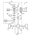
図1は、本発明が適用されたハイブリッド車両10(以下、車両10という)の概略構成を説明する骨子図である。図1において、車両10は、走行用の駆動源としてのエンジン12と、動力伝達装置32とを備えている。動力伝達装置32は、エンジン12から出力される動力を第1電動機MG1およびカウンタドライブギヤ14(以下、ドライブギヤ14)へ分配するための動力分配機構16と、ドライブギヤ14およびそのドライブギヤ14と噛み合うカウンタドリブンギヤ18(以下、ドリブンギヤ18という)から構成されるカウンタギヤ対20と、ドリブンギヤ18にリダクションギヤ22を介して動力伝達可能に連結されている第2電動機MG2と、デフドライブギヤ24およびデフドリブンギヤ26から構成されるファイナルギヤ対28と、差動歯車装置30(終減速機)と、左右一対の車軸34とを、含んで構成されている。この動力伝達装置32は、車両10において横置きされるFF(フロントエンジン・フロントドライブ)型車両に好適に用いられる。ドリブンギヤ18とデフドライブギヤ24とは、一体回転するように構成されている。
FIG. 1 is a skeleton view illustrating a schematic configuration of a hybrid vehicle 10 (hereinafter referred to as a vehicle 10) to which the present invention is applied. In FIG. 1, a
このように構成される動力伝達装置32にあっては、エンジン12の動力が、動力分配機構16およびドライブギヤ14を介してドリブンギヤ18に伝達されるとともに、第2電動機MG2の動力が、リダクションギヤ22を介してドリブンギヤ18に伝達され、そのドリブンギヤ18からファイナルギヤ対28、差動歯車装置30、左右一対の車軸34(ドライブシャフト、D/S)を順次介して左右一対の駆動輪36に動力が伝達される。また、エンジン12と動力分配機構16との間には、トルク変動を吸収するダンパ装置38が介挿されている。
In the
動力分配機構16は、サンギヤS、ピニオンギヤP、そのピニオンギヤPを自転および公転可能に支持するキャリヤCA、およびピニオンギヤPを介してサンギヤSと噛み合うリングギヤRを、回転要素として備える公知のシングルピニオンギヤ型の遊星歯車装置から構成されている。サンギヤSは第1電動機MG1に動力伝達可能に連結され、キャリヤCAはエンジン12に動力伝達可能に連結され、リングギヤRはドライブギヤ14に動力伝達可能に連結されている。これより、サンギヤS、キャリヤCA、およびリングギヤRは、それぞれ相互に相対回転可能となることから、エンジン12の動力が第1電動機MG1およびドライブギヤ14に分配される。また、動力分配機構16は、例えば無段変速状態(電気的CVT状態)とされて、エンジン12の所定回転に拘わらずドライブギヤ14に連結されたリングギヤRの回転が連続的に変化させられる電気的な無段変速機として機能する。つまり、動力分配機構16およびその動力分配機構16を備えた動力伝達装置32は、差動用電動機として機能する第1電動機MG1の運転状態が制御されることにより、動力分配機構16の差動状態が制御される電気式差動部(電気式無段変速部)として機能する。
The
また、ドライブギヤ14と並んでパーキングロック機構46が設けられている。パーキングロック機構46は、ドライブギヤ14を回転停止させることにより駆動輪36を回転停止させる。なお、ドライブギヤ14は、カウンタギヤ対20、ファイナルギヤ対28、差動歯車装置30、および左右の車軸34を介して駆動輪36に機械的に連結されていることから、ドライブギヤ14が回転停止させられると駆動輪36についても回転停止させられる。このドライブギヤ14が、本発明の回転部材に対応している。
Further, a
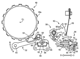
図2は、図1のパーキングロック機構46の全体構成を示す図である。パーキングロック機構46は、ドライブギヤ14に一体的に設けられているパーキングギヤ48と、パーキングギヤ48と噛合可能なロック爪50が形成されているパーキングポール52と、パーキングポール52と接触するカム54(図3参照)を有し、カム54をパーキングギヤ48の回転軸線CL(以下、軸線CL)に対して平行に移動することでパーキングポール52を回動させるカム機構56と、カム機構56を駆動するアクチュエータ58とを、含んで構成されている。
FIG. 2 is a view showing the overall configuration of the
パーキングギヤ48には、パーキングポール52のロック爪50と噛み合うための噛合歯48aが周方向に等角度間隔で複数個形成されている。噛合歯48aがロック爪50と噛み合うと、パーキングギヤ48およびドライブギヤ14が回転停止させられ、ドライブギヤ14に機械的に連結されている駆動輪36についても回転停止させられる。
In the
パーキングポール52は、パーキングギヤ48の噛合歯48aと噛合可能なロック爪50が形成されている長手方向に伸びる板状の部材である。パーキングポール52は、軸線CLと平行な回動軸60を中心にして回動可能に構成されており、パーキングポール52が、図2に示す矢印A側に回動するとロック爪50と噛合歯48aとが噛み合わされてロック状態に切り替えられ、矢印B側に回動するとロック爪50と噛合歯48aとの噛合が解除される非ロック状態に切り替えられる。このように、パーキングポール52は、回動させられることによって、ロック爪50とパーキングギヤ48の噛合歯48aとが噛み合うロック状態と、ロック爪50とパーキングギヤ48の噛合歯48aとの噛合が解除される非ロック状態と、に切り替える機能を有している。
The
次に、カム機構56の構造について説明する。図3は、パーキングロック機構46において、パーキングポール52のロック爪50とパーキングギヤ48の噛合歯48aとが噛み合った状態(噛合状態、ロック状態)を示し、図4は、パーキングロック機構46において、パーキングポール52のロック爪50とパーキングギヤ48の噛合歯48aとが正常に噛み合わない状態(非噛合状態)を示している。図3、図4の紙面左側が、それぞれパーキングギヤ48、パーキングポール52、およびカム機構56を、軸線CLの方向から見た図に対応し、図3、図4の紙面右側が、それぞれカム機構56(断面図)およびアクチュエータ58に対応している。なお、図3、図4の紙面上方が、車両10において鉛直上方に対応している。図3、4に示すように、パーキングロック機構46がロック側に作動しても、パーキングギヤ48の回転位置によって、パーキングポール52のロック爪50とパーキングギヤ48の噛合歯48aとが正常に噛み合う噛合状態(図3)と、ロック爪50と噛合歯48aとが正常に噛み合わない非噛合状態(図4)とに切り替わる。
Next, the structure of the
カム機構56は、パーキングポール52に接触するカム54と、先端側にカム54が取り付けられ、軸線CLに対して平行に移動することで、カム54を移動するパーキングロッド62と、パーキングロッド62を収容するカバー64と、カム54を案内するパーキングスリーブ66と、パーキングスリーブ66を保持するプレート68と、カム54に付勢力を付与するカムスプリング72と、を備えている。
The
カム54は、円錐状のテーパ面70が形成される環状の部材であり、パーキングロッド62の先端側に取り付けられている。具体的には、カム54は、パーキングロッド62に、そのパーキングロッド62に対して軸方向への相対移動可能な状態で挿し通されている。カムスプリング72は、コイルスプリングからなり、内部をパーキングロッド62が貫通している。カムスプリング72は、パーキングロッド62に移動不能に固定されているリング73とカム54との間に介挿されており、カム54をパーキングロッド62の先端側に付勢している。また、パーキングロッド62の先端には、カム54の軸方向への移動を規制する大径部74が形成されている。これより、カム54は、カムスプリング72によってパーキングロッド62の先端側に付勢され、通常の状態では、図3右側に示すように、パーキングロッド62の先端側に形成されている大径部74に当接させられる。
The
パーキングロッド62は、アクチュエータ58を介して、図2〜図4の矢印で示すC方向およびD方向(すなわちパーキングロッド62の軸方向)に移動可能とされている。なお、図3、図4は、何れもパーキングロッド62が矢印C方向(すなわちプレート68側)に移動した状態を示している。パーキングスリーブ66には、パーキングロッド62とともにカム54が移動した際に、カム54を案内する案内溝76が形成されている。カム54は、この案内溝76に沿って移動させられる。
The
プレート68には、パーキングスリーブ66が貫通する穴80が形成されている。また、プレート68には、リターンスプリング82を支持する支持軸84が設けられている。リターンスプリング82は、パーキングポール52に当接し、パーキングポール52のロック爪50とパーキングギヤ48の噛合歯48aとの噛合が解除される非ロック側に、パーキングポール52を常時付勢している。従って、パーキングロック機構46がロック状態から非ロック状態に切り替わる際には、パーキングポール52がリターンスプリング82によって非ロック側に速やかに回動させられる。また、運転者の意図しない、パーキングロック機構46のロック状態への切り替わりも防止される。
The
アクチュエータ58は、回転軸86を回転させることにより、パーキングロッド62を軸方向に移動させる。回転軸86は、中間部材88を介してパーキングロッド62のカム54の取付位置と反対側の軸端部に連結されている。従って、回転軸86が回転すると、中間部材88とパーキングロッド62との連結部90の位置が変化し、この連結部90の位置に応じてパーキングロッド62およびカム54が軸方向に移動する。
The
回転軸86には、ディテント機構92が設けられている。ディテント機構92は、回転軸86に連動するディテントプレート94と、ディテントプレート94に形成されている後述する波状面96に先端部が押し付けられるディテントスプリング98とを、備えている。ディテントプレート94には、山と谷が交互に連続して形成された波状面96が形成されている。ディテントスプリング98の先端部が、この波状面96に押し付けられており、回転軸86が所定のシフトポジションに対応する回転位置に到達すると、ディテントスプリング98の先端部が、波状面96の所定のシフトポジションに対応する谷の位置に移動させられる。
The rotating shaft 86 is provided with a
上記のように構成されるパーキングロック機構46の作動について、図3および図4を用いて説明する。先ず、図3に示すように、パーキングロック機構46がロック側に作動した際に、正常に噛合状態となる場合について説明する。なお、パーキングロック機構46は、例えば運転者によって不図示のPロックスイッチが押された場合に作動する。
The operation of the
Pロックスイッチが押されることで、回転軸86が反時計回りに回転すると、ディテントプレート94についても回転軸86を中心に反時計回りに回動させられる。このとき、ディテントプレート94の波状面96のうち一端に形成されている谷に、ディテントスプリング98の先端部が押し付けられる。また、パーキングロッド62が、図3の矢印C方向(紙面右方向)に移動し、パーキングロッド62の先端側に設けられているカム54についてもパーキングロッド62と連動して矢印C方向に移動させられる。このとき、カム54は、パーキングスリーブ66の案内溝76に沿って移動することで、カム54のテーパ面70が、パーキングポール52に形成されている切欠78を押しのけて移動し、パーキングポール52が鉛直上方に押し上げられる。言い換えれば、カム54が矢印C方向に移動することで、パーキングポール52が、回動軸60を中心にして矢印A方向に回動させられる。パーキングポール52が矢印A方向に回動させられることで、パーキングポール52のロック爪50と、パーキングギヤ48の噛合歯48aとが噛み合わされ、パーキングギヤ48が回転停止させられるロック状態となる。
By pressing the P lock switch, when the rotary shaft 86 rotates counterclockwise, the
次に、パーキングロック機構46がロック側に作動したにも拘わらず、ロック爪50と噛合歯48aとが噛み合わない非噛合状態となる場合について、図4を用いて説明する。
Next, a case where the
Pロックスイッチが押されることで、回転軸86が反時計回りに回転すると、ディテントプレート94についても回転軸86を中心に反時計回りに回動させられ、パーキングロッド62が、図4の矢印C方向(紙面右方向)に移動させられる。ここで、図4に示すパーキングロック機構46の非噛合状態にあっては、パーキングギヤ48の噛合歯48aの頂部(頂面)とパーキングポール52のロック爪50の頂部(頂面)とが互いに接触することで、パーキングポール52の回動が阻止されている。これに関連して、カム54は、パーキングポール52を押し上げて矢印C方向に移動することができず、図4に示すように、カム54のテーパ面70とパーキングポール52の切欠78とが接触する位置で停止させられている。このとき、カムスプリング72が収縮することで、パーキングロッド62については軸方向への移動が許容され、カム54とパーキングロッド62との相対位置が変化し、カム54と大径部74とが乖離させられる。また、カムスプリング72の収縮に伴って、カム54を大径部74側に移動させる方向の付勢力が発生する。
When the rotary shaft 86 rotates counterclockwise by pressing the P lock switch, the
図4に示す状態から、車両10が移動することでパーキングギヤ48が回転し、ロック爪50の頂部と噛合歯48aの頂部とが接触しなくなる、すなわち、ロック爪50と噛合歯48aとが噛合可能な回転位置になると、カムスプリング72の付勢力によってカム54が大径部74側に移動し、パーキングポール52がカム54によって鉛直上方に押し上げられる。これより、パーキングロック機構46は、図3に示すような、噛合歯48aとロック爪50とが互いに噛み合う噛合状態(すなわちロック状態)に速やかに切り替えられる。なお、リターンスプリング82は、パーキングポール52を常時鉛直下方に付勢している、すなわち、ロック爪50と噛合歯48aとの噛合が解除される非ロック側に付勢しているが、カムスプリング72の付勢力の方が、リターンスプリング82の付勢力よりも大きくなるように設計されることで、リターンスプリング82の付勢力に抗ってパーキングポール52が鉛直上方に押し上げられる。
From the state shown in FIG. 4, the
ところで、車両10が一定の車速を有している状態で、運転者によってPロックスイッチが押された場合には、パーキングギヤ48によってパーキングポール52が弾かされるため、噛合歯48aとロック爪50とは噛み合わない。このとき、カムスプリング72およびリターンスプリング82が伸縮することで、パーキングポール52は、カムスプリング72およびリターンスプリング82から荷重を受けつつパーキングギヤ48に弾かれ、パーキングポール52の回転慣性に従ってパーキングギヤ48と衝突を繰り返す(以下、このような現象をラチェット挙動という)。
By the way, when the P lock switch is pressed by the driver in a state where the
ラチェット挙動は、所定の車速V1(以下、嵌合車速V1という)以下では発生せず、パーキングギヤ48の噛合歯48aとパーキングポール52のロック爪50とが噛み合うことで、パーキングロック機構46がロック状態となる。嵌合車速V1は、パーキングポール52の回転慣性、カムスプリング72およびリターンスプリング82の剛性などに基づいて設計的に決定される。例えば、パーキングポール52の回転慣性が大きくなると、嵌合車速V1が低下する。ここで、嵌合車速V1が低くなりすぎると、例えば急坂路で非噛合状態となった後、車両10が僅かにずり下がってパーキングギヤ48が回転する間に、車速Vが嵌合車速V1を越えてしまい、パーキングポール52のロック爪50がパーキングギヤ48の噛合歯48aと噛み合うことができずにラチェット挙動が発生する。従って、パーキングロック機構46をロック状態に切り替えることが困難となり、パーキング性能が低下するという問題が生じる。
The ratcheting behavior does not occur at a predetermined vehicle speed V1 (hereinafter referred to as a fitting vehicle speed V1) or less, and the
一方、パーキングポール52のロック爪50に大荷重が入力されることが想定される場合、パーキングポール52のロック爪50にかかる面圧を低減するため、パーキングポール52の板の厚みを厚くすることが考えられる。しかしながら、パーキングポール52の板の厚みを厚くすると、パーキングポール52の回転慣性が増加することから、上述したようにパーキング性能が低下する他、パーキングポール52の重心の位置が変化することで、パーキングポール52に作用する回転モーメントが大きくなり、ラチェット挙動が発生したときにパーキングポール52が傾く虞がある。結果として、パーキングポール52と、パーキングギヤ48およびカム54とが互いに接触する位置が悪くなることで、パーキングギヤ48やカム54をはじめとする部品の耐久性が低下する虞がある。例えばパーキングポール52が傾くことで、パーキングポール52の角がカム54のテーパ面70と接触すると、テーパ面70が損傷しやすくなる。これを防止するには、パーキングポール52の形状の変化に合わせて、パーキングロッド62、カム54、カムスプリング72など他の周辺部品についても適切な諸元に設計し直す必要が生じてしまう。
On the other hand, when it is assumed that a large load is input to the
上記問題を解消するため、本実施例のパーキングポール52のロック爪50が形成されている部位は、パーキングポール52の他の部位に比べて板の厚みが厚く形成されている。このように、パーキングポール52のロック爪50が形成される部位の板の厚みが厚くされることで、ロック爪50にかかる面圧が低減されため、大荷重を受けることができる。また、板の厚みが増加される部位が、ロック爪50が形成される部位に限定されるため、パーキングポール52の回転慣性の増加も最小限に抑えられ、嵌合車速V1の低下も抑えられる。これに加えて、板の厚みの増加によってロック爪50の剛性が高くなるため、トルクの比較的大きいアクチュエータ58においても使用可能となる。なお、パーキングポール52は、鍛造または鋳造によって製造される。
In order to solve the above-mentioned problem, the portion of the
図5は、パーキングポール52の斜視図であり、図6は、パーキングポール52の平面図である。図5、図6に示すように、パーキングポール52は、長手状の板状の部材から構成されている。パーキングポール52の長手方向の一方には、回転軸60を貫通させるための貫通穴100が形成されている。また、パーキングポール52には、パーキングギヤ48の噛合歯48aと噛合可能なロック爪50が形成されている。また、パーキングロック機構46のロック側への作動時においてカム54と接触する、図6右図の破線で示す切欠78が形成されている。具体的には、パーキングロック機構46が非ロック状態からロック状態に切り替わるときのカム54の進行方向の後側に位置する、パーキングポール52の面P1に、カム54のテーパ面70が接触するテーパ状の切欠78が形成されている。
FIG. 5 is a perspective view of the
また、パーキングポール52のロック爪50が形成されている部位は、パーキングポール52の他の部位に比べて板の厚みが厚く(板厚が増加)されている。具体的には、図6の右図に示すように、パーキングポール52のロック爪50が形成される部位の板の厚み方向(板厚方向)の寸法W1が、パーキングポール52のロック爪50が形成される部位以外の厚み方向の寸法W2に比べて大きくされている(W1>W2)。
Further, in the portion where the
具体的には、ロック爪50が形成されている部位では、カム54が接触する切欠78が形成されている側の面P1と反対側の面P2、言い換えれば、カム54が接触する面P1と反対側の面P2が、その面P2よりも面P1から離れる側に膨らむことで板の厚みが増加されている。この面P2は、パーキングロック機構46をロック側に作動させる(すなわちパーキングロック機構46を非ロック状態からロック状態に切り替える)場合において、カム54の進行方向の前側に形成される面となる。これより、パーキングポール52のロック爪50が形成される部位では、パーキングロック機構46がロック側に作動するとき(すなわちパーキングロック機構46が非ロック状態からロック状態に切り替わるとき)のカム54の進行方向の前側に形成されている面が、そのカム54の進行方向側に膨らむことで板の厚みが厚く形成されている。以下、ロック爪50のうち、面P2より膨らむ図6の斜面で示す部位を、板厚増加部51と定義する。
Specifically, at the portion where the
上記のように、ロック爪50では、パーキングポール52の面P2側が膨らむ、言い換えれば、面P2側に板厚増加部51が形成されることによる効果を、以下から説明する。
As described above, in the
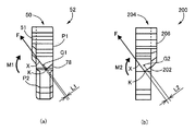
図7は、パーキングロック機構46がロック側に作動したときにカム54から入力されるカム荷重Fと、パーキングポールの重心Gとの関係を示している。図7(a)が、本実施例のパーキングポール52に対応し、図7(b)が、比較対象としてのパーキングポール200に対応している。パーキングポール200においても、カムと接触する切欠202およびパーキングギヤ48の噛合歯48aと噛合可能なロック爪204が形成され、ロック爪204が形成されている部位については、パーキングポール202の他の部位に比べて板の厚みが厚くされている。一方、パーキングポール200にあっては、切欠202が形成されている側の面に板厚増加部206が形成されることで板の厚みが厚くされている。このように、パーキングポール52とパーキングポール202とは、板厚増加部51、206が形成される面が異なっている。
FIG. 7 shows the relationship between the cam load F input from the
図7(a)に示すG1は、パーキングポール52の重心(以下、重心G1)の位置を示し、図7(b)のG2は、パーキングポール200の重心(以下、重心G2)を示している。また、パーキングポール52において、パーキングロック機構46が作動した際には、カム54からカム荷重Fが作用する。このカム荷重Fは、切欠78に対して垂直に作用する。同様に、パーキングポール202においても、カム荷重Fが切欠202に対して垂直に作用する。
G1 shown in FIG. 7A indicates the position of the center of gravity (hereinafter referred to as the center of gravity G1) of the
ここで、パーキングポール52の面P2側に板厚増加部51が形成されることで、パーキングポール52の重心G1が、板の厚み方向(紙面左右方向)で板厚増加部51側(紙面左側)に移動する。これに関連して、重心G1とカム荷重Fの作用線Xとの距離L1が短くなる。この距離L1は、カム荷重Fの作用線Xから垂直に伸び、且つ、重心G1を通る直線の、作用線Xから重心G1までの長さに対応している。なお、カム荷重Fの作用線Xとは、カム荷重Fの作用点(図7に示すカム荷重Fが作用する点K)を通り、力の方向に引いた直線に対応している。
Here, the
一方、パーキングポール200では、切欠202が形成される側の面に板厚増加部206が形成されることで、パーキングポール200の重心G2が、板の厚み方向で板厚増加部206側(紙面右側)に移動する。これに関連して、重心G2とカム荷重Fの作用線Xとの距離L2が距離L1よりも長くなる(L2>L1)。このように、パーキングポール52では、重心G1とカム荷重Fの作用線Xとの距離L1が短くなることで、カム荷重Fと距離L1との積(=F×L1)で算出される回転モーメントM1が、パーキングポール200で発生する回転モーメントM2(=F×L2)に比べて小さくなる(M1<M2)。従って、パーキングポール52にあっては、ラチェット挙動中のパーキングポール52の傾きが抑制され、ラチェット挙動中にパーキングポール52とパーキングギヤ48およびカム54とが互いに接触する位置が設計的に狙った位置となるため、パーキングロック機構46を構成する部品の耐久性低下も抑制される。また、ラチェット挙動中のパーキングポール52の傾きが抑制されることから、この傾きを抑制するために他の周辺部品を設計し直す必要もなくなり、既存の装置を使用することができる。
On the other hand, in the
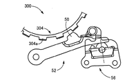
上記より、パーキングポール52にあっては、既存の装置を使用することができるが、既存の装置に対してパーキングポール52を使用する際には、板の厚みが全て同じである従来品のパーキングポール302(図8参照)よりもロック爪50の高さを低くし、且つ、パーキングギヤ48の外径を大径化することが望ましい。このように設計されることで、本実施例のパーキングロック機構46の組付の際に、誤って従来品のパーキングポール302を組み付けてしまった場合であっても、図8に示すように、パーキングポール302のロック爪305とパーキングギヤ48の噛合歯48aとが常に噛み合うため、特別な検出装置を用いなくても誤組付を容易に検出することができる。同様に、従来のパーキングロック機構300の組付の際に、誤って本実施例のパーキングポール52を組み付けてしまった場合であっても、図9に示すように、パーキングポール52のロック爪50とパーキングギヤ304の噛合歯304aとが常に噛み合わないため、特別な検出装置を用いなくても誤組付を容易に検出することができる。
From the above, the existing device can be used for the
上述のように、本実施例によれば、パーキングポール52のロック爪50が形成される部位のうち、非ロック状態からロック状態に切り替わるときのカム54の進行方向の前側に形成されているP2面が、その進行方向に向かって膨らんでいるため、例えばカム54の進行方向の後側に形成されている面P1が膨らんでいる場合に比べて、パーキングポール52の重心G1の位置と、カム54からパーキングポール52に入力される荷重Fの作用線Xとの距離を短くすることができる。よって、パーキングポール52の板の厚みの増加に伴う、パーキングポール52に作用する回転モーメントの増加が抑制される。結果として、パーキングポール52の傾きが抑制されるため、ラチェット挙動が不安定になることを抑制することができる。
As described above, according to the present embodiment, P2 formed at the front side of the advancing direction of the
また、本実施例によれば、パーキングポール52を非ロック側に付勢するリターンスプリング82を備えるため、運転者の意図しないパーキングロック機構46のロック状態への切り替わりを防止することができる。また、カム54のテーパ面70にパーキングポール54の切欠78が当接するため、カム54がロック側に移動した際には、パーキングポール52を滑らかに回動させることができる。
Further, according to the present embodiment, since the
以上、本発明の実施例を図面に基づいて詳細に説明したが、本発明はその他の態様においても適用される。 Although the embodiments of the present invention have been described in detail with reference to the drawings, the present invention is also applicable in other aspects.
例えば、前述の実施例では、パーキングロック機構46が、FF形式のハイブリッド車両10に適用されていたが、必ずしもこれに限定されない。例えばFR形式の車両であってもよく、ハイブリッド車両にも限定されない。要は、パーキングロック機構を備える車両であれば、適宜適用することができる。
For example, although the
また、前述の実施例では、アクチュエータ58によってカム機構56が作動させられていたが、機械的なリンク機構によってカム機構56が作動させられるものであっても構わない。この場合においても、パーキングポール52のロック爪50の板の厚みの増加に伴って、パーキングポール52の剛性が高くなるため、伝達される荷重の大きいリンク機構を使用することができる。
Further, in the above-described embodiment, the
また、前述の実施例では、パーキングポール52は、ロック爪50が形成されている部位の板の厚みが厚くされていたが、板の厚みが厚くされる範囲を、パーキングポール52の回転慣性の増加が問題にならない範囲でさらに拡げても構わない。
Further, in the above-described embodiment, the thickness of the plate at the portion where the
なお、上述したのはあくまでも一実施形態であり、本発明は当業者の知識に基づいて種々の変更、改良を加えた態様で実施することができる。 Note that what has been described above is merely an embodiment, and the present invention can be implemented in variously modified and improved forms based on the knowledge of those skilled in the art.
14:ドライブギヤ(回転部材)
36:駆動輪
46:パーキングロック機構
48:パーキングギヤ
50:ロック爪
52:パーキングポール
54:カム
56:カム機構
62:パーキングロッド
70:テーパ面
72:カムスプリング
74:大径部
78:切欠
82:リターンスプリング
P2:進行方向の前側に形成されている面
14: Drive gear (rotary member)
36: drive wheel 46: parking lock mechanism 48: parking gear 50: lock claw 52: parking pole 54: cam 56: cam mechanism 62: parking rod 70: tapered surface 72: cam spring 74: large diameter portion 78: notch 82: Return spring P2: Surface formed on the front side in the direction of travel
Claims (4)
前記パーキングギヤに噛合可能なロック爪が形成され、回動することによって、前記ロック爪と前記パーキングギヤとが噛み合うロック状態と、前記ロック爪と前記パーキングギヤとの噛合が解除される非ロック状態とに切り替える板状のパーキングポールと、
前記パーキングポールと接触するカムを有し、該カムを前記パーキングギヤの回転軸線に対して平行に移動することで、前記パーキングポールを回動させるカム機構と、を含み、
前記パーキングポールの前記ロック爪が形成される部位は、前記パーキングポールの他の部位に比べて板の厚みが厚く形成されているパーキングロック機構であって、
前記パーキングポールの前記ロック爪が形成される部位では、前記非ロック状態から前記ロック状態に切り替わるときの前記カムの進行方向の前側に形成されている面が、該進行方向側に膨らんでいる
ことを特徴とするパーキングロック機構。 A parking gear integrally provided on a rotating member mechanically connected to the drive wheel;
A lock claw capable of meshing with the parking gear is formed, and when it is rotated, a locked state in which the lock claw and the parking gear mesh with each other and a non-locked state in which meshing between the lock claw and the parking gear is released. Plate-like parking pole to switch to
A cam mechanism having a cam in contact with the parking pole, and moving the cam parallel to the rotation axis of the parking gear to rotate the parking pole;
A portion of the parking pole where the lock claw is formed is a parking lock mechanism in which a plate is formed to be thicker than other portions of the parking pole,
In a portion of the parking pole where the lock claw is formed, a surface formed on the front side in the advancing direction of the cam when switching from the unlocked state to the locked state bulges in the advancing direction side. Parking lock mechanism characterized by.
前記非ロック状態から前記ロック状態に切り替わるときの前記カムの進行方向の後側に位置する、前記パーキングポールの面には、前記カムの前記テーパ面が接触するテーパ状の切欠が形成されていることを特徴とする請求項1または2のパーキングロック機構。 The cam has a conical tapered surface.
A tapered notch is formed in the surface of the parking pole located on the rear side in the advancing direction of the cam when switching from the non-locking state to the locking state, and in which the tapered surface of the cam contacts. The parking lock mechanism according to claim 1 or 2, characterized in that:
前記カムは、前記パーキングロッドに該パーキングロッドに対して軸方向への相対移動可能に挿し通され、且つ、前記カムスプリングによって前記パーキングロッドの先端側に付勢されており、
前記パーキングロッドの先端には、前記カムと当接し、該カムの移動を規制する大径部が形成されていることを特徴とする請求項1から3の何れか1のパーキングロック機構。 The cam mechanism includes the cam, a parking rod moving parallel to the rotation axis of the parking gear, and a cam rod for attaching the cam, and a cam spring for biasing the cam toward the tip end of the parking rod. Have
The cam is inserted into the parking rod so as to be movable relative to the parking rod in the axial direction, and is biased toward the tip of the parking rod by the cam spring.
The parking lock mechanism according to any one of claims 1 to 3, wherein a large diameter portion which contacts the cam and restricts the movement of the cam is formed at an end of the parking rod.
Priority Applications (4)
| Application Number | Priority Date | Filing Date | Title |
|---|---|---|---|
| JP2017195509A JP2019069638A (en) | 2017-10-05 | 2017-10-05 | Parking lock mechanism |
| CN201811139183.XA CN109630676A (en) | 2017-10-05 | 2018-09-28 | Parking locking mechanism |
| US16/148,131 US20190107196A1 (en) | 2017-10-05 | 2018-10-01 | Parking lock mechanism |
| EP18198833.8A EP3466777A1 (en) | 2017-10-05 | 2018-10-05 | Parking lock mechanism |
Applications Claiming Priority (1)
| Application Number | Priority Date | Filing Date | Title |
|---|---|---|---|
| JP2017195509A JP2019069638A (en) | 2017-10-05 | 2017-10-05 | Parking lock mechanism |
Publications (1)
| Publication Number | Publication Date |
|---|---|
| JP2019069638A true JP2019069638A (en) | 2019-05-09 |
Family
ID=63798834
Family Applications (1)
| Application Number | Title | Priority Date | Filing Date |
|---|---|---|---|
| JP2017195509A Pending JP2019069638A (en) | 2017-10-05 | 2017-10-05 | Parking lock mechanism |
Country Status (4)
| Country | Link |
|---|---|
| US (1) | US20190107196A1 (en) |
| EP (1) | EP3466777A1 (en) |
| JP (1) | JP2019069638A (en) |
| CN (1) | CN109630676A (en) |
Families Citing this family (5)
| Publication number | Priority date | Publication date | Assignee | Title |
|---|---|---|---|---|
| DE102019209453B4 (en) * | 2019-06-28 | 2021-02-11 | Zf Friedrichshafen Ag | Pawl for a parking lock arrangement |
| IT202000004459A1 (en) * | 2020-03-03 | 2021-09-03 | Piaggio & C Spa | A PARKING BRAKE FOR A MOTORCYCLE AND MOTORCYCLE INCLUDING THE PARKING BRAKE |
| DE102020003311A1 (en) | 2020-06-02 | 2021-12-02 | Daimler Ag | Parking lock system for a motor vehicle |
| TWI792733B (en) * | 2020-12-03 | 2023-02-11 | 日商日本電產股份有限公司 | drive unit |
| JP2023097575A (en) | 2021-12-28 | 2023-07-10 | ニデック株式会社 | Parking mechanism and assembling method of parking mechanism |
Family Cites Families (7)
| Publication number | Priority date | Publication date | Assignee | Title |
|---|---|---|---|---|
| JPS55164527A (en) * | 1979-06-12 | 1980-12-22 | Daihatsu Motor Co Ltd | Parking lock device for automobile |
| JPH0336454Y2 (en) | 1985-03-07 | 1991-08-01 | ||
| JP4127286B2 (en) * | 2006-03-28 | 2008-07-30 | いすゞ自動車株式会社 | Parking lock device for transmission |
| JP4784363B2 (en) * | 2006-03-28 | 2011-10-05 | いすゞ自動車株式会社 | Parking lock device for transmission |
| DE102009027759A1 (en) | 2009-07-16 | 2011-01-20 | Zf Friedrichshafen Ag | Rack element has handle tooth made from sheet metal having plate thickness, where handle tooth has tooth width, which is larger than plate thickness |
| JP2011183449A (en) | 2010-03-11 | 2011-09-22 | Ohashi Technica Inc | Blank for parking pole, and method for manufacturing the same |
| EP2508274B1 (en) | 2011-04-05 | 2013-07-17 | Feintool Intellectual Property AG | Method and device for increasing the bearing area of a fine blanked workpiece with a tooth, a tooth section or the like |
-
2017
- 2017-10-05 JP JP2017195509A patent/JP2019069638A/en active Pending
-
2018
- 2018-09-28 CN CN201811139183.XA patent/CN109630676A/en not_active Withdrawn
- 2018-10-01 US US16/148,131 patent/US20190107196A1/en not_active Abandoned
- 2018-10-05 EP EP18198833.8A patent/EP3466777A1/en not_active Withdrawn
Also Published As
| Publication number | Publication date |
|---|---|
| CN109630676A (en) | 2019-04-16 |
| US20190107196A1 (en) | 2019-04-11 |
| EP3466777A1 (en) | 2019-04-10 |
Similar Documents
| Publication | Publication Date | Title |
|---|---|---|
| JP2019069638A (en) | Parking lock mechanism | |
| US8684880B2 (en) | Rattling noise reduction device for vehicle | |
| JP2009509596A (en) | Vehicle seat fitting | |
| WO2017163859A1 (en) | Clutch unit | |
| WO2018042990A1 (en) | Clutch unit | |
| JP2009509596A5 (en) | ||
| CN211117538U (en) | Gear-shifting parking system for vehicle and vehicle with gear-shifting parking system | |
| JP4697784B2 (en) | Electric linear actuator | |
| US11493128B2 (en) | Motive power transmission route switching device and two-speed transmission | |
| JP6939647B2 (en) | Parking lock mechanism | |
| KR20180127219A (en) | Multi-speed transmission for motor | |
| JP6163827B2 (en) | Vehicle parking device | |
| KR20170117327A (en) | Transmission system for hybrid electric vehicle | |
| JP6006963B2 (en) | Internally assisted bicycle transmission | |
| JP5771046B2 (en) | Electric assist bicycle with regenerative mechanism | |
| US20200339075A1 (en) | Manual release mechanism for vehicle parking lock device | |
| WO2010137668A1 (en) | Power transmission equipment | |
| JP2003004065A (en) | Friction engaging device | |
| WO2012111080A1 (en) | Parking lock device for vehicle | |
| JP6474871B1 (en) | Clutch unit | |
| JP2017171011A (en) | Control device of parking mechanism | |
| JP2018158630A (en) | Hybrid-vehicular power transmission apparatus | |
| JP2020050112A (en) | Vehicle parking lock device | |
| CN214171302U (en) | Shift actuator assembly | |
| JP2020019443A (en) | Parking mechanism |