JP2019059082A - Arithmetic processing unit, arithmetic method and program of arithmetic processing unit - Google Patents
Arithmetic processing unit, arithmetic method and program of arithmetic processing unit Download PDFInfo
- Publication number
- JP2019059082A JP2019059082A JP2017184712A JP2017184712A JP2019059082A JP 2019059082 A JP2019059082 A JP 2019059082A JP 2017184712 A JP2017184712 A JP 2017184712A JP 2017184712 A JP2017184712 A JP 2017184712A JP 2019059082 A JP2019059082 A JP 2019059082A
- Authority
- JP
- Japan
- Prior art keywords
- monitoring
- unit
- period
- timing
- time
- Prior art date
- Legal status (The legal status is an assumption and is not a legal conclusion. Google has not performed a legal analysis and makes no representation as to the accuracy of the status listed.)
- Granted
Links
Images


Classifications
-
- B—PERFORMING OPERATIONS; TRANSPORTING
- B29—WORKING OF PLASTICS; WORKING OF SUBSTANCES IN A PLASTIC STATE IN GENERAL
- B29C—SHAPING OR JOINING OF PLASTICS; SHAPING OF MATERIAL IN A PLASTIC STATE, NOT OTHERWISE PROVIDED FOR; AFTER-TREATMENT OF THE SHAPED PRODUCTS, e.g. REPAIRING
- B29C45/00—Injection moulding, i.e. forcing the required volume of moulding material through a nozzle into a closed mould; Apparatus therefor
- B29C45/17—Component parts, details or accessories; Auxiliary operations
- B29C45/76—Measuring, controlling or regulating
Abstract
Description
本技術は、演算処理装置、演算処理装置の演算方法及びプログラムに関する。詳しくは、射出成形装置により製造される成形品の良品判定のための基準情報を生成する技術分野に関する。 The present technology relates to an arithmetic processing unit, an arithmetic method of the arithmetic processing unit, and a program. In particular, the present invention relates to the technical field of generating reference information for determining non-defective items of molded articles manufactured by an injection molding apparatus.
射出成形装置に設置したセンサと監視装置とを有して構成される射出成形品質モニタリングシステムが知られている。射出成形品質モニタリングシステムは、射出成形装置に設けられた金型内における樹脂等の成形材料の挙動を上記センサにより検出し、波形としてパーソナルコンピュータ等の情報処理装置にリアルタイム出力可能とされている。射出成形品質モニタリングシステムでは、センサの検出信号に基づく計測値を監視し、不良品の識別を行うことが可能となる。射出成形品質モニタリングシステムとしては、例えば特許文献1に記載のものがある。
An injection molding quality monitoring system is known which comprises a sensor installed in an injection molding apparatus and a monitoring device. The injection molding quality monitoring system detects the behavior of a molding material such as resin in a mold provided in the injection molding apparatus by the above sensor, and can output it as a waveform to an information processing apparatus such as a personal computer in real time. In the injection molding quality monitoring system, it becomes possible to monitor the measurement value based on the detection signal of the sensor and to identify a defective product. As an injection molding quality monitoring system, there exists a thing of
特許文献1には、射出成形装置に設けられたセンサ(ロードセル)がキャビティ内の樹脂の圧力を検出し、該センサの検出信号をアンプ装置によりサンプリングする技術が開示されている。
このような射出成形品質モニタリングシステムを用いて不良品の識別を行うにあたり、ユーザは自身の判断で監視対象となる監視タイミングを設定する必要があった。そのため、射出成形品質モニタリングシステムについてある程度の経験がないと、不良品の識別を行うのに適した監視タイミングを設定することが難しい場合があった。 In identifying defective products using such an injection molding quality monitoring system, it has been necessary for the user to set monitoring timings to be monitored at his or her own discretion. Therefore, it may be difficult to set a monitoring timing suitable for identifying a defective product unless there is a certain degree of experience with the injection molding quality monitoring system.
そこで本技術は、射出成形品質モニタリングシステムについて経験の浅いユーザであっても、容易に監視タイミングを設定することのできる機能を提供することを目的とする。 Therefore, the present technology aims to provide a function capable of easily setting the monitoring timing even for an inexperienced user about the injection molding quality monitoring system.
本技術に係る演算処理装置は、射出成形装置に備えられたセンサにより1又は複数の計測項目の検出信号を入力する監視装置で行われる、良品判定のための単位空間情報を生成する演算処理装置であって、監視開始時点を特定し、前記監視開始時点から所定期間を監視期間として設定する監視期間設定部と、指定された分割数に基づいて、前記監視期間内における複数の監視タイミングを設定する監視タイミング設定部と、前記監視タイミング設定部が設定した前記監視タイミングにおいて成形品の監視処理に用いる単位空間情報を、取得した良品製造時の計測項目データに基づいて設定する単位空間情報設定部と、を備えるものである。
即ち、少なくとも監視開始時点及び監視期間の分割数を設定することにより、監視タイミングを自動的に設定する。また、それぞれの監視タイミングごとに、成形品の良品を判定する処理に用いる単位空間情報を、取得した良品製造時の計測項目データに基づいて算出する。
ここで、監視タイミングとは、成形品の製造工程の内の良否判定を行うタイミングをいう。監視装置は、成形品を量産する前に、あらかじめ監視タイミング毎の良品判定のための単位空間情報を取得しておき、当該単位空間情報に基づいて良品判定を行う。
また、計測項目データとは、良品判定を行う際に用いられる計測項目のデータをいう。計測項目には、例えば樹脂圧力、樹脂の流速、樹脂温度、金型表面温度等、成形品の品質を評価するために必要な様々な項目が考えられる。
The arithmetic processing unit according to the present technology is an arithmetic processing unit that generates unit space information for non-defective item determination that is performed by a monitoring device that inputs detection signals of one or more measurement items by a sensor provided in an injection molding device. A monitoring period setting unit that specifies a monitoring start time and sets a predetermined period as the monitoring period from the monitoring start time, and sets a plurality of monitoring timings within the monitoring period based on the designated number of divisions Monitoring timing setting unit, and unit space information setting unit for setting unit space information used for monitoring processing of a molded article at the monitoring timing set by the monitoring timing setting unit, based on the acquired measurement item data at the time of non-defective product manufacturing And.
That is, the monitoring timing is automatically set by setting at least the monitoring start time and the division number of the monitoring period. Further, at each monitoring timing, unit space information used in the process of determining the non-defective item of the molded item is calculated based on the acquired measurement item data at the time of non-defective item manufacturing.
Here, the monitoring timing refers to the timing at which the quality determination within the manufacturing process of the molded product is performed. Before mass-producing molded articles, the monitoring device acquires unit space information for non-defective item determination at each monitoring timing in advance, and performs non-defective item determination based on the unit space information.
Further, the measurement item data refers to data of measurement items used when performing the non-defective item determination. As measurement items, for example, various items necessary for evaluating the quality of molded articles, such as resin pressure, resin flow rate, resin temperature, mold surface temperature, etc., can be considered.
上記した本技術に係る演算処理装置において、前記監視期間設定部は、ゲートシール期間を前記監視期間として設定することが考えられる。
成形品の良否判定のために用いる検出信号を金型内の樹脂圧力とした場合等においては、監視タイミングはゲートシール期間中に設定することが望ましい。
なぜなら、ゲートシール期間は、金型内に充填された樹脂が固化するまでの期間である。そのため、このような期間の値は成形品の品質の評価に有用であるが、固化した後の期間については、あまり意味がない場合があるためである。
In the arithmetic processing unit according to the present technology described above, the monitoring period setting unit may set a gate seal period as the monitoring period.
When the detection signal used for determining the quality of the molded product is the resin pressure in the mold, the monitoring timing is preferably set during the gate seal period.
Because, the gate seal period is a period until the resin filled in the mold solidifies. Therefore, although the value of such a period is useful for evaluation of the quality of a molded article, it is because the period after solidification may not have much meaning.
上記した本技術に係る演算処理装置において、前記監視期間設定部は、設定された所定の閾値に前記検出信号が到達した時点を用いて前記監視開始時点を特定することが考えられる。
圧力センサの検出信号を考えると、その立ち上がりタイミングは、金型内に成形材料が充満した直後のタイミングとなる。そこで当該立ち上がりのタイミングを監視開始時点として特定する。
In the arithmetic processing device according to the present technology described above, it is conceivable that the monitoring period setting unit specifies the monitoring start time using the time when the detection signal reaches the set predetermined threshold.
Considering the detection signal of the pressure sensor, the rising timing is the timing immediately after the molding material is filled in the mold. Therefore, the timing of the rise is specified as the monitoring start time.
上記した本技術に係る演算処理装置において、前記監視期間設定部は、設定された所定の閾値に前記検出信号が到達した時点よりも所定時間前の時点を前記監視開始時点として特定することが考えられる。
即ち、圧力センサの検出信号の立ち上がりタイミングよりも所定期間前から成形品の監視を開始する。
In the arithmetic processing device according to the present technology described above, it is considered that the monitoring period setting unit specifies a time point that is a predetermined time before the time when the detection signal reaches the set predetermined threshold value as the monitoring start time point. Be
That is, monitoring of the molded article is started before a predetermined period before the rising timing of the detection signal of the pressure sensor.
上記した本技術に係る演算処理装置において、前記単位空間情報設定部は、複数の計測項目のそれぞれの前記監視タイミング毎の値を用いて前記単位空間情報を設定することが考えられる。
これにより、多様な計測項目及び監視タイミングを加味した上で、単位空間情報を設定することになる。
In the arithmetic processing device according to the present technology described above, the unit space information setting unit may set the unit space information using a value for each monitoring timing of each of a plurality of measurement items.
In this way, unit space information is set in consideration of various measurement items and monitoring timings.
上記した本技術に係る演算処理装置において、前記単位空間情報はマハラノビス距離を2乗した値を算出するために用いられる情報であることが考えられる。
即ち、単位の異なる多次元の各計測項目の値を、共通の一次元としての単位に置き換えるための単位空間情報を設定する。
In the arithmetic processing unit according to the present technology described above, the unit space information may be information used to calculate a value obtained by squaring the Mahalanobis distance.
That is, unit space information is set to replace the value of each multi-dimensional measurement item having different units with a unit as a common one dimension.
本発明に係る演算処理装置の演算方法は、射出成形装置に備えられたセンサにより1又は複数の計測項目の検出信号を入力する監視装置で行われる、良品判定のための単位空間情報を生成する演算処理装置が、監視開始時点を特定し、前記監視開始時点から所定期間を監視期間として設定する処理と、設定された分割数に基づいて、前記監視期間内における複数の監視タイミングを設定する処理と、設定した前記監視タイミングにおいて成形品の監視処理に用いる単位空間情報を、取得した良品製造時の計測項目データに基づいて算出する処理と、を実行するための演算方法である。
本発明に係るプログラムは、上記各ステップの処理を演算処理装置に実行させるプログラムである。
The calculation method of the calculation processing device according to the present invention generates unit space information for non-defective item determination performed by a monitoring device which inputs detection signals of one or more measurement items by a sensor provided in an injection molding device. The arithmetic processing unit specifies a monitoring start time, and sets a predetermined period as the monitoring period from the monitoring start time, and sets a plurality of monitoring timings in the monitoring period based on the set number of divisions. And a process of calculating unit space information used for the monitoring process of a molded article at the set monitoring timing based on the acquired measurement item data at the time of non-defective product manufacturing.
A program according to the present invention is a program that causes an arithmetic processing unit to execute the processing of each of the above steps.
本技術によれば、射出成形装置により製造した成形品の良否判定のために用いられる単位空間情報の設定を行うことができる。 According to the present technology, it is possible to set unit space information used to determine the quality of a molded product manufactured by the injection molding apparatus.
以下、実施の形態を次の順序で説明する。
<1.品質モニタリングシステムの構成>
<2.監視装置の構成>
<3.コンピュータ装置の構成>
<4.品質モニタリングシステムの概要>
<5.単位空間設定処理>
<6.量産監視処理>
<7.まとめ及び変形例>
<8.プログラム及び記憶媒体>
Hereinafter, embodiments will be described in the following order.
<1. Configuration of Quality Monitoring System>
<2. Configuration of monitoring device>
<3. Computer device configuration>
<4. Overview of Quality Monitoring System>
<5. Unit space setting process>
<6. Mass production monitoring process>
<7. Summary and Modifications>
<8. Program and storage medium>
<1.品質モニタリングシステムの構成>
以下、本発明に係る実施の形態について説明する。まず本発明の実施の形態となる監視装置1と射出成形装置2とパーソナルコンピュータ4とを含む射出成形品質モニタリングシステム100(単に「品質モニタリングシステム100」とも表記する)について説明する。
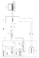
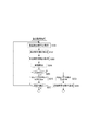
図1は品質モニタリングシステム100の構成概要を示した図である。
図示するように品質モニタリングシステム100は、監視装置1、射出成形装置2、専用アンプ3、パーソナルコンピュータ4(以下「コンピュータ装置4」とも表記する)を備えている。
<1. Configuration of Quality Monitoring System>
Hereinafter, embodiments according to the present invention will be described. First, an injection molding quality monitoring system 100 (also simply referred to as a "
FIG. 1 is a diagram showing a configuration outline of the
As illustrated, the
射出成形装置2は、一般的に公知のとおり、所定位置に配置される金型10と、金型10に対して樹脂材料を射出充填するための機構を備えた射出部11と、射出部11の射出動作や金型10の開閉動作等を制御して一連の射出成形動作を実行制御する成形制御部12を有して構成されている。
The
金型10は、例えば上型、下型が配置され、例えば成形ステージ内に配置された下型に対して射出部11に設けられた機構によって上型が開閉される。上型が下型に対して閉じられた状態で、例えば上型に設けられたゲートに対し、射出部11の射出シリンダによって樹脂材料が注入され、金型10内のキャビティに樹脂材料が充填される。そして充填後、所要の時間が経過したら上型が開放され、キャビティから樹脂成形品が取り出される。
金型10内には金型内センサ31が配置されている。例えば充填された樹脂材料の温度を検出する温度センサや、樹脂材料の圧力を検出する圧力センサなどである。
金型10の構造、種別については特に限定されずに各種のものが想定される。
For example, an upper mold and a lower mold are disposed in the
An in-
The structure and type of the
射出部11には、金型10に対する樹脂材料の注入機構、型締め機構、射出シリンダ機構、射出モータ等、射出成形に必要な機構が設けられている。
また射出部11には射出部内センサ32及びセンサ用アンプ33が設けられている。射出部内センサ32としては、注入過程の樹脂材料の温度を検出する温度センサや、圧力を検出する圧力センサ、注入速度を算出する位置センサなどがある。
本実施の形態では射出部11の機構、構造、例えばシリンダ構造、型締め機構の構造、ランナー構造、ノズル構造、ヒーター配置、モータ配置、材料投入機構などは特に限定されず、どのような構造/種別のものでもよい。
The
Further, the
In the present embodiment, the mechanism and structure of the
成形制御部12は、例えばROM(Read Only Memory)、RAM(Random Access Memory)、CPU(Central Processing Unit)を有するマイクロコンピュータを備えて構成されている。
成形制御部12は、射出部11による各部の駆動制御を行う。例えば射出モータ制御、金型ステージ動作制御、金型開閉機構の動作制御、ノズル開閉機構の動作制御、ヒーター制御、材料投入動作制御などを行う。これによって一連の射出成形動作を実行させる。
The forming
The forming
金型内センサ31の検出信号S1は、例えば射出成形装置2とは別体に配置された専用アンプ3により電圧値に変換される。そして電圧信号に変換された検出信号Vs1として監視装置1に供給される。
射出部内センサ32の検出信号S2は、例えば射出部11内に設けられたセンサ用アンプ33により電圧値に変換される。そして電圧信号に変換された検出信号Vs2として監視装置1に供給される。
The detection signal S1 of the in-
The detection signal S2 of the in-emission unit sensor 32 is converted into a voltage value by a sensor amplifier 33 provided in the
なお、ここでは検出信号Vs1,Vs2として2つの検出信号を示しているが、検出信号Vs1は金型内センサ31からの検出信号の総称で、検出信号Vs2は射出部内センサ32からの検出信号の総称である。金型内センサ31として複数のセンサが配置される場合や射出部内センサ32として複数のセンサが配置される場合も当然に想定される。
従って検出信号Vs1,Vs2は2系統のみの検出信号を示しているものではなく、金型内センサ31と射出部内センサ32のいずれの検出信号についても監視装置1に入力できることを示しているに過ぎない。
監視装置1にはnチャネルの入力系が用意されており、n系統の検出信号の同時入力が可能である。従って金型内センサ31としてn個のセンサの検出信号Vs1を監視装置1に供給してもよいし、射出部内センサ32としてのn個のセンサの検出信号Vs2を監視装置1に供給してもよい。さらに金型内センサ31と射出部内センサ32としてのそれぞれ1又は複数系統の検出信号Vs1,Vs2をnチャネルに振り分けて監視装置1に供給してもよい。
監視装置1に対してどのような検出信号入力を行うかは、実際の射出成形装置2や金型10の構造、種別、成形品、搭載センサ数、実行したい計測・監視の内容などに応じて適宜決められればよい。
また、図示していないが射出成形装置2の周辺機器、例えば冷却用の温調機や真空引き装置などに各種のセンサが設けられる場合もあり、それらのセンサの検出信号を監視装置1に供給することも想定されている。
Here, although two detection signals are shown as the detection signals Vs1 and Vs2, the detection signal Vs1 is a generic name of the detection signal from the in-
Therefore, the detection signals Vs1 and Vs2 do not indicate detection signals of only two systems, but merely indicate that any detection signals of the in-
The
Which detection signal is to be input to the
Although not shown, various sensors may be provided on peripheral equipment of the
監視装置1と成形制御部12の間は各種の通信が可能とされる。図1では、通信の1つとして、成形制御部12から監視装置1に対して各種のタイミング信号STMが送信されること、及び監視装置1から成形制御部12に対して通知信号SIが送信されることを示している。
タイミング信号STMの1つとしては、例えば射出成形の1サイクルの開始/終了タイミングを通知する信号がある。監視装置1は、タイミング信号STMにより、1ショットの樹脂注入による1サイクルの成形期間を検知し、その間の各種検出信号のロギングや判定を行うことができる。
また他のタイミング信号STMとしては、後述するように型締め期間の開始/終了のタイミングを示す信号や、工程の遷移タイミングを示す信号、或いは制御方式(速度制御、圧力制御)の切替タイミングを示す信号などが考えられる。
Various types of communication are enabled between the
One of the timing signals STM is, for example, a signal that indicates the start / end timing of one injection molding cycle. The
As other timing signals STM, as described later, a signal indicating the start / end timing of the mold clamping period, a signal indicating the transition timing of the process, or the switching timing of the control method (speed control, pressure control) A signal etc. can be considered.
監視装置1からの通知信号SIは各種の検出情報や判定情報の結果を通知する信号である。例えば成形不良等が推定される異常判定の際のアラーム通知や、検出信号波形の立ち上がりタイミング/立ち下がりタイミングの通知などの信号である。成形制御部12は、これらの内容の通知信号SIに応じて各種動作制御を行うことができる。
The notification signal SI from the
監視装置1による温度や圧力などの計測結果は、監視装置1と有線又は無線の通信経路USによって接続されたコンピュータ装置4により閲覧可能とされている。通信経路USは、例えばLAN(Local Area Network)ケーブルなどにより実現される。
コンピュータ装置4には、監視装置1による各種検出信号の計測について管理を行うための管理ソフトウェアがインストールされている。この管理ソフトウェアにより、作業員等はコンピュータ装置4のディスプレイを介して監視装置1による計測結果を閲覧可能とされている。
また、管理ソフトウェアを用いた設定により、作業員等は各種の数値設定を行うことができる。
さらに計測結果をコンピュータ装置4におけるHDD(Hard Disk Drive)やSSD(Solid State Disk)等の所定の記憶装置に収録させることが可能とされている。
The measurement results such as temperature and pressure by the
Management software for managing the measurement of various detection signals by the
In addition, workers and the like can perform various numerical settings by setting using management software.
Furthermore, it is possible to record the measurement result in a predetermined storage device such as a hard disk drive (HDD) or a solid state disk (SSD) in the
図2は管理ソフトウェアによってコンピュータ装置4の画面に提示される管理画面90の表示内容例を示している。図示のように管理画面90には、各種センサによる検出信号の計測結果を波形により示すことが可能とされるとともに、各検出信号の所定の数値(例えばピーク値、積分値、立ち上がりタイミング値、立ち下がりタイミング値等)が示される。また作業者が各種設定入力を行うための操作子が用意されている。
FIG. 2 shows an example of display contents of the
<2.監視装置の構成>
図3は監視装置1の内部構成を示している。
監視装置1には、演算部20、入力部21、A/D変換器22、バッファ及びIF部23、メモリ部24が設けられている。
<2. Configuration of monitoring device>
FIG. 3 shows the internal configuration of the
The
入力部21は、検出信号Vs1,Vs2についてnチャネルの入力が可能とされる。図の例では8チャネル入力を想定し、入力チャネルをI1〜I8として示している。
各入力チャネルI1〜I8に入力される検出信号Vs1,Vs2は、上述のように専用アンプ3又はセンサ用アンプ33で検出情報が電圧レベルに変換された信号である。
チャネルI1〜I8の全部又は一部に対して、検出信号Vs1又はVs2が入力される。即ち金型内センサ31や射出部内センサ32として射出成形装置2に配備された1又は複数のセンサの検出信号を、同時に、それぞれ所要のチャネルに入力可能とされている。
The
The detection signals Vs1 and Vs2 input to the input channels I1 to I8 are signals obtained by converting the detection information into voltage levels by the
The detection signal Vs1 or Vs2 is input to all or part of the channels I1 to I8. That is, detection signals of one or a plurality of sensors provided in the
A/D変換器22は、入力チャネル数と同数の同時入力が可能とされる。従って図の例では8チャネル入力のA/D変換器とされている。
A/D変換器22は、入力された各チャネルI1〜I8の検出信号について電圧値に応じたデジタルデータに変換し、バッファ及びIF部23に供給する。
The A /
The A /
バッファ及びIF部23は、各チャネルI1〜I8の検出信号の演算部20への受け渡しや、演算部20と外部機器(コンピュータ装置4や成形制御部12)との通信データの送受信を行う部位を総括して示している。
例えばA/D変換器22から出力される同時入力された複数チャネルの検出信号のデジタルデータ(後述する検出値Ddet)は、バッファ及びIF部23で一時的にバファリングされながら各時点の検出情報として検出信号のサンプリング時点の時刻情報(後述する時間値Tdet)とともに順次演算部20に転送される。
また演算部20からの通知信号SIは、バッファ及びIF部23が端子TM2から成形制御部12に送信する。また成形制御部12からの各種のタイミング信号STMは、端子TM1からバッファ及びIF部23に一旦取り込まれ、時刻情報とともに順次演算部20に転送される。
また演算部20とコンピュータ装置4の各種情報通信は、バッファ及びIF部23を介して、端子TM3(例えばLANコネクタ端子)に接続された通信経路USにより実行される。
The buffer and
For example, digital data (detection value Ddet to be described later) of detection signals of a plurality of channels input simultaneously from A /
Further, the buffer /
Further, various information communication between the
演算部20は例えばROM、RAM、CPUを有するマイクロコンピュータにより構成される。
本実施の形態では、演算部20は、入力部21の各入力チャネルに入力された各時点での検出信号値をログデータとしてメモリ部24記憶する処理を行う。
例えばA/D変換器22でデジタル値とされた各チャネルI1〜I8の検出信号についてサンプル毎の値を記憶していく処理を行う。
また演算部20は、射出成形装置2による監視期間内において設定された監視タイミング毎に、入力部21に入力された検出信号値を用いて評価値の算出を行う。
さらに演算部20は、算出した評価値を用いて射出成形状況の判定結果を求める処理を行う。また判定処理に応じた通知信号SIの出力処理を行う。
これらの機能を有する演算部20の具体的な処理例については後述する。
The
In the present embodiment, the
For example, processing is performed to store values for each sample for the detection signals of the channels I1 to I8 converted to digital values by the A /
The
Furthermore, the
A specific processing example of the
メモリ部24は、例えばROM、ワークメモリ、不揮発性メモリ等として演算部20が使用できるメモリ領域を総括して示している。
メモリ部24は、例えば演算部20の処理によるログデータの記憶領域として用いられる。またメモリ部24は、各種演算処理のワーク領域として用いられる。またメモリ部24は、演算部20の各種処理を実現するためのプログラムの格納領域としても用いられる。
The
The
<3.コンピュータ装置の構成>
図4はコンピュータ装置4の内部構成を示している。
コンピュータ装置4のCPU41は、ROM42に記憶されているプログラム、または記憶部48からRAM43にロードされたプログラムに従って各種の処理を実行する。RAM43にはまた、CPU41が各種の処理を実行する上において必要なデータなども適宜記憶される。
CPU41、ROM42、及びRAM43は、バス44を介して相互に接続されている。このバス44には、入出力インターフェース45も接続されている。
入出力インターフェース45には、キーボード、マウス、タッチパネルなどよりなる入力部46、LCD(Liquid Crystal Display)、CRT(Cathode Ray Tube)、有機EL(Electroluminescence)パネルなどよりなるディスプレイ、並びにスピーカなどよりなる出力部47、HDDやフラッシュメモリ装置などより構成される記憶部48、端子TM3に接続された通信経路USを介した監視装置1との通信処理やインターネットを介した通信を行う通信部49が接続されている。
<3. Computer device configuration>
FIG. 4 shows the internal configuration of the
The
The
The input /
本実施の形態では、CPU41は特に監視期間設定部41a、監視タイミング設定部41b、単位空間情報設定部41cとしての機能を持つ。
監視期間設定部41aは、監視開始時点を特定し、特定した監視開始時点から所定期間を監視期間として設定する処理を行う。
また監視タイミング設定部41bは、設定された分割数に基づいて、監視期間内における複数の監視タイミングを設定する処理を行う。
さらに単位空間情報設定部41cは、監視タイミング設定部41bが設定した監視タイミングにおいて成形品の監視処理に用いる単位空間情報を、取得した良品製造時の計測項目データに基づいて設定する処理を行う。
これらの機能を有するCPU41の具体的な処理例については後述する。
In the present embodiment, the
The monitoring
Further, the monitoring
Furthermore, the unit space
A specific processing example of the
<4.品質モニタリングシステムの概要>
本実施の形態のコンピュータ装置4において実行する、品質モニタリングシステムにおける単位空間設定処理の概要を説明する。本実施の形態の単位空間設定処理は、1成形サイクル内から監視タイミングを設定し、監視タイミング毎の検出信号から良品判定の際に用いる単位空間情報を設定する処理である。
<4. Overview of Quality Monitoring System>
An outline of unit space setting processing in the quality monitoring system, which is executed in the
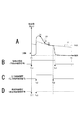
図5Aは金型内センサ31又は射出部内センサ32としてのセンサによって検出された検出信号の波形の例を示している。縦軸は検出値(Ddet)、横軸は時間である。例えば実線の波形PRは圧力センサの検出値、破線の波形TPは金型内温度である。
FIG. 5A shows an example of the waveform of the detection signal detected by the in-
これらは例えば1ショットの樹脂注入に応じた1成形サイクルにおける検出信号波形である。時点T0〜T1が1成形サイクルの期間である。この1成形サイクルには、例えば、金型10の上型と下型を閉じる型締め、金型10に対して射出部11のシリンダにより樹脂材料を注入する射出、充填後の保圧、成形固化までの計量・冷却、型開き、成形品の突き出し等の各工程が含まれている。
These are, for example, detection signal waveforms in one molding cycle corresponding to one shot of resin injection. Time point T0 to T1 is a period of one molding cycle. In this one molding cycle, for example, the upper mold and the lower mold of the
1成形サイクルの検出信号の評価のためには、通常、この期間T0〜T1における各監視タイミングの検出信号から求めた評価値が必要となる。
本実施の形態では、評価値を算出する手法として、MT(Maharanobis Taguchi)法を用いる。
設備の製造条件パラメータに多種多様の計測項目及び計測時点(監視タイミング)が含まれており、かつ、これらが相互に影響し合う関係にある場合には、一つの項目が所望しない方向に変化してしまう可能性を考慮し、製造条件パラメータに含まれる全ての項目を総合的に監視することが望ましい。
このような場合には、各次元における相関を考慮したうえで、相互に影響し合う複数の項目を一次元化する手法であるMT法を用いるのが好適である。
MT法においては、基準となる項目群にどれだけ似ているかを示す評価値として、マハラノビス距離を2乗した値を用いる。マハラノビス距離の詳細については後述する。
In order to evaluate the detection signal of one molding cycle, normally, an evaluation value obtained from the detection signal of each monitoring timing in this period T0 to T1 is required.
In the present embodiment, the MT (Maharanobis Taguchi) method is used as a method of calculating the evaluation value.
If the manufacturing condition parameters of the facility include various measurement items and measurement points (monitoring timing), and they are in a mutually affecting relationship, one item changes in an undesired direction. It is desirable to comprehensively monitor all the items included in the manufacturing condition parameters in consideration of the possibility of
In such a case, it is preferable to use the MT method, which is a method of one-dimensionalizing a plurality of mutually affecting items in consideration of the correlation in each dimension.
In the MT method, a value obtained by squaring the Mahalanobis distance is used as an evaluation value indicating how similar to the reference item group. Details of the Mahalanobis distance will be described later.
ところで、検出信号の意味合いは工程毎に異なるものとなる。例えば金型温度の検出値Ddetは、金型10が閉じられている期間の値は成形品の品質の評価に有用であるが、金型10が開かれた後は、あまり意味がないものである。
このように、成形品の品質を評価するにあたっては、工程における適切な監視タイミングを設定する必要がある。しかしながら、品質モニタリングシステムについてある程度の経験がないと、不良品の識別を行うのに適したタイミングを設定することが難しい場合がある。
そこで本実施の形態では、品質モニタリングシステムによる成形品の良否判定を行うにあたり、以下のような処理を行うこととした。
By the way, the meaning of the detection signal is different for each process. For example, the detection value Ddet of the mold temperature is useful for evaluating the quality of a molded article while the
As described above, in order to evaluate the quality of a molded article, it is necessary to set an appropriate monitoring timing in the process. However, without a certain level of experience with the quality monitoring system, it may be difficult to set a suitable timing for identifying defective products.
Therefore, in the present embodiment, the following processing is performed to determine the quality of the molded product by the quality monitoring system.
<5.単位空間情報設定処理>
本実施の形態の品質モニタリングシステムにおける単位空間情報設定処理について、図5乃至図7を用いて説明する。
単位空間設定処理は、後述する量産監視処理を監視装置1が実行する際の監視タイミングを決定し、その監視タイミングにおける成形品の品質評価に用いるための情報である単位空間情報を算出する処理である。単位空間情報設定処理は、コンピュータ装置4のCPU41により行われる。
<5. Unit space information setting process>
The unit space information setting process in the quality monitoring system of the present embodiment will be described using FIG. 5 to FIG.
The unit space setting process is a process of determining the monitoring timing when the
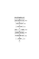
まずCPU41は、図6のステップS101において、良品の1成形サイクルにおける計測項目毎の検出信号のデータを記憶部48から取得する。CPU41は、例えば100サイクル分の良品の検出信号データを取得する。当該検出信号データは、CPU41が、データの計測を行った監視装置1から取得し、記憶部48に記憶したものである。
取得する検出信号データの計測項目としては、樹脂圧力、樹脂の流速、樹脂温度、金型表面温度等、成形品の品質を評価するために必要な様々な項目が考えられる。
First, in step S101 of FIG. 6, the
As measurement items of the detection signal data to be acquired, various items such as resin pressure, flow velocity of resin, resin temperature, mold surface temperature, etc., which are necessary for evaluating the quality of a molded product can be considered.
次にCPU41は、ステップS102において、監視期間設定処理を行う。即ち、CPU41は、1成形サイクル内の一部の期間を監視期間として設定する。これにより、品質の評価に有用である期間を監視期間として計測項目毎に設定することができる。
監視期間の設定方法は多様に考えられる。例えば図5Bに示す時点Ts1〜Te1の型締め期間を監視期間に設定することが考えられる。この期間は、型締めから型開きまでの複数の工程が行われる期間である。即ち、金型10が閉じられている期間のみを監視期間としている。監視装置1は図4Bの波形の型締め期間信号をタイミング信号STMの1つとして成形制御部12から取得することで、この時点Ts1〜Te1の監視期間の検出値Ddetの値を取得する。
Next, the
There are various ways of setting the monitoring period. For example, it is conceivable to set the mold clamping period of time points Ts1 to Te1 shown in FIG. 5B as the monitoring period. This period is a period in which a plurality of steps from mold clamping to mold opening are performed. That is, only the period in which the
或いは図5Cに示すように、波形の立ち上がりを判定する閾値thDH及び立ち下がりを判定する閾値thDLを設定し、圧力センサの波形PRを監視する。上述のように圧力センサの検出信号の立ち上がりタイミングは、キャビティに樹脂材料が充満した直後のタイミングとなる。そこで圧力センサの検出値Ddetを監視し、これが閾値thDH以上となった時点を圧力制御の開始タイミング(Ts2)と判断できる。圧力制御の終了タイミングは金型10を開く前のタイミングであるが、これを例えば検出値Ddetの値や値の変化から判断し、例えば検出値Ddetが閾値thDL以下になった時点を終了タイミング(Te2)とすることも可能である。これにより時点Ts2〜Te2を監視期間として設定することができる。
キャビティに樹脂材料が充満した直後のタイミングは、検出値Ddetの単位時間あたりの立ち上がりの幅が大きい。そのため、閾値thDHを設定しておけば、その時点を基準として、さまざまなタイミングを検出することが可能となる。
例えば、閾値thDH以上となった時点よりも所定時間前の時点を検出することで、樹脂材料が充満されたタイミングをある程度正確に検出することが可能である。つまり、閾値thDH以上となった時点から、樹脂材料が充満されるまでに掛かる時間を逆算することで、樹脂注入開始時点を特定することが可能となる。
従って、監視期間の開始タイミングを閾値thDH以上となった時点から、成形サイクルにおける樹脂注入開始時点を設定することができるようになる。これにより、成形制御部12から樹脂注入開始時点の情報を受信することなく、受信した検出信号データのみから樹脂注入開始時点を特定することができる。
なお、基準として設定できる時点は、検出値Ddetの単位時間あたりの変動の幅が大きいものであればよく、例えば金型10を開く前のタイミングであって検出値Ddetが閾値thDL以下になった時点を基準とすることも可能である。
また、これらの基準となる時点を用いて、他の計測項目における様々な時点を特定することも可能である。
Alternatively, as shown in FIG. 5C, the threshold value thDH for determining the rising edge of the waveform and the threshold value thDL for determining the falling edge are set, and the waveform PR of the pressure sensor is monitored. As described above, the rising timing of the detection signal of the pressure sensor is the timing immediately after the resin material fills the cavity. Therefore, it is possible to monitor the detected value Ddet of the pressure sensor, and determine that the time when this becomes equal to or greater than the threshold value thDH is the pressure control start timing (Ts2). The end timing of the pressure control is the timing before the
The timing immediately after the resin material fills the cavity has a large rise width per unit time of the detection value Ddet. Therefore, if the threshold value thDH is set, various timings can be detected on the basis of that time point.
For example, the timing at which the resin material is filled can be detected to some extent accurately by detecting a point in time which is a predetermined time before the point in time at which the threshold value thDH is exceeded. That is, it is possible to specify the resin injection start time point by calculating back the time it takes to fill the resin material after the threshold value thDH is reached or more.
Therefore, it becomes possible to set the resin injection start time point in the molding cycle from the time point when the start time of the monitoring period becomes the threshold thDH or more. Thus, the resin injection start time can be specified only from the received detection signal data without receiving information from the
The point at which it can be set as the reference may be any one if the range of fluctuation of the detection value Ddet per unit time is large. For example, it is the timing before opening the
Moreover, it is also possible to specify various time points in other measurement items using these reference time points.
また、ゲートシール期間を監視期間として設定することもできる。この場合、射出成形装置2に取り付けられた金型10や使用する樹脂材料等により、ゲートシール期間の具体的な時間を把握することが可能である。そこで、あらかじめ波形の立ち上がりを判定する閾値thDHのみを設定しておき、圧力センサの検出値Ddetが閾値thDH以上となった時点を圧力制御の開始タイミングとすることで、ゲートシール期間が経過した時点を監視期間の終了タイミングとして設定することもできる。
Also, the gate seal period can be set as the monitoring period. In this case, it is possible to grasp the specific time of the gate seal period by the
図5Dは、時点Ts3〜Te3を射出成形装置2において樹脂射出の速度制御が行われる期間としている。即ち注入速度を監視しながらシリンダによる注入動作を制御する期間である。
例えば成形制御部12は、樹脂が金型10のキャビティに充満するまでは、注入樹脂の速度制御を行い、充満後に圧力制御に切り換えるような制御を行う。その場合に、樹脂射出の速度制御については、速度制御期間のみの評価値を得たい場合もある。
このような場合、例えば波形の立ち上がりを判定する閾値thDHを設定し、圧力センサの波形PRを監視する。圧力センサの検出信号を考えると、その立ち上がりタイミングは、キャビティに樹脂材料が充満した直後のタイミングとなる。充満後にさらに樹脂が注入されることで樹脂が圧縮されて圧力が高くなるためである。
圧力センサの検出値Ddetは充満直後に急激に上昇する。そこで圧力センサの検出値Ddetを監視し、これが閾値thDH以上となった時点を充満タイミング(時点Te3)と判断し、時点Ts3〜Te3の期間を監視期間として設定することができる。
監視装置1は図5Dの波形の速度制御期間信号をタイミング信号STMの1つとして成形制御部12から取得することで、この時点Ts3〜Te3の期間の検出値Ddetの値を取得することができる。
In FIG. 5D, time points Ts3 to Te3 are periods in which the speed control of resin injection is performed in the
For example, the
In such a case, for example, a threshold value thDH for determining the rising of the waveform is set, and the waveform PR of the pressure sensor is monitored. Considering the detection signal of the pressure sensor, the rising timing is the timing immediately after the resin material fills the cavity. It is because the resin is compressed by the injection of the resin after the filling and the pressure becomes high.
The detection value Ddet of the pressure sensor rises rapidly immediately after the filling. Therefore, it is possible to monitor the detected value Ddet of the pressure sensor and determine the point in time when this becomes equal to or higher than the threshold value thDH as the filling timing (point Te3), and set the period from point Ts3 to Te3 as the monitoring period.
The
以上では一部期間の計測として3つの例を挙げたが、例えば上述した各工程の1つの期間、樹脂流入が進行している状態の期間、成形品の取り出しから次の1サイクルの開始までの期間など、対象とする期間は各種考えられる。
また、計測項目毎の監視期間は共通していても良いし、異なる期間であってもよい。つまり、監視期間は、計測項目毎に、良品判定の際に効果的な評価値が算出できる期間を設定することができる。
Although three examples have been described above as measurement of a partial period, for example, one period of each of the above-described steps, a period of a state in which resin inflow is in progress, and removal of a molded article to the start of the next cycle. There are various possible target periods, such as the period.
Further, the monitoring period for each measurement item may be common or different. That is, as the monitoring period, a period in which an effective evaluation value can be calculated at the time of non-defective item determination can be set for each measurement item.
ステップS102にて監視期間の設定処理が完了すると、CPU41は、ステップS103に処理を進め、分割数の設定情報を取得する。分割数の数値は、ユーザの入力部46を介した入力操作により指定される。分割数の指定方法は多様に考えられ、過去に入力された分割数の数値を指定してもよいし、予め分割数の数値が固定して設定されていてもよい。
When the setting process of the monitoring period is completed in step S102, the
監視期間を設定した後、CPU41は、ステップS104において、指定された分割数に基づいて、監視タイミングを設定する処理を行う。
監視タイミングとは、後述する量産監視処理における良品判定を行う際に用いられる検出値Ddetを検出するタイミングのことをいう。監視タイミングは、計測項目毎の監視期間のそれぞれについて設定される。
例えば分割数が4と指定された場合、図5A及び図5Cでは、圧力制御期間Ts2〜Te2を監視期間とした圧力センサの波形PRが、4つの領域に分割されるようにX1,X2,X3が監視タイミングとして設定される。ここで、監視期間開始時点Ts2,X1,X2,X3,監視期間終了時点Te2は均等間隔になるように設けられる。樹脂圧力のみならず、樹脂の流速や樹脂温度等の他の計測項目についても、同様に監視タイミングが設定される。
なお、監視タイミングの設定には様々な態様が考えられる。例えば、予め良品判定を行うために有用なタイミングを設定しておき、分割数を優先的にそのタイミングに振り分けることも考えられる。また、良品判定に有用なタイミングの付近に重点的に監視タイミングを設定することもできる。
After setting the monitoring period, in step S104, the
The monitoring timing refers to timing for detecting a detection value Ddet used when performing non-defective item determination in mass production monitoring processing described later. The monitoring timing is set for each monitoring period for each measurement item.
For example, when the division number is designated as 4, in FIGS. 5A and 5C, the pressure sensor waveform PR with pressure control period Ts2 to Te2 as the monitoring period is divided into four regions X1, X2, and X3. Is set as the monitoring timing. Here, the monitoring period start points Ts2, X1, X2, X3 and the monitoring period end point Te2 are provided at equal intervals. The monitoring timing is similarly set not only for the resin pressure but also for other measurement items such as the resin flow velocity and the resin temperature.
Note that various modes can be considered for setting the monitoring timing. For example, it is also conceivable to set in advance a timing that is useful for performing non-defective item determination, and to divide the number of divisions to that timing with priority. In addition, it is possible to set the monitoring timing in the vicinity of the timing useful for the non-defective item determination.
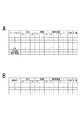
CPU41は、ステップS105において、図7Aに示すような、ステップS101にて取得した良品製造時の検出信号のデータを用いて、設定した監視タイミング毎の検出信号データ群を抽出する。
そしてCPU41は、ステップS106において、抽出した検出信号データ群の監視タイミング毎の平均値や標準偏差を求めることで、それぞれの検出信号データの正規化を行う。
その後、CPU41は、正規化した検出信号データ群から相関係数行列を算出し、算出した相関係数行列の逆行列を求める。このとき、良品と判定するための基準値が用いられる。基準値は{(計測値)−(平均値)}/(標準偏差)により算出する。
上記逆行列と任意の検出信号データの二次形式により、そのデータのマハラノビス距離(D値)を求めることが可能となる。
MT法においては、算出したD値を2乗した値(D2値)を用いて製造した成形品の良品判定が行われる。これは基準データ群の、D値の2乗平均を変量の数にかかわらず1前後に調整するための処置である。D2値は、良品データとの乖離を数値化したものであり、その数値が1に近いほど良品であることを示している。
このようにして本実施の形態における単位空間情報が設定される。
In step S105, the
Then, the
Thereafter, the
The Mahalanobis distance (D value) of the data can be obtained by the above-mentioned inverse matrix and a quadratic form of arbitrary detection signal data.
In the MT method, the non-defective product judgment of a molded product is performed using a value (D2 value) obtained by squaring the calculated D value. This is a procedure for adjusting the root mean square of D value of the reference data group to around 1 regardless of the number of variables. The D2 value is a digitization of the deviation from the non-defective item data, and the closer the value is to 1, the better the item is.
Thus, unit space information in the present embodiment is set.
その後、CPU41は、ステップS107において、基準値を含む単位空間の設定情報を監視装置1に送信することで、図6の単位空間情報設定処理を完了する。
Thereafter, in step S107, the
<6.量産監視処理>
本実施の形態における量産監視処理について、図7及び図8を用いて説明する。
量産監視処理は、単位空間情報設定処理において設定した単位空間情報に基づいて成形品の良品判定を行うものである。量産監視処理は、監視装置1の演算部20により行われる。
なお、以下の処理は、例えば樹脂成形の1成形サイクル実行中にリアルタイムで評価値(D2値)演算及び判定を行う例とする。また演算部20は、複数の入力チャネルI1〜I8の検出信号について、計測項目毎にそれぞれ並行して(実際の処理としては時分割でもよい)、図8の処理を行う。
<6. Mass production monitoring process>
The mass production monitoring process according to the present embodiment will be described with reference to FIGS. 7 and 8.
In the mass production monitoring process, the non-defective item determination of the molded article is performed based on the unit space information set in the unit space information setting process. The mass production monitoring process is performed by the
In the following processing, for example, evaluation value (D2 value) calculation and determination are performed in real time during execution of one molding cycle of resin molding. In addition, the
まず演算部20は、図8のステップS201において、監視装置1から良品の1成形サイクルにおける計測項目毎の検出信号のデータを取得する。そしてステップS202において、演算部20は、図7Bに示すような製品毎の各計測項目における監視タイミングの検出信号を抽出する。
First, in step S201 in FIG. 8, the
その後、演算部20は、ステップS203において、コンピュータ装置4から取得した良品の単位空間情報を抽出する。そして演算部20は、抽出した各計測項目における監視タイミングで検出された検出値Ddetと当該単位空間情報を用いて、図7Bに示すようにMT法におけるマハラノビス距離(D値)を算出する。そしてマハラノビス距離を2乗することでD2値を算出する。
Thereafter, in step S203, the
そして演算部20はステップS205で、D2値を用いた良否判定を行う。例えば単位空間情報から導かれる閾値thEH,thELを用いて、D2値が、thEH≧D2値≧thELとなっているか否かを確認する。
もし、この判定条件を満たしていればOK判定としてステップS205からS206に進み、判定OKの通知信号SIを成形制御部12に送信し、またコンピュータ装置4に判定OKを通知する。
なおこの段階で判定OKという判定結果情報を、今回の成形サイクルの識別情報(何サイクル目かの情報)とともにログデータとして記憶させる。
Then, in step S205, the
If this determination condition is satisfied, the process proceeds from step S205 to S206 as OK determination, and a notification signal SI of determination OK is transmitted to the forming
At this stage, the determination result information that the determination is OK is stored as log data together with identification information (information on the number of cycles) of the molding cycle this time.
その後、演算部20は、ステップS207において、監視を継続するかを判定し、継続する場合はステップS201に処理を進め、以下同様の処理を行う。また係属しない場合は、図8の処理を終了する。
Thereafter, in step S207, the
一方、thEH≧D2値≧thELという判定条件を満たしていなければ、エラー判定としてステップS205からS208に進み、判定エラーの通知信号SI(アラーム信号)を成形制御部12に送信し、またステップS209において、コンピュータ装置4に判定エラーを通知する。
なおこの段階で判定エラー(成形不良)という判定結果情報を、今回の成形サイクルの識別情報とともにメモリ部24にログデータとして記憶させてもよい。
On the other hand, if the determination condition of thEH ≧ D2 value ≧ thEL is not satisfied, the process proceeds from step S205 to S208 as an error determination, and transmits a determination error notification signal SI (alarm signal) to the forming
At this stage, determination result information that is a determination error (forming failure) may be stored as log data in the
以上のように演算部20の処理が行われることで、1成形サイクル内の指定期間におけるD2値の生成や、D2値に基づいた良否判定が行われる。
As described above, when the processing of the
<7.まとめ及び変形例>
以上の実施の形態のコンピュータ装置4は、射出成形装置2に備えられたセンサ(金型内センサ31及び射出部内センサ32)により1又は複数の計測項目の検出信号を入力する監視装置1で行われる、良品判定のための単位空間情報を生成する。またコンピュータ装置4は、監視開始時点(Ts)を特定し、監視開始時点から所定期間を監視期間(Ts〜Te)として設定する監視期間設定部41aと、指定された分割数に基づいて、監視期間内における複数の監視タイミング(X1,X2,…,Xn)を設定する監視タイミング設定部41bと、監視タイミング設定部41bが設定した監視タイミング(X1,X2,…,Xn)において成形品の監視処理に用いる単位空間情報を、取得した良品製造時の計測項目データに基づいて設定する単位空間情報設定部41cと、を備えている。
即ち、少なくとも監視開始時点及び監視期間の分割数を設定することにより、監視タイミングを自動的に設定する。また、それぞれの監視タイミングごとに、成形品の監視処理に用いる基準値を、取得した良品製造時の計測項目データに基づいて算出する。
これにより、射出成形装置2の成形サイクルの動作や成形品の良否判定のための準備(設定)をより的確に容易に行うことができる。
<7. Summary and Modifications>
The
That is, the monitoring timing is automatically set by setting at least the monitoring start time and the division number of the monitoring period. Further, at each monitoring timing, a reference value used for monitoring processing of a molded product is calculated based on the acquired measurement item data at the time of non-defective product manufacturing.
As a result, the operation of the molding cycle of the
またコンピュータ装置4の監視期間設定部41aは、ゲートシール期間を監視期間として設定する処理を行う。
成形品の良否判定のために用いる検出信号を金型内の樹脂圧力とした場合等においては、監視タイミングはゲートシール期間中に設定することが望ましい。なぜなら、ゲートシール期間は、金型内に充填された樹脂が固化するまでの期間であるため、成形品の品質の評価に有用な部分であるが、固化した後に期間については、あまり意味がない場合があるためである。
計測項目の性質に応じた成形品の良品判定に適したゲートシール期間を監視期間として設定することで、成形品の成形過程に関連性の高い時点を監視タイミングとすることができる。これにより、一層精度の高い良品判定を行うことが可能となる。
Further, the monitoring
When the detection signal used for determining the quality of the molded product is the resin pressure in the mold, the monitoring timing is preferably set during the gate seal period. Because the gate seal period is the period until the resin filled in the mold solidifies, it is a useful part for evaluating the quality of molded products, but the period after solidifying is not so meaningful It is because there is a case.
By setting the gate seal period suitable for the non-defective item determination of the molded item according to the property of the measurement item as the monitoring period, it is possible to set the monitoring timing to a point highly relevant to the molding process of the molded item. As a result, it is possible to perform the non-defective item determination with higher accuracy.
またコンピュータ装置4の監視期間設定部41aは、設定された所定の閾値(thDH)に検出信号が到達した時点を用いて監視開始時点(Ts)を特定する処理を行う。
圧力センサの検出信号を考えると、その立ち上がりタイミングは、金型内に成形材料が充満した直後のタイミングとなる。そこで当該立ち上がりのタイミングを監視開始時点として特定する。
これにより、ユーザが具体的な監視開始時間を設定しなくても、閾値を設定しておくだけで監視開始時点を特定することができる。従って、ユーザの利便性の向上を図ることができる。
Further, the monitoring
Considering the detection signal of the pressure sensor, the rising timing is the timing immediately after the molding material is filled in the mold. Therefore, the timing of the rise is specified as the monitoring start time.
Thus, even if the user does not set a specific monitoring start time, it is possible to specify the monitoring start time only by setting the threshold. Therefore, the convenience of the user can be improved.
またコンピュータ装置4の監視期間設定部41aは、設定された所定の閾値(thDH)に検出信号が到達した時点よりも所定時間前の時点を監視開始時点(Ts)として特定する処理を行う。即ち、圧力センサの検出信号の立ち上がりタイミングよりも所定期間前から成形品の監視を開始する。
キャビティに樹脂材料が充満した直後のタイミングは、検出値Ddetの単位時間あたりの立ち上がりの幅が大きい。そのため、樹脂材料が充満されたタイミングをある程度正確に検出することが可能である。
これにより、成形制御部12から樹脂注入開始時点の情報を受信することなく、受信した検出信号データのみから樹脂注入開始時点を特定することができる。
Further, the monitoring
The timing immediately after the resin material fills the cavity has a large rise width per unit time of the detection value Ddet. Therefore, it is possible to detect the timing at which the resin material is filled accurately to a certain extent.
Thus, the resin injection start time can be specified only from the received detection signal data without receiving information from the
またコンピュータ装置4の単位空間情報設定部41cは、複数の計測項目のそれぞれの監視タイミング毎の値を用いて基準値を算出する処理を行う(図6のS106)。
これにより、多様な計測項目及び監視タイミングを加味した上で、単位空間情報を設定することになる。従って、成形品の良否判定の精度を向上させることができる。
Further, the unit space
In this way, unit space information is set in consideration of various measurement items and monitoring timings. Therefore, it is possible to improve the accuracy of the quality determination of the molded product.
また 単位空間情報はマハラノビス距離を2乗した値を算出するために用いられる情報であることが考えられる。即ち、単位の異なる多次元の各計測項目の値を、共通の一次元としての単位に置き換えるための単位空間情報を設定する。
これにより、成形品の良否判定において、計測項目の全てが規格を充足していたとしても、成形品全体として不良品の可能性がある製品を発見することができる。従って、成形品の良否判定の精度をより一層向上させることができる。
Also, unit space information is considered to be information used to calculate a value obtained by squaring the Mahalanobis distance. That is, unit space information is set to replace the value of each multi-dimensional measurement item having different units with a unit as a common one dimension.
Thereby, in the quality determination of the molded product, even if all the measurement items satisfy the standard, it is possible to discover a product having a possibility of being a defective product as a whole of the molded product. Therefore, it is possible to further improve the accuracy of the quality determination of the molded product.
また本発明は上記した具体例に限定されるべきものではなく、多様な変形例が考えられる。
射出成形装置2の構成は多様に考えられる。監視装置1及びコンピュータ装置4の構成も同様である。
図6の処理を監視装置1の演算部20で行ってもよい。この場合においては、監視装置1が請求項でいう演算処理装置となる。
図6に示したコンピュータ装置4のCPU41の処理例も一例に過ぎず、具体的な処理例は多様に考えられる。また図8に示した監視装置1の演算部20の処理例についても同様である。
射出成形装置2に搭載されるセンサ(金型内センサ31や射出部内センサ32)としては多様に考えられる。即ち監視装置1は、圧力センサによる射出部11内や金型10内における樹脂材料の圧力計測や、温度センサの検出信号に基づく成形材料や金型表面温度の計測以外にも多様な検出信号の計測に適用できる。例えば光センサ等の検出信号に基づく成形材料の流速計測、赤外線センサ等の検出信号に基づくフローフロント計測(例えば成形樹脂がキャビティ内の所定位置に到達するまでの時間の計測)、位置センサ等の検出信号に基づく型閉時における金型同士の位置ズレ量の計測(型開き量の計測)等、射出成形に係る他の計測を行う場合の各種センサの検出信号についても好適に適用できる。
Furthermore, the present invention should not be limited to the above-described specific examples, and various modifications can be considered.
The configuration of the
The process of FIG. 6 may be performed by the
The processing example of the
A variety of sensors (in-
<8.プログラム及び記憶媒体>
本発明の実施の形態のプログラムは、コンピュータ装置4におけるCPU41(マイクロコンピュータ等の演算処理装置)に監視期間設定部41a、監視タイミング設定部41b、単位空間情報設定部41cとしての機能を実行させるプログラムである。
<8. Program and storage medium>
The program according to the embodiment of the present invention is a program that causes the CPU 41 (an arithmetic processing unit such as a microcomputer) of the
実施の形態のプログラムは、射出成形装置に備えられたセンサにより1又は複数の計測項目の検出信号を入力する監視装置で行われる、良品判定のための単位空間情報を生成する演算処理装置に、監視開始時点を特定し、前記監視開始時点から所定期間を監視期間として設定する処理と、設定された分割数に基づいて、前記監視期間内における複数の監視タイミングを設定する処理と、設定した前記監視タイミングにおいて成形品の監視処理に用いる単位空間情報を、取得した良品製造時の計測項目データに基づいて算出する処理と、を実行させるプログラムプログラムである。即ち図6の処理を実行させるプログラムである。 A program according to an embodiment of the present invention is an arithmetic processing unit that generates unit space information for non-defective item determination performed by a monitoring device that inputs detection signals of one or more measurement items by a sensor provided in an injection molding device. The process of specifying a monitoring start time and setting a predetermined period as the monitoring time from the monitoring start time, the process of setting a plurality of monitoring timings within the monitoring period based on the set number of divisions, and the setting It is a program program for executing processing of calculating unit space information used for monitoring processing of a molded product at monitoring timing based on the acquired measurement item data at the time of non-defective product manufacturing. That is, it is a program for executing the process of FIG.
このようなプログラムにより本実施の形態のコンピュータ装置4の製造が容易となる。
そしてこのようなプログラムはコンピュータ装置4等の機器に内蔵されている記憶媒体や、CPUを有するマイクロコンピュータ内のROM等に予め記憶しておくことができる。あるいはまた、半導体メモリ、メモリカード、光ディスク、光磁気ディスク、磁気ディスクなどのリムーバブル記憶媒体に、一時的あるいは永続的に格納(記憶)しておくことができる。またこのようなリムーバブル記憶媒体は、いわゆるパッケージソフトウェアとして提供することができる。
また、このようなプログラムは、リムーバブル記憶媒体からパーソナルコンピュータ等にインストールする他、ダウンロードサイトから、LAN、インターネットなどのネットワークを介してダウンロードすることもできる。
Such a program facilitates the manufacture of the
Such a program can be stored in advance in a storage medium built in an apparatus such as the
Further, such a program can be installed from a removable storage medium to a personal computer or the like, and can also be downloaded from a download site via a network such as a LAN or the Internet.
またこのような実施の形態の監視装置1に実行させるプログラムがコンピュータ装置4にインストールされることで、コンピュータ装置4が監視装置1の機能を備えるようにすることもできる。
例えば専用アンプ3とコンピュータ装置4をコネクタで直接接続する。専用アンプ3を介してコンピュータ装置4には1又は複数の入力チャネルの検出信号が供給されるようにする。そしてコンピュータ装置4において当該プログラムを含むソフトウェアが起動されることで、図6の処理をコンピュータ装置4で実行する。即ちセンサ(31,32)の検出信号を取得し、射出成形装置2による1成形サイクルの期間内の一部の期間とされた指定期間における検出信号値(検出値Ddet)を用いて評価値の算出を行い、評価値を用いて射出成形状況の判定結果を求める処理を行う。これにより、パーソナルコンピュータ等のコンピュータ装置4を用いて監視装置1を実現できる。
In addition, the
For example, the
1…監視装置、2…射出成形装置、4…コンピュータ装置、41a…監視期間設定部、41b…監視タイミング設定部、41c…単位空間情報設定部
DESCRIPTION OF
Claims (8)
監視開始時点を特定し、前記監視開始時点から所定期間を監視期間として設定する監視期間設定部と、
指定された分割数に基づいて、前記監視期間内における複数の監視タイミングを設定する監視タイミング設定部と、
前記監視タイミング設定部が設定した前記監視タイミングにおいて成形品の監視処理に用いる単位空間情報を、取得した良品製造時の計測項目データに基づいて設定する単位空間情報設定部と、
を備える演算処理装置。 An arithmetic processing unit that generates unit space information for non-defective item determination, which is performed by a monitoring device that inputs detection signals of one or a plurality of measurement items by a sensor provided in an injection molding device.
A monitoring period setting unit that specifies a monitoring start time and sets a predetermined period as the monitoring time from the monitoring start time;
A monitoring timing setting unit configured to set a plurality of monitoring timings in the monitoring period based on the designated number of divisions;
A unit space information setting unit configured to set unit space information used for monitoring processing of a molded article at the monitoring timing set by the monitoring timing setting unit based on the acquired measurement item data at the time of non-defective product manufacturing;
Arithmetic processing device provided with
請求項1に記載の演算処理装置。 The arithmetic processing unit according to claim 1, wherein the monitoring period setting unit sets a gate seal period as the monitoring period.
請求項1又は請求項2に記載の演算処理装置。 The arithmetic processing unit according to claim 1, wherein the monitoring period setting unit specifies the monitoring start time point using a time point when the detection signal reaches a set predetermined threshold.
請求項3に記載の演算処理装置。 The arithmetic processing unit according to claim 3, wherein the monitoring period setting unit specifies a point in time a predetermined time before the point in time at which the detection signal reaches the set predetermined threshold as the monitoring start point.
請求項1乃至請求項4に記載の演算処理装置。 The arithmetic processing device according to any one of claims 1 to 4, wherein the unit space information setting unit sets the unit space information based on values of a plurality of measurement items at the monitoring timing.
請求項5に記載の演算処理装置。 The arithmetic processing unit according to claim 5, wherein the unit space information is information used to calculate a value obtained by squaring the Mahalanobis distance.
監視開始時点を特定し、前記監視開始時点から所定期間を監視期間として設定する処理と、
設定された分割数に基づいて、前記監視期間内における複数の監視タイミングを設定する処理と、
設定した前記監視タイミングにおいて成形品の監視処理に用いる単位空間情報を、取得した良品製造時の計測項目データに基づいて算出する処理と、
を実行するための演算方法。 An arithmetic processing unit for generating unit space information for non-defective item determination performed by a monitoring device that inputs detection signals of one or more measurement items by a sensor provided in an injection molding device,
A process of specifying a monitoring start time and setting a predetermined period as the monitoring time from the monitoring start time;
A process of setting a plurality of monitoring timings in the monitoring period based on the set number of divisions;
A process of calculating unit space information used for a monitoring process of a molded product at the set monitoring timing based on the acquired measurement item data at the time of non-defective product manufacturing;
Arithmetic method for performing.
監視開始時点を特定し、前記監視開始時点から所定期間を監視期間として設定する処理と、
設定された分割数に基づいて、前記監視期間内における複数の監視タイミングを設定する処理と、
設定した前記監視タイミングにおいて成形品の監視処理に用いる単位空間情報を、取得した良品製造時の計測項目データに基づいて算出する処理と、
を実行させるプログラム。 An arithmetic processing unit that generates unit space information for determination of non-defective items, which is performed by a monitoring device that inputs detection signals of one or more measurement items by a sensor provided in an injection molding device.
A process of specifying a monitoring start time and setting a predetermined period as the monitoring time from the monitoring start time;
A process of setting a plurality of monitoring timings in the monitoring period based on the set number of divisions;
A process of calculating unit space information used for a monitoring process of a molded product at the set monitoring timing based on the acquired measurement item data at the time of non-defective product manufacturing;
A program that runs
Priority Applications (3)
| Application Number | Priority Date | Filing Date | Title |
|---|---|---|---|
| JP2017184712A JP6772119B2 (en) | 2017-09-26 | 2017-09-26 | Arithmetic processing unit, arithmetic processing unit arithmetic method and program |
| PCT/JP2018/023300 WO2019064734A1 (en) | 2017-09-26 | 2018-06-19 | Computation processing device, computation method for computation processing device, and program |
| CN201880058735.6A CN111093936B (en) | 2017-09-26 | 2018-06-19 | Arithmetic processing device, arithmetic method of arithmetic processing device, and storage medium |
Applications Claiming Priority (1)
| Application Number | Priority Date | Filing Date | Title |
|---|---|---|---|
| JP2017184712A JP6772119B2 (en) | 2017-09-26 | 2017-09-26 | Arithmetic processing unit, arithmetic processing unit arithmetic method and program |
Publications (2)
| Publication Number | Publication Date |
|---|---|
| JP2019059082A true JP2019059082A (en) | 2019-04-18 |
| JP6772119B2 JP6772119B2 (en) | 2020-10-21 |
Family
ID=65903402
Family Applications (1)
| Application Number | Title | Priority Date | Filing Date |
|---|---|---|---|
| JP2017184712A Active JP6772119B2 (en) | 2017-09-26 | 2017-09-26 | Arithmetic processing unit, arithmetic processing unit arithmetic method and program |
Country Status (3)
| Country | Link |
|---|---|
| JP (1) | JP6772119B2 (en) |
| CN (1) | CN111093936B (en) |
| WO (1) | WO2019064734A1 (en) |
Families Citing this family (2)
| Publication number | Priority date | Publication date | Assignee | Title |
|---|---|---|---|---|
| JP7477419B2 (en) * | 2020-09-30 | 2024-05-01 | 住友重機械工業株式会社 | Injection molding machine |
| CN112277275B (en) * | 2020-12-28 | 2021-03-30 | 温州市健牌模具有限公司 | Method and device for processing plastic product |
Family Cites Families (10)
| Publication number | Priority date | Publication date | Assignee | Title |
|---|---|---|---|---|
| US3932083A (en) * | 1973-12-03 | 1976-01-13 | Barber-Colman Company | Injection molding control |
| ATE46843T1 (en) * | 1983-05-20 | 1989-10-15 | John Mickowski | METHOD FOR MONITORING AND CONTROLLING PERIODIC MOLDING AND CASTING MACHINES AND AN APPARATUS FOR CARRYING OUT THESE METHOD. |
| JPS59224323A (en) * | 1983-06-03 | 1984-12-17 | Tekunopurasu:Kk | Monitoring method by in-mold pressure wave form |
| JPS60242026A (en) * | 1984-04-20 | 1985-12-02 | Mitsubishi Heavy Ind Ltd | Monitoring of injection pressure |
| JP3677627B2 (en) * | 2001-12-13 | 2005-08-03 | 住友重機械工業株式会社 | Product pass / fail judgment method |
| JP2008001028A (en) * | 2006-06-23 | 2008-01-10 | Sumitomo Heavy Ind Ltd | Method for detecting abnormality of injection molding machine |
| JP2008246734A (en) * | 2007-03-29 | 2008-10-16 | Yamashiro Seiki Seisakusho:Kk | Method for judging whether plastication process in injection molding machine is good or not |
| CN101298178A (en) * | 2008-06-19 | 2008-11-05 | 大连理工大学 | Injection molding intelligent control apparatus |
| CN202053492U (en) * | 2011-05-13 | 2011-11-30 | 印玉秀 | Auxiliary device used for injection molding machine die |
| CN103640194B (en) * | 2013-12-26 | 2016-06-08 | 宁波恩瑞德机电科技有限公司 | A kind of Intelligent injection machine and injecting method thereof |
-
2017
- 2017-09-26 JP JP2017184712A patent/JP6772119B2/en active Active
-
2018
- 2018-06-19 WO PCT/JP2018/023300 patent/WO2019064734A1/en active Application Filing
- 2018-06-19 CN CN201880058735.6A patent/CN111093936B/en active Active
Also Published As
| Publication number | Publication date |
|---|---|
| CN111093936A (en) | 2020-05-01 |
| CN111093936B (en) | 2022-02-11 |
| JP6772119B2 (en) | 2020-10-21 |
| WO2019064734A1 (en) | 2019-04-04 |
Similar Documents
| Publication | Publication Date | Title |
|---|---|---|
| JP6532845B2 (en) | Measuring device, measuring method, program | |
| CN111163914B (en) | Real-time material and speed control in a molding system | |
| TWI293916B (en) | Control apparatus for injection molding machine | |
| US10836088B2 (en) | Method for reproducing injection molded parts of quality and injection molding unit for performing the method | |
| WO2019064734A1 (en) | Computation processing device, computation method for computation processing device, and program | |
| JP6494113B2 (en) | Measuring device, measuring method, program | |
| JP6155290B2 (en) | Measuring device | |
| JP6587989B2 (en) | Measuring device, measuring method, program | |
| JP7311387B2 (en) | Injection molding machine management support device and injection molding machine | |
| JP2014069382A (en) | Defect factor determination device, defect occurrence predictor, defect factor determination system, defect factor determination method, and program | |
| EP3721343B1 (en) | Predictive simulation system and method for injection molding | |
| JP6687574B2 (en) | Arithmetic processing device, arithmetic method of arithmetic processing device, and program | |
| JP6753791B2 (en) | Maintenance time prediction device, flow control device and maintenance time prediction method | |
| JP2009254104A (en) | Conductor monitor for power receiving and distributing equipment | |
| US20230173725A1 (en) | Controller and program for injection molding machine | |
| JP2009045904A (en) | Injection molding machine having screw rotational torque monitoring function | |
| JP5811035B2 (en) | Electric injection molding machine load status display method and electric injection molding machine drive device | |
| JP2003340898A (en) | Method for calculating pressure history of tip of nozzle in consideration of characteristic of molding machine, method for simulating injection molding, and its program | |
| JP7397185B2 (en) | Injection molding machine control device and program | |
| JP2023165267A (en) | Device for producing resin molded article, method, learning device and inference device | |
| US20230182362A1 (en) | Controller for injection molding machine and program | |
| JP5233679B2 (en) | Accuracy verification method for solidification defect prediction analysis | |
| JPH07205242A (en) | Method and apparatus for monitoring quality and deciding propriety of molded form of injection molding machine | |
| JP2020131268A (en) | Molding machine | |
| JP2006110878A (en) | Method for analyzing injection molding process, device for the method, and method for producing injection-molded article |
Legal Events
| Date | Code | Title | Description |
|---|---|---|---|
| A621 | Written request for application examination |
Free format text: JAPANESE INTERMEDIATE CODE: A621 Effective date: 20190115 |
|
| A131 | Notification of reasons for refusal |
Free format text: JAPANESE INTERMEDIATE CODE: A131 Effective date: 20191008 |
|
| A521 | Request for written amendment filed |
Free format text: JAPANESE INTERMEDIATE CODE: A523 Effective date: 20191202 |
|
| A131 | Notification of reasons for refusal |
Free format text: JAPANESE INTERMEDIATE CODE: A131 Effective date: 20200310 |
|
| A521 | Request for written amendment filed |
Free format text: JAPANESE INTERMEDIATE CODE: A523 Effective date: 20200429 |
|
| TRDD | Decision of grant or rejection written | ||
| A01 | Written decision to grant a patent or to grant a registration (utility model) |
Free format text: JAPANESE INTERMEDIATE CODE: A01 Effective date: 20200915 |
|
| A61 | First payment of annual fees (during grant procedure) |
Free format text: JAPANESE INTERMEDIATE CODE: A61 Effective date: 20200930 |
|
| R150 | Certificate of patent or registration of utility model |
Ref document number: 6772119 Country of ref document: JP Free format text: JAPANESE INTERMEDIATE CODE: R150 |
|
| R250 | Receipt of annual fees |
Free format text: JAPANESE INTERMEDIATE CODE: R250 |