JP2019042807A - Manufacturing method of steel plate and surface layer hardness measuring device for magnetic material - Google Patents
Manufacturing method of steel plate and surface layer hardness measuring device for magnetic material Download PDFInfo
- Publication number
- JP2019042807A JP2019042807A JP2018159161A JP2018159161A JP2019042807A JP 2019042807 A JP2019042807 A JP 2019042807A JP 2018159161 A JP2018159161 A JP 2018159161A JP 2018159161 A JP2018159161 A JP 2018159161A JP 2019042807 A JP2019042807 A JP 2019042807A
- Authority
- JP
- Japan
- Prior art keywords
- hardness
- steel plate
- surface layer
- steel sheet
- steel
- Prior art date
- Legal status (The legal status is an assumption and is not a legal conclusion. Google has not performed a legal analysis and makes no representation as to the accuracy of the status listed.)
- Granted
Links
Images


Abstract
Description
本発明は、鋼板の製造方法及び磁性材用表層硬さ計測装置に関する。 The present invention relates to a method for manufacturing a steel plate and a surface hardness measuring apparatus for a magnetic material.
従来、エネルギー需要の高まりにより、天然ガスや石油を輸送するためのパイプラインの建設が増えてきている。パイプラインに使われる鋼管の種類の一つとして、UOE鋼管(またはベンディング鋼管)が知られている。UOE鋼管を製作する際には、まず連続鋳造された鋼片を粗圧延し、その後、所定の板厚及び内質を得るために仕上げ圧延を行う。次に、様々な機械特性を得るための熱処理として、焼き入れや焼鈍を行う。そして、このようなプロセスを経て得られた鋼板を、筒状になるように板幅方向に対して弯曲させて、突合せ部分を鋼板長軸方向にむかって溶接することにより、鋼管が製作される。 Conventionally, construction of pipelines for transporting natural gas and oil has been increasing due to rising energy demand. UOE steel pipe (or bending steel pipe) is known as one of the types of steel pipe used for pipelines. When manufacturing a UOE steel pipe, first, a continuously cast steel slab is roughly rolled, and then finish rolling is performed in order to obtain a predetermined thickness and quality. Next, quenching and annealing are performed as heat treatment for obtaining various mechanical properties. Then, the steel plate obtained through such a process is bent with respect to the plate width direction so as to be cylindrical, and the butt portion is welded toward the long axis direction of the steel plate, thereby producing a steel pipe. .
パイプラインに適用される鋼管の内面における表層硬さは、腐食割れの原因となるため、鋼管製造時の仕様として定められており、従来は、抜き取り検査によって鋼管の内面における表層硬さの品質保証を実施してきた。また、特許文献1には、渦電流などの電磁気的な特性値を検出するセンサを用いて、鋼管の外面における表層硬さを測定する技術が開示されている。
The surface hardness of the inner surface of a steel pipe applied to a pipeline is a specification at the time of steel pipe production because it causes corrosion cracking. Conventionally, quality assurance of the surface hardness of the inner surface of a steel pipe by sampling inspection Has been implemented.
しかしながら、従来の抜き取り検査による鋼管の内面における表層硬さの品質保証では、鋼管の内面全域における表層硬さが保証できるものではなく、鋼管がパイプラインに適用された後、鋼管の内面に表層硬さが部分的に硬い領域であるハードスポットが存在するために、このハードスポットが原因となって腐食割れが発生してしまう。 However, the quality assurance of the surface hardness on the inner surface of the steel pipe by the conventional sampling inspection cannot guarantee the surface layer hardness on the entire inner surface of the steel pipe. After the steel pipe is applied to the pipeline, the surface hardness on the inner surface of the steel pipe is not guaranteed. Since there is a hard spot that is a partially hard region, corrosion cracking occurs due to this hard spot.
また、特許文献1に開示された技術のように電磁気的な特性値を検出するセンサを用いて、鋼管の内面全域における表層硬さを計測することが考えられる。しかしながら、前記センサを用いて鋼管の内面側を全面走査するには、複雑な機構が必要となり実用的ではない。具体的には、例えば、鋼管の内面側に前記センサを複数配置し、且つ、これら複数のセンサの配置を鋼管のサイズに応じて調整する必要があったり、鋼管の内面側を全面走査するために、複数のセンサまたは鋼管を回転させたりしなければならない。そのため、表層硬さの計測作業が煩雑となり、鋼管の生産性の低下を招くおそれがある。
Further, it is conceivable to measure the surface hardness of the entire inner surface of the steel pipe using a sensor that detects an electromagnetic characteristic value as in the technique disclosed in
本発明は、上記課題に鑑みてなされたものであって、その目的は、生産性の低下を抑えつつ、製造された鋼板のハードスポットを抑制することができる鋼板の製造方法及び磁性材用表層硬さ計測装置を提供することである。 The present invention has been made in view of the above-mentioned problems, and the object thereof is a steel sheet manufacturing method and a magnetic material surface layer capable of suppressing hard spots of the manufactured steel sheet while suppressing a decrease in productivity. It is to provide a hardness measuring device.
上述した課題を解決し、目的を達成するために、本発明に係る鋼板の製造方法は、鋼片を圧延して鋼板とする圧延工程と、前記鋼板の表層硬さを計測し、前記計測された前記鋼板の表層硬さに基づいて、前記鋼板の表層に対して予め設定された表層硬さよりも硬い部位を、硬さ指示部位として判定する表層硬さ計測工程と、前記鋼板の表層における前記判定された硬さ指示部位を除去する除去工程と、を有し、前記表層硬さ計測工程は、前記鋼板の表層の脱磁を行う脱磁工程と、前記脱磁工程の後に、前記鋼板の表層の電磁気的な特性値を測定し、前記測定された電磁気的な特性値から前記鋼板の前記表層硬さを計測する電磁気計測工程と、を有することを特徴とするものである。 In order to solve the above-described problems and achieve the object, the steel sheet manufacturing method according to the present invention measures a rolling step of rolling a steel piece into a steel sheet, and measures the surface layer hardness of the steel sheet. Further, based on the surface layer hardness of the steel sheet, a surface hardness measurement step for determining a part harder than the surface layer hardness preset for the surface layer of the steel sheet as a hardness indicating part, and the surface layer of the steel sheet A removal step of removing the determined hardness indicating portion, and the surface hardness measurement step includes: a demagnetization step of demagnetizing the surface layer of the steel plate; and a step of the steel plate after the demagnetization step. An electromagnetic measurement step of measuring an electromagnetic characteristic value of the surface layer and measuring the surface layer hardness of the steel sheet from the measured electromagnetic characteristic value.
また、本発明に係る鋼板の製造方法は、上記の発明において、前記圧延工程の後、且つ、前記表層硬さ計測工程の前に、前記鋼板に熱処理を施す熱処理工程を有することを特徴とするものである。 Moreover, the manufacturing method of the steel plate according to the present invention is characterized in that, in the above invention, the method includes a heat treatment step of performing heat treatment on the steel plate after the rolling step and before the surface hardness measurement step. Is.
また、本発明に係る鋼板の製造方法は、上記の発明において、前記電磁気計測工程は、校正用鋼板を用いて前記表層硬さの閾値を設定する工程を有することを特徴とするものである。 The steel sheet manufacturing method according to the present invention is characterized in that, in the above invention, the electromagnetic measurement step includes a step of setting a threshold value of the surface hardness using a calibration steel plate.
また、本発明に係る磁性材用表層硬さ計測装置は、磁性材と対向する側の面に、表層硬さを計測する手段が設けられている計測用センサヘッドと、前記磁性材の幅方向へ前記計測用センサヘッドが移動可能なように構成されている可動手段と、前記磁性材の長手方向へ前記磁性材が搬送可能なように構成されている搬送機構と、前記表層硬さを計測する手段に接続されている制御手段と、を備え、前記表層硬さを計測する手段は、前記磁性材の前記表層を脱磁し、前記磁性材の前記表層を磁化し、前記表層の電磁気的な特性値を測定し、前記制御手段は、前記表層硬さを計測する手段による前記脱磁と前記磁化とを制御し、測定された前記電磁気的な特性値に基づいて前記磁性材の表層硬さを算出する、ことを特徴とするものである。 The surface hardness measurement apparatus for a magnetic material according to the present invention includes a measurement sensor head in which means for measuring surface hardness is provided on the surface facing the magnetic material, and the width direction of the magnetic material. The movable sensor configured to move the measurement sensor head, the transport mechanism configured to transport the magnetic material in the longitudinal direction of the magnetic material, and the surface hardness And means for measuring the surface hardness, demagnetizing the surface layer of the magnetic material, magnetizing the surface layer of the magnetic material, and electromagnetically controlling the surface layer. The control means controls the demagnetization and the magnetization by the means for measuring the surface hardness, and the surface hardness of the magnetic material is controlled based on the measured electromagnetic characteristic value. It is characterized by calculating the thickness.
本発明に係る鋼板の製造方法及び磁性材用表層硬さ計測装置は、生産性の低下を抑えつつ、製造された鋼板のハードスポットを抑制することができるという効果を奏する。 The steel sheet manufacturing method and the magnetic material surface hardness measuring apparatus according to the present invention have an effect of suppressing hard spots of the manufactured steel sheet while suppressing a decrease in productivity.
以下に、本発明に係る鋼板の製造方法の一実施形態について説明する。なお、本実施形態により本発明が限定されるものではない。 Below, one Embodiment of the manufacturing method of the steel plate which concerns on this invention is described. In addition, this invention is not limited by this embodiment.
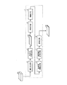
図1は、本実施形態に係る鋼板の製造方法を適用した、鋼片から鋼板を製造する鋼板製造工程1で実施される各処理工程を示す図である。図1に示すように、本実施形態に係る鋼板製造工程1は、連続鋳造機で製造された鋼片S1を圧延して鋼板S2とする圧延工程である粗圧延工程2及び仕上げ圧延工程3と、鋼板S2に冷却を行う冷却工程4と、鋼板S2に熱処理を施す熱処理工程に該当する焼鈍工程5と、鋼板S2の内部品質の検査を行う超音波探傷工程6と、鋼板S2の表層硬さを電磁的な特性値から計測する表層硬さ計測工程7と、鋼板S2にある硬さ指示部位(ハードスポット)を除去する除去工程に該当し、鋼板S2にある硬さ指示部位(ハードスポット)を研削する研削工程8とで構成されている。
また、本実施形態に係る鋼板製造工程1では、粗圧延工程2、仕上げ圧延工程3、冷却工程4、焼鈍工程5、超音波探傷工程6の順に経たのちに、表層硬さ計測工程7にて、電磁気的な特性値から鋼板S2の表層硬さが計測される。なお、表層硬さ計測工程7は、鋼板S2の表層組織の状態が変わることがなくなる、鋼板S2がほぼ最終製品(鋼板S3)となっている段階で行われなければならない。そのため、焼鈍工程5よりも後段で表層硬さ計測工程7を行う。一方で、超音波探傷工程6の後では、鋼板S2に熱処理が施されることはなく表層組織の状態が変わらないため、本実施形態に係る鋼板製造工程1においては、超音波探傷工程6の直後に表層硬さ計測工程7を行う。そして、表層硬さ計測工程7を経た後、鋼板S2は研削工程8へと送られる。
Moreover, in the steel
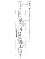
図2は、表層硬さ計測工程7及び研削工程8の詳細について示す図である。図2に示すように、表層硬さ計測工程7は、オンライン脱磁工程7aと、オンライン電磁気計測工程7bと、指示部脱磁工程7cと、オフライン電磁気計測工程7dと、で構成されている。なお、表層硬さ計測工程7では、鋼板S2の上面及び下面の表層硬さとして、表層下0.1[mm]〜1[mm]の範囲の硬さを計測する。
FIG. 2 is a diagram showing details of the surface hardness measurement process 7 and the
表層硬さ計測工程7では、まず、鋼板S2はオンライン脱磁工程7aにおいて、自動または半自動により鋼板S2の上面及び下面の表層の残留磁化を脱磁する。オンライン脱磁工程7aに続く、オンライン電磁気計測工程7bで、鋼板S2の上面及び下面の表層の電磁気的な特性値(保持力や透磁率の変化等)を測定し、その測定された特性値に基づいて上面及び下面の表層の硬さを計測する。 In the surface hardness measurement process 7, first, the steel sheet S2 demagnetizes the residual magnetization of the surface layer on the upper surface and the lower surface of the steel sheet S2 automatically or semi-automatically in the online demagnetization process 7a. In the online electromagnetic measurement process 7b following the online demagnetization process 7a, the electromagnetic characteristic values (retention force, change in permeability, etc.) of the upper and lower surfaces of the steel sheet S2 are measured, and the measured characteristic values are obtained. Based on this, the hardness of the upper and lower surface layers is measured.
ここで、鋼板S2の表層の電磁気的な特性値から表層の硬さを計測するには、公知の方法を用いることができる。一般に、鋼板の表層に対する磁気ヒステリシスカーブの形状と、鋼板の表層の硬さとには関係があることが知られており、例えば、非特許文献1に記載の方法では、透磁率を計測することによって鋼板の表層の硬さを推定している。また、非特許文献2に記載の方法では、磁気ヒステリシスカーブの形状から特徴量を抽出し、その特徴量と鋼板の表層の硬さとの関係を事前に機械学習させて、鋼板の表層の硬さを推定している。本発明におけるオンライン電磁気計測工程7b及びオフライン電磁気計測工程7dでは、非特許文献1や非特許文献2に記載されている磁気パラメーター(保持率や透磁率、あるいはヒステリシスカーブの特徴量)と、鋼板の表層の硬さとの関係から、鋼板S2の表層の硬さを評価する手法を適用する。
Here, in order to measure the hardness of the surface layer from the electromagnetic characteristic value of the surface layer of the steel plate S2, a known method can be used. In general, it is known that there is a relationship between the shape of the magnetic hysteresis curve for the surface layer of the steel sheet and the hardness of the surface layer of the steel sheet. For example, in the method described in
また、鋼板S2の表層に残留磁気があると、その残留磁気の影響を受けて、鋼板S2の硬さを硬さセンサによって正しく計測することができなくなる。鋼板製造工程1における鋼板S2のハンドリングや搬送の際には、リフティングマグネットを用いることが常であり、リフティングマグネットが使用されると、鋼板S2の表層にどうしても残留磁気が存在してしまう。そのため、本実施形態に係る鋼板製造工程1においては、オンライン電磁気計測工程7bの直前のオンライン脱磁工程7aにて、鋼板S2の上面及び下面の表層の脱磁を行う。公知の脱磁方法には、大きく分けて距離減衰方式と電流減衰方式とがあるので、どちらを適用しても良い。距離減衰方式の方が、鋼板S2の搬送を利用することが可能であることと、交流磁界を発生させる電流が交流であるので、表皮効果により鋼板表層近傍の脱磁を効果的に行うことが可能であることから望ましい。このように、電磁気的な特性値を用いて鋼板S2の表層の硬さを計測する工程の前に、表層の脱磁を行うことが、本願における最も重要な特徴である。このとき、鋼板S2の各表層における残留磁気は、地磁気レベルである1ガウス以下まで消磁するのが好ましい。
Further, if there is residual magnetism on the surface layer of the steel sheet S2, the hardness of the steel sheet S2 cannot be correctly measured by the hardness sensor due to the influence of the residual magnetism. When handling or transporting the steel sheet S2 in the steel
オンライン脱磁工程7aにて上面の全面及び下面の全面の表層が消磁された鋼板S2は、オンライン電磁気計測工程7bに送られ、上面の全面及び下面の全面の表層硬さが計測される。そして、鋼板S2の上面及び下面において表層硬さを計測した領域内に、予め設定された表層硬さの閾値を超える部位があるかを判定する。前記閾値を超えると判定された部位である硬さ指示部位があった場合には、鋼板S2は指示部脱磁工程7cに送られる。続いて、オフライン電磁気計測工程7dに進み、そこで上記硬さ指示部位の表層の硬さを再度計測する。
The steel sheet S2 whose surface on the entire upper surface and the entire surface on the lower surface is demagnetized in the online demagnetization step 7a is sent to the online electromagnetic measurement step 7b, and the surface hardness of the entire upper surface and the entire lower surface is measured. Then, it is determined whether or not there is a portion exceeding the preset threshold value of the surface layer hardness in the region where the surface layer hardness is measured on the upper surface and the lower surface of the steel plate S2. If there is a hardness indicating portion that is determined to exceed the threshold, the steel sheet S2 is sent to the indicating
ここでも、鋼板S2の表層に残留磁気があると、その残留磁気の影響を受けて、鋼板S2の硬さを正しく計測することができなくなる。そのため、オフライン電磁気計測工程7dの直前の指示部脱磁工程7cにおいても、上記硬さ指示部位の表層の脱磁を行う。通常、オフライン電磁気計測工程7dに鋼板S2を搬送する場合には、リフティングマグネットを用いるため、残留磁気の影響を受けている可能性がある。オフライン電磁気計測工程7dに鋼板S2を搬送する経路において、リフティングマグネットを用いずに搬送可能であれば、指示部脱磁工程7cを省略してもよい。
Also here, if there is residual magnetism on the surface layer of the steel plate S2, the hardness of the steel plate S2 cannot be measured correctly due to the influence of the residual magnetism. Therefore, also in the
なお、上記硬さ指示部位における残留磁気は、指示部脱磁工程7cでも先のオンライン脱磁工程7aと同様に、地磁気レベルである1ガウス以下まで消磁するのが好ましい。指示部脱磁工程7cに送られた鋼板S2は、上記硬さ指示部位のみを部分的に消磁され、その後、オフライン電磁気計測工程7dが実施される。指示部脱磁工程7cの部分的な消磁には、公知の方法を用いることができる。例えば、ハンディ型(ポータブル型とも呼ばれる)の脱磁装置を用いる。または、脱磁をする前に、ハンディ型の残留磁気計で上記硬さ指示部位の残留磁気を測定して、残留磁気が1ガウス越えの場合、1ガウス以下まで脱磁を行う。オフライン電磁気計測工程7dにおける脱磁の方法としては、搬送機構が不要な電流減衰方式が望ましく、その交流磁界を発生させる電流は、交流でも直流反転方式のどちらでも良い。残留磁気が1ガウス以下の場合には、脱磁は行わず、オフライン電磁気計測工程7dを実施する。
The residual magnetism at the hardness indicating portion is preferably demagnetized to 1 gauss or less, which is the geomagnetic level, in the indicating
オフライン電磁気計測工程7dでは、オンライン電磁気計測工程7bにて検出された上記硬さ指示部位の表層硬さの再計測を行う。オフライン電磁気計測工程7dでは、上記硬さ指示部位の表層の電磁気的な特性値を測定し、その測定された電磁気的な特性値に基づいて上記硬さ指示部位の表層の硬さを計測する。ここで、上記硬さ指示部位の表層の電磁気的な特性値から表層の硬さを計測するには、オンライン電磁気計測工程7bにも用いた公知の方法を適用する。そして、再計測された上記硬さ指示部位の表層硬さが、上記閾値を超えると再び判定された場合には、上記硬さ指示部位の箇所にハードスポットがあると判定し、鋼板S2を研削工程8に送る。そして、研削工程8にて、上記硬さ指示部位の箇所にあるハードスポットと判定された箇所を、グラインダーなどの公知の研削手段によって研削して取り除く。研削工程8の後に、鋼板S2から鋼板S3への製造が完了し、次工程(鋼管製造工程など)へと鋼板S3が送られる。
In the off-line
なお、鋼板S2の研削工程8にて研削した部位は、超音波厚み計を使用して研削位置における鋼板S2の肉厚を測定し、鋼板製造時に予め設定されている寸法公差に入っているか確認を行うことが望ましい。さらに、通常の超音波厚み計は、超音波の送受信を一つの振動子で行う一探触子、または、超音波の送信と受信とをそれぞれ分割して行う二分割探触子が用いられるが、研削面全体を評価する必要があるため、フェーズドアレイを活用して、研削面に対して効率良く肉厚を計測することが望ましい。
In addition, the part ground in the grinding
なお、本実施形態では、鋼板S2の表層における表層硬さ計測工程7で判定された硬さ指示部位を除去する除去工程として研削工程8にて説明をしたが、本発明においてはそれに限定されない。組織を変えることなく硬さ指示部位を除去できる方法であるならば、研削以外の公知の方法を用いた工程で除去することもできる。
In the present embodiment, the removal process for removing the hardness indicating portion determined in the surface hardness measurement process 7 in the surface layer of the steel sheet S2 has been described in the grinding
一方、オンライン電磁気計測工程7bにて上記硬さ指示部位がないと判定された場合、または、オフライン電磁気計測工程7dにて上記硬さ指示部位にハードスポットがないと判定された場合には、研削工程8は経ずに、鋼板S2から鋼板S3への製造が完了し、次工程(鋼管製造工程など)へと鋼板S3が送られる。
On the other hand, if it is determined in the online electromagnetic measurement step 7b that there is no hardness indicating portion, or if it is determined in the offline
このように、本実施形態に係る鋼板製造工程1においては、上述したような表層硬さ計測工程7と必要に応じて研削工程8を経ることによって、鋼板S2からハードスポットが抑制された鋼板S3を製造することができる。製造されたハードスポットの抑制された鋼板S3は、次工程(例えば、鋼管製造工程など)に送られる。
Thus, in the steel
特に、製造する鋼板S3の表層硬さ(より具体的には、酸化スケールを除去した表面で上面から、ASTM A 956/A 956MA Standard Test Method for Leeb Hardness Testing of Steel Productsにしたがって測定したビッカース硬さ)が230Hv以上、且つ、鋼板S2に反りが生じやすい鋼の品種の場合には、鋼板製造工程1のように、冷却工程4の後に焼鈍工程5を経た後で超音波探傷工程6を経ることが望ましい。焼鈍工程5を経ることで、焼き戻しによる組織の軟化が期待できる。組織の軟化は、ハードスポットの抑制に繋がるので、結果として除去領域が減ることを期待できる。
In particular, the surface hardness of the steel sheet S3 to be manufactured (more specifically, the Vickers hardness measured according to ASTM A 956 / A 956MA Standard Test Method for Leeb Hardness Testing of Steel Products from the top surface with the oxide scale removed) ) Is 230 Hv or more and the steel plate S2 is likely to warp, the steel
さらに、表層硬さを計測するセンサは、一般的に鋼板の反りによるセンサと鋼板表面との距離の変化による影響を受けやすい。一方、焼鈍工程5を経ることによって、鋼板S2の局所的な反りも緩和されるため、鋼板S2の健全部をハードスポットと判定するなどの誤判定を低減することが期待できる。結果として、図2における指示部脱磁工程7cとオフライン電磁気計測工程7dとに送られる鋼板S2の枚数が低減されて、図1に示す鋼板S3の製造方法の工程における鋼板製造の能率向上を期待できる。
Furthermore, the sensor for measuring the surface hardness is generally easily affected by a change in the distance between the sensor and the steel plate surface due to the warpage of the steel plate. On the other hand, since the local warpage of the steel plate S2 is also eased by passing through the
なお、本発明に係る鋼板S3の製造方法においては、焼鈍工程5は必須ではなく、製造する鋼板S3の表層硬さが230Hv未満であるか、鋼板S2に反りが生じにくい鋼の品種であるか、の少なくとも一方の場合に、焼鈍工程5を飛ばして、冷却工程4の後に超音波探傷工程6へ鋼板S2を送ることもできる。その場合の鋼板製造工程9を図6に示す。
In addition, in the manufacturing method of the steel plate S3 according to the present invention, the
図6に示す鋼板製造工程9における、粗圧延工程2、仕上げ圧延工程3、冷却工程4、超音波探傷工程6、表層硬さ計測工程7及び研削工程8に関しては、上述した鋼板製造工程1と同じであるため、詳細な説明は省略する。
Regarding the
鋼板製造工程9は、粗圧延工程2、仕上げ圧延工程3、冷却工程4、超音波探傷工程6の順に経たのちに、表層硬さ計測工程7にて、電磁気的な特性値から鋼板S2の表層硬さが計測される。なお、表層硬さ計測工程7は、鋼板S2の表層組織の状態が変わることがなくなる、鋼板S2がほぼ最終製品(鋼板S3)となっている段階で行わなければならない。そのため、冷却工程4よりも後段で表層硬さ計測工程7を行う。一方で、超音波探傷工程6の後では、鋼板S2に熱処理が施されることはなく、表層組織の状態が変わらないため、本実施形態に係る鋼板製造工程9においては、超音波探傷工程6の直後に表層硬さ計測工程7を行う。そして、表層硬さ計測工程7を経た後、鋼板S2は研削工程8へと送られる。
In the steel
鋼板製造工程9は、特に鋼板S2の平坦度が、鋼板S2の長手方向及び幅方向において1[m]あたり10[mm]以内である場合に採用するのが望ましい。この場合、センサヘッドと鋼板表面との距離変化による影響を抑制できる利点がある。なお、鋼板S2の平坦度は、例えば、鋼の品種や冷却温度などによって経験的にわかっているものを用いることができる。
It is desirable to employ the steel
図3は、オンライン脱磁工程7aとオンライン電磁気計測工程7bとで用いられる自動表層硬さ計測装置70の一例を示す図である。なお、図3〜図5中において、Y方向は鋼板S2の長手方向を、X方向は上記Y方向と直交する鋼板S2の幅方向であることを示す。
FIG. 3 is a diagram showing an example of an automatic surface
オンライン電磁気計測工程7bで用いられる自動表層硬さ計測装置70は、上面計測用センサヘッド71、下面計測用センサヘッド72、表層硬さ計測エリア73、上面側可動手段74、下面側可動手段75、及び、校正用鋼板77を備えている。
The automatic surface
上面計測用センサヘッド71は鋼板S2の上面の表層硬さを計測するものであり、下面計測用センサヘッド72は鋼板S2の下面の表層硬さを計測するものである。また、上面計測用センサヘッド71及び下面計測用センサヘッド72それぞれの鋼板S2と対向する側の面には、表層硬さを計測する手段として、複数の硬さセンサ78がアレイ状に配列されて設けられている。
The upper surface measuring
図4に、上面計測用センサヘッド71及び下面計測用センサヘッド72における硬さセンサ78の配列状態の一例を示す。上面計測用センサヘッド71及び下面計測用センサヘッド72は、備えられた硬さセンサ78によって鋼板S2の上面及び下面の表層の全面を脱磁する。加えて、上面計測用センサヘッド71及び下面計測用センサヘッド72は、備えられた硬さセンサ78によって鋼板S2の上面及び下面の表層の全面を磁化し、各表層の電磁気的な特性値(保磁力や透磁率の変化等)を測定する。
FIG. 4 shows an example of an arrangement state of the
複数の硬さセンサ78は、硬さセンサ78を制御するための硬さセンサ制御手段79に接続されている。硬さセンサ制御手段79は、硬さセンサ78の脱磁、磁化及び電磁気的な特性値の測定を制御する。さらに、硬さセンサ制御手段79は、その測定された電磁気的な特性値に基づいて上面及び下面の表層の硬さを算出する。また、これら制御と算出とは、各硬さセンサ78毎に対し個別に、または、全硬さセンサ78に対し同時に、行うことができる。
The plurality of
ここで、硬さセンサ78と硬さセンサ制御手段79とは、オンライン電磁気計測工程7bとして説明した公知の装置を用いることができる。例えば、電磁気的な特性値と表層硬さとの関係を鋼板S2の表層に対して予め設定しておき、この関係と、硬さセンサ78で測定された表層の電磁気的な特性値とに基づいて、鋼板S2の表層の硬さを算出し計測することができる。
Here, as the
上面側可動手段74は、上面側駆動モータ74aと、図中X方向に長尺な上面側ガイドレール74bとを備えており、上面側駆動モータ74aからの駆動力によって上面計測用センサヘッド71が、上面側ガイドレール74bに沿って図中X方向へ移動可能なように構成されている。また、下面側可動手段75は、下面側駆動モータ75aと、図中X方向に長尺な下面側ガイドレール75bとを備えており、下面側駆動モータ75aからの駆動力によって下面計測用センサヘッド72が、下面側ガイドレール75bに沿って図中X方向へ移動可能なように構成されている。
The upper surface side movable means 74 includes an upper surface
この自動表層硬さ計測装置70は、表層硬さ計測エリア73にて硬さ計測が可能となっている。さらに、この表層硬さ計測エリア73は、計測対象である鋼板S2のX方向及びY方向よりも大きな領域が設定されている。表層硬さ計測エリア73では、不図示の複数の搬送ローラなどで構成された搬送機構によって、鋼板S2が図中Y方向に移動可能である。この表層硬さ計測エリア73の一部には、開口部73aが設けられている。この開口部73aに、下面計測用センサヘッド72の一部または全部と、下面側ガイドレール75bとが埋め込まれた状態で設けられている。この設置状態により、下面計測用センサヘッド72に備え付けられている硬さセンサ78は、鋼板S2の下面に非接触で対向できる。
This automatic surface
そして、上面側可動手段74により上面計測用センサヘッド71を図中X方向に移動させること、下面側可動手段75により下面計測用センサヘッド72を図中X方向に移動させること、及び、鋼板S2を図中Y方向に移動させることを組み合わせることにより、上面計測用センサヘッド71及び下面計測用センサヘッド72を、図中X方向と図中Y方向とに走査(XY走査)させることができる。その結果、鋼板S2の上面の全面及び下面の全面の脱磁と表層硬さの計測が可能となる。
Then, the upper surface measuring
なお、本実施形態では、上面計測用センサヘッド71及び下面計測用センサヘッド72の図中X方向の長さが、鋼板S2の図中X方向における最大幅よりも短く、前記最大幅の半分の長さよりも長くなっている。そして、上面計測用センサヘッド71及び下面計測用センサヘッド72それぞれの鋼板S2と対向する側の面には、鋼板S2の図中X方向における最大幅の半分の幅で表層硬さが計測可能なように、複数の硬さセンサ78がアレイ状に配列されている。そのため、表層硬さ計測時には、表層硬さ計測エリア73内において鋼板S2を図中X方向で半分に分けて片側ずつ、鋼板S2の上面及び下面の片側の表層硬さを計測する。
In the present embodiment, the length in the X direction in the drawing of the upper surface measuring
一方、上面計測用センサヘッド71及び下面計測用センサヘッド72としては、図中X方向の長さが鋼板S2の図中X方向における最大幅以上であり、前記最大幅で表層硬さの計測が可能なように複数の硬さセンサ78がアレイ上に配列されたものを用いてもよい。この場合には、上面計測用センサヘッド71及び下面計測用センサヘッド72を表層硬さ計測エリア73内において移動させずに、鋼板S2を図中Y方向に移動させて、図中Y方向に走査(Y走査)することによって、鋼板S2の上面及び下面の表層硬さを計測する。
On the other hand, as the upper surface measuring
ここで、上面計測用センサヘッド71及び下面計測用センサヘッド72によって表層硬さを精度良く計測するためには、各硬さセンサ78の感度のバラツキを補正することが望ましい。そのため、表層硬さ計測工程7では、鋼板S2の上面及び下面の表層硬さの計測を行う前に、上面計測用センサヘッド71及び下面計測用センサヘッド72を感度校正エリア76内に移動させて、一様な組織をもつ校正用鋼板77を用いて各硬さセンサ78の感度校正を行ってもよい。
Here, in order to accurately measure the surface hardness by the upper surface
この自動表層硬さ計測装置70は、感度校正エリア76にて硬さセンサ78の感度校正が可能となっている。さらに、この感度校正エリア76は、校正用鋼板77の図中X方向及び図中Y方向よりも大きな領域が設定されている。感度校正エリア76では、不図示の複数の搬送ローラなどで構成された搬送機構によって、校正用鋼板77が図中Y方向に移動可能である。この感度校正エリア76の一部には、開口部76aが設けられている。この開口部76aに、下面側ガイドレール75bが埋め込まれた状態で設けられている。下面計測用センサヘッド72が下面側ガイドレール75bに沿って感度校正エリア76内に位置する場合には、下面計測用センサヘッド72の一部または全部が、この開口部76aに埋め込まれた状態で配される。この設置状態により、下面計測用センサヘッド72に備え付けられている硬さセンサ78は、校正用鋼板77の下面に非接触で対向できる。
The automatic surface
そして、各硬さセンサ78の感度校正を行う際には、上面側可動手段74により上面計測用センサヘッド71を図中X方向に移動させること、下面側可動手段75により下面計測用センサヘッド72を図中X方向に移動させること、及び、校正用鋼板77を図中Y方向に移動させることを組み合わせることにより、上面計測用センサヘッド71及び下面計測用センサヘッド72を、図中X方向と図中Y方向とに走査(XY走査)させることができる。その結果、校正用鋼板77に設けられた後述する感度校正用部位90と人工ハードスポット91の脱磁と表層硬さの計測が可能となる。
When the sensitivity of each
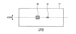
なお、校正用鋼板77として、一様な組織を広い範囲でもつものを準備するのは困難である。そこで、本実施形態では、図5に示すように、上面計測用センサヘッド71及び下面計測用センサヘッド72が、図中X方向へ移動した際、校正用鋼板77における各硬さセンサ78が必ず通過する部分に、100[mm]×100[mm]程度の大きさを有する一様な組織をもつ試験片を埋め込むことによって、一様な組織をもつ感度校正用部位90を校正用鋼板77に設けている。そして、上面計測用センサヘッド71及び下面計測用センサヘッド72の各硬さセンサ78によって、感度校正用部位90の表層硬さを計測し、その計測結果に基づいて各硬さセンサ78の感度校正を行う。これにより、いずれの硬さセンサ78も一様な組織をもつ感度校正用部位90にて感度校正がなされるため、より精度の高い感度校正を実現することが可能となる。
It is difficult to prepare a
また、図5に示すように、校正用鋼板77の上面及び下面には、人工ハードスポット91が設けられている。この人工ハードスポット91は、鋼板S2の表層に対して予め設定された表層硬さの上記閾値に相当する硬さを有する組織を持ち、アークストライクによって人工的に形成されている。そして、各硬さセンサ78の感度校正を行った後、校正用鋼板77を図中Y方向に移動させて、上面計測用センサヘッド71及び下面計測用センサヘッド72によって人工ハードスポット91の表層硬さを測定し、その測定結果に基づいて、硬さセンサ78ごとに上記閾値を設定する。これにより、オンライン電磁気計測工程7bにて、各硬さセンサ78の感度校正を行った後の上面計測用センサヘッド71及び下面計測用センサヘッド72を用いて、鋼板S2の上面及び下面の表層硬さを計測した領域内に上記硬さ指示部位があるかを、上記閾値に基づいて精度良く判定することができる。
As shown in FIG. 5, artificial
なお、本実施形態においては、自動表層硬さ計測装置70を鋼片用として説明したが、本表層硬さ計測装置は鋼片用に限定されない。すなわち、脱磁と電磁気的な特性値の測定とが行えれば、どの材料にも用いることができる。
In addition, in this embodiment, although the automatic surface layer
なお、本実施形態においては、鋼板S2の上面及び下面の表層硬さを計測するとして説明したが、上面のみの表層または下面のみの表層を脱磁するとしてもよい。脱磁の範囲は、鋼板S2の品種によって、鋼板S2の状態によって、または、鋼板S2の表層硬さの計測領域に合わせて、適宜選択すればよい。 In the present embodiment, the surface hardness of the upper surface and the lower surface of the steel plate S2 has been described as being measured. However, the surface layer of only the upper surface or the surface layer of only the lower surface may be demagnetized. The range of demagnetization may be appropriately selected according to the type of the steel plate S2, the state of the steel plate S2, or the surface hardness measurement region of the steel plate S2.
以上のように、本発明に係る鋼板S3の製造方法を適用した鋼板製造工程1及び鋼板製造工程9においては、鋼管へ加工する前の鋼板S3の製造中に、鋼板S2の上面及び/又は下面の表層を脱磁した後に電磁気的な特性値を測定することから、非接触で連続的に鋼板S2の上面及び/又は下面の表層硬さを計測することができ、その結果、従来の抜き取り検査で課題となっていたハードスポットの見逃しを抑えることができる。さらに、鋼板S2からハードスポットを除去することにより、最終的にハードスポットがない鋼板S3を製造することができる。
As described above, in the steel
さらに、このようなハードスポットがない鋼板S3を用いて鋼管等を製作した場合、製作された鋼製加工品(鋼管等)の表層に存在するハードスポットに起因した腐食割れの発生が抑制されることが期待できる。特に、本発明に係る鋼板の製造方法により製造された鋼板S3を用いて製造された鋼管を、パイプラインに適用した場合には、鋼管の内面におけるハードスポット起因と考えられる腐食割れの発生が抑制される効果が、より大きく得ることを期待できる。 Furthermore, when a steel pipe or the like is manufactured using the steel plate S3 without such a hard spot, the occurrence of corrosion cracking due to the hard spot existing on the surface layer of the manufactured steel product (steel pipe or the like) is suppressed. I can expect that. In particular, when a steel pipe manufactured by using the steel sheet S3 manufactured by the steel sheet manufacturing method according to the present invention is applied to a pipeline, the occurrence of corrosion cracking that is considered to be caused by hard spots on the inner surface of the steel pipe is suppressed. It can be expected that the effect will be greater.
さらに、本実施形態にて説明した自動表層硬さ計測装置70によれば、単純な装置構成によって鋼板S2の上面及び/又は下面の表層を脱磁した後に表層硬さを計測することができるので、生産性を低下させずに鋼板S2の上面及び/又は下面にあるハードスポットを計測することができる。
Furthermore, according to the automatic surface
1 鋼板製造工程
2 粗圧延工程
3 仕上げ圧延工程
4 冷却工程
5 焼鈍工程
6 超音波探傷工程
7 表層硬さ計測工程
7a オンライン脱磁工程
7b オンライン電磁気計測工程
7c 指示部脱磁工程
7d オフライン電磁気計測工程
8 研削工程
9 鋼板製造工程
70 自動表層硬さ計測装置
71 上面計測用センサヘッド
72 下面計測用センサヘッド
73 表層硬さ計測エリア
73a 開口部
74 上面側可動手段
75 下面側可動手段
76 感度校正エリア
77 校正用鋼板
78 硬さセンサ
79 硬さセンサ制御手段
90 感度校正用部位
91 人工ハードスポット
S1 鋼片
S2 鋼板
S3 鋼板
DESCRIPTION OF
Claims (4)
前記鋼板の表層硬さを計測し、前記計測された前記鋼板の表層硬さに基づいて、前記鋼板の表層に対して予め設定された表層硬さよりも硬い部位を、硬さ指示部位として判定する表層硬さ計測工程と、
前記鋼板の表層における前記判定された硬さ指示部位を除去する除去工程と、
を有し、
前記表層硬さ計測工程は、前記鋼板の表層の脱磁を行う脱磁工程と、
前記脱磁工程の後に、前記鋼板の表層の電磁気的な特性値を測定し、前記測定された電磁気的な特性値から前記鋼板の前記表層硬さを計測する電磁気計測工程と、
を有することを特徴とする鋼板の製造方法。 A rolling process for rolling a steel piece into a steel plate;
The surface layer hardness of the steel sheet is measured, and based on the measured surface layer hardness of the steel sheet, a part harder than the surface layer hardness preset for the surface layer of the steel sheet is determined as a hardness indicating part. Surface hardness measurement process,
A removal step of removing the determined hardness indicating site in the surface layer of the steel sheet;
Have
The surface hardness measurement step includes a demagnetization step of demagnetizing the surface layer of the steel plate,
After the demagnetization step, the electromagnetic characteristic value of the surface layer of the steel sheet is measured, and the surface hardness of the steel sheet is measured from the measured electromagnetic characteristic value; and
The manufacturing method of the steel plate characterized by having.
前記磁性材の幅方向へ前記計測用センサヘッドが移動可能なように構成されている可動手段と、
前記磁性材の長手方向へ前記磁性材が搬送可能なように構成されている搬送機構と、
前記表層硬さを計測する手段に接続されている制御手段と、
を備え、
前記表層硬さを計測する手段は、前記磁性材の前記表層を脱磁し、前記磁性材の前記表層を磁化し、前記表層の電磁気的な特性値を測定し、
前記制御手段は、前記表層硬さを計測する手段による前記脱磁と前記磁化とを制御し、測定された前記電磁気的な特性値に基づいて前記磁性材の表層硬さを算出する、
ことを特徴とする磁性材用表層硬さ計測装置。 A sensor head for measurement provided with means for measuring surface hardness on the surface facing the magnetic material;
Movable means configured such that the sensor head for measurement is movable in the width direction of the magnetic material;
A transport mechanism configured to transport the magnetic material in the longitudinal direction of the magnetic material;
Control means connected to the means for measuring the surface hardness,
With
The means for measuring the surface layer hardness demagnetizes the surface layer of the magnetic material, magnetizes the surface layer of the magnetic material, measures the electromagnetic characteristic value of the surface layer,
The control means controls the demagnetization and the magnetization by the means for measuring the surface hardness, and calculates the surface hardness of the magnetic material based on the measured electromagnetic characteristic value.
A surface hardness measuring apparatus for magnetic materials.
Applications Claiming Priority (2)
| Application Number | Priority Date | Filing Date | Title |
|---|---|---|---|
| JP2017169318 | 2017-09-04 | ||
| JP2017169318 | 2017-09-04 |
Publications (2)
| Publication Number | Publication Date |
|---|---|
| JP2019042807A true JP2019042807A (en) | 2019-03-22 |
| JP6948297B2 JP6948297B2 (en) | 2021-10-13 |
Family
ID=65815239
Family Applications (1)
| Application Number | Title | Priority Date | Filing Date |
|---|---|---|---|
| JP2018159161A Active JP6948297B2 (en) | 2017-09-04 | 2018-08-28 | Steel sheet manufacturing method, surface hardness measuring device for magnetic materials, and steel sheet manufacturing equipment line |
Country Status (1)
| Country | Link |
|---|---|
| JP (1) | JP6948297B2 (en) |
Cited By (9)
| Publication number | Priority date | Publication date | Assignee | Title |
|---|---|---|---|---|
| WO2021256444A1 (en) * | 2020-06-15 | 2021-12-23 | Jfeスチール株式会社 | Mechanical property measurement device, mechanical property measurement method, material production equipment, material management method, and material production method |
| WO2021256443A1 (en) * | 2020-06-15 | 2021-12-23 | Jfeスチール株式会社 | Mechanical property measurement device, mechanical property measurement method, material manufacturing facility, material managing method, and material manufacturing method |
| WO2021256442A1 (en) * | 2020-06-15 | 2021-12-23 | Jfeスチール株式会社 | Mechanical property measuring device, mechanical property measuring method, substance manufacturing facility, substance management method, and substance manufacturing method |
| KR20220089061A (en) * | 2020-12-21 | 2022-06-28 | 주식회사 포스코 | Steel Plate for Calibration, Electro-magnetic Test Device and Manufacturing Method of Steel Plate for Calibration |
| WO2022195788A1 (en) * | 2021-03-17 | 2022-09-22 | 日本製鉄株式会社 | Hardness computing device, hardness measuring system, hardness computing method, and hardness computing program |
| EP4080204A4 (en) * | 2019-12-20 | 2022-12-28 | Posco | Device and method for testing surface material of steel plate |
| RU2808619C1 (en) * | 2020-06-15 | 2023-11-30 | ДжФЕ СТИЛ КОРПОРЕЙШН | Device for measurement of mechanical properties, method for measurement of mechanical properties, equipment for manufacturing material, method for control of material and method for material manufacturing |
| JP7397318B2 (en) | 2020-04-23 | 2023-12-13 | 日本製鉄株式会社 | Steel plate manufacturing method, steel pipe manufacturing method, steel plate manufacturing equipment and program |
| JP7448803B2 (en) | 2020-04-23 | 2024-03-13 | 日本製鉄株式会社 | Steel plate manufacturing method, steel pipe manufacturing method, steel plate manufacturing equipment and program |
Citations (11)
| Publication number | Priority date | Publication date | Assignee | Title |
|---|---|---|---|---|
| JPS5021869B1 (en) * | 1964-02-13 | 1975-07-25 | ||
| JPS5036791B1 (en) * | 1970-12-03 | 1975-11-27 | ||
| JPS58102148A (en) * | 1981-12-14 | 1983-06-17 | Kawasaki Steel Corp | On-line hardness measuring method for steel sheet |
| JPS59147253A (en) * | 1983-02-12 | 1984-08-23 | Kawasaki Steel Corp | On-line hardness measurement of steel plate |
| JPH08145816A (en) * | 1994-11-21 | 1996-06-07 | Hitachi Metals Ltd | Measuring method of residual stress distribution in rolled thin steel plate |
| JP2005138168A (en) * | 2003-11-10 | 2005-06-02 | Nippon Steel Corp | Equipment train and method for inspection/maintenance of steel billet |
| JP2005153089A (en) * | 2003-11-27 | 2005-06-16 | Nippon Steel Corp | Method for removing surface flaw of billet |
| JP2008224494A (en) * | 2007-03-14 | 2008-09-25 | Sumitomo Metal Ind Ltd | Eddy current inspection method, steel pipe inspected thereby and eddy current inspection device for executing the eddy current inspection method |
| JP2008224495A (en) * | 2007-03-14 | 2008-09-25 | Sumitomo Metal Ind Ltd | Eddy current inspection method, steel pipe inspected thereby and eddy current inspection device for executing the eddy current inspection method |
| JP2011252787A (en) * | 2010-06-02 | 2011-12-15 | Ntn Corp | Hardening quality inspection device |
| WO2016085382A1 (en) * | 2014-11-28 | 2016-06-02 | Scania Cv Ab | A method of calibrating an evaluation arrangement for sensing magnetic barkhausen noise. |
-
2018
- 2018-08-28 JP JP2018159161A patent/JP6948297B2/en active Active
Patent Citations (11)
| Publication number | Priority date | Publication date | Assignee | Title |
|---|---|---|---|---|
| JPS5021869B1 (en) * | 1964-02-13 | 1975-07-25 | ||
| JPS5036791B1 (en) * | 1970-12-03 | 1975-11-27 | ||
| JPS58102148A (en) * | 1981-12-14 | 1983-06-17 | Kawasaki Steel Corp | On-line hardness measuring method for steel sheet |
| JPS59147253A (en) * | 1983-02-12 | 1984-08-23 | Kawasaki Steel Corp | On-line hardness measurement of steel plate |
| JPH08145816A (en) * | 1994-11-21 | 1996-06-07 | Hitachi Metals Ltd | Measuring method of residual stress distribution in rolled thin steel plate |
| JP2005138168A (en) * | 2003-11-10 | 2005-06-02 | Nippon Steel Corp | Equipment train and method for inspection/maintenance of steel billet |
| JP2005153089A (en) * | 2003-11-27 | 2005-06-16 | Nippon Steel Corp | Method for removing surface flaw of billet |
| JP2008224494A (en) * | 2007-03-14 | 2008-09-25 | Sumitomo Metal Ind Ltd | Eddy current inspection method, steel pipe inspected thereby and eddy current inspection device for executing the eddy current inspection method |
| JP2008224495A (en) * | 2007-03-14 | 2008-09-25 | Sumitomo Metal Ind Ltd | Eddy current inspection method, steel pipe inspected thereby and eddy current inspection device for executing the eddy current inspection method |
| JP2011252787A (en) * | 2010-06-02 | 2011-12-15 | Ntn Corp | Hardening quality inspection device |
| WO2016085382A1 (en) * | 2014-11-28 | 2016-06-02 | Scania Cv Ab | A method of calibrating an evaluation arrangement for sensing magnetic barkhausen noise. |
Non-Patent Citations (1)
| Title |
|---|
| "Development of an Eddy Current based Inspection Technique for the Detection of Hard Spots on Heavy P", 19TH WORLD CONFERENCE ON NON-DESTRUCTIVE TESITNG 2016, JPN7020000225, 2016, ISSN: 0004407214 * |
Cited By (19)
| Publication number | Priority date | Publication date | Assignee | Title |
|---|---|---|---|---|
| EP4080204A4 (en) * | 2019-12-20 | 2022-12-28 | Posco | Device and method for testing surface material of steel plate |
| JP7448803B2 (en) | 2020-04-23 | 2024-03-13 | 日本製鉄株式会社 | Steel plate manufacturing method, steel pipe manufacturing method, steel plate manufacturing equipment and program |
| JP7397318B2 (en) | 2020-04-23 | 2023-12-13 | 日本製鉄株式会社 | Steel plate manufacturing method, steel pipe manufacturing method, steel plate manufacturing equipment and program |
| WO2021256442A1 (en) * | 2020-06-15 | 2021-12-23 | Jfeスチール株式会社 | Mechanical property measuring device, mechanical property measuring method, substance manufacturing facility, substance management method, and substance manufacturing method |
| RU2808619C1 (en) * | 2020-06-15 | 2023-11-30 | ДжФЕ СТИЛ КОРПОРЕЙШН | Device for measurement of mechanical properties, method for measurement of mechanical properties, equipment for manufacturing material, method for control of material and method for material manufacturing |
| JPWO2021256442A1 (en) * | 2020-06-15 | 2021-12-23 | ||
| JPWO2021256444A1 (en) * | 2020-06-15 | 2021-12-23 | ||
| WO2021256444A1 (en) * | 2020-06-15 | 2021-12-23 | Jfeスチール株式会社 | Mechanical property measurement device, mechanical property measurement method, material production equipment, material management method, and material production method |
| JP7095815B2 (en) | 2020-06-15 | 2022-07-05 | Jfeスチール株式会社 | Mechanical property measuring device, mechanical property measuring method, substance manufacturing equipment, substance management method and substance manufacturing method |
| JP7095817B2 (en) | 2020-06-15 | 2022-07-05 | Jfeスチール株式会社 | Mechanical property measuring device, mechanical property measuring method, substance manufacturing equipment, substance management method and substance manufacturing method |
| JP7095814B2 (en) | 2020-06-15 | 2022-07-05 | Jfeスチール株式会社 | Mechanical property measuring device, mechanical property measuring method, substance manufacturing equipment, substance management method and substance manufacturing method |
| WO2021256443A1 (en) * | 2020-06-15 | 2021-12-23 | Jfeスチール株式会社 | Mechanical property measurement device, mechanical property measurement method, material manufacturing facility, material managing method, and material manufacturing method |
| JPWO2021256443A1 (en) * | 2020-06-15 | 2021-12-23 | ||
| RU2808618C1 (en) * | 2020-06-15 | 2023-11-30 | ДжФЕ СТИЛ КОРПОРЕЙШН | Device for measurement of mechanical properties, method for measurement of mechanical properties, equipment for material manufacturing, method for control of material and method of manufacturing |
| WO2022139281A1 (en) | 2020-12-21 | 2022-06-30 | 주식회사 포스코 | Correction steel sheet, electromagnetic inspection device capable of correcting, and method for manufacturing correction steel sheet |
| KR102553226B1 (en) * | 2020-12-21 | 2023-07-07 | 주식회사 포스코 | Electro-magnetic Test Device |
| KR20220089061A (en) * | 2020-12-21 | 2022-06-28 | 주식회사 포스코 | Steel Plate for Calibration, Electro-magnetic Test Device and Manufacturing Method of Steel Plate for Calibration |
| JP7461569B2 (en) | 2020-12-21 | 2024-04-03 | ポスコ カンパニー リミテッド | Electromagnetic testing equipment that can be calibrated |
| WO2022195788A1 (en) * | 2021-03-17 | 2022-09-22 | 日本製鉄株式会社 | Hardness computing device, hardness measuring system, hardness computing method, and hardness computing program |
Also Published As
| Publication number | Publication date |
|---|---|
| JP6948297B2 (en) | 2021-10-13 |
Similar Documents
| Publication | Publication Date | Title |
|---|---|---|
| JP6948297B2 (en) | Steel sheet manufacturing method, surface hardness measuring device for magnetic materials, and steel sheet manufacturing equipment line | |
| Dobmann et al. | Industrial applications of 3MA–micromagnetic multiparameter microstructure and stress analysis | |
| JP4829883B2 (en) | Method and apparatus for non-destructive inspection of tubes | |
| US8490492B2 (en) | Method for nondestructive testing of pipes | |
| JP4998820B2 (en) | Eddy current inspection method and eddy current inspection apparatus for implementing the eddy current inspection method | |
| JPWO2018138850A1 (en) | Magnetic body inspection apparatus and magnetic body inspection method | |
| US20110199081A1 (en) | Barkhausen noise inspection apparatus and inspection method | |
| US9304108B2 (en) | Quenching depth measurement method and quenching depth measurement apparatus | |
| US8552718B2 (en) | Method for the nondestructive testing of pipes | |
| JP2011069654A (en) | Barkhausen noise inspection system and barkhausen noise inspection method | |
| Nosov et al. | Nondestructive testing of the quality of blanks for the fabrication of hot-rolled strips using the acoustic-emission method | |
| KR101358452B1 (en) | Apparatus for detecting defect of rolled coil | |
| Wolter et al. | Micromagnetic testing for rolled steel | |
| JPH05142203A (en) | Method for diagnosing environmental stress cracking of high-strength material | |
| JP5004324B2 (en) | Repair method for molds containing magnetic material | |
| WO2023106047A1 (en) | Steel plate manufacturing method and steel plate manufacturing equipment line | |
| JP2023507637A (en) | Steel plate surface material inspection device and method | |
| JP7265139B2 (en) | Steel material surface layer inspection method and steel material surface layer inspection system | |
| JP6601599B1 (en) | Rolling part inspection method and rolling part inspection apparatus | |
| Kikuchi et al. | Applicability of magnetic flux leakage method for wall thinning monitoring in nuclear power plants | |
| JP5445054B2 (en) | Processed alteration layer detection apparatus and processing alteration layer detection method | |
| JP2005059070A (en) | Steel strip manufacturing method | |
| JP7448803B2 (en) | Steel plate manufacturing method, steel pipe manufacturing method, steel plate manufacturing equipment and program | |
| JP7397318B2 (en) | Steel plate manufacturing method, steel pipe manufacturing method, steel plate manufacturing equipment and program | |
| KR102553226B1 (en) | Electro-magnetic Test Device |
Legal Events
| Date | Code | Title | Description |
|---|---|---|---|
| A621 | Written request for application examination |
Free format text: JAPANESE INTERMEDIATE CODE: A621 Effective date: 20190425 |
|
| A977 | Report on retrieval |
Free format text: JAPANESE INTERMEDIATE CODE: A971007 Effective date: 20200122 |
|
| A131 | Notification of reasons for refusal |
Free format text: JAPANESE INTERMEDIATE CODE: A131 Effective date: 20200204 |
|
| A521 | Request for written amendment filed |
Free format text: JAPANESE INTERMEDIATE CODE: A523 Effective date: 20200326 |
|
| A02 | Decision of refusal |
Free format text: JAPANESE INTERMEDIATE CODE: A02 Effective date: 20200818 |
|
| A521 | Request for written amendment filed |
Free format text: JAPANESE INTERMEDIATE CODE: A523 Effective date: 20201020 |
|
| C60 | Trial request (containing other claim documents, opposition documents) |
Free format text: JAPANESE INTERMEDIATE CODE: C60 Effective date: 20201020 |
|
| A911 | Transfer to examiner for re-examination before appeal (zenchi) |
Free format text: JAPANESE INTERMEDIATE CODE: A911 Effective date: 20201028 |
|
| C21 | Notice of transfer of a case for reconsideration by examiners before appeal proceedings |
Free format text: JAPANESE INTERMEDIATE CODE: C21 Effective date: 20201104 |
|
| A912 | Re-examination (zenchi) completed and case transferred to appeal board |
Free format text: JAPANESE INTERMEDIATE CODE: A912 Effective date: 20201211 |
|
| C211 | Notice of termination of reconsideration by examiners before appeal proceedings |
Free format text: JAPANESE INTERMEDIATE CODE: C211 Effective date: 20201215 |
|
| C22 | Notice of designation (change) of administrative judge |
Free format text: JAPANESE INTERMEDIATE CODE: C22 Effective date: 20210413 |
|
| C13 | Notice of reasons for refusal |
Free format text: JAPANESE INTERMEDIATE CODE: C13 Effective date: 20210525 |
|
| C19 | Decision taken to dismiss amendment |
Free format text: JAPANESE INTERMEDIATE CODE: C19 Effective date: 20210608 |
|
| C30A | Notification sent |
Free format text: JAPANESE INTERMEDIATE CODE: C3012 Effective date: 20210608 |
|
| A521 | Request for written amendment filed |
Free format text: JAPANESE INTERMEDIATE CODE: A523 Effective date: 20210623 |
|
| C302 | Record of communication |
Free format text: JAPANESE INTERMEDIATE CODE: C302 Effective date: 20210623 |
|
| C23 | Notice of termination of proceedings |
Free format text: JAPANESE INTERMEDIATE CODE: C23 Effective date: 20210727 |
|
| C03 | Trial/appeal decision taken |
Free format text: JAPANESE INTERMEDIATE CODE: C03 Effective date: 20210914 |
|
| C30A | Notification sent |
Free format text: JAPANESE INTERMEDIATE CODE: C3012 Effective date: 20210914 |
|
| A61 | First payment of annual fees (during grant procedure) |
Free format text: JAPANESE INTERMEDIATE CODE: A61 Effective date: 20210917 |
|
| R150 | Certificate of patent or registration of utility model |
Ref document number: 6948297 Country of ref document: JP Free format text: JAPANESE INTERMEDIATE CODE: R150 |