JP2019039511A - Brake pad wear detector - Google Patents

Brake pad wear detector Download PDF

Info

Publication number
JP2019039511A
JP2019039511A JP2017162425A JP2017162425A JP2019039511A JP 2019039511 A JP2019039511 A JP 2019039511A JP 2017162425 A JP2017162425 A JP 2017162425A JP 2017162425 A JP2017162425 A JP 2017162425A JP 2019039511 A JP2019039511 A JP 2019039511A
Authority
JP
Japan
Prior art keywords
base
disk rotor
brake pad
lining
rotor
Prior art date
Legal status (The legal status is an assumption and is not a legal conclusion. Google has not performed a legal analysis and makes no representation as to the accuracy of the status listed.)
Pending
Application number
JP2017162425A
Other languages
Japanese (ja)
Other versions
JP2019039511A5 (en
Inventor
理 一色
Tadashi Isshiki
理 一色
Current Assignee (The listed assignees may be inaccurate. Google has not performed a legal analysis and makes no representation or warranty as to the accuracy of the list.)
Advics Co Ltd
Original Assignee
Advics Co Ltd
Priority date (The priority date is an assumption and is not a legal conclusion. Google has not performed a legal analysis and makes no representation as to the accuracy of the date listed.)
Filing date
Publication date
Application filed by Advics Co Ltd filed Critical Advics Co Ltd
Priority to JP2017162425A priority Critical patent/JP2019039511A/en
Priority to PCT/JP2018/030947 priority patent/WO2019039501A1/en
Publication of JP2019039511A publication Critical patent/JP2019039511A/en
Publication of JP2019039511A5 publication Critical patent/JP2019039511A5/ja
Pending legal-status Critical Current

Links

Images

Classifications

    • FMECHANICAL ENGINEERING; LIGHTING; HEATING; WEAPONS; BLASTING
    • F16ENGINEERING ELEMENTS AND UNITS; GENERAL MEASURES FOR PRODUCING AND MAINTAINING EFFECTIVE FUNCTIONING OF MACHINES OR INSTALLATIONS; THERMAL INSULATION IN GENERAL
    • F16DCOUPLINGS FOR TRANSMITTING ROTATION; CLUTCHES; BRAKES
    • F16D66/00Arrangements for monitoring working conditions, e.g. wear, temperature
    • F16D66/02Apparatus for indicating wear

Abstract

To provide a brake pad wear detector which can generate a stable alarm sound without receiving the interference of the other component.SOLUTION: An alarm part K has: a curved part 22 which is connected to an attachment part 21 at one end, and curved to a disc rotor side in a first direction X; a base part 23 which is connected to the other end of the curved part 22 at a base end, opposes a disc rotor side face, and extends to a radial direction (third direction Z) of a disc rotor; a salient part 24 which is connected to a tip of the base part 23, and curvedly salient toward a slide-contact part with which a lining contacts at the inside rather than an external peripheral face of the disc rotor; and a first notch 26 formed at the base part 23 in a connection portion between the base part 23 and the salient part 24.SELECTED DRAWING: Figure 4

Description

本発明は、ブレーキパッド摩耗検出器に関する。   The present invention relates to a brake pad wear detector.

従来から、例えば、下記特許文献1に開示されたディスクブレーキが知られている。この従来のディスクブレーキは、車輪とともに回転するディスクロータの側面に押圧されて制動力を発生させるブレーキパッドのライニングが摩耗し、ブレーキパッド(ライニング)の使用限界に到達したことをユーザに警告するブレーキパッド摩耗検出器を備えている。ブレーキパッド摩耗検出器は、金属板を折り曲げて形成されたセンサ片を有しており、このセンサ片がライニングを支持する裏板に固定されるようになっている。そして、ブレーキパッド摩耗検出器は、ライニングが使用限界まで摩耗した場合に、ディスクロータに接触して振動することにより、警告音(可聴音)を発生するようになっている。   Conventionally, for example, a disc brake disclosed in Patent Document 1 below is known. This conventional disc brake is a brake that warns the user that the lining of the brake pad that has been pressed against the side of the disc rotor that rotates together with the wheels to generate braking force has been worn and the use limit of the brake pad (lining) has been reached. A pad wear detector is provided. The brake pad wear detector has a sensor piece formed by bending a metal plate, and the sensor piece is fixed to a back plate that supports the lining. The brake pad wear detector generates a warning sound (audible sound) by vibrating in contact with the disk rotor when the lining is worn to the use limit.

実開平3−118333号公報Japanese Utility Model Publication No. 3-118333

しかしながら、上記従来のディスクブレーキに設けられるブレーキパッド摩耗検出器は、裏板のディスクロータとは反対側の面(シリンダ押圧面)にセンサ片の本体を突出させることによって振動部分を形成し、センサ片の先端がディスクロータに臨むようになっている。このため、ブレーキパッド摩耗検出器を設ける場合、シリンダ押圧面側に配置されるシリンダ等の他の部品との干渉を避ける必要があり、ブレーキパッド摩耗検出器の形状や大きさの制限を設けてしまう。その結果、発生させる警告音(可聴音)の大きさや音色にばらつきが生じて、ユーザに適切にライニングの摩耗を警告できない可能性がある。   However, the brake pad wear detector provided in the conventional disc brake forms a vibration part by projecting the main body of the sensor piece on the surface (cylinder pressing surface) opposite to the disc rotor of the back plate, The tip of the piece faces the disc rotor. For this reason, when providing a brake pad wear detector, it is necessary to avoid interference with other parts such as a cylinder arranged on the cylinder pressing surface side, and there is a restriction on the shape and size of the brake pad wear detector. End up. As a result, the magnitude and tone color of the warning sound (audible sound) to be generated may vary, and the user may not be appropriately warned of lining wear.

本発明は、上記課題を解決するためになされたものであり、他の部品の干渉を受けず、安定した警告音を発生することができるブレーキパッド摩耗検出器を提供することにある。   The present invention has been made to solve the above-described problems, and it is an object of the present invention to provide a brake pad wear detector that can generate a stable warning sound without receiving interference from other components.

上記の課題を解決するため、請求項1に係るブレーキパッド摩耗検出器の発明は、車両の回転部材に連結されて回転部材と一体に回転するディスクロータと、ディスクロータの外周部の一部を跨ぐように設けられて車両の非回転部材に固定されるキャリパと、ディスクロータの側面に対向するライニング及びライニングが固定された裏板からなり、キャリパに組み付けられた一対のブレーキパッドと、を備えたディスクブレーキ装置に適用されて、ブレーキパッドの裏板に取り付けられた取付部と、取付部から延設され、ライニングが摩耗した場合にディスクロータと接触してライニングの摩耗を警告する警告部と、を備えたブレーキパッド摩耗検出器であって、警告部は、一端が取付部に連結され、ディスクロータの側に向けて湾曲する湾曲部と、湾曲部の他端に基端が連結され、ディスクロータの側面に対向し且つディスクロータの径方向に沿って延びる基部と、基部の基端とは反対側の先端に連結され、ディスクロータの外周部よりも内側にてディスクロータに向けて屈曲して突出し、ライニングが摺接するディスクロータの摺接部に接触可能な突出部と、基部と突出部との連結部分にて基部に形成された第一切欠き部と、を有するように構成される。   In order to solve the above-described problems, a brake pad wear detector according to a first aspect of the present invention includes a disk rotor connected to a rotating member of a vehicle and rotating integrally with the rotating member, and a part of an outer peripheral portion of the disk rotor. A caliper provided to straddle and fixed to a non-rotating member of the vehicle, and a pair of brake pads assembled to the caliper, comprising a lining facing the side surface of the disk rotor and a back plate to which the lining is fixed Applied to the disc brake device and attached to the back plate of the brake pad, and a warning portion that extends from the attachment portion and that contacts the disc rotor when the lining wears and warns the lining wear The warning pad is a bay that has one end connected to the mounting portion and curved toward the disc rotor side. And a base end connected to the other end of the curved portion, a base portion facing the side surface of the disk rotor and extending along a radial direction of the disk rotor, and a tip end opposite to the base end of the base portion. Formed at the base at the joint between the base and the projecting part, and the projecting part that can be bent and projecting toward the disk rotor inside the outer peripheral part of the rotor and that can contact the sliding part of the disk rotor where the lining slides And a first notch portion formed.

これによれば、ブレーキパッド摩耗検出器は、ディスクロータの側に湾曲部、基部及び突出部が設けられることにより、キャリパに設けられる他の部材(例えば、シリンダやピストン等)との干渉を避けることができ、湾曲部、基部及び突出部等の設計の自由度を向上させることができる。従って、警告部Kは、適切な音色(可聴周波数)且つ十分な音量を有する警告音(可聴音)を安定して発生させることができる。又、基部に第一切欠き部を設けることにより、ライニングが摩耗して突出部がディスクロータの摺接部に接触した場合に基部が撓むことにより発生する応力集中を緩和することができる。これにより、基部及び突出部が必要十分な機械的な強度を有することができて突出部が摺接部に対して適切に接触することができ、その結果、警告部は警告音(可聴音)を安定して発生させることができる。   According to this, the brake pad wear detector avoids interference with other members (for example, cylinders, pistons, etc.) provided in the caliper by providing the curved portion, the base portion, and the protruding portion on the disc rotor side. Therefore, the degree of freedom in designing the curved portion, the base portion, the protruding portion, and the like can be improved. Therefore, the warning unit K can stably generate a warning sound (audible sound) having an appropriate tone color (audible frequency) and a sufficient volume. Further, by providing the first notch portion at the base portion, it is possible to alleviate the stress concentration generated when the base portion is bent when the lining wears and the protruding portion contacts the sliding contact portion of the disk rotor. As a result, the base portion and the protruding portion can have a necessary and sufficient mechanical strength, and the protruding portion can properly contact the sliding contact portion. As a result, the warning portion generates a warning sound (audible sound). Can be generated stably.

ディスクブレーキ装置の全体図である。1 is an overall view of a disc brake device. 図1のキャリパの構成を概略的に示す斜視図である。It is a perspective view which shows the structure of the caliper of FIG. 1 schematically. 図2のブレーキパッドに本発明の実施形態に係るブレーキパッド摩耗検出器を装着した状態を示す図である。It is a figure which shows the state which mounted | wore the brake pad of FIG. 2 with the brake pad wear detector which concerns on embodiment of this invention. 図3のブレーキパッド摩耗検出器の構成を示す斜視図である。It is a perspective view which shows the structure of the brake pad wear detector of FIG. 図3のブレーキパッド摩耗検出器の構成を示す正面図である。It is a front view which shows the structure of the brake pad wear detector of FIG. 図3のブレーキパッド摩耗検出器の構成を示す側面図である。It is a side view which shows the structure of the brake pad wear detector of FIG. ブレーキパッド摩耗検出器の作動を説明するための図である。It is a figure for demonstrating the action | operation of a brake pad abrasion detector. 実施形態の変形例に係るブレーキパッド摩耗検出器の構成を示す正面図である。It is a front view which shows the structure of the brake pad wear detector which concerns on the modification of embodiment.

以下、本発明の実施形態について図面を参照しながら説明する。尚、説明に用いる各図は概念図であり、各部の形状は必ずしも厳密なものではない場合がある。   Hereinafter, embodiments of the present invention will be described with reference to the drawings. Each figure used for explanation is a conceptual diagram, and the shape of each part may not necessarily be exact.

先ず、本実施形態に係るブレーキパッド摩耗検出器20(以下、単に、「摩耗検出器20」とも称呼する。)が適用されるディスクブレーキ装置10の構成を説明する。ディスクブレーキ装置10は、例えば、ピストン対向型のディスクブレーキ装置である。尚、ディスクブレーキ装置10としては、マウンティングを有する浮動型のディスクブレーキ装置を用いることも可能である。   First, the configuration of the disc brake device 10 to which the brake pad wear detector 20 (hereinafter simply referred to as “wear detector 20”) according to the present embodiment is applied will be described. The disc brake device 10 is, for example, a piston-facing disc brake device. The disc brake device 10 may be a floating disc brake device having a mounting.

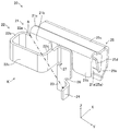
図1に示すように、ディスクブレーキ装置10は、円盤状のディスクロータ11とディスクロータ11の外周部の一部を跨ぐキャリパ12とを備えている。ディスクロータ11は、金属材料(例えば、鋳鉄等)から形成されている。ディスクロータ11は、円盤状のロータ本体11aと、車両の回転部材としての車軸(図示省略)にボルト及びナット等により締結される円筒状のハット部11bと、から構成される。これにより、ディスクロータ11即ちロータ本体11a及びハット部11bは、車両の回転部材と一体に回転する。ロータ本体11aは、外周部よりも内側の側面にて、後述する一対のブレーキパッド13のライニング13bと摺接する摺接部Rを有している。ここで、以下の説明において、円盤状のディスクロータ11の軸方向Xを第一方向Xと称呼し、第一方向Xに直交し且つキャリパ12の組み付け位置におけるディスクロータ11の接線に平行な方向Yを第二方向Yと称呼し、第一方向X及び第二方向Yに直交する方向Z即ちディスクロータ11の径方向Zを第三方向Zと称呼する。即ち、第一方向X、第二方向Y及び第三方向Zは、互いに直交する関係にある。   As shown in FIG. 1, the disc brake device 10 includes a disc-shaped disc rotor 11 and a caliper 12 straddling a part of the outer periphery of the disc rotor 11. The disk rotor 11 is made of a metal material (for example, cast iron). The disk rotor 11 includes a disk-like rotor body 11a and a cylindrical hat portion 11b fastened to an axle (not shown) as a rotating member of the vehicle by bolts, nuts, and the like. Thereby, the disk rotor 11, that is, the rotor main body 11a and the hat portion 11b rotate integrally with the rotating member of the vehicle. The rotor main body 11a has a sliding contact portion R that is in sliding contact with a lining 13b of a pair of brake pads 13 to be described later on the side surface inside the outer peripheral portion. Here, in the following description, the axial direction X of the disk-shaped disk rotor 11 is referred to as a first direction X, and is a direction orthogonal to the first direction X and parallel to the tangent to the disk rotor 11 at the position where the caliper 12 is assembled. Y is referred to as the second direction Y, and the first direction X and the direction Z orthogonal to the second direction Y, that is, the radial direction Z of the disk rotor 11 is referred to as the third direction Z. That is, the first direction X, the second direction Y, and the third direction Z are orthogonal to each other.

キャリパ12は、金属材料(例えば、アルミ)から形成されている。キャリパ12は、車両の非回転部材(例えば、図示省略の車体)に固定される。キャリパ12は、図2に示すように、インナー部12a、アウター部12b、ブリッジ部12c及び窓部12dを有している。インナー部12a及びアウター部12bは、それぞれ、第一方向Xにて両側に配置され、図示省略のシリンダ内に図示省略のピストンを収容するようになっている。ブリッジ部12cは、インナー部12a及びアウター部12bを連結し、制動時において後述する一対のブレーキパッド13から伝達される制動トルクを受けるようになっている。窓部12dは、インナー部12a、アウター部12b及びブリッジ部12cによって形成される。窓部12dの内部には、一対のブレーキパッド13が収容されて組み込まれるようになっている。   The caliper 12 is made of a metal material (for example, aluminum). The caliper 12 is fixed to a non-rotating member (for example, a vehicle body not shown) of the vehicle. As shown in FIG. 2, the caliper 12 has an inner portion 12a, an outer portion 12b, a bridge portion 12c, and a window portion 12d. The inner portion 12a and the outer portion 12b are respectively arranged on both sides in the first direction X, and accommodate a piston (not shown) in a cylinder (not shown). The bridge portion 12c connects the inner portion 12a and the outer portion 12b, and receives braking torque transmitted from a pair of brake pads 13 described later during braking. The window portion 12d is formed by an inner portion 12a, an outer portion 12b, and a bridge portion 12c. A pair of brake pads 13 are accommodated and incorporated in the window portion 12d.

キャリパ12の内部に組み込まれる一対のブレーキパッド13は、第一方向Xに沿って進退するピストンの作動により、ディスクロータ11の側面、より詳しくは、摺接部Rに向けて押圧される。一対のブレーキパッド13は、図2及び図3に示すように、それぞれ、裏板13aと、摩擦材であるライニング13bと、を有している。裏板13aは、板状に形成されており、一対のパッドピン14(図2を参照)を挿通する挿通孔13a1と、後述する摩耗検出器20が装着される凹状の装着部13a2と、を有している。裏板13aは、表面13a3側にライニング13bが接着により固定され、背面13a4側がピストンによって押圧される。   The pair of brake pads 13 incorporated in the caliper 12 is pressed toward the side surface of the disk rotor 11, more specifically, the sliding contact portion R by the operation of the piston that advances and retreats along the first direction X. As shown in FIGS. 2 and 3, the pair of brake pads 13 each have a back plate 13 a and a lining 13 b that is a friction material. The back plate 13a is formed in a plate shape, and has an insertion hole 13a1 through which a pair of pad pins 14 (see FIG. 2) are inserted, and a concave mounting portion 13a2 in which a wear detector 20 described later is mounted. doing. In the back plate 13a, a lining 13b is fixed to the front surface 13a3 side by adhesion, and the back surface 13a4 side is pressed by a piston.

ライニング13bは、裏板13aとともに第一方向Xに移動し、ディスクロータ11の摺接部Rと摺接する。ライニング13bは、例えば、アラミド遷移や無機繊維、スチール繊維等を用いた有機系摩擦材から所定の厚みを有するように成形されている。尚、ライニング13bの所定の厚みは、裏板13aの表面13a3を基準にして設定される。   The lining 13 b moves in the first direction X together with the back plate 13 a and comes into sliding contact with the sliding contact portion R of the disk rotor 11. The lining 13b is formed to have a predetermined thickness from, for example, an organic friction material using an aramid transition, inorganic fiber, steel fiber, or the like. The predetermined thickness of the lining 13b is set based on the surface 13a3 of the back plate 13a.

摩耗検出器20は、図2及び図3に示すように、裏板13aの装着部13a2に装着される。摩耗検出器20は、ライニング13bがディスクロータ11の摺接部Rと摺接することによって摩耗して薄くなり、ライニング13bの使用限界を迎えると、回転するディスクロータ11と接触する。そして、摩耗検出器20は、ユーザにライニング13bの摩耗を認識させるために、予め設定された可聴周波数を有する警告音(可聴音)を発生するものである。尚、警告音としては、摺動音、接触音、振動音等である。   As shown in FIGS. 2 and 3, the wear detector 20 is attached to the attachment portion 13a2 of the back plate 13a. The wear detector 20 is worn and thin when the lining 13b is in sliding contact with the sliding contact portion R of the disk rotor 11, and contacts the rotating disk rotor 11 when the use limit of the lining 13b is reached. The wear detector 20 generates a warning sound (audible sound) having a preset audible frequency in order to make the user recognize the wear of the lining 13b. The warning sound includes sliding sound, contact sound, vibration sound, and the like.

摩耗検出器20は、ばね性を有する金属材料、例えば、ステンレス等の金属板を曲げ加工して形成されており、図4〜図7に示すように、取付部21と、警告部Kを構成する湾曲部22、基部23及び突出部24と、を備えている。取付部21は、裏板13aの表面13a3と接触する第一面21aと、第一方向Xにて第一面21aと反対側であってディスクロータ11の側面(摺接部R)に対向する第二面21bと、を有する。第二面21bは、第二方向Y及び第三方向Zに沿った方向にて平面(平板状)となるように設けられている。   The wear detector 20 is formed by bending a metal material having a spring property, for example, a metal plate such as stainless steel, and constitutes an attachment portion 21 and a warning portion K as shown in FIGS. A bending portion 22, a base portion 23, and a protruding portion 24. The attachment portion 21 is opposed to the first surface 21a in contact with the surface 13a3 of the back plate 13a and the side surface (sliding contact portion R) of the disk rotor 11 on the opposite side to the first surface 21a in the first direction X. And a second surface 21b. The second surface 21b is provided so as to be flat (in a flat plate shape) in the direction along the second direction Y and the third direction Z.

ここで、摩耗検出器20は、第一面21aが表面13a3に対して密着するように、裏板13aの装着部13a2に装着される(図7を参照)。これにより、ライニング13bと取付部21とが第一方向Xにて同一の高さの面に固定される。従って、図7に示すように、ライニング13bの厚み(摩耗後の残り厚み)を検出するための摩耗検出器20の第一方向Xにおける設置高さが正確に設定される。   Here, the wear detector 20 is mounted on the mounting portion 13a2 of the back plate 13a so that the first surface 21a is in close contact with the surface 13a3 (see FIG. 7). Thereby, the lining 13b and the attachment part 21 are fixed to the surface of the same height in the first direction X. Therefore, as shown in FIG. 7, the installation height in the first direction X of the wear detector 20 for detecting the thickness of the lining 13b (remaining thickness after wear) is accurately set.

又、取付部21は、裏板13aの表面13a3と背面13a4とを跨いで挟持する弾性クリップ25(挟持体)によって、装着部13a2に付勢状態で固定される。弾性クリップ25は、表面13a3に当接する第一付勢部25aと、背面13a4に当接する第二付勢部25bと、を有している。又、弾性クリップ25は、第一付勢部25aと第二付勢部25bとを接続し、表面13a3と背面13a4とを跨ぐように形成される接続部25cを有している。   Further, the mounting portion 21 is fixed to the mounting portion 13a2 in a biased state by an elastic clip 25 (clamping body) that sandwiches the front surface 13a3 and the back surface 13a4 of the back plate 13a. The elastic clip 25 has a first urging portion 25a that abuts on the surface 13a3 and a second urging portion 25b that abuts on the back surface 13a4. The elastic clip 25 has a connecting portion 25c that connects the first urging portion 25a and the second urging portion 25b and is formed so as to straddle the front surface 13a3 and the back surface 13a4.

第一付勢部25aは、図4及び図5に示すように、二つに分割されており、分割された一方は取付部21を兼用している。即ち、第一付勢部25aの一部が取付部21を形成している。第二付勢部25bは、図4及び図6に示すように、中央部分が第一方向Xにて背面13a4から表面13a3に向けて折り返された係合爪25dを有している。係合爪25dは、図7に示すように、裏板13aに形成された凹部13a5(被係合部)と係合することにより、弾性クリップ25を位置決めするようになっている。即ち、係合爪25dは、裏板13aに対する摩耗検出器20の位置を決めるようになっている。   As shown in FIGS. 4 and 5, the first urging portion 25 a is divided into two, and one of the divided portions also serves as the attachment portion 21. That is, a part of the first urging portion 25 a forms the attachment portion 21. As shown in FIGS. 4 and 6, the second urging portion 25 b has an engaging claw 25 d whose center portion is folded back from the back surface 13 a 4 toward the surface 13 a 3 in the first direction X. As shown in FIG. 7, the engaging claw 25d engages with a recess 13a5 (engaged portion) formed in the back plate 13a to position the elastic clip 25. That is, the engaging claw 25d determines the position of the wear detector 20 with respect to the back plate 13a.

ここで、第二付勢部25bは、裏板13aの装着部13a2に装着されていない自由状態時において、第一方向Xにて第一付勢部25aに接近するように斜めに傾いている。これにより、第二付勢部25bは、装着部13a2に装着されたときに背面13a4から第一方向Xにて表面13a3とは反対の方向に押し広げられることによりばね力を発生する。その結果、裏板13aを第一付勢部25aと第二付勢部25bとが付勢状態で挟持し、弾性クリップ25、即ち、摩耗検出器20が裏板13aの装着部13a2に固定される。   Here, the second urging portion 25b is inclined obliquely so as to approach the first urging portion 25a in the first direction X in a free state where the second urging portion 25b is not attached to the attachment portion 13a2 of the back plate 13a. . Thereby, the second urging portion 25b generates a spring force by being pushed and expanded in the first direction X from the back surface 13a4 in the direction opposite to the surface 13a3 when mounted on the mounting portion 13a2. As a result, the back plate 13a is sandwiched between the first urging portion 25a and the second urging portion 25b, and the elastic clip 25, that is, the wear detector 20 is fixed to the mounting portion 13a2 of the back plate 13a. The

又、取付部21は、第一付勢部25aと接続部25cとの接続位置に形成された屈曲部21cを有している。屈曲部21cは、図6及び図7に示すように、第三方向Z(即ち、ディスクロータ11の径方向)に沿って、装着部13a2から離間するように屈曲している。このように、屈曲部21cを形成することにより、取付部21が第三方向Zにてディスクロータ11の外周部から離間する。又、取付部21には、湾曲部22が連結されている。従って、湾曲部22は、屈曲部21cによって、第三方向Z(即ち、ディスクロータ11の径方向)にて外方に向けて、ディスクロータ11の外周部から離間される。   Moreover, the attachment part 21 has the bending part 21c formed in the connection position of the 1st biasing part 25a and the connection part 25c. As shown in FIGS. 6 and 7, the bent portion 21c is bent so as to be separated from the mounting portion 13a2 along the third direction Z (that is, the radial direction of the disk rotor 11). In this way, by forming the bent portion 21 c, the attachment portion 21 is separated from the outer peripheral portion of the disc rotor 11 in the third direction Z. Further, the bending portion 22 is connected to the attachment portion 21. Therefore, the bending portion 22 is separated from the outer peripheral portion of the disc rotor 11 in the third direction Z (that is, the radial direction of the disc rotor 11) by the bent portion 21c.

湾曲部22は、図4に示すように、一端が取付部21に連結されており、第一方向Xにて表面13a3の背面13a4とは反対側に突出し、且つ、屈曲されて湾曲した形状を有している。即ち、摩耗検出器20の可聴音を発生する警告部Kは、裏板13aの表面13a3、換言すれば、ライニング13bの固定側にのみ存在する。又、表面13a3側で湾曲部22が屈曲することにより、湾曲部22の剛性を向上させている。湾曲部22の剛性が向上することにより、基部23の先端に連結された突出部24が回転するディスクロータ11の摺接部Rに接触した場合、警告部K(より具体的には、湾曲部22)が連結位置Aを支点に振動して発生する警告音(可聴音)を大きくすることができる。   As shown in FIG. 4, the bending portion 22 has one end connected to the mounting portion 21, projects in the first direction X to the opposite side of the back surface 13 a 4, and is bent and curved. Have. That is, the warning part K that generates the audible sound of the wear detector 20 exists only on the surface 13a3 of the back plate 13a, in other words, on the fixed side of the lining 13b. Further, the bending portion 22 is bent on the surface 13a3 side, whereby the rigidity of the bending portion 22 is improved. When the protruding portion 24 connected to the tip of the base portion 23 comes into contact with the sliding contact portion R of the rotating disk rotor 11 by improving the rigidity of the bending portion 22, the warning portion K (more specifically, the bending portion). 22) can increase the warning sound (audible sound) generated by vibrating the connection position A as a fulcrum.

ここで、摩耗検出器20が発生する警告音(可聴音)の周波数が高すぎると、換言すれば、高音になりすぎると、ユーザが聞き取りにくくなる。このため、警告音(可聴音)の周波数を適切に下げて可聴周波数の警告音を発生させるために、湾曲部22は、長さが長くなるように形成される。   Here, if the frequency of the warning sound (audible sound) generated by the wear detector 20 is too high, in other words, if the frequency becomes too high, it becomes difficult for the user to hear. For this reason, in order to generate a warning sound having an audible frequency by appropriately reducing the frequency of the warning sound (audible sound), the bending portion 22 is formed to have a long length.

具体的に、湾曲部22は、図3及び図4に示すように、摩耗検出器20が装着部13a2に装着された状態で、表面13a3に沿って突出部24とは反対側の方向に延びた第一延設部22aを有する。即ち、本実施形態においては、第一延設部22aは、取付部21から表面13a3に沿って第二方向Yに沿って直線状に延びている。又、湾曲部22は、第一延設部22aの端部に連結されてディスクロータ11の側に延びる第二延設部22bを有する。即ち、本実施形態においては、第二延設部22bは、第一延設部22aの端部でほぼ直角に折れ曲がり、第一方向Xに沿って直線状に延びている。   Specifically, as shown in FIGS. 3 and 4, the bending portion 22 extends in the direction opposite to the protruding portion 24 along the surface 13 a 3 in a state where the wear detector 20 is mounted on the mounting portion 13 a 2. The first extending portion 22a is provided. That is, in the present embodiment, the first extending portion 22a extends linearly along the second direction Y from the attachment portion 21 along the surface 13a3. The curved portion 22 has a second extending portion 22b that is connected to the end portion of the first extending portion 22a and extends toward the disk rotor 11 side. In other words, in the present embodiment, the second extending portion 22 b is bent at a substantially right angle at the end of the first extending portion 22 a and extends linearly along the first direction X.

又、湾曲部22は、第二延設部22bの端部に設けられ突出部24が設けられた方向に折り返されるように延びる第三延設部22cを有する。即ち、本実施形態においては、第三延設部22cは、第二延設部22bの端部でほぼ直角に折れ曲がり、第二方向Yに沿って直線状に延びている。又、湾曲部22は、第三延設部22cの端部に設けられディスクロータ11の側とは反対方向に延びる第四延設部22dを有する。即ち、本実施形態においては、第四延設部22dは、第三延設部22cの端部でほぼ直角に折れ曲がり、第一方向Xに沿って直線状に延びている。更に、第四延設部22dの端部には、基部23が連結されている。   The curved portion 22 includes a third extending portion 22c that is provided at an end of the second extending portion 22b and extends so as to be folded back in the direction in which the protruding portion 24 is provided. In other words, in the present embodiment, the third extending portion 22 c is bent at a substantially right angle at the end of the second extending portion 22 b and extends linearly along the second direction Y. The curved portion 22 has a fourth extending portion 22d provided at the end of the third extending portion 22c and extending in the direction opposite to the disk rotor 11 side. That is, in the present embodiment, the fourth extending portion 22d is bent at a substantially right angle at the end of the third extending portion 22c and extends linearly along the first direction X. Furthermore, the base 23 is connected to the end of the fourth extending portion 22d.

このように、湾曲部22は、複数回屈曲することにより、取付部21との連結位置Aを支点として自由に揺動する部分の長さを、摩耗検出器20の第二方向Yに沿った幅寸法が増大することなく、延ばしている。又、湾曲部22は、を複数箇所で屈曲させることにより、湾曲部22の強度(剛性)を全体として高めている。   In this way, the bending portion 22 is bent a plurality of times so that the length of the portion that freely swings around the connection position A with the mounting portion 21 is set along the second direction Y of the wear detector 20. The width is extended without increasing. Further, the bending portion 22 is bent at a plurality of locations to increase the strength (rigidity) of the bending portion 22 as a whole.

基部23は、図4、図5及び図6に示すように、第四延設部22dの端部、換言すれば、湾曲部22の他端に基端が連結されて突出部24の方向に延びている。即ち、本実施形態においては、基部23は、第四延設部22dの端部に接続されて第三方向Zに沿って突出部24に向けて直線状に延びている。そして、基部23は、第二方向Y及び第三方向Zに沿った方向にて平面(平板状)となるように設けられている。   As shown in FIGS. 4, 5, and 6, the base 23 is connected to the end of the fourth extending portion 22 d, in other words, the other end of the curved portion 22, and the base 23 is connected to the protruding portion 24. It extends. That is, in the present embodiment, the base portion 23 is connected to the end portion of the fourth extending portion 22d and extends linearly along the third direction Z toward the protruding portion 24. And the base 23 is provided so that it may become a plane (flat plate shape) in the direction along the 2nd direction Y and the 3rd direction Z.

基部23は、突出部24との連結位置に第一切欠き部26が形成されている。又、基部23は、第四延設部22dとの連結位置であって、基部23の幅方向(即ち、第二方向Y)にて第四延設部22d側に第二切欠き部27が形成されている。このように、基部23は、第一切欠き部26及び第二切欠き部27を有することにより、屈曲することに伴う応力集中及び突出部24がディスクロータ11の摺接部Rに接触して警告音(可聴音)を発生させる際に発生する応力集中を緩和し、その結果、湾曲部22の強度(剛性)を高めている。   The base 23 is formed with a first notch 26 at a position where it is connected to the protrusion 24. The base 23 is a connection position with the fourth extending portion 22d, and the second cutout portion 27 is provided on the fourth extending portion 22d side in the width direction of the base 23 (that is, the second direction Y). Is formed. As described above, the base portion 23 has the first notch portion 26 and the second notch portion 27, so that the stress concentration caused by the bending and the protruding portion 24 come into contact with the sliding contact portion R of the disc rotor 11. The stress concentration generated when the warning sound (audible sound) is generated is reduced, and as a result, the strength (rigidity) of the bending portion 22 is increased.

突出部24は、図4及び図6に示すように、基部23の基端とは反対側の先端(第三方向Zにてディスクロータ11側)に連結されて、表面13a3の背面13a4とは反対側に突出している。即ち、本実施形態においては、突出部24は、基部23の先端に設けられて、第一方向Xに沿ってディスクロータ11に向けて屈曲して突出し、ディスクロータ11の摺接部Rに接触可能に設けられている。本実施形態における突出部24は、図4に示すように、基部23の先端における両側部のうち、取付部21と湾曲部22(第一延設部22a)との連結位置Aからの直線距離が最大となる側の側部に設けられている。   As shown in FIGS. 4 and 6, the projecting portion 24 is connected to the distal end (the disc rotor 11 side in the third direction Z) opposite to the proximal end of the base portion 23, and the rear surface 13 a 4 of the surface 13 a 3 is Projects to the opposite side. That is, in the present embodiment, the projecting portion 24 is provided at the tip of the base portion 23, bends and projects toward the disc rotor 11 along the first direction X, and contacts the sliding contact portion R of the disc rotor 11. It is provided as possible. As shown in FIG. 4, the protruding portion 24 in the present embodiment is a linear distance from the connection position A between the attachment portion 21 and the bending portion 22 (first extending portion 22 a) among both side portions at the tip of the base portion 23. Is provided on the side of the side where is the largest.

又、突出部24は、図7に示すように、摩耗検出器20が装着部13a2に装着された状態で、第三方向Zに沿った方向の位置が、ディスクロータ11の摺接部Rの外周よりも所定の長さだけ内方に位置するように設けられる。これにより、突出部24は、例えば、ディスクロータ11の摺接部Rがライニング13bとの摩擦によって摩耗した場合、換言すれば、ディスクロータ11において摺接部Rの外周よりも外周側にて摩耗が生じないエッジ11a1が生じた場合であっても、確実にディスクロータ11(摺接部R)と接触することができる。   Further, as shown in FIG. 7, the protrusion 24 is positioned in the direction along the third direction Z of the sliding contact portion R of the disk rotor 11 with the wear detector 20 mounted on the mounting portion 13 a 2. It is provided so as to be located inward by a predetermined length from the outer periphery. Thereby, the protrusion 24 is worn, for example, when the sliding contact portion R of the disk rotor 11 is worn by friction with the lining 13b, in other words, the outer periphery of the disk rotor 11 is more outer than the outer periphery of the sliding contact portion R. Even when the edge 11a1 that does not occur is generated, the disk rotor 11 (sliding contact portion R) can be reliably contacted.

摩耗検出器20は、図3及び図7に示すように、屈曲部21cによって湾曲部22がディスクロータ11の外周部から第三方向Zに沿って離間した外側に位置するように、装着部13a2に取り付けられている。又、突出部24は、上述したように、基部23の先端に設けられている。これらにより、湾曲部22がディスクロータ11に接触することが回避され、突出部24のみがライニング13bの摩耗により接近してきたディスクロータ11の摺接部Rに接触する。これにより、摩耗検出器20の警告部Kは、ユーザに、ライニング13bが使用限界に到達したことを警告(通知)する。尚、ライニング13bの使用限界は、直ちに制動力が発生できない状況を意味するのではなく、ライニング13bの交換を推奨することを意味するものである。   As shown in FIGS. 3 and 7, the wear detector 20 has the mounting portion 13a2 such that the bending portion 22c is positioned outside the outer periphery of the disk rotor 11 along the third direction Z by the bending portion 21c. Is attached. Moreover, the protrusion part 24 is provided in the front-end | tip of the base 23 as mentioned above. As a result, the curved portion 22 is prevented from coming into contact with the disk rotor 11, and only the protruding portion 24 comes into contact with the sliding contact portion R of the disk rotor 11 that has approached due to wear of the lining 13 b. Thereby, the warning unit K of the wear detector 20 warns (notifies) the user that the lining 13b has reached the use limit. The use limit of the lining 13b does not mean a situation where the braking force cannot be generated immediately, but means that the lining 13b should be replaced.

ところで、裏板13aの表面13a3側で湾曲部22を複数回屈曲させることで、突出部24がディスクロータ11と接触したときに必要な剛性(強度)を確保するとともに、必要な音色や音量を出すための湾曲部22の長さを確保することができる。これにより、突出部24が摺接部Rに接触する場合、基部23を介して連結された湾曲部22は突出部24の振動が伝達されることにより、撓み量(振動量)が大きくなる。その結果、湾曲部22、基部23及び突出部24からなる警告部Kの全体が振動し易くなり、警告部Kが発する警告音(可聴音)の音量は大きくなる。   By the way, by bending the curved portion 22 a plurality of times on the surface 13a3 side of the back plate 13a, the necessary rigidity (strength) is ensured when the projecting portion 24 comes into contact with the disk rotor 11, and the necessary tone and volume are obtained. The length of the curved part 22 for taking out can be ensured. Thereby, when the protrusion part 24 contacts the slidable contact part R, the bending part 22 connected via the base part 23 is transmitted with the vibration of the protrusion part 24, and the amount of deflection (vibration amount) increases. As a result, the entire warning portion K including the curved portion 22, the base portion 23, and the protruding portion 24 is likely to vibrate, and the volume of the warning sound (audible sound) generated by the warning portion K is increased.

ここで、基部23には、第一切欠き部26及び第二切欠き部27が形成されている。これにより、突出部24を介して基部23の撓み量(振動量)が大きくなっても、基部23における突出部24との連結位置及び第四延設部22dとの連結位置に発生する応力を低減すること、即ち、応力集中を緩和することができる。従って、摩耗検出器20は、例えば、警告部Kが破損することを抑制することができ、且つ、ユーザが確実に知覚し得る警告音(可聴音)を発生することができる。   Here, the base 23 is formed with a first notch 26 and a second notch 27. Thereby, even if the bending amount (vibration amount) of the base part 23 becomes large via the protrusion part 24, the stress which generate | occur | produces in the connection position with the protrusion part 24 in the base part 23 and the connection position with the 4th extension part 22d is produced. It is possible to reduce the stress concentration. Therefore, the wear detector 20 can suppress, for example, damage to the warning unit K and can generate a warning sound (audible sound) that can be perceived by the user with certainty.

又、突出部24は、図3に示すように、基部23の先端における第三方向Z(ディスクロータ11の径方向)の両側部のうち、湾曲部22と取付部21との連結位置Aからの直線距離が最大となり且つディスクロータ11の外周部の内側の側部を含むように設けられる。このように、基部23の先端において、連結位置Aからの直線距離が最大となり且つディスクロータ11の外周部の内側の側部を含むように突出部24を設けることにより、突出部24が摺接部Rに接触したときに湾曲部22の全体が振動し易くなる。これにより、警告部Kは、所定周波数を有する警告音(可聴音)を確実に発生するとともに警告音(可聴音)の音色も安定する。即ち、摩耗検出器20は、ユーザが聴き取り易い(知覚し易い)警告音(可聴音)を安定して発生させることができる。   Further, as shown in FIG. 3, the projecting portion 24 is located from a connecting position A between the curved portion 22 and the mounting portion 21 in both side portions in the third direction Z (the radial direction of the disc rotor 11) at the tip of the base portion 23. The linear distance is maximized and includes the inner side of the outer periphery of the disk rotor 11. As described above, by providing the protrusion 24 so that the linear distance from the connection position A is maximized at the tip of the base 23 and includes the inner side of the outer periphery of the disk rotor 11, the protrusion 24 is in sliding contact. When the portion R is contacted, the entire bending portion 22 is likely to vibrate. Thus, the warning unit K reliably generates a warning sound (audible sound) having a predetermined frequency and stabilizes the tone of the warning sound (audible sound). That is, the wear detector 20 can stably generate a warning sound (audible sound) that is easy for the user to hear (easy to perceive).

以上の説明からも理解できるように、本実施形態のブレーキパッド摩耗検出器20は、車両の回転部材である車軸に連結されて車軸と一体に回転するディスクロータ11と、ディスクロータ11の外周部の一部を跨ぐように設けられて車両の非回転部材である車体に固定されるキャリパ12と、ディスクロータ11の側面に対向するライニング13b及びライニング13bが固定された裏板13aとからなり、キャリパ12に組み付けられた一対のブレーキパッド13と、を備えたディスクブレーキ装置10に適用される。   As can be understood from the above description, the brake pad wear detector 20 of the present embodiment is connected to an axle that is a rotating member of the vehicle and rotates integrally with the axle, and an outer peripheral portion of the disc rotor 11. A caliper 12 that is provided so as to straddle part of the vehicle and is fixed to a vehicle body that is a non-rotating member of the vehicle, a lining 13b that faces the side surface of the disk rotor 11, and a back plate 13a to which the lining 13b is fixed. The disk brake device 10 includes a pair of brake pads 13 assembled to the caliper 12.

ブレーキパッド摩耗検出器20は、ブレーキパッド13の裏板13aに取り付けられた取付部21と、取付部21から延設され、ライニング13bが摩耗した場合にディスクロータ11(ロータ本体11a)と接触してライニング13bの摩耗を警告する警告部Kと、を備えたブレーキパッド摩耗検出器であって、警告部Kは、一端が取付部21に連結され、ディスクロータ11の側に向けて湾曲する湾曲部22と、湾曲部22の他端に基端が連結され、ディスクロータ11の側面に対向し且つディスクロータ11の径方向(第三方向Z)に延びる基部23と、基部23の基端とは反対側の先端に連結され、ディスクロータ11の外周部よりも内側にてライニング13bが摺接する摺接部Rに接触可能な突出部24と、基部23と突出部24との連結部分にて基部23に形成された第一切欠き部26と、を有するように構成される。   The brake pad wear detector 20 extends from the attachment portion 21 attached to the back plate 13a of the brake pad 13 and contacts the disc rotor 11 (rotor body 11a) when the lining 13b is worn. A brake pad wear detector that warns the wear of the lining 13b, and the warning portion K is connected to the mounting portion 21 at one end and curved toward the disk rotor 11 side. A base portion 23, a base end connected to the other end of the curved portion 22, a base portion 23 facing the side surface of the disc rotor 11 and extending in the radial direction (third direction Z) of the disc rotor 11, and a base end of the base portion 23 Is connected to the tip on the opposite side, and can be brought into contact with a sliding contact portion R with which the lining 13b is in sliding contact with the inner side of the outer periphery of the disk rotor 11, and a base 23 and a protruding portion 24. A first change-out portion 26 formed in the base 23 at connection portion configured to have a.

この場合、より具体的に、湾曲部22は、裏板13aのライニング13bの固定された面である表面13a3に沿って突出部24とは反対側の方向(第二方向Yに沿った方向)に延びた第一延設部22aと、第一延設部22aの端部に連結されてディスクロータ11の側(第一方向Xに沿った方向)に向けて延びた第二延設部22bと、第二延設部22bの端部に設けられて突出部24が設けられた方向(第二方向Yに沿った方向)に折り返されるように延びた第三延設部22cと、第三延設部22cの端部に設けられディスクロータ11の側とは反対方向(第一方向Xに沿った方向)に延びるとともに基部23に連結された第四延設部22dと、を有する。   In this case, more specifically, the curved portion 22 is in a direction opposite to the protruding portion 24 along the surface 13a3 that is a surface to which the lining 13b of the back plate 13a is fixed (direction along the second direction Y). A first extending portion 22a extending to the end of the first extending portion 22a and a second extending portion 22b extending toward the disk rotor 11 (the direction along the first direction X). A third extending portion 22c provided at the end of the second extending portion 22b and extending so as to be folded back in the direction in which the protruding portion 24 is provided (the direction along the second direction Y); A fourth extending portion 22d provided at an end of the extending portion 22c and extending in a direction opposite to the disk rotor 11 side (a direction along the first direction X) and connected to the base portion 23;

これらによれば、湾曲部22は、ディスクロータ11の側に向けて湾曲しているため、ライニング13bが固定される裏板13aの表面13a3側に突出することができる。従って、ブレーキパッド摩耗検出器20は、キャリパ12において裏板13aの背面13a4側に設けられる他の部材(例えば、シリンダやピストン等)との干渉を避けることができ、湾曲部22、基部23及び突出部24からなる警告部Kの長さ及び剛性等の設計の自由度を向上させることができる。又、基部23に第一切欠き部26を設けることができるので、ライニング13bが摩耗して突出部24がディスクロータ11の摺接部Rに接触した場合に基部23が撓むことにより局所的に発生する応力集中を緩和することができる。これにより、基部23及び突出部24が必要十分な機械的な強度を有することができて突出部24が摺接部Rに対して適切に接触することができ、その結果、警告部Kは警告音(可聴音)を安定して発生させることができる。   According to these, since the curved portion 22 is curved toward the disk rotor 11, the curved portion 22 can protrude toward the surface 13a3 side of the back plate 13a to which the lining 13b is fixed. Therefore, the brake pad wear detector 20 can avoid interference with other members (for example, a cylinder, a piston, etc.) provided on the back surface 13a4 side of the back plate 13a in the caliper 12, and the bending portion 22, the base portion 23, and the The degree of freedom in design such as the length and rigidity of the warning portion K formed of the protruding portion 24 can be improved. In addition, since the first notch 26 can be provided in the base 23, the base 23 is locally bent when the lining 13 b is worn and the protrusion 24 comes into contact with the sliding contact portion R of the disk rotor 11. It is possible to alleviate the stress concentration generated in the substrate. Thereby, the base 23 and the protrusion 24 can have a necessary and sufficient mechanical strength, and the protrusion 24 can properly contact the sliding contact portion R. As a result, the warning portion K is warned. Sound (audible sound) can be generated stably.

又、これらの場合、取付部21は、湾曲部22をディスクロータ11の外周部から離間させるように、ディスクロータ11の径方向である第三方向Zにて外方に向けて屈曲した屈曲部21cを有する。   In these cases, the mounting portion 21 is a bent portion that is bent outward in the third direction Z that is the radial direction of the disk rotor 11 so as to separate the curved portion 22 from the outer peripheral portion of the disk rotor 11. 21c.

これによれば、取付部21に連結された湾曲部22をディスクロータ11の外周部から離間させることができる。これにより、湾曲部22がディスクロータ11の外周部と接触することを防止することができ、警告部Kは突出部24が摺接部Rに接触した場合において確実に警告音(可聴音)を発生することができる。   According to this, the bending portion 22 connected to the attachment portion 21 can be separated from the outer peripheral portion of the disk rotor 11. Thereby, it can prevent that the curved part 22 contacts with the outer peripheral part of the disc rotor 11, and when the protrusion part 24 contacts the sliding contact part R, the warning part K reliably warns (audible sound). Can be generated.

又、これらの場合、警告部Kは、湾曲部22(第四延設部22d)と基部23との連結部分にて、基部23に形成された第二切欠き部27を有する。   In these cases, the warning portion K has a second notch portion 27 formed in the base portion 23 at a connecting portion between the bending portion 22 (fourth extending portion 22 d) and the base portion 23.

これによれば、基部23に連結された突出部24が摺接部Rに接触した場合において、湾曲部22(第四延設部22d)と基部23との連結部分に局所的に応力集中が発生することを抑制することができる。従って、突出部24が摺接部Rに接触した場合において、警告部Kは破損することなく振動して警告音(可聴音)を確実に発生させることができる。   According to this, when the projecting portion 24 connected to the base portion 23 comes into contact with the sliding contact portion R, stress concentration locally occurs at the connecting portion between the bending portion 22 (fourth extending portion 22d) and the base portion 23. Generation | occurrence | production can be suppressed. Therefore, when the protruding portion 24 comes into contact with the sliding contact portion R, the warning portion K can vibrate without being damaged and can reliably generate a warning sound (audible sound).

又、これらの場合、突出部24は、基部23の先端における第三方向Z(ディスクロータ11の径方向)の両側部のうち、取付部21と湾曲部22との連結位置Aからの直線距離が最大となり且つディスクロータ11の外周部の内側の側部を含むように設けられる。   Further, in these cases, the protruding portion 24 is a linear distance from the connecting position A between the mounting portion 21 and the bending portion 22 among both side portions in the third direction Z (the radial direction of the disk rotor 11) at the tip of the base portion 23. Is maximized and includes the inner side of the outer periphery of the disk rotor 11.

これによれば、湾曲部22、基部23及び突出部24からなる警告部Kの長さを十分に確保することができるとともに、基部23と突出部24との連結部分に第一切欠き部26が形成されることによって十分な剛性を確保することが可能となる。従って、警告部Kにおいて、警告音(可聴音)として発生させるために必要な音色や音量を出すための長さを容易に確保することができる。   According to this, it is possible to secure a sufficient length of the warning portion K composed of the curved portion 22, the base portion 23, and the protruding portion 24, and the first notch portion 26 at the connecting portion between the base portion 23 and the protruding portion 24. It becomes possible to ensure sufficient rigidity by forming. Therefore, in the warning unit K, it is possible to easily ensure the length for producing the tone color and volume necessary for generating the warning sound (audible sound).

又、これらの場合、基部23は、ディスクロータ11の径方向である第三方向Zと、ディスクロータ11の軸方向である第一方向X及び第三方向Zに直交する方向である第二方向Yと、に沿った方向にて、平面となるように設けられる。   Further, in these cases, the base portion 23 has a third direction Z that is the radial direction of the disk rotor 11, and a first direction X that is the axial direction of the disk rotor 11 and a second direction that is orthogonal to the third direction Z. Y is provided so as to be a plane in the direction along Y.

これによれば、基部23を第一方向Xに沿った方向にて凹凸を有しない平面(平板状)とすることができるので、例えば、裏板13aとの干渉を回避しつつ、基部23の板厚を任意に、換言すれば、基部23の剛性を任意に設定することができる。従って、突出部24が摺接部Rに接触した場合において、基部23の撓み量(振動量)を適宜調整することができ、その結果、警告部Kが警告音(可聴音)として発生させるために必要な音色や音量を容易に調整することができる。   According to this, since the base 23 can be a flat surface (flat plate shape) having no irregularities in the direction along the first direction X, for example, while avoiding interference with the back plate 13a, The plate thickness can be arbitrarily set, in other words, the rigidity of the base 23 can be set arbitrarily. Therefore, when the protruding portion 24 comes into contact with the sliding contact portion R, the deflection amount (vibration amount) of the base portion 23 can be adjusted as appropriate, and as a result, the warning portion K generates a warning sound (audible sound). It is possible to easily adjust the tone and volume necessary for the sound.

更に、これらの場合、取付部21は、裏板13aのライニング13bが固定される表面13a3と接触する第一面21aと、第一面21aと反対側であってディスクロータ11の側面(即ち、摺接部R)に対向する第二面21bと、を有しており、第二面21bがディスクロータ11の径方向である第三方向Zと、ディスクロータ11の軸方向である第一方向X及び第三方向Zに直交する方向である第二方向Yと、に沿った方向にて、平面となるように設けられる。   Furthermore, in these cases, the attachment portion 21 includes a first surface 21a that contacts the surface 13a3 to which the lining 13b of the back plate 13a is fixed, and a side surface opposite to the first surface 21a and the side surface of the disk rotor 11 (that is, A second surface 21b facing the sliding contact portion R), and the second surface 21b is a third direction Z that is the radial direction of the disk rotor 11, and a first direction that is the axial direction of the disk rotor 11. In a direction along the second direction Y, which is a direction orthogonal to X and the third direction Z, it is provided to be a plane.

これによれば、ブレーキパッド摩耗検出器20がブレーキパッド13の裏板13aに形成された装着部13a2に装着された状態でディスクロータ11の摺接部Rに対向する取付部21の第二面21bを第一方向Xに沿った方向にて凹凸を有しない平面(平板状)とすることができる。これにより、突出部24が摺接部Rに接触した場合において、取付部21の第二面21bとディスクロータ11の摺接部Rとの間の距離を十分に確保することができ、取付部21がディスクロータ11と接触することを防止することができる。   According to this, the second surface of the attachment portion 21 facing the sliding contact portion R of the disc rotor 11 in a state where the brake pad wear detector 20 is attached to the attachment portion 13a2 formed on the back plate 13a of the brake pad 13. 21b can be a flat surface (flat plate shape) having no irregularities in the direction along the first direction X. Thereby, when the protrusion part 24 contacts the sliding contact part R, the distance between the 2nd surface 21b of the attaching part 21 and the sliding contact part R of the disk rotor 11 can be ensured enough, and an attaching part 21 can be prevented from coming into contact with the disk rotor 11.

本発明の実施にあたっては、上記実施形態に限定されることはなく、本発明の範囲内において種々の変形例を採用可能である。   In carrying out the present invention, the present invention is not limited to the above embodiment, and various modifications can be employed within the scope of the present invention.

例えば、上記実施形態においては、突出部24を、基部23の先端における両側部のうち、連結位置Aからの直線距離が最大となる側の側部に設けるようにした。これに代えて、図8に示すように、基部23の先端における両側部のうち、突出部24とは反対側となる側部に、突出部24と同様の形成された突出部28を設けることも可能である。この場合、突出部28の形成位置に対応して、基部23と突出部28との連結部分に第一切欠き部29が形成される。この場合においても、上記実施形態と同様の効果を得ることができる。   For example, in the above-described embodiment, the projecting portion 24 is provided on the side portion on the side where the linear distance from the connection position A is the maximum among the both side portions at the tip of the base portion 23. Instead of this, as shown in FIG. 8, a protruding portion 28 that is formed in the same manner as the protruding portion 24 is provided on a side portion that is opposite to the protruding portion 24 among both side portions at the tip of the base portion 23. Is also possible. In this case, the first notch portion 29 is formed at the connecting portion between the base portion 23 and the protruding portion 28 corresponding to the position where the protruding portion 28 is formed. Even in this case, the same effect as the above embodiment can be obtained.

又、上記実施形態においては、湾曲部22の第四延設部22dと基部23との連結部分に第二切欠き部27を設けるようにした。これに代えて、例えば、図8に示すように、必要に応じて第二切欠き部27を省略することも可能である。このように、第二切欠き部27を省略する場合であっても、基部23の剛性が十分に確保できる限り、上記実施形態と同様の効果を得ることができる。   In the above embodiment, the second cutout portion 27 is provided at the connection portion between the fourth extending portion 22 d of the bending portion 22 and the base portion 23. Instead of this, for example, as shown in FIG. 8, it is possible to omit the second notch portion 27 as required. As described above, even when the second notch 27 is omitted, the same effect as that of the above embodiment can be obtained as long as the rigidity of the base 23 can be sufficiently secured.

又、上記実施形態においては、取付部21が屈曲部21cを有するようにした。これに代えて、例えば、ディスクロータ11の外周部と湾曲部22とが第三方向Z(ディスクロータ11の径方向)にて十分に離間している場合には、屈曲部21cを省略することも可能である。   Moreover, in the said embodiment, the attaching part 21 was made to have the bending part 21c. Instead, for example, when the outer peripheral portion of the disk rotor 11 and the curved portion 22 are sufficiently separated in the third direction Z (the radial direction of the disk rotor 11), the bent portion 21c is omitted. Is also possible.

又、上記実施形態においては、基部23の形状を平面(平板状)とした。これに代えて、基部23の形状を平面以外の形状とすることも可能である。基部23の形状を平面以外の形状とする場合、例えば、基部23が第三方向Zに沿った方向に曲面を有する場合には、基部23の板厚を薄くしつつリブ効果により剛性を高めることができる。従って、基部23の形状を平面以外の形状とする場合であっても、基部23の形状を適宜設定することにより、警告部Kが警告音(可聴音)として発生させるために必要な音色や音量を容易に調整することができる。   Moreover, in the said embodiment, the shape of the base 23 was made into the plane (flat plate shape). Instead of this, the shape of the base 23 may be a shape other than a plane. When the shape of the base portion 23 is a shape other than a plane, for example, when the base portion 23 has a curved surface in the direction along the third direction Z, the rigidity of the base portion 23 is increased by the rib effect while reducing the plate thickness. Can do. Therefore, even if the shape of the base 23 is a shape other than a plane, the timbre and volume necessary for the warning unit K to generate a warning sound (audible sound) by appropriately setting the shape of the base 23. Can be adjusted easily.

又、上記実施形態では、湾曲部22を各端部でほぼ直角に折り曲げるようにした。しかしながら、これに限らず、例えば、直角以外の角度に曲げることも可能である。この場合においても、湾曲部22の長さの増加と剛性の増加が可能であり、上記実施形態と同様の効果を得ることができる。また、第一延設部22a、第二延設部22b、第三延設部22c、第四延設部22dはそれぞれ直線状に形成するようにした。しかしながら、例えば、弧状でもよいし、波状にしてもよい。この場合においても、湾曲部22の長さの増加と剛性の増加が可能であり、上記実施形態と同様の効果を得ることができる。   In the above embodiment, the curved portion 22 is bent at substantially right angles at each end. However, the present invention is not limited to this, and for example, it can be bent to an angle other than a right angle. Even in this case, the length of the bending portion 22 and the rigidity can be increased, and the same effect as in the above embodiment can be obtained. The first extending portion 22a, the second extending portion 22b, the third extending portion 22c, and the fourth extending portion 22d are each formed in a straight line. However, for example, an arc shape or a wave shape may be used. Even in this case, the length of the bending portion 22 and the rigidity can be increased, and the same effect as in the above embodiment can be obtained.

又、図3等で示される摩耗検出器20は、裏板13aの表面13a3と背面13a4とを跨ぐ弾性クリップ25を用いて、裏板13aの装着部13a2に装着されるようにした。しかしながら、これに限らず、例えば、取付部21を表面13a3に直接固定することも可能である。この場合、例えば、取付部21をリベットやボルト等の締結部材を用いて表面13a3に固定してもよい。これにより、弾性クリップ25の部分が省略可能となり、摩耗検出器20の形状がシンプルになるとともに、摩耗検出器20を曲げ加工して形成するときの工数の削減や材料の削減を達成することができる。   Further, the wear detector 20 shown in FIG. 3 and the like is mounted on the mounting portion 13a2 of the back plate 13a using an elastic clip 25 straddling the front surface 13a3 and the back surface 13a4 of the back plate 13a. However, the present invention is not limited to this, and for example, the attachment portion 21 can be directly fixed to the surface 13a3. In this case, for example, the attachment portion 21 may be fixed to the surface 13a3 using a fastening member such as a rivet or a bolt. Accordingly, the elastic clip 25 can be omitted, the shape of the wear detector 20 can be simplified, and man-hours and materials can be reduced when the wear detector 20 is formed by bending. it can.

又、上記実施形態においては、湾曲部22を摩耗検出器20の第二方向Y(長さ方向)に沿って延設するようにした。しかしながら、湾曲部22が屈曲部21cによって第三方向Z(ディスクロータ11の径方向)に沿ってディスクロータ11の外周部から離間する方向に配置されるので、例えば、摩耗検出器20の第三方向Zに延設することも可能である。この場合においても、上記実施形態と同様の効果を得ることができる。   In the above embodiment, the curved portion 22 extends along the second direction Y (length direction) of the wear detector 20. However, since the curved portion 22 is disposed in the direction away from the outer peripheral portion of the disk rotor 11 along the third direction Z (the radial direction of the disk rotor 11) by the bent portion 21c, for example, the third portion of the wear detector 20 is used. It is also possible to extend in the direction Z. Even in this case, the same effect as the above embodiment can be obtained.

更に、上記実施形態において説明した湾曲部22の屈曲回数は、発生させたい警告音(可聴音)の大きさや音色に応じて選択可能であり、図4等に示す回数より多くても少なくてもよい。また、ブレーキパッド13ごとに警告音(可聴音)の大きさや音色が異なるように湾曲部22を調整したり、摩耗検出器20の材料を選択したりしてもよい。例えば、前輪側のブレーキパッド13と後輪側のブレーキパッド13で警告音の音色や大きさを異ならせてもよい。又、インナー側とアウター側で異ならせてもよい。このような構成にすることで、機械式(可聴式)の摩耗検出器20を用いて、摩耗箇所の特定を行うことが可能になる。   Furthermore, the number of times of bending of the bending portion 22 described in the above embodiment can be selected according to the size and tone of the warning sound (audible sound) to be generated, and can be greater or less than the number of times shown in FIG. Good. Further, the bending portion 22 may be adjusted or the material of the wear detector 20 may be selected so that the level and tone color of the warning sound (audible sound) are different for each brake pad 13. For example, the timbre and magnitude of the warning sound may be different between the front wheel side brake pad 13 and the rear wheel side brake pad 13. Further, the inner side and the outer side may be different. With such a configuration, it is possible to specify the wear location using the mechanical (audible) wear detector 20.

10…ディスクブレーキ装置、11…ディスクロータ、11a…ロータ本体、11a1…エッジ、11b…ハット部、12…キャリパ、12a…インナー部、12b…アウター部、12c…ブリッジ部、12d…窓部、13…ブレーキパッド、13a…裏板、13a1…挿通孔、13a2…装着部、13a3…表面、13a4…背面、13a5…凹部、13b…ライニング、14…パッドピン、20…ブレーキパッド摩耗検出器、21…取付部、21a…第一面、21b…第二面、21c…屈曲部、22…湾曲部、22a…第一延設部、22b…第二延設部、22c…第三延設部、22d…第四延設部、23…基部、24…突出部、25…弾性クリップ、25a…第一付勢部、25b…第二付勢部、25c…接続部、25d…係合爪、26…第一切欠き部、27…第二切欠き部、28…突出部、29…第一切欠き部、K…警告部、R…摺接部、A…連結位置、X…第一方向、Y…第二方向、Z…第三方向(ディスクロータの径方向) DESCRIPTION OF SYMBOLS 10 ... Disc brake device, 11 ... Disc rotor, 11a ... Rotor main body, 11a1 ... Edge, 11b ... Hat part, 12 ... Caliper, 12a ... Inner part, 12b ... Outer part, 12c ... Bridge part, 12d ... Window part, 13 Brake pad, 13a ... Back plate, 13a1 ... Insertion hole, 13a2 ... Mounting part, 13a3 ... Front surface, 13a4 ... Back, 13a5 ... Recess, 13b ... Lining, 14 ... Pad pin, 20 ... Brake pad wear detector, 21 ... Installation Part, 21a ... first surface, 21b ... second surface, 21c ... bent portion, 22 ... curved portion, 22a ... first extending portion, 22b ... second extending portion, 22c ... third extending portion, 22d ... 4th extending part, 23 ... base, 24 ... projecting part, 25 ... elastic clip, 25a ... first urging part, 25b ... second urging part, 25c ... connection part, 25d ... engaging claw, 26 ... 27. Second notch, 28 ... Projection, 29 ... First notch, K ... Warning part, R ... Sliding part, A ... Connection position, X ... First direction, Y ... First Two directions, Z ... Third direction (diameter direction of the disk rotor)

Claims (5)

車両の回転部材に連結されて前記回転部材と一体に回転するディスクロータと、
前記ディスクロータの外周部の一部を跨ぐように設けられて前記車両の非回転部材に固定されるキャリパと、
前記ディスクロータの側面に対向するライニング及び前記ライニングが固定された裏板からなり、前記キャリパに組み付けられた一対のブレーキパッドと、を備えたディスクブレーキ装置に適用されて、
前記ブレーキパッドの前記裏板に取り付けられた取付部と、
前記取付部から延設され、前記ライニングが摩耗した場合に前記ディスクロータと接触して前記ライニングの摩耗を警告する警告部と、
を備えたブレーキパッド摩耗検出器であって、
前記警告部は、
一端が前記取付部に連結され、前記ディスクロータの側に向けて湾曲する湾曲部と、
前記湾曲部の他端に基端が連結され、前記ディスクロータの前記側面に対向し且つ前記ディスクロータの径方向に沿って延びる基部と、
前記基部の前記基端とは反対側の先端に連結され、前記ディスクロータの前記外周部よりも内側にて前記ディスクロータの側に向けて屈曲して突出し、前記ライニングが摺接する前記ディスクロータの摺接部に接触可能な突出部と、
前記基部と前記突出部との連結部分にて前記基部に形成された第一切欠き部と、を有するように構成された、ブレーキパッド摩耗検出器。
A disk rotor connected to a rotating member of a vehicle and rotating integrally with the rotating member;
A caliper provided so as to straddle a part of the outer periphery of the disk rotor and fixed to a non-rotating member of the vehicle;
A disc brake device comprising a lining facing a side surface of the disc rotor and a back plate to which the lining is fixed, and a pair of brake pads assembled to the caliper,
An attachment portion attached to the back plate of the brake pad;
A warning portion that extends from the mounting portion and warns the wear of the lining in contact with the disk rotor when the lining is worn;
A brake pad wear detector comprising:
The warning part is
One end is connected to the mounting portion, and a curved portion that curves toward the disk rotor side,
A base end coupled to the other end of the curved portion, a base portion facing the side surface of the disc rotor and extending along a radial direction of the disc rotor;
The disk rotor is connected to a tip of the base opposite to the base end, bends and protrudes toward the disk rotor inside the outer periphery of the disk rotor, and the lining is in sliding contact with the disk rotor. A protrusion that can contact the sliding contact portion;
A brake pad wear detector configured to have a first notch formed in the base at a connecting portion between the base and the protrusion.
前記取付部は、
前記湾曲部を前記ディスクロータの前記外周部から離間させるように、前記ディスクロータの径方向にて外方に向けて屈曲した屈曲部を有する、請求項1に記載のブレーキパッド摩耗検出器。
The mounting portion is
2. The brake pad wear detector according to claim 1, further comprising a bent portion bent outward in a radial direction of the disc rotor so as to separate the curved portion from the outer peripheral portion of the disc rotor.
前記警告部は、
前記湾曲部と前記基部との連結部分にて、前記基部に形成された第二切欠き部を有する、請求項1又は請求項2に記載のブレーキパッド摩耗検出器。
The warning part is
The brake pad wear detector according to claim 1, further comprising a second notch formed in the base at a connection portion between the curved portion and the base.
前記突出部は、
前記基部の先端における前記径方向の両側部のうち、前記取付部と前記湾曲部との連結位置からの直線距離が最大となり且つ前記外周部の内側の側部を含むように設けられる、請求項1乃至請求項3のうちの何れか一項に記載のブレーキパッド摩耗検出器。
The protrusion is
The linear distance from the connecting position of the mounting portion and the bending portion among the two radial side portions at the distal end of the base portion is maximized, and is provided so as to include the inner side portion of the outer peripheral portion. The brake pad wear detector according to any one of claims 1 to 3.
前記取付部は、
前記裏板の前記ライニングが固定される表面と接触する第一面と、
前記第一面と反対側であって前記ディスクロータの前記側面に対向する第二面と、を有しており、
前記第二面が前記ディスクロータの前記径方向と、前記ディスクロータの軸方向及び前記径方向に直交する方向と、に沿った方向にて、平面となるように設けられる、請求項1乃至請求項4のうちの何れか一項に記載のブレーキパッド摩耗検出器。
The mounting portion is
A first surface in contact with a surface to which the lining of the back plate is fixed;
A second surface opposite to the first surface and opposite to the side surface of the disk rotor,
2. The second surface is provided such that the second surface is a flat surface in a direction along the radial direction of the disk rotor and an axial direction of the disk rotor and a direction orthogonal to the radial direction. The brake pad wear detector according to any one of Items 4 to 5.
JP2017162425A 2017-08-25 2017-08-25 Brake pad wear detector Pending JP2019039511A (en)

Priority Applications (2)

Application Number Priority Date Filing Date Title
JP2017162425A JP2019039511A (en) 2017-08-25 2017-08-25 Brake pad wear detector
PCT/JP2018/030947 WO2019039501A1 (en) 2017-08-25 2018-08-22 Brake pad wear detector

Applications Claiming Priority (1)

Application Number Priority Date Filing Date Title
JP2017162425A JP2019039511A (en) 2017-08-25 2017-08-25 Brake pad wear detector

Publications (2)

Publication Number Publication Date
JP2019039511A true JP2019039511A (en) 2019-03-14
JP2019039511A5 JP2019039511A5 (en) 2019-05-30

Family

ID=65439126

Family Applications (1)

Application Number Title Priority Date Filing Date
JP2017162425A Pending JP2019039511A (en) 2017-08-25 2017-08-25 Brake pad wear detector

Country Status (2)

Country Link
JP (1) JP2019039511A (en)
WO (1) WO2019039501A1 (en)

Family Cites Families (3)

* Cited by examiner, † Cited by third party
Publication number Priority date Publication date Assignee Title
WO2014192495A1 (en) * 2013-05-31 2014-12-04 日立オートモティブシステムズ株式会社 Disc brake
JP2015148318A (en) * 2014-02-07 2015-08-20 日信工業株式会社 Disk brake for vehicle
JP6724488B2 (en) * 2015-03-31 2020-07-15 株式会社アドヴィックス Brake pad wear detector

Also Published As

Publication number Publication date
WO2019039501A1 (en) 2019-02-28

Similar Documents

Publication Publication Date Title
JP2013061012A (en) Pad assembly for disk brake
WO2017047629A1 (en) Friction pad assembly for disc brakes
JP2014516143A (en) Swing pad type brake caliper
JP6724488B2 (en) Brake pad wear detector
US9797464B2 (en) Disk brake
US4124105A (en) Audible alarm sounding type pad clip device for disc brake
JP2019039511A (en) Brake pad wear detector
JP2011163520A (en) Disc brake device
JP6757592B2 (en) Disc brake
JP5791449B2 (en) Disc brake device
WO2012111827A1 (en) Brake pad for disc-brake device
JP4932651B2 (en) Opposite piston type disc brake
JP4332049B2 (en) Disc brake
GB2103737A (en) Disc brake pad lining wear sensor
JPS6027858B2 (en) Disc brake friction pad wear limit warning device
JP2013087851A (en) Brake pad
JP2008144914A (en) Wear alarm device of disk brake device
JP4747577B2 (en) Disc brake
JPS6015956Y2 (en) Disc brake friction pad wear limit warning device
JPH0159460B2 (en)
JPS62435Y2 (en)
JPS621130B2 (en)
JP2013113420A (en) Disk brake
JPH0547300Y2 (en)
JP2006038025A (en) Disk rotor fitting structure and disc brake device

Legal Events

Date Code Title Description
A521 Written amendment

Free format text: JAPANESE INTERMEDIATE CODE: A523

Effective date: 20190419

A621 Written request for application examination

Free format text: JAPANESE INTERMEDIATE CODE: A621

Effective date: 20190419

A131 Notification of reasons for refusal

Free format text: JAPANESE INTERMEDIATE CODE: A131

Effective date: 20200114

A521 Written amendment

Free format text: JAPANESE INTERMEDIATE CODE: A523

Effective date: 20200311

A02 Decision of refusal

Free format text: JAPANESE INTERMEDIATE CODE: A02

Effective date: 20200512