JP2019038262A - Corrugated cardboard sheet bonding apparatus, manufacturing method of continuous corrugated cardboard sheet, and corrugated cardboard blank manufacturing apparatus - Google Patents
Corrugated cardboard sheet bonding apparatus, manufacturing method of continuous corrugated cardboard sheet, and corrugated cardboard blank manufacturing apparatus Download PDFInfo
- Publication number
- JP2019038262A JP2019038262A JP2018159730A JP2018159730A JP2019038262A JP 2019038262 A JP2019038262 A JP 2019038262A JP 2018159730 A JP2018159730 A JP 2018159730A JP 2018159730 A JP2018159730 A JP 2018159730A JP 2019038262 A JP2019038262 A JP 2019038262A
- Authority
- JP
- Japan
- Prior art keywords
- corrugated
- sheet
- cardboard
- cardboard sheet
- corrugated cardboard
- Prior art date
- Legal status (The legal status is an assumption and is not a legal conclusion. Google has not performed a legal analysis and makes no representation as to the accuracy of the status listed.)
- Pending
Links
Images


Abstract
Description
本発明は、ダンボールシートを接合することによって、多数のダンボール箱を製造する際の素材となる連続段ボールシートを製造する装置に関する。 The present invention relates to an apparatus for manufacturing a continuous corrugated cardboard sheet as a material for manufacturing a large number of cardboard boxes by bonding cardboard sheets.
段ボール箱は包装資材である段ボールシートから切り出されたブランク(段ボールブランク)を組み立てたものであり、縦、横、高さが標準的なサイズである定形品から、定形外のものまで様々な種類がある。段ボールブランクは、通常、板状の段ボールシートから一枚ずつ切り出し、必要な箇所にスリットや罫線を入れることにより製造される。定形の段ボールブランクの製造に際しては、一定の長さによる切り出し、及び一定の箇所へのスリット・罫線入れを連続的且つ高速に行うことができるため、大量の段ボールブランクを安価に製造することができる。 A cardboard box is an assembly of blanks (corrugated cardboard blanks) cut out from corrugated cardboard sheets that are packaging materials. Various types are available, ranging from standard products with standard sizes in vertical, horizontal, and height to non-standard products. There is. Corrugated cardboard blanks are usually manufactured by cutting out one by one from a plate-shaped cardboard sheet and putting slits or ruled lines at necessary locations. When manufacturing a standard cardboard blank, it can be cut out at a certain length and slits and ruled lines into a certain point can be continuously and at high speed, so a large amount of cardboard blanks can be manufactured at low cost. .
しかし、近年、多様な被梱包物に対応して個別に段ボール箱を作製したいという、いわゆるオンデマンドによる段ボール箱製造に対する要望が高まってきている。そのような場合、一定サイズの板状の段ボールシートから様々な展開形状の段ボール箱を製造していたのでは、切り出しの無駄が多くなる。 However, in recent years, there has been an increasing demand for so-called on-demand cardboard box manufacturing in which it is desired to individually manufacture cardboard boxes corresponding to various packages. In such a case, if cardboard boxes having various unfolded shapes are manufactured from a plate-shaped corrugated cardboard sheet having a certain size, waste of cutting is increased.
そこで、長尺の段ボールシートを予め製造して保管しておき、必要なときに必要な長さだけ引き出して、所望のサイズの段ボール箱に対応したブランクシートを切り出す装置が提案されている(例えば、特許文献1を参照)。この段ボールブランク製造装置は、ストックされた長尺段ボールシートを少しずつ引き出して搬送する搬送装置と、その搬送方向と直交する方向に切り込みを入れる横切装置と、前記搬送方向に沿って切り込みを入れる縦切装置とを備え、縦切装置は幅方向(搬送方向と直交する方向)に移動可能となっている。ストックから引き出された長尺段ボールシートは、まず、横切装置により必要な長さに切断され、更に、適宜の箇所に横切装置及び縦切装置で切り込みを入れることにより、要求された形状及びサイズの段ボールブランクが作製される。 Therefore, an apparatus has been proposed in which a long cardboard sheet is manufactured and stored in advance, and a necessary length is drawn out when necessary, and a blank sheet corresponding to a cardboard box of a desired size is cut out (for example, , See Patent Document 1). This corrugated board blank manufacturing apparatus includes a transporting device that pulls out and transports stock long cardboard sheets little by little, a crossing device that cuts in a direction perpendicular to the transporting direction, and a cut along the transporting direction. A vertical cutting device is provided, and the vertical cutting device is movable in the width direction (direction orthogonal to the conveying direction). The long corrugated cardboard sheet drawn from the stock is first cut to a required length by a crossing device, and further, the required shape and A sized cardboard blank is produced.
こうしたオンデマンドによる段ボール箱製造において、素材となる長尺ダンボールシートが片面段ボールであれば、ロール状に巻き取ってストックしておくことができる。しかし、段ボール箱の素材として通常用いられる両面段ボールの場合、ロール状に巻き取ることは困難である。そこで、予め製造した長尺の両面段ボールをジャバラ状に折り畳んだ状態でストックしておき、これを上記のようなオンデマンドによる段ボール箱製造に用いることが提案されている(例えば、非特許文献1を参照)。このようにジャバラ状に折り畳むことで、両面段ボール、片面段ボールのいずれの場合も長尺の段ボールシートとして保存することが可能となる。 In such on-demand cardboard box manufacturing, if the long cardboard sheet as a raw material is single-sided cardboard, it can be rolled up and stocked. However, in the case of double-sided cardboard that is usually used as a material for a cardboard box, it is difficult to wind it in a roll shape. Therefore, it has been proposed that long-sided double-sided cardboards manufactured in advance are stocked in a bellows-like state and used for on-demand cardboard box manufacturing (for example, Non-Patent Document 1). See). By folding in a bellows shape in this way, it is possible to store as a long cardboard sheet in both cases of double-sided cardboard and single-sided cardboard.
しかし、上記のようなオンデマンドによる段ボール箱製造において、長尺段ボールシートをロール状に巻き取ったもの又はジャバラ状に折り畳んだもののいずれを素材として利用する場合であっても、一枚の長尺段ボールシートの前端側から順次段ボールブランクを切り出していき、残りの段ボールシートの長さが所望の段ボールブランクに必要な長さに満たなくなると、該残りの段ボールシートは廃棄されるため、僅かではあるが用紙の無駄が生じる。また、一枚の長尺段ボールシートを使い終わると、搬送装置に新たなロール状又はジャバラ状の長尺段ボールシートを補充する必要があるが、こうした補充作業を行う際には、搬送装置だけでなく上述の横切装置と縦切装置を含む段ボールブランク製造装置全体を一旦停止させる必要があり、生産効率を低下させる要因となる。 However, in the on-demand cardboard box manufacturing as described above, even if a long cardboard sheet rolled up in a roll shape or folded in a bellows shape is used as a material, a single long cardboard sheet is used. The cardboard blanks are cut out sequentially from the front end side of the cardboard sheet, and when the remaining cardboard sheet is less than the length required for the desired cardboard blank, the remaining cardboard sheet is discarded, which is slight. However, paper is wasted. In addition, when one long cardboard sheet is used up, it is necessary to replenish a new roll-shaped or bellows-like long cardboard sheet to the transport device. In other words, it is necessary to temporarily stop the entire corrugated board blank manufacturing apparatus including the above-described crossing apparatus and vertical cutting apparatus, which causes a reduction in production efficiency.
本発明は上記の点に鑑みて成されたものであり、その目的とするところは、オンデマンドによる段ボール箱の製造において、紙取りの無駄を解消すると共に、素材となる段ボールシートの補充に要する時間を短縮することにある。 The present invention has been made in view of the above points, and an object of the present invention is to eliminate the waste of paper removal and to replenish a corrugated sheet as a material in the production of a corrugated cardboard box on demand. It is to shorten time.
上記課題を解決するために成された本発明に係る段ボールシート接合装置は、
a) 段ボールシートを該段ボールシートの一辺と平行な方向に搬送する搬送手段と、
b) 前記搬送手段によって前後して搬送される2枚の段ボールシートの対向する端縁同士を接合する接合手段と、
を有することを特徴としている。
A cardboard sheet joining apparatus according to the present invention, which has been made to solve the above problems,
a) conveying means for conveying the cardboard sheet in a direction parallel to one side of the cardboard sheet;
b) joining means for joining opposite edges of the two corrugated cardboard sheets conveyed back and forth by the conveying means;
It is characterized by having.
なお、前記接合手段は、例えば、前記2枚の段ボールシートを接着剤によって接合するものとしたり、ホチキスや鋲などの留め具によって接合するものとしたりすることができる。 In addition, the said joining means shall be what shall join the said 2 corrugated cardboard sheet | seats with an adhesive agent, or shall join by fasteners, such as a stapler and a hook.
上記本発明に係る段ボールシート接合手段によれば、複数の段ボールシートを自動的に接合して切れ目のない連続段ボールシートとすることができる。
そのため、本発明に係る段ボールシート接合装置を、上述した段ボールブランク製造装置における縦切装置及び横切装置の前段に配置することにより、該縦切装置及び横切装置に対して、段ボールシートを切れ目なく連続的に供給することが可能となる。これにより、紙取りの無駄がなくなると共に、段ボールシートの補充のために装置を一旦停止させる必要がなくなり、段ボールブランクの生産効率を向上させることができる。
According to the corrugated cardboard joining means according to the present invention, a plurality of corrugated cardboard sheets can be automatically joined to form a continuous corrugated cardboard sheet.
Therefore, by disposing the corrugated sheet joining apparatus according to the present invention in front of the vertical cutting apparatus and the horizontal cutting apparatus in the above-described corrugated cardboard blank manufacturing apparatus, It becomes possible to supply continuously. This eliminates waste of paper removal and eliminates the need to temporarily stop the apparatus for replenishing cardboard sheets, thereby improving the production efficiency of cardboard blanks.
なお、上記本発明に係る段ボールシート接合装置によって接合される各段ボールシートは、枚葉状の段ボールシート、すなわち折れや曲がりのない板状の段ボールシートであってもよく、ジャバラ状に折り畳まれた長尺の段ボールシートや、ロール状に巻き取られた長尺の段ボールシートであってもよい。 Each of the corrugated cardboard sheets joined by the corrugated cardboard joining apparatus according to the present invention may be a sheet-like corrugated cardboard sheet, that is, a plate-shaped corrugated cardboard sheet that is not folded or bent, and is a length folded in a bellows shape. It may be a long cardboard sheet or a long cardboard sheet wound up in a roll shape.
すなわち、本発明に係る段ボールシート接合装置は、
積み重ねられた枚葉状の前記段ボールシートを一枚ずつ前記搬送手段に供給する給紙手段を有するものとしてもよく、
ジャバラ状に折り畳まれた前記段ボールシートの一端を引き出して前記搬送手段に供給する給紙手段を有するものとしてもよく、
あるいは、ロール状に巻かれた前記段ボールシートの一端を引き出して前記搬送手段に供給する給紙手段を有するものとしてもよい。
That is, the corrugated board joining apparatus according to the present invention is
The sheet-fed corrugated cardboard sheets may be fed one by one to the conveying unit, and may have a sheet feeding unit,
It may have a paper feeding means that pulls out one end of the corrugated cardboard sheet folded into a bellows shape and supplies it to the conveying means,
Alternatively, it may have a paper feeding means that pulls out one end of the corrugated cardboard sheet wound in a roll shape and supplies it to the conveying means.
また、本発明に係る段ボールシート接合装置は、更に、
前記接合手段によって接合された前記段ボールシートに、一定の間隔で、前記搬送手段による搬送方向と直交する折罫を付与する折罫付与手段、
を有するものとすることが望ましい。
Moreover, the corrugated cardboard sheet joining apparatus according to the present invention further includes:
A crease applying means for applying a crease perpendicular to a conveying direction by the conveying means to the corrugated cardboard sheet joined by the joining means at a constant interval;
It is desirable to have.
これにより、複数の段ボールシートの接合により得られた連続段ボールシートを、ジャバラ状に折り畳むことが可能となる。 This makes it possible to fold a continuous corrugated cardboard sheet obtained by joining a plurality of corrugated cardboard sheets into a bellows shape.
また、本発明に係る段ボールシート接合装置を用いて連続段ボールシートを製造する際には、複数の段ボールシートの接合により得られる前記連続段ボールシートにおいて、接合箇所とその他の領域とで厚みに大きな差が生じないようにすることが望ましい。 Further, when a continuous corrugated sheet is produced using the corrugated sheet joining apparatus according to the present invention, in the continuous corrugated sheet obtained by joining a plurality of corrugated cardboard sheets, there is a large difference in thickness between the joining location and other regions. It is desirable to prevent this from occurring.
そこで、本発明に係る連続段ボールシートの製造方法は、上記本発明に係る段ボールシート接合装置によって複数の段ボールシートを接合することにより連続段ボールシートを製造する方法であって、
前記搬送手段によって搬送される各段ボールシートの前端及び後端を、予め厚さ方向に押し潰すことによって糊代部を形成しておき、
前記接合手段において、前記2枚の段ボールシートのうちの前側の段ボールシートの後端に設けられた前記糊代部と、後側の段ボールシートの前端に設けられた前記糊代部とを重ね合わせて接合することを特徴としている。
Therefore, a method for producing a continuous cardboard sheet according to the present invention is a method for producing a continuous cardboard sheet by joining a plurality of cardboard sheets with the cardboard sheet joining apparatus according to the present invention,
Forming a margin part by crushing the front end and the rear end of each cardboard sheet conveyed by the conveying means in the thickness direction in advance;
In the joining means, the glue margin provided at the rear end of the front cardboard sheet of the two cardboard sheets and the glue margin provided at the front end of the rear cardboard sheet are overlapped. It is characterized by joining.
あるいは、本発明に係る連続段ボールシートの製造方法は、上記本発明に係る段ボールシート接合装置によって複数の段ボールシートを接合することにより連続段ボールシートを製造する方法であって、
前記搬送手段によって搬送される各段ボールシートの前端及び後端に、段ボールシートを構成する2枚のライナーと1枚の波板のうち、1枚のライナー又は1枚のライナー及び波板が欠けた糊代部を予め設けておき、
前記接合手段において、前記2枚の段ボールシートのうちの前側の段ボールシートの後端に設けられた前記糊代部と、後側の段ボールシートの前端に設けられた前記糊代部とを重ね合わせて接合することを特徴としている。
Alternatively, the method for producing a continuous cardboard sheet according to the present invention is a method for producing a continuous cardboard sheet by joining a plurality of cardboard sheets with the cardboard sheet joining apparatus according to the present invention,
One liner or one liner and corrugated sheet out of two liners and one corrugated sheet constituting the corrugated cardboard sheet are missing at the front and rear ends of each corrugated sheet conveyed by the conveying means. Preliminary glue margin is provided,
In the joining means, the glue margin provided at the rear end of the front cardboard sheet of the two cardboard sheets and the glue margin provided at the front end of the rear cardboard sheet are overlapped. It is characterized by joining.
本発明に係る連続段ボールシートは、
一列に配列され互いの端縁を重ね合わせて接合された複数の段ボールシートから成るものであって、該端縁において前記段ボールシートの各々が厚さ方向に押し潰されていることを特徴としている。
The continuous cardboard sheet according to the present invention is
It is composed of a plurality of corrugated cardboard sheets arranged in a line and joined to each other with their edges overlapped, and each of the corrugated cardboard sheets is crushed in the thickness direction at the edges. .
また、本発明に係る連続段ボールシートは、
一列に配列され互いの端縁を重ね合わせて接合された複数の段ボールシートから成るものであって、前記複数の段ボールシートの各々が、前記端縁において、各段ボールシートを構成する2枚のライナーと1枚の波板のうち、1枚のライナー又は1枚のライナー及び波板が欠けた領域を備えることを特徴としている。
In addition, the continuous cardboard sheet according to the present invention is
It is composed of a plurality of corrugated cardboard sheets arranged in a row and joined to each other with their edges overlapped, and each of the corrugated cardboard sheets comprises two liners constituting each corrugated cardboard sheet at the edge And one corrugated sheet, or a region where one liner or one liner and the corrugated sheet are missing.
また、本発明に係る段ボールブランク製造装置は、
a) 上記本発明に係る段ボールシート接合装置と、
b) 該段ボールシート接合装置によって生成された連続段ボールシートを搬送する連続段ボールシート搬送手段と、
c) 該搬送手段による搬送方向と平行な方向及び直交する方向に沿って前記連続段ボールシートに切り込みを入れることにより、該連続段ボールシートから段ボールブランクを切り出すブランク切り出し手段と、
を備えることを特徴としている。
Moreover, the corrugated board blank manufacturing apparatus according to the present invention is
a) Corrugated cardboard sheet joining apparatus according to the present invention,
b) a continuous corrugated sheet conveying means for conveying the continuous corrugated sheet generated by the corrugated sheet joining apparatus;
c) a blank cutting means for cutting a cardboard blank from the continuous cardboard sheet by cutting the continuous cardboard sheet along a direction parallel to and perpendicular to the transport direction by the transport means;
It is characterized by having.
以上で説明した通り、本発明に係る段ボールシート接合装置によれば、オンデマンドによる段ボール箱の製造において、紙取りの無駄を解消すると共に、素材となる段ボールシートの補充に要する時間を短縮することができる。 As described above, according to the corrugated cardboard sheet joining apparatus according to the present invention, it is possible to eliminate the waste of paper removal and reduce the time required for replenishing the corrugated cardboard sheet as a material in the production of a corrugated cardboard box on demand. Can do.
以下、本発明を実施するための形態について図面を参照しつつ説明する。 Hereinafter, embodiments for carrying out the present invention will be described with reference to the drawings.
<実施形態1>
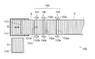
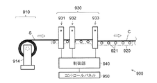
図1は、本発明の第1の実施形態による段ボールシート接合装置100の概略構成図である。本実施形態に係る段ボールシート接合装置100は、枚葉型の段ボールシートSを接合することによって連続段ボールシートCを生成するものであり、給紙部110、搬送部120、接合部130、これらを制御する制御部140、及びユーザが制御部140に各種設定を入力するためのコントロールパネル150を備えている。なお、以下では段ボールシートSの搬送方向、すなわち図1(a)中の白矢印が指す方向を前方として前後左右を定義する。また、枚葉型の段ボールシートS及び連続段ボールシートCにおいて、前記搬送方向と平行な方向を長さ方向とよび、該搬送方向と直交する方向を幅方向とよぶ。
<
FIG. 1 is a schematic configuration diagram of a corrugated
給紙部110は、一定形状を有する枚葉型の段ボールシートSを複数枚重ねて収容可能なシート収容部111を備えており、シート収容部111の内底面112aは、図示しないモータ等を含む底面駆動機構112により上下動可能に構成されている。給紙部110は、更に、シート収容部111内に積層された複数の段ボールシートSのうち、一番上の一枚を図中右方に向かって押し出すためのキッカー113を備えている。なお、キッカー113によって一番上の段ボールシートSが押し出される毎に、底面駆動機構112によりシート収容部111の内底面112aが段ボールシートSの厚さ一枚分だけ上昇する。また、図1(b)に示すように、シート収容部111の左右両側には、それぞれ段ボールシートSのストックが配置される給紙準備部114、115があり、シート収容部111内の段ボールシートSが無くなると、これら給紙準備部114、115のいずれか一方から段ボールシートSがシート収容部111に供給される。
The
なお、図1(b)では、シート収容部111の左右両側に給紙準備部114、115を配置する構成を示したが、これに限らず、シート収容部111の左右いずれか一方のみに給紙準備部114を配置した構成(図2)や、シート収容部111の後方に給紙準備部114を配置した構成(図3)とすることもできる(後述の実施形態2において同じ)。
In FIG. 1B, the configuration in which the sheet feeding
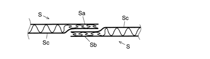
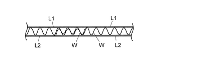
給紙部110に収容される各段ボールシートSは、予め、前端と後端(すなわち搬送時に前側に位置する端部と後側に位置する端部)の所定の長さの領域を、それぞれ幅方向の全域に亘って押し潰すことにより、元の厚さの半分程度に圧縮しておく。このとき、図4に示すように、段ボールシートSの前端(図中右側の端部)は下面側を上方向に圧縮し、後端(図中左側の端部)は上面側を下方向に圧縮する。以下、各段ボールシートSの前端及び後端の押し潰された領域を糊代部Sa、Sbとよび、その他の領域を本体部Scとよぶ。上記のような圧縮を行うことにより、各段ボールシートSの前端の糊代部Saはその上面が本体部Scと面一となり、後端の糊代部Sbはその下面が本体部Scと面一となる。
Each corrugated cardboard sheet S accommodated in the
搬送部120は、段ボールシートSの搬送路を形成する複数の搬送ローラ121及びそれらを駆動するモータ(図示略)を備えており、キッカー113によってシート収容部111から一枚ずつ押し出された段ボールシートSは、これらの搬送ローラ121に乗って順次搬送されていく。
The
接合部130は、紙端検知部131と、接着剤塗布部132と、圧着部133とを備えている。紙端検知部131、接着剤塗布部132、及び圧着部133は、それぞれ搬送路の左右両側に配置された支持台131b、132b、133bと、左右の支持台131b、132b、133bにまたがるように掛け渡されたフレーム131c、132c、133cとを備えている。紙端検知部131は、更に、フレーム131cに取り付けられた赤外線センサ等のセンサ131aを備えており、搬送路を移動する各段ボールシートSの前端及び後端を検知して検知信号を制御部140に送信する。接着剤塗布部132は、フレーム132cに取り付けられたスプレーノズル132aを備えており、制御部140の制御の下に、各段ボールシートSの後端が通過するタイミングで段ボールシートSの幅方向全域に亘って接着剤を噴射することによって各段ボールシートSの後端の糊代部Sbの上面に接着剤を塗布する。
The joining
なお、図1(a)に示すように、接着剤塗布部132の下流の所定地点よりも上流側の搬送路と下流側の搬送路とでは、下流側の搬送路の方が、段ボールシートSが載置される面(すなわち搬送ローラ121の上端位置)が僅かに低くなっている。そのため、接着剤塗布部132を通過した一枚の段ボールシートSの全体が前記下流側の搬送路に乗った時点で該下流側の搬送路のみを一旦停止させることにより、次に接着剤塗布部132を通過した段ボールシートSの前端の糊代部Saを、前記下流側の搬送路上で停止している段ボールシートSの後端の糊代部Sbの上に重ねることができる(図5)。そして、この状態で、前記下流側の搬送路を再び稼働させることにより、前記前端と後端とが重なった状態の2枚の段ボールシートSが圧着部133に導入される。
In addition, as shown in FIG. 1A, the downstream conveyance path is more corrugated than the predetermined point downstream of the
圧着部133は、フレーム133cに取り付けられ、搬送ローラ121の上方に配置された圧着ローラ133aを備えており、圧着部133における搬送ローラ121と圧着ローラ133aの間隔は段ボールシートSの厚さとほぼ等しくなっている。圧着部133に導入された段ボールシートSは、搬送ローラ121と圧着ローラ133aの間を通過し、その過程で、前記下流側に位置する段ボールシートSの後端と上流側に位置する段ボールシートSの前端との重なり部分が厚さ方向に加圧されて確実に接着される(図6)。
The
<実施形態2>
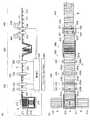
続いて、本発明の第2の実施形態による段ボールブランク製造装置について図7を参照しつつ説明する。本実施形態に係る段ボールブランク製造装置は、複数枚の枚葉型の段ボールシートSを接合して連続段ボールシートCを作成する段ボールシート接合装置200と、該連続段ボールシートCから段ボールブランクBの切り出しを行うブランク切り出し装置400と、これらを制御する制御部540と、ユーザが制御部540に各種設定を入力するためのコントロールパネル550と、段ボールシート接合装置200とブランク切り出し装置400の間に設けられた緩衝帯300とを備えている。
<
Subsequently, a corrugated board blank manufacturing apparatus according to a second embodiment of the present invention will be described with reference to FIG. The corrugated board blank manufacturing apparatus according to this embodiment includes a corrugated
本実施形態における段ボールシート接合装置200は、圧着部233の下流側に折罫付与部260が設けられている点以外は、第1の実施形態に係る段ボールシート接合装置100と同様の構成を有している。したがって、図7に示した段ボールシート接合装置200の構成要素のうち、第1の実施形態で説明したものと同一又は対応する構成要素については、下二桁が共通する符号を付し、適宜説明を省略する。
The corrugated
本実施形態における段ボールシート接合装置200においても、第1の実施形態と同様に、給紙部210から枚葉型の段ボールシートSが一枚ずつ搬送路に送り出され、これらの段ボールシートSが、紙端検知部231、接着剤塗布部232、及び圧着部233を通過することにより、連続段ボールシートCが生成される。そして、この連続段ボールシートCが折罫付与部260を通過する際に、連続段ボールシートCの幅方向の全域に亘る罫線(折罫)が、一定間隔毎に形成される。
Also in the corrugated
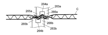
折罫付与部260は、図7(b)及び図8に示すように、搬送路の左右両側に配置された支持台260bと、左右の支持台260bの間に掛け渡され、搬送路上の連続段ボールシートCを挟むように上下に並んで配置された二つの押罫ローラ261a、261bと、これらを回転駆動させるモータ等から成る第1駆動部262a及び第2駆動部262bを備えている。押罫ローラ261a、261bは、それぞれ連続段ボールシートCの幅方向に延設され、連続段ボールシートCの幅よりも広い幅を有する。これら押罫ローラ261a、261bの表面には、それぞれ押罫ローラ261a、261bの軸方向に延びる押圧部材263a、263bが設けられている。これらの押圧部材263a、263bは、いずれも押罫ローラ261a、261bの軸方向長さと同じ長さを有する、断面が略長方形状の棒状部材である。
As shown in FIGS. 7B and 8, the
図9に示すように、各押圧部材263a、263bには、軸方向に延びる溝264a、264bが形成されており、これにより、各押圧部材263a、263bは、その先端面にそれぞれ2本の突条部265a、266a、265b、266bを有する。これらの突条部265a、266a(及び265b、266b)は、連続段ボールシートCの厚さの1〜3倍の間隔を空けて設けられている。また、二つの押罫ローラ261a、261bの位置は、前記二つの押圧部材263a、263bが互いに接近した際に、上側の押圧部材263aの上流側の突条部265aが下側の押圧部材263bの二つの突条部265b、266bの間に嵌るように、その回転中心を連続段ボールシートCの搬送方向にずらして配置されている。
As shown in FIG. 9, each pressing
制御部540の制御の下に、折罫付与部260の第1駆動部262a及び第2駆動部262bが押罫ローラ261a、261bを回転駆動すると、折罫付与部260に供給される連続段ボールシートCは、一定の長さ(例えば1100mm)毎に、図9に示すように上下の押圧部材263a、263bに挟まれることで両側から押圧される。これにより、図10に示すように、近接した互いに平行な2本の押罫611、612から成る折罫610が一定間隔毎に連続段ボールシートCに付与される。
Under the control of the
なお、ここでは、折罫610を連続段ボールシートCの全幅に設けるものとしたが、幅方向の一部にのみ設けてもよい。また、上記のように2本の押罫611、612で折罫610を構成する代わりに、1本の押罫から折罫を構成してもよい。
Here, the
以上のようにして折罫610が付与された連続段ボールシートCは、緩衝帯300に送られ、所定の折り畳み機構(図示略)によって折罫610に沿ってジャバラ状に折り畳まれていく。緩衝帯300にてジャバラ状に折り畳まれた連続段ボールシートCは、その下流側から順次引き出され、平坦に広がった状態で後段のブランク切り出し装置400に送られる。このように、段ボールシート接合装置200によって生成された連続段ボールシートCを溜めておくための緩衝帯300を設けることにより、前後の工程における速度差を吸収することができると共に、段ボールシート接合装置200とブランク切り出し装置400のいずれか一方の装置が、何らかの理由で一時的に停止した場合であっても、一方の装置を稼働させ続けることができる。
The continuous corrugated cardboard sheet C to which the
ブランク切り出し装置400は、連続段ボールシートCを搬送するための搬送ローラ411を備えた搬送部410と、連続段ボールシートCに縦方向(すなわち長さ方向)の切り込みを入れる縦切装置420と、連続段ボールシートCに横方向(すなわち幅方向)の切り込みを入れる横切装置430とを備えている。
The
縦切装置420及び横切装置430は、それぞれ搬送路の左右両側に配置された支持台421、431と、左右の支持台421、431にまたがるように掛け渡されたフレーム422、432とを備えている。縦切装置420は、更に、フレーム422に取り付けられ、連続段ボールシートCの長さ方向に切り込みを入れるための切刃を備えた複数の縦切ユニット423と、フレーム422に沿って各縦切ユニット423を移動させる左右移動機構424と、各縦切ユニット423の切刃を上下動させる上下動機構425とを備えている。また、横切装置430は、フレーム432に取り付けられ、連続段ボールシートCの幅方向に切り込みを入れるための切刃を備えた複数の横切ユニット433と、フレーム432に沿って各横切ユニット433を移動させる左右移動機構434と、各横切ユニット433の切刃を上下動させる上下動機構435とを備えている。
Each of the
縦切ユニット423及び横切ユニット433の切刃としては、例えば円盤状回転刃、又はカッター、スリッター、スロッターなどを用いることができる。なお、図示しないが、縦切装置420及び横切装置430には、切断位置を正しく測定するための測長センサや、段ボールブランクから段ボール箱を組み立てる際に折り曲げる部分に罫線を入れるための罫線付けローラが含まれている。更に、縦切装置420によって連続段ボールシートCから切り離された部分を巻き取る巻取ロールが備えられていてもよい。
As the cutting blades of the
このブランク切り出し装置400において、連続段ボールシートCの長さ方向に切り込みを入れる場合は、まず、搬送部が停止した状態で、縦切装置420の切刃の間隔が設定されたシート幅になるよう、左右移動機構424が縦切ユニット423をフレーム422に沿って移動させる。その後、上下動機構425によって前記切刃が連続段ボールシートC上に下ろされ、その状態で搬送部410が駆動され、切り込みが入れられる。一方、連続段ボールシートCの幅方向に切り込みを入れる場合は、切り込みを入れるべき位置が横切ユニット433の真下に来た時点で搬送部410が停止し、横切ユニット433の切刃が切り込み開始位置に来るよう、左右移動機構434が横切ユニット433をフレーム432に沿って移動させる。その後、上下動機構435によって前記切刃が連続段ボールシートC上に下ろされ、その状態で左右移動機構434により横切ユニット433が駆動され、前記切刃が切り込み終了位置まで移動することにより切り込みが入れられる。1個の段ボールブランクBの長さ方向両端の位置においては、幅方向いっぱいに切り込みが入れられ、この結果、多数の段ボールブランクBはそれぞれ切り離された状態で順次製造される。
In the
また、このとき、制御部540は、後述する波目のピッチの情報に基づき、横切装置430の切刃が切り込みを入れる位置が、連続段ボールシートCの波板の谷部になるように調整する。この調整は、例えば、段ボール箱の蓋に相当する部分の寸法を調節することにより行われる。これにより、連続段ボールシートCに対して波板の谷部に沿った真っ直ぐな切り込みを入れることが可能となる。
At this time, the
この段ボールブランク製造装置では、使用者がコントロールパネル550を操作して、枚葉型の段ボールシートSの寸法(長さ、幅、厚さ、及び波目のピッチ等)に関する情報、折罫付与部260で付与する折罫の間隔、所望の段ボール箱の種類(A式、タトウ式など)及びサイズ(縦、横、高さの寸法)に関する情報等を設定する。これらの設定が行われると、制御部540は、設定された情報に基づいて段ボールブランクBの各部の寸法を決定した上で、段ボールシート接合装置200及びブランク切り出し装置400を駆動し、枚葉型の段ボールシートSを搬送又は停止しながら、枚葉型の段ボールシートSから連続段ボールシートCを製造すると共に、該連続段ボールシートCを搬送又は停止しながら段ボールブランクBの切り出しを行う。なお、使用者によるコントロールパネル550を介した手入力ではなく、オンラインにより送られて来る段ボール箱の寸法等のデータを制御部540が受けて、切断位置や罫線位置を決定するようにしてもよい。
In this cardboard blank manufacturing apparatus, the user operates the
以上、本発明を実施するための形態について説明を行ったが、本発明は上記実施形態に限定されるものではなく、本発明の趣旨の範囲で適宜変更が許容される。 As mentioned above, although the form for implementing this invention was demonstrated, this invention is not limited to the said embodiment, A change is accept | permitted suitably in the range of the meaning of this invention.
例えば、上記第1及び第2の実施形態における段ボールシート接合装置100、200では、図4〜図6で説明したように、接合しようとする段ボールシートSの糊代部Sa、Sbを潰しておくことにより、接合箇所とその他の箇所で連続段ボールシートCの厚みに大きな差が生じないようにしたが、これに代えて、例えば図11に示すように、糊代部Sa、Sbにおいて、段ボールシートSを構成する1枚の波板Wと2枚のライナーL1、L2の少なくともいずれか1つを設けないようにしてもよい。例えば、図11に示す例では、枚葉型の段ボールシートSの前端に所定の長さに亘って下側のライナーL2を設けない領域(糊代部Sa)を設け、同枚葉型の段ボールシートSの後端に所定の長さに亘って波板W及び上側のライナーL1を設けない領域(糊代部Sb)を設ける。このような枚葉型の段ボールシートSを段ボールシート接合装置200で接合する際には、搬送路上で前後して搬送される2枚の段ボールシートSのうち、前側の段ボールシートSの後端の糊代部Sb又は後側の段ボールシートSの前端の糊代部Saに接着剤を塗布した上で、これら後端の糊代部Sbと前端の糊代部Saとを図12に示すように重ね合わせ、ローラ等で上下方向から押圧することにより両者を接着する。なお、このとき、図13に示すように、接合された2枚の段ボールシートSの上側のライナーL1同士と下側のライナーL2同士が一部重なるようにすることにより、一層強固な接着が可能となる。
For example, in the corrugated paper
また、上記実施形態では、段ボールシートSを波目と直交する方向に搬送しながら接合する例を示したが、これに限らず、段ボールシートSを波目と平行な方向に搬送しながら接合を行うようにしてもよい。この場合、段ボールシート接合装置200に供給する枚葉型の段ボールシートSには、例えば、図14に示すように、前端側の所定の長さに亘る領域(前端の糊代部Sa)に下側のライナーL2を設けない(すなわち該領域を波板Wと上側のライナーL1のみで構成する)と共に、後端側の所定の長さに亘る領域(後端の糊代部Sb)に上側のライナーL1を設けない(すなわち該領域を波板Wと下側のライナーL2のみで構成する)ものとする。
Moreover, in the said embodiment, although the example which joins while conveying the corrugated cardboard sheet S in the direction orthogonal to a wave pattern was shown, it is not restricted to this, and it joins while conveying the corrugated cardboard sheet S in the direction parallel to a corrugated pattern. You may make it perform. In this case, for example, as shown in FIG. 14, the single-wafer type corrugated cardboard sheet S supplied to the corrugated
このような枚葉型の段ボールシートSを段ボールシート接合装置100(又は段ボールシート接合装置200)で接合する際には、搬送路上で前後して搬送される2枚の段ボールシートSのうち、前側の段ボールシートSの後端の糊代部Sb又は後側の段ボールシートSの前端の糊代部Saに接着剤を塗布した上で、これらの糊代部Sa、Sbを図15に示すように重ね合わせ、ローラ等で上下方向から押圧することにより両者を接着する。なお、糊代部Sa、Sb同士を重ね合わせる際には、図17に示すように、一方の段ボールシートの波板Wの凹凸が、他方の段ボールシートの波板Wの凹凸に嵌り込むようにする。これにより、接合箇所とその他の箇所で連続段ボールシートCの厚みに大きな差が生じるのを防ぐことができる。更に、このとき、図16に示すように、接合された2枚の段ボールシートSの上側のライナーL1同士と下側のライナーL2同士が一部重なるようにすることにより、一層強固な接着が可能となる。 When joining such a sheet type corrugated cardboard sheet S with the corrugated cardboard sheet joining device 100 (or the corrugated cardboard sheet joining device 200), the front side of the two corrugated cardboard sheets S transported back and forth on the transport path. FIG. 15 shows adhesive margins Sa and Sb after the adhesive is applied to the margin margin Sb at the rear end of the corrugated cardboard sheet S or the margin margin Sa at the front end of the rear corrugated cardboard sheet S. The two are bonded together by pressing from above and below with overlapping or rollers. When the adhesive margins Sa and Sb are overlapped with each other, as shown in FIG. 17, the corrugations of the corrugated sheet W of one cardboard sheet are fitted into the corrugations of the corrugated sheet W of the other corrugated sheet. To do. Thereby, it can prevent that a big difference arises in the thickness of the continuous corrugated-cardboard sheet | seat C in a joining location and another location. Further, at this time, as shown in FIG. 16, the upper liner L1 and the lower liner L2 of the joined two corrugated cardboard sheets S partially overlap each other, so that stronger adhesion is possible. It becomes.
図14で示したような枚葉型の段ボールシートSを製造するための装置を、図18に示す。この段ボールシート製造装置700において、第1原紙掛701及び第3原紙掛703にはロール状に巻き取られたライナー原紙がセットされ、第2原紙掛702にはロール状に巻き取られた中芯原紙がセットされる。なお、ここで第1原紙掛701と第2原紙掛702にセットされるライナー原紙は互いに幅が等しいものを使用し、中芯原紙には、ライナー原紙よりも数センチから数十センチほど広幅のものを使用する。
FIG. 18 shows an apparatus for manufacturing a sheet-type cardboard sheet S as shown in FIG. In this corrugated
第1原紙掛701から引き出されたライナー原紙(以下「第1ライナーL1」とよぶ)と、第2原紙掛702から引き出された中芯原紙Mは片段製造機704(本発明における「片段生成手段」に相当)に導入される。片段製造機704は、中芯原紙Mに波状の凹凸を(その波目が中芯原紙Mの幅方向と平行となるように)形成することによって波板Wを生成すると共に、波板Wに接着剤を塗布して第1ライナーL1と貼り合わせることで片面段ボールシートPを生成する。上記のように中芯原紙Mはライナー原紙よりも幅広であり、中芯原紙Mから生成された波板Wは、第1ライナーL1と右辺(図18(b)中の下側の辺)を揃えた状態で貼付される。従って、片段製造機704によって得られる片面段ボールシートPは、左辺の数センチから数十センチに亘る領域が、波板Wのみの状態(すなわち第1ライナーL1が貼り付けられていない状態)となる。このようにして得られた片面段ボールシートPは、糊付け機705に導入され、下面(すなわち波板W側の面)に糊付けがなされると共に、第3原紙掛703から引き出されたライナー原紙(以下、「第2ライナーL2」とよぶ)と共に、2本のローラ711a、711bの間に導入される。これにより、片面段ボールシートPと第2ライナーL2が2本のローラ711a、711bによって上下から押圧されて貼り合わされ、両面段ボールシートDが生成される(ここでは、糊付け機705及びローラ711a、711bが本発明における「両段生成手段」に相当する)。このとき、片面段ボールシートPと第2ライナーL2とは左辺を揃えた状態で貼付されるため、これにより得られる両面段ボールシートDは、右辺の数センチから数十センチに亘る領域が、第1ライナーL1と波板Wのみの状態(すなわち第2ライナーL2が貼り付けられていない状態)となる。以上により得られた両面段ボールシートDは、熱板部706で加熱されると共に冷却部707で冷却され、その後、カッター機709によって所定の長さに切り取られる。また、必要に応じて、両面段ボールシートDは、カッター機709で切り取る前にスリッター・スコアラー708で切れ目や罫線が形成される。これにより、図14に示したような段ボールシートSが完成する。得られた段ボールシートSはスタッカー機710によって積み重ねられ、図1で示したような本発明に係る段ボールシート接合装置100の給紙部110に、波目が搬送方向と平行になるように(例えば、第2ライナーL2が貼り付けられていない領域が搬送方向前方側に位置するように)セットされて、連続段ボールシートCの製造に用いられる。
A liner base paper (hereinafter referred to as “first liner L1”) drawn from the first
また、第1及び第2の実施形態では、枚葉型の段ボールシート同士を接合して連続段ボールシートを製造する例を示したが、本発明に係る段ボール接合装置は、これに限らず、ジャバラ状に折り畳まれた長尺段ボールシート同士、又はロール状に巻き取られた長尺段ボールシート同士を接合して連続段ボールシートを製造するようにしてもよい。これにより、一つの長尺段ボールシートを使い終わった際に、その末端と次の長尺段ボールシートの先端とが自動的に接続されて連続段ボールシートとなるため、長尺段ボールシートの末端部における紙取りの無駄を無くすことができると共に、長尺段ボールシートを補充するために装置を停止させる必要が無くなる。このような段ボールシート接合装置800、900の構成例を図19及び図20に示す。これらの装置は、給紙部810、910がキッカー113を有しない点、及びロール状の長尺段ボールシートSを用いる装置900には、シート収容部111及び底面駆動機構112に代えて、該ロール状の長尺段ボールシートSを回転可能に支持するロール支持部914が設けられている点以外は、図1に示した段ボール接合装置100とほぼ同様の構成を有している。そのため、図1と同一又は対応する構成要素については下二桁が共通する符号を付して説明を省略する。なお、これらの段ボールシート接合装置800、900にも、図7〜図9に示したような折罫付与部260を設けることがより望ましい。これにより、連続段ボールシートCに一定の長さ毎に図10のような折罫610を付与することができ、生成された連続段ボールシートCをジャバラ状に折り畳むことが可能となる。なお、ジャバラ状に折り畳まれた長尺の段ボールシートSから連続段ボールシートCを製造する場合、折罫付与部260では段ボールシートS同士の接合箇所のみに折罫610を形成すればよい。
Further, in the first and second embodiments, the example in which the continuous corrugated cardboard sheets are manufactured by joining the single-wafer type corrugated cardboard sheets is shown, but the corrugated cardboard joining apparatus according to the present invention is not limited to this, and the bellows A continuous corrugated board sheet may be manufactured by joining long corrugated cardboard sheets folded into a shape or long corrugated cardboard sheets wound up in a roll shape. As a result, when one long corrugated cardboard sheet is used up, the end of the long corrugated cardboard sheet is automatically connected to the leading end of the next long corrugated cardboard sheet to form a continuous corrugated cardboard sheet. Paper waste can be eliminated and the apparatus does not need to be stopped to replenish the long cardboard sheet. An example of the configuration of such corrugated
また、第1及び第2の実施形態における段ボールシート接合装置100、200を用いて接合される段ボールシートSの別の例を図11、図14に示したが、これら以外に段ボールシートを用いることができる。例えば、図21は、枚葉形の段ボールシートSの前端及び後端に、所定の長さに亘って糊代部Sa及び糊代部Sbを設ける点では、図11に示す段ボールシートSと同じであるが、糊代部Sa及び糊代部Sbは、それぞれ下側のライナーL2を設けないこと及び上側のライナーL1を設けないことで形成されている。このような枚葉型の段ボールシートSを段ボールシート接合装置200で接合する際には、搬送路上で前後して搬送される2枚の段ボールシートSのうち、前側の段ボールシートSの後端の糊代部Sb又は後側の段ボールシートSの前端の糊代部Saに接着剤を塗布した上で、これら後端の糊代部Sbと前端の糊代部Saとを図22に示すように重ね合わせ、ローラ等で上下方向から押圧することにより両者を接着する。これにより、図23に示すように、2枚の段ボールシートSが接合された部分では波板Wが2枚重なった状態となるため、2枚の段ボールシートSを強固に接合することができる。
Moreover, although the other example of the corrugated cardboard sheet S joined using the corrugated cardboard
図24、図25は、図14に示す段ボールシートSの変形例を示している。この例の段ボールシート(両面段ボールシート)Sは、同じ大きさの2枚の片面段ボールシートS1、S2の波板W1、W2同士を、該波板の波目を揃えた状態で、且つ、波目と平行な方向にずらした状態で貼り合わせることにより形成されている。これにより、前記段ボールシートSは、前端側の所定の長さに亘る領域(前端の糊代部Sa)には下側のライナーL2がなく、後端側の所定の長さに亘る領域(後端の糊代部Sb)には上側のライナーL1がなく、さらに、それ以外の領域(糊代部Saと糊代部Sbの間の領域)Scでは、2枚の波板W1、W2が重なった状態となる。 24 and 25 show a modification of the corrugated cardboard sheet S shown in FIG. The corrugated cardboard sheet (double-sided corrugated cardboard sheet) S of this example is in a state where the corrugated sheets W1 and W2 of two single-sided corrugated cardboard sheets S1 and S2 having the same size are aligned with each other, It is formed by bonding in a state shifted in a direction parallel to the eyes. As a result, the corrugated sheet S does not have the lower liner L2 in the region extending over a predetermined length on the front end side (the adhesive margin Sa on the front end), and the region extending over the predetermined length on the rear end side (rear side). The edge margin Sb) does not have the upper liner L1, and in the other region (region between the margin margin Sa and the margin margin Sb) Sc, the two corrugated plates W1 and W2 overlap. It becomes a state.
このような枚葉型の段ボールシートSも、図14に示した段ボールシートSと同じように、段ボールシート接合装置100(又は段ボール接合装置200)で接合することにより長尺の段ボールシートを形成することができる。この例では、2枚の段ボールシートSの接合部分において2枚の波板が重なるため、長尺段ボールシートの全体において2枚の波板が重なった状態となる。このため、非常に強固な長尺段ボールシートを得ることができる。 Similarly to the corrugated cardboard sheet S shown in FIG. 14, such a single-wafer type corrugated cardboard sheet S is joined by the corrugated cardboard joining device 100 (or the corrugated cardboard joining device 200) to form a long corrugated cardboard sheet. be able to. In this example, since the two corrugated sheets overlap at the joint portion of the two corrugated cardboard sheets S, the two corrugated sheets overlap in the entire long corrugated cardboard sheet. For this reason, a very strong long cardboard sheet can be obtained.
100、200…段ボールシート接合装置
110、210…給紙部
120、220…搬送部
130、230…接合部
131、231…紙端検知部
132、232…接着剤塗布部
133、233…圧着部
140、540…制御部
150、550…コントロールパネル
260…折罫付与部
261a…押罫ローラ
262a…第1駆動部
262b…第2駆動部
263a、263b…押圧部材
300…緩衝帯
400…ブランク切り出し装置
410…搬送部
420…縦切装置
430…横切装置
610…折罫
611、612…押罫
700…段ボールシート製造装置
704…片段製造機
705…糊付け機
711a、711b…ローラ
S…段ボールシート
L1…上側ライナー(第1ライナー)
L2…下側ライナー(第2ライナー)
W…波板
Sa、Sb…糊代部
DESCRIPTION OF
L2 ... Lower liner (second liner)
W ... Corrugated sheet Sa, Sb ... Paste part
Claims (12)
b) 前記搬送手段によって前後して搬送される2枚の段ボールシートの対向する端縁同士を接合する接合手段と、
を有することを特徴とする段ボールシート接合装置。 a) conveying means for conveying the cardboard sheet in a direction parallel to one side of the cardboard sheet;
b) joining means for joining opposite edges of the two corrugated cardboard sheets conveyed back and forth by the conveying means;
A corrugated board joining apparatus characterized by comprising:
c) 積み重ねられた枚葉状の前記段ボールシートを一枚ずつ前記搬送手段に供給する給紙手段、
を有することを特徴とする請求項1に記載の段ボールシート接合装置。 Furthermore,
c) paper feeding means for feeding the stacked sheet-like cardboard sheets one by one to the transport means;
The corrugated board joining apparatus according to claim 1, wherein
d) ジャバラ状に折り畳まれた前記段ボールシートの一端を引き出して前記搬送手段に供給する給紙手段、
を有することを特徴とする請求項1に記載の段ボールシート接合装置。 Furthermore,
d) paper feeding means for pulling out one end of the corrugated cardboard sheet folded into a bellows and supplying it to the conveying means;
The corrugated board joining apparatus according to claim 1, wherein
e) ロール状に巻かれた前記段ボールシートの一端を引き出して前記搬送手段に供給する給紙手段、
を有することを特徴とする請求項1に記載の段ボールシート接合装置。 Furthermore,
e) paper feeding means for pulling out one end of the corrugated cardboard sheet wound in a roll and supplying it to the conveying means;
The corrugated board joining apparatus according to claim 1, wherein
f) 前記接合手段によって接合された前記段ボールシートに、一定の間隔で、前記搬送手段による搬送方向と直交する折罫を付与する折罫付与手段、
を有することを特徴とする請求項1〜4のいずれかに記載の段ボールシート接合装置。 Furthermore,
f) A crease applying means for applying a crease perpendicular to the conveying direction by the conveying means to the corrugated sheet joined by the joining means at a constant interval;
The corrugated board joining apparatus according to any one of claims 1 to 4, characterized by comprising:
前記搬送手段によって搬送される各段ボールシートの前端及び後端を、予め厚さ方向に押し潰すことによって糊代部を形成しておき、
前記接合手段において、前記2枚の段ボールシートのうちの前側の段ボールシートの後端に設けられた前記糊代部と、後側の段ボールシートの前端に設けられた前記糊代部とを重ね合わせて接合することを特徴とする連続段ボールシートの製造方法。 A method for producing a continuous cardboard sheet by joining a plurality of cardboard sheets by the cardboard sheet joining apparatus according to any one of claims 1 to 5,
Forming a margin part by crushing the front end and the rear end of each cardboard sheet conveyed by the conveying means in the thickness direction in advance;
In the joining means, the glue margin provided at the rear end of the front cardboard sheet of the two cardboard sheets and the glue margin provided at the front end of the rear cardboard sheet are overlapped. A method for producing a continuous corrugated cardboard sheet.
前記搬送手段によって搬送される各段ボールシートの前端及び後端に、段ボールシートを構成する2枚のライナーと1枚の波板のうち、1枚のライナー又は1枚のライナー及び波板が欠けた糊代部を設けておき、
前記接合手段において、前記2枚の段ボールシートのうちの前側の段ボールシートの後端に設けられた前記糊代部と、後側の段ボールシートの前端に設けられた前記糊代部とを重ね合わせて接合することを特徴とする連続段ボールシートの製造方法。 A method for producing a continuous cardboard sheet by joining a plurality of cardboard sheets by the cardboard sheet joining apparatus according to any one of claims 1 to 5,
One liner or one liner and corrugated sheet out of two liners and one corrugated sheet constituting the corrugated cardboard sheet are missing at the front and rear ends of each corrugated sheet conveyed by the conveying means. There is a glue margin,
In the joining means, the glue margin provided at the rear end of the front cardboard sheet of the two cardboard sheets and the glue margin provided at the front end of the rear cardboard sheet are overlapped. A method for producing a continuous corrugated cardboard sheet.
b) 該段ボールシート接合装置によって生成された連続段ボールシートを搬送する連続段ボールシート搬送手段と、
c) 該搬送手段による搬送方向と平行な方向及び直交する方向に沿って前記連続段ボールシートに切り込みを入れることにより、該連続段ボールシートから段ボールブランクを切り出すブランク切り出し手段と、
を備えることを特徴とする段ボールブランク製造装置。 a) the corrugated cardboard sheet joining device according to any one of claims 1 to 5;
b) a continuous corrugated sheet conveying means for conveying the continuous corrugated sheet generated by the corrugated sheet joining apparatus;
c) a blank cutting means for cutting a cardboard blank from the continuous cardboard sheet by cutting the continuous cardboard sheet along a direction parallel to and perpendicular to the transport direction by the transport means;
A cardboard blank manufacturing apparatus comprising:
前記片面段ボールシートに含まれる前記波板の他方の面に、前記幅方向の寸法が前記波板よりも小さい第2のライナーを、前記波板の前記幅方向の他方の辺と該第2のライナーの前記幅方向の一辺とを揃えた状態で貼り付けることによって両面段ボールシートを生成する両段生成手段と、
を備えることを特徴とする段ボールシート製造装置。 On one surface of the corrugated sheet, a first liner having a width dimension that is parallel to the corrugation of the corrugated sheet is smaller than that of the corrugated sheet. Single-stage generating means for generating a single-sided corrugated cardboard sheet by pasting in a state in which one side of the first liner in the width direction is aligned;
A second liner having a width dimension smaller than that of the corrugated sheet is provided on the other surface of the corrugated sheet included in the single-faced corrugated sheet, and the second side of the corrugated sheet and the second side of the corrugated sheet. Both-stage generating means for generating a double-sided corrugated cardboard sheet by pasting in a state aligned with one side in the width direction of the liner;
A cardboard sheet manufacturing apparatus comprising:
を備えることを特徴とする段ボールシート製造装置。 The corrugated sheets of two single-sided corrugated cardboard sheets of the same size are shifted in a state where the corrugations of the corrugated sheets are aligned and in a direction parallel to the corrugations or in a direction perpendicular to the corrugations. A corrugated sheet manufacturing apparatus comprising: a double-stage corrugated sheet generating means for generating a double-faced corrugated sheet by pasting in a state where the corrugated sheet is attached.
Applications Claiming Priority (2)
| Application Number | Priority Date | Filing Date | Title |
|---|---|---|---|
| JP2017163729 | 2017-08-28 | ||
| JP2017163729 | 2017-08-28 |
Related Child Applications (1)
| Application Number | Title | Priority Date | Filing Date |
|---|---|---|---|
| JP2020158424A Division JP2020199778A (en) | 2017-08-28 | 2020-09-23 | Method of producing continuous corrugated board sheet and corrugated board sheet production apparatus |
Publications (2)
| Publication Number | Publication Date |
|---|---|
| JP2019038262A true JP2019038262A (en) | 2019-03-14 |
| JP2019038262A5 JP2019038262A5 (en) | 2020-07-27 |
Family
ID=65725242
Family Applications (3)
| Application Number | Title | Priority Date | Filing Date |
|---|---|---|---|
| JP2018159730A Pending JP2019038262A (en) | 2017-08-28 | 2018-08-28 | Corrugated cardboard sheet bonding apparatus, manufacturing method of continuous corrugated cardboard sheet, and corrugated cardboard blank manufacturing apparatus |
| JP2020158424A Pending JP2020199778A (en) | 2017-08-28 | 2020-09-23 | Method of producing continuous corrugated board sheet and corrugated board sheet production apparatus |
| JP2021025041A Active JP6990789B2 (en) | 2017-08-28 | 2021-02-19 | Continuous corrugated board sheet manufacturing method and corrugated cardboard sheet manufacturing equipment |
Family Applications After (2)
| Application Number | Title | Priority Date | Filing Date |
|---|---|---|---|
| JP2020158424A Pending JP2020199778A (en) | 2017-08-28 | 2020-09-23 | Method of producing continuous corrugated board sheet and corrugated board sheet production apparatus |
| JP2021025041A Active JP6990789B2 (en) | 2017-08-28 | 2021-02-19 | Continuous corrugated board sheet manufacturing method and corrugated cardboard sheet manufacturing equipment |
Country Status (1)
| Country | Link |
|---|---|
| JP (3) | JP2019038262A (en) |
Cited By (11)
| Publication number | Priority date | Publication date | Assignee | Title |
|---|---|---|---|---|
| JP2020131475A (en) * | 2019-02-14 | 2020-08-31 | 株式会社TanaーX | Bellow-like cardboard sheet laminate and production method of continuous cardboard sheet |
| WO2021070945A1 (en) * | 2019-10-11 | 2021-04-15 | 王子ホールディングス株式会社 | Cardboard material, conveyed object and cardboard box |
| JP2021062888A (en) * | 2019-10-11 | 2021-04-22 | 王子ホールディングス株式会社 | Cardboard material and cardboard box using the same |
| JP2021062914A (en) * | 2020-03-05 | 2021-04-22 | 王子ホールディングス株式会社 | Cardboard material and cardboard box using the same |
| JP2021062615A (en) * | 2019-10-11 | 2021-04-22 | 王子ホールディングス株式会社 | Corrugated cardboard material |
| JP2021062598A (en) * | 2020-03-05 | 2021-04-22 | 王子ホールディングス株式会社 | Corrugated cardboard material, and corrugated cardboard box using the same |
| JP2021062538A (en) * | 2019-10-11 | 2021-04-22 | 王子ホールディングス株式会社 | Corrugated cardboard material |
| JP2021062915A (en) * | 2020-03-05 | 2021-04-22 | 王子ホールディングス株式会社 | Cardboard material and cardboard box using the same |
| WO2021200988A1 (en) * | 2020-03-31 | 2021-10-07 | 王子ホールディングス株式会社 | Corrugated fiberboard material |
| JP7367039B2 (en) | 2018-10-19 | 2023-10-23 | シー.エム.シー. エス.ピー.エー. | A device for embodying packaging cardboard pieces by successively joining several packaging cardboard sheets to each other |
| CN113979225B (en) * | 2021-11-22 | 2024-04-19 | 河南天悦包装有限公司 | Packing box handle processing equipment |
Citations (10)
| Publication number | Priority date | Publication date | Assignee | Title |
|---|---|---|---|---|
| JPS4830240U (en) * | 1971-08-17 | 1973-04-13 | ||
| JPS5662798A (en) * | 1980-08-30 | 1981-05-28 | Rengo Co Ltd | Puncher |
| JPH02235623A (en) * | 1989-03-09 | 1990-09-18 | Risaburo Yada | Double faced corrugated cardboard and preparation thereof |
| WO1999065668A1 (en) * | 1998-06-15 | 1999-12-23 | I.M.A. Engineering Ltd. | Manufacture of boxes |
| JP2011201594A (en) * | 2010-03-26 | 2011-10-13 | Suntory Holdings Ltd | Corrugated cardboard sheet and article storage body |
| JP2013099853A (en) * | 2011-10-18 | 2013-05-23 | Crown Package Co Ltd | Corrugated board sheet, box body, and method of manufacturing the corrugated board sheet |
| WO2015173745A1 (en) * | 2014-05-16 | 2015-11-19 | System S.P.A. | A machine and method for making blanks for boxes to measure |
| JP2016030442A (en) * | 2014-07-25 | 2016-03-07 | 株式会社TanaーX | Folding rule application device to corrugated fiberboard material |
| JP2016120594A (en) * | 2014-12-24 | 2016-07-07 | レンゴー株式会社 | Joining apparatus of cardboard sheet |
| WO2017138413A1 (en) * | 2016-02-10 | 2017-08-17 | 株式会社TanaーX | Double-sided corrugated board material and device for imparting crease to sheet-shaped material |
Family Cites Families (1)
| Publication number | Priority date | Publication date | Assignee | Title |
|---|---|---|---|---|
| JP3005052U (en) * | 1994-06-08 | 1994-12-06 | 栄二 加藤 | Corrugated corrugated core |
-
2018
- 2018-08-28 JP JP2018159730A patent/JP2019038262A/en active Pending
-
2020
- 2020-09-23 JP JP2020158424A patent/JP2020199778A/en active Pending
-
2021
- 2021-02-19 JP JP2021025041A patent/JP6990789B2/en active Active
Patent Citations (10)
| Publication number | Priority date | Publication date | Assignee | Title |
|---|---|---|---|---|
| JPS4830240U (en) * | 1971-08-17 | 1973-04-13 | ||
| JPS5662798A (en) * | 1980-08-30 | 1981-05-28 | Rengo Co Ltd | Puncher |
| JPH02235623A (en) * | 1989-03-09 | 1990-09-18 | Risaburo Yada | Double faced corrugated cardboard and preparation thereof |
| WO1999065668A1 (en) * | 1998-06-15 | 1999-12-23 | I.M.A. Engineering Ltd. | Manufacture of boxes |
| JP2011201594A (en) * | 2010-03-26 | 2011-10-13 | Suntory Holdings Ltd | Corrugated cardboard sheet and article storage body |
| JP2013099853A (en) * | 2011-10-18 | 2013-05-23 | Crown Package Co Ltd | Corrugated board sheet, box body, and method of manufacturing the corrugated board sheet |
| WO2015173745A1 (en) * | 2014-05-16 | 2015-11-19 | System S.P.A. | A machine and method for making blanks for boxes to measure |
| JP2016030442A (en) * | 2014-07-25 | 2016-03-07 | 株式会社TanaーX | Folding rule application device to corrugated fiberboard material |
| JP2016120594A (en) * | 2014-12-24 | 2016-07-07 | レンゴー株式会社 | Joining apparatus of cardboard sheet |
| WO2017138413A1 (en) * | 2016-02-10 | 2017-08-17 | 株式会社TanaーX | Double-sided corrugated board material and device for imparting crease to sheet-shaped material |
Cited By (11)
| Publication number | Priority date | Publication date | Assignee | Title |
|---|---|---|---|---|
| JP7367039B2 (en) | 2018-10-19 | 2023-10-23 | シー.エム.シー. エス.ピー.エー. | A device for embodying packaging cardboard pieces by successively joining several packaging cardboard sheets to each other |
| JP2020131475A (en) * | 2019-02-14 | 2020-08-31 | 株式会社TanaーX | Bellow-like cardboard sheet laminate and production method of continuous cardboard sheet |
| WO2021070945A1 (en) * | 2019-10-11 | 2021-04-15 | 王子ホールディングス株式会社 | Cardboard material, conveyed object and cardboard box |
| JP2021062888A (en) * | 2019-10-11 | 2021-04-22 | 王子ホールディングス株式会社 | Cardboard material and cardboard box using the same |
| JP2021062615A (en) * | 2019-10-11 | 2021-04-22 | 王子ホールディングス株式会社 | Corrugated cardboard material |
| JP2021062538A (en) * | 2019-10-11 | 2021-04-22 | 王子ホールディングス株式会社 | Corrugated cardboard material |
| JP2021062914A (en) * | 2020-03-05 | 2021-04-22 | 王子ホールディングス株式会社 | Cardboard material and cardboard box using the same |
| JP2021062598A (en) * | 2020-03-05 | 2021-04-22 | 王子ホールディングス株式会社 | Corrugated cardboard material, and corrugated cardboard box using the same |
| JP2021062915A (en) * | 2020-03-05 | 2021-04-22 | 王子ホールディングス株式会社 | Cardboard material and cardboard box using the same |
| WO2021200988A1 (en) * | 2020-03-31 | 2021-10-07 | 王子ホールディングス株式会社 | Corrugated fiberboard material |
| CN113979225B (en) * | 2021-11-22 | 2024-04-19 | 河南天悦包装有限公司 | Packing box handle processing equipment |
Also Published As
| Publication number | Publication date |
|---|---|
| JP2020199778A (en) | 2020-12-17 |
| JP2021073125A (en) | 2021-05-13 |
| JP6990789B2 (en) | 2022-01-12 |
Similar Documents
| Publication | Publication Date | Title |
|---|---|---|
| JP6990789B2 (en) | Continuous corrugated board sheet manufacturing method and corrugated cardboard sheet manufacturing equipment | |
| WO2014119439A1 (en) | Corrugated cardboard blank manufacturing apparatus, and commodity automatic packing system provided therewith | |
| JP6803492B2 (en) | Double-sided corrugated cardboard material | |
| JP2019038262A5 (en) | ||
| JP5895316B1 (en) | Folder gluer | |
| WO2016031010A1 (en) | Blank-supplying apparatus, method for supplying blank using same | |
| US20200316898A1 (en) | Continuous fanfolded joined corrugated | |
| KR101747658B1 (en) | Method for Binding Printed Matter Using Laminating Film | |
| JP2016074136A (en) | Cardboard warp prevention method and device | |
| JP6235784B2 (en) | Folio format paper wrapping method and apparatus | |
| JPH08169634A (en) | Remedy method for warp of corrugated cardboard and device thereof | |
| JP6811793B2 (en) | Method for manufacturing a bellows-shaped corrugated cardboard sheet laminate, a connecting body of the bellows-shaped corrugated cardboard sheet laminate, and a continuous corrugated cardboard sheet | |
| WO2022155386A1 (en) | Single face tube die-cut and sheet production | |
| JP2003291230A (en) | Apparatus for laminating double-faced corrugated cardboard sheet | |
| JP7072342B2 (en) | Double corrugated cardboard sheet and its manufacturing method | |
| JP2001001430A (en) | Manufacture of corrugated fiberboard | |
| JP6729733B1 (en) | Blank sheet manufacturing method | |
| US20230166490A1 (en) | Insulation products and methods and machines for making insulation products | |
| JP2006035758A (en) | Folding apparatus of corrugated cardboard sheet | |
| WO2021167076A1 (en) | Ruled line formation device and ruled line formation method | |
| JP6687407B2 (en) | Clear file manufacturing apparatus and clear file manufacturing system including the clear file manufacturing apparatus | |
| JP2022044009A (en) | Corrugated cardboard sheet feeder | |
| JP5719686B2 (en) | A device for shortening and supplying the back paper for the cover sticker | |
| JP2003334873A (en) | Slip sheet device for wales and course composite double- faced corrugated cardboard | |
| JPH1044269A (en) | Corrugate machine |
Legal Events
| Date | Code | Title | Description |
|---|---|---|---|
| A621 | Written request for application examination |
Free format text: JAPANESE INTERMEDIATE CODE: A621 Effective date: 20200605 |
|
| A871 | Explanation of circumstances concerning accelerated examination |
Free format text: JAPANESE INTERMEDIATE CODE: A871 Effective date: 20200605 |
|
| A521 | Request for written amendment filed |
Free format text: JAPANESE INTERMEDIATE CODE: A523 Effective date: 20200615 |
|
| A975 | Report on accelerated examination |
Free format text: JAPANESE INTERMEDIATE CODE: A971005 Effective date: 20200717 |
|
| A977 | Report on retrieval |
Free format text: JAPANESE INTERMEDIATE CODE: A971007 Effective date: 20200717 |
|
| A131 | Notification of reasons for refusal |
Free format text: JAPANESE INTERMEDIATE CODE: A131 Effective date: 20200728 |
|
| A521 | Request for written amendment filed |
Free format text: JAPANESE INTERMEDIATE CODE: A523 Effective date: 20200923 |
|
| A131 | Notification of reasons for refusal |
Free format text: JAPANESE INTERMEDIATE CODE: A131 Effective date: 20210105 |
|
| A521 | Request for written amendment filed |
Free format text: JAPANESE INTERMEDIATE CODE: A523 Effective date: 20210304 |
|
| A02 | Decision of refusal |
Free format text: JAPANESE INTERMEDIATE CODE: A02 Effective date: 20210518 |