JP2019016819A - Method for manufacturing solar cell module and apparatus for manufacturing solar cell module - Google Patents
Method for manufacturing solar cell module and apparatus for manufacturing solar cell module Download PDFInfo
- Publication number
- JP2019016819A JP2019016819A JP2018208089A JP2018208089A JP2019016819A JP 2019016819 A JP2019016819 A JP 2019016819A JP 2018208089 A JP2018208089 A JP 2018208089A JP 2018208089 A JP2018208089 A JP 2018208089A JP 2019016819 A JP2019016819 A JP 2019016819A
- Authority
- JP
- Japan
- Prior art keywords
- sealing material
- temperature
- heating
- light
- laminate
- Prior art date
- Legal status (The legal status is an assumption and is not a legal conclusion. Google has not performed a legal analysis and makes no representation as to the accuracy of the status listed.)
- Granted
Links
- 238000000034 method Methods 0.000 title claims abstract description 47
- 238000004519 manufacturing process Methods 0.000 title claims abstract description 38
- 238000010438 heat treatment Methods 0.000 claims abstract description 107
- 239000003566 sealing material Substances 0.000 claims abstract description 95
- 238000001816 cooling Methods 0.000 claims abstract description 57
- 230000001681 protective effect Effects 0.000 claims description 29
- 238000010030 laminating Methods 0.000 claims description 15
- 239000007822 coupling agent Substances 0.000 claims description 9
- 230000001678 irradiating effect Effects 0.000 claims description 4
- 238000003825 pressing Methods 0.000 abstract description 2
- 230000005855 radiation Effects 0.000 abstract 1
- 229920005989 resin Polymers 0.000 description 29
- 239000011347 resin Substances 0.000 description 29
- 239000000758 substrate Substances 0.000 description 18
- 239000011521 glass Substances 0.000 description 15
- 229910052751 metal Inorganic materials 0.000 description 10
- 239000002184 metal Substances 0.000 description 10
- 238000006243 chemical reaction Methods 0.000 description 9
- 239000000853 adhesive Substances 0.000 description 7
- 230000001070 adhesive effect Effects 0.000 description 7
- 238000004132 cross linking Methods 0.000 description 7
- 239000000463 material Substances 0.000 description 6
- 229910021417 amorphous silicon Inorganic materials 0.000 description 5
- 238000011144 upstream manufacturing Methods 0.000 description 5
- 239000004711 α-olefin Substances 0.000 description 5
- NIXOWILDQLNWCW-UHFFFAOYSA-N Acrylic acid Chemical compound OC(=O)C=C NIXOWILDQLNWCW-UHFFFAOYSA-N 0.000 description 4
- 239000012298 atmosphere Substances 0.000 description 4
- 238000009413 insulation Methods 0.000 description 4
- 239000004065 semiconductor Substances 0.000 description 4
- 239000006087 Silane Coupling Agent Substances 0.000 description 3
- 229920001577 copolymer Polymers 0.000 description 3
- 230000007423 decrease Effects 0.000 description 3
- 229920001971 elastomer Polymers 0.000 description 3
- 239000005038 ethylene vinyl acetate Substances 0.000 description 3
- 238000003475 lamination Methods 0.000 description 3
- 229910021421 monocrystalline silicon Inorganic materials 0.000 description 3
- 238000013021 overheating Methods 0.000 description 3
- 229920001200 poly(ethylene-vinyl acetate) Polymers 0.000 description 3
- 229920000647 polyepoxide Polymers 0.000 description 3
- -1 polyethylene Polymers 0.000 description 3
- 229920005672 polyolefin resin Polymers 0.000 description 3
- 230000002265 prevention Effects 0.000 description 3
- 230000003595 spectral effect Effects 0.000 description 3
- VYPSYNLAJGMNEJ-UHFFFAOYSA-N Silicium dioxide Chemical compound O=[Si]=O VYPSYNLAJGMNEJ-UHFFFAOYSA-N 0.000 description 2
- 239000002253 acid Substances 0.000 description 2
- 150000007513 acids Chemical class 0.000 description 2
- 239000000969 carrier Substances 0.000 description 2
- 150000001875 compounds Chemical class 0.000 description 2
- 229910021419 crystalline silicon Inorganic materials 0.000 description 2
- 230000006866 deterioration Effects 0.000 description 2
- 238000009826 distribution Methods 0.000 description 2
- 150000002148 esters Chemical class 0.000 description 2
- 229910052736 halogen Inorganic materials 0.000 description 2
- 150000002367 halogens Chemical class 0.000 description 2
- 125000004435 hydrogen atom Chemical group [H]* 0.000 description 2
- 238000002161 passivation Methods 0.000 description 2
- 229920000573 polyethylene Polymers 0.000 description 2
- 229920000642 polymer Polymers 0.000 description 2
- 229920005862 polyol Polymers 0.000 description 2
- 150000003077 polyols Chemical class 0.000 description 2
- 229910052724 xenon Inorganic materials 0.000 description 2
- FHNFHKCVQCLJFQ-UHFFFAOYSA-N xenon atom Chemical compound [Xe] FHNFHKCVQCLJFQ-UHFFFAOYSA-N 0.000 description 2
- DMWVYCCGCQPJEA-UHFFFAOYSA-N 2,5-bis(tert-butylperoxy)-2,5-dimethylhexane Chemical compound CC(C)(C)OOC(C)(C)CCC(C)(C)OOC(C)(C)C DMWVYCCGCQPJEA-UHFFFAOYSA-N 0.000 description 1
- XMNIXWIUMCBBBL-UHFFFAOYSA-N 2-(2-phenylpropan-2-ylperoxy)propan-2-ylbenzene Chemical compound C=1C=CC=CC=1C(C)(C)OOC(C)(C)C1=CC=CC=C1 XMNIXWIUMCBBBL-UHFFFAOYSA-N 0.000 description 1
- XDLMVUHYZWKMMD-UHFFFAOYSA-N 3-trimethoxysilylpropyl 2-methylprop-2-enoate Chemical compound CO[Si](OC)(OC)CCCOC(=O)C(C)=C XDLMVUHYZWKMMD-UHFFFAOYSA-N 0.000 description 1
- JBRZTFJDHDCESZ-UHFFFAOYSA-N AsGa Chemical compound [As]#[Ga] JBRZTFJDHDCESZ-UHFFFAOYSA-N 0.000 description 1
- 239000004342 Benzoyl peroxide Substances 0.000 description 1
- OMPJBNCRMGITSC-UHFFFAOYSA-N Benzoylperoxide Chemical compound C=1C=CC=CC=1C(=O)OOC(=O)C1=CC=CC=C1 OMPJBNCRMGITSC-UHFFFAOYSA-N 0.000 description 1
- GPXJNWSHGFTCBW-UHFFFAOYSA-N Indium phosphide Chemical compound [In]#P GPXJNWSHGFTCBW-UHFFFAOYSA-N 0.000 description 1
- 239000004698 Polyethylene Substances 0.000 description 1
- ATJFFYVFTNAWJD-UHFFFAOYSA-N Tin Chemical compound [Sn] ATJFFYVFTNAWJD-UHFFFAOYSA-N 0.000 description 1
- GWEVSGVZZGPLCZ-UHFFFAOYSA-N Titan oxide Chemical compound O=[Ti]=O GWEVSGVZZGPLCZ-UHFFFAOYSA-N 0.000 description 1
- RTAQQCXQSZGOHL-UHFFFAOYSA-N Titanium Chemical compound [Ti] RTAQQCXQSZGOHL-UHFFFAOYSA-N 0.000 description 1
- XLOMVQKBTHCTTD-UHFFFAOYSA-N Zinc monoxide Chemical compound [Zn]=O XLOMVQKBTHCTTD-UHFFFAOYSA-N 0.000 description 1
- 239000000654 additive Substances 0.000 description 1
- 125000005907 alkyl ester group Chemical group 0.000 description 1
- 150000004645 aluminates Chemical class 0.000 description 1
- 229910052782 aluminium Inorganic materials 0.000 description 1
- XAGFODPZIPBFFR-UHFFFAOYSA-N aluminium Chemical compound [Al] XAGFODPZIPBFFR-UHFFFAOYSA-N 0.000 description 1
- 150000008064 anhydrides Chemical class 0.000 description 1
- 229910052787 antimony Inorganic materials 0.000 description 1
- WATWJIUSRGPENY-UHFFFAOYSA-N antimony atom Chemical compound [Sb] WATWJIUSRGPENY-UHFFFAOYSA-N 0.000 description 1
- 239000003963 antioxidant agent Substances 0.000 description 1
- 230000003078 antioxidant effect Effects 0.000 description 1
- 235000019400 benzoyl peroxide Nutrition 0.000 description 1
- 229920001400 block copolymer Polymers 0.000 description 1
- 125000004432 carbon atom Chemical group C* 0.000 description 1
- 230000015556 catabolic process Effects 0.000 description 1
- 238000004040 coloring Methods 0.000 description 1
- 239000004020 conductor Substances 0.000 description 1
- 239000000470 constituent Substances 0.000 description 1
- 239000003431 cross linking reagent Substances 0.000 description 1
- 238000006731 degradation reaction Methods 0.000 description 1
- 150000001991 dicarboxylic acids Chemical class 0.000 description 1
- 150000002009 diols Chemical class 0.000 description 1
- 239000008393 encapsulating agent Substances 0.000 description 1
- 239000003822 epoxy resin Substances 0.000 description 1
- LNEPOXFFQSENCJ-UHFFFAOYSA-N haloperidol Chemical compound C1CC(O)(C=2C=CC(Cl)=CC=2)CCN1CCCC(=O)C1=CC=C(F)C=C1 LNEPOXFFQSENCJ-UHFFFAOYSA-N 0.000 description 1
- 229910003437 indium oxide Inorganic materials 0.000 description 1
- PJXISJQVUVHSOJ-UHFFFAOYSA-N indium(iii) oxide Chemical compound [O-2].[O-2].[O-2].[In+3].[In+3] PJXISJQVUVHSOJ-UHFFFAOYSA-N 0.000 description 1
- 150000002484 inorganic compounds Chemical class 0.000 description 1
- 229910010272 inorganic material Inorganic materials 0.000 description 1
- 229910001507 metal halide Inorganic materials 0.000 description 1
- 150000005309 metal halides Chemical class 0.000 description 1
- 229910044991 metal oxide Inorganic materials 0.000 description 1
- 150000004706 metal oxides Chemical class 0.000 description 1
- 239000000178 monomer Substances 0.000 description 1
- 150000001451 organic peroxides Chemical class 0.000 description 1
- 230000035699 permeability Effects 0.000 description 1
- 229920000768 polyamine Polymers 0.000 description 1
- 229920001228 polyisocyanate Polymers 0.000 description 1
- 239000005056 polyisocyanate Substances 0.000 description 1
- 230000000379 polymerizing effect Effects 0.000 description 1
- 229920006295 polythiol Polymers 0.000 description 1
- 229920005604 random copolymer Polymers 0.000 description 1
- 238000007142 ring opening reaction Methods 0.000 description 1
- 239000000377 silicon dioxide Substances 0.000 description 1
- 239000000126 substance Substances 0.000 description 1
- 229920002803 thermoplastic polyurethane Polymers 0.000 description 1
- OGIDPMRJRNCKJF-UHFFFAOYSA-N titanium oxide Inorganic materials [Ti]=O OGIDPMRJRNCKJF-UHFFFAOYSA-N 0.000 description 1
- BPSIOYPQMFLKFR-UHFFFAOYSA-N trimethoxy-[3-(oxiran-2-ylmethoxy)propyl]silane Chemical compound CO[Si](OC)(OC)CCCOCC1CO1 BPSIOYPQMFLKFR-UHFFFAOYSA-N 0.000 description 1
- 238000009966 trimming Methods 0.000 description 1
- 239000006097 ultraviolet radiation absorber Substances 0.000 description 1
- 125000000391 vinyl group Chemical group [H]C([*])=C([H])[H] 0.000 description 1
- 229920002554 vinyl polymer Polymers 0.000 description 1
Images


Classifications
-
- H—ELECTRICITY
- H01—ELECTRIC ELEMENTS
- H01L—SEMICONDUCTOR DEVICES NOT COVERED BY CLASS H10
- H01L31/00—Semiconductor devices sensitive to infrared radiation, light, electromagnetic radiation of shorter wavelength or corpuscular radiation and specially adapted either for the conversion of the energy of such radiation into electrical energy or for the control of electrical energy by such radiation; Processes or apparatus specially adapted for the manufacture or treatment thereof or of parts thereof; Details thereof
- H01L31/18—Processes or apparatus specially adapted for the manufacture or treatment of these devices or of parts thereof
- H01L31/1876—Particular processes or apparatus for batch treatment of the devices
-
- H—ELECTRICITY
- H01—ELECTRIC ELEMENTS
- H01L—SEMICONDUCTOR DEVICES NOT COVERED BY CLASS H10
- H01L31/00—Semiconductor devices sensitive to infrared radiation, light, electromagnetic radiation of shorter wavelength or corpuscular radiation and specially adapted either for the conversion of the energy of such radiation into electrical energy or for the control of electrical energy by such radiation; Processes or apparatus specially adapted for the manufacture or treatment thereof or of parts thereof; Details thereof
- H01L31/04—Semiconductor devices sensitive to infrared radiation, light, electromagnetic radiation of shorter wavelength or corpuscular radiation and specially adapted either for the conversion of the energy of such radiation into electrical energy or for the control of electrical energy by such radiation; Processes or apparatus specially adapted for the manufacture or treatment thereof or of parts thereof; Details thereof adapted as photovoltaic [PV] conversion devices
- H01L31/042—PV modules or arrays of single PV cells
- H01L31/048—Encapsulation of modules
-
- B—PERFORMING OPERATIONS; TRANSPORTING
- B32—LAYERED PRODUCTS
- B32B—LAYERED PRODUCTS, i.e. PRODUCTS BUILT-UP OF STRATA OF FLAT OR NON-FLAT, e.g. CELLULAR OR HONEYCOMB, FORM
- B32B17/00—Layered products essentially comprising sheet glass, or glass, slag, or like fibres
- B32B17/06—Layered products essentially comprising sheet glass, or glass, slag, or like fibres comprising glass as the main or only constituent of a layer, next to another layer of a specific material
- B32B17/10—Layered products essentially comprising sheet glass, or glass, slag, or like fibres comprising glass as the main or only constituent of a layer, next to another layer of a specific material of synthetic resin
- B32B17/10005—Layered products essentially comprising sheet glass, or glass, slag, or like fibres comprising glass as the main or only constituent of a layer, next to another layer of a specific material of synthetic resin laminated safety glass or glazing
- B32B17/10009—Layered products essentially comprising sheet glass, or glass, slag, or like fibres comprising glass as the main or only constituent of a layer, next to another layer of a specific material of synthetic resin laminated safety glass or glazing characterized by the number, the constitution or treatment of glass sheets
- B32B17/10018—Layered products essentially comprising sheet glass, or glass, slag, or like fibres comprising glass as the main or only constituent of a layer, next to another layer of a specific material of synthetic resin laminated safety glass or glazing characterized by the number, the constitution or treatment of glass sheets comprising only one glass sheet
-
- B—PERFORMING OPERATIONS; TRANSPORTING
- B32—LAYERED PRODUCTS
- B32B—LAYERED PRODUCTS, i.e. PRODUCTS BUILT-UP OF STRATA OF FLAT OR NON-FLAT, e.g. CELLULAR OR HONEYCOMB, FORM
- B32B17/00—Layered products essentially comprising sheet glass, or glass, slag, or like fibres
- B32B17/06—Layered products essentially comprising sheet glass, or glass, slag, or like fibres comprising glass as the main or only constituent of a layer, next to another layer of a specific material
- B32B17/10—Layered products essentially comprising sheet glass, or glass, slag, or like fibres comprising glass as the main or only constituent of a layer, next to another layer of a specific material of synthetic resin
- B32B17/10005—Layered products essentially comprising sheet glass, or glass, slag, or like fibres comprising glass as the main or only constituent of a layer, next to another layer of a specific material of synthetic resin laminated safety glass or glazing
- B32B17/1055—Layered products essentially comprising sheet glass, or glass, slag, or like fibres comprising glass as the main or only constituent of a layer, next to another layer of a specific material of synthetic resin laminated safety glass or glazing characterized by the resin layer, i.e. interlayer
- B32B17/10697—Layered products essentially comprising sheet glass, or glass, slag, or like fibres comprising glass as the main or only constituent of a layer, next to another layer of a specific material of synthetic resin laminated safety glass or glazing characterized by the resin layer, i.e. interlayer being cross-linked
-
- B—PERFORMING OPERATIONS; TRANSPORTING
- B32—LAYERED PRODUCTS
- B32B—LAYERED PRODUCTS, i.e. PRODUCTS BUILT-UP OF STRATA OF FLAT OR NON-FLAT, e.g. CELLULAR OR HONEYCOMB, FORM
- B32B17/00—Layered products essentially comprising sheet glass, or glass, slag, or like fibres
- B32B17/06—Layered products essentially comprising sheet glass, or glass, slag, or like fibres comprising glass as the main or only constituent of a layer, next to another layer of a specific material
- B32B17/10—Layered products essentially comprising sheet glass, or glass, slag, or like fibres comprising glass as the main or only constituent of a layer, next to another layer of a specific material of synthetic resin
- B32B17/10005—Layered products essentially comprising sheet glass, or glass, slag, or like fibres comprising glass as the main or only constituent of a layer, next to another layer of a specific material of synthetic resin laminated safety glass or glazing
- B32B17/1055—Layered products essentially comprising sheet glass, or glass, slag, or like fibres comprising glass as the main or only constituent of a layer, next to another layer of a specific material of synthetic resin laminated safety glass or glazing characterized by the resin layer, i.e. interlayer
- B32B17/10788—Layered products essentially comprising sheet glass, or glass, slag, or like fibres comprising glass as the main or only constituent of a layer, next to another layer of a specific material of synthetic resin laminated safety glass or glazing characterized by the resin layer, i.e. interlayer containing ethylene vinylacetate
-
- B—PERFORMING OPERATIONS; TRANSPORTING
- B32—LAYERED PRODUCTS
- B32B—LAYERED PRODUCTS, i.e. PRODUCTS BUILT-UP OF STRATA OF FLAT OR NON-FLAT, e.g. CELLULAR OR HONEYCOMB, FORM
- B32B17/00—Layered products essentially comprising sheet glass, or glass, slag, or like fibres
- B32B17/06—Layered products essentially comprising sheet glass, or glass, slag, or like fibres comprising glass as the main or only constituent of a layer, next to another layer of a specific material
- B32B17/10—Layered products essentially comprising sheet glass, or glass, slag, or like fibres comprising glass as the main or only constituent of a layer, next to another layer of a specific material of synthetic resin
- B32B17/10005—Layered products essentially comprising sheet glass, or glass, slag, or like fibres comprising glass as the main or only constituent of a layer, next to another layer of a specific material of synthetic resin laminated safety glass or glazing
- B32B17/10807—Making laminated safety glass or glazing; Apparatus therefor
- B32B17/10816—Making laminated safety glass or glazing; Apparatus therefor by pressing
- B32B17/10871—Making laminated safety glass or glazing; Apparatus therefor by pressing in combination with particular heat treatment
-
- B—PERFORMING OPERATIONS; TRANSPORTING
- B32—LAYERED PRODUCTS
- B32B—LAYERED PRODUCTS, i.e. PRODUCTS BUILT-UP OF STRATA OF FLAT OR NON-FLAT, e.g. CELLULAR OR HONEYCOMB, FORM
- B32B17/00—Layered products essentially comprising sheet glass, or glass, slag, or like fibres
- B32B17/06—Layered products essentially comprising sheet glass, or glass, slag, or like fibres comprising glass as the main or only constituent of a layer, next to another layer of a specific material
- B32B17/10—Layered products essentially comprising sheet glass, or glass, slag, or like fibres comprising glass as the main or only constituent of a layer, next to another layer of a specific material of synthetic resin
- B32B17/10005—Layered products essentially comprising sheet glass, or glass, slag, or like fibres comprising glass as the main or only constituent of a layer, next to another layer of a specific material of synthetic resin laminated safety glass or glazing
- B32B17/10807—Making laminated safety glass or glazing; Apparatus therefor
- B32B17/10972—Degassing during the lamination
-
- Y—GENERAL TAGGING OF NEW TECHNOLOGICAL DEVELOPMENTS; GENERAL TAGGING OF CROSS-SECTIONAL TECHNOLOGIES SPANNING OVER SEVERAL SECTIONS OF THE IPC; TECHNICAL SUBJECTS COVERED BY FORMER USPC CROSS-REFERENCE ART COLLECTIONS [XRACs] AND DIGESTS
- Y02—TECHNOLOGIES OR APPLICATIONS FOR MITIGATION OR ADAPTATION AGAINST CLIMATE CHANGE
- Y02E—REDUCTION OF GREENHOUSE GAS [GHG] EMISSIONS, RELATED TO ENERGY GENERATION, TRANSMISSION OR DISTRIBUTION
- Y02E10/00—Energy generation through renewable energy sources
- Y02E10/50—Photovoltaic [PV] energy
-
- Y—GENERAL TAGGING OF NEW TECHNOLOGICAL DEVELOPMENTS; GENERAL TAGGING OF CROSS-SECTIONAL TECHNOLOGIES SPANNING OVER SEVERAL SECTIONS OF THE IPC; TECHNICAL SUBJECTS COVERED BY FORMER USPC CROSS-REFERENCE ART COLLECTIONS [XRACs] AND DIGESTS
- Y02—TECHNOLOGIES OR APPLICATIONS FOR MITIGATION OR ADAPTATION AGAINST CLIMATE CHANGE
- Y02P—CLIMATE CHANGE MITIGATION TECHNOLOGIES IN THE PRODUCTION OR PROCESSING OF GOODS
- Y02P70/00—Climate change mitigation technologies in the production process for final industrial or consumer products
- Y02P70/50—Manufacturing or production processes characterised by the final manufactured product
Abstract
Description
本開示は、太陽電池モジュールの製造方法、及び太陽電池モジュールの製造装置に関する。 The present disclosure relates to a solar cell module manufacturing method and a solar cell module manufacturing apparatus.
特許文献1には、太陽電池セル、封止材を構成する樹脂シート、及び保護部材を順次重ね合わせて加熱圧着した積層体を形成して、太陽電池モジュールを製造することが開示されている。さらに、特許文献1には、当該積層体に対して、波長1.2μm〜12μmの間で最大分光放射輝度を示し、かつ波長1.1μmでの分光放射輝度が最大分光放射輝度の30%以下となる光を照射して、当該積層体を加熱することが記載されている。
太陽電池セルと封止材との接着力が弱い場合、その界面で剥がれが発生し、外観不良、絶縁低下等の問題を引き起こす可能性がある。かかる接着力を強くするために、封止材をより高温で加熱することが考えられるが、封止材の温度が高くなり過ぎると、封止材中の揮発成分により気泡が発生し、外観不良、絶縁低下がより顕著に現れる場合がある。 When the adhesive force between the solar battery cell and the sealing material is weak, peeling occurs at the interface, which may cause problems such as poor appearance and reduced insulation. In order to strengthen such an adhesive force, it is conceivable to heat the sealing material at a higher temperature, but if the temperature of the sealing material becomes too high, bubbles are generated due to volatile components in the sealing material, resulting in poor appearance. In some cases, a decrease in insulation appears more prominently.
本開示の一態様である太陽電池モジュールの製造方法は、太陽電池セル、封止材、及び保護部材を重ね合わせて加熱圧着することにより積層体を作製する工程と、前記積層体の全体を加熱し、加熱が終了した後に所定の温度に冷却する熱処理工程と、前記積層体を構成する前記太陽電池セル及び前記封止材の温度が少なくとも前記熱処理工程における各々の最高到達温度を超えないように、LEDを用いて最大ピーク波長が400nm〜1200nm以下の光を前記積層体の前記太陽電池セルに照射して、当該セルの温度上昇により前記封止材を加熱する光照射工程とを備える。 A method for manufacturing a solar cell module according to one embodiment of the present disclosure includes a step of manufacturing a laminate by stacking solar cells, a sealing material, and a protective member and thermocompression bonding, and heating the entire laminate. And the heat treatment process which cools to predetermined temperature after completion | finish of heating, and the temperature of the said photovoltaic cell which comprises the said laminated body, and the temperature of the said sealing material do not exceed each highest reached temperature in the said heat treatment process at least And a light irradiation step of irradiating the solar cell of the laminate with light having a maximum peak wavelength of 400 nm to 1200 nm or less using an LED, and heating the sealing material due to a temperature rise of the cell.
本開示の一態様である太陽電池モジュールの製造装置は、太陽電池セル、封止材、及び保護部材を重ね合わせて加熱圧着することにより積層体を作製するラミネート装置と、前記積層体の全体を加熱する加熱炉と、前記加熱炉で熱処理された前記積層体を冷却する冷却装置と、最大ピーク波長が400nm〜1200nm以下の光を、前記冷却装置で冷却された前記積層体の前記太陽電池セルに照射するLEDと、前記積層体を搬送する搬送手段とを備える。 An apparatus for manufacturing a solar cell module according to one embodiment of the present disclosure includes a laminating apparatus for manufacturing a laminated body by stacking solar cells, a sealing material, and a protective member and thermocompression bonding, and the entire laminated body. A heating furnace for heating, a cooling device for cooling the laminated body heat-treated in the heating furnace, and the solar battery cell of the laminated body cooled by the cooling apparatus with light having a maximum peak wavelength of 400 nm to 1200 nm or less LED which irradiates to, and the conveyance means which conveys the said laminated body.
本開示の一態様によれば、太陽電池セルと封止材との接着力が強い太陽電池モジュールを提供することができる。本開示の一態様である太陽電池モジュールは、例えば良好な外観、及び優れた絶縁性を有する。 According to one embodiment of the present disclosure, it is possible to provide a solar cell module having strong adhesive force between the solar cell and the sealing material. The solar cell module that is one embodiment of the present disclosure has, for example, a good appearance and an excellent insulating property.
以下、図面を参照しながら、実施形態の一例について詳細に説明する。
実施形態において参照する図面は、模式的に記載されたものであり、図面に描画された構成要素の寸法比率などは、現物と異なる場合がある。具体的な寸法比率等は、以下の説明を参酌して判断されるべきである。
Hereinafter, an example of an embodiment will be described in detail with reference to the drawings.
The drawings referred to in the embodiments are schematically described, and the dimensional ratios of the components drawn in the drawings may be different from the actual products. Specific dimensional ratios and the like should be determined in consideration of the following description.
図1は、実施形態の一例である太陽電池モジュール10の断面図である。
太陽電池モジュール10は、複数の太陽電池セル11と、太陽電池セル11の受光面側に設けられた第1保護部材12と、太陽電池セル11の裏面側に設けられた第2保護部材13とを備える。複数の太陽電池セル11は、第1保護部材12及び第2保護部材13により挟持され、各保護部材の間に充填された封止材14により封止されている。太陽電池モジュール10は、例えば隣り合う太陽電池セル11が導線15で接続されてなるストリングを複数有する。ストリングとは、列状に配置された複数の太陽電池セル11が導線15によって直列接続されたものである。
The
ここで、太陽電池モジュール10及び太陽電池セル11の「受光面」とは太陽光が主に入射(50%超過〜100%)する面を意味し、「裏面」とは受光面と反対側の面を意味する。受光面、裏面の用語は、保護部材等の他の構成要素についても使用する。
Here, the “light-receiving surface” of the
太陽電池セル11は、太陽光を受光してキャリアを生成する光電変換部を備える。光電変換部には、受光面上に受光面電極が、裏面上に裏面電極がそれぞれ形成される(いずれも図示せず)。裏面電極は、受光面電極よりも大面積に形成されることが好適である。太陽電池セル11の構造は特に限定されず、光電変換部の裏面上のみに電極が形成された構造であってもよい。
The
光電変換部は、例えば結晶系シリコン(c‐Si)、ガリウム砒素(GaAs)、インジウム燐(InP)等の半導体基板と、半導体基板上に形成された非晶質半導体層と、非晶質半導体層上に形成された透明導電層とを有する。具体例としては、n型単結晶シリコン基板の受光面上にp型非晶質シリコン層及び透明導電層を順に形成し、裏面上にn型非晶質シリコン層及び透明導電層を順に形成した構造が挙げられる。n型単結晶シリコン基板とp型非晶質シリコン層との間には、i型非晶質シリコン層のようなパッシベーション層を設けてもよい。n型単結晶シリコン基板とn型非晶質シリコン層との間にも同様に、パッシベーション層を設けてもよい。透明導電層は、酸化インジウム(In2O3)、酸化亜鉛(ZnO)等の金属酸化物に、錫(Sn)、アンチモン(Sb)等をドープした透明導電性酸化物から構成されることが好ましい。 The photoelectric conversion unit includes, for example, a semiconductor substrate such as crystalline silicon (c-Si), gallium arsenide (GaAs), and indium phosphide (InP), an amorphous semiconductor layer formed on the semiconductor substrate, and an amorphous semiconductor A transparent conductive layer formed on the layer. As a specific example, a p-type amorphous silicon layer and a transparent conductive layer were sequentially formed on the light-receiving surface of an n-type single crystal silicon substrate, and an n-type amorphous silicon layer and a transparent conductive layer were sequentially formed on the back surface. Structure is mentioned. A passivation layer such as an i-type amorphous silicon layer may be provided between the n-type single crystal silicon substrate and the p-type amorphous silicon layer. Similarly, a passivation layer may be provided between the n-type single crystal silicon substrate and the n-type amorphous silicon layer. The transparent conductive layer may be composed of a transparent conductive oxide in which a metal oxide such as indium oxide (In 2 O 3 ) or zinc oxide (ZnO) is doped with tin (Sn), antimony (Sb), or the like. preferable.
電極は、複数のフィンガー部と、複数のバスバー部とからなる。フィンガー部は、透明導電層上に形成される細線状の電極であり、バスバー部は、透明導電層上に形成され、フィンガー部からキャリアを収集する電極である。本実施形態では、光電変換部の各面上に3本のバスバー部が設けられ、導線15は各バスバー部上にそれぞれ取り付けられている。導線15は、一方の太陽電池セル11の受光面と他方の太陽電池セル11の裏面とにそれぞれ接続される。
The electrode includes a plurality of finger portions and a plurality of bus bar portions. The finger part is a thin line electrode formed on the transparent conductive layer, and the bus bar part is an electrode formed on the transparent conductive layer and collecting carriers from the finger part. In the present embodiment, three bus bar portions are provided on each surface of the photoelectric conversion portion, and the
第1保護部材12には、例えばガラス基板、樹脂基板、樹脂フィルム等の透光性を有する部材を用いることができる。これらのうち、耐火性、耐久性等の観点から、ガラス基板を用いることが好ましい。ガラス基板の厚みは特に限定されないが、好ましくは2mm〜6mm程度である。
For the first
第2保護部材13には、第1保護部材12と同じ透明な部材を用いてもよいし、不透明な部材を用いてもよい。第2保護部材13には、例えば樹脂フィルム(樹脂シート)が適用される。水分透過性を低くする等の観点から、樹脂フィルムには、アルミニウム等の金属層、シリカ等の無機化合物層が形成されていてもよい。樹脂フィルムの厚みは特に限定されないが、好ましくは100μm〜300μm程度である。
As the second
封止材14は、太陽電池セル11と第1保護部材12との間に設けられた第1封止材14a(以下、「封止材14a」とする)と、太陽電池セル11と第2保護部材13との間に設けられた第2封止材14b(以下、「封止材14b」とする)とを含むことが好適である。詳しくは後述するように、太陽電池モジュール10は、シート状の封止材14a,14bを用いてラミネート工程を経て製造される。封止材14a,14bの厚みは特に限定されないが、好ましくは100μm〜1000μm程度である。
The sealing
封止材14の構成材料は、ラミネート工程に適用可能な樹脂を主成分(50重量%超過)とし、好ましくは当該樹脂を80重量%以上、より好ましくは90重量%以上含む。封止材14には、樹脂の他に、酸化防止剤、紫外線吸収剤、波長変換物質、色材などの各種添加剤が含まれていてもよい。封止材14は、少なくともカップリング剤を含有することが好ましい。
The constituent material of the sealing
封止材14の主成分として好適な樹脂は、炭素数2〜20のαオレフィンから選ばれる少なくとも1種を重合して得られるオレフィン系樹脂(例えば、ポリエチレン、ポリプロピレン、エチレンとその他のαオレフィンとのランダム又はブロック共重合体など)、エステル系樹脂(例えば、ポリオールとポリカルボン酸又はその酸無水物・低級アルキルエステルとの重縮合物など)、ウレタン系樹脂(例えば、ポリイソシアネートと活性水素基含有化合物(ジオール、ポリオールリオール、ジカルボン酸、ポリカルボン酸、ポリアミン、ポリチオール等)との重付加物など)、エポキシ系樹脂(例えば、ポリエポキシドの開環重合物、ポリエポキシドと上記活性水素基含有化合物との重付加物など)、αオレフィンとカルボン酸ビニル、アクリル酸エステル、又はその他ビニルモノマーとの共重合体などが例示できる。
Resin suitable as the main component of the sealing
これらのうち、特に好ましくはオレフィン系樹脂(特に、エチレンを含む重合体)、及びαオレフィンとカルボン酸ビニルとの共重合体である。αオレフィンとカルボン酸ビニルとの共重合体としては、エチレン−酢酸ビニル共重合体(EVA)が特に好ましい。EVAを用いる場合には、ベンゾイルペルオキシド、ジクミルペルオキシド、2,5−ジメチル−2,5−ジ(t−ブチルペルオキシ)ヘキサン等の有機過酸化物を架橋剤として用いることが好ましい。 Of these, olefin resins (particularly polymers containing ethylene) and copolymers of α-olefin and vinyl carboxylate are particularly preferable. As the copolymer of α-olefin and vinyl carboxylate, ethylene-vinyl acetate copolymer (EVA) is particularly preferable. When EVA is used, it is preferable to use an organic peroxide such as benzoyl peroxide, dicumyl peroxide, 2,5-dimethyl-2,5-di (t-butylperoxy) hexane as a crosslinking agent.
封止材14a,14bは、同じ材料から構成されてもよいが、温度サイクル耐性及び高温高湿耐性の両立等を考慮して、互いに異なる材料で構成してもよい。封止材14a,14bを異なる材料で構成する場合の組み合わせとしては、封止材14aに架橋密度の高い樹脂を用い、封止材14bに架橋密度の低い樹脂又は非架橋性の樹脂を用いることが挙げられる。樹脂の架橋密度はゲル分率により評価できる。ゲル分率が高いほど樹脂の架橋密度が高い傾向にある。
The sealing
上記カップリング剤は、少なくとも封止材14aに含有され、好ましくは封止材14bにも含有される。カップリング剤を用いることにより、太陽電池セル11と封止材14との接着力が向上し、界面剥離を抑制し易くなる。カップリング剤としては、シランカップリング剤、チタネート系カップリング剤、アルミネート系カップリング剤等が挙げられる。これらのうち、シランカップリング剤が特に好ましい。シランカップリング剤としては、ビニルトリエトキシキシシラン、γ−グリシドキシプロピルトリメトキシシラン、γ−メタクリロキシプロピルトリメトキシシラン等が挙げられる。
The coupling agent is contained at least in the sealing
以下、図2を参照しながら、また図3〜図7を適宜参照しながら、上記構成を備えた太陽電池モジュール10の製造工程の一例について詳説する。
Hereinafter, an example of a manufacturing process of the
図2(a)に例示するように、太陽電池モジュール10の製造工程は、積層体16を作製する工程(以下、「ラミネート工程」という)を備える。図2(b)〜(d)に例示するように、太陽電池モジュール10の製造工程は、さらに熱処理工程及び光照射工程を備える。太陽電池モジュール10の製造工程は、ラミネート工程、熱処理工程、及び光照射工程を、この順番で有することが好適である。熱処理工程は、積層体16を加熱する加熱工程と、加熱された積層体16を冷却する冷却工程とを備える。即ち、加熱工程で上昇した積層体16の温度を冷却工程によって下げてから光照射工程が実行される。光照射工程では太陽電池セル11及び封止材14の温度が上昇するが、光照射前に積層体16を冷却することで、これらの温度が高くなり過ぎることを防止し、太陽電池モジュール10の性能劣化(例えば、外観不良、絶縁低下等)を抑制する。冷却工程は、太陽電池セル11及び封止材14を含む積層体16の全体を所定の温度まで冷却し、光照射工程において太陽電池セル11及び封止材14の温度が熱処理工程における各々の最高到達温度を超えないようにする。詳しくは後述する。
As illustrated in FIG. 2A, the manufacturing process of the
ラミネート工程では、太陽電池セル11のストリング、第1保護部材12、第2保護部材13、及びシート状の封止材14a,14b(以下、それぞれ「封止材シート14a,14b」という)を重ね合わせて加熱圧着することにより積層体16を作製する。なお、太陽電池セル11のストリングは、従来公知の方法で作製できる。ラミネート工程は、ラミネート装置20を用いて行われる。ラミネート装置20は、例えばヒーター21と、2室に分離された真空室(上部真空室22及び下部真空室23)とを備える。真空室は、伸縮性を有するラバー24により仕切られている。
In the laminating step, the strings of
ラミネート工程では、第1保護部材12、封止材シート14a、太陽電池セル11、封止材シート14b、及び第2保護部材13が、この順番でヒーター21上に重ね合わせて載置される。続いて、上部真空室22及び下部真空室23を排気しながら、重ね合わせた部材をヒーター21で加熱する。次に、上部真空室22の排気を停止して大気を導入することで、ラバー24がヒーター21側に伸びて重ね合わせた部材を押えつける。この状態で150℃程度に加熱することにより、封止材シート14a,14bを構成する樹脂を軟化(溶融)させ、また樹脂が架橋性である場合は当該加熱により架橋反応が進行して、積層体16が一体化する。
In the laminating process, the first
加熱工程は、ラミネート工程で作製された積層体16の全体を加熱する工程であって、太陽電池セル11と封止材14との密着性を高めるため、また封止材14を構成する樹脂の架橋反応を促進して架橋密度を高めるために行われる。加熱工程は、加熱炉30を用いて行うことが好適である。加熱炉30としては、積層体16を搬入可能なものであれば特に限定されず、例えば抵抗加熱炉を用いることができる。加熱炉30内の温度、即ち加熱工程における加熱温度は、145℃〜180℃が好ましく、150℃〜170℃がより好ましい。加熱工程の時間は、架橋反応の促進と生産性等を考慮して、5分〜60分程度が好ましく、10分〜45分程度がより好ましい。加熱工程における積層体16の最高到達温度は、例えば加熱炉30内の最大温度と同じである。
The heating step is a step of heating the entire
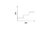
図3(a)に例示するように、熱処理工程では、経時的に加熱温度を低くしてもよい。即ち、加熱炉30内の温度を次第に又は段階的に低くすることで、図3(b)に示すように、積層体16の温度を経時的に下げることができる。例えば、積層体16の搬送経路に沿って加熱炉30が設置される場合に、上流側を高温(例えば、170℃)に設定し、下流側を低温(例えば、130℃)に設定することができる。このようなヒートパターンを適用すれば、積層体16の温度が経時的に下がるため、後の光照射工程における太陽電池セル11及び封止材14の過熱防止に寄与する。
As illustrated in FIG. 3A, in the heat treatment step, the heating temperature may be lowered over time. That is, by gradually lowering the temperature in the
冷却工程は、光照射工程の前に、加熱工程で加熱された積層体16を冷却する工程である。冷却工程では、加熱炉30から取り出した積層体16を室温雰囲気に置き、自然放冷により積層体16を冷却してもよいが、生産性等の観点から冷却装置35を用いて積層体16を積極的に冷却することが好適である。冷却装置35は、積層体16に接触して冷却する接触式の冷却機構を有してもよいが、好ましくは非接触式の空冷機構を有する。好適な冷却装置35としては、送風機が例示できる。
A cooling process is a process of cooling the
冷却工程は、上記のように、所定の温度まで冷却して、後の光照射工程において太陽電池セル11及び封止材14の温度が加熱工程における各々の最高到達温度を超えないようにする。具体的には、積層体16を構成する太陽電池セル11及び封止材14の温度が140℃以下になるまで積層体16を冷却することが好適である。冷却工程では、光照射工程における過熱防止及び生産性等の観点から、例えば封止材14の温度を50℃〜140℃の範囲まで下げ、特に好ましくは60℃〜130℃の範囲まで下げる。なお、太陽電池セル11及び封止材14が140℃以下に冷却された場合、積層体16の表面を構成する各保護部材の温度は140℃以下である。
As described above, the cooling process is performed by cooling to a predetermined temperature so that the temperature of the
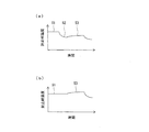
図4(a)は、加熱工程S1、冷却工程S2、及び光照射工程S3における太陽電池セル11の温度(セル温度)を示している。図4(b)には、比較として冷却工程S2を有さない場合のセル温度を示している。図4(a)に示すように、後述の光照射工程S3により太陽電池セル11の温度は上昇するが、冷却工程S2を設けて加熱工程S1により上昇したセル温度を下げることで、光照射工程S3における太陽電池セル11の過剰な温度上昇を防止できる。つまり、冷却工程S2は、光照射工程S3におけるセル温度の上昇を考慮して冷却条件を設定し、光照射工程S3は、セル温度が加熱工程S1におけるセルの最高到達温度に達する前に終了する。一方、図4(b)に示すように、冷却工程S2を有さない場合、光照射工程S3におけるセル温度は加熱工程S1におけるセルの最高到達温度を超えてしまう場合がある。
Fig.4 (a) has shown the temperature (cell temperature) of the
図5は、図4のセル温度に代えて、各工程における封止材14の温度(封止材温度)を示す。詳しくは後述するように、光照射工程S3では太陽電池セル11から伝わる熱により封止材14が加熱されるため、光照射工程S3における封止材14の温度上昇の程度は太陽電池セル11よりも小さい。しかし、図5(b)に示すように、冷却工程S2を有さない場合、例えば光照射工程S3における封止材温度は加熱工程S1における封止材14の最高到達温度を超えてしまう。図5(a)に示すように、冷却工程S2を設けることで、光照射工程S3における封止材14の過剰な温度上昇を防止できる。
FIG. 5 shows the temperature of the sealing material 14 (sealing material temperature) in each step instead of the cell temperature of FIG. As will be described in detail later, since the sealing
光照射工程は、最大ピーク波長が1500nm以下の光(以下、「特定光」という)を積層体16の太陽電池セル11に照射して、セルの温度上昇により封止材14を加熱する工程である。即ち、光照射工程は、太陽電池セル11が特定光を吸収し、当該セルの温度上昇により封止材14を間接的に加熱する。
The light irradiation step is a step in which the
光照射工程は、積層体16を構成する太陽電池セル11及び封止材14の温度が少なくとも加熱工程における各々の最高到達温度を超えないように実行される。本実施形態では、冷却工程により加熱工程で上昇した積層体16の温度が下がっているため、光照射工程で太陽電池セル11及び封止材14の温度が上昇しても、加熱工程における最高到達温度には達しない。光照射工程は、室温雰囲気で行われてもよく、加熱工程における加熱温度よりも低い温度に設定された加熱炉内で行われてもよい。当該加熱炉内の最大温度は、110℃以下であることが好ましい。
The light irradiation process is performed so that the temperature of the
光照射工程では、特定光を吸収した太陽電池セル11の熱が封止材14に伝わり、太陽電池セル11との界面近傍における封止材14が局所的に加熱される。かかる局所的な封止材14の加熱により、封止材14中の気泡の発生を防止しながら、太陽電池セル11と封止材14との接着力を向上させることができる。そして、冷却工程を設けることにより光照射工程における太陽電池セル11及び封止材14の過剰な温度上昇が防止される。
In the light irradiation step, the heat of the
光照射工程には、特定光を照射可能な光源が用いられる。特定光の最大ピーク波長は、太陽電池セル11の選択的な加熱と封止材14等の劣化防止の観点から、400nm〜1500nm程度が好ましく、400nm〜1200nm程度がより好ましい。最大ピーク波長が当該範囲にある光は、太陽電池セル11に吸収され易く、かつ封止材14を透過し易いため、太陽電池セル11のみを選択的に加熱することができる。
In the light irradiation step, a light source capable of emitting specific light is used. The maximum peak wavelength of the specific light is preferably about 400 nm to 1500 nm, more preferably about 400 nm to 1200 nm, from the viewpoint of selective heating of the
光照射工程では、好ましくは1500nm以上の光の照射強度が最大ピークの1%以下、より好ましくは最大ピークの0.5%以下である光源を用いて光照射を行う。さらに、当該光源から出力される光(特定光)は、1200nm以下の光の割合が99%以上であることが特に好ましい。波長1200nm、特に1500nmを超える光は封止材14(オレフィン系樹脂)に吸収され易い。このため、積層体16に照射される特定光は、波長1200nm以下の光の割合が多く、波長1200nm、特に1500nmを超える光の割合が少ないことが好適である。
In the light irradiation step, light irradiation is preferably performed using a light source whose irradiation intensity of light of 1500 nm or more is 1% or less of the maximum peak, more preferably 0.5% or less of the maximum peak. Furthermore, it is particularly preferable that the light (specific light) output from the light source has a ratio of light of 1200 nm or less of 99% or more. Light exceeding a wavelength of 1200 nm, particularly 1500 nm, is easily absorbed by the sealing material 14 (olefin resin). For this reason, it is preferable that the specific light irradiated to the
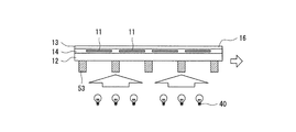
光照射工程で用いられる光源40は、上記特定光を照射可能なものであれば特に限定されず、例えばキセノンランプ、ハロゲンランプ、又はLED等を用いることができる。図2等では光源40を電球形で図示しているが、上記のように図面は模式的に記載されたものであり、当該記載は光源の形状を限定するものではない。後述の図8に示すように、LED基板をそのまま光源に用いてもよい。
The
光照射工程により、太陽電池セル11及びセルとの界面近傍における封止材14の温度は、積層体16の他の部分の温度よりも、例えば5℃〜120℃程度、好ましくは30℃〜80℃程度高くなる。但し、光照射工程における太陽電池セル11及び封止材14の最高到達温度は、加熱工程時における最高到達温度よりも低くする必要があり、好ましくは90℃〜170℃、より好ましくは120℃〜160℃である。光照射工程における太陽電池セル11等の最高到達温度は、例えば冷却工程で積層体16の温度を下げるほど低く抑えることができる。
Due to the light irradiation step, the temperature of the sealing
特定光は、積層体16の両側から照射してもよいが、生産性等の観点から、好ましくは積層体16の片側から照射する。例えば、第2保護部材13に金属層が設けられている場合、また封止材14bが酸化チタン等の色材を含む場合は、第1保護部材12側から特定光を照射する。
The specific light may be irradiated from both sides of the
図6に例示するように、特定光の照射量(以下、「光量」という)は経時的に増加させてもよい。例えば、複数の光源を積層体16の搬送経路に沿って配置し、上流側から下流側に向かってその出力を高くすることで光量を段階的に増加させることができる。或いは、1つの光源を用いて、その出力を次第に又は段階的に上昇させてもよい。また、光源の数、処理時間等を変更して光量を調整してもよい。
As illustrated in FIG. 6, the irradiation amount of specific light (hereinafter referred to as “light amount”) may be increased over time. For example, by arranging a plurality of light sources along the transport path of the stacked
図7に例示するように、第1保護部材12上に高熱伝導性部材41を配置した状態で、第1保護部材12側から積層体16に対して特定光を照射してもよい。高熱伝導性部材41は、複数の太陽電池セル11上に亘って当該各セルの一部を覆うように第1保護部材12上に配置される。即ち、図7に示す例では、積層体16の厚み方向に、太陽電池セル11と高熱伝導性部材41とが重なっている。
As illustrated in FIG. 7, specific light may be applied to the laminate 16 from the first
高熱伝導性部材41は、保護部材及び封止材14よりも熱伝導性の高い部材であって、光照射により上昇する各太陽電池セル11の温度の分布を小さくする役割を果たす。つまり、光照射により温度が上昇した高熱伝導性部材41から保護部材等を介して複数の太陽電池セル11に熱が伝達される。これにより、各太陽電池セル11に入射する光量に差がある場合でも、各太陽電池セル11の温度分布を小さくすることができ、各太陽電池セル11と封止材14との接着強度の均一化を図ることができる。
The high
高熱伝導性部材41には、金属プレート、金属バー、金属ワイヤー、金属メッシュ等を用いることができる。高熱伝導性部材41は、例えば太陽電池セル11同士の間隙の幅よりもやや長い幅と、太陽電池セル11の複数個分の長さとを有し、隣り合う太陽電池セル11の間隙上に設けることができる。この場合、太陽電池セル11に入射する光量の減少を抑制しながら、各太陽電池セル11の均熱化を図ることができる。高熱伝導性部材41は、全ての太陽電池セル11の一部を覆って配置されてもよく、太陽電池セル11に入射する光量の差が大きな部分のみに配置されてもよい。後述する搬送手段の支持部を高熱伝導性部材41として利用することもできる。
For the high thermal
上記工程の終了後、必要により、積層体16のトリミング工程、フレーム、端子ボックスの取り付け工程等を経て、太陽電池モジュール10が製造される。
After the above process is completed, the
以上のように、上記製造工程によれば、封止材14全体の温度が過剰な温度上昇を防止しながら、太陽電池セル11と封止材14との接着力を向上させることができる。したがって、上記製造工程によれば、太陽電池セル11と封止材14との界面における剥離、又は太陽電池セル11及び封止材14の過熱に起因する外観不良、絶縁低下の発生を抑制し、信頼性の高い太陽電池モジュール10を提供することができる。上記製造工程は、封止材14がカップリング剤を含有する場合に、太陽電池セル11の表面とカップリング剤との反応を大幅に促進できるため、特に好適である。
As mentioned above, according to the said manufacturing process, the adhesive force of the
以下、図8〜図13を参照しながら、実施形態の一例である太陽電池モジュールの製造装置50(以下、「製造装置50」とする)について詳説する。
Hereinafter, a solar cell module manufacturing apparatus 50 (hereinafter referred to as “
図8は、製造装置50を示す図である。
製造装置50は、ラミネート装置20(図2参照)と、加熱炉30と、冷却装置35と、光源40と、積層体16を搬送する搬送手段とを備える。ラミネート装置20は、太陽電池セル11、封止材14、及び保護部材を順に重ねて加熱圧着することにより積層体16を作製する。好適な搬送手段は、積層体16を連続搬送可能なコンベアであって、本実施形態ではベルトコンベア51を用いる。
FIG. 8 is a view showing the
The
ベルトコンベア51は、積層体16が載せられる支持部53を有する。各支持部53は、例えば無端状のベルト52の長手方向に所定間隔で複数配置された金属バー又は金属プレートであって、各支持部53の端部同士が連結されてベルト52が構成されている。ベルトコンベア51は、ラミネート装置20で作製された積層体16を加熱炉30内(加熱ゾーンZ1)に搬送し、続いて冷却装置35が設置された冷却ゾーンZ2、及び光源40が設置された光照射ゾーンZ3に順次搬送する。即ち、ベルトコンベア51の上流側から加熱炉30、冷却装置35、光源40が順に配置されている。図8に示す例では、光照射ゾーンZ3に加熱炉が設置されておらず、光照射工程は室温雰囲気で行われる。
The
第1保護部材12がガラス基板であり、第2保護部材13が樹脂フィルムである場合、積層体16は、ガラス基板を支持部53側に向けてベルトコンベア51に載せられることが好適である。ガラス基板は、樹脂フィルムに比べて加熱により変形し難いため、このように配置することが好ましい。樹脂フィルムが特定光を透過する場合は、ガラス基板側、樹脂フィルム側の両方から特定光が入射可能(両面入射可能)である。各保護部材がガラス基板である場合も両面入射が可能である。樹脂フィルムが特定光を透過し難い又は透過しない場合は、ガラス基板側から光照射を行う。
When the
加熱炉30は、積層体16の全体を加熱する。加熱炉30は、抵抗加熱炉を含んで構成することができる。加熱炉30は、145℃〜180℃の温度範囲で積層体16を加熱することが好ましい。加熱炉30内の温度は、120℃〜180℃が好ましく、150℃〜170℃がより好ましい。図8に示す例では、加熱炉30がコンベアに沿って、即ち積層体16の搬送経路に沿って配置されている。加熱炉30は、コンベアの下流側ほど加熱温度を低く設定してもよい。例えば、コンベアの上流側を170℃に設定し、下流側を150℃に設定してもよい。積層体16が加熱炉30内を通過する時間は、5分〜60分程度が好ましく、10分〜45分程度がより好ましい。加熱ゾーンZ1から搬出された積層体16(太陽電池セル11及び封止材14)の温度は、例えば145℃〜180℃である。
The
冷却装置35は、加熱炉30で加熱された積層体16を冷却する。冷却装置35は、送風機を含んで構成することが好適である。図8に示す例では、積層体16の搬送経路に沿って複数の送風機が設置されている。冷却装置35は、例えばベルト52のキャリア部52aとリターン部52bとの間に配置することができる。ここで、キャリア部52aとは、積層体16を載せて搬送する部分であり、リターン部52bとは、キャリア部52aの裏側に回り込む部分である。冷却装置35は、積層体16を構成する太陽電池セル11及び封止材14の温度が140℃以下になるまで積層体16を冷却することが好適である。冷却ゾーンZ2から搬出された積層体16の温度は、例えば50℃〜140℃である。
The
光源40は、冷却装置35で冷却された積層体16の太陽電池セル11に、特定光を照射する。光源40から出力される特定光が積層体16の太陽電池セル11に照射されることで、当該セルの温度が上昇し、当該セルの界面近傍における封止材14が局所的に加熱される。光源40には、例えばキセノンランプ、ハロゲンランプ、メタルハライドランプ、LED等が用いられる。図8に示す例では、ベルト52の流れ方向に沿って複数の光源40が配置されている。各光源40は、同じものであってもよく、出力等が異なるものであってもよい。例えば、ベルトコンベア51の下流側に上流側よりも高出力の光源40を設置して、加熱炉30で行われる加熱工程から時間が経過するほど積層体16に対する光量を増加させてもよい。
The
光源40は、例えばベルト52のキャリア部52aとリターン部52bとの間に配置され、各支持部53の間から積層体16に光を照射する。つまり、ベルトコンベア51の中において、各支持部53の間から積層体16に対して光照射可能な位置に光源40を設置する。これにより、例えばベルトコンベア51の下(リターン部52bの下)に光源40を設置した場合と比べて効率良く光照射を行うことができる。
The
好適な光源40の一例はLEDである。光源40には、好ましくは1500nm以上の光の照射強度が最大ピークの1%以下、より好ましくは最大ピークの0.5%以下であるLEDを用いることができる。LEDから出力される光(特定光)は、1200nm以下の光の割合が99%以上であることが特に好ましい。かかるLEDとしては、COB(Chip on Board)構造のLEDが例示できる。LED等の光源40から出力される光を目的とする照射位置に集光すべく、光源40と積層体16の間にレンズ42を設けてもよい。レンズ42は、ガラス製、樹脂製、金属製のいずれであってもよい。
An example of a suitable
図9に例示する製造装置50xでは、光照射ゾーンZ3xに加熱炉31が設置されている。但し、加熱炉31内の温度は、加熱ゾーンZ1の加熱炉30内の温度よりも低い温度、好ましくは140℃以下に設定される。光源40は、加熱炉31の外部に配置され、透光性部材32を通して加熱炉31内の積層体16に特定光を照射することが好適である。これにより、光源40を加熱炉内に設置する場合と比べて、光源40の寿命を延ばすことができる。
In the
図10で例示するように、加熱炉31の壁部の少なくとも一部は、特定光を透過する透光性部材32で構成されている。透光性部材32には、例えば特定光を透過するガラス、樹脂シート等が用いられる。効率的な光照射を可能とすべく、光源40から出力された特定光のガラスに対する入射角θが60°以下である割合が高いことが好ましく、具体的には全出力光の50%以上であることが好ましい。
As illustrated in FIG. 10, at least a part of the wall portion of the
図11に示す例では、ベルトコンベア51の支持部53が、積層体16の端部に位置するように設けられている。また、支持部53は、積層体16の太陽電池セル11同士の間隙に位置するように設けられている。ゆえに、積層体16の厚み方向に、太陽電池セル11と支持部53とが略重なっていない。つまり、図11に示す例では、支持部53が太陽電池セル11同士の間隙に対応する間隔で配置され、かつ支持部53が当該間隙に位置するように積層体16がベルトコンベア51に載せられる。搬送性等に問題がなければ、積層体16の端部、又は太陽電池セル11同士の間隙のいずれかに合わせて、支持部53を設けてもよい。これにより、支持部53による遮光ロスを低減乃至無くすことができる。
In the example shown in FIG. 11, the
図12に示す例では、搬送手段として、積層体16が載せられる支持部である搬送ローラー55が複数配置されたローラーコンベア54が適用されている。光源40は、ローラーコンベア54の裏側、即ち搬送ローラー55の下に配置され、各搬送ローラー55の間から積層体16に特定光を照射する。ローラーコンベア54では、各搬送ローラー55の位置は固定されており、例えば搬送ローラー55の一部が回転駆動して積層体16を搬送する。ゆえに、積層体16において搬送ローラー55により遮光される部分は変化するため、積層体16の各太陽電池セル11に対してまんべんなく特定光を照射することができる。
In the example illustrated in FIG. 12, a
図13に示す例では、第2保護部材13(樹脂フィルム)を支持部53側に向けた状態で積層体16を搬送する。即ち、ベルトコンベア51は、第1保護部材12(ガラス基板)が上を向いた状態で積層体16を搬送する。この場合も、ガラス基板側から積層体16に光照射を行うことが好ましく、光源40は、例えばベルトコンベア51の上方に配置される。
In the example shown in FIG. 13, the
搬送手段の支持部を透光性部材、例えば特定光を透過するガラス又は樹脂で構成することもできる。支持部が金属製である場合は、これを上記高熱伝導性部材として利用することもできる。 The support part of the conveying means can also be constituted by a translucent member, for example, glass or resin that transmits specific light. When the support is made of metal, it can be used as the high thermal conductivity member.
上記実施形態では、冷却ゾーンZ2に冷却装置35を設置しているが、冷却装置35を設置しない形態とすることも可能である。この場合、積層体16は冷却ゾーンZ2で自然放冷される。また、加熱ゾーンZ1で経時的に加熱温度を低くして積層体16の温度を下げ、続けて太陽電池セル11及び封止材14の温度が加熱工程における各々の最高到達温度を超えないように光照射工程を実行することも可能である。但し、生産性等の観点から、光照射前に、積層体16の温度を迅速に下げることが可能な冷却工程を設けることが好適である。
In the above-described embodiment, the
10 太陽電池モジュール、11 太陽電池セル、12 第1保護部材、13 第2保護部材、14 封止材、14a 第1封止材、14b 第2封止材、15 導線、16 積層体、20 ラミネート装置、21 ヒーター、22 上部真空室、23 下部真空室、24 ラバー、30,31 加熱炉、32 透光性部材、35 冷却装置、40 光源、41 高熱伝導性部材、42 レンズ、50 太陽電池モジュールの製造装置、51 ベルトコンベア、52 ベルト、52a キャリア部、52b リターン部、53 支持部、54 ローラーコンベア、55 搬送ローラー、Z1 加熱ゾーン、Z2 冷却ゾーン、Z3,Z3x 光照射ゾーン
DESCRIPTION OF
Claims (10)
前記積層体の全体を加熱し、加熱が終了した後に所定の温度に冷却する熱処理工程と、
前記積層体を構成する前記太陽電池セル及び前記封止材の温度が少なくとも前記熱処理工程における各々の最高到達温度を超えないように、LEDを用いて最大ピーク波長が400nm〜1200nm以下の光を前記積層体の前記太陽電池セルに照射して、当該セルの温度上昇により前記封止材を加熱する光照射工程と、
を備える太陽電池モジュールの製造方法。 A step of producing a laminate by superposing solar cells, a sealing material, and a protective member and thermocompression bonding;
A heat treatment step of heating the entire laminate and cooling to a predetermined temperature after the heating is completed;
The light having a maximum peak wavelength of 400 nm to 1200 nm or less using an LED so that the temperature of the solar battery cell and the sealing material constituting the laminated body does not exceed at least the highest temperature reached in each of the heat treatment steps. A light irradiation step of irradiating the solar battery cell of the laminate and heating the sealing material due to a temperature rise of the cell,
A method for manufacturing a solar cell module comprising:
前記積層体の全体を加熱する加熱工程と、
前記加熱工程で加熱された前記積層体を冷却する冷却工程と、
を備える、請求項1に記載の太陽電池モジュールの製造方法。 The heat treatment step includes
A heating step of heating the entire laminate,
A cooling step for cooling the laminate heated in the heating step;
The manufacturing method of the solar cell module of Claim 1 provided with these.
前記冷却工程は、前記積層体を構成する前記太陽電池セル及び前記封止材の温度が140℃以下になるまで前記積層体を冷却する、請求項2に記載の太陽電池モジュールの製造方法。 The heating step heats the laminate in a temperature range of 145 ° C. to 180 ° C.,
The said cooling process is a manufacturing method of the solar cell module of Claim 2 which cools the said laminated body until the temperature of the said photovoltaic cell and the said sealing material which comprises the said laminated body becomes 140 degrees C or less.
前記積層体の全体を加熱する加熱炉と、
前記加熱炉で熱処理された前記積層体を冷却する冷却装置と、
最大ピーク波長が400nm〜1200nm以下の光を、前記冷却装置で冷却された前記積層体の前記太陽電池セルに照射するLEDと、
前記積層体を搬送する搬送手段と、
を備える、太陽電池モジュールの製造装置。 A laminating apparatus for producing a laminate by superposing solar cells, a sealing material, and a protective member and thermocompression bonding;
A heating furnace for heating the entire laminate,
A cooling device for cooling the laminated body heat-treated in the heating furnace;
An LED that irradiates the solar cells of the laminate that has been cooled by the cooling device with light having a maximum peak wavelength of 400 nm to 1200 nm or less;
Conveying means for conveying the laminate;
An apparatus for manufacturing a solar cell module.
前記冷却装置は、前記積層体を構成する前記太陽電池セル及び前記封止材の温度が140℃以下になるまで前記積層体を冷却する、請求項6に記載の太陽電池モジュールの製造装置。 The heating furnace heats the laminate in a temperature range of 145 ° C to 180 ° C,
The said cooling device is a manufacturing apparatus of the solar cell module of Claim 6 which cools the said laminated body until the temperature of the said photovoltaic cell and the said sealing material which comprises the said laminated body becomes 140 degrees C or less.
前記加熱炉は、前記コンベアに沿って配置され、前記コンベアの下流側ほど加熱温度が低く設定される、請求項6又は7項に記載の太陽電池モジュールの製造装置。 The conveying means is a conveyor,
The said heating furnace is a manufacturing apparatus of the solar cell module of Claim 6 or 7 arrange | positioned along the said conveyor and heating temperature is set low as the downstream of the said conveyor.
Applications Claiming Priority (2)
| Application Number | Priority Date | Filing Date | Title |
|---|---|---|---|
| JP2014218584 | 2014-10-27 | ||
| JP2014218584 | 2014-10-27 |
Related Parent Applications (1)
| Application Number | Title | Priority Date | Filing Date |
|---|---|---|---|
| JP2016556187A Division JPWO2016067516A1 (en) | 2014-10-27 | 2015-09-24 | Solar cell module manufacturing method and solar cell module manufacturing apparatus |
Publications (2)
| Publication Number | Publication Date |
|---|---|
| JP2019016819A true JP2019016819A (en) | 2019-01-31 |
| JP6709996B2 JP6709996B2 (en) | 2020-06-17 |
Family
ID=55856886
Family Applications (2)
| Application Number | Title | Priority Date | Filing Date |
|---|---|---|---|
| JP2016556187A Pending JPWO2016067516A1 (en) | 2014-10-27 | 2015-09-24 | Solar cell module manufacturing method and solar cell module manufacturing apparatus |
| JP2018208089A Active JP6709996B2 (en) | 2014-10-27 | 2018-11-05 | Solar cell module manufacturing method and solar cell module manufacturing apparatus |
Family Applications Before (1)
| Application Number | Title | Priority Date | Filing Date |
|---|---|---|---|
| JP2016556187A Pending JPWO2016067516A1 (en) | 2014-10-27 | 2015-09-24 | Solar cell module manufacturing method and solar cell module manufacturing apparatus |
Country Status (5)
| Country | Link |
|---|---|
| US (1) | US20170229605A1 (en) |
| EP (1) | EP3214658A4 (en) |
| JP (2) | JPWO2016067516A1 (en) |
| CN (1) | CN107078173B (en) |
| WO (1) | WO2016067516A1 (en) |
Families Citing this family (3)
| Publication number | Priority date | Publication date | Assignee | Title |
|---|---|---|---|---|
| WO2016181615A1 (en) * | 2015-05-13 | 2016-11-17 | パナソニックIpマネジメント株式会社 | Solar cell module manufacturing device and solar cell module manufacturing method |
| US10411152B2 (en) * | 2016-06-27 | 2019-09-10 | Merlin Solar Technologies, Inc. | Solar cell bonding |
| JP2020161684A (en) * | 2019-03-27 | 2020-10-01 | パナソニック株式会社 | Manufacturing method of solar cell module |
Citations (6)
| Publication number | Priority date | Publication date | Assignee | Title |
|---|---|---|---|---|
| JPS5916388A (en) * | 1982-07-19 | 1984-01-27 | Matsushita Electric Ind Co Ltd | Solar battery module |
| JPS6144741A (en) * | 1984-08-10 | 1986-03-04 | Bridgestone Corp | Production of laminate |
| JP2002096388A (en) * | 2000-09-26 | 2002-04-02 | Nisshinbo Ind Inc | Method and apparatus for laminating |
| JP2008117926A (en) * | 2006-11-02 | 2008-05-22 | Mitsui Chemicals Inc | Solar battery module manufacturing method and its manufacturing apparatus |
| WO2012082943A1 (en) * | 2010-12-15 | 2012-06-21 | E. I. Du Pont De Nemours And Company | Method for fabricating a photovoltaic module using a fixture and using localized heating to heat areas of increased heating capability and module produced thereby |
| WO2015059875A1 (en) * | 2013-10-24 | 2015-04-30 | パナソニックIpマネジメント株式会社 | Solar cell module manufacturing method and solar cell module manufacturing apparatus |
Family Cites Families (12)
| Publication number | Priority date | Publication date | Assignee | Title |
|---|---|---|---|---|
| EP0969521A1 (en) * | 1998-07-03 | 2000-01-05 | ISOVOLTAÖsterreichische IsolierstoffwerkeAktiengesellschaft | Photovoltaic module and method of fabrication |
| ATE529896T1 (en) * | 2003-07-07 | 2011-11-15 | Dow Corning | ENCAPSULATION FOR SOLAR CELLS |
| US8158450B1 (en) * | 2006-05-05 | 2012-04-17 | Nanosolar, Inc. | Barrier films and high throughput manufacturing processes for photovoltaic devices |
| US20100101647A1 (en) * | 2008-10-24 | 2010-04-29 | E.I. Du Pont De Nemours And Company | Non-autoclave lamination process for manufacturing solar cell modules |
| US20100101646A1 (en) * | 2008-10-24 | 2010-04-29 | E. I. Du Pont De Nemours And Company | Non-autoclave lamination process for manufacturing solar cell modules |
| JP2011115987A (en) * | 2009-12-01 | 2011-06-16 | Asahi Kasei E-Materials Corp | Solar cell resin sealing sheet |
| JP2011119475A (en) * | 2009-12-03 | 2011-06-16 | Asahi Kasei E-Materials Corp | Method of manufacturing solar cell module |
| JP5755862B2 (en) * | 2010-09-27 | 2015-07-29 | 株式会社ブリヂストン | Laminated glass manufacturing method |
| AU2013266009B2 (en) * | 2012-05-21 | 2017-02-16 | Newsouth Innovations Pty Limited | Advanced hydrogenation of silicon solar cells |
| DE102012015439A1 (en) * | 2012-08-02 | 2014-02-06 | Institut Für Solarenergieforschung Gmbh | Method and device for laminating objects, in particular solar cells |
| EP3014663B1 (en) * | 2013-06-26 | 2020-09-02 | Universität Konstanz | Method and device for producing a photovoltaic element with stabilized efficiency |
| US10443941B2 (en) * | 2015-05-20 | 2019-10-15 | Illinois Tool Works Inc. | Light annealing in a cooling chamber of a firing furnace |
-
2015
- 2015-09-24 JP JP2016556187A patent/JPWO2016067516A1/en active Pending
- 2015-09-24 CN CN201580058509.4A patent/CN107078173B/en active Active
- 2015-09-24 EP EP15854343.9A patent/EP3214658A4/en not_active Withdrawn
- 2015-09-24 WO PCT/JP2015/004833 patent/WO2016067516A1/en active Application Filing
-
2017
- 2017-04-25 US US15/496,218 patent/US20170229605A1/en not_active Abandoned
-
2018
- 2018-11-05 JP JP2018208089A patent/JP6709996B2/en active Active
Patent Citations (6)
| Publication number | Priority date | Publication date | Assignee | Title |
|---|---|---|---|---|
| JPS5916388A (en) * | 1982-07-19 | 1984-01-27 | Matsushita Electric Ind Co Ltd | Solar battery module |
| JPS6144741A (en) * | 1984-08-10 | 1986-03-04 | Bridgestone Corp | Production of laminate |
| JP2002096388A (en) * | 2000-09-26 | 2002-04-02 | Nisshinbo Ind Inc | Method and apparatus for laminating |
| JP2008117926A (en) * | 2006-11-02 | 2008-05-22 | Mitsui Chemicals Inc | Solar battery module manufacturing method and its manufacturing apparatus |
| WO2012082943A1 (en) * | 2010-12-15 | 2012-06-21 | E. I. Du Pont De Nemours And Company | Method for fabricating a photovoltaic module using a fixture and using localized heating to heat areas of increased heating capability and module produced thereby |
| WO2015059875A1 (en) * | 2013-10-24 | 2015-04-30 | パナソニックIpマネジメント株式会社 | Solar cell module manufacturing method and solar cell module manufacturing apparatus |
Also Published As
| Publication number | Publication date |
|---|---|
| CN107078173B (en) | 2020-06-09 |
| JP6709996B2 (en) | 2020-06-17 |
| WO2016067516A1 (en) | 2016-05-06 |
| CN107078173A (en) | 2017-08-18 |
| JPWO2016067516A1 (en) | 2017-08-10 |
| US20170229605A1 (en) | 2017-08-10 |
| EP3214658A4 (en) | 2017-10-25 |
| EP3214658A1 (en) | 2017-09-06 |
Similar Documents
| Publication | Publication Date | Title |
|---|---|---|
| US10020412B2 (en) | Module assembly for thin solar cells | |
| JP5121365B2 (en) | Solar cell module and manufacturing method thereof | |
| KR101997921B1 (en) | Solar cell module | |
| JP6709996B2 (en) | Solar cell module manufacturing method and solar cell module manufacturing apparatus | |
| JPWO2005096396A1 (en) | Manufacturing method of solar cell | |
| US9627567B2 (en) | Solar cell module manufacturing method and solar cell module manufacturing apparatus | |
| US9337378B2 (en) | System and method for photovoltaic device temperature control while conditioning a photovoltaic device | |
| TWI596791B (en) | Solar cell module | |
| US20150114447A1 (en) | Junction box and photovoltaic module including the same | |
| KR101747344B1 (en) | Solar cell module | |
| JP6535089B2 (en) | Apparatus for manufacturing solar cell module and method for manufacturing solar cell module | |
| TWI624956B (en) | Solar battery module and manufacturing method thereof | |
| US20180182909A1 (en) | Solar cell module and method for manufacturing solar cell module | |
| EP2973748B1 (en) | System and method for photovoltaic device temperature control while conditioning a photovoltaic device | |
| WO2021095217A1 (en) | Solar cell panel, solar cell module, method for manufacturing solar cell panel, and method for manufacturing solar cell module | |
| JP2016207891A (en) | Manufacturing method of solar cell module |
Legal Events
| Date | Code | Title | Description |
|---|---|---|---|
| A621 | Written request for application examination |
Free format text: JAPANESE INTERMEDIATE CODE: A621 Effective date: 20181105 |
|
| A131 | Notification of reasons for refusal |
Free format text: JAPANESE INTERMEDIATE CODE: A131 Effective date: 20190903 |
|
| A601 | Written request for extension of time |
Free format text: JAPANESE INTERMEDIATE CODE: A601 Effective date: 20191101 |
|
| A521 | Request for written amendment filed |
Free format text: JAPANESE INTERMEDIATE CODE: A523 Effective date: 20191226 |
|
| TRDD | Decision of grant or rejection written | ||
| A01 | Written decision to grant a patent or to grant a registration (utility model) |
Free format text: JAPANESE INTERMEDIATE CODE: A01 Effective date: 20200428 |
|
| A61 | First payment of annual fees (during grant procedure) |
Free format text: JAPANESE INTERMEDIATE CODE: A61 Effective date: 20200511 |
|
| R151 | Written notification of patent or utility model registration |
Ref document number: 6709996 Country of ref document: JP Free format text: JAPANESE INTERMEDIATE CODE: R151 |