JP2019014507A - Packing machine having ultrasonic sealing device - Google Patents
Packing machine having ultrasonic sealing device Download PDFInfo
- Publication number
- JP2019014507A JP2019014507A JP2017132340A JP2017132340A JP2019014507A JP 2019014507 A JP2019014507 A JP 2019014507A JP 2017132340 A JP2017132340 A JP 2017132340A JP 2017132340 A JP2017132340 A JP 2017132340A JP 2019014507 A JP2019014507 A JP 2019014507A
- Authority
- JP
- Japan
- Prior art keywords
- packaging material
- ultrasonic sealing
- sealing device
- ultrasonic
- packaging
- Prior art date
- Legal status (The legal status is an assumption and is not a legal conclusion. Google has not performed a legal analysis and makes no representation as to the accuracy of the status listed.)
- Granted
Links
Images


Abstract
Description
この発明は、超音波ホーンとこれに対向配置されたアンビルとを有しており、前記超音波ホーンと前記アンビルとの間に重ね合わせ状態で送り込まれる包装材に加圧状態で超音波を印加することにより、前記包装材に超音波シールを施す超音波シール装置を備えた包装機に関する。 The present invention has an ultrasonic horn and an anvil disposed opposite to the ultrasonic horn, and applies ultrasonic waves in a pressurized state to a packaging material fed in an overlapped state between the ultrasonic horn and the anvil. By doing this, it is related with the packaging machine provided with the ultrasonic sealing apparatus which ultrasonically seals the said packaging material.
従来、包装物を収容する包装材のシールとして、包装材の重なり部分にスポット状のシールをするスポットシール手段がある。スポットシール手段と包装材が相対的に移動をすることで、包装材に線状のシールを施すことができる。 2. Description of the Related Art Conventionally, as a seal of a packaging material that accommodates a package, there is a spot seal means that performs spot-like sealing on an overlapping portion of the packaging material. By linearly moving the spot seal means and the packaging material, a linear seal can be applied to the packaging material.
スポットシール手段としては、高周波電気等の電気的な手段もあるが、包装材が熱可塑性樹脂である場合には、熱可塑性樹脂材に微細な超音波振動と圧力を加えることで熱可塑性樹脂材を瞬時に溶融して接合する超音波溶着によるシール手段がある。超音波溶着(シール)装置は、電気エネルギーを機械的振動エネルギーに変換し、当該振動と同時に圧力をかけることにより2つの熱可塑性樹脂材の接合面に強力な摩擦熱を発生させ、樹脂を溶融し結合させるものである。超音波シール装置は、シール時に超音波を発振する超音波ホーンと、熱可塑性樹脂材を挟み込んで超音波ホーンに対して圧力を以て強く押し当てられるアンビルを備えている。 There are electrical means such as high-frequency electricity as the spot seal means, but when the packaging material is a thermoplastic resin, the thermoplastic resin material is applied by applying fine ultrasonic vibration and pressure to the thermoplastic resin material. There is a sealing means by ultrasonic welding that melts and joins instantly. The ultrasonic welding (seal) device converts electrical energy into mechanical vibration energy, and applies pressure simultaneously with the vibration to generate strong frictional heat on the joint surface of the two thermoplastic resin materials, melting the resin. To be combined. The ultrasonic sealing device includes an ultrasonic horn that oscillates an ultrasonic wave at the time of sealing, and an anvil that sandwiches a thermoplastic resin material and is pressed strongly against the ultrasonic horn with pressure.
本出願人は、共同出願人の一人として、スポットシール手段を備えており、当該スポットシール手段を超音波シール装置とした製袋充填包装機を提案している(特許文献1)。超音波シール装置を備えた製袋充填包装機の一例を図5及び図6に示す。図5は超音波シール装置を備えた製袋充填包装機の一例を示す斜視図であり、図6は図5に示す製袋充填包装機に用いられる縦シール手段の横断面図である。 As one of the joint applicants, the present applicant has proposed a bag-filling and packaging machine including spot seal means and using the spot seal means as an ultrasonic seal device (Patent Document 1). An example of a bag making filling and packaging machine provided with an ultrasonic sealing device is shown in FIGS. FIG. 5 is a perspective view showing an example of a bag making filling and packaging machine provided with an ultrasonic sealing device, and FIG. 6 is a transverse sectional view of a vertical sealing means used in the bag making filling and packaging machine shown in FIG.
図5、図6に示す超音波シール装置を備えた製袋充填包装機50は、基本的には従来良く知られた縦型製袋充填包装機のように、帯状包装材Fwがロール状に巻き取られて成る巻取りロールFrから帯状包装材Fwを繰り出して、一部を貯留するとともに適当な張力を与える繰出し機構51、帯状包装材Fwに対して印刷を行う印刷装置等の付属装置52、連続して繰り出された帯状包装材Fwを略筒状包装材に曲成するフォーマ53、縦シールを施して形成された筒状包装材Ftに横断方向にシールを施す横シーラ55,55を備える横シール手段54、及びフォーマ53内に隙間を置いて嵌入されている金属製(ステンレス製)の充填筒56を備えている。
The bag making and
フォーマ53は、帯状包装材Fwを略円筒状に曲成し、正面下端において、略円筒状に曲成された包装材の両側縁部分fe,feを重ね合わせる作用を奏する。包装材の重ね合わされた両側縁部分fe,feがフォーマ53の表側に飛び出た状態で縦方向に通過する。縦シール手段は、フォーマ53の直下に配置されており、当該両側縁部分fe,feに対してスポット状に溶着を施すスポットシール手段60である。スポットシール手段60は、製袋充填包装機50において、略円筒状に曲成された帯状包装材Fwの両側縁部分fe,feを幅方向中央にてシールするセンターシール装置として適用されている。
The former 53 bends the strip-shaped packaging material Fw into a substantially cylindrical shape, and has an effect of superimposing the side edge portions fe and fe of the packaging material bent into a substantially cylindrical shape at the lower front end. Both side edge portions fe and fe on which the packaging material is overlapped pass in the vertical direction in a state of protruding to the front side of the former 53. The vertical sealing means is a spot sealing means 60 that is disposed immediately below the former 53 and that welds the side edge portions fe and fe in a spot shape. The spot seal means 60 is applied as a center seal device that seals both side edge portions fe and fe of the belt-shaped packaging material Fw bent in a substantially cylindrical shape at the center in the width direction in the bag making and filling and
スポットシール手段60は超音波溶着手段であって、超音波ホーン61、アンビル62、及び超音波発生部63を備えている。スポットシール手段60は、機械フレーム(図示せず)に取り付けられた取付けアーム64にヒンジ66で回動可能に設けられた回動アーム65の内側に収容状態に設けられている。スポットシール手段60を稼働させるには、回動アーム65を図の装填位置に置く。装填位置から回動して退避させることで、包装機1のセッティングやメンテナンスを行うことができる。取付けアーム64は、回動アーム65及びヒンジ66を支持体66aとともに、フォーマ53に対して進退させることができるようにネジ機構67を備えており、フォーマ53のサイズ等に応じて、包装材の両側縁部分fe,feに対するスポットシール手段60の位置を調整することができる。
The spot seal means 60 is an ultrasonic welding means, and includes an
スポットシール手段60の超音波ホーン61とアンビル62とは、帯状包装材Fwの搬送方向と交差する横方向に並べて配置されている。超音波ホーン61は、金属製の略棒軸状体であり、その基端側にある超音波発生部63からアンビル62に向かって突出している。アンビル62は、金属製の円柱体であり、周面が超音波ホーン61の先端部に対向している。超音波ホーン61とアンビル62は、特にアンビル62を、例えばエア圧作動のアクチュエータとスライダを備えるガイド構造によって超音波ホーン61に向かう方向に移動可能とすることで、相対的に接近・離反移動可能に構成されており、両者が接近移動した際、アンビル62と超音波ホーン61との間で帯状包装材Fwの両側縁部分fe,feを所定の圧力で挟み付ける。アンビル62を移動させる力を変えることで、超音波シール時の圧力を変えることができる。超音波発生部63によって発振された超音波振動は、アンビル62との間で挟んでいる略円筒包装材に曲成された包装材の両側縁同士fe,feに作用し、両側縁同士fe,feを擦り合わせて超音波溶着する。スポットシール手段60が採用されることで従来のバー状の縦ヒートシーラの場合と比較して高さ寸法を抑えることができる。
The
紙送り手段は、筒状包装材Ftをその外側から吸引しながら紙送りする吸引紙送り手段70である。吸引紙送り手段70は、具体的には、筒状包装材Ftの直径方向両側に対向して配置されている紙送りベルト71,71を備えている。各紙送りベルト71には、その幅方向中央の位置において長手方向に列状に並ぶ複数の吸引孔72が形成されている。各紙送りベルト71は、モータ駆動される送り用駆動プーリ73、送り用従動プーリ74、及びガイドプーリ75に巻き掛けられている。図示しない吸引手段が吸引孔72を通して空気を吸引する。送り用駆動プーリ73からの駆動力によって、紙送りベルト71は、充填筒56との間に挟む筒状包装材Ftをその外側から接触・吸引しつつ下方へと紙送りする。略筒状に曲成された包装材が紙送りによってスポットシール手段60に対して相対的に送り込まれることで、両側縁部分fe,feにはスポットシール手段60によって線状に連続した縦シールが施され、包装材は筒状包装材Ftに成形される。縦シールが施された筒状包装材Ftに充填筒56を通して包装物を投入し、更に横シール手段54で横シールを施すことで、包装物が封入された袋包装体Bpが製造される。袋包装体Bpは、その形態から、縦シールが施された部分を背貼りシール部分とするピロー袋による袋包装体と称される。
The paper feeding means is suction paper feeding means 70 that feeds paper while sucking the cylindrical packaging material Ft from the outside. Specifically, the suction paper feeding means 70 includes
包装機用の超音波シール装置として、超音波ホーンとアンビルとを、いずれも、回転する円盤状の構造からなるロータリー式の超音波シール装置としたものが提案されている(特許文献2)。この超音波シール装置は、帯状フィルムを筒状フィルムに成形しつつ、搬送供給されてくる包装物を当該筒状フィルムに送り込み、当該包装物のフィルム送り方向前後でトップシール(エンドシール)を施すことで、袋包装体を連続して製造する横型の製袋充填包装機において、帯状フィルムから筒状に重ね合わされた両側端縁部をシールするセンターシール装置として適用されている。 As an ultrasonic sealing device for a packaging machine, an ultrasonic horn and an anvil are both proposed as a rotary ultrasonic sealing device having a rotating disk-like structure (Patent Document 2). This ultrasonic sealing device forms a strip-shaped film into a cylindrical film, feeds the package to be conveyed and fed into the cylindrical film, and applies a top seal (end seal) before and after the package in the film feeding direction. Thus, in a horizontal bag-making filling and packaging machine that continuously manufactures a bag package, it is applied as a center seal device that seals both side edges that are overlapped in a cylindrical shape from a belt-like film.
このセンターシール装置は、帯状包装材の搬送方向と交差する横方向に並べて配置する超音波ホーンユニットとアンビルユニットを備えている。超音波ホーンユニットは、円盤状の超音波ホーンと、超音波ホーンの下方に配置され当該超音波ホーンを超音波振動させるための超音波発生用コンバータや増幅用ブースタ等の駆動源を備える。駆動源は、超音波ホーンとともに機械フレームに回転可能に軸受支持されている。超音波ホーンは、駆動源の動力を受けて径が拡縮する振動をする。 The center seal device includes an ultrasonic horn unit and an anvil unit that are arranged side by side in a lateral direction that intersects the transport direction of the belt-shaped packaging material. The ultrasonic horn unit includes a disk-shaped ultrasonic horn, and a driving source such as an ultrasonic wave generating converter and an amplification booster which are arranged below the ultrasonic horn and cause the ultrasonic horn to vibrate ultrasonically. The drive source is rotatably supported by the machine frame along with the ultrasonic horn. The ultrasonic horn vibrates so that its diameter expands and contracts by receiving the power of the drive source.
アンビルユニットは、側周面に円周方向に連続して突出する突条が形成されている円盤状のアンビルを備えている。超音波ホーンとアンビルは、相対的に接近・離反移動するように構成されており、両者が接近移動した際、円盤状アンビルの突条と超音波ホーンの側面との間で帯状包装材の両側端縁部を所定の圧力で挟持する。アンビルは移動軸受け部材に軸受け支持され、移動軸受け部材は更にスライダに連結されている。スライダは、帯状包装材の搬送方向と交差する横方向に延びるように配置したガイドレールに沿って往復直線移動するようにガイドされている。このガイド構造により、移動軸受け部材ひいてはアンビルが、当該横方向に、即ち、超音波ホーンに向けて接近・離反移動する。 The anvil unit includes a disk-shaped anvil in which ridges that continuously protrude in the circumferential direction are formed on the side peripheral surface. The ultrasonic horn and the anvil are configured to move relatively toward and away from each other, and when both move close to each other, the both sides of the belt-shaped packaging material between the protrusion of the disk-shaped anvil and the side surface of the ultrasonic horn. The end edge is clamped with a predetermined pressure. The anvil is supported by the moving bearing member, and the moving bearing member is further connected to the slider. The slider is guided so as to reciprocate linearly along a guide rail disposed so as to extend in the lateral direction intersecting the transport direction of the belt-shaped packaging material. With this guide structure, the moving bearing member, and thus the anvil, moves toward and away from the lateral direction, that is, toward the ultrasonic horn.
アンビルは、エア圧で作動するアクチュエータによって往復移動される。アクチュエータは二段階で作動されるデュアル行程シリンダとすることで、往復移動の迅速性と、超音波シールをするのに適切なシール圧の制御とを可能にしている。 The anvil is reciprocated by an actuator that operates with air pressure. The actuator is a dual stroke cylinder that is operated in two stages, thereby enabling quick reciprocation and control of a sealing pressure appropriate for ultrasonic sealing.
超音波ホーンとアンビルを有する超音波シール装置を備えた包装機においては、波打った状態のシワが発生した包装材に無理に超音波シールを施そうとする事態に陥ることがある。図7は、円盤状超音波ホーン82と円盤状アンビル83とを有する超音波シール装置81を備えた包装機80において、帯状包装材FwのシワWrが重なり波打った状態となった両側縁部分fe,feが、超音波シール装置81に送り込まれようとする状況を示している。帯状包装材Fwが、充填筒56の上部に配設されているフォーマ53の先端部53a,53aを通過して略筒状に曲成される際に、包装材の特に両側縁部分fe,feを含む領域(シール予定領域Rs)が弛みや伸びに起因して綺麗に合わされず、波打ったシワWrを生じる場合がある。
In a packaging machine equipped with an ultrasonic sealing device having an ultrasonic horn and an anvil, there may be a situation in which an ultrasonic seal is forcibly applied to a packaging material in which wrinkles in a wavy state are generated. FIG. 7 shows both side edge portions of the
また、包装材が厚さの薄いフィルムである場合に、円盤状のホーンと円盤状のアンビルの径に微妙な差があるときには、周速度の差が僅かであっても、フィルムの送込みの上流側でシワが発生しやすい。更に、フィルムの製造段階で幅方向片側が他側よりも伸びていて長さが異なることで、両側縁部分を合わせたときにシワが発生しやすいことがある。このように、シワWrを生じた部分がそのまま解消されることなく超音波シール装置81に送り込まれて超音波シールが施されると、波打ったシワWrは平らに伸ばしきれず、結局、筒状包装材FtのセンターシールScにはシールが不十分で密封できないシール不良Siが残る原因となる。
In addition, when the packaging material is a thin film, if there is a slight difference in the diameter of the disk-shaped horn and the disk-shaped anvil, even if the difference in the peripheral speed is small, the film can be fed. Wrinkles are likely to occur on the upstream side. Furthermore, when one side in the width direction extends from the other side and has a different length at the stage of film production, wrinkles are likely to occur when both edge portions are combined. As described above, when the wrinkled Wr is sent to the
そこで、超音波シール装置を備えた包装機においては、超音波シール装置に送り込まれる包装材のシール予定領域に弛みや伸び等に起因してシワが発生するような場合であっても、超音波シールの直前で、包装材のシール予定領域を引き伸ばして張りのある状態とし、シワを解消して超音波シール装置に送り込む点で、解決すべき課題がある。 Therefore, in a packaging machine equipped with an ultrasonic sealing device, even if wrinkles are generated due to slack or elongation in the planned sealing region of the packaging material fed into the ultrasonic sealing device, Immediately before the sealing, there is a problem to be solved in that the planned sealing region of the packaging material is stretched to be in a tensioned state, and the wrinkles are eliminated and sent to the ultrasonic sealing device.
この発明の目的は、超音波シール装置に送り込まれる包装材のシール予定領域に弛みや伸び等に起因してシワが発生するような場合であっても、超音波シールの直前で、包装材のシール予定領域を引き伸ばして張りのある状態とし、シワを解消した上で超音波シールを施すことで、シール不良の発生を極力防止した超音波シール装置を備えた包装機を得ることである。 The object of the present invention is to provide a packaging material that is fed into an ultrasonic sealing device, even if wrinkles occur due to slack, elongation, etc., immediately before the ultrasonic sealing. The purpose of the present invention is to obtain a packaging machine equipped with an ultrasonic sealing device that prevents the occurrence of defective seals as much as possible by extending the planned sealing area to be in a tensioned state, eliminating wrinkles, and applying ultrasonic sealing.
この発明による超音波シール装置を備えた包装機は、超音波ホーンとこれに対向配置されたアンビルとを有しており、前記超音波ホーンと前記アンビルとの間に重ね合わせ状態で相対的に移動する包装材に超音波シールを施す超音波シール装置と、前記超音波シール装置に前記包装材が相対的に送り込まれる上流側又は相対的に送り出される下流側に前記包装材を挟む態様で配設されているシワ抑え手段とを備えており、前記シワ抑え手段は、前記包装材に対してすべりに起因した摩擦力を与えることで、少なくとも前記超音波シール装置に送り込まれる上流側の前記包装材を緊張状態とすることから成っている。 A packaging machine provided with an ultrasonic sealing device according to the present invention has an ultrasonic horn and an anvil disposed opposite thereto, and the ultrasonic horn and the anvil are relatively overlapped with each other. An ultrasonic sealing device that performs ultrasonic sealing on a moving packaging material, and an arrangement in which the packaging material is sandwiched between an upstream side where the packaging material is relatively fed into the ultrasonic sealing device or a downstream side where the packaging material is relatively fed out. Wrinkle restraining means provided, and the wrinkle restraining means applies frictional force due to slip to the packaging material, so that at least the upstream side of the packaging fed into the ultrasonic seal device It consists of putting the material in tension.
この超音波シール装置を備えた包装機によれば、重ね合わせ状態にある包装材が超音波シール装置の超音波ホーンとこれに対向配置されたアンビルとの間に相対的に送り込まれ、超音波ホーンとアンビルによって包装材を加圧状態にして超音波を印加することにより、包装材に超音波シールが施される。超音波シール装置について包装材が相対的に送り込まれる上流側又は相対的に送り出される下流側には、包装材を挟む態様でシワ抑え手段が設けられている。超音波シール装置に対して包装材が相対的に移動しているとき、シワ抑え手段と当該シワ抑え手段が接触する包装材との間にはすべりが生じており、このすべりに起因する摩擦力によって、少なくとも超音波シール装置に送り込まれる上流側の包装材、即ち、シール予定領域を含む包装材が緊張状態となる。その結果、送り込み側の包装材に仮にシワになるような弛みや伸び等が生じたとしても、このような緊張状態によって弛みや伸び等は平坦化されてシワの発生が抑えられた状態となり、包装材のシール予定領域にはシワの発生の抑制状態で超音波シールが施される。 According to the packaging machine provided with this ultrasonic sealing device, the packaging material in an overlapped state is relatively fed between the ultrasonic horn of the ultrasonic sealing device and the anvil disposed opposite to the ultrasonic horn. The packaging material is pressurized by the horn and the anvil, and an ultrasonic wave is applied to the packaging material, so that the packaging material is ultrasonically sealed. On the upstream side in which the packaging material is relatively fed or the downstream side in which the packaging material is relatively fed out of the ultrasonic sealing device, wrinkle suppressing means is provided in such a manner as to sandwich the packaging material. When the packaging material is moved relative to the ultrasonic sealing device, a slip is generated between the wrinkle restraining means and the packaging material in contact with the wrinkle restraining means, and the frictional force caused by the slip is generated. As a result, at least the upstream packaging material fed into the ultrasonic sealing device, that is, the packaging material including the planned sealing region is in a tension state. As a result, even if looseness or elongation that would cause wrinkles in the packaging material on the feeding side occurred, the slackness and elongation etc. were flattened by such a tension state, and the occurrence of wrinkles was suppressed, An ultrasonic seal is applied to the planned sealing region of the packaging material in a state where wrinkles are suppressed.
この超音波シール装置を備えた包装機において、前記包装材を紙送りする紙送り手段を更に備えており、前記超音波シール装置は固定配置されていて、前記超音波シール装置に対する前記包装材の相対的な移動を前記紙送り手段によって与える、とすることができる。超音波シール装置は、包装材の流れに対しては固定位置に配置されている。したがって、超音波シール装置に対する包装材の相対的な移動は、すべて紙送り手段によって与えられる。 The packaging machine provided with the ultrasonic sealing device further includes paper feeding means for feeding the packaging material, the ultrasonic sealing device is fixedly arranged, and the packaging material with respect to the ultrasonic sealing device is arranged. Relative movement can be provided by the paper feeding means. The ultrasonic sealing device is disposed at a fixed position with respect to the flow of the packaging material. Therefore, the relative movement of the packaging material with respect to the ultrasonic sealing device is all given by the paper feeding means.
この超音波シール装置を備えた包装機において、前記シワ抑え手段は、前記紙送り手段によって前記包装材が前記超音波シール装置に送り込まれる上流側に設けられており、前記包装材の移動にブレーキを与える摩擦抵抗材、若しくは周速度が前記紙送り手段による前記包装材の紙送り速度と同期、又は当該紙送り速度よりも遅くなる態様で回転制御されるシワ抑えローラである、とすることができる。
超音波シール装置に包装材が送り込まれる上流側にシワ抑え手段を設ける場合には、当該シワ抑え手段は、包装材の移動にブレーキを与える摩擦抵抗材、若しくは周速度が紙送り手段による包装材の紙送り速度と同期、又は当該紙送り速度よりも遅くなる態様で回転制御されるシワ抑えローラとすることができる。摩擦抵抗材又はシワ抑えローラの下流側に送り出される包装材は、摩擦抵抗材による摩擦抵抗力、又はより速い紙送り速度とシワ抑えローラの遅い周速度との速度差に応じた摩擦力によって緊張状態となり、超音波シール装置に送り込まれる上流側の包装材に仮に生じていたとしてもそのようなシワは解消され、シワの発生が抑制された状態となる。シワ抑えローラの周速度を紙送り手段による包装材の紙送り速度と同期させることでも、包装材のシール予定領域に対するシワ抑えローラの均し作用によって、シワが生じることを抑えることができる。
In the packaging machine provided with this ultrasonic sealing device, the wrinkle suppressing means is provided on the upstream side where the packaging material is fed into the ultrasonic sealing device by the paper feeding means, and brakes the movement of the packaging material. And a wrinkle suppressing roller that is rotationally controlled in a manner in which the peripheral speed is synchronized with the paper feed speed of the packaging material by the paper feed means or is slower than the paper feed speed. it can.
When the wrinkle restraining means is provided on the upstream side where the packaging material is fed into the ultrasonic sealing device, the wrinkle restraining means is a friction resistance material that gives a brake to the movement of the packaging material, or a packaging material that has a peripheral speed of the paper feeding means. It is possible to provide a wrinkle-reducing roller that is rotationally controlled in a manner that is synchronized with or slower than the paper feed speed. The packaging material sent to the downstream side of the frictional resistance material or the wrinkle suppression roller is tensioned by the frictional resistance force by the frictional resistance material or the frictional force according to the speed difference between the faster paper feed speed and the lower peripheral speed of the wrinkle suppression roller. Even if it occurs in the packaging material on the upstream side fed into the ultrasonic sealing device, such wrinkles are eliminated, and the generation of wrinkles is suppressed. By synchronizing the circumferential speed of the wrinkle suppression roller with the paper feed speed of the packaging material by the paper feeding means, it is possible to suppress the occurrence of wrinkles due to the leveling action of the wrinkle suppression roller with respect to the seal material planned area of the packaging material.
この超音波シール装置を備えた包装機において、前記シワ抑え手段は、前記紙送り手段によって前記包装材が前記超音波シール装置から送り出される下流側に設けられており、周速度が前記紙送り手段による前記包装材の紙送り速度よりも速くする態様で回転制御されるシワ抑えローラである、とすることができる。
超音波シール装置に包装材が送り出される下流側にシワ抑えローラを設けた場合には、シワ抑えローラの周速度を紙送り手段による包装材の紙送り速度よりも速くすることで、シワ抑えローラの上流側の包装材は、紙送り速度よりも速いシワ抑えローラの周速度との速度差に応じた摩擦力によって緊張状態となり、超音波シール装置に送り込まれる上流側の包装材に仮に生じていたとしてもそのようなシワは解消され、シワの発生が抑制された状態となる。
In the packaging machine provided with the ultrasonic sealing device, the wrinkle suppressing means is provided on the downstream side where the packaging material is sent out from the ultrasonic sealing device by the paper feeding means, and the peripheral speed is the paper feeding means. The wrinkle-reducing roller that is rotationally controlled in a manner that is faster than the paper feed speed of the packaging material.
When a wrinkle suppression roller is provided on the downstream side from which the packaging material is sent out to the ultrasonic sealing device, the wrinkle suppression roller is made faster by making the peripheral speed of the wrinkle suppression roller faster than the paper feeding speed of the packaging material by the paper feeding means. The upstream packaging material is in tension due to the frictional force corresponding to the speed difference with the circumferential speed of the wrinkle suppression roller faster than the paper feed speed, and is temporarily generated in the upstream packaging material fed into the ultrasonic sealing device Even so, such wrinkles are eliminated, and the generation of wrinkles is suppressed.
この超音波シール装置を備えた包装機において、前記シワ抑え手段は、前記紙送り手段によって前記包装材が前記超音波シール装置に送り込まれる上流側に設けられており、前記包装材の移動にブレーキを与える摩擦抵抗材、若しくは周速度が前記紙送り手段による前記包装材の紙送り速度と同期、又は当該紙送り速度よりも遅くなる態様で回転制御される上流側シワ抑えローラと、前記紙送り手段によって前記包装材が前記超音波シール装置から送り出される下流側に設けられており、周速度が前記紙送り手段による前記包装材の紙送り速度よりも速くする態様で回転制御される下流側シワ抑えローラである、とすることができる。
シワ抑え手段は、紙送り手段によって包装材が超音波シール装置に送り込まれる上流側
紙送り手段によって包装材が超音波シール装置から送り出される下流側との双方に設けることができ、上流側では摩擦抵抗材又は上流側シワ抑えローラとし、下流側では、下流側シワ抑えローラとすることで、超音波シール装置に送り込まれる包装材に対するシワ抑えを強力に作用させることができる。
In the packaging machine provided with this ultrasonic sealing device, the wrinkle suppressing means is provided on the upstream side where the packaging material is fed into the ultrasonic sealing device by the paper feeding means, and brakes the movement of the packaging material. A friction resisting material that gives a friction, or an upstream wrinkle suppression roller that is rotationally controlled in a manner in which the peripheral speed is synchronized with or slower than the paper feed speed of the packaging material by the paper feed means, and the paper feed The packaging material is provided downstream from the ultrasonic sealing device by means, and the downstream wrinkles are rotationally controlled in such a manner that the peripheral speed is higher than the paper feeding speed of the packaging material by the paper feeding means. It can be said that it is a restraining roller.
The wrinkle restraining means can be provided both on the upstream side where the packaging material is fed from the ultrasonic sealing device by the upstream paper feeding means where the packaging material is fed to the ultrasonic sealing device by the paper feeding means. By using a resistance material or an upstream wrinkle restraining roller and a downstream wrinkle restraining roller on the downstream side, it is possible to strongly act on the wrinkle restraining of the packaging material fed into the ultrasonic sealing device.
この超音波シール装置を備えた包装機において、前記包装機は、繰り出された帯状包装材を略筒状包装材に曲成するフォーマ、及び略筒状包装材から形成された筒状包装材に横シールを施す横シール手段を備える製袋充填包装機であり、前記紙送り手段は、少なくとも前記筒状包装材をその長手方向に送る送り手段であり、前記超音波シール装置は、前記略筒状包装材の両側縁部分にシールを施して前記筒状包装材に形成する縦シール手段として適用されている、とすることができる。
製袋充填包装機は、帯状包装材をフォーマによって略筒状包装材に曲成し、更に縦シール手段によって筒状包装材に成形し、筒状包装材に包装すべき製品を送り込み、更に横シール手段によって筒状包装材に横シールを施して、袋包装体を連続して且つ高速で製造することができる包装機であり、この発明の超音波シール装置は、こうした製袋充填包装機の縦シール手段として適用され、製袋充填包装機の利点を享受しながら、シワの発生が抑制された袋包装体を製造することができる。
In the packaging machine provided with the ultrasonic sealing device, the packaging machine is provided with a former that bends the fed strip-shaped packaging material into a substantially cylindrical packaging material, and a cylindrical packaging material formed from the substantially cylindrical packaging material. It is a bag making filling and packaging machine provided with a lateral sealing means for performing lateral sealing, the paper feeding means is a feeding means for feeding at least the cylindrical packaging material in the longitudinal direction thereof, and the ultrasonic sealing device is the substantially cylindrical cylinder It can be said that it is applied as a vertical sealing means for forming the cylindrical packaging material by sealing both side edge portions of the cylindrical packaging material.
The bag-making filling and packaging machine forms a belt-shaped packaging material into a substantially cylindrical packaging material by a former, further forms it into a cylindrical packaging material by means of a vertical sealing means, sends a product to be packaged into the cylindrical packaging material, This is a packaging machine capable of producing a bag package continuously and at a high speed by applying a horizontal seal to the cylindrical packaging material by the sealing means. A bag package body that is applied as a vertical sealing means and that suppresses the generation of wrinkles can be manufactured while enjoying the advantages of the bag making filling and packaging machine.
この超音波シール装置を備えた包装機において、前記超音波シール装置は、停止している前記包装材に対して駆動手段によって移動可能とされており、前記超音波シール装置に対する前記包装材の相対的な移動を前記駆動手段によって与える、とすることができる。 シールをすべき包装材は、例えば、固定把持された袋であるように、送り手段によって送られておらず、固定配置とされる。反対に、超音波シール装置は駆動手段によって移動される。したがって、超音波シール装置に対する包装材の相対的な移動は、すべて超音波シール装置を移動させる駆動手段によって与えられる。 In the packaging machine including the ultrasonic sealing device, the ultrasonic sealing device can be moved by a driving unit with respect to the packaging material that is stopped, and the packaging material is relative to the ultrasonic sealing device. Movement can be provided by the drive means. The packaging material to be sealed is not sent by the feeding means and is fixedly arranged, for example, as a fixedly gripped bag. On the contrary, the ultrasonic sealing device is moved by the driving means. Therefore, the relative movement of the packaging material with respect to the ultrasonic sealing device is all given by the driving means for moving the ultrasonic sealing device.
この駆動手段によって移動される超音波シール装置を備えた包装機において、前記シワ抑え手段は、前記駆動手段によって前記包装材が前記超音波シール装置に相対的に送り込まれる上流側に設けられており、前記包装材の相対的な移動にブレーキを与える摩擦抵抗材、若しくは周速度が前記駆動手段による前記包装材の相対的な紙送り速度と同期、又は当該紙送り速度よりも遅くなる態様で回転制御されるシワ抑えローラである、とすることができる。
超音波シール装置に包装材が相対的に送り込まれる上流側にシワ抑え手段を設ける場合には、当該シワ抑え手段は、包装材の相対的な移動にブレーキを与える摩擦抵抗材、若しくは周速度が紙送り手段による包装材の紙送り速度と同期、又は当該紙送り速度よりも遅くなる態様で回転制御されるシワ抑えローラとすることができる。摩擦抵抗材又はシワ抑えローラの下流側に送り出される包装材は、摩擦抵抗材による摩擦抵抗力、又はより速い紙送り速度とシワ抑えローラの遅い周速度との速度差に応じた摩擦力によって、超音波シール装置が移動される方向に緊張状態となり、超音波シール装置に相対的に送り込まれる上流側の包装材に仮に生じていたとしてもそのようなシワは解消され、シワの発生が抑制された状態となる。シワ抑えローラの周速度を紙送り手段による包装材の紙送り速度と同期させることでも、包装材のシール予定領域に対するシワ抑えローラの均し作用によって、シワが生じることを抑えることができる。
In the packaging machine provided with the ultrasonic sealing device moved by the driving means, the wrinkle suppressing means is provided on the upstream side where the packaging material is relatively fed to the ultrasonic sealing device by the driving means. , A friction resistance material that applies a brake to the relative movement of the packaging material, or a peripheral speed that is synchronized with a relative paper feeding speed of the packaging material by the driving means or that is slower than the paper feeding speed. The wrinkle suppression roller can be controlled.
When the wrinkle restraining means is provided on the upstream side where the packaging material is relatively fed into the ultrasonic sealing device, the wrinkle restraining means has a friction resistance material that gives a brake to the relative movement of the packaging material or a peripheral speed. A wrinkle suppressing roller that is rotationally controlled in a manner that is synchronized with or slower than the paper feed speed of the packaging material by the paper feed means. The packaging material sent to the downstream side of the friction resistance material or the wrinkle suppression roller is a friction resistance force by the friction resistance material, or a friction force according to a speed difference between a faster paper feed speed and a slower peripheral speed of the wrinkle suppression roller, Even if the ultrasonic sealing device is in a tensioned state in the moving direction and is generated in the upstream packaging material fed relatively to the ultrasonic sealing device, such wrinkles are eliminated and the generation of wrinkles is suppressed. It becomes a state. By synchronizing the circumferential speed of the wrinkle suppression roller with the paper feed speed of the packaging material by the paper feeding means, it is possible to suppress the occurrence of wrinkles due to the leveling action of the wrinkle suppression roller with respect to the seal material planned area of the packaging material.
この駆動手段によって移動される超音波シール装置を備えた包装機において、前記シワ抑え手段は、前記駆動手段によって前記包装材が前記超音波シール装置から相対的送り出される下流側に設けられており、周速度が前記駆動手段による前記包装材の相対的な紙送り速度よりも速くする態様で回転制御される前記シワ抑えローラである、とすることができる。
超音波シール装置に包装材が相対的に送り出される下流側にシワ抑えローラを設けた場合には、シワ抑えローラの周速度を駆動手段による超音波シール装置の移動速度よりも速くすることで、シワ抑えローラの上流側の包装材は、超音波シール装置の移動速よりも速いシワ抑えローラの周速度との速度差に応じた摩擦力によって緊張状態となり、超音波シール装置に相対的に送り込まれる上流側の包装材に仮に生じていたとしてもそのようなシワは解消され、シワの発生が抑制された状態となる。
In the packaging machine provided with the ultrasonic sealing device moved by the driving means, the wrinkle suppressing means is provided on the downstream side where the packaging material is relatively fed out from the ultrasonic sealing device by the driving means, The wrinkle-reducing roller is rotationally controlled in such a manner that the peripheral speed is faster than the relative paper feed speed of the packaging material by the driving means.
When the wrinkle suppression roller is provided on the downstream side where the packaging material is relatively sent out to the ultrasonic sealing device, by making the peripheral speed of the wrinkle suppression roller faster than the moving speed of the ultrasonic sealing device by the driving means, The packaging material on the upstream side of the wrinkle suppression roller is in tension due to the frictional force according to the speed difference with the peripheral speed of the wrinkle suppression roller, which is faster than the moving speed of the ultrasonic sealing device, and is sent relatively to the ultrasonic sealing device. Even if they occur in the upstream packaging material, such wrinkles are eliminated, and the generation of wrinkles is suppressed.
この駆動手段によって移動される超音波シール装置を備えた包装機において、前記シワ抑え手段は、前記駆動手段によって前記包装材が前記超音波シール装置に相対的に送り込まれる上流側に設けられており、前記包装材の相対的な移動にブレーキを与える摩擦抵抗材、若しくは周速度が前記駆動手段による前記包装材の相対的な紙送り速度と同期、又は当該紙送り速度よりも遅くなる態様で回転制御される上流側シワ抑えローラと、前記駆動手段によって前記包装材が前記超音波シール装置から相対的に送り出される下流側に設けられており、周速度が前記駆動手段による前記包装材の相対的な紙送り速度よりも速くする態様で回転制御される下流側シワ抑えローラである、とすることができる。
包装材が超音波シール装置に相対的に送り込まれる上流側、及び超音波シール装置から相対的に送りだされる下流側の双方にシワ抑え手段を設けることで、シワ抑えを強力に作用させることができる。
In the packaging machine provided with the ultrasonic sealing device moved by the driving means, the wrinkle suppressing means is provided on the upstream side where the packaging material is relatively fed to the ultrasonic sealing device by the driving means. , A friction resistance material that applies a brake to the relative movement of the packaging material, or a peripheral speed that is synchronized with a relative paper feeding speed of the packaging material by the driving means or that is slower than the paper feeding speed. The upstream wrinkle suppressing roller to be controlled and the drive means are provided on the downstream side from which the packaging material is relatively sent out from the ultrasonic sealing device, and the peripheral speed is relative to the packaging material by the drive means. It can be said that it is a downstream side wrinkle suppressing roller that is rotationally controlled in a mode of making it faster than the paper feeding speed.
By providing wrinkle suppression means on both the upstream side where the packaging material is relatively fed to the ultrasonic sealing device and the downstream side where the packaging material is relatively fed from the ultrasonic sealing device, the wrinkle suppression is made to act strongly. Can do.
この超音波シール装置を備えた包装機において、前記超音波シール装置は、前記超音波ホーンが周面を超音波シール面とする円盤状超音波ホーンであり、且つ前記アンビルが前記超音波シール面との間に接合すべき包装材を挟み込み可能なアンビル面を周面に持つ円盤状アンビルであるロータリー式の超音波シール装置である、とすることができる。
円盤状超音波ホーンと円盤状アンビルとは回転しながら接触するので、包装材との摩擦抵抗を少なくして包装材に超音波シールを施すことができるとともに、それぞれの周面が逐次接触位置を変えながら包装材に挟み込み、常時同じ面で以て超音波シールをしているのではないので、円盤状超音波ホーンと円盤状アンビルの超音波に起因した劣化を大きく低減することができる。
In the packaging machine provided with this ultrasonic sealing device, the ultrasonic sealing device is a disk-shaped ultrasonic horn having an ultrasonic sealing surface as a peripheral surface, and the anvil is the ultrasonic sealing surface. And a rotary ultrasonic sealing device which is a disc-shaped anvil having an anvil surface on its peripheral surface that can sandwich a packaging material to be bonded between the two.
Since the disk-shaped ultrasonic horn and the disk-shaped anvil are in contact with each other while rotating, the frictional resistance with the packaging material can be reduced, and the packaging material can be subjected to ultrasonic sealing, and each circumferential surface has a sequential contact position. Since it is not sandwiched between the packaging materials while being changed and the ultrasonic sealing is always performed on the same surface, deterioration due to the ultrasonic waves of the disk-shaped ultrasonic horn and the disk-shaped anvil can be greatly reduced.
この超音波シール装置を備えた包装機において、前記超音波シール装置は、前記超音波ホーンが先端面を超音波シール面とする棒状超音波ホーンであり、且つ前記アンビルが前記超音波シール面との間に接合すべき包装材を挟み込み可能なアンビル端面を持つ固定アンビルであるとした固定式の超音波シール装置である、とすることができる。
固定式の超音波シール装置は、回転部分がなく構造が簡単であるので、包装機の製造コストを安価に抑えることができる。
In the packaging machine provided with the ultrasonic sealing device, the ultrasonic sealing device is a rod-shaped ultrasonic horn having a tip end surface as an ultrasonic sealing surface, and the anvil is connected to the ultrasonic sealing surface. It can be said that it is a fixed type ultrasonic sealing device which is a fixed anvil having an anvil end face capable of sandwiching a packaging material to be bonded between the two.
Since the fixed ultrasonic sealing device has no rotating part and has a simple structure, the manufacturing cost of the packaging machine can be kept low.
この発明による超音波シール装置を備えた包装機は、上記のように構成されているので、超音波シール装置に対する包装材の相対的な移動速度は紙送り手段又は駆動手段によって定められ、シワ抑え手段と当該シワ抑え手段が接触する包装材との間に生じるすべりに起因する摩擦力によって、少なくとも超音波シール装置に相対的に送り込まれる側の包装材(シール予定領域)が緊張状態となる。その結果、超音波シール装置に相対的に送り込まれる側の包装材に弛みや伸びに起因してシワが発生するような場合であっても、こうした包装材の緊張状態によってシワの発生が抑えられた状態となり、包装材はそうしたシワ発生抑制状態で超音波シールをすることができる。このように、超音波シールの直前で包装材のシール予定領域を引き伸ばして張りのある状態とし、シワを解消した上で包装材に超音波シールを施すことで、袋包装体としてシール不良の発生を極力防止した超音波シール装置を備えた包装機を得ることができる。 Since the packaging machine provided with the ultrasonic sealing device according to the present invention is configured as described above, the relative moving speed of the packaging material with respect to the ultrasonic sealing device is determined by the paper feeding means or the driving means, so At least the packaging material (scheduled seal area) on the side relatively fed to the ultrasonic sealing device is in a tensioned state due to the frictional force caused by the slip generated between the means and the packaging material in contact with the wrinkle suppressing means. As a result, even when wrinkles are generated due to slack or elongation in the packaging material relatively fed to the ultrasonic sealing device, the generation of wrinkles is suppressed by the tension state of such packaging materials. The packaging material can be ultrasonically sealed in such a wrinkle-suppressed state. In this way, the seal planned area of the packaging material is stretched immediately before the ultrasonic sealing to make it tight, and after the wrinkles are eliminated, the packaging material is ultrasonically sealed, resulting in a seal failure as a bag package. It is possible to obtain a packaging machine equipped with an ultrasonic sealing device that prevents as much as possible.
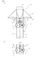
以下、添付した図面に基づいて、この発明による超音波シール装置を備えた包装機の実施例を説明する。図1はこの発明による超音波シール装置を備えた包装機の実施例(実施例1)を示す正面図であり、(a)はシワ抑え手段がローラで構成さている場合の実施例であり、(b)はシワ抑え手段が摩擦抵抗材からなるブレーキで構成されている場合の実施例である。 Hereinafter, an embodiment of a packaging machine including an ultrasonic sealing device according to the present invention will be described with reference to the accompanying drawings. FIG. 1 is a front view showing an embodiment (Example 1) of a packaging machine provided with an ultrasonic sealing device according to the present invention, and (a) is an example in the case where the wrinkle suppressing means is constituted by a roller. (B) is an Example in case a wrinkle suppression means is comprised with the brake which consists of a friction resistance material.
図1(a)に示す超音波シール装置を備えた包装機の実施例は、縦シール手段以外の基本的な包装機としては、図5或いは図7に示したような従来周知の縦型製袋充填包装機である。したがって、縦シール手段以外の縦型製袋充填包装機そのものについては、繰り出された帯状包装材Fwを略筒状包装材に曲成するフォーマ53、略筒状包装材から形成された筒状包装材Ftに横シールを施す横シール手段54、及びフォーマ53内に隙間を置いて嵌入されている充填筒56を備えているものであってよく、それ以外の詳細な構造については、ここでの再度の説明を省略する。
In the embodiment of the packaging machine provided with the ultrasonic sealing device shown in FIG. 1A, as a basic packaging machine other than the vertical sealing means, a conventionally known vertical type as shown in FIG. 5 or FIG. It is a bag filling and packaging machine. Therefore, with respect to the vertical bag making filling and packaging machine itself other than the vertical sealing means, the former 53 that bends the fed strip-shaped packaging material Fw into a substantially cylindrical packaging material, and the cylindrical packaging formed from the substantially cylindrical packaging material. There may be provided a horizontal sealing means 54 for performing a horizontal seal on the material Ft, and a filling
図1(a)に示す縦型製袋充填包装機10において、例えば包装材ロールから繰り出された帯状包装材Fwは、フォーマ53よって帯状包装材Ftの両側縁部分fe,feが互いに合掌状に重ね合わされ、充填筒56取り囲むように略筒状包装材に曲成される。包装材の側縁部分fe,feがフォーマ53の先端部53a,53aを通過する際に、弛みや伸び等に起因してシワWrが生じやすい。図1では図示していないが、吸引ベルト手段のような包装材を紙送りする紙送り手段(図5に示す吸引紙送り手段70と同等のもの)が例えば充填筒56の両側方に設けられており、充填筒56と協働して筒状包装材Ftを強制的に引き下げることで包装材(少なくとも筒状包装材Ft。それ以外にも補助的に略筒状包装材や帯状包装材Fwを紙送りする手段を備えていてもよい)が紙送りされる。
In the vertical bag making and filling
充填筒56の前方で、且つフォーマ53の設置位置よりも下方には、ロータリー式の超音波シール装置11が製袋充填包装機10の縦シール手段として配設されている。超音波シール装置11は、縦型製袋充填包装機10において、包装材の紙送り方向には移動せず、固定的に配置されている。ロータリー式の超音波シール装置11は、円盤状の超音波ホーン12とこれに対向配置された円盤状のアンビル13とを有しており、略筒状包装材の両側縁部分fe,feは、上記の紙送り手段による紙送りによって、超音波ホーン12の超音波シール面である周面14と、アンビル13のシール受け面である周面15との間に重ね合わせ状態で送り込まれる。両側縁部分fe,feは、超音波ホーン12はアンビル13との間に挟み込まれて加圧状態とされ、超音波ホーン12が発する超音波が印加されることにより、摩擦熱によって超音波シールが施される。このシールによって、略筒状包装材は筒状包装材Ftに成形される。
In front of the filling
フォーマ53の設置位置よりも下方で且つ超音波シール装置11の設置位置よりも上方、即ち、超音波シール装置11から見るときに包装材が超音波シール装置11に入り込む側である上流側には、シワ抑えローラユニット16が設けられている。シワ抑えローラユニット16は、一対のシワ抑えローラ17,17を備えており、ローラの周面間で略筒状包装材の両側縁部分fe,feを挟み込んでいる。
Below the installation position of the former 53 and above the installation position of the
シワ抑えローラユニット16を構成する一対のシワ抑えローラ17,17は、図示しないが、サーボモータのような制御性の優れた適宜の駆動モータと適宜の動力伝動機構とによってそれぞれが互いに反対方向に同期した速度で回転される。ロータリー式の超音波シール装置11の超音波ホーン12とアンビル13の周速度は、設定としては、包装材の紙送り速度Vfと同じ速度とされている。なお、製造過程では、超音波ホーン12とアンビル13の径には微妙な誤差が生じるのは回避し難く、包装材が厚さの薄いフィルムである場合には、周速度の僅かな差で包装材にシワが発生しやすいことは、既に言及したとおりである。また、シワ抑えローラ17,17の周速度Vr1は、当該紙送り速度Vfと同速度、又は当該紙送り速度Vfよりも遅い速度に設定されている。
The pair of
シワ抑えローラユニット16は、包装材の紙送り速度との間に速度差がある場合には、その速度差の分だけ包装材に対してブレーキ作用を奏している。即ち、包装材の紙送り速度Vfとシワ抑えローラ17,17の周速度Vr1との間に速度差がある(周速度Vr1の方が紙送り速度Vfよりも遅い)ときには、包装材の紙送りは全体として速度が維持されているので、シワ抑えローラ17,17と包装材の側縁部分fe,feとの間にはその速度差に応じたすべりが生じることになり、包装材の側縁部分fe,feにはそのすべりに起因して包装材の送りに対して抵抗する方向に作用する摩擦力が生じている。したがって、シワ抑えローラユニット16と超音波シール装置11との間に存在する包装材の側縁部分fe,fe(シール予定領域Rs)には、摩擦力がもたらす張力によって、弛みや伸び等を平坦化させる緊張状態が作り出されている。その結果、フォーマ53の先端部53a,53aを通過した包装材にシワWrが生じたとしても、シワWrの進みはシワ抑えローラユニット16までに止めることができる。シワ抑えローラユニット16を通過したシール予定領域Rsの包装材の側縁部分fe,feは、シワの発生が抑えられた緊張状態で超音波シール装置11に送り込まれる。側縁部分fe,feには超音波シールが正しく充分に行われるので、シワWrに起因したシール不良を生じることがない。
When there is a speed difference between the wrinkle-reducing
シワ抑えローラ17,17の周速度Vr1が包装材の紙送り速度Vfと同じ速度であって速度差がなくても、包装材のシール予定領域Rsには、シワ抑えローラ17,17の均し作用が生じる。したがって、上記速度差がなくてもシワWrの発生が充分に抑えられ、シール予定領域Rsには遜色のない超音波シールが施される。
Even if the circumferential speed Vr1 of the
図1(b)は、図1(a)に示す実施例1において、シワ抑え手段として、シワ抑えローラに代えて摩擦抵抗材を用いた変形例を示す部分図である。シワ抑えローラ17,17から成るシワ抑えローラユニット16に代えて、一対の摩擦抵抗材19,19から成る摩擦抵抗材ユニット18が包装材の側縁部分fe,feを挟み込む態様で配置されている。摩擦抵抗材19,19は、シワ抑えローラ17,17のブレーキ作用に着目して周速度を0としたものに相当している。摩擦抵抗材19をフェルトのような低摩擦の繊維材から構成することで、包装材には強すぎることのない安定した走行抵抗を与えることができ、包装材の送りを滑らかに維持することができる。
FIG. 1B is a partial view showing a modification in which a friction resistance material is used instead of the wrinkle suppressing roller as the wrinkle suppressing means in the embodiment 1 shown in FIG. Instead of the wrinkle restraining
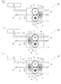
この発明による超音波シール装置を備えた包装機の別の実施例(実施例2)が図2に示されている。本例の場合、製袋充填包装機20は、シワ抑えローラユニットの配設位置を除いて図1に示す実施例1と同じ構造を備えているので、共通する構成要素等については同じ符号を付すことで再度の説明を省略する。実施例2では、シワ抑えローラユニット26は、超音波シールユニット11から包装材が送り出される下流側に設けられている。
Another embodiment (embodiment 2) of the packaging machine provided with the ultrasonic sealing device according to the present invention is shown in FIG. In the case of this example, the bag making and filling
シワ抑えローラユニット26は、間に包装材の両側縁部分fe,feを挟み込む一対のシワ抑えローラ27,27を備えており、シワ抑えローラユニット16の場合と同様に、図示しないが、両シワ抑えローラ27,27を回転させるサーボモータのような制御性の優れた駆動モータを備えている。両シワ抑えローラ27,27は、適宜の動力伝動機構によって互いに逆方向に且つ同じ速さの周速度で回転される。
The wrinkle restraining
実施例2の場合、シワ抑えローラ27,27の周速度Vr2は、包装材の紙送り速度Vfよりも速い速度に設定されている。このように速度を設定することで、包装材の送りよりも速く回転しようとするシワ抑えローラ27,27が包装材に対してすべることに基づいて摩擦力が作用し、シワ抑えローラ27,27の上流側の包装材には緊張状態がもたらされる。即ち、超音波シール装置11の特性上、包装材を挟んでいるシール中においても、包装材は超音波ホーン12とアンビル13の間を滑ることができるので、超音波シール装置11の下流側に配置されているシワ抑えローラ27,27によってもたらされる緊張状態は、超音波シール装置11の上流側の包装材の部分(フォーマ53の先端部53a,53aまでのシール予定領域Rs)にも及び、包装材のシール予定領域Rsに緊張状態を作り出すことができる。
In the case of Example 2, the circumferential speed Vr2 of the
図3はこの発明による超音波シール装置を備えた包装機の実施例(実施例3)を示す正面図である。実施例3は、図1(a)に示すシワ抑えローラユニット16と、図2に示すシワ抑えローラユニット26を同時に備えた実施例である。超音波シール装置に対する包装材の送り込み側と送り出し側との両方にシワ抑えローラユニット16,26を設けているので、包装材の両側縁部分fe,feに対するシワ抑え作用を高めることができる。
FIG. 3 is a front view showing an embodiment (Example 3) of a packaging machine provided with the ultrasonic sealing device according to the present invention. The third embodiment is an embodiment in which the wrinkle suppressing
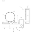
図4はこの発明による超音波シール装置を備えた包装機の実施例4の概要を模式的に示す図である。実施例4は、包装材を固定とし、超音波シール装置を駆動手段によって移動させる型式の実施例である。実施例4では、例えば、把持部材33,33によって位置が固定された状態で保持されている包装袋を包装材とし、移動される超音波シール装置によって包装袋の表裏の包装フィルムが重なった開口部に、超音波シールが線状に施される。図4に示す袋包装機30a、30b、30cにおいて、超音波シール装置及びシワ抑えローラについては、実施例1に用いた構成要素と同等のものには、同じ符号を付すことで、再度の説明を省略する。
FIG. 4 is a diagram schematically showing an outline of a packaging machine having an ultrasonic sealing device according to Embodiment 4 of the present invention. Example 4 is an example of a type in which the packaging material is fixed and the ultrasonic sealing device is moved by the driving means. In Example 4, for example, the packaging bag that is held in a state where the position is fixed by the gripping
図4(a)に示す袋包装機30aにおいては、超音波シール装置11に対する包装材(包装袋B)の相対的な送り込み側にシワ抑えローラユニット16が配設されている。超音波シール装置11とシワ抑えローラユニット16とは移動フレーム31に相対位置を保って装着されている。移動フレーム31は、適宜の駆動手段32によって、包装袋Bのシールすべき開口部分が延びる方向(紙面の左右方向であるX方向)に往復駆動可能である。駆動手段32は、例えば、サーボモータとその回転を直線運動に変換する変換機構とで構成する、或いは流体作動式のピストン・シリンダ装置で構成することができる。このように、超音波シール装置11とシワ抑えローラユニット16とが、全体として移動フレーム31上にユニット化されており、駆動手段32によって移動される。
In the
超音波シール装置11の円盤状の超音波ホーン12と円盤状のアンビル13とは、超音波シール装置11とシワ抑えローラユニット16とが駆動手段32によって移動されるときに、包装袋B上をすべることなく転がるように周速度が設定されている。また、シワ抑えローラユニット16のシワ抑えローラ17,17の周速度Vr1は、駆動手段32による移動速度Vdよりも遅くなるように設定されている。シワ発生の抑え作用は基本的に実施例1と同様である。即ち、シワ抑えローラ17,17は包装袋B上を移動速度Vdよりも遅い速度で転がることになり、包装袋Bに対しては、相対的な速度差に基づくすべりに起因した摩擦力がブレーキとしての作用を及ぼす。したがって、超音波シール装置11からするとシワ抑えローラユニット16からの相対的に送り込み側となる上流側の包装材(シール予定領域Rs)は緊張状態となり、シワWrの発生が抑えられる。シワ抑えローラユニット16に代えて、図1(b)に示したような摩擦抵抗材ユニット18を用いることもできる。
The disk-shaped
図4(b)に示す袋包装機30bにおいては、超音波シール装置11に対する包装材(包装袋B)の相対的な送り出し側となる下流側にシワ抑えローラユニット26が配設されている。袋包装機30bの場合、シワ抑えローラ27,27の周速度Vr2は、駆動手段32による移動速度Vdよりも速い速度に設定されている。このように速度を設定することで、駆動手段32による移動よりも速く回転しようとするシワ抑えローラ27,27が包装袋B包装材に対してすべることに基づいて摩擦力が作用し、シワ抑えローラ27,27の上流側の包装材には超音波シール装置11を越えた上流側のシール予定領域Rsを含めて緊張状態がもたらされ、シワWrの発生が抑えられる。
In the
図4(c)に示す袋包装機30cは、超音波シール装置11に対する包装材(包装袋B)の相対的な送り込み側である上流側に、図4(a)で示したシワ抑えローラユニット16を、そして相対的な送り出し側となる下流側に、図4(b)で示したシワ抑えローラユニット26を、それぞれ同時に備えた実施例である。超音波シール装置11に対する包装袋Bの相対的な送り込み側と送り出し側との両方にシワ抑えローラユニット16,26を設けているので、包装袋Bに対するシワ抑え作用を高めることができる。
The
上記したように、包装材の相対的な送り速度とシワ抑え手段の速度との間に速度差を設け、速度差に起因する摩擦力によって包装材のシール予定領域に緊張状態を作り出すことで、包装材が弛みや伸びに起因してシワが発生しようとしても、この緊張状態によってシワの発生が抑えられ、包装材をシワのない状態で超音波シール装置に送り込むことができる。したがって、超音波シールが正しく充分に行われるので、包装材にはシワに起因したシール不良を生じることがない。 As described above, by providing a speed difference between the relative feeding speed of the packaging material and the speed of the wrinkle suppressing means, and creating a tension state in the planned sealing region of the packaging material by the frictional force caused by the speed difference, Even if wrinkles are about to be generated due to slack or elongation of the packaging material, the generation of wrinkles is suppressed by this tension state, and the packaging material can be fed into the ultrasonic sealing device without wrinkles. Therefore, since ultrasonic sealing is performed correctly and sufficiently, the packaging material does not cause a sealing failure due to wrinkles.
上記の各実施例では、包装機が、包装材を送り包装機側の構成要素については移動しない型式のもの、又は超音波シール装置を移動させて包装材については送りをしない型式のものとして説明したが、包装材を送り、同時に超音波シール装置を移動させる型式の包装機であっても、本発明は適用可能である。また、特に実施例1〜3では縦型の製袋充填包装機について本発明を適用した例を示したが、横型の製袋充填包装機にも本発明は適用可能であることは勿論である。更に、各実施例において、超音波シール装置については、円盤状超音波ホーンや円盤状アンビルを備えたロータリー式の超音波シール装置を示したが、円盤状でなくても、図5、図6に示すような棒状の超音波ホーンや固定のアンビルを備えた超音波シール装置にも適用可能であることは明らかである。 In each of the above embodiments, the packaging machine is described as a type that does not move the components on the side of the packaging machine that sends the packaging material, or a type that does not feed the packaging material by moving the ultrasonic sealing device. However, the present invention can also be applied to a type of packaging machine that feeds the packaging material and simultaneously moves the ultrasonic sealing device. In particular, in Examples 1 to 3, an example in which the present invention is applied to a vertical bag making and filling machine has been shown, but the present invention is naturally applicable to a horizontal bag making and filling machine. . Furthermore, in each Example, although the rotary type ultrasonic sealing apparatus provided with the disk-shaped ultrasonic horn and the disk-shaped anvil was shown about the ultrasonic sealing apparatus, even if it is not disk-shaped, FIG. It is obvious that the present invention can also be applied to an ultrasonic sealing device having a rod-shaped ultrasonic horn or a fixed anvil as shown in FIG.
10,20 縦型製袋充填包装機 11 超音波シール装置
12 超音波ホーン 13 アンビル
14 周面(超音波シール面) 15 周面(シール受け面)15
16 シワ抑えローラユニット 17,17 シワ抑えローラ
18 摩擦抵抗材ユニット 19,19 摩擦抵抗材
26 シワ抑えローラユニット 27,27 シワ抑えローラ
30a,30b,30c 袋包装機 31 移動フレーム
32 駆動手段 33,33 把持部材
50 製袋充填包装機 51 繰出し機構
52 付属装置 53 フォーマ 53a,53a 先端部
54 横シール手段 55,55 横シーラ
56 充填筒
60 スポットシール手段 61 超音波ホーン
62 アンビル 63 超音波発生部
64 取付けアーム 65 回動アーム
66 ヒンジ 66a 支持体
67 ネジ機構
70 吸引紙送り手段 71,71 紙送りベルト
72 吸引孔 73 送り用駆動プーリ
74 送り用従動プーリ 75 ガイドプーリ
80 包装機 81 超音波シール装置
82 円盤状超音波ホーン 83 円盤状アンビル
Fr 巻取りロール Fw 帯状包装材
fe,fe 両側縁部分 Ft 筒状包装材
Rs シール予定領域 Sc センターシール(縦シール)
Wr シワ Si シール不良
Vf 包装材送り速度 Vr1,Vr2 シワ抑えローラの周速度
B 袋 Bp 袋包装体
DESCRIPTION OF
16 Wrinkle
Wr Wrinkle Si Seal failure Vf Packaging material feed speed Vr1, Vr2 Wrinkle suppression roller peripheral speed B Bag Bp Bag package
Claims (12)
前記超音波シール装置に前記包装材が相対的に送り込まれる上流側又は相対的に送り出される下流側に前記包装材を挟む態様で配設されているシワ抑え部材手段を備えており、 前記シワ抑え手段は、前記包装材に対してすべりに起因した摩擦力を与えることで、少なくとも前記超音波シール装置に送り込まれる上流側の前記包装材を緊張状態とすること からなる超音波シール装置を備えた包装機。 An ultrasonic sealing device that includes an ultrasonic horn and an anvil disposed opposite to the ultrasonic horn, and performs ultrasonic sealing on a packaging material that moves relatively in a superimposed state between the ultrasonic horn and the anvil. When,
Wrinkle suppression member means arranged in a manner to sandwich the packaging material on the upstream side where the packaging material is relatively fed to the ultrasonic sealing device or on the downstream side where the packaging material is relatively fed out, The means includes an ultrasonic sealing device that applies a frictional force due to slip to the packaging material, and at least puts the upstream packaging material fed into the ultrasonic sealing device into a tension state. Packaging machine.
前記超音波シール装置は固定配置されていて、前記超音波シール装置に対する前記包装材の相対的な移動は前記紙送り手段によって与えられていること
から成る請求項1に記載の超音波シール装置を備えた包装機。 A paper feeding means for feeding the packaging material;
The ultrasonic sealing device according to claim 1, wherein the ultrasonic sealing device is fixedly arranged, and the relative movement of the packaging material with respect to the ultrasonic sealing device is given by the paper feeding means. Equipped packaging machine.
から成る請求項2に記載の超音波シール装置を備えた包装機。 The wrinkle suppressing means is provided on the upstream side where the packaging material is fed into the ultrasonic sealing device by the paper feeding means, and a friction resistance material that gives a brake to the movement of the packaging material, or a peripheral speed is the paper The packaging with the ultrasonic sealing device according to claim 2, wherein the wrinkle suppressing roller is rotationally controlled in a manner that is synchronized with or slower than the paper feeding speed of the packaging material by the feeding means. Machine.
から成る請求項2に記載の超音波シール装置を備えた包装機。 The wrinkle suppressing means is provided on the downstream side where the packaging material is delivered from the ultrasonic sealing device by the paper feeding means, and the peripheral speed is higher than the paper feeding speed of the packaging material by the paper feeding means. The wrapping machine provided with the ultrasonic sealing device according to claim 2, wherein the wrapping roller is a wrinkle suppressing roller that is rotationally controlled in an aspect.
から成る請求項2に記載の超音波シール装置を備えた包装機。 The wrinkle suppressing means is provided on the upstream side where the packaging material is fed into the ultrasonic sealing device by the paper feeding means, and a friction resistance material that gives a brake to the movement of the packaging material, or a peripheral speed is the paper An upstream wrinkle suppression roller that is rotated in a manner that is synchronized with or slower than the paper feeding speed of the packaging material by the feeding means, and the packaging material is removed from the ultrasonic sealing device by the paper feeding means. The downstream wrinkle suppressing roller is provided on the downstream side to be fed out and is rotationally controlled in such a manner that the peripheral speed is higher than the paper feeding speed of the packaging material by the paper feeding means. Packaging machine equipped with an ultrasonic sealing device.
前記紙送り手段は、少なくとも前記筒状包装材をその長手方向に送る送り手段であり、
前記超音波シール装置は、前記略筒状包装材の両側縁部分にシールを施して前記筒状包装材に形成する縦シール手段として適用されている
ことから成る請求項1〜5のいずれか一項に記載の超音波シール装置を備えた包装機。 The packaging machine includes a former that bends the fed strip-shaped packaging material into a substantially cylindrical packaging material, and a bag making and filling device that includes a horizontal sealing unit that laterally seals the cylindrical packaging material formed from the substantially cylindrical packaging material. A packaging machine,
The paper feeding means is a feeding means for feeding at least the cylindrical packaging material in the longitudinal direction thereof,
6. The ultrasonic sealing apparatus according to claim 1, wherein the ultrasonic sealing device is applied as a vertical sealing means that seals both side edge portions of the substantially cylindrical packaging material to form the cylindrical packaging material. A packaging machine comprising the ultrasonic sealing device according to item.
前記超音波シール装置に対する前記包装材の相対的な移動は前記駆動手段によって与えられていること
から成る請求項1に記載の超音波シール装置を備えた包装機。 The ultrasonic sealing device is movable by driving means with respect to the packaging material that is stopped,
The packaging machine provided with the ultrasonic sealing device according to claim 1, wherein relative movement of the packaging material with respect to the ultrasonic sealing device is given by the driving means.
から成る請求項7に記載の超音波シール装置を備えた包装機。 The wrinkle suppressing means is provided on the upstream side where the packaging material is relatively fed to the ultrasonic sealing device by the driving means, and a friction resistance material that applies a brake to the relative movement of the packaging material, or The super-wrinkle control roller according to claim 7, wherein the roller is a wrinkle-reducing roller that is rotationally controlled in such a manner that a peripheral speed is synchronized with a relative paper feed speed of the packaging material by the driving means or slower than the paper feed speed. A packaging machine equipped with a sonic seal device.
から成る請求項7に記載の超音波シール装置を備えた包装機。 The wrinkle suppressing means is provided on the downstream side where the packaging material is relatively fed out from the ultrasonic sealing device by the driving means, and the peripheral speed is higher than the relative paper feed speed of the packaging material by the driving means. The wrapping machine provided with the ultrasonic sealing device according to claim 7, wherein the wrinkle suppressing roller is rotationally controlled in such a manner that the rotation speed is increased.
から成る請求項7に記載の超音波シール装置を備えた包装機。 The wrinkle suppressing means is provided on the upstream side where the packaging material is relatively fed to the ultrasonic sealing device by the driving means, and a friction resistance material that applies a brake to the relative movement of the packaging material, or An upstream wrinkle suppression roller whose rotation speed is controlled in a manner that the peripheral speed is synchronized with the relative paper feeding speed of the packaging material by the driving means or slower than the paper feeding speed, and the packaging material is Downstream wrinkle suppression that is provided on the downstream side that is relatively fed out from the ultrasonic sealing device and that is rotationally controlled in such a manner that the peripheral speed is faster than the relative paper feed speed of the packaging material by the driving means. The packaging machine provided with the ultrasonic sealing device according to claim 7, which is a roller.
から成る請求項1〜10のいずれか一項に記載の超音波シール装置を備えた包装機。 The ultrasonic sealing device is a disk-shaped ultrasonic horn having an ultrasonic sealing surface as a peripheral surface, and the anvil can sandwich a packaging material to be bonded to the ultrasonic sealing surface. A wrapping machine provided with the ultrasonic sealing device according to any one of claims 1 to 10, which is a rotary ultrasonic sealing device which is a disk-shaped anvil having a peripheral anvil surface.
から成る請求項1〜10のいずれか一項に記載の超音波シール装置を備えた包装機。 In the ultrasonic sealing device, the ultrasonic horn is a rod-shaped ultrasonic horn having a tip end surface as an ultrasonic sealing surface, and the anvil can sandwich a packaging material to be bonded to the ultrasonic sealing surface. A packaging machine provided with the ultrasonic sealing device according to any one of claims 1 to 10, which is a fixed ultrasonic sealing device that is a fixed anvil having an anvil end face.
Priority Applications (1)
| Application Number | Priority Date | Filing Date | Title |
|---|---|---|---|
| JP2017132340A JP6970423B2 (en) | 2017-07-05 | 2017-07-05 | Packaging machine equipped with ultrasonic sealing device |
Applications Claiming Priority (1)
| Application Number | Priority Date | Filing Date | Title |
|---|---|---|---|
| JP2017132340A JP6970423B2 (en) | 2017-07-05 | 2017-07-05 | Packaging machine equipped with ultrasonic sealing device |
Publications (2)
| Publication Number | Publication Date |
|---|---|
| JP2019014507A true JP2019014507A (en) | 2019-01-31 |
| JP6970423B2 JP6970423B2 (en) | 2021-11-24 |
Family
ID=65356771
Family Applications (1)
| Application Number | Title | Priority Date | Filing Date |
|---|---|---|---|
| JP2017132340A Active JP6970423B2 (en) | 2017-07-05 | 2017-07-05 | Packaging machine equipped with ultrasonic sealing device |
Country Status (1)
| Country | Link |
|---|---|
| JP (1) | JP6970423B2 (en) |
Cited By (2)
| Publication number | Priority date | Publication date | Assignee | Title |
|---|---|---|---|---|
| CN114801307A (en) * | 2022-05-18 | 2022-07-29 | 合肥远传包装科技有限公司 | Ultrasonic wave carton former |
| JP7469811B2 (en) | 2021-08-06 | 2024-04-17 | 株式会社フジキカイ | Vertical sealing device for bag making and filling machines |
Citations (5)
| Publication number | Priority date | Publication date | Assignee | Title |
|---|---|---|---|---|
| JPH01171848A (en) * | 1987-12-28 | 1989-07-06 | Toshiba Seiki Kk | Sealing device |
| JP2000177707A (en) * | 1998-10-05 | 2000-06-27 | Ueda Avancer Corp | Portion packing paper melt adhering device |
| JP2001002012A (en) * | 1999-06-21 | 2001-01-09 | Ishida Co Ltd | Longitudinal sealing mechanism in packaging machine |
| JP2014227204A (en) * | 2013-05-23 | 2014-12-08 | 株式会社東京自働機械製作所 | Upright bag-making, filling, and packaging machine |
| JP2017071433A (en) * | 2015-10-09 | 2017-04-13 | 大森機械工業株式会社 | Center seal device |
-
2017
- 2017-07-05 JP JP2017132340A patent/JP6970423B2/en active Active
Patent Citations (5)
| Publication number | Priority date | Publication date | Assignee | Title |
|---|---|---|---|---|
| JPH01171848A (en) * | 1987-12-28 | 1989-07-06 | Toshiba Seiki Kk | Sealing device |
| JP2000177707A (en) * | 1998-10-05 | 2000-06-27 | Ueda Avancer Corp | Portion packing paper melt adhering device |
| JP2001002012A (en) * | 1999-06-21 | 2001-01-09 | Ishida Co Ltd | Longitudinal sealing mechanism in packaging machine |
| JP2014227204A (en) * | 2013-05-23 | 2014-12-08 | 株式会社東京自働機械製作所 | Upright bag-making, filling, and packaging machine |
| JP2017071433A (en) * | 2015-10-09 | 2017-04-13 | 大森機械工業株式会社 | Center seal device |
Cited By (2)
| Publication number | Priority date | Publication date | Assignee | Title |
|---|---|---|---|---|
| JP7469811B2 (en) | 2021-08-06 | 2024-04-17 | 株式会社フジキカイ | Vertical sealing device for bag making and filling machines |
| CN114801307A (en) * | 2022-05-18 | 2022-07-29 | 合肥远传包装科技有限公司 | Ultrasonic wave carton former |
Also Published As
| Publication number | Publication date |
|---|---|
| JP6970423B2 (en) | 2021-11-24 |
Similar Documents
| Publication | Publication Date | Title |
|---|---|---|
| JP4763619B2 (en) | Attaching the zipper to the moving film material | |
| JP5684645B2 (en) | Bag making and packaging machine | |
| CA2880697C (en) | Ultrasonic sealing of packages | |
| US20160001499A1 (en) | Ultrasonic Sealing of Packages | |
| JP2011063002A (en) | Ultrasonic welding method, ultrasonic welding machine, and packaging machine | |
| JP2004530601A (en) | Method and system for ultrasonically sealing food packaging | |
| JP2012236621A (en) | Form-fill-seal machine | |
| JP2012236620A5 (en) | ||
| JP2019014507A (en) | Packing machine having ultrasonic sealing device | |
| JP2016124610A (en) | Strip packaging material supply device in bag making packaging machine | |
| JP4753899B2 (en) | Automatic packaging machine | |
| JP5790541B2 (en) | Sheet splicing device and splicing method | |
| JP6749272B2 (en) | Horizontal sealing device in bag making and filling machine | |
| WO2011061859A1 (en) | Method and machine for manufacturing sheets for use in infusion bags | |
| JP3831351B2 (en) | Packaging bag manufacturing method and vertical filling and packaging machine | |
| JP6334283B2 (en) | Packaging machine and packaging method | |
| JP2017071433A (en) | Center seal device | |
| JP6708879B2 (en) | Bag-making filling and packaging machine | |
| JP6914520B2 (en) | Packaging machine equipped with ultrasonic sealing device | |
| JP6474622B2 (en) | Cutter blade, cutter device, packaging machine and packaging body | |
| JP2007111861A (en) | Feed device of zipper piece | |
| JP4261972B2 (en) | Sealing device for vertical multi-row automatic filling and packaging machine | |
| JP2017218169A (en) | Vertical bag-making, filling and packaging machine | |
| US11873128B2 (en) | Systems and methods using an ultrasonic transducer and scrubbing horn motion to seal a part | |
| JP7289120B2 (en) | Packaging material supply device for packaging machine and horizontal pillow packaging machine equipped with the packaging material supply device |
Legal Events
| Date | Code | Title | Description |
|---|---|---|---|
| A621 | Written request for application examination |
Free format text: JAPANESE INTERMEDIATE CODE: A621 Effective date: 20200704 |
|
| A977 | Report on retrieval |
Free format text: JAPANESE INTERMEDIATE CODE: A971007 Effective date: 20210514 |
|
| A131 | Notification of reasons for refusal |
Free format text: JAPANESE INTERMEDIATE CODE: A131 Effective date: 20210608 |
|
| A521 | Request for written amendment filed |
Free format text: JAPANESE INTERMEDIATE CODE: A523 Effective date: 20210809 |
|
| TRDD | Decision of grant or rejection written | ||
| A01 | Written decision to grant a patent or to grant a registration (utility model) |
Free format text: JAPANESE INTERMEDIATE CODE: A01 Effective date: 20211012 |
|
| A61 | First payment of annual fees (during grant procedure) |
Free format text: JAPANESE INTERMEDIATE CODE: A61 Effective date: 20211022 |
|
| R150 | Certificate of patent or registration of utility model |
Ref document number: 6970423 Country of ref document: JP Free format text: JAPANESE INTERMEDIATE CODE: R150 |