JP2019012638A - Power storage device and manufacturing method thereof - Google Patents
Power storage device and manufacturing method thereof Download PDFInfo
- Publication number
- JP2019012638A JP2019012638A JP2017128813A JP2017128813A JP2019012638A JP 2019012638 A JP2019012638 A JP 2019012638A JP 2017128813 A JP2017128813 A JP 2017128813A JP 2017128813 A JP2017128813 A JP 2017128813A JP 2019012638 A JP2019012638 A JP 2019012638A
- Authority
- JP
- Japan
- Prior art keywords
- current collector
- negative electrode
- external terminal
- collector plate
- positive
- Prior art date
- Legal status (The legal status is an assumption and is not a legal conclusion. Google has not performed a legal analysis and makes no representation as to the accuracy of the status listed.)
- Granted
Links
Images


Classifications
-
- Y—GENERAL TAGGING OF NEW TECHNOLOGICAL DEVELOPMENTS; GENERAL TAGGING OF CROSS-SECTIONAL TECHNOLOGIES SPANNING OVER SEVERAL SECTIONS OF THE IPC; TECHNICAL SUBJECTS COVERED BY FORMER USPC CROSS-REFERENCE ART COLLECTIONS [XRACs] AND DIGESTS
- Y02—TECHNOLOGIES OR APPLICATIONS FOR MITIGATION OR ADAPTATION AGAINST CLIMATE CHANGE
- Y02E—REDUCTION OF GREENHOUSE GAS [GHG] EMISSIONS, RELATED TO ENERGY GENERATION, TRANSMISSION OR DISTRIBUTION
- Y02E60/00—Enabling technologies; Technologies with a potential or indirect contribution to GHG emissions mitigation
- Y02E60/10—Energy storage using batteries
Abstract
Description
本発明は、蓄電装置および蓄電装置の製造方法に関する。 The present invention relates to a power storage device and a method for manufacturing the power storage device.
近年、ハイブリッド電気自動車や純粋な電気自動車等の動力源として、大容量かつ高出力なリチウムイオン等の二次電池が注目されている。二次電池は、電池容器内に収容された蓄電要素に集電接続体を介して接続される外部端子を備えている。
集電接続体と外部端子との接続構造の一例として下記のものがある。
貫通孔を有する蓋体の外面側に、蓋体の貫通孔に対応する開口が形成され、蓋体の貫通孔の軸方向に延在する立ち上げ部を有する絶縁部材を配置し、鍔部を有するリベットの軸部を、蓋体の内面側から外面側に向けて、蓋体の貫通孔および絶縁部材の開口を貫通する。そして、貫通されたリベットの先端部をかしめ、リベットとのかしめ部および絶縁部材の立ち上げ部を直角に屈曲して蓋体の外面に密着するように積層する。この状態では、リベットおよび絶縁部材の立ち上げ部の先端面は、蓋体の外面に垂直になっている。この後、蓋体の上面に対して垂直面となった、リベット先端面と絶縁部材の立ち上げ部の先端面とを蓋体の外面に溶接する(例えば、特許文献1参照)。
2. Description of the Related Art In recent years, a secondary battery such as a high-capacity and high-power lithium ion has attracted attention as a power source for hybrid electric vehicles and pure electric vehicles. The secondary battery includes an external terminal connected to a power storage element accommodated in the battery container via a current collector connection body.
An example of the connection structure between the current collector connector and the external terminal is as follows.
An insulating member having a rising portion extending in the axial direction of the through-hole of the lid body is disposed on the outer surface side of the lid body having the through-hole, and an opening corresponding to the through-hole of the lid body is disposed. The shaft portion of the rivet that is provided passes through the through hole of the lid and the opening of the insulating member from the inner surface side to the outer surface side of the lid body. Then, the leading end of the penetrated rivet is caulked, and the caulking portion with the rivet and the rising portion of the insulating member are bent at right angles and laminated so as to be in close contact with the outer surface of the lid. In this state, the leading end surface of the rising portion of the rivet and the insulating member is perpendicular to the outer surface of the lid. Thereafter, the rivet tip surface and the tip surface of the rising portion of the insulating member, which are perpendicular to the top surface of the lid, are welded to the outer surface of the lid (for example, see Patent Document 1).
通常、リベットの先端面の周縁部は、側面に対して完全に直角に形成されず、面取り状の円みが形成されている。このため、上記特許文献1の図面には図示されている従来技術では、リベットの先端面の周縁部と溶接時の溶融金属により形成される溶接部との間に隙間が形成される可能性がある。このように、リベットの先端面の周縁部と溶接部との間に隙間が介在されると、接合強度や接合抵抗などの接合品質が低下する。 Usually, the peripheral edge portion of the tip surface of the rivet is not formed at a right angle to the side surface, and a chamfered round shape is formed. For this reason, in the prior art shown in the drawing of Patent Document 1, there is a possibility that a gap is formed between the peripheral portion of the tip surface of the rivet and the welded portion formed by the molten metal at the time of welding. is there. As described above, when a gap is interposed between the peripheral edge portion of the tip surface of the rivet and the welded portion, bonding quality such as bonding strength and bonding resistance is deteriorated.
本発明の一態様によると、蓄電装置は、蓄電要素と、開口部を有し、前記蓄電要素に接続される集電板と、前記集電板および前記蓄電要素を収納する電池容器と、前記電池容器の一側部に設けられ、前記集電板に接続される外部端子とを備え、前記外部端子は前記集電板の前記開口部に貫通された軸部を有し、前記軸部は、前記集電板にかしめられたかしめ部を有し、前記軸部のかしめ部と前記集電板の前記開口部との接触部に接合部が設けられている。
本発明の一態様によると、蓄電装置の製造方法は、蓄電要素と、開口部を有し、前記蓄電要素に接続される集電板と、前記貫通孔に貫通される軸部を有する外部端子とを備えた蓄電装置の製造方法であって、前記外部端子の前記軸部を前記集電板の前記開口部に貫通して、前記軸部を前記集電板にかしめることと、前記軸部のかしめ部の外周と前記集電板の前記開口部の周縁部の接触部とを接合すること、とを有する。
According to one aspect of the present invention, a power storage device includes a power storage element, a current collector having an opening and connected to the power storage element, a battery container that houses the current collector and the power storage element, and An external terminal provided on one side of the battery container and connected to the current collector plate, the external terminal having a shaft portion penetrating through the opening of the current collector plate, the shaft portion being The current collecting plate has a caulking portion, and a joint portion is provided at a contact portion between the caulking portion of the shaft portion and the opening portion of the current collecting plate.
According to one aspect of the present invention, a method for manufacturing a power storage device includes a power storage element, a current collector plate having an opening, connected to the power storage element, and an external terminal having a shaft portion penetrating the through hole. A method of manufacturing a power storage device, comprising: penetrating the shaft portion of the external terminal into the opening of the current collector plate and caulking the shaft portion to the current collector plate; Joining the outer periphery of the caulking part of the part and the contact part of the peripheral part of the opening of the current collector plate.
本発明によれば、良好な接合状態を得ることができる。 According to the present invention, a good bonded state can be obtained.
−第1の実施形態−
以下、図1〜図8を参照して本発明の第1の実施形態を説明する。
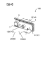
図1は、扁平捲回形の二次電池の外観斜視図であり、図2は、図1に図示された二次電池の分解斜視図である。
二次電池100は、電池容器を形成する電池缶1および電池蓋6を備える。電池缶1は、扁平な箱型形状を有する角形二次電池であり、相対的に面積の大きい一対の対向する幅広側面1bと、相対的に面積の小さい一対の対向する幅狭側面1cと、底面1dを有し、その上方に開口部1aを有する。
電池缶1内には、捲回電極群3および電池蓋組立体106が収容され、電池缶1の開口部1aが電池蓋6によって封止されている。電池蓋6は略矩形の平板状であって、電池缶1の開口部1aを塞いで溶接され、外部に対し電池缶1を封止している。電池蓋6には、正極外部端子14と、負極外部端子12が設けられている。正極外部端子14、負極外部端子12は、バスバー(図示せず)を介して外部機器に接続される。正極外部端子14と負極外部端子12を介して捲回電極群3に充電され、また外部負荷に電力が供給される。電池蓋6には、ガス排出弁10が一体的に設けられている。電池容器内の圧力が上昇すると、ガス排出弁10が開いて内部からガスが排出され、電池容器内の圧力が低減される。これによって、扁平捲回形の二次電池100の安全性が確保される。電池蓋6には、注液孔9(図2参照)を封止する注液栓11が設けられている。
-First embodiment-
Hereinafter, a first embodiment of the present invention will be described with reference to FIGS.
FIG. 1 is an external perspective view of a flat wound secondary battery, and FIG. 2 is an exploded perspective view of the secondary battery shown in FIG.
The
In the battery can 1, the
二次電池100の電池缶1内には、絶縁保護フィルム2を介して捲回電極群3が収容されている。
捲回電極群3は、負極電極32と正極電極34とを、両部材の間にセパレータ33、35を介して捲回して形成されている(図3参照)。捲回電極群3は、扁平な平坦部36と、平坦部36の捲回方向の両端に形成された断面半円形状の湾曲部37を有する。捲回電極群3は、捲回軸方向が電池缶1の横幅方向に沿うように、一方の湾曲部37側から電池缶1内に挿入され、他方の湾曲部37側が、電池缶1の開口部1a側に配置される。
A
The
詳細は後述するが、正極電極34は、正極箔露出部34cを有し、負極電極32は、負極箔露出部32cを有する。
捲回電極群3の正極箔露出部34cは、正極集電板44を介して電池蓋6に設けられた正極外部端子14に電気的に接続されている。また、捲回電極群3の負極箔露出部32cは、負極集電板24を介して電池蓋6に設けられた負極外部端子12に電気的に接続されている。これにより、正極集電板44および負極集電板24を介して捲回電極群3から外部負荷へ電力が供給され、正極集電板44および負極集電板24を介して捲回電極群3へ外部発電電力が供給され充電される。
Although details will be described later, the
The positive electrode foil exposed
図4は、図2に図示された電池蓋組立体外観斜視図であり、図5は、図4に図示された電池蓋組立体の分解斜視図である。図4、図5では負極側の構造を示しているが、負極側と正極側とは同様の構造であり、負極側の各部材の参照番号に相当する正極側の各部材の参照番号をかっこ書きで付している。 4 is an external perspective view of the battery lid assembly shown in FIG. 2, and FIG. 5 is an exploded perspective view of the battery lid assembly shown in FIG. 4 and 5 show the structure of the negative electrode side, the negative electrode side and the positive electrode side have the same structure, and the reference numbers of the positive electrode members corresponding to the reference numbers of the negative electrode members are parenthesized. It is attached in writing.
電池蓋組立体106は、電池蓋6と、負・正極外部端子12、14と、一対のガスケット5と、一対の絶縁板7と、負・正極集電板24、44とを有する。電池蓋6には、負・正極側貫通孔26、46が設けられている。負・正極外部端子12、14には、それぞれ、下方に向かって突出する負・正極外部端子軸部12a、14aが形成されている。負・正極外部端子軸部12a、14aは、それぞれ、円柱形状を有している。
各絶縁板7には、貫通孔17が設けられている。また、負・正極集電板24、44には、それぞれ、負・正極側集電板貫通孔25、45が設けられている。負・正極側貫通孔26、46と、各貫通孔17と、負・正極側集電板貫通孔25、45とは、それぞれ、負・正極外部端子12、14の負・正極外部端子軸部12a、14aが挿通される大きさに形成されている。
The
Each
電池蓋6の一面側にガスケット5が取付けられ、正極外部端子14および負極外部端子12が、それぞれ、電池蓋6と絶縁される。また、電池蓋6の他面側に絶縁板7が取付けられ、正極集電板44および負極集電板24は、それぞれ、電池蓋6と絶縁される。
The
電池蓋組立体106の組立は、下記の手順による。
電池蓋6の外面側(図2、図5では上方側)に各ガスケット5を配置する。ガスケット5は、負・正極外部端子12、14を収容する収容部5aと、電池蓋6の負・正極側貫通孔26、46内に嵌入する貫通孔嵌入部5bとを有する(図6も参照)。貫通孔嵌入部5bを電池蓋6の負・正極側貫通孔26、46内に嵌入する。電池蓋6の内面側(図2、図5では下方側)に各々絶縁板を配置し、各絶縁板7の下方に、それぞれ、負・正極集電板24、44を配置する。各絶縁板7と負・正極集電板24、44とは、各絶縁板7の貫通孔17の軸心と、負・正極集電板24、44の負・正極側集電板貫通孔25、45の軸心とを、それぞれ、電池蓋6の負・正極側貫通孔26、46の軸心に一致するように位置決めする。この状態で、負極外部端子12の負極外部端子軸部12aを、ガスケット5の貫通孔5c、絶縁板7の貫通孔17および負極集電板24の負極側集電板貫通孔25に貫通して、後述する方法により負極外部端子12を電池蓋6に固定する。また、正極外部端子14の正極外部端子軸部14aを、ガスケット5、絶縁板7の貫通孔17および正極集電板44の正極側集電板貫通孔45に貫通して、後述する方法により正極外部端子14を電池蓋6に固定する。負極外部端子12と正極外部端子14の電池蓋6への固定は、どちらを先に行っても差し支えない。
The
Each
正極外部端子14および正極集電板44の形成素材としては、例えばアルミニウム合金が挙げられ、負極外部端子12および負極集電板24の形成素材としては、例えば、銅合金が挙げられる。また、絶縁板7およびガスケット5の形成素材としては、例えばポリブチレンテレフタレートやポリフェニレンサルファイド、ペルフルオロアルコキシフッ素樹脂等の絶縁性を有する樹脂材が挙げられる。
Examples of the material for forming the positive electrode
電池容器内に注入される電解液としては、例えば、エチレンカーボネート等の炭酸エステル系の有機溶媒に6フッ化リン酸リチウム(LiPF6)等のリチウム塩が溶解された非水電解液を適用することができる。電池容器内外の圧力を適切に調整すると、捲回電極群3内の空気と電解液の置換が促進されて、電池容器内に電解液を効率的に注入することができる。
As the electrolytic solution injected into the battery container, for example, a non-aqueous electrolytic solution in which a lithium salt such as lithium hexafluorophosphate (LiPF 6 ) is dissolved in a carbonic acid ester-based organic solvent such as ethylene carbonate is applied. be able to. When the pressure inside and outside the battery container is appropriately adjusted, the replacement of the air in the
正極集電板44は、正極集電板基部41と、正極側接続部42とを有している。正極側接続端部は、正極集電板基部41の側端で折曲されて、電池缶1の幅広側面1bに沿って底面1d側に向かって延出される。正極集電板44の正極側接続部42は、捲回電極群3の正極箔露出部34cに対向して重ね合わされた状態で接続される。正極集電板基部41には、上述したように、正極外部端子軸部14aが挿通される正極側集電板貫通孔45が形成されている。
負極集電板24は、負極集電板基部21と、負極側接続部22とを有している。負極側接続部22は、負極集電板基部21の側端で折曲されて、電池缶1の幅広側面1bに沿って底面1d側に向かって延出される。負極集電板24の負極側接続部22は、捲回電極群3の負極箔露出部32cに対向して重ね合わされた状態で接続される。負極集電板基部21には、上述したように、負極外部端子軸部12aが挿通される負極側集電板貫通孔25が形成されている。
The positive electrode
The negative electrode
正極箔露出部34cと正極集電板44、および負極箔露出部32cと負極集電板24は、それぞれ、例えば、超音波溶接により接合される。超音波溶接は、正・負極集電板44、24をアンビルで固定した状態で、正・負極箔露出部34c、32cにホーンを押し当てて、超音波振動により金属界面を接合する手法である。
なお、集電部の接合方法としては、抵抗溶接等の他の方法を適用しても良い。
The positive electrode foil exposed
In addition, as a joining method of a current collection part, you may apply other methods, such as resistance welding.
絶縁保護フィルム2は、捲回電極群3の平坦部36に沿う方向でかつ捲回電極群3の捲回軸方向に直交する方向を巻き付け中心として、捲回電極群3の周囲に巻き付けられている。絶縁保護フィルム2は、例えばPP(ポリプロピレン)などの合成樹脂製の一枚のシートまたは複数のフィルム部材からなり、捲回電極群3の平坦部36と平行な方向でかつ捲回軸方向に直交する方向を巻き付け中心として少なくとも1周以上巻き付けることができる長さを有している。
The insulating
図3は、図2に図示された捲回電極群の分解斜視図である。図3は、捲回電極群3の外周側を展開した状態で示している。
捲回電極群3は、負極電極32と正極電極34とを間にセパレータ33、35を介して扁平状に捲回することによって構成されている。セパレータ35は、負極電極32の一面と正極電極34の他面との間に介在している。セパレータ33は、正極電極34の一面と負極電極32の他面との間に介在している。負極電極32の最外周部およびセパレータ33の最外周部が、捲回電極群3の最外周になるように捲回されている。従って、捲回電極群3は、外周側から順に、セパレータ33、負極電極32、セパレータ35、正極電極34、セパレータ33、負極電極32、セパレータ35、正極電極34……を繰り返して捲回されている。セパレータ33、35は、正極電極34と負極電極32との間を絶縁する役割を有している。
FIG. 3 is an exploded perspective view of the wound electrode group illustrated in FIG. 2. FIG. 3 shows a state in which the outer peripheral side of the
The
負極電極32の負極合剤層32bは、正極電極34の正極合剤層34bよりも幅方向に大きく、正極合剤層34bは、必ず負極合剤層32bの間に挟まれるように構成されている。すなわち、負極電極32は、正極合剤層34bよりも幅広の負極合剤層32bを有しており、負極合剤層32bの捲回軸方向に直交する方向(幅方向)の両側の端部が正極合剤層34bの捲回軸方向に直交する方向(幅方向)の両側の端部よりもそれぞれ突出した状態で、正極電極34と重ね合わされて捲回される。正極箔露出部34c、負極箔露出部32cは、相互に、幅方向の反対側に配置されている。
The negative
正極箔露出部34c、負極箔露出部32cは、平面部分で厚さ方向に束ねられて溶接等により正極集電板44、負極集電板24に接続される。なお、セパレータ33、35は幅方向で負極合剤層32bよりも広いが、正極箔露出部34c、負極箔露出部32cで端部の金属箔面が露出する位置に捲回されるため、束ねて溶接する場合の支障にはならない。
必要に応じて、捲回電極群3の最内周に軸芯を配置することも可能である。軸芯としては例えば、正極金属箔、負極金属箔、セパレータ33、35のいずれよりも曲げ剛性の高い樹脂シートを捲回して構成したものを用いることができる。
The positive electrode foil exposed
If necessary, it is also possible to arrange an axial center on the innermost circumference of the
セパレータ33、35は、軟質な帯状のシート部材からなり、基材となる多孔質のポリオレフィン樹脂層の一方の面に、無機材料とバインダからなる耐熱層が積層されて設けられている。セパレータ33、35は、耐熱層が正極電極34に対向する向きに配置される。なお、二次電池の仕様によっては、この限りではなく、耐熱層を有していない樹脂層のみのセパレータを適用してもよい。
The
負極電極32は、負極集電体である負極金属箔32aの両面に負極活物質を含む負極合剤を塗布して形成された負極合剤層32bが設けられている。そして、負極金属箔32aの幅方向一方側の端部には、負極合剤が塗布されていない未塗工部である負極箔露出部32cが設けられている。すなわち、負極電極32は、負極金属箔32aに塗工された負極合剤層32bと、負極金属箔32aが露出する負極箔露出部32cとを有している。負極箔露出部32cは、負極合剤層32bから負極金属箔32aが突出した領域であり、捲回電極群3の捲回軸方向に直交する方向(幅方向)の他方側の位置に配置される。
The
負極電極32に関しては、負極活物質として天然黒鉛粉末100重量部に対して、結着剤として10重量部のスチレンブタジエンゴム(以下、SBRという。)を添加し、これに分散溶媒としてH2Oの溶媒に、増粘剤としてカルボキシメチルセルロース(CMC)を添加、混練した負極合剤を作製した。この負極合剤を銅箔(負極金属箔32a)の両面に溶接部である負極箔露出部32c(負極未塗工部)を残して塗布した。その後、乾燥、プレス、裁断工程を経て、負極電極32を得た。
Regarding the
上記では、負極活物質に天然黒鉛を用いる場合について例示したが、これに限定されるものではなく、リチウムイオンを挿入、脱離可能な非晶質炭素や、人造の各種黒鉛材、コークスなどの炭素質材料やSiやSnなどの化合物(例えば、SiO、TiSi2等)、またはそれの複合材料でもよく、その粒子形状においても、鱗片状、球状、繊維状、塊状等、特に制限されるものではない。 In the above, the case where natural graphite is used as the negative electrode active material is exemplified, but the present invention is not limited to this, and amorphous carbon capable of inserting and releasing lithium ions, various artificial graphite materials, coke, etc. It may be a carbonaceous material, a compound such as Si or Sn (for example, SiO, TiSi 2, etc.), or a composite material thereof, and the particle shape is also particularly limited, such as scaly, spherical, fibrous, or massive is not.
また、負極電極32における塗工部の結着剤としてSBRを用いる場合について例示したが、ポリフッ化ビニリデン(PVDF)、ポリテトラフルオロエチレン(PTFE)、ポリエチレン、ポリスチレン、ポリブタジエン、ブチルゴム、ニトリルゴム、多硫化ゴム、ニトロセルロース、シアノエチルセルロース、各種ラテックス、アクリロニトリル、フッ化ビニル、フッ化ビニリデン、フッ化プロピレン、フッ化クロロプレン、アクリル系樹脂などの重合体およびこれらの混合体などを用いることができる。
Moreover, although illustrated about the case where SBR is used as the binder of the coating part in the
また、負極電極32における塗工部の分散溶媒としてH2Oの溶媒に、増粘剤としてCMCを添加した場合について例示したが、これに限られたものではなく、例えばH2Oの溶媒に、分散溶媒としてN−メチルピロリドン(NMP)を添加したものを用いてもよい。
Further, the solvent of H 2 O as a dispersion solvent for the coated portion of the
正極電極34は、正極集電体である正極金属箔34aの両面に正極活物質を含む正極合剤を塗布して形成された正極合剤層34bが設けられている。そして、正極金属箔34aの幅方向一方側の端部には、正極合剤が塗布されていない未塗工部である正極箔露出部34cが設けられている。すなわち、正極電極34は、正極金属箔34aに塗工された正極合剤層34bと、正極金属箔34aが露出する正極箔露出部34cとを有している。正極箔露出部34cは、正極合剤層34bから正極金属箔34aが突出した領域であり、捲回電極群3の捲回軸方向に直交する方向(幅方向)の一方側の位置に配置される。
The
正極電極34に関しては、正極活物質としてマンガン酸リチウム(化学式LiMn2O4)100重量部に対し、導電材として10重量部の鱗片状黒鉛と、結着剤として10重量部のPVDFとを添加し、これに分散溶媒としてNMPを添加、混練してスラリ状の正極合剤を作製した。このスラリ状の正極合剤をアルミニウム箔(正極金属箔)の両面に溶接部である正極箔露出部34c(正極未塗工部)を残して塗布した。その後、乾燥、プレス、裁断工程を経て正極電極34を得た。
As for the
本実施形態では、正極活物質にマンガン酸リチウムを用いる場合について例示したが、スピネル結晶構造を有する他のマンガン酸リチウムや一部を金属元素で置換又はドープしたリチウムマンガン複合酸化物や層状結晶構造を有すコバルト酸リチウムやチタン酸リチウムやこれらの一部を金属元素で置換またはドープしたリチウム-金属複合酸化物を用いるようにしてもよい。 In the present embodiment, the case where lithium manganate is used as the positive electrode active material is exemplified. However, another lithium manganate having a spinel crystal structure or a lithium manganese composite oxide or layered crystal structure in which a part is substituted or doped with a metal element Lithium cobaltate, lithium titanate, or a lithium-metal composite oxide in which a part thereof is substituted or doped with a metal element may be used.
また、本実施形態では、正極合剤における結着剤としてPVDFを用いる場合について例示したが、ポリテトラフルオロエチレン(PTFE)、ポリエチレン、ポリスチレン、ポリブタジエン、ブチルゴム、ニトリルゴム、スチレンブタジエンゴム、多硫化ゴム、ニトロセルロース、シアノエチルセルロース、各種ラテックス、アクリロニトリル、フッ化ビニル、フッ化ビニリデン、フッ化プロピレン、フッ化クロロプレン、アクリル系樹脂などの重合体およびこれらの混体などを用いることができる。 Moreover, in this embodiment, although the case where PVDF was used as a binder in a positive electrode mixture was illustrated, polytetrafluoroethylene (PTFE), polyethylene, polystyrene, polybutadiene, butyl rubber, nitrile rubber, styrene butadiene rubber, polysulfide rubber Polymers such as nitrocellulose, cyanoethyl cellulose, various latexes, acrylonitrile, vinyl fluoride, vinylidene fluoride, propylene fluoride, chloroprene fluoride, and acrylic resins, and mixtures thereof can be used.
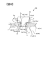
図6〜図8を参照して、電池組立体の電池蓋に外部端子を固定する方法を説明する。
図6は、外部端子を集電板にかしめた状態を示す断面図であり、図7は、図6に続く工程を説明するための断面図であり、図8は、図7に続く工程を説明するための断面図である。
上述した通り、電池蓋組立体106を構成するには、ガスケット5の貫通孔嵌入部5bを電池蓋6の負・正極側貫通孔26、46内に嵌入する。そして、電池蓋6の外面側に負・正極外部端子12、14を配置し、電池蓋6の内面側に絶縁板7と負・正極集電板24、44の負・正極集電板基部21、41を配置する。そして、負・正極外部端子12、14の負・正極外部端子軸部12a、14aを、それぞれ、ガスケット5の貫通孔5c、絶縁板7の貫通孔5c、絶縁板7の貫通孔17および負・正極集電板24、44の負・正極集電板基部21、41に形成された負・正極側集電板貫通孔25、45を挿通する。
With reference to FIGS. 6-8, the method to fix an external terminal to the battery cover of a battery assembly is demonstrated.
6 is a cross-sectional view showing a state in which the external terminal is caulked to the current collector plate, FIG. 7 is a cross-sectional view for explaining a process following FIG. 6, and FIG. 8 is a process following FIG. It is sectional drawing for demonstrating.
As described above, in order to configure the
負・正極外部端子12、14は、それぞれ、上部に負・正極外部端子出力部12c、14cを有している。負・正極外部端子軸部12a、14aは、負・正極外部端子出力部12c、14cの幅より小さい軸部材である。図6は、負・正極外部端子軸部12a、14aはかしめられた状態の図であるが、かしめる前は、負・正極外部端子軸部12a、14aは負・正極外部端子出力部12c、14cから、軸方向に直線状に延在されている。負・正極外部端子軸部12a、14aの下端部には、底面12b、14bを有する凹部12e、14eが形成されている。
The negative / positive electrode
負・正極外部端子12、14を負・正極集電板24、44にかしめ・接合により固定する。負極外部端子12を負極集電板24に固定する方法と正極外部端子14を正極集電板44に固定する方法は、同様である。従って、以下においては、負極外部端子12を負極集電板24に固定する方法を説明することとする。
負極外部端子12の負極外部端子軸部12aを、ガスケット5の貫通孔5c、絶縁板7の貫通孔17および負極集電板基部21に形成された負極側集電板貫通孔25を挿通する。そして、負極外部端子12の負極外部端子出力部12cの下面を、ガスケット5の収容部5aの底部5dに当接させる。この状態で、負極外部端子軸部12aの下端部は、負極集電板基部21の下面21aの下方に突出する。このとき、負極外部端子軸部12aの下端部に設けられた凹部12eの底面12bは、負極集電板基部21の、負極外部端子出力部12cとは反対側の面である下面21aと、ほぼ同一の高さに位置している。
The negative / positive electrode
The negative electrode external
この状態で、負極外部端子軸部12aと負極集電板基部21とをかしめる。
かしめはかしめ機のヘッドにより、負極外部端子12の負極外部端子軸部12aを押圧することにより行われる。かしめ機のヘッドにより、負極外部端子軸部12aの負極集電板基部21の下面21aより突出する部分を外側に押し広げることにより負極外部端子軸部12aと負極集電板基部21がかしめられる。図6は負極外部端子軸部12aと負極集電板基部21とが負極外部端子軸部12aのかしめ部12dでかしめられた状態を示している。かしめ機は、ヘッドが負極外部端子軸部12aの凹部12eの底面12bの位置まで下降可能なように設定する。それにより、負極外部端子軸部12aの負極集電板基部21の下面21aより突出する部分を外側に十分に押し広げることができる。
In this state, the negative electrode external
Caulking is performed by pressing the negative electrode external
外側に押し広げられた負極外部端子12の負極外部端子軸部12aは、負極集電板24に設けられた負極側集電板貫通孔25に接触する。さらに、負極外部端子軸部12aは、負極外部端子軸部12aが負極集電板24に設けられた負極側集電板貫通孔25との接触部28を起点として、さらに外側に押し広げられる。これにより、負極外部端子12の負極外部端子軸部12aと負極集電板24に設けられた負極集電板基部21とがかしめられる。
The negative electrode external
負極外部端子軸部12aと負極集電板基部21とがかしめられることにより、負極外部端子出力部12cの底面と負極側集電板貫通孔25の周縁部の接触部28との間に、負極集電板基部21と、絶縁板7と、電池蓋6と、ガスケット5とが挟持される。この際、樹脂からなるガスケット5の収容部5aの底部5dが圧迫され、電池蓋6に設けられた負極側貫通孔26を封止する。また、負極外部端子12は、電池蓋6の上面と負極外部端子出力部12cとの間に介在されたガスケット5の収容部5aの底部5dにより絶縁され、かつ、電池蓋6の負極側貫通孔26の周縁部と負極外部端子軸部12aとの間に介在されたガスケット5の貫通孔嵌入部5bにより絶縁される。これにより、負極外部端子12は、電池蓋6から絶縁された状態で、電池蓋6に固定される。
The negative electrode external
次に、図7に図示されるように、負極外部端子軸部12aと負極側集電板貫通孔25との接触部28を接合して、この接触部28に接合部29を形成する。上述したように、負極外部端子軸部12aは、負極集電板24の負極側集電板貫通孔25との接触部28を起点として、さらに外側に押し広げられる。このため、負極外部端子軸部12aと負極集電板24の負極側集電板貫通孔25との接触部28には、空間が形成されていない。この空間が形成されていない接触部28を接合部29とするため、負極外部端子軸部12aと負極集電板24との接触抵抗が低減され、かつ、接合強度が大きい安定した高品質の接合が得られる。なお、負極外部端子軸部12aと負極側集電板貫通孔25との接合としては、例えば、レーザ溶接等の溶接を用いることができる。
Next, as illustrated in FIG. 7, a
この後、負極外部端子軸部12aのかしめ部12dを、さらに、外側に押し広げる、再かしめを行う。つまり、負極外部端子軸部12aと負極側集電板貫通孔25との接触部28に接合部29を形成した後、再度、かしめ機のヘッドにより、負極外部端子軸部12aのかしめ部12dの軸方向端面を押圧して、負極外部端子軸部12aのかしめ部12dを、さらに、外側に押し広げる。これにより、接合部29における負極外部端子軸部12aとの負極外部端子軸部12aとの接触面積が増大し、負極外部端子軸部12aと負極集電板24との接触抵抗が、さらに、低減される。
Thereafter, re-caulking is performed by further pushing the
図8は、負極外部端子軸部12aのかしめ部12dに再かしめを行った後の状態を示す。
図8に図示されるように、再かしめを行った後でも、負極外部端子軸部12aのかしめ部12dの外周面31は、軸方向に対して傾斜しており、軸方向に直交するほどにまで屈曲されていない。つまり、負極外部端子軸部12aのかしめ部12dの外周面31と負極集電板基部21の下面21aとの間には隙間Sが形成されている。このように、接合部29の外面側に隙間Sが形成されているため、この隙間Sを介して、接合部29の接合状態を確認することができる。
FIG. 8 shows a state after re-caulking the
As shown in FIG. 8, even after re-caulking, the outer
本発明の第1の実施形態によれば、下記の効果を奏する。
(1)捲回電極群3と、正・負極集電板44、24と、電池容器と、正・負極外部端子14、12とを備え、正・負極外部端子14、12は、正・負極集電板44、24の正・負極集側貫通孔46、26に貫通された正・負極外部端子軸部14a、12aを有し、正・負極外部端子軸部14a、12aは、正・負極外部端子軸部14a、12aにかしめられたかしめ部14d、12dを有し、正・負極外部端子軸部14a、12aのかしめ部12dと正・負極集電板44、24の正・負極側集電板貫通孔45、25との接触部28に接合部29が設けられている。正・負極外部端子軸部14a、12aのかしめ部12dと正・負極集電板44、24の正・負極側集電板貫通孔45、25との接触部28を接合部29としたことで、正・負極外部端子軸部14a、12aと正・負極集電板44、24との接触抵抗が低減され、かつ、接合強度が大きい安定した高品質の接合を得ることができる。
According to the first embodiment of the present invention, the following effects can be obtained.
(1) A
(2)正・負極外部端子軸部14a、12aのかしめ部14d、12dの外周面31と正・負極集電板44、24との間に隙間Sを有している。このため、隙間Sを介して、接合部29の接合状態を確認することができる。
(2) There is a gap S between the outer
(3)正・負極外部端子軸部14a、12aの前記かしめ部14d、12dの軸方向端部に凹部14e、12eが設けられている。このため、正・負極外部端子軸部14a、12aのかしめ部14d、12dは、凹部14e、12eを中心に周囲に平均的に加圧し、正・負極集電板44、24との接合強度を高めることができる。
(3)
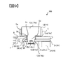
−第2の実施形態−
図9は、本発明の第2の実施形態を示す断面図である。図9は、第1の実施形態の図6に相当する図であり、最初のかしめが完了した状態を示す。
第2の実施形態では、負極外部端子軸部12aの凹部12eの底面12bは、負極集電板基部21の下面21aより上方に位置している。換言すれば、負極外部端子軸部12aの凹部12eの底面12bの高さ位置は、負極集電板基部21の下面21aより、軸方向における負極集電板基部21の下面21の反対面側に引っ込んだ位置に配置されている。また、負極外部端子軸部12aと負極集電板基部21の負極側集電板貫通孔25との寸法関係は、圧入寸法となっている。
第2の実施形態における他の構成は、第1の実施形態と同様であり、対応する部材に同一の符号を付して説明を省略する。
なお、第2の実施形態においても、図9に示す最初のかしめを行った後、第1の実施形態と同様、接触部28を接合し、この後、再かしめを行う。
-Second Embodiment-
FIG. 9 is a cross-sectional view showing a second embodiment of the present invention. FIG. 9 is a diagram corresponding to FIG. 6 of the first embodiment, and shows a state in which the first caulking is completed.
In the second embodiment, the
Other configurations in the second embodiment are the same as those in the first embodiment, and the corresponding members are denoted by the same reference numerals and description thereof is omitted.
In the second embodiment as well, after the first caulking shown in FIG. 9 is performed, the
従って、第2の実施形態でも、第1の実施形態と同様な効果を奏する。
また、負極外部端子軸部12aの凹部12eの底面12bが、負極集電板基部21の下面21aより上方に位置するため、負極外部端子軸部12aの凹部12eの周壁を、より、確実かつ容易に外方に押し広げることができる。これにより、負極外部端子軸部12aと負極集電板基部21の負極側集電板貫通孔25の周縁部との接触をより確実とすることができる。
さらに、負極外部端子軸部12aは負極集電板基部21の負極側集電板貫通孔25に圧入されるので、接触部28における、負極外部端子軸部12aと負極集電板基部21の負極側集電板貫通孔25の周縁部との接触はより確実となる。
Therefore, the second embodiment also has the same effect as the first embodiment.
Further, since the
Further, since the negative electrode external
−第3の実施形態−
図10は、本発明の第3の実施形態を示す断面図である。図9は、第1の実施形態の図8に相当する図である。
第3の実施形態では、負極外部端子軸部12aは、軸方向端部に凹部12eを有しておらず、軸方向の全長に亘り、中実なっている。
第3の実施形態においても、負極外部端子軸部12aと負極集電板基部21とのかしめは、かしめ機のヘッドを負極外部端子軸部12aの軸方向の端面に押し当てて、軸方向に押圧することにより行う。
-Third embodiment-
FIG. 10 is a cross-sectional view showing a third embodiment of the present invention. FIG. 9 is a diagram corresponding to FIG. 8 of the first embodiment.
In the third embodiment, the negative electrode external
Also in the third embodiment, the caulking of the negative electrode external
負極外部端子軸部12aと負極集電板基部21の負極側集電板貫通孔25の関係寸法は、圧入寸法であっても、すきま代が設けられていてもよい。
第3の実施形態における他の構成は第1の実施形態と同様であり、対応する部材に同一の符号を付し、その説明を省略する。
The relational dimension between the negative electrode external
Other configurations in the third embodiment are the same as those in the first embodiment, and corresponding members are denoted by the same reference numerals, and description thereof is omitted.
従って、第3の実施形態のおいても、第1の実施形態と同様の効果を奏する。
また、第3の実施形態では、負極外部端子軸部12aに凹部12eを形成しないので、負極外部端子軸部12aの構造が簡素となり、安価にすることができる。
Therefore, also in the third embodiment, the same effect as in the first embodiment is obtained.
In the third embodiment, since the
なお、上記各実施形態では、正・負極外部端子軸部14a、12aと正・負極集電板基部41、21との固定は、かしめ、接合の後、再かしめを行うこととして例示した。しかし、再かしめを行わず、かしめ、接合により、正・負極外部端子軸部14a、12aと正・負極集電板基部41、21との固定を終了するようにしてもよい。
In the above-described embodiments, the positive and negative electrode external
上記各実施形態では、正・負極外部端子軸部14a、12aと正・負極集電板基部41、21とが固定された状態で、正・負極外部端子軸部14a、12aのかしめ部14d、12dの外周面31と正・負極集電板基部21の下面41a、21aとの間に隙間Sが形成されている構造として例示した。しかし、正・負極外部端子軸部14a、12aのかしめ部14d、12dの外周面31が正・負極集電板基部21の下面41a、21に接触するように、かしめ部14d、12dの外周面31が軸方向にほぼ垂直になるようにかしめてもよい。
In each of the above embodiments, the positive / negative electrode external
上記各実施形態では、正・負極集電板44、24は、それぞれ、正・負極集電板基部41、21および正・負極側接続部42、22を有し、正・負極外部端子軸部14a、12aは、正・負極集電板基部41、21に固定する構造として例示した。しかし、正・負極集電板は、任意な構造とすることが可能であり、本発明は、この任意な構造の正・負極集電板と正・負極外部端子軸部14a、12aとを一体化する構造に適用することができる。
In each of the above-described embodiments, the positive / negative electrode
上記各実施形態では、正・負極外部端子14、12の正・負極外部端子出力部14c、12cをほぼ直方体形状として例示した。しかし、正・負極外部端子出力部の形状は、任意とすることができる。
In each said embodiment, the positive / negative external
上記各実施形態では、正・負極外部端子14、12を、電池缶1の開口部1aを塞ぐ電池蓋6に固定する構造として例示した。しかし、正・負極外部端子14、12を、電池缶1の側壁に取付けるようにしてもよい。
In each of the above embodiments, the positive and negative
上記各実施形態では、正・負極外部端子14、12の正・負極外部端子軸部14a、12aは、正・負極外部端子出力部14c、12cとは反対側の端部に凹部14e、12eを有するか、全長に亘り中実であるとして、例示した。しかし、正・負極外部端子軸部14a、12aは、ほぼ全長に亘り、軸心部が中空とされた中空軸としてもよい。
In each of the above embodiments, the positive / negative external
上記各実施形態では、正極電極34と負極電極32とが、セパレータ33、35を介して捲回された捲回電極群3を有する二次電池100として例示した。しかし、本発明は、矩形シート状の正極電極と矩形シート状の負極電極とを、セパレータを介して平坦状に積層した電極群を備える二次電池に適用することができる。
In each said embodiment, the
上記各実施形態ではリチウムイオン二次電池を蓄電素子の一例として説明したが、ニッケル水素電池などその他の二次電池にも本発明を適用できる。さらに、電気二重層キャパシタやリチウムイオンキャパシタを蓄電素子とした場合にも本発明を適用できる。 In each of the above embodiments, the lithium ion secondary battery has been described as an example of the storage element, but the present invention can also be applied to other secondary batteries such as a nickel metal hydride battery. Furthermore, the present invention can also be applied when an electric double layer capacitor or a lithium ion capacitor is used as a storage element.
上記では、種々の実施の形態および変形例を説明したが、本発明はこれらの内容に限定されるものではない。本発明の技術的思想の範囲内で考えられるその他の態様も本発明の範囲内に含まれる。 Although various embodiments and modifications have been described above, the present invention is not limited to these contents. Other embodiments conceivable within the scope of the technical idea of the present invention are also included in the scope of the present invention.
1 電池缶
3 捲回電極群(蓄電要素)
6 電池蓋(一側部)
12 負極外部端子
12a 負極外部端子軸部
12b 底面
12d かしめ部
12e 凹部
14 正極外部端子
14a 正極外部端子軸部
14b 底面
14d かしめ部
14e 凹部
21 負極集電板基部
21a 下面(一面)
24 負極集電板
25 負極側集電板貫通孔(開口部)
29 接合部
31 外周面
41 正極集電板基部
41a 下面(一面)
44 正極集電板
45 正極側集電板貫通孔(開口部)
100 二次電池(蓄電装置)
106 電池蓋組立体
1 Battery can 3 Winding electrode group (storage element)
6 Battery cover (one side)
12 Negative electrode
24 Negative electrode
29
44 Positive
100 Secondary battery (power storage device)
106 Battery lid assembly
Claims (8)
開口部を有し、前記蓄電要素に接続される集電板と、
前記集電板および前記蓄電要素を収納する電池容器と、
前記電池容器の一側部に設けられ、前記集電板に接続される外部端子とを備え、
前記外部端子は前記集電板の前記開口部に貫通された軸部を有し、
前記軸部は、前記集電板にかしめられたかしめ部を有し、
前記軸部のかしめ部と前記集電板の前記開口部との接触部に接合部が設けられている、蓄電装置。 A storage element;
A current collector having an opening and connected to the power storage element;
A battery container for storing the current collector plate and the power storage element;
An external terminal provided on one side of the battery container and connected to the current collector;
The external terminal has a shaft portion that passes through the opening of the current collector plate,
The shaft portion has a caulking portion that is caulked to the current collector plate,
A power storage device, wherein a joint portion is provided at a contact portion between the caulking portion of the shaft portion and the opening portion of the current collector plate.
前記軸部の前記かしめ部における前記接触部より端部側の外周面と前記集電板との間に隙間を有する、蓄電装置。 The power storage device according to claim 1,
The electrical storage apparatus which has a clearance gap between the outer peripheral surface at the edge part side rather than the said contact part in the said crimping part of the said axial part, and the said current collection board.
前記軸部の前記かしめ部の軸方向の端部に凹部が設けられている、蓄電装置。 The power storage device according to claim 1,
The electrical storage apparatus in which the recessed part is provided in the edge part of the axial direction of the said crimping part of the said axial part.
前記軸部の前記凹部の底面は、前記集電板における前記軸部が貫通した側の一面よりも、軸方向おける前記集電板の前記一面の反対面側に引っ込んだ位置に配置されている、蓄電装置。 The power storage device according to claim 3,
The bottom surface of the concave portion of the shaft portion is disposed at a position retracted to the opposite side of the one surface of the current collector plate in the axial direction from one surface of the current collector plate on the side where the shaft portion penetrates. , Power storage device.
前記軸部の前記かしめ部は中実である、蓄電装置。 The power storage device according to claim 1,
The power storage device, wherein the caulking portion of the shaft portion is solid.
前記外部端子の前記軸部を前記集電板の前記開口部に貫通して、前記軸部を前記集電板にかしめることと、
前記軸部のかしめ部の外周と前記集電板の前記開口部の周縁部の接触部とを接合すること、とを有する蓄電装置の製造方法。 A method for manufacturing a power storage device, comprising: a power storage element; a current collector plate having an opening and connected to the power storage element; and an external terminal having a shaft portion penetrating the opening.
Penetrating the shaft portion of the external terminal into the opening of the current collector plate, and caulking the shaft portion to the current collector plate;
The manufacturing method of the electrical storage apparatus which has joining the outer periphery of the crimping part of the said axial part, and the contact part of the peripheral part of the said opening part of the said current collecting plate.
前記接合することの後に、再度、前記軸部をかしめることを有する蓄電装置の製造方法。 It is a manufacturing method of the electrical storage device according to claim 6,
The manufacturing method of the electrical storage apparatus which has caulking the said axial part again after the said joining.
前記軸部を前記集電板の前記開口部に貫通する際、前記軸部を前記集電板の前記開口部に圧入することを含む蓄電装置の製造方法。
It is a manufacturing method of the electrical storage device according to claim 6,
A method for manufacturing a power storage device, comprising: press-fitting the shaft portion into the opening portion of the current collector plate when penetrating the shaft portion into the opening portion of the current collector plate.
Priority Applications (1)
| Application Number | Priority Date | Filing Date | Title |
|---|---|---|---|
| JP2017128813A JP6892338B2 (en) | 2017-06-30 | 2017-06-30 | Power storage device and manufacturing method of power storage device |
Applications Claiming Priority (1)
| Application Number | Priority Date | Filing Date | Title |
|---|---|---|---|
| JP2017128813A JP6892338B2 (en) | 2017-06-30 | 2017-06-30 | Power storage device and manufacturing method of power storage device |
Publications (2)
| Publication Number | Publication Date |
|---|---|
| JP2019012638A true JP2019012638A (en) | 2019-01-24 |
| JP6892338B2 JP6892338B2 (en) | 2021-06-23 |
Family
ID=65227012
Family Applications (1)
| Application Number | Title | Priority Date | Filing Date |
|---|---|---|---|
| JP2017128813A Active JP6892338B2 (en) | 2017-06-30 | 2017-06-30 | Power storage device and manufacturing method of power storage device |
Country Status (1)
| Country | Link |
|---|---|
| JP (1) | JP6892338B2 (en) |
Citations (5)
| Publication number | Priority date | Publication date | Assignee | Title |
|---|---|---|---|---|
| JP2002190314A (en) * | 2000-12-20 | 2002-07-05 | Nissan Motor Co Ltd | Battery |
| JP2004014173A (en) * | 2002-06-04 | 2004-01-15 | Japan Storage Battery Co Ltd | Battery and manufacturing method for battery |
| WO2015025388A1 (en) * | 2013-08-22 | 2015-02-26 | 日立オートモティブシステムズ株式会社 | Secondary cell |
| JP2016111012A (en) * | 2014-11-28 | 2016-06-20 | 三洋電機株式会社 | Secondary battery |
| JP6014808B1 (en) * | 2015-08-17 | 2016-10-26 | 日立金属株式会社 | Battery terminal and battery terminal manufacturing method |
-
2017
- 2017-06-30 JP JP2017128813A patent/JP6892338B2/en active Active
Patent Citations (5)
| Publication number | Priority date | Publication date | Assignee | Title |
|---|---|---|---|---|
| JP2002190314A (en) * | 2000-12-20 | 2002-07-05 | Nissan Motor Co Ltd | Battery |
| JP2004014173A (en) * | 2002-06-04 | 2004-01-15 | Japan Storage Battery Co Ltd | Battery and manufacturing method for battery |
| WO2015025388A1 (en) * | 2013-08-22 | 2015-02-26 | 日立オートモティブシステムズ株式会社 | Secondary cell |
| JP2016111012A (en) * | 2014-11-28 | 2016-06-20 | 三洋電機株式会社 | Secondary battery |
| JP6014808B1 (en) * | 2015-08-17 | 2016-10-26 | 日立金属株式会社 | Battery terminal and battery terminal manufacturing method |
Also Published As
| Publication number | Publication date |
|---|---|
| JP6892338B2 (en) | 2021-06-23 |
Similar Documents
| Publication | Publication Date | Title |
|---|---|---|
| US10388939B2 (en) | Secondary battery | |
| JP5452303B2 (en) | Secondary battery and manufacturing method thereof | |
| JP6446239B2 (en) | Secondary battery | |
| JP6892495B2 (en) | Secondary battery | |
| JP5087110B2 (en) | Secondary battery | |
| JP6167185B2 (en) | Prismatic secondary battery | |
| US11728518B2 (en) | Rectangular secondary battery | |
| JP6207950B2 (en) | Square secondary battery and battery pack | |
| WO2020066050A1 (en) | Fastening structure | |
| WO2017130702A1 (en) | Rectangular secondary battery | |
| JP2016110787A (en) | Square secondary battery | |
| JP6382336B2 (en) | Prismatic secondary battery | |
| JP6562726B2 (en) | Rectangular secondary battery and manufacturing method thereof | |
| JP2015103420A (en) | Square secondary battery | |
| JP6182061B2 (en) | Secondary battery | |
| JP6892338B2 (en) | Power storage device and manufacturing method of power storage device | |
| JP2021064519A (en) | Secondary battery | |
| JP2016173907A (en) | Square secondary battery | |
| WO2015125223A1 (en) | Secondary battery | |
| JP2016143618A (en) | Rectangular secondary battery | |
| JP2018056086A (en) | Secondary battery and method of manufacturing secondary battery | |
| JP6752737B2 (en) | Prismatic secondary battery | |
| WO2023007756A1 (en) | Secondary battery | |
| JP6978500B2 (en) | Secondary battery | |
| JP2016219356A (en) | Square secondary battery |
Legal Events
| Date | Code | Title | Description |
|---|---|---|---|
| A621 | Written request for application examination |
Free format text: JAPANESE INTERMEDIATE CODE: A621 Effective date: 20191120 |
|
| A711 | Notification of change in applicant |
Free format text: JAPANESE INTERMEDIATE CODE: A712 Effective date: 20200227 |
|
| A521 | Request for written amendment filed |
Free format text: JAPANESE INTERMEDIATE CODE: A523 Effective date: 20200409 |
|
| A521 | Request for written amendment filed |
Free format text: JAPANESE INTERMEDIATE CODE: A523 Effective date: 20200416 |
|
| A521 | Request for written amendment filed |
Free format text: JAPANESE INTERMEDIATE CODE: A523 Effective date: 20200703 |
|
| A977 | Report on retrieval |
Free format text: JAPANESE INTERMEDIATE CODE: A971007 Effective date: 20200730 |
|
| A131 | Notification of reasons for refusal |
Free format text: JAPANESE INTERMEDIATE CODE: A131 Effective date: 20201110 |
|
| A521 | Request for written amendment filed |
Free format text: JAPANESE INTERMEDIATE CODE: A523 Effective date: 20210108 |
|
| TRDD | Decision of grant or rejection written | ||
| A01 | Written decision to grant a patent or to grant a registration (utility model) |
Free format text: JAPANESE INTERMEDIATE CODE: A01 Effective date: 20210506 |
|
| A61 | First payment of annual fees (during grant procedure) |
Free format text: JAPANESE INTERMEDIATE CODE: A61 Effective date: 20210527 |
|
| R150 | Certificate of patent or registration of utility model |
Ref document number: 6892338 Country of ref document: JP Free format text: JAPANESE INTERMEDIATE CODE: R150 |