JP2019011682A - Vane compressor - Google Patents
Vane compressor Download PDFInfo
- Publication number
- JP2019011682A JP2019011682A JP2017127070A JP2017127070A JP2019011682A JP 2019011682 A JP2019011682 A JP 2019011682A JP 2017127070 A JP2017127070 A JP 2017127070A JP 2017127070 A JP2017127070 A JP 2017127070A JP 2019011682 A JP2019011682 A JP 2019011682A
- Authority
- JP
- Japan
- Prior art keywords
- cylinder
- vane
- rotor
- side block
- passage
- Prior art date
- Legal status (The legal status is an assumption and is not a legal conclusion. Google has not performed a legal analysis and makes no representation as to the accuracy of the status listed.)
- Pending
Links
Images


Classifications
-
- F—MECHANICAL ENGINEERING; LIGHTING; HEATING; WEAPONS; BLASTING
- F04—POSITIVE - DISPLACEMENT MACHINES FOR LIQUIDS; PUMPS FOR LIQUIDS OR ELASTIC FLUIDS
- F04C—ROTARY-PISTON, OR OSCILLATING-PISTON, POSITIVE-DISPLACEMENT MACHINES FOR LIQUIDS; ROTARY-PISTON, OR OSCILLATING-PISTON, POSITIVE-DISPLACEMENT PUMPS
- F04C18/00—Rotary-piston pumps specially adapted for elastic fluids
- F04C18/30—Rotary-piston pumps specially adapted for elastic fluids having the characteristics covered by two or more of groups F04C18/02, F04C18/08, F04C18/22, F04C18/24, F04C18/48, or having the characteristics covered by one of these groups together with some other type of movement between co-operating members
- F04C18/34—Rotary-piston pumps specially adapted for elastic fluids having the characteristics covered by two or more of groups F04C18/02, F04C18/08, F04C18/22, F04C18/24, F04C18/48, or having the characteristics covered by one of these groups together with some other type of movement between co-operating members having the movement defined in group F04C18/08 or F04C18/22 and relative reciprocation between the co-operating members
- F04C18/344—Rotary-piston pumps specially adapted for elastic fluids having the characteristics covered by two or more of groups F04C18/02, F04C18/08, F04C18/22, F04C18/24, F04C18/48, or having the characteristics covered by one of these groups together with some other type of movement between co-operating members having the movement defined in group F04C18/08 or F04C18/22 and relative reciprocation between the co-operating members with vanes reciprocating with respect to the inner member
- F04C18/3441—Rotary-piston pumps specially adapted for elastic fluids having the characteristics covered by two or more of groups F04C18/02, F04C18/08, F04C18/22, F04C18/24, F04C18/48, or having the characteristics covered by one of these groups together with some other type of movement between co-operating members having the movement defined in group F04C18/08 or F04C18/22 and relative reciprocation between the co-operating members with vanes reciprocating with respect to the inner member the inner and outer member being in contact along one line or continuous surface substantially parallel to the axis of rotation
- F04C18/3442—Rotary-piston pumps specially adapted for elastic fluids having the characteristics covered by two or more of groups F04C18/02, F04C18/08, F04C18/22, F04C18/24, F04C18/48, or having the characteristics covered by one of these groups together with some other type of movement between co-operating members having the movement defined in group F04C18/08 or F04C18/22 and relative reciprocation between the co-operating members with vanes reciprocating with respect to the inner member the inner and outer member being in contact along one line or continuous surface substantially parallel to the axis of rotation the surfaces of the inner and outer member, forming the inlet and outlet opening
-
- F—MECHANICAL ENGINEERING; LIGHTING; HEATING; WEAPONS; BLASTING
- F01—MACHINES OR ENGINES IN GENERAL; ENGINE PLANTS IN GENERAL; STEAM ENGINES
- F01C—ROTARY-PISTON OR OSCILLATING-PISTON MACHINES OR ENGINES
- F01C21/00—Component parts, details or accessories not provided for in groups F01C1/00 - F01C20/00
- F01C21/08—Rotary pistons
- F01C21/0809—Construction of vanes or vane holders
- F01C21/0818—Vane tracking; control therefor
- F01C21/0854—Vane tracking; control therefor by fluid means
- F01C21/0863—Vane tracking; control therefor by fluid means the fluid being the working fluid
-
- F—MECHANICAL ENGINEERING; LIGHTING; HEATING; WEAPONS; BLASTING
- F01—MACHINES OR ENGINES IN GENERAL; ENGINE PLANTS IN GENERAL; STEAM ENGINES
- F01C—ROTARY-PISTON OR OSCILLATING-PISTON MACHINES OR ENGINES
- F01C21/00—Component parts, details or accessories not provided for in groups F01C1/00 - F01C20/00
- F01C21/08—Rotary pistons
- F01C21/0809—Construction of vanes or vane holders
- F01C21/0818—Vane tracking; control therefor
- F01C21/0854—Vane tracking; control therefor by fluid means
- F01C21/0872—Vane tracking; control therefor by fluid means the fluid being other than the working fluid
-
- F—MECHANICAL ENGINEERING; LIGHTING; HEATING; WEAPONS; BLASTING
- F04—POSITIVE - DISPLACEMENT MACHINES FOR LIQUIDS; PUMPS FOR LIQUIDS OR ELASTIC FLUIDS
- F04C—ROTARY-PISTON, OR OSCILLATING-PISTON, POSITIVE-DISPLACEMENT MACHINES FOR LIQUIDS; ROTARY-PISTON, OR OSCILLATING-PISTON, POSITIVE-DISPLACEMENT PUMPS
- F04C28/00—Control of, monitoring of, or safety arrangements for, pumps or pumping installations specially adapted for elastic fluids
- F04C28/06—Control of, monitoring of, or safety arrangements for, pumps or pumping installations specially adapted for elastic fluids specially adapted for stopping, starting, idling or no-load operation
Landscapes
- Engineering & Computer Science (AREA)
- Mechanical Engineering (AREA)
- General Engineering & Computer Science (AREA)
- Rotary Pumps (AREA)
- Applications Or Details Of Rotary Compressors (AREA)
Abstract
Description
本発明は、ベーン型圧縮機に関し、特に起動時等において発生するベーンの振動に伴うノイズ(チャタリングノイズ)を低減するために有用な構造を備えたベーン型圧縮機に関する。 The present invention relates to a vane type compressor, and more particularly to a vane type compressor having a structure useful for reducing noise (chattering noise) associated with vane vibration that occurs during startup.
一般的に、ベーン型圧縮機は、両端が閉塞されると共にカム面が内周面に形成されたシリンダと、シリンダ内に回転可能に支持されたロータと、このロータの外周面から内部に向けて形成されたベーン溝と、このベーン溝に出没可能に収容されたベーンとを有し、ロータの回転による遠心力およびベーン溝の底部に設けられた背圧室から作用する背圧によってベーンをシリンダの内周面に接触支持させる構造となっている。 In general, a vane compressor has a cylinder in which both ends are closed and a cam surface is formed on an inner peripheral surface, a rotor that is rotatably supported in the cylinder, and an outer surface of the rotor that is directed inward. The vane groove formed in the vane groove and removably accommodated in the vane groove. The vane is formed by centrifugal force due to rotation of the rotor and back pressure acting from the back pressure chamber provided at the bottom of the vane groove. It is structured to be in contact with and supported on the inner peripheral surface of the cylinder.
このような圧縮機においては、起動初期において高低圧差が小さいため、ベーンがシリンダの内周面から離れ、再びシリンダの内周面に着地して衝突音(チャタリングノイズ)を発生させる状態が長く続きやすい。 In such a compressor, since the high / low pressure difference is small in the initial stage of the start-up, the state in which the vane leaves the inner peripheral surface of the cylinder and landes on the inner peripheral surface of the cylinder again to generate a collision noise (chattering noise) continues for a long time. Cheap.
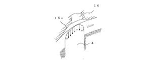
この現象は、特に、ベーンの先端部が吐出ポートの中程を通過する付近からロータとシリンダの内周面とが摺接する部分(ラジアルシール部)を通過するまでの間で生じやすい。これは、図7に示すように、ベーン4の先端部が吐出ポート16に差し掛かると(図中においてベーンの回転方向を白抜きの矢印で示す)、ベーン4の背面側(ベーンの回転方向後方側)の圧縮室で圧縮された高い圧力が吐出ポート16を回り込んでベーン4の先端部の全面に作用し、起動時においてはベーン4の底部に作用する背圧(ベーン背圧)が十分に高くないため、べーン4が吐出ポートを通過する際のベーン4の先端部にかかる前記圧力を支えきれなくなるためである。この現象は、吐出ポート16のシリンダの内周面との開口端に周方向に延設された座ぐり(カウンターボア)16aが形成されている場合において、一層生じやすいものとなる。
This phenomenon is particularly likely to occur between the vicinity of the vane tip passing through the middle of the discharge port and the passage of the portion where the rotor and the inner peripheral surface of the cylinder are in sliding contact (radial seal portion). As shown in FIG. 7, when the tip of the
そこで、このような不都合を解消するために、本出願人は、リア側サイドブロックの圧縮室側の端面に、ベーンの先端部が吐出ポートの途中からラジアルシール部までの範囲にある行程において、ベーン溝の底部と連通する凹部を設け、この凹部を連通路(以下、高圧導入通路という)を介して吐出ポートから吐出された流体を収容する吐出流体収容室と連通させ、ベーンの先端部がチャタリングを発生しやすい吐出ポートの途中からラジアルシール部までの範囲にある場合に、吐出流体をロータのリア側からベーン溝の底部(背圧室)に導いてベーンを確実にシリンダの内周面に付勢する構成を先に提案している(特許文献1参照)。 Therefore, in order to eliminate such inconvenience, the present applicant, on the end face of the rear side block on the compression chamber side, in the stroke where the tip of the vane is in the range from the middle of the discharge port to the radial seal part, A recess that communicates with the bottom of the vane groove is provided, and the recess communicates with a discharge fluid storage chamber that stores fluid discharged from the discharge port via a communication passage (hereinafter referred to as a high pressure introduction passage). When it is in the range from the middle of the discharge port where chattering is likely to occur to the radial seal, the discharge fluid is guided from the rear side of the rotor to the bottom of the vane groove (back pressure chamber) to ensure the vane's inner peripheral surface The structure which urges | biases is proposed previously (refer patent document 1).
しかしながら、ロータが固装されている駆動軸のフロント側の端部は、駆動源に直結させる必要や、駆動源の動力を伝達する動力伝達部材(プーリ、電磁クラッチ等)を装着する必要から、フロント側サイドブロックを貫通してハウジングの外部に突出させている。 However, the end on the front side of the drive shaft on which the rotor is fixed is required to be directly connected to the drive source, or a power transmission member (pulley, electromagnetic clutch, etc.) for transmitting the power of the drive source is required, It passes through the front side block and protrudes outside the housing.
このような構成においては、駆動軸のフロント側のサイドブロックから外部に突出しているフロント側の端部には大気圧が作用し、これに対して、駆動軸のリア側の端部には、ロータとリア側サイドブロックとの間のクリアランスや軸受等を介して圧縮機内部の相対的に高い圧力が作用するため、駆動軸は、軸方向の前後両側に作用する圧力差により、フロント側へ付勢された状態となる。このため、ロータの前端とフロント側サイドブロックとの間のクリアランスは相対的に小さくなり、また、ロータの後端とリア側サイドブロックとの間のクリアランスは相対的に大きくなる。 In such a configuration, atmospheric pressure acts on the front end protruding from the front side block of the drive shaft to the outside, whereas, on the rear end of the drive shaft, The relatively high pressure inside the compressor acts via the clearance between the rotor and the rear side block, bearings, etc., so the drive shaft moves to the front side due to the pressure difference acting on both the front and rear sides in the axial direction. It will be energized. For this reason, the clearance between the front end of the rotor and the front side block is relatively small, and the clearance between the rear end of the rotor and the rear side block is relatively large.
したがって、吐出流体収容室から高圧導入通路を介してリア側サイドブロックの圧縮室側の端面に導かれた吐出流体は、ロータ3の後端とリア側サイドブロック13との間のクリアランスを介して漏れ易くなり、ベーンの先端部が吐出ポートの途中からラジアルシール部までの範囲にある行程においてベーン溝の底部(背圧室)に吐出流体を効果的に導入できなくなる不都合が懸念される。
また、吐出流体収容室から供給された吐出流体がロータの後端とリア側サイドブロックとの間のクリアランスを介して漏出し易くなると、この間に形成されているオイル被膜が除去され、オイルによるシール効果が低下して圧縮効率が低下する不都合も懸念される。
Therefore, the discharge fluid guided from the discharge fluid storage chamber to the end surface on the compression chamber side of the rear side block via the high pressure introduction passage is connected via the clearance between the rear end of the
Further, when the discharge fluid supplied from the discharge fluid storage chamber is likely to leak through the clearance between the rear end of the rotor and the rear side block, the oil film formed between the two is removed, and the oil seal is removed. There is also a concern that the effect is reduced and the compression efficiency is lowered.
本発明は、係る事情に鑑みてなされたものであり、駆動軸のフロント側の端部がハウジングの外部に突出し、リア側の端部がハウジング内に収容されている圧縮機において、起動初期等においてベーンを確実にシリンダの内周面に付勢してベーンのチャタリングの発生を防止するようにしたベーン型圧縮機を提供することを主たる課題としている。 The present invention has been made in view of such circumstances, and in a compressor in which a front side end portion of a drive shaft protrudes to the outside of a housing and a rear side end portion is accommodated in the housing, the initial stage of startup, etc. The main object of the present invention is to provide a vane type compressor that reliably biases the vane toward the inner peripheral surface of the cylinder to prevent chattering of the vane.
上記課題を達成するために、本発明に係るベーン型圧縮機は、ハウジングと、カム面が内周面に形成され、前記ハウジングの一部を構成するシリンダと、前記シリンダの軸方向の両端を閉塞し、前記ハウジングの一部を構成するフロント側及びリア側の一対のサイドブロックと、前記一対のサイドブロックに回転自在に支持された駆動軸と、前記駆動軸に固装されて前記シリンダに回転可能に収容されるロータと、前記ロータの外周面の一部と前記シリンダの内周面の一部が摺接するラジアルシール部と、前記ロータに形成された複数のベーン溝と、前記ベーン溝に摺動自在に挿入され、先端部が前記ベーン溝から出没して前記カム面を摺動する複数のベーンと、前記シリンダと前記一対のサイドブロックとにより閉塞された空間に、前記ロータと前記ベーンによって画成される圧縮室と、前記圧縮室に流体を吸入する吸入ポートと、前記圧縮室で圧縮された前記流体を吐出する吐出ポートと、前記吐出ポートから吐出された流体を収容する吐出流体収容室と、を備えたベーン型圧縮機において、前記吐出流体収容室に一端が接続され、他端がロータのフロント側の端面に臨み、前記ベーンの先端部が前記吐出ポートの中程から前記ラジアルシール部までの範囲にある行程において、前記ベーン溝の底部と連通する高圧導入通路を設けたことを特徴としている。 In order to achieve the above object, a vane type compressor according to the present invention includes a housing, a cylinder having a cam surface formed on an inner peripheral surface, constituting a part of the housing, and both axial ends of the cylinder. A pair of front and rear side blocks that are closed and constitute a part of the housing, a drive shaft that is rotatably supported by the pair of side blocks, and a cylinder that is fixedly mounted on the drive shaft. A rotor that is rotatably accommodated, a radial seal portion in which a part of an outer peripheral surface of the rotor and a part of an inner peripheral surface of the cylinder are in sliding contact, a plurality of vane grooves formed in the rotor, and the vane grooves Slidably inserted into the space closed by the plurality of vanes whose tip ends protrude from and retract from the vane groove and slide on the cam surface, and the cylinder and the pair of side blocks. A compression chamber defined by the compressor and the vane, a suction port for sucking fluid into the compression chamber, a discharge port for discharging the fluid compressed in the compression chamber, and a fluid discharged from the discharge port. A vane-type compressor including a discharge fluid storage chamber, wherein one end of the vane compressor is connected to the discharge fluid storage chamber, the other end faces an end surface on a front side of the rotor, and a tip of the vane is connected to the discharge port. In a stroke in the range from the middle to the radial seal portion, a high pressure introduction passage communicating with the bottom of the vane groove is provided.
したがって、ベーンの先端部が吐出ポートの中程から前記ラジアルシール部までの範囲にある行程においては、吐出流体収容室とベーン溝の底部とが、ロータのフロント側において高圧導入通路を介して連通することになる。ロータのフロント側の端面とフロント側サイドブロックとのクリアランスは、駆動軸の両端に作用する圧力差に起因するフロント側への付勢力により小さくなっているため、吐出流体収容室から供給される吐出流体は、ロータのフロント側の端面とフロント側サイドブロックと間のクリアランスを介して漏出する虞は少なく、ベーン溝の底部へ効果的に導入される。 Therefore, in the stroke in which the tip of the vane is in the range from the middle of the discharge port to the radial seal portion, the discharge fluid storage chamber and the bottom of the vane groove communicate with each other via the high pressure introduction passage on the front side of the rotor. Will do. The clearance between the front end face of the rotor and the front side block is reduced by the biasing force to the front side due to the pressure difference acting on both ends of the drive shaft, so the discharge supplied from the discharge fluid storage chamber The fluid is less likely to leak through the clearance between the front end face of the rotor and the front side block, and is effectively introduced into the bottom of the vane groove.
このため、ベーンのチャタリングが発生しやすい領域において、十分な背圧力を確保することができるので、ベーンの先端部が吐出ポートに差し掛かった後にベーンの先端部にかかる圧力を支えることができ、ベーンのカム面に当接した状態を維持することが可能となる。
また、ロータのフロント側の端面とフロント側サイドブロックとの間のクリアランスを介して吐出流体が漏出する虞も殆どないため、ロータのフロント側の端面とフロント側サイドブロックとの間のオイルによるシール効果を損なう虞はなく、良好なシール状態を維持することも可能となる。
For this reason, sufficient back pressure can be secured in an area where chattering of the vane is likely to occur, so that the pressure applied to the tip of the vane after the tip of the vane reaches the discharge port can be supported. It is possible to maintain the state in contact with the cam surface.
In addition, since there is almost no possibility that the discharged fluid leaks through the clearance between the front end face of the rotor and the front side block, the seal between the front end face of the rotor and the front side block is made of oil. There is no risk of impairing the effect, and a good sealing state can be maintained.
なお、ベーンの先端部がラジアルシール部から吐出ポートの手前までの範囲にある行程においてベーン背圧を従前と同様に供給する場合には、上述した構成に加え、前記吐出ポートから吐出された前記流体の圧力に相当する圧力のオイルを貯留するオイル溜まり室と、少なくとも一方のサイドブロックの前記圧縮室側端面に形成され、前記ベーンの先端部が前記ラジアルシール部から前記吐出ポートの手前までの範囲にある行程において、前記ベーン溝の底部と連通するオイル導入溝と、このオイル導入溝と前記オイル溜まり室とを連通するオイル導入通路と、を更に設けるとよい。 In the case where the vane back pressure is supplied in the same manner as before in the stroke where the tip of the vane is in the range from the radial seal portion to the front of the discharge port, in addition to the above-described configuration, the discharge from the discharge port is performed. An oil reservoir chamber for storing oil at a pressure corresponding to the pressure of the fluid, and at least one side block of the compression chamber side end surface, and the tip of the vane extends from the radial seal portion to the front of the discharge port. In the stroke within the range, an oil introduction groove communicating with the bottom of the vane groove, and an oil introduction passage communicating the oil introduction groove and the oil reservoir chamber may be further provided.
また、前記高圧導入通路は、前記吐出流体収容室に連通する前記シリンダに形成されたシリンダ側通路と、前記ロータのフロント側の端面に臨む前記フロント側サイドブロックに形成されたサイドブロック側通路と、を連接して形成され、前記シリンダ側通路と前記サイドブロック側通路とは、前記シリンダと前記フロント側サイドブロックとを位置決めする位置決めピンに設けられた通孔を介して連通させるようにするとよい。 The high pressure introduction passage includes a cylinder side passage formed in the cylinder communicating with the discharge fluid storage chamber, and a side block side passage formed in the front side block facing a front side end surface of the rotor. The cylinder side passage and the side block side passage may be communicated with each other through a through hole provided in a positioning pin for positioning the cylinder and the front side block. .
このような構成においては、シリンダやフロント側サイドブロックに、高圧導入通路と、位置決めピンの装着箇所とを別々に設ける必要がなくなり、レイアウトの自由度を高めることが可能となる。 In such a configuration, it is not necessary to separately provide the high pressure introduction passage and the positioning pin mounting portion in the cylinder or the front side block, and the degree of freedom in layout can be increased.
なお、前記位置決めピンは、加工や組付けの容易さを考慮すると、スプリングピンで構成するとよい。
また、前記ハウジングは、前記シリンダ、及び、このシリンダのリア側を閉塞するリア側サイドブロックが一体に形成された第1のハウジング部材と、前記シリンダのフロント側を閉塞するフロント側サイドブロック、及び、前記第1のハウジング部材の外周を覆う円筒部が一体に形成された第2のハウジング部材と、を組み合わせて構成するようにしてもよい。
The positioning pin is preferably a spring pin in consideration of ease of processing and assembly.
The housing includes a first housing member integrally formed with the cylinder and a rear side block for closing the rear side of the cylinder, a front side block for closing the front side of the cylinder, and A second housing member integrally formed with a cylindrical portion covering the outer periphery of the first housing member may be combined.
以上述べたように、本発明によれば、吐出ポートから吐出された流体を収容する吐出流体収容室に一端が接続され、他端がロータのフロント側の端面に臨み、ベーンの先端部が吐出ポートの中程からラジアルシール部までの範囲にある行程において、ベーン溝の底部と連通する高圧導入通路を設けたので、チャタリングが発生しやすい領域において、十分な背圧力を確保することができ、起動初期等においてもベーンを確実にシリンダの内周面に付勢してベーンのチャタリングを防止することが可能となる。 As described above, according to the present invention, one end is connected to the discharge fluid storage chamber that stores the fluid discharged from the discharge port, the other end faces the end surface on the front side of the rotor, and the tip of the vane discharges. In the stroke from the middle of the port to the radial seal portion, a high pressure introduction passage communicating with the bottom of the vane groove is provided, so that sufficient back pressure can be secured in an area where chattering is likely to occur. Even in the initial stage of startup, the vane can be reliably urged to the inner peripheral surface of the cylinder to prevent chattering of the vane.
また、高圧導入通路を設けるにあたり、吐出流体収容室に連通するシリンダに形成されたシリンダ側通路と、ロータのフロント側の端面に臨むフロント側サイドブロックに形成されたサイドブロック側通路とを、シリンダとフロント側サイドブロックとを位置決めする位置決めピンに設けられた通孔を介して連通させるようにすることで、シリンダやフロント側サイドブロックに、、高圧導入通路と、位置決めピンの装着箇所とを別々に設ける必要がなくなり、レイアウトの自由度を高めることが可能となる。 Further, when providing the high pressure introduction passage, a cylinder side passage formed in the cylinder communicating with the discharge fluid storage chamber and a side block side passage formed in the front side block facing the front end face of the rotor And the front side block through a through hole provided in the positioning pin, the high pressure introduction passage and the location of the positioning pin are installed separately on the cylinder and the front side block. Therefore, it is possible to increase the degree of freedom of layout.
以下、本発明のベーン型圧縮機について図面を参照しながら説明する。 Hereinafter, the vane type compressor of the present invention will be described with reference to the drawings.
図1及び図2において、冷媒を作動流体とする冷凍サイクルに適したベーン型圧縮機が示されている。このベーン型圧縮機1は、駆動軸2と、駆動軸2に固定されて当該駆動軸2の回動に伴い回転するロータ3と、このロータ3に取り付けられるベーン4と、駆動軸2を回転自在に支持すると共にロータ3及びベーン4を収容するハウジング5とを有して構成されている。なお、図1において、左側をフロント側、右側をリア側とする。
1 and 2 show a vane type compressor suitable for a refrigeration cycle using a refrigerant as a working fluid. The
ハウジング5は、第1のハウジング部材10と第2のハウジング部材20との2つの部材を組み合わせて構成されている。
第1のハウジング部材10は、ロータ3を収納すると共にカム面11が内周面に形成されたシリンダ12と、このシリンダ12の軸方向のリア側を閉塞するように一体に形成されたリア側サイドブロック13とから構成されている。シリンダ12の内周面(カム面11)は、断面が真円に形成され、軸方向の長さが後述するロータ3の軸方向の長さにほぼ等しく形成されている。
The
The
第2のハウジング部材20は、シリンダ12のフロント側の端面に当接してこのフロント側を閉塞するフロント側サイドブロック21と、このフロント側サイドブロック21に一体に形成されて駆動軸2の軸方向に延設され、前記第1のハウジング部材(シリンダ12及びリア側サイドブロック13)の外周面を包囲するように形成された円筒部22とを有して構成されている。
The
そして、これら第1のハウジング部材10と第2のハウジング部材20とは、ボルト等の図示しない締結具を介して軸方向に締結され、第1のハウジング部材10のリア側サイドブロック13と第2のハウジング部材20の円筒部22との間は、Oリング等のシール部材7が介在されて気密よくシールされている。
The
また、第2のハウジング部材20には、フロント側サイドブロック21からフロント側に延設されたボス部23が一体に形成されている。このボス部23には、駆動軸2に回転動力を伝えるプーリ25が回転自在に外装され、このプーリ25から電磁クラッチ26を介して回転動力が駆動軸2に伝達されるようになっている。
The
前記駆動軸2は、リア側サイドブロック13とフロント側サイドブロック21とにベアリング14,24を介して回転自在に支持されている。この駆動軸2の先端部は、第2のハウジング部材20のフロント側サイドブロック21を貫通してボス部23内に突出し、ボス部23との間に設けられたシール部材27によって該ボス部23との間が気密よくシールされている。
The
前記ロータ3は、断面が真円状に形成され、その軸中心Oに設けられた挿通孔3aに前記駆動軸2が挿通され、互いの軸中心を一致させた状態で駆動軸2に固定されている。また、シリンダ12の軸中心O’とロータ3(駆動軸2)の軸中心Oとは、ロータ3の外周面とシリンダ12の内周面(カム面11)とが周方向の一箇所で当接してラジアルシール部40を形成するようにずらして設けられている(シリンダ12の内径とロータ3の外径との差の1/2だけずらして設けられている)。そして、シリンダ12とリア側サイドブロック13及びフロント側サイドブロック21とにより閉塞された空間には、シリンダ12の内周面(カム面11)とロータ3の外周面との間に圧縮空間30が画成されている。
The
前記ロータ3の外周面には、複数のベーン溝8が形成され、それぞれのベーン溝8には、ベーン4が摺動自在に挿入されている。ベーン溝8は、ロータ3の外周面のみならずリア側サイドブロック13及びフロント側サイドブロック21と対峙する端面にも開口されており、底部にはベーン4とによって画成された背圧室8aが形成されている。このベーン溝8は、周方向に等間隔に複数形成されているもので、この例では、180度位相が異なる2箇所に互いに略平行となるように形成されており、ベーン4を含む平面と、ベーン4と平行をなし駆動軸2の軸心を含む平面とが所定の距離だけ離れた状態(オフセットされた状態)で形成されている。
A plurality of
ベーン4は、駆動軸2の軸方向に沿った幅が前記ロータ3の軸方向の長さに等しく形成され、ベーン溝8への挿入方向(摺動方向)の長さは、ベーン溝8の同方向の長さに略等しく形成されている。このベーン4は、ベーン溝8の背圧室8aに供給される後述するオイルや冷媒ガスにより、ベーン溝8から突出されて先端部がシリンダ12の内周面(カム面11)に当接可能となっている。
The
したがって、前記圧縮空間30は、ベーン溝8に摺動自在に挿入されたベーン4によって複数の圧縮室31に仕切られ、それぞれの圧縮室31の容積は、ロータ3の回転によって変化するようになっている。
Therefore, the
なお、第2のハウジング部材20には、作動流体(冷媒ガス)を外部から吸入する図示しない吸入口と作動流体を外部へ吐出する図示しない吐出口が形成されている。第1のハウジング部材10のシリンダ12には、ラジアルシール部40のロータ3の回転方向(図中、ロータに記載された矢印方向)の前方側近傍から、吸入口と連通して前記圧縮室31に流体を供給するための吸入ポート15が形成されている。
The
また、シリンダ12には、ラジアルシール部40のロータ3の回転方向の後方側近傍に、前記圧縮室31で圧縮された流体を吐出するための吐出ポート16が設けられ、また、この吐出ポート16を介して吐出された圧縮流体を収容する吐出流体収容室32が円筒部22との間に形成されている。
吐出ポート16は、シリンダ12の内周面(カム面11)との開口端に周方向に沿って湾曲状に凹ませた座ぐり(カウンターボア)16aを有し、圧縮ガスはこの座ぐり16aを介して吐出される。この吐出ポート16は吐出流体収容室32に設けられた吐出弁33により開閉可能に閉塞されている。
なお、図2において、35は、締結具を螺合するねじ穴である。
Further, the
The
In FIG. 2,
吐出流体収容室32は、シリンダ12と円筒部22との間に周方向に延設され、ここに吐出された吐出流体は、リア側サイドブロック13に設けられたオイル分離器34(後述する図4に示す)へ導入され、このオイル分離器34でオイルが分離された後に吐出口から送出される。また、オイル分離器34よって分離された高圧オイルは、第1のハウジング部材10のリア側サイドブロック13の下部と第2のハウジング部材20の円筒部22の下部との間に形成されたオイル溜り室18に溜められる。
The discharge
また、図3にも示されるように、リア側サイドブロック13のロータ3の端面と対峙する面には、駆動軸2がベアリング14を介して挿入される軸受け孔13aの開口周縁を凹ませて周方向に延設されたオイル導入溝41が形成されている。また、フロント側サイドブロック21のロータ3の端面と対峙する面にも、駆動軸2がベアリング24を介して挿入される軸受け孔21aの開口周縁を凹ませて周方向に延設されたオイル導入溝42が形成されている。
Further, as shown in FIG. 3, the opening peripheral edge of the bearing
これらオイル導入溝41,42は、ベーン4の先端部がラジアルシール部40の位置から吐出ポート16に差し掛かる手前(座ぐり16aより手前)までを移動する範囲において、ベーン溝8の底部(背圧室8a)と連通するように形成されている。
なお、リア側のオイル導入溝41は、絞り部を有するオイル導入通路19を介して前記オイル室18に接続されている。
These
The rear
したがって、吐出圧が高くなると、オイル室18に貯留されている高圧オイルは、オイル導入通路19を介してリア側サイドブロック13に形成されたリア側のオイル導入溝41に供給され、このリア側のオイル導入溝41からベアリング14等の摺動部分や駆動軸2の後端部とリア側サイドブロック13との間に形成された空間43に送り込まれると共に、ロータ3の背圧室8aに送り込まれるようになっている。この背圧室8aに送り込まれたオイルにより、ベーン4はシリンダ12の内周面(カム面11)に押し付けられる。
Therefore, when the discharge pressure increases, the high-pressure oil stored in the
そして、背圧室8aに送り込まれたオイルは、この背圧室8aがフロント側のオイル導入溝42と連通する行程でフロント側のオイル導入溝42に供給され、このフロント側のオイル導入溝42を介してベアリング24等の摺動部分に送り込まれるようになっている。
The oil sent to the
また、ハウジング5には、図4にも示すように、一端が吐出流体収容室32と連通し、他端がロータ3のフロント側の端面に臨む高圧導入通路50が設けられている。
この例において、高圧導入通路50は、吐出流体収容室32に連通するシリンダ12に形成されたシリンダ側通路51と、ロータ3のフロント側の端面に臨むフロント側サイドブロック21に形成されたサイドブロック側通路52と、を連接して形成されている。
In addition, as shown in FIG. 4, the
In this example, the high-
シリンダ側通路51は、図5にも示されるように、シリンダ12の吐出流体収容室32から径方向に穿設された径方向通路孔53とシリンダ12のフロント側サイドブロック21と対峙する端面から軸方向に穿設され、前記径方向通路孔53と連通する軸方向通路孔54とを有して構成されている。
As shown also in FIG. 5, the
また、サイドブロック側通路52は、フロント側サイドブロック21のシリンダ12と対峙する面から軸方向に穿設された第1の軸方向通路孔55と、フロント側サイドブロック21のロータ3のフロント側端面と対峙する面から軸方向に穿設された第2の軸方向通路孔56と、これら第1の軸方向通路孔55と第2の軸方向通路孔56とを連通するように、ボス部23の周面から斜めに穿設された傾斜通路孔57とを有して構成されている。
なお、傾斜通路孔57は、ボス部23の周面に開口された部分が封止部材58により気密よく閉塞されている。
The side
The
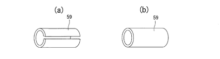
そして、シリンダ側通路51とサイドブロック側通路52とは、シリンダ12とフロント側サイドブロック21とを位置決めする位置決めピン59に設けられた通孔59aを介して連通されている。
この位置決めピン59は、スプリングピン(割ピン)によって形成されており、シリンダ側通路51の軸方向通路孔54に圧入され、フロント側サイドブロック21に形成され第1の軸方向通路孔55に遊嵌されている。また、この例においては、位置決めピン59を設けた箇所によって、高圧導入通路50が絞られることないよう、軸方向通路孔54の位置決めピン59を圧入する領域は、幾分径が大きく形成されており、位置決めピン59の内径が高圧導入通路50の他の箇所の内径とほぼ等しくなるようになっている。
The
The
また、第2の軸方向通路孔56は、ベーン溝8の底部に設けられた背圧室8aと連通可能となっており、特に、この例では、ベーン4の先端部が吐出ポート16の中程からラジアルシール部40までの範囲にある行程において、ベーン溝8の底部(背圧室8a)と連通するように形成されている。
The second
したがって、ベーン溝8の底部(背圧室8a)がオイル導入溝41に連通すると、オイル導入通路19を介してオイル溜まり室18から供給された吐出圧力に相当するオイルが背圧室8aに送り込まれる。そして、ベーン溝8の底部(背圧室8a)が高圧導入通路50の第2の軸方向通路孔56に連通すると、高圧導入通路50を介して吐出流体収容室32から供給された吐出流体が背圧室8aに直接送り込まれる。
Accordingly, when the bottom portion (back
以上の構成において、圧縮機1が起動してロータ3が回転し始めると、圧縮室31で圧縮した吐出ガスが吐出ポート16を介して吐出流体収容室32に吐出されるが、起動初期においては、吐出圧が十分に大きくなく、また、吐出圧によりオイル溜まり室18からオイル導入通路19を介してオイル導入溝41に送り込まれるオイルは、その粘性抵抗等のため、起動後ただちにベーン4に対して十分な背圧力を供給することができない。しかし、ベーン4の先端部がシリンダ12の内周面(カム面11)から離れやすい吐出ポート16(座ぐり16a)の中程から、ベーン溝8の底部(背圧室8a)は高圧導入通路50と連通し、このベーン溝8の底部(背圧室8a)に吐出ガスが直接導入される。このように、吐出ガスを圧縮機1の起動後ただちに高圧導入通路50を介して直接背圧室8aに供給することで、ベーン4の先端部が吐出ポート16を通過する場合でも、ベーン4はシリンダ12の内周面(カム面11)に安定して押し付けられ、ベーン4がシリンダ12の内周面(カム面11)から離れて再び着地することで生じる衝突音(チャタリングノイズ)を無くすことが可能となる。
In the above configuration, when the
特に、ロータ3のフロント側の端面とフロント側サイドブロック21とのクリアランスは、駆動軸2の両端に作用する圧力差に起因するフロント側への付勢力によって小さくなっているため、吐出流体収容室32から供給される吐出流体は、ロータ3のフロント側の端面とフロント側サイドブロック21との間から漏出することは殆どなく、ベーン溝8の底部(背圧室8a)へ効果的に導入される。このため、高圧導入通路50をリア側に設けた場合と比べてチャタリングの発生をより効果的に抑制することが可能となる。
In particular, the clearance between the front end face of the
また、ロータ3のフロント側の端面とフロント側サイドブロック21との間のクリアランスを介して吐出流体が漏出する虞が殆どないため、吐出流体を高圧導入通路50を介して供給しても、この間のオイルによるシール効果を損なう虞はない。逆に、吐出流体収容室32からオイル分離器を経由せずに吐出流体がロータ3のフロント側端面に供給されるので、吐出流体中のオイルを供給することができ、オイルによる良好なシール効果を維持することが可能となる。
Further, since there is almost no risk of the discharge fluid leaking through the clearance between the front side end face of the
ところで、上述した構成においては、高圧導入通路50をフロント側に設けたので、高圧導入通路50は、シリンダ12とフロント側サイドブロック21とを跨いで形成される必要がある。このため、本来であれば、シリンダ12とフロント側サイドブロック21との突き合わせ部分に、高圧導入通路50を形成する箇所と、シリンダ12とフロント側サイドブロック21とを位置決めする位置決めピン59の装着箇所とを確保する必要がある。しかしながら、上述した構成においては、位置決めピン59を筒状形状として高圧導入通路50の一部としたので、第1の軸方向通路孔55の形成位置に位置決めピン59を移動させるか、既存の位置決めピンの装着箇所に第1の軸方向通路を形成すればよく、高圧導入通路50のレイアウトの自由度を大きくすることが可能となる。
In the configuration described above, the high
なお、以上の構成においては、ベーン4が2枚の場合の圧縮機について説明したが、3枚以上のベーン型圧縮機においても、同様の構成を採用することが可能である。
また、上述の構成においては、位置決めピン59としてスプリングピンを設けた例を示したが、図5(b)に示されるように、円筒状のピンを用いてもよい。
In the above configuration, the compressor in the case where there are two
In the above-described configuration, the spring pin is provided as the
1 ベーン型圧縮機
2 駆動軸
3 ロータ
4 ベーン
5 ハウジング
8 ベーン溝
8a 背圧室
10 第1のハウジング部材
11 カム面
12 シリンダ
13 リア側サイドブロック
15 吸入ポート
16 吐出ポート
17 吐出室
18 オイル室
19 オイル連通路
20 第2のハウジング部材
21 フロント側サイドブロック
31 圧縮室
32 吐出流体収容室
50 高圧導入通路
51 シリンダ側通路
52 サイドブロック側通路
59 位置決めピン
DESCRIPTION OF
DESCRIPTION OF
Claims (5)
カム面が内周面に形成され、前記ハウジングの一部を構成するシリンダと、
前記シリンダの軸方向の両端を閉塞し、前記ハウジングの一部を構成するフロント側及びリア側の一対のサイドブロックと、
前記一対のサイドブロックに回転自在に支持された駆動軸と、前記駆動軸に固装されて前記シリンダに回転可能に収容されるロータと、
前記ロータの外周面の一部と前記シリンダの内周面の一部が摺接するラジアルシール部と、
前記ロータに形成された複数のベーン溝と、前記ベーン溝に摺動自在に挿入され、先端部が前記ベーン溝から出没して前記カム面を摺動する複数のベーンと、
前記シリンダと前記一対のサイドブロックとにより閉塞された空間に、前記ロータと前記ベーンによって画成される圧縮室と、
前記圧縮室に流体を吸入する吸入ポートと、前記圧縮室で圧縮された前記流体を吐出する吐出ポートと、
前記吐出ポートから吐出された流体を収容する吐出流体収容室と、
を備えたベーン型圧縮機において、
前記吐出流体収容室に一端が接続され、他端がロータのフロント側の端面に臨み、前記ベーンの先端部が前記吐出ポートの中程から前記ラジアルシール部までの範囲にある行程において、前記ベーン溝の底部と連通する高圧導入通路を設けたことを特徴とするベーン型圧縮機。 A housing;
A cylinder having a cam surface formed on an inner peripheral surface and constituting a part of the housing;
A pair of side blocks on the front side and rear side that close both ends in the axial direction of the cylinder and constitute a part of the housing;
A drive shaft rotatably supported by the pair of side blocks; a rotor fixed to the drive shaft and rotatably accommodated in the cylinder;
A radial seal portion in which a part of the outer peripheral surface of the rotor and a part of the inner peripheral surface of the cylinder are in sliding contact;
A plurality of vane grooves formed in the rotor, and a plurality of vanes which are slidably inserted into the vane grooves, and whose tip ends slide out of the vane grooves and slide on the cam surface;
A compression chamber defined by the rotor and the vane in a space closed by the cylinder and the pair of side blocks;
A suction port for sucking fluid into the compression chamber; a discharge port for discharging the fluid compressed in the compression chamber;
A discharge fluid storage chamber for storing the fluid discharged from the discharge port;
In a vane compressor equipped with
In the stroke in which one end is connected to the discharge fluid storage chamber, the other end faces the end surface on the front side of the rotor, and the tip of the vane is in the range from the middle of the discharge port to the radial seal portion. A vane type compressor having a high-pressure introduction passage communicating with a bottom of a groove.
少なくとも一方のサイドブロックの前記圧縮室側の端面に、前記ベーンの先端部が前記ラジアルシール部から前記吐出ポートの手前までの範囲にある行程において、前記ベーン溝の底部と連通するオイル導入溝と、
前記オイル溜まり室と前記オイル導入溝とを連通するオイル導入通路と、
が更に設けられていることを特徴とする請求項1記載のベーン型圧縮機。 An oil reservoir chamber for storing oil having a pressure corresponding to the pressure of the fluid discharged from the discharge port;
An oil introduction groove communicating with the bottom of the vane groove in a stroke in which the tip of the vane is in a range from the radial seal portion to the front of the discharge port on the end surface of the compression chamber side of at least one side block; ,
An oil introduction passage communicating the oil reservoir chamber and the oil introduction groove;
The vane type compressor according to claim 1, further comprising:
前記シリンダ側通路と前記サイドブロック側通路とは、前記シリンダと前記フロント側サイドブロックとを位置決めする位置決めピンに設けられた通孔を介して連通していることを特徴とする請求項1又は2に記載のベーン型圧縮機。 The high pressure introduction passage includes a cylinder side passage formed in the cylinder communicating with the discharge fluid storage chamber, and a side block side passage formed in the front side block facing the front end surface of the rotor. Formed by connecting,
3. The cylinder side passage and the side block side passage communicate with each other via a through hole provided in a positioning pin for positioning the cylinder and the front side block. The vane type compressor described in 1.
Priority Applications (2)
| Application Number | Priority Date | Filing Date | Title |
|---|---|---|---|
| JP2017127070A JP2019011682A (en) | 2017-06-29 | 2017-06-29 | Vane compressor |
| EP18179689.7A EP3421718A1 (en) | 2017-06-29 | 2018-06-25 | Vane type compressor |
Applications Claiming Priority (1)
| Application Number | Priority Date | Filing Date | Title |
|---|---|---|---|
| JP2017127070A JP2019011682A (en) | 2017-06-29 | 2017-06-29 | Vane compressor |
Publications (1)
| Publication Number | Publication Date |
|---|---|
| JP2019011682A true JP2019011682A (en) | 2019-01-24 |
Family
ID=62784043
Family Applications (1)
| Application Number | Title | Priority Date | Filing Date |
|---|---|---|---|
| JP2017127070A Pending JP2019011682A (en) | 2017-06-29 | 2017-06-29 | Vane compressor |
Country Status (2)
| Country | Link |
|---|---|
| EP (1) | EP3421718A1 (en) |
| JP (1) | JP2019011682A (en) |
Family Cites Families (5)
| Publication number | Priority date | Publication date | Assignee | Title |
|---|---|---|---|---|
| JPS58104381U (en) * | 1981-12-08 | 1983-07-15 | セイコ−精機株式会社 | gas compressor |
| JPS5968587A (en) * | 1982-10-13 | 1984-04-18 | Toyoda Autom Loom Works Ltd | Compressor |
| JPS60192891A (en) * | 1984-03-14 | 1985-10-01 | Hitachi Ltd | Vane type compressor |
| JPS62153587A (en) * | 1985-12-27 | 1987-07-08 | Nissan Motor Co Ltd | Rotary compressor |
| JP6174879B2 (en) | 2013-03-27 | 2017-08-02 | 株式会社ヴァレオジャパン | Vane type compressor |
-
2017
- 2017-06-29 JP JP2017127070A patent/JP2019011682A/en active Pending
-
2018
- 2018-06-25 EP EP18179689.7A patent/EP3421718A1/en not_active Withdrawn
Also Published As
| Publication number | Publication date |
|---|---|
| EP3421718A1 (en) | 2019-01-02 |
Similar Documents
| Publication | Publication Date | Title |
|---|---|---|
| JP2014125962A (en) | Gas compressor | |
| JP6174879B2 (en) | Vane type compressor | |
| JP5708570B2 (en) | Vane type compressor | |
| JP6852636B2 (en) | Vane compressor | |
| JP5120721B2 (en) | Vane type compressor | |
| JP6083408B2 (en) | Vane type compressor | |
| WO2011080924A1 (en) | Lubricating oil supply structure of vane-type compressor | |
| WO2013183609A1 (en) | Gas compressor | |
| JP2019011682A (en) | Vane compressor | |
| JP4684832B2 (en) | Gas compressor | |
| JP2008169811A (en) | Gas compressor | |
| JP2007100602A (en) | Gas compressor | |
| JP6242606B2 (en) | Vane type compressor | |
| JP2007327376A (en) | Gas compressor | |
| WO2014203879A1 (en) | Vane compressor | |
| WO2017111012A1 (en) | Vane compressor | |
| JP2014001710A (en) | Tandem vane type compressor | |
| JP2014125960A (en) | Gas compressor | |
| JP2018141430A (en) | Vane type compressor | |
| JP7272310B2 (en) | vane compressor | |
| JP6098265B2 (en) | Compressor | |
| JP2013249768A (en) | Gas compressor | |
| JP2014218961A (en) | Vane type compressor | |
| JP2004052607A (en) | Gas compressor | |
| JP2008014227A (en) | Gas compressor |