JP2018519631A - Occupied message communication in wireless networked lighting system - Google Patents
Occupied message communication in wireless networked lighting system Download PDFInfo
- Publication number
- JP2018519631A JP2018519631A JP2017564805A JP2017564805A JP2018519631A JP 2018519631 A JP2018519631 A JP 2018519631A JP 2017564805 A JP2017564805 A JP 2017564805A JP 2017564805 A JP2017564805 A JP 2017564805A JP 2018519631 A JP2018519631 A JP 2018519631A
- Authority
- JP
- Japan
- Prior art keywords
- area
- light
- controller
- amount
- lamp
- Prior art date
- Legal status (The legal status is an assumption and is not a legal conclusion. Google has not performed a legal analysis and makes no representation as to the accuracy of the status listed.)
- Granted
Links
Images

Classifications
-
- H—ELECTRICITY
- H05—ELECTRIC TECHNIQUES NOT OTHERWISE PROVIDED FOR
- H05B—ELECTRIC HEATING; ELECTRIC LIGHT SOURCES NOT OTHERWISE PROVIDED FOR; CIRCUIT ARRANGEMENTS FOR ELECTRIC LIGHT SOURCES, IN GENERAL
- H05B47/00—Circuit arrangements for operating light sources in general, i.e. where the type of light source is not relevant
- H05B47/10—Controlling the light source
- H05B47/175—Controlling the light source by remote control
- H05B47/19—Controlling the light source by remote control via wireless transmission
-
- H—ELECTRICITY
- H05—ELECTRIC TECHNIQUES NOT OTHERWISE PROVIDED FOR
- H05B—ELECTRIC HEATING; ELECTRIC LIGHT SOURCES NOT OTHERWISE PROVIDED FOR; CIRCUIT ARRANGEMENTS FOR ELECTRIC LIGHT SOURCES, IN GENERAL
- H05B47/00—Circuit arrangements for operating light sources in general, i.e. where the type of light source is not relevant
- H05B47/10—Controlling the light source
- H05B47/105—Controlling the light source in response to determined parameters
- H05B47/11—Controlling the light source in response to determined parameters by determining the brightness or colour temperature of ambient light
-
- H—ELECTRICITY
- H05—ELECTRIC TECHNIQUES NOT OTHERWISE PROVIDED FOR
- H05B—ELECTRIC HEATING; ELECTRIC LIGHT SOURCES NOT OTHERWISE PROVIDED FOR; CIRCUIT ARRANGEMENTS FOR ELECTRIC LIGHT SOURCES, IN GENERAL
- H05B47/00—Circuit arrangements for operating light sources in general, i.e. where the type of light source is not relevant
- H05B47/10—Controlling the light source
- H05B47/105—Controlling the light source in response to determined parameters
- H05B47/115—Controlling the light source in response to determined parameters by determining the presence or movement of objects or living beings
-
- Y—GENERAL TAGGING OF NEW TECHNOLOGICAL DEVELOPMENTS; GENERAL TAGGING OF CROSS-SECTIONAL TECHNOLOGIES SPANNING OVER SEVERAL SECTIONS OF THE IPC; TECHNICAL SUBJECTS COVERED BY FORMER USPC CROSS-REFERENCE ART COLLECTIONS [XRACs] AND DIGESTS
- Y02—TECHNOLOGIES OR APPLICATIONS FOR MITIGATION OR ADAPTATION AGAINST CLIMATE CHANGE
- Y02B—CLIMATE CHANGE MITIGATION TECHNOLOGIES RELATED TO BUILDINGS, e.g. HOUSING, HOUSE APPLIANCES OR RELATED END-USER APPLICATIONS
- Y02B20/00—Energy efficient lighting technologies, e.g. halogen lamps or gas discharge lamps
- Y02B20/40—Control techniques providing energy savings, e.g. smart controller or presence detection
Landscapes
- Engineering & Computer Science (AREA)
- Computer Networks & Wireless Communication (AREA)
- Circuit Arrangement For Electric Light Sources In General (AREA)
- Mobile Radio Communication Systems (AREA)
Abstract
装置10は、第1エリア1内のターゲットの存在を検出するためのターゲット検出器11と、検出された存在に応じて、無線ネットワーク化照明システム内のコントローラ20、及びランプ21乃至24にマルチキャストメッセージを送信するための送信機12とを有する。このようなマルチキャストメッセージは、前記システムの信頼性を高める。前記マルチキャストメッセージは、前記ランプ21乃至24をオンに切り替える。好ましくは、前記マルチキャストメッセージは、第2エリア2において相対的に少ない量の光が検出される場合にしか、送信されない。前記第2エリア2において相対的に多くの量の光が検出される場合には、検出された存在に応じて、前記装置10から前記コントローラ20にユニキャストメッセージが送信され、前記コントローラ20は、それに応じて、前記ランプ21乃至24をオンに切り替えられるよう制御する。前記第1エリア1及び前記第2エリア2は、少なくとも部分的に重なり合っているエリアであってもよい。前記装置10は、前記第2エリア2内の光の量を検出するための内蔵光検出器13、又は外部光検出器から光検出情報を受信するための受信機を有してもよい。The device 10 has a target detector 11 for detecting the presence of a target in the first area 1 and a multicast message to the controller 20 and the lamps 21 to 24 in the wireless networked lighting system according to the detected presence. And a transmitter 12 for transmitting. Such a multicast message increases the reliability of the system. The multicast message switches the lamps 21 to 24 on. Preferably, the multicast message is transmitted only when a relatively small amount of light is detected in the second area 2. When a relatively large amount of light is detected in the second area 2, a unicast message is transmitted from the device 10 to the controller 20 according to the detected presence, and the controller 20 Accordingly, the lamps 21 to 24 are controlled to be turned on. The first area 1 and the second area 2 may be areas that overlap at least partially. The device 10 may have a built-in photodetector 13 for detecting the amount of light in the second area 2 or a receiver for receiving light detection information from an external photodetector.
Description
本発明は、コントローラ及びランプを有する無線ネットワーク化照明システムの一部を形成するよう構成される装置に関する。本発明は、このような装置を有すると共に、前記コントローラ及び/又は1つ以上のランプを更に有するシステム、並びに方法に関する。このような装置の例は、占有センサ(occupancy sensor)、及びこのような占有センサを有するランプである。 The present invention relates to an apparatus configured to form part of a wireless networked lighting system having a controller and a lamp. The invention relates to a system and method comprising such a device and further comprising the controller and / or one or more lamps. Examples of such devices are occupancy sensors and lamps having such occupancy sensors.
WO 2006 / 065653 A2は、分散インテリジェンスバラストシステム及び拡張照明制御プロトコルを開示している。その0147に記載されているように、電力及び制御が、インテリジェント装置の間で分散されており、故に、コントローラの故障は、ネットワーク全体の故障を引き起こさない。それに加えて、バラストが、向上されたインテリジェンスを得ている。 拡張プロトコルが使用可能である有線ネットワーク上の各装置(バラスト)は、コントローラの役割を果たし得る。 WO 2006/065653 A2 discloses a distributed intelligence ballast system and an extended lighting control protocol. As described in that 0147, power and control are distributed among intelligent devices, so controller failures do not cause network-wide failures. In addition, ballast has gained improved intelligence. Each device (ballast) on the wired network where the extension protocol can be used can act as a controller.
一般に、無線ネットワーク化スマート照明システムなどの無線ネットワーク化照明システムは、中央コントローラと、分散検出装置と、分散ランプとを有する。分散検出装置は、検出結果を備える第1メッセージを集中コントローラに送信する。中央コントローラは、この第1メッセージに応じて、いくつかの分散ランプに、これらの分散ランプを制御するために、1つ以上の第2メッセージを送信する。 In general, a wireless networked lighting system, such as a wireless networked smart lighting system, includes a central controller, a distributed detection device, and a distributed lamp. The distributed detection apparatus transmits a first message including a detection result to the centralized controller. In response to this first message, the central controller sends one or more second messages to several distributed lamps to control these distributed lamps.
検出装置から中央コントローラに送信された第1メッセージが失われる又は遅れる場合には、前記幾つかのランプがオンに切り替えられない又はあまりに遅くオンに切り替えられるという問題がある。 If the first message sent from the detection device to the central controller is lost or delayed, there is a problem that some of the lamps are not switched on or switched on too late.
WO 01 / 11926 A1は、無線遠隔センサを含む照明制御システムを開示している。 WO 01/11926 A1 discloses a lighting control system including a wireless remote sensor.
本発明の目的は、改善された装置を提供することである。本発明の他の目的は、システム及び改善された方法を提供することである。 An object of the present invention is to provide an improved apparatus. Another object of the present invention is to provide a system and an improved method.
第1の態様によれば、装置が提供され、前記装置は、コントローラ及びランプを有する無線ネットワーク化照明システムの一部を形成するよう構成され、前記装置は、
− 第1エリア内のターゲットの存在を検出するよう構成されるターゲット検出器と、
− 前記装置が高速応答の必要性を確認するときには、前記第1エリア内の前記ターゲットの存在の検出に応じて、前記コントローラ、及び前記ランプのうちの1つ以上にマルチキャストメッセージを送信し、前記装置が、相対的によりゆっくりとした応答が許容可能であることを確認するときには、前記コントローラにユニキャストメッセージを送信するよう構成される送信機とを有する。
According to a first aspect, an apparatus is provided, wherein the apparatus is configured to form part of a wireless networked lighting system having a controller and a lamp, the apparatus comprising:
A target detector configured to detect the presence of a target in the first area;
-When the device confirms the need for fast response, in response to detecting the presence of the target in the first area, sends a multicast message to the controller and one or more of the lamps; A transmitter configured to send a unicast message to the controller when confirming that a relatively slower response is acceptable.
上記のような装置は、上記のようにして、幾つかのランプが、オンに切り替わらないこと、又は高速切り替えの必要性があるときに遅れてオンに切り替わることをもたらし得るメッセージ損失又は遅延の影響を打ち消すよう、マルチキャスト又はユニキャストアプローチのいずれかの形態でメッセージ通信ポリシーを選択することを可能にする。 Such a device, as described above, has the effect of message loss or delay which can result in some lamps not switching on or switching on late when there is a need for fast switching. It is possible to select a message communication policy in either form of a multicast or unicast approach to cancel.
装置が提供され、前記装置は、コントローラ及びランプを有する無線ネットワーク化照明システムの一部を形成するよう構成される。このような無線ネットワーク化照明システムの例は、無線ネットワーク化スマート照明システムであり、前記コントローラは、中央コントローラであり、前記ランプは、分散ランプである。前記装置は、第1エリア内のターゲットの存在を検出するよう構成されるターゲット検出器を有すると共に、前記第1エリア内の前記ターゲットの存在の検出に応じて、前記コントローラ、及び前記ランプのうちの1つ以上にマルチキャストメッセージを送信するよう構成される送信機を有する。このような送信は、無線プロトコルによる無線送信であり、このような送信機は、無線送信機である。このような無線プロトコルの例は、ZigBee(登録商標)及び6LoWPANであるが、他の種類の無線プロトコルを除外してはいない。 An apparatus is provided and is configured to form part of a wireless networked lighting system having a controller and a lamp. An example of such a wireless networked lighting system is a wireless networked smart lighting system, where the controller is a central controller and the lamp is a distributed lamp. The apparatus includes a target detector configured to detect the presence of a target in a first area, and in response to detecting the presence of the target in the first area, the controller and the lamp A transmitter configured to transmit a multicast message to one or more of the. Such transmission is wireless transmission according to a wireless protocol, and such a transmitter is a wireless transmitter. Examples of such wireless protocols are ZigBee® and 6LoWPAN, but do not exclude other types of wireless protocols.
前記装置から相対的に遠くに位置し得る前記コントローラ、及び前記装置の相対的に近くに位置し得る前記ランプのうちの1つ以上にマルチキャストメッセージを送信することによって、より短い並列メッセージ通信ルートが作成されている。結果として、前記第1エリア内の前記ターゲットの存在の検出がランプに知らされない又はあまりに遅くに知らされる可能性は減らされる。このような装置は、前記無線ネットワーク化照明システムの信頼性を高める。これは、大きな技術的利点である。前記ターゲットは人間又は畜牛のような動物であってもよいことに注意されたい。前記ターゲットは、物体、例えば、車又はオートバイのような車両であってもよい。WO 2006 / 065653 A2は、人間検出器及び無線送信機を有する装置からコントローラ及び1つ以上のランプへのマルチキャストメッセージの無線送信を開示していない。WO 2006 / 065653 A2において、有線ネットワークは、シリアル電力バス及びシリアル制御バスをベースにしている。 By sending a multicast message to one or more of the controller that may be located relatively far from the device and the lamp that may be located relatively close to the device, a shorter parallel message communication route is achieved. Has been created. As a result, the possibility that the detection of the presence of the target in the first area is not informed to the lamp or too late is reduced. Such a device increases the reliability of the wireless networked lighting system. This is a great technical advantage. Note that the target may be an animal such as a human or cattle. The target may be an object, for example a vehicle such as a car or a motorcycle. WO 2006/065653 A2 does not disclose wireless transmission of multicast messages from a device having a human detector and a wireless transmitter to a controller and one or more lamps. In WO 2006/065653 A2, the wired network is based on a serial power bus and a serial control bus.
前記第1エリアは、例えば、ビルの部屋、又はビルのフロア(の一部)、又はビル(の一部)、又は道路(の一部)、又は船の船室、又は船の甲板(の一部)、又は船(の一部)などであり得る。 The first area may be, for example, a building room, a building floor (part), a building (part), a road (part), a ship cabin, or a ship deck. Part), or a ship (part).
前記マルチキャストメッセージが、前記1つ以上のランプのうちの少なくとも1つのランプをオンに切り替えるよう構成される、前記装置の実施例が規定されている。前記第1エリア内の前記ターゲットの存在の検出に応じて、前記マルチキャストメッセージを受信した前記ランプのうちの少なくとも1つは、オンに切り替えられる。ランプをオンに切り替えることは、前記ランプの光強度をゼロレベルからゼロより大きい如何なるレベルへ増加させることも含み得る。 An embodiment of the apparatus is defined wherein the multicast message is configured to switch on at least one of the one or more lamps. In response to detecting the presence of the target in the first area, at least one of the lamps that has received the multicast message is switched on. Switching on the lamp may include increasing the light intensity of the lamp from zero level to any level greater than zero.
前記マルチキャストメッセージが、装置識別、1つ以上のランプ識別、コントローラ識別、及び検出結果を有する、前記装置の実施例が規定されている。装置識別は、前記装置を、前記マルチキャストメッセージを送信する供給源と特定する。ランプ識別は、特定のランプを、前記マルチキャストメッセージを受信する宛先のうちの1つと特定する。コントローラ識別は、前記コントローラを、前記マルチキャストメッセージを受信する宛先のうちの1つと特定する。検出結果は、前記第1エリア内の前記ターゲットの不在から存在への変化などの、検出の種類を規定する。前記マルチキャストメッセージは、更に、この第1エリアを規定し得る。 An embodiment of the device is defined in which the multicast message has a device identification, one or more lamp identifications, a controller identification, and a detection result. Device identification identifies the device as the source sending the multicast message. Lamp identification identifies a particular lamp as one of the destinations that receive the multicast message. The controller identification identifies the controller as one of the destinations receiving the multicast message. The detection result defines the type of detection, such as a change from absence to presence of the target in the first area. The multicast message may further define this first area.
前記送信機が、第2エリアにおいて第1の量の光が検出される場合は、前記コントローラ、及び前記ランプのうちの前記1つ以上に前記マルチキャストメッセージを送信するよう構成され、前記送信機が、前記第2エリアにおいて第2の量の光が検出される場合は、前記第1エリア内の前記ターゲットの存在の検出に応じて、前記コントローラに前記ユニキャストメッセージを送信するよう構成され、前記第1の量の光が、しきい値より少なく、前記第2の量の光が、前記しきい値より多く、前記第1エリア及び前記第2エリアが、少なくとも部分的に重なり合っているエリアである、前記装置の実施例が規定されている。前記第1エリアと部分的に又は完全に一致していてもよい第2エリアにおいて、光の量が検出される。前記第2エリアにおいて相対的に少ない第1の量の光が検出される場合には、前記第1/第2エリアの中/近くにある1つ以上のランプをオンに切り替えることは、前記第1エリアに入るターゲットにとって相対的に重要であり、前記ランプに十分に通知される可能性を高めるために、前記コントローラ、及び前記ランプのうちの1つ以上に、前記マルチキャストメッセージが送信される。前記第2エリアにおいて相対的に多い第2の量の光が検出される場合には、前記第1/第2エリアの中/近くにある1つ以上のランプをオンに切り替えることは、前記第1エリアに入るターゲットにとって相対的に重要ではなく、前記ユニキャストメッセージが前記コントローラだけに送信され得る。前記相対的に少ない第1の量の光は、しきい値より少なく、前記相対的に多い第2の量の光は、前記しきい値より多い。更に、前記量の光のうちの一方は、前記しきい値と同じであってもよい。 The transmitter is configured to transmit the multicast message to the controller and the one or more of the lamps when a first amount of light is detected in a second area; Configured to send the unicast message to the controller in response to detecting the presence of the target in the first area when a second amount of light is detected in the second area, In an area where the first amount of light is less than a threshold, the second amount of light is greater than the threshold, and the first area and the second area at least partially overlap. An embodiment of the device is defined. The amount of light is detected in a second area that may partially or completely coincide with the first area. If a relatively small first amount of light is detected in the second area, switching on one or more lamps in / near the first / second area is on the first The multicast message is sent to the controller and to one or more of the lamps in order to increase the likelihood of being well informed to the lamps, which is relatively important for targets entering one area. If a relatively large second amount of light is detected in the second area, switching on one or more lamps in / near the first / second area is on the first Relatively unimportant for targets entering one area, the unicast message may be sent only to the controller. The relatively small first amount of light is less than a threshold, and the relatively large second amount of light is greater than the threshold. Further, one of the amounts of light may be the same as the threshold value.
通常、前記第2エリアにおける光の量を検出することを可能にするためには、光検出器が用いられる。このような光検出器は、内蔵検出器であってもよく、前記装置の一部を形成してもよく、前記第2エリアにおける光の量を規定する光検出情報を前記装置に供給してもよい。他の例においては、このような光検出器は、外部検出器であってもよく、前記装置の外部に位置していてもよく、その場合には、前記装置には、前記第2エリアにおける光の量を規定する前記光検出情報を前記外部光検出器から受信するための受信機が設けられるべきである。いずれの場合にも、前記マルチキャストメッセージは、検出された光の量及び/又はランプ設定を更に規定し得る。 Usually, a photodetector is used to make it possible to detect the amount of light in the second area. Such a light detector may be a built-in detector, may form part of the device, and supplies the device with light detection information defining the amount of light in the second area. Also good. In another example, such a light detector may be an external detector and may be located outside the device, in which case the device is in the second area. A receiver for receiving the light detection information defining the amount of light from the external light detector should be provided. In any case, the multicast message may further define the amount of light detected and / or lamp settings.
前記装置が、占有センサを有する、前記装置の実施例が規定されている。前記装置は、占有センサの形態で製造などをされ得る。 An embodiment of the device is defined, wherein the device has an occupancy sensor. The device may be manufactured in the form of an occupancy sensor.
前記装置が、ランプを有し、前記送信機が、前記コントローラ、及び他のランプのうちの1つ以上に前記マルチキャストメッセージを送信するよう構成される、前記装置の実施例が規定されている。前記装置は、ランプの形態で製造などをされ得る。 An embodiment of the apparatus is defined wherein the apparatus comprises a lamp and the transmitter is configured to transmit the multicast message to one or more of the controller and other lamps. The device may be manufactured in the form of a lamp.
前記ランプが、前記第1エリア内の前記ターゲットの存在の検出に応じて、オンに切り替えられるよう構成され、前記マルチキャストメッセージが、前記1つ以上の他のランプのうちの少なくとも1つのランプをオンに切り替えるよう構成される、前記装置の実施例が規定されている。 The lamp is configured to be turned on in response to detecting the presence of the target in the first area, and the multicast message turns on at least one of the one or more other lamps. An embodiment of said device is defined, which is configured to switch to
前記マルチキャストメッセージが、ランプ識別、1つ以上の他のランプ識別、コントローラ識別、及び検出結果を有する、前記装置の実施例が規定されている。 An embodiment of the apparatus is defined wherein the multicast message comprises a lamp identification, one or more other lamp identifications, a controller identification, and a detection result.
前記ランプが、昼光モードにおいて、オンに切り替えられた後に最低調光レベルにとどまるよう構成される、又はオフに切り替えられないよう構成される、前記装置の実施例が規定されている。前記ランプは、前記ランプの内蔵光検出器によって前記昼光モードそれ自体を検出してもよく、又は別のランプ、外部光検出器若しくは前記コントローラによって、前記昼光モードを知らされてもよい。 An embodiment of the device is defined in which the lamp is configured to remain at a minimum dimming level after being switched on or not switched off in daylight mode. The lamp may detect the daylight mode itself by a built-in light detector of the lamp, or may be informed of the daylight mode by another lamp, an external light detector or the controller.
前記送信機が、第2エリアにおいて第1の量の光が検出される場合は、前記コントローラ、及び前記他のランプのうちの前記1つ以上に前記マルチキャストメッセージを送信するよう構成され、前記送信機が、前記第2エリアにおいて第2の量の光が検出される場合は、前記第1エリア内の前記ターゲットの存在の検出に応じて、前記コントローラに前記ユニキャストメッセージを送信するよう構成され、前記第1の量の光が、しきい値より少なく、前記第2の量の光が、前記しきい値より多く、前記第1エリア及び前記第2エリアが、少なくとも部分的に重なり合っているエリアである、前記装置の実施例が規定されている。 The transmitter is configured to transmit the multicast message to the controller and the one or more of the other lamps when the first amount of light is detected in a second area, the transmission A device is configured to send the unicast message to the controller in response to detecting the presence of the target in the first area when a second amount of light is detected in the second area. The first amount of light is less than a threshold, the second amount of light is greater than the threshold, and the first area and the second area at least partially overlap. An embodiment of the device, which is an area, is defined.
前記第2エリア内の光の量を検出するよう構成される内蔵光検出器、又は前記第2エリア内の光の量を検出するよう構成される外部光検出器から光検出情報を受信するよう構成される受信機を更に有する、前記装置の実施例が規定されている。 Receiving light detection information from a built-in photodetector configured to detect the amount of light in the second area, or from an external photodetector configured to detect the amount of light in the second area. An embodiment of the device is further defined, further comprising a configured receiver.
前記第2エリアにおいて検出された光の量に対するランプ設定を算出するよう構成される計算機を更に有する、前記装置の実施例が規定されている。 An embodiment of the apparatus is further defined, further comprising a computer configured to calculate a lamp setting for the amount of light detected in the second area.
通常、ランプ設定を算出するための計算機は、占有センサ又はランプの一部を形成することができ、それによって、前記占有センサ又は前記ランプは、両方とも上で記述されている、前記第2エリアにおいて検出される光の量を知らされるための、前記内蔵光検出器又は前記受信機を更に有し得る。 Typically, the calculator for calculating the lamp settings can form part of an occupancy sensor or lamp, whereby the occupancy sensor or lamp is both described above. It may further comprise the built-in photodetector or the receiver for being informed of the amount of light detected at.
第2の態様によれば、上記のような装置を有すると共に、前記コントローラ、及び/又は前記ランプのうちの1つ以上を更に有するシステムが提供される。 According to a second aspect, there is provided a system comprising the device as described above and further comprising one or more of the controller and / or the lamp.
前記ランプが、オンに切り替えられた後に最低調光レベルにとどまるよう構成される、又はオフに切り替えられないよう構成される実施例は、占有センサ又はランプの形態の装置が内蔵又は外部光検出器からの光検出情報にアクセスできない場合に、とりわけ有利である。その場合、前記ランプは、前記ランプ自身の状態(オン又はオフ)に応じて、前記マルチキャストメッセージに反応するよう決定し得る。従って、前記装置及び前記コントローラが前記光検出情報を入手可能であるか、前記コントローラのみが前記光検出情報を入手可能であるかに依存して、異なる状況があり得る。前記装置が前記光検出情報にアクセスできる場合には、前記装置は、前記コントローラにユニキャストメッセージを送信することを、又は前記コントローラ及び少なくとも1つの(他の)ランプにマルチキャストメッセージを送信することを決定することができる。前記装置が前記光検出情報にアクセスできない場合には、前記装置は、前記コントローラ及び少なくとも1つの(他の)ランプにマルチキャストメッセージを送信し、前記ランプは、次いで、オンに切り替えられた後に最低調光レベルにとどまることができる、又は次いで、オフに切り替えられないことができる。 Embodiments in which the lamp is configured to remain at a minimum dimming level after being switched on, or not to be switched off, can be implemented in a device in the form of an occupancy sensor or lamp, or an external photodetector. This is particularly advantageous when the light detection information from is not accessible. In that case, the lamp may decide to react to the multicast message depending on its own state (on or off). Thus, there can be different situations depending on whether the device and the controller can obtain the light detection information or only the controller can obtain the light detection information. If the device has access to the light detection information, the device sends a unicast message to the controller or sends a multicast message to the controller and at least one (other) lamp. Can be determined. If the device does not have access to the light detection information, the device sends a multicast message to the controller and at least one (other) lamp, and the lamp is then turned off after being switched on. It can remain at the light level or it can then not be switched off.
第3の態様によれば、コントローラ及びランプを有する無線ネットワーク化照明システムを動作させる方法が提供され、前記方法は、第1エリア内のターゲットの存在を検出するステップと、高速応答の必要性が確認されるときには、前記第1エリア内の前記ターゲットの存在の検出に応じて、前記コントローラ、及び前記ランプのうちの1つ以上にマルチキャストメッセージを送信し、相対的によりゆっくりとした応答が許容可能であることが確認される場合には、前記第1エリア内の前記ターゲットの存在の検出に応じて、前記コントローラにユニキャストメッセージを送信するステップとを有する。 According to a third aspect, there is provided a method of operating a wireless networked lighting system having a controller and a lamp, said method detecting the presence of a target in the first area and the need for a fast response. When confirmed, a multicast message is sent to one or more of the controller and the lamp in response to detecting the presence of the target in the first area, allowing a relatively slower response A unicast message is sent to the controller in response to detection of the presence of the target in the first area.
前記システム及び前記方法の実施例は、前記装置の実施例と一致する。更に、前記装置の実施例(の一部)及び前記装置の別の実施例(の一部)は組み合わされ得る。 Embodiments of the system and the method are consistent with embodiments of the apparatus. Furthermore, an embodiment of the device (part) and another embodiment of the device may be combined.
基本的なアイデアは、第1エリア内のターゲットの存在の検出に応じて、マルチキャストメッセージが、コントローラ及び1つ以上のランプに送信されるというものである。 The basic idea is that a multicast message is sent to the controller and one or more lamps in response to detecting the presence of a target in the first area.
無線ネットワーク化照明システムの信頼性を高める改善された装置を提供するという課題は、解決された。他の利点は、エネルギが節約されること、及び様々なエリアを有する環境の使い勝手の良さが高められることである。 The problem of providing an improved device that increases the reliability of a wireless networked lighting system has been solved. Another advantage is that energy is saved and the usability of environments with different areas is increased.
下記の実施例を参照して、本発明のこれら及び他の態様を説明し、明らかにする。 These and other aspects of the invention are described and elucidated with reference to the following examples.
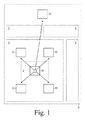
図1においては、第1状況における無線ネットワーク化照明システムが示されている。無線ネットワーク化スマート照明システムなどの無線ネットワーク化照明システムは、コントローラ20、ランプ21乃至24及び装置10を有する。装置10は、第1エリア1内のターゲット、例えばこの実施例においては人の存在を検出するよう構成されると共に、この特定の場合には、第2エリア2内の光の量を検出する、又は第2エリア2内で検出された光の量についての情報を受信するよう構成される。第1エリア1及び第2エリア2は、少なくとも部分的に重なり合っているエリアである。通常、これらの第1エリア1及び第2エリア2は、相対的に一致しているエリアであるだろう。
In FIG. 1, a wireless networked lighting system in a first situation is shown. A wireless networked lighting system, such as a wireless networked smart lighting system, includes a
この第1状況においては、第2エリア2において検出される光の第1の量は、しきい値より小さく、装置10は、この第1状況においては、コントローラ20及びランプ21乃至24のうちの1つ以上にマルチキャストメッセージを送信するよう構成される。このマルチキャストメッセージは、このマルチキャストメッセージを受信した1つ以上のランプ21乃至24のうちの少なくとも1つのランプをオンに切り替えよう構成される。
In this first situation, the first amount of light detected in the
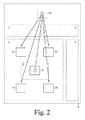
図2においては、第2状況における無線ネットワーク化照明システムが示されている。この第2状況においては、第2エリア2において検出される光の第2の量は、しきい値より大きく、装置10は、この第2状況においては、コントローラ20にユニキャストメッセージを送信するよう構成される。コントローラ20は、このユニキャストメッセージの受信に応じて、ランプ21乃至24のうちの1つ以上をオンに切り替えるために、ランプ21乃至24のうちの1つ以上にマルチキャストメッセージを送信するだろう、又は1つ以上のランプ21乃至24のうちの関連する1つに関連するユニキャストメッセージを送信するだろう。
In FIG. 2, the wireless networked lighting system in the second situation is shown. In this second situation, the second amount of light detected in the
ランプ21乃至24は、通常、装置10から相対的に小さい距離のところに位置し、コントローラ20は、通常、装置10から相対的に大きい距離のところに位置する。第2状況において装置10からコントローラ20に送信されたユニキャストメッセージが失われる又は遅れる場合には、1つ以上のランプ21乃至24は、オンに切り替えられない、又はあまりに遅くにオンに切り替えられる。
The
従って、相対的に暗い第1状況においては、第1エリア1内/近くにある1つ以上のランプ21乃至24をオンに切り替えることは、第1エリア1に入る人にとって相対的に重要であり、ランプ21乃至24に十分に通知される可能性を増加させるために、マルチキャストメッセージが送信されるべきである。相対的に明るい第2状況においては、第1エリア1内/近くにある1つ以上のランプ21乃至24をオンに切り替えることは、第1エリア1に入る人にとって相対的に重要ではなく、ユニキャストメッセージが送信され得る。
Thus, in a relatively dark first situation, switching on one or
各々が装置及び1つ以上のランプを有する、例えば、エリア3、4及び5などの他のエリアが存在してもよく、それによって、全てのエリア1乃至5が、ビル若しくは船、又はそれらの一部などのより大きいエリアの一部を形成してもよい。各コントローラが1つ以上のエリアを制御するより多くのコントローラも存在していてもよい。第1エリア1及び第2エリア2は、相対的に一致するエリアであってもよいが、他の状況を除外しない。第2エリア2は、例えば、第1エリア1より小さくてもよく、例えば、部屋の中央などのような光の量を検出するためにとりわけ選ばれた第1エリア1内の1つ以上の特定の場所を含み得る。他の例においては、第1エリア1は、例えば、第2エリア2より小さくてもよく、例えば、部屋の中のドアの近くの小さなエリアなどのような人の存在を検出するためにとりわけ選ばれた第2エリア2内の1つ以上の特定の場所を含み得る。エリア1、3、4、5ごとに2つ以上の装置10が存在していてもよい。
There may be other areas, each with a device and one or more lamps, for
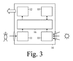
図3においては、装置の第1実施例が示されている。例えば占有センサなどの装置10は、図1及び2において示されている第1エリア1内のターゲット(例えば、人)の存在を検出するよう構成されるターゲット検出器11(例えば、人間検出器)を有する。装置10は、第1エリア1内のターゲットの存在の検出に応じて図1及び2において示されているコントローラ20及びランプ21乃至24のうちの1つ以上の全てにマルチキャストメッセージを送信するよう構成される送信機12を更に有する。それに加えて、プロセッサ16が、ターゲット検出器11からターゲット検出情報を受信するためにターゲット検出器11に結合されると共に、送信機12に送信情報を供給するために送信機12に結合される。上記のように、ターゲットは、この実施例における人間、又は家畜のような動物であってもよい。ターゲットは、物体、例えば車であってもよい。ターゲットは、識別されていないもの(unidentified)、即ち、任意の人間であってもよい。この実施例の変形例においては、それは、他の実施例全てに適用されてもよく、ターゲット検出器11は、特定のターゲット、例えば、特定の個人を認識/識別するよう適応されると共に、特定の個人が認識された場合にだけ装置にマルチキャストメッセージを送信させるよう適応される。
In FIG. 3, a first embodiment of the device is shown. A
好ましくは、装置10は、図1及び2において示されている第2エリア2内の光の量を検出するよう構成される内蔵光検出器を更に有する。その場合には、送信機12は、第2エリア2において相対的に少ない第1の量の光が検出される場合は、コントローラ20及びランプ21乃至24のうちの1つ以上にマルチキャストメッセージを送信するよう構成され、更に、送信機12は、第2エリア2において相対的に多い第2の量の光が検出される場合は、第1エリア1内のターゲットの存在の検出に応じて、コントローラ20にユニキャストメッセージを送信するよう構成される。それに加えて、プロセッサ16が、内蔵光検出器13から光検出情報を受信するために内蔵光検出器12に結合される。
Preferably, the
好ましくは、装置10は、第2エリア2において検出された光の量に対するランプ設定を算出するよう構成される計算機15を更に有する。それに加えて、プロセッサ16が、計算機15に(処理されたバージョンの)光検出情報を供給し、計算機15から算出情報を受信するために、計算機15に結合される。他の例においては、計算機15が、プロセッサ16の一部を形成してもよく、又はプロセッサ16が、検出器11及び13と送信機12と計算機15との間にバス又は接続部が存在する状態で、計算機15の一部を形成してもよい。計算機は、(処理されたバージョンの)光検出情報を用いてもよく、場合によっては、何らかの方法でコントローラ20から受信されるコントローラ情報を更に用いてもよい。
Preferably, the
図4においては、装置の第2実施例が示されている。この第2実施例は、内蔵光検出器13が、第2エリア2内の光の量を検出するよう構成される外部光検出器から光検出情報を受信するよう構成される受信機14に置き換えられている点だけが、第1実施例と異なる。図3について記述されている全ての可能性が、図4の場合も有効である。その上、受信機14は、更に、コントローラ20からコントローラ情報を受信するために用いられ得る。
In FIG. 4 a second embodiment of the device is shown. In this second embodiment, the built-in
一般に、マルチキャストメッセージは、1つ以上のランプ21乃至24のうちの少なくとも1つのランプをオンに切り替えるよう構成される。ランプをオンに切り替えることは、ランプの光強度をゼロレベルから非ゼロレベルに増加させることを含み得る。マルチキャストメッセージは、装置識別、1つ以上のランプ識別、コントローラ識別、及び検出結果を有してもよく、第1エリア1(の定義)、第2エリア2(の定義)、及び非ゼロレベル(の定義)を更に有してもよい。 In general, the multicast message is configured to switch on at least one of the one or more lamps 21-24. Switching on the lamp may include increasing the light intensity of the lamp from a zero level to a non-zero level. The multicast message may have a device identification, one or more lamp identifications, a controller identification, and a detection result, a first area 1 (definition), a second area 2 (definition), and a non-zero level ( May be further included.
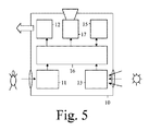
図5においては、装置の第3実施例が示されている。例えばランプなどの装置10のこの第3実施例は、光源17が付加されている点だけが第1実施例と異なる。この光源17は、プロセッサ16に結合される、又はプロセッサが計算機15の一部を形成する場合には、上記のバス若しくは接続部に、又はプロセッサを有する計算機15に結合される。
In FIG. 5 a third embodiment of the device is shown. For example, this third embodiment of the
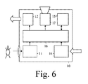
図6においては、装置の第4実施例が示されている。装置のこの第4実施例は、光源17が付加されている点だけが第2実施例と異なる。この光源17は、プロセッサ16に結合される、又はプロセッサが計算機15の一部を形成する場合には、上記のバス若しくは接続部に、又はプロセッサを有する計算機15に結合される。
In FIG. 6, a fourth embodiment of the device is shown. This fourth embodiment of the apparatus differs from the second embodiment only in that a
図3及び4について記述されている全ての可能性が、図5及び6の場合も有効である。更に、昼光モードにおいては、光源17は、オンに切り替えられた後に最低調光レベルにとどまるよう構成されてもよく、又はオフに切り替えられないよう構成されてもよい。コントローラ20が、ユニキャストメッセージによって若しくはマルチキャストメッセージによって装置10にこの昼光モードを知らせてもよく、又は別のランプ21乃至24が、装置10にこの昼光モードを知らせてもよく、又は内蔵光検出器13が、この昼光モードを検出し、装置10に知らせてもよく、又は外部光検出器が、装置10にこの昼光モードを知らせてもよい。図5及び6を考慮すると、図1及び2におけるランプ21乃至24の各々は、光源17を有する場合の装置と同じであってもよく、又はそうでなくでもよい。
All the possibilities described for FIGS. 3 and 4 are also valid in the case of FIGS. Further, in the daylight mode, the
装置が、無線ネットワーク化照明システムの別の部分にメッセージを送信することができる場合に、及び/又は装置が、無線ネットワーク化照明システムの別の部分からメッセージを受信することができる場合に、装置は、無線ネットワーク化照明システムの一部を形成するよう構成される。無線ネットワーク化照明システムは、コントローラ及びランプを有し、コントローラは、ランプを制御するよう構成される。無線ネットワーク化照明システムが、存在検出器を備える装置(このような装置はここでは占有センサと呼ばれる)を更に有してもよく、又はランプのうちの1つ以上が、このような存在検出器を有してもよい。存在検出器は、例えば、人によって放射される熱、又は人によってなされる動きなどを通して、直接、人の存在を検出することができる。存在検出器は、例えば、人によって動かされる物体の動き、又は人によって実施される操作、又は人によって運ばれる装置の検出などを通して、間接的に、人の存在を検出することもできる。 A device if the device can send a message to another part of the wireless networked lighting system and / or if the device can receive a message from another part of the wireless networked lighting system Are configured to form part of a wireless networked lighting system. The wireless networked lighting system has a controller and a lamp, and the controller is configured to control the lamp. The wireless networked lighting system may further comprise a device comprising a presence detector (such a device is referred to herein as an occupancy sensor), or one or more of the lamps may be such a presence detector. You may have. A presence detector can detect the presence of a person directly, for example through heat radiated by a person or movement made by a person. A presence detector can also detect the presence of a person indirectly, for example, through the movement of an object moved by a person, or an operation performed by a person, or detection of a device carried by the person.
要約すると、装置10は、第1エリア1内のターゲットの存在を検出するためのターゲット検出器11、例えば、人間検出器と、検出された存在に応じて、無線ネットワーク化照明システム内のコントローラ20及びランプ21乃至24にマルチキャストメッセージを送信するための送信機12とを有する。このようなマルチキャストメッセージは、システムの信頼性を高める。マルチキャストメッセージは、ランプ21乃至24をオンに切り替える。好ましくは、マルチキャストメッセージは、第2エリア2において相対的に少ない量の光が検出される場合にしか、送信されない。第2エリア2において相対的に多くの量の光が検出される場合には、検出された存在に応じて、装置10からコントローラ20にユニキャストメッセージが送信され、前記コントローラ20は、それに応じて、ランプ21乃至24をオンに切り替えられるよう制御する。第1エリア1及び第2エリア2は、少なくとも部分的に重なり合っているエリアであってもよい。装置10は、第2エリア2内の光の量を検出するための内蔵光検出器13、又は外部光検出器から光検出情報を受信するための受信機を有してもよい。
In summary, the
本発明を、図面において図示し、上記の説明において詳細に説明しているが、このような図及び説明は、説明的なもの又は例示的なものとみなされるべきであって、限定するものとみなされるべきではない。本発明は、開示されている実施例に限定されない。請求項に記載の発明を実施する当業者は、図面、明細及び添付の請求項の研究から、開示されている実施例に対する他の変形を、理解し、達成し得る。請求項において、「有する」という用語は、他の要素又はステップを除外せず、単数形表記は、複数の存在を除外しない。単に、特定の手段が、相互に異なる従属請求項において引用されているという事実は、これらの手段の組み合わせが有利になるように用いられることができないことを示すものではない。請求項におけるいかなる参照符号も、範囲を限定するものとして解釈されてはならない。 While the invention is illustrated in the drawings and has been described in detail in the foregoing description, such illustration and description are to be considered illustrative and exemplary and limited Should not be considered. The invention is not limited to the disclosed embodiments. Those skilled in the art in practicing the claimed invention may understand and achieve other variations to the disclosed embodiments from a study of the drawings, the specification, and the appended claims. In the claims, the word “comprising” does not exclude other elements or steps, and the singular form does not exclude the presence of a plurality. The mere fact that certain measures are recited in mutually different dependent claims does not indicate that a combination of these measures cannot be used to advantage. Any reference signs in the claims should not be construed as limiting the scope.
Claims (15)
第1エリア内のターゲットの存在を検出するよう構成されるターゲット検出器と、
送信機であって、
前記装置が高速応答の必要性を確認するときには、前記第1エリア内の前記ターゲットの存在の検出に応じて、前記コントローラ、及び前記ランプのうちの1つ以上にマルチキャストメッセージを送信し、
前記装置が、相対的によりゆっくりとした応答が許容可能であることを確認するときには、前記コントローラにユニキャストメッセージを送信するよう構成される送信機とを有する装置。 An apparatus configured to form part of a wireless networked lighting system having a controller and a lamp, comprising:
A target detector configured to detect the presence of a target in the first area;
A transmitter,
When the device confirms the need for fast response, in response to detecting the presence of the target in the first area, sends a multicast message to the controller and one or more of the lamps;
A device having a transmitter configured to send a unicast message to the controller when the device confirms that a relatively slower response is acceptable.
前記第2エリア内の光の量を検出するよう構成される外部光検出器から光検出情報を受信するよう構成される受信機を更に有する請求項4に記載の装置。 Receiving light detection information from a built-in photodetector configured to detect the amount of light in the second area, or from an external photodetector configured to detect the amount of light in the second area. The apparatus of claim 4 further comprising a configured receiver.
第1エリア内のターゲットの存在を検出するステップと、
送信するステップであって、
高速応答の必要性が確認されるときには、前記第1エリア内の前記ターゲットの存在の検出に応じて、前記コントローラ、及び前記ランプのうちの1つ以上にマルチキャストメッセージを送信し、
相対的によりゆっくりとした応答が許容可能であることが確認される場合には、前記第1エリア内の前記ターゲットの存在の検出に応じて、前記コントローラにユニキャストメッセージを送信するステップとを有する方法。 A method of operating a wireless networked lighting system having a controller and a lamp, comprising:
Detecting the presence of a target in the first area;
Sending step,
When a need for a fast response is confirmed, a multicast message is sent to the controller and one or more of the lamps in response to detecting the presence of the target in the first area;
Sending a unicast message to the controller in response to detecting the presence of the target in the first area if a relatively slower response is confirmed to be acceptable. Method.
Applications Claiming Priority (3)
| Application Number | Priority Date | Filing Date | Title |
|---|---|---|---|
| EP15175447.0 | 2015-07-06 | ||
| EP15175447 | 2015-07-06 | ||
| PCT/EP2016/064576 WO2017005499A1 (en) | 2015-07-06 | 2016-06-23 | Occupancy messaging in wireless networked lighting system |
Publications (3)
| Publication Number | Publication Date |
|---|---|
| JP2018519631A true JP2018519631A (en) | 2018-07-19 |
| JP2018519631A5 JP2018519631A5 (en) | 2019-07-25 |
| JP7085842B2 JP7085842B2 (en) | 2022-06-17 |
Family
ID=53682499
Family Applications (1)
| Application Number | Title | Priority Date | Filing Date |
|---|---|---|---|
| JP2017564805A Expired - Fee Related JP7085842B2 (en) | 2015-07-06 | 2016-06-23 | Exclusive message communication in wireless networked lighting system |
Country Status (6)
| Country | Link |
|---|---|
| US (1) | US10440804B2 (en) |
| EP (1) | EP3320756B1 (en) |
| JP (1) | JP7085842B2 (en) |
| CN (1) | CN107852801B (en) |
| RU (1) | RU2719502C2 (en) |
| WO (1) | WO2017005499A1 (en) |
Families Citing this family (6)
| Publication number | Priority date | Publication date | Assignee | Title |
|---|---|---|---|---|
| US10426017B2 (en) * | 2016-07-05 | 2019-09-24 | Lutron Technology Company Llc | Controlling groups of electrical loads via multicast and/or unicast messages |
| US10382284B1 (en) * | 2018-03-02 | 2019-08-13 | SILVAIR Sp. z o.o. | System and method for commissioning mesh network-capable devices within a building automation and control system |
| US10769909B1 (en) * | 2018-07-02 | 2020-09-08 | Amazon Technologies, Inc. | Using sensor data to detect events |
| CN109195284B (en) * | 2018-09-21 | 2020-07-31 | 赛尔富电子有限公司 | Illumination control method and system |
| CN114189967A (en) * | 2021-12-03 | 2022-03-15 | 中国船舶工业集团公司第七0八研究所 | An intelligent lighting system for a floating production oil loading and unloading device |
| AT526331B1 (en) | 2022-11-04 | 2024-02-15 | Molto Luce Gmbh | Luminaire for illuminating at least two spatial areas with a first lighting segment aimed at a first spatial area |
Citations (4)
| Publication number | Priority date | Publication date | Assignee | Title |
|---|---|---|---|---|
| JP2003506838A (en) * | 1999-08-10 | 2003-02-18 | コーニンクレッカ フィリップス エレクトロニクス エヌ ヴィ | Lighting control system including wireless remote sensor |
| JP2013127930A (en) * | 2011-12-19 | 2013-06-27 | Panasonic Corp | Lighting control system |
| WO2014024072A2 (en) * | 2012-08-06 | 2014-02-13 | Koninklijke Philips N.V. | Out-of-the-box commissioning of a lighting control system |
| US20150181662A1 (en) * | 2013-12-20 | 2015-06-25 | Ams Ag | Sensor arrangement for controlling room lighting, sensor network for controlling room lighting and method for controlling room lighting |
Family Cites Families (21)
| Publication number | Priority date | Publication date | Assignee | Title |
|---|---|---|---|---|
| US6912429B1 (en) | 2000-10-19 | 2005-06-28 | Destiny Networks, Inc. | Home automation system and method |
| US20040056771A1 (en) * | 2001-05-14 | 2004-03-25 | Gastronics' Inc. | Apparatus and method for wireless gas monitoring |
| US6894609B2 (en) * | 2001-07-17 | 2005-05-17 | Royal Thoughts, Llc | Electrical power control and sensor module for a wireless system |
| US7889051B1 (en) * | 2003-09-05 | 2011-02-15 | The Watt Stopper Inc | Location-based addressing lighting and environmental control system, device and method |
| US7369060B2 (en) | 2004-12-14 | 2008-05-06 | Lutron Electronics Co., Inc. | Distributed intelligence ballast system and extended lighting control protocol |
| US7608807B2 (en) | 2005-05-05 | 2009-10-27 | Leviton Manufacturing Co., Inc. | Closed loop daylight harvesting light control system having auto-calibration |
| EP2098101B1 (en) * | 2006-12-20 | 2011-07-06 | Koninklijke Philips Electronics N.V. | Method and system to select devices of a wireless network, particularly a network of wireless lighting devices |
| US8450670B2 (en) | 2007-06-29 | 2013-05-28 | Orion Energy Systems, Inc. | Lighting fixture control systems and methods |
| KR20110101182A (en) * | 2008-12-04 | 2011-09-15 | 코닌클리즈케 필립스 일렉트로닉스 엔.브이. | Device selection and control method |
| ES2388597T3 (en) * | 2009-02-13 | 2012-10-16 | Koninklijke Philips Electronics N.V. | Method for communication in a network comprising a ZigBee device without battery, network and device for it |
| US8410706B2 (en) | 2009-03-27 | 2013-04-02 | Lutron Electronics Co., Inc. | Method of calibrating a daylight sensor |
| US8648550B2 (en) | 2010-03-13 | 2014-02-11 | Zilog, Inc. | Ambient light sensor auto-calibration in a lighting control system |
| CN102014550A (en) | 2010-09-16 | 2011-04-13 | 徐大江 | System and method for parallelly controlling intelligent street lamps |
| US9521731B2 (en) * | 2010-12-22 | 2016-12-13 | Philips Lighting Holding B.V. | Control of network lighting systems |
| US8547036B2 (en) * | 2011-11-20 | 2013-10-01 | Available For Licensing | Solid state light system with broadband optical communication capability |
| CA2762869C (en) | 2011-12-20 | 2021-09-14 | Premier Lighting Ltd. | Wireless lighting and electrical device control system |
| US9210759B2 (en) | 2012-11-19 | 2015-12-08 | Express Imaging Systems, Llc | Luminaire with ambient sensing and autonomous control capabilities |
| US8912735B2 (en) | 2012-12-18 | 2014-12-16 | Cree, Inc. | Commissioning for a lighting network |
| US9462663B2 (en) | 2013-05-28 | 2016-10-04 | Abl Ip Holding Llc | Interactive user interface functionality for lighting devices or system |
| US10568179B2 (en) * | 2013-09-20 | 2020-02-18 | Osram Sylvania Inc. | Techniques and photographical user interface for controlling solid-state luminaire with electronically adjustable light beam distribution |
| US9985436B2 (en) * | 2014-04-11 | 2018-05-29 | Lutron Electronics Co., Inc. | Digital messages in a load control system |
-
2016
- 2016-06-23 WO PCT/EP2016/064576 patent/WO2017005499A1/en not_active Ceased
- 2016-06-23 EP EP16731178.6A patent/EP3320756B1/en active Active
- 2016-06-23 CN CN201680039953.6A patent/CN107852801B/en not_active Expired - Fee Related
- 2016-06-23 US US15/741,273 patent/US10440804B2/en active Active
- 2016-06-23 RU RU2018104257A patent/RU2719502C2/en active
- 2016-06-23 JP JP2017564805A patent/JP7085842B2/en not_active Expired - Fee Related
Patent Citations (4)
| Publication number | Priority date | Publication date | Assignee | Title |
|---|---|---|---|---|
| JP2003506838A (en) * | 1999-08-10 | 2003-02-18 | コーニンクレッカ フィリップス エレクトロニクス エヌ ヴィ | Lighting control system including wireless remote sensor |
| JP2013127930A (en) * | 2011-12-19 | 2013-06-27 | Panasonic Corp | Lighting control system |
| WO2014024072A2 (en) * | 2012-08-06 | 2014-02-13 | Koninklijke Philips N.V. | Out-of-the-box commissioning of a lighting control system |
| US20150181662A1 (en) * | 2013-12-20 | 2015-06-25 | Ams Ag | Sensor arrangement for controlling room lighting, sensor network for controlling room lighting and method for controlling room lighting |
Also Published As
| Publication number | Publication date |
|---|---|
| RU2719502C2 (en) | 2020-04-20 |
| US20180199415A1 (en) | 2018-07-12 |
| EP3320756B1 (en) | 2022-12-21 |
| EP3320756A1 (en) | 2018-05-16 |
| RU2018104257A (en) | 2019-08-06 |
| RU2018104257A3 (en) | 2020-02-06 |
| CN107852801B (en) | 2020-01-24 |
| JP7085842B2 (en) | 2022-06-17 |
| US10440804B2 (en) | 2019-10-08 |
| CN107852801A (en) | 2018-03-27 |
| WO2017005499A1 (en) | 2017-01-12 |
Similar Documents
| Publication | Publication Date | Title |
|---|---|---|
| JP7085842B2 (en) | Exclusive message communication in wireless networked lighting system | |
| EP2494712B1 (en) | Commissioning coded light sources | |
| US20160134369A1 (en) | Setting up hybrid coded-light - zigbee lighting system | |
| US20110295389A1 (en) | Lighting control network | |
| US10742510B2 (en) | Method and device for commissioning of nodes of a network | |
| JP2015528999A (en) | Lighting control device and process | |
| KR101110111B1 (en) | Mesh Networking Method for Remote Control of Street Light and Applied Apparatus | |
| JP2018507522A (en) | Existence request via dimming | |
| JP6223428B2 (en) | A method for adaptively controlling lighting based on traffic information in outdoor lighting networks | |
| JP2017016868A (en) | Control system | |
| JP6223459B2 (en) | Apparatus and method for interpreting reception control command | |
| KR101682350B1 (en) | Led illumination system and method for controlling them | |
| US20170055332A1 (en) | Illumination system | |
| JP2022549017A (en) | Proximity-based commissioning system | |
| US11751030B2 (en) | Trigger-based commissioning system | |
| US12402229B2 (en) | Controller for controlling a lighting system | |
| JP6502563B1 (en) | Load control system | |
| JP2019160808A (en) | Luminaire and control system | |
| JP6642181B2 (en) | Lighting control device and lighting system |
Legal Events
| Date | Code | Title | Description |
|---|---|---|---|
| A521 | Request for written amendment filed |
Free format text: JAPANESE INTERMEDIATE CODE: A523 Effective date: 20190621 |
|
| A621 | Written request for application examination |
Free format text: JAPANESE INTERMEDIATE CODE: A621 Effective date: 20190621 |
|
| A977 | Report on retrieval |
Free format text: JAPANESE INTERMEDIATE CODE: A971007 Effective date: 20200514 |
|
| A131 | Notification of reasons for refusal |
Free format text: JAPANESE INTERMEDIATE CODE: A131 Effective date: 20200528 |
|
| A601 | Written request for extension of time |
Free format text: JAPANESE INTERMEDIATE CODE: A601 Effective date: 20200825 |
|
| A521 | Request for written amendment filed |
Free format text: JAPANESE INTERMEDIATE CODE: A523 Effective date: 20201106 |
|
| A131 | Notification of reasons for refusal |
Free format text: JAPANESE INTERMEDIATE CODE: A131 Effective date: 20210302 |
|
| A601 | Written request for extension of time |
Free format text: JAPANESE INTERMEDIATE CODE: A601 Effective date: 20210528 |
|
| A131 | Notification of reasons for refusal |
Free format text: JAPANESE INTERMEDIATE CODE: A131 Effective date: 20211026 |
|
| A521 | Request for written amendment filed |
Free format text: JAPANESE INTERMEDIATE CODE: A523 Effective date: 20220121 |
|
| TRDD | Decision of grant or rejection written | ||
| A01 | Written decision to grant a patent or to grant a registration (utility model) |
Free format text: JAPANESE INTERMEDIATE CODE: A01 Effective date: 20220509 |
|
| A61 | First payment of annual fees (during grant procedure) |
Free format text: JAPANESE INTERMEDIATE CODE: A61 Effective date: 20220607 |
|
| R150 | Certificate of patent or registration of utility model |
Ref document number: 7085842 Country of ref document: JP Free format text: JAPANESE INTERMEDIATE CODE: R150 |
|
| LAPS | Cancellation because of no payment of annual fees |