CN107852801B - Wireless networked lighting systems and associated devices and methods - Google Patents
Wireless networked lighting systems and associated devices and methods Download PDFInfo
- Publication number
- CN107852801B CN107852801B CN201680039953.6A CN201680039953A CN107852801B CN 107852801 B CN107852801 B CN 107852801B CN 201680039953 A CN201680039953 A CN 201680039953A CN 107852801 B CN107852801 B CN 107852801B
- Authority
- CN
- China
- Prior art keywords
- area
- light
- controller
- lamps
- amount
- Prior art date
- Legal status (The legal status is an assumption and is not a legal conclusion. Google has not performed a legal analysis and makes no representation as to the accuracy of the status listed.)
- Active
Links
Images


Classifications
-
- H—ELECTRICITY
- H05—ELECTRIC TECHNIQUES NOT OTHERWISE PROVIDED FOR
- H05B—ELECTRIC HEATING; ELECTRIC LIGHT SOURCES NOT OTHERWISE PROVIDED FOR; CIRCUIT ARRANGEMENTS FOR ELECTRIC LIGHT SOURCES, IN GENERAL
- H05B47/00—Circuit arrangements for operating light sources in general, i.e. where the type of light source is not relevant
- H05B47/10—Controlling the light source
- H05B47/175—Controlling the light source by remote control
- H05B47/19—Controlling the light source by remote control via wireless transmission
-
- H—ELECTRICITY
- H05—ELECTRIC TECHNIQUES NOT OTHERWISE PROVIDED FOR
- H05B—ELECTRIC HEATING; ELECTRIC LIGHT SOURCES NOT OTHERWISE PROVIDED FOR; CIRCUIT ARRANGEMENTS FOR ELECTRIC LIGHT SOURCES, IN GENERAL
- H05B47/00—Circuit arrangements for operating light sources in general, i.e. where the type of light source is not relevant
- H05B47/10—Controlling the light source
- H05B47/105—Controlling the light source in response to determined parameters
- H05B47/11—Controlling the light source in response to determined parameters by determining the brightness or colour temperature of ambient light
-
- H—ELECTRICITY
- H05—ELECTRIC TECHNIQUES NOT OTHERWISE PROVIDED FOR
- H05B—ELECTRIC HEATING; ELECTRIC LIGHT SOURCES NOT OTHERWISE PROVIDED FOR; CIRCUIT ARRANGEMENTS FOR ELECTRIC LIGHT SOURCES, IN GENERAL
- H05B47/00—Circuit arrangements for operating light sources in general, i.e. where the type of light source is not relevant
- H05B47/10—Controlling the light source
- H05B47/105—Controlling the light source in response to determined parameters
- H05B47/115—Controlling the light source in response to determined parameters by determining the presence or movement of objects or living beings
-
- Y—GENERAL TAGGING OF NEW TECHNOLOGICAL DEVELOPMENTS; GENERAL TAGGING OF CROSS-SECTIONAL TECHNOLOGIES SPANNING OVER SEVERAL SECTIONS OF THE IPC; TECHNICAL SUBJECTS COVERED BY FORMER USPC CROSS-REFERENCE ART COLLECTIONS [XRACs] AND DIGESTS
- Y02—TECHNOLOGIES OR APPLICATIONS FOR MITIGATION OR ADAPTATION AGAINST CLIMATE CHANGE
- Y02B—CLIMATE CHANGE MITIGATION TECHNOLOGIES RELATED TO BUILDINGS, e.g. HOUSING, HOUSE APPLIANCES OR RELATED END-USER APPLICATIONS
- Y02B20/00—Energy efficient lighting technologies, e.g. halogen lamps or gas discharge lamps
- Y02B20/40—Control techniques providing energy savings, e.g. smart controller or presence detection
Abstract
The device (10) comprises an object detector (11) for detecting the presence of an object in the first area (1) and a transmitter (12) for transmitting a multicast message to the controller (20) and the lamps (21-24) in the wireless networked lighting system in response to the detected presence. Such multicast messages improve the reliability of the system. The multicast message switches on the lamps (21-24). Preferably, the multicast message is transmitted only if a relatively small amount of light is detected in the second area (2). In case a relatively large amount of light is detected in the second area (2), in response to the detected presence, a unicast message is transmitted from the device (10) to the controller (20), which controller (20) in response controls the lamps (21-24) to be switched on. The first and second regions (1, 2) may be at least partially overlapping regions. The device (10) may comprise an internal light detector (13) for detecting the amount of light in the second area (2) or a receiver for receiving light detection information from an external light detector.
Description
Technical Field
The invention relates to a device configured to form part of a wireless networked lighting system comprising a controller and a lamp. The invention also relates to a system comprising such a device and further comprising one or more of a controller and/or a lamp, and to a method. Examples of such devices are occupancy (occupancy) sensors and lamps comprising such occupancy sensors.
Background
WO2006/065653a2 discloses a distributed intelligent ballast system and an extended lighting control protocol. As described in paragraph 0147 thereof, power and control are distributed among the smart devices so that a controller failure does not cause the entire network to fail. In addition, the ballast gains increased intelligence. Each device (ballast) on the wired network enabled with the extended protocol may act as a controller.
In general, wireless networked lighting systems, such as wireless networked intelligent lighting systems, include a central controller and distributed sensing devices and distributed lights. The distributed sensing device sends a first message with the sensing result to the centralized controller. In response to the first message, the central controller sends one or more second messages to the number of distributed lamps to control the distributed lamps.
In case the first message transmitted from the sensing device to the central controller is lost or delayed, there is a problem because the several lamps are not switched on or switched on too late.
WO 01/11926 a1 discloses a lighting control system comprising a wireless remote sensor.
Disclosure of Invention
It is an object of the present invention to provide an improved apparatus. It is a further object of the invention to provide a system and an improved method.
According to a first aspect, there is provided a device configured to form part of a wireless networked lighting system comprising a controller and a lamp, wherein the device comprises:
-an object detector configured to detect the presence of an object in the first area, an
-a transmitter configured to transmit a multicast message to the controller and to one or more of the lamps in response to detecting the presence of the target in the first area when the device determines a need for a first response speed, and to transmit a unicast message to the controller when the device determines that the first response speed is not needed and thus a second, slower response speed can be accepted.
In the above manner, the device as described above enables the selection of a messaging strategy in the form of a multicast or unicast approach to combat the effects of message loss or delay that may result in several lamps not turning on or turning on later when fast switching is required.
There is provided a device configured to form part of a wireless networked lighting system comprising a controller and a lamp. An example of such a wireless networked lighting system is a wireless networked intelligent lighting system, wherein the controller is a central controller, and wherein the lights are distributed lights. The apparatus includes an object detector configured to detect a presence of an object in a first area, and a transmitter configured to transmit a multicast message to the controller and to one or more of the lamps in response to detecting the presence of the object in the first area. Such transmission is a wireless transmission via a wireless protocol and such transmitter is a wireless transmitter. An example of such a wireless protocol is ZigBeeTMAnd 6LoWPAN without excluding other kinds of wireless protocols.
By transmitting multicast messages to a controller, which may be located relatively far from the device, and one or more lamps, which may be located relatively close to the device, a shorter and parallel messaging route is created. As a result, the probability that the lamp is not notified or is notified too late that the object is detected to be present in the first area is reduced. Such a device improves the reliability of the wireless networked lighting system, which is a great technical advantage. It is noted that the target may be an animal, such as a human or a domestic animal. The target may also be an object, for example a vehicle like a car or a motorcycle. WO2006/065653a2 does not disclose the wireless transmission of multicast messages from a device comprising a human detector and a wireless transmitter to a controller and one or more lamps. In WO2006/065653A2, the wired network is based on a serial power bus and a serial control bus.
For example, the first area may be a room of a building, or (a part of) a floor of a building, or (a part of) a street, or (a part of) a cabin of a ship, or (a part of) a deck of a ship, or (a part of) a ship, etc.
An embodiment of the device is defined wherein the multicast message is configured to switch on at least one of the one or more lamps. In response to detecting the presence of the target in the first area, at least one of the lights that received the multicast message will be turned on. Switching on the lamp may include increasing the light intensity of the lamp from zero level to any level greater than zero.
An embodiment of the device is defined wherein the multicast message comprises a device identification, one or more lamp identifications, a controller identification and a detection result. The device identification identifies the device as a source that transmits the multicast message. The lamp identification identifies a particular lamp as one of the destinations to receive the multicast message. The controller identifies the controller as one of the destinations that receive the multicast message. The detection result defines a detection, such as a change from the absence of the object in the first area to the presence of the object. The multicast message may further define the first region.
An embodiment of the device is defined wherein the transmitter is configured to transmit a multicast message to the controller and to one or more of the lamps for a first amount of light detected in the second area, and wherein the transmitter is configured to transmit a unicast message to the controller in response to detecting the presence of the target in the first area for a second amount of light detected in the second area, the first amount of light being smaller than a threshold value and the second amount of light being larger than the threshold value, and the first area and the second area being at least partially overlapping areas. In a second area, which may partially or completely coincide with the first area, the amount of light will be detected. In case a first relatively small amount of light is detected in the second area, the switching on of one or more lamps present in/near the first/second area is relatively important for the purpose of entering the first area, then a multicast message will be transmitted to the controller and to one or more of the lamps to increase the probability that the lamps are well informed. In case a second relatively large amount of light is detected in the second area, the switching on of one or more lamps present in/near the first/second area is relatively unimportant for the purpose of entering the first area, then only a unicast message may be transmitted to the controller. The first relatively small amount of light is less than the threshold value and the second relatively large amount of light is greater than the threshold value. One of the light quantities may also be equivalent to a threshold value.
In general, in order to be able to detect the amount of light in the second region, a light detector is used. Such a light detector may be an internal detector and form part of the device, and may provide light detection information defining the amount of light in the second area to the device. Alternatively, such a light detector may be an external detector and be located outside the device, in which case the device will be equipped with a receiver for receiving light detection information defining the amount of light in the second area from the external light detector. In both cases, the multicast message may further define the amount of light detected and/or the light settings.
An embodiment of the device is defined, wherein the device comprises an occupancy sensor. The device may be produced in the form of an occupancy sensor or the like.
An embodiment of the device is defined, wherein the device comprises a lamp, and wherein the transmitter is configured to transmit the multicast message to the controller and to one or more of the other lamps. The device may be produced in the form of a lamp or the like.
An embodiment of the device is defined wherein the lamp is configured to be switched on in response to detecting the presence of the target in the first area, and wherein the multicast message is configured to switch on at least one of the one or more other lamps.
An embodiment of the device is defined wherein the multicast message comprises a lamp identification, one or more other lamp identifications, a controller identification and a detection result.
An embodiment of the device is defined wherein in daylight mode the lamp is configured to remain at a dimmest level after being switched on, or is configured not to be switched off. The lamp may detect the daylight mode itself via its internal light detector, or may be informed of the daylight mode by another lamp or by an external light detector or by a controller.
An embodiment of the device is defined wherein the transmitter is configured to transmit a multicast message to the controller and to one or more of the other lamps for a first amount of light detected in the second area, and wherein the transmitter is configured to transmit a unicast message to the controller in response to detecting the presence of the target in the first area for a second amount of light detected in the second area, the first amount of light being smaller than a threshold value and the second amount of light being larger than the threshold value, and the first area and the second area being at least partially overlapping areas.
An embodiment of the device is defined, which further comprises
An internal light detector configured to detect the amount of light in the second area, or
A receiver configured to receive light detection information from an external light detector configured to detect an amount of light in the second area.
An embodiment of the device is defined, which further comprises
A calculator configured to calculate a lamp setting for the detected amount of light in the second area.
Typically, the calculator for calculating the lamp settings may form part of the occupancy sensor or lamp, whereby the occupancy sensor or lamp may further comprise an internal light detector or receiver, both discussed above, for being informed of the amount of light detected in the second area.
According to a second aspect, there is provided a system comprising the apparatus defined above and further comprising one or more of the controller and/or the lamp.
Embodiments in which the light is configured to remain at the dimmest level after being turned on, or to not be turned off, are particularly advantageous in cases where a device in the form of an occupancy sensor or light cannot access light detection information from an internal light detector or an external light detector. The lamp may then decide to react to the multicast message depending on its own state (on or off). Thus, there are different circumstances depending on whether the light detection information is available to the device and the controller or only to the controller. In case the device has access to the light detection information, it may decide whether to send a unicast message to the controller or a multicast message to the controller and to the at least one (further) lamp. In case the device has no access to the light detection information, it sends a multicast message to the controller and to at least one (other) lamp, which may then remain at the dimmest level after being switched on, or which may then not be switched off.
According to a third aspect, there is provided a method for operating a wireless networked lighting system comprising a controller and a lamp, the method comprising the steps of: detecting a presence of a target in a first area; when a need for a first response speed is determined, in response to detecting the presence of a target in the first area, transmitting a multicast message to the controller and to one or more of the lamps, and if it is determined that the first response speed is not needed and therefore a slower second response speed can be accepted, transmitting a unicast message to the controller in response to detecting the presence of a target in the first area.
Embodiments of the system and method correspond with the embodiments of the device. And (a part of) an embodiment of the apparatus and (a part of) another embodiment of the apparatus may be combined.
The basic concept is that: in response to detecting the presence of the target in the first area, a multicast message is transmitted to the controller and to the one or more lights.
The problem of providing an improved device for enhancing the reliability of a wireless networked lighting system has been solved. Further advantages are that energy is saved and that the user friendliness of the environment including the different zones is enhanced.
These and other aspects of the invention will be apparent from and elucidated with reference to the embodiments described hereinafter.
Drawings
In the drawings:
figure 1 shows a wireless networked lighting system in a first situation,
figure 2 shows the wireless networked lighting system in a second situation,
figure 3 shows a first embodiment of the device,
figure 4 shows a second embodiment of the device,
FIG. 5 shows a third embodiment of the apparatus, an
Fig. 6 shows a fourth embodiment of the device.
Detailed Description
In fig. 1, a wireless networked lighting system in a first scenario is shown. A wireless networked lighting system, such as a wireless networked intelligent lighting system, includes a controller 20, lamps 21-24, and a device 10. The device 10 is configured to detect the presence of an object (e.g. a person in the present embodiment) in the first area 1 and in this particular case is configured to detect the amount of light in the second area 2 or to receive information about the amount of light detected in the second area 2. The first region 1 and the second region 2 are regions that at least partially overlap. Typically, these first 1 and second 2 regions will be relatively coincident regions.
In this first situation the first amount of light detected in the second area 2 is smaller than the threshold value and the device 10 is in this first situation configured to transmit a multicast message to the controller 20 and to one or more of the lamps 21-24. The multicast message is configured to switch on at least one of the one or more lamps 21-24 that have received the multicast message.
In fig. 2, a wireless networked lighting system in a second scenario is shown. In this second situation, the second amount of light detected in the second area 2 is greater than the threshold, and the device 10 is configured in this second situation to transmit a unicast message to the controller 20. In response to receiving the unicast message, the controller 20 will send a multicast message to one or more of the plurality of lamps 21-24 or will send a corresponding unicast message to a corresponding one of the one or more lamps 21-24 to turn on the one or more of the lamps 21-24.
The lamps 21-24 are typically located at a relatively small distance from the device 10, and the controller 20 is typically located at a relatively large distance from the device 10. In case the unicast message transmitted from the device 10 to the controller 20 is lost or delayed in the second scenario, one or more lamps 21-24 are not switched on or are switched on too late.
Thus, in a first relatively dark situation, the switching on of one or more lamps 21-24 present in/near the first area 1 is relatively important for a person entering the first area 1, and a multicast message will be transmitted to increase the probability that the lamps 21-24 are well informed. In a second relatively bright situation, the switching on of one or more lamps 21-24 present in/near the first area 1 is relatively unimportant to a person entering the first area 1, and a unicast message may be transmitted.
There may be further areas such as, for example, areas 3, 4 and 5, each of which comprises equipment and one or more lights, whereby all areas 1-5 may form part of a larger area 6, the area 6 being such as a building or a ship or a part thereof. There may also be more controllers, each controlling one or more zones. The first region 1 and the second region 2 may be relatively coinciding regions without excluding other situations. The second area 2 may, for example, be smaller than the first area 1 and, for example, comprise one or more specific locations within the first area 1, such as the center of a room, or the like, specifically selected for detecting the amount of light. Alternatively, the first area 1 may be smaller than the second area 2 and for example comprise one or more specific locations within the second area 2 specifically selected for detecting the presence of a person, such as a small area in a room near a door, etc. There may be more than one device 10 per zone 1, 3, 4, 5.
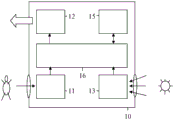
In fig. 3, a first embodiment of the device is shown. The device 10, such as for example an occupancy sensor, comprises an object detector 11, e.g. a person detector, which is configured to detect the presence of an object, e.g. a person, in the first area 1 shown in fig. 1 and 2. The device 10 further comprises a transmitter 12 configured to transmit a multicast message to one or more of the lamps 21-24 and the controller 20, all shown in fig. 1 and 2, in response to detecting the presence of the target in the first area 1. Further, processor 16 is coupled to target detector 10 for receiving target detection information from target detector 11 and to transmitter 12 for providing transmission information to transmitter 12. As discussed previously, the target may be an animal, such as a human in this embodiment, or a livestock animal. The target may also be an object, such as a car. The target may be unidentified, i.e., any human. In a variant of this embodiment, which can be applied to all other embodiments, the target detector 11 is adapted to recognize/identify a specific target (e.g. a specific individual) and to cause the device to transmit the multicast message only if the specific individual is recognized.
Preferably, the device 10 further comprises an internal light detector 13 configured to detect the amount of light in the second area 2 shown in fig. 1 and 2. In that case, the transmitter 12 is configured to transmit a multicast message to the controller 20 and to one or more of the lamps 21-24 for a relatively small first amount of light detected in the second area 2, and the transmitter 12 is configured to transmit a unicast message to the controller 20 in response to detecting the presence of the target in the first area 1 for a relatively large second amount of light detected in the second area 2. Further, the processor 16 is coupled to the internal light detector 13 for receiving light detection information from the internal light detector 13.
Preferably, the device 10 further comprises a calculator 15 configured to calculate a lamp setting for the amount of light detected in the second area 2. Further, the processor 16 is coupled to the calculator 15 for providing (the processed version of) the light detection information to the calculator 15 and for receiving the calculation information from the calculator 15. Alternatively, the calculator 15 may form part of the processor 16, or the processor 16 may form part of the calculator 15, wherein there is a bus or connection between the detectors 11 and 13 and the transmitter 12 and the calculator 15. The calculator may use (a processed version of) the light detection information and may further possibly use controller information received in any way from the controller 20.
In fig. 4, a second embodiment of the device is shown. This second embodiment differs from the first embodiment only in that: the internal light detector 13 is replaced by a receiver 14, the receiver 14 being configured to receive light detection information from an external light detector configured to detect the amount of light in the second area 2. All possibilities discussed with respect to fig. 3 are also valid for fig. 4. In addition, the receiver 14 may also be used to receive controller information from the controller 20.
Generally, the multicast message is configured to switch on at least one of the one or more lights 21-24. Switching on the lamp may comprise increasing the light intensity of the lamp from zero order to non-zero order. The multicast message may comprise a device identification, one or more lamp identifications, a controller identification and a detection result and may further comprise (a definition of) a first area 1, (a definition of) a second area 2 and (a definition of) a non-zero level.
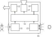
In fig. 5, a third embodiment of the device is shown. This third embodiment of the device 10, such as for example a lamp, differs from the first embodiment only in that a light source 17 is added. The light source 17 is coupled to the processor 16 or, in case the processor forms part of the calculator 15, to a bus or connection as discussed above, or to the calculator 15 comprising the processor.
In fig. 6, a fourth embodiment of the device is shown. This fourth embodiment of the device 10, such as for example a lamp, differs from the second embodiment only in that a light source 17 is added. The light source 17 is coupled to the processor 16 or, in case the processor forms part of the calculator 15, to a bus or connection as discussed above, or to the calculator 15 comprising the processor.
All possibilities discussed with respect to fig. 3 and 4 are valid also for fig. 5 and 6. In addition, in the daylight mode, the light source 17 may be configured to be maintained at the darkest level after being turned on, or may be configured not to be turned off. The controller 20 may inform the device 10 about the daylight mode by a unicast message or by a multicast message, or another lamp 21-24 may inform the device 10 about the daylight mode, or the internal light detector 13 may detect the daylight mode and inform the device 10, or the external light detector may inform the device 10 about the daylight mode. In view of fig. 5 and 6, in fig. 1 and 2, each of the lamps 21-24 may be the same as the device 10 when the device 10 includes the light source 17, or different.
The device is configured to form part of a wireless networked lighting system in the event that the device can transmit a message to another part of the wireless networked lighting system and/or in the event that the device can receive a message from another part of the wireless networked lighting system. A wireless networked lighting system includes a controller and a lamp, where the controller is configured to control the lamp. The wireless networked lighting system may also include devices with presence detectors (such devices are referred to herein as occupancy sensors), or one or more of the lights may include such presence detectors. The presence detector may directly detect the presence of a person, e.g. by heat radiated by the person, or by movements made by the person, etc. The presence detector may also detect the presence of a person indirectly, for example by movement of an object moved by the person, or by an operation performed by the person, or by detection of a device carried by the person, or the like.
In summary, the device 10 comprises an object detector 11, e.g. a person detector, for detecting the presence of an object in the first area 1, and a transmitter 12 for transmitting a multicast message to the controller 20 and the lamps 21-24 in the wireless networked lighting system in response to detecting the presence. Such multicast messages improve the reliability of the system. The multicast message turns on the lamps 21-24. Preferably, the multicast message is transmitted only if a relatively small amount of light is detected in the second area 2. In case a relatively large amount of light is detected in the second area 2, an unicast message is transmitted from the device 10 to the controller 20 in response to the detection of presence, the controller 20 controlling the lamps 21-24 to be switched on in response. The first region 1 and the second region 2 may be regions that at least partially overlap. The device 10 may comprise an internal light detector 13 for detecting the amount of light in the second area 2, or a receiver for receiving light detection information from an external light detector.
While the invention has been illustrated and described in detail in the drawings and foregoing description, such illustration and description are to be considered illustrative or exemplary and not restrictive; the invention is not limited to the disclosed embodiments. Other variations to the disclosed embodiments can be understood and effected by those skilled in the art in practicing the claimed invention, from a study of the drawings, the disclosure, and the appended claims. In the claims, the word "comprising" does not exclude other elements or steps, and the indefinite article "a" or "an" does not exclude a plurality. The mere fact that certain measures are recited in mutually different dependent claims does not indicate that a combination of these measures cannot be used to advantage. Any reference signs in the claims shall not be construed as limiting the scope.
Claims (15)
1. A device (10) configured to form part of a wireless networked lighting system comprising a controller (20) and lamps (21-24), wherein the device (10) comprises:
-an object detector (11) configured to detect the presence of an object in the first area (1), and
-a transmitter (12) configured to:
-transmitting a multicast message to the controller (20) and to one or more of the lamps (21-24) in response to detecting the presence of the target in the first area (1) when the device determines a need for a first response speed, and
-transmitting a unicast message to the controller (20) when the device determines that a first response speed is not required and therefore a second, slower response speed can be accepted.
2. The device (10) as defined in claim 1, wherein the multicast message is configured to switch on at least one of the one or more lamps (21-24).
3. The device (10) as defined in claim 1, wherein the multicast message comprises a device identification, one or more lamp identifications, a controller identification and a detection result.
4. The device (10) as defined in claim 1, wherein the transmitter (12) is configured to transmit a multicast message to the controller (20) and to one or more of the lamps (21-24) for a first amount of light detected in the second area (2), and wherein the transmitter (12) is configured to transmit a unicast message to the controller (20) in response to detecting the presence of the target in the first area (1) for a second amount of light detected in the second area (2), the first amount of light being smaller than a threshold value and the second amount of light being larger than the threshold value, and the first and second areas (1, 2) being at least partially overlapping areas.
5. The apparatus (10) as defined in claim 4, further comprising:
-an internal light detector (13) configured to detect the amount of light in the second area (2), or
-a receiver (14) configured to receive light detection information from an external light detector configured to detect an amount of light in the second area (2).
6. The device (10) as defined in claim 1, wherein the device (10) comprises an occupancy sensor.
7. The device (10) as defined in claim 1, wherein the device (10) comprises one of the lamps, and wherein the transmitter (12) is configured to transmit a multicast message to the controller (20) and to one or more of the other lamps (21-24) of the lamps.
8. The device (10) as defined in claim 7, wherein the one of the lamps is configured to be switched on in response to detecting the presence of the target in the first area (1), and wherein the multicast message is configured to switch on at least one of the one or more other lamps (21-24).
9. The device (10) as defined in claim 7, wherein the multicast message comprises a lamp identification, one or more other lamp identifications, a controller identification and a detection result.
10. The device (10) as defined in claim 7, wherein in daylight mode, the light is configured to remain at a dimmest level after being switched on, or is configured not to be switched off.
11. The device (10) as defined in claim 7, wherein the transmitter (12) is configured to transmit a multicast message to the controller (20) and to one or more of the other lamps (21-24) for a first amount of light detected in the second area (2), and wherein the transmitter (12) is configured to transmit a unicast message to the controller (20) in response to detecting the presence of the target in the first area (1) for a second amount of light detected in the second area (2), the first amount of light being smaller than a threshold value and the second amount of light being larger than the threshold value, and the first and second areas (1, 2) being at least partially overlapping areas.
12. The apparatus (10) as defined in claim 1, further comprising:
-a calculator (15) configured to calculate a lamp setting for the detected amount of light in the second area (2).
13. A wireless networked lighting system comprising the device (10) as defined in claim 1 and further comprising one or more of the controller (20) and/or the lamps (21-24).
14. A method for operating a wireless networked lighting system comprising a controller (20) and lamps (21-24), the method comprising the steps of:
-detecting the presence of an object in the first area (1), and
-transmitting a multicast message to the controller (20) and to one or more of the lamps (21-24) in response to detecting the presence of the target in the first area (1) when determining the need for a first response speed, and
-transmitting a unicast message to the controller (20) in response to detecting the presence of the target in the first area (1) if it is determined that the first response speed is not required and thus a slower second response speed can be accepted.
15. The method as defined in claim 14, wherein the multicast message is transmitted for a first amount of light detected in the second area (2), and wherein the unicast message is transmitted for a second amount of light detected in the second area (2), the first amount of light being smaller than a threshold value and the second amount of light being larger than the threshold value, and the first and second areas (1, 2) being at least partially overlapping areas.
Applications Claiming Priority (3)
| Application Number | Priority Date | Filing Date | Title |
|---|---|---|---|
| EP15175447 | 2015-07-06 | ||
| EPEP15175447.0 | 2015-07-06 | ||
| PCT/EP2016/064576 WO2017005499A1 (en) | 2015-07-06 | 2016-06-23 | Occupancy messaging in wireless networked lighting system |
Publications (2)
| Publication Number | Publication Date |
|---|---|
| CN107852801A CN107852801A (en) | 2018-03-27 |
| CN107852801B true CN107852801B (en) | 2020-01-24 |
Family
ID=53682499
Family Applications (1)
| Application Number | Title | Priority Date | Filing Date |
|---|---|---|---|
| CN201680039953.6A Active CN107852801B (en) | 2015-07-06 | 2016-06-23 | Wireless networked lighting systems and associated devices and methods |
Country Status (6)
| Country | Link |
|---|---|
| US (1) | US10440804B2 (en) |
| EP (1) | EP3320756B1 (en) |
| JP (1) | JP7085842B2 (en) |
| CN (1) | CN107852801B (en) |
| RU (1) | RU2719502C2 (en) |
| WO (1) | WO2017005499A1 (en) |
Families Citing this family (6)
| Publication number | Priority date | Publication date | Assignee | Title |
|---|---|---|---|---|
| EP3482534B1 (en) * | 2016-07-05 | 2022-11-23 | Lutron Technology Company LLC | Controlling groups of electrical loads via multicast and/or unicast messages |
| US10382284B1 (en) * | 2018-03-02 | 2019-08-13 | SILVAIR Sp. z o.o. | System and method for commissioning mesh network-capable devices within a building automation and control system |
| US10769909B1 (en) * | 2018-07-02 | 2020-09-08 | Amazon Technologies, Inc. | Using sensor data to detect events |
| CN109195284B (en) * | 2018-09-21 | 2020-07-31 | 赛尔富电子有限公司 | Illumination control method and system |
| CN114189967A (en) * | 2021-12-03 | 2022-03-15 | 中国船舶工业集团公司第七0八研究所 | Floating production oil loading and unloading device intelligent lighting system |
| AT526331B1 (en) * | 2022-11-04 | 2024-02-15 | Molto Luce Gmbh | Luminaire for illuminating at least two spatial areas with a first lighting segment aimed at a first spatial area |
Citations (2)
| Publication number | Priority date | Publication date | Assignee | Title |
|---|---|---|---|---|
| US6912429B1 (en) * | 2000-10-19 | 2005-06-28 | Destiny Networks, Inc. | Home automation system and method |
| CN102014550A (en) * | 2010-09-16 | 2011-04-13 | 徐大江 | System and method for parallelly controlling intelligent street lamps |
Family Cites Families (23)
| Publication number | Priority date | Publication date | Assignee | Title |
|---|---|---|---|---|
| US6340864B1 (en) * | 1999-08-10 | 2002-01-22 | Philips Electronics North America Corporation | Lighting control system including a wireless remote sensor |
| US20040056771A1 (en) | 2001-05-14 | 2004-03-25 | Gastronics' Inc. | Apparatus and method for wireless gas monitoring |
| US6894609B2 (en) * | 2001-07-17 | 2005-05-17 | Royal Thoughts, Llc | Electrical power control and sensor module for a wireless system |
| US7889051B1 (en) * | 2003-09-05 | 2011-02-15 | The Watt Stopper Inc | Location-based addressing lighting and environmental control system, device and method |
| US7369060B2 (en) | 2004-12-14 | 2008-05-06 | Lutron Electronics Co., Inc. | Distributed intelligence ballast system and extended lighting control protocol |
| US7608807B2 (en) | 2005-05-05 | 2009-10-27 | Leviton Manufacturing Co., Inc. | Closed loop daylight harvesting light control system having auto-calibration |
| EP2098101B1 (en) * | 2006-12-20 | 2011-07-06 | Koninklijke Philips Electronics N.V. | Method and system to select devices of a wireless network, particularly a network of wireless lighting devices |
| US8450670B2 (en) | 2007-06-29 | 2013-05-28 | Orion Energy Systems, Inc. | Lighting fixture control systems and methods |
| JP2012511275A (en) | 2008-12-04 | 2012-05-17 | コーニンクレッカ フィリップス エレクトロニクス エヌ ヴィ | Method for selecting and controlling a device |
| WO2010092532A1 (en) * | 2009-02-13 | 2010-08-19 | Koninklijke Philips Electronics N.V. | Method for communicating in a network comprising a batteryless zigbee device, network and device therefor |
| US8410706B2 (en) | 2009-03-27 | 2013-04-02 | Lutron Electronics Co., Inc. | Method of calibrating a daylight sensor |
| US8648550B2 (en) | 2010-03-13 | 2014-02-11 | Zilog, Inc. | Ambient light sensor auto-calibration in a lighting control system |
| CN103329629B (en) * | 2010-12-22 | 2016-01-20 | 皇家飞利浦电子股份有限公司 | Networking illuminator controls |
| US8547036B2 (en) * | 2011-11-20 | 2013-10-01 | Available For Licensing | Solid state light system with broadband optical communication capability |
| JP5891450B2 (en) | 2011-12-19 | 2016-03-23 | パナソニックIpマネジメント株式会社 | Lighting control system |
| CA2762869C (en) | 2011-12-20 | 2021-09-14 | Premier Lighting Ltd. | Wireless lighting and electrical device control system |
| EP2880965B1 (en) | 2012-08-06 | 2023-05-03 | Signify Holding B.V. | Automatic commissioning of a lighting system |
| US9210759B2 (en) | 2012-11-19 | 2015-12-08 | Express Imaging Systems, Llc | Luminaire with ambient sensing and autonomous control capabilities |
| US9155165B2 (en) | 2012-12-18 | 2015-10-06 | Cree, Inc. | Lighting fixture for automated grouping |
| US9462663B2 (en) | 2013-05-28 | 2016-10-04 | Abl Ip Holding Llc | Interactive user interface functionality for lighting devices or system |
| US10568179B2 (en) * | 2013-09-20 | 2020-02-18 | Osram Sylvania Inc. | Techniques and photographical user interface for controlling solid-state luminaire with electronically adjustable light beam distribution |
| EP2887771B1 (en) | 2013-12-20 | 2018-02-28 | ams AG | Sensor arrangement for controlling room lighting, sensor network for controlling room lighting and method for controlling room lighting |
| EP3130201B1 (en) * | 2014-04-11 | 2021-06-23 | Lutron Technology Company LLC | Digital messages in a load control system |
-
2016
- 2016-06-23 EP EP16731178.6A patent/EP3320756B1/en active Active
- 2016-06-23 JP JP2017564805A patent/JP7085842B2/en active Active
- 2016-06-23 CN CN201680039953.6A patent/CN107852801B/en active Active
- 2016-06-23 RU RU2018104257A patent/RU2719502C2/en active
- 2016-06-23 WO PCT/EP2016/064576 patent/WO2017005499A1/en active Application Filing
- 2016-06-23 US US15/741,273 patent/US10440804B2/en active Active
Patent Citations (2)
| Publication number | Priority date | Publication date | Assignee | Title |
|---|---|---|---|---|
| US6912429B1 (en) * | 2000-10-19 | 2005-06-28 | Destiny Networks, Inc. | Home automation system and method |
| CN102014550A (en) * | 2010-09-16 | 2011-04-13 | 徐大江 | System and method for parallelly controlling intelligent street lamps |
Also Published As
| Publication number | Publication date |
|---|---|
| JP7085842B2 (en) | 2022-06-17 |
| RU2018104257A (en) | 2019-08-06 |
| CN107852801A (en) | 2018-03-27 |
| WO2017005499A1 (en) | 2017-01-12 |
| JP2018519631A (en) | 2018-07-19 |
| EP3320756B1 (en) | 2022-12-21 |
| US20180199415A1 (en) | 2018-07-12 |
| RU2018104257A3 (en) | 2020-02-06 |
| US10440804B2 (en) | 2019-10-08 |
| RU2719502C2 (en) | 2020-04-20 |
| EP3320756A1 (en) | 2018-05-16 |
Similar Documents
| Publication | Publication Date | Title |
|---|---|---|
| CN107852801B (en) | Wireless networked lighting systems and associated devices and methods | |
| US8729808B2 (en) | Commissioning coded light sources | |
| EP2845449B1 (en) | Method and device for commissioning of nodes of a network | |
| JP6223428B2 (en) | A method for adaptively controlling lighting based on traffic information in outdoor lighting networks | |
| KR101214235B1 (en) | Wireless sensing module, wireless lighting controller and wireless lighting system | |
| WO2017091349A1 (en) | Wireless behavioral feedback for active lighting control | |
| CN104582175A (en) | Intelligent illumination control system and method | |
| US9521724B1 (en) | Method for automatically commissioning devices used in building lighting and controls | |
| US20130332114A1 (en) | Systems and Methods for Commissioning a Sensor | |
| JP2018519631A5 (en) | ||
| JP2018507522A (en) | Existence request via dimming | |
| CN102378434A (en) | Guiding lighting system | |
| US10634299B2 (en) | Motion sensor based lighting fixture operation | |
| EP2910089B1 (en) | Apparatus and method for interpreting received control commands | |
| KR102081840B1 (en) | Control system using gateway and control method of the same | |
| KR101682350B1 (en) | Led illumination system and method for controlling them | |
| JP2017139090A (en) | Lighting control system, lighting control device, and program | |
| US20240107649A1 (en) | A controller for controlling a lighting system | |
| EP4203624A1 (en) | Lighting control | |
| EP3749060A1 (en) | Self-configuring lighting control | |
| BE1024372B1 (en) | METHOD AND SYSTEM FOR WIRELESS AND LOCATION-BASED CONTROL OF A LIGHTING SYSTEM |
Legal Events
| Date | Code | Title | Description |
|---|---|---|---|
| PB01 | Publication | ||
| PB01 | Publication | ||
| SE01 | Entry into force of request for substantive examination | ||
| SE01 | Entry into force of request for substantive examination | ||
| GR01 | Patent grant | ||
| GR01 | Patent grant | ||
| CP03 | Change of name, title or address |
Address after: Eindhoven Patentee after: Signify Holdings Ltd. Address before: Eindhoven, the Netherlands Patentee before: PHILIPS LIGHTING HOLDING B.V. |
|
| CP03 | Change of name, title or address |