JP2018512766A - CMUT array with acoustic window layer - Google Patents
CMUT array with acoustic window layer Download PDFInfo
- Publication number
- JP2018512766A JP2018512766A JP2017544959A JP2017544959A JP2018512766A JP 2018512766 A JP2018512766 A JP 2018512766A JP 2017544959 A JP2017544959 A JP 2017544959A JP 2017544959 A JP2017544959 A JP 2017544959A JP 2018512766 A JP2018512766 A JP 2018512766A
- Authority
- JP
- Japan
- Prior art keywords
- layer
- acoustic
- cmut
- particles
- cell
- Prior art date
- Legal status (The legal status is an assumption and is not a legal conclusion. Google has not performed a legal analysis and makes no representation as to the accuracy of the status listed.)
- Pending
Links
Images


Classifications
-
- B—PERFORMING OPERATIONS; TRANSPORTING
- B06—GENERATING OR TRANSMITTING MECHANICAL VIBRATIONS IN GENERAL
- B06B—METHODS OR APPARATUS FOR GENERATING OR TRANSMITTING MECHANICAL VIBRATIONS OF INFRASONIC, SONIC, OR ULTRASONIC FREQUENCY, e.g. FOR PERFORMING MECHANICAL WORK IN GENERAL
- B06B1/00—Methods or apparatus for generating mechanical vibrations of infrasonic, sonic, or ultrasonic frequency
- B06B1/02—Methods or apparatus for generating mechanical vibrations of infrasonic, sonic, or ultrasonic frequency making use of electrical energy
- B06B1/0292—Electrostatic transducers, e.g. electret-type
-
- G—PHYSICS
- G01—MEASURING; TESTING
- G01S—RADIO DIRECTION-FINDING; RADIO NAVIGATION; DETERMINING DISTANCE OR VELOCITY BY USE OF RADIO WAVES; LOCATING OR PRESENCE-DETECTING BY USE OF THE REFLECTION OR RERADIATION OF RADIO WAVES; ANALOGOUS ARRANGEMENTS USING OTHER WAVES
- G01S15/00—Systems using the reflection or reradiation of acoustic waves, e.g. sonar systems
- G01S15/02—Systems using the reflection or reradiation of acoustic waves, e.g. sonar systems using reflection of acoustic waves
-
- G—PHYSICS
- G01—MEASURING; TESTING
- G01S—RADIO DIRECTION-FINDING; RADIO NAVIGATION; DETERMINING DISTANCE OR VELOCITY BY USE OF RADIO WAVES; LOCATING OR PRESENCE-DETECTING BY USE OF THE REFLECTION OR RERADIATION OF RADIO WAVES; ANALOGOUS ARRANGEMENTS USING OTHER WAVES
- G01S7/00—Details of systems according to groups G01S13/00, G01S15/00, G01S17/00
- G01S7/52—Details of systems according to groups G01S13/00, G01S15/00, G01S17/00 of systems according to group G01S15/00
- G01S7/521—Constructional features
Abstract
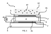
音響波送信に対する超音波アレイは、少なくとも1つの容量性マイクロマシン超音波トランスデューサ(CMUT)セル6を有し、前記CMUTセルは、基板4と、第1の電極7と、間に空洞8を挟んで前記第1の電極及び前記第2の基板に対向する第2の電極7'を持ち、セル活性化時に振動するように構成されるセル膜5と、前記セル膜を覆い、外側表面及び前記セル膜に対向する内側表面を持つ音響窓層13とを有する。前記音響窓層は、抗酸化物質の分子及び中に絶縁粒子41を埋め込まれた高分子材料47を有する第1の層を有し、前記高分子材料は、水素及び炭素原子からなり、0.95g/cm3以下の密度及び1.45MRayl以上の音響インピーダンスを持つ。この音響窓層は、CMUTベースのアレイを用いる応用において、広い帯域幅及び低い減衰のような改良された音響性能を提供する。The ultrasonic array for acoustic wave transmission has at least one capacitive micromachined ultrasonic transducer (CMUT) cell 6, said CMUT cell sandwiching a cavity 8 between a substrate 4 and a first electrode 7. A cell film 5 having a second electrode 7 ′ facing the first electrode and the second substrate and configured to vibrate when the cell is activated; and covering the cell film; And an acoustic window layer 13 having an inner surface facing the membrane. The acoustic window layer has a first layer having a molecule of antioxidant substance and a polymer material 47 in which insulating particles 41 are embedded. It has a density of 95 g / cm 3 or less and an acoustic impedance of 1.45 MRayl or more. This acoustic window layer provides improved acoustic performance such as wide bandwidth and low attenuation in applications using CMUT-based arrays.
Description
本発明は、少なくとも1つの容量性マイクロマシン超音波トランスデューサ(CMUT)セルを有する音響波送信に対する超音波アレイに関し、前記CMUTセルは、第1の電極を持つ基板と、間に空洞を挟んで前記第1の電極に対向する第2の電極を持ち、セル活性化(activation)すると振動するように構成されるセル膜と、前記セル膜を覆い、外面及び前記セル膜に対向する内面を持つ音響窓層とを有する。 The present invention relates to an ultrasonic array for acoustic wave transmission having at least one capacitive micromachined ultrasonic transducer (CMUT) cell, wherein the CMUT cell includes a substrate having a first electrode and a first cavity sandwiched therebetween. An acoustic window having a second electrode facing one electrode and configured to vibrate upon cell activation, and having an outer surface and an inner surface that covers the cell film and faces the cell film And having a layer.
本発明は、更に、このようなアレイの製造方法及びこのような超音波アレイを有する超音波撮像システムに関する。 The invention further relates to a method for manufacturing such an array and an ultrasound imaging system comprising such an ultrasound array.
いかなる超音波(撮像)アレイの中心となるのは、電気エネルギを音響エネルギに及びその逆に変換する超音波トランスデューサである。半導体技術における近年の進歩は、容量性マイクロマシン超音波トランスデューサ(CMUT)の開発をもたらした。これらのトランスデューサは、従来の圧電ベースの超音波トランスデューサ(PZT)を置き換える潜在的な候補であると見なされる。CMUTトランスデューサセルは、膜とも称される可動機械部分を持つ空洞及び前記空洞により分離された電極の対を有する。超音波を受信する場合、超音波は、前記膜に移動又は振動させ、前記電極間のキャパシタンスを変化させ、これは検出されることができる。これにより、超音波は、対応する電気信号に変換される。逆に、前記電極に印加された電気信号は、前記膜に移動又は振動させ、これにより超音波を送信する。 Central to any ultrasound (imaging) array is an ultrasound transducer that converts electrical energy into acoustic energy and vice versa. Recent advances in semiconductor technology have led to the development of capacitive micromachined ultrasonic transducers (CMUTs). These transducers are considered potential candidates for replacing conventional piezoelectric-based ultrasonic transducers (PZT). The CMUT transducer cell has a cavity with a movable mechanical part, also called a membrane, and a pair of electrodes separated by the cavity. When receiving ultrasound, the ultrasound is moved or oscillated into the membrane, changing the capacitance between the electrodes, which can be detected. Thereby, an ultrasonic wave is converted into a corresponding electric signal. Conversely, the electrical signal applied to the electrode moves or vibrates to the membrane, thereby transmitting ultrasonic waves.
CMUTの利点は、これらが、半導体製造プロセスを使用して作成されることができ、したがって、特定用途向け集積回路(ASIC)と一体化されるのが、より容易でありえ、CMUTトランスデューサが、従来のPZTに対して低コスト、拡張された周波数範囲及びより細かい音響ピッチを提供することである。 The advantages of CMUTs are that they can be created using semiconductor manufacturing processes, and therefore can be easier to integrate with application specific integrated circuits (ASICs), and CMUT transducers are traditionally To provide low cost, extended frequency range and finer acoustic pitch for PZT.
PZTベースの技術から本質的に、一般に使用されるCMUTを持つ超音波アレイのほとんどは、シリコンゴム、例えばRTVのようなPZTベースのトランスデューサに対して使用される材料から選択された音響窓又はレンズ材料を持つ。 Essentially from PZT-based technology, most commonly used ultrasonic arrays with CMUT are acoustic windows or lenses selected from materials used for PZT-based transducers such as silicone rubber, eg RTV. Have materials.
しかしながら、CMUTは、PZTとは異なる電気音響変換のメカニズムを有し、CMUT膜と音響窓又はレンズに使用される音響材料との間の相互作用は、トランスデューサの音響性能を低下させうる。 However, CMUT has a different electroacoustic conversion mechanism than PZT, and the interaction between the CMUT membrane and the acoustic material used in the acoustic window or lens can degrade the acoustic performance of the transducer.
US2013/0301394A1は、CMUTと音響窓との間で結合媒体を使用することを提案する。媒体材料の提示された例は、プラスチック、ゴム、室温硬化シリコン(RTV)、ドライフィルムフォトレジストのような固体ベース材料、又はオイル、ゲルのような液体ベース材料のいずれかを含む。この結合媒体の欠点は、前記結合媒体材料の提案されたリストが、伝搬する音響波に対してしばしば強力な減衰を示す広い範囲の音響特性を持つ異なる材料を含むことである。特定の媒体材料の選択は、更に、前記超音波アレイに使用される音響窓層に対する調節を必要とする。 US 2013/0301394 A1 proposes to use a coupling medium between the CMUT and the acoustic window. Presented examples of media materials include either plastic, rubber, room temperature cured silicon (RTV), solid base materials such as dry film photoresist, or liquid base materials such as oil, gel. The disadvantage of this coupling medium is that the proposed list of coupling medium materials includes different materials with a wide range of acoustic properties that often exhibit strong attenuation to the propagating acoustic wave. The selection of a specific media material further requires adjustment to the acoustic window layer used in the ultrasound array.
音響波送信に対するCMUTベースの超音波アレイに適した改良された音響窓層を提供する必要性が存在する。 There is a need to provide an improved acoustic window layer suitable for CMUT-based ultrasound arrays for acoustic wave transmission.
本発明の目的は、改良された音響波伝搬を提供する、冒頭の段落に記載された種類の少なくとも1つの容量性マイクロマシン超音波トランスデューサセルを有する超音波アレイを提供することである。 It is an object of the present invention to provide an ultrasound array having at least one capacitive micromachined ultrasound transducer cell of the type described in the opening paragraph that provides improved acoustic wave propagation.
この目的は、抗酸化物質の分子と粒子を中に埋め込まれた高分子材料とを有する第1の層を有する音響波窓層を提供することにより本発明によって達成され、前記高分子材料は、水素及び炭素原子を含み、0.95g/cm3以下の密度及び1.45MRayl以上の音響インピーダンスを持つ。 This object is achieved according to the present invention by providing an acoustic wave window layer having a first layer comprising molecules of antioxidants and a polymeric material in which the particles are embedded, said polymeric material comprising: It contains hydrogen and carbon atoms, has a density of 0.95 g / cm 3 or less and an acoustic impedance of 1.45 MRayl or more.
容易に位置づけられ、所望の形状にモールディングすることにより形成される、硬化(ここで室温硬化ゴム又はRTVとも称される)音響レンズ材料により得られ、前記CMUTアレイと接触させられた従来の充填シリコンゴムが、通常の周波数依存減衰に加えて前記CMUTアレイに追加の音響的損失を導入することが発見された。この損失は、2dBのオーダの増大された減衰及び4MHzまでの中心周波数のダウンシフトに表れる。水素及び炭素原子のみを含む高分子材料が、2乃至25MHzのような、医療用超音波において使用可能な広い範囲の音響波周波数に対して1.5dBより低い、通過する音響エネルギに対するミリメートルごとの音響損失を示しうることが発見された。本発明の特徴的なフィーチャは、前記第1の層が、追加的に、抗酸化物質の分子を有し、これは、前記高分子層が時間とともに更に架橋(酸化)することを防ぐ。したがって、前記抗酸化物質は、硬度のような前記高分子材料の特性を時間において一定に保つ。この高分子材料に埋め込まれた粒子の導入は、前記音響層の合計インピーダンスを増大させ、約1.6MRaylの超音波処理された組織のインピーダンス値に近づける可能性を提供する。前記高分子層が、このような低い音響エネルギ損失(減衰)を示すという事実により、前記埋め込まれた粒子により生じる可能な追加の音響損失は、前記音響窓層を通る音響波伝搬の品質に影響を与えるために十分に低くてもよい。前記高分子材料が、炭素及び水素原子のみを含み、0.95g/cm3以下の密度及び1.45MRayl以上の音響インピーダンスを持つ場合、前記CMUTセルの前記膜に対する前記音響窓層の直接的な音響結合が、提供される。したがって、前記音響窓と前記CMUTアレイとの間の追加の結合媒体は、必要とされない。更に、1.4MRayl以上の音響インピーダンスは、前記第1の層のインピーダンスを前記超音波処理された組織のインピーダンス(1.6MRayl)に近づけるために前記粒子の比較的少ない量を必要とする。 Conventional filled silicon obtained by cured (herein also referred to as room temperature cured rubber or RTV) acoustic lens material that is easily positioned and formed by molding into the desired shape and contacted with the CMUT array It has been discovered that rubber introduces additional acoustic losses to the CMUT array in addition to normal frequency dependent attenuation. This loss is manifested in an increased attenuation on the order of 2 dB and a downshift of the center frequency up to 4 MHz. A polymeric material containing only hydrogen and carbon atoms is less than 1.5 dB per millimeter for passing acoustic energy for a wide range of acoustic frequencies that can be used in medical ultrasound, such as 2-25 MHz. It has been discovered that it can exhibit acoustic loss. A characteristic feature of the present invention is that the first layer additionally comprises antioxidant molecules, which prevents the polymer layer from further crosslinking (oxidation) over time. Therefore, the antioxidant keeps the properties of the polymeric material such as hardness constant over time. The introduction of particles embedded in this polymeric material increases the total impedance of the acoustic layer and offers the possibility of approaching the impedance value of the sonicated tissue of about 1.6 MRayl. Due to the fact that the polymer layer exhibits such low acoustic energy loss (attenuation), possible additional acoustic loss caused by the embedded particles affects the quality of acoustic wave propagation through the acoustic window layer. May be low enough to give If the polymeric material contains only carbon and hydrogen atoms and has a density of 0.95 g / cm 3 or less and an acoustic impedance of 1.45 MRayl or more, the acoustic window layer directly to the membrane of the CMUT cell. Acoustic coupling is provided. Thus, no additional coupling medium between the acoustic window and the CMUT array is required. Furthermore, an acoustic impedance of 1.4 MRayl or higher requires a relatively small amount of the particles to bring the impedance of the first layer closer to the impedance of the sonicated tissue (1.6 MRayl).
本発明の一実施例において、前記高分子材料は、熱硬化性エラストマを有する。 In an embodiment of the present invention, the polymer material has a thermosetting elastomer.
熱硬化ゴムとしても知られる、水素及び炭素原子のみを含む前記熱硬化エラストマは、比較的低い密度を持ち、未硬化状態において、(エラストマに対して典型的な)50ショアAより低い硬度値を持つ。低い音響波減衰と組み合わせたこれらの特性は、前記音響窓層に対する前記CMUT振動膜の改良された音響結合に対して有益な効果を提供しうる。加えて、前記エラストマの音響インピーダンス値は、組織のインピーダンスにより近く、これは、平均で、音響インピーダンス調整に対して必要とされる、より少量の導入された粒子を、もたらしうる。 The thermoset elastomer, which is also known as thermoset rubber, containing only hydrogen and carbon atoms, has a relatively low density and, in the uncured state, has a hardness value lower than 50 Shore A (typical for elastomers). Have. These properties in combination with low acoustic wave attenuation may provide a beneficial effect on the improved acoustic coupling of the CMUT diaphragm to the acoustic window layer. In addition, the acoustic impedance value of the elastomer is closer to the tissue impedance, which on average can result in less introduced particles needed for acoustic impedance adjustment.
本発明の他の実施例において、前記熱硬化エラストマは、ポリブタジエンである。 In another embodiment of the invention, the thermoset elastomer is polybutadiene.
ポリブタジエンは、水素及び炭素(炭化水素)以外の原子タイプを含まない熱硬化エラストマに属する。この材料は、伝搬する音響エネルギに対して最も低い減衰効果の1つを示す。加えて、ポリブタジエン材料は、伝搬する音響信号に対する3dB点において約140%の大きな帯域幅を提供する。前記抗酸化物質分子は、ポリブタジエンを有する前記第1の層の硬度を、50ショアをはるかに下回る約5ショアに保つ。ポリブタジエン材料に対する絶縁粒子の追加は、前記材料の硬度を著しく変化させることはない。したがって、前記CMUTの前記膜に対する埋め込まれた粒子を持つポリブタジエンを有する前記音響窓層の音響結合は、振動(可動)部分の機械的特性の最適な保存を提供し、最適な音響エネルギ伝搬をもたらす。 Polybutadiene belongs to a thermoset elastomer that does not contain atomic types other than hydrogen and carbon (hydrocarbon). This material exhibits one of the lowest damping effects on propagating acoustic energy. In addition, the polybutadiene material provides a large bandwidth of about 140% at 3 dB points for propagating acoustic signals. The antioxidant molecules keep the hardness of the first layer with polybutadiene at about 5 shore, well below 50 shore. The addition of insulating particles to the polybutadiene material does not significantly change the hardness of the material. Thus, the acoustic coupling of the acoustic window layer comprising polybutadiene with embedded particles to the membrane of the CMUT provides optimal preservation of the mechanical properties of the vibrating (movable) part and results in optimal acoustic energy propagation. .
本発明の他の実施例において、前記熱硬化ゴムは、ブチルゴムのような共重合体である。 In another embodiment of the present invention, the thermosetting rubber is a copolymer such as butyl rubber.
2つの単量体を有する共重合体は、イソプレンのような前記単量体の1つから有益な音響特性の一部を引き継ぐことにより前記音響層の減衰及び硬度調整に対する更なる可能性を提供する。特に、ブチルゴムは、イソブチレン‐イソプレン共重合体であり、40ショアAまで低い硬度を示す。 Copolymers with two monomers offer further possibilities for damping and hardness adjustment of the acoustic layer by taking over some of the beneficial acoustic properties from one of the monomers such as isoprene To do. In particular, butyl rubber is an isobutylene-isoprene copolymer and exhibits a hardness as low as 40 Shore A.
他の実施例において、前記抗酸化物質の分子は、フェノール系安定剤であり、前記フェノール系安定剤の各分子は、ヒンダードフェノール基に結合された炭化水素鎖を持つ。 In another embodiment, the antioxidant molecule is a phenolic stabilizer, and each molecule of the phenolic stabilizer has a hydrocarbon chain bonded to a hindered phenol group.
前記フェノール系安定剤の分子の前記炭化水素鎖は、ポリブタジエンのような高分子材料に対する前記抗酸化物質の混合を改良し、前記分子の頭部を形成するヒンダードフェノール基は、水素供与体として機能し、これにより外側から酸素を中和する。 The hydrocarbon chain of the molecule of the phenolic stabilizer improves the mixing of the antioxidant with a polymeric material such as polybutadiene, and the hindered phenol group that forms the head of the molecule acts as a hydrogen donor. Functions, thereby neutralizing oxygen from the outside.
他の実施例において、前記第1の層における抗酸化物質の分子の重量比は、多くとも0.3%であり、好ましくは0.1%である。 In another embodiment, the weight ratio of antioxidant molecules in the first layer is at most 0.3%, preferably 0.1%.
これらの濃度範囲は、前記高分子層の音響特性を変更せずに保ち、大気暴露により引き起こされる前記層の酸化を効率的に防ぐ。 These concentration ranges keep the acoustic properties of the polymer layer unchanged and effectively prevent oxidation of the layer caused by atmospheric exposure.
本発明の他の実施例において、前記第1の層は、前記第1の層の合計重量に基づいて4乃至24重量パーセント、好ましくは15又は20重量パーセントの前記粒子を有する。 In another embodiment of the invention, the first layer has 4 to 24 weight percent, preferably 15 or 20 weight percent of the particles based on the total weight of the first layer.
前記高分子層が、例えばシリコンゴムと比較して、比較的低い密度及び比較的高い音響インピーダンスを持つという事実により、前記第1の層の合計重量に基づくより小さな重量パーセントの(前記高分子層に埋め込まれた)前記粒子が、更なる音響インピーダンス調整のために加えられる必要がありうる。 Due to the fact that the polymer layer has a relatively low density and a relatively high acoustic impedance compared to, for example, silicon rubber, a smaller weight percentage based on the total weight of the first layer (the polymer layer The particles (embedded in) may need to be added for further acoustic impedance adjustment.
本発明の他の実施例において、前記粒子は、前記音響窓層を通って伝搬する音響波長の10分の1より小さい平均サイズを持つ。 In another embodiment of the invention, the particles have an average size less than one tenth of the acoustic wavelength propagating through the acoustic window layer.
前記粒子の平均サイズは、好ましくは、選択された超音波応用に対する動作帯域幅内の最短波の音響波長の10分の1より小さい。前記粒子の平均サイズが、前記伝搬する波の波長より大きくなる場合、前記音響窓層内の追加の散乱が起こりうる。 The average size of the particles is preferably less than one tenth of the acoustic wavelength of the shortest wave within the operating bandwidth for the selected ultrasound application. If the average size of the particles is larger than the wavelength of the propagating wave, additional scattering within the acoustic window layer can occur.
本発明の他の実施例において、前記粒子は、10ナノメートル乃至10マイクロメートル、特に10ナノメートル乃至100ナノメートル又は1マイクロメートル乃至10マイクロメートルの平均サイズを持つ。 In another embodiment of the invention, the particles have an average size of 10 nanometers to 10 micrometers, in particular 10 nanometers to 100 nanometers or 1 micrometer to 10 micrometers.
平均粒子のこれらの範囲は、異なる周波数における超音波撮像システムの主要な応用をカバーする。例えば、1500m/sの音響波速度に対して、前記音響波長の10分の1は、1MHzの周波数に対して150マイクロメートル、10MHzの周波数に対して15マイクロメートル及び30MHzの周波数に対して5マイクロメートルである。 These ranges of average particles cover the main applications of ultrasound imaging systems at different frequencies. For example, for an acoustic wave velocity of 1500 m / s, one tenth of the acoustic wavelength is 150 micrometers for a frequency of 1 MHz, 15 micrometers for a frequency of 10 MHz, and 5 for a frequency of 30 MHz. Micrometer.
本発明の一実施例において、前記粒子は、セラミック粒子である。 In one embodiment of the invention, the particles are ceramic particles.
セラミック粒子は、高度に絶縁し、化学的に安定であることができる。更に、これらは、より明確なサイズ分布で既知の技術を使用して製造されることができる。 Ceramic particles can be highly insulating and chemically stable. Furthermore, they can be manufactured using known techniques with a clearer size distribution.
本発明の他の実施例において、前記超音波アレイは、80%、好ましくは100%より上の比帯域を持つ。 In another embodiment of the invention, the ultrasound array has a specific band of 80%, preferably above 100%.
前記音響窓層の前記第1の層により重ねられた前記超音波アレイが、前記音響波伝搬に対して最適な条件(時間に対して安定)で提供され、前記第1の層は、前記セル膜と直接的に接触し、抗酸化物質分子と水素及び炭素原子を含む高分子材料、好ましくは熱硬化エラストマとを有し、前記高分子層は、0.95g/cm3以下の密度及び1.45MRayl以上の音響インピーダンスを持つ。したがって、本発明の超音波アレイは、従来の音響層と比較して、本発明の音響窓層の改良された音響特性により超広帯域幅を持つ。これは、前記超音波CMUTアレイに対して追加の利点を提供し、2MHz乃至30MHzのような可変の超音波周波数において動作することができる。 The ultrasonic array overlaid by the first layer of the acoustic window layer is provided in an optimal condition (stable with respect to time) for the acoustic wave propagation, and the first layer comprises the cell. Directly in contact with the membrane and having an antioxidant molecule and a polymer material containing hydrogen and carbon atoms, preferably a thermoset elastomer, the polymer layer having a density of 0.95 g / cm 3 or less and 1 It has an acoustic impedance of 45 MRayl or higher. Accordingly, the ultrasonic array of the present invention has an ultra-wide bandwidth due to the improved acoustic properties of the acoustic window layer of the present invention compared to conventional acoustic layers. This provides an additional advantage over the ultrasonic CMUT array and can operate at variable ultrasonic frequencies such as 2-30 MHz.
本発明の一実施例において、前記音響窓層は、更に、前記外側表面に面し、前記第1の層より大きな硬度を持つ第2の層を有する。 In one embodiment of the invention, the acoustic window layer further comprises a second layer facing the outer surface and having a hardness greater than that of the first layer.
例えばポリメチルペンテンのような比較的硬い層を有する前記追加の第2の層は、前記音響窓層に対して環境の影響に対する改良された化学的安定性を提供する。 The additional second layer having a relatively hard layer, such as polymethylpentene, provides improved chemical stability to environmental effects for the acoustic window layer.
本発明の他の実施例において、前記第1の層と前記第2の層との間の音響インピーダンス差は、0.3MRaylより小さい。 In another embodiment of the invention, the acoustic impedance difference between the first layer and the second layer is less than 0.3 MRayl.
この条件は、前記音響窓層を通って伝搬する音響波が前記2つの層の境界において多量の後方散乱を経験しないように、前記第1の層と前記第2の層との間の音響インピーダンス不整合を最小化する。 This condition is that the acoustic impedance between the first layer and the second layer is such that acoustic waves propagating through the acoustic window layer do not experience a large amount of backscattering at the boundary of the two layers. Minimize inconsistencies.
本発明の他の実施例において、超音波アレイを製造する方法は、高分子材料を溶媒に溶かすステップと、前記溶媒に抗酸化物質及び粒子を加えるステップであって、前記高分子材料及び前記粒子の液体混合物が提供されるように前記高分子材料が前記粒子に対する分散剤として機能する、当該加えるステップと、集積回路に結合された少なくとも1つのCMUTセルを持つチップを提供するステップと、前記液体混合物を有する層が前記CMUTセルを覆うように、前記チップを前記液体混合物内に浸漬(dipping)する又は前記液体混合物を前記チップ上に分注(dispensing)するステップと、粒子を中に埋め込まれた高分子材料を有する音響窓層が提供されて前記CMUTセルを覆うように、前記液体混合物から前記溶媒を蒸発させるのに十分な温度で前記層を硬化させるステップとを有する。 In another embodiment of the present invention, a method of manufacturing an ultrasonic array includes dissolving a polymer material in a solvent, and adding an antioxidant and particles to the solvent, the polymer material and the particles. The step of adding, wherein the polymeric material functions as a dispersant for the particles so as to provide a liquid mixture of: a chip having at least one CMUT cell coupled to an integrated circuit; Dipping the chip into the liquid mixture or dispensing the liquid mixture onto the chip such that a layer having a mixture covers the CMUT cell; An acoustic window layer comprising a polymeric material provided is sufficient to evaporate the solvent from the liquid mixture so as to cover the CMUT cell. And a step of curing the layer at a temperature.
この新しい方法は、埋め込まれた粒子を持つ高分子材料に基づく前記音響窓層の工業生産まで拡大されることができる。更に、これは、浸漬技術により集積回路に結合されたCMUTセルを持つチップ上に前記音響窓材料の均質な層を作成することを可能にする。浸漬又は分注技術は、ワイヤボンディングのような前記集積回路に対する異なる様式のCMUTボンディングを有する異なるチップサイズに対して有益に使用されることができ、一般に使用される製造方法でコーティングされた一般に使用される音響窓材料は、組織整合音響インピーダンス及び最小化された音響損失を持つ均質な音響層を提供するのに失敗する。 This new method can be extended to industrial production of the acoustic window layer based on a polymeric material with embedded particles. Furthermore, this makes it possible to create a homogeneous layer of said acoustic window material on a chip with CMUT cells coupled to an integrated circuit by immersion techniques. Immersion or dispensing techniques can be beneficially used for different chip sizes with different styles of CMUT bonding to the integrated circuit, such as wire bonding, and commonly used coated with commonly used manufacturing methods The resulting acoustic window material fails to provide a homogeneous acoustic layer with tissue matched acoustic impedance and minimized acoustic loss.
前記方法の他の実施例において、前記高分子材料は、ポリブタジエンである。 In another embodiment of the method, the polymeric material is polybutadiene.
好ましくは絶縁性の、埋め込まれた粒子による増大された音響インピーダンスと組み合わせられたブタジエンの低い減衰特性は、前記アレイにわたる前記音響窓層の厚さに対する厳しい要件を下げる。これは、超音波アレイ製造に対する高速かつ容易な方法を提供する。 The low attenuation characteristics of butadiene combined with increased acoustic impedance, preferably due to insulating, embedded particles, lowers the stringent requirements for the thickness of the acoustic window layer across the array. This provides a fast and easy method for ultrasonic array manufacturing.
本発明のこれら及び他の態様は、以下に記載される実施例を参照して説明され、明らかになる。 These and other aspects of the invention are apparent from and will be elucidated with reference to the embodiments described hereinafter.
図1は、本発明によるCMUTセルを断面図で概略的に及び典型的に示す。このようなCMUTセルは、典型的には、シリコンウエハのような基板4上に製造される。超音波システムの超音波アレイは、1以上のCMUTセル6を有しうる。前記CMUTセルは、個別に活性化されるか又は互いに組み合わせて活性化されるかのいずれかでありうる。個別のセルは、丸い、長方形、六角形又は他の周囲の形状を持つことができる。
FIG. 1 schematically and typically shows a CMUT cell according to the invention in cross-section. Such CMUT cells are typically manufactured on a
各CMUTセルは、少なくとも空洞8により分離された電極の対7'及び7を持つ。空洞8は、基板4の上面により形成されるセル床31上に掛けられた(suspended)膜5の間に形成される。膜5は、窒化シリコンで作成されえ、移動又は振動するように構成される。これは、複数の支持部分9(図1において2つの支持部分9が図示される)によりセル床31(又は基板)上に掛けられることができる。電極7、7'は、金属のような導電性材料で作成される。底部電極7は、セル31の床に埋め込まれてもよく、上部電極7'は、膜5に埋め込まれてもよい。電極7及び7'は、追加の層としてセル床31又は膜5上に堆積され(deposited)てもよい。底部電極7は、典型的には、追加の層(図示されない)を用いて空洞に面する表面において絶縁される。この絶縁層は、酸化‐窒化‐酸化(ONO)誘電層、酸化シリコン層、酸化アルミニウム又はハフニウム層のいずれか1つ又は組み合わせを有することができる。前記絶縁層は、底部電極7の上及び膜電極7'の下に形成されうる。前記ONO誘電層は、有利には、装置不安定性、音響出力圧力におけるドリフト及び減少を引き起こす前記電極における電荷蓄積を減少する。支持部分9は、酸化シリコン又は窒化シリコンのような絶縁材料で作成されうる。空洞8は、空気若しくは気体を充填されるか、又は全体的に若しくは部分的に真空化されるかのいずれかであることができる。空洞8により分離された2つの電極7及び7'は、キャパシタンスを表す。電極7及び7'に結合された駆動回路45による電気信号の印加は、膜5の機械的移動/振動を引き起こし、これは、キャパシタンスの変化を生じ、CMUTトランスデューサ集積回路に関連付けられることにより操作されることができる。駆動回路45は、前記集積回路の集積部分として実施されることができる。駆動回路45は、通常、AC信号及びDC信号源を有し、これらのソース回路に関連付けられる。
Each CMUT cell has an
本発明の原理によると、前記CMUTセルの膜5は、前記セル膜を覆い、前記セル膜に対向する内側表面及び前記内側表面の反対方向に配置される外側表面を持つ音響窓層13に音響的に結合される。前記外側表面は、超音波検査の対象であることができる患者又は対象に面する側のいずれかでありうる。前記音響窓層は、抗酸化物質と、粒子41を中に埋め込まれた高分子材料47を有する第1の層とを有する。本発明によると、前記高分子材料は、水素及び炭素原子を含み、0.95g/cm3以下の密度及び1.4MRayl以上の音響インピーダンスを持つ。特に、適切な材料は、熱硬化ゴム(エラストマ)から選択されてもよい。
According to the principles of the present invention, the
水素及び炭素原子に対する前記高分子材料の限定的な含有量により、前記材料の密度は、他の高分子材料、特にゴムと比較して比較的低い。 Due to the limited content of the polymeric material relative to hydrogen and carbon atoms, the density of the material is relatively low compared to other polymeric materials, particularly rubber.
エラストマは、一般に、「からめられた(knotted)」分子鎖の広い網目の架橋により特徴づけられる。このタイプの架橋は、前記材料が、高レベルの寸法安定性を持つが、依然として弾性的に可鍛であることを意味する。荷重(例えば引張荷重)を加えることにより、前記鎖は、延伸されるが、前記荷重の除去後には、再び緩和する。未硬化エラストマの典型的な硬度は、デュロメータ(Aスケール)により測定される50ショアAより低い。一般に、硬化(焼成)エラストマは、50ショアAより高い硬度を示す。硬度を50ショアAより低く保つために、層を有するエラストマは、硬化過程であることができ(前記溶媒がステップに記載されるように完全に蒸発されていない)、加えて、エラストマが大気からの酸素暴露下で時間に対して酸化することを防ぐために、前記抗酸化物質分子は、同様に前記第1の層に加えられる。エラストマは、熱硬化性樹脂であることもでき、前記熱交性樹脂の個別の分子鎖は、三次元の狭い網目の不可逆な架橋により特徴づけられる。熱硬化エラストマは、エラストマの中でも、更に融解可能ではない「純粋な」エラストマとは対照的に、化学的に及び機械的に安定しており、熱硬化エラストマは、熱可塑性物質と同様に加工されうる。 Elastomers are generally characterized by wide network cross-linking of “knotted” molecular chains. This type of cross-linking means that the material has a high level of dimensional stability but is still elastically malleable. By applying a load (eg tensile load), the chain is stretched but relaxes again after removal of the load. The typical hardness of an uncured elastomer is lower than 50 Shore A as measured by a durometer (A scale). Generally, cured (fired) elastomers exhibit a hardness greater than 50 Shore A. In order to keep the hardness below 50 Shore A, the elastomer with the layer can be in the process of curing (the solvent is not fully evaporated as described in the step), in addition the elastomer is out of the atmosphere In order to prevent oxidation over time under oxygen exposure, the antioxidant molecules are likewise added to the first layer. The elastomer can also be a thermosetting resin, and the individual molecular chains of the thermophilic resin are characterized by irreversible crosslinking of a three-dimensional narrow network. Thermoset elastomers are chemically and mechanically stable, as opposed to “pure” elastomers, which are not even meltable, among other elastomers. Thermoset elastomers are processed in the same way as thermoplastics. sell.
水素及び炭素原子を含み、0.95g/cm3以下(特に0.85乃至0.95g/cm3)の密度を持つ適切な熱硬化エラストマは、表1にリストされる。化学式は、高分子鎖形成に対して使用される単量体を表す。例えば、ポリブタジエン及びブチルゴムの最初の高分子鎖は、オレフィン(アルケンとも称される)を有する。熱硬化性樹脂製造の架橋プロセスの間に、前記高分子鎖の多くの炭素‐炭素二重結合は、壊され、鎖間結合(架橋)のネットワークを形成する。

本発明による特性を持つ高分子材料は、1乃至20MHzの範囲内の周波数を持つ音響波に対して大幅に低い減衰(dB毎ミリメートルで測定された音響エネルギ損失)を持つことが示された。図6は、異なる音響窓材料に対して通過する音響エネルギの減衰の音響周波数依存性を示す。シンボルは、測定されたデータを示し、線は、シミュレートされた依存性を示す。提示された材料は、周波数の増加に対して減衰値の着実な増加を示す。周波数に対して大幅に増加する最高の減衰は、一般的に使用される充填シリコンゴム(RTV−560、曲線81)に対して観測され、減衰は、約7MHzの周波数においてほぼ5dB/mmに到達する。最小の減衰は、ポリブタジエン(曲線85)に対して観測され、これは、5MHzより低い周波数において0.5dB/mm及び10MHzより低い周波数において1dB/mmより低い減衰を示す。更に記載されるように、ポリブタジエン材料に埋め込まれた絶縁粒子の導入でさえ、前記層の減衰を大幅に増加させない。曲線84は、ZrO2を合計重量の20%埋め込まれたポリブタジエン層の減衰が、5MHzより低い周波数において1dB/mm及び10MHzより低い周波数において2dB/mmより低いままであることを示す。比較のために、ポリメチルペンテン材料(三井の商品名TPX、曲線83)は、ポリブタジエンとRTVとの間の減衰を示し、2MHzにおける約0.5dB/mmから10MHzにおける3dB/mmまで変化する。前記第1の層の音響特性を一定に保つ(更なる硬化を防ぐ)ために、抗酸化物質分子が前記第1の層に加えられることが示されている。前記第1の層における前記抗酸化物質の分子の重量比は、好ましくは、多くとも0.3%であるか、又はより良好には約0.1%である。
Polymeric materials with properties according to the present invention have been shown to have significantly lower attenuation (acoustic energy loss measured in dB per millimeter) for acoustic waves with frequencies in the range of 1-20 MHz. FIG. 6 shows the acoustic frequency dependence of the attenuation of acoustic energy passing for different acoustic window materials. Symbols indicate measured data and lines indicate simulated dependencies. The presented material shows a steady increase in attenuation values with increasing frequency. The highest attenuation, which increases significantly with frequency, is observed for the commonly used filled silicone rubber (RTV-560, curve 81), with attenuation reaching approximately 5 dB / mm at a frequency of about 7 MHz. To do. Minimum attenuation is observed for polybutadiene (curve 85), which shows 0.5 dB / mm at frequencies below 5 MHz and less than 1 dB / mm at frequencies below 10 MHz. As further described, even the introduction of insulating particles embedded in a polybutadiene material does not significantly increase the attenuation of the layer.
本発明の原理によると、ポリブタジエンのような高分子材料47を有する音響窓層13による音響波送信の報告された改良(低い減衰)は、PZTと比較して前記CMUTの電気音響変換の異なるメカニズムによることができる。PZTベースのトランスデューサは、典型的には、平行6面体形状を持ち、面の少なくとも1つは、音響波の送信中にピストンのような運動で振動するように構成される。振動(活性)面の変位は、面を通して均質である。
In accordance with the principles of the present invention, the reported improvement (low attenuation) of acoustic wave transmission by the
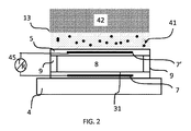
対照的に、前記CMUTの振動膜は、前記膜の面積(表面)にわたって異なる変位を持つ。従来の動作モードにおいて、前記膜の変位は、前記CMUTセルの中心部分において最高であり、前記膜の外縁において最低である。図10に示されるような動作の崩壊モード(collapsed mode)において、CMUTセル6の膜5は、セル床31に部分的に接触し、結果として従来の動作モードと比較して最大の膜変位(D)を生じる。前記CMUT動作中に、膜の中心部分46は、崩壊DC電圧値を印加することによりセル床31と接触(崩壊)させられうる(前記DC電圧は、駆動回路45により供給される)。駆動回路45により供給される印加されたAC信号電圧は、(前記膜の外縁に配置される)膜の掛けられた部分43に電極7及び7'の間の印加された電気信号下で振幅dで移動/振動させる。技術の観点から、前記崩壊膜を持つ前記CMUTは、原理的には、膜を持つCMUTを提供するステップ及び膜を崩壊状態にするために、電気(バイアス電圧)又は圧力のような異なる手段を使用するステップを有する、いかなる従来の様式で製造されることができる。崩壊動作モードにおいて、前記膜の中心部分の変位Dは固定であり、前記膜の掛けられた部分は、印加されるAC電圧信号により決定される振幅dで振動する。
In contrast, the CMUT vibrating membrane has different displacements over the area (surface) of the membrane. In conventional operating modes, the displacement of the membrane is highest at the central portion of the CMUT cell and lowest at the outer edge of the membrane. In the collapsed mode of operation as shown in FIG. 10, the
前記膜の振動部分の変位のばらつきは、動作するCMUTトランスデューサの改良された音響結合を提供するために前記音響窓層の特性に対して異なる要件を課す。前記音響窓層は、前記膜の変位に対して内側表面を選択する必要がありうる。高分子材料47、好ましくは熱硬化エラストマの単量体の比較的軽い分子量は、前記材料の比較的低い硬度(60ショアAより低い、好ましくは50ショアAより低い)と組み合わせて、音響窓層13と振動するように構成された前記CMUTの膜との間の改良された音響接触を提供しうる。加えて、この高分子材料の低い音響波減衰は、音響層13を通る波の改良された遷移を提供しうる。
Variations in the displacement of the vibrating portion of the membrane impose different requirements on the properties of the acoustic window layer in order to provide improved acoustic coupling of a working CMUT transducer. The acoustic window layer may need to select an inner surface for displacement of the membrane. The relatively light molecular weight of the
抗酸化物質分子の不在の場合に、ポリブタジエンを有する音響層が、酸化による経年劣化により引き起こされる前記高分子材料の硬度の増加を生じることが、わかっている。前記CMUTアレイと接触している前記音響層の硬度が、60ショアより上に増加する場合、(前記CMUTアレイに対する)前記層の音響送信特性は、実質的に減少される。時間とともに変化する特性を持つ音響材料を持つことは、望ましくなく、更に、不適切な音響波送信を持つ音響窓層で終わることは、更に望ましくない。 It has been found that in the absence of antioxidant molecules, an acoustic layer with polybutadiene results in an increase in the hardness of the polymeric material caused by aging due to oxidation. If the hardness of the acoustic layer in contact with the CMUT array increases above 60 shore, the acoustic transmission characteristics of the layer (relative to the CMUT array) are substantially reduced. Having an acoustic material with properties that change over time is undesirable, and it is even more undesirable to end up with an acoustic window layer with inadequate acoustic wave transmission.
本発明によると、抗酸化物質分子は、ポリブタジエン層に加えられる。例えば、フェノール系安定剤の分子が、使用されることができる。フェノール系安定剤は、前記高分子材料において水素供与体として機能する一次抗酸化物質である。これらは、ペルオキシラジカルと反応してヒドロペルオキシドを形成し、高分子骨格からの水素引き抜きを防止する。 According to the invention, antioxidant molecules are added to the polybutadiene layer. For example, phenolic stabilizer molecules can be used. Phenol stabilizers are primary antioxidants that function as hydrogen donors in the polymeric material. These react with peroxy radicals to form hydroperoxides and prevent hydrogen abstraction from the polymer backbone.
本実施例において、立体障害フェノールが、未硬化ポリブタジエン層とともに使用された。この抗酸化物質(BASF商品名Irganox 1076)の分子は、ヒンダードフェノール基(頭部)に結合された炭化水素鎖(又は尾部)を持つ。
本発明の他の実施例は、図2に示される。音響窓層13は、更に、外側表面側に配置された耐久性外面層42を有する第2の層を持ちうる。前記外側表面として配置された前記耐久性外面層は、音響窓層13の異なる機械的及び/又は化学的特性を満足しうる。例えば、前記超音波トランスデューサの目的に依存して、以下の材料、すなわち、高分子材料47に対して異なる摩耗抵抗を持つ材料、異なる摩擦係数を持つ材料が、前記第2の層において使用されうる。前記音響窓の化学的安定性を改良するために、前記第2の層は、ポリメチルペンテンのような熱可塑性高分子の層を持ちえ、防湿層を提供するために、マイラー、ポリエチレン及び/又はパリレンの層が、前記第2の層に導入されてもよい。
Another embodiment of the present invention is shown in FIG. The
音響窓層13の合計硬度を変化させるために、追加の層、ポリオレフィン熱可塑性エラストマが、選択されてもよい。例えば、共重合体は、オクタン又はブタンのようなアルファオレフィン及びエチレンの単量体を持つ。時々熱可塑性ゴムとも称される熱可塑性エラストマ(TPE)は、熱可塑性及びエラストマ特性の両方を持つ材料からなる高分子(通常はプラスチック及びゴム)の物理的混合物又は共重合体のクラスである。
In order to change the total hardness of the
改良された生体適合性又は弾性特性を持つ音響窓層を提供する追加の層が、音響窓13に導入されてもよいと、当業者により理解されるべきである。
It should be understood by those skilled in the art that additional layers may be introduced into the
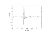
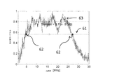
図3は、前記音響窓層を通って前記アレイの前記CMUTセルにより送信される基準音響信号を示す。図4は、5マイクロメートルの厚さのパリレンの第2の層をかぶせた30マイクロメートルの厚さのポリブタジエン層により覆われた前記アレイの正規化された出力圧力63を示す。図4に見られるように、前記ポリブタジエン層は、前記音響窓に優れた音響特性、特に超広帯域幅を提供する。前記アレイの出力圧力曲線63に対する水平線61の交点62は、3dBの前記信号の減衰において約5MHzの下方カットオフ周波数(f1)及び約27MHzの上方カットオフ周波数(f2)を与える。したがって、前記アレイの帯域幅は、約140%である。
FBW=2・(f2−f1)/(f2+f1)
の百分率値として計算される比帯域幅(FBW%)が参照されることに注意する。このアレイの相対感度は、印加されるAC信号の100Vに対して約4MPaである。前記相対感度は、以下のように決定される。CMUT電極7、7'に印加された各与えられたAC信号(例えば20V)に対して、出力圧力が測定され、次いで、100Vにおいて達成された出力圧力に対して正規化される。
FIG. 3 shows a reference acoustic signal transmitted by the CMUT cell of the array through the acoustic window layer. FIG. 4 shows the normalized
FBW = 2 · (f 2 −f 1 ) / (f 2 + f 1 )
Note that the specific bandwidth (FBW%) calculated as a percentage value of is referenced. The relative sensitivity of this array is about 4 MPa for 100 V of the applied AC signal. The relative sensitivity is determined as follows. For each given AC signal (eg, 20V) applied to
図5は、TPX材料の第2の層をかぶせられた60マイクロメートルの厚さのポリブタジエン層により覆われた前記アレイの正規化された出力圧力64を示し、前記TPX層は、0.2ミリメートルの厚さであり、ポリウレタンの第3の層でポリブタジエンの第1の層に接着される。前記アレイの出力圧力曲線64に対する水平線65の交点66は、3dBの信号減衰において、約5MHzの下方カットオフ周波数(f1)及び約23MHzの上方カットオフ周波数(f2)を与える。したがって、前記アレイの帯域幅は、約130%である。前記CMUT膜と結合するポリブタジエンの第1の層より厚い耐久性材料層の導入でさえ、前記アレイの超広帯域幅を大幅に減少させない。この実施例における前記アレイの感度は、100Vに対して約3MPaである。前記TPX材料の追加の利点は、特に医療的応用において一般に使用される洗浄剤に対する、化学的安定性、及び機械的耐久性である。
FIG. 5 shows the normalized
水素及び炭素原子を含み、0.95g/cm以下の密度を持つ前記高分子層、特に熱硬化エラストマは、低い音響エネルギ損失(減衰)及び適切な音響インピーダンス最適化を示しうる。 Said polymer layer, especially thermoset elastomers, containing hydrogen and carbon atoms and having a density of 0.95 g / cm or less may exhibit low acoustic energy loss (damping) and appropriate acoustic impedance optimization.
音響インピーダンス(Z)は、媒体内の音響エネルギ(又は波)に対する音響伝搬速度(v)及び前記媒体の密度(ρ)の積として規定される。
Z=ρ×v
これらの高分子材料は、約1.6MRaylの軟組織のインピーダンスに近い、約1.4MRaylより上の音響インピーダンスを持ちうる。前記超音波アレイと前記超音波処理される組織との間のインピーダンス不整合を最小化するために、前記高分子層を有する前記音響窓材料の音響インピーダンス値を更に増加することが、望ましいかもしれない。これは、高分子層47内に粒子41(好ましくは絶縁性)のような充填剤を加えることにより達成されることができる。前記高分子層内への前記粒子の導入は、前記第1の層の合計密度を増加させる。埋め込まれた絶縁粒子により引き起こされる追加の音響損失が、十分に低く、前記高分子層を通る音響波伝搬の品質に大幅な影響を与えないことが、発見された。
The acoustic impedance (Z) is defined as the product of the acoustic propagation velocity (v) for the acoustic energy (or waves) in the medium and the density (ρ) of the medium.
Z = ρ × v
These polymeric materials can have an acoustic impedance above about 1.4 MRayl, close to the soft tissue impedance of about 1.6 MRayl. It may be desirable to further increase the acoustic impedance value of the acoustic window material having the polymer layer to minimize impedance mismatch between the ultrasound array and the sonicated tissue. Absent. This can be achieved by adding a filler such as particles 41 (preferably insulating) in the
一例として、表2は、約2.5マイクロメートルの平均直径を持ち、前記第1の層の合計重量の固定の割合を取る二酸化ジルコニウム(ZrO2)絶縁粒子の導入に対する前記ポリブタジエン層の音響特性の測定された変化を示す。
ポリブタジエンを有する前記第1の層の合計密度増加を持つ前記表から見られるように、前記層の音響インピーダンスは、例えば前記組織の音響インピーダンスに近い、より高い値に向けて調整されることができ、前記層の減衰は、その重量の20%を前記絶縁粒子(ZrO2)により取られた前記層に対してでさえ、1.5dB/mmより低いままである。前記抗酸化物質分子と絶縁粒子を埋め込まれた前記高分子材料とを有する前記音響窓層の前記第1の層が、0.94g/cm以上の密度及び約1.5MRayl以上の音響インピーダンスを持つ場合に、前記CMUTセルの前記膜に対する前記音響窓層の直接的な音響結合が、提供される。したがって、前記音響窓と前記CMUTアレイとの間の追加の結合媒体は、必要とされない。更に、1.5MRayl以上の音響インピーダンスは、前記超音波処理される組織のインピーダンスに、より近く整合する。 As can be seen from the table with the total density increase of the first layer with polybutadiene, the acoustic impedance of the layer can be adjusted towards higher values, for example close to the acoustic impedance of the tissue. The attenuation of the layer remains below 1.5 dB / mm, even for the layer taken up by 20% of its weight by the insulating particles (ZrO 2 ). The first layer of the acoustic window layer having the antioxidant molecule and the polymeric material embedded with insulating particles has a density of 0.94 g / cm or more and an acoustic impedance of about 1.5 MRayl or more. In some cases, direct acoustic coupling of the acoustic window layer to the membrane of the CMUT cell is provided. Thus, no additional coupling medium between the acoustic window and the CMUT array is required. In addition, an acoustic impedance of 1.5 MRayl or greater matches more closely to the impedance of the sonicated tissue.
水素及び炭素原子を含み、0.95g/cm以下の密度及び1.45MRayl、好ましくは1.5MRayl以上の音響インピーダンスを持つ前記高分子材料の追加の利点は、超音波において一般に使用されるシリコンベースのゴム(約1.1乃至1.2MRaylの典型的な音響インピーダンスを持つ)と比較して、これらの高分子材料、特にポリブタジエンは、より高い音響インピーダンスを有する。したがって、高分子層47の音響インピーダンスを組織のインピーダンスまで調整するために、充填されたシリコーンと比較して、比較的少量の充填剤が、使用されうる。層への絶縁粒子の導入は、平均で硬度を増加させるので、より高い音響インピーダンスを持つこれらの高分子材料の使用は、充填されたシリコーンと比較して、充填後の比較的小さい変更された硬度(60ショアAより低い、好ましくは50ショアAより低いままである)及び大幅に低い減衰(好ましくは1.5又は2dB/mmより低い)を持つ音響窓層13を提供する。充填されたシリコンの音響インピーダンスを前記軟組織のインピーダンスに、すなわち1.1MRaylから1.6MRaylまで近づけるために、より大量の充填粒子が必要とされる。前記粒子のこの導入は、大きな減衰を導入し、充填されたシリコン層の硬度を増加させる。
An additional advantage of the polymeric material containing hydrogen and carbon atoms, having a density of 0.95 g / cm or less and an acoustic impedance of 1.45 MRayl, preferably 1.5 MRayl or more is the silicon base commonly used in ultrasound These polymeric materials, especially polybutadiene, have a higher acoustic impedance compared to the rubbers (with a typical acoustic impedance of about 1.1 to 1.2 MRayl). Thus, a relatively small amount of filler can be used to adjust the acoustic impedance of the
前記CMUTセルの前記膜に対する前記音響窓層の最適な音響結合は、低い減衰及び1.4MRaylより上の音響インピーダンスを持ち、経時的な酸化(経年劣化)に対して耐久性のある未硬化高分子材料と、前記埋め込まれた絶縁粒子の導入を持つ前記第1の層の比較的一定の硬度との組み合わせにより提供されることができる。 The optimal acoustic coupling of the acoustic window layer to the membrane of the CMUT cell has an uncured high durability with low attenuation and acoustic impedance above 1.4 MRayl and durable against aging (aging). It can be provided by a combination of molecular material and a relatively constant hardness of the first layer with the introduction of the embedded insulating particles.
本発明による前記第1の層を有する前記音響窓層の使用の利点は、崩壊モードで動作するCMUTセルを使用する前記トランスデューサアレイに対して更に目立つ。前記崩壊モードの動作は、前記CMUTの電極に印加されるDCバイアス電圧を変化させることにより調整されることができる幅広い範囲の音響波周波数において超音波アレイを動作させることを可能にする。したがって、従来の(非崩壊)CMUT動作モードと比較して、前記音響窓層帯域幅に対して、より高い要件を課す。本発明の原理によって音響窓層13により覆われた前記超音波アレイ(好ましくは、しかしながら非限定的に、CMUT超音波アレイ)に対する好適な帯域幅は、80%より高い、好ましくは100%又は120%より高い。PZTとは異なる、CMUTにおいて使用される電気から音響エネルギへの変換原理は、前記CMUT動作の崩壊モードに対して更に目立つようになりうる、前記CMUTの振動膜と直接的に接触する前記音響窓層に向けて、CMUTアレイを、より要求の多いものにする。
The advantages of using the acoustic window layer with the first layer according to the present invention are even more pronounced for the transducer array using CMUT cells operating in collapsed mode. The collapse mode operation allows the ultrasound array to operate at a wide range of acoustic frequencies that can be adjusted by changing the DC bias voltage applied to the electrodes of the CMUT. Therefore, it imposes higher requirements on the acoustic window layer bandwidth compared to the conventional (non-collapse) CMUT mode of operation. A suitable bandwidth for the ultrasound array (preferably, but not exclusively, a CMUT ultrasound array) covered by an
第1の層47の減衰特性に対して、より良好な制御を持つために、前記絶縁粒子は、音響波長の10分の1より小さい平均サイズを持ちうる。好ましくは、前記粒子の平均サイズは、前記超音波アレイの動作帯域幅内の最短波の音響波長の10分の1より小さい。前記帯域幅は、高い周波数(15MHzより高い)及び高い画像解像度の心臓撮像のような超音波応用に基づいて選択されうる。前記粒子の平均サイズが、伝搬波の波長より大きくなる場合、前記音響窓層における追加の散乱が、起きうる。これは、超音波画像にアーチファクトを導入しうる。
In order to have better control over the attenuation characteristics of the
前記粒子の特定の平均サイズは、10ナノメートル乃至10マイクロメートル、10ナノメートル乃至100ナノメートル、又は1マイクロメートル乃至10マイクロメートルでありうる。これらの範囲の平均粒子は、異なる周波数における超音波撮像システムの主要な応用をカバーする。例えば、1500m/sの音響波速度に対して、音響波長の10分の1は、1MHzの周波数に対して150マイクロメートル、10MHzの周波数に対して15マイクロメートル、及び30MHzの周波数に対して5マイクロメートルである。 The specific average size of the particles can be 10 nanometers to 10 micrometers, 10 nanometers to 100 nanometers, or 1 micrometer to 10 micrometers. These ranges of average particles cover the major applications of ultrasound imaging systems at different frequencies. For example, for an acoustic wave velocity of 1500 m / s, one tenth of the acoustic wavelength is 150 micrometers for a frequency of 1 MHz, 15 micrometers for a frequency of 10 MHz, and 5 for a frequency of 30 MHz. Micrometer.
本発明の一実施例において、前記絶縁粒子としてセラミック粒子を使用することは、有益でありうる。酸化金属(ZrO2、Al2O3、TiO2、Bi2O3、BaSO4等)のようなセラミック粒子は、高い絶縁特性を示し、これは、アレイ電子機器に追加の絶縁を提供するのに有利でありうる。更に、当技術分野において開発された、明確に定義されたサイズのセラミック粒子を製造する複数の方法が存在する。
In one embodiment of the present invention, it may be beneficial to use ceramic particles as the insulating particles. Ceramic particles such as metal oxides (
前記高分子材料の開発された工業的応用が、更に記載される。図7において、本発明による超音波アレイを製造する新しい方法20が、示される。重合前のポリブタジエン38(LanxessからのCB728 T)の粒が、ステップ31において提供される。ステップ32において、ブロックが粒状にされ、アルカン、分岐又は環状アルカン、例えばヘキサン、ヘプタン、シクロヘキサンのような溶媒に溶かされる。ステップ33において、立体障害フェノールのような抗酸化物質(本例においてIraganox 1076)が加えられ、更に、前記第1の層の音響インピーダンスの最適化が、前記溶媒に絶縁粒子を加えることにより達成されることができ、前記高分子材料は、前記高分子材料及び前記絶縁粒子の液体混合物が提供されるように、前記粒子に対する分散剤として機能する。脂肪酸(飽和又は不飽和のいずれかである脂肪族鎖を持つカルボン酸)のような追加の分散剤が、前記液体混合物に加えられうる。前記液体混合物における充填剤粒子は、前記音響窓の前記第1の層の硬度を増加させえ、脂肪酸は、この硬度増加に反撃しえ、前記第1の層の平均硬度を比較的一定の値に保つ。オレイン酸、リノール酸及びリノレン酸(それぞれ1、2及び3の二重炭素結合)のような脂肪酸の不飽和鎖は、重合し、ポリブタジエン鎖に結合することができる。これは、前記液体混合物において粒子の良好な分散/分布を提供する。ステップ54において、集積回路に結合された少なくとも1つのCMUTセルを持つ前記超音波アレイを持つチップが、提供される。ステップ34において、前記チップは、前記液体混合物を有する層が前記CMUTセルを覆うように、前記液体混合物内に浸漬される。代わりに、ステップ34において、前記液体混合物が、当業者に既知の分散技術を使用して前記チップ上に分注されることができる。ステップ33において、前記液体混合物と前記伝搬媒体との間の最小のインピーダンス不整合が、達成されることができるので、前記液体混合物層の厚さの変化に対する耐性は、かなり高い。浸漬時間の増加は、前記液体混合物層の厚さを増加する。ステップ35において、前記液体混合物層を持つ前記チップは、約70℃の高温で乾燥させられうる。前記溶媒が前記液体混合物から蒸発し始める時間に対して、前記液体混合物層は、より固体(粘着性)になりうる。この段階において、他の材料の第2の層が、前記液体混合物層に付着されることができる。このステップの利点は、前記第2の層が、いかなる接着剤もなしで前記第1の層に取り付けられることができることである。ステップ36において、前記CMUTセルを覆う前記層は、絶縁粒子41を埋め込まれた高分子材料47を有する音響窓層13が提供されて前記CMUTセルを覆うように、前記液体混合物層から残りの溶媒を蒸発させるのに十分な温度(ヘプタンの場合に約100℃)で硬化される。代わりに、より良好な固定を保証するように、前記第2の層は、接着剤の第3の層で前記第1の層に結合され、更にステップ37において硬化されてもよい。
The developed industrial application of the polymeric material is further described. In FIG. 7, a
この方法は、有利には、工程の単純さと音響層窓の厚さに対する前記超音波アレイの性能の大きな耐性とのおかげで工業規模で適用されることができる。前記層の厚さは、浸漬34及び乾燥35のステップを繰り返すことにより増加されることができる。ステップ33におけるインピーダンス最適化の可能性及び本発明の原理による選択された高分子材料の低い減衰特性により、前記平均値からの前記音響窓層における局所厚さずれは、一般に使用される噴霧又はスピンコート製造における受け入れられた標準より高いことができる。加えて、この製造方法は、異なるチップ設計及び前記アレイにおいて実施される電気接点結合において柔軟性を提供する。
This method can advantageously be applied on an industrial scale thanks to the simplicity of the process and the great tolerance of the performance of the ultrasound array to the thickness of the acoustic layer window. The layer thickness can be increased by repeating the steps of dipping 34 and drying 35. Due to the possibility of impedance optimization in
例えば、図8は、本発明の方法を使用する音響窓層堆積の前(a)及び後(b)のボンディングワイヤ22と一緒に超音波アレイ23を有するチップの写真を示す。音響レンズ(又は窓層)の一般に使用される噴霧又はスピンコート製造方法は、高度に層の厚さに敏感であり、独立のボンディングワイヤ22の周りの前記アレイの均質なカバレージを提供するのに失敗しうる(図8aは、ボンディングワイヤ22の近接撮影を示す)。図8(b)に見られるように、提示された方法は、この問題を克服して、改良された広い帯域幅性能を持つ安定した音響窓を持つ完全に覆われたCMUTトランスデューサアレイを提供する。
For example, FIG. 8 shows a photograph of a chip having an ultrasonic array 23 with
前記方法は、異なるチップサイズに対して、特に介入装置及びカテーテルのような小型超音波アレイの分野において、有益に使用されることもできる。 The method can also be beneficially used for different chip sizes, especially in the field of small ultrasound arrays such as interventional devices and catheters.
図9は、超音波撮像システム202の原理的設計を示す。
FIG. 9 shows the principle design of the
前記超音波撮像システムは、一般に、参照番号202で示される。超音波撮像システム202は、例えば患者201の体の領域又は体積をスキャンするのに使用される。超音波システム202は、他の領域又は体積、例えば動物若しくは他の生物の身体部分をスキャンするのに使用されてもよい。
The ultrasound imaging system is generally indicated by
患者201をスキャンするために、超音波プローブ200が、提供されうる。図示された実施例において、超音波プローブ200は、コンソール装置203に接続される。コンソール装置203は、モバイルコンソールとして図9に示される。このコンソール203は、しかしながら、静止装置として実現されてもよい。コンソール装置203は、有線形式で形成されたインタフェース206を介してプローブ200に接続される。更に、コンソール装置203が、例えばUWB送信技術を使用して、無線形式でプローブ200に接続されてもよい。コンソール装置203は、更に、入力装置205を有してもよい。前記入力装置は、超音波撮像システム202のユーザに入力機構を提供するようにボタン、キーパッド及び/又はタッチスクリーンを持ちうる。加えて又は代わりに、ユーザが超音波撮像システム202を制御することを可能にするように、他の機構が、入力装置205内に存在してもよい。
In order to scan the
更に、コンソール装置203は、超音波撮像システム202により生成された表示データを前記ユーザに表示するディスプレイ204を有する。これにより、超音波プローブ200によりスキャンされる患者201内の体積が、超音波システム200の前記ユーザによりコンソール装置203上で見られることができる。
Further, the
超音波プローブ200は、本発明によって構成されたCMUTトランスデューサアレイを有する。
The
開示された実施例に対する他の変形例は、図面、開示及び添付の請求項の検討から、請求された発明を実施する当業者により理解及び達成されることができる。 Other variations to the disclosed embodiments can be understood and attained by those skilled in the art in practicing the claimed invention, from a study of the drawings, the disclosure, and the appended claims.
請求項において、単語「有する」は、他の要素又はステップを除外せず、不定冠詞「1つの」は、複数を除外しない。 In the claims, the word “comprising” does not exclude other elements or steps, and the indefinite article “a” does not exclude a plurality.
単一のユニット又は装置が、請求項に記載された複数のアイテムの機能を満たしてもよい。特定の方策が相互に異なる従属請求項に記載されているという単なる事実は、これらの方策の組み合わせが有利に使用されることができないことを示さない。 A single unit or device may fulfill the functions of several items recited in the claims. The mere fact that certain measures are recited in mutually different dependent claims does not indicate that a combination of these measures cannot be used to advantage.
コンピュータプログラムは、他のハードウェアの一部として又は一緒に供給される光記憶媒体又は半導体媒体のような適切な媒体に記憶/分配されてもよいが、インターネット又は他の有線若しくは無線電気通信システムを介するような他の形式で分配されてもよい。 The computer program may be stored / distributed on a suitable medium, such as an optical storage medium or a semiconductor medium supplied as part of or together with other hardware, but the Internet or other wired or wireless telecommunications system It may be distributed in other forms, such as via
Claims (15)
外側表面及び前記セル膜に対向する内側表面を持ち、前記セル膜を覆う音響窓層と、
を有する音響波送信に対する超音波アレイにおいて、
前記音響窓層が、抗酸化物質の分子及び中に粒子を埋め込まれた高分子材料を有する第1の層を有し、前記高分子材料が、水素及び炭素原子を含み、前記第1の層が、0.95g/cm3以下の密度及び1.45MRayl以上の音響インピーダンスを持つことを特徴とする、超音波アレイ。 At least one having a substrate, a first electrode, and a cell film having the first electrode and a second electrode facing the substrate with a cavity in between and configured to vibrate when the cell is activated A capacitive micromachined ultrasonic transducer (CMUT) cell;
An acoustic window layer having an outer surface and an inner surface facing the cell membrane, covering the cell membrane;
In an ultrasonic array for acoustic wave transmission having
The acoustic window layer has a first layer having an antioxidant substance molecule and a polymer material in which particles are embedded, the polymer material containing hydrogen and carbon atoms, and the first layer Has an density of 0.95 g / cm 3 or less and an acoustic impedance of 1.45 MRayl or more.
前記溶媒に抗酸化物質及び粒子を加えるステップであって、前記高分子材料は、前記高分子材料及び前記絶縁粒子の液体混合物が提供されるように、前記粒子に対する分散剤として機能する、当該加えるステップと、
集積回路に結合された少なくとも1つのCMUTセルを持つチップを提供するステップと、
前記液体混合物を有する層が前記CMUTセルを覆うように、前記液体混合物内に前記チップを浸漬する又は前記チップ上に前記液体混合物を分注するステップと、
絶縁粒子を中に埋め込まれた高分子材料を有する音響窓層が提供されて前記CMUTセルを覆うように、前記液体混合物から前記溶媒を蒸発させるのに十分な温度で前記層を硬化させるステップと、
を有する超音波アレイを製造する方法。 Dissolving a polymeric material in a solvent;
Adding an antioxidant and particles to the solvent, wherein the polymeric material serves as a dispersant for the particles such that a liquid mixture of the polymeric material and the insulating particles is provided. Steps,
Providing a chip having at least one CMUT cell coupled to an integrated circuit;
Immersing the tip in the liquid mixture or dispensing the liquid mixture on the tip such that the layer having the liquid mixture covers the CMUT cell;
Curing the layer at a temperature sufficient to evaporate the solvent from the liquid mixture so that an acoustic window layer having a polymeric material embedded with insulating particles is provided to cover the CMUT cell; ,
A method of manufacturing an ultrasonic array having
Applications Claiming Priority (3)
| Application Number | Priority Date | Filing Date | Title |
|---|---|---|---|
| EP15157276 | 2015-03-03 | ||
| EP15157276.5 | 2015-03-03 | ||
| PCT/EP2016/053799 WO2016139087A1 (en) | 2015-03-03 | 2016-02-23 | A cmut array comprising an acoustic window layer |
Publications (2)
| Publication Number | Publication Date |
|---|---|
| JP2018512766A true JP2018512766A (en) | 2018-05-17 |
| JP2018512766A5 JP2018512766A5 (en) | 2019-03-14 |
Family
ID=52595202
Family Applications (1)
| Application Number | Title | Priority Date | Filing Date |
|---|---|---|---|
| JP2017544959A Pending JP2018512766A (en) | 2015-03-03 | 2016-02-23 | CMUT array with acoustic window layer |
Country Status (5)
| Country | Link |
|---|---|
| US (1) | US11358174B2 (en) |
| EP (1) | EP3265244A1 (en) |
| JP (1) | JP2018512766A (en) |
| CN (1) | CN107405648B (en) |
| WO (1) | WO2016139087A1 (en) |
Families Citing this family (7)
| Publication number | Priority date | Publication date | Assignee | Title |
|---|---|---|---|---|
| US11386883B2 (en) * | 2015-12-18 | 2022-07-12 | Koninklijke Philips N.V. | Acoustic lens for an ultrasound array |
| EP3506833B1 (en) * | 2016-08-30 | 2020-10-07 | Koninklijke Philips N.V. | Imaging device with ultrasound transducer array |
| US11253232B2 (en) * | 2016-11-15 | 2022-02-22 | Koninklijke Philips N.V. | Ultrasound device contacting |
| US20190357882A1 (en) * | 2016-11-22 | 2019-11-28 | Koninklijke Philips N.V. | Ultrasound device and acoustic component for use in such a device |
| US11061000B2 (en) | 2016-12-01 | 2021-07-13 | Koninklijke Philips N.V. | CMUT probe, system and method |
| AU2019231793A1 (en) | 2018-03-09 | 2020-09-24 | Butterfly Network, Inc. | Ultrasound transducer devices and methods for fabricating ultrasound transducer devices |
| EP3590437A1 (en) * | 2018-07-02 | 2020-01-08 | Koninklijke Philips N.V. | Acoustically transparent window for intraluminal ultrasound imaging device |
Citations (4)
| Publication number | Priority date | Publication date | Assignee | Title |
|---|---|---|---|---|
| JPS62233149A (en) * | 1986-04-02 | 1987-10-13 | 松下電器産業株式会社 | Ultrasonic probe |
| JP2000001652A (en) * | 1998-06-12 | 2000-01-07 | Tomoegawa Paper Co Ltd | Adhesive tape |
| JP2014144155A (en) * | 2013-01-30 | 2014-08-14 | Nippon Zeon Co Ltd | Acoustic medium |
| JP2014183589A (en) * | 2013-03-15 | 2014-09-29 | Sonosite Inc | Acoustic lens for micromachined ultrasound transducer |
Family Cites Families (35)
| Publication number | Priority date | Publication date | Assignee | Title |
|---|---|---|---|---|
| FR2585944B1 (en) * | 1985-08-12 | 1988-07-08 | Alvar Electronic Sa | IMPLANTABLE ULTRASOUND PROBE AND ITS MANUFACTURING PROCESS |
| DE3787746T2 (en) | 1986-04-02 | 1994-02-17 | Matsushita Electric Ind Co Ltd | Ultrasound transducer with an ultrasound propagation medium. |
| US4813415A (en) * | 1986-08-18 | 1989-03-21 | Siemens Aktiengesellschaft | Sensor for evaluation of shock wave pulses |
| US5318035A (en) * | 1991-12-02 | 1994-06-07 | Nitto Denko Corporation | Crosslinked molding, sound medium using it and ultrasonic coupler |
| US5423220A (en) * | 1993-01-29 | 1995-06-13 | Parallel Design | Ultrasonic transducer array and manufacturing method thereof |
| IT1264623B1 (en) * | 1993-06-16 | 1996-10-04 | Enichem Spa | (CO) AROMATIC VINYL POLYMER REINFORCED WITH RUBBER |
| US5355048A (en) * | 1993-07-21 | 1994-10-11 | Fsi International, Inc. | Megasonic transducer for cleaning substrate surfaces |
| US6443901B1 (en) * | 2000-06-15 | 2002-09-03 | Koninklijke Philips Electronics N.V. | Capacitive micromachined ultrasonic transducers |
| DE60138247D1 (en) * | 2000-07-13 | 2009-05-20 | Panasonic Corp | Acoustic lens and related manufacturing process |
| JP3655860B2 (en) * | 2001-09-27 | 2005-06-02 | アロカ株式会社 | Ultrasonic probe |
| JP2003169806A (en) * | 2001-12-05 | 2003-06-17 | Olympus Optical Co Ltd | Ultrasonic probe |
| US6599249B1 (en) * | 2002-02-14 | 2003-07-29 | Koninklijke Philips Electronics N.V. | Intraoperative ultrasound probe with an integrated acoustic standoff |
| US6865140B2 (en) * | 2003-03-06 | 2005-03-08 | General Electric Company | Mosaic arrays using micromachined ultrasound transducers |
| US6831876B1 (en) * | 2003-07-09 | 2004-12-14 | Goodrich Corporation | Acoustic window |
| US20050113700A1 (en) * | 2003-11-26 | 2005-05-26 | Koji Yanagihara | Ultrasonic probe |
| US7588540B2 (en) * | 2005-04-08 | 2009-09-15 | Vermon | Ultrasonic probe for scanning a volume |
| US7658967B2 (en) * | 2005-08-25 | 2010-02-09 | Pittsburgh Glass Works, Llc | Methods for applying sound dampening and/or aesthetic coatings and articles made thereby |
| EP1950997B1 (en) * | 2005-10-18 | 2019-10-09 | Hitachi, Ltd. | Ultrasonic probe |
| US7750536B2 (en) * | 2006-03-02 | 2010-07-06 | Visualsonics Inc. | High frequency ultrasonic transducer and matching layer comprising cyanoacrylate |
| JP5075665B2 (en) * | 2008-02-18 | 2012-11-21 | 株式会社東芝 | Two-dimensional array ultrasonic probe |
| US7902294B2 (en) * | 2008-03-28 | 2011-03-08 | General Electric Company | Silicone rubber compositions comprising bismuth oxide and articles made therefrom |
| KR20110137576A (en) * | 2010-06-17 | 2011-12-23 | 삼성전기주식회사 | Conductive polymer composition for transparent electrode and touch panel using the same |
| JP5881582B2 (en) | 2012-02-07 | 2016-03-09 | 富士フイルム株式会社 | Manufacturing method of ultrasonic probe |
| US9221077B2 (en) * | 2012-05-09 | 2015-12-29 | Kolo Technologies, Inc. | CMUT assembly with acoustic window |
| US20130319729A1 (en) * | 2012-06-01 | 2013-12-05 | Nuovo Film Inc. | Low Haze Transparent Conductive Electrodes and Method of Making the Same |
| US20150321026A1 (en) * | 2012-06-07 | 2015-11-12 | Ulthera, Inc. | Devices and methods for ultrasound focal depth control |
| KR20140070005A (en) * | 2012-11-30 | 2014-06-10 | 코닝정밀소재 주식회사 | Transparent conductive substrate and touch panel having the same |
| JP6149425B2 (en) * | 2013-03-01 | 2017-06-21 | コニカミノルタ株式会社 | Manufacturing method of ultrasonic probe |
| CN113648551A (en) * | 2013-03-08 | 2021-11-16 | 奥赛拉公司 | Apparatus and method for multi-focal ultrasound therapy |
| WO2015095721A1 (en) * | 2013-12-20 | 2015-06-25 | Fujifilm Sonosite, Inc. | High frequency ultrasound transducers |
| MX371246B (en) * | 2014-04-18 | 2020-01-22 | Ulthera Inc | Band transducer ultrasound therapy. |
| US10572707B2 (en) * | 2016-02-09 | 2020-02-25 | Synaptics Incorporated | Transparent fingerprint sensor pattern |
| RU2748788C2 (en) * | 2016-08-16 | 2021-05-31 | Ультера, Инк. | Systems and methods for cosmetic ultrasonic skin treatment |
| TW202327520A (en) * | 2018-01-26 | 2023-07-16 | 美商奧賽拉公司 | Systems and methods for simultaneous multi-focus ultrasound therapy in multiple dimensions |
| US11944849B2 (en) * | 2018-02-20 | 2024-04-02 | Ulthera, Inc. | Systems and methods for combined cosmetic treatment of cellulite with ultrasound |
-
2016
- 2016-02-23 WO PCT/EP2016/053799 patent/WO2016139087A1/en active Application Filing
- 2016-02-23 US US15/554,454 patent/US11358174B2/en active Active
- 2016-02-23 JP JP2017544959A patent/JP2018512766A/en active Pending
- 2016-02-23 CN CN201680013262.9A patent/CN107405648B/en not_active Expired - Fee Related
- 2016-02-23 EP EP16707036.6A patent/EP3265244A1/en not_active Withdrawn
Patent Citations (4)
| Publication number | Priority date | Publication date | Assignee | Title |
|---|---|---|---|---|
| JPS62233149A (en) * | 1986-04-02 | 1987-10-13 | 松下電器産業株式会社 | Ultrasonic probe |
| JP2000001652A (en) * | 1998-06-12 | 2000-01-07 | Tomoegawa Paper Co Ltd | Adhesive tape |
| JP2014144155A (en) * | 2013-01-30 | 2014-08-14 | Nippon Zeon Co Ltd | Acoustic medium |
| JP2014183589A (en) * | 2013-03-15 | 2014-09-29 | Sonosite Inc | Acoustic lens for micromachined ultrasound transducer |
Also Published As
| Publication number | Publication date |
|---|---|
| CN107405648B (en) | 2021-08-10 |
| US11358174B2 (en) | 2022-06-14 |
| CN107405648A (en) | 2017-11-28 |
| WO2016139087A1 (en) | 2016-09-09 |
| US20180065148A1 (en) | 2018-03-08 |
| EP3265244A1 (en) | 2018-01-10 |
Similar Documents
| Publication | Publication Date | Title |
|---|---|---|
| CN107405648B (en) | CMUT array including acoustic window layer | |
| CN107405649B (en) | CMUT array including acoustic window layer | |
| US10736606B2 (en) | Acoustic window layer for an ultrasound array | |
| CN108430651B (en) | Acoustic lens for ultrasound array | |
| US11278932B2 (en) | Capacitive micro-machined ultrasound transducer cell | |
| US11627938B2 (en) | Imaging device with ultrasound transducer array | |
| WO2023016133A1 (en) | Diaphragm of sound production device, preparation method for diaphragm, and sound production device | |
| WO2023016132A1 (en) | Diaphragm of sound generation device, preparation method therefor, and sound generation device | |
| CN109069107B (en) | Ultrasonic device contact | |
| US11529120B2 (en) | Ultrasound device contacting | |
| CN113490129A (en) | Vibrating diaphragm for sound production device and sound production device | |
| JP2016040798A (en) | Piezoelectric material, manufacturing method of the same, ultrasonic transducer, and ultrasonic imaging apparatus | |
| JP2011072162A (en) | Dielectric film and transducer using the same | |
| JP2011155574A (en) | Laminated ultrasonic vibrator, ultrasonic probe using the same, and ultrasonic medical image diagnostic device | |
| WO2021186276A1 (en) | Diaphragm for microspeaker and manufacturing method thereof | |
| CN114989619A (en) | Vibrating diaphragm of sound production device, preparation method of vibrating diaphragm and sound production device |
Legal Events
| Date | Code | Title | Description |
|---|---|---|---|
| A521 | Request for written amendment filed |
Free format text: JAPANESE INTERMEDIATE CODE: A523 Effective date: 20190201 |
|
| A621 | Written request for application examination |
Free format text: JAPANESE INTERMEDIATE CODE: A621 Effective date: 20190201 |
|
| A977 | Report on retrieval |
Free format text: JAPANESE INTERMEDIATE CODE: A971007 Effective date: 20200207 |
|
| A131 | Notification of reasons for refusal |
Free format text: JAPANESE INTERMEDIATE CODE: A131 Effective date: 20200312 |
|
| A601 | Written request for extension of time |
Free format text: JAPANESE INTERMEDIATE CODE: A601 Effective date: 20200612 |
|
| A521 | Request for written amendment filed |
Free format text: JAPANESE INTERMEDIATE CODE: A523 Effective date: 20200910 |
|
| A02 | Decision of refusal |
Free format text: JAPANESE INTERMEDIATE CODE: A02 Effective date: 20210325 |