EP3506833B1 - Imaging device with ultrasound transducer array - Google Patents
Imaging device with ultrasound transducer array Download PDFInfo
- Publication number
- EP3506833B1 EP3506833B1 EP17755180.1A EP17755180A EP3506833B1 EP 3506833 B1 EP3506833 B1 EP 3506833B1 EP 17755180 A EP17755180 A EP 17755180A EP 3506833 B1 EP3506833 B1 EP 3506833B1
- Authority
- EP
- European Patent Office
- Prior art keywords
- layer
- ultrasound
- ultrasound transducer
- imaging device
- hydrocarbon elastomer
- Prior art date
- Legal status (The legal status is an assumption and is not a legal conclusion. Google has not performed a legal analysis and makes no representation as to the accuracy of the status listed.)
- Active
Links
- 238000002604 ultrasonography Methods 0.000 title claims description 158
- 238000003384 imaging method Methods 0.000 title claims description 53
- 229920001971 elastomer Polymers 0.000 claims description 75
- 239000000806 elastomer Substances 0.000 claims description 75
- 150000002430 hydrocarbons Chemical class 0.000 claims description 72
- 239000004215 Carbon black (E152) Substances 0.000 claims description 71
- 229930195733 hydrocarbon Natural products 0.000 claims description 71
- 239000003963 antioxidant agent Substances 0.000 claims description 34
- 230000003078 antioxidant effect Effects 0.000 claims description 31
- 239000002245 particle Substances 0.000 claims description 31
- 239000005062 Polybutadiene Substances 0.000 claims description 20
- 238000000034 method Methods 0.000 claims description 20
- 229920002857 polybutadiene Polymers 0.000 claims description 20
- 239000003960 organic solvent Substances 0.000 claims description 13
- 239000000523 sample Substances 0.000 claims description 12
- 238000012285 ultrasound imaging Methods 0.000 claims description 11
- ISWSIDIOOBJBQZ-UHFFFAOYSA-N phenol group Chemical group C1(=CC=CC=C1)O ISWSIDIOOBJBQZ-UHFFFAOYSA-N 0.000 claims description 9
- 239000003381 stabilizer Substances 0.000 claims description 8
- 238000004132 cross linking Methods 0.000 claims description 6
- 238000000151 deposition Methods 0.000 claims description 6
- 239000000919 ceramic Substances 0.000 claims description 3
- 210000004027 cell Anatomy 0.000 description 25
- 239000012528 membrane Substances 0.000 description 21
- 210000001519 tissue Anatomy 0.000 description 15
- 239000000463 material Substances 0.000 description 14
- 238000002592 echocardiography Methods 0.000 description 10
- 238000004073 vulcanization Methods 0.000 description 8
- MCMNRKCIXSYSNV-UHFFFAOYSA-N ZrO2 Inorganic materials O=[Zr]=O MCMNRKCIXSYSNV-UHFFFAOYSA-N 0.000 description 7
- 230000033001 locomotion Effects 0.000 description 7
- RVTZCBVAJQQJTK-UHFFFAOYSA-N oxygen(2-);zirconium(4+) Chemical compound [O-2].[O-2].[Zr+4] RVTZCBVAJQQJTK-UHFFFAOYSA-N 0.000 description 7
- IMNFDUFMRHMDMM-UHFFFAOYSA-N N-Heptane Chemical compound CCCCCCC IMNFDUFMRHMDMM-UHFFFAOYSA-N 0.000 description 6
- 230000017531 blood circulation Effects 0.000 description 6
- 239000002904 solvent Substances 0.000 description 6
- 239000000853 adhesive Substances 0.000 description 5
- 230000001070 adhesive effect Effects 0.000 description 5
- 238000003491 array Methods 0.000 description 5
- 230000004888 barrier function Effects 0.000 description 5
- 230000002349 favourable effect Effects 0.000 description 5
- 239000000203 mixture Substances 0.000 description 5
- 101000860173 Myxococcus xanthus C-factor Proteins 0.000 description 4
- 230000008901 benefit Effects 0.000 description 4
- 230000005540 biological transmission Effects 0.000 description 4
- 210000004369 blood Anatomy 0.000 description 4
- 239000008280 blood Substances 0.000 description 4
- 230000008878 coupling Effects 0.000 description 4
- 238000010168 coupling process Methods 0.000 description 4
- 238000005859 coupling reaction Methods 0.000 description 4
- 239000007788 liquid Substances 0.000 description 4
- 230000010355 oscillation Effects 0.000 description 4
- 238000011002 quantification Methods 0.000 description 4
- VYPSYNLAJGMNEJ-UHFFFAOYSA-N Silicium dioxide Chemical compound O=[Si]=O VYPSYNLAJGMNEJ-UHFFFAOYSA-N 0.000 description 3
- QVGXLLKOCUKJST-UHFFFAOYSA-N atomic oxygen Chemical compound [O] QVGXLLKOCUKJST-UHFFFAOYSA-N 0.000 description 3
- 238000002059 diagnostic imaging Methods 0.000 description 3
- 235000014113 dietary fatty acids Nutrition 0.000 description 3
- 238000003618 dip coating Methods 0.000 description 3
- 239000006185 dispersion Substances 0.000 description 3
- 238000001035 drying Methods 0.000 description 3
- 239000000194 fatty acid Substances 0.000 description 3
- 229930195729 fatty acid Natural products 0.000 description 3
- 150000004665 fatty acids Chemical class 0.000 description 3
- 238000005259 measurement Methods 0.000 description 3
- VLKZOEOYAKHREP-UHFFFAOYSA-N n-Hexane Chemical compound CCCCCC VLKZOEOYAKHREP-UHFFFAOYSA-N 0.000 description 3
- 230000003647 oxidation Effects 0.000 description 3
- 238000007254 oxidation reaction Methods 0.000 description 3
- 239000001301 oxygen Substances 0.000 description 3
- 229910052760 oxygen Inorganic materials 0.000 description 3
- 230000008569 process Effects 0.000 description 3
- 230000009467 reduction Effects 0.000 description 3
- 229910052814 silicon oxide Inorganic materials 0.000 description 3
- 239000000758 substrate Substances 0.000 description 3
- UFHFLCQGNIYNRP-UHFFFAOYSA-N Hydrogen Chemical compound [H][H] UFHFLCQGNIYNRP-UHFFFAOYSA-N 0.000 description 2
- RRHGJUQNOFWUDK-UHFFFAOYSA-N Isoprene Chemical compound CC(=C)C=C RRHGJUQNOFWUDK-UHFFFAOYSA-N 0.000 description 2
- OFBQJSOFQDEBGM-UHFFFAOYSA-N Pentane Chemical compound CCCCC OFBQJSOFQDEBGM-UHFFFAOYSA-N 0.000 description 2
- GWEVSGVZZGPLCZ-UHFFFAOYSA-N Titan oxide Chemical compound O=[Ti]=O GWEVSGVZZGPLCZ-UHFFFAOYSA-N 0.000 description 2
- 150000001335 aliphatic alkanes Chemical class 0.000 description 2
- 125000001931 aliphatic group Chemical group 0.000 description 2
- TZCXTZWJZNENPQ-UHFFFAOYSA-L barium sulfate Chemical compound [Ba+2].[O-]S([O-])(=O)=O TZCXTZWJZNENPQ-UHFFFAOYSA-L 0.000 description 2
- WMWLMWRWZQELOS-UHFFFAOYSA-N bismuth(iii) oxide Chemical compound O=[Bi]O[Bi]=O WMWLMWRWZQELOS-UHFFFAOYSA-N 0.000 description 2
- 210000001124 body fluid Anatomy 0.000 description 2
- 230000003139 buffering effect Effects 0.000 description 2
- 239000003795 chemical substances by application Substances 0.000 description 2
- 238000013461 design Methods 0.000 description 2
- 238000001514 detection method Methods 0.000 description 2
- 238000010586 diagram Methods 0.000 description 2
- 239000012777 electrically insulating material Substances 0.000 description 2
- 239000001257 hydrogen Substances 0.000 description 2
- 229910052739 hydrogen Inorganic materials 0.000 description 2
- 239000000852 hydrogen donor Substances 0.000 description 2
- 238000002156 mixing Methods 0.000 description 2
- SSDSCDGVMJFTEQ-UHFFFAOYSA-N octadecyl 3-(3,5-ditert-butyl-4-hydroxyphenyl)propanoate Chemical compound CCCCCCCCCCCCCCCCCCOC(=O)CCC1=CC(C(C)(C)C)=C(O)C(C(C)(C)C)=C1 SSDSCDGVMJFTEQ-UHFFFAOYSA-N 0.000 description 2
- 210000000056 organ Anatomy 0.000 description 2
- 229920001296 polysiloxane Polymers 0.000 description 2
- 229920002635 polyurethane Polymers 0.000 description 2
- 239000004814 polyurethane Substances 0.000 description 2
- 238000000926 separation method Methods 0.000 description 2
- 210000004872 soft tissue Anatomy 0.000 description 2
- XLYOFNOQVPJJNP-UHFFFAOYSA-N water Substances O XLYOFNOQVPJJNP-UHFFFAOYSA-N 0.000 description 2
- -1 x>1) Chemical compound 0.000 description 2
- WRIDQFICGBMAFQ-UHFFFAOYSA-N (E)-8-Octadecenoic acid Natural products CCCCCCCCCC=CCCCCCCC(O)=O WRIDQFICGBMAFQ-UHFFFAOYSA-N 0.000 description 1
- LQJBNNIYVWPHFW-UHFFFAOYSA-N 20:1omega9c fatty acid Natural products CCCCCCCCCCC=CCCCCCCCC(O)=O LQJBNNIYVWPHFW-UHFFFAOYSA-N 0.000 description 1
- QSBYPNXLFMSGKH-UHFFFAOYSA-N 9-Heptadecensaeure Natural products CCCCCCCC=CCCCCCCCC(O)=O QSBYPNXLFMSGKH-UHFFFAOYSA-N 0.000 description 1
- XDTMQSROBMDMFD-UHFFFAOYSA-N Cyclohexane Chemical compound C1CCCCC1 XDTMQSROBMDMFD-UHFFFAOYSA-N 0.000 description 1
- VHOQXEIFYTTXJU-UHFFFAOYSA-N Isobutylene-isoprene copolymer Chemical compound CC(C)=C.CC(=C)C=C VHOQXEIFYTTXJU-UHFFFAOYSA-N 0.000 description 1
- OYHQOLUKZRVURQ-HZJYTTRNSA-N Linoleic acid Chemical compound CCCCC\C=C/C\C=C/CCCCCCCC(O)=O OYHQOLUKZRVURQ-HZJYTTRNSA-N 0.000 description 1
- 239000005642 Oleic acid Substances 0.000 description 1
- ZQPPMHVWECSIRJ-UHFFFAOYSA-N Oleic acid Natural products CCCCCCCCC=CCCCCCCCC(O)=O ZQPPMHVWECSIRJ-UHFFFAOYSA-N 0.000 description 1
- 241000907903 Shorea Species 0.000 description 1
- 229910052581 Si3N4 Inorganic materials 0.000 description 1
- XUIMIQQOPSSXEZ-UHFFFAOYSA-N Silicon Chemical compound [Si] XUIMIQQOPSSXEZ-UHFFFAOYSA-N 0.000 description 1
- 238000009825 accumulation Methods 0.000 description 1
- 239000002253 acid Substances 0.000 description 1
- 238000004026 adhesive bonding Methods 0.000 description 1
- DTOSIQBPPRVQHS-PDBXOOCHSA-N alpha-linolenic acid Chemical compound CC\C=C/C\C=C/C\C=C/CCCCCCCC(O)=O DTOSIQBPPRVQHS-PDBXOOCHSA-N 0.000 description 1
- 235000020661 alpha-linolenic acid Nutrition 0.000 description 1
- 229910052782 aluminium Inorganic materials 0.000 description 1
- XAGFODPZIPBFFR-UHFFFAOYSA-N aluminium Chemical compound [Al] XAGFODPZIPBFFR-UHFFFAOYSA-N 0.000 description 1
- PNEYBMLMFCGWSK-UHFFFAOYSA-N aluminium oxide Inorganic materials [O-2].[O-2].[O-2].[Al+3].[Al+3] PNEYBMLMFCGWSK-UHFFFAOYSA-N 0.000 description 1
- 210000003484 anatomy Anatomy 0.000 description 1
- 210000001367 artery Anatomy 0.000 description 1
- 230000009286 beneficial effect Effects 0.000 description 1
- 238000001574 biopsy Methods 0.000 description 1
- 210000000601 blood cell Anatomy 0.000 description 1
- 239000010839 body fluid Substances 0.000 description 1
- 125000000484 butyl group Chemical group [H]C([*])([H])C([H])([H])C([H])([H])C([H])([H])[H] 0.000 description 1
- 229910052799 carbon Inorganic materials 0.000 description 1
- 125000004432 carbon atom Chemical group C* 0.000 description 1
- 150000001735 carboxylic acids Chemical class 0.000 description 1
- 230000015556 catabolic process Effects 0.000 description 1
- 229910010293 ceramic material Inorganic materials 0.000 description 1
- 230000008859 change Effects 0.000 description 1
- 239000003086 colorant Substances 0.000 description 1
- 238000013329 compounding Methods 0.000 description 1
- 150000001875 compounds Chemical class 0.000 description 1
- 239000004020 conductor Substances 0.000 description 1
- 239000000470 constituent Substances 0.000 description 1
- 229920001577 copolymer Polymers 0.000 description 1
- 229910052593 corundum Inorganic materials 0.000 description 1
- 238000006731 degradation reaction Methods 0.000 description 1
- 230000001419 dependent effect Effects 0.000 description 1
- 230000008021 deposition Effects 0.000 description 1
- 238000011161 development Methods 0.000 description 1
- 239000003989 dielectric material Substances 0.000 description 1
- 238000009826 distribution Methods 0.000 description 1
- 238000010292 electrical insulation Methods 0.000 description 1
- 230000008030 elimination Effects 0.000 description 1
- 238000003379 elimination reaction Methods 0.000 description 1
- 239000000945 filler Substances 0.000 description 1
- 238000001914 filtration Methods 0.000 description 1
- 239000007789 gas Substances 0.000 description 1
- 239000003292 glue Substances 0.000 description 1
- 239000008187 granular material Substances 0.000 description 1
- 229910000449 hafnium oxide Inorganic materials 0.000 description 1
- WIHZLLGSGQNAGK-UHFFFAOYSA-N hafnium(4+);oxygen(2-) Chemical compound [O-2].[O-2].[Hf+4] WIHZLLGSGQNAGK-UHFFFAOYSA-N 0.000 description 1
- 238000010438 heat treatment Methods 0.000 description 1
- 150000002432 hydroperoxides Chemical class 0.000 description 1
- 238000011065 in-situ storage Methods 0.000 description 1
- QXJSBBXBKPUZAA-UHFFFAOYSA-N isooleic acid Natural products CCCCCCCC=CCCCCCCCCC(O)=O QXJSBBXBKPUZAA-UHFFFAOYSA-N 0.000 description 1
- 235000020778 linoleic acid Nutrition 0.000 description 1
- OYHQOLUKZRVURQ-IXWMQOLASA-N linoleic acid Natural products CCCCC\C=C/C\C=C\CCCCCCCC(O)=O OYHQOLUKZRVURQ-IXWMQOLASA-N 0.000 description 1
- 229960004488 linolenic acid Drugs 0.000 description 1
- KQQKGWQCNNTQJW-UHFFFAOYSA-N linolenic acid Natural products CC=CCCC=CCC=CCCCCCCCC(O)=O KQQKGWQCNNTQJW-UHFFFAOYSA-N 0.000 description 1
- 229910052751 metal Inorganic materials 0.000 description 1
- 239000002184 metal Substances 0.000 description 1
- 229910001092 metal group alloy Inorganic materials 0.000 description 1
- 229910044991 metal oxide Inorganic materials 0.000 description 1
- 150000004706 metal oxides Chemical class 0.000 description 1
- 238000012544 monitoring process Methods 0.000 description 1
- 239000000178 monomer Substances 0.000 description 1
- TVMXDCGIABBOFY-UHFFFAOYSA-N octane Chemical compound CCCCCCCC TVMXDCGIABBOFY-UHFFFAOYSA-N 0.000 description 1
- ZQPPMHVWECSIRJ-KTKRTIGZSA-N oleic acid Chemical compound CCCCCCCC\C=C/CCCCCCCC(O)=O ZQPPMHVWECSIRJ-KTKRTIGZSA-N 0.000 description 1
- 235000021313 oleic acid Nutrition 0.000 description 1
- 238000005457 optimization Methods 0.000 description 1
- 239000007800 oxidant agent Substances 0.000 description 1
- 230000001590 oxidative effect Effects 0.000 description 1
- 230000035515 penetration Effects 0.000 description 1
- 230000002093 peripheral effect Effects 0.000 description 1
- 229920000052 poly(p-xylylene) Polymers 0.000 description 1
- 229920000642 polymer Polymers 0.000 description 1
- 238000002360 preparation method Methods 0.000 description 1
- 238000012545 processing Methods 0.000 description 1
- 230000002035 prolonged effect Effects 0.000 description 1
- 230000001902 propagating effect Effects 0.000 description 1
- 230000004044 response Effects 0.000 description 1
- 229920006395 saturated elastomer Polymers 0.000 description 1
- 238000006748 scratching Methods 0.000 description 1
- 230000002393 scratching effect Effects 0.000 description 1
- 229910052710 silicon Inorganic materials 0.000 description 1
- 239000010703 silicon Substances 0.000 description 1
- HQVNEWCFYHHQES-UHFFFAOYSA-N silicon nitride Chemical compound N12[Si]34N5[Si]62N3[Si]51N64 HQVNEWCFYHHQES-UHFFFAOYSA-N 0.000 description 1
- 210000002784 stomach Anatomy 0.000 description 1
- 238000003860 storage Methods 0.000 description 1
- 239000000126 substance Substances 0.000 description 1
- 210000004243 sweat Anatomy 0.000 description 1
- 229920001187 thermosetting polymer Polymers 0.000 description 1
- 210000003462 vein Anatomy 0.000 description 1
- 229910001845 yogo sapphire Inorganic materials 0.000 description 1
Images


Classifications
-
- A—HUMAN NECESSITIES
- A61—MEDICAL OR VETERINARY SCIENCE; HYGIENE
- A61B—DIAGNOSIS; SURGERY; IDENTIFICATION
- A61B8/00—Diagnosis using ultrasonic, sonic or infrasonic waves
- A61B8/44—Constructional features of the ultrasonic, sonic or infrasonic diagnostic device
- A61B8/4444—Constructional features of the ultrasonic, sonic or infrasonic diagnostic device related to the probe
- A61B8/445—Details of catheter construction
-
- A—HUMAN NECESSITIES
- A61—MEDICAL OR VETERINARY SCIENCE; HYGIENE
- A61B—DIAGNOSIS; SURGERY; IDENTIFICATION
- A61B8/00—Diagnosis using ultrasonic, sonic or infrasonic waves
- A61B8/42—Details of probe positioning or probe attachment to the patient
- A61B8/4272—Details of probe positioning or probe attachment to the patient involving the acoustic interface between the transducer and the tissue
- A61B8/4281—Details of probe positioning or probe attachment to the patient involving the acoustic interface between the transducer and the tissue characterised by sound-transmitting media or devices for coupling the transducer to the tissue
-
- A—HUMAN NECESSITIES
- A61—MEDICAL OR VETERINARY SCIENCE; HYGIENE
- A61B—DIAGNOSIS; SURGERY; IDENTIFICATION
- A61B8/00—Diagnosis using ultrasonic, sonic or infrasonic waves
- A61B8/48—Diagnostic techniques
- A61B8/488—Diagnostic techniques involving Doppler signals
-
- B—PERFORMING OPERATIONS; TRANSPORTING
- B06—GENERATING OR TRANSMITTING MECHANICAL VIBRATIONS IN GENERAL
- B06B—METHODS OR APPARATUS FOR GENERATING OR TRANSMITTING MECHANICAL VIBRATIONS OF INFRASONIC, SONIC, OR ULTRASONIC FREQUENCY, e.g. FOR PERFORMING MECHANICAL WORK IN GENERAL
- B06B1/00—Methods or apparatus for generating mechanical vibrations of infrasonic, sonic, or ultrasonic frequency
- B06B1/02—Methods or apparatus for generating mechanical vibrations of infrasonic, sonic, or ultrasonic frequency making use of electrical energy
- B06B1/0292—Electrostatic transducers, e.g. electret-type
-
- C—CHEMISTRY; METALLURGY
- C09—DYES; PAINTS; POLISHES; NATURAL RESINS; ADHESIVES; COMPOSITIONS NOT OTHERWISE PROVIDED FOR; APPLICATIONS OF MATERIALS NOT OTHERWISE PROVIDED FOR
- C09D—COATING COMPOSITIONS, e.g. PAINTS, VARNISHES OR LACQUERS; FILLING PASTES; CHEMICAL PAINT OR INK REMOVERS; INKS; CORRECTING FLUIDS; WOODSTAINS; PASTES OR SOLIDS FOR COLOURING OR PRINTING; USE OF MATERIALS THEREFOR
- C09D109/00—Coating compositions based on homopolymers or copolymers of conjugated diene hydrocarbons
-
- C—CHEMISTRY; METALLURGY
- C09—DYES; PAINTS; POLISHES; NATURAL RESINS; ADHESIVES; COMPOSITIONS NOT OTHERWISE PROVIDED FOR; APPLICATIONS OF MATERIALS NOT OTHERWISE PROVIDED FOR
- C09D—COATING COMPOSITIONS, e.g. PAINTS, VARNISHES OR LACQUERS; FILLING PASTES; CHEMICAL PAINT OR INK REMOVERS; INKS; CORRECTING FLUIDS; WOODSTAINS; PASTES OR SOLIDS FOR COLOURING OR PRINTING; USE OF MATERIALS THEREFOR
- C09D7/00—Features of coating compositions, not provided for in group C09D5/00; Processes for incorporating ingredients in coating compositions
- C09D7/40—Additives
- C09D7/48—Stabilisers against degradation by oxygen, light or heat
-
- G—PHYSICS
- G10—MUSICAL INSTRUMENTS; ACOUSTICS
- G10K—SOUND-PRODUCING DEVICES; METHODS OR DEVICES FOR PROTECTING AGAINST, OR FOR DAMPING, NOISE OR OTHER ACOUSTIC WAVES IN GENERAL; ACOUSTICS NOT OTHERWISE PROVIDED FOR
- G10K11/00—Methods or devices for transmitting, conducting or directing sound in general; Methods or devices for protecting against, or for damping, noise or other acoustic waves in general
- G10K11/02—Mechanical acoustic impedances; Impedance matching, e.g. by horns; Acoustic resonators
-
- A—HUMAN NECESSITIES
- A61—MEDICAL OR VETERINARY SCIENCE; HYGIENE
- A61B—DIAGNOSIS; SURGERY; IDENTIFICATION
- A61B8/00—Diagnosis using ultrasonic, sonic or infrasonic waves
- A61B8/12—Diagnosis using ultrasonic, sonic or infrasonic waves in body cavities or body tracts, e.g. by using catheters
-
- A—HUMAN NECESSITIES
- A61—MEDICAL OR VETERINARY SCIENCE; HYGIENE
- A61B—DIAGNOSIS; SURGERY; IDENTIFICATION
- A61B8/00—Diagnosis using ultrasonic, sonic or infrasonic waves
- A61B8/44—Constructional features of the ultrasonic, sonic or infrasonic diagnostic device
- A61B8/4483—Constructional features of the ultrasonic, sonic or infrasonic diagnostic device characterised by features of the ultrasound transducer
- A61B8/4494—Constructional features of the ultrasonic, sonic or infrasonic diagnostic device characterised by features of the ultrasound transducer characterised by the arrangement of the transducer elements
-
- Y—GENERAL TAGGING OF NEW TECHNOLOGICAL DEVELOPMENTS; GENERAL TAGGING OF CROSS-SECTIONAL TECHNOLOGIES SPANNING OVER SEVERAL SECTIONS OF THE IPC; TECHNICAL SUBJECTS COVERED BY FORMER USPC CROSS-REFERENCE ART COLLECTIONS [XRACs] AND DIGESTS
- Y10—TECHNICAL SUBJECTS COVERED BY FORMER USPC
- Y10T—TECHNICAL SUBJECTS COVERED BY FORMER US CLASSIFICATION
- Y10T29/00—Metal working
- Y10T29/49—Method of mechanical manufacture
- Y10T29/49002—Electrical device making
- Y10T29/49005—Acoustic transducer
Definitions
- the present invention relates to an imaging device comprising an ultrasound transducer array having a plurality of ultrasound transducer elements defining an ultrasound emitting surface of the ultrasound transducer array; and an acoustic window on the ultrasound emitting surface.
- the present invention further relates to an ultrasound imaging system comprising such an imaging device.
- the present invention further relates to a method of forming such an acoustic window on the ultrasound emitting surface of an ultrasound transducer array for such an imaging device.
- Ultrasound imaging is an important diagnostic tool for imaging internals of the patient's body. This is typically achieved using one or more ultrasound transducer elements, typically organised in an ultrasound transducer array, which convert electrical energy into acoustic energy (ultrasound pulses) and convert the received pulse echoes back into electrical energy, which may be processed by a dedicated processing arrangement to convert the received electrical energy into ultrasound images.
- ultrasound transducer elements typically organised in an ultrasound transducer array, which convert electrical energy into acoustic energy (ultrasound pulses) and convert the received pulse echoes back into electrical energy, which may be processed by a dedicated processing arrangement to convert the received electrical energy into ultrasound images.
- ultrasound transducer elements include piezoelectric-based ultrasound transducers (PZT) and capacitive micro-machined ultrasound transducers (CMUTs). These different types of transducers have in common that they require an acoustic matching material, commonly referred to as an acoustic window, between the ultrasound transducer elements and the patient's body in order to improve the acoustic performance of the ultrasound transducer elements by acoustic impedance matching of the emitting surfaces of the ultrasound transducer elements to the patient's body.
- An example of a CMUT assembly comprising such an acoustic window is disclosed in US 2016/0101437 A1 .
- composition of such an acoustic window for ultrasound transducer arrays, e.g. ultrasound probes, to be applied to the skin of the patient is relatively straightforward, as the acoustic window does not have to meet stringent water barrier and thickness requirements that for instance are required when the ultrasound transducer array has to be operated for a longer period of time (such as monitoring) or within the body of the patient.
- One such application domain is catheters equipped with ultrasound imaging functionality, e.g. comprising a forward facing and/or side facing ultrasound transducer array.
- Such catheters must have a small form factor to facilitate penetration of small cavities, e.g. arteries or veins, within the body of the patient.
- the ultrasound transducer arrays deployed with such catheters must be able to withstand the harsh environments, e.g. bodily fluids such as blood, stomach acid, and the like, in which case the acoustic window typically needs to provide additional protection to the ultrasound transducer elements of such an array.
- the favorable application is ultrasound based patches, which configured for external use via a surface of a subject. These patches (low profile ultrasound probes) are configured to be used for a longer period of time (from hours to several days) and are desirable to withstand external body fluids such as sweat as well as a longer exposure to an acoustically coupling gel.
- Document WO 2016/139087 A1 describes an ultrasound array for acoustic wave transmission comprising at least one capacitive micro-machined ultrasound transducer and an acoustic window layer.
- the acoustic window layer of WO 2016/139087 A1 comprising a first layer comprising molecules of antioxidant and a polymeric material with insulating particles embedded therein, wherein the polymeric material consists of hydrogen and carbon atoms.
- the present invention seeks to provide a medical imaging device comprising an ultrasound transducer array having thereon a resilient thin acoustic window that is watertight and has improved acoustic characteristics.
- the present invention further seeks to provide an ultrasound imaging system comprising such an imaging device.
- the present invention yet further seeks to provide a method of forming such an acoustic window and the ultrasound transducer array for an imaging device.
- an imaging device such as catheter, said device comprising an ultrasound transducer array having a plurality of ultrasound transducer elements defining an ultrasound emitting surface of the ultrasound transducer array; and an acoustic window on the ultrasound emitting surface, said acoustic window comprising a first layer of a hydrocarbon elastomer contacting the ultrasound emitting surface, said first layer further containing an antioxidant; and a second layer of a further hydrocarbon elastomer on the first layer, said second layer having a greater Shore A hardness than the first layer, wherein the hydrocarbon elastomer is the same as the further hydrocarbon elastomer.
- the second layer does not contain the (i.e. any) antioxidant, such that oxidation (weathering) of the second layer is not suppressed.
- the further hydrocarbon elastomer in the second layer is further actively cross-linked to accelerate the hardening of the second layer.
- the present invention is based on the insight that hydrocarbon elastomers, e.g. hydrocarbon thermosetting elastomers, are prone to gradual vulcanisation (oxidative cross-linking) through prolonged exposure to UV light or ambient environments containing oxidants, e.g. oxygen or water. Consequently, the inclusion of an antioxidant in a first layer of such an hydrocarbon elastomer of the acoustic window ensures that this first layer maintains its desired softness, which is desired to maximize the acoustic performance of the hydrocarbon elastomer, whilst the vulcanisation of the second layer, i.e.
- outer layer, of a further hydrocarbon elastomer of the acoustic window provides the desired watertight characteristic of the acoustic window and the consequential hardening of this second layer further provides improved protection of the ultrasound transducer array against accidental damage, e.g. scratching or the like.
- the imaging device is configured is configured for external use via a surface of a subject or internal use within a subject.
- the imaging device preferably comprises an ultrasound probe or a patch enclosing the ultrasound transducer array.
- the imaging device may comprise a catheter.
- the first layer has a thickness in a range of 5-10 micron as this is the minimum thickness at which the acoustic window achieves the desired acoustic impedance matching properties.
- the acoustic window may have a thickness of less than 100 micron and preferably less than 30 micron to make the acoustic window particularly suitable for catheter applications, i.e. to limit the dimensions of the catheter whilst achieving the desired acoustic properties of the acoustic window.
- the hydrocarbon elastomer preferably is the same as the further hydrocarbon elastomer such that the acoustic properties of the first and second layers are closely matched.
- Polybutadiene is particularly suitable although other hydrocarbon elastomers, e.g. hydrocarbon copolymers, may be contemplated as alternatives to polybutadiene.
- the first layer preferably has a Shore A hardness of less than 50 Shore, preferably less than 10 Shore, when measured with a durometer in accordance with the ASTM D2240 standard. This ensures good compliance with a moving ultrasound emitting surface, e.g. a membrane of a CMUT cell, whilst at the same time providing the first layer with a desirable acoustic impedance.
- the antioxidant may be a phenolic stabilizer such as a stabilizer comprising a sterically hindered phenol head group and an aliphatic, e.g. hydrocarbon, tail, to facilitate blending of the antioxidant in the hydrocarbon elastomer.
- a phenolic stabilizer such as a stabilizer comprising a sterically hindered phenol head group and an aliphatic, e.g. hydrocarbon, tail, to facilitate blending of the antioxidant in the hydrocarbon elastomer.
- the first layer may contain the antioxidant in an amount of 0.05%-0.5% by weight based on the total weight of the first layer. This amount of the antioxidant is sufficient to effectively suppress oxidation of the hydrocarbon elastomer in the first layer without significantly affecting the desired properties, e.g. acoustic impedance, of the first layer.
- At least the first layer of the acoustic window may further comprise particles embedded in the hydrocarbon elastomer in order to tune the density and the acoustic impedance of the first layer, e.g. to minimize an acoustic impedance mismatch between the first layer and the body tissue to be exposed to ultrasound waves generated with the ultrasound transducer array.
- particles for example may be electrically insulating particles such as ceramic particles.
- the first layer may comprise the particles in an amount of 4-24% by weight based on the total weight of the first layer in order to tune the acoustic impedance of the first layer to a desired value.
- an ultrasound imaging system comprising the imaging device of any of the herein described embodiments such an ultrasound imaging and control circuitry for controlling the ultrasound transducer array.
- an ultrasound imaging system e.g. an ultrasound diagnostic imaging system
- a method of forming an acoustic window on an ultrasound transducer array for an imaging device comprising depositing a first solution of a hydrocarbon elastomer and an antioxidant in an organic solvent on the ultrasound emitting surface; removing the organic solvent to form a first layer of the acoustic window contacting the ultrasound emitting surface, said first layer comprising the hydrocarbon elastomer and the antioxidant; depositing a second solution of a further hydrocarbon elastomer in a further organic solvent on the first layer; removing the further organic solvent to form a second layer of the acoustic window contacting the first layer, wherein the second layer has a greater Shore A hardness than the first layer; and cross-linking the further hydrocarbon elastomer in the second layer to increase the Shore A hardness of the second layer; and wherein the hydrocarbon elast
- This method facilitates the provision of ultrasound transducer array of an imaging device having an acoustic window that combines favourable acoustic impedance properties with excellent mechanical properties.
- the cross-linking of the further hydrocarbon elastomer in the second layer allows increasing the Shore A hardness of the second layer, such that the increased hardness of the second layer does not have to be the result of weathering of the second layer.
- the solvent and the further organic solvent may be an alkane solvent such as heptane.
- Such solvents are particularly suitable for dissolving hydrocarbon elastomers and have the further benefit that they can be evaporated at relatively low temperatures due to the low vapour pressures of such solvents, such that the acoustic window may be formed without having to expose the ultrasound transducer array and the acoustic window layers to overly elevated temperatures, which may damage the ultrasound transducer array and/or the acoustic window layers.
- the hydrocarbon elastomer is the same as the further hydrocarbon elastomer.
- Polybutadiene is particularly suitable as polybutadiene has particularly favourable acoustic properties and may be readily oxidized (vulcanized) to form a second layer of the acoustic window having the desired mechanical and moisture barrier properties.
- FIG. 1 schematically depicts an example embodiment of an imaging device: a catheter 100.
- the catheter 100 has a forward facing array 120 of ultrasound transducer elements mounted on the tip 110 of the catheter 100.
- the forward facing array 120 for example may be an IC chip carrying the ultrasound transducer elements, which may be mounted on the tip 110 in any suitable manner, e.g. gluing.
- the forward facing array 120 may include an aperture or channel 125 to facilitate an instrument (not shown) to extend through the tip of the catheter, e.g. for extracting a tissue sample from the patient for biopsy purposes.
- the catheter 100 may further comprise an arrangement of ultrasound transducer elements 130 wrapped around a side wall of the catheter 100, thereby facilitating a close to 360° field of ultra-sound vision of the catheter 100.
- the catheter can include only the side looking arrangement of the elements 130. This for instance maybe achieved by providing islands or chips 130 carrying one or more ultrasound transducer elements interconnected by a flexible strip or the like that facilitates the wrapping of the respective islands or chips 130 around the catheter side wall. As such flexible arrangements are well-known per se, this will not be explained in further detail for the sake of brevity.
- the forward facing array 120 and the islands or chips 130 may contain any suitable number and type of ultrasound transducer elements benefiting from an acoustic window according to embodiments of the present invention as will be explained in further detail below.
- the ultrasound transducer elements may be CMUT elements, PZT elements, and so on.
- the catheter tip 110 may be connected to a guide wire 140 or the like, to facilitate maneuvering the catheter tip 110 to the desired location within a patient's body.
- embodiments of the present invention are not limited to the depicted example embodiment of the catheter 100.
- the catheter 100 it is equally feasible for the catheter 100 to only comprise one or more forward facing ultrasound transducer elements or to only comprise one or sideways facing ultrasound transducer elements.
- the aperture or channel 125 may not be present, and so on.
- Embodiments of the present invention may be applied to any catheter design comprising any number of ultrasound transducer elements carrying an acoustic window according to an embodiment of the present invention.
- the imaging device may be configured for external use via a surface of a subject or internal use within a subject (not shown).
- the imaging device might include an ultrasound probe (preferably low profile ultrasound probe) comprising an acoustic window 220 coupled to an ultrasound emitting surface of said probe and described in more detail below.
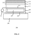
- FIG. 2 schematically depicts an ultrasound transducer element 200 (here a CMUT cell by way of non-limiting example) as deployed on an imaging device such as a catheter 100 or an ultrasound probe (patch), said element comprising the acoustic window 220 according to an embodiment of the present invention.
- a CMUT cell 200 is typically fabricated on a substrate 201, such as a silicon wafer.
- An ultrasound transducer array of an ultrasound imaging system may comprise one or more CMUT cells 200.
- the CMUT cells 200 may be either individually activated or in combination with each other.
- the individual cells 200 can have round, rectangular, hexagon or other peripheral shapes.
- Each CMUT cell 200 has at least a pair of electrodes 205 and 215 separated by a cavity 207.
- the cavity 207 is formed in between a membrane 211 that is suspended over a cell floor 203 formed by the top surface of the substrate 201.
- the membrane 211 may be made of one or more layers of electrically insulating materials, e.g. silicon oxide (SiO x , x>1), silicon nitride, low-k dielectric materials and the like.
- the membrane 211 is flexible, i.e. is adapted to move or vibrate.
- the membrane 211 may be suspended over the cell floor 203 (i.e. the substrate 201) through a support structure 209, which may be made of the same material as the membrane 211, e.g. by depositing the membrane 211 over a sacrificial material defining the cavity 207 and subsequently removing the sacrificial material to form the cavity 207 surrounded by the membrane 211 including the support structure 209.
- the electrodes 205, 215 may be made of any suitable electrically conductive material, such as a metal or metal alloy.
- the bottom electrodes 205 may be embedded in the floor 203 of the cell 200, while the top electrode 215 may be embedded in the membrane 211.
- the electrode 205 and 215 may be deposited on the cell floor 31 or the membrane 5 as additional layers.
- the bottom electrode 205 may be insulated on its cavity-facing surface with an additional layer (not pictured).
- This insulating layer may comprise either one of or a combination of an oxide-nitride-oxide (ONO) dielectric layer, silicon oxide layer, aluminum or hafnium oxide layers, for example.
- the insulating layer may be formed above the bottom electrode 205 and below the membrane electrode 215.
- An ONO-dielectric layer advantageously reduces charge accumulation on the electrodes which leads to device instability, drift and reduction in acoustic output pressure.
- the cavity 207 may be either air-or gas-filled, or wholly or partially evacuated.
- Two electrodes 205 and 215 separated by the cavity 207 represent a capacitance.
- the drive circuit 45 may be implemented as an integrated part of the integrated circuitry.
- the drive circuit 45 usually comprises an A/C signal source and a D/C voltage source.
- the D/C voltage source may be used to bias the membrane 211 with the A/C signal source driving an oscillation of the biased membrane 211 to generate ultrasound signals, e.g. pulses, at the oscillation frequency, as is well-known per se.
- the A/C component is typically omitted in a receive mode of the CMUT cell 200, in which the oscillations of the membrane 211 are induced by echoes of previously emitted ultrasound signals, e.g. pulse echoes, by the CMUT cell 200.
- the D/C voltage source may be adapted to bias the membrane 211 into a so-called collapse mode, in which a central portion of the membrane 211 is kept in contact with the cell floor 203 during the oscillations induced with the A/C signal originating from the A/C signal source.
- operation of a CMUT cell 200 in collapse mode may increase the acoustic pressure and the dynamic range of the CMUT cell 200.
- the transducer element here a CMUT cell 200 by way of non-limiting example as previously explained as other types of transducer elements, e.g. PZT elements, may also be deployed, further comprises an acoustic window 220 preferably having a total thickness of less than 100 micron, more preferably less than 30 micron, in some embodiments, e.g. catheter applications.
- the acoustic window 220 comprises a first layer 221 contacting the ultrasound emitting surface of the ultrasound transducer element (e.g.
- the first layer 221 and the second layer 223 both may be formed from the same hydrocarbon elastomer or from different hydrocarbon elastomers preferably having closely matched acoustic properties, e.g. acoustic impedances.
- Hydrocarbon elastomers, and in particular polybutadiene may have a density equal or below 0.95 g/cm 3 and may exhibit a low acoustic energy loss (attenuation) and a suitable acoustic impedance optimization.
- Hydrocarbon elastomers may have an acoustic impedance value of above 1.4 MRayl, which is close to soft tissue's impedance of about 1.6 MRayl, such that acoustic losses through acoustic impedance mismatches can be reduced by the deployment of such hydrocarbon elastomers, e.g. polybutadiene.
- Such elastomers may exhibit an acoustic loss per millimeter for acoustic energy passing therethrough of less than 1.5 dB for a wide range of the acoustic wave frequencies applicable in medical ultrasound, such as in between 2 and 25 MHz, which are typical frequency domains of a wide variety of ultrasound transducer elements including CMUTs and PZTs.
- such elastomers have a relatively low density and in an uncured state have a hardness value below 50 Shore A, which softness combined with the aforementioned low acoustic wave attenuation characteristics of such elastomers may provide a beneficial effect on the improved acoustic coupling of the ultrasound transducer element (in particular a CMUT vibrating membrane) with the acoustic window layer.
- hydrocarbon elastomers such as in particular polybutadiene
- vulcanization improves the mechanical robustness and moisture barrier properties of the hydrocarbon elastomer.
- the first layer 221 of a hydrocarbon elastomer, preferably in uncured form, in the acoustic window 220 further comprises an antioxidant to prevent vulcanization of the first layer 221 such that the first layer 221 retains its desired acoustic properties.
- the second layer 223 of a further hydrocarbon elastomer in the acoustic window 220 is allowed to harden through vulcanization, for example by omitting the antioxidant from the second layer 223 or alternatively by including the antioxidant in the second layer 223 in such an amount (i.e.
- hydrocarbon elastomer and the further hydrocarbon elastomer preferably are the same hydrocarbon elastomer as this guarantees the desired acoustic impedance matching.
- a particularly suitable hydrocarbon elastomer is polybutadiene although hydrocarbon elastomers such as Butyl (isobutylene-isoprene copolymer), ethylene propylene, isoprene, e.g. synthetic cis-isoprene or natural isoprene, may be considered as alternatives to polybutadiene.
- the first layer 221 preferably has a Shore A hardness of less than 50 Shore A, preferably of less than 10 Shore A, when measured with a durometer in accordance with the ASTM D2240 standard.
- the second layer 223 preferably has a Shore A hardness in excess of 50 Shore A, preferably in excess of 60 Shore A, when measured with a durometer in accordance with the ASTM D2240 standard.
- the second layer 223 may be left to naturally vulcanize during use of the imaging device although in an alternative preferred embodiment, the hydrocarbon elastomer in the second layer 223 is actively vulcanized, e.g. using a suitable heat treatment, to obtain a cross-linked hydrocarbon elastomer second layer 223 having the desired mechanical and moisture barrier properties.
- the same hydrocarbon elastomer, e.g. polybutadiene, for both layers 221 and 223 excellent adhesion between the layers 221 and 23 is achieved without the need for an adhesive, which would negatively affect acoustic properties of the acoustic window 220.
- the first layer 221 may have a thickness in a range of 5-10 micron ( ⁇ m).
- Any suitable antioxidant may be included in the first layer 221.
- Such antioxidants for hydrocarbon elastomers are well-known per se.
- a particularly suitable class of antioxidants is so-called phenolic stabilizers, which are primary antioxidants that act as hydrogen donors in the polymeric first layer 221.
- phenolic stabilizers Such compounds react with peroxy radicals to form hydroperoxides and prevent the abstraction of hydrogen from the hydrocarbon elastomer backbone, thereby preventing cross-linking of the backbone with other backbones in the polymeric first layer 221.
- a non-limiting example of such a phenolic stabilizer is shown in Formula 1:
- antioxidant is marketed by the BASF Company under the trade name Irganox 1076.
- the hydrocarbon chain of such a phenolic stabilizer improves mixing of the antioxidant with a hydrocarbon backbone of an elastomer such as polybutadiene, whilst the sterically hindered phenol group forming a head of the antioxidant molecule acts as a hydrogen donor thereby buffering ambient oxygen.
- any suitable antioxidant may be used in the first layer 221 of the acoustic window 220.
- the antioxidant may be present in the first layer 221 in an amount of 0.05%-0.5% by weight based on the total weight of the first layer 221 in some embodiments.
- hydrocarbon elastomers such as polybutadiene have a particularly suitable acoustic impedance for impedance matching a transducer element with body tissue, in particular soft tissue, as previously explained, it may be desirable to further reduce the acoustic impedance mismatch between the acoustic window 220 and in particular the first layer 221 of the acoustic window 220 and such body tissue.
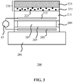
- at least the first layer 221 of the acoustic window 220 may further include particles 225 as schematically depicted in FIG. 3 .
- the particles 225 preferably are made of an electrically insulating material such as a ceramic material having a higher density than the hydrocarbon elastomer such as to increase the total density of the first layer 221.
- ceramic particles such as metal oxide (ZrO 2 , Al 2 O 3 , TiO 2 , Bi 2 O 3 , BaSO 4 , and so on) particles exhibit electrically insulating properties, which may be advantageous in providing additional electrical insulation to the transducer element electronics. It has been found that the inclusion (embedding) of such particles 225 in the first layer 221 causes minimal additional acoustic losses, in particular when the first particles 225 are included in the first layer 221 in an amount of 4-24% by weight based on the total weight of the first layer 221, preferably in an amount of 5-20% by weight based on the total weight of the first layer 221.
- the particles 225 preferably have an average size lower than one tenth of the acoustic wavelength of the shortest wave within an operation bandwidth for the selected ultrasound application of the ultrasound transducer element(s) of the catheter 100.
- the average size of the particles 225 becomes larger than the wavelength of the propagating ultrasound wave, this may cause additional scattering of the ultrasound wave in the acoustic window 220.
- the particles may have an average size in between 10 nm and 10 micron, in particular in between 10 - 100 nm or in between 1 - 10 micron, depending on the operation bandwidth of the ultrasound transducer element(s) of the catheter 100.
- Table 1 shows the measured changes in acoustic properties of an uncured polybutadiene layer with the introduction of zirconium dioxide (ZrO 2 ) insulating particles having in average diameter of about 2.5 micron and taking a fixed percentage of a total weight of the first layer 221.
- Table 1 Changes in the density, acoustic wave velocity, acoustic impedance and attenuation (at frequency of 7 MHz) with an increasing percentage by weight of ZrO 2 particles based on the total weight of the polybutadiene layer.
- the acoustic impedance of the layer can be tuned towards higher values, e.g. closer to the tissue's acoustic impedance by increasing the total density of the first layer 221 by addition of the particles 225 (here ZrO 2 particles) to the layer 221, whilst the attenuation of the layer 221 still remains below 1.5 dB/mm, even for the layers comprising 20% by weight of the insulating particles 225 (ZrO 2 ).
- the first layer 221 of the acoustic window 220 comprising the antioxidant and the hydrocarbon elastomer with embedded insulating particles 225 has a density equal or above 0.94g/cm 3 and an acoustic impedance equal or above 1.5 MRayl
- a direct acoustical coupling of the acoustic window 220 to the ultrasound emitting surface of the ultrasound transducer element, e.g. a membrane 211 of the CMUT cell 200 is provided, thereby obviating the need for an additional coupling medium between the acoustic window 220 and the ultrasound transducer element(s).
- an acoustic impedance equal or above 1.5 MRayl closely matches the acoustic impedance of ultrasonicated body tissue as previously explained.
- the acoustic window 220 may be deployed on any type of ultrasound transducer element as previously explained, the use of a soft first layer 221 in such an acoustic window 220 is especially advantageous for CMUT cells 220, in particular CMUT cells 200 operated in the so-called collapse mode. This is because the relatively light molecular weight of the monomers of the hydrocarbon elastomers, combined with these elastomers' relatively low hardness of preferably below 50 ShoreA may provide an improved acoustic contact between the acoustic window 220 and the membrane 211 adapted to vibrate.
- FIG. 4 is a flow chart of a method 300 to form an acoustic window 220 on one or more ultrasound transducer elements such as one or more CMUT cells 200.
- the method 300 starts in 301 with the preparation of a first solution of the hydrocarbon elastomer, preferably polybutadiene, in an organic solvent such as an alkane solvent, e.g. pentane, hexane, cyclohexane, heptane, octane, and so on. Heptane is particularly mentioned.
- the solution may be prepared by dissolving a granulate of pre-polymerized polybutadiene (CB728 T from Lanxess) in the organic solvent.
- An antioxidant e.g.
- a sterically hindered phenolic stabilizer such as Irganox 1076 is added, and optionally insulating particles 225 may be added to the solution to increase the acoustic impedance of the first layer 221 to be formed from this solution as previously explained.
- the polymeric material acts as a dispersion agent for the particles 225, such that a liquid mixture of the polymeric material and the insulating particles 225 in the organic solvent is provided.
- the filler particles 225 in the liquid mixture may increase the hardness of the first layer 221 of the acoustic window 220.
- additional dispersion agents such as fatty acids (a carboxylic acid with an aliphatic chain, which is either saturated or unsaturated) may be added to the liquid mixture, which fatty acids may assist in keeping the average hardness of the first layer 221 at a relatively constant value.
- the unsaturated chains of fatty acid like oleic acid, linoleic acid and linolenic acid (one, two and respectively three double carbon bonds) can polymerize and bond to the polybutadiene chains. This provides a good dispersion/distribution of particles 225 in the liquid mixture.
- the first solution is applied in 303 to the ultrasound emission surface of an ultrasound transducer array 101 comprising one or more ultrasound transducer elements, e.g. by dip coating the ultrasound emission surface with the first solution or by dispensing the first solution on the ultrasound emission surface using well-known dispensing techniques.
- the thickness of the first solution layer on the ultrasound emission surface may be controlled in case of the dip coating technique by the contact time between the first solution and the ultrasound emission surface.
- the organic solvent is evaporated from the first solution layer on the ultrasound emission surface during a drying step to form the first layer 221 of the acoustic window 220.
- a drying step may be achieved by a drying process at an elevated temperature, e.g. about 70°C.
- This drying step may be terminated once the first layer 221 becomes tacky, to promote adhesion of the second layer 223 to the first layer 221 without requiring separate adhesives.
- a second solution of a further hydrocarbon elastomer which may be the same hydrocarbon elastomer as used in the first solution, e.g. polybutadiene, is prepared in 307, which second solution may be prepared in the same manner as the first solution using the same constituents apart from the reduction or omission of the antioxidant from the second solution in order to prepare a second layer 223 that can be vulcanized (cross-linked) in order to increase the Shore A hardness of the second layer 223 compared to the first layer 221.
- the second solution does not contain any antioxidant.
- a layer of the second solution is applied over the partially developed first layer 221, e.g.
- the ultrasound transducer array 101 may be in situ on the imaging device such as the catheter 100 or may be mounted on this imaging device (catheter 100) after deposition of the acoustic window 220 on the ultrasound emission surface(s) of the ultrasound transducer array 101.
- the acoustic window forming method 300 as depicted by the flowchart of FIG. 4 is a non-limiting example embodiment of such a method; many variations to this method will be immediately apparent to the skilled person. For instance, the skilled person will immediately realize that the order of the steps depicted in the flowchart of FIG. 4 may be altered without departing from the present invention; for example, the second solution may be prepared prior to or simultaneously with the first solution.
- the first layer 221 and the second layer 223 are preferably formed on the ultrasound emission surface(s) and the first layer 221 respectively without the use of an adhesive such as glue, it should be understood that in alternative embodiments such adhesives may be applied to increase the adhesive strength between the various layers and surfaces.
- FIG. 5 schematically depicts a block diagram of the electronics, i.e. control circuitry, of an ultrasound imaging system 10 according to an example embodiment that may be deployed to interface with an imaging device by controlling the ultrasound transducer array 101 including the acoustic window 220 (for example disposed on a catheter 100) for the generation of ultrasound waves, e.g. ultrasound pulses, and reception of ultrasound echoes, e.g. pulse echoes, e.g. for diagnostic imaging purposes.
- the ultrasound transducer array(s) 101 of the imaging device may be coupled to a microbeam former 12, which may be located within said imaging device, e.g. in the ultrasound transducer array 101 or on an interface, e.g.
- the microbeam former 12 controls transmission and reception of signals by the one or more ultrasound transducer cells of the ultrasound transducer array 101.
- Microbeam formers are capable of at least partial beam forming of the signals received by groups or "patches" of transducer element tiles for instance as described in US patents US 5,997,479 (Savord et al. ), US 6,013,032 (Savord ), and US 6,623,432 (Powers et al. )
- the microbeam former 12 may be coupled by a probe cable, e.g. coaxial wire, to a terminal, e.g. a user console device or the like, comprising a transmit/receive (T/R) switch 16 which switches between transmission and reception modes and protects the main beam former 20 from high energy transmit signals when a microbeam former is not present or used and the ultrasound transducer array 101 is operated directly by the main system beam former 20.
- T/R transmit/receive
- the transmission of ultrasonic beams from the ultrasound transducer array 101 under control of the microbeam former 12 may be directed by a transducer controller 18 coupled to the microbeam former by the T/R switch 16 and the main system beam former 20, which receives input from the user's operation of the user interface 10 through control panel 38.
- the transducer controller 18 may be coupled to control the aforementioned drive circuit 45 for the ultrasound transducer array 101.
- the drive circuit 45 may set the DC and AC bias voltage(s) that are applied to CMUT elements of a CMUT array, e.g. to operate the CMUT elements in collapse mode, as is well-known per se, in case of a CMUT-based ultrasound transducer array 101.
- the transducer controller 18 may be further adapted to control the drive circuit 45 such as to switch the ultrasound transducer elements to a low-power mode, e.g. in response to a temperature sensor signal indicative of the ultrasound transducer elements reaching a critical temperature.
- the partially beam-formed signals produced by the microbeam former 12 may be forwarded to the main beam former 20 where partially beam-formed signals from individual patches of ultrasound transducer elements are combined into a fully beam-formed signal.
- the main beam former 20 may have 128 channels, each of which receives a partially beam-formed signal from a patch of dozens or hundreds of ultrasound transducer elements and/or from clusters of such ultrasound transducer elements, e.g. from ultrasound transducer tiles carrying a plurality of such ultrasound transducer elements. In this way the signals received by thousands of transducer elements of an ultrasound transducer array 101 can contribute efficiently to a single beam-formed signal.
- the beam-formed signals are coupled to a signal processor 22.
- the signal processor 22 can process the received echo signals in various ways, such as bandpass filtering, decimation, I and Q component separation, and harmonic signal separation which acts to separate linear and nonlinear signals so as to enable the identification of nonlinear (higher harmonics of the fundamental frequency) echo signals returned from tissue and microbubbles.
- the signal processor 22 optionally may perform additional signal enhancement such as speckle reduction, signal compounding, and noise elimination.
- the bandpass filter in the signal processor 22 may be a tracking filter, with its passband sliding from a higher frequency band to a lower frequency band as echo signals are received from increasing depths, thereby rejecting the noise at higher frequencies from greater depths where these frequencies are devoid of anatomical information.
- the processed signals may be forwarded to a B-mode processor 26 and optionally to a Doppler processor 28.
- the B-mode processor 26 employs detection of an amplitude of the received ultrasound signal for the imaging of structures in the body such as the tissue of organs and vessels in the body.
- B-mode images of structure of the body may be formed in either the harmonic image mode or the fundamental image mode or a combination of both for instance as described in US Patents US 6,283,919 (Roundhill et al. ) and US 6,458,083 (Jago et al. )
- the Doppler processor 28 processes temporally distinct signals from tissue movement and blood flow for the detection of the motion of substances, such as the flow of blood cells in the image field.
- the Doppler processor typically includes a wall filter with parameters which may be set to pass and/or reject echoes returned from selected types of materials in the body.
- the wall filter can be set to have a passband characteristic which passes signal of relatively low amplitude from higher velocity materials while rejecting relatively strong signals from lower or zero velocity material.
- This passband characteristic will pass signals from flowing blood while rejecting signals from nearby stationary or slowing moving objects such as the wall of the heart.
- An inverse characteristic would pass signals from moving tissue of the heart while rejecting blood flow signals for what is referred to as tissue Doppler imaging, detecting and depicting the motion of tissue.
- the Doppler processor may receive and process a sequence of temporally discrete echo signals from different points in an image field, the sequence of echoes from a particular point referred to as an ensemble.
- An ensemble of echoes received in rapid succession over a relatively short interval can be used to estimate the Doppler shift frequency of flowing blood, with the correspondence of the Doppler frequency to velocity indicating the blood flow velocity.
- An ensemble of echoes received over a longer period of time is used to estimate the velocity of slower flowing blood or slowly moving tissue.
- the structural and motion signals produced by the B-mode (and Doppler) processor(s) are coupled to a scan converter 32 and a multiplanar reformatter 44.
- the scan converter 32 arranges the echo signals in the spatial relationship from which they were received in a desired image format. For instance, the scan converter may arrange the echo signal into a two dimensional (2D) sector-shaped format, or a pyramidal three dimensional (3D) image.
- the scan converter can overlay a B-mode structural image with colors corresponding to motion at points in the image field with their Doppler-estimated velocities to produce a color Doppler image which depicts the motion of tissue and blood flow in the image field.
- the multiplanar reformatter 44 will convert echoes which are received from points in a common plane in a volumetric region of the body into an ultrasonic image of that plane, for instance as described in US Patent US 6,443,896 (Detmer ).
- a volume renderer 42 converts the echo signals of a 3D data set into a projected 3D image as viewed from a given reference point as described in US Pat. 6,530,885 (Entrekin et al. )
- the 2D or 3D images are coupled from the scan converter 32, multiplanar reformatter 44, and volume renderer 42 to an image processor 30 for further enhancement, buffering and temporary storage for display on an image display 40.
- the blood flow values produced by the Doppler processor 28 and tissue structure information produced by the B-mode processor 26 are coupled to a quantification processor 34.
- the quantification processor produces measures of different flow conditions such as the volume rate of blood flow as well as structural measurements such as the sizes of organs and gestational age.
- the quantification processor may receive input from the user control panel 38, such as the point in the anatomy of an image where a measurement is to be made.
- Output data from the quantification processor is coupled to a graphics processor 36 for the reproduction of measurement graphics and values with the image on the display 40.
- the graphics processor 36 can also generate graphic overlays for display with the ultrasound images. These graphic overlays can contain standard identifying information such as patient name, date and time of the image, imaging parameters, and the like. For these purposes the graphics processor receives input from the control panel 38, such as patient name.
- the user interface is also coupled to the transmit controller 18 to control the generation of ultrasound signals from the ultrasound transducer array 101 and hence the images produced by the transducer array and the ultrasound system.
- the user interface is also coupled to the multiplanar reformatter 44 for selection and control of the planes of multiple multiplanar reformatted (MPR) images which may be used to perform quantified measures in the image field of the MPR images.
- MPR multiplanar reformatted
- an ultrasonic (diagnostic) imaging system 10 is intended to give a non-limiting example of such an ultrasonic (diagnostic) imaging system.
- the skilled person will immediately realize that several variations in the architecture of the ultrasonic imaging system 10 are feasible without departing from the teachings of the present invention.
- the microbeam former 12 and/or the Doppler processor 28 may be omitted, the ultrasound probe 100 may not have 3D imaging capabilities and so on.
- Other variations will be apparent to the skilled person.
- acoustic window 220 has particular benefits when applied to an ultrasound transducer array of a catheter 100, such an acoustic window 220 may be equally applied to ultrasound transducer arrays in other applications, e.g. stand-alone ultrasound transducer arrays such as ultrasound probes to be applied to the skin of a patient. It will be readily understood that in such embodiments, certain embodiments preferred in the context of catheters, such as the overall thickness of the acoustic window 220, may not necessarily be preferred in such other application domains.
- the acoustic window 220 may have a thickness in excess of 100 micron as in such application domains the thickness is not particularly limited by the application domain (contrary to catheter applications, in which the thickness limitations typically are applicable to limit the overall dimensions of the catheter as previously explained).
Landscapes
- Life Sciences & Earth Sciences (AREA)
- Health & Medical Sciences (AREA)
- Engineering & Computer Science (AREA)
- Physics & Mathematics (AREA)
- Heart & Thoracic Surgery (AREA)
- Surgery (AREA)
- Veterinary Medicine (AREA)
- Biophysics (AREA)
- Nuclear Medicine, Radiotherapy & Molecular Imaging (AREA)
- Pathology (AREA)
- Radiology & Medical Imaging (AREA)
- Biomedical Technology (AREA)
- Public Health (AREA)
- Medical Informatics (AREA)
- Molecular Biology (AREA)
- General Health & Medical Sciences (AREA)
- Animal Behavior & Ethology (AREA)
- Acoustics & Sound (AREA)
- Chemical & Material Sciences (AREA)
- Mechanical Engineering (AREA)
- Multimedia (AREA)
- Materials Engineering (AREA)
- Wood Science & Technology (AREA)
- Organic Chemistry (AREA)
- Transducers For Ultrasonic Waves (AREA)
- Ultra Sonic Daignosis Equipment (AREA)
- Gynecology & Obstetrics (AREA)
Description
- The present invention relates to an imaging device comprising an ultrasound transducer array having a plurality of ultrasound transducer elements defining an ultrasound emitting surface of the ultrasound transducer array; and an acoustic window on the ultrasound emitting surface.
- The present invention further relates to an ultrasound imaging system comprising such an imaging device.
- The present invention further relates to a method of forming such an acoustic window on the ultrasound emitting surface of an ultrasound transducer array for such an imaging device.
- Ultrasound imaging is an important diagnostic tool for imaging internals of the patient's body. This is typically achieved using one or more ultrasound transducer elements, typically organised in an ultrasound transducer array, which convert electrical energy into acoustic energy (ultrasound pulses) and convert the received pulse echoes back into electrical energy, which may be processed by a dedicated processing arrangement to convert the received electrical energy into ultrasound images.
- Commonly used ultrasound transducer elements include piezoelectric-based ultrasound transducers (PZT) and capacitive micro-machined ultrasound transducers (CMUTs). These different types of transducers have in common that they require an acoustic matching material, commonly referred to as an acoustic window, between the ultrasound transducer elements and the patient's body in order to improve the acoustic performance of the ultrasound transducer elements by acoustic impedance matching of the emitting surfaces of the ultrasound transducer elements to the patient's body. An example of a CMUT assembly comprising such an acoustic window is disclosed in
US 2016/0101437 A1 . - The composition of such an acoustic window for ultrasound transducer arrays, e.g. ultrasound probes, to be applied to the skin of the patient is relatively straightforward, as the acoustic window does not have to meet stringent water barrier and thickness requirements that for instance are required when the ultrasound transducer array has to be operated for a longer period of time (such as monitoring) or within the body of the patient. One such application domain is catheters equipped with ultrasound imaging functionality, e.g. comprising a forward facing and/or side facing ultrasound transducer array. Such catheters must have a small form factor to facilitate penetration of small cavities, e.g. arteries or veins, within the body of the patient. At the same time, the ultrasound transducer arrays deployed with such catheters must be able to withstand the harsh environments, e.g. bodily fluids such as blood, stomach acid, and the like, in which case the acoustic window typically needs to provide additional protection to the ultrasound transducer elements of such an array. Another example the favorable application is ultrasound based patches, which configured for external use via a surface of a subject. These patches (low profile ultrasound probes) are configured to be used for a longer period of time (from hours to several days) and are desirable to withstand external body fluids such as sweat as well as a longer exposure to an acoustically coupling gel.
- Materials that are commonly used for such imaging devices comprising ultrasound transducer arrays include silicone layers and soft polyurethane layers, as these materials have favourable acoustic properties bought have the disadvantage that they are not watertight. To this end, a covering layer of parylene is often added over the silicone or polyurethane layer to make the acoustic window watertight. However, this compromises the acoustic performance of the ultrasound transducer array due to the introduction of reflections and acoustic ringing problems associated with the interface between these two polymer layers.
- Document
WO 2016/139087 A1 describes an ultrasound array for acoustic wave transmission comprising at least one capacitive micro-machined ultrasound transducer and an acoustic window layer. The acoustic window layer ofWO 2016/139087 A1 comprising a first layer comprising molecules of antioxidant and a polymeric material with insulating particles embedded therein, wherein the polymeric material consists of hydrogen and carbon atoms. - The present invention seeks to provide a medical imaging device comprising an ultrasound transducer array having thereon a resilient thin acoustic window that is watertight and has improved acoustic characteristics.
- The present invention further seeks to provide an ultrasound imaging system comprising such an imaging device.
- The present invention yet further seeks to provide a method of forming such an acoustic window and the ultrasound transducer array for an imaging device.
- According to an aspect, there is provided an imaging device such as catheter, said device comprising an ultrasound transducer array having a plurality of ultrasound transducer elements defining an ultrasound emitting surface of the ultrasound transducer array; and an acoustic window on the ultrasound emitting surface, said acoustic window comprising a first layer of a hydrocarbon elastomer contacting the ultrasound emitting surface, said first layer further containing an antioxidant; and a second layer of a further hydrocarbon elastomer on the first layer, said second layer having a greater Shore A hardness than the first layer, wherein the hydrocarbon elastomer is the same as the further hydrocarbon elastomer. In order to facilitate the selective hardening of the second layer, the second layer does not contain the (i.e. any) antioxidant, such that oxidation (weathering) of the second layer is not suppressed. The further hydrocarbon elastomer in the second layer is further actively cross-linked to accelerate the hardening of the second layer.
- The present invention is based on the insight that hydrocarbon elastomers, e.g. hydrocarbon thermosetting elastomers, are prone to gradual vulcanisation (oxidative cross-linking) through prolonged exposure to UV light or ambient environments containing oxidants, e.g. oxygen or water. Consequently, the inclusion of an antioxidant in a first layer of such an hydrocarbon elastomer of the acoustic window ensures that this first layer maintains its desired softness, which is desired to maximize the acoustic performance of the hydrocarbon elastomer, whilst the vulcanisation of the second layer, i.e. outer layer, of a further hydrocarbon elastomer of the acoustic window provides the desired watertight characteristic of the acoustic window and the consequential hardening of this second layer further provides improved protection of the ultrasound transducer array against accidental damage, e.g. scratching or the like.
- In further embodiments the imaging device is configured is configured for external use via a surface of a subject or internal use within a subject. For external use configuration the imaging device preferably comprises an ultrasound probe or a patch enclosing the ultrasound transducer array. For internal use configuration the imaging device may comprise a catheter.
- In an embodiment, the first layer has a thickness in a range of 5-10 micron as this is the minimum thickness at which the acoustic window achieves the desired acoustic impedance matching properties. The acoustic window may have a thickness of less than 100 micron and preferably less than 30 micron to make the acoustic window particularly suitable for catheter applications, i.e. to limit the dimensions of the catheter whilst achieving the desired acoustic properties of the acoustic window.
- The hydrocarbon elastomer preferably is the same as the further hydrocarbon elastomer such that the acoustic properties of the first and second layers are closely matched. Polybutadiene is particularly suitable although other hydrocarbon elastomers, e.g. hydrocarbon copolymers, may be contemplated as alternatives to polybutadiene.
- The first layer preferably has a Shore A hardness of less than 50 Shore, preferably less than 10 Shore, when measured with a durometer in accordance with the ASTM D2240 standard. This ensures good compliance with a moving ultrasound emitting surface, e.g. a membrane of a CMUT cell, whilst at the same time providing the first layer with a desirable acoustic impedance.
- The antioxidant may be a phenolic stabilizer such as a stabilizer comprising a sterically hindered phenol head group and an aliphatic, e.g. hydrocarbon, tail, to facilitate blending of the antioxidant in the hydrocarbon elastomer.
- The first layer may contain the antioxidant in an amount of 0.05%-0.5% by weight based on the total weight of the first layer. This amount of the antioxidant is sufficient to effectively suppress oxidation of the hydrocarbon elastomer in the first layer without significantly affecting the desired properties, e.g. acoustic impedance, of the first layer.
- At least the first layer of the acoustic window may further comprise particles embedded in the hydrocarbon elastomer in order to tune the density and the acoustic impedance of the first layer, e.g. to minimize an acoustic impedance mismatch between the first layer and the body tissue to be exposed to ultrasound waves generated with the ultrasound transducer array. Such particles for example may be electrically insulating particles such as ceramic particles. The first layer may comprise the particles in an amount of 4-24% by weight based on the total weight of the first layer in order to tune the acoustic impedance of the first layer to a desired value.
- In accordance with another aspect, there is provided an ultrasound imaging system comprising the imaging device of any of the herein described embodiments such an ultrasound imaging and control circuitry for controlling the ultrasound transducer array. Such an ultrasound imaging system, e.g. an ultrasound diagnostic imaging system, benefits from the inclusion of an imaging device according to an embodiment of the present invention by being able to generate high-resolution ultrasound images owing to the acoustic window on the ultrasound transducer array of the imaging device having favourable acoustic impedance properties as well as excellent mechanical properties.
- According to yet another aspect, there is provided a method of forming an acoustic window on an ultrasound transducer array for an imaging device, the ultrasound transducer array having a plurality of ultrasound transducer elements defining an ultrasound emitting surface of the ultrasound transducer array, the method comprising depositing a first solution of a hydrocarbon elastomer and an antioxidant in an organic solvent on the ultrasound emitting surface; removing the organic solvent to form a first layer of the acoustic window contacting the ultrasound emitting surface, said first layer comprising the hydrocarbon elastomer and the antioxidant; depositing a second solution of a further hydrocarbon elastomer in a further organic solvent on the first layer; removing the further organic solvent to form a second layer of the acoustic window contacting the first layer, wherein the second layer has a greater Shore A hardness than the first layer; and cross-linking the further hydrocarbon elastomer in the second layer to increase the Shore A hardness of the second layer; and wherein the hydrocarbon elastomer is the same as the further hydrocarbon elastomer.
- This method facilitates the provision of ultrasound transducer array of an imaging device having an acoustic window that combines favourable acoustic impedance properties with excellent mechanical properties.The cross-linking of the further hydrocarbon elastomer in the second layer allows increasing the Shore A hardness of the second layer, such that the increased hardness of the second layer does not have to be the result of weathering of the second layer.
- The solvent and the further organic solvent may be an alkane solvent such as heptane. Such solvents are particularly suitable for dissolving hydrocarbon elastomers and have the further benefit that they can be evaporated at relatively low temperatures due to the low vapour pressures of such solvents, such that the acoustic window may be formed without having to expose the ultrasound transducer array and the acoustic window layers to overly elevated temperatures, which may damage the ultrasound transducer array and/or the acoustic window layers.
- The hydrocarbon elastomer is the same as the further hydrocarbon elastomer. Polybutadiene is particularly suitable as polybutadiene has particularly favourable acoustic properties and may be readily oxidized (vulcanized) to form a second layer of the acoustic window having the desired mechanical and moisture barrier properties.
- Embodiments of the invention are described in more detail and by way of non-limiting examples with reference to the accompanying drawings, wherein:
-
FIG. 1 schematically depicts a catheter as an example of an imaging device; -
FIG. 2 schematically depicts an aspect of an imaging device according to an example embodiment; -
FIG. 3 schematically depicts an aspect of an imaging device according to another example embodiment; -
FIG. 4 is a flowchart of a method for forming an acoustic window or the ultrasound transducer array of such an imaging device; and -
FIG. 5 schematically depicts a circuit diagram of an ultrasound imaging system according to an example embodiment. - It should be understood that the Figures are merely schematic and are not drawn to scale. It should also be understood that the same reference numerals are used throughout the Figures to indicate the same or similar parts.
-
FIG. 1 schematically depicts an example embodiment of an imaging device: acatheter 100. Thecatheter 100 has a forward facingarray 120 of ultrasound transducer elements mounted on thetip 110 of thecatheter 100. The forward facingarray 120 for example may be an IC chip carrying the ultrasound transducer elements, which may be mounted on thetip 110 in any suitable manner, e.g. gluing. The forward facingarray 120 may include an aperture orchannel 125 to facilitate an instrument (not shown) to extend through the tip of the catheter, e.g. for extracting a tissue sample from the patient for biopsy purposes. Thecatheter 100 may further comprise an arrangement ofultrasound transducer elements 130 wrapped around a side wall of thecatheter 100, thereby facilitating a close to 360° field of ultra-sound vision of thecatheter 100. In some embodiments the catheter can include only the side looking arrangement of theelements 130. This for instance maybe achieved by providing islands orchips 130 carrying one or more ultrasound transducer elements interconnected by a flexible strip or the like that facilitates the wrapping of the respective islands orchips 130 around the catheter side wall. As such flexible arrangements are well-known per se, this will not be explained in further detail for the sake of brevity. The forward facingarray 120 and the islands orchips 130 may contain any suitable number and type of ultrasound transducer elements benefiting from an acoustic window according to embodiments of the present invention as will be explained in further detail below. For example, the ultrasound transducer elements may be CMUT elements, PZT elements, and so on. Thecatheter tip 110 may be connected to aguide wire 140 or the like, to facilitate maneuvering thecatheter tip 110 to the desired location within a patient's body. - It should be understood that embodiments of the present invention are not limited to the depicted example embodiment of the
catheter 100. For example, it is equally feasible for thecatheter 100 to only comprise one or more forward facing ultrasound transducer elements or to only comprise one or sideways facing ultrasound transducer elements. Similarly, the aperture orchannel 125 may not be present, and so on. Embodiments of the present invention may be applied to any catheter design comprising any number of ultrasound transducer elements carrying an acoustic window according to an embodiment of the present invention. - In further embodiments the imaging device may be configured for external use via a surface of a subject or internal use within a subject (not shown). In this case the imaging device might include an ultrasound probe (preferably low profile ultrasound probe) comprising an
acoustic window 220 coupled to an ultrasound emitting surface of said probe and described in more detail below.FIG. 2 schematically depicts an ultrasound transducer element 200 (here a CMUT cell by way of non-limiting example) as deployed on an imaging device such as acatheter 100 or an ultrasound probe (patch), said element comprising theacoustic window 220 according to an embodiment of the present invention. Such aCMUT cell 200 is typically fabricated on asubstrate 201, such as a silicon wafer. An ultrasound transducer array of an ultrasound imaging system may comprise one ormore CMUT cells 200. TheCMUT cells 200 may be either individually activated or in combination with each other. Theindividual cells 200 can have round, rectangular, hexagon or other peripheral shapes. - Each
CMUT cell 200 has at least a pair ofelectrodes cavity 207. Thecavity 207 is formed in between amembrane 211 that is suspended over acell floor 203 formed by the top surface of thesubstrate 201. Themembrane 211 may be made of one or more layers of electrically insulating materials, e.g. silicon oxide (SiOx, x>1), silicon nitride, low-k dielectric materials and the like. Themembrane 211 is flexible, i.e. is adapted to move or vibrate. Themembrane 211 may be suspended over the cell floor 203 (i.e. the substrate 201) through asupport structure 209, which may be made of the same material as themembrane 211, e.g. by depositing themembrane 211 over a sacrificial material defining thecavity 207 and subsequently removing the sacrificial material to form thecavity 207 surrounded by themembrane 211 including thesupport structure 209. - The
electrodes bottom electrodes 205 may be embedded in thefloor 203 of thecell 200, while thetop electrode 215 may be embedded in themembrane 211. Theelectrode bottom electrode 205 may be insulated on its cavity-facing surface with an additional layer (not pictured). This insulating layer may comprise either one of or a combination of an oxide-nitride-oxide (ONO) dielectric layer, silicon oxide layer, aluminum or hafnium oxide layers, for example. The insulating layer may be formed above thebottom electrode 205 and below themembrane electrode 215. An ONO-dielectric layer advantageously reduces charge accumulation on the electrodes which leads to device instability, drift and reduction in acoustic output pressure. Thecavity 207 may be either air-or gas-filled, or wholly or partially evacuated. Twoelectrodes cavity 207 represent a capacitance. - An application of electrical signal through a
drive circuit 45 coupled to theelectrodes membrane 211, which results in the change of the capacitance and can be manipulated by integrated circuitry an associated with theCMUT cell 200. An example embodiment of such integrated circuitry will be explained in more detail below. Thedrive circuit 45 may be implemented as an integrated part of the integrated circuitry. Thedrive circuit 45 usually comprises an A/C signal source and a D/C voltage source. In a transmit mode of theCMUT cell 200, the D/C voltage source may be used to bias themembrane 211 with the A/C signal source driving an oscillation of thebiased membrane 211 to generate ultrasound signals, e.g. pulses, at the oscillation frequency, as is well-known per se. The A/C component is typically omitted in a receive mode of theCMUT cell 200, in which the oscillations of themembrane 211 are induced by echoes of previously emitted ultrasound signals, e.g. pulse echoes, by theCMUT cell 200. In an embodiment, the D/C voltage source may be adapted to bias themembrane 211 into a so-called collapse mode, in which a central portion of themembrane 211 is kept in contact with thecell floor 203 during the oscillations induced with the A/C signal originating from the A/C signal source. As is well-known per se, operation of aCMUT cell 200 in collapse mode may increase the acoustic pressure and the dynamic range of theCMUT cell 200. - According to an embodiment of the present invention, the transducer element, here a
CMUT cell 200 by way of non-limiting example as previously explained as other types of transducer elements, e.g. PZT elements, may also be deployed, further comprises anacoustic window 220 preferably having a total thickness of less than 100 micron, more preferably less than 30 micron, in some embodiments, e.g. catheter applications. Theacoustic window 220 comprises afirst layer 221 contacting the ultrasound emitting surface of the ultrasound transducer element (e.g. the upper surface of themembrane 211 of a CMUT cell 200) and asecond layer 223 on thefirst layer 221 such that thefirst layer 221 is sandwiched in between the ultrasound emitting surface and thesecond layer 223. Thefirst layer 221 and thesecond layer 223 both may be formed from the same hydrocarbon elastomer or from different hydrocarbon elastomers preferably having closely matched acoustic properties, e.g. acoustic impedances. Hydrocarbon elastomers, and in particular polybutadiene, may have a density equal or below 0.95 g/cm3 and may exhibit a low acoustic energy loss (attenuation) and a suitable acoustic impedance optimization. Acoustic impedance (Z) is defined as the product of acoustic propagation velocity (v) for acoustic energy (or wave) in a medium and density (p) of this medium:
- Hydrocarbon elastomers may have an acoustic impedance value of above 1.4 MRayl, which is close to soft tissue's impedance of about 1.6 MRayl, such that acoustic losses through acoustic impedance mismatches can be reduced by the deployment of such hydrocarbon elastomers, e.g. polybutadiene. Such elastomers may exhibit an acoustic loss per millimeter for acoustic energy passing therethrough of less than 1.5 dB for a wide range of the acoustic wave frequencies applicable in medical ultrasound, such as in between 2 and 25 MHz, which are typical frequency domains of a wide variety of ultrasound transducer elements including CMUTs and PZTs. Furthermore, such elastomers have a relatively low density and in an uncured state have a hardness value below 50 Shore A, which softness combined with the aforementioned low acoustic wave attenuation characteristics of such elastomers may provide a beneficial effect on the improved acoustic coupling of the ultrasound transducer element (in particular a CMUT vibrating membrane) with the acoustic window layer.
- However, the softness of such hydrocarbon elastomers is less suitable to provide the ultrasound transducer element with mechanical protection and may not provide the ultrasound transducer element with the desired moisture barrier properties. Moreover, many hydrocarbon elastomers, such as in particular polybutadiene, experience hardening over time through (photo-)oxidation causing cross-linking (vulcanization) of the elastomer material when exposed to UV light or oxygen for instance, causing a degradation of the acoustic properties of the hydrocarbon elastomer. At the same time, such vulcanization improves the mechanical robustness and moisture barrier properties of the hydrocarbon elastomer.
- This insight has been utilized in embodiments of the present invention, in which the
first layer 221 of a hydrocarbon elastomer, preferably in uncured form, in theacoustic window 220 further comprises an antioxidant to prevent vulcanization of thefirst layer 221 such that thefirst layer 221 retains its desired acoustic properties. In contrast, thesecond layer 223 of a further hydrocarbon elastomer in theacoustic window 220 is allowed to harden through vulcanization, for example by omitting the antioxidant from thesecond layer 223 or alternatively by including the antioxidant in thesecond layer 223 in such an amount (i.e. a small amount than in the first layer 221) such that vulcanization of thesecond layer 223 is not prevented, but instead the rate of vulcanization is controlled by the inclusion of the small amount of antioxidant in thesecond layer 223. The hydrocarbon elastomer and the further hydrocarbon elastomer preferably are the same hydrocarbon elastomer as this guarantees the desired acoustic impedance matching. A particularly suitable hydrocarbon elastomer is polybutadiene although hydrocarbon elastomers such as Butyl (isobutylene-isoprene copolymer), ethylene propylene, isoprene, e.g. synthetic cis-isoprene or natural isoprene, may be considered as alternatives to polybutadiene. Thefirst layer 221 preferably has a Shore A hardness of less than 50 Shore A, preferably of less than 10 Shore A, when measured with a durometer in accordance with the ASTM D2240 standard. Thesecond layer 223 preferably has a Shore A hardness in excess of 50 Shore A, preferably in excess of 60 Shore A, when measured with a durometer in accordance with the ASTM D2240 standard. - In an embodiment, the
second layer 223 may be left to naturally vulcanize during use of the imaging device although in an alternative preferred embodiment, the hydrocarbon elastomer in thesecond layer 223 is actively vulcanized, e.g. using a suitable heat treatment, to obtain a cross-linked hydrocarbon elastomersecond layer 223 having the desired mechanical and moisture barrier properties. Moreover, by using the same hydrocarbon elastomer, e.g. polybutadiene, for bothlayers layers 221 and 23 is achieved without the need for an adhesive, which would negatively affect acoustic properties of theacoustic window 220. - In an embodiment, the
first layer 221 may have a thickness in a range of 5-10 micron (µm). Any suitable antioxidant may be included in thefirst layer 221. Such antioxidants for hydrocarbon elastomers are well-known per se. For example, a particularly suitable class of antioxidants is so-called phenolic stabilizers, which are primary antioxidants that act as hydrogen donors in the polymericfirst layer 221. Such compounds react with peroxy radicals to form hydroperoxides and prevent the abstraction of hydrogen from the hydrocarbon elastomer backbone, thereby preventing cross-linking of the backbone with other backbones in the polymericfirst layer 221. A non-limiting example of such a phenolic stabilizer is shown in Formula 1:
- This antioxidant is marketed by the BASF Company under the trade name Irganox 1076. Without wishing to be bound by theory, it is believed that the hydrocarbon chain of such a phenolic stabilizer improves mixing of the antioxidant with a hydrocarbon backbone of an elastomer such as polybutadiene, whilst the sterically hindered phenol group forming a head of the antioxidant molecule acts as a hydrogen donor thereby buffering ambient oxygen. However, it is reiterated for the avoidance of doubt that embodiments of the present invention are not limited to a particular type of phenolic stabilizer or indeed a particular type of antioxidant; any suitable antioxidant may be used in the
first layer 221 of theacoustic window 220. The antioxidant may be present in thefirst layer 221 in an amount of 0.05%-0.5% by weight based on the total weight of thefirst layer 221 in some embodiments. - Although hydrocarbon elastomers such as polybutadiene have a particularly suitable acoustic impedance for impedance matching a transducer element with body tissue, in particular soft tissue, as previously explained, it may be desirable to further reduce the acoustic impedance mismatch between the
acoustic window 220 and in particular thefirst layer 221 of theacoustic window 220 and such body tissue. To this end, at least thefirst layer 221 of theacoustic window 220 may further includeparticles 225 as schematically depicted inFIG. 3 . Theparticles 225 preferably are made of an electrically insulating material such as a ceramic material having a higher density than the hydrocarbon elastomer such as to increase the total density of thefirst layer 221. For example, ceramic particles such as metal oxide (ZrO2, Al2O3, TiO2, Bi2O3, BaSO4, and so on) particles exhibit electrically insulating properties, which may be advantageous in providing additional electrical insulation to the transducer element electronics. It has been found that the inclusion (embedding) ofsuch particles 225 in thefirst layer 221 causes minimal additional acoustic losses, in particular when thefirst particles 225 are included in thefirst layer 221 in an amount of 4-24% by weight based on the total weight of thefirst layer 221, preferably in an amount of 5-20% by weight based on the total weight of thefirst layer 221. - The
particles 225 preferably have an average size lower than one tenth of the acoustic wavelength of the shortest wave within an operation bandwidth for the selected ultrasound application of the ultrasound transducer element(s) of thecatheter 100. When the average size of theparticles 225 becomes larger than the wavelength of the propagating ultrasound wave, this may cause additional scattering of the ultrasound wave in theacoustic window 220. For example, the particles may have an average size in between 10 nm and 10 micron, in particular in between 10 - 100 nm or in between 1 - 10 micron, depending on the operation bandwidth of the ultrasound transducer element(s) of thecatheter 100. - As an example, Table 1 shows the measured changes in acoustic properties of an uncured polybutadiene layer with the introduction of zirconium dioxide (ZrO2) insulating particles having in average diameter of about 2.5 micron and taking a fixed percentage of a total weight of the
first layer 221.Table 1: Changes in the density, acoustic wave velocity, acoustic impedance and attenuation (at frequency of 7 MHz) with an increasing percentage by weight of ZrO2 particles based on the total weight of the polybutadiene layer. % ZrO2 Density (g/cm3) Velocity (mm/microsec) Impedance (MRayl) Attenuation @7 MHz (dB/mm) 0 0.906 1.570 1.423 0.55 4% 0.937 1.553 1.455 0.75 8% 0.972 1.532 1.489 0.87 16% 1.0405 1.503 1.564 1.05 20% 1.0855 1.469 1.5945 1.25 - As can be seen from Table 1, the acoustic impedance of the layer can be tuned towards higher values, e.g. closer to the tissue's acoustic impedance by increasing the total density of the
first layer 221 by addition of the particles 225 (here ZrO2 particles) to thelayer 221, whilst the attenuation of thelayer 221 still remains below 1.5 dB/mm, even for the layers comprising 20% by weight of the insulating particles 225 (ZrO2). When thefirst layer 221 of theacoustic window 220 comprising the antioxidant and the hydrocarbon elastomer with embedded insulatingparticles 225 has a density equal or above 0.94g/cm3 and an acoustic impedance equal or above 1.5 MRayl, a direct acoustical coupling of theacoustic window 220 to the ultrasound emitting surface of the ultrasound transducer element, e.g. amembrane 211 of theCMUT cell 200 is provided, thereby obviating the need for an additional coupling medium between theacoustic window 220 and the ultrasound transducer element(s). Moreover, an acoustic impedance equal or above 1.5 MRayl closely matches the acoustic impedance of ultrasonicated body tissue as previously explained. - At this point it is noted that although the
acoustic window 220 may be deployed on any type of ultrasound transducer element as previously explained, the use of a softfirst layer 221 in such anacoustic window 220 is especially advantageous forCMUT cells 220, inparticular CMUT cells 200 operated in the so-called collapse mode. This is because the relatively light molecular weight of the monomers of the hydrocarbon elastomers, combined with these elastomers' relatively low hardness of preferably below 50 ShoreA may provide an improved acoustic contact between theacoustic window 220 and themembrane 211 adapted to vibrate. -
FIG. 4 is a flow chart of amethod 300 to form anacoustic window 220 on one or more ultrasound transducer elements such as one ormore CMUT cells 200. Themethod 300 starts in 301 with the preparation of a first solution of the hydrocarbon elastomer, preferably polybutadiene, in an organic solvent such as an alkane solvent, e.g. pentane, hexane, cyclohexane, heptane, octane, and so on. Heptane is particularly mentioned. The solution may be prepared by dissolving a granulate of pre-polymerized polybutadiene (CB728 T from Lanxess) in the organic solvent. An antioxidant, e.g. a sterically hindered phenolic stabilizer such as Irganox 1076 is added, and optionally insulatingparticles 225 may be added to the solution to increase the acoustic impedance of thefirst layer 221 to be formed from this solution as previously explained. The polymeric material acts as a dispersion agent for theparticles 225, such that a liquid mixture of the polymeric material and the insulatingparticles 225 in the organic solvent is provided. Thefiller particles 225 in the liquid mixture may increase the hardness of thefirst layer 221 of theacoustic window 220. To counteract this, additional dispersion agents such as fatty acids (a carboxylic acid with an aliphatic chain, which is either saturated or unsaturated) may be added to the liquid mixture, which fatty acids may assist in keeping the average hardness of thefirst layer 221 at a relatively constant value. The unsaturated chains of fatty acid like oleic acid, linoleic acid and linolenic acid (one, two and respectively three double carbon bonds) can polymerize and bond to the polybutadiene chains. This provides a good dispersion/distribution ofparticles 225 in the liquid mixture. - Next, the first solution is applied in 303 to the ultrasound emission surface of an
ultrasound transducer array 101 comprising one or more ultrasound transducer elements, e.g. by dip coating the ultrasound emission surface with the first solution or by dispensing the first solution on the ultrasound emission surface using well-known dispensing techniques. The thickness of the first solution layer on the ultrasound emission surface may be controlled in case of the dip coating technique by the contact time between the first solution and the ultrasound emission surface. - Next, in 305, the organic solvent is evaporated from the first solution layer on the ultrasound emission surface during a drying step to form the
first layer 221 of theacoustic window 220. This for example may be achieved by a drying process at an elevated temperature, e.g. about 70°C. This drying step may be terminated once thefirst layer 221 becomes tacky, to promote adhesion of thesecond layer 223 to thefirst layer 221 without requiring separate adhesives. - A second solution of a further hydrocarbon elastomer, which may be the same hydrocarbon elastomer as used in the first solution, e.g. polybutadiene, is prepared in 307, which second solution may be prepared in the same manner as the first solution using the same constituents apart from the reduction or omission of the antioxidant from the second solution in order to prepare a
second layer 223 that can be vulcanized (cross-linked) in order to increase the Shore A hardness of thesecond layer 223 compared to thefirst layer 221. Preferably, the second solution does not contain any antioxidant. In 309, a layer of the second solution is applied over the partially developedfirst layer 221, e.g. through dip coating, dispensing or the like, after which the second solution layer is dried in 311 at a temperature, e.g. 100°C, sufficient to remove the remaining solvent from the partially developedfirst layer 221 and the second solution layer to form thesecond layer 223 over thefirst layer 221, whichsecond layer 223 may be cured, e.g. cross-linked in 313 (or alternatively during the development step in 311) to form theacoustic window 220 over theultrasound transducer array 101. Theultrasound transducer array 101 may be in situ on the imaging device such as thecatheter 100 or may be mounted on this imaging device (catheter 100) after deposition of theacoustic window 220 on the ultrasound emission surface(s) of theultrasound transducer array 101. - It is noted for the avoidance of doubt that the acoustic
window forming method 300 as depicted by the flowchart ofFIG. 4 is a non-limiting example embodiment of such a method; many variations to this method will be immediately apparent to the skilled person. For instance, the skilled person will immediately realize that the order of the steps depicted in the flowchart ofFIG. 4 may be altered without departing from the present invention; for example, the second solution may be prepared prior to or simultaneously with the first solution. Also, although thefirst layer 221 and thesecond layer 223 are preferably formed on the ultrasound emission surface(s) and thefirst layer 221 respectively without the use of an adhesive such as glue, it should be understood that in alternative embodiments such adhesives may be applied to increase the adhesive strength between the various layers and surfaces. -
FIG. 5 schematically depicts a block diagram of the electronics, i.e. control circuitry, of anultrasound imaging system 10 according to an example embodiment that may be deployed to interface with an imaging device by controlling theultrasound transducer array 101 including the acoustic window 220 (for example disposed on a catheter 100) for the generation of ultrasound waves, e.g. ultrasound pulses, and reception of ultrasound echoes, e.g. pulse echoes, e.g. for diagnostic imaging purposes. The ultrasound transducer array(s) 101 of the imaging device may be coupled to a microbeam former 12, which may be located within said imaging device, e.g. in theultrasound transducer array 101 or on an interface, e.g. a PCB between theultrasound transducer array 101 and a coaxial wire connecting theultrasound transducer array 101 to thee electronics, in some embodiments. The microbeam former 12 controls transmission and reception of signals by the one or more ultrasound transducer cells of theultrasound transducer array 101. Microbeam formers are capable of at least partial beam forming of the signals received by groups or "patches" of transducer element tiles for instance as described in US patentsUS 5,997,479 (Savord et al. ),US 6,013,032 (Savord ), andUS 6,623,432 (Powers et al. ) - The microbeam former 12 may be coupled by a probe cable, e.g. coaxial wire, to a terminal, e.g. a user console device or the like, comprising a transmit/receive (T/R) switch 16 which switches between transmission and reception modes and protects the main beam former 20 from high energy transmit signals when a microbeam former is not present or used and the
ultrasound transducer array 101 is operated directly by the main system beam former 20. The transmission of ultrasonic beams from theultrasound transducer array 101 under control of the microbeam former 12 may be directed by atransducer controller 18 coupled to the microbeam former by the T/R switch 16 and the main system beam former 20, which receives input from the user's operation of theuser interface 10 throughcontrol panel 38. One of the functions controlled by thetransducer controller 18 is the direction in which beams are steered and focused. Beams may be steered straight ahead from (orthogonal to) theultrasound transducer array 101, or at different angles for a wider field of view. Thetransducer controller 18 may be coupled to control theaforementioned drive circuit 45 for theultrasound transducer array 101. For instance, thedrive circuit 45 may set the DC and AC bias voltage(s) that are applied to CMUT elements of a CMUT array, e.g. to operate the CMUT elements in collapse mode, as is well-known per se, in case of a CMUT-basedultrasound transducer array 101. Thetransducer controller 18 may be further adapted to control thedrive circuit 45 such as to switch the ultrasound transducer elements to a low-power mode, e.g. in response to a temperature sensor signal indicative of the ultrasound transducer elements reaching a critical temperature. - The partially beam-formed signals produced by the microbeam former 12 may be forwarded to the main beam former 20 where partially beam-formed signals from individual patches of ultrasound transducer elements are combined into a fully beam-formed signal. For example, the main beam former 20 may have 128 channels, each of which receives a partially beam-formed signal from a patch of dozens or hundreds of ultrasound transducer elements and/or from clusters of such ultrasound transducer elements, e.g. from ultrasound transducer tiles carrying a plurality of such ultrasound transducer elements. In this way the signals received by thousands of transducer elements of an
ultrasound transducer array 101 can contribute efficiently to a single beam-formed signal. - The beam-formed signals are coupled to a
signal processor 22. Thesignal processor 22 can process the received echo signals in various ways, such as bandpass filtering, decimation, I and Q component separation, and harmonic signal separation which acts to separate linear and nonlinear signals so as to enable the identification of nonlinear (higher harmonics of the fundamental frequency) echo signals returned from tissue and microbubbles. - The
signal processor 22 optionally may perform additional signal enhancement such as speckle reduction, signal compounding, and noise elimination. The bandpass filter in thesignal processor 22 may be a tracking filter, with its passband sliding from a higher frequency band to a lower frequency band as echo signals are received from increasing depths, thereby rejecting the noise at higher frequencies from greater depths where these frequencies are devoid of anatomical information. - The processed signals may be forwarded to a B-
mode processor 26 and optionally to aDoppler processor 28. The B-mode processor 26 employs detection of an amplitude of the received ultrasound signal for the imaging of structures in the body such as the tissue of organs and vessels in the body. B-mode images of structure of the body may be formed in either the harmonic image mode or the fundamental image mode or a combination of both for instance as described in US PatentsUS 6,283,919 (Roundhill et al. ) andUS 6,458,083 (Jago et al. ) - The
Doppler processor 28, if present, processes temporally distinct signals from tissue movement and blood flow for the detection of the motion of substances, such as the flow of blood cells in the image field. The Doppler processor typically includes a wall filter with parameters which may be set to pass and/or reject echoes returned from selected types of materials in the body. For instance, the wall filter can be set to have a passband characteristic which passes signal of relatively low amplitude from higher velocity materials while rejecting relatively strong signals from lower or zero velocity material. - This passband characteristic will pass signals from flowing blood while rejecting signals from nearby stationary or slowing moving objects such as the wall of the heart. An inverse characteristic would pass signals from moving tissue of the heart while rejecting blood flow signals for what is referred to as tissue Doppler imaging, detecting and depicting the motion of tissue. The Doppler processor may receive and process a sequence of temporally discrete echo signals from different points in an image field, the sequence of echoes from a particular point referred to as an ensemble. An ensemble of echoes received in rapid succession over a relatively short interval can be used to estimate the Doppler shift frequency of flowing blood, with the correspondence of the Doppler frequency to velocity indicating the blood flow velocity. An ensemble of echoes received over a longer period of time is used to estimate the velocity of slower flowing blood or slowly moving tissue.
- The structural and motion signals produced by the B-mode (and Doppler) processor(s) are coupled to a
scan converter 32 and amultiplanar reformatter 44. Thescan converter 32 arranges the echo signals in the spatial relationship from which they were received in a desired image format. For instance, the scan converter may arrange the echo signal into a two dimensional (2D) sector-shaped format, or a pyramidal three dimensional (3D) image. - The scan converter can overlay a B-mode structural image with colors corresponding to motion at points in the image field with their Doppler-estimated velocities to produce a color Doppler image which depicts the motion of tissue and blood flow in the image field. The
multiplanar reformatter 44 will convert echoes which are received from points in a common plane in a volumetric region of the body into an ultrasonic image of that plane, for instance as described in US PatentUS 6,443,896 (Detmer ). Avolume renderer 42 converts the echo signals of a 3D data set into a projected 3D image as viewed from a given reference point as described inUS Pat. 6,530,885 (Entrekin et al. ) - The 2D or 3D images are coupled from the
scan converter 32,multiplanar reformatter 44, andvolume renderer 42 to animage processor 30 for further enhancement, buffering and temporary storage for display on animage display 40. In addition to being used for imaging, the blood flow values produced by theDoppler processor 28 and tissue structure information produced by the B-mode processor 26 are coupled to aquantification processor 34. The quantification processor produces measures of different flow conditions such as the volume rate of blood flow as well as structural measurements such as the sizes of organs and gestational age. The quantification processor may receive input from theuser control panel 38, such as the point in the anatomy of an image where a measurement is to be made. - Output data from the quantification processor is coupled to a
graphics processor 36 for the reproduction of measurement graphics and values with the image on thedisplay 40. Thegraphics processor 36 can also generate graphic overlays for display with the ultrasound images. These graphic overlays can contain standard identifying information such as patient name, date and time of the image, imaging parameters, and the like. For these purposes the graphics processor receives input from thecontrol panel 38, such as patient name. - The user interface is also coupled to the transmit
controller 18 to control the generation of ultrasound signals from theultrasound transducer array 101 and hence the images produced by the transducer array and the ultrasound system. The user interface is also coupled to themultiplanar reformatter 44 for selection and control of the planes of multiple multiplanar reformatted (MPR) images which may be used to perform quantified measures in the image field of the MPR images. - As will be understood by the skilled person, the above embodiment of an ultrasonic (diagnostic)
imaging system 10 is intended to give a non-limiting example of such an ultrasonic (diagnostic) imaging system. The skilled person will immediately realize that several variations in the architecture of theultrasonic imaging system 10 are feasible without departing from the teachings of the present invention. For instance, as also indicated in the above embodiment, the microbeam former 12 and/or theDoppler processor 28 may be omitted, theultrasound probe 100 may not have 3D imaging capabilities and so on. Other variations will be apparent to the skilled person. - At this point, it is noted that although the
acoustic window 220 according to embodiments of the present invention has particular benefits when applied to an ultrasound transducer array of acatheter 100, such anacoustic window 220 may be equally applied to ultrasound transducer arrays in other applications, e.g. stand-alone ultrasound transducer arrays such as ultrasound probes to be applied to the skin of a patient. It will be readily understood that in such embodiments, certain embodiments preferred in the context of catheters, such as the overall thickness of theacoustic window 220, may not necessarily be preferred in such other application domains. Specifically, for a stand-alone ultrasound transducer array (forming a part of the imaging device configured for external use, for example), theacoustic window 220 may have a thickness in excess of 100 micron as in such application domains the thickness is not particularly limited by the application domain (contrary to catheter applications, in which the thickness limitations typically are applicable to limit the overall dimensions of the catheter as previously explained). - It should be noted that the above-mentioned embodiments illustrate rather than limit the invention, and that those skilled in the art will be able to design many alternative embodiments without departing from the scope of the appended claims. In the claims, any reference signs placed between parentheses shall not be construed as limiting the claim. The word "comprising" does not exclude the presence of elements or steps other than those listed in a claim. The word "a" or "an" preceding an element does not exclude the presence of a plurality of such elements. The invention can be implemented by means of hardware comprising several distinct elements. In the device claim enumerating several means, several of these means can be embodied by one and the same item of hardware. The mere fact that certain measures are recited in mutually different dependent claims does not indicate that a combination of these measures cannot be used to advantage.
Claims (13)
- A imaging device comprising:an ultrasound transducer array (101, 120, 130) having a plurality of ultrasound transducer elements defining an ultrasound emitting surface of the ultrasound transducer array; and
an acoustic window (220) coupled to the ultrasound emitting surface, said acoustic window comprising:a first layer (221) contacting the ultrasound emitting surface, said first layer comprising a hydrocarbon elastomer and an antioxidant; anda second layer (223) contacting the first layer and comprising a further hydrocarbon elastomer, wherein the second layer has a greater Shore A hardness than the first layer and does not contain the antioxidant;characterized in thatthe hydrocarbon elastomer and the further hydrocarbon elastomer are the same hydrocarbon elastomer and the hydrocarbon elastomer in the second layer (223) is cross-linked. - The imaging device of any of claims 1 configured for external use via a surface of a subject, preferably said device comprising an ultrasound probe enclosing the ultrasound transducer array.
- The imaging device of any of claims 1 configured for internal use within a subject, wherein said device comprises a catheter (100).
- The imaging device of claim 3, wherein the first layer (221) has a thickness in a range of 5-10 micron and/or the acoustic window has a thickness of less than 100 micron, preferably less than 30 micron.
- The imaging device of claim 1, wherein the hydrocarbon elastomer is polybutadiene.
- The imaging device of any of claims 1-4, wherein the first layer (221) has a Shore A hardness of less than 50 Shore, preferably less than 10 Shore, when measured with a durometer in accordance with the ASTM D2240 standard.
- The imaging device of any of claims 1-6, wherein the antioxidant is a phenolic stabilizer.
- The imaging device of any of claims 1-7, wherein the first layer (221) contains the antioxidant in an amount of 0.05%-0.5% by weight based on the total weight of the first layer.
- The imaging device of any of claims 1-8, wherein at least the first layer (221) of the acoustic window (220) further comprises particles (225) embedded in the hydrocarbon elastomer, preferably wherein the particles (225) are insulating particles such as ceramic particles.
- The imaging device of claim 9, wherein the first layer (221) comprises the particles (225) in an amount of 4-24% by weight based on the total weight of the first layer.
- An ultrasound imaging system (10) comprising the imaging device of any of claims 1-10 and control circuitry for controlling the ultrasound transducer array (101, 120, 130) of said imaging device.
- A method (300) of forming an acoustic window (220) on an ultrasound transducer array (101, 120, 130) for a imaging device, the ultrasound transducer array comprising a plurality of ultrasound transducer elements that define an ultrasound emitting surface of the ultrasound transducer array, the method comprising:depositing (303) a first solution that comprises a hydrocarbon elastomer and an antioxidant in an organic solvent on the ultrasound emitting surface;removing (305) the organic solvent to form a first layer (221) of the acoustic window contacting the ultrasound emitting surface, said first layer comprising the hydrocarbon elastomer and the antioxidant;depositing (309) a second solution comprising a further hydrocarbon elastomer in a further organic solvent on the first layer;removing (311) the further organic solvent to form a second layer (223) of the acoustic window contacting the first layer, wherein the second layer comprises a greater Shore A hardness than the first layer;
characterized in that the method further comprisescross-linking (313) the further hydrocarbon elastomer in the second layer (223) to increase the Shore A hardness of the second layer; and wherein the hydrocarbon elastomer is the same as the further hydrocarbon elastomer. - The method (300) of any of claims 12, wherein the hydrocarbon elastomer is polybutadiene.
Applications Claiming Priority (2)
| Application Number | Priority Date | Filing Date | Title |
|---|---|---|---|
| EP16186332 | 2016-08-30 | ||
| PCT/EP2017/071067 WO2018041658A2 (en) | 2016-08-30 | 2017-08-22 | Imaging device with ultrasound transducer array |
Publications (2)
| Publication Number | Publication Date |
|---|---|
| EP3506833A2 EP3506833A2 (en) | 2019-07-10 |
| EP3506833B1 true EP3506833B1 (en) | 2020-10-07 |
Family
ID=56842760
Family Applications (1)
| Application Number | Title | Priority Date | Filing Date |
|---|---|---|---|
| EP17755180.1A Active EP3506833B1 (en) | 2016-08-30 | 2017-08-22 | Imaging device with ultrasound transducer array |
Country Status (5)
| Country | Link |
|---|---|
| US (1) | US11627938B2 (en) |
| EP (1) | EP3506833B1 (en) |
| JP (1) | JP6835954B2 (en) |
| CN (1) | CN109640832B (en) |
| WO (1) | WO2018041658A2 (en) |
Families Citing this family (4)
| Publication number | Priority date | Publication date | Assignee | Title |
|---|---|---|---|---|
| EP3590437A1 (en) * | 2018-07-02 | 2020-01-08 | Koninklijke Philips N.V. | Acoustically transparent window for intraluminal ultrasound imaging device |
| US11666304B2 (en) * | 2019-02-15 | 2023-06-06 | Medos International Sarl | Portable ultrasound based nerve imaging system |
| CN110115599B (en) * | 2019-05-16 | 2021-09-24 | 声索生物科技(上海)有限公司 | Sheath tube assembly, ultrasonic probe and assembling method thereof |
| CN111281428B (en) * | 2020-02-12 | 2021-08-06 | 深圳大学 | Ultrasonic probe for monitoring hemodynamic parameters |
Family Cites Families (33)
| Publication number | Priority date | Publication date | Assignee | Title |
|---|---|---|---|---|
| US4756313A (en) | 1986-11-05 | 1988-07-12 | Advanced Diagnostic Medical Systems, Inc. | Ultrasonic probe |
| US5817015A (en) | 1993-06-22 | 1998-10-06 | Adair; Edwin L. | Endoscope with reusable core and disposable sheath with passageways |
| US6283919B1 (en) | 1996-11-26 | 2001-09-04 | Atl Ultrasound | Ultrasonic diagnostic imaging with blended tissue harmonic signals |
| US6458083B1 (en) | 1996-11-26 | 2002-10-01 | Koninklijke Philips Electronics N.V. | Ultrasonic harmonic imaging with adaptive image formation |
| US6106474A (en) * | 1997-11-19 | 2000-08-22 | Scimed Life Systems, Inc. | Aerogel backed ultrasound transducer |
| US6013032A (en) | 1998-03-13 | 2000-01-11 | Hewlett-Packard Company | Beamforming methods and apparatus for three-dimensional ultrasound imaging using two-dimensional transducer array |
| US5997479A (en) | 1998-05-28 | 1999-12-07 | Hewlett-Packard Company | Phased array acoustic systems with intra-group processors |
| US6530885B1 (en) | 2000-03-17 | 2003-03-11 | Atl Ultrasound, Inc. | Spatially compounded three dimensional ultrasonic images |
| US6443896B1 (en) | 2000-08-17 | 2002-09-03 | Koninklijke Philips Electronics N.V. | Method for creating multiplanar ultrasonic images of a three dimensional object |
| US6468216B1 (en) | 2000-08-24 | 2002-10-22 | Kininklijke Philips Electronics N.V. | Ultrasonic diagnostic imaging of the coronary arteries |
| US7135809B2 (en) * | 2001-06-27 | 2006-11-14 | Koninklijke Philips Electronics, N.V. | Ultrasound transducer |
| JP2005013453A (en) * | 2003-06-26 | 2005-01-20 | Terumo Corp | Ultrasonic catheter |
| WO2005055195A1 (en) * | 2003-12-04 | 2005-06-16 | Koninklijke Philips Electronics, N.V. | Implementing ic mounted sensor with high attenuation backing |
| US20050165312A1 (en) * | 2004-01-26 | 2005-07-28 | Knowles Heather B. | Acoustic window for ultrasound probes |
| US7303374B2 (en) | 2005-03-08 | 2007-12-04 | The Boeing Company | Disbond resistant composite joint and method of forming |
| WO2007000680A2 (en) * | 2005-06-29 | 2007-01-04 | Koninklijke Philips Electronics, N.V. | Optimized temperature measurement in an ultrasound transducer |
| JP4373982B2 (en) | 2006-01-11 | 2009-11-25 | 株式会社東芝 | Array-type ultrasonic probe and ultrasonic diagnostic apparatus |
| JP5204116B2 (en) * | 2006-11-03 | 2013-06-05 | リサーチ・トライアングル・インスティチュート | Enhanced ultrasound imaging probe using a flexural mode piezoelectric transducer |
| JP2009066302A (en) * | 2007-09-14 | 2009-04-02 | Toshiba Corp | Two-dimensional array ultrasonic probe |
| US20090082673A1 (en) * | 2007-09-26 | 2009-03-26 | Xuanming Lu | Semiconductor matching layer in a layered ultrasound transducer array |
| RU2475891C2 (en) * | 2007-10-29 | 2013-02-20 | Конинклейке Филипс Электроникс, Н.В. | Systems and methods for ultrasonic devices, including multiple antenna arrays of image converter |
| CN103415246B (en) * | 2011-03-01 | 2015-11-25 | 皇家飞利浦有限公司 | For locating the method and apparatus of doppler ultrasound transducer and the system for blood flow measurement for blood flow measurement |
| DE102011076224B4 (en) | 2011-05-20 | 2021-09-30 | Ge Sensing & Inspection Technologies Gmbh | Ultrasonic probe and ultrasonic testing device |
| BR112014006480A2 (en) * | 2011-09-22 | 2017-03-28 | Koninklijke Philips Nv | ultrasound device and computer readable medium for an ultrasound imaging device |
| IN2014CN03656A (en) * | 2011-11-17 | 2015-10-16 | Koninkl Philips Nv | |
| RU2014142053A (en) * | 2012-03-20 | 2016-05-10 | Конинклейке Филипс Н.В. | ULTRASONIC MATRIX SENSOR WITH THERMAL DIFFUSING CABLE |
| US9221077B2 (en) | 2012-05-09 | 2015-12-29 | Kolo Technologies, Inc. | CMUT assembly with acoustic window |
| US9502023B2 (en) * | 2013-03-15 | 2016-11-22 | Fujifilm Sonosite, Inc. | Acoustic lens for micromachined ultrasound transducers |
| CN104367345B (en) * | 2013-08-13 | 2016-09-21 | 深圳迈瑞生物医疗电子股份有限公司 | A kind of ultrasonic probe assembly |
| JP6474139B2 (en) * | 2013-08-30 | 2019-02-27 | コーニンクレッカ フィリップス エヌ ヴェKoninklijke Philips N.V. | Capacitive micromachined ultrasonic transducer cell |
| US11358174B2 (en) * | 2015-03-03 | 2022-06-14 | Koninklijke Philips N.V. | CMUT array comprising an acoustic window layer |
| JP2018512769A (en) * | 2015-03-03 | 2018-05-17 | コーニンクレッカ フィリップス エヌ ヴェKoninklijke Philips N.V. | CMUT array with acoustic window layer |
| CN105662476B (en) * | 2016-04-05 | 2019-01-04 | 中南大学 | Optoacoustic/ultrasonic probe is peeped in full view |
-
2017
- 2017-08-22 WO PCT/EP2017/071067 patent/WO2018041658A2/en unknown
- 2017-08-22 JP JP2019511536A patent/JP6835954B2/en active Active
- 2017-08-22 EP EP17755180.1A patent/EP3506833B1/en active Active
- 2017-08-22 US US16/329,048 patent/US11627938B2/en active Active
- 2017-08-22 CN CN201780053541.2A patent/CN109640832B/en active Active
Non-Patent Citations (1)
| Title |
|---|
| None * |
Also Published As
| Publication number | Publication date |
|---|---|
| US20190192116A1 (en) | 2019-06-27 |
| JP6835954B2 (en) | 2021-02-24 |
| JP2019524381A (en) | 2019-09-05 |
| EP3506833A2 (en) | 2019-07-10 |
| CN109640832B (en) | 2022-05-27 |
| US11627938B2 (en) | 2023-04-18 |
| WO2018041658A3 (en) | 2018-05-03 |
| CN109640832A (en) | 2019-04-16 |
| WO2018041658A2 (en) | 2018-03-08 |
Similar Documents
| Publication | Publication Date | Title |
|---|---|---|
| EP3506833B1 (en) | Imaging device with ultrasound transducer array | |
| CN106999163B (en) | Catheter transducer with staggered micro-machined ultrasonic transducers | |
| JP6782691B2 (en) | Intravascular ultrasound imaging device, interface architecture, and manufacturing method | |
| US11253232B2 (en) | Ultrasound device contacting | |
| EP3265243B1 (en) | A cmut array comprising an acoustic window layer | |
| CA2583661A1 (en) | Integrated bias circuitry for ultrasound imaging devices | |
| JP2017513572A (en) | Needle with piezoelectric polymer sensor | |
| CN107405130B (en) | Ultrasound system and method | |
| KR20080094020A (en) | Ultrasonic probe | |
| US20140187957A1 (en) | Ultrasonic Transducer Electrode Assembly | |
| US20140184023A1 (en) | Layout and Method of Singulating Miniature Ultrasonic Transducers | |
| CN109069107B (en) | Ultrasonic device contact | |
| US11529120B2 (en) | Ultrasound device contacting | |
| EP2679160A2 (en) | Ultrasonic probe having a bonded chemical barrier | |
| US11213855B2 (en) | Capacitive micromachined ultrasonic transducers with increased patient safety | |
| Haider | Power drive circuits for diagnostic medical ultrasound | |
| JP2008307117A (en) | Ultrasonic probe | |
| KR101625657B1 (en) | Ultrasound probe | |
| JP2020115940A (en) | Ultrasonic probe and ultrasonic diagnostic apparatus | |
| US11738369B2 (en) | Capactive micromachined transducer having a high contact resistance part | |
| JP2009297118A (en) | Ultrasonic transducer and ultrasonic probe | |
| JP2010219634A (en) | Ultrasonic probe and ultrasonic diagnostic device | |
| JP2009285257A (en) | Ultrasonic transducer and ultrasonic probe |
Legal Events
| Date | Code | Title | Description |
|---|---|---|---|
| STAA | Information on the status of an ep patent application or granted ep patent |
Free format text: STATUS: UNKNOWN |
|
| STAA | Information on the status of an ep patent application or granted ep patent |
Free format text: STATUS: THE INTERNATIONAL PUBLICATION HAS BEEN MADE |
|
| PUAI | Public reference made under article 153(3) epc to a published international application that has entered the european phase |
Free format text: ORIGINAL CODE: 0009012 |
|
| STAA | Information on the status of an ep patent application or granted ep patent |
Free format text: STATUS: REQUEST FOR EXAMINATION WAS MADE |
|
| 17P | Request for examination filed |
Effective date: 20190401 |
|
| AK | Designated contracting states |
Kind code of ref document: A2 Designated state(s): AL AT BE BG CH CY CZ DE DK EE ES FI FR GB GR HR HU IE IS IT LI LT LU LV MC MK MT NL NO PL PT RO RS SE SI SK SM TR |
|
| AX | Request for extension of the european patent |
Extension state: BA ME |
|
| DAV | Request for validation of the european patent (deleted) | ||
| DAX | Request for extension of the european patent (deleted) | ||
| RAP1 | Party data changed (applicant data changed or rights of an application transferred) |
Owner name: KONINKLIJKE PHILIPS N.V. |
|
| GRAP | Despatch of communication of intention to grant a patent |
Free format text: ORIGINAL CODE: EPIDOSNIGR1 |
|
| STAA | Information on the status of an ep patent application or granted ep patent |
Free format text: STATUS: GRANT OF PATENT IS INTENDED |
|
| INTG | Intention to grant announced |
Effective date: 20200324 |
|
| GRAS | Grant fee paid |
Free format text: ORIGINAL CODE: EPIDOSNIGR3 |
|
| GRAA | (expected) grant |
Free format text: ORIGINAL CODE: 0009210 |
|
| STAA | Information on the status of an ep patent application or granted ep patent |
Free format text: STATUS: THE PATENT HAS BEEN GRANTED |
|
| AK | Designated contracting states |
Kind code of ref document: B1 Designated state(s): AL AT BE BG CH CY CZ DE DK EE ES FI FR GB GR HR HU IE IS IT LI LT LU LV MC MK MT NL NO PL PT RO RS SE SI SK SM TR |
|
| REG | Reference to a national code |
Ref country code: GB Ref legal event code: FG4D |
|
| REG | Reference to a national code |
Ref country code: CH Ref legal event code: EP Ref country code: AT Ref legal event code: REF Ref document number: 1320314 Country of ref document: AT Kind code of ref document: T Effective date: 20201015 |
|
| REG | Reference to a national code |
Ref country code: IE Ref legal event code: FG4D |
|
| REG | Reference to a national code |
Ref country code: DE Ref legal event code: R096 Ref document number: 602017025074 Country of ref document: DE |
|
| REG | Reference to a national code |
Ref country code: DE Ref legal event code: R084 Ref document number: 602017025074 Country of ref document: DE |
|
| REG | Reference to a national code |
Ref country code: GB Ref legal event code: 746 Effective date: 20201214 |
|
| REG | Reference to a national code |
Ref country code: NL Ref legal event code: MP Effective date: 20201007 |
|
| REG | Reference to a national code |
Ref country code: AT Ref legal event code: MK05 Ref document number: 1320314 Country of ref document: AT Kind code of ref document: T Effective date: 20201007 |
|
| PG25 | Lapsed in a contracting state [announced via postgrant information from national office to epo] |
Ref country code: FI Free format text: LAPSE BECAUSE OF FAILURE TO SUBMIT A TRANSLATION OF THE DESCRIPTION OR TO PAY THE FEE WITHIN THE PRESCRIBED TIME-LIMIT Effective date: 20201007 Ref country code: GR Free format text: LAPSE BECAUSE OF FAILURE TO SUBMIT A TRANSLATION OF THE DESCRIPTION OR TO PAY THE FEE WITHIN THE PRESCRIBED TIME-LIMIT Effective date: 20210108 Ref country code: RS Free format text: LAPSE BECAUSE OF FAILURE TO SUBMIT A TRANSLATION OF THE DESCRIPTION OR TO PAY THE FEE WITHIN THE PRESCRIBED TIME-LIMIT Effective date: 20201007 Ref country code: PT Free format text: LAPSE BECAUSE OF FAILURE TO SUBMIT A TRANSLATION OF THE DESCRIPTION OR TO PAY THE FEE WITHIN THE PRESCRIBED TIME-LIMIT Effective date: 20210208 Ref country code: NO Free format text: LAPSE BECAUSE OF FAILURE TO SUBMIT A TRANSLATION OF THE DESCRIPTION OR TO PAY THE FEE WITHIN THE PRESCRIBED TIME-LIMIT Effective date: 20210107 |
|
| REG | Reference to a national code |
Ref country code: LT Ref legal event code: MG4D |
|
| PG25 | Lapsed in a contracting state [announced via postgrant information from national office to epo] |
Ref country code: AT Free format text: LAPSE BECAUSE OF FAILURE TO SUBMIT A TRANSLATION OF THE DESCRIPTION OR TO PAY THE FEE WITHIN THE PRESCRIBED TIME-LIMIT Effective date: 20201007 Ref country code: ES Free format text: LAPSE BECAUSE OF FAILURE TO SUBMIT A TRANSLATION OF THE DESCRIPTION OR TO PAY THE FEE WITHIN THE PRESCRIBED TIME-LIMIT Effective date: 20201007 Ref country code: BG Free format text: LAPSE BECAUSE OF FAILURE TO SUBMIT A TRANSLATION OF THE DESCRIPTION OR TO PAY THE FEE WITHIN THE PRESCRIBED TIME-LIMIT Effective date: 20210107 Ref country code: SE Free format text: LAPSE BECAUSE OF FAILURE TO SUBMIT A TRANSLATION OF THE DESCRIPTION OR TO PAY THE FEE WITHIN THE PRESCRIBED TIME-LIMIT Effective date: 20201007 Ref country code: LV Free format text: LAPSE BECAUSE OF FAILURE TO SUBMIT A TRANSLATION OF THE DESCRIPTION OR TO PAY THE FEE WITHIN THE PRESCRIBED TIME-LIMIT Effective date: 20201007 Ref country code: PL Free format text: LAPSE BECAUSE OF FAILURE TO SUBMIT A TRANSLATION OF THE DESCRIPTION OR TO PAY THE FEE WITHIN THE PRESCRIBED TIME-LIMIT Effective date: 20201007 Ref country code: IS Free format text: LAPSE BECAUSE OF FAILURE TO SUBMIT A TRANSLATION OF THE DESCRIPTION OR TO PAY THE FEE WITHIN THE PRESCRIBED TIME-LIMIT Effective date: 20210207 |
|
| PG25 | Lapsed in a contracting state [announced via postgrant information from national office to epo] |
Ref country code: NL Free format text: LAPSE BECAUSE OF FAILURE TO SUBMIT A TRANSLATION OF THE DESCRIPTION OR TO PAY THE FEE WITHIN THE PRESCRIBED TIME-LIMIT Effective date: 20201007 Ref country code: HR Free format text: LAPSE BECAUSE OF FAILURE TO SUBMIT A TRANSLATION OF THE DESCRIPTION OR TO PAY THE FEE WITHIN THE PRESCRIBED TIME-LIMIT Effective date: 20201007 |
|
| REG | Reference to a national code |
Ref country code: DE Ref legal event code: R097 Ref document number: 602017025074 Country of ref document: DE |
|
| PG25 | Lapsed in a contracting state [announced via postgrant information from national office to epo] |
Ref country code: SK Free format text: LAPSE BECAUSE OF FAILURE TO SUBMIT A TRANSLATION OF THE DESCRIPTION OR TO PAY THE FEE WITHIN THE PRESCRIBED TIME-LIMIT Effective date: 20201007 Ref country code: RO Free format text: LAPSE BECAUSE OF FAILURE TO SUBMIT A TRANSLATION OF THE DESCRIPTION OR TO PAY THE FEE WITHIN THE PRESCRIBED TIME-LIMIT Effective date: 20201007 Ref country code: EE Free format text: LAPSE BECAUSE OF FAILURE TO SUBMIT A TRANSLATION OF THE DESCRIPTION OR TO PAY THE FEE WITHIN THE PRESCRIBED TIME-LIMIT Effective date: 20201007 Ref country code: CZ Free format text: LAPSE BECAUSE OF FAILURE TO SUBMIT A TRANSLATION OF THE DESCRIPTION OR TO PAY THE FEE WITHIN THE PRESCRIBED TIME-LIMIT Effective date: 20201007 Ref country code: LT Free format text: LAPSE BECAUSE OF FAILURE TO SUBMIT A TRANSLATION OF THE DESCRIPTION OR TO PAY THE FEE WITHIN THE PRESCRIBED TIME-LIMIT Effective date: 20201007 Ref country code: SM Free format text: LAPSE BECAUSE OF FAILURE TO SUBMIT A TRANSLATION OF THE DESCRIPTION OR TO PAY THE FEE WITHIN THE PRESCRIBED TIME-LIMIT Effective date: 20201007 |
|
| PLBE | No opposition filed within time limit |
Free format text: ORIGINAL CODE: 0009261 |
|
| STAA | Information on the status of an ep patent application or granted ep patent |
Free format text: STATUS: NO OPPOSITION FILED WITHIN TIME LIMIT |
|
| PG25 | Lapsed in a contracting state [announced via postgrant information from national office to epo] |
Ref country code: DK Free format text: LAPSE BECAUSE OF FAILURE TO SUBMIT A TRANSLATION OF THE DESCRIPTION OR TO PAY THE FEE WITHIN THE PRESCRIBED TIME-LIMIT Effective date: 20201007 |
|
| 26N | No opposition filed |
Effective date: 20210708 |
|
| PG25 | Lapsed in a contracting state [announced via postgrant information from national office to epo] |
Ref country code: IT Free format text: LAPSE BECAUSE OF FAILURE TO SUBMIT A TRANSLATION OF THE DESCRIPTION OR TO PAY THE FEE WITHIN THE PRESCRIBED TIME-LIMIT Effective date: 20201007 Ref country code: AL Free format text: LAPSE BECAUSE OF FAILURE TO SUBMIT A TRANSLATION OF THE DESCRIPTION OR TO PAY THE FEE WITHIN THE PRESCRIBED TIME-LIMIT Effective date: 20201007 |
|
| PG25 | Lapsed in a contracting state [announced via postgrant information from national office to epo] |
Ref country code: SI Free format text: LAPSE BECAUSE OF FAILURE TO SUBMIT A TRANSLATION OF THE DESCRIPTION OR TO PAY THE FEE WITHIN THE PRESCRIBED TIME-LIMIT Effective date: 20201007 |
|
| REG | Reference to a national code |
Ref country code: CH Ref legal event code: PL |
|
| PG25 | Lapsed in a contracting state [announced via postgrant information from national office to epo] |
Ref country code: MC Free format text: LAPSE BECAUSE OF FAILURE TO SUBMIT A TRANSLATION OF THE DESCRIPTION OR TO PAY THE FEE WITHIN THE PRESCRIBED TIME-LIMIT Effective date: 20201007 |
|
| REG | Reference to a national code |
Ref country code: BE Ref legal event code: MM Effective date: 20210831 |
|
| PG25 | Lapsed in a contracting state [announced via postgrant information from national office to epo] |
Ref country code: LI Free format text: LAPSE BECAUSE OF NON-PAYMENT OF DUE FEES Effective date: 20210831 Ref country code: CH Free format text: LAPSE BECAUSE OF NON-PAYMENT OF DUE FEES Effective date: 20210831 |
|
| PG25 | Lapsed in a contracting state [announced via postgrant information from national office to epo] |
Ref country code: IS Free format text: LAPSE BECAUSE OF FAILURE TO SUBMIT A TRANSLATION OF THE DESCRIPTION OR TO PAY THE FEE WITHIN THE PRESCRIBED TIME-LIMIT Effective date: 20210207 Ref country code: LU Free format text: LAPSE BECAUSE OF NON-PAYMENT OF DUE FEES Effective date: 20210822 |
|
| PG25 | Lapsed in a contracting state [announced via postgrant information from national office to epo] |
Ref country code: IE Free format text: LAPSE BECAUSE OF NON-PAYMENT OF DUE FEES Effective date: 20210822 Ref country code: BE Free format text: LAPSE BECAUSE OF NON-PAYMENT OF DUE FEES Effective date: 20210831 |
|
| PGFP | Annual fee paid to national office [announced via postgrant information from national office to epo] |
Ref country code: GB Payment date: 20220823 Year of fee payment: 6 |
|
| PGFP | Annual fee paid to national office [announced via postgrant information from national office to epo] |
Ref country code: FR Payment date: 20220824 Year of fee payment: 6 |
|
| PG25 | Lapsed in a contracting state [announced via postgrant information from national office to epo] |
Ref country code: CY Free format text: LAPSE BECAUSE OF FAILURE TO SUBMIT A TRANSLATION OF THE DESCRIPTION OR TO PAY THE FEE WITHIN THE PRESCRIBED TIME-LIMIT Effective date: 20201007 |
|
| PG25 | Lapsed in a contracting state [announced via postgrant information from national office to epo] |
Ref country code: HU Free format text: LAPSE BECAUSE OF FAILURE TO SUBMIT A TRANSLATION OF THE DESCRIPTION OR TO PAY THE FEE WITHIN THE PRESCRIBED TIME-LIMIT; INVALID AB INITIO Effective date: 20170822 |
|
| PGFP | Annual fee paid to national office [announced via postgrant information from national office to epo] |
Ref country code: DE Payment date: 20230828 Year of fee payment: 7 |
|
| GBPC | Gb: european patent ceased through non-payment of renewal fee |
Effective date: 20230822 |