JP2018204379A - Joint structure for steel material - Google Patents
Joint structure for steel material Download PDFInfo
- Publication number
- JP2018204379A JP2018204379A JP2017113353A JP2017113353A JP2018204379A JP 2018204379 A JP2018204379 A JP 2018204379A JP 2017113353 A JP2017113353 A JP 2017113353A JP 2017113353 A JP2017113353 A JP 2017113353A JP 2018204379 A JP2018204379 A JP 2018204379A
- Authority
- JP
- Japan
- Prior art keywords
- steel
- cylinder
- joint socket
- steel material
- support
- Prior art date
- Legal status (The legal status is an assumption and is not a legal conclusion. Google has not performed a legal analysis and makes no representation as to the accuracy of the status listed.)
- Granted
Links
Images


Abstract
Description
本発明は仮設橋や架設桟橋等の支持杭と支持柱の接合に適用可能な鋼材の接合構造に関する。 The present invention relates to a joining structure of steel materials applicable to joining of support piles and support columns such as temporary bridges and piers.
仮設桟橋等の支持杭や支持柱として鋼管等の鋼材が用いられていて、地中に打ち込んだ支持杭の上部に支持柱を接合して延長している。
支持杭と支持柱の接合手段としては全周溶接が知られているが、作業が大掛かりとなる等の理由から筒状の継手ソケットを用いた種々の機械式接合方法が提案されている。
Steel materials such as steel pipes are used as support piles and support pillars for temporary piers, etc., and the support pillars are joined to the upper part of the support piles that are driven into the ground and extended.
Although all-around welding is known as a means for joining the support pile and the support column, various mechanical joining methods using a cylindrical joint socket have been proposed for the reason that the work becomes large.
特許文献1には上下の鋼管の外径と略同径の内径を有する継手ソケットを使用し、該継手ソケットを上下の鋼管の突合せ部に跨って外装した接合方法が開示されている。
特許文献2には上下の鋼管の外径より大径の内径を有する継手ソケットを使用し、上下の鋼管の突合せ部に跨って外装した継手ソケットと上下の鋼管との間に複数の貫通ボルトを貫通して螺着した後に、継手ソケットと上下の鋼管の周面間に形成される隙間内に接着剤を充填して固着する接合方法が開示されている。
特許文献3には上下の鋼管の外径より大径の内径を有する分割式の継手ソケットと、継手ソケットを締付ける複数組のバンド材と、継手ソケットトと上下の鋼管の周面間の隙間内に介装する硬質ゴム製で環状を呈する一対のスペーサとを使用し、間にスペーサを介装して上下の鋼管に分割した半筒状のソケットを外装した後にバンド材を締め付けて上下の鋼管の接合部を可撓可能に接合した接合方法が開示されている。
特許文献4には継手ソケットを使用せずに、上下の鋼管の端部同士を直接インロー嵌合させ、重合させた嵌合部に複数の貫通ボルトを螺着して一体化した接合方法が開示されている。
Patent Document 1 discloses a joining method in which a joint socket having an inner diameter substantially the same as the outer diameter of the upper and lower steel pipes is used and the joint socket is sheathed across the abutting portions of the upper and lower steel pipes.
In Patent Document 2, a joint socket having an inner diameter larger than the outer diameter of the upper and lower steel pipes is used, and a plurality of through bolts are provided between the joint socket and the upper and lower steel pipes that are sheathed across the butt portion of the upper and lower steel pipes. There is disclosed a joining method in which an adhesive is filled and fixed in a gap formed between the joint socket and the peripheral surfaces of the upper and lower steel pipes after being threaded through.
In Patent Document 3, a split joint socket having an inner diameter larger than the outer diameter of the upper and lower steel pipes, a plurality of band members for fastening the joint socket, and a gap between the joint socket and the peripheral surfaces of the upper and lower steel pipes are included. Using a pair of spacers made of hard rubber and presenting an annular shape, a semi-cylindrical socket divided into upper and lower steel pipes with an intervening spacer between them and then tightening the band material to tighten the upper and lower steel pipes A joining method is disclosed in which joints are joined flexibly.
Patent Document 4 discloses a joining method in which end portions of upper and lower steel pipes are directly fitted with each other without using a joint socket, and a plurality of through bolts are screwed to and integrated with a superposed fitting portion. Has been.
従来の鋼管の機械式接合構造はつぎの問題点を有する。
<1>河川敷等では鉛直性を保ち正規の高さに支持杭を打ち込むことは至難であることから、支持杭の上部が正規位置からずれたり傾倒して打ち込まれたりする場合がある。
打込み後の支持杭に水平方向のずれや傾倒を生じた場合、従来の継手ソケットではこれらの施工誤差を吸収することができない。
<2>特許文献2,4の接合方法にあっては、面倒なボルト穴の位置合わせを行いながら多数のボルトを取り付けなければならず、接合作業に多くの時間と労力を要して作業性が悪く工費も高くつく。
<3>分割式の継手ソケットとバンド材と硬質ゴム製のスペーサを使用した特許文献3の接合技術は接合部の変位を許容した接合構造であり、接合部を変位不能に接合することができない。
A conventional steel pipe mechanical joint structure has the following problems.
<1> Since it is difficult to drive a support pile to a normal height while maintaining verticality in a riverbed or the like, the upper portion of the support pile may be displaced from a normal position or tilted.
When a horizontal displacement or tilt occurs in the support pile after driving in, the conventional joint socket cannot absorb these construction errors.
<2> In the joining methods disclosed in Patent Documents 2 and 4, a large number of bolts must be attached while performing troublesome positioning of the bolt holes, requiring much time and labor for joining work. However, the construction cost is high.
<3> The joining technique of Patent Document 3 using a split joint socket, a band material, and a hard rubber spacer is a joining structure that allows displacement of the joining portion, and the joining portion cannot be joined undisplaceably. .
本発明は以上の点に鑑みて成されたもので、その目的とするところは少なくとも次のひとつの鋼管の接合構造を提供することにある。
<1>鋼材の施工誤差を吸収して接合できること。
<2>現場における作業性を改善して経済的に接合できること。
<3>接合後に鋼材の水平位置又は角度の再調整が可能であること。
<4>公知の各種鋼材の接合に適用できること。
The present invention has been made in view of the above points, and an object thereof is to provide at least one of the following steel pipe joint structures.
<1> It must be able to absorb steel construction errors and join them.
<2> Able to improve the workability on site and economically join.
<3> The horizontal position or angle of the steel material can be readjusted after joining.
<4> Applicable to joining of various known steel materials.
本発明は、縦方向に向けた上位および下位の鋼材の突合せ部に跨って外装可能な筒状の異径筒本体と、異径筒本体と前記鋼材との間に形成される調整間隙を調整して前記異径筒本体と鋼材とを位置決めする複数の間隙調整手段とを具備した継手ソケットを使用して支持杭の上部と支持柱の下部との間を一体に接合する鋼材の接合構造であって、前記異径筒本体は下位の鋼材の上部に外装可能な下筒と、上位の鋼材の下部に外装可能な上筒と、同軸線上に位置させた前記下筒と上筒の境界部に介装して一体化した棚板とを有し、異径に形成された少なくとも前記下筒と上筒の何れか一方と、前記上位又は下位の何れか一方の鋼材の周面間に調整間隙が形成され、下位の鋼材と上位の鋼材に跨って継手ソケットが外装されたときに前記下位の鋼材の上端と上位の鋼材の下端の間に棚板が介在することで前記継手ソケットが位置決めされ、前記複数の間隙調整手段が調整間隙の範囲で調整された上位の鋼材の水平位置と立設角度を保持する。
本発明の他の形態において、前記継手ソケットの下筒の内径が上筒の内径より大きい寸法関係にあり、少なくとも該下筒の一部に複数の間隙調整手段が配設され、該複数の間隙調整手段が下位の鋼材の外周面を押圧可能である。
本発明の他の形態において、前記継手ソケットの上筒の内径が下筒の内径より大きい寸法関係にあり、少なくとも該上筒の一部に複数の間隙調整手段が配設され、該複数の間隙調整手段が上位の鋼材の外周面を押圧可能である。
本発明の他の形態において、前記継手ソケットの上筒または下筒の何れか一方が上位または下位の何れか一方の鋼材に外接可能な寸法関係にある。
本発明の他の形態において、前記複数の間隙調整手段が異径筒本体の一部に螺着した複数の固定調整ボルトである。
本発明の他の形態において、前記上位および下位の鋼材の外周面と前記継手ソケットの外周面との間に軸方向に沿って引張材が張設されている。
本発明の他の形態において、前記下位の鋼材が鋼管、コラム材、またはH形鋼の何れか一種であり、前記上位の鋼材が鋼管、コラム材、またはH形鋼の何れか一種であり、前記下位または上位の鋼材が同種鋼材の組み合わせまたは異種鋼材の組み合せである。
本発明の他の形態において、前記下位の鋼材が支持杭であり、前記上位の鋼材が支持柱である。
The present invention adjusts a cylindrical different-diameter cylinder body that can be externally straddled across the abutting portions of the upper and lower steel materials in the vertical direction, and an adjustment gap formed between the different-diameter cylinder body and the steel material. And a steel material joining structure in which the upper part of the support pile and the lower part of the support column are integrally joined using a joint socket having a plurality of gap adjusting means for positioning the different-diameter cylinder main body and the steel material. The lower-diameter cylinder main body has a lower cylinder that can be packaged on the upper part of the lower steel material, an upper cylinder that can be packaged on the lower part of the upper steel material, and a boundary portion between the lower cylinder and the upper cylinder positioned on the coaxial line. And at least one of the lower cylinder and the upper cylinder formed in different diameters and adjusted between the peripheral surfaces of either the upper or lower steel material. When a gap is formed and the joint socket is sheathed across the lower steel and the upper steel, the lower steel The joint socket is positioned by interposing a shelf plate between the upper end and the lower end of the upper steel material, and the horizontal position and the standing angle of the upper steel material adjusted by the plurality of gap adjusting means within the adjustment gap range. Hold.
In another embodiment of the present invention, the inner diameter of the lower cylinder of the joint socket is larger than the inner diameter of the upper cylinder, and a plurality of gap adjusting means are disposed at least in a part of the lower cylinder. The adjusting means can press the outer peripheral surface of the lower steel material.
In another aspect of the present invention, the inner diameter of the upper cylinder of the joint socket is larger than the inner diameter of the lower cylinder, and a plurality of gap adjusting means are disposed at least in a part of the upper cylinder, The adjusting means can press the outer peripheral surface of the upper steel material.
In another embodiment of the present invention, either the upper cylinder or the lower cylinder of the joint socket has a dimensional relationship that can circumscribe either the upper or lower steel material.
In another embodiment of the present invention, the plurality of gap adjusting means are a plurality of fixed adjusting bolts screwed to a part of the different diameter cylinder main body.
In another embodiment of the present invention, a tensile material is stretched along the axial direction between the outer peripheral surface of the upper and lower steel materials and the outer peripheral surface of the joint socket.
In another aspect of the present invention, the lower steel material is any one of a steel pipe, a column material, or an H-shaped steel, and the upper steel material is any one of a steel pipe, a column material, or an H-shaped steel, The lower or upper steel material is a combination of the same steel materials or a combination of different steel materials.
In another embodiment of the present invention, the lower steel material is a support pile, and the upper steel material is a support column.
本発明は少なくとも次のひとつの効果を奏する。
<1>縦方向に向けて突き合せた上位および下位の鋼材の突合せ部に跨って継手ソケットを外装した後に、固定調整ボルト等の複数の間隙調整手段を操作して異径筒本体と鋼材とを位置決めするだけの簡単な作業で以て、下位の鋼材の施工誤差を吸収して上位の鋼材を正規位置に立設することができる。
<2>鋼材にボルトを貫通させずに上位および下位の鋼材を強固に接合できるので、従来と比べて現場における作業性を大幅に改善できて経済的に接合することができる。
<3>接合後において、複数の間隙調整手段を操作することで鋼材の水平位置又は傾倒の再調整を行うことができる。
<4>継手ソケットは、公知の鋼管だけでなくコラム材やH形鋼等の公知の各種鋼材に適用できて汎用性に富む。
The present invention has at least one of the following effects.
<1> After covering the joint socket across the abutting portions of the upper and lower steel materials butted in the vertical direction, and operating a plurality of gap adjusting means such as fixing adjustment bolts, With a simple operation of positioning the upper steel material, it is possible to absorb the construction error of the lower steel material and stand the upper steel material at the normal position.
<2> Since the upper and lower steel materials can be firmly joined without penetrating the bolts in the steel material, the workability in the field can be greatly improved as compared with the conventional case, and the joining can be performed economically.
<3> After the joining, the horizontal position or tilt of the steel material can be readjusted by operating a plurality of gap adjusting means.
The <4> joint socket can be applied not only to known steel pipes but also to various known steel materials such as column materials and H-shaped steels, and is versatile.
以下に図面を参照しながら本発明の実施例について詳細に説明する。 Hereinafter, embodiments of the present invention will be described in detail with reference to the drawings.
<1>支持杭と支持柱の鋼材の組み合せ
本実施例1では支持杭10と支持柱20が同種同径の鋼管である形態について説明する。
<1> Combination of steel material of support pile and support column In the first embodiment, a mode in which the
<2>鋼材の機械式接合手段
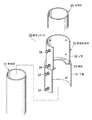
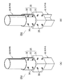
図1,2を参照して説明すると、本発明では筒状の継手ソケット30を使用して縦方向に向けた突き合せた下位の支持杭10と上位の支持柱20の間を一体に接合する。
継手ソケット30は支持杭10と支持柱20の突合せ部に跨って外装可能な異径の異径筒本体35と、異径筒本体35、支持杭10および支持柱20を位置決めする複数の間隙調整手段とを具備する。
本例では複数の間隙調整手段が異径筒本体35の周面に螺着した固定調整ボルト34,36である場合について説明する。
<2> Mechanical Joining Means for Steel Materials Referring to FIGS. 1 and 2, in the present invention, a
The
In this example, a case will be described in which the plurality of gap adjusting means are fixed adjusting
<2.1>異径筒本体
異径筒本体35は支持杭10の上部に第1調整間隙G1を介して外装可能な下筒31と、支持柱20の下部に第2調整間隙G2を介して外装可能な上筒32と、同軸線上に位置させた両筒31,32の境界部に介装して一体化した棚板33とからなる。
本例では下筒31と上筒32はそれぞれ異径の鋼管で形成されている。
棚板33は径差のある両筒31,32を荷重伝達可能に一体化すると共に、支持杭10と支持柱20の突合せ端の間に介装する板材であり、例えば鋼板で形成されている。
棚板33の形状は図示した円環形に限定されず角形でもよい。
棚板33は支持杭10と支持柱20の突合せ端の間に介装可能なように、両筒31,32の内方に向けて水平に張り出している。
<2.1> different diameter tubular body different diameter
In this example, the
The
The shape of the
The
<2.2>鋼材と下筒と上筒の寸法関係
継手ソケット30の下筒31と上筒32を支持杭10と支持柱20にそれぞれ外装するだけであれば、下筒31の内径D1と上筒32の内径D2を支持杭10及び支持柱20の径d1,径d2より大きい同一径すればよい。
本発明では支持杭10の施工誤差(水平方向の誤差、傾倒誤差)を継手ソケット30に吸収させるために、下筒31の内径D1と上筒32の内径D2を同一径とせずに異径の組み合せとし、少なくとも下筒31または上筒32の何れか一方と、支持杭10または支持柱20の何れか一方の周面間に調整間隙を形成するようにした。
<2.2> If only the outer respectively the
Construction error (horizontal error, tilting errors) of the
<2.3>調整間隙
本例では下筒31と支持杭10との周面間に第1調整間隙G1を形成すると共に、上筒32と支持柱20との周面間に第2調整間隙G2を形成した形態について説明する。
更に本例では第2調整間隙G2に対して第1調整間隙G1が大きくなるように、下筒31の内径D1を上筒32の内径D2より大きい(D1>D2)寸法関係にしてある。
<2.3> to form a first adjustment gap G 1 between the peripheral surface of the
As first adjustment gap G 1 is increased with respect to the second adjustment gap G 2 is further in this example, greater than the inner diameter D 2 of the
<2.3.1>第1調整間隙
第1調整間隙G1は支持杭10の施工誤差(水平位置と傾倒)を吸収して調整(修正)するための隙間である。
支持杭10の水平位置の変位量は第1調整間隙G1に比例する。
支持杭10の立設角度の変位量は第1調整間隙G1に比例し、下筒31の全長に反比例する。
したがって、想定される支持杭10の施工誤差を吸収し得るように第1調整間隙G1と下筒31の全長は適宜変更可能である。
<2.3.1> first adjusting clearance first adjustment gap G 1 is a gap for adjusting by absorbing construction errors of the supporting piles 10 (tilting and horizontal position) (corrected).
Displacement of the horizontal position of the supporting
Displacement of the standing angle at which the supporting
Therefore, the total length of the first adjustment gap G 1 and the
<2.3.2>第2調整間隙
第2調整間隙G2は支持杭10と支持柱20の接合後において支持柱20の水平位置と傾倒を微調整するための隙間である。
支持柱20の水平位置の変位量は第2調整間隙G2に比例する。
支持柱20の角度の変位量は第2調整間隙G2に比例し、上筒32の全長に反比例する。
<2.3.2> second adjustment gap second adjustment gap G 2 is a gap for fine adjustment of the tilt and horizontal position of the support pillar 20 after joining of the supporting
Displacement of the horizontal position of the support column 20 is proportional to the second adjust gap G 2.
Displacement of the angle of the supporting pillar 20 is proportional to the second adjust gap G 2, is inversely proportional to the total length of the
<2.4>固定調整ボルト
複数の固定調整ボルト34,36は異径筒本体35と協働して支持杭10と支持柱20の水平位置と角度を調整する機能と、調整を終えた支持杭10と支持柱20の位置を保持する機能(位置決め機能)を有している。
複数の固定調整ボルト34,36は支持杭10や支持柱20を貫通しないので、支持杭10や支持柱20にボルト孔を開設する等の特別な加工は一切不要である。
<2.4> Fixed Adjustment Bolts A plurality of fixed
Since the plurality of fixed
<2.4.1>固定調整ボルトの本数と螺着位置
各筒31,32に周方向に向けて等間隔に螺着する各調整固定ボルト34,36の本数は3本以上であればよく、継手ソケット30に求められる曲げ耐力等を考慮して適宜本数を選択する。
更に各調整固定ボルト34,36の螺着位置は各筒31,32の上部と下部に限定されず、その上下部間の周面に追加して設けてもよい。
本例では各筒31,32の外周面に溶接等で固着したナット31a,32aに各調整固定ボルト34,36を螺着した形態を示すが、各筒31,32にネジ穴を直接形成して各調整固定ボルト34,36を螺着するようにしてもよい。
<2.4.1> Number of fixing adjustment bolts and screwing positions The number of adjusting fixing
Furthermore, the screwing positions of the
In this example, the
<2.4.2>当板付きの固定調整ボルト
図2(D)に示すように、各調整固定ボルト34,36としてボルト軸の先端にボルト軸より大形の当板37を付設したボルトを使用してもよい。当板37を付設した調整固定ボルト34,36を使用すると、支持杭10や支持柱20との間の固定力を増大できて調整固定ボルト34,36の使用本数を低減できる。
<2.4.2> Fixed adjustment bolts with contact plates As shown in FIG. 2 (D), bolts having
[接合方法]
図3を参照して継手ソケット30を使用した支持杭10と支持柱20との接合方法について説明する。
[Joint method]
A method of joining the
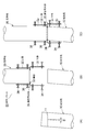
<1>支持杭の立設
図3(A)は打設した支持杭10の杭頭高さが正規位置より高く、打設予定の鉛直線に対して角度θだけ傾いている場合を示している。
鉛直性を保ったまま所定の杭頭高さに合せて支持杭10を打設することは至難であるとこから、杭頭を修正するために支持杭10の上部を破線で示した杭頭の設計高さ11に沿って水平に切除する。
<1> Standing support pile FIG. 3 (A) shows a case where the pile head height of the placed
Since it is difficult to place the
<2>継手ソケットの地組
地表に寝かせた支持柱20の一端に上筒32を外装して継手ソケット30を地組する。
棚板33が支持柱20の一端に当接するまで上筒32を差し込み、複数の固定調整ボルト36を締付けて支持柱20の一端に継手ソケット30を地組する。
継手ソケット30を地組する場合、支持柱20を吊り上げたときに継手ソケット30が自重落下しない程度に固定調整ボルト36を締付けて仮組みしておく。
尚、支持柱20を吊り上げた状態で支持柱20の下部に継手ソケット30を仮組みする場合もある。
<2> Joint socket grounding The
The
When the
In some cases, the
<3>支持柱の吊り込み
図3(B)は下部に継手ソケット30を付設した支持柱20がクレーン等に縦向きに吊り下げられた状態を示し、図3(C)は継手ソケット30の下筒31を支持杭10の上部に外装した状態を示している。
クレーン等に吊り下げられた支持柱20を既設の支持杭10の真上に移動し、支持柱20を降下して支持杭10の上部に継手ソケット30の下筒31を外装する。
継手ソケット30の棚板33が支持杭10の端面に当接することで、支持柱20の降下が規制されて、支持杭10の上部に支持柱20が延設される。
支持杭10の上端と支持柱20の下端の間に棚板33を介在させることで、支持杭10と支持柱20の間に跨って外装した継手ソケット30を位置決めできる。
<3> Suspension of Support Column FIG. 3B shows a state in which the support column 20 with the
The support column 20 suspended from a crane or the like is moved directly above the existing
When the
By interposing the
<4>施工誤差の修正
本発明では以下に説明する継手ソケット30による簡単な修正操作を行うことで接合した既設の支持杭10の施工誤差を吸収して支持柱20を正規位置に立設することができる。
<4> Correction of construction error In the present invention, the support column 20 is erected at a normal position by absorbing a construction error of the existing
<4.1>水平位置の調整
支持杭10の上部位置が正規位置から水平にずれているときは、下筒31に螺着した複数の固定調整ボルト34を正逆転操作して継手ソケット30を修正方向に向けて変位させる。
複数の固定調整ボルト34の先端を支持杭10の外周面に当接させた押圧操作と、他側の固定調整ボルト34の後退操作を行いながら、固定調整ボルト34の押圧反力で以て継手ソケット30全体を修正方向へ向けて水平移動させる。
上筒32に内挿された支持柱20は継手ソケット30に追従して修正方向へ向けて水平に移動する。
<4.1> Adjustment of horizontal position When the upper position of the
While performing a pressing operation in which the tips of the plurality of fixed
The support column 20 inserted in the
<4.2>角度の調整
支持杭10が正規の鉛直線に対して角度θだけ傾斜している場合は、下筒31に螺着した上位と下位の固定調整ボルト34を正逆方向に回転操作して継手ソケット30と共に支持柱20の角度を鉛直に修正する。
下筒31と支持杭10との周面間に形成される第1調整間隙G1の範囲内において、継手ソケット30及び支持柱20の水平位置と角度を修正することができる。
説明の便宜上、支持杭10に対する継手ソケット30の水平位置と角度調整を個別に分けて説明したが、実際はこれらの作業を並行して行う。
<4.2> Angle adjustment When the
In a first range of adjustment gap G 1 is formed between the peripheral surface of the
For convenience of explanation, the horizontal position and angle adjustment of the
<4.3>支持杭と下筒の固定
支持杭10に対する継手ソケット30の水平位置と角度の修正を終えたら、すべての固定調整ボルト34を締付けて支持杭10と下筒31との間を変位不能に剛結する。
<4.3> Fixing of the support pile and the lower cylinder After completing the correction of the horizontal position and angle of the
<4.4>支持柱の微調整
第1調整間隙G1の範囲内において支持柱20の調整量が不足するときは、継手ソケット30の上筒32に螺着した複数の固定調整ボルト36を正逆方向に回転操作して支持柱20の水平位置と角度を微調整する。
継手ソケット30は下筒31と複数の固定調整ボルト34によって支持杭10の上部に変位不能に固定されているので、支持杭10と継手ソケット30から押圧反力を得て、第2調整間隙G2の範囲内において支持柱20の水平位置と角度を微調整できる。
<4.4> When the adjustment amount of the support posts 20 in the fine adjustment first adjusting the gap G 1 range of support column is insufficient, a plurality of fixed
Since the
<4.5>支持杭と上筒の固定
支持柱20の水平位置と立設角度の修正を終えたら、すべての固定調整ボルト36を締付けて支持柱20と上筒32との間を変位不能に剛結する。
継手ソケット30を使用して支持杭10と支持柱20との間の接合をすべて完了した後に、支持柱20をクレーン等から切り離す。
このように支持杭10と支持柱20の突合せ部に跨って継手ソケット30を外装した後に、複数の固定調整ボルト36を回転操作するだけの簡単な作業で以て、支持杭10の施工誤差を吸収して支持柱20を正規位置に立設することができる。
したがって、従来の接合構造と比較して現場における作業性を大幅に改善できて経済的に接合することができる。
<4.5> Fixing of the support pile and the upper cylinder After the correction of the horizontal position and the standing angle of the support pillar 20, all the fixing
After all the joints between the
Thus, after the
Therefore, compared with the conventional joining structure, workability in the field can be greatly improved and joining can be performed economically.
[接合部の特性]
図2を参照しながら継手ソケット30を使用して接合した支持杭10と支持柱20の接合部の特性について説明する。
[Characteristics of joint part]
The characteristics of the joint between the
<1>圧縮軸力
支持杭10と支持柱20の接合部には支持柱20の自重と上載荷重による圧縮軸力が常に作用している。
相対向する支持杭10の上端と支持柱20の下端の対向面の間には継手ソケット30の棚板33の上下面が接面した状態で介装してあるため、圧縮軸力は棚板33を通じて支持杭10と支持柱20の相互間で伝達し合う。
圧縮軸力は下筒31や上筒32に直接作用することはなく、同様に両筒31,32に螺着した複数の固定調整ボルト34,36に作用することもない。
<1> Compression Axial Force A compression axial force due to the weight of the support column 20 and the overload is always acting on the joint between the
Since the upper and lower surfaces of the
The compression axial force does not directly act on the
<2>曲げ力
圧縮軸力が常時作用する支持杭10と支持柱20の接合部に曲げ力が作用すると、継手ソケット30の強度が曲げ力に抵抗する。
具体的には、固定調整ボルト34,36と異径筒本体35を通じて支持杭10と支持柱20との間で曲げ力が伝達可能であり、継手ソケット30の強度が曲げ力に抵抗する。
両筒31,32の周面に均等な間隔で螺着した複数の固定調整ボルト34,36が両筒31,32の外周面に当接して両筒31,32の自由変形を拘束するので、異径筒本体35に曲げ力が加わっても両筒31,32の円形が保持される。
このように本発明では接合部に圧縮軸力が作用する条件下において、継手ソケット30を通じて曲げ力の伝達が可能であるから合理的で簡易な接合構造が得られる。
<2> Bending force When a bending force acts on the joint between the
Specifically, the bending force can be transmitted between the
Since a plurality of fixing
Thus, in the present invention, since a bending force can be transmitted through the
<3>接合後の再調整
支持杭10と支持柱20の接合後においても、必要に応じて継手ソケット30に螺着した固定調整ボルト34,36の回動操作によって支持杭10と支持柱20の水平位置と角度の再調整をすることができる。
<3> Readjustment after Joining After joining the
<4>解体分離
仮設桟橋や仮設橋等を解体する場合には、継手ソケット30の固定調整ボルト34,36を緩めるだけの簡単な操作で支持杭10と支持柱20の接合を解除することができる。分離撤去した継手ソケット30は再使用が可能である。
<4> Dismantling separation When dismantling a temporary pier, temporary bridge, etc., it is possible to release the joint between the
以降に他の実施例について説明するが、その説明に際し、前記した実施例1と同一の部位は同一の符号を付してその詳しい説明を省略する。 Other embodiments will be described below. In the description, the same parts as those in the first embodiment are denoted by the same reference numerals, and detailed description thereof will be omitted.
図4を参照して支持柱20の下部を上筒32に内接させて外装可能に構成した継手ソケット30aを使用して接合する実施例2について説明する。
A second embodiment in which the lower part of the support pillar 20 is inscribed in the
<1>継手ソケット
継手ソケット30aは、支持杭10の上部に第1調整間隙G1を介して外装可能な下筒31と、支持柱20の下部に外装可能な上筒32と、両筒31,32の境界部に介装して一体化した棚板33とを具備する。
上筒32の内径D2は支持柱20の径d2と同径か僅かに大径に形成してあって、上筒32に支持柱20の下部を内接させて収容可能な寸法関係になっている。
下筒31の内径D1は上筒32の内径D2より大きい(D1>D2)寸法関係にあり、第1調整間隙G1の範囲内において継手ソケット30及び支持柱20の水平位置と角度を修正することについては先の実施例1と同様である。
<1> Joint socket
The inner diameter D 2 of the
The inner diameter D 1 of the
<2>本実施例の効果
本実施例2にあっては先の実施例1の効果にくわえて、上筒32の固定調整ボルト36を省略できるので、継手ソケット30aの製作コストを削減できる。
<2> Effects of the present embodiment In the second embodiment, in addition to the effects of the first embodiment, the fixing
以上の実施例1,2では継手ソケット30,30aの下筒31の内径D1が上筒32の内径D2より大きい(D1>D2)寸法関係にある形態について説明したが、下筒31と上筒32の寸法関係を逆にした継手ソケット30bを使用して接合してもよい。
Or an inner diameter D 1 of the
<1>継手ソケット
図5を参照して説明すると、継手ソケット30bの異径筒本体35は、上筒32の内径D2が下筒31の内径D1より大きい(D2>D1)寸法関係にある。
本実施例3では継手ソケット30bの下筒31を支持杭10の上部に外装して取り付けた後に、上筒32内に支持柱20の下部を落とし込んで支持杭10と支持柱20を接合する。
図5では下筒31と支持杭10との周面間に第1調整間隙G1を形成すると共に、複数の固定調整ボルト34を螺着した形態について示すが、固定調整ボルト34を省略した下筒31と支持杭10の周面を接面させて外装してもよい。
<1> Joint Socket Referring to FIG. 5, the different-diameter cylinder
In the third embodiment, after the
To form a first adjustment gap G 1 between the peripheral surface of the
<2>本実施例の効果
本実施例3にあっては、継手ソケット30bの下筒31が支持杭10の上部に変位不能に固定されているので、支持杭10と継手ソケット30bから反力を得て、支持柱20と上筒32と支持柱20の間に形成された第2調整間隙G2の範囲において複数の固定調整ボルト36を回転操作することで支持柱20の水平位置と角度を修正することが可能である。
<2> Effects of the present embodiment In the third embodiment, since the
先の実施例1〜3では支持杭10と支持柱20を構成する鋼材が鋼管同士の組み合せである形態について説明したが、支持杭10と支持柱20を構成する鋼材は鋼管以外に断面矩形のコラム材やH形鋼でもよく、更に支持杭10及び支持柱20の鋼材の組み合せは同種鋼材の組み合せの他に異種鋼材の組み合せも可能である。
以下に支持杭10と支持柱20を構成する他の鋼材の組み合せについて例示する。
Although the steel materials which comprise the
Below, the combination of the other steel materials which comprise the
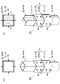
<1>支持柱がコラムの場合
図6(A)は鋼管製の支持杭10に対して支持柱20が断面矩形を呈するコラム材を適用した異種鋼材の組み合わせを示している。
本例の接合では断面円形の下筒31と断面矩形の上筒32と両筒31,32の間に介装した棚板33とを具備した継手ソケット30cを使用する。
継手ソケット30cの上筒32に収容させた支持柱20は図示した複数の固定調整ボルト36で固定してもよいし、固定調整ボルト36を用いずに上筒32に内接させて接合してもよい。
<1> When the Support Column is a Column FIG. 6A shows a combination of different steel materials in which a column material in which the support column 20 has a rectangular cross section is applied to the
In this example, a
The support column 20 accommodated in the
<2>支持柱がH形鋼の場合
図6(B)は鋼管製の支持杭10に対して支持柱20がH形鋼である異種鋼材の組み合わせを示している。
本例の接合には図6(A)と同様の継手ソケット30cを使用する。
継手ソケット30cの上筒32に収容させた支持柱20は図示した複数の固定調整ボルト36で固定してもよいし、固定調整ボルト36を用いずに上筒32に内接させて接合しもよい。
上筒32に収容させた支持柱20を複数の固定調整ボルト36で固定する場合、H形鋼のフランジとウェブの間に形成させた凹部空間内に同空間と同形のスペーサ21,21を収容させると、上筒32の四方に設けた複数の固定調整ボルト36を用いてH形鋼製の支持柱20の水平位置と角度を調整することができる。
<2> Case where Support Column is H-Shaped Steel FIG. 6B shows a combination of dissimilar steel materials in which the support column 20 is H-shaped steel with respect to the
A
The support column 20 accommodated in the
When the support column 20 accommodated in the
<3>支持杭がコラムの場合
図7(A)は鋼管製の支持柱20に対して支持杭10が断面矩形を呈するコラム材を適用した異種鋼材の組み合わせを示している。
本例の接合には断面矩形の下筒31と断面円形の上筒32と両筒31,32の間に介装した棚板33とを具備した継手ソケット30dを使用する。
継手ソケット30dの下筒31に収容させた支持杭10は図示した複数の固定調整ボルト34で固定してもよいし、固定調整ボルト34を用いずに下筒31に内接させて接合してもよい。
<3> Case where Support Pile is Column FIG. 7A shows a combination of different steel materials in which a column material in which the
In this example, a
The
<4>支持杭がH形鋼の場合
図7(B)は鋼管製の支持柱20に対して支持杭10にH形鋼を適用した異種鋼材の組み合わせを示している。
本例の接合には先の継手ソケット30dを使用して、断面矩形の下筒31をH形鋼製の支持杭20に外装すると共に、円形断面を呈する上筒32に鋼管製の支持柱20を内挿している。
<4> When a support pile is H-section steel FIG.7 (B) has shown the combination of the dissimilar steel materials which applied H-section steel to the
The
<5>他の接合例
図8(A)は鋼管製の支持柱20に対して支持杭10に断面矩形を呈するコラム材を適用した異種鋼材の組み合わせを示し、図8(B)は支持杭10にH形鋼を適用した異種鋼材の組み合わせを示している。
支持杭10と支持柱20の組み合せは図7と同様であるが、本例では断面円形の下筒31と断面円形の上筒32と両筒31,32の間に介装した棚板33とを具備した実施例1で使用した継手ソケット30を使用して接合することも可能である。
<5> Other Joining Examples FIG. 8A shows a combination of different steel materials in which a column material having a rectangular cross section is applied to the
The combination of the
<6>実施例2,3との組み合せ
支持杭10及び支持柱20の組み合せが鋼管以外のコラム材またはH形鋼の同種または異種の鋼材を組み合せる本実施例4に既述した実施例2,3を適用して接合することも可能である。
<6> Combination with Embodiments 2 and 3 The combination of the
<7>本実施例の効果
本実施例4にあっては、支持杭10及び支持柱20の組み合せが鋼管以外のコラム材またはH形鋼の同種または異種の鋼材を組み合せであっても、支持杭10または支持柱20の断面形に応じて下筒31または上筒32の断面形を変更した継手ソケット30a〜30dを使い分けることで、支持杭10の立設誤差を修正して支持柱20を接合できて汎用性に富む。
<7> Effects of the present embodiment In the fourth embodiment, even if the combination of the
複数の間隙調整手段は既述した固定調整ボルト34,36に限定されるものではない。
他の複数の間隙調整手段としては、例えば第1調整間隙D1または第2調整間隙D2に進退自在に内挿可能な複数の楔体を適用できる。
更に他の複数の間隙調整手段としては、例えば第1調整間隙D1または第2調整間隙D2に内挿されて流体圧により防縮可能な複数の防縮バッグを適用することも可能である。
要は複数の間隙調整手段が第1調整間隙D1または第2調整間隙D2を調整して、異径筒本体35、支持杭10および支持柱20を位置決めできる機構であればよい。
The plurality of gap adjusting means is not limited to the fixed adjusting
Other multiple gap adjusting means, can be applied movably interpolation possible plurality of wedge for example, the first adjustment gap D 1 or the second adjusting gap D 2.
Still other more gap adjusting means, it is also possible that the first interpolated to adjust the gap D 1 or the second adjusting gap D 2 by applying a plurality of shrink bags that can shrink by a fluid pressure.
In short plurality of gap adjusting means adjusts the first adjustment gap D 1 or the second adjusting gap D 2, may be any mechanism capable of positioning the different diameter
図9を参照して継手ソケット30に複数の引張材40を追加配置した実施例6について説明する。
A sixth embodiment in which a plurality of
<1>引張材
引張材40は継手ソケット30の下筒31と支持杭10と外周面の間、及び継手ソケット30の上筒31と支持柱20の外周面の間を軸方向に連結する引張強度の高い棒状またはロープ状の緊張材である。
継手ソケット30の下筒31と上筒32の外周面には周方向に向けた筒側ブラケット31b,32bが突設してあり、支持杭10及び支持柱20の外周面にも軸方向に向けたブラケット11,21が突設してある。
軸方向に配列されて対をなすブラケット11,31bの間と、ブラケット21,32bの間にはそれぞれ引張材40が架け渡して連結されている。
各軸方向に配置した一対の引張材40,40を1組とし、図外の間隙調整手段と干渉しないように、継手ソケット30の円周方向に沿って2組以上の引張材40が等間隔に配設されている。
<1> Tensile
A pair of
<2>引張材の例示
本例では引張材40が連結ボルト41とナット42の組み合せで構成する場合について説明する。
引張材40の連結ボルト41の基端がピンまたはボルト等の支軸43を介して各ブラケット11,21に回動可能に枢支されていて、筒側ブラケット31b,32bに開設したボルト孔又はスリットに貫通させた各連結ボルト41の先端部にナット42を螺着して締付けることで継手ソケット30の下筒31と支持杭10と外周面の間、及び継手ソケット30の上筒31と支持柱20の外周面の間を締付けできる。
なお、各引張材40は上下の向きを逆向きにして連結してもよい。
<2> Illustration of Tensile Material In this example, the case where the
The base end of the connecting
In addition, you may connect each tension |
<3>引張材の作用
継手ソケット30と突き合せた支持杭10と支持柱20の接合部の間を複数組の引張材40で連結した本実施例にあっては、継手ソケット30に対して支持杭10と支持柱20の抜け出しを防止できるだけでなく、補強材40が接合部の引張と曲げの強度部材として機能するため、接合部における引張耐力と曲げ耐力が格段に向上する。
<3> Action of Tensile Material In the present embodiment in which the joint portion between the
10・・・支持杭(下位の鋼材)
20・・・支持柱(上位の鋼材)
30・・・継手ソケット
30a〜30d・・・継手ソケット
31・・・継手ソケットの下筒
32・・・継手ソケットの上筒
33・・・継手ソケットの棚板
34・・・下筒の固定調整ボルト(間隙調整手段)
35・・・異径筒本体
36・・・上筒の固定調整ボルト(間隙調整手段)
40・・・引張材
41・・・連結ボルト
42・・・ナット
D1・・・第1調整間隙
D2・・・第2調整間隙
10 ... Support pile (lower steel)
20 ... support pillar (upper steel)
30 ...
35 ... Different
40 ...
Claims (8)
前記異径筒本体は下位の鋼材の上部に外装可能な下筒と、上位の鋼材の下部に外装可能な上筒と、同軸線上に位置させた前記下筒と上筒の境界部に介装して一体化した棚板とを有し、
異径に形成された少なくとも前記下筒と上筒の何れか一方と、前記上位又は下位の何れか一方の鋼材の周面間に調整間隙が形成され、
下位の鋼材と上位の鋼材に跨って継手ソケットが外装されたときに前記下位の鋼材の上端と上位の鋼材の下端の間に棚板が介在することで前記継手ソケットが位置決めされ、
前記複数の間隙調整手段が調整間隙の範囲で調整された上位の鋼材の水平位置と立設角度を保持することを特徴とする、
鋼材の接合構造。 Adjusting the adjustment gap formed between the different diameter cylinder main body and the steel material by adjusting the cylindrical different diameter cylinder main body that can be externally straddled across the abutting portions of the upper and lower steel materials in the vertical direction. A steel material joint structure that integrally joins between the upper portion of the support pile and the lower portion of the support column using a joint socket having a plurality of gap adjusting means for positioning the diameter tube main body and the steel material,
The different-diameter cylinder main body is provided at a lower cylinder that can be packaged on the upper part of the lower steel material, an upper cylinder that can be packaged on the lower part of the upper steel material, and a boundary between the lower cylinder and the upper cylinder positioned on the same axis. And integrated shelf board,
An adjustment gap is formed between at least one of the lower cylinder and the upper cylinder formed in different diameters, and a peripheral surface of either the upper or lower steel material,
When the joint socket is sheathed across the lower steel and the upper steel, the joint socket is positioned by interposing a shelf between the upper end of the lower steel and the lower end of the upper steel,
The plurality of gap adjusting means holds the horizontal position and the standing angle of the upper steel material adjusted in the range of the adjustment gap,
Steel joint structure.
Priority Applications (1)
| Application Number | Priority Date | Filing Date | Title |
|---|---|---|---|
| JP2017113353A JP6737740B2 (en) | 2017-06-08 | 2017-06-08 | Steel material joining structure |
Applications Claiming Priority (1)
| Application Number | Priority Date | Filing Date | Title |
|---|---|---|---|
| JP2017113353A JP6737740B2 (en) | 2017-06-08 | 2017-06-08 | Steel material joining structure |
Publications (2)
| Publication Number | Publication Date |
|---|---|
| JP2018204379A true JP2018204379A (en) | 2018-12-27 |
| JP6737740B2 JP6737740B2 (en) | 2020-08-12 |
Family
ID=64955339
Family Applications (1)
| Application Number | Title | Priority Date | Filing Date |
|---|---|---|---|
| JP2017113353A Active JP6737740B2 (en) | 2017-06-08 | 2017-06-08 | Steel material joining structure |
Country Status (1)
| Country | Link |
|---|---|
| JP (1) | JP6737740B2 (en) |
Cited By (4)
| Publication number | Priority date | Publication date | Assignee | Title |
|---|---|---|---|---|
| WO2020090716A1 (en) | 2018-10-30 | 2020-05-07 | 東京瓦斯株式会社 | Fuel cell system and regeneration method of off-gas |
| CN111906709A (en) * | 2020-07-19 | 2020-11-10 | 杭州盛通科技有限公司 | Communication base station stake fixing device with locating component |
| JP2021110162A (en) * | 2020-01-10 | 2021-08-02 | 日本コンクリート工業株式会社 | Joint pipe, assembly type concrete column, and assembly method of assembly type concrete column |
| JP7098079B1 (en) | 2022-04-22 | 2022-07-08 | 日本製鉄株式会社 | Steel joint structure |
Citations (8)
| Publication number | Priority date | Publication date | Assignee | Title |
|---|---|---|---|---|
| JPS51372B1 (en) * | 1968-08-16 | 1976-01-07 | ||
| JPS6414238U (en) * | 1987-07-17 | 1989-01-25 | ||
| JPH0376930A (en) * | 1989-08-17 | 1991-04-02 | Misawa Homes Co Ltd | Adjusting method for level of steel-framed foundation |
| JP2000273833A (en) * | 1999-03-23 | 2000-10-03 | Minoru Kitagawa | Column to be constructed in ground |
| JP2005226309A (en) * | 2004-02-12 | 2005-08-25 | Jfe Steel Kk | Joint structure and jointing method for upper part structure and pile |
| JP2012246696A (en) * | 2011-05-30 | 2012-12-13 | Sumitomo Mitsui Construction Co Ltd | Erection engineering method of steel column and base member used for the same |
| JP2013155567A (en) * | 2012-01-31 | 2013-08-15 | Hitachi Metals Techno Ltd | Column member connection structure and assembly method for the same |
| US20160186402A1 (en) * | 2014-12-30 | 2016-06-30 | TorcSill Foundations, LLC | Helical pile assembly with top plate |
-
2017
- 2017-06-08 JP JP2017113353A patent/JP6737740B2/en active Active
Patent Citations (8)
| Publication number | Priority date | Publication date | Assignee | Title |
|---|---|---|---|---|
| JPS51372B1 (en) * | 1968-08-16 | 1976-01-07 | ||
| JPS6414238U (en) * | 1987-07-17 | 1989-01-25 | ||
| JPH0376930A (en) * | 1989-08-17 | 1991-04-02 | Misawa Homes Co Ltd | Adjusting method for level of steel-framed foundation |
| JP2000273833A (en) * | 1999-03-23 | 2000-10-03 | Minoru Kitagawa | Column to be constructed in ground |
| JP2005226309A (en) * | 2004-02-12 | 2005-08-25 | Jfe Steel Kk | Joint structure and jointing method for upper part structure and pile |
| JP2012246696A (en) * | 2011-05-30 | 2012-12-13 | Sumitomo Mitsui Construction Co Ltd | Erection engineering method of steel column and base member used for the same |
| JP2013155567A (en) * | 2012-01-31 | 2013-08-15 | Hitachi Metals Techno Ltd | Column member connection structure and assembly method for the same |
| US20160186402A1 (en) * | 2014-12-30 | 2016-06-30 | TorcSill Foundations, LLC | Helical pile assembly with top plate |
Cited By (7)
| Publication number | Priority date | Publication date | Assignee | Title |
|---|---|---|---|---|
| WO2020090716A1 (en) | 2018-10-30 | 2020-05-07 | 東京瓦斯株式会社 | Fuel cell system and regeneration method of off-gas |
| JP2021110162A (en) * | 2020-01-10 | 2021-08-02 | 日本コンクリート工業株式会社 | Joint pipe, assembly type concrete column, and assembly method of assembly type concrete column |
| JP7288407B2 (en) | 2020-01-10 | 2023-06-07 | 日本コンクリート工業株式会社 | Prefabricated concrete column and its assembly method |
| CN111906709A (en) * | 2020-07-19 | 2020-11-10 | 杭州盛通科技有限公司 | Communication base station stake fixing device with locating component |
| CN111906709B (en) * | 2020-07-19 | 2022-01-25 | 河北卓思通信器材有限公司 | Communication base station stake fixing device with locating component |
| JP7098079B1 (en) | 2022-04-22 | 2022-07-08 | 日本製鉄株式会社 | Steel joint structure |
| JP2023160391A (en) * | 2022-04-22 | 2023-11-02 | 日本製鉄株式会社 | Steel material joint structure |
Also Published As
| Publication number | Publication date |
|---|---|
| JP6737740B2 (en) | 2020-08-12 |
Similar Documents
| Publication | Publication Date | Title |
|---|---|---|
| JP2018204379A (en) | Joint structure for steel material | |
| JP5131518B2 (en) | Steel pipe pile and steel column joint structure | |
| JP4683579B1 (en) | Reinforcement structure for wooden buildings | |
| JP6445090B2 (en) | Force test equipment | |
| JP6740738B2 (en) | Joining method and joining structure of steel members | |
| JP2017223072A (en) | Method and structure for joining steel pipe | |
| WO2019074050A1 (en) | Joint structure for h-beam | |
| JP7013352B2 (en) | Construction method of temporary bridge | |
| KR101571489B1 (en) | The device for earth retaining wall self supported by bracing | |
| CN110359722A (en) | A kind of steel column correction jacking bracket and its application method | |
| JP7098079B1 (en) | Steel joint structure | |
| JP6320500B1 (en) | Bridge main girder, bridge with the main girder, and method of constructing the bridge | |
| KR102213361B1 (en) | Connection device for strut | |
| JP2013108302A (en) | Inclination angle adjustment device and inclination angle adjustment method of steel tower main column material | |
| JP6940870B2 (en) | Support | |
| JP2017155469A (en) | Steel pipe joint structure and steel pipe joining method | |
| JP2008038367A (en) | Disassemblable column/beam joint | |
| CN209816666U (en) | Assembled bracing connection structure between steel-pipe piles | |
| JP5207005B2 (en) | Verticalness adjustment jig and verticality adjustment method | |
| JP6467202B2 (en) | Steel tower main column replacement method | |
| JP6888696B2 (en) | Joint structure of steel members | |
| JP2017008504A (en) | Connection structure of foundation pile and unit, and unit construction method using the same | |
| JP6917653B1 (en) | Support | |
| JP6333675B2 (en) | Reinforcement method for steel tower legs and displacement adjustment fittings to eliminate inconsistent displacement of steel towers, etc. | |
| CN214005664U (en) | Connecting device of prefabricated square pile |
Legal Events
| Date | Code | Title | Description |
|---|---|---|---|
| A521 | Request for written amendment filed |
Free format text: JAPANESE INTERMEDIATE CODE: A523 Effective date: 20170703 |
|
| A521 | Request for written amendment filed |
Free format text: JAPANESE INTERMEDIATE CODE: A523 Effective date: 20170621 |
|
| A621 | Written request for application examination |
Free format text: JAPANESE INTERMEDIATE CODE: A621 Effective date: 20190213 |
|
| A977 | Report on retrieval |
Free format text: JAPANESE INTERMEDIATE CODE: A971007 Effective date: 20191210 |
|
| A131 | Notification of reasons for refusal |
Free format text: JAPANESE INTERMEDIATE CODE: A131 Effective date: 20191217 |
|
| A521 | Request for written amendment filed |
Free format text: JAPANESE INTERMEDIATE CODE: A523 Effective date: 20200206 |
|
| TRDD | Decision of grant or rejection written | ||
| A01 | Written decision to grant a patent or to grant a registration (utility model) |
Free format text: JAPANESE INTERMEDIATE CODE: A01 Effective date: 20200630 |
|
| A61 | First payment of annual fees (during grant procedure) |
Free format text: JAPANESE INTERMEDIATE CODE: A61 Effective date: 20200716 |
|
| R150 | Certificate of patent or registration of utility model |
Ref document number: 6737740 Country of ref document: JP Free format text: JAPANESE INTERMEDIATE CODE: R150 |
|
| R250 | Receipt of annual fees |
Free format text: JAPANESE INTERMEDIATE CODE: R250 |