JP2012246696A - Erection engineering method of steel column and base member used for the same - Google Patents
Erection engineering method of steel column and base member used for the same Download PDFInfo
- Publication number
- JP2012246696A JP2012246696A JP2011120055A JP2011120055A JP2012246696A JP 2012246696 A JP2012246696 A JP 2012246696A JP 2011120055 A JP2011120055 A JP 2011120055A JP 2011120055 A JP2011120055 A JP 2011120055A JP 2012246696 A JP2012246696 A JP 2012246696A
- Authority
- JP
- Japan
- Prior art keywords
- steel column
- pipe
- steel
- horizontal position
- hole
- Prior art date
- Legal status (The legal status is an assumption and is not a legal conclusion. Google has not performed a legal analysis and makes no representation as to the accuracy of the status listed.)
- Granted
Links
Images


Abstract
Description
本発明は、鉄骨柱を建て込む鉄骨柱の建込工法、及び該工法に使用されるベース部材に関する。 The present invention relates to a steel column mounting method for building a steel column and a base member used in the method.
鉄骨柱脚形式の一つである埋め込み柱脚は剛性や耐力などの構造性能面で比較的優れているが、一般的な埋込み柱脚工法の場合は、基礎部のRC造の施工は鉄骨柱が現場に搬入された後に開始する必要があった。しかしながら、この鉄骨柱は、発注の遅れや製作の遅れなどが原因で必要な期日までに納品されないこともあり、鉄骨柱の搬入が遅れた場合には現場の工事も遅れてしまうという問題があった。 The embedded column base, which is one of the types of steel column bases, is relatively superior in terms of structural performance such as rigidity and proof strength. However, in the case of a general embedded column base method, the RC construction of the foundation is a steel column. Had to be started after it was brought into the field. However, this steel column may not be delivered by the necessary date due to delays in ordering or production, and there is a problem that construction work on site will be delayed if the delivery of steel columns is delayed. It was.
そこで、そのような問題を解決する鉄骨柱の建込工法については種々の方法が提案されている(例えば、特許文献1及び2参照)。
Therefore, various methods have been proposed for steel column erection methods that solve such problems (see, for example,
図6は、鉄骨柱の建込工法の従来例を示す斜視図であって、符号100は、鉄骨柱102を建て込むための穴(箱抜きにした穴)を示し、符号103は、該穴100の周囲に配置される鉄筋を示し、符号104は、該鉄筋103を埋設するように打設されたコンクリートを示す。この図6に示す方法では、鉄骨柱が納入されなくとも基礎工事(つまり、鉄筋103の配置、及びコンクリート104の打設)を完了することが出来、鉄骨柱の納期に左右されにくいというメリットがある。
FIG. 6 is a perspective view showing a conventional example of a steel column embedding method, in which
しかしながら、図6に示す従来工法の場合、鉄骨柱を埋め込む部分を箱抜き状態にしなければならないため、型枠等を用いた作業が必要となり、その作業が煩雑になるという問題があった。また、鉄骨柱を埋め込む穴の周囲には多量の鉄筋103を配置する必要があり、その配筋作業も繁雑になるという問題もあった。さらに、鉄骨柱の高さ調整は高さ調整用のモルタル105によって行われているが、その作業が煩雑になるという問題もあった。
However, in the case of the conventional method shown in FIG. 6, the portion in which the steel column is to be embedded has to be unboxed, which requires a work using a mold or the like, and there is a problem that the work becomes complicated. In addition, it is necessary to arrange a large amount of reinforcing
本発明は、上述の問題を解消することのできる鉄骨柱の建込工法、及び該工法に使用されるベース部材を提供することを目的とするものである。 An object of the present invention is to provide a steel column erection method that can solve the above-described problems, and a base member used in the method.
請求項1に係る発明は、図1及び図2に例示するものであって、鋼管からなる管部(10)と、該管部(10)に連結されると共に該管部(10)の軸方向(+z)と略直交する方向(±x,±y)に延設されてなる圧延鋼材(以下、「アンカー部」とする)(11)と、を有するベース部材(1)を、前記管部(10)が略上下方向に延設されると共に前記アンカー部(11)が略水平方向に延設されるように設置する工程と、
該アンカー部(11)を囲繞するように鉄筋(3)を配置する工程と、
該アンカー部(11)及び該鉄筋(3)を埋設するようにコンクリート(4)を打設する工程と、
鉄骨柱(2)の下端部を前記管部(10)に挿入して該鉄骨柱(2)を建て込む工程と、
該管部(10)の側に配置された第1ナット部材(図3(b) の符号13参照)に螺合されると共に管壁を貫通して前記管部(10)の内部(図3(b) の符号S参照)に略水平に突出されてなる水平位置調整ボルト(12)を操作して該水平位置調整ボルト(12)の該管部(10)の内部への突出量を調整することにより前記鉄骨柱(2)の水平位置を調整する工程と、
前記管部(10)の内部(図3(b) の符号S参照)にコンクリートを打設して該鉄骨柱(2)を固定する工程と、を備えたことを特徴とする。
The invention according to
Arranging the reinforcing bars (3) so as to surround the anchor portion (11);
Placing concrete (4) so as to embed the anchor portion (11) and the reinforcing bar (3);
Inserting the lower end portion of the steel column (2) into the pipe portion (10) to build the steel column (2);
It is screwed into a first nut member (see
A step of placing concrete in the pipe portion (10) (see S in FIG. 3B) to fix the steel column (2).
請求項2に係る発明は、図3(b) に例示するものであって、請求項1に係る発明において、前記水平位置調整ボルト(12)は少なくとも四方から前記鉄骨柱(2)を押し付けるように配置されていることを特徴とする。
The invention according to
請求項3に係る発明は、図1及び図2に例示するものであって、請求項1又は2に係る発明において、前記水平位置調整ボルト(12)は、異なる高さに複数配置されていて、前記鉄骨柱(2)の建込角度を調整できるように構成されたことを特徴とする。
The invention according to
請求項4に係る発明は、図1及び図2に例示するものであって、請求項1乃至3のいずれか1項に記載の発明において、上下に貫通する第1貫通孔(不図示)を有する支持部材(5)を前記管部(10)の上端縁に載置し、
前記鉄骨柱(2)の側であって前記第1貫通孔の下方に相当する位置に、上下に貫通する第2貫通孔(2a)を形成し、
これらの第1貫通孔及び第2貫通孔(2a)に挿通されるように鉛直位置調整ボルト(6)を配置し、
前記1貫通孔が形成された部分及び前記第2貫通孔(2a)が形成された部分のいずれか一方は、他方の側に前記鉛直位置調整ボルト(6)が移動しないような状態で該鉛直位置調整ボルト(6)を回転自在に支持し、
該他方の側には、前記鉛直位置調整ボルト(6)に螺合されてなる第2ナット部材(不図示)を配置し、
該鉛直位置調整ボルト(6)を操作することにより前記鉄骨柱(2)の上下位置を調整することを特徴とする。
The invention according to claim 4 is illustrated in FIGS. 1 and 2, and in the invention according to any one of
Forming a second through hole (2a) penetrating vertically at a position corresponding to the lower side of the first through hole on the steel column (2) side;
The vertical position adjusting bolt (6) is disposed so as to be inserted through the first through hole and the second through hole (2a),
One of the portion where the first through hole is formed and the portion where the second through hole (2a) is formed is such that the vertical position adjusting bolt (6) does not move to the other side. The position adjustment bolt (6) is supported rotatably,
On the other side, a second nut member (not shown) screwed to the vertical position adjusting bolt (6) is disposed,
The vertical position of the steel column (2) is adjusted by operating the vertical position adjusting bolt (6).
請求項5に係る発明は、少なくとも一部がコンクリート(4)に埋設された状態で配置されると共に鉄骨柱(2)の下端部を支持するように構成されたベース部材(1)において、
略上下方向に延設された鋼管にて形成されて鉄骨柱(2)の下端部が挿入されるように構成された管部(10)と、
該管部(10)に連結されると共に略水平方向に延設された圧延鋼材からなるアンカー部(11)と、
を備え、
該アンカー部(11)はコンクリート(4)に埋設された状態に配置され、
前記管部(10)には、第1ナット部材(13)と、該第1ナット部材(13)に螺合されると共に管壁を貫通して該管部(10)の内部に略水平に突出されて前記鉄骨柱(2)の水平位置を規定する水平位置調整ボルト(12)と、が配置されてなることを特徴とする。
The invention according to
A pipe portion (10) formed of a steel pipe extending in a substantially vertical direction and configured to be inserted into the lower end portion of the steel column (2);
An anchor part (11) made of a rolled steel material connected to the pipe part (10) and extending in a substantially horizontal direction;
With
The anchor part (11) is arranged in a state embedded in the concrete (4),
The pipe part (10) is screwed into the first nut member (13) and the first nut member (13) and penetrates the pipe wall so as to be substantially horizontal in the pipe part (10). A horizontal position adjusting bolt (12) protruding and defining a horizontal position of the steel column (2) is arranged.
なお、括弧内の番号などは、図面における対応する要素を示す便宜的なものであり、従って、本記述は図面上の記載に限定拘束されるものではない。 Note that the numbers in parentheses are for the sake of convenience indicating the corresponding elements in the drawings, and therefore the present description is not limited to the descriptions on the drawings.
請求項1及び5に係る発明によれば、鉄骨柱が現場に搬入されなくても基礎工事(つまり、鉄筋の配置、及びコンクリートの打設)を完了することが出来、基礎工事が鉄骨柱の納期の影響を受けないというメリットがある。また、本発明によれば、型枠として機能する管部をコンクリート打設後に取り外す必要が無いため、その分、作業が簡素化される。さらに、該管部の固定は、その周囲に埋設される鉄筋だけでなく該管部に連結されたアンカー部によっても行われるため、アンカー部を使用しない場合に比べて鉄筋の数を減らすことが出来、その配筋作業が簡素化される。またさらに、本発明によれば、鉄骨柱を建て込む穴は、鋼管からなる管部にて形成されているため、該管部を利用して上述のような水平位置調整ボルトを設けることができる。その結果、水平位置調整ボルトを時計回り又は反時計回りに回転させるだけで鉄骨柱の水平位置等を簡単に調整することができる。
According to the inventions according to
請求項2に係る発明によれば、各水平位置調整ボルトを回転操作することにより、該鉄骨柱の位置調整を4つの方向に対して行うことができる。
According to the invention which concerns on
請求項3に係る発明によれば、前記鉄骨柱の建込角度を調整することができる。
According to the invention which concerns on
請求項4に係る発明によれば、高さ調整用のモルタルを使用しなくても、前記鉛直位置調整ボルトを操作するだけで鉄骨柱の高さ調整を簡単に行うことができる。 According to the invention which concerns on Claim 4, even if it does not use the mortar for height adjustment, the height adjustment of a steel column can be easily performed only by operating the said vertical position adjustment volt | bolt.
以下、図1乃至図5に沿って、本発明の実施の形態について説明する。 Hereinafter, embodiments of the present invention will be described with reference to FIGS. 1 to 5.
本発明に係る鉄骨柱の建込工法は、建築物(例えば、集合住宅やオフィスビルや工場や倉庫や商業施設など)を建築する際に鉄骨柱を建て込む方法であって、図1に例示するような部材(少なくとも一部がコンクリート4に埋設された状態で配置されると共に鉄骨柱2の下端部を支持するように構成された部材であって、本明細書においては「ベース部材」とする)1を使用して鉄骨柱2を建て込む方法である。このベース部材1は、
・ 鋼管からなる管部10と、
・ 該管部10に連結されると共に該管部10の軸方向+zと略直交する方向±x,±yに延設されてなる圧延鋼材(本明細書においては「アンカー部」とする)11と、
を有している。なお、このベース部材1は、後述するように、前記管部10が略上下方向に延設される(つまり、前記軸方向+zが略上方を向く)と共に前記アンカー部11が略水平方向に延設される(つまり、前記方向±x,±yが略水平方向を向く)ように配置されることとなる。また、該アンカー部11は後述のようにコンクリート4に埋設された状態に配置される。
The steel column embedding method according to the present invention is a method of building a steel column when building a building (for example, an apartment house, an office building, a factory, a warehouse, a commercial facility, etc.), and is exemplified in FIG. Such a member (a member arranged at least partially embedded in the concrete 4 and configured to support the lower end portion of the
A
A rolled steel material 11 (hereinafter referred to as “anchor portion”) 11 connected to the
have. As will be described later, in this
ところで、図1に示すベース部材1ではアンカー部11の数は4本であるが、もちろんこれに限られるものではなく、5本以上であっても、3本以下であっても良い。また、図1に示すアンカー部11は、その挟角θが略90度となるように設定されているが、もちろんこれに限られるものではなく、任意の角度にすると良い。さらに、このアンカー部11に使用する圧延鋼材としては、H形鋼やT形鋼等の形鋼、或いは棒鋼を挙げることができる。
By the way, in the
一方、図1に示す管部10はいわゆる四角形鋼管であるが、もちろんこれに限られるものではなく、鉄骨柱2の下端部を挿入できるものであれば他の形状であっても良い。
On the other hand, although the
また一方、この管部10には、挿入された鉄骨柱2の水平位置を調整するためのボルト(本明細書においては「水平位置調整ボルト」とする)12が取り付けられている。すなわち、該管部10の管壁には貫通孔(図3(b) に符号10aで示すように水平に貫通される貫通孔であって、以下、適宜「第3貫通孔」とする)が穿設されていて、該水平位置調整ボルト12が該第3貫通孔10aに挿通された状態で略水平に配置されている。したがって、該水平位置調整ボルト12は、前記管壁を貫通して該管部10の内部Sに略水平に突出されることとなる。また、この管部10の側には、前記第3貫通孔10aに略一致するようにナット部材(以下、「第1ナット部材」とする)13が配置されており、前記水平位置調整ボルト12がこの第1ナット部材13に螺合されて回転自在に支持されている。したがって、該水平位置調整ボルト12を時計回り又は反時計回りに回転させるとその突出量(つまり、前記管部10の内部Sへの突出量)も変化することとなり、その変化によって前記鉄骨柱2の水平位置を調整できるようになっている。
On the other hand, a bolt (referred to as “horizontal position adjusting bolt” in this specification) 12 for adjusting the horizontal position of the inserted
そして、本発明に係る鉄骨柱の建込方法は以下の工程を備えている。すなわち、
・ 図2に示すように、上述したベース部材1の管部10が略上下方向に延設されると共に前記アンカー部11が略水平方向に延設されるように該ベース部材1を設置する工程
・ 前記アンカー部11を囲繞するように鉄筋(図2の符号3参照)を配置する工程
・ 該アンカー部11及び該鉄筋3を埋設するようにコンクリート4を打設する工程
・ 鉄骨柱2の下端部を前記管部10に挿入して該鉄骨柱2を建て込む工程
・ 該水平位置調整ボルト12を時計回り又は反時計回りに回転操作して該水平位置調整ボルト12の前記管部10の内部Sへの突出量を調整することにより前記鉄骨柱2の水平位置を調整する工程
・ 前記管部10の内部S(つまり、該管部10の内周壁と前記鉄骨柱2との間)にコンクリートを打設して該鉄骨柱2を固定する工程
And the construction method of the steel column which concerns on this invention is equipped with the following processes. That is,
As shown in FIG. 2, the step of installing the
本発明によれば、鉄骨柱が現場に搬入されなくても基礎工事(つまり、鉄筋3の配置、及びコンクリート4の打設)を完了することが出来、基礎工事が鉄骨柱の納期の影響を受けないというメリットがある。また、本発明によれば、型枠として機能する管部10をコンクリート打設後に取り外す必要が無いため、その分、作業が簡素化される。さらに、該管部10の固定は、その周囲に埋設される鉄筋3だけでなく該管部10に連結されたアンカー部11によっても行われるため、図6に示す従来工法に比べて鉄筋の数を減らすことが出来、その配筋作業が簡素化される。またさらに、本発明によれば、鉄骨柱2を建て込む穴は、鋼管からなる管部10にて形成されているため、該管部10を利用して上述のような水平位置調整ボルト12を設けることができる。その結果、水平位置調整ボルト12を時計回り又は反時計回りに回転させるだけで鉄骨柱2の水平位置等を簡単に調整することができる。
According to the present invention, the foundation work (that is, the placement of the reinforcing
ところで、前記水平位置調整ボルト12は、図3(b) に例示するように、少なくとも四方から前記鉄骨柱2を押し付けるように配置しておくと良い。そのようにした場合には、各水平位置調整ボルト12を回転操作することにより、該鉄骨柱2の位置調整を4つの方向に対して行うことができる。
Incidentally, the horizontal
また、上述の水平位置調整ボルト12を、図1及び図2に例示するように、異なる高さに複数配置しておくと良い。そのようにした場合には、前記鉄骨柱2の建込角度を調整することができる。
Also, a plurality of the horizontal
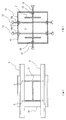
一方、図1及び図2に例示するように、上下に貫通する第1貫通孔(不図示)を有する支持部材5を前記管部10の上端縁に載置し、前記鉄骨柱2の側であって前記第1貫通孔の下方に相当する位置に、上下に貫通する第2貫通孔(図1の符号2a参照)を形成し、これらの第1貫通孔及び第2貫通孔2aに挿通されるように鉛直位置調整ボルト6を配置すると良い。そして、前記1貫通孔が形成された部分(つまり、前記支持部材5)及び前記第2貫通孔2aが形成された部分のいずれか一方は、他方の側に前記鉛直位置調整ボルト6が移動しないような状態で該鉛直位置調整ボルト6を回転自在に支持するようにし、該他方の側には、前記鉛直位置調整ボルト6に螺合されてなる第2ナット部材(不図示)を配置し、該鉛直位置調整ボルト6を操作することにより前記鉄骨柱2の上下位置を調整するようにすると良い。そのようにした場合には、高さ調整用のモルタルを使用しなくても、該鉛直位置調整ボルト6を操作するだけで鉄骨柱の高さ調整を簡単に行うことができる。
On the other hand, as illustrated in FIGS. 1 and 2, a
本実施例においては、鉄骨柱2を建て込む地盤を基礎底まで掘削し、砕石敷きを行い(図2の符号7参照)、捨てコンクリート8を打設した。なお、砕石の厚さは100mmとし、捨てコンクリートの厚さは50mmとした。
In this example, the ground into which the
次に、図1に示す構造のベース部材1を作製した。すなわち、図5に示すように、150mm×150mmのH形鋼(アンカー部)11を十字形に組み、その交差部に四角形鋼管10Aを溶接し、該鋼管10Aの下方には鋼片10Bを溶接した。なお、このベース部材1には上述の水平位置調整ボルト12を12本取り付けておき、管部10が略上下方向に延設されるように該ベース部材1を捨てコンクリート8の上に配置した。
Next, the
そして、図4に詳示するように、前記アンカー部11を囲繞するように鉄筋3を配置し、該アンカー部11及び該鉄筋3を埋設するようにコンクリート4を打設してフーチングを形成した。
Then, as shown in detail in FIG. 4, the reinforcing
一方、鉄骨柱2の底面には、第2貫通孔2aが穿設されたベースプレート(図1の符号2b参照)を取り付け、該ベースプレート2bの下方には鉤状の部材2cを突出させておいた。この鉄骨柱2が現場に搬入されると、該鉄骨柱2の下端部を前記管部10に挿入して該鉄骨柱2を建て込んだ。その後、前記水平位置調整ボルト12を時計回り又は反時計回りに回転操作して該水平位置調整ボルト12の前記管部10の内部Sへの突出量を調整することにより前記鉄骨柱2の水平位置を調整した。さらに、第1貫通孔が穿設された支持部材5(75×75×6の等辺山形鋼)を2本、前記管部10の上端面に載置し、前記第1貫通孔及び前記第2貫通孔2aに鉛直位置調整ボルト6を挿通させて、該ボルト6を回転操作することにより前記鉄骨柱2の高さ調整を行った。
On the other hand, a base plate (see
このようにして鉄骨柱2の水平位置及び高さを適正位置に調整した後、管部10の内部Sにコンクリート(又はモルタル)を打設して該鉄骨柱2を固定した。その際、上述の鉤状の部材2cはコンクリートに埋設されることとなり、鉄骨柱2を引き抜こうとする外力に抵抗するように機能することとなる。
Thus, after adjusting the horizontal position and height of the
1 ベース部材
2 鉄骨柱
2a 第2貫通孔
3 鉄筋
4 コンクリート
5 支持部材
6 鉛直位置調整ボルト
10 管部
11 アンカー部
12 水平位置調整ボルト
13 第1ナット部材
+z 管部の軸方向
DESCRIPTION OF
Claims (5)
該アンカー部を囲繞するように鉄筋を配置する工程と、
該アンカー部及び該鉄筋を埋設するようにコンクリートを打設する工程と、
鉄骨柱の下端部を前記管部に挿入して該鉄骨柱を建て込む工程と、
該管部の側に配置された第1ナット部材に螺合されると共に管壁を貫通して前記管部の内部に略水平に突出されてなる水平位置調整ボルトを操作して該水平位置調整ボルトの該管部の内部への突出量を調整することにより前記鉄骨柱の水平位置を調整する工程と、
前記管部の内部にコンクリートを打設して該鉄骨柱を固定する工程と、
を備えたことを特徴とする鉄骨柱の建込工法。 A base member having a pipe portion made of a steel pipe and a rolled steel material (hereinafter referred to as “anchor portion”) connected to the pipe portion and extending in a direction substantially orthogonal to the axial direction of the pipe portion. A step of installing the pipe portion so as to extend in a substantially vertical direction and the anchor portion so as to extend in a substantially horizontal direction;
Arranging a reinforcing bar so as to surround the anchor part;
Placing concrete so as to bury the anchor part and the reinforcing bar;
Inserting the lower end of the steel column into the pipe part and building the steel column;
The horizontal position adjustment is performed by operating a horizontal position adjusting bolt which is screwed into a first nut member arranged on the side of the pipe part and penetrates the pipe wall and protrudes substantially horizontally into the pipe part. Adjusting the horizontal position of the steel column by adjusting the amount of protrusion of the bolt into the tube part; and
Placing the concrete inside the pipe portion and fixing the steel column; and
A steel column construction method characterized by comprising:
ことを特徴とする請求項1に記載の鉄骨柱の建込工法。 The horizontal position adjustment bolt is arranged to press the steel column from at least four sides.
The steel column embedding method according to claim 1.
ことを特徴とする請求項1又は2に記載の鉄骨柱の建込工法。 A plurality of the horizontal position adjustment bolts are arranged at different heights, and configured to be able to adjust the erection angle of the steel column,
The steel column embedding method according to claim 1 or 2.
前記鉄骨柱の側であって前記第1貫通孔の下方に相当する位置に、上下に貫通する第2貫通孔を形成し、
これらの第1貫通孔及び第2貫通孔に挿通されるように鉛直位置調整ボルトを配置し、
前記1貫通孔が形成された部分及び前記第2貫通孔が形成された部分のいずれか一方は、他方の側に前記鉛直位置調整ボルトが移動しないような状態で該鉛直位置調整ボルトを回転自在に支持し、
該他方の側には、前記鉛直位置調整ボルトに螺合されてなる第2ナット部材を配置し、
該鉛直位置調整ボルトを操作することにより前記鉄骨柱の上下位置を調整する、
ことを特徴とする請求項1乃至3のいずれか1項に記載の鉄骨柱の建込工法。 A support member having a first through-hole penetrating vertically is placed on the upper edge of the pipe part,
Forming a second through-hole penetrating vertically at a position corresponding to the lower side of the first through-hole on the steel column side;
The vertical position adjustment bolt is arranged so as to be inserted into these first through hole and second through hole,
Either the portion where the first through hole is formed or the portion where the second through hole is formed can freely rotate the vertical position adjusting bolt in a state where the vertical position adjusting bolt does not move to the other side. To support
On the other side, a second nut member screwed to the vertical position adjusting bolt is disposed,
Adjusting the vertical position of the steel column by operating the vertical position adjustment bolt;
The steel column erection method according to any one of claims 1 to 3.
略上下方向に延設された鋼管にて形成されて鉄骨柱の下端部が挿入されるように構成された管部と、
該管部に連結されると共に略水平方向に延設された圧延鋼材からなるアンカー部と、
を備え、
該アンカー部はコンクリートに埋設された状態に配置され、
前記管部には、第1ナット部材と、該第1ナット部材に螺合されると共に管壁を貫通して該管部の内部に略水平に突出されて前記鉄骨柱の水平位置を規定する水平位置調整ボルトと、が配置されてなる、
ことを特徴とするベース部材。 In a base member that is arranged with at least a portion embedded in concrete and is configured to support the lower end of a steel column,
A pipe portion formed of a steel pipe extending substantially in the vertical direction and configured to be inserted into the lower end of the steel column;
An anchor portion made of a rolled steel material connected to the pipe portion and extending in a substantially horizontal direction;
With
The anchor portion is arranged in a state embedded in concrete,
A first nut member and a first nut member are screwed onto the tube portion and penetrate the tube wall and project substantially horizontally into the tube portion to define the horizontal position of the steel column. A horizontal position adjusting bolt, and
A base member characterized by that.
Priority Applications (1)
| Application Number | Priority Date | Filing Date | Title |
|---|---|---|---|
| JP2011120055A JP5721221B2 (en) | 2011-05-30 | 2011-05-30 | Steel column construction method |
Applications Claiming Priority (1)
| Application Number | Priority Date | Filing Date | Title |
|---|---|---|---|
| JP2011120055A JP5721221B2 (en) | 2011-05-30 | 2011-05-30 | Steel column construction method |
Publications (2)
| Publication Number | Publication Date |
|---|---|
| JP2012246696A true JP2012246696A (en) | 2012-12-13 |
| JP5721221B2 JP5721221B2 (en) | 2015-05-20 |
Family
ID=47467403
Family Applications (1)
| Application Number | Title | Priority Date | Filing Date |
|---|---|---|---|
| JP2011120055A Active JP5721221B2 (en) | 2011-05-30 | 2011-05-30 | Steel column construction method |
Country Status (1)
| Country | Link |
|---|---|
| JP (1) | JP5721221B2 (en) |
Cited By (2)
| Publication number | Priority date | Publication date | Assignee | Title |
|---|---|---|---|---|
| JP2018204379A (en) * | 2017-06-08 | 2018-12-27 | 新日鐵住金株式会社 | Joint structure for steel material |
| KR20220039327A (en) * | 2020-09-22 | 2022-03-29 | 삼성엔지니어링 주식회사 | Shear Reinforcement Integrated with Vertical Rebars that can be Constructed with a Crane and its Installation Method |
Families Citing this family (1)
| Publication number | Priority date | Publication date | Assignee | Title |
|---|---|---|---|---|
| CN112227735B (en) * | 2020-09-30 | 2021-04-20 | 中建鸿腾建设集团有限公司 | Centering assembly for hoisting assembled column |
Citations (5)
| Publication number | Priority date | Publication date | Assignee | Title |
|---|---|---|---|---|
| JPH032107U (en) * | 1989-05-30 | 1991-01-10 | ||
| JPH0535902U (en) * | 1991-10-16 | 1993-05-18 | 清水建設株式会社 | Steel column joint structure |
| JPH10219700A (en) * | 1996-12-03 | 1998-08-18 | Nkk Corp | Joint structure of column base part and steel-made underground beam |
| JP2002146800A (en) * | 2000-11-14 | 2002-05-22 | Nippon Steel Corp | Connecting structure between superstructure and foundation pile, and support hardware |
| JP2003105858A (en) * | 2001-09-28 | 2003-04-09 | Daiwa House Ind Co Ltd | Embedded-in-concrete type column base structure of square steel tube column |
-
2011
- 2011-05-30 JP JP2011120055A patent/JP5721221B2/en active Active
Patent Citations (5)
| Publication number | Priority date | Publication date | Assignee | Title |
|---|---|---|---|---|
| JPH032107U (en) * | 1989-05-30 | 1991-01-10 | ||
| JPH0535902U (en) * | 1991-10-16 | 1993-05-18 | 清水建設株式会社 | Steel column joint structure |
| JPH10219700A (en) * | 1996-12-03 | 1998-08-18 | Nkk Corp | Joint structure of column base part and steel-made underground beam |
| JP2002146800A (en) * | 2000-11-14 | 2002-05-22 | Nippon Steel Corp | Connecting structure between superstructure and foundation pile, and support hardware |
| JP2003105858A (en) * | 2001-09-28 | 2003-04-09 | Daiwa House Ind Co Ltd | Embedded-in-concrete type column base structure of square steel tube column |
Cited By (3)
| Publication number | Priority date | Publication date | Assignee | Title |
|---|---|---|---|---|
| JP2018204379A (en) * | 2017-06-08 | 2018-12-27 | 新日鐵住金株式会社 | Joint structure for steel material |
| KR20220039327A (en) * | 2020-09-22 | 2022-03-29 | 삼성엔지니어링 주식회사 | Shear Reinforcement Integrated with Vertical Rebars that can be Constructed with a Crane and its Installation Method |
| KR102429445B1 (en) * | 2020-09-22 | 2022-08-04 | 삼성엔지니어링 주식회사 | Shear Reinforcement Integrated with Vertical Rebars that can be Constructed with a Crane and its Installation Method |
Also Published As
| Publication number | Publication date |
|---|---|
| JP5721221B2 (en) | 2015-05-20 |
Similar Documents
| Publication | Publication Date | Title |
|---|---|---|
| JP2008025125A (en) | Column unit and construction method for building using it | |
| JP6815183B2 (en) | Complex building | |
| JP6111922B2 (en) | Column base reinforcement method and apparatus | |
| JP4284056B2 (en) | Non-embedded column base construction method and non-embedded column base structure | |
| JP5721221B2 (en) | Steel column construction method | |
| JP5896441B1 (en) | Assembly block | |
| JP5662677B2 (en) | Multistory building | |
| JP2006265980A (en) | Steel foundation structure | |
| JP5159942B1 (en) | Column base of building | |
| JP2007321400A (en) | Pile head jointing structure and jointing material for use in it | |
| JP5129297B2 (en) | Building installation tools | |
| JP2008223242A (en) | Manufacturing method for precast concrete panel | |
| JP2008223466A (en) | Log fence and components for fence | |
| JP5379277B2 (en) | Seismic structure of tombstone | |
| JP2012229531A (en) | Column base part of building and method of fixing column base part of building | |
| JP6300228B2 (en) | Flat slab structure | |
| KR101692151B1 (en) | A deck support frame | |
| JP5828572B2 (en) | How to build steel columns | |
| JP7083285B2 (en) | Seismic isolation upper foundation structure and its manufacturing method | |
| JP6873302B2 (en) | Complex building | |
| JP6807157B2 (en) | Joint member and joint structure | |
| JP6331089B2 (en) | Extension structure and construction method of extension building | |
| JP5501294B2 (en) | Support device for anchor bolt for foundation | |
| JP2020133199A (en) | Deck, deck structure, and method of constructing deck | |
| JP2004353254A (en) | Foundation structure of building and its construction method |
Legal Events
| Date | Code | Title | Description |
|---|---|---|---|
| A621 | Written request for application examination |
Free format text: JAPANESE INTERMEDIATE CODE: A621 Effective date: 20131129 |
|
| A977 | Report on retrieval |
Free format text: JAPANESE INTERMEDIATE CODE: A971007 Effective date: 20140822 |
|
| A131 | Notification of reasons for refusal |
Free format text: JAPANESE INTERMEDIATE CODE: A131 Effective date: 20140909 |
|
| A521 | Written amendment |
Free format text: JAPANESE INTERMEDIATE CODE: A523 Effective date: 20141030 |
|
| TRDD | Decision of grant or rejection written | ||
| A01 | Written decision to grant a patent or to grant a registration (utility model) |
Free format text: JAPANESE INTERMEDIATE CODE: A01 Effective date: 20150320 |
|
| A61 | First payment of annual fees (during grant procedure) |
Free format text: JAPANESE INTERMEDIATE CODE: A61 Effective date: 20150320 |
|
| R150 | Certificate of patent or registration of utility model |
Ref document number: 5721221 Country of ref document: JP Free format text: JAPANESE INTERMEDIATE CODE: R150 |
|
| R250 | Receipt of annual fees |
Free format text: JAPANESE INTERMEDIATE CODE: R250 |