JP2018203034A - Travel track determination device and automatic driving device - Google Patents
Travel track determination device and automatic driving device Download PDFInfo
- Publication number
- JP2018203034A JP2018203034A JP2017110415A JP2017110415A JP2018203034A JP 2018203034 A JP2018203034 A JP 2018203034A JP 2017110415 A JP2017110415 A JP 2017110415A JP 2017110415 A JP2017110415 A JP 2017110415A JP 2018203034 A JP2018203034 A JP 2018203034A
- Authority
- JP
- Japan
- Prior art keywords
- travel
- value
- trajectory
- future
- traveling
- Prior art date
- Legal status (The legal status is an assumption and is not a legal conclusion. Google has not performed a legal analysis and makes no representation as to the accuracy of the status listed.)
- Granted
Links
- 238000012937 correction Methods 0.000 claims description 183
- 238000004364 calculation method Methods 0.000 claims description 151
- 238000004422 calculation algorithm Methods 0.000 claims description 27
- 230000008859 change Effects 0.000 claims description 12
- 230000007423 decrease Effects 0.000 claims description 8
- 230000008901 benefit Effects 0.000 abstract description 65
- 238000001514 detection method Methods 0.000 abstract description 9
- 230000002093 peripheral effect Effects 0.000 abstract description 4
- 230000006870 function Effects 0.000 description 125
- 238000011156 evaluation Methods 0.000 description 47
- 238000000034 method Methods 0.000 description 33
- 230000008569 process Effects 0.000 description 19
- 238000004088 simulation Methods 0.000 description 8
- 230000006399 behavior Effects 0.000 description 5
- 238000010845 search algorithm Methods 0.000 description 5
- 230000014509 gene expression Effects 0.000 description 4
- 238000010586 diagram Methods 0.000 description 3
- 238000004519 manufacturing process Methods 0.000 description 3
- 230000000737 periodic effect Effects 0.000 description 3
- 238000005314 correlation function Methods 0.000 description 2
- 230000001747 exhibiting effect Effects 0.000 description 2
- 230000004048 modification Effects 0.000 description 2
- 238000012986 modification Methods 0.000 description 2
- 238000003860 storage Methods 0.000 description 2
- 230000003044 adaptive effect Effects 0.000 description 1
- 238000013528 artificial neural network Methods 0.000 description 1
- 238000005304 joining Methods 0.000 description 1
- 238000010606 normalization Methods 0.000 description 1
- 230000003534 oscillatory effect Effects 0.000 description 1
- 238000004886 process control Methods 0.000 description 1
- 238000012545 processing Methods 0.000 description 1
- 230000009467 reduction Effects 0.000 description 1
- 230000002787 reinforcement Effects 0.000 description 1
- 230000004044 response Effects 0.000 description 1
- 238000005070 sampling Methods 0.000 description 1
Images

Classifications
-
- G—PHYSICS
- G05—CONTROLLING; REGULATING
- G05D—SYSTEMS FOR CONTROLLING OR REGULATING NON-ELECTRIC VARIABLES
- G05D1/00—Control of position, course, altitude or attitude of land, water, air or space vehicles, e.g. using automatic pilots
- G05D1/02—Control of position or course in two dimensions
- G05D1/021—Control of position or course in two dimensions specially adapted to land vehicles
- G05D1/0212—Control of position or course in two dimensions specially adapted to land vehicles with means for defining a desired trajectory
- G05D1/0214—Control of position or course in two dimensions specially adapted to land vehicles with means for defining a desired trajectory in accordance with safety or protection criteria, e.g. avoiding hazardous areas
-
- B—PERFORMING OPERATIONS; TRANSPORTING
- B60—VEHICLES IN GENERAL
- B60W—CONJOINT CONTROL OF VEHICLE SUB-UNITS OF DIFFERENT TYPE OR DIFFERENT FUNCTION; CONTROL SYSTEMS SPECIALLY ADAPTED FOR HYBRID VEHICLES; ROAD VEHICLE DRIVE CONTROL SYSTEMS FOR PURPOSES NOT RELATED TO THE CONTROL OF A PARTICULAR SUB-UNIT
- B60W30/00—Purposes of road vehicle drive control systems not related to the control of a particular sub-unit, e.g. of systems using conjoint control of vehicle sub-units
- B60W30/14—Adaptive cruise control
-
- B—PERFORMING OPERATIONS; TRANSPORTING
- B60—VEHICLES IN GENERAL
- B60W—CONJOINT CONTROL OF VEHICLE SUB-UNITS OF DIFFERENT TYPE OR DIFFERENT FUNCTION; CONTROL SYSTEMS SPECIALLY ADAPTED FOR HYBRID VEHICLES; ROAD VEHICLE DRIVE CONTROL SYSTEMS FOR PURPOSES NOT RELATED TO THE CONTROL OF A PARTICULAR SUB-UNIT
- B60W40/00—Estimation or calculation of non-directly measurable driving parameters for road vehicle drive control systems not related to the control of a particular sub unit, e.g. by using mathematical models
- B60W40/02—Estimation or calculation of non-directly measurable driving parameters for road vehicle drive control systems not related to the control of a particular sub unit, e.g. by using mathematical models related to ambient conditions
-
- G—PHYSICS
- G05—CONTROLLING; REGULATING
- G05D—SYSTEMS FOR CONTROLLING OR REGULATING NON-ELECTRIC VARIABLES
- G05D1/00—Control of position, course, altitude or attitude of land, water, air or space vehicles, e.g. using automatic pilots
- G05D1/0088—Control of position, course, altitude or attitude of land, water, air or space vehicles, e.g. using automatic pilots characterized by the autonomous decision making process, e.g. artificial intelligence, predefined behaviours
-
- B—PERFORMING OPERATIONS; TRANSPORTING
- B60—VEHICLES IN GENERAL
- B60W—CONJOINT CONTROL OF VEHICLE SUB-UNITS OF DIFFERENT TYPE OR DIFFERENT FUNCTION; CONTROL SYSTEMS SPECIALLY ADAPTED FOR HYBRID VEHICLES; ROAD VEHICLE DRIVE CONTROL SYSTEMS FOR PURPOSES NOT RELATED TO THE CONTROL OF A PARTICULAR SUB-UNIT
- B60W2554/00—Input parameters relating to objects
-
- B—PERFORMING OPERATIONS; TRANSPORTING
- B60—VEHICLES IN GENERAL
- B60W—CONJOINT CONTROL OF VEHICLE SUB-UNITS OF DIFFERENT TYPE OR DIFFERENT FUNCTION; CONTROL SYSTEMS SPECIALLY ADAPTED FOR HYBRID VEHICLES; ROAD VEHICLE DRIVE CONTROL SYSTEMS FOR PURPOSES NOT RELATED TO THE CONTROL OF A PARTICULAR SUB-UNIT
- B60W2556/00—Input parameters relating to data
- B60W2556/45—External transmission of data to or from the vehicle
- B60W2556/50—External transmission of data to or from the vehicle of positioning data, e.g. GPS [Global Positioning System] data
Landscapes
- Engineering & Computer Science (AREA)
- Automation & Control Theory (AREA)
- Physics & Mathematics (AREA)
- Remote Sensing (AREA)
- General Physics & Mathematics (AREA)
- Aviation & Aerospace Engineering (AREA)
- Radar, Positioning & Navigation (AREA)
- Mechanical Engineering (AREA)
- Transportation (AREA)
- Business, Economics & Management (AREA)
- Health & Medical Sciences (AREA)
- Artificial Intelligence (AREA)
- Evolutionary Computation (AREA)
- Game Theory and Decision Science (AREA)
- Medical Informatics (AREA)
- Mathematical Physics (AREA)
- Control Of Driving Devices And Active Controlling Of Vehicle (AREA)
- Traffic Control Systems (AREA)
Abstract
Description
本発明は、自車両の未来の走行軌道を決定する走行軌道決定装置及び自動運転装置に関する。 The present invention relates to a traveling track determination device and an automatic driving device that determine a future traveling track of a host vehicle.
自車両の未来の走行軌道を決定する走行軌道決定装置として、特許文献1に記載されたものが知られている。この走行軌道決定装置は、移動ロボット車両(以下「自車両」という)を制御する移動ロボット制御装置に適用されたものである。この移動ロボット制御装置は、自車両と、その移動方向の障害物との距離データを測定する外界センサと、GPSなどからの位置情報を受信するためのアンテナと、走行ルールを含む地図情報を記憶する記憶部と、障害物地図作成部などを備えている。この障害物地図作成部は、外界センサが測定した距離データに基づいて、障害物地図を作成する。
As a traveling track determination device that determines the future traveling track of the host vehicle, a device described in
この走行軌道決定装置では、同文献の図10に示すアルゴリズムにより、現在位置から目標位置までの未来の走行軌道を決定する。すなわち、自車両の移動量に基づいて、自車両の現在位置を計算し、外界センサが測定した距離データに基づいて、障害物地図を作成するとともに、記憶部から地図情報を読み込む(ステップ201〜203)。 In this travel trajectory determination device, a future travel trajectory from the current position to the target position is determined by the algorithm shown in FIG. That is, the current position of the host vehicle is calculated based on the movement amount of the host vehicle, the obstacle map is created based on the distance data measured by the external sensor, and the map information is read from the storage unit (step 201 to step 201). 203).
次いで、障害物地図及び地図情報を参照して、障害物が地図情報に記憶された軌道上に存在するか否かを判定し(ステップ204)、障害物が軌道上に存在する場合には、走行軌道の探索をA*探索アルゴリズムにより実行する(ステップ205)。具体的には、現在位置情報、障害物地図及び地図情報に基づいて、グリッドマップ上の自車両を取り囲む多数のグリッドにおける障害物の存在確率(経路探索コスト)を算出し、障害物の存在確率が最も低いグリッドを未来の走行軌道として決定/選択する。そして、決定された走行軌道で自車両を走行させるための制御指令信号値を算出し、それに相当する制御指令信号が自車両の駆動部に入力される(ステップ206〜207)。 Next, referring to the obstacle map and the map information, it is determined whether the obstacle exists on the trajectory stored in the map information (step 204). If the obstacle exists on the trajectory, The travel trajectory search is executed by the A * search algorithm (step 205). Specifically, based on the current position information, obstacle map, and map information, the obstacle existence probability (route search cost) in many grids surrounding the vehicle on the grid map is calculated, and the obstacle existence probability The grid with the lowest is determined / selected as a future trajectory. And the control command signal value for making the own vehicle drive | work on the determined driving | running track is calculated, and the control command signal equivalent to it is input into the drive part of the own vehicle (steps 206-207).
上記特許文献1の走行軌道決定装置によれば、1回の演算周期で、現在位置情報、障害物地図及び地図情報に基づき、自車両を取り囲む多数のグリッドにおける障害物の存在確率を算出しなければならないので、演算装置の演算が負荷が高くなってしまう。その結果、演算装置の製造コストの上昇を招いてしまうとともに、現在の自動車に搭載されている演算装置の能力では、演算が困難となる可能性がある。
According to the traveling track determination device of
また、同じ理由により、演算装置の演算時間が長くなることで、演算が1回の演算周期で終了しない状態となるおそれがあり、その場合には、走行軌道が決定されていないことで、自車両が走行停止したり、演算時間を確保するために、自車両が低速走行しかできない状態となる。その結果、一般道や高速道路を走行する自動運転車両のような、高速走行が要求される車両には適用することができず、商品性の低下を招いてしまう。 Further, for the same reason, the calculation time of the calculation device becomes long, and there is a possibility that the calculation will not be completed in one calculation cycle. In this case, the traveling track is not determined, In order for the vehicle to stop running or to secure the calculation time, the host vehicle can only run at a low speed. As a result, it cannot be applied to a vehicle that requires high-speed driving such as an autonomous driving vehicle that travels on a general road or a highway, resulting in a reduction in merchantability.
さらに、障害物の存在確率が最も低いグリッドが多数存在する条件下では、円滑かつより安全性の高い最適な走行軌道を選択することができないという問題があり、この問題は、上述した自動運転車両の場合にはより顕著となる。また、以上の問題は、走行軌道の探索において、A*探索アルゴリズムに代えて、CC−RRT法を用いた場合にも同様に発生する。 Furthermore, under the condition that there are many grids with the lowest probability of obstacles, there is a problem that it is not possible to select an optimal traveling track that is smoother and safer. In this case, it becomes more remarkable. In addition, the above problem occurs similarly when the CC-RRT method is used instead of the A * search algorithm in the search for the traveling track.
本発明は、上記課題を解決するためになされたもので、自車両の未来の走行軌道を迅速かつ適切に決定することができる走行軌道決定装置及びそれを備えた自動運転装置を提供することを目的とする。 The present invention has been made to solve the above-described problems, and provides a traveling track determination device that can quickly and appropriately determine the future traveling track of the host vehicle and an automatic driving device including the traveling track determination device. Objective.
上記目的を達成するために、請求項1に係る走行軌道決定装置1は、自車両3の周辺状況を表す周辺状況データD_infoを取得する周辺状況データ取得手段(状況検出装置5)と、周辺状況データD_infoを用いて、自車両3の周辺における、交通参加者(他車両77a〜7e、歩行者8,8a,8b)が現在から未来において存在する可能性のある領域又は未来において存在する可能性のある領域である存在領域を表す存在領域データ(リスクポテンシャルPrisk)を算出する存在領域データ算出手段(ECU2、リスクポテンシャル算出部20)と、存在領域データ(リスクポテンシャルPrisk)と所定の関数値(基準走行軌道wbs、軌道重み関数値Wtr_i、基準道なり方向速度v_bs)を補正値(縦方向速度補正係数kv、軌道補正係数ktr,ktr_2,ktr2_i、速度補正係数kv_i、探索軌道補正ベクトルKθ)で補正した値とを用いて、自車両3の未来の走行軌道Tr_skを決定する走行軌道決定手段(ECU2、走行環境モデル推定部40)と、所定のアルゴリズム(式(1)〜(30))を用いて、未来の走行軌道Tr_skと存在領域データが表す存在領域との交錯度合いが最小値を含む当該最小値付近の値になるように、補正値(探索軌道補正ベクトルKθ)を算出する補正値算出手段(ECU2、極値探索コントローラ50)と、を備えることを特徴とする。
In order to achieve the above object, the traveling
この走行軌道決定装置によれば、自車両の周辺状況を表す周辺状況データが取得され、この周辺状況データを用いて、自車両の周辺における、交通参加者が現在から未来において存在する可能性のある領域又は未来において存在する可能性のある領域である存在領域を表す存在領域データが算出され、存在領域データと所定の関数値を補正値で補正した値とを用いて、自車両の未来の走行軌道が決定される。この補正値は、所定のアルゴリズムを用いて、未来の走行軌道と存在領域データが表す存在領域との交錯度合いが最小値を含む当該最小値付近の値になるように算出されるので、自車両の未来の走行軌道を算出する際、特許文献1の場合と異なり、自車両を取り囲む多数のグリッドにおける障害物などの存在確率を算出/推定する必要がなくなることで、自車両の未来の走行軌道が交通参加者の存在領域と交錯するのを回避しながら、自車両の未来の走行軌道を迅速かつ適切に決定することができる。それにより、この走行軌道決定装置を自動運転車両に適用した場合には、熟練ドライバが運転した場合と同様に、安全かつ理想的な走行状態を自動運転によって実現することができ、高い商品性を確保することができる(なお、本明細書における「周辺状況データを取得」の「取得」は、センサなどにより周辺状況データを直接検出することに限らず、周辺状況データを他のパラメータに基づいて算出することを含む。また、本明細書における「交通参加者」は、歩行者、他車両及び障害物などを含む)。
According to this traveling track determination device, the surrounding situation data representing the surrounding situation of the own vehicle is acquired, and using this surrounding situation data, there is a possibility that traffic participants around the own vehicle may exist from the present to the future. Presence area data representing an existence area that may exist in a certain area or in the future is calculated, and using the existence area data and a value obtained by correcting a predetermined function value with a correction value, A traveling track is determined. This correction value is calculated using a predetermined algorithm so that the degree of intersection between the future traveling track and the existence area represented by the existence area data becomes a value near the minimum value including the minimum value. When calculating the future travel trajectory of the vehicle, unlike the case of
請求項2に係る発明は、請求項1に記載の走行軌道決定装置1において、所定の関数値(基準走行軌道wbs)は、自車両3が進路変更するときの形態をマップとして予め定義した関数値であることを特徴とする。
According to a second aspect of the present invention, in the traveling
この走行軌道決定装置によれば、自車両が進路変更するときの形態をマップとして予め定義した関数値を補正値で補正した値を用いて、自車両の未来の走行軌道が決定されるので、自車両の未来の走行軌道が交通参加者の存在領域と交錯するのを回避しながら、自車両が追従できないような未来の走行軌道に決定されるのを回避することができる。それにより、この走行軌道決定装置を自動運転車両に適用した場合には、車両がスピンや蛇行などの不安定な挙動を示すのを防止しながら、安全かつ理想的な走行状態を自動運転によって実現することができる。 According to this travel track determination device, the future travel track of the host vehicle is determined using a value obtained by correcting the function value defined in advance as a map with the form when the host vehicle changes course, It is possible to avoid the future traveling track of the host vehicle from being determined to be a future traveling track that the host vehicle cannot follow while avoiding the intersection of the future traveling track of the host vehicle with the area where the traffic participant exists. As a result, when this traveling track determination device is applied to an autonomous driving vehicle, it realizes a safe and ideal traveling state by automatic driving while preventing the vehicle from exhibiting unstable behavior such as spin and meandering. can do.
請求項3に係る発明は、請求項2に記載の走行軌道決定装置1において、所定の関数値(基準走行軌道wbs)は、自車両3が進路変更するときの進路変更速度を定義した関数値であり、補正値(縦方向速度補正係数kv、軌道補正係数ktr,ktr_2)は、進路変更速度を補正するように構成されていることを特徴とする。
According to a third aspect of the present invention, in the traveling
この走行軌道決定装置によれば、所定の関数値が自車両が進路変更するときの進路変更速度を定義した関数値であり、補正値が進路変更速度を補正するように構成されているので、自車両の横方向の速度を適切に設定できる。それにより、この走行軌道決定装置を自動運転車両に適用した場合には、円滑な自動運転を実現することができる。 According to this traveling track determination device, the predetermined function value is a function value that defines the course changing speed when the host vehicle changes course, and the correction value is configured to correct the course changing speed. The speed in the lateral direction of the host vehicle can be set appropriately. Thereby, when this traveling track determination device is applied to an autonomous driving vehicle, smooth automatic driving can be realized.
請求項4に係る発明は、請求項1に記載の走行軌道決定装置1において、所定の関数値は、互いに交差する複数の関数値で構成され、補正値は、複数の補正値(軌道補正係数ktr2_i)で構成され、走行軌道決定手段は、複数の関数値(軌道重み関数値Wtr_i)を複数の補正値(軌道補正係数ktr2_i)でそれぞれ補正した複数の値を合成することにより、未来の走行軌道Tr_skを決定することを特徴とする。
According to a fourth aspect of the present invention, in the traveling
この走行軌道決定装置によれば、所定の関数値が互いに交差する複数の関数値で構成され、補正値は、複数の補正値で構成されているとともに、複数の関数値を複数の補正値でそれぞれ補正した複数の値を合成することにより、未来の走行軌道が決定されるので、自車両の未来の走行軌道が交通参加者の存在領域と交錯するのを回避しながら、自車両が左側に進路変更した後、右側に進路変更する場合や、ジグザグ走行を繰り返す場合のような条件下での未来の走行軌道を適切に設定することができる。それにより、この走行軌道決定装置を自動運転車両に適用した場合には、自車両が左側に進路変更した後、右側に進路変更する場合や、ジグザグ走行を繰り返す場合などにおいて、円滑かつ安全な自動運転を実現することができる。 According to this traveling trajectory determination device, a predetermined function value is composed of a plurality of function values intersecting each other, the correction value is composed of a plurality of correction values, and the plurality of function values are composed of a plurality of correction values. Combining multiple corrected values will determine the future travel trajectory, so that the vehicle will move to the left while avoiding the future travel trajectory of the vehicle crossing the area where the traffic participant exists. After changing the course, it is possible to appropriately set the future traveling trajectory under conditions such as changing the course to the right side or repeating zigzag traveling. As a result, when this traveling track determination device is applied to an autonomous driving vehicle, smooth and safe automatic operation is possible when the vehicle changes its course to the left and then changes to the right or repeats zigzag traveling. Driving can be realized.
請求項5に係る発明は、請求項1に記載の走行軌道決定装置1において、所定の関数値は、複数の線分を互いの間に角度を存する状態で結合した関数値で構成され、補正値(速度補正係数kv_i)は、複数の線分の長さ及び角度の少なくとも一方を補正するように構成されていることを特徴とする。
The invention according to
この走行軌道決定装置によれば、所定の関数値が複数の線分を互いの間に角度を存する状態で結合した関数値で構成され、補正値が複数の線分の長さ及び角度の少なくとも一方を補正するように構成されているので、自車両の未来の走行軌道が交通参加者の存在領域と交錯するのを回避しながら、自車両が交差点で左折又は右折する場合や、高速道路で合流する場合のような条件下での未来の走行軌道を適切に設定することができる。それにより、この走行軌道決定装置を自動運転車両に適用した場合には、自車両が交差点で左折又は右折する場合や、高速道路で合流する場合のような条件下で、円滑かつ安全な自動運転を実現することができる。 According to this traveling trajectory determination device, the predetermined function value is composed of a function value obtained by combining a plurality of line segments with an angle between each other, and the correction value is at least of the length and angle of the plurality of line segments. Since it is configured to correct one side, the vehicle's future traveling trajectory avoids crossing with the traffic participant's existing area, while the vehicle turns left or right at the intersection, or on the expressway It is possible to appropriately set the future traveling trajectory under conditions such as when joining. As a result, when this traveling track determination device is applied to an autonomous driving vehicle, smooth and safe automatic driving under conditions such as when the vehicle turns left or right at an intersection or merges on a highway. Can be realized.
請求項6に係る発明は、請求項1ないし5のいずれかに記載の走行軌道決定装置1において、補正値算出手段は、所定のアルゴリズム(式(1)〜(30))を用いて、未来の走行軌道Tr_skを変化させたときの未来の走行軌道Tr_skと存在領域データが表す存在領域との交錯度合いの変化の方向を表す方向値(移動平均値Pa_i)を算出するとともに、方向値(移動平均値Pa_i)を用いて、未来の走行軌道Tr_skを存在領域との交錯度合いが減少する方向に変化させるように、補正値(探索軌道補正ベクトルKθ)を算出することを特徴とする。
According to a sixth aspect of the present invention, in the traveling
この走行軌道決定装置によれば、所定のアルゴリズムを用いて、未来の走行軌道を変化させたときの未来の走行軌道と存在領域データが表す存在領域との交錯度合いの変化の方向を表す方向値が算出されるとともに、方向値を用いて、未来の走行軌道を存在領域との交錯度合いが減少する方向に変化させるように、補正値が算出されるので、未来の走行軌道を算出する際の算出時間を短縮できると同時に、算出負荷を低減することができる。その結果、走行軌道決定装置の製造コストを削減することができるとともに、比較的、低い能力の演算装置を用いて、走行軌道決定装置を実現することができる。また、上記の理由により、この走行軌道決定装置を自動運転車両に適用した場合には、自動運転車両の高速走行を実現することができる。 According to this traveling trajectory determination device, using a predetermined algorithm, a direction value representing the direction of change in the degree of intersection between the future traveling trajectory and the existing area represented by the existing area data when the future traveling trajectory is changed. Is calculated, and the correction value is calculated using the direction value so that the future travel trajectory is changed in a direction in which the degree of intersection with the existing area decreases, so when calculating the future travel trajectory Calculation time can be shortened and calculation load can be reduced. As a result, the manufacturing cost of the traveling track determination device can be reduced, and the traveling track determination device can be realized by using a relatively low-performance computing device. For the above reasons, when this traveling track determination device is applied to an autonomous driving vehicle, the autonomous driving vehicle can be driven at high speed.
請求項7に係る発明は、請求項1ないし6のいずれかに記載の走行軌道決定装置1において、周辺状況データD_infoを用いて、自車両3が走行すべきでない走行不可領域を表す走行不可領域データ(リスクポテンシャルPrisk)を算出する走行不可領域データ算出手段(ECU2、リスクポテンシャル算出部20)をさらに備え、補正値算出手段は、所定のアルゴリズム(式(1)〜(30))を用いて、未来の走行軌道Tr_skと存在領域データが表す存在領域(リスクポテンシャルPrisk)との交錯度合いに加えて、未来の走行軌道Tr_skと走行不能領域データが表す走行不可領域(リスクポテンシャルPrisk)との交錯度合いが最小値を含む当該最小値付近の値になるように、補正値(探索軌道補正ベクトルKθ)を算出することを特徴とする。
According to a seventh aspect of the present invention, in the travel
この走行軌道決定装置によれば、周辺状況データを用いて、自車両が走行すべきでない走行不可領域を表す走行不可領域データが算出され、所定のアルゴリズムを用いて、未来の走行軌道と存在領域データが表す存在領域との交錯度合いに加えて、未来の走行軌道と走行不能領域データが表す走行不可領域との交錯度合いが最小値を含む当該最小値付近の値になるように、補正値が算出されるので、自車両の未来の走行軌道が走行不可領域と交錯するのを回避できる。それにより、この走行軌道決定装置を自動運転車両に適用した場合には、より高い安全性を確保しながら、理想的な走行状態を自動運転によって実現することができる。 According to this travel trajectory determination device, the travel impossible area data representing the travel impossible area where the host vehicle should not travel is calculated using the surrounding situation data, and the future travel trajectory and the existence area are calculated using a predetermined algorithm. In addition to the degree of intersection with the existence area represented by the data, the correction value is set so that the degree of intersection between the future traveling track and the non-driving area represented by the non-driving area data becomes a value around the minimum value including the minimum value. Since it is calculated, it is possible to avoid the future traveling trajectory of the host vehicle from intersecting with the untravelable region. Thereby, when this traveling track determination device is applied to an autonomous driving vehicle, an ideal traveling state can be realized by automatic driving while ensuring higher safety.
請求項8に係る発明は、請求項1ないし6のいずれかに記載の走行軌道決定装置1において、自車両3が走行すべき理想的な未来の走行領域を表す走行領域データ(ベネフィットポテンシャルPbnf)を算出する走行領域データ算出手段(ECU2、ベネフィットポテンシャル算出部21)をさらに備え、補正値算出手段は、所定のアルゴリズム(式(1)〜(30))を用いて、未来の走行軌道Tr_skと存在領域データが表す存在領域との交錯度合いが最小値を含む当該最小値付近の値になるとともに、未来の走行軌道Tr_skと走行領域データが表す走行領域との交錯度合いが最大値を含む当該最大値付近の値になるように、補正値(探索軌道補正ベクトルKθ)を算出することを特徴とする。
According to an eighth aspect of the present invention, in the travel
この走行軌道決定装置によれば、自車両が走行すべき理想的な未来の走行領域を表す走行領域データが算出され、所定のアルゴリズムを用いて、未来の走行軌道と存在領域データが表す存在領域との交錯度合いが最小値を含む当該最小値付近の値になるとともに、未来の走行軌道と走行領域データが表す走行領域との交錯度合いが最大値を含む当該最大値付近の値になるように、補正値が算出されるので、自車両の未来の走行軌道を、交通参加者の存在領域と交錯するのを回避しながら、理想的な未来の走行領域とできるだけ交錯するように迅速かつ適切に決定することができる。 According to this traveling track determination device, traveling region data representing an ideal future traveling region in which the host vehicle should travel is calculated, and using a predetermined algorithm, a future traveling track and an existing region represented by existing region data. So that the degree of intersection between the future running track and the running area represented by the running area data becomes a value around the maximum value including the maximum value. Since the correction value is calculated, the future travel trajectory of the own vehicle is avoided quickly and appropriately so as to intersect with the ideal future travel area as much as possible while avoiding the intersection with the area where the traffic participant exists. Can be determined.
請求項9に係る発明は、請求項8に記載の走行軌道決定装置1において、補正値手段は、走行領域データが表す走行領域と存在領域データが表す存在領域とが交錯している場合には、交錯した領域における交通参加者の存在確率が高いほど、未来の走行軌道Tr_skと存在領域データが表す存在領域との交錯度合いがより減少するように、補正値(探索軌道補正ベクトルKθ)を算出することを特徴とする
According to a ninth aspect of the present invention, in the travel
この走行軌道決定装置によれば、走行領域データが表す走行領域と存在領域データが表す存在領域とが交錯している場合には、交錯した領域における交通参加者の存在確率が高いほど、未来の走行軌道と存在領域データが表す存在領域との交錯度合いがより減少するように、補正値が算出されるので、理想的な未来の走行領域と交通参加者の存在領域とが交錯する条件下では、自車両の未来の走行軌道を、その走行軌道上に交通参加者が存在する確率を減少させながら迅速かつ適切に決定することができる。 According to this traveling track determination device, when the traveling area represented by the traveling area data and the existence area represented by the existence area data are interlaced, the higher the probability that a traffic participant exists in the intersecting area, the more the future Since the correction value is calculated so that the degree of intersection between the running trajectory and the existence area represented by the existence area data is further reduced, under the condition where the ideal future driving area and the existence area of the traffic participant intersect It is possible to quickly and appropriately determine the future traveling track of the host vehicle while reducing the probability that a traffic participant exists on the traveling track.
請求項10に係る走行軌道決定装置1は、自車両3の周辺状況を表す周辺状況データD_infoを取得する周辺状況データ取得手段(状況検出装置5)と、周辺状況データD_infoを用いて、自車両3の周辺における、交通参加者(他車両7,7a〜7e、歩行者8,8a,8b)が現在から未来において存在する可能性のある領域又は未来において存在する可能性のある領域である存在領域を表す存在領域データ(リスクポテンシャルPrisk)を算出する存在領域データ算出手段(ECU2、リスクポテンシャル算出部20)と、自車両3が走行すべき理想的な未来の走行領域を表す走行領域データ(ベネフィットポテンシャルPbnf)を算出する走行領域データ算出手段(ECU2、ベネフィットポテンシャル算出部21)と、存在領域データ(リスクポテンシャルPrisk)及び走行領域データ(ベネフィットポテンシャルPbnf)を用いて、自車両3の未来の走行軌道Tr_skを決定する走行軌道決定手段(ECU2、走行環境モデル推定部40)と、を備えることを特徴とする。
The traveling
この走行軌道決定装置によれば、自車両の周辺状況を表す周辺状況データが取得され、周辺状況データを用いて、自車両の周辺における、交通参加者が現在から未来において存在する可能性のある領域又は未来において存在する可能性のある領域である存在領域を表す存在領域データが算出され、自車両が走行すべき理想的な未来の走行領域を表す走行領域データが算出される。そして、存在領域データ及び走行領域データを用いて、自車両の未来の走行軌道が決定されるので、自車両の未来の走行軌道を算出する際、特許文献1の場合と異なり、自車両を取り囲む多数のグリッドにおける障害物などの存在確率を算出/推定する必要がなくなることで、自車両の未来の走行軌道が交通参加者の存在領域と交錯するのを回避しながら、自車両の未来の走行軌道を迅速かつ適切に決定することができる。それにより、この走行軌道決定装置を自動運転車両に適用した場合には、熟練ドライバが運転した場合と同様に、安全かつ理想的な走行状態を自動運転によって実現することができるとともに、高速走行状態を自動運転によって実現することができる。それにより、高い商品性を確保することができる。
According to this traveling track determination device, the surrounding situation data representing the surrounding situation of the own vehicle is acquired, and there is a possibility that traffic participants around the own vehicle exist from the present to the future using the surrounding situation data. Existence area data that represents an area or an area that may exist in the future is calculated, and travel area data that represents an ideal future travel area in which the host vehicle should travel is calculated. And since the future traveling track of the own vehicle is determined using the existence region data and the traveling region data, unlike the case of
請求項11に係る発明は、請求項10に記載の走行軌道決定装置1において、走行軌道決定手段は、未来の走行軌道Tr_skと存在領域データ(リスクポテンシャルPrisk)が表す存在領域との交錯度合いが最小値を含む当該最小値付近の値になるとともに、未来の走行軌道Tr_skと走行領域データ(ベネフィットポテンシャルPbnf)が表す走行領域との交錯度合いが最大値を含む当該最大値付近の値になるように、未来の走行軌道Tr_skを決定することを特徴とする。
According to an eleventh aspect of the present invention, in the traveling
この走行軌道決定装置によれば、未来の走行軌道と存在領域データが表す存在領域との交錯度合いが最小値を含む当該最小値付近の値になるとともに、未来の走行軌道と走行領域データが表す走行領域との交錯度合いが最大値を含む当該最大値付近の値になるように、未来の走行軌道が決定されるので、自車両の未来の走行軌道を、交通参加者の存在領域と交錯するのを回避しながら、理想的な未来の走行領域とできるだけ交錯するように迅速かつ適切に決定することができる。それにより、この走行軌道決定装置を自動運転車両に適用した場合には、熟練ドライバが運転した場合と同様に、安全かつ理想的な走行状態を自動運転によって実現することができ、高い商品性を確保することができる。 According to this travel trajectory determination device, the degree of intersection between the future travel trajectory and the existence region represented by the existence region data becomes a value near the minimum value including the minimum value, and the future travel trajectory and the travel region data represent Since the future travel trajectory is determined so that the degree of intersection with the travel area becomes a value near the maximum value including the maximum value, the future travel trajectory of the own vehicle intersects with the existence area of the traffic participant. It is possible to determine quickly and appropriately so as to intersect with the ideal future driving area as much as possible. As a result, when this traveling track determination device is applied to an autonomous driving vehicle, a safe and ideal traveling state can be realized by automatic driving as in the case of driving by a skilled driver. Can be secured.
請求項12に係る発明は、請求項10又は11に記載の走行軌道決定装置1において、走行軌道決定手段は、未来の走行軌道Tr_skの基準となる基準走行軌道(基準軌道wbs)を決定し、基準走行軌道(基準軌道wbs)を、未来の走行軌道Tr_skと存在領域データが表す領域との交錯度合いが最小値を含む当該最小値付近の値になるとともに、未来の走行軌道Tr_skと走行領域データが表す走行領域との交錯度合いが最大値を含む当該最大値付近の値になるように補正することにより、未来の走行軌道Tr_skを決定することを特徴とする。
According to a twelfth aspect of the present invention, in the traveling
この走行軌道決定装置によれば、未来の走行軌道の基準となる基準走行軌道が決定され、この基準走行軌道を、未来の走行軌道と存在領域データが表す領域との交錯度合いが最小値を含む当該最小値付近の値になるとともに、未来の走行軌道と走行領域データが表す走行領域との交錯度合いが最大値を含む当該最大値付近の値になるように補正することにより、未来の走行軌道が決定されるので、未来の走行軌道を、交通参加者の存在領域と交錯するのを回避しながら、理想的な未来の走行領域と可能な限り交錯するように迅速かつ適切に決定することができる。 According to this travel trajectory determination device, a reference travel trajectory serving as a reference for the future travel trajectory is determined, and the degree of intersection between the future travel trajectory and the region represented by the existing region data includes a minimum value. By correcting the value so that the intersection between the future travel path and the travel area represented by the travel area data becomes a value near the maximum value including the maximum value, the future travel path becomes a value near the minimum value. Therefore, it is possible to quickly and appropriately determine the future travel trajectory so as to intersect with the ideal future travel area as much as possible while avoiding the intersection with the area where the traffic participant exists. it can.
請求項13に係る発明は、請求項11に記載の走行軌道決定装置1において、走行軌道決定手段は、走行領域データが表す走行領域と存在領域データが表す存在領域とが交錯している場合には、交錯した領域における交通参加者の存在確率が高いほど、未来の走行軌道Tr_skと存在領域データが表す存在領域との交錯度合いがより減少するように、未来の走行軌道Tr_skを決定することを特徴とする。
According to a thirteenth aspect of the present invention, in the traveling
この走行軌道決定装置によれば、走行領域データが表す走行領域と存在領域データが表す存在領域とが交錯している場合には、交錯した領域における交通参加者の存在確率が高いほど、未来の走行軌道と存在領域データが表す存在領域との交錯度合いがより減少するように、未来の走行軌道が決定されるので、理想的な未来の走行領域と交通参加者の存在領域とが交錯する場合には、自車両の未来の走行軌道を、その走行軌道上に交通参加者が存在する確率を減少させながら迅速かつ適切に決定することができる。 According to this traveling track determination device, when the traveling area represented by the traveling area data and the existence area represented by the existence area data are interlaced, the higher the probability that a traffic participant exists in the intersecting area, the more the future Since the future driving trajectory is determined so that the degree of intersection between the driving trajectory and the existing area represented by the existing area data is further reduced, the ideal future driving area and the traffic participant existing area intersect Therefore, it is possible to quickly and appropriately determine the future traveling track of the host vehicle while reducing the probability that a traffic participant exists on the traveling track.
請求項14に係る自動運転装置1は、請求項1ないし13のいずれかに記載の走行軌道決定装置1を備え、走行軌道決定装置1によって決定された未来の走行軌道Tr_skで走行するように、自車両3の走行状態を制御することを特徴とする。
An
この自動運転装置によれば、請求項1ないし13のいずれかに記載の走行軌道決定装置によって決定された未来の走行軌道で走行するように、自車両の走行状態が制御されるので、安全かつ理想的な走行状態を自動運転によって実現することができ、高い商品性を確保することができる。
According to this automatic driving device, since the traveling state of the host vehicle is controlled so as to travel on the future traveling track determined by the traveling track determining device according to any one of
以下、図面を参照しながら、本発明の一実施形態に係る走行軌道決定装置及び自動運転装置について説明する。なお、本実施形態の自動運転装置は走行軌道決定装置も兼用しているので、以下の説明では、自動運転装置について説明するとともに、その中で、走行軌道決定装置の機能及び構成についても説明する。 Hereinafter, a traveling track determination device and an automatic driving device according to an embodiment of the present invention will be described with reference to the drawings. In addition, since the automatic driving device of the present embodiment also serves as a traveling track determination device, the following description will describe the automatic driving device and the function and configuration of the traveling track determination device therein. .
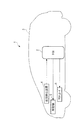
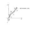
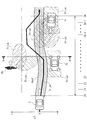
図1に示すように、この自動運転装置1は、四輪車両3に適用されたものであり、ECU2を備えている。なお、以下の説明では、この自動運転装置1を備えた車両3を「自車両3」という。
As shown in FIG. 1, the
このECU2には、状況検出装置4、原動機5及びアクチュエータ6が電気的に接続されている。この状況検出装置4(周辺状況データ取得手段)は、カメラ、ミリ波レーダー、レーザーレーダ、ソナー、GPS及び各種のセンサなどで構成されており、自車両3の位置及び自車両3の進行方向の周辺状況(交通環境や交通参加者など)を表す周辺状況データD_infoをECU2に出力する。
The
ECU2は、後述するように、この状況検出装置4からの周辺状況データD_infoに基づいて、自車両3の位置及び自車両3の周辺の交通環境や交通参加者などを認識し、自車両3の未来の走行軌道を決定する。
As will be described later, the
原動機5は、例えば、電気モータなどで構成されており、後述するように、自車両3の未来の走行軌道が決定されたときに、自車両3がこの走行軌道で走行するように、ECU2によって原動機5の出力が制御される。
The
また、アクチュエータ6は、制動用アクチュエータ及び操舵用アクチュエータなどで構成されており、後述するように、自車両3の未来の走行軌道が決定されたときに、自車両3がこの走行軌道で走行するように、ECU2によってアクチュエータ6の動作が制御される。
The
一方、ECU2は、CPU、RAM、ROM、E2PROM、I/Oインターフェース及び各種の電気回路(いずれも図示せず)などからなるマイクロコンピュータで構成されており、上述した状況検出装置4からの周辺状況データD_infoなどに基づいて、後述するように、走行軌道決定処理などを実行する。なお、本実施形態では、ECU2が、存在領域データ算出手段、走行軌道決定手段、走行不可領域データ算出手段及び走行領域データ算出手段に相当する。
On the other hand, the
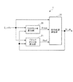
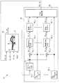
次に、図2を参照しながら、本実施形態の自動運転装置1の機能的な構成について説明する。この自動運転装置1は、以下に述べる算出アルゴリズムによって、走行軌道Tr_skを算出し、この走行軌道Tr_skで走行するように、自車両3の走行状態を制御するものである。
Next, a functional configuration of the
同図2に示すように、自動運転装置1は、リスクポテンシャル算出部20、ベネフィットポテンシャル算出部21及び走行軌道算出部30を備えており、これらの要素20,21,30は、具体的にはECU2によって構成されている。
As shown in FIG. 2, the
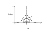
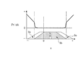
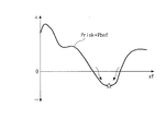
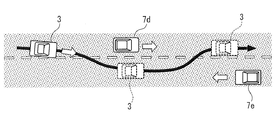
まず、リスクポテンシャル算出部20について説明する。このリスクポテンシャル算出部20では、前述した周辺状況データD_infoに基づき、交通参加者(歩行者や車両)の現在から未来における存在確率や、走行してはいけない領域を表すマップ(図示せず)を作成し、走行軌道Tr_skに応じて、このマップを検索することにより、リスクポテンシャルPriskが算出される。このリスクポテンシャルPriskは、現在から未来において、自車両3の進行方向の周辺における交通参加者が存在する可能性(確率)がある領域、及び自車両3が走行すべきでない走行不可能域が存在する可能性(確率)がある領域などを表す値であり、具体的には、図3〜5に示すように算出される。
First, the risk
まず、図3は、自車両3の進行方向に他車両7が存在する走行環境下での、他車両7のリスクポテンシャルPriskの算出結果の一例を表している。同図の横軸の値xrは、自車両3の進行方向に直交する横方向において、自車両3と他車両7との相対位置を表している。この相対位置xrは、他車両7の中心位置を値0として、他車両7の左側が負値に設定され、右側が正値に設定される。同図に示すように、他車両7のリスクポテンシャルPriskは、他車両7の存在確率が低い領域では値0として算出されるとともに、存在確率が高いほど、より大きい正値として算出される。なお、図3〜5では、リスクポテンシャルPriskは、便宜上、直線を組み合わせた形で表現されている。
First, FIG. 3 shows an example of a calculation result of the risk potential Prisk of the
また、図4は、自車両3の進行方向に歩行者8が存在する走行環境下での、歩行者8のリスクポテンシャルPriskの算出結果の一例を表している。同図に示すように、歩行者8のリスクポテンシャルPriskは、他車両7の場合と同様に、歩行者8の存在確率が低い領域では値0として算出され、存在確率が高いほど、より大きい正値になるように算出される。
FIG. 4 shows an example of a calculation result of the risk potential Prisk of the pedestrian 8 under a traveling environment where the pedestrian 8 exists in the traveling direction of the
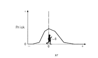
さらに、図5は、自車両3の進行方向に交通参加者が存在しない走行環境下でのリスクポテンシャルPriskの算出結果の一例を表している。この場合のリスクポテンシャルPriskは、同図に示す歩道9aなどのような、自車両3が走行すべきでない走行不可領域における走行を回避すべき確率を表す値である。同図において、横軸の値xは、自車両3の幅方向すなわち横方向における自車両3の絶対位置を表しており、この絶対位置xは、自車両3の中心位置を値0として、自車両3の左側が負値に設定され、右側が正値に設定されている。この点は、後述する図6においても同様である。
Further, FIG. 5 shows an example of the calculation result of the risk potential Prisk under a traveling environment where no traffic participant exists in the traveling direction of the
同図に示すように、自車両3の進行方向に交通参加者が存在しない走行環境下でのリスクポテンシャルPriskは、絶対位置xに対するマップ値として算出される。より具体的には、リスクポテンシャルPriskは、車道9bと歩道9aの境界付近において上昇するとともに、歩道9a内では車道9bから遠ざかるほど、より大きい正値になるように算出される。
As shown in the figure, the risk potential Prisk under a traveling environment in which no traffic participant exists in the traveling direction of the
なお、本実施形態では、リスクポテンシャル算出部20が存在領域データ算出手段及び走行不可領域データ算出手段に相当し、リスクポテンシャルPriskが存在領域データ及び走行不可領域データに相当する。
In the present embodiment, the risk
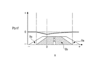
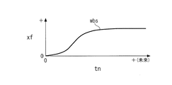
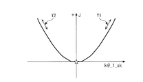
次に、ベネフィットポテンシャル算出部21について説明する。このベネフィットポテンシャル算出部21では、周辺状況データD_info及び走行軌道Tr_sk(これまで自車両3が走行してきた走行軌道Tr_sk)に応じて、図示しないマップを検索することにより、ベネフィットポテンシャルPbnfが算出される。このベネフィットポテンシャルPbnfは、自車両3が走行するときの、進行方向における理想的な走行領域の存在確率を表す値であり、具体的には、例えば、図6〜7に示すように算出される。
Next, the benefit
この図6は、自車両3の進行方向に交通参加者が存在しない走行環境下でのベネフィットポテンシャルPbnfの算出結果の一例を表している。同図に示すように、ベネフィットポテンシャルPbnfは、負値又は値0になるように算出され、最も理想的な走行位置(☆で示すポイント)で最小値となるとともに、最も理想的な走行位置から横方向に遠ざかるほど、その絶対値が減少するように算出される。なお、図6では、ベネフィットポテンシャルPbnfは、便宜上、直線を組み合わせた形で表現されている。
FIG. 6 illustrates an example of a calculation result of the benefit potential Pbnf under a traveling environment in which no traffic participant exists in the traveling direction of the
また、自車両3の実際の走行中は、例えば、図7に示すような、歩行者8a及び他車両7aなどの交通参加者などが存在する走行環境となる。図7に示す走行環境下の場合、ベネフィットポテンシャルPbnf及びリスクポテンシャルPriskは、図中に示すように算出される。
Further, during actual traveling of the
また、ベネフィットポテンシャルPbnfを、周辺状況データD_info及び走行軌道Tr_skを入力とし、ベネフィットポテンシャルPbnfを出力とする深層ニューラルネットワークを用い、熟練ドライバの走行データを学習することによって算出してもよい。さらに、逆強化学習の手法を用いて、熟練ドライバの走行データから熟練ドライバの最適経路を判断する関数値を抽出し、この関数値を用いて、ベネフィットポテンシャルPbnfを算出してもよい。 Further, the benefit potential Pbnf may be calculated by learning the driving data of an expert driver using a deep neural network that receives the surrounding situation data D_info and the running trajectory Tr_sk and outputs the benefit potential Pbnf. Further, a function value for determining the optimum route of the skilled driver may be extracted from the driving data of the skilled driver by using the inverse reinforcement learning method, and the benefit potential Pbnf may be calculated using the function value.
なお、本実施形態では、ベネフィットポテンシャル算出部21が走行領域データ算出手段に相当し、ベネフィットポテンシャルPbnfが走行領域データに相当する。
In the present embodiment, the benefit
次に、図8を参照しながら、前述した走行軌道算出部30について説明する。この走行軌道算出部30は、以下に述べるように、走行軌道Tr_skを算出(探索)するものであり、この走行軌道Tr_skは、自車両3が現在から未来にかけて走行すべき軌道に相当する。同図に示すように、走行軌道算出部30は、走行環境モデル推定部40及び極値探索コントローラ50を備えている。
Next, the traveling
この走行環境モデル推定部40(走行軌道決定手段)は、後述するように、周辺状況データD_infoと、極値探索コントローラ50からの最終探索軌道補正ベクトルKθ_skとを用いて、走行軌道Tr_skを算出し、評価関数値Jを算出するとともに、この評価関数値Jを極値探索コントローラ50に出力する。
As will be described later, the travel environment model estimation unit 40 (travel trajectory determination means) calculates the travel trajectory Tr_sk using the surrounding situation data D_info and the final search trajectory correction vector Kθ_sk from the extreme
また、極値探索コントローラ50(補正値算出手段)は、走行環境モデル推定部40から入力された評価関数値Jを用いて、上述した最終探索軌道補正ベクトルKθ_skを算出し、これを走行環境モデル推定部40に出力する。
Further, the extreme value search controller 50 (correction value calculation means) calculates the above-described final search trajectory correction vector Kθ_sk using the evaluation function value J input from the travel environment
次に、上述した走行環境モデル推定部40について説明する。この走行環境モデル推定部40では、まず、以下に述べるように、周辺状況データD_infoに応じて、タイプ1〜4の走行軌道算出手法のいずれかを選択し、選択した走行軌道算出手法によって、走行軌道Tr_skが算出される。なお、以下の説明では、自車両3の進行方向の位置を「縦位置」と呼び、幅方向の位置を「横位置」という。
Next, the traveling environment
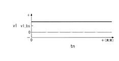
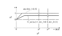
まず、タイプ1の走行軌道算出手法について説明する。このタイプ1の走行軌道算出手法の場合、走行軌道Tr_skの基準となる基準走行軌道wbsを、図9に示す関数値のように定義する。この基準走行軌道wbs(所定の関数値)は、自車両3が基準縦方向速度vl_bsで進行方向に走行したときの、自車両3の相対横位置xfと正規化時刻tnとの関係を定義したもの、すなわち自車両3の進路変更速度を定義したものである。
First, a
この場合、縦軸の相対横位置xfは、自車両3の中心位置を値0として、右側の相対位置を正値で、左側の相対位置を負値でそれぞれ表したものである。また、横軸の正規化時刻tnは、自車両3が基準縦方向速度vl_bsで進行方向に走行した際の未来時刻を表す値であり、正規化時刻tn=0は現在の時刻を表している。以上のように、基準走行軌道wbsは、基準縦方向速度vl_bsとともに定義されている関係上、現在からの未来の経過時間である未来時刻をtfとし、基準縦方向速度vl_bsで走行したときの現在位置に対する相対縦位置をyfとした場合、未来時刻tfにおける相対縦位置yfと縦方向速度vlを表すものとなる。したがって、基準走行軌道wbsは、図9の横軸の正規化時刻tnを、未来時刻tf又は相対縦位置yfに置き換えて定義することも可能である。
In this case, the relative horizontal position xf on the vertical axis represents the center position of the
図9に示す基準走行軌道wbsと、これを補正するための軌道補正係数ktr及び縦方向速度補正係数kvを用いて、任意の未来時刻tf*における走行軌道Tr_skは、以下のように算出される。この軌道補正係数ktr(補正値)は、前述した周辺状況データD_infoに応じて、正負の所定範囲(例えば、wbs・ktrの絶対値が走路幅を超えない範囲)内の値に設定され、基準縦方向速度vl_bsが法定速度又はドライバの要求設定速度のどちらか小さい方に設定されたとした場合、縦方向速度補正係数kvは、前述した周辺状況データD_infoに応じて、1≦kvが成立する範囲内の値に設定される。 Using the reference traveling trajectory wbs shown in FIG. 9 and the trajectory correction coefficient ktr and the vertical speed correction coefficient kv for correcting this, the traveling trajectory Tr_sk at an arbitrary future time tf * is calculated as follows. . The trajectory correction coefficient ktr (correction value) is set to a value within a predetermined positive / negative range (for example, a range in which the absolute value of wbs · ktr does not exceed the travel width) according to the above-described surrounding situation data D_info, When the vertical speed vl_bs is set to the smaller one of the legal speed and the driver's required setting speed, the vertical speed correction coefficient kv is a range in which 1 ≦ kv is satisfied according to the above-described peripheral state data D_info. Is set to the value in
まず、下式(1)により、任意の未来時刻tf*における縦方向速度vlを算出する。
![]()
![]()
次いで、下式(2)により、任意の未来時刻tf*における相対縦位置yf*を算出する。
![]()
![]()
次に、下式(3)により、任意の正規化時刻tn*を算出する。

さらに、上式(3)で算出した任意の正規化時刻tn*に応じて、図9を検索することにより、基準走行軌道wbsを算出する。 Furthermore, the reference travel path wbs is calculated by searching FIG. 9 according to the arbitrary normalized time tn * calculated by the above equation (3).
そして、最終的に、下式(4)により、走行軌道Tr_skを算出する。
![]()
![]()
以上の手法により算出されるので、走行軌道Tr_skは、軌道補正係数ktr、縦方向速度補正係数kv及び任意の未来時刻tf*を独立変数とする関数F(ktr,kv,tf*)として算出されることになる。ここで、探索軌道補正ベクトルKθ(補正値)を下式(5)に示すように定義した場合、走行軌道Tr_skは、探索軌道補正ベクトルKθ及び任意の未来時刻tf*を独立変数とする関数F(Kθ,tf*)として算出されることになる。
![]()
![]()
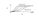
以上のタイプ1の算出手法の場合、例えば、kv=1,ktr=1が成立しているときには、上式(1),(4)を参照すると明らかなように、vl=vl_bs,Tr_sk=wbsが成立することになるので、走行軌道Tr_skは、図9に示す基準走行軌道wbsと同一になるように算出されることになる。
In the case of the
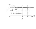
一方、例えば、kv>1,ktr<1が成立しているときには、上式(1),(4)を参照すると明らかなように、縦方向速度vlは、基準縦方向速度vl_bsよりも大きい値になる(図10参照)とともに、走行軌道Tr_skの相対横位置は、基準走行軌道wbsよりも小さい値になる。その結果、走行軌道Tr_skは、図11に示すように算出されることになる。この図11は、理解の容易化のために、横軸を相対縦位置yfで表したものである。 On the other hand, for example, when kv> 1 and ktr <1, the vertical speed vl is larger than the reference vertical speed vl_bs, as is apparent from the above equations (1) and (4). (See FIG. 10), the relative lateral position of the traveling track Tr_sk is smaller than the reference traveling track wbs. As a result, the traveling track Tr_sk is calculated as shown in FIG. In FIG. 11, the horizontal axis represents the relative vertical position yf for easy understanding.
同図において、yf',yf*は、kv=1,ktr=1が成立しているとき及びkv>1,ktr<1が成立しているときの、任意の正規化時刻tn*に対応する相対縦位置を表している。同図に示すように、kv>1,ktr<1が成立している場合、vl>vl_bsが成立することで、相対縦位置yf*は、kv=1,ktr=1が成立しているときの相対縦位置yf'よりも前方に移動した位置になるとともに、相対横位置もkv=1,ktr=1が成立しているときよりも小さい値になる。 In the figure, yf ′, yf * corresponds to an arbitrary normalized time tn * when kv = 1, ktr = 1 holds and when kv> 1, ktr <1 holds. It represents the relative vertical position. As shown in the figure, when kv> 1, ktr <1 is established, vl> vl_bs is established, so that the relative vertical position yf * is when kv = 1, ktr = 1 is established. The relative vertical position is smaller than that when kv = 1 and ktr = 1 are established.
この場合、図11は、理解の容易化のために、横軸を相対縦位置yfで表したものであるが、前述したように、横軸を正規化時刻tnや未来時刻tfに置き換えて表すことも可能である。そのため、このタイプ1の走行軌道算出手法の場合には、実際の走行軌道Tr_skは、未来時刻tfと関連付けられた状態で算出される。この点は、後述するタイプ2やタイプ3の走行軌道算出手法などにおいても同様である。
In this case, FIG. 11 shows the horizontal axis as the relative vertical position yf for easy understanding, but as described above, the horizontal axis is replaced with the normalized time tn and the future time tf. It is also possible. Therefore, in the case of this
以上のタイプ1の走行軌道算出手法は、例えば、前方の走行車両を追い抜く走行環境下(後述する図27参照)や、車線変更などを実行する走行環境下で、走行軌道Tr_skを算出するのに最適な手法である。
The
なお、タイプ1の走行軌道算出手法において、基準走行軌道wbsとして、図9に示す関数値に代えて、図12に示すような、車両の操舵特性を考慮した関数値を用いてもよい。
In the
次に、前述したタイプ2の走行軌道算出手法について説明する。このタイプ2の走行軌道算出手法の場合、基準軌道Wbsを図13に示す関数値のように定義する。この図13の関数値と前述した図9の関数値を比較すると明らかなように、図13の関数値の場合、複数の基準走行軌道wbsが設定されているとともに、これらの複数の基準走行軌道wbsは、第1軌道設定値ktr_1に応じたマップ値として設定されている。この第1軌道設定値ktr_1は、走行軌道の左右方向の位置変更の際における移動速度を設定(選択)するためのものであり、前述した周辺状況データD_infoに応じて、正負の所定範囲(例えば、wbs・ktr_1の絶対値が走路幅を超えない範囲)内の値に設定されている。
Next, the
また、このタイプ2の走行軌道算出手法の場合、前述したタイプ1の走行軌道算出手法における軌道補正係数ktrに相当する値が、第2軌道補正係数ktr_2(補正値)として設定される。すなわち、基準縦方向速度vl_bsが法定速度又はドライバの要求設定速度のどちらか小さい方に設定されたとした場合、第2軌道補正係数ktr_2は、前述した周辺状況データD_infoに応じて、−1≦ktr_2≦1が成立する範囲内の値に設定される。そして、図13に示す基準走行軌道wbsの関数値、第1軌道設定値ktr_1、第2軌道補正係数ktr_2及び縦方向速度補正係数kvを用いて、任意の未来時刻tf*における走行軌道Tr_skは、以下のように算出される。
In the case of this
まず、下式(6)により、任意の未来時刻tf*における縦方向速度vlを算出する。
![]()
![]()
次いで、下式(7)により、任意の未来時刻tf*における相対縦位置yf*を算出する。
![]()
![]()
次に、下式(8)により、任意の正規化時刻tn*を算出する。
さらに、上式(8)で算出した任意の正規化時刻tn*及び第1軌道設定値ktr_1に応じて、図13を検索することにより、基準走行軌道wbsを算出する。 Further, the reference traveling track wbs is calculated by searching FIG. 13 according to the arbitrary normalized time tn * and the first track setting value ktr_1 calculated by the above equation (8).
そして、最終的に、下式(9)により、走行軌道Tr_skを算出する。
![]()
![]()
以上の手法により算出されるので、走行軌道Tr_skは、第1軌道設定値ktr_1、第2軌道補正係数ktr_2、縦方向速度補正係数kv及び任意の未来時刻tf*を独立変数とする関数F(ktr_1,ktr_2,kv,tf*)として算出されることになる。ここで、探索軌道補正ベクトルKθ(補正値)を下式(10)に示すように定義した場合、走行軌道Tr_skは、探索軌道補正ベクトルKθ及び任意の未来時刻tf*を独立変数とする関数F(Kθ,tf*)として算出されることになる。
![]()
![]()
以上のタイプ2の走行軌道算出手法の場合、例えば、kv=1,ktr_1=0,ktr_2=1が成立しているときには、上式(6),(9)を参照すると明らかなように、vl=vl_bs,Tr_sk=wbsが成立することになるので、走行軌道Tr_skは、図13に示すktr_1=0のときの基準走行軌道wbsと同一になるように算出されることになる。
In the case of the above-described
一方、例えば、kv>1,ktr_1=0.5,ktr_2<1が成立しているときには、上式(6),(9)を参照すると明らかなように、縦方向速度vlは、基準縦方向速度vl_bsよりも大きい値になる(前述した図10参照)とともに、走行軌道Tr_skの相対横位置は、ktr_1=0.5のときの基準走行軌道wbsよりも小さい値になる。その結果、走行軌道Tr_skは、図14に示すように算出されることになる。 On the other hand, for example, when kv> 1, ktr_1 = 0.5, and ktr_2 <1 are satisfied, as is apparent from the above equations (6) and (9), the vertical speed vl is the reference vertical direction. The value is larger than the velocity vl_bs (see FIG. 10 described above), and the relative lateral position of the traveling track Tr_sk is smaller than the reference traveling track wbs when ktr_1 = 0.5. As a result, the traveling track Tr_sk is calculated as shown in FIG.
すなわち、同図に示すように、kv>1,ktr_1=0.5,ktr_2<1が成立しているときには、その相対縦位置yf*は、kv=1,ktr_1=0.5,ktr_2=1が成立しているときの相対縦位置yf'よりも前方に移動した位置になるとともに、相対横位置もkv=1,ktr_1=0.5,ktr_2=1が成立しているときよりも小さい値になる。 That is, as shown in the figure, when kv> 1, ktr_1 = 0.5, and ktr_2 <1, the relative vertical position yf * is kv = 1, ktr_1 = 0.5, ktr_2 = 1 And the relative horizontal position is smaller than kv = 1, ktr_1 = 0.5, and ktr_2 = 1. become.
この場合、図14は、理解の容易化のために、横軸を相対縦位置yfで表したものであるが、このタイプ2の走行軌道算出手法の場合、実際の走行軌道Tr_skは、未来時刻tfと関連付けられた状態で算出される。
In this case, FIG. 14 shows the horizontal axis as a relative vertical position yf for easy understanding, but in the case of this
以上のタイプ2の走行軌道算出手法は、タイプ1の走行軌道算出手法と同様に、例えば、前方の走行車両を追い抜く走行環境下や、車線変更などを実行する走行環境下で、走行軌道Tr_skを算出するのに最適な手法である。
The
なお、タイプ2の走行軌道算出手法において、基準走行軌道wbsとして、図13に示す関数値に代えて、図15に示すような、車両の操舵特性を考慮した関数値を用いてもよい。
In the
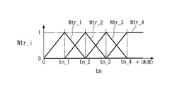
次に、前述したタイプ3の走行軌道算出手法について説明する。このタイプ3の走行軌道算出手法の場合、まず、図16に示すように、4つの軌道重み関数値Wtr_i(i=1〜4)を正規化時刻tnに対して定義する。
Next, the
同図に示すように、4つの軌道重み関数値Wtr_i(所定の関数値)は、正規化時刻tnの4つの所定値tn_1〜4によって規定される領域に対応して設定されている。第1の軌道重み関数値Wtr_1は、0〜tn_2の期間で規定される第1領域に対応し、第2の軌道重み関数値Wtr_2は、tn_1〜tn_3の期間で規定される第2領域に対応し、第3の軌道重み関数値Wtr_3は、tn_2〜tn_4と規定される第3領域に対応し、第4の軌道重み関数値Wtr_4は、tn_4〜未来と規定される第4領域に対応するように設定されている。 As shown in the figure, the four orbital weight function values Wtr_i (predetermined function values) are set corresponding to the areas defined by the four predetermined values tn_1 to 4 at the normalization time tn. The first trajectory weight function value Wtr_1 corresponds to a first area defined by a period of 0 to tn_2, and the second trajectory weight function value Wtr_2 corresponds to a second area defined by a period of tn_1 to tn_3. The third orbital weight function value Wtr_3 corresponds to the third area defined as tn_2 to tn_4, and the fourth orbital weight function value Wtr_4 corresponds to the fourth area defined as tn_4 to the future. Is set to
また、4つの軌道重み関数値Wtr_iの各々は、上述した対応する領域では値1以下の正値にかつそれ以外の領域では値0に設定されており、隣り合う各2つの軌道重み関数値は、互いにオーバーラップするように設定されているとともに、オーバーラップ部分の2つの軌道重み関数値の和が値1になるように設定されている。 In addition, each of the four orbital weight function values Wtr_i is set to a positive value of 1 or less in the corresponding area described above and set to a value of 0 in the other areas, and each of the two adjacent orbital weight function values is Are set so that they overlap each other, and the sum of the two orbital weight function values in the overlap portion is set to a value of 1.
さらに、このタイプ3の走行軌道算出手法では、4つの軌道補正係数ktr2_i(i=1〜4)が用いられる。これらの4つの軌道補正係数ktr2_i(補正値)は、周辺状況データD_infoに応じて、正負の所定範囲(例えば、Wtr_i・ktr2_iの絶対値が走路幅を超えない範囲)内の値に設定される。
Further, in this
そして、図16に示す4つの軌道重み関数値Wtr_i、縦方向速度補正係数kv、4つの軌道補正係数ktr2_iを用いて、任意の未来時刻tf*における走行軌道Tr_skは、以下のように算出される。 Then, using the four trajectory weight function values Wtr_i, the vertical speed correction coefficient kv, and the four trajectory correction coefficients ktr2_i shown in FIG. 16, the travel trajectory Tr_sk at an arbitrary future time tf * is calculated as follows. .
まず、下式(11)により、任意の未来時刻tf*における縦方向速度vlを算出する。
![]()
![]()
次いで、下式(12)により、任意の未来時刻tf*における相対縦位置yf*を算出する。
![]()
![]()
次に、下式(13)により、任意の正規化時間tn*を算出する。
さらに、上式(13)で算出した任意の正規化時間tn*に応じて、図16を検索することにより、4つの軌道重み関数値Wtr_iを算出する。 Furthermore, four trajectory weight function values Wtr_i are calculated by searching FIG. 16 according to the arbitrary normalized time tn * calculated by the above equation (13).
そして、最終的に、下式(14)により、走行軌道Tr_skを算出する。
このタイプ3の走行軌道算出手法の場合、走行軌道Tr_skは、以上の手法により算出されるので、4つの軌道補正係数ktr2_i、縦方向速度補正係数kv及び任意の未来時刻tf*を独立変数とする関数F(ktr2_i,kv,tf*)として算出されることになる。ここで、探索軌道補正ベクトルKθ(補正値)を下式(15)に示すように定義した場合、走行軌道Tr_skは、探索軌道補正ベクトルKθ及び任意の未来時刻tf*を独立変数とする関数F(Kθ,tf*)として算出されることになる。なお、この探索軌道補正ベクトルKθの値は、前述した極値探索コントローラ50において、後述する手法により算出される。
![]()
![]()
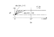
以上のタイプ3の走行軌道算出手法の場合、走行軌道Tr_skは、kv=1が成立しているときには、例えば、図17の実線で示す値として算出され、kv>1が成立しているときには、図17の破線で示す値として算出される。同図において、yf_1〜4は、kv=1が成立しているときの正規化時間tn_1〜4に対応する相対縦位置yfの値である。
In the case of the
同図において、yf',yf*はそれぞれ、kv=1及びkv>1が成立しているときの、任意の正規化時刻tn*に対応する相対縦位置を表している。同図に示すように、kv>1が成立しているときの相対縦位置yf*は、vl>vl_bsが成立することで、kv=1が成立しているときの相対縦位置yf'よりも前方に移動した位置になる。 In the figure, yf ′ and yf * represent relative vertical positions corresponding to an arbitrary normalized time tn * when kv = 1 and kv> 1 are satisfied. As shown in the figure, the relative vertical position yf * when kv> 1 is satisfied is greater than the relative vertical position yf ′ when kv = 1 is satisfied when vl> vl_bs is satisfied. The position moved forward.
この場合、図17は、理解の容易化のために、横軸を相対縦位置yfで表したものであるが、このタイプ3の走行軌道算出手法の場合、実際の走行軌道Tr_skは、未来時刻tfと関連付けられた状態で算出される。
In this case, FIG. 17 shows the horizontal axis as a relative vertical position yf for easy understanding, but in the case of this
以上のタイプ3の走行軌道算出手法は、繁華街を走行する場合や、交通参加者をジグザグに回避しながら走行する場合(後述する図19参照)などの、複雑な走行環境下で、走行軌道Tr_skを算出するのに最適な手法である。
The
なお、タイプ3の走行軌道算出手法においては、軌道重み関数値Wtr_iとして4つの値Wtr_1〜4を用いたが、軌道重み関数値Wtr_iの数はこれに限らず、2〜3又は5つ以上の関数値を用いてもよい。その場合には、軌道補正係数ktr2_iも、軌道重み関数値Wtr_iと同じ数の値を用いればよい。
In the
次に、前述したタイプ4の走行軌道算出手法について説明する。このタイプ4の走行軌道算出手法の場合、図18に示すように、自車両3の相対横位置xfを横軸とし、相対縦位置yfを縦軸とする平面において、n(n≧2)個の線分の各2つを互いの間に角度を付けた状態で組み合わせて、走行軌道Tr_skを決定/算出するものである。
Next, the
具体的には、まず、下式(16)により、ローカル軌道距離Li(i=1〜n)を算出する。このローカル軌道距離Liは、n個の線分の各々の長さに相当する。
![]()
![]()
上式(16)において、kv_i(i=1〜n)は速度補正係数(補正値)を、v_bsは基準道なり方向速度(所定の関数値)を、Δtはローカル区間走行時間をそれぞれ表している。このローカル区間走行時間Δtは、自車両3がローカル軌道距離Liを走行するのに要する時間である。
In the above equation (16), kv_i (i = 1 to n) is a speed correction coefficient (correction value), v_bs is a reference road direction speed (predetermined function value), and Δt is a local section travel time. Yes. This local section travel time Δt is the time required for the
次いで、下式(17)により、任意の未来時刻tf*における相対縦位置yf*を算出する。
次に、下式(18)により、任意の未来時刻tf*における相対横位置xf*を算出する。
そして、下式(19)により、走行軌道Tr_skを算出する。
![]()
![]()
さらに、下式(20)により、道なり方向速度vを算出する。この道なり方向速度vは、自車両3の走行方向の速度である。
![]()
![]()
走行軌道Tr_skは、以上の手法により算出されるので、n個の速度補正係数kv_i、n個の角度θi及び任意の未来時刻tf*を独立変数とする関数F(kv_i,θi,tf*)として算出されることになる。ここで、探索軌道補正ベクトルKθ(補正値)を下式(21)に示すように定義した場合、走行軌道Tr_skは、探索軌道補正ベクトルKθ及び任意の未来時刻tf*を独立変数とする関数F(Kθ,tf*)として算出されることになる。なお、この探索軌道補正ベクトルKθの値は、前述した極値探索コントローラ50において、後述する手法により算出される。
![]()
![]()
このタイプ4の走行軌道算出手法の場合、探索軌道補正ベクトルKθの算出式(17),(18)において、角度θiが含まれているので、走行軌道Tr_skを算出する際、隣り合う各2つの線分の間の角度が探索軌道補正ベクトルKθによって補正(変更)されることになる。
In the case of this
なお、タイプ4の走行軌道算出手法において、探索軌道補正ベクトルKθをn個の速度補正係数kv_iのみ又はn個の角度θiのみを要素とするベクトルとして構成してもよい。
In the
以上のように、走行環境モデル推定部40では、周辺状況データD_infoに基づき、タイプ1〜4の走行軌道算出手法のいずれかを選択し、選択した走行軌道算出手法を用いて、走行軌道Tr_skが算出される。
As described above, the travel environment
なお、以上の説明では、タイプ1〜4の走行軌道算出手法において、探索軌道補正ベクトルKθを用いて、走行軌道Tr_skを算出するように説明したが、走行軌道Tr_skの実際の演算では、後述する理由により、探索軌道補正ベクトルKθに代えて、極値探索コントローラ50で算出された最終探索軌道補正ベクトルKθ_skが用いられる。
In the above description, in the travel trajectory calculation methods of
さらに、走行環境モデル推定部40は、走行軌道Tr_sk、リスクポテンシャルPrisk及びベネフィットポテンシャルPbnfに基づいて、例えば、図19に示す走行環境モデルを作成するとともに、この図19の走行環境モデルを用いて、以下に述べる手法により、評価関数値Jを所定の算出周期(探索周期)ΔTskで算出する。
Furthermore, the traveling environment
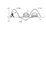
同図19は、交通参加者として、歩行者8b、反対車線で停止中の他車両3b及び反対車線を走行中の他車両3cが存在する走行環境下での走行環境モデルを平面的に示したものである。
FIG. 19 is a plan view of a traveling environment model under a traveling environment in which a
この走行環境モデル推定部40では、まず、図19中の探索インデックスzj(j=0〜m:mは整数)の時刻又は距離で、走行環境モデルを探索(検索)することにより、探索インデックスzjに対応するベネフィットポテンシャルPbnf(zj)及びリスクポテンシャルPrisk(zj)を算出する。この場合、探索インデックスzjとしては、タイプ1〜3の走行軌道算出手法を実行している場合には、未来時刻tfが用いられ、タイプ4の走行軌道算出手法を実行している場合には、道なり距離xが用いられる。
The travel environment
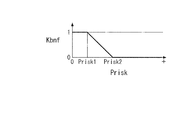
そして、探索したベネフィットポテンシャルPbnf(zj)及びリスクポテンシャルPrisk(zj)を用いて、下式(22)により、評価関数値Jを算出する。
上式(22)において、kは算出時刻(探索時刻)であり、Kbnfは、ベネフィットポテンシャル補正係数である。このベネフィットポテンシャル補正係数Kbnfは、リスクポテンシャルPriskに応じて、図20に示すマップを検索することにより算出される。 In the above equation (22), k is a calculation time (search time), and Kbnf is a benefit potential correction coefficient. The benefit potential correction coefficient Kbnf is calculated by searching a map shown in FIG. 20 according to the risk potential Prisk.
同図のPrisk1〜2は、Prisk1<Prisk2が成立するように設定されるリスクポテンシャルPriskの所定値である。このマップでは、ベネフィットポテンシャル補正係数Kbnfは、Prisk≦Prisk1の領域では、値1に設定され、Prisk2≦Priskの領域では、値0に設定されているとともに、Prisk1<Prisk<Prisk2の領域では、リスクポテンシャルPriskが大きいほど、より小さい値に設定されている。以上のようなベネフィットポテンシャル補正係数Kbnfの設定理由については後述する。また、以上の評価関数値Jの算出手法の原理についても後述する。
次に、前述した極値探索コントローラ50について説明する。図8に示すように、極値探索コントローラ50は、ウォッシュアウトフィルタ51、n個の参照信号発生器52_i(i=1〜n)、n個の乗算器53_i(i=1〜n)、n個の移動平均フィルタ54_i、n個の探索コントローラ55_i(i=1〜n)及びベクトル算出部56を備えている。
Next, the aforementioned extreme
このウォッシュアウトフィルタ51では、下式(23)により、フィルタ値Pwが算出される。
![]()
![]()
上式(23)に示すように、フィルタ値Pwは、評価関数値の今回値J(k)と前回値J(k−1)の差分として算出される。また、ウォッシュアウトフィルタ51は、評価関数値Jに含まれている、後述する参照信号値w_iに起因する周波数成分を通過させるためのものである。この場合、上式(23)に代えて、後述するn個の参照信号値w_iの周波数成分を通過させるバタワースハイパスフィルタアルゴリズムにより、フィルタ値Pwを算出してもよく、n個の参照信号値w_iの各々の周波数成分のみを通過させるn個のバンドパスフィルタアルゴリズムにより、n個のフィルタ値Pwを算出するように構成してもよい。
As shown in the above equation (23), the filter value Pw is calculated as the difference between the current value J (k) and the previous value J (k−1) of the evaluation function value. The
また、n個の参照信号発生器52_iからは、n個の参照信号値w_i(i=1〜n)がそれぞれ出力される。これらのn個の参照信号値w_iは、互いに異なる周期の周期関数値に設定されており、それらの周期は互いに異なるn個の値m_i(i=1〜n)と算出周期ΔTskの積m_i・ΔTskに設定されている。さらに、周期関数の波形としては、例えば、正弦波、余弦波、三角波、台形波及び矩形波などが用いられる。 Also, n reference signal values w_i (i = 1 to n) are output from the n reference signal generators 52_i, respectively. These n reference signal values w_i are set to periodic function values having different periods, and the periods m_i · are the products of n values m_i (i = 1 to n) different from each other and the calculation period ΔTsk. ΔTsk is set. Furthermore, as the waveform of the periodic function, for example, a sine wave, cosine wave, triangular wave, trapezoidal wave, rectangular wave, or the like is used.
さらに、n個の乗算器53_iでは、下式(24)により、n個の中間値Pc_i(i=1〜n)がそれぞれ算出される。
![]()
![]()
また、n個の移動平均フィルタ54_iでは、下式(25)により、n個の移動平均値Pa_iが算出される。
上式(25)のmlcmは、上述した値m_iの最大公倍数である。このように、移動平均値Pa_iのサンプリング個数を値mlcm+1に設定した理由は、移動平均値Pa_iから参照信号値w_iの周波数成分を除去するためである。 In the above equation (25), mlcm is the greatest common multiple of the above-described value m_i. Thus, the reason why the sampling number of the moving average value Pa_i is set to the value mlcm + 1 is to remove the frequency component of the reference signal value w_i from the moving average value Pa_i.
次いで、n個の探索コントローラ55_iでは、下式(26),(27)に示すスライディングモード制御アルゴリズムにより、n個の補正係数kθ_i(i=1〜n)が算出される。 Next, in the n search controllers 55_i, n correction coefficients kθ_i (i = 1 to n) are calculated by the sliding mode control algorithm shown in the following equations (26) and (27).
![]()
![]()
![]()
![]()
上式(26)のσ_i(i=1〜n)は切換関数であり、S_i(i=1〜n)は−1<S_i<0が成立するように設定される応答指定パラメータである。また、式(27)のKsk_i(i=1〜n)は、所定のゲインである。上式(26),(27)を参照すると明らかなように、n個の補正係数kθ_iは、適応則入力のみのスライディングモード制御アルゴリズムによって、n個の移動平均値Pa_iを値0に収束させる機能を有するように算出される。 In the above equation (26), σ_i (i = 1 to n) is a switching function, and S_i (i = 1 to n) is a response designation parameter set so that −1 <S_i <0 holds. Further, Ksk_i (i = 1 to n) in Expression (27) is a predetermined gain. As is apparent from the above equations (26) and (27), the n correction coefficients kθ_i are functions for converging the n moving average values Pa_i to a value of 0 by a sliding mode control algorithm with only an adaptive law input. Is calculated to have
この場合、n個の補正係数kθ_iは、下式(28)に示す探索軌道補正ベクトルKθとして表すことができる。
![]()
![]()
上式(28)の場合、その右辺の要素は、前述したタイプ1の走行軌道算出手法を用いる場合には前述した式(5)の右辺の要素に、タイプ2の走行軌道算出手法を用いる場合には、前述した式(10)の右辺の要素に、タイプ3の走行軌道算出手法を用いる場合には、前述した式(15)の右辺の要素にそれぞれ相当する。さらに、タイプ4の走行軌道算出手法を用いる場合には、以上の所定値nに代えて、その2倍値2nを用いて式(22)〜(28)の算出が実行されるとともに、その場合の式(28)の右辺が前述した式(21)の右辺の要素に相当することになる。
In the case of the above equation (28), the right side element is the
そして、ベクトル算出部56では、下式(29),(30)により、最終探索軌道補正ベクトルKθ_skが算出される。
Then, the
![]()
![]()
![]()
![]()
上式(29),(30)と、前述した式(27),(28)を比較すると明らかなように、最終探索軌道補正ベクトルKθ_skの場合、その各要素kθ_i_skは、探索軌道補正ベクトルKθの各要素kθ_iに参照信号値w_iをそれぞれ加算した値として算出される。したがって、結果的に、走行軌道Tr_skは、探索軌道補正ベクトルKθを用いて算出されることになる。例えば、タイプ1,2の走行軌道算出手法の場合には、探索軌道補正ベクトルKθで基準軌道wbsを補正することによって算出されることになる。
As is clear from a comparison of the above equations (29) and (30) with the aforementioned equations (27) and (28), in the case of the final search trajectory correction vector Kθ_sk, each element kθ_i_sk is obtained from the search trajectory correction vector Kθ. It is calculated as a value obtained by adding the reference signal value w_i to each element kθ_i. Therefore, as a result, the traveling trajectory Tr_sk is calculated using the search trajectory correction vector Kθ. For example, in the case of the
以上のように、走行環境モデル推定部40では、前述した算出手法により、評価関数値Jが算出され、極値探索コントローラ50では、前述した算出手法により、最終探索軌道補正ベクトルKθ_skが算出される。次に、これらの評価関数値J及び最終探索軌道補正ベクトルKθ_skの算出手法の原理について説明する。
As described above, the travel environment
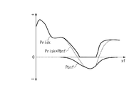
まず、評価関数値Jの算出手法の原理について説明する。例えば、タイプ1〜4の走行軌道算出手法のいずれかで走行軌道Tr_skを算出している場合、図19のA−A線で示す探索インデックスの時刻においては、リスクポテンシャルPrisk及びベネフィットポテンシャルPbnfは、例えば、図21に示すものとなる。
First, the principle of the evaluation function value J calculation method will be described. For example, when the travel trajectory Tr_sk is calculated by any of the travel trajectory calculation methods of
同図に示すように、リスクポテンシャルPriskは正値で表され、ベネフィットポテンシャルPbnfは負値で表されるので、最も理想的な走行軌道Tr_skの位置は、図22に示すような、リスクポテンシャルPriskとベネフィットポテンシャルPbnfの和Prisk+Pbnfが極小値(すなわち最小値)になるポイント(☆で示すポイント)となる。 As shown in FIG. 22, since the risk potential Prisk is represented by a positive value and the benefit potential Pbnf is represented by a negative value, the most ideal position of the traveling trajectory Tr_sk is as shown in FIG. And the sum (Prisk + Pbnf) of the benefit potential Pbnf becomes a point (a point indicated by ☆) at which the value becomes a minimum value (that is, a minimum value).
したがって、走行軌道Tr_skを最も理想的な走行軌道になるように決定する場合、その評価関数値Jを、2つの値の和Prisk+Pbnfを用いて定義することが考えられる。しかしながら、ベネフィットポテンシャルPbnfの領域とリスクポテンシャルPriskの領域が平面的に見て重なっている条件下(例えば、図19の探索インデックスzm−xの時刻)では、走行軌道Tr_skを2つの値の和Prisk+Pbnfの最小値の位置になるように決定すると、自車両3が交通参加者に接触する可能性が高まってしまう。
Therefore, when determining the travel trajectory Tr_sk so as to be the most ideal travel trajectory, it is conceivable that the evaluation function value J is defined using the sum of two values, Prisk + Pbnf. However, under the condition where the region of the benefit potential Pbnf and the region of the risk potential Prisk overlap in plan view (for example, the time of the search index zm-x in FIG. 19), the traveling trajectory Tr_sk is the sum of two values Pris + Pbnf. If it is determined to be the position of the minimum value, the possibility that the
この事象を回避するために、本実施形態の評価関数値Jは、その算出式(22)に示すように、ベネフィットポテンシャル補正係数KbnfをベネフィットポテンシャルPbnfに乗算した値Kbnf・Pbnfを用いるとともに、このベネフィットポテンシャル補正係数Kbnfを、前述した図20に示すように、リスクポテンシャルPriskが所定値Prisk2よりも大きい領域では値0に設定することによって、評価関数値Jの算出において、リスクポテンシャルPriskを優先させるように構成している。 In order to avoid this phenomenon, the evaluation function value J of this embodiment uses a value Kbnf · Pbnf obtained by multiplying the benefit potential correction coefficient Kbnf by the benefit potential Pbnf as shown in the calculation formula (22). As shown in FIG. 20 described above, the benefit potential correction coefficient Kbnf is set to a value of 0 in the region where the risk potential Prisk is larger than the predetermined value Prisk2, thereby giving priority to the risk potential Prisk in the calculation of the evaluation function value J. It is configured as follows.
これにより、ベネフィットポテンシャルPbnfの領域とリスクポテンシャルPriskの領域が平面的に見て重なっている条件下では、走行軌道Tr_skがリスクポテンシャルPriskの大きい領域と交錯するのを回避でき、自車両3が交通参加者に接触するのを回避できることになる。以上の理由により、評価関数値Jは、ベネフィットポテンシャル補正係数Kbnfを用いて算出される。
As a result, under the condition that the area of the benefit potential Pbnf and the area of the risk potential Prisk overlap in plan view, it is possible to prevent the traveling track Tr_sk from intersecting with the area where the risk potential Prisk is large, and the
次に、最終探索軌道補正ベクトルKθ_skの算出原理について説明する。まず、走行軌道Tr_skの最適な軌道を算出するには、リスクポテンシャルPriskが存在する領域との交錯度合いが最小値となるとともに、ベネフィットポテンシャルPbnfが存在する領域との交錯度合いが最大値となるように、走行軌道Tr_skを算出すればよいことになる。 Next, the calculation principle of the final search trajectory correction vector Kθ_sk will be described. First, in order to calculate the optimal trajectory of the travel trajectory Tr_sk, the degree of intersection with the area where the risk potential Prisk exists is the minimum value, and the degree of intersection with the area where the benefit potential Pbnf exists is the maximum value. In addition, the traveling track Tr_sk may be calculated.
言い換えれば、リスクポテンシャルPriskとベネフィットポテンシャルPbnfとの和が最小値になるポイントが、その時刻での走行軌道Tr_skの最適な軌道となるので、評価関数値Jが極小値(すなわち最小値)となるように、走行軌道Tr_skを決定すればよいことになる。この場合、走行軌道Tr_skは、前述したように、最終探索軌道補正ベクトルKθ_skを用いて算出される関係上、評価関数値Jが極小値となるように、最終探索軌道補正ベクトルKθ_skを算出すればよいことになる。 In other words, the point at which the sum of the risk potential Prisk and the benefit potential Pbnf is the minimum value is the optimal trajectory of the travel trajectory Tr_sk at that time, and thus the evaluation function value J is the minimum value (that is, the minimum value). As described above, the traveling track Tr_sk may be determined. In this case, the traveling trajectory Tr_sk is calculated using the final search trajectory correction vector Kθ_sk, as described above, and therefore, if the final search trajectory correction vector Kθ_sk is calculated so that the evaluation function value J is a minimum value. It will be good.
したがって、本実施形態の場合、評価関数値Jが極小値となるように、最終探索軌道補正ベクトルKθ_skを算出するために、以下の原理を用いている。まず、走行軌道Tr_skは、最終探索軌道補正ベクトルKθ_skを用いて算出される関係上、最終探索軌道補正ベクトルKθ_skに含まれる参照信号値w_iの特性(周期関数)に起因して、所定振幅の振動的な挙動を示すことになる。さらに、そのような走行軌道Tr_skを用いて、リスクポテンシャルPrisk及びベネフィットポテンシャルPbnfが算出される関係上、評価関数値Jも所定振幅の振動的な挙動を示すことになる。 Therefore, in the case of the present embodiment, the following principle is used to calculate the final search trajectory correction vector Kθ_sk so that the evaluation function value J becomes a minimum value. First, the traveling trajectory Tr_sk is calculated using the final search trajectory correction vector Kθ_sk, and therefore has a predetermined amplitude due to the characteristic (periodic function) of the reference signal value w_i included in the final search trajectory correction vector Kθ_sk. Behavior will be shown. Furthermore, the evaluation function value J also exhibits a vibrational behavior with a predetermined amplitude because the risk potential Prisk and the benefit potential Pbnf are calculated using such a traveling track Tr_sk.
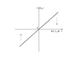
ここで、最終探索軌道補正ベクトルKθ_skの1つの要素kθ_1_skと評価関数値Jの関係が図23に示す曲線として表されると仮定した場合、参照信号値w_iに起因する評価関数値Jの振動的な挙動は、図中の矢印Y1又はY2に示すように、ある傾きを持った状態となる。一方、前述した移動平均値Pa_iは、評価関数値Jのフィルタ値Pwと参照信号値w_iの積の移動平均値であるので、評価関数値Jと参照信号値w_iの相関関数に相当する値となる。 Here, if it is assumed that the relationship between one element kθ_1_sk of the final search trajectory correction vector Kθ_sk and the evaluation function value J is expressed as a curve shown in FIG. 23, the evaluation function value J caused by the reference signal value w_i is oscillatory. As shown by an arrow Y1 or Y2 in the figure, the correct behavior is in a state having a certain inclination. On the other hand, the moving average value Pa_i described above is a moving average value of the product of the filter value Pw of the evaluation function value J and the reference signal value w_i, and therefore, a value corresponding to the correlation function of the evaluation function value J and the reference signal value w_i Become.
そのため、相関関数に相当する移動平均値Pa_iが正値であれば、評価関数値Jの傾きが正値を示し、移動平均値Pa_iが負値であれば、評価関数値Jの傾きは負値を示すことになる。これに加えて、移動平均値Pa_iは、前述した式(25)で算出されることにより、参照信号値w_iの周波数成分が除去した状態で算出される。以上の理由により、移動平均値Pa_iと要素kθ_1_skの関係は、例えば、図24に示すような単調増加の関数として表すことができる。すなわち、移動平均値Pa_iは、走行軌道Tr_skを変更したときに、評価関数値Jが変化する方向を表すことになる。 Therefore, if the moving average value Pa_i corresponding to the correlation function is a positive value, the gradient of the evaluation function value J indicates a positive value, and if the moving average value Pa_i is a negative value, the gradient of the evaluation function value J is a negative value. Will be shown. In addition to this, the moving average value Pa_i is calculated in the state in which the frequency component of the reference signal value w_i is removed by the above-described equation (25). For the above reason, the relationship between the moving average value Pa_i and the element kθ_1_sk can be expressed as a monotonically increasing function as shown in FIG. 24, for example. That is, the moving average value Pa_i represents the direction in which the evaluation function value J changes when the traveling track Tr_sk is changed.
したがって、評価関数値Jが極小値(最小値)になるように、最終探索軌道補正ベクトルKθ_skを算出するには、図24に示す関数の傾きが値0になるように、移動平均値Pa_iを算出すればよいことになる。すなわち、移動平均値Pa_iが値0に収束するように、フィードバック制御アルゴリズムを用いて、最終探索軌道補正ベクトルKθ_skを算出すればよいことになる。
Therefore, in order to calculate the final search trajectory correction vector Kθ_sk so that the evaluation function value J becomes a minimum value (minimum value), the moving average value Pa_i is set so that the slope of the function shown in FIG. It is only necessary to calculate. That is, the final search trajectory correction vector Kθ_sk may be calculated using the feedback control algorithm so that the moving average value Pa_i converges to the
以上の理由により、本実施形態の極値探索コントローラ50では、フィードバック制御アルゴリズムとしてのスライディングモード制御アルゴリズム(26),(27)を含む、式(23)〜(30)の算出アルゴリズムを用いて、最終探索軌道補正ベクトルKθ_skが算出される。
For the above reason, the extreme
このように評価関数値Jの極小値を探索する場合、一般的な極値探索アルゴリズムでは、評価関数値Jの傾きのデータが必要となるのに対して、本実施形態の算出アルゴリズムでは、評価関数値Jの傾きのデータが不要となる。その結果、本実施形態の算出アルゴリズムの場合、一般的な極値探索アルゴリズムと比べて、演算負荷を低減でき、演算精度を向上させることができるという利点がある。同じ理由により、自動運転装置における走行軌道を決定するシステムのような、時間的に変化するシステムに適用した場合、一般的な極値探索アルゴリズムでは、ロバスト性が低下してしまうのに対して、本実施形態の算出アルゴリズムでは、高いロバスト性を確保することができるという利点がある。 In this way, when searching for the minimum value of the evaluation function value J, the data of the slope of the evaluation function value J is required in a general extreme value search algorithm, whereas in the calculation algorithm of the present embodiment, evaluation is performed. Data on the slope of the function value J is not necessary. As a result, the calculation algorithm of the present embodiment has an advantage that the calculation load can be reduced and the calculation accuracy can be improved as compared with a general extremum search algorithm. For the same reason, when applied to a system that changes over time, such as a system that determines a traveling trajectory in an automatic driving device, in a general extreme value search algorithm, robustness decreases, The calculation algorithm of the present embodiment has an advantage that high robustness can be ensured.
また、前述したように、移動平均値Pa_iは、走行軌道Tr_skを変更したときに、評価関数値Jの傾きすなわち評価関数値Jが変化する方向を表す値(方向値)であるので、評価関数値Jが最小値になるように(すなわち移動平均値Pa_iが値0に収束するように)、最終探索軌道補正ベクトルKθ_skを算出することは、リスクポテンシャルPriskが存在する領域との交錯度合いが最小値となるとともに、ベネフィットポテンシャルPbnfが存在する領域との交錯度合いが最大値となるように、最終探索軌道補正ベクトルKθ_skを算出することに相当する。 Further, as described above, the moving average value Pa_i is a value (direction value) representing the inclination of the evaluation function value J, that is, the direction in which the evaluation function value J changes when the traveling track Tr_sk is changed. Calculating the final search trajectory correction vector Kθ_sk so that the value J becomes the minimum value (that is, the moving average value Pa_i converges to the value 0) has the minimum degree of intersection with the area where the risk potential Prisk exists. This corresponds to calculating the final search trajectory correction vector Kθ_sk so that the degree of intersection with the region where the benefit potential Pbnf exists becomes the maximum value.
さらに、評価関数値Jが、ベネフィットポテンシャル補正係数Kbnfを用いて算出されるので、リスクポテンシャルPriskが存在する領域とベネフィットポテンシャルPbnfが存在する領域とが交錯している場合には、リスクポテンシャルPriskが大きいほど、走行軌道Tr_skとリスクポテンシャルPriskが存在する領域との交錯度合いが減少するように、最終探索軌道補正ベクトルKθ_skが算出されることになる。その結果、自車両3が交通参加者に接触するのを回避できることになる。
Furthermore, since the evaluation function value J is calculated using the benefit potential correction coefficient Kbnf, when the region where the risk potential Prisk exists and the region where the benefit potential Pbnf exists intersect, the risk potential Prisk is As the value increases, the final search trajectory correction vector Kθ_sk is calculated so that the degree of intersection between the travel trajectory Tr_sk and the region where the risk potential Prisk exists decreases. As a result, the
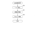
次に、図25を参照しながら、走行軌道探索処理について説明する。この走行軌道探索処理は、前述した算出手法によって、走行軌道Tr_sk、評価関数値J及び最終探索軌道補正ベクトルKθ_skなどを算出するものであり、ECU2によって、前述した所定の算出周期ΔTskで実行される。なお、以下の説明において算出される各種の値は、ECU2のE2PROM内に記憶されるものとする。
Next, the travel trajectory search process will be described with reference to FIG. This travel trajectory search process calculates the travel trajectory Tr_sk, the evaluation function value J, the final search trajectory correction vector Kθ_sk, and the like by the calculation method described above, and is executed by the
同図に示すように、まず、ステップ1(図では「S1」と略す。以下同じ)で、状況検出装置5からの周辺状況データD_infoを読み込む。
As shown in the figure, first, in step 1 (abbreviated as “S1” in the figure, the same applies hereinafter), the surrounding situation data D_info from the
次いで、ステップ2に進み、E2PROM内の走行軌道Tr_sk及び周辺状況データD_infoに応じて、図示しないマップを検索することにより、リスクポテンシャルPriskを算出する。この場合、リスクポテンシャルPriskは、探索インデックスz0〜zmまでの値が算出され、それらの値がE2PROM内に記憶されている前回値(探索インデックスz0〜zmまでの値)に上書きされる。 Next, the process proceeds to step 2, and a risk potential Prisk is calculated by searching a map (not shown) according to the traveling track Tr_sk and the surrounding situation data D_info in the E2PROM. In this case, as the risk potential Prisk, values from the search index z0 to zm are calculated, and those values are overwritten on the previous values (values from the search index z0 to zm) stored in the E2PROM.
次に、ステップ3で、E2PROM内の走行軌道Tr_sk及び周辺状況データD_infoに応じて、図示しないマップを検索することにより、ベネフィットポテンシャルPbnfを算出する。この場合、ベネフィットポテンシャルPbnfは、探索インデックスz0〜zmまでの値が算出され、それらの値がE2PROM内に記憶されている前回値(探索インデックスz0〜zmまでの値)に上書きされる。
Next, in
ステップ3に続くステップ4で、走行軌道Tr_skを算出する。具体的には、周辺状況データD_infoに基づいて、前述したタイプ1〜4の走行軌道算出手法の算出式、すなわち式(1)〜(5)、式(6)〜(10)、式(11)〜(15)及び式(16)〜(21)のいずれかを選択し、選択した算出式における探索軌道補正ベクトルKθの要素を、最終探索軌道補正ベクトルKθ_skの要素に置き換えて、走行軌道Tr_skを算出する。
In
この場合、走行軌道Tr_skは、探索インデックスz0〜zmまでの値が算出され、それらの値がE2PROM内に記憶されている前回値(探索インデックスz0〜zmまでの値)に上書きされる。すなわち、走行軌道Tr_skは、算出周期ΔTskで逐次、更新されることになる。 In this case, values for the search trajectory Tr_sk are calculated from the search indexes z0 to zm, and those values are overwritten on the previous values (values for the search indexes z0 to zm) stored in the E2PROM. That is, the traveling track Tr_sk is sequentially updated at the calculation cycle ΔTsk.
次いで、ステップ5に進み、前述した式(22)により、評価関数値Jを算出した後、ステップ6で、前述した式(23)により、フィルタ値Pwを算出する。
Next, the process proceeds to step 5, and after the evaluation function value J is calculated by the above-described equation (22), the filter value Pw is calculated by the above-described equation (23) at
次に、ステップ7で、前述した式(24)により、n個の中間値Pc_iを算出した後、ステップ8に進み、前述した式(25)により、n個の移動平均値Pa_iを算出する。
Next, in
次いで、ステップ9に進み、前述した式(26)〜(28)により、探索軌道補正ベクトルKθを算出する。 Next, the process proceeds to step 9, and the search trajectory correction vector Kθ is calculated by the above-described equations (26) to (28).
次に、ステップ10で、前述した式(29)〜(30)により、最終探索軌道補正ベクトルKθ_skを算出した後、本処理を終了する。
Next, in
以上のように、本実施形態の自動運転装置1では、所定の算出周期ΔTskで、最終探索軌道補正ベクトルKθ_skが、逐次更新されるとともに、次の算出タイミングで、そのように更新された最終探索軌道補正ベクトルKθ_skを用いて、走行軌道Tr_skが逐次更新されることになる。
As described above, in the
次に、図26を参照しながら、自動運転制御処理について説明する。この自動運転制御処理は、自車両3を、算出された走行軌道Tr_skで走行するように制御するものであり、ECU2によって、前述した所定の算出周期ΔTskよりも長い所定の制御周期ΔTadで実行される。
Next, the automatic operation control process will be described with reference to FIG. This automatic driving control process controls the
同図に示すように、まず、ステップ20で、E2PROM内に記憶されている走行軌道Tr_skを読み込む。
As shown in the figure, first, at
次いで、ステップ21に進み、自車両3が読み込んだ走行軌道Tr_skで走行するように、原動機5を駆動する。
Next, the process proceeds to step 21 where the
次に、ステップ22で、自車両3が読み込んだ走行軌道Tr_skで走行するようにアクチュエータ6を駆動した後、本処理を終了する。
Next, in step 22, the
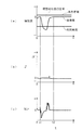
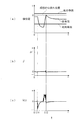
次に、以上のように構成された本実施形態の自動運転装置1による走行軌道決定処理のシミュレーション結果について説明する。以下に述べるシミュレーション結果は、図27に示すような、先行車両7d及び対向車両7eが存在する走行環境条件下において、前述したタイプ1の走行軌道算出手法を用い、先行車両7dを追い越すときのものである。
Next, the simulation result of the traveling track determination process by the
まず、図28は、本実施形態の自動運転装置1による走行軌道決定処理のシミュレーション結果(以下「本願結果」という)を示しており、図29は、比較のために、ベネフィットポテンシャルPbnfを省略したときの走行軌道決定処理のシミュレーション結果(以下「第1比較結果」という)を示しており、図30は、比較のために、最終探索軌道補正ベクトルKθ_skを省略したときの走行軌道決定処理のシミュレーション結果(以下「第2比較結果」という)を示している。
First, FIG. 28 shows a simulation result (hereinafter referred to as “result of the present application”) of the traveling track determination process by the
また、図28〜図30におけるJ’は、自車両3の先端位置のみでの評価関数値であり、下式(31)により算出される。
![]()
![]()
まず、第2比較結果を参照すると、時刻t21で、評価関数値J’が所定値J1’付近まで急増していることが判る。この所定値J1’は、自車両3が交通参加者に衝突したことなどを表す値であり、この時刻t21における評価関数値J’の急増は、自車両3が先行車両7dに衝突したことに起因するものである。
First, referring to the second comparison result, it can be seen that at time t21, the evaluation function value J ′ rapidly increases to the vicinity of the predetermined value J1 ′. This predetermined value J1 ′ is a value indicating that the
また、時刻t22で、車線変更を開始した後、時刻t23で、評価関数値J’が再度、所定値J1’付近まで急増していることが判る。これは、自車両3が対向車両7eと衝突したことに起因するものである。
In addition, after the lane change is started at time t22, it can be seen that the evaluation function value J 'is rapidly increased again to the vicinity of the predetermined value J1' at time t23. This is because the
これに対して、本願結果の場合、時刻t1で、追い越し動作を開始し、車線変更を実行した後、時刻t2で、理想的な走行位置に復帰している。その間、第2比較結果のような他車両と衝突を生じる場合と異なり、評価関数値J’がほとんど上昇しておらず、走行軌道Tr_skを適切に決定できていることが判る。 On the other hand, in the case of the result of the present application, after the overtaking operation is started at time t1 and the lane change is executed, the vehicle returns to the ideal travel position at time t2. In the meantime, unlike the case where a collision occurs with another vehicle as in the second comparison result, it can be seen that the evaluation function value J ′ hardly increases, and the traveling track Tr_sk can be determined appropriately.
さらに、第1比較結果を参照すると、この第1比較結果の場合、時刻t11で、追い越し動作を開始し、車線変更を実行した後、時刻t12で、元の走行位置に復帰している。その間、評価関数値J’は、本願結果と同様にほとんど上昇しておらず、その点では、走行軌道Tr_skを適切に決定できていることが判る。 Further, referring to the first comparison result, in the case of the first comparison result, after the overtaking operation is started at time t11 and the lane change is executed, the vehicle returns to the original traveling position at time t12. In the meantime, the evaluation function value J ′ hardly increases like the result of the present application, and it can be seen that the traveling track Tr_sk can be appropriately determined.
しかしながら、第1比較結果の場合、時刻t12以降、自車両3が理想的な走行位置から離間しているのに対して、本願結果の場合、前述したように、時刻t2以降、自車両3が理想的な走行位置に復帰していることが判る。すなわち、本願結果の場合、ベネフィットポテンシャルPbnfを用いることで、自車両3を理想的な走行位置に復帰させることができ、走行軌道Tr_skをより適切に決定できていることが判る。
However, in the case of the first comparison result, the
以上のように、本実施形態の自動運転装置1によれば、状況検出装置5で検出された周辺状況データD_info及び走行軌道Tr_skを用いて、リスクポテンシャルPrisk及びベネフィットポテンシャルPbnfが算出される。そして、周辺状況データD_infoに基づいて、タイプ1〜4の走行軌道算出手法のいずれかを選択し、選択した走行軌道算出手法及び最終探索軌道補正ベクトルKθ_skを用いて、現在から未来までの走行軌道Tr_skが算出される。
As described above, according to the
この最終探索軌道補正ベクトルKθ_skの場合、リスクポテンシャルPrisk、ベネフィットポテンシャルPbnf及びベネフィットポテンシャル補正係数Kbnfを用いて、式(22)により、評価関数値Jを算出し、この評価関数値Jが極小値となるように、最終探索軌道補正ベクトルKθ_sk(すなわち探索軌道補正ベクトルKθ)が算出される。これは、リスクポテンシャルPriskが存在する領域との交錯度合いが最小となるとともに、ベネフィットポテンシャルPbnfが存在する領域との交錯度合いが最大となるように、最終探索軌道補正ベクトルKθ_skを算出することに相当する。 In the case of the final search trajectory correction vector Kθ_sk, the evaluation function value J is calculated by the equation (22) using the risk potential Prisk, the benefit potential Pbnf, and the benefit potential correction coefficient Kbnf. Thus, the final search trajectory correction vector Kθ_sk (that is, the search trajectory correction vector Kθ) is calculated. This is equivalent to calculating the final search trajectory correction vector Kθ_sk so that the degree of intersection with the region where the risk potential Prisk exists is minimized and the degree of intersection with the region where the benefit potential Pbnf exists is maximized. To do.
さらに、そのような最終探索軌道補正ベクトルKθ_skで基準軌道wbs及び軌道重み関数値Wtr_iなどを補正することにより、走行軌道Tr_skが算出されるので、走行軌道Tr_skを算出する際、特許文献1の場合と異なり、自車両3を取り囲む多数のグリッドにおける障害物の存在確率を算出/推定する必要がなくなることで、走行軌道Tr_skを迅速かつ適切に算出することができる。それにより、自車両3を、熟練ドライバが運転した場合と同様に、安全かつ理想的な走行状態を自動運転によって実現することができ、高い商品性を確保することができる。
Furthermore, since the travel trajectory Tr_sk is calculated by correcting the reference trajectory wbs, the trajectory weight function value Wtr_i, and the like with such a final search trajectory correction vector Kθ_sk, the case of
また、タイプ1,2の走行軌道算出手法の場合、マップ状に定義された基準軌道wbsを最終探索軌道補正ベクトルKθ_sk(すなわち探索軌道補正ベクトルKθ)で補正することによって、走行軌道Tr_skが決定されるので、自車両3の走行軌道Tr_skが交通参加者の存在領域と交錯するのを回避しながら、自車両3が追従できないような走行軌道Tr_skに決定されるのを回避することができるとともに、自車両3の横方向の速度を適切に設定することができる。それにより、自車両3がスピンや蛇行などの不安定な挙動を示すのを防止しながら、安全かつ理想的な走行状態を自動運転によって実現することができる。
In the case of the
さらに、タイプ3の走行軌道算出手法の場合、軌道重み関数値Wtr_iを最終探索軌道補正ベクトルKθ_sk(すなわち探索軌道補正ベクトルKθ)で補正した値を合成することにより、走行軌道Tr_skが決定されるので、自車両3の走行軌道Tr_skが交通参加者の存在する可能性がある存在領域と交錯するのを回避しながら、自車両3が左側に進路変更した後、右側に進路変更する場合や、ジグザグ走行を繰り返す場合のような走行環境下での走行軌道Tr_skを適切に設定することができ、そのような走行環境下において、円滑かつ安全な自動運転を実現することができる。
Further, in the case of the
これに加えて、タイプ4の走行軌道算出手法の場合、走行軌道Tr_skがn個の線分をn個の角度で結合した状態で決定されるとともに、最終探索軌道補正ベクトルKθ_skを用いて、走行軌道Tr_skが補正されるので、自車両3の走行軌道Tr_skが交通参加者の存在領域と交錯するのを回避しながら、自車両3が交差点で左折又は右折する場合や、高速道路で合流する場合のような走行環境下での走行軌道Tr_skを適切に設定することができ、そのような走行環境下で、円滑かつ安全な自動運転を実現することができる。
In addition, in the case of the
また、最終探索軌道補正ベクトルKθ_skを算出する際、移動平均値Pa_iが、走行軌道Tr_skを変化させたときの走行軌道Tr_skと存在領域データが表す存在領域との交錯度合いの変化の方向を表す値として算出され、この移動平均値Pa_iが値0になるように最終探索軌道補正ベクトルKθ_skが算出されるので、走行軌道Tr_skを算出する際の算出時間を短縮できると同時に、算出負荷を低減することができる。その結果、自動運転装置1の製造コストを削減することができるとともに、比較的、低い能力の演算装置を用いて、自動運転装置1を実現することができる。同じ理由により、この自動運転装置1を用いて、自動運転車両の高速走行を実現することができる。
Further, when the final search trajectory correction vector Kθ_sk is calculated, the moving average value Pa_i represents a change direction of the degree of change between the traveling trajectory Tr_sk and the existing region represented by the existing region data when the traveling trajectory Tr_sk is changed. Since the final search trajectory correction vector Kθ_sk is calculated so that the moving average value Pa_i becomes 0, the calculation time for calculating the travel trajectory Tr_sk can be shortened and the calculation load can be reduced. Can do. As a result, the manufacturing cost of the
なお、実施形態は、存在領域データとして、リスクポテンシャルPriskを用いた例であるが、本発明の存在領域データはこれに限らず、自車両の周辺における、交通参加者が現在から未来において存在する可能性のある領域又は未来において存在する可能性のある領域である存在領域を表すものであればよい。例えば、自車両の周辺における、交通参加者が未来において存在する可能性のある領域を存在領域を表す存在領域データとして、リスクポテンシャルPriskを算出するように構成してもよい。 The embodiment is an example in which the risk potential Prisk is used as the existence area data. However, the existence area data of the present invention is not limited to this, and traffic participants around the host vehicle exist from the present to the future. It only has to represent an existing area that is a possible area or an area that may exist in the future. For example, the risk potential Prisk may be calculated by using an area in the vicinity of the host vehicle where a traffic participant may exist in the future as existing area data representing the existing area.
また、実施形態は、走行領域データとして、ベネフィットポテンシャルPbnfを用いた例であるが、本発明の存在領域データはこれに限らず、自車両が走行すべき理想的な未来の走行領域を表すものであればよい。 Further, the embodiment is an example in which the benefit potential Pbnf is used as the travel area data. However, the existence area data of the present invention is not limited to this, and represents an ideal future travel area where the host vehicle should travel. If it is.
さらに、実施形態は、リスクポテンシャルPrisk及びベネフィットポテンシャルPbnfの双方を用いて、走行軌道Tr_skを決定した例であるが、リスクポテンシャルPriskのみを用いて、走行軌道Tr_skを決定してもよい。その場合、評価関数値Jの算出式として、前述した式(22)でPbnf(zj)=0と設定したものを用いればよい。さらに、リスクポテンシャルPriskのみを用いて、走行軌道Tr_skを決定する場合において、リスクポテンシャルPrisk、周辺状況データD_info及び最終探索軌道補正ベクトルKθ_skに加えて、他のパラメータを用いて、走行軌道Tr_skを決定してもよい。 Furthermore, although the embodiment is an example in which the travel trajectory Tr_sk is determined using both the risk potential Prisk and the benefit potential Pbnf, the travel trajectory Tr_sk may be determined using only the risk potential Prisk. In that case, as a formula for calculating the evaluation function value J, a formula in which Pbnf (zj) = 0 in the above-described formula (22) may be used. Further, when the travel trajectory Tr_sk is determined using only the risk potential Prisk, the travel trajectory Tr_sk is determined using other parameters in addition to the risk potential Prisk, the surrounding situation data D_info, and the final search trajectory correction vector Kθ_sk. May be.
一方、実施形態は、周辺状況データD_info、リスクポテンシャルPrisk、ベネフィットポテンシャルPbnf及び最終探索軌道補正ベクトルKθ_skを用いて、走行軌道Tr_skを決定した例であるが、これら以外のパラメータをさらに用いて、走行軌道Tr_skを決定してもよい。 On the other hand, the embodiment is an example in which the travel trajectory Tr_sk is determined using the surrounding situation data D_info, the risk potential Prisk, the benefit potential Pbnf, and the final search trajectory correction vector Kθ_sk. The trajectory Tr_sk may be determined.
また、実施形態は、探索軌道補正ベクトルKθの算出アルゴリズムとして、式(1)〜(30)を用いた例であるが、探索軌道補正ベクトルKθの算出アルゴリズムはこれに限らず、未来の走行軌道と存在領域データが表す存在領域との交錯度合いが最小値を含む当該最小値付近の値になるように、探索軌道補正ベクトルKθを算出できるものや、未来の走行軌道と存在領域データが表す存在領域との交錯度合いが最小値を含む当該最小値付近の値になるとともに、未来の走行軌道と走行領域データが表す走行領域との交錯度合いが最大値を含む当該最大値付近の値になるように、探索軌道補正ベクトルKθを算出できるものであればよい。 Further, the embodiment is an example in which the equations (1) to (30) are used as the calculation algorithm of the search trajectory correction vector Kθ, but the calculation algorithm of the search trajectory correction vector Kθ is not limited to this, and the future travel trajectory The search trajectory correction vector Kθ can be calculated so that the degree of crossing between the existing area and the existing area represented by the existing area data is a value near the minimum value including the minimum value, or the presence represented by the future traveling trajectory and the existing area data The degree of intersection with the region is a value near the minimum value including the minimum value, and the degree of intersection between the future traveling track and the traveling region represented by the traveling region data is a value near the maximum value including the maximum value. In addition, any method capable of calculating the search trajectory correction vector Kθ may be used.
さらに、実施形態は、本発明の自動運転装置1及び走行軌道決定装置1を4輪車両に適用した例であるが、本発明の自動運転装置及び走行軌道決定装置は、これに限らず、2輪車両、3輪車両及び5輪以上の車両にも適用可能である。
Further, the embodiment is an example in which the
1 自動運転装置、走行軌道決定装置
2 ECU(存在領域データ算出手段、走行軌道決定手段、走行不可領域データ 算出手段、走行領域データ算出手段)
3 自車両
5 状況検出装置(周辺状況データ取得手段)
7 他車両(交通参加者)
7a〜7e 他車両(交通参加者)
8 歩行者(交通参加者)
8a〜8b 歩行者(交通参加者)
20 リスクポテンシャル算出部(存在領域データ算出手段、走行不可領域データ 算出手段)
21 ベネフィットポテンシャル(走行領域データ算出手段)
40 走行環境モデル推定部(走行軌道決定手段)
50 極値探索コントローラ(補正値算出手段)
D_info 周辺状況データ
Prisk リスクポテンシャル(存在領域データ、走行不可領域データ)
Pbnf ベネフィットポテンシャル(走行領域データ)
wbs 基準走行軌道(所定の関数値)
kv 縦方向速度補正係数(補正値)
ktr 軌道補正係数(補正値)
ktr_2 第2軌道補正係数(補正値)
Wtr_i 軌道重み関数値(所定の関数値)
ktr2_i 軌道補正係数(補正値)
v_bs 基準道なり方向速度(所定の関数値)
kv_i 速度補正係数(補正値)
Kθ 探索軌道補正ベクトル(補正値)
Tr_sk 走行軌道
Pa_i 移動平均値(方向値)
DESCRIPTION OF
3
7 Other vehicles (traffic participants)
7a-7e Other vehicles (traffic participants)
8 Pedestrians (traffic participants)
8a-8b Pedestrians (traffic participants)
20 Risk potential calculation unit (existing area data calculating means, non-running area data calculating means)
21 Benefit potential (travel area data calculation means)
40 Traveling environment model estimation unit (traveling track determination means)
50 Extreme value search controller (correction value calculation means)
D_info Surrounding situation data Prisk Risk potential (existing area data, non-running area data)
Pbnf Benefit Potential (Running area data)
wbs Reference running track (predetermined function value)
kv Vertical speed correction coefficient (correction value)
ktr trajectory correction coefficient (correction value)
ktr_2 Second trajectory correction coefficient (correction value)
Wtr_i orbital weight function value (predetermined function value)
ktr2_i trajectory correction coefficient (correction value)
v_bs Reference road direction speed (predetermined function value)
kv_i Speed correction coefficient (correction value)
Kθ search trajectory correction vector (correction value)
Tr_sk Traveling track Pa_i Moving average value (direction value)
Claims (14)
当該周辺状況データを用いて、前記自車両の周辺における、交通参加者が現在から未来において存在する可能性のある領域又は未来において存在する可能性のある領域である存在領域を表す存在領域データを算出する存在領域データ算出手段と、
前記存在領域データと所定の関数値を補正値で補正した値とを用いて、前記自車両の未来の走行軌道を決定する走行軌道決定手段と、
所定のアルゴリズムを用いて、前記未来の走行軌道と前記存在領域データが表す前記存在領域との交錯度合いが最小値を含む当該最小値付近の値になるように、前記補正値を算出する補正値算出手段と、
を備えることを特徴とする走行軌道決定装置。 Surrounding situation data obtaining means for obtaining surrounding situation data representing the surrounding situation of the own vehicle;
Using the surrounding state data, presence region data representing an existing region that is a region in which the traffic participant may exist in the future from the present or in the future in the vicinity of the host vehicle. Presence area data calculating means for calculating;
Using the presence area data and a value obtained by correcting a predetermined function value with a correction value, a traveling track determination means for determining a future traveling track of the host vehicle;
Using a predetermined algorithm, a correction value for calculating the correction value so that the degree of intersection between the future traveling trajectory and the existence area represented by the existence area data becomes a value near the minimum value including the minimum value A calculation means;
A travel trajectory determination device comprising:
前記補正値は、当該進路変更速度を補正するように構成されていることを特徴とする請求項2に記載の走行軌道決定装置。 The predetermined function value is a function value that defines a course change speed when the host vehicle changes course.
The travel path determination device according to claim 2, wherein the correction value is configured to correct the course change speed.
前記補正値は、複数の補正値で構成され、
前記走行軌道決定手段は、当該複数の関数値を複数の補正値でそれぞれ補正した複数の値を合成することにより、前記未来の走行軌道を決定することを特徴とする請求項1に記載の走行軌道決定装置。 The predetermined function value includes a plurality of function values intersecting each other,
The correction value is composed of a plurality of correction values,
2. The travel according to claim 1, wherein the travel trajectory determination unit determines the future travel trajectory by combining a plurality of values obtained by correcting the plurality of function values with a plurality of correction values. Orbit determination device.
前記補正値算出手段は、前記所定のアルゴリズムを用いて、前記未来の走行軌道と前記存在領域データが表す存在領域との交錯度合いに加えて、前記未来の走行軌道と前記走行不能領域データが表す走行不可領域との交錯度合いが最小値を含む当該最小値付近の値になるように、前記補正値を算出することを特徴とする請求項1ないし6のいずれかに記載の走行軌道決定装置。 Using the surrounding situation data, further comprising a travel impossible area data calculating means for calculating travel impossible area data representing a travel impossible area where the host vehicle should not travel,
The correction value calculation means uses the predetermined algorithm to represent the future travel trajectory and the non-travelable region data in addition to the degree of intersection between the future travel trajectory and the presence region represented by the presence region data. The travel path determination device according to any one of claims 1 to 6, wherein the correction value is calculated so that the degree of intersection with the travel impossible region is a value in the vicinity of the minimum value including the minimum value.
前記補正値算出手段は、前記所定のアルゴリズムを用いて、前記未来の走行軌道と前記存在領域データが表す前記存在領域との交錯度合いが最小値を含む当該最小値付近の値になるとともに、前記未来の走行軌道と前記走行領域データが表す走行領域との交錯度合いが最大値を含む当該最大値付近の値になるように、前記補正値を算出することを特徴とする請求項1ないし6のいずれかに記載の走行軌道決定装置。 The vehicle further comprises travel area data calculating means for calculating travel area data representing an ideal future travel area where the host vehicle should travel,
The correction value calculation means uses the predetermined algorithm, and the degree of intersection between the future traveling track and the existence area represented by the existence area data becomes a value near the minimum value including a minimum value, and 7. The correction value is calculated so that a degree of intersection between a future travel track and a travel region represented by the travel region data becomes a value near the maximum value including the maximum value. The travel trajectory determination device according to any one of the above.
当該周辺状況データを用いて、前記自車両の周辺における、交通参加者が現在から未来において存在する可能性のある領域又は未来において存在する可能性のある領域である存在領域を表す存在領域データを算出する存在領域データ算出手段と、
前記自車両が走行すべき理想的な未来の走行領域を表す走行領域データを算出する走行領域データ算出手段と、
前記存在領域データ及び前記走行領域データを用いて、前記自車両の未来の走行軌道を決定する走行軌道決定手段と、
を備えることを特徴とする走行軌道決定装置。 Surrounding situation data obtaining means for obtaining surrounding situation data representing the surrounding situation of the own vehicle;
Using the surrounding state data, presence region data representing an existing region that is a region in which the traffic participant may exist in the future from the present or in the future in the vicinity of the host vehicle. Presence area data calculating means for calculating;
Traveling region data calculating means for calculating traveling region data representing an ideal future traveling region in which the host vehicle should travel;
Using the presence area data and the travel area data, a travel path determination means for determining a future travel path of the host vehicle;
A travel trajectory determination device comprising:
当該走行軌道決定装置によって決定された前記未来の走行軌道で走行するように、前記自車両の走行状態を制御することを特徴とする自動運転装置。 A travel trajectory determining device according to any one of claims 1 to 13,
An automatic driving device that controls a traveling state of the host vehicle so that the vehicle travels on the future traveling track determined by the traveling track determination device.
Priority Applications (3)
| Application Number | Priority Date | Filing Date | Title |
|---|---|---|---|
| JP2017110415A JP6580087B2 (en) | 2017-06-02 | 2017-06-02 | Traveling track determination device and automatic driving device |
| CN201810530513.1A CN108973997B (en) | 2017-06-02 | 2018-05-29 | Travel track determination device and automatic steering device |
| US15/993,598 US10775798B2 (en) | 2017-06-02 | 2018-05-31 | Running track determining device and automatic driving apparatus |
Applications Claiming Priority (1)
| Application Number | Priority Date | Filing Date | Title |
|---|---|---|---|
| JP2017110415A JP6580087B2 (en) | 2017-06-02 | 2017-06-02 | Traveling track determination device and automatic driving device |
Publications (2)
| Publication Number | Publication Date |
|---|---|
| JP2018203034A true JP2018203034A (en) | 2018-12-27 |
| JP6580087B2 JP6580087B2 (en) | 2019-09-25 |
Family
ID=64458745
Family Applications (1)
| Application Number | Title | Priority Date | Filing Date |
|---|---|---|---|
| JP2017110415A Active JP6580087B2 (en) | 2017-06-02 | 2017-06-02 | Traveling track determination device and automatic driving device |
Country Status (3)
| Country | Link |
|---|---|
| US (1) | US10775798B2 (en) |
| JP (1) | JP6580087B2 (en) |
| CN (1) | CN108973997B (en) |
Cited By (6)
| Publication number | Priority date | Publication date | Assignee | Title |
|---|---|---|---|---|
| KR20200116409A (en) * | 2019-03-28 | 2020-10-12 | 바이두 온라인 네트웍 테크놀러지 (베이징) 캄파니 리미티드 | Lane changing method, device for driverless vehicle and computer-readable storage medium |
| WO2020251034A1 (en) * | 2019-06-13 | 2020-12-17 | 株式会社小糸製作所 | Traffic infrastructure, vehicle, and traffic system |
| JP2021147010A (en) * | 2020-03-23 | 2021-09-27 | トヨタ自動車株式会社 | Drive support system |
| JP2021160530A (en) * | 2020-03-31 | 2021-10-11 | 本田技研工業株式会社 | Vehicle control device, vehicle control method, and program |
| US11975758B2 (en) | 2020-11-24 | 2024-05-07 | Toyota Jidosha Kabushiki Kaisha | Driving support system |
| JP7496797B2 (en) | 2021-03-29 | 2024-06-07 | 本田技研工業株式会社 | Trajectory generation device and trajectory generation method |
Families Citing this family (10)
| Publication number | Priority date | Publication date | Assignee | Title |
|---|---|---|---|---|
| US11077756B2 (en) * | 2017-11-23 | 2021-08-03 | Intel Corporation | Area occupancy determining device |
| EP3499405A1 (en) * | 2017-12-13 | 2019-06-19 | My Virtual Reality Software AS | Method and device for augmenting a person's view of a mining vehicle on a mining worksite in real-time |
| US10678487B2 (en) * | 2018-06-20 | 2020-06-09 | Hewlett-Packard Development Company, L.P. | Output bins with adjustable offset positions |
| CN110083165B (en) * | 2019-05-21 | 2022-03-08 | 大连大学 | Path planning method of robot in complex narrow environment |
| US11467584B2 (en) * | 2019-12-27 | 2022-10-11 | Baidu Usa Llc | Multi-layer grid based open space planner |
| CN111338360B (en) * | 2020-05-18 | 2020-10-02 | 北京三快在线科技有限公司 | Method and device for planning vehicle driving state |
| CN111604908B (en) * | 2020-06-04 | 2022-09-02 | 云南电网有限责任公司电力科学研究院 | Force and position hybrid control method for mechanical arm of overhead line maintenance robot |
| CN111899509B (en) * | 2020-07-20 | 2021-11-16 | 北方工业大学 | Intelligent networking automobile state vector calculation method based on vehicle-road information coupling |
| CN113960996A (en) * | 2020-07-20 | 2022-01-21 | 华为技术有限公司 | Planning method and device for obstacle avoidance path of driving device |
| CN112486018B (en) * | 2020-12-23 | 2021-08-17 | 中国矿业大学(北京) | Model-free unmanned vehicle path tracking method based on speed adaptive preview |
Citations (13)
| Publication number | Priority date | Publication date | Assignee | Title |
|---|---|---|---|---|
| JPH0781604A (en) * | 1993-09-17 | 1995-03-28 | Honda Motor Co Ltd | Automatic travel vehicle |
| JP2002140798A (en) * | 2000-11-06 | 2002-05-17 | Masato Abe | Driving support control system |
| JP2007253745A (en) * | 2006-03-22 | 2007-10-04 | Nissan Motor Co Ltd | Avoidance operation calculating device, avoidance controller, vehicle provided with each device, avoidance operation calculating method, and avoidance control method |
| CN102591332A (en) * | 2011-01-13 | 2012-07-18 | 同济大学 | Device and method for local path planning of pilotless automobile |
| WO2013051081A1 (en) * | 2011-10-03 | 2013-04-11 | トヨタ自動車株式会社 | Vehicle driving support system |
| JP2013180638A (en) * | 2012-03-01 | 2013-09-12 | Nissan Motor Co Ltd | Vehicle travel control device |
| JP2014031039A (en) * | 2012-08-01 | 2014-02-20 | Mazda Motor Corp | Lane sustentation control method and lane sustentation control unit |
| JP2014080046A (en) * | 2012-10-12 | 2014-05-08 | Toyota Motor Corp | Running support system, and control unit |
| JP2014211759A (en) * | 2013-04-18 | 2014-11-13 | 株式会社豊田中央研究所 | Route modification device |
| JP2015195009A (en) * | 2014-03-17 | 2015-11-05 | 日産自動車株式会社 | Sliding mode control method and sliding mode control device |
| JP2016148918A (en) * | 2015-02-10 | 2016-08-18 | 国立大学法人神戸大学 | Vehicle controller and vehicle control method |
| US20170031362A1 (en) * | 2015-07-31 | 2017-02-02 | Ford Global Technologies, Llc | Field-based torque steering control |
| JP2017047694A (en) * | 2015-08-31 | 2017-03-09 | 日立オートモティブシステムズ株式会社 | Vehicle control device and vehicle control system |
Family Cites Families (23)
| Publication number | Priority date | Publication date | Assignee | Title |
|---|---|---|---|---|
| US20080065328A1 (en) * | 2006-09-08 | 2008-03-13 | Andreas Eidehall | Method and system for collision avoidance |
| JP4970156B2 (en) * | 2007-06-12 | 2012-07-04 | 富士重工業株式会社 | Vehicle driving support device |
| US8605947B2 (en) * | 2008-04-24 | 2013-12-10 | GM Global Technology Operations LLC | Method for detecting a clear path of travel for a vehicle enhanced by object detection |
| JP5070171B2 (en) * | 2008-09-19 | 2012-11-07 | 日立オートモティブシステムズ株式会社 | Vehicle control device |
| JP5402057B2 (en) | 2009-02-16 | 2014-01-29 | トヨタ自動車株式会社 | Mobile robot control system, route search method, route search program |
| JP5262986B2 (en) * | 2009-03-05 | 2013-08-14 | 日産自動車株式会社 | Travel route generation device, travel route generation method, and driving operation support device |
| US8244408B2 (en) * | 2009-03-09 | 2012-08-14 | GM Global Technology Operations LLC | Method to assess risk associated with operating an autonomic vehicle control system |
| JP5531455B2 (en) * | 2009-06-03 | 2014-06-25 | 日産自動車株式会社 | Vehicle travel control device and vehicle travel control method |
| US20110190972A1 (en) * | 2010-02-02 | 2011-08-04 | Gm Global Technology Operations, Inc. | Grid unlock |
| US9381916B1 (en) * | 2012-02-06 | 2016-07-05 | Google Inc. | System and method for predicting behaviors of detected objects through environment representation |
| DE102012005272A1 (en) * | 2012-02-20 | 2012-10-25 | Daimler Ag | Method for determining risk probability of situation between two vehicles, for issuing different driver warnings, involves determining space for maneuvering between vehicles for determining risk probability, based on size of each space |
| DE102013001229A1 (en) * | 2013-01-25 | 2014-07-31 | Wabco Gmbh | Method for determining a triggering criterion for braking and an emergency braking system for carrying out the method |
| US9254846B2 (en) * | 2013-05-03 | 2016-02-09 | Google Inc. | Predictive reasoning for controlling speed of a vehicle |
| DE102013010004A1 (en) * | 2013-06-14 | 2014-12-18 | Valeo Schalter Und Sensoren Gmbh | Method and device for carrying out collision avoiding measures |
| US9440649B2 (en) * | 2014-10-29 | 2016-09-13 | Robert Bosch Gmbh | Impact mitigation by intelligent vehicle positioning |
| US9487139B1 (en) * | 2015-05-15 | 2016-11-08 | Honda Motor Co., Ltd. | Determining a driver alert level for a vehicle alert system and method of use |
| JP6532786B2 (en) * | 2015-08-07 | 2019-06-19 | 株式会社日立製作所 | Vehicle travel control device and speed control method |
| SE539097C2 (en) * | 2015-08-20 | 2017-04-11 | Scania Cv Ab | Method, control unit and system for avoiding collision with vulnerable road users |
| DE102015016531A1 (en) * | 2015-12-18 | 2017-06-22 | Adam Opel Ag | Driver assistance system and method for collision avoidance |
| JP6461042B2 (en) * | 2016-05-18 | 2019-01-30 | トヨタ自動車株式会社 | Driving assistance device |
| US11167753B2 (en) * | 2017-01-11 | 2021-11-09 | Honda Motor Co., Ltd. | Vehicle control device, vehicle control method, and vehicle control program |
| WO2018150580A1 (en) * | 2017-02-20 | 2018-08-23 | 三菱電機株式会社 | Traveling plan correction device and traveling plan correction method |
| US10710579B2 (en) * | 2017-06-01 | 2020-07-14 | Waymo Llc | Collision prediction system |
-
2017
- 2017-06-02 JP JP2017110415A patent/JP6580087B2/en active Active
-
2018
- 2018-05-29 CN CN201810530513.1A patent/CN108973997B/en active Active
- 2018-05-31 US US15/993,598 patent/US10775798B2/en active Active
Patent Citations (13)
| Publication number | Priority date | Publication date | Assignee | Title |
|---|---|---|---|---|
| JPH0781604A (en) * | 1993-09-17 | 1995-03-28 | Honda Motor Co Ltd | Automatic travel vehicle |
| JP2002140798A (en) * | 2000-11-06 | 2002-05-17 | Masato Abe | Driving support control system |
| JP2007253745A (en) * | 2006-03-22 | 2007-10-04 | Nissan Motor Co Ltd | Avoidance operation calculating device, avoidance controller, vehicle provided with each device, avoidance operation calculating method, and avoidance control method |
| CN102591332A (en) * | 2011-01-13 | 2012-07-18 | 同济大学 | Device and method for local path planning of pilotless automobile |
| WO2013051081A1 (en) * | 2011-10-03 | 2013-04-11 | トヨタ自動車株式会社 | Vehicle driving support system |
| JP2013180638A (en) * | 2012-03-01 | 2013-09-12 | Nissan Motor Co Ltd | Vehicle travel control device |
| JP2014031039A (en) * | 2012-08-01 | 2014-02-20 | Mazda Motor Corp | Lane sustentation control method and lane sustentation control unit |
| JP2014080046A (en) * | 2012-10-12 | 2014-05-08 | Toyota Motor Corp | Running support system, and control unit |
| JP2014211759A (en) * | 2013-04-18 | 2014-11-13 | 株式会社豊田中央研究所 | Route modification device |
| JP2015195009A (en) * | 2014-03-17 | 2015-11-05 | 日産自動車株式会社 | Sliding mode control method and sliding mode control device |
| JP2016148918A (en) * | 2015-02-10 | 2016-08-18 | 国立大学法人神戸大学 | Vehicle controller and vehicle control method |
| US20170031362A1 (en) * | 2015-07-31 | 2017-02-02 | Ford Global Technologies, Llc | Field-based torque steering control |
| JP2017047694A (en) * | 2015-08-31 | 2017-03-09 | 日立オートモティブシステムズ株式会社 | Vehicle control device and vehicle control system |
Cited By (11)
| Publication number | Priority date | Publication date | Assignee | Title |
|---|---|---|---|---|
| KR20200116409A (en) * | 2019-03-28 | 2020-10-12 | 바이두 온라인 네트웍 테크놀러지 (베이징) 캄파니 리미티드 | Lane changing method, device for driverless vehicle and computer-readable storage medium |
| KR102324154B1 (en) * | 2019-03-28 | 2021-11-16 | 아폴로 인텔리전트 드라이빙 테크놀로지(베이징) 컴퍼니 리미티드 | Lane changing method, device for driverless vehicle and computer-readable storage medium |
| US11409288B2 (en) | 2019-03-28 | 2022-08-09 | Apollo Intelligent Driving Technology (Beijing) Co., Ltd. | Lane changing method, device for driverless vehicle and computer-readable storage medium |
| WO2020251034A1 (en) * | 2019-06-13 | 2020-12-17 | 株式会社小糸製作所 | Traffic infrastructure, vehicle, and traffic system |
| JP2021147010A (en) * | 2020-03-23 | 2021-09-27 | トヨタ自動車株式会社 | Drive support system |
| JP7268629B2 (en) | 2020-03-23 | 2023-05-08 | トヨタ自動車株式会社 | driving support system |
| US11807228B2 (en) | 2020-03-23 | 2023-11-07 | Toyota Jidosha Kabushiki Kaisha | Driving support system that executes a risk avoidance control for reducing a risk of collision with an object in front of a vehicle |
| JP2021160530A (en) * | 2020-03-31 | 2021-10-11 | 本田技研工業株式会社 | Vehicle control device, vehicle control method, and program |
| JP7440324B2 (en) | 2020-03-31 | 2024-02-28 | 本田技研工業株式会社 | Vehicle control device, vehicle control method, and program |
| US11975758B2 (en) | 2020-11-24 | 2024-05-07 | Toyota Jidosha Kabushiki Kaisha | Driving support system |
| JP7496797B2 (en) | 2021-03-29 | 2024-06-07 | 本田技研工業株式会社 | Trajectory generation device and trajectory generation method |
Also Published As
| Publication number | Publication date |
|---|---|
| CN108973997B (en) | 2021-07-16 |
| CN108973997A (en) | 2018-12-11 |
| US10775798B2 (en) | 2020-09-15 |
| JP6580087B2 (en) | 2019-09-25 |
| US20180348770A1 (en) | 2018-12-06 |
Similar Documents
| Publication | Publication Date | Title |
|---|---|---|
| JP6580087B2 (en) | Traveling track determination device and automatic driving device | |
| EP3291202B1 (en) | Method of road vehicle trajectory planning | |
| Min et al. | Deep distributional reinforcement learning based high-level driving policy determination | |
| US10802492B2 (en) | Vehicle path identification | |
| US9405293B2 (en) | Vehicle trajectory optimization for autonomous vehicles | |
| US10703370B2 (en) | Vehicle action control | |
| JP6634100B2 (en) | Trajectory determination device and automatic driving device | |
| CN111552284A (en) | Method, device, equipment and medium for planning local path of unmanned vehicle | |
| CN112590775B (en) | Automatic parking method and device, vehicle and storage medium | |
| JP5907141B2 (en) | Vehicle travel route calculation device | |
| US11899453B2 (en) | Systems and methods to control autonomous vehicle motion | |
| CN112639849A (en) | Route selection method and route selection device | |
| CN109407660B (en) | System for operating an autonomous vehicle and autonomous vehicle | |
| JP2012243029A (en) | Traveling object with route search function | |
| JP7048455B2 (en) | Learning equipment, simulation systems, learning methods, and programs | |
| JP2020097276A (en) | Travel trajectory determining device and automatic driving device | |
| WO2022070290A1 (en) | Travel path generation device and travel path generation method | |
| JP7125286B2 (en) | Behavior prediction device and automatic driving device | |
| US20240025412A1 (en) | Trajectory planning method and related device | |
| CN113366400B (en) | Method for realizing dynamic cost function of automatic driving vehicle | |
| JP2019028524A (en) | Controller | |
| Urmson et al. | From automated highways to urban challenges | |
| Jin et al. | A practical sampling-based motion planning method for autonomous driving in unstructured environments | |
| Bae et al. | Risk-aware lane selection on highway with dynamic obstacles | |
| JP7341334B2 (en) | Driving route generation device and driving route generation method |
Legal Events
| Date | Code | Title | Description |
|---|---|---|---|
| A621 | Written request for application examination |
Free format text: JAPANESE INTERMEDIATE CODE: A621 Effective date: 20180129 |
|
| A131 | Notification of reasons for refusal |
Free format text: JAPANESE INTERMEDIATE CODE: A131 Effective date: 20190129 |
|
| A601 | Written request for extension of time |
Free format text: JAPANESE INTERMEDIATE CODE: A601 Effective date: 20190328 |
|
| A521 | Request for written amendment filed |
Free format text: JAPANESE INTERMEDIATE CODE: A523 Effective date: 20190527 |
|
| A131 | Notification of reasons for refusal |
Free format text: JAPANESE INTERMEDIATE CODE: A131 Effective date: 20190611 |
|
| A521 | Request for written amendment filed |
Free format text: JAPANESE INTERMEDIATE CODE: A523 Effective date: 20190806 |
|
| TRDD | Decision of grant or rejection written | ||
| A01 | Written decision to grant a patent or to grant a registration (utility model) |
Free format text: JAPANESE INTERMEDIATE CODE: A01 Effective date: 20190827 |
|
| A61 | First payment of annual fees (during grant procedure) |
Free format text: JAPANESE INTERMEDIATE CODE: A61 Effective date: 20190827 |
|
| R150 | Certificate of patent or registration of utility model |
Ref document number: 6580087 Country of ref document: JP Free format text: JAPANESE INTERMEDIATE CODE: R150 |