JP6532786B2 - Vehicle travel control device and speed control method - Google Patents
Vehicle travel control device and speed control method Download PDFInfo
- Publication number
- JP6532786B2 JP6532786B2 JP2015156980A JP2015156980A JP6532786B2 JP 6532786 B2 JP6532786 B2 JP 6532786B2 JP 2015156980 A JP2015156980 A JP 2015156980A JP 2015156980 A JP2015156980 A JP 2015156980A JP 6532786 B2 JP6532786 B2 JP 6532786B2
- Authority
- JP
- Japan
- Prior art keywords
- vehicle
- speed
- change
- moving body
- control device
- Prior art date
- Legal status (The legal status is an assumption and is not a legal conclusion. Google has not performed a legal analysis and makes no representation as to the accuracy of the status listed.)
- Active
Links
Images


Classifications
-
- B—PERFORMING OPERATIONS; TRANSPORTING
- B60—VEHICLES IN GENERAL
- B60K—ARRANGEMENT OR MOUNTING OF PROPULSION UNITS OR OF TRANSMISSIONS IN VEHICLES; ARRANGEMENT OR MOUNTING OF PLURAL DIVERSE PRIME-MOVERS IN VEHICLES; AUXILIARY DRIVES FOR VEHICLES; INSTRUMENTATION OR DASHBOARDS FOR VEHICLES; ARRANGEMENTS IN CONNECTION WITH COOLING, AIR INTAKE, GAS EXHAUST OR FUEL SUPPLY OF PROPULSION UNITS IN VEHICLES
- B60K31/00—Vehicle fittings, acting on a single sub-unit only, for automatically controlling vehicle speed, i.e. preventing speed from exceeding an arbitrarily established velocity or maintaining speed at a particular velocity, as selected by the vehicle operator
- B60K31/0008—Vehicle fittings, acting on a single sub-unit only, for automatically controlling vehicle speed, i.e. preventing speed from exceeding an arbitrarily established velocity or maintaining speed at a particular velocity, as selected by the vehicle operator including means for detecting potential obstacles in vehicle path
-
- B—PERFORMING OPERATIONS; TRANSPORTING
- B60—VEHICLES IN GENERAL
- B60W—CONJOINT CONTROL OF VEHICLE SUB-UNITS OF DIFFERENT TYPE OR DIFFERENT FUNCTION; CONTROL SYSTEMS SPECIALLY ADAPTED FOR HYBRID VEHICLES; ROAD VEHICLE DRIVE CONTROL SYSTEMS FOR PURPOSES NOT RELATED TO THE CONTROL OF A PARTICULAR SUB-UNIT
- B60W30/00—Purposes of road vehicle drive control systems not related to the control of a particular sub-unit, e.g. of systems using conjoint control of vehicle sub-units
- B60W30/08—Active safety systems predicting or avoiding probable or impending collision or attempting to minimise its consequences
- B60W30/09—Taking automatic action to avoid collision, e.g. braking and steering
-
- B—PERFORMING OPERATIONS; TRANSPORTING
- B60—VEHICLES IN GENERAL
- B60W—CONJOINT CONTROL OF VEHICLE SUB-UNITS OF DIFFERENT TYPE OR DIFFERENT FUNCTION; CONTROL SYSTEMS SPECIALLY ADAPTED FOR HYBRID VEHICLES; ROAD VEHICLE DRIVE CONTROL SYSTEMS FOR PURPOSES NOT RELATED TO THE CONTROL OF A PARTICULAR SUB-UNIT
- B60W30/00—Purposes of road vehicle drive control systems not related to the control of a particular sub-unit, e.g. of systems using conjoint control of vehicle sub-units
- B60W30/08—Active safety systems predicting or avoiding probable or impending collision or attempting to minimise its consequences
- B60W30/095—Predicting travel path or likelihood of collision
- B60W30/0956—Predicting travel path or likelihood of collision the prediction being responsive to traffic or environmental parameters
-
- B—PERFORMING OPERATIONS; TRANSPORTING
- B60—VEHICLES IN GENERAL
- B60W—CONJOINT CONTROL OF VEHICLE SUB-UNITS OF DIFFERENT TYPE OR DIFFERENT FUNCTION; CONTROL SYSTEMS SPECIALLY ADAPTED FOR HYBRID VEHICLES; ROAD VEHICLE DRIVE CONTROL SYSTEMS FOR PURPOSES NOT RELATED TO THE CONTROL OF A PARTICULAR SUB-UNIT
- B60W30/00—Purposes of road vehicle drive control systems not related to the control of a particular sub-unit, e.g. of systems using conjoint control of vehicle sub-units
- B60W30/14—Adaptive cruise control
- B60W30/143—Speed control
-
- G—PHYSICS
- G08—SIGNALLING
- G08G—TRAFFIC CONTROL SYSTEMS
- G08G1/00—Traffic control systems for road vehicles
- G08G1/16—Anti-collision systems
- G08G1/166—Anti-collision systems for active traffic, e.g. moving vehicles, pedestrians, bikes
-
- B—PERFORMING OPERATIONS; TRANSPORTING
- B60—VEHICLES IN GENERAL
- B60K—ARRANGEMENT OR MOUNTING OF PROPULSION UNITS OR OF TRANSMISSIONS IN VEHICLES; ARRANGEMENT OR MOUNTING OF PLURAL DIVERSE PRIME-MOVERS IN VEHICLES; AUXILIARY DRIVES FOR VEHICLES; INSTRUMENTATION OR DASHBOARDS FOR VEHICLES; ARRANGEMENTS IN CONNECTION WITH COOLING, AIR INTAKE, GAS EXHAUST OR FUEL SUPPLY OF PROPULSION UNITS IN VEHICLES
- B60K31/00—Vehicle fittings, acting on a single sub-unit only, for automatically controlling vehicle speed, i.e. preventing speed from exceeding an arbitrarily established velocity or maintaining speed at a particular velocity, as selected by the vehicle operator
- B60K31/0008—Vehicle fittings, acting on a single sub-unit only, for automatically controlling vehicle speed, i.e. preventing speed from exceeding an arbitrarily established velocity or maintaining speed at a particular velocity, as selected by the vehicle operator including means for detecting potential obstacles in vehicle path
- B60K2031/0025—Detecting position of target vehicle, e.g. vehicle driving ahead from host vehicle
-
- B—PERFORMING OPERATIONS; TRANSPORTING
- B60—VEHICLES IN GENERAL
- B60K—ARRANGEMENT OR MOUNTING OF PROPULSION UNITS OR OF TRANSMISSIONS IN VEHICLES; ARRANGEMENT OR MOUNTING OF PLURAL DIVERSE PRIME-MOVERS IN VEHICLES; AUXILIARY DRIVES FOR VEHICLES; INSTRUMENTATION OR DASHBOARDS FOR VEHICLES; ARRANGEMENTS IN CONNECTION WITH COOLING, AIR INTAKE, GAS EXHAUST OR FUEL SUPPLY OF PROPULSION UNITS IN VEHICLES
- B60K31/00—Vehicle fittings, acting on a single sub-unit only, for automatically controlling vehicle speed, i.e. preventing speed from exceeding an arbitrarily established velocity or maintaining speed at a particular velocity, as selected by the vehicle operator
- B60K2031/0091—Speed limiters or speed cutters
-
- B—PERFORMING OPERATIONS; TRANSPORTING
- B60—VEHICLES IN GENERAL
- B60W—CONJOINT CONTROL OF VEHICLE SUB-UNITS OF DIFFERENT TYPE OR DIFFERENT FUNCTION; CONTROL SYSTEMS SPECIALLY ADAPTED FOR HYBRID VEHICLES; ROAD VEHICLE DRIVE CONTROL SYSTEMS FOR PURPOSES NOT RELATED TO THE CONTROL OF A PARTICULAR SUB-UNIT
- B60W2554/00—Input parameters relating to objects
- B60W2554/40—Dynamic objects, e.g. animals, windblown objects
- B60W2554/402—Type
- B60W2554/4029—Pedestrians
-
- B—PERFORMING OPERATIONS; TRANSPORTING
- B60—VEHICLES IN GENERAL
- B60W—CONJOINT CONTROL OF VEHICLE SUB-UNITS OF DIFFERENT TYPE OR DIFFERENT FUNCTION; CONTROL SYSTEMS SPECIALLY ADAPTED FOR HYBRID VEHICLES; ROAD VEHICLE DRIVE CONTROL SYSTEMS FOR PURPOSES NOT RELATED TO THE CONTROL OF A PARTICULAR SUB-UNIT
- B60W2554/00—Input parameters relating to objects
- B60W2554/80—Spatial relation or speed relative to objects
-
- B—PERFORMING OPERATIONS; TRANSPORTING
- B60—VEHICLES IN GENERAL
- B60W—CONJOINT CONTROL OF VEHICLE SUB-UNITS OF DIFFERENT TYPE OR DIFFERENT FUNCTION; CONTROL SYSTEMS SPECIALLY ADAPTED FOR HYBRID VEHICLES; ROAD VEHICLE DRIVE CONTROL SYSTEMS FOR PURPOSES NOT RELATED TO THE CONTROL OF A PARTICULAR SUB-UNIT
- B60W2720/00—Output or target parameters relating to overall vehicle dynamics
- B60W2720/10—Longitudinal speed
- B60W2720/103—Speed profile
Landscapes
- Engineering & Computer Science (AREA)
- Transportation (AREA)
- Mechanical Engineering (AREA)
- Automation & Control Theory (AREA)
- Physics & Mathematics (AREA)
- General Physics & Mathematics (AREA)
- Chemical & Material Sciences (AREA)
- Combustion & Propulsion (AREA)
- Traffic Control Systems (AREA)
- Control Of Driving Devices And Active Controlling Of Vehicle (AREA)
- Regulating Braking Force (AREA)
- Electric Propulsion And Braking For Vehicles (AREA)
Description
本発明は、自車両と移動体の衝突を回避する車両走行制御装置及び速度制御方法に関する。 The present invention relates to a vehicle travel control device and a speed control method for avoiding a collision between a host vehicle and a moving object.
従来、歩行者、自転車などの移動体が急な進路変更を起こした際の自車両との衝突を未然に防ぎ、乗員の安全性や安心感を確保することを目的とした運転支援装置や車両走行制御装置が知られている。例えば、特許文献1には、車両が走行する走行車線に隣接する車道又は歩道上の移動体を含む前後2つの物体間の距離の変化を検出して移動体の移動方向を予測し、車両と移動体とが衝突する危険性があると判定したときに情報提供手段を介してその旨を通知することが示されている。また、特許文献2には、自車両前方に2つの移動物体が検出された際に、この2つの移動物体どうしの相対速度、2つの移動物体の自車両走行方向と直交する方向のオフセット量を求め、2つの移動物体の位置、相対速度、及びオフセット量に基づいて、自車両側に進入すると予想される移動物体に対して自車両を回避する制御を行う運転支援が示されている。
Conventionally, a driving support device or vehicle aiming to prevent a collision with the host vehicle when a moving object such as a pedestrian or a bicycle makes a sudden course change, and to secure the safety and sense of security of the occupant A travel control device is known. For example,
特許文献1の方法では、自車両が走行する走行車線に隣接する車道又は歩道上の物体間の距離の変化を検出し、前記物体の距離が所定値となった時に、移動速度の速い物体が前記自車両の走行車線側に進路変更することを予測する。また、特許文献2では、物体の相対速度及び自車両の進行方向と直交する方向のオフセット量に基づき、前記物体が前記自車両の走行車線側に進路変更を開始する位置を予測することで、速度が遅い物体側が進路変更する場合にも対応する。
According to the method of
しかしながら、特許文献1、特許文献2ともに、物体と自車両の位置関係について自車両の走行方向のみの距離に基づいて将来の衝突を予測しており、物体と自車両の直交方向の位置関係に関しては考慮がされていない。本装置を自動運転等の自動速度制御装置に適用した場合、仮に物体が進路変更しても衝突の危険が小さいほど物体と自車両が離れている場合にも、減速して乗員にとっての速達性を損ねる可能性があり、頻繁な加減速が乗員にとっての乗り心地を損なう可能性もある。
However, both
本発明は、自車両と物体の将来の衝突予測を適切に行い、乗員にとっての利便性と安心感を高めた車両走行制御装置及び速度制御方法を提供することを目的とする。 An object of the present invention is to provide a vehicle travel control device and a speed control method, which appropriately predict the future collision between the own vehicle and an object, and enhance the convenience and security for the occupant.
上記目的を達成するために、本発明の車両走行制御装置は、自車両周辺の物体の位置および速度および大きさを検出する物体検出手段と、前記物体検出手段で検出した物体の中から前記自車両の予定走行経路に隣接する場所に存在する移動体と前記移動体の将来の速度ベクトル変化を誘発する速度変化誘発障害物とを検出し、前記自車両、検出した前記移動体および前記速度変化誘発障害物の相対位置関係に基づき前記自車両の速度を変更する速度制御手段と、を備える。 In order to achieve the above object, a vehicle travel control device according to the present invention comprises an object detection means for detecting the position, speed and size of an object in the vicinity of the host vehicle, and the object detected by the object detection means. A vehicle present at a location adjacent to a planned travel route of a vehicle and a velocity change-induced obstacle that induces a future velocity vector change of the vehicle are detected, and the vehicle, the detected vehicle, and the velocity change And speed control means for changing the speed of the vehicle based on the relative positional relationship of the induced obstacles.
本発明によれば、自車両と物体の将来の衝突予測を適切に行い、乗員にとっての利便性と安心感を高めた車両走行制御装置を提供することが可能となる。 According to the present invention, it is possible to appropriately predict the future collision between the own vehicle and the object, and to provide a vehicle travel control device with enhanced convenience and security for the occupant.
以下、本発明の実施形態を図面に基づいて説明する。 Hereinafter, embodiments of the present invention will be described based on the drawings.
まず初めに本発明の一例である実施例1について図1〜図5を用いて説明する。 First, a first embodiment which is an example of the present invention will be described with reference to FIGS.
図1は、本発明の実施例1を搭載した車両41の全体構成を示した説明図である。FL輪は左前輪、FR輪は右前輪、RL輪は左後輪、RR輪は右後輪をそれぞれ意味する。
FIG. 1 is an explanatory view showing the overall configuration of a
外界を認識するセンサ2、3、4、5の情報に基づき、車両の進行方向を制御するためのステアリング制御機構10、ブレーキ制御機構13、スロットル制御機構20への指令値を演算する車両走行制御装置1を備える。また、当該車両走行制御装置1からの指令値に基づき上記ステアリング制御機構10を制御する操舵制御装置8と、当該指令値に基づき上記ブレーキ制御機構13を制御し各輪のブレーキ力配分を調整する制動制御装置15と、当該指令値に基づきスロットル制御機構20を制御しエンジンのトルク出力を調整する加速制御装置19と、自車両41の走行計画や周辺に存在する移動体の行動予測等を表示する表示装置24を備える。
Vehicle travel control that calculates command values to the
外界を認識するセンサとして、前方にカメラ2、左右側方にレーザレーダ3、4、後方にミリ波レーダ5を備えており、自車と周囲車両の相対距離及び相対速度を検出することができる。また、路車間または車車間の通信を行う通信装置23を備える。尚、本実施例では、センサ構成の一例として上記センサの組み合わせを示しているが、それに限定するものではなく、超音波センサ、ステレオカメラ、赤外線カメラなどとの組み合わせでもよい。上記センサ信号が、車両走行制御装置1に入力される。
As a sensor for recognizing the external world, the camera 2 in front, the
車両走行制御装置1は、図1に詳細に示していないが、例えば、CPU、ROM、RAM及び入出力装置を有する。上記ROMには、図2および図3を用いて説明する車両走行制御のフローが記憶されている。詳細は後述するが、車両走行制御装置1は、生成した走行計画に従って車両走行を制御するための各アクチュエータ10、13、20の指令値を演算する。各アクチュエータ10、13、20の制御装置8、15、19は、車両走行制御装置1の指令値を通信により受信し、当該指令値に基づき各アクチュエータを制御する。
Although not shown in detail in FIG. 1, the vehicle
次に、ブレーキの動作について説明する。ドライバが車両を運転している状態では、ドライバのブレーキペダル12を踏む踏力を、ブレーキブースタ(不図示)で倍力し、マスタシリンダ(不図示)によって、その力に応じた油圧を発生させる。発生した油圧は、ブレーキ制御機構13を介して、ホイルシリンダ16に供給される。ホイルシリンダ16FL〜16RRは、シリンダ(不図示)、ピストン、パッド、等から構成されており、マスタシリンダ9から供給された作動液によってピストンが推進され、ピストンに連結されたパッドがディスクロータに押圧される。尚、ディスクロータは、車輪(不図示)とともに回転している。そのため、ディスクロータに作用したブレーキトルクは、車輪と路面との間に作用するブレーキ力となる。以上により、ドライバのブレーキペダル操作に応じて、各輪に制動力が発生させることができる。
Next, the operation of the brake will be described. When the driver is driving the vehicle, the depression force of the driver on the
制動制御装置15は、図1に詳細に示していないが、車両走行制御装置1と同様に例えばCPU、ROM、RAM及び入出力装置を有する。制動制御装置15には、前後加速度、横加速度、ヨーレートを検出可能なコンバインセンサ14と、各輪に設置された車輪速センサ11FL〜11RRと、上述の制動制御装置15からのブレーキ力指令と、後述する操舵制御装置8を介しハンドル角検出装置21からのセンサ信号が入力されている。
Although not shown in detail in FIG. 1, the
又、制動制御装置15の出力は、ポンプ(不図示)、制御バルブを有するブレーキ制御機構13に接続されており、ドライバのブレーキペダル操作とは独立に、各輪に任意の制動力を発生させることができる。制動制御装置15は、上記情報に基づいて車両のスピン、ドリフトアウト、車輪のロックを推定し、それらを抑制するように該当輪の制動力を発生させ、ドライバの操縦安定性を高める役割を担っている。
The output of the
又、車両走行制御装置1が、制動制御装置にブレーキ指令を通信することで、車両に任意のブレーキ力を発生させることができ、ドライバの操作が生じない自動運転においては自動的に制動を行う役割を担っている。但し、本発明では上記制動制御装置に限定するものではなく、ブレーキバイワイヤ等のほかのアクチュエータを用いてもよい。
Further, by communicating the brake command to the braking control device, the vehicle
次に、ステアリングの動作について説明する。ドライバが車両を運転している状態では、ドライバがハンドル6を介して入力した操舵トルクとハンドル角をそれぞれ操舵トルク検出装置7とハンドル角検出装置21で検出し、それらの情報に基づいて操舵制御装置8はモータを制御しアシストトルクを発生させる。尚、操舵制御装置8も、図1に詳細に示していないが、車両走行制御装置1と同様に例えばCPU、ROM、RAM及び入出力装置を有する。上記ドライバの操舵トルクと、モータによるアシストトルクの合力により、ステアリング制御機構10が可動し、前輪が切れる。一方で、前輪の切れ角に応じて、路面からの反力がステアリング制御機構に伝わり、路面反力としてドライバに伝わる構成となっている。
Next, the operation of the steering will be described. In a state where the driver is driving the vehicle, the steering torque and the steering wheel angle input by the driver via the steering wheel 6 are detected by the steering
操舵制御装置8は、ドライバのステアリング操作とは独立に、モータ9によりトルクを発生し、ステアリング制御機構10を制御することができる。従って、車両走行制御装置1は、操舵制御装置8に操舵力指令を通信することで、前輪を任意の切れ角に制御することができ、ドライバの操作が生じない自動運転においては自動的に操舵を行う役割を担っている。但し、本発明では上記操舵制御装置に限定するものではなく、ステアバイワイヤ等のほかのアクチュエータを用いてもよい。
The steering control device 8 can generate torque by the motor 9 and control the
次に、アクセルについて説明する。ドライバのアクセルペダル17の踏み込み量はストロークセンサ18で検出され、加速制御装置19に入力される。尚、加速制御装置19も、図1に詳細に示していないが、車両走行制御装置1と同様に例えばCPU、ROM、RAM及び入出力装置を有する。加速制御装置19は、上記アクセルペダル踏み込み量に応じてスロットル開度を調節し、エンジンを制御する。
Next, the accelerator will be described. The depression amount of the driver's
以上により、ドライバのアクセルペダル操作に応じて車両を加速させることができる。又、加速制御装置19はドライバのアクセル操作とは独立にスロットル開度を制御することができる。従って、車両走行制御装置1は、加速制御装置19に加速指令を通信することで、車両に任意の加速度を発生させることができ、ドライバの操作が生じない自動運転においては自動的に加速を行う役割を担っている。
Thus, the vehicle can be accelerated according to the driver's accelerator pedal operation. Further, the
図2は、本発明の実施例1の構成の一部を示すブロック図である。図2の実施例では、車両走行制御装置1は少なくとも物体検出手段31、速度制御手段32から構成されている。
FIG. 2 is a block diagram showing a part of the configuration of the first embodiment of the present invention. In the embodiment of FIG. 2, the vehicle
物体検出手段31は、自車両41に搭載されたセンサ2乃至センサ5にて取得した周辺外界情報から、自車両41周辺の物体の位置情報、大きさ、当該障害物が移動体である場合には移動体の位置、速度情報等を求める。カメラ2の画像データを用いる場合は、複数の物体に対して、同時に種類を識別して、情報を取得することが可能である。特に、2つのカメラを用いたステレオカメラでは、移動体や障害物の相対距離、相対速度を検出することもできるため、優位である。
The object detection means 31 detects the position information and size of an object around the
速度制御手段32は、物体検出手段31で検知した物体から、移動体及び速度変化誘発障害物を検出した場合に、自車両41の速度を変更する。速度制御手段32は少なくとも移動体検出手段33、速度変化誘発障害物検出手段34、速度変更手段35から構成されている。
The speed control means 32 changes the speed of the
移動体検出手段33は、物体検出手段31で検知した物体の中で、自車両41の予定走行経路に隣接する場所に存在し、自車両41の進行方向とのなす角が所定値以内の方向に進行し、さらに前記自車両との距離が所定値以内である物体を移動体42として検出する。なす角の所定値として、例えば45゜と設定することにより、将来の速度ベクトル変化による自車両との接触の可能性がある移動体に限定した制御が可能である。また、距離の所定値として、例えば30mと設定することにより、自車両41が回避対象とする移動体の候補を自車両近傍に限定し、計算負荷の低減が可能である。なお、距離の所定値は必ずしも定数とする必要はなく、距離に応じて決定してもよく、センサで検出可能な範囲に設定してもよい。
Among the objects detected by the object detection means 31, the moving body detection means 33 exists at a location adjacent to the planned traveling route of the
予定走行経路としては、例えば自車両41の現在の操舵角が維持されるとした場合の自車両41が将来通過する領域を前記予定走行経路として取得する。あるいは、自車両41の走行可能領域や目的地等の情報から予定走行経路を生成する自車両予定走行生成手段を別途構成し、前記予定走行経路を取得してもよい。移動体42として、例えば自車両41の左前方を背面歩行する歩行者や二輪車などを検出する。
As the planned traveling route, for example, an area through which the
速度変化誘発障害物検出手段34は、物体検出手段31で検知した物体の中で、移動体42の進行方向を延長した直線に対する最小距離が所定値以内であり、かつ移動体42との相対距離が縮小する方向に移動または静止している物体を速度変化誘発障害物43として検出する。前記最小距離の所定値として、例えば0.5mに設定する。この場合、移動体42が現在の速度ベクトルを維持して直進した場合に、速度変化誘発障害物43と0.5m以内の距離まで近づくことを意味する。速度変化誘発障害物43が移動体42の進路をふさぐ形で存在する場合、前記最小距離は0mとみなす。
Among the objects detected by the object detection means 31, the speed change-induced obstacle detection means 34 has a minimum distance to a straight line extending the traveling direction of the
図3は、移動体42および障害物43の一例を示す。図3(a)は、移動体42が歩行者であり、速度変化誘発障害物43が駐車車両である例を示す。この場合、駐車車両は静止しており、移動体42は前記駐車車両に向かっているため、相対距離は縮小方向である。図3(b)は、移動体42が歩行者であり、速度変化誘発障害物43が対面歩行する歩行者である例を示す。この場合、前記歩行者は移動体42に向かっているため、相対距離は縮小方向である。図3(c)は、移動体42が自転車であり、速度変化誘発障害物43が背面歩行する歩行者である例を示す。この場合、移動体42に比べて前記歩行者の速度が遅く、相対距離は縮小方向である。
FIG. 3 shows an example of the
速度変更手段35は、図3に示す通り、自車両の予定走行経路44と速度変化誘発障害物43との最小距離45に基づき速度変更を行う。具体的には、最小距離45が小さいほど自車両41の速度が小さくなるように速度変更を行い、最小距離45が大きい場合には速度変更の量を縮小、すなわち減速をあまり行わない。
The speed changing means 35 changes the speed based on the
これにより、最小距離45が小さい場合には、移動体42の速度ベクトルが自車両41側に変化して自車両との接触の危険が高いと事前に判断し、自車両41の速度を予め落とすことが可能である。また、最小距離45が大きい場合には、仮に移動体42の速度ベクトルが変化したとしても、自車両41との間に十分な距離があるため接触可能性が低いと判断し、不必要な速度減少を防止する。
Thereby, when the
このように生成した速度変更の計画に基づき、自車両41の現在時刻から、速度変化誘発障害物43の側面を通過するまでの速度計画を生成する。そして前記速度計画に車両挙動が追従するように、自車位置および動作状態量に基づき加減速指令値を生成し、加速制御装置19、制動制御装置15にそれぞれ通信で指令値を伝送する。
Based on the speed change plan generated in this manner, a speed plan is generated from the current time of the
図4は、発明の実施例1のシステムフローを説明するフロー図である。このフローでは、毎計算ステップ毎に速度変更の要否を判定し、要変更の場合には所定の手段に従って速度の変更を行う。 FIG. 4 is a flow diagram for explaining the system flow of the first embodiment of the invention. In this flow, it is determined whether or not the speed change is necessary for each calculation step, and in the case of the change required, the speed is changed according to a predetermined means.
まず、自車両41の周辺に存在する物体を検出し(S51)、移動体42が存在するか否かを判定する(S52)。移動体42を検出した場合(S52:YES)にはS54に進み、移動体42を検出しなかった場合(S52:NO)には自車両41の現在速度から速度変更せずに維持する(S53)。
First, an object present in the vicinity of the
次に、移動体42を検出した場合、速度変化誘発障害物43が存在するか否かを判定する(S54)。速度変化誘発障害物43を検出した場合(S54:YES)にはS55に進み、速度変化誘発障害物43を検出しなかった場合(S54:NO)には自車両41の現在速度から速度変更せずに維持する(S53)。
Next, when the
S54がYESの場合、S55に進み、自車両の予定走行経路を取得する。そして、前記予定走行経路と、速度変化誘発障害物43の最小距離を算出する(S56)。次に、前記最小距離に応じて、自車両41の速度が減少する方向に速度変更を実施する(S57)。
If S54 is YES, the process proceeds to S55, and a planned traveling route of the vehicle is acquired. Then, the minimum distance between the planned traveling route and the speed change induced
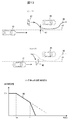
図5を用いて、本発明の実施例1の作用を説明する。ここでは移動体42が背面歩行する歩行者、速度変化誘発障害物43が駐車車両である場合を説明するが、移動体42、速度変化誘発障害物43の組み合わせは、図3で示した他の例であってもよい。図5(a)は、自車両41の予定走行経路44と速度変化誘発障害物43の最小距離45が小さい場合を示す。図5(b)は、最小距離45が大きい場合を示す。図5(c)は、現在時刻(T0)から、自車両41が速度変化誘発障害物43の横を通過する時刻(T1)までの自車両41の速度計画80を示す。ここでは最小距離45が小さい例と大きい例を重ねて表示している。
The operation of the first embodiment of the present invention will be described with reference to FIG. Here, a description will be given of the case where the moving
現在時刻(T0)において、自車両41の速度はV0であり、時刻(T1)において自車両41の速度が最小となるように速度計画を行っている。図5(c)に示すように、最小距離45が小さいほど速度計画80を低く設定する。なお、ここでは減速を開始する時刻をどちらもT0として設定しているが、最小距離が大きいほど減速開始時刻を遅らせてもよい。
At the current time (T0), the speed of the
以上が実施例1の作用であり、本発明によって、移動体42が速度変化誘発障害物43を避けて自車両41側に速度ベクトル変化を起こす行動変化を予め予測し、自車両41の速度を減少するように速度計画を行うことが可能である。これにより、移動体42の行動変化に対して衝突回避のための急ブレーキを防止し、乗員にとっての安心感や乗り心地を向上可能である。
The above is the operation of the first embodiment, and according to the present invention, the behavior change causing the velocity vector change on the
また、自車両41と速度変化誘発障害物43の距離が十分に離れており、移動体42が行動変化を起こしたとしても十分な距離を保てる、すなわち衝突可能性が低いと予測した場合には、不要な減速を防止することで、目的への速達性という乗員にとっての利便性を確保可能である。
In addition, if the distance between the
次に、本発明の一例である実施例2について図6〜図20を用いて説明する。なお、前述した実施例1と同様の部分については説明を省略する。 Next, a second embodiment which is an example of the present invention will be described with reference to FIGS. The description of the same parts as those of the first embodiment described above will be omitted.
実施例1では、自車両41と速度変化誘発障害物43の最小距離に基づき速度変更を行うが、実際には、移動体42と速度変化誘発障害物43の両者が検出されたとしても、移動体42の移動ベクトル変化が起きるより前に、自車両41が速度変化誘発障害物43の横を通過できる可能性がある。この場合、移動体42と速度変化誘発障害物43の両者が検出されたら毎回減速するような速度計画を立てることは、乗員にとっての速達性を損なう恐れがある。したがって、移動体42の将来位置を具体的に予測し、自車両41と移動体42の将来の接触可能性の有無を判定して、速度変更の要否を判定してもよい。
In the first embodiment, the speed change is performed based on the minimum distance between the
図6は、本発明の実施例2の構成の一部を示すブロック図である。図6の実施例では、速度制御手段32は、実施例1と同様に移動体検出手段33、速度変化誘発障害物検出手段34を備え、さらに、自車情報取得手段61、自車両予定走行経路取得手段62、移動体経路予測手段63、衝突予測地点算出手段64、到達時間差算出手段65、速度変更手段66から構成されている。 FIG. 6 is a block diagram showing a part of the configuration of the second embodiment of the present invention. In the embodiment of FIG. 6, the speed control means 32 includes the moving body detection means 33 and the speed change induced obstacle detection means 34 as in the first embodiment, and further, the own vehicle information acquisition means 61 and the own vehicle scheduled traveling route. An acquisition means 62, a mobile route estimation means 63, a collision predicted point calculation means 64, an arrival time difference calculation means 65, and a speed change means 66 are provided.
自車情報取得手段61は、自車両41の現在位置特定および動作状態量取得を行う。現在位置特定の処理は、GPS(不図示)、センサ2乃至センサ5の少なくとも1つによって取得した外界情報から自車両41の位置を特定する。GPSによる現在位置取得のほか、例えば、カメラ2によって自車両41周辺の画像データを取得し、記憶している外界画像と位置情報を照合して、自車両41の位置を特定しても良い。
The host vehicle
あるいは、画像などによって特定のランドマークを認識し、ランドマークと自車両41の相対位置情報とランドマークの絶対位置情報から自車両41の位置を特定する方法などもある。また、動作状態量取得処理 において取得する動作状態量の具体例としては、コンバインセンサ14から取得した速度、前後加速度、横方向加速度、ヨーレート、ヨー角およびハンドル角検出装置21から取得したステアリング操舵角等がある。
Alternatively, there is also a method of identifying a specific landmark by an image or the like and specifying the position of the
自車両予定走行経路取得手段62は、例えば自車両41の現在の操舵角が維持されるとした場合の自車両41が将来通過する領域を前記予定走行経路として取得する。あるいは、自車両41の走行可能領域や目的地等の情報から予定走行経路を生成する自車両予定走行生成手段を別途構成し、前記予定走行経路を取得してもよい。
The own vehicle scheduled traveling route acquisition means 62 acquires, as the planned traveling route, an area through which the
具体的な自車両予定走行生成方法は、例えば、車両に搭載したナビゲーションシステム(不図示)から、乗員の目的地情報およびルート情報を取得し、走行予定の道路に関する情報から、走行車線を決定し、前記走行車線内を通る軌道を生成する。その際、軌道上に障害物がある場合、障害物を避けるように随時軌道の修正を行う。 A specific method for generating planned vehicle travel is, for example, acquiring the destination information and route information of the occupant from a navigation system (not shown) mounted on the vehicle, and determining the traveling lane from the information on the road scheduled to travel. Generating a track passing in the traffic lane. At that time, if there is an obstacle on the orbit, correction of the orbit is made as needed to avoid the obstacle.
また、交差点等の車線が存在しない箇所においては、取得した交差点形状等の情報に基づき、走行車線同士をつなぐなめらかな軌道を生成する。なお、自車両予定走行生成方法は上記に限ったものではなく、地図情報に関連づけた目標走行軌道を予め取得しても良い。 In addition, in a place where no lane such as an intersection exists, a smooth track connecting the traveling lanes is generated based on the acquired information such as the shape of the intersection. In addition, the own vehicle scheduled traveling generation method is not limited to the above, and a target traveling track associated with map information may be acquired in advance.
移動体経路予測手段63は、移動体42と速度変化誘発障害物43の相対位置関係から、移動体42の現在位置から所定時刻後までの移動経路を予測する。具体的には、移動体42が速度変化誘発障害物43を回避するように、速度変化誘発障害物43から一定の距離をとって進行するような軌道を予測移動経路として算出する。所定値として、例えば5秒に設定し、現在時刻から5秒後までの予測移動経路を算出する。このとき、予測移動経路は所定の時間間隔(例えば1秒)ごとの時系列位置情報として算出してもよく、時間または位置に関する関数を立式してもよい。
The moving body path predicting means 63 predicts a moving path from the current position of the moving
図7は、移動体42の予測移動経路46の一例を示す。本図では、現在時刻において、自車両41、移動体42、速度変化誘発障害物43がそれぞれ図示する通りの位置関係に存在する場合を示している。ここでは移動体42が背面歩行する歩行者、速度変化誘発障害物43が駐車車両である場合を説明するが、移動体42、速度変化誘発障害物43の組み合わせは、図3で示した他の例であってもよい。
FIG. 7 shows an example of the predicted
移動体42の進行方向に延長した直線上に速度変化誘発障害物43が存在するため、移動体経路予測手段63は、移動体42が速度変化誘発障害物43を回避するように移動すると仮定して予測移動経路46を図示するように生成する。ここでは滑らかな軌道を描くように予測移動経路46を生成しているが、所定の時間間隔(例えば1秒)ごとの時系列位置情報として予測移動経路46として生成する場合、予測移動経路46は時系列位置情報の点列として図示することも可能である。
Since the velocity change induced
衝突予測地点算出手段64は、自車両の予定走行経路44と予測移動経路46の距離が所定値以下となる領域が存在する場合、その中で自車両41にもっとも近い点を衝突予測地点47と定義し、その位置を算出する。距離が所定値として、例えば1mに設定すると、自車両41と移動体42の距離が1mに接近する箇所を衝突予測地点47として設定することになる。
When there is a region where the distance between the
この所定値は、センサによる物体位置取得情報の誤差に応じて決定してもよく、乗員が移動体近傍を通過する際に必要と考えるクリアランスの大きさに基づいて決定してもよい。例えば、ある乗員が移動体の近傍を通過する際に、1.5m以上の間隔をとらないと不安感を覚える場合には、この所定値を1.5mと設定する。 The predetermined value may be determined according to the error of the object position acquisition information by the sensor, or may be determined based on the size of the clearance considered necessary when the occupant passes near the moving object. For example, when an occupant passes by the vicinity of the moving body, the predetermined value is set to 1.5 m if the user feels anxious unless the distance is 1.5 m or more.
到達時間差算出手段65は、自車両41と移動体42がそれぞれ現在の速度を維持すると仮定した場合に、自車両41と移動体42がそれぞれ衝突予測地点47に到達するまでに要する時間TTCPを算出し、その差分ΔTTCPを算出する。具体的には、自車両41の進行方向をX座標とし、自車両41の現在位置のX座標をX1、速度をV1とし、移動体42の現在位置のX座標をX2、速度をV2とし、衝突予測地点47のX座標をX3とすれば、ΔTTCPを数式1の通り求める。
ΔTTCP=(X3−X2)/V2−(X3−X1)/V1……数式1
なお、自車両41の所定時刻後までの速度計画を取得し、それに基づき到達時間差を算出しても良い。
The arrival time difference calculating means 65 calculates the time TTCP required for the
ΔTTCP = (X3−X2) / V2− (X3−X1) /
In addition, you may acquire the speed plan until the predetermined time of the
速度変更手段66は、到達時間差算出手段65により得られたΔTTCPに基づき、自車両の速度を変更する。ΔTTCPが0に近づくことは、自車両41と移動体42が衝突予測地点47をほぼ同時刻に通過すること、すなわち、自車両41と移動体42との接触の可能性があることを意味する。したがって、速度変更手段66は、ΔTTCPの絶対値が所定値未満と予想される場合には、ΔTTCPを所定値に一致させるよう自車両41を減速させる。例えば前記所定値を2秒と設定した場合、衝突予測地点47において、移動体42が自車両41より2秒以上先に到達するか、自車両41が移動体42より2秒以上先に到達するかのいずれかの条件では接触可能性は低いと判断して速度変更は行わない。
The speed changing means 66 changes the speed of the host vehicle based on ΔTTCP obtained by the arrival time difference calculating means 65. The fact that ΔTTCP approaches 0 means that the
一方、前記条件が満たされない場合、移動体42の2秒後に自車両41が衝突予測地点47を通過するように、衝突予測地点47における目標到達時刻を設定する。そして、現在時刻から目標到達時刻まで、自車両が現在の速度から減速するように速度計画を行い、前記速度計画に車両挙動が追従するように、自車位置および動作状態量に基づき加減速指令値を生成し、加速制御装置19、制動制御装置15にそれぞれ通信で指令値を伝送する。なお、前記所定値は2秒に限定されるものではなく、乗員の好みに応じて設定しても良い。具体的には、目的地への速達性を重視して前記所定値を1秒に設定する、安全性や安心感を優先して前記所定値を3秒に設定する、などの使用方法が可能である。
On the other hand, when the above condition is not satisfied, the target arrival time at the collision predicted
図8は、発明の実施例2のシステムフローを説明するフロー図である。このフローでは、毎計算ステップ毎に速度変更の要否を判定し、要変更の場合には所定の手段に従って速度の変更を行う。 FIG. 8 is a flowchart for explaining the system flow of the second embodiment of the present invention. In this flow, it is determined whether or not the speed change is necessary for each calculation step, and in the case of the change required, the speed is changed according to a predetermined means.
まず、自車両41の周辺に存在する物体を検出し(S71)、移動体42が存在するか否かを判定する(S72)。移動体42を検出した場合(S72:YES)にはS74に進み、移動体42を検出しなかった場合(S72:NO)には自車両41の現在速度から速度変更せずに維持する(S73)。
First, an object present in the vicinity of the
次に、移動体42を検出した場合、速度変化誘発障害物43が存在するか否かを判定する(S74)。速度変化誘発障害物43を検出した場合(S74:YES)にはS75に進み、速度変化誘発障害物43を検出しなかった場合(S74:NO)には自車両41の現在速度から速度変更せずに維持する(S73)。
Next, when the
S74がYESの場合、S75に進み、自車両の予定走行経路44を取得する。そして、移動体42の予測移動経路46を生成し、移動体42の将来位置を予測する(S76)。次に、自車両の予定走行経路44と予測移動経路46の各点における距離を算出し、前記距離が所定値以内となる地点が存在するか否かを判定する(S77)。前記地点が存在した場合(S77:YES)にはS78に進み、前記地点が存在しない場合(S77:NO)には自車両41の現在速度から速度変更せずに維持する(S73)。
If S74 is YES, the process proceeds to S75, and the planned
S77がYESの場合、S78に進み、予定走行経路44と予測移動経路46の距離が所定値以内となる点のうち、自車両41にもっとも近い点である、衝突予測地点47を取得する。そして、その点において、自車両41と移動体42の到達時間差ΔTTCPを算出し、ΔTTCPが所定値未満か否かを判定する。ΔTTCPが所定値未満である場合(S78:YES)、自車両41の速度が減少する方向に速度変更を実施する(S79)。一方、ΔTTCPが所定値以上である場合(S77:NO)には自車両41の現在速度から速度変更せずに維持する(S73)。
If S77 is YES, the process proceeds to S78, and among the points at which the distance between the planned traveling
図9乃至図11を用いて、本発明の実施例2の作用を説明する。図9は自車両41、移動体42、速度変化誘発障害物43の位置関係の時間経過の一例を示す。図9(a)は現在時刻(時刻T0)、図9(b)は移動体42が速度ベクトル変化を起こした瞬間における時刻(時刻T1)、図9(c)は移動体42が自車両41の走行予定経路44と所定値以内となった時刻(時刻T2)を示す。
The operation of the second embodiment of the present invention will be described with reference to FIGS. 9 to 11. FIG. 9 shows an example of the time course of the positional relationship between the
図10は、図9に示す時間経過が生じた際の自車両41の速度計画80の時間推移を示す。現在時刻T0において、移動体42と速度変化誘発障害物43を検出し、衝突予測地点47におけるΔTTCPを所定値内と予測して減速するような速度計画80を生成している。このとき、時刻T1で移動体42が実際に速度ベクトル変化を起こす前に、現在時刻T0の時点で自車両41は減速を開始する。
FIG. 10 shows the time transition of the
移動体42が予定走行経路44と所定値以内の距離となる時刻T2の時点で、自車両41の速度は移動体42と同じV1となり、移動体42に一定の距離を空けて追従するような運転行動となる。これにより、時刻T1で移動体42の速度ベクトル変化を検出してから初めて減速する場合と比べて、弱いブレーキ力での減速が可能となり、乗員にとっての乗り心地や安心感を向上できる。
At time T2 when the moving
図11は、図9に比べて自車両41と移動体42及び速度変化誘発障害物43の距離が離れている場合の自車両41の速度計画80の時間推移を示す。それぞれ図11(a)は現在時刻(時刻T0)、図11(b)は図9(c)と同様の位置に移動体42が到達する時刻(時刻T2)における自車両41、移動体42、速度変化誘発障害物43の位置関係の時間経過の一例を示す。また、図11(c)はこのときの自車両41の速度計画80の時間推移を示す。
FIG. 11 shows the time transition of the
この場合、自車両41と移動体42及び速度変化誘発障害物43の距離が離れているため、予定走行経路44と予測移動経路46の距離が所定値以内となる箇所が存在せず、すなわち衝突予測地点47が存在しない。したがって、図11(c)に示すとおり、速度計画80は減速せず、現在速度V0を維持するような速度計画となる。これにより、自車両41と移動体42の将来の接触可能性が低い場合には不要な減速を防止し、目的地への速達性という乗員にとっての利便性の確保が可能となる。
In this case, there is no location where the distance between the
以上が本発明の実施例2の作用であるが、実施例2は、移動体42又は速度変化誘発障害物43が予測と異なる動きをした場合にも適用可能である。図12では、移動体42が予測移動経路46に反して、速度ベクトル変化を起こさなかった、あるいは自車両41から離れる方向に速度ベクトル変化を起こした場合を示す。
Although the above is an effect | action of Example 2 of this invention, Example 2 is applicable also when the moving
図12(a)に示すとおり自車両41、移動体42、速度変化誘発障害物43が存在すると、本発明は予測移動経路46の通り移動体42の将来位置を予測し、衝突予測地点47においてΔTTCPを所定値とするように自車両の速度を計画する。しかしながら、図12(b)に示すとおり時刻T2で移動体42が予測移動経路46から逸脱した場合、図12(c)に示す速度計画80の時間推移の通り、時刻T2までは自車両が減速するように速度計画80を生成し、時刻T2からは自車両41と移動体42の接触可能性がなくなったと判定し、初期値V0に戻すように加速するよう速度計画80を設定する。
As shown in FIG. 12A, when the
図13では、移動体42が予測移動経路46に比べて、早い時間に速度ベクトル変化を起こし、自車両41との距離が縮小した場合を示す。図13(a)に示すとおり時刻T0で自車両41、移動体42、速度変化誘発障害物43が存在すると、本発明は予測移動経路46の通り移動体42の将来位置を予測し、衝突予測地点47においてΔTTCPを所定値とするように自車両の速度を計画する。しかしながら、図13(b)に示すとおり時刻T1で移動体42が予測移動経路46から逸脱した場合、図13(c)に示す速度計画80の時間推移の通り、自車両41は移動体42との接触を防止するため、急ブレーキで停止する。
FIG. 13 shows the case where the moving
図14では、予測に反して移動体42の速度ベクトルに変化がなく、速度変化誘発障害物43が自車両側に速度ベクトル変化を起こした場合を示す。図14(a)に示すとおり時刻T0で自車両41、移動体42、速度変化誘発障害物43が存在すると、本発明は予測移動経路46の通り移動体42の将来位置を予測し、衝突予測地点47においてΔTTCPを所定値とするように自車両の速度を計画する。
FIG. 14 shows a case where there is no change in the velocity vector of the moving
しかしながら、図14(b)に示すとおり時刻T2の時点で移動体42は予測移動経路46に比べて自車両41から離れた位置に存在し、代わりに速度変化誘発障害物43が自車両41に近づく方向に行動変化を起こした場合、速度変化誘発障害物43と予定走行経路44の最小距離が小さくなるため自車両41の速度を低下させる。すなわち図14(c)に示す速度計画80の時間推移の通り、時刻T2以降も自車両41の速度は低下を続ける。図14(c)は、速度変化誘発障害物43が予定走行経路44と重なる位置まで移動してきた場合を示しており、自車両41は速度変化誘発障害物43との接触を防止するため停止する。
However, as shown in FIG. 14 (b), at time T 2, the moving
図15では、予測に反して移動体42の速度ベクトルに変化がなく、速度変化誘発障害物43が自車両41から離れる方向に速度ベクトル変化を起こした場合を示す。図15(a)に示すとおり時刻T0で自車両41、移動体42、速度変化誘発障害物43が存在すると、本発明は予測移動経路46の通り移動体42の将来位置を予測し、衝突予測地点47においてΔTTCPを所定値とするように自車両の速度を計画する。
FIG. 15 shows the case where there is no change in the velocity vector of the moving
しかしながら、図15(b)に示すとおり時刻T2の時点で移動体42は予測移動経路46に比べて自車両41から離れた位置に存在し、さらに速度変化誘発障害物43が自車両41から遠ざかる方向に行動変化を起こした場合、速度変化誘発障害物43と予定走行経路44の最小距離が大きくなるため自車両41は速度を大きくする。すなわち図15(c)に示す速度計画80の時間推移の通り、時刻T2以降は自車両41の速度減少を止め、加速に転じる。
However, as shown in FIG. 15B, at time T2, the moving
図16乃至図18を用いて、移動体経路予測手段63における経路予測方法の一例を説明する。 図16は移動体経路予測手段63の構成の一例を示すブロック図である。本実施例では、移動体経路予測手段63は、進路変更地点算出手段91、横方向オフセット地点算出手段92、移動体予測経路算出手段93、記憶部94から構成されている。
An example of the route prediction method in the mobile object route prediction means 63 will be described using FIG. 16 to FIG. FIG. 16 is a block diagram showing an example of the configuration of the mobile path prediction means 63. As shown in FIG. In the present embodiment, the moving body route predicting means 63 comprises a course change point calculating means 91, a lateral offset point calculating means 92, a moving body predicted path calculating means 93, and a
進路変更地点算出手段91は、移動体42が速度変化誘発障害物43の手前で速度ベクトル変化を起こし、自車両41に近づく方向に移動を開始する地点を進路変更地点82として算出する。
The course change point calculation means 91 calculates, as a
横方向オフセット地点算出手段92は、移動体42が速度ベクトル変化を起こした後、速度変化誘発障害物43の横を通過するため再びに速度ベクトル変化を起こし、進路変更地点82より前に進行していた方向に再び進行を開始する地点を横方向オフセット地点83として算出する。
Lateral offset point calculation means 92 causes the velocity vector to change again to pass the side of the velocity
図17は、進路変更地点82及び横方向オフセット地点83の位置関係を示す。ここでは図示の通り、自車両41の進行方向をX軸、進行方向に直交する方向であって進行方向に向かって左方向をY軸とする。移動体42は、速度変化誘発障害物43の手前に位置する進路変更地点82から、自車両41に近づく方向に向かって斜めに移動する。このとき、進路変更地点82と速度変化誘発障害物43とのX方向距離を進路変更距離84と定義する。
FIG. 17 shows the positional relationship between the
また、移動体42が進路変更地点82を通過後、速度変化誘発障害物43の横を通過可能な位置である横方向オフセット地点83に達すると、進路変更地点82より前に進行していた方向に再び進行を開始する。このとき、横方向オフセット地点83と速度変化誘発障害物43のY方向距離を横方向オフセット距離85と定義する。図17では、横方向オフセット地点83のX座標は、速度変化誘発障害物43の4辺のうち、最も自車両41に近い辺のX座標と等しく設定する場合の例を示す。なお、実際の移動体42の動きには個人差があり、前記個人差を考慮して横方向オフセット地点83のX座標を可変としてもよい。
In addition, when the moving
移動体予測経路算出手段93は、進路変更地点82及び横方向オフセット地点83に基づき、移動体42の予測移動経路46を生成する。図17では、移動体42の現在位置から、進路変更地点82及び横方向オフセット地点83を折れ線で結ぶように予測移動経路46を生成する例を示している。なお、折れ線に限定されるものではなく、進路変更地点82及び横方向オフセット地点83を経由する滑らかな曲線であってもよい。
The mobile body predicted path calculation means 93 generates a predicted
記憶部94は、移動体予測経路算出手段93において必要な情報を記憶する。例えば、移動体42を検出した際のセンサ値に基づき、歩行者・二輪車、年齢、性別、地域等の属性を取得し、前記属性に基づき予測移動経路46の平均値、あるいは進路変更地点82及び横方向オフセット地点83の平均位置を記憶または通信で取得し、記憶部94に蓄積する。そして、移動体42を検出してから現在時刻までの移動軌跡を記憶し、両者を比較することにより進路変更地点82及び横方向オフセット地点83を決定すれば、移動体42の実際の移動経路に近い予測移動経路46が得られる。
The
自車両41と移動体42との距離が離れている場合、移動体42の現在位置に誤差が生じやすく、かつセンサ情報から前記属性の取得が困難であることから、進路変更地点82及び横方向オフセット地点83の正確な予測が困難である。従って、距離が遠いほど安全側に予測し、距離が近くなり、移動体42の予測移動経路46の正確性が高まるほど、進路変更地点82及び横方向オフセット地点83をリアルタイムに同定することが望ましい。
If the distance between the
進路変更地点82及び横方向オフセット地点83の同定方法の一例を図18に示す。図18(a)は現在時刻T0における自車両41、移動体42、速度変化誘発障害物43の位置関係を示している。このとき、自車両41と移動体42の距離が離れており、移動体42の属性が十分に取得できていない場合、移動体予測経路算出手段93は、進路変更距離84及び横方向オフセット距離85について、記憶部94が記憶した過去の移動経路データから、最も速度変化誘発障害物43から離れた位置に設定する。設定した進路変更距離84及び横方向オフセット距離85に基づき、予測移動経路46及び衝突予測地点47の位置を同定し、自車両41の速度計画80を生成する。
An example of the identification method of the
しかしながら、前記予測移動経路は最も速度変化誘発障害物43から離れた位置を通過する経路であり、当該の移動体は前記予測移動経路より速度変化誘発障害物43の近くを通る可能性が高い。したがって、図18(b)に示すように、時刻T1において移動体42が一度設定した進路変更地点82を超えて速度変化誘発障害物43に近づくと、記憶部94に記憶した過去の移動経路データと照らし合わせて進路変更距離84と横方向オフセット距離85の少なくとも1つを減少させる。その結果、衝突予測地点47は自車両41から遠ざかる方向に移動するため、図18(c)に示す通り、時刻T1以降は速度計画80の減速度が緩和され、速度の減少が弱まる。
However, the predicted movement path is a path that passes the position farthest from the speed change induced
以上の実施例では、進路変更地点82及び横方向オフセット地点83に基づく予測移動経路生成方法を前提としてリアルタイム同定方法を説明したが、このリアルタイム同定方法は上記実施例に限定されるものではない。例えば、記憶部94に記憶した過去の移動経路データと照らし合わせて、最も似ている経路を予測移動経路46として生成する手法であれば、移動体42を検出してから現在時刻までの移動軌跡を記憶部94に蓄積し、蓄積データが少ないうちは、最も速度変化誘発障害物43から遠い場所を通過する経路を選択し、前記蓄積データが十分に保存された段階で、徐々に予測移動経路46の候補を限定してもよい。
In the above embodiments, the real time identification method has been described on the premise of the predicted movement path generation method based on the
以上、移動体経路予測手段63における経路予測方法の一例を説明したが、移動体経路予測手段63は本構成に限定されるものではなく、移動体42の予測将来位置もしくは軌道を生成する手段であれば何でも適用可能である。
In the above, an example of the route prediction method in the mobile object route prediction means 63 has been described, but the mobile object route prediction means 63 is not limited to this configuration, and means for generating the predicted future position or trajectory of the
以上述べた実施例2では、現在時刻から目標到達時刻まで、一定加速度での減速を前提として速度計画方法を説明したが、人間の安心感や乗り心地を考慮すると、加速度の時間変化である加加速度を抑えることが必要である。したがって、図19及び図20を用いて、加加速度の時間変化を考慮した速度計画手段の一例を説明する。 In the second embodiment described above, the velocity planning method has been described on the premise of deceleration at a constant acceleration from the current time to the target arrival time, but when human sense of security and comfort are taken into account, It is necessary to suppress the acceleration. Therefore, an example of the speed planning means in consideration of the time change of the jerk will be described using FIG. 19 and FIG.
自車両41、移動体42、速度変化誘発障害物43の位置関係が図19に示す通りであると仮定する。すなわち、現在時刻T0において図19(a)に示すような位置関係であり、時刻T1で移動体42が予測移動経路46の通り速度ベクトル変化を起こし、自車両41の予定走行経路44に重なる位置に到達した場合を想定する。このとき、自車両41は現在時刻T0において速度V0で走行しており、図19(b)に示すように時刻T1において移動体42の後ろを移動体と同じ速度V1で走行するように速度計画を行う。
It is assumed that the positional relationship between the
図20に、速度計画方法の一例を示す。本実施例では、現在時刻T0から目標到達時刻T1までの速度計画を、N次元の時系列ベクトルVとして定義する。また、ベクトルVの要素ごとの時間微分である加速度をN次元ベクトルα,さらにαの要素ごとの時間微分である加加速度をN次元ベクトルUとするとき、本実施例ではUを数式2に基づき計画する。
U=ΣT・(Σ・ΣT)^−1・(X〔N〕−A^N・X〔N〕)……数式2
ここで、Σは数式3で定義される行列、Aは数式4で定義される行列、Xは数式5で定義される3次元ベクトルであり、Tは行列の転置を表す。
Σ=[A^(N−1)・B,A^(N−2)・B,…,B]……数式3
A=[1 Ts 0;0 1 Ts;0 0 1]……数式4
X[k]=[x[k];V[k];α[k]]……数式5
ここでxは自車両41の目標位置を表すN次元ベクトル、Bは数式6で定義される3次元ベクトル、Tsは速度計画41の時系列データの時間間隔(例えば0.1秒)であり、セミコロン(;)は行列における改行を表す。
B=[0;0;Ts]……数式6
数式2に基づきN次元ベクトルUを決定し、時間積分によりαを、さらに時間積分によりVを求めた結果を図20に示す。それらの時間変化の特徴について説明する。まず、速度計画Vは図20(a)に示す通り、現在時刻T0と目標到達時刻T1の途中に変曲点111が存在し、変曲点の前ではVが上に凸となるように変化し、変曲点を越えるとVは下に凸となるように変化する。その結果、加速度αは図20(b)に示す通り、常に連続的かつ滑らかに変化する。また、加加速度Uは、図20(c)に示すとおり、時間に関する二次関数として変化する。
FIG. 20 shows an example of the velocity planning method. In this embodiment, a velocity plan from the current time T0 to the target arrival time T1 is defined as an N-dimensional time-series vector V. Further, when an acceleration which is a time derivative of each element of the vector V is an N-dimensional vector α, and an additive acceleration which is a time derivative of each element of α is an N-dimensional vector U, U is expressed by To plan.
U = ΣT · (T · (T) ^ − 1 · (X [N] −A ^ N · X [N]) Formula 2
Here, Σ is a matrix defined by
Σ = [A ^ (N−1) · B, A ^ (N−2) · B,.
A = [1
X [k] = [x [k]; V [k]; α [k]]
Here, x is an N-dimensional vector representing the target position of the
B = [0; 0; Ts] ... Equation 6
An N-dimensional vector U is determined based on Expression 2, and α is obtained by time integration, and V is obtained by time integration. The results are shown in FIG. The characteristics of those time changes will be described. First, as shown in FIG. 20A, the velocity plan V changes so that the inflection point 111 exists midway between the current time T0 and the target arrival time T1 and V is convex upward before the inflection point When V exceeds the inflection point, V changes to be convex downward. As a result, as shown in FIG. 20 (b), the acceleration α always changes continuously and smoothly. Moreover, the jerk U changes as a quadratic function regarding time, as shown in FIG. 20 (c).
以上、本実施例では、移動体42の予測移動経路46に基づき自車両41を減速させる際の加速度変化が滑らかとなり、乗員にとっての乗り心地や安心感を高めることが可能である。
As described above, in the present embodiment, the acceleration change when the
次に本発明の一例である実施例3について図21〜24を用いて説明する。なお、実施例1あるいは実施例2と同様の部分は説明を省略する。 Next, a third embodiment which is an example of the present invention will be described with reference to FIGS. The same parts as those in the first embodiment or the second embodiment will not be described.
実施例1及び実施例2では、移動体42と速度変化誘発障害物43が両方存在する場合にのみ速度変更を行うが、移動体42が単体で存在する場合には速度変更が行われない。これにより、移動体42のすぐ近くを通過する場合にも自車両41が減速せず、乗員にとっての違和感や不安感につながる可能性がある。
In the first embodiment and the second embodiment, the speed change is performed only when both the moving
また、予測移動経路46はあくまで予測であり、移動体42が予測に反して速度ベクトル変化を起こした場合にも、必ず自車両41との接触を防止するための速度計画を併用することが望ましい。したがって、本発明において、移動体41が単独で存在している場合にも、その近傍を通過する際には減速するような速度計画を併用してもよい。
Further, the predicted
図21は、本発明の実施例3の構成の一部を示すブロック図である。図21の実施例では、車両走行制御装置1は実施例1、2同様に、物体検出手段31、速度制御手段32から構成されている。速度制御手段32は、実施例1、2同様に、移動体検出手段33、速度変化誘発障害物検出手段34、自車情報取得手段61から構成され、さらに安全速度計画手段121、速度変更手段122から構成されている。
FIG. 21 is a block diagram showing a part of the configuration of the third embodiment of the present invention. In the embodiment of FIG. 21, the vehicle
安全速度計画手段121は、自車情報取得手段61で取得した自車両41の現在位置と、移動体検出手段33で検出した移動体42の現在位置に基づき、安全速度131を算出する。この安全速度は、自車両と移動体の距離が近いほど低く設定することを特徴とし、自車両の速度を常に安全速度より下回るように制御することで、移動体が予想外の進路変更をした際に自車両が急ブレーキをかけて、両者の接触前に自車両が停車可能な上限速度として設定する。
The safety speed planning means 121 calculates the
図22を用いて、安全速度131の算出方法を説明する。安全速度は、自車両41と移動体42の相対距離に応じて決定する。具体的には、自車両の進行方向に沿った相対距離である進行方向距離125、及び自車両の進行方向に直行する方向の相対距離である横方向距離126の2つから算出する。安全速度は、横方向距離が同じであれば進行方向距離が近いほど低く設定する。これは、自車両41が移動体42と同じ方向に進行した場合に、移動体42に近づくほど速度が減少することを意味する。
The method of calculating the
一方、進行方向距離が同じであれば横方向距離が近いほど安全速度を低く設定する。これは、自車両が移動体の近傍を通過する際、移動体の近くを通過するほど速度が下がることを意味する。以上の特徴を統合すると、安全速度は図22の2次元マップの例に示すような分布となる。 On the other hand, if the traveling direction distance is the same, the safe speed is set lower as the lateral direction distance is shorter. This means that when the host vehicle passes near the moving object, the speed decreases as it passes near the moving object. When the above features are integrated, the safe velocity has a distribution as shown in the example of the two-dimensional map of FIG.
自車両が走行中に移動体を検出した場合の安全速度131の算出方法として、図22の2次元マップに示す関係を予めルックアップテーブルとして記憶し、その瞬間における進行方向距離125及び横方向距離126から安全速度を決定する方法が一例として挙げられる。また、現在時刻において移動体42が進路変更を起こすと想定し、全ての進行角について安全速度を算出してその最小値を選択しても良い。
As a method of calculating the
例えば、横方向距離が十分小さい場合、自車両41と移動体42の距離がX〔m〕であり、移動体42が進路変更をした際の自車両41の設定減速度がα〔m/s^2〕である時、安全速度Vs〔m/s〕は数式7の通り近似的に求まる。
Vs=√(2・α・X)……数式7
数式7の通り、安全速度は設定減速度αが大きいほど高く、αが小さいほど低くなる。従って、図22の2次元マップも自車両41の設定減速度αによって分布の広がりが異なるため、その時々の路面状態等に応じて安全速度のルックアップテーブルを切り替えてもよい。
For example, when the lateral distance is sufficiently small, the distance between the
Vs = ((2 · α · X) ...
As the
速度変更手段122は、自車両41、移動体42および速度変化誘発障害物43の相対位置関係に基づき生成した速度計画80と、安全速度計画手段121により生成した安全速度131のうち、低い方を自車両41の目標速度として決定する。そして、前記目標速度に車両挙動が追従するように、自車位置および動作状態量に基づき加減速指令値を生成し、加速制御装置19、制動制御装置15にそれぞれ通信で指令値を伝送する。
The speed changing means 122 sets the lower one of the
図23及び図24を用いて、本発明の実施例3の作用を説明する。図23は、移動体42が単独で存在している場合の安全速度131及び自車両の速度計画80の時間推移を示す。図23(a)に示すとおり時刻T0で自車両41、移動体42が存在している。ここでは、自車両と移動体の距離が十分に離れているとき、安全速度は上限値Vmaxに設定する場合の例を示す。この時、速度変化誘発障害物43が存在しないため、移動体42の速度ベクトル変化予測に基づく減速は行われない。
The operation of the third embodiment of the present invention will be described with reference to FIGS. 23 and 24. FIG. FIG. 23 shows time transition of the
しかしながら、図23(b)に示す速度計画80の時間推移の通り、安全速度131が常に算出され、自車両41が移動体42に近づくほど低く設定されるため、最終的な速度計画80は、移動体に近づいた時刻T1から、移動体の横を通過する時刻T2の間、減速するように速度計画が変化する。そして、移動体の横を通過すると安全速度は再びVmaxとなるため、自車両が再び加速するように速度計画を行う。なお、図23では安全速度に基づく減速が行われているが、横方向距離126が十分大きい場合、安全速度が常に自車両41の現在速度を上回ることで減速が行われないこともありうる。
However, as the time transition of the
図24は、移動体42と速度変化誘発障害物43が両方存在し、移動体42の速度ベクトル変化予測に基づく速度変更が行われる際の安全速度131及び自車両の速度計画80の時間推移を示す。現在時刻T0における自車両41、移動体42、速度変化誘発障害物43の位置関係が図24(a)に示す通りとなった場合、速度ベクトル変化予測に基づき速度計画80は減速する。
FIG. 24 shows the time transition of the
そして、図24(b)に示す通り移動体42が自車両の予定走行経路44に重なる時刻T1までには十分減速する。この時、図24(c)に示す通り、安全速度131も自車両と移動体の相対位置関係に基づき同時に算出され、自車両が移動体に近づくほど安全速度も減少する。図24(c)の例では、移動体42の速度ベクトル変化予測に基づく速度計画が常に安全速度を下回っているが、速度ベクトル変化予測に基づく速度計画が安全速度を上回る場合、安全速度が最終的な速度計画値として選択される。
Then, as shown in FIG. 24 (b), the moving
以上説明した実施例3により、移動体42が単独で存在する場合にも、移動体近傍を通過する際に適切な減速が行われ、乗員にとっての不安感を低減可能である。
According to the third embodiment described above, even when the
以上、説明した実施例1乃至3において、移動体42の予測移動経路46、及び予測移動経路46に基づく自車両41の速度計画80の内容を、表示装置24で乗員に示すことが望ましい。表示する情報の具体例としては、 自車両41の周辺に存在する物体の表示および移動体42の予測移動経路46の表示、自車両41と移動体42との経路交差有無、ΔTTCP、自車両41の現在の走行計画およびこれからとる運転行動等が挙げられる。乗員の操作が介在しない自動走行の場合、乗員の想定する走行と、車両が実際に行った走行の間に相違が生じることは、乗員の不安感につながる。表示装置24 により、前記相違を低減し、乗員の安心感をさらに高めることが可能である。
As described above, in the first to third embodiments described above, it is desirable that the display 24 shows the content of the predicted
以上の実施例1乃至3では、車両走行制御装置1により自動走行を行う場合について述べたが、ドライバが運転操作する車両に搭載する運転支援システムに対しても適用可能である。この場合、ドライバの現在の運転状態から、自車両の将来の走行経路および速度を予測し、その予測に従って走行すると速度変化した移動体との衝突危険がある場合に、ドライバに警告を与えることができる。また、衝突回避のための緊急自動ブレーキを従来技術より早期にかけることが可能であるため、より確度の高い衝突回避システムを実現する。
In the above-described first to third embodiments, the case where automatic travel is performed by the vehicle
また、以上の実施例1乃至3では、移動体の将来の進路変化を、現在の相対位置関係から予測しているが、移動体の行動意思を直接検知する手段によって、当該移動体の速度変化予測の確度を高めることが可能である。例えば、自車両が移動体の持つ携帯端末との通信手段を備え、当該携帯端末から当該移動体の移動予定経路を通信で取得することにより、当該移動体の進行方向をより高い確度で判定することが可能となり、自車両41の目標走行軌道と、移動体の予測軌道が交差するか否かの判定がより正確となる。
Further, in the above-described first to third embodiments, the future course change of the mobile unit is predicted from the current relative positional relationship, but the speed change of the mobile unit by means of directly detecting the action intention of the mobile unit. It is possible to increase the accuracy of the prediction. For example, the own vehicle is provided with a communication means with a portable terminal of a moving object, and the traveling direction of the moving object is determined with higher accuracy by acquiring a planned movement route of the moving object from the portable terminal by communication. This makes it possible to determine whether the target traveling track of the
以上、各実施例について説明したが、具体的な構成は各実施例に限定されるものではなく、発明の要旨を逸脱しない範囲の設計変更等があっても、本発明に含まれる。 As mentioned above, although each Example was described, a specific structure is not limited to each Example, Even if there are design changes in the range which does not deviate from the summary of invention, it is contained in this invention.
1…車両走行制御装置、2〜5…センサ、8…操舵制御装置、15…制動制御装置、19…加速制御装置、23…通信装置、24…表示装置、31…物体検出手段、32…速度制御手段、33…移動体検出手段、34…速度変化誘発障害物検出手段、35…速度変更手段(実施例1)、41…自車両、42…移動体、43…速度変化誘発障害物、44…自車両41の予定走行経路、45…自車両41と速度変化誘発障害物43の最小距離、46…移動体42の予測移動経路、47…衝突予測地点、61…自車情報取得手段、62…自車両予定走行経路取得手段、63…移動体経路予測手段、64…衝突予測地点算出手段、65…到着時間差算出手段、66…速度変更手段(実施例2)、80…自車両41の速度計画、82…進路変更地点、83…横方向オフセット地点、84…進路変更距離、85…横方向オフセット距離、91…進路変更地点算出手段、92…横方向オフセット地点算出手段、93…移動体予測経路算出手段、94…記憶部、111…速度計画80の変曲点、112…加速度計画、113…加加速度計画、121…安全速度計画手段、122…速度変更手段(実施例3)、125…自車両41と移動体42の進行方向距離、126…自車両41と移動体42の横方向距離、131…安全速度。
DESCRIPTION OF
Claims (14)
前記物体検出手段で検出した前記物体の中から前記自車両の予定走行経路に隣接する場所に存在する移動体と前記移動体の将来の速度ベクトル変化を誘発する速度変化誘発障害物とを検出し、前記自車両、検出した前記移動体および前記速度変化誘発障害物の相対位置関係に基づき前記自車両の速度を変更する速度制御手段と、を備え、
前記速度制御手段は、
前記移動体が前記速度変化誘発障害物を回避するための将来の進路変更を予測し、所定時間後までの前記移動体の予測将来位置を算出する移動体経路予測手段をさらに備え、
前記移動体経路予測手段に基づき、前記予定走行経路と前記予測将来位置の距離が所定値以内となる地点のうち前記自車両に最も近い地点である衝突予測地点における前記移動体と前記自車両の到達時間差が所定値以内と予測した場合に、前記自車両が現在速度より減速するように速度を変更することを特徴とする車両走行制御装置。 Object detection means for detecting the position, velocity and size of an object around the host vehicle;
Among the objects detected by the object detecting means, a moving object existing at a location adjacent to the planned traveling path of the vehicle and a velocity change induced obstacle which induces a future velocity vector change of the moving object are detected. And speed control means for changing the speed of the own vehicle based on the relative positional relationship between the own vehicle, the detected moving body, and the speed change induction obstacle .
The speed control means
The mobile body further includes mobile body route prediction means for predicting a future course change for avoiding the speed change-induced obstacle and calculating a predicted future position of the mobile body up to a predetermined time later.
The moving object and the own vehicle at the collision predicted point which is the closest point to the own vehicle among the points where the distance between the planned traveling route and the predicted future position is within a predetermined value based on the moving object route prediction means The vehicle travel control device, wherein the speed is changed so that the host vehicle decelerates from the current speed when the arrival time difference is predicted to be within a predetermined value.
前記移動体および前記速度変化誘発障害物を検出した場合に、前記予定走行経路と前記速度変化誘発障害物との最小距離が小さいほど前記自車両の速度を小さくするように速度制御することを特徴とする請求項1に記載の車両走行制御装置。 The speed control means
When the moving body and the speed change induced obstacle are detected, the speed is controlled so as to reduce the speed of the own vehicle as the minimum distance between the planned traveling route and the speed change induced obstacle is smaller. The vehicle travel control device according to claim 1.
前記物体のうち、前記自車両の進行方向とのなす角が所定値以内の方向に進行し、かつ、前記自車両との距離が所定値以内である前記物体を前記移動体として検出し、
前記移動体の進行方向を延長した直線に対する最小距離が所定値以内であり、かつ、前記移動体との相対距離が縮小する方向に移動または静止している前記物体を前記速度変化誘発障害物として検出することを特徴とする請求項1に記載の車両走行制御装置。 The speed control means
Among the objects, the object traveling in a direction within a predetermined value with respect to the traveling direction of the host vehicle and having a distance to the host vehicle within a predetermined value is detected as the movable body.
The velocity change-induced obstacle is the object moving or stationary in a direction in which the minimum distance to a straight line extending the traveling direction of the moving body is within a predetermined value and the relative distance to the moving body decreases. The vehicle travel control device according to claim 1, wherein the vehicle travel control device detects the vehicle.
前記移動体が前記予測将来位置に反して前記自車両の進路方向と平行方向に進行、又は、前記自車両より離れる方向に移動した場合に、そうでない場合に比べて前記自車両を加速させることを特徴とする請求項1に記載の車両走行制御装置。When the moving object travels in a direction parallel to the traveling direction of the host vehicle against the predicted future position, or moves in a direction away from the host vehicle, the host vehicle is accelerated compared to the case where it is not so. The vehicle travel control device according to claim 1, characterized in that
前記移動体が前記予測将来位置に反して前記自車両との距離が小さくなる方向に移動した場合に、そうでない場合に比べて前記自車両を減速させることを特徴とする請求項1に記載の車両走行制御装置。2. The vehicle according to claim 1, wherein, when the movable body moves in a direction in which the distance to the vehicle decreases as opposed to the predicted future position, the vehicle is decelerated as compared with a case other than that. Vehicle travel control device.
前記移動体が進路変更する場所である進路変更地点および進路変更後に前記移動体が前記自車両の進路方向と平行の方向に進路を変更する場所である横方向オフセット地点の2点を算出し、Calculating two points of a course change point where the moving body changes course and a lateral offset point where the moving body changes course in a direction parallel to the course direction of the host vehicle after the course change;
前記進路変更地点と前記横方向オフセット地点の2点を結ぶ軌道を前記移動体の前記予測将来位置とすることを特徴とする請求項1に記載の車両走行制御装置。The vehicle travel control device according to claim 1, wherein a trajectory connecting two points of the route change point and the lateral offset point is set as the predicted future position of the moving body.
前記進路変更地点および前記横方向オフセット地点について複数のパターンが記憶され、あるいは、通信でパターンを取得し、A plurality of patterns are stored for the route change point and the lateral offset point, or a pattern is acquired through communication,
前記移動体の過去の移動軌跡を記憶し、Storing a past movement trajectory of the moving body,
前記移動軌跡と前記パターンとを照合して前記進路変更地点及び前記横方向オフセット地点を算出することを特徴とする請求項6に記載の車両走行制御装置。The vehicle travel control device according to claim 6, wherein the path change point and the lateral offset point are calculated by collating the movement locus with the pattern.
前記移動体と前記自車両との距離が遠いほど前記衝突予測地点を前記自車両に近づけることを特徴とする請求項6に記載の車両走行制御装置。The vehicle travel control device according to claim 6, wherein the collision predicted point is brought closer to the host vehicle as the distance between the movable body and the host vehicle is larger.
前記到達時間差が所定値以内と予測した場合に、前記自車両が前記衝突予測地点において前記移動体より所定値の時間経過後に通過するように前記衝突予測地点における前期自車両の目標到達時刻を決定し、When the arrival time difference is predicted to be within the predetermined value, the target arrival time of the vehicle at the collision predicted point is determined so that the vehicle passes after the predetermined time from the moving object at the collision predicted point. And
前記目標到達時刻において前記自車両が前記衝突予測地点に到達し、かつ、前記自車両の速度が前記移動体の速度と同じとなるように前記自車両の速度を変更することを特徴とする請求項1に記載の車両走行制御装置。The speed of the vehicle is changed so that the vehicle reaches the collision predicted point at the target arrival time, and the speed of the vehicle becomes equal to the speed of the moving object. The vehicle travel control device according to Item 1.
現在時刻から速度の時間変化が上に凸となるように前記自車両の速度を変更し、
その後、前記目標到達時刻までは速度の時間変化が下に凸となるように前記自車両の速度を変更することを特徴とする請求項9に記載の車両走行制御装置。 The speed control means
Change the speed of the vehicle so that the time change of the speed from the current time is convex upward,
10. The vehicle travel control device according to claim 9, wherein the speed of the vehicle is changed so that the time change of the speed is downwardly convex until the target arrival time.
現在時刻から前記目標到達時刻まで、前記自車両の加速度の時間変化が連続的であり、The time change of the acceleration of the host vehicle is continuous from the current time to the target arrival time,
かつ加加速度が時間に関する二次関数で変化するように前記自車両の速度を変更することを特徴とする請求項9に記載の車両走行制御装置。The vehicle travel control device according to claim 9, wherein the speed of the host vehicle is changed such that the jerk changes in a quadratic function with respect to time.
前記移動体と前記自車両との現在時刻における相対位置関係に基づき、前記自車両と前記移動体の距離が近いほど前記自車両の速度を減少させるように速度を計画する安全速度計画手段をさらに備え、The safety speed planning means for planning the speed so as to reduce the speed of the host vehicle as the distance between the host vehicle and the host vehicle decreases, based on the relative positional relationship between the host vehicle and the host vehicle at the current time. Equipped
前記安全速度計画手段に基づく速度計画値を常に下回るように前記自車両の速度を変更することを特徴とする請求項1乃至11の何れか1項に記載の車両走行制御装置。The vehicle travel control device according to any one of claims 1 to 11, wherein the speed of the host vehicle is changed so as to always fall below a speed plan value based on the safe speed planning means.
前記移動体の任意の時刻における任意の方向への進路変化に対し、所定減速度で減速して前記自車両と前記移動体の接触前に前記自車両を停止できるような前記自車両の速度上限値を算出又は記憶し、The upper limit of the speed of the subject vehicle such that the subject vehicle can be stopped before contacting the subject vehicle with the subject vehicle, decelerating at a predetermined deceleration with respect to a course change in a given direction at a given time of the subject vehicle. Calculate or store the value,
前記速度上限値に基づき速度を計画することを特徴とする請求項12に記載の車両走行制御装置。The vehicle travel control device according to claim 12, wherein a speed is planned based on the speed upper limit value.
前記物体検出手段で検出した前記物体の中から前記自車両の予定走行経路に隣接する場所に存在する移動体と前記移動体の将来の速度ベクトル変化を誘発する速度変化誘発障害物とを検出し、前記自車両、検出した前記移動体および前記速度変化誘発障害物の相対位置関係に基づき前記自車両の速度を変更する速度制御手段と、を備える車両走行制御装置の速度制御方法において、Among the objects detected by the object detecting means, a moving object existing at a location adjacent to the planned traveling path of the vehicle and a velocity change induced obstacle which induces a future velocity vector change of the moving object are detected. A speed control method of a vehicle travel control device, comprising: speed control means for changing the speed of the own vehicle based on the relative positional relationship between the own vehicle, the detected moving body, and the speed change induced obstacle;
前記速度制御手段は、The speed control means
前記移動体が前記速度変化誘発障害物を回避するための将来の進路変更を予測し、所定時間後までの前記移動体の予測将来位置を算出し、The mobile unit predicts a future course change for avoiding the speed change-induced obstacle, and calculates a predicted future position of the mobile unit up to a predetermined time later.
前記予定走行経路と前記予測将来位置の距離が所定値以内となる地点のうち前記自車両に最も近い地点である衝突予測地点における前記移動体と前記自車両の到達時間差が所定値以内と予測した場合に、前記自車両が現在速度より減速するように速度を変更するAmong the points where the distance between the planned travel route and the predicted future position is within a predetermined value, it is predicted that the arrival time difference between the mobile object and the vehicle at the collision prediction point closest to the vehicle is within the predetermined value. Change the speed so that the host vehicle decelerates from the current speed
ことを特徴とする車両走行制御装置の速度制御方法。A speed control method of a vehicle travel control device characterized in that.
Priority Applications (3)
| Application Number | Priority Date | Filing Date | Title |
|---|---|---|---|
| JP2015156980A JP6532786B2 (en) | 2015-08-07 | 2015-08-07 | Vehicle travel control device and speed control method |
| EP16179708.9A EP3127770B1 (en) | 2015-08-07 | 2016-07-15 | Vehicle drive control apparatus and speed control method |
| US15/215,843 US10026318B2 (en) | 2015-08-07 | 2016-07-21 | Vehicle drive control apparatus and speed control method |
Applications Claiming Priority (1)
| Application Number | Priority Date | Filing Date | Title |
|---|---|---|---|
| JP2015156980A JP6532786B2 (en) | 2015-08-07 | 2015-08-07 | Vehicle travel control device and speed control method |
Publications (3)
| Publication Number | Publication Date |
|---|---|
| JP2017035927A JP2017035927A (en) | 2017-02-16 |
| JP2017035927A5 JP2017035927A5 (en) | 2018-05-10 |
| JP6532786B2 true JP6532786B2 (en) | 2019-06-19 |
Family
ID=56787235
Family Applications (1)
| Application Number | Title | Priority Date | Filing Date |
|---|---|---|---|
| JP2015156980A Active JP6532786B2 (en) | 2015-08-07 | 2015-08-07 | Vehicle travel control device and speed control method |
Country Status (3)
| Country | Link |
|---|---|
| US (1) | US10026318B2 (en) |
| EP (1) | EP3127770B1 (en) |
| JP (1) | JP6532786B2 (en) |
Families Citing this family (70)
| Publication number | Priority date | Publication date | Assignee | Title |
|---|---|---|---|---|
| US9878710B2 (en) * | 2015-05-04 | 2018-01-30 | Honda Research Institute Europe Gmbh | Method for improving performance of a method for computationally predicting a future state of a target object, driver assistance system, vehicle including such driver assistance system and respective program storage medium and program |
| GB201602440D0 (en) * | 2016-02-11 | 2016-03-30 | Jaguar Land Rover Ltd | Improvements in vehicle speed control |
| JP6692899B2 (en) * | 2016-04-15 | 2020-05-13 | 本田技研工業株式会社 | Vehicle control system, vehicle control method, and vehicle control program |
| JP6418407B2 (en) * | 2016-05-06 | 2018-11-07 | トヨタ自動車株式会社 | Brake control device for vehicle |
| WO2017220705A1 (en) * | 2016-06-24 | 2017-12-28 | Jaguar Land Rover Limited | Control system for a vehicle |
| US20180052470A1 (en) * | 2016-08-18 | 2018-02-22 | GM Global Technology Operations LLC | Obstacle Avoidance Co-Pilot For Autonomous Vehicles |
| US10640111B1 (en) | 2016-09-07 | 2020-05-05 | Waymo Llc | Speed planning for autonomous vehicles |
| JP6443418B2 (en) * | 2016-10-03 | 2018-12-26 | トヨタ自動車株式会社 | Vehicle driving support device |
| DE102016224913A1 (en) * | 2016-12-14 | 2018-06-14 | Robert Bosch Gmbh | Method for automatically setting the speed of a motorcycle |
| JP6597585B2 (en) * | 2016-12-15 | 2019-10-30 | トヨタ自動車株式会社 | Driving assistance device |
| US11292460B2 (en) * | 2017-01-19 | 2022-04-05 | Honda Motor Co., Ltd. | Vehicle control system, vehicle control method, and vehicle control program |
| JP6846624B2 (en) * | 2017-02-23 | 2021-03-24 | パナソニックIpマネジメント株式会社 | Image display system, image display method and program |
| WO2018160724A1 (en) | 2017-02-28 | 2018-09-07 | Wayfarer, Inc. | Transportation system |
| WO2018159429A1 (en) | 2017-03-02 | 2018-09-07 | パナソニックIpマネジメント株式会社 | Driving assistance method, and driving assistance device and driving assistance system using said method |
| JP6272592B1 (en) * | 2017-05-22 | 2018-01-31 | 三菱電機株式会社 | POSITION ESTIMATION DEVICE, POSITION ESTIMATION METHOD, AND POSITION ESTIMATION PROGRAM |
| JP6673293B2 (en) * | 2017-05-24 | 2020-03-25 | トヨタ自動車株式会社 | Vehicle system |
| JP6580087B2 (en) * | 2017-06-02 | 2019-09-25 | 本田技研工業株式会社 | Traveling track determination device and automatic driving device |
| JP6564424B2 (en) * | 2017-06-09 | 2019-08-21 | 株式会社Subaru | Vehicle control device |
| US20180374341A1 (en) * | 2017-06-27 | 2018-12-27 | GM Global Technology Operations LLC | Systems and methods for predicting traffic patterns in an autonomous vehicle |
| JP6926723B2 (en) * | 2017-06-27 | 2021-08-25 | いすゞ自動車株式会社 | Vehicle speed control device |
| RU2724213C1 (en) * | 2017-07-03 | 2020-06-22 | Ниссан Мотор Ко., Лтд. | Method for generation of target speed and device for generation of target speed of vehicle with driving assistance |
| JP6525401B2 (en) * | 2017-08-30 | 2019-06-05 | マツダ株式会社 | Vehicle control device |
| JP6651486B2 (en) * | 2017-09-01 | 2020-02-19 | 本田技研工業株式会社 | Vehicle control device, vehicle control method, and program |
| JP6575016B2 (en) * | 2017-09-22 | 2019-09-18 | 本田技研工業株式会社 | Vehicle control apparatus, vehicle control method, and program |
| JP6881219B2 (en) * | 2017-10-18 | 2021-06-02 | トヨタ自動車株式会社 | Pre-collision control device and pre-collision control method |
| US10449959B2 (en) * | 2017-10-30 | 2019-10-22 | Wipro Limited | System and method for navigating an autonomous vehicle |
| KR102361501B1 (en) * | 2017-11-14 | 2022-02-10 | 현대자동차주식회사 | Vehicle and controlling method thereof |
| JP6907896B2 (en) * | 2017-11-17 | 2021-07-21 | トヨタ自動車株式会社 | Autonomous driving system |
| US10627825B2 (en) | 2017-11-22 | 2020-04-21 | Waymo Llc | Using discomfort for speed planning in autonomous vehicles |
| US10967861B2 (en) | 2018-11-13 | 2021-04-06 | Waymo Llc | Using discomfort for speed planning in responding to tailgating vehicles for autonomous vehicles |
| JP7135308B2 (en) * | 2017-12-04 | 2022-09-13 | スズキ株式会社 | Driving support device |
| JP7077606B2 (en) * | 2017-12-22 | 2022-05-31 | 株式会社デンソー | Collision detection device |
| US10906397B2 (en) * | 2018-01-05 | 2021-02-02 | Ford Global Technologies, Llc | Methods and systems for cruise control |
| JP2019156222A (en) * | 2018-03-14 | 2019-09-19 | 本田技研工業株式会社 | Vehicle controller, vehicle control method and program |
| JP7030573B2 (en) * | 2018-03-15 | 2022-03-07 | 本田技研工業株式会社 | Vehicle control devices, vehicle control methods, and programs |
| KR102127741B1 (en) * | 2018-03-20 | 2020-07-01 | 모빌아이 비젼 테크놀로지스 엘티디. | Systems and methods for navigation of vehicles |
| CN108437794B (en) * | 2018-03-20 | 2021-07-06 | 重庆电讯职业学院 | Automobile speed limiting system |
| KR102354615B1 (en) * | 2018-09-28 | 2022-01-24 | 바이두닷컴 타임즈 테크놀로지(베이징) 컴퍼니 리미티드 | A pedestrian interaction system for low speed scenes for autonomous vehicles |
| JP2022028983A (en) * | 2018-12-05 | 2022-02-17 | 日立Astemo株式会社 | Vehicle controller |
| JP2020093373A (en) * | 2018-12-14 | 2020-06-18 | オムロン株式会社 | Robot interference determination device, robot interference determination method, robot control device, and robot control system |
| US11618439B2 (en) * | 2019-04-11 | 2023-04-04 | Phantom Auto Inc. | Automatic imposition of vehicle speed restrictions depending on road situation analysis |
| CN111880521B (en) * | 2019-04-15 | 2022-06-14 | 比亚迪股份有限公司 | Vehicle control method and device, vehicle and electronic equipment |
| CN110293968B (en) * | 2019-06-18 | 2021-09-28 | 百度在线网络技术(北京)有限公司 | Control method, device and equipment for automatic driving vehicle and readable storage medium |
| JP7166988B2 (en) | 2019-06-26 | 2022-11-08 | 本田技研工業株式会社 | VEHICLE CONTROL DEVICE, VEHICLE CONTROL METHOD, AND PROGRAM |
| JP2021009653A (en) * | 2019-07-03 | 2021-01-28 | 本田技研工業株式会社 | Vehicle control device, vehicle control method, and program |
| WO2021020311A1 (en) | 2019-07-26 | 2021-02-04 | 株式会社Soken | Vehicle control apparatus, vehicle control method, autonomous driving apparatus, and autonomous driving method |
| EP4017772B1 (en) | 2019-08-22 | 2026-01-07 | Volkswagen Group of America Investments, LLC | Systems and methods for trajectory based safekeeping of vehicles |
| US11072326B2 (en) * | 2019-08-22 | 2021-07-27 | Argo AI, LLC | Systems and methods for trajectory based safekeeping of vehicles |
| US11167754B2 (en) | 2019-08-22 | 2021-11-09 | Argo AI, LLC | Systems and methods for trajectory based safekeeping of vehicles |
| FR3104520B1 (en) * | 2019-12-16 | 2021-11-05 | Renault Sas | Method for determining a speed profile of a motor vehicle with non-predetermined acceleration |
| KR102712173B1 (en) * | 2020-01-06 | 2024-10-02 | 주식회사 에이치엘클레무브 | An apparatus for assisting driving of a vehicle and method thereof |
| CN115667041A (en) * | 2020-03-20 | 2023-01-31 | 格莱德韦斯有限公司 | Vehicle control scheme for autonomous vehicle system |
| CN114080345B (en) * | 2020-04-21 | 2023-08-08 | 日本精工株式会社 | Steering device |
| CN112256052B (en) * | 2020-09-14 | 2024-03-12 | 北京三快在线科技有限公司 | Speed control method, device, drone and storage medium for drone |
| US11731661B2 (en) | 2020-10-01 | 2023-08-22 | Argo AI, LLC | Systems and methods for imminent collision avoidance |
| US12103560B2 (en) | 2020-10-01 | 2024-10-01 | Argo AI, LLC | Methods and systems for predicting actions of an object by an autonomous vehicle to determine feasible paths through a conflicted area |
| US11358598B2 (en) | 2020-10-01 | 2022-06-14 | Argo AI, LLC | Methods and systems for performing outlet inference by an autonomous vehicle to determine feasible paths through an intersection |
| US11618444B2 (en) | 2020-10-01 | 2023-04-04 | Argo AI, LLC | Methods and systems for autonomous vehicle inference of routes for actors exhibiting unrecognized behavior |
| FR3115752B1 (en) * | 2020-11-02 | 2022-10-07 | Renault Sas | Method for determining longitudinal acceleration setpoints |
| US11884268B2 (en) * | 2020-11-25 | 2024-01-30 | Ford Global Technologies, Llc | Motion planning in curvilinear coordinates for autonomous vehicles |
| CN113212459A (en) * | 2021-06-17 | 2021-08-06 | 鄂尔多斯市普渡科技有限公司 | Automatic driving vehicle detection system and method capable of automatically removing obstacles |
| JP7648328B2 (en) * | 2021-10-27 | 2025-03-18 | 矢崎エナジーシステム株式会社 | Alarm device and alarm method |
| CN113867365B (en) * | 2021-10-28 | 2024-05-14 | 广州文远知行科技有限公司 | Method and device for determining variable acceleration of unmanned vehicle and related equipment |
| CN114103893A (en) * | 2021-11-26 | 2022-03-01 | 河北春玖智能科技有限公司 | Unmanned vehicle trajectory prediction anti-collision method |
| CN114167906A (en) * | 2021-12-08 | 2022-03-11 | 安徽江淮汽车集团股份有限公司 | An acceleration control method for automatic driving |
| US11840257B2 (en) * | 2022-03-25 | 2023-12-12 | Embark Trucks Inc. | Lane change determination for vehicle on shoulder |
| US20250383209A1 (en) * | 2022-06-30 | 2025-12-18 | Robert Bosch Gmbh | Information processing apparatus, information processing system, and information processing method |
| CN115520225B (en) * | 2022-11-25 | 2023-03-14 | 小米汽车科技有限公司 | Vehicle obstacle avoidance method, device, medium and vehicle |
| JP2025075228A (en) * | 2023-10-31 | 2025-05-15 | Astemo株式会社 | Vehicle motion control device and vehicle motion control method |
| DE102024125278A1 (en) | 2024-09-04 | 2026-03-05 | Valeo Schalter Und Sensoren Gmbh | Automatic or semi-automatic braking control of a vehicle |
Family Cites Families (10)
| Publication number | Priority date | Publication date | Assignee | Title |
|---|---|---|---|---|
| JP3736400B2 (en) * | 2001-08-31 | 2006-01-18 | 株式会社デンソー | Vehicle travel control device |
| JP4576445B2 (en) | 2007-04-12 | 2010-11-10 | パナソニック株式会社 | Autonomous mobile device and program for autonomous mobile device |
| JP5172366B2 (en) * | 2008-01-22 | 2013-03-27 | アルパイン株式会社 | Vehicle driving support device |
| JP5088444B2 (en) * | 2009-03-04 | 2012-12-05 | トヨタ自動車株式会社 | Follow-up control device |
| JP2010215160A (en) * | 2009-03-18 | 2010-09-30 | Toyota Motor Corp | Device for generation of travel control target |
| EP2388756B1 (en) * | 2010-05-17 | 2019-01-09 | Volvo Car Corporation | Forward collision risk reduction |
| WO2012172632A1 (en) | 2011-06-13 | 2012-12-20 | トヨタ自動車株式会社 | Driving assistance device and driving assistance method |
| JP5974607B2 (en) * | 2012-04-23 | 2016-08-23 | 日産自動車株式会社 | Vehicle travel control device |
| US9988047B2 (en) * | 2013-12-12 | 2018-06-05 | Magna Electronics Inc. | Vehicle control system with traffic driving control |
| US9809219B2 (en) * | 2014-01-29 | 2017-11-07 | Continental Automotive Systems, Inc. | System for accommodating a pedestrian during autonomous vehicle operation |
-
2015
- 2015-08-07 JP JP2015156980A patent/JP6532786B2/en active Active
-
2016
- 2016-07-15 EP EP16179708.9A patent/EP3127770B1/en active Active
- 2016-07-21 US US15/215,843 patent/US10026318B2/en active Active
Also Published As
| Publication number | Publication date |
|---|---|
| US20170039855A1 (en) | 2017-02-09 |
| JP2017035927A (en) | 2017-02-16 |
| EP3127770A2 (en) | 2017-02-08 |
| EP3127770B1 (en) | 2020-02-19 |
| US10026318B2 (en) | 2018-07-17 |
| EP3127770A3 (en) | 2017-05-03 |
Similar Documents
| Publication | Publication Date | Title |
|---|---|---|
| JP6532786B2 (en) | Vehicle travel control device and speed control method | |
| JP6294247B2 (en) | Vehicle travel control device | |
| JP7295012B2 (en) | Vehicle control system and vehicle control method | |
| JP6839770B2 (en) | Mobile control system and control device | |
| JP6568759B2 (en) | Lane change system | |
| CN106796759B (en) | Vehicle control system | |
| CN109591813B (en) | Collision avoidance assistance device | |
| JP6935813B2 (en) | Driving support method and driving support device | |
| JP7003423B2 (en) | Vehicle driving control device | |
| JP5300357B2 (en) | Collision prevention support device | |
| JP6773220B2 (en) | Driving support method of driving support device and driving support device | |
| JP6108974B2 (en) | Vehicle control system | |
| JP6049542B2 (en) | Vehicle control system | |
| JP2023067966A (en) | Vehicle travel control device | |
| US11292455B2 (en) | Vehicle traveling control device | |
| JP2021094953A (en) | Vehicle control device and vehicle control system | |
| JP2019123377A (en) | Vehicle controller | |
| JP2009078733A (en) | Driving support device | |
| JP5774966B2 (en) | Vehicle obstacle avoidance device | |
| CN104960509A (en) | Method for minimizing automatic braking intrusion based on collision confidence | |
| WO2018139294A1 (en) | Moving object prediction device | |
| JP2016103131A (en) | Automatic operation controller | |
| JP2022053297A (en) | Vehicle travelling control device | |
| US12491872B2 (en) | Vehicle collision control system |
Legal Events
| Date | Code | Title | Description |
|---|---|---|---|
| A521 | Request for written amendment filed |
Free format text: JAPANESE INTERMEDIATE CODE: A523 Effective date: 20180323 |
|
| A621 | Written request for application examination |
Free format text: JAPANESE INTERMEDIATE CODE: A621 Effective date: 20180323 |
|
| A977 | Report on retrieval |
Free format text: JAPANESE INTERMEDIATE CODE: A971007 Effective date: 20190214 |
|
| A131 | Notification of reasons for refusal |
Free format text: JAPANESE INTERMEDIATE CODE: A131 Effective date: 20190305 |
|
| A521 | Request for written amendment filed |
Free format text: JAPANESE INTERMEDIATE CODE: A523 Effective date: 20190408 |
|
| TRDD | Decision of grant or rejection written | ||
| A01 | Written decision to grant a patent or to grant a registration (utility model) |
Free format text: JAPANESE INTERMEDIATE CODE: A01 Effective date: 20190514 |
|
| A61 | First payment of annual fees (during grant procedure) |
Free format text: JAPANESE INTERMEDIATE CODE: A61 Effective date: 20190522 |
|
| R150 | Certificate of patent or registration of utility model |
Ref document number: 6532786 Country of ref document: JP Free format text: JAPANESE INTERMEDIATE CODE: R150 |