JP2018198304A5 - - Google Patents
Download PDFInfo
- Publication number
- JP2018198304A5 JP2018198304A5 JP2017181115A JP2017181115A JP2018198304A5 JP 2018198304 A5 JP2018198304 A5 JP 2018198304A5 JP 2017181115 A JP2017181115 A JP 2017181115A JP 2017181115 A JP2017181115 A JP 2017181115A JP 2018198304 A5 JP2018198304 A5 JP 2018198304A5
- Authority
- JP
- Japan
- Prior art keywords
- bus bar
- portions
- main body
- pair
- flat plate
- Prior art date
- Legal status (The legal status is an assumption and is not a legal conclusion. Google has not performed a legal analysis and makes no representation as to the accuracy of the status listed.)
- Granted
Links
Images
Description
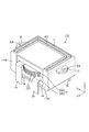
第1バスバー101は、U字状であって、例えば実施形態4のバスバー101と同じものを用いることができる。第2バスバー111は、第1バスバー101の外側を包囲する大きさであって、図23に示すように、一定の幅寸法でU字状に延びる本体部112と、本体部112に対して下方に突出する複数(本実施形態では4本)の接続部114とを備えている。本体部112は、平板状の第1板状部113Bと、第1板状部113Bの左右の端部から前方(直交する方向)に延びる平板状の一対の第2板状部113A,113Cとを有する。複数の接続部114は、第1板状部113Bの下端部に一体的に形成されており、第1板状部113Bの左右に設けられた一対の接続部114間の間隔は、一対の接続部42間の間隔よりも大きくされている。なお、バスバー111に流れる電流は例えばコンバータの昇降圧部のスイッチング電流とすることができる。本実施形態では、第1バスバー101と第2バスバー111とを逆位相で通電することにより、逆位相の電流による電磁ノイズを相互にキャンセルすることができる。なお、バスバー101,111の電流は逆位相に限られず、例えば同位相としてもよい。
The
Priority Applications (5)
| Application Number | Priority Date | Filing Date | Title |
|---|---|---|---|
| CN201880029796.XA CN110603616A (en) | 2017-05-23 | 2018-05-09 | Coil device, coil device with substrate, and electrical connection box |
| PCT/JP2018/017880 WO2018216466A1 (en) | 2017-05-23 | 2018-05-09 | Coil device, coil device with substrate, and electrical connection box |
| KR1020197034602A KR102315176B1 (en) | 2017-05-23 | 2018-05-09 | Coil device, coil device with substrate and electrical junction box |
| DE112018002658.2T DE112018002658T5 (en) | 2017-05-23 | 2018-05-09 | Coil device, coil device with circuit board and electrical distribution box |
| US16/615,795 US20200194159A1 (en) | 2017-05-23 | 2018-05-09 | Coil device, coil device with circuit board, and electrical junction box |
Applications Claiming Priority (2)
| Application Number | Priority Date | Filing Date | Title |
|---|---|---|---|
| JP2017101612 | 2017-05-23 | ||
| JP2017101612 | 2017-05-23 |
Publications (3)
| Publication Number | Publication Date |
|---|---|
| JP2018198304A JP2018198304A (en) | 2018-12-13 |
| JP2018198304A5 true JP2018198304A5 (en) | 2020-01-09 |
| JP6958164B2 JP6958164B2 (en) | 2021-11-02 |
Family
ID=64662586
Family Applications (1)
| Application Number | Title | Priority Date | Filing Date |
|---|---|---|---|
| JP2017181115A Active JP6958164B2 (en) | 2017-05-23 | 2017-09-21 | Coil device, coil device with substrate and electrical junction box |
Country Status (5)
| Country | Link |
|---|---|
| US (1) | US20200194159A1 (en) |
| JP (1) | JP6958164B2 (en) |
| KR (1) | KR102315176B1 (en) |
| CN (1) | CN110603616A (en) |
| DE (1) | DE112018002658T5 (en) |
Families Citing this family (10)
| Publication number | Priority date | Publication date | Assignee | Title |
|---|---|---|---|---|
| JP2018164324A (en) * | 2017-03-24 | 2018-10-18 | 株式会社オートネットワーク技術研究所 | Electric connection box |
| JP6740959B2 (en) * | 2017-05-17 | 2020-08-19 | 株式会社オートネットワーク技術研究所 | Circuit device |
| JP6988432B2 (en) * | 2017-12-18 | 2022-01-05 | 株式会社デンソー | Reactor unit |
| JP6948013B2 (en) * | 2018-06-11 | 2021-10-13 | 住友電装株式会社 | Electrical junction box |
| WO2019245148A1 (en) * | 2018-06-20 | 2019-12-26 | 엘지이노텍 주식회사 | Converter |
| JP7127498B2 (en) * | 2018-11-09 | 2022-08-30 | 住友電装株式会社 | Heat dissipation material and electric connection box |
| US20210134510A1 (en) * | 2019-10-31 | 2021-05-06 | Analog Devices International Unlimited Company | Electronic device |
| JP7255453B2 (en) * | 2019-11-06 | 2023-04-11 | 株式会社オートネットワーク技術研究所 | circuit construct |
| JP7352833B2 (en) * | 2020-01-30 | 2023-09-29 | 株式会社オートネットワーク技術研究所 | circuit construct |
| FR3130082A1 (en) * | 2021-12-07 | 2023-06-09 | Valeo Systemes De Controle Moteur | Electric component for electric machine |
Family Cites Families (21)
| Publication number | Priority date | Publication date | Assignee | Title |
|---|---|---|---|---|
| JPS5393622U (en) * | 1976-12-28 | 1978-07-31 | ||
| US4658091A (en) * | 1985-04-04 | 1987-04-14 | Motorola, Inc. | Inductor housing |
| JPH0515036A (en) * | 1991-07-04 | 1993-01-22 | Fujikura Ltd | Electric connection box |
| US5226220A (en) * | 1991-12-19 | 1993-07-13 | Allied-Signal Inc. | Method of making a strain relief for magnetic device lead wires |
| JPH08130127A (en) * | 1994-06-15 | 1996-05-21 | Nippondenso Co Ltd | High voltage transformer and discharge lamp circuit |
| US8669838B2 (en) * | 2012-07-03 | 2014-03-11 | Chicony Power Technology Co., Ltd. | Transformer having assembled bobbins and voltage transformation module having the transformer |
| US10044018B2 (en) * | 2013-09-06 | 2018-08-07 | Johnson Controls Technology Company | Battery module lid assembly system and method of making the same |
| US9559508B2 (en) * | 2013-10-10 | 2017-01-31 | Hamilton Sundstrand Corporation | Housings with embedded bus bars and standoffs |
| JP2015201260A (en) * | 2014-04-04 | 2015-11-12 | 矢崎総業株式会社 | connector device |
| JP6187380B2 (en) * | 2014-05-09 | 2017-08-30 | 株式会社オートネットワーク技術研究所 | Circuit assembly and electrical junction box |
| JP2016119798A (en) * | 2014-12-22 | 2016-06-30 | 株式会社オートネットワーク技術研究所 | Circuit structure and electric connection box |
| JP6252871B2 (en) * | 2015-01-16 | 2017-12-27 | 株式会社オートネットワーク技術研究所 | Circuit structure and electrical junction box |
| US9985265B2 (en) * | 2015-04-13 | 2018-05-29 | Johnson Controls Technology Company | Flexible ribs of a bus bar carrier |
| KR101590132B1 (en) * | 2015-07-31 | 2016-02-01 | 삼성전기주식회사 | Transformer and plate coil shaped parts |
| JP2017084927A (en) * | 2015-10-27 | 2017-05-18 | 株式会社オートネットワーク技術研究所 | Coil assembly and electric connection box |
| JP6183440B2 (en) * | 2015-11-20 | 2017-08-23 | 株式会社安川電機 | Power converter and noise filter |
| JP2017123733A (en) * | 2016-01-07 | 2017-07-13 | 住友電装株式会社 | Electric connection box |
| US11104282B2 (en) * | 2016-03-10 | 2021-08-31 | Autonetworks Technologies, Ltd. | Circuit assembly |
| JP6604289B2 (en) * | 2016-08-30 | 2019-11-13 | 株式会社オートネットワーク技術研究所 | Electrical junction box |
| JP6556114B2 (en) * | 2016-12-27 | 2019-08-07 | コーセル株式会社 | Switching power supply |
| JP2018117012A (en) * | 2017-01-17 | 2018-07-26 | 株式会社オートネットワーク技術研究所 | Multi-stage coil and circuit component |
-
2017
- 2017-09-21 JP JP2017181115A patent/JP6958164B2/en active Active
-
2018
- 2018-05-09 DE DE112018002658.2T patent/DE112018002658T5/en active Pending
- 2018-05-09 CN CN201880029796.XA patent/CN110603616A/en active Pending
- 2018-05-09 US US16/615,795 patent/US20200194159A1/en not_active Abandoned
- 2018-05-09 KR KR1020197034602A patent/KR102315176B1/en active IP Right Grant
Similar Documents
| Publication | Publication Date | Title |
|---|---|---|
| JP2018198304A5 (en) | ||
| JP2015226438A5 (en) | ||
| EP2704292B1 (en) | Feed apparatus, current collector, and power transfer apparatus of the magnetic induction type, considering lateral deviation | |
| JP2014533487A5 (en) | ||
| TW201405596A (en) | Three-phase reactor | |
| JP2016507147A5 (en) | ||
| JP2009195104A5 (en) | ||
| TW200714121A (en) | Drum heater systems and methods | |
| JP2012204774A5 (en) | ||
| JP2020060457A5 (en) | ||
| JP2010118650A5 (en) | Semiconductor device | |
| JP2015149863A (en) | Stator of rotary electric machine | |
| JP6160378B2 (en) | DC-DC converter device | |
| US10450705B2 (en) | Magnetic levitation train system | |
| JP2017045521A5 (en) | ||
| JP2019029204A5 (en) | ||
| JP2016092842A (en) | Linear motor reducing cogging torque | |
| JP2013256862A5 (en) | ||
| JP2019032990A5 (en) | ||
| JP2016503278A5 (en) | ||
| WO2015140266A3 (en) | Hybrid electric machine | |
| JP2009165278A (en) | Semiconductor circuit | |
| CN204303375U (en) | Medium-and-large-sized DC motor brush rack lead wire flexible connecting structure | |
| JP2012120269A5 (en) | ||
| JP2021065061A5 (en) |