JP2018185263A - silo - Google Patents
silo Download PDFInfo
- Publication number
- JP2018185263A JP2018185263A JP2017088226A JP2017088226A JP2018185263A JP 2018185263 A JP2018185263 A JP 2018185263A JP 2017088226 A JP2017088226 A JP 2017088226A JP 2017088226 A JP2017088226 A JP 2017088226A JP 2018185263 A JP2018185263 A JP 2018185263A
- Authority
- JP
- Japan
- Prior art keywords
- coal
- side wall
- silo
- measuring cable
- temperature measuring
- Prior art date
- Legal status (The legal status is an assumption and is not a legal conclusion. Google has not performed a legal analysis and makes no representation as to the accuracy of the status listed.)
- Granted
Links
- 239000003245 coal Substances 0.000 abstract description 85
- 230000020169 heat generation Effects 0.000 abstract description 19
- 238000001514 detection method Methods 0.000 description 7
- 229910001220 stainless steel Inorganic materials 0.000 description 6
- 239000010935 stainless steel Substances 0.000 description 6
- 238000000034 method Methods 0.000 description 5
- 238000009529 body temperature measurement Methods 0.000 description 4
- 238000012986 modification Methods 0.000 description 4
- 230000004048 modification Effects 0.000 description 4
- 238000005192 partition Methods 0.000 description 4
- 206010037660 Pyrexia Diseases 0.000 description 2
- 239000002028 Biomass Substances 0.000 description 1
- 238000006243 chemical reaction Methods 0.000 description 1
- 238000004590 computer program Methods 0.000 description 1
- 239000000470 constituent Substances 0.000 description 1
- 238000010586 diagram Methods 0.000 description 1
- 238000007599 discharging Methods 0.000 description 1
- 230000012447 hatching Effects 0.000 description 1
- 238000012544 monitoring process Methods 0.000 description 1
- 238000007254 oxidation reaction Methods 0.000 description 1
- 238000012545 processing Methods 0.000 description 1
- 239000004449 solid propellant Substances 0.000 description 1
- 230000002269 spontaneous effect Effects 0.000 description 1
Images


Classifications
-
- A—HUMAN NECESSITIES
- A01—AGRICULTURE; FORESTRY; ANIMAL HUSBANDRY; HUNTING; TRAPPING; FISHING
- A01F—PROCESSING OF HARVESTED PRODUCE; HAY OR STRAW PRESSES; DEVICES FOR STORING AGRICULTURAL OR HORTICULTURAL PRODUCE
- A01F25/00—Storing agricultural or horticultural produce; Hanging-up harvested fruit
-
- B—PERFORMING OPERATIONS; TRANSPORTING
- B65—CONVEYING; PACKING; STORING; HANDLING THIN OR FILAMENTARY MATERIAL
- B65D—CONTAINERS FOR STORAGE OR TRANSPORT OF ARTICLES OR MATERIALS, e.g. BAGS, BARRELS, BOTTLES, BOXES, CANS, CARTONS, CRATES, DRUMS, JARS, TANKS, HOPPERS, FORWARDING CONTAINERS; ACCESSORIES, CLOSURES, OR FITTINGS THEREFOR; PACKAGING ELEMENTS; PACKAGES
- B65D90/00—Component parts, details or accessories for large containers
- B65D90/48—Arrangements of indicating or measuring devices
-
- G—PHYSICS
- G01—MEASURING; TESTING
- G01K—MEASURING TEMPERATURE; MEASURING QUANTITY OF HEAT; THERMALLY-SENSITIVE ELEMENTS NOT OTHERWISE PROVIDED FOR
- G01K13/00—Thermometers specially adapted for specific purposes
- G01K13/10—Thermometers specially adapted for specific purposes for measuring temperature within piled or stacked materials
-
- G—PHYSICS
- G01—MEASURING; TESTING
- G01K—MEASURING TEMPERATURE; MEASURING QUANTITY OF HEAT; THERMALLY-SENSITIVE ELEMENTS NOT OTHERWISE PROVIDED FOR
- G01K7/00—Measuring temperature based on the use of electric or magnetic elements directly sensitive to heat ; Power supply therefor, e.g. using thermoelectric elements
- G01K7/02—Measuring temperature based on the use of electric or magnetic elements directly sensitive to heat ; Power supply therefor, e.g. using thermoelectric elements using thermoelectric elements, e.g. thermocouples
Abstract
Description
本発明は、サイロに関し、特に石炭を貯蔵する石炭サイロに関する。 The present invention relates to a silo, and more particularly to a coal silo for storing coal.
石炭火力発電所等に設置される石炭サイロでは、石炭の貯蔵期間が長くなると石炭サイロ内で石炭が酸化発熱して自然発火が生じる場合がある。そこで、石炭サイロ内に貯蔵された石炭の発熱を監視し、発熱が発生した場合には石炭の払い出しや放水を行って発熱箇所の冷却を行っている。 In a coal silo installed in a coal-fired power plant or the like, if the storage period of the coal becomes long, the coal may oxidize and generate heat in the coal silo and spontaneous ignition may occur. Therefore, the heat generation of the coal stored in the coal silo is monitored, and when the heat generation occurs, the coal is discharged or discharged to cool the heat generation portion.
従来、石炭サイロ内に貯蔵された石炭の発熱を監視するために、熱電対を備えた測温ケーブルを石炭サイロの略中央部分に吊り下げて貯蔵石炭中に埋め込み、該熱電対からの信号を検出することにより、石炭の発熱を監視する方法が知られている(例えば特許文献1参照)。 Conventionally, in order to monitor the heat generation of coal stored in a coal silo, a temperature measuring cable equipped with a thermocouple is suspended in a substantially central portion of the coal silo and embedded in the stored coal, and a signal from the thermocouple is received. A method for monitoring the heat generation of coal by detection is known (see, for example, Patent Document 1).
しかしながら、上記のような方法の場合、石炭の出し入れに伴い測温ケーブルの熱電対の位置が変わり、発熱の生じやすい箇所の温度測定を行うことが難しい可能性やできない可能性がある。 However, in the case of the method as described above, the position of the thermocouple of the temperature measuring cable changes with the taking in and out of the coal, and it may be difficult or impossible to measure the temperature at a place where heat generation is likely to occur.
本発明は、こうした状況を鑑みてなされたものであり、その目的は、サイロ内の貯蔵物の発熱を適切に検知できる技術を提供することにある。 This invention is made | formed in view of such a condition, The objective is to provide the technique which can detect the heat_generation | fever of the storage thing in a silo appropriately.
上記課題を解決するために、本発明のある態様のサイロは、基礎上に立設された側壁と、貯蔵された貯蔵物の発熱を検出するための温度センサとを備える。温度センサは、側壁の近傍の貯蔵物中に埋設される。 In order to solve the above-described problems, a silo according to an aspect of the present invention includes a side wall erected on a foundation and a temperature sensor for detecting heat generation of a stored product. The temperature sensor is embedded in the storage near the side wall.
温度センサは、側壁の近傍に垂下されるケーブルに設けられていてもよい。 The temperature sensor may be provided in a cable that hangs in the vicinity of the side wall.
ケーブルは、側壁に設けられた滑車を介して、側壁の近傍に垂下されてもよい。 The cable may be hung near the side wall via a pulley provided on the side wall.
貯蔵物の発熱時に生じたガスを検知するためのガスパイプがケーブルに設けられてもよい。 The cable may be provided with a gas pipe for detecting gas generated when the stored item is heated.
なお、以上の構成要素の任意の組合せ、本発明の表現を方法、装置、システム、記録媒体、コンピュータプログラムなどの間で変換したものもまた、本発明の態様として有効である。 It should be noted that any combination of the above-described constituent elements and a conversion of the expression of the present invention between a method, an apparatus, a system, a recording medium, a computer program, etc. are also effective as an aspect of the present invention.
本発明によれば、サイロ内の貯蔵物の発熱を適切に検知できる。 ADVANTAGE OF THE INVENTION According to this invention, the heat_generation | fever of the stored item in a silo can be detected appropriately.
図1は、本発明の実施形態に係る石炭サイロ100の構成を説明するための図である。
FIG. 1 is a diagram for explaining a configuration of a
石炭サイロ100は、例えば、内径60m、高さ75m、石炭容量10万トンの大型のものであってよい。
The
図1に示すように、石炭サイロ100は、基礎102と、基礎102上に立設された側壁104と、側壁104の上に形成された屋根106とを備える。石炭サイロ100内には石炭120が貯蔵される。側壁104は、略円筒形状の下部側壁104aと、下部側壁104aの上に形成された略円錐台形状の上部側壁104bとから成る。
As shown in FIG. 1, the
石炭サイロ100の上部には積付所ステージ108が設けられている。積付所ステージ108には、石炭を搬入するための搬入コンベヤ110が設けられている。搬入コンベヤ110によって運ばれた石炭は、積付所ステージ108から落下されて石炭サイロ100内に貯蔵される。
At the upper part of the
石炭サイロ100の底部には、複数の小コーン(小仕切板、小仕切壁)112と、複数の大コーン(大仕切板、大仕切壁)114が設けられている。小コーン112の下方には、搬出コンベヤ116が設けられている。石炭サイロ100内に貯蔵された石炭120は、底部に設けられた開口部から搬出コンベヤ116に払い出され、搬出コンベヤ116によって石炭サイロ100の外に搬出される。
At the bottom of the
石炭サイロ100は、貯蔵された石炭120の発熱を検出するための温度センサを備える。本実施形態の石炭サイロ100は、貯蔵された石炭中の温度を検出するための測温ケーブル10を備える。
測温ケーブル10は、内部に温度センサとして熱電対を備える。測温ケーブル10の一端10aは、積付所ステージ108の下面に固定される。測温ケーブル10は、積付所ステージ108から上部側壁104bに沿って斜め下方に延び、上部側壁104bと下部側壁104aの境界部付近に設けられた滑車12を介して下部側壁104aの近傍に垂下され、下部側壁104aの近傍の石炭中に埋設されている。
The
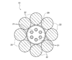
図2は、測温ケーブル10の構造を説明するための概略断面図である。図2に示すように、ステンレスフレキシブルチューブ20内に6本のシース熱電対21が挿通されており、さらにステンレスフレキシブルチューブ20を外周に複数本のワイヤーロープ22が巻回されている。このようにシース熱電対21をステンレスフレキシブルチューブ20で保護し、さらにステンレスフレキシブルチューブ20をワイヤーロープ22で覆うことにより、石炭とシース熱電対21が直接接触してシース熱電対21が破損するのを防ぐことができる。6本のシース熱電対21は、その先端までの長さがそれぞれ異なっており、石炭サイロ100の高さ方向において等間隔で6箇所の温度を測定できるようになっている。
FIG. 2 is a schematic cross-sectional view for explaining the structure of the
図3は、石炭サイロ100内に石炭を長期間貯蔵したときの石炭温度分布の一例を示す。図3ではハッチングにより石炭の温度を表している。また、図3中の破線で示す測温ケーブル30は、石炭サイロの略中央部分に吊り下げた従来の測温ケーブルの配置例を示す。
FIG. 3 shows an example of a coal temperature distribution when coal is stored in the
図3から、石炭サイロ100の側壁104(下部側壁104a)の近傍に位置する石炭に発熱が生じやすいことが分かる。石炭サイロ100では、石炭を搬出コンベヤ116に払い出すために底部に設けられた開口部から空気が上方に流れ、この空気により石炭が酸化されて発熱が生じる(図3において矢印は空気の流れを表す)。石炭サイロ100で上方から石炭を落下させて貯蔵する場合、側壁104の近傍には大きな石炭塊が偏って位置しやすいため、側壁104の近傍は空隙が多く空気の流れが速くなる。その結果、側壁104の近傍に位置する石炭は酸化反応が促進されやすく、発熱が生じやすい。
From FIG. 3, it can be seen that the coal located near the side wall 104 (
図3中に破線で示す従来のように測温ケーブル30を石炭サイロの略中央部分に吊り下げた場合、石炭の出し入れに伴って熱電対の位置が変わり、発熱の生じやすい箇所の温度測定を行うことが難しい可能性がある。すなわち、測温ケーブル中の熱電対の位置は安定せず、偶然に左右されるということである。例えば測温ケーブル内の熱電対が側壁の近傍に位置すれば発熱の生じやすい箇所(例えば図3で80℃や89℃以上の箇所)の温度測定を行うことができるが、熱電対が石炭サイロの中央部分に位置すれば発熱があまり生じない箇所(例えば図3で30℃の箇所)の温度を測定していることになる。
When the
一方、本実施形態に係る石炭サイロ100では、測温ケーブル10が側壁104の近傍に垂下されているので、発熱が生じやすい側壁104の近傍の石炭の温度を適切に検知することができる。石炭の出し入れに応じて多少、測温ケーブル10の位置が変動することはあるが、石炭サイロの略中央部分に吊り下げた場合と比べればその変動は小さい。
On the other hand, in the
本実施形態で用いているような吊り下げ式の測温ケーブル10では、石炭の出し入れに伴って、測温ケーブル10と石炭との間に下向きの摩擦力が生じる。従来のように石炭サイロの略中央部分に吊り下げた場合、積付所ステージ108に過度の荷重が作用するおそれがある。
In the suspended
一方、本実施形態に係る石炭サイロ100では、測温ケーブル10は滑車12を介して吊り下げられているので、測温ケーブル10と石炭との間に生じる下向きの摩擦力が積付所ステージ108と滑車12とに分散される。その結果、積付所ステージ108に作用する荷重を軽減することができる。
On the other hand, in the
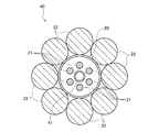
図4は、測温ケーブルの変形例を説明するための概略断面図である。図4に示す測温ケーブル40において、図2に示す測温ケーブル10と同一または対応する構成要素には同一の符号を付し、重複する説明は適宜省略する。
FIG. 4 is a schematic cross-sectional view for explaining a modification of the temperature measuring cable. In the
図4に示す測温ケーブル40は、ステンレスフレキシブルチューブ20内にシース熱電対21に加えてガスパイプ41が挿通されている点が図2に示す測温ケーブル10と異なる。このガスパイプ41は、石炭の発熱時に生じるガスを検知するためのものである。ガスパイプ41内に入ったガスは、ガスパイプ41内を通って例えば積付所ステージ108上に設けられたガスセンサ(図示せず)により検知される。このように、シース熱電対21による温度検知に加えて、ガス検知を行う構成とすることにより、例えば一方のセンサが故障した場合などでも、温度センサによる温度検知とガスセンサによるガス検知とのいずれか一方に基づいて石炭の発熱を検出することもできるし、温度センサによる温度検知とガスセンサによるガス検知との両方に基づいて石炭の発熱を検出することによって、石炭の発熱をより高い精度で検出することもできる。
The
以上、本発明を実施例をもとに説明した。この実施例は例示であり、それらの各構成要素や各処理プロセスの組合せにいろいろな変形例が可能なこと、またそうした変形例も本発明の範囲にあることは当業者に理解されるところである。 In the above, this invention was demonstrated based on the Example. This embodiment is an exemplification, and it will be understood by those skilled in the art that various modifications can be made to the combination of each component and each processing process, and such modifications are also within the scope of the present invention. .
上述の実施形態の石炭サイロ100では、測温ケーブル10は滑車12を介して吊り下げられているものとしたが、滑車12に代えて、例えば釣り針状などの吊り具(フック)を用いるものとしてもよい。
In the
上述の実施形態の石炭サイロ100は、側壁104が略円筒形状の下部側壁104aと略円錐台形状の上部側壁104bとから成るものとしたが、本発明の石炭サイロはいかなる形状としてもよい。例えば、搬入コンベヤや搬出コンベヤによる石炭の搬入出方向を長手方向とする略直方体形状の石炭サイロとしてもよい。また、搬出コンベヤ116は、並列に4本設けられているものとしたが、1本や2本設けられているものとしても構わない。
In the
上述の実施形態では、石炭を貯蔵する石炭サイロを例として本発明を説明した。しかしながら、本発明は石炭サイロに限定されず、例えば、穀物サイロ、バイオマスサイロ、リサイクル固形燃料サイロ等の他のサイロにも適用可能である。 In the above-described embodiment, the present invention has been described using a coal silo that stores coal as an example. However, the present invention is not limited to coal silos, and can be applied to other silos such as grain silos, biomass silos, and recycled solid fuel silos.
10、30 測温ケーブル、 12 滑車、 20 ステンレスフレキシブルチューブ、 21 シース熱電対、 22 ワイヤーロープ、 40 測温ケーブル、 41 ガスパイプ、 100 石炭サイロ、 102 基礎、 104 側壁、 106 屋根、 108 積付所ステージ、 110 搬入コンベヤ、 112 小コーン、 114 大コーン、 116 搬出コンベヤ、 120 石炭。 10, 30 temperature measurement cable, 12 pulley, 20 stainless steel flexible tube, 21 sheathed thermocouple, 22 wire rope, 40 temperature measurement cable, 41 gas pipe, 100 coal silo, 102 foundation, 104 side wall, 106 roof, 108 loading station stage , 110 carry-in conveyor, 112 small cone, 114 large cone, 116 carry-out conveyor, 120 coal.
Claims (4)
貯蔵された貯蔵物の発熱を検出するための温度センサと、
を備え、
前記温度センサは、前記側壁の近傍の貯蔵物中に埋設されることを特徴とするサイロ。 Side walls erected on the foundation;
A temperature sensor for detecting the exotherm of the stored product;
With
The silo, wherein the temperature sensor is embedded in a storage near the side wall.
Priority Applications (2)
| Application Number | Priority Date | Filing Date | Title |
|---|---|---|---|
| JP2017088226A JP6864540B2 (en) | 2017-04-27 | 2017-04-27 | silo |
| PCT/JP2018/015753 WO2018198865A1 (en) | 2017-04-27 | 2018-04-16 | Silo |
Applications Claiming Priority (1)
| Application Number | Priority Date | Filing Date | Title |
|---|---|---|---|
| JP2017088226A JP6864540B2 (en) | 2017-04-27 | 2017-04-27 | silo |
Publications (2)
| Publication Number | Publication Date |
|---|---|
| JP2018185263A true JP2018185263A (en) | 2018-11-22 |
| JP6864540B2 JP6864540B2 (en) | 2021-04-28 |
Family
ID=63918288
Family Applications (1)
| Application Number | Title | Priority Date | Filing Date |
|---|---|---|---|
| JP2017088226A Active JP6864540B2 (en) | 2017-04-27 | 2017-04-27 | silo |
Country Status (2)
| Country | Link |
|---|---|
| JP (1) | JP6864540B2 (en) |
| WO (1) | WO2018198865A1 (en) |
Cited By (1)
| Publication number | Priority date | Publication date | Assignee | Title |
|---|---|---|---|---|
| KR102076107B1 (en) * | 2019-02-22 | 2020-02-11 | (주)아이스메카텍 | Thermocouple replacement type with minimized measurement error due to slip prevention and heat resistance Fire monitoring and suppression unit |
Family Cites Families (5)
| Publication number | Priority date | Publication date | Assignee | Title |
|---|---|---|---|---|
| JPS5969945U (en) * | 1982-11-02 | 1984-05-12 | 株式会社竹中工務店 | Coal storage silo abnormality monitoring and control device |
| JPS63206617A (en) * | 1987-02-23 | 1988-08-25 | Chino Corp | Temperature and level measuring instrument |
| JP3798738B2 (en) * | 2002-07-04 | 2006-07-19 | 電源開発株式会社 | Heat generation / ignition prevention agent and prevention method |
| JP2007271289A (en) * | 2006-03-30 | 2007-10-18 | Kurimoto Ltd | Device for measuring temperature in reservoir tank |
| JP4958701B2 (en) * | 2007-09-12 | 2012-06-20 | 株式会社神戸製鋼所 | Temperature measuring cable for coal silo and manufacturing method thereof |
-
2017
- 2017-04-27 JP JP2017088226A patent/JP6864540B2/en active Active
-
2018
- 2018-04-16 WO PCT/JP2018/015753 patent/WO2018198865A1/en active Application Filing
Cited By (1)
| Publication number | Priority date | Publication date | Assignee | Title |
|---|---|---|---|---|
| KR102076107B1 (en) * | 2019-02-22 | 2020-02-11 | (주)아이스메카텍 | Thermocouple replacement type with minimized measurement error due to slip prevention and heat resistance Fire monitoring and suppression unit |
Also Published As
| Publication number | Publication date |
|---|---|
| JP6864540B2 (en) | 2021-04-28 |
| WO2018198865A1 (en) | 2018-11-01 |
Similar Documents
| Publication | Publication Date | Title |
|---|---|---|
| WO2018198869A1 (en) | Heating monitoring system of stored product, heating monitoring method of stored product, and silo | |
| WO2018198870A1 (en) | Heating monitoring system of stored product, and silo | |
| JP6580686B2 (en) | Tube reactor | |
| WO2018198865A1 (en) | Silo | |
| JP2009174032A (en) | Method and apparatus for detecting calcinating point in sintering machine | |
| CN203053604U (en) | Coal storage bunker temperature all-directional monitoring system | |
| JP2014118987A (en) | In-gas-holder piston monitor and in-gas-holder piston monitoring method | |
| JP3404976B2 (en) | Conveyor temperature monitoring device | |
| JP3256889B2 (en) | Fire detection method | |
| JP5274511B2 (en) | Coal storage equipment | |
| JP2018185262A (en) | Coal heat generation monitoring system, method for monitoring heat generation of coal, and coal silo | |
| CN202670535U (en) | Silo | |
| KR20130060727A (en) | Inside temperature sencer of coal silo | |
| JPH11125690A (en) | Multiple sheath type sodium leak detector | |
| JP2008101933A (en) | Surface temperature measuring method for steel structure | |
| JP5405388B2 (en) | Coal storage facility | |
| JP6775903B2 (en) | Silo temperature measurement system and silo temperature measurement method | |
| JP2011241052A (en) | Device and method for storing coal | |
| JP3835186B2 (en) | How to determine maintenance status and operability of bulk load container | |
| Yatsukh et al. | Analysisof Riskof Self-Ignition Grain Products During Storage | |
| CN109211431A (en) | Distributed fiber optic temperature monitoring method and system | |
| JP2006097112A (en) | Method for deciding dry state of refractory, dry state supervising unit, and method for controlling refractory arrangement work | |
| JP3482568B2 (en) | Fire detection method | |
| JPS6318629Y2 (en) | ||
| JP2604254Y2 (en) | Piping |
Legal Events
| Date | Code | Title | Description |
|---|---|---|---|
| A621 | Written request for application examination |
Free format text: JAPANESE INTERMEDIATE CODE: A621 Effective date: 20190617 |
|
| A131 | Notification of reasons for refusal |
Free format text: JAPANESE INTERMEDIATE CODE: A131 Effective date: 20200804 |
|
| A521 | Request for written amendment filed |
Free format text: JAPANESE INTERMEDIATE CODE: A523 Effective date: 20201005 |
|
| TRDD | Decision of grant or rejection written | ||
| A01 | Written decision to grant a patent or to grant a registration (utility model) |
Free format text: JAPANESE INTERMEDIATE CODE: A01 Effective date: 20210323 |
|
| A61 | First payment of annual fees (during grant procedure) |
Free format text: JAPANESE INTERMEDIATE CODE: A61 Effective date: 20210402 |
|
| R150 | Certificate of patent or registration of utility model |
Ref document number: 6864540 Country of ref document: JP Free format text: JAPANESE INTERMEDIATE CODE: R150 |
|
| R250 | Receipt of annual fees |
Free format text: JAPANESE INTERMEDIATE CODE: R250 |