JP2018128564A - Image forming apparatus and conveyance control method - Google Patents
Image forming apparatus and conveyance control method Download PDFInfo
- Publication number
- JP2018128564A JP2018128564A JP2017021144A JP2017021144A JP2018128564A JP 2018128564 A JP2018128564 A JP 2018128564A JP 2017021144 A JP2017021144 A JP 2017021144A JP 2017021144 A JP2017021144 A JP 2017021144A JP 2018128564 A JP2018128564 A JP 2018128564A
- Authority
- JP
- Japan
- Prior art keywords
- nip
- paper
- conveyance
- transfer
- transport
- Prior art date
- Legal status (The legal status is an assumption and is not a legal conclusion. Google has not performed a legal analysis and makes no representation as to the accuracy of the status listed.)
- Granted
Links
Images

Landscapes
- Paper Feeding For Electrophotography (AREA)
- Electrostatic Charge, Transfer And Separation In Electrography (AREA)
- Control Or Security For Electrophotography (AREA)
- Delivering By Means Of Belts And Rollers (AREA)
Abstract
【課題】転写ニップと搬送ローラー対との間における用紙の弛みに起因した転写ニップにおける画像不良の発生を抑制することが可能な画像形成装置および搬送制御方法を提供する。【解決手段】画像形成装置は、転写部と、搬送ローラー対と、搬送ローラー対により形成された搬送ニップまで搬送された用紙を所定のニップ圧で搬送し、かつ、搬送ニップにおける用紙の搬送速度を転写ニップにおける用紙の搬送速度よりも速くする制御を行うことにより、転写ニップと搬送ニップとの間で用紙に弛みを生じさせる制御部と、を備え、制御部は、搬送ニップにおける用紙の搬送量の増加に応じて、搬送ニップにおける用紙の搬送速度に対する転写ニップにおける用紙の搬送速度の差分を小さくする搬送速度変更処理と、搬送ニップにおけるニップ圧を減少させるニップ圧変更処理との少なくとも一方を実行させる。【選択図】図2PROBLEM TO BE SOLVED: To provide an image forming apparatus and a transfer control method capable of suppressing the occurrence of image defects in a transfer nip due to looseness of paper between a transfer nip and a transfer roller pair. An image forming apparatus conveys paper conveyed to a transfer unit, a transfer roller pair, and a transfer nip formed by the transfer roller pair at a predetermined nip pressure, and the transfer speed of the paper at the transfer nip. The control unit is provided with a control unit that causes the paper to slacken between the transfer nip and the transfer nip by controlling the speed of the transfer of the paper to be faster than the transfer speed of the paper at the transfer nip. At least one of a transfer speed change process that reduces the difference between the paper transfer rate at the transfer nip and the paper transfer rate at the transfer nip and a nip pressure change process that reduces the nip pressure at the transfer nip according to the increase in the amount. Let it run. [Selection diagram] Fig. 2
Description
本発明は、画像形成装置および搬送制御方法に関する。 The present invention relates to an image forming apparatus and a conveyance control method.
一般に、電子写真プロセス技術を利用した画像形成装置(プリンター、複写機、ファクシミリ等)は、帯電した感光体ドラム(像担持体)に対して、画像データに基づくレーザー光を照射(露光)することにより静電潜像を形成する。そして、静電潜像が形成された感光体ドラムへ現像装置よりトナーを供給することにより静電潜像を可視化してトナー像を形成する。さらに、このトナー像を直接または間接的に用紙に転写させた後、定着ニップで加熱、加圧して定着させることにより用紙にトナー像を形成する。 In general, an image forming apparatus (printer, copying machine, facsimile, etc.) using an electrophotographic process technology irradiates (exposes) a charged photosensitive drum (image carrier) with laser light based on image data. To form an electrostatic latent image. Then, by supplying toner from the developing device to the photosensitive drum on which the electrostatic latent image is formed, the electrostatic latent image is visualized to form a toner image. Further, after the toner image is directly or indirectly transferred to the sheet, the toner image is formed on the sheet by fixing it by heating and pressing at the fixing nip.
用紙に画像を転写させる転写ニップの上流側には、搬送ローラー対として、例えばレジストローラー対が設けられる(例えば、特許文献1参照)。レジストローラー対に用紙が挟持されると、転写ニップに用紙の先端が突入する前にレジストローラー対が幅方向に移動して用紙を移動させることにより、用紙の幅方向における位置を補正する。 On the upstream side of the transfer nip for transferring an image onto a sheet, for example, a pair of conveying rollers is provided as a pair of conveying rollers (see, for example, Patent Document 1). When the sheet is sandwiched between the registration roller pair, the registration roller pair moves in the width direction and moves the sheet before the leading edge of the sheet enters the transfer nip, thereby correcting the position in the width direction of the sheet.
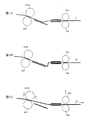
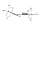
また、一般に、レジストローラー対における用紙の搬送速度は、転写ニップにおける用紙の搬送速度よりも速く設定される。このようにすることで、図1Aに示すように、転写ニップ(ローラー423B,424に挟持される部分)とレジストローラー対53aとの間において、用紙Sに弛みが生じる。
In general, the sheet conveyance speed at the registration roller pair is set to be higher than the sheet conveyance speed at the transfer nip. By doing so, as shown in FIG. 1A, the sheet S is slackened between the transfer nip (portion between the
転写ニップと、レジストローラー対53aとのレジスト転写間や、定着ニップと転写ニップとの定着転写間においては、ローラーの径の差異による搬送速度の差異や、アライメントの差による搬送速度の差異がある。この搬送速度の差異に起因してレジスト転写間や定着転写間において用紙Sの引っ張り合いが生じ、ひいては画像不良が発生する。そのため、レジスト転写間等において用紙Sに弛みを生じさせたり、定着部における搬送速度を制御して、定着転写間において用紙Sに弛みを生じさせることにより、当該画像不良の発生を抑制する。
Between the resist transfer between the transfer nip and the
ところで、A3サイズより大きい長さを有する長尺紙に画像形成する場合、長尺紙の長さが長くなるほど、用紙Sの搬送量が増える。そのため、ローラーの径の差異やアライメント差による搬送速度の差異による画像不良抑制のため、転写ニップにおける搬送速度とレジストローラー対53aにおける搬送速度に差異を持たせると、図1Bに示すように、長尺紙S1の弛みが非長尺紙の場合(図1A参照)よりも大きくなってしまう。
By the way, when an image is formed on a long paper having a length larger than the A3 size, the transport amount of the paper S increases as the length of the long paper increases. Therefore, in order to suppress image defects due to differences in roller diameters and differences in conveyance speed due to alignment differences, if there is a difference between the conveyance speed at the transfer nip and the conveyance speed at the
そのため、長尺紙S1の後端がレジストローラー対53aを通過したり、レジストローラー対53aを長尺紙S1の搬送途中で離間させたような場合、図1Cに示すように、長尺紙S1の戻り量が大きくなり、転写ニップにおいてショックノイズ等の画像不良が生じてしまうおそれがあった。
Therefore, when the trailing edge of the long paper S1 passes through the
本発明の目的は、転写ニップと搬送ローラー対との間における用紙の弛みに起因した転写ニップにおける画像不良の発生を抑制することが可能な画像形成装置および搬送制御方法を提供することである。 An object of the present invention is to provide an image forming apparatus and a conveyance control method capable of suppressing the occurrence of an image defect in a transfer nip due to a slack of paper between a transfer nip and a conveyance roller pair.
本発明に係る画像形成装置は、
用紙に画像を転写する転写ニップを形成する転写部と、
前記用紙の搬送方向における前記転写ニップよりも上流側に配置される搬送ローラー対と、
前記搬送ローラー対により形成された搬送ニップまで搬送された前記用紙を所定のニップ圧で搬送し、かつ、前記搬送ニップにおける前記用紙の搬送速度を前記転写ニップにおける前記用紙の搬送速度よりも速くする制御を行うことにより、前記転写ニップと前記搬送ニップとの間で前記用紙に弛みを生じさせる制御部と、
を備え、
前記制御部は、前記搬送ニップにおける前記用紙の搬送量の増加に応じて、前記搬送ニップにおける前記用紙の搬送速度に対する前記転写ニップにおける前記用紙の搬送速度の差分を小さくする搬送速度変更処理と、前記搬送ニップにおけるニップ圧を減少させるニップ圧変更処理との少なくとも一方を実行させる。
An image forming apparatus according to the present invention includes:
A transfer portion for forming a transfer nip for transferring an image to paper;
A pair of transport rollers disposed upstream of the transfer nip in the transport direction of the paper;
The paper transported to the transport nip formed by the transport roller pair is transported at a predetermined nip pressure, and the transport speed of the paper in the transport nip is faster than the transport speed of the paper in the transfer nip. A control unit that causes slack in the paper between the transfer nip and the transport nip by performing control;
With
The control unit is configured to change a conveyance speed change process for reducing a difference between the conveyance speed of the paper in the transfer nip with respect to the conveyance speed of the paper in the conveyance nip in response to an increase in the conveyance amount of the paper in the conveyance nip. At least one of the nip pressure changing process for reducing the nip pressure in the transport nip is executed.
本発明に係る搬送制御方法は、
用紙に画像を転写する転写ニップを形成する転写部と、
前記用紙の搬送方向における前記転写ニップよりも上流側に配置され、前記用紙の幅方向に移動して搬送中の前記用紙の位置を補正する搬送ローラー対と、を備える画像形成装置の搬送制御方法であって、
前記搬送ローラー対により形成された搬送ニップまで搬送された前記用紙を所定のニップ圧で搬送し、かつ、前記搬送ニップにおける前記用紙の搬送速度を前記転写ニップにおける前記用紙の搬送速度よりも速くする制御を行うことにより、前記転写ニップと前記搬送ニップとの間で前記用紙に弛みを生じさせ、
前記搬送ニップにおける前記用紙の搬送量の増加に応じて、前記搬送ニップにおける前記用紙の搬送速度に対する前記転写ニップにおける前記用紙の搬送速度の差分を小さくする搬送速度変更処理と、前記搬送ニップにおけるニップ圧を減少させるニップ圧変更処理との少なくとも一方を実行させる。
The conveyance control method according to the present invention includes:
A transfer portion for forming a transfer nip for transferring an image to paper;
A conveyance control method for an image forming apparatus, comprising: a conveyance roller pair that is disposed upstream of the transfer nip in the conveyance direction of the sheet and moves in the width direction of the sheet to correct the position of the sheet being conveyed. Because
The paper transported to the transport nip formed by the transport roller pair is transported at a predetermined nip pressure, and the transport speed of the paper in the transport nip is faster than the transport speed of the paper in the transfer nip. By performing the control, the paper is slackened between the transfer nip and the transport nip,
A conveyance speed changing process for reducing a difference in the conveyance speed of the sheet in the transfer nip with respect to the conveyance speed of the sheet in the conveyance nip according to an increase in the conveyance amount of the sheet in the conveyance nip; and a nip in the conveyance nip. At least one of the nip pressure changing process for decreasing the pressure is executed.
本発明によれば、転写ニップと搬送ローラー対との間における用紙の弛みに起因した転写ニップにおける画像不良の発生を抑制することができる。 According to the present invention, it is possible to suppress the occurrence of image defects in the transfer nip due to the slack of the paper between the transfer nip and the transport roller pair.
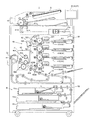
以下、本実施の形態を図面に基づいて詳細に説明する。図2は、本実施の形態における画像形成装置1の全体構成を概略的に示す図である。図3は、本実施の形態における画像形成装置1の制御系の主要部を示す。
Hereinafter, the present embodiment will be described in detail with reference to the drawings. FIG. 2 is a diagram schematically showing the overall configuration of the
本実施の形態の画像形成装置1は、用紙Sとして長尺紙または非長尺紙を使用し、当該用紙Sに画像を形成する。
The
本実施の形態において、長尺紙は、一般に良く用いられるA4サイズ、A3サイズ等の用紙よりも搬送方向の長さが長い枚葉紙であり、機内の給紙トレイユニット51a〜51cに収容できない長さを有する。以下、単に「用紙」という場合、長尺紙および非長尺紙の両方が含まれ得る。
In the present embodiment, the long paper is a sheet having a longer length in the transport direction than the commonly used A4 size, A3 size paper, etc., and cannot be accommodated in the paper
画像形成装置1は、電子写真プロセス技術を利用した中間転写方式のカラー画像形成装置である。すなわち、画像形成装置1は、感光体ドラム413上に形成されたY(イエロー)、M(マゼンタ)、C(シアン)、K(ブラック)の各色トナー像を中間転写ベルト421に一次転写し、中間転写ベルト421上で4色のトナー像を重ね合わせた後、用紙に二次転写することにより、トナー像を形成する。
The
また、画像形成装置1には、YMCKの4色に対応する感光体ドラム413を中間転写ベルト421の走行方向に直列配置し、中間転写ベルト421に一回の手順で各色トナー像を順次転写させるタンデム方式が採用されている。
Further, in the
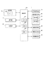
図3に示すように、画像形成装置1は、画像読取部10、操作表示部20、画像処理部30、画像形成部40、用紙搬送部50、定着部60および制御部100等を備える。
As shown in FIG. 3, the
制御部100は、CPU(Central Processing Unit)101、ROM(Read Only Memory)102、RAM(Random Access Memory)103等を備える。CPU101は、ROM102から処理内容に応じたプログラムを読み出してRAM103に展開し、展開したプログラムと協働して画像形成装置1の各ブロックの動作を集中制御する。このとき、記憶部72に格納されている各種データが参照される。
The
制御部100は、通信部71を介して、LAN(Local Area Network)、WAN(Wide Area Network)等の通信ネットワークに接続された外部の装置(例えばパーソナルコンピューター)との間で各種データの送受信を行う。制御部100は、例えば、外部の装置から送信された画像データを受信し、この画像データ(入力画像データ)に基づいて用紙にトナー像を形成させる。
The
画像読取部10は、ADF(Auto Document Feeder)と称される自動原稿給紙装置11および原稿画像走査装置12(スキャナー)等を備えて構成される。
The
自動原稿給紙装置11は、原稿トレイに載置された原稿Dを搬送機構により搬送して原稿画像走査装置12へ送り出す。自動原稿給紙装置11は、原稿トレイに載置された多数枚の原稿Dの画像(両面を含む)を連続して一挙に読み取ることができる。 The automatic document feeder 11 transports the document D placed on the document tray by a transport mechanism and sends it out to the document image scanning device 12. The automatic document feeder 11 can continuously read images (including both sides) of a large number of documents D placed on a document tray all at once.
原稿画像走査装置12は、自動原稿給紙装置11からコンタクトガラス上に搬送された原稿またはコンタクトガラス上に載置された原稿を光学的に走査し、原稿からの反射光をCCD(Charge Coupled Device)センサー12aの受光面上に結像させ、原稿画像を読み取る。画像読取部10は、原稿画像走査装置12による読取結果に基づいて入力画像データを生成する。この入力画像データには、画像処理部30において所定の画像処理が施される。
The document image scanning device 12 optically scans a document conveyed on the contact glass from the automatic document feeder 11 or a document placed on the contact glass, and reflects light from the document to a CCD (Charge Coupled Device). ) An image is formed on the light receiving surface of the
操作表示部20は、例えばタッチパネル付の液晶ディスプレイ(LCD:Liquid Crystal Display)で構成され、表示部21および操作部22として機能する。表示部21は、制御部100から入力される表示制御信号に従って、各種操作画面、画像の状態表示、各機能の動作状況等の表示を行う。操作部22は、テンキー、スタートキー等の各種操作キーを備え、ユーザーによる各種入力操作を受け付けて、操作信号を制御部100に出力する。
The
画像処理部30は、入力画像データに対して、初期設定またはユーザー設定に応じたデジタル画像処理を行う回路等を備える。例えば、画像処理部30は、制御部100の制御下で、記憶部72内の階調補正データ(階調補正テーブルLUT)に基づいて階調補正を行う。また、画像処理部30は、入力画像データに対して、階調補正の他、色補正、シェーディング補正等の各種補正処理や、圧縮処理等を施す。これらの処理が施された画像データに基づいて、画像形成部40が制御される。
The
画像形成部40は、入力画像データに基づいて、Y成分、M成分、C成分、K成分の各有色トナーによる画像を形成するための画像形成ユニット41Y、41M、41C、41K、中間転写ユニット42等を備える。
The
Y成分、M成分、C成分、K成分用の画像形成ユニット41Y、41M、41C、41Kは、同様の構成を有する。図示及び説明の便宜上、共通する構成要素は同一の符号で示し、それぞれを区別する場合には符号にY、M、C、又はKを添えて示す。図2では、Y成分用の画像形成ユニット41Yの構成要素についてのみ符号が付され、その他の画像形成ユニット41M、41C、41Kの構成要素については符号が省略されている。
The Y component, M component, C component, and K component
画像形成ユニット41は、露光装置411、現像装置412、感光体ドラム413、帯電装置414、およびドラムクリーニング装置415等を備える。
The
感光体ドラム413は、例えばアルミニウム製の導電性円筒体(アルミ素管)の周面に、アンダーコート層(UCL:Under Coat Layer)、電荷発生層(CGL:Charge Generation Layer)、電荷輸送層(CTL:Charge Transport Layer)を順次積層した負帯電型の有機感光体(OPC:Organic Photo-conductor)である。
The
制御部100は、感光体ドラム413を回転させる駆動モーター(図示略)に供給される駆動電流を制御することにより、感光体ドラム413を一定の周速度(線速度)で回転させる。
The
帯電装置414は、光導電性を有する感光体ドラム413の表面を一様に負極性に帯電させる。露光装置411は、例えば半導体レーザーで構成され、感光体ドラム413に対して各色成分の画像に対応するレーザー光を照射する。これにより、感光体ドラム413の表面には、周囲との電位差により各色成分の静電潜像が形成される。
The charging
現像装置412は、例えば二成分現像方式の現像装置であり、感光体ドラム413の表面に各色成分のトナーを付着させることにより静電潜像を可視化してトナー像を形成する。
The developing
ドラムクリーニング装置415は、感光体ドラム413の表面に摺接されるクリーニング部材等を有する。ドラムクリーニング装置415は、一次転写後に感光体ドラム413の表面に残存する転写残トナーをクリーニングブレードによって除去する。
The
中間転写ユニット42は、中間転写ベルト421、一次転写ローラー422、複数の支持ローラー423、二次転写ローラー424、及びベルトクリーニング装置426等を備える。
The
中間転写ベルト421は、無端状ベルトで構成され、複数の支持ローラー423にループ状に張架される。複数の支持ローラー423のうちの少なくとも1つは駆動ローラーで構成され、その他は従動ローラーで構成される。例えば、K成分用の一次転写ローラー422よりもベルト走行方向下流側に配置されるローラー423Aが駆動ローラーであることが好ましい。これにより、一次転写部におけるベルトの走行速度を一定に保持しやすくなる。駆動ローラー423Aが回転することにより、中間転写ベルト421は矢印A方向に一定速度で走行する。
The
一次転写ローラー422は、各色成分の感光体ドラム413に対向して、中間転写ベルト421の内周面側に配置される。中間転写ベルト421を挟んで、一次転写ローラー422が感光体ドラム413に圧接されることにより、感光体ドラム413から中間転写ベルト421へトナー像を転写するための一次転写ニップが形成される。
The
二次転写ローラー424は、駆動ローラー423Aのベルト走行方向下流側に配置されるバックアップローラー423Bに対向して、中間転写ベルト421の外周面側に配置される。中間転写ベルト421を挟んで、二次転写ローラー424がバックアップローラー423Bに圧接されることにより、中間転写ベルト421から用紙Sへトナー像を転写するための二次転写ニップが形成される。
The
中間転写ベルト421、バックアップローラー423Bおよび二次転写ローラー424は、本発明の「転写部」に対応する。二次転写ニップは、本発明の「転写ニップ」に対応する。
The
一次転写ニップを中間転写ベルト421が通過する際、感光体ドラム413上のトナー像が中間転写ベルト421に順次重ねて一次転写される。具体的には、一次転写ローラー422に一次転写バイアスを印加し、中間転写ベルト421の一次転写ローラー422と当接する側にトナーと逆極性の電荷を付与することにより、トナー像は中間転写ベルト421に静電的に転写される。
When the
その後、用紙が二次転写ニップを通過する際、中間転写ベルト421上のトナー像が用紙に二次転写される。具体的には、二次転写ローラー424に二次転写バイアスを印加し、用紙の二次転写ローラー424と当接する側にトナーと逆極性の電荷を付与することにより、トナー像は用紙に静電的に転写される。トナー像が転写された用紙は定着部60に向けて搬送される。
Thereafter, when the sheet passes through the secondary transfer nip, the toner image on the
ベルトクリーニング装置426は、中間転写ベルト421の表面に摺接するベルトクリーニングブレード等を有し、二次転写後に中間転写ベルト421の表面に残留する転写残トナーを除去する。
The
定着部60は、用紙の定着面側に配置される定着面側部材を有する上側定着部60A、用紙の定着面の反対の面側に配置される裏面側支持部材を有する下側定着部60B、及び加熱源60C等を備える。定着面側部材に裏面側支持部材が圧接されることにより、用紙を狭持して搬送する定着ニップが形成される。
The fixing
定着部60は、トナー像が二次転写され、搬送されてきた用紙を定着ニップで加熱、加圧することにより、用紙にトナー像を定着させる。定着部60は、定着器F内にユニットとして配置される。
The fixing
用紙搬送部50は、給紙部51、排紙部52および搬送経路部53等を備える。給紙部51を構成する3つの給紙トレイユニット51a〜51cには、坪量(剛度)やサイズ等に基づいて識別された用紙S(規格用紙、特殊用紙)が予め設定された種類ごとに収容される。搬送経路部53は、レジストローラー対53a等の複数の搬送ローラー、用紙の両面に画像形成するための両面搬送経路等を有する。レジストローラー対53aは、本発明の「搬送ローラー対」に対応する。
The
レジストローラー対53aは、制御部100の制御の下、用紙Sの幅方向における位置を補正する。具体的には、レジストローラー対53aに用紙Sが挟持されると、二次転写ニップに用紙の先端が突入する前にレジストローラー対53aが幅方向に移動して用紙Sを移動させることにより、用紙Sの幅方向における位置が補正される。
The
レジストローラー対53aは、用紙Sの幅方向における位置を補正した後、当該用紙Sがレジストローラー対53aにより形成されるレジストニップを通過し終わる前、つまり、用紙Sの搬送途中で離間して、移動する前の位置に戻される。そして、レジストローラー対53aは、用紙Sの後端がレジストニップを通過した後、再度圧着される。レジストニップは、本発明の「搬送ニップ」に対応する。なお、レジストローラー対53aは、用紙Sの搬送中において圧着したままにしても良い。
After correcting the position in the width direction of the paper S, the
また、レジストローラー対53a、つまり、レジストニップにおける用紙Sの搬送速度は、制御部100の制御の下、バックアップローラー423Bと二次転写ローラー424の部分、つまり、二次転写ニップにおける用紙Sの搬送速度よりも速く設定される。具体的に、レジストニップにおける用紙Sの搬送速度は、二次転写ニップにおける用紙Sの搬送速度に対して0.5%増速された搬送速度である。
Further, the conveyance speed of the sheet S in the
また、レジストローラー対53aは、レジストニップにおいて所定のニップ圧で用紙Sを搬送するように制御される。所定のニップ圧は、レジストニップおよび二次転写ニップにおいて設定された各搬送速度において、二次転写ニップにおける用紙Sの搬送量よりもレジストニップにおける用紙Sの搬送量の方が多くなるようなニップ圧のことである。
The
このようにすることで、二次転写ニップにおける用紙Sの搬送量よりもレジストニップにおける用紙Sの搬送量の方が多くなって、二次転写ニップとレジストニップとの間(以下、「レジスト転写間」という)において用紙Sに弛みが生じる。 By doing so, the transport amount of the paper S in the registration nip is larger than the transport amount of the paper S in the secondary transfer nip, and the gap between the secondary transfer nip and the resist nip (hereinafter referred to as “resist transfer”). The slack of the paper S occurs during the “interval”).
レジスト転写間や、定着ニップと二次転写ニップとの間(以下、「定着転写間」という)においては、ローラーの径の差異による搬送速度の差異や、アライメントの差による搬送速度の差異がある。この搬送速度の差異に起因してレジスト転写間や定着転写間において用紙Sの引っ張り合いが生じ、ひいては画像不良が発生する。そのため、レジスト転写間において用紙Sに弛みを生じさせたり、定着部60における搬送速度を制御して定着転写間において用紙Sに弛みを生じさせることにより、上記の画像不良の発生を抑制する。
Between resist transfer and between fixing nip and secondary transfer nip (hereinafter referred to as “between fixing and transferring”), there is a difference in conveying speed due to a difference in roller diameter and a difference in conveying speed due to a difference in alignment. . Due to the difference in the conveyance speed, the sheet S is pulled between the resist transfer and the fixing transfer, and as a result, an image defect occurs. For this reason, the occurrence of the above-described image defect is suppressed by causing the sheet S to be slack during the resist transfer or by controlling the conveyance speed in the fixing
また、定着転写間において、用紙Sに弛みが発生するように定着部60における搬送速度を制御する場合、定着転写間にて用紙Sの弛みを検出する検出部を設けると良い。
In addition, when the conveyance speed in the fixing
給紙トレイユニット51a〜51cに収容されている用紙Sは、最上部から一枚ずつ送出され、搬送経路部53により画像形成部40に搬送される。このとき、レジストローラー対53aにより、給紙された用紙Sの傾きが補正されるとともに搬送タイミングが調整される。
The sheets S stored in the sheet
そして、画像形成部40において、中間転写ベルト421のトナー像が用紙Sの一方の面に一括して二次転写され、定着部60において定着工程が施される。画像形成された用紙Sは、排紙ローラー52aを備えた排紙部52により機外に排紙される。
In the
ところで、A3サイズよりも大きい長さを有する長尺紙に画像形成する場合、長尺紙の長さが長くなるほど、用紙Sの搬送量が増える。レジスト転写間では、レジストニップにおける用紙Sの搬送量が二次転写ニップにおける用紙Sの搬送量より大きいため、用紙Sの弛み量が用紙Sの搬送量が増えるほど大きくなる。 By the way, when an image is formed on a long paper having a length larger than the A3 size, the transport amount of the paper S increases as the length of the long paper increases. During the resist transfer, the transport amount of the paper S in the registration nip is larger than the transport amount of the paper S in the secondary transfer nip. Therefore, the slack amount of the paper S increases as the transport amount of the paper S increases.
例えば、レジストニップにおける用紙Sの搬送速度を、二次転写ニップにおける用紙Sの搬送速度に対して0.5%増速させた場合、搬送方向の長さが488mmの用紙Sを搬送すると、最大で2.4mmの弛み量となる。当該弛み量は、レジスト転写間での用紙Sの長さである。それに対し、搬送方向の長さが1200mmの用紙Sを搬送すると、レジスト転写間で、最大で6mmの弛み量となる。 For example, when the conveyance speed of the paper S in the registration nip is increased by 0.5% with respect to the conveyance speed of the paper S in the secondary transfer nip, if the paper S having a length of 488 mm in the conveyance direction is conveyed, The slack amount is 2.4 mm. The amount of looseness is the length of the sheet S between resist transfers. On the other hand, when a sheet S having a length in the transport direction of 1200 mm is transported, the slack amount is 6 mm at the maximum between resist transfers.
このように、ローラーの径の差異やアライメント差による搬送速度の差異による画像不良抑制のため、二次転写ニップにおける搬送速度とレジストニップにおける搬送速度に差異を持たせると、長尺紙に画像形成をする際、用紙Sの弛み量が非長尺紙の場合よりも大きくなってしまう。 In this way, in order to suppress image defects due to differences in roller diameters and differences in conveyance speed due to alignment differences, if there is a difference between the conveyance speed in the secondary transfer nip and the conveyance speed in the resist nip, image formation is performed on long paper. When the printing is performed, the slack amount of the paper S becomes larger than that of the non-long paper.
例えば、搬送方向の長さが1200mmの長尺紙の場合、搬送方向の長さが488mmの非長尺紙よりも弛み量の差異が3mm以上となり、当該非長尺紙の倍以上の弛み量となってしまう。 For example, in the case of a long paper having a length in the transport direction of 1200 mm, the difference in the amount of slack is 3 mm or more than that of a non-long paper having a length in the transport direction of 488 mm, and the amount of slack is more than double that of the non-long paper. End up.
そのため、用紙Sの後端がレジストニップを通過したり、レジストローラー対53aを用紙Sの搬送途中で離間させたような場合、図1Cに示すように、用紙Sの戻り量が大きくなり、二次転写ニップにおいてショックノイズ等の画像不良が生じてしまうおそれがあった。
Therefore, when the trailing edge of the sheet S passes through the registration nip or when the
そこで、本実施の形態では、制御部100は、レジストニップにおける用紙Sの搬送量の増加に応じて、以下に示す搬送速度変更処理と、ニップ圧変更処理との少なくとも一方を実行させる。
Therefore, in the present embodiment, the
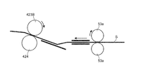
搬送速度変更処理は、レジストニップにおける用紙Sの搬送速度に対する二次転写ニップにおける用紙Sの搬送速度の差分を小さくする処理のことである。具体的に、図4に示すように、制御部100は、用紙Sの搬送量が所定の搬送量になるまでは、レジストニップにおける搬送速度を初期状態の搬送速度に設定して用紙Sの搬送速度を制御する。
The conveyance speed changing process is a process for reducing the difference in the conveyance speed of the paper S in the secondary transfer nip with respect to the conveyance speed of the paper S in the registration nip. Specifically, as illustrated in FIG. 4, the
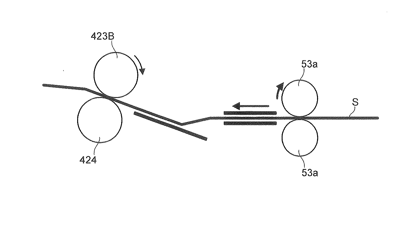
そして、制御部100は、図5に示すように、用紙Sの搬送量が所定の搬送量になった場合、レジストニップにおける搬送速度を変更前の搬送速度よりも遅くすることで、搬送速度の差分を小さくさせる。変更後の用紙Sの搬送速度は、例えば二次転写ニップにおける搬送速度と同じ搬送速度に設定される。
Then, as shown in FIG. 5, when the transport amount of the sheet S reaches a predetermined transport amount, the
所定の搬送量は、例えば、用紙Sの弛みに起因した画像不良が発生しない程度の用紙Sの弛み量に相当する搬送量のことであり、画像形成装置1のレジスト転写間におけるスペースによって適宜変更しても良い。例えば、搬送方向の長さが488mmの用紙Sにおいて画像不良が発生しない程度の用紙Sの弛み量が2.4mmである場合、所定の搬送量は、当該2.4mmに相当する搬送量となる。なお、所定の搬送量は、用紙Sの種類等に応じて適宜設定することができる。
The predetermined transport amount is, for example, a transport amount corresponding to the slack amount of the paper S that does not cause image defects due to the slack of the paper S, and is appropriately changed depending on the space between the resist transfer of the
このように制御することで、レジスト転写間で画像不良が発生しない程度の用紙Sの弛みを維持しながら、長尺紙の残りの部分を搬送することができる。そのため、長尺紙搬送の際に用紙Sの弛み量が大きくなり過ぎることを抑制することができ、ひいてはレジスト転写間における用紙Sの弛みに起因した二次転写ニップにおける画像不良の発生を抑制することができる。 By controlling in this way, the remaining portion of the long paper can be conveyed while maintaining the slackness of the paper S to such an extent that no image defect occurs between the resist transfers. For this reason, it is possible to suppress the amount of slackness of the paper S from being excessively large when transporting the long paper, and consequently suppress the occurrence of image defects in the secondary transfer nip due to the slackness of the paper S during resist transfer. be able to.
また、ニップ圧変更処理は、レジストニップにおけるニップ圧を所定のニップ圧から徐々に減少させる処理のことである。具体的に、図4に示すように、レジストニップにおける用紙Sの搬送量が所定の搬送量となるまでは、制御部100の制御の下、レジストニップにおけるニップ圧が所定のニップ圧のままで用紙Sが搬送される。そして、レジストニップにおける用紙Sの搬送量が所定の搬送量となった場合、図6に示すように、制御部100の制御の下、レジストニップにおけるニップ圧を小さくした状態で用紙Sが搬送される。
The nip pressure changing process is a process of gradually decreasing the nip pressure at the resist nip from a predetermined nip pressure. Specifically, as shown in FIG. 4, the nip pressure at the registration nip remains at the predetermined nip pressure under the control of the
また、ニップ圧を減少させる制御としては、レジストローラー対53aを圧着させる図示しないカム等を制御してレジストローラー対53aの圧着量を変更する制御が挙げられる。つまり、制御部100は、レジストローラー対53aにおける各ローラーを互いに離れる側に移動させることにより(図6の破線矢印参照)、レジストローラー対53aにおけるニップ圧を減少させる。
The control for reducing the nip pressure includes control for changing the amount of pressure applied to the
これにより、レジストローラー対53aにおける用紙Sの搬送量が徐々に少なくなるので、レジスト転写間において用紙Sの弛みが大きくなり過ぎず、制御の開始時の状態が維持される。そのため、レジスト転写間における用紙Sの弛みに起因した二次転写ニップにおける画像不良の発生を抑制することができる。
As a result, the conveyance amount of the paper S by the
ところで、用紙Sのコシが弱い場合、用紙Sが弛みやすいため、レジストニップにおいてニップ圧を緩めてしまうと、レジストニップにおける用紙Sの搬送力が確保されず、用紙Sの弛みを制御しにくくなる可能性がある。そのため、用紙Sのコシが弱い場合、搬送速度変更処理により用紙Sを搬送することが望ましい。 By the way, when the stiffness of the paper S is weak, the paper S is easily loosened. Therefore, if the nip pressure is relaxed at the registration nip, the conveyance force of the paper S at the registration nip is not secured, and it becomes difficult to control the looseness of the paper S. there is a possibility. For this reason, when the stiffness of the paper S is weak, it is desirable to transport the paper S by the transport speed changing process.
それに対し、用紙Sのコシが強い場合、用紙Sの後端がレジストニップを抜けた際、又は、レジストローラー対53aが離間した際に、用紙Sが元に戻ろうとする復元力が強くなる。
On the other hand, when the stiffness of the paper S is strong, when the trailing edge of the paper S passes through the registration nip or when the
この用紙Sの復元力を利用する観点を考慮すると、搬送速度変更処理によりニップ圧を維持したまま強制的に用紙Sの弛みを制御するよりは、レジストニップにおけるニップ圧を弱くして搬送力を緩めてやる方が、用紙Sの弛み量を適度に維持しやすくなる。そのため、用紙Sのコシが強い場合、ニップ圧変更処理により用紙Sを搬送することが望ましい。 Considering the viewpoint of using the restoring force of the sheet S, the nip pressure in the registration nip is weakened and the conveying force is reduced rather than forcibly controlling the slack of the sheet S while maintaining the nip pressure by the conveying speed changing process. Loosening makes it easier to maintain a moderate amount of slackness of the paper S. Therefore, when the stiffness of the paper S is strong, it is desirable to transport the paper S by the nip pressure changing process.
そこで、制御部100は、用紙Sの剛度に応じて、搬送速度変更処理およびニップ圧変更処理の何れか一方を実行させる。具体的には、制御部100は、用紙Sのコシが弱い薄紙(例えば、坪量が80gsm以下)の場合、搬送速度変更処理を実行させる。また、制御部100は、用紙Sのコシが強い厚紙(例えば、坪量が211gsm以上)の場合、ニップ圧変更処理を実行させる。これにより、用紙Sの剛度に応じた適切な搬送制御を行うことができる。
Therefore, the
また、用紙Sのコシは、画像形成装置1の周囲の環境に応じて変動するので、制御部100は、画像形成装置1の周囲の環境に応じて、搬送速度変更処理およびニップ圧変更処理の何れか一方を実行させる。
Further, the stiffness of the paper S varies according to the environment around the
具体的には、制御部100は、高温高湿環境のように用紙Sのコシが弱くなる場合、搬送速度変更処理を実行させる。また、制御部100は、低温低湿環境のように用紙Sのコシが強くなる場合、ニップ圧変更処理を実行させる。これにより、画像形成装置1の周囲の環境に応じた適切な搬送制御を行うことができる。
Specifically, when the stiffness of the paper S becomes weak, such as in a high temperature and high humidity environment, the
ところで、両面印刷する際において、用紙Sの第1面(例えば、表面)に画像形成された後、第1面とは反対側の第2面(例えば、裏面)に画像形成される制御がなされる。第1面に画像形成をする際には、両面ともに画像が形成されていないが、第2面に画像形成をする際、第1面に画像が形成されている。 By the way, when performing duplex printing, after an image is formed on the first surface (for example, the front surface) of the paper S, the image is formed on the second surface (for example, the back surface) opposite to the first surface. The When an image is formed on the first side, no image is formed on both sides, but when an image is formed on the second side, an image is formed on the first side.
そのため、レジストニップにおけるスリップ量が第1面に画像形成する場合と第2面に画像形成する場合とで異なってくる。具体的には、用紙Sに画像が形成されている場合、画像が形成されていない場合と比べて、レジストニップにおいてスリップしやすくなるため、両面印刷時における第2面に画像形成をする際、ある程度のニップ圧を確保する必要がある。 Therefore, the amount of slip at the registration nip differs depending on whether an image is formed on the first surface or an image is formed on the second surface. Specifically, when an image is formed on the paper S, it is easier to slip at the registration nip than when no image is formed. Therefore, when forming an image on the second surface during duplex printing, It is necessary to ensure a certain nip pressure.
そこで、制御部100は、両面印刷の際において、用紙Sの第1面に画像形成するか、用紙Sの第2面に画像形成するかに応じて、搬送速度変更処理及び押圧力変更処理の何れか一方を実行させる。
Therefore, the
用紙Sの第1面に画像形成した後、第2面に画像形成する際、第1面に画像が形成されているため、レジストニップにおいてスリップしやすい。そのため、制御部100は、押圧力変更処理を実行させる。
When an image is formed on the first surface of the sheet S and then formed on the second surface, the image is formed on the first surface, so that slip easily occurs in the registration nip. Therefore, the
また、用紙Sの第1面に画像形成する際、制御部100は、用紙Sの剛度や画像形成装置1の周囲の環境に応じて、適当な方を選択すると良い。なお、第1面に形成された画像のカバレッジが小さい場合においては、レジストニップにおいてスリップしにくくなるので、この場合、用紙Sの剛度や画像形成装置1の周囲の環境に応じて、適当な方を選択すると良い。
Further, when forming an image on the first surface of the sheet S, the
このようにすることで、両面印刷の際において、用紙Sにおける画像形成状況に応じた適切な搬送制御を行うことができる。 By doing so, it is possible to perform appropriate conveyance control in accordance with the image formation status on the paper S during double-sided printing.
また、記憶部72(図3参照)に、以下の表1〜3に示すテーブルを記憶させておくことにより、制御部100は、当該テーブルを参照しながら、搬送速度変更処理及びニップ圧変更処理の何れかを実行させる。
Further, by storing the tables shown in Tables 1 to 3 below in the storage unit 72 (see FIG. 3), the
表1は、常温常湿条件における用紙Sの坪量毎の各処理における画像不良の発生しやすさを示すテーブルである。表2は、高温高湿条件における用紙Sの坪量毎の各処理における画像不良の発生しやすさを示すテーブルである。表3は、低温低湿条件における用紙Sの坪量毎の各処理における画像不良の発生しやすさを示すテーブルである。なお、表1〜3における「○」は、画像不良が発生しないことを示し、「×」は、画像不良が発生する可能性が高いことを示している。 Table 1 is a table showing the likelihood of image defects in each process for each basis weight of the paper S under normal temperature and humidity conditions. Table 2 is a table showing the likelihood of image defects in each process for each basis weight of the paper S under high temperature and high humidity conditions. Table 3 is a table showing the likelihood of image defects in each process for each basis weight of the paper S under low temperature and low humidity conditions. In Tables 1 to 3, “◯” indicates that an image defect does not occur, and “x” indicates that the possibility of an image defect is high.
上記のようなテーブルを参照することにより、例えば、表1に示すような用紙Sの坪量が50〜80gsmにおけるニップ圧変更処理のような画像不良が発生しやすい条件に該当する処理を選択しないようにすることができる。そのため、画像不良が発生しない条件を正確に選択した上で、搬送制御を行うことができる。 By referring to the table as described above, for example, a process corresponding to a condition in which an image defect is likely to occur, such as a nip pressure changing process when the basis weight of the sheet S is 50 to 80 gsm as shown in Table 1, is not selected. Can be. For this reason, it is possible to perform the conveyance control after correctly selecting the conditions under which the image defect does not occur.
ここで、例えば、表1における坪量が81〜210gsmまでの範囲の場合、搬送速度変更処理及びニップ圧変更処理の何れの処理において画像不良が発生しない条件となる。このような場合、制御部100は、搬送速度変更処理及びニップ圧変更処理の何れか一方を実行させる、または、搬送速度変更処理及びニップ圧変更処理を同時に実行させるかを選択するようにしても良い。
Here, for example, when the basis weight in Table 1 is in the range of 81 to 210 gsm, there is a condition in which no image defect occurs in any of the conveyance speed changing process and the nip pressure changing process. In such a case, the
このようにすることで、搬送制御における選択の幅を広げることができるので、条件に合わせた適切な搬送制御を行いやすくすることができる。 By doing in this way, since the range of selection in conveyance control can be expanded, it can be made easy to perform suitable conveyance control according to conditions.
また、制御部100は、搬送速度変更処理及びニップ圧変更処理を交互に実行させても良い。このようにすることで、例えば、同じ印刷ジョブにおいて用紙Sの種類が変わるような場合においても、搬送中の用紙Sの剛度等に対応した適切な搬送制御を行うことができるとともに、1枚の用紙Sの画像形成中において、用紙Sの状況に応じて、柔軟に搬送速度変更処理とニップ圧変更処理とを使い分けることができる。
Further, the
また、ユーザーが使用条件により上記表1〜3のテーブルに基づいて、搬送速度変更処理及びニップ圧変更処理の何れか一方又は両方を選択できるようにしても良い。この場合、操作部22(図2および図3参照)において、ユーザーにより搬送速度変更処理及びニップ圧変更処理の何れか又は両方を選択可能にしておく必要がある。 Further, the user may be able to select either one or both of the conveyance speed changing process and the nip pressure changing process based on the table in Tables 1 to 3 according to the use conditions. In this case, in the operation unit 22 (see FIGS. 2 and 3), it is necessary that the user can select either or both of the conveyance speed changing process and the nip pressure changing process.
そして、制御部100は、操作部22における操作情報、つまり、ユーザーの指示に応じて、搬送速度変更処理及びニップ圧変更処理の少なくとも一方を実行させることができる。これにより、ユーザーが上記テーブルを参照しながら、用紙Sの種類および画像形成装置1の環境に応じて適切な搬送制御を選択することができる。
And the
また、ユーザーが画像形成後の用紙Sの状況を確認後に、任意に搬送速度変更処理及びニップ圧変更処理の少なくとも一方を選択できるようにしても良い。 Further, after the user confirms the state of the sheet S after the image formation, it may be possible to arbitrarily select at least one of the conveyance speed changing process and the nip pressure changing process.
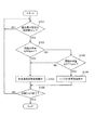
以上のように構成された画像形成装置1における搬送制御の動作の一例について説明する。図7は、画像形成装置1における搬送制御の動作例の一例を示すフローチャートである。図7における処理は、印刷ジョブを行う際において適宜実行される。なお、図における処理は、常温常湿条件における用紙Sが長尺紙である場合の制御の一例である。
An example of the conveyance control operation in the
図7に示すように、制御部100は、用紙Sの搬送量が所定の搬送量以上になったか否かについて判定する(ステップS101)。判定の結果、用紙Sの搬送量が所定の搬送量以上になっていない場合(ステップS101、NO)、ステップS101の処理が繰り返される。
As shown in FIG. 7, the
一方、用紙Sの搬送量が所定の搬送量以上になった場合(ステップS101、YES)、制御部100は、用紙Sの坪量が例えば80gsm以下であるか否かについて判定する(ステップS102)。判定の結果、用紙Sの坪量が80gsm以下である場合(ステップS102、YES)、制御部100は、搬送速度変更処理を実行させる(ステップS103)。
On the other hand, when the transport amount of the paper S is equal to or greater than the predetermined transport amount (step S101, YES), the
一方、用紙Sの坪量が80gsm以下でない場合(ステップS102、NO)、制御部100は、用紙Sの坪量が211gsm以上であるか否かについて判定する(ステップS104)。判定の結果、用紙Sの坪量が211gsm以上である場合(ステップS104、YES)、制御部100は、ニップ圧変更処理を実行させる(ステップS105)。
On the other hand, when the basis weight of the sheet S is not 80 gsm or less (step S102, NO), the
一方、用紙Sの坪量が211gsm以上でない場合(ステップS104、NO)、制御部100は、例えばステップS103の処理に遷移する。つまり、制御部100は、搬送速度変更処理を実行させる。なお、ステップS104においてNOと判定した場合、ステップS105の処理、つまり、ニップ圧変更処理を実行させても良いし、搬送速度変更処理及びニップ圧変更処理の両方を同時に実行させても良い。
On the other hand, when the basis weight of the paper S is not 211 gsm or more (step S104, NO), the
ステップS103およびステップS105の後、制御部100は、印刷ジョブが終了したか否かについて判定する(ステップS106)。判定の結果、印刷ジョブが終了していない場合(ステップS106、NO)、処理はステップS101に戻る。一方、印刷ジョブが終了した場合(ステップS106、YES)、本制御は終了する。
After step S103 and step S105, the
以上のように構成された本実施の形態によれば、長尺紙搬送の際に用紙Sの弛み量が大きくなり過ぎることを抑制することができ、ひいてはレジスト転写間における用紙Sの弛みに起因した二次転写ニップにおける画像不良の発生を抑制することができる。 According to the present embodiment configured as described above, it is possible to prevent the amount of slackness of the paper S from being excessively large when transporting long paper, and as a result, the paper S is slackened between resist transfers. The occurrence of image defects in the secondary transfer nip can be suppressed.
また、非長尺紙の場合においても、用紙Sの搬送における後半でショックノイズが発生する可能性がある場合、搬送途中において搬送速度変更処理やニップ圧変更処理を行うことにより、二次転写ニップにおける画像不良の発生を抑制することができる。 Even in the case of non-long paper, if there is a possibility that shock noise may occur in the second half of the conveyance of the paper S, a secondary transfer nip is performed by performing a conveyance speed changing process or a nip pressure changing process during the conveyance. The occurrence of image defects can be suppressed.
また、用紙Sの剛度や画像形成装置1の周囲の環境に応じて、搬送速度変更処理及びニップ圧変更処理の何れかを実行させるので、状況に応じた適切な搬送制御を行うことができる。
In addition, since either the conveyance speed changing process or the nip pressure changing process is executed according to the stiffness of the paper S or the surrounding environment of the
その他、上記実施の形態は、何れも本発明を実施するにあたっての具体化の一例を示したものに過ぎず、これらによって本発明の技術的範囲が限定的に解釈されてはならないものである。すなわち、本発明はその要旨、またはその主要な特徴から逸脱することなく、様々な形で実施することができる。 In addition, each of the above-described embodiments is merely an example of actualization in carrying out the present invention, and the technical scope of the present invention should not be construed as being limited thereto. That is, the present invention can be implemented in various forms without departing from the gist or the main features thereof.
1 画像形成装置
53a レジストローラー対
100 制御部
421 中間転写ベルト
423B バックアップローラー
424 二次転写ローラー
DESCRIPTION OF
Claims (9)
前記用紙の搬送方向における前記転写ニップよりも上流側に配置される搬送ローラー対と、
前記搬送ローラー対により形成された搬送ニップまで搬送された前記用紙を所定のニップ圧で搬送し、かつ、前記搬送ニップにおける前記用紙の搬送速度を前記転写ニップにおける前記用紙の搬送速度よりも速くする制御を行うことにより、前記転写ニップと前記搬送ニップとの間で前記用紙に弛みを生じさせる制御部と、
を備え、
前記制御部は、前記搬送ニップにおける前記用紙の搬送量の増加に応じて、前記搬送ニップにおける前記用紙の搬送速度に対する前記転写ニップにおける前記用紙の搬送速度の差分を小さくする搬送速度変更処理と、前記搬送ニップにおけるニップ圧を減少させるニップ圧変更処理との少なくとも一方を実行させる、
画像形成装置。 A transfer portion for forming a transfer nip for transferring an image to paper;
A pair of transport rollers disposed upstream of the transfer nip in the transport direction of the paper;
The paper transported to the transport nip formed by the transport roller pair is transported at a predetermined nip pressure, and the transport speed of the paper in the transport nip is faster than the transport speed of the paper in the transfer nip. A control unit that causes slack in the paper between the transfer nip and the transport nip by performing control;
With
The control unit is configured to change a conveyance speed change process for reducing a difference between the conveyance speed of the paper in the transfer nip with respect to the conveyance speed of the paper in the conveyance nip in response to an increase in the conveyance amount of the paper in the conveyance nip. Executing at least one of a nip pressure changing process for reducing a nip pressure in the transport nip,
Image forming apparatus.
請求項1に記載の画像形成装置。 When the conveyance amount of the paper becomes a conveyance amount corresponding to the amount of slackness of the paper to such an extent that an image defect due to the slackness of the paper does not occur, the control unit changes the conveyance speed changing process and the nip pressure. To execute at least one of the change processes,
The image forming apparatus according to claim 1.
請求項1または請求項2に記載の画像形成装置。 The controller causes the conveyance speed change process and the nip pressure change process to be executed according to the stiffness of the paper.
The image forming apparatus according to claim 1.
請求項1〜3の何れか1項に記載の画像形成装置。 The control unit causes the conveyance speed change process and the nip pressure change process to be executed according to an environment around the image forming apparatus.
The image forming apparatus according to claim 1.
請求項1〜4の何れか1項に記載の画像形成装置。 In the double-sided printing, the control unit performs the conveyance speed changing process and the image formation on the first surface of the paper or on the second surface opposite to the first surface. Executing one of the nip pressure changing processes;
The image forming apparatus according to claim 1.
請求項1または請求項2に記載の画像形成装置。 The control unit causes the conveyance speed change process and the nip pressure change process to be performed, or causes the conveyance speed change process and the nip pressure change process to be performed simultaneously.
The image forming apparatus according to claim 1.
請求項1〜5の何れか1項に記載の画像形成装置。 The controller causes the conveyance speed change process and the nip pressure change process to be executed alternately.
The image forming apparatus according to claim 1.
請求項1〜7の何れか1項に記載の画像形成装置。 The controller causes at least one of the conveyance speed change process and the nip pressure change process to be executed in accordance with a user instruction.
The image forming apparatus according to claim 1.
前記用紙の搬送方向における前記転写ニップよりも上流側に配置され、前記用紙の幅方向に移動して搬送中の前記用紙の位置を補正する搬送ローラー対と、を備える画像形成装置の搬送制御方法であって、
前記搬送ローラー対により形成された搬送ニップまで搬送された前記用紙を所定のニップ圧で搬送し、かつ、前記搬送ニップにおける前記用紙の搬送速度を前記転写ニップにおける前記用紙の搬送速度よりも速くする制御を行うことにより、前記転写ニップと前記搬送ニップとの間で前記用紙に弛みを生じさせ、
前記搬送ニップにおける前記用紙の搬送量の増加に応じて、前記搬送ニップにおける前記用紙の搬送速度に対する前記転写ニップにおける前記用紙の搬送速度の差分を小さくする搬送速度変更処理と、前記搬送ニップにおけるニップ圧を減少させるニップ圧変更処理との少なくとも一方を実行させる搬送制御方法。 A transfer portion for forming a transfer nip for transferring an image to paper;
A conveyance control method for an image forming apparatus, comprising: a conveyance roller pair that is disposed upstream of the transfer nip in the conveyance direction of the sheet and moves in the width direction of the sheet to correct the position of the sheet being conveyed. Because
The paper transported to the transport nip formed by the transport roller pair is transported at a predetermined nip pressure, and the transport speed of the paper in the transport nip is faster than the transport speed of the paper in the transfer nip. By performing the control, the paper is slackened between the transfer nip and the transport nip,
A conveyance speed changing process for reducing a difference in the conveyance speed of the sheet in the transfer nip with respect to the conveyance speed of the sheet in the conveyance nip according to an increase in the conveyance amount of the sheet in the conveyance nip; and a nip in the conveyance nip. A conveyance control method for executing at least one of nip pressure changing processing for reducing pressure.
Priority Applications (1)
| Application Number | Priority Date | Filing Date | Title |
|---|---|---|---|
| JP2017021144A JP6891523B2 (en) | 2017-02-08 | 2017-02-08 | Image forming device and transfer control method |
Applications Claiming Priority (1)
| Application Number | Priority Date | Filing Date | Title |
|---|---|---|---|
| JP2017021144A JP6891523B2 (en) | 2017-02-08 | 2017-02-08 | Image forming device and transfer control method |
Publications (2)
| Publication Number | Publication Date |
|---|---|
| JP2018128564A true JP2018128564A (en) | 2018-08-16 |
| JP6891523B2 JP6891523B2 (en) | 2021-06-18 |
Family
ID=63172882
Family Applications (1)
| Application Number | Title | Priority Date | Filing Date |
|---|---|---|---|
| JP2017021144A Active JP6891523B2 (en) | 2017-02-08 | 2017-02-08 | Image forming device and transfer control method |
Country Status (1)
| Country | Link |
|---|---|
| JP (1) | JP6891523B2 (en) |
Cited By (1)
| Publication number | Priority date | Publication date | Assignee | Title |
|---|---|---|---|---|
| JP2021026117A (en) * | 2019-08-05 | 2021-02-22 | キヤノン株式会社 | Image forming apparatus |
Citations (11)
| Publication number | Priority date | Publication date | Assignee | Title |
|---|---|---|---|---|
| JP2001175041A (en) * | 1999-12-20 | 2001-06-29 | Ricoh Co Ltd | Image forming device |
| JP2003316092A (en) * | 2002-04-22 | 2003-11-06 | Ricoh Co Ltd | Paper transport apparatus and image forming apparatus using the same |
| JP2004045735A (en) * | 2002-07-11 | 2004-02-12 | Hitachi Printing Solutions Ltd | Image forming apparatus |
| JP2006330420A (en) * | 2005-05-27 | 2006-12-07 | Konica Minolta Business Technologies Inc | Image forming apparatus |
| JP2010245875A (en) * | 2009-04-07 | 2010-10-28 | Konica Minolta Business Technologies Inc | Print system, print instructing device, printer driver and image forming apparatus |
| JP2011081066A (en) * | 2009-10-05 | 2011-04-21 | Canon Inc | Image forming apparatus and sheet conveying method |
| JP2011133524A (en) * | 2009-12-22 | 2011-07-07 | Canon Inc | Image forming apparatus |
| JP2011225353A (en) * | 2010-04-22 | 2011-11-10 | Kyocera Mita Corp | Image forming device |
| JP2012166891A (en) * | 2011-02-14 | 2012-09-06 | Canon Inc | Sheet conveying apparatus and printing apparatus |
| JP2014048601A (en) * | 2012-09-04 | 2014-03-17 | Konica Minolta Inc | Image forming apparatus |
| US9108811B1 (en) * | 2014-10-09 | 2015-08-18 | Xerox Corporation | Variably changing nip feeding speeds to maintain optimal sheet buckle |
-
2017
- 2017-02-08 JP JP2017021144A patent/JP6891523B2/en active Active
Patent Citations (11)
| Publication number | Priority date | Publication date | Assignee | Title |
|---|---|---|---|---|
| JP2001175041A (en) * | 1999-12-20 | 2001-06-29 | Ricoh Co Ltd | Image forming device |
| JP2003316092A (en) * | 2002-04-22 | 2003-11-06 | Ricoh Co Ltd | Paper transport apparatus and image forming apparatus using the same |
| JP2004045735A (en) * | 2002-07-11 | 2004-02-12 | Hitachi Printing Solutions Ltd | Image forming apparatus |
| JP2006330420A (en) * | 2005-05-27 | 2006-12-07 | Konica Minolta Business Technologies Inc | Image forming apparatus |
| JP2010245875A (en) * | 2009-04-07 | 2010-10-28 | Konica Minolta Business Technologies Inc | Print system, print instructing device, printer driver and image forming apparatus |
| JP2011081066A (en) * | 2009-10-05 | 2011-04-21 | Canon Inc | Image forming apparatus and sheet conveying method |
| JP2011133524A (en) * | 2009-12-22 | 2011-07-07 | Canon Inc | Image forming apparatus |
| JP2011225353A (en) * | 2010-04-22 | 2011-11-10 | Kyocera Mita Corp | Image forming device |
| JP2012166891A (en) * | 2011-02-14 | 2012-09-06 | Canon Inc | Sheet conveying apparatus and printing apparatus |
| JP2014048601A (en) * | 2012-09-04 | 2014-03-17 | Konica Minolta Inc | Image forming apparatus |
| US9108811B1 (en) * | 2014-10-09 | 2015-08-18 | Xerox Corporation | Variably changing nip feeding speeds to maintain optimal sheet buckle |
Cited By (2)
| Publication number | Priority date | Publication date | Assignee | Title |
|---|---|---|---|---|
| JP2021026117A (en) * | 2019-08-05 | 2021-02-22 | キヤノン株式会社 | Image forming apparatus |
| JP7438687B2 (en) | 2019-08-05 | 2024-02-27 | キヤノン株式会社 | Image forming device |
Also Published As
| Publication number | Publication date |
|---|---|
| JP6891523B2 (en) | 2021-06-18 |
Similar Documents
| Publication | Publication Date | Title |
|---|---|---|
| JP6540734B2 (en) | Image reading apparatus and image forming system | |
| JP5928494B2 (en) | Image forming apparatus | |
| JP6358245B2 (en) | Image forming apparatus, image forming system, and distortion correction method | |
| CN110231757B (en) | Image forming apparatus and conveyance control method | |
| JP6855761B2 (en) | Fixing device, image forming device and pressure switching method | |
| JP6891523B2 (en) | Image forming device and transfer control method | |
| JP6965306B2 (en) | Image reader and image forming system | |
| JP6977271B2 (en) | Image forming device and transfer control method | |
| JP2018128563A (en) | Image forming apparatus and conveyance speed control method | |
| JP2017165577A (en) | Image forming apparatus and conveyance control method | |
| JP6620617B2 (en) | Image forming apparatus and conveyance control method | |
| JP2018185361A (en) | Image forming apparatus and conveyance control method | |
| JP2018197805A (en) | Image forming apparatus | |
| JP7081221B2 (en) | Image forming device and intermediate transfer belt position control method | |
| JP6953793B2 (en) | Image forming device and transfer control method | |
| JP2018025691A (en) | Fixing device, image forming apparatus, and belt shape changing method | |
| JP6844196B2 (en) | Image forming device and image forming program | |
| JP2019015809A (en) | Image forming apparatus and conveyance control method | |
| JP2015105162A (en) | Image forming apparatus | |
| JP2018197151A (en) | Image forming device and conveyance control method | |
| JP2019014569A (en) | Image formation apparatus and conveyance control method | |
| JP2018197804A (en) | Image forming apparatus and conveyance control method | |
| JP2018184232A (en) | Image formation apparatus and conveyance control method | |
| JP2020194045A (en) | Image forming apparatus | |
| JP2019014560A (en) | Image formation apparatus and conveyance control method |
Legal Events
| Date | Code | Title | Description |
|---|---|---|---|
| RD02 | Notification of acceptance of power of attorney |
Free format text: JAPANESE INTERMEDIATE CODE: A7422 Effective date: 20190708 |
|
| RD04 | Notification of resignation of power of attorney |
Free format text: JAPANESE INTERMEDIATE CODE: A7424 Effective date: 20191011 |
|
| A621 | Written request for application examination |
Free format text: JAPANESE INTERMEDIATE CODE: A621 Effective date: 20191023 |
|
| A977 | Report on retrieval |
Free format text: JAPANESE INTERMEDIATE CODE: A971007 Effective date: 20200907 |
|
| A131 | Notification of reasons for refusal |
Free format text: JAPANESE INTERMEDIATE CODE: A131 Effective date: 20201020 |
|
| A521 | Request for written amendment filed |
Free format text: JAPANESE INTERMEDIATE CODE: A523 Effective date: 20201218 |
|
| TRDD | Decision of grant or rejection written | ||
| A01 | Written decision to grant a patent or to grant a registration (utility model) |
Free format text: JAPANESE INTERMEDIATE CODE: A01 Effective date: 20210427 |
|
| A61 | First payment of annual fees (during grant procedure) |
Free format text: JAPANESE INTERMEDIATE CODE: A61 Effective date: 20210510 |
|
| R150 | Certificate of patent or registration of utility model |
Ref document number: 6891523 Country of ref document: JP Free format text: JAPANESE INTERMEDIATE CODE: R150 |