JP2018123744A - Waste power generation plant and operation method of the same - Google Patents
Waste power generation plant and operation method of the same Download PDFInfo
- Publication number
- JP2018123744A JP2018123744A JP2017015936A JP2017015936A JP2018123744A JP 2018123744 A JP2018123744 A JP 2018123744A JP 2017015936 A JP2017015936 A JP 2017015936A JP 2017015936 A JP2017015936 A JP 2017015936A JP 2018123744 A JP2018123744 A JP 2018123744A
- Authority
- JP
- Japan
- Prior art keywords
- heat
- heat medium
- waste
- steam
- flow rate
- Prior art date
- Legal status (The legal status is an assumption and is not a legal conclusion. Google has not performed a legal analysis and makes no representation as to the accuracy of the status listed.)
- Granted
Links
Images
Classifications
-
- Y—GENERAL TAGGING OF NEW TECHNOLOGICAL DEVELOPMENTS; GENERAL TAGGING OF CROSS-SECTIONAL TECHNOLOGIES SPANNING OVER SEVERAL SECTIONS OF THE IPC; TECHNICAL SUBJECTS COVERED BY FORMER USPC CROSS-REFERENCE ART COLLECTIONS [XRACs] AND DIGESTS
- Y02—TECHNOLOGIES OR APPLICATIONS FOR MITIGATION OR ADAPTATION AGAINST CLIMATE CHANGE
- Y02E—REDUCTION OF GREENHOUSE GAS [GHG] EMISSIONS, RELATED TO ENERGY GENERATION, TRANSMISSION OR DISTRIBUTION
- Y02E20/00—Combustion technologies with mitigation potential
- Y02E20/12—Heat utilisation in combustion or incineration of waste
-
- Y—GENERAL TAGGING OF NEW TECHNOLOGICAL DEVELOPMENTS; GENERAL TAGGING OF CROSS-SECTIONAL TECHNOLOGIES SPANNING OVER SEVERAL SECTIONS OF THE IPC; TECHNICAL SUBJECTS COVERED BY FORMER USPC CROSS-REFERENCE ART COLLECTIONS [XRACs] AND DIGESTS
- Y02—TECHNOLOGIES OR APPLICATIONS FOR MITIGATION OR ADAPTATION AGAINST CLIMATE CHANGE
- Y02T—CLIMATE CHANGE MITIGATION TECHNOLOGIES RELATED TO TRANSPORTATION
- Y02T10/00—Road transport of goods or passengers
- Y02T10/10—Internal combustion engine [ICE] based vehicles
- Y02T10/12—Improving ICE efficiencies
-
- Y—GENERAL TAGGING OF NEW TECHNOLOGICAL DEVELOPMENTS; GENERAL TAGGING OF CROSS-SECTIONAL TECHNOLOGIES SPANNING OVER SEVERAL SECTIONS OF THE IPC; TECHNICAL SUBJECTS COVERED BY FORMER USPC CROSS-REFERENCE ART COLLECTIONS [XRACs] AND DIGESTS
- Y02—TECHNOLOGIES OR APPLICATIONS FOR MITIGATION OR ADAPTATION AGAINST CLIMATE CHANGE
- Y02T—CLIMATE CHANGE MITIGATION TECHNOLOGIES RELATED TO TRANSPORTATION
- Y02T10/00—Road transport of goods or passengers
- Y02T10/10—Internal combustion engine [ICE] based vehicles
- Y02T10/30—Use of alternative fuels, e.g. biofuels
Landscapes
- Engine Equipment That Uses Special Cycles (AREA)
- Processing Of Solid Wastes (AREA)
Abstract
【課題】廃棄物発電プラント全体における熱損失を低減させて、廃棄物発電プラント全体における発電効率を向上させることができる廃棄物発電プラント及び廃棄物発電プラントの運転方法を提供することを目的とする。【解決手段】燃焼炉2内で廃棄物を燃焼して蒸気を生成するボイラ3と、ボイラ3で生成した蒸気によって駆動される蒸気タービン4と、蒸気タービン4によって発電する第1発電機7と、廃棄物から生成されたメタン含有バイオガスによって駆動するガスエンジン6と、ガスエンジン6によって発電する第2発電機8とを備えた廃棄物発電プラント1であって、ガスエンジン6に設けられた第1熱交換器で一次冷却水を加熱し、給水予熱器26に設けられた第2熱交換器で給水を予熱する廃棄物発電プラント1。【選択図】図1An object of the present invention is to provide a waste power generation plant capable of reducing heat loss in the entire waste power generation plant and improving power generation efficiency in the entire waste power generation plant, and a method for operating the waste power generation plant. . A boiler 3 that burns waste in a combustion furnace 2 to generate steam, a steam turbine 4 that is driven by the steam generated in the boiler 3, and a first generator 7 that generates power by the steam turbine 4, A waste power generation plant 1 including a gas engine 6 driven by methane-containing biogas generated from waste and a second generator 8 that generates electric power by the gas engine 6, provided in the gas engine 6. A waste power plant 1 that heats primary cooling water with a first heat exchanger and preheats feed water with a second heat exchanger provided in a feed water preheater 26. [Selection] Figure 1
Description
本発明は、廃棄物を燃焼することで生成した蒸気によって発電するとともに、廃棄物から生成したバイオガスによってガスエンジンを駆動する廃棄物発電プラント及び廃棄物発電プラントの運転方法に関するものである。 The present invention relates to a waste power generation plant that generates power using steam generated by burning waste and drives a gas engine using biogas generated from the waste, and a method for operating the waste power generation plant.
廃棄物から生成されるバイオガスによってガスエンジンを駆動する廃棄物発電プラントにおいて、ガスエンジンを冷却するための冷却水は、プラントから独立した冷却水系統となることがある。このため、ガスエンジンの排熱は、冷却水を介してすべて大気中に放熱され、廃棄物発電プラント全体としては熱損失となっているという問題があった。エンジンを冷却する冷却液の熱を利用して、他の設備を加熱するものには、例えば特許文献1のものがある。
特許文献1には、発酵処理槽内に設けられた撹拌羽根と、撹拌羽根を回転させるモータと、モータを回すコジェネレーションシステムとを備えた生ゴミ減容処理機が開示されている。発酵処理槽は、二重に形成され、その間に発酵処理槽を加熱する螺旋配管をもうけ、螺旋配管はコジェネレーションシステムの冷却温水に連結し、冷却温水を発酵処理槽に循環させて、発酵処理槽を加熱する。
In a waste power generation plant in which a gas engine is driven by biogas generated from waste, cooling water for cooling the gas engine may be a cooling water system independent of the plant. For this reason, all the exhaust heat of the gas engine is radiated to the atmosphere via the cooling water, and there is a problem that the waste power generation plant as a whole is a heat loss. There exists a thing of patent document 1 in what heats the other equipment using the heat of the cooling fluid which cools an engine, for example.
Patent Document 1 discloses a garbage reduction processing machine including a stirring blade provided in a fermentation processing tank, a motor that rotates the stirring blade, and a cogeneration system that rotates the motor. Fermentation tanks are formed in a double layer, and a spiral pipe for heating the fermentation tank is provided between them. The spiral pipe is connected to the cooling hot water of the cogeneration system, and the cooling hot water is circulated to the fermentation processing tank. Heat the bath.
しかしながら、特許文献1に記載のものは、生ゴミを発酵分解・乾燥して減容するための装置において、コジェネレーションシステムの冷却水を発酵処理槽に利用することのみを想定したものであって、廃棄物発電プラントのような大規模な設備において、設備全体としての発電効率を向上させることを目的としたものではない。また、発酵処理槽内の生ゴミは、発酵反応する際に発熱するために、発酵処理槽の設置環境(例えば発酵処理槽が屋内等の比較的暖かい場所に設置される場合等)によっては、発酵処理槽を加熱する必要がなく、このような場合には、コジェネレーションシステムの冷却温水を有効に利用することができない可能性があった。 However, the thing of patent document 1 assumes only using the cooling water of a cogeneration system for a fermentation processing tank in the apparatus for fermenting decomposition | disassembly and drying and reducing volume of garbage. However, it is not intended to improve the power generation efficiency of the entire facility in a large-scale facility such as a waste power plant. In addition, because the garbage in the fermentation tank generates heat when it undergoes a fermentation reaction, depending on the installation environment of the fermentation tank (for example, when the fermentation tank is installed in a relatively warm place such as indoors) There is no need to heat the fermentation tank, and in such a case, there is a possibility that the cooling hot water of the cogeneration system cannot be used effectively.
本発明は、このような事情に鑑みてなされたものであって、廃棄物発電プラント全体における熱損失を低減させて、廃棄物発電プラント全体における発電効率を向上させることができる廃棄物発電プラント及び廃棄物発電プラントの運転方法を提供することを目的とする。 The present invention has been made in view of such circumstances, and a waste power plant that can reduce heat loss in the entire waste power plant and improve power generation efficiency in the entire waste power plant, and An object is to provide a method for operating a waste power plant.
上記課題を解決するために、本発明の廃棄物発電プラント及び廃棄物発電プラントの運転方法は以下の手段を採用する。
本発明の一態様に係る廃棄物発電プラントは、燃焼炉内で廃棄物を燃焼して蒸気を生成するボイラと、前記ボイラで生成した蒸気によって駆動される蒸気タービンと、前記蒸気タービンによって発電する発電機と、前記廃棄物から生成されたメタン含有バイオガスによって駆動するガスエンジンと、を備えた廃棄物発電プラントであって、熱媒体が流通する熱媒体流路と、前記ガスエンジンに設けられ、前記ガスエンジンと前記熱媒体とを熱交換する第1熱交換器と、前記熱媒体流路を介して前記熱媒体が供給され、前記廃棄物発電プラントに対して熱の授受を行う流通媒体と前記熱媒体とを熱交換する第2熱交換器と、を備えている。
In order to solve the above problems, the waste power plant and the operation method of the waste power plant of the present invention employ the following means.
A waste power generation plant according to an aspect of the present invention generates a steam by burning waste in a combustion furnace, a steam turbine driven by the steam generated in the boiler, and power generation by the steam turbine A waste power plant comprising a generator and a gas engine driven by a methane-containing biogas generated from the waste, the heat medium flow path through which a heat medium flows, and the gas engine A first heat exchanger that exchanges heat between the gas engine and the heat medium, and a distribution medium that is supplied with the heat medium via the heat medium flow path and transfers heat to the waste power plant And a second heat exchanger for exchanging heat with the heat medium.
上記構成では、ガスエンジンで発生した熱と熱媒体とが熱交換する第1熱交換器、及び、廃棄物発電プラントに対して熱の授受を行う流通媒体と熱媒体とが熱交換する第2熱交換器を備えている。なお、ここでいう流通媒体とは、熱交換相手である熱媒体とは異なる媒体のことである。これにより、廃棄物発電プラントにおいて、ガスエンジンと流通媒体とで熱媒体を介して熱交換を行うことができる。例えば、ガスエンジンから高温が発生する場合には、第1熱交換器でガスエンジンの熱を回収し、第2熱交換器で流通媒体を加熱することができる。また、例えば、ガスエンジンの始動前などに、ガスエンジンの温度が低くガスエンジンの暖気が必要な場合には、第2熱交換器で熱を回収し、第1熱交換器でガスエンジンを加熱することができる。このように、ガスエンジンまたは流通媒体で発生した熱を、廃棄物発電プラント内で利用することができる。したがって、廃棄物発電プラント全体における熱損失を低減させて、廃棄物発電プラント全体における発電効率を向上させることができる。 In the above configuration, the first heat exchanger that exchanges heat between the heat generated in the gas engine and the heat medium, and the second that exchanges heat between the distribution medium that transfers heat to the waste power plant and the heat medium. It has a heat exchanger. Note that the distribution medium here is a medium different from the heat medium that is a heat exchange partner. Thereby, in the waste power generation plant, heat exchange can be performed between the gas engine and the distribution medium via the heat medium. For example, when high temperature is generated from the gas engine, the heat of the gas engine can be recovered by the first heat exchanger, and the flow medium can be heated by the second heat exchanger. Also, for example, when the gas engine temperature is low and the gas engine needs to be warmed before the gas engine is started, the heat is recovered by the second heat exchanger and the gas engine is heated by the first heat exchanger. can do. Thus, the heat generated in the gas engine or the distribution medium can be used in the waste power plant. Therefore, heat loss in the entire waste power generation plant can be reduced, and power generation efficiency in the entire waste power generation plant can be improved.
本発明の一態様に係る廃棄物発電プラントは、前記第1熱交換器で行われる熱交換によって前記ガスエンジンを加熱し、前記第2熱交換器で行われる熱交換によって前記熱媒体を加熱するようにしてもよい。 The waste power plant according to one aspect of the present invention heats the gas engine by heat exchange performed in the first heat exchanger, and heats the heat medium by heat exchange performed in the second heat exchanger. You may do it.
上記構成では、廃棄物発電プラントにおける流通媒体からの熱によって、ガスエンジンが加熱される。これにより、例えば、停止中のガスエンジンを暖機する場合に、流通媒体からの熱を利用して、ガスエンジンを暖機することができる。したがって、ガスエンジンを暖機するためのヒータ等を設けることなくガスエンジンを暖機することができる。また、ガスエンジンを暖機するために廃棄物発電プラントで発電した電気を使用している場合と比較して、廃棄物発電プラントの発電効率を向上させることができる。 In the above configuration, the gas engine is heated by heat from the distribution medium in the waste power plant. Thereby, for example, when the gas engine that is stopped is warmed up, the gas engine can be warmed up using heat from the distribution medium. Therefore, the gas engine can be warmed up without providing a heater or the like for warming up the gas engine. Moreover, compared with the case where the electric power generated in the waste power generation plant is used to warm up the gas engine, the power generation efficiency of the waste power generation plant can be improved.
本発明の一態様に係る廃棄物発電プラントは、前記第1熱交換器で行われる熱交換によって前記熱媒体を加熱し、前記第2熱交換器で行われる熱交換によって前記流通媒体を加熱するようにしてもよい。 The waste power plant according to one aspect of the present invention heats the heat medium by heat exchange performed in the first heat exchanger, and heats the distribution medium by heat exchange performed in the second heat exchanger. You may do it.
上記構成では、ガスエンジンで発生した熱によって、廃棄物発電プラントにおける流通媒体が加熱される。これにより、廃棄物発電プラントにおいて、ガスエンジンで発生する熱を利用して、流通媒体を加熱することができる。したがって、廃棄物発電プラントの発電効率を向上させることができる。
第2熱交換器を設ける例としては、ボイラ内に供給する給水を予熱する給水予熱器に設けることが考えられる。給水加熱器に第2熱交換器を設けることで、ボイラ内に供給する給水を予熱することができ、給水加熱に使われる蒸気タービンからの抽気量を低減させることができる。これにより、蒸気タービンによる発電量を向上させて、廃棄物発電プラント全体の発電効率を向上させることができる。
In the above configuration, the distribution medium in the waste power plant is heated by the heat generated by the gas engine. Thereby, in a waste power generation plant, the distribution medium can be heated using heat generated by the gas engine. Therefore, the power generation efficiency of the waste power plant can be improved.
As an example of providing the second heat exchanger, it is conceivable to provide a feed water preheater for preheating the feed water supplied into the boiler. By providing a 2nd heat exchanger in a feed water heater, the feed water supplied in a boiler can be pre-heated, and the amount of extraction from the steam turbine used for feed water heating can be reduced. Thereby, the electric power generation amount by a steam turbine can be improved and the electric power generation efficiency of the whole waste power generation plant can be improved.
本発明の一態様に係る廃棄物発電プラントは、前記流通媒体は、前記燃焼炉内に供給される燃焼用空気および/または前記燃焼炉内に供給される前記廃棄物および/または前記メタン含有バイオガスおよび/または前記ボイラに供給される給水および/または作動流体および/または前記メタン含有バイオガスの生成時に排出される排出物および/または前記熱媒体とは別の熱媒体であってもよい。 In the waste power plant according to an aspect of the present invention, the distribution medium includes combustion air supplied into the combustion furnace and / or the waste supplied into the combustion furnace and / or the methane-containing biotechnology. It may be a heating medium different from the heating medium supplied with gas and / or the feed water and / or working fluid supplied to the boiler and / or the methane-containing biogas.
上記構成では、ガスエンジンで発生した熱によって、燃焼用空気および/または燃焼炉内に供給される廃棄物および/またはメタン含有バイオガスおよび/またはボイラに供給される給水および/または作動流体および/またはメタン含有バイオガスの生成時に排出される排出物および/または熱媒体とは別の熱媒体を加熱することができる。すなわち、エンジンで発生した熱を利用して、これらの流通媒体の加熱することができるので、廃棄物発電プラント全体の発電効率を向上させることができる。 In the above-described configuration, the heat generated in the gas engine causes the waste air and / or the methane-containing biogas and / or the feed water and / or the working fluid supplied to the boiler to be supplied into the combustion furnace and / or Alternatively, a heat medium other than the effluent and / or heat medium discharged during the production of the methane-containing biogas can be heated. That is, the heat generated in the engine can be used to heat these distribution media, so that the power generation efficiency of the entire waste power generation plant can be improved.
本発明の一態様に係る廃棄物発電プラントは、前記熱媒体流路は、前記第1熱交換器から前記第2熱交換器へ前記熱媒体を流入させる第1熱媒体流路と、前記第2熱交換器から前記第1熱交換器へと前記熱媒体を流入させる第2熱媒体流路と、前記第2熱交換器をバイパスするように前記第1熱媒体流路と前記第2熱媒体流路とを連通させる第3熱媒体流路と、を有し、前記第2熱媒体流路には、該第2熱媒体流路内を流通する前記熱媒体の温度を計測する温度計測部が設けられ、前記熱媒体流路には、前記第2熱交換器及び前記第3熱媒体流路に流入する前記熱媒体の流量を調整する流量調整部が設けられ、前記流量調整部は、前記温度計測部が計測した前記熱媒体の温度に応じて前記第2熱交換器及び前記第3熱媒体流路に流入する前記熱媒体の流量を調整してもよい。 In the waste power plant according to one aspect of the present invention, the heat medium flow path includes a first heat medium flow path for allowing the heat medium to flow from the first heat exchanger to the second heat exchanger, and the first heat medium flow path. A second heat medium flow path through which the heat medium flows from the two heat exchangers to the first heat exchanger; and the first heat medium flow path and the second heat so as to bypass the second heat exchanger. A third heat medium flow path communicating with the medium flow path, and a temperature measurement for measuring a temperature of the heat medium flowing through the second heat medium flow path in the second heat medium flow path A flow rate adjusting unit that adjusts the flow rate of the heat medium flowing into the second heat exchanger and the third heat medium flow channel is provided in the heat medium flow channel. The flow into the second heat exchanger and the third heat medium flow path according to the temperature of the heat medium measured by the temperature measurement unit It may adjust the flow rate of the medium.
上記構成では、第2熱媒体流路において、第2熱交換器で熱交換を行った熱媒体と、第2熱交換器で熱交換を行っていない熱媒体(すなわち第3熱媒流路を流通する熱媒体)とが合流する。すなわち、第2熱媒体流路において、第2熱交換器で流通媒体を加熱した比較的低温の熱媒体と、第2熱交換器を介さない第3熱媒体流路を流通する比較的高温の熱媒体とが合流する。第2熱媒体流路内を流通する熱媒体の温度に応じて、第2熱交換器及び第3熱媒体流路に流入する熱媒体の流量を調整しているので、第2熱媒体流路内の熱媒体の温度を所望の温度とすることができる。このように、第2熱媒体流路内の温度を所望の温度とすることができるので、ガスエンジンと熱交換する第1熱交換器に流入する熱媒体の温度を所望の温度とすることができ、ガスエンジンの運転を安定させることができる。したがって、例えば、温度計測部で計測した温度が所定の閾値よりも低い場合には、第2熱交換器に流入する熱媒体の流量を低減させることで、第1熱交換器に流入する熱媒体の温度を上昇させることができる。 In the above configuration, in the second heat medium flow path, the heat medium that has exchanged heat with the second heat exchanger and the heat medium that has not exchanged heat with the second heat exchanger (that is, the third heat medium flow path) Circulated heat medium). That is, in the second heat medium flow path, a relatively low temperature heat medium that has heated the flow medium by the second heat exchanger and a relatively high temperature flow that flows through the third heat medium flow path that does not pass through the second heat exchanger. The heat medium merges. Since the flow rate of the heat medium flowing into the second heat exchanger and the third heat medium flow path is adjusted according to the temperature of the heat medium flowing through the second heat medium flow path, the second heat medium flow path The temperature of the internal heat medium can be set to a desired temperature. Thus, since the temperature in the second heat medium flow path can be set to a desired temperature, the temperature of the heat medium flowing into the first heat exchanger that exchanges heat with the gas engine can be set to the desired temperature. The operation of the gas engine can be stabilized. Therefore, for example, when the temperature measured by the temperature measuring unit is lower than a predetermined threshold, the heat medium flowing into the first heat exchanger is reduced by reducing the flow rate of the heat medium flowing into the second heat exchanger. The temperature can be increased.
本発明の一態様に係る廃棄物発電プラントは、前記第2熱交換器は、複数設けられ、各前記第2熱交換器に接続される前記熱媒体流路は、複数設けられ、前記ボイラで生成される前記蒸気の蒸気量を計測する蒸気量計測部と、各前記熱媒体流路に設けられ、各前記熱媒体流路を流通する前記熱媒体の流量を調整する流量調整部と、前記蒸気量計測部が計測した前記蒸気量に基づいて各前記流量調整部を制御する制御部と、を備えていてもよい。 In the waste power generation plant according to one aspect of the present invention, a plurality of the second heat exchangers are provided, and a plurality of the heat medium flow paths connected to the second heat exchangers are provided, A steam amount measuring unit that measures a steam amount of the generated steam, a flow rate adjusting unit that is provided in each of the heat medium flow paths and adjusts the flow rate of the heat medium that flows through each of the heat medium flow paths, A control unit that controls each of the flow rate adjusting units based on the steam amount measured by the steam amount measuring unit.
上記構成では、第2熱交換器が複数設けられ、ボイラで生成される蒸気の蒸気量に基づいて各第2熱交換器に接続される各熱媒体流路に流通する熱媒体の流量を調整している。したがって、例えば、蒸気量が所望の量よりも少ない場合には、複数の熱媒体流路のうち、蒸気の生成に影響が大きい流通媒体を加熱する第2熱交換器に接続する熱媒体流路内の流量を多くすることで、生成する蒸気量を増加させることができる。また、蒸気量が所望の量よりも多い場合には、複数の熱媒体流路のうち、蒸気の生成に影響の少ない流通媒体を加熱する第2熱交換器に接続する熱媒体流路内の流量を多くすることで、生成する蒸気量を低減しつつ、ガスエンジンの熱を蒸気の生成以外に利用することができるので、廃棄物発電プラント全体における熱損失を低減することができる。このように、上記構成では、ボイラで生成される蒸気量を所望の蒸気量にすることができる。所望の蒸気量とは、例えば、発電機の定格回転数を維持する一定の蒸気量である。 In the above configuration, a plurality of second heat exchangers are provided, and the flow rate of the heat medium flowing through each heat medium flow path connected to each second heat exchanger is adjusted based on the amount of steam generated in the boiler. doing. Therefore, for example, when the amount of steam is smaller than a desired amount, among the plurality of heat medium channels, the heat medium channel connected to the second heat exchanger that heats the flow medium that has a large influence on the generation of steam. By increasing the flow rate inside, the amount of steam generated can be increased. Further, when the amount of steam is larger than a desired amount, among the plurality of heat medium channels, the heat medium channels in the heat medium channel connected to the second heat exchanger that heats the circulation medium having little influence on the generation of steam. By increasing the flow rate, it is possible to use the heat of the gas engine in addition to the generation of steam while reducing the amount of steam to be generated, and thus it is possible to reduce heat loss in the entire waste power generation plant. Thus, with the above configuration, the amount of steam generated in the boiler can be set to a desired amount of steam. The desired amount of steam is, for example, a certain amount of steam that maintains the rated rotational speed of the generator.
本発明の一態様に係る廃棄物発電プラントは、前記第2熱交換器は、複数設けられ、各前記第2熱交換器に接続される前記熱媒体流路は、複数設けられ、前記燃焼炉内の前記廃棄物の燃焼状態を検出する燃焼状態検出部と、各前記熱媒体流路に設けられ、各前記熱媒体流路を流通する熱媒体の流量を調整する流量調整部と、前記燃焼状態検出部が検出した前記燃焼状態に基づいて各前記流量調整部を制御する制御部と、を備えていてもよい。 In the waste power plant according to one aspect of the present invention, a plurality of the second heat exchangers are provided, a plurality of the heat medium flow paths connected to the second heat exchangers are provided, and the combustion furnace A combustion state detection unit that detects a combustion state of the waste in the interior, a flow rate adjustment unit that is provided in each of the heat medium flow paths and adjusts the flow rate of the heat medium that flows through each of the heat medium flow paths, and the combustion And a control unit that controls each of the flow rate adjustment units based on the combustion state detected by the state detection unit.
上記構成では、第2熱交換器が複数設けられ、燃料炉内の廃棄物の燃焼状態に基づいて各第2熱交換器に接続される各熱媒体流路に流通する熱媒体の流量を調整している。燃焼炉内の廃棄物の燃焼状態を直接検出しているので、詳細に燃焼炉内の燃焼状態を判断することができる。また、例えば、燃焼状態が良好でなく、生成される蒸気量が所望の蒸気量よりも少ない場合には、廃棄物の燃焼状態に影響の大きい流通媒体を加熱する第2熱交換器に接続する熱媒体流路内の流量を多くすることで、廃棄物を良好な燃焼状態で燃焼させることができる。また、所望の蒸気量よりも多くの蒸気が生成される燃焼状態の場合には、複数の熱媒体流路のうち、廃棄物の燃焼状態に影響の少ない流通媒体を加熱する第2熱交換器に接続する熱媒体流路の流量を多くすることで、生成する蒸気量を低減しつつ、ガスエンジンの熱を利用することができるので、廃棄物発電プラント全体における熱損失を低減することができる。このように、上記構成では、ボイラで生成される蒸気量を所望の蒸気量にすることができる。所望の蒸気量とは、例えば、発電機の定格回転数を維持する一定の蒸気量である。 In the above configuration, a plurality of second heat exchangers are provided, and the flow rate of the heat medium flowing through each heat medium flow path connected to each second heat exchanger is adjusted based on the combustion state of the waste in the fuel furnace. doing. Since the combustion state of the waste in the combustion furnace is directly detected, the combustion state in the combustion furnace can be determined in detail. In addition, for example, when the combustion state is not good and the amount of generated steam is less than the desired amount of steam, it is connected to a second heat exchanger that heats the flow medium that has a large influence on the combustion state of waste. By increasing the flow rate in the heat medium flow path, the waste can be burned in a good combustion state. Further, in a combustion state in which a larger amount of steam than the desired amount of steam is generated, a second heat exchanger that heats a circulation medium that has less influence on the combustion state of waste among the plurality of heat medium flow paths. Since the heat of the gas engine can be used while reducing the amount of steam generated by increasing the flow rate of the heat medium flow path connected to the heat medium, heat loss in the entire waste power generation plant can be reduced. . Thus, with the above configuration, the amount of steam generated in the boiler can be set to a desired amount of steam. The desired amount of steam is, for example, a certain amount of steam that maintains the rated rotational speed of the generator.
本発明の一態様に係る廃棄物発電プラントの運転方法は、前記第2熱交換器は、複数設けられ、各前記第2熱交換器に接続される前記熱媒体流路は、複数設けられ、前記ボイラで生成される前記蒸気の蒸気量を計測する蒸気量計測工程と、前記蒸気量計測工程で計測した前記蒸気量に基づいて、各前記熱媒体流路に設けられた各前記流量調整部で各前記熱媒体流路を流通する熱媒体の流量を調整する流量調整工程と、を備えていてもよい。 In the operating method of the waste power plant according to one aspect of the present invention, a plurality of the second heat exchangers are provided, and a plurality of the heat medium flow paths connected to the second heat exchangers are provided, Based on the steam amount measuring step for measuring the steam amount of the steam generated in the boiler, and the steam amount measured in the steam amount measuring step, each flow rate adjusting unit provided in each heat medium flow path And a flow rate adjusting step for adjusting the flow rate of the heat medium flowing through each of the heat medium flow paths.
本発明の一態様に係る廃棄物発電プラントの運転方法は、前記第2熱交換器は、複数設けられ、各前記第2熱交換器に接続される前記熱媒体流路は、複数設けられ、前記燃焼炉内の前記廃棄物の燃焼状態を検出する燃焼状態検出工程と、前記燃焼状態検出工程で検出した前記燃焼状態に基づいて、各前記熱媒体流路に設けられた各前記流量調整部で各前記熱媒体流路を流通する熱媒体の流量を調整する流量調整工程と、を備えていてもよい。 In the operating method of the waste power plant according to one aspect of the present invention, a plurality of the second heat exchangers are provided, and a plurality of the heat medium flow paths connected to the second heat exchangers are provided, A combustion state detection step for detecting a combustion state of the waste in the combustion furnace, and each flow rate adjusting unit provided in each heat medium flow path based on the combustion state detected in the combustion state detection step And a flow rate adjusting step for adjusting the flow rate of the heat medium flowing through each of the heat medium flow paths.
本発明によれば、廃棄物発電プラント全体における熱損失を低減させて、廃棄物発電プラント全体の発電効率を向上させることができる。 ADVANTAGE OF THE INVENTION According to this invention, the heat loss in the whole waste power plant can be reduced, and the power generation efficiency of the whole waste power plant can be improved.
以下に、本発明に係る廃棄物発電プラント1の一実施形態について、図面を参照して説明する。
〔第1実施形態〕
以下、本発明の第1実施形態について、図1を用いて説明する。
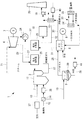
本実施形態に係る廃棄物発電プラント1は、図1に示すように、燃焼炉2内で廃棄物を燃焼して生成された燃焼ガスによって蒸気を生成するボイラ3と、ボイラ3からの蒸気によって駆動される蒸気タービン4と、廃棄物からメタン含有バイオガスを生成するメタン発酵槽5と、メタン発酵槽5からのメタン含有バイオガスによって駆動するガスエンジン6とを備えている。また、廃棄物発電プラント1は、第1発電機(発電機)7及び第2発電機8によって発電を行っている。第1発電機7の回転軸は、蒸気タービン4の回転軸に接続され、第1発電機7は蒸気タービン4の回転力によって発電している。また、第2発電機8の回転軸は、ガスエンジン6の回転軸に接続され、第2発電機8は、ガスエンジン6の駆動力によって発電している。
Hereinafter, an embodiment of a waste power plant 1 according to the present invention will be described with reference to the drawings.
[First Embodiment]
Hereinafter, a first embodiment of the present invention will be described with reference to FIG.
As shown in FIG. 1, the waste power plant 1 according to the present embodiment includes a
ボイラ3は、廃棄物を燃焼して燃焼ガスを生成する燃焼炉2と、燃焼炉2にて生成された燃焼ガスを導く煙道11と、内部に給水(流通媒体)が流通して煙道11内に設置される複数の伝熱管(図示省略)とを有する。
The
燃焼炉2は、例えば、ストーカ炉といわれる燃焼炉2が挙げられる。ストーカ炉は、廃棄物供給路12から移動床(図示省略)上に投入された廃棄物を、移動床によって移送する。燃焼炉2内では、炉底より燃焼空気を導入され、移動床上に形成された一次燃焼室にて廃棄物の乾燥、熱分解を行った後に、移動床の下流側にて燃焼を行い、燃焼ガスを生成する。燃焼空気は、燃焼炉2に連通した燃焼空気導入管13内を流通して燃焼炉2内に導入される。
なお、廃棄物供給路12には、廃棄物分別機14が設けられている。廃棄物分別機14は、廃棄物供給路12内を流通する廃棄物を、メタン発酵処理される廃棄物と、焼却処理される廃棄物とに分別している。本実施形態では、燃焼炉2に供給される廃棄物は焼却処理する廃棄物である。廃棄物分別機14で分別されたメタン発酵処理される廃棄物は、メタン発酵槽廃棄物供給路15を介して後述するメタン発酵槽5に供給される。
An example of the
The
燃焼炉2内で生成された燃焼ガスは、煙道11内を流れる。燃焼ガスは、煙道11内に設置された複数の伝熱管(図示省略)内を流れる給水と熱交換を行う。伝熱管内を流れる給水と熱交換を終えた燃焼ガスは、燃焼排ガスとしてボイラ3から排出される。ボイラ3から排出された燃焼排ガスは、燃焼排ガス管17内を流通し、濾過式集塵機18において必要な処理を施した後に、ファン19を介して煙突20から大気へ排気される。
The combustion gas generated in the
伝熱管は、煙道11内に延在し、煙道11の壁部近傍で複数回に亘って折り返される構造をしている。伝熱管の内部には給水が流通する。伝熱管の上流側端部は蒸気供給管21に連通し、下流側端部は給水供給管22に連通している。伝熱管内を流れる給水と、煙道11内を流れる燃焼ガスとが熱交換を行うことで、蒸気が生成される。
The heat transfer tube extends into the
生成された蒸気は、蒸気供給管21内を流通して蒸気タービン4に導入される。蒸気タービン4に導入された蒸気は、蒸気タービン4を回転させる。蒸気タービン4の回転軸には、第1発電機7の回転軸が接続されていて、蒸気タービン4が回転することで、第1発電機7が駆動し、発電する。なお、蒸気タービン4に導入された蒸気の一部は、抽気蒸気管23を介して後述する給水加熱器26に供給される。
The generated steam flows through the
蒸気タービン4を回転させた蒸気は、復水器24において凝縮し水になる。復水器24で生成された水は、給水供給管22内を流通し、ボイラ3内に設けられた伝熱管に給水として供給される。給水供給管22には、上流側から順に、給水予熱器25及び給水加熱器26が設けられている。給水予熱器25には後述する第2熱交換器(図示省略)が設けられ、この第2熱交換器内を流れる一次冷却水と、復水器24からボイラ3に供給される給水とが熱交換することによって、給水が予熱される。給水加熱器26では、蒸気タービン4から抽気された蒸気の一部によって、給水予熱器25で予熱された給水がさらに加熱される。なお、給水加熱器26で給水を加熱した後の水または蒸気は、排出管27を介して復水器24に戻される。
The steam rotating the steam turbine 4 is condensed in the
廃棄物分別機14において分別されたメタン発酵処理される廃棄物は、メタン発酵槽廃棄物供給路15を介してメタン発酵槽5に供給される。メタン発酵槽5では、メタン発酵処理される廃棄物からメタン含有バイオガスを生成する。生成されたメタン含有バイオガスは、バイオガス供給管28を介してガスエンジン6に供給される。また、メタン含有バイオガスを生成した際に生じる汚泥は、メタン発酵槽5から排出され、汚泥排出管29内を流通し、汚泥回収部(図示省略)にて回収される。
The waste separated by the
ガスエンジン6は、バイオガス供給管28から供給されたメタン含有バイオガスを空気供給装置(図示省略)から供給される空気とともに燃焼させて駆動する。ガスエンジン6では駆動するピストン(図示省略)をクランクシャフト(図示省略)によって回転運動に変換する。ガスエンジン6の回転軸には、第2発電機8の回転軸が接続されていて、ガスエンジン6が駆動することで第2発電機8が駆動し、発電する。
The
ガスエンジン6から排出された燃焼排ガスは、ガスエンジン用燃焼排ガス管30内を流通し、燃焼排ガス管17に合流し、ファン19を介して煙突20から大気へ排気される。なお、ガスエンジン用燃焼排ガス管30には、排ガス排熱回収装置(例えば、有機ランキンサイクル)16が設けられている場合がある。排ガス排熱回収装置16では、ガスエンジン用燃焼排ガス管30内を流通する燃焼排ガスと、排ガス排熱回収装置16内を流通する作動流体とが熱交換することで、燃焼排ガスの熱を回収している。
The combustion exhaust gas discharged from the
ガスエンジン6には、メタン含有バイオガスによって駆動するガスエンジン本体(図示省略)と、ガスエンジン本体と一次冷却水(熱媒体)とが熱交換を行う第1熱交換器(図示省略)とを有する。第1熱交換器は、内部を一次冷却水が流通していて、この一次冷却水がガスエンジン本体と熱交換を行うことでガスエンジン本体を冷却する。すなわち、一次冷却水は、ガスエンジン本体によって加熱される。
The
ガスエンジン本体によって加熱された一次冷却水は、ガスエンジン6から排出される。ガスエンジン6から排出された一次冷却水は、第1熱媒体管(熱媒体流路)31を介して、給水予熱器25内に設けられた第2熱交換器に供給される。第2熱交換器では、ガスエンジン本体によって加熱された一次冷却水と、ボイラ3に供給される給水とが熱交換を行い、給水を予熱する。給水予熱器25で給水の予熱を終えた一次冷却水は、第2熱交換器と第1熱交換器とを連通する第2熱媒体管(熱媒体流路)32を介して、第1熱交換器に供給される。第2熱媒体管32には、内部を二次冷却水が流通する廃熱回収部33が設けられている。廃熱回収部33は、一次冷却水と二次冷却水とが熱交換を行う熱交換部34及び熱交換部34で回収した熱を放熱する放熱部35を有する。廃熱回収部33によって、第1熱交換器に流入する一次冷却水を所定の温度に冷却する。このように、一次冷却水は、第1熱媒体管31内及び第2熱媒体管32内を流通することにより、第1熱交換器と第2熱交換器との間を循環している。
The primary cooling water heated by the gas engine body is discharged from the
本実施形態によれば、以下の作用効果を奏する。
本実施形態では、ガスエンジン6で発生した熱によって、ボイラ3内に供給する給水を予熱している。給水を予熱することで、給水加熱器26において給水を加熱する際に用いられる熱を低減させることができる。すなわち、本実施形態では、給水加熱器26において蒸気タービン4から蒸気の一部を抽気し、その蒸気を使用して給水を加熱しているので、ガスエンジン6で発生した熱によって給水を予熱することで、蒸気タービン4から抽気する蒸気の量を低減することができる。これにより、蒸気タービン4によって駆動する第1発電機7の発電量が、抽気量が低減した分だけ向上する。すなわち、廃棄物発電プラント1全体の発電量が向上する。したがって、ガスエンジン6で発生した熱を給水の予熱に使用しない場合と比較して、廃棄物発電プラント1全体の発電効率を向上させることができる。
According to this embodiment, there exist the following effects.
In the present embodiment, the water supplied to the
なお、本実施形態では、第2熱交換器を給水予熱器25に設けているが、第2熱交換器を設ける箇所はこれに限らない。例えば、燃焼空気導入管13に燃焼空気予熱器37を設け、燃焼空気予熱器37に第2熱交換器を設けることで燃焼空気を加熱するようにしてもよい。このような構成によれば、ガスエンジン6の熱を利用して、燃焼炉2に供給される燃焼空気を予熱できるので、燃焼炉2内で廃棄物を好適に燃焼させ、蒸気の生成量を向上させることができる。
In addition, in this embodiment, although the 2nd heat exchanger is provided in the
また、廃棄物供給路12に廃棄物予熱器38を設け、廃棄物予熱器38に第2熱交換器を設けることで廃棄物を加熱するようにしてもよい。このような構成によれば、ガスエンジン6の熱を利用して、燃焼炉2に供給される廃棄物を予熱・乾燥できるので、燃焼炉2内で廃棄物を好適に燃焼させ、蒸気の生成量を向上させることができる。
In addition, the
また、メタン発酵槽5にメタン発酵槽加熱器39を設け、メタン発酵槽加熱器39に第2熱交換器を設けることで、メタン発酵槽5の内部のメタン発酵処理される廃棄物を加熱するようにしてもよい。このような構成によれば、例えば、メタン発酵槽5が屋外等の比較的低温の場所に設置されたとしても、ガスエンジン6の熱を利用して、メタン発酵処理される廃棄物を好適に加熱できるので、発酵反応を促進して好適にメタン含有バイオガスを生成することができる。
In addition, the methane
また、排ガス排熱回収装置16に作動流体加熱器40を設け、作動流体加熱器40に第2熱交換器を設けることで、排ガス排熱回収装置16内を流通する作動流体を加熱するようにしてもよい。このような構成によれば、ガスエンジン6の熱を利用して、作動流体を好適に加熱することができる。
Further, the working fluid heater 40 is provided in the exhaust gas exhaust
また、汚泥排出管29に汚泥加熱器41を設け、汚泥加熱器41に第2熱交換器を設けることで、汚泥を加熱するようにしてもよい。このような構成によれば、ガスエンジン6の熱を利用して汚泥を乾燥させることができる。汚泥を乾燥させることで、その後キルン等で炭化させることが容易となる。
Further, the
また、廃棄物発電プラント1内にヒートポンプ(図示省略)を設け、ヒートポンプに第2熱交換器を設けることで、ヒートポンプ内を流通する熱媒体を加熱するようにしてもよい。このようなヒートポンプで発生させた熱の利用先としては、燃焼空気予熱器37、廃棄物予熱器38、メタン発酵槽加熱器39、作動流体加熱器40及び汚泥加熱器41等としてもよい。
Further, a heat pump (not shown) may be provided in the waste power plant 1, and a heat medium circulating in the heat pump may be heated by providing a second heat exchanger in the heat pump. The heat generated by the heat pump may be used as the
また、本実施形態では、第2熱交換器を給水予熱器25のみに設けているが、第2熱交換器を燃焼空気予熱器37、廃棄物予熱器38、メタン発酵槽加熱器39、作動流体加熱器40、汚泥加熱器41及びヒートポンプ等のうちの複数の設備に設けてもよい。
Moreover, in this embodiment, although the 2nd heat exchanger is provided only in the
〔第2実施形態〕
以下、本発明の第2実施形態について、図2を用いて説明する。
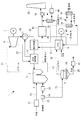
本実施形態では、基本的に第1実施形態と同様の構造を有し、給水供給管22に設けられた第2熱交換器と第1熱交換器とを接続する第2熱媒体管45の構造が相違している。したがって、第1実施形態と同一の構成については同一符号を付しその説明を省略する。
図2に示すように、第2熱交換器と第1熱交換器とを接続する第2熱媒体管45には、第1実施形態と異なり、廃熱回収部33が設けられていない。
[Second Embodiment]
Hereinafter, a second embodiment of the present invention will be described with reference to FIG.
In the present embodiment, the second
As shown in FIG. 2, unlike the first embodiment, the second
本実施形態によれば、以下の作用効果を奏する。
本実施形態によれば、第2熱交換器から第1熱交換器の間で一次冷却水の温度が低下し難くすることができる。したがって、給水供給管22内を流通する給水よりも、ガスエンジン6の温度が低い場合には、給水供給管22内を流通する給水の熱によって、ガスエンジン6を加熱することができる。これにより、例えば、停止中で温度が低い状態のガスエンジン6を始動させるために暖機する場合に、給水供給管22内を流通する給水の熱を利用して、ガスエンジン6を暖機することができる。したがって、ガスエンジン6を暖機するためのヒータ等を設けることなくガスエンジン6を暖機することができる。また、ガスエンジン6を暖機するために廃棄物発電プラント1で発電した電気を使用している場合と比較して、廃棄物発電プラント1の発電効率を向上させることができる。
なお、本実施形態において、第2熱交換器が設けられているのは、給水を予熱するものではないので、図2では第2熱交換器が設けられるものを単なる「熱交換器」と図示している。図1における給水予熱器25と、図2における熱交換器とは構成に相違はない。
According to this embodiment, there exist the following effects.
According to this embodiment, the temperature of the primary cooling water can be made difficult to decrease between the second heat exchanger and the first heat exchanger. Therefore, when the temperature of the
In the present embodiment, the second heat exchanger is not provided for preheating the water supply, so in FIG. 2, the second heat exchanger provided is simply referred to as a “heat exchanger”. Show. There is no difference in configuration between the
次に、本実施形態の変形例について説明する。
本実施形態では、廃熱回収部33が設けられていない第2熱媒体管45のみを設ける構成について説明したが、廃熱回収部33を設けた熱媒体管を同時に設けてもよい。具体的には、図2の破線で示すように、第2熱媒体管45の途中位置から分岐した分岐熱媒体管46を設け、分岐熱媒体管46に廃熱回収部33を設けてもよい。このような構成では、一次冷却水が流通する熱媒体管を切り替えることで、ガスエンジン6の加熱と冷却とを行うことができる。すなわち、ガスエンジン6を加熱したい場合には、上述のように、廃熱回収部33を設けていない第2熱媒体管45内に一次冷却水を流通させる。一方、ガスエンジン6を冷却したい場合には、廃熱回収部33を設けた分岐熱媒体管46内に一次冷却水を流通させることで、廃熱回収部33において冷却された一次冷却水をガスエンジン6に供給し、ガスエンジン6を冷却することができる。一次冷却水が流通する熱媒体管を切り替える手段としては、分岐熱媒体管46に開閉弁(図示省略)を設けてもよい。
Next, a modification of this embodiment will be described.
In the present embodiment, the configuration in which only the second
〔第3実施形態〕
以下、本発明の第3実施形態について、図3を用いて説明する。
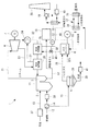
本実施形態では、基本的に第1実施形態と同様の構造を有し、第1熱交換器と第2熱交換器とを接続する第1熱媒体管48等の構造が相違している。したがって、他の実施形態と同一の構成については同一符号を付しその説明を省略する。
本実施形態では、第1熱媒体管(第1熱媒体流路)48と第2熱媒体管(第2熱媒体流路)49とを、給水加熱器26に設けられた第2熱交換器をバイパスするように連通する第3熱媒体管(第3熱媒体流路)50を有する。また、第1熱媒体管48には、第2熱交換器に流入する一次冷却水の流量と、第3熱媒体管50に流入する一次冷却水の流量とを調整する流量調整弁(流量調整部)51が設けられている。また、第2熱媒体管49のうち、第3熱媒体管50との合流位置よりも下流側には、第2熱媒体管49の内部を流通する一次冷却水の温度を計測する温度計(温度計測部)52が設けられている。また、温度計52が計測した一次冷却水の温度に応じて、第2熱交換器に流入する一次冷却水の流量と、第3熱媒体管50に流入する一次冷却水の流量とを調整する流量調整弁51を制御する図示しない制御装置(制御部)が設けられている。本実施形態では、温度計52で計測した温度が所定の閾値よりも低い場合には、第2熱交換器に流入する一次冷却水の流量を低減させて、第3熱媒体管50に流入する一次冷却水の流量を増加させるように流量調整弁51を制御する。なお、制御方法は一例であり、流量調整弁51の制御方法は、他の制御方法であってもよい。
[Third Embodiment]
Hereinafter, a third embodiment of the present invention will be described with reference to FIG.
In the present embodiment, the structure is basically the same as that of the first embodiment, and the structures of the first
In the present embodiment, the first heat medium pipe (first heat medium flow path) 48 and the second heat medium pipe (second heat medium flow path) 49 are connected to the second heat exchanger provided in the
制御装置は、例えば、CPU(Central Processing Unit)、RAM(Random Access Memory)、ROM(Read Only Memory)、及びコンピュータ読み取り可能な記憶媒体等から構成されている。そして、各種機能を実現するための一連の処理は、一例として、プログラムの形式で記憶媒体等に記憶されており、このプログラムをCPUがRAM等に読み出して、情報の加工・演算処理を実行することにより、各種機能が実現される。なお、プログラムは、ROMやその他の記憶媒体に予めインストールしておく形態や、コンピュータ読み取り可能な記憶媒体に記憶された状態で提供される形態、有線又は無線による通信手段を介して配信される形態等が適用されてもよい。コンピュータ読み取り可能な記憶媒体とは、磁気ディスク、光磁気ディスク、CD−ROM、DVD−ROM、半導体メモリ等である。 The control device includes, for example, a central processing unit (CPU), a random access memory (RAM), a read only memory (ROM), and a computer-readable storage medium. A series of processes for realizing various functions is stored in a storage medium or the like in the form of a program as an example, and the CPU reads the program into a RAM or the like to execute information processing / arithmetic processing. As a result, various functions are realized. The program is preinstalled in a ROM or other storage medium, provided in a state stored in a computer-readable storage medium, or distributed via wired or wireless communication means. Etc. may be applied. The computer-readable storage medium is a magnetic disk, a magneto-optical disk, a CD-ROM, a DVD-ROM, a semiconductor memory, or the like.
本実施形態によれば、以下の作用効果を奏する。
本実施形態では、第2熱媒体管49において、第2熱交換器で熱交換を行った一次冷却水と、第2熱交換器で熱交換を行っていない一次冷却水(すなわち第3熱媒体管50を流通する一次冷却水)とが合流する。すなわち、第2熱媒体管49において、第2熱交換器で給水を予熱した比較的低温の一次冷却水と、第2熱交換器を介さない第3熱媒体管50を流通する比較的高温の一次冷却水とが合流する。第2熱媒体管49内を流通する一次冷却水の温度に応じて、第2熱交換器及び第3熱媒体管50に流入する熱媒体の流量を調整しているので、第2熱媒体管49内の熱媒体の温度を所望の温度とすることができる。このように、第2熱媒体管49内の一次冷却水の温度を所望の温度とすることができるので、ガスエンジン6と熱交換する第1熱交換器に流入する一次冷却水の温度を所望の温度とすることができる。本実施形態では、温度計52で計測した温度が所定の閾値よりも低い場合には、第2熱交換器に流入する一次冷却水の流量を低減させて、第3熱媒体管50に流入する一次冷却水の流量を増加させているので、第1熱交換器に流入する熱媒体の温度を一定とさせ、ガスエンジン6の運転を安定させることができる。
According to this embodiment, there exist the following effects.
In the present embodiment, in the second
なお、本実施形態では、廃熱回収部33が設けられていない第2熱媒体管49のみを設ける構成について説明したが、廃熱回収部33を介さない熱媒体管を同時に設けてもよい。具体的には、図3の破線で示すように、第2熱媒体管49の途中位置から分岐し、廃熱回収部33を介さない分岐熱媒体管53を設けてもよい。このような構成では、第2実施形態の変形例と同様に、一次冷却水が流通する熱媒体管を切り替えることで、ガスエンジン6の加熱と冷却とを行うことができる。また、ガスエンジン6を加熱する際にも、温度計で第2熱媒体管49の温度を計測し、第2熱媒体管49内を流通する一次冷却水の温度に応じて、第2熱交換器及び第3熱媒体管50に流入する熱媒体の流量を調整することで、ガスエンジン6を加熱する場合でも、ガスエンジン6と熱交換する第1熱交換器に流入する一次冷却水の温度を所望の温度とすることができる。
In the present embodiment, the configuration in which only the second
また、本実施形態では、温度計52は第2熱媒体管49と第3熱媒体管50の合流後とする構成について説明したが、熱交換部34を通過した後に温度計を設けてもよい。
In the present embodiment, the
〔第4実施形態〕
以下、本発明の第4実施形態について、図4を用いて説明する。
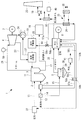
本実施形態では、基本的に第1実施形態と同様の構造を有し、第2熱交換器が複数設置され、第1熱交換器と第2熱交換器とを接続する熱媒体管等も複数設けられている点が相違している。したがって、他の実施形態と同一の構成については同一符号を付しその説明を省略する。
本実施形態では、第2熱交換器が、ボイラ3に供給される給水を予熱する給水予熱器25と、燃焼空気を加熱する燃焼空気予熱器37と、廃棄物を加熱する廃棄物予熱器38とに、それぞれ設けられている。また、それに伴い、ガスエンジン6に設けられた第1熱交換器とそれぞれの第2熱交換器とを接続する第1熱媒体管56a、56b、56c及び第2熱媒体管57a、57b、57cも複数設けられている。また、第1熱媒体管56aと第2熱媒体管57aとを、給水予熱器25に設けられた第2熱交換器をバイパスするように連通する第3熱媒体管60を有する。また、第1熱媒体管56a、56b、56cには、それぞれに流量調整弁58a、58b、58cが設けられる。このうち、第1熱媒体管56aに設けられている調整弁58aは、給水予熱器25に設けられた第2熱交換器に流入する一次冷却水の流量と、第3熱媒体管60に流入する一次冷却水の流量とを調整することができる流量調整弁である。
[Fourth Embodiment]
Hereinafter, a fourth embodiment of the present invention will be described with reference to FIG.
In the present embodiment, a heat medium pipe having a structure basically similar to that of the first embodiment, in which a plurality of second heat exchangers are installed, and connecting the first heat exchanger and the second heat exchanger, etc. The difference is that a plurality of points are provided. Therefore, the same components as those of the other embodiments are denoted by the same reference numerals and the description thereof is omitted.
In the present embodiment, the second heat exchanger includes a
また、蒸気供給管21には、蒸気供給管21内を流通する蒸気の流量を計測する蒸気量計測器59が設けられている。また、蒸気量計測器(蒸気量計測部)59が計測した蒸気の流量に基づいて各流量調整弁58a、58b、58cのそれぞれの開度を制御する制御装置(図示省略)が設けられている。本実施形態では、蒸気量計測器59で計測した蒸気の流量が第1閾値よりも低い値である場合には、燃焼空気予熱器37に設けられた第2熱交換器に流入する一次冷却水の流量を増加させ、蒸気の流量が第1閾値よりも高く第2閾値よりも低い値である場合には、廃棄物予熱器38に設けられた第2熱交換器に流入する一次冷却水の流量を増加させ、蒸気の流量が第2閾値よりも高い場合には、第3熱媒体管60に流入する一次冷却水の流量を増加させるように各流量調整弁58a、58b、58cの開度等を制御している。なお、制御方法は一例であり、各流量調整弁58a、58b、58cの開度等の制御方法は、他の制御方法であってもよい。
The
本実施形態によれば、以下の作用効果を奏する。
本実施形態では、蒸気量計測器59で計測した蒸気の流量が所定の第1閾値よりも低い値である場合には、燃焼空気予熱器37に設けられた第2熱交換器に流入する一次冷却水の流量を増加させ、蒸気の流量が第1閾値よりも高く第2閾値よりも低い値である場合には、廃棄物予熱器38に設けられた第2熱交換器に流入する一次冷却水の流量を増加させるように各流量調整弁58a、58b、58cを制御している。したがって、計測された蒸気の流量が、所望の蒸気の流量と比較して大きく下回っている場合(第1閾値よりも低い値の場合)には、流量調整弁58bの開度を大きくし、蒸気の生成に影響が大きい燃焼空気予熱器37に設けられた第2熱交換器に接続する第1熱媒体管56b内の流量を多くすることで、ボイラ3に供給される燃焼空気を予熱し、ボイラ3で生成する蒸気量を増加させて所望の蒸気の流量とすることができる。また、測定された蒸気の流量が、所望の蒸気量と比較して小さく下回っている場合(第1閾値よりも高く第2閾値よりも低い値である場合)には、流量調整弁58cの開度を大きくし、蒸気の生成量への影響が、燃焼空気予熱器37よりも少ない廃棄物予熱器38に設けられた第2熱交換器に接続する第2熱媒体管56c内の流量を多くすることで、生成する蒸気量を増加させ所望の量とすることができる。よって、ボイラ3において生成する蒸気量(すなわち、蒸気タービン4に流入する蒸気量)を一定とすることができ、第1発電機7の発電効率を向上させることができる。また、ボイラ3で生成する蒸気量が所望の蒸気の流量よりも多い場合(第2閾値よりも高い値である場合)には、流量調整弁58a、流量調整弁58bおよび58cの開度を調整し、第3熱媒体管60への流量を増加させるとともに、給水予熱器25、燃焼空気予熱器37及び廃棄物予熱器38に設けられた第2熱交換器に流入する一次冷却水の流量を少なくすることで、生成する蒸気量を減少させ所望の量とすることができる。なお、流入する一次冷却水の流量を少なくする第2熱交換器は、給水予熱器25、燃焼空気予熱器37及び廃棄物予熱器38に設けられたすべての第2熱交換器であってもよく、3つのうちのいずれか1つまたは2つの第2熱交換器であってもよい。
According to this embodiment, there exist the following effects.
In the present embodiment, when the steam flow rate measured by the steam
なお、本実施形態では、蒸気量計測器59で計測した蒸気の流量に基づいて各流量調整弁58a、58b、58cの開度を制御する例について説明したが、各流量調整弁58a、58b、58cの開度の制御は、他に基づいてもよい。例えば、燃焼炉2内に設けたカメラ(図示省略)で廃棄物の燃焼状態を検出、確認し、廃棄物の燃焼状態に基づいて各流量調整弁58a、58b、58cの開度を制御してもよい。また、燃焼炉2内の移動床に温度計(図示省略)を設けて、この温度計の計測する温度に基づいて各流量調整弁58a、58b、58cの開度を制御してもよい。このような構成によっても、ボイラ3において生成する蒸気量(すなわち、蒸気タービン4に流入する蒸気量)を一定とすることができ、第1発電機7の発電効率を向上させることができる。
In the present embodiment, the example in which the opening degree of each flow
なお、本発明は、上記各実施形態にかかる発明に限定されるものではなく、その要旨を逸脱しない範囲において、適宜変形が可能である。例えば、上記第3実施形態及び第4実施形態では、制御装置によって、流量調整弁を制御しているが、制御装置を設けずに、作業者によって流量調整弁の開度を調整してもよい。
また、第4実施形態において、第2熱交換器を給水予熱器25、燃焼空気予熱器37及び廃棄物予熱器38の3箇所に設けているが、第2熱交換器を設けるのは他の機器でもよい。例えば、メタン発酵槽加熱器39でもよく、作動流体加熱器40でもよく、汚泥加熱器41でもよく、ヒートポンプでもよい。メタン発酵槽加熱器39等に第2熱交換器を設けることで、ボイラ3で生成する蒸気量が所望の蒸気の流量よりも多い場合には、蒸気の生成量への直接的な影響がないメタン発酵槽加熱器39等に設けられた第2熱交換器に接続する第2熱媒体管内を流通する一次冷却水の流量を多くすることで、生成する蒸気量を減少させ所望の量とすることができる。また、第2熱交換器を設ける箇所は、複数であればよく、3箇所でなくてもよい。2箇所であってもよく、4箇所以上であってもよい。
Note that the present invention is not limited to the invention according to each of the above embodiments, and can be appropriately modified without departing from the gist thereof. For example, in the said 3rd Embodiment and 4th Embodiment, although the flow regulating valve is controlled by the control apparatus, you may adjust the opening degree of a flow regulating valve by an operator, without providing a control apparatus. .
Moreover, in 4th Embodiment, although the 2nd heat exchanger is provided in three places, the
1 廃棄物発電プラント
2 燃焼炉
3 ボイラ
4 蒸気タービン
5 メタン発酵槽
6 ガスエンジン
7 第1発電機(発電機)
8 第2発電機
12 廃棄物供給路
13 燃焼空気導入管
14 廃棄物分別機
15 メタン発酵槽廃棄物供給路
16 排ガス排熱回収装置
21 蒸気供給管
22 給水供給管
25 給水予熱器
26 給水加熱器
28 バイオガス供給管
29 汚泥排出管
31 第1熱媒体管(熱媒体流路)
32 第2熱媒体管(熱媒体流路)
33 廃熱回収部
37 燃焼空気予熱器
38 廃棄物予熱器
39 メタン発酵槽加熱器
40 作動流体加熱器
41 汚泥加熱器
45 第2熱媒体管
46 分岐熱媒体管
48 第1熱媒体管(第1熱媒体流路)
49 第2熱媒体管(第2熱媒体流路)
50 第3熱媒体管(第3熱媒体流路)
51 流量調整弁(流量調整部)
52 温度計(温度計測部)
53 分岐熱媒体管
56a〜56c 第1熱媒体管(熱媒体流路)
57a〜57c 第2熱媒体管(熱媒体流路)
58a〜58c 流量調整弁(流量調整部)
59 蒸気量計測器(蒸気量計測部)
DESCRIPTION OF SYMBOLS 1
8
32 Second heat medium pipe (heat medium flow path)
33 Waste
49 Second heat medium pipe (second heat medium flow path)
50 Third heat medium pipe (third heat medium flow path)
51 Flow adjustment valve (Flow adjustment part)
52 Thermometer (Temperature Measurement Unit)
53 1st heat-medium pipe | tube (heat-medium flow path)
57a to 57c second heat medium pipe (heat medium flow path)
58a to 58c Flow rate adjustment valve (Flow rate adjustment unit)
59 Vapor amount measuring device (Vapor amount measuring unit)
Claims (9)
前記ボイラで生成した蒸気によって駆動される蒸気タービンと、
前記蒸気タービンによって発電する発電機と、
前記廃棄物から生成されたメタン含有バイオガスによって駆動するガスエンジンと、を備えた廃棄物発電プラントであって、
熱媒体が流通する熱媒体流路と、
前記ガスエンジンに設けられ、前記ガスエンジンと前記熱媒体とを熱交換する第1熱交換器と、
前記熱媒体流路を介して前記熱媒体が供給され、前記廃棄物発電プラントに対して熱の授受を行う流通媒体と前記熱媒体とを熱交換する第2熱交換器と、を備えた廃棄物発電プラント。 A boiler that generates steam by burning waste in a combustion furnace;
A steam turbine driven by steam generated in the boiler;
A generator for generating electricity by the steam turbine;
A waste power plant comprising a gas engine driven by methane-containing biogas generated from the waste,
A heat medium flow path through which the heat medium flows;
A first heat exchanger provided in the gas engine for exchanging heat between the gas engine and the heat medium;
A waste provided with the heat medium supplied through the heat medium flow path, and a second heat exchanger for exchanging heat between the distribution medium for transferring heat to the waste power plant and the heat medium Power plant.
前記第2熱媒体流路には、該第2熱媒体流路内を流通する前記熱媒体の温度を計測する温度計測部が設けられ、
前記熱媒体流路には、前記第2熱交換器及び前記第3熱媒体流路に流入する前記熱媒体の流量を調整する流量調整部が設けられ、
前記流量調整部は、前記温度計測部が計測した前記熱媒体の温度に応じて前記第2熱交換器及び前記第3熱媒体流路に流入する前記熱媒体の流量を調整する請求項3または請求項4に記載の廃棄物発電プラント。 The heat medium flow path includes a first heat medium flow path for allowing the heat medium to flow from the first heat exchanger to the second heat exchanger, and from the second heat exchanger to the first heat exchanger. A second heat medium flow path through which the heat medium flows, and a third heat medium flow path communicating the first heat medium flow path and the second heat medium flow path so as to bypass the second heat exchanger. And having
The second heat medium flow path is provided with a temperature measurement unit that measures the temperature of the heat medium flowing through the second heat medium flow path,
The heat medium flow path is provided with a flow rate adjusting unit for adjusting the flow rate of the heat medium flowing into the second heat exchanger and the third heat medium flow path,
The flow rate adjusting unit adjusts the flow rate of the heat medium flowing into the second heat exchanger and the third heat medium flow path according to the temperature of the heat medium measured by the temperature measurement unit. The waste power plant according to claim 4.
各前記第2熱交換器に接続される前記熱媒体流路は、複数設けられ、
前記ボイラで生成される前記蒸気の蒸気量を計測する蒸気量計測部と、
各前記熱媒体流路に設けられ、各前記熱媒体流路を流通する前記熱媒体の流量を調整する流量調整部と、
前記蒸気量計測部が計測した前記蒸気量に基づいて各前記流量調整部を制御する制御部と、を備える請求項3または請求項4に記載の廃棄物発電プラント。 A plurality of the second heat exchangers are provided,
A plurality of the heat medium flow paths connected to each of the second heat exchangers are provided,
A steam amount measuring unit for measuring a steam amount of the steam generated in the boiler;
A flow rate adjusting unit that is provided in each of the heat medium flow paths and adjusts the flow rate of the heat medium flowing through each of the heat medium flow paths;
The waste power generation plant according to claim 3 or 4 provided with a control part which controls each said flow volume adjustment part based on said steam quantity which said steam quantity measurement part measured.
各前記第2熱交換器に接続される前記熱媒体流路は、複数設けられ、
前記燃焼炉内の前記廃棄物の燃焼状態を検出する燃焼状態検出部と、
各前記熱媒体流路に設けられ、各前記熱媒体流路を流通する前記熱媒体の流量を調整する流量調整部と、
前記燃焼状態検出部が検出した前記燃焼状態に基づいて各前記流量調整部を制御する制御部と、を備える請求項3または請求項4に記載の廃棄物発電プラント。 A plurality of the second heat exchangers are provided,
A plurality of the heat medium flow paths connected to each of the second heat exchangers are provided,
A combustion state detection unit for detecting a combustion state of the waste in the combustion furnace;
A flow rate adjusting unit that is provided in each of the heat medium flow paths and adjusts the flow rate of the heat medium flowing through each of the heat medium flow paths;
The waste power generation plant according to claim 3 or 4 provided with a control part which controls each said flow volume adjustment part based on said combustion state which said said combustion state detection part detected.
前記第2熱交換器は、複数設けられ、
各前記第2熱交換器に接続される前記熱媒体流路は、複数設けられ、
前記ボイラで生成される前記蒸気の蒸気量を計測する蒸気量計測工程と、
前記蒸気量計測工程で計測した前記蒸気量に基づいて、各前記熱媒体流路に設けられた各流量調整部によって各前記熱媒体流路を流通する前記熱媒体の流量を調整する流量調整工程と、
を備えた廃棄物発電プラントの運転方法。 A method for operating a waste power plant according to claim 3 or claim 4,
A plurality of the second heat exchangers are provided,
A plurality of the heat medium flow paths connected to each of the second heat exchangers are provided,
A steam amount measuring step for measuring a steam amount of the steam generated in the boiler;
A flow rate adjusting step of adjusting the flow rate of the heat medium flowing through each of the heat medium flow paths by each flow rate adjusting unit provided in each of the heat medium flow paths based on the steam amount measured in the steam amount measuring step. When,
Of operating a waste power plant equipped with
前記第2熱交換器は、複数設けられ、
各前記第2熱交換器に接続される前記熱媒体流路は、複数設けられ、
前記燃焼炉内の前記廃棄物の燃焼状態を検出する燃焼状態検出工程と、
前記燃焼状態検出工程で検出した前記燃焼状態に基づいて、各前記熱媒体流路に設けられた各流量調整部によって各前記熱媒体流路を流通する前記熱媒体の流量を調整する流量調整工程と、
を備えた廃棄物発電プラントの運転方法。
A method for operating a waste power plant according to claim 3 or claim 4,
A plurality of the second heat exchangers are provided,
A plurality of the heat medium flow paths connected to each of the second heat exchangers are provided,
A combustion state detection step of detecting a combustion state of the waste in the combustion furnace;
Based on the combustion state detected in the combustion state detection step, a flow rate adjustment step of adjusting the flow rate of the heat medium flowing through each of the heat medium channels by each flow rate adjusting unit provided in each of the heat medium channels. When,
Of operating a waste power plant equipped with
Priority Applications (1)
| Application Number | Priority Date | Filing Date | Title |
|---|---|---|---|
| JP2017015936A JP6847682B2 (en) | 2017-01-31 | 2017-01-31 | How to operate a waste power plant and a waste power plant |
Applications Claiming Priority (1)
| Application Number | Priority Date | Filing Date | Title |
|---|---|---|---|
| JP2017015936A JP6847682B2 (en) | 2017-01-31 | 2017-01-31 | How to operate a waste power plant and a waste power plant |
Publications (2)
| Publication Number | Publication Date |
|---|---|
| JP2018123744A true JP2018123744A (en) | 2018-08-09 |
| JP6847682B2 JP6847682B2 (en) | 2021-03-24 |
Family
ID=63109523
Family Applications (1)
| Application Number | Title | Priority Date | Filing Date |
|---|---|---|---|
| JP2017015936A Active JP6847682B2 (en) | 2017-01-31 | 2017-01-31 | How to operate a waste power plant and a waste power plant |
Country Status (1)
| Country | Link |
|---|---|
| JP (1) | JP6847682B2 (en) |
Cited By (2)
| Publication number | Priority date | Publication date | Assignee | Title |
|---|---|---|---|---|
| CN112266851A (en) * | 2020-10-28 | 2021-01-26 | 浙江天地环保科技股份有限公司 | Efficient heat recycling system and method for coupling biogas engineering and biogas slurry thermal hydrolysis engineering |
| JP2022163635A (en) * | 2021-04-14 | 2022-10-26 | 三菱重工パワーインダストリー株式会社 | Biomass fuel utilization system |
Citations (12)
| Publication number | Priority date | Publication date | Assignee | Title |
|---|---|---|---|---|
| JPS635102A (en) * | 1986-06-24 | 1988-01-11 | Mitsubishi Heavy Ind Ltd | Exhaust heat recovery power plant |
| JPH01227805A (en) * | 1988-03-04 | 1989-09-12 | Pps Project Promotion Service Ab | Heat and power coincidence plant |
| JP2001280102A (en) * | 2000-03-30 | 2001-10-10 | Kawasaki Heavy Ind Ltd | Method and apparatus for recovering energy from waste gasification gas |
| JP2004161972A (en) * | 2002-11-13 | 2004-06-10 | Tokyo Electric Power Co Inc:The | Slurry manufacturing storage system using waste heat |
| JP2005262103A (en) * | 2004-03-18 | 2005-09-29 | Fuji Electric Holdings Co Ltd | Methane fermentation treatment equipment for organic waste |
| JP2008221142A (en) * | 2007-03-13 | 2008-09-25 | Kawasaki Plant Systems Ltd | Waste treatment methods and equipment |
| JP2009236014A (en) * | 2008-03-27 | 2009-10-15 | Isuzu Motors Ltd | Waste heat recovery system |
| JP2011241744A (en) * | 2010-05-18 | 2011-12-01 | Mitsubishi Heavy Ind Ltd | Supercharging device of internal combustion engine |
| JP2012101139A (en) * | 2010-11-05 | 2012-05-31 | Tokyo Gas Co Ltd | Biogas producing system and method for removing ammonia in biogas |
| JP2016142223A (en) * | 2015-02-04 | 2016-08-08 | 三菱重工業株式会社 | Waste heat recovery device, waste heat recovery type ship propulsion device, and waste heat recovery method |
| JP2016200083A (en) * | 2015-04-13 | 2016-12-01 | 株式会社藤井基礎設計事務所 | Power generation system |
| JP2017006891A (en) * | 2015-06-26 | 2017-01-12 | 日立造船株式会社 | Waste treating method for providing useful substance by using biomass in waste as raw material |
-
2017
- 2017-01-31 JP JP2017015936A patent/JP6847682B2/en active Active
Patent Citations (12)
| Publication number | Priority date | Publication date | Assignee | Title |
|---|---|---|---|---|
| JPS635102A (en) * | 1986-06-24 | 1988-01-11 | Mitsubishi Heavy Ind Ltd | Exhaust heat recovery power plant |
| JPH01227805A (en) * | 1988-03-04 | 1989-09-12 | Pps Project Promotion Service Ab | Heat and power coincidence plant |
| JP2001280102A (en) * | 2000-03-30 | 2001-10-10 | Kawasaki Heavy Ind Ltd | Method and apparatus for recovering energy from waste gasification gas |
| JP2004161972A (en) * | 2002-11-13 | 2004-06-10 | Tokyo Electric Power Co Inc:The | Slurry manufacturing storage system using waste heat |
| JP2005262103A (en) * | 2004-03-18 | 2005-09-29 | Fuji Electric Holdings Co Ltd | Methane fermentation treatment equipment for organic waste |
| JP2008221142A (en) * | 2007-03-13 | 2008-09-25 | Kawasaki Plant Systems Ltd | Waste treatment methods and equipment |
| JP2009236014A (en) * | 2008-03-27 | 2009-10-15 | Isuzu Motors Ltd | Waste heat recovery system |
| JP2011241744A (en) * | 2010-05-18 | 2011-12-01 | Mitsubishi Heavy Ind Ltd | Supercharging device of internal combustion engine |
| JP2012101139A (en) * | 2010-11-05 | 2012-05-31 | Tokyo Gas Co Ltd | Biogas producing system and method for removing ammonia in biogas |
| JP2016142223A (en) * | 2015-02-04 | 2016-08-08 | 三菱重工業株式会社 | Waste heat recovery device, waste heat recovery type ship propulsion device, and waste heat recovery method |
| JP2016200083A (en) * | 2015-04-13 | 2016-12-01 | 株式会社藤井基礎設計事務所 | Power generation system |
| JP2017006891A (en) * | 2015-06-26 | 2017-01-12 | 日立造船株式会社 | Waste treating method for providing useful substance by using biomass in waste as raw material |
Cited By (3)
| Publication number | Priority date | Publication date | Assignee | Title |
|---|---|---|---|---|
| CN112266851A (en) * | 2020-10-28 | 2021-01-26 | 浙江天地环保科技股份有限公司 | Efficient heat recycling system and method for coupling biogas engineering and biogas slurry thermal hydrolysis engineering |
| JP2022163635A (en) * | 2021-04-14 | 2022-10-26 | 三菱重工パワーインダストリー株式会社 | Biomass fuel utilization system |
| JP7601694B2 (en) | 2021-04-14 | 2024-12-17 | 三菱重工パワーインダストリー株式会社 | Biomass fuel utilization system |
Also Published As
| Publication number | Publication date |
|---|---|
| JP6847682B2 (en) | 2021-03-24 |
Similar Documents
| Publication | Publication Date | Title |
|---|---|---|
| RU2352859C2 (en) | Steam generator on waste heat | |
| JP3783195B2 (en) | Current generation in a combined power plant with gas and steam turbines. | |
| CN102656407B (en) | Method and apparatus for recovering heat from bottom ash | |
| TWI848256B (en) | System and method for improving startup time in a fossil-fueled power generation system | |
| CN101230985B (en) | Process for operating a thermal generator set with a coal-fired boiler as well as a thermal generator set | |
| JP5501841B2 (en) | Waste heat recovery equipment for steelmaking arc furnace and arc furnace equipment for steelmaking | |
| JP6224858B1 (en) | Power plant and operation method thereof | |
| CN115075901B (en) | Energy storage power generation system for thermal power plants | |
| CN108731004B (en) | Circulating cooling device of water-cooled grate and waste incineration power generation device | |
| JPS61250306A (en) | Hot air turbine and steam turbine combination power plant | |
| JP6847682B2 (en) | How to operate a waste power plant and a waste power plant | |
| CZ26344U1 (en) | Electric power generating plant from solid fuels and employing gas turbine engine | |
| CN103573311A (en) | Steam exhaust energy utilizing system of driving steam turbine of thermal power plant and thermal power unit | |
| JP5501842B2 (en) | Waste heat recovery equipment and waste heat recovery method for steel making arc furnace, and steel making arc furnace equipment | |
| CN117128494B (en) | Device and method for jointly starting coal-fired unit by fused salt heat storage and oil-fired boiler | |
| CN115111010B (en) | A power generation system with decoupling of boiler regulation process based on high-temperature molten salt energy storage | |
| CN206281365U (en) | A kind of high-temp waste gas afterheat utilizing system | |
| JP2021046989A (en) | Feedwater heating system, power generation plant equipped with the same, and operation method of feedwater heating system | |
| KR101999448B1 (en) | Hybrid power generation system using a supercritical CO2 working fluid | |
| JP4823998B2 (en) | Waste power generation method | |
| JP6797776B2 (en) | How to operate a waste treatment plant and a waste treatment plant | |
| KR101696297B1 (en) | Combined Heat and Power System for Energy-saving type | |
| CN106855363B (en) | Waste heat utilization system of electric converter flue gas based on multi-pressure mode | |
| KR102188155B1 (en) | Hybrid heat supply apparatus using solid fuel direct combustion method and gasification combustion method, and cogeneration system using the same | |
| CN103562634B (en) | Steam generator |
Legal Events
| Date | Code | Title | Description |
|---|---|---|---|
| A621 | Written request for application examination |
Free format text: JAPANESE INTERMEDIATE CODE: A621 Effective date: 20191011 |
|
| A977 | Report on retrieval |
Free format text: JAPANESE INTERMEDIATE CODE: A971007 Effective date: 20200731 |
|
| A131 | Notification of reasons for refusal |
Free format text: JAPANESE INTERMEDIATE CODE: A131 Effective date: 20200804 |
|
| A521 | Request for written amendment filed |
Free format text: JAPANESE INTERMEDIATE CODE: A523 Effective date: 20201005 |
|
| A131 | Notification of reasons for refusal |
Free format text: JAPANESE INTERMEDIATE CODE: A131 Effective date: 20201027 |
|
| A521 | Request for written amendment filed |
Free format text: JAPANESE INTERMEDIATE CODE: A523 Effective date: 20201228 |
|
| TRDD | Decision of grant or rejection written | ||
| A01 | Written decision to grant a patent or to grant a registration (utility model) |
Free format text: JAPANESE INTERMEDIATE CODE: A01 Effective date: 20210202 |
|
| A61 | First payment of annual fees (during grant procedure) |
Free format text: JAPANESE INTERMEDIATE CODE: A61 Effective date: 20210303 |
|
| R150 | Certificate of patent or registration of utility model |
Ref document number: 6847682 Country of ref document: JP Free format text: JAPANESE INTERMEDIATE CODE: R150 |
|
| S111 | Request for change of ownership or part of ownership |
Free format text: JAPANESE INTERMEDIATE CODE: R313113 |
|
| R350 | Written notification of registration of transfer |
Free format text: JAPANESE INTERMEDIATE CODE: R350 |