JP2018120456A - Alarm display system and alarm display method - Google Patents
Alarm display system and alarm display method Download PDFInfo
- Publication number
- JP2018120456A JP2018120456A JP2017011983A JP2017011983A JP2018120456A JP 2018120456 A JP2018120456 A JP 2018120456A JP 2017011983 A JP2017011983 A JP 2017011983A JP 2017011983 A JP2017011983 A JP 2017011983A JP 2018120456 A JP2018120456 A JP 2018120456A
- Authority
- JP
- Japan
- Prior art keywords
- information
- alarm
- display
- alarm display
- database
- Prior art date
- Legal status (The legal status is an assumption and is not a legal conclusion. Google has not performed a legal analysis and makes no representation as to the accuracy of the status listed.)
- Pending
Links
Images


Classifications
-
- G—PHYSICS
- G05—CONTROLLING; REGULATING
- G05B—CONTROL OR REGULATING SYSTEMS IN GENERAL; FUNCTIONAL ELEMENTS OF SUCH SYSTEMS; MONITORING OR TESTING ARRANGEMENTS FOR SUCH SYSTEMS OR ELEMENTS
- G05B23/00—Testing or monitoring of control systems or parts thereof
- G05B23/02—Electric testing or monitoring
- G05B23/0205—Electric testing or monitoring by means of a monitoring system capable of detecting and responding to faults
- G05B23/0259—Electric testing or monitoring by means of a monitoring system capable of detecting and responding to faults characterized by the response to fault detection
- G05B23/0267—Fault communication, e.g. human machine interface [HMI]
- G05B23/0272—Presentation of monitored results, e.g. selection of status reports to be displayed; Filtering information to the user
-
- G—PHYSICS
- G05—CONTROLLING; REGULATING
- G05B—CONTROL OR REGULATING SYSTEMS IN GENERAL; FUNCTIONAL ELEMENTS OF SUCH SYSTEMS; MONITORING OR TESTING ARRANGEMENTS FOR SUCH SYSTEMS OR ELEMENTS
- G05B23/00—Testing or monitoring of control systems or parts thereof
- G05B23/02—Electric testing or monitoring
- G05B23/0205—Electric testing or monitoring by means of a monitoring system capable of detecting and responding to faults
- G05B23/0218—Electric testing or monitoring by means of a monitoring system capable of detecting and responding to faults characterised by the fault detection method dealing with either existing or incipient faults
- G05B23/0224—Process history based detection method, e.g. whereby history implies the availability of large amounts of data
- G05B23/0227—Qualitative history assessment, whereby the type of data acted upon, e.g. waveforms, images or patterns, is not relevant, e.g. rule based assessment; if-then decisions
- G05B23/0232—Qualitative history assessment, whereby the type of data acted upon, e.g. waveforms, images or patterns, is not relevant, e.g. rule based assessment; if-then decisions based on qualitative trend analysis, e.g. system evolution
-
- G—PHYSICS
- G05—CONTROLLING; REGULATING
- G05B—CONTROL OR REGULATING SYSTEMS IN GENERAL; FUNCTIONAL ELEMENTS OF SUCH SYSTEMS; MONITORING OR TESTING ARRANGEMENTS FOR SUCH SYSTEMS OR ELEMENTS
- G05B23/00—Testing or monitoring of control systems or parts thereof
- G05B23/02—Electric testing or monitoring
- G05B23/0205—Electric testing or monitoring by means of a monitoring system capable of detecting and responding to faults
- G05B23/0259—Electric testing or monitoring by means of a monitoring system capable of detecting and responding to faults characterized by the response to fault detection
- G05B23/0267—Fault communication, e.g. human machine interface [HMI]
- G05B23/027—Alarm generation, e.g. communication protocol; Forms of alarm
-
- G—PHYSICS
- G05—CONTROLLING; REGULATING
- G05B—CONTROL OR REGULATING SYSTEMS IN GENERAL; FUNCTIONAL ELEMENTS OF SUCH SYSTEMS; MONITORING OR TESTING ARRANGEMENTS FOR SUCH SYSTEMS OR ELEMENTS
- G05B23/00—Testing or monitoring of control systems or parts thereof
- G05B23/02—Electric testing or monitoring
- G05B23/0205—Electric testing or monitoring by means of a monitoring system capable of detecting and responding to faults
- G05B23/0259—Electric testing or monitoring by means of a monitoring system capable of detecting and responding to faults characterized by the response to fault detection
- G05B23/0286—Modifications to the monitored process, e.g. stopping operation or adapting control
Abstract
Description
本発明は、アラーム表示システムおよびアラーム表示方法に関する。 The present invention relates to an alarm display system and an alarm display method.
プラントにおける機器の監視システムでは、アラームが大量に発生することへの対応が求められている(例えば、特許文献1)。特許文献1に記載されているシステムでは、対処が必要なアラーム信号(アラーム)の受信パターンを予め登録しておき、逐次受信するアラーム信号のシーケンスが登録した受信パターンと合致した場合に、合致した受信パターンに対応付けられているアクションの内容が表示される。
Equipment monitoring systems in plants are required to cope with a large amount of alarms (for example, Patent Document 1). In the system described in
上述したように、特許文献1に記載されているシステムでは、パターン単位でアクション内容の表示等の支援情報の表示が行われる。つまり、特許文献1に記載されているシステムでは、すべてのアラーム信号(以下、アラーム情報)に対応づけて支援情報が表示されるということはない。
As described above, in the system described in
一方、アラーム情報は、例えば、所定の事象が所定の機器で発生したことを通知する機能を個々に有する。すなわち、すべてのアラーム情報は意味を持つ。したがって、発生したアラーム情報をすべてオペレータが確認できるようにすること、つまり、すべてのアラーム情報をオペレータが見通せるようにすることには意味がある。しかしながら、すべてのアラーム情報を表示する場合、アラームが大量に発生したときに、真に監視・注意すべきアラームが埋もれてしまうことがあるという課題がある。 On the other hand, the alarm information individually has a function of notifying that a predetermined event has occurred in a predetermined device, for example. That is, all alarm information is meaningful. Therefore, it is meaningful to allow an operator to check all generated alarm information, that is, to allow an operator to see all alarm information. However, when all alarm information is displayed, there is a problem that when a large number of alarms occur, alarms that should be truly monitored and noted may be buried.
本発明は、上記事情に鑑みてなされたものであり、アラームが大量に発生した場合でも真に監視・注意すべきアラームが埋もれてしまうことがなく、かつ、見通しのよい監視を可能とすることができるアラーム表示システムおよびアラーム表示方法を提供することを目的とする。 The present invention has been made in view of the above circumstances, and even when a large number of alarms are generated, alarms that should be truly monitored and warned are not buried, and monitoring with good visibility is possible. An object of the present invention is to provide an alarm display system and an alarm display method capable of performing the above.
上記課題を解決するため、本発明の一態様は、所定の事象と、その発生確率と、その事象についての確認状況と、その事象に対する対処方針とを対応づけて複数組、記憶するデータベースと、監視対象の機器にて前記事象が発生したことを示すアラーム情報を取得するアラーム情報取得部と、前記取得したアラーム情報に対して、前記データベースが記憶する情報に基づき、当該アラーム情報への対処の判断を支援する支援情報を付加する支援情報付加部と、前記支援情報が付加されたアラーム表示情報を表示する表示部と、を備えるアラーム表示システムである。 In order to solve the above problems, one aspect of the present invention is a database that stores a plurality of sets of predetermined events, their occurrence probabilities, confirmation statuses for the events, and countermeasure policies for the events, An alarm information acquisition unit that acquires alarm information indicating that the event has occurred in the device to be monitored, and a response to the alarm information based on information stored in the database for the acquired alarm information This is an alarm display system comprising: a support information adding unit that adds support information that supports this determination; and a display unit that displays alarm display information to which the support information is added.
また、本発明の一態様は、上記アラーム表示システムであって、前記支援情報付加部が、前記表示部による前記アラーム表示情報の表示状態を指定する情報を前記支援情報として前記アラーム情報に付加し、前記表示部が、複数の前記アラーム表示情報を時系列で並べて表示する。 One aspect of the present invention is the alarm display system, wherein the support information adding unit adds information specifying a display state of the alarm display information by the display unit to the alarm information as the support information. The display unit displays a plurality of the alarm display information side by side in time series.
また、本発明の一態様は、上記アラーム表示システムであって、前記支援情報付加部が、前記対処方針を表す情報を前記支援情報として前記アラーム情報に付加し、前記表示部が、複数の前記アラーム表示情報を時系列で並べて表示する。 One aspect of the present invention is the alarm display system, wherein the support information adding unit adds information indicating the countermeasure policy to the alarm information as the support information, and the display unit includes a plurality of the information Alarm display information is displayed in chronological order.
また、本発明の一態様は、上記アラーム表示システムであって、前記データベースが、前記機器の運転パターン別に前記組を記憶する。 Moreover, 1 aspect of this invention is the said alarm display system, Comprising: The said database memorize | stores the said group according to the driving | operation pattern of the said apparatus.
また、本発明の一態様は、上記アラーム表示システムであって、前記データベースが、複数の前記機器の組み合わせ別に前記組を記憶する。 One embodiment of the present invention is the above-described alarm display system, wherein the database stores the set for each combination of a plurality of the devices.
また、本発明の一態様は、上記アラーム表示システムであって、前記データベースが、前記機器の経年変化に関する情報を記憶し、前記支援情報付加部が、前記経年変化に関する情報を前記支援情報として前記アラーム情報に付加する。 One aspect of the present invention is the alarm display system, wherein the database stores information related to aging of the device, and the support information adding unit uses the information related to aging as the support information. Add to alarm information.
また、本発明の一態様は、上記アラーム表示システムであって、前記データベースが記憶する前記対処方針が、対処の要否または対処の重要度を示す。 One embodiment of the present invention is the above-described alarm display system, wherein the countermeasure policy stored in the database indicates necessity of countermeasure or importance of countermeasure.
また、本発明の一態様は、上記アラーム表示システムであって、前記支援情報が、前記当該アラーム情報と1または複数の他の前記アラーム情報とに基づき決定される。 One embodiment of the present invention is the alarm display system, wherein the support information is determined based on the alarm information and one or more other alarm information.
また、本発明の一態様は、上記アラーム表示システムであって、前記データベースが、記憶する情報の更新の履歴を記憶し、前記支援情報付加部が、前記履歴を示す情報を前記支援情報として前記アラーム情報に付加する。 One aspect of the present invention is the alarm display system, wherein the database stores a history of update of information stored therein, and the support information adding unit uses the information indicating the history as the support information. Add to alarm information.
また、本発明の一態様は、所定の事象と、その発生確率と、その事象についての確認状況と、その事象に対する対処方針とを対応づけて複数組、記憶するデータベースと、監視対象の機器にて前記事象が発生したことを示すアラーム情報を取得するアラーム情報取得部と、前記取得したアラーム情報に対して、前記データベースが記憶する情報に基づき、当該アラーム情報への対処の判断を支援する支援情報を付加する支援情報付加部と、を用い、表示部によって、前記支援情報が付加されたアラーム表示情報を表示するアラーム表示方法である。 Further, according to one aspect of the present invention, a predetermined event, an occurrence probability thereof, a confirmation status of the event, and a database for storing a plurality of sets in association with a countermeasure policy for the event, and a monitoring target device An alarm information acquisition unit that acquires alarm information indicating that the event has occurred, and assists in determining whether to deal with the acquired alarm information based on information stored in the database This is an alarm display method for displaying alarm display information to which the support information is added by a display unit using a support information adding unit for adding support information.
本発明によれば、アラームが大量に発生した場合でも真に監視・注意すべきアラームが埋もれてしまうことがなく、かつ、見通しのよい監視を可能とすることができる。 According to the present invention, even if a large number of alarms are generated, alarms that should be truly monitored and noted are not buried, and monitoring with good visibility can be realized.
<第1の実施形態>
以下、図面を参照して本発明の実施形態について説明する。
図1は、本発明の実施形態に係るアラーム表示システム1の構成例を説明するためのブロック図である。
図1に示すアラーム表示システム1は、アラーム表示装置11とデータベース12を備える。アラーム表示装置11は、例えばパーソナルコンピュータ、タブレット、スマートフォン等のコンピュータであり、CPU(中央処理装置)と、入出力装置、表示装置、通信装置、記憶装置等を備える。アラーム表示装置11は、アラーム表示装置11が有するハードウェアを利用して所定のソフトウェアを実行することで、情報取得部111、支援情報付加部112、および表示部113として機能する。データベース12は、アラーム表示装置11が有する記憶装置内、あるいはアラーム表示装置11の外部に設けられた記憶装置内に記憶されているデータベース(ファイルまたはファイルとその管理システム)である。アラーム表示システム1は、通信線4を介して制御装置2に接続されている。通信線4は、例えば有線や無線の構内通信網や公衆通信網内に設定された通信回線である。
<First Embodiment>
Hereinafter, embodiments of the present invention will be described with reference to the drawings.
FIG. 1 is a block diagram for explaining a configuration example of an
The
制御装置2は、プラント3内に設置されている機器31、32および33から所定の情報を受け取り、それに基づいて、アラーム情報、イベント情報、およびプロセス値情報(状態量情報)を生成し、アラーム表示システム1に対して送信する。プラント3は、例えば発電施設、生産施設、工場施設等の施設である。機器31、32および33は、制御装置2およびアラーム表示システム1が監視対象とする装置であり、制御装置2との間で所定の情報を送受信する機能を有する。機器31、32および33は、例えば、各種状態量(各部の温度や圧力、流量、速度等)を検知する1または複数のセンサを備え、制御装置2からの要求に応じてあるいは自発的に検知した状態量を表す情報を有線または無線の通信線を介して制御装置2に対して送信する。例えばプラント3が発電施設である場合、機器31、32および33は、ガスタービン、蒸気タービン、HRSG(Heat Recovery Steam Generator)等である。あるいは、機器31、32および33は、IoT(Internet of Things)端末等であってもよい。
The control device 2 receives predetermined information from the
アラーム情報は、運転中あるいは停止中の機器31、32および33にて発生した予め定められた基準に基づく通知すべき事象(当該事象)の発生を示す情報である。事象とは、例えば、機器31、32および33にて所定の温度や圧力、流量、速度等が所定の基準値を上回ったことや下回ったこと、範囲外となったこと、あるいは機器31、32および33または機器31、32および33内の装置の運転遮断、故障等である。アラーム情報は、例えば、当該事象が発生したプラント3、機器31、32または33、機器31、32または33の部位(装置、部品等)等の発生箇所を識別する情報、当該事象の内容を識別する情報、当該事象が発生した日時を示す時刻情報等を含んで構成されている。なお、本実施形態では、アラーム情報がアラーム名と時刻情報から構成されていて、アラーム名が当該事象の発生箇所を識別する情報と内容を識別する情報とを含んで構成されているものとする。
The alarm information is information indicating the occurrence of an event (the event) to be notified based on a predetermined criterion that has occurred in the
イベント情報は、所定の事項の発生を示す情報であり、プラント3や機器31、32および33の起動、停止、機器の動作や運転状態の変更等の事項(当該事項)の発生を示す。イベント情報は、機器31等から受け取った所定の情報の他、オペレータが制御装置2等に入力した操作情報に基づいて生成されてもよい。イベント情報は、例えば、当該事項が発生したプラント3、機器31、32または33、機器31、32または33の部位(装置、部品等)等の発生箇所を識別する情報、当該事項の内容を識別する情報、当該事項が発生した日時を示す時刻情報等を含んで構成されている。
The event information is information indicating the occurrence of a predetermined matter, and indicates the occurrence of matters (the matter) such as the start and stop of the plant 3 and the
プロセス値情報(状態量情報)は、上述した各種状態量(プロセス値)(各部の温度や圧力、流量、速度等)を検知するセンサの検知結果や、複数のセンサの検知結果に基づいて制御装置2等で算出した算出結果を示す情報である。算出結果は、例えば、定格出力に対する現在の出力の比率、運転効率、最大定格値に対する温度、速度、電圧、電流等の値の比率である。 Process value information (state quantity information) is controlled based on the detection results of the sensors that detect the various state quantities (process values) described above (temperature, pressure, flow rate, speed, etc. of each part) and the detection results of multiple sensors. This is information indicating a calculation result calculated by the device 2 or the like. The calculation result is, for example, the ratio of the current output to the rated output, the operation efficiency, and the ratio of values such as temperature, speed, voltage, and current to the maximum rated value.
制御装置2は、アラーム情報については、例えば、当該事象が発生するたびにアラーム情報を生成してアラーム表示システム1に対して送信する。また、制御装置2は、イベント情報については、例えば、当該事項が発生するたびにイベント情報を生成してアラーム表示システム1に対して送信する。また、制御装置2は、プロセス値情報については、例えば、所定周期毎、プロセス値に所定の変化が発生した場合、または、アラーム表示システム1から要求があった場合に、プロセス値情報を生成してアラーム表示システム1に対して送信する。
For example, the control device 2 generates alarm information and transmits it to the
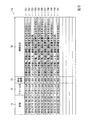
一方、データベース12は、アラーム情報が示す事象に対応する所定の事象と、その発生確率と、その事象についての確認状況と、その事象に対する対処方針とを対応づけて複数組、記憶するファイルである。ここで、図2を参照して、データベース12の構成例について説明する。図2は、図1に示すデータベース12をテーブル121として構成した場合の構成例を説明するための図である。
On the other hand, the
図2に示すテーブル121は、複数のレコードR11、R12、R13等を有して構成されている。各レコードR11、R12、R13は、フィールドF11、F12、F13およびF14を有して構成されている。 A table 121 shown in FIG. 2 includes a plurality of records R11, R12, R13, and the like. Each record R11, R12, R13 has a field F11, F12, F13, and F14.
フィールドF11はアラーム名を示す情報を格納する。上述したようにアラーム名は、当該事象の発生箇所を識別する情報と内容を識別する情報とを含む。また、フィールドF12は発生確率を格納する。発生確率は、当該事象の所定期間における発生確率である。発生確率は、例えば時間、日、週、月、年等を単位とする期間、継続的な1回の運転期間等を所定期間とし、当該期間内に発生した過去の実績値(もしくは同種の機器における実績値)または計算上予想される値とすることができる。 A field F11 stores information indicating an alarm name. As described above, the alarm name includes information for identifying the occurrence location of the event and information for identifying the content. The field F12 stores the occurrence probability. The occurrence probability is an occurrence probability of the event in a predetermined period. The probability of occurrence is, for example, a period in units of hours, days, weeks, months, years, etc., a continuous operation period, etc. as a predetermined period, and a past actual value (or similar type of equipment) that occurred within that period. Actual value) or a value predicted by calculation.
フィールドF13は確認状況を示す情報を格納する。確認状況とは、当該事象に対する知見を示す情報である。また、確認状況は、例えばオペレータが対処の内容を決定するのに役立つ情報である。確認状況は、例えば、当該事象が過去に発生した際に確認された原因、結果等を示す情報、当該事象の深刻度や重要度を示す情報等を表す文字列等である。また、フィールドF14は、当該事象に対する対処方針を示す情報を格納する。当該事象に対する対処方針を示す情報は、例えば、当該事象が発生した場合にその都度確認することが必要か否かを示す情報(都度確認要否の情報)である。 A field F13 stores information indicating the confirmation status. The confirmation status is information indicating knowledge about the event. Further, the confirmation status is information that is useful for the operator to determine the content of the countermeasure, for example. The confirmation status is, for example, a character string representing information indicating a cause, a result, or the like confirmed when the event has occurred in the past, information indicating a severity or importance of the event, and the like. The field F14 stores information indicating a countermeasure policy for the event. The information indicating the coping policy for the event is, for example, information indicating whether or not it is necessary to confirm each time the event occurs (information regarding necessity of confirmation each time).
なお、図2に示す例では、レコードR11のフィールドF11が「アラームA」(この場合、「アラームA」は、当該事象の発生箇所を識別する情報と内容を識別する情報を示す文字列(英数字列等)を表す。)、フィールドF12が「80%」、フィールドF13が「計器公正不備。即座に運転に影響するものではない。」、そして、フィールドF14が「不要」である。また、レコードR12のフィールドF11が「アラームB」(「アラームA」と同様の文字列(英数字列等)を表す。)、フィールドF12が「20%」、フィールドF13が「ポンプの状態による。機器状態確認必要。」、そして、フィールドF14が「要」である。また、レコードR13のフィールドF11が「アラームC」(「アラームA」と同様の文字列(英数字列等)を表す。)、フィールドF12が「20%」、フィールドF13が「ロジック設定不備。即座に運転に影響するものではない。」、そして、フィールドF14が「不要」である。 In the example shown in FIG. 2, the field F11 of the record R11 is “alarm A” (in this case, “alarm A” is a character string (English The field F12 is “80%”, the field F13 is “insufficient instrumentation. It does not immediately affect driving”, and the field F14 is “unnecessary”. Further, the field F11 of the record R12 is “alarm B” (character string (alphanumeric character string or the like) similar to “alarm A”), the field F12 is “20%”, and the field F13 is “depends on the state of the pump. Device status confirmation is necessary. "And field F14 is" necessary. " Further, the field F11 of the record R13 indicates “alarm C” (character string (alphanumeric character string or the like) similar to “alarm A”), the field F12 indicates “20%”, and the field F13 indicates “logic setting deficiency. Immediately. Does not affect the driving of the vehicle ", and the field F14 is" unnecessary ".
なお、データベース12へのデータ登録は別システムで別途計算したものでもいいし、オペレータ等による手入力によるものでもよい。例えば、発生確率は別システムで算出し、確認状況は人が入力するなどとすることができる。
The data registration in the
次に、図1に戻り、アラーム表示装置11の各機能部の説明を行う。図1に示すアラーム表示装置11が有する情報取得部111(アラーム情報取得部)は、通信線4を介して制御装置2から、監視対象の機器31〜33にて所定の事象が発生したことを示すアラーム情報を取得するほか、イベント情報およびプロセス値情報を取得する。情報取得部111は、取得したアラーム情報、イベント情報およびプロセス値情報を所定の記憶装置(例えば、アラーム表示装置11が備える図示しない記憶部)に蓄積する。
Next, returning to FIG. 1, each functional unit of the
また、支援情報付加部112は、情報取得部111が取得したアラーム情報に対して、データベース12が記憶する情報に基づき、当該アラーム情報への対処の判断を支援する支援情報を付加する。支援情報は、例えば、図2に示す発生確率を示す情報、確認状況を示す情報、都度確認要否を示す情報である。また、支援情報とは、例えば、グレーアウトして表示する、赤文字でハイライト表示するなどの表示状態に関する情報である。また、表示部113は、アラーム情報に支援情報が付加された情報(アラーム表示情報とする)を所定の表示装置に表示する。なお、表示部113は、アラーム表示情報を、アラーム表示装置11が有する表示装置に表示してもよいし、それとともに(あるいはそれに代えて)、スマートフォンや携帯電話等の携帯端末の表示装置に表示してもよい。
In addition, the support
次に、図3〜図5を参照して、図1に示すアラーム表示装置11の動作例について説明する。図3は、図1に示すアラーム表示装置11の動作例を説明するためのフローチャートである。図3に示す処理は、情報取得部111が制御装置2からアラーム情報を取得した場合にその都度、アラーム表示装置11において実行される。情報取得部111が制御装置2からアラーム情報を取得すると、支援情報付加部112が、取得したアラーム情報が示すアラーム名に対応する支援情報をデータベース12から取得し、アラーム情報に支援情報を付加して表示部113へ渡す(ステップS11)。次に、表示部113が、アラーム情報にステップS11で取得された支援情報が付加された情報であるアラーム表示情報を表示し、処理を終了する(ステップS12)。
Next, an operation example of the
図4は、表示部113による表示例7を示す図である。表示例7ではアラーム表示情報701〜711が時系列降順で並べて表示されている。各アラーム表示情報701〜711は、アラーム情報の発生時刻を表す時刻の要素71、アラーム名の要素72、発生確率の要素73(図2のフィールドF12に対応)、確認状況の要素74(図2のフィールドF13に対応)、および都度確認要否の要素75(図2のフィールドF14に対応)を含む。図4に示す例では、要素71および72がアラーム情報に対応し、要素73、74および75が支援情報に対応する。
FIG. 4 is a diagram showing a display example 7 by the
図4に示す表示例では、例えば直近の4つのアラーム情報として、時刻「2016/8/19 22:25」(年/月/日 時:分)で発生したアラーム名「アラームC」のアラーム情報に対応するアラーム表示情報704と、時刻「2016/8/19 23:25」で発生したアラーム名「アラームB」のアラーム情報に対応するアラーム表示情報703と、時刻「2016/8/20 00:15」で発生したアラーム名「アラームA」のアラーム情報に対応するアラーム表示情報702と、時刻「2016/8/20 00:35」で発生したアラーム名「アラームA」のアラーム情報に対応するアラーム表示情報701とが表示されている。
In the display example shown in FIG. 4, for example, alarm information of the alarm name “Alarm C” that occurred at the time “2016/8/19 22:25” (year / month / day hour: minute) is displayed as the latest four alarm information.
以上のように、本実施形態によれば、表示部113によって、すべてのアラーム情報に対して各支援情報を付加した情報である各アラーム表示情報が表示される。よって、オペレータは、すべてのアラーム情報を把握することができるとともに、支援情報に基づき、真に監視・注意すべきアラームを容易に判断することができる。すなわち、本実施形態によれば、支援情報(特に要素75の都度確認要否を示す情報)を付加することで、アラームが大量に発生した場合でも真に監視・注意すべきアラームが埋もれてしまうことがなく、かつ、見通しのよい監視が可能となる。
As described above, according to the present embodiment, each alarm display information which is information obtained by adding each support information to all alarm information is displayed on the
次に、図5を参照して、表示部113による他の表示例について説明する。図5は、情報取得部111が図4に示す表示例7の場合と同じアラーム情報を取得したときの表示部113による他の表示例7aを示す。図5に示す表示例7aでは、アラーム表示情報721〜731が時系列降順で並べて表示されている。また、アラーム表示情報723および730が通常の表示状態で表示されていて、アラーム表示情報721〜722、724〜729および731はグレーアウトの表示状態で表示されている(図5では網掛けで表示)。また、各アラーム表示情報721〜731は、アラーム情報の発生時刻を表す時刻の要素71、アラーム名の要素72、発生確率の要素73(図2のフィールドF12に対応)、および確認状況の要素74(図2のフィールドF13に対応)を含む。また、図5の表示例7aでは、図4に示す都度確認要否の要素75(図2のフィールドF14に対応)に対応する情報(要または不要)が、アラーム表示情報の表示状態の違いで示されている。すなわち、図4に示す都度確認要否の要素75(図2のフィールドF14に対応)に対応する情報が「要」であるアラーム表示情報723および730が通常の表示状態で表示されている。他方、図4に示す都度確認要否の要素75(図2のフィールドF14に対応)に対応する情報が「不要」であるアラーム表示情報721〜722、724〜729および731はグレーアウトの表示状態で表示されている。図5に示す例では、要素71および72がアラーム情報に対応し、要素73および74と表示状態の違い(グレーアウトされているか否か)が支援情報に対応する。
Next, another display example by the
図5に示す表示例7aでは、オペレータは、すべてのアラーム情報を把握することができるとともに、表示状態の違いとして付加された支援情報に基づき、真に監視・注意すべきアラームを容易に判断することができる。 In the display example 7a shown in FIG. 5, the operator can grasp all the alarm information, and easily determine the alarm to be monitored and noted based on the support information added as the difference in display state. be able to.
なお、表示状態の違いは、グレーアウトするか否かのほか、例えば、文字色の違い、文字輝度の違い、点滅の有無、フォントの違いや文字の太さの違いを単独または組み合わせて設定することができる。 In addition to whether or not the display state is grayed out, for example, a character color difference, a character brightness difference, a blinking presence / absence, a font difference or a character thickness difference must be set alone or in combination. Can do.
以上のように、本実施形態によれば、例えば過去のアラーム情報を基に、支援情報として、現在発生したアラームの処置判断(例えば重要度の判断)を明示することにより、迅速にアラームに対処可能となった。また、例えば、過去に発生したアラームとそのアラームに対する判断、対処、知見などの支援情報をデータベース12に保有しておくことで、監視時に発生したアラームに対し、過去の発生確率、および、以前にジャッジした知見を表示するとともに、監視不要なものについては例えばグレーアウトすることで監視の見通しをよくすることができた。したがって、本実施形態によれば、監視すべきアラームの明確化により注目すべきアラームが明らかとなり、見通しのよい監視が可能である。これにより、プラント稼働率向上に寄与することが期待できる。
なお、図5の表示例7aにおいて、図4の表示例7と同様に都度確認要否の要素75を表示するように構成してもよい。また、図4の表示例7と図5の表示例7aをオペレータの操作により、切り替えて表示することができるように構成してもよい。
As described above, according to the present embodiment, for example, based on past alarm information, it is possible to quickly cope with an alarm by clearly indicating the judgment of treatment of the alarm that has occurred (eg, judgment of importance) as support information. It has become possible. Further, for example, by holding in the
In addition, in the display example 7a in FIG. 5, the
<第2の実施形態>
次に、図6〜図8を参照して、本発明の他の実施形態について説明する。図6は、図1に示すデータベース12の第2の実施形態における構成例を説明するための図である。図7は、図1に示すアラーム表示装置11の第2の実施形態における動作例を説明するためのフローチャートである。図8は、図1に示すアラーム表示装置11の第2の実施形態における動作例を説明するための図である。
<Second Embodiment>
Next, another embodiment of the present invention will be described with reference to FIGS. FIG. 6 is a diagram for explaining a configuration example of the
本実施形態では、データベース12において、アラーム情報が示す事象に対応する所定の事象と、その発生確率と、その事象についての確認状況と、その事象に対する対処方針とを対応づけて複数組、記憶する際に、複数の組を機器31、32および33の運転パターン別に記憶する。例えばプラント3が発電プラントで機器31がガスタービンの場合、運転パターンは、ガスタービンの起動時、部分負荷運転時、定格運転時、停止時などに分類することができる。図6は、図1に示すデータベース12の構成例を示す図であり、本実施形態では、図1に示すデータベース12を、図6(a)に示すテーブル122と図6(b)に示すテーブル123から構成する。図6(a)に示すテーブル122は、機器31、32および33の起動時に適用される支援情報を含む。図6(b)に示すテーブル123は、機器31、32および33の起動時後(例えば、定格運転時)に適用される支援情報を含む。図6(a)に示すテーブル122の各レコードR11、R12、R13、…と図6(b)に示すテーブル123の各レコードR11、R12、R13、…は、図2を参照して説明したテーブル121の各レコードR11、R12、R13、…と同一構成である。すなわち、フィールドF11、F12、F13およびF14に格納する情報の種類は同一である。ただし、各フィールドF11、F12、F13およびF14に格納される情報の内容は、運転パターンに応じて異なる場合がある。
In the present embodiment, the
例えば、アラーム名「アラームA」については、起動時に適用されるテーブル122と起動時後に適用されるテーブル123では、設定内容は同一である。一方、アラーム名「アラームB」については、起動時に適用されるテーブル122では、発生確率「30%」、確認状況「ポンプの手動操作による可能性あり。」、および都度確認要否「要」と設定されている。一方、起動時後の定格運転時に適用されるテーブル123では、発生確率「20%」、確認状況「ポンプの重大故障の可能性あり。機器状態確認必要。」、および都度確認要否「要」と設定されている。また、アラーム名「アラームC」については、起動時に適用されるテーブル122では、発生確率「40%」、確認状況「ロジック設定不備。即座に運転に影響するものではない。」、および都度確認要否「要」と設定されている。一方、起動時後に適用されるテーブル123では、発生確率「20%」、確認状況「機器故障の可能性あり。」、および都度確認要否「要」と設定されている。 For example, for the alarm name “alarm A”, the setting contents are the same in the table 122 applied at the time of activation and the table 123 applied after the activation. On the other hand, for the alarm name “alarm B”, the occurrence probability “30%”, the confirmation status “Possible due to manual operation of the pump”, and the necessity of confirmation “necessary” are required in the table 122 applied at the time of activation. Is set. On the other hand, in the table 123 applied at the rated operation after startup, the probability of occurrence is “20%”, the confirmation status “Possible serious failure of the pump. The device status needs to be confirmed.” Is set. For the alarm name “alarm C”, the occurrence probability “40%”, the confirmation status “logic setting deficiency. Immediately does not affect driving.” No “required” is set. On the other hand, in the table 123 applied after startup, the occurrence probability “20%”, the confirmation status “possibility of equipment failure”, and the necessity of confirmation “necessary” are set each time.
次に、図7を参照して本実施形態におけるアラーム表示装置11の動作例について説明する。図7は、図1に示すアラーム表示装置11の第2の実施形態における動作例を説明するためのフローチャートである。図7に示す処理は、情報取得部111が制御装置2からアラーム情報を取得した場合にその都度、アラーム表示装置11において実行される。情報取得部111が制御装置2からアラーム情報を取得すると、支援情報付加部112が、当該機器の既取得のイベント情報やプロセス値情報に基づき運転パターン(起動時または起動後)を判別する(ステップS21)。例えば、機器31(ガスタービン)の起動を示すイベント情報を既に取得していて、その受け取ったプロセス値に含まれる当該ガスタービンの出力値が、定格出力の50%未満で上昇する傾向を示していれば、支援情報付加部112は、機器31の運転パターンは起動時であると判別する。また、例えば、機器31の起動を示すイベント情報を既に取得していて、そのイベント情報が示す時刻から所定の時間が経過し、さらに直近の所定時間に受け取ったプロセス値に含まれるガスタービン出力値が定格出力の50%以上100%未満であれば、支援情報付加部112は、機器31の運転パターンは部分負荷時であると判別する。また、ガスタービン出力値が定格出力値を示していれば、支援情報付加部112は、機器31の運転パターンは定格運転時であると判別する。
Next, an operation example of the
次に、支援情報付加部112が、ステップS21で判別した運転パターンに応じてデータベース12からアラーム名に対応する支援情報を取得し、アラーム情報に支援情報を付加して表示部113へ渡す(ステップS22)。支援情報付加部112は、例えば運転パターンが起動時の場合はテーブル122から、運転パターンが起動時後の定格運転時の場合はテーブル123から、支援情報を取得する。
Next, the support
次に、表示部113が、アラーム情報にステップS22で取得された支援情報が付加された情報であるアラーム表示情報を表示し、処理を終了する(ステップS23)。
Next, the
図8は、表示部113による表示例70を示す図であり、表示例70ではアラーム表示情報741〜751が時系列降順で並べて表示されている。各アラーム表示情報741〜751は、アラーム情報の発生時刻を表す時刻の要素71、アラーム名の要素72、発生確率の要素73(図6(a)または(b)のフィールドF12に対応)、確認状況の要素74(図6(a)または(b)のフィールドF13に対応)、および都度確認要否の要素75(図6(a)または(b)のフィールドF14に対応)を含む。図8に示す例では、要素71および72がアラーム情報に対応し、要素73、74および75ならびに表示状態の違い(グレーアウトされているか否か)が支援情報に対応する。
FIG. 8 is a diagram illustrating a display example 70 by the
すなわち、図8に示す表示例70では、アラーム表示情報743、744、746および750が通常の表示状態で表示されていて、アラーム表示情報741、742、745、747〜749および751はグレーアウトの表示状態で表示されている(図8では網掛けで表示)。図8の表示例70では、都度確認要否の要素75が「要」であるアラーム表示情報743、744、746および750が通常の表示状態で表示されている。他方、都度確認要否の要素75が「不要」であるアラーム表示情報741、742、745、747〜749および751はグレーアウトの表示状態で表示されている。図8に示す例では、要素71および72がアラーム情報に対応し、要素73、74および75と表示状態の違い(グレーアウトされているか否か)が支援情報に対応する。
That is, in the display example 70 shown in FIG. 8, the
図8に示す表示例70では、時刻「2016/8/19 22:20」(年/月/日 時:分)以後に発生したアラーム情報は、運転パターンが「起動時」であるときに発生したアラーム情報であり、時刻「2016/8/19 22:15」以前に発生したアラーム情報は、運転パターンが「起動時後」であるときに発生したアラーム情報である。すなわち、表示例70は、機器31、32および33の運転中に、例えば、時刻「2016/8/19 22:15」で発生したアラーム情報に基づきオペレータの指示によって機器31、32および33の運転を停止し、時刻「2016/8/19 22:20」より前に機器31、32および33を再度起動した場合に対応している。
In the display example 70 shown in FIG. 8, the alarm information generated after the time “2016/8/19 22:20” (year / month / day hour: minute) is generated when the operation pattern is “start-up”. The alarm information that occurred before the time “2016/8/19 22:15” is the alarm information that occurred when the driving pattern was “after startup”. That is, in the display example 70, during the operation of the
以上のように、本実施形態によれば、第1の実施形態と同様、表示部113によって、すべてのアラーム情報に対して各支援情報を付加した情報である各アラーム表示情報が表示される。よって、オペレータは、すべてのアラーム情報を把握することができるとともに、支援情報に基づき、真に監視・注意すべきアラームを容易に判断することができる。すなわち、本実施形態によれば、支援情報を付加することで、アラームが大量に発生した場合でも真に監視・注意すべきアラームが埋もれてしまうことがなく、かつ、見通しのよい監視が可能となる。
As described above, according to the present embodiment, each alarm display information, which is information obtained by adding each support information to all alarm information, is displayed on the
さらに、本実施形態によれば、過去のアラームをデータベース化するにあたり運転パターンを考慮することで、処置判断の質を向上させることができる。すなわち、第2の実施形態では、第1の実施形態の構成に加え、運転パターンごとにアラーム情報を保有している。なお、運転パターンは、起動時と起動後(起動時以外)に限らず、機器の運転パターンごとの特性に応じて任意に設定されたものであってよい。これにより、運転パターンそれぞれで発生するアラームをカテゴライズし、実プラントで発生したアラームに対して運転パターンを判断し、該当運転パターンに対応したアラーム情報を出力することができる。また、同じ起動時についても、起動前の停止時間に応じて、ホットスタート(例えば停止時間が8時間以内)、ウォームスタート(例えば停止時間が24時間以内)、コールドスタート(例えば停止時間が24時間超)と運転パターンを分類してもよい。なお、運転状態は、イベント情報やプロセス値情報から判別する。すなわち、運転パターンに応じて、適切な情報をピックアップすることでアラームに対するステータスや発生確率がより正確に判別できる。例えば、図6に示す例では、起動中にアラームBが通知された場合は手動操作の可能性が高いが、起動後の場合は重大故障の可能性が高い、等、同じアラームであっても見るべきポイントの違いや発生頻度の違いを加味できる。このように本実施形態によれば、アラーム表示情報をより高精度に提示することができる。
なお、図8の表示例70にて、運転パターンを表示させるフィールドを追加して表示するようにしてもよい。
Furthermore, according to the present embodiment, the quality of treatment determination can be improved by taking into account the driving pattern when the past alarms are made into a database. That is, in the second embodiment, in addition to the configuration of the first embodiment, alarm information is held for each operation pattern. The operation pattern is not limited to the time of activation and after activation (other than during activation), and may be arbitrarily set according to the characteristics of each device operation pattern. Thereby, the alarms generated in each operation pattern can be categorized, the operation pattern can be determined for the alarm generated in the actual plant, and the alarm information corresponding to the corresponding operation pattern can be output. Also, at the same start time, depending on the stop time before start-up, hot start (for example, stop time is within 8 hours), warm start (for example, stop time is within 24 hours), cold start (for example, stop time is 24 hours) Super) and driving patterns may be classified. The operating state is determined from event information and process value information. That is, the status and occurrence probability for an alarm can be more accurately determined by picking up appropriate information according to the driving pattern. For example, in the example shown in FIG. 6, when alarm B is notified during start-up, the possibility of manual operation is high, but after start-up, the possibility of a serious failure is high. You can take into account differences in points to be seen and differences in the frequency of occurrence. Thus, according to the present embodiment, alarm display information can be presented with higher accuracy.
In addition, in the display example 70 of FIG. 8, you may make it display by adding the field which displays a driving | running pattern.
以上、本発明の各実施形態によれば、発生したアラームに対して過去に発生したアラームを集約したデータベース情報を参照し,確認要・不要の情報や対応状況をオペレータに明示・ガイドすることで、監視の質向上および初動対応の迅速化を図ることができる。 As described above, according to each embodiment of the present invention, it is possible to refer to database information obtained by aggregating alarms that have occurred in the past with respect to generated alarms, and to clearly indicate and guide information that needs to be checked and the response status to the operator. Therefore, it is possible to improve the quality of monitoring and speed up the initial response.
なお、本発明の実施形態は上記のものに限定されない。例えば、以下のような変形が可能である。 The embodiment of the present invention is not limited to the above. For example, the following modifications are possible.
例えば、上記各実施形態では、支援情報付加部112が、対処方針を表す情報(都度確認要否の情報)について、表示部113によるアラーム表示情報の表示状態を指定する情報(グレーアウトするか否か)を支援情報として、アラーム情報に付加し、表示部113が複数のアラーム表示情報を時系列で並べて表示することとしたが、例えば、発生確率の情報について、発生確率に応じて異なる表示状態で表示するよう指定する情報を支援情報として付加することもできる(例えば、発生確率の高いものをグレーアウトして表示する等)。
For example, in each of the above-described embodiments, the support
また、データベース12は、複数の機器の組み合わせ別に構成してもよい。例えば、GTCC(Gas Turbine Combined Cycle)プラントにて、2台のガスタービン(機器Aと機器B)で1台の蒸気タービンを駆動する構成の場合に、機器Aと機器Bの両方を稼働させる機器の組み合わせに対応したテーブルと、機器Aと機器Bのいずれか一方を稼働させる機器の組み合わせに対応したテーブルを、データベース12に含ませることができる。あるいは、テーブルを構成するレコードに機器の組み合わせを示すフィールドを追加して対応させてもよい。
The
また、データベース12が、機器の経年変化に関する情報を記憶するようにし、支援情報付加部112が、経年変化に関する情報を支援情報としてアラーム情報に付加するようにしてもよい。この場合、例えば、アラーム表示情報に、所定期間前の発生確率や発生確率の増加率を示す項目を追加したり、機器の稼働年数や設計寿命を表す項目を追加したりすることができる。
Further, the
また、データベース12が記憶する対処方針は、対処の要否または対処の重要度や緊急度を示す情報とすることができる。すなわち、対処方針は、対処の要否に代えて、または対処の要否とともに、例えば5段階の重要度で示すことができる。この場合に例えば最重要な5では必ず確認が必要、3〜4では確認が望ましい等とすることができる。また、対処の要否や重要度に応じて文字色を複数の色に分類してもよい。あるいは、対処の緊急度を5段階で示し、緊急度5なら所定の時間内に対処しなければならないことを定めておいてもよい。
The coping policy stored in the
また、支援情報は、当該アラーム情報と1または複数の他記アラーム情報とに基づき決定してもよい。例えば、アラームA発生単独では都度確認要否は不要であるが、アラームBやアラームCの発生後(あるいはアラームBの発生後のアラームCの発生後)にアラームAが発生した場合には当該アラームAの都度確認要否は要とすること等ができる。このような判定基準をデータベース12に記憶し、記憶した判定基準を用いた判定部による判定処理を追加することで本変形に対応することができる。
Further, the support information may be determined based on the alarm information and one or more other alarm information. For example, it is not necessary to confirm each time when the alarm A is generated alone, but when the alarm A occurs after the occurrence of the alarm B or C (or after the occurrence of the alarm C after the occurrence of the alarm B), the alarm concerned Whether or not confirmation is required for each A can be considered necessary. By storing such a determination criterion in the
また、データベース12は、記憶する情報の更新の履歴を記憶し、支援情報付加部112が、履歴を示す情報を支援情報としてアラーム情報に付加するようにしてもよい。例えば、図2に示すテーブル121の確認状況のフィールドF13の内容が更新された場合、更新前の情報を更新日時の情報とともに記憶しておく。そして、例えば、図4に示す確認状況の要素74の表示情報が選択された場合に、履歴情報として以前の登録内容を表示すること等ができる。例えば、事象について確認した状況(昔は即座の対応不要だったが、今はXXが閾値以下であることの確認だけはするなど)や事象に対する対処方針(昔は対処要、今は不要など)履歴が表示できる。
In addition, the
1 アラーム表示システム
2 制御装置
3 プラント
4 通信線
11 アラーム表示装置
12 データベース
31、32、33 機器
111 情報取得部
112 支援情報付加部
113 表示部
DESCRIPTION OF
Claims (10)
監視対象の機器にて前記事象が発生したことを示すアラーム情報を取得するアラーム情報取得部と、
前記取得したアラーム情報に対して、前記データベースが記憶する情報に基づき、当該アラーム情報への対処の判断を支援する支援情報を付加する支援情報付加部と、
前記支援情報が付加されたアラーム表示情報を表示する表示部と、
を備えるアラーム表示システム。 A database for storing a plurality of sets of predetermined events, their occurrence probabilities, confirmation statuses for the events, and countermeasures for the events;
An alarm information acquisition unit for acquiring alarm information indicating that the event has occurred in the monitored device;
A support information adding unit for adding support information for supporting determination of handling of the alarm information based on information stored in the database with respect to the acquired alarm information;
A display unit for displaying alarm display information to which the support information is added;
Alarm display system with
前記表示部が、複数の前記アラーム表示情報を時系列で並べて表示する
請求項1に記載のアラーム表示システム。 The support information adding unit adds information specifying the display state of the alarm display information by the display unit to the alarm information as the support information,
The alarm display system according to claim 1, wherein the display unit displays a plurality of the alarm display information in time series.
前記表示部が、複数の前記アラーム表示情報を時系列で並べて表示する
請求項1に記載のアラーム表示システム。 The support information adding unit adds information indicating the countermeasure policy to the alarm information as the support information,
The alarm display system according to claim 1, wherein the display unit displays a plurality of the alarm display information in time series.
請求項1から請求項3のいずれか1項に記載のアラーム表示システム。 The alarm display system according to any one of claims 1 to 3, wherein the database stores the set for each operation pattern of the device.
請求項1から請求項4のいずれか1項に記載のアラーム表示システム。 The alarm display system according to any one of claims 1 to 4, wherein the database stores the set for each combination of a plurality of the devices.
前記支援情報付加部が、前記経年変化に関する情報を前記支援情報として前記アラーム情報に付加する
請求項1から請求項5のいずれか1項に記載のアラーム表示システム。 The database stores information on aging of the equipment,
The alarm display system according to any one of claims 1 to 5, wherein the support information adding unit adds information on the secular change as the support information to the alarm information.
請求項1から請求項6のいずれか1項に記載のアラーム表示システム。 The alarm display system according to any one of claims 1 to 6, wherein the countermeasure policy stored in the database indicates necessity of countermeasure or importance of countermeasure.
請求項1から請求項7のいずれか1項に記載のアラーム表示システム。 The alarm display system according to any one of claims 1 to 7, wherein the support information is determined based on the alarm information and one or more other alarm information.
前記支援情報付加部が、前記履歴を示す情報を前記支援情報として前記アラーム情報に付加する
請求項1から請求項8のいずれか1項に記載のアラーム表示システム。 The database stores an update history of information stored therein,
The alarm display system according to any one of claims 1 to 8, wherein the support information adding unit adds information indicating the history to the alarm information as the support information.
監視対象の機器にて前記事象が発生したことを示すアラーム情報を取得するアラーム情報取得部と、
前記取得したアラーム情報に対して、前記データベースが記憶する情報に基づき、当該アラーム情報への対処の判断を支援する支援情報を付加する支援情報付加部と、
を用い、
表示部によって、前記支援情報が付加されたアラーム表示情報を表示する
アラーム表示方法。 A database for storing a plurality of sets of predetermined events, their occurrence probabilities, confirmation statuses for the events, and countermeasures for the events;
An alarm information acquisition unit for acquiring alarm information indicating that the event has occurred in the monitored device;
A support information adding unit for adding support information for supporting determination of handling of the alarm information based on information stored in the database with respect to the acquired alarm information;
Use
An alarm display method for displaying alarm display information to which the support information is added by a display unit.
Priority Applications (7)
| Application Number | Priority Date | Filing Date | Title |
|---|---|---|---|
| JP2017011983A JP2018120456A (en) | 2017-01-26 | 2017-01-26 | Alarm display system and alarm display method |
| KR1020197019841A KR102295135B1 (en) | 2017-01-26 | 2018-01-26 | Alarm display system and alarm display method |
| CN201880004918.XA CN110050242B (en) | 2017-01-26 | 2018-01-26 | Alarm display system and alarm display method |
| DE112018000539.9T DE112018000539T5 (en) | 2017-01-26 | 2018-01-26 | ALARM DISPLAY SYSTEM AND ALARM DISPLAY METHODS |
| TW107102884A TWI679509B (en) | 2017-01-26 | 2018-01-26 | Alarm display system and alarm display method |
| US16/469,994 US10698398B2 (en) | 2017-01-26 | 2018-01-26 | Alarm display system and alarm display method |
| PCT/JP2018/002506 WO2018139586A1 (en) | 2017-01-26 | 2018-01-26 | Alarm display system and alarm display method |
Applications Claiming Priority (1)
| Application Number | Priority Date | Filing Date | Title |
|---|---|---|---|
| JP2017011983A JP2018120456A (en) | 2017-01-26 | 2017-01-26 | Alarm display system and alarm display method |
Publications (2)
| Publication Number | Publication Date |
|---|---|
| JP2018120456A true JP2018120456A (en) | 2018-08-02 |
| JP2018120456A5 JP2018120456A5 (en) | 2019-10-31 |
Family
ID=62978564
Family Applications (1)
| Application Number | Title | Priority Date | Filing Date |
|---|---|---|---|
| JP2017011983A Pending JP2018120456A (en) | 2017-01-26 | 2017-01-26 | Alarm display system and alarm display method |
Country Status (7)
| Country | Link |
|---|---|
| US (1) | US10698398B2 (en) |
| JP (1) | JP2018120456A (en) |
| KR (1) | KR102295135B1 (en) |
| CN (1) | CN110050242B (en) |
| DE (1) | DE112018000539T5 (en) |
| TW (1) | TWI679509B (en) |
| WO (1) | WO2018139586A1 (en) |
Cited By (3)
| Publication number | Priority date | Publication date | Assignee | Title |
|---|---|---|---|---|
| WO2020075819A1 (en) * | 2018-10-12 | 2020-04-16 | 三菱日立パワーシステムズ株式会社 | Apparatus evaluation device, apparatus evaluation method, and program |
| JP2021026716A (en) * | 2019-08-08 | 2021-02-22 | 横河電機株式会社 | Alarm management device, alarm management system, and alarm management method |
| JP2021060852A (en) * | 2019-10-08 | 2021-04-15 | 株式会社アマダ | Alarm issuing device and alarm issuing method |
Families Citing this family (6)
| Publication number | Priority date | Publication date | Assignee | Title |
|---|---|---|---|---|
| JP2018120456A (en) * | 2017-01-26 | 2018-08-02 | 三菱日立パワーシステムズ株式会社 | Alarm display system and alarm display method |
| JP7208500B2 (en) * | 2019-02-19 | 2023-01-19 | 日本電信電話株式会社 | ALARM CONTROL DEVICE AND ALARM CONTROL METHOD |
| KR20230104870A (en) * | 2020-11-11 | 2023-07-11 | 스미도모쥬기가이고교 가부시키가이샤 | Display device, control device, control method and computer program |
| JP2022117290A (en) * | 2021-01-29 | 2022-08-10 | 三菱重工業株式会社 | Countermeasure presentation system, countermeasure presentation method, and program |
| JP2022117231A (en) * | 2021-01-29 | 2022-08-10 | 三菱重工業株式会社 | Countermeasure presentation system, countermeasure presentation method, and program |
| CN113727067B (en) * | 2021-08-17 | 2023-04-07 | 杭州海康威视系统技术有限公司 | Alarm display method and device, electronic equipment and machine-readable storage medium |
Citations (13)
| Publication number | Priority date | Publication date | Assignee | Title |
|---|---|---|---|---|
| JPS5783808A (en) * | 1980-11-11 | 1982-05-25 | Toshiba Corp | Plant operating device |
| JPS63135402U (en) * | 1987-02-24 | 1988-09-06 | ||
| JPH02207293A (en) * | 1989-02-07 | 1990-08-16 | Hitachi Ltd | Alarm display method and process monitor system |
| JPH0991572A (en) * | 1995-09-28 | 1997-04-04 | Toshiba Corp | Alarm device for plant state |
| JPH10340121A (en) * | 1997-06-06 | 1998-12-22 | Mitsubishi Chem Corp | Plant operation supporting device |
| JPH11231928A (en) * | 1998-02-13 | 1999-08-27 | Fuji Electric Co Ltd | System, device and method for displaying ras |
| JPH11345023A (en) * | 1998-06-01 | 1999-12-14 | Mitsubishi Electric Corp | Plant supervisory and controlling device |
| JP2000270430A (en) * | 1999-03-18 | 2000-09-29 | Mitsubishi Electric Corp | Plant monitor assist system |
| JP2001141872A (en) * | 1999-11-12 | 2001-05-25 | Hitachi Ltd | Method and device for monitoring reactor output |
| JP2005031820A (en) * | 2003-07-09 | 2005-02-03 | Hitachi Ltd | Remote monitoring system and remote monitoring method |
| JP2008046925A (en) * | 2006-08-17 | 2008-02-28 | Mitsubishi Electric Corp | Alarm display device |
| JP2015114778A (en) * | 2013-12-10 | 2015-06-22 | 横河電機株式会社 | Plant control system, control device, management device, and plant information processing method |
| JP2017010155A (en) * | 2015-06-18 | 2017-01-12 | アズビル株式会社 | Facility monitoring device and facility monitoring method |
Family Cites Families (19)
| Publication number | Priority date | Publication date | Assignee | Title |
|---|---|---|---|---|
| JPH0764884B2 (en) | 1986-11-27 | 1995-07-12 | 株式会社トクヤマ | Cyclodextrin composition |
| US8806630B2 (en) * | 2008-05-13 | 2014-08-12 | At&T Intellectual Property, I, L.P. | Methods and apparatus for intrusion protection in systems that monitor for improper network usage |
| US8269620B2 (en) * | 2008-12-19 | 2012-09-18 | Honeywell Internatonal Inc. | Alarm trend summary display system and method |
| EP2388683A1 (en) * | 2010-05-19 | 2011-11-23 | ABB Technology AG | Simplified navigation among process control views in a process control system |
| US9348332B2 (en) * | 2011-03-29 | 2016-05-24 | Mitsubishi Electric Corporation | Abnormality diagnosis device and abnormality diagnosis system for servo control device |
| JP5522491B2 (en) * | 2011-12-13 | 2014-06-18 | 横河電機株式会社 | Alarm display device and alarm display method |
| JP5764081B2 (en) | 2012-03-05 | 2015-08-12 | 株式会社日立製作所 | Plant monitoring and control system |
| WO2014008941A1 (en) * | 2012-07-12 | 2014-01-16 | Abb Technology Ltd | A method of handling an alarm or an event within a process control system |
| CN104020724B (en) * | 2013-03-01 | 2017-02-08 | 中芯国际集成电路制造(上海)有限公司 | alarm monitoring method and device |
| JP2014222485A (en) * | 2013-05-14 | 2014-11-27 | 株式会社東芝 | Information display board |
| JP6139306B2 (en) * | 2013-07-10 | 2017-05-31 | 株式会社東芝 | Operation plan optimization device, operation plan optimization method, and operation plan optimization program |
| JP2015056139A (en) * | 2013-09-13 | 2015-03-23 | 株式会社東芝 | Electronic apparatus, program recommendation system, program recommendation method and program recommendation program |
| JP2015064821A (en) * | 2013-09-26 | 2015-04-09 | アズビル株式会社 | Annunciator display terminal |
| JP2015225470A (en) * | 2014-05-27 | 2015-12-14 | 株式会社日立製作所 | Monitoring control system and monitoring control method |
| KR101646467B1 (en) | 2015-06-18 | 2016-08-05 | 현대자동차주식회사 | Demagnetization diagnosis method for permanent magnet motor of eco-friendly vehicle |
| JP6880560B2 (en) * | 2016-03-30 | 2021-06-02 | 株式会社Ihi | Failure prediction device, failure prediction method and failure prediction program |
| CN106200615B (en) * | 2016-07-15 | 2018-06-19 | 国电南瑞科技股份有限公司 | A kind of intelligent track-traffic early warning implementation method based on incidence relation |
| JP2018120456A (en) * | 2017-01-26 | 2018-08-02 | 三菱日立パワーシステムズ株式会社 | Alarm display system and alarm display method |
| US10832564B2 (en) * | 2017-05-01 | 2020-11-10 | Johnson Controls Technology Company | Building security system with event data analysis for generating false alarm rules for false alarm reduction |
-
2017
- 2017-01-26 JP JP2017011983A patent/JP2018120456A/en active Pending
-
2018
- 2018-01-26 US US16/469,994 patent/US10698398B2/en active Active
- 2018-01-26 TW TW107102884A patent/TWI679509B/en active
- 2018-01-26 DE DE112018000539.9T patent/DE112018000539T5/en active Pending
- 2018-01-26 KR KR1020197019841A patent/KR102295135B1/en active IP Right Grant
- 2018-01-26 CN CN201880004918.XA patent/CN110050242B/en active Active
- 2018-01-26 WO PCT/JP2018/002506 patent/WO2018139586A1/en active Application Filing
Patent Citations (13)
| Publication number | Priority date | Publication date | Assignee | Title |
|---|---|---|---|---|
| JPS5783808A (en) * | 1980-11-11 | 1982-05-25 | Toshiba Corp | Plant operating device |
| JPS63135402U (en) * | 1987-02-24 | 1988-09-06 | ||
| JPH02207293A (en) * | 1989-02-07 | 1990-08-16 | Hitachi Ltd | Alarm display method and process monitor system |
| JPH0991572A (en) * | 1995-09-28 | 1997-04-04 | Toshiba Corp | Alarm device for plant state |
| JPH10340121A (en) * | 1997-06-06 | 1998-12-22 | Mitsubishi Chem Corp | Plant operation supporting device |
| JPH11231928A (en) * | 1998-02-13 | 1999-08-27 | Fuji Electric Co Ltd | System, device and method for displaying ras |
| JPH11345023A (en) * | 1998-06-01 | 1999-12-14 | Mitsubishi Electric Corp | Plant supervisory and controlling device |
| JP2000270430A (en) * | 1999-03-18 | 2000-09-29 | Mitsubishi Electric Corp | Plant monitor assist system |
| JP2001141872A (en) * | 1999-11-12 | 2001-05-25 | Hitachi Ltd | Method and device for monitoring reactor output |
| JP2005031820A (en) * | 2003-07-09 | 2005-02-03 | Hitachi Ltd | Remote monitoring system and remote monitoring method |
| JP2008046925A (en) * | 2006-08-17 | 2008-02-28 | Mitsubishi Electric Corp | Alarm display device |
| JP2015114778A (en) * | 2013-12-10 | 2015-06-22 | 横河電機株式会社 | Plant control system, control device, management device, and plant information processing method |
| JP2017010155A (en) * | 2015-06-18 | 2017-01-12 | アズビル株式会社 | Facility monitoring device and facility monitoring method |
Cited By (12)
| Publication number | Priority date | Publication date | Assignee | Title |
|---|---|---|---|---|
| WO2020075819A1 (en) * | 2018-10-12 | 2020-04-16 | 三菱日立パワーシステムズ株式会社 | Apparatus evaluation device, apparatus evaluation method, and program |
| JP2020061067A (en) * | 2018-10-12 | 2020-04-16 | 三菱日立パワーシステムズ株式会社 | Device evaluation apparatus, device evaluation method and program |
| JP7249122B2 (en) | 2018-10-12 | 2023-03-30 | 三菱重工業株式会社 | Device evaluation device, device evaluation method and program |
| TWI801676B (en) * | 2018-10-12 | 2023-05-11 | 日商三菱動力股份有限公司 | Machine evaluation device, machine evaluation method, and program product |
| JP2021026716A (en) * | 2019-08-08 | 2021-02-22 | 横河電機株式会社 | Alarm management device, alarm management system, and alarm management method |
| JP7344041B2 (en) | 2019-08-08 | 2023-09-13 | 横河電機株式会社 | Alarm management device, alarm management system, and alarm management method |
| US11869335B2 (en) | 2019-08-08 | 2024-01-09 | Yokogawa Electric Corporation | Alarm management apparatus, alarm management system, and alarm management method |
| JP2021060852A (en) * | 2019-10-08 | 2021-04-15 | 株式会社アマダ | Alarm issuing device and alarm issuing method |
| WO2021070667A1 (en) * | 2019-10-08 | 2021-04-15 | 株式会社アマダ | Alarm reporting device and alarm reporting method |
| CN114514567A (en) * | 2019-10-08 | 2022-05-17 | 株式会社天田集团 | Alarm reporting device and alarm reporting method |
| EP4043977A4 (en) * | 2019-10-08 | 2022-11-30 | Amada Co., Ltd. | Alarm reporting device and alarm reporting method |
| JP7257304B2 (en) | 2019-10-08 | 2023-04-13 | 株式会社アマダ | Alarm issuing device and alarm issuing method |
Also Published As
| Publication number | Publication date |
|---|---|
| CN110050242A (en) | 2019-07-23 |
| TW201832033A (en) | 2018-09-01 |
| CN110050242B (en) | 2022-03-11 |
| KR102295135B1 (en) | 2021-08-27 |
| US10698398B2 (en) | 2020-06-30 |
| TWI679509B (en) | 2019-12-11 |
| KR20190089215A (en) | 2019-07-30 |
| WO2018139586A1 (en) | 2018-08-02 |
| US20200096984A1 (en) | 2020-03-26 |
| DE112018000539T5 (en) | 2019-10-02 |
Similar Documents
| Publication | Publication Date | Title |
|---|---|---|
| WO2018139586A1 (en) | Alarm display system and alarm display method | |
| JP2018500710A (en) | Adaptive processing of motion data | |
| WO2016039219A1 (en) | Abnormality detection step developing device and abnormality detection step developing method | |
| TWI653530B (en) | Operation information analysis device | |
| US9019124B2 (en) | System and method for monitoring and alerting on equipment errors | |
| JP6280862B2 (en) | Event analysis system and method | |
| CN109617745A (en) | Alarm prediction method, device, system and storage medium | |
| CA2779328C (en) | Method and system for event pattern detection | |
| CN106233217A (en) | For providing the apparatus and method of the continuous performance indicator of generalization | |
| JP3653004B2 (en) | Fault history monitoring system, fault history monitoring method, and fault history monitoring program | |
| CN113835961A (en) | Alarm information monitoring method, device, server and storage medium | |
| US10614702B2 (en) | Alarm tuning using alarm and process data for condition monitoring | |
| CN110942246A (en) | Work order monitoring method and equipment | |
| CN111624972A (en) | Method for diagnosing state of equipment of production process and machine readable storage medium | |
| JP2002091562A (en) | Supervisory control system | |
| US10642261B2 (en) | High notification rate detection | |
| JP2019102037A (en) | Plant monitoring device and plant monitoring method | |
| KR20110017631A (en) | Performance analysising method for power facilities | |
| CN115345479A (en) | Power generation equipment fault detection method and device, electronic equipment and storage medium | |
| JP2020135016A (en) | Monitoring control device | |
| JP2011192082A (en) | Alarm monitoring system and method of displaying monitoring information | |
| JP2015064683A (en) | Monitoring device, fault alarm signal generation method, fault alarm signal generation program, and communication system | |
| JP2005275512A (en) | Process operation business management system and program |
Legal Events
| Date | Code | Title | Description |
|---|---|---|---|
| A521 | Request for written amendment filed |
Free format text: JAPANESE INTERMEDIATE CODE: A821 Effective date: 20170127 |
|
| RD03 | Notification of appointment of power of attorney |
Free format text: JAPANESE INTERMEDIATE CODE: A7423 Effective date: 20181109 |
|
| A521 | Request for written amendment filed |
Free format text: JAPANESE INTERMEDIATE CODE: A523 Effective date: 20190918 |
|
| A621 | Written request for application examination |
Free format text: JAPANESE INTERMEDIATE CODE: A621 Effective date: 20190918 |
|
| A131 | Notification of reasons for refusal |
Free format text: JAPANESE INTERMEDIATE CODE: A131 Effective date: 20200519 |
|
| A521 | Request for written amendment filed |
Free format text: JAPANESE INTERMEDIATE CODE: A523 Effective date: 20200625 |
|
| A02 | Decision of refusal |
Free format text: JAPANESE INTERMEDIATE CODE: A02 Effective date: 20200915 |