JP2022117290A - Countermeasure presentation system, countermeasure presentation method, and program - Google Patents
Countermeasure presentation system, countermeasure presentation method, and program Download PDFInfo
- Publication number
- JP2022117290A JP2022117290A JP2021013903A JP2021013903A JP2022117290A JP 2022117290 A JP2022117290 A JP 2022117290A JP 2021013903 A JP2021013903 A JP 2021013903A JP 2021013903 A JP2021013903 A JP 2021013903A JP 2022117290 A JP2022117290 A JP 2022117290A
- Authority
- JP
- Japan
- Prior art keywords
- alarm
- information
- master information
- alarm master
- coping method
- Prior art date
- Legal status (The legal status is an assumption and is not a legal conclusion. Google has not performed a legal analysis and makes no representation as to the accuracy of the status listed.)
- Pending
Links
- 238000000034 method Methods 0.000 title claims description 77
- 230000010485 coping Effects 0.000 claims description 66
- 238000012544 monitoring process Methods 0.000 claims description 14
- 238000010586 diagram Methods 0.000 description 14
- 230000006870 function Effects 0.000 description 10
- 238000010276 construction Methods 0.000 description 9
- 230000008569 process Effects 0.000 description 7
- 230000005856 abnormality Effects 0.000 description 5
- 230000008859 change Effects 0.000 description 3
- 238000012549 training Methods 0.000 description 3
- 230000002159 abnormal effect Effects 0.000 description 2
- 238000004891 communication Methods 0.000 description 2
- 238000007689 inspection Methods 0.000 description 2
- 230000007257 malfunction Effects 0.000 description 2
- 230000000737 periodic effect Effects 0.000 description 2
- 238000012545 processing Methods 0.000 description 2
- 230000009471 action Effects 0.000 description 1
- 230000006399 behavior Effects 0.000 description 1
- 230000001364 causal effect Effects 0.000 description 1
- 239000000498 cooling water Substances 0.000 description 1
- 238000013461 design Methods 0.000 description 1
- 230000006866 deterioration Effects 0.000 description 1
- 230000000694 effects Effects 0.000 description 1
- 238000005485 electric heating Methods 0.000 description 1
- 238000009434 installation Methods 0.000 description 1
- 238000010801 machine learning Methods 0.000 description 1
- 230000007246 mechanism Effects 0.000 description 1
- 230000002093 peripheral effect Effects 0.000 description 1
- 230000004044 response Effects 0.000 description 1
- 239000004065 semiconductor Substances 0.000 description 1
- 238000004088 simulation Methods 0.000 description 1
- 239000007787 solid Substances 0.000 description 1
Images


Classifications
-
- G—PHYSICS
- G05—CONTROLLING; REGULATING
- G05B—CONTROL OR REGULATING SYSTEMS IN GENERAL; FUNCTIONAL ELEMENTS OF SUCH SYSTEMS; MONITORING OR TESTING ARRANGEMENTS FOR SUCH SYSTEMS OR ELEMENTS
- G05B23/00—Testing or monitoring of control systems or parts thereof
- G05B23/02—Electric testing or monitoring
- G05B23/0205—Electric testing or monitoring by means of a monitoring system capable of detecting and responding to faults
- G05B23/0259—Electric testing or monitoring by means of a monitoring system capable of detecting and responding to faults characterized by the response to fault detection
- G05B23/0267—Fault communication, e.g. human machine interface [HMI]
- G05B23/0272—Presentation of monitored results, e.g. selection of status reports to be displayed; Filtering information to the user
-
- G—PHYSICS
- G05—CONTROLLING; REGULATING
- G05B—CONTROL OR REGULATING SYSTEMS IN GENERAL; FUNCTIONAL ELEMENTS OF SUCH SYSTEMS; MONITORING OR TESTING ARRANGEMENTS FOR SUCH SYSTEMS OR ELEMENTS
- G05B23/00—Testing or monitoring of control systems or parts thereof
- G05B23/02—Electric testing or monitoring
- G05B23/0205—Electric testing or monitoring by means of a monitoring system capable of detecting and responding to faults
- G05B23/0259—Electric testing or monitoring by means of a monitoring system capable of detecting and responding to faults characterized by the response to fault detection
- G05B23/0267—Fault communication, e.g. human machine interface [HMI]
- G05B23/027—Alarm generation, e.g. communication protocol; Forms of alarm
-
- G—PHYSICS
- G05—CONTROLLING; REGULATING
- G05B—CONTROL OR REGULATING SYSTEMS IN GENERAL; FUNCTIONAL ELEMENTS OF SUCH SYSTEMS; MONITORING OR TESTING ARRANGEMENTS FOR SUCH SYSTEMS OR ELEMENTS
- G05B23/00—Testing or monitoring of control systems or parts thereof
- G05B23/02—Electric testing or monitoring
- G05B23/0205—Electric testing or monitoring by means of a monitoring system capable of detecting and responding to faults
- G05B23/0218—Electric testing or monitoring by means of a monitoring system capable of detecting and responding to faults characterised by the fault detection method dealing with either existing or incipient faults
- G05B23/0221—Preprocessing measurements, e.g. data collection rate adjustment; Standardization of measurements; Time series or signal analysis, e.g. frequency analysis or wavelets; Trustworthiness of measurements; Indexes therefor; Measurements using easily measured parameters to estimate parameters difficult to measure; Virtual sensor creation; De-noising; Sensor fusion; Unconventional preprocessing inherently present in specific fault detection methods like PCA-based methods
-
- G—PHYSICS
- G05—CONTROLLING; REGULATING
- G05B—CONTROL OR REGULATING SYSTEMS IN GENERAL; FUNCTIONAL ELEMENTS OF SUCH SYSTEMS; MONITORING OR TESTING ARRANGEMENTS FOR SUCH SYSTEMS OR ELEMENTS
- G05B23/00—Testing or monitoring of control systems or parts thereof
- G05B23/02—Electric testing or monitoring
- G05B23/0205—Electric testing or monitoring by means of a monitoring system capable of detecting and responding to faults
- G05B23/0218—Electric testing or monitoring by means of a monitoring system capable of detecting and responding to faults characterised by the fault detection method dealing with either existing or incipient faults
- G05B23/0224—Process history based detection method, e.g. whereby history implies the availability of large amounts of data
-
- G—PHYSICS
- G05—CONTROLLING; REGULATING
- G05B—CONTROL OR REGULATING SYSTEMS IN GENERAL; FUNCTIONAL ELEMENTS OF SUCH SYSTEMS; MONITORING OR TESTING ARRANGEMENTS FOR SUCH SYSTEMS OR ELEMENTS
- G05B2219/00—Program-control systems
- G05B2219/20—Pc systems
- G05B2219/24—Pc safety
- G05B2219/24086—Expert system, guidance operator, locate fault and indicate how to repair
Abstract
Description
本開示は、対処法提示システム、対処法提示方法およびプログラムに関する。 The present disclosure relates to a coping method presentation system, a coping method presentation method, and a program.
特許文献1には、機器損傷事象データベースとプロセス異常事象データベースを併用し、因果関係データベースで紐付けすることにより、運転員にプロセスの事象や機器の状態に関する保安管理上の情報として、想定される原因と、波及するであろう事象等の情報を提供するプラント保安管理システムが開示されている。
In
しかしながら、特許文献1に記載のプラント保安管理システムでは、対処が必要な事象が発生した場合にその事象に対する対処法を適切に提示する構成を備えていないという課題があった。
However, the plant safety management system described in
本開示は、上記課題を解決するためになされたものであって、対処法を適切に提示することができる対処法提示システム、対処法提示方法およびプログラムを提供することを目的とする。 The present disclosure has been made to solve the above problems, and aims to provide a coping method presentation system, a coping method presentation method, and a program capable of appropriately presenting a coping method.
上記課題を解決するために、本開示に係る対処法提示システムは、1または複数の監視対象から発せられる各アラームに関連づけられた1または複数のアラームマスタ情報と、前記各アラームマスタ情報に関連付けられた各対処法を表す情報と、前記各アラームマスタ情報間の時系列の関連性を表す情報とを記憶する記憶部と、指定されたアラームに対応する前記アラームマスタ情報に関連付けられた前記対処法と、当該アラームマスタ情報と前記関連性を有する他の前記アラームマスタ情報に係る情報とを、前記記憶部から取得して提示する提示部と、を備える。 In order to solve the above problems, a coping method presentation system according to the present disclosure includes: one or more alarm master information associated with each alarm issued from one or more monitoring targets; a storage unit for storing information representing each coping method and information representing a time-series relationship between each of the alarm master information; and the coping method associated with the alarm master information corresponding to the designated alarm. and a presentation unit that acquires from the storage unit and presents the alarm master information and information related to the other alarm master information having the relationship.
本開示に係る対処法提示方法は、1または複数の監視対象から発せられる各アラームに関連づけられた1または複数のアラームマスタ情報と、前記各アラームマスタ情報に関連付けられた各対処法を表す情報と、前記各アラームマスタ情報間の時系列の関連性を表す情報とを記憶する記憶部を用いて、指定されたアラームに対応する前記アラームマスタ情報に関連付けられた前記対処法と、当該アラームマスタ情報と前記関連性を有する他の前記アラームマスタ情報に係る情報とを、前記記憶部から取得して提示するステップを含む。 A coping method presentation method according to the present disclosure includes: one or more alarm master information associated with each alarm issued from one or more monitoring targets; and information representing each coping method associated with each of the alarm master information. , and information representing the time-series relationship between each of the alarm master information, the countermeasure associated with the alarm master information corresponding to the designated alarm, and the alarm master information and the information related to the other alarm master information having the relevance, from the storage unit and presenting the information.
本開示に係るプログラムは、1または複数の監視対象から発せられる各アラームに関連づけられた1または複数のアラームマスタ情報と、前記各アラームマスタ情報に関連付けられた各対処法を表す情報と、前記各アラームマスタ情報間の時系列の関連性を表す情報とを記憶する記憶部を用いて、指定されたアラームに対応する前記アラームマスタ情報に関連付けられた前記対処法と、当該アラームマスタ情報と前記関連性を有する他の前記アラームマスタ情報に係る情報とを、前記記憶部から取得して提示するステップをコンピュータに実行させる。 A program according to the present disclosure includes: one or more alarm master information associated with each alarm issued from one or more monitoring targets; information representing each coping method associated with each of the alarm master information; The countermeasure associated with the alarm master information corresponding to the designated alarm, the alarm master information and the association are stored using a storage unit that stores information representing time-series relationships between alarm master information. causing a computer to execute a step of acquiring information related to the other alarm master information having a property from the storage unit and presenting the information.
本開示の対処法提示システム、対処法提示方法およびプログラムによれば、対処法を適切に提示することができる。 According to the coping method presentation system, coping method presentation method, and program of the present disclosure, coping methods can be presented appropriately.
以下、本開示の実施形態に係る対処法提示システム、対処法提示方法およびプログラムについて、図面を参照して説明する。なお、各図において同一または対応する構成には同一の符号を用いて説明を適宜省略する。 A coping method presentation system, coping method presentation method, and program according to embodiments of the present disclosure will be described below with reference to the drawings. In each figure, the same reference numerals are used for the same or corresponding configurations, and the description thereof will be omitted as appropriate.
図1は、本開示の実施形態に係る対処法提示システムの構成例を示すシステム図である。図2は、図1に示すWebサーバの構成例を示すブロック図である。図3は、本開示の実施形態に係る対処法提示システムの動作例を説明するための模式図である。図4は、図2に示す対処法データベースの構成例を示す模式図である。図5は、本開示の実施形態に係る対処法提示システムの動作例の概要を示すフローチャートである。図6は、図1に示すユーザ端末における表示例を示す模式図である。図7は、本開示の実施形態に係る対処法提示システムの動作例を示すフローチャートである。図8は、図1に示すユーザ端末における表示例を示す模式図である。 FIG. 1 is a system diagram showing a configuration example of a coping method presentation system according to an embodiment of the present disclosure. FIG. 2 is a block diagram showing a configuration example of the web server shown in FIG. FIG. 3 is a schematic diagram for explaining an operation example of the coping method presentation system according to the embodiment of the present disclosure. FIG. 4 is a schematic diagram showing a configuration example of the countermeasure database shown in FIG. FIG. 5 is a flowchart showing an overview of an operation example of the coping method presentation system according to the embodiment of the present disclosure. FIG. 6 is a schematic diagram showing a display example on the user terminal shown in FIG. FIG. 7 is a flow chart showing an operation example of the coping method presentation system according to the embodiment of the present disclosure. FIG. 8 is a schematic diagram showing a display example on the user terminal shown in FIG.
(対処法提示システムの構成)
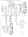
図1に示す対処法提示システム1は、コンピュータと、そのコンピュータの周辺装置等のハードウェアと、そのコンピュータが実行するプログラムや処理するデータ等のソフトウェアとの組み合わせから構成された機能的構成として、データベースサーバ11と、Webサーバ12と、データベースサーバ13とを備える。対処法提示システム1は、発電所等のプラント2に設けられたユニット3等の監視対象から発せられたアラームデータを遠隔監視する遠隔監視システム100の1要素として構成されている。
(Configuration of coping method presentation system)
The coping
データベースサーバ11は、発電所等のプラント2に設けられたユニット3等の監視対象から発せられたアラームデータを蓄積する。データベースサーバ11は、プラント2から送信されたアラームデータを受信し、受信したアラームデータをデータベースに蓄積して管理する。アラームデータは、ユニット3、機器、装置、設備あるいはプラント全体を監視対象として、所定の異常(異常状態を示すイベント)が確認された場合に監視対象を監視する図示していないコンピュータが発する情報であり、例えば、異常が確認された日時、監視対象の識別情報、異常の内容等を表す。なお、プラント2からデータベースサーバ11へは、アラームデータに加え、所定の状態や状態変化の発生を示す所定のイベントが発生したことを示すイベントデータも送信される。
The database server 11 accumulates alarm data generated from monitored objects such as the
データベースサーバ13は、シミュレータ5が発したアラームデータを蓄積する。シミュレータ5が発するアラームデータは、プラント2が発するアラームデータと同一形式のデータである。
The
そして、Webサーバ12は、対処法データベース125を備え、プラント2から発せられたアラームデータに対する対処法データベース125から検索してユーザ端末4に対して提示する機能と、プラント2をシミュレートするシミュレータ5が発したアラームデータに対する対処法データベース125から検索してユーザ端末6に対して提示する機能を有する。Webサーバ12は、Webシステム上で、ユーザ端末4とユーザ端末6に対しネットワークを通じて検索・閲覧・登録等の機能を提供し、対処法を示す情報を提供する。ユーザ端末4とユーザ端末6は、例えば、サーバ、デスクトップ型パーソナルコンピュータ、ノート型パーソナルコンピュータ、タブレット端末等の端末であり、表示部4aと表示部6aを備えている。ユーザ端末4は、例えばプラント2においてユニット3等の運用時に利用される端末である。ユーザ端末6は、例えばプラント2のオペレータがプラント2の運用を訓練する際にトレーニーとトレーナーによって利用される端末である。
The
対処法提示システム1は、例えば、「実運用モード」と「トレーニングモード」を選択して動作し、モードに応じて、データベースサーバ11による「実プラント環境」と、データベースサーバ13による「シミュレータ環境」で切替可能とする。また、Webサーバ12aは、「実運用モード」では、プラント2が発したアラームデータに基づきユーザ端末4に対する対処法の提示と対処法データベース125の更新を行い、「トレーニングモード」では、シミュレータ5が発したアラームデータに基づきユーザ端末6に対する対処法の提示と対処法データベース125の更新を行う。Webサーバ12は、対処法データベース125を、プラント2からのアラームデータとシミュレータ5からのアラームデータに対して共用する。対処法データベース125の構成例等については後述する。
The coping
シミュレータ5は、例えば、機械学習モデルを用いたり、物理モデルと簡易モデルを組み合わせたモデルを用いたりすることで、プラント2の各ユニット等の動作を模擬し、アラームデータを発生する。シミュレータ5の操作は、例えば、ユーザ端末6から行う。この場合、シミュレータ5は、例えば次の機能を有していることが望ましい。すなわち、シミュレータ5は、プラント運転操作(起動/停止)、シミュレーションの実行速度変更、バックトラック機能(過去の状態にシミュレータ状態を戻し、再訓練する)、運転条件(例:大気温度、冷却水温度など)の設定変更、事故項目の設定、疑似発生機能など有していることが望ましい。
The
この場合、シミュレータ5が発したトレーニングデータ活用による、アラーム対処のナレッジ蓄積が可能となる。この構成によれば、シミュレータ5の活用により、実運用での発生頻度が少ないアラーム(以下、"レアアラーム"とする)に対するナレッジを蓄積・活用できる仕組みを構築することができる。
In this case, the training data generated by the
(Webサーバの構成)
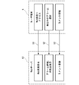
Webサーバ12は、例えば、図2に示すように、ハードウェアとソフトウェアとの組み合わせから構成される機能的構成として、提示部121と、登録部122と、データベース管理部123と、記憶部124とを備える。また、記憶部124は、対処法データベース125を記憶する。ここで、図3と図4を参照して対処法データベース125の構成例について説明する。
(Web server configuration)
For example, as shown in FIG. 2, the
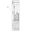
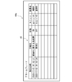
図3は、対処法データベース125を構築する際に用いるシミュレータ5によって作成したアラームデータ(レアアラーム)の時系列501の一例を示す。対処法データベース125を構築する際には、シミュレータ5を用いて、下記の事象を疑似的に発生させることで、これらに起因するレアアラームを出力する。「補機異常」「制御弁異常」等、数年に一度程度発生すると思われる異常事象、“電熱配管の取替工事”や“燃焼器等のハードウェアのアップデート”等、プラント設備変更に関する作業など、また、シミュレータ上の実行速度を加速させることにより、時間経過に応じたアラームの発生状況の変化を、データとしてシミュレータ5に出力される。図3に示す時系列501は、2020年11月12日11時19分42秒に重大度が低の機器A設備の軽故障のアラームが発生し、11時20分08秒に重大度が低の機器Aに関する温度高のアラームが発生し、11時27分24秒に重大度が中の機器Aの圧力低下のアラームが発生し、そして、12時49分16秒に重大度が高の機器Bの圧力低下に伴うトリップの発生のアラームが発生したという例である。この例では、異常発生当初は機器Aに関連したアラームが発報され、時間経過に伴い機器Bに関するアラームが発報されている。図3に示すように、“ある事象が起因し、機器A・機器Bに関するレアアラームが発生する”という内容がシミュレータ上で判明した場合は、対処法データベース125のナレッジベース上でこれらのアラームへの関連性を付与する。こうすることで、今後、実運用時にこれらのアラームの中から実際に発生したものがあれば、他アラームのファーストエイド(対処法)も一緒に確認するよう、対処法提示システム1がリコメンドすることができる。
FIG. 3 shows an example of a
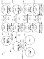
図4は、図2に示す対処法データベース125の構成例を示す。図4に示す対処法データベース125は、グラフデータベースとして構成されている。グラフデータベースは、グラフ構造を備えたデータベースであり、「ノード」「エッジ」「プロパティ」の3要素によって、ノード間の「関係性」を表現する。ノードは、対象物を表し、エッジはノード間の関係を表し、プロパティはノードとエッジの属性を表す。グラフデータベースは、つながりを辿る検索が高速であり、データベース全体をくまなく検索するリレーショナルデータベース等に比べ、データ量の増大に影響を受けにくく、つながりを辿るような検索が高速である。また、開発者から見て、データ定義が視覚的に理解しやすいという特長を持つ。
FIG. 4 shows a configuration example of the
図4に示す対処法データベース125は、ノードN11~N22と、エッジE11~E21を有する。なお、図4では、ラベル「工事履歴」、「アラーム」、「ドキュメント情報」、「コメント」で分類された各種別のノードを、種別毎に1個のみ示している。ただし、ノードの個数は、1個に限定されず、通常、複数である。
The
ノードN11~N14は、アラームマスタ情報を表すノードである。アラームマスタ情報は、アラームデータの基本となるデータである。ノードN11~N14は、例えば、警報名、ユニット名、装置名、警報区分等のプロパティを有する。ノードN11は、「機器A設備の軽故障」のプロパティを有し、インストラクションのエッジE11によってノードN15に関連付けられているとともに、関連のエッジE15によってノードN12に関連付けられている。ノードN12は、「機器Aに関する温度高」のプロパティを有し、インストラクションのエッジE12によってノードN16に、関連のエッジE16によってノードN13に、発生のエッジE18によってノードN19に、それぞれ関連付けられている。ノードN13は、「機器Aの圧力低下」のプロパティを有し、インストラクションのエッジE13によってノードN17に関連付けられているとともに、関連のエッジE17によってノードN14に関連付けられている。ノードN14は、「機器Bの圧力低下に伴うトリップの発生」のプロパティを有し、インストラクションのエッジE14によってノードN18に関連付けられている。 Nodes N11 to N14 are nodes representing alarm master information. Alarm master information is data that is the basis of alarm data. Nodes N11 to N14 have properties such as alarm name, unit name, device name, and alarm category, for example. Node N11 has the property of "minor failure of equipment A equipment" and is related to node N15 by instruction edge E11 and to node N12 by association edge E15. Node N12 has the property "high temperature for device A" and is related to node N16 by an instruction edge E12, to node N13 by an association edge E16, and to node N19 by an occurrence edge E18. Node N13 has the property "Pressure Drop on Equipment A" and is related to node N17 by an instruction edge E13 and to node N14 by an association edge E17. Node N14 has a property of "occurrence of trip due to pressure drop in device B" and is associated with node N18 by edge E14 of the instruction.
ノードN15~N18は、ファーストエイド(対処法)を表すノードであり、ノードN11~N14が表すアラームマスタに対する対処法等を表す。ノードN15~N18は、例えば、警報名(警報名称)、挙動、要因、対処法等のプロパティを有する。この場合、ノードN15~N18は、「機器A設備の軽故障」、「機器Aに関する温度高」、「機器Aの圧力低下」、「機器Bの圧力低下に伴うトリップの発生」の各プロパティを有する。 Nodes N15 to N18 are nodes representing first aid (countermeasures), and represent measures and the like for the alarm master represented by nodes N11 to N14. Nodes N15 to N18 have properties such as an alarm name (alarm name), behavior, cause, countermeasure, and the like. In this case, the nodes N15 to N18 have the respective properties of "minor failure of device A equipment", "high temperature regarding device A", "pressure drop in device A", and "occurrence of trip due to pressure drop in device B". have.
ノードN19は、発生したアラームを表すノードである。ノードN19は、例えば、発生日時、警報名、状態、ユニット、装置名等のプロパティを有する。ノードN19は、コメントのエッジE19によってノードN20に関連付けられているとともに、添付ドキュメントのエッジE20によってノードN21に関連付けられている。なお、ノードN19は、ノードN12へ向けたマスタのエッジを張っておらず、発生のエッジE18を逆に辿ることで、ノードN12へのつながりを定義している。これによれば情報量を節約することできるが、辿る頻度が多い場合は、エッジを定義してもよい。 A node N19 is a node representing an alarm that has occurred. The node N19 has properties such as date and time of occurrence, alarm name, status, unit, device name, and the like. Node N19 is related to node N20 by edge E19 of the comment and to node N21 by edge E20 of the attached document. Note that the node N19 does not extend a master edge directed to the node N12, and defines a connection to the node N12 by tracing back the generation edge E18. This can save the amount of information, but if the frequency of tracing is high, edges may be defined.
ノードN20は、ユーザがノードN19のアラームに対して登録したドキュメント情報(登録情報)を表すノードである。ドキュメントは、例えば、アラームへの対処時に参照されたドキュメント(文書、Web上でダウンロードできる文書ファイル、Webページ等)である。ノードN20は、ドキュメント名、ドキュメントの参照先のURL(Uniform Resource Locator)等のプロパティを有する。 The node N20 is a node representing document information (registration information) registered by the user for the alarm of the node N19. The document is, for example, a document (a document, a document file that can be downloaded on the Web, a Web page, etc.) that was referred to when coping with the alarm. The node N20 has properties such as a document name and a URL (Uniform Resource Locator) to which the document is referenced.
ノードN21は、ユーザがノードN19のアラームに対して登録したコメント(登録情報)を表すノードである。コメントは、例えば、アラームへの対処に係る文章である。ノードN21は、コメントの内容を表す文字情報等のプロパティを有する。 A node N21 is a node representing a comment (registered information) registered by the user with respect to the alarm of the node N19. A comment is, for example, a text related to dealing with an alarm. The node N21 has properties such as character information representing the content of the comment.
そして、ノードN22は、工事履歴を表すノードである。ノードN22は、例えば、工事内容、工事実施日時、実施後、監視が必要な経過期間等のプロパティを有する(この例では、「機器Cの取替工事」のプロパティを有する)。ノードN22は、発生可能性のエッジE21によってノードN12に関連付けられている。ただし、工事履歴を表す1つのノードは、複数のアラームマスタのノードに関連付けられていてもよい。 A node N22 is a node representing construction history. The node N22, for example, has properties such as the content of the work, the date and time of work execution, and the elapsed period that needs to be monitored after the work is done (in this example, it has the property of "replacement work for device C"). Node N22 is related to node N12 by edge of occurrence E21. However, one node representing the construction history may be associated with multiple alarm master nodes.
図2に戻り、提示部121は、対処法データベース125を参照し、ユーザによって指定されたアラームに対応するアラームマスタ情報に関連付けられた対処法と、当該アラームマスタ情報と時系列の関連性を有する他のアラームマスタ情報に関連付けられた対処法等の他のアラームマスタ情報に係る情報とを、記憶部124から取得してユーザ端末4またはユーザ端末6に対して提示する。
Returning to FIG. 2, the presenting
また、登録部122は、ユーザによって指定されたアラームに関連付けて新たにコメントやドキュメント情報(登録情報)を対処法データベース125に登録する。なお、本実施形態で、登録情報とは、ユーザによって指定されたアラームへの対処に係るコメントまたは指定されたアラームへの対処時に参照されたドキュメントの少なくとも一方を表す情報である。
The
また、データベース管理部123は、提示部121、登録部122等の指示に従って、対処法データベース125を検索したり、更新したりする。
Also, the
(対処法提示システムの動作例)
次に、図5~図8を参照して、図1および図2に示す対処法提示システム1の動作例について説明する。図5は、ユーザが、ユーザ端末6からWebサーバ12が表示するWeb画面にアクセスし(ステップS1)、例えば現在発生しているアラームを選択してそのアラームの詳細情報、対処法を確認し(ステップS2)、さらに、アラームに対してコメントを登録する(ステップS3)際の処理の流れを示す。
(Operational example of coping method presentation system)
Next, an operation example of the coping
ステップS1において、Webサーバ12(提示部121)は、ユーザ端末6で例えば図6に示す画面40aを表示するための情報を提示する。図6に示す画面40aは、ユーザが例えばプラント2、ユニット3等を指定して表示させたアラームデータの一覧41(この例では2件)を含む。この場合、一覧41において、アラームデータを表す各レコードは、発生日時、警報名、状態(継続しているのか否か)、ユニット、装置名の各項目を含む。
In step S1, the Web server 12 (presentation unit 121) presents information for displaying a
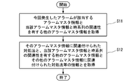
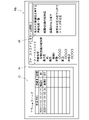
ステップS2において、画面40aにてユーザが例えば一番上のアラームデータ(「機器Aに関する温度高」)を選択したとすると、図7に示す処理の流れで、Webサーバ12(提示部121)は、ユーザ端末6で例えば図8に示す画面40bを表示するための情報を提示する。図8に示す画面40bは、アラームデータの一覧42と、選択されたアラームデータに対応するファーストエイド(対処法)の情報を表す表示領域44と、選択されたアラームデータに対して時系列の関連性を有する他のアラームマスタの一覧を表す表示領域45とを含む。ここで、図4と図7を参照して、指定したアラームデータに時系列に関連するアラームデータを対処法データベース125から検索する処理について説明する。この場合、Webサーバ12(提示部121)は、今回発生したアラームが該当するアラームマスタ情報と当該アラームマスタ情報と時系列の関連性を有する他のアラームマスタ情報を取得する(ステップS11)。次に、Webサーバ12(提示部121)は、そのアラームマスタ情報に関連付けられた対処法と、当該アラームマスタ情報と時系列の関連性を有する他のアラームマスタ情報と、その他のアラームマスタ情報に関連付けられた対処法等のその他のアラームマスタ情報に係る情報とを取得する(ステップS12)。
In step S2, assuming that the user selects, for example, the top alarm data (“High temperature regarding device A”) on the
図4に示す対処法データベース125では、ノードN19からエッジE18を逆に辿ってノードN12にたどり着き、さらに、ノードN12からエッジE16を辿ってノードN13にたどり着くとともに、ノードN12からエッジE15を辿ってノードN11にたどり着き、さらに、ノードN13からエッジE17を辿ってノードN14にたどり着く。そして、ノードN11~N14から、インストラクションのエッジE11~E14を辿ることでファーストエイドのノードN15~N18を検索することができる。この場合、図8の表示領域45には、ノードN11とノードN13とノードN14に対応するアラームデータが含まれている。なお、Webサーバ12(提示部121)は、例えば、図8の表示領域45で他のアラームマスタが選択された場合、選択されたアラームマスタに関連付けられた対処法等の情報を例えばポップアップ画面等で表示するための情報をユーザ端末6に対して提示することができる。なお、図4において、破線のブロックで囲んで示すノードN15、N17およびN18が、他に確認した方が良い情報としてリコメンドされる情報である。
In the
次に、図5のステップS3において、今回のアラームに対してコメントやドキュメントが登録される。この場合、図4に示す今回のアラームのノードN19に対して関連付けられた新たなコメントとのノードN21とドキュメント情報のノードN20が生成される。 Next, in step S3 of FIG. 5, comments and documents are registered for this alarm. In this case, a new comment node N21 and a document information node N20 associated with the current alarm node N19 shown in FIG. 4 are generated.
なお、その他の例として、ポンプの性能低下に伴う取替工事を実施した場合、接続したポンプの下流側にある配管やフランジに設定以上の負荷がかかり、その結果レアアラームが発生する可能性がある。シミュレータ機能によって、そうした各機器/アラームの関係性が判明した場合は、図4に示すように対処法データベース125でのナレッジベース上で各機器の工事履歴(例えばノードN22)とアラームマスタを関連づけておき、実際にその工事が発生した際には関連するファーストエイドをリコメンドする。なお各機器の取付実施後、任意の期間が経過した場合は、“その機器の取替工事に起因するアラームは発生しなくなる”ものと判断し、工事履歴とアラームマスタの関連性は削除して、ナレッジベースの精度向上を図ることができる。
尚、工事が発生したことを検知しファーストエイドをリコメンドする例として、定検管理システム等(不図示、工事実績を履歴管理しているシステム)と対処法データベース125を事前に連携しておき、実際に工事が発生し、定検管理システムにその実績が登録された際に、対処法データベース125の工事履歴(例えば、ノードN22)にも実績登録される。
そして、実績登録されたタイミングで、画面40aに工事情報、あるいはこの工事から発生すると思われるレアアラームを先行して表示し、これらの情報をクリックすると、関連するファーストエイドがリコメンドされ、対応を促すことがあげられる。
In addition, as another example, when replacement work is carried out due to deterioration of pump performance, there is a possibility that a load exceeding the setting will be applied to the pipes and flanges downstream of the connected pump, and as a result, a rare alarm will occur. be. When the relationship between each device/alarm is clarified by the simulator function, the work history (for example, node N22) of each device and the alarm master are associated on the knowledge base in the
As an example of detecting the occurrence of construction work and recommending first aid, a periodic inspection management system (not shown, a system that manages the history of construction results) and the
Then, at the timing when the results are registered, the construction information or rare alarms that are thought to occur from this construction work are displayed in advance on the
(作用・効果)
本実施形態によれば、実運用で発生したアラームに対するナレッジに加え、疑似発生させたレアアラームに対するナレッジを1つのナレッジベースに集約することにより、ナレッジの精度向上に繋げる。また、レアアラームを含め、様々なアラームに対して運転員がナレッジを確認・登録・更新できることから、運転員のトラブル対応力向上が期待できる。以上のように、本実施形態によれば、アラームデータを選択するだけで、当該アラームに対する対処法を適切に提示することができる。
(action/effect)
According to this embodiment, in addition to knowledge about alarms that have occurred in actual operation, knowledge about rare alarms that have been pseudo-generated are integrated into one knowledge base, leading to improved accuracy of knowledge. In addition, since operators can check, register, and update knowledge for various alarms, including rare alarms, it is expected to improve the ability of operators to respond to troubles. As described above, according to the present embodiment, simply by selecting alarm data, it is possible to appropriately present countermeasures against the alarm.
(その他の実施形態)
以上、本開示の実施の形態について図面を参照して詳述したが、具体的な構成はこの実施の形態に限られるものではなく、本開示の要旨を逸脱しない範囲の設計変更等も含まれる。
なお、上記実施形態では1個のプラント2のみを監視対象としたが、これに限るものではなく、例えば複数のプラント2を監視対象としてもよい。また、監視対象はプラント2に限られず、プラントに設置されていない、装置や機器、ユニットを監視対象としてもよい。また、登録情報は、コメントとドキュメント情報の一方であってもよい。また、対処法データベース125は、グラフデータベースに限らず、他の形式のデータベースであってもよいし、あるいは他の形式のデータベースとグラフデータベースとの組み合わせであってもよい。また、上記実施形態では、対処法提示システム1がプラント2あるいはシミュレータ5が発したアラームデータを処理することとしたが、対処法提示システム1は、アラームデータに加えて(あるいは代えて)イベントデータを処理するようにしてもよい。この場合、本願において、「アラーム」という文言は、「アラーム/イベント」(アラームまたはイベントの少なくとも一方の意。)という文言に読み替えることができる。
(Other embodiments)
As described above, the embodiments of the present disclosure have been described in detail with reference to the drawings, but the specific configuration is not limited to these embodiments, and design changes etc. within the scope of the present disclosure are also included. .
In the above-described embodiment, only one plant 2 is monitored, but the present invention is not limited to this. For example, a plurality of plants 2 may be monitored. Also, the monitoring target is not limited to the plant 2, and devices, equipment, and units that are not installed in the plant may be monitored. Also, the registration information may be either one of comments and document information. Further, the
〈コンピュータ構成〉
図9は、上記実施形態に係るコンピュータの構成を示す概略ブロック図である。
コンピュータ90は、プロセッサ91、メインメモリ92、ストレージ93、および、インタフェース94を備える。
上述の対処法提示システム1は、コンピュータ90に実装される。そして、上述した各処理部の動作は、プログラムの形式でストレージ93に記憶されている。プロセッサ91は、プログラムをストレージ93から読み出してメインメモリ92に展開し、当該プログラムに従って上記処理を実行する。また、プロセッサ91は、プログラムに従って、上述した各記憶部に対応する記憶領域をメインメモリ92に確保する。
<Computer configuration>
FIG. 9 is a schematic block diagram showing the configuration of a computer according to the above embodiment.
Computer 90 comprises
The coping
プログラムは、コンピュータ90に発揮させる機能の一部を実現するためのものであってもよい。例えば、プログラムは、ストレージに既に記憶されている他のプログラムとの組み合わせ、または他の装置に実装された他のプログラムとの組み合わせによって機能を発揮させるものであってもよい。なお、他の実施形態においては、コンピュータは、上記構成に加えて、または上記構成に代えてPLD(Programmable Logic Device)などのカスタムLSI(Large Scale Integrated Circuit)を備えてもよい。PLDの例としては、PAL(Programmable Array Logic)、GAL(Generic Array Logic)、CPLD(Complex Programmable Logic Device)、FPGA(Field Programmable Gate Array)等が挙げられる。この場合、プロセッサによって実現される機能の一部または全部が当該集積回路によって実現されてよい。 The program may be for realizing part of the functions that the computer 90 is caused to exhibit. For example, the program may function in combination with another program already stored in the storage or in combination with another program installed in another device. Note that in other embodiments, the computer may include a custom LSI (Large Scale Integrated Circuit) such as a PLD (Programmable Logic Device) in addition to or instead of the above configuration. Examples of PLD include PAL (Programmable Array Logic), GAL (Generic Array Logic), CPLD (Complex Programmable Logic Device), FPGA (Field Programmable Gate Array), and the like. In this case, part or all of the functions implemented by the processor may be implemented by the integrated circuit.
ストレージ93の例としては、HDD(Hard Disk Drive)、SSD(Solid State Drive)、磁気ディスク、光磁気ディスク、CD-ROM(Compact Disc Read Only Memory)、DVD-ROM(Digital Versatile Disc Read Only Memory)、半導体メモリ等が挙げられる。ストレージ93は、コンピュータ90のバスに直接接続された内部メディアであってもよいし、インタフェース94または通信回線を介してコンピュータ90に接続される外部メディアであってもよい。また、このプログラムが通信回線によってコンピュータ90に配信される場合、配信を受けたコンピュータ90が当該プログラムをメインメモリ92に展開し、上記処理を実行してもよい。少なくとも1つの実施形態において、ストレージ93は、一時的でない有形の記憶媒体である。
Examples of the
<付記>
各実施形態に記載の対処法提示システム1は、例えば以下のように把握される。
<Appendix>
The coping
(1)第1の態様に係る対処法提示システム1は、1または複数の監視対象(プラント2、ユニット3)から発せられる各アラームに関連づけられた1または複数のアラームマスタ情報と、前記各アラームマスタ情報に関連付けられた各対処法を表す情報と、前記各アラームマスタ情報間の時系列の関連性を表す情報(エッジE15、E16、E17)とを記憶する記憶部124と、指定されたアラーム(ノードN19)に対応する前記アラームマスタ情報(ノードN12)に関連付けられた前記対処法(ノードN16)と、当該アラームマスタ情報と前記関連性を有する他の前記アラームマスタ情報(ノードN11、N13およびN14)に係る情報(ノードN15、N17およびN18等)とを、前記記憶部124から取得して提示する提示部121と、を備える。本実施形態および以下の各実施形態によれば、指定したアラームに対する対処法を適切に提示することができる。
(1) The coping
(2)第2の態様に係る対処法提示システム1は、(1)の対処法提示システム1であって、前記記憶部124は、前記監視対象に対する作業履歴に係る作業履歴情報(ノードN22)と、前記作業履歴情報と1または複数の前記アラームマスタ情報(ノードN12)とを関連付ける情報とをさらに記憶し、前記提示部121は、前記指定されたアラーム(ノードN19)に対応する前記アラームマスタ情報(ノードN12)が前記作業履歴情報(ノードN22)と関連付けられている場合、当該作業履歴情報に関連付けられている他の1または複数の前記アラームマスタ情報に係る情報(例えば、対処法を示す情報)を、さらに前記記憶部124から取得して提示する。
(2) The coping
(3)第3の態様に係る対処法提示システム1は、(2)の対処法提示システム1であって、前記作業履歴情報と1または複数の前記アラームマスタ情報とを関連付ける情報は、所定の時間が経過した場合に削除される。本態様によれば、ナレッジベースの精度の向上を図ることができる。
(3) The coping
1…対処法提示システム
2…プラント
3…ユニット
4、6…ユーザ端末
5…シミュレータ
11、13…データベースサーバ
12…Webサーバ
121…提示部
122…登録部
123…データベース管理部
124…記憶部
125…対処法データベース
1 Coping method presentation system 2
Claims (5)
指定されたアラームに対応する前記アラームマスタ情報に関連付けられた前記対処法と、当該アラームマスタ情報と前記関連性を有する他の前記アラームマスタ情報に係る情報とを、前記記憶部から取得して提示する提示部と、
を備える対処法提示システム。 One or a plurality of alarm master information associated with each alarm issued from one or a plurality of monitoring targets, information representing each coping method associated with each of the alarm master information, and time series between each of the alarm master information a storage unit that stores information representing the relevance of
Acquiring from the storage unit and presenting the countermeasure associated with the alarm master information corresponding to the designated alarm and information relating to the other alarm master information having the association with the alarm master information a presentation unit to
A coping method presentation system.
前記提示部は、前記指定されたアラームに対応する前記アラームマスタ情報が前記作業履歴情報と関連付けられている場合、当該作業履歴情報に関連付けられている他の1または複数の前記アラームマスタ情報に係る情報を、さらに前記記憶部から取得して提示する
を備える請求項1に記載の対処法提示システム。 The storage unit further stores work history information related to the work history for the monitoring target and information associating the work history information with one or more of the alarm master information,
When the alarm master information corresponding to the specified alarm is associated with the work history information, the presenting unit provides information related to the other one or more alarm master information associated with the work history information. The coping method presentation system according to claim 1, further comprising acquiring information from the storage unit and presenting the information.
を備える請求項2に記載の対処法提示システム。 3. The coping method presentation system according to claim 2, wherein the information that associates the work history information with one or more pieces of the alarm master information is deleted after a predetermined period of time has elapsed.
指定されたアラームに対応する前記アラームマスタ情報に関連付けられた前記対処法と、当該アラームマスタ情報と前記関連性を有する他の前記アラームマスタ情報に係る情報とを、前記記憶部から取得して提示するステップ
を含む対処法提示方法。 One or a plurality of alarm master information associated with each alarm issued from one or a plurality of monitoring targets, information representing each coping method associated with each of the alarm master information, and time series between each of the alarm master information Using a storage unit that stores information representing the relevance of
Acquiring from the storage unit and presenting the countermeasure associated with the alarm master information corresponding to the designated alarm and information relating to the other alarm master information having the association with the alarm master information Remedy presentation method including steps to
指定されたアラームに対応する前記アラームマスタ情報に関連付けられた前記対処法と、当該アラームマスタ情報と前記関連性を有する他の前記アラームマスタ情報に係る情報とを、前記記憶部から取得して提示するステップ
をコンピュータに実行させるプログラム。 One or a plurality of alarm master information associated with each alarm issued from one or a plurality of monitoring targets, information representing each coping method associated with each of the alarm master information, and time series between each of the alarm master information Using a storage unit that stores information representing the relevance of
Acquiring from the storage unit and presenting the countermeasure associated with the alarm master information corresponding to the designated alarm and information relating to the other alarm master information having the association with the alarm master information A program that causes a computer to perform steps to do.
Priority Applications (6)
| Application Number | Priority Date | Filing Date | Title |
|---|---|---|---|
| JP2021013903A JP2022117290A (en) | 2021-01-29 | 2021-01-29 | Countermeasure presentation system, countermeasure presentation method, and program |
| US18/036,810 US20240019861A1 (en) | 2021-01-29 | 2021-11-25 | First aid presentation system, first aid presentation method, and program |
| PCT/JP2021/043233 WO2022163103A1 (en) | 2021-01-29 | 2021-11-25 | Coping method presentation system, coping method presentation method, and program |
| EP21923108.1A EP4242764A4 (en) | 2021-01-29 | 2021-11-25 | Coping method presentation system, coping method presentation method, and program |
| TW110146056A TWI825523B (en) | 2021-01-29 | 2021-12-09 | Disposal method prompting system, disposal method prompting method and program |
| KR1020220007525A KR20220110091A (en) | 2021-01-29 | 2022-01-19 | Coping method presentation system, coping method presentation method and recording medium |
Applications Claiming Priority (1)
| Application Number | Priority Date | Filing Date | Title |
|---|---|---|---|
| JP2021013903A JP2022117290A (en) | 2021-01-29 | 2021-01-29 | Countermeasure presentation system, countermeasure presentation method, and program |
Publications (2)
| Publication Number | Publication Date |
|---|---|
| JP2022117290A true JP2022117290A (en) | 2022-08-10 |
| JP2022117290A5 JP2022117290A5 (en) | 2023-12-13 |
Family
ID=82653176
Family Applications (1)
| Application Number | Title | Priority Date | Filing Date |
|---|---|---|---|
| JP2021013903A Pending JP2022117290A (en) | 2021-01-29 | 2021-01-29 | Countermeasure presentation system, countermeasure presentation method, and program |
Country Status (6)
| Country | Link |
|---|---|
| US (1) | US20240019861A1 (en) |
| EP (1) | EP4242764A4 (en) |
| JP (1) | JP2022117290A (en) |
| KR (1) | KR20220110091A (en) |
| TW (1) | TWI825523B (en) |
| WO (1) | WO2022163103A1 (en) |
Family Cites Families (13)
| Publication number | Priority date | Publication date | Assignee | Title |
|---|---|---|---|---|
| JP3087974B2 (en) * | 1991-08-28 | 2000-09-18 | 株式会社日立製作所 | Plant abnormal operation support method and apparatus |
| JP3229858B2 (en) * | 1998-12-28 | 2001-11-19 | ダイセル化学工業株式会社 | Business support type education system |
| US6839660B2 (en) * | 2002-04-22 | 2005-01-04 | Csi Technology, Inc. | On-line rotating equipment monitoring device |
| JP4957423B2 (en) | 2007-07-13 | 2012-06-20 | 東ソー株式会社 | Plant security management system |
| JP5029632B2 (en) * | 2009-03-03 | 2012-09-19 | 横河電機株式会社 | Plant information management apparatus and plant information management method |
| US9613523B2 (en) * | 2014-12-09 | 2017-04-04 | Unilectric, Llc | Integrated hazard risk management and mitigation system |
| US9720408B2 (en) * | 2015-05-04 | 2017-08-01 | Fisher-Rosemount Systems, Inc. | Methods and apparatus to detect root causes of alarm patterns in process control systems |
| JP2018120456A (en) * | 2017-01-26 | 2018-08-02 | 三菱日立パワーシステムズ株式会社 | Alarm display system and alarm display method |
| JP6515937B2 (en) * | 2017-02-08 | 2019-05-22 | 横河電機株式会社 | Event analysis apparatus, event analysis system, event analysis method, event analysis program, and recording medium |
| FR3069086A1 (en) * | 2017-07-13 | 2019-01-18 | Airbus | METHOD FOR EVALUATING A RATE OF VARIATION OF A FAILURE |
| JP7166846B2 (en) * | 2018-09-03 | 2022-11-08 | エスペック株式会社 | Information management system, information management method, terminal device, server, and information management program |
| JP2020173683A (en) * | 2019-04-12 | 2020-10-22 | 三菱電機株式会社 | Plant monitoring control system and plant monitoring control method |
| JP7177014B2 (en) | 2019-07-12 | 2022-11-22 | 水ing株式会社 | Organic wastewater treatment method and organic wastewater treatment apparatus |
-
2021
- 2021-01-29 JP JP2021013903A patent/JP2022117290A/en active Pending
- 2021-11-25 US US18/036,810 patent/US20240019861A1/en active Pending
- 2021-11-25 EP EP21923108.1A patent/EP4242764A4/en active Pending
- 2021-11-25 WO PCT/JP2021/043233 patent/WO2022163103A1/en active Application Filing
- 2021-12-09 TW TW110146056A patent/TWI825523B/en active
-
2022
- 2022-01-19 KR KR1020220007525A patent/KR20220110091A/en not_active Application Discontinuation
Also Published As
| Publication number | Publication date |
|---|---|
| WO2022163103A1 (en) | 2022-08-04 |
| KR20220110091A (en) | 2022-08-05 |
| TWI825523B (en) | 2023-12-11 |
| TW202303324A (en) | 2023-01-16 |
| EP4242764A1 (en) | 2023-09-13 |
| EP4242764A4 (en) | 2024-04-03 |
| US20240019861A1 (en) | 2024-01-18 |
Similar Documents
| Publication | Publication Date | Title |
|---|---|---|
| JP6048038B2 (en) | Information processing apparatus, program, and information processing method | |
| CN111814999B (en) | Fault work order generation method, device and equipment | |
| JP7221644B2 (en) | Equipment failure diagnosis support system and equipment failure diagnosis support method | |
| JP6280862B2 (en) | Event analysis system and method | |
| JP6880560B2 (en) | Failure prediction device, failure prediction method and failure prediction program | |
| JP2020057192A (en) | Malfunction factor priority presenting apparatus | |
| WO2022163103A1 (en) | Coping method presentation system, coping method presentation method, and program | |
| JP2001331350A (en) | Maintenance management device | |
| JP2022083474A (en) | Maintenance recommendation system | |
| CN112769615A (en) | Anomaly analysis method and device | |
| JP2019049802A (en) | Failure analysis supporting device, incident managing system, failure analysis supporting method, and program | |
| WO2022163102A1 (en) | Troubleshooting method presentation system, troubleshooting method presentation method, and program | |
| TWI832124B (en) | Disposal method prompting system, disposal method prompting method and program | |
| JP6738208B2 (en) | Plant operation support system | |
| JP5987581B2 (en) | FT calculation support program, FT calculation support method, and FT calculation support apparatus | |
| JP2021039553A (en) | Data extraction device, data extraction method, and data extraction program | |
| JP2020197777A (en) | Monitoring device and monitoring system | |
| JPWO2016163008A1 (en) | Abnormality diagnosis apparatus and abnormality diagnosis method | |
| JP6861653B2 (en) | Monitoring and control support device | |
| US20230143297A1 (en) | Production knowledge management system, production knowledge management method, and production knowledge management program | |
| WO2021070512A1 (en) | Failure tree generation device and method therefor | |
| KR20110017631A (en) | Performance analysising method for power facilities | |
| Xu | Modelling and well-posed analysis for software system with rejuvenation | |
| JP2023136926A (en) | Operation note production support system, operation note production support method, and operation note production support program | |
| JP2015148839A (en) | incident management system, search history management method, and program |
Legal Events
| Date | Code | Title | Description |
|---|---|---|---|
| A711 | Notification of change in applicant |
Free format text: JAPANESE INTERMEDIATE CODE: A712 Effective date: 20220124 |
|
| A521 | Request for written amendment filed |
Free format text: JAPANESE INTERMEDIATE CODE: A523 Effective date: 20231205 |
|
| A621 | Written request for application examination |
Free format text: JAPANESE INTERMEDIATE CODE: A621 Effective date: 20231205 |