JP2018105850A - Non-contact electrical parameter measurement system - Google Patents
Non-contact electrical parameter measurement system Download PDFInfo
- Publication number
- JP2018105850A JP2018105850A JP2017218392A JP2017218392A JP2018105850A JP 2018105850 A JP2018105850 A JP 2018105850A JP 2017218392 A JP2017218392 A JP 2017218392A JP 2017218392 A JP2017218392 A JP 2017218392A JP 2018105850 A JP2018105850 A JP 2018105850A
- Authority
- JP
- Japan
- Prior art keywords
- sensor
- voltage
- measurement system
- current
- insulated wire
- Prior art date
- Legal status (The legal status is an assumption and is not a legal conclusion. Google has not performed a legal analysis and makes no representation as to the accuracy of the status listed.)
- Pending
Links
- 238000005259 measurement Methods 0.000 title claims abstract description 482
- 238000012360 testing method Methods 0.000 claims abstract description 53
- 238000004891 communication Methods 0.000 claims abstract description 41
- 238000000034 method Methods 0.000 claims abstract description 41
- 230000000007 visual effect Effects 0.000 claims abstract description 6
- 239000003990 capacitor Substances 0.000 claims description 98
- 239000003086 colorant Substances 0.000 claims description 4
- 238000005286 illumination Methods 0.000 claims 1
- 239000000523 sample Substances 0.000 abstract description 34
- 230000008569 process Effects 0.000 abstract description 13
- 239000004020 conductor Substances 0.000 description 152
- 238000010586 diagram Methods 0.000 description 49
- 230000008878 coupling Effects 0.000 description 36
- 238000010168 coupling process Methods 0.000 description 36
- 238000005859 coupling reaction Methods 0.000 description 36
- 238000009413 insulation Methods 0.000 description 21
- 238000012545 processing Methods 0.000 description 18
- 230000006870 function Effects 0.000 description 14
- 230000015654 memory Effects 0.000 description 11
- 238000003860 storage Methods 0.000 description 11
- 230000000694 effects Effects 0.000 description 10
- 239000007787 solid Substances 0.000 description 9
- 239000012212 insulator Substances 0.000 description 7
- 230000005355 Hall effect Effects 0.000 description 6
- 230000003287 optical effect Effects 0.000 description 5
- 238000004364 calculation method Methods 0.000 description 4
- 238000012937 correction Methods 0.000 description 4
- 239000011888 foil Substances 0.000 description 4
- 230000003993 interaction Effects 0.000 description 4
- 238000005070 sampling Methods 0.000 description 4
- RYGMFSIKBFXOCR-UHFFFAOYSA-N Copper Chemical compound [Cu] RYGMFSIKBFXOCR-UHFFFAOYSA-N 0.000 description 3
- 229910052802 copper Inorganic materials 0.000 description 3
- 239000010949 copper Substances 0.000 description 3
- 238000013461 design Methods 0.000 description 3
- 230000004907 flux Effects 0.000 description 3
- 230000016507 interphase Effects 0.000 description 3
- 241000238366 Cephalopoda Species 0.000 description 2
- 238000004422 calculation algorithm Methods 0.000 description 2
- 210000000078 claw Anatomy 0.000 description 2
- 238000009795 derivation Methods 0.000 description 2
- 238000001514 detection method Methods 0.000 description 2
- 230000005672 electromagnetic field Effects 0.000 description 2
- 230000007613 environmental effect Effects 0.000 description 2
- 239000000835 fiber Substances 0.000 description 2
- 230000014509 gene expression Effects 0.000 description 2
- 230000007246 mechanism Effects 0.000 description 2
- 230000007935 neutral effect Effects 0.000 description 2
- 238000000819 phase cycle Methods 0.000 description 2
- 230000000704 physical effect Effects 0.000 description 2
- 229920003223 poly(pyromellitimide-1,4-diphenyl ether) Polymers 0.000 description 2
- APTZNLHMIGJTEW-UHFFFAOYSA-N pyraflufen-ethyl Chemical compound C1=C(Cl)C(OCC(=O)OCC)=CC(C=2C(=C(OC(F)F)N(C)N=2)Cl)=C1F APTZNLHMIGJTEW-UHFFFAOYSA-N 0.000 description 2
- 230000035945 sensitivity Effects 0.000 description 2
- 238000000926 separation method Methods 0.000 description 2
- 238000010897 surface acoustic wave method Methods 0.000 description 2
- 230000001360 synchronised effect Effects 0.000 description 2
- 206010014405 Electrocution Diseases 0.000 description 1
- 230000001154 acute effect Effects 0.000 description 1
- 230000002730 additional effect Effects 0.000 description 1
- 230000002776 aggregation Effects 0.000 description 1
- 238000004220 aggregation Methods 0.000 description 1
- 238000003491 array Methods 0.000 description 1
- 238000013528 artificial neural network Methods 0.000 description 1
- 230000000712 assembly Effects 0.000 description 1
- 238000000429 assembly Methods 0.000 description 1
- 230000005540 biological transmission Effects 0.000 description 1
- 238000009529 body temperature measurement Methods 0.000 description 1
- 230000008859 change Effects 0.000 description 1
- 238000012512 characterization method Methods 0.000 description 1
- 238000006243 chemical reaction Methods 0.000 description 1
- 238000004590 computer program Methods 0.000 description 1
- 230000001143 conditioned effect Effects 0.000 description 1
- 238000001816 cooling Methods 0.000 description 1
- 230000001419 dependent effect Effects 0.000 description 1
- 238000009826 distribution Methods 0.000 description 1
- 238000005516 engineering process Methods 0.000 description 1
- 238000010438 heat treatment Methods 0.000 description 1
- 230000010354 integration Effects 0.000 description 1
- 238000002955 isolation Methods 0.000 description 1
- 239000004973 liquid crystal related substance Substances 0.000 description 1
- 238000012423 maintenance Methods 0.000 description 1
- 238000004519 manufacturing process Methods 0.000 description 1
- 239000000463 material Substances 0.000 description 1
- 239000002184 metal Substances 0.000 description 1
- 229910052751 metal Inorganic materials 0.000 description 1
- 238000005065 mining Methods 0.000 description 1
- 230000010363 phase shift Effects 0.000 description 1
- 239000004033 plastic Substances 0.000 description 1
- 238000007493 shaping process Methods 0.000 description 1
- 230000035939 shock Effects 0.000 description 1
- 238000001228 spectrum Methods 0.000 description 1
- 239000010409 thin film Substances 0.000 description 1
- 238000013024 troubleshooting Methods 0.000 description 1
Images


Classifications
-
- G—PHYSICS
- G01—MEASURING; TESTING
- G01R—MEASURING ELECTRIC VARIABLES; MEASURING MAGNETIC VARIABLES
- G01R15/00—Details of measuring arrangements of the types provided for in groups G01R17/00 - G01R29/00, G01R33/00 - G01R33/26 or G01R35/00
- G01R15/12—Circuits for multi-testers, i.e. multimeters, e.g. for measuring voltage, current, or impedance at will
- G01R15/125—Circuits for multi-testers, i.e. multimeters, e.g. for measuring voltage, current, or impedance at will for digital multimeters
-
- G—PHYSICS
- G01—MEASURING; TESTING
- G01R—MEASURING ELECTRIC VARIABLES; MEASURING MAGNETIC VARIABLES
- G01R19/00—Arrangements for measuring currents or voltages or for indicating presence or sign thereof
- G01R19/25—Arrangements for measuring currents or voltages or for indicating presence or sign thereof using digital measurement techniques
-
- G—PHYSICS
- G01—MEASURING; TESTING
- G01R—MEASURING ELECTRIC VARIABLES; MEASURING MAGNETIC VARIABLES
- G01R1/00—Details of instruments or arrangements of the types included in groups G01R5/00 - G01R13/00 and G01R31/00
- G01R1/20—Modifications of basic electric elements for use in electric measuring instruments; Structural combinations of such elements with such instruments
- G01R1/22—Tong testers acting as secondary windings of current transformers
-
- G—PHYSICS
- G01—MEASURING; TESTING
- G01R—MEASURING ELECTRIC VARIABLES; MEASURING MAGNETIC VARIABLES
- G01R15/00—Details of measuring arrangements of the types provided for in groups G01R17/00 - G01R29/00, G01R33/00 - G01R33/26 or G01R35/00
- G01R15/14—Adaptations providing voltage or current isolation, e.g. for high-voltage or high-current networks
- G01R15/16—Adaptations providing voltage or current isolation, e.g. for high-voltage or high-current networks using capacitive devices
-
- G—PHYSICS
- G01—MEASURING; TESTING
- G01R—MEASURING ELECTRIC VARIABLES; MEASURING MAGNETIC VARIABLES
- G01R15/00—Details of measuring arrangements of the types provided for in groups G01R17/00 - G01R29/00, G01R33/00 - G01R33/26 or G01R35/00
- G01R15/14—Adaptations providing voltage or current isolation, e.g. for high-voltage or high-current networks
- G01R15/20—Adaptations providing voltage or current isolation, e.g. for high-voltage or high-current networks using galvano-magnetic devices, e.g. Hall-effect devices, i.e. measuring a magnetic field via the interaction between a current and a magnetic field, e.g. magneto resistive or Hall effect devices
- G01R15/207—Constructional details independent of the type of device used
-
- G—PHYSICS
- G01—MEASURING; TESTING
- G01R—MEASURING ELECTRIC VARIABLES; MEASURING MAGNETIC VARIABLES
- G01R19/00—Arrangements for measuring currents or voltages or for indicating presence or sign thereof
Abstract
Description
本開示は、一般に、電気的特性の測定に関し、より詳しくは、電気回路内の電気的パラメータの非接触測定に関する。 The present disclosure relates generally to measurement of electrical characteristics, and more particularly to contactless measurement of electrical parameters in an electrical circuit.
電圧計が、電気回路内の電圧を測定するのに使用される器具である。1つを超える電気的特性を測定する器具は、マルチメータつまりデジタルマルチメータ(digital multimeter、DMM)と呼ばれ、サービス用途、トラブルシューティング用途及びメンテナンス用途に一般に必要とされるいくつかのパラメータを測定するように動作する。そのようなパラメータとしては、典型的には交流(alternating current、AC)電圧及び電流、直流(direct current、DC)電圧及び電流、並びに抵抗又は継続性が挙げられる。電力特性、周波数、容量及び温度など、他のパラメータも特定の用途の要件を満たすために測定することができる。 A voltmeter is an instrument used to measure the voltage in an electrical circuit. An instrument that measures more than one electrical characteristic is called a multimeter, or digital multimeter (DMM), and measures several parameters commonly required for service, troubleshooting, and maintenance applications To work. Such parameters typically include alternating current (AC) voltage and current, direct current (DC) voltage and current, and resistance or continuity. Other parameters such as power characteristics, frequency, capacity and temperature can also be measured to meet specific application requirements.
AC電圧及び/又は電流を測定する従来の電圧計又はマルチメータに関しては、少なくとも1つの測定電極又はプローブを導体とガルバニック接触させることが必要であり、これには、前もって、絶縁電線の絶縁の一部の切断、回路の断路、及び/又は、測定のための端子の設置が必要であることが多い。プローブを露出した電線又は端子に接触させるステップは、ガルバニック接触のために剥き出しにした電線又は端子が必要であるばかりでなく、ショック又は感電死のリスクのために相対的に危険である可能性がある。 With conventional voltmeters or multimeters that measure AC voltage and / or current, it is necessary to have at least one measuring electrode or probe in galvanic contact with the conductor, which in advance is one of the insulation of insulated wires. Often it is necessary to disconnect the part, disconnect the circuit and / or install a terminal for measurement. The step of contacting the probe to the exposed wire or terminal not only requires a bare wire or terminal for galvanic contact, but may also be relatively dangerous due to the risk of shock or electrocution. is there.
非接触測定システムは、前端を備えるハウジングと、動作時に、絶縁電線内の電圧を、絶縁電線にガルバニック接触することなく感知する、ハウジングの前端に近接して位置決めされた電圧センサーと、動作時に、絶縁電線内の電圧を、絶縁電線にガルバニック接触することなく感知する、ハウジングの前端に近接して位置決めされた電流センサーと、ハウジング内に位置決めされた少なくとも1つのプロセッサであって、少なくとも1つのプロセッサは、電圧センサー及び電流センサーに動作可能に結合される、少なくとも1つのプロセッサと、を備えると要約することができ、動作時に、少なくとも1つのプロセッサは、絶縁電線内の電圧を示す、電圧センサーによって取得された電圧センサー信号を、測定時間間隔中に電圧センサーから受信し、絶縁電線内の電流を示す、電流センサーによって取得された電流センサー信号を、測定時間間隔中に電流センサーから受信し、少なくとも1つの交流(AC)電気的パラメータを受信された電圧センサー信号及び電流センサー信号に少なくとも部分的に基づいて判定する。 A non-contact measurement system includes a housing with a front end, a voltage sensor positioned in proximity to the front end of the housing that senses, in operation, the voltage in the insulated wire without galvanic contact with the insulated wire, and in operation. A current sensor positioned proximate to a front end of the housing for sensing a voltage in the insulated wire without galvanic contact with the insulated wire, and at least one processor positioned in the housing, the at least one processor Can be summarized as comprising at least one processor operably coupled to the voltage sensor and the current sensor, wherein in operation, the at least one processor is a voltage sensor that indicates a voltage within the insulated wire. The acquired voltage sensor signal is sent to the voltage sensor during the measurement time interval. A voltage sensor signal received and received from the current sensor during the measurement time interval and received at least one alternating current (AC) electrical parameter, the current sensor signal being received and indicative of the current in the insulated wire And determining based at least in part on the current sensor signal.
電流センサーは、磁場センサーを含むことができる。電圧センサーは、容量分圧器型電圧センサー、基準信号型電圧センサー又はマルチコンデンサ型電圧センサーのうちの1つを含むことができる。電圧センサーは、動作時に、絶縁電線内の基準信号を、絶縁電線にガルバニック接触することなく感知する基準信号型電圧センサーを含むことができ、少なくとも1つのプロセッサは、基準信号を受信し、絶縁電線を通って流れる電流の少なくとも1つの特性を受信された基準信号に少なくとも部分的に基づいて判定する。少なくとも1つのAC電気的パラメータは、電力、位相、周波数、高調波又はエネルギーのうちの少なくとも1つを含むことができる。動作時に、少なくとも1つのプロセッサは、複数のAC電気的パラメータを受信された電圧センサー信号及び電流センサー信号に少なくとも部分的に基づいて判定することができる。 The current sensor can include a magnetic field sensor. The voltage sensor may include one of a capacitive voltage divider type voltage sensor, a reference signal type voltage sensor, or a multi-capacitor type voltage sensor. The voltage sensor may include a reference signal type voltage sensor that, in operation, senses a reference signal in the insulated wire without galvanic contact with the insulated wire, wherein at least one processor receives the reference signal, At least one characteristic of the current flowing through is determined based at least in part on the received reference signal. The at least one AC electrical parameter can include at least one of power, phase, frequency, harmonics or energy. In operation, the at least one processor can determine a plurality of AC electrical parameters based at least in part on the received voltage sensor signal and current sensor signal.
非接触測定システムは、少なくとも1つのプロセッサに動作可能に結合されたディスプレイを更に含むことができ、動作時に、少なくとも1つのプロセッサは、ディスプレイにうちの少なくとも1つのAC電気的パラメータを示させることができる。 The non-contact measurement system can further include a display operably coupled to the at least one processor, wherein in operation, the at least one processor can cause the display to display at least one AC electrical parameter of the display. it can.
動作時に、少なくとも1つのプロセッサは、ディスプレイに少なくとも1つのAC電気的パラメータに関連した波形又はグラフのうちの少なくとも一方を示させることができる。 In operation, the at least one processor can cause the display to show at least one of a waveform or a graph associated with the at least one AC electrical parameter.
非接触測定システムは、少なくとも1つのプロセッサに動作可能に結合された通信インターフェースを更に含むことができ、動作時に、少なくとも1つのプロセッサは、通信インターフェースを介して、データを少なくとも1つの外部デバイスに送ることができ、データは、電圧センサー信号、電流センサー信号、又は、判定された少なくとも1つのAC電気的パラメータのうちの少なくとも1つに関連している。 The contactless measurement system can further include a communication interface operably coupled to the at least one processor, wherein in operation, the at least one processor sends data to the at least one external device via the communication interface. The data can be related to at least one of a voltage sensor signal, a current sensor signal, or at least one determined AC electrical parameter.
通信インターフェースは、データを、少なくとも1つの外部デバイスに無線で送るように動作可能な無線通信インターフェースを含むことができる。 The communication interface can include a wireless communication interface operable to send data wirelessly to at least one external device.
非接触測定システムは、少なくとも1つの外部デバイスを更に含むことができ、少なくとも1つの外部デバイスは、ディスプレイと、動作時に、非接触測定システムの通信インターフェースによって送られたデータを受信する通信インターフェースと、ディスプレイ及び通信インターフェースに動作可能に結合された少なくとも1つのプロセッサと、を含み、動作時に、少なくとも1つのプロセッサは、通信インターフェースを介してデータを非接触測定システムから受信し、ディスプレイに少なくとも1つのAC電気的パラメータを示させる。 The non-contact measurement system can further include at least one external device, wherein the at least one external device is a display and a communication interface that, in operation, receives data sent by the non-contact measurement system communication interface; At least one processor operably coupled to the display and the communication interface, wherein in operation, the at least one processor receives data from the contactless measurement system via the communication interface and the display includes at least one AC Let the electrical parameters be shown.
非接触測定システムは、少なくとも1つのプロセッサに動作可能に結合され、非接触測定システムのハウジングの前端に近接して位置決めされた位置合わせ用フィードバックセンサーであって、動作時に、位置合わせ用フィードバックセンサーは、電圧センサー及び電流センサーに対する絶縁電線の現在の位置合わせを示す位置合わせフィードバックセンサー信号を生成する、位置合わせ用フィードバックセンサーと、少なくとも1つのプロセッサに動作可能に結合されたインジケータ装置とを更に含むことができ、動作時に、少なくとも1つのプロセッサは、位置合わせフィードバックセンサー信号を位置合わせ用フィードバックセンサーから受信し、インジケータ装置に、位置合わせ表示を受信された位置合わせフィードバックセンサー信号に少なくとも部分的に基づいて非接触測定システムのユーザーに提供させる。 The non-contact measurement system is an alignment feedback sensor operably coupled to at least one processor and positioned proximate to the front end of the non-contact measurement system housing, wherein in operation, the alignment feedback sensor is And further including an alignment feedback sensor for generating an alignment feedback sensor signal indicative of the current alignment of the insulated wire with respect to the voltage sensor and the current sensor, and an indicator device operably coupled to the at least one processor. In operation, at least one processor receives the alignment feedback sensor signal from the alignment feedback sensor, and the indicator device receives the alignment indication received from the alignment feedback sensor. It is provided to the user of the non-contact measuring system based at least in part on the item.
インジケータ装置は、視覚インジケータ装置又は可聴インジケータ装置のうちの少なくとも一方を含むことができる。インジケータ装置は、ディスプレイ又は複数の照明部のうちの少なくとも一方を含むことができ、動作時に、少なくとも1つのプロセッサは、インジケータ装置に、複数の色を含む位置合わせ表示をユーザーに提供させることができ、複数の色のうちのそれぞれは、電圧センサー及び電流センサーに対する絶縁電線の位置合わせの異なるレベルに対応する。動作時に、少なくとも1つのプロセッサは、インジケータ装置に、測定値精度の表示を受信された位置合わせフィードバックセンサー信号に少なくとも部分的に基づいて提供させることができる。動作時に、少なくとも1つのプロセッサは、インジケータ装置に、試験中の絶縁電線に近接して通電された回路の表示を受信された位置合わせフィードバックセンサー信号に少なくとも部分的に基づいて提供させることができる。 The indicator device can include at least one of a visual indicator device or an audible indicator device. The indicator device can include at least one of a display or a plurality of lighting units, and in operation, at least one processor can cause the indicator device to provide a user with an alignment display that includes a plurality of colors. Each of the plurality of colors corresponds to a different level of alignment of the insulated wire relative to the voltage sensor and the current sensor. In operation, the at least one processor may cause the indicator device to provide an indication of measurement accuracy based at least in part on the received alignment feedback sensor signal. In operation, the at least one processor can cause the indicator device to provide an indication of the energized circuit proximate to the insulated wire under test based at least in part on the received alignment feedback sensor signal.
絶縁電線内の少なくとも1つの交流(AC)電気的パラメータを判定するために非接触測定システムを操作する方法は、非接触測定システムのハウジング内に位置決めされた電圧センサーを介して、絶縁電線内の電圧を、測定時間間隔中に、絶縁電線にガルバニック接触することなく感知することと、非接触測定システムの記ハウジング内に位置決めされた電流センサーを介して、絶縁電線内の電流を、測定時間間隔中に、絶縁電線にガルバニック接触することなく感知することと、非接触測定システムのハウジング内に位置決めされた少なくとも1つのプロセッサを介して、少なくとも1つの交流(AC)電気的パラメータを感知された電圧及び感知された電流に少なくとも部分的に基づいて判定することと、を含むと要約することができる。 A method for operating a non-contact measurement system to determine at least one alternating current (AC) electrical parameter in an insulated wire includes a voltage sensor positioned in the housing of the non-contact measurement system, Sensing the voltage during the measurement time interval without galvanic contact with the insulated wire and measuring the current in the insulated wire through the current sensor positioned in the housing of the non-contact measurement system. A voltage sensed at least one alternating current (AC) electrical parameter via sensing at least one processor positioned within the housing of the non-contact measurement system and sensing without galvanic contact with the insulated wire And determining based at least in part on the sensed current. .
電圧を感知することは、容量分圧器型電圧センサー、基準信号型電圧センサー又はマルチコンデンサ型電圧センサーのうちの1つを利用して電圧を感知することを含むことができ、電流を感知することは、磁場センサーを利用して電流を感知することを含むことができる。少なくとも1つのAC電気的パラメータを判定することは、電力、位相、周波数、高調波又はエネルギーのうちの少なくとも1つを感知された電圧及び感知された電流に少なくとも部分的に基づいて判定することを含むことができる。 Sensing the voltage can include sensing the voltage using one of a capacitive voltage divider type voltage sensor, a reference signal type voltage sensor, or a multi-capacitor type voltage sensor, and sensing the current. May include sensing current using a magnetic field sensor. Determining the at least one AC electrical parameter comprises determining at least one of power, phase, frequency, harmonics or energy based at least in part on the sensed voltage and sensed current. Can be included.
絶縁電線内のうちの少なくとも1つの交流(AC)電気的パラメータを判定するために非接触測定システムを操作する方法は、少なくとも1つのAC電気的パラメータの表示を非接触測定システムのユーザーに示すことを更に含むことができる。 A method of operating a non-contact measurement system to determine at least one alternating current (AC) electrical parameter in an insulated wire indicates a display of the at least one AC electrical parameter to a user of the non-contact measurement system Can further be included.
非接触測定システムは、前端を備えるハウジングと、動作時に、絶縁電線内の電圧を、測定時間間隔中に、絶縁電線にガルバニック接触することなく感知する、前端に近接して位置決めされた電圧センサーと、動作時に、絶縁電線内の電流を、測定時間間隔中に、絶縁電線にガルバニック接触することなく感知する前端に近接して位置決めされた電流センサーと、前端に近接して位置決めされた位置合わせ用フィードバックセンサーと、動作時に、絶縁電線内の電圧を、測定時間間隔中に、絶縁電線にガルバニック接触することなく感知する、前端に近接して位置決めされた電圧センサーと、動作時に、絶縁電線内の電流を、測定時間間隔中に、絶縁電線にガルバニック接触することなく感知する前端に近接して位置決めされた電流センサーと、前端に近接して位置決めされた位置合わせ用フィードバックセンサーと、ハウジングの表面上に位置決めされたインジケータ装置と、ハウジング内に位置決めされた少なくとも1つのプロセッサであって、少なくとも1つのプロセッサは、電圧センサー、電流センサー、位置合わせ用フィードバックセンサー及びインジケータ装置に通信可能に結合されている、少なくとも1つのプロセッサとを含むと要約することができ、動作時に、少なくとも1つのプロセッサは、少なくとも1つの交流(AC)電気的パラメータを感知された電圧及び感知された電流に少なくとも部分的に基づいて判定し、電圧センサーに対する絶縁電線の現在の位置合わせを示す位置合わせフィードバックセンサー信号を位置合わせ用フィードバックセンサー、位置合わせ用フィードバックセンサー及び電流センサーから受信し、インジケータ装置に、位置合わせ表示を受信された位置合わせフィードバックセンサー信号に少なくとも部分的に基づいて非接触測定システムのユーザーに提供させる。 A non-contact measurement system includes a housing with a front end and a voltage sensor positioned in proximity to the front end that senses, during operation, the voltage in the insulated wire without galvanic contact with the insulated wire during the measurement time interval. During operation, the current sensor positioned near the front end that senses the current in the insulated wire during the measurement time interval without galvanic contact with the insulated wire, and for alignment positioned close to the front end A feedback sensor, a voltage sensor positioned in proximity to the front end that senses the voltage in the insulated wire during operation, without galvanic contact with the insulated wire during the measurement time interval, and a voltage sensor in the insulated wire during operation A current sensor positioned close to the front end that senses current during the measurement time interval without galvanic contact with the insulated wire An alignment feedback sensor positioned proximate to the front end, an indicator device positioned on the surface of the housing, and at least one processor positioned in the housing, wherein the at least one processor is a voltage sensor At least one processor communicatively coupled to the current sensor, the alignment feedback sensor and the indicator device, wherein in operation, the at least one processor is at least one alternating current (AC ) Determining an electrical parameter based at least in part on the sensed voltage and sensed current and providing an alignment feedback sensor signal indicative of the current alignment of the insulated wire with respect to the voltage sensor; Received from the feedback sensor and a current sensor for laminated, the indicator device, is provided based at least in part on the user of the non-contact measurement systems for positioning feedback sensor signal received alignment display.
図面中、全く同じ参照番号によって同様の要素又は行為が識別される。図面における構成要素のサイズ及び相対位置は、必ずしも尺度どおりに描かれていない。例えば、様々な要素及び角度の形状は、必ずしも縮尺通りに描かれているわけではなく、これらの要素の一部は、図面が読みやすくなるように任意に拡大して位置決めされている場合がある。更に、描かれている要素の特定の形状は、必ずしも特定の要素の実際の形状に関する任意の情報を伝えることが意図されているわけではなく、単に図面中で認識しやすいように選択された場合がある。
本開示のシステム及び方法は、有利なことには、絶縁電線内の1つ又は2つ以上の交流(AC)電気的パラメータの、絶縁電線と試験電極又はプローブとのガルバニック接続を必要としない測定を提供する。全体的に、非接触電流センサーと非接触電圧センサーとを含むハウジングの両方を含む「非接触測定システム」を本明細書で開示する。非接触電流センサーの形式の非限定的な実施例としては、異方性磁気抵抗(anisotropic magnetoresistive、AMR)センサー、巨大磁気抵抗(giant magnetoresistive、GMR)センサー、フラックスゲートセンサー、SQUIDセンサー、光ファイバーセンサー、光励起型センサー、ニュークリアプロセッション(nuclear procession)センサー、サーチコイルセンサー、磁気トランジスタセンサー、磁気ダイオードセンサー、光磁気センサー、ホール効果センサー、ロゴウスキーコイル、変流器又は他の形式の磁場センサーなどの、磁場センサーが挙げられる。非接触電圧センサーの形式の非限定的な実施例としては、容量分圧器型電圧センサー、基準信号型電圧センサー、マルチコンデンサ型電圧センサーなどが挙げられる。電圧センサー及び電流センサーの例示的な実行例を以下で更に詳細に論じる。 The systems and methods of the present disclosure advantageously measure one or more alternating current (AC) electrical parameters in an insulated wire without requiring a galvanic connection between the insulated wire and the test electrode or probe. I will provide a. In general, a “non-contact measurement system” is disclosed herein that includes both a housing that includes a non-contact current sensor and a non-contact voltage sensor. Non-limiting examples of non-contact current sensor types include anisotropic magnetoresistive (AMR) sensors, giant magnetoresistive (GMR) sensors, fluxgate sensors, SQUID sensors, fiber optic sensors, Photo-excited sensors, nuclear procession sensors, search coil sensors, magnetic transistor sensors, magnetic diode sensors, magneto-optical sensors, Hall effect sensors, Rogowski coils, current transformers or other types of magnetic field sensors Magnetic field sensor. Non-limiting examples of non-contact voltage sensor types include capacitive voltage divider type voltage sensors, reference signal type voltage sensors, multi-capacitor type voltage sensors, and the like. Exemplary implementations of voltage and current sensors are discussed in further detail below.
本明細書で論じる非接触測定システムは、それぞれ、電圧センサー信号及び電流センサー信号を電圧センサー及び電流センサーから受信する少なくとも1つのプロセッサを含むことができる。電圧センサー信号は、絶縁電線内の電圧を示し、電流センサー信号は、絶縁電線内の電流を示す。電圧センサー信号及び電流センサー信号は、共通のつまり重なり合う測定時間間隔中にそれぞれの電圧センサー及び電流センサーによって取得することができ、この測定時間間隔は、持続時間が比較的短くてもよい(例えば、10ミリ秒(ms)、100ms、1秒、10秒)。例えば、電圧センサー及び電流センサーは、少なくとも部分的に互いに並行して測定値を取得することができる。別の実施例として、電圧センサー及び電流センサーの一方は、電圧センサー及び電流センサーの他方が測定値を取得した実質的に直後に測定値を取得することができ、測定値は、ほぼ同時に、かつ、共通の測定時間間隔内に取得されるようになっている。一部の実行例において、電圧センサー及び電流センサーは、測定値を指定の間隔にて(例えば、10ms毎に、100ms毎に、1秒毎に、10秒毎に)繰り返し取得するように動作することができる。一般的に、電圧センサー及び電流センサーは、いずれも測定時間間隔内にそれぞれの測定値を取得し、測定時間間隔は、電圧測定値及び電流測定値の対が互いに対応するように十分に短く、これによって、取得された電流測定値及び電圧測定値を使用した1つ又は2つ以上のAC電気的パラメータ(例えば、電力、段階)の導出又は判定が可能である。 The non-contact measurement systems discussed herein can include at least one processor that receives a voltage sensor signal and a current sensor signal from the voltage sensor and the current sensor, respectively. The voltage sensor signal indicates the voltage in the insulated wire, and the current sensor signal indicates the current in the insulated wire. The voltage sensor signal and the current sensor signal can be acquired by the respective voltage sensor and current sensor during a common or overlapping measurement time interval, which can be relatively short in duration (eg, 10 milliseconds (ms), 100 ms, 1 second, 10 seconds). For example, the voltage sensor and the current sensor can obtain measurements at least partially in parallel with each other. As another example, one of the voltage sensor and the current sensor can obtain a measurement value substantially immediately after the other of the voltage sensor and the current sensor obtains the measurement value, and the measurement value is substantially simultaneously, and , To be acquired within a common measurement time interval. In some implementations, the voltage and current sensors operate to repeatedly acquire measurements at specified intervals (eg, every 10 ms, every 100 ms, every second, every 10 seconds). be able to. In general, both the voltage sensor and the current sensor acquire their respective measured values within the measurement time interval, and the measurement time interval is sufficiently short so that the pair of voltage measurement value and current measurement value correspond to each other, This allows the derivation or determination of one or more AC electrical parameters (eg, power, stage) using the acquired current and voltage measurements.
少なくとも一部の実行例において、判定されたAC電気的パラメータを、視覚インジケータ装置(例えば、ディスプレイ、照明部)を介して、オペレータに示すことができる。判定された1つ又は2つ以上のAC電気的パラメータを、付加的又は代替的に、有線及び/又は無線通信インターフェースを介して外部デバイスに通信することができる。AC電気的パラメータとしては、電力、位相、周波数、高調波、エネルギー、などを挙げることができる。更に、図30を参照して以下で論じるように、本開示の非接触測定値システムは、電圧センサー及び電流センサーに対する絶縁電線の機械的位置合わせに関するフィードバックを提供する位置合わせ用フィードバックセンサーを含むことができる。位置合わせフィードバックは、インジケータ装置(例えば、ディスプレイ、照明部、スピーカー、ブザー)を介して非接触測定値システムのユーザーに提供することができる。少なくとも一部の実行例において、位置合わせ用フィードバックセンサーは、また、ユーザーが回避したいと思う可能性がある近くの通電された回路の存在に関係するフィードバックを提供することもできる。 In at least some implementations, the determined AC electrical parameter can be indicated to the operator via a visual indicator device (eg, display, lighting). The determined one or more AC electrical parameters can additionally or alternatively be communicated to an external device via a wired and / or wireless communication interface. AC electrical parameters can include power, phase, frequency, harmonics, energy, and the like. Further, as discussed below with reference to FIG. 30, the non-contact measurement system of the present disclosure includes an alignment feedback sensor that provides feedback regarding the mechanical alignment of the insulated wire with respect to the voltage and current sensors. Can do. The alignment feedback can be provided to the user of the non-contact measurement system via an indicator device (e.g., display, illuminator, speaker, buzzer). In at least some implementations, the alignment feedback sensor may also provide feedback related to the presence of nearby energized circuitry that the user may wish to avoid.
初めに、基準信号型非接触電圧センサー又はシステムの実施例を図1〜図15を参照して論じる。その後、容量分圧器型電圧センサー又はシステムの実施例を図16〜図22を参照して論じる。その後、マルチコンデンサ型電圧センサー又はシステムの実施例を図23A〜図27を参照して論じる。その後、本明細書で開示する機能性の少なくとも一部を含むことができる様々な非接触測定値システムの実施例を、図28〜図42Bを参照して論じる。最後に、非接触電流測定値システムの実施例を図43〜図48を参照して論じる。本明細書で論じる実行例の様々な機能は、所望の機能性を提供するために数多くの方法で並べ替えられ及び/又は組み合わされ得ることが認識される。 First, an embodiment of a reference signal type contactless voltage sensor or system will be discussed with reference to FIGS. Thereafter, an example of a capacitive voltage divider type voltage sensor or system will be discussed with reference to FIGS. Thereafter, an embodiment of a multi-capacitor voltage sensor or system will be discussed with reference to FIGS. Thereafter, examples of various non-contact measurement systems that can include at least some of the functionality disclosed herein are discussed with reference to FIGS. 28-42B. Finally, an example of a non-contact current measurement system will be discussed with reference to FIGS. It will be appreciated that the various functions of the implementations discussed herein can be rearranged and / or combined in a number of ways to provide the desired functionality.
以下の詳細な説明において、本発明の様々な実施形態を完全な理解が得られるように或る特定の詳細部について述べる。しかしながら、関連技術分野の当業者は、実行例がこれらの特定の詳細の1つ又は2つ以上なしで、又は、他の方法、構成要素、材料などで実施され得ることを認識するであろう。他の実例において、コンピュータシステム、サーバーコンピュータ、及び/又は通信ネットワークに関連したよく知られた構造は、実行例の説明を不必要に不明瞭にしないように詳細には図示及び/又は説明されていない。 In the following detailed description, certain specific details are set forth in order to provide a thorough understanding of various embodiments of the invention. However, one of ordinary skill in the relevant art will recognize that implementations may be practiced without one or more of these specific details, or with other methods, components, materials, and the like. . In other instances, well-known structures related to computer systems, server computers, and / or communication networks have been shown and / or described in detail to avoid unnecessarily obscuring the description of the implementations. Absent.
コンテクスト上別段に必要とされない限り、以下の明細書及び特許請求項の範囲を通して、「備える(comprising)」という語は、「含む(including)」という語と同義であり、包括的、つまり、制限がない(即ち、更なる、記載されていない要素又は方法の行為を除外しない)。 Unless otherwise required by context, throughout the following specification and claims, the word “comprising” is synonymous with the word “including” and is inclusive, ie, limiting (Ie, does not exclude further, undescribed elements or method actions).
本明細書全体の「一実行例」又は「実行例」を参照することは、実行例に関して記述された特定の特徴部、構造体又は特性が少なくとも1つの実行例に含まれることを意味する。このため、本明細書全体の様々な位置での語句「一実行例では」又は「実施形態では」は、必ずしも同じ実行例に全てを援用するものではない。更に、特定の特徴部、構造体又は特性は、1つ又は2つ以上の実行例において任意の好適な方法で組み合わせてもよい。 Reference to “one execution example” or “execution example” throughout this specification means that the particular feature, structure, or characteristic described with respect to the execution example is included in at least one execution example. Thus, the phrases “in one implementation” or “in an embodiment” in various positions throughout this specification are not necessarily all incorporated by reference in the same implementation. Furthermore, the particular features, structures or characteristics may be combined in any suitable manner in one or more implementations.
本明細書及び添付の特許請求の範囲において使用するときに、単数形「a」、「an」、及び「the」は、その内容について別段の明確な指示がない限り、複数の指示対象を含む。用語「又は」は、一般的に、コンテクスト上別段の明確な指示がない限り、その意味において「及び/又は」を含んで採用されることもまた注意されたい。更に、本明細書で提示する見出し及び要約書は、便宜上のものであるにすぎず、実行例の範囲又は意味を解釈するものではない。 As used in this specification and the appended claims, the singular forms “a”, “an”, and “the” include plural referents unless the content clearly dictates otherwise. . It should also be noted that the term “or” is generally employed in its sense including “and / or” unless the context clearly dictates otherwise. Further, the headings and abstracts presented herein are for convenience only and do not interpret the scope or meaning of the examples.
基準信号型非接触電圧測定システム
以下で論じる内容では、絶縁又はブランク非絶縁導体(例えば、絶縁電線)の交流(AC)電圧を、導体と試験電極又はプローブとのガルバニック接続を必要とすることなく測定するシステム及び方法を提示する。本セクションで開示する実行例を本明細書では「基準信号型電圧センサー」又はシステムという場合がある。全体的に、非ガルバニック接触(つまり「非接触」)電圧測定システムを提示し、該システムは、接地に対する絶縁導体内のAC電圧信号を、容量センサーを使用して測定する。ガルバニック接続を必要としないそのようなシステムを本明細書では「非接触」という。本明細書で使用するとき、「電気的に結合された」は、特記のない限り、直接及び間接の両方の電気的結合を含む。
Reference signal type non-contact voltage measurement system In the following discussion, an alternating current (AC) voltage of an insulated or blank non-insulated conductor (eg, insulated wire) can be used without requiring a galvanic connection between the conductor and the test electrode or probe. A system and method for measuring are presented. The implementation disclosed in this section may be referred to herein as a “reference signal voltage sensor” or system. Overall, a non-galvanic contact (or “non-contact”) voltage measurement system is presented that measures an AC voltage signal in an insulated conductor to ground using a capacitive sensor. Such a system that does not require a galvanic connection is referred to herein as “contactless”. As used herein, “electrically coupled” includes both direct and indirect electrical coupling, unless otherwise specified.
以下で更に論じるように、以下で論じる「基準信号」システム及び方法を使用して、絶縁電線の少なくとも1つの物理的寸法(例えば、絶縁厚さ)を、絶縁電線の導体とセンサー又は電極(「基準信号センサー」)とのガルバニック接続を必要とすることなく測定することもできる。少なくとも一部の実行例において、非接触電流測定システムが、機械的位置フィードバックの有無を問わず、基準信号による方法を利用して、絶縁電線の1つ又は2つ以上の物理的寸法(例えば、導体の直径)を判定又は推定することができる。そのような機能は、物理的寸法情報がなくても達成することができるよりも大きな精度での絶縁電線を流れる電流の判定を可能にすることを含め、いくつかの理由で有利であり得る。 As discussed further below, using the “reference signal” system and method discussed below, at least one physical dimension (eg, insulation thickness) of the insulated wire is determined by the conductor of the insulated wire and the sensor or electrode (“ It can also be measured without the need for a galvanic connection with a reference signal sensor "). In at least some implementations, the contactless current measurement system utilizes a reference signal method with or without mechanical position feedback to determine one or more physical dimensions (eg, The diameter of the conductor) can be determined or estimated. Such a function may be advantageous for several reasons, including allowing determination of current through an insulated wire with greater accuracy than can be achieved without physical dimensional information.
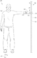
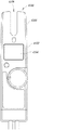
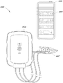
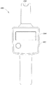
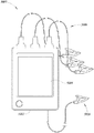
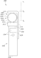
図1Aは、基準信号型電圧センサーを含む非接触電圧測定システム102を、オペレータ104が使用して、絶縁導体106内に存在するAC電圧を、非接触電圧測定システムと電線106とのガルバニック接触を必要とすることなく測定することができる環境100の絵図である。図1Bは、図1Aの非接触電圧測定システム102の上面図であり、動作中の非接触電圧測定システムの様々な電気的特性を示す。非接触電圧測定システム102は、ハウジングつまり本体108を含み、ハウジングつまり本体108は、握持部分つまり端部110と、握持部分の反対側の、本明細書では前端ともいうプローブ部分つまり端部112とを含む。ハウジング108はまた、非接触電圧測定システム102とのユーザーインタラクションを促進するユーザーインターフェース114を含むこともできる。ユーザーインターフェース114は、任意の数の入力部(例えば、ボタン、ダイヤル、スイッチ、タッチセンサー)と、任意の数の出力部(例えば、ディスプレイ、LED、スピーカー、ブザー)とを含むことができる。非接触電圧測定システム102はまた、1つ又は2つ以上の有線及び/又は無線通信インターフェース(例えば、USB、Wi−Fi(登録商標)、Bluetooth(登録商標))を含むこともできる。
FIG. 1A illustrates a non-contact
少なくとも一部の実行例において、図1Bに最も良好に示すように、プローブ部分112は、第1及び第2の拡張部分118及び120によって画成された凹部分116を含むことができる。凹部分116は、絶縁導体106(図1Aを参照)を受容する。絶縁導体106は、導体122と、導体122を取り囲む絶縁体124とを含む。凹部分116は、センサー又は電極126を含むことができ、センサー又は電極126は、絶縁電線が非接触電圧測定システム102の凹部分116内に位置決めされたときに絶縁電線106の絶縁体124に近接して載置される。明瞭さのために図示していないが、センサー126は、センサーと他の物体と物理的及び電気的接触を防止するためにハウジング108の内側に配設することができる。
In at least some implementations, as best shown in FIG. 1B,
図1Aに示すように、使用時に、オペレータ104は、ハウジング108の握持部分110を把持し、プローブ部分112を絶縁導体106に近接して配置することができ、非接触電圧測定システム102は、電線内に存在するAC電圧を接地(又は、別の基準ノード)に対して正確に測定することができるようになっている。プローブ端部112は凹部分116を有すると示されているが、他の実行例において、プローブ部分112は、異なる方法で構成することができる。例えば、少なくとも一部の実行例において、プローブ部分112は、移動可能なクランプ、フック、センサーを含む選択的に平坦な又は円弧の面、又は、非接触電圧測定システム102のセンサーを絶縁導体106に近接して位置決めすることを可能にする他の形式のインターフェースを含むことができる。様々なプローブ部分及びセンサーの実施例を図10〜図15を参照して以下で論じる。
As shown in FIG. 1A, in use, the
アース/接地の基準の役目を務めるオペレータの体は、一部の実行例にあるにすぎない。本明細書で論じる非接触測定値の機能性は、接地に対して測定する用途のみに限定されない。外部基準は、任意の他の電位に容量結合することができる。例えば、外部基準が三相システムの別の位相に容量結合された場合、相間電圧が測定される。一般的に、本明細書で論じる概念は、基準電圧及び任意の他の基準電位に容量結合接続された人体を使用するアースに対する基準のみに限定されない。 The body of the operator serving as the ground / ground reference is only in some implementations. The functionality of non-contact measurements discussed herein is not limited to applications that measure against ground. The external reference can be capacitively coupled to any other potential. For example, if the external reference is capacitively coupled to another phase of a three phase system, the interphase voltage is measured. In general, the concepts discussed herein are not limited to only a reference to ground using a human body capacitively coupled to a reference voltage and any other reference potential.
以下で更に論じるように、少なくとも一部の実行例において、非接触電圧測定システム102は、オペレータ104と接地128との間の人体容量(CB)をAC電圧測定中に利用することができる。接地という用語がノード128に使用されているが、ノードは、必ずしもアース/接地であるというわけではなく、容量結合によって任意の他の基準電位にガルバニック絶縁された方法で接続することができる。
As discussed further below, in at least some implementations, the contactless
AC電圧を測定するために非接触電圧測定システム102によって使用される特定のシステム及び方法を図2〜図15を参照して以下で論じる。
Specific systems and methods used by contactless
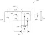
図2は、図1A及び図1Bにも示す非接触電圧測定システム102の様々な内部構成要素の概略図を示す。この実施例において、非接触電圧測定システム102の導電センサー126は、実質的に「V字形」であり、試験中の絶縁導体106に近接して位置決めされ、絶縁導体106の導体122と容量結合して、センサー結合コンデンサ(CO)を形成する。非接触電圧測定システム102を取り扱うオペレータ104は、人体容量(CB)を接地に対して有する。したがって、図1B及び図2に示すように、電線122内のAC電圧信号(VO)は、絶縁導体電流成分又は「信号電流」(IO)を、直列に接続されている結合コンデンサ(CO)及び人体容量(CB)にわたって生成する。一部の実行例において、人体容量(CB)はまた、容量を接地又は任意の他の基準電位に生成するガルバニック絶縁されたテスト用リード線を含むこともできる。
FIG. 2 shows a schematic diagram of the various internal components of the contactless
測定される電線122内のAC電圧(VO)は、外部接地128(例えば、中立)との接続を有する。非接触電圧測定システム102自体もまた、接地128に対する容量を有し、この容量は、主として、オペレータ104(図1)が非接触電圧測定システムを手に保持したときの人体容量(CB)からなる。容量CO及びCBの両方によって、導電ループが生成され、ループ内側の電圧は、信号電流(IO)を生成する。信号電流(IO)は、導電センサー126に容量結合されたAC電圧信号(VO)によって生成され、非接触電圧測定システムのハウジング108及び接地128に対する人体コンデンサ(CB)を介して外部接地128に戻る。電流信号(IO)は、非接触電圧測定システム102の導電センサー126と試験中の絶縁導体106との間の距離、導電センサー126の特定の形状、及び導体122内のサイズ及び電圧レベル(VO)に左右される。
The AC voltage (V O ) within the
信号電流(IO)に直接的な影響を与える距離変動及びそれに伴う結合コンデンサ(CO)変動を補正するために、非接触電圧測定システム102は、共通モード基準電圧源130を含み、共通モード基準電圧源130は、信号電圧周波数(fO)と異なる基準周波数(fR)を有するAC基準電圧(VR)を生成する。
In order to compensate for distance variations and associated coupling capacitor (C O ) variations that directly affect the signal current (I O ), the contactless
迷走電流を低減又は回避するために、非接触電圧測定システム102の少なくとも一部は、導電内部接地ガードつまりスクリーン132によって取り囲むことができ、スクリーン132は、電流の大部分に導電センサー126を通させ、導電センサー126は、結合コンデンサ(CO)を絶縁導体106の導体122で形成する。内部接地ガード132は、任意の好適な導電材料(例えば、銅製)から形成することができ、中実(例えば、箔)とすることができるか、又は、1つ又は2つ以上の開口部(例えば、メッシュ)を有することができる。
In order to reduce or avoid stray currents, at least a portion of the contactless
更に、内部接地ガード132と外部接地128との間の電流を回避するために、非接触電圧測定システム102は、導電基準遮蔽体134を含む。基準遮蔽体134は、任意の好適な導電材料(例えば、銅製)から形成することができ、中実(例えば、箔)とすることができるか、又は、1つ又は2つ以上の開口部(例えば、メッシュ)を有することができる。共通モード基準電圧源130は、基準遮蔽体134と内部接地ガード132との間に電気的に結合され、これによって、非接触電圧測定システム102の基準電圧(VR)と基準周波数(fR)とを有する共通モード電圧が生成される。そのようなAC基準電圧(VR)によって、付加的な基準電流(IR)が、結合コンデンサ(CO)及び人体コンデンサ(CB)を介して駆動される。
Further, to avoid current between the
導電センサー126の少なくとも一部を取り囲む内部接地ガード132は、導電センサーを、導電センサー126と基準遮蔽体134との間の基準電流(IR)の望ましくない偏位を引き起こすAC基準電圧(VR)の直接的な影響に対して保護する。上述したように、内部接地ガード132は、非接触電圧測定システム102の内部電子接地138である。少なくとも一部の実行例において、内部接地ガード132はまた、電子品に結合するAC基準電圧(VR)を回避するために非接触電圧測定システム102の電子品のうちの一部又は全部も取り囲む。
An
上述したように、基準遮蔽体134は、基準信号を入力AC電圧信号(VO)上へ投入するために利用され、第2の機能としてガード132を接地128容量に最小限に抑える。少なくとも一部の実行例において、基準遮蔽体134は、非接触電圧測定システム102のハウジング108のうちの一部又は全部を取り囲む。そのような実行例において、電子品の一部又は全てには、基準共通モード信号があり、基準共通モード信号はまた、基準電流(IR)を絶縁導体106内の導電センサー126と導体122との間に生成する。少なくとも一部の実行例において、基準遮蔽体134の唯一の間隙は、導電センサー126用の開口部とすることができ、この開口部によって、導電センサーを非接触電圧測定システム102の作動中に絶縁導体106に近接して位置決めすることができる。
As described above, the
内部接地ガード132及び基準遮蔽体134は、二重層スクリーンを非接触電圧測定システム102のハウジング108(図1A及び図1Bを参照)の周りにもたらすことができる。基準遮蔽体134は、ハウジング108の外面上に配設することができ、内部接地ガード132は、内部遮蔽体又はガードとして機能することができる。導電センサー126は、基準遮蔽体134に対してガード132によって遮蔽され、任意の基準電流流量が、導電センサー126と試験中の導体122との間に結合コンデンサ(CO)によって生成されるようになっている。
An
センサー126の周りのガード132もまた、センサーに近い隣接する電線の漂遊影響を低減する。
A
図2に示すように、非接触電圧測定システム102は、反転電流電圧変換器として動作する入力増幅器136を含むことができる。入力増幅器136は、非接触電圧測定システム102の内部接地138として機能する内部接地ガード132に電気的に結合された非反転端子を有する。入力増幅器136の反転端子を導電センサー126に電気的に結合することができる。フィードバック回路137(例えば、フィードバック抵抗)はまた、入力増幅器136の反転端子と出力端子との間に結合して、フィードバック及び適切なゲインを入力信号の調整のために供給することもできる。
As shown in FIG. 2, the contactless
入力増幅器136は、信号電流(IO)及び基準電流(IR)を導電センサー126から受け取り、受け取った電流を、入力増幅器の出力端子にて導電センサー電流を示すセンサー電流電圧信号に変換する。例えば、センサー電流電圧信号は、アナログ電圧とすることができる。アナログ電圧は、信号処理モジュール140に供給することができ、信号処理モジュール140は、以下で更に論じるように、センサー電流電圧信号を処理し、絶縁導体106の導体122内のAC電圧(VO)を判定する。信号処理モジュール140は、デジタル及び/又はアナログ回路の任意の組み合わせを含むことができる。
非接触電圧測定システム102はまた、判定されたAC電圧(VO)を示すか、又は、非接触電圧測定システムのオペレータ104にインターフェースによって通信するために信号処理モジュール140に通信可能に結合されたユーザーインターフェース142(例えば、ディスプレイ)を含むこともできる。
The contactless
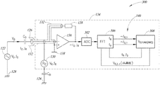
図3は、非接触電圧測定システムの様々な信号処理構成要素を示す非接触電圧測定システム300のブロック図である。図4は、図3の非接触電圧測定システム300のより詳細な図である。
FIG. 3 is a block diagram of a contactless
非接触電圧測定システム300は、先に論じた非接触電圧測定システム102と類似又は全く同じとすることができる。したがって、類似の又は全く同じ構成要素は、同じ参照番号が記載される。図示するように、入力増幅器136は、導電センサー126からの入力電流(IO+IR)を入力電流を示すセンサー電流電圧信号に変換する。センサー電流電圧信号は、アナログ/デジタル変換器(ADC)302を使用してデジタル形式に変換される。
The non-contact
電線122内のAC電圧(VO)は、式(1)によってAC基準電圧(VR)に関係する。

AC電圧(VO)に関係する指数「O」を有する信号は、共通モード基準電圧源130に関係する指数「R」を有する信号と異なる、周波数のような特性を有する。図4の実行例において、高速フーリエ変換(fast Fourier transform、FFT)アルゴリズム306を実行する回路など、デジタル処理を使用して、異なる周波数を有する信号の大きさを分離することができる。以下で論じる図5の実行例において、アナログ電子フィルターを使用して、「O」信号特性(例えば、大きさ、周波数)を「R」信号特性から分離することもできる。
A signal having an index “O” related to the AC voltage (V O ) has a frequency-like characteristic that is different from a signal having an index “R” related to the common mode
電流(IO)及び(IR)は、結合コンデンサ(CO)のために、それぞれ、周波数(fO)及び(fR)に左右される。結合コンデンサ(CO)及び人体容量(CB)を通って流れる電流は、周波数に比例し、したがって、試験中の導体122内のAC電圧(VO)の周波数(fO)を測定して、信号周波数(fO)に対する基準周波数(fR)の比率を判定する必要があり、この比率は、先に記載した式(1)において利用されるか、又は、基準周波数は、システム自体によって生成されるので既にわかっている。
The currents (I O ) and (I R ) depend on the frequencies (f O ) and (f R ), respectively, due to the coupling capacitor (C O ). The current flowing through the coupling capacitor (C O ) and the human body capacitance (C B ) is proportional to the frequency, thus measuring the frequency (f O ) of the AC voltage (V O ) in the
入力電流(IO+IR)が入力増幅器136によって条件づけられてADC 302によってデジタル化された後、FFT 306を使用して周波数領域の信号を表すことによってデジタルセンサー電流電圧信号の周波数成分を判定することができる。周波数(fO)及び(fR)の両方が測定されたとき、電流(IO)及び(IR)の基本的な大きさをFFT 306から計算するために周波数ビンを判定することができる。
After the input current (I O + I R ) is conditioned by the
電流(IR)及び/又は電流(IO)の大きさは、基準信号センサー又は電極(例えば、電極126)と絶縁電線体106の導体122との間の距離の関数として変動する場合がある。したがって、システムは、測定された電流(IR)及び/又は電流(IO)を予想されたそれぞれの電流と比較して、基準信号センサー又は電極と導体122との間の距離を判定することができる。測定中に絶縁電線106を(例えば、調整可能なクランプアセンブリを介して)基準信号センサー又は電極近傍に位置決めすることができることから、基準信号センサーと絶縁電線106の導体122との間の距離は、絶縁層124の厚さにほぼ等しい。以下で論じるように、調整可能なクランプアセンブリに動作可能に結合された位置フィードバックセンサーが、絶縁電線106の全体径を供給する。したがって、絶縁電線の判定された全体径及び絶縁層124の判定された厚さを使用して、システムは、絶縁電線106の内側の導体122の直径又はゲージを正確に判定することができる。この情報は、磁場センサーによって測定された磁場と共に、絶縁電線106の内側の導体122を通って流れる電流の大きさを正確に判定するためにシステムによって使用されてもよい。
The magnitude of the current (I R ) and / or the current (I O ) may vary as a function of the distance between the reference signal sensor or electrode (eg, electrode 126) and the
次に、ブロック308によって示すように、IR,1及びIO,1と指定された電流(IR)及び(IO)の基本高調波の比率を、判定された周波数(fO)及び(fR)によってそれぞれ補正することができ、この係数を使用して、高調波(VO)を電線122内に追加することによって測定された元の基本的つまりRMS電圧を計算することができ、これは、二乗高調波合計の平方根を計算することによって行われ、ディスプレイ312上でユーザーに示すことができる。
Next, as shown by
結合コンデンサ(CO)は、絶縁導体106と導電センサー126との間の距離、並びに、センサー126の特定の形状及び寸法に応じて、例えば、ほぼ0.02pF〜1pFの範囲の容量値を一般的に有することができる。人体容量(CB)は、例えば、ほぼ20pF〜200pFの容量値を有することができる。
The coupling capacitor (C O ) generally has a capacitance value in the range of approximately 0.02 pF to 1 pF, for example, depending on the distance between the
上記の式(1)から、共通モード基準電圧源130によって生成されたAC基準電圧(VR)は、同様の電流の大きさを信号電流(IO)及び基準電流(IR)について達成するために導体122内のAC電圧(VO)と同じ範囲内である必要はないことがわかる。AC基準電圧(VR)は、相対的に高いように基準周波数(fR)を選択することによって相対的に低い(例えば、5V未満)とすることができる。一例として、基準周波数(fR)は、3kHzであるように選択することができ、3kHzは、60Hzの信号周波数(fO)を有する典型的な120 VRMS AC電圧(VO)の50倍の高さである。そのような場合、AC基準電圧(VR)は、信号電流(IO)と同じ基準電流(IR)を生成するためにわずか2.4V(即ち、120V÷50)であるように選択することができる。一般的に、基準周波数(fR)を信号周波数(fO)のN倍であると設定すると、AC基準電圧(VR)は、同様の不確実性をIR及びI0について達成するように互いと同じ範囲にある電流(IR)及び(IO)を生成するために電線122内のAC電圧(VO)の(1/N)倍である値を有することができる。
From equation (1) above, the AC reference voltage (V R ) generated by the common mode
任意の好適な信号発生器を使用して、基準周波数(fR)を有するAC基準電圧(VR)を生成することができる。図3に図示した実施例において、シグマデルタデジタル/アナログ変換器(Σ−Δ DAC)310が使用されている。Σ−Δ DAC 310は、ビットストリームを使用して、定義された基準周波数(fR)及びAC基準電圧(VR)を有する波形(例えば、正弦波形)信号を生成する。少なくとも一部の実行例において、Σ−Δ DAC 310は、ジッタを低減するためにFFT 306のウィンドウと同相である波形を生成することができる。
Any suitable signal generator can be used to generate an AC reference voltage (V R ) having a reference frequency (f R ). In the embodiment illustrated in FIG. 3, a sigma delta digital-to-analog converter (Σ-Δ DAC) 310 is used. The Σ-
少なくとも一部の実行例において、ADC 302は、14ビットの解像度を有することができる。動作時に、ADC 302は、FFT 306によって処理に対して準備完了である100msの2n個サンプル(1024)(FFT 306用に10Hzビン)を供給するために入力増幅器136からの出力を名目50Hz入力信号がないか10.24kHzのサンプリング周波数にてサンプリングすることができる。60Hzの入力信号については、サンプリング周波数は、例えば、同じサンプル数/サイクルを得るために12.288kHzとすることができる。ADC 302のサンプリング周波数を基準周波数(fR)の完全なサイクル数に同期させることができる。例えば、入力信号周波数は、40〜70Hzの範囲内とすることができる。AC電圧(VO)の測定された周波数に応じて、集約間隔内で捕捉された不完全な信号周期によって引き起こされた位相推移ジッタを抑制するために、FFT 306を使用し、そしてハニング窓機能を更なる計算のために使用する、AC電圧(VO)のビンを判定することができる。
In at least some implementations, the
1つの実施例において、共通モード基準電圧源130は、2419Hzの基準周波数(fR)を有するAC基準電圧(VR)を生成する。この周波数は、60Hz信号については40番目の高調波と41番目の高調波との間に、50Hz信号については、48番目の高調波と49番目の高調波との間にある。予想されたAC電圧(VO)の高調波ではない基準周波数(fR)を有するAC基準電圧(VR)を供給することによって、AC電圧(VO)は、基準電流(IR)の測定値に影響を及ぼす可能性が少なくなっている。
In one embodiment, common mode
少なくとも一部の実行例において、共通モード基準電圧源130の基準周波数(fR)は、試験中の導体122内のAC電圧(VO)の高調波の影響を受ける可能性が最も少ない周波数であるように選択される。一例として、共通モード基準電圧源130は、基準電流(IR)が境界を超えたときに電源を切断することができ、これは、導電センサー126が試験中の導体122に接近していることを示すことができる。共通モード基準電圧源130を電源切断した状態で測定(例えば、100msの測定)を行って、信号高調波をいくつか(例えば、3つ、5つ)の候補基準周波数にて検出することができる。その後、AC電圧(VO)内の信号高調波の大きさをその数の候補基準周波数にて判定して、どの候補基準周波数がAC電圧(VO)の信号高調波により受ける影響が最も少ない可能性があるかを識別することができる。その後、基準周波数(fR)を識別された候補基準周波数に設定することができる。基準周波数のこの切り替えによって、信号スペクトル内の可能性がある基準周波数成分の衝撃を回避又は低減することができるが、これによって、測定された基準信号が増大して精度が低減する恐れがあり、不安定な結果が出る恐れがある。同じ特性を有する2419Hzの他の周波数としては、例えば、2344Hz及び2679Hzが挙げられる。
In at least some implementations, the reference frequency (f R ) of the common mode
図5は、電子フィルターを実行する非接触電圧測定システムの信号処理部500のブロック図である。信号処理部500は、電流測定値サブシステム(例えば、入力増幅器136)からの導電センサー126電流(IO+IR)に比例しているセンサー電流電圧信号を受信することができる。
FIG. 5 is a block diagram of a
上述したように、信号電流(IO)は基準電流(IR)と異なる周波数を有する。信号電流(IO)を基準電流(IR)から隔離するために、信号処理部500は、信号電流(IO)を伝えて基準電流(IR)を拒絶するように動作する第1のフィルター502を含むことができる。その後、フィルターリングされた信号を、第1の整流器504によって整流し、第1のADC 506によってデジタル化することができる。デジタル化された信号は、先に論じたように、計算において使用されるように好適なプロセッサ508に供給することができる。同様に、基準電流(IR)を信号電流(IO)から隔離するために、信号処理部500は、基準電流(IR)を伝えて信号電流(IO)を拒絶するように動作する第2のフィルター510を含むことができる。その後、フィルターリングされた信号を、第2の整流器512によって整流し、第2のADC 514によってデジタル化することができる。デジタル化された信号は、計算において使用されるように好適なプロセッサ508に供給することができる。第1及び第2のフィルター502及び510は、任意の好適なアナログフィルターとすることができ、それぞれ、いくつかの個別構成部品(例えば、コンデンサ、誘導体)を含むことができる。
As described above, the signal current (I O ) has a different frequency from the reference current (I R ). In order to isolate the signal current (I O ) from the reference current (I R ), the
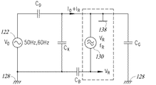
図6は、共通モード基準電圧源130、人体容量(CB)、結合コンデンサ(CO)、電線122、外部接地128、及び内部接地138によって形成されたループを示す、先に論じた非接触電圧測定システムのいずれかなど、非接触電圧測定システムの各部の概略回路図である。
FIG. 6 shows the contactless discussed above, showing the loop formed by the common mode
図7Aは、様々なリーク及び浮遊容量を示す、非接触電圧測定システム102の概略図である。一般的に、システム(例えば、センサー126)にある異なる浮遊容量の影響の除去は、高度な遮蔽材技術でさえも特別なセンサー設計法及びスクーリング法によって完全に達成することができるわけではない。上述したように、本開示の実行例は、共通モード基準電圧源130を利用して、測定された信号周波数(fO)と異なる基準周波数(fR)を有する基準電圧を生成し、システムにある浮遊容量を補正する。
FIG. 7A is a schematic diagram of the contactless
特に、結合コンデンサ(CO)に加えて、図7Aは、人体容量(CB)、容量(CX)、容量(CSENS-REF)及び容量(CG)を示す。人体容量(CB)は、結合コンデンサ(CO)と直列であり、典型的な用途において、人体容量(CB)は、結合コンデンサ(CO)よりもはるかに大きい。したがって、人体容量(CB)は、電流(IO+IR)の大きさに影響を与えるだけであり、電流の比率(IO/IR)には影響を与えない。 In particular, in addition to the coupling capacitor (C O ), FIG. 7A shows human body capacitance (C B ), capacitance (C X ), capacitance (C SENS-REF ) and capacitance (C G ). The human body capacitance (C B ) is in series with the coupling capacitor (C O ), and in a typical application, the human body capacitance (C B ) is much larger than the coupling capacitor (C O ). Therefore, the human body capacity (C B ) only affects the magnitude of the current (I O + I R ) and does not affect the current ratio (I O / I R ).
図7A及び図8に示すように、容量(CX)は、導電センサー126と外部接地128との間のセンサー容量である。結合コンデンサ(CO)は、電線122とセンサー126との間の唯一の容量ではない。特にセンサー126の領域を実質的に覆わない細線についてはセンサー126と外部接地128との間の容量(CX)もある。容量(CX)は、容量性電圧分圧器効果を信号電流(IO)について有し、結果的に、AC電圧(VO)についてはより低い電圧測定値となる場合がある。したがって、容量(CX)は、電流(IO+IR)の大きさを低減する。しかしながら、基準電流(IR)は、同じ比率で分割され、したがって、浮遊容量(CX)も補正するので、比率(IO/IR)は影響を受けない。また、非接触電圧測定システムの外側への内部の電流の流れを回避するために、少なくとも一部の実行例において上述したように、基準遮蔽体134によって感知面積以外の測定システム全体を外部環境から遮蔽し、共通モード基準電圧源130の出力部に接続して、基準電流(IR)を生成することができる。
As shown in FIGS. 7A and 8, the capacitance (C X ) is a sensor capacitance between the
図7Aに示すように、容量(CSENS-REF)は、基準遮蔽体134と導電センサー126との間の残り容量である。容量(CSENS-REF)は、センサー電流(IO+IR)について、電線106内のAC電圧(VO)が測定されていないときでさえも存在するオフセットを引き起こす。
As shown in FIG. 7A, the capacitance (C SENS-REF ) is the remaining capacitance between the
図7A及び図9Aに示すように、容量(CG)は、内部接地138と外部接地128との間の容量つまり基準電位である。容量(CG)は、基準電流(IR)に対する並列経路であり、基準電流を低減する。したがって、容量(CG)によって、電線106内のAC電圧(VO)について、計算された結果の増加が生じる。容量(CG)の影響を示す図9Bを参照されたい。特に、容量(CG)は、異なる影響をIR及びIOに与え、したがって、比率IO/IRに影響を与える。
上記式(2)−(5)からわかるように、比率IO/IRは、CB/CGに左右される。容量CGは、基準スクリーンが非接触電圧測定システム102の筐体全体及びセンサーの周りにあるときの方がはるかに小さい。
The formula (2) - As can be seen from (5), the ratio I O / I R is dependent on C B / C G. Capacitance C G is much smaller when the reference screen is around the entire housing of the contactless
図7Bは、反転基準信号(−VR)と、反転基準信号をセンサー126に結合する構成とを使用することによって、基準電圧(VR)がセンサー126に及ぼす影響の補正を行う実行例を示す。図7Cは、反転基準信号補正を含む例示的なセンサー構成を示す。
FIG. 7B illustrates an example implementation of correcting the effect of the reference voltage (V R ) on the
図7Bにおいて、調整可能反転増幅器141が、基準電圧(+VR)がセンサーに及ぼす影響を補正するために反転基準信号(−VR)をセンサー126に供給するために使用されている。これは、センサー126に近接して位置決めされた容量結合(CC)によって達成することができる。容量結合(CC)は、センサーに近接して位置決めされた電線、スクリーン、遮蔽体などの形とすることができる。補正は、そのような実例において、基準遮蔽体134からの基準電圧(VR)がセンサー126に最も大きい影響を与える恐れがあるので絶縁導体106が相対的に小さな直径を有するときに特に有利であり得る。
In FIG. 7B, an
図7Cは、上述した基準信号補正を行う実行例において使用される例示的なセンサー構成139を示す。センサー構成139は、センサー139aと、絶縁層139b(例えば、Kapton(登録商標)テープ)と、内部接地ガード139cと、反転基準信号層139d(−VR)と、絶縁層139eと、基準信号層139f(+VR)とを含む。
FIG. 7C shows an
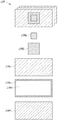
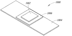
図10は、先に論じた非接触電圧測定システムのいずれかなど、非接触電圧測定システム用の例示的なセンサー及びガードアセンブリ1000の斜視図である。この実施例において、センサー及びガードアセンブリ1000は、導電センサー1002、内部接地ガード1004、及び、センサーと内部接地ガードとの間に配設された絶縁層1006を備える。一般的に、センサーアセンブリ1000は、良好な結合容量(CO)をセンサー1002と試験中の電線との間にもたらす必要があり、他の隣接電線に対する容量と外部接地に対する容量とを抑制する必要がある。センサーアセンブリ1000は、センサー1002と基準遮蔽体(例えば、基準遮蔽体134)との間の容量(CSENS-REF)を最小限に抑える必要もある。
FIG. 10 is a perspective view of an exemplary sensor and guard assembly 1000 for a contactless voltage measurement system, such as any of the contactless voltage measurement systems discussed above. In this embodiment, the sensor and guard assembly 1000 includes a
単純な実施例として、センサー1002、ガード1004及び絶縁層1006は、それぞれ、箔片を備えることができる。ガード1004は担体(図11を参照)に結合することができ、絶縁層1006(例えば、Kapton(登録商標)テープ)はガードに結合することができ、センサー1002は絶縁層に結合することができる。
As a simple example, the
図11は、非接触電圧測定システムのプローブつまり前端1100のセンサー実現の実施例の断面図を示し、プローブつまり前端1100は、センサーアセンブリと任意の物体との直接的なガルバニック接触を回避するためにセンサーアセンブリ1000を覆うハウジング層1102(例えば、プラスチック)を含む。前端1100は、図1A及び図1Bに示す非接触電圧測定システム102の前端112と類似又は全く同じとすることができる。この例示において、センサー1002、ガード1004及び絶縁層1006を含め、センサーアセンブリ1000は、センサーアセンブリ1000が、異径の絶縁電線を取り囲み、結合容量(CO)を増大させ、ガードによって隣接導電物体に対してより良好に遮蔽することを可能にするために「U」又は「V」の形で成形されている。
FIG. 11 shows a cross-sectional view of an embodiment of a sensor implementation of a probe or front end 1100 of a contactless voltage measurement system, where the probe or front end 1100 avoids direct galvanic contact between the sensor assembly and any object. A housing layer 1102 (eg, plastic) covering sensor assembly 1000 is included. The front end 1100 may be similar or identical to the
図11に示す実施例において、センサーアセンブリ1000は、相対的に大きな直径を有する絶縁電線1104又は相対的に小さな直径を有する絶縁電線1106など、様々な直径の絶縁電線を収容するように成形されている。それぞれの場合において、センサーアセンブリ1000は、電線が前端1100の凹部分1108内に位置決めされているときに電線を実質的に取り囲む。凹部分1108を画成し、かつセンサーアセンブリ1000と試験中の電線との間に位置決めされている前端1100の壁部は、ガルバニック絶縁をもたらし、同時にそれでも好適な容量結合を可能にするために相対的に肉薄(例えば、1mm)とすることができる。凹部分1108の「V」形状のために、より肉厚の電線1104は、結合容量の広範囲を低減し、また、電線直径との独立性を低減するために環境容量を低減するためにもより肉薄の電線1106よりも多くの隔たりを有する。
In the example shown in FIG. 11, the sensor assembly 1000 is shaped to accommodate various diameters of insulated wire, such as
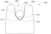
図12は、非接触電圧測定システムの弓形形状前端1200の立面図である。前端1200は、第1及び第2の拡張部分1204及び1206によって画成された凹部分1202を含む。凹部分1202は、相対的に大きな直径を有する絶縁電線1210を受け取る相対的に大きな上部弓形形状部分1208を含む。凹部分1202はまた、相対的に小さな直径を有する絶縁電線1214を受け取る相対的に小さなより低い弓形形状部分1212を部分1208より下方に含む。図10に示すセンサーアセンブリ1000と類似のものとすることができ、部分1208及び1212によって覆われているセンサーアセンブリ1216は、弓形形状部分1208及び1212に実質的に適合する形状を有することができ、センサーアセンブリ1216は、相対的に大きな直径(例えば、電線1210)を有する電線及び相対的に小さな直径(例えば、電線1214)を有する電線を実質的に取り囲むようになっている。
FIG. 12 is an elevational view of the arcuate front end 1200 of the contactless voltage measurement system. The front end 1200 includes a recessed portion 1202 defined by first and
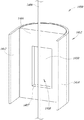
図13は、非接触電圧測定システムの円筒形前端1300の斜視図である。この実施例において、前端1300は、側壁1304を有する円筒形の内部接地ガード1302と、試験中の電線に近接して位置決めすることができる前面1306とを含む。内部接地ガード1302の前面1306は、中央開口部1308を含む。結合コンデンサ(CO)を試験中の電線と共に形成する導電センサー1310は、隣接物体との容量結合を回避するために内部接地ガード1302の開口部1308の後ろに凹設されている。センサー1310は、例えば、内部接地ガード1302の前面1306から(例えば、3mm)隔てて凹設することができる。
FIG. 13 is a perspective view of the cylindrical
内部接地ガード1302の側壁1304は、円筒形の基準遮蔽体1312によって取り囲まれてもよく、円筒形の基準遮蔽体1312は、絶縁層1314によって内部接地ガードから隔離されている。共通モード基準電圧源(例えば、電圧源130)を、内部のガード接地1302と基準遮蔽体1312との間に接続して、先に論じた機能性を提供することができる。
The
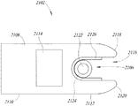
図14A及び図14Bは、非接触電圧測定システムの前端1400の上面図を示し、図15は、前端の一部の斜視図を示す。この実施例において、前端1400は、前面1404を含む内部接地ガード1402を含み、前面1404に当接して、試験中の電線1406(図15)を位置決めすることができる。前面1404は、この場合では長方形の縁部1407を含み、縁部1407は、開口部1408を前面に画成する。この小さく長い矩形の開口部は、側面から見られる、また、より長いが肉薄形状を有する電線形状を収容する。これは、やはり、隣接電線に対する影響を低減し、またセンサーに関係する環境容量も大きく低減する。これによって、結果的に、線径から独立した高い精度が得られる。結合コンデンサ(CO)を試験中の電線と共に形成する導電センサー1410が、(例えば、3mm)隔てて内部ガード接地1402の前面1404の開口部1408の後ろに凹設されている。
14A and 14B show a top view of the
内部接地ガード1402はまた、前面1404の側方縁部から(試験中の電線の方に)前方に延びる側壁1412及び1414も含む。側壁は、センサー浮遊容量を低減し、基準信号結合を導く。内部接地ガード1402はまた、第1のクランプアーム1416Aと第2のクランプアーム1416Bとを含む導電ガードリングクランプ1416も含むことができる。クランプアーム1416A及び1416Bは、試験中の電線を内部接地ガード1402の前面1404近傍に位置決めすることができるように図14Bに示す開位置へ選択的に移動させることができる。電線が所定の位置になると、クランプアーム1416A及び1416Bを図14Aに示す閉位置へ選択的に移動させて、外部環境との容量(例えば、近接する導体、近接する物体)に対する遮蔽体をセンサー1410の周りにもたらすことができる。閉位置であるとき、ガードリングクランプ1416は、実質的に、例えば、センサー1410より上方及び下方に延びる高さを有するシリンダーの形状とすることができる。クランプアーム1416A及び1416Bは、任意の好適な手動又は自動の作動サブシステム1418を使用して選択的に移動可能とすることができる。例えば、クランプアーム1416A及び1416Bは、作動システム1418として機能するばね又は他の付勢機構によって閉位置(図14A)の方に付勢することができ、この付勢をオペレータが克服して、クランプアームを開位置(図14B)に移動させることができ、試験中の電線を内部接地ガード1402の前面1404に近接して位置決めすることができるようになっている。
The
容量分圧器型非接触電圧測定システム
以下で論じる内容は、容量分圧器型電圧センサー又はシステムを利用して、絶縁導体(例えば、絶縁電線)のAC電圧を、導体と試験電極又はプローブとのガルバニック接続を必要とすることなく測定するシステム及び方法に関する。本セクションで開示する実行例を本明細書では「容量分圧器型電圧センサー」又はシステムという場合がある。一般的に、可変容量性電圧を試験中の絶縁導体と接地の間に生成するように動作する可変容量サブシステムを含む非接触電圧測定システムを提供する。測定中、非接触電圧測定システムは、可変容量サブシステムの容量を変え、試験中の絶縁導体と接地との間の容量分圧器回路のインピーダンスを変える。2回(又は3回)の測定を可変容量サブシステム全体にわたって順次に行うことによって、絶縁導体のAC電圧を、絶縁導体とのガルバニック接続を必要とすることなく判定することができる。ガルバニック接続を必要としないそのようなシステムを本明細書では「非接触」という。本明細書で使用するとき、「電気的に結合された」は、特記のない限り、直接及び間接の両方の電気的結合を含む。
Capacitive Voltage Divider Type Non-Contact Voltage Measurement System The following discussion uses a capacitive voltage divider voltage sensor or system to determine the AC voltage of an insulated conductor (eg, an insulated wire) and to galvanic the conductor and test electrode or probe. The present invention relates to a system and method for measuring without requiring a connection. The implementation disclosed in this section may be referred to herein as a “capacitive voltage divider voltage sensor” or system. In general, a contactless voltage measurement system is provided that includes a variable capacitance subsystem that operates to generate a variable capacitive voltage between an insulated conductor under test and ground. During measurement, the contactless voltage measurement system changes the capacitance of the variable capacitance subsystem and changes the impedance of the capacitive voltage divider circuit between the insulated conductor under test and ground. By performing two (or three) measurements sequentially across the variable capacitance subsystem, the AC voltage of the insulated conductor can be determined without requiring a galvanic connection with the insulated conductor. Such a system that does not require a galvanic connection is referred to herein as “contactless”. As used herein, “electrically coupled” includes both direct and indirect electrical coupling, unless otherwise specified.
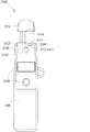
図16は、本開示の非接触電圧測定システム2102をオペレータ2104が使用して、絶縁電線内に存在するAC電圧2106を、非接触電圧測定システムと電線2106とのガルバニック接触を必要とすることなく測定することができる環境2100の概略図である。図17は、図16の非接触電圧測定システム2102の上面図である。非接触電圧測定システム2102は、握持部分つまり端部2110と、握持部分の反対側のプローブ部分つまり端部2112とを含むハウジング又は本体2108を含む。ハウジング2108はまた、非接触電圧測定システム2102とのユーザーインタラクションを促進するユーザーインターフェース2114を含むこともできる。ユーザーインターフェース2114は、任意の数の入力部(例えば、ボタン、ダイヤル、スイッチ、タッチセンサー)と、任意の数の出力部(例えば、ディスプレイ、LED、スピーカー、ブザー)とを含むことができる。
FIG. 16 illustrates the use of the non-contact
少なくとも一部の実行例において、図17に最も良好に示すように、プローブ部分つまり端部2112は、第1及び第2の拡張部分2118及び2120によって画成された凹部分2116を含むことができる。凹部分2116は、絶縁電線2106を受け取る。絶縁電線2106は、導体2122と、導体2122を取り囲む絶縁体2124とを含む。凹部分2116は、センサー又は電極2126を含むことができ、センサー又は電極2126は、絶縁電線が非接触電圧測定システム2102の凹部分2116内に位置決めされたときに絶縁電線2106の絶縁体2124に近接して又は実質的に近接して載置される。
In at least some implementations, as best shown in FIG. 17, the probe portion or
図16に示すように、使用時に、オペレータ2104は、ハウジング2108の握持部分2110を把持し、プローブ部分2112を絶縁電線2106に近接して配置することができ、非接触電圧測定システム2102は、電線内に存在するAC電圧を接地(又は、別の基準ノード)に対して正確に測定することができるようになっている。プローブ端部つまり端部2112は凹部分2116を有すると示されているが、他の実行例において、プローブ部分2112は、異なる方法で構成することができる。例えば、少なくとも一部の実行例において、プローブ部分2112は、センサーを含む選択的に移動可能なクランプ、フック、平坦な又は円弧の面、又は、非接触電圧測定システム2102のセンサーを絶縁電線2106に近接して位置決めすることを可能にする他の形式のインターフェースを含むことができる。
As shown in FIG. 16, in use, the
以下で更に論じるように、少なくとも一部の実行例において、非接触電圧測定システム2102は、オペレータ2104と接地2128との間の人体容量(CB)をAC電圧測定中に利用することができる。AC電圧を測定するために非接触電圧測定システム2102によって使用される特定のシステム及び方法を図18〜図22を参照して以下で論じる。
As discussed further below, in at least some implementations, the contactless
図18は、非接触電圧測定システム2300の高レベルブロック図である。非接触電圧測定システム2300は、先に論じた図16及び図17の非接触電圧測定システム2102と類似又は全く同じとすることができる。
FIG. 18 is a high level block diagram of a non-contact
非接触電圧測定システム2300は、導電センサーつまり電極2302を含み、導電センサーつまり電極2302は、オペレータ2104がプローブ部分又は端部2112(図16)を電線に近接して位置決めしたときに絶縁電線2106の近傍であるようにサイズ決定、寸法決定、及び位置決めされている。センサー2302は、例えば、図17のセンサー2126と類似又は全く同じとすることができる。センサー2302が電線の近傍にある状態で非接触電圧測定システム2300が絶縁電線2106に近接して位置決めされたとき、センサーは、絶縁電線と容量結合する。換言すると、センサー2302の導電部は、センサーコンデンサ(CS)のうちの一方の半分を備え、絶縁電線2106(図17)の導体2122は、センサーコンデンサのうちの他方の半分を備える。少なくとも一部の実行例において、センサー2302は、絶縁電線2106に面するセンサーの側の電磁場に対する感度が絶縁電線に面しないセンサーの他の側の電磁場に対する感度よりも大きいように設計することができる。
The non-contact
非接触電圧測定システム2300はまた、導電センサー2302に電気的に結合されている可変容量サブシステム2304も含む。可変容量サブシステム2304は、第2の容量値(C2)が第1の容量値(C1)と異なる場合、少なくとも第1の容量値(C1)と第2の容量値(C2)との間で選択的に可変である容量値を有する.少なくとも一部の実行例において、可変容量サブシステム2304は、第1、第2及び第3の容量値のそれぞれが互いと異なる場合、少なくとも第1の容量値(C1)と、第2の容量値(C2)と、第3の容量値(C3)との間で可変である容量値を選択的に有するように制御することができる。以下で更に論じるように、可変容量サブシステム2304は、絶縁電線2106から非接触電圧測定システム2300を通って接地2128又は他の基準ノードに延びる直列容量性回路の容量を変えるために使用されている。
Contactless
少なくとも一部の実行例において、容量値のうちの少なくとも1つ(例えば、容量値C1)は、入力信号及び入力容量の異なる値に対応するために選択的に可変とすることができる。例えば、システム2300は、入力信号が正確な測定には大きすぎるか又は小さすぎと判定することができ、正確な信号測定値を取得することができるように容量値のうちの1つ又は2つ以上を選択的に調節することができる。それゆえに、容量値(例えば、C1)のうちの1つ又は2つ以上は、特定の入力信号及び入力容量について好適な所望の容量値が得られるように選択的に結合することができる複数の物理コンデンサを利用して実行することができる。
In at least some implementations, at least one of the capacitance values (eg, capacitance value C 1 ) can be selectively variable to accommodate different values of the input signal and input capacitance. For example, the
非接触電圧測定システム2300はまた、電圧又は電圧を示す信号を可変容量サブシステム2304全体にわたって感知するように動作する電圧測定値サブシステム2306も含む。少なくとも一部の実行例において、電圧測定サブシステム2306は、アナログ電圧信号をデジタル信号に変換するアナログ/デジタル変換器(analog-to-digital converter、ADC)を含むことができる。例えば、電圧測定サブシステム2306は、非常に正確な測定値を促進する、20ビット以上(例えば、22ビット)の解像度など、相対的に高い有効解像度を有するADCを含むことができる。少なくとも一部の実行例において、電圧測定サブシステム2306は、ADCを使用して信号をデジタル形式変換する前に可変容量サブシステム2304から検出された電圧をバッファリング、成形、及び/又は増幅する調整回路(例えば、1つ又は2つ以上の増幅器及び/又はフィルター)を含むことができる。
The contactless
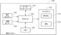
非接触電圧測定システム2300はまた、電圧測定サブシステム2306及び可変容量サブシステム2304に通信可能に結合されている制御装置2308を含むこともできる。制御装置2308は、任意の好適なハードウェア、ソフトウェア又はその組み合わせとすることができる。一例として、制御装置2308は、1つ又は2つ以上のプロセッサと、1つ又は2つ以上のプロセッサに通信可能に結合された1つ又は2つ以上の非一時的プロセス可読記憶媒体とを含むことができる。非一時的プロセス可読記憶媒体は、1つ又は2つ以上のプロセッサによって実行されたとき、1つ又は2つ以上のプロセッサに本明細書で論じる機能性を実行(例えば、絶縁電線2106内のAC電圧を測定)させる命令及び/又はデータを記憶することができる。
The contactless
制御装置2308は、1つ又は2つ以上の中央演算処理装置(central processing unit、CPU)、デジタル信号プロセッサ(digital signal processor、DSP)、特定用途向け集積回路(application-specific integrated circuit、ASIC)、フィールドプログラマブルゲートアレイ(field programmable gate array、FPGA)、プログラマブル論理制御回路(programmable logic controller、PLC)、人工ニューラルネットワーク回路又はシステム、又は、任意の他の論理構成要素など、任意の形式の処理ユニットを含むことができる。制御装置2308に結合された非一時的プロセス可読記憶媒体は、任意の形式の非一時的揮発性及び/又は不揮発性メモリを含むことができる。
The
非接触電圧測定システム2300はまた、制御装置2308に通信可能に結合されたユーザーインターフェース2310を含むこともできる。ユーザーインターフェース2310は、任意の数の入力部(例えば、ボタン、ダイヤル、スイッチ、タッチセンサー)と、任意の数の出力部(例えば、ディスプレイ、LED、スピーカー、ブザー)とを含むことができる。少なくとも一部の実行例において、制御装置2308及び/又はユーザーインターフェース2310は、データ及び/又は命令を非接触電圧測定システム2300と1つ又は2つ以上の外部デバイスとの間で通信することを可能にする1つ又は2つ以上の有線及び/又は無線通信インターフェース(例えば、USB、Bluetooth(登録商標)、WiFi(登録商標))を含むことができる。
The contactless
動作時に、オペレータ2104は、センサーコンデンサCSを形成するためにセンサー2302が電線と容量結合するように非接触電圧測定システム2300を絶縁電線2106に近接して位置決めすることができる。センサー2302がそのように位置決めされたとき、制御装置2308は、可変容量サブシステム2304に異なる容量値を有させることができ、測定値を異なる容量値のそれぞれにて電圧測定サブシステム2306から取得することができる。その後、制御装置2308は、絶縁電線2106内に存在するAC電圧の大きさを取得された測定値に基づいて判定し、結果をユーザーインターフェース2310を介してオペレータ2104に示すことができる。非接触電圧測定システム2300の特定の実行例に関する更なる詳細を図19〜図21を参照して以下で論じる。
In operation, the
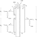
図19は、コンデンサ2401及び2403と指定された2つのコンデンサを利用する可変容量サブシステム2402を含む非接触電圧測定システム2400の概略図である。コンデンサ2401及び2403は、互いと同じか又は互いと異なる容量値を有することができる。非限定的な実施例として、コンデンサ2401及び2403は、それぞれ、1000ピコファラド(pF)の容量値を有することができる。別の実施例として、コンデンサ2401は、1000pFの容量値を有することができ、コンデンサ2403は、2000pFの容量値を有することができる。
FIG. 19 is a schematic diagram of a contactless
可変容量サブシステム2402は、第1の容量サブシステムノード2404と第2の容量サブシステムノード2406とを含む。コンデンサ2401は、第1の容量サブシステムノード2404と第2の容量サブシステムノード2406との間に電気的に結合されている。第1の容量サブシステムノード2404は、導電センサー2408に更に電気的に結合され、導電センサー2408は、それぞれ、先に論じた図17及び図18の非接触電圧測定システム2102及び2300の導電センサー2126及び2302と類似又は全く同じとすることができる。先に論じたように、非接触電圧測定システム2400が絶縁電線2106近傍に位置決めされたとき、導電センサー2408は、センサーコンデンサCSのうちの一方の半分を形成し、電線2106の導体2122(図17)は、センサーコンデンサCSのうちの他方の半分を形成する。
The
可変容量サブシステム2402はまた、コンデンサ2403をコンデンサ2401と並列に選択的に電気的に結合するように動作するスイッチS1も含む。したがって、スイッチS1を選択的に制御することによって、第1の容量サブシステムノード2404と第2の容量サブシステムノード2406との間の容量値は、コンデンサ2401の容量値と、コンデンサ2401及び2403の容量値の合計との間で選択的に可変である。コンデンサ2401及び2403が同じ容量値(例えば、1000pF)を有する場合、スイッチS1が閉にされたときの可変容量サブシステム2402の容量は、スイッチS1が開にされたときの可変容量サブシステム2402の容量の2倍(例えば、2000pF対1000pF)である。
第2の容量サブシステムノード2406は、人体容量CBを介して接地2128に電気的に結合することができ、人体容量CBは、非接触電圧測定システム2400を動作中に保持するオペレータ2104(図16及び図17)の容量である。一般的に、オペレータの体は、接地2128に対して薄膜絶縁体によって覆われた導体としてモデル化することができる。典型的には、人体容量CBは、様々な要因に応じて、数十〜低くは数百ピコファラド(例えば、50〜300pF)の範囲にある。少なくとも一部の実行例において、人体容量CBを利用するよりはむしろ、第2の容量サブシステムノード2406を、非接触電圧測定システム2400と接地との好適な電気的接続を介して接地2128に任意選択的に電気的に結合することができる。
Second
制御装置2308は、スイッチS1の動作を選択的に制御するために結合され、スイッチS1は、次に、容量値C1又は容量値C2であるように可変容量サブシステム2402の容量値を選択的に制御する。この実施例において、容量値C1は、コンデンサ2401の容量に等しく、容量値C2は、コンデンサ2401及び2403の容量の合計に等しい。他の実施例において、第1の容量サブシステムノード2404と第2の容量サブシステムノード2406との間のコンデンサ及び1つ又は2つ以上のスイッチの構成に応じて、可変容量サブシステム2402内の異なる容量値C1及びC2を選択的に達成することができる。
非接触電圧測定システム2400はまた、第1の容量サブシステムノード2404及び第2の容量サブシステムノード2406に電気的に結合されているADC 2410も含む。ADC 2410は、好適なインターフェース(例えば、同位相のシリアルインターフェース(synchronous serial interface、(SSI)を介して制御装置2308に通信可能に結合されている。ADC 2410は、第1の容量サブシステムノード2404と第2の容量サブシステムノード2406との間のアナログ電圧をデジタル信号に変換し、デジタル信号を制御装置2308に提供するように動作する。少なくとも一部の実行例において、ADC 2410は、20以上のビット(例えば、22ビット、24ビット、30ビット)の解像度など、相対的に高い有効解像度を有することができる。明瞭さのために図示していないが、ADC 2410は、信号をデジタル形式に変換する前に、可変容量サブシステム2402から検出された電圧をバッファリング、成形、及び/又は増幅する調整回路(例えば、1つ又は2つ以上の増幅器及び/又はフィルター)を含むことができるか、又は、該調整回路に結合することができる。更に、制御装置2308及びADC 2410は別個の構成要素として概略的に示されているが、少なくとも一部の実行例において、機能性のうちの一部又は全部を単一システム又は構成要素(例えば、単一の集積回路)内に結合することができる。
The contactless
センサー及び電線がセンサーコンデンサCSを形成するようにセンサー2408が電線近傍に位置決めされているときに電線2106内のAC電圧を測定するために、制御装置2308は、まず、可変容量サブシステム2402に、第1の容量値C1を第1の容量サブシステムノード2404と第2の容量サブシステムノード2406との間に有させることができる。例えば、制御装置2308は、スイッチS1を開にすることによってそのようなことを達成することができ、これに起因して、可変容量サブシステム2402は、コンデンサ2401の容量に等しい容量値を有する。
In order to measure the AC voltage in the
次に、可変容量サブシステム2402が第1の容量値C1を有する間、制御装置2308は、ADC 2410に、第1の容量サブシステムノード2404と第2の容量サブシステムノード2406との間の第1の電圧VM1を捕捉つまり測定させることができる。そのような電圧VM1は、その後の使用のために非一時的プロセス可読記憶媒体に制御装置2308によって記憶することができる。
Next, while the
次に、第1の電圧VM1の測定値を取得した後、制御装置2308は、可変容量サブシステム2402に、第2の容量値C2を第1の容量サブシステムノード2404と第2の容量サブシステムノード2406との間に有させることができる。例えば、制御装置2308は、コンデンサ2401と並列にコンデンサ2403を配置するためにスイッチS2を閉にすることによってそのようなことを達成することができ、これによって、可変容量サブシステム2402は、コンデンサ2401及び2403の容量値の合計に等しい容量値を有する。
Next, after obtaining the measured value of the first voltage V M1 , the
可変容量サブシステム2402は第2の容量値C2を有するが、制御装置2308は、ADC 2410に第1の容量サブシステムノード2404と第2の容量サブシステムノード2406との間の第2の電圧VM2を捕捉つまり測定させることができる。
While the
次に、制御装置2308は、絶縁電線2106内のAC電圧を検出された第1の電圧VM1、検出された第2の電圧VM2、第1の容量値C1及び第2の容量値C2に少なくとも部分的に基づいて判定することができる。絶縁電線2106内のAC電圧を判定する例示的なプロセスを図20を参照して以下で論じる。
Next, the
図20は、図19の非接触電圧測定システム2400の概略回路図を示す。この実施例において、絶縁電線2106のAC電圧は、交流電源(VAC)によって表されている。直列容量性回路が、交流電源(VAC)と、センサーコンデンサCSと、容量値C1又はスイッチS1の状態に応じて容量値C2である測定容量CMと、オペレータ2104(図16及び図17)の人体容量CBとの間に形成されている。先に論じたように、ADC 2410は、可変容量サブシステム2402が第1の容量値(即ち、CM=C1)を有するときに第1の電圧測定値VM1をノード2404及び2406全体にわたって取得し、可変容量サブシステムが第2の容量値(即ち、CM=C2)を有するときに第2の電圧測定値VM2をノード2404及び2406全体にわたって取得する。測定された電圧VMは、ノード2404での電圧(V404)とノード2406での電圧(V406)との間の電位差に等しい(即ち、VM=V404〜V406)。
FIG. 20 shows a schematic circuit diagram of the non-contact
ノード2404での電流は、式によって表すことができる。
ICS−ICM=0 (6)
電流(ICS)は、以下の式によって与えられる。
I CS −I CM = 0 (6)
The current (I CS ) is given by:
同様に、ノード2406での電流は、式によって表すことができる。
ICM−ICB=0 (9)
電流(ICB)は、以下の式によって与えられる。
I CM −I CB = 0 (9)
The current (I CB ) is given by:
上記式(6)及び(9)を使用して、及び、VM=V404〜V406、VMは以下の式によって表すことができる。
先に論じたように、ADC 2410は、可変容量システム2402が容量値C1を有するときに第1の電圧測定値VM1を取得するし、可変容量システム2402が容量値C2を有するときに第2の電圧測定値VM2を取得する。したがって、VM1及びVM2は、以下の式によって表すことができる。
式(13)及び(14)は、絶縁電線2106内のAC電圧(VAC)について解くことができ、これは、以下の式によって提示される。
式(15)からわかるように、AC電圧(VAC)は、既知の容量値C1及びC2(つまり容量値C1とC2との比率)、及び、測定された電圧VM1及びVM2のみを使用して実行時間中に判定することができる。即ち、絶縁電線2106内のAC電圧(VAC)を取得するためには、センサーコンデンサCS及び人体容量CBを判定する必要はない。更に、尚、AC電圧の周波数は、式から脱落するが、システム2400の全体的なインピーダンスは、回路の最小コンデンサの周波数及び容量に左右される。例えば、回路内の最小コンデンサである1pFのセンサー容量CSで、回路のインピーダンスは、50Hzにて3.5GΩ台である。
As can be seen from equation (15), the AC voltage (V AC ) is the known capacitance values C 1 and C 2 (ie, the ratio between the capacitance values C 1 and C 2 ) and the measured voltages V M1 and
図21は、3つのコンデンサ、即ち、コンデンサ2602、2604及び2606を利用する可変容量サブシステム2601を含む非接触電圧測定システム2600の概略図である。非接触電圧測定システム2600は、先に論じた非接触電圧測定システムと類似又は全く同じであるので、簡潔さのために実質的な違いのみを以下で論じる。
FIG. 21 is a schematic diagram of a contactless
非接触電圧測定システム2600は、センサー2408に電気的に結合された第1の容量サブシステムノード2608と、オペレータ2104(図16及び図17)の人体容量CBを介して接地2128に電気的に結合された第2の容量サブシステムノード2610とを含む。少なくとも一部の実行例において、第2の容量型サブシステムノード2610は、好適な電気接続部2612(「基準接続部」)を介して接地2128に任意選択的に直に電気的に結合することができる。
Non-contact
コンデンサ2602は、制御装置2308によって制御可能であるスイッチS2を介してノード2608とノード2610との間に選択的に直列に結合することができる。コンデンサ2604は、制御装置2308によって制御可能であるスイッチS3を介してノード2608とノード2610との間に選択的に直列に結合することができる。コンデンサ2606は、制御装置2308によって制御可能であるスイッチS4を介してノード2608とノード2610との間に選択的に直列に結合することができる。少なくとも一部の実行例において、制御装置2308は、一度にスイッチS2、S3及びS4のうちの1つを閉にし、一度にコンデンサのうちの1つをノード2608とノード2610との間に直列に結合する。そのような実例において、コンデンサ2602、2604及び2606のそれぞれは、互いと異なる容量値を有することができる。例えば、コンデンサ2602は、1000pFの容量値を有することができ、コンデンサ2604は、2000pFの容量値を有することができ、コンデンサ2606は、24000pFの容量値を有することができる。一般的に、容量値は、コンデンサのそれぞれが回路にスイッチングされるときに電圧測定値の相対的に大きな変動をもたらすように選ばれる必要がある。
センサー及び電線がセンサーコンデンサCSを形成するようにセンサー2408が電線2106の近傍に位置決めされているときに電線2106内のAC電圧(VAC)を測定するために、制御装置2308は、まず、可変容量サブシステム2402に、第1の容量値C1を第1の容量サブシステムノード2608と第2の容量サブシステムノード2610との間に有させることができる。例えば、制御装置2308は、スイッチS2を閉にし、スイッチS3及びS4を開にすることによってそのようなことを達成することができ、これに起因して、可変容量サブシステム2601は、コンデンサ2602の容量に等しい容量値を有する。
In order to measure the AC voltage (V AC ) in the
次に、可変容量サブシステム2402は、第1の容量値C1を有するが、制御装置2308は、ADC 2410に第1の測定された電圧VM1を第1の容量サブシステムノード2608と第2の容量サブシステムノード2610との間で捕捉することができる。そのような電圧VM1は、その後の使用のために非一時的プロセス可読記憶媒体に制御装置2308によって記憶することができる。
Next, the
次に、第1の電圧VM1の測定値を取得した後、制御装置2308は、可変容量サブシステム2601に第2の容量値C2を第1の容量サブシステムノード2608と第2の容量サブシステムノード2610との間に有させることができる。例えば、制御装置2308は、スイッチS3を閉にし、スイッチS2及びS4を開にすることによってそのようなことを達成することができ、これに起因して、可変容量サブシステム2601は、コンデンサ2604の容量値に等しい容量値を有する。
Next, after obtaining the measured value of the first voltage V M1 , the
可変容量サブシステム2601は、第2の容量値C2を有するが、制御装置2308は、ADC 2410に第2の測定された電圧VM2を第1の容量サブシステムノード2608と第2の容量サブシステムノード2610との間で捕捉させることができる。
While the
第2の電圧VM2の測定値を取得した後、制御装置2308は、可変容量サブシステム2601に第3の容量値C3を第1の容量サブシステムノード2608と第2の容量サブシステムノード2610との間に有させることができる。例えば、制御装置2308は、スイッチS4を閉にし、スイッチS2及びS3を開にすることによってそのようなことを達成することができ、これに起因して、可変容量サブシステム2601は、コンデンサ2606の容量値に等しい容量値を有する。
After obtaining the measured value of the second voltage V M2 , the
可変容量サブシステム2601は、第3の容量値C3を有するが、制御装置2308は、ADC 2410に第3の測定された電圧VM3を第1の容量サブシステムノード2608と第2の容量サブシステムノード2610との間で捕捉させることができる。
While the
次に、制御装置2308は、絶縁電線2106内のAC電圧(VAC)を検出された第1の電圧VM1、検出された第2の電圧VM2、検出された第3の電圧VM3、第1の容量値C1、第2の容量値C2及び第3の容量値C3に少なくとも部分的に基づいて判定することができる。絶縁電線2106内のAC電圧(VAC)を判定する例示的なプロセスを以下で論じる。
Next, the
スイッチS2が閉にされ、スイッチS3及びS4が開にされたとき、絶縁電線2106内のAC電圧(VAC)は、以下の式によって表すことができる。
VAC=I1(ZS+ZB+Z602) (16)
式中、I1は、直巻電流であり、ZSは、センサーコンデンサCSの未知のインピーダンスであり、ZBは、オペレータ2104(図16及び図17)の人体容量CBの未知のインピーダンスであり、Z602は、コンデンサ2602のインピーダンスである。
When switch S 2 is closed and switches S 3 and S 4 are opened, the AC voltage (V AC ) in
V AC = I 1 (Z S + Z B + Z 602 ) (16)
Where I 1 is the series current, Z S is the unknown impedance of the sensor capacitor C S , and Z B is the unknown impedance of the human body capacitance C B of the operator 2104 (FIGS. 16 and 17). Z 602 is the impedance of the
スイッチS3が閉にされ、スイッチS2及びS4が開にされたとき、絶縁電線2106内のAC電圧は、以下の式によって表すことができる。
VAC=I2(ZS+ZB+Z604) (17)
式中、I2は、直巻電流であり、ZSは、センサーコンデンサCSの未知のインピーダンスであり、ZBは、オペレータ2104(図16及び図17)の人体容量CBの未知のインピーダンスであり、Z604は、コンデンサ2604のインピーダンスである。
Switch S 3 is closed, when the switch S 2 and S 4 is in the open, AC voltage in the
V AC = I 2 (Z S + Z B + Z 604 ) (17)
Where I 2 is the series current, Z S is the unknown impedance of the sensor capacitor C S , and Z B is the unknown impedance of the human body capacitance C B of the operator 2104 (FIGS. 16 and 17). Z 604 is the impedance of the
スイッチS4が閉にされ、スイッチS2及びS3が開にされたとき、絶縁電線2106内のAC電圧(VAC)は、以下の式によって表すことができる。
VAC=I3(ZS+ZB+Z606) (18)
式中、I3は、直巻電流であり、ZSは、センサーコンデンサCSの未知のインピーダンスであり、ZBは、オペレータ2104(図16及び図17)の人体容量CBの未知のインピーダンスであり、Z606は、コンデンサ2606のインピーダンスである。
When switch S 4 is closed and switches S 2 and S 3 are opened, the AC voltage (V AC ) in
V AC = I 3 (Z S + Z B + Z 606 ) (18)
Where I 3 is a series current, Z S is an unknown impedance of the sensor capacitor C S , and Z B is an unknown impedance of the human body capacitance C B of the operator 2104 (FIGS. 16 and 17). Z 606 is the impedance of the
互いに等しい式(16)及び(17)を設定し、ZS+ZBについて解くと以下の式が得られる。
式(19)を式(18)に代入すると、以下の式が得られる。
IX=VX/ZX及びZX=1/(2πωCX)置換し、結果を簡略化すると、絶縁電線2106内のAC電圧(VAC)は以下の式によって表すことができる。
その後、絶縁電線2106の判定されたAC電圧をオペレータに示すか、又は、好適な通信インターフェースを介して外部デバイスに通信することができる。
The determined AC voltage of the
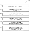
図22は、ガルバニック接触なしに絶縁電線内のAC電圧を測定するために非接触電圧測定システムを操作する方法2700のフロー図である。非接触電圧測定システムは先に論じた非接触電圧測定システムの実行例のいずれかと類似又は全く同じとすることができ、及び/又は、そのような非接触電圧測定システムの様々な組み合わせを含むことができる。
FIG. 22 is a flow diagram of a
方法2700は、2702にて始まることができ、オペレータが、非接触電圧測定システムの導電センサーを測定される絶縁電線近傍に位置決めする。先に論じたように、導電センサーが絶縁電線近傍に位置決めされたとき、絶縁電線内のセンサー及び導体は、センサーコンデンサCSを形成するために共に容量結合される。
The
2704にて、非接触電圧測定システムの少なくとも1つのプロセッサ(制御装置)は、センサーに電気的に結合された可変容量サブシステムに第1の容量値を有させることができる。少なくとも一部の実行例において、可変容量サブシステムは、例えば、少なくとも第1のコンデンサと、第2のコンデンサと、プロセッサに制御されたスイッチとを含む。 At 2704, at least one processor (controller) of the contactless voltage measurement system can have a first capacitance value in a variable capacitance subsystem electrically coupled to the sensor. In at least some implementations, the variable capacitance subsystem includes, for example, at least a first capacitor, a second capacitor, and a processor controlled switch.
2706にて、少なくとも1つのプロセッサは、第1の電圧を可変容量サブシステム全体にわたって検出つまり測定して、第1の測定された電圧を非一時的プロセス可読記憶媒体に記憶することができる。先に論じたように、少なくとも一部の実行例において、少なくとも1つのプロセッサは、相対的に高い(例えば、20ビット、22ビット)有効解像度を有するADCを介して、可変容量サブシステム全体にわたる電圧を検出つまり測定することができる。 At 2706, the at least one processor can detect or measure the first voltage across the variable capacitance subsystem and store the first measured voltage in a non-transitory process readable storage medium. As discussed above, in at least some implementations, the at least one processor is coupled to a voltage across the variable capacity subsystem via an ADC having a relatively high (eg, 20 bit, 22 bit) effective resolution. Can be detected or measured.
2708にて、非接触電圧測定システムの少なくとも1つのプロセッサは、可変容量サブシステムに第1の容量値と異なる第2の容量値を有させることができる。少なくとも一部の実行例において、第1の容量値及び第2の容量値のうちの一方は、第1の容量値及び第2の容量値のうちの他方の少なくとも2倍とすることができる。非限定的な実施例として、第1及び第2の容量値のうちのそれぞれは、1000pF〜5000pFとすることができる。 At 2708, at least one processor of the contactless voltage measurement system can cause the variable capacitance subsystem to have a second capacitance value that is different from the first capacitance value. In at least some implementations, one of the first capacitance value and the second capacitance value can be at least twice the other of the first capacitance value and the second capacitance value. As a non-limiting example, each of the first and second capacitance values can be between 1000 pF and 5000 pF.
2710にて、少なくとも1つのプロセッサは、第2の電圧を可変容量サブシステム全体にわたって検出つまり測定して、第2の測定された電圧を非一時的プロセス可読記憶媒体に記憶することができる。 At 2710, the at least one processor can detect or measure the second voltage across the variable capacitance subsystem and store the second measured voltage in a non-transitory process readable storage medium.
2712にて、少なくとも1つのプロセッサは、絶縁導体内のAC電圧を第1及び第2の測定された電圧及び第1及び第2の容量値に少なくとも部分的に基づいて判定することができる。例えば、先に論じたように、少なくとも1つのプロセッサは、絶縁導体内のAC電圧(VAC)を式に従って判定することができる。
VAC=VM1×[(C1/C2)−1]/[(C1VM1/C2VM2)−1] (22)
式中、C1及びC2は、それぞれ、第1及び第2の容量値であり、VM1及びVM2は、可変容量サブシステム全体にわたる第1及び第2の測定された電圧である。
At 2712, the at least one processor can determine an AC voltage in the insulated conductor based at least in part on the first and second measured voltages and the first and second capacitance values. For example, as discussed above, at least one processor can determine the AC voltage (V AC ) in the insulated conductor according to an equation.
V AC = V M1 × [(
Where C 1 and C 2 are the first and second capacitance values, respectively, and V M1 and V M2 are the first and second measured voltages across the variable capacitance subsystem.
絶縁導体内のAC電圧を判定した後、少なくとも1つのプロセッサは、結果を、少なくとも1つのプロセッサに通信可能に結合されたユーザーインターフェースを介してオペレータに示すことができる。ユーザーインターフェースは、ビジュアルコンポーネント(例えば、ディスプレイ、発光体(例えば、LED)、複数の発光体(例えば、LED))及び/又はオーディオコンポーネント(例えば、スピーカー、ブザー)を含むことができる。付加的又は代替的に、少なくとも1つのプロセッサは、結果を好適な有線及び/又は無線通信インターフェースを介して外部デバイスに通信することができる。 After determining the AC voltage within the insulated conductor, the at least one processor can indicate the result to the operator via a user interface communicatively coupled to the at least one processor. The user interface may include visual components (eg, display, light emitter (eg, LED), multiple light emitters (eg, LED)) and / or audio components (eg, speaker, buzzer). Additionally or alternatively, the at least one processor can communicate the results to an external device via a suitable wired and / or wireless communication interface.
少なくとも一部の実行例において、第2の測定された電圧を取得した後、少なくとも1つのプロセッサは、可変容量サブシステムに第3の容量値を有させることができる。そのような実例において、その後、少なくとも1つのプロセッサは、第3の測定値電圧を可変容量サブシステム全体にわたって検出つまり測定することができる。 In at least some implementations, after obtaining the second measured voltage, the at least one processor can cause the variable capacitance subsystem to have a third capacitance value. In such instances, at least one processor can then detect or measure the third measured voltage across the variable capacitance subsystem.
その後、少なくとも1つのプロセッサは、絶縁導体内のAC電圧(VAC)を第1の測定された電圧(VM1)、第2の測定された電圧(VM2)、第3の測定された電圧(VM3)、第1の容量値(C1)、第2の容量値(C2)及び第3の容量値(C3)に少なくとも部分的に基づいて判定することができる。例えば、少なくとも1つのプロセッサは、絶縁導体内のAC電圧(VAC)を式に従って判定することができる。
VAC=C3VM3×[(VM2−VM1)/(C1VM1−C2VM2)]+VM3 (23)
The at least one processor then converts the AC voltage (V AC ) in the insulated conductor to the first measured voltage (V M1 ), the second measured voltage (V M2 ), and the third measured voltage. The determination can be made based at least in part on (V M3 ), the first capacitance value (C 1 ), the second capacitance value (C 2 ), and the third capacitance value (C 3 ). For example, the at least one processor can determine an AC voltage (V AC ) in the insulated conductor according to an equation.
V AC = C 3 V M3 × [(V M2 -V M1) / (C 1 V M1 -C 2 V M2)] + V M3 (23)
その後、判定されたAC電圧(VAC)を好適なインターフェースを介してオペレータに示し、及び/又は、有線及び/又は無線通信インターフェースを介して外部デバイスに通信することができる。 The determined AC voltage (V AC ) can then be shown to the operator via a suitable interface and / or communicated to an external device via a wired and / or wireless communication interface.
マルチコンデンサ型非接触電圧測定システム
以下で論じる内容は、マルチコンデンサ型電圧測定値センサー又はシステムを使用して、絶縁又はブランク非絶縁導体(例えば、絶縁電線)のAC電圧を、導体と試験電極又はプローブとのガルバニック接続を必要とすることなく測定するシステム及び方法を対象とする。本セクションで開示する実行例を本明細書では「マルチコンデンサ型電圧センサー」又はシステムという場合がある。全体的に、非ガルバニック接触(つまり「非接触」)電圧測定システムを提示し、該システムは、接地に対する絶縁導体内のAC電圧信号を容量センサーを使用して測定する。
Multi-capacitor non-contact voltage measurement system The following discussion uses a multi-capacitor voltage measurement sensor or system to determine the AC voltage of an insulated or blank non-insulated conductor (eg, insulated wire), the conductor and test electrode or It is directed to a system and method for measuring without requiring a galvanic connection with a probe. The implementations disclosed in this section may be referred to herein as “multi-capacitor voltage sensors” or systems. Overall, a non-galvanic contact (or “non-contact”) voltage measurement system is presented that measures an AC voltage signal in an insulated conductor to ground using a capacitive sensor.
図23Aは、マルチコンデンサ電圧センサー又はシステムを含む非接触電圧測定システム3102を、オペレータ3104が使用して、絶縁導体3106内に存在するAC電圧を、非接触電圧測定システムと電線3106とのガルバニック接触を必要とすることなく測定することができる環境3100の絵図である。図23Bは、動作中の非接触電圧測定システムの様々な電気的特性を示す、図23Aの非接触電圧測定システム3102の上面図である。非接触電圧測定システム3102は、握持部分つまり端部3110と、握持部分の反対側の、本明細書では前端ともいうプローブ部分つまり端部3112とを含むハウジングつまり本体3108を含む。ハウジング3108はまた、非接触電圧測定システム3102とのユーザーインタラクションを促進するユーザーインターフェース3114を含むこともできる。ユーザーインターフェース3114は、任意の数の入力部(例えば、ボタン、ダイヤル、スイッチ、タッチセンサー)と、任意の数の出力部(例えば、ディスプレイ、LED、スピーカー、ブザー)とを含むことができる。非接触電圧測定システム3102はまた、ローカル又は遠隔配置装置と通信を促進する1つ又は2つ以上の有線及び/又は無線通信インターフェース(例えば、USB、Wi−Fi(登録商標)、Bluetooth(登録商標))を含むこともできる。
FIG. 23A illustrates the use of a contactless
少なくとも一部の実行例において、図23Bに最も良好に示すように、プローブ部分3112は、第1及び第2の拡張部分3118及び3120によって画成された凹部分3116を含むことができる。凹部分3116は、測定が行われるときに絶縁電線3106(図23Aを参照)を受け取る。絶縁電線3106は、導体3122と、導体3122を取り囲む絶縁体3124とを含む。凹部分3116は、センサー又は電極S1、S2及びS3を含むことができ、センサー又は電極S1、S2及びS3は、絶縁電線が非接触電圧測定システム3102の凹部分3116内に位置決めされたときに絶縁電線3106の絶縁体3124に近接して位置決めされている。図示した実施例において、センサーS1及びS2は、ハウジング3108の拡張部分3118の内側に配設され、センサーS3は、拡張部分3120の内側に配設されている。センサーと他の物体(例えば、絶縁電線3106、金属物体)との物理的及び電気的接触を防止するためにセンサーS1及びS2を凹部分3116から分離するために拡張部分3119の表面3119を設けることができる。同様に、拡張部分3120の表面3121は、センサーS3を凹部分3116から分離することができる。図27を参照して以下で論じるように、少なくとも一部の実行例において、表面3119は、表面3121が凹部分からセンサーS3を分離する距離(例えば、図27の厚さT2)と異なる距離(例えば、図27の厚さT1)だけセンサーS1及びS2を凹部分3116から分離することができる。
In at least some implementations, as best shown in FIG. 23B,
図23Aに示すように、使用時に、オペレータ3104は、ハウジング3108の握持部分3110を把持して絶縁電線3106に近接してプローブ部分3112を配置することができ、非接触電圧測定システム3102は、電線内に存在するAC電圧を接地(又は、別の基準ノード)に対して正確に測定することができるようになっている。プローブ端部3112は凹部分3116を有すると示されているが、他の実行例において、プローブ部分3112は、異なる方法で構成することができる。例えば、少なくとも一部の実行例において、プローブ部分3112は、選択的に移動可能なクランプ、フック、センサーを含む平坦な又は円弧の面、又は、非接触電圧測定システム3102のセンサーを絶縁電線3106に近接して位置決めすることを可能にする他の形式のインターフェースを含むことができる。
As shown in FIG. 23A, in use, the
プローブ部分3112が絶縁電線3106に近接して位置決めされたとき、センサーS1、S2及びS3は、それぞれ、容量C1、C2及びC3を生成する電線の導体3122とそれぞれ容量結合する。以下で更に論じるように、センサーS1、S2及びS3のうちのそれぞれは、絶縁電線3106内のAC電圧(VO)を正確に判定するためにセンサーS1、S2及びS3での異なる電圧V1、V2及びV3を検出及び使用することができるように、絶縁電線3106との容量結合に影響を与える少なくとも1つの特性に関して互いと異なる。
When the
少なくとも一部の実行例において、出力電圧V1と、V2と、V3と様々な比率が、絶縁導体の3106の特性を判定するために使用される。判定された特性を使用して、絶縁導体3106内のAC電圧を、較正されたルックアップテーブル及び/又は1つ又は2つ以上の判定された式を介して判定することができる。
In at least some implementations, various ratios of output voltages V 1 , V 2 , and V 3 are used to determine the characteristics of
AC電圧を測定するために非接触電圧測定システム3102によって使用される特定のシステム及び方法を図24〜図27を参照して以下で論じる。
Specific systems and methods used by contactless
図24は、図23A及び図23Bにもまた示す非接触電圧測定システム3102の様々な内部構成要素の概略図を示す。この実施例において、非接触電圧測定システム3102の導電センサーS1、S2及びS3は、試験中の絶縁電線3106に近接して位置決めされている。センサーS1、S2及びS3のうちのそれぞれは、それぞれ、絶縁電線3106の導体3122と容量結合して、センサー結合コンデンサC1、C2及びC3(図23B)を形成する。電線3122内のAC電圧信号(VO)は、それぞれ、センサー電圧信号V1、V2及びV3をセンサーS1、S2及びS3にて生成し、これらの電圧信号は、それぞれのセンサーS1、S2及びS3の結合容量C1、C2及びC3に左右される。
FIG. 24 shows a schematic diagram of the various internal components of the contactless
測定される電線3122内のAC電圧(VO)は、外部接地3128(例えば、中立)との接続を有する。非接触電圧測定システム3102自体もまた、接地3128に対する容量を有し、この容量は、主として、オペレータ3104(図23A)が非接触電圧測定システムを手に保持したときの人体容量(CB)からなる。容量C1、C2及びC3のうちのそれぞれは、導電ループをCBを介して生成し、ループの内側の電圧は、それぞれの信号電流(I1、I2及びI3)を生成する。電流信号(I1、I2及びI3)は、それぞれ、導電センサーS1、S2及びS3に容量結合されている絶縁電線3106の導体3122内のAC電圧信号(VO)によって生成され、非接触電圧測定システム3102のハウジング3108及び接地3128に至る人体コンデンサ(CB)を介して外部接地3128に戻る。電流信号(I1、I2及びI3)は、それぞれ、導電センサーS1、S2及びS3と試験中の絶縁電線3106との間の距離、導電センサーS1、S2及びS3の特定の形状及びサイズ、及び、導体3122のサイズ、電圧レベル(VO)及び相対位置にそれぞれ左右される。電圧V1、V2及びV3は、それぞれ、電流信号I1、I2及びI3に比例している。内部接地ガード3154(図25、図26A、図26B及び図27を参照)からテスト用リード線などの測定された基準電位までの接続がある場合、接地(人体容量CB)に対する任意の他の基準電位を使用することもできる。この接続は、使用された場合、接地/アースに接続された場合には低い人体容量CBの影響を無効にすることもできる。一例であれば、内部接地ガード3154を1つの位相に接続し、非接触センサー3112を別の位相に使用する多相環境における相間測定であろう。
The AC voltage (V O ) in the
迷走電流を低減又は回避するために、非接触電圧測定システム3102の少なくとも一部(例えば、センサーS1、S2及びS3)は、導電内部接地ガード又はスクリーン3132A〜B(図26A〜Bにもまた図示)によって少なくとも部分的に取り囲むことができ、これに起因して、電流の大部分は、導電センサーS1、S2及びS3を通り、センサーS1、S2及びS3は、絶縁電線3106の導体3122で、結合コンデンサC1、C2及びC3を、それぞれ、形成する。内部接地ガード3132A〜Bは、任意の好適な導電材料(例えば、銅製)から形成することができ、中実(例えば、箔)とすることができるか、又は、1つ又は2つ以上の開口部(例えば、メッシュ)を有することができる。センサーS1、S2及びS3の周りのガード3132A〜Bは、また、センサーに近い隣接電線の迷走による影響を低減することもできる。図25、図26A、図26B及び図27で参照番号3154によっても参照されるガード3132A〜Bは、非接触電圧測定システム3102の内部接地接続をもたらす。
To reduce or avoid stray currents, at least a portion of the contactless voltage measurement system 3102 (eg, sensors S 1 , S 2, and S 3 ) is connected to conductive internal ground guards or screens 3132A-B (FIGS. 26A-B). Can also be at least partially surrounded by this, so that most of the current passes through the conductive sensors S 1 , S 2 and S 3 , and the sensors S 1 , S 2 and S 3 are Coupling capacitors C 1 , C 2, and C 3 are formed by the
図24に示すように、非接触電圧測定システム3102は、電圧測定構成要素3136A、3136B及び3136Cを含む電圧測定サブシステム3136を含むことができ、電圧測定構成要素3136A、3136B及び3136Cは、それぞれ、電圧信号V1、V2及びV3、及び/又は、電圧信号に比例しているそれぞれの電流信号I1、I2及びI3を検出するように動作する。非限定的な実施例として、電圧測定構成要素3136のうちのそれぞれは、電圧信号V1、V2及びV3を検出するアナログ/デジタル変換器(ADC)及び関連の回路を備えることができる。別の非限定的な実施例として、電圧測定構成要素3136A、3136B及び3136Cのうちのそれぞれは、電圧信号V1、V2及びV3に比例している入力電流I1、I2及びI3を電圧レベルに変換する反転電流電圧変換器をとして動作する入力増幅器及びフィードバック回路を含むことができる。
As shown in FIG. 24, the contactless
電圧信号V1、V2及びV3(又は、その代表的な信号)を信号処理モジュール3140に供給することができ、信号処理モジュール3140は、以下で更に論じるように、電圧信号V1、V2及びV3を処理して絶縁導体3106の導体3122内のAC電圧(VO)を判定する。信号処理モジュール3140は、デジタル及び/又はアナログ回路の任意の組み合わせを含むことができる。
Voltage signals V 1 , V 2, and V 3 (or representative signals thereof) can be provided to signal
非接触電圧測定システム3102はまた、判定されたAC電圧(VO)を示すか、又は、インターフェースによって非接触電圧測定システムのオペレータ3104に通信するために信号処理モジュール3140に通信可能に結合されたユーザーインターフェース3142(例えば、ディスプレイ)も含むことができる。
The contactless
図25は、1つの図示した実行例による、絶縁電線の測定中に絶縁導体3106に近接して位置決めされた非接触電圧測定システム3102の導電センサーS1、S2及びS3を示す概略図である。この実施例において、導電センサーS1は、第1の距離D1だけ絶縁導体3106から分離され、導電センサーS2は、第2の距離D2だけ絶縁導体3106から分離され、導電センサーS3は、第3の距離D3だけ絶縁導体3106から分離されている。少なくとも一部の実行例において、距離D1、D2及びD3のうちの少なくとも1つは、距離D1、D2及びD3のうちの少なくとも1つの他の距離と異なってもよい。例えば、少なくとも一部の実行例において、距離D1及びD2は、互いに等しくてもよく、距離D3は、距離D1及びD2と異なってもよい。図27に示すように、距離D1、D2及びD3は、1つ又は2つ以上の絶縁層の物理特性(例えば、厚さ)によって少なくとも部分的に制御することができる。
FIG. 25 is a schematic diagram illustrating conductive sensors S 1 , S 2, and S 3 of contactless
図25にもまた図示したように、導電センサーS1、S2及びS3は、異なる物理的寸法(例えば、高さ、幅、形状、面積)を有することができる。図示した実施例において、導電センサーS1は、導電センサーS2の幅(W2)を下回る幅(W1)を有し、導電センサーS2は、導電センサーS3の幅(W3)を下回る幅(W2)を有する。センサーS1、S2とS3のそのような違いが、絶縁電線内のAC電圧を独自に判定するための電圧V1、V2及びV3の測定を可能にする。 As also illustrated in FIG. 25, the conductive sensors S 1 , S 2 and S 3 can have different physical dimensions (eg, height, width, shape, area). In the illustrated embodiment, the conductive sensor S 1 has a conductive sensor S 2 of the width (W 2) of less than the width (W 1), a conductive sensor S 2, the conductive sensor S 3 of width (W 3) It has a lower width (W 2 ). Such a difference between sensors S 1 , S 2 and S 3 enables the measurement of voltages V 1 , V 2 and V 3 to uniquely determine the AC voltage in the insulated wire.
図26Aは、内部接地ガード3132Aによって少なくとも部分的に取り囲まれた第1及び第2の導電センサーS1及びS2の平面図である。この実施例において、センサーS1は、直角を隅部3151に形成する第1の縁部3150A及び第2の縁部3150Bと、直角の反対側の斜辺縁部3150Cとを画成する平面直角三角形を有する。同様に、センサーS2は、直角を隅部3153に形成する第1の縁部3152A及び第2の縁部3152Bと、直角の反対側の斜辺縁部3152Cとを画成する平面直角三角形を有する。この実施例において、センサーS1及びS2は、第1及び第2の導電センサーS1及びS2の斜辺縁部3150C及び3152Cが、それぞれ、小さい間隙がその間にあって互いの横に(例えば、実質的に隣接して)位置決めされるように互いに対して逆転されている。
FIG. 26A is a plan view of the first and second conductive sensors S 1 and S 2 at least partially surrounded by the
図26Bは、内部接地ガード3132Bによって少なくとも部分的に取り囲まれた第3の導電センサーS3の平面図である。この実施例において、第3の導電センサーS3は、形状は長方形である。この実施例において、第3の導電センサーS3は、形状は長方形である。少なくとも一部の実行例において、第3のセンサーS3の面積は、第1及び第2の導電センサーS1及びS2の組み合わせ面積と同じ(又は実質的に同じ)であるが、そのような特徴は、要件ではない。第3のセンサーS3は、第1及び第2の導電センサーS1及びS2の組み合せ面積と同じであり、センサーS1及びS2は、センサーS3が絶縁電線から離間されている距離と異なる距離によって絶縁電線から離間されている実例において、組み合わされたセンサーS1及びS2は、距離の違いを形が似たコンデンサを使用して説明するために容量C3と比較することができる単一の容量(C1+C2)としてみなすことができる。
FIG. 26B is a plan view of the third conductive sensor S3 at least partially surrounded by the
センサーS1、S2及びS3の特定の形状、サイズ、相対位置及び配向は例示的であり、限定的ではないことを認識されたい。実際には、センサーS1、S2及びS3のうちのそれぞれの形状、サイズ、相対位置及び配向は、数多くの組み合わせで変えることができる。 It should be appreciated that the specific shapes, sizes, relative positions and orientations of sensors S 1 , S 2 and S 3 are exemplary and not limiting. In practice, the shape, size, relative position and orientation of each of the sensors S 1 , S 2 and S 3 can be varied in many combinations.
図27は、センサーS1、S2及びS3を含む非接触電圧測定システム3102の前端3112の断面図である。センサーS1及びS2を回路基板3156Aによって支えることができ、回路基板3156Aは、内部接地ガード3132Aによって少なくとも部分的に取り囲まれている。同様に、センサーS3を回路基板3156Bによって支えることができ、回路基板3156Bは、内部接地ガード3132Bによって少なくとも部分的に取り囲まれている。
FIG. 27 is a cross-sectional view of the
第1の絶縁層3158Aが、センサーS1及びS2を前端3112の凹部分3118から分離している。第2の絶縁層3158Bが、センサーS3を前端の凹部分3118から分離している。第1及び第2の絶縁層3158A及び3158Bは、それぞれ、平面3119及び3121を有することができ、平面3119及び3121は、「V」字形の凹部分3116を画成するように互いに対して鋭角(α)にて配設され、「V」字形の凹部分3116は、絶縁導体をその中で受け取る。非限定的な実施例として、角度(α)は、少なくとも一部の実行例において20°〜50°(例えば、39°、42°)であってもよい。例示的な絶縁導体3162、3164及び3166は、平面3119及び3121近傍に凹部分3116内に配設されると図示されている。絶縁導体3162は、絶縁3162Aによって取り囲まれた導線3162Bを含み、絶縁導体3164は、絶縁3164Aによって取り囲まれた導線3164Bを含み、絶縁導体3166は、絶縁3166Aによって取り囲まれた導線3166Bを含む。
A first insulating
図27に示す実施例において、前端つまりプローブ端部3112は、相対的に大きな直径を有する絶縁電線3162又は相対的に小さな直径を有する絶縁電線3166など、様々な直径の絶縁電線を収容するように成形されている。絶縁電線3162、3164及び3166はまた、それぞれ、異なる直径を有する導体3162A、3164A及び3166A、及び/又は、異なる厚さを有するそれぞれの絶縁層3162B、3164B及び3166Bを有することもできる。
In the embodiment shown in FIG. 27, the front or probe
第1の絶縁層3158Aは、第1の厚さT1を有することができ、第2の絶縁層3158Bは、第2の厚さT2を有することができる。少なくとも一部の実行例において、第1の厚さT1は、第2の厚さT2と異なってもよい。例えば、少なくとも一部の実行例において、第1の厚さは、ほぼ0.5ミリメートル(mm)であってもよく、第2の厚さT2は、ほぼ2.5mmであってもよい。
The first insulating
試験中の絶縁電線との容量結合に影響を与える少なくとも1つの特性(例えば、サイズ、形状、絶縁導体3106からの距離)に関して互いと異なる3つのセンサーS1、S2及びS3を設置すると、非接触電圧測定システム3102は、センサーと絶縁導体3106との間の容量結合に影響を与える異なる変数を補正することができる。そのような変数としては、絶縁導体3106の直径、絶縁導体3106の絶縁の厚さ、前端3112の凹部分3116内の絶縁導体3106の位置などを挙げることができる。
When installing three sensors S 1 , S 2 and S 3 that differ from each other with respect to at least one characteristic (eg, size, shape, distance from insulated conductor 3106) that affects capacitive coupling with the insulated wire under test, Non-contact
有利なことに、それぞれ、電圧V1、V2及びV3の電圧測定値をセンサーS1、S2及びS3にて取得することによって、非接触電圧測定システム3102の少なくとも1つのプロセッサは、絶縁導体3106上のAC電圧を正確に判定することができる。そのような判定を行うために、既知のAC電圧を有する既知の絶縁導体3106を使用して非接触電圧測定システム3102を(例えば、製造又は設計中に)較正することができる。付加的又は代替的に、非接触電圧測定システム3102の少なくとも1つのプロセッサは、1つ又は2つ以上の判定された式を利用し、と共に、電圧V1、V2及びV3を入力として利用して、絶縁導体3106のAC電圧を出力として供給することができる。動作中、非接触電圧測定システム3102の少なくとも1つのプロセッサは、電圧V1、V2及びV3を取得し、その後、電圧を入力として受け取り、絶縁電線内のAC電圧を出力するルックアップテーブル又は1つ又は2つ以上の式を使用して絶縁電線内のAC電圧を判定することができる。
Advantageously, by taking voltage measurements of voltages V 1 , V 2 and V 3 , respectively, with sensors S 1 , S 2 and S 3, at least one processor of contactless
図26A、図26B及び図27に示す例示的なセンサー構成については、それぞれ、センサーS1、S2及びS3で測定された電圧V1、V2及びV3間の様々な関係を使用して、試験中の絶縁導体のAC電圧を判定することができる。少なくとも一部の実行例において、非接触電圧測定システム3102は、以下の関係のうちの1つ又は2つ以上を利用することができる。
上記の関係(24)〜(27)を用いて、様々なサイズの絶縁導体内のAC電圧を測定することができるように、絶縁導体とセンサーS1、S2及びS3との間の距離から独立している関数を絶縁導体(例えば、絶縁導体3106)内の未知のAC電圧について提供することができる。 Using the above relations (24)-(27), the distance between the insulated conductor and the sensors S 1 , S 2 and S 3 so that the AC voltage in the insulated conductor of various sizes can be measured. Can be provided for unknown AC voltages within an insulated conductor (eg, insulated conductor 3106).
センサーS1及びS2について、以下の式を使用することができる。
VO=k×(V1+V2) (28)
式中、VOは、絶縁導体内のAC電圧であり、kは、上記の関係(24)の関数である(即ち、k=f(V1/V2))。
For sensors S 1 and S 2 , the following equation can be used:
V O = k × (V 1 + V 2 ) (28)
Where V O is the AC voltage in the insulated conductor and k is a function of the above relationship (24) (ie, k = f (V 1 / V 2 )).
測定された電圧V1、V2及びV3は、それぞれ、センサーS1、S2及びS3と絶縁導体との間の容量C1、C2及びC3に左右される。したがって、平面又は壁部(例えば、センサーS1、S2及びS3のうちのそれぞれ)に平行である電線(例えば、絶縁導体)間の容量について既知の式に従って容量C1、C2及びC3を計算することができる。センサーのうちのそれぞれの容量Cの式は、以下の通りである。
先に論じたように、電流をセンサーS1、S2及びS3のうちのそれぞれを介してそれぞれの電圧に変換する1つ又は2つ以上のADC又は1つ又は2つ以上の反転演算増幅器など、それぞれ、好適な電圧測定構成要素3136A、3136B及び3136Cで電圧V1、V2及びV3を測定することができる。
As discussed above, one or more ADCs or one or more inverting operational amplifiers that convert the current to a respective voltage via each of the sensors S 1 , S 2, and S 3. Etc., voltages V 1 , V 2 and V 3 can be measured with suitable
上記の関係(24)、(25)及び(26)は、独自の値を電圧V1、V2及びV3の所与の測定値について提供する3つの式を識別し、電圧V1、V2及びV3の所与の測定値は、試験中の導線の直径並びに導線の絶縁厚さを識別し、上記の式(29)を使用して容量C1、C2及びC3を計算するために使用することができる。その後、絶縁電線内のAC電圧を以下の式に従って計算することができる。
![]()
![]()
3つのセンサーS1、S2及びS3の3つの出力電圧V1、V2及びV3によって、導体の直径及び絶縁の厚さによる試験中の絶縁電線の特徴づけが可能である。上記の関係(24)は、主として、絶縁電線の外径を定義し、関係(27)は、主として、絶縁電線の導体の直径を定義する。先に論じたように、電圧V1、V2及びV3は、ルックアップテーブルから較正係数を取得するために、又は、較正係数を1つ又は2つ以上の式を利用して計算するために入力として使用される。 By three sensors S 1, S 2 and three output voltage V 1 of the S 3, V 2 and V 3, it is possible characterization of the insulated wire under test by the diameter and thickness of the insulation of the conductors. The above relationship (24) mainly defines the outer diameter of the insulated wire, and the relationship (27) mainly defines the diameter of the conductor of the insulated wire. As discussed above, voltages V 1 , V 2, and V 3 are used to obtain calibration coefficients from a look-up table or to calculate calibration coefficients using one or more equations. Used as input.
一例として、電圧V1、V2及びV3の所与の測定値について、上記の式(29)を使用して、関係(24)は、電線直径及び絶縁厚さの可能な組み合わせを試験中の絶縁電線について制限する。同様に、関係(25)は、電線直径及び絶縁厚さの可能な組み合わせを試験中の絶縁電線について制限する。したがって、関係(24)及び(25)を使用して、指定の電線直径及び指定の絶縁厚さを有する仮想電線を判定することができる。判定された仮想電線の物理特性を使用して、上記の関係(24)及び(25)の両方に左右される係数「k」を識別することができる。判定された仮想電線及び測定された電圧V1及びV2を使用して、試験中の絶縁電線の異なる位置によって生成される較正表によって、位置から独立した最終的な電圧結果が得られる。 As an example, for a given measurement of voltages V 1 , V 2 and V 3 , using equation (29) above, relationship (24) is testing possible combinations of wire diameter and insulation thickness. Restrictions on insulated wires. Similarly, relationship (25) limits the possible combinations of wire diameter and insulation thickness for the insulated wire under test. Accordingly, relationships (24) and (25) can be used to determine virtual wires having a specified wire diameter and a specified insulation thickness. Using the determined physical properties of the virtual wire, a coefficient “k” that depends on both of the above relationships (24) and (25) can be identified. Using the determined virtual wires and the measured voltages V 1 and V 2 , a calibration table generated by different locations of the insulated wires under test provides a final voltage result independent of location.
電圧V1及びV2のみを使用すると、結果は、不正確な値を示す恐れがある。したがって、上述した電圧と同様にセンサーS3からの電圧V3を使用すると、より良好な位置定義を得ることができる。特に、関係(27)では、電圧V1及びV2の合計を利用する。共に結合されたときのセンサーS1及びS2の形状はセンサーS3の形状と類似のものであることから、関係(27)によって、2つの異なる距離(即ち、T1及びT2)での同様のコンデンサ(即ち、C1+C2及びC3)の比率が得られる。 If only the voltages V 1 and V 2 are used, the results may show inaccurate values. Thus, using the voltage V 3 from the sensor S 3 similar to the voltage as described above, it is possible to obtain a better position definition. In particular, relationship (27) utilizes the sum of voltages V 1 and V 2 . Since the shape of sensors S 1 and S 2 when coupled together is similar to the shape of sensor S 3 , the relationship (27) at two different distances (ie, T 1 and T 2 ) Similar capacitor (ie, C 1 + C 2 and C 3 ) ratios are obtained.
妥当な容量(例えば、数ピコファラド)をセンサーと試験中の絶縁電線との間で達成し、また、人体容量(CB)(例えば、30〜200ピコファラド)をはるかに下回るようにセンサーS1、S2及びS3の実際寸法及び形状を選択することができ、人体容量(CB)は、ハンドヘルド用途の接地に対する可能な基準として使用することができる。 Reasonable capacity (e.g., several picofarads) was achieved between the insulated wire under test and the sensor, also the human body capacitance (CB) (e.g., 30 to 200 picofarads) sensor S 1 as well below, S You can select the actual size and shape of the 2 and S 3, the body capacitance (CB) can be used as a reference possible to ground handheld applications.
非接触AC電気的パラメータ測定システム
以下で論じる内容は、本明細書で論じる機能性のうちの一部又は全部を含むことができる非接触測定システムの様々な例示的な実行例を提示する。
Non-contact AC Electrical Parameter Measurement System The content discussed below presents various exemplary implementations of a non-contact measurement system that can include some or all of the functionality discussed herein.
図28は、非接触電圧測定機能性及び非接触電流測定機能性を提供する非接触測定システムつまり器具3700の概略ブロック図である。測定システム3700はまた、電圧及び/又は電流測定値から導出された1つ又は2つ以上のAC電気的パラメータ(例えば、電力、エネルギー、周波数、高調波)を判定することもできる。測定システム3700は、プロセッサ3706にそれぞれ通信可能に結合されている電圧センサー3702と電流センサー3704とを含む。
FIG. 28 is a schematic block diagram of a contactless measurement system or
電圧センサー3702及び/又はプロセッサ3706は、本明細書で論じる非接触検出器のいずれかと類似又は全く同じとすることができる。プロセッサ3706は、1つ又は2つ以上の中央演算処理装置(CPU)、マイクロプロセッサ、デジタル信号プロセッサ(DSP)、特定用途向け集積回路(ASIC)、フィールドプログラマブルゲートアレイ(FPGA)など、1つ又は2つ以上の論理回路処理装置を含むことができる。測定システム3700はまた、命令又はデータのうちの少なくとも一方を記憶するプロセッサ3706に通信可能に結合されたメモリ3708含むこともできる。メモリ3708は、例えば、1つ又は2つ以上のソリッドステートメモリフラッシュメモリ又はソリッドステートドライブ(SSD)を含むことができ、1つ又は2つ以上のソリッドステートメモリは、コンピュータ可読命令、データ構造、プログラムモジュール及び他のデータの不揮発性記憶を測定システム3700について行う。図示していないが、測定システム3700は、他の非一時的コンピュータ可読又はプロセッサ可読媒体、例えばハードディスクドライブ、光ディスク駆動装置又はメモリカードメディアドライブを採用することができる。
The
測定システム3700は、ユーザーインターフェース3710を含むことができ、ユーザーインターフェース3710は、任意の数の入力部(例えば、ボタン、ダイヤル、スイッチ、タッチスクリーン)と、任意の数の出力部(例えば、ディスプレイ、LED、スピーカー、ブザー)とを含むことができる。測定システム3700はまた、読み出し3714及び/又は波形3716を示す1つ又は2つ以上のディスプレイ3712を含むこともできる。
The
動作時に、プロセッサ3706は、信号を電圧センサー3702及び電流センサー3704から受け取って、それぞれ、電圧測定値及び電流測定値を取得する。プロセッサ3706は、そのような電圧測定値及び電流測定値を利用して、付加的なAC電気的パラメータを測定値の組み合わせに基づいて導出することができる。そのようなパラメータとしては、例えば、電力(真の電力、皮相電力など)、位相(例えば、三相)、周波数、高調波、エネルギーなどを挙げることができる。
In operation,
電圧センサー信号及び電流センサー信号は、共通測定時間間隔中にそれぞれの電圧センサー3702及び電流センサー3704によって取得することができ、共通測定時間間隔は、持続時間が比較的短くてもよい(例えば、10ミリ秒(ms)、100ms、1秒、10秒)。例えば、電圧センサー3702及び電流センサー3704は、少なくとも部分的に互いに並行して測定値を取得することができる。別の実施例として、電圧センサー3702及び電流センサー3704のうちの一方は、電圧センサー及び電流センサーのうちの他方が測定値を取得した実質的に直後に測定値を取得することができ、測定値は、ほぼ同時に取得されるようになっている。一部の実行例において、電圧センサー3702及び電流センサー3704は、測定値を指定の間隔にて(例えば、10ms毎に、100ms毎に、1秒毎に、10秒毎に)同時に又は連続して繰り返し取得するように動作することができる。一般的に、電圧センサー3702及び電流センサー3704は、両方とも、それぞれの測定値を測定時間間隔内に取得し、測定時間間隔は、電圧測定値及び電流測定値の対が互いに対応するように十分に短く、これによって、取得された電流測定値及び電圧測定値を使用する1つ又は2つ以上のAC電気的パラメータ(例えば、電力、位相)の正確な導出又は判定が可能である。
The voltage sensor signal and the current sensor signal can be acquired by the
プロセッサ3706は、測定又は導出されたパラメータのうちの1つ又は2つ以上の読み出し3714を提供することができ、1つ又は2つ以上の特性のグラフ表示を提供することができる。そのようなグラフ表示は、波形、高調波棒グラフなどを含むことができる。ディスプレイ3712を介して示すことができる例示的な信号特性としては、電圧、電流、周波数、電力パラメータ(例えば、ワット、kVA)、位相、エネルギー、高調波、相順検出などが挙げられる。
The
図29は、非接触電圧測定機能性及び/又は非接触電流測定機能性を提供する非接触測定システムつまり器具3800の概略ブロック図である。測定システム3800は多くの点において図28の測定システム3700と類似又は全く同じであるので、関連の違いのみを簡潔さのために本明細書で論じる。
FIG. 29 is a schematic block diagram of a contactless measurement system or instrument 3800 that provides contactless voltage measurement functionality and / or contactless current measurement functionality. Since measurement system 3800 is similar or identical in many respects to
この実行例において、測定システム3800は、ディスプレイを含むことができず、その代わりに、電気機器を外部のプロセッサベースの装置3806を介して遠隔操作にてモニターする「後に残る」センサーとして使用することができる。そのようなプロセッサベースの装置3806は、スマートフォン、タブレットコンピュータ、ラップトップコンピュータ、ウェアラブルコンピュータ、サーバー、クラウドコンピュータなどなど、様々な形式の装置を含むことができる。外部のプロセッサベースの装置3806は、一定期間にわたって(例えば、分、時間、日、週、年)測定3800によって収集されたデータを示すディスプレイを含むことができる。
In this implementation, the measurement system 3800 may not include a display, but instead be used as a “remaining” sensor that remotely monitors electrical equipment via an external processor-based
1つ又は2つ以上の外部のプロセッサベースの装置と通信するために、測定システムは1つ又は2つ以上の有線通信インターフェース3802及び/又は1つ又は2つ以上の無線通信インターフェース3804を含むことができる。
The measurement system includes one or more
無線通信インターフェース3804の非限定的な実施例としては、Wi−Fi(登録商標)、Bluetooth(登録商標)、Bluetooth(登録商標)Low Energy、Zigbee(登録商標)、6LoWPAN(登録商標)、Optical IR、無線HARTなどが挙げられる。有線通信インターフェース3802の非限定的な実施例は、USB(登録商標)、イーサネット、PLC、HART、MODBUS、FireWire(登録商標)、Thunderbolt(登録商標)などが挙げられる。
Non-limiting examples of the
外部デバイス3806にデータを送ることに加えて、少なくとも一部の実行例において、測定システム3800は、データ又は命令(例えば、制御命令)のうちの少なくとも一方を有線通信インターフェース3802及び/又は無線通信インターフェース3802を介して外部デバイス3806から受信することができる。
In addition to sending data to the
図30は、測定システム3800など、測定システムの前端つまりプローブ端部3900の一部を示す。測定システムは、本明細書で論じる測定システムのうちの1つ又は2つ以上と類似又は全く同じであってもよい。この実行例において、測定システムの前端3900は、第1及び第2の離間された突起3902a及び3902bを有する固定式爪3902を含み、第1及び第2の離間された突起3902a及び3902bは、試験中の絶縁導体(明瞭さのために図示せず)を受け取る凹部分3904を画成する。窪み3904の一番奥の部分3906に近接して、試験中の絶縁導体内の電圧及び電流のうちの少なくとも一方を測定するように動作するセンサー3908がある。
FIG. 30 shows a portion of the front or probe
測定システムの前端3900はまた、突起3902a及び3902bの周りに配設された1つ又は2つ以上の位置合わせ用フィードバックセンサー3910も含み、1つ又は2つ以上の位置合わせ用フィードバックセンサー3910は、様々な情報を測定動作中にユーザーに提供するために使用することができる。例えば、少なくとも一部の実行例において、1つ又は2つ以上の位置合わせ用フィードバックセンサー3910を使用して、前端3900に対する絶縁導体の位置合わせに関するフィードバックをユーザーに提供することができる。そのようなことは、1つ又は2つ以上の位置合わせ用フィードバックセンサー3910を利用して絶縁導体の場所を判定し、そのような場所の表示をユーザーに提供することによって達成することができる。
The
例えば、測定システムのディスプレイ3912は、位置合わせフィードバック情報をユーザーに提供することができる。別の実施例として、着色光(例えば、LED)を使用して、位置合わせフィードバックをユーザーに提供することができる。実施例として、赤色光を照射して、絶縁導体が位置合わせされていないことを示すことができ、黄色光を照射して、絶縁導体がほぼ位置合わせされていることを示すことができ、緑色光を照射して、絶縁導体が適切に位置合わせされていることを示すことができる。別の実施例として、前端3900に対する絶縁導体の位置をディスプレイ上にグラフ表示にて表示することができる。別の実施例として、音を使用して位置合わせフィードバックを提供することができる。例えば、測定システムは、「ビープ音」又は他の音を、絶縁導体が位置合わせされているか否かに基づいて変動する間隔、強度(音量)又は周波数にて生成することができる(例えば、位置合わせなしには遅いビープ音、ほぼ位置合わせ済みにはより速いビープ音、位置合わせ済みには最速又は安定したビープ音)。
For example, the
少なくとも一部の実行例において、1つ又は2つ以上の位置合わせ用フィードバックセンサー3910は、代替的に又は付加的に実際の電圧(例えば、試験中の導体近傍の通電された回路)を近くで検出するために使用することができる。そのような実際の電圧が検出されると、表示(例えば、音、光、警告メッセージ)を示して、実際の電圧が近くにあることをユーザーに通知することができる。
In at least some implementations, one or more
少なくとも一部の実行例において、1つ又は2つ以上の位置合わせ用フィードバックセンサー3910を使用して、ユーザーによって取得された測定値の精度の表示を行うことができる。例えば、ユーザーが測定値を取得したとき、色分けされた信号(例えば、赤色、黄色、緑色)を提供して、測定値精度が良好(緑色)、ぎりぎり(黄色)、又は不良(赤色)であることを位置合わせ判定に基づいてユーザーに通知することができる。色又はグラフィックによる位置合わせフィードバックの他に、他の形式のフィードバックを提供することができる。例えば、判定された位置合わせ情報を数値として、棒グラフとして、「高温/低温」インジケータとして、又は任意の他の好適なインジケータとして示すことができる。
In at least some implementations, one or more
図31〜図41Bは、それぞれ、本明細書で論じる機能性の少なくとも一部を組み込むことができる測定器具の様々な実施例を示す。図31は、測定器具4000を示し、測定器具4000は、ハウジング4002と、読み出しディスプレイ4004と、センサーを備える前端4006と、絶縁電線を把持する退避可能なクランプつまり顎部4008とを含む。本開示のクランプつまり顎部4008並びに他のクランプつまり顎部は、ハウジング4002に永久的に装着されていてもよく、又は、選択的に着脱可能であってもよい。図32は、測定器具4100を示し、測定器具4100は、ハウジング4102と、読み出しディスプレイ4104と、センサーを備える前端4106と、絶縁導体を中で受け取る固定式爪4108とを含む。図33は、測定器具4200を示し、測定器具4200は、ハウジング4202と、読み出しディスプレイ4204と、センサーを備える前端4206と、試験中の絶縁導体を把持する退避可能なフック4208とを含む。図34は、測定器具4300を示し、測定器具4300は、ハウジング4302と、読み出し及びグラフィック情報(例えば、波形、高調波グラフ)を示すディスプレイ4304と、センサーを備える前端4306と、試験中の絶縁導体を把持する退避可能なフック4308)とを含む。図35は、測定器具4400を示し、測定器具4400は、ハウジング4402と、ディスプレイ4404と、センサーを中に含む弓形形状の前端4406とを含む。
FIGS. 31-41B each show various examples of measurement instruments that can incorporate at least some of the functionality discussed herein. FIG. 31 shows a
図36は、測定器具4500を示し、測定器具4500は、ハウジング4502と、読み出しディスプレイ4504と、センサーを備える前端4506と、退避可能なフック4508と、任意選択的な基準リード線4510とを含む。測定器具4500を使用して、非接触AC電圧、AC電流、DC電圧、抵抗、周波数、位相、kWh、KW、VA、var、PF、THD、突入電流、相順、及び電圧降下試験を含むがこれらに限定されない様々な電気的特性を測定及び/又は導出することができる。
FIG. 36 illustrates a
測定システム3800の例示的な形状要素が、図37に示されており、図37は、測定器具4600を例示し、測定器具4600は、測定される絶縁導体を把持するハウジング部分4604から延びるクランプ4602と、基準ノードに結合することができる任意選択的なクリップ4606とを含む。動作時に、ユーザーは、クランプ4604を測定される絶縁導体上へ配置することができ、測定器具4600は、電流測定値及び/又は電流測定値を一定期間にわたって(例えば、秒、分、時間、日、週、年)取得することができ、1つ又は2つ以上の付加的なAC電気的パラメータを測定値から導出することができる。測定データ及び/又は導出されたパラメータを1つ又は2つ以上の外部のプロセッサベースの装置にリアルタイムで又は判定された間隔で送ることができ、そのようなデータを処理し、及び/又は、好適なユーザーインターフェース(例えば、ディスプレイ)を介してユーザーに示すことができる。先に論じたように、測定器具4600はまた、命令又はデータを有線及び/又は無線の通信を介して1つ又は2つ以上の外部デバイスから受信することもできる。
Exemplary shape elements of measurement system 3800 are shown in FIG. 37, which illustrates
図38は、測定器具4700を示し、測定器具4700は、ケーブル4706によって第2のハウジング4704に電気的に結合された第1のハウジング4702を含む。第1のハウジング4702は、測定情報をユーザーに示すディスプレイ4708をその上に含むことができる。第1のハウジング4702は、非接触電圧測定値を取得するセンサーを中に有する前端4710を含むことができる。同様に、第2のハウジング4704は、非接触電圧測定を取得するセンサーを中に有する前端4712を含むことができる。動作時に、第1及び第2のハウジング4702及び4704のうちの一方又は両方を使用して、個々の非接触AC電圧測定値及び/又は個々のAC電圧電流測定値を取得することができる。更に、第1のハウジング4702の前端4710が第1の絶縁導体に近接して位置決めされ、第2のハウジング4704の前端4712が第2の絶縁導体に近接して位置決めされたとき、測定システム4700は、結合された非接触相間AC電圧測定値を2つの絶縁導体間で取得することができる。
FIG. 38 illustrates a
図39は、測定器具4800を示し、測定器具4800は、結合された複数のテスト用リード線4802を有するハウジング4804を含む。測定器具4800は、外部のプロセッサベースの装置4806(例えば、スマートフォン、タブレット)と無線で通信することができ、この外部のプロセッサベースの装置は、測定器具を制御し、表示4808に関して測定器具によって取得された測定値を示すユーザーインターフェースとして機能することができる。少なくとも一部の実行例において、測定器具4800は、(例えば、外部のプロセッサベースの装置4806を介して)ファン、圧縮機、ポンプなどの運転サイクル、及び/又は、加熱システム、冷却システム及び/又は照明システムの動作特性を測定して示すことができる。測定器具4800はまた、例えば、非接触AC電圧、AC電圧、AC電流、DC電圧、抵抗、周波数、位相、kWh、KW、VA、var、PF及びTHDを測定及び/又は導出することもできる。
FIG. 39 shows a
図40は、測定器具4900を示し、測定器具4900は、ハウジング4902と、ディスプレイ4904と、非接触AC電圧を測定するセンサーをその中に備える前端4906とを含む。測定器具4900を使用して、(例えば、1kVよりも大きい)高電圧を測定又は検出することができる。ホットスティック(例えば、テレスコープホットスティック)を、測定器具4900に任意選択的に結合して、回路に触れたり、切り離したりすることなく高いAC電圧を試験することができる。そのようなことは例えば、伝送線路、落下した電力線、ヒューズ及び負荷遮断コネクタなどの高電圧設備で作業するときに用役用途、工業用途、採鉱用途において有用であり得る。
FIG. 40 shows a
図41は、測定器具5000を示し、測定器具5000は、ハウジング5002と、ディスプレイパネル5004(例えば、タッチスクリーン)と、3本の信号入力リード線5006と、基準入力リード線5008とを含む。測定器具5000は、例えば、非接触AC電圧、AC電流、DC電圧、抵抗、継続性、周波数、位相、kWh、KW、VA、var、PF、THD、突入電流、相順及び電圧降下試験を測定するように動作することができる。
FIG. 41 shows a
図42A及び図42Bは、赤外線カメラ5100を示し、赤外線カメラ5100は、ハウジング5102とディスプレイ5104とを含む。赤外線カメラ5100は、前端部分5106を含み、前端部分5106は、非接触AC電圧及びAC電流を交互に又は同時に測定するために使用することができるセンサーを含む。赤外線カメラ5100は、視覚映像をディスプレイ5104上で提供することができ、任意選択的にレーザー案内式とすることができる。少なくとも一部の実行例において、赤外線カメラ5100は、有線及び/又は無線通信インターフェース(例えば、スパイラルケーブル、Bluetooth(登録商標)Low Energy)を介して、外部のプロセッサベースの装置(例えば、スマートフォン、タブレットコンピュータ、別の測定器具)に通信可能に結合可能である。
42A and 42B show an
本開示の測定システム又は器具のうちの1つ又は2つ以上は、以下の機能、即ち、隙間がない電線への良好なアクセスのためのより小さい顎部幅より大きい導体のためのより広い顎部開口部、懐中電灯、接地測定に即した非接触AC電圧、位相測定に即した非接触AC電圧位相、非接触AC電圧インジケータ、バックライトディスプレイ、ゴースト電圧検出(低Z)、インピーダンス、音、交換可能な試験リード線、任意選択的なフレックスクランプ、容量測定、オートホールド、温度測定、真のRMS、電流(例えば、mA)、直流、電力、など、のうちの1つ又は2つ以上を含むことができる。 One or more of the measurement systems or instruments of the present disclosure may have the following functions: a wider jaw for a conductor that is larger than a smaller jaw width for good access to a gapless wire Head opening, flashlight, non-contact AC voltage for ground measurement, non-contact AC voltage phase for phase measurement, non-contact AC voltage indicator, backlight display, ghost voltage detection (low Z), impedance, sound, One or more of replaceable test leads, optional flex clamp, capacitance measurement, auto hold, temperature measurement, true RMS, current (eg, mA), direct current, power, etc. Can be included.
非接触電流測定システム
本明細書で開示するシステム及び方法は、絶縁電線を通って流れる電流を、絶縁電線の導体とのガルバニック接触を必要とすることなく測定する非接触電流測定システムを提供する。本明細書で論じる非接触電流測定システムを独立型電流計として実行するか、又は、本明細書で論じる1つ又は2つ以上の他の実行例と組み合わせて、様々なAC電気的パラメータ(例えば、電力、位相、周波数、高調波、エネルギー)の測定など、付加的な機能性を提供することができる。少なくとも一部の実行例において、非接触電流測定システムは、試験中の絶縁電線に近接(例えば、隣接)して選択的に位置決め可能である磁場センサーを含む。磁場センサーの非限定的な実施例としては、異方性磁気抵抗((AMR)センサー、巨大磁気抵抗(GMR)センサー、フラックスゲートセンサー、SQUIDセンサー、光ファイバーセンサー、光励起型センサー、ニュークリアプロセッションセンサー、サーチコイルセンサー、磁気トランジスタセンサー、磁気ダイオードセンサー、光磁気センサー、ホール効果センサー、ロゴウスキーコイル、変流器又は他の形式の磁場センサーなど、磁場センサーが挙げられる。磁場センサーは、絶縁電線内を流れる電流によって生成された磁場を検出する。絶縁電線の導体を取り囲む磁場の大きさは、絶縁電線の導体を通って流れる電流の大きさに関係がある(例えば、比例する)。
Non-contact current measurement system The systems and methods disclosed herein provide a non-contact current measurement system that measures current flowing through an insulated wire without requiring galvanic contact with the conductor of the insulated wire. The non-contact current measurement system discussed herein can be implemented as a stand-alone ammeter, or combined with one or more other implementations discussed herein for various AC electrical parameters (e.g., Can provide additional functionality such as measurement of power, phase, frequency, harmonics, energy). In at least some implementations, the contactless current measurement system includes a magnetic field sensor that can be selectively positioned proximate (eg, adjacent) to the insulated wire under test. Non-limiting examples of magnetic field sensors include anisotropic magnetoresistive (AMR) sensors, giant magnetoresistive (GMR) sensors, fluxgate sensors, SQUID sensors, fiber optic sensors, photoexcited sensors, nuclear process sensors. , Search coil sensors, magnetic transistor sensors, magnetic diode sensors, magneto-optical sensors, Hall effect sensors, Rogowski coils, current transformers or other types of magnetic field sensors, etc. Magnetic field sensors are insulated wires. Detecting the magnetic field generated by the current flowing in. The magnitude of the magnetic field surrounding the insulated wire conductor is related to (eg, proportional to) the magnitude of the current flowing through the insulated wire conductor.
導体を取り囲む磁場を検出することに加えて、本開示の実行例のうちの少なくとも一部は、調整可能なクランプアセンブリを利用して絶縁電線の機械的位置決めを磁場センサーに対して制御する。更に、少なくとも一部の実行例において、非接触電流測定システムは、絶縁電線の絶縁の内側の導体の外径又はゲージなど、試験中の絶縁電線の少なくとも1つの物理的寸法に関係する情報を判定する。検出された磁場、制御された機械的位置決め及び判定された物理的寸法情報を使用して、非接触電流測定システムは、絶縁電線の導体を通って流れる電流の大きさを正確に判定する。 In addition to detecting the magnetic field surrounding the conductor, at least some of the implementations of the present disclosure utilize an adjustable clamp assembly to control the mechanical positioning of the insulated wire relative to the magnetic field sensor. Further, in at least some implementations, the contactless current measurement system determines information related to at least one physical dimension of the insulated wire under test, such as the outer diameter or gauge of the inner conductor of the insulated wire insulation. To do. Using the detected magnetic field, controlled mechanical positioning and determined physical dimensional information, the contactless current measurement system accurately determines the magnitude of the current flowing through the conductor of the insulated wire.
図43は、環境5200の絵図であり、環境5200において、非接触電流測定システム5202を技術員5204が使用して、絶縁電線5206内に存在するAC電流を、非接触電流測定システムと絶縁電線5206とのガルバニック接触を必要とすることなく測定することができる。図44A及び図44Bは、非接触電流測定システム5202の拡大図を示す。
FIG. 43 is a pictorial diagram of the
非接触電流測定システム5202は、握持部分つまり端部5210と、握持部分の反対側のプローブ部分つまり端部5212とを含むハウジング又は本体5208を含む。ハウジング5208はまた、非接触電流測定システム5202とユーザーインタラクションを促進するユーザーインターフェース5214を含むこともできる。ユーザーインターフェース5214は、任意の数の入力部(例えば、ボタン、ダイヤル、スイッチ、タッチセンサー)と、任意の数の出力部(例えば、ディスプレイ、LED、スピーカー、ブザー)とを含むことができる。非接触電流測定システム5202はまた、1つ又は2つ以上の有線及び/又は無線通信インターフェース(例えば、USB、Wi−Fi(登録商標)、Bluetooth(登録商標))を含むこともできる。
Non-contact
図44A及び図44Bに示すように、磁場センサー5216(例えば、異方性磁気抵抗(AMR)センサー、巨大磁気抵抗(GMR)センサー、フラックスゲートセンサー又は他の磁場センサー)が、前端5212の頂面5218より下方に位置決めされている。磁場センサー5216は、絶縁電線5206内を流れる電流によって生成された磁場を検出するために使用され、絶縁電線5206は、1つ又は2つ以上の絶縁層5224によって取り囲まれた導体5222を備える。導体5222を取り囲む磁場の大きさは、導体を通って流れる電流の大きさに関係がある(例えば、比例する)。一般的に、導体5222内を流れる電流の大きさは、2つのパラメータが満たされるときに磁場センサー5216によって正確に判定することができる。第1のパラメータは、磁場センサー5216に対する絶縁電線5206の機械的位置決めの制御であり、磁場センサー5216は、少なくとも一部の実行例において調整可能なクランプアセンブリ5226によって制御される。第2のパラメータは、外径又は絶縁電線の絶縁の内側の導体の直径(即ち、測ゲージ)など、絶縁電線5206の物理的寸法情報であり、該物理的寸法情報は、調整可能なクランプアセンブリ5226に動作可能に結合された位置フィードバックセンサー5228によって判定又推定することができる。調整可能なクランプアセンブリ5226及び位置フィードバックセンサー5228を更に以下で論じる。
44A and 44B, a magnetic field sensor 5216 (eg, an anisotropic magnetoresistive (AMR) sensor, a giant magnetoresistive (GMR) sensor, a fluxgate sensor or other magnetic field sensor) is mounted on the top surface of the
更に、少なくとも一部の実行例において、絶縁電線5206のゲージに関する物理的寸法情報は、付加的又は代替的に、センサーと絶縁電線5206との間で生成された基準信号(例えば、基準電流信号)を検出する1つ又は2つ以上の基準信号センサーを利用して取得することができる。物理的寸法情報を絶縁電線について検出するそのような「基準信号」方法を実行する様々な例示的な非接触測定システムは、図1A〜図15を参照して先に論じている。例えば、少なくとも一部の実行例において、調整可能なクランプアセンブリ及び位置フィードバックセンサーを使用して、絶縁電線の全体径を判定することができ、基準信号による方法を使用して、絶縁電線の絶縁の厚さを判定することができる。絶縁電線及び判定された絶縁厚さの判定された全体径を使用して、非接触電流測定システムは、絶縁電線の絶縁の内側の導体の直径を自動的に判定又は推定することができる(例えば、導体の直径は、絶縁厚さの2倍だけ低減された絶縁電線の全体径に等しい)。その後、導体の判定された直径を検出された磁場と共に使用して、絶縁電線を通って流れる電流の大きさを正確に判定することができる。
Further, in at least some implementations, the physical dimensional information regarding the gauge of the
図示した実行例において、絶縁電線5206の機械的位置決めは、調整可能なクランプ又は「スライダ」クランプアセンブリ5226によって行われ、調整可能なクランプ又は「スライダ」クランプアセンブリ5226は、絶縁導体が、測定中に磁場センサー5216と適切に位置合わせして(例えば、隣接して)位置決めされることを確実にする。調整可能なクランプアセンブリ5226は、ハウジング5208に結合されたクランプ部材5230を含み、クランプ部材5230は、前端5212の頂面5218の方に及び頂面5218から離れて選択的に移動可能である。クランプ部材5230を第1のクランプ部分と本明細書で呼ぶことができ、前端5212を第2のクランプ部分と本明細書で呼ぶことができる。クランプ部材5230は、前端5212の頂面5218に面し、頂面5218に概ね平行であるクランプ表面5232を含む。クランプ表面5232及び頂面5218は、共に、絶縁電線5206の一部を中で受け取るようにサイズ決定及び寸法決定された可変サイズのクランプ開口部5234を画成している。図示した実施例において、クランプ部材5230は、クランプ開口部5234が相対的に大きい第1の位置P1と、クランプ開口部が相対的に小さい第2の位置P2との間で選択的に移動可能である。
In the illustrated implementation, the mechanical positioning of the
図44Aに示すように、ユーザーは、絶縁電線容易をクランプ開口部内へ移動させることを可能にするのに十分な量だけクランプ部材5230のクランプ表面5232が前端5212の頂面5218から離間されているときに絶縁電線5206をクランプ開口部5234内に位置決めすることができる。その後、図44Bに示すように、ユーザーは、クランプ部材5230を第3の位置P3に下方に移動させて、頂面及びクランプ表面が両方とも両側で絶縁電線の絶縁層に接触するように、絶縁電線5206を前端5212の頂面5218とクランプ表面5232の間に「クランプする」ことができる。本明細書で使用するとき、「クランプ」という用語は、電線の位置を磁場センサー5216に対して維持するために絶縁電線5206が絶縁電線の両側で頂面5218及びクランプ表面5232によって接触されることを指すために使用されている。即ち、この用語は、頂面5218又はクランプ表面5232が任意の特定の量の力を必ず絶縁電線5206に与えることを示すわけではない。
As shown in FIG. 44A, the
位置フィードバックセンサー5228は、クランプ部材5230の位置(例えば、線形位置)を感知するように動作して、そのようなことを示す位置フィードバックセンサー信号(例えば、線形位置フィードバックセンサー信号)を生成する。位置フィードバック信号は、例えば、デジタル信号又はアナログ信号とすることができる。絶縁電線5206がクランプ表面5232と前端5212の頂面5218との間にクランプされているとき、クランプ部材5230の感知された位置を使用して、絶縁電線の直径又はゲージを判定又は推定することができる。例えば、位置フィードバックセンサー5228は、クランプ部材5230の延長部に比例している位置フィードバックセンサー信号を提供することができる。位置フィードバックセンサー5228は、クランプ部材5230の延長部を感知して絶縁電線5206の直径を判定するように動作する任意の好適なセンサーとすることができる。例えば、位置フィードバックセンサー5228は、抵抗センサー、磁気抵抗センサー、ホール効果センサー、光センサーなどを含むことができる。少なくとも一部の実行例において、「基準信号」方法を付加的又は代替的に使用して、絶縁電線5206の内側の導体の直径又は寸法を判定することができ、これは、更に、システム5202が正確な電流測定値を提供することを可能にすることができる。
The
少なくとも一部の実行例において、クランプ部材5230を好適な付勢部材5236によって第2の位置P2の方に付勢することができる。例えば、クランプ部材5230をクランプ部材とハウジング5208の一部との間に結合されたばねによって第2の位置P2の方に付勢することができる。有利なことに、クランプ部材5230の付勢は、クランプアセンブリ5226が絶縁電線5206をクランプ開口部5234により良好に保持し、同時に、また、絶縁電線5206の直径のより均一な測定値を提供することを可能にすることができる。
In at least some implementations, the
磁場センサー5216に対する絶縁電線5206の機械的位置決めは、磁束密度と電流の流れとの直交関係(例えば、通電導体の周りの磁束の「右手の法則」)のために重要であり得る。更に、位置フィードバックセンサー5228によって提供された物理的寸法情報は、磁束密度のために重要であり得、磁束密度は、導体の周縁部に接し、同じ電流の流れについては、大きい直径を有する導体よりも小さい直径を有する導体の方が高い。したがって、少なくとも絶縁電線の直径の推定値がわかれば、非接触電流測定システム5202は、電線の直径が感知された磁場と電線内を流れる電流との関係に及ぼす影響を考慮することによって、絶縁電線を通る電流をより正確に判定することができる。
The mechanical positioning of the
図48を参照して以下で更に論じるように、磁場センサー5216からのデータ及び位置フィードバックセンサー5228及び/又は基準信号センサーからの直径又はゲージデータを使用して、非接触電流測定システム5202の少なくとも1つのプロセッサは、絶縁電線5206を通って流れる電流の少なくとも1つの特性(例えば、大きさ、周波数)を正確に判定することができる。そのような情報をユーザーインターフェース5214のディスプレイを介してユーザーに示し、非接触電流測定システムの非一時的プロセッサ可読記憶媒体内に記憶し、及び/又は、有線又は無線通信インターフェースによって別個の装置に送信することができる。
As discussed further below with reference to FIG. 48, the data from the
図示した非接触電流測定システム5202が磁場センサー5216を含むが、他の実行例において、非接触電流測定システムが、電流によって生成された磁場を、試験中の電線とのガルバニック接触を必要とすることなく感知することができる様々な他の形式の電流センサー(例えば、ホール効果センサー、ロゴウスキーコイル、変流器など)を含むことができることが認識される。
Although the illustrated non-contact
少なくとも一部の実行例において、非接触測定システム5202は、人体容量(CB)を電流測定中にオペレータ5204と接地5228との間で利用することができる。接地という用語がノード128に使用されているが、ノードは、必ずしもアース/接地であるというわけではなく、容量結合によって任意の他の基準電位にガルバニック絶縁された方法で接続することができる。
In at least some implementations, the
図45は、非接触電流測定システム5300の正面立面図を示し、非接触電流測定システム5300は、図44A〜図44Bの非接触電流測定システム5202と異なる形態要素を有する。非接触電流測定システム5300は、先に論じた非接触電流測定システム5202と多くの点で類似又は全く同じとすることができる。したがって、非接触電流測定システム5202の機能に関する先に論じた内容のうちの一部又は全部はまた、非接触電流測定システム5300に適用することもできる。
FIG. 45 shows a front elevation view of a contactless
非接触電流測定システム5300は、前端5304と、前端の反対側の握持部分つまり端部5306とを有するハウジング5302を含む。ハウジング5302は、ハウジングの表面上に位置決めされたユーザーインターフェース5308(例えば、ディスプレイ、ボタン)を含む。前端5304は、電流センサー5312(例えば、磁場センサー)と、任意選択的な基準信号センサー5313と、絶縁電線(例えば、図43、図44A及び図44Bの絶縁電線5206)を把持する退避可能な顎部つまりクランプ部材5314とを含む。様々な基準信号センサーの動作は、図1A〜図15を参照して先に論じている。前端5304は、電流センサー5312近傍の前端面5316を含み、クランプ部材5314は、前端面5316の反対側のクランプ表面5318を含む。電流測定値精度の更なる増加のために、第2の磁場センサーをクランプ部材5314内で使用することができよう。その後、電流センサー5312とクランプ部材5314内に位置する付加的なセンサーとの間の平均信号を電流計算に使用することができる。更に、境界を超える両方のセンサーの差を使用して、外部の迷走電流又はクランプ部材5314とクランプ部材5316との間にクランプされた不適切に位置決めされた電線によって引き起こされた信頼性が低い状況を識別することができる。使用時に、絶縁電線を前端面5316とクランプ表面5318との間にクランプして、絶縁電線を電流センサー5312近傍に位置決めすることができる。本開示のクランプ部材5314並びに他のクランプ部材は、ハウジング5302に永久的に装着されていてもよく、又は、ハウジングから選択的に着脱可能であってもよい。非接触電流測定システム5300はまた、位置フィードバックセンサー5320も含み、絶縁電線を前端面5316とクランプ表面5318との間にクランプするためにクランプ部材5314をハウジング5302の方に付勢する付勢部材5322を任意選択的に含む。非接触電流測定システム5300における使用に好適な電流センサー及び位置フィードバックセンサーの実施形態の更に論じる内容を図48に関して提示する。
Non-contact
図46は、非接触電流測定システム5400の正面立面図を示し、非接触電流測定システム5400は、図44A〜図44Bの非接触電流測定システム5202と異なる形態要素を有する。非接触電流測定システム5400は、先に論じた非接触電流測定システムと多くの点で類似又は全く同じとすることができる。したがって、先の非接触電流測定システムの機能に関する先に論じた内容のうちの一部又は全部はまた、非接触電流測定システム5400に適用することもできる。
46 shows a front elevation view of a non-contact
非接触電流測定システム5400は、前端5404と、前端の反対側の握持部分つまり端部5406とを有するハウジング5402を含む。ハウジング5402は、ハウジングの表面上に位置決めされたユーザーインターフェース5408(例えば、ディスプレイ、ボタン、ダイヤル)を含む。前端5404は、電流センサー5412(例えば、磁場センサー)と、任意選択的な基準信号センサー5413と、絶縁電線(例えば、図44、図44A及び図44Bの絶縁電線5206)を把持する退避可能なフックつまりクランプ部材5414とを含む。前端5404は、電流センサー5412近傍の前端面5416を含み、クランプ部材5414は、前端面5416の反対側のクランプ表面5418を含む。使用時に、絶縁電線を前端面5416とクランプ表面5418との間にクランプして、絶縁電線を電流センサー5412近傍に位置決めすることができる。クランプ部材5414は、ハウジング5402に永久的に装着されていてもよく、又は、ハウジングから選択的に着脱可能であってもよい。非接触電流測定システム5400はまた、位置フィードバックセンサー5420も含み、絶縁電線を前端面5416とクランプ表面5418との間にクランプするためにクランプ部材5414をハウジング5402の方に付勢する付勢部材5422を任意選択的に含む。非接触電流測定システム5400において使用することができる電流センサー及び位置フィードバックセンサーの好適な実施形態を図48に関して提示する。
Non-contact
図47は、非接触電流測定システム5500の正面立面図を示し、非接触電流測定システム5500は、図44A〜図44Bの非接触電流測定システム5202と異なる形態要素を有する。非接触電流測定システム5500は、先に論じた非接触電流測定システムと多くの点で類似又は全く同じとすることができる。したがって、先の非接触電流測定システムの機能に関する先に論じた内容のうちの一部又は全部はまた、非接触電流測定システム5500に適用することもできる。
FIG. 47 shows a front elevation view of a contactless
非接触電流測定システム5500は、前端5504と、前端の反対側の握持部分つまり端部5506とを有するハウジング5502を含む。ハウジング5502は、ハウジングの表面上に位置決めされたユーザーインターフェース5508(例えば、ディスプレイ、ボタン、ダイヤル)を含む。前端5504は、電流センサー5512(例えば、磁場センサー)と、任意選択的な基準信号センサー5513と、絶縁電線(例えば、図43、図44A及び図44Bの絶縁電線5206)を把持する退避可能なフックつまりクランプ部材5514を含む。前端5504は、電流センサー5512近傍の前端面5516を含み、クランプ部材5514は、前端面5516の反対側のクランプ表面5518を含む。使用時に、絶縁電線を前端面5516とクランプ表面5518との間にクランプして、絶縁電線を電流センサー5512近傍に位置決めすることができる。クランプ部材5514は、ハウジング5502に永久的に装着されていてもよく、又は、ハウジングから選択的に着脱可能であってもよい。非接触電流測定システム5500はまた、位置フィードバックセンサー5520も含み、絶縁電線を前端面5516とクランプ表面5518との間にクランプするためにクランプ部材5514をハウジング5502の方に付勢する付勢部材5522を任意選択的に含む。以下で論じる図48は、非接触電流測定システム5500における使用に好適な電流センサー及び位置フィードバックセンサーの実施形態の付加的な説明を提示する。
Non-contact
図48は、非接触電流測定システムつまり器具5600の概略ブロック図であり、非接触電流測定システムつまり器具5600は、非接触電流測定機能性を提供する。非接触電流測定システム5600は、本明細書で論じる非接触電流測定システムのいずれかと類似又は全く同じとすることができる。
FIG. 48 is a schematic block diagram of a contactless current measurement system or
非接触電流測定システム5600は、プロセッサ5604に通信可能に結合された電流センサー5602(例えば、磁場センサー)を含む。非接触電流測定システム5600はまた、調整可能なクランプアセンブリ5606、及び、調整可能なクランプアセンブリ及びプロセッサ5604に動作可能に結合された位置フィードバックセンサー5608も含む。動作時に、位置フィードバックセンサー5608は、調整可能なクランプアセンブリ5606の位置を示す位置フィードバックセンサー信号を生成し、検出された位置から、先に論じたように、調整可能なクランプアセンブリ5606内にクランプされた絶縁電線の直径を判定する。プロセッサ5604は、位置フィードバックセンサー信号を位置フィードバックセンサー5608から受信する。
Non-contact
電流センサー5602は、磁場センサー、ホール効果センサーなど、任意の好適な非接触電流センサーとすることができる。作動時に、電流センサー5602は、調整可能なクランプアセンブリ5606内にクランプされた絶縁電線を通って流れる電流の少なくとも1つの特性を示す電流センサー信号を生成する。例えば、少なくとも1つの特性は、電流の大きさ又は電流の周波数を含むことができる。電流センサー5602が磁場センサーである実行例において、電流センサーは、絶縁電線を通って流れる電流によって生成された磁場を示す磁場センサー信号を生成することができ、この磁場をプロセッサ5604によって分析して、絶縁電線を通って流れる電流の少なくとも1つの特性を判定することができる。
The
調整可能なクランプアセンブリ5606は、本明細書で論じる調整可能なクランプアセンブリのいずれかと類似又は全く同じとすることができる。位置フィードバックセンサー5608は、調整可能なクランプアセンブリ5606のクランプ位置を示す位置フィードバックセンサー信号を生成するように動作し、この位置フィードバックセンサー信号は、次に、調整可能なクランプアセンブリによってクランプされた絶縁電線の直径を示す。位置フィードバックセンサー5608は、抵抗センサー、磁気抵抗センサー、ホール効果センサー、光センサーなどを含むがこれらに限定されない任意の好適な位置センサーとすることができる。
プロセッサ5604は、1つ又は2つ以上の中央演算処理装置(CPU)、マイクロプロセッサ、デジタル信号プロセッサ(DSP)、特定用途向け集積回路(ASIC)、フィールドプログラマブルゲートアレイ(FPGA)、マイクロコントローラ、他のプログラマブル回路、上記などの組み合わせなど、1つ又は2つ以上の論理回路処理装置を含むことができる。一般的に、プロセッサ5604は、命令の実行をサポートし、データを1つ又は2つ以上の記憶デバイス、I/Oインターフェース及び通信システムに読み書きすることによって非接触電流測定システム5600の計算センターの役目をすることができる。
The
非接触電流測定システム5600はまた、プロセッサ5604に通信可能に結合されたメモリ5610を含むこともでき、メモリ5610は、命令又はデータのうちの少なくとも一方を記憶する。メモリ5610は、1つ又は2つ以上のソリッドステートメモリ、例えば、フラッシュメモリ又はソリッドステートドライブ(SSD)を含むことができ、1つ又は2つ以上のソリッドステートメモリは、非接触電流測定システム5600のコンピュータ可読命令、データ構造、プログラムモジュール及び他のデータの不揮発性記憶を行う。図示されていないが、非接触電流測定システム5600は、他の非一時的コンピュータ可読又はプロセッサ可読媒体、例えば、ハードディスクドライブ、光ディスクドライブ又はメモリカードメディアドライブを採用することができる。
Non-contact
非接触電流測定システム5600は、ユーザーインターフェース5612を含むことができ、ユーザーインターフェース5612は、任意の数の入力部5613(例えば、ボタン、ダイヤル、スイッチ、タッチセンサー、タッチスクリーン、トリガースイッチ、セレクタ、ロータリスイッチ)及び任意の数の出力部5614(例えば、ディスプレイ、LED、スピーカー、ブザー)を含むことができる。表示装置の非限定的な実施例としては、液晶表示(LCD)装置、発光ダイオード(LED)装置及び/又は有機発光ダイオード(OLED)装置が挙げられる。ユーザーインターフェース5612は、タッチスクリーンを含むことができ、タッチスクリーンは、現在知られているか又は後に開発される任意の形式のタッチスクリーンとすることができる。例えば、タッチスクリーンは、容量性、赤外線、抵抗性、又は表面音響波(surface acoustic wave)(SAW)装置とすることができる。非接触電流測定システム5600がディスプレイを含む実行例において、ディスプレイは、試験中の絶縁電線を通って流れる電流の少なくとも1つの特性(例えば、大きさ、周波数)を示す読み出し及び/又は波形を示すことができる。
The non-contact
動作時に、プロセッサ5604は、センサー信号を位置フィードバックセンサー5608及び電流センサー5602から受信して、それぞれ、クランプ位置及び電流測定値を取得する。先に論じたように、クランプ位置測定値は、試験中の絶縁電線の直径を示し、電流センサー信号は、絶縁電線を通って流れる電流の少なくとも1つの特性(例えば、大きさ)を示すことができる。先に論じたように、プロセッサ5604は、そのような測定値を利用して、絶縁電線を通って流れる電流の大きさ及び/又は周波数など、試験中の絶縁電線を通って流れる電流の少なくとも1つの特性を判定することができる。
In operation,
プロセッサ5604は、測定又は判定された特性(例えば,電流の大きさ、電流周波数、絶縁電線の直径)のうちの1つ又は2つ以上の読み出しを提供することができ、1つ又は2つ以上の特性のグラフ表示を提供することができる。そのようなグラフ表示としては、波形、高調波棒グラフなどを挙げることができる。
The
1つ又は2つ以上の外部のプロセッサベースの装置と通信するために、非接触電流測定システム5600は、1つ又は2つ以上の有線及び/又は無線通信インターフェース5616を含むことができる。無線通信インターフェースの非限定的な実施例としては、Wi−Fi(登録商標)、Bluetooth(登録商標)、Bluetooth(登録商標)Low Energy、Zigbee(登録商標)、6LoWPAN(登録商標)、Optical IR、無線HART、などが挙げられる。有線通信インターフェースの非限定的な実施例としては、USB(登録商標)、イサーネット、PLC、HART、MODBUS、FireWire(登録商標)、Thunderbolt(登録商標)などが挙げられる。
To communicate with one or more external processor-based devices, the contactless
外部デバイスにデータを送ることに加えて、少なくとも一部の実行例において、非接触電流測定システム5600は、データ又は命令(例えば、制御命令)のうちの少なくとも一方を有線及び/又は無線通信インターフェース5616を介して外部デバイスから受信することができる。
In addition to sending data to an external device, in at least some implementations, the contactless
少なくとも一部の実行例において、非接触電流測定システム5600は、ディスプレイを含むことができず、その代わりに、電気機器を外部のプロセッサベースの装置を介して遠隔操作にてモニターするセンサーとして使用することができる。そのようなプロセッサベースの装置としては、スマートフォン、タブレットコンピュータ、ラップトップコンピュータ、ウェアラブルコンピュータ、サーバー、クラウドコンピュータなど、様々な形式の装置を挙げることができる。外部のプロセッサベースの装置は、非接触電流測定システム5600によって収集されたデータを一定期間(例えば、分、時間、日、週)にわたって示すディスプレイを含むことができる。
In at least some implementations, the contactless
少なくとも一部の実行例において、非接触電流測定システムは、プロセッサ5604に通信可能に結合された1つ又は2つ以上の付加的な電気センサー5618を含むことができる。そのような電気センサー5618としては、電圧を感知することができる電圧センサー、抵抗を感知することができる抵抗センサー、容量を感知することができる容量センサーなどを挙げることができる。1つ又は2つ以上の付加的なセンサー5618を含むそのような実行例において、非接触電流測定システム5600は、複数の電気的特性(例えば、電流、電圧、電力、抵抗、容量)を提供するマルチメータとして機能することができる。
In at least some implementations, the contactless current measurement system can include one or more additional
少なくとも一部の実行例において、電気センサー5618は、試験中の絶縁電線の絶縁の厚さを検出するように動作する基準信号センサーを備えることができる。様々な例示的な基準信号センサーは、図1A〜図15を参照して先に論じている。そのような実行例において、調整可能なクランプアセンブリ5606及び位置フィードバックセンサー5608を使用して絶縁電線の全体径を判定することができ、基準信号センサー5618は、先に論じた基準信号による方法を利用して、絶縁電線の絶縁の厚さを判定することができる。調整可能なクランプアセンブリ5606及び位置フィードバックセンサー5608によって判定された絶縁電線の全体径、及び、基準信号センサー5618によって判定された判定された絶縁厚さを使用して、非接触電流測定システムは、絶縁電線の導体の直径を自動的に判定することができ、絶縁電線の絶縁の導体の直径は、判定された絶縁厚さの2倍だけ低減された絶縁電線の全体径に等しい。その後、導体の判定された直径を検出された磁場と共に使用して、絶縁電線を通って流れる電流の大きさを判定することができる。
In at least some implementations, the
前出の詳細な説明では、ブロック図、概略図及び実施例の使用を介して、装置及び/又はプロセスの様々な実行例を説明してきた。そのようなブロック図、系統図及び実施例が1つ又は2つ以上の機能及び/又は動作を含む限り、そのようなブロック図、フロー図又は実施例内のそれぞれの機能及び/又は動作は、広範囲にわたるハードウェア、ソフトウェア、ファームウェア又はその実質的に任意の組み合わせによって個別に及び/又は集合的に実行することができることが、当業者により理解されるであろう。1つの実行例において、本主題を特定用途向け集積回路(ASIC)を介して実行することができる。しかしながら、当業者は、本明細書で開示する実行例は、全部、一部を問わず、1つ又は2つ以上のコンピュータ上で実行される1つ又は2つ以上のコンピュータプログラムとして(例えば、1つ又は2つ以上のコンピュータシステム上で実行される1つ又は2つ以上のプログラムとして)、1つ又は2つ以上の制御装置(例えば、マイクロコントローラ)上で実行される1つ又は2つ以上のプログラムとして、1つ又は2つ以上のプロセッサ(例えば、マイクロプロセッサ)上で実行される1つ又は2つ以上のプログラムとして、ファームウェアとして、又は、その実質的に任意の組み合わせとして標準的な集積回路内で同等に実行することができ、ソフトウェア及び/又はファームウェアについての回路設計及び/又はコード書き込みであれば、十分に、本開示に照らして当技術分野における当業者の知識の範囲内になることを認識するであろう。 In the foregoing detailed description, various implementations of apparatuses and / or processes have been described through the use of block diagrams, schematic diagrams, and embodiments. As long as such block diagrams, system diagrams, and examples include one or more functions and / or operations, each function and / or operation in such a block diagram, flow diagram, or example is It will be appreciated by those skilled in the art that it can be performed individually and / or collectively by a wide range of hardware, software, firmware, or virtually any combination thereof. In one implementation, the present subject matter can be implemented via an application specific integrated circuit (ASIC). However, those skilled in the art will understand that the implementations disclosed herein, in whole or in part, may be implemented as one or more computer programs running on one or more computers (eg, One or two running on one or more controllers (eg, a microcontroller) (as one or more programs running on one or more computer systems) Standard as the above programs, as one or more programs running on one or more processors (eg, a microprocessor), as firmware, or substantially any combination thereof Can be performed equally within an integrated circuit, with circuit design and / or code writing for software and / or firmware Lever, sufficiently, will recognize that fall within the purview of those skilled in the art in light of the present disclosure.
当業者は、本明細書に記載する方法又はアルゴリズムの多くは、付加的な行為を採用することができ、一部の行為を省略することができ、及び/又は、行為を指定された順番と異なる順番で実行することができることを認識するであろう。一例として、少なくとも一部の実行例において、非接触測定システムは、命令を実行するプロセッサを利用することができない。例えば、非接触測定システムは、本明細書で論じる機能性のうちの一部又は全部を提供するように配線することができる。更に、少なくとも一部の実行例において、非接触測定システムは、本明細書で論じる異なる機能性を引き起こすか又は開始するプロセッサを利用することができない。 Those skilled in the art will appreciate that many of the methods or algorithms described herein can employ additional actions, omit some actions, and / or perform actions in a specified order. It will be appreciated that it can be performed in a different order. As an example, in at least some implementations, a non-contact measurement system cannot utilize a processor that executes instructions. For example, a non-contact measurement system can be wired to provide some or all of the functionality discussed herein. Further, in at least some implementations, a non-contact measurement system cannot utilize a processor that causes or initiates different functionality as discussed herein.
更に、当業者は、本明細書で教示する機構は、様々な形態でプログラム製品として流通可能であり、例示的な実行例は、流通を実際に実行するために使用される特定の形式の信号担持媒体に関係なく等しく適用されることを認識するであろう。信号担持媒体の実施例としては、以下、即ち、フロッピーディスク、ハードディスクドライブ、CD−ROM、デジタルテープ及びコンピュータメモリなどの記録可能な形式の媒体が挙げられるがこれらに限定されない。 Further, those skilled in the art will be able to distribute the mechanisms taught herein in various forms as program products, and exemplary implementations are specific types of signals used to actually perform distribution. It will be appreciated that it applies equally regardless of the carrier medium. Examples of signal bearing media include, but are not limited to, recordable media such as: floppy disk, hard disk drive, CD-ROM, digital tape, and computer memory.
上述した様々な実行例を組み合わせて、更なる実行例を提供することができる。更なる実行例が本明細書の特定の教示及び定義と矛盾しない範囲で、2016年11月11日出願の米国特許仮出願第62/421,124号、2016年11月7日出願の米国特許出願第15/345,256号と、2017年1月23日出願の同第15/412,891号と、2017年1月23日出願の同第15/413,025号とが、参照により本明細書に全体が組み入れられる。 The various execution examples described above can be combined to provide further execution examples. U.S. Provisional Application No. 62 / 421,124, filed Nov. 11, 2016, U.S. Patent, filed Nov. 7, 2016, to the extent that further implementations are consistent with the specific teachings and definitions herein. Application No. 15 / 345,256, No. 15 / 412,891 filed Jan. 23, 2017, and No. 15 / 413,025 filed Jan. 23, 2017, which are hereby incorporated by reference. The whole is incorporated into the description.
上記の説明を考慮すれば実行例へのこれらの及び他の変更を行うことができる。概して、次の請求項では、使用する用語は、明細書及び請求項に開示された特定の実行例に対する請求項を制限するものと解釈すべきではないが、こうした請求項に権利を与えた等価物の全範囲と共に全ての考えられる実行例を含むものと解釈すべきである。したがって、請求項は、開示によって制限されるものではない。 These and other changes to the implementation can be made in light of the above description. In general, in the following claims, the terminology used should not be construed as limiting the claim to the specific implementations disclosed in the specification and the claims, but is equivalent to such claims. It should be construed to include all possible implementations along with the full range of objects. Accordingly, the claims are not limited by the disclosure.
Claims (21)
前端を含むハウジングと、
動作時に、絶縁電線内の電圧を、前記絶縁電線にガルバニック接触することなく感知する、前記ハウジングの前記前端に近接して位置決めされた電圧センサーと、
動作時に、前記絶縁電線内の電流を、前記絶縁電線にガルバニック接触することなく感知する、前記ハウジングの前記前端に近接して位置決めされた電流センサーと、
前記ハウジング内に位置決めされた少なくとも1つのプロセッサであって、前記少なくとも1つのプロセッサは、前記電圧センサー及び前記電流センサーに動作可能に結合される、少なくとも1つのプロセッサと、を備え、動作時に、前記少なくとも1つのプロセッサは、
測定時間間隔中に前記電圧センサーによって取得された電圧センサー信号であって、前記絶縁電線内の前記電圧を示す前記電圧センサー信号を、前記電圧センサーから受信し、
前記測定時間間隔中に前記電流センサーによって取得された電流センサー信号であって、前記絶縁電線内の前記電流を示す前記電流センサー信号を、前記電流センサーから受信し、
少なくとも1つの交流(AC)電気的パラメータを、前記受信された電圧センサー信号及び電流センサー信号に少なくとも部分的に基づいて判定する、非接触測定システム。 A non-contact measuring system,
A housing including a front end;
A voltage sensor positioned in proximity to the front end of the housing that senses a voltage in the insulated wire in operation without galvanic contact with the insulated wire;
A current sensor positioned proximate to the front end of the housing for sensing current in the insulated wire without galvanic contact with the insulated wire during operation;
At least one processor positioned within the housing, the at least one processor comprising at least one processor operably coupled to the voltage sensor and the current sensor, wherein in operation, the At least one processor is
A voltage sensor signal acquired by the voltage sensor during a measurement time interval, wherein the voltage sensor signal indicating the voltage in the insulated wire is received from the voltage sensor;
A current sensor signal obtained by the current sensor during the measurement time interval, wherein the current sensor signal indicating the current in the insulated wire is received from the current sensor;
A non-contact measurement system that determines at least one alternating current (AC) electrical parameter based at least in part on the received voltage sensor signal and current sensor signal.
前記少なくとも1つのプロセッサは、前記基準信号を受信し、前記絶縁電線を通って流れる前記電流の少なくとも1つの特性を、前記受信された基準信号に少なくとも部分的に基づいて判定する、請求項1に記載の非接触測定システム。 The voltage sensor includes a reference signal voltage sensor that senses a reference signal in the insulated wire without galvanic contact with the insulated wire during operation,
The at least one processor receives the reference signal and determines at least one characteristic of the current flowing through the insulated wire based at least in part on the received reference signal. Non-contact measurement system as described.
ディスプレイと、
動作時に、前記非接触測定システムの前記通信インターフェースによって送られた前記データを受信する通信インターフェースと、
前記ディスプレイ及び前記通信インターフェースに動作可能に結合された少なくとも1つのプロセッサと、を含む、少なくとも1つの外部デバイスを更に備え、動作時に、前記少なくとも1つのプロセッサは、
前記通信インターフェースを介して、前記データを前記非接触測定システムから受信し、
前記ディスプレイに前記少なくとも1つのAC電気的パラメータを示させる、請求項9に記載の非接触測定システム。 At least one external device,
Display,
A communication interface that, in operation, receives the data sent by the communication interface of the contactless measurement system;
And at least one external device, operatively coupled to the display and the communication interface, wherein in operation, the at least one processor comprises:
Receiving the data from the non-contact measurement system via the communication interface;
The contactless measurement system of claim 9, wherein the display causes the at least one AC electrical parameter to be displayed.
前記少なくとも1つのプロセッサに動作可能に結合されたインジケータ装置と、を更に備え、動作時に、前記少なくとも1つのプロセッサは、前記位置合わせフィードバックセンサー信号を前記位置合わせ用フィードバックセンサーから受信し、前記インジケータ装置に、位置合わせ表示を、前記受信された位置合わせフィードバックセンサー信号に少なくとも部分的に基づいて前記非接触測定システムのユーザーに提供させる、請求項1に記載の非接触測定システム。 An alignment feedback sensor operably coupled to the at least one processor and positioned proximate to a front end of the housing of the non-contact measurement system, wherein in operation, the alignment feedback sensor is the voltage An alignment feedback sensor that generates an alignment feedback sensor signal indicative of a current alignment of the insulated wire with respect to a sensor and the current sensor;
An indicator device operably coupled to the at least one processor, wherein in operation, the at least one processor receives the alignment feedback sensor signal from the alignment feedback sensor; and the indicator device The contactless measurement system of claim 1, further comprising providing an alignment indication to a user of the contactless measurement system based at least in part on the received alignment feedback sensor signal.
前記非接触測定システムのハウジング内に位置決めされた電圧センサーを介して、前記絶縁電線内の電圧を、測定時間間隔中に、前記絶縁電線にガルバニック接触することなく感知することと、
前記非接触測定システムの前記ハウジング内に位置決めされた電流センサーを介して、前記絶縁電線内の電流を、前記測定時間間隔中に、前記絶縁電線にガルバニック接触することなく感知することと、
前記非接触測定システムの前記ハウジング内に位置決めされた少なくとも1つのプロセッサを介して、少なくとも1つの交流(AC)電気的パラメータを、前記感知された電圧及び前記感知された電流に少なくとも部分的に基づいて判定することと、
を含む、方法。 A method of operating a contactless measurement system to determine at least one alternating current (AC) electrical parameter in an insulated wire comprising:
Sensing the voltage in the insulated wire via a voltage sensor positioned in the housing of the non-contact measuring system without galvanic contact with the insulated wire during a measurement time interval;
Sensing a current in the insulated wire via a current sensor positioned in the housing of the non-contact measurement system without galvanic contact with the insulated wire during the measurement time interval;
Based at least in part on the sensed voltage and the sensed current, via at least one alternating current (AC) electrical parameter, via at least one processor positioned within the housing of the non-contact measurement system. And judging
Including a method.
前端を含むハウジングと、
動作時に、絶縁電線内の電圧を、測定時間間隔中に、前記絶縁電線にガルバニック接触することなく感知する、前記前端に近接して位置決めされた電圧センサーと、
動作時に、前記絶縁電線内の電流を、測定時間間隔中に、前記絶縁電線にガルバニック接触することなく感知する、前記前端に近接して位置決めされた電流センサーと、
前記前端に近接して位置決めされた位置合わせ用フィードバックセンサーと、
前記ハウジングの表面上に位置決めされたインジケータ装置と、
前記ハウジング内に位置決めされた少なくとも1つのプロセッサであって、前記少なくとも1つのプロセッサは、前記電圧センサー、前記電流センサー、前記位置合わせ用フィードバックセンサー及び前記インジケータ装置に通信可能に結合されている、少なくとも1つのプロセッサと、を備え、動作時に、前記少なくとも1つのプロセッサは、
少なくとも1つの交流(AC)電気的パラメータを前記感知された電圧及び前記感知された電流に少なくとも部分的に基づいて判定し、
前記電圧センサー及び前記電流センサーに対する前記絶縁電線の現在の位置合わせを示す位置合わせフィードバックセンサー信号を前記位置合わせ用フィードバックセンサーから受信し、
前記インジケータ装置に、位置合わせ表示を前記受信された位置合わせフィードバックセンサー信号に少なくとも部分的に基づいて前記非接触測定システムのユーザーに提供させる、非接触測定システム。 A non-contact measuring system,
A housing including a front end;
In operation, a voltage sensor positioned proximate to the front end that senses the voltage in the insulated wire during a measurement time interval without galvanic contact with the insulated wire;
In operation, a current sensor positioned proximate to the front end that senses the current in the insulated wire without galvanic contact with the insulated wire during a measurement time interval;
An alignment feedback sensor positioned proximate to the front end;
An indicator device positioned on a surface of the housing;
At least one processor positioned within the housing, wherein the at least one processor is communicatively coupled to the voltage sensor, the current sensor, the alignment feedback sensor, and the indicator device; One processor, and in operation, the at least one processor is
Determining at least one alternating current (AC) electrical parameter based at least in part on the sensed voltage and the sensed current;
Receiving an alignment feedback sensor signal indicating the current alignment of the insulated wire relative to the voltage sensor and the current sensor from the alignment feedback sensor;
A non-contact measurement system that causes the indicator device to provide an alignment indication to a user of the non-contact measurement system based at least in part on the received alignment feedback sensor signal.
Priority Applications (1)
| Application Number | Priority Date | Filing Date | Title |
|---|---|---|---|
| JP2022162295A JP2022185097A (en) | 2016-11-11 | 2022-10-07 | Non-contact electrical parameter measurement system |
Applications Claiming Priority (4)
| Application Number | Priority Date | Filing Date | Title |
|---|---|---|---|
| US201662421124P | 2016-11-11 | 2016-11-11 | |
| US62/421,124 | 2016-11-11 | ||
| US15/625,745 US10352967B2 (en) | 2016-11-11 | 2017-06-16 | Non-contact electrical parameter measurement systems |
| US15/625,745 | 2017-06-16 |
Related Child Applications (1)
| Application Number | Title | Priority Date | Filing Date |
|---|---|---|---|
| JP2022162295A Division JP2022185097A (en) | 2016-11-11 | 2022-10-07 | Non-contact electrical parameter measurement system |
Publications (2)
| Publication Number | Publication Date |
|---|---|
| JP2018105850A true JP2018105850A (en) | 2018-07-05 |
| JP2018105850A5 JP2018105850A5 (en) | 2020-12-17 |
Family
ID=60301942
Family Applications (2)
| Application Number | Title | Priority Date | Filing Date |
|---|---|---|---|
| JP2017218392A Pending JP2018105850A (en) | 2016-11-11 | 2017-11-13 | Non-contact electrical parameter measurement system |
| JP2022162295A Pending JP2022185097A (en) | 2016-11-11 | 2022-10-07 | Non-contact electrical parameter measurement system |
Family Applications After (1)
| Application Number | Title | Priority Date | Filing Date |
|---|---|---|---|
| JP2022162295A Pending JP2022185097A (en) | 2016-11-11 | 2022-10-07 | Non-contact electrical parameter measurement system |
Country Status (5)
| Country | Link |
|---|---|
| US (1) | US10352967B2 (en) |
| EP (1) | EP3321696B1 (en) |
| JP (2) | JP2018105850A (en) |
| CN (1) | CN108072789B (en) |
| TW (1) | TWI764953B (en) |
Cited By (1)
| Publication number | Priority date | Publication date | Assignee | Title |
|---|---|---|---|---|
| WO2022173051A1 (en) * | 2021-02-15 | 2022-08-18 | 日本電産リード株式会社 | Voltage measurement device |
Families Citing this family (25)
| Publication number | Priority date | Publication date | Assignee | Title |
|---|---|---|---|---|
| CA2852076A1 (en) * | 2011-10-12 | 2013-04-18 | Cequent Performance Products, Inc. | Current sensing electrical converter |
| US10557875B2 (en) * | 2018-05-09 | 2020-02-11 | Fluke Corporation | Multi-sensor scanner configuration for non-contact voltage measurement devices |
| US10551416B2 (en) * | 2018-05-09 | 2020-02-04 | Fluke Corporation | Multi-sensor configuration for non-contact voltage measurement devices |
| CN108646079B (en) * | 2018-06-29 | 2019-06-28 | 苏州大学 | Lower stray electrical current non-contact detection method coexists in a kind of different buried depth pipeline |
| CN112997086A (en) * | 2018-11-16 | 2021-06-18 | Abb瑞士股份有限公司 | Voltage sensor and device |
| GB2585135B (en) * | 2018-11-29 | 2021-08-04 | Trust Power Ltd | Non-invasive electricity monitoring |
| GB2579376B (en) * | 2018-11-29 | 2020-12-30 | Trust Power Ltd | Non-invasive electricity monitoring |
| US11067641B2 (en) * | 2019-07-22 | 2021-07-20 | Fluke Corporation | Measurement device and operating methods thereof for power disturbance indication |
| CN110412337A (en) * | 2019-08-02 | 2019-11-05 | 贵州电网有限责任公司 | A kind of telescopic current reading device |
| US11112433B2 (en) | 2019-08-08 | 2021-09-07 | Fluke Corporation | Non-contact electrical parameter measurement device with clamp jaw assembly |
| CN110542788A (en) * | 2019-09-23 | 2019-12-06 | 武汉理工大学 | composite current frequency sensor |
| US11029341B2 (en) * | 2019-11-01 | 2021-06-08 | James William Masten, JR. | Low-noise, large dynamic-range sensor for measuring current |
| CN111025006B (en) * | 2019-12-20 | 2021-04-16 | 云南电网有限责任公司玉溪供电局 | Non-contact voltage detection and phase recognition device |
| CN113219230A (en) * | 2020-02-05 | 2021-08-06 | 弗兰克公司 | Sensor probe for contactless electrical measurement with a clamp having an adjustable inner region |
| US11662368B2 (en) | 2020-02-05 | 2023-05-30 | Fluke Corporation | Non-contact voltage measurement with adjustable size Rogowski coil |
| CN111948452A (en) * | 2020-08-13 | 2020-11-17 | 南方电网科学研究院有限责任公司 | Harmonic detection device and method of non-invasive micro sensor and terminal equipment |
| TW202227833A (en) * | 2020-09-15 | 2022-07-16 | 美商富克有限公司 | Non-contact electrical parameter measurement device with radial dual mounted sensors |
| US11002765B1 (en) | 2020-12-04 | 2021-05-11 | Vizi Metering, Inc. | Non-contact voltage sensing method and apparatus |
| US11614469B2 (en) * | 2020-12-04 | 2023-03-28 | Interbay Assets, Llc | Capacitive non-contact voltage sensing method and apparatus |
| WO2022120612A1 (en) * | 2020-12-08 | 2022-06-16 | 华为数字能源技术有限公司 | Ac electrical energy detection device |
| RU207874U1 (en) * | 2021-04-28 | 2021-11-22 | Общество с ограниченной ответственностью "Каскад Электро" | High voltage meter |
| CN113256958B (en) * | 2021-06-22 | 2021-09-24 | 北京星天科技有限公司 | Remote data transmission apparatus and method |
| CN113687288B (en) * | 2021-09-23 | 2023-09-26 | 温州大学乐清工业研究院 | Detection device and control method for output characteristics of non-contact voltage sensor |
| US11821925B2 (en) | 2021-11-08 | 2023-11-21 | Fluke Corporation | Accessory for utilization with non-contact electrical detector |
| FR3132357A1 (en) * | 2022-02-02 | 2023-08-04 | Sncf Reseau | Device for non-contact voltage measurement |
Citations (13)
| Publication number | Priority date | Publication date | Assignee | Title |
|---|---|---|---|---|
| JPH04233470A (en) * | 1990-12-28 | 1992-08-21 | Energy Support Corp | Electric physical quantity measuring sensor with non-contact type distance detector |
| US5473244A (en) * | 1992-09-17 | 1995-12-05 | Libove; Joel M. | Apparatus for measuring voltages and currents using non-contacting sensors |
| JPH09138245A (en) * | 1995-11-16 | 1997-05-27 | Yokogawa Electric Corp | Measuring apparatus for quantity of electricity |
| JPH1096756A (en) * | 1996-09-24 | 1998-04-14 | Fujikura Ltd | Detecting method for defect of insulated wire and device therefor |
| JP2001013173A (en) * | 1999-06-30 | 2001-01-19 | Kansai Electric Power Co Inc:The | Charging detector |
| JP2007132926A (en) * | 2005-10-12 | 2007-05-31 | Hioki Ee Corp | Voltage measuring device and electric power measuring device |
| JP2008107289A (en) * | 2006-10-27 | 2008-05-08 | Hioki Ee Corp | Electroscope |
| JP2009180630A (en) * | 2008-01-31 | 2009-08-13 | Hioki Ee Corp | Measuring device |
| US20130147464A1 (en) * | 2011-12-07 | 2013-06-13 | Brymen Technology Corporation | Clamp meter with multipoint measurement |
| JP2014211379A (en) * | 2013-04-19 | 2014-11-13 | 三菱電機株式会社 | Current measuring device, and apparatus operation detection system |
| JP2016148597A (en) * | 2015-02-13 | 2016-08-18 | 横河電機株式会社 | Current sensor |
| WO2016175123A1 (en) * | 2015-04-28 | 2016-11-03 | アルプス・グリーンデバイス株式会社 | Non-contact voltage measurement device |
| JP2018105848A (en) * | 2016-11-07 | 2018-07-05 | フルークコーポレイションFluke Corporation | Non-contact voltage measurement system |
Family Cites Families (89)
| Publication number | Priority date | Publication date | Assignee | Title |
|---|---|---|---|---|
| DE2363933C3 (en) | 1973-12-20 | 1980-09-04 | Siemens Ag, 1000 Berlin Und 8000 Muenchen | Combined current and voltage measuring device |
| US4173970A (en) | 1977-08-03 | 1979-11-13 | Jaymin Research Corporation | Thermographic diagnostic method and system |
| US4709339A (en) * | 1983-04-13 | 1987-11-24 | Fernandes Roosevelt A | Electrical power line parameter measurement apparatus and systems, including compact, line-mounted modules |
| US4689752A (en) | 1983-04-13 | 1987-08-25 | Niagara Mohawk Power Corporation | System and apparatus for monitoring and control of a bulk electric power delivery system |
| US4714893A (en) * | 1983-04-13 | 1987-12-22 | Niagara Mohawk Power Corporation | Apparatus for measuring the potential of a transmission line conductor |
| US4584523A (en) | 1983-10-03 | 1986-04-22 | Rca Corporation | Measurement of the current flow in an electric power transmission line by detection of infrared radiation therefrom |
| US5140257A (en) * | 1984-06-22 | 1992-08-18 | Davis Murray W | System for rating electric power transmission lines and equipment |
| US5124642A (en) | 1989-12-21 | 1992-06-23 | Sigma Instruments, Inc. | Power line post insulator with dual inductor current sensor |
| JPH06235735A (en) | 1992-04-27 | 1994-08-23 | Kaise Kk | Digital clamp tester |
| JP2581605Y2 (en) | 1992-09-01 | 1998-09-24 | 株式会社アドバンテスト | Non-contact AC voltmeter |
| JPH06222087A (en) | 1993-01-27 | 1994-08-12 | Hamamatsu Photonics Kk | Voltage detector |
| US5973501A (en) | 1993-10-18 | 1999-10-26 | Metropolitan Industries, Inc. | Current and voltage probe for measuring harmonic distortion |
| JPH09184866A (en) | 1995-12-28 | 1997-07-15 | Sumitomo Electric Ind Ltd | Diagnostic method for degradation of cable under electrification |
| US6043640A (en) | 1997-10-29 | 2000-03-28 | Fluke Corporation | Multimeter with current sensor |
| US6118270A (en) | 1998-02-17 | 2000-09-12 | Singer; Jerome R. | Apparatus for fast measurements of current and power with scaleable wand-like sensor |
| GB2340224B (en) | 1998-08-01 | 2001-06-06 | British Aerospace | Thermographic wiring inspection |
| US6177800B1 (en) | 1998-11-10 | 2001-01-23 | Xerox Corporation | Method and apparatus for using shuttered windows in a micro-electro-mechanical system |
| IL127699A0 (en) | 1998-12-23 | 1999-10-28 | Bar Dov Aharon | Method and device for non contact detection of external electric or magnetic fields |
| US6091237A (en) * | 1999-09-14 | 2000-07-18 | Chen; Lee-Fei | Three-phrase clamp-type power meter |
| US6452398B1 (en) * | 2000-11-08 | 2002-09-17 | Joel Libove | Method and apparatus for measuring D.C. and A.C. voltages using non-contacting sensors |
| US6812685B2 (en) | 2001-03-22 | 2004-11-02 | Actuant Corporation | Auto-selecting, auto-ranging contact/noncontact voltage and continuity tester |
| JP3761470B2 (en) | 2001-04-04 | 2006-03-29 | 北斗電子工業株式会社 | Non-contact voltage measurement method and apparatus, and detection probe |
| TWI229243B (en) * | 2002-09-20 | 2005-03-11 | Asml Netherlands Bv | Lithographic marker structure, lithographic projection apparatus comprising such a lithographic marker structure and method for substrate alignment using such a lithographic marker structure |
| EP1704417A1 (en) | 2004-01-07 | 2006-09-27 | Suparules Limited | Voltage measuring device |
| US7164263B2 (en) | 2004-01-16 | 2007-01-16 | Fieldmetrics, Inc. | Current sensor |
| US7256588B2 (en) | 2004-04-16 | 2007-08-14 | General Electric Company | Capacitive sensor and method for non-contacting gap and dielectric medium measurement |
| DE102004063249A1 (en) | 2004-12-23 | 2006-07-13 | Fraunhofer-Gesellschaft zur Förderung der angewandten Forschung e.V. | Sensor system and method for the capacitive measurement of electromagnetic signals of biological origin |
| JP4611774B2 (en) | 2005-03-04 | 2011-01-12 | 東日本電信電話株式会社 | Non-contact voltage detection method and non-contact voltage detection device |
| US7466145B2 (en) | 2005-10-12 | 2008-12-16 | Hioki Denki Kabushiki Kaisha | Voltage measuring apparatus and power measuring apparatus |
| JP4607752B2 (en) | 2005-12-16 | 2011-01-05 | 日置電機株式会社 | Variable capacitance circuit, voltage measuring device and power measuring device |
| JP4607753B2 (en) | 2005-12-16 | 2011-01-05 | 日置電機株式会社 | Voltage measuring device and power measuring device |
| JP4713358B2 (en) | 2006-02-08 | 2011-06-29 | 日置電機株式会社 | Voltage detector |
| JP4648228B2 (en) | 2006-03-24 | 2011-03-09 | 日置電機株式会社 | Voltage detection apparatus and initialization method |
| JP5106798B2 (en) | 2006-06-22 | 2012-12-26 | 日置電機株式会社 | Voltage measuring device |
| JP4726721B2 (en) | 2006-07-03 | 2011-07-20 | 日置電機株式会社 | Voltage measuring device |
| JP4726722B2 (en) | 2006-07-03 | 2011-07-20 | 日置電機株式会社 | Voltage measuring device |
| JP4629625B2 (en) | 2006-07-12 | 2011-02-09 | 日置電機株式会社 | Voltage measuring device |
| GB0614261D0 (en) | 2006-07-18 | 2006-08-30 | Univ Sussex The | Electric Potential Sensor |
| JP2008215900A (en) | 2007-03-01 | 2008-09-18 | Hitachi Mobile Co Ltd | Noncontact current meter and measurement auxiliary tool of the same |
| JP5106909B2 (en) | 2007-04-10 | 2012-12-26 | 日置電機株式会社 | Line voltage measuring device |
| JP4927632B2 (en) | 2007-04-13 | 2012-05-09 | 日置電機株式会社 | Voltage measuring device |
| JP5144110B2 (en) | 2007-04-13 | 2013-02-13 | 日置電機株式会社 | Voltage measuring device |
| FI121522B (en) | 2007-06-06 | 2010-12-15 | Abb Oy | Procedure for controlling frequency converter unit and frequency converter assembly |
| JP5069978B2 (en) | 2007-08-31 | 2012-11-07 | 株式会社ダイヘン | Printed circuit board for current / voltage detection and current / voltage detector |
| JP5160248B2 (en) | 2008-01-18 | 2013-03-13 | 日置電機株式会社 | Voltage detector |
| US20100090682A1 (en) | 2008-02-14 | 2010-04-15 | Armstrong Eric A | Multi-Meter Test Lead Probe For Hands-Free Electrical Measurement of Control Panel Industrial Terminal Blocks |
| US8222886B2 (en) | 2008-06-18 | 2012-07-17 | Hioki Denki Kabushiki Kaisha | Voltage detecting apparatus and line voltage detecting apparatus having a detection electrode disposed facing a detected object |
| JP5389389B2 (en) | 2008-07-22 | 2014-01-15 | 日置電機株式会社 | Line voltage measuring apparatus and program |
| CN101881791B (en) | 2009-04-30 | 2015-08-05 | 日置电机株式会社 | Voltage check device |
| JP5340817B2 (en) | 2009-06-11 | 2013-11-13 | 日置電機株式会社 | Voltage detector |
| US8330449B2 (en) * | 2009-07-20 | 2012-12-11 | Fluke Corporation | Clamp-on multimeters including a Rogowski coil for measuring alternating current in a conductor |
| US10660697B2 (en) | 2009-11-10 | 2020-05-26 | Cardea Medsystems (Tianjin) Co., Ltd. | Hollow body cavity ablation apparatus |
| JP5420387B2 (en) | 2009-12-09 | 2014-02-19 | 日置電機株式会社 | Voltage detector |
| CN102725808B (en) | 2010-01-28 | 2016-01-20 | 株式会社村田制作所 | Variable capacity device |
| US9615147B2 (en) | 2010-05-17 | 2017-04-04 | Flir Systems, Inc. | Multisensory meter system |
| JP5474707B2 (en) | 2010-08-30 | 2014-04-16 | 日置電機株式会社 | Detection circuit and voltage detection device for voltage detection device |
| US8466687B2 (en) | 2010-09-20 | 2013-06-18 | The Aerospace Corporation | System and method for detecting defects |
| US9063184B2 (en) | 2011-02-09 | 2015-06-23 | International Business Machines Corporation | Non-contact current-sensing and voltage-sensing clamp |
| US8680845B2 (en) | 2011-02-09 | 2014-03-25 | International Business Machines Corporation | Non-contact current and voltage sensor |
| US9148201B2 (en) * | 2011-02-11 | 2015-09-29 | Qualcomm Incorporated | Systems and methods for calibration of a wireless power transmitter |
| CA2827680A1 (en) * | 2011-02-17 | 2012-08-23 | Outsmart Power Systems, Llc | Energy monitoring device |
| JP5737750B2 (en) | 2011-02-25 | 2015-06-17 | 株式会社日立パワーソリューションズ | AC power measuring device |
| JP5834663B2 (en) | 2011-04-06 | 2015-12-24 | 富士通株式会社 | AC power measuring device |
| JP5834292B2 (en) | 2011-05-09 | 2015-12-16 | アルプス・グリーンデバイス株式会社 | Current sensor |
| WO2013020110A2 (en) | 2011-08-03 | 2013-02-07 | Fluke Corporation | Maintenance management systems and methods |
| JP4995993B2 (en) | 2012-03-05 | 2012-08-08 | 日置電機株式会社 | Clamp sensor |
| WO2013138784A1 (en) * | 2012-03-16 | 2013-09-19 | Flir Systems, Inc. | Electrical sensor systems and methods |
| CN103576057B (en) * | 2012-07-19 | 2016-01-13 | 华东交通大学 | Insulated on-line monitoring system and method |
| US20140035607A1 (en) | 2012-08-03 | 2014-02-06 | Fluke Corporation | Handheld Devices, Systems, and Methods for Measuring Parameters |
| JP5981270B2 (en) | 2012-08-28 | 2016-08-31 | 日置電機株式会社 | Voltage measuring sensor and voltage measuring device |
| US9007077B2 (en) | 2012-08-28 | 2015-04-14 | International Business Machines Corporation | Flexible current and voltage sensor |
| JP5981271B2 (en) | 2012-08-28 | 2016-08-31 | 日置電機株式会社 | Voltage measuring sensor and voltage measuring device |
| KR101961097B1 (en) | 2012-09-06 | 2019-03-25 | 삼성전자 주식회사 | Test apparatus for semiconductor packages |
| JP6104578B2 (en) | 2012-11-30 | 2017-03-29 | 日置電機株式会社 | Inspection apparatus and inspection method |
| WO2014088562A1 (en) | 2012-12-05 | 2014-06-12 | Schneider Electric USA, Inc. | Isolated and self-calibrating voltage measurement sensor |
| JP6065671B2 (en) | 2013-03-15 | 2017-01-25 | オムロン株式会社 | Measuring device and mounting unit |
| US9461559B2 (en) | 2013-03-15 | 2016-10-04 | Rockwell Automation Technologies, Inc. | Active front end power converter with boost mode derating to protect filter inductor |
| US9625535B2 (en) | 2013-08-07 | 2017-04-18 | Allegro Microsystems, Llc | Systems and methods for computing a position of a magnetic target |
| JP2015111087A (en) | 2013-12-06 | 2015-06-18 | オムロン株式会社 | Non-contact voltage measurement device and non-contact voltage measurement method |
| US9678115B2 (en) * | 2014-05-13 | 2017-06-13 | General Electric Company | Contactless voltage sensing devices |
| JP5727074B1 (en) | 2014-06-04 | 2015-06-03 | 長谷川電機工業株式会社 | DC voltage detector |
| JP6210938B2 (en) | 2014-06-18 | 2017-10-11 | 日置電機株式会社 | Non-contact voltage detector |
| US9689903B2 (en) | 2014-08-12 | 2017-06-27 | Analog Devices, Inc. | Apparatus and methods for measuring current |
| US20160080666A1 (en) | 2014-09-17 | 2016-03-17 | Fluke Corporation | Test and measurement system with removable imaging tool |
| US10602082B2 (en) | 2014-09-17 | 2020-03-24 | Fluke Corporation | Triggered operation and/or recording of test and measurement or imaging tools |
| TWI649568B (en) | 2014-10-17 | 2019-02-01 | 日商日置電機股份有限公司 | Voltage detecting device |
| WO2016065261A1 (en) | 2014-10-24 | 2016-04-28 | Fluke Corporation | Imaging system employing fixed, modular mobile, and portable infrared cameras with ability to receive, communicate, and display data and images with proximity detection |
| US9915686B2 (en) | 2014-12-29 | 2018-03-13 | Eaton Corporation | Voltage sensor housing and assembly including the same |
| CN204632741U (en) * | 2014-12-31 | 2015-09-09 | 北京七星华创电子股份有限公司 | A kind of control device of fixture vertical process position |
-
2017
- 2017-06-16 US US15/625,745 patent/US10352967B2/en active Active
- 2017-11-06 TW TW106138284A patent/TWI764953B/en active
- 2017-11-10 EP EP17201197.5A patent/EP3321696B1/en active Active
- 2017-11-10 CN CN201711104471.7A patent/CN108072789B/en active Active
- 2017-11-13 JP JP2017218392A patent/JP2018105850A/en active Pending
-
2022
- 2022-10-07 JP JP2022162295A patent/JP2022185097A/en active Pending
Patent Citations (13)
| Publication number | Priority date | Publication date | Assignee | Title |
|---|---|---|---|---|
| JPH04233470A (en) * | 1990-12-28 | 1992-08-21 | Energy Support Corp | Electric physical quantity measuring sensor with non-contact type distance detector |
| US5473244A (en) * | 1992-09-17 | 1995-12-05 | Libove; Joel M. | Apparatus for measuring voltages and currents using non-contacting sensors |
| JPH09138245A (en) * | 1995-11-16 | 1997-05-27 | Yokogawa Electric Corp | Measuring apparatus for quantity of electricity |
| JPH1096756A (en) * | 1996-09-24 | 1998-04-14 | Fujikura Ltd | Detecting method for defect of insulated wire and device therefor |
| JP2001013173A (en) * | 1999-06-30 | 2001-01-19 | Kansai Electric Power Co Inc:The | Charging detector |
| JP2007132926A (en) * | 2005-10-12 | 2007-05-31 | Hioki Ee Corp | Voltage measuring device and electric power measuring device |
| JP2008107289A (en) * | 2006-10-27 | 2008-05-08 | Hioki Ee Corp | Electroscope |
| JP2009180630A (en) * | 2008-01-31 | 2009-08-13 | Hioki Ee Corp | Measuring device |
| US20130147464A1 (en) * | 2011-12-07 | 2013-06-13 | Brymen Technology Corporation | Clamp meter with multipoint measurement |
| JP2014211379A (en) * | 2013-04-19 | 2014-11-13 | 三菱電機株式会社 | Current measuring device, and apparatus operation detection system |
| JP2016148597A (en) * | 2015-02-13 | 2016-08-18 | 横河電機株式会社 | Current sensor |
| WO2016175123A1 (en) * | 2015-04-28 | 2016-11-03 | アルプス・グリーンデバイス株式会社 | Non-contact voltage measurement device |
| JP2018105848A (en) * | 2016-11-07 | 2018-07-05 | フルークコーポレイションFluke Corporation | Non-contact voltage measurement system |
Non-Patent Citations (1)
| Title |
|---|
| "FLUKE T5-1000 VOLTAGE, CONTINUITY AND CURRENT TESTER", JPN6022054032, 13 October 2016 (2016-10-13), ISSN: 0004945860 * |
Cited By (1)
| Publication number | Priority date | Publication date | Assignee | Title |
|---|---|---|---|---|
| WO2022173051A1 (en) * | 2021-02-15 | 2022-08-18 | 日本電産リード株式会社 | Voltage measurement device |
Also Published As
| Publication number | Publication date |
|---|---|
| EP3321696A1 (en) | 2018-05-16 |
| CN108072789B (en) | 2022-01-18 |
| TW201830030A (en) | 2018-08-16 |
| EP3321696B1 (en) | 2019-08-28 |
| JP2022185097A (en) | 2022-12-13 |
| TWI764953B (en) | 2022-05-21 |
| CN108072789A (en) | 2018-05-25 |
| US20180136257A1 (en) | 2018-05-17 |
| US10352967B2 (en) | 2019-07-16 |
Similar Documents
| Publication | Publication Date | Title |
|---|---|---|
| JP2018105850A (en) | Non-contact electrical parameter measurement system | |
| TWI790244B (en) | Calibration system for voltage measurement devices | |
| JP7166750B2 (en) | Non-contact current measurement system | |
| TWI744409B (en) | Non-contact voltage measurement system using reference signal | |
| TWI742188B (en) | Non-contact voltage measurement system | |
| TWI821286B (en) | Position dependent non-contact voltage and current measurement | |
| CN108072788B (en) | Sensor subsystem for a non-contact voltage measuring device | |
| JP2019045480A (en) | Multiple-phase measurement device | |
| TW202001249A (en) | Multi-sensor configuration for non-contact voltage measurement devices | |
| JP2023541200A (en) | Non-contact electrical parameter measurement device with dual radial mounting sensors |
Legal Events
| Date | Code | Title | Description |
|---|---|---|---|
| A521 | Request for written amendment filed |
Free format text: JAPANESE INTERMEDIATE CODE: A523 Effective date: 20201030 |
|
| A621 | Written request for application examination |
Free format text: JAPANESE INTERMEDIATE CODE: A621 Effective date: 20201030 |
|
| A977 | Report on retrieval |
Free format text: JAPANESE INTERMEDIATE CODE: A971007 Effective date: 20211021 |
|
| A131 | Notification of reasons for refusal |
Free format text: JAPANESE INTERMEDIATE CODE: A131 Effective date: 20211116 |
|
| A521 | Request for written amendment filed |
Free format text: JAPANESE INTERMEDIATE CODE: A523 Effective date: 20220210 |
|
| A521 | Request for written amendment filed |
Free format text: JAPANESE INTERMEDIATE CODE: A821 Effective date: 20220413 |
|
| RD02 | Notification of acceptance of power of attorney |
Free format text: JAPANESE INTERMEDIATE CODE: A7422 Effective date: 20220413 |
|
| A02 | Decision of refusal |
Free format text: JAPANESE INTERMEDIATE CODE: A02 Effective date: 20220607 |
|
| A521 | Request for written amendment filed |
Free format text: JAPANESE INTERMEDIATE CODE: A523 Effective date: 20221007 |
|
| C60 | Trial request (containing other claim documents, opposition documents) |
Free format text: JAPANESE INTERMEDIATE CODE: C60 Effective date: 20221007 |
|
| A911 | Transfer to examiner for re-examination before appeal (zenchi) |
Free format text: JAPANESE INTERMEDIATE CODE: A911 Effective date: 20221025 |
|
| C21 | Notice of transfer of a case for reconsideration by examiners before appeal proceedings |
Free format text: JAPANESE INTERMEDIATE CODE: C21 Effective date: 20221101 |
|
| A912 | Re-examination (zenchi) completed and case transferred to appeal board |
Free format text: JAPANESE INTERMEDIATE CODE: A912 Effective date: 20221223 |
|
| C211 | Notice of termination of reconsideration by examiners before appeal proceedings |
Free format text: JAPANESE INTERMEDIATE CODE: C211 Effective date: 20230104 |
|
| C22 | Notice of designation (change) of administrative judge |
Free format text: JAPANESE INTERMEDIATE CODE: C22 Effective date: 20230425 |