JP2018105341A - Shaft sleeve, rotary machine and method for manufacturing shaft sleeve - Google Patents
Shaft sleeve, rotary machine and method for manufacturing shaft sleeve Download PDFInfo
- Publication number
- JP2018105341A JP2018105341A JP2016249747A JP2016249747A JP2018105341A JP 2018105341 A JP2018105341 A JP 2018105341A JP 2016249747 A JP2016249747 A JP 2016249747A JP 2016249747 A JP2016249747 A JP 2016249747A JP 2018105341 A JP2018105341 A JP 2018105341A
- Authority
- JP
- Japan
- Prior art keywords
- shaft sleeve
- outer peripheral
- peripheral surface
- base material
- annular recess
- Prior art date
- Legal status (The legal status is an assumption and is not a legal conclusion. Google has not performed a legal analysis and makes no representation as to the accuracy of the status listed.)
- Pending
Links
Images


Abstract
Description
本発明は、回転軸に取り付けられる軸スリーブに関し、特に海水などの液体を移送するポンプに組み込まれる軸スリーブに関する。また、本発明は、そのような軸スリーブが組み込まれたポンプやコンプレッサなどの回転機械に関する。さらに本発明は、軸スリーブの製造方法に関する。 The present invention relates to a shaft sleeve attached to a rotating shaft, and more particularly to a shaft sleeve incorporated in a pump for transferring a liquid such as seawater. The present invention also relates to a rotary machine such as a pump or a compressor incorporating such a shaft sleeve. Furthermore, the present invention relates to a method for manufacturing a shaft sleeve.
排水ポンプに使用される水中軸受は潤滑油を不要とするため、設備の簡素化、保守の容易化などの点で有利であるが、水中軸受の摺動部には耐摩耗性に優れた材料を用いる必要がある。そこで、超硬合金の軸スリーブとSiCの軸受を組み合わせたセラミック軸受が開発されている。 Submersible bearings used in drainage pumps are advantageous in terms of simplifying equipment and facilitating maintenance because they do not require lubricating oil, but the sliding parts of submersible bearings are materials with excellent wear resistance. Must be used. Therefore, ceramic bearings in which a cemented carbide shaft sleeve and a SiC bearing are combined have been developed.
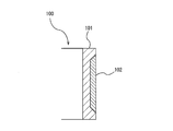
図8は、軸スリーブの従来の構造を模式的に示す断面図である。図8に示すように、軸スリーブ100は、回転軸(図示せず)に固定される円筒状の基材101と、この基材101の外周面に溶射によって形成された皮膜102とを備える。基材101には、液体に対して優れた耐食性を有するステンレス鋼が使用される。皮膜102は、基材101の外周面に形成された窪み内に形成される。皮膜102を形成する溶射材としては、WC(炭化タングステン)、Cr3C2(二炭化三クロム)のうちの少なくとも1つを主成分とし、残りがNi、Cr、Mo、Co、Feのうち少なくとも1つと、不可避不純物とからなる結合材を含有するものが挙げられる。
FIG. 8 is a cross-sectional view schematically showing a conventional structure of a shaft sleeve. As shown in FIG. 8, the
軸スリーブ100が回転すると、皮膜102は、セラミックなどの硬質部材から構成される軸受に摺接し、回転軸および軸スリーブ100は軸受によって回転可能に支持される。超硬合金からなる皮膜102は、優れた耐摩耗性及び耐食性を有し、ステンレス鋼からなる基材101を保護することができる。
When the shaft sleeve 100 rotates, the
軸スリーブ100の製造では、高速フレーム溶射によって皮膜102が形成される。すなわち、図9に示すように、溶射材は、基材101の外周面に形成された窪み105に高速で吹き付けられる。矢印で示すように、溶射材は、窪み105の全体に対して垂直な方向から吹き付けられる。高速の溶射材は、窪み105に強い衝撃力を伴って衝突し、窪み105の表面に食い込む。さらに、一旦吹き付けられた溶射材は、後続の溶射材によって圧縮される。このようにして、溶射材は窪み105の表面に強く付着する。このような現象はアンカー効果と呼ばれる。
In manufacturing the
窪み105の両端においてもアンカー効果が得られるように、窪み105の両端には傾斜面105bが形成されている。基材101の軸心Cと平行な窪み105の底面105aに対する傾斜面105bの角度は45°である。傾斜面105bは、溶射材の噴流を受けることができるので、窪み51の全体でアンカー効果が得られる。
しかしながら、傾斜面105bに衝突する溶射材の力の向きは傾斜面105bに対して垂直ではない。結果として、傾斜面105bでのアンカー効果は、底面105aでのアンカー効果よりも弱くなる。このため、傾斜面105b上に形成された皮膜102が剥がれることがあった。
However, the direction of the force of the thermal spray material that collides with the
そこで、本発明は、基材からの皮膜の剥がれを防ぐことができる軸スリーブを提供することを目的とする。また、本発明は、そのような軸スリーブを備えた回転機械を提供することを目的とする。さらに、本発明は、軸スリーブの製造方法を提供することを目的とする。 Then, an object of this invention is to provide the axial sleeve which can prevent peeling of the film | membrane from a base material. Another object of the present invention is to provide a rotating machine including such a shaft sleeve. Furthermore, this invention aims at providing the manufacturing method of a shaft sleeve.
上述した目的を達成するために、本発明の一態様によれば、回転軸の外周面に固定される軸スリーブであって、外周面に環状の窪みが形成された円筒状の基材と、高速フレーム溶射によって前記環状の窪み内に形成された皮膜とを備え、前記環状の窪みは、少なくとも、前記基材の軸心に平行な底面と、前記底面の両端から前記基材の外周面まで延びる2つの傾斜面によって構成され、前記底面に対する前記傾斜面の角度は10度から30度の範囲内であることを特徴とする軸スリーブが提供される。 In order to achieve the above-described object, according to one aspect of the present invention, a shaft sleeve fixed to the outer peripheral surface of the rotating shaft, and a cylindrical base material having an annular recess formed in the outer peripheral surface; A coating formed in the annular recess by high-speed flame spraying, and the annular recess includes at least a bottom surface parallel to the axis of the substrate, and both ends of the bottom surface to the outer peripheral surface of the substrate. An axial sleeve is provided, characterized in that it is constituted by two inclined surfaces extending, and the angle of the inclined surface with respect to the bottom surface is in the range of 10 to 30 degrees.
本発明の一態様によれば、回転軸と、前記回転軸を回転可能に支持する滑り軸受と、前記回転軸の外周面に固定され、前記滑り軸受に摺接する上記軸スリーブとを備えたことを特徴とする回転機械が提供される。 According to one aspect of the present invention, the rotating shaft, the sliding bearing that rotatably supports the rotating shaft, and the shaft sleeve that is fixed to the outer peripheral surface of the rotating shaft and that is in sliding contact with the sliding bearing are provided. A rotating machine is provided.
本発明の一態様によれば、円筒状の基材を用意し、前記基材の軸心に平行な底面と、前記底面の両端から前記基材の外周面まで延びる2つの傾斜面とから少なくとも構成される環状の窪みを前記基材の外周面に形成し、前記底面に対する前記傾斜面の角度は10度から30度までの範囲内であり、前記環状の窪みに溶射材を高速フレーム溶射によって吹き付けて、前記環状の窪みに皮膜を形成することを特徴とする軸スリーブの製造方法が提供される。 According to one aspect of the present invention, a cylindrical base material is prepared, and at least from a bottom surface parallel to the axis of the base material and two inclined surfaces extending from both ends of the bottom surface to the outer peripheral surface of the base material. An annular recess formed is formed on the outer peripheral surface of the substrate, and an angle of the inclined surface with respect to the bottom surface is within a range of 10 degrees to 30 degrees, and a thermal spray material is sprayed on the annular recess by high-speed flame spraying. There is provided a method for manufacturing a shaft sleeve, characterized in that a film is formed by spraying on the annular recess.
溶射材がターゲット面に対して垂直に衝突するとき、溶射材のアンカー効果は最大となる。本発明によれば、溶射材の進行方向に垂直な底面に対して10度から30度の角度で傾斜面が傾いているので、底面でのアンカー効果に近いアンカー効果が傾斜面でも得られる。よって、皮膜は傾斜面から剥がれにくく、信頼性の高い軸スリーブが得られる。 When the spray material collides perpendicularly to the target surface, the anchor effect of the spray material is maximized. According to the present invention, since the inclined surface is inclined at an angle of 10 to 30 degrees with respect to the bottom surface perpendicular to the traveling direction of the thermal spray material, an anchor effect close to the anchor effect on the bottom surface can be obtained even on the inclined surface. Therefore, the coating is difficult to peel off from the inclined surface, and a highly reliable shaft sleeve can be obtained.
以下、本発明の実施形態について図面を参照して説明する。
図1は、本発明の一実施形態に係る軸スリーブが組み込まれた立軸ポンプを示す模式図である。立軸ポンプは、海水や河川水などの液体を吸込水槽5から吐出水槽21まで汲み上げるためのポンプである。図1に示す立軸ポンプは、本発明の一実施形態に係る軸スリーブが組み込まれたポンプの一例であり、当該軸スリーブは他の構成のポンプにも適用可能である。さらに、本発明は、ポンプのみならず、コンプレッサやファンなどの他のタイプの回転機械にも適用可能である。
Embodiments of the present invention will be described below with reference to the drawings.
FIG. 1 is a schematic view showing a vertical shaft pump incorporating a shaft sleeve according to an embodiment of the present invention. The vertical shaft pump is a pump for pumping liquids such as seawater and river water from the suction water tank 5 to the
図1に示すように、立軸ポンプは、吸込ベルマウス1a及び吐出ボウル1bを有するインペラケーシング1と、インペラケーシング1を吸込水槽5内に吊り下げる揚水管3と、揚水管3の上端に接続された吐出エルボ管4と、インペラケーシング1内に収容された羽根車10と、羽根車10が固定された回転軸6とを備えている。
As shown in FIG. 1, the vertical shaft pump is connected to an impeller casing 1 having a
ポンプ据付床22は、吸込水槽5の上部に接続されている。揚水管3は、ポンプ据付床22に形成された挿通口24を通して下方に延び、揚水管3の上端に設けられた据付用ベース23を介してポンプ据付床22に固定される。回転軸6は、吐出エルボ管4、揚水管3、及びインペラケーシング1内を通って鉛直方向に延びている。ポンプケーシング2は、インペラケーシング1、揚水管3、及び吐出エルボ管4により構成される。
The
吸込ベルマウス1aは下方を向いて開口し、吸込ベルマウス1aの上端は吐出ボウル1bの下端に接続されている。羽根車10は回転軸6の下端に固定されており、羽根車10と回転軸6とは一体的に回転する。この羽根車10の上方(吐出側)には複数のガイドベーン14が配置されている。これらのガイドベーン14は吐出ボウル1bの内周面に固定されている。
The
回転軸6は吐出エルボ管4を貫通して上方に延び、駆動源18に連結されている。駆動源18は、ポンプ据付床22に固定された架台19上に固定されている。立軸ポンプの運転時には、羽根車10は、吸込水槽5内の液面より下に位置している。
The
回転軸6は、外軸受11及び水中軸受12,15により回転可能に支持されている。外軸受11はボールベアリングなどの転がり軸受、または滑り軸受であり、水中軸受12,15は、滑り軸受である。外軸受11は、ポンプケーシング2に配置されている。より具体的には、外軸受11は吐出エルボ管4の上方に配置されている。
The
水中軸受12は吐出ボウル1b内に収容されており、羽根車10の上方に配置されている。水中軸受12を支持する支持部材7はボウルブッシュ13の内面に固定されており、さらに、ボウルブッシュ13はガイドベーン14を介してインペラケーシング1に支持されている。水中軸受15は、揚水管3内に配置されている。水中軸受15は複数の支持部材32に支持されており、これら支持部材32は揚水管3の内面に固定されている。回転軸6には、本発明の一実施形態に係る軸スリーブ35が固定されている。軸スリーブ35と回転軸6は一体に回転する。
The
立軸ポンプは、吸込水槽5内の液体を吐出水槽21まで移送する。すなわち、駆動源18を運転することにより回転軸6を介して羽根車10を回転させると、吸込水槽5内の液体が吸込ベルマウス1aから吸い込まれ、吐出ボウル1b、揚水管3、吐出エルボ管4、および吐出配管20を通って吐出水槽21に移送される。
The vertical pump transfers the liquid in the suction water tank 5 to the
吐出配管20は、吐出エルボ管4から吐出水槽21まで延びている。吐出水槽21の液面は、吐出エルボ管4よりも上方に位置する。吐出配管20の途中には、仕切弁25が配置されており、この仕切弁25は、立軸ポンプの通常運転時には開かれている。立軸ポンプの停止時には仕切弁25が閉じられ、液体が吐出水槽21から吐出配管20を通じて吸込水槽5へ逆流することを防止する。仕切弁25の代わりに、逆止弁を設けてもよい。また、吐出配管20の吐出末端に、フラップ弁を配置してもよい。
The
図2は、図1に示す軸スリーブ35及び水中軸受15を示す拡大図である。軸スリーブ35は円筒状であり、回転軸6の外周面に固定されている。水中軸受15は、軸スリーブ35と同じ高さに配置されており、軸スリーブ35を介して回転軸6を支持する。より具体的には、回転軸6及び軸スリーブ35が回転すると、軸スリーブ35の外周面は水中軸受15の内周面に滑り接触する。軸スリーブ35の外周面と水中軸受15の内周面との間には微小な隙間が形成されている。揚水管3(図1参照)内に存在する液体はこの隙間を通過することによって、軸スリーブ35及び水中軸受15を潤滑する。
FIG. 2 is an enlarged view showing the
軸スリーブ35は、円筒状の基材41と、基材41の外周面に形成された皮膜43とを備えている。本実施形態では、軸スリーブ35は鉛直に配置されており、皮膜43は水中軸受15と同じ高さに位置している。立軸ポンプの運転中は、皮膜43のみが水中軸受15に接触し、基材41は水中軸受15には接触しない。
The
図3は、図2に示す軸スリーブ35の拡大図である。基材41は、ステンレス鋼などの金属から構成されている。本実施形態では、液体に対して耐腐食性を有するステンレス鋼が使用されている。皮膜43は、基材41の外周面の全周に亘って形成されている。より具体的には、基材41の外周面には、その全周に亘って延びる環状の窪み51が形成されており、皮膜43は窪み51内に溶射によって形成されている。皮膜43を形成する溶射材としては、炭化物セラミックであるWC(炭化タングステン)、W2C、Cr3C2(二炭化三クロム)、Cr7C3、Cr23C6、NbC(炭化ニオブ)、TiC(炭化チタン)のうちの少なくとも1つを主成分とし、残りがNi、Cr、Mo、Co、Feのうち少なくとも1つと、不可避不純物とからなる結合材を含有するものが挙げられる。WCおよび/またはCr3C2は、高い耐摩耗性を有する観点から好ましく使用される。溶射方法としては高速フレーム溶射が使用される。
FIG. 3 is an enlarged view of the
基材41の外周面に形成された環状の窪み51は、基材41の軸心Cと平行な底面51aと、この底面51aの両端から基材41の外周面まで延びる2つの傾斜面51bとから少なくとも構成される。窪み51はテーパー状の断面を有する。底面51aに対する各傾斜面51bの角度θは、10度から30度までの範囲内である。軸スリーブ35と水中軸受15との間の隙間を液体が滞りなく通過できるようにするために、基材41の外周面と、皮膜43の外周面は、同一面内にあることが好ましい。
An
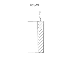
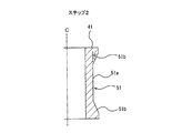
本実施形態の軸スリーブ35は、以下のようにして製造される。ステップ1では、図4に示すように、円筒状の基材41を用意する。ステップ2では、図5に示すように、基材41をその軸心Cを中心に回転させながら、切削工具(図示せず)を基材41の外周面に押し付け、基材41の外周面にその全周に亘って環状の窪み51を形成する。より具体的には、窪み51の底面51aと、この底面51aから基材41の外周面まで延びる2つの傾斜面51bが形成されるように、基材41の外周面が切削される。基材41の軸心Cと平行な底面51aに対する傾斜面51bの角度θは10度から30度までの範囲内とされる。この傾斜面51bは、次のステップで実行される高速フレーム溶射において、溶射材を窪み51の端部に確実に密着させるために形成される。
The
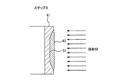
ステップ3では、図6に示すように、基材41の窪み51に溶射材を高速フレーム溶射によって吹き付けて、窪み51内に皮膜43を形成する。このステップ3では、窪み51が溶射材で完全に満たされるまで、溶射材が吹き付けられる。溶射材は、窪み51の全体に対して垂直な方向(軸心Cに垂直な方向)から吹き付けられる。窪み51の底面51a及び傾斜面51bの全体は、溶射材の噴流を受けることができるので、一旦窪み51に吹き付けられた溶射材は後続の溶射材の圧力を受けて底面51a及び傾斜面51bの全体に強く密着することができる。すなわち、底面51a及び傾斜面51bの全体でアンカー効果が得られる。
In
高速フレーム溶射は、燃焼室の圧力を高めることにより高速の火炎を生成し、溶融または半溶融状態の溶射材を高速でターゲット面に吹き付ける溶射技術である。溶射材がターゲット面に対して垂直に衝突するとき、溶射材のアンカー効果は最大となる。本実施形態によれば、溶射材の進行方向に垂直な底面51aに対して10度から30度の角度で傾斜面51bが傾いているので、底面51aでのアンカー効果に近いアンカー効果が傾斜面51bでも得られる。よって、皮膜43は傾斜面51bから剥がれにくく、信頼性の高い軸スリーブ35が得られる。さらに、傾斜面51bでの溶射材の飛び散りが少なくなるという効果も得られる。
High-speed flame spraying is a spraying technique in which a high-speed flame is generated by increasing the pressure in the combustion chamber, and a molten or semi-molten spray material is sprayed onto a target surface at a high speed. When the spray material collides perpendicularly to the target surface, the anchor effect of the spray material is maximized. According to the present embodiment, since the
ステップ4では、図7に示すように、研削などの表面加工を皮膜43に施して、皮膜43の外周面を滑らかにする。以上の製造工程を経て、本実施形態に係る軸スリーブ35が製造される。
In step 4, as shown in FIG. 7, surface treatment such as grinding is performed on the
上述した実施形態は、本発明が属する技術分野における通常の知識を有する者が本発明を実施できることを目的として記載されたものである。上記実施形態の種々の変形例は、当業者であれば当然になしうることであり、本発明の技術的思想は他の実施形態にも適用しうる。したがって、本発明は、記載された実施形態に限定されることはなく、特許請求の範囲によって定義される技術的思想に従った最も広い範囲に解釈されるものである。 The embodiment described above is described for the purpose of enabling the person having ordinary knowledge in the technical field to which the present invention belongs to implement the present invention. Various modifications of the above embodiment can be naturally made by those skilled in the art, and the technical idea of the present invention can be applied to other embodiments. Accordingly, the present invention is not limited to the described embodiments, but is to be construed in the widest scope according to the technical idea defined by the claims.
1a 吸込ベルマウス
1b 吐出ボウル
1 インペラケーシング
3 揚水管
4 吐出エルボ管
5 吸込水槽
6 回転軸
10 羽根車
11 外軸受
12,15 水中軸受
13 ボウルブッシュ
14 ガイドベーン
18 駆動源
19 架台
20 吐出配管
21 吐出水槽
22 ポンプ据付床
23 据付用ベース
24 挿通口
25 仕切弁
32 支持部材
35 軸スリーブ
41 基材
43 皮膜
51 環状の窪み
DESCRIPTION OF
Claims (3)
外周面に環状の窪みが形成された円筒状の基材と、
高速フレーム溶射によって前記環状の窪み内に形成された皮膜とを備え、
前記環状の窪みは、少なくとも、前記基材の軸心に平行な底面と、前記底面の両端から前記基材の外周面まで延びる2つの傾斜面によって構成され、
前記底面に対する前記傾斜面の角度は10度から30度の範囲内であることを特徴とする軸スリーブ。 A shaft sleeve fixed to the outer peripheral surface of the rotating shaft,
A cylindrical base material having an annular depression formed on the outer peripheral surface;
A coating formed in the annular recess by high-speed flame spraying,
The annular recess is composed of at least a bottom surface parallel to the axis of the substrate and two inclined surfaces extending from both ends of the bottom surface to the outer peripheral surface of the substrate,
The shaft sleeve according to claim 1, wherein an angle of the inclined surface with respect to the bottom surface is in a range of 10 degrees to 30 degrees.
前記回転軸を回転可能に支持する滑り軸受と、
前記回転軸の外周面に固定され、前記滑り軸受に摺接する軸スリーブとを備え、
前記軸スリーブは、請求項1に記載の軸スリーブであることを特徴とする回転機械。 A rotation axis;
A sliding bearing that rotatably supports the rotating shaft;
A shaft sleeve fixed to the outer peripheral surface of the rotating shaft and in sliding contact with the sliding bearing;
The rotating machine according to claim 1, wherein the shaft sleeve is a shaft sleeve according to claim 1.
前記基材の軸心に平行な底面と、前記底面の両端から前記基材の外周面まで延びる2つの傾斜面とから少なくとも構成される環状の窪みを前記基材の外周面に形成し、前記底面に対する前記傾斜面の角度は10度から30度までの範囲内であり、
前記環状の窪みに溶射材を高速フレーム溶射によって吹き付けて、前記環状の窪みに皮膜を形成することを特徴とする軸スリーブの製造方法。 Prepare a cylindrical substrate,
Forming an annular recess formed on the outer peripheral surface of the base material at least from a bottom surface parallel to the axis of the base material and two inclined surfaces extending from both ends of the bottom surface to the outer peripheral surface of the base material; The angle of the inclined surface with respect to the bottom surface is in the range of 10 degrees to 30 degrees;
A method of manufacturing a shaft sleeve, comprising spraying a spray material on the annular recess by high-speed flame spraying to form a coating on the annular recess.
Priority Applications (1)
| Application Number | Priority Date | Filing Date | Title |
|---|---|---|---|
| JP2016249747A JP2018105341A (en) | 2016-12-22 | 2016-12-22 | Shaft sleeve, rotary machine and method for manufacturing shaft sleeve |
Applications Claiming Priority (1)
| Application Number | Priority Date | Filing Date | Title |
|---|---|---|---|
| JP2016249747A JP2018105341A (en) | 2016-12-22 | 2016-12-22 | Shaft sleeve, rotary machine and method for manufacturing shaft sleeve |
Publications (1)
| Publication Number | Publication Date |
|---|---|
| JP2018105341A true JP2018105341A (en) | 2018-07-05 |
Family
ID=62786864
Family Applications (1)
| Application Number | Title | Priority Date | Filing Date |
|---|---|---|---|
| JP2016249747A Pending JP2018105341A (en) | 2016-12-22 | 2016-12-22 | Shaft sleeve, rotary machine and method for manufacturing shaft sleeve |
Country Status (1)
| Country | Link |
|---|---|
| JP (1) | JP2018105341A (en) |
Cited By (1)
| Publication number | Priority date | Publication date | Assignee | Title |
|---|---|---|---|---|
| CN113814667A (en) * | 2021-10-20 | 2021-12-21 | 重庆江增船舶重工有限公司 | Machining method of triangular shaft sleeve |
-
2016
- 2016-12-22 JP JP2016249747A patent/JP2018105341A/en active Pending
Cited By (2)
| Publication number | Priority date | Publication date | Assignee | Title |
|---|---|---|---|---|
| CN113814667A (en) * | 2021-10-20 | 2021-12-21 | 重庆江增船舶重工有限公司 | Machining method of triangular shaft sleeve |
| CN113814667B (en) * | 2021-10-20 | 2023-11-03 | 重庆江增船舶重工有限公司 | Processing method of triangular shaft sleeve |
Similar Documents
| Publication | Publication Date | Title |
|---|---|---|
| CA2797164C (en) | Centrifugal pump for slurries | |
| WO2008094801A4 (en) | Method and device for reducing axial thrust and radial oscillations and rotary machines using same | |
| CN204755377U (en) | Vertical axial -flow pump | |
| JP2018105341A (en) | Shaft sleeve, rotary machine and method for manufacturing shaft sleeve | |
| CN203822654U (en) | Stainless steel magnetic drive pump capable of approximate zero inner leakage | |
| CN215763292U (en) | Fluid film lubrication mechanical sealing structure | |
| JP2018105340A (en) | Shaft sleeve and pump | |
| JP6777529B2 (en) | How to manufacture shaft sleeves, pumps, and shaft sleeves | |
| JP2006316793A (en) | Pump and its manufacturing method | |
| JP2014077475A (en) | Bearing structure and water injection type air compression device | |
| KR20100050986A (en) | A underwater pump | |
| JP6382147B2 (en) | Sliding bearing device and pump equipped with the same | |
| CN207554351U (en) | Wear-resisting centrifugal multistage pump multiple centrifugal pump | |
| JP2002303297A (en) | Horizontal shaft type pump | |
| JPH10259790A (en) | Pump and its manufacture | |
| JP2006183475A (en) | Centrifugal compressor | |
| JP2017166380A (en) | Rotating machine | |
| KR101514640B1 (en) | Hydraulic machine, energy conversion plant comprising such a machine, and use of a hydrastatic labyrinth bearing in such a machine | |
| JP4704066B2 (en) | Vertical shaft pump | |
| JP6723834B2 (en) | Pumps and methods for improving existing pumps | |
| JP2899641B2 (en) | Bearing structure and pump for drainage pump | |
| CN207960964U (en) | A kind of centrifugal pump of single stage type | |
| JPH10122117A (en) | Hydraulic machinery | |
| CN210178578U (en) | Festival segmentation multistage pump axial force balanced structure | |
| CN211525172U (en) | Industrial wear-resisting corrosion-resistant mixed flow pump impeller |