JP6777529B2 - How to manufacture shaft sleeves, pumps, and shaft sleeves - Google Patents
How to manufacture shaft sleeves, pumps, and shaft sleeves Download PDFInfo
- Publication number
- JP6777529B2 JP6777529B2 JP2016249745A JP2016249745A JP6777529B2 JP 6777529 B2 JP6777529 B2 JP 6777529B2 JP 2016249745 A JP2016249745 A JP 2016249745A JP 2016249745 A JP2016249745 A JP 2016249745A JP 6777529 B2 JP6777529 B2 JP 6777529B2
- Authority
- JP
- Japan
- Prior art keywords
- shaft sleeve
- base material
- film
- peripheral surface
- outer peripheral
- Prior art date
- Legal status (The legal status is an assumption and is not a legal conclusion. Google has not performed a legal analysis and makes no representation as to the accuracy of the status listed.)
- Active
Links
Images


Landscapes
- Shafts, Cranks, Connecting Bars, And Related Bearings (AREA)
- Coating By Spraying Or Casting (AREA)
- Structures Of Non-Positive Displacement Pumps (AREA)
- Sliding-Contact Bearings (AREA)
Description
本発明は、回転軸に取り付けられる軸スリーブに関し、特に海水などの液体を移送するポンプに組み込まれる軸スリーブに関する。また、本発明は、そのような軸スリーブが組み込まれたポンプに関する。さらに本発明は、軸スリーブの製造方法に関する。 The present invention relates to a shaft sleeve attached to a rotating shaft, and more particularly to a shaft sleeve incorporated in a pump for transferring a liquid such as seawater. The present invention also relates to a pump incorporating such a shaft sleeve. Furthermore, the present invention relates to a method for manufacturing a shaft sleeve.
排水ポンプに使用される水中軸受は潤滑油を不要とするため、設備の簡素化、保守の容易化などの点で有利であるが、水中軸受の摺動部には耐摩耗性に優れた材料を用いる必要がある。そこで、超硬合金の軸スリーブとSiCの軸受を組み合わせたセラミック軸受が開発されている。 Since the submersible bearing used for the drainage pump does not require lubricating oil, it is advantageous in terms of simplification of equipment and ease of maintenance, but the sliding part of the submersible bearing is made of a material with excellent wear resistance. Must be used. Therefore, a ceramic bearing that combines a cemented carbide shaft sleeve and a SiC bearing has been developed.
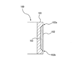
図10は、軸スリーブの従来の構造を模式的に示す断面図である。図10に示すように、軸スリーブ100は、回転軸(図示せず)に固定される円筒状の基材101と、この基材101の外周面に溶射によって形成された皮膜102とを備える。基材101には、液体に対して優れた耐食性を有するステンレス鋼が使用される。皮膜102は、基材101の外周面に形成された窪み内に形成される。皮膜102を形成する溶射材としては、WC(炭化タングステン)、Cr3C2(二炭化三クロム)のうちの少なくとも1つを主成分とし、残りがNi、Cr、Mo、Co、Feのうち少なくとも1つと、不可避不純物とからなる結合材を含有するものが挙げられる。
FIG. 10 is a cross-sectional view schematically showing the conventional structure of the shaft sleeve. As shown in FIG. 10, the
軸スリーブ100が回転すると、皮膜102は、セラミックなどの硬質部材から構成される軸受に摺接し、回転軸および軸スリーブ100は軸受によって回転可能に支持される。超硬合金からなる皮膜102は、優れた耐摩耗性及び耐食性を有し、ステンレス鋼からなる基材101を保護することができる。
When the shaft sleeve 100 rotates, the
しかしながら、基材101と皮膜102との界面103の端部103a,103bは軸スリーブ100の外周面上に露出しており、取扱液は界面103の端部103a,103bに接触する。基材101と皮膜102との界面103には構造上の微細な空隙が存在する。この空隙に液体が浸入すると、いわゆる隙間腐食が発生することがある。特に、ステンレス鋼からなる基材101と皮膜102との界面103に海水が接触すると、隙間腐食が発生しやすい。
However, the
そこで、本発明は、基材と皮膜との界面で隙間腐食が発生することを防ぐことができる軸スリーブを提供することを目的とする。また、本発明は、そのような軸スリーブを備えたポンプを提供することを目的とする。さらに、本発明は、軸スリーブの製造方法を提供することを目的とする。 Therefore, an object of the present invention is to provide a shaft sleeve capable of preventing the occurrence of crevice corrosion at the interface between the base material and the coating film. It is also an object of the present invention to provide a pump with such a shaft sleeve. Furthermore, it is an object of the present invention to provide a method for manufacturing a shaft sleeve.
上述した目的を達成するために、本発明の一態様によれば、回転軸の外周面に固定される軸スリーブであって、円筒状の基材と、前記基材の外周面に溶射によって形成された皮膜と、前記皮膜の両縁部にそれぞれ密着した2つの樹脂リングとを備え、前記基材と前記皮膜との界面の両端部は前記樹脂リングで覆われ、前記基材は、その外周面に形成された環状の窪みと、該環状の窪みの両側に位置する2つの環状の溝を有しており、前記皮膜は前記環状の窪み内に形成されており、前記樹脂リングは前記環状の溝内に形成されていることを特徴とする軸スリーブが提供される。 In order to achieve the above-mentioned object, according to one aspect of the present invention, it is a shaft sleeve fixed to the outer peripheral surface of the rotating shaft, and is formed on a cylindrical base material and the outer peripheral surface of the base material by thermal spraying. A coated film and two resin rings that are in close contact with both edges of the film are provided, both ends of the interface between the base material and the film are covered with the resin rings, and the base material is the outer periphery thereof. It has an annular recess formed on the surface and two annular grooves located on both sides of the annular recess, the film is formed in the annular recess, and the resin ring is the annular. A shaft sleeve is provided, characterized in that it is formed in the groove of the .
一実施形態では、前記皮膜と前記基材との界面の全体は、前記軸スリーブの内部に位置している。
一実施形態では、前記皮膜の外周面と前記樹脂リングの外周面は、同一面内にある。
In one embodiment, the entire interface between the coating and the substrate is located inside the shaft sleeve.
In one embodiment, the outer peripheral surface of the resin ring and the outer peripheral surface of the coating, Ru same plane near.
本発明の一態様によれば、回転軸と、前記回転軸に固定された羽根車と、前記回転軸を回転可能に支持する水中軸受と、前記回転軸の外周面に固定され、前記水中軸受に摺接する上記軸スリーブとを備えたことを特徴とするポンプが提供される。 According to one aspect of the present invention, a rotating shaft, an impeller fixed to the rotating shaft, an underwater bearing that rotatably supports the rotating shaft, and an underwater bearing fixed to the outer peripheral surface of the rotating shaft. Provided is a pump comprising the shaft sleeve that is in sliding contact with the shaft sleeve.
本発明の一態様によれば、円筒状の基材を用意し、前記基材の外周面に、該外周面の全周に亘って環状の窪みを形成し、前記環状の窪みに溶射材を溶射によって吹き付けて、前記環状の窪みに皮膜を形成し、前記皮膜の両縁部を除去しながら、前記環状の窪みの両側に位置する2つの環状の溝を前記基材の外周面に形成し、前記環状の溝内に樹脂リングを形成することを特徴とする軸スリーブの製造方法が提供される。 According to one aspect of the present invention, a cylindrical base material is prepared, an annular recess is formed on the outer peripheral surface of the base material over the entire circumference of the outer peripheral surface, and a thermal spray material is formed in the annular recess. By spraying, a film is formed in the annular recess, and while removing both edges of the film, two annular grooves located on both sides of the annular recess are formed on the outer peripheral surface of the base material. Provided is a method for manufacturing a shaft sleeve, which comprises forming a resin ring in the annular groove.
本発明によれば、基材と皮膜との界面の端部は樹脂で覆われているので、海水などの液体は、基材と皮膜との界面に接触しない。よって、基材と皮膜との間で隙間腐食が起こりにくくなり、皮膜は剥がれにくくなる。結果として、軸スリーブは設計寿命に達するまでその本来の性能を発揮することができ、軸スリーブの信頼性が向上する。 According to the present invention, since the end of the interface between the base material and the film is covered with the resin, a liquid such as seawater does not come into contact with the interface between the base material and the film. Therefore, crevice corrosion between the base material and the film is less likely to occur, and the film is less likely to peel off. As a result, the shaft sleeve can exhibit its original performance until the design life is reached, and the reliability of the shaft sleeve is improved.
以下、本発明の実施形態について図面を参照して説明する。
図1は、本発明の一実施形態に係る軸スリーブが組み込まれた立軸ポンプを示す模式図である。立軸ポンプは、海水や河川水などの液体を吸込水槽5から吐出水槽21まで汲み上げるためのポンプである。図1に示す立軸ポンプは、本発明の一実施形態に係る軸スリーブが組み込まれたポンプの一例であり、当該軸スリーブは他の構成のポンプにも適用可能である。
Hereinafter, embodiments of the present invention will be described with reference to the drawings.
FIG. 1 is a schematic view showing a vertical shaft pump incorporating a shaft sleeve according to an embodiment of the present invention. The vertical shaft pump is a pump for pumping a liquid such as seawater or river water from the
図1に示すように、立軸ポンプは、吸込ベルマウス1a及び吐出ボウル1bを有するインペラケーシング1と、インペラケーシング1を吸込水槽5内に吊り下げる揚水管3と、揚水管3の上端に接続された吐出エルボ管4と、インペラケーシング1内に収容された羽根車10と、羽根車10が固定された回転軸6とを備えている。
As shown in FIG. 1, the vertical shaft pump is connected to an impeller casing 1 having a suction bell mouth 1a and a discharge bowl 1b, a
ポンプ据付床22は、吸込水槽5の上部に接続されている。揚水管3は、ポンプ据付床22に形成された挿通口24を通して下方に延び、揚水管3の上端に設けられた据付用ベース23を介してポンプ据付床22に固定される。回転軸6は、吐出エルボ管4、揚水管3、及びインペラケーシング1内を通って鉛直方向に延びている。ポンプケーシング2は、インペラケーシング1、揚水管3、及び吐出エルボ管4により構成される。
The
吸込ベルマウス1aは下方を向いて開口し、吸込ベルマウス1aの上端は吐出ボウル1bの下端に接続されている。羽根車10は回転軸6の下端に固定されており、羽根車10と回転軸6とは一体的に回転する。この羽根車10の上方(吐出側)には複数のガイドベーン14が配置されている。これらのガイドベーン14は吐出ボウル1bの内周面に固定されている。
The suction bell mouth 1a opens downward, and the upper end of the suction bell mouth 1a is connected to the lower end of the discharge bowl 1b. The
回転軸6は吐出エルボ管4を貫通して上方に延び、駆動源18に連結されている。駆動源18は、ポンプ据付床22に固定された架台19上に固定されている。立軸ポンプの運転時には、羽根車10は、吸込水槽5内の液面より下に位置している。
The rotating
回転軸6は、外軸受11及び水中軸受12,15により回転可能に支持されている。外軸受11はボールベアリングなどの転がり軸受、または滑り軸受であり、水中軸受12,15は、滑り軸受である。外軸受11は、ポンプケーシング2に配置されている。より具体的には、外軸受11は吐出エルボ管4の上方に配置されている。
The
水中軸受12は吐出ボウル1b内に収容されており、羽根車10の上方に配置されている。水中軸受12を支持する支持部材7はボウルブッシュ13の内面に固定されており、さらに、ボウルブッシュ13はガイドベーン14を介してインペラケーシング1に支持されている。水中軸受15は、揚水管3内に配置されている。水中軸受15は複数の支持部材32に支持されており、これら支持部材32は揚水管3の内面に固定されている。回転軸6には、本発明の一実施形態に係る軸スリーブ35が固定されている。軸スリーブ35と回転軸6は一体に回転する。
The
立軸ポンプは、吸込水槽5内の液体を吐出水槽21まで移送する。すなわち、駆動源18を運転することにより回転軸6を介して羽根車10を回転させると、吸込水槽5内の液体が吸込ベルマウス1aから吸い込まれ、吐出ボウル1b、揚水管3、吐出エルボ管4、および吐出配管20を通って吐出水槽21に移送される。
The vertical shaft pump transfers the liquid in the
吐出配管20は、吐出エルボ管4から吐出水槽21まで延びている。吐出水槽21の液面は、吐出エルボ管4よりも上方に位置する。吐出配管20の途中には、仕切弁25が配置されており、この仕切弁25は、立軸ポンプの通常運転時には開かれている。立軸ポンプの停止時には仕切弁25が閉じられ、液体が吐出水槽21から吐出配管20を通じて吸込水槽5へ逆流することを防止する。仕切弁25の代わりに、逆止弁を設けてもよい。また、吐出配管20の吐出末端に、フラップ弁を配置してもよい。
The
図2は、図1に示す軸スリーブ35及び水中軸受15を示す拡大図である。軸スリーブ35は円筒状であり、回転軸6の外周面に固定されている。水中軸受15は、軸スリーブ35と同じ高さに配置されており、軸スリーブ35を介して回転軸6を支持する。より具体的には、回転軸6及び軸スリーブ35が回転すると、軸スリーブ35の外周面は水中軸受15の内周面に滑り接触する。軸スリーブ35の外周面と水中軸受15の内周面との間には微小な隙間が形成されている。揚水管3(図1参照)内に存在する液体はこの隙間を通過することによって、軸スリーブ35及び水中軸受15を潤滑する。
FIG. 2 is an enlarged view showing the
軸スリーブ35は、円筒状の基材41と、基材41の外周面に形成された皮膜43と、皮膜43の両縁部43a,43bにそれぞれ密着した2つの樹脂リング45とを備えている。本実施形態では、軸スリーブ35は鉛直に配置されているので、2つの樹脂リング45の一方は皮膜43の上側縁部43aに接触し、他方の樹脂リング45は皮膜43の下側縁部43bに接触している。皮膜43は水中軸受15と同じ高さに位置しており、上側の樹脂リング45は水中軸受15よりも上方に、下側の樹脂リング45は水中軸受15よりも下方に位置する。立軸ポンプの運転中は、皮膜43のみが水中軸受15に接触し、樹脂リング45及び基材41は水中軸受15には接触しない。
The
図3は、図2に示す軸スリーブ35の拡大図である。基材41は、ステンレス鋼などの金属から構成されている。本実施形態では、液体に対して耐腐食性を有するステンレス鋼が使用されている。皮膜43は、基材41の外周面の全周に亘って形成されている。より具体的には、基材41の外周面には、その全周に亘って延びる環状の窪み51が形成されており、皮膜43は窪み51内に溶射によって形成されている。皮膜43を形成する溶射材としては、炭化物セラミックであるWC(炭化タングステン)、W2C、Cr3C2(二炭化三クロム)、Cr7C3、Cr23C6、NbC(炭化ニオブ)、TiC(炭化チタン)のうちの少なくとも1つを主成分とし、残りがNi、Cr、Mo、Co、Feのうち少なくとも1つと、不可避不純物とからなる結合材を含有するものが挙げられる。WCおよび/またはCr3C2は、高い耐摩耗性を有する観点から好ましく使用される。溶射方法としては高速フレーム溶射が挙げられるが、サーメット材料が溶射できる減圧プラズマ溶射、爆発溶射などの他のタイプの溶射を使用してもよい。
FIG. 3 is an enlarged view of the
樹脂リング45は、皮膜43と同様に、基材41の外周面に形成されている。より具体的には、樹脂リング45は、基材41の外周面に形成された2つの環状の溝55内に形成されている。これら環状の溝55は窪み51の両側(上側及び下側)に位置している。軸スリーブ35と水中軸受15との間の隙間を液体が滞りなく通過できるようにするために、樹脂リング45の外周面と、皮膜43の外周面は、同一面内にあることが好ましい。皮膜43は、2つの樹脂リング45の間に配置されている。樹脂リング45は皮膜43に密着しており、皮膜43と樹脂リング45との間には隙間は実質的に存在しない。樹脂リング45の材料は、液体に対して耐食性を有している樹脂であれば、特に限定されない。
The
基材41と皮膜43との界面60の両端部60a,60bは、2つの樹脂リング45によって覆われており、かつ界面60の全体は軸スリーブ35の内部に位置している。言い換えれば、基材41と皮膜43との界面60は、軸スリーブ35の外部には露出していない。したがって、揚水管3内に存在する液体は、基材41と皮膜43との界面60に接触しない。本実施形態によれば、基材41と皮膜43との界面60で隙間腐食が起こりにくくなり、皮膜43は剥がれにくくなる。結果として、軸スリーブ35は設計寿命に達するまでその本来の性能を発揮することができ、軸スリーブ35の信頼性が向上する。
Both ends 60a and 60b of the
樹脂リング45の半径方向の厚さW1は、皮膜43の半径方向の厚さW2よりも大きいことが好ましい。その理由は、軸スリーブ35の外周面からの、基材41と皮膜43との界面60の端部60a,60bまでの距離が長いほど、液体が界面60の端部60a,60bに接触する可能性が低くなるからである。
The radial thickness W1 of the
本実施形態の軸スリーブ35は、以下のようにして製造される。ステップ1では、図4に示すように、円筒状の基材41を用意する。ステップ2では、図5に示すように、基材41をその軸心を中心に回転させながら、切削工具(図示せず)を基材41の外周面に押し付け、基材41の外周面にその全周に亘って環状の窪み51を形成する。より具体的には、窪み51の底面51aと、この底面51aから基材41の外周面まで延びる2つの傾斜面51bが形成されるように、基材41の外周面が切削される。基材41の軸心と平行な底面51aに対する傾斜面51bの角度は45度とされる。この傾斜面51bは、次のステップで実行される溶射において、溶射材を窪み51の端部に確実に密着させるために形成される。一実施形態では、窪み51は、傾斜面51bに代えて、底面51aに垂直な側面を有してもよい。
The
ステップ3では、図6に示すように、基材41の窪み51に溶射材を溶射によって吹き付けて、窪み51内に皮膜43を形成する。このステップ3では、窪み51が溶射材で完全に満たされるまで、溶射材が吹き付けられる。溶射材は、窪み51の全体に対して垂直な方向から吹き付けられる。窪み51の底面51a及び傾斜面51bの全体は、溶射材の噴流を受けることができるので、一旦窪み51に吹き付けられた溶射材は後続の溶射材の圧力を受けて底面51a及び傾斜面51bの全体に強く密着することができる。すなわち、底面51a及び傾斜面51bの全体でアンカー効果が得られる。
In
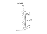
ステップ4では、図7に示すように、研削などの表面加工を皮膜43に施して、皮膜43の外周面を滑らかにする。ステップ5では、図8に示すように、基材41をその軸心を中心に回転させながら、切削工具(図示せず)を皮膜43の両縁部及び基材41の外周面に押し付け、皮膜43の両縁部を削りながら、窪み51の両側に位置する2つの環状の溝55を基材41の外周面に形成する。本実施形態では、上述した窪み51の傾斜面51bの全体が除去されるように環状の溝55が形成される。環状の溝55は、基材41の露出面と、皮膜43の縁部43a,43bによって構成される。
In step 4, as shown in FIG. 7, surface processing such as grinding is applied to the
そして、ステップ6では、図9に示すように、流動状態の樹脂を環状の溝55に流し込み、樹脂を固化させて樹脂リング45を形成する。本実施形態の樹脂としては、熱可塑性樹脂、熱硬化性樹脂、ゴムなどが使用できる。樹脂リング45の材料の例としては、酢酸ビニル系樹脂(PVAc)、ポリビニルアルコール系樹脂(PVA)、エチレン酢酸ビニル系樹脂(EVA)、塩化ビニル系樹脂(PVC)、アクリル系樹脂(PA)、ポリアミド系樹脂、ポリイミド系樹脂(PI)、セルロース系樹脂、ポリビニルピロリドン系樹脂(PVP)、ポリスチレン系樹脂(PS)、シアノアクリレート系樹脂、ポリビニルアセタール系樹脂、エポキシ系樹脂、ウレタン系樹脂(ポリウレタン)、ポリウレア系樹脂、ポリアロマティック系樹脂、ユリア系樹脂(UF)、メラミン系樹脂、フェノール系樹脂、レゾルシノール系樹脂、エステル系樹脂(ポリエステル)、クロロブレンゴム(CR)、ニトリルゴム(NBR)、スチレンブタジエンゴム(SBR)、熱可塑性エラストマー(SBS,SIS等)、プチルゴム(IIR)、シリコーン、変性シリコン、シリル化ウレタン、ウレタンゴム、ポリサルファイド、アクリルゴムなどが挙げられる。
Then, in
以上の製造工程を経て、本実施形態に係る軸スリーブ35が製造される。本実施形態では、皮膜43が溶射によって形成された後に、樹脂リング45が形成される。このようなステップ順とすることにより、樹脂リング45は皮膜43の縁部43a,43bに隙間なく密着することができる。
Through the above manufacturing process, the
上述した実施形態は、本発明が属する技術分野における通常の知識を有する者が本発明を実施できることを目的として記載されたものである。上記実施形態の種々の変形例は、当業者であれば当然になしうることであり、本発明の技術的思想は他の実施形態にも適用しうる。したがって、本発明は、記載された実施形態に限定されることはなく、特許請求の範囲によって定義される技術的思想に従った最も広い範囲に解釈されるものである。 The above-described embodiment is described for the purpose of enabling a person having ordinary knowledge in the technical field to which the present invention belongs to carry out the present invention. Various modifications of the above embodiment can be naturally performed by those skilled in the art, and the technical idea of the present invention can be applied to other embodiments. Therefore, the present invention is not limited to the described embodiments, but is construed in the broadest range according to the technical idea defined by the claims.
1a 吸込ベルマウス
1b 吐出ボウル
1 インペラケーシング
3 揚水管
4 吐出エルボ管
5 吸込水槽
6 回転軸
10 羽根車
11 外軸受
12,15 水中軸受
13 ボウルブッシュ
14 ガイドベーン
18 駆動源
19 架台
20 吐出配管
21 吐出水槽
22 ポンプ据付床
23 据付用ベース
24 挿通口
25 仕切弁
32 支持部材
35 軸スリーブ
41 基材
43 皮膜
45 樹脂リング
51 環状の窪み
55 環状の溝
60 界面
1a Suction bell mouth 1b Discharge bowl 1
Claims (5)
円筒状の基材と、
前記基材の外周面に溶射によって形成された皮膜と、
前記皮膜の両縁部にそれぞれ密着した2つの樹脂リングとを備え、
前記基材と前記皮膜との界面の両端部は前記樹脂リングで覆われ、
前記基材は、その外周面に形成された環状の窪みと、該環状の窪みの両側に位置する2つの環状の溝を有しており、
前記皮膜は前記環状の窪み内に形成されており、前記樹脂リングは前記環状の溝内に形成されていることを特徴とする軸スリーブ。 A shaft sleeve that is fixed to the outer peripheral surface of the rotating shaft.
Cylindrical base material and
A film formed by thermal spraying on the outer peripheral surface of the base material and
It is provided with two resin rings that are in close contact with each other on both edges of the film.
Both ends of the interface between the base material and the coating film are covered with the resin ring .
The base material has an annular recess formed on the outer peripheral surface thereof and two annular grooves located on both sides of the annular recess.
A shaft sleeve characterized in that the film is formed in the annular recess and the resin ring is formed in the annular groove .
前記回転軸に固定された羽根車と、
前記回転軸を回転可能に支持する水中軸受と、
前記回転軸の外周面に固定され、前記水中軸受に摺接する軸スリーブとを備え、
前記軸スリーブは、請求項1乃至3のいずれか一項に記載の軸スリーブであることを特徴とするポンプ。 The axis of rotation and
An impeller fixed to the rotating shaft and
An underwater bearing that rotatably supports the rotating shaft,
A shaft sleeve fixed to the outer peripheral surface of the rotating shaft and sliding in contact with the underwater bearing is provided.
The pump according to any one of claims 1 to 3 , wherein the shaft sleeve is the shaft sleeve.
前記基材の外周面に、該外周面の全周に亘って環状の窪みを形成し、
前記環状の窪みに溶射材を溶射によって吹き付けて、前記環状の窪みに皮膜を形成し、
前記皮膜の両縁部を除去しながら、前記環状の窪みの両側に位置する2つの環状の溝を前記基材の外周面に形成し、
前記環状の溝内に樹脂リングを形成することを特徴とする軸スリーブの製造方法。 Prepare a cylindrical base material and
An annular recess is formed on the outer peripheral surface of the base material over the entire circumference of the outer peripheral surface.
A thermal spray material is sprayed onto the annular recess to form a film on the annular recess.
While removing both edges of the film, two annular grooves located on both sides of the annular recess are formed on the outer peripheral surface of the base material.
A method for manufacturing a shaft sleeve, which comprises forming a resin ring in the annular groove.
Priority Applications (1)
| Application Number | Priority Date | Filing Date | Title |
|---|---|---|---|
| JP2016249745A JP6777529B2 (en) | 2016-12-22 | 2016-12-22 | How to manufacture shaft sleeves, pumps, and shaft sleeves |
Applications Claiming Priority (1)
| Application Number | Priority Date | Filing Date | Title |
|---|---|---|---|
| JP2016249745A JP6777529B2 (en) | 2016-12-22 | 2016-12-22 | How to manufacture shaft sleeves, pumps, and shaft sleeves |
Publications (2)
| Publication Number | Publication Date |
|---|---|
| JP2018105339A JP2018105339A (en) | 2018-07-05 |
| JP6777529B2 true JP6777529B2 (en) | 2020-10-28 |
Family
ID=62787711
Family Applications (1)
| Application Number | Title | Priority Date | Filing Date |
|---|---|---|---|
| JP2016249745A Active JP6777529B2 (en) | 2016-12-22 | 2016-12-22 | How to manufacture shaft sleeves, pumps, and shaft sleeves |
Country Status (1)
| Country | Link |
|---|---|
| JP (1) | JP6777529B2 (en) |
Families Citing this family (1)
| Publication number | Priority date | Publication date | Assignee | Title |
|---|---|---|---|---|
| CN111677686A (en) * | 2020-06-03 | 2020-09-18 | 黄河水利委员会黄河水利科学研究院 | A kind of centrifugal water pump wear-resistant mouth ring and preparation method thereof |
Family Cites Families (3)
| Publication number | Priority date | Publication date | Assignee | Title |
|---|---|---|---|---|
| JP3271363B2 (en) * | 1992-03-18 | 2002-04-02 | 株式会社日立製作所 | Bearing device, drain pump and water turbine provided with the bearing device, and method of manufacturing bearing device |
| JP3627614B2 (en) * | 1992-03-18 | 2005-03-09 | 株式会社日立製作所 | Drainage pump |
| JPH06122954A (en) * | 1992-10-13 | 1994-05-06 | Hitachi Ltd | Bearing device for drainage pump and drainage pump |
-
2016
- 2016-12-22 JP JP2016249745A patent/JP6777529B2/en active Active
Also Published As
| Publication number | Publication date |
|---|---|
| JP2018105339A (en) | 2018-07-05 |
Similar Documents
| Publication | Publication Date | Title |
|---|---|---|
| CA2940395C (en) | Abrasion resistance in well fluid wetted assemblies | |
| US20160115998A1 (en) | Electric submersible pump assembly bearing | |
| US10359045B2 (en) | Press-fit thrust bearing system and apparatus | |
| GB2411670A (en) | Submersible motor protector having means for reducing wear from abrasives | |
| CA2905848A1 (en) | Centrifugal pump for handling abrasive-laden fluid | |
| WO2008094801A4 (en) | Method and device for reducing axial thrust and radial oscillations and rotary machines using same | |
| JP5270329B2 (en) | Thrust slide bearing and pump equipped with the thrust slide bearing | |
| CN104421093A (en) | Hydraulic turbine and pipe | |
| JP6777529B2 (en) | How to manufacture shaft sleeves, pumps, and shaft sleeves | |
| JPS58174195A (en) | Pump device for water-supply system | |
| JP5909392B2 (en) | Slide bearing device | |
| JP6769965B2 (en) | Shaft sealing device and vertical shaft pump equipped with this shaft sealing device | |
| JP5675964B2 (en) | Self-contained oil film bearing | |
| JP5964576B2 (en) | Impeller and submersible pump | |
| CN215763292U (en) | Fluid film lubrication mechanical sealing structure | |
| CA2246188C (en) | Front-removable bearing housing for vertical turbine pump | |
| JP2018105340A (en) | Shaft sleeve and pump | |
| JP2018105341A (en) | Shaft sleeve, rotary machine and method for manufacturing shaft sleeve | |
| CN103348142A (en) | Centrifugal pump and a double bent rotor blade for use in such a centrifugal pump | |
| JP5939901B2 (en) | Sealing device for rotating fluid equipment | |
| JP5683693B2 (en) | System used in rolling mill oil film bearings | |
| CN109533257B (en) | Maintenance method for rotary seal structure of nacelle propulsion device | |
| CN107956703A (en) | A kind of abrasion-proof corrosion-proof pump | |
| JP2015175278A (en) | Centrifugal pump | |
| CN108626172A (en) | A kind of Novel submersible pump |
Legal Events
| Date | Code | Title | Description |
|---|---|---|---|
| A621 | Written request for application examination |
Free format text: JAPANESE INTERMEDIATE CODE: A621 Effective date: 20190723 |
|
| A977 | Report on retrieval |
Free format text: JAPANESE INTERMEDIATE CODE: A971007 Effective date: 20200603 |
|
| A131 | Notification of reasons for refusal |
Free format text: JAPANESE INTERMEDIATE CODE: A131 Effective date: 20200609 |
|
| A521 | Request for written amendment filed |
Free format text: JAPANESE INTERMEDIATE CODE: A523 Effective date: 20200625 |
|
| TRDD | Decision of grant or rejection written | ||
| A01 | Written decision to grant a patent or to grant a registration (utility model) |
Free format text: JAPANESE INTERMEDIATE CODE: A01 Effective date: 20200929 |
|
| A61 | First payment of annual fees (during grant procedure) |
Free format text: JAPANESE INTERMEDIATE CODE: A61 Effective date: 20201008 |
|
| R150 | Certificate of patent or registration of utility model |
Ref document number: 6777529 Country of ref document: JP Free format text: JAPANESE INTERMEDIATE CODE: R150 |
|
| R250 | Receipt of annual fees |
Free format text: JAPANESE INTERMEDIATE CODE: R250 |
|
| R250 | Receipt of annual fees |
Free format text: JAPANESE INTERMEDIATE CODE: R250 |
|
| R250 | Receipt of annual fees |
Free format text: JAPANESE INTERMEDIATE CODE: R250 |