JP2017166380A - Rotating machine - Google Patents
Rotating machine Download PDFInfo
- Publication number
- JP2017166380A JP2017166380A JP2016051134A JP2016051134A JP2017166380A JP 2017166380 A JP2017166380 A JP 2017166380A JP 2016051134 A JP2016051134 A JP 2016051134A JP 2016051134 A JP2016051134 A JP 2016051134A JP 2017166380 A JP2017166380 A JP 2017166380A
- Authority
- JP
- Japan
- Prior art keywords
- bearing
- fan
- pump
- rotating shaft
- impeller
- Prior art date
- Legal status (The legal status is an assumption and is not a legal conclusion. Google has not performed a legal analysis and makes no representation as to the accuracy of the status listed.)
- Pending
Links
- 239000012530 fluid Substances 0.000 claims description 10
- 238000011144 upstream manufacturing Methods 0.000 claims description 3
- XLYOFNOQVPJJNP-UHFFFAOYSA-N water Substances O XLYOFNOQVPJJNP-UHFFFAOYSA-N 0.000 description 59
- 229910052751 metal Inorganic materials 0.000 description 15
- 239000002184 metal Substances 0.000 description 15
- 239000007788 liquid Substances 0.000 description 11
- 230000002093 peripheral effect Effects 0.000 description 11
- 238000005086 pumping Methods 0.000 description 11
- 239000000463 material Substances 0.000 description 8
- 238000010586 diagram Methods 0.000 description 6
- 238000002156 mixing Methods 0.000 description 5
- 239000011347 resin Substances 0.000 description 5
- 229920005989 resin Polymers 0.000 description 5
- 230000000712 assembly Effects 0.000 description 4
- 238000000429 assembly Methods 0.000 description 4
- 238000005452 bending Methods 0.000 description 4
- 238000009434 installation Methods 0.000 description 3
- XEEYBQQBJWHFJM-UHFFFAOYSA-N Iron Chemical compound [Fe] XEEYBQQBJWHFJM-UHFFFAOYSA-N 0.000 description 2
- 239000004696 Poly ether ether ketone Substances 0.000 description 2
- 238000013019 agitation Methods 0.000 description 2
- 239000010426 asphalt Substances 0.000 description 2
- 239000000919 ceramic Substances 0.000 description 2
- 238000003780 insertion Methods 0.000 description 2
- 230000037431 insertion Effects 0.000 description 2
- 238000005461 lubrication Methods 0.000 description 2
- 229920002530 polyetherether ketone Polymers 0.000 description 2
- 229920001343 polytetrafluoroethylene Polymers 0.000 description 2
- 239000004810 polytetrafluoroethylene Substances 0.000 description 2
- 229910001220 stainless steel Inorganic materials 0.000 description 2
- 239000010935 stainless steel Substances 0.000 description 2
- 230000001133 acceleration Effects 0.000 description 1
- 230000004323 axial length Effects 0.000 description 1
- 230000001934 delay Effects 0.000 description 1
- 230000006866 deterioration Effects 0.000 description 1
- 238000006073 displacement reaction Methods 0.000 description 1
- 230000000694 effects Effects 0.000 description 1
- 239000013013 elastic material Substances 0.000 description 1
- 238000007667 floating Methods 0.000 description 1
- 210000004907 gland Anatomy 0.000 description 1
- 230000005484 gravity Effects 0.000 description 1
- 230000020169 heat generation Effects 0.000 description 1
- 238000007689 inspection Methods 0.000 description 1
- 229910052742 iron Inorganic materials 0.000 description 1
- 238000012423 maintenance Methods 0.000 description 1
- 238000000034 method Methods 0.000 description 1
- 238000012856 packing Methods 0.000 description 1
- -1 polytetrafluoroethylene Polymers 0.000 description 1
- 238000003825 pressing Methods 0.000 description 1
- 239000004576 sand Substances 0.000 description 1
- 239000002002 slurry Substances 0.000 description 1
- 238000003756 stirring Methods 0.000 description 1
- UONOETXJSWQNOL-UHFFFAOYSA-N tungsten carbide Chemical compound [W+]#[C-] UONOETXJSWQNOL-UHFFFAOYSA-N 0.000 description 1
Images


Landscapes
- Sliding-Contact Bearings (AREA)
- Structures Of Non-Positive Displacement Pumps (AREA)
Abstract
Description
本発明は回転軸を支持するすべり軸受を備えた回転機械に関するものである。 The present invention relates to a rotating machine including a slide bearing that supports a rotating shaft.
近年の先行待機運転ポンプの状況により、背景技術の一例を説明する。近年、都市化の進展により、緑地の減少および路面のコンクリート化、アスファルト化の拡大が進むことでヒートアイランド現象が発生し、いわゆるゲリラ豪雨と呼ばれる局所的な集中豪雨が都市部で頻発している。局所的な大量の降雨は、コンクリート化、アスファルト化した路面では、地中に吸収されることなくそのまま水路に導かれる。その結果、大量の雨水が、短時間のうちに排水機場に流入する。 An example of the background art will be described based on the situation of the preceding standby operation pump in recent years. In recent years, with the progress of urbanization, the heat island phenomenon has occurred due to the reduction of green spaces, the road surface becoming concrete, and the expansion of asphalt, and so-called guerrilla heavy rains frequently occur in urban areas. A large amount of local rainfall is introduced into the waterway without being absorbed into the ground on concrete and asphalt road surfaces. As a result, a large amount of rainwater flows into the drainage station in a short time.
頻発するこのような集中豪雨によってもたらされる大量の雨水の速やかな排水に備えるために、排水機場に設置する排水ポンプでは、始動遅れによる浸水被害が生じないよう、雨水が排水機場に到達する前に予め始動させておく先行待機運転が行われている。 In order to prepare for the rapid drainage of a large amount of rainwater caused by such frequent torrential rains, drainage pumps installed in the drainage pump station will have rainwater before it reaches the drainage pump station to prevent inundation damage due to delays in starting. Prior standby operation that is started in advance is performed.
図5は、先行待機運転を行う立軸ポンプを示す模式図である。排水機場の水槽100には、縦方向に配置された回転軸122の先端に羽根車120を備え、羽根車120に水と共に空気を吸い込ませることにより、水槽100の水位が最低運転水位LWL以下であっても運転(先行待機運転)を継続することが可能な立軸ポンプが配置されている。回転軸122はすべり軸受135,145によって回転自在に支持されている。吸込ベルマウス110の側面部に貫通孔105が設けられており、この貫通孔105には、外気に接する開口106aを備えた空気管106が取付けられている。これにより、この立軸ポンプでは貫通孔105を介して立軸ポンプ内に供給する空気の供給量を水位に応じて変化させ、最低運転水位LWL以下で立軸ポンプの排水量がコントロールされる。
FIG. 5 is a schematic diagram showing a vertical shaft pump that performs a preliminary standby operation. The
先行待機運転の運転状態について説明する。例えば大都市の雨水排水用として、吸込水位に関係なく降雨情報等により予め立軸ポンプを始動しておく(気中運転)。低水位の状態から水位が上昇するに従って、羽根車120の位置まで水位が達し、立軸ポンプは空運転(気中運転)から羽根車120で水を撹拌する運転(気水撹拌運転)を行う。さらに立軸ポンプは貫通孔105を経て供給される空気を水と共に吸い込ませつつ水量を徐々に増やす運転(気水混合運転)を経て100%水の排出を行う全量運転(定常運転)へ移行する。また、高水位から水位が低下するときは、立軸ポンプは全量運転から貫通孔105を経て供給する空気を水と共に吸い込ませつつ水量を徐々に減らす運転(気水混合運転)へ移行する。水位がLLWLの近くに至ると、立軸ポンプは水を吸い込まず排水もしない運転(エアロック運転)へ移行する。これら5つの特徴ある運転を総称して先行待機運転という。なお、ポンプ始動は、吸込ベルマウス110の下端よりも低い水位LLLWLから開始する。
The operating state of the preceding standby operation will be described. For example, for a rainwater drainage in a large city, a vertical shaft pump is started in advance based on rainfall information or the like regardless of the suction water level (air operation). As the water level rises from the low water level state, the water level reaches the position of the
図5に示す立軸ポンプは、ポンプ起動時には大気中で運転される。すなわち、すべり軸受135,145は流体の潤滑のないドライ条件で回転軸122に固定されたスリーブ111(図6参照)にすべり接触する。ここでドライ条件とは、ポンプ運転中のすべり軸受135,145の雰囲気が、流体の潤滑がない大気中である条件をいい、ドライ運転とはその条件で運転することをいう。また、すべり軸受135,145はすべり軸受135,145に通水した排水条件でもスリーブ111にすべり接触する。ここで、排水条件とは、ポンプ運転中のすべり軸受135,145の雰囲気が、土砂等の異物(スラリー)が混入した水中である条件をいい、排水運転とはその条件で運転すること、例えば気水混合運転、全量運転、エアロック運転等をいう。このような条件下ですべり軸受135,145が使用される。
The vertical shaft pump shown in FIG. 5 is operated in the atmosphere when the pump is started. That is, the
ここで、排水機場で用いられるポンプ等は、水中で運転されるだけでなく、先行待機運転の場合には、大気中での運転と水中での運転が繰り返される。大気中での運転の場合には、すべり軸受のすべり面(回転軸または回転軸の外周に設けられたスリーブと接触するすべり軸受の面)が、ドライ条件で低摩擦であることが求められる。この要求に鑑みて、すべり軸受にセラミックス、樹脂材料が用いられた場合、考慮すべき点がある。 Here, the pump or the like used in the drainage station is not only operated in water, but in the case of a prior standby operation, the operation in the atmosphere and the operation in water are repeated. In the case of operation in the atmosphere, the sliding surface of the sliding bearing (the surface of the sliding bearing that contacts the rotating shaft or the sleeve provided on the outer periphery of the rotating shaft) is required to have low friction under dry conditions. In view of this requirement, there are some points to consider when ceramics and resin materials are used for the sliding bearing.
セラミックス、樹脂材料の熱伝導率は小さく、これらの線膨張係数は大きい。ポンプが駆動すると、すべり軸受のすべり面に摩擦熱が発生する。すべり軸受が水中に没しているときは、水によってすべり面が冷却されるのですべり面の温度が低く保たれるが、空気中で運転するドライ運転時では、すべり軸受の熱伝導率が小さいのですべり面の摩擦熱が拡散せず、すべり軸受の温度が上昇する。これに加えて、すべり軸受の線膨張係数が大きいので、すべり軸受の温度の上昇に伴ってすべり軸受が膨張したときに、すべり軸受と回転軸(またはスリーブ)との隙間が小さくなり、摩擦によりすべり面が焼付く虞がある。また、すべり軸受135,145がスリーブ111にすべり接触する際に、接触部で多大な摩擦熱が発生しやすくなり、そこで局所的に高温となる虞がある。図6において、網掛け部分は局所的に高温になる部分である。
The thermal conductivity of ceramics and resin materials is small, and their linear expansion coefficient is large. When the pump is driven, frictional heat is generated on the sliding surface of the sliding bearing. When the slide bearing is submerged in water, the slide surface is cooled by water, so the temperature of the slide surface is kept low. However, in dry operation that operates in air, the thermal conductivity of the slide bearing is low. Therefore, the frictional heat on the sliding surface does not diffuse and the temperature of the sliding bearing rises. In addition, since the linear expansion coefficient of the slide bearing is large, when the slide bearing expands as the temperature of the slide bearing increases, the clearance between the slide bearing and the rotating shaft (or sleeve) becomes small, and friction There is a risk that the sliding surface will seize. Further, when the sliding
このようなスリーブ111の局所的な高温化によって、回転軸122は局所的に膨張し、結果的に回転軸122がわずかに曲がる虞がある。それによりポンプの回転部分と固定部分の干渉による振動や、軸受荷重の増加が起こりやすくなる。すなわち、回転体としてのアンバランス方向に接触し、この接触部が発熱するために軸断面に温度分布が生じ、熱膨張のために回転軸122が曲がる。この際、曲がりにより回転体重心がずれるために回転体全体のアンバランスが徐々に大きくなっていく。また、曲がりにより軸受の当たり方が変化し、各軸受の温度勾配が変化する場合もある。
Such a local high temperature of the
さらに、軸曲がりによる変位が軸受すきまより大きくなると、図6に示すように、逆位相の2点接触状態となり、曲げ変位が拘束される。さらに熱膨張が続くために押付荷重が上昇するが、荷重上昇⇒発熱量増加⇒熱曲がり加速⇒荷重上昇といった悪循環に陥り、加速度的に軸受温度が上昇する。結果として、すべり軸受135,145が焼付いてしまい、最悪の場合、すべり軸受135,145が損傷してしまう。
Further, when the displacement due to the shaft bending becomes larger than the bearing clearance, as shown in FIG. In addition, the pressing load increases due to continued thermal expansion, but the bearing temperature rises at an accelerated rate due to a vicious cycle of load increase ⇒ heat generation increase ⇒ thermal bending acceleration ⇒ load increase. As a result, the
本発明は上述した問題点に鑑みてなされたもので、すべり軸受の温度上昇を抑制することができる回転機械を提供することを目的とする。 The present invention has been made in view of the above-described problems, and an object of the present invention is to provide a rotating machine that can suppress an increase in temperature of a sliding bearing.
上述した課題を解決するための本発明の一態様は、羽根車と、前記羽根車が固定された回転軸と、前記回転軸を回転自在に支持するすべり軸受と、前記すべり軸受に空気を送るためのファンとを備え、前記ファンは、前記回転軸に固定されていることを特徴とする回転機械である。 One aspect of the present invention for solving the above-described problems is an impeller, a rotating shaft to which the impeller is fixed, a sliding bearing that rotatably supports the rotating shaft, and air is sent to the sliding bearing. A rotating machine characterized in that the fan is fixed to the rotating shaft.
本発明の好ましい態様は、前記ファンおよび前記すべり軸受は、前記羽根車の回転によって移送される流体の流路内に配置されていることを特徴とする。
本発明の好ましい態様は、前記ファンは軸流ファンであることを特徴とする。
本発明の好ましい態様は、前記ファンは、前記流体の流れ方向において、前記すべり軸受の上流側に位置していることを特徴とする。
本発明の好ましい態様は、前記ファンは、前記流体の流れ方向において、前記すべり軸受の下流側に位置していることを特徴とする。
In a preferred aspect of the present invention, the fan and the plain bearing are arranged in a flow path of a fluid transferred by rotation of the impeller.
In a preferred aspect of the present invention, the fan is an axial fan.
In a preferred aspect of the present invention, the fan is located upstream of the sliding bearing in the fluid flow direction.
In a preferred aspect of the present invention, the fan is located on the downstream side of the sliding bearing in the fluid flow direction.
すべり軸受に空気を送るためのファンは回転軸に固定されている。したがって、待機運転時において、ファンが回転軸とともに回転すると、空気はすべり軸受に接触して、すべり軸受で発生した熱(摩擦熱)を奪う。結果として、すべり軸受は冷却され、待機運転時のすべり軸受の温度上昇を抑制することができる。 A fan for sending air to the slide bearing is fixed to the rotating shaft. Accordingly, during the standby operation, when the fan rotates together with the rotating shaft, the air contacts the sliding bearing and takes away the heat (friction heat) generated in the sliding bearing. As a result, the slide bearing is cooled, and the temperature rise of the slide bearing during standby operation can be suppressed.
本発明の実施形態について図面を参照して説明する。以下に説明する実施形態において、回転機械の一例としての立軸ポンプについて説明するが、回転機械は立軸ポンプに限定されない。回転機械の他の例として、横軸ポンプ、コンプレッサ、蒸気タービンなどを挙げることができる。 Embodiments of the present invention will be described with reference to the drawings. In the embodiments described below, a vertical pump as an example of a rotary machine will be described, but the rotary machine is not limited to a vertical pump. Other examples of the rotating machine include a horizontal shaft pump, a compressor, and a steam turbine.
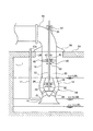
図1は、先行待機運転を行う立軸ポンプを示す模式図である。図1に示すように、立軸ポンプは、吸込ベルマウス10および吐出ボウル12を有するポンプケーシング14と、ポンプケーシング14を水槽1内に吊り下げる揚水管16と、揚水管16の上端に接続された吐出エルボ管18と、ポンプケーシング14内に収容された羽根車20と、羽根車20が固定された回転軸22とを備えている。
FIG. 1 is a schematic diagram showing a vertical shaft pump that performs a preliminary standby operation. As shown in FIG. 1, the vertical shaft pump is connected to a
揚水管16は、水槽1の上部のポンプ据付床24に形成された挿通孔26を通して下方に延びている。ポンプ据付床24にはポンプベース28が固定されており、揚水管16の上端はポンプベース28に接続されている。回転軸22は吐出エルボ管18、揚水管16、およびポンプケーシング14内を通って鉛直方向に延びている。
The pumping
吸込ベルマウス10は下方を向いて開口し、吸込ベルマウス10の上端は吐出ボウル12の下端に固定されている。羽根車20は回転軸22の下端に固定されており、羽根車20と回転軸22とは一体的に回転するようになっている。この羽根車20の上方(吐出側)には複数のガイドベーン(静翼)34が配置されている。これらガイドベーン34は吐出ボウル12の内面に固定されている。
The
吸込ベルマウス10の側面部に貫通孔15が設けられており、この貫通孔15には、外気に接する開口17aを備えた空気管17が取付けられている。これにより、この立軸ポンプでは貫通孔15を介して立軸ポンプ内に供給する空気の供給量を水位に応じて変化させ、最低運転水位LWL以下で立軸ポンプの排水量がコントロールされる。
A through
回転軸22は、吐出エルボ管18に設けられた孔を通って、水槽1の上方まで延びている。回転軸22は、水槽1の上方の位置において、駆動機(図示しない)に接続されている。駆動機は保守点検を容易に行うことができるように陸上に設けられる。駆動機の回転は回転軸22に伝達され、回転軸22に固定された羽根車20が回転する。羽根車20の回転によって流体(例えば液体)は吸込ベルマウス10から吸い込まれ、ポンプケーシング14、揚水管16、および吐出エルボ管18を通って外部に吐出される。
The rotating
先行待機運転の運転状態について説明する。例えば大都市の雨水排水用として、吸込水位に関係なく降雨情報等により予め立軸ポンプを始動しておく(気中運転)。低水位の状態から水位が上昇するに従って、羽根車20の位置まで水位が達し、立軸ポンプは空運転(気中運転)から羽根車20で水を撹拌する運転(気水撹拌運転)を行う。さらに立軸ポンプは貫通孔15を経て供給される空気を水と共に吸い込ませつつ水量を徐々に増やす運転(気水混合運転)を経て100%水の排出を行う全量運転(定常運転)へ移行する。また、高水位から水位が低下するときは、立軸ポンプは全量運転から貫通孔15を経て供給する空気を水と共に吸い込ませつつ水量を徐々に減らす運転(気水混合運転)へ移行する。水位がLLWLの近くに至ると、立軸ポンプは水を吸い込まず排水もしない運転(エアロック運転)へ移行する。これら5つの特徴ある運転を総称して先行待機運転という。なお、ポンプ始動は、吸込ベルマウス10の下端よりも低い水位LLLWLから開始する。
The operating state of the preceding standby operation will be described. For example, for a rainwater drainage in a large city, a vertical shaft pump is started in advance based on rainfall information or the like regardless of the suction water level (air operation). As the water level rises from the low water level, the water level reaches the position of the
立軸ポンプは、揚水管16内に設けられた上側軸受組立体40と、ポンプケーシング14内に設けられた下側軸受組立体36とをさらに備えている。回転軸22は、吐出エルボ管18の上部に設けられた外軸受43と、これら軸受組立体36,40により回転自在に支持されている。本実施形態において、回転軸22は2つの軸受組立体36,40によって支持されているが、軸受組立体36,40の数はこの実施形態に限定されない。軸受組立体の数は回転軸の長さに基づいて決定される。
The vertical shaft pump further includes an
吐出エルボ管18に設けられた孔と回転軸22との間の僅かな隙間には、フローティングシール、グランドパッキン、またはメカニカルシールなどの軸シール35が設けられている。この軸シール35は、立軸ポンプが扱う流体である液体が吐出エルボ管18の外部に流出することを防止している。
A
上側軸受組立体40および下側軸受組立体36は同一の構成を有しているので、以下、上側軸受組立体40について図面を参照しつつ説明し、下側軸受組立体36の説明は省略する。
Since the
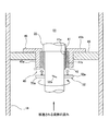
図2は上側軸受組立体40の一実施形態を示す断面図である。上側軸受組立体40は、回転軸22の周囲に配置されたすべり軸受41と、すべり軸受41が固定された金属リング42とを備えている。すべり軸受41および金属リング42は回転軸22の軸方向に沿って延びる円筒形状を有しており、かつ互いに同心状に配置されている。回転軸22は、すべり軸受41によって回転自在に支持されている。
FIG. 2 is a cross-sectional view illustrating one embodiment of the
すべり軸受41は耐熱性の高い樹脂材料から構成されている。すべり軸受41に適用される樹脂材料の例として、PTFE(ポリテトラフルオロエチレン)やPEEK(ポリエーテルエーテルケトン)が挙げられる。金属リング42は、すべり軸受41よりも高い熱伝導率を有する材料から構成されている。一実施形態では、金属リング42は、高い耐久性を有し、かつ高い熱伝導率を有するステンレス鋼から構成されている。
The
上側軸受組立体40は、回転軸22の外周面に固定された円筒状のスリーブ11をさらに備えている。スリーブ11は回転軸22と同心状に配置されており、回転軸22とともに回転する。スリーブ11は、例えば超硬合金から構成されている。一実施形態では、スリーブ11は、タングステンカーバイト系の超硬合金から構成されている。すべり軸受41は、スリーブ11を囲むように配置されている。すべり軸受41の内周面41aとスリーブ11の外周面との間には僅かな隙間が形成されている。すべり軸受41の内周面41aは、スリーブ11の外周面にすべり接触する支持面を構成している。すべり軸受41の外周面41bは金属リング42の内周面に接触している。
The
上側軸受組立体40は、金属リング42を保持する軸受ケース45をさらに備えている。軸受ケース45は、揚水管16に固定された支持部材46に支持されている。軸受ケース45は、例えば鉄などの材料から構成されてもよい。好ましくは、軸受ケース45は、金属リング42と同じ材料、例えば、ステンレス鋼から構成されている。すべり軸受41が固定された金属リング42は軸受ケース45に固定されている。
The
軸受ケース45は、円筒部45aと、円筒部45aから外側に突出するフランジ部45bとを有している。円筒部45aは回転軸22の軸方向に延びている。円筒部45aおよびフランジ部45bは一体的に構成されている。金属リング42の外周面は、円筒部45aの内周面に接触している。
The bearing
立軸ポンプは、すべり軸受41に空気を送るためのファン52を備えている。ファン52は、回転軸22に固定されており、回転軸22と一体に回転する。ファン52は軸流ファンである。ファン52は複数の羽根52aを有しており、これら複数の羽根52aは回転軸22の周方向に沿って等間隔に配置されている。ファン52は、羽根車20の回転によって移送される液体の流れ方向において、上側軸受組立体40の上流側に配置されている。本実施形態では、ファン52は上側軸受組立体40の下方に位置している。
The vertical shaft pump includes a
上述したように、駆動機(図示しない)により回転軸22および羽根車20が回転すると、水槽1内の液体は吸込ベルマウス10から吸い込まれ、ポンプケーシング14、揚水管16、および吐出エルボ管18を通って外部に吐出される。ファン52および上側軸受組立体40(より具体的には、すべり軸受41)は、羽根車20の回転によって移送される液体の流路55(図1および図2参照)内に配置されている。したがって、立軸ポンプ内に吸い込まれた液体は、ファン52および上側軸受組立体40(より具体的には、すべり軸受41)に接触しつつ外部に吐出される。
As described above, when the
流路55は、ポンプケーシング14、揚水管16、および吐出エルボ管18によって形成されている。本実施形態では、上側軸受組立体40は、揚水管16によって形成された流路55内に配置されており、下側軸受組立体36は、ポンプケーシング14によって形成された流路55内に配置されている。
The
ファン52の羽根52aは、ファン52が回転したときに、空気がすべり軸受41に向かって流れる方向に傾斜している。空気の流れ方向は図2の白抜き矢印で示されている。回転するファン52によって形成される空気の流れの方向は、回転する羽根車20によって移送される液体の方向と同じである。待機運転時において、ファン52が回転軸22とともに回転すると、空気の流れはすべり軸受41に接触して、すべり軸受41で発生した熱(摩擦熱)を奪う。したがって、すべり軸受41は冷却され、すべり軸受41が液体のないドライ条件でスリーブ11にすべり接触しても、すべり軸受41の温度上昇を抑制することができる。
The
本実施形態によれば、待機運転時でのすべり軸受41の温度を約10%低減することができる。したがって、すべり軸受41自体の耐久性を向上させることができる。つまり、すべり軸受41の温度上昇を抑制することにより、樹脂材料から構成されたすべり軸受41の劣化を抑制することができる。図1に示すように、下側軸受組立体36のすべり軸受の下方にもファン52が配置されているため、下側軸受組立体36のすべり軸受でも同様の効果が得られる。
According to this embodiment, the temperature of the
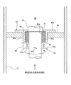
図3は上側軸受組立体40の他の実施形態を示す図である。下側軸受組立体36も上側軸受組立体40と同様の構成を有しているため、その重複する説明を省略する。図3に示すように、上側軸受組立体40は円筒状の弾性リング49をさらに備えている。弾性リング49はゴムなどの弾性材から構成されている。弾性リング49は、すべり軸受41および金属リング42と同心状に配置されている。弾性リング49は、金属リング42と軸受ケース45との間に挟まれている。弾性リング49は、すべり軸受41と同じ軸方向の長さを有しており、軸方向においてすべり軸受41と同じ位置に配置されている。
FIG. 3 is a view showing another embodiment of the
すべり軸受41とスリーブ11との接触により、すべり軸受41にはラジアル荷重が作用する。弾性リング49は、このラジアル荷重を金属リング42から受けたときに弾性変形することができるので、ラジアル荷重に起因するすべり軸受41および金属リング42の損傷を防止することができる。さらに、弾性リング49は、スリーブ11とすべり軸受41との接触に起因する振動を吸収することができる。
A radial load acts on the
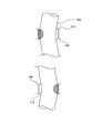
図4は立軸ポンプの他の実施形態を示す図である。ファン52は、羽根車20の回転によって移送される液体の流れ方向において、上側軸受組立体40の下流側に配置されている。本実施形態では、図4に示すように、ファン52は上側軸受組立体40の上方に位置している。
FIG. 4 is a diagram showing another embodiment of the vertical shaft pump. The
本実施形態でも、ファン52の羽根52aは、ファン52が回転したときに、空気がすべり軸受41に向かって流れる方向に傾斜している。空気の流れ方向は図4の白抜き矢印で示されている。回転するファン52によって形成される空気の流れの方向は、回転する羽根車20によって移送される液体の方向とは逆である。待機運転時において、ファン52が回転軸22とともに回転すると、空気の流れはすべり軸受41に接触して、すべり軸受41で発生した熱(摩擦熱)を奪う。したがって、すべり軸受41は冷却され、すべり軸受41が液体のないドライ条件でスリーブ11にすべり接触しても、すべり軸受41の温度上昇を抑制することができる。
Also in this embodiment, the
図3に示す実施形態の要素と図4に示す実施形態の要素とを組み合わせてもよい。つまり、軸受組立体は、金属リングと軸受ケースとの間に配置された弾性リングを備えてもよい。 You may combine the element of embodiment shown in FIG. 3, and the element of embodiment shown in FIG. In other words, the bearing assembly may include an elastic ring disposed between the metal ring and the bearing case.
これまで本発明の実施形態について説明したが、本発明は上述の実施形態に限定されず、その技術思想の範囲内において、種々の異なる形態で実施されてよいことは勿論である。 Although the embodiment of the present invention has been described so far, the present invention is not limited to the above-described embodiment, and it is needless to say that the present invention may be implemented in various different forms within the scope of the technical idea.
1 水槽
10 吸込ベルマウス
11 スリーブ
12 吐出ボウル
14 ポンプケーシング
15 貫通孔
17 空気管
17a 開口
18 吐出エルボ管
20 羽根車
22 回転軸
24 ポンプ据付床
26 挿通孔
28 ポンプベース
34 ガイドベーン
35 軸シール
36 下側軸受組立体
40 上側軸受組立体
41 すべり軸受
41a 内周面
41b 外周面
42 金属リング
43 外軸受
45 軸受ケース
45a 円筒部
45b フランジ部
46 支持部材
49 弾性リング
52 ファン
52a 羽根
55 流路
100 水槽
105 貫通孔
106 空気管
110 吸込ベルマウス
111 スリーブ
120 羽根車
122 回転軸
135,145 すべり軸受
1
Claims (5)
前記羽根車が固定された回転軸と、
前記回転軸を回転自在に支持するすべり軸受と、
前記すべり軸受に空気を送るためのファンとを備え、
前記ファンは、前記回転軸に固定されていることを特徴とする回転機械。 Impeller,
A rotating shaft to which the impeller is fixed;
A plain bearing that rotatably supports the rotating shaft;
A fan for sending air to the plain bearing,
The rotating machine is characterized in that the fan is fixed to the rotating shaft.
Priority Applications (1)
| Application Number | Priority Date | Filing Date | Title |
|---|---|---|---|
| JP2016051134A JP2017166380A (en) | 2016-03-15 | 2016-03-15 | Rotating machine |
Applications Claiming Priority (1)
| Application Number | Priority Date | Filing Date | Title |
|---|---|---|---|
| JP2016051134A JP2017166380A (en) | 2016-03-15 | 2016-03-15 | Rotating machine |
Publications (1)
| Publication Number | Publication Date |
|---|---|
| JP2017166380A true JP2017166380A (en) | 2017-09-21 |
Family
ID=59913048
Family Applications (1)
| Application Number | Title | Priority Date | Filing Date |
|---|---|---|---|
| JP2016051134A Pending JP2017166380A (en) | 2016-03-15 | 2016-03-15 | Rotating machine |
Country Status (1)
| Country | Link |
|---|---|
| JP (1) | JP2017166380A (en) |
Cited By (2)
| Publication number | Priority date | Publication date | Assignee | Title |
|---|---|---|---|---|
| JP2019167829A (en) * | 2018-03-22 | 2019-10-03 | 新菱工業株式会社 | Special rubber supporting bearing for vertical long-sized pump and special rubber damper device for vertical long-sized pump |
| CN113104591A (en) * | 2021-04-06 | 2021-07-13 | 吕明杰 | Powder material pumping machine and pumping method |
-
2016
- 2016-03-15 JP JP2016051134A patent/JP2017166380A/en active Pending
Cited By (3)
| Publication number | Priority date | Publication date | Assignee | Title |
|---|---|---|---|---|
| JP2019167829A (en) * | 2018-03-22 | 2019-10-03 | 新菱工業株式会社 | Special rubber supporting bearing for vertical long-sized pump and special rubber damper device for vertical long-sized pump |
| CN113104591A (en) * | 2021-04-06 | 2021-07-13 | 吕明杰 | Powder material pumping machine and pumping method |
| CN113104591B (en) * | 2021-04-06 | 2022-09-02 | 吕明杰 | Powder material pumping machine and pumping method |
Similar Documents
| Publication | Publication Date | Title |
|---|---|---|
| CN107605793B (en) | Vertical shaft pump | |
| JP2017166380A (en) | Rotating machine | |
| JP2017166590A (en) | Bearing assembly and rotating machine | |
| JP6389657B2 (en) | Slide bearing device | |
| JP2017172660A (en) | Bearing assembly and rotary machine | |
| JP6411902B2 (en) | Vertical shaft pump | |
| JP2017166589A (en) | Bearing assembly and vertical shaft pump | |
| JP6745876B2 (en) | Vertical pump | |
| JP2017061999A (en) | Slide bearing device | |
| JP2016109082A (en) | Impeller and turbomachine | |
| JP6382147B2 (en) | Sliding bearing device and pump equipped with the same | |
| JP7158256B2 (en) | Vertical shaft pump | |
| JP6749393B2 (en) | Vertical pump | |
| JP6488207B2 (en) | Slide bearing device | |
| JP6527805B2 (en) | Sliding bearing device | |
| JP6900410B2 (en) | Vertical pump | |
| CN106574623B (en) | Vertical shaft pump | |
| JP6936060B2 (en) | Vertical pump | |
| JP6936061B2 (en) | Vertical pump | |
| JP7518254B2 (en) | Vertical Pump | |
| JP7688568B2 (en) | pump | |
| CN216077608U (en) | Submerged pump for ship | |
| JP2019044606A (en) | Vertical shaft pump bearing device and vertical shaft pump | |
| JP2020020292A (en) | Preceding standby operation pump | |
| CN101839253A (en) | Vertical two-phase flow submerged pump |