JP2018100800A - Heat exchanger and air conditioner - Google Patents
Heat exchanger and air conditioner Download PDFInfo
- Publication number
- JP2018100800A JP2018100800A JP2016247153A JP2016247153A JP2018100800A JP 2018100800 A JP2018100800 A JP 2018100800A JP 2016247153 A JP2016247153 A JP 2016247153A JP 2016247153 A JP2016247153 A JP 2016247153A JP 2018100800 A JP2018100800 A JP 2018100800A
- Authority
- JP
- Japan
- Prior art keywords
- chamber
- heat transfer
- heat exchanger
- header
- refrigerant
- Prior art date
- Legal status (The legal status is an assumption and is not a legal conclusion. Google has not performed a legal analysis and makes no representation as to the accuracy of the status listed.)
- Pending
Links
Images


Classifications
-
- F—MECHANICAL ENGINEERING; LIGHTING; HEATING; WEAPONS; BLASTING
- F28—HEAT EXCHANGE IN GENERAL
- F28F—DETAILS OF HEAT-EXCHANGE AND HEAT-TRANSFER APPARATUS, OF GENERAL APPLICATION
- F28F9/00—Casings; Header boxes; Auxiliary supports for elements; Auxiliary members within casings
- F28F9/02—Header boxes; End plates
- F28F9/0202—Header boxes having their inner space divided by partitions
- F28F9/0204—Header boxes having their inner space divided by partitions for elongated header box, e.g. with transversal and longitudinal partitions
- F28F9/0214—Header boxes having their inner space divided by partitions for elongated header box, e.g. with transversal and longitudinal partitions having only longitudinal partitions
-
- F—MECHANICAL ENGINEERING; LIGHTING; HEATING; WEAPONS; BLASTING
- F25—REFRIGERATION OR COOLING; COMBINED HEATING AND REFRIGERATION SYSTEMS; HEAT PUMP SYSTEMS; MANUFACTURE OR STORAGE OF ICE; LIQUEFACTION SOLIDIFICATION OF GASES
- F25B—REFRIGERATION MACHINES, PLANTS OR SYSTEMS; COMBINED HEATING AND REFRIGERATION SYSTEMS; HEAT PUMP SYSTEMS
- F25B39/00—Evaporators; Condensers
-
- F—MECHANICAL ENGINEERING; LIGHTING; HEATING; WEAPONS; BLASTING
- F28—HEAT EXCHANGE IN GENERAL
- F28D—HEAT-EXCHANGE APPARATUS, NOT PROVIDED FOR IN ANOTHER SUBCLASS, IN WHICH THE HEAT-EXCHANGE MEDIA DO NOT COME INTO DIRECT CONTACT
- F28D1/00—Heat-exchange apparatus having stationary conduit assemblies for one heat-exchange medium only, the media being in contact with different sides of the conduit wall, in which the other heat-exchange medium is a large body of fluid, e.g. domestic or motor car radiators
- F28D1/02—Heat-exchange apparatus having stationary conduit assemblies for one heat-exchange medium only, the media being in contact with different sides of the conduit wall, in which the other heat-exchange medium is a large body of fluid, e.g. domestic or motor car radiators with heat-exchange conduits immersed in the body of fluid
- F28D1/04—Heat-exchange apparatus having stationary conduit assemblies for one heat-exchange medium only, the media being in contact with different sides of the conduit wall, in which the other heat-exchange medium is a large body of fluid, e.g. domestic or motor car radiators with heat-exchange conduits immersed in the body of fluid with tubular conduits
- F28D1/053—Heat-exchange apparatus having stationary conduit assemblies for one heat-exchange medium only, the media being in contact with different sides of the conduit wall, in which the other heat-exchange medium is a large body of fluid, e.g. domestic or motor car radiators with heat-exchange conduits immersed in the body of fluid with tubular conduits the conduits being straight
- F28D1/0535—Heat-exchange apparatus having stationary conduit assemblies for one heat-exchange medium only, the media being in contact with different sides of the conduit wall, in which the other heat-exchange medium is a large body of fluid, e.g. domestic or motor car radiators with heat-exchange conduits immersed in the body of fluid with tubular conduits the conduits being straight the conduits having a non-circular cross-section
- F28D1/05366—Assemblies of conduits connected to common headers, e.g. core type radiators
- F28D1/05375—Assemblies of conduits connected to common headers, e.g. core type radiators with particular pattern of flow, e.g. change of flow direction
-
- F—MECHANICAL ENGINEERING; LIGHTING; HEATING; WEAPONS; BLASTING
- F28—HEAT EXCHANGE IN GENERAL
- F28F—DETAILS OF HEAT-EXCHANGE AND HEAT-TRANSFER APPARATUS, OF GENERAL APPLICATION
- F28F9/00—Casings; Header boxes; Auxiliary supports for elements; Auxiliary members within casings
- F28F9/02—Header boxes; End plates
- F28F9/0243—Header boxes having a circular cross-section
Landscapes
- Engineering & Computer Science (AREA)
- Physics & Mathematics (AREA)
- Thermal Sciences (AREA)
- Mechanical Engineering (AREA)
- General Engineering & Computer Science (AREA)
- Details Of Heat-Exchange And Heat-Transfer (AREA)
- Heat-Exchange Devices With Radiators And Conduit Assemblies (AREA)
Abstract
Description
本発明は、熱交換器及び空気調和機に関する。 The present invention relates to a heat exchanger and an air conditioner.
空気調和機の熱交換器として、水平方向に延びる伝熱管を上下方向に間隔をあけて複数配置し、各伝熱管の外面にフィンを設けたものが知られている。複数の伝熱管の両端は上下方向に延びる一対のヘッダにそれぞれ接続されている。このような熱交換器では、一方のヘッダに導入されて伝熱管を経て他方のヘッダに流通した冷媒が、該他方のヘッダで折り返すようにして再度伝熱管を経て一方のヘッダに戻るように構成されている。 As a heat exchanger for an air conditioner, there is known a heat exchanger tube in which a plurality of heat transfer tubes extending in the horizontal direction are arranged at intervals in the vertical direction and fins are provided on the outer surface of each heat transfer tube. Both ends of the plurality of heat transfer tubes are respectively connected to a pair of headers extending in the vertical direction. In such a heat exchanger, the refrigerant introduced into one header and circulated through the heat transfer tube to the other header is folded back at the other header so as to return to the one header through the heat transfer tube again. Has been.
折り返し側のヘッダ内には、該ヘッダ内を上下方向に区画する仕切板によって複数の領域が区画形成されている。これによって、ヘッダ内の一の領域内に伝熱管を経て導入された冷媒は、接続管を介してヘッダ内の他の領域に導入された後に、該他の領域に接続された複数の伝熱管を経由して出入口側の一方のヘッダに戻される。
冷媒が折り返しする際、比重の大きい液相冷媒は下方に流れやすく、また比重の小さい気相冷媒は上方に流れやすい。そのため、各伝熱管に流れ込む冷媒に偏流が生じる。
例えば特許文献1には、ヘッダ内を仕切板により伝熱管側空間と反伝熱管側空間とに区分けし、これら空間同士を上部及び下部で連通させることで冷媒の偏流を抑制させることが記載されている。
In the folded-back header, a plurality of regions are defined by partition plates that divide the header in the vertical direction. Thus, the refrigerant introduced into the one area in the header via the heat transfer tube is introduced into the other area in the header via the connection pipe, and then the plurality of heat transfer pipes connected to the other area. Is returned to one header on the entrance / exit side.
When the refrigerant turns, liquid phase refrigerant having a large specific gravity tends to flow downward, and gas phase refrigerant having a small specific gravity tends to flow upward. Therefore, a drift occurs in the refrigerant flowing into each heat transfer tube.
For example, Patent Document 1 describes that the header is divided into a heat transfer tube side space and a counter heat transfer tube side space by a partition plate, and these spaces are communicated with each other at an upper part and a lower part to suppress refrigerant drift. ing.
液相冷媒と気相冷媒との気液分離による冷媒の偏流を抑制したとしても、冷媒がヘッダ内下部から流入しヘッダ内を上昇する際、各伝熱管に流れ込む冷媒流量の差が生じる。そのような状態では熱交換器の伝熱性能を十分に活用することができない。熱交換器の性能低下を抑制するためには、伝熱管に流れ込む冷媒流量は上部から下部のどの伝熱管でも均等化することが好ましい。 Even if the refrigerant drift due to gas-liquid separation between the liquid-phase refrigerant and the gas-phase refrigerant is suppressed, when the refrigerant flows in from the lower part in the header and rises in the header, a difference in the refrigerant flow rate flowing into each heat transfer tube occurs. In such a state, the heat transfer performance of the heat exchanger cannot be fully utilized. In order to suppress the performance deterioration of the heat exchanger, it is preferable that the refrigerant flow rate flowing into the heat transfer tube is equalized in any heat transfer tube from the upper part to the lower part.
本発明はこのような課題に鑑みてなされたものであって、性能低下を抑制することができる熱交換器、及び、該熱交換器を用いた空気調和機を提供することを目的とする。 This invention is made | formed in view of such a subject, Comprising: It aims at providing the heat exchanger which can suppress a performance fall, and the air conditioner using this heat exchanger.
本発明は、上記課題を解決するため、以下の手段を採用している。
即ち、本発明の第一態様の熱交換器は、水平方向に延びて内部に冷媒が流通するとともに、上下方向に間隔をあけて複数が配列された伝熱管と、上下方向に延びる管状をなして複数の前記伝熱管の一端が内部空間に連通状態で接続されたヘッダ部と、前記ヘッダ部内を水平断面視にて、各前記伝熱管と前記ヘッダ部内の内周面とにわたって延びて前記ヘッダ部内を各前記伝熱管とそれぞれ連通する第一室及び第二室とに区画するとともに、前記第一室及び前記第二室を前記伝熱管のうち最も上方の前記伝熱管の高さ以上の位置で互いに連通させる第一連通部を形成している縦仕切板と、前記第一室と前記第二室のうち前記第一室のみに接続されており、内部を冷媒が流通する流通路と、を備える。
The present invention employs the following means in order to solve the above problems.
In other words, the heat exchanger according to the first aspect of the present invention includes a heat transfer tube extending in the horizontal direction and having a refrigerant flowing therein, and a plurality of heat transfer tubes arranged at intervals in the vertical direction, and a tubular shape extending in the vertical direction. And a header portion in which one end of the plurality of heat transfer tubes is connected in communication with an internal space, and the header portion extends over each of the heat transfer tubes and an inner peripheral surface in the header portion in a horizontal sectional view. The inside of the section is divided into a first chamber and a second chamber that communicate with the heat transfer tubes, respectively, and the first chamber and the second chamber are positioned above the height of the uppermost heat transfer tube among the heat transfer tubes. A vertical partition plate that forms a first communication portion that communicates with each other, and a flow passage that is connected to only the first chamber of the first chamber and the second chamber, and through which the refrigerant flows. .
このような熱交換器によれば、熱交換器が蒸発器として用いられる場合、流通路を介してヘッダ部内の第一室に冷媒が導入される。第一室に導入された冷媒の一部は各伝熱管に導入されるが、伝熱管に導入されなかった冷媒は、縦仕切板の上部に形成された第一連通部を介して第二室に導入され、第二室内を下方に移動しながら各伝熱管に導入されることになる。これによって、冷媒流量が少ない場合であっても第一室内を移動する冷媒の流速が下がることを抑制でき、ヘッダ部内の上部や中央部に接続される各伝熱管に導入される冷媒量が確保され、各伝熱管内を流通する冷媒流量のばらつきの発生を抑制できる。また、冷媒流量が多い場合、冷媒が第一室の上部に集中することがあるが、縦仕切板の上部に形成された第一連通部を介して第二室の上部に冷媒が導入され、第二室内を下方に移動しながら各伝熱管に導入されることになるので、冷媒はヘッダ部の上部に集中することなく、ヘッダ部内の下部や中央部に接続される各伝熱管に導入される冷媒量が確保されることになるので、各伝熱管内を流通する冷媒流量のばらつきの発生を抑制できる。 According to such a heat exchanger, when the heat exchanger is used as an evaporator, the refrigerant is introduced into the first chamber in the header portion via the flow passage. A part of the refrigerant introduced into the first chamber is introduced into each heat transfer tube, but the refrigerant that has not been introduced into the heat transfer tube passes through the second series passage formed at the upper part of the vertical partition plate. It introduce | transduces into a room | chamber and introduce | transduces into each heat exchanger tube, moving below a 2nd chamber | room. As a result, even when the refrigerant flow rate is small, the flow rate of the refrigerant moving in the first chamber can be suppressed, and the amount of refrigerant introduced into each heat transfer tube connected to the upper part or the central part in the header part is secured. Thus, it is possible to suppress the occurrence of variations in the flow rate of the refrigerant flowing through each heat transfer tube. In addition, when the flow rate of refrigerant is large, the refrigerant may concentrate on the upper part of the first chamber, but the refrigerant is introduced into the upper part of the second chamber through the first series part formed at the upper part of the vertical partition plate. Since the refrigerant is introduced into each heat transfer tube while moving downward in the second chamber, the refrigerant is introduced into each heat transfer tube connected to the lower part and the central part in the header part without concentrating on the upper part of the header part. As a result, the amount of refrigerant to be ensured is ensured, so that the variation in the flow rate of the refrigerant flowing through each heat transfer tube can be suppressed.
上記熱交換器では、前記第一連通部は、前記縦仕切板に形成された連通孔であってもよい。 In the above heat exchanger, the first series communication portion may be a communication hole formed in the vertical partition plate.
上記熱交換器では、前記第一連通部は、前記縦仕切板と前記ヘッダ部の上端との間の隙間であってもよい。 In the heat exchanger, the first series passage portion may be a gap between the vertical partition plate and the upper end of the header portion.
上記熱交換器では、前記縦仕切板は、上下に隣り合う前記伝熱管の間に、前記第一室及び前記第二室を互いに連通させる第二連通部を形成していてもよい。 In the heat exchanger, the vertical partition plate may form a second communication portion that allows the first chamber and the second chamber to communicate with each other between the vertically adjacent heat transfer tubes.
これによって、熱交換器が凝縮器として用いられる場合、各伝熱管からヘッダ部内の第一室および第二室へと冷媒が導入され、第一室に導入された冷媒は、流通路に導入される。第二室に導入された冷媒は、縦仕切板に形成された第二連通部を介して第一室に導入された後、流通路に導入される。これにより、各伝熱管から第二室へ導入された冷媒が第二室内で溜まり込むことなく、第二連通部を介して第一室へ導入され、流通路に導入することができる。 Thus, when the heat exchanger is used as a condenser, the refrigerant is introduced from each heat transfer tube into the first chamber and the second chamber in the header portion, and the refrigerant introduced into the first chamber is introduced into the flow passage. The The refrigerant introduced into the second chamber is introduced into the first chamber via the second communication portion formed in the vertical partition plate and then introduced into the flow passage. Thereby, the refrigerant introduced into the second chamber from each heat transfer tube can be introduced into the first chamber via the second communication portion without being accumulated in the second chamber and introduced into the flow passage.
上記熱交換器では、前記縦仕切板は、前記第一室と前記第二室とを前記伝熱管のうち最も下方の前記伝熱管よりも下方の位置で互いに連通させる第三連通部を形成していてもよい。 In the heat exchanger, the vertical partition plate forms a third communication portion that communicates the first chamber and the second chamber with each other at a position below the lowest heat transfer tube among the heat transfer tubes. It may be.
これによって、熱交換器が凝縮器として用いられる場合、各伝熱管からヘッダ部内の第一室および第二室へと冷媒が導入され、第一室に導入された冷媒は、流通路に導入される。第二室に導入された冷媒は、第二室内の下方に移動し、縦仕切板に形成された第三連通部を介して第一室に導入された後、流通路に導入される。これにより、各伝熱管から第二室へ導入された冷媒は第二室内で溜まり込むことなく、第二連通部を介して第一室へ導入され、流通路に導入することができる。 Thus, when the heat exchanger is used as a condenser, the refrigerant is introduced from each heat transfer tube into the first chamber and the second chamber in the header portion, and the refrigerant introduced into the first chamber is introduced into the flow passage. The The refrigerant introduced into the second chamber moves downward in the second chamber, is introduced into the first chamber via the third communication portion formed in the vertical partition plate, and is then introduced into the flow passage. Thereby, the refrigerant introduced into the second chamber from each heat transfer tube can be introduced into the first chamber via the second communication portion without being accumulated in the second chamber and introduced into the flow passage.
上記熱交換器では、前記縦仕切板の下部が前記第二室側から前記第一室側に湾曲しており、前記第三連通部は、前記縦仕切板と前記ヘッダ部の下端との間の隙間であってもよい。 In the heat exchanger, a lower portion of the vertical partition plate is curved from the second chamber side to the first chamber side, and the third communication portion is between the vertical partition plate and a lower end of the header portion. It may be a gap.
これによって、熱交換器が凝縮器として用いられる場合、各伝熱管からヘッダ部内の第一室および第二室へと冷媒が導入され、第一室に導入された冷媒は、流通路に導入される。第二室に導入された冷媒は、第二室内の下方に移動し、縦仕切板に形成された第三連通部を介して第一室に導入された後、流通路に導入される。これにより、各伝熱管から第二室へ導入された冷媒は第二室内で溜まり込むことなく、第二連通部を介して第一室へ導入され、流通路に導入することができる。さらに、縦仕切板の下部が第二室側へ湾曲されていることで、この湾曲形状が冷媒の流れをガイドすることになり、冷媒が第二室から第一室へ導入されやすくなる。 Thus, when the heat exchanger is used as a condenser, the refrigerant is introduced from each heat transfer tube into the first chamber and the second chamber in the header portion, and the refrigerant introduced into the first chamber is introduced into the flow passage. The The refrigerant introduced into the second chamber moves downward in the second chamber, is introduced into the first chamber via the third communication portion formed in the vertical partition plate, and is then introduced into the flow passage. Thereby, the refrigerant introduced into the second chamber from each heat transfer tube can be introduced into the first chamber via the second communication portion without being accumulated in the second chamber and introduced into the flow passage. Furthermore, since the lower part of the vertical partition plate is curved toward the second chamber, the curved shape guides the flow of the refrigerant, and the refrigerant is easily introduced from the second chamber into the first chamber.
上記熱交換器では、前記伝熱管の延在方向における該伝熱管の前記ヘッダ部内での長さLpは、前記ヘッダ部の内径Diの半分以下であってもよい。 In the heat exchanger, a length Lp in the header portion of the heat transfer tube in the extending direction of the heat transfer tube may be less than or equal to half of the inner diameter Di of the header portion.
これによって、熱交換器が蒸発器として用いられる場合、
伝熱管におけるヘッダ部内の長さが短いため、流通路から第一室および第一室から第二室へ導入された気液二相状態の冷媒が第一室および第二室内の各伝熱管の上下間に溜まり込むことによる冷媒の流れの乱れを抑制することができ、液相冷媒が各伝熱管へ導入されやすくなる。これによりさらに各伝熱管内を流通する冷媒流量のばらつきの発生を抑制できる。
Thereby, when the heat exchanger is used as an evaporator,
Since the length in the header portion of the heat transfer tube is short, the refrigerant in the gas-liquid two-phase state introduced from the flow passage to the first chamber and the first chamber to the second chamber passes through the heat transfer tubes in the first chamber and the second chamber. Disturbances in the refrigerant flow due to accumulation between the upper and lower sides can be suppressed, and the liquid-phase refrigerant is easily introduced into each heat transfer tube. This further suppresses the occurrence of variations in the flow rate of the refrigerant flowing through each heat transfer tube.
本発明の第二態様に係る空気調和機は、上記いずれかの熱交換器を備える。
これによって、各伝熱管を流通する冷媒流量のばらつきの発生を抑制でき、冷房及び暖房性能の低下を回避することができる。
The air conditioner according to the second aspect of the present invention includes any one of the above heat exchangers.
As a result, it is possible to suppress the occurrence of variations in the flow rate of the refrigerant flowing through each heat transfer tube, and to avoid a decrease in cooling and heating performance.
本発明の熱交換器及び空気調和機によれば、複数の伝熱管を流通する冷媒流量の不均一化による性能低下を抑制することができる。 According to the heat exchanger and the air conditioner of the present invention, it is possible to suppress the performance degradation due to the non-uniform refrigerant flow rate flowing through the plurality of heat transfer tubes.
以下、本発明の第一実施形態に係る熱交換器10を備えた空気調和機1について図1〜4を参照して説明する。
図1に示すように、空気調和機1は、圧縮機2、室内熱交換器3(熱交換器10)、膨張弁4、室外熱交換器5(熱交換器10)、四方弁6、及び、これらを接続する配管7を備えており、これらからなる冷媒回路を構成している。
Hereinafter, the air conditioner 1 provided with the
As shown in FIG. 1, the air conditioner 1 includes a
圧縮機2は、冷媒を圧縮し、圧縮した冷媒を冷媒回路に供給する。
室内熱交換器3は、冷媒と室内の空気との間で熱交換を行う。室内熱交換器3は、冷房運転時には蒸発器として用いられ室内から吸熱し、暖房運転時には凝縮器として用いられ室内へ放熱する。室外熱交換器5は、冷媒と室外の空気との間で熱交換を行う。
膨張弁4は、凝縮器で熱交換をすることで液化した高圧の冷媒を膨張させることで低圧化する。
室外熱交換器5は、冷房運転時には、凝縮器として用いられ室外へ放熱し、暖房運転時には、蒸発器として用いられ室外から吸熱する。
四方弁6は、暖房運転時と冷房運転時とで冷媒の流通する方向を切り替える。これにより、冷房運転時には、冷媒が、圧縮機2、室外熱交換器5、膨張弁4及び室内熱交換器3の順に循環する。一方、暖房運転時には、冷媒が、圧縮機2、室内熱交換器3、膨張弁4及び室外熱交換器5、の順に循環する。
The
The
The
The
The four-
次に、上記室内熱交換器3及び室外熱交換器5として用いられる熱交換器10について、図2〜図4について説明する。
図2に示すように、熱交換器10は、複数の伝熱管20、複数のフィン23、一対のヘッダ30及び接続管55を備える。
Next, the
As shown in FIG. 2, the
伝熱管20は、水平方向に直線状に延びる管状の部材であって、内部に冷媒が流通する流路が形成されている。このような伝熱管20は、上下方向に間隔をあけて複数が配列されており、互いに平行に配置されている。
本実施形態では、各伝熱管20は扁平管状をなしており、伝熱管20の内部には、該伝熱管20の延在方向に直交する水平方向に並設された複数の流路が形成されている。これら複数の流路は互いに平行に配列されている。これにより、伝熱管20の延在方向に直交する断面の外形は、伝熱管20の延在方向に直交する水平方向を長手方向とした扁平状とされている。
The
In this embodiment, each
フィン23は、上記のように配列された伝熱管20の間にそれぞれ配置されており、本実施形態では、各伝熱管20の延在方向に向かうにしたがって上下に隣り合う伝熱管20に交互に接触するように延びるいわゆるコルゲート状に延びている。なお、フィン23の形状はこれに限定されることはなく、伝熱管20の外周面から張り出すように設けられていれば、いかなる形状であってもよい。
The
一対のヘッダ30は、上記複数の伝熱管20の両端にこれら伝熱管20を挟み込むように設けられている。これら一対のヘッダ30の一方は、外部から熱交換器10内への冷媒の出入り口となる出入口側ヘッダ40とされており、他方は、熱交換器10内で冷媒が折り返すための折り返し側ヘッダ50とされている。
The pair of
出入口側ヘッダ40は、上下方向に延びる筒状の部材であって、上端及び下端が閉塞されるとともに内部が仕切板によって上下二つの領域に区画されている。出入側仕切板41によって区画された下方の領域は下部出入領域42とされ、上方の領域は上部出入領域43とされている。これら下部出入領域42と上部出入領域43とは出入口側ヘッダ40内で互いに非連通状態とされている。これら下部出入領域42及び上部出入領域43は、冷媒回路を構成する配管7がそれぞれ接続されている。
ここで、複数の伝熱管20のうち、下部出入領域42と連通状態で接続されている伝熱管20は、第一伝熱管21とされており、上部出入領域43と連通状態で接続されている伝熱管20は、第二伝熱管22(伝熱管20)とされている。
The entrance /
Here, among the plurality of
折り返し側ヘッダ50は、ヘッダ本体51、折り返し側仕切板54及び縦仕切板70を備えている。
ヘッダ本体51は、上下方向に延びる筒状をなす部材であって、上端及び下端が閉塞されている。折り返し側仕切板54は、ヘッダ本体51内に設けられ、該ヘッダ本体51内の空間を上下二つの領域に区画している。ヘッダ本体51の折り返し側仕切板54の下方の部分は第一ヘッダ部52とされており、ヘッダ本体51の折り返し側仕切板54の上方の部分は第二ヘッダ部53(ヘッダ部)とされている。即ち、本実施形態では、ヘッダ本体51内が折り返し側仕切板54によって区画されることで、折り返し側ヘッダ50に、それぞれ内部に空間を有する第一ヘッダ部52及び第二ヘッダ部53が形成されている。換言すれば、第一ヘッダ部52及び第二ヘッダ部53によって折り返し側ヘッダ50が構成されている。
The folded-
The header
上記第一伝熱管21は、それぞれ第一ヘッダ部52内と連通状態となるように該第一ヘッダ部52に水平方向一方側から接続されている。また、上記第二伝熱管22は、それぞれ第二ヘッダ部53内と連通状態となるように水平方向一方側から該第二ヘッダ部53に接続されている。換言すれば、第一ヘッダ部52に接続されている伝熱管20が第一伝熱管21とされ、第二ヘッダ部53に接続されている伝熱管20が第二伝熱管22とされている。
The first
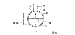
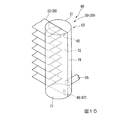
図3に示すように、縦仕切板70は、上下方向に延びる板状の部材であって、第二ヘッダ部53内に設けられている。縦仕切板70は、第二ヘッダ部53内の空間を水平断面視にて、それぞれが各第二伝熱管22と連通するよう第一室76と第二室77との二つの領域に区画している。具体的には、縦仕切板70は、水平断面視にて第二伝熱管22が延びる方向に設置される。縦仕切板70は、第二ヘッダ部53内で水平方向にわたって延びている。これによって本実施形態では、上下に隣り合う第二伝熱管22の間でも縦仕切板70によって第一室76及び第二室77とが隔てられている各第二伝熱管が前記第二ヘッダ部53内に突出した部分では、縦仕切板70の水平方向の両端のうちの第二伝熱管側の一端は、第二伝熱管に接触している。各第二伝熱管22の開口部は、縦仕切板の一端によって第二伝熱管22の延在方向に直交する水平方向に分割されている。
As shown in FIG. 3, the
接続管55は、内部に流路が形成された管状の部材であって、その一端が第一ヘッダ部52に対して該第一ヘッダ部52の内部と連通状態で接続されており、他端が第二ヘッダ部53に対して該第二ヘッダ部53の内部と連通状態で接続されている。より詳細には、接続管55の一端は、第一ヘッダ部52における上下方向の中央部に接続されている。一方で、接続管55の他端は、第二ヘッダ部53の第一室76における下部に接続されている。
この接続管55の内側に形成された流路が、第一ヘッダ部52内と第二ヘッダ部53内との間で冷媒の流通を可能とする流通路56とされている。
なお、接続管55を用いず、折り返し側仕切板54に第一ヘッダ部52内と第一室76とを直接連通するよう流通路56を形成してもよい。
The connecting
A flow path formed inside the
Instead of using the connecting
本実施形態では、ヘッダ30は上下方向に延びる円筒形状をなしており、これにともなって内部空間も円筒状をなしている。そして、縦仕切板70は、円筒状をなす第二ヘッダ部53の内部空間の水平断面視における直径方向に沿うようにして配置されている。これによって、第一室76及び第二室77はそれぞれ水平断面視が半円形状をなしている。
In the present embodiment, the
縦仕切板70には、該縦仕切板70を貫通することで第一室76と第二室77とを連通させる上部連通孔62(第一連通部61)が形成されている。上部連通孔62は、詳しくは図5に示すように、各第二伝熱管22のうち最も上方に位置する伝熱管である第二ヘッダ部最上部伝熱管24の高さと同一又はこれよりも高い位置に形成されている。上部連通孔62は、水平断面視にて、第二伝熱管22の先端よりも先の位置、すなわち第二ヘッダ部53と第二伝熱管22との接続部とは反対側に形成されている。
The
次に上記熱交換器10が蒸発器として用いられる場合の作用・効果について説明する。
なお、熱交換器10が室内熱交換器3の場合は空気調和機1の冷房運転時に蒸発器として用いられることになり、室外熱交換器5の場合には空気調和機1の暖房運転時に蒸発器として用いられることになる。
Next, operations and effects when the
When the
熱交換器10が蒸発器として用いられる際には、図2に示す出入口側ヘッダ40の下部出入領域42に配管7から液相分の多い気液二相冷媒が供給される。この冷媒は、下部出入領域42で複数の第一伝熱管21内に分配供給され、第一伝熱管21を流通する過程で該第一伝熱管21の外部雰囲気との間で熱交換することで蒸発が促される。これにより、第一伝熱管21から折り返し側ヘッダ50の第一ヘッダ部52内に供給される冷媒は、一部が液相から気相に変化したことで液相割合が減少した気液二相冷媒となる。
When the
そして、図2及び図3に示すように、第一ヘッダ部52内に供給される気液二相状態の冷媒は、該第一ヘッダ部52に接続された接続管55内に導入され、該接続管55を介して該第二ヘッダ部53内の第一室76に導入される。
第一室76に導入された冷媒は、冷媒が供給され続けるにしたがって順次第一室76内を上方に移動し各第二伝熱管22に導入される。第二伝熱管22に導入されなかった冷媒は、縦仕切板70の上部に形成された上部連通孔62を介して第二室77の上部に導入され、第二室77の上部に導入された冷媒は、第二室77内を下方に移動しながら各第二伝熱管22に導入される。
As shown in FIGS. 2 and 3, the gas-liquid two-phase refrigerant supplied into the
The refrigerant introduced into the
ここで、第二ヘッダ部53を縦仕切板70により第一室76と第二室77とに区分けしているため、第一室76の冷媒流路の断面積は第二ヘッダ部53全体としての断面積よりも小さくなっている。このため、冷媒流量が少ない場合であっても第一室76内を上方に移動する冷媒の流速が下がることを抑制でき、第二ヘッダ部53内の上部や中央部に接続される各第二伝熱管22に導入される冷媒量が確保され、各第二伝熱管22内を流通する冷媒流量のばらつきの発生を抑制できる。また、冷媒流量が著しく多い場合は、冷媒が第一室76の上部に集中することがあるが、縦仕切板70の上部に形成された上部連通孔62を介して第二室77の上部に冷媒が導入され、第二室77内を下方に移動しながら各第二伝熱管22に導入されることになるので、冷媒は第二ヘッダ部53の上部に集中することなく、第二ヘッダ部53内の下部や中央部に接続される各第二伝熱管22に導入される冷媒量が確保されることになり、やはり各第二伝熱管22内を流通する冷媒流量のばらつきの発生を抑制できる。
Here, since the
その後、冷媒は、第二伝熱管22を流通する過程で該第二伝熱管22の外部雰囲気との間で熱交換することで、再度蒸発が促される。
これにより、第二伝熱管22内にて、冷媒における残存していた液相が気相に変化し、出入口側ヘッダ40の上部出入領域43には気相状態の冷媒が供給される。そして、この冷媒は上部出入領域43から配管7に導入され、冷媒回路を循環することになる。
Thereafter, the refrigerant is urged to evaporate again by exchanging heat with the external atmosphere of the second
As a result, the liquid phase remaining in the refrigerant changes into a gas phase in the second
以上のように、本実施形態の熱交換器10によれば、第二ヘッダ部53に供給された冷媒は、冷媒流量が少ない場合であっても多い場合であっても各第二伝熱管22に導入される冷媒量のばらつきの発生を抑制でき、伝熱管に流れ込む冷媒流量の偏りによる熱交換器の性能低下を抑制することができる。その結果、本実施形態の熱交換器10を用いた空気調和機では、冷房性能や暖房性能が損なわれることはない。
As described above, according to the
なお、第一実施形態の変形例として、縦仕切板70に上部連通孔62を形成するのではなく、例えば図6、図7及び図8に示すように、縦仕切板70の高さを第二ヘッダ部最上部伝熱管24と同じ高さ又は第二ヘッダ部最上部伝熱管24から第二ヘッダ部53の上端までの間の高さとしてもよい。この場合、縦仕切板70と第二ヘッダ部53との間には隙間が形成され、当該隙間が第一室76と第二室77とを連通させる上部連通部63(第一連通部61)となる。
これによっても、第一室76に導入された冷媒は、冷媒が供給され続けるにしたがって順次第一室76内を上方に移動し各第二伝熱管22に導入され、第一室76から各第二伝熱管22に導入されなかった冷媒は、縦仕切板70の上部に形成された上部連通部63を介して第二室77の上部に冷媒が導入され、第二室内を下方に移動しながら各第二伝熱管22に導入されることになるので、上記同様に各第二伝熱管22に導入される冷媒量のばらつきの発生を抑制できる。
As a modification of the first embodiment, instead of forming the
Also in this way, the refrigerant introduced into the
次に本発明の第二実施形態に係る熱交換器80について、図9、図10及び図11を参照して説明する。なお、第二実施形態では、第一実施形態と同様の構成要素については、該第一実施形態同一の符号を付して詳細な説明を省略する。
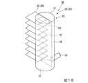
図9、図10及び図11に示すように、第二実施形態の熱交換器80の縦仕切板71は、第一実施形態と同様に、円筒状をなす第二ヘッダ部53の内部空間の水平断面視における直径方向に沿うようにして配置されている。縦仕切板71は、第一実施形態と同様の上部連通孔62が形成されている。一方、本実施形態では、さらに縦仕切板71の水平方向の長さは、伝熱管22の先端位置から第二ヘッダ部53の内周面までとされている。第二ヘッダ部53内における各伝熱管22の上下の部分には縦仕切板71がなく、これによって第一室76と第二室77とを連通させる伝熱管側連通部65(第二連通部64)が形成されている。
Next, the
As shown in FIGS. 9, 10, and 11, the
次に上記熱交換器80が凝縮器として用いられる場合の作用・効果について説明する。空気調和機1の冷房運転時に熱交換器80が凝縮器として作動する際、蒸発器として用いられる場合とは逆に、各第二伝熱管22から第二ヘッダ部53内の第一室76および第二室77へと冷媒が導入される。第一室76に導入された冷媒は、第一室76内の下方へ移動し、接続管55を介して第一ヘッダ部52に導入される。第二室77に導入された冷媒は、縦仕切板71に形成された伝熱管側連通部65を介して第一室76に導入された後、接続管55を介して第一ヘッダ部52に導入される。
Next, operations and effects when the
以上のように、本実施形態の熱交換器80によれば、蒸発器として作動する場合は第一実施形態と同様であるが、さらに凝縮器として作動する場合、各第二伝熱管22から第二室77へ導入された冷媒が第二室77内で溜まり込むことなく、縦仕切板71に形成された伝熱管側連通部65を介して第一室76へ導入され、第一室76の下部に接続された接続管55を介して第一ヘッダ部に導入することができる。その結果、本実施形態の熱交換器80を用いた空気調和機では、冷房性能や暖房性能が損なわれることはない。
As described above, according to the
なお、第二実施形態の変形例として、縦仕切板71の水平方向の長さは、第一実施形態と同様であるが、例えば図12、図13及び図14に示すように、縦仕切板71における各第二伝熱管22の上下に相当する部分に伝熱管側連通孔66(第二連通部64)を形成し、第一室76と第二室77とを連通させてもよい。これによっても、各第二伝熱管22から第二室77へと導入された冷媒が第二室77内で溜まり込むことなく、縦仕切板71に形成された伝熱管側連通孔66を介して第一室76へ導入され、第一室76の下部に接続された接続管55を介して第一ヘッダ部に導入することができる。その結果、本実施形態の熱交換器80を用いた空気調和機では、冷房性能や暖房性能が損なわれることはない。
As a modification of the second embodiment, the length of the
次に本発明の第三実施形態に係る熱交換器90について、図15、図16及び図17を参照して説明する。なお、第三実施形態では、第一実施形態と同様の構成要素については、該第一実施形態同一の符号を付して詳細な説明を省略する。
図15、図16及び図17に示すように、第三実施形態の熱交換器90の縦仕切板72は、第一実施形態と同様に、円筒状をなす第二ヘッダ部53の内部空間の水平断面視における直径方向に沿うようにして配置され、第一実施形態同様の上部連通孔62が形成されている。本実施形態では、さらに縦仕切板72は、各第二伝熱管22中の最下部に位置する伝熱管である第二ヘッダ部最下部伝熱管25よりも下方の位置で第一室76と第二室77とを連通させる下部連通孔68(第三連通部67)が形成されている。また、下部連通孔68は、水平断面視にて、第二伝熱管22の先端よりも先の位置、即ち、第二ヘッダ部53と第二伝熱管22との接続部とは反対側に形成される。
Next, the
As shown in FIGS. 15, 16, and 17, the
次に上記熱交換器90が凝縮器として用いられる場合の作用・効果について説明する。空気調和機1の冷房運転時に熱交換器90が凝縮器として作動する際、蒸発器として用いられる場合とは逆に、各第二伝熱管22から第二ヘッダ部53内の第一室76および第二室77へと冷媒が導入される。第一室76に導入された冷媒は、第一室76内の下方へ移動し、接続管55を介して第一ヘッダ部52に導入される。第二室77内に導入された冷媒は、第二室77内の下方に移動し、その後、縦仕切板72に形成された下部連通孔68を介して第一室76に導入された後、接続管55を介して該第一ヘッダ部52に導入される。
Next, operations and effects when the
以上のように、本実施形態の熱交換器90によれば、蒸発器として作動する場合は第一実施形態と同様であるが、さらに凝縮器として作動する場合、各第二伝熱管22から第二室77へ導入された冷媒が第二室77内で溜まり込むことなく、縦仕切板72に形成された下部連通孔68を介して第一室76へ導入され、第一室76の下部に接続された接続管55を介して第一ヘッダ部に導入することができる。その結果、本実施形態の熱交換器90を用いた空気調和機では、冷房性能や暖房性能が損なわれることはない。
As described above, according to the
なお、第三実施形態の変形例として、例えば図18、図19及び図20に示すように、縦仕切板72の下部を第一室76側へ湾曲させ、第二ヘッダ部最下部伝熱管25よりも下方に第一室76と第二室77とを連通させる下部連通部69(第三連通部67)を形成させてもよい。この場合、下部連通部69は縦仕切板72の下端と第二ヘッダ部53の下端との間の隙間として形成されている。これによっても、各第二伝熱管22から第二室77へと導入された冷媒が第二室77内で溜まり込むことなく、縦仕切板72に形成された下部連通部69を介して第一室76へ導入され、第一室76の下部に接続された接続管55を介して第一ヘッダ部に導入することができる。また、縦仕切板72の下部を第二室77側へ湾曲させていることで、湾曲形状が冷媒の流れをガイドすることになり、冷媒が第二室77から第一室76へ導入されやすくなる。その結果、本実施形態の熱交換器90を用いた空気調和機では、冷房性能や暖房性能が損なわれることはない。
なお、第三実施形態では第二実施形態で説明した第二連通部64を設けてもよい。
As a modification of the third embodiment, for example, as shown in FIGS. 18, 19, and 20, the lower part of the
In the third embodiment, the
次に本発明の第四実施形態に係る熱交換器100について、図21を参照して説明する。第四実施形態では、縦仕切板は第一実施形態から第三実施形態のいずれかと同様の構成である。本実施形態では第一実施形態の縦仕切板70と同様の構成として説明する。第一実施形態と同様の構成要素については、該第一実施形態同一の符号を付して詳細な説明を省略する。
第四実施形態の熱交換器100は、図21に示すように、第二伝熱管22の延在方向における第二伝熱管22の第二ヘッダ部53内の長さLpが、第二ヘッダ部53の内径Diの半分以下とされている。すなわち、第二伝熱管22の先端位置は、第二ヘッダ部53の中心位置と同じ又は第二ヘッダ部53の中心よりも第二ヘッダ部53と第二伝熱管22との接続部側とされている。
このような熱交換器100によれば、蒸発器として作動する場合、第二伝熱管22における第二ヘッダ部53内の長さが短いため、接続管55から第一室76および第一室76から上部連通孔62を介して第二室77へ導入された気液二相状態の冷媒が第一室76および第二室77内の各第二伝熱管22の上下間に溜まり込むことによる冷媒の流れの乱れを抑制することができ、液相冷媒が各第二伝熱管へ導入されやすくなる。これによりさらに各第二伝熱管22内を流通する冷媒流量のばらつきの発生を抑制できる。
これにより、各第二伝熱管22内にて、冷媒における残存していた液相が気相に変化し、出入口側ヘッダ40の上部出入領域43には気相状態の冷媒が供給される。そして、この冷媒は上部出入領域43から配管7に導入され、冷媒回路を循環することになる。
Next, the heat exchanger 100 which concerns on 4th embodiment of this invention is demonstrated with reference to FIG. In the fourth embodiment, the vertical partition plate has the same configuration as that of any one of the first to third embodiments. This embodiment demonstrates as a structure similar to the
In the heat exchanger 100 of the fourth embodiment, as shown in FIG. 21, the length Lp in the
According to such a heat exchanger 100, when operating as an evaporator, since the length in the
As a result, the liquid phase remaining in the refrigerant changes into a gas phase in each second
以上、本発明の実施の形態について説明したが、本発明はこれに限定されることなく、その発明の技術的思想を逸脱しない範囲で適宜変更可能である。 The embodiment of the present invention has been described above, but the present invention is not limited to this, and can be appropriately changed without departing from the technical idea of the present invention.
1 空気調和機
2 圧縮機
3 室内熱交換器
4 膨張弁
5 室外熱交換器
6 四方弁
7 配管
10 熱交換器
20 伝熱管
21 第一伝熱管
22 第二伝熱管
23 フィン
24 第二ヘッダ部最上部伝熱管
25 第二ヘッダ部最下部伝熱管
30 ヘッダ
40 出入口側ヘッダ
41 出入側仕切板
42 下部出入領域
43 上部出入領域
50 折り返し側ヘッダ
51 ヘッダ本体
52 第一ヘッダ部
53 第二ヘッダ部
54 折り返し側仕切板
55 接続管
56 流通路
61 第一連通部
62 上部連通孔
63 上部連通部
64 第二連通部
65 伝熱管側連通部
66 伝熱管側連通孔
1 Air conditioner
2 Compressor
3 Indoor heat exchanger
4 Expansion valve
5 Outdoor heat exchanger
6 Four-way valve
7 Piping
10 Heat exchanger
20 Heat transfer tube
21 1st heat transfer tube
22 Second heat transfer tube
23 Fin
24 Second header section uppermost
40 Entrance / exit header
41 Entrance / exit partition plate
42 Lower access area
43 Upper access area
50 Return header
51 Header body
52 First header
53 Second header section
54 Folding side divider
55 Connection pipe
56 Passage
61 Series 1
62 Upper communication hole
63 Upper communication part
64 Second communication part
65 Heat transfer tube side communication part
66 Heat transfer tube side communication hole
Claims (8)
上下方向に延びる管状をなして複数の前記伝熱管の一端が内部空間に連通状態で接続されたヘッダ部と、
前記ヘッダ部内を水平断面視にて、各前記伝熱管と前記ヘッダ部内の内周面とにわたって延びて前記ヘッダ部内を各前記伝熱管とそれぞれ連通する第一室及び第二室とに区画するとともに、前記第一室及び前記第二室を前記伝熱管のうち最も上方の前記伝熱管の高さ以上の位置で互いに連通させる第一連通部を形成している縦仕切板と、
前記第一室と前記第二室のうち前記第一室のみに接続されており、内部を冷媒が流通する流通路と、
を備える熱交換器。 A refrigerant pipe that extends in the horizontal direction and circulates inside, and a plurality of heat transfer tubes that are arranged at intervals in the vertical direction;
A header portion which is formed in a tubular shape extending in the vertical direction, and one end of the plurality of heat transfer tubes is connected in communication with the internal space;
The header section is divided into a first chamber and a second chamber extending in a horizontal sectional view across the heat transfer tubes and an inner peripheral surface of the header portion and communicating with the heat transfer tubes. A vertical partition plate that forms a first communicating portion that allows the first chamber and the second chamber to communicate with each other at a position equal to or higher than the height of the uppermost heat transfer tube among the heat transfer tubes;
Of the first chamber and the second chamber, connected to only the first chamber, a flow passage through which the refrigerant flows,
A heat exchanger.
前記第三連通部は、前記縦仕切板と前記ヘッダ部の下端との間の隙間である請求項5に記載の熱交換器。 The lower part of the vertical partition plate is curved from the second chamber side to the first chamber side,
The heat exchanger according to claim 5, wherein the third communication part is a gap between the vertical partition plate and a lower end of the header part.
An air conditioner comprising the heat exchanger according to any one of claims 1 to 7.
Priority Applications (3)
| Application Number | Priority Date | Filing Date | Title |
|---|---|---|---|
| JP2016247153A JP2018100800A (en) | 2016-12-20 | 2016-12-20 | Heat exchanger and air conditioner |
| EP17883828.0A EP3473963A4 (en) | 2016-12-20 | 2017-12-13 | Heat exchanger and air conditioner |
| PCT/JP2017/044694 WO2018116929A1 (en) | 2016-12-20 | 2017-12-13 | Heat exchanger and air conditioner |
Applications Claiming Priority (1)
| Application Number | Priority Date | Filing Date | Title |
|---|---|---|---|
| JP2016247153A JP2018100800A (en) | 2016-12-20 | 2016-12-20 | Heat exchanger and air conditioner |
Publications (1)
| Publication Number | Publication Date |
|---|---|
| JP2018100800A true JP2018100800A (en) | 2018-06-28 |
Family
ID=62627706
Family Applications (1)
| Application Number | Title | Priority Date | Filing Date |
|---|---|---|---|
| JP2016247153A Pending JP2018100800A (en) | 2016-12-20 | 2016-12-20 | Heat exchanger and air conditioner |
Country Status (3)
| Country | Link |
|---|---|
| EP (1) | EP3473963A4 (en) |
| JP (1) | JP2018100800A (en) |
| WO (1) | WO2018116929A1 (en) |
Cited By (4)
| Publication number | Priority date | Publication date | Assignee | Title |
|---|---|---|---|---|
| JP2021148389A (en) * | 2020-03-23 | 2021-09-27 | 株式会社富士通ゼネラル | Heat exchanger |
| JP2021148388A (en) * | 2020-03-23 | 2021-09-27 | 株式会社富士通ゼネラル | Heat exchanger |
| WO2022030376A1 (en) | 2020-08-03 | 2022-02-10 | 株式会社富士通ゼネラル | Heat exchanger |
| JP2023515380A (en) * | 2020-02-19 | 2023-04-13 | ハンオン システムズ | Heat exchanger with flow distribution tank structure for distributing thermal stress |
Families Citing this family (3)
| Publication number | Priority date | Publication date | Assignee | Title |
|---|---|---|---|---|
| EP3922941A4 (en) * | 2019-02-04 | 2022-02-16 | Mitsubishi Electric Corporation | Heat exchanger and air-conditioner provided with same |
| WO2021149223A1 (en) * | 2020-01-23 | 2021-07-29 | 三菱電機株式会社 | Heat exchanger and refrigeration cycle apparatus |
| WO2021192192A1 (en) * | 2020-03-27 | 2021-09-30 | 三菱電機株式会社 | Heat exchanger, heat exchanger unit, and refrigeration cycle device |
Family Cites Families (13)
| Publication number | Priority date | Publication date | Assignee | Title |
|---|---|---|---|---|
| JPH0435742Y2 (en) * | 1986-11-10 | 1992-08-24 | ||
| JP3454518B2 (en) * | 1990-07-20 | 2003-10-06 | サンデン株式会社 | Heat exchanger |
| JPH06300477A (en) * | 1993-04-12 | 1994-10-28 | Matsushita Refrig Co Ltd | Heat exchanger |
| JP2002139293A (en) * | 2000-10-31 | 2002-05-17 | Mitsubishi Heavy Ind Ltd | Heat exchanger |
| DE10056074B4 (en) * | 2000-11-07 | 2017-03-23 | Mahle International Gmbh | Heat exchanger |
| JP4143955B2 (en) * | 2001-11-30 | 2008-09-03 | 株式会社ティラド | Heat exchanger |
| DE10226753A1 (en) * | 2002-06-14 | 2004-01-08 | Behr Gmbh & Co. | heat exchangers |
| JP2005337669A (en) * | 2004-05-31 | 2005-12-08 | Mitsubishi Heavy Ind Ltd | Heat exchanger |
| DE102006036742A1 (en) * | 2006-08-05 | 2008-02-14 | Modine Manufacturing Co., Racine | Heat exchanger e.g. refrigerant cooler, for use in motor vehicle, has pipe body connected with collecting box, which has contour when box is seen in transverse direction, and another contour corresponding with former contour |
| JP5046771B2 (en) * | 2007-07-27 | 2012-10-10 | 三菱重工業株式会社 | Refrigerant evaporator |
| JP5097472B2 (en) * | 2007-08-10 | 2012-12-12 | Gac株式会社 | Heat exchanger |
| US8353330B2 (en) * | 2007-11-02 | 2013-01-15 | Halla Climate Control Corp. | Heat exchanger |
| JP5754490B2 (en) * | 2013-09-30 | 2015-07-29 | ダイキン工業株式会社 | Heat exchanger and air conditioner |
-
2016
- 2016-12-20 JP JP2016247153A patent/JP2018100800A/en active Pending
-
2017
- 2017-12-13 EP EP17883828.0A patent/EP3473963A4/en not_active Withdrawn
- 2017-12-13 WO PCT/JP2017/044694 patent/WO2018116929A1/en unknown
Cited By (10)
| Publication number | Priority date | Publication date | Assignee | Title |
|---|---|---|---|---|
| JP2023515380A (en) * | 2020-02-19 | 2023-04-13 | ハンオン システムズ | Heat exchanger with flow distribution tank structure for distributing thermal stress |
| JP7445774B2 (en) | 2020-02-19 | 2024-03-07 | ハンオン システムズ | Heat exchanger with flow distribution tank structure to disperse thermal stress |
| JP2021148389A (en) * | 2020-03-23 | 2021-09-27 | 株式会社富士通ゼネラル | Heat exchanger |
| JP2021148388A (en) * | 2020-03-23 | 2021-09-27 | 株式会社富士通ゼネラル | Heat exchanger |
| WO2021192903A1 (en) | 2020-03-23 | 2021-09-30 | 株式会社富士通ゼネラル | Heat exchanger |
| WO2021192902A1 (en) | 2020-03-23 | 2021-09-30 | 株式会社富士通ゼネラル | Heat exchanger |
| US20230108901A1 (en) * | 2020-03-23 | 2023-04-06 | Fujitsu General Limited | Heat exchanger |
| AU2021242930B2 (en) * | 2020-03-23 | 2024-03-07 | Fujitsu General Limited | Heat exchanger |
| WO2022030376A1 (en) | 2020-08-03 | 2022-02-10 | 株式会社富士通ゼネラル | Heat exchanger |
| JP2022028490A (en) * | 2020-08-03 | 2022-02-16 | 株式会社富士通ゼネラル | Heat exchanger |
Also Published As
| Publication number | Publication date |
|---|---|
| WO2018116929A1 (en) | 2018-06-28 |
| EP3473963A4 (en) | 2019-07-03 |
| EP3473963A1 (en) | 2019-04-24 |
Similar Documents
| Publication | Publication Date | Title |
|---|---|---|
| JP6202451B2 (en) | Heat exchanger and air conditioner | |
| WO2018116929A1 (en) | Heat exchanger and air conditioner | |
| US10041710B2 (en) | Heat exchanger and air conditioner | |
| JP6145189B1 (en) | Heat exchanger and air conditioner | |
| KR20160131577A (en) | Heat exchanger for air conditioner | |
| EP3141859B1 (en) | Micro channel type heat exchanger | |
| JP2018162900A (en) | Heat exchanger and air conditioner including the same | |
| JP6341099B2 (en) | Refrigerant evaporator | |
| JP5975971B2 (en) | Heat exchanger and refrigeration cycle apparatus | |
| JP6906141B2 (en) | Heat exchanger shunt | |
| KR101837046B1 (en) | Heat exchanger | |
| JP6742112B2 (en) | Heat exchanger and air conditioner | |
| JP6611335B2 (en) | Heat exchanger and air conditioner | |
| JP6169199B2 (en) | Heat exchanger and refrigeration cycle apparatus | |
| WO2017150221A1 (en) | Heat exchanger and air conditioner | |
| US10670343B2 (en) | Micro channel type heat exchanger | |
| JP7366255B2 (en) | Heat exchangers, outdoor units of air conditioners, and air conditioners | |
| JP7210744B2 (en) | Heat exchanger and refrigeration cycle equipment | |
| JP6853867B2 (en) | Heat exchanger and air conditioner | |
| JP2020115070A (en) | Heat exchanger | |
| JP2020148346A (en) | Heat exchanger and air conditioner | |
| JP2019027685A (en) | Condenser | |
| JP7209821B2 (en) | Heat exchanger and refrigeration cycle equipment | |
| JP7132138B2 (en) | Heat exchanger and refrigeration cycle equipment | |
| JP6658242B2 (en) | Heat exchanger |
Legal Events
| Date | Code | Title | Description |
|---|---|---|---|
| A521 | Written amendment |
Free format text: JAPANESE INTERMEDIATE CODE: A821 Effective date: 20161221 |
|
| A711 | Notification of change in applicant |
Free format text: JAPANESE INTERMEDIATE CODE: A711 Effective date: 20170526 |
|
| A521 | Written amendment |
Free format text: JAPANESE INTERMEDIATE CODE: A821 Effective date: 20170529 |
|
| A521 | Written amendment |
Free format text: JAPANESE INTERMEDIATE CODE: A821 Effective date: 20170526 |
|
| RD03 | Notification of appointment of power of attorney |
Free format text: JAPANESE INTERMEDIATE CODE: A7423 Effective date: 20181109 |