JP2018100734A - Lubrication control device for friction fastening elements - Google Patents
Lubrication control device for friction fastening elements Download PDFInfo
- Publication number
- JP2018100734A JP2018100734A JP2016247842A JP2016247842A JP2018100734A JP 2018100734 A JP2018100734 A JP 2018100734A JP 2016247842 A JP2016247842 A JP 2016247842A JP 2016247842 A JP2016247842 A JP 2016247842A JP 2018100734 A JP2018100734 A JP 2018100734A
- Authority
- JP
- Japan
- Prior art keywords
- clutch
- oil passage
- flow rate
- oil
- control device
- Prior art date
- Legal status (The legal status is an assumption and is not a legal conclusion. Google has not performed a legal analysis and makes no representation as to the accuracy of the status listed.)
- Pending
Links
Images


Abstract
Description
本発明は、摩擦締結要素の潤滑制御装置に関する。 The present invention relates to a lubrication control device for a frictional engagement element.
従来より、エンジンと奇数段ギヤ列との間に設けられた第1クラッチ(摩擦締結要素)と、エンジンと偶数段ギヤ列との間に設けられた第2クラッチ(摩擦締結要素)とを備え、エンジンからの駆動力を第1クラッチまたは第2クラッチを介して出力側に伝達するデュアルクラッチトランスミッション(DCT)が知られている(特許文献1)。特許文献1には、DCTにおける第1および第2クラッチを湿式多板クラッチとするとともに、第1および第2クラッチに対して潤滑油を供給する潤滑制御装置を設けたものが開示されている。 Conventionally, a first clutch (friction engagement element) provided between the engine and the odd-numbered gear train and a second clutch (friction engagement element) provided between the engine and the even-numbered gear train are provided. A dual clutch transmission (DCT) that transmits driving force from an engine to an output side via a first clutch or a second clutch is known (Patent Document 1). Patent Document 1 discloses a DCT in which the first and second clutches are wet multi-plate clutches, and a lubrication control device that supplies lubricating oil to the first and second clutches is provided.
特許文献1に記載のDCTでは、第1クラッチの係合時に第2クラッチが開放され、第2クラッチの係合時に第1クラッチが開放される。また、特許文献1に記載の潤滑制御装置では、潤滑油路にオイルクーラー弁を設け、潤滑油の温度が高い場合にオイルクーラーを経由させるようにしている。 In the DCT described in Patent Document 1, the second clutch is released when the first clutch is engaged, and the first clutch is released when the second clutch is engaged. Moreover, in the lubrication control apparatus described in Patent Document 1, an oil cooler valve is provided in the lubricating oil passage so that the oil cooler is routed when the temperature of the lubricating oil is high.
しかしながら、特許文献1に記載の潤滑制御装置では、第1および第2クラッチを潤滑する潤滑油量が多く、第1クラッチおよび第2クラッチの一方の係合時に、開放されている他方のクラッチにおいてドラグトルクが大きくなる。そのため、燃費が悪化するという問題があった。 However, in the lubrication control device described in Patent Document 1, the amount of lubricating oil that lubricates the first and second clutches is large, and in the other clutch that is released when one of the first clutch and the second clutch is engaged, Drag torque increases. For this reason, there has been a problem that fuel consumption deteriorates.
本発明の目的は、燃費を向上させることができる摩擦締結要素の潤滑制御装置を提供することである。 An object of the present invention is to provide a lubrication control device for a frictional engagement element capable of improving fuel consumption.
本発明に係る摩擦締結要素の潤滑制御装置は、一方の係合時に他方が非係合とされる第1および第2の摩擦締結要素に対して潤滑油を供給する摩擦締結要素の潤滑制御装置であって、油圧源からの前記潤滑油が供給される第1の油路と、前記第1の油路と接続され、前記第1および第2の摩擦締結要素の温度が閾値以下の場合に、前記第1および第2の摩擦締結要素に供給する潤滑油の流量を減少させる流量変更部と、を備える。 The friction control device for a frictional engagement element according to the present invention is a friction control device for a frictional engagement element that supplies lubricating oil to the first and second frictional engagement elements that are disengaged when one is engaged. When the first oil passage to which the lubricating oil from a hydraulic pressure source is supplied and the first oil passage are connected, and the temperatures of the first and second frictional engagement elements are below a threshold value And a flow rate changing unit for reducing the flow rate of the lubricating oil supplied to the first and second frictional engagement elements.
本発明によれば、燃費を向上させることができる。 According to the present invention, fuel consumption can be improved.
以下、本発明の実施形態について、図面を参照して詳細に説明する。なお、以下に説明する実施形態は一例であり、本発明はこの実施形態により限定されるものではない。 Hereinafter, embodiments of the present invention will be described in detail with reference to the drawings. In addition, embodiment described below is an example and this invention is not limited by this embodiment.
まず、図1を参照して、車両の全体構成について説明する。図1に示すように、車両1は、エンジン10と、第1クラッチ20、第2クラッチ30および変速部40からなるDCT2とを備えている。そして、DCT2の出力側に、不図示のプロペラシャフトおよびデファレンシャルギヤを介して、駆動輪が動力伝達可能に連結されている。
First, the overall configuration of the vehicle will be described with reference to FIG. As shown in FIG. 1, the vehicle 1 includes an
エンジン10は、例えばディーゼルエンジンである。エンジン10の出力回転数(以下、「エンジン回転数NE」という。)および出力トルクは、アクセル開度センサ101によって検出されるアクセルペダルのアクセル開度Accに基づいて制御される。また、エンジン10の出力軸11には、エンジン回転数NEを検出するエンジン回転数センサ102が設けられている。
The
第1クラッチ20は、複数の入力側クラッチ板21および複数の出力側クラッチ板22を有する油圧作動式の湿式多板クラッチである。入力側クラッチ板21は、エンジン10のエンジン出力軸11と一体回転する。出力側クラッチ板22は、変速部40の第1入力軸41と一体回転する。
The
第1クラッチ20は、不図示のリターンスプリングによって断方向に付勢されており、クラッチ作動油圧によってピストン23が移動して、入力側クラッチ板21および出力側クラッチ板22を圧接することで接とされる。第1クラッチ20が接とされることで、エンジン10の動力が第1入力軸41に伝達される。第1クラッチ20の断接は、制御装置50によって制御される。
The
第2クラッチ30は、複数の入力側クラッチ板31および複数の出力側クラッチ板32を有する油圧作動式の湿式多板クラッチである。入力側クラッチ板31は、エンジン10のエンジン出力軸11と一体回転する。出力側クラッチ板32は、変速部40の第2入力軸42と一体回転する。
The
第2クラッチ30は、不図示のリターンスプリングによって断方向に付勢されており、クラッチ作動油圧によってピストン33が移動して、入力側クラッチ板31および出力側クラッチ板32を圧接することで接とされる。第2クラッチ30が接とされることで、エンジン10の動力が第2入力軸42に伝達される。第2クラッチ30の断接は、制御装置50によって制御される。なお、以下の説明では、入力側クラッチ板21および31、出力側クラッチ板22および32を単に「クラッチ板」と呼ぶことがある。
The
第2クラッチ30は、第1クラッチ20の外周側に設けられている。また、第1入力軸41には、軸方向油路および1つまたは複数の径方向油路からなる不図示の潤滑油路が設けられており、第1入力軸41から潤滑油が放射状に噴射されることで、第1クラッチ20の各クラッチ板が冷却され、さらに、第2クラッチ30の各クラッチ板が冷却される。第2クラッチ30の各クラッチ板を冷却した潤滑油は、第2クラッチ30の外径側等から流出し、不図示のオイルパンに戻る。なお、本実施形態では、第2クラッチ30が第1クラッチ20の外周側に設けられているものを例に挙げて説明を行うが、第1クラッチ20および第2クラッチ30の配置関係はこれに限定されない。具体的には、例えば、第2クラッチ30を、第1クラッチ20の後側に配置するようにしてもよい。
The
変速部40は、第1クラッチ20の出力側に接続された第1入力軸41と、第2クラッチ30の出力側に接続された第2入力軸42とを備えている。また、変速部40は、第1入力軸41および第2入力軸42と平行に配置された副軸43と、第1入力軸41および第2入力軸42と同軸上に配置された出力軸44と、を備えている。また、出力軸44の後端側には、車両1の速度を検出する車速センサ103が設けられている。
The
変速部40は、第1変速部60と、第2変速部70と、前後進切替部80と、を備えている。第1変速部60は、第1高速ギヤ列61と、第1低速ギヤ列62と、第1連結機構63とを備えている。
The
第1高速ギヤ列61は、第1入力軸41に対して相対回転可能に設けられた第1入力ギヤ61aと、第1入力ギヤ61aと噛合し、副軸43と一体回転するように設けられた第1副ギヤ61bとからなる。
The first high-
第1低速ギヤ列62は、第1入力軸44に対して相対回転可能に設けられた第2入力ギヤ62aと、第2入力ギヤ62aと噛合し、副軸43と一体回転するように設けられた第2副ギヤ62bとからなる。
The first low-
第1連結機構63は、不図示のギヤシフトアクチュエータによってスリーブ63aを軸方向(図1の左右方向)に移動させることによって、第1入力ギヤ61aおよび第2入力ギヤ62aを選択的に第1入力軸41と一体回転させる。
The
第2変速部70は、第2高速ギヤ列71と、第2低速ギヤ列72と、第2連結機構73とを備えている。第2高速ギヤ列71は、第2入力軸42に対して相対回転可能に設けられた第3入力ギヤ71aと、第3入力ギヤ71aと噛合し、副軸43と一体回転するように設けられた第3副ギヤ71bとからなる。
The
第2低速ギヤ列72は、第2入力軸42に対して相対回転可能に設けられた第4入力ギヤ72aと、第4入力ギヤ72aと噛合し、副軸43と一体回転するように設けられた第4副ギヤ72bとからなる。
The second low-
第2連結機構73は、不図示のギヤシフトアクチュエータによってスリーブ73aを軸方向に移動させることによって、第3入力ギヤ71aおよび第4入力ギヤ72aを選択的に第2入力軸42と一体回転させる。
The
前後進切替部80は、前進ギヤ列81と、後進ギヤ列82と、第3連結機構83とを備えている。前進ギヤ列81は、出力軸44に対して相対回転可能に設けられた第1出力ギヤ81aと、第1出力ギヤ81aと噛合し、副軸43と一体回転するように設けられた第5副ギヤ81bとからなる。
The forward /
後進ギヤ列82は、出力軸44に対して相対回転可能に設けられた第2出力ギヤ82aと、第2出力ギヤ82aとアイドラギヤ82cを介して噛合し、副軸43と一体回転するように設けられた第6副ギヤ82bとからなる。
The reverse gear train 82 meshes with the
第5連結機構83は、不図示のギヤシフトアクチュエータによってスリーブ83aを軸方向に移動させることによって、第1出力ギヤ81aおよび第2出力ギヤ82aを選択的に出力軸44と一体回転させる。
The fifth connecting mechanism 83 selectively rotates the
ここで、DCT2における動力伝達経路について簡単に説明する。1速は、第1連結機構63によって第2入力ギヤ62aと第1入力軸41とを連結し、第3連結機構83によって第1出力ギヤ81aと出力軸44とを連結し、かつ第1クラッチ20を接とすることで成立する。これにより、エンジン10の動力は、第1クラッチ20から、第1入力軸41、第1低速ギヤ列62、副軸43、前進ギヤ列81、出力軸44の順に伝達される。
Here, a power transmission path in the
2速は、第2連結機構73によって第4入力ギヤ72aと第2入力軸42とを連結し、第3連結機構83によって第1出力ギヤ81aと出力軸44とを連結し、かつ第2クラッチ30を接とすることで成立する。これにより、エンジン10の動力は、第2クラッチ30から、第2入力軸42、第2低速ギヤ列72、副軸43、前進ギヤ列81、出力軸44の順に伝達される。
For the second speed, the
3速は、第1連結機構63によって第1入力ギヤ61aと第1入力軸41とを連結し、第3連結機構83によって第1出力ギヤ81aと出力軸44とを連結し、かつ第1クラッチ20を接とすることで成立する。これにより、エンジン10の動力は、第1クラッチ20から、第1入力軸41、第1高速ギヤ列61、副軸43、前進ギヤ列81、出力軸44の順に伝達される。
In the third speed, the
4速は、第2連結機構73によって第4入力ギヤ72aと第2入力軸42とを連結し、第3連結機構83によって第1出力ギヤ81aと出力軸44とを連結し、かつ第2クラッチ30を接とすることで成立する。これにより、エンジン10の動力は、第2クラッチ30から、第2入力軸42、第2低速ギヤ列72、副軸43、前進ギヤ列81、出力軸44の順に伝達される。
For the fourth speed, the
制御装置50は、アクセル開度Accおよび車速Vに基づいて、DCT2の変速段を決定するとともに、油圧回路90を介して第1クラッチ20の断接制御、第2クラッチ30の断接制御、変速部40の変速制御等の各種制御を行う。
The
次に、図2Aおよび図2Bの油圧回路図を参照して、本発明の油圧回路90の詳細について説明する。なお、図2Aおよび図2Bでは、第1クラッチ20の断接制御部、第2クラッチ30の断接制御部、変速部40の変速制御部等、本発明に関係のない構成については省略している。
Next, details of the
図2Aに示すように、エンジン10で駆動されるオイルポンプ92によってオイルパン91からフィルタ91aを介して吸い上げられた作動油は、ライン圧油路L1に供給され、ライン圧制御バルブ93により、ライン圧に調圧される。ライン圧油路L1の作動油は、不図示のクラッチ制御用油路及び変速制御用油路に供給され、第1クラッチ20、第2クラッチ30の断接制御および変速部40の変速制御に用いられる。
As shown in FIG. 2A, the hydraulic oil sucked up from the
また、ライン圧油路L1の作動油は、油路L2に供給される。油路L2は、潤滑流量切替バルブ95と接続されている。なお、ライン圧油路L1および油路L2は、本発明の「第1の油路」に相当する。また、潤滑流量切替バルブ95は、本発明の「流量変更部」および「切替バルブ」に相当する。
The hydraulic oil in the line pressure oil passage L1 is supplied to the oil passage L2. The oil passage L2 is connected to the lubrication flow
潤滑流量切替バルブ95は、パイロット油圧作動式のスプールバルブである。潤滑流量切替バルブ95は、入力ポート95a、第1出力ポート95b、第2出力ポート95cおよびパイロットポート95dを有する。
The lubrication flow
また、ライン圧油路L1の作動油は、油路L3に供給される。油路L3には、潤滑流量切替バルブ95のパイロットポート95dへの作動油の供給を制御するソレノイドバルブ96が設けられている。ソレノイドバルブ96は、ノーマルクローズタイプのオン−オフソレノイドバルブである。
Further, the hydraulic oil in the line pressure oil passage L1 is supplied to the oil passage L3. The oil passage L3 is provided with a
ソレノイドバルブ96の開閉は、制御装置50により制御される。ソレノイドバルブ96がオフの場合(図2Aの状態)、潤滑流量切替バルブ95のパイロットポート95dに作動油は供給されない。この場合、潤滑流量切替バルブ95のスプールは、スプリング95eによって右方向に付勢されている。これにより、入力ポート95aおよび第1出力ポート95bが連通するとともに、第2出力ポート95cは遮断される。
The opening and closing of the
また、ソレノイドバルブ96がオンとされ、潤滑流量切替バルブ95のパイロットポート95dに作動油が供給されると(図2Bの状態)、入力ポート95aおよび第2出力ポート95cが連通するとともに、第1出力ポート95bは遮断される。
When the
潤滑流量切替バルブ95の第1出力ポート95bには、油路L4が接続されている。油路L4には、第1オリフィス97およびATFクーラ98が順に設けられている。なお、油路L4は、本発明の「第2の油路」に相当する。
An oil passage L4 is connected to the
潤滑流量切替バルブ95の第2出力ポート95cには、油路L5が接続されている。油路L5には、第2オリフィス99が設けられている。第2オリフィス99の長さは第1オリフィス97と同じである。また、第2オリフィス99の径は、第1オリフィス97の径よりも小さい。なお、油路L5は、本発明の「第3の油路」に相当する。
An oil path L5 is connected to the
油路L4と油路L5は、ATFクーラ98の下流側および第2オリフィス99の下流側において合流して油路L6となる。油路L6は、上述の第1入力軸41に設けられた潤滑油路に接続されている。この潤滑油路に供給された潤滑油は、第1クラッチ20および第2クラッチ30の各クラッチ板(以下、「クラッチ被潤滑部100」という。)に供給された後、オイルパン91に戻る。
The oil passage L4 and the oil passage L5 merge at the downstream side of the
本発明において、第2オリフィス99が設けられた油路L5の圧力損失は、第1オリフィス97およびATFクーラ98が設けられた油路L4の圧力損失よりも大きい。そのため、油路L2に供給される潤滑油の流量が一定であると仮定すると、油路L2から油路L4を経由して油路L6に供給される流量のほうが、油路L2から油路L5を経由して油路L6に供給される流量よりも多くなる。
In the present invention, the pressure loss of the oil passage L5 provided with the
本発明では、ソレノイドバルブ96のオン、オフによって、クラッチ被潤滑部100に供給される潤滑油の流量が変更される。具体的には、ソレノイドバルブ96がオフの状態では、潤滑流量切替バルブ95は図2Aに示す左位置となり、油路L2に供給された潤滑油は油路L4、油路L6を経由してクラッチ被潤滑部100に供給される。
In the present invention, the flow rate of the lubricating oil supplied to the clutch lubricated
一方、ソレノイドバルブ96がオンの状態では、潤滑流量切替バルブ95は図2Bに示す右位置となり、油路L2に供給された潤滑油は油路L5、油路L6を経由してクラッチ被潤滑部100に供給される。
On the other hand, when the
上述のとおり、油路L5の圧力損失は、油路L4の圧力損失よりも大きいため、油路L2に供給される潤滑油の流量が一定であると仮定すると、油路L5を経由した場合にクラッチ被潤滑部100に供給される潤滑油の流量は、油路L4を経由した場合にクラッチ被潤滑部100に供給される潤滑油の流量に比べて、相対的に減少する。
As described above, since the pressure loss of the oil passage L5 is larger than the pressure loss of the oil passage L4, assuming that the flow rate of the lubricating oil supplied to the oil passage L2 is constant, when the oil passage L5 passes through the oil passage L5, The flow rate of the lubricating oil supplied to the clutch-lubricated
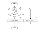
続いて、図3のフローチャートを参照して、本発明において実行される、潤滑油量切替制御について詳細に説明する。なお、図3の処理は、エンジン運転中、所定の周期(例えば、10ms)で繰り返し実行される。 Next, the lubricating oil amount switching control executed in the present invention will be described in detail with reference to the flowchart of FIG. Note that the process of FIG. 3 is repeatedly executed at a predetermined cycle (for example, 10 ms) during engine operation.
まず、ステップS1で、制御装置50は、クラッチ板(上述のとおり、入力側クラッチ板21および31、出力側クラッチ板22および32)の温度Tclがクラッチ温度閾値T1以下であるか否かを判断する。なお、クラッチ温度閾値T1は、この温度以下であれば潤滑油量を少なくしてもクラッチ焼き付きのおそれがなく、逆に、この温度より高い場合は潤滑油量を多くしてクラッチの冷却を行う必要があると判断する閾値として、実験等に基づいて予め設定されている。
First, in step S1, the
また、本発明では、クラッチ板の温度Tclは、クラッチ板の摩擦による発熱量と、潤滑油の熱量持ち去りによる放熱量とにより、演算で求められる。発熱量と放熱量とからクラッチ板の温度を求める手法は、公知の手法を用いることができる。 Further, in the present invention, the temperature Tcl of the clutch plate is obtained by calculation from the amount of heat generated by friction of the clutch plate and the amount of heat released by carrying away the amount of heat of the lubricating oil. A known method can be used as a method for obtaining the temperature of the clutch plate from the heat generation amount and the heat radiation amount.
なお、クラッチ板の温度Tclは、他の方法により求めてもよい。具体的には、例えば、熱電対を用いてクラッチ板の温度を直接検出するようにしてもよい。また、例えば、クラッチ被潤滑部100を通過した後の潤滑油の温度を検出し、この温度からクラッチ板の温度Tclを推定するようにしてもよい。
The clutch plate temperature Tcl may be obtained by other methods. Specifically, for example, the temperature of the clutch plate may be directly detected using a thermocouple. Further, for example, the temperature of the lubricating oil after passing the clutch lubricated
ステップS1でクラッチ板の温度TclがT1以下であると判断された場合(ステップS1:YES)、処理はステップS2に進む。そして、ステップS2で、制御装置50は、変速が行われたか否かを判断する。
When it is determined in step S1 that the clutch plate temperature Tcl is equal to or lower than T1 (step S1: YES), the process proceeds to step S2. In step S2, the
この判断には、例えば、アクセル開度Accおよび車速Vに基づき、制御装置50に記憶してある変速マップにおける変速線を跨いだか否かを判断する等の手法を用いることができる。また、第1クラッチ20又は第2クラッチ30の断接制御が開始した場合に変速が行われたと判断することもできる。さらに、手動変速モードを有する場合には、運転者によるシフト操作が行われた場合に変速が行われたと判断することもできる。
For this determination, for example, a method of determining whether or not the shift line in the shift map stored in the
ステップS2で変速が行われたと判断されなかった場合(ステップS2:NO)、処理はステップS3に進む。そして、ステップS3で、制御装置50は、ソレノイドバルブ96をオンにする。これにより、潤滑流量切替バルブ95は、図2Bに示す右位置となる。そのため、油路L2に供給された潤滑油は、油路L5および油路L6を経由してクラッチ被潤滑部100に供給される。
If it is not determined in step S2 that a shift has been performed (step S2: NO), the process proceeds to step S3. In step S3, the
ステップS2で変速が行われたと判断された場合(ステップS2:YES)、処理はステップS4に進む。そして、ステップS4で、制御装置50は、ソレノイドバルブ96をオフにする。これにより、潤滑流量切替バルブ95は図2Aに示す左位置となる。そのため、油路L2に供給された潤滑油は、油路L4および油路L6を経由してクラッチ被潤滑部100に供給される。
If it is determined in step S2 that a shift has been performed (step S2: YES), the process proceeds to step S4. In step S4, the
なお、ステップS2の処理を行うのは、以下の理由による。すなわち、クラッチ板の温度Tclが上昇する原因は、クラッチ板をスリップさせることにより発生する摩擦熱によるものが大きい。 Note that the process of step S2 is performed for the following reason. That is, the cause of the increase in the clutch plate temperature Tcl is largely due to frictional heat generated by slipping the clutch plate.
クラッチ板の温度TclがT1以下であっても、なんらかの理由(例えば、重量物を積載している状態で登坂路を走行中に変速が行われた場合、または、変速時にクラッチ板を長時間スリップさせた場合等)により、クラッチ板の温度Tclが急上昇し、1回の変速でクラッチ板が焼き付いてしまうおそれがある。 Even if the clutch plate temperature Tcl is equal to or lower than T1, for some reason (for example, when shifting is performed while traveling on an uphill with heavy loads loaded, or when the clutch plate slips for a long time during shifting) Etc.), the temperature Tcl of the clutch plate suddenly rises, and the clutch plate may be burned by one shift.
そのため、本実施形態では、クラッチ板の温度TclがT1以下であっても、クラッチ板の温度Tclが上昇する変速時には、潤滑流量を増やすことで、クラッチ板の焼き付きをより確実に防止している。 Therefore, in the present embodiment, even when the clutch plate temperature Tcl is equal to or lower than T1, the clutch plate is more reliably prevented from seizing by increasing the lubrication flow rate at the time of shifting when the clutch plate temperature Tcl increases. .
なお、ステップS2の処理は省略してもよい。その場合でも、制御周期を適切に設定しておけば、変速中にクラッチ板の温度Tclの温度がT1を超えた場合に、ステップS1における判断が「NO」となり、潤滑流量が増やされるため、クラッチ板の焼き付きは防止される。 Note that the process of step S2 may be omitted. Even in that case, if the control cycle is set appropriately, if the temperature of the clutch plate temperature Tcl exceeds T1 during gear shifting, the determination in step S1 becomes “NO”, and the lubricating flow rate is increased. Seizure of the clutch plate is prevented.
一方、ステップS1でクラッチ板の温度TclがT1以下であると判断されなかった場合(ステップS1:NO)、処理はステップS4に進む。 On the other hand, if it is not determined in step S1 that the clutch plate temperature Tcl is equal to or lower than T1 (step S1: NO), the process proceeds to step S4.
以上説明したように、本実施形態によれば、クラッチ板の温度が低い場合に、クラッチ板の冷却に用いられる潤滑油の流量を減少させるようにした。そのため、非締結側クラッチにおけるドラグトルクを減少させることができ、非締結側クラッチでのドラグトルクに起因する燃費の悪化を抑制することが可能となる。 As described above, according to this embodiment, when the temperature of the clutch plate is low, the flow rate of the lubricating oil used for cooling the clutch plate is reduced. Therefore, the drag torque in the non-engagement side clutch can be reduced, and the deterioration of fuel consumption due to the drag torque in the non-engagement side clutch can be suppressed.
また、本実施形態によれば、オイルポンプ92からクラッチ被潤滑部100までの油路を、相対的に圧力損失の大きい油路と小さい油路のいずれかに選択的に接続する潤滑流量切替バルブ95を設け、クラッチ板の温度に応じて潤滑流量切替バルブ95を切り替えるようにした。そのため、潤滑流量切替バルブ95を切り替えるのみで潤滑油の流量を変更することができ、構造を単純化できる。
Further, according to the present embodiment, the lubricating flow rate switching valve that selectively connects the oil passage from the
また、本実施形態によれば、潤滑流量切替バルブ95を、ソレノイドバルブ96からのパイロット圧で切替可能な油圧制御バルブとした。そのため、高価なリニアソレノイドバルブを用いることなく、潤滑油の流量を変更することができる。
Further, according to the present embodiment, the lubricating flow
また、本実施形態によれば、クラッチ板の温度が低い場合に、さらに変速の有無を判断し、変速時には流量を増やすようにした。そのため、変速時のスリップによりクラッチが発熱しても、クラッチが焼き付くことを確実に防止することができる。さらに、変速終了後は速やかに潤滑油の流量を減少させることができるため、非締結側クラッチでのドラグトルクに起因する燃費の悪化を効果的に抑制することができる。 Further, according to the present embodiment, when the temperature of the clutch plate is low, the presence / absence of a shift is further determined, and the flow rate is increased during a shift. Therefore, even if the clutch generates heat due to slip at the time of shifting, it is possible to reliably prevent the clutch from seizing. Furthermore, since the flow rate of the lubricating oil can be quickly reduced after the shift is completed, it is possible to effectively suppress the deterioration of fuel consumption caused by the drag torque in the non-engagement side clutch.
なお、上述の実施形態では、クラッチ被潤滑部100に供給する潤滑油の流量をクラッチ板の温度により切り替えるようにしたが、これに限定されない。具体的には、例えば、外気温、走行履歴、前回のエンジン停止(キーオフ)からの経過時間等から、クラッチ板を冷却すべきか否かを判断し、これに基づいて潤滑油の流量を切り替えるようにしてもよい。
In the above-described embodiment, the flow rate of the lubricating oil supplied to the clutch-lubricated
また、上述の実施形態では、クラッチ被潤滑部100に供給する潤滑油の流量をクラッチ板の温度により2段階に切り替えるようにしたが、これに限定されない。具体的には、例えば、クラッチ被潤滑部100に供給する潤滑油の流量を、3段階以上に切り替えるようにしてもよいし、リニアに制御してもよい。
In the above-described embodiment, the flow rate of the lubricating oil supplied to the clutch-lubricated
また、上述の実施形態では、第1オリフィス97を経由する場合に、ATFクーラを経由するようにしたが、これに限定されない。具体的には、例えば、油路L4に、ATFクーラを通過させるか否かを選択可能な切替バルブを追加し、ATFクーラを通過するか否かを選択できるようにしてもよい。
In the above-described embodiment, when the
本発明の摩擦締結要素の潤滑制御装置は、潤滑油の温度が低く、非締結側におけるドラグトルクが大きくなるような場合に有用である。 The frictional engagement element lubrication control device of the present invention is useful when the temperature of the lubricating oil is low and the drag torque on the non-engagement side is large.
20 第1クラッチ
30 第2クラッチ
90 油圧回路
91 オイルパン
91aフィルタ
92 オイルポンプ
93 ライン圧制御バルブ
95 潤滑流量切替バルブ
95a 入力ポート
95b 第1出力ポート
95c 第2出力ポート
95d パイロットポート
95e スプリング
96 ソレノイドバルブ
97 第1オリフィス
98 ATFクーラ
99 第2オリフィス
L1 ライン圧油路
L2、L3、L4、L5、L6 油路
20 First clutch 30 Second clutch 90
Claims (3)
油圧源からの前記潤滑油が供給される第1の油路と、
前記第1の油路と接続され、前記第1および第2の摩擦締結要素の温度が閾値以下の場合に、前記第1および第2の摩擦締結要素に供給する潤滑油の流量を減少させる流量変更部と、を備える
摩擦締結要素の潤滑制御装置。 A friction control device for a frictional engagement element that supplies lubricating oil to the first and second frictional engagement elements that are disengaged when one is engaged,
A first oil passage to which the lubricating oil from a hydraulic source is supplied;
A flow rate that is connected to the first oil passage and reduces the flow rate of the lubricating oil supplied to the first and second frictional engagement elements when the temperature of the first and second frictional engagement elements is equal to or lower than a threshold value. A friction control device for a frictional engagement element.
前記切替バルブは、前記第1および第2の摩擦締結要素の温度が閾値以下の場合、前記第1の油路と前記第3の油路とを接続するように切り替えられる、
請求項1に記載の摩擦締結要素の潤滑制御装置。 The flow rate changing unit is a switching valve that selectively connects the first oil passage to a second oil passage or a third oil passage having a larger pressure loss than the second oil passage,
The switching valve is switched to connect the first oil passage and the third oil passage when the temperatures of the first and second frictional engagement elements are equal to or lower than a threshold value.
The friction control device for a frictional engagement element according to claim 1.
請求項2に記載の摩擦締結要素の潤滑制御装置。 The switching valve is configured such that when the temperature of the first and second frictional engagement elements is not more than the threshold value and the engagement operation of the first or second frictional engagement element is not performed, Is switched to connect the third oil passage and the third oil passage,
The friction control device for a frictional engagement element according to claim 2.
Priority Applications (1)
| Application Number | Priority Date | Filing Date | Title |
|---|---|---|---|
| JP2016247842A JP2018100734A (en) | 2016-12-21 | 2016-12-21 | Lubrication control device for friction fastening elements |
Applications Claiming Priority (1)
| Application Number | Priority Date | Filing Date | Title |
|---|---|---|---|
| JP2016247842A JP2018100734A (en) | 2016-12-21 | 2016-12-21 | Lubrication control device for friction fastening elements |
Publications (1)
| Publication Number | Publication Date |
|---|---|
| JP2018100734A true JP2018100734A (en) | 2018-06-28 |
Family
ID=62715219
Family Applications (1)
| Application Number | Title | Priority Date | Filing Date |
|---|---|---|---|
| JP2016247842A Pending JP2018100734A (en) | 2016-12-21 | 2016-12-21 | Lubrication control device for friction fastening elements |
Country Status (1)
| Country | Link |
|---|---|
| JP (1) | JP2018100734A (en) |
-
2016
- 2016-12-21 JP JP2016247842A patent/JP2018100734A/en active Pending
Similar Documents
| Publication | Publication Date | Title |
|---|---|---|
| JP5702228B2 (en) | Hydraulic supply device for transmission | |
| JP5331884B2 (en) | Hydraulic control device for automatic transmission | |
| US8406976B2 (en) | Clutch control device and clutch control correction amount calculating method | |
| US9709165B2 (en) | Control apparatus for automatic transmission | |
| KR101823244B1 (en) | Control apparatus for power transmission system | |
| US9581235B2 (en) | Heat exchanging device of lubrication oil | |
| JP4998226B2 (en) | Automatic manual transmission clutch cooling system | |
| JP4530999B2 (en) | Control device for hybrid vehicle | |
| JP5926222B2 (en) | Transmission | |
| CN112443647A (en) | Control device for automatic transmission | |
| JP2012149675A (en) | Controller for automatic transmission | |
| JP2017026008A (en) | Vehicle control device | |
| KR101786206B1 (en) | Eop controlling method of transmission | |
| JP3005348B2 (en) | Transmission control device | |
| JP2013217492A (en) | Hydraulic pressure supply device of automatic transmission | |
| JP2018100734A (en) | Lubrication control device for friction fastening elements | |
| JP6551190B2 (en) | Hydraulic oil control device | |
| KR102417329B1 (en) | Hydraulic control system of automatic transmission for hybrid vehicle | |
| JP5947070B2 (en) | Transmission control device | |
| JP2018100737A (en) | Lubrication control device for friction fastening element | |
| JP2013199985A (en) | Oil pressure supply device of automatic transmission | |
| JP2018100735A (en) | Hydraulic control device | |
| JP2016031118A (en) | Automatic transmission hydraulic pressure supply device | |
| JP2018100736A (en) | Lubrication control device of friction fastening element | |
| US20210262567A1 (en) | Lockup control device and lockup control method for vehicle power transmission device |
Legal Events
| Date | Code | Title | Description |
|---|---|---|---|
| RD02 | Notification of acceptance of power of attorney |
Free format text: JAPANESE INTERMEDIATE CODE: A7422 Effective date: 20190612 |
|
| RD04 | Notification of resignation of power of attorney |
Free format text: JAPANESE INTERMEDIATE CODE: A7424 Effective date: 20191024 |