JP2018094583A - Knock-out device and press device - Google Patents
Knock-out device and press device Download PDFInfo
- Publication number
- JP2018094583A JP2018094583A JP2016240217A JP2016240217A JP2018094583A JP 2018094583 A JP2018094583 A JP 2018094583A JP 2016240217 A JP2016240217 A JP 2016240217A JP 2016240217 A JP2016240217 A JP 2016240217A JP 2018094583 A JP2018094583 A JP 2018094583A
- Authority
- JP
- Japan
- Prior art keywords
- knockout
- piston
- pistons
- knock
- pin
- Prior art date
- Legal status (The legal status is an assumption and is not a legal conclusion. Google has not performed a legal analysis and makes no representation as to the accuracy of the status listed.)
- Pending
Links
Images


Abstract
Description
本発明は、ノックアウト装置、およびプレス装置に関する。さらに詳しくは、作動流体によりノックアウトピンが動作させられるノックアウト装置、およびこのノックアウト装置が備えらえているプレス装置に関する。 The present invention relates to a knockout device and a press device. More specifically, the present invention relates to a knockout device in which a knockout pin is operated by a working fluid, and a press device provided in the knockout device.
従来、ノックアウト装置の推進力は、回転動作するエキセン軸から機械的に取り出す構成が多く採用されていたが、プレス装置で製造する製品が多様化することにより、エキセン軸と独立してノックアウト装置の推進力が生じる構成が求められるようになり、油圧のみによる推進力により動作させられる装置が増えている。しかし、油圧による推進力でノックアウト装置が駆動されている場合、ノックアウト装置の動作速度を上げようとすると、油圧源の容量を飛躍的に大きくする必要があり、プレス装置全体が、補助装置である油圧源により大型化するという問題がある。また、ノックアウト装置では、成形品を金型から最初に離型させる一次ノックアウト(以下、本明細書では金型から成形品を分離させるなど、最初の比較的大きな推進力を必要とする段階を「一次ノックアウト」と称する)のときには大きな推進力が必要になるが、成形品が金型から引き離され、所定の位置まで移動させられる二次ノックアウト(以下、本明細書では、一次ノックアウトよりも小さな力で十分である段階を「二次ノックアウト」と称する)の際には、比較的小さな推進力で十分であり、二次ノックアウト時に負荷された推進力の多くは無駄に消費され、ノックアウト装置の作動効率が悪くなるという問題がある。 Conventionally, the propulsive force of the knockout device has been often adopted by mechanically removing it from the rotating eccentric shaft, but as the products manufactured by the press device diversify, the knockout device's propulsive force is independent of the eccentric shaft. A configuration in which a propulsive force is generated has been demanded, and the number of devices that can be operated by a propulsive force using only hydraulic pressure is increasing. However, when the knockout device is driven by a hydraulic propulsion force, if the operation speed of the knockout device is increased, it is necessary to dramatically increase the capacity of the hydraulic source, and the entire press device is an auxiliary device. There is a problem that the size is increased by a hydraulic source. Further, in the knockout device, a primary knockout in which the molded product is first released from the mold (hereinafter, in this specification, a stage that requires a relatively large driving force such as separating the molded product from the mold is referred to as “ In the case of a “primary knockout”, a large propulsive force is required. However, a secondary knockout (hereinafter referred to as a primary knockout) in which a molded article is pulled away from a mold and moved to a predetermined position. Is called “secondary knockout”), a relatively small propulsive force is sufficient, and much of the propulsive force applied during the secondary knockout is wasted, and the knockout device operates. There is a problem of inefficiency.
特許文献1では、機械駆動機構と油圧駆動機構とを組み合わせ、機械駆動機構により一次ノックアウトを行うとともに、油圧駆動機構により二次ノックアウトを行うノックアウト装置が開示されている。また、特許文献2では、複数のシリンダを直列に並べて、異なるストロークで製品を押出すノックアウトピン駆動手段が備えられている熱間鍛造装置が開示されている。加えて、特許文献3では、二段ストロークシリンダが備えられた回転鍛造機が開示されている。 Patent Document 1 discloses a knockout device that combines a mechanical drive mechanism and a hydraulic drive mechanism, performs primary knockout by the mechanical drive mechanism, and performs secondary knockout by the hydraulic drive mechanism. Further, Patent Document 2 discloses a hot forging device provided with a knockout pin driving means for arranging a plurality of cylinders in series and extruding a product with different strokes. In addition, Patent Document 3 discloses a rotary forging machine provided with a two-stage stroke cylinder.
しかるに、特許文献1では、ノックアウトピンは、機械駆動機構と油圧駆動機構の2つの駆動機構により駆動されている。すなわち機械駆動機構が備えられているため、この機械駆動動作機構であるスライドと独立した機構にならず、プレス装置で製造する製品の多様化に対応することができないという問題がある。また、特許文献2では、複数のシリンダは直列に並べられているが、これらのシリンダを構成するピストンの圧力流体作用面積が同じであることから、ノックアウト装置の動作速度をあげようとした場合に、油圧源が大型化するという問題や、ノックアウト装置の作動効率が悪くなるという問題は残存する。なお、特許文献3では、二段ストロークシリンダとノックアウトピンの駆動手段とは別個独立に備えられているだけであり、この二段ストロークシリンダにより、プレス装置で製造する製品が押し出されるという記載はない。 However, in Patent Document 1, the knockout pin is driven by two drive mechanisms, a mechanical drive mechanism and a hydraulic drive mechanism. In other words, since a mechanical drive mechanism is provided, there is a problem that it is not a mechanism independent of the slide that is the mechanical drive operation mechanism, and it cannot cope with diversification of products manufactured by the press device. Further, in Patent Document 2, a plurality of cylinders are arranged in series, but since the pressure fluid action area of the pistons constituting these cylinders is the same, when trying to increase the operating speed of the knockout device The problem that the hydraulic power source becomes large and the operation efficiency of the knockout device deteriorates remain. In Patent Document 3, the two-stage stroke cylinder and the knockout pin driving means are provided separately and independently, and there is no description that a product manufactured by a press device is pushed out by the two-stage stroke cylinder. .
本発明は上記事情に鑑み、油圧等の液体を利用した流体駆動装置を含んで構成され、補助装置である油圧源の容量増加を抑えながら、ノックアウトピンの高速化を図ることができる、高効率なノックアウト装置を提供することを目的とする。 In view of the above circumstances, the present invention is configured to include a fluid drive device using a fluid such as hydraulic pressure, and can increase the speed of the knockout pin while suppressing an increase in the capacity of a hydraulic source that is an auxiliary device. An object of the present invention is to provide a knockout device.
第1発明のノックアウト装置は、プレス加工後の成形品を金型から離型させるノックアウトピンと、該ノックアウトピンを作動させる流体駆動装置と、を含んで構成されるノックアウト装置であって、前記流体駆動装置は、直列に設けられた複数のピストンと、これらに対応するシリンダとが備えられ、前記複数のピストンは、一次ノックアウトで前記金型から前記成形品を離型させたあと、二次ノックアウトで前記成形品を移動させ、前記一次ノックアウトで、前記ノックアウトピンの推進力を生じさせるための圧力流体作用面積が、前記二次ノックアウトで、前記ノックアウトピンの推進力を生じさせるための圧力流体作用面積とは異なっていることを特徴とする。
第2発明のノックアウト装置は、第1発明において、前記複数のピストンは、それぞれのピストンに対して、前記シリンダに存している、1の内室の液体により圧力が加えられていることを特徴とする。
第3発明のノックアウト装置は、第1発明において、前記複数のピストンは、それぞれのピストンに対して、前記シリンダに2以上存している、異なる内室の液体により圧力が加えられていることを特徴とする。
第4発明のノックアウト装置は、第1発明から第3発明において、前記複数のピストンの、少なくとも1つのピストンと、前記ノックアウトピンとが、直列に設けられていることを特徴とする。
第5発明のノックアウト装置は、第1発明から第3発明において、前記ノックアウトピンが、前記複数のピストンの少なくとも1つのピストンにより、リンク機構を介して動作させられていることを特徴とする。
第6発明のプレス装置は、第1発明から第6発明のいずれかのノックアウト装置が備えられていることを特徴とする。
A knockout device according to a first aspect of the present invention is a knockout device including a knockout pin for releasing a molded product after pressing from a mold, and a fluid drive device for operating the knockout pin, wherein the fluid drive The apparatus includes a plurality of pistons provided in series and cylinders corresponding to the pistons, and the plurality of pistons are subjected to secondary knockout after releasing the molded product from the mold by primary knockout. The pressure fluid working area for generating the driving force of the knockout pin in the secondary knockout is the pressure fluid working area for generating the driving force of the knockout pin in the secondary knockout. It is characterized by being different.
The knockout device according to a second aspect of the present invention is the knockout device according to the first aspect, wherein the plurality of pistons are pressurized against the respective pistons by the liquid in one inner chamber existing in the cylinder. And
The knockout device according to a third aspect of the present invention is the knockout device according to the first aspect, wherein the plurality of pistons are pressured by liquids in different inner chambers, wherein two or more pistons exist in each cylinder. Features.
A knockout device according to a fourth invention is characterized in that, in the first to third inventions, at least one piston of the plurality of pistons and the knockout pin are provided in series.
A knockout device according to a fifth invention is characterized in that, in the first invention to the third invention, the knockout pin is operated by at least one piston of the plurality of pistons via a link mechanism.
A press apparatus according to a sixth aspect is characterized in that the knockout apparatus according to any one of the first to sixth aspects is provided.
第1発明によれば、流体駆動装置を含んで構成されるノックアウト装置であって、流体駆動装置は、直列に設けられた複数のピストンが備えられており、一次ノックアウトでノックアウトピンの推進力を生じさせるための圧力流体作用面積が、二次ノックアウトでの圧力流体作用面積とは異なっていることにより、一次ノックアウトでは比較的大きな推進力をノックアウトピンに付与し、二次ノックアウトでは、ノックアウトピンを比較的高速度で動かすことができる。これにより、ノックアウト装置に供給される液体の流量を増やすことなく、ノックアウト装置のノックアウトピンの速度を上げることができる。また二次ノックアウトで、無駄に大きな推進力を付加することがないので、ノックアウト装置を高効率で動作させることができる。
第2発明によれば、複数のピストンは、シリンダに存している、1の内室の液体により圧力が加えられていることにより、それぞれのピストンに対し、シリンダ内に内室を設ける必要がなくなり、ノックアウト装置の構成をシンプルにでき、ノックアウト装置のコストを抑えることができる。
第3発明によれば、複数のピストンは、シリンダに2以上存している、異なる内室の液体により圧力が加えられていることにより、それぞれの内室の液体圧を変えることができ、二次ノックアウト時のノックアウトピンの速度をさらに上げることができる。
第4発明によれば、複数のピストンの少なくともいずれかと、ノックアウトピンとが直列に設けられていることにより、ノックアウト装置全体の構成をシンプルにでき、ノックアウト装置のコストを抑えることができる。
第5発明によれば、ノックアウトピンが、リンク機構を介して動作させられていることにより、流体駆動装置を設ける場所を任意に選択できる。これによりこのノックアウト装置が設けられたプレス装置の構成の自由度を上げることができる。
第6発明によれば、プレス装置に、第1発明から第5発明のいずれかのノックアウト装置が備えられていることにより、ノックアウトピンの速度を上げて、プレス装置全体の効率を上げながら、ノックアウト装置に供給する液体の圧力装置の大きさを抑えることで、プレス装置全体の大きさを抑えることができる。
According to the first invention, the knockout device includes a fluid drive device, and the fluid drive device includes a plurality of pistons provided in series, and the propulsive force of the knockout pin is generated by the primary knockout. Because the pressure fluid action area for generating is different from the pressure fluid action area in the secondary knockout, a relatively large driving force is applied to the knockout pin in the primary knockout, and the knockout pin is applied in the secondary knockout. It can be moved at a relatively high speed. Thereby, the speed of the knockout pin of the knockout device can be increased without increasing the flow rate of the liquid supplied to the knockout device. In addition, since the secondary knockout does not add a large driving force unnecessarily, the knockout device can be operated with high efficiency.
According to the second invention, the plurality of pistons are present in the cylinder, and the pressure is applied by the liquid in one inner chamber, so that it is necessary to provide the inner chamber in the cylinder for each piston. Therefore, the configuration of the knockout device can be simplified, and the cost of the knockout device can be reduced.
According to the third aspect of the present invention, the plurality of pistons can change the liquid pressure in each of the inner chambers by applying pressure by the liquid in the different inner chambers existing in two or more cylinders. The speed of the knockout pin at the next knockout can be further increased.
According to the fourth invention, since at least one of the plurality of pistons and the knockout pin are provided in series, the configuration of the entire knockout device can be simplified, and the cost of the knockout device can be suppressed.
According to the fifth aspect, since the knockout pin is operated via the link mechanism, the place where the fluid drive device is provided can be arbitrarily selected. Thereby, the freedom degree of a structure of the press apparatus provided with this knockout apparatus can be raised.
According to the sixth aspect of the invention, the knockout device according to any one of the first to fifth aspects of the invention is provided in the press device, so that the speed of the knockout pin is increased and the efficiency of the entire press device is increased. By suppressing the size of the pressure device for the liquid supplied to the device, the size of the entire pressing device can be suppressed.
まず、プレス装置を構成するプレス装置本体40について図1により説明したあと、ノックアウト装置10(図1、2等)について説明する。プレス装置は、熱間鍛造プレス等が該当し、プレス機構により金型で成形品を製造するプレス装置本体40と、このプレス装置本体40へ圧油を供給する油圧源等を含んで構成されている。なお、以下の説明において、同一の要素には同一の符号を付し、重複する説明を省略する。
First, the press device
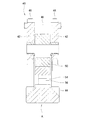
図1には、プレス装置を構成するプレス装置本体40の正面図を示す。図1に示すように、プレス装置本体40は、プレスフレーム42と、プレスフレーム42の下方に配置されたベッド44と、プレスフレーム42の上方に配置されたクラウン46と、を備える。ベッド44とクラウン46とは、プレスフレーム42を挟んで、鉛直方向に延びる4本のタイロッド48により結合されている。
In FIG. 1, the front view of the press apparatus
クラウン46には、スライド50を昇降させるための駆動装置が取り付けられている。また、スライド50は、ベッド44に対向して配置されている。スライド50は、プレスフレーム42に備えられたガイド部材により案内されて、上下方向に昇降動作可能に設けられている。プレス装置本体40のベッド44は、コンクリート製、または、鋼製構造等のベース上に固定されている。
A driving device for raising and lowering the
上金型54はスライド50に対し上ダイホルダを介して固定されており、下金型56は、下ダイホルダを介してベッド44に対して固定されている。そして、スライド50が下方向に動作することで、上金型54と下金型56で素材が挟持されて成形品が製造される。本発明の実施形態に係るノックアウト装置10は、ベッド44もしくはスライド50の内部に設けられており、プレス加工後に成形品を上金型54、もしくは下金型56から離型させるとともに、所定の位置まで移動させる機能を有する。
The
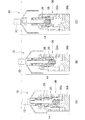
図2には、図1の本発明に係るノックアウト装置10を構成する流体駆動装置14の第1配置の説明図を、図3には、本発明の第1実施形態に係るノックアウト装置10を構成する流体駆動装置14の正面断面図を、図4には、ノックアウト装置10を構成する流体駆動装置14の説明図を、図5には、ノックアウト装置10を構成する流体駆動装置14の動作説明模式図を示す。図5は、図4の動作を理解しやすいように、流路等を省略するとともに、機械要素を模式的に示したものである。図4(A)、図5(A)は、流体駆動装置14がもっとも縮小した状態を示した図であり、図4(B)、図5(B)は、一次ノックアウトが終了した状態を示した図であり、図4(C)、図5(C)は、二次ノックアウトが終了した状態を示した図である。図4、5で示すように、ノックアウト装置10は、(A)図から(C)図に移るに従い、紙面上の上側に向けて伸長している。
FIG. 2 is an explanatory diagram of a first arrangement of the
ノックアウト装置10は、プレス加工後の成形品を金型から離型させるノックアウトピン12と、このノックアウトピン12を作動させる流体駆動装置14とを含んで構成されている。本実施形態では、使用される流体は作動油であり、流体駆動装置14は、油圧シリンダである。ただし、使用される流体は、例えば水や空気であっても問題ない。この場合流体駆動装置14は、水圧シリンダ、空圧シリンダとなる。
The
本実施形態に係る流体駆動装置14は、複数のピストンが設けられ、本実施形態では、第1ピストン20と、この第1ピストン20と直列に設けられている第2ピストン26と、が設けられている。また、本実施形態に係る流体駆動装置14では、シリンダ30内に第1ピストン20の圧力流体作用部が収容され、さらに、第1ピストン20内に第2ピストンの圧力作用部が収容されている、二重構造になっている。すなわち、第1ピストン20の圧力流体作用部が、シリンダ30に収納され、このシリンダ30に対して相対的に移動可能な構成である。第2ピストン26の圧力流体作用部は、第1ピストン20に収納され、第1ピストン20に対して相対的に移動可能な構成である。ここで「2つのピストンが直列に設けられている」とは、2つのピストンが同じ方向に向けて動作し、かつ、これらのピストンの圧力流体作用面が、これらのピストンの動作方向で見たときに、少なくとも一部が重なっている状態を言う。このような状態のときに、流体駆動装置14は、コンパクトな構成で、2つのピストンにより動作量を変化させることができる。なお、ピストンの動作方向以外の力が発生しないように、2つのピストンの圧力流体作用面の重心が、ピストンの動作方向で見たときに重なる状態が好ましい。
The
シリンダ30は、第1ピストン20を収納しているシリンダ本体部30aと、シリンダ本体部30aの反ピストン側に設けられ流体の流出入口が設けられたシリンダ端部30bとから構成されている。第1ピストン20と第2ピストン26とシリンダ端部30bとの間に、第1内室22aが形成されている。第1ピストン20とシリンダ本体部30aの間に、第2内室22bが形成されている。第1ピストン20の内周側と第2ピストン26の外周側の間に、第3内室22cが形成されている。第1ピストン20には、第2内室22bと第3内室22cとが連通する第1油路20aが形成されている。シリンダ本体部30aには、第2内室22bとシリンダ端部30bに形成された第3油路30dに連通する第2油路30cが形成されている。また、シリンダ端部30bには、第1内室22aに連通する第4油路30eが形成されている。
第1ピストン20と第2ピストン26とは、シリンダ30に設けられている第1内室22aの圧油により圧力が加えられている。すなわち第1ピストン20と第2ピストン26とは、第1内室22aという1つの内室の圧力流体により圧力が加えられる。シリンダ端部30bは、シリンダ本体部30aに図示しないボルト等で固定されている。
The
Pressure is applied to the
第3油路30dと第4油路30eとは、図示しないバルブと連通しており、このバルブが、これらの油路を通じて作動油を流入出させる。すなわち、第1ピストン20が、図3に記載の状態から、シリンダ30内を図3の紙面において上側に移動すると、第2内室22bの容積が減少し、第2内室22bの作動油が第2油路30cから第4油路30dを通じて流出する。また、第2ピストン26が、図3の状態から、第1ピストン20内を図3の紙面において上側に移動すると、第3内室22cの容積が減少し、第3内室22cの作動油が第2内室22b、および第2油路30cから第4油路30dを通じて流出する。
The
図4、5により、本実施形態に係るノックアウト装置10を構成する流体駆動装置14の動作を説明する。図4(A)、図5(A)で示すように、一次ノックアウト前には、第1ピストン20と、第2ピストン26とは、それぞれの紙面において、もっとも下側に位置し、流体駆動装置14自体はもっとも縮小した状態である。
The operation of the
一次ノックアウトで、金型から成形品を離型させるときには、第1内室22aに作動油を流入させ、第1ピストン20と第2ピストン26を、図4(B)、図5(B)に示す位置まで移動させる。この際、第2ピストン26のみが移動する場合も考えられるが、金型から成形品を離型させるためには比較的大きな力が必要とされるため、第2ピストン26のみが最初に移動したとしても、第2ピストン26のみでは必要な力を発揮することができないため、ノックアウトピン12が成形品に接触すると第2ピストン26は停止し、第1ピストン20が、第2ピストン26に追いつき、第1ピストン20と第2ピストン26とが一体となって動作する。
When the molded product is released from the mold by the primary knockout, the hydraulic oil is caused to flow into the first
よって、一次ノックアウトでの圧力流体作用面積は、第1ピストン20の圧力流体作用面積と、第2ピストン26の圧力流体作用面積を加えた値になる。
Therefore, the pressure fluid action area in the primary knockout is a value obtained by adding the pressure fluid action area of the
金型から成形品が離型された後の二次ノックアウトでは、第1内室22aに作動油を流入させると、第1ピストン20がシリンダ本体部30aのストロークエンドに達すると第2ピストン26のみが第1ピストン20内を移動する。そして、図4(C)、図5(C)に示す位置まで第2ピストン26が移動する。二次ノックアウトでは、一次ノックアウトで必要とされた力よりも小さな力で十分であるので、第2ピストン26のみにより発生する力で、成形品を移動させることができる。
In the secondary knockout after the molded product is released from the mold, when the hydraulic oil flows into the first
よって、二次ノックアウトでの圧力流体作用面積は、第2ピストン26の圧力流体作用面積となる。すなわち、二次ノックアウトでの圧力流体作用面積は、一次ノックアウトでの圧力流体作用面積よりも第1ピストン20の圧力流体作用面積の分だけ小さくなる。このため、流体駆動装置14が一定の伸縮長さにより駆動される場合、第1ピストン20のみで駆動される場合と比較して、本実施形態に係るノックアウト装置10の流体駆動装置14では、作動流体の流入量を少なくすることができる。
Therefore, the pressure fluid action area in the secondary knockout is the pressure fluid action area of the
流体駆動装置14を含んで構成されるノックアウト装置10であって、流体駆動装置14は、直列に設けられた2つのピストンが備えられており、一次ノックアウトでノックアウトピン12の推進力を生じさせるための圧力流体作用面積が、二次ノックアウトでの圧力流体作用面積とは異なっていることにより、一次ノックアウトでは比較的大きな推進力をノックアウトピン12に付与し、二次ノックアウトでは、ノックアウトピン12を比較的高速度で動かすことができる。これにより、ノックアウト装置10に供給される液体の流量を増やすことなく、ノックアウト装置10のノックアウトピン12の速度を上げることができる。また二次ノックアウトで、無駄に大きな推進力を付加することがないので、ノックアウト装置10を高効率で動作させることができる。
A
2つのピストンは、シリンダ30に存している、1の内室の液体により圧力が加えられていることにより、それぞれのピストンに対し、シリンダ30内に内室を設ける必要がなくなり、ノックアウト装置10の構成をシンプルにでき、ノックアウト装置10のコストを抑えることができる。
The two pistons exist in the
プレス装置に、上記構成のノックアウト装置10が備えられていることにより、ノックアウトピン12の速度を上げて、プレス装置全体の効率を上げながら、ノックアウト装置10に供給する液体の圧力装置の大きさを抑えることで、プレス装置全体の大きさを抑えることができる。
Since the press device is provided with the
図6には、本発明の第2実施形態に係るノックアウト装置10を構成する流体駆動装置140の断面正面図を模式的に示す。図5と同様、図6(A)は、流体駆動装置140がもっとも縮小した状態を示した図であり、図6(B)は、一次ノックアウトが終了した状態を示した図であり、図6(C)は、二次ノックアウトが終了した状態を示した図である。図6で示すように、ノックアウト装置10は、(A)図から(C)図に移るに従い、紙面上の上側に向けて伸長している。
In FIG. 6, the cross-sectional front view of the
第2実施形態のノックアウト装置10の流体駆動装置における、第1実施形態のものとの相違点は、シリンダ300が大径シリンダ室300aと小径シリンダ室300bとが直列に配置され、ノックアウトピン12側のシリンダ室に小径シリンダ室300bが配置されている。そして大径シリンダ室300aに第1ピストン200が、小径シリンダ室300bに第2ピストン260が収納されている。
すなわち、第1ピストン200の圧力流体作用部は、シリンダ300aに収納され、第2ピストン260の圧力流体作用部は、シリンダ300bに収納され、このシリンダ300に対してそれぞれ相対的に移動可能な構成である。そして、第1ピストン200は、大径シリンダ室300aに設けられている、第1内室220aの圧油により圧力が加えられ、第2ピストン260は、小径シリンダ300bに設けられている第4内室320aの圧油により圧力が加えられている。
The difference between the fluid driving device of the
That is, the pressure fluid action part of the
図6により、第2実施形態にかかるノックアウト装置10を構成する流体駆動装置140の動作を説明する。図6(A)で示すように、一次ノックアウト前には、第1ピストン200と、第2ピストン260とは、それぞれの紙面において、もっとも下側に位置し、流体駆動装置14自体はもっとも縮小した状態である。
The operation of the
一次ノックアウトで、金型から成形品を離型させるときには、第1内室220aと第4内室320aとに作動油を流入させ、第1ピストン200と第2ピストン260を、図6(B)に示す位置まで移動させる。この際、第2ピストン260は、第1ピストン200の動きに合わせて動作させられている。そして、第2内室220bの容積が減少し、第2内室220bの作動油が流出し、また、第3内室320bの容積が減少し、第3内室320bの作動油が流出する。
When the molded product is released from the mold by the primary knockout, the hydraulic oil is caused to flow into the first
よって、一次ノックアウトでの圧力流体作用面積は、第1ピストン200の圧力流体作用面積と第2ピストン260の圧力流体作用面積の合計面積になる。
Therefore, the pressure fluid action area in the primary knockout is the total area of the pressure fluid action area of the
金型から成形品が離型された後の二次ノックアウトでは、第4内室320aに作動油を流入させると、第2ピストン260のみが移動する。その際、第3内室320bの容積が減少し、第3内室320bの作動油が流出する。そして、図6(C)に示す位置まで第2ピストン260が移動する。二次ノックアウトでは、一次ノックアウトで必要とされた力よりも小さな力で十分であるので、第2ピストン260のみにより発生する力で、成形品を移動させることができる。また、このような構成の場合、第1内室220a内の圧力と、第4内室320a内の圧力を異ならせることができるので、第4内室320a内の圧力を上げ、ノックアウトピン12の速度をさらに上げることができる。
In the secondary knockout after the molded product is released from the mold, only the
このように、二次ノックアウトでの圧力流体作用面積は、第2ピストン260の圧力流体作用面積となる。図6で示すように、第1ピストン200の内径は、第2ピストン260の内径よりも大きいので、二次ノックアウトでの圧力流体作用面積は、一次ノックアウトでの圧力流体作用面積よりも小さくなる。このため、流体駆動装置14が一定の伸縮長さにより駆動される場合、第1ピストン200のみで駆動される場合と比較して、本実施形態のノックアウト装置10は、作動流体の流入量を少なくすることができる。
Thus, the pressure fluid action area in the secondary knockout is the pressure fluid action area of the
2つのピストンは、シリンダに2以上設けられている、異なる内室の液体により圧力が加えられていることにより、それぞれの内室の液体圧を変えて、二次ノックアウト時のノックアウトピン12の速度をさらに上げることができる。
Two pistons are provided with two or more cylinders, and pressure is applied by liquids in different inner chambers, so that the liquid pressure in each inner chamber is changed, and the speed of the
ここで用いられている流体駆動装置14、140(図2参照)は、第1実施形態および第2実施形態で示された流体駆動装置14、140のいずれであっても問題ない。また、ノックアウト装置10は、ベッド44でなく、スライド50に設けることも可能である。
The
ベッド44の下方にスペースがある場合は、ノックアウトピン12の下側に流体駆動装置14、140が設けられる。この場合、流体駆動装置14、140内にある2つのピストンの、少なくともいずれかと、ノックアウトピン12とは直列に設けられている。「ノックアウトピン12とピストンとが直列に設けられている」とは、ピストンの動作方向にこれらの機械要素が並んで設けられ、かつ、ピストンの動作方向と、ノックアウトピン12の動作方向が平行である場合を言う。
When there is a space below the
2つのピストンの少なくともいずれかと、ノックアウトピン12とが直列に設けられていることにより、ノックアウト装置10全体の構成をシンプルにでき、ノックアウト装置10のコストを抑えることができる。
Since at least one of the two pistons and the
図7は、本発明に係るノックアウト装置10の第2配置の説明図である。図7は、ノックアウト装置10が、ベッド44に設けられている状態を示す正面断面図であるが、ノックアウト装置10はベッド44でなく、プレスフレーム42やクラウン46に設けることも可能である。
FIG. 7 is an explanatory diagram of the second arrangement of the
ベッド44の下方にスペースがない場合は、リンク機構34がベッド44に設けられ、ノックアウトピン12は、流体駆動装置14内にある2つのピストンにより、このリンク機構34を介して動作させられている。リンク機構34は、ベッド44の下部に設けられたブラケット37に軸36を介してリンク38が揺動可能に設けられ、リンク38の一端を流体駆動装置14で作動させるとリンク38の他端がノックアウトピン12を動作させる。
When there is no space below the
ノックアウトピン12が、リンク機構34を介して動作させられていることにより、流体駆動装置14が設けられる場所を任意に選択できる。これによりこのノックアウト装置10が設けられたプレス装置の構成の自由度を上げることができる。
Since the
10 ノックアウト装置
12 ノックアウトピン
14、140 流体駆動装置
20、200 第1ピストン
22a、220a 第1内室
26、260 第2ピストン
30、300 シリンダ
34 リンク機構
DESCRIPTION OF
Claims (6)
前記流体駆動装置は、直列に設けられた複数のピストンと、これらに対応するシリンダとが備えられ、
前記複数のピストンは、一次ノックアウトで前記金型から前記成形品を離型させたあと、二次ノックアウトで前記成形品を移動させ、
前記一次ノックアウトで、前記ノックアウトピンの推進力を生じさせるための圧力流体作用面積が、前記二次ノックアウトで、前記ノックアウトピンの推進力を生じさせるための圧力流体作用面積とは異なっている、
ことを特徴とするノックアウト装置。 A knockout device configured to include a knockout pin for releasing a molded product after pressing from a mold, and a fluid driving device for operating the knockout pin,
The fluid drive device includes a plurality of pistons provided in series and cylinders corresponding to the pistons.
The plurality of pistons move the molded product by secondary knockout after releasing the molded product from the mold by primary knockout,
The pressure fluid action area for generating the driving force of the knockout pin in the primary knockout is different from the pressure fluid action area for generating the driving force of the knockout pin in the secondary knockout.
A knockout device characterized by that.
ことを特徴とする請求項1記載のノックアウト装置。 The plurality of pistons are pressurized by a liquid in one inner chamber existing in the cylinder with respect to each piston.
The knockout device according to claim 1.
ことを特徴とする請求項1記載のノックアウト装置。 In the plurality of pistons, pressure is applied to each piston by two or more liquids in different inner chambers in the cylinder.
The knockout device according to claim 1.
ことを特徴とする請求項1から3のいずれかに記載のノックアウト装置。 At least one piston of the plurality of pistons and the knockout pin are provided in series.
The knockout device according to any one of claims 1 to 3, wherein
ことを特徴とする請求項1から3のいずれかに記載のノックアウト装置。 The knockout pin is operated via a link mechanism by at least one piston of the plurality of pistons;
The knockout device according to any one of claims 1 to 3, wherein
ことを特徴とするプレス装置。 The knockout device according to any one of claims 1 to 5 is provided.
The press apparatus characterized by the above-mentioned.
Priority Applications (1)
| Application Number | Priority Date | Filing Date | Title |
|---|---|---|---|
| JP2016240217A JP2018094583A (en) | 2016-12-12 | 2016-12-12 | Knock-out device and press device |
Applications Claiming Priority (1)
| Application Number | Priority Date | Filing Date | Title |
|---|---|---|---|
| JP2016240217A JP2018094583A (en) | 2016-12-12 | 2016-12-12 | Knock-out device and press device |
Publications (1)
| Publication Number | Publication Date |
|---|---|
| JP2018094583A true JP2018094583A (en) | 2018-06-21 |
Family
ID=62634164
Family Applications (1)
| Application Number | Title | Priority Date | Filing Date |
|---|---|---|---|
| JP2016240217A Pending JP2018094583A (en) | 2016-12-12 | 2016-12-12 | Knock-out device and press device |
Country Status (1)
| Country | Link |
|---|---|
| JP (1) | JP2018094583A (en) |
Cited By (2)
| Publication number | Priority date | Publication date | Assignee | Title |
|---|---|---|---|---|
| CN112935123A (en) * | 2021-02-01 | 2021-06-11 | 上海应用技术大学 | Plate male die blanking device based on hydraulic system |
| CN113600687A (en) * | 2021-06-15 | 2021-11-05 | 瑞鹄汽车模具股份有限公司 | Automobile panel pressing die side pressing mechanism |
-
2016
- 2016-12-12 JP JP2016240217A patent/JP2018094583A/en active Pending
Cited By (2)
| Publication number | Priority date | Publication date | Assignee | Title |
|---|---|---|---|---|
| CN112935123A (en) * | 2021-02-01 | 2021-06-11 | 上海应用技术大学 | Plate male die blanking device based on hydraulic system |
| CN113600687A (en) * | 2021-06-15 | 2021-11-05 | 瑞鹄汽车模具股份有限公司 | Automobile panel pressing die side pressing mechanism |
Similar Documents
| Publication | Publication Date | Title |
|---|---|---|
| JP5426656B2 (en) | Double occlusion hydraulic die set | |
| CA2498825C (en) | Mechanical press apparatus | |
| JP6208139B2 (en) | accumulator | |
| JP6345050B2 (en) | Method and apparatus for precision cutting of workpieces in a press | |
| KR20160081890A (en) | Pressure Relief System and Method in an Energy Recovery Device | |
| WO2001083202A1 (en) | Booster and press working device | |
| CN106862402A (en) | A kind of gas-liquid mixed power pipe expander | |
| JP2018094583A (en) | Knock-out device and press device | |
| JP2016070500A (en) | Fluid circuit, and machine having fluid circuit | |
| JP6415529B2 (en) | Molding press machine | |
| TW201738010A (en) | Synchronous cylinder for extruders | |
| JP6514650B2 (en) | Forging press | |
| IT201800009060A1 (en) | HYDRAULIC DRIVE SYSTEM FOR A PUNCHING APPARATUS | |
| JP3213661U (en) | Processing equipment | |
| TWM517710U (en) | Pneumatic and hydraulic type seat tube assembly of bicycle | |
| JP6010756B2 (en) | Multi-stage press machine | |
| KR101568641B1 (en) | Cylinder apparatus and hybrid type brow molding machine using this | |
| JP2005028427A (en) | Multi-stage type press die for press machine | |
| JP4699284B2 (en) | Drive mechanism in crank press | |
| JP2010036226A (en) | Press working apparatus | |
| TWI817216B (en) | Device for reducing load from slide for machines having slide and installation method thereof | |
| JP6199763B2 (en) | Double acting hydraulic press | |
| CN104533871A (en) | Cylinder controlled by diaphragm | |
| JP6816730B2 (en) | Power generator | |
| JP6796328B2 (en) | Shrink tube device |
Legal Events
| Date | Code | Title | Description |
|---|---|---|---|
| A621 | Written request for application examination |
Free format text: JAPANESE INTERMEDIATE CODE: A621 Effective date: 20190314 |
|
| A131 | Notification of reasons for refusal |
Free format text: JAPANESE INTERMEDIATE CODE: A131 Effective date: 20200128 |
|
| A977 | Report on retrieval |
Free format text: JAPANESE INTERMEDIATE CODE: A971007 Effective date: 20200129 |
|
| A521 | Written amendment |
Free format text: JAPANESE INTERMEDIATE CODE: A523 Effective date: 20200330 |
|
| A02 | Decision of refusal |
Free format text: JAPANESE INTERMEDIATE CODE: A02 Effective date: 20200512 |