JP2018048798A - refrigerator - Google Patents

refrigerator Download PDF

Info

Publication number
JP2018048798A
JP2018048798A JP2017028976A JP2017028976A JP2018048798A JP 2018048798 A JP2018048798 A JP 2018048798A JP 2017028976 A JP2017028976 A JP 2017028976A JP 2017028976 A JP2017028976 A JP 2017028976A JP 2018048798 A JP2018048798 A JP 2018048798A
Authority
JP
Japan
Prior art keywords
refrigerator
evaporator
refrigeration
refrigeration cooler
flat tube
Prior art date
Legal status (The legal status is an assumption and is not a legal conclusion. Google has not performed a legal analysis and makes no representation as to the accuracy of the status listed.)
Pending
Application number
JP2017028976A
Other languages
Japanese (ja)
Inventor
林 秀竹
Hidetake Hayashi
秀竹 林
野口 明裕
Akihiro Noguchi
明裕 野口
耕世 西村
Kosei Nishimura
耕世 西村
Current Assignee (The listed assignees may be inaccurate. Google has not performed a legal analysis and makes no representation or warranty as to the accuracy of the list.)
Toshiba Lifestyle Products and Services Corp
Original Assignee
Toshiba Lifestyle Products and Services Corp
Priority date (The priority date is an assumption and is not a legal conclusion. Google has not performed a legal analysis and makes no representation as to the accuracy of the date listed.)
Filing date
Publication date
Application filed by Toshiba Lifestyle Products and Services Corp filed Critical Toshiba Lifestyle Products and Services Corp
Priority to CN201710825741.7A priority Critical patent/CN107830680A/en
Publication of JP2018048798A publication Critical patent/JP2018048798A/en
Pending legal-status Critical Current

Links

Images

Abstract

PROBLEM TO BE SOLVED: To provide a refrigerator that can secure effective internal volume of a compartment that is available for a storage chamber.SOLUTION: In a refrigerator 100, a multi-flow type evaporator (refrigerating chiller 24) including a flat tube 24c formed with a plurality of flow channels through which refrigerant flows is disposed on a ceiling side of the refrigerator 100 while at least part of the evaporator is positioned on a front side relative to a back face duct (cold air supply duct 37) provided on a back face side of the refrigerator 100.SELECTED DRAWING: Figure 14

Description

本発明の実施形態は、冷蔵庫に関する。   Embodiments of the present invention relate to a refrigerator.

従来、冷蔵庫では、コンプレッサ、コンデンサおよびエバポレータ等で構成された冷凍サイクルにより貯蔵室を冷却することが行われている。このとき、エバポレータは、例えば貯蔵室の背面側のダクトに設けられることがある(例えば、特許文献1参照)。   Conventionally, in a refrigerator, a storage room is cooled by a refrigeration cycle including a compressor, a condenser, an evaporator, and the like. At this time, the evaporator may be provided, for example, in a duct on the back side of the storage chamber (see, for example, Patent Document 1).

特開2016−033449号公報JP, 2006-033449, A

さて、特許文献1のように冷蔵庫の背面側にエバポレータを配置する場合、エバポレータの本体部を垂直に配置することで設置スペースの前後方向の長さを短くするようにしているものの、吸熱量を稼ぐためにはエバポレータの上下方向もある程度の長さが必要になることから、エバポレータによって占有されるスペースが大きくなっていた。その結果、貯蔵室の奥行きを確保するためにはエバポレータの上部もしくは下部にファンを配置せざるを得ず、背面側に大きなデッドスペースつまりは貯蔵室として利用できないスペースが存在していた。
そこで、貯蔵室として利用可能な有効な庫内体積を稼ぐことができる冷蔵庫を提供する。
Now, when the evaporator is arranged on the back side of the refrigerator as in Patent Document 1, the length of the installation space in the front-rear direction is shortened by vertically arranging the main body of the evaporator. In order to earn, a certain length is required in the vertical direction of the evaporator, so that the space occupied by the evaporator has been increased. As a result, in order to secure the depth of the storage room, a fan has to be arranged above or below the evaporator, and there is a large dead space on the back side, that is, a space that cannot be used as a storage room.
Then, the refrigerator which can earn the effective internal volume which can be utilized as a storage room is provided.

実施形態の冷蔵庫は、内部に冷媒が流れる流路が複数形成されている偏平管を有するマルチフロー型のエバポレータを、少なくとも一部が当該冷蔵庫の背面側に設けられている背面ダクトよりも前方側に位置した状態で、当該冷蔵庫の天井側に配置した。   The refrigerator according to the embodiment includes a multiflow evaporator having a flat tube in which a plurality of flow paths through which a refrigerant flows is formed, at least partly in front of a rear duct provided on the rear side of the refrigerator. Placed in the ceiling side of the refrigerator.

第1態様の冷蔵庫の構成を模式的に示す図The figure which shows typically the structure of the refrigerator of a 1st aspect. 冷蔵用冷却器(エバポレータ)の外観を模式的に示す図Schematic view of the appearance of the refrigerator for refrigeration (evaporator) 偏平管の構造を模式的に示す図Diagram showing the structure of a flat tube 冷蔵用冷却器の配置態様を模式的に示す図The figure which shows typically the arrangement | positioning aspect of the refrigerator for refrigeration 第2態様における冷蔵用冷却器の配置態様を模式的に示す図その1The figure which shows typically the arrangement | positioning aspect of the refrigerator for refrigeration in a 2nd aspect 1 冷蔵用冷却器の配置態様を模式的に示す図その2The figure which shows the arrangement | positioning aspect of the cooler for refrigeration typically 2 冷蔵用冷却器の配置態様を模式的に示す図その3Figure 3 schematically showing the arrangement of the refrigeration cooler 冷蔵用冷却器の配置態様を模式的に示す図その4The figure which shows typically the arrangement | positioning aspect of the refrigerator for refrigeration 4 冷蔵用冷却器の他の構造を模式的に示す図その1Figure 1 schematically showing another structure of a refrigerator for refrigeration 冷蔵用冷却器の他の構造を模式的に示す図その2Figure 2 schematically showing another structure of the refrigerator for refrigeration 第3態様における冷蔵用冷却器の設置場所を模式的に示す図その1The figure which shows typically the installation place of the refrigerator for refrigeration in a 3rd aspect 1 冷蔵用冷却器の設置場所を模式的に示す図その2Figure 2 schematically showing the location of the refrigerator for refrigeration 冷蔵用冷却器の設置場所を模式的に示す図その3Figure 3 schematically showing the location of the refrigerator for refrigeration 天井配置態様におけるエバポレータの配置を模式的に示す図その1The figure which shows typically the arrangement | positioning of the evaporator in a ceiling arrangement | positioning aspect 1 エバポレータの配置を模式的に示す図その2Figure 2 schematically showing the arrangement of the evaporator エバポレータの配置を模式的に示す図その3Figure 3 schematically showing the arrangement of the evaporator

(第1実施形態)
以下、実施形態について、図面を参照しながら説明する。なお、説明の簡略化のために、まず第1態様から第3態様としてマルチフロー型のエバポレータの構造や特徴ならびにそれを用いた冷蔵庫について説明し、その後、天井配置態様として、マルチフロー型のエバポレータを天井側に設ける態様の具体例について説明する。
(First embodiment)
Hereinafter, embodiments will be described with reference to the drawings. For the sake of simplification, first, the structure and characteristics of a multiflow evaporator and the refrigerator using the multiflow evaporator will be described as the first to third aspects, and then the multiflow evaporator will be used as the ceiling arrangement. A specific example of a mode in which the is provided on the ceiling side will be described.

<第1態様>
以下、第1態様について、図1から図4を参照して説明する。
図1に示すように、冷蔵庫1は、前面が開口した縦長矩形箱状の断熱箱体2内に、上下方向に並んで配置された複数の貯蔵室を有している。具体的には、断熱箱体2内には、上段から順に、貯蔵室として、冷蔵室3、野菜室4が設けられ、その下方に製氷室5と小冷凍室6が左右に並べて設けられ、これらの下方に冷凍室7が設けられている。製氷室5内には、周知の自動製氷装置8(図1参照)が設けられている。断熱箱体2は、基本的には、鋼板製の外箱2aと、合成樹脂製の内箱2bと、外箱2aと内箱2bとの間に設けられた断熱材2cとから構成されている。
<First aspect>
Hereinafter, the first aspect will be described with reference to FIGS. 1 to 4.
As shown in FIG. 1, the refrigerator 1 has a plurality of storage chambers arranged side by side in a vertical direction in a heat insulating box 2 having a vertically long rectangular box shape with an open front. Specifically, in the heat insulation box 2, a refrigeration room 3 and a vegetable room 4 are provided as storage rooms in order from the top, and an ice making room 5 and a small freezer room 6 are provided side by side on the lower side. A freezer compartment 7 is provided below these. A known automatic ice making device 8 (see FIG. 1) is provided in the ice making chamber 5. The heat insulating box 2 is basically composed of a steel plate outer box 2a, a synthetic resin inner box 2b, and a heat insulating material 2c provided between the outer box 2a and the inner box 2b. Yes.

冷蔵室3および野菜室4は、いずれも冷蔵温度帯(例えば1〜4℃)の貯蔵室であり、冷蔵室3と野菜室4との間は、プラスチック製の仕切壁10により上下に仕切られている。冷蔵室3の前面部には、図1に示すように、ヒンジ開閉式の断熱扉3aが設けられている。野菜室4の前面部には、引出し式の断熱扉4aが設けられている。断熱扉4aの背面部には、貯蔵容器を構成する下部ケース11が連結されている。下部ケース11の上部の後部には、下部ケース11よりも小型の上部ケース12が設けられている。   The refrigerator compartment 3 and the vegetable compartment 4 are both storage compartments in a refrigerated temperature zone (for example, 1 to 4 ° C.), and the refrigerator compartment 3 and the vegetable compartment 4 are partitioned vertically by a plastic partition wall 10. ing. As shown in FIG. 1, a hinged heat insulating door 3 a is provided on the front surface of the refrigerator compartment 3. A drawer-type heat insulating door 4 a is provided on the front surface of the vegetable compartment 4. The lower case 11 which comprises a storage container is connected with the back surface part of the heat insulation door 4a. An upper case 12 that is smaller than the lower case 11 is provided at the rear of the upper portion of the lower case 11.

冷蔵室3内は、複数の棚板13により上下に複数段に区切られている。冷蔵室3内の最下部(仕切壁10の上部)には、右側にはチルド室14が設けられ、その左側には卵ケースおよび小物ケースが上下に設けられ、さらに、これらの左側には貯水タンクが設けられている。貯水タンクは、自動製氷装置8の製氷皿8aに供給する水を貯留するためのものである。チルド室14には、チルドケース18が出し入れ可能に設けられている。   The inside of the refrigerator compartment 3 is divided into a plurality of stages vertically by a plurality of shelf boards 13. A chilled chamber 14 is provided on the right side at the lowermost part (the upper part of the partition wall 10) in the refrigerator compartment 3, and egg cases and accessory cases are provided vertically on the left side thereof. A tank is provided. The water storage tank is for storing water to be supplied to the ice tray 8 a of the automatic ice making device 8. A chilled case 18 is provided in the chilled chamber 14 so that it can be taken in and out.

製氷室5、小冷凍室6および冷凍室7は、いずれも冷凍温度帯(例えば−10〜−20℃)の貯蔵室である。また、野菜室4と、製氷室5および小冷凍室6との間は、図1に示すように断熱仕切壁19により上下に仕切られている。製氷室5の前面部には、引出し式の断熱扉5aが設けられている。断熱扉5aの後方には、貯氷容器20が連結されている。小冷凍室6の前面部にも、図示はしないが貯蔵容器が連結された引出し式の断熱扉が設けられている。冷凍室7の前面部にも、貯蔵容器22が連結された引出し式の断熱扉7aが設けられている。   The ice making room 5, the small freezer room 6, and the freezer room 7 are all storage rooms in a freezing temperature zone (for example, −10 to −20 ° C.). Further, the vegetable compartment 4 and the ice making compartment 5 and the small freezer compartment 6 are vertically partitioned by a heat insulating partition wall 19 as shown in FIG. A drawer-type heat insulating door 5 a is provided on the front surface of the ice making chamber 5. An ice storage container 20 is connected to the rear of the heat insulating door 5a. Although not shown, a drawer-type heat insulating door connected to a storage container is also provided on the front surface of the small freezer compartment 6. A drawer-type heat insulating door 7 a to which a storage container 22 is connected is also provided on the front surface of the freezer compartment 7.

冷蔵庫1には、詳しく図示はしないが、冷蔵用冷却器24および冷凍用冷却器25の2つの冷却器を備える冷凍サイクルが組み込まれている。冷蔵用冷却器24は、冷蔵室3および野菜室4を冷却するための冷気を生成するものであり、冷蔵庫1の背面部に設けられている。この冷蔵用冷却器24は、詳細は後述するが、偏平状に形成され、その内部に冷媒が流れる流路が複数形成されている偏平管24c(図2、図3参照)と、偏平管24cへの冷媒の入口となるヘッダ24a(図2参照)と、冷媒の出口となるヘッダ24b(図2参照)とを有し、本体部24g(図2参照)が概ね薄い直方体状に形成されたマルチフロー型のエバポレータ(蒸発器)である。   Although not shown in detail in the refrigerator 1, a refrigeration cycle including two coolers, a refrigeration cooler 24 and a refrigeration cooler 25, is incorporated. The refrigerating cooler 24 generates cold air for cooling the refrigerating room 3 and the vegetable room 4, and is provided on the back surface of the refrigerator 1. As will be described in detail later, the refrigeration cooler 24 is formed in a flat shape, and a flat tube 24c (see FIGS. 2 and 3) in which a plurality of channels through which a refrigerant flows is formed, and a flat tube 24c. The main body 24g (see FIG. 2) is formed in a substantially rectangular parallelepiped shape, and has a header 24a (see FIG. 2) serving as a refrigerant inlet and a header 24b (see FIG. 2) serving as a refrigerant outlet. It is a multi-flow type evaporator (evaporator).

冷凍用冷却器25は、製氷室5、小冷凍室6および冷凍室7を冷却するための冷気を生成するものであり、冷蔵庫1の背面部であって冷蔵用冷却器24の下方に設けられている。冷蔵庫1の下部背面部には、機械室26が設けられている。詳しく図示はしないが、この機械室26内には、上述の冷凍サイクルを構成する圧縮機27、凝縮器(図示せず)、圧縮機27および凝縮器を冷却するための冷却ファン(図示せず)、除霜水蒸発皿28などが設けられている。また、冷凍用冷却器25も、マルチフロー型のエバポレータを採用している。   The freezer cooler 25 generates cold air for cooling the ice making room 5, the small freezer room 6, and the freezer room 7, and is provided at the back of the refrigerator 1 and below the refrigerating cooler 24. ing. A machine room 26 is provided on the lower back surface of the refrigerator 1. Although not shown in detail, this machine room 26 has a compressor 27, a condenser (not shown), and a cooling fan (not shown) for cooling the compressor 27 and the condenser constituting the above-described refrigeration cycle. ), A defrosted water evaporating dish 28 and the like are provided. The refrigeration cooler 25 also employs a multiflow evaporator.

冷蔵庫1の背面下部寄り部分には、全体を制御するマイコン等を実装した制御装置29が設けられている。なお、図示はしないが、冷蔵庫1に設けられる電気機器のアース線は、外箱2aなどを介して接地されている。   A control device 29 in which a microcomputer or the like for controlling the whole is mounted is provided near the lower rear portion of the refrigerator 1. Although not shown, the ground wire of the electric device provided in the refrigerator 1 is grounded via the outer box 2a or the like.

冷蔵庫1内の冷凍室7の背面部には、冷凍用冷却器室30が設けられている。冷凍用冷却器室30内には、冷凍用冷却器25、除霜用ヒータ(図示せず)、送風手段たる冷凍用送風ファン31などが設けられている。冷凍用送風ファン31は、ファンが回転することによる送風作用によって風を発生させて冷凍用冷却器25によって生成した冷気を循環させるものであり、冷凍用冷却器25の上方に設けられている。冷凍用冷却器室30の前面の中間部には、冷気吹出口30aが設けられ、下部には、戻り口30bが設けられている。   A refrigeration cooler chamber 30 is provided on the back surface of the freezer chamber 7 in the refrigerator 1. In the refrigeration cooler chamber 30, a refrigeration cooler 25, a defrost heater (not shown), a refrigeration blower fan 31 serving as a blowing means, and the like are provided. The refrigeration blower fan 31 circulates the cold air generated by the refrigeration cooler 25 by generating air by the blowing action caused by the rotation of the fan, and is provided above the refrigeration cooler 25. A cold air outlet 30a is provided in the middle part of the front surface of the freezer cooler chamber 30, and a return port 30b is provided in the lower part.

この構成において、冷凍用送風ファン31および冷凍サイクルが駆動されると、送風作用によって風が生成され、冷凍用冷却器25によって生成した冷気は、冷気吹出口30aから製氷室5、小冷凍室6、冷凍室7内に供給され、戻り口30bから冷凍用冷却器室30内に戻される循環をする。これにより、それら製氷室5、小冷凍室6および冷凍室7は冷却される。なお、冷凍用冷却器25の下方には、当該冷凍用冷却器25の除霜時の除霜水を受ける排水樋32が設けられている。その排水樋32に受けられた除霜水は、機械室26内に設けられた除霜水蒸発皿28に導かれ、除霜水蒸発皿28の所で蒸発される。   In this configuration, when the refrigeration blower fan 31 and the refrigeration cycle are driven, wind is generated by the air blowing action, and the cold air generated by the refrigeration cooler 25 is supplied from the cold air outlet 30a to the ice making chamber 5 and the small freezer compartment 6. Then, it is circulated in the freezer compartment 7 and returned to the freezer cooler compartment 30 from the return port 30b. Thereby, the ice making room 5, the small freezer room 6, and the freezer room 7 are cooled. A drainage basin 32 that receives defrost water when the refrigeration cooler 25 is defrosted is provided below the refrigeration cooler 25. The defrost water received by the drainage basin 32 is guided to the defrost water evaporating dish 28 provided in the machine room 26 and evaporated at the defrost water evaporating dish 28.

そして、冷蔵庫1内における冷蔵室3および野菜室4の後方には、冷蔵用冷却器24、冷気ダクト34、送風手段たる冷蔵用送風ファン35などが設けられている。即ち、冷蔵庫1内における冷蔵室3の最下段の後方(チルド室14の後方)には、冷気ダクト34の一部を構成する冷蔵用冷却器室36が設けられ、この冷蔵用冷却器室36内に冷蔵用冷却器24が設けられている。冷気ダクト34は、冷蔵用冷却器24によって生成した冷気を冷蔵室3および野菜室4に供給するための通路を形成するものである。冷蔵用送風ファン35は、ファン体が回転することによる送風作用によって風を発生させ冷蔵用冷却器24によって生成した冷気を循環させるものであり、冷蔵用冷却器24の下方に設けられている。   In the refrigerator 1, a refrigeration cooler 24, a cold air duct 34, a refrigeration blower fan 35 serving as a blower, and the like are provided behind the refrigerator compartment 3 and the vegetable compartment 4. That is, a refrigeration cooler chamber 36 that constitutes a part of the cold air duct 34 is provided behind the lowermost stage of the refrigerator compartment 3 in the refrigerator 1 (behind the chilled chamber 14). A refrigeration cooler 24 is provided therein. The cold air duct 34 forms a passage for supplying the cold air generated by the refrigerating cooler 24 to the refrigerating room 3 and the vegetable room 4. The refrigeration blower fan 35 circulates the cold air generated by the refrigeration cooler 24 by generating air by the blowing action caused by the rotation of the fan body, and is provided below the refrigeration cooler 24.

冷蔵用冷却器室36の上方には、上方に延びる冷気供給ダクト37(後述する背面ダクトに相当する)が設けられ、冷蔵用冷却器室36の上端部が冷気供給ダクト37の下端部に連通している。この場合、冷蔵用冷却器室36と冷気供給ダクト37とから冷気ダクト34が構成される。冷蔵用冷却器室36の前部壁36aは、冷気供給ダクト37よりも前方に膨出している。また、その前部壁36aの背面側(冷蔵用冷却器24側)には、冷蔵用冷却器24の前面を覆う断熱性を有する断熱材38が設けられている。冷気供給ダクト37の前部には、冷蔵室3内に開口する冷気供給口39が複数個設けられている。   A chilled air supply duct 37 (corresponding to a rear duct described later) extending upward is provided above the refrigerated cooler chamber 36, and the upper end portion of the refrigerated cooler chamber 36 communicates with the lower end portion of the cold air supply duct 37. doing. In this case, the cold air duct 34 is constituted by the refrigeration cooler chamber 36 and the cold air supply duct 37. The front wall 36 a of the refrigeration cooler chamber 36 bulges forward from the cold air supply duct 37. In addition, a heat insulating material 38 having heat insulation covering the front surface of the refrigeration cooler 24 is provided on the back side (the refrigeration cooler 24 side) of the front wall 36a. In front of the cold air supply duct 37, a plurality of cold air supply ports 39 that open into the refrigerator compartment 3 are provided.

冷蔵用冷却器室36内の下部であって冷蔵用冷却器24の下方には、排水樋40が設けられている。排水樋40は、冷蔵用冷却器24からの除霜水を受けるものである。この排水樋40に受けられた除霜水も、排水樋32で受けられた除霜水と同様に、機械室26内に設けられた除霜水蒸発皿28に導かれ、除霜水蒸発皿28の所で蒸発される。排水樋40の左右の長さ寸法および前後の奥行き寸法は、冷蔵用冷却器24の左右の長さ寸法および前後の奥行き寸法よりも大きく、冷蔵用冷却器24から滴下する除霜水をすべて受けられる大きさに構成されている。   A drainage basin 40 is provided below the refrigeration cooler chamber 36 and below the refrigeration cooler 24. The drainage basin 40 receives defrosted water from the refrigeration cooler 24. The defrost water received by the drainage basin 40 is guided to the defrosting water evaporating dish 28 provided in the machine room 26 in the same manner as the defrosting water received by the drainage basin 32, and the defrosting water evaporating dish is provided. It is evaporated at 28. The left and right length dimensions and the front and rear depth dimensions of the drainage basin 40 are larger than the left and right length dimensions and the front and rear depth dimensions of the refrigeration cooler 24, and receive all the defrost water dripping from the refrigeration cooler 24. It is configured in a size that can be

野菜室4の後方には、送風ダクト42が設けられている。送風ダクト42内には、送風手段たる冷蔵用送風ファン35が設けられている。送風ダクト42は、下端部に吸込み口43を有し、上端部が排水樋40をう回するようにして冷蔵用冷却器室36(冷気ダクト34)に連通している。吸込み口43は、野菜室4において開口している。なお、冷蔵室3の底部を構成する仕切壁10の後部の左右の両隅部には、野菜室4に連通する複数の連通口が形成されている。   An air duct 42 is provided behind the vegetable compartment 4. A refrigeration blower fan 35 serving as a blower is provided in the blower duct 42. The air duct 42 has a suction port 43 at its lower end, and communicates with the refrigeration cooler chamber 36 (cold air duct 34) so that the upper end of the air duct 42 bypasses the drain 40. The suction port 43 is open in the vegetable compartment 4. A plurality of communication ports communicating with the vegetable compartment 4 are formed at the left and right corners of the rear part of the partition wall 10 that constitutes the bottom of the refrigerator compartment 3.

この構成において、冷蔵用送風ファン35が駆動されると送風作用によって、主に図1の白抜き矢印で示すように、風が発生する。すなわち、野菜室4内の空気は、吸込み口43から冷蔵用送風ファン35側に吸い込まれ、送風ダクト42側へ吹き出される。送風ダクト42側へ吹き出された空気は、冷気ダクト34、具体的には冷蔵用冷却器室36および冷気供給ダクト37を通り、複数の冷気供給口39から冷蔵室3内に吹き出される。   In this configuration, when the refrigeration blower fan 35 is driven, wind is generated by the air blowing action as indicated mainly by the white arrows in FIG. That is, the air in the vegetable compartment 4 is sucked into the refrigeration blower fan 35 side from the suction port 43 and blown out to the blower duct 42 side. The air blown to the air duct 42 side passes through the cold air duct 34, specifically, the refrigeration cooler chamber 36 and the cold air supply duct 37, and is blown out from the plurality of cold air supply ports 39 into the refrigerator compartment 3.

冷蔵室3内に吹き出された空気は、連通口44を通して野菜室4内にも供給され、最終的に冷蔵用送風ファン35に吸い込まれる。このように、冷蔵用送風ファン35の送風作用により風の循環が行われる。この風の循環の過程中に冷凍サイクルが駆動されていると、冷蔵用冷却器室36内を通る空気が冷蔵用冷却器24によって冷却されて冷気となり、その冷気が冷蔵室3および野菜室4に供給されることによって、冷蔵室3および野菜室4が冷蔵温度帯の温度に冷却される。   The air blown into the refrigerator compartment 3 is also supplied into the vegetable compartment 4 through the communication port 44 and is finally sucked into the refrigerator fan 35 for refrigerator. In this way, the wind is circulated by the blowing action of the refrigeration blower fan 35. When the refrigeration cycle is driven during the wind circulation process, the air passing through the refrigeration cooler chamber 36 is cooled by the refrigeration cooler 24 to become cold air, and the cold air is stored in the refrigerator compartment 3 and the vegetable compartment 4. , The refrigerator compartment 3 and the vegetable compartment 4 are cooled to temperatures in the refrigerator temperature zone.

また、冷蔵用冷却器室36内の下部の前部には、貯水部を構成する貯水容器56が設けられている。この貯水容器56は、冷蔵用冷却器24と排水樋40との間で、かつ給水部53の下方に設けられている。そして、貯水容器56は、前部が冷蔵用冷却器室36の前部壁36aに取り付けられ、後方へ突出する片持ち状態に設けられている。この貯水容器56は、冷蔵用冷却器24から滴下する除霜水を受けて貯留するものである。   In addition, a water storage container 56 constituting a water storage section is provided in the front part of the lower part in the refrigeration cooler chamber 36. The water storage container 56 is provided between the refrigeration cooler 24 and the drain 40 and below the water supply unit 53. And the front part of the water storage container 56 is attached to the front part wall 36a of the refrigerator room 36 for refrigeration, and is provided in the cantilever state which protrudes back. The water storage container 56 receives and stores defrost water dripped from the refrigeration cooler 24.

次に上記した構成の作用について説明する。
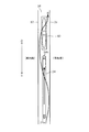
まず、冷蔵用冷却器24の詳細な構造について説明する。図2に示すように、冷媒の入口となるヘッダ24a、冷媒の出口となるヘッダ24b、これらヘッダ24aとヘッダ24bとの間を接続する偏平管24c、各偏平管24cの間に設けられている金属材料で波状に形成された吸熱用のフィン24d、入口側のヘッダ24aに設けられ、冷媒配管(図示省略)が接続される入口側接続部24e、および、出口側のヘッダ24bに設けられ、外部配管(図示省略)が接続される出口側接続部24fを備えている。このとき、偏平管24cが設けられている部位である本体部24gは、その外形が概ね薄い直方体状となっている。
Next, the operation of the above configuration will be described.
First, the detailed structure of the refrigeration cooler 24 will be described. As shown in FIG. 2, a header 24a serving as a refrigerant inlet, a header 24b serving as a refrigerant outlet, a flat tube 24c connecting the header 24a and the header 24b, and the flat tubes 24c are provided. An endothermic fin 24d formed in a wave shape with a metal material, provided on the inlet-side header 24a, provided on the inlet-side connecting portion 24e to which a refrigerant pipe (not shown) is connected, and provided on the outlet-side header 24b, The outlet side connection part 24f to which external piping (illustration omitted) is connected is provided. At this time, the main body 24g, which is a portion where the flat tube 24c is provided, has a rectangular parallelepiped shape.

ヘッダ24aおよびヘッダ24bは、中空円筒状に形成されており、互いの中空部(図示省略)が各偏平管24cによってそれぞれ連通した状態となっている。より具体的には、偏平管24cは、図3に示すように、その外形が偏平状に形成されているとともに、その内部に冷媒が流れる複数の流路24hが形成されている。そして、各流路24hによって、ヘッダ24aおよびヘッダ24bの互いの中空部が連通している。   The header 24a and the header 24b are formed in a hollow cylindrical shape, and the hollow portions (not shown) are in communication with each other through the flat tubes 24c. More specifically, as shown in FIG. 3, the flat tube 24c has a flat outer shape and a plurality of flow paths 24h through which the refrigerant flows. And each hollow part of the header 24a and the header 24b is connected by each flow path 24h.

このように流路24hを複数設けることにより、従来のような系の大きい流路が1つ設けられているタイプのものに比べて、冷媒と偏平管24cとの接触面積が増大する。これにより、冷媒から偏平管24cに効率よく熱が伝わる。また、偏平管24cとフィン24dとが接触しているため、偏平管24cからフィン24dにも効率よく熱が伝わる。そして、フィン24dが波状に形成されていることから、空気との接触面積つまりは熱交換面積を一層大きくすることが可能となる。   By providing a plurality of flow paths 24h in this way, the contact area between the refrigerant and the flat tube 24c is increased as compared with the conventional type in which one large flow path is provided. Thereby, heat is efficiently transferred from the refrigerant to the flat tube 24c. Further, since the flat tubes 24c and the fins 24d are in contact, heat is efficiently transferred from the flat tubes 24c to the fins 24d. Since the fins 24d are formed in a wave shape, the contact area with air, that is, the heat exchange area can be further increased.

このように、マルチフロー型の冷蔵用冷却器24は、空気との間で効率的な熱交換を行うことが可能となっている。例えば、冷蔵用冷却器24は、同体積であれば従来のフィンチューブ型のものに比べて2〜3倍の吸熱効果が期待できる一方、従来と同様の吸熱効果を得られればよいのであれば薄型にできる等、体積を大きく削減することができる。これにより、本態様のように冷蔵庫1の背面側に冷蔵用冷却器24を配置する場合には、背面側のデッドスペースつまりは貯蔵室として利用できないスペースを削減することができる。   As described above, the multi-flow refrigeration cooler 24 can efficiently exchange heat with air. For example, if the refrigeration cooler 24 has the same volume, the endothermic effect can be expected to be two to three times that of the conventional fin tube type. The volume can be greatly reduced, such as being thin. Thereby, when arrange | positioning the refrigerator 24 for refrigeration on the back side of the refrigerator 1 like this aspect, the dead space on the back side, ie, the space which cannot be used as a storage room, can be reduced.

また、本態様の場合、冷蔵用冷却器24は、図4に示すように、入口側のヘッダ24aが下方に、出口側のヘッダ24bが上方となるように配置されている。換言すると、冷蔵用冷却器24は、偏平管24cが配置されている部位である本体部24gが冷蔵庫1の設置面に対して垂直となるように配置されているとともに、偏平管24cも設置面に対して垂直となるように配置されている。なお、ここでいう垂直とは、設置面に対して90度の状態に限らず、概ね垂直と見なせる状態、例えば若干斜めになった状態も含んでいる。   In the case of this embodiment, the refrigeration cooler 24 is arranged such that the inlet-side header 24a is downward and the outlet-side header 24b is upward, as shown in FIG. In other words, the refrigeration cooler 24 is disposed such that the main body 24g, which is a portion where the flat tube 24c is disposed, is perpendicular to the installation surface of the refrigerator 1, and the flat tube 24c is also disposed on the installation surface. It is arrange | positioned so that it may become perpendicular | vertical with respect to. The term “perpendicular” here is not limited to a state of 90 degrees with respect to the installation surface, but includes a state that can be regarded as being substantially vertical, for example, a state that is slightly inclined.

冷蔵用冷却器24に流入する冷媒は、矢印Fにて示すように入口側接続部24eから冷蔵用冷却器24に液体状態で流入し、冷蔵用冷却器24内で蒸発して気体状態となった後、上方の出口側接続部24fから主に気体状態となって流出する。このとき、液体状態の冷媒は重力によって下方に流下することから、図4(B)に模式的に示すように冷媒の入口を下方に設置し、出口を上方に設置することにより、冷媒の移動をスムーズにすることができ、効率的な熱交換を行うことができる。なお、図4(B)は、図4(A)に示す冷蔵用冷却器24を図示左方側から視た状態を模式的に示している。   The refrigerant flowing into the refrigeration cooler 24 flows into the refrigeration cooler 24 in a liquid state from the inlet side connection portion 24e as indicated by an arrow F, and evaporates in the refrigeration cooler 24 to become a gas state. After that, the gas mainly flows out from the upper outlet side connection portion 24f. At this time, since the refrigerant in the liquid state flows down due to gravity, the refrigerant moves by installing the refrigerant at the lower side and installing the outlet at the upper side as schematically shown in FIG. Can be made smooth and efficient heat exchange can be performed. 4B schematically shows a state where the refrigeration cooler 24 shown in FIG. 4A is viewed from the left side in the figure.

さて、冷蔵用冷却器24は、冷凍サイクルが運転されると、温度が低下して霜が生じる。この霜は熱交換性能を低下させることから、霜を除去する除霜処理が例えば一定期間毎に行われている。この除霜処理では、付着した霜を溶かして除霜水として下方に排出している。そのため、本態様のように冷蔵用冷却器24の本体部24gを垂直に配置することにより、除霜水の流下を促すことができる。さらに、偏平管24cも垂直になるように配置していることにより、除霜水が偏平管24cを伝わりやすくなり、流下をさらに促すことができる。   Now, when the refrigeration cycle is operated, the refrigeration cooler 24 decreases in temperature and generates frost. Since this frost reduces the heat exchange performance, a defrosting process for removing the frost is performed, for example, at regular intervals. In this defrosting process, the attached frost is melted and discharged downward as defrosted water. Therefore, the flow of the defrost water can be promoted by arranging the main body 24g of the refrigeration cooler 24 vertically as in this embodiment. Furthermore, by arranging the flat tube 24c so as to be vertical, the defrost water is easily transmitted through the flat tube 24c, and can further promote the flow down.

以上説明した冷蔵庫1によれば、次のような効果を得ることができる。
冷蔵庫1は、内部に冷媒が流れる流路24hが複数形成されている偏平管24cを有するマルチフロー型の冷蔵用冷却器24(エバポレータ)を用いて冷凍サイクルの熱交換を行う。
According to the refrigerator 1 demonstrated above, the following effects can be acquired.
The refrigerator 1 performs heat exchange of the refrigeration cycle using a multi-flow type refrigeration cooler 24 (evaporator) having a flat tube 24c in which a plurality of flow paths 24h through which refrigerant flows are formed.

マルチフロー型の冷蔵用冷却器24は、上記したように熱交換性能が高く、同一性能であれば従来のフィンチューブ型のものに比べてその体積を大きく削減することができる。また、薄型化が可能となるため、配置場所の自由度も向上する。したがって、冷蔵用冷却器24の配置の自由度を高めることができ、有効な庫内体積つまりは貯蔵室に利用できる庫内スペースを稼ぐことができる。   The multi-flow type refrigeration cooler 24 has a high heat exchange performance as described above, and its volume can be greatly reduced as compared with a conventional fin tube type if the performance is the same. Further, since the thickness can be reduced, the degree of freedom of the arrangement location is also improved. Therefore, the freedom degree of arrangement | positioning of the cooler 24 for refrigeration can be raised, and the effective internal volume, ie, the internal space which can be utilized for a storage room, can be earned.

また、冷蔵用冷却器24の本体部24gを垂直に配置したことにより、除霜水の流下を促すことができる。この場合、偏平管24cも垂直になるように配置したことにより、除霜水が偏平管24cを伝わり易くなり、除霜水の流下をさらに促すことができる。   Moreover, the flow of the defrost water can be promoted by arranging the main body 24g of the refrigeration cooler 24 vertically. In this case, by arranging the flat tubes 24c so as to be vertical, the defrost water is easily transmitted through the flat tubes 24c, and the flow of the defrost water can be further promoted.

また、本態様のように冷蔵用冷却器24と冷凍用冷却器25の2つのエバポレータを有している場合には、冷蔵用冷却器24をその動作サイクル毎に毎サイクル除霜することができる。冷蔵用冷却器24は、冷媒がながれていれば冷却される一方、冷蔵室3の庫内温度が0℃以上であることから、冷媒が流れていなければ冷蔵用送風ファン35を回し続けることによりエバを温めて除霜することができる。   Moreover, when it has two evaporators, the refrigeration cooler 24 and the refrigeration cooler 25 as in this embodiment, the refrigeration cooler 24 can be defrosted every cycle for each operation cycle. . The refrigerating cooler 24 is cooled if the refrigerant is flowing, while the internal temperature of the refrigerating chamber 3 is 0 ° C. or higher. Therefore, if the refrigerant is not flowing, the refrigerating fan 35 is kept running. Eva can be warmed and defrosted.

このとき、マルチフロー型の冷蔵用冷却器24は熱容量が小さくなるため、従来のフィンチューブ型のものに比べて除霜時間が短くなり、効率の良い運転ができ、省電力化を図ることができる。   At this time, since the heat capacity of the multi-flow type refrigeration cooler 24 becomes smaller, the defrosting time is shorter than that of the conventional fin tube type, and an efficient operation can be achieved, thereby saving power. it can.

また、入口側接続部24eおよび出口側接続部24fを本体部24gと概ね平行に設けているので、冷蔵用冷却器24の前後方向への長さ(厚み)を薄くすることができ、貯蔵室を大きくすることができる。
また、冷凍用冷却器25についても、冷蔵用冷却器24と同様の効果を得ることができる。
Further, since the inlet side connecting portion 24e and the outlet side connecting portion 24f are provided substantially in parallel with the main body portion 24g, the length (thickness) in the front-rear direction of the refrigeration cooler 24 can be reduced, and the storage chamber Can be increased.
Further, the same effect as that of the refrigeration cooler 24 can be obtained for the refrigeration cooler 25.

<第2態様>
以下、第2態様について、図5から図10を参照しながら説明する。第2態様では、冷蔵用冷却器24の配置態様および構造の他の例について説明する。
上記したように、冷蔵用冷却器24の下方側は、除霜水が流下するため、その範囲(流下領域(Rx。図7参照)内に冷蔵用送風ファン35を配置すると、除霜処理が行われた際に冷蔵用送風ファン35に除霜水がかかるおそれがある。
<Second aspect>
Hereinafter, the second mode will be described with reference to FIGS. In the second aspect, another example of the arrangement and structure of the refrigeration cooler 24 will be described.
As described above, since the defrost water flows down on the lower side of the refrigeration cooler 24, if the refrigeration blower fan 35 is disposed in the range (flow area (Rx, see FIG. 7)), the defrost treatment is performed. When it is performed, there is a possibility that the defrost water is applied to the refrigeration blower fan 35.

そのため、例えば図5に示すように冷蔵用冷却器室36内に配置する場合には、冷蔵用冷却器24に送風するためのファン60を、冷蔵用冷却器24と概ね平行となる位置に配置することが考えられる。なお、ファン60は冷蔵用送風ファン35であってもよい。
これにより、重力によって流下する除霜水がファン60にかかることを防止できる。なお、マルチフロー型の冷蔵用冷却器24であれば、上記したように薄型にできるため、冷蔵用冷却器室36内にファン60と併設することも可能である。
Therefore, for example, as shown in FIG. 5, when arranged in the refrigeration cooler chamber 36, the fan 60 for sending air to the refrigeration cooler 24 is arranged at a position substantially parallel to the refrigeration cooler 24. It is possible to do. The fan 60 may be the refrigeration blower fan 35.
Thereby, it is possible to prevent the defrost water flowing down due to gravity from being applied to the fan 60. Note that the multi-flow type refrigeration cooler 24 can be thinned as described above, and therefore can be provided with the fan 60 in the refrigeration cooler chamber 36.

この場合、冷蔵用冷却器24の下方側には貯水容器56(図1参照)が設けられているため、この貯水容器56によって冷蔵用冷却器24の下方側の空間は、庫内側が一部塞がれた状態となっている。この状態でファン60を回転させた場合には、空気の流れは、矢印Bにて示すようにまず下方側からファン60に吸い込まれた後、冷蔵用冷却器24を通過して上方に抜けていく。   In this case, since a water storage container 56 (see FIG. 1) is provided on the lower side of the refrigeration cooler 24, the space on the lower side of the refrigeration cooler 24 by the water storage container 56 is partially on the inside of the refrigerator. It is in a blocked state. When the fan 60 is rotated in this state, the air flow is first sucked into the fan 60 from the lower side as indicated by an arrow B, and then passes upward through the refrigeration cooler 24. Go.

つまり、このファン60は、冷蔵用冷却器24に対して風の流れの上流側つまりは風上側に配置されている。これにより、冷蔵用冷却器24に生じた霜が飛び散ったり蒸発したりした場合であっても、水分がファン60にかかることを防止できる。   That is, the fan 60 is arranged on the upstream side of the wind flow with respect to the refrigeration cooler 24, that is, on the windward side. Thereby, even if the frost generated in the refrigeration cooler 24 is scattered or evaporated, it is possible to prevent moisture from being applied to the fan 60.

あるいは、図6に示すように冷気ダクト34内に配置する場合には、冷蔵用冷却器24の上方側にファン60を配置することができる。これにより、除霜水がファン60にかかることを防止できる。この場合、下方側から吸い上げられた空気は、矢印Bにて示すように冷蔵用冷却器24を通った後に上方に抜けていくものの、飛び散った水滴は重力によって下方に移動すると考えられるため、ファン60にかかるおそれは低減される。   Or when arrange | positioning in the cool air duct 34 as shown in FIG. 6, the fan 60 can be arrange | positioned above the cooler 24 for refrigeration. Thereby, it can prevent that defrost water applies to the fan 60. FIG. In this case, although the air sucked from the lower side passes through the refrigeration cooler 24 as indicated by an arrow B, it is considered that the scattered water droplets move downward due to gravity. The risk of 60 is reduced.

あるいは、図7に示すように、冷蔵用冷却器24よりも下方であっても、除霜水の流下領域(Rx)つまりは概ね冷蔵用冷却器24の真下の範囲から外れた位置であれば除霜水がファン60にかかることを防止できると考えられる。このとき、ファン60を、冷蔵用冷却器24に対して、冷蔵用冷却器24を通過する際の風向きとは逆側に配置するとよい。   Alternatively, as shown in FIG. 7, even if it is below the refrigeration cooler 24, the defrost water flow area (Rx), that is, a position that is substantially out of the range immediately below the refrigeration cooler 24. It is considered that defrost water can be prevented from being applied to the fan 60. At this time, the fan 60 may be disposed on the side opposite to the wind direction when passing through the refrigeration cooler 24 with respect to the refrigeration cooler 24.

図7の場合には冷蔵用冷却器24を通過する際の風向きが図示左向きであることから、ファン60を、冷蔵用冷却器24よりも図示右方側にするとよい。これにより、冷蔵用冷却器24の表面に付着した霜が風によって飛ばされたとしても、ファン60にかかるおそれを低減できる。   In the case of FIG. 7, the wind direction when passing through the refrigeration cooler 24 is leftward in the figure, and therefore the fan 60 may be placed on the right side of the refrigeration cooler 24 in the figure. Thereby, even if the frost adhering to the surface of the refrigeration cooler 24 is blown off by the wind, the risk of being applied to the fan 60 can be reduced.

このように、冷蔵用冷却器24は、除霜水の流下領域外であれば、任意の位置に配置することができる。そのため、例えば図6において、図示左右方向にスペースがあれば、ファン60を冷蔵用冷却器24の斜め上方等に配置することもできる。   As described above, the refrigeration cooler 24 can be disposed at any position as long as it is outside the flow area of the defrost water. Therefore, for example, in FIG. 6, if there is a space in the horizontal direction in the figure, the fan 60 can be disposed obliquely above the refrigeration cooler 24.

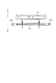
また、冷蔵用冷却器24は、図8に示すように、冷蔵庫1の設置面に対して水平に配置できる。なお、ここで言う水平とは、概ね水平と見なせる状態、例えば若干斜めになった状態を含んでいる。
このように概ね水平に配置することにより、高さ方向の必要スペースを削減することができる。また、天井に沿って配置したり、断熱仕切り部分に配置できたりするため、庫内容積を増大させることができる。
Moreover, the refrigerator 24 for refrigeration can be arrange | positioned horizontally with respect to the installation surface of the refrigerator 1, as shown in FIG. Here, the term “horizontal” includes a state that can be regarded as being almost horizontal, for example, a state that is slightly inclined.
Thus, the required space in the height direction can be reduced by disposing substantially horizontally. Moreover, since it can arrange | position along a ceiling or can arrange | position to a heat insulation partition part, the volume in a store | warehouse | chamber can be increased.

この場合、ファン60を冷蔵用冷却器24の上方に配置することで、除霜水がファン60にかかることを防止できる。また、概ね水平にすることにより、本体部24gを大きくして表面積を稼いだり、本体部24gを薄型化することで設置の自由度の向上や必要スペースの削減を図ったりすることができる。   In this case, it is possible to prevent the defrost water from being applied to the fan 60 by disposing the fan 60 above the refrigeration cooler 24. Further, by making the main body portion 24g large to increase the surface area, the main body portion 24g can be thinned to improve the degree of freedom of installation and reduce the required space.

また、図8では風向きを上向き、つまりは、冷蔵用冷却器24からファン60に向かう向きにしているが、冷蔵用冷却器24から剥離した霜は重力によって下方に移動するため、風向きが問題になることはない。なお、風向きを下向き、つまりは、ファン60から冷蔵用冷却器24に向かう向きにすることで、冷蔵用冷却器24から剥離した霜がファン60に付着することをさらに抑制できるようになる。   Further, in FIG. 8, the wind direction is upward, that is, the direction from the refrigeration cooler 24 toward the fan 60, but the frost peeled off from the refrigeration cooler 24 moves downward due to gravity, so the wind direction is a problem. Never become. In addition, it becomes possible to further suppress the frost peeled from the refrigeration cooler 24 from adhering to the fan 60 by making the wind direction downward, that is, the direction from the fan 60 toward the refrigeration cooler 24.

さて、ここまでは冷蔵用冷却器24としていわゆる並行式のものを説明したが、冷蔵用冷却器24は、図9に示すように蛇行式のものを採用できる。蛇行式の冷蔵用冷却器24は、1本の偏平管24cを折り返しながら冷媒の入口から出口までが接続された構成となっている。この偏平管24cには、冷媒の入口側にはヘッダ24aが設けられ、冷媒の出口側にはヘッダ24bが設けられている。また、折り返されている偏平管24cの間には、フィン24dが設けられている。   So far, the so-called parallel type has been described as the refrigeration cooler 24, but the refrigeration cooler 24 can adopt a meandering type as shown in FIG. 9. The meandering refrigeration cooler 24 has a configuration in which the refrigerant is connected from the inlet to the outlet while folding one flat tube 24c. The flat tube 24c is provided with a header 24a on the refrigerant inlet side and a header 24b on the refrigerant outlet side. A fin 24d is provided between the folded flat tubes 24c.

このような蛇行式の冷蔵用冷却器24であっても、第1態様で示した並行式のものと同様に、熱交換性能が高く、同一性能であれば従来のフィンチューブ型のものに比べてその体積を大きく削減することができ、薄型化が可能となるため配置場所の自由度も向上することから、貯蔵室として利用可能な有効な庫内体積を稼ぐことができる。
ところで、冷蔵用冷却器24は、上記したように、液体状態の冷媒が流入し、気体状態で流出する。このとき、蒸発しきれなかった冷媒が、液体状態で流出するいわゆる液バックが生じる可能性がある。
Even in such a meandering refrigeration cooler 24, the heat exchange performance is high and the same performance as in the parallel type shown in the first aspect, compared to the conventional fin tube type. Thus, the volume can be greatly reduced and the thickness can be reduced, so that the degree of freedom of the arrangement location is also improved, so that an effective internal volume usable as a storage room can be earned.
By the way, as described above, in the refrigeration cooler 24, the refrigerant in the liquid state flows in and flows out in the gaseous state. At this time, there may be a so-called liquid back in which the refrigerant that cannot be evaporated flows out in a liquid state.

そこで、図10(a)に模式的に示す並行式の冷蔵用冷却器24や図10(b)に模式的に示す蛇行式の冷蔵用冷却器24において、出口側のヘッダ24bの容積を、入口側のヘッダ24aの容積よりも大きく形成する。なお、図10は、ヘッダ24aとヘッダ24bの直径の違いにより、容積の違いを模式的に示している。
これにより、出口側のヘッダ24bがアキュムレータのように機能し、冷蔵用冷却器24の後段側において冷媒が液体状態のまま循環するおそれを低減することができる。また、十分な容積を確保できれば、アキュムレータレス化を図ることもできる。
また、冷凍用冷却器25についても、冷蔵用冷却器24と同様の効果を得ることができる。
Therefore, in the parallel refrigeration cooler 24 schematically shown in FIG. 10 (a) and the meandering refrigeration cooler 24 schematically shown in FIG. 10 (b), the volume of the header 24b on the outlet side is It is formed larger than the volume of the header 24a on the inlet side. FIG. 10 schematically shows a difference in volume due to a difference in diameter between the header 24a and the header 24b.
Thereby, the header 24b on the outlet side functions as an accumulator, and the possibility that the refrigerant circulates in the liquid state on the rear stage side of the refrigeration cooler 24 can be reduced. If a sufficient volume can be secured, accumulator-less operation can be achieved.
Further, the same effect as that of the refrigeration cooler 24 can be obtained for the refrigeration cooler 25.

<第3態様>
以下、第3態様について、図11から図13を参照しながら説明する。第3態様では、冷蔵用冷却器24の設置場所の他の例について説明する。
第1態様では冷蔵室3内のチルド室14の後方に冷蔵用冷却器24を配置した例を示したが、冷蔵用冷却器24は、他の場所にも配置することができる。
<Third aspect>
Hereinafter, the third aspect will be described with reference to FIGS. 11 to 13. In the third aspect, another example of the installation location of the refrigeration cooler 24 will be described.
In the first aspect, the example in which the refrigeration cooler 24 is disposed behind the chilled chamber 14 in the refrigeration chamber 3 is shown, but the refrigeration cooler 24 can be disposed in other places.

例えば、図11に示すように、冷蔵用冷却器24を、冷蔵庫1の内部であって天井側且つ背面側(以下、便宜的に上部背面側と称する)に配置することができる。冷蔵庫1の上部背面側は、冷蔵庫1の大きさにもよるものの、冷蔵室3に食材を出し入れする際に比較的手が届き難い場所である。また、マルチフロー型の冷蔵用冷却器24は上記したように小型化されているため、その必要スペースも小さくなっている。   For example, as shown in FIG. 11, the refrigeration cooler 24 can be disposed inside the refrigerator 1 on the ceiling side and the back side (hereinafter referred to as the upper back side for convenience). The upper back side of the refrigerator 1 is a place that is relatively difficult to reach when putting food into and out of the refrigerator compartment 3 depending on the size of the refrigerator 1. Further, since the multi-flow type refrigeration cooler 24 is downsized as described above, the required space is also reduced.

そこで、上部背面側に冷蔵用冷却器室36のスペースを確保し、そこに冷蔵用冷却器24を配置することにより、比較的手が届き難い場所を有効活用することができる。また、チルド室14の後方側には冷蔵用冷却器室36用のスペースが不要となることから、チルド室14を大きくすることができる。   Therefore, by securing a space for the refrigeration cooler chamber 36 on the upper back side and disposing the refrigeration cooler 24 there, it is possible to effectively utilize a place that is relatively difficult to reach. Further, since the space for the refrigeration cooler chamber 36 is not required on the rear side of the chilled chamber 14, the chilled chamber 14 can be enlarged.

この場合、図12に示すように、冷蔵用冷却器24と冷蔵用送風ファン35を併設(図5参照)して上部背面側に配置することにより、本態様では野菜室4の後方に空きスペースができることから、野菜室4も大型化することができる。
また、図13に示すように、冷蔵用冷却器24と冷蔵用送風ファン35を併設(図5参照)してチルド室14の後方に配置した場合には、野菜室4を大型化することができる。
In this case, as shown in FIG. 12, the refrigeration cooler 24 and the refrigeration blower fan 35 are provided side by side (see FIG. 5) and arranged on the upper back side, so that an empty space is provided behind the vegetable compartment 4 in this embodiment. Therefore, the vegetable compartment 4 can also be enlarged.
Moreover, as shown in FIG. 13, when the refrigeration cooler 24 and the refrigeration blower fan 35 are provided side by side (see FIG. 5) and arranged behind the chilled chamber 14, the vegetable compartment 4 may be enlarged. it can.

このように、冷蔵用冷却器24にマルチフロー型のものを採用することにより、冷蔵用冷却器24だけでなく冷蔵用送風ファン35の配置場所や配置態様の自由度も向上する。これにより、食材の出し入れがし辛い上部背面側を有効活用できる等、貯蔵室として利用可能な有効な庫内体積を稼ぐことができる。また、冷凍用冷却器25についても、冷蔵用冷却器24と同様の効果を得ることができる。   Thus, by adopting a multi-flow type as the refrigeration cooler 24, not only the refrigeration cooler 24 but also the refrigeration blower fan 35 can be arranged and the degree of freedom is improved. Thereby, the effective internal volume which can be used as a storage room can be earned, such as being able to effectively utilize the upper back side where it is difficult to put in and out food. Further, the same effect as that of the refrigeration cooler 24 can be obtained for the refrigeration cooler 25.

<天井配置態様>
上記したように、冷蔵用冷却器24のようなマルチフロー型のエバポレータは、従来のフィンチューブ型のものに比べて同体積であれば2〜3倍の吸熱効果が期待できる一方、従来と同等の吸熱効果を得られればよいのであれば小型化および薄型化することができる。つまり、マルチフロー型のエバポレータを用いることにより、必要となる設置スペースを大きく削減することが可能になり、それによって、貯蔵室として利用可能な庫内容積を相対的に増加させることが可能になる。
<Ceiling arrangement>
As described above, a multi-flow type evaporator such as the refrigeration cooler 24 can be expected to have a heat absorption effect of 2 to 3 times as long as the volume is the same as that of the conventional fin tube type, but is equivalent to the conventional one. As long as the endothermic effect can be obtained, the size and thickness can be reduced. In other words, by using a multi-flow type evaporator, it becomes possible to greatly reduce the required installation space, thereby making it possible to relatively increase the internal volume that can be used as a storage room. .

さて、従来に比べれば設置スペースを削減できるとしても、設置スペースがゼロになる訳ではないため、庫内容積のさらなる増加のためには、エバポレータをどこに配置するかが重要になる。これは、エバポレータで発生した冷気を貯蔵室に供給するためにはダクト等を配設する必要があることから、エバポレータを貯蔵室から離間した位置に配置してしまうと、ダクトの設置スペースが増加し、反って庫内容積が縮小してしまう可能性があるためである。   Now, even if the installation space can be reduced as compared with the conventional case, the installation space does not become zero. Therefore, in order to further increase the internal volume, it is important where the evaporator is arranged. This is because it is necessary to dispose a duct or the like in order to supply the cool air generated in the evaporator to the storage chamber, so if the evaporator is disposed at a position away from the storage chamber, the installation space for the duct increases. However, this is because there is a possibility that the internal volume is reduced.

そこで、本態様では、一般的な冷蔵庫の利用形態に鑑みて比較的デッドスペースになり易く、且つ、ダクトの設置スペースの増加を抑制できる位置にエバポレータを配置している。   Therefore, in this aspect, the evaporator is disposed at a position where it is relatively easy to become a dead space in view of a general usage form of the refrigerator and the increase in the installation space of the duct can be suppressed.

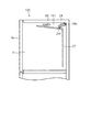
具体的には、図14に示すように、マルチフロー型のエバポレータの一例である冷蔵用冷却器24(図2、図9参照)は、冷蔵庫100の天井側に設けられ、背面ダクトに相当する冷気供給ダクト37から前方に延びている天井ダクト101内に配置されている。この天井ダクト101は、冷気供給ダクト37に接続しているとともに、前方側に開口において冷蔵室3に連通している。   Specifically, as shown in FIG. 14, a refrigeration cooler 24 (see FIGS. 2 and 9), which is an example of a multiflow evaporator, is provided on the ceiling side of the refrigerator 100 and corresponds to a rear duct. It is arranged in a ceiling duct 101 extending forward from the cold air supply duct 37. The ceiling duct 101 is connected to the cold air supply duct 37 and communicates with the refrigerating chamber 3 through an opening on the front side.

そして、冷蔵用冷却器24は、概ね矩形状つまりは概ね薄い直方体状の外形をなす本体部24gを含むその全体が、天井ダクト101内に配置されている。つまり、冷蔵用冷却器24は、冷気供給ダクト37よりも前方に位置した状態で、冷蔵庫100の天井側に配置されている。   The entire refrigeration cooler 24 is disposed in the ceiling duct 101 including a main body 24g having a substantially rectangular shape, that is, a substantially thin rectangular parallelepiped shape. That is, the refrigeration cooler 24 is disposed on the ceiling side of the refrigerator 100 in a state of being positioned in front of the cold air supply duct 37.

一般的な利用形態においては、冷蔵室3の天井側且つ背面側は、冷蔵庫100の大きさにもよるものの、食材を出し入れする際に比較的手が届き難いことからデッドスペースになりがちな場所である。換言すると、冷蔵室3の天井側且つ背面側は、冷蔵用冷却器24の設置スペースとして利用しても使い勝手を悪化させるおそれが低い場所である。また、冷蔵室3の天井側且つ背面側は、当然のことながら冷蔵室3のごく近傍であるため、冷気を供給するためのダクトも最小限の設置スペースで済むことになる。   In a general usage form, the ceiling side and the back side of the refrigerator compartment 3 tend to be dead spaces because they are relatively difficult to reach when putting in and out food, although depending on the size of the refrigerator 100 It is. In other words, the ceiling side and the back side of the refrigerating room 3 are places where the possibility of deteriorating usability is low even when the refrigerating room 3 is used as an installation space for the refrigerating cooler 24. In addition, since the ceiling side and the back side of the refrigerator compartment 3 are, of course, very close to the refrigerator compartment 3, a duct for supplying cold air can be provided with a minimum installation space.

そして、マルチフロー型の冷蔵用冷却器24は、上記した図2、図9等に示したように、非常に薄型化することができる。このとき、冷蔵用冷却器24を薄型化すると、外形が同じであれば冷却性能が低下するものの、冷蔵室3の天井側は概ね冷蔵室3の横幅と同等の長さを利用することができるため、必要であれば冷蔵用冷却器24の横幅を大きくすることができる。そのため、冷却性能が不足してしまうことを回避することができる。   The multi-flow refrigeration cooler 24 can be made very thin as shown in FIGS. At this time, if the refrigeration cooler 24 is thinned, the cooling performance is lowered if the outer shape is the same, but the ceiling side of the refrigeration room 3 can use a length substantially equal to the width of the refrigeration room 3. Therefore, if necessary, the lateral width of the refrigeration cooler 24 can be increased. Therefore, it can be avoided that the cooling performance is insufficient.

このように、冷蔵室3の天井側且つ背面側は、冷蔵用冷却器24の設置スペースとして利用するのに非常に都合が良い場所であると言える。
したがって、マルチフロー型のエバポレータとしての冷蔵用冷却器24を、冷蔵庫100の背面側に設けられている背面ダクトとしての冷気供給ダクト37よりも前方側に位置した状態で、冷蔵庫100の天井側に配置することにより、製造側およびユーザ側の双方にとってデメリットが無い状態で、貯蔵室として利用可能な有効な庫内体積を稼ぐことができる。
Thus, it can be said that the ceiling side and the back side of the refrigerating room 3 are very convenient places to use as the installation space for the refrigerating cooler 24.
Therefore, the refrigeration cooler 24 as a multi-flow type evaporator is placed on the ceiling side of the refrigerator 100 in a state of being positioned in front of the cold air supply duct 37 as a back duct provided on the back side of the refrigerator 100. By arranging, it is possible to earn an effective internal volume that can be used as a storage room in a state where there is no disadvantage for both the manufacturing side and the user side.

このとき、壁部例えば天井ダクト101の上面から、本体部24gの外縁つまりは本体部24gの壁部とは反対側の部位までの距離が、できるだけ小さくなるように配置することができる。具体的には、冷蔵用冷却器24の本体部24gを設置面に対して水平に設けることができる。これにより、天井ダクト101の上下方向の高さを低減することができる。   At this time, the distance from the upper surface of the wall part, for example, the ceiling duct 101, to the outer edge of the main body part 24g, that is, the part opposite to the wall part of the main body part 24g, can be arranged to be as small as possible. Specifically, the main body 24g of the refrigeration cooler 24 can be provided horizontally with respect to the installation surface. Thereby, the height of the vertical direction of the ceiling duct 101 can be reduced.

この場合、冷蔵用冷却器24には外部配管に接続するための入口側接続部24eおよび出口側接続部24f(図2、図9参照)が設けられているが、これら入口側接続部24eおよび出口側接続部24fを本体部24gから水平方向に延びるように設けることができる。   In this case, the refrigeration cooler 24 is provided with an inlet-side connecting portion 24e and an outlet-side connecting portion 24f (see FIGS. 2 and 9) for connecting to an external pipe. The outlet side connection part 24f can be provided so as to extend in the horizontal direction from the main body part 24g.

これにより、設置スペースの高さ方向に必要な長さを削減することができ、庫内容積が低下することを抑制できる。また、入口側接続部24eおよび出口側接続部24fは、本体部24gから冷蔵室3の横幅方向に水平に延びるようにすることもでき、その場合も同様に庫内容積が低下することを抑制できる。   Thereby, the length required in the height direction of an installation space can be reduced, and it can suppress that an internal volume falls. Moreover, the inlet side connection part 24e and the outlet side connection part 24f can be made to extend horizontally from the main body part 24g in the lateral width direction of the refrigerator compartment 3, and also in this case, the reduction of the internal volume is similarly suppressed. it can.

また、入口側接続部24eおよび出口側接続部24fを本体部24gよりも後方側に向けることで、冷気供給ダクト37の前後方向の距離を入口側接続部24eおよび出口側接続部24fの配置領域として利用することができる。これにより、冷蔵用冷却器24をより後方に配置することが可能となり、手が届きにくい場所とは言え冷蔵室3としては利用できるスペースをより有効に活用することができる。   Further, the inlet-side connection portion 24e and the outlet-side connection portion 24f are directed to the rear side of the main body portion 24g, so that the distance in the front-rear direction of the cold air supply duct 37 is set as the arrangement region of the inlet-side connection portion 24e and the outlet-side connection portion 24f Can be used as Thereby, it becomes possible to arrange | position the cooler 24 for refrigeration more back, and the space which can be utilized as the refrigerator compartment 3 can be utilized more effectively although it is a place where it is hard to reach.

ところで、冷蔵室3内に冷気を供給するため、冷蔵用冷却器24の近傍には、ファン60が設置される。本態様では、ファン60は、天井ダクト101内において、冷蔵用冷却器24よりも前方つまりは空気の流れにおいて下流側に配置されている。このとき、ファン60は、ファン体が水平となるように、つまりは、空気の流れが鉛直となるように配置されているため、天井ダクト101の高さが増加することを抑えることができる。   By the way, in order to supply cold air into the refrigerator compartment 3, a fan 60 is installed in the vicinity of the refrigerator 24 for refrigerator. In this aspect, the fan 60 is disposed in the ceiling duct 101 in front of the refrigeration cooler 24, that is, on the downstream side in the air flow. At this time, since the fan 60 is arranged so that the fan body is horizontal, that is, the air flow is vertical, it is possible to suppress an increase in the height of the ceiling duct 101.

このとき、冷気は、循環する空気が冷蔵用冷却器24の表面に触れることで生成される。ただし、冷蔵用冷却器24を水平に配置している場合には、冷蔵用冷却器24の本体部を垂直方向に通る空気の流れが必要になる。そのため、本態様では、冷蔵用冷却器24の上部側且つ後端側に、冷気供給ダクト37から冷蔵用冷却器24の上部側への空気の流れを阻害する阻害部材102を設けるとともに、冷蔵用冷却器24の下部側且つ前端側に、冷蔵用冷却器24の下部側からファン60側への空気の流れを阻害する阻害部材102を設けている。   At this time, the cold air is generated when the circulating air touches the surface of the refrigeration cooler 24. However, when the refrigeration cooler 24 is disposed horizontally, an air flow that passes through the main body of the refrigeration cooler 24 in the vertical direction is required. Therefore, in this aspect, the inhibition member 102 that inhibits the flow of air from the cold air supply duct 37 to the upper side of the refrigeration cooler 24 is provided on the upper side and the rear end side of the refrigeration cooler 24, and On the lower side and the front end side of the cooler 24, an inhibition member 102 that inhibits the flow of air from the lower side of the refrigeration cooler 24 to the fan 60 side is provided.

これにより、冷気供給ダクト37から天井ダクト101に流入した空気は、上部側の阻害部材102によって冷蔵用冷却器24の下部側に流入する流れが形成されるとともに、下部側の阻害部材102によって冷蔵用冷却器24の本体部24gを通る流れが形成される。これにより、冷気を効率よく生成することができる。   As a result, the air flowing into the ceiling duct 101 from the cold air supply duct 37 forms a flow that flows into the lower side of the refrigeration cooler 24 by the upper-side inhibition member 102, and is refrigerated by the lower-side inhibition member 102. A flow through the main body 24g of the cooler 24 is formed. Thereby, cold air can be generated efficiently.

また、本体部24gを水平に配置した場合には、偏平管24cの偏平方向およびフィン24dの面方向は、図14でいう本体部24gの厚み方向つまりは鉛直方向になる。この場合、偏平管24cやフィン24dの表面に水滴が付着すると、その水滴は重力によって下方に流下する。   When the main body 24g is horizontally disposed, the flat direction of the flat tube 24c and the surface direction of the fin 24d are the thickness direction of the main body 24g as shown in FIG. 14, that is, the vertical direction. In this case, when a water droplet adheres to the surface of the flat tube 24c or the fin 24d, the water droplet flows downward due to gravity.

つまり、冷蔵用冷却器24を、偏平管24cの偏平方向が冷蔵庫100の設置面に対して傾くように配置したり、フィン24dの表面が冷蔵庫100の設置面に対して傾くように配置したりすることにより、冷蔵用冷却器24に付着した水滴の除去を促すことができる。ここで、設置面に対して傾いているとは、設置面と水平ではない状態を意味しており、設置面に垂直な向きも含まれる。   That is, the refrigeration cooler 24 is arranged such that the flat direction of the flat tube 24 c is inclined with respect to the installation surface of the refrigerator 100, or the surface of the fin 24 d is arranged so as to be inclined with respect to the installation surface of the refrigerator 100. By doing so, removal of water droplets adhering to the refrigeration cooler 24 can be promoted. Here, being inclined with respect to the installation surface means a state that is not horizontal with the installation surface, and includes a direction perpendicular to the installation surface.

ところで、冷蔵用冷却器24を除霜すると、水滴つまりは除霜水が多く発生する。そのため、除霜水が天井ダクト101に対流しないように、天井ダクト101からの除霜水の排水を促す必要がある。そのため、本態様では、冷蔵用冷却器24の下方に位置する天井ダクト101の下面を、冷気供給ダクト37側つまりは冷蔵庫100の後方に向かって下方に傾斜するようにしている。また、天井ダクト101の下面は、冷気供給ダクト37の前面と一体に形成されている。   By the way, when the refrigeration cooler 24 is defrosted, a lot of water droplets, that is, defrosted water is generated. Therefore, it is necessary to promote drainage of the defrost water from the ceiling duct 101 so that the defrost water does not convect to the ceiling duct 101. Therefore, in this aspect, the lower surface of the ceiling duct 101 positioned below the refrigeration cooler 24 is inclined downward toward the cold air supply duct 37 side, that is, toward the rear of the refrigerator 100. Further, the lower surface of the ceiling duct 101 is formed integrally with the front surface of the cold air supply duct 37.

これにより、天井ダクト101からの除霜水の排出を促すことができる。このとき、天井ダクト101の下面と冷気供給ダクト37の前面と一体に形成していることから、効率的に除霜水を排水することが可能となる。   Thereby, discharge | emission of the defrost water from the ceiling duct 101 can be promoted. At this time, since the lower surface of the ceiling duct 101 and the front surface of the cold air supply duct 37 are integrally formed, the defrost water can be efficiently drained.

このように、冷蔵用冷却器24を除霜した際に発生する除霜水の排水を促す排水促進部材として冷気を供給するために必要となる構造である天井ダクト101を利用することにより、構造を簡略化することができるとともに製造コストの増加を抑制することができる。   Thus, by using the ceiling duct 101 which is a structure necessary for supplying cold air as a drainage promotion member that promotes drainage of defrost water generated when the refrigeration cooler 24 is defrosted, Can be simplified, and an increase in manufacturing cost can be suppressed.

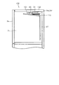
さて、ここまでは冷蔵用冷却器24を天井ダクト101内に設置面に対して水平となるように配置する例を示したが、冷蔵用冷却器24は、図15に示すように、冷蔵用冷却器24を冷蔵庫100の設置面に対して傾くように配置することもできる。   Up to this point, an example in which the refrigeration cooler 24 is arranged in the ceiling duct 101 so as to be horizontal to the installation surface has been shown. However, as shown in FIG. The cooler 24 may be arranged so as to be inclined with respect to the installation surface of the refrigerator 100.

この場合、冷蔵用冷却器24の前端を天井ダクト101の下面側に位置させ、冷蔵用冷却器24の後端を天井ダクト101の上面側に位置させることができる。この場合、偏平管24cの偏平方向およびフィン24dの面方向も、冷蔵庫100の設置面に対して傾くように配置される。   In this case, the front end of the refrigeration cooler 24 can be positioned on the lower surface side of the ceiling duct 101, and the rear end of the refrigeration cooler 24 can be positioned on the upper surface side of the ceiling duct 101. In this case, the flat direction of the flat tube 24 c and the surface direction of the fins 24 d are also arranged to be inclined with respect to the installation surface of the refrigerator 100.

そのため、冷気供給ダクト37から天井ダクト101への空気は、偏平管24cの偏平方向およびフィン24dの面方向に沿ってスムーズに流れることになる。つまり、冷蔵用冷却器24を、通過する空気の流れが冷蔵庫100の設置面に対して傾くように配置することにより、冷気の循環を効率よく行うことができる。   Therefore, the air from the cold air supply duct 37 to the ceiling duct 101 flows smoothly along the flat direction of the flat tube 24c and the surface direction of the fin 24d. That is, by arranging the refrigeration cooler 24 so that the flow of air passing through the refrigerator 24 is inclined with respect to the installation surface of the refrigerator 100, the circulation of the cold air can be performed efficiently.

また、本体部24gの少なくとも一部が天井ダクト101内に位置するように配置することにより、冷気供給ダクト37を大きくすることなく、また、天井ダクト101を過度に大きくすることなく、冷蔵用冷却器24を配置することができる。つまり、庫内容積の低下を抑制することができる。   Further, by disposing at least a part of the main body portion 24g in the ceiling duct 101, the cooling air cooling duct 37 is not enlarged, and the ceiling duct 101 is not excessively enlarged. A vessel 24 can be arranged. That is, a decrease in the internal volume can be suppressed.

また、冷蔵用冷却器24を冷蔵庫100の設置面に対して傾くように配置することにより、偏平管24cの偏平方向およびフィン24dの面方向も傾くことから、表面に付着した除霜水の滴下を促すことができる。このとき、本態様のように冷蔵用冷却器24の後端が上方に位置するように傾けることにより、除霜水は冷気供給ダクト37側に滴下するため、天井ダクト101からの排水を促すこともできる。   Further, by arranging the refrigeration cooler 24 so as to be inclined with respect to the installation surface of the refrigerator 100, the flat direction of the flat tube 24c and the surface direction of the fin 24d are also inclined. Can be encouraged. At this time, since the defrost water is dripped to the cold air supply duct 37 side by inclining so that the rear end of the refrigeration cooler 24 is positioned upward as in this embodiment, the drainage from the ceiling duct 101 is promoted. You can also.

図15に示す例では、天井ダクト101の上面から本体部24gの外縁までの距離をできるだけ小さくなるように配置しているが、背面から本体部24gの外縁までの距離をできるだけ小さくなるように配置することができる。具体的には、図15の状態よりも冷蔵用冷却器24を立てた状態である。このような配置の場合も、貯蔵室として利用可能な有効な庫内体積を稼ぐことができる等、上記した各種の効果を得ることができる。   In the example shown in FIG. 15, the distance from the upper surface of the ceiling duct 101 to the outer edge of the main body part 24g is arranged to be as small as possible, but the distance from the back surface to the outer edge of the main body part 24g is arranged to be as small as possible. can do. Specifically, it is a state where the refrigeration cooler 24 is raised from the state of FIG. Even in such an arrangement, the various effects described above can be obtained, such as an effective internal volume that can be used as a storage room.

また、図16に示すように、天井ダクト101の下面ではなく、専用の受け皿110を排水促進部材として使うこともできる。この場合、受け皿110は、除霜水を一時的に貯留する貯留部材としても機能する。これにより、除霜水を単に排水するだけでなく、いわゆるうるおい制御等に除霜水を有効利用することができる。   Moreover, as shown in FIG. 16, not the lower surface of the ceiling duct 101 but a dedicated tray 110 can be used as a drainage promotion member. In this case, the tray 110 also functions as a storage member that temporarily stores defrost water. Thereby, the defrost water can be effectively used not only for draining the defrost water but also for so-called moisture control.

このとき、受け皿110は、冷蔵用冷却器24の下方を覆う長さ、より具体的には、水平または傾けて配置されている本体部24gを鉛直方向に投影した際の前後方向および左右方向の投影幅よりも大きく形成することで、除霜水を適切に貯留および排出することができる。これは、図11等に示した貯水容器56も同様である。   At this time, the tray 110 has a length that covers the lower side of the refrigeration cooler 24, more specifically, in the front-rear direction and the left-right direction when the main body 24g that is horizontally or tilted is projected in the vertical direction. By forming it larger than the projected width, the defrost water can be appropriately stored and discharged. The same applies to the water storage container 56 shown in FIG.

(その他の実施形態)
実施形態ではヘッダ24a、24bを有するマルチフロー型のエバポレータを例示したが、ヘッダ24a等を介さず、偏平管24cに直接的に外部配管を接続する構成にすることができる。
(Other embodiments)
In the embodiment, the multi-flow type evaporator having the headers 24a and 24b has been exemplified. However, the external pipe can be directly connected to the flat tube 24c without using the header 24a or the like.

入口側接続部24eおよび出口側接続部24fが延びる向きは、実施形態で例示した向きに限らない。例えば、第1実施形態や図8に示したような冷蔵用冷却器24の配置の場合には、入口側接続部24eおよび出口側接続部24fを上下方向つまりはファン60の厚み方向に延びる向きとすることができる。これにより、入口側接続部24eおよび出口側接続部24fの長さの範囲内にファン60を配置することにより設置スペースの省スペース化を図ることができる。   The direction in which the inlet side connection part 24e and the outlet side connection part 24f extend is not limited to the direction illustrated in the embodiment. For example, in the case of the arrangement of the refrigeration cooler 24 as shown in the first embodiment or FIG. It can be. Thereby, the installation space can be saved by arranging the fan 60 within the range of the length of the inlet side connecting portion 24e and the outlet side connecting portion 24f.

各実施形態は、例として提示したものであり、発明の範囲を限定することは意図していない。これら新規な実施形態は、その他の様々な形態で実施されることが可能であり、発明の要旨を逸脱しない範囲で、種々の省略、置き換え、変更を行うことができる。本実施形態およびその変形は、発明の範囲および要旨に含まれるとともに、特許請求の範囲に記載された発明とその均等の範囲に含まれる。   Each embodiment is presented as an example and is not intended to limit the scope of the invention. These novel embodiments can be implemented in various other forms, and various omissions, replacements, and changes can be made without departing from the scope of the invention. This embodiment and its modifications are included in the scope and gist of the invention, and are included in the invention described in the claims and the equivalents thereof.

図面中、1、100は冷蔵庫、24は冷蔵用冷却器(エバポレータ)、24a、24bはヘッダ、24cは偏平管、24dはフィン、24gは本体部、37は冷気供給ダクト(背面ダクト、排水促進部材)、35は冷蔵用送風ファン、(ファン)、56は貯水容器(排水促進部材)、60はファン、101は天井ダクト(排水促進部材)、110は受け皿(排水促進部材)を示す。   In the drawings, 1 and 100 are refrigerators, 24 is a refrigeration cooler (evaporator), 24a and 24b are headers, 24c is a flat tube, 24d is fins, 24g is a main body, 37 is a cool air supply duct (back duct, drainage promotion) Member), 35 is a refrigeration fan, (fan), 56 is a water storage container (drainage promoting member), 60 is a fan, 101 is a ceiling duct (drainage promoting member), and 110 is a tray (drainage promoting member).

Claims (13)

内部に冷媒が流れる流路が複数形成されている偏平管を有するマルチフロー型のエバポレータを、少なくとも一部が当該冷蔵庫の背面側に設けられている背面ダクトよりも前方側に位置した状態で、当該冷蔵庫の天井側に配置したことを特徴とする冷蔵庫。   In a state where at least a part of the multi-flow type evaporator having a flat tube in which a plurality of flow paths for the refrigerant flow is formed is located on the front side of the back duct provided on the back side of the refrigerator, A refrigerator that is arranged on a ceiling side of the refrigerator. 前記エバポレータは、前記偏平管が配置されている部位である本体部が矩形状に形成されており、壁部から本体部の外縁までの距離が小さくなるように配置されていることを特徴とする請求項1記載の冷蔵庫。   The evaporator is characterized in that the main body portion, which is a portion where the flat tube is disposed, is formed in a rectangular shape, and is arranged so that the distance from the wall portion to the outer edge of the main body portion is small. The refrigerator according to claim 1. 前記エバポレータは、前記偏平管が配置されている部位である本体部の少なくとも一部が、当該冷蔵庫の天井側に設けられている天井ダクトに位置するように配置されていることを特徴とする請求項1または2記載の冷蔵庫。   The evaporator is disposed such that at least a part of a main body portion, which is a portion where the flat tube is disposed, is located in a ceiling duct provided on a ceiling side of the refrigerator. Item 3. The refrigerator according to item 1 or 2. 前記エバポレータは、前記偏平管が配置されている部位である本体部が、当該冷蔵庫の設置面に対して水平になるように配置されていることを特徴とする請求項1から3のいずれか一項記載の冷蔵庫。   The said evaporator is arrange | positioned so that the main-body part which is a site | part by which the said flat tube is arrange | positioned may become horizontal with respect to the installation surface of the said refrigerator. The refrigerator according to the item. 前記エバポレータは、前記偏平管が配置されている部位である本体部が、当該冷蔵庫の設置面に対して傾くように配置されていることを特徴とする請求項1から3のいずれか一項記載の冷蔵庫。   The said evaporator is arrange | positioned so that the main-body part which is a site | part in which the said flat tube is arrange | positioned may incline with respect to the installation surface of the said refrigerator. Refrigerator. 前記エバポレータは、前記偏平管の偏平方向が、当該冷蔵庫の設置面に対して傾くように配置されていることを特徴とする請求項1から5のいずれか一項記載の冷蔵庫。   The refrigerator according to any one of claims 1 to 5, wherein the evaporator is arranged such that a flat direction of the flat tube is inclined with respect to an installation surface of the refrigerator. 前記エバポレータは、前記偏平管に連通するヘッダが、前記偏平管が配置されている部位である本体部よりも後方に配置されていることを特徴とする請求項1から6のいずれか一項記載の冷蔵庫。   7. The evaporator according to claim 1, wherein a header communicating with the flat tube is disposed rearward of a main body portion that is a portion where the flat tube is disposed. Refrigerator. 前記エバポレータは、当該エバポレータを通過する空気の流れが、当該冷蔵庫の設置面に対して傾くように配置されていることを特徴とする請求項1から7のいずれか一項記載の冷蔵庫。   The refrigerator according to any one of claims 1 to 7, wherein the evaporator is disposed so that an air flow passing through the evaporator is inclined with respect to an installation surface of the refrigerator. 前記エバポレータは、前記偏平管に設けられているフィンの面方向が、当該冷蔵庫の設置面に対して傾くように配置されていることを特徴とする請求項1から8のいずれか一項記載の冷蔵庫。   The said evaporator is arrange | positioned so that the surface direction of the fin provided in the said flat tube may incline with respect to the installation surface of the said refrigerator, It is any one of Claim 1 to 8 characterized by the above-mentioned. refrigerator. 空気の流れにおいて前記エバポレータの下流側にファンを設けたことを特徴とする請求項1から9のいずれか一項記載の冷蔵庫。   The refrigerator according to any one of claims 1 to 9, wherein a fan is provided on the downstream side of the evaporator in an air flow. 前記エバポレータの下方側に、当該エバポレータから滴下する水の排水を促す排水促進部材を備えることを特徴とする請求項1から10のいずれか一項記載の冷蔵庫。   The refrigerator according to any one of claims 1 to 10, further comprising a drainage promotion member that promotes drainage of water dripped from the evaporator on a lower side of the evaporator. 前記排水促進部材は、前記背面ダクトと一体に形成されていることを特徴とする請求項11記載の冷蔵庫。   The refrigerator according to claim 11, wherein the drainage promotion member is formed integrally with the rear duct. 前記排水促進部材は、当該冷蔵庫の後方に向かって下方に傾斜して設けられていることを特徴とする請求項11または12記載の冷蔵庫。   The refrigerator according to claim 11 or 12, wherein the drainage promotion member is inclined downward toward the rear of the refrigerator.
JP2017028976A 2016-09-16 2017-02-20 refrigerator Pending JP2018048798A (en)

Priority Applications (1)

Application Number Priority Date Filing Date Title
CN201710825741.7A CN107830680A (en) 2016-09-16 2017-09-14 Refrigerator

Applications Claiming Priority (2)

Application Number Priority Date Filing Date Title
JP2016181674 2016-09-16

Publications (1)

Publication Number Publication Date
JP2018048798A true JP2018048798A (en) 2018-03-29

Family

ID=61766225

Family Applications (2)

Application Number Title Priority Date Filing Date
JP2017028976A Pending JP2018048798A (en) 2016-09-16 2017-02-20 refrigerator
JP2017082014A Active JP7032055B2 (en) 2016-09-16 2017-04-18 refrigerator

Family Applications After (1)

Application Number Title Priority Date Filing Date
JP2017082014A Active JP7032055B2 (en) 2016-09-16 2017-04-18 refrigerator

Country Status (1)

Country Link
JP (2) JP2018048798A (en)

Cited By (1)

* Cited by examiner, † Cited by third party
Publication number Priority date Publication date Assignee Title
US11512887B2 (en) 2018-12-19 2022-11-29 Samsung Electronics Co., Ltd. Refrigerator

Families Citing this family (1)

* Cited by examiner, † Cited by third party
Publication number Priority date Publication date Assignee Title
JP2023058069A (en) * 2021-10-13 2023-04-25 パナソニックIpマネジメント株式会社 refrigerator

Family Cites Families (21)

* Cited by examiner, † Cited by third party
Publication number Priority date Publication date Assignee Title
JPS5613682U (en) * 1979-07-10 1981-02-05
JPS602475Y2 (en) * 1979-10-22 1985-01-23 松下冷機株式会社 Heat exchanger
JPH0377170U (en) * 1989-11-29 1991-08-02
JPH03181759A (en) * 1989-12-08 1991-08-07 Nippondenso Co Ltd Refrigerant evaporator
JPH06317363A (en) * 1993-05-07 1994-11-15 Showa Alum Corp Heat exchanger
JPH08247622A (en) * 1995-03-08 1996-09-27 Toshiba Corp Refrigerator
JP3863217B2 (en) * 1996-05-29 2006-12-27 株式会社デンソー Stacked evaporator
JP3734922B2 (en) * 1997-04-23 2006-01-11 松下冷機株式会社 Freezer refrigerator
JP3903888B2 (en) * 2002-09-10 2007-04-11 株式会社デンソー Heat exchanger
JP2004347314A (en) * 2003-04-28 2004-12-09 Showa Denko Kk Evaporator and its manufacturing method
JP2005024187A (en) * 2003-07-03 2005-01-27 Matsushita Electric Ind Co Ltd Outdoor heat exchanger for heat pump
KR100676634B1 (en) * 2004-11-17 2007-02-02 주식회사 동성기연 Cooling fin for heat exchanger
JP2009068742A (en) * 2007-09-12 2009-04-02 Sharp Corp Heat exchanger
JP2010025481A (en) * 2008-07-22 2010-02-04 Daikin Ind Ltd Heat exchanger
JP2012032111A (en) * 2010-08-02 2012-02-16 Fuji Electric Co Ltd Heat exchanger
JP2012132593A (en) * 2010-12-20 2012-07-12 Fuji Electric Co Ltd Heat exchanger
US9534827B2 (en) * 2012-06-07 2017-01-03 Johnson Controls-Hitachi Air Conditioning Technology (Hong Kong) Limited Air heat exchanger
JP2016003831A (en) * 2014-06-18 2016-01-12 シャープ株式会社 refrigerator
KR102236751B1 (en) * 2014-08-18 2021-04-06 삼성전자주식회사 Refrigerator
JP2016095094A (en) * 2014-11-14 2016-05-26 東芝キヤリア株式会社 Heat exchanger and refrigeration cycle device
CN205481945U (en) * 2016-01-08 2016-08-17 浙江同星制冷有限公司 Many flat union coupling heating plate heat exchanger

Cited By (1)

* Cited by examiner, † Cited by third party
Publication number Priority date Publication date Assignee Title
US11512887B2 (en) 2018-12-19 2022-11-29 Samsung Electronics Co., Ltd. Refrigerator

Also Published As

Publication number Publication date
JP2018048799A (en) 2018-03-29
JP7032055B2 (en) 2022-03-08

Similar Documents

Publication Publication Date Title
CN107621114A (en) A kind of wind cooling refrigerator
JP5872143B2 (en) refrigerator
JP5450462B2 (en) refrigerator
KR101520704B1 (en) Refrigerator
RU2422737C1 (en) Refrigerator
JP2007064597A (en) Refrigerator
JP2013019623A (en) Refrigerator
JP2014048030A (en) Cooling warehouse
JP2012127629A (en) Cooling storage cabinet
JP2000018800A (en) Structure of evaporation pan of refrigerator
JP2018048798A (en) refrigerator
JP2007064601A (en) Refrigerator
JP2014048031A (en) Refrigerator
JP6426350B2 (en) refrigerator
JP2014077615A (en) Refrigerator
JP2010117038A (en) Refrigerator
JP2007064598A (en) Refrigerator
CN210035945U (en) Refrigerator with evaporator with bending structure
JP2018036024A (en) refrigerator
JP6955348B2 (en) refrigerator
JP5990731B2 (en) refrigerator
JP2019132494A (en) refrigerator
CN218065495U (en) Refrigerator with a door
JP2006023035A (en) Refrigerator
JP4203662B2 (en) refrigerator