JP2018043669A - Vehicle seat - Google Patents
Vehicle seat Download PDFInfo
- Publication number
- JP2018043669A JP2018043669A JP2016180481A JP2016180481A JP2018043669A JP 2018043669 A JP2018043669 A JP 2018043669A JP 2016180481 A JP2016180481 A JP 2016180481A JP 2016180481 A JP2016180481 A JP 2016180481A JP 2018043669 A JP2018043669 A JP 2018043669A
- Authority
- JP
- Japan
- Prior art keywords
- bracket
- frame
- side holes
- frame side
- holes
- Prior art date
- Legal status (The legal status is an assumption and is not a legal conclusion. Google has not performed a legal analysis and makes no representation as to the accuracy of the status listed.)
- Pending
Links
Images


Classifications
-
- B—PERFORMING OPERATIONS; TRANSPORTING
- B60—VEHICLES IN GENERAL
- B60N—SEATS SPECIALLY ADAPTED FOR VEHICLES; VEHICLE PASSENGER ACCOMMODATION NOT OTHERWISE PROVIDED FOR
- B60N2/00—Seats specially adapted for vehicles; Arrangement or mounting of seats in vehicles
- B60N2/80—Head-rests
-
- B—PERFORMING OPERATIONS; TRANSPORTING
- B60—VEHICLES IN GENERAL
- B60N—SEATS SPECIALLY ADAPTED FOR VEHICLES; VEHICLE PASSENGER ACCOMMODATION NOT OTHERWISE PROVIDED FOR
- B60N2/00—Seats specially adapted for vehicles; Arrangement or mounting of seats in vehicles
- B60N2/68—Seat frames
- B60N2/682—Joining means
-
- B—PERFORMING OPERATIONS; TRANSPORTING
- B60—VEHICLES IN GENERAL
- B60N—SEATS SPECIALLY ADAPTED FOR VEHICLES; VEHICLE PASSENGER ACCOMMODATION NOT OTHERWISE PROVIDED FOR
- B60N2/00—Seats specially adapted for vehicles; Arrangement or mounting of seats in vehicles
- B60N2/80—Head-rests
- B60N2/806—Head-rests movable or adjustable
-
- B—PERFORMING OPERATIONS; TRANSPORTING
- B60—VEHICLES IN GENERAL
- B60N—SEATS SPECIALLY ADAPTED FOR VEHICLES; VEHICLE PASSENGER ACCOMMODATION NOT OTHERWISE PROVIDED FOR
- B60N2/00—Seats specially adapted for vehicles; Arrangement or mounting of seats in vehicles
- B60N2/80—Head-rests
- B60N2002/899—Head-rests characterised by structural or mechanical details not otherwise provided for
Abstract
Description
本開示は乗物用シートに関する。 The present disclosure relates to a vehicle seat.
従来、以下のような乗物用シートが知られている。乗物用シートは、着座者の背部を支持するフレームと、そのフレームの上部に取り付けられるブラケットと、ブラケットに対し、フレームとは反対側から取り付けられるヘッドレストサポートブラケットとを備える。ヘッドレストサポートブラケットには、ヘッドレストが取り付けられる(特許文献1参照)。 Conventionally, the following vehicle seats are known. The vehicle seat includes a frame that supports the back of the seated person, a bracket that is attached to an upper portion of the frame, and a headrest support bracket that is attached to the bracket from the opposite side of the frame. A headrest is attached to the headrest support bracket (see Patent Document 1).
フレームに対するブラケットの取付位置を決める方法として、以下の方法が知られている。フレームには、複数の孔(以下ではフレーム側孔とする)が設けられている。また、ブラケットにも、複数の孔(以下ではブラケット側孔とする)が設けられている。正面視において、フレーム側孔とブラケット側孔とが一致するように、フレームに対するブラケットの取付位置を決める。次に、フレームとブラケットとを溶接する。 The following methods are known as methods for determining the mounting position of the bracket with respect to the frame. The frame is provided with a plurality of holes (hereinafter referred to as frame side holes). The bracket is also provided with a plurality of holes (hereinafter referred to as bracket side holes). In front view, the mounting position of the bracket with respect to the frame is determined so that the frame side hole and the bracket side hole coincide. Next, the frame and the bracket are welded.
フレーム、ブラケットは同一であっても、仕様、車種等に応じて、フレームに対するブラケットの取付位置が異なることがある。この場合、上述した方法で取付位置を決めるためには、仕様、車種ごとに、フレーム側孔又はブラケット側孔の位置を変更する必要がある。そのため、乗物用シートの製造工程が煩雑となってしまう。 Even if the frame and the bracket are the same, the mounting position of the bracket with respect to the frame may differ depending on the specifications, vehicle type, and the like. In this case, in order to determine the mounting position by the method described above, it is necessary to change the position of the frame side hole or the bracket side hole for each specification and vehicle type. Therefore, the manufacturing process of the vehicle seat becomes complicated.
本開示の一局面は、フレームに対するブラケットの取付位置が複数存在する場合でも、製造工程が煩雑になり難い乗物用シートを提供することを目的とする。 An object of one aspect of the present disclosure is to provide a vehicle seat in which a manufacturing process is difficult to be complicated even when there are a plurality of bracket mounting positions with respect to a frame.
本開示の一態様は、着座者の背部を支持するフレームと、前記フレームの上部に取り付けられるブラケットと、前記ブラケットに対し、前記フレームとは反対側から取り付けられるヘッドレストサポートブラケットと、前記フレームに設けられた3個以上のフレーム側孔と、前記ブラケットに設けられた3個以上のブラケット側孔と、を備え、前記フレーム側孔及び前記ブラケット側孔は、以下の条件(a)を充足するとともに、以下の条件(b)又は(c)を充足するように配置されている乗物用シートである。 One aspect of the present disclosure includes a frame that supports a back of a seated person, a bracket that is attached to an upper portion of the frame, a headrest support bracket that is attached to the bracket from a side opposite to the frame, and the frame. Three or more frame side holes and three or more bracket side holes provided in the bracket, and the frame side hole and the bracket side hole satisfy the following condition (a): The vehicle seat is arranged so as to satisfy the following condition (b) or (c).
(a)2個以上の前記フレーム側孔と、2個以上の前記ブラケット側孔とが一致する、前記フレームに対する前記ブラケットの取付位置が2以上存在する。
(b)任意の前記取付位置において、前記ブラケット側孔と一致する2個以上の前記フレーム側孔の少なくとも一部は、他の前記取付位置では前記ブラケット側孔のいずれとも一致しない。
(A) There are two or more mounting positions of the bracket with respect to the frame where two or more of the frame side holes and two or more of the bracket side holes match.
(B) At any of the attachment positions, at least a part of the two or more frame side holes that coincide with the bracket side holes do not coincide with any of the bracket side holes at the other attachment positions.
(c)任意の前記取付位置において、前記フレーム側孔と一致する2個以上の前記ブラケット側孔の少なくとも一部は、他の前記取付位置では前記フレーム側孔のいずれとも一致しない。 (C) At any of the attachment positions, at least some of the two or more bracket side holes that coincide with the frame side hole do not coincide with any of the frame side holes at the other attachment positions.
本開示の乗物用シートでは、フレーム側孔及びブラケット側孔が前記条件(a)を充足するので、2個以上のフレーム側孔と、2個以上のブラケット側孔とが一致する取付位置が2以上存在する。そのため、同一のフレーム及びブラケットにおいて、2以上の取付位置の中から、1つの取付位置を選択し、決定することができる。その結果、乗物用シートの製造工程が煩雑になることを抑制できる。 In the vehicle seat of the present disclosure, since the frame side hole and the bracket side hole satisfy the condition (a), there are two mounting positions where the two or more frame side holes and the two or more bracket side holes match. There are more. Therefore, in the same frame and bracket, one attachment position can be selected and determined from two or more attachment positions. As a result, it can suppress that the manufacturing process of the vehicle seat becomes complicated.
また、本開示の乗物用シートでは、フレーム側孔及びブラケット側孔が前記条件(b)又は(c)を充足する。フレーム側孔及びブラケット側孔が前記条件(b)を充足する場合、特定の2以上のフレーム側孔の全てがブラケット側孔と一致する取付位置は1のみである。そのため、その特定の2以上のフレーム側孔の全てがブラケット側孔と一致する取付位置を選択するようにすれば、取付位置の選択を誤ってしまうことを抑制できる。 In the vehicle seat of the present disclosure, the frame side hole and the bracket side hole satisfy the condition (b) or (c). When the frame side hole and the bracket side hole satisfy the condition (b), the mounting position where all of the specific two or more frame side holes coincide with the bracket side hole is only one. For this reason, if the mounting position in which all of the two or more specific frame side holes coincide with the bracket side hole is selected, it is possible to suppress erroneous selection of the mounting position.
また、フレーム側孔及びブラケット側孔が前記条件(c)を充足する場合、特定の2以上のブラケット側孔の全てがフレーム側孔と一致する取付位置は1のみである。そのため、その特定の2以上のブラケット側孔の全てがフレーム側孔と一致する取付位置を選択するようにすれば、取付位置の選択を誤ってしまうことを抑制できる。 Further, when the frame side hole and the bracket side hole satisfy the condition (c), only one mounting position is obtained in which all of the specific two or more bracket side holes coincide with the frame side hole. For this reason, if the mounting position in which all of the two or more specific bracket side holes coincide with the frame side hole is selected, it is possible to suppress erroneous selection of the mounting position.
本開示の乗物用シートは、例えば、以下の構成1をさらに備えていてもよい。
(構成1)
前記フレーム側孔及び前記ブラケット側孔のうちの一方は、前記フレーム及び前記ブラケットのうちの一方において、長方形の4頂点、及び前記長方形の1辺における中点に該当する位置に配置され、
前記フレーム側孔及び前記ブラケット側孔のうちの他方は、前記フレーム及び前記ブラケットのうちの他方において、いずれかの前記取付位置にあるとき、前記1辺の両端に一致する位置、及び前記長方形において前記1辺に対向する辺の中点に一致する位置に配置されている。
The vehicle seat of the present disclosure may further include the following
(Configuration 1)
One of the frame side hole and the bracket side hole is arranged at a position corresponding to the midpoint of the four vertices of the rectangle and one side of the rectangle in one of the frame and the bracket,
The other of the frame side hole and the bracket side hole is the other of the frame and the bracket. It is arranged at a position that coincides with the midpoint of the side facing the one side.
本開示の乗物用シートは、前記構成1をさらに備える場合、前記(a)を充足するとともに、前記条件(b)又は(c)を充足するフレーム側孔及びブラケット側孔を、簡易な構成で実現できる。
When the vehicle seat of the present disclosure further includes the
本開示の乗物用シートは、例えば、以下の構成2をさらに備えていてもよい。
(構成2)
前記フレーム側孔の直径は、前記ブラケット側孔の直径より大きい。
The vehicle seat of the present disclosure may further include the following configuration 2, for example.
(Configuration 2)
The diameter of the frame side hole is larger than the diameter of the bracket side hole.
本開示の乗物用シートは、前記構成2をさらに備える場合、フレーム側孔からブラケット側孔に向けて治具を差し込み、フレーム側孔とブラケット側孔との位置を正面視において一致させることが一層容易になる。 When the vehicle seat of the present disclosure further includes the configuration 2, it is preferable that a jig is inserted from the frame side hole toward the bracket side hole so that the positions of the frame side hole and the bracket side hole coincide with each other in a front view. It becomes easy.
本開示の実施形態を図面に基づき説明する。
<第1実施形態>
1.乗物用シート1の構成
乗物用シート1の構成を図1〜図5に基づき説明する。図1に示す乗物用シート1は、自動車に搭載されるシートである。乗物用シート1は、シートバック3及び図示しないシートクッションを備えた周知の形態を有する。
An embodiment of the present disclosure will be described with reference to the drawings.
<First Embodiment>
1. Configuration of
乗物用シート1は、フレーム5、ブラケット7、及び一対のヘッドレストサポートブラケット9を備える。フレーム5は、略矩形の形状を有する板状部材である。フレーム5はシートバック3の骨格の一部を成す。フレーム5は着座者の背部を支持する。
The
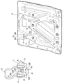
図2に示すように、フレーム5における上方且つ右側の部分に、3個のフレーム側孔10A、10B、10Cが設けられている。フレーム側孔10A、10B、10Cはフレーム5を前後方向に貫通する。前後方向とは、乗物用シート1及び自動車の前後方向である。フレーム側孔10A、10B、10Cの形状は正面視において円形である。フレーム側孔10A、10B、10Cの直径は全て同じである。
As shown in FIG. 2, three frame side holes 10 </ b> A, 10 </ b> B, and 10 </ b> C are provided in the upper and right part of the
フレーム側孔10A、10Bの上下方向における位置は同じである。フレーム側孔10Cは、フレーム側孔10A、10Bよりも下方にある。図2に示すように、フレーム側孔10A、10Bを結ぶ線分を辺12とし、その辺12に対向する辺14がフレーム側孔10Cを通る仮想的な長方形16を想定した場合、フレーム側孔10Cは辺14の中点に位置する。フレーム5のうち、フレーム側孔10A、10B、10Cで囲まれる部分に孔17が形成されている。
The positions of the
図1に示すように、ブラケット7はフレーム5の上部に、前方側から取り付けられる部材である。ブラケット7は、ベース部19と、一対の突出部21とを備える。ベース部19は、略平板形状を有し、フレーム5に対向している。一対の突出部21は、ブラケット7の上方の部分における左右両側に設けられている。一対の突出部21は、ベース部19よりも前方に突出する形状を有する。
As shown in FIG. 1, the
ベース部19には、5個のブラケット側孔22A、22B、22C、22D、22Eが設けられている。ブラケット側孔22A、22B、22C、22D、22Eはベース部19を前後方向に貫通する。ブラケット側孔22A、22B、22C、22D、22Eの形状は正面視において円形である。ブラケット側孔22A、22B、22C、22D、22Eの直径は全て同じである。ブラケット側孔22A、22B、22C、22D、22Eの直径は、フレーム側孔10A、10B、10Cの直径より小さい。
The
ブラケット側孔22A、22B、22Cの上下方向における位置は同じである。ブラケット側孔22D、22Eは、ブラケット側孔22A、22B、22Cよりも下方にある。ブラケット側孔22D、22Eの上下方向における位置は同じである。ブラケット側孔22Dは、正面視においてブラケット側孔22Cの真下にある。ブラケット側孔22Eは、正面視においてブラケット側孔22Aの真下にある。
The positions of the bracket side holes 22A, 22B, and 22C in the vertical direction are the same. The
ブラケット側孔22A、22C、22D、22Eは、ベース部19の表面における仮想的な長方形24の4頂点に該当する位置に配置されている。ブラケット側孔22Bは、長方形24における、ブラケット側孔22A、22Cを結ぶ辺26の中点に該当する位置に配置されている。長方形24の形状及び大きさは、長方形16と同一である。
The bracket side holes 22 </ b> A, 22 </ b> C, 22 </ b> D, 22 </ b> E are arranged at positions corresponding to the four vertices of the
ヘッドレストサポートブラケット9は、中空円筒形状を有する部材である。ヘッドレストサポートブラケット9は、突出部21に前方側から取り付けられている。すなわち、ヘッドレストサポートブラケット9は、ブラケット7に対し、フレーム5とは反対側から取り付けられている。ヘッドレストサポートブラケット9の向きは、その軸方向が正面視において上下方向となる向きである。ヘッドレストサポートブラケット9の上端及び下端は開口している。一方のヘッドレストサポートブラケット9の上端には、略U字形状を有するステー27の一端が差し込まれ、他方のヘッドレストサポートブラケット9の上端には、ステー27の他端が差し込まれる。ステー27はヘッドレスト(図示略)の一部である。ステー27を前記のようにヘッドレストサポートブラケット9に差し込むことでヘッドレストがシートバック3に固定される。
The
ブラケット7は、スポット溶接により、フレーム5に取り付けられる。フレーム5に対するブラケット7の取付位置(以下ではP−B取付位置とする)は、フレーム側孔10A、10B、10Cと、ブラケット側孔22A、22B、22C、22D、22Eとを用いて決められる。
The
P−B取付位置としては、図3に示す第1の取付位置と、図4に示す第2の取付位置と、図5に示す第3の取付位置とがある。
図3に示すように、第1の取付位置では、フレーム側孔10Bと、ブラケット側孔22Bとが正面視において一致しており、フレーム側孔10Cと、ブラケット側孔22Eとが正面視において一致している。フレーム側孔10Aは、ブラケット側孔22A、22B、22C、22D、22Eのいずれにも正面視において一致していない。ブラケット側孔22A、22C、22Dは、フレーム側孔10A、10B、10Cのいずれにも正面視において一致していない。
The PB attachment position includes a first attachment position shown in FIG. 3, a second attachment position shown in FIG. 4, and a third attachment position shown in FIG.
As shown in FIG. 3, at the first attachment position, the
P−B取付位置を第1の取付位置とする場合、1本の直線棒状の治具を、フレーム側孔10B及びブラケット側孔22Bに前後方向に差し込むとともに、もう一本の直線棒状の治具を、フレーム側孔10C及びブラケット側孔22Eに前後方向に差し込むことで、P−B取付位置の位置決めを行う。
When the P-B mounting position is the first mounting position, one straight bar-shaped jig is inserted into the
図4に示すように、第2の取付位置では、フレーム側孔10Aと、ブラケット側孔22Aとが正面視において一致しており、フレーム側孔10Bと、ブラケット側孔22Cとが正面視において一致している。フレーム側孔10Cは、ブラケット側孔22A、22B、22C、22D、22Eのいずれにも正面視において一致していない。ブラケット側孔22B、22D、22Eは、フレーム側孔10A、10B、10Cのいずれにも正面視において一致していない。
As shown in FIG. 4, at the second mounting position, the
P−B取付位置を第2の取付位置とする場合、1本の直線棒状の治具を、フレーム側孔10A及びブラケット側孔22Aに前後方向に差し込むとともに、もう一本の直線棒状の治具を、フレーム側孔10B及びブラケット側孔22Cに前後方向に差し込むことで、P−B取付位置の位置決めを行う。第2の取付位置の場合、第1の取付位置の場合に比べて、ブラケット7がフレーム5に対し、正面視において左側に位置する。第2の取付位置の場合、長方形16と長方形24とは正面視において一致する。第2の取付位置は、第1の取付位置に比べて、ブラケット7の高さ及び向きは変化せず、ブラケット7のシート幅方向における位置が変化している。
When the P-B mounting position is the second mounting position, one straight bar-shaped jig is inserted into the
図5に示すように、第3の取付位置では、フレーム側孔10Aと、ブラケット側孔22Bとが正面視において一致しており、フレーム側孔10Cと、ブラケット側孔22Dとが正面視において一致している。フレーム側孔10Bは、ブラケット側孔22A、22B、22C、22D、22Eのいずれにも正面視において一致していない。ブラケット側孔22A、22C、22Eは、フレーム側孔10A、10B、10Cのいずれにも正面視において一致していない。
As shown in FIG. 5, at the third attachment position, the
P−B取付位置を第3の取付位置とする場合、1本の直線棒状の治具を、フレーム側孔10A及びブラケット側孔22Bに前後方向に差し込むとともに、もう一本の直線棒状の治具を、フレーム側孔10C及びブラケット側孔22Dに前後方向に差し込むことで、P−B取付位置の位置決めを行う。第3の取付位置の場合、第2の取付位置の場合に比べて、ブラケット7がフレーム5に対し、正面視において左側に位置する。第3の取付位置は、第1の取付位置及び第2の取付位置に比べて、ブラケット7の高さ及び向きは変化せず、ブラケット7のシート幅方向における位置が変化している。
When the P-B mounting position is the third mounting position, one straight bar-shaped jig is inserted into the
2.乗物用シート1が奏する効果
乗物用シート1は以下の効果を奏する。
(1A)乗物用シート1において、P−B取付位置は3つ存在する。そのため、同一のフレーム5及びブラケット7において、3つのP−B取付位置の中から1つのP−B取付位置を選択し、決定することができる。その結果、乗物用シート1の製造工程が煩雑になることを抑制できる。
2. Effects of the
(1A) In the
(1B)図3に示すように、第1の取付位置において、フレーム側孔10B、10Cは、ブラケット側孔22A、22B、22C、22D、22Eのいずれかと一致する。一方、図4、図5に示すように、フレーム側孔10B、10Cの少なくとも一部は、第2の取付位置、及び第3の取付位置では、ブラケット側孔22A、22B、22C、22D、22Eのいずれとも一致しない。すなわち、第2の取付位置では、フレーム側孔10Cは、ブラケット側孔22A、22B、22C、22D、22Eのいずれとも一致しない。また、第3の取付位置では、フレーム側孔10Bは、ブラケット側孔22A、22B、22C、22D、22Eのいずれとも一致しない。
(1B) As shown in FIG. 3, in the first attachment position, the frame side holes 10B, 10C coincide with any one of the bracket side holes 22A, 22B, 22C, 22D, 22E. On the other hand, as shown in FIGS. 4 and 5, at least a part of the frame side holes 10B and 10C are at the
よって、フレーム側孔10B、10Cの両方が、ブラケット側孔22A、22B、22C、22D、22Eのいずれかと一致するようにP−B取付位置を決めれば、P−B取付位置は必ず第1の取付位置となる。その結果、第1の取付位置を選択すべき場合に、誤って、第2の取付位置又は第3の取付位置を選択してしまうことを抑制できる。 Therefore, if the PB mounting position is determined so that both the frame side holes 10B and 10C coincide with any one of the bracket side holes 22A, 22B, 22C, 22D, and 22E, the PB mounting position is always the first. This is the mounting position. As a result, when the first attachment position is to be selected, it is possible to suppress erroneous selection of the second attachment position or the third attachment position.
また、図4に示すように、第2の取付位置において、フレーム側孔10A、10Bは、ブラケット側孔22A、22B、22C、22D、22Eのいずれかと一致する。一方、図3、図5に示すように、フレーム側孔10A、10Bの少なくとも一部は、第1の取付位置、及び第3の取付位置では、ブラケット側孔22A、22B、22C、22D、22Eのいずれとも一致しない。すなわち、第1の取付位置では、フレーム側孔10Aは、ブラケット側孔22A、22B、22C、22D、22Eのいずれとも一致しない。また、第3の取付位置では、フレーム側孔10Bは、ブラケット側孔22A、22B、22C、22D、22Eのいずれとも一致しない。
As shown in FIG. 4, in the second attachment position, the frame side holes 10A, 10B coincide with any one of the bracket side holes 22A, 22B, 22C, 22D, 22E. On the other hand, as shown in FIGS. 3 and 5, at least a part of the
よって、フレーム側孔10A、10Bの両方が、ブラケット側孔22A、22B、22C、22D、22Eのいずれかと一致するようにP−B取付位置を決めれば、P−B取付位置は必ず第2の取付位置となる。その結果、第2の取付位置を選択すべき場合に、誤って、第1の取付位置又は第3の取付位置を選択してしまうことを抑制できる。
Therefore, if the PB mounting position is determined so that both the
また、図5に示すように、第3の取付位置において、フレーム側孔10A、10Cは、ブラケット側孔22A、22B、22C、22D、22Eのいずれかと一致する。一方、図3、図4に示すように、フレーム側孔10A、10Cの少なくとも一部は、第1の取付位置、及び第2の取付位置では、ブラケット側孔22A、22B、22C、22D、22Eのいずれとも一致しない。すなわち、第1の取付位置では、フレーム側孔10Aは、ブラケット側孔22A、22B、22C、22D、22Eのいずれとも一致しない。また、第2の取付位置では、フレーム側孔10Cは、ブラケット側孔22A、22B、22C、22D、22Eのいずれとも一致しない。
Further, as shown in FIG. 5, in the third attachment position, the frame side holes 10A, 10C coincide with any one of the bracket side holes 22A, 22B, 22C, 22D, 22E. On the other hand, as shown in FIGS. 3 and 4, at least a part of the
よって、フレーム側孔10A、10Cの両方が、ブラケット側孔22A、22B、22C、22D、22Eのいずれかと一致するようにP−B取付位置を決めれば、P−B取付位置は必ず第3の取付位置となる。その結果、第3の取付位置を選択すべき場合に、誤って、第1の取付位置又は第2の取付位置を選択してしまうことを抑制できる。
Therefore, if the PB mounting position is determined so that both the
(1C)図3に示すように、第1の取付位置において、ブラケット側孔22B、22Eは、フレーム側孔10A、10B、10Cのいずれかと一致する。一方、図4、図5に示すように、ブラケット側孔22B、22Eの少なくとも一部は、第2の取付位置、及び第3の取付位置では、フレーム側孔10A、10B、10Cのいずれとも一致しない。すなわち、第2の取付位置では、ブラケット側孔22B、22Eは、フレーム側孔10A、10B、10Cのいずれとも一致しない。また、第3の取付位置では、ブラケット側孔22Eは、フレーム側孔10A、10B、10Cのいずれとも一致しない。
(1C) As shown in FIG. 3, the bracket side holes 22B and 22E coincide with any of the frame side holes 10A, 10B, and 10C at the first mounting position. On the other hand, as shown in FIGS. 4 and 5, at least a part of the bracket side holes 22B and 22E coincides with any of the frame side holes 10A, 10B, and 10C at the second mounting position and the third mounting position. do not do. That is, in the second attachment position, the bracket side holes 22B and 22E do not coincide with any of the frame side holes 10A, 10B, and 10C. Further, at the third attachment position, the
よって、ブラケット側孔22B、22Eの両方が、フレーム側孔10A、10B、10Cのいずれかと一致するようにP−B取付位置を決めれば、P−B取付位置は必ず第1の取付位置となる。その結果、第1の取付位置を選択すべき場合に、誤って、第2の取付位置又は第3の取付位置を選択してしまうことを抑制できる。 Therefore, if the PB mounting position is determined so that both the bracket side holes 22B and 22E coincide with any of the frame side holes 10A, 10B, and 10C, the PB mounting position is always the first mounting position. . As a result, when the first attachment position is to be selected, it is possible to suppress erroneous selection of the second attachment position or the third attachment position.
また、図4に示すように、第2の取付位置において、ブラケット側孔22A、22Cは、フレーム側孔10A、10B、10Cのいずれかと一致する。一方、図3、図5に示すように、ブラケット側孔22A、22Cの少なくとも一部は、第1の取付位置、及び第3の取付位置では、フレーム側孔10A、10B、10Cのいずれとも一致しない。すなわち、第1の取付位置では、ブラケット側孔22A、22Cは、フレーム側孔10A、10B、10Cのいずれとも一致しない。また、第3の取付位置でも、ブラケット側孔22A、22Cは、フレーム側孔10A、10B、10Cのいずれとも一致しない。
As shown in FIG. 4, the
よって、ブラケット側孔22A、22Cの両方が、フレーム側孔10A、10B、10Cのいずれかと一致するようにP−B取付位置を決めれば、P−B取付位置は必ず第2の取付位置となる。その結果、第2の取付位置を選択すべき場合に、誤って、第1の取付位置又は第3の取付位置を選択してしまうことを抑制できる。
Therefore, if the PB mounting position is determined so that both the
また、図5に示すように、第3の取付位置において、ブラケット側孔22B、22Dは、フレーム側孔10A、10B、10Cのいずれかと一致する。一方、図3、図4に示すように、ブラケット側孔22B、22Dの少なくとも一部は、第1の取付位置、及び第2の取付位置では、フレーム側孔10A、10B、10Cのいずれとも一致しない。すなわち、第1の取付位置では、ブラケット側孔22Dは、フレーム側孔10A、10B、10Cのいずれとも一致しない。また、第2の取付位置では、ブラケット側孔22B、22Dは、フレーム側孔10A、10B、10Cのいずれとも一致しない。
As shown in FIG. 5, the bracket side holes 22B and 22D coincide with any one of the frame side holes 10A, 10B, and 10C at the third attachment position. On the other hand, as shown in FIGS. 3 and 4, at least a part of the bracket side holes 22B and 22D coincides with any of the frame side holes 10A, 10B, and 10C at the first mounting position and the second mounting position. do not do. That is, in the first attachment position, the
よって、ブラケット側孔22B、22Dの両方が、フレーム側孔10A、10B、10Cのいずれかと一致するようにP−B取付位置を決めれば、P−B取付位置は必ず第3の取付位置となる。その結果、第3の取付位置を選択すべき場合に、誤って、第1の取付位置又は第2の取付位置を選択してしまうことを抑制できる。 Therefore, if the PB mounting position is determined so that both the bracket side holes 22B and 22D coincide with any of the frame side holes 10A, 10B, and 10C, the PB mounting position is always the third mounting position. . As a result, when the third attachment position is to be selected, it is possible to suppress erroneous selection of the first attachment position or the second attachment position.
(1D)図1、図2に示すように、ブラケット側孔22A、22B、22C、22D、22Eは、長方形24の4頂点、及び長方形24を構成する辺26における中点に該当する位置に配置されている。図4に示すように、フレーム側孔10A、10Bは、第2の取付位置において、辺26の両端に一致する位置にあり、フレーム側孔10Cは、長方形24において辺26に対向する辺28の中点に一致する位置にある。
(1D) As shown in FIGS. 1 and 2, the bracket side holes 22 </ b> A, 22 </ b> B, 22 </ b> C, 22 </ b> D, 22 </ b> E are arranged at positions corresponding to the four vertices of the
フレーム側孔10A、10B、10C及びブラケット側孔22A、22B、22C、22D、22Eが前記のように配置されていることにより、簡易な構成にて前記(1B)及び(1C)の効果を奏することができる。 Since the frame side holes 10A, 10B, and 10C and the bracket side holes 22A, 22B, 22C, 22D, and 22E are arranged as described above, the effects (1B) and (1C) are achieved with a simple configuration. be able to.
(1E)フレーム側孔10A、10B、10Cの直径は、ブラケット側孔22A、22B、22C、22D、22Eの直径より大きい。そのため、フレーム側孔10A、10B、10Cからブラケット側孔22A、22B、22C、22D、22Eに向けて治具を差し込み、フレーム側孔10A、10B、10Cのいずれかとブラケット側孔22A、22B、22C、22D、22Eのいずれかとの位置を正面視において一致させることが一層容易になる。
<他の実施形態>
以上、本開示を実施するための形態について説明したが、本開示は上述の実施形態に限定されることなく、種々変形して実施することができる。
(1E) The diameters of the frame side holes 10A, 10B, and 10C are larger than the diameters of the bracket side holes 22A, 22B, 22C, 22D, and 22E. Therefore, a jig is inserted from the frame side holes 10A, 10B, and 10C toward the bracket side holes 22A, 22B, 22C, 22D, and 22E, and one of the frame side holes 10A, 10B, and 10C and the bracket side holes 22A, 22B, and 22C are inserted. , 22D, and 22E are more easily matched with each other in a front view.
<Other embodiments>
As mentioned above, although the form for implementing this indication was demonstrated, this indication is not limited to the above-mentioned embodiment, and can carry out various modifications.
(1)ブラケット側孔22A、22B、22C、22D、22Eと同様に配置された孔を、フレーム5に設け、フレーム側孔10A、10B、10Cと同様に配置された孔をブラケット7に設けてもよい。この場合も、前記(1A)〜(1D)の効果を奏することができる。
(1) Holes arranged in the same manner as the bracket side holes 22A, 22B, 22C, 22D, and 22E are provided in the
(2)フレーム側孔10A、10B、10C及びブラケット側孔22A、22B、22C、22D、22Eの配置パターンを、第1実施形態における配置パターンを上下反転したものとしてもよい。この場合も、前記(1A)〜(1D)の効果を奏することができる。 (2) The arrangement pattern of the frame side holes 10A, 10B, and 10C and the bracket side holes 22A, 22B, 22C, 22D, and 22E may be a vertically inverted version of the arrangement pattern in the first embodiment. Also in this case, the effects (1A) to (1D) can be achieved.
(3)フレーム側孔10A、10B、10C及びブラケット側孔22A、22B、22C、22D、22Eの配置パターンは、前記(1A)〜(1D)の効果を奏する範囲において、適宜変更してもよい。 (3) The arrangement pattern of the frame side holes 10A, 10B, and 10C and the bracket side holes 22A, 22B, 22C, 22D, and 22E may be changed as appropriate within the range of the effects (1A) to (1D). .
(4)P−B取付位置の種類は、3種以外であってもよい。例えば、P−B取付位置の種類は、2、4、5・・・種であってもよい。
(5)P−B取付位置において、ブラケット側孔と一致するフレーム側孔の数は3個以上であってもよい。
(4) The types of PB attachment positions may be other than three types. For example, the types of PB attachment positions may be 2, 4, 5,.
(5) At the PB attachment position, the number of frame side holes that coincide with the bracket side holes may be three or more.
(6)第1の取付位置、第2の取付位置、及び第3の取付位置のうちの一部は、他に比べて、ブラケット7の高さ、又はブラケット7の向きが異なる取付位置であってもよい。
(7)前記実施形態では、乗物用シート1を自動車に適用したが、乗物用シート1を、自動車以外の乗り物(例えば、鉄道車両、航空機、船舶等)に用いてもよい。
(6) Some of the first attachment position, the second attachment position, and the third attachment position are attachment positions in which the height of the
(7) In the above embodiment, the
(8)前記各実施形態における1つの構成要素が有する機能を複数の構成要素に分担させたり、複数の構成要素が有する機能を1つの構成要素に発揮させたりしてもよい。また、前記各実施形態の構成の一部を省略してもよい。また、前記各実施形態の構成の少なくとも一部を、他の前記実施形態の構成に対して付加、置換等してもよい。なお、特許請求の範囲に記載の文言から特定される技術思想に含まれるあらゆる態様が本開示の実施形態である。 (8) A function of one component in each of the above embodiments may be shared by a plurality of components, or a function of a plurality of components may be exhibited by one component. Moreover, you may abbreviate | omit a part of structure of each said embodiment. In addition, at least a part of the configuration of each of the embodiments may be added to or replaced with the configuration of the other embodiments. In addition, all the aspects included in the technical idea specified from the wording described in the claims are embodiments of the present disclosure.
1…乗物用シート、3…シートバック、5…フレーム、7…ブラケット、9…ヘッドレストサポートブラケット、10A、10B、10C…フレーム側孔、12、14、26、28…辺、16、24…長方形、17…孔、19…ベース部、21…突出部、22A、22B、22C、22D、22E…ブラケット側孔、27…ステー
DESCRIPTION OF
Claims (3)
前記フレームの上部に取り付けられるブラケットと、
前記ブラケットに対し、前記フレームとは反対側から取り付けられるヘッドレストサポートブラケットと、
前記フレームに設けられた3個以上のフレーム側孔と、
前記ブラケットに設けられた3個以上のブラケット側孔と、
を備え、
前記フレーム側孔及び前記ブラケット側孔は、以下の条件(a)を充足するとともに、以下の条件(b)又は(c)を充足するように配置されている乗物用シート。
(a)2個以上の前記フレーム側孔と、2個以上の前記ブラケット側孔とが一致する、前記フレームに対する前記ブラケットの取付位置が2以上存在する。
(b)任意の前記取付位置において、前記ブラケット側孔と一致する2個以上の前記フレーム側孔の少なくとも一部は、他の前記取付位置では前記ブラケット側孔のいずれとも一致しない。
(c)任意の前記取付位置において、前記フレーム側孔と一致する2個以上の前記ブラケット側孔の少なくとも一部は、他の前記取付位置では前記フレーム側孔のいずれとも一致しない。 A frame that supports the back of the seated person,
A bracket attached to the top of the frame;
A headrest support bracket attached to the bracket from the opposite side of the frame;
Three or more frame side holes provided in the frame;
Three or more bracket side holes provided in the bracket;
With
The frame side hole and the bracket side hole satisfy the following condition (a), and are arranged so as to satisfy the following condition (b) or (c).
(A) There are two or more mounting positions of the bracket with respect to the frame where two or more of the frame side holes and two or more of the bracket side holes match.
(B) At any of the attachment positions, at least a part of the two or more frame side holes that coincide with the bracket side holes do not coincide with any of the bracket side holes at the other attachment positions.
(C) At any of the attachment positions, at least some of the two or more bracket side holes that coincide with the frame side hole do not coincide with any of the frame side holes at the other attachment positions.
前記フレーム側孔及び前記ブラケット側孔のうちの一方は、前記フレーム及び前記ブラケットのうちの一方において、長方形の4頂点、及び前記長方形の1辺における中点に該当する位置に配置され、
前記フレーム側孔及び前記ブラケット側孔のうちの他方は、前記フレーム及び前記ブラケットのうちの他方において、いずれかの前記取付位置にあるとき、前記1辺の両端に一致する位置、及び前記長方形において前記1辺に対向する辺の中点に一致する位置に配置されている乗物用シート。 The vehicle seat according to claim 1,
One of the frame side hole and the bracket side hole is arranged at a position corresponding to the midpoint of the four vertices of the rectangle and one side of the rectangle in one of the frame and the bracket,
The other of the frame side hole and the bracket side hole is the other of the frame and the bracket. A vehicle seat disposed at a position that coincides with a midpoint of a side facing the one side.
前記フレーム側孔の直径は、前記ブラケット側孔の直径より大きい乗物用シート。 The vehicle seat according to claim 1 or 2,
The vehicle seat has a diameter greater than that of the bracket side hole.
Priority Applications (3)
| Application Number | Priority Date | Filing Date | Title |
|---|---|---|---|
| JP2016180481A JP2018043669A (en) | 2016-09-15 | 2016-09-15 | Vehicle seat |
| CN201721176807.6U CN207374184U (en) | 2016-09-15 | 2017-09-13 | Seat for vehicle |
| US15/703,151 US20180072202A1 (en) | 2016-09-15 | 2017-09-13 | Vehicle seat |
Applications Claiming Priority (1)
| Application Number | Priority Date | Filing Date | Title |
|---|---|---|---|
| JP2016180481A JP2018043669A (en) | 2016-09-15 | 2016-09-15 | Vehicle seat |
Publications (1)
| Publication Number | Publication Date |
|---|---|
| JP2018043669A true JP2018043669A (en) | 2018-03-22 |
Family
ID=61559072
Family Applications (1)
| Application Number | Title | Priority Date | Filing Date |
|---|---|---|---|
| JP2016180481A Pending JP2018043669A (en) | 2016-09-15 | 2016-09-15 | Vehicle seat |
Country Status (3)
| Country | Link |
|---|---|
| US (1) | US20180072202A1 (en) |
| JP (1) | JP2018043669A (en) |
| CN (1) | CN207374184U (en) |
Families Citing this family (2)
| Publication number | Priority date | Publication date | Assignee | Title |
|---|---|---|---|---|
| JP6575597B2 (en) * | 2015-08-04 | 2019-09-18 | テイ・エス テック株式会社 | Headrest support device |
| GB2612087A (en) * | 2021-10-21 | 2023-04-26 | Jaguar Land Rover Ltd | Headrest mounting assembly |
Family Cites Families (4)
| Publication number | Priority date | Publication date | Assignee | Title |
|---|---|---|---|---|
| US4030781A (en) * | 1976-01-21 | 1977-06-21 | Howard Harold P | Headrest |
| US5658245A (en) * | 1994-06-24 | 1997-08-19 | Mcginnis; Cathy D. | Therapeutic tension applying travel aid apparatus attachable to a seat |
| US6840581B2 (en) * | 2003-04-22 | 2005-01-11 | Chun Chen | Height adjustment arrangement for chair headrest |
| KR100590947B1 (en) * | 2004-06-07 | 2006-06-19 | 현대자동차주식회사 | Magnesium back frame for automotive-seat system and its manufacturing method |
-
2016
- 2016-09-15 JP JP2016180481A patent/JP2018043669A/en active Pending
-
2017
- 2017-09-13 CN CN201721176807.6U patent/CN207374184U/en not_active Expired - Fee Related
- 2017-09-13 US US15/703,151 patent/US20180072202A1/en not_active Abandoned
Also Published As
| Publication number | Publication date |
|---|---|
| CN207374184U (en) | 2018-05-18 |
| US20180072202A1 (en) | 2018-03-15 |
Similar Documents
| Publication | Publication Date | Title |
|---|---|---|
| JP6189269B2 (en) | Headrest support structure for vehicle seat | |
| JP6346119B2 (en) | Skin clip | |
| JP2018043669A (en) | Vehicle seat | |
| JP5966901B2 (en) | Frame and electronic equipment | |
| JP2015003599A (en) | Vehicle seat | |
| WO2017141476A1 (en) | Seat structure | |
| JP6343024B2 (en) | Lattice panel structure and method | |
| US20170174106A1 (en) | Device for mounting a headrest in a seat structure of a vehicle seat | |
| JP6117012B2 (en) | Vehicle seat | |
| JP2017089671A (en) | Pipe clamp | |
| JPWO2018163585A1 (en) | Vehicle seat | |
| JP2018127108A (en) | Vehicle seat and manufacturing method therefor | |
| JP6669974B2 (en) | Vehicle seat | |
| JP6720780B2 (en) | Vehicle seat | |
| JP5205913B2 (en) | Vehicle headrest structure | |
| JP2014218155A (en) | Vehicle seat | |
| JP5776504B2 (en) | Vehicle seat | |
| JP2018047138A (en) | Chair | |
| JP2018099995A (en) | Motion guide device and seat for aircraft | |
| JP2018143786A (en) | desk | |
| JP7067283B2 (en) | Vehicle seat | |
| JP3212259U (en) | Assembled car bed | |
| JP6345913B2 (en) | desk | |
| JP2017171098A (en) | Vehicular seat | |
| JP7093643B2 (en) | furniture |