JP2018036084A - Water Quality Analyzer - Google Patents
Water Quality Analyzer Download PDFInfo
- Publication number
- JP2018036084A JP2018036084A JP2016167570A JP2016167570A JP2018036084A JP 2018036084 A JP2018036084 A JP 2018036084A JP 2016167570 A JP2016167570 A JP 2016167570A JP 2016167570 A JP2016167570 A JP 2016167570A JP 2018036084 A JP2018036084 A JP 2018036084A
- Authority
- JP
- Japan
- Prior art keywords
- sample
- predetermined amount
- sample solution
- container
- liquid
- Prior art date
- Legal status (The legal status is an assumption and is not a legal conclusion. Google has not performed a legal analysis and makes no representation as to the accuracy of the status listed.)
- Granted
Links
- XLYOFNOQVPJJNP-UHFFFAOYSA-N water Substances O XLYOFNOQVPJJNP-UHFFFAOYSA-N 0.000 title claims abstract description 27
- 238000001514 detection method Methods 0.000 claims abstract description 10
- 230000001678 irradiating effect Effects 0.000 claims abstract description 5
- 239000007788 liquid Substances 0.000 claims description 67
- 238000005259 measurement Methods 0.000 claims description 38
- 238000006243 chemical reaction Methods 0.000 claims description 14
- 238000005303 weighing Methods 0.000 claims description 3
- 239000012488 sample solution Substances 0.000 abstract description 59
- 239000000523 sample Substances 0.000 abstract description 52
- 230000005856 abnormality Effects 0.000 abstract description 5
- 230000003287 optical effect Effects 0.000 abstract description 5
- 238000005070 sampling Methods 0.000 abstract description 5
- IJGRMHOSHXDMSA-UHFFFAOYSA-N Atomic nitrogen Chemical compound N#N IJGRMHOSHXDMSA-UHFFFAOYSA-N 0.000 description 58
- 229910052757 nitrogen Inorganic materials 0.000 description 29
- HEMHJVSKTPXQMS-UHFFFAOYSA-M Sodium hydroxide Chemical compound [OH-].[Na+] HEMHJVSKTPXQMS-UHFFFAOYSA-M 0.000 description 15
- 239000000243 solution Substances 0.000 description 14
- 238000000034 method Methods 0.000 description 9
- 239000004065 semiconductor Substances 0.000 description 9
- VEXZGXHMUGYJMC-UHFFFAOYSA-N Hydrochloric acid Chemical compound Cl VEXZGXHMUGYJMC-UHFFFAOYSA-N 0.000 description 8
- USHAGKDGDHPEEY-UHFFFAOYSA-L potassium persulfate Chemical compound [K+].[K+].[O-]S(=O)(=O)OOS([O-])(=O)=O USHAGKDGDHPEEY-UHFFFAOYSA-L 0.000 description 8
- 238000002835 absorbance Methods 0.000 description 7
- 230000002159 abnormal effect Effects 0.000 description 5
- 229910017464 nitrogen compound Inorganic materials 0.000 description 5
- 150000002830 nitrogen compounds Chemical class 0.000 description 5
- 238000006864 oxidative decomposition reaction Methods 0.000 description 5
- 229910002651 NO3 Inorganic materials 0.000 description 3
- -1 nitrate ions Chemical class 0.000 description 3
- CIWBSHSKHKDKBQ-JLAZNSOCSA-N Ascorbic acid Chemical compound OC[C@H](O)[C@H]1OC(=O)C(O)=C1O CIWBSHSKHKDKBQ-JLAZNSOCSA-N 0.000 description 2
- NHNBFGGVMKEFGY-UHFFFAOYSA-N Nitrate Chemical compound [O-][N+]([O-])=O NHNBFGGVMKEFGY-UHFFFAOYSA-N 0.000 description 2
- IOVCWXUNBOPUCH-UHFFFAOYSA-M Nitrite anion Chemical compound [O-]N=O IOVCWXUNBOPUCH-UHFFFAOYSA-M 0.000 description 2
- VYPSYNLAJGMNEJ-UHFFFAOYSA-N Silicium dioxide Chemical compound O=[Si]=O VYPSYNLAJGMNEJ-UHFFFAOYSA-N 0.000 description 2
- QAOWNCQODCNURD-UHFFFAOYSA-N Sulfuric acid Chemical compound OS(O)(=O)=O QAOWNCQODCNURD-UHFFFAOYSA-N 0.000 description 2
- 238000010586 diagram Methods 0.000 description 2
- 239000012895 dilution Substances 0.000 description 2
- 238000010790 dilution Methods 0.000 description 2
- 229940005654 nitrite ion Drugs 0.000 description 2
- 239000007800 oxidant agent Substances 0.000 description 2
- 229910052700 potassium Inorganic materials 0.000 description 2
- 239000011591 potassium Substances 0.000 description 2
- OTYBMLCTZGSZBG-UHFFFAOYSA-L potassium sulfate Chemical compound [K+].[K+].[O-]S([O-])(=O)=O OTYBMLCTZGSZBG-UHFFFAOYSA-L 0.000 description 2
- 229910052939 potassium sulfate Inorganic materials 0.000 description 2
- 235000011151 potassium sulphates Nutrition 0.000 description 2
- 239000002699 waste material Substances 0.000 description 2
- 229910052724 xenon Inorganic materials 0.000 description 2
- FHNFHKCVQCLJFQ-UHFFFAOYSA-N xenon atom Chemical compound [Xe] FHNFHKCVQCLJFQ-UHFFFAOYSA-N 0.000 description 2
- YZCKVEUIGOORGS-OUBTZVSYSA-N Deuterium Chemical compound [2H] YZCKVEUIGOORGS-OUBTZVSYSA-N 0.000 description 1
- 238000011481 absorbance measurement Methods 0.000 description 1
- 238000010521 absorption reaction Methods 0.000 description 1
- 229960005070 ascorbic acid Drugs 0.000 description 1
- 235000010323 ascorbic acid Nutrition 0.000 description 1
- 239000011668 ascorbic acid Substances 0.000 description 1
- 238000011074 autoclave method Methods 0.000 description 1
- 230000003111 delayed effect Effects 0.000 description 1
- 229910052805 deuterium Inorganic materials 0.000 description 1
- 230000000694 effects Effects 0.000 description 1
- 230000007613 environmental effect Effects 0.000 description 1
- 230000006870 function Effects 0.000 description 1
- 238000010438 heat treatment Methods 0.000 description 1
- QSHDDOUJBYECFT-UHFFFAOYSA-N mercury Chemical compound [Hg] QSHDDOUJBYECFT-UHFFFAOYSA-N 0.000 description 1
- 229910052753 mercury Inorganic materials 0.000 description 1
- 229910052751 metal Inorganic materials 0.000 description 1
- 239000002184 metal Substances 0.000 description 1
- VLAPMBHFAWRUQP-UHFFFAOYSA-L molybdic acid Chemical compound O[Mo](O)(=O)=O VLAPMBHFAWRUQP-UHFFFAOYSA-L 0.000 description 1
- 238000007254 oxidation reaction Methods 0.000 description 1
- 230000002093 peripheral effect Effects 0.000 description 1
- 238000002798 spectrophotometry method Methods 0.000 description 1
- 238000010998 test method Methods 0.000 description 1
- 238000002834 transmittance Methods 0.000 description 1
- 239000002351 wastewater Substances 0.000 description 1
Images


Abstract
Description
本発明は、水質分析計に関し、特に試料液中の全窒素濃度を測定する全窒素測定装置に関する。 The present invention relates to a water quality analyzer, and more particularly to a total nitrogen measuring device that measures the total nitrogen concentration in a sample solution.
工場排水等の試料液中の全窒素化合物総量を窒素の濃度で表す全窒素の測定方法は、日本工業規格の「工場から排出される排水の試験方法」に規定されている「紫外吸光光度法」(JIS K 0102 45.2)が一般に利用されている。この紫外吸光光度法は、酸化剤であるペルオキソ二硫酸カリウムを添加した試料液をオートクレーブ法、すなわち高温・高圧下で処理する方法である。
また、「紫外吸光光度法」に「紫外線酸化分解」を組み合わせた方法(以下、「紫外線酸化分解法」という)を採用した全窒素測定装置も市販されている。
The total nitrogen compounds in the sample liquid such as factory effluent is measured by the UV absorption spectrophotometric method specified in the Japanese Industrial Standards “Test method for wastewater discharged from factories”. (JIS K 0102 45.2) is generally used. This ultraviolet absorptiometric method is an autoclave method, that is, a method of treating a sample solution to which potassium peroxodisulfate as an oxidizing agent is added, that is, under a high temperature and a high pressure.
In addition, a total nitrogen measuring apparatus employing a method combining “ultraviolet oxidative decomposition” with “ultraviolet oxidative decomposition” (hereinafter referred to as “ultraviolet oxidative decomposition”) is also commercially available.
紫外線酸化分解法において、採取された所定量aの試料液Sは、まず初めに計量されて所定量bの希釈水で希釈される。そして、試料液S中の窒素化合物が分解されやすいように、試料液Sをアルカリ性とするための前処理として所定量cの水酸化ナトリウム溶液(NaOH)が添加される。次に、酸化剤となる所定量dのペルオキソ二硫酸カリウム溶液が添加された後、所定量(a+b+c+d)の調整試料液S1は紫外線酸化分解工程へ移される。 In the ultraviolet oxidative decomposition method, the collected sample solution S of a predetermined amount a is first weighed and diluted with a predetermined amount b of diluted water. Then, a predetermined amount c of sodium hydroxide solution (NaOH) is added as a pretreatment for making the sample solution S alkaline so that the nitrogen compound in the sample solution S is easily decomposed. Next, after a predetermined amount d of potassium peroxodisulfate solution as an oxidizing agent is added, a predetermined amount (a + b + c + d) of the adjusted sample solution S1 is moved to the ultraviolet oxidative decomposition step.
そして、調整試料液S1は70℃以上の加熱条件下で紫外線が照射され、調整試料液S1中の窒素化合物は紫外線に反応して硝酸イオンにまで酸化分解されて反応試料液S2となる。その後、吸光度測定時にpHを調整するための所定量eの塩酸等が添加され、220nm付近の吸光度測定によって所定量(a+b+c+d+e)の調整試料液S3中の全窒素濃度の測定が行われる(例えば特許文献1参照)。 The adjusted sample solution S1 is irradiated with ultraviolet rays under a heating condition of 70 ° C. or higher, and the nitrogen compound in the adjusted sample solution S1 reacts with the ultraviolet rays and is oxidized and decomposed to nitrate ions to become a reaction sample solution S2. Thereafter, a predetermined amount e of hydrochloric acid or the like for adjusting the pH is added during the absorbance measurement, and the total nitrogen concentration in the adjusted sample solution S3 of the predetermined amount (a + b + c + d + e) is measured by measuring the absorbance near 220 nm (for example, patent) Reference 1).
図4は、従来のオンライン全窒素測定装置の全体構成の一例を概略的に示す図である。また、リアクタと測定部の構成の一例を図2、3に断面図で示す。なお、地面に水平な一方向をX方向とし、地面に水平でX方向と垂直な方向をY方向とし、X方向とY方向とに垂直な方向をZ方向とする。
オンライン全窒素測定装置101は、試料槽2と、シリンジポンプ(計量部)12と、第一マルチポートバルブ20と、第二マルチポートバルブ30と、リアクタ40と、測定部50と、コンピュータ160とを備える。
FIG. 4 is a diagram schematically showing an example of the overall configuration of a conventional online total nitrogen measuring apparatus. An example of the configuration of the reactor and the measurement unit is shown in cross-sectional views in FIGS. One direction horizontal to the ground is defined as an X direction, a direction horizontal to the ground and perpendicular to the X direction is defined as a Y direction, and a direction perpendicular to the X direction and the Y direction is defined as a Z direction.
The online total
試料槽2は、例えば工場排水や環境水等の試料液Sが連続して供給されるようになっており、第一マルチポートバルブ20の1つの分配ポートに接続されている。
The
シリンジポンプ12は、筒状体のシリンジ12aと、シリンジ12a内に挿入される円柱形状のピストン12bと、コンピュータ160に制御されるパルスモータ12cとを備える。そして、シリンジポンプ12のピストン12bは、パルスモータ12cにより上下動するようになっており、ピストン12bが下方に引かれると所定量の溶液をシリンジ12a内に注入し、ピストン12bが上方に押されるとシリンジ12a内の所定量の溶液を排出している。
The
第一マルチポートバルブ20は、8個の分配ポートと1個の共通ポートとからなる。分配ポートには、試料槽2と、スパン液入り容器3と、標準試料液入り容器4と、希釈水入り容器5と、リアクタ40と、測定部50とが接続されている。そして、第一マルチポートバルブ20は、モータ(図示せず)により駆動され、共通ポートと1個の分配ポートとを選択的に接続するようになっている。
The
第二マルチポートバルブ30は、8個の分配ポートと1個の共通ポートとからなる。分配ポートには、ペルオキソ二硫酸カリウム溶液入り容器6と、水酸化ナトリウム溶液入り容器7と、塩酸入り容器8と、モリブデン酸入り容器9と、アスコルビン酸入り容器10と、硫酸入り容器11と、第一マルチポートバルブ20の共通ポートとが接続されている。さらに、第二マルチポートバルブ30の共通ポートには、シリンジポンプ12が接続されている。そして、第二マルチポートバルブ30は、モータ(図示せず)により駆動され、共通ポートと1個の分配ポートとを選択的に接続するようになっている。
The
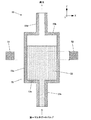
リアクタ40は、図2に示すように、調整試料液S1を収容するための反応容器41と、調整試料液S1に紫外線を照射する紫外線ランプ42と、調整試料液S1の酸化反応温度を制御するヒータ43とを備える。
As shown in FIG. 2, the
反応容器41は、円筒状(例えば外径12mm、内径10mm、高さ130mm)の側壁41aと円形状の下面41bとからなり、側壁41aの下部には第一マルチポートバルブ20と接続された試料液導入口41cが形成され、下面41bには廃液を処理するためのドレインと接続された試料液排出口41dが形成されている。なお、反応容器41は、石英ガラス等で形成されている。
ヒータ43は、金属製で円筒状のブロック体と、ブロック体に埋め込まれた熱電対(図示せず)とを備え、反応容器41の外周面に接触するように配置されている。
The
The heater 43 includes a metal cylindrical block body and a thermocouple (not shown) embedded in the block body, and is disposed so as to contact the outer peripheral surface of the
紫外線ランプ42は、例えば低圧水銀灯やエキシマレーザや重水素ランプやキセノンランプやHg−Zn−Pbランプ等である。
そして、紫外線ランプ42は、反応容器41内の中央部に上方から挿入されて配置されている。これにより、反応容器41内に所定量の調整試料液S1が収容されると、紫外線ランプ42は調整試料液S1に浸漬されるようになっている。
The
The
測定部50は、図3に示すように、レーザ光を右方(X方向)に出射する半導体レーザ素子(光源部)51と、X方向に進行するレーザ光の光強度Iを検出するフォトダイオード(検出部)52と、半導体レーザ素子51とフォトダイオード52との間に配置され所定量の調整試料液S3を収容するための測定セル(試料容器)53とを備える。なお、光源部は半導体レーザ素子に限らずキセノンフラッシュランプ等としてもよい。
As shown in FIG. 3, the
測定セル53は、円筒状(例えば外径12mm、内径10mm、高さ130mm)の側壁53aと円形状の上面53b及び下面53cとからなり、上面53bには廃液を処理するためのドレインと接続された試料液排出口53dが形成され、下面53cには第一マルチポートバルブ20と接続された試料液導入口53eが形成されている。なお、測定セル53は、石英ガラス等で形成されている。
これにより、半導体レーザ素子51から出射されたレーザ光は、側壁53aを透過して測定対象領域(光路)を通過し、対面側の側壁53aを透過後にフォトダイオード52で受光されるようになっている。このとき、調整試料液S3が測定対象領域に存在すれば、レーザ光の一部は調整試料液S3により吸収される。
The
As a result, the laser light emitted from the
ここで、上述したオンライン全窒素測定装置101を用いて試料液Sの全窒素濃度を自動的に分析する方法について説明する。コンピュータ160は、所定のタイミングでパルスモータ12cに駆動信号を出力することにより、試料槽2から所定量aの試料液Sをシリンジポンプ12で計量して採取し、再度パルスモータ12cに駆動信号を出力することにより、容器5から所定量bの希釈水をシリンジポンプ12で計量して採取し、シリンジ12a内で試料液Sを希釈する。次に、コンピュータ160は、パルスモータ12cに駆動信号を出力することにより、シリンジ12a内に容器7の所定量cの水酸化ナトリウム溶液と容器6の所定量dのペルオキソ二硫酸カリウム溶液とを添加して調整試料液S1とした後、再度パルスモータ12cに駆動信号を出力することにより、所定量(a+b+c+d)の調整試料液S1をシリンジポンプ12からリアクタ40へ導入する。
Here, a method for automatically analyzing the total nitrogen concentration of the sample liquid S using the above-described online total
リアクタ40では、紫外線ランプ42により約20分間紫外線を調整試料液S1に照射し、窒素化合物を硝酸イオンに酸化分解するとともに、液中のペルオキソ二硫酸カリウムを硫酸カリウムに分解する。そして、全てのペルオキソ二硫酸カリウムを分解後、さらに紫外線を5〜20分間照射することにより、硝酸イオンを亜硝酸イオンへ還元する。これらの反応が終了した後に、コンピュータ160は、パルスモータ12cに駆動信号を出力することにより、所定量(a+b+c+d)の反応試料液S2をシリンジポンプ12で計量して採取し、再度パルスモータ12cに駆動信号を出力することにより、シリンジ12a内で容器8の所定量eの塩酸を添加して所定量(a+b+c+d+e)の調整試料液S3を生成させる。
In the
次に、コンピュータ160は、パルスモータ12cに駆動信号を出力することにより、所定量(a+b+c+d+e)の調整試料液S3をシリンジポンプ12から測定セル53へ導入後、半導体レーザ素子51からレーザ光を出射させて、フォトダイオード52で光強度Iを検出させる。そして、コンピュータ160は、検出された光強度Iに基づいて220nmにおける吸光度を測定することにより、調整試料液S3の全窒素濃度を算出する。
Next, the
上述したようなオンライン全窒素測定装置101では、試料槽2や容器3〜11内の液量が不足していたり、配管等に異常があったりすることで、必要な量の溶液がシリンジポンプ12に採取できないことや、シリンジポンプ12で採取して測定セル53へ送液するまでの過程で調整試料液S3が漏れてしまうことにより、予め決められた所定量(a+b+c+d+e)の調整試料液S3が測定セル53内に送液されないことがあった。
しかし、オンライン全窒素測定装置101では、試料液Sの全窒素濃度を自動的に算出しているため、分析者等が液切れや液漏れ等の異常状態を発見できなかったり、発見が遅れたりすることにより、試料液Sの全窒素濃度が正確に測定できていないことがあった。
In the on-line total
However, since the online total
本出願人は、オンライン全窒素測定装置101の異常状態を発見する検知方法について検討し、所定量(a+b+c+d+e)の調整試料液S3が測定セル53内に送液されたか否かを検知することに着目した。このような採水異常の検知方法としては、調整試料液S3を測定セル53内に送液後、フォトダイオード52で検出された光の透過率の大小を確認することで調整試料液S3の有無を検知することが考えられる。
しかし、従来のオンライン全窒素測定装置101では、試料槽2及び容器3〜11のいずれか1種類の液量が不足しているような場合には、測定セル53内が空(無)になることはない。例えば、所定量dのペルオキソ二硫酸カリウム溶液が添加されず、(a+b+c+e)の調整試料液S3’が測定セル53内に送液されていても「問題なし」と判定される。したがって、測定セル53内が空(無)か否かを判定するような検知方法では不充分である。
The present applicant examines a detection method for detecting an abnormal state of the online total
However, in the conventional on-line total
ところで、上述したような測定セル53内に調整試料液S3が送液されると、(1)光路(測定対象領域)に調整試料液S3層の界面が未到達の状態と、(2)光路中に調整試料液S3層の界面が到達した状態と、(3)光路が調整試料液S3層中の状態とに順次変化していく。このとき、半導体レーザ素子51を点灯させながら測定セル53内に調整試料液S3を送液すると、測定セル53内が空の状態から所定量(a+b+c+d+e)の調整試料液S3が収容された状態になるまでの間に得られる光強度変化I(L)は、調整試料液S3の送液量Lに対して特徴的な波形となる。この波形は、図5に示すように、送液量Lに対して、「(1)光強度Iの増減が比較的小さい状態」から始まり、「(2)光強度Iの増減が比較的大きい状態」を経て、最後に再度「(3)光強度Iの増減が比較的小さい状態」となる。
When the adjusted sample solution S3 is fed into the
通常、測定セル53内へ調整試料液S3を送液するときの送液量は、測定の種類によって一意的に決まっているため、測定の種類(例えば、送液量(a+b+c+d+e))が決まっていれば、得られた光強度変化I(L)において「(2)光強度Iの増減が比較的大きい状態」となる送液量ポイントL’も決まる。よって、得られた光強度変化I(L)において「(2)光強度Iの増減が比較的大きい状態」が送液量ポイントL’より大きい場合、或いは、「(1)光強度Iの増減が比較的小さい状態」のまま「(2)光強度Iの増減が比較的大きい状態」とならない場合には、測定セル53内への送液量が不足していることになる。つまり、シリンジポンプ12による計量後から測定セル53へ送液するまでの過程において採水異常があることになる。
Usually, since the liquid supply amount when the adjusted sample liquid S3 is supplied into the
そこで、半導体レーザ素子51を点灯させながら測定セル53内に調整試料液S3を送液していき、そのときの光強度Iを監視し、比較的大きな光強度Iの変動が起きたポイントでの送液量Lが基準送液量L’よりも大きいとき、或いは、光強度Iが変動しないときには、採水異常と判定することを見出した。
Therefore, the adjusted sample liquid S3 is fed into the
すなわち、本発明の水質分析計は、下部に試料液導入口が形成され、当該試料液導入口から所定量の試料液が導入される試料容器と、前記試料容器に光を照射する光源部と、前記試料容器を透過した光を検出する検出部とを備える水質分析計であって、前記試料容器内に試料液が収容されていくときに前記検出部で検出された光強度変化に基づいて、前記試料容器内に所定量の試料液が収容されたか否かを判定する判定部を備えるようにしている。 That is, the water quality analyzer of the present invention has a sample liquid inlet formed in the lower part, a sample container into which a predetermined amount of sample liquid is introduced from the sample liquid inlet, and a light source unit that irradiates the sample container with light. A water quality analyzer comprising a detection unit for detecting light transmitted through the sample container, based on a change in light intensity detected by the detection unit when the sample liquid is accommodated in the sample container. A determination unit for determining whether or not a predetermined amount of the sample liquid is stored in the sample container is provided.
ここで、「所定量」とは、分析者等によって予め決められた試料液の吸光度等を測定するための任意の量である。 Here, the “predetermined amount” is an arbitrary amount for measuring the absorbance or the like of the sample solution determined in advance by an analyst or the like.
以上のように、本発明の水質分析計によれば、液切れや液漏れによる異常状態を早急に発見することができる。 As described above, according to the water quality analyzer of the present invention, it is possible to quickly find an abnormal state due to liquid shortage or liquid leakage.
(その他の課題を解決するための手段及び効果)
また、本発明の水質分析計において、前記試料容器は、前記試料液を分析するための測定セルであるか、或いは、前記試料液を反応させるための反応容器であるようにしてもよい。
さらに、本発明の水質分析計は、前記試料液を計量する計量部と、前記試料液導入口と前記計量部とが接続されたバルブと、前記計量部及び前記バルブを制御する制御部とを備えるようにしてもよい。
(Means and effects for solving other problems)
In the water quality analyzer of the present invention, the sample container may be a measurement cell for analyzing the sample solution or a reaction container for reacting the sample solution.
Furthermore, the water quality analyzer of the present invention comprises a measuring unit for measuring the sample solution, a valve connected to the sample solution introduction port and the measuring unit, and a control unit for controlling the measuring unit and the valve. You may make it prepare.
以下、本発明の実施形態について図面を用いて説明する。なお、本発明は、以下に説明するような実施形態に限定されるものではなく、本発明の趣旨を逸脱しない範囲で種々の態様が含まれることはいうまでもない。 Hereinafter, embodiments of the present invention will be described with reference to the drawings. Note that the present invention is not limited to the embodiments described below, and it goes without saying that various aspects are included without departing from the spirit of the present invention.
本発明に係る水質分析計の一例として、オンライン全窒素測定装置の概略的な全体構成例を図1に示す。なお、上述したオンライン全窒素測定装置101と同様のものについては、同じ符号を付すことにより説明を省略する。
オンライン全窒素測定装置1は、試料槽2と、シリンジポンプ(計量部)12と、第一マルチポートバルブ20と、第二マルチポートバルブ30と、リアクタ40と、測定部50と、コンピュータ60とを備える。
As an example of the water quality analyzer according to the present invention, a schematic overall configuration example of an online total nitrogen measuring device is shown in FIG. In addition, about the thing similar to the online total
The online total
コンピュータ60は、CPU(制御部)61とモニタ等の表示装置62とメモリ63とを備える。また、CPU61が処理する機能をブロック化して説明すると、フォトダイオード(検出部)52から光強度Iを取得する取得部61aと、検出された光強度Iに基づいて吸光度を算出する吸光度算出部61bと、光強度変化I(L)に基づいて所定量の調整試料液S3が収容されたか否かを判定する判定部61cと、シリンジポンプ12を制御する計量部制御部61dとを有する。
The
さらに、メモリ63には、採水異常を判定するために、所定量(a+b+c+d+e)の調整試料液S3送液時に「(2)光強度Iの増減が比較的大きい状態」となる基準送液量L’(例えば900μl)が予め記憶されている。
Further, the
判定部61cは、測定セル53内に調整試料液S3が収容されていくときにフォトダイオード52で検出された光強度変化I(L)に基づいて、測定セル53内に所定量(a+b+c+d+e)の調整試料液S3が収容されたか否かを判定する制御を行う。
具体的には、測定セル53内に反応試料液S2が収容されていくときにフォトダイオード52で検出された光強度変化I(L)の曲線の傾斜量を順次調べて、傾斜量が所定値以下になったときをピークの開始点であると判定し、傾斜量が負から正に転じたときをピークの頂点(送液量ポイントL)であると判定し、さらに傾斜量が所定値以下になったときをピークの終了点であると判定する。そして、送液量ポイントLが基準送液量L’より大きい場合には、測定セル53内への送液量が不足していると判定して表示装置62に警告表示を行う。また、ピークが検出されなかった場合にも、測定セル53内への送液量が不足していると判定して表示装置62に警告表示を行う。
The
Specifically, the amount of inclination of the curve of the light intensity change I (L) detected by the
ここで、上述したオンライン全窒素測定装置1を用いて試料液Sの全窒素濃度を自動的に分析する方法について説明する。コンピュータ60の計量部制御部61dは、所定のタイミングでパルスモータ12cに駆動信号を出力することにより、試料槽2から所定量aの試料液Sをシリンジポンプ12で計量して採取し、再度パルスモータ12cに駆動信号を出力することにより、容器5から所定量bの希釈水をシリンジポンプ12で計量して採取し、シリンジ12a内で試料液Sを希釈する。次に、計量部制御部61dは、パルスモータ12cに駆動信号を出力することにより、シリンジ12a内に容器7の所定量cの水酸化ナトリウム溶液と容器6の所定量dのペルオキソ二硫酸カリウム溶液とを添加して調整試料液S1とした後、再度パルスモータ12cに駆動信号を出力することにより、所定量(a+b+c+d)の調整試料液S1をシリンジポンプ12からリアクタ40へ導入する。
Here, a method for automatically analyzing the total nitrogen concentration of the sample liquid S using the above-described online total
リアクタ40では、紫外線ランプ42により約20分間紫外線を調整試料液S1に照射し、窒素化合物を硝酸イオンまで酸化分解するとともに、液中のペルオキソ二硫酸カリウムを硫酸カリウムに分解する。そして、全てのペルオキソ二硫酸カリウムを分解後、さらに紫外線を5〜20分間照射することにより、硝酸イオンを亜硝酸イオンへ還元する。これらの反応が終了した後に、計量部制御部61dは、パルスモータ12cに駆動信号を出力することにより、所定量(a+b+c+d)の反応試料液S2をシリンジポンプ12で計量して採取し、再度パルスモータ12cに駆動信号を出力することにより、シリンジ12a内で容器8の所定量eの塩酸を添加して所定量(a+b+c+d+e)の調整試料液S3を生成させる。
In the
次に、計量部制御部61dは、パルスモータ12cに駆動信号を出力することにより、所定量(a+b+c+d+e)の調整試料液S3をシリンジポンプ12から測定セル53へ導入する。このとき、取得部61aは、半導体レーザ素子51からレーザ光を出射させて光強度変化I(L)をフォトダイオード52で検出させる。次に、判定部61cは、検出された光強度変化I(L)に基づいて、測定セル53内に所定量(a+b+c+d+e)の調整試料液S3が収容されたか否かを判定する。
Next, the measuring
そして、所定量(a+b+c+d+e)の調整試料液S3が収容されたと判定したときには、吸光度算出部61bは、検出された光強度Iに基づいて220nmにおける吸光度を測定することにより、試料液Sの全窒素濃度を算出してメモリ63に記憶させる。一方、所定量(a+b+c+d+e)の調整試料液S3が収容されていないと判定したときには、判定部61cは、表示装置62に警告表示を行う。
When it is determined that a predetermined amount (a + b + c + d + e) of the adjusted sample liquid S3 has been stored, the
以上のように、本発明に係る構成を有したオンライン全窒素測定装置1によれば、液切れや液漏れ等の異常状態を早期に発見することができる。
As described above, according to the on-line total
<他の実施形態>
<1>上述したオンライン全窒素測定装置1では、測定セル53内に所定量(a+b+c+d+e)の調整試料液S3が収容されたか否かを判定する構成を示したが、これに代えて、リアクタ40に光源部と検出部とを設け、リアクタ40内に所定量(a+b+c+d)の調整試料液S1が収容されたか否かを判定するような構成としてもよい。
<Other embodiments>
<1> In the online total
<2>上述した実施形態では、本発明をオンライン全窒素測定装置1に適用した場合の構成について説明したが、これに代えて、その他の水質分析計に適用してもよい。
<2> In the above-described embodiment, the configuration when the present invention is applied to the on-line total
本発明は、試料液中の全窒素濃度を測定する全窒素測定装置等の水質分析計に利用することができる。 The present invention can be used for a water quality analyzer such as a total nitrogen measuring device for measuring the total nitrogen concentration in a sample solution.
1: オンライン全窒素測定装置(水質分析計)
51: 半導体レーザ素子(光源部)
52: フォトダイオード(検出部)
53: 測定セル(試料容器)
53e: 試料液導入口
61c: 判定部
1: Online total nitrogen measuring device (water quality analyzer)
51: Semiconductor laser element (light source part)
52: Photodiode (detector)
53: Measurement cell (sample container)
53e: Sample
Claims (3)
前記試料容器に光を照射する光源部と、
前記試料容器を透過した光を検出する検出部とを備える水質分析計であって、
前記試料容器内に試料液が収容されていくときに前記検出部で検出された光強度変化に基づいて、前記試料容器内に所定量の試料液が収容されたか否かを判定する判定部を備えることを特徴とする水質分析計。 A sample liquid inlet is formed in the lower part, and a sample container into which a predetermined amount of sample liquid is introduced from the sample liquid inlet;
A light source unit for irradiating the sample container with light;
A water quality analyzer comprising a detection unit for detecting light transmitted through the sample container,
A determination unit for determining whether or not a predetermined amount of the sample liquid is stored in the sample container based on a change in light intensity detected by the detection unit when the sample liquid is stored in the sample container; A water quality analyzer characterized by comprising.
前記試料液導入口と前記計量部とが接続されたバルブと、
前記計量部及び前記バルブを制御する制御部とを備えることを特徴とする請求項1又は請求項2に記載の水質分析計。 A weighing unit for weighing the sample liquid;
A valve to which the sample liquid inlet and the measuring unit are connected;
The water quality analyzer according to claim 1, further comprising a control unit that controls the measuring unit and the valve.
Priority Applications (1)
| Application Number | Priority Date | Filing Date | Title |
|---|---|---|---|
| JP2016167570A JP6965502B2 (en) | 2016-08-30 | 2016-08-30 | Water quality analyzer |
Applications Claiming Priority (1)
| Application Number | Priority Date | Filing Date | Title |
|---|---|---|---|
| JP2016167570A JP6965502B2 (en) | 2016-08-30 | 2016-08-30 | Water quality analyzer |
Publications (2)
| Publication Number | Publication Date |
|---|---|
| JP2018036084A true JP2018036084A (en) | 2018-03-08 |
| JP6965502B2 JP6965502B2 (en) | 2021-11-10 |
Family
ID=61565704
Family Applications (1)
| Application Number | Title | Priority Date | Filing Date |
|---|---|---|---|
| JP2016167570A Active JP6965502B2 (en) | 2016-08-30 | 2016-08-30 | Water quality analyzer |
Country Status (1)
| Country | Link |
|---|---|
| JP (1) | JP6965502B2 (en) |
Cited By (4)
| Publication number | Priority date | Publication date | Assignee | Title |
|---|---|---|---|---|
| JP2019191181A (en) * | 2018-04-27 | 2019-10-31 | 株式会社島津製作所 | Determination method for determining whether detection sample is supplied |
| JPWO2019188011A1 (en) * | 2018-03-27 | 2021-02-12 | 株式会社島津製作所 | Multi-port valve for water quality analyzer |
| JPWO2020136944A1 (en) * | 2018-12-27 | 2021-10-28 | 株式会社島津製作所 | A method for detecting the presence or absence of liquid inhalation by a syringe pump, and a device equipped with a syringe pump. |
| CN114720650A (en) * | 2022-03-28 | 2022-07-08 | 天津大学 | City water supply water barrier detection device |
Citations (9)
| Publication number | Priority date | Publication date | Assignee | Title |
|---|---|---|---|---|
| JPS57101981U (en) * | 1980-12-12 | 1982-06-23 | ||
| JPS58103639A (en) * | 1981-12-15 | 1983-06-20 | Hitachi Ltd | Sampling and metering device for minute amount of sample liquid |
| JPS5992356A (en) * | 1982-11-15 | 1984-05-28 | テクニコン・インストルメンツ・コ−ポレ−シヨン | Weighing method and weigher |
| JP2000258224A (en) * | 1999-03-05 | 2000-09-22 | Hitachi Koki Co Ltd | Liquid quantity detecting mechanism |
| JP2004184162A (en) * | 2002-12-02 | 2004-07-02 | Kurabo Ind Ltd | Spectral measuring instrument |
| JP2005091216A (en) * | 2003-09-18 | 2005-04-07 | Dkk Toa Corp | Analyzer |
| JP2005316617A (en) * | 2004-04-27 | 2005-11-10 | M Fsi Kk | Method for controlling liquid suction/discharge and liquid suction/discharge device using the same |
| JP2009186365A (en) * | 2008-02-07 | 2009-08-20 | Dkk Toa Corp | Optical unit, manufacturing method therefor, and water quality analyzer |
| JP2016080441A (en) * | 2014-10-14 | 2016-05-16 | 株式会社島津製作所 | Water quality analyzer |
-
2016
- 2016-08-30 JP JP2016167570A patent/JP6965502B2/en active Active
Patent Citations (9)
| Publication number | Priority date | Publication date | Assignee | Title |
|---|---|---|---|---|
| JPS57101981U (en) * | 1980-12-12 | 1982-06-23 | ||
| JPS58103639A (en) * | 1981-12-15 | 1983-06-20 | Hitachi Ltd | Sampling and metering device for minute amount of sample liquid |
| JPS5992356A (en) * | 1982-11-15 | 1984-05-28 | テクニコン・インストルメンツ・コ−ポレ−シヨン | Weighing method and weigher |
| JP2000258224A (en) * | 1999-03-05 | 2000-09-22 | Hitachi Koki Co Ltd | Liquid quantity detecting mechanism |
| JP2004184162A (en) * | 2002-12-02 | 2004-07-02 | Kurabo Ind Ltd | Spectral measuring instrument |
| JP2005091216A (en) * | 2003-09-18 | 2005-04-07 | Dkk Toa Corp | Analyzer |
| JP2005316617A (en) * | 2004-04-27 | 2005-11-10 | M Fsi Kk | Method for controlling liquid suction/discharge and liquid suction/discharge device using the same |
| JP2009186365A (en) * | 2008-02-07 | 2009-08-20 | Dkk Toa Corp | Optical unit, manufacturing method therefor, and water quality analyzer |
| JP2016080441A (en) * | 2014-10-14 | 2016-05-16 | 株式会社島津製作所 | Water quality analyzer |
Cited By (8)
| Publication number | Priority date | Publication date | Assignee | Title |
|---|---|---|---|---|
| JPWO2019188011A1 (en) * | 2018-03-27 | 2021-02-12 | 株式会社島津製作所 | Multi-port valve for water quality analyzer |
| US11781660B2 (en) | 2018-03-27 | 2023-10-10 | Shimadzu Corporation | Multiport valve for water quality analyzer |
| JP2019191181A (en) * | 2018-04-27 | 2019-10-31 | 株式会社島津製作所 | Determination method for determining whether detection sample is supplied |
| JP2023029636A (en) * | 2018-04-27 | 2023-03-03 | 株式会社島津製作所 | Determination method for determining whether detection sample is supplied |
| JPWO2020136944A1 (en) * | 2018-12-27 | 2021-10-28 | 株式会社島津製作所 | A method for detecting the presence or absence of liquid inhalation by a syringe pump, and a device equipped with a syringe pump. |
| JP7207432B2 (en) | 2018-12-27 | 2023-01-18 | 株式会社島津製作所 | METHOD FOR DETECTING PRESENCE OF LIQUID SUCTION BY SYRINGE PUMP, AND APPARATUS WITH SYRINGE PUMP |
| CN114720650A (en) * | 2022-03-28 | 2022-07-08 | 天津大学 | City water supply water barrier detection device |
| CN114720650B (en) * | 2022-03-28 | 2023-08-08 | 天津大学 | Urban water supply water barrier detection device |
Also Published As
| Publication number | Publication date |
|---|---|
| JP6965502B2 (en) | 2021-11-10 |
Similar Documents
| Publication | Publication Date | Title |
|---|---|---|
| US11703494B2 (en) | Measuring device | |
| JP6965502B2 (en) | Water quality analyzer | |
| US10295458B2 (en) | Analytical device for determining a digestion parameter of a liquid sample | |
| JP6394263B2 (en) | Water quality analyzer | |
| US8956875B2 (en) | Water hardness monitoring via fluorescence | |
| CN107533043B (en) | Water quality analysis device | |
| CN104713768A (en) | Digestion reactor and analytical device for determining a digestion parameter of a liquid sample | |
| JP4758863B2 (en) | Mercury analyzer and mercury analysis method | |
| JP6665751B2 (en) | Water quality analyzer | |
| US10627384B1 (en) | Water quality analyzer | |
| US10317385B2 (en) | Calibration method for water hardness measurement | |
| CN113390808B (en) | Water quality analysis device and water quality analysis method | |
| WO2021250944A1 (en) | Water quality analyzer and water quality analysis method | |
| US10345321B2 (en) | Automatic analyzer and method | |
| CA2785392A1 (en) | Method for detecting a concentration of chlorate-ions in an aqueous solution, apparatus for detecting a concentration of chlorate-ions and control unit | |
| JP2004257916A (en) | Method and instrument for measuring total phosphorus | |
| JP2009204431A (en) | Measuring method of chemical oxygen demand | |
| JP2020063998A (en) | Water analyzer and method for determining deterioration of ultraviolet lamp | |
| JPH02152544A (en) | Liquid management method | |
| US20180095027A1 (en) | Colorimetric analyzer with reagent diagnostics | |
| JP2004239858A (en) | Total nitrogen measuring method and system | |
| CN115867787A (en) | Large dynamic range dynamics monitor | |
| JPS62232542A (en) | Automatic analysis of waste water |
Legal Events
| Date | Code | Title | Description |
|---|---|---|---|
| A621 | Written request for application examination |
Free format text: JAPANESE INTERMEDIATE CODE: A621 Effective date: 20181126 |
|
| A977 | Report on retrieval |
Free format text: JAPANESE INTERMEDIATE CODE: A971007 Effective date: 20191025 |
|
| A131 | Notification of reasons for refusal |
Free format text: JAPANESE INTERMEDIATE CODE: A131 Effective date: 20191203 |
|
| A521 | Request for written amendment filed |
Free format text: JAPANESE INTERMEDIATE CODE: A523 Effective date: 20200129 |
|
| A131 | Notification of reasons for refusal |
Free format text: JAPANESE INTERMEDIATE CODE: A131 Effective date: 20200707 |
|
| A601 | Written request for extension of time |
Free format text: JAPANESE INTERMEDIATE CODE: A601 Effective date: 20200904 |
|
| A521 | Request for written amendment filed |
Free format text: JAPANESE INTERMEDIATE CODE: A523 Effective date: 20201002 |
|
| A02 | Decision of refusal |
Free format text: JAPANESE INTERMEDIATE CODE: A02 Effective date: 20210323 |
|
| A521 | Request for written amendment filed |
Free format text: JAPANESE INTERMEDIATE CODE: A523 Effective date: 20210622 |
|
| C60 | Trial request (containing other claim documents, opposition documents) |
Free format text: JAPANESE INTERMEDIATE CODE: C60 Effective date: 20210622 |
|
| C11 | Written invitation by the commissioner to file amendments |
Free format text: JAPANESE INTERMEDIATE CODE: C11 Effective date: 20210706 |
|
| A911 | Transfer to examiner for re-examination before appeal (zenchi) |
Free format text: JAPANESE INTERMEDIATE CODE: A911 Effective date: 20210713 |
|
| C21 | Notice of transfer of a case for reconsideration by examiners before appeal proceedings |
Free format text: JAPANESE INTERMEDIATE CODE: C21 Effective date: 20210720 |
|
| TRDD | Decision of grant or rejection written | ||
| A01 | Written decision to grant a patent or to grant a registration (utility model) |
Free format text: JAPANESE INTERMEDIATE CODE: A01 Effective date: 20210921 |
|
| A61 | First payment of annual fees (during grant procedure) |
Free format text: JAPANESE INTERMEDIATE CODE: A61 Effective date: 20211004 |
|
| R151 | Written notification of patent or utility model registration |
Ref document number: 6965502 Country of ref document: JP Free format text: JAPANESE INTERMEDIATE CODE: R151 |