JP2018031440A - Fastening member - Google Patents
Fastening member Download PDFInfo
- Publication number
- JP2018031440A JP2018031440A JP2016164933A JP2016164933A JP2018031440A JP 2018031440 A JP2018031440 A JP 2018031440A JP 2016164933 A JP2016164933 A JP 2016164933A JP 2016164933 A JP2016164933 A JP 2016164933A JP 2018031440 A JP2018031440 A JP 2018031440A
- Authority
- JP
- Japan
- Prior art keywords
- nut
- casing member
- bolt
- fastening member
- fastening
- Prior art date
- Legal status (The legal status is an assumption and is not a legal conclusion. Google has not performed a legal analysis and makes no representation as to the accuracy of the status listed.)
- Granted
Links
Images


Abstract
Description
この発明は、おねじであるボルトに取り付けて、締結後に緩みが生じにくい締結部材に関する。 The present invention relates to a fastening member which is attached to a bolt which is a male screw and hardly loosens after fastening.
ボルトとナットの組み合わせによる締結は簡便な締結手段であり、従来より機械、建設など様々な分野で使用されている。しかし、締結後において振動などによってナットの意図しない回転が生じて締結が緩むことが多く生じる。そのため、長期間使用する施設等においては定期的な点検・保守作業が必要となるが、これには多大な労力がかかる。 Fastening with a combination of bolts and nuts is a simple fastening means and has been used in various fields such as machinery and construction. However, there are many cases where the fastening is loosened due to unintentional rotation of the nut due to vibration or the like after fastening. For this reason, periodic inspection and maintenance work is required in facilities that are used for a long period of time, but this requires a lot of labor.
さらに、ナットをボルトの中間位置に設置したい場合は、特に緩みが問題になる。板状の部材にの穴にボルトを通し、ナットをその板状部材に接する位置で締め付ける場合には、ばね座金を使用することにより板上部材表面とナットの間に弾性力を反力として生じさせて、それによりナットの緩みを防止することはできる。しかし、ボルト以外の固定物に接しないような状態の場合にはナットとボルトの間の摩擦力を高めるような反力を得ることはできず、ナットの緩みを防止する有効な手段はない。 Furthermore, loosening becomes a problem especially when it is desired to install the nut at an intermediate position of the bolt. When a bolt is passed through a hole in a plate-like member and the nut is tightened at a position in contact with the plate-like member, an elastic force is generated as a reaction force between the plate member surface and the nut by using a spring washer. Thereby preventing the nut from loosening. However, in a state where it is not in contact with a fixed object other than the bolt, a reaction force that increases the frictional force between the nut and the bolt cannot be obtained, and there is no effective means for preventing the nut from loosening.
特許文献1には、ダブルナット構造によって、ボルト・ナットの緩み止めを図ることが記載されている。
従来の締結部材では、ボルトの中間位置にナットを安定的に設置することができなかった。特許文献1の緩み止めロック装置は、上ナットの突き当て凸部ならびに締結ボルトの突き当て段差部の先端外周角部を下ナットのテーパ透孔受部に当接させて先端部より徐々に且つ、均等に全周囲に渉って締め付ける楔構造と、上ナットと下ナットの逆締めによるダブルナット構造と、テーパ透孔受部の溝に上ナットならびに締結ボルトの突き当て凸部の先端外周角部を食い込ませる食い込み構造とを用いるという複雑なものである。しかも、使用されるのは同文献の各図に示すように固定物に対してナットを締め付けるような結合形態のみであり、ボルトの中間部に取り付けることについては記載も示唆もない。
In the conventional fastening member, the nut cannot be stably installed at the intermediate position of the bolt. In the locking device for locking according to
この発明は、簡単な構造でありながら任意の位置にナットを安定的に設置でき、しかも長期間緩みが生じにくい締結部材を提供することを目的とする。 An object of the present invention is to provide a fastening member that has a simple structure and can stably install a nut at an arbitrary position and is less likely to be loosened for a long period of time.
上記の課題を解決するために、この発明の締結部材は、正多角形柱状の側面を有する第1ナットおよび第2ナットと、正多角形状の側壁を有し第1ナットおよび第2ナットを収納するケーシング部材とを有し、第1ナットおよび第2ナットは軸心を合わせてかつ相互にねじの位相をずらしてケーシング部材に収納されていて、ケーシング部材には第1ナットの水平面に軸方向の力を加える弾性部と第2ナットの軸方向の運動を規制する規制部が形成されている。また、第1ナットおよび第2ナットを六角ナットとし、ケーシング部材も六角柱状にしてもよい。第1ナットと第2ナットのねじの位相のずれが全周角の1/3以上2/3以下であることが好ましい。 In order to solve the above-described problems, a fastening member of the present invention includes a first nut and a second nut having regular polygonal columnar side surfaces, and a regular polygonal side wall for accommodating the first nut and the second nut. The first nut and the second nut are housed in the casing member with their axes aligned and shifted in phase with respect to each other. The casing member is axially aligned with the horizontal surface of the first nut. The elastic part which applies this force and the restricting part which restricts the axial movement of the second nut are formed. The first nut and the second nut may be hexagonal nuts, and the casing member may be hexagonal columnar. It is preferable that the phase shift between the screws of the first nut and the second nut is 1/3 or more and 2/3 or less of the entire circumferential angle.
この発明の締結部材はボルトに取り付けたときに、ボルト上のどの位置にあっても内部のナットをボルトに対して強い力で押し付けるので、ボルトに対するナットの相対的な回転が生じることを防止する。2つのナットに対して相互に逆方向に押し付け力が作用しているので、振動などによる外力が生じたとき、それぞれのナットの回転しようとする向きは逆であるので、回転しようとする作用が相殺され、回転が防止される。簡単な構造であり、しかも取り付けや取り外しには特別な工具は必要としない。 When the fastening member of the present invention is attached to the bolt, the inner nut is pressed against the bolt with a strong force at any position on the bolt, thereby preventing relative rotation of the nut with respect to the bolt. . Since the pressing force acts on the two nuts in opposite directions, when an external force is generated due to vibration or the like, the direction in which each nut tries to rotate is opposite. It cancels out and rotation is prevented. It has a simple structure and does not require special tools for installation and removal.
本発明を実施するための形態について、図面に基づいて詳細に説明する。図1は締結部材を示す断面図である。本発明の締結部材1は、正多角形柱状の側面を有する第1ナット2および第2ナット3と、正多角形状の側壁を有し第1ナット2および第2ナット3を収納するケーシング部材4とを有する。図2はケーシング部材を示す斜視図、図3は第1ナットを示す斜視図、図4は第2ナットを示す斜視図である。
EMBODIMENT OF THE INVENTION The form for implementing this invention is demonstrated in detail based on drawing. FIG. 1 is a cross-sectional view showing a fastening member. The fastening
第1ナット2および第2ナット3は概ね正多角形柱状の外形であり、例えば正方形などでもよいが、本例では普及しているナットと同様に正六角形柱状になっている。正六角形にすることにより、従来の製造設備を流用でき、また、締結のための工具として通常のスパナ類などがそのまま使用できる。第1ナット2は通常の六角ナットを使用している。第2ナット3も通常の六角ナットでもよいが、本例では側面に凹部5を設けている。この凹部5は、対抗する2面だけに設けてもよいが、ここでは6つの側面のすべてに設けている。また、第1ナット2および第2ナット3にはボルトの挿入口となる側(図1において下側)においてねじ部にテーパー6が形成され、下面に向かって徐々に広がった開口形状が形成されている。
The
ケーシング部材4も正多角形柱状の側壁を有するが、第1ナット2および第2ナット3の測面形状に対応している。本例では正六角柱の筒状であり、内壁面は第1ナット2および第2ナット3の側面とほぼ同じ大きさか、それよりも若干大きくなっているが、第1ナット2および第2ナット3を内部に収納したとき、中の第1ナット2や第2ナット3の回転をほどんと許さない程度になっている。
The
ケーシング部材4には第1ナット2の水平面に軸方向の力を加える弾性部7が設けられている。本例ではケーシング部材4の一端部を内側に折り込んだ後に焼き入れ加工をすることによって、板ばねとして作用するようにして弾性部7を形成している。第1ナット2により押し上げようとした力が作用した時、その力に応じて変形して第1ナット2の移動をある程度は許すようになっており、その変形量(第1ナットの移動量)に応じて第1ナット2を押し戻そうとする弾性力が生じるようになっている。この弾性部7のバネとしての強さは、締結時の緩み防止の程度に合わせて設定され、たとえば折り曲げ部の素材や厚さ、折り曲げ角度、あるいは焼き入れ温度などによって調整するができる。
The
ケーシング部材4には、第2ナット3の軸方向の運動を規制する規制部も形成されている。たとえば、ケーシング部材4の中に第1ナット2と第2ナット3を収納した後に、ケーシング部材4の反対側の端部(図1における下側)を内側に折り曲げて形成することができる。その場合には第2ナットも通常の六角ナットを使用できるが、十分な規制力を得るためにはその折り曲げ部に再度焼き入れをすることが好ましい。本例では、第2ナット3の凹部5に係合する突起部8を規制部としてケーシング部材4に設けている。ケーシング部材4の測壁において長さ方向に垂直な2本の切込み9を平行に入れ、切込み9の間の部分を内側にプレスすることによって突起部8を形成している。2本の切込み9の間隔を第2ナット3の凹部5の幅に合わせて選択することによって、凹部5にほぼ度入り込むように作ることができる。
The
ケーシング部材4の下側の開口より第1ナット2と第2ナット3を順次挿入していくことにより、図1に示す締結部材1が得られる。このとき、第1ナット2と第2ナット3はそれぞれボルトの出口側、すなわち、ねじ部にテーパーが形成されていない側から投入していく。そして、第2ナット3を入れるとき、第1ナット2のねじの位相を第2ナット3に対してずらす必要がある。
The
ここで、第1ナット2と第2ナット3のねじの位相について詳しく説明する。第1ナット2と第2ナット3の間に隙間がない状態で第2ナット3の入口側からボルトを挿入し、第2ナット3を通過した後に第1ナット2の入口側にボルトの先端が到達したときにボルトが第1ナット2のネジ部にそのままかみ合うような場合、位相のずれがないとする。ケーシング部材4の中にセットするためには第2ナット3の角度は正多角形の角数に合わせた間欠的な角度の変化、たとえば正六角形の場合は60°ずつの角度変化しか選択できないが、その60°ずつの角度のうち、最も位相のずれの小さい入れ方を避けるようにする。
Here, the screw phases of the
図5は締結部材の作用を示す断面図である。第1ナット2および第2ナット3は軸心を合わせてかつ相互にねじの位相をずらしてケーシング部材4に収納されている。たとえば180°だけ第2ナット3のネジの位相が第1ナット2に対して遅れるような向きにしてケーシング4に収納するとする。この場合、第2ナット3を通過したボルトの先端が第1ナット2の入口側のネジ部に到達したとき、そのままボルトは第1ナット2のネジ部に進入することはできない。さらにボルトを回転させ続けるとボルトの先端が第1ナット2を押し上げていく。第1ナット2はケーシング部材4の弾性部7を変形させながら軸方向に進行し、第1ナット2と第2ナット3の間に隙間ができてくる。そして、第1ナット2と第2ナット3の間にねじのピッチ長Pの1/2に相当する隙間ができたときにボルトが第1ナット2のネジ部に係合するようになる。その後、ボルトの先端は第1ナット2のネジ部を通り、ケーシング部材4をも通過する。
FIG. 5 is a sectional view showing the operation of the fastening member. The
しかし、第1ナット2と第2ナット3の間にはピッチ長Pの1/2の隙間が維持され、これによって生じた弾性部7の変形により第1ナット2と第2ナット3を相互に近づけようとする方向の力が加わる。したがって、第1ナット2のネジ部はボルトのおねじ部に対して下方向に押し付けられ、第2ナット3のネジ部はボルトのおねじ部に対して上方向に押し付けらる。これより、ボルトに対する相対的な回転を妨げるような摩擦力が第1ナット2と第2ナット3の双方に発生する。この摩擦力は締結部材1がボルト上のどの位置にあっても同じように生じる。したがって、他の固定物とは接触していないようなボルトの途中位置にあっても、締結部材1の回転は防止される。振動によりナットを回転させようとする力が働いても、この摩擦力によって回転を防止する。この摩擦抵抗を超えるような回転力が加わる場合でも、2つのナットにはボルトに対して相互に逆方向に押し付け力が作用しているので、2つのナットは相互に逆方向に回転しようする。図5の例では第1ナット2には下向きの押し付け力が加わっており、これに対応した第1の方向に回転しようとする。一方、第2ナット3には同じ大きさの力が上向きに加わっているので第1の方向とは逆である第2の方向に回転しようとする。そして、第2ナット3と第3ナット3はケーシング部材内に収納されているので一体として同一方向にしか回転できないので、相互の回転力が相殺されて締結部材1は回転しない。設置後に振動などの外力が加わっても緩みが生じにくい。この摩擦力は意図しない自然な緩みを防止するには十分であるが、それを超えた過剰なものではない。スパナなど通常の工具を使って回転させようとすれば、さほど大きな力を加えなくても簡単に回転させることができるので、必要な時には問題なく締結部材1を取り外したり、締結位置を変えることができる。
However, a gap of 1/2 of the pitch length P is maintained between the
以上、第1ナット2と第2ナット3のねじの位相のずれが全周角の1/2、すなわち180°の場合で説明した。位相のずれを変えることによって締結時に生じる第1ナット2と第2ナット3の隙間の大きさも変わり、回転を妨げようとする摩擦力も変化する。第1ナットと第2ナットのねじの位相のずれを全周角の1/3以上2/3以下、すなわち120°以上240°以下とするのが、十分な摩擦力を得て、しかもボルトのかみ込が生じにくくなるので好ましい。その中でも、全周角の1/2が特に好ましい。
As described above, the case where the phase shift of the screw of the
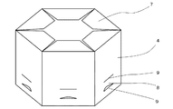
つぎに、締結部材の別の実施例について説明する。図6は第2ナットの第2の例を示す斜視図、図7は締結部材の第2の例を示す斜視部である。本例においては、第2ナット3の入口側(図6において下側)の端部にはフランジ部10が設けられている。このフランジ部10はナット本体と一体に形成されてもよいが、ここでは平座金のような環状の部材を溶接によって固定している。
Next, another embodiment of the fastening member will be described. FIG. 6 is a perspective view showing a second example of the second nut, and FIG. 7 is a perspective view showing a second example of the fastening member. In this example, a
このフランジ部10はボルトを取り付ける対象物yの表面にとりつけるのに利用することができる。図8は本例の締結部材の使用例を示す断面図である。対象物に対してボルト通し孔11を設けておき、その孔に締結部材1のネジ孔を合わせ、フランジ部10を溶接によって対象物yに固定することができる。フランジ部10に接するだけの平面があれば対象物yは任意に選択できる。
The
対象物yのボルト通し孔11からボルトxを挿入し、締結部材1にねじ込むことによって、ボルトを取り付けることができる。ボルトxの頭が対象物に当たるまで締め込む必要はない。ボルトが対象物の表面から突き出した状態で設置してもよい。そのような状態でも、ケーシング部材4の中の第1ナット2と第2ナット3はボルトに対して十分な摩擦力を作用することができ、設置後に自然に緩むことはない。ボルトと対象物の表面の間には、さまざまなものを取り付けることができる。たとえば、ボルトxの頭に広い平座金12を入れ、対象物yである鋼板の表面と平座金12の間にスポンジ13のような柔らかな部材をそのふくらみを保った状態で取り付けることができる。また、可動性の部材を締め付けることなく取り付けることもできる。
The bolt x can be attached by inserting the bolt x from the bolt through hole 11 of the object y and screwing it into the
1.締結部材
2.第1ナット
3.第2ナット
4.ケーシング部材
5.凹部
7.弾性部
8.規制部
10.フランジ部
x.ボルト
y.取り付け対象物
1. Fastening
Claims (3)
Priority Applications (1)
| Application Number | Priority Date | Filing Date | Title |
|---|---|---|---|
| JP2016164933A JP6077168B1 (en) | 2016-08-25 | 2016-08-25 | Fastening member |
Applications Claiming Priority (1)
| Application Number | Priority Date | Filing Date | Title |
|---|---|---|---|
| JP2016164933A JP6077168B1 (en) | 2016-08-25 | 2016-08-25 | Fastening member |
Publications (2)
| Publication Number | Publication Date |
|---|---|
| JP6077168B1 JP6077168B1 (en) | 2017-02-08 |
| JP2018031440A true JP2018031440A (en) | 2018-03-01 |
Family
ID=57981524
Family Applications (1)
| Application Number | Title | Priority Date | Filing Date |
|---|---|---|---|
| JP2016164933A Active JP6077168B1 (en) | 2016-08-25 | 2016-08-25 | Fastening member |
Country Status (1)
| Country | Link |
|---|---|
| JP (1) | JP6077168B1 (en) |
Cited By (1)
| Publication number | Priority date | Publication date | Assignee | Title |
|---|---|---|---|---|
| CN112325008A (en) * | 2020-11-19 | 2021-02-05 | 浙江恒展机械有限公司 | Novel double-nut pipe joint |
Families Citing this family (2)
| Publication number | Priority date | Publication date | Assignee | Title |
|---|---|---|---|---|
| CN111023045B (en) * | 2019-12-11 | 2021-09-07 | 陕西铭泊停车服务有限公司 | Protection architecture for parking area lighting device |
| CN112145537A (en) * | 2020-09-30 | 2020-12-29 | 黄淼鑫 | Self-locking bolt with anti-loosening function |
Family Cites Families (4)
| Publication number | Priority date | Publication date | Assignee | Title |
|---|---|---|---|---|
| US3233262A (en) * | 1963-02-18 | 1966-02-08 | Vollman Walter | Method of producing locknuts by assembling laminae in a housing |
| JPS59174245A (en) * | 1983-03-23 | 1984-10-02 | Fuji Seimitsu Seisakusho:Kk | Production of lock nut |
| ITMI981644A1 (en) * | 1998-07-17 | 2000-01-17 | Urama S R L | IMPROVEMENTS TO THE SELF-BLOCKING METAL RINGS AND PROCEDURES FOR THEIR PRODUCTION |
| JP6178105B2 (en) * | 2013-04-23 | 2017-08-09 | 株式会社NejiLaw | Fastening holding member and fastening holding structure |
-
2016
- 2016-08-25 JP JP2016164933A patent/JP6077168B1/en active Active
Cited By (1)
| Publication number | Priority date | Publication date | Assignee | Title |
|---|---|---|---|---|
| CN112325008A (en) * | 2020-11-19 | 2021-02-05 | 浙江恒展机械有限公司 | Novel double-nut pipe joint |
Also Published As
| Publication number | Publication date |
|---|---|
| JP6077168B1 (en) | 2017-02-08 |
Similar Documents
| Publication | Publication Date | Title |
|---|---|---|
| US7338242B2 (en) | Quick-connect fastener assembly | |
| JP6661632B2 (en) | Loosening prevention bolt | |
| EP3587842B1 (en) | Fastening structure | |
| JP6077168B1 (en) | Fastening member | |
| JP2009275727A (en) | Looseness preventing locking device | |
| JP5283051B2 (en) | Loosening prevention nut | |
| JP4418899B2 (en) | Locking nut | |
| US20150204374A1 (en) | Ratchet nut and washer | |
| JP2008038947A (en) | Locking mechanism for screw | |
| JP5923150B2 (en) | Rock bolt | |
| JP3892479B2 (en) | Lock member | |
| KR20180043692A (en) | Non-release bolt and nut | |
| KR20190119403A (en) | A bolt to be fastened bidirectionally for extension | |
| US20080145178A1 (en) | Threaded engagement element with self-locking threads | |
| JP2016161127A (en) | Falling prevention device for fastening nut | |
| JP2019039244A (en) | Exterior member mounting method | |
| JP4837963B2 (en) | Screw locking structure | |
| US11835080B2 (en) | Anti-loosening metallic externally threaded fastener | |
| KR102194640B1 (en) | Bolt assembly reinforced to loose stopping | |
| US20160208840A1 (en) | Fastener With Removable Head End | |
| AU2008200632B2 (en) | Locking washer | |
| KR20010059806A (en) | clamping bolt structure | |
| US992137A (en) | Nut-lock. | |
| JP6282539B2 (en) | Fixing bracket for existing folded plate roof | |
| JP2014109378A (en) | Ratchet lock bolt |
Legal Events
| Date | Code | Title | Description |
|---|---|---|---|
| TRDD | Decision of grant or rejection written | ||
| A01 | Written decision to grant a patent or to grant a registration (utility model) |
Free format text: JAPANESE INTERMEDIATE CODE: A01 Effective date: 20170104 |
|
| A61 | First payment of annual fees (during grant procedure) |
Free format text: JAPANESE INTERMEDIATE CODE: A61 Effective date: 20170111 |
|
| R150 | Certificate of patent or registration of utility model |
Ref document number: 6077168 Country of ref document: JP Free format text: JAPANESE INTERMEDIATE CODE: R150 |
|
| R250 | Receipt of annual fees |
Free format text: JAPANESE INTERMEDIATE CODE: R250 |