JP2018024476A - Packaging container - Google Patents
Packaging container Download PDFInfo
- Publication number
- JP2018024476A JP2018024476A JP2017144873A JP2017144873A JP2018024476A JP 2018024476 A JP2018024476 A JP 2018024476A JP 2017144873 A JP2017144873 A JP 2017144873A JP 2017144873 A JP2017144873 A JP 2017144873A JP 2018024476 A JP2018024476 A JP 2018024476A
- Authority
- JP
- Japan
- Prior art keywords
- lid
- packaging container
- container
- opening
- area
- Prior art date
- Legal status (The legal status is an assumption and is not a legal conclusion. Google has not performed a legal analysis and makes no representation as to the accuracy of the status listed.)
- Granted
Links
Images


Classifications
-
- Y—GENERAL TAGGING OF NEW TECHNOLOGICAL DEVELOPMENTS; GENERAL TAGGING OF CROSS-SECTIONAL TECHNOLOGIES SPANNING OVER SEVERAL SECTIONS OF THE IPC; TECHNICAL SUBJECTS COVERED BY FORMER USPC CROSS-REFERENCE ART COLLECTIONS [XRACs] AND DIGESTS
- Y02—TECHNOLOGIES OR APPLICATIONS FOR MITIGATION OR ADAPTATION AGAINST CLIMATE CHANGE
- Y02W—CLIMATE CHANGE MITIGATION TECHNOLOGIES RELATED TO WASTEWATER TREATMENT OR WASTE MANAGEMENT
- Y02W30/00—Technologies for solid waste management
- Y02W30/50—Reuse, recycling or recovery technologies
- Y02W30/80—Packaging reuse or recycling, e.g. of multilayer packaging
Abstract
Description
本発明は、包装容器に関する。より詳しくは、食品の包装用途に有用な密着嵌合方式の包装容器に関する。 The present invention relates to a packaging container. More specifically, the present invention relates to a tightly fitting packaging container useful for food packaging applications.
食品等を包装する合成樹脂製の包装容器において、容器内に収納した内容物が容器外に漏れることを防止するために、容器本体と蓋体との嵌合部の密着性を高めた密着嵌合方式の包装容器が一般的に使用されている。密着嵌合方式の包装容器は通常、加熱した合成樹脂シートを真空成形加工や圧空成形加工を行うことによって製造することができる。 In a plastic packaging container that wraps food, etc., in order to prevent the contents stored in the container from leaking out of the container, a close fitting with improved adhesion between the container body and the lid Commonly used packaging containers are commonly used. A close-fitting packaging container can usually be manufactured by subjecting a heated synthetic resin sheet to vacuum forming or pressure forming.
密着嵌合方式の包装容器においては、蓋体を閉める際に、容器内の空気を排出できず容器内の圧力が高くなるため蓋体を閉めにくいという現象が発生することがある。さらに、容器本体と蓋体との嵌合力が小さいと、一旦蓋体を閉めても容器内の圧力により蓋体が外れるという現象も生じることがある。 In a close-fitting packaging container, when the lid is closed, the air in the container cannot be discharged and the pressure in the container increases, so that a phenomenon may occur that the lid is difficult to close. Further, if the fitting force between the container body and the lid is small, there may be a phenomenon that the lid is detached due to the pressure in the container even if the lid is once closed.
また、密着嵌合方式の包装容器に収納した食品等の内容物を電子レンジで加熱する場合には、内容物から発生する水蒸気を容器外に排出させることが必要である。水蒸気を容器外に排出させるためには、容器に通気用の孔を穿孔したり、通気路を形成したりする必要がある。発生した水蒸気をスムーズに排出できないと、容器内の圧力が高くなり容器本体から蓋体が外れてしまう虞がある。 In addition, when heating contents such as food stored in a tightly fitting packaging container with a microwave oven, it is necessary to discharge water vapor generated from the contents out of the container. In order to discharge water vapor out of the container, it is necessary to perforate holes in the container or to form an air passage. If the generated water vapor cannot be discharged smoothly, the pressure in the container increases and the lid body may come off from the container body.
従来、蓋体の閉めにくさの回避策や水蒸気の排出手段として、蓋体の天面にU字形状のスリットを入れていた。特許文献1には、天板部に切込みを入れて舌片部が形成された包装容器の蓋が開示されている。特許文献2には、蓋の蒸気抜き部を覆うように貼着され、電子レンジで加熱すると変形する熱収縮フィルムの開閉ラベルを有した電子レンジ用食品容器の蓋が開示されている。
Conventionally, a U-shaped slit has been provided on the top surface of the lid as a measure for avoiding difficulty in closing the lid and as means for discharging water vapor. Patent Document 1 discloses a lid of a packaging container in which a tongue piece portion is formed by cutting a top plate portion.
しかしながら、特許文献1や特許文献2に開示された、舌片状のスリットを包装容器の蓋体に形成する方法は、水蒸気を排出することはできても、スリットから埃や虫等が侵入したり、店頭においていたずらによって異物を混入されたり、舌片状のスリットが割れて容器内に切片が混入するといった問題があった。
However, the method of forming a tongue-shaped slit on the lid of the packaging container disclosed in Patent Document 1 and
本発明は、このような状況に鑑みてなされた発明である。すなわち、本発明の課題は、蓋体の閉めにくさを回避することができ、電子レンジで加熱しても内容物から発生する水蒸気圧によって蓋体が外れることがなく、異物の侵入や蓋体の割れの発生を防止することが可能な包装容器を提供することである。 The present invention has been made in view of such a situation. That is, the problem of the present invention is that it is possible to avoid difficulty in closing the lid, and even if heated by a microwave oven, the lid does not come off due to the water vapor pressure generated from the contents. It is to provide a packaging container capable of preventing the occurrence of cracks.
本発明者は、蓋体に形成する孔の形状について検討を進めた。蓋体の閉めにくさを回避したり、電子レンジで加熱した際の水蒸気圧を低減させるためには、十分に大きな孔を形成すればよい。しかし、大きな孔であると、異物の侵入を防いだり、割れが発生することを防止することが難しい。さらに、外観の商品性の観点からは、孔の大きさを極力小さくすることが求められている。そして、電子レンジで加熱した際の水蒸気圧によって蓋体が外れることがないようにするためには、密着嵌合方式の包装容器の嵌合強度と孔の大きさとの関係を子細に検討することが必要であった。本発明はこのような検討を重ねた結果、到達することができたものである。 This inventor advanced examination about the shape of the hole formed in a cover body. In order to avoid the difficulty of closing the lid or to reduce the water vapor pressure when heated by a microwave oven, a sufficiently large hole may be formed. However, if it is a large hole, it is difficult to prevent the intrusion of foreign matter or to prevent the occurrence of cracks. Furthermore, from the viewpoint of the merchantability of the appearance, it is required to make the size of the hole as small as possible. And in order to prevent the lid from coming off due to the water vapor pressure when heated in a microwave oven, the relationship between the fitting strength and the hole size of the tightly fitting packaging container must be studied in detail. Was necessary. The present invention has been achieved as a result of such studies.
すなわち、本発明の包装容器は、以下のような構成を有するものである。
(1)上方に開口部を有する容器本体と、該容器本体に密着嵌合させて前記開口部を塞ぐ合成樹脂製の蓋体とから構成される包装容器であって、前記蓋体は複数の微細孔を有し、前記微細孔は、最大径が1.5mm以下で、孔面積が1.8mm2以下であり、前記微細孔の孔面積の合計が6mm2以上であることを特徴とする包装容器である。
That is, the packaging container of the present invention has the following configuration.
(1) A packaging container composed of a container main body having an opening on the upper side and a synthetic resin lid that closely fits the container main body and closes the opening. The fine holes have a maximum diameter of 1.5 mm or less, a hole area of 1.8 mm 2 or less, and a total of the hole areas of the fine holes is 6 mm 2 or more. It is a packaging container.
(2)前記容器本体の開口部の面積が300cm2以下である前記(1)に記載の包装容器である。 (2) The packaging container according to (1), wherein an area of the opening of the container body is 300 cm 2 or less.
(3)前記容器本体と前記蓋体との開蓋嵌合力が500〜2000cNである前記(1)または前記(2)に記載の包装容器である。 (3) The packaging container according to (1) or (2), wherein an opening fitting force between the container body and the lid is 500 to 2000 cN.
(4)前記容器本体と前記蓋体とが内嵌合方式で嵌合されている前記(1)〜(3)のいずれか1項に記載の包装容器である。 (4) The packaging container according to any one of (1) to (3), wherein the container body and the lid body are fitted by an internal fitting method.
(5)前記微細孔が前記蓋体の傾斜面部および曲面部のいずれかまたは両方に形成されている前記(1)〜(4)のいずれか1項に記載の包装容器である。 (5) The packaging container according to any one of (1) to (4), wherein the fine hole is formed in one or both of the inclined surface portion and the curved surface portion of the lid.
(6)前記蓋体が透明合成樹脂製である前記(1)〜(5)のいずれか1項に記載の包装容器である。 (6) The packaging container according to any one of (1) to (5), wherein the lid is made of a transparent synthetic resin.
(7)前記蓋体がビカット軟化点が107℃以上の合成樹脂製である前記(1)〜(6)のいずれか1項に記載の包装容器である。 (7) The packaging container according to any one of (1) to (6), wherein the lid is made of a synthetic resin having a Vicat softening point of 107 ° C or higher.
(8)食品を収納し、電子レンジで加熱して使用することを特徴とする前記(1)〜(7)のいずれか1項に記載の包装容器である。 (8) The packaging container according to any one of (1) to (7), wherein food is stored and heated in a microwave oven.
本発明の包装容器は、蓋体の閉めにくさを回避することができ、電子レンジで加熱しても内容物から発生する水蒸気圧によって蓋体が外れることがなく、異物の侵入や蓋体の割れの発生を防止することが可能である。 The packaging container of the present invention can avoid the difficulty of closing the lid, and even when heated by a microwave oven, the lid does not come off due to the water vapor pressure generated from the contents. It is possible to prevent the occurrence of cracks.
本発明の実施形態について以下説明する。但し、本発明の実施形態は、以下の実施形態に限定されるものではない。 Embodiments of the present invention will be described below. However, embodiments of the present invention are not limited to the following embodiments.
本実施形態の包装容器は、上方に開口部を有する容器本体と、該容器本体に密着嵌合させて前記開口部を塞ぐ合成樹脂製の蓋体とから構成される包装容器である。嵌合方式とは、包装容器を構成する容器本体と蓋体とが互いに嵌合して結合する方式である。嵌合方式の中でも、空気の漏れを低減するように容器本体と蓋体との嵌合部の密着性を高めた嵌合方式を密着嵌合方式という。本実施形態の包装容器は、密着嵌合方式の包装容器であり、電子レンジで加熱しても内容物から発生する水蒸気圧によって蓋体が外れることがないという性能を有するものである。 The packaging container of this embodiment is a packaging container comprised from the container main body which has an opening part upwards, and the synthetic resin lid body which close-fits the said container main body and plugs up the said opening part. The fitting method is a method in which the container main body and the lid constituting the packaging container are fitted and joined to each other. Among the fitting methods, a fitting method in which the adhesion of the fitting portion between the container main body and the lid is improved so as to reduce air leakage is referred to as a close fitting method. The packaging container of the present embodiment is a close-fitting packaging container, and has the performance that the lid body does not come off due to the water vapor pressure generated from the contents even when heated by a microwave oven.
密着嵌合方式としては、内嵌合、外嵌合および内外嵌合の何れの方式であってもよい。内嵌合方式とは、容器本体の開口部の内周嵌合面に蓋体の外周嵌合面が面接触する嵌合方式である。外嵌合方式とは、容器本体の開口部の外周嵌合面に蓋体の内周嵌合面が面接触する嵌合方式である。内外嵌合方式とは、容器本体に形成された環状凸条又は環状凹溝と、蓋体に形成された環状凹溝又は環状凸条とが、環状凸条の内側嵌合面および外側嵌合面の両面で接触する嵌合方式である。内嵌合、外嵌合および内外嵌合の各方式の中では、内嵌合方式が、蓋体の外周縁が容器本体の外周縁の内側に収めることができ、蓋体が不用意に外れる虞が少ないため、より好ましい。 The close fitting method may be any of inner fitting, outer fitting, and inner / outer fitting. The inner fitting method is a fitting method in which the outer peripheral fitting surface of the lid is in surface contact with the inner peripheral fitting surface of the opening of the container body. The outer fitting method is a fitting method in which the inner peripheral fitting surface of the lid is in surface contact with the outer peripheral fitting surface of the opening of the container body. The inner / outer fitting method means that the annular ridge or annular groove formed in the container body and the annular groove or annular ridge formed in the lid body are fitted to the inner fitting surface and the outer fitting of the annular ridge. This is a fitting method that makes contact on both sides of the surface. Among each of the inner fitting, outer fitting, and inner / outer fitting methods, the inner fitting method allows the outer peripheral edge of the lid to be accommodated inside the outer peripheral edge of the container body, and the lid is inadvertently removed. Since there is little possibility, it is more preferable.
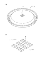
図1は、包装容器5の一例の形状を示す斜視図である。図1の上の図は蓋体2の斜視図であり、微細孔3を複数有している。図1の下の図は容器本体1の斜視図であり、上方に開口部4を有している。図2は、包装容器の一例の形状を示す断面図である。図2の上の図は蓋体2の断面図であり、図1の上の図のA−Aの位置における断面図である。図2の下の図は容器本体1の断面図であり、図1の下の図のB−Bの位置における断面図であり、容器本体1の開口部4の位置が示されている。
FIG. 1 is a perspective view showing an example of the shape of the
容器本体1および蓋体2の嵌合形状の成形には、通常、公知の真空成形法、圧空成形法、真空圧空成形法、プレス成形法等が使用される。また、真空成形法、圧空成形法または真空圧空成形法において、シートの加熱手段として熱板を用いる方法を熱板成形法ということがある。
For forming the fitting shape of the container body 1 and the
図1および図2で示した包装容器5は、発泡させた合成樹脂シートを真空成形して形成された円形の開口部4を有する丼形状の内嵌合方式の容器本体1と、合成樹脂シートを熱板成形して形成された容器本体1の開口部4に密着内嵌合する蓋体2とから構成されている。
The
本実施形態の包装容器5では、蓋体2は5×5=25個の微細孔3を有している。当該微細孔3によって、包装容器5内部の空気を外部に放出することができるため、蓋体2の閉めにくさを回避することができ、電子レンジで加熱したときに発生する水蒸気圧によって蓋体2が外れることを抑制することができる。また、蓋体2が複数の微細孔3を有していることによって、1つの微細孔3あたりの大きさを小さくすることが可能となり、外観上の見栄えを改善し、蓋体2の割れの発生を防止することができる。
In the
微細孔3は、最大径が1.5mm以下である。微細孔3の最大径が1.5mmを超えると、埃や虫等が侵入する虞がある。微細孔3の最大径は、好ましくは0.3mm以上であり、1.0mm以下である。最大径が0.3mmより小さいと、容器外へのスムーズな水蒸気の排出が困難となる懸念がある。ここで、最大径とは、微細孔3の内周を結ぶ直線距離の中で最長の長さをいう。
The
微細孔3は、孔面積が1.8mm2以下である。微細孔3の孔面積が1.8mm2を超えると、埃や虫等が侵入する虞がある。微細孔3の孔面積は、好ましくは0.05mm2以上であり、0.8mm2以下である。微細孔3の孔面積が0.05mm2未満であると、容器外へのスムーズな水蒸気の排出が困難となる懸念がある。微細孔3の孔面積は、微細孔3の内周で形成される面の面積として求められる。通常は、光学顕微鏡による拡大写真を撮り、微細孔3の寸法から算出される。
The
微細孔3の孔面積の合計は、6mm2以上である。微細孔3の孔面積の合計を6mm2以上とすることによって、1500Wの電子レンジを使用した場合であっても内容物から発生する水蒸気圧によって蓋体2が外れることを低減させることができる。微細孔3の孔面積の合計は、好ましくは30mm2以下である。微細孔3の孔面積の合計が30mm2を超えると、微細孔3の孔面積を確保するために微細孔3を多数形成することが必要となり、生産性の点で好ましくなく、また外観上も好ましくない。
The total hole area of the
蓋体2に形成した微細孔3の孔面積の合計が大きいほど、包装容器5内部に発生した水蒸気を多く排出でき、包装容器5内部の圧力上昇を抑えることができる。一方、包装容器5内に発生する水蒸気の量が微細孔3から包装容器5外に排出される水蒸気の量を超えると、包装容器5内の圧力が上昇していき、蓋体2が外れる虞が出てくる。開蓋押力が容器本体1と蓋体2との開蓋嵌合力を超えると蓋体2が容器本体1から外れる。
As the total area of the
本実施形態において、容器本体1と蓋体2との開蓋嵌合力は、500〜2000cNであることが好ましく、1000〜1500cNがより好ましい。開蓋嵌合力が500cN未満であると蓋体2が外れ易くなり、2000cNを超えると蓋体2を外し難くなり、実用的に懸念がある。開蓋嵌合力は、容器本体1と蓋体2とを反対方向に引っ張ったときに、両者が外れたときの最大力(cN)として求めることができる。開蓋嵌合力の測定には、通常、引張試験機が使用される。
In the present embodiment, the opening fitting force between the container body 1 and the
微細孔3の穿孔方法は、特に限定されるものではない。例えば、トリミング機を使用して穿孔する方法(トリミング法)や、炭酸ガスレーザー、YAGレーザー、半導体レーザー、アルゴンレーザー等の各種レーザーを照射して穿孔する方法(レーザー法)がある。但し、トリミング法においては、細い抜き刃治具を使用すると抜き刃治具が折れ易いという問題がある。また、トリミング法では、穿孔の際に発生した抜きカスが容器内に混入し易かったり、破断面から割れが発生し易い傾向にある。そのため、微細孔3の穿孔方法としては、トリミング法よりもレーザー法の方が好ましく、特に、波長領域9〜11μmの炭酸ガスレーザーを用いることが好ましい。
The method for drilling the
微細孔3の形状は、特に限定されない。しかし、トリミング法であってもレーザー法であっても、加工のし易さから、通常は円形が好ましい。
The shape of the
レーザー法の場合は、10〜100Wの出力の炭酸ガスレーザー光源による照射が好ましい。炭酸ガスレーザーの出力範囲が、10Wよりも低出力である場合には、作業性が悪く、また、樹脂を貫通できないことがあり、100Wを超えると過負荷な状態となり、所望の径の穿孔を達成できないことがある。 In the case of the laser method, irradiation with a carbon dioxide laser light source having an output of 10 to 100 W is preferable. When the output range of the carbon dioxide laser is lower than 10 W, the workability is poor, and the resin may not be able to penetrate. There are things that cannot be achieved.
また、レーザーの移送速度については、樹脂表面に5〜30000mm/sの移送速度で照射光線を動作することで行われるものであれば、穿孔を円滑に形成することができる。レーザー光の移動速度が5mm/sより低速になると、作業性が悪く、また、過剰な照射となることがあり、好ましくない。一方、レーザー光の移動速度が30000mm/sを超える場合には、所望の径の穿孔を達成できない場合がある。 Moreover, about the transfer speed of a laser, if it is performed by operating an irradiation light beam with the transfer speed of 5-30000 mm / s on the resin surface, a perforation can be formed smoothly. When the moving speed of the laser beam is lower than 5 mm / s, workability is poor and excessive irradiation may occur, which is not preferable. On the other hand, when the moving speed of the laser beam exceeds 30000 mm / s, there may be a case where drilling with a desired diameter cannot be achieved.
本実施形態において、微細孔3を形成する位置は特に限定されず、包装容器5の任意の位置に形成することができる。複数の微細孔3を蓋体2に形成するとき、微細孔3は蓋体2の特定の箇所にすべてまとめて形成してもよいし、複数のグループに分けて、複数箇所に形成してもよい。また、複数の微細孔3の並べ方のパターンについても特に限定されない。図3は、蓋体2に形成された微細孔3の位置の具体例(a)〜(d)を示す。
In the present embodiment, the position where the
蓋体2に微細孔3を形成するとき、微細孔3を形成する位置は蓋体2の天面の水平面部であっても、蓋体2の側面等の傾斜面部や曲面部であってもよい。微細孔3が蓋体2の傾斜面部および曲面部のいずれかまたは両方に形成されていると、外観上の見栄えが改善でき、包装容器5に帯封を掛けたときに微細孔3が塞がれにくく、また埃等がより侵入し難くなるため、好ましい。
When the
食品を収納した包装容器5においては、包装容器5の中央部に容器本体1から蓋体2まで全体に一周させて帯封を掛けることがある。この場合、帯封によって微細孔3が塞がれるのを防止するため、蓋体2の天面に他の天面よりも高くした凸部を設けて、帯封が掛からない天面の部分に微細孔3を形成してもよい。また、帯封の下に微細孔3を設ける場合は、帯封によって微細孔3が直接塞がれるのを防ぐため、その位置に他の天面より低くした凹部を設けて、当該凹部に微細孔3を形成してもよい。
In the
本実施形態の包装容器5は、容器本体1の開口部4の面積が300cm2以下であることが好ましい。開口部4の面積が300cm2よりも大きいと、電子レンジで加熱した際に内容物から発生する水蒸気圧によって容器内の蓋体2を押し上げる開蓋力が容器本体1と蓋体2との嵌合力を上回り蓋体2が外れてしまう虞がある。より好ましくは、開口部4の面積は、100cm2以上で、300cm2以下である。開口部4の面積が100cm2より小さいと包装容器5の内容積が小さ過ぎて実用性に欠ける。ここで、容器本体1の開口部4の面積とは、容器本体1の開口部4の嵌合面と蓋体2の嵌合面とが面接触している帯部の最下線で囲まれた面積のことをいう。
As for the
開口部4の面積が300cm2より大きい場合であっても、容器本体1と蓋体2との嵌合力を大きくすれば、水蒸気圧による開蓋力が増大しても蓋体2が外れないようにすることはできる。しかし、嵌合力をあまりに大きくすると、蓋体2の開閉のために大きな力が必要となるため、実用的に懸念がある。
Even if the area of the opening 4 is larger than 300 cm 2, if the fitting force between the container body 1 and the
本実施形態の蓋体2の素材は、合成樹脂であれば特に限定されるものではない。しかし、包装容器5内の内容物を目視で確認できることから、透明合成樹脂を使用することが好ましい。透明合成樹脂としては、スチレン系、ポリプロピレン系、ポリエステル系、ポリエチレン系の合成樹脂が通常よく使用される。特に延伸したスチレン系の合成樹脂は、剛性、耐熱性、透明性、環境性、加工性においてバランスのとれた性能を有しており、蓋体2の素材として適している。合成樹脂の透明性は、Hazeにより、評価でき、5%以下が好ましく、3%以下がより好ましい。Hazeは、JIS−K7361に準拠して測定される。Haze Meterは、NDH5000(日本電色工業株式会社製)を用いた。
The material of the
本実施形態の容器本体1の素材は、特に限定されない。合成樹脂、紙類、金属類、セラミックス類、これらの複合材料等、種々の素材を使用することができる。しかし、蓋体2と密着嵌合することが可能な形状を形成することができ、軽量であり、量産性に優れていることから、合成樹脂を使用することが好ましい。さらに、発泡させた合成樹脂を使用すると、容器本体1に断熱性を付与することができるのでより好ましい。
The material of the container body 1 of the present embodiment is not particularly limited. Various materials such as synthetic resins, papers, metals, ceramics, and composite materials thereof can be used. However, it is preferable to use a synthetic resin because it can form a shape that can be closely fitted to the
本実施形態の包装容器5は、食品を収納して、電子レンジ加熱用として使用する場合には、耐熱性を有する必要がある。電子レンジとしては業務用の1500Wの電子レンジを用いたときの加熱に耐え得ることが必要とされる。特に蓋体2においては、水蒸気による温度上昇を考慮すると、蓋体2を構成する合成樹脂は、ビカット軟化点で107℃以上の耐熱性を有することが好ましく、110℃以上であることがより好ましく、115℃以上であることがさらに好ましい。ビカット軟化点が107℃以上の耐熱性を有するスチレン系樹脂の一例としては、(メタ)アクリル酸等を共重合させたスチレン系樹脂等がある。
The
ここで、ビカット軟化点は、JIS−K7206:1999に準拠して測定される。すなわち、試験片として厚み3.2mmの射出成形品を成形後、23℃×50%RHの恒温恒湿槽にて24時間放置して状態調整を行い、5kgfのウェイトを使用し、50℃/hrの昇温速度で温度上昇させ、試験片に圧子が1mm進入したときの温度として測定される。本実施形態では、この操作を3回繰り返し、その平均値としてビカット軟化点を規定する。 Here, the Vicat softening point is measured according to JIS-K7206: 1999. That is, after molding an injection molded product having a thickness of 3.2 mm as a test piece, it was left in a constant temperature and humidity chamber of 23 ° C. × 50% RH for 24 hours to adjust the condition, and using a 5 kgf weight, The temperature is increased at a rate of temperature increase of hr, and the temperature is measured when the indenter enters 1 mm into the test piece. In the present embodiment, this operation is repeated three times, and the Vicat softening point is defined as the average value.
本実施形態の包装容器5の形状は、図1には丼形状の容器本体1とそれに対応する形状の蓋体2とを例示したが、特に限定されない。開口部4の形状も、円形、楕円形、矩形、三角形、五角形、六角形等、種々の形状にすることが可能であり、特に限定されない。
Although the shape of the
以上説明してきたように、本実施形態の包装容器5は、蓋体2が微細孔3を複数有しているため、蓋体2を閉める際に包装容器5内の空気が排出され、包装容器5内の圧力上昇によって蓋体2を閉めにくくなるという現象を回避することができる。また、微細孔3は、最大径が1.5mm以下であり、孔面積が1.8mm2以下であるため、埃や虫等の異物の侵入を防止することができ、蓋体2の割れの発生も防止することができる。
As described above, in the
また、包装容器5内に収納された食品を電子レンジで加熱する場合は、微細孔3の孔面積の合計が6mm2以上であるため、内容物から発生する水蒸気を微細孔3によって容器外に排出することができ、容器内の圧力上昇によって蓋体2が外れることを防止することができる。特に、内嵌合方式の密着嵌合包装容器を使用すれば、蓋体2の外周縁が容器本体1の外周縁の内側に収まるため不用意に蓋体2が外れる虞が少なくなる。
In addition, when the food stored in the
また、微細孔3は、最大径や孔面積が小さいものであるため、外観上見栄えの優れたものとなり、包装容器5内の収納物を視認し易くなる。さらに、微細孔3を蓋体2の天面の水平面部以外の傾斜面部や曲面部に設けることによって、異物がより侵入し難くなると共に、水平な天面部に微細孔3がないために包装容器5内の収納物をより一層視認し易くなる。
Moreover, since the
以下に実施例と比較例を用いて、本発明の実施の形態をさらに具体的に説明するが、本発明はこれらの例に限定されるものではない。 Hereinafter, embodiments of the present invention will be described more specifically with reference to examples and comparative examples, but the present invention is not limited to these examples.
実験Iに用いた試料の作製条件は以下の通りである。
(容器本体)
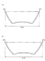
図1に記載した形状であって、次の寸法を有した2種類の容器本体(i)、(ii)を作製した。いずれも耐熱・耐圧試験用であるため、モデル的にベークライトを用いて作製した。
(i)開口部の直径125mm、開口部の面積123cm2の容器本体
(ii)開口部の直径175mm、開口部の面積240cm2の容器本体
図4は、容器本体(i)および(ii)の断面図である。図4(a)は容器本体(i)の断面図であり、図4(b)は容器本体(ii)の断面図である。
The sample preparation conditions used in Experiment I are as follows.
(Container body)
Two types of container main bodies (i) and (ii) having the shapes described in FIG. 1 and having the following dimensions were produced. Since both are for heat resistance and pressure resistance test, they were modeled using bakelite.
(I) Container body with an opening diameter of 125 mm and an opening area of 123 cm 2 (ii) Container body with an opening diameter of 175 mm and an opening area of 240 cm 2 FIG. 4 shows the container body (i) and (ii) It is sectional drawing. 4A is a cross-sectional view of the container body (i), and FIG. 4B is a cross-sectional view of the container body (ii).
(蓋体)
厚さ0.25mmの耐熱性二軸延伸ポリスチレンシート(デンカ社製、デンカサーモシート高耐熱BOPS(R反)(Haze1.2%、ビカット軟化点122℃))を熱板成形することによって、図1に記載した形状であって、直径の異なる2種類の蓋体を作製した。これらは、上記2種類の容器本体(i)および(ii)に密着内嵌合する形状を有した2種類の蓋体である。蓋体の天面には、表1および表2に記載の種々の微細孔を形成した。当該微細孔は炭酸ガスレーザーを用いて穿孔し、微細孔の形状はすべて円形であった。炭酸ガスレーザーとしては、ビデオジェット社製Videojet 3340を用いた。レーザーの照射条件は、波長10.6μm、最大平均出力45Wとした。レーザーの平均出力とレーザー光の移動速度を適度に調整することにより、所望の穿孔を達成した。
(Lid)
By hot plate molding a heat-resistant biaxially stretched polystyrene sheet (Denka Co., Ltd., Denka Thermo sheet high heat resistance BOPS (R anti) (Haze 1.2%, Vicat softening point 122 ° C.)) having a thickness of 0.25 mm. Two types of lids having the shapes described in 1 and having different diameters were produced. These are two types of lids having a shape that fits closely into the two types of container bodies (i) and (ii). Various fine holes described in Tables 1 and 2 were formed on the top surface of the lid. The micropores were drilled using a carbon dioxide laser, and the micropores were all circular. As the carbon dioxide laser, Videojet 3340 manufactured by Videojet Co. was used. The laser irradiation conditions were a wavelength of 10.6 μm and a maximum average output of 45 W. Desired drilling was achieved by appropriately adjusting the average power of the laser and the moving speed of the laser beam.
容器本体に水100ccを入れ、蓋体を閉めて、1500Wの電子レンジで2分間加熱し、容器本体から蓋体が外れるか否かを確認した。蓋体が外れたときは×、蓋体が外れなかったときは○と表示した。加熱前の容器本体と蓋体との開蓋嵌合力を測定した。さらに、加熱後に蓋体が外れた後に、あらためて蓋体を容器本体に嵌合させてから加熱後の容器本体と蓋体との開蓋嵌合力を測定した。開蓋嵌合力の測定には、(株)大場計器製作所製 丸型テンションゲージを用いた。開蓋嵌合力は50cNを単位として測定される。結果を表1および表2に示した(実験No.1〜26)。 100 cc of water was put into the container main body, the lid body was closed, and it was heated in a 1500 W microwave oven for 2 minutes to check whether the lid body was detached from the container main body. When the lid was removed, it was indicated as x, and when the lid was not removed, it was indicated as ◯. The lid opening fitting force between the container body and the lid before heating was measured. Furthermore, after the lid body was removed after heating, the lid body was again fitted to the container main body, and then the opening fitting force between the heated container main body and the lid body was measured. A round tension gauge manufactured by Oba Keiki Seisakusho Co., Ltd. was used for the measurement of the lid opening fitting force. The lid opening fitting force is measured in units of 50 cN. The results are shown in Tables 1 and 2 (Experiment Nos. 1 to 26).
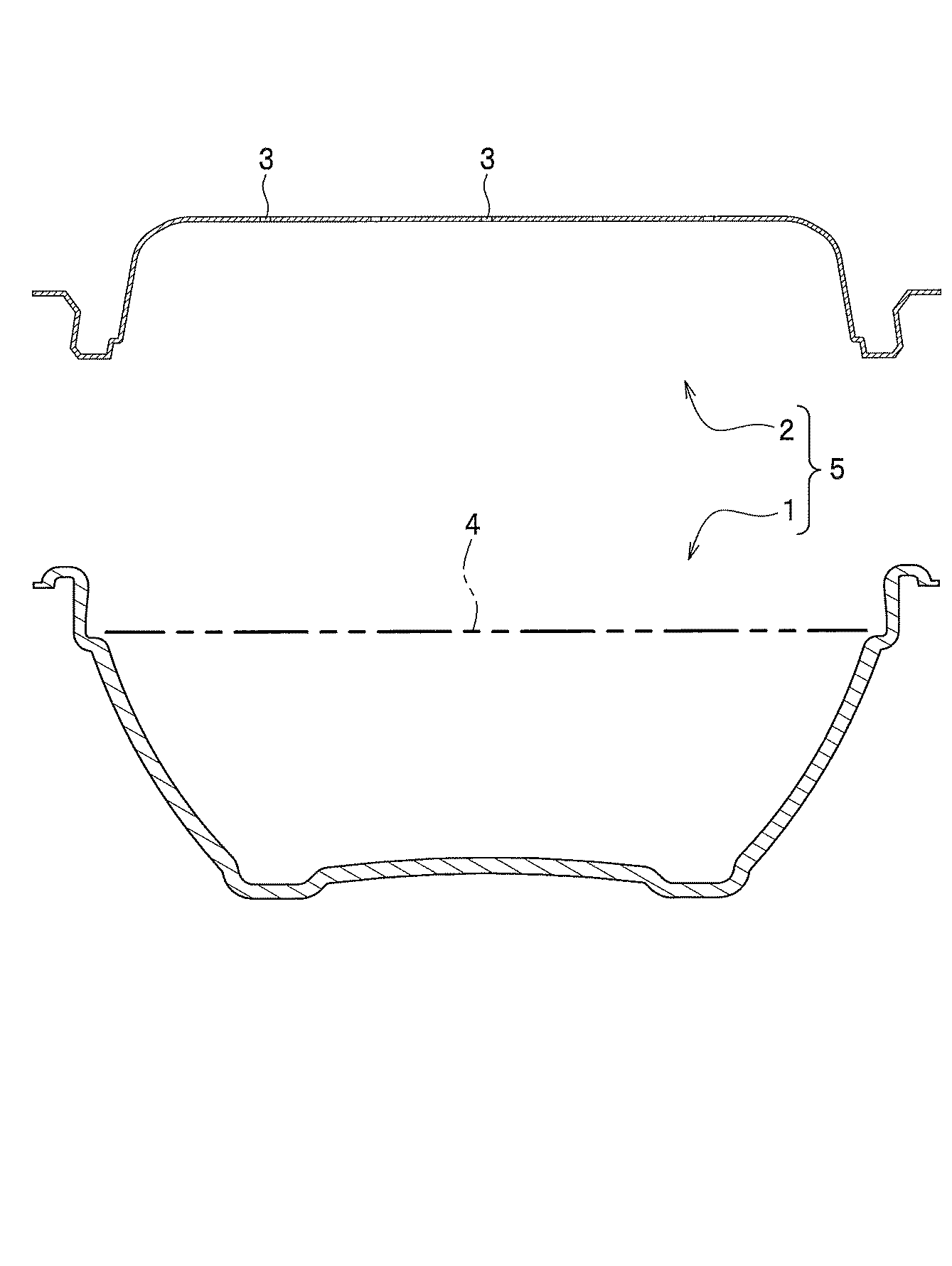
表1は、微細孔の数を16個で一定としたとき、微細孔の最大径および孔面積を変化させた場合における電子レンジ加熱時の蓋外れの有無を検討したものである。実験No.1〜6は開口部の面積が123cm2の場合であり、実験No.7〜12は、開口部の面積が240cm2の場合である。実験No.3〜6、実験No.9〜12においては電子レンジで加熱した際に蓋体が外れることはなかったが、実験No.1、2、7、8においては電子レンジで加熱した際に蓋体が外れた。すなわち、開口部の面積に拘らず、微細孔の孔面積の合計が6mm2以上であるときは、蓋体が外れることはなかったが、微細孔の孔面積の合計が6mm2未満であるときは、蓋体が外れた。 Table 1 shows the presence or absence of lid removal during microwave heating when the maximum diameter and the hole area of the fine holes are changed when the number of fine holes is constant at 16. Experiment No. 1-6 is a case where the area of an opening part is 123 cm < 2 >. 7-12 is a case where the area of an opening part is 240 cm < 2 >. Experiment No. 3-6, Experiment No. In Nos. 9-12, the lid did not come off when heated in the microwave oven. In 1, 2, 7, and 8, the lids were removed when heated in the microwave. That is, regardless of the area of the opening, when the total hole area of the fine holes is 6 mm 2 or more, the lid did not come off, but when the total hole area of the fine holes was less than 6 mm 2 The lid was removed.
表2の実験No.13〜20は、微細孔の最大径を1.5mm、孔面積を1.77mm2と一定とし、微細孔の数を変化させた場合における電子レンジ加熱時の蓋外れの有無を検討したものである。実験No.13〜16は開口部の面積が123cm2の場合であり、実験No.17〜20は開口部の面積が240cm2の場合である。実験No.14〜16、18〜20においては電子レンジで加熱した際に蓋体が外れることはなかったが、実験No.13、17においては電子レンジで加熱した際に蓋体が外れた。すなわち、開口部の面積に拘らず、微細孔の孔面積の合計が6mm2以上であるときは、蓋体が外れることはなかったが、微細孔の孔面積の合計が6mm2未満であるときは、蓋体が外れた。 Experiment No. 2 in Table 2 Nos. 13 to 20 were examined for the presence or absence of lid removal during microwave heating when the maximum diameter of the micro holes was fixed at 1.5 mm and the hole area was fixed at 1.77 mm 2 and the number of micro holes was changed. is there. Experiment No. 13-16 is a case where the area of an opening part is 123 cm < 2 >. 17-20 is a case where the area of an opening part is 240 cm < 2 >. Experiment No. In Nos. 14-16 and 18-20, the lid did not come off when heated in a microwave oven. In 13 and 17, the lid body was removed when heated in the microwave. That is, regardless of the area of the opening, when the total hole area of the fine holes is 6 mm 2 or more, the lid did not come off, but when the total hole area of the fine holes was less than 6 mm 2 The lid was removed.
表2の実験No.21〜26は、微細孔の最大径を0.4mm、孔面積を0.13mm2と一定とし、微細孔の数を変化させた場合における電子レンジ加熱時の蓋外れの有無を検討したものである。実験No.21〜23は開口部の面積が123cm2の場合であり、実験No.24〜26は開口部の面積が240cm2の場合である。実験No.22、23、25、26においては電子レンジで加熱した際に蓋体が外れることはなかったが、実験No.21、24においては電子レンジで加熱した際に蓋体が外れた。すなわち、実験No.13〜20に比べて、微細孔の最大径を約4分の1、微細孔1つあたりの孔面積を約14分の1にしたときであっても、微細孔の孔面積の合計が6mm2以上であるときは、蓋体が外れることはなかったが、微細孔の孔面積の合計が6mm2未満であるときは、蓋体が外れた。 Experiment No. 2 in Table 2 Nos. 21 to 26 were examined for the presence or absence of lid removal during microwave heating when the maximum diameter of the fine holes was constant at 0.4 mm and the hole area was fixed at 0.13 mm 2 and the number of fine holes was changed. is there. Experiment No. 21-23 is a case where the area of an opening part is 123 cm < 2 >. 24 to 26 are cases where the area of the opening is 240 cm 2 . Experiment No. In Nos. 22, 23, 25 and 26, the lid did not come off when heated in a microwave oven. In Nos. 21 and 24, the lid body was removed when heated in a microwave oven. That is, Experiment No. Compared to 13-20, even when the maximum diameter of the fine holes is about 1/4 and the hole area per fine hole is about 14 times, the total hole area of the fine holes is 6 mm. When it was 2 or more, the lid did not come off, but when the total pore area was less than 6 mm 2 , the lid was removed.
表1および表2から分かるように、電子レンジで加熱する前では、容器本体と蓋体との開蓋嵌合力は850〜900cNであったが、電子レンジで2分間加熱後では、容器本体と蓋体との開蓋嵌合力が500〜600cNにまで低下した。加熱後に開蓋嵌合力が低下した原因は、加熱によって蓋体の寸法が収縮したためと考えている。加熱前後の蓋体の寸法を測定したところ、加熱後に蓋体の直径は0.1〜0.2%収縮していた。尚、実験No.1、2、7、8、13、17、21、24の加熱後の開蓋嵌合力が800乃至850cNであり、加熱前の開蓋嵌合力と同等の値であるのは、加熱によって蓋体の寸法が収縮する前に蓋体が外れてしまったためである。 As can be seen from Tables 1 and 2, the opening fitting force between the container body and the lid was 850 to 900 cN before heating in the microwave, but after heating for 2 minutes in the microwave, The opening fitting force with the lid body was reduced to 500 to 600 cN. The reason why the lid opening fitting force is reduced after heating is considered to be that the dimensions of the lid body contracted by heating. When the dimensions of the lid body before and after heating were measured, the diameter of the lid body was contracted by 0.1 to 0.2% after heating. Experiment No. The lid fitting force after heating of 1, 2, 7, 8, 13, 17, 21, and 24 is 800 to 850 cN, and the lid fitting force before heating is a value equivalent to the lid fitting force before heating. This is because the lid has been removed before the size of the container shrinks.
上記の電子レンジで2分間加熱する実験とは別に、同等の包装容器を用いて電子レンジで6分間加熱する実験も行った。その結果、実験No.3、9、14、18、22、25の包装容器は、加熱開始から2分間を超えて6分間に達するまでの間に容器本体から蓋体が外れた。また、実験No.4〜6、10〜12、15、16、19、20、23、26の包装容器は、6分間加熱を行った後も容器本体から蓋体が外れなかった。6分間加熱を行った後でも容器本体から蓋体が外れなかった原因は、本実験における包装容器が密着嵌合方式による包装容器であるためと考えている。 In addition to the above-described experiment of heating for 2 minutes in a microwave oven, an experiment of heating for 6 minutes in a microwave oven using an equivalent packaging container was also performed. As a result, Experiment No. As for the packaging containers of 3, 9, 14, 18, 22, and 25, the lid body was removed from the container main body during the period from the start of heating to 6 minutes exceeding 2 minutes. In addition, Experiment No. As for the packaging containers of 4-6, 10-12, 15, 16, 19, 20, 23, 26, the lid body did not come off from the container body even after heating for 6 minutes. The reason why the lid did not come off from the container body even after heating for 6 minutes is thought to be that the packaging container in this experiment is a packaging container by the close fitting method.
実験IIに用いた試料の作製条件は以下の通りである。
(容器本体)
図1に記載した形状であって、次の寸法を有した2種類の容器本体(iii)、(iv)を作製した。いずれもスチレン系樹脂発泡シートにて作製した。
(iii)開口部の直径155mm、開口部の面積190cm2の容器本体
(iv)開口部の直径170mm、開口部の面積227cm2の容器本体
図5は、容器本体(iii)および(iv)の断面図である。図5(a)は容器本体(iii)の断面図であり、図5(b)は容器本体(iv)の断面図である。
The sample preparation conditions used in Experiment II are as follows.
(Container body)
Two types of container main bodies (iii) and (iv) having the shapes described in FIG. 1 and having the following dimensions were produced. All were produced with a styrene resin foam sheet.
(Iii) A container body having an opening diameter of 155 mm and an opening area of 190 cm 2 (iv) A container body having an opening diameter of 170 mm and an opening area of 227 cm 2 FIG. 5 shows the container body (iii) and (iv) It is sectional drawing. Fig.5 (a) is sectional drawing of a container main body (iii), FIG.5 (b) is sectional drawing of a container main body (iv).
(蓋体)
厚さ0.25mmの耐熱性二軸延伸ポリスチレンシート(デンカ社製、デンカサーモシート高耐熱BOPS(R反)(Haze1.2%、ビカット軟化点122℃))を熱板成形することによって、図1に記載した形状であって、直径の異なる2種類の蓋体を作製した。これらは、上記2種類の容器本体(iii)および(iv)に密着内嵌合する形状を有した2種類の蓋体である。蓋体の天面には、表3および表4に記載の種々の微細孔を形成した。当該微細孔は炭酸ガスレーザーを用いて穿孔し、微細孔の形状はすべて円形であった。炭酸ガスレーザーとしては、ビデオジェット社製Videojet 3340を用いた。レーザーの照射条件は、波長10.6μm、最大平均出力45Wとした。レーザーの平均出力とレーザー光の移動速度を適度に調整することにより、所望の穿孔を達成した。
(Lid)
By hot plate molding a heat-resistant biaxially stretched polystyrene sheet (Denka Co., Ltd., Denka Thermo sheet high heat resistance BOPS (R anti) (Haze 1.2%, Vicat softening point 122 ° C.)) having a thickness of 0.25 mm. Two types of lids having the shapes described in 1 and having different diameters were produced. These are two types of lids having a shape that fits closely into the two types of container bodies (iii) and (iv). Various fine holes described in Table 3 and Table 4 were formed on the top surface of the lid. The micropores were drilled using a carbon dioxide laser, and the micropores were all circular. As the carbon dioxide laser, Videojet 3340 manufactured by Videojet Co. was used. The laser irradiation conditions were a wavelength of 10.6 μm and a maximum average output of 45 W. Desired drilling was achieved by appropriately adjusting the average power of the laser and the moving speed of the laser beam.
容器本体に水400ccを入れ、蓋体を閉めて、1500Wの電子レンジで2分間加熱し、容器本体から蓋体が外れるか否かを確認した。蓋体が外れたときは×、蓋体が外れなかったときは○と表示した。加熱前の容器本体と蓋体との開蓋嵌合力を測定した。結果を表3および表4に示した(実験No.27〜52)。 400 cc of water was put into the container body, the lid was closed, and it was heated in a 1500 W microwave oven for 2 minutes to check whether the lid was removed from the container body. When the lid was removed, it was indicated as x, and when the lid was not removed, it was indicated as ◯. The lid opening fitting force between the container body and the lid before heating was measured. The results are shown in Tables 3 and 4 (Experiment Nos. 27 to 52).
表3は、微細孔の数を16個で一定としたとき、微細孔の最大径および孔面積を変化させた場合における電子レンジ加熱時の蓋外れの有無を検討したものである。実験No.27〜32は開口部の面積が190cm2の場合であり、実験No.33〜38は、開口部の面積が227cm2の場合である。実験No.29〜32、実験No.35〜38においては電子レンジで加熱した際に蓋体が外れることはなかったが、実験No.27、28、33、34においては電子レンジで加熱した際に蓋体が外れた。すなわち、開口部の面積に拘らず、微細孔の孔面積の合計が6mm2以上であるときは、蓋体が外れることはなかったが、微細孔の孔面積の合計が6mm2未満であるときは、蓋体が外れた。 Table 3 shows the presence or absence of lid removal during microwave heating when the maximum diameter and area of the micropores are changed when the number of micropores is constant at 16. Experiment No. 27 to 32 are cases where the area of the opening is 190 cm 2 . 33-38 is a case where the area of an opening part is 227 cm < 2 >. Experiment No. 29-32, Experiment No. In 35 to 38, the lid did not come off when heated in a microwave oven. In 27, 28, 33, and 34, the lids were removed when heated in a microwave oven. That is, regardless of the area of the opening, when the total hole area of the fine holes is 6 mm 2 or more, the lid did not come off, but when the total hole area of the fine holes was less than 6 mm 2 The lid was removed.
表4の実験No.39〜46は、微細孔の最大径を1.5mm、孔面積を1.77mm2と一定とし、微細孔の数を変化させた場合における電子レンジ加熱時の蓋外れの有無を検討したものである。実験No.39〜42は開口部の面積が190cm2の場合であり、実験No.43〜46は開口部の面積が227cm2の場合である。実験No.40〜42、44〜46においては電子レンジで加熱した際に蓋体が外れることはなかったが、実験No.39、43においては電子レンジで加熱した際に蓋体が外れた。すなわち、開口部の面積に拘らず、微細孔の孔面積の合計が6mm2以上であるときは、蓋体が外れることはなかったが、微細孔の孔面積の合計が6mm2未満であるときは、蓋体が外れた。 Experiment No. 4 in Table 4 39-46 is the maximum diameter of the fine pores was 1.5 mm, the open area between 1.77 mm 2 and the constant, which was examined whether the lid off during microwave heating in the case of changing the number of micropores is there. Experiment No. 39 to 42 are cases in which the area of the opening is 190 cm 2 . 43 to 46 are cases where the area of the opening is 227 cm 2 . Experiment No. In Nos. 40 to 42 and 44 to 46, the lid did not come off when heated in a microwave oven. In 39 and 43, the lid body was removed when heated in the microwave. That is, regardless of the area of the opening, when the total hole area of the fine holes is 6 mm 2 or more, the lid did not come off, but when the total hole area of the fine holes was less than 6 mm 2 The lid was removed.
表4の実験No.47〜52は、微細孔の最大径を0.4mm、孔面積を0.13mm2と一定とし、微細孔の数を変化させた場合における電子レンジ加熱時の蓋外れの有無を検討したものである。実験No.47〜49は開口部の面積が190cm2の場合であり、実験No.50〜52は開口部の面積が227cm2の場合である。実験No.48、49、51、52においては電子レンジで加熱した際に蓋体が外れることはなかったが、実験No.47、50においては電子レンジで加熱した際に蓋体が外れた。すなわち、実験No.39〜46に比べて、微細孔の最大径を約4分の1、微細孔1つあたりの孔面積を約14分の1にしたときであっても、微細孔の孔面積の合計が6mm2以上であるときは、蓋体が外れることはなかったが、微細孔の孔面積の合計が6mm2未満であるときは、蓋体が外れた。 Experiment No. 4 in Table 4 47-52 is the maximum diameter of the fine pores was 0.4 mm, the open area between 0.13 mm 2 and the constant, which was examined whether the lid off during microwave heating in the case of changing the number of micropores is there. Experiment No. 47 to 49 are cases where the area of the opening is 190 cm 2 . 50 to 52 are cases where the area of the opening is 227 cm 2 . Experiment No. In Nos. 48, 49, 51, and 52, the lid did not come off when heated in a microwave oven. In 47 and 50, the lid body was removed when heated in a microwave oven. That is, Experiment No. Compared to 39-46, even when the maximum diameter of the fine holes is about 1/4 and the hole area per fine hole is about 14 times, the total hole area of the fine holes is 6 mm. When it was 2 or more, the lid did not come off, but when the total pore area was less than 6 mm 2 , the lid was removed.
上記の電子レンジで2分間加熱する実験とは別に、同等の包装容器を用いて電子レンジで6分間加熱する実験も行った。その結果、実験No.29、35、40、44、48、51の包装容器は、加熱開始から2分間を超えて6分間に達するまでの間に容器本体から蓋体が外れた。また、実験No.30〜32、36〜38、41、42、45、46、49、52の包装容器は、6分間加熱を行った後も容器本体から蓋体が外れなかった。6分間加熱を行った後でも容器本体から蓋体が外れなかった原因は、本実験における包装容器が密着嵌合方式による包装容器であるためと考えている。 In addition to the above-described experiment of heating for 2 minutes in a microwave oven, an experiment of heating for 6 minutes in a microwave oven using an equivalent packaging container was also performed. As a result, Experiment No. The lids of the 29, 35, 40, 44, 48, and 51 packaging containers were removed from the container body during the period from the start of heating to the 6 minutes exceeding 2 minutes. In addition, Experiment No. The packaging containers 30 to 32, 36 to 38, 41, 42, 45, 46, 49, and 52 did not come off the container body after heating for 6 minutes. The reason why the lid did not come off from the container body even after heating for 6 minutes is thought to be that the packaging container in this experiment is a packaging container by the close fitting method.
実験IIIに用いた試料の作製条件は以下の通りである。
(容器本体)
実験IIにおいて用いた容器本体(iii)、(iv)と同じものを用いた。
The sample preparation conditions used in Experiment III are as follows.
(Container body)
The same container body (iii) and (iv) used in Experiment II were used.
(蓋体)
微細孔3の形状と位置を図6に記載したものとした以外は、実験IIにおいて用いた蓋体)と同等の直径の異なる2種類の蓋体を用いた。蓋体の天面には、表5に記載の種々の微細孔を形成した。当該微細孔は炭酸ガスレーザーを用いて穿孔した。炭酸ガスレーザーとしては、実験IIと同じものを用いた。微細孔の形状はすべて図6に示された最大径と最小径を有する細長い孔であった。
(Lid)
Two types of lids having the same diameter as the lids used in Experiment II were used except that the shape and position of the
ここで、最大径とは、微細孔3の内周を結ぶ直線距離の中で最長の長さ(孔の長さ)をいい、最小径とは、微細孔3の内周を結ぶ直線距離の中で最短の長さ(孔の幅)をいう。最大径と最小径は、画像測定器((株)ミツトヨ製、QS250Z)を用いて測定される。測定方法は、ディスプレイ上で拡大された孔の画像を最大径の位置および幅の位置(最小径)を指定することにより自動計測される。各実験No.毎に5サンプルを作成し、各サンプルに穿孔されている全ての孔(10個および15個)を測定し、それらの平均値を求めた。
Here, the maximum diameter refers to the longest length (hole length) among the linear distances connecting the inner peripheries of the
開蓋嵌合力および蓋外れの有無の評価方法は、実験IIと同様である。結果を表5に示した(実験No.53〜58)。 The evaluation method for the lid fitting force and the presence / absence of detachment of the lid is the same as in Experiment II. The results are shown in Table 5 (Experiment Nos. 53 to 58).
表5は、微細孔の形状を細長い孔としたときの、微細孔の最大径、最小径および孔数を変化させた場合における電子レンジ加熱時の蓋外れの有無を検討したものである。実験No.53〜55は開口部の面積が190cm2の場合であり、実験No.56〜58は、開口部の面積が227cm2の場合である。 Table 5 shows the presence or absence of lid removal during microwave heating when the maximum diameter, the minimum diameter, and the number of holes are changed when the shape of the micro holes is an elongated hole. Experiment No. 53 to 55 are cases where the area of the opening is 190 cm 2 . 56 to 58 are cases where the area of the opening is 227 cm 2 .
実験No.54と実験No.57においては、孔面積の合計が6mm2以上であり、開蓋嵌合力も適切であって、電子レンジで加熱した際に蓋体が外れることはなかった。しかし、実験No.53と実験No.56においては、孔面積の合計が少ないため、電子レンジで加熱した際に蓋体が外れた。一方、実験No.55と実験No.58においては、孔面積の合計が6mm2以上であり、電子レンジで加熱した際に蓋体が外れることはなかったが、最大径が2mmであるため、埃や虫等の異物が侵入する懸念を有するものであった。 Experiment No. 54 and Experiment No. In No. 57, the total hole area was 6 mm 2 or more, and the lid opening fitting force was also appropriate, and the lid did not come off when heated in a microwave oven. However, experiment no. 53 and Experiment No. In 56, since the total hole area was small, the lid body was removed when heated in a microwave oven. On the other hand, Experiment No. 55 and Experiment No. 58, the total pore area was 6 mm 2 or more, and the lid did not come off when heated in a microwave oven, but because the maximum diameter was 2 mm, foreign matter such as dust and insects could enter. It was what had.
1 容器本体
2 蓋体
3 微細孔
4 開口部
5 包装容器
DESCRIPTION OF SYMBOLS 1 Container
Claims (8)
前記蓋体は複数の微細孔を有し、
前記微細孔は、最大径が1.5mm以下で、孔面積が1.8mm2以下であり、
前記微細孔の孔面積の合計が6mm2以上であることを特徴とする包装容器。 A packaging container composed of a container body having an opening on the upper side, and a synthetic resin lid that close-fits the container body and closes the opening,
The lid has a plurality of micro holes,
The fine holes have a maximum diameter of 1.5 mm or less and a hole area of 1.8 mm 2 or less.
The packaging container, wherein the total pore area of the micropores is 6 mm 2 or more.
Applications Claiming Priority (2)
| Application Number | Priority Date | Filing Date | Title |
|---|---|---|---|
| JP2016154056 | 2016-08-04 | ||
| JP2016154056 | 2016-08-04 |
Publications (2)
| Publication Number | Publication Date |
|---|---|
| JP2018024476A true JP2018024476A (en) | 2018-02-15 |
| JP7169741B2 JP7169741B2 (en) | 2022-11-11 |
Family
ID=61195451
Family Applications (1)
| Application Number | Title | Priority Date | Filing Date |
|---|---|---|---|
| JP2017144873A Active JP7169741B2 (en) | 2016-08-04 | 2017-07-26 | packaging container |
Country Status (1)
| Country | Link |
|---|---|
| JP (1) | JP7169741B2 (en) |
Cited By (4)
| Publication number | Priority date | Publication date | Assignee | Title |
|---|---|---|---|---|
| JP2019182523A (en) * | 2018-04-16 | 2019-10-24 | シーピー化成株式会社 | Packaging container |
| JP2019189313A (en) * | 2018-04-27 | 2019-10-31 | デンカ株式会社 | Packaging container |
| JP2020050368A (en) * | 2018-09-26 | 2020-04-02 | デンカ株式会社 | Lid, packaging container, and method for manufacturing lid |
| JP2020104898A (en) * | 2018-12-28 | 2020-07-09 | デンカ株式会社 | Lid body of packaging container and packaging container |
Citations (9)
| Publication number | Priority date | Publication date | Assignee | Title |
|---|---|---|---|---|
| JPH02116985U (en) * | 1989-03-06 | 1990-09-19 | ||
| JPH1111543A (en) * | 1997-06-20 | 1999-01-19 | Dainippon Printing Co Ltd | Cup for microwave oven |
| JPH11227123A (en) * | 1998-02-19 | 1999-08-24 | Dainippon Ink & Chem Inc | Biaxially oriented styrene resin laminated sheet and its manufacture |
| JP2007191161A (en) * | 2006-01-17 | 2007-08-02 | Fp Corp | Lid for packaging container, packaging container and food package |
| US20080210686A1 (en) * | 2007-03-02 | 2008-09-04 | Conagra Foods Rdm, Inc. | Multi-Component Packaging System and Apparatus |
| JP2014091542A (en) * | 2012-11-01 | 2014-05-19 | Vendor Service Kk | Food container for microwave oven |
| JP2014144796A (en) * | 2013-01-30 | 2014-08-14 | Denki Kagaku Kogyo Kk | Liquid leakage preventive container |
| JP2014227185A (en) * | 2013-05-21 | 2014-12-08 | シーピー化成株式会社 | Lid for food packaging container |
| JP2017081599A (en) * | 2015-10-28 | 2017-05-18 | アテナ工業株式会社 | Container for food to be heated by microwave oven |
-
2017
- 2017-07-26 JP JP2017144873A patent/JP7169741B2/en active Active
Patent Citations (9)
| Publication number | Priority date | Publication date | Assignee | Title |
|---|---|---|---|---|
| JPH02116985U (en) * | 1989-03-06 | 1990-09-19 | ||
| JPH1111543A (en) * | 1997-06-20 | 1999-01-19 | Dainippon Printing Co Ltd | Cup for microwave oven |
| JPH11227123A (en) * | 1998-02-19 | 1999-08-24 | Dainippon Ink & Chem Inc | Biaxially oriented styrene resin laminated sheet and its manufacture |
| JP2007191161A (en) * | 2006-01-17 | 2007-08-02 | Fp Corp | Lid for packaging container, packaging container and food package |
| US20080210686A1 (en) * | 2007-03-02 | 2008-09-04 | Conagra Foods Rdm, Inc. | Multi-Component Packaging System and Apparatus |
| JP2014091542A (en) * | 2012-11-01 | 2014-05-19 | Vendor Service Kk | Food container for microwave oven |
| JP2014144796A (en) * | 2013-01-30 | 2014-08-14 | Denki Kagaku Kogyo Kk | Liquid leakage preventive container |
| JP2014227185A (en) * | 2013-05-21 | 2014-12-08 | シーピー化成株式会社 | Lid for food packaging container |
| JP2017081599A (en) * | 2015-10-28 | 2017-05-18 | アテナ工業株式会社 | Container for food to be heated by microwave oven |
Cited By (5)
| Publication number | Priority date | Publication date | Assignee | Title |
|---|---|---|---|---|
| JP2019182523A (en) * | 2018-04-16 | 2019-10-24 | シーピー化成株式会社 | Packaging container |
| JP7227587B2 (en) | 2018-04-16 | 2023-02-22 | シーピー化成株式会社 | packaging container |
| JP2019189313A (en) * | 2018-04-27 | 2019-10-31 | デンカ株式会社 | Packaging container |
| JP2020050368A (en) * | 2018-09-26 | 2020-04-02 | デンカ株式会社 | Lid, packaging container, and method for manufacturing lid |
| JP2020104898A (en) * | 2018-12-28 | 2020-07-09 | デンカ株式会社 | Lid body of packaging container and packaging container |
Also Published As
| Publication number | Publication date |
|---|---|
| JP7169741B2 (en) | 2022-11-11 |
Similar Documents
| Publication | Publication Date | Title |
|---|---|---|
| JP2018024476A (en) | Packaging container | |
| BR112018068696B1 (en) | THERMOPLASTIC FILM FOR VACUUM FILM PACKAGING, PACKAGING METHOD AND USE THEREOF | |
| RU2011139123A (en) | METHOD FOR CANNING FOOD | |
| JP4287118B2 (en) | Microwave packaging bag | |
| ES2147667T3 (en) | THERMAL-FORMABLE FOAM BASED SHEET FOR THE MANUFACTURE OF OPEN CONTAINER CONTAINERS. | |
| JP2018044086A (en) | Polystyrenic resin foamed sheet, polystyrenic resin laminated foamed sheet, and polystyrenic resin laminated foamed molded body | |
| JP2013209449A (en) | Polystyrene-based resin foamed sheet and molded container | |
| JP2021165157A (en) | Lid body and packaging container comprising lid body and container body | |
| JP2024052960A (en) | Steam-through pouch | |
| EP3398878B1 (en) | Instant noodles container lid | |
| JP2018048278A (en) | Polystyrenic resin foam sheet, polystyrenic resin laminated foam sheet, and polystyrenic resin laminated foam molded body | |
| JP7249778B2 (en) | Packaging container lid and packaging container | |
| AU2014308039A1 (en) | Tray | |
| EP1997618A3 (en) | Sheet of plastic material, tray for a food product obtained from said sheet, packaging comprising said tray and related manufacture method | |
| JPS58208036A (en) | Microwave-resisting heating and fat-resisting vessel | |
| JP3235398U (en) | Food packaging container | |
| US10810909B2 (en) | Labeled molded container having light contrast at three-dimensional end portion | |
| JP2020050368A (en) | Lid, packaging container, and method for manufacturing lid | |
| JP5608620B2 (en) | Manufacturing method of resin molded product and resin molded product | |
| JP4987193B2 (en) | Microwave oven food packaging bag | |
| JP2019172351A (en) | Packaging base material and package for microwave treatment | |
| JP4765057B2 (en) | PTP package and manufacturing method thereof | |
| JP2004059025A (en) | Molded container made of polystyrene resin laminated foamed sheet having superior impact resistance, laminated foamed sheet for molding, and molding method for container | |
| JP7202077B2 (en) | packaging container | |
| JP2022179023A (en) | Lid body and packaging container |
Legal Events
| Date | Code | Title | Description |
|---|---|---|---|
| A521 | Request for written amendment filed |
Free format text: JAPANESE INTERMEDIATE CODE: A523 Effective date: 20170728 |
|
| A621 | Written request for application examination |
Free format text: JAPANESE INTERMEDIATE CODE: A621 Effective date: 20200408 |
|
| A977 | Report on retrieval |
Free format text: JAPANESE INTERMEDIATE CODE: A971007 Effective date: 20210216 |
|
| A131 | Notification of reasons for refusal |
Free format text: JAPANESE INTERMEDIATE CODE: A131 Effective date: 20210316 |
|
| A131 | Notification of reasons for refusal |
Free format text: JAPANESE INTERMEDIATE CODE: A131 Effective date: 20211026 |
|
| A521 | Request for written amendment filed |
Free format text: JAPANESE INTERMEDIATE CODE: A523 Effective date: 20211221 |
|
| A02 | Decision of refusal |
Free format text: JAPANESE INTERMEDIATE CODE: A02 Effective date: 20220510 |
|
| A521 | Request for written amendment filed |
Free format text: JAPANESE INTERMEDIATE CODE: A523 Effective date: 20220714 |
|
| C60 | Trial request (containing other claim documents, opposition documents) |
Free format text: JAPANESE INTERMEDIATE CODE: C60 Effective date: 20220714 |
|
| RD02 | Notification of acceptance of power of attorney |
Free format text: JAPANESE INTERMEDIATE CODE: A7422 Effective date: 20220714 |
|
| A521 | Request for written amendment filed |
Free format text: JAPANESE INTERMEDIATE CODE: A523 Effective date: 20220723 |
|
| A911 | Transfer to examiner for re-examination before appeal (zenchi) |
Free format text: JAPANESE INTERMEDIATE CODE: A911 Effective date: 20220823 |
|
| C21 | Notice of transfer of a case for reconsideration by examiners before appeal proceedings |
Free format text: JAPANESE INTERMEDIATE CODE: C21 Effective date: 20220906 |
|
| TRDD | Decision of grant or rejection written | ||
| A01 | Written decision to grant a patent or to grant a registration (utility model) |
Free format text: JAPANESE INTERMEDIATE CODE: A01 Effective date: 20221020 |
|
| A61 | First payment of annual fees (during grant procedure) |
Free format text: JAPANESE INTERMEDIATE CODE: A61 Effective date: 20221031 |
|
| R150 | Certificate of patent or registration of utility model |
Ref document number: 7169741 Country of ref document: JP Free format text: JAPANESE INTERMEDIATE CODE: R150 |