JP2018009873A - Probe and leakage flux flaw detection device equipped with the same - Google Patents
Probe and leakage flux flaw detection device equipped with the same Download PDFInfo
- Publication number
- JP2018009873A JP2018009873A JP2016138770A JP2016138770A JP2018009873A JP 2018009873 A JP2018009873 A JP 2018009873A JP 2016138770 A JP2016138770 A JP 2016138770A JP 2016138770 A JP2016138770 A JP 2016138770A JP 2018009873 A JP2018009873 A JP 2018009873A
- Authority
- JP
- Japan
- Prior art keywords
- magnetic field
- magnetic
- permanent magnet
- probe
- generation unit
- Prior art date
- Legal status (The legal status is an assumption and is not a legal conclusion. Google has not performed a legal analysis and makes no representation as to the accuracy of the status listed.)
- Pending
Links
- 239000000523 sample Substances 0.000 title claims abstract description 66
- 230000004907 flux Effects 0.000 title claims abstract description 60
- 238000001514 detection method Methods 0.000 title claims abstract description 49
- 230000005291 magnetic effect Effects 0.000 claims abstract description 258
- 239000000758 substrate Substances 0.000 claims abstract description 46
- 239000002344 surface layer Substances 0.000 claims abstract description 7
- 239000000463 material Substances 0.000 claims description 13
- 238000007689 inspection Methods 0.000 abstract description 14
- 230000005415 magnetization Effects 0.000 description 40
- 238000012360 testing method Methods 0.000 description 7
- 229910000831 Steel Inorganic materials 0.000 description 5
- 239000010959 steel Substances 0.000 description 5
- 230000005347 demagnetization Effects 0.000 description 4
- 238000000034 method Methods 0.000 description 4
- 238000004804 winding Methods 0.000 description 4
- 239000011347 resin Substances 0.000 description 3
- 229920005989 resin Polymers 0.000 description 3
- 238000010586 diagram Methods 0.000 description 2
- 230000005381 magnetic domain Effects 0.000 description 2
- 239000000696 magnetic material Substances 0.000 description 2
- RYGMFSIKBFXOCR-UHFFFAOYSA-N Copper Chemical compound [Cu] RYGMFSIKBFXOCR-UHFFFAOYSA-N 0.000 description 1
- 239000011889 copper foil Substances 0.000 description 1
- 230000007547 defect Effects 0.000 description 1
- 230000000694 effects Effects 0.000 description 1
- 239000003302 ferromagnetic material Substances 0.000 description 1
- 239000006249 magnetic particle Substances 0.000 description 1
- 230000005389 magnetism Effects 0.000 description 1
- 239000002861 polymer material Substances 0.000 description 1
Images
Landscapes
- Investigating Or Analyzing Materials By The Use Of Magnetic Means (AREA)
Abstract
Description
本発明は、探触子およびこれを備えた漏洩磁束探傷装置に関する。 The present invention relates to a probe and a leakage magnetic flux flaw detector provided with the probe.
従来、対象物の表層のきず(JIS Z 2300:2009)を検出するための磁気を利用した非破壊検査として、漏洩磁束探傷法(Magnetic Flux Leakage:MFL)が知られている。漏洩磁束探傷法は、対象物の探傷面を磁化し、きずから漏洩する磁束の有無等を測定することにより、きずを探傷する。たとえば、特許文献1に示される漏洩磁束探傷装置は、磁化器と、磁化器に対向して配置された磁気センサとを備える。この漏洩磁束探傷装置は、一定速度で搬送される鋼板を磁化器によって磁化するとともに、鋼板の表面近傍に配置された磁気センサにより、鋼板に存在する微少欠陥を探傷する。 Conventionally, as a nondestructive inspection using magnetism for detecting a flaw (JIS Z 2300: 2009) on the surface layer of an object, a magnetic flux leak detection method (Magnetic Flux Leakage: MFL) is known. In the leakage magnetic flux flaw detection method, the flaw detection surface of an object is magnetized and flaws are detected by measuring the presence or absence of magnetic flux leaking from the flaws. For example, the leakage magnetic flux flaw detector disclosed in Patent Document 1 includes a magnetizer and a magnetic sensor arranged to face the magnetizer. This leakage magnetic flux flaw detector magnetizes a steel plate conveyed at a constant speed by a magnetizer, and flaws a minute defect present in the steel plate by a magnetic sensor arranged near the surface of the steel plate.
特許文献1に記載の装置では、様々な磁化条件で磁化を行っている。しかし、特許文献1に記載の装置では、鋼板の第1の面側に磁化器が配置され、鋼板の第2の面側に磁気センサが配置されるため、装置が大がかりになる。本発明は、コンパクトな探触子によって、漏洩磁束探傷法による検査を簡便に実施することができる探触子およびこれを備えた漏洩磁束探傷装置を提供することを目的とする。 In the apparatus described in Patent Document 1, magnetization is performed under various magnetization conditions. However, in the apparatus described in Patent Document 1, since the magnetizer is disposed on the first surface side of the steel sheet and the magnetic sensor is disposed on the second surface side of the steel sheet, the apparatus becomes large. An object of the present invention is to provide a probe capable of easily performing an inspection by a leakage magnetic flux flaw detection method using a compact probe, and a leakage magnetic flux inspection device including the probe.
本発明の一態様に係る探触子は、対象物の探傷面上を磁気センサが走査することにより探傷面を含む表層のきずを探傷する漏洩磁束探傷装置の探触子であって、磁気センサと、磁気センサが取り付けられたフレキシブル基板と、フレキシブル基板の表面に沿う方向において磁気センサの両側に配置された第1磁場発生部および第2磁場発生部と、を備え、第1磁場発生部および第2磁場発生部は、第1磁場発生部および第2磁場発生部の間において対象物を局所的に磁化するように構成されている。 A probe according to an aspect of the present invention is a probe of a leakage magnetic flux flaw detector that detects flaws on a surface layer including a flaw detection surface by scanning the flaw detection surface of an object with the magnetic sensor. And a flexible substrate to which the magnetic sensor is attached, and a first magnetic field generating unit and a second magnetic field generating unit disposed on both sides of the magnetic sensor in a direction along the surface of the flexible substrate, the first magnetic field generating unit and The second magnetic field generator is configured to locally magnetize the object between the first magnetic field generator and the second magnetic field generator.
この探触子によれば、第1磁場発生部および第2磁場発生部によって、対象物が局所的に磁化される。第1磁場発生部および第2磁場発生部の間に配置された磁気センサでは、第1磁場発生部および第2磁場発生部の間に形成された磁束に基づく磁界が検出される。このように、フレキシブル基板上に、磁気センサと磁化のための機構とが設けられているため、コンパクトな探触子によって磁化および磁界の検出が可能になっている。よって、漏洩磁束探傷法による検査を簡便に実施することができる。フレキシブル基板は柔軟性を有するので、凹凸部や狭隘部にも探触子を挿入することができ、あらゆる形状の探傷面に適用可能である。 According to this probe, the object is locally magnetized by the first magnetic field generator and the second magnetic field generator. In the magnetic sensor disposed between the first magnetic field generation unit and the second magnetic field generation unit, a magnetic field based on the magnetic flux formed between the first magnetic field generation unit and the second magnetic field generation unit is detected. As described above, since the magnetic sensor and the mechanism for magnetization are provided on the flexible substrate, it is possible to detect the magnetization and the magnetic field with a compact probe. Therefore, the inspection by the leakage magnetic flux flaw detection method can be easily performed. Since the flexible substrate has flexibility, the probe can be inserted also into the concavo-convex portion and the narrow portion, and can be applied to a flaw detection surface of any shape.
いくつかの態様において、磁気センサは、第1磁場発生部および第2磁場発生部の中間位置に配置されている。この場合、磁気センサの位置においては、第1磁場発生部による磁場と第2磁場発生部による磁場とが打ち消し合う。よって、磁気センサに対する、第1磁場発生部および第2磁場発生部に由来する磁場の影響が低減され、対象物における磁束(その磁束に基づく磁界)をより正確に測定することができる。 In some embodiments, the magnetic sensor is disposed at an intermediate position between the first magnetic field generation unit and the second magnetic field generation unit. In this case, at the position of the magnetic sensor, the magnetic field generated by the first magnetic field generator and the magnetic field generated by the second magnetic field generator cancel each other. Therefore, the influence of the magnetic field derived from the first magnetic field generation unit and the second magnetic field generation unit on the magnetic sensor is reduced, and the magnetic flux in the object (the magnetic field based on the magnetic flux) can be measured more accurately.
いくつかの態様において、第1磁場発生部および第2磁場発生部は、それぞれ永久磁石である。この場合、永久磁石による磁場の安定性により、磁力センター部に安定的な磁場が形成される。これにより、ノイズの発生が低減され得る。さらに、電源等が不要であって、しかも磁気センサと永久磁石とがユニット化されており、探触子の小型化が図られる。 In some embodiments, each of the first magnetic field generation unit and the second magnetic field generation unit is a permanent magnet. In this case, a stable magnetic field is formed in the magnetic force center due to the stability of the magnetic field by the permanent magnet. Thereby, generation of noise can be reduced. Further, a power source or the like is unnecessary, and the magnetic sensor and the permanent magnet are unitized, so that the probe can be miniaturized.
いくつかの態様において、第1磁場発生部および第2磁場発生部は、それぞれ電磁石である。この場合も、電磁石によって、対象物が局所的に磁化され、コンパクトな探触子によって磁化および磁界の検出が可能である。 In some embodiments, each of the first magnetic field generator and the second magnetic field generator is an electromagnet. Also in this case, the object is locally magnetized by the electromagnet, and the magnetization and the magnetic field can be detected by the compact probe.
いくつかの態様において、磁気センサと、第1磁場発生部および第2磁場発生部との間には磁場遮蔽材が設けられている。この場合、磁場遮蔽材によって、外部からの影響(たとえば地磁気等による影響)が低減される。これにより、対象物における磁束(その磁束に基づく磁界)をより正確に測定することができる。 In some embodiments, a magnetic shielding material is provided between the magnetic sensor and the first magnetic field generation unit and the second magnetic field generation unit. In this case, the influence from the outside (for example, influence by geomagnetism etc.) is reduced by the magnetic field shielding material. Thereby, the magnetic flux (magnetic field based on the magnetic flux) in a target object can be measured more correctly.
本発明の一態様に係る漏洩磁束探傷装置は、上記のいずれかの探触子と、磁気センサにおいて検出された磁界を示す信号を入力して処理する処理部と、を備える。この漏洩磁束探傷装置によれば、コンパクトな探触子によって磁化および磁界の検出が可能であり、漏洩磁束探傷法による検査を簡便に実施することができる。 A leakage magnetic flux flaw detector according to an aspect of the present invention includes any one of the above probes and a processing unit that inputs and processes a signal indicating a magnetic field detected by a magnetic sensor. According to this leakage magnetic flux flaw detection apparatus, it is possible to detect the magnetization and the magnetic field with a compact probe, and it is possible to easily carry out the inspection by the leakage magnetic flux flaw detection method.
本発明のいくつかの態様によれば、コンパクトな探触子によって、漏洩磁束探傷法による検査を簡便に実施することができる。 According to some aspects of the present invention, inspection by a leakage magnetic flux flaw detection method can be easily performed with a compact probe.
以下、本発明の実施形態について、図面を参照しながら説明する。なお、図面の説明において同一要素には同一符号を付し、重複する説明は省略する。 Hereinafter, embodiments of the present invention will be described with reference to the drawings. In the description of the drawings, the same elements are denoted by the same reference numerals, and redundant descriptions are omitted.
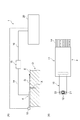
図1(A)に示されるように、漏洩磁束探傷装置1は、探触子4を用いて検査対象である対象物Oの探傷面Eを走査し、探傷面Eを含む表層のきずXを探傷するための装置である。対象物Oは、たとえば航空機のジェットエンジンのシャフト等であるが、これに限られない。対象物Oは、磁性体であれば何であってもよい。 As shown in FIG. 1 (A), the magnetic flux leakage flaw detector 1 scans a flaw detection surface E of an object O to be inspected using a probe 4 and detects a flaw X on the surface layer including the flaw detection surface E. It is a device for flaw detection. The object O is, for example, a shaft of an aircraft jet engine, but is not limited thereto. The object O may be anything as long as it is a magnetic material.
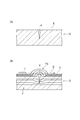
漏洩磁束探傷法の原理について説明する。漏洩磁束探傷法とは、図2(A)に示されるように、強磁性体からなる対象物Oの表面を含む表層に存在し得るきずXを、磁気センサTを用いて探索する検査法である。図2(B)に示されるように、漏洩磁束探傷法では、種々の方法により対象物Oを磁化することにより、対象物Oに所定方向の磁束Fを発生させる。磁束Fを遮るきずXがある場合には、そのきずXに起因して漏洩磁束Faが発生する。対象物Oの探傷面E上で磁気センサTを走査方向Dに走査させることにより、漏洩磁束Faが検出される。磁気センサTからの信号を用いる漏洩磁束探傷法は、従来採用されてきた磁粉探傷法に比して、探傷の自動化と結果のデジタル化とが容易であるという利点を有する。 The principle of the leakage magnetic flux flaw detection method will be described. As shown in FIG. 2 (A), the leakage magnetic flux flaw detection method is an inspection method that uses a magnetic sensor T to search for flaws X that may exist on the surface layer including the surface of the object O made of a ferromagnetic material. is there. As shown in FIG. 2B, in the leakage magnetic flux flaw detection method, a magnetic flux F in a predetermined direction is generated on the object O by magnetizing the object O by various methods. When there is a flaw X that blocks the magnetic flux F, a leakage magnetic flux Fa is generated due to the flaw X. By causing the magnetic sensor T to scan in the scanning direction D on the flaw detection surface E of the object O, the leakage magnetic flux Fa is detected. The leakage magnetic flux flaw detection method using a signal from the magnetic sensor T has an advantage that the flaw detection automation and the digitization of the result are easier than the magnetic particle flaw detection method conventionally employed.
図1(A)に示されるように、漏洩磁束探傷装置1は、対象物Oの探傷面Eを走査するための探触子4と、探触子4からの信号を入力して所定の処理を行い、探傷試験の結果を出力するパーソナルコンピュータ(処理部。以下、PCという)20とを備える。探触子4には複数のリード線14が設けられており、これらのリード線14が、たとえばAD変換器15に接続される。AD変換器15とPC20とは、USBケーブル等のケーブル16によって接続される。探触子4は、走査方向Dに走査させられる。この走査は、手動で行われてもよく、自動で行われてもよい。探触子4を保持するアーム等が走査方向Dに移動することで走査が行われてもよいし、探触子4を固定した状態で、対象物Oを保持したステージ等が走査方向Dと逆方向に移動することで走査が行われてもよい。
As shown in FIG. 1 (A), the leakage magnetic flux flaw detector 1 receives a probe 4 for scanning the flaw detection surface E of the object O and a signal from the probe 4 and performs predetermined processing. And a personal computer (processing unit; hereinafter referred to as PC) 20 for outputting the results of the flaw detection test. The probe 4 is provided with a plurality of
図1(B)に示されるように、探触子4は、計装アンプ基板11と、計装アンプ基板11に取り付けられたセンサモジュール10とを含む。計装アンプ基板11は、探触子4から出力される信号を増幅させる。センサモジュール10は、フレキシブル基板10aと、フレキシブル基板10aに搭載された複数の磁気センサ12(図2(B)に示される磁気センサTに相当)と、を含む。フレキシブル基板10aは、計装アンプ基板11に対して差し込まれ、コネクタ接続されている。探触子4において、センサモジュール10のみを交換することが可能になっている。漏洩磁束探傷装置1は、探触子4の位置情報を取得するためのエンコーダ13を備えており、エンコーダ13のワイヤの端部がフレキシブル基板10aに連結されている。
As shown in FIG. 1B, the probe 4 includes an
PC20は、探触子4から出力される、磁束に基づく磁界を示す信号と、エンコーダ13から出力される探触子4の位置情報とを入力し、対象物Oの探傷面(表面)Eを含む表層におけるきずXの有無判定のための探傷試験結果を出力する。きずXが存在する場合には、探傷試験結果において、きず指示が表れる。探傷試験結果に表れるきず指示に基づいて、きずXの有無だけでなく、きずXの幅や長さを推定することも可能である。
The
以下、図3および図4を参照して、一実施形態に係る探触子4について説明する。漏洩磁束探傷装置1の探触子4は、小型の磁気センサ12が柔軟なフレキシブル基板10aに保持された構成を有することにより、探傷面Eの形状を問わず、漏洩磁束探傷法による対象物Oの検査を可能とする。探触子4の適用対象とされ得る対象物Oとしては、たとえば、ギア、ねじ、タップ等の部品が挙げられる。探触子4は、ギアの歯部分や、ねじのねじ山部分等におけるきずXの検査を可能とする。
Hereinafter, a probe 4 according to an embodiment will be described with reference to FIGS. 3 and 4. The probe 4 of the leakage flux testing apparatus 1 has a configuration in which a small
特に、探触子4では、磁気センサ12と共に、磁化のための機構がフレキシブル基板10aに搭載されている。言い換えれば、磁気センサ12と磁化のための機構とがセットになってフレキシブル基板10a上に設けられている。探触子4のセンサモジュール10は、柔軟性を有するフレキシブル基板10aを含む。フレキシブル基板10aは、主として高分子材料からなるシート状の基材である。フレキシブル基板10aには、配線パターンが形成されている。これらの配線パターンは、各磁気センサ12と、上記の計装アンプ基板11の回路とを電気的に接続する。計装アンプ基板11は、柔軟性を有しておらず、定形性を有する。すなわち、探触子4では、柔軟性を有するフレキシブル基板10aからセンサ部が構成され、定形性を有する計装アンプ基板11から信号出力部が構成される。
In particular, in the probe 4, a mechanism for magnetization is mounted on the
フレキシブル基板10aには、たとえば1つの磁気センサ12が取り付けられている。磁気センサ12は、探傷面Eの近傍において磁界の大きさを測定可能なセンサである。磁気センサ12は、磁界検出部(図示せず)を含む。磁気センサ12としては、MI(Magneto-Impedance)センサ、GMR(Giant Magneto Resistive effect)センサ、TMR(Tunnel Magneto-Resistance)センサ、AMR(Anisotropic Magneto-Resistance)センサ、FG(Flux-Gate)センサ、ホール素子、SQUID(Superconducting QUantum Interference Device)センサ、コイル等が用いられ得る。
For example, one
フレキシブル基板10aに実装される磁気センサ12としては、非常に小型の磁気センサが用いられ得る。磁気センサ12は、一辺の長さが1mm以下の磁気センサであってもよい。磁気センサ12は、一辺の長さが2mm以下の磁気センサであってもよく、一辺の長さが4mm以下の磁気センサであってもよい。
As the
磁気センサ12は、図示しない導通部を介して、フレキシブル基板10aの第1面10bに搭載されている。磁気センサ12は、公知の手段を用いて、フレキシブル基板10aに搭載され得る。磁気センサ12は、フレキシブル基板10aの第1面10b側に埋設されてもよいし、フレキシブル基板10aに内蔵されてもよい。磁気センサ12は、フレキシブル基板10aの第1面10bとは反対の第2面10c側に搭載されてもよい。磁気センサ12は、フレキシブル基板10aの第2面10c側に埋設されてもよい。磁気センサ12の個数は、特に限定されない。複数の磁気センサ12が設けられてもよい。複数の磁気センサ12が設けられる場合、磁気センサ12は、一列に配列されてもよいし、複数列に配列されてもよい。磁気センサ12が複数列に配列される場合、複数の磁気センサ12が千鳥状に配置されてもよい。
The
フレキシブル基板10aに対する磁気センサ12の接合部の周囲には、樹脂等による封入部19が形成されてもよい。封入部19によって、フレキシブル基板10aに対する磁気センサ12の固定強度が高められている。
An encapsulating
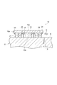
センサモジュール10は、磁気センサ12の両側に配置された第1永久磁石(第1磁場発生部)21および第2永久磁石(第2磁場発生部)22を備える。第1永久磁石21および第2永久磁石22は、それぞれ、円柱状をなす。第1永久磁石21および第2永久磁石22は、他の形状、たとえば角柱状などをなしてもよい。
The
第1永久磁石21および第2永久磁石22は、第1面10bに沿う方向において、磁気センサ12と並ぶように配置されている。言い換えれば、第1永久磁石21および第2永久磁石22は、磁気センサ12を挟むように配置されている。より詳細には、磁気センサ12は、第1永久磁石21および第2永久磁石22の中間位置に配置されている。第1永久磁石21から磁気センサ12までの距離と、第2永久磁石22から磁気センサ12までの距離は、等しい。
The first
第1永久磁石21および第2永久磁石22は、たとえば接着等により、フレキシブル基板10aの第1面10bに固定され得る。第1永久磁石21および第2永久磁石22は、フレキシブル基板10aの第1面10b側に埋設されてもよいし、フレキシブル基板10aに内蔵されてもよい。第1永久磁石21および第2永久磁石22は、フレキシブル基板10aの第1面10bとは反対の第2面10c側に搭載されてもよい。第1永久磁石21および第2永久磁石22は、フレキシブル基板10aの第2面10c側に埋設されてもよい。
The first
複数の磁気センサ12が設けられる場合、複数の磁気センサ12の両側に一対の第1永久磁石21および第2永久磁石22が設けられてもよいし、個々の磁気センサ12の両側に、それぞれ第1永久磁石21および第2永久磁石22が設けられてもよい。その場合、それぞれの第1永久磁石21および第2永久磁石22が並ぶ方向は同一とされる(平行に揃えられる)。
When a plurality of
フレキシブル基板10aに対する第1永久磁石21の接合部の周囲には、樹脂等による封入部23が形成されてもよい。フレキシブル基板10aに対する第2永久磁石22の接合部の周囲には、樹脂等による封入部24が形成されてもよい。封入部23および封入部24によって、フレキシブル基板10aに対する第1永久磁石21および第2永久磁石22の固定強度が高められている。
An encapsulating
第1永久磁石21および第2永久磁石22は、これらの間において対象物Oを局所的に磁化するように構成されている。より詳細には、第1永久磁石21には、フレキシブル基板10aに近い側に、S極が形成されている。第1永久磁石21のS極側が、フレキシブル基板10aに取り付けられている。第2永久磁石22には、フレキシブル基板10aに近い側に、N極が形成されている。第2永久磁石22のN極側が、フレキシブル基板10aに取り付けられている。これにより、対象物Oには、第1永久磁石21から第2永久磁石22へと向かう磁束が形成されている。すなわち、局所的に磁化された対象物Oにおいて、磁化方向は、第1永久磁石21から第2永久磁石22へと向かう向きである。
The first
第1永久磁石21および第2永久磁石22としては、公知の永久磁石が用いられ得る。第1永久磁石21および第2永久磁石22は、同一の永久磁石であって、配置のみが逆とされてもよい。第1永久磁石21および第2永久磁石22に用いられる材料は、求められる磁化の強度に応じて、適宜設定され得る。適切な磁化強度については、後述する。
As the first
磁気センサ12の周囲には、磁場遮蔽材25が設けられている。言い換えれば、磁気センサ12と、第1永久磁石21および第2永久磁石22との間には、矩形環状の磁場遮蔽材25が設けられている。磁場遮蔽材25は、フレキシブル基板10aの第1面10bに立設されており、磁気センサ12に略等しい高さを有する。磁場遮蔽材25は、たとえば銅箔からなる。磁場遮蔽材25は、外部からの影響(たとえば地磁気等による影響)を低減する。
A
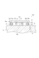
上記した探触子4を用いて走査が行われる際には、図3に示されるように、第1面10bが対象物Oの探傷面Eに対面するように、センサモジュール10が対象物Oに置かれる。磁気センサ12と探傷面Eとは当接していてもよいし、磁気センサ12と探傷面Eとは離間していてもよい。磁気センサ12と探傷面Eとが離間している場合には、これらの距離を一定に保つ(リフトオフを一定にする)ことが好ましい。
When scanning is performed using the probe 4 described above, the
第1永久磁石21および第2永久磁石22によって、これらの間が局所的に磁化される。センサモジュール10は、第1永久磁石21および第2永久磁石22による磁化方向に沿って移動され得る。すなわち、第1永久磁石21および第2永久磁石22による磁化方向と、磁気センサ12の走査方向Dとは略等しい。
The first
ここで、第1永久磁石21および第2永久磁石22による磁化は、従来の漏洩磁束探傷法における磁化に比して、弱くなっている。第1永久磁石21および第2永久磁石22による磁化は、一時的に磁区方向を揃える程度の比較的弱い磁化であり、残留磁化ではない。この点、本明細書における「磁化」は、残留磁化を意味するのではなく、残留磁化を生じさせないような一時的な磁化である。しかしながら、第1永久磁石21および第2永久磁石22による磁化は、漏洩磁束探傷法による検査を行うには十分な程度に設定されている。
Here, the magnetization by the 1st
センサモジュール10による走査の結果、凹部表面E2の近傍における磁気センサ12が検出する磁界の大きさに応じた電気信号が、磁気センサ12からPC20に対して出力される。探触子4によれば、磁化方向(すなわち走査方向D)に探触子4を移動させて走査を行うことにより、順次、対象物Oの脱磁が行われ得る。言い換えれば、探触子4による走査が行われている間、第1永久磁石21と第2永久磁石22との間では対象物Oは磁化されているが、探触子4が通過した領域では、対象物Oは磁化されていない。
As a result of scanning by the
本実施形態の探触子4によれば、第1永久磁石21および第2永久磁石22によって、対象物Oが局所的に磁化される。第1永久磁石21および第2永久磁石22の間に配置された磁気センサ12では、第1永久磁石21および第2永久磁石22の間に形成された磁束に基づく磁界が検出される。このように、フレキシブル基板10a上に、磁気センサ12と磁化のための機構とが設けられているため、コンパクトな探触子4によって磁化および磁界の検出が可能になっている。よって、大がかりな磁化機構は不要になっており、漏洩磁束探傷法による検査を簡便に実施することができる。フレキシブル基板10aは柔軟性を有するので、対象物Oの凹凸部や狭隘部にも探触子4を挿入することができ、あらゆる形状の探傷面Eに適用可能である。
According to the probe 4 of the present embodiment, the object O is locally magnetized by the first
従来、たとえば凹凸部を探傷する場合に、凹凸部に起因する漏洩磁束により誤ったきず指示が与えられることがあったが、本実施形態の探触子4によれば、局所的な磁化により、磁束が漏洩し得る箇所はきずXの部分に限定されている。これにより、凹凸部の探傷が可能になっている。また、第1永久磁石21および第2永久磁石22による磁化は、一時的に磁区方向を揃える程度の比較的弱い磁化であり、残留磁化ではない。磁化方向に探触子4を移動させて走査を行うことにより、順次、脱磁が行われ得る。すなわち、走査に伴って、自動的な脱磁が行われる。これにより、対象物Oの全面を測定できると同時に、走査後に、脱磁工程を別途実施する必要がない。時間や手間を要する脱磁工程が省かれることにより、漏洩磁束探傷法による検査をより一層簡便に実施することができる。
Conventionally, for example, when flaw detection is performed on a concavo-convex portion, an erroneous flaw instruction may be given due to leakage magnetic flux caused by the concavo-convex portion, but according to the probe 4 of the present embodiment, due to local magnetization, The portion where the magnetic flux can leak is limited to the portion of the scratch X. Thereby, the flaw detection of the uneven | corrugated | grooved part is attained. Moreover, the magnetization by the 1st
磁気センサ12は、第1永久磁石21および第2永久磁石22の中間位置に配置されている。これにより、磁気センサ12の位置においては、第1永久磁石21による磁場と第2永久磁石22による磁場とが打ち消し合う。よって、磁気センサ12に対する、第1永久磁石21および第2永久磁石22に由来する磁場の影響が低減され、対象物Oにおける磁束(その磁束に基づく磁界)をより正確に測定することができる。
The
第1永久磁石21および第2永久磁石22では、永久磁石による磁場の安定性により、磁力センター部に安定的な磁場が形成される。これにより、ノイズの発生が低減されている。さらに、電源等が不要であって、しかも磁気センサ12と永久磁石とがユニット化されており、探触子4の小型化が図られている。
In the first
また、磁場遮蔽材25によって、外部からの影響(たとえば地磁気等による影響)が低減されている。これにより、対象物Oにおける磁束(その磁束に基づく磁界)をより正確に測定することができる。
Further, the magnetic
小型の磁気センサ12を用いた探触子4によれば、従来の磁気センサでは入ることのできなかった狭隘部にも、磁気センサ12が挿入され得るので、あらゆる複雑な形状に対して、汎用性が高められている。
According to the probe 4 using the small-sized
また、計装アンプ基板11に対してフレキシブル基板10aが差し込まれ、コネクタ接続されることにより、センサモジュール10のみの交換が可能となっている。また、センサモジュール10と計装アンプ基板11が至近距離に設けられている。これにより、ノイズが混入しやすい配線部が短くなり、計装アンプ基板11によってノイズが増幅されることを防ぐことにより、ノイズが低減される。
Further, only the
上記のセンサモジュール10を含む探触子4を備えた漏洩磁束探傷装置1によれば、コンパクトな探触子4によって磁化および磁界の検出が可能であり、漏洩磁束探傷法による検査を簡便に実施することができる。
According to the leakage magnetic flux flaw detector 1 provided with the probe 4 including the
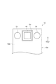
図5を参照して、の実施形態に係る探触子4のセンサモジュール10Aについて説明する。センサモジュール10Aでは、第1磁場発生部および第2磁場発生部として、それぞれ電磁石が用いられている。センサモジュール10Aは、第1磁場発生部である第1電磁石31と、第2磁場発生部である第2電磁石32とを備える。第1電磁石31は、第1面10bに立設されたコア部31aと、コア部31aの周囲に形成された巻線部31bとを含む。第2電磁石32は、第1面10bに立設されたコア部32aと、コア部32aの周囲に形成された巻線部32bとを含む。コア部31aおよびコア部32aは磁性材料からなる。第1電磁石31の巻線部31bと、第2電磁石32の巻線部32bとには、それぞれ直流電源が接続される。第1電磁石31および第2電磁石32の配置と、第1電磁石31および第2電磁石32による磁化に関しては、先の実施形態における第1永久磁石21および第2永久磁石22と同様である。
A
第1電磁石31および第2電磁石32を含むセンサモジュール10Aを備えた探触子4によっても、対象物Oが局所的に磁化され、コンパクトな探触子4によって磁化および磁界の検出が可能である。
Even with the probe 4 including the
以上、本発明の実施形態について説明したが、本発明は上記実施形態に限定されない。たとえば、第1永久磁石21および第2永久磁石22を備えるセンサモジュール10において、磁場遮蔽材25を省略することもできる。第1永久磁石21および第2永久磁石22によれば、上記したように安定的な磁場が形成されるため、第1永久磁石21による磁場と第2永久磁石22による磁場とを確実に打ち消すことができる。たとえば、第1永久磁石21と第2永久磁石22とに同一の永久磁石を用い、第1永久磁石21および第2永久磁石22の中間位置に磁気センサ12を配置することにより、磁場遮蔽材25は省略され得る。磁場遮蔽材25が不要である分、部品点数の削減が図られる。
As mentioned above, although embodiment of this invention was described, this invention is not limited to the said embodiment. For example, in the
第1磁場発生部および第2磁場発生部とは別に、第3磁場発生部および第4磁場発生部が設けられてもよい。この場合、第3磁場発生部および第4磁場発生部は、第1磁場発生部および第2磁場発生部とは異なる位置に配置されると共に、第3磁場発生部および第4磁場発生部の間に磁気センサ12が配置される。磁気センサ12を中心にして、十字の位置に4つの磁場発生部が設けられることで、磁化方向を自在に調整することができる。たとえば、第1磁場発生部および第2磁場発生部が並ぶ方向と、第3磁場発生部および第4磁場発生部が並ぶ方向とが直交するように配置し、2つの方向に対して45°の角度をなすような磁化方向を形成することができる。その場合でも、走査が行われる際には、磁化方向と走査方向Dとが一致させられる。
A third magnetic field generator and a fourth magnetic field generator may be provided separately from the first magnetic field generator and the second magnetic field generator. In this case, the third magnetic field generation unit and the fourth magnetic field generation unit are arranged at positions different from the first magnetic field generation unit and the second magnetic field generation unit, and between the third magnetic field generation unit and the fourth magnetic field generation unit. The
第1磁場発生部および第2磁場発生部は、別体ではなく、一体の永久磁石または電磁石の、第1部分および第2部分であってもよい。この場合、第1部分と第2部分とは、異なる磁極を有するように構成される。 The first magnetic field generation unit and the second magnetic field generation unit may be the first part and the second part of an integral permanent magnet or an electromagnet, not separately. In this case, the first part and the second part are configured to have different magnetic poles.
計装アンプ基板11が省略されてもよい。
The
1 漏洩磁束探傷装置
4 探触子
10 センサモジュール
10A センサモジュール
10a フレキシブル基板
11 計装アンプ基板
12 磁気センサ
20 PC(処理部)
21 第1永久磁石(第1磁場発生部)
22 第2永久磁石(第2磁場発生部)
31 第1電磁石(第1磁場発生部)
32 第2電磁石(第2磁場発生部)
D 走査方向
E 探傷面
F 磁束
Fa 漏洩磁束
O 対象物
T 磁気センサ
X きず
DESCRIPTION OF SYMBOLS 1 Leakage magnetic flux flaw detector 4
21 1st permanent magnet (1st magnetic field generation part)
22 Second permanent magnet (second magnetic field generator)
31 1st electromagnet (1st magnetic field generation part)
32 Second electromagnet (second magnetic field generator)
D Scanning direction E Flaw detection surface F Magnetic flux Fa Leakage magnetic flux O Object T Magnetic sensor X Scratches
Claims (6)
前記磁気センサと、
前記磁気センサが取り付けられたフレキシブル基板と、
前記フレキシブル基板の表面に沿う方向において前記磁気センサの両側に配置された第1磁場発生部および第2磁場発生部と、を備え、
前記第1磁場発生部および前記第2磁場発生部は、前記第1磁場発生部および前記第2磁場発生部の間において前記対象物を局所的に磁化するように構成されている、探触子。 A probe of a leakage magnetic flux flaw detector that detects flaws on a surface layer including a flaw detection surface by scanning a flaw detection surface of an object with a magnetic sensor,
The magnetic sensor;
A flexible substrate to which the magnetic sensor is attached;
A first magnetic field generator and a second magnetic field generator disposed on both sides of the magnetic sensor in a direction along the surface of the flexible substrate,
The first magnetic field generation unit and the second magnetic field generation unit are configured to locally magnetize the object between the first magnetic field generation unit and the second magnetic field generation unit. .
前記磁気センサにおいて検出された磁界を示す信号を入力して処理する処理部と、
を備える漏洩磁束探傷装置。 The probe according to any one of claims 1 to 5,
A processing unit for inputting and processing a signal indicating a magnetic field detected by the magnetic sensor;
A leakage magnetic flux flaw detector comprising:
Priority Applications (1)
| Application Number | Priority Date | Filing Date | Title |
|---|---|---|---|
| JP2016138770A JP2018009873A (en) | 2016-07-13 | 2016-07-13 | Probe and leakage flux flaw detection device equipped with the same |
Applications Claiming Priority (1)
| Application Number | Priority Date | Filing Date | Title |
|---|---|---|---|
| JP2016138770A JP2018009873A (en) | 2016-07-13 | 2016-07-13 | Probe and leakage flux flaw detection device equipped with the same |
Publications (1)
| Publication Number | Publication Date |
|---|---|
| JP2018009873A true JP2018009873A (en) | 2018-01-18 |
Family
ID=60995390
Family Applications (1)
| Application Number | Title | Priority Date | Filing Date |
|---|---|---|---|
| JP2016138770A Pending JP2018009873A (en) | 2016-07-13 | 2016-07-13 | Probe and leakage flux flaw detection device equipped with the same |
Country Status (1)
| Country | Link |
|---|---|
| JP (1) | JP2018009873A (en) |
Citations (7)
| Publication number | Priority date | Publication date | Assignee | Title |
|---|---|---|---|---|
| JPS58153157A (en) * | 1982-03-05 | 1983-09-12 | Shimadzu Corp | Magnetic detector for magnetic flaw detector |
| WO1992014145A1 (en) * | 1991-02-04 | 1992-08-20 | Nkk Corporation | Magnetic inspecting method and device therefor |
| JPH0772122A (en) * | 1993-09-06 | 1995-03-17 | Babcock Hitachi Kk | Leak flux flaw detection method and apparatus for internal defect of magnetic material |
| JPH08101167A (en) * | 1994-09-30 | 1996-04-16 | Tokyo Gas Co Ltd | Nondestructive inspection sensor and manufacturing method thereof |
| JP2007192803A (en) * | 2005-12-19 | 2007-08-02 | Ishikawajima Harima Heavy Ind Co Ltd | Corrosion evaluation apparatus and corrosion evaluation method |
| JP2011007565A (en) * | 2009-06-24 | 2011-01-13 | Jfe Engineering Corp | Leakage flux flaw detector |
| US20150239708A1 (en) * | 2014-02-25 | 2015-08-27 | Thyssenkrupp Elevator Ag | System and Method for Monitoring a Load Bearing Member |
-
2016
- 2016-07-13 JP JP2016138770A patent/JP2018009873A/en active Pending
Patent Citations (7)
| Publication number | Priority date | Publication date | Assignee | Title |
|---|---|---|---|---|
| JPS58153157A (en) * | 1982-03-05 | 1983-09-12 | Shimadzu Corp | Magnetic detector for magnetic flaw detector |
| WO1992014145A1 (en) * | 1991-02-04 | 1992-08-20 | Nkk Corporation | Magnetic inspecting method and device therefor |
| JPH0772122A (en) * | 1993-09-06 | 1995-03-17 | Babcock Hitachi Kk | Leak flux flaw detection method and apparatus for internal defect of magnetic material |
| JPH08101167A (en) * | 1994-09-30 | 1996-04-16 | Tokyo Gas Co Ltd | Nondestructive inspection sensor and manufacturing method thereof |
| JP2007192803A (en) * | 2005-12-19 | 2007-08-02 | Ishikawajima Harima Heavy Ind Co Ltd | Corrosion evaluation apparatus and corrosion evaluation method |
| JP2011007565A (en) * | 2009-06-24 | 2011-01-13 | Jfe Engineering Corp | Leakage flux flaw detector |
| US20150239708A1 (en) * | 2014-02-25 | 2015-08-27 | Thyssenkrupp Elevator Ag | System and Method for Monitoring a Load Bearing Member |
Similar Documents
| Publication | Publication Date | Title |
|---|---|---|
| US9146214B2 (en) | Leakage magnetic flux flaw inspection method and device | |
| Ramos et al. | Present and future impact of magnetic sensors in NDE | |
| US10677755B2 (en) | Apparatus and method for detecting inner defects of steel plate | |
| CN103884999B (en) | For the device and method in the magnetic field in the air gap between the stator and rotor of measurement motor | |
| CN106814131B (en) | Magnetic emission detection method and magnetic emission detection system for shallow damage of ferromagnetic planar components | |
| US20040041560A1 (en) | Method, system and apparatus for ferromagnetic wall monitoring | |
| CN102549375A (en) | Eddy current inspection of case hardening depth | |
| US20120274319A1 (en) | Eddy Current Probe for Surface and Sub-Surface Inspection | |
| CN103675094A (en) | Non-destructive testing device | |
| CN107290424A (en) | Steel wire nondestructive detection device and method side by side | |
| JP2017150904A (en) | Flaw detection apparatus and flaw detection method | |
| CN107144628B (en) | Electromagnetic detection method based on defect leakage magnetic field source and active detection magnetic source | |
| JP2008032575A (en) | Eddy current measuring probe and flaw detector using the same | |
| EP3081932B1 (en) | Apparatus and method of inspecting defect of steel plate | |
| Kaur et al. | Selection of a hall sensor for usage in a wire rope tester | |
| Kreutzbruck et al. | Adapted gmr array used in magnetic flux leakage inspection | |
| Atzlesberger et al. | Magnetic flux leakage measurement setup for defect detection | |
| JP2018009873A (en) | Probe and leakage flux flaw detection device equipped with the same | |
| Witoś et al. | NDE of mining ropes and conveyors using magnetic methods | |
| JP7073617B2 (en) | Detector, magnetic flux leakage detector, and magnetic flux leakage detection method | |
| JP2019020273A (en) | Surface flaw inspection device | |
| Chady et al. | Electromagnetic system for nondestructive evaluation of train hollow axles | |
| JP2021001813A (en) | Nondestructive inspection magnetic sensor and nondestructive inspection device | |
| Pelkner et al. | Size adapted GMR arrays for the automated inspection of surface breaking cracks in roller bearings | |
| CN107576720A (en) | Ferromagnetic slender member shallow damage magnetic transmitting detection method and magnetic emission detection system |
Legal Events
| Date | Code | Title | Description |
|---|---|---|---|
| A621 | Written request for application examination |
Free format text: JAPANESE INTERMEDIATE CODE: A621 Effective date: 20190530 |
|
| A977 | Report on retrieval |
Free format text: JAPANESE INTERMEDIATE CODE: A971007 Effective date: 20200515 |
|
| A131 | Notification of reasons for refusal |
Free format text: JAPANESE INTERMEDIATE CODE: A131 Effective date: 20200630 |
|
| A02 | Decision of refusal |
Free format text: JAPANESE INTERMEDIATE CODE: A02 Effective date: 20210105 |