JP2018009872A - Probe, flaw detection tool, leakage flux flaw detection device, and leakage flux flaw detection method - Google Patents
Probe, flaw detection tool, leakage flux flaw detection device, and leakage flux flaw detection method Download PDFInfo
- Publication number
- JP2018009872A JP2018009872A JP2016138767A JP2016138767A JP2018009872A JP 2018009872 A JP2018009872 A JP 2018009872A JP 2016138767 A JP2016138767 A JP 2016138767A JP 2016138767 A JP2016138767 A JP 2016138767A JP 2018009872 A JP2018009872 A JP 2018009872A
- Authority
- JP
- Japan
- Prior art keywords
- flaw detection
- probe
- sensor
- magnetic
- magnetic flux
- Prior art date
- Legal status (The legal status is an assumption and is not a legal conclusion. Google has not performed a legal analysis and makes no representation as to the accuracy of the status listed.)
- Granted
Links
- 238000001514 detection method Methods 0.000 title claims abstract description 110
- 230000004907 flux Effects 0.000 title claims abstract description 67
- 239000000523 sample Substances 0.000 title claims abstract description 64
- 230000005291 magnetic effect Effects 0.000 claims abstract description 161
- 239000000463 material Substances 0.000 claims abstract description 45
- 239000002344 surface layer Substances 0.000 claims abstract description 7
- 239000000758 substrate Substances 0.000 claims description 58
- 239000012212 insulator Substances 0.000 claims description 21
- 238000007689 inspection Methods 0.000 abstract description 13
- 238000005259 measurement Methods 0.000 description 13
- 238000000034 method Methods 0.000 description 6
- 230000000694 effects Effects 0.000 description 4
- 229910000831 Steel Inorganic materials 0.000 description 3
- 239000002952 polymeric resin Substances 0.000 description 3
- 239000010959 steel Substances 0.000 description 3
- 229920003002 synthetic resin Polymers 0.000 description 3
- 238000010586 diagram Methods 0.000 description 2
- 239000002184 metal Substances 0.000 description 2
- 229920001296 polysiloxane Polymers 0.000 description 2
- 230000001681 protective effect Effects 0.000 description 2
- 239000007787 solid Substances 0.000 description 2
- 230000007547 defect Effects 0.000 description 1
- 239000004744 fabric Substances 0.000 description 1
- 239000003302 ferromagnetic material Substances 0.000 description 1
- 239000010410 layer Substances 0.000 description 1
- 239000000696 magnetic material Substances 0.000 description 1
- 239000006249 magnetic particle Substances 0.000 description 1
- 230000005389 magnetism Effects 0.000 description 1
- 230000005415 magnetization Effects 0.000 description 1
- 239000002861 polymer material Substances 0.000 description 1
- 229920005989 resin Polymers 0.000 description 1
- 239000011347 resin Substances 0.000 description 1
Images

Landscapes
- Investigating Or Analyzing Materials By The Use Of Magnetic Means (AREA)
Abstract
Description
本発明は、探触子、探傷用器具、漏洩磁束探傷装置、および漏洩磁束探傷方法に関する。 The present invention relates to a probe, a flaw detection instrument, a leakage magnetic flux inspection device, and a leakage magnetic flux inspection method.
従来、対象物の表層のきず(JIS Z 2300:2009)を検出するための磁気を利用した非破壊検査として、漏洩磁束探傷法(Magnetic Flux Leakage:MFL)が知られている。漏洩磁束探傷法は、対象物の探傷面を磁化し、きずから漏洩する磁束の有無等を測定することにより、きずを探傷する。たとえば、特許文献1に示される漏洩磁束探傷装置は、磁化器と、磁化器に対向して配置された磁気センサとを備える。この漏洩磁束探傷装置は、一定速度で搬送される鋼板を磁化器によって磁化するとともに、鋼板の表面近傍に配置された磁気センサにより、鋼板に存在する微少欠陥を探傷する。 Conventionally, as a nondestructive inspection using magnetism for detecting a flaw (JIS Z 2300: 2009) on the surface layer of an object, a magnetic flux leak detection method (Magnetic Flux Leakage: MFL) is known. In the leakage magnetic flux flaw detection method, the flaw detection surface of an object is magnetized and flaws are detected by measuring the presence or absence of magnetic flux leaking from the flaws. For example, the leakage magnetic flux flaw detector disclosed in Patent Document 1 includes a magnetizer and a magnetic sensor arranged to face the magnetizer. This leakage magnetic flux flaw detector magnetizes a steel plate conveyed at a constant speed by a magnetizer, and flaws a minute defect present in the steel plate by a magnetic sensor arranged near the surface of the steel plate.
従来、漏洩磁束探傷法およびその探触子(上記の磁気センサ等)は、平板または平板状の部品に対して使用されることが多かった。探傷の対象物が複雑な形状を有する場合、従来の探触子をそのまま複雑な形状に適用しても、漏洩磁束探傷法による検査の実施は難しい。たとえば、凹凸部や狭隘部に従来の探触子を使用した場合、凹凸部に起因する磁束漏洩により測定が不能となったり、狭隘部に磁気センサが入らなかったりする等の問題点があった。 Conventionally, the leakage magnetic flux flaw detection method and its probe (the above-described magnetic sensor or the like) are often used for flat plates or flat plate-like components. When the object for flaw detection has a complicated shape, even if the conventional probe is applied to the complicated shape as it is, it is difficult to perform inspection by the leakage magnetic flux flaw detection method. For example, when a conventional probe is used for an uneven part or a narrow part, there are problems such as that measurement cannot be performed due to magnetic flux leakage due to the uneven part, or a magnetic sensor does not enter the narrow part. .
本発明は、対象物が複雑な形状を有する場合であっても、漏洩磁束探傷法による検査が可能な探触子、探傷用器具、漏洩磁束探傷装置、および漏洩磁束探傷方法を提供することを目的とする。 It is an object of the present invention to provide a probe, a flaw detection instrument, a leak magnetic flux flaw detector, and a leak magnetic flux flaw detection method that can be inspected by a leak magnetic flux flaw detection method even when the object has a complicated shape. Objective.
本発明の一態様に係る探触子は、対象物の探傷面上を磁気センサが走査することにより探傷面を含む表層のきずを探傷する漏洩磁束探傷装置の探触子であって、一または複数の磁気センサ、または、磁気センサをそれぞれ含む一または複数のセンサユニットと、磁気センサまたはセンサユニットが取り付けられた柔軟性を有する基材と、を備える。 A probe according to an aspect of the present invention is a probe for a leakage magnetic flux flaw detector that detects flaws on a surface layer including a flaw detection surface by scanning a flaw detection surface of an object with a magnetic sensor. A plurality of magnetic sensors, or one or a plurality of sensor units each including the magnetic sensor, and a flexible base material to which the magnetic sensors or the sensor units are attached are provided.
この探触子によれば、一または複数の磁気センサ、または、一または複数のセンサユニットは、柔軟性を有する基材に取り付けられている。よって、凹凸部や狭隘部などの複雑な形状を有する探傷面に沿うように、基材を配置することができる。これにより、磁気センサは、対象物の探傷面上を走査することができる。このような柔軟な基材を有する探触子によれば、対象物が複雑な形状を有する場合であっても、漏洩磁束探傷法による検査が可能である。 According to this probe, one or more magnetic sensors or one or more sensor units are attached to a flexible substrate. Therefore, a base material can be arrange | positioned along the flaw detection surface which has complicated shapes, such as an uneven | corrugated | grooved part and a narrow part. Thereby, the magnetic sensor can scan the flaw detection surface of the object. According to the probe having such a flexible substrate, it is possible to inspect by the leakage magnetic flux flaw detection method even when the object has a complicated shape.
いくつかの態様において、基材はシート状である。この場合、シート状の基材を凹凸部や狭隘部等に挿入することにより、基材が探傷面に沿うように、基材を配置することができる。 In some embodiments, the substrate is in the form of a sheet. In this case, the base material can be disposed so that the base material is along the flaw detection surface by inserting the sheet-like base material into the uneven part or the narrow part.
いくつかの態様において、基材はフレキシブル基板である。この場合、フレキシブル基板に配線パターンが形成されることで、基材上に磁気センサ回路を形成することができる。 In some embodiments, the substrate is a flexible substrate. In this case, the magnetic sensor circuit can be formed on the base material by forming the wiring pattern on the flexible substrate.
いくつかの態様において、探触子は、基材が外周に巻かれる棒状の絶縁体を更に備える。この場合、基材が巻かれた棒状の絶縁体を凹凸部や狭隘部等に挿入することにより、基材が探傷面に沿うように、基材を配置することができる。 In some embodiments, the probe further includes a rod-like insulator around which the substrate is wound. In this case, the base material can be arranged so that the base material is along the flaw detection surface by inserting a rod-like insulator around which the base material is wound into an uneven portion or a narrow portion.
いくつかの態様において、基材は棒状である。この場合、棒状の基材を凹凸部や狭隘部等に挿入することにより、基材が探傷面に沿うように、基材を配置することができる。 In some embodiments, the substrate is rod-shaped. In this case, the base material can be arranged so that the base material follows the flaw detection surface by inserting the rod-shaped base material into the concavo-convex part or the narrow part.
本発明の一態様に係る探傷用器具は、上記のいずれかの探触子と、探傷面の形状に適合する先端形状を有する治具と、を備える。この探傷用器具によれば、治具によって基材を探傷面に沿わせることができ、複雑な形状の探傷面に対しても簡易かつ確実に漏洩磁束探傷法による検査を行うことができる。 A flaw detection instrument according to one aspect of the present invention includes any one of the above probes and a jig having a tip shape that matches the shape of the flaw detection surface. According to this flaw detection instrument, the substrate can be made to follow the flaw detection surface by the jig, and the complicated magnetic flaw detection surface can be easily and reliably inspected by the leakage magnetic flux flaw detection method.
本発明の一態様に係る漏洩磁束探傷装置は、上記のいずれかの探触子と、磁気センサにおいて検出された磁界を示す信号を入力して処理する処理部と、を備える。この漏洩磁束探傷装置によれば、対象物が複雑な形状を有する場合であっても、磁気センサによる探傷面の走査が可能であり、漏洩磁束探傷法による検査が可能となる。 A leakage magnetic flux flaw detector according to an aspect of the present invention includes any one of the above probes and a processing unit that inputs and processes a signal indicating a magnetic field detected by a magnetic sensor. According to the leakage magnetic flux flaw detection apparatus, even if the object has a complicated shape, the flaw detection surface can be scanned by the magnetic sensor, and the inspection by the leakage magnetic flux flaw detection method can be performed.
いくつかの態様に係る漏洩磁束探傷装置は、上記の探傷用器具と、磁気センサにおいて検出された磁界を示す信号を入力して処理する処理部と、を備える。この漏洩磁束探傷装置によれば、治具によって基材を探傷面に沿わせることができ、複雑な形状の探傷面に対しても簡易かつ確実に漏洩磁束探傷法による検査を行うことができる。 A leakage magnetic flux flaw detector according to some aspects includes the flaw detection instrument and a processing unit that inputs and processes a signal indicating a magnetic field detected by a magnetic sensor. According to the leakage magnetic flux flaw detection apparatus, the base material can be made to follow the flaw detection surface by the jig, and the complicated magnetic flaw detection surface can be easily and reliably inspected by the leakage magnetic flux flaw detection method.
本発明の一態様に係る漏洩磁束探傷方法は、上記の探傷用器具を用い、基材を探傷面上に配置し、基材の上から治具の先端を探傷面に対して押し当てた状態で、磁気センサを走査させる。この漏洩磁束探傷方法によっても、上記の漏洩磁束探傷装置と同様の作用・効果が得られる。治具によって基材が探傷面に押し当てられて、磁気センサによる走査が行われるので、複雑な形状の探傷面に対しても簡易かつ確実に漏洩磁束探傷法による検査を行うことができる。 A leakage magnetic flux flaw detection method according to one aspect of the present invention is a state in which the above-described flaw detection instrument is used, the base material is disposed on the flaw detection surface, and the tip of the jig is pressed against the flaw detection surface from above the base material. Then, the magnetic sensor is scanned. This leakage magnetic flux flaw detection method can also provide the same operations and effects as the above leakage magnetic flux flaw detection device. Since the base material is pressed against the flaw detection surface by the jig and scanning by the magnetic sensor is performed, even a complicated flaw detection surface can be easily and reliably inspected by the leakage magnetic flux flaw detection method.
本発明のいくつかの態様によれば、対象物が複雑な形状を有する場合であっても、漏洩磁束探傷法による検査が可能である。 According to some embodiments of the present invention, even when the object has a complicated shape, inspection by the leakage magnetic flux flaw detection method is possible.
以下、本発明の実施形態について、図面を参照しながら説明する。なお、図面の説明において同一要素には同一符号を付し、重複する説明は省略する。 Hereinafter, embodiments of the present invention will be described with reference to the drawings. In the description of the drawings, the same elements are denoted by the same reference numerals, and redundant descriptions are omitted.
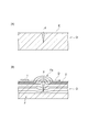
図1(A)に示されるように、漏洩磁束探傷装置1は、探触子4を用いて検査対象である対象物Oの探傷面Eを走査し、探傷面Eを含む表層のきずXを探傷するための装置である。漏洩磁束探傷装置1は、特に、複雑な形状の対象物Oに対する探傷を行う。対象物Oは、たとえば航空機のジェットエンジンのシャフト等であるが、これに限られない。対象物Oは、磁性体であれば何であってもよい。
As shown in FIG. 1 (A), the magnetic flux leakage flaw detector 1 scans a flaw detection surface E of an object O to be inspected using a
漏洩磁束探傷法の原理について説明する。漏洩磁束探傷法とは、図2(A)に示されるように、強磁性体からなる対象物Oの表面を含む表層に存在し得るきずXを、磁気センサTを用いて探索する検査法である。図2(B)に示されるように、漏洩磁束探傷法では、種々の方法により対象物Oを磁化することにより、対象物Oに所定方向の磁束Fを発生させる。磁束Fを遮るきずXがある場合には、そのきずXに起因して漏洩磁束Faが発生する。対象物Oの探傷面E上で磁気センサTを走査方向Dに走査させることにより、漏洩磁束Faが検出される。磁気センサTからの信号を用いる漏洩磁束探傷法は、従来採用されてきた磁粉探傷法に比して、探傷の自動化と結果のデジタル化とが容易であるという利点を有する。 The principle of the leakage magnetic flux flaw detection method will be described. As shown in FIG. 2 (A), the leakage magnetic flux flaw detection method is an inspection method that uses a magnetic sensor T to search for flaws X that may exist on the surface layer including the surface of the object O made of a ferromagnetic material. is there. As shown in FIG. 2B, in the leakage magnetic flux flaw detection method, a magnetic flux F in a predetermined direction is generated on the object O by magnetizing the object O by various methods. When there is a flaw X that blocks the magnetic flux F, a leakage magnetic flux Fa is generated due to the flaw X. By causing the magnetic sensor T to scan in the scanning direction D on the flaw detection surface E of the object O, the leakage magnetic flux Fa is detected. The leakage magnetic flux flaw detection method using a signal from the magnetic sensor T has an advantage that the flaw detection automation and the digitization of the result are easier than the magnetic particle flaw detection method conventionally employed.
図1(A)に示されるように、漏洩磁束探傷装置1は、対象物Oの探傷面Eを走査するための探触子4と、探触子4からの信号を入力して所定の処理を行い、探傷試験の結果を出力するパーソナルコンピュータ(処理部。以下、PCという)20とを備える。探触子4には複数のリード線14が設けられており、これらのリード線14が、たとえばAD変換器15に接続される。AD変換器15とPC20とは、USBケーブル等のケーブル16によって接続される。探触子4は、走査方向Dに走査させられる。この走査は、手動で行われてもよく、自動で行われてもよい。探触子4を保持するアーム等が走査方向Dに移動することで走査が行われてもよいし、探触子4を固定した状態で、対象物Oを保持したステージ等が走査方向Dと逆方向に移動することで走査が行われてもよい。
As shown in FIG. 1 (A), the leakage magnetic flux flaw detector 1 receives a
図1(B)に示されるように、探触子4は、計装アンプ基板11と、計装アンプ基板11に取り付けられたセンサモジュール10とを含む。計装アンプ基板11は、探触子4から出力される信号を増幅させる。センサモジュール10は、フレキシブル基板(基材)10aと、フレキシブル基板10aに搭載された複数の磁気センサ12(図2(B)に示される磁気センサTに相当)と、を含む。フレキシブル基板10aは、計装アンプ基板11に対して差し込まれ、コネクタ接続されている。探触子4において、センサモジュール10のみを交換することが可能になっている。漏洩磁束探傷装置1は、探触子4の位置情報を取得するためのエンコーダ13を備えており、エンコーダ13のワイヤの端部がフレキシブル基板10aに連結されている。
As shown in FIG. 1B, the
PC20は、探触子4から出力される、磁束に基づく磁界を示す信号と、エンコーダ13から出力される探触子4の位置情報とを入力し、対象物Oの探傷面(表面)Eを含む表層におけるきずXの有無判定のための探傷試験結果を出力する。きずXが存在する場合には、探傷試験結果において、きず指示が表れる。探傷試験結果に表れるきず指示に基づいて、きずXの有無だけでなく、きずXの幅や長さを推定することも可能である。
The
以下、図3〜図5を参照して、センサモジュール10のいくつかの構成例について詳細に説明する。漏洩磁束探傷装置1の探触子4は、対象物Oが凹凸部や狭隘部等の複雑な形状を有する場合に特に有効である。探触子4は、小型の磁気センサ12が柔軟なフレキシブル基板10aに保持された構成を有することにより、探傷面Eの形状を問わず、漏洩磁束探傷法による対象物Oの検査を可能とする。探触子4の適用対象とされ得る対象物Oとしては、たとえば、ギア、ねじ、タップ等の部品が挙げられる。探触子4は、ギアの歯部分や、ねじのねじ山部分等におけるきずXの検査を可能とする。
Hereinafter, several configuration examples of the
図3を参照して、第1の構成例に係る探触子4のセンサモジュール10について説明する。図3に示されるように、センサモジュール10は、柔軟性を有するフレキシブル基板10aを含む。フレキシブル基板10aは、主として高分子材料からなるシート状の基材である。フレキシブル基板10aには、配線パターンが形成されている。これらの配線パターンは、各磁気センサ12と、上記の計装アンプ基板11の回路とを電気的に接続する。計装アンプ基板11は、柔軟性を有しておらず、定形性を有する。すなわち、探触子4では、柔軟性を有するフレキシブル基板10aからセンサ部が構成され、定形性を有する計装アンプ基板11から信号出力部が構成される。
With reference to FIG. 3, the
フレキシブル基板10aには、たとえば複数の磁気センサ12が取り付けられている。磁気センサ12は、探傷面Eの近傍において磁界の大きさを測定可能なセンサである。磁気センサ12は、磁界検出部(図示せず)を含む。磁気センサ12としては、MI(Magneto-Impedance)センサ、GMR(Giant Magneto Resistive effect)センサ、TMR(Tunnel Magneto-Resistance)センサ、AMR(Anisotropic Magneto-Resistance)センサ、FG(Flux-Gate)センサ、ホール素子、SQUID(Superconducting QUantum Interference Device)センサ、コイル等が用いられ得る。
For example, a plurality of
各磁気センサ12は、図示しない導通部を介して、フレキシブル基板10aに搭載されている。磁気センサ12は、公知の手段を用いて、フレキシブル基板10aに搭載され得る。磁気センサ12は、フレキシブル基板10aに埋設または内蔵されてもよい。なお、磁気センサ12の個数は、特に限定されない。磁気センサ12の個数は、1個であってもよい。複数の磁気センサ12が設けられる場合、磁気センサ12は、一列に配列されてもよいし、複数列に配列されてもよい。磁気センサ12が複数列に配列される場合、複数の磁気センサ12が千鳥状に配置されてもよい。
Each
フレキシブル基板10aに実装される磁気センサ12としては、非常に小型の磁気センサが用いられ得る。磁気センサ12は、一辺の長さが1mm以下の磁気センサであってもよい。磁気センサ12は、一辺の長さが2mm以下の磁気センサであってもよく、一辺の長さが4mm以下の磁気センサであってもよい。
As the
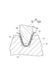
図3に示されるように、対象物Oは、平坦部表面E1と、平坦部表面E1よりも窪んだ凹部表面E2とを含む。このようなセンサモジュール10を用いた検査では、対象物Oの凹部表面E2に対してフレキシブル基板10aが沿うように、センサモジュール10が対象物Oにあてがわれる。柔軟性を有するフレキシブル基板10aは、凹部表面E2の形状に沿うように、自在に変形し得る。
As shown in FIG. 3, the object O includes a flat surface E1 and a concave surface E2 that is recessed from the flat surface E1. In such an inspection using the
必要に応じて、凹部表面E2にセンサモジュール10を沿わせるための計測用治具50が用いられてもよい。計測用治具50の先端形状は、凹部表面E2に適合している。計測用治具50は、たとえば、シリコーン等の高分子樹脂材料からなる。計測用治具50は、対象物Oの凹部表面E2に押し当てられる。計測用治具50の形状および大きさは、対象物Oの凹凸部または狭隘部の形状および寸法に合わせて変更され得る。そのために、複数種類の計測用治具50が準備されてもよい。探触子4と、探傷面Eの形状に適合する一または複数の治具とによって、探傷用器具60が構成される。探傷用器具60により、様々な凹凸部または狭隘部における磁界の計測が可能となる。
If necessary, a measuring
探触子4および計測用治具50を備える探傷用器具60によれば、計測用治具50によってフレキシブル基板10aを凹部表面E2(探傷面E)に沿わせることができる。計測用治具50によってフレキシブル基板10aが探傷面Eに押し当てられて、磁気センサ12による走査が行われる。これにより、複雑な形状の探傷面Eに対しても簡易かつ確実に漏洩磁束探傷法による検査を行うことができる。もちろん、平坦面等の比較的単純な形状の探傷面Eに探傷用器具60が適用されてもよい。
According to the
走査が行われる際には、対象物Oが、公知の手段(ハンドマグナ等)によって磁化される。そして、計測用治具50およびセンサモジュール10は、たとえば対象物Oの凹部が連続する方向に移動させられる。すなわち、凹部が溝状に連続する場合は、計測用治具50およびセンサモジュール10は、その溝が延びる方向に移動させられる。計測用治具50およびセンサモジュール10は、たとえば、図3の紙面垂直方向に移動させられる。
When scanning is performed, the object O is magnetized by a known means (hand magna or the like). Then, the
磁気センサ12は、フレキシブル基板10aの凹部表面E2に対面する側とは反対側に配置され得る。すなわち、磁気センサ12は、計測用治具50側に配置され得る。上記の探傷用器具60を用い、フレキシブル基板10aを凹部表面E2上に配置し、フレキシブル基板10aの上から計測用治具50の先端を凹部表面E2に対して押し当てた状態で、磁気センサ12が走査させられる。このような漏洩磁束探傷方法により、複雑な形状の凹部表面E2(探傷面E)に対しても、簡易かつ確実に漏洩磁束探傷法による検査を行うことができる。また、上記のような配置により、磁気センサ12が凹部表面E2に当接することが防止され得る。なお、磁気センサ12は、対象物Oの凹部表面E2に対面するように配置されてもよい。磁気センサ12は、対象物Oの凹部表面E2に当接してもよい。磁気センサ12上に、磁束の測定に影響を与えない保護シートが設けられてもよい。
The
また、走査が行われる際、磁気センサ12と凹部表面E2とは当接していてもよいし、磁気センサ12と凹部表面E2とは離間していてもよい。磁気センサ12と凹部表面E2とが離間している場合には、これらの距離を一定に保つ(リフトオフを一定にする)ことが好ましい。
Further, when scanning is performed, the
センサモジュール10による走査の結果、凹部表面E2の近傍における磁気センサ12が検出する磁界の大きさに応じた電気信号が、磁気センサ12からPC20に対して出力される。言うまでもなく、センサモジュール10を用いて平坦部表面E1の検査を行うこともできる。
As a result of scanning by the
本実施形態の探触子4によれば、複数の磁気センサ12が、柔軟性を有するフレキシブル基板10aに取り付けられている。よって、凹凸部や狭隘部などの複雑な形状を有する探傷面E(凹部表面E2等)に沿うように、フレキシブル基板10aを配置することができる。これにより、磁気センサ12は、対象物Oの凹部表面E2上を走査することができる。このような柔軟なフレキシブル基板10aを有する探触子4によれば、対象物Oが複雑な形状を有する場合であっても、漏洩磁束探傷法による検査が可能である。
According to the
シート状のフレキシブル基板10aを凹凸部や狭隘部等に挿入することにより、フレキシブル基板10aが探傷面E(凹部表面E2等)に沿うように、フレキシブル基板10aを配置することができる。
By inserting the sheet-like
フレキシブル基板10aに配線パターンが形成されることで、フレキシブル基板10a上に磁気センサ回路を形成することができる。
By forming a wiring pattern on the
小型の磁気センサ12を用いた探触子4によれば、従来の磁気センサでは入ることのできなかった狭隘部にも、磁気センサ12が挿入され得るので、あらゆる複雑な形状に対して、汎用性が高められている。
According to the
また、計装アンプ基板11に対してフレキシブル基板10aが差し込まれ、コネクタ接続されることにより、センサモジュール10のみの交換が可能となっている。また、センサモジュール10と計装アンプ基板11が至近距離に設けられている。これによりノイズが混入しやすい配線部を短くし、計装アンプ基板11によってノイズが増幅されることを防ぐことにより、ノイズが低減される。
Further, only the
上記のセンサモジュール10を含む探触子4を備えた漏洩磁束探傷装置1によれば、対象物Oが複雑な形状を有する場合であっても、磁気センサ12による探傷面Eの走査が可能であり、漏洩磁束探傷法による検査が可能になっている。
According to the leakage magnetic flux flaw detector 1 having the
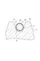
図4を参照して、第2の構成例に係る探触子4のセンサモジュール10Aについて説明する。図4に示されるように、センサモジュール10Aは、棒状の絶縁体17の外周にフレキシブル基板10aが巻き付けられた構成を有する。絶縁体17は、中実の円柱状であってもよいし、中空の円筒状であってもよい。絶縁体17の形状および大きさ(直径)は、凹部表面E2に適合している。絶縁体17は、たとえば、シリコーン等の高分子樹脂材料からなる。絶縁体17は、対象物Oの凹部表面E2に押し当てられる。絶縁体17の形状および大きさ(直径)は、対象物Oの凹凸部または狭隘部の形状および寸法に合わせて変更され得る。そのために、複数種類の絶縁体17が準備されてもよい。これにより、様々な凹凸部または狭隘部における磁界の計測が可能となる。
With reference to FIG. 4, the
センサモジュール10Aを用いた走査は、装置によって自動で行われてもよいし、手動で行われてもよい。手動で走査が行われる場合に、絶縁体17が作業者の手によって持たれてもよい。手動で走査が行われる場合には、位置情報を正確に得られない可能性があるが、対象物OにおけるきずXの有無を判定することは可能である。
The scanning using the
また、センサモジュール10Aを用いた走査が行われる際、絶縁体17を含むセンサモジュール10Aの全体が回転されてもよい。絶縁体17を含むセンサモジュール10Aの全体が回転されずに、平行移動させられてもよい。
Further, when scanning using the
センサモジュール10Aおよびセンサモジュール10Aを備えた探触子4によれば、上記のセンサモジュール10を備えた探触子4と同様の作用・効果が奏される。また、フレキシブル基板10aが巻かれた棒状の絶縁体17を凹凸部や狭隘部等に挿入することにより、フレキシブル基板10aが探傷面Eに沿うように、フレキシブル基板10aを配置することができる。なお、絶縁体17は、探触子4の一部として設けられてもよいし、探触子4とは別体のものとして用いられてもよい。絶縁体17が探触子4とは別体のものとして用いられる場合、探触子4(センサモジュール10A)と絶縁体17とによって、探傷用器具が構成される。絶縁体17は、探傷面Eの形状に適合する先端形状を有する治具に相当する。
According to the
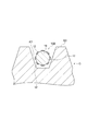
図5を参照して、第3の構成例に係る探触子4のセンサモジュール10Bについて説明する。図5に示されるように、センサモジュール10Bは、棒状の基材18に複数の磁気センサ12が取り付けられた構成を有する。センサモジュール10Bでは、シート状のフレキシブル基板10aは設けられていない。基材18は、中実の円柱状であってもよいし、中空の円筒状であってもよい。基材18の形状および大きさ(直径)は、凹部表面E2に適合している。基材18は、たとえば、柔軟性を有する材料からなる。基材18は、高分子樹脂材料からなってもよい。基材18の形状および大きさ(直径)は、対象物Oの凹凸部または狭隘部の形状および寸法に合わせて変更され得る。柔軟性を有する基材18は、凹部表面E2の形状に沿うように、自在に変形し得る。磁気センサ12は、公知の手段を用いて、基材18に接合または搭載され得る。
With reference to FIG. 5, a
なお、磁気センサ12に接続される配線は、基材18上に形成されてもよいし、基材18の外部に設けられてもよい。
In addition, the wiring connected to the
磁気センサ12は、対象物Oの凹部表面E2に対面するように配置される。磁気センサ12は、対象物Oの凹部表面E2に当接してもよい。磁気センサ12上に、磁束の測定に影響を与えない保護シートが設けられてもよい。基材18を含むセンサモジュール10Bにより、様々な凹凸部または狭隘部における磁界の計測が可能となる。
The
センサモジュール10Bを用いた走査は、装置によって自動で行われてもよいし、手動で行われてもよい。センサモジュール10Bを用いた走査が行われる際、センサモジュール10Bの全体が回転されてもよい。センサモジュール10Bの全体が回転されずに、平行移動させられてもよい。
Scanning using the
センサモジュール10Bおよびセンサモジュール10Bを備えた探触子4によれば、上記のセンサモジュール10を備えた探触子4と同様の作用・効果が奏される。また、棒状の基材18を凹凸部や狭隘部等に挿入することにより、基材18が探傷面Eに沿うように、基材18を配置することができる。
According to the
以上、本発明の実施形態について説明したが、本発明は上記実施形態に限定されない。たとえば、基材はフレキシブル基板10aである場合に限られず、布や紙であってもよい。すなわち、フレキシブル基板10a以外のシート状の基材が用いられてもよい。また、基材は、網状であってもよく、帯状であってもよい。配線は、公知の手段を用いて、基材上に形成されてもよいし、基材の外部に設けられてもよい。
As mentioned above, although embodiment of this invention was described, this invention is not limited to the said embodiment. For example, the base material is not limited to the
基材上に、磁気センサ12を含むセンサユニットが取り付けられてもよい。その場合、センサユニットは、一または複数の磁気センサ12と、対象物Oに磁界を形成するための磁化部とを含んでもよい。
A sensor unit including the
探触子4のセンサモジュールが挿入され得る対象物Oの形状は、上記した凹部表面E2に限られない。対象物Oのスリットにセンサモジュールが挿入されてもよい。その場合にスリットは、入り組んだ形状をなしてもよい。対向する対象物Oの2つの表面の間にセンサモジュールを挿入し、磁気センサ12の両面を用いて各表面の磁界を測定してもよい。対象物Oの孔部や中空部にセンサモジュールが挿入されてもよい。
The shape of the object O into which the sensor module of the
絶縁体17または基材18が、中心部に配置された金属製の線状体(針金等)と、線状体の周囲に設けられた樹脂層とからなってもよい。金属製の線状体を備えることにより、絶縁体17または基材18が、変形した形状を維持し得るように構成されてもよい。
The
計測用治具50は必須ではない。計測用治具50が省略されてもよい。計装アンプ基板11が省略されてもよい。
The measuring
1 漏洩磁束探傷装置
4 探触子
10 センサモジュール
10A、10B センサモジュール
10a フレキシブル基板(基材)
11 計装アンプ基板
12 磁気センサ
17 絶縁体
18 基材
20 PC(処理部)
50 計測用治具(治具)
60 探傷用器具
D 走査方向
E 探傷面
E1 平坦部表面(探傷面)
E2 凹部表面(探傷面)
F 磁束
Fa 漏洩磁束
O 対象物
T 磁気センサ
X きず
DESCRIPTION OF SYMBOLS 1 Leakage magnetic
11
50 Jig for measurement
60 Flaw detection instrument D Scanning direction E Flaw detection surface E1 Flat surface (flaw detection surface)
E2 Concave surface (flaw detection surface)
F Magnetic flux Fa Leakage magnetic flux O Object T Magnetic sensor X Scratches
Claims (9)
一または複数の前記磁気センサ、または、前記磁気センサをそれぞれ含む一または複数のセンサユニットと、
前記磁気センサまたは前記センサユニットが取り付けられた柔軟性を有する基材と、
を備える探触子。 A probe of a leakage magnetic flux flaw detector that detects flaws on a surface layer including a flaw detection surface by scanning a flaw detection surface of an object with a magnetic sensor,
One or more magnetic sensors, or one or more sensor units each including the magnetic sensor; and
A flexible substrate to which the magnetic sensor or the sensor unit is attached;
A probe with
前記探傷面の形状に適合する先端形状を有する治具と、
を備える探傷用器具。 The probe according to any one of claims 1 to 5,
A jig having a tip shape that matches the shape of the flaw detection surface;
A flaw detection instrument comprising:
前記磁気センサにおいて検出された磁界を示す信号を入力して処理する処理部と、
を備える漏洩磁束探傷装置。 The probe according to any one of claims 1 to 5,
A processing unit for inputting and processing a signal indicating a magnetic field detected by the magnetic sensor;
A leakage magnetic flux flaw detector comprising:
前記磁気センサにおいて検出された磁界を示す信号を入力して処理する処理部と、
を備える漏洩磁束探傷装置。 A flaw detection instrument according to claim 6;
A processing unit for inputting and processing a signal indicating a magnetic field detected by the magnetic sensor;
A leakage magnetic flux flaw detector comprising:
前記基材を前記探傷面上に配置し、前記基材の上から前記治具の先端を前記探傷面に対して押し当てた状態で、前記磁気センサを走査させる、漏洩磁束探傷方法。 Using the flaw detection instrument according to claim 6,
A leakage magnetic flux flaw detection method, wherein the magnetic sensor is scanned in a state in which the base material is disposed on the flaw detection surface and the tip of the jig is pressed against the flaw detection surface from above the base material.
Priority Applications (1)
| Application Number | Priority Date | Filing Date | Title |
|---|---|---|---|
| JP2016138767A JP7073617B2 (en) | 2016-07-13 | 2016-07-13 | Detector, magnetic flux leakage detector, and magnetic flux leakage detection method |
Applications Claiming Priority (1)
| Application Number | Priority Date | Filing Date | Title |
|---|---|---|---|
| JP2016138767A JP7073617B2 (en) | 2016-07-13 | 2016-07-13 | Detector, magnetic flux leakage detector, and magnetic flux leakage detection method |
Publications (2)
| Publication Number | Publication Date |
|---|---|
| JP2018009872A true JP2018009872A (en) | 2018-01-18 |
| JP7073617B2 JP7073617B2 (en) | 2022-05-24 |
Family
ID=60995374
Family Applications (1)
| Application Number | Title | Priority Date | Filing Date |
|---|---|---|---|
| JP2016138767A Active JP7073617B2 (en) | 2016-07-13 | 2016-07-13 | Detector, magnetic flux leakage detector, and magnetic flux leakage detection method |
Country Status (1)
| Country | Link |
|---|---|
| JP (1) | JP7073617B2 (en) |
Families Citing this family (1)
| Publication number | Priority date | Publication date | Assignee | Title |
|---|---|---|---|---|
| KR102780463B1 (en) * | 2023-12-20 | 2025-03-12 | 주식회사 로보로 | Gear integrity inspection device using leakage magnetic flux |
Citations (11)
| Publication number | Priority date | Publication date | Assignee | Title |
|---|---|---|---|---|
| JPS63304154A (en) * | 1987-06-05 | 1988-12-12 | Tokyo Gas Co Ltd | Sensor profiling device for outside surface corrosion inspection pig |
| JPH0933488A (en) * | 1995-07-20 | 1997-02-07 | Daido Steel Co Ltd | Eddy current flaw detection probe and manufacturing method thereof |
| JP2001522046A (en) * | 1997-11-04 | 2001-11-13 | シーメンス アクチエンゲゼルシヤフト | Eddy current inspection head, method of manufacturing eddy current inspection head, and eddy current inspection method |
| US6339326B1 (en) * | 2000-03-15 | 2002-01-15 | General Electric Company | Eddy current inspection probe |
| JP2005164593A (en) * | 2003-12-03 | 2005-06-23 | General Electric Co <Ge> | Pulsed eddy current sensor probe and inspection method |
| JP2007057281A (en) * | 2005-08-23 | 2007-03-08 | Sumitomo Metal Ind Ltd | Magnetic flux leakage inspection device |
| JP2008298478A (en) * | 2007-05-29 | 2008-12-11 | Hitachi Ltd | Eddy current testing probe |
| JP2009537834A (en) * | 2006-05-24 | 2009-10-29 | エアバス・フランス | Nondestructive inspection system for parts by analyzing the distribution of leakage magnetic field |
| US20160025682A1 (en) * | 2012-07-11 | 2016-01-28 | Electric Power Research Institute Inc. | Flexible eddy current probe |
| US20160161449A1 (en) * | 2013-07-10 | 2016-06-09 | Snecma | Device for inspecting a surface of an electrically conductive part |
| EP3163296A1 (en) * | 2015-10-28 | 2017-05-03 | Nokia Technologies Oy | An apparatus and method for sensing an analyte, using a graphene channel, quantum dots and electromagnetic radiation |
-
2016
- 2016-07-13 JP JP2016138767A patent/JP7073617B2/en active Active
Patent Citations (11)
| Publication number | Priority date | Publication date | Assignee | Title |
|---|---|---|---|---|
| JPS63304154A (en) * | 1987-06-05 | 1988-12-12 | Tokyo Gas Co Ltd | Sensor profiling device for outside surface corrosion inspection pig |
| JPH0933488A (en) * | 1995-07-20 | 1997-02-07 | Daido Steel Co Ltd | Eddy current flaw detection probe and manufacturing method thereof |
| JP2001522046A (en) * | 1997-11-04 | 2001-11-13 | シーメンス アクチエンゲゼルシヤフト | Eddy current inspection head, method of manufacturing eddy current inspection head, and eddy current inspection method |
| US6339326B1 (en) * | 2000-03-15 | 2002-01-15 | General Electric Company | Eddy current inspection probe |
| JP2005164593A (en) * | 2003-12-03 | 2005-06-23 | General Electric Co <Ge> | Pulsed eddy current sensor probe and inspection method |
| JP2007057281A (en) * | 2005-08-23 | 2007-03-08 | Sumitomo Metal Ind Ltd | Magnetic flux leakage inspection device |
| JP2009537834A (en) * | 2006-05-24 | 2009-10-29 | エアバス・フランス | Nondestructive inspection system for parts by analyzing the distribution of leakage magnetic field |
| JP2008298478A (en) * | 2007-05-29 | 2008-12-11 | Hitachi Ltd | Eddy current testing probe |
| US20160025682A1 (en) * | 2012-07-11 | 2016-01-28 | Electric Power Research Institute Inc. | Flexible eddy current probe |
| US20160161449A1 (en) * | 2013-07-10 | 2016-06-09 | Snecma | Device for inspecting a surface of an electrically conductive part |
| EP3163296A1 (en) * | 2015-10-28 | 2017-05-03 | Nokia Technologies Oy | An apparatus and method for sensing an analyte, using a graphene channel, quantum dots and electromagnetic radiation |
Also Published As
| Publication number | Publication date |
|---|---|
| JP7073617B2 (en) | 2022-05-24 |
Similar Documents
| Publication | Publication Date | Title |
|---|---|---|
| CN102549375B (en) | Eddy current inspection of case hardening depth | |
| Ramos et al. | Present and future impact of magnetic sensors in NDE | |
| US6975108B2 (en) | Methods and devices for eddy current PCB inspection | |
| US7038445B2 (en) | Method, system and apparatus for ferromagnetic wall monitoring | |
| US8717012B2 (en) | Eddy current probe for surface and sub-surface inspection | |
| CN112352166B (en) | An Electromagnetic Eddy Current Probe Using Three-Dimensional Exciting Coils | |
| US20120109565A1 (en) | Leakage magnetic flux flaw inspection method and device | |
| CN103675094A (en) | Non-destructive testing device | |
| Peng et al. | A novel differential excitation capacitive sensing for hydrogen pipeline inspection | |
| JP2017150904A (en) | Flaw detection apparatus and flaw detection method | |
| US7304474B2 (en) | Eddy current inspection device with arrays of magnetoresistive sensors | |
| JP7073617B2 (en) | Detector, magnetic flux leakage detector, and magnetic flux leakage detection method | |
| JP2019020273A (en) | Surface flaw inspection device | |
| JP2016008931A (en) | Nondestructive inspection system and nondestructive inspection method | |
| Chomsuwan et al. | High-Spatial Resolution Giant Magnetoresistive Sensors-Part I: Application in Non-Destructive Evaluation | |
| JP2021001813A (en) | Nondestructive inspection magnetic sensor and nondestructive inspection device | |
| JP2018009873A (en) | Probe and leakage flux flaw detection device equipped with the same | |
| JP2019020272A (en) | Front surface scratch inspection device | |
| Pelkner et al. | Local magnetization unit for GMR array based magnetic flux leakage inspection | |
| Tian et al. | Eddy-current model and detection in a thick stainless steel plate | |
| US12235240B2 (en) | Magnetic body inspection apparatus and magnetic body inspection method | |
| KR20130132370A (en) | Apparatus for detection defect using the different kind magnetic sensor | |
| JP2018009874A (en) | Magnetic probe | |
| CN203616286U (en) | Lossless flaw detection device | |
| Pelkner et al. | Automated inspection of surface breaking cracks using GMR sensor arrays |
Legal Events
| Date | Code | Title | Description |
|---|---|---|---|
| A621 | Written request for application examination |
Free format text: JAPANESE INTERMEDIATE CODE: A621 Effective date: 20190530 |
|
| A131 | Notification of reasons for refusal |
Free format text: JAPANESE INTERMEDIATE CODE: A131 Effective date: 20200714 |
|
| A521 | Request for written amendment filed |
Free format text: JAPANESE INTERMEDIATE CODE: A523 Effective date: 20200911 |
|
| A131 | Notification of reasons for refusal |
Free format text: JAPANESE INTERMEDIATE CODE: A131 Effective date: 20210302 |
|
| A521 | Request for written amendment filed |
Free format text: JAPANESE INTERMEDIATE CODE: A523 Effective date: 20210428 |
|
| A131 | Notification of reasons for refusal |
Free format text: JAPANESE INTERMEDIATE CODE: A131 Effective date: 20210928 |
|
| A521 | Request for written amendment filed |
Free format text: JAPANESE INTERMEDIATE CODE: A523 Effective date: 20211126 |
|
| TRDD | Decision of grant or rejection written | ||
| A01 | Written decision to grant a patent or to grant a registration (utility model) |
Free format text: JAPANESE INTERMEDIATE CODE: A01 Effective date: 20220412 |
|
| A61 | First payment of annual fees (during grant procedure) |
Free format text: JAPANESE INTERMEDIATE CODE: A61 Effective date: 20220425 |
|
| R151 | Written notification of patent or utility model registration |
Ref document number: 7073617 Country of ref document: JP Free format text: JAPANESE INTERMEDIATE CODE: R151 |