JP2018009857A - Wavelength calibration method and spectrophotometer using wavelength calibration method - Google Patents
Wavelength calibration method and spectrophotometer using wavelength calibration method Download PDFInfo
- Publication number
- JP2018009857A JP2018009857A JP2016138283A JP2016138283A JP2018009857A JP 2018009857 A JP2018009857 A JP 2018009857A JP 2016138283 A JP2016138283 A JP 2016138283A JP 2016138283 A JP2016138283 A JP 2016138283A JP 2018009857 A JP2018009857 A JP 2018009857A
- Authority
- JP
- Japan
- Prior art keywords
- wavelength
- coefficient
- assembly error
- lambda
- calibration method
- Prior art date
- Legal status (The legal status is an assumption and is not a legal conclusion. Google has not performed a legal analysis and makes no representation as to the accuracy of the status listed.)
- Granted
Links
Images

Landscapes
- Spectrometry And Color Measurement (AREA)
Abstract
Description
本発明は、試料に照射する光の波長λsを校正する波長校正方法及びその波長校正方法を用いた分光光度計に関する。 The present invention relates to a wavelength calibration method for calibrating a wavelength λ s of light irradiated on a sample and a spectrophotometer using the wavelength calibration method.
所定波長λsの光を試料に照射するために、紫外可視光分光光度計や原子吸光分光光度計等の分光光度計では分光器(モノクロメータ)が用いられている。分光器の一般的な構成としては、出口スリットを有する筐体を備え、筐体内には、所定波長範囲(例えば190nm〜900nm)の光を出射する光源(例えばキセノンアークランプやフラッシュキセノンランプ等)と、波長分解するための回折格子(波長分散素子)と、光源から出射された光に対する回折格子の角度θsを変えるための回転駆動機構とが設置されている。このような分光器によれば、回転駆動機構により回折格子を所望角度θsに回転させることにより、出口スリットを通して所望波長λsの光を出射している。つまり、分光器から出射される光の波長λsの精度は、回折格子の角度θsの精度に大きく依存しており、波長λsの精度を高めるには、回折格子を微小ピッチで精度良く回転駆動できる回転駆動機構が必要となる。 In order to irradiate the sample with light having a predetermined wavelength λ s, a spectrophotometer (monochromator) is used in a spectrophotometer such as an ultraviolet-visible light spectrophotometer or an atomic absorption spectrophotometer. As a general configuration of a spectroscope, a housing having an exit slit is provided, and a light source (for example, a xenon arc lamp or a flash xenon lamp) that emits light in a predetermined wavelength range (for example, 190 nm to 900 nm) is provided in the housing. And a diffraction grating (wavelength dispersion element) for wavelength decomposition and a rotation drive mechanism for changing the angle θ s of the diffraction grating with respect to the light emitted from the light source. According to such a spectroscope, light having a desired wavelength λ s is emitted through the exit slit by rotating the diffraction grating to the desired angle θ s by the rotation driving mechanism. In other words, the accuracy of the wavelength lambda s of light emitted from the spectroscope is highly dependent on the accuracy of the angle theta s of the diffraction grating, to improve the accuracy of wavelength lambda s can accurately diffraction grating at small pitches A rotational drive mechanism that can be rotationally driven is required.
ところで、分光器から出射される光の波長λsの精度を高めるためには、前述したように回折格子を微小ピッチで精度良く回転駆動できるようにする必要があるが、分光器に回折格子や回転駆動機構を取り付ける際には組立て誤差が発生する。 By the way, in order to increase the accuracy of the wavelength λ s of the light emitted from the spectrometer, it is necessary to be able to rotate the diffraction grating with high accuracy with a fine pitch as described above. An assembly error occurs when the rotation drive mechanism is attached.
そこで、分光器の組立て誤差を、下記補正式(1)〜(3)を用いて補正する波長補正方法が提案されている(例えば、特許文献1及び特許文献2参照)。
θs=θ’+Δθ ・・・(1)
Therefore, there has been proposed a wavelength correction method for correcting the assembly error of the spectrometer using the following correction equations (1) to (3) (see, for example,
θ s = θ ′ + Δθ (1)
θ’=sin−1〔mλ’/(2d・cosK)〕 ・・・(2)
ここで、mは使用する回折光の次数であり、dは回折格子の格子溝間隔(nm)であり、Kは分光器偏角(回折格子の入射光と出射光との成す角)の1/2(rad)である。つまり、dやKが製造及び組立時の誤差等によってばらついた場合、取り出される光の波長λ’は(2d・cosK/m)の変化に伴って、下記式(3)のように一次的に変化する。
λ’=a・λ+b ・・・(3)
よって、組立て誤差に関する係数となるdとKとは、輝線スペクトルの実測波長λxに基づいて実験的に求められている。
θ ′ = sin −1 [mλ ′ / (2d · cosK)] (2)
Here, m is the order of the diffracted light to be used, d is the grating groove interval (nm) of the diffraction grating, and K is 1 of the spectroscopic declination (angle formed by the incident light and the outgoing light of the diffraction grating). / 2 (rad). That is, when d and K vary due to errors in manufacturing and assembly, etc., the wavelength λ ′ of the extracted light is primarily expressed by the following equation (3) with a change of (2d · cos K / m). Change.
λ ′ = a · λ + b (3)
Therefore, d and K, which are coefficients related to the assembly error, are experimentally obtained based on the actually measured wavelength λ x of the emission line spectrum.
補正式(1)〜(3)を用いて補正する波長補正方法では、d、Kは実測波長λxから推測しなければならない未知のパラメータであり、各分光器毎に求めておく必要がある。そこで、工場出荷前の調整工程(波長校正)において、オペレータ等は、その分光器でのd、Kを求めるために、実際にX個(例えば40個)の既知の基準波長Λ1、Λ2、・・・Λxの輝線スペクトルについて実測波長λ1、λ2、・・・λxを測定している。このとき、基準波長Λ1、Λ2、・・・Λxは既知波長ではあるが、上述したような誤差による波長ずれΔλxを考慮して、第一の基準波長Λ1±Δλa(例えば4nm)の範囲と、第二の基準波長Λ2±Δλaの範囲と、・・・第Xの基準波長Λ1±Δλaの範囲とを測定するように、パルスモータを制御して回折格子を回転させている。
In the wavelength correction method for correction using the correction equations (1) to (3), d and K are unknown parameters that must be estimated from the actually measured wavelength λ x , and must be obtained for each spectroscope. . Therefore, in the adjustment process (wavelength calibration) before factory shipment, the operator or the like actually obtains X (for example, 40) known reference wavelengths Λ 1 and Λ 2 in order to obtain d and K in the spectrometer. Found wavelength lambda 1 for bright line spectrum of ··· Λ x, λ 2, measures the · · · lambda x. At this time, the reference wavelength lambda 1, lambda 2, although · · · lambda x is a known wavelength, in consideration of the wavelength shift [Delta] [lambda] x due to an error such as described above, the first reference wavelength Λ 1 ±
しかしながら、上述したような波長校正方法では、各基準波長Λxについて、基準波長Λx±4nmとなる広めの波長範囲を測定する必要があり、測定時間が非常に長くなっていた。
また、基準波長Λx±4nmとなる広めの波長範囲を測定するため、例えば第一の基準波長Λ1±4nmの範囲に、第二の基準波長Λ2に対応する第二の実測波長λ2のピークが存在していても、第一の基準波長Λ1に対応するピークとして誤検出することがあった。
However, in the wavelength calibration method as described above, it is necessary to measure a wider wavelength range where the reference wavelength Λ x ± 4 nm for each reference wavelength Λ x , and the measurement time is very long.
Further, in order to measure a wider wavelength range that becomes the reference wavelength Λ x ± 4 nm, for example, the second actually measured wavelength λ 2 corresponding to the second reference wavelength Λ 2 in the range of the first reference wavelength Λ 1 ± 4 nm. be in the peak of existence, there can be erroneously detected as a peak corresponding to the first reference wavelength lambda 1.
本件発明者は、上記課題を解決するために、分光器の組立て誤差を充分に校正しつつ、その校正にかかる時間を短くすることができる波長校正方法について検討を行った。そこで、まず第一段階として、例えば近くに隣接するピークがないため弁別の必要のない4(N)個の輝線スペクトルを広めの波長範囲2Δλaで測定することで、組立て誤差に関する係数d、Kを粗く決定することにした。そして、組立て誤差に関する係数d、Kを粗く決定することができれば、残りの36個の輝線スペクトルについての組立て誤差の影響が予測できるので、第二段階として、36個の輝線スペクトルを狭い波長範囲2Δλbで測定することにした。つまり、36個の輝線スペクトルについては、組立て誤差粗補正基準波長Λx’±2nmとなる狭い波長範囲を測定するため、測定時間が短く、かつ、ピークの誤検出を防止することができる。その後、組立て誤差に関する係数d、Kを精度良く再決定するようにした。 In order to solve the above-mentioned problems, the present inventor has studied a wavelength calibration method capable of calibrating the spectrometer assembly error sufficiently and shortening the time required for the calibration. Therefore, as a first step, for example, by measuring 4 (N) emission line spectra that do not need to be distinguished because there is no adjacent peak in the wider wavelength range 2Δλ a , coefficients d and K relating to assembly errors are measured. Was decided roughly. If the coefficients d and K relating to the assembly error can be roughly determined, the influence of the assembly error on the remaining 36 emission line spectra can be predicted. Therefore, as the second stage, the 36 emission line spectra are narrowed to a narrow wavelength range 2Δλ. We decided to measure with b . That is, for 36 bright line spectra, a narrow wavelength range in which the assembly error rough correction reference wavelength Λ x ′ ± 2 nm is measured, so that the measurement time is short and erroneous peak detection can be prevented. Thereafter, the coefficients d and K relating to the assembly error are redetermined with high accuracy.
すなわち、本発明の波長校正方法は、モータによる回転駆動力により駆動される波長分散素子を備える分光器により取り出される光の波長λsを、補正式を用いて校正するための波長校正方法であって、前記補正式は、組立て誤差に関する係数を含むものであり、少なくともX個の既知の基準波長Λxを有する光を出射するための光源、及び/又は、波長校正用フィルタを用いて、X個の内のN個の輝線スペクトルについて基準波長Λx±Δλaの範囲の波長を測定することにより、N個の実測波長λxを得る第一測定ステップと、N個の輝線スペクトルについて、決定された実測波長λxと基準波長Λxとの波長ずれΔλxを算出して、組立て誤差に関する係数を粗く決定する第一係数決定ステップと、(X−N)個の輝線スペクトルについて組立て誤差に関する係数に基づいて2Δλaより狭い範囲となる波長範囲2Δλbの波長を測定することにより、(X−N)個の実測波長λxを得る第二測定ステップと、(X−N)個の輝線スペクトルについて実測波長λxと基準波長Λxとの波長ずれΔλxを算出して、前記第一係数決定ステップで算出された波長ずれΔλxも用いて、組立て誤差に関する係数を精度良く再決定する第二係数決定ステップとを含むようにしている。 That is, the wavelength calibration method of the present invention is a wavelength calibration method for calibrating the wavelength λ s of light extracted by a spectroscope equipped with a wavelength dispersion element driven by a rotational driving force by a motor using a correction formula. The correction formula includes a coefficient related to an assembly error, and a light source for emitting light having at least X known reference wavelengths Λ x and / or a wavelength calibration filter is used. A first measurement step for obtaining N actually measured wavelengths λ x by measuring wavelengths in the range of the reference wavelength Λ x ± Δλ a for N of the bright lines spectra, and determination of N bright lines spectra and calculates the wavelength shift [Delta] [lambda] x between actual measurement wavelength lambda x and the reference wavelength lambda x, and the first coefficient determining step of determining coarsely the coefficients relating to assembling errors, with the (X-N) number of bright line spectrum A second measurement step of obtaining (XN) number of actually measured wavelengths λ x by measuring the wavelength in the wavelength range 2Δλ b which is narrower than 2Δλ a based on the coefficient relating to the assembly error; ) number for the bright line spectrum to calculate the wavelength shift [Delta] [lambda] x between the measured wavelength lambda x and the reference wavelength lambda x, is also used wavelength shift [Delta] [lambda] x calculated by the first coefficient determining step, accuracy coefficient for assembly errors And a second coefficient determination step that is re-determined well.
ここで、「N個の輝線スペクトル」とは、オペレータ等によって決められる任意の個数であり、組立て誤差が粗く測定できれば良く、例えば近くに隣接するピークがないため弁別の必要のない2個から4個等となる。一方、「(X−N)個の輝線スペクトル」とは、オペレータ等によって決められる任意の個数であり、組立て誤差を精度良く測定できる充分な個数であって、「N個」より多く、例えば36個や40個等となる。なお、本願に係る「輝線スペクトル」は、波長校正用フィルタを備える場合には、波長校正用フィルタの吸収ピークも含まれるものとする。
また、「Δλa」は、オペレータ等によって決められる任意の波長であり、組立て誤差による波長ずれを考慮したものであって、例えば4nm等となる。一方、「Δλb」とは、オペレータ等によって決められる任意の波長であり、組立て誤差以外の小さな誤差による波長ずれを考慮したものであって「Δλa」より小さく、例えば2nm等となる。
Here, the “N emission line spectra” is an arbitrary number determined by an operator or the like, as long as the assembly error can be measured roughly. For example, since there is no adjacent peak, 2 to 4 that do not require discrimination. It becomes individual etc. On the other hand, “(X−N) emission line spectra” is an arbitrary number determined by an operator or the like, which is a sufficient number that can accurately measure an assembly error, and is larger than “N”, for example, 36 And 40 or so. In addition, the “bright line spectrum” according to the present application includes an absorption peak of the wavelength calibration filter when the wavelength calibration filter is provided.
Further, “Δλ a ” is an arbitrary wavelength determined by an operator or the like, which takes into account a wavelength shift due to an assembly error, and is, for example, 4 nm. On the other hand, “Δλ b ” is an arbitrary wavelength determined by an operator or the like, which takes into account a wavelength shift due to a small error other than an assembly error, and is smaller than “Δλ a ”, for example, 2 nm.
以上のように、本発明の波長校正方法によれば、分光器の波長校正において、分光器の組立て誤差等を充分に校正しつつ、その校正にかかる時間を短くすることができる。 As described above, according to the wavelength calibration method of the present invention, in the wavelength calibration of the spectrometer, it is possible to shorten the time required for calibration while sufficiently calibrating the assembly error of the spectrometer.
(他の課題を解決するための手段および効果)
また、本発明の波長校正方法は、減速機構としてハーモニックドライブ(登録商標)を用いている装置において、第二係数決定ステップでは、組立て誤差に関する係数d、Kを精度良く再決定するのみでなく、下記式(4)で示されるハーモニックドライブの周期性誤差に関する係数A、B、θa、θb、θc(例えば、特許文献1及び特許文献2参照)を決定するようにしても良い。ハーモニックドライブの周期性誤差は、組立て誤差よりも充分に小さいため、「Δλa」よりも小さい「Δλb」を設定することができる。この場合も同様に、校正にかかる時間を短縮したり、近隣のピークの誤検出を防いだりする効果がある。
Δθ=A・sin(C1・θ+θa)+B・sin(C2・θ+θb)+θc ・・・(4)
ここで、C1とC2とは、ハーモニックドライブ機構(ハーモニックギア)の構造により理論的に決まる係数であり、例えば減速比が1/100であるハーモニックドライブギアの場合には、C1とC2とはそれぞれ200と100となる。また、A、B、θa、θb、θcは、減速機構毎(つまり分光器毎又は分光光度計毎)に相違する装置固有の係数であり、いずれも輝線スペクトルの実測波長λxに基づいて、つまり実験的に決まる係数(周期性誤差に関する係数)となる。
すなわち、本発明の波長校正方法において、前記分光器は、モータと、当該モータの回転を減速するハーモニックドライブ機構による減速手段と、当該減速手段で減速された回転駆動力により駆動される波長分散素子とを備えるものであり、前記補正式は、組立て誤差に関する係数及びハーモニックドライブの周期性誤差に関する係数を含むものであり、前記第二係数決定ステップは、(X−N)個の輝線スペクトルについて実測波長λxと基準波長Λxとの波長ずれΔλxを算出して、前記第一係数決定ステップで算出された波長ずれΔλxも用いて、組立て誤差に関する係数を精度良く再決定するととともに、ハーモニックドライブの周期性誤差に関する係数を決定するようにしても良い。
そして、本発明の分光光度計は、上述したような波長校正方法で算出された係数及び補正式を記憶する記憶部と、モータによる回転駆動力により駆動される波長分散素子とを備える分光器と、試料が配置される試料室と、前記試料から放出される光の波長及び強度を検出する光検出器とを備える分光光度計であって、前記試料が測定される際に目的波長λsが設定されたとき、前記補正式を適用して目的波長λsに対応する波長分散素子の角度θsを算出し、角度θsを得るようにモータを制御する制御部を備えるようにしている。
(Means and effects for solving other problems)
In the wavelength calibration method of the present invention, in the apparatus using the harmonic drive (registered trademark) as the speed reduction mechanism, the second coefficient determination step not only re-determines the coefficients d and K related to the assembly error with high accuracy, Coefficients A, B, θa, θb, and θc (for example, refer to
Δθ = A · sin (C1 · θ + θa) + B · sin (C2 · θ + θb) + θc (4)
Here, C1 and C2 are coefficients theoretically determined by the structure of the harmonic drive mechanism (harmonic gear). For example, in the case of a harmonic drive gear having a reduction ratio of 1/100, C1 and C2 are respectively 200 and 100. A, B, θa, θb, θc are coefficients unique to the device that differ for each deceleration mechanism (that is, for each spectroscope or spectrophotometer), and all are based on the actually measured wavelength λ x of the emission line spectrum. That is, it is an experimentally determined coefficient (coefficient related to periodicity error).
That is, in the wavelength calibration method of the present invention, the spectroscope includes a motor, a speed reduction unit using a harmonic drive mechanism that decelerates the rotation of the motor, and a wavelength dispersion element that is driven by a rotational driving force decelerated by the speed reduction unit. The correction formula includes a coefficient relating to an assembly error and a coefficient relating to a periodic error of the harmonic drive, and the second coefficient determining step is actually measuring (X−N) emission line spectra. and calculates the wavelength shift [Delta] [lambda] x and the wavelength lambda x and the reference wavelength lambda x, wherein also used wavelength shift [Delta] [lambda] x calculated by the first coefficient determining step, together with the coefficients relating to assembling errors accurately re determining harmonic A coefficient related to the periodicity error of the drive may be determined.
The spectrophotometer according to the present invention includes a storage unit that stores a coefficient and a correction formula calculated by the wavelength calibration method as described above, and a spectrometer including a wavelength dispersion element that is driven by a rotational driving force of a motor. A spectrophotometer comprising a sample chamber in which the sample is placed and a photodetector for detecting the wavelength and intensity of the light emitted from the sample, the target wavelength λ s being measured when the sample is measured When set, the correction equation is applied to calculate the angle θ s of the wavelength dispersion element corresponding to the target wavelength λ s , and a control unit for controlling the motor to obtain the angle θ s is provided.
以下、本発明の実施形態について図面を用いて説明する。なお、本発明は、以下に説明するような実施形態に限定されるものではなく、本発明の趣旨を逸脱しない範囲で種々の態様が含まれる。 Hereinafter, embodiments of the present invention will be described with reference to the drawings. The present invention is not limited to the embodiments described below, and includes various modes without departing from the spirit of the present invention.
図1は、実施形態に係る分光光度計の一例を示す概略構成図である。分光光度計1は、設定波長λsの光を出射するための分光器10と、試料Sが配置される試料室40と、光検出器30と、分光光度計1全体を制御するコンピュータ50とを備える。
FIG. 1 is a schematic configuration diagram illustrating an example of a spectrophotometer according to the embodiment. The
分光器10は、出口スリット11aを有する筐体11を備え、筐体11内には、所定波長範囲(例えば190nm〜900nm)の光を出射する光源(例えばキセノンアークランプやフラッシュキセノンランプ等)12と、波長分解するための回折格子(波長分散素子)13と、光源11から出射された光に対する回折格子13の角度θsを変えるための回転駆動機構20とが設置されている。回転駆動機構20は、回転駆動源であるパルスモータ21と、モータ軸の回転を所定の減速比で減速させて回折格子13を回転駆動するハーモニックドライブ(減速機構)22とを備える。
このような分光器10によれば、ハーモニックドライブ22により回折格子13を設定角度θsに回転させることによって、出口スリット11aを通して設定波長λsの光を出射することができるようになっている。
The
According to such a
試料室40には、分析したい試料Sが収納された10mmキュベットセル等が配置されるようになっている。これにより、分光器10で取り出された設定波長λsの光が、試料Sに照射され、試料Sで反射又は試料Sを透過した光が光検出器30に導入されることになる。そして、光検出器30は、光強度に応じた検出信号をコンピュータ50に出力する。
In the
コンピュータ50においては、CPU(制御部)51とメモリ(記憶部)54とを備え、さらにキーボードやマウス等を有する入力装置52と、表示装置(図示せず)とが連結されている。また、CPU51が処理する機能をブロック化して説明すると、分光器10を制御する分光器制御部51aと、光検出器30からの検出信号を取得する光検出器制御部51bと、所定の演算処理を行うことによって試料Sの吸光度や反射率等を計算する分析部51cと、係数d、K、A、B、θa、θb、θcを算出してメモリ54に記憶させる波長校正部51dとを有する。さらに、メモリ54は、補正式(1)〜(4)を予め記憶する補正式記憶領域54aと、係数d、K、A、B、θa、θb、θcを記憶するための係数記憶領域54bとを有する。
The
分光器制御部51aは、試料Sの測定の際に測定者等によって入力装置52を用いて入力された目的波長λsと、メモリ54に記憶された補正式(1)〜(4)及び係数d、K、A、B、θa、θb、θcとに基づいて、目的波長λsに対応する回折格子13の角度θsを算出し、角度θsを得るようにパルスモータ21を制御する。
The
波長校正部51dは、工場出荷前の調整工程(波長校正)等において、オペレータ等が入力装置52を用いて「波長校正」信号を入力することにより、係数d、K、A、B、θa、θb、θcを算出して係数記憶領域54bに記憶させる制御を行う。
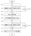
ここで、波長校正部51dが波長校正する波長校正方法(アルゴリズム)の一例について説明する。図2は、波長校正方法について説明するためのフローチャートである。
波長校正方法は、4(N)個の輝線スペクトルの実測波長λxを得る第一測定ステップAと、組立て誤差に関する係数d、Kを粗く決定する第一係数決定ステップBと、36(X−N)個の輝線スペクトルの組立て誤差粗補正基準波長Λx’を算出する組立て誤差粗補正基準波長算出ステップCと、36個の輝線スペクトルの実測波長λxを得る第二測定ステップDと、組立て誤差に関する係数d、Kを精度良く再決定するとともに、周期性誤差に関する係数A、B、θa、θb、θcを決定する第二係数決定ステップEとを含む。
The
Here, an example of a wavelength calibration method (algorithm) in which the
The wavelength calibration method includes a first measurement step A for obtaining an actually measured wavelength λ x of 4 (N) emission line spectra, a first coefficient determination step B for roughly determining coefficients d and K relating to assembly errors, and 36 (X− N) Assembly error rough correction reference wavelength calculation step C for calculating the assembly error rough correction reference wavelength Λ x ′ of the number of emission line spectra, a second measurement step D for obtaining the actually measured wavelength λ x of the 36 emission line spectra, and assembly And a second coefficient determination step E for determining the coefficients d and K relating to the error with high accuracy and determining the coefficients A, B, θa, θb and θc related to the periodic error.
(A)第一測定ステップ
まず、ステップS101の処理において、係数d、Kを粗く決定するための輝線スペクトルの個数を示すパラメータN=1とする。
次に、ステップS102の処理において、光源12の第Nの輝線スペクトルについて、パルスモータ21を制御して回折格子13を回転させながら、光検出器30で検出信号を0.01nm間隔で取得していくことで、基準波長ΛN±Δλa(例えば4nm)の範囲のスペクトルを測定して、そのスペクトル中のピークから第Nの実測波長λNを得る。
次に、ステップS103の処理において、N=4であるか否かを判定する。N=4でないと判定したときには、ステップS104の処理において、N=N+1として、ステップS102の処理に戻る。つまり、4個の実測波長λNを、基準波長ΛN±Δλaの範囲を測定して得ることになる。なお、40(X)個の輝線スペクトルの内からどの4個の輝線スペクトルを選択するかについては、任意に指定できるようにしても良いし、予め設定しておいても良いが、近くに隣接するピークがないため弁別の必要がなく、できるだけ校正波長範囲の両端付近の波長となる輝線スペクトルを選択することが好ましい。
(A) First Measurement Step First, in the process of step S101, a parameter N = 1 indicating the number of bright line spectra for roughly determining the coefficients d and K is set.
Next, in the process of step S102, with respect to the Nth emission line spectrum of the
Next, in the process of step S103, it is determined whether N = 4. When it is determined that N = 4 is not satisfied, N = N + 1 is set in the process of step S104, and the process returns to step S102. That is, four actually measured wavelengths λ N are obtained by measuring the range of the reference wavelength Λ N ± Δλ a . It should be noted that any of the 40 (X) emission line spectra to be selected from which four emission line spectra may be arbitrarily specified or may be set in advance, but adjacent to each other. Since there is no peak to be discriminated, it is not necessary to discriminate, and it is preferable to select an emission line spectrum having a wavelength as close to both ends of the calibration wavelength range as possible.
(B)第一係数決定ステップ
一方、N=4であると判定したときには、ステップS105の処理において、選択した4個の輝線スペクトルについて、実測波長λxと基準波長Λxとの波長ずれΔλxを算出し、補正式(1)〜(3)を用いてΔθ=0とし、組立て誤差に関する係数d、Kを粗く決定して係数記憶領域54bに記憶させる。
(B) First Coefficient Determination Step On the other hand, when it is determined that N = 4, the wavelength shift Δλ x between the measured wavelength λ x and the reference wavelength Λ x for the selected four emission line spectra in the process of step S105. And Δθ = 0 using correction equations (1) to (3), and coefficients d and K relating to the assembly error are roughly determined and stored in the
(C)組立て誤差粗補正基準波長算出ステップ
次に、ステップS106の処理において、ステップS105で決定した係数d、Kに基づいて、組立て誤差の影響を粗く取り除いた36(X−N)個の輝線スペクトルの組立て誤差粗補正基準波長Λx’を算出する。
(C) Assembly Error Rough Correction Reference Wavelength Calculation Step Next, in the process of Step S106, 36 (X−N) bright lines from which the influence of the assembly error has been roughly removed based on the coefficients d and K determined in Step S105. A spectrum assembly error rough correction reference wavelength Λ x ′ is calculated.
(D)第二測定ステップ
次に、ステップS107の処理において、組立て誤差に関する係数d、Kを精度良く再決定するための輝線スペクトルの個数を示すパラメータM=1とする。
次に、ステップS108の処理において、光源12の第Mの輝線スペクトルについて、パルスモータ21を制御して回折格子13を回転させながら、光検出器30で検出信号を0.01nm間隔で取得していくことで、組立て誤差粗補正基準波長ΛM’±Δλb(例えば2nm)の範囲のスペクトルを測定して、そのスペクトル中のピークから第Mの実測波長λMを得る。
次に、ステップS109の処理において、M=36であるか否かを判定する。M=36でないと判定したときには、ステップS110の処理において、M=M+1として、ステップS108の処理に戻る。つまり、36個の実測波長λMを、組立て誤差粗補正基準波長ΛM’±Δλbの範囲を測定して得ることになる。なお、第一測定ステップで選択された4個の輝線スペクトルは、第二測定ステップでは選択されないように設定されている。
(D) Second Measurement Step Next, in the process of step S107, a parameter M = 1 indicating the number of bright line spectra for accurately re-determining the coefficients d and K relating to the assembly error is set.
Next, in the process of step S108, with respect to the Mth emission line spectrum of the
Next, in the process of step S109, it is determined whether M = 36. If it is determined that M = 36 is not satisfied, M = M + 1 is set in the process of step S110, and the process returns to step S108. That is, 36 actually measured wavelengths λ M are obtained by measuring the range of the assembly error rough correction reference wavelength Λ M ′ ± Δλ b . The four bright line spectra selected in the first measurement step are set so as not to be selected in the second measurement step.
(E)第二係数決定ステップ
一方、M=36であると判定したときには、ステップS111の処理において、36個の輝線スペクトルについて、実測波長λxと基準波長Λxとの波長ずれΔλxを算出し、さらに(B)第一係数決定ステップで算出された4個の輝線スペクトルにおける波長ずれΔλxと、補正式(1)〜(3)とを用いてΔθ=0とし、組立て誤差に関する係数d、Kを精度良く再決定して係数記憶領域54bに記憶させる。
また、36個の輝線スペクトルにおける波長ずれΔλxと、(B)第一係数決定ステップで算出された4個の輝線スペクトルにおける波長ずれΔλxと、補正式(1)〜(4)と、再決定された係数d、Kとを用いて、周期性誤差に関する係数A、B、θa、θb、θcを決定して係数記憶領域54bに記憶させる。
そして、ステップS111の完了をもって本フローチャートを終了させる。
(E) Second Coefficient Determination Step On the other hand, when it is determined that M = 36, the wavelength shift Δλ x between the measured wavelength λ x and the reference wavelength Λ x is calculated for the 36 emission line spectra in the process of step S111. Further, (B) Δθ = 0 is set by using the wavelength shift Δλ x in the four emission line spectra calculated in the first coefficient determination step and the correction equations (1) to (3), and the coefficient d regarding the assembly error , K is redetermined with high accuracy and stored in the
Further, a wavelength shift [Delta] [lambda] x in 36 bright line spectrum, and (B) and the wavelength shift [Delta] [lambda] x in the four bright line spectrum calculated by the first coefficient determining step, the correction equation (1) to (4), re Using the determined coefficients d and K, coefficients A, B, θa, θb, and θc related to the periodic error are determined and stored in the
Then, upon completion of step S111, this flowchart is terminated.
以上のように、本発明を適用した分光光度計1によれば、ハーモニックドライブ22を用いた分光器10の波長校正において、分光器10の組立て誤差やハーモニックドライブ22の周期性誤差を充分に校正しつつ、その校正にかかる時間を短くすることができる。
As described above, according to the
<他の実施形態>
(1)上述した分光光度計1では波長校正部51dを備える構成としたが、波長校正部は、波長校正方法が実行された後は、取り除いたり削除されるようにしても良い。
(2)上述した分光光度計1では、波長校正部51dで、光源12の輝線スペクトルのみを用いる構成としたが、波長校正用フィルタを備え、波長校正用フィルタの吸収ピークも用いるようにしても良い。
<Other embodiments>
(1) The
(2) In the
本発明は、分光光度計等に好適に利用できる。 The present invention can be suitably used for a spectrophotometer or the like.
10 分光器
12 光源
13 回折格子(波長分散素子)
21 パルスモータ
22 ハーモニックドライブ(減速手段)
10
21
Claims (3)
前記補正式は、組立て誤差に関する係数を含むものであり、
少なくともX個の既知の基準波長Λxを有する光を出射するための光源、及び/又は、波長校正用フィルタを用いて、X個の内のN個の輝線スペクトルについて基準波長Λx±Δλaの範囲の波長を測定することにより、N個の実測波長λxを得る第一測定ステップと、
N個の輝線スペクトルについて、決定された実測波長λxと基準波長Λxとの波長ずれΔλxを算出して、組立て誤差に関する係数を粗く決定する第一係数決定ステップと、
(X−N)個の輝線スペクトルについて組立て誤差に関する係数に基づいて2Δλaより狭い範囲となる波長範囲2Δλbの波長を測定することにより、(X−N)個の実測波長λxを得る第二測定ステップと、
(X−N)個の輝線スペクトルについて実測波長λxと基準波長Λxとの波長ずれΔλxを算出して、前記第一係数決定ステップで算出された波長ずれΔλxも用いて、組立て誤差に関する係数を精度良く再決定する第二係数決定ステップとを含むことを特徴とする波長校正方法。 A wavelength calibration method for calibrating a wavelength λ s of light extracted by a spectroscope including a wavelength dispersion element driven by a rotational driving force by a motor using a correction formula,
The correction formula includes a coefficient related to an assembly error,
Using a light source for emitting light having at least X known reference wavelengths Λ x and / or a wavelength calibration filter, reference wavelengths Λ x ± Δλ a for N of the X emission line spectra A first measurement step of obtaining N measured wavelengths λ x by measuring wavelengths in the range of
A first coefficient determination step of calculating a wavelength shift Δλ x between the determined actual measurement wavelength λ x and the reference wavelength Λ x for the N emission line spectra, and roughly determining a coefficient relating to an assembly error;
By measuring the wavelength of the wavelength range 2Derutaramuda b to be narrower range 2Derutaramuda a based on the coefficient related to the assembly error for (X-N) pieces of line spectra, the get (X-N) number of measured wavelengths lambda x Two measurement steps;
(X-N) number for the bright line spectrum to calculate the wavelength shift [Delta] [lambda] x between the measured wavelength lambda x and the reference wavelength lambda x, be used wavelength shift [Delta] [lambda] x calculated by the first coefficient determining step, an assembly error And a second coefficient determination step for accurately re-determining the coefficient relating to the wavelength calibration method.
前記補正式は、組立て誤差に関する係数及びハーモニックドライブの周期性誤差に関する係数を含むものであり、
前記第二係数決定ステップは、(X−N)個の輝線スペクトルについて実測波長λxと基準波長Λxとの波長ずれΔλxを算出して、前記第一係数決定ステップで算出された波長ずれΔλxも用いて、組立て誤差に関する係数を精度良く再決定するととともに、ハーモニックドライブの周期性誤差に関する係数を決定することを特徴とする請求項1に記載の波長校正方法。 The spectroscope includes a motor, a speed reduction means by a harmonic drive mechanism that reduces the rotation of the motor, and a wavelength dispersion element that is driven by a rotational driving force that is reduced by the speed reduction means,
The correction formula includes a coefficient relating to an assembly error and a coefficient relating to a periodic error of the harmonic drive,
The second coefficient determination step calculates a wavelength shift Δλ x between the actually measured wavelength λ x and the reference wavelength Λ x for (X−N) bright line spectra, and calculates the wavelength shift calculated in the first coefficient determination step. 2. The wavelength calibration method according to claim 1, wherein Δλ x is also used to accurately re-determine a coefficient relating to assembly error and to determine a coefficient relating to a periodic error of the harmonic drive.
モータによる回転駆動力により駆動される波長分散素子とを備える分光器と、
試料が配置される試料室と、
前記試料から放出される光の波長及び強度を検出する光検出器とを備える分光光度計であって、
前記試料が測定される際に目的波長λsが設定されたとき、前記補正式を適用して目的波長λsに対応する波長分散素子の角度θsを算出し、角度θsを得るようにモータを制御する制御部を備えることを特徴とする分光光度計。 A storage unit for storing a coefficient and a correction formula calculated by the wavelength calibration method according to claim 1 or 2,
A spectrometer having a wavelength dispersion element driven by a rotational driving force of a motor;
A sample chamber in which the sample is placed;
A spectrophotometer comprising a photodetector for detecting the wavelength and intensity of light emitted from the sample,
When the target wavelength lambda s when the sample is measured is set, the by applying the correction equation to calculate the angle theta s wavelength dispersion element corresponding to the target wavelength lambda s, to obtain the angle theta s A spectrophotometer comprising a control unit for controlling a motor.
Priority Applications (1)
| Application Number | Priority Date | Filing Date | Title |
|---|---|---|---|
| JP2016138283A JP6677109B2 (en) | 2016-07-13 | 2016-07-13 | Wavelength calibration method and spectrophotometer using the wavelength calibration method |
Applications Claiming Priority (1)
| Application Number | Priority Date | Filing Date | Title |
|---|---|---|---|
| JP2016138283A JP6677109B2 (en) | 2016-07-13 | 2016-07-13 | Wavelength calibration method and spectrophotometer using the wavelength calibration method |
Publications (2)
| Publication Number | Publication Date |
|---|---|
| JP2018009857A true JP2018009857A (en) | 2018-01-18 |
| JP6677109B2 JP6677109B2 (en) | 2020-04-08 |
Family
ID=60995364
Family Applications (1)
| Application Number | Title | Priority Date | Filing Date |
|---|---|---|---|
| JP2016138283A Active JP6677109B2 (en) | 2016-07-13 | 2016-07-13 | Wavelength calibration method and spectrophotometer using the wavelength calibration method |
Country Status (1)
| Country | Link |
|---|---|
| JP (1) | JP6677109B2 (en) |
Citations (8)
| Publication number | Priority date | Publication date | Assignee | Title |
|---|---|---|---|---|
| JPS5543411A (en) * | 1978-09-22 | 1980-03-27 | Hitachi Ltd | Spectrophotometer |
| JPH02201231A (en) * | 1989-01-31 | 1990-08-09 | Shimadzu Corp | Spectrophotometer |
| JPH0682307A (en) * | 1992-02-12 | 1994-03-22 | Perkin Elmer Corp:The | Standardizing method for spectroscope apparatus and spectroscope apparatus |
| JP2000136965A (en) * | 1998-08-28 | 2000-05-16 | Shimadzu Corp | Spectrophotometer wavelength calibration method |
| JP2002116089A (en) * | 2000-08-16 | 2002-04-19 | Agilent Technol Inc | Highly accurate wavemeter |
| JP2004163126A (en) * | 2002-11-11 | 2004-06-10 | Shimadzu Corp | Spectrophotometer |
| US20070258091A1 (en) * | 2006-05-03 | 2007-11-08 | Varian Australia Pty. Ltd. | Calibrated spectroscopy instrument and method |
| JP2014077792A (en) * | 2012-10-11 | 2014-05-01 | Teknologian Tutkimuskeskus Vtt | Method for determining calibration parameter of spectrometer |
-
2016
- 2016-07-13 JP JP2016138283A patent/JP6677109B2/en active Active
Patent Citations (8)
| Publication number | Priority date | Publication date | Assignee | Title |
|---|---|---|---|---|
| JPS5543411A (en) * | 1978-09-22 | 1980-03-27 | Hitachi Ltd | Spectrophotometer |
| JPH02201231A (en) * | 1989-01-31 | 1990-08-09 | Shimadzu Corp | Spectrophotometer |
| JPH0682307A (en) * | 1992-02-12 | 1994-03-22 | Perkin Elmer Corp:The | Standardizing method for spectroscope apparatus and spectroscope apparatus |
| JP2000136965A (en) * | 1998-08-28 | 2000-05-16 | Shimadzu Corp | Spectrophotometer wavelength calibration method |
| JP2002116089A (en) * | 2000-08-16 | 2002-04-19 | Agilent Technol Inc | Highly accurate wavemeter |
| JP2004163126A (en) * | 2002-11-11 | 2004-06-10 | Shimadzu Corp | Spectrophotometer |
| US20070258091A1 (en) * | 2006-05-03 | 2007-11-08 | Varian Australia Pty. Ltd. | Calibrated spectroscopy instrument and method |
| JP2014077792A (en) * | 2012-10-11 | 2014-05-01 | Teknologian Tutkimuskeskus Vtt | Method for determining calibration parameter of spectrometer |
Also Published As
| Publication number | Publication date |
|---|---|
| JP6677109B2 (en) | 2020-04-08 |
Similar Documents
| Publication | Publication Date | Title |
|---|---|---|
| US12013347B2 (en) | Product inspection method and product inspection apparatus | |
| JP5233529B2 (en) | Spectral characteristic measuring apparatus, calibration method thereof, and spectral characteristic measuring system | |
| JP7275581B2 (en) | Fourier transform infrared spectrometer | |
| JP3702889B2 (en) | Spectrometer and spectroscopic device correction method | |
| JP4994031B2 (en) | Method and apparatus for measuring laser output bandwidth | |
| JP4814790B2 (en) | Method and apparatus for measuring bandwidth of optical spectrum output of ultrashort wavelength ultra narrow bandwidth high power laser | |
| JP5644043B2 (en) | Wavelength calibration device | |
| US7561266B2 (en) | Calibrated spectroscopy instrument and method | |
| US20080240354A1 (en) | Method for X-ray wavelength measurement and X-ray wavelength measurement apparatus | |
| US10768048B2 (en) | Method of calibrating spectral apparatus and method of producing calibrated spectral apparatus | |
| US20150138536A1 (en) | Data knitting tandem dispersive range monochromator | |
| JP6677109B2 (en) | Wavelength calibration method and spectrophotometer using the wavelength calibration method | |
| JP2008522171A (en) | Spectrophotometer | |
| US9612205B2 (en) | Etching amount measurement apparatus for dry etching apparatus | |
| US20160282221A1 (en) | Testing device for an euv optical system | |
| JP4146697B2 (en) | Temperature measuring method and temperature measuring device | |
| JP7206576B2 (en) | Measuring method and equipment | |
| EP3784997B1 (en) | Spectrophotometer calibration method | |
| CN115427788A (en) | Method for determining optical path length through cuvette | |
| US20050128478A1 (en) | Optical unit and measuring apparatus having the same | |
| RU2823906C1 (en) | Method of determining length of optical path through cuvette | |
| JP7841435B2 (en) | Optical property measurement device, wavelength shift correction device, wavelength shift correction method, and program | |
| JP2007192747A (en) | Device for measuring spectral characteristic, and method of deriving shift amount | |
| JP3128163U (en) | Spectrophotometer | |
| JPS63149542A (en) | Method and apparatus for measuring specimen processing state |
Legal Events
| Date | Code | Title | Description |
|---|---|---|---|
| A621 | Written request for application examination |
Free format text: JAPANESE INTERMEDIATE CODE: A621 Effective date: 20190116 |
|
| A131 | Notification of reasons for refusal |
Free format text: JAPANESE INTERMEDIATE CODE: A131 Effective date: 20191126 |
|
| A977 | Report on retrieval |
Free format text: JAPANESE INTERMEDIATE CODE: A971007 Effective date: 20191127 |
|
| A521 | Request for written amendment filed |
Free format text: JAPANESE INTERMEDIATE CODE: A523 Effective date: 20200127 |
|
| TRDD | Decision of grant or rejection written | ||
| A01 | Written decision to grant a patent or to grant a registration (utility model) |
Free format text: JAPANESE INTERMEDIATE CODE: A01 Effective date: 20200212 |
|
| A61 | First payment of annual fees (during grant procedure) |
Free format text: JAPANESE INTERMEDIATE CODE: A61 Effective date: 20200225 |
|
| R151 | Written notification of patent or utility model registration |
Ref document number: 6677109 Country of ref document: JP Free format text: JAPANESE INTERMEDIATE CODE: R151 |