JP4994031B2 - Method and apparatus for measuring laser output bandwidth - Google Patents
Method and apparatus for measuring laser output bandwidth Download PDFInfo
- Publication number
- JP4994031B2 JP4994031B2 JP2006518780A JP2006518780A JP4994031B2 JP 4994031 B2 JP4994031 B2 JP 4994031B2 JP 2006518780 A JP2006518780 A JP 2006518780A JP 2006518780 A JP2006518780 A JP 2006518780A JP 4994031 B2 JP4994031 B2 JP 4994031B2
- Authority
- JP
- Japan
- Prior art keywords
- bandwidth
- optical
- output
- detector
- parameter
- Prior art date
- Legal status (The legal status is an assumption and is not a legal conclusion. Google has not performed a legal analysis and makes no representation as to the accuracy of the status listed.)
- Expired - Lifetime
Links
- 238000000034 method Methods 0.000 title claims description 26
- 230000003287 optical effect Effects 0.000 claims description 83
- BJQHLKABXJIVAM-UHFFFAOYSA-N bis(2-ethylhexyl) phthalate Chemical compound CCCCC(CC)COC(=O)C1=CC=CC=C1C(=O)OCC(CC)CCCC BJQHLKABXJIVAM-UHFFFAOYSA-N 0.000 claims description 82
- 238000001228 spectrum Methods 0.000 claims description 82
- 238000005259 measurement Methods 0.000 claims description 48
- 230000004044 response Effects 0.000 claims description 38
- 230000003595 spectral effect Effects 0.000 claims description 25
- 230000008859 change Effects 0.000 claims description 18
- 238000005316 response function Methods 0.000 claims description 16
- 238000001514 detection method Methods 0.000 claims description 12
- 238000012546 transfer Methods 0.000 claims description 12
- 230000035945 sensitivity Effects 0.000 claims description 11
- 238000000206 photolithography Methods 0.000 claims description 6
- 238000004364 calculation method Methods 0.000 claims description 5
- 238000000691 measurement method Methods 0.000 claims description 2
- 230000006870 function Effects 0.000 description 12
- 238000010586 diagram Methods 0.000 description 8
- 238000004519 manufacturing process Methods 0.000 description 7
- 238000004088 simulation Methods 0.000 description 5
- 238000012937 correction Methods 0.000 description 4
- 239000006185 dispersion Substances 0.000 description 3
- 230000000694 effects Effects 0.000 description 3
- 230000005540 biological transmission Effects 0.000 description 2
- 230000008569 process Effects 0.000 description 2
- 230000009467 reduction Effects 0.000 description 2
- 239000004065 semiconductor Substances 0.000 description 2
- 101100456571 Mus musculus Med12 gene Proteins 0.000 description 1
- 230000002159 abnormal effect Effects 0.000 description 1
- 238000004458 analytical method Methods 0.000 description 1
- 230000008901 benefit Effects 0.000 description 1
- 238000004422 calculation algorithm Methods 0.000 description 1
- 238000006243 chemical reaction Methods 0.000 description 1
- 230000001427 coherent effect Effects 0.000 description 1
- 230000001419 dependent effect Effects 0.000 description 1
- 238000009826 distribution Methods 0.000 description 1
- 230000009977 dual effect Effects 0.000 description 1
- 238000005538 encapsulation Methods 0.000 description 1
- 238000005516 engineering process Methods 0.000 description 1
- 238000003384 imaging method Methods 0.000 description 1
- 238000010348 incorporation Methods 0.000 description 1
- 238000007689 inspection Methods 0.000 description 1
- 239000007788 liquid Substances 0.000 description 1
- -1 made by coherent Chemical compound 0.000 description 1
- 230000000873 masking effect Effects 0.000 description 1
- 239000000463 material Substances 0.000 description 1
- 239000011159 matrix material Substances 0.000 description 1
- 238000012986 modification Methods 0.000 description 1
- 230000004048 modification Effects 0.000 description 1
- 238000005457 optimization Methods 0.000 description 1
- 229920002120 photoresistant polymer Polymers 0.000 description 1
- 230000005855 radiation Effects 0.000 description 1
- 238000002310 reflectometry Methods 0.000 description 1
- 238000004611 spectroscopical analysis Methods 0.000 description 1
- 238000010183 spectrum analysis Methods 0.000 description 1
- 238000012360 testing method Methods 0.000 description 1
- 230000009466 transformation Effects 0.000 description 1
- 238000012800 visualization Methods 0.000 description 1
Images

Classifications
-
- G—PHYSICS
- G01—MEASURING; TESTING
- G01J—MEASUREMENT OF INTENSITY, VELOCITY, SPECTRAL CONTENT, POLARISATION, PHASE OR PULSE CHARACTERISTICS OF INFRARED, VISIBLE OR ULTRAVIOLET LIGHT; COLORIMETRY; RADIATION PYROMETRY
- G01J1/00—Photometry, e.g. photographic exposure meter
- G01J1/42—Photometry, e.g. photographic exposure meter using electric radiation detectors
- G01J1/4257—Photometry, e.g. photographic exposure meter using electric radiation detectors applied to monitoring the characteristics of a beam, e.g. laser beam, headlamp beam
-
- G—PHYSICS
- G01—MEASURING; TESTING
- G01J—MEASUREMENT OF INTENSITY, VELOCITY, SPECTRAL CONTENT, POLARISATION, PHASE OR PULSE CHARACTERISTICS OF INFRARED, VISIBLE OR ULTRAVIOLET LIGHT; COLORIMETRY; RADIATION PYROMETRY
- G01J3/00—Spectrometry; Spectrophotometry; Monochromators; Measuring colours
- G01J3/02—Details
- G01J3/027—Control of working procedures of a spectrometer; Failure detection; Bandwidth calculation
-
- G—PHYSICS
- G01—MEASURING; TESTING
- G01J—MEASUREMENT OF INTENSITY, VELOCITY, SPECTRAL CONTENT, POLARISATION, PHASE OR PULSE CHARACTERISTICS OF INFRARED, VISIBLE OR ULTRAVIOLET LIGHT; COLORIMETRY; RADIATION PYROMETRY
- G01J3/00—Spectrometry; Spectrophotometry; Monochromators; Measuring colours
- G01J3/28—Investigating the spectrum
- G01J3/45—Interferometric spectrometry
-
- G—PHYSICS
- G01—MEASURING; TESTING
- G01J—MEASUREMENT OF INTENSITY, VELOCITY, SPECTRAL CONTENT, POLARISATION, PHASE OR PULSE CHARACTERISTICS OF INFRARED, VISIBLE OR ULTRAVIOLET LIGHT; COLORIMETRY; RADIATION PYROMETRY
- G01J1/00—Photometry, e.g. photographic exposure meter
- G01J1/02—Details
- G01J1/0228—Control of working procedures; Failure detection; Spectral bandwidth calculation
Landscapes
- Physics & Mathematics (AREA)
- Spectroscopy & Molecular Physics (AREA)
- General Physics & Mathematics (AREA)
- Optics & Photonics (AREA)
- Lasers (AREA)
- Spectrometry And Color Measurement (AREA)
- Testing Of Optical Devices Or Fibers (AREA)
- Investigating, Analyzing Materials By Fluorescence Or Luminescence (AREA)
- Photometry And Measurement Of Optical Pulse Characteristics (AREA)
Description
関連出願
本出願は、本出願の出願人に譲渡された本出願と同日出願の「レーザの光出力の帯域幅を測定する方法及び装置」という名称の出願(代理人整理番号2003−0056−01)に関連しており、その開示は、本明細書において引用により組み込まれる。
本発明は、非常に狭い帯域幅、例えば、ピコメートルの100分のいくつか及びそれよりも小さな許容誤差を有するサブピコメートル帯域幅で光を発するレーザのためのレーザ放射光帯域幅の検出に関する。より具体的には、本発明は、例えばインパルス応答関数が測定されている光源にほぼ同等か又はそれよりも大きい帯域幅を有する干渉計器又は分散計器(分光計)を使用して光源の帯域幅を正確に推定することに関する。
Related Application This application is an application entitled “Method and Apparatus for Measuring Bandwidth of Laser Optical Output Bandwidth” (Attorney Docket No. 2003-0056-01) filed on the same day as the present application assigned to the applicant of this application. ), The disclosure of which is incorporated herein by reference.
The present invention relates to the detection of laser radiation bandwidth for lasers that emit light in a very narrow bandwidth, eg, sub-picometer bandwidth with some hundredth of a picometer and smaller tolerances. More specifically, the present invention relates to the bandwidth of a light source using, for example, an interferometer or dispersion meter (spectrometer) having a bandwidth that is approximately equal to or greater than that of the light source whose impulse response function is being measured. It is related to estimating accurately.
分光計は、光源、例えばレーザの波長と帯域幅の両方の測定に使用されることが公知である。実際には、例えばこのような帯域幅メーターの出力は、実際には帯域幅メーターの中に入力される光スペクトルの実帯域幅(測定される実際の帯域幅)と帯域幅メーターの応答関数との畳み込みである例えば分光計光学装置からの出力の帯域幅を測定するための当業技術で公知のような例えばフォトダイオードアレイ(PDA)を利用する測定の結果である。帯域幅メーターは、帯域幅の測定中に測定されているスペクトルを修正するそれ独自の応答関数を有する。 Spectrometers are known to be used to measure both the wavelength and bandwidth of a light source, such as a laser. In practice, for example, the output of such a bandwidth meter is actually the actual bandwidth of the optical spectrum that is input into the bandwidth meter (the actual bandwidth that is measured) and the response function of the bandwidth meter. Is the result of a measurement utilizing, for example, a photodiode array (PDA) as is known in the art for measuring the bandwidth of the output from, for example, a spectrometer optic. The bandwidth meter has its own response function that modifies the spectrum being measured during bandwidth measurement.
これが2つの解析的ガウススペクトル又は2つの解析的ローレンツスペクトルの数学的畳み込みとして正確に表すことができる処理であったとすれば、レーザ光の帯域幅は、簡単な代数方程式を使ってメーターの応答から判断することができるであろう。しかし、ほとんどのレーザの出力スペクトルは、そのような簡単な解析的な形ではなく、かつ例えば光学分散帯域幅検出計器、例えばエタロンの応答関数でもない。 If this was a process that could be accurately represented as a mathematical convolution of two analytic Gaussian spectra or two analytic Lorentz spectra, the bandwidth of the laser beam can be calculated from the meter response using a simple algebraic equation. I will be able to judge. However, the output spectrum of most lasers is not such a simple analytical form and is not the response function of, for example, an optical dispersion bandwidth detector instrument, such as an etalon.
分光計光学装置、特に光学干渉計、例えばエタロンは、rをエタロン内の並列に置かれた部分反射性ミラーの反射率とした場合に、式f=(πr1/2)/1−rによって計算される有限フィネス又は「Q」を有する。エタロンはまた、λを波長、nを部分的反射性ミラーの並列に置かれた反射面を分離する材料の屈折率、dをその2つの間の距離とする場合に、式FSR=λ2/2*n*dによって求められる自由スペクトル領域(FSR)の特性も有する。帯域幅の「エタロン解像度」(ER)として公知の係数は、式ER=FRS/フィネスによって求められる。これに対する妥当な近似であるが正確な表現ではないものが、ローレンツ形曲線である。例えばピコメートル範囲の帯域幅を有する例えばレーザのための帯域幅メーターにおいて現在では、誤差は、例えば帯域幅メーターで使用されているエタロンの通過帯域が、測定されているレーザ出力の帯域幅よりも相対的にずっと広いために、何らかの較正定数を使用するオフセット又はデルタ関数で通常は処理することができる。 Spectrometer optics, particularly optical interferometers, such as etalons, have the formula f = (πr 1/2 ) / 1−r, where r is the reflectivity of a partially reflective mirror placed in parallel in the etalon. Has a finite finesse or “Q” to be calculated. The etalon also has the formula FSR = λ 2 / where λ is the wavelength, n is the refractive index of the material separating the reflective surfaces placed in parallel with the partially reflective mirror, and d is the distance between the two . It also has a free spectral region (FSR) characteristic determined by 2 * n * d. The coefficient known as the “etalon resolution” (ER) of the bandwidth is given by the equation ER = FRS / Finness. A reasonable approximation to this, but not an exact representation, is the Lorentzian curve. For example, in bandwidth meters for lasers with bandwidths in the picometer range, for example, the error is now that the passband of the etalon used in the bandwidth meter is more than the bandwidth of the laser output being measured. Because it is relatively wide, it can usually be handled with an offset or delta function using some calibration constant.
しかし、例えば「超大規模集積回路」(ULSI)の集積回路製造でのより狭い限界寸法ライン形態に対する要件が益々増加する(限界寸法を小さくする)時に、これは、中心波長付近の非常に狭く制御された帯域幅によって定義された純度を有する、特定の非常に狭い波長(遠紫外線−「DUV」、及び極紫外線−「EUV」)での純粋なレーザ光に対する要求であるが、このような測定のために使用されるエタロンは、応答関数においてレーザ光それ自体の帯域幅により接近することになり、従来のデルタ関数はもはや適用されない。例えば、本出願の譲渡による所有者であるサイマー・インコーポレーテッドの最近発売された製「XLA 100」では、搭載型帯域幅メーターは、約0.12pmの通過帯域を有するエタロンを利用し、レーザは、一般的に約0.1pmと0.18pmの間の出力を供給し、帯域幅共振を割り引くものである。畳み込みは、次に、波長及び/又は帯域幅が望ましいターゲットから離れるように又は望ましい範囲から出るように移動する時にレーザの作動を修正するのに使用されるコントローラ内への適正な入力に対して、例えば半値全幅(FWHM)の測定値をすぐに精度を不十分にするか又は直にそうすることになる方法で、例えば帯域幅を測定したレーザ光を歪ませる。これは、部分的には、少なくとも測定されているレーザ光からエタロン出力スペクトル内へのエネルギの流入のためである。この流入問題は、測定された入力光の帯域幅よりも広いものがエタロンの通過帯域であり、両方が近い値である場合に更に大きく誇張される可能性があり、その理由は、それによってエタロンの通過帯域が、測定されたレーザ光スペクトルによって更により多く影響を受ける(歪められる)からである。 However, as the requirements for narrower critical dimension line configurations in, for example, “ultra-large scale integrated circuit” (ULSI) integrated circuit manufacturing increase (decrease critical dimension), this is very narrow control around the center wavelength. Such a measurement is a requirement for pure laser light at certain very narrow wavelengths (far ultraviolet-"DUV" and extreme ultraviolet-"EUV") with a purity defined by the defined bandwidth. The etalon used for the will be closer to the bandwidth of the laser light itself in the response function, and the conventional delta function is no longer applied. For example, in the recently released “XLA 100” of Cymer Incorporated, the owner of the present application, the on-board bandwidth meter utilizes an etalon with a passband of approximately 0.12 pm, and the laser In general, it provides an output between about 0.1 pm and 0.18 pm and discounts the bandwidth resonance. Convolution is then relative to the proper input into the controller used to modify the operation of the laser as the wavelength and / or bandwidth moves away from the desired target or out of the desired range. For example, the laser beam whose bandwidth has been measured is distorted, for example, in such a way that the accuracy of the full width at half maximum (FWHM) measurement will soon be insufficient or will be so. This is due in part to the inflow of energy into the etalon output spectrum from at least the laser beam being measured. This inflow problem can be exaggerated even more if the etalon passband is wider than the measured input light bandwidth, both of which are close in value, because of the etalon This is because the passband of is more influenced (distorted) by the measured laser light spectrum.
現在、測定されたレーザ光学帯域幅の帯域幅の指示として使用される帯域幅メーターの出力は、例えば、エタロン光学装置によって生成されたフリンジの例えばFWHMでのフリンジ幅の尺度から何らかの一定の誤差値、例えば別に「エタロン補正」(EC)として公知のERを引いたものである。しかし、上述のように、これは、エタロンの出力の分布がローレンツ形でない限り正確ではなく、実際にそれはローレンツ形ではない。 The bandwidth meter output currently used as an indication of the bandwidth of the measured laser optical bandwidth is, for example, some constant error value from a measure of the fringe width, eg, FWHM, of the fringes produced by the etalon optics. For example, the ER known as “etalon correction” (EC) is subtracted. However, as noted above, this is not accurate unless the distribution of the etalon output is not Lorentzian, and in fact it is not Lorentzian.
問題を悪化させることには、最初に製造された時の仕様内の所定のレーザシステム上で帯域幅メーターを維持するのに満足できる測定値を最初にERに関して得ることができる場合であっても、エタロンがレーザ帯域幅メーター光学装置のように寿命中に変化し、寿命を通してのレーザの作動の様々な条件が実際のERに影響を与えることが見出されており、更に、スペアが問題になる場合は、帯域幅メーターは、現場で帯域幅メーターになることになるその同じレーザによって工場で較正することができず、較正システムは、帯域幅メーターを顧客レーザに合わせるために顧客サイトまであちこち移動するのに大きすぎて敏感すぎ、かつ各顧客サイトでそれを維持するのに高価すぎるものである。 To exacerbate the problem, even if a satisfactory measurement can be initially obtained for the ER to maintain a bandwidth meter on a given laser system within specifications as originally manufactured. It has been found that etalon changes during life, like laser bandwidth meter optics, and various conditions of laser operation throughout life affect the actual ER, and spares are a problem If so, the bandwidth meter cannot be calibrated at the factory with that same laser that will become the bandwidth meter in the field, and the calibration system will scatter around the customer site to tune the bandwidth meter to the customer laser. It is too big and sensitive to move and too expensive to maintain it at each customer site.
それでもまだ十分でなければ、純度の適正な制御のための帯域幅の実際の尺度は、例えばE95であり、これは、ある一定のパーセント、この場合はスペクトルの全エネルギのE95に対する95%を構成し、かつピーク値の両側でエネルギの+/−無限大でゼロまでの減衰に対するある一定の有限境界、一般的に約10pmに制限されたレーザ出力スペクトル内の集積エネルギの尺度であることが、例えば0.1ミクロン未満ライン幅製造の半導体製造に対して業界で益々信じられている。 If still not enough, the actual measure of bandwidth for proper control of purity is, for example, E95, which constitutes a certain percentage, in this case 95% of E95 of the total energy of the spectrum. And a measure of the integrated energy in the laser output spectrum, limited to a certain finite boundary, typically about 10 pm, for the attenuation of energy to +/- infinity and zero on either side of the peak value, For example, it is increasingly believed in the industry for semiconductor manufacturing with line widths of less than 0.1 microns.
本出願人はまた、パルスレーザが駆動されるデューティサイクルに依存してFWHM及びE95の変動が存在し、それがサブpmレーザに対してER内の初期較正で考慮するには大きすぎ、また、レーザ毎及びレーザ寿命にわたって変化することを発見した。
例えば分散光学要素又は光学干渉現象に基づく帯域幅検出器(波長計)、例えば分光計は、光源の絶対波長及び帯域幅の測定に一般的に適用される公知の計器である。帯域幅測定ツール(帯域幅検出器/メーター)として用いられる場合には、測定されている光源の帯域幅を判断する時に、分光計の有限インパルス応答の影響を考慮すべきである。本出願の目的に対して、「帯域幅」は、半値強度でのスペクトルの全幅(FWHM)、最大値のいくらかの他のパーセントでの全幅(FWXM)、95%封入強度積分の幅(「I95%」又は「E95%」)、又はスペクトル部分に封入されたエネルギのいくらかの他のパーセントの幅(「IX%」又は「EX%」)などのようなあらゆる数の測定基準又は数学的構成の意味することができる。光源の帯域幅の正確な知識は、多くの学術的及び産業的応用、例えば、液体又は気体の分光法、半導体フォトリソグラフィでの限界寸法制御などにおいて非常に重要である。
Applicants also have FWHM and E95 variations depending on the duty cycle the pulsed laser is driven, which is too large to take into account in the initial calibration in the ER for sub-pm lasers, It has been found that it varies from laser to laser and over the lifetime of the laser.
Bandwidth detectors (wavemeters), for example spectrometers based on dispersive optical elements or optical interference phenomena, for example spectrometers, are known instruments that are generally applied to the measurement of the absolute wavelength and bandwidth of a light source. When used as a bandwidth measurement tool (bandwidth detector / meter), the influence of the finite impulse response of the spectrometer should be considered when determining the bandwidth of the light source being measured. For purposes of this application, “bandwidth” refers to the full width of the spectrum at half-value intensity (FWHM), the full width at some other percentage of the maximum (FWXM), the width of the 95% encapsulation intensity integral (“I95 % "Or" E95% "), or any other percentage width of energy encapsulated in the spectral portion (" IX% "or" EX% "), etc. Can mean Accurate knowledge of the source bandwidth is very important in many academic and industrial applications such as liquid or gas spectroscopy, critical dimension control in semiconductor photolithography, and the like.
非常に簡単な場合、例えば、光源のスペクトル及び分光計インパルス応答が、両方とも解析的ガウス関数によって又は両方とも解析的ローレンツ関数によって正確に表される場合、分光計インパルス応答の影響は、ほとんどの帯域幅測定基準に対して簡単な代数方程式を使用して容易に対処することができる。しかし、ほとんどの光源、例えばレーザの出力スペクトルは、このような簡単な形を持たず、分光計のインパルス応答は、同様に複雑及び/又は未知である場合があるか、又は時間にわたって又は変動する作動環境において変化する場合がある。更に、光源自体のスペクトルの詳細な形状は、時間にわたって又は変化する作動条件と共に変化する場合がある。 In very simple cases, for example, if the source spectrum and spectrometer impulse response are both accurately represented by an analytical Gaussian function or both by an analytical Lorentz function, the impact of the spectrometer impulse response is most A simple algebraic equation can be easily handled for bandwidth metrics. However, the output spectrum of most light sources, such as lasers, does not have such a simple shape, and the impulse response of the spectrometer may be similarly complex and / or unknown, or it may vary over time or fluctuate May vary in operating environment. In addition, the detailed shape of the spectrum of the light source itself may change over time or with changing operating conditions.
これらの障害を克服するために用いられる一般的な方法は、インパルス応答が測定される光源の予想帯域幅に比べて非常に狭い帯域幅を有し、そのために測定されているスペクトルと帯域幅検出光学装置のインパルス応答との畳み込みにおいて帯域幅検出光学装置の影響を無視することができると考えることができる分光計を用いることである。すなわち、分光計インパルス応答は、簡単な数学的デルタ関数によって近似することができる。しかし、特にレーザのようなそれ自体が極めて狭いことがある(波長スケールで数十フェムトメートル又はそれ未満)光源に比べて狭い必要がある時に、このような狭帯域幅インパルス応答を備えた分光計を取得することは常に実際的であるとは限らず、又は不可能でさえある。 A common method used to overcome these obstacles has a very narrow bandwidth compared to the expected bandwidth of the light source where the impulse response is measured, so the spectrum and bandwidth detection being measured The use of a spectrometer that can be considered to be able to ignore the influence of the bandwidth detection optical device in convolution with the impulse response of the optical device. That is, the spectrometer impulse response can be approximated by a simple mathematical delta function. However, a spectrometer with such a narrow bandwidth impulse response, especially when it needs to be narrow compared to a light source that may itself be very narrow (tens of femtometers or less on the wavelength scale), such as a laser Is not always practical or even impossible.
一般的に使用される第2のある程度より洗煉された方法は、分光計内の畳み込みの影響を簡単な数学的な項で表すことができる解析関数(例えば、ローレンツ、ガウス、又は混合タイプの)で分光計インパルス応答関数及び光源スペクトルを近似することである。上述のように、これは必ずしも良好な近似ではなく、ある一定の種類の帯域幅測定基準に対して信頼性を有して実施することに多くの場合に失敗するか又は非常に困難になる。I95%のような積分帯域幅測定基準の計算は、この技術を使用すると不正確になるか又は非常に計算集中的になる可能性がある。 A second, more elaborate method that is commonly used is an analytical function (eg, Lorentz, Gaussian, or mixed type) that can represent the effect of convolution in a spectrometer with a simple mathematical term. ) To approximate the spectrometer impulse response function and the light source spectrum. As mentioned above, this is not necessarily a good approximation, and often fails or becomes very difficult to implement reliably for certain types of bandwidth metrics. Calculation of an integral bandwidth metric such as I95% can be inaccurate or very computationally intensive using this technique.
第2の方法及びその欠点の解説として、本出願の譲受人の最近発売された製品「XLA−100」は、約0.17pmの平均的な典型的FWHM帯域幅を有する遠紫外線エキシマレーザ光源の出力を質問するために使用される約0.12ピコメートル(pm)のFWHM通過帯域を有する単一エタロンを用いる搭載型帯域幅メーターを含んでいる。レーザとエタロン分光器の両方が解析的ローレンツスペクトル形状を有すると仮定される上述の近似が為され、従って、計器のFWHM出力は、単にレーザ光源のFWHMとエタロン分光計インパルス応答の和として数学的に見出される。この近似では、次に、レーザ帯域幅は、計器のFWHM出力からエタロン分光計インパルス応答のFWHM(独立した測定で判断される)を引いたものによって推定される。しかし、光源スペクトルのFWHM帯域幅とインパルス応答関数の比が1に近いので、この方法は、レーザスペクトルの形状が近似的ローレンツ形状から大きくかけ離れる場合に精度を失う場合がある。例えば、実際のレーザスペクトルの接近したウィングにおけるエネルギの同時増加を伴う光源スペクトルの中心スペクトルピークの狭まりにより、この近似のFWHM帯域幅の過剰推定を生じる可能性がある。 As an explanation of the second method and its drawbacks, the assignee of this application recently released product “XLA-100” is a deep ultraviolet excimer laser source with an average typical FWHM bandwidth of about 0.17 pm. It includes an on-board bandwidth meter that uses a single etalon with a FWHM passband of about 0.12 picometers (pm) used to query the output. The above approximation is made where both the laser and the etalon spectrometer are assumed to have an analytical Lorentz spectrum shape, so the FWHM output of the instrument is simply mathematical as the sum of the FWHM of the laser source and the etalon spectrometer impulse response. To be found. In this approximation, the laser bandwidth is then estimated by the instrument FWHM output minus the etalon spectrometer impulse response FWHM (determined by an independent measurement). However, since the ratio of the FWHM bandwidth of the light source spectrum to the impulse response function is close to 1, this method may lose accuracy when the shape of the laser spectrum is far from the approximate Lorentz shape. For example, a narrowing of the center spectral peak of the source spectrum with a concomitant increase in energy in the close wings of the actual laser spectrum can result in overestimation of this approximate FWHM bandwidth.
更に、レーザスペクトルの詳細な形状が一定である場合、この例で差し引かれたオフセットを調節して補償することができる。しかし、レーザスペクトルの形状が、例えば、作動条件及びシステムアラインメントと共に、又は製品の寿命にわたって変化する場合、この補正でさえも精度を保たないことになる。同じく問題点は、製造環境において、エタロン分光計を1つのレーザ上で試験してオフセットを較正することができるが、結局は、例えば交換部品として僅かに異なるスペクトル形状を有する別のレーザに設置されるという事態を複雑にする可能性である。この場合、較正自体に誤差があるであろう。 Furthermore, if the detailed shape of the laser spectrum is constant, the offset subtracted in this example can be adjusted to compensate. However, even this correction will not maintain accuracy if the shape of the laser spectrum changes, for example, with operating conditions and system alignment, or over the life of the product. Similarly, the problem is that in a production environment, the etalon spectrometer can be tested on one laser to calibrate the offset, but eventually it is installed on another laser with a slightly different spectral shape, for example as a replacement part. This may complicate the situation. In this case, there will be an error in the calibration itself.
従って、レーザからレーザに携帯可能であり、レーザの寿命にわたる変化を含むレーザ特性変化及びレーザ作動変化に応じるような方法で較正することができるサブpm(フェムトメートル「fm」に近づく)帯域幅メーターに対する必要性が存在する。この必要性は、例えば上述のようなレーザによって生成されたより高い純度の光のユーザによって益々要求されている例えば封入エネルギパラメータの推定値、例えばE95%を通じてより正確な測定を提供するために存在する。非常に高いパルス繰返し数とパルス間補正とをサポートするために、この必要性はまた、計算の実行が簡単であり、すなわち、最少の数の命令、従って利用するどのようなプロセッサのサイクルにおいても最小の計算時間しか必要としないソリューションによって満足されるべきである。 Thus, a sub-pm (approaching femtometer “fm”) bandwidth meter that is portable from laser to laser and can be calibrated in a manner that responds to changes in laser characteristics, including changes over the life of the laser, and laser operating changes. There is a need for This need exists to provide more accurate measurements, for example through estimates of encapsulated energy parameters, eg E95%, which are increasingly demanded by users of higher purity light produced by lasers such as those described above. . In order to support very high pulse repetition rates and pulse-to-pulse correction, this need is also easy to perform calculations, i.e., with a minimum number of instructions and therefore any processor cycle utilized. It should be satisfied by a solution that requires minimal computation time.
レーザから放射された光の帯域幅を測定する方法及び装置が開示され、これは、第1及び第2帯域幅検出器によってそれぞれ測定される時の放射された光の帯域幅を示す第1パラメータを表す出力をそれぞれ提供する第1及び第2波長感知光学帯域幅検出器と、第1又は第2帯域幅検出器のいずれかに特定の所定の較正変数を用いる多変数線形方程式の一部としてこれらの2つの出力を利用して第1の実帯域幅パラメータ又は第2の実帯域幅パラメータを計算するようになった実帯域幅計算装置とを含むことができる。第1の実帯域幅パラメータは、最大値のいくらかのパーセントでのスペクトル全幅(FWXM)とすることができ、第2の実帯域幅パラメータは、エネルギのいくらかのパーセントを含む部分(EX)とすることができる。第1及び第2帯域幅検出器は、エタロンとすることができ、出力は、FWXMでのそれぞれのエタロンの光出力のフリンジのフリンジ幅を表すものとすることができる。事前に計算された較正変数は、FWXM及びEXとすることができる第1及び第2の実帯域幅パラメータの既知の値を有する較正入力光に関連して検出器出力をそれぞれ表すそれぞれの三次元プロットから導出することができる。第1/第2三次元プロットは、解:(第1/第2出力)=(a/d*(FWXMの較正入力光既知値))+(b/e*(EXの較正入力光既知値)+c/fを提供することができ、実帯域幅計算装置は、導出された方程式:(第1の実帯域幅パラメータ)=((b*(第2出力))−(e*(第1出力))+ce−bf)/(bd−ae)、又は方程式:(第2の実帯域幅パラメータ)=((a*(第2出力))−(d*(第1出力))+cd−af)/(ae−bd)を使用することができる。FWXMは、FWHMとすることができ、EXは、E95とすることができる。第1光学帯域幅検出器の伝達関数は、EXよりもFWXMに対してより感度が高くなるように選択することができ、第2光学帯域幅検出器の伝達関数は、FWXMよりもEXに対してより感度が高くなるように選択することができる。 A method and apparatus for measuring the bandwidth of light emitted from a laser is disclosed, which includes a first parameter indicative of the bandwidth of emitted light as measured by a first and second bandwidth detector, respectively. As part of a multivariable linear equation using first and second wavelength sensitive optical bandwidth detectors, each providing an output representative of and a predetermined calibration variable specific to either the first or second bandwidth detector An actual bandwidth calculation device adapted to calculate the first actual bandwidth parameter or the second actual bandwidth parameter using these two outputs can be included. The first real bandwidth parameter may be the full spectrum width (FWXM) at some percentage of the maximum, and the second real bandwidth parameter is the portion (EX) that contains some percentage of energy. be able to. The first and second bandwidth detectors may be etalons and the output may represent the fringe width of the fringe of the optical output of each etalon at the FWXM. The pre-calculated calibration variables are the respective three-dimensional values that respectively represent the detector output in relation to the calibration input light having known values of the first and second actual bandwidth parameters, which can be FWXM and EX. It can be derived from the plot. The first / second three-dimensional plot is the solution: (first / second output) = (a / d * (FWXM calibration input light known value)) + (b / e * (EX calibration input light known value) ) + C / f, and the real bandwidth calculator can derive the derived equation: (first real bandwidth parameter) = ((b * (second output)) − (e * (first Output)) + ce−bf) / (bd−ae), or equation: (second real bandwidth parameter) = ((a * (second output)) − (d * (first output)) + cd−af ) / (Ae−bd) can be used, FWXM can be FWHM and EX can be E95 The transfer function of the first optical bandwidth detector is FWXM rather than EX. The second optical bandwidth detector has a transfer function of FWXM. May be selected to be more sensitive is high relative to EX.
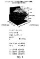
ここで図1を参照すると、非常に正確な分光計、例えばレーザ・テクニック・ベルリン(LTB)製のような例えば格子分光計を利用して測定される時にFWHM及びE95の値が変化する時の、例えばコヒーラント製によって作られたような例えば超低ウエッジエタロンを有し、従来技術の補正ERを利用する帯域幅メーター(波長計)の応答の三次元プロットが示されている。
従来技術のERを使用するエタロン波長計は、E95及びFWHMの両方に対して両方ともピコメートルにおいて大体同じ応答を示すことが分る。図示の相関格子応答は、「Levenburg Marquardt」多変数最小化アルゴリズムのようないくつかの公知の当て嵌め技術のいずれかによって平滑化される場合に、応答関数A*x+B*y+Cを示し、ここで、A=0.64495±0.0166、B=0.20797±0.01105、及びC=0.22983±0.00719であり、従来技術では、FWHMの変化を表すA項といくらかの一定オフセットを表すC項とは、製造時の較正処理中に工場であらゆる所定の波長計に対してERを設定するのに利用される。B項は、完全には無視されないが、平均化されて定数Cに組み込まれる。
Referring now to FIG. 1, when the values of FWHM and E95 change when measured using a very accurate spectrometer, such as a grating spectrometer such as that manufactured by Laser Technique Berlin (LTB). Shown is a three-dimensional plot of the response of a bandwidth meter (wavemeter) having, for example, an ultra-low wedge etalon, such as made by coherent, and utilizing a prior art correction ER.
It can be seen that etalon wavemeters using prior art ER show roughly the same response in picometers both for E95 and FWHM. The illustrated correlation lattice response shows the response function A * x + B * y + C when smoothed by any of several known fitting techniques, such as the “Levenburg Marquardt” multivariable minimization algorithm, where A = 0.644495 ± 0.0166, B = 0.20797 ± 0.01105, and C = 0.22983 ± 0.00719, and in the prior art, the A term representing the change in FWHM and some constant offset The C term that represents is used to set the ER for any given wavemeter at the factory during the calibration process during manufacture. The B term is not completely ignored, but is averaged into the constant C.
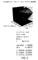
ここで図2を参照すると、例えば光学帯域幅測定装置、例えば干渉計と、例えばフォトダイオードのアレイ(PDA)上に光学的に投影されるエタロンによって作成されたフリンジのFWHMを検出することによって入力レーザ光の帯域幅を検出する例えばエタロン干渉計とを利用する模擬帯域幅メーター(波長計)の三次元プロットが示されている。応答は、帯域幅メーターがE95の変化よりもFWHMの変化に対して相対的により感度が高いことを示している。図2に示す平滑化されたプロットから導出される応答方程式は、A=0.66704±0.00221、及びB=0.8951±0.00079、及びC=0.10172±0.00039をもたらす。 Referring now to FIG. 2, for example, input by detecting the FWHM of a fringe created by an optical bandwidth measurement device, eg, an interferometer, and an etalon that is optically projected onto, for example, an array of photodiodes (PDA). A three-dimensional plot of a simulated bandwidth meter (wavemeter) that utilizes, for example, an etalon interferometer that detects the bandwidth of the laser light is shown. The response shows that the bandwidth meter is relatively more sensitive to changes in FWHM than changes in E95. The response equation derived from the smoothed plot shown in FIG. 2 yields A = 0.667704 ± 0.00221, and B = 0.951 ± 0.00079, and C = 0.10172 ± 0.00039. .
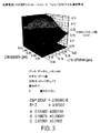
ここで図3を参照すると、例えば光学帯域幅測定装置、例えば干渉計と、例えばフォトダイオードのアレイ(PDA)上に光学的に投影されるエタロンによって作成されたフリンジのFWHMを検出することによって入力レーザ光の帯域幅を検出するエタロン干渉計とを利用する模擬帯域幅メーター(波長計)の三次元プロットが示されている。このシミュレーションは、0.7pm/20ピクセル通過帯域を利用する。応答は、帯域幅メーターがFWHMよりもE95の変化に対して相対的により感度が高いことを示している。図3に示す平滑化されたプロットから導出される応答方程式は、A=0.14483±0.00114、及びB=0.16575±00041、及びC=0.67263±0.0002をもたらす。 Referring now to FIG. 3, for example, input by detecting the FWHM of a fringe created by an optical bandwidth measurement device, eg, an interferometer, and an etalon that is optically projected onto, for example, an array of photodiodes (PDA). A three-dimensional plot of a simulated bandwidth meter (wavemeter) utilizing an etalon interferometer that detects the bandwidth of the laser light is shown. This simulation utilizes a 0.7 pm / 20 pixel passband. The response shows that the bandwidth meter is relatively more sensitive to changes in E95 than FWHM. The response equation derived from the smoothed plot shown in FIG. 3 yields A = 0.14483 ± 0.00114, B = 0.16575 ± 00041, and C = 0.67263 ± 0.0002.
本出願人は、2つの異なる帯域幅メーター、例えばE95の変化に相対的により感度の高いものとFWHMの変化に相対的により感度の高いものであって、帯域幅を測定するのにエタロン光学装置を用いる帯域幅メーターの場合は異なるフィネスを有するものの各々に対して2つのこのような応答プロットを取り、2つの別々の線形方程式:
(第1出力、例えば、エタロン1フリンジ幅値)=(a*(スペクトルの全幅内の最大値のいくらかのパーセントでの全幅の較正入力光既知値、例えば、FWXM))+(b*(全スペクトルのエネルギのいくらかのパーセントを包含するスペクトルのコンテントを定めるスペクトル上の2つのポイント間の幅の較正入力光既知値、例えば、EX)+c、及び
(第2出力、例えば、エタロン2フリンジ幅値)=(a*(スペクトルの全幅内の最大値のいくらかのパーセントでの全幅の較正入力光既知値、例えば、FWXM))+(b*(全スペクトルのエネルギのいくらかのパーセントを包含するスペクトルのコンテントを定めるスペクトル上の2つのポイント間の幅の較正入力光既知値、例えば、EX))+c、
におけるD、E、及びFとして上述した、A、B、及びCの第2の値を使用すると、実帯域幅計算装置は、導出された式:
(第1の実帯域幅パラメータ、例えば、FWXM)=((b*(第2出力、例えば、エタロン2フリンジ幅値))−(e*(第1出力、例えば、エタロン1フリンジ幅値))+ce−bf)/(bd−ae)、又は、方程式:
(第2の実帯域幅パラメータ、例えば、EX)=((a*(第2出力、例えば、エタロン2フリンジ幅値))−(d*(第1出力、例えば、エタロン1フリンジ幅値))+cd−af)/(ae−bd)、
を解くようにプログラムすることができることを発見した。
The Applicant has proposed that the etalon optical device be used to measure the bandwidth of two different bandwidth meters, eg, one that is relatively more sensitive to changes in E95 and one that is relatively more sensitive to changes in FWHM. Take two such response plots for each of the bandwidth meters that use different finesses and take two separate linear equations:
(First output, e.g. etalon 1 fringe width value) = (a * (full width calibration input light known value, e.g. FWXM) at some percentage of the maximum value within the full width of the spectrum)) + (b * (total A calibration input light known value of the width between two points on the spectrum that defines the spectral content encompassing some percentage of the spectral energy, eg EX) + c, and (second
Using the second values of A, B, and C, described above as D, E, and F in the real bandwidth calculator, the derived equation:
(First real bandwidth parameter, eg FWXM) = ((b * (second output, eg
(Second real bandwidth parameter, eg, EX) = ((a * (second output, eg,
Found that it can be programmed to solve.
FWXMがFWHM値であり、EXがE95であり、Xが第1エタロンPDAの出力であり、X’が第2エタロンPDAの出力であるより特殊な場合には、X=a*FWHM+b*E95+c、及びX’=d*FWHM+e*E95+f、及び従って以下のようになる。
FWHM=(b*X’−e*X+ce−bf)/(bd−ae)、及び
E95=(a*X’−d*X+cd−af)/(ae−bd)
If FWXM is the FWHM value, EX is E95, X is the output of the first etalon PDA, and X ′ is the output of the second etalon PDA, then X = a * FWHM + b * E95 + c, And X ′ = d * FWHM + e * E95 + f, and thus:
FWHM = (b * X′−e * X + ce−bf) / (bd−ae), and E95 = (a * X′−d * X + cd−af) / (ae−bd)
従って、帯域幅メーターの各々は、例えば並行して作動させるために製造時に工場で較正して帯域幅メーターにまとめることができ、以下に説明するコントローラは、各帯域幅メーター、例えばa−fに対する所定の較正値を有する2つの出力と、FWXM及びEXのいずれか又は両方を解くために同じレーザ出力の帯域幅を測定する2つの出力とを利用するようにプログラムすることができる。すなわち、最大値のいくらかのパーセントでの全幅、例えば、FWHM又はFW75%M、及び/又はEX、すなわち、全エネルギのいくらかのパーセントが包含されるスペクトルの幅、例えば、E95%(E95)又はE97%又はE93%は、プロセッサに利用可能なメモリにそれぞれの係数を記憶し、それぞれの帯域幅メーター、例えばコントローラに入力を供給するのに並行して2つのそれぞれのエタロンでの光出力を測定する実際のレーザ作動中のエタロンからプロセッサの実際の出力に提供することによって解くことができる。現在の標準FWHM及び/又はE95以外が測定されて工場で較正される場合は、このような他の値(複数の値)は、出力、例えばエタロンフリンジ測定値がa−fの値を得るために上述のようにプロットされることになるものに対するものであることになることが理解されるであろう。 Thus, each of the bandwidth meters can be calibrated at the factory at the time of manufacture, for example to operate in parallel, and combined into a bandwidth meter, and the controller described below can be used for each bandwidth meter, eg, af. It can be programmed to utilize two outputs with a predetermined calibration value and two outputs that measure the bandwidth of the same laser output to solve either or both of FWXM and EX. That is, the full width at some percentage of the maximum value, eg, FWHM or FW 75% M, and / or EX, ie the width of the spectrum that contains some percentage of the total energy, eg, E95% (E95) or E97. % Or E93% stores the respective coefficients in memory available to the processor and measures the light output at the two respective etalons in parallel to provide input to the respective bandwidth meter, eg, controller. It can be solved by providing the actual output of the processor from the etalon during actual laser operation. If other than the current standard FWHM and / or E95 is measured and calibrated at the factory, such other value (s) may be used to obtain an output, eg, etalon fringe measurement value af. It will be understood that this will be relative to what will be plotted as described above.
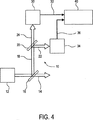
ここで図4を参照すると、本発明の実施形態による帯域幅メーター10の概略ブロック図が示されている。帯域幅メーター10は、レーザ、例えば高パルスパワーエキシマレーザ、例えば193.350nmの公称波長、0.3pm未満の帯域幅、及び±0.02pmの帯域幅精度要件で光を生成する「ArF MOPA」デュアルチャンバレーザによって発生した光ビーム14の帯域幅を測定するように設定することができる。例えば、集積回路のサブミクロン製造、マイクロマシン、又はナノテクノロジーなど(フォトリソグラフィ)でレチクル(マスク作業)を通して例えばフォトレジストを露出するための光源として利用することができるレーザ光ビーム14は、ビーム14のほとんどを通過させ、例えばビーム18の1%よりも少ない小部分を反射するように設定することができる例えばビームスプリッタ16で分割することができ、ビーム18の1%よりも少ない小部分は、それぞれの帯域幅メーター30及び34に各々が入る反射ビーム22及び通過ビーム24にビーム18の本質的に同一の量を反射して通過させるように設定された第2ビームスプリッタ20を通過することができる。帯域幅メーター30及び34は、光学帯域幅測定装置、例えば測定された光の帯域幅を示すフリンジを生成するためのエタロン及び電子回路(図示せず)、例えばエタロン等によって生成されたフリンジ等の測定値を表すことのできるコントローラ40へのアナログ又はデジタル入力を提供するためのPDAを含むことができる。エタロン30は、例えば0.12pmFWHM、ArFレーザ帯域幅測定のための193.36での例えば3pmの自由スペクトル範囲、及び例えば10mm開口にわたる≧25の有効フィネス、及び193.350nm標準入射での≧50%のピーク伝達(フリンジピーク光電信号と入力ピーク信号の比)の公称通過帯域値を有するように選択することができる。エタロン34は、例えば0.7pmFWHM、ArFレーザ帯域幅測定のための193.36での例えば20pmの自由スペクトル範囲、及び例えばa_mm開口にわたる≧29の有効フィネス、及び193.350nm標準入射での≧_%のピーク伝達(フリンジピーク光電信号と入力ピーク信号の比)の公称通過帯域値を有するように選択することができる。
この種の較正は、同じか又は類似の種類の周波数依存の応答問題を受けやすい他の帯域幅測定計器と共に用いることができることが理解されるであろう。
Referring now to FIG. 4, a schematic block diagram of a
It will be appreciated that this type of calibration can be used with other bandwidth measurement instruments that are susceptible to the same or similar types of frequency dependent response problems.
本出願人は、例えば大きく異なる通過帯域の2つのエタロンを使用して、光のビーム、例えば非常に小さな波長及び非常に狭い帯域幅でのレーザからの出力の並行測定から成る光学帯域幅測定装置を作成したことが上記から理解されるであろう。帯域幅測定装置の2つのアームは、測定されるスペクトルのウィング又はスカートのエネルギコンテントに対する異なる感度を示すものである。2つの並行帯域幅測定装置の各々の出力、例えば各それぞれのエタロンによって生成されたフリンジのFWHM値は、測定されているレーザ光の実際のFWHM及びE95%幅の良好な近似を見つけるために反転することができる連立双線形方程式のシステムに対する近似解を提供する。E95軸に沿った例えば図3に示されている平面の勾配は、エタロン楔、すなわちフィネス(すなわち通過帯域)に対して非常に敏感である。同様に、図2のFWHM勾配は、第2エタロンの通過帯域のためにより大きくなる。 The Applicant has proposed an optical bandwidth measuring device comprising a parallel measurement of the output of a beam of light, for example a laser with a very small wavelength and a very narrow bandwidth, using for example two etalons with very different passbands Will be understood from the above. The two arms of the bandwidth measurement device show different sensitivity to the energy content of the measured spectrum wing or skirt. The output of each of the two parallel bandwidth measuring devices, eg the FWHM value of the fringe generated by each respective etalon, is inverted to find a good approximation of the actual FWHM and E95% width of the laser light being measured It provides an approximate solution for a system of simultaneous bilinear equations that can be done. The slope of the plane along, for example, FIG. 3 along the E95 axis is very sensitive to etalon wedges, ie finesse (ie passband). Similarly, the FWHM slope of FIG. 2 is larger due to the passband of the second etalon.
例えば、図1−3に示す測定及びシミュレーションに対して取られたデータは、非常に感度の高いかつ高度に較正された波長計、例えばレーザ・テクニック・ベルリンによって作られるような格子分光計でFWHM及びE95%が測定され、これらのプロットは、例えば、その各々が様々な充填を有する共鳴走査の組に対する本出願の譲受人の製品である「7000A」エキシマレーザ及び/又は「XLA−100」エキシマレーザからの光を測定する各それぞれのエタロンの出力に対して作られたものである。本出願人は、例えば試験製造中の「XLA−100」からスペクトルの多くのサンプルを収集し、フーリエ法を使用して脱畳み込みすることによって近似の実際のレーザスペクトルを取得し、1つのエタロンに対して0.7pmのFWHM、20pmのFSR、及びF=29、及び第2エタロンに対して0.12pmのFWHM、3pmのFSR、及びF=25の公称通過帯域値を選択して理論的なエタロン回路の応答を計算した。エタロン波長計を利用する譲受人の製品に見られるようなライン中心解析モジュール(LAM)もまた模擬され、このエタロン波長メーターは、ピクセルエイリアシングを防ぐために高解像度撮像システム、すなわち他のエタロンと同じ解像度、例えばスペクトル解析モジュール(SAM)での譲受人の製品に見られるようなもの、すなわち、現在のLAMで〜4ではなくFWHMの〜20ピクセルを有するものである。 For example, the data taken for the measurements and simulations shown in FIGS. 1-3 can be obtained with a highly sensitive and highly calibrated wavelength meter, such as a FWHM on a grating spectrometer such as that produced by Laser Technique Berlin. And E95% are measured, and these plots are, for example, “7000A” excimer laser and / or “XLA-100” excimer, which is the product of the assignee of the present application for a set of resonant scans, each having a different filling. Created for the output of each respective etalon that measures the light from the laser. Applicants have collected many samples of spectra from, for example, “XLA-100” under test production and obtained approximate actual laser spectra by deconvolution using Fourier methods to produce a single etalon. For 0.7 FWHM, 20 pm FSR, and F = 29, and for the second etalon, select 0.12 pm FWHM, 3 pm FSR, and F = 25 nominal passband values to theoretically The response of the etalon circuit was calculated. A line-centric analysis module (LAM) such as found in assignee's products that use etalon wavemeters is also simulated, and this etalon wavelength meter is a high resolution imaging system to prevent pixel aliasing, ie the same resolution as other etalons. For example, as found in assignee's products in the Spectrum Analysis Module (SAM), ie, having ˜20 pixels of FWHM instead of ˜4 in the current LAM.
本出願人は、エタロンの出力の挙動を三次元プロットから生じる平面の表面によって妥当に近似することができることを発見した。しかし、波長計毎に、本出願人は、E95軸上のプロットの勾配がエタロン楔(フィネス)に対して感度が高いことも発見した。これによって本出願人は、例えば帯域幅の並行測定を使用する波長計を較正し、事前に計算された較正係数と2つの並行波長計の別々の出力とを用いる帯域幅測定装置を提供するために、大きく異なる通過帯域の2つのエタロン、例えば2つの未知変数であるFWHM又はE95のいずれかを解くべき係数を有するエタロンと共に上述の連立方程式を使用することができると結論付けた。例えば、2つのエタロンからの2つの出力は、実際のFWHM及びE95値に対する事前に計算された係数を使用する線形変換によって結合される。より狭い通過帯域を有するエタロンは、FWHM軸での非常に大きな勾配を示し、より狭い通過帯域を有するエタロンは、図3に示すようにE95軸上で今度は更に感度が高く、方程式内の定数Cに現れる感度のほとんどを有し、この第2エタロンの相対的に広い通過帯域スペクトルを反映するものである。 Applicants have discovered that the output behavior of an etalon can be reasonably approximated by a planar surface resulting from a three-dimensional plot. However, for each wavemeter, Applicants have also discovered that the slope of the plot on the E95 axis is sensitive to etalon wedges (finesse). This allows the applicant to calibrate a wavelength meter using, for example, parallel measurement of bandwidth and to provide a bandwidth measurement device that uses pre-calculated calibration factors and separate outputs of the two parallel wavelength meters. It was concluded that the above simultaneous equations can be used with two etalons in very different passbands, for example etalons with coefficients to solve either of the two unknown variables FWHM or E95. For example, the two outputs from two etalons are combined by a linear transformation using pre-calculated coefficients for the actual FWHM and E95 values. An etalon with a narrower passband shows a very large slope on the FWHM axis, and an etalon with a narrower passband is now more sensitive on the E95 axis as shown in FIG. It has most of the sensitivity that appears in C and reflects the relatively wide passband spectrum of this second etalon.
本発明の開示された実施形態によると、FWHMの移植性を使用する帯域幅検出器の追跡は、かなり改善することができ、E95測定法を実装したハイパワー高パルス繰返し数狭帯域幅エキシマレーザが現在可能である。半値以外の何かでの全幅、すなわちFWXMがより良い測定値であるか否か、及び/又はスペクトル内の95%以外の何かのエネルギ、すなわちEXが例えばフォトリソグラフィのために非常に純粋な光を送出するようなある一定の用途で帯域幅測定のようにより最適であるか否かは、まだ分からないままである。更に、例えば2つのエタロンの通過帯域の差の最適選択が判断されずに残っている。しかし、図9及び図10に関して以下に説明するように、これは、例えば満足できるように機能する本発明の実施形態による並行エタロン帯域幅検出器を可能にする各エタロンの通過帯域に対する通過帯域の最大比として容易に判断することができ、正確に測定される十分なSN比である出力信号を生成する。 According to disclosed embodiments of the present invention, tracking of bandwidth detectors using FWHM portability can be significantly improved, and a high power high pulse repetition rate narrow bandwidth excimer laser implementing the E95 measurement method. Is currently possible. The full width at something other than half-value, ie whether FWXM is a better measurement, and / or some energy other than 95% in the spectrum, ie EX is very pure for eg photolithography Whether it is more optimal, such as bandwidth measurement, in certain applications such as transmitting light remains unknown. Furthermore, for example, the optimal choice of the difference between the passbands of two etalons remains unjudged. However, as described below with respect to FIGS. 9 and 10, this is, for example, a passband for each etalon passband that allows a parallel etalon bandwidth detector according to embodiments of the invention to function satisfactorily. It can be easily determined as the maximum ratio and produces an output signal that is a sufficient signal-to-noise ratio that is accurately measured.
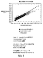
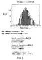
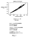
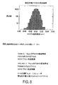
ここで図5を参照すると、本発明の実施形態による模擬波長計の能力を追跡するFWHMの図が示されている。ここで図6を参照すると、模擬波長計のFWHM追跡誤差の図が示されており、0.0により近い平均値付近のより狭い分散及び異常値(仕様読取値から大きく外れた)の排除を示しており、これは、今日のレーザ上で使用する帯域幅検出装置の現在の状態においてFWHMとE95の両方が既に大きい、すなわち誤差範囲が最小である時にFWHMを過大評価するように見える。ここで図7を参照すると、本発明による模擬帯域幅検出装置のE95(%)追跡の図が示されている。ここで図8を参照すると、数十フェムトメートルで測定される本発明による模擬帯域幅検出装置のためのE95%追跡誤差の図が示されている。 Referring now to FIG. 5, a diagram of a FWHM that tracks the capabilities of a simulated wavemeter according to an embodiment of the present invention is shown. Referring now to FIG. 6, a diagram of the FWHM tracking error of the simulated wavemeter is shown, which eliminates narrower dispersion and outliers (which deviated significantly from the specification reading) near the mean value closer to 0.0. This appears to overestimate the FWHM when both the FWHM and E95 are already large, ie, the error range is minimal, in the current state of the bandwidth detector used on today's lasers. Referring now to FIG. 7, there is shown a diagram of E95 (%) tracking of a simulated bandwidth detector according to the present invention. Referring now to FIG. 8, there is shown a diagram of E95% tracking error for a simulated bandwidth detector according to the present invention measured in tens of femtometers.
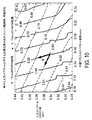
ここで図9を参照すると、入力スペクトルFWHM及びE95の実際の値に比べた様々な入力スペクトルの正規化畳み込みフリンジ幅超過(2つの例えば光学帯域幅メーターの各々の模擬出力)を表す図が示されている。実線は、相対的により狭い通過帯域を有する第1検出器の模擬出力を表し、破線は、相対的により狭い通過帯域を有する第2検出器の模擬出力を表している。図10を参照すると、図9に示す模擬応答の平面化近似が示されている。第1及び第2検出器の応答は、ほぼ直線的に変化し、異なる勾配を有することが図10から見ることができる。本来、本発明の実施形態の目的に対しては、勾配は、ある時点で角度θが非常に大きくなり、そのためにフリンジに対してΔフリンジが非常に小さくなり、信号対ノイズの考慮が出力の精度に作用し始めてこれに干渉することを認識することにより、角度θが可能な限り大きい角度θを形成すべきである。すなわち、例えば、本発明の実施形態に従ってより広い通過帯域測定が更に広い通過帯域で行われる時には、本発明の恩典は、並行した2つの検出器の各々の通過帯域の間の相対差が出力の精度のSN比低下を引き起こす何らかの限界点まで増大する。 Referring now to FIG. 9, there is shown a diagram representing normalized convolution fringe width overruns (simulated outputs of each of two optical bandwidth meters, for example) of various input spectra compared to the actual values of the input spectra FWHM and E95. Has been. The solid line represents the simulated output of the first detector having a relatively narrower passband, and the dashed line represents the simulated output of the second detector having a relatively narrower passband. Referring to FIG. 10, a planarized approximation of the simulated response shown in FIG. 9 is shown. It can be seen from FIG. 10 that the response of the first and second detectors varies approximately linearly and has a different slope. Essentially, for the purposes of the embodiments of the present invention, the gradient is such that the angle θ is very large at some point, so that the Δ fringe is very small relative to the fringe, and signal-to-noise considerations are output. By recognizing that it begins to act on and interferes with accuracy, the angle θ should be formed as large as possible. That is, for example, when a wider passband measurement is made in a wider passband according to an embodiment of the present invention, the benefit of the present invention is that the relative difference between the passbands of each of the two parallel detectors is output. It increases to some limit point that causes a reduction in the SN ratio of accuracy.
正規化フリンジ幅超過は、例えばフリンジのFWHMがエタロン分光計のインパルス応答のFWHMを超える量をデータサンプルにおけるスペクトルの全てに対して得られた最大値で割った量を意味する。すなわち、例えば、以下の通りである。
正規化フリンジ−幅超過=(FWHMフリンジ−FWHM応答関数)/(これらの差の最も大きいもの)
Normalized fringe width excess means, for example, the amount that the fringe FWHM exceeds the FWHM of the impulse response of the etalon spectrometer divided by the maximum value obtained for all of the spectra in the data sample. That is, for example, as follows.
Normalized fringe-over width = (FWHM fringe-FWHM response function) / (the largest of these differences)
この測定基準は、例えば同じスケールでの2つの分光計チャンネル出力の変化を比較することを可能にする。図9及び10は、従って、シミュレーションの実際の出力を表すものである。このシミュレーションでは、6つの異なるレーザ、例えば本出願の譲受人によって販売されている試験的「XLA−100」からのほぼ4,800の実際に測定した格子分光計スペクトルが、格子分光計の測定した応答関数及び「フーリエ変換」法を使用して脱畳み込みされた。各レーザスペクトルの検査領域は、16pm幅であった。これは、レーザから放射されることが予想される光の実際のスペクトルの良質のサンプルを提供するのに十分である。これらのスペクトルは、次に、画素化された検出器、例えばPDAなどの影響を含む2つの模擬エタロン分光計の応答関数で畳み込まれた。模擬エタロン分光計は、0.12pmのFWHM(25のフィネスを有する〜3pmのFSR)及び0.70pmのFWHM(28のフィネスを有する〜20pmのFSR)の応答関数を有していた。データは、可視化の目的のために相関半径4を有する相関法を使用して69x69マトリックスに格子化された。格子化するために選択する方法により、データがその外観に影響を及ぼし、この平面近似(第2プロット)では、線は完全に直線的であるはずであるが、それらはそうではない。これは、使用された格子化方法のアーチファクトである。より真っ直ぐな線を生成するのにより良好に働くように恐らくこれを微調節できるであろう。しかし、それは、平面化された当て嵌めを表しており、本発明の実施形態の概念を明らかにするのに十分である。 This metric makes it possible, for example, to compare changes in the output of two spectrometer channels at the same scale. FIGS. 9 and 10 therefore represent the actual output of the simulation. In this simulation, approximately 4,800 actual measured grating spectrometer spectra from six different lasers, for example the experimental “XLA-100” sold by the assignee of the present application, were measured by the grating spectrometer. Deconvolved using response function and "Fourier transform" method. The inspection area of each laser spectrum was 16 pm wide. This is sufficient to provide a good quality sample of the actual spectrum of light expected to be emitted from the laser. These spectra were then convolved with the response functions of two simulated etalon spectrometers including the effects of a pixelated detector, such as a PDA. The simulated etalon spectrometer had a response function of 0.12 pm FWHM (˜3 pm FSR with 25 finesses) and 0.70 pm FWHM (˜20 pm FSR with 28 finesses). The data was gridded in a 69x69 matrix using a correlation method with a correlation radius of 4 for visualization purposes. Depending on the method you choose to grid, the data affects its appearance, and in this planar approximation (second plot), the lines should be perfectly linear, but they are not. This is an artifact of the gridding method used. This could probably be tweaked to work better to produce a straighter line. However, it represents a planarized fit and is sufficient to clarify the concept of an embodiment of the present invention.
「当て嵌め」という用語は、フリンジ幅データの「パラメータ的モデリング」を数学的に示すものである。様々な実際の入力スペクトルに対する模擬応答でそれぞれのエタロン分光計によって測定された表面の4,800データポイントを取ることは、平面z=ax+by+cでこのデータのモデル化を試みることである。これは、4,800の数を単に3つに低減する。図9から図10に進んで、例えば、平面表面に対する実際のデータ、例えば「χ2/自由度」(DoF)を利用するカイ二乗統計関数とR2との間の一致を測定するメリット関数を選択し、次に、当業技術で公知の基本的に現代標準の非線形最小二乗最適化ルーチンである例えば「Levenberg−Marquardt」法を使用していわゆる「最良適合パラメータ」A、B、及びCを取得するために、多次元でこのメリット関数を最小化する。当業者は、予想されるレーザスペクトル変動と共に働くエタロン応答関数を選択すると共にこの技術を利用することで、何千ものデータポイントを単に3つのパラメータによって説明することができるこの近似を行うことができることを理解するであろう。これは、全ての可能性のあるスペクトル形状に対して働かないであろうが、本出願人は、中心ピークに関して比較的対称であるスペクトルに対してこれが非常によく働くことを観察した。 The term “fitting” mathematically indicates “parametric modeling” of fringe width data. Taking 4,800 data points of the surface measured by each etalon spectrometer with simulated responses to various actual input spectra is an attempt to model this data in the plane z = ax + by + c. This reduces the number of 4,800 to just three. Proceeding from FIG. 9 to FIG. 10, for example, a merit function for measuring the coincidence between R 2 and a chi-square statistical function using actual data for a planar surface, eg, “χ 2 / DOF” (DoF). Select and then use the so-called “best fit parameters” A, B, and C using the “Levenberg-Marquardt” method, which is an essentially modern standard nonlinear least-squares optimization routine known in the art. Minimize this merit function in multiple dimensions to get. Those skilled in the art are able to make this approximation where thousands of data points can be described by just three parameters by selecting an etalon response function that works with expected laser spectral variations and utilizing this technique. Will understand. Although this will not work for all possible spectral shapes, Applicants have observed that it works very well for spectra that are relatively symmetrical about the central peak.
本発明の説明した実施形態による装置及び方法は、全体的に改善された予測及び実際の追跡(例えば、FWHM誤差分散の〜1/2の低減)を提供し、例えば測定された光ビームの実際のE95変化による追跡誤差の異常値の発生を低減する。本発明はまた、共振走査較正と例えば気体濃縮の変動及びフレーム毎のスペクトル変動を有する作動との間の係数の大いに改善された移植性を与える。それはまた、既存の技術、例えば並列のエタロンを利用した非常に合理的に正確な搭載型E95追跡(例えば、±0.015pm)も提供するように見える。 The apparatus and method according to the described embodiments of the present invention provides an overall improved prediction and actual tracking (e.g., ~ 1/2 reduction in FWHM error variance), e.g. The occurrence of an abnormal value of the tracking error due to the E95 change of the. The present invention also provides greatly improved portability of coefficients between resonant scan calibration and operation with, for example, gas enrichment variations and frame-to-frame spectral variations. It also appears to provide very reasonably accurate on-board E95 tracking (eg, ± 0.015 pm) utilizing existing technology, eg, parallel etalon.
当業者は、本発明の開示された実施形態の態様は、この方法及び装置が、1つの帯域幅パラメータ、例えばEXを示す計算された出力を提供するために波長計を較正するように適用することができ、測定されたパラメータが、同じ種類のパラメータ、すなわち、当業技術で公知のようにより正確に検出するのが容易であり及び/又は感光性ダイオードのアレイ(PDA)上で測定されるような観察可能な情報、例えばFWHMでの例えばフリンジ幅から計算するのがより計算的に簡単であるFWHMではないことであることを認めるであろう。更に、本発明の実施形態によると、帯域幅検出器の各々の出力は、例えばFWHMにある場合があり、全帯域幅検出器の出力は、最大値の半分での幅以外の何かであるFWXMにあるであろう。更に、2つの光学帯域幅検出器の出力は、本発明の別の実施形態によるとFWHMではなく、FWXMにある場合がある。 Those skilled in the art will apply aspects of the disclosed embodiments of the present invention such that the method and apparatus calibrates the wavemeter to provide a calculated output indicative of one bandwidth parameter, eg, EX. The measured parameters can be easily detected more accurately and / or measured on an array of photosensitive diodes (PDA) as known in the art, i.e. It will be appreciated that it is not a FWHM that is more computationally simple to calculate from such observable information, for example, the fringe width in FWHM. Furthermore, according to an embodiment of the present invention, the output of each bandwidth detector may be at FWHM, for example, and the output of the entire bandwidth detector is something other than the width at half maximum. Will be in FWXM. Furthermore, the outputs of the two optical bandwidth detectors may be in the FWXM instead of the FWHM according to another embodiment of the invention.
本発明の別の実施形態によると、較正係数は、例えばFWXMとFWX’Mを利用して判断することができ、ここで、X及びX’は、最大値の2つの異なるパーセント、例えばFW75%MとFW25%Mであり、すなわち、同じくいくらかのFWXM(又は、それが帯域幅検出器の使用で実際の入射スペクトルを測定するのに最終的に利用されるエタロンからの応答である場合は更にEX)でのエタロンフリンジ幅測定値と比較して、例えば一方の水平軸上でのLTBのDFW75%Mと他方でのLTBのDFW25%Mとの測定値を用いて例えば図2に示すような三次元プロットを形成し、更に、第1検出器がE95よりもFWHMに対して相対的により感度が高く、第2検出器がFWHMよりもE95に対して相対的により感度が高いという条件で実際の入射スペクトルのFWXM、例えばFWHM、及びEX、例えばE95に関して依然として解くことができる。 According to another embodiment of the invention, the calibration factor can be determined using, for example, FWXM and FWX′M, where X and X ′ are two different percentages of the maximum value, eg, FW75% M and FW 25% M, ie also some FWXM (or if it is the response from the etalon that will ultimately be used to measure the actual incident spectrum with the use of a bandwidth detector) 2) using the measured values of LTB DFW 75% M on one horizontal axis and LTB DFW 25% M on the other, for example, compared to the measured etalon fringe width at EX) Form a three-dimensional plot, and the first detector is relatively more sensitive to FWHM than E95 and the second detector is relatively more sensitive to E95 than FWHM FWXM actual incident spectrum under the conditions referred to, for example FWHM, and EX, for example, can still be solved with respect to E95.
当業者は、本発明の実施形態の一般化として、BW1を1つの帯域幅検出器によって測定される時に検出される帯域幅と考えることができ、BW2を第2の帯域幅検出器によって並行に測定される時に検出される帯域幅と考えられることができることを理解するであろう。また、BW3は、入射ビーム、例えば測定を必要とする遠紫外線(DUV)レーザ又は極紫外線(EUV)レーザのようなエキシマレーザの出力の第1帯域幅パラメータであると考えられ、BW4は、測定を必要とする入射ビームの第2のこのような帯域幅パラメータとすることができる。本発明の実施形態によると、次に、BW3又はBW4のいずれかは、BW1をもたらす測定が主としてBW3に対して敏感であり、BW4には単にいくらか敏感であり、BW1の測定値が主としてBW4に対して敏感であり、BW3には単にいくらか敏感であるという条件で、上述のように出力BW1及びBW2及び事前に計算された係数から計算することができる。 One skilled in the art can consider BW 1 as the bandwidth detected when measured by one bandwidth detector as a generalization of an embodiment of the present invention, and BW 2 by a second bandwidth detector. It will be appreciated that the bandwidth detected when measured in parallel can be considered. Also, BW 3 is considered to be the first bandwidth parameter of the output of an incident beam, eg, an excimer laser such as a deep ultraviolet (DUV) laser or extreme ultraviolet (EUV) laser that requires measurement, and BW 4 is The second such bandwidth parameter of the incident beam that needs to be measured. According to an embodiment of the present invention, then, is either a BW 3 or BW 4, is sensitive to measurement mainly BW 3 resulting in BW 1, is merely somewhat sensitive to BW 4, the BW 1 It can be calculated from the outputs BW 1 and BW 2 and the pre-calculated coefficients as described above, provided that the measured values are primarily sensitive to BW 4 and only somewhat sensitive to BW 3 .
「実」帯域幅は、正確には測定できないことも理解されるであろう。本発明の実施形態による完全な較正定数係数でさえも、小さいが有限である測定中のLTB分光計の誤差を少なくとも有するであろう。本出願人は、このような誤差をフェムトメートルの範囲であると推定する。従って、本明細書及び特許請求の範囲で使用される用語「実帯域幅」は、並行した入力と、2つの平行波長計計器の各々に対して事前に計算された較正係数とから計算された帯域幅を意味する。これは、「実」帯域幅ではないが、特に例えば波長及び帯域幅に対して上述した範囲において、従来技術の帯域幅検出器を使用した時よりもずっと近い値であり、例えば作動E95の変化及び同じ誤差がもたらす影響は、測定された値の「実」帯域幅への変換の必要な信頼度での既存の波長計を利用する能力をより明白に妨げるものである。 It will also be appreciated that “real” bandwidth cannot be measured accurately. Even complete calibration constant coefficients according to embodiments of the present invention will have at least errors in the LTB spectrometer during measurement that are small but finite. Applicants estimate such errors to be in the femtometer range. Thus, the term “real bandwidth” used in the specification and claims was calculated from parallel inputs and pre-calculated calibration factors for each of the two parallel wavelength instruments. It means bandwidth. This is not the “real” bandwidth, but is much closer than when using prior art bandwidth detectors, particularly in the ranges described above for wavelength and bandwidth, for example, changes in operating E95. And the effect of the same error more clearly impedes the ability to utilize existing wavemeters with the required reliability of conversion of measured values to "real" bandwidth.
当業者は、本発明の装置及び方法が、分かり易い代数を使用して実施するように装置を単純にし、かつ入力光源のスペクトル形状又は分光計のインパルス応答関数の詳細な知識を必要としない数学的近似及び較正方法を含むことを認めるであろう。当業者はまた、本発明の説明した実施形態の特徴は、この実施形態が単純な数学的演算を伴う比較的計算が簡単なものであるということであることを認めるであろう。 Those skilled in the art will understand that the apparatus and methods of the present invention simplify the apparatus to be implemented using straightforward algebra and do not require detailed knowledge of the spectral shape of the input light source or the impulse response function of the spectrometer. It will be appreciated that the method includes an approximate approximation and calibration method. Those skilled in the art will also recognize that a feature of the described embodiment of the present invention is that it is relatively easy to compute with simple mathematical operations.
本発明の上述の実施形態は、単に説明及び例示目的のためであることを意図しており、本発明を適用することができる唯一の実施形態ではない。当業者は、本発明の意図及び精神を変えることなく多くの修正及び変更を説明した実施形態に行うことができることを理解するであろう。例えば、較正のための並行帯域幅測定と、実際のFWXM及びEXの測定のために並行して使用される2つの帯域幅検出メーターからの実際の読取り値と共に後で用いられる事前に計算された較正係数の判断のための較正方程式への組み込みとを提供するために、エタロン以外の他の帯域幅検出装置を用いることができる。2つの並行帯域幅検出器に対する広範囲な差動通過帯域値を利用することができ、異なる用途と、波長、帯域幅に対する様々な要件とに対してある一定の範囲がより良いことを明らかにすることができる。更に、本発明は、2つのエタロン分光計と2つの平面モデルを利用する実施形態を用いて説明されたが、例えば、2つの代わりに3つ又は4つのエタロン/分光計、及び/又は平面z=ax+by+cとは異なる恐らくは何らかの他の種類のモデル化、例えばどのような光源のスペクトル変動が予想されるか、どの種類の分光計が使用されるかに応じて、例えば他の比較的単純な表面、例えば放物形表面を利用して本発明を実施することも可能であろう。従って、本発明の範囲は、特許請求の範囲及び正当な均等物のみに照らして考えるべきである。 The above-described embodiments of the present invention are intended to be illustrative and exemplary purposes only, and are not the only embodiments to which the present invention can be applied. Those skilled in the art will appreciate that many modifications and variations can be made to the described embodiments without changing the spirit and spirit of the invention. For example, pre-computed to be used later along with parallel bandwidth measurements for calibration and actual readings from two bandwidth detection meters used in parallel for actual FWXM and EX measurements Other bandwidth detection devices other than etalon can be used to provide for incorporation into the calibration equation for determination of the calibration factor. A wide range of differential passband values for two parallel bandwidth detectors can be used, demonstrating that certain ranges are better for different applications and different requirements for wavelength and bandwidth be able to. Further, although the present invention has been described using an embodiment that utilizes two etalon spectrometers and two planar models, for example, three or four etalon / spectrometers instead of two and / or a planar z Possibly other types of modeling different from ax + by + c, eg depending on what light source spectral variation is expected, what type of spectrometer is used, eg other relatively simple surfaces For example, it would be possible to practice the present invention utilizing a parabolic surface. Accordingly, the scope of the invention should be considered only in light of the following claims and their legal equivalents.
10 帯域幅メーター
16 ビームスプリッタ
20 第2ビームスプリッタ
22 反射ビーム
24 通過ビーム
10
Claims (13)
第1のインパルス応答を有し、前記レーザから光を受け取り、受け取った光のスペクトルの第1フリンジ幅を測定し、測定された第1フリンジ幅を第1出力として提供する第1光学帯域幅検出器と、
前記第1のインパルス応答とは異なる第2のインパルス応答を有し、前記レーザから光を受け取り、受け取った光のスペクトルの第2フリンジ幅を測定し、測定された第2フリンジ幅を第2出力として提供する第2光学帯域幅検出器と、
前記第1出力及び第2出力を変数として含み、かつ、それぞれが第1光学帯域幅検出器又は第2光学帯域幅検出器のいずれかに依存する事前に計算された較正定数を含む多変数線形方程式を解くことによって実帯域幅パラメータを計算する実帯域幅計算装置と、
を含み、
前記実帯域幅パラメータは、1つ又は複数の第1実帯域幅パラメータ及び第2実帯域幅パラメータを含み、
前記第1実帯域幅パラメータは、レーザから放射された光の全スペクトルの最大強度のある割合でのスペクトル全幅であり、
前記第2実帯域幅パラメータは、レーザから放射された光の全スペクトルのエネルギのある割合を包含するスペクトル上の2点間の幅であり、
前記第1光学帯域幅検出器は、第1光学帯域幅検出器による第1実帯域幅パラメータでの帯域幅測定における、帯域幅の変化に対する感度が、第1光学帯域幅検出器による第2実帯域幅パラメータでの帯域幅測定における、帯域幅の変化に対する感度よりも高くなるように設定されており、
前記第2光学帯域幅検出器は、第2光学帯域幅検出器による第2実帯域幅パラメータでの帯域幅測定における、帯域幅の変化に対する感度が、第2光学帯域幅検出器による第1実帯域幅パラメータでの帯域幅測定における、帯域幅の変化に対する感度よりも高くなるように設定されている、
ことを特徴とする帯域幅メーター。A bandwidth meter for measuring the spectral bandwidth of light emitted from a laser and inputted,
First optical bandwidth detection having a first impulse response, receiving light from the laser, measuring a first fringe width of a spectrum of the received light, and providing the measured first fringe width as a first output And
Having a second impulse response different from the first impulse response, receiving light from the laser, measuring a second fringe width of a spectrum of the received light, and outputting the measured second fringe width to a second output A second optical bandwidth detector provided as
Multivariable linear including the first output and the second output as variables and including pre-calculated calibration constants each depending on either the first optical bandwidth detector or the second optical bandwidth detector An actual bandwidth calculator that calculates the actual bandwidth parameters by solving the equations;
Including
The real bandwidth parameters include one or more first real bandwidth parameters and second real bandwidth parameters;
The first real bandwidth parameter is the spectral full width at a percentage of the maximum intensity of the total spectrum of light emitted from the laser;
The second real bandwidth parameter is the width between two points on the spectrum that includes a percentage of the total spectral energy of the light emitted from the laser;
The first optical bandwidth detector is sensitive to a change in bandwidth in bandwidth measurement with a first actual bandwidth parameter by the first optical bandwidth detector. It is set to be higher than the sensitivity to bandwidth change in bandwidth measurement with bandwidth parameter,
The second optical bandwidth detector is sensitive to a change in bandwidth in bandwidth measurement with a second actual bandwidth parameter by the second optical bandwidth detector. It is set to be higher than the sensitivity to the bandwidth change in the bandwidth measurement with the bandwidth parameter.
Bandwidth meter characterized by that.
第1のインパルス応答を有し、前記レーザから光を受け取り、受け取った光のスペクトルの第1フリンジ幅を測定し、測定された第1フリンジ幅を第1出力として提供する第1光学帯域幅検出器と、
前記第1のインパルス応答とは異なる第2のインパルス応答を有し、前記レーザから光を受け取り、受け取った光のスペクトルの第2フリンジ幅を測定し、測定された第2フリンジ幅を第2出力として提供する第2光学帯域幅検出器と、
前記第1出力及び第2出力を変数として含み、かつ、それぞれが第1光学帯域幅検出器又は第2光学帯域幅検出器のいずれかに依存する事前に計算された較正定数を含む多変数線形方程式を解くことによって実帯域幅パラメータを計算する実帯幅域計算装置と、
を含み、
前記実帯域幅パラメータは、1つ又は複数の第1実帯域幅パラメータ及び第2実帯域幅パラメータを含み、
前記第1光学帯域幅検出器は、第1のエタロンであり、前記第1フリンジ幅は、該第1のエタロンの光出力のフリンジの最大強度のある割合での全幅であり、
前記第2光学帯域幅検出器は、第1のエタロンとは通過帯域が異なる第2のエタロンであり、前記第2フリンジ幅は、該第2のエタロンの光出力のフリンジの最大強度のある割合での全幅であり、
前記第1光学帯域幅検出器は、第1光学帯域幅検出器による第1実帯域幅パラメータでの帯域幅測定における、帯域幅の変化に対する感度が、第1光学帯域幅検出器による第2実帯域幅パラメータでの帯域幅測定における、帯域幅の変化に対する感度よりも高くなるように設定されており、
前記第2光学帯域幅検出器は、第2光学帯域幅検出器による第2実帯域幅パラメータでの帯域幅測定における、帯域幅の変化に対する感度が、第2光学帯域幅検出器による第1実帯域幅パラメータでの帯域幅測定における、帯域幅の変化に対する感度よりも高くなるように設定されている、
ことを特徴とする帯域幅メーター。A bandwidth meter for measuring the spectral bandwidth of light emitted from a laser and inputted,
First optical bandwidth detection having a first impulse response, receiving light from the laser, measuring a first fringe width of a spectrum of the received light, and providing the measured first fringe width as a first output And
Having a second impulse response different from the first impulse response, receiving light from the laser, measuring a second fringe width of a spectrum of the received light, and outputting the measured second fringe width to a second output A second optical bandwidth detector provided as
Multivariable linear including the first output and the second output as variables and including pre-calculated calibration constants each depending on either the first optical bandwidth detector or the second optical bandwidth detector A real bandwidth calculator that calculates the real bandwidth parameters by solving the equations;
Including
The real bandwidth parameters include one or more first real bandwidth parameters and second real bandwidth parameters;
The first optical bandwidth detector is a first etalon, and the first fringe width is a full width at a percentage of the maximum intensity of the fringe of the light output of the first etalon;
The second optical bandwidth detector is a second etalon having a pass band different from that of the first etalon, and the second fringe width is a ratio of the maximum intensity of the fringe of the optical output of the second etalon. The full width at
The first optical bandwidth detector is sensitive to a change in bandwidth in bandwidth measurement with a first actual bandwidth parameter by the first optical bandwidth detector. It is set to be higher than the sensitivity to bandwidth change in bandwidth measurement with bandwidth parameter,
The second optical bandwidth detector is sensitive to a change in bandwidth in bandwidth measurement with a second actual bandwidth parameter by the second optical bandwidth detector. It is set to be higher than the sensitivity to the bandwidth change in the bandwidth measurement with the bandwidth parameter.
Bandwidth meter characterized by that.
(第1出力)=(a*(第1実帯域幅パラメータの既知の値)+(b*(第2実帯域幅パラメータの既知の値)+c
という式により表され、前記較正入力光のスペクトルの第2フリンジ幅を測定した第2データは、
(第2出力)=(d*(第1実帯域幅パラメータの既知の値)+(e*(第2実帯域幅パラメータの既知の値)+f
という式により表され、
前記実帯域幅計算装置は、
(第1実帯域幅パラメータ)=((b*(第2出力))−(e*(第1出力))+ce−bf)/(bd−ae)、
又は
(第2実帯域幅パラメータ)=((a*(第2出力))−(d*(第1出力))+cd−af)/(ae−bd)
のいずれかの導出された式を用いて実帯域幅パラメータを計算し、
ここで、前記事前に計算された較正定数はa、b、c、d、e、fを含むものである、請求項3に記載の帯域幅メーター。The first data obtained by measuring the first fringe width of the spectrum of the calibration input light is:
(First output) = (a * (known value of the first actual bandwidth parameter) + (b * (known value of the second actual bandwidth parameter) + c
The second data obtained by measuring the second fringe width of the spectrum of the calibration input light is expressed by the following equation:
(Second output) = (d * (known value of the first actual bandwidth parameter) + (e * (known value of the second actual bandwidth parameter) + f
Represented by the formula
The actual bandwidth calculation device includes:
(First actual bandwidth parameter) = ((b * (second output)) − (e * (first output)) + ce−bf) / (bd−ae),
Or (second actual bandwidth parameter) = ((a * (second output)) − (d * (first output)) + cd−af) / (ae−bd)
Calculate the real bandwidth parameter using any derived formula of
4. The bandwidth meter according to claim 3, wherein the pre-calculated calibration constant includes a, b, c, d, e, and f.
前記レーザから放射されて入力された光のスペクトルの帯域幅を測定するための帯域幅メーターと、
を含み、
前記帯域幅メーターは、
前記レーザからの光を受け取り、受け取った光のスペクトルの第1フリンジ幅を測定し、測定された第1フリンジ幅を第1出力として提供する、第1の伝達関数を有する第1光学帯域幅検出器と、
前記レーザからの光を受け取り、受け取った光のスペクトルの第2フリンジ幅を測定し、測定された第2フリンジ幅を第2出力として提供する、前記第1の伝達関数とは異なる第2の伝達関数を有する第2光学帯域幅検出器と、
前記第1出力及び第2出力を変数として含み、かつ、それぞれが第1光学帯域幅検出器又は第2光学帯域幅検出器のいずれかに依存する事前に計算された較正定数を含む多変数線形方程式を解くことによって実帯域幅パラメータを計算する実帯域幅計算装置と、を含み、
前記実帯域幅パラメータは、1つ又は複数の第1実帯域幅パラメータ及び第2実帯域幅パラメータを含み、
前記第1実帯域幅パラメータは、前記レーザから放射された光のスペクトルの最大強度のある割合でのスペクトル全幅であり、
前記第2実帯域幅パラメータは、前記レーザから放射された光の全スペクトルのエネルギのある割合を包含する該スペクトル上の2点間の幅であり、
前記第1光学帯域幅検出器の伝達関数は、第1実帯域幅パラメータでの帯域幅測定における変化に対する感度が、第2実帯域幅パラメータでの帯域幅測定における、帯域幅の変化に対する感度よりも高くなるように設定されており、
前記第2光学帯域幅検出器の伝達関数は、第2実帯域幅パラメータでの帯域幅測定における変化に対する感度が、第1実帯域幅パラメータでの帯域幅測定における、帯域幅の変化に対する感度よりも高くなるように設定されている、
ことを特徴とするフォトリソグラフィ光源。A laser that outputs light;
A bandwidth meter for measuring the spectral bandwidth of the light emitted from the laser and input;
Including
The bandwidth meter is
A first optical bandwidth detection having a first transfer function that receives light from the laser, measures a first fringe width of a spectrum of the received light, and provides the measured first fringe width as a first output. And
A second transfer different from the first transfer function that receives light from the laser, measures a second fringe width of the spectrum of the received light, and provides the measured second fringe width as a second output; A second optical bandwidth detector having a function;
Multivariable linear including the first output and the second output as variables and including pre-calculated calibration constants each depending on either the first optical bandwidth detector or the second optical bandwidth detector A real bandwidth calculator that calculates real bandwidth parameters by solving an equation;
The real bandwidth parameters include one or more first real bandwidth parameters and second real bandwidth parameters;
The first real bandwidth parameter is a spectral full width at a percentage of the maximum intensity of the spectrum of light emitted from the laser;
The second real bandwidth parameter is the width between two points on the spectrum that includes a percentage of the total spectral energy of the light emitted from the laser;
The transfer function of the first optical bandwidth detector is more sensitive to changes in bandwidth measurement with the first actual bandwidth parameter than to sensitivity to change in bandwidth in bandwidth measurement with the second actual bandwidth parameter. Is set to be high,
The transfer function of the second optical bandwidth detector is more sensitive to changes in bandwidth measurement with the second actual bandwidth parameter than to changes in bandwidth in bandwidth measurement with the first actual bandwidth parameter. Is set to be higher,
A photolithography light source characterized by the above.
前記レーザから放射されて入力された光のスペクトルの帯域幅を測定するための帯域幅メーターと、
を含み、
前記帯域幅メーターは、
前記レーザからの光を受け取り、受け取った光のスペクトルの第1フリンジ幅を測定し、測定された第1フリンジ幅を第1出力として提供する、第1の伝達関数を有する第1光学帯域幅検出器と、
前記レーザからの光を受け取り、受け取った光のスペクトルの第2フリンジ幅を測定し、測定された第2フリンジ幅を第2出力として提供する、前記第1の伝達関数とは異なる第2の伝達関数を有する第2光学帯域幅検出器と、
前記第1出力及び第2出力を変数として含み、かつ、それぞれが第1光学帯域幅検出器又は第2光学帯域幅検出器のいずれかに依存する事前に計算された較正定数を含む多変数線形方程式を解くことによって実帯域幅パラメータを計算する実帯域幅計算装置と、を含み、
前記実帯域幅パラメータは、1つ又は複数の第1実帯域幅パラメータ及び第2実帯域幅パラメータを含み、
前記第1光学帯域幅検出器は、第1のエタロンであり、前記第1出力は、該第1のエタロンの光出力のフリンジの最大強度のある割合での全幅であり、
前記第2光学帯域幅検出器は、第1のエタロンとは通過帯域が異なる第2のエタロンであり、前記第2出力は、該第2のエタロンの光出力のフリンジの最大強度のある割合での全幅であり、
前記第1光学帯域幅検出器の伝達関数は、第1実帯域幅パラメータでの帯域幅測定における変化に対する感度が、第2実帯域幅パラメータでの帯域幅測定における、帯域幅の変化に対する感度よりも高くなるように設定されており、
前記第2光学帯域幅検出器の伝達関数は、第2実帯域幅パラメータでの帯域幅測定における変化に対する感度が、第1実帯域幅パラメータでの帯域幅測定における、帯域幅の変化に対する感度よりも高くなるように設定されている、
ことを特徴とするフォトリソグラフィ光源。A laser that outputs light;
A bandwidth meter for measuring the spectral bandwidth of the light emitted from the laser and input;
Including
The bandwidth meter is
A first optical bandwidth detection having a first transfer function that receives light from the laser, measures a first fringe width of a spectrum of the received light, and provides the measured first fringe width as a first output. And
A second transfer different from the first transfer function that receives light from the laser, measures a second fringe width of the spectrum of the received light, and provides the measured second fringe width as a second output; A second optical bandwidth detector having a function;
Multivariable linear including the first output and the second output as variables and including pre-calculated calibration constants each depending on either the first optical bandwidth detector or the second optical bandwidth detector A real bandwidth calculator that calculates real bandwidth parameters by solving an equation;
The real bandwidth parameters include one or more first real bandwidth parameters and second real bandwidth parameters;
The first optical bandwidth detector is a first etalon, and the first output is a full width at a percentage of the maximum intensity of the fringe of the optical output of the first etalon;
The second optical bandwidth detector is a second etalon having a pass band different from that of the first etalon, and the second output is a ratio of the maximum intensity of the fringe of the optical output of the second etalon. The full width of
The transfer function of the first optical bandwidth detector is more sensitive to changes in bandwidth measurement with the first actual bandwidth parameter than to sensitivity to change in bandwidth in bandwidth measurement with the second actual bandwidth parameter. Is set to be high,
The transfer function of the second optical bandwidth detector is more sensitive to changes in bandwidth measurement with the second actual bandwidth parameter than to changes in bandwidth in bandwidth measurement with the first actual bandwidth parameter. Is set to be higher,
A photolithography light source characterized by the above.
(第1出力)=(a*(第1実帯域幅パラメータの既知の値)+(b*(第2実帯域幅パラメータの既知の値)+c
という式により表され、前記較正入力光のスペクトルの第2フリンジ幅を測定した第2データは、
(第2出力)=(d*(第1実帯域幅パラメータの既知の値)+(e*(第2実帯域幅パラメータの既知の値)+f
という式により表され、
前記実帯域幅計算装置は、
(第1実帯域幅パラメータ)=((b*(第2出力))−(e*(第1出力))+ce−bf)/(bd−ae)、
又は
(第2実帯域幅パラメータ)=((a*(第2出力))−(d*(第1出力))+cd−af)/(ae−bd)
のいずれかの導出された式を用いて実帯域幅パラメータを計算し、
ここで、前記事前に計算された較正定数はa、b、c、d、e、fを含むものである、請求項8に記載のフォトリソグラフィ光源。The first data measuring the first fringe width of the spectrum of the calibration input light is:
(First output) = (a * (known value of the first actual bandwidth parameter) + (b * (known value of the second actual bandwidth parameter) + c
The second data obtained by measuring the second fringe width of the spectrum of the calibration input light is expressed by the following equation:
(Second output) = (d * (known value of the first actual bandwidth parameter) + (e * (known value of the second actual bandwidth parameter) + f
Represented by the formula
The actual bandwidth calculation device includes:
(First actual bandwidth parameter) = ((b * (second output)) − (e * (first output)) + ce−bf) / (bd−ae),
Or (second actual bandwidth parameter) = ((a * (second output)) − (d * (first output)) + cd−af) / (ae−bd)
Calculate the real bandwidth parameter using any derived formula of
9. The photolithography light source according to claim 8, wherein the pre-calculated calibration constant includes a, b, c, d, e, and f.
第1のインパルス応答を有する第1光学帯域幅検出器において、前記レーザからの光を受け取る段階と、
前記第1光学帯域幅検出器において、受け取った光のスペクトルの第1フリンジ幅を測定する段階と、
前記第1光学帯域幅検出器から測定された第1フリンジ幅を第1出力として提供する段階と、
前記第1インパルス応答とは異なる第2インパルス応答を有する第2光学帯域幅検出器において、前記レーザからの光を受け取る段階と、
前記第2光学帯域幅検出器において、受け取った光のスペクトルの第2フリンジ幅を測定する段階と、
前記第2光帯域幅検出器から測定された第2フリンジ幅を第2出力として提供する段階と、
前記第1出力及び第2出力を受け取る段階と、
第1光学帯域幅検出器又は第2光学帯域幅検出器のいずれかに依存する事前に計算された較正定数を受け取る段階と、
前記第1出力及び第2出力を変数として含むと共に、第1光学帯域幅検出器又は第2光学帯域幅検出器にいずれかに特有の事前に計算された較正定数を含んだ、多変数線形方程式を解くことによって実帯域幅パラメータを計算する段階と、
を含み、
ここで、前記実帯域幅パラメータは、1つ又はそれ以上の第1実帯域幅パラメータ及び第2実帯域幅パラメータを含み、
前記第1実帯域幅パラメータは、前記レーザから放射された光のスぺクトルの最大強度のある割合でのスペクトル全幅であり、
前記第2実帯域幅パラメータは、前記レーザから放射された光の全スペクトルのエネルギのある割合を包含する該スペクトル上の2点間の幅であり、
前記第1光学帯域幅検出器の第1インパルス応答は、第1光学帯域幅検出器による第1実帯域幅パラメータでの帯域幅測定における変化に対する感度が、第1光学帯域幅検出器による第2実帯域幅パラメータでの帯域幅測定における、帯域幅の変化に対する感度よりも高くなるように設定されており、
前記第2光学帯域幅検出器の第2インパルス応答は、第2光学帯域幅検出器による第2実帯域幅パラメータでの帯域幅測定における、帯域幅の変化に対する感度が、第2光学帯域幅検出器による第1実帯域幅パラメータでの帯域幅測定における、帯域幅の変化に対する感度よりも高くなるように設定されている、
ことを特徴とする帯域幅測定方法。A bandwidth measurement method for measuring the spectral bandwidth of light emitted from a laser, comprising:
Receiving light from the laser in a first optical bandwidth detector having a first impulse response;
Measuring a first fringe width of a spectrum of received light in the first optical bandwidth detector;
Providing a first fringe width measured from the first optical bandwidth detector as a first output;
Receiving light from the laser in a second optical bandwidth detector having a second impulse response different from the first impulse response;
Measuring a second fringe width of a spectrum of received light in the second optical bandwidth detector;
Providing a second fringe width measured from the second optical bandwidth detector as a second output;
Receiving the first output and the second output;
Receiving a pre-calculated calibration constant depending on either the first optical bandwidth detector or the second optical bandwidth detector;
A multivariable linear equation including the first output and the second output as variables and including pre-calculated calibration constants specific to either the first optical bandwidth detector or the second optical bandwidth detector. Calculating the actual bandwidth parameter by solving
Including
Wherein the actual bandwidth parameters include one or more first actual bandwidth parameters and second actual bandwidth parameters;
The first real bandwidth parameter is the full width of the spectrum at a percentage of the maximum intensity of the spectrum of light emitted from the laser;
The second real bandwidth parameter is the width between two points on the spectrum that includes a percentage of the total spectral energy of the light emitted from the laser;
The first impulse response of the first optical bandwidth detector is sensitive to a change in bandwidth measurement with a first actual bandwidth parameter by the first optical bandwidth detector and is second by the first optical bandwidth detector. It is set to be higher than the sensitivity to the bandwidth change in the bandwidth measurement with the actual bandwidth parameter,
The second impulse response of the second optical bandwidth detector is such that the sensitivity to a change in bandwidth in the bandwidth measurement with the second actual bandwidth parameter by the second optical bandwidth detector is the second optical bandwidth detection. Is set to be higher than the sensitivity to bandwidth change in the bandwidth measurement with the first actual bandwidth parameter by the instrument,
A bandwidth measuring method characterized by the above.
i)前記第1光学帯域幅検出器への光入力のスペクトルの実帯域幅、及び
ii)前記第1光学帯域幅検出器の応答関数
の畳み込みである、請求項1に記載の帯域幅メーター。The spectral output from the first optical bandwidth detector is:
i) the actual bandwidth of the spectrum of the optical input to the first optical bandwidth detector; and
The bandwidth meter of claim 1, wherein ii) is a convolution of a response function of the first optical bandwidth detector.
i)前記第2光学帯域幅検出器への光入力のスペクトルの実帯域幅、及び
ii)前記第2光学帯域幅検出器の応答関数
の畳み込みである、請求項1に記載の帯域幅メーター。The spectral output from the second optical bandwidth detector is:
i) the actual bandwidth of the spectrum of the optical input to the second optical bandwidth detector; and
The bandwidth meter of claim 1, wherein ii) is a convolution of the response function of the second optical bandwidth detector.
Applications Claiming Priority (3)
| Application Number | Priority Date | Filing Date | Title |
|---|---|---|---|
| US10/615,321 | 2003-07-07 | ||
| US10/615,321 US6952267B2 (en) | 2003-07-07 | 2003-07-07 | Method and apparatus for measuring bandwidth of a laser output |
| PCT/US2004/021259 WO2005008295A2 (en) | 2003-07-07 | 2004-06-29 | Optical bandwidth meter for very narrow bandwidth laser emitted light |
Publications (2)
| Publication Number | Publication Date |
|---|---|
| JP2007527522A JP2007527522A (en) | 2007-09-27 |
| JP4994031B2 true JP4994031B2 (en) | 2012-08-08 |
Family
ID=33564534
Family Applications (1)
| Application Number | Title | Priority Date | Filing Date |
|---|---|---|---|
| JP2006518780A Expired - Lifetime JP4994031B2 (en) | 2003-07-07 | 2004-06-29 | Method and apparatus for measuring laser output bandwidth |
Country Status (7)
| Country | Link |
|---|---|
| US (1) | US6952267B2 (en) |
| EP (1) | EP1649244B1 (en) |
| JP (1) | JP4994031B2 (en) |
| KR (1) | KR101084016B1 (en) |
| CN (1) | CN100538258C (en) |
| TW (1) | TWI294961B (en) |
| WO (1) | WO2005008295A2 (en) |
Families Citing this family (29)
| Publication number | Priority date | Publication date | Assignee | Title |
|---|---|---|---|---|
| US7154928B2 (en) * | 2004-06-23 | 2006-12-26 | Cymer Inc. | Laser output beam wavefront splitter for bandwidth spectrum control |
| US7256893B2 (en) * | 2003-06-26 | 2007-08-14 | Cymer, Inc. | Method and apparatus for measuring bandwidth of an optical spectrum output of a very small wavelength very narrow bandwidth high power laser |
| TWI263412B (en) * | 2003-06-26 | 2006-10-01 | Cymer Inc | Improved bandwidth estimation |
| US7889346B2 (en) | 2003-12-31 | 2011-02-15 | University Of South Carolina | Thin-layer porous optical sensors for gases and other fluids |
| TWI240794B (en) * | 2004-03-02 | 2005-10-01 | Ind Tech Res Inst | Wavelength meter |
| US20070201136A1 (en) | 2004-09-13 | 2007-08-30 | University Of South Carolina | Thin Film Interference Filter and Bootstrap Method for Interference Filter Thin Film Deposition Process Control |
| US7317536B2 (en) | 2005-06-27 | 2008-01-08 | Cymer, Inc. | Spectral bandwidth metrology for high repetition rate gas discharge lasers |
| US8345234B2 (en) | 2005-11-28 | 2013-01-01 | Halliburton Energy Services, Inc. | Self calibration methods for optical analysis system |
| US8358418B2 (en) | 2005-11-28 | 2013-01-22 | Halliburton Energy Services, Inc. | Optical analysis system for dynamic real-time detection and measurement |
| US20070166245A1 (en) | 2005-11-28 | 2007-07-19 | Leonard Mackles | Propellant free foamable toothpaste composition |
| EP1969326B1 (en) | 2005-11-28 | 2020-06-10 | Ometric Corporation | Optical analysis system and method for real time multivariate optical computing |
| US7733494B2 (en) * | 2006-03-31 | 2010-06-08 | Cymer, Inc. | Bandwidth measuring device for high pulse repetition rate pulsed laser |
| US7411686B2 (en) * | 2006-06-14 | 2008-08-12 | Cymer, Inc. | Methods and apparatus for aligning an etalon with a photodiode array |
| US9170154B2 (en) | 2006-06-26 | 2015-10-27 | Halliburton Energy Services, Inc. | Data validation and classification in optical analysis systems |
| WO2008057912A2 (en) | 2006-11-02 | 2008-05-15 | University Of South Carolina | Multi-analyte optical computing system |
| US8213006B2 (en) * | 2007-03-30 | 2012-07-03 | Halliburton Energy Services, Inc. | Multi-analyte optical computing system |
| WO2008121692A1 (en) | 2007-03-30 | 2008-10-09 | University Of South Carolina | Tablet analysis and measurement system |
| WO2008121715A1 (en) | 2007-03-30 | 2008-10-09 | Ometric Corporation | In-line process measurement systems and methods |
| US7659529B2 (en) * | 2007-04-13 | 2010-02-09 | Cymer, Inc. | Method and apparatus for vibration reduction in laser system line narrowing unit wavelength selection optical element |
| US8283633B2 (en) | 2007-11-30 | 2012-10-09 | Halliburton Energy Services, Inc. | Tuning D* with modified thermal detectors |
| US8212213B2 (en) | 2008-04-07 | 2012-07-03 | Halliburton Energy Services, Inc. | Chemically-selective detector and methods relating thereto |
| US8520186B2 (en) * | 2009-08-25 | 2013-08-27 | Cymer, Llc | Active spectral control of optical source |
| US8837536B2 (en) | 2010-04-07 | 2014-09-16 | Cymer, Llc | Method and apparatus for controlling light bandwidth |
| US9207119B2 (en) | 2012-04-27 | 2015-12-08 | Cymer, Llc | Active spectral control during spectrum synthesis |
| US9715180B2 (en) | 2013-06-11 | 2017-07-25 | Cymer, Llc | Wafer-based light source parameter control |
| US9778108B2 (en) | 2015-05-22 | 2017-10-03 | Cymer, Llc | Metrology system and method having a plurality of sensors for estimating a spectral feature of a pulsed light beam |
| EP3531091A4 (en) * | 2016-10-06 | 2020-01-15 | Konica Minolta, Inc. | Diagnosis assistance device for optical characteristic measurement device, and diagnosis assistance method for optical characteristic measurement device |
| US10012544B2 (en) | 2016-11-29 | 2018-07-03 | Cymer, Llc | Homogenization of light beam for spectral feature metrology |
| CN111316512B (en) * | 2017-12-05 | 2022-10-21 | 极光先进雷射株式会社 | Excimer laser apparatus and method for manufacturing electronic device |
Family Cites Families (7)
| Publication number | Priority date | Publication date | Assignee | Title |
|---|---|---|---|---|
| JPH07113583B2 (en) * | 1988-07-07 | 1995-12-06 | 気象庁長官 | Wide wavelength simultaneous measurement spectrometer using Fabry-Perot interferometer |
| JP3219879B2 (en) * | 1992-12-21 | 2001-10-15 | 株式会社小松製作所 | Wavelength detector |
| JP3385898B2 (en) * | 1997-03-24 | 2003-03-10 | 安藤電気株式会社 | Tunable semiconductor laser light source |
| DE69706827T2 (en) | 1997-05-02 | 2002-03-28 | Agilent Technologies Inc., A Delaware Corp. | Wavelength measuring device and a device for regulating the wavelength of a light source |
| US6580517B2 (en) * | 2000-03-01 | 2003-06-17 | Lambda Physik Ag | Absolute wavelength calibration of lithography laser using multiple element or tandem see through hollow cathode lamp |
| US6317448B1 (en) * | 1999-09-23 | 2001-11-13 | Cymer, Inc. | Bandwidth estimating technique for narrow band laser |
| US6603549B2 (en) * | 2000-02-25 | 2003-08-05 | Cymer, Inc. | Convolution method for measuring laser bandwidth |
-
2003
- 2003-07-07 US US10/615,321 patent/US6952267B2/en not_active Expired - Lifetime
-
2004
- 2004-06-21 TW TW093117938A patent/TWI294961B/en active
- 2004-06-29 JP JP2006518780A patent/JP4994031B2/en not_active Expired - Lifetime
- 2004-06-29 WO PCT/US2004/021259 patent/WO2005008295A2/en active Application Filing
- 2004-06-29 CN CNB2004800194660A patent/CN100538258C/en not_active Expired - Lifetime
- 2004-06-29 EP EP04777419.5A patent/EP1649244B1/en not_active Expired - Lifetime
- 2004-06-29 KR KR1020067000333A patent/KR101084016B1/en active IP Right Grant
Also Published As
| Publication number | Publication date |
|---|---|
| KR101084016B1 (en) | 2011-11-16 |
| EP1649244A2 (en) | 2006-04-26 |
| WO2005008295A3 (en) | 2005-05-12 |
| WO2005008295A2 (en) | 2005-01-27 |
| US20050007600A1 (en) | 2005-01-13 |
| TW200504340A (en) | 2005-02-01 |
| US6952267B2 (en) | 2005-10-04 |
| EP1649244A4 (en) | 2009-08-26 |
| CN1820178A (en) | 2006-08-16 |
| KR20060052783A (en) | 2006-05-19 |
| TWI294961B (en) | 2008-03-21 |
| EP1649244B1 (en) | 2014-10-22 |
| JP2007527522A (en) | 2007-09-27 |
| CN100538258C (en) | 2009-09-09 |
Similar Documents
| Publication | Publication Date | Title |
|---|---|---|
| JP4994031B2 (en) | Method and apparatus for measuring laser output bandwidth | |
| US7684046B2 (en) | Method and apparatus for bandwidth measurement and bandwidth parameter calculation for laser light | |
| JP2005521893A (en) | Vertical cavity surface emitting laser (VCSEL) as interferometer reference | |
| JP6293762B2 (en) | Position monitoring system with reduced noise | |
| US20200274315A1 (en) | Excimer laser apparatus and electronic-device manufacturing method | |
| US9983060B1 (en) | Calibration of a spectral analysis module | |
| JP4773957B2 (en) | Improved bandwidth estimation method | |
| US7256893B2 (en) | Method and apparatus for measuring bandwidth of an optical spectrum output of a very small wavelength very narrow bandwidth high power laser | |
| US11808629B2 (en) | Sensor degradation evaluation method | |
| US11435234B1 (en) | Increasing the measurement precision of optical instrumentation using Kalman-type filters | |
| Zong | Wavelength calibration method for spectroradiometers with picometer uncertainties | |
| US20240044710A1 (en) | Deterioration evaluation method of line sensor, spectrum measurement device, and computer readable medium | |
| Ershov et al. | Laser spectrum line shape metrology at 193 nm | |
| JP2000266604A (en) | Apparatus and method for evaluating spectrum |
Legal Events
| Date | Code | Title | Description |
|---|---|---|---|
| A621 | Written request for application examination |
Free format text: JAPANESE INTERMEDIATE CODE: A621 Effective date: 20070628 |
|
| A131 | Notification of reasons for refusal |
Free format text: JAPANESE INTERMEDIATE CODE: A131 Effective date: 20100705 |
|
| A601 | Written request for extension of time |
Free format text: JAPANESE INTERMEDIATE CODE: A601 Effective date: 20100917 |
|
| A602 | Written permission of extension of time |
Free format text: JAPANESE INTERMEDIATE CODE: A602 Effective date: 20100928 |
|
| A521 | Request for written amendment filed |
Free format text: JAPANESE INTERMEDIATE CODE: A523 Effective date: 20110104 |
|
| A02 | Decision of refusal |
Free format text: JAPANESE INTERMEDIATE CODE: A02 Effective date: 20110322 |
|
| A521 | Request for written amendment filed |
Free format text: JAPANESE INTERMEDIATE CODE: A523 Effective date: 20110714 |
|
| A521 | Request for written amendment filed |
Free format text: JAPANESE INTERMEDIATE CODE: A523 Effective date: 20110801 |
|
| A521 | Request for written amendment filed |
Free format text: JAPANESE INTERMEDIATE CODE: A523 Effective date: 20110823 |
|
| A911 | Transfer to examiner for re-examination before appeal (zenchi) |
Free format text: JAPANESE INTERMEDIATE CODE: A911 Effective date: 20110826 |
|
| RD13 | Notification of appointment of power of sub attorney |
Free format text: JAPANESE INTERMEDIATE CODE: A7433 Effective date: 20111006 |
|
| A521 | Request for written amendment filed |
Free format text: JAPANESE INTERMEDIATE CODE: A523 Effective date: 20111031 |
|
| A131 | Notification of reasons for refusal |
Free format text: JAPANESE INTERMEDIATE CODE: A131 Effective date: 20120131 |
|
| A521 | Request for written amendment filed |
Free format text: JAPANESE INTERMEDIATE CODE: A523 Effective date: 20120313 |
|
| TRDD | Decision of grant or rejection written | ||
| A01 | Written decision to grant a patent or to grant a registration (utility model) |
Free format text: JAPANESE INTERMEDIATE CODE: A01 Effective date: 20120417 |
|
| A01 | Written decision to grant a patent or to grant a registration (utility model) |
Free format text: JAPANESE INTERMEDIATE CODE: A01 |
|
| A61 | First payment of annual fees (during grant procedure) |
Free format text: JAPANESE INTERMEDIATE CODE: A61 Effective date: 20120508 |
|
| FPAY | Renewal fee payment (event date is renewal date of database) |
Free format text: PAYMENT UNTIL: 20150518 Year of fee payment: 3 |
|
| R150 | Certificate of patent or registration of utility model |
Ref document number: 4994031 Country of ref document: JP Free format text: JAPANESE INTERMEDIATE CODE: R150 Free format text: JAPANESE INTERMEDIATE CODE: R150 |
|
| S111 | Request for change of ownership or part of ownership |
Free format text: JAPANESE INTERMEDIATE CODE: R313111 |
|
| R350 | Written notification of registration of transfer |
Free format text: JAPANESE INTERMEDIATE CODE: R350 |
|
| R250 | Receipt of annual fees |
Free format text: JAPANESE INTERMEDIATE CODE: R250 |
|
| RD02 | Notification of acceptance of power of attorney |
Free format text: JAPANESE INTERMEDIATE CODE: R3D02 |
|
| R250 | Receipt of annual fees |
Free format text: JAPANESE INTERMEDIATE CODE: R250 |
|
| R250 | Receipt of annual fees |
Free format text: JAPANESE INTERMEDIATE CODE: R250 |
|
| R250 | Receipt of annual fees |
Free format text: JAPANESE INTERMEDIATE CODE: R250 |
|
| R250 | Receipt of annual fees |
Free format text: JAPANESE INTERMEDIATE CODE: R250 |
|
| R250 | Receipt of annual fees |
Free format text: JAPANESE INTERMEDIATE CODE: R250 |
|
| R250 | Receipt of annual fees |
Free format text: JAPANESE INTERMEDIATE CODE: R250 |
|
| R250 | Receipt of annual fees |
Free format text: JAPANESE INTERMEDIATE CODE: R250 |
|
| R250 | Receipt of annual fees |
Free format text: JAPANESE INTERMEDIATE CODE: R250 |