JP2018008365A - Cutting device and cutting method - Google Patents
Cutting device and cutting method Download PDFInfo
- Publication number
- JP2018008365A JP2018008365A JP2017007460A JP2017007460A JP2018008365A JP 2018008365 A JP2018008365 A JP 2018008365A JP 2017007460 A JP2017007460 A JP 2017007460A JP 2017007460 A JP2017007460 A JP 2017007460A JP 2018008365 A JP2018008365 A JP 2018008365A
- Authority
- JP
- Japan
- Prior art keywords
- crop
- main
- cutting
- crop mark
- scanning direction
- Prior art date
- Legal status (The legal status is an assumption and is not a legal conclusion. Google has not performed a legal analysis and makes no representation as to the accuracy of the status listed.)
- Pending
Links
Images


Abstract
Description
本発明は、カッティング装置およびカッティング方法に関する。 The present invention relates to a cutting apparatus and a cutting method.
従来から、紙や樹脂シート等からなる媒体を切断するカッティング装置が知られている。また、媒体に印刷を行う機能を備えたカッティング装置が知られている。例えば特許文献1に、このようなカッティング装置が記載されている。このようなカッティング装置では、例えば、媒体に複数の画像を印刷した後、媒体の各画像の周囲をカッターで切断する処理が行われる。各画像に対するカット線の位置は予め定められており、高精度のカッティングを行うためには、カッターがたどる軌跡と予め定められたカット線との間の位置ずれを極力小さくする必要がある。
2. Description of the Related Art Conventionally, a cutting device that cuts a medium made of paper, a resin sheet or the like is known. A cutting device having a function of printing on a medium is also known. For example,
特許文献1には、媒体に画像を印刷するときに、各画像の周囲に複数のクロップマークを印刷することが記載されている。そして、カッティングの際にそれらクロップマークの位置を検出し、クロップマークの位置に基づいてカッティングヘッドの位置決めを行うこととしている。このように、各画像の周囲に印刷したクロップマークを利用することにより、カッティングヘッドの位置決めを高精度に行うことができ、カッティングの精度を高めることができる。 Japanese Patent Application Laid-Open No. 2004-228561 describes that when an image is printed on a medium, a plurality of crop marks are printed around each image. Then, the positions of these crop marks are detected at the time of cutting, and the cutting head is positioned based on the positions of the crop marks. Thus, by using the crop marks printed around each image, the cutting head can be positioned with high accuracy, and the accuracy of cutting can be increased.
ところが、各画像の周囲に複数のクロップマークを印刷し、カッティングの際にそれぞれの画像毎にクロップマークの位置検出を行っていたのでは、カッティングの精度は向上するものの、カッティングに多くの時間を要してしまう。 However, printing multiple crop marks around each image and detecting the position of the crop mark for each image during cutting improves the accuracy of cutting, but takes a lot of time for cutting. I need it.
そこで、図10に示すように、各画像200の四隅の外側にそれぞれクロップマークを印刷する代わりに、全画像200を含む矩形領域201の四隅の外側にクロップマークCを印刷することが考えられる。これにより、クロップマークCの位置検出に要する時間を大幅に短縮することができる。しかし、カッティングヘッドの位置決めに用いられるクロップマークの数が少ないと、媒体によっては、カッティングヘッドのカッティング時の各画像200に対する位置決めの精度が低下し、カッティング位置の誤差が生じることがある。
Therefore, as shown in FIG. 10, it is conceivable to print the crop marks C outside the four corners of the
このような誤差が生じる原因として、以下の事項が考えられる。カッティング装置では、クロップマークCの位置検出に基づいてカッティング位置データのキャリブレーションが行われ、カッティングヘッドの各画像200に対する位置決めは、カッティング位置データのキャリブレーション値に基づいて行われる。しかし、キャリブレーションを行った後、媒体がプラテン上を移動する際に媒体とプラテンとの位置関係にずれが生じ、カッティングヘッドと媒体上の各画像200との間に位置ずれが生じてしまうことがある。プラテン上を移動する媒体の位置ずれが生じる理由としては、プラテンと媒体との間の摩擦、媒体に当接するピンチローラの滑り、温度や湿度による媒体の伸縮などが挙げられる。各画像200の数が増大すると、媒体202の長手方向Xの長さは幅方向Yの長さよりも長くなる傾向があり、特に長手方向Xに関して、このようなカッティング位置の誤差が生じやすい。
The following items can be considered as causes of such errors. In the cutting device, the cutting position data is calibrated based on the position detection of the crop mark C, and the positioning of the cutting head with respect to each
本発明はかかる点に鑑みてなされたものであり、その目的は、カッティング時間の短縮とカッティングの精度の向上とをバランス良く両立させることができるカッティング装置およびカッティング方法を提供することである。 The present invention has been made in view of such a point, and an object thereof is to provide a cutting apparatus and a cutting method capable of achieving both a reduction in cutting time and an improvement in cutting accuracy in a balanced manner.
本発明に係るカッティング装置は、媒体を支持する支持台と、前記支持台に支持された前記媒体に対し印刷を行う印刷ヘッドと、前記支持台に支持された前記媒体を切断するカッティングヘッドと、印刷時に前記印刷ヘッドを前記媒体の幅方向である主走査方向に移動させ、カッティング時に前記カッティングヘッドを前記主走査方向に移動させる第1移動機構と、印刷時に前記支持台に支持された前記媒体を前記印刷ヘッドに対し、前記媒体の長手方向である副走査方向に相対的に移動させ、カッティング時に前記支持台に支持された前記媒体を前記カッティングヘッドに対し前記副走査方向に相対的に移動させる第2移動機構と、前記印刷ヘッド、前記第1移動機構、および前記第2移動機構を制御することにより、前記媒体に複数の画像および複数のクロップマークを印刷する印刷制御装置と、前記カッティングヘッド、前記第1移動機構、および前記第2移動機構を制御することにより、前記媒体を切断するカッティング制御装置と、前記クロップマークの位置を検出するクロップマーク検出装置と、を備える。前記複数の画像には、前記副走査方向の位置が異なる2つ以上の画像が含まれる。前記印刷制御装置は、前記媒体における前記複数の画像の全てを含む矩形領域の四隅のうちの一つの外側に位置する第1主クロップマークと、前記四隅のうちの他の一つの外側に位置し、前記第1主クロップマークから前記主走査方向に離間した第2主クロップマークと、前記四隅のうちの他の一つの外側に位置し、前記第1主クロップマークから前記副走査方向に離間した第3主クロップマークと、前記四隅のうちの他の一つの外側に位置し、前記第2主クロップマークから前記副走査方向に離間すると共に前記第3主クロップマークから前記主走査方向に離間した第4主クロップマークと、を印刷する主クロップマーク印刷部と、前記媒体における前記第1主クロップマークと前記第3主クロップマークとの間、および、前記第2主クロップマークと前記第4主クロップマークとの間に、1つまたは2つ以上の補助クロップマークを印刷する補助クロップマーク印刷部と、を有している。前記カッティング制御装置は、カッティングの際に、前記クロップマーク検出装置により検出される前記第1〜第4主クロップマークおよび前記補助クロップマークのうちの3つ以上の位置に基づいて、前記カッティングヘッドの位置決めを行う位置決め制御部を有している。 A cutting apparatus according to the present invention includes a support base that supports a medium, a print head that performs printing on the medium supported by the support base, a cutting head that cuts the medium supported by the support base, A first moving mechanism that moves the print head in the main scanning direction, which is the width direction of the medium during printing, and moves the cutting head in the main scanning direction during cutting; and the medium supported by the support table during printing Is moved relative to the print head in the sub-scanning direction, which is the longitudinal direction of the medium, and the medium supported by the support table during cutting is moved relative to the cutting head in the sub-scanning direction. A plurality of images on the medium by controlling the second moving mechanism, the print head, the first moving mechanism, and the second moving mechanism. And a printing control device that prints a plurality of crop marks, a cutting control device that cuts the medium by controlling the cutting head, the first moving mechanism, and the second moving mechanism, and a position of the crop mark. And a crop mark detecting device for detecting. The plurality of images include two or more images having different positions in the sub-scanning direction. The print control device is positioned outside a first main crop mark located outside one of four corners of a rectangular area including all of the plurality of images on the medium, and outside the other one of the four corners. The second main crop mark spaced from the first main crop mark in the main scanning direction and the outer side of the other one of the four corners, and separated from the first main crop mark in the sub scanning direction. Located outside the third main crop mark and the other one of the four corners, spaced from the second main crop mark in the sub-scanning direction and spaced from the third main crop mark in the main scanning direction A fourth main crop mark, a main crop mark printing unit for printing, a space between the first main crop mark and the third main crop mark on the medium, and the second main crop mark. Between the fourth main crop marked Pumaku has one or more auxiliary crop mark printing unit for printing an auxiliary crop marks, the. The cutting control device is configured to control the cutting head based on three or more positions of the first to fourth main crop marks and the auxiliary crop marks detected by the crop mark detection device at the time of cutting. It has a positioning control unit that performs positioning.
本発明に係る他のカッティング装置は、複数の画像および複数のクロップマークが印刷された媒体を支持する支持台と、前記支持台に支持された前記媒体を切断するカッティングヘッドと、前記カッティングヘッドを前記媒体の幅方向である主走査方向に移動させる第1移動機構と、前記支持台に支持された前記媒体を前記カッティングヘッドに対し、前記媒体の長手方向である副走査方向に相対的に移動させる第2移動機構と、前記カッティングヘッド、前記第1移動機構、および前記第2移動機構を制御することにより、前記媒体を切断するカッティング制御装置と、前記クロップマークの位置を検出するクロップマーク検出装置と、を備える。前記複数の画像には、前記副走査方向の位置が異なる2つ以上の画像が含まれる。前記複数のクロップマークには、前記媒体における前記複数の画像の全てを含む矩形領域の四隅のうちの一つの外側に位置する第1主クロップマークと、前記四隅のうちの他の一つの外側に位置し、前記第1主クロップマークから前記主走査方向に離間した第2主クロップマークと、前記四隅のうちの他の一つの外側に位置し、前記第1主クロップマークから前記副走査方向に離間した第3主クロップマークと、前記四隅のうちの他の一つの外側に位置し、前記第2主クロップマークから前記副走査方向に離間すると共に前記第3主クロップマークから前記主走査方向に離間した第4主クロップマークと、が含まれる。前記複数のクロップマークには更に、前記媒体における前記第1主クロップマークと前記第3主クロップマークとの間、および、前記第2主クロップマークと前記第4主クロップマークとの間に印刷された1つまたは2つ以上の補助クロップマークが含まれる。前記カッティング制御装置は、カッティングの際に、前記クロップマーク検出装置により検出される前記第1〜第4主クロップマークおよび前記補助クロップマークのうちの3つ以上の位置に基づいて、前記カッティングヘッドの位置決めを行う位置決め制御部を有している。 Another cutting apparatus according to the present invention includes a support base that supports a medium on which a plurality of images and a plurality of crop marks are printed, a cutting head that cuts the medium supported by the support base, and the cutting head. A first moving mechanism that moves in the main scanning direction, which is the width direction of the medium, and the medium supported by the support base is moved relative to the cutting head in the sub-scanning direction, which is the longitudinal direction of the medium. A second moving mechanism that controls the cutting head, the first moving mechanism, and the second moving mechanism to control the cutting control device that cuts the medium, and a crop mark detection that detects the position of the crop mark. An apparatus. The plurality of images include two or more images having different positions in the sub-scanning direction. The plurality of crop marks include a first main crop mark located outside one of the four corners of a rectangular area including all of the plurality of images on the medium and the other one outside the four corners. A second main crop mark that is positioned and spaced apart from the first main crop mark in the main scanning direction, and is positioned outside the other one of the four corners, and from the first main crop mark in the sub-scanning direction. A third main crop mark that is spaced apart and located outside the other one of the four corners, spaced from the second main crop mark in the sub-scanning direction, and from the third main crop mark in the main scanning direction And a fourth main crop mark that is spaced apart. The plurality of crop marks are further printed between the first main crop mark and the third main crop mark on the medium and between the second main crop mark and the fourth main crop mark. One or more auxiliary crop marks are included. The cutting control device is configured to control the cutting head based on three or more positions of the first to fourth main crop marks and the auxiliary crop marks detected by the crop mark detection device at the time of cutting. It has a positioning control unit that performs positioning.
本発明に係るカッティング方法は、媒体に対し、前記媒体の長手方向である副走査方向に並ぶ2つ以上の画像を含む複数の画像を印刷する工程と、前記媒体における前記複数の画像の全てを含む矩形領域の四隅のうちの一つの外側に位置する第1主クロップマークと、前記四隅のうちの他の一つの外側に位置し、前記第1主クロップマークから前記主走査方向に離間した第2主クロップマークと、前記四隅のうちの他の一つの外側に位置し、前記第1主クロップマークから前記副走査方向に離間した第3主クロップマークと、前記四隅のうちの他の一つの外側に位置し、前記第2主クロップマークから前記副走査方向に離間すると共に前記第3主クロップマークから前記主走査方向に離間した第4主クロップマークと、を印刷する工程と、前記媒体における前記第1主クロップマークと前記第3主クロップマークとの間、および、前記第2主クロップマークと前記第4主クロップマークとの間に、1つまたは2つ以上の補助クロップマークを印刷する工程と、クロップマーク検出装置により、前記第1〜第4主クロップマークおよび前記補助クロップマークのうちの3つ以上の位置を検出する工程と、前記クロップマーク検出装置により検出される前記第1〜第4主クロップマークおよび前記補助クロップマークの位置に基づいて、カッティングヘッドの位置決めを行う工程と、位置決めされた前記カッティングヘッドにより、前記複数の画像のそれぞれに対し設定されたカット線に沿って前記媒体を切断する工程と、を含んでいる。 The cutting method according to the present invention includes a step of printing a plurality of images including two or more images arranged in a sub-scanning direction that is a longitudinal direction of the medium, and all of the plurality of images on the medium. A first main crop mark located outside one of the four corners of the included rectangular region, and a first main crop mark located outside the other one of the four corners and spaced apart from the first main crop mark in the main scanning direction. Two main crop marks, a third main crop mark located outside the other one of the four corners and spaced from the first main crop mark in the sub-scanning direction, and another one of the four corners Printing a fourth main crop mark located outside and spaced from the second main crop mark in the sub-scanning direction and spaced from the third main crop mark in the main scanning direction; One or more auxiliary crop marks are provided between the first main crop mark and the third main crop mark and between the second main crop mark and the fourth main crop mark in the medium. A step of printing, a step of detecting three or more positions of the first to fourth main crop marks and the auxiliary crop mark by a crop mark detection device, and the first of which is detected by the crop mark detection device. A step of positioning the cutting head based on the positions of the first to fourth main crop marks and the auxiliary crop mark, and along the cut lines set for each of the plurality of images by the positioned cutting head Cutting the medium.
前記カッティング装置および前記カッティング方法によれば、前記複数の画像の全てを含む矩形領域の四隅の外側に位置する第1〜第4クロップマークに加え、互いに副走査方向に離間する第1クロップマークと第3クロップマークとの間、および、互いに副走査方向に離間する第2クロップマークと第4クロップマークとの間に配置された補助クロップマークを利用して、カッティングヘッドの位置決めを行うことができる。よって、カッティングの際にそれぞれの画像毎にクロップマークの位置検出を行う場合に比べて、カッティング時間を短縮することができる。また、第1〜第4クロップマークのみを用いてカッティングヘッドの位置決めを行う場合に比べて、カッティングの位置精度を向上させることができる。 According to the cutting device and the cutting method, in addition to the first to fourth crop marks located outside the four corners of the rectangular area including all of the plurality of images, the first crop marks spaced apart from each other in the sub-scanning direction The cutting head can be positioned by using the auxiliary crop marks arranged between the third crop marks and between the second crop marks and the fourth crop marks that are separated from each other in the sub-scanning direction. . Therefore, the cutting time can be shortened compared to the case where the position of the crop mark is detected for each image during cutting. Also, the cutting position accuracy can be improved as compared with the case where the cutting head is positioned using only the first to fourth crop marks.
本発明によれば、カッティング時間の短縮とカッティングの精度の向上とをバランス良く両立させることができるカッティング装置およびカッティング方法を提供することができる。 According to the present invention, it is possible to provide a cutting device and a cutting method capable of achieving both a reduction in cutting time and an improvement in cutting accuracy in a balanced manner.
(第1実施形態)
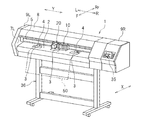
以下、図面を参照しながら、本発明の実施の形態について説明する。図1に示すように、本実施形態に係るカッティング装置1は、媒体50に対して印刷およびカッティングが可能なプリント&カット機である。図示は省略するが、本実施形態に係る媒体50は、台紙と、台紙上に積層されかつ粘着剤が塗布された剥離紙とからなるシール材である。ただし、媒体50は印刷およびカッティングが可能な媒体であれば足り、特に限定されない。媒体50は、記録紙、樹脂製のシート等であってもよい。本明細書において「カッティング」、「切断」とは、媒体50の厚み方向の全体を切断する場合(例えば、シール材の台紙および剥離紙の両方を切断する場合)と、媒体50の厚み方向の一部を切断する場合(例えば、シール材の台紙は切断せず、剥離紙のみを切断する場合)とが含まれる。
(First embodiment)
Hereinafter, embodiments of the present invention will be described with reference to the drawings. As shown in FIG. 1, the
カッティング装置1は、媒体50を支持するプラテン2と、プラテン2に支持された媒体50に対し印刷を行う印刷ヘッド10と、プラテン2に支持された媒体50を切断するカッティングヘッド20とを備えている。詳細は後述するが、印刷ヘッド10およびカッティングヘッド20は、図示Y方向に移動可能に構成されている。以下では、Y方向を主走査方向または左右方向といい、Y方向に対して垂直な方向であるX方向を副走査方向または前後方向という。なお、主走査方向は媒体50の幅方向に対応し、副走査方向は媒体50の長手方向に対応する。図1の符号F、Rr、L、Rは、それぞれ前、後、左、右を表している。
The
本実施形態では、印刷ヘッド10は、インクを吐出するインクジェットヘッドによって構成されている。しかし、印刷ヘッド10の印刷方式はインクジェット方式に限らず、印刷ヘッド10はインクジェットヘッドに限定されない。印刷ヘッド10は、例えばドットインパクト方式の印刷を行うプリントヘッド等であってもよい。
In the present embodiment, the
プラテン2には、グリッドローラ3が設けられている。グリッドローラ3は、フィードモータ61(図1では図示せず。図3参照)に駆動されることによって回転する。プラテン2の上方には、ガイドレール5が設けられている。ガイドレール5は左右方向に延びている。ガイドレール5の下部には、ピンチローラ4が設けられている。ピンチローラ4は、グリッドローラ3の上方に配置されている。ピンチローラ4は、グリッドローラ3に対し接近および離反が可能なように、上下に揺動自在に構成されている。媒体50がピンチローラ4とグリッドローラ3との間に挟み込まれた状態でグリッドローラ3が回転すると、媒体50は前方または後方に搬送される。なお、図1では、3つのグリッドローラ3および2つのピンチローラ4しか図示されていないが、実際にはより多くのグリッドローラ3およびピンチローラ4がそれぞれ主走査方向に配列されている。グリッドローラ3およびフィードモータ61は、媒体50を印刷ヘッド10およびカッティングヘッド20に対し副走査方向に相対的に移動させる第2移動機構を構成している。
A
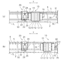
図2(a)に示すように、印刷ヘッド10はキャリッジ11を介してガイドレール5に支持されている。カッティングヘッド20は、キャリッジ21を介してガイドレール5に支持されている。キャリッジ11およびキャリッジ21は、ガイドレール5に対し、左右方向に移動自在に係合している。
As shown in FIG. 2A, the
図2(a)に示すように、キャリッジ21には、ソレノイド22を介してカッター23が取り付けられている。ソレノイド22は、コントローラ60(図3参照)によって制御される。ソレノイド22がON/OFFされると、カッター23は上下方向に移動して媒体50に接触し、あるいは媒体50から離反する。カッティングヘッド20には、後述するクロップマークを検出するセンサ25が設けられている。センサ25の種類は特に限定されず、光学式センサ等の従来から用いられている各種のセンサを好適に利用することができる。キャリッジ21の右側には、磁石によって構成される連結部材24が固定されている。
As shown in FIG. 2A, a
キャリッジ21の背面上部には、左右方向に延びるベルト6が固定されている。ベルト6は、スキャンモータ62(図3参照)に接続されている。スキャンモータ62が回転すると、ベルト6が左右方向に走行する。これにより、キャリッジ21は左右方向に移動する。なお、スキャンモータ62はコントローラ60によって制御される。キャリッジ21、ガイドレール5、およびスキャンモータ62は、印刷ヘッド10およびカッティングヘッド20を主走査方向に移動させる第1移動機構を構成している。
A belt 6 extending in the left-right direction is fixed to the upper back of the
印刷ヘッド10のキャリッジ11には、インクを吐出する複数のノズル(図示せず)を有する記録ヘッド12が支持されている。ここでは、5つの記録ヘッド12がキャリッジ11に支持されている。5つの記録ヘッド12は、互いに異なる5つの色、例えば、イエロインク、マゼンタインク、シアンインク、ブラックインク、ホワイトインクを吐出する。ただし、記録ヘッド12の個数は5個に限定されない。また、記録ヘッド12が吐出するインクの色も何ら限定されない。
The
キャリッジ11の左側部分には、磁石によって構成される連結部材14が設けられている。この連結部材14は、カッティングヘッド20の連結部材24に対し、着脱自在に連結する。本実施形態では、連結部材14,24は、磁力を利用するものである。ただし、連結部材14,24は磁力を利用するものに限られず、係合部材等の他の構成を備えたものであってもよい。キャリッジ11の右側には、L字状に形成された受け金具15が設けられている。
A connecting
プラテン2の左右両端部には、サイドフレーム7L,7Rが配置されている。ガイドレール5は、両サイドフレーム7L,7Rに支持されている。右側のサイドフレーム7Rには、印刷ヘッド10を待機位置にロックするためのロック装置30が設けられている。ロック装置30は、受け金具15に引っ掛けられる受け金具31と、受け金具31をロック位置(図2(b)参照)と非ロック位置(図2(a)参照)との間で移動させるロック用ソレノイド32(図3参照)とを備えている。ロック用ソレノイド32は、コントローラ60によって制御される。
Side frames 7 </ b> L and 7 </ b> R are disposed at the left and right ends of the
図2(a)に示すように、印刷ヘッド10による印刷を行う際には、受け金具31が非ロック位置に設定される。カッティングヘッド20のキャリッジ21が右方に移動し、連結部材24と連結部材14とが接触すると、キャリッジ21とキャリッジ11とが連結される。その結果、印刷ヘッド10は、カッティングヘッド20と共に左右方向に移動可能となる。一方、カッティングヘッド20によるカッティングの際には、図2(b)に示すように、印刷ヘッド10が待機位置に位置付けられ、ロック装置30の受け金具31がロック位置に設定される。これにより、印刷ヘッド10の移動が阻止される。キャリッジ21が左方へ移動すると、連結部材24と連結部材14とが離反し、キャリッジ21とキャリッジ11との連結が解除される。その結果、印刷ヘッド10が待機位置に待機した状態で、カッティングヘッド20が左右方向に移動可能となる。
As shown in FIG. 2 (a), when printing is performed by the
図1に示すように、カッティング装置1は、上側の筐体を構成する上カバー8を備えている。サイドフレーム7Lの左側、サイドフレーム7R(図2(a)参照)の右側には、サイドカバー9L,9Rがそれぞれ設けられている。右側のサイドカバー9Rの前面には、ボタンおよびディスプレイを有する操作パネル35が配置されている。プラテン2の下方には、キャスター付きのスタンド36が設けられている。
As shown in FIG. 1, the
図示は省略するが、カッティング装置1は、印刷前の媒体50が巻かれた供給ローラを備えている。供給ローラはプラテン2の後斜め下方に配置されている。印刷時には、供給ローラに巻かれた媒体50は、プラテン2上を経由して前方に搬送される。
Although not shown, the
コントローラ60は、図示しないCPU、ROM、およびRAMなどからなるマイクロコンピュータによって構成されている。図3に示すように、コントローラ60は、インターフェース63を介して、外部のコンピュータ70に有線または無線による通信が可能に接続されている。コンピュータ70には、印刷およびカッティングのためのデータが保存されている。コントローラ60は、コンピュータ70からデータを受け、フィードモータ61、スキャンモータ62、ロック装置30、カッティングヘッド20、および印刷ヘッド10を制御する。コンピュータ70には、キーボードやマウス等からなる入力装置71と、液晶ディスプレイ等からなる表示装置72とが接続されている。
The
図4は、コントローラ60の機能ブロック図である。すなわち、コントローラ60がコンピュータ70からデータを受信することにより、コントローラ60が果たすようになる機能を表すブロック図である。後述するコントローラ60の各部は、物理的には、1つまたは2つ以上のプロセッサによって構成される。図4に示すように、コントローラ60は、印刷制御部80とカッティング制御部90とを有している。
FIG. 4 is a functional block diagram of the
印刷制御部80は印刷を実行する。印刷制御部80は、スキャンモータ62を駆動することにより印刷ヘッド10を主走査方向に移動させつつ、印刷ヘッド10の各記録ヘッド12からインクを吐出させる。これにより、一走査ラインの印刷が行われる。印刷ヘッド10の主走査方向の移動が済むと、フィードモータ61を駆動することにより、次の走査ラインの位置まで媒体50を副走査方向に搬送する。媒体50の副走査方向の搬送が済むと、再びスキャンモータ62を駆動すると共に印刷ヘッド10を駆動し、次の走査ラインの印刷を行う。以下、印刷の終了まで同様の動作を繰り返す。
The print control unit 80 executes printing. The print controller 80 drives the
カッティング制御部90はカッティングを実行する。カッティング制御部90は、スキャンモータ62を駆動すると共にフィードモータ61を駆動することにより、媒体50に対しカッティングヘッド20を2次元的に相対移動させる。ソレノイド22をONすると、カッター23を媒体50に押し当てることができる。カッター23を媒体50に押し当てたままカッティングヘッド20を媒体50に対し相対移動させることにより、媒体50を任意のカット線に沿って切断することができる。
The cutting control unit 90 performs cutting. The cutting control unit 90 drives the
印刷制御部80は、画像印刷部81と、主クロップマーク印刷部82と、補助クロップマーク印刷部83と、を有している。カッティング制御部90は、位置決め制御部91と、カッティング部92とを有している。位置決め制御部91は、高品質モード設定部91aと、標準モード設定部91bと、高速モード設定部91cとを有している。上記各部が行う動作については後述する。
The print control unit 80 includes an
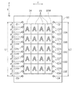
次に、カッティング装置1の動作の例について説明する。ここでは図5に示すように、カッティング装置1が媒体50上に複数の画像33を印刷し、更に、各画像33の周囲を切断する動作について説明する。符号34により示される破線は、カッティングヘッド20によって切断されるカット線を表している。なお、「画像」とは、印刷ヘッド10によって媒体50上に形成される像のことであり、その内容は特に限定されない。画像には、文字、記号、図形、写真等が含まれる。ここでは1枚の媒体50に対し、主走査方向に4個の画像33が印刷され、副走査方向に5個の画像33が印刷されるものとする。以下では、それぞれ主走査方向に並ぶ4個の画像33のことを、媒体50の前方から後方に向かって順に、1行目の画像33A、2行目の画像33B、3行目の画像33C、4行目の画像33D、5行目の画像33Eと呼ぶこととする。
Next, an example of the operation of the
始めに、コンピュータ70からコントローラ60に画像データが送信される。すると、印刷制御部80が画像33を印刷すると共に、主クロップマークC1〜C4および補助クロップマークC11〜C30を印刷する。なお、図5の上方、下方は、それぞれ前方、後方を表している。カッティング装置1では、媒体50を前方に搬送しながら印刷が行われる。そのため、図5の上方から下方に向けて印刷が行われる。
First, image data is transmitted from the
主クロップマークC1〜C4は、全ての画像33(ここでは20個の画像)を含む矩形領域33Wの四隅の外側に印刷されるクロップマークである。ここでは、主クロップマークC1、C2、C3、C4は、それぞれ矩形領域33Wの図5の左斜め上方、右斜め上方、左斜め下方、右斜め下方に印刷されている。主クロップマークC2は、主クロップマークC1から主走査方向に離間している。主クロップマークC3は、主クロップマークC1から副走査方向に離間している。主クロップマークC4は、主クロップマークC2から副走査方向に離間し、主クロップマークC3から主走査方向に離間している。
The main crop marks C1 to C4 are crop marks that are printed outside the four corners of the
補助クロップマークC11〜C20は、主クロップマークC1と主クロップマークC3との間に印刷されるクロップマークである。補助クロップマークC21〜C30は、主クロップマークC2と主クロップマークC4との間に印刷されるクロップマークである。補助クロップマークC11〜C20は矩形領域33Wの図5の左の外側に印刷され、補助クロップマークC21〜C30は矩形領域33Wの図5の右の外側に印刷されている。主クロップマークC1、補助クロップマークC11〜C20、および主クロップマークC3は、副走査方向に一列に並んでいる。主クロップマークC2、補助クロップマークC21〜C30、および主クロップマークC4は、副走査方向に一列に並んでいる。
The auxiliary crop marks C11 to C20 are crop marks printed between the main crop mark C1 and the main crop mark C3. The auxiliary crop marks C21 to C30 are crop marks printed between the main crop mark C2 and the main crop mark C4. The auxiliary crop marks C11 to C20 are printed on the left outside of the
主クロップマークC1〜C4および補助クロップマークC11〜C30は、いずれも黒色の丸によって形成されている。ただし、主クロップマークC1〜C4および補助クロップマークC11〜C30の形状は丸に限定されず、その色は黒色に限定されない。本実施形態では、主クロップマークC1〜C4および補助クロップマークC11〜C30の寸法は同じである。しかし、主クロップマークC1〜C4および補助クロップマークC11〜C30の一部は、他の一部と形状または寸法が異なっていてもよい。 The main crop marks C1 to C4 and the auxiliary crop marks C11 to C30 are all formed by black circles. However, the shapes of the main crop marks C1 to C4 and the auxiliary crop marks C11 to C30 are not limited to circles, and the color is not limited to black. In this embodiment, the dimensions of the main crop marks C1 to C4 and the auxiliary crop marks C11 to C30 are the same. However, some of the main crop marks C1 to C4 and the auxiliary crop marks C11 to C30 may be different in shape or size from other parts.
本実施形態では、主クロップマークC1〜C4および補助クロップマークC11〜C30のうち、副走査方向に隣り合う2つのクロップマークの中心同士の距離は、一定値Pに設定されている。ここでは、P=100mmに設定されている。例えば、主クロップマークC1と補助クロップマークC11との中心同士の距離は100mmであり、補助クロップマークC11と補助クロップマークC12との中心同士の距離は100mmである。なお、副走査方向に隣り合う2つのクロップマークの中心同士の距離は、クロップマークの副走査方向のピッチと言い換えることができる。 In the present embodiment, the distance between the centers of two crop marks adjacent in the sub-scanning direction among the main crop marks C1 to C4 and the auxiliary crop marks C11 to C30 is set to a constant value P. Here, P is set to 100 mm. For example, the distance between the centers of the main crop mark C1 and the auxiliary crop mark C11 is 100 mm, and the distance between the centers of the auxiliary crop mark C11 and the auxiliary crop mark C12 is 100 mm. The distance between the centers of two crop marks adjacent in the sub-scanning direction can be restated as the pitch of the crop marks in the sub-scanning direction.
コントローラ60は、画像33を印刷するときに画像印刷部81として機能し、主クロップマークC1〜C4を印刷するときに主クロップマーク印刷部82として機能し、補助クロップマークC11〜C30を印刷するときに補助クロップマーク印刷部83として機能する。画像33の印刷は画像印刷部81によって行われ、主クロップマークC1〜C4の印刷は主クロップマーク印刷部82によって行われ、補助クロップマークC11〜C30の印刷は補助クロップマーク印刷部83によって行われる。本実施形態では、画像33、主クロップマークC1〜C4、および補助クロップマークC11〜C30は、媒体の前方から後方に向かって順に印刷される。
The
画像33、主クロップマークC1〜C4、および補助クロップマークC11〜C30の印刷が終了した後、カット線34に沿って媒体50を切断する。本実施形態では、印刷後の媒体50を十分に乾燥させるため、印刷が終了した後、媒体50の主クロップマークC3およびC4よりも後方の部分を主走査方向に沿って切断する。そして、媒体50をカッティング装置1から取り出し、カッティング装置1の外部にて乾燥させる。乾燥終了後、媒体50をカッティング装置1のプラテン2上に再配置し、カッティングを開始する。ただし、印刷終了後、カッティング装置1から媒体50を取り出さずにカッティングを開始することも勿論可能である。
After the printing of the
ところで、フィードモータ61の誤差、グリッドローラ3の寸法誤差、媒体50に対するグリッドローラ3の滑り、媒体50をプラテン2上に再配置するときの位置の誤差などにより、カッティング制御部90が把握しているカッティングヘッド20の媒体50に対する相対位置(以下、単に位置という)と、カッティングヘッド20の実際の位置との間にずれが生じる場合がある。そこで、カッティングの際には、カット線34の切断に先立ってカッティングヘッド20の位置決めを行う。
By the way, the cutting control unit 90 grasps the error of the
本実施形態では、カッティングのモードとして、位置決めの精度の異なる複数のモードが用意されている。具体的には、高速モード、標準モード、高品質モードの3種類のモードが用意されている。高速モードは、標準モードよりもカッティングヘッド20の位置決め精度は低いが、標準モードよりもカッティング位置の補正の頻度が少なく、高速なカッティングが可能なモードである。高品質モードは、標準モードよりも低速であるが、標準モードよりもカッティング位置の補正の頻度が多く、カッティングヘッド20の位置決め精度が高いモードである。ユーザは、操作パネル35またはコンピュータ70の入力装置71を操作することにより、モードを自由に選択することができる。ユーザの操作を受け、高品質モード設定部91aにより高品質モードが設定され、または、標準モード設定部91bにより標準モードが設定され、または、高速モード設定部91cにより高速モードが設定される。例えば媒体50がグリッドローラ3に対して滑りやすい媒体の場合には、高品質モードを選択することにより、より精度の高いカッティングを行うことができる。例えば媒体50がグリッドローラ3に対して滑りにくい媒体の場合には、高速モードを選択することにより、より短時間でカッティングを終了させることができる。媒体50がグリッドローラ3に対して滑りやすい媒体の場合には、高品質モードを選択することにより、カッティングの精度を高めることができる。
In this embodiment, a plurality of modes with different positioning accuracy are prepared as cutting modes. Specifically, three types of modes are prepared: a high speed mode, a standard mode, and a high quality mode. The high-speed mode is a mode in which the positioning accuracy of the cutting
カッティングヘッド20の位置決めは、主クロップマークC1〜C4および補助クロップマークC11〜C20のうちの3つ以上を利用して行われる。高速モードは、利用するクロップマークの数が標準モードよりも少ないモードである。高品質モードは、利用するクロップマークの数が標準モードよりも多いモードである。なお、本実施形態および後述する他の実施形態においては、いずれのモードも、利用する3つ以上のクロップマークで定義される正方形または長方形状の領域内に完全に入る画像33をカットの対象とする。しかし、カットの対象とする画像33の選択については、これに限定されない。例えば、利用する3つ以上のクロップマークで定義される正方形または長方形状の領域内に、所定の割合以上(例えば60%以上)含まれる画像33をカットの対象としてもよい。
The cutting
本実施形態では、標準モードでは、中心同士の副走査方向の距離が500mmとなるクロップマークを利用する。標準モードにおいて利用されるクロップマークの中心同士の副走査方向の距離をn2×Pとした場合(ただし、n2は自然数)、本実施形態ではn2=5に設定されている。具体的には、始めに、主クロップマークC1、主クロップマークC2、補助クロップマークC15、および補助クロップマークC25を利用してカッティングヘッド20の位置決めを行い、その後、1行目の画像33Aおよび2行目の画像33Bのカット線34を切断する。次に、補助クロップマークC14、補助クロップマークC24、補助クロップマークC19、および補助クロップマークC29を利用してカッティングヘッド20の位置決めを行い、その後、3行目の画像33Cおよび4行目の画像33Dのカット線34を切断する。最後に、補助クロップマークC16、補助クロップマークC26、主クロップマークC3、および主クロップマークC4を利用してカッティングヘッド20の位置決めを行い、その後、5行目の画像33Eのカット線34を切断する。
In this embodiment, in the standard mode, a crop mark having a distance of 500 mm between the centers in the sub-scanning direction is used. When the distance in the sub-scanning direction between the centers of the crop marks used in the standard mode is n 2 × P (where n 2 is a natural number), n 2 = 5 is set in this embodiment. Specifically, first, the cutting
高速モードでは、主クロップマークC1〜C4のみを利用する。高速モードにおいて利用されるクロップマークの中心同士の副走査方向の距離をn3×Pとした場合(ただし、n3はn2よりも大きな自然数)、本実施形態ではn3=11に設定されている。具体的には、始めに、主クロップマークC1〜C4を用いてカッティングヘッド20の位置決めを行い、その後、全画像33のカット線34を切断する。
In the high-speed mode, only the main crop marks C1 to C4 are used. When the distance in the sub-scanning direction between the centers of the crop marks used in the high-speed mode is n 3 × P (where n 3 is a natural number larger than n 2 ), in this embodiment, n 3 = 11 is set. ing. Specifically, first, the cutting
高品質モードでは、中心同士の副走査方向の距離が300mmとなるクロップマークを利用する。高品質モードにおいて利用されるクロップマークの中心同士の副走査方向の距離をn1×Pとした場合(ただし、n1はn2よりも小さな自然数)、本実施形態ではn1=3に設定されている。具体的には、始めに、主クロップマークC1、主クロップマークC2、補助クロップマークC13、および補助クロップマークC23を利用してカッティングヘッド20の位置決めを行い、その後、1行目の各画像33Aのカット線34を切断する。次に、補助クロップマークC12、補助クロップマークC22、補助クロップマークC15、および補助クロップマークC25を利用してカッティングヘッド20の位置決めを行い、その後、2行目の各画像33Bのカット線34を切断する。次に、補助クロップマークC14、補助クロップマークC24、補助クロップマークC17、および補助クロップマークC27を利用してカッティングヘッド20の位置決めを行い、その後、3行目の各画像33Cのカット線34を切断する。次に、補助クロップマークC16、補助クロップマークC26、補助クロップマークC19、および補助クロップマークC29を利用してカッティングヘッド20の位置決めを行い、その後、4行目の各画像33Dのカット線34を切断する。最後に、補助クロップマークC18、補助クロップマークC28、主クロップマークC3、および主クロップマークC4を利用してカッティングヘッド20の位置決めを行い、その後、5行目の各画像33Eのカット線34を切断する。
In the high quality mode, a crop mark having a distance of 300 mm between the centers in the sub-scanning direction is used. When the distance in the sub-scanning direction between the centers of the crop marks used in the high quality mode is n 1 × P (where n 1 is a natural number smaller than n 2 ), in this embodiment, n 1 = 3 is set. Has been. Specifically, first, the cutting
なお、センサ25によりクロップマークの位置を検出し、検出された4つのクロップマークを利用してカッティングヘッド20の位置決めを行う方法は周知であるため、ここではその具体的な説明は省略する。
Since a method for detecting the position of the crop mark by the
以上のように、本実施形態に係るカッティング装置1によれば、主クロップマークC1〜C4および補助クロップマークC11〜C30を利用してカッティングヘッド20の位置決めを行うことができる。よって、各画像33の四隅にクロップマークを印刷し、カッティングの際にそれぞれの画像33毎にクロップマークの位置検出を行う場合に比べて、カッティング時間を短縮することができる。また、標準モードおよび高品質モードにおいて、主クロップマークC1〜C4に加え、補助クロップマークC11〜C30を利用してカッティングヘッド20の位置決めを行うことができる。よって、高速モードのように主クロップマークC1〜C4のみを用いてカッティングヘッド20の位置決めを行う場合に比べて、カッティングの精度を向上させることができる。したがって、本実施形態に係るカッティング装置1によれば、カッティング時間の短縮とカッティングの精度の向上とをバランス良く両立させることができる。
As described above, according to the
また、本実施形態に係るカッティング装置1によれば、カッティング時間およびカッティング精度の異なる3つのモード、すなわち高速モード、標準モード、高品質モードを選択することができる。媒体50の特性等に応じて、自由にモードを選択することができる。例えば、カッティングヘッド20の位置がずれやすい媒体50を用いる場合には、高品質モードを選択することにより、高精度の位置決めを行うことができる。カッティングヘッド20の位置がずれにくい媒体50を用いる場合には、高速モードを選択することにより、カッティング時間を短縮することができる。よって、媒体50の特性等に応じて、カッティング時間の短縮とカッティングの精度の向上とをバランス良く両立させることができる。
Moreover, according to the
(第2実施形態)
第2実施形態に係るカッティング装置1は、主クロップマークC1〜C4を利用してカッティングヘッド20の位置ずれ量の程度を予測し、位置ずれ量の程度が大きいと予測される場合に、位置決め精度を自動的に高めるようにしたものである。ここでは、第1実施形態の標準モードを例にして説明する。
(Second Embodiment)
The
本実施形態では、カッティングの際に、最初に、主クロップマークC1〜C4の位置を検出する。始めに主クロップマークC1およびC2の位置を検出し、次にグリッドローラ3を回転させて媒体50を副走査方向に搬送した後、主クロップマークC3およびC4の位置を検出する。そして、上記検出結果に基づいて、主クロップマークC1およびC3の中心同士の距離L1と、主クロップマークC2およびC4の中心同士の距離L2とを演算する。ところで、主クロップマークC1およびC3は、中心同士の副走査方向の距離が予め設定された設定値L0(=1100mm)となる位置に印刷され、主クロップマークC2およびC4も中心同士の副走査方向の距離が設定値L0となる位置に印刷されている。そのため、主クロップマークC1およびC3の中心同士の実際の距離、並びに、主クロップマークC2およびC4の中心同士の実際の距離は、設定値L0である。ところが、例えば媒体50を副走査方向に搬送しているときに、グリッドローラ3が媒体50に対して滑ると、主クロップマークC1〜C4の検出結果に基づいて演算される上記距離L1またはL2が設定値L0からずれることになる。主クロップマークC1〜C4の検出に基づいて演算される上記距離L1およびL2と、設定値L0との間に大きなずれがあった場合、標準モードのままでは、カッティングの際にカッティングヘッド20の位置ずれ量の程度が大きくなることが予測される。このような媒体50を用いる場合には、カッティングヘッド20の位置決め精度を高めることが望ましい。
In the present embodiment, at the time of cutting, first, the positions of the main crop marks C1 to C4 are detected. First, the positions of the main crop marks C1 and C2 are detected. Next, after the
本実施形態に係るカッティング装置1では、図6に示すように、位置決め制御部91は判定部95とモード設定変更部96とを有している。判定部95は、主クロップマークC1の中心と主クロップマークC3の中心との距離L1、または、主クロップマークC2の中心と主クロップマークC4の中心との距離L2と、設定値L0との差の絶対値が閾値ΔL以上か否かを判定するように構成されている。すなわち、判定部95は、|L1−L0|≧ΔL、または、|L2−L0|≧ΔLという条件が成立するか否かを判定する。
In the
モード設定変更部96は、判定部95により上記条件が成立すると判定された場合に、標準モード設定部91bの設定を変更する。nを自然数、mをnよりも小さな自然数としたときに、モード設定変更部96は、中心同士の副走査方向の距離がn×Pとなるクロップマークを利用するという設定を、中心同士の副走査方向の距離が(n−m)×Pとなるクロップマークを利用するという設定に変更する。すなわち、利用するクロップマークの中心同士の副走査方向の距離が小さくなるように、利用するクロップマークを変更する。ここでは、n=5、m=1であり、モード設定変更部96は、中心同士の副走査方向の距離が500mmとなるクロップマークを利用するという設定を、中心同士の副走査方向の距離が400mmとなるクロップマークを利用するという設定に変更する。なお、ここでは、上記距離が変更前から100mm小さくなるように設定変更することとしたが、変更前後の数値の差は特に限定されず、100mmに限られないことは勿論である。
The mode setting
例えば、閾値ΔLが1mmに設定され、検出した主クロップマークC1の中心と主クロップマークC3の中心との距離L1が1098mmであったとする。この場合、|L1−L0|=|1098−1100|mm=2mmであるため、|L1−L0|≧ΔLとなる。したがって、標準モードにおいて、利用するクロップマークの中心同士の副走査方向の距離は、500mmから400mmに変更される。 For example, it is assumed that the threshold ΔL is set to 1 mm and the distance L1 between the detected center of the main crop mark C1 and the center of the main crop mark C3 is 1098 mm. In this case, since | L1-L0 | = | 1098-1100 | mm = 2 mm, | L1-L0 | ≧ ΔL. Therefore, in the standard mode, the distance in the sub-scanning direction between the centers of the crop marks to be used is changed from 500 mm to 400 mm.
その結果、カッティングの際には、始めに主クロップマークC1、主クロップマークC2、補助クロップマークC14、および補助クロップマークC24を利用してカッティングヘッド20の位置決めが行われ、1行目の各画像33Aのカット線34のカッティングが行われる。次に、補助クロップマークC12、補助クロップマークC22、補助クロップマークC16、および補助クロップマークC26を利用してカッティングヘッド20の位置決めが行われ、2行目の各画像33Bのカット線34のカッティングが行われる。次に、補助クロップマークC14、補助クロップマークC24、補助クロップマークC18、および補助クロップマークC28を利用してカッティングヘッド20の位置決めが行われ、3行目の各画像33Cのカット線34のカッティングが行われる。次に、補助クロップマークC16、補助クロップマークC26、補助クロップマークC20、および補助クロップマークC30を利用してカッティングヘッド20の位置決めが行われ、4行目の各画像33Dのカット線34のカッティングが行われる。最後に、補助クロップマークC17、補助クロップマークC27、主クロップマークC3、および主クロップマークC4を利用してカッティングヘッド20の位置決めが行われ、5行目の各画像33Eのカット線34のカットが行われる。
As a result, at the time of cutting, first, the cutting
本実施形態によれば、主クロップマークC1〜C4の検出に基づいてカッティングヘッド20の位置ずれ量の程度を予測することができ、位置ずれ量の程度が大きいと予測される場合に、位置決め精度を自動的に高めることができる。したがって、媒体50が実際にはユーザが思っていた以上に滑りやすいものであった場合でも、適度な精度でカッティングヘッド20の位置決めを行うことができる。本実施形態によれば、媒体50の特性等に応じて、カッティング時間の短縮とカッティングの精度の向上とを自動的にバランス良く両立させることができる。
According to the present embodiment, the degree of positional deviation of the cutting
なお、上記実施形態は、主クロップマークC1〜C4の検出に基づいてカッティングヘッド20の位置ずれ量の程度を予測し、位置ずれ量の程度が大きいと予測される場合に、位置決め精度を自動的に高めるものであるが、逆に、位置ずれ量の程度が小さいと予測される場合に、カッティング時間を自動的に短縮するようにしてもよい。例えば、判定部95は、ΔLminを許容誤差とした場合、|L1−L0|≦ΔLmin、および、|L2−L0|≦ΔLminという条件が成立するか否かを判定するようにしてもよい。モード設定変更部96は、判定部95により上記条件が成立すると判定された場合に、利用するクロップマークの中心同士の副走査方向の距離が大きくなるように、利用するクロップマークを変更してもよい。モード設定変更部96は、例えば、中心同士の副走査方向の距離がn×Pとなるクロップマークを利用するという設定を、中心同士の副走査方向の距離が(n+q)×Pとなるクロップマークを利用するという設定に変更してもよい(ただし、qは自然数)。これにより、媒体50が実際にはユーザが思っていた以上に滑りにくいものであった場合に、適度なカッティング精度を保ちつつ、カッティング時間を短縮することができる。
In the above embodiment, the degree of positional deviation of the cutting
なお、上記実施形態では、カッティングヘッド20の位置ずれ量の程度を予測するに当たり、主クロップマークC1〜C4の検出位置を用いることとしたが、他のクロップマークを用いることも可能である。例えば、補助クロップマークC11、C21、C20、およびC30の検出位置に基づいて、カッティングヘッド20の位置ずれ量の程度を予測するようにしてもよい。
In the embodiment described above, the detection positions of the main crop marks C1 to C4 are used for predicting the degree of positional deviation of the cutting
(第3実施形態)
第1実施形態および第2実施形態では、印刷の際に主クロップマークC1〜C4および補助クロップマークC11〜C30を印刷し、カッティングの際にそれらの一部を利用することとしていた。しかし、印刷の前にモードを選択し、主クロップマークC1〜C4および補助クロップマークC11〜C30のうち必要なものだけを印刷するようにしてもよい。第3実施形態は、必要なクロップマークのみを印刷するようにしたものである。
(Third embodiment)
In the first embodiment and the second embodiment, the main crop marks C1 to C4 and the auxiliary crop marks C11 to C30 are printed at the time of printing, and a part of them is used at the time of cutting. However, the mode may be selected before printing, and only necessary ones of the main crop marks C1 to C4 and the auxiliary crop marks C11 to C30 may be printed. In the third embodiment, only necessary crop marks are printed.
例えば、印刷の前に、標準モードが選択されたとする。この場合、前述したように、カッティングの際に使用されるクロップマークは、主クロップマークC1〜C4、補助クロップマークC14、C15、C16、C19、C24、C25、C26、およびC29である。そこで、図7に示すように、印刷の際に、画像33と共に、主クロップマークC1〜C4、補助クロップマークC14、C15、C16、C19、C24、C25、C26、およびC29を印刷する。
For example, assume that the standard mode is selected before printing. In this case, as described above, the crop marks used for cutting are the main crop marks C1 to C4, the auxiliary crop marks C14, C15, C16, C19, C24, C25, C26, and C29. Therefore, as shown in FIG. 7, the main crop marks C1 to C4 and the auxiliary crop marks C14, C15, C16, C19, C24, C25, C26, and C29 are printed together with the
同様に、印刷の前に高速モードが選択された場合には、印刷の際に、画像33と共に、主クロップマークC1〜C4のみを印刷する。そして、カッティングの際に、主クロップマークC1〜C4を利用してカッティングヘッド20の位置決めを行う。
Similarly, when the high speed mode is selected before printing, only the main crop marks C1 to C4 are printed together with the
印刷の前に高品質モードが選択された場合には、印刷の際に、画像33と共に、主クロップマークC1〜C4、補助クロップマークC12〜C19、およびC22〜C29を印刷する。そして、カッティングの際に、それら主クロップマークC1〜C4、補助クロップマークC12〜C19、およびC22〜C29を利用してカッティングヘッド20の位置決めを行う。
When the high quality mode is selected before printing, the main crop marks C1 to C4, the auxiliary crop marks C12 to C19, and C22 to C29 are printed together with the
本実施形態によれば、印刷の際に必要最小限のクロップマークのみを印刷するので、インク消費量の低減および印刷時間の短縮化を図ることができる According to the present embodiment, since only the minimum crop marks necessary for printing are printed, it is possible to reduce the ink consumption and the printing time.
(第4実施形態)
クロップマークの中心同士の副走査方向の距離、または、4つのクロップマークによって囲まれる画像の数は、ユーザが設定できるようになっていてもよい。
(Fourth embodiment)
The distance between the centers of the crop marks in the sub-scanning direction or the number of images surrounded by the four crop marks may be set by the user.
例えば、図8に示すように、操作パネル35またはコンピュータ70の表示装置72に、クロップマークの中心同士の副走査方向の距離(以下、印刷長ともいう)を設定するための画像101を表示し、ユーザが操作パネル35またはコンピュータ70の入力装置71を操作することにより、印刷長の数値を入力できるようにしてもよい。なお、図8に示す例では、印刷長は600mmに設定されている。
For example, as shown in FIG. 8, an
また、図9に示すように、操作パネル35またはコンピュータ70の表示装置72に、4つのクロップマークによって囲まれる画像33の数を(以下、データ数ともいう)を設定するための画像102を表示し、ユーザが操作パネル35またはコンピュータ70の入力装置71を操作することにより、データ数を入力できるようになっていてもよい。なお、図9に示す例では、データ数は8個に設定されている。
Further, as shown in FIG. 9, an
本実施形態によれば、ユーザの希望に合わせて、カッティング時間の短縮とカッティングの精度の向上とをバランス良く両立させることができる。 According to the present embodiment, according to the user's desire, it is possible to achieve both a reduction in cutting time and an improvement in cutting accuracy in a balanced manner.
(その他の実施形態)
前記実施形態では、カッティング装置1はカッティングヘッド20と共に印刷ヘッド10を備えており、印刷機能を有するカッティング装置であった。しかし、本発明に係るカッティング装置は、印刷ヘッド10を備えていないカッティング装置であってもよい。本発明に係るカッティング装置は、印刷機能を有していないカッティング装置であってもよい。この場合、画像およびクロップマークは、カッティング装置とは別の印刷装置によって印刷される。カッティング装置は、上記印刷装置によって印刷が行われた媒体に対し、カッティングを行う。
(Other embodiments)
In the embodiment, the
前記実施形態では、カッティング装置1は、印刷ヘッド10およびカッティングヘッド20を主走査方向に移動させ、媒体50を副走査方向に搬送するように構成されていた。しかし、カッティング装置1は、印刷ヘッド10およびカッティングヘッド20が媒体50に対して2次元的に相対移動可能に構成されていれば足り、例えば、印刷ヘッド10およびカッティングヘッド20を主走査方向および副走査方向に移動させるように構成されていてもよい。例えば、カッティング装置1は、媒体50を支持するフラットベッドと、印刷ヘッド10およびカッティングヘッド20を主走査方向に移動自在に支持するガイドレールと、印刷ヘッド10およびカッティングヘッド20を主走査方向に駆動するモータ等の駆動装置と、ガイドレールを副走査方向に移動可能に支持するレールと、ガイドレールを副走査方向に駆動するモータ等の駆動装置とを備えていてもよい。
In the embodiment described above, the
1 カッティング装置
2 プラテン(支持台)
3 グリッドローラ
4 ピンチローラ
5 ガイドレール
10 印刷ヘッド
20 カッティングヘッド
25 センサ(クロップマーク検出装置)
33 画像
34 カット線
50 媒体
60 コントローラ
80 印刷制御部(印刷制御装置)
81 画像印刷部
82 主クロップマーク印刷部
83 補助クロップマーク印刷部
90 カッティング制御部(カッティング制御装置)
91 位置決め制御部
C1 主クロップマーク(第1主クロップマーク)
C2 主クロップマーク(第2主クロップマーク)
C3 主クロップマーク(第3主クロップマーク)
C4 主クロップマーク(第4主クロップマーク)
C11〜C30 補助クロップマーク
1 Cutting
3
33
81
91 Positioning control unit C1 Main crop mark (first main crop mark)
C2 main crop mark (second main crop mark)
C3 main crop mark (third main crop mark)
C4 main crop mark (4th main crop mark)
C11-C30 Auxiliary crop mark
Claims (11)
前記支持台に支持された前記媒体に対し印刷を行う印刷ヘッドと、
前記支持台に支持された前記媒体を切断するカッティングヘッドと、
印刷時に前記印刷ヘッドを前記媒体の幅方向である主走査方向に移動させ、カッティング時に前記カッティングヘッドを前記主走査方向に移動させる第1移動機構と、
印刷時に前記支持台に支持された前記媒体を前記印刷ヘッドに対し、前記媒体の長手方向である副走査方向に相対的に移動させ、カッティング時に前記支持台に支持された前記媒体を前記カッティングヘッドに対し前記副走査方向に相対的に移動させる第2移動機構と、
前記印刷ヘッド、前記第1移動機構、および前記第2移動機構を制御することにより、前記媒体に複数の画像および複数のクロップマークを印刷する印刷制御装置と、
前記カッティングヘッド、前記第1移動機構、および前記第2移動機構を制御することにより、前記媒体を切断するカッティング制御装置と、
前記クロップマークの位置を検出するクロップマーク検出装置と、を備え、
前記複数の画像には、前記副走査方向の位置が異なる2つ以上の画像が含まれ、
前記印刷制御装置は、
前記媒体における前記複数の画像の全てを含む矩形領域の四隅のうちの一つの外側に位置する第1主クロップマークと、前記四隅のうちの他の一つの外側に位置し、前記第1主クロップマークから前記主走査方向に離間した第2主クロップマークと、前記四隅のうちの他の一つの外側に位置し、前記第1主クロップマークから前記副走査方向に離間した第3主クロップマークと、前記四隅のうちの他の一つの外側に位置し、前記第2主クロップマークから前記副走査方向に離間すると共に前記第3主クロップマークから前記主走査方向に離間した第4主クロップマークと、を印刷する主クロップマーク印刷部と、
前記媒体における前記第1主クロップマークと前記第3主クロップマークとの間、および、前記第2主クロップマークと前記第4主クロップマークとの間に、1つまたは2つ以上の補助クロップマークを印刷する補助クロップマーク印刷部と、を有し、
前記カッティング制御装置は、カッティングの際に、前記クロップマーク検出装置により検出される前記第1〜第4主クロップマークおよび前記補助クロップマークのうちの3つ以上の位置に基づいて、前記カッティングヘッドの位置決めを行う位置決め制御部を有している、カッティング装置。 A support for supporting the medium;
A print head for printing on the medium supported by the support;
A cutting head for cutting the medium supported by the support base;
A first moving mechanism that moves the print head in a main scanning direction that is the width direction of the medium during printing, and moves the cutting head in the main scanning direction during cutting;
The medium supported by the support table during printing is moved relative to the print head in the sub-scanning direction, which is the longitudinal direction of the medium, and the medium supported by the support table during cutting is moved to the cutting head. A second moving mechanism that moves relative to the sub-scanning direction,
A print control device that prints a plurality of images and a plurality of crop marks on the medium by controlling the print head, the first movement mechanism, and the second movement mechanism;
A cutting control device for cutting the medium by controlling the cutting head, the first moving mechanism, and the second moving mechanism;
A crop mark detection device for detecting the position of the crop mark,
The plurality of images include two or more images having different positions in the sub-scanning direction,
The print control device includes:
A first main crop mark positioned outside one of the four corners of a rectangular area including all of the plurality of images on the medium; and the first main crop mark positioned outside the other one of the four corners. A second main crop mark spaced from the mark in the main scanning direction; and a third main crop mark located outside the other one of the four corners and spaced from the first main crop mark in the sub-scanning direction; A fourth main crop mark located outside the other one of the four corners, spaced from the second main crop mark in the sub-scanning direction and spaced from the third main crop mark in the main scanning direction; A main crop mark printing section for printing,
One or more auxiliary crop marks in the medium between the first main crop mark and the third main crop mark and between the second main crop mark and the fourth main crop mark. An auxiliary crop mark printing section for printing
The cutting control device is configured to control the cutting head based on three or more positions of the first to fourth main crop marks and the auxiliary crop marks detected by the crop mark detection device at the time of cutting. A cutting apparatus having a positioning control unit for performing positioning.
前記支持台に支持された前記媒体を切断するカッティングヘッドと、
前記カッティングヘッドを前記媒体の幅方向である主走査方向に移動させる第1移動機構と、
前記支持台に支持された前記媒体を前記カッティングヘッドに対し、前記媒体の長手方向である副走査方向に相対的に移動させる第2移動機構と、
前記カッティングヘッド、前記第1移動機構、および前記第2移動機構を制御することにより、前記媒体を切断するカッティング制御装置と、
前記クロップマークの位置を検出するクロップマーク検出装置と、を備え、
前記複数の画像には、前記副走査方向の位置が異なる2つ以上の画像が含まれ、
前記複数のクロップマークには、前記媒体における前記複数の画像の全てを含む矩形領域の四隅のうちの一つの外側に位置する第1主クロップマークと、前記四隅のうちの他の一つの外側に位置し、前記第1主クロップマークから前記主走査方向に離間した第2主クロップマークと、前記四隅のうちの他の一つの外側に位置し、前記第1主クロップマークから前記副走査方向に離間した第3主クロップマークと、前記四隅のうちの他の一つの外側に位置し、前記第2主クロップマークから前記副走査方向に離間すると共に前記第3主クロップマークから前記主走査方向に離間した第4主クロップマークと、が含まれ、
前記複数のクロップマークには更に、前記媒体における前記第1主クロップマークと前記第3主クロップマークとの間、および、前記第2主クロップマークと前記第4主クロップマークとの間に印刷された1つまたは2つ以上の補助クロップマークが含まれ、
前記カッティング制御装置は、カッティングの際に、前記クロップマーク検出装置により検出される前記第1〜第4主クロップマークおよび前記補助クロップマークのうちの3つ以上の位置に基づいて、前記カッティングヘッドの位置決めを行う位置決め制御部を有している、カッティング装置。 A support for supporting a medium on which a plurality of images and a plurality of crop marks are printed;
A cutting head for cutting the medium supported by the support base;
A first moving mechanism for moving the cutting head in a main scanning direction which is a width direction of the medium;
A second moving mechanism for moving the medium supported by the support base relative to the cutting head in a sub-scanning direction which is a longitudinal direction of the medium;
A cutting control device for cutting the medium by controlling the cutting head, the first moving mechanism, and the second moving mechanism;
A crop mark detection device for detecting the position of the crop mark,
The plurality of images include two or more images having different positions in the sub-scanning direction,
The plurality of crop marks include a first main crop mark located outside one of the four corners of a rectangular area including all of the plurality of images on the medium and the other one outside the four corners. A second main crop mark that is positioned and spaced apart from the first main crop mark in the main scanning direction, and is positioned outside the other one of the four corners, and from the first main crop mark in the sub-scanning direction. A third main crop mark that is spaced apart and located outside the other one of the four corners, spaced from the second main crop mark in the sub-scanning direction, and from the third main crop mark in the main scanning direction A fourth main crop mark spaced apart,
The plurality of crop marks are further printed between the first main crop mark and the third main crop mark on the medium and between the second main crop mark and the fourth main crop mark. Contains one or more auxiliary crop marks,
The cutting control device is configured to control the cutting head based on three or more positions of the first to fourth main crop marks and the auxiliary crop marks detected by the crop mark detection device at the time of cutting. A cutting apparatus having a positioning control unit for performing positioning.
前記副走査方向に隣り合うクロップマークの中心同士の距離をPとし、nを2以上の自然数としたときに、前記副走査方向に関してn×P毎に前記カッティングヘッドの位置決めを行うように設定されたモード設定部と、
mをnよりも小さな自然数としたときに、前記クロップマーク検出装置により検出される前記第1主クロップマークの中心と前記第3主クロップマークの中心との距離、または、前記第2主クロップマークの中心と前記第4主クロップマークの中心との距離と、予め設定された設定値との差の絶対値が閾値以上か否かを判定する判定部と、
前記判定部により前記差の絶対値が前記閾値以上と判定されると、前記副走査方向に関して(n−m)×P毎に前記カッティングヘッドの位置決めを行うように設定を変更するモード設定変更部と、を有している、請求項3に記載のカッティング装置。 The positioning control unit
When the distance between the centers of the crop marks adjacent in the sub-scanning direction is P and n is a natural number of 2 or more, the cutting head is positioned every n × P in the sub-scanning direction. Mode setting section,
The distance between the center of the first main crop mark and the center of the third main crop mark detected by the crop mark detection device when m is a natural number smaller than n, or the second main crop mark A determination unit that determines whether an absolute value of a difference between a center of the fourth main crop mark and a center of the fourth main crop mark is greater than or equal to a threshold value;
When the determination unit determines that the absolute value of the difference is equal to or greater than the threshold value, the mode setting change unit changes the setting so that the cutting head is positioned every (n−m) × P with respect to the sub-scanning direction. The cutting apparatus according to claim 3, further comprising:
前記副走査方向に隣り合うクロップマークの中心同士の距離をPとし、nを2以上の自然数としたときに、前記副走査方向に関してn×P毎に前記カッティングヘッドの位置決めを行うように設定されたモード設定部と、
mをnよりも小さな自然数としたときに、前記クロップマーク検出装置により検出される互いに副走査方向に離間した2つのクロップマークの中心同士の距離と、予め設定された設定値との差の絶対値が閾値以上か否かを判定する判定部と、
前記判定部により前記差の絶対値が前記閾値以上と判定されると、前記副走査方向に関して(n−m)×P毎に前記カッティングヘッドの位置決めを行うように設定を変更するモード設定変更部と、を有している、請求項3に記載のカッティング装置。 The positioning control unit
When the distance between the centers of the crop marks adjacent in the sub-scanning direction is P and n is a natural number of 2 or more, the cutting head is positioned every n × P in the sub-scanning direction. Mode setting section,
When m is a natural number smaller than n, the absolute difference between the distance between the centers of two crop marks that are separated from each other in the sub-scanning direction, detected by the crop mark detection device, and a preset setting value A determination unit for determining whether the value is equal to or greater than a threshold;
When the determination unit determines that the absolute value of the difference is equal to or greater than the threshold value, the mode setting change unit changes the setting so that the cutting head is positioned every (n−m) × P with respect to the sub-scanning direction. The cutting apparatus according to claim 3, further comprising:
前記副走査方向に隣り合うクロップマークの中心同士の距離をPとし、n1を自然数としたときに、前記副走査方向に関してn1×P毎に前記カッティングヘッドの位置決めを行うように設定された第1モード設定部と、
n2をn1よりも大きな自然数としたときに、前記副走査方向に関してn2×P毎に前記カッティングヘッドの位置決めを行うように設定された第2モード設定部と、を有している、請求項3〜5のいずれか一つに記載のカッティング装置。 The positioning control unit
The distance between the centers of the crop marks adjacent to the sub-scanning direction is P, when the n 1 is a natural number, which is set to perform positioning of the cutting head n 1 × every P with respect to the subscanning direction A first mode setting unit;
a second mode setting unit set to position the cutting head every n 2 × P with respect to the sub-scanning direction when n 2 is a natural number larger than n 1 ; The cutting apparatus as described in any one of Claims 3-5.
n3をn2よりも大きな自然数としたときに、前記副走査方向に関してn3×P毎に前記カッティングヘッドの位置決めを行うように設定された第3設定部を更に有している、請求項6に記載のカッティング装置。 The positioning control unit
3. A third setting unit set to position the cutting head every n 3 × P with respect to the sub-scanning direction when n 3 is a natural number larger than n 2. 6. The cutting device according to 6.
前記補助クロップマークには、前記第1画像の前記主走査方向の一方側に位置する第1補助クロップマークと、前記第1補助クロップマークに対して前記副走査方向の一方側に位置する第2補助クロップマークとが含まれ、
前記位置決め制御部は、前記第1画像のカッティングの際に、少なくとも前記第2補助クロップマークの位置に基づいて前記カッティングヘッドの位置決めを行い、前記第2画像のカッティングの際に、少なくとも前記第1補助クロップマークの位置に基づいて前記カッティングヘッドの位置決めを行うように構成されている、請求項1〜7のいずれか一つに記載のカッティング装置。 The plurality of images include a first image and a second image located on one side in the sub-scanning direction with respect to the first image,
The auxiliary crop mark includes a first auxiliary crop mark positioned on one side of the first image in the main scanning direction and a second auxiliary crop mark positioned on one side of the sub scanning direction with respect to the first auxiliary crop mark. Including auxiliary crop marks,
The positioning control unit positions the cutting head based on at least the position of the second auxiliary crop mark when cutting the first image, and at least the first image when cutting the second image. The cutting apparatus according to claim 1, wherein the cutting head is configured to position the cutting head based on a position of an auxiliary crop mark.
前記補助クロップマーク印刷部は、前記第1〜第4主クロップマークおよび前記補助クロップマークのうち前記副走査方向に隣り合うクロップマークの中心同士の距離が、前記入力装置に入力された距離となるように、前記補助クロップマークを印刷するように構成されている、請求項1に記載のカッティング装置。 An input device for inputting a distance between centers of crop marks adjacent in the sub-scanning direction;
In the auxiliary crop mark printing unit, the distance between the centers of the crop marks adjacent to each other in the sub-scanning direction among the first to fourth main crop marks and the auxiliary crop mark is the distance input to the input device. The cutting apparatus according to claim 1, wherein the cutting apparatus is configured to print the auxiliary crop mark.
前記補助クロップマーク印刷部は、前記副走査方向に隣り合う2つのクロップマークの間に位置する画像の数が、前記入力装置に入力された数となるように、前記補助クロップマークを印刷するように構成されている、請求項1に記載のカッティング装置。 An input device for inputting the number of images positioned between two crop marks adjacent in the sub-scanning direction;
The auxiliary crop mark printing unit prints the auxiliary crop mark so that the number of images positioned between two crop marks adjacent in the sub-scanning direction is the number input to the input device. The cutting device according to claim 1, which is configured as follows.
前記媒体における前記複数の画像の全てを含む矩形領域の四隅のうちの一つの外側に位置する第1主クロップマークと、前記四隅のうちの他の一つの外側に位置し、前記第1主クロップマークから前記主走査方向に離間した第2主クロップマークと、前記四隅のうちの他の一つの外側に位置し、前記第1主クロップマークから前記副走査方向に離間した第3主クロップマークと、前記四隅のうちの他の一つの外側に位置し、前記第2主クロップマークから前記副走査方向に離間すると共に前記第3主クロップマークから前記主走査方向に離間した第4主クロップマークと、を印刷する工程と、
前記媒体における前記第1主クロップマークと前記第3主クロップマークとの間、および、前記第2主クロップマークと前記第4主クロップマークとの間に、1つまたは2つ以上の補助クロップマークを印刷する工程と、
クロップマーク検出装置により、前記第1〜第4主クロップマークおよび前記補助クロップマークのうちの3つ以上の位置を検出する工程と、
前記クロップマーク検出装置により検出される前記第1〜第4主クロップマークおよび前記補助クロップマークの位置に基づいて、カッティングヘッドの位置決めを行う工程と、
位置決めされた前記カッティングヘッドにより、前記複数の画像のそれぞれに対し設定されたカット線に沿って前記媒体を切断する工程と、
を含むカッティング方法。 Printing a plurality of images including two or more images arranged in a sub-scanning direction, which is a longitudinal direction of the medium, on the medium;
A first main crop mark positioned outside one of the four corners of a rectangular area including all of the plurality of images on the medium; and the first main crop mark positioned outside the other one of the four corners. A second main crop mark spaced from the mark in the main scanning direction; and a third main crop mark located outside the other one of the four corners and spaced from the first main crop mark in the sub-scanning direction; A fourth main crop mark located outside the other one of the four corners, spaced from the second main crop mark in the sub-scanning direction and spaced from the third main crop mark in the main scanning direction; Printing,
One or more auxiliary crop marks in the medium between the first main crop mark and the third main crop mark and between the second main crop mark and the fourth main crop mark. Printing process,
A step of detecting three or more positions of the first to fourth main crop marks and the auxiliary crop marks by a crop mark detection device;
Positioning the cutting head based on the positions of the first to fourth main crop marks and the auxiliary crop marks detected by the crop mark detection device;
Cutting the medium along a cut line set for each of the plurality of images by the positioned cutting head;
Including cutting method.
Applications Claiming Priority (2)
| Application Number | Priority Date | Filing Date | Title |
|---|---|---|---|
| JP2016128796 | 2016-06-29 | ||
| JP2016128796 | 2016-06-29 |
Publications (1)
| Publication Number | Publication Date |
|---|---|
| JP2018008365A true JP2018008365A (en) | 2018-01-18 |
Family
ID=60994721
Family Applications (2)
| Application Number | Title | Priority Date | Filing Date |
|---|---|---|---|
| JP2017007460A Pending JP2018008365A (en) | 2016-06-29 | 2017-01-19 | Cutting device and cutting method |
| JP2017007461A Withdrawn JP2018008366A (en) | 2016-06-29 | 2017-01-19 | Cutting device and cutting method |
Family Applications After (1)
| Application Number | Title | Priority Date | Filing Date |
|---|---|---|---|
| JP2017007461A Withdrawn JP2018008366A (en) | 2016-06-29 | 2017-01-19 | Cutting device and cutting method |
Country Status (1)
| Country | Link |
|---|---|
| JP (2) | JP2018008365A (en) |
Cited By (3)
| Publication number | Priority date | Publication date | Assignee | Title |
|---|---|---|---|---|
| JP2020157412A (en) * | 2019-03-26 | 2020-10-01 | ローランドディー.ジー.株式会社 | Cutting device |
| JP2020172053A (en) * | 2019-04-10 | 2020-10-22 | ローランドディー.ジー.株式会社 | Printer with cutting head |
| JP2021024174A (en) * | 2019-08-02 | 2021-02-22 | ローランドディー.ジー.株式会社 | Ink jet printer with cutting head |
Families Citing this family (1)
| Publication number | Priority date | Publication date | Assignee | Title |
|---|---|---|---|---|
| JP7137405B2 (en) | 2018-08-28 | 2022-09-14 | キヤノン株式会社 | PRINTING DEVICE AND CONTROL METHOD THEREOF, PROGRAM, STORAGE MEDIUM |
-
2017
- 2017-01-19 JP JP2017007460A patent/JP2018008365A/en active Pending
- 2017-01-19 JP JP2017007461A patent/JP2018008366A/en not_active Withdrawn
Cited By (5)
| Publication number | Priority date | Publication date | Assignee | Title |
|---|---|---|---|---|
| JP2020157412A (en) * | 2019-03-26 | 2020-10-01 | ローランドディー.ジー.株式会社 | Cutting device |
| JP2020172053A (en) * | 2019-04-10 | 2020-10-22 | ローランドディー.ジー.株式会社 | Printer with cutting head |
| JP7234016B2 (en) | 2019-04-10 | 2023-03-07 | ローランドディー.ジー.株式会社 | printer with cutting head |
| JP2021024174A (en) * | 2019-08-02 | 2021-02-22 | ローランドディー.ジー.株式会社 | Ink jet printer with cutting head |
| JP7280141B2 (en) | 2019-08-02 | 2023-05-23 | ローランドディー.ジー.株式会社 | Inkjet printer with cutting head |
Also Published As
| Publication number | Publication date |
|---|---|
| JP2018008366A (en) | 2018-01-18 |
Similar Documents
| Publication | Publication Date | Title |
|---|---|---|
| JP2018008365A (en) | Cutting device and cutting method | |
| JP6093078B1 (en) | Cutting device | |
| US10919324B2 (en) | Platen unit | |
| JP5473435B2 (en) | Control method of recording apparatus | |
| EP2829405B1 (en) | Printer with cutting function, and method for cutting and printing | |
| US20050001867A1 (en) | Printing method, computer-readable medium, printing apparatus, printing system, and pattern for correction | |
| JP7181029B2 (en) | How to calibrate the printing system and printer | |
| KR100565070B1 (en) | Method of distinguishing thermal media | |
| JP2018058185A (en) | Cutting device | |
| JPH11115253A (en) | Multihead printer having large breadth printing mode | |
| JP6153682B1 (en) | Cutting device | |
| JP2014151462A (en) | Printing apparatus and color measuring method | |
| JP6252240B2 (en) | Printing system, density correction method, and correction necessity determination program | |
| KR100580263B1 (en) | Method of printing on thermal media | |
| JP2011121314A (en) | Method for setting image processing parameter | |
| JP2007144785A (en) | Paper dust trouble-avoiding method for image forming device | |
| JP6502671B2 (en) | Recording apparatus and control method thereof | |
| JP7086792B2 (en) | Inkjet printing equipment | |
| JP5261603B2 (en) | Inkjet printer, printing method, and program | |
| JP5884511B2 (en) | Image reading apparatus, image forming / reading system, image reading apparatus control method, image forming / reading system control method, and program thereof | |
| JP2006289868A (en) | Method and device of adjusting margin, line printer and printing system | |
| JP4770257B2 (en) | Medium transport variation detecting method and detecting apparatus therefor | |
| JP2007160814A (en) | Automatic registration adjustment method of recording device, recording device and its control program | |
| JP7130586B2 (en) | cutting device | |
| JP5101320B2 (en) | Inkjet printer, printing method, and program |