JP6502671B2 - Recording apparatus and control method thereof - Google Patents
Recording apparatus and control method thereof Download PDFInfo
- Publication number
- JP6502671B2 JP6502671B2 JP2015001075A JP2015001075A JP6502671B2 JP 6502671 B2 JP6502671 B2 JP 6502671B2 JP 2015001075 A JP2015001075 A JP 2015001075A JP 2015001075 A JP2015001075 A JP 2015001075A JP 6502671 B2 JP6502671 B2 JP 6502671B2
- Authority
- JP
- Japan
- Prior art keywords
- recording
- distance
- head
- recording medium
- recording head
- Prior art date
- Legal status (The legal status is an assumption and is not a legal conclusion. Google has not performed a legal analysis and makes no representation as to the accuracy of the status listed.)
- Active
Links
Images
Landscapes
- Ink Jet (AREA)
Description
本発明は記録装置、及びその制御方法に関し、特に、例えば、インクジェット記録ヘッドを用いて記録を行う記録装置、及びその記録方法に関する。 The present invention relates to a recording apparatus and a control method thereof, and more particularly, to a recording apparatus which performs recording using an inkjet recording head, and a recording method thereof.
記録装置の一種であるインクジェット記録ヘッド(以下、記録ヘッド)から記録媒体にインクを吐出して記録を行うプリンタでは、記録媒体が記録ヘッドのインク吐出面に接触し、インク吐出面にて異なる色のインクとの混色が発生してしまうことがある。そのような場合、記録画像の品位を著しく劣化させてしまうため、インク吐出面への記録媒体の接触を検知した場合は、記録動作を中止することが一般的である(特許文献1参照)。 In a printer in which ink is ejected from an inkjet recording head (hereinafter, recording head), which is a type of recording apparatus, onto a recording medium for recording, the recording medium contacts the ink ejection surface of the recording head and different colors on the ink ejection surface Color mixing with the ink may occur. In such a case, the quality of the recorded image is significantly degraded. Therefore, when the contact of the recording medium to the ink ejection surface is detected, it is general to stop the recording operation (see Patent Document 1).
しかしながら上記従来例ではインク吐出面と記録媒体が接触した場合に必ず記録動作を停止してしまうと、即座に印刷物を入手したい使用者の要求を満たすことができない。即座に印刷物を入手したい場合には、多少の記録品質の劣化よりも記録完了までの即時性が必要な場合であり、例えば、会議での閲覧用の配布資料や内容確認用のドラフト資料などである。 However, in the above-described conventional example, when the recording operation is always stopped when the ink discharge surface and the recording medium come in contact with each other, it is not possible to satisfy the request of the user who wants to obtain the printed matter immediately. If you want to obtain the printed matter immediately, it may be necessary to have the immediacy of the recording completion rather than a slight deterioration of the recording quality, for example, a handout for reading in a meeting or a draft for content confirmation. is there.
本発明は上記従来例に鑑みてなされたもので、例えば、記録媒体の表面の変化により記録ヘッドの記録面と記録媒体との距離が近接した場合でも、記録動作の続行が可能な記録装置及びその制御方法を提供することを目的としている。 The present invention has been made in view of the above-described conventional example, and, for example, a recording apparatus capable of continuing the recording operation even when the distance between the recording surface of the recording head and the recording medium is close due to the change of the surface of the recording medium It aims at providing the control method.
上記目的を達成するために本発明の記録装置は次のような構成からなる。 In order to achieve the above object, the recording apparatus of the present invention is configured as follows.
即ち、シート状の記録媒体を予め定められた方向に搬送させ、前記記録媒体に記録ヘッドからインクを吐出して画像を記録する記録装置であって、前記記録媒体を搬送する搬送手段と、前記搬送手段による前記記録媒体の搬送方向に関し前記記録ヘッドにより記録がなされる位置より上流側に備えられ、前記記録ヘッドの記録面と前記記録媒体との間の距離を測定する第1の測定手段と、前記記録ヘッドを移動させて前記距離を変化させる移動手段と、前記第1の測定手段により測定された前記距離が閾値より小さくない場合には記録を続行し、前記測定された前記距離が前記閾値より小さい場合には、記録に用いられる画像データの種別情報を少なくとも含む予め定められた条件に基づいて記録を続行させるかどうかを判断する判断手段と、前記測定された前記距離が前記閾値より小さい場合に、前記判断手段による判断に基づいて、前記距離を離すように前記移動手段を駆動して前記記録ヘッドによる記録を続行させるよう制御する制御手段とを有することを特徴とする。 That is, a recording apparatus which conveys a sheet-like recording medium in a predetermined direction and ejects ink from the recording head onto the recording medium to record an image, and a conveying unit for conveying the recording medium; A first measurement unit provided on the upstream side of a position where recording is performed by the recording head in the conveyance direction of the recording medium by the conveyance unit, and measuring a distance between the recording surface of the recording head and the recording medium a moving means for changing the distance by moving the recording head, said to continue recording in the first case the distance measured by the measuring means is not smaller than the threshold value, the measured the distance And a determination unit that determines whether to continue recording based on a predetermined condition including at least type information of image data used for recording if smaller than the threshold. If the distance is the measurement is less than the threshold value, based on the determination by the determination means, control means for controlling so as to continue the recording by the recording head by driving the moving means and away the distance And.
また本発明を別の側面から見れば、シート状の記録媒体を予め定められた方向に搬送させ、前記記録媒体に記録ヘッドからインクを吐出して画像を記録する記録装置の制御方法であって、前記記録媒体の搬送方向に関し前記記録ヘッドにより記録がなされる位置より上流側に備えられたセンサを用いて、前記記録ヘッドの記録面と前記記録媒体との間の距離を測定する測定工程と、前記測定工程において測定された前記距離が閾値より小さくない場合には、記録を続行し、前記測定された前記距離が前記閾値より小さい場合には、記録に用いられる画像データの種別情報を少なくとも含む予め定められた条件に基づいて記録を続行させるかどうかを判断する判断工程と、前記測定された前記距離が前記閾値より小さい場合に、前記判断工程における判断に基づいて、前記記録ヘッドを移動させる移動手段を駆動して、前記距離を離すようにし、前記記録ヘッドによる記録を続行させるよう制御する制御工程とを有することを特徴とする制御方法を備える。 According to another aspect of the present invention, there is provided a control method of a recording apparatus which conveys a sheet-like recording medium in a predetermined direction and ejects ink from the recording head onto the recording medium to record an image. Measuring the distance between the recording surface of the recording head and the recording medium using a sensor provided on the upstream side of the position at which recording is performed by the recording head with respect to the conveyance direction of the recording medium; If the distance measured in the measuring step is not smaller than the threshold, the recording is continued, and if the measured distance is smaller than the threshold, the type information of the image data used for the recording is at least a determination step of determining whether to continue the recording on the basis of predetermined conditions including, when the distance is the measurement is less than the threshold value, the judgment step Based on the kicking determination, the drives the moving means for moving the recording head, a control method to apart the distance, and having a control step of controlling so as to continue the recording by the recording head Equipped with
従って本発明によれば、記録ヘッドの記録面と記録媒体とは接近した場合でも、記録ヘッドを移動させて、記録面と記録媒体との間の距離を離すことにより記録動作を継続することができるという効果がある。また、この制御を予め定められた記録条件を満たす場合に実行することで、必要に応じて記録動作を継続して行わせることが可能となる。 Therefore, according to the present invention, even when the recording surface of the recording head and the recording medium approach each other, the recording head can be moved to continue the recording operation by increasing the distance between the recording surface and the recording medium. It has the effect of being able to Further, by executing this control when predetermined recording conditions are satisfied, it becomes possible to continue the recording operation as needed.
以下添付図面を参照して本発明の実施例について、さらに具体的かつ詳細に説明する。 Hereinafter, the embodiments of the present invention will be described more specifically and in detail with reference to the attached drawings.
なお、この明細書において、「記録」(「プリント」という場合もある)とは、文字、図形等有意の情報を形成する場合のみならず、有意無意を問わない。さらに人間が視覚で知覚し得るように顕在化したものであるか否かも問わず、広く記録媒体上に画像、模様、パターン等を形成する、または媒体の加工を行う場合も表すものとする。 In this specification, "recording" (sometimes referred to as "printing") is not limited to the case of forming significant information such as characters and figures, but may be significant meaningless. Furthermore, whether or not the image, pattern, pattern or the like is formed on the recording medium, or the medium is processed, is broadly represented regardless of whether it is manifested so that it can be perceived visually by humans.
また、「記録媒体」とは、一般的な記録装置で用いられる紙のみならず、広く、布、プラスチック・フィルム、金属板、ガラス、セラミックス、木材、皮革等、インクを受容可能なものも表すものとする。 Also, "recording medium" refers not only to paper used in general recording devices, but also widely to those that can accept ink, such as cloth, plastic film, metal plate, glass, ceramics, wood, leather, etc. It shall be.
さらに、「インク」とは、上記「記録」の定義と同様広く解釈されるべきもので、記録媒体上に付与されることによって、画像、模様、パターン等の形成又は記録媒体の加工、或いはインクの処理に供され得る液体を表すものとする。インクの処理としては、例えば記録媒体に付与されるインク中の色剤の凝固又は不溶化させることが挙げられる。 Furthermore, “ink” should be interpreted broadly as in the above definition of “recording”, and by being applied onto the recording medium, formation of an image, a pattern, a pattern, etc. or processing of the recording medium, or ink Represents a liquid that can be subjected to the treatment of Examples of the treatment of the ink include coagulation or insolubilization of a colorant in the ink applied to the recording medium.
またさらに、「記録要素(記録素子又はノズル)」とは、特にことわらない限り吐出口ないしこれに連通する液路およびインク吐出に利用されるエネルギーを発生する素子を総括して言うものとする。 Furthermore, the term "recording element (recording element or nozzle)" generally refers to an ejection port or a liquid path communicating with the ejection port unless otherwise specified, and an element that generates energy used for ink ejection. .
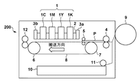
図1は本発明の代表的な実施例であるインクジェット記録ヘッド(以下、記録ヘッド)を用いて記録を行う記録装置の内部構造を概略的に示す側断面図である。 FIG. 1 is a side sectional view schematically showing the internal structure of a recording apparatus which performs recording using an ink jet recording head (hereinafter, recording head) as a typical embodiment of the present invention.
記録装置200は、図1に示されているように、カセット給紙ユニット10とロール紙給紙ユニット9と手差しトレイ給紙ユニット(不図示)が設けられており、それらいずれかの給紙ユニットから供給されるシート状の記録媒体に対して記録を行う。カセット給紙ユニット10からの給紙はピックアップローラ11を駆動することにより1枚ずつシート状の記録媒体をピックアップすることにより行う。それらの給紙ユニットから給紙された記録媒体Pは、ニップローラ対4の位置まで給紙されると、ニップローラ対4が回転し、矢印が示す搬送方向に沿って搬送される。記録媒体Pは、搬送ベルト8とピンチローラ対5とで挟持され、搬送ベルト8の移動に伴い、搬送方向に搬送される。
As shown in FIG. 1, the
そして、搬送ベルト8に伴い搬送された記録媒体Pは記録ヘッド1の記録開始位置まで搬送される。搬送ベルト8は、駆動ローラ6と従動ローラ7によって張架される。記録装置200は、記録媒体Pがピンチローラ対5にニップされた位置を記録開始位置とし、駆動ローラ6の位置を基準として記録ヘッド1の記録タイミングを制御することにより記録媒体上の所定位置に画像を記録する。記録後の記録媒体は排紙ローラ対12を駆動して装置外に排出される。
Then, the recording medium P conveyed along with the conveyance belt 8 is conveyed to the recording start position of the
記録ヘッド1は、記録媒体の幅に相当する記録幅をもち異なる色のインクを吐出する4つのフルライン記録ヘッド1C、1M、1Y、1Kから構成され、これら4つのフルライン記録ヘッドは搬送方向に沿って配列され、ヘッドユニット2に取り付けられている。各フルライン記録ヘッドは、単一のノズルチップで形成されたものでも、分割されたノズルチップが一列または、千鳥配列のように規則的に配置されたものであってもよい。
The
フルライン記録ヘッド1C、1M、1Y、1Kには、各色のインクを独立して貯蔵するインクタンク(不図示)から、チューブによってインクが供給される。この実施例では、フルライン記録ヘッド1C、1M、1Y、1Kには、シアンインク、マゼンタ、イエロインク、ブラックインクがそれぞれ供給され、これら4色のインクによりカラー記録がなされる。以下、4つのフルライン記録ヘッドに個別的に言及する場合には、参照番号として1C、1M、1Y、1Kを用い、全体的に言及する場合には参照番号として1を用いる。そして、いずれの場合にせよ、単に記録ヘッドというものとする。従って、記録装置200は少なくともカラーモードとモノクロモードの2つの記録モードをもつ。
The full-
また、ヘッドユニットリフト機構(不図示)により、ヘッドユニット2を上下させることが可能である。それにより、ヘッド−記録媒体間距離を変更することが可能である。ヘッドユニット2に2つの光学的接近検知センサが備えられ、このセンサから記録媒体に光が照射され、その反射光量を用いてヘッド−記録媒体間の距離を測定する。また、その接近検知センサは、上流側接近検知センサ3aと下流側接近検知センサ3bとを有する構成となっている。
Further, the
上流側接近検知センサ3aによりインク吐出面と記録前の記録媒体との間隔を検知し、下流側接近検知センサ3bにより、インク吐出面とインク吐出後の記録媒体との間隔を検知する。なお、この実施例では接近検知センサを光学センサとしたが、超音波センサなどのヘッド−記録媒体間の距離を計測可能なセンサであればその種類は問わない。なお、これら2つのセンサを総称して接近検知センサ3という。
The upstream
なお、上述のインク吐出面とはインクジェット方式に従う記録ヘッドを用いた場合の表現であって、記録方式によらない一般的な表現は記録ヘッドの記録面である。 The above-mentioned ink ejection surface is a representation in the case of using a recording head according to the ink jet method, and a general expression not based on the recording method is the recording surface of the recording head.
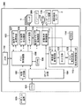
図2は図1に示す記録装置の概略制御構成を示すブロック図である。 FIG. 2 is a block diagram showing a schematic control configuration of the recording apparatus shown in FIG.
図2に示すように、記録装置200は、システム全体を制御するCPU101の制御により、例えば、PCやHDDのような外部入力装置100から画像データを入力する。記録装置200は、制御構成の点からすれば、CPU101、記録装置特有のハードウエア制御を行なうASIC102、DDR112、記録ヘッド1、エンコーダ206、モータ115、接近検知センサ3、ヘッドユニットリフト機構116を含む。ここで、DDRとは倍速データ転送速度のSDRAMのことをいう。
As shown in FIG. 2, the
ASIC102は、外部インタフェース(I/F)回路103、CPU I/F回路104、メモリ制御回路105、SRAM106、114、画像データ処理回路107、吐出画像生成回路108、ヘッドI/F回路109、接近検知制御回路113を含む。さらにASIC102は、転送タイミング制御回路110、装置本体駆動回路111を含む。
The ASIC 102 includes an external interface (I / F)
次にASIC102の内部回路の動作について説明する。
Next, the operation of the internal circuit of the
外部インタフェース回路103はUSBインタフェース回路やLANインタフェース回路やIDEインタフェース回路など、外部入力装置100と接続されるインタフェース回路を含む。CPUインタフェース回路104はCPU101と接続して、CPU101とASIC102内の各ブロックとの通信を制御する。
The
メモリ制御回路105は、外部I/F回路103、SRAM106、画像データ処理回路107、吐出画像生成回路108、ヘッドインタフェース回路109、DDR112と接続している。メモリ制御回路105は、外部入力装置100から入力される画像データをSRAM106に転送する制御を行うともに、SRAM106とDDR112からのデータの読出しやSRAM106とDDR112への書込み制御も行なう。SRAM106は作業バッファとして用いられ、画像データが記録のために特定サイズに分割されて格納されている。このSRAMの個数はインク色数分やノズル数分などに依存して決定される構成となっている。
The
画像データ処理回路107は、SRAM106に格納された画像データに対して画像処理を行なう。ここでいう画像処理とは、境界処理、エッジ処理、HV変換、スムージング、不吐補間などの処理であるが、この限りではない。
The image
吐出画像生成回路108は画像処理が終了した画像データを記録ヘッド1のノズルに合わせた形式のデータ(以下、吐出画像データという)に変換する。転送タイミング制御回路110は、エンコーダ206より入力される信号を逓倍することで信号の転送タイミング信号を生成する。ヘッドインタフェース回路109は、吐出画像データを転送タイミング信号のタイミングで記録ヘッド1へ転送する。DDR112は、ASIC102に外付けされる受信バッファであり、その受信バッファには、画像補正処理が施された画像データが格納される。装置本体駆動回路111はモータ115の駆動制御やヘッドユニットリフト機構116やセンサ(不図示)の駆動制御を行う。
The discharge
接近検知制御回路113は、測定値取得回路121、判定回路122、メモリ制御回路123から構成され、接近検知センサ3にて測定した測定値と、エンコーダ206から位置情報を入力する。接近検知制御回路113はまた、CPU101を介して記録媒体接近時の設定、画像データの種別情報、閾値などを入力する。ここで、画像データの種別情報とは、ドライバで設定する記録品質の情報や、ドライバで設定する記録品質の情報と画像データから生成される記録モードにより決定される情報である。
The approach
また、閾値とは、記録ヘッドのインク吐出面の記録媒体への接近検知を行う際に設定される値をいう。具体的には、例えば、記録媒体がない状態での反射光量の値、記録媒体がないと判断できる反射光量の値、記録媒体の厚みが最大の場合の反射光量の値などであるが、その他の値を閾値として用いても良い。 The threshold value is a value set when detecting the approach of the ink ejection surface of the recording head to the recording medium. Specifically, for example, the value of the amount of reflected light when there is no recording medium, the value of the amount of reflected light when it can be judged that there is no recording medium, the value of the amount of reflected light when the thickness of the recording medium is maximum, etc. The value of may be used as a threshold.
測定値取得回路121は、エンコーダ206から取得する位置情報を基に、接近検知制御回路113と接近検知センサ3の動作開始と終了の処理を行なう。また、接近検知センサ3から取得したAD値から測定値を算出する。仮に、接近検知センサ3から反射光量の値としてAD値が0〜1023の範囲で40μ秒の周期で入力されるとする。ここでは、ノイズなどの影響によるAD値のばらつきを抑えるためにフィルタ処理を行なう。フィルタ処理方法の一例として、複数のAD値の移動平均値を測定値とする方法がある。また、測定値取得回路121は、CPU101を介して閾値の検出も行なう。
Based on the position information acquired from the
判定回路122は、接近検知制御回路113の状態を管理し、CPU101を介して設定される格納タイミングに応じて測定値を保持し、メモリ制御回路123に転送する。また、判定回路122は、記録ヘッドのインク吐出面が記録媒体に接近した時にどんな処理を行うのかを判断し、装置本体駆動回路111に対してヘッド高さ変更の指示を行う。
The
メモリ制御回路123は、判定回路122から転送された測定値をSRAM114の所定の領域に格納する。ここで、接近検知制御回路113は、メモリ制御回路123を介してSRAM114から測定値を読みだすことにより、インク吐出面と記録媒体の間隔の変化を取得することも可能である。
The
次に以上の構成の記録装置が実行するヘッド高さ変更処理について説明する。 Next, head height change processing executed by the recording apparatus having the above configuration will be described.
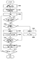
図3はヘッド高さ変更処理を示すフローチャートである。このフローチャートは、印刷ジョブを記録装置に送信する際に、インク吐出面と記録媒体とが接近した場合の処理方法を記録装置が判断する処理のフローを示している。 FIG. 3 is a flowchart showing head height change processing. This flowchart shows the flow of processing in which the printing apparatus determines the processing method when the ink ejection surface and the printing medium approach each other when transmitting the printing job to the printing apparatus.
まず、ステップS300では、外部入力装置100より画像データが記録装置200に入力され、画像データの印刷設定が決定され印刷設定が画像データの種別情報となり、CPU101から接近検知制御回路113に伝達される。
First, in step S300, image data is input from the
次に、ステップS301では、画像データの種別情報とユーザによる記録媒体の接近時の設定により、インク吐出面に記録媒体が接近した場合の処理を決定する。決定された処理方法は判定回路122に格納する。
Next, in step S301, the process in the case where the recording medium approaches the ink ejection surface is determined based on the type information of the image data and the setting when the recording medium approaches by the user. The determined processing method is stored in the
ユーザによる記録媒体接近時の設定は、外部入力装置100から画像データ転送時に設定したり、初期設定時や未印刷時に記録装置本体に設定記憶させることも可能であるが、特別なユーザ設定を行わずに画像データの種別情報のみで決定することも可能である。
The settings when the recording medium approaches by the user can be set when transferring image data from the
その種別情報のみで記録動作の続行を決定する一例としては、次のようなものがある。即ち、線画など画像データの全体的なデューティが低く印刷パラメータに含まれる記録速度が速い設定の場合、プリンタドライバでの用紙種類の設定が普通紙で高速印刷と設定された場合、モノクロモード、インク節約モードと設定された場合などである。反対に記録動作を中止を決定する一例としては、次のようなものがある。写真などの画像データの全体的なデューティが高い場合、プリンタドライバでの用紙種類の設定が光沢紙で印刷品質が高画質と設定された場合などである。 As an example of determining the continuation of the recording operation only by the type information, there is the following. That is, when the overall duty of image data such as line drawing is low and the printing speed included in the printing parameters is high, when the paper type setting in the printer driver is set to high speed printing with plain paper, monochrome mode, ink For example, when the saving mode is set. On the contrary, as an example of deciding to stop the recording operation, there are the following. For example, when the overall duty of image data such as a photo is high, the setting of the paper type in the printer driver is glossy paper and the print quality is set to high image quality.
ステップS302では、記録媒体を記録開始位置まで搬送し、記録媒体への印刷を開始する。これとともに、接近検知センサ3による測定を開始する。接近検知センサ3は特定の周期、例えば、40μ秒などの特定周期でヘッド−記録媒体間の距離の測定を行う。CPU101では、上述したように、ヘッド−記録媒体接近時の閾値を設定しており、閾値を超えるまでは印刷を継続する。
In step S302, the recording medium is conveyed to the recording start position, and printing on the recording medium is started. At the same time, measurement by the
このため、ステップS303では、特定周期でヘッド−記録媒体間の距離の測定を行う毎に、インク吐出面に記録媒体が接近したかどうかを調べる。その接近の判定は、接近検知センサ3による測定から得られた距離(ML)が閾値(TH)未満となったかどうかを判断することによりなされる。ここで、ML≧THであれば、インク吐出面は記録媒体に接近していないと判断し、処理はステップS302に戻り、印刷を続ける。これに対して、ML<THであれば、インク吐出面は記録媒体に接近していると判断し、処理はステップS304に進む。
For this reason, in step S303, whenever the distance between the head and the recording medium is measured at a specific cycle, it is checked whether the recording medium approaches the ink ejection surface. The determination of the approach is made by determining whether the distance (ML) obtained from the measurement by the
ステップS304では、判定回路122に格納された処理方法に従って、記録動作が続行可能かどうかを判断する。ここで、記録動作続行不可能と判断した場合には、処理はステップS305に進み、印刷を停止し、さらに、ステップS306ではユーザに異常を通知するため、記録装置の表示画面にエラーメッセージを表示する。これに対して、記録動作続行可能と判断した場合には、ステップS307に進み、判定回路122から装置本体駆動回路111に対してヘッド高さ変更の指示が伝えられ、印刷を続行する。さらに、ステップS308では印刷を継続したまま、ヘッドユニット2を所定量上昇させる。
In step S304, according to the processing method stored in the
さらに、ステップS309では、そのまま印刷を続行しながら、接近検知センサ3は特定周期でヘッド−記録媒体間の距離の測定を行い、ヘッドユニットの高さ変更後、測定されたヘッド−記録媒体間の距離(ML)が規定値以上離れたかどうかを調べる。この規定値は、ヘッドユニットリフト機構116によるヘッドユニット2の移動限界値と判定回路122に格納された処理方法と接近検知センサ3による測定値などに基づいて定められるものである。
Furthermore, in step S309, while continuing printing as it is, the
ここで、その距離(ML)が規程値以上離れていないと判断された場合、処理はステップS308に戻り、さらにヘッドユニット2を上昇させたまま印刷を継続し、再び、ステップS309の処理を行う。このようにして、ヘッド−記録媒体間の距離(ML)が規定値以上離れたと判断された場合、処理はステップS310に進み、ヘッド高さを印刷開始時の高さに変更する。
Here, if it is determined that the distance (ML) is not greater than or equal to the standard value, the process returns to step S308, continues printing with the
その後、ステップS311では印刷が終了したかどうかを調べ、印刷終了と判断されれば処理は終了するが、印刷続行と判断されれば、印刷終了するまでステップS303〜S310の処理を繰り返す。 Thereafter, in step S311, it is checked whether printing is completed. If it is determined that printing is completed, the process is terminated. If it is determined that printing is continued, the processes of steps S303 to S310 are repeated until printing is completed.
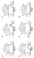
次に、図3のステップS308〜S310に対応するヘッド高さ変更処理の詳細について図4を用いて説明する。 Next, the details of the head height change processing corresponding to steps S308 to S310 in FIG. 3 will be described using FIG.
図4はヘッド高さ変更処理の詳細を説明するための図である。 FIG. 4 is a diagram for explaining the details of the head height change process.
図4(a)〜(f)において、Lは記録開始時のヘッド−記録媒体間距離、L’はヘッド上昇後のヘッド−記録媒体間距離である。また、Laは上流側接近検知センサ3aで測定されるヘッド−記録媒体間距離、Lbは下流側接近検知センサ3bで測定されるヘッド−記録媒体間距離を示す。ここで、L’>L、L’>La、L’>Lbである。また、記録媒体Pの搬送方向は、図中の矢印の方向である。
In FIGS. 4A to 4F, L is the head-recording medium distance at the start of recording, and L 'is the head-recording medium distance after the head ascent. Further, La indicates the head-recording medium distance measured by the upstream
図4(a)は、記録媒体Pが正常な状態を示している。この状態では、La、Lbは搬送する記録媒体の厚み分だけLよりも低い値を示す。 FIG. 4A shows a state in which the recording medium P is normal. In this state, La and Lb show values lower than L by the thickness of the recording medium to be conveyed.
次に、図4(b)は、何らかの要因により記録媒体Pに浮きが発生するなどしてLaが変化した状態を示している。この時、LとLaの差分が閾値を超えると、図4(c)で示すように、ヘッドユニットリフト機構116を動作させ、ヘッドユニット2を上昇させ、ヘッド−記録媒体間距離がLからL’になるようにヘッド高さを変化させる。
Next, FIG. 4B shows a state in which La changes due to, for example, the occurrence of floating on the recording medium P due to some factor. At this time, when the difference between L and La exceeds the threshold value, as shown in FIG. 4C, the head
図4(d)は、さらに記録媒体Pが搬送され、記録媒体の浮きが上流側接近検知センサ3aと下流側接近検知センサ3bとの間にある状態を示している。この場合、上流側接近検知センサ3aは、Laの値の変化により記録媒体Pが記録ヘッドのインク吐出面より十分に離れた状態であることは検知できている。これに対して、まだ下流側接近検知センサ3bはこの時点では、記録媒体Pの浮きの状態を検知できていないので、ヘッド高さの変更(ヘッド−記録媒体間距離がL’からLに戻すこと)は行わない。
FIG. 4D shows a state in which the recording medium P is further conveyed, and the floating state of the recording medium is between the upstream
図4(e)は、上流側接近検知センサ3aが浮きがないことを検知してからヘッド長さ分、記録媒体Pを搬送した状態を示している。この状態まで記録媒体Pを搬送すると、接近検知センサ3は特定周期でヘッド−記録媒体間距離(ML)を測定しているので、下流側接近検知センサ3bはLbの値の変化により下流側接近検知センサ3bの位置でも記録媒体の浮きがなくなったことを確認できる。なお、ここでいうヘッド長さとは記録媒体Pの搬送方向に関するヘッドユニット2の長さのことであり、図4に示す上流側接近検知センサ3aと下流側接近検知センサ3bとの間の距離に相当する。
FIG. 4E shows a state in which the recording medium P is conveyed by the head length after the upstream
浮きがなくなったことを確認すると、図4(f)で示すように、ヘッド−記録媒体間距離を正常な状態のヘッド−記録媒体間距離Lに変更する。 When it is confirmed that the floating has disappeared, as shown in FIG. 4F, the head-recording medium distance is changed to the head-recording medium distance L in a normal state.
ここでは、下流側接近検知センサ3bにより測定されるヘッド−記録媒体間距離Lbの変化により記録媒体Pの浮きがなくなったことを判定したが、その判定は次のような方法を用いても良い。即ち、上流側接近検知センサ3aで記録媒体Pの浮きを検知しヘッドユニット2を上昇させた後、ヘッド長さに相当する時間、記録媒体Pを搬送中は上流側接近検知センサ3aを用いた監視を続行する。そして、その監視中に、既に検知した以上の状態変化が発生することがなく、記録媒体Pの浮きがなくなったことを確認したなら、ヘッドの長さ分、記録媒体Pを搬送後、ヘッド−記録媒体間距離を正常な状態の値Lに戻すように制御すると良い。これにより、下流側接近検知センサ3bを削除することができる。
Here, the change in the head-recording medium distance Lb measured by the downstream side
従って以上説明した実施例に従えば、インク吐出面への記録媒体の接近を検知し、接近を検知した場合でも記録条件により記録動作の継続が可能と判断できれば記録動作を継続することができる。 Therefore, according to the embodiment described above, the approach of the recording medium to the ink ejection surface is detected, and even when the approach is detected, the recording operation can be continued if it can be judged that the recording operation can be continued according to the recording condition.
なお、以上説明した実施例で用いた記録装置は、記録媒体の幅に相当するフルライン記録ヘッドを用いた構成を採用したが、本発明はこれによって限定されるものではない。例えば、記録ヘッドを搭載したキャリッジを往復走査しながら、記録ヘッドからインクを吐出して記録を行うシリアル型の記録装置でも、本発明を実施することは可能である。さらに、シリアル型の記録装置の場合は、各走査の間にヘッド高さを変更を実施するようにしても良い。 Although the recording apparatus used in the embodiment described above adopts a configuration using a full line recording head corresponding to the width of the recording medium, the present invention is not limited to this. For example, it is possible to practice the present invention even in a serial type recording apparatus which ejects ink from the recording head to perform recording while reciprocating a carriage on which the recording head is mounted. Furthermore, in the case of a serial type recording apparatus, the head height may be changed between each scan.
また、以上説明した実施例で用いた記録装置は単機能の装置であったが本発明はこれによって限定されるものではない。例えば、スキャナ機能や複写機能やファクシミリ機能などを搭載した多機能プリンタ装置(MFP)を用いても良い。 Further, although the recording apparatus used in the embodiment described above is a single function apparatus, the present invention is not limited by this. For example, a multifunction printer (MFP) equipped with a scanner function, a copying function, a facsimile function, and the like may be used.
1 記録ヘッド、3 接近検知センサ、102 ASIC、113 接近検知制御回路、
121 測定値取得回路、122 判定回路、200 記録装置
1 recording head, 3 approach detection sensor, 102 ASIC, 113 approach detection control circuit,
121 Measurement value acquisition circuit, 122 judgment circuit, 200 recording device
Claims (12)
前記記録媒体を搬送する搬送手段と、
前記搬送手段による前記記録媒体の搬送方向に関し前記記録ヘッドにより記録がなされる位置より上流側に備えられ、前記記録ヘッドの記録面と前記記録媒体との間の距離を測定する第1の測定手段と、
前記記録ヘッドを移動させて前記距離を変化させる移動手段と、
前記第1の測定手段により測定された前記距離が閾値より小さくない場合には記録を続行し、前記測定された前記距離が前記閾値より小さい場合には、記録に用いられる画像データの種別情報を少なくとも含む予め定められた条件に基づいて記録を続行させるかどうかを判断する判断手段と、
前記測定された前記距離が前記閾値より小さい場合に、前記判断手段による判断に基づいて、前記距離を離すように前記移動手段を駆動して前記記録ヘッドによる記録を続行させるよう制御する制御手段とを有することを特徴とする記録装置。 A recording apparatus which conveys a sheet-like recording medium in a predetermined direction and discharges ink from the recording head onto the recording medium to record an image.
Transport means for transporting the recording medium;
A first measuring unit provided upstream of a position where recording is performed by the recording head in the conveyance direction of the recording medium by the conveyance unit, and measuring a distance between the recording surface of the recording head and the recording medium When,
A moving means for changing the distance by moving the recording head,
The recording is continued if the distance measured by the first measuring means is not smaller than the threshold, and if the measured distance is smaller than the threshold, type information of image data used for recording is used. Determining means for determining whether to continue recording based on at least a predetermined condition including at least one of:
If the distance is the measurement is less than the threshold value, based on the determination by the determination means, control means for controlling so as to continue the recording by the recording head by driving the moving means and away the distance And a recording device characterized by comprising:
複数の色のインクを吐出させるために、前記インクジェット記録ヘッドを前記複数の色の数、備えることを特徴とする請求項3又は4に記載の記録装置。 The recording head is Lee ink jet recording head,
5. The recording apparatus according to claim 3 , wherein the ink jet recording head is provided with the number of the plurality of colors in order to discharge the ink of the plurality of colors.
前記記録媒体の搬送方向に関し前記記録ヘッドにより記録がなされる位置より上流側に備えられたセンサを用いて、前記記録ヘッドの記録面と前記記録媒体との間の距離を測定する測定工程と、
前記測定工程において測定された前記距離が閾値より小さくない場合には、記録を続行し、前記測定された前記距離が前記閾値より小さい場合には、記録に用いられる画像データの種別情報を少なくとも含む予め定められた条件に基づいて記録を続行させるかどうかを判断する判断工程と、
前記測定された前記距離が前記閾値より小さい場合に、前記判断工程における判断に基づいて、前記記録ヘッドを移動させる移動手段を駆動して、前記距離を離すようにし、前記記録ヘッドによる記録を続行させるよう制御する制御工程とを有することを特徴とする制御方法。 A control method of a recording apparatus, which conveys a sheet-like recording medium in a predetermined direction and discharges ink from a recording head to the recording medium to record an image.
Measuring the distance between the recording surface of the recording head and the recording medium using a sensor provided on the upstream side of the position at which recording is performed by the recording head in the transport direction of the recording medium;
When the distance measured in the measurement step is not smaller than the threshold, recording is continued, and when the measured distance is smaller than the threshold, at least the type information of the image data used for recording is included. A determination step of determining whether to continue recording based on a predetermined condition;
If the distance is the measurement is less than the threshold value, based on the determination of definitive to the determination step, by driving the moving means for moving the recording head, so as to release the said distance, recording by the recording head And a control step of controlling to continue the control.
Priority Applications (1)
| Application Number | Priority Date | Filing Date | Title |
|---|---|---|---|
| JP2015001075A JP6502671B2 (en) | 2015-01-06 | 2015-01-06 | Recording apparatus and control method thereof |
Applications Claiming Priority (1)
| Application Number | Priority Date | Filing Date | Title |
|---|---|---|---|
| JP2015001075A JP6502671B2 (en) | 2015-01-06 | 2015-01-06 | Recording apparatus and control method thereof |
Publications (3)
| Publication Number | Publication Date |
|---|---|
| JP2016124235A JP2016124235A (en) | 2016-07-11 |
| JP2016124235A5 JP2016124235A5 (en) | 2018-02-08 |
| JP6502671B2 true JP6502671B2 (en) | 2019-04-17 |
Family
ID=56356879
Family Applications (1)
| Application Number | Title | Priority Date | Filing Date |
|---|---|---|---|
| JP2015001075A Active JP6502671B2 (en) | 2015-01-06 | 2015-01-06 | Recording apparatus and control method thereof |
Country Status (1)
| Country | Link |
|---|---|
| JP (1) | JP6502671B2 (en) |
Families Citing this family (3)
| Publication number | Priority date | Publication date | Assignee | Title |
|---|---|---|---|---|
| JP6516503B2 (en) * | 2015-02-18 | 2019-05-22 | キヤノン株式会社 | Ink jet recording device |
| JPWO2018155568A1 (en) | 2017-02-27 | 2019-11-07 | 富士フイルム株式会社 | Liquid ejecting apparatus and medium floating countermeasure |
| JP7600635B2 (en) | 2020-11-20 | 2024-12-17 | セイコーエプソン株式会社 | Printing device and printing method |
Family Cites Families (4)
| Publication number | Priority date | Publication date | Assignee | Title |
|---|---|---|---|---|
| JP3727512B2 (en) * | 2000-06-21 | 2005-12-14 | ローランドディー.ジー.株式会社 | Ink head lifting device |
| US6666537B1 (en) * | 2002-07-12 | 2003-12-23 | Hewlett-Packard Development Company, L.P. | Pen to paper spacing for inkjet printing |
| JP2008246879A (en) * | 2007-03-30 | 2008-10-16 | Brother Ind Ltd | Image recording device |
| JP2011178105A (en) * | 2010-03-03 | 2011-09-15 | Seiko Epson Corp | Recorder |
-
2015
- 2015-01-06 JP JP2015001075A patent/JP6502671B2/en active Active
Also Published As
| Publication number | Publication date |
|---|---|
| JP2016124235A (en) | 2016-07-11 |
Similar Documents
| Publication | Publication Date | Title |
|---|---|---|
| JP5623192B2 (en) | Image processing apparatus and image processing method | |
| JP4737210B2 (en) | Image recording apparatus and image recording method | |
| JP6362382B2 (en) | Printing control apparatus and control method therefor | |
| JP2012176612A (en) | Inkjet recording apparatus | |
| JP2012158067A (en) | Inkjet recording apparatus | |
| US20150042715A1 (en) | Printing apparatus and control method | |
| JP2012089922A (en) | Image reading device | |
| JP2010214865A (en) | Inkjet recorder and inkjet recording method | |
| JP6502671B2 (en) | Recording apparatus and control method thereof | |
| JP2011051671A (en) | Ink jet recording device | |
| US12053975B2 (en) | Printing apparatus and conveyance control method thereof | |
| JP2014151462A (en) | Printing apparatus and color measuring method | |
| JP2009234076A (en) | Inkjet recording apparatus and method | |
| JP5015051B2 (en) | Inkjet recording apparatus and method | |
| JP4345700B2 (en) | Image recording device | |
| JP2014108614A (en) | Image forming apparatus and image forming method | |
| JP2010214741A (en) | Image forming apparatus and program | |
| JP2009196752A (en) | Image forming device | |
| JP4733575B2 (en) | Inkjet recording device | |
| JP2023170172A (en) | Recording device, its control method and program | |
| US7360854B2 (en) | Ink jet recording apparatus | |
| JP2011056754A (en) | Image forming apparatus, maintenance method, image forming system, maintenance program, and recording medium | |
| JP2001001617A (en) | Image-recording apparatus | |
| JP2002067460A (en) | Printing apparatus and printing operation control method in printing apparatus | |
| JP2016068454A (en) | Inkjet printer |
Legal Events
| Date | Code | Title | Description |
|---|---|---|---|
| A521 | Written amendment |
Free format text: JAPANESE INTERMEDIATE CODE: A523 Effective date: 20171219 |
|
| A621 | Written request for application examination |
Free format text: JAPANESE INTERMEDIATE CODE: A621 Effective date: 20171219 |
|
| A977 | Report on retrieval |
Free format text: JAPANESE INTERMEDIATE CODE: A971007 Effective date: 20180910 |
|
| A131 | Notification of reasons for refusal |
Free format text: JAPANESE INTERMEDIATE CODE: A131 Effective date: 20180918 |
|
| A521 | Written amendment |
Free format text: JAPANESE INTERMEDIATE CODE: A523 Effective date: 20181114 |
|
| TRDD | Decision of grant or rejection written | ||
| A01 | Written decision to grant a patent or to grant a registration (utility model) |
Free format text: JAPANESE INTERMEDIATE CODE: A01 Effective date: 20190222 |
|
| A61 | First payment of annual fees (during grant procedure) |
Free format text: JAPANESE INTERMEDIATE CODE: A61 Effective date: 20190322 |
|
| R151 | Written notification of patent or utility model registration |
Ref document number: 6502671 Country of ref document: JP Free format text: JAPANESE INTERMEDIATE CODE: R151 |