JP2017535239A - How to optimize reactive power consumption - Google Patents
How to optimize reactive power consumption Download PDFInfo
- Publication number
- JP2017535239A JP2017535239A JP2017527799A JP2017527799A JP2017535239A JP 2017535239 A JP2017535239 A JP 2017535239A JP 2017527799 A JP2017527799 A JP 2017527799A JP 2017527799 A JP2017527799 A JP 2017527799A JP 2017535239 A JP2017535239 A JP 2017535239A
- Authority
- JP
- Japan
- Prior art keywords
- compensation
- power
- electrical load
- electrical
- consumption
- Prior art date
- Legal status (The legal status is an assumption and is not a legal conclusion. Google has not performed a legal analysis and makes no representation as to the accuracy of the status listed.)
- Granted
Links
- 238000000034 method Methods 0.000 claims abstract description 19
- 238000012544 monitoring process Methods 0.000 claims abstract description 13
- 230000005540 biological transmission Effects 0.000 claims abstract description 7
- 238000005259 measurement Methods 0.000 claims description 16
- 238000009826 distribution Methods 0.000 claims description 13
- 238000013480 data collection Methods 0.000 claims description 7
- 238000004364 calculation method Methods 0.000 claims description 5
- 238000005265 energy consumption Methods 0.000 claims 1
- 230000001105 regulatory effect Effects 0.000 claims 1
- 230000010363 phase shift Effects 0.000 description 12
- 230000001939 inductive effect Effects 0.000 description 8
- 238000010586 diagram Methods 0.000 description 7
- 239000003990 capacitor Substances 0.000 description 5
- 230000008901 benefit Effects 0.000 description 3
- 238000001514 detection method Methods 0.000 description 3
- 230000002457 bidirectional effect Effects 0.000 description 2
- 238000005516 engineering process Methods 0.000 description 2
- 238000005457 optimization Methods 0.000 description 2
- 230000008569 process Effects 0.000 description 2
- 239000013598 vector Substances 0.000 description 2
- 230000003044 adaptive effect Effects 0.000 description 1
- 230000002776 aggregation Effects 0.000 description 1
- 238000004220 aggregation Methods 0.000 description 1
- 238000004378 air conditioning Methods 0.000 description 1
- 230000003321 amplification Effects 0.000 description 1
- 230000009286 beneficial effect Effects 0.000 description 1
- 230000008859 change Effects 0.000 description 1
- 230000003750 conditioning effect Effects 0.000 description 1
- 230000008878 coupling Effects 0.000 description 1
- 238000010168 coupling process Methods 0.000 description 1
- 238000005859 coupling reaction Methods 0.000 description 1
- 238000013499 data model Methods 0.000 description 1
- 230000000694 effects Effects 0.000 description 1
- 238000007726 management method Methods 0.000 description 1
- 238000004519 manufacturing process Methods 0.000 description 1
- 238000003199 nucleic acid amplification method Methods 0.000 description 1
- 230000000737 periodic effect Effects 0.000 description 1
- 239000007787 solid Substances 0.000 description 1
- 230000009182 swimming Effects 0.000 description 1
- 238000011144 upstream manufacturing Methods 0.000 description 1
- 239000002699 waste material Substances 0.000 description 1
- 230000003442 weekly effect Effects 0.000 description 1
- 238000004804 winding Methods 0.000 description 1
Images
Classifications
-
- H—ELECTRICITY
- H02—GENERATION; CONVERSION OR DISTRIBUTION OF ELECTRIC POWER
- H02J—CIRCUIT ARRANGEMENTS OR SYSTEMS FOR SUPPLYING OR DISTRIBUTING ELECTRIC POWER; SYSTEMS FOR STORING ELECTRIC ENERGY
- H02J13/00—Circuit arrangements for providing remote indication of network conditions, e.g. an instantaneous record of the open or closed condition of each circuitbreaker in the network; Circuit arrangements for providing remote control of switching means in a power distribution network, e.g. switching in and out of current consumers by using a pulse code signal carried by the network
- H02J13/00002—Circuit arrangements for providing remote indication of network conditions, e.g. an instantaneous record of the open or closed condition of each circuitbreaker in the network; Circuit arrangements for providing remote control of switching means in a power distribution network, e.g. switching in and out of current consumers by using a pulse code signal carried by the network characterised by monitoring
-
- H02J13/0006—
-
- H—ELECTRICITY
- H02—GENERATION; CONVERSION OR DISTRIBUTION OF ELECTRIC POWER
- H02J—CIRCUIT ARRANGEMENTS OR SYSTEMS FOR SUPPLYING OR DISTRIBUTING ELECTRIC POWER; SYSTEMS FOR STORING ELECTRIC ENERGY
- H02J3/00—Circuit arrangements for ac mains or ac distribution networks
-
- H—ELECTRICITY
- H02—GENERATION; CONVERSION OR DISTRIBUTION OF ELECTRIC POWER
- H02J—CIRCUIT ARRANGEMENTS OR SYSTEMS FOR SUPPLYING OR DISTRIBUTING ELECTRIC POWER; SYSTEMS FOR STORING ELECTRIC ENERGY
- H02J3/00—Circuit arrangements for ac mains or ac distribution networks
- H02J3/18—Arrangements for adjusting, eliminating or compensating reactive power in networks
- H02J3/1821—Arrangements for adjusting, eliminating or compensating reactive power in networks using shunt compensators
- H02J3/1835—Arrangements for adjusting, eliminating or compensating reactive power in networks using shunt compensators with stepless control
- H02J3/1864—Arrangements for adjusting, eliminating or compensating reactive power in networks using shunt compensators with stepless control wherein the stepless control of reactive power is obtained by at least one reactive element connected in series with a semiconductor switch
-
- Y—GENERAL TAGGING OF NEW TECHNOLOGICAL DEVELOPMENTS; GENERAL TAGGING OF CROSS-SECTIONAL TECHNOLOGIES SPANNING OVER SEVERAL SECTIONS OF THE IPC; TECHNICAL SUBJECTS COVERED BY FORMER USPC CROSS-REFERENCE ART COLLECTIONS [XRACs] AND DIGESTS
- Y02—TECHNOLOGIES OR APPLICATIONS FOR MITIGATION OR ADAPTATION AGAINST CLIMATE CHANGE
- Y02E—REDUCTION OF GREENHOUSE GAS [GHG] EMISSIONS, RELATED TO ENERGY GENERATION, TRANSMISSION OR DISTRIBUTION
- Y02E40/00—Technologies for an efficient electrical power generation, transmission or distribution
- Y02E40/30—Reactive power compensation
-
- Y—GENERAL TAGGING OF NEW TECHNOLOGICAL DEVELOPMENTS; GENERAL TAGGING OF CROSS-SECTIONAL TECHNOLOGIES SPANNING OVER SEVERAL SECTIONS OF THE IPC; TECHNICAL SUBJECTS COVERED BY FORMER USPC CROSS-REFERENCE ART COLLECTIONS [XRACs] AND DIGESTS
- Y02—TECHNOLOGIES OR APPLICATIONS FOR MITIGATION OR ADAPTATION AGAINST CLIMATE CHANGE
- Y02E—REDUCTION OF GREENHOUSE GAS [GHG] EMISSIONS, RELATED TO ENERGY GENERATION, TRANSMISSION OR DISTRIBUTION
- Y02E40/00—Technologies for an efficient electrical power generation, transmission or distribution
- Y02E40/70—Smart grids as climate change mitigation technology in the energy generation sector
-
- Y—GENERAL TAGGING OF NEW TECHNOLOGICAL DEVELOPMENTS; GENERAL TAGGING OF CROSS-SECTIONAL TECHNOLOGIES SPANNING OVER SEVERAL SECTIONS OF THE IPC; TECHNICAL SUBJECTS COVERED BY FORMER USPC CROSS-REFERENCE ART COLLECTIONS [XRACs] AND DIGESTS
- Y02—TECHNOLOGIES OR APPLICATIONS FOR MITIGATION OR ADAPTATION AGAINST CLIMATE CHANGE
- Y02E—REDUCTION OF GREENHOUSE GAS [GHG] EMISSIONS, RELATED TO ENERGY GENERATION, TRANSMISSION OR DISTRIBUTION
- Y02E60/00—Enabling technologies; Technologies with a potential or indirect contribution to GHG emissions mitigation
-
- Y—GENERAL TAGGING OF NEW TECHNOLOGICAL DEVELOPMENTS; GENERAL TAGGING OF CROSS-SECTIONAL TECHNOLOGIES SPANNING OVER SEVERAL SECTIONS OF THE IPC; TECHNICAL SUBJECTS COVERED BY FORMER USPC CROSS-REFERENCE ART COLLECTIONS [XRACs] AND DIGESTS
- Y04—INFORMATION OR COMMUNICATION TECHNOLOGIES HAVING AN IMPACT ON OTHER TECHNOLOGY AREAS
- Y04S—SYSTEMS INTEGRATING TECHNOLOGIES RELATED TO POWER NETWORK OPERATION, COMMUNICATION OR INFORMATION TECHNOLOGIES FOR IMPROVING THE ELECTRICAL POWER GENERATION, TRANSMISSION, DISTRIBUTION, MANAGEMENT OR USAGE, i.e. SMART GRIDS
- Y04S10/00—Systems supporting electrical power generation, transmission or distribution
- Y04S10/22—Flexible AC transmission systems [FACTS] or power factor or reactive power compensating or correcting units
-
- Y—GENERAL TAGGING OF NEW TECHNOLOGICAL DEVELOPMENTS; GENERAL TAGGING OF CROSS-SECTIONAL TECHNOLOGIES SPANNING OVER SEVERAL SECTIONS OF THE IPC; TECHNICAL SUBJECTS COVERED BY FORMER USPC CROSS-REFERENCE ART COLLECTIONS [XRACs] AND DIGESTS
- Y04—INFORMATION OR COMMUNICATION TECHNOLOGIES HAVING AN IMPACT ON OTHER TECHNOLOGY AREAS
- Y04S—SYSTEMS INTEGRATING TECHNOLOGIES RELATED TO POWER NETWORK OPERATION, COMMUNICATION OR INFORMATION TECHNOLOGIES FOR IMPROVING THE ELECTRICAL POWER GENERATION, TRANSMISSION, DISTRIBUTION, MANAGEMENT OR USAGE, i.e. SMART GRIDS
- Y04S10/00—Systems supporting electrical power generation, transmission or distribution
- Y04S10/30—State monitoring, e.g. fault, temperature monitoring, insulator monitoring, corona discharge
Abstract
本発明は、発電機、電気負荷、電力補償システム、送電線、デジタル電子プロセッサおよび遠隔読み出し可能な量計を備えている、電源監視調整システムを含む電気ネットワークにおける無効電力の消費を最適化する方法に関する。上記方法は、少なくとも1つの遠隔読み出し可能な量計を介して上記電気負荷のデータセットを計測する工程と、上記電気負荷のデータセットを収集し、かつデータ曲線を構築するために、上記デジタル電子プロセッサに上記データセットを送信する工程と、上記電気負荷の力率を算出する工程と、算出された上記力率が、既定の閾値未満または閾値に等しい値を有する場合、導入される上記補償システムのタイプおよび構成を設定することによって無効電力の補償を可能にする工程と、上記補償システムを作動することによって無効電力に対する補償を行う工程と、を備えている。The present invention is a method for optimizing reactive power consumption in an electrical network including a power monitoring and regulation system comprising a generator, an electrical load, a power compensation system, a transmission line, a digital electronic processor and a remotely readable meter. About. The method includes measuring the electrical load data set via at least one remotely readable meter, collecting the electrical load data set, and constructing a data curve to construct the digital electronics. Transmitting the data set to a processor; calculating a power factor of the electrical load; and the compensation system introduced if the calculated power factor has a value less than or equal to a predetermined threshold. Enabling the compensation of reactive power by setting the type and configuration, and compensating the reactive power by operating the compensation system.
Description
〔技術分野〕
本発明は、電気ネットワークの監視の分野および無効電力量の消費の最適化に関する。
〔Technical field〕
The present invention relates to the field of electrical network monitoring and optimization of reactive power consumption.
より具体的には、無効電力量の検出を自動化することにより、電気ネットワークにおける電力消費の最適化を可能とする方法に関する。 More specifically, the present invention relates to a method that enables optimization of power consumption in an electric network by automating detection of reactive power.
〔先行技術〕
最先端技術として、仏国特許出願公開第2494055号明細書に記載されている解決法が知られている。この出願には、ネットワークに接続されている少なくとも1つの補償ユニットを含む、ネットワークにおける無効電力量を補償するための装置が示されている。上記補償ユニットは、インダクタ、コンデンサおよび第1の双方向サイリスタスイッチならびに第2の双方向サイリスタスイッチを備えている。当該補填ユニットは、論理ORゲートと、一方では、上記第1のスイッチへの端子電圧の既定の閾値の検出を含む第1の計測回路への、およびまた一方では、上記第2のスイッチへの端子電圧の既定の閾値の検出を含む第2の計測回路への入力、を備える制御手段と同様である。
[Prior art]
As a state-of-the-art technology, a solution described in French Patent Application No. 2494055 is known. This application shows an apparatus for compensating reactive energy in a network including at least one compensation unit connected to the network. The compensation unit includes an inductor, a capacitor, a first bidirectional thyristor switch, and a second bidirectional thyristor switch. The compensation unit includes a logical OR gate and, on the one hand, to a first measuring circuit that includes detection of a predetermined threshold of the terminal voltage to the first switch, and on the other hand to the second switch. This is similar to the control means having an input to the second measurement circuit including detection of a predetermined threshold value of the terminal voltage.
同様に知られているのは、仏国特許出願公開第2693601号明細書によって提案されている解決法である。当該解決法には、制御されるスイッチの接続部の下流にある、主電源回路における電流を計測するための手段、および電流計測手段の出力に接続されている、皮相電力の典型的な大きさを計測するための手段を含む無効電力補償装置が記載されている。上記制御されるスイッチの開口部は、上記典型的な大きさが既定の閾値より大きい場合に作動される。 Similarly known is the solution proposed by French Patent Application No. 2669601. The solution includes a typical magnitude of the apparent power connected to the means for measuring the current in the main power circuit downstream of the controlled switch connection and to the output of the current measuring means. A reactive power compensator is described that includes means for measuring. The controlled switch opening is activated when the typical size is greater than a predetermined threshold.
無効電力量補償システムのための電流調整解決策も、当技術分野において知られている。 Current regulation solutions for reactive energy compensation systems are also known in the art.
仏国特許出願公開第2873866号明細書は、電流調整装置の例を記載している。当該装置は、二次巻線が配電ネットワークと無効電力量補償コンデンサとの間に直列に接続されている結合変圧器と、能動フィルタのインバータに閉ループ電流制御を与えるために、電流の基本値を評価するインバータおよび電流制御ループを備えた能動フィルタを備えている。 French patent application 2873866 describes an example of a current regulator. The device uses a basic current value to provide closed-loop current control for the coupling transformer, whose secondary winding is connected in series between the distribution network and the reactive energy compensation capacitor, and for the inverter of the active filter. An active filter with an inverter to be evaluated and a current control loop is provided.
〔先行技術の欠点〕
ネットワークにおける上記無効電力量を補償する装置に関する先行技術の解決策は、いくつかの欠点を有する。
[Disadvantages of the prior art]
Prior art solutions for devices that compensate for the reactive energy in the network have several drawbacks.
いくつかの解決策は、遠隔で無効電力量を検出する能力を提供しない機械によって事前に決定された閾値に基づくため、使用の実情に適応して使用することができない。 Some solutions are based on thresholds pre-determined by machines that do not provide the ability to remotely detect reactive energy, and therefore cannot be used in an adaptive manner.
他の解決策は、ある時間の現場の労働者の関与を必要とする。この解決策は、遠隔監視および連続監視を可能にし得ない。 Other solutions require some time of field worker involvement. This solution may not allow remote monitoring and continuous monitoring.
さらに、先行技術の解決策は、個々の電気負荷を補償するのに適している。よって、先行技術の解決策は、複数の場所の、同時集中型の管理を可能にし得ない。 Furthermore, the prior art solutions are suitable for compensating individual electrical loads. Thus, prior art solutions cannot enable simultaneous centralized management of multiple locations.
最終的に、先行技術の解決策は、受動的補償に限定される。上記補償装置は、補償を開始する引き金となる所定の閾値を待たなければならない。上記補償装置は、あらかじめプログラミングされた能動補償を可能にし得ない。 Ultimately, prior art solutions are limited to passive compensation. The compensator must wait for a predetermined threshold value that triggers compensation. The compensator cannot enable pre-programmed active compensation.
〔本発明によって提供される解決策〕
これらの欠点を改善するために、本発明は、最も一般的な意味では、監視および調整システムを用いた電気ネットワークにおける無効電力の消費を最適化する方法に関する。上記システムは、発電機、電気負荷、電力量計、電力補償システム、送電線およびデジタル電子プロセッサを備えている。上記方法は、上記電気負荷によって消費される電力を、遠隔読み出しが可能な少なくとも1つの電力量計によって計測する工程と、このデータを収集し、かつデータ曲線を作成するために上記データを上記デジタル電子プロセッサに送信する工程と、上記電気負荷の力率を算出する工程と、算出された上記力率が、既定の閾値より低いまたは同等の値を有する場合、無効電力を補償する必要を確認する工程と、導入される上記補償システムのタイプおよび構成を決定する工程と、その後上記補償システムを制御する工程とを含む。望ましくは、全ての電気負荷データの計測、データの収集、力率の算出、および電力の補償が自動化されることである。
[Solution provided by the present invention]
To remedy these drawbacks, the present invention relates, in the most general sense, to a method for optimizing reactive power consumption in an electrical network using a monitoring and conditioning system. The system includes a generator, an electrical load, a watt hour meter, a power compensation system, a transmission line, and a digital electronic processor. The method includes measuring power consumed by the electrical load with at least one watt-hour meter capable of remote reading, collecting the data, and generating the data curve to generate the data curve. Transmitting to the electronic processor; calculating the power factor of the electrical load; and confirming that the reactive power needs to be compensated if the calculated power factor has a value lower than or equal to a predetermined threshold. And determining the type and configuration of the compensation system to be introduced and then controlling the compensation system. Desirably, all electrical load data measurements, data collection, power factor calculations, and power compensation are automated.
ある実施形態によれば、全ての電気負荷データの計測、データの収集、力率の算出、および電力の補償は、リアルタイムかつ遠隔で監視される。 According to certain embodiments, all electrical load data measurements, data collection, power factor calculations, and power compensation are monitored in real time and remotely.
別の実施形態によれば、上記方法における各工程は、定期計測モードと任意の時間における計測モードとの間で切り替え得る。別のある実施形態によれば、電力の補償は、あらかじめプログラミングされたパラメータによって能動的に行われる。 According to another embodiment, each step in the method can be switched between a regular measurement mode and a measurement mode at any time. According to another embodiment, power compensation is actively performed by pre-programmed parameters.
好都合なことに、2つのタイプの補償が、達成されるべき目標によって実行され得る。例えば、上記2つのタイプの補償は、「電気負荷を対象とする補償」と言われる補償、および「電気ネットワークを対象とする補償」と言われる補償であり得る。「電気負荷を対象とする補償」は、電気負荷のレベルの力率が、(負荷のエンドユーザによって都合よく決定された)所定の閾値より大きい場合に達成される補償を意味する。「電気ネットワークを対象とする補償」は、電気ネットワークのレベルの力率が、(上記ネットワークの操作者によって都合よく決定された)所定の閾値より大きい場合に達成される補償を意味する。 Advantageously, two types of compensation can be performed depending on the goal to be achieved. For example, the two types of compensation may be compensation referred to as “compensation intended for electrical loads” and compensation referred to as “compensation intended for electrical networks”. “Compensation for an electrical load” means the compensation that is achieved when the power factor at the level of the electrical load is greater than a predetermined threshold (conveniently determined by the end user of the load). “Compensation for the electrical network” means compensation that is achieved when the power factor at the level of the electrical network is greater than a predetermined threshold (conveniently determined by the operator of the network).
1つの実施形態によれば、電気負荷を対象とする補償は、以下の3つのモード:個々の補償モード、部分補償モードおよび全体補償モード、の中から選択された1つの補償モードに係る上記無効電力の補償によって達成される。 According to one embodiment, the compensation for the electrical load is performed according to one of the following three modes: the individual compensation mode, the partial compensation mode, and the overall compensation mode. Achieved by power compensation.
別の実施形態によれば、電気ネットワークを対象とする補償は、受動モードにおいて算出および自動的にアップロードされたデータを収集する工程と、負荷を対象とする補償のための配電計画の形式をとる論理的な補償工程と、を含む。 According to another embodiment, the compensation for the electrical network takes the form of collecting data calculated and automatically uploaded in passive mode and a distribution plan for compensation for the load. Logical compensation step.
本発明は、改善された寸法の調整、小さな電圧降下および線路損といった技術的観点から、いくつかの利点を有する。経済的理由から、無効電力の消費をなくし、有効電力を増加させることは、企業に対する請求額を削減する。 The present invention has several advantages from a technical point of view, improved dimensional adjustment, small voltage drop and line loss. For economic reasons, eliminating reactive power consumption and increasing active power reduces billing for businesses.
さらに、本発明により、遠隔で行われるべき電力診断が可能になり、特に、現場に技術者を行かせる必要、および高額な計測器を導入する必要をなくす。本発明は、あつらえ向けのサービスである。 In addition, the present invention enables power diagnostics to be performed remotely, and eliminates the need to send technicians to the site and to introduce expensive instruments. The present invention is a customized service.
〔図面の詳細な説明〕
本発明は、添付の図面を参照すると同時に、非制限的である例示的な実施形態に関する本発明の以下の説明を読めば、よりよく理解されるであろう。
[Detailed description of the drawings]
The invention will be better understood upon reading the following description of the invention with reference to the accompanying drawings and exemplary embodiments which are non-limiting.
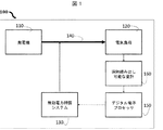
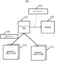
図1は、本発明に係る、配電網における監視および調整システムを説明する概略図を示す。 FIG. 1 shows a schematic diagram illustrating a monitoring and adjustment system in a distribution network according to the present invention.
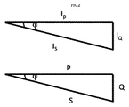
図2は、電流および電力の、有効および無効部分の見かけ上のベクトルを示す。 FIG. 2 shows the apparent vectors of valid and invalid parts of current and power.
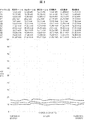
図3は、三相交流回路における有効電力、無効電力および皮相電力を示す。 FIG. 3 shows active power, reactive power, and apparent power in a three-phase AC circuit.
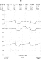
図4は、90秒の期間にわたって毎秒収集された上記三相の力率を示す。 FIG. 4 shows the three-phase power factor collected every second over a period of 90 seconds.
図5は、電気負荷を対象とする補償と電気ネットワークを対象とする補償との間で収集されたデータの流れを説明する概略図を示す。 FIG. 5 shows a schematic diagram illustrating the flow of data collected between compensation for electrical loads and compensation for electrical networks.
〔本発明の非制限的例の詳細な説明〕
図1は、電源監視調整システム100の、本発明にかかる概略図を示している。上記監視システムは、発電機110、電気負荷120、無効電力補償システム130、送電線140、デジタル電子プロセッサ150および遠隔読み出しが可能な電力量計160を備えている。
Detailed Description of Non-limiting Examples of the Invention
FIG. 1 shows a schematic diagram of a power supply
上記発電機110は、上記送電線140を通して上記電気負荷120へ電力を供給する。交流回路において、変圧器は、所定の固定電圧で電流を送る。上記電気負荷120の特性にしたがって、当該電気負荷は、抵抗性受容体、誘導性受容体および容量受容体として分類され得る。誘導性受容体および容量受容体は、電圧に対して電流の位相シフトを誘導する。この位相シフトは、熱または機械的な作用力に相当しない電力の無駄な消費を引き起こす。電力を節約するために、上記電力補償システム130は、上記デジタル電子プロセッサ150によってセットアップおよび構成される。
The
電力量計(160)は、ユーザの必要に従って、遠隔読み出しと、電気負荷によって消費される電力の計測とを既定の時間で定期的に、または自動的におよび継続的に行うことができる。上記電力量計は、上記電気負荷の端部、または上記発電機の端部に設置されている、もしくは媒介として設置されている。上記電力量計は、上記デジタル電子プロセッサ150へ、上記電気負荷によって消費される電力に関するデータを送信する。上記データは、上記電力補償システム130のコントローラに適用される構成を決定するために使用されるアルゴリズムを用いて分析される。
The watt-hour meter (160) can perform remote reading and measurement of the power consumed by the electrical load at regular time intervals or automatically and continuously according to the needs of the user. The watt-hour meter is installed at the end of the electric load, or at the end of the generator, or is installed as a medium. The watt-hour meter transmits data regarding the power consumed by the electrical load to the digital
図2は、電流の位相シフトならびに有効電力および無効電力の位相シフトを示している。上記電気負荷は、誘導性受容体、容量受容体および抵抗性受容体を備えており、上記位相シフトを誘導し得る。誘導受容体または容量受容体が上記回路内に接続される場合、全電流Isは、電圧に対してphi(φ)から位相シフトされ、2つの部分に分解される。ここで、2つの部分は、構成要素が電圧と同位相である有効電流Ip=Isxcosφと、および構成要素が電圧の位相から90°離れている無効電流Iq=Isxsinφと、に分解される。 FIG. 2 shows the current phase shift and the active and reactive power phase shifts. The electrical load comprises inductive receptors, capacitive receptors and resistive receptors, and can induce the phase shift. When an inductive or capacitive receptor is connected in the circuit, the total current Is is phase shifted from phi (φ) with respect to the voltage and decomposed into two parts. Here, the two parts are decomposed into an active current Ip = Isx cos φ whose component is in phase with the voltage and a reactive current Iq = Isx sin φ whose component is 90 ° away from the phase of the voltage.
有効電力の式:
P=U×Is×cosφ
において、φは、電圧に対する全電流の位相シフトである。上記因数cosφは、力率と呼ばれており、ほとんどの電気機械の電気表札上にしばしば示される。有効電力Qは、上記有効電力Pに対する類比によって定義される。:
Q=u×Is×sinφ
上記無効電力は、装置内の誘導性受容体(モーター、蛍光灯)および容量受容体(コンデンサ)の妥当性を評価するために使用される。全電流と電圧との積は、皮相電力S:
S=U×Is
と呼ばれている。
Active power formula:
P = U × Is × cosφ
Is the phase shift of the total current with respect to the voltage. The factor cosφ is called the power factor and is often shown on the electrical nameplate of most electrical machines. The active power Q is defined by an analogy with the active power P. :
Q = u × Is × sinφ
The reactive power is used to evaluate the validity of inductive receptors (motors, fluorescent lights) and capacitive receptors (capacitors) in the device. The product of total current and voltage is the apparent power S:
S = U × Is
is called.
図3は、三相交流回路における有効電力、無効電力および皮相電力を示している。本データは、90秒の期間にわたって毎秒収集される。 FIG. 3 shows active power, reactive power, and apparent power in a three-phase AC circuit. This data is collected every second over a period of 90 seconds.
交流を供給される上記電気負荷は、所定の継続時間に対する有効電力および無効電力のそれぞれにおける作用に相当する、有効電力量および無効電力量を含む。上記有効電力量は、機械エネルギーまたは熱に変換される。上記無効電力は、負荷に存在する誘導性受容体/容量受容体に本質的に起因しており、かつ熱および機械による作用力のいずれにも相当しない。既知の方法で、上記無効電力量は、例えばコンデンサ・バンクシステムなどの補償システムを上記送電線に接続することによって減らされ得る。上記補償システムは、高調波ひずみを低減すること、ならびにピークが過剰消費につながることおよび機器の耐用年限に影響を及ぼすことを回避することを目的とする、抗高調波フィルタも含み得る。 The electric load supplied with the alternating current includes an active power amount and a reactive power amount corresponding to actions in the active power and the reactive power for a predetermined duration. The effective electric energy is converted into mechanical energy or heat. The reactive power is essentially due to the inductive / capacitive receptors present in the load and does not correspond to either thermal or mechanical forces. In a known manner, the reactive power can be reduced by connecting a compensation system, such as a capacitor bank system, to the transmission line. The compensation system may also include anti-harmonic filters aimed at reducing harmonic distortion and avoiding peaks leading to over-consumption and affecting the useful life of the equipment.
図4は、90秒の期間にわたって毎秒収集された三相の力率を示している。0.75の値における力率cosφは、既定の閾値未満であり、導入の機器における上記無効電力量の需要が高すぎることを示している。上記補償の目的は、過補償または過負荷を誘導することなく、力率を最大化することである。例えば、力率が0.95未満の場合、高い位相シフトメールアラートの引き金となる。さらに、上記補償は、不要になり、別のアラートが送信される。 FIG. 4 shows the three-phase power factor collected every second over a period of 90 seconds. The power factor cos φ at a value of 0.75 is less than a predetermined threshold value, indicating that the demand for the reactive power amount in the installed device is too high. The purpose of the compensation is to maximize the power factor without inducing overcompensation or overload. For example, if the power factor is less than 0.95, it will trigger a high phase shift email alert. Furthermore, the compensation is no longer necessary and another alert is sent.
電力量の消費を最適化する過程は、4つの工程を含む。 The process of optimizing power consumption includes four steps.
第1の工程は、監視期間中に、電気負荷によって消費される電力を計測する工程である。上記計測は、自動的かつ継続的に、所定の期間が経過するか既定の電力量が消費されるまで、実行される。例えば、次世代の電力量計の遠隔読み出しに基づいて、上記データは10分ごとに収集される。労働者が午前8時から午後8時まで働く工場においては、1週間当たりの電力負荷の記録は、各機械が接続される限り、例えばパラメータ変動などの、典型的な消費行動を示すであろう。上記無効電力量の消費が、週の終わりの前に所定の閾値を超過した場合、これは電力量の無駄を示すので、監視期間はすみやかに終わる。 The first step is a step of measuring the power consumed by the electric load during the monitoring period. The measurement is executed automatically and continuously until a predetermined period elapses or a predetermined amount of power is consumed. For example, the data is collected every 10 minutes based on the remote reading of the next generation watt-hour meter. In factories where workers work from 8:00 am to 8:00 pm, the weekly power load record will show typical consumption behavior, for example, parameter variations, as long as each machine is connected. . If the reactive power consumption exceeds a predetermined threshold before the end of the week, this indicates a waste of power and the monitoring period ends quickly.
第2の工程は、位相シフト(進みまたは遅れ)のタイプ、上記位相シフトが引き起こされる時間、および上記位相シフトの継続期間を分析する上記デジタル電子プロセッサ150へデータを送信する工程に存する。既知の方法で、容量性電流位相が、電圧位相より90°進んでいるのに対し、誘導電流位相は90°遅れている。上記抵抗性受容体は、上記電流位相を変化させない。
The second step consists in sending data to the digital
第3の工程は、上記補償アルゴリズムが力率を算出し、かつ必要であれば、特に電力供給者と電気負荷を所有するユーザとの間で締結されている契約によって警告する、診断工程である。この例が、図4に示されているものである。範囲(0.95、1)における力率cosφの推奨値は、最適化された状況だと考えられる。この範囲外において、上記補償システムは、手動制御または自動制御のいずれかによって作動される。上記補償システムの安定性を確実にするために、この範囲外の力率の継続期間も考慮される。 The third step is a diagnostic step in which the compensation algorithm calculates the power factor and warns, if necessary, by a contract concluded between the power supplier and the user who owns the electrical load. . An example of this is shown in FIG. The recommended value of the power factor cosφ in the range (0.95, 1) is considered to be an optimized situation. Outside this range, the compensation system is operated either manually or automatically. To ensure the stability of the compensation system, power factor durations outside this range are also considered.
第4の工程は、関係するネットワークおよび上記ネットワークのニーズに適した補償モードにおける補償機器を導入する工程に存する。例えば、補償は3つのモードで実行され得る。 The fourth step consists in introducing a compensation device in a compensation mode suitable for the network concerned and the needs of the network. For example, compensation can be performed in three modes.
第1のモードは、個々の補償に存する。上記補償機器は、各誘導受容体または容量受容体の端子に直接接続される。この補償は、無効電力量が消費されるちょうどそこに、および要求に適応される分量で、無効電力量を生成するため、技術的観点から、理想的である。しかしながら、この補償は、好ましくは、操作スケジュールが所定の時間に達する、および無効電力量が所定の閾値に達するかいずれかを満たす機械に対して使用される。 The first mode resides in individual compensation. The compensation device is connected directly to the terminal of each inductive or capacitive receptor. This compensation is ideal from a technical point of view because it generates reactive power just as the reactive power is consumed and in the amount adapted to the demand. However, this compensation is preferably used for machines that meet either the operating schedule reaches a predetermined time and the reactive energy reaches a predetermined threshold.
第2のモードは、部分補償に存する。上記補償機器は、領域別に導入される。1つの領域において、異なるレセプタを備えたいくつかの機械が、同一の電力供給ネットワークに接続されている。領域の電力負荷曲線は、この領域内に接続されている様々な機械の位相シフトのキャンセルおよび増幅から生じる無効電力および無効電力量を示す。 The second mode is partial compensation. The compensation device is introduced by region. In one area, several machines with different receptors are connected to the same power supply network. The region's power load curve shows the reactive power and reactive energy resulting from the cancellation and amplification of the phase shifts of the various machines connected in this region.
第3のモードは、全体補償に存する。補償機器は、電気負荷より先に導入され、かつ上記補償の全負荷を処理する。上記負荷は、電力供給者によって導入された上記変圧器を解放するのに役立つ。しかしながら、上記位相シフトは、全ての接続された機械の集合効果に起因して不規則に変更し得る。 The third mode resides in overall compensation. The compensation device is introduced before the electrical load and handles the full load of the compensation. The load serves to release the transformer introduced by the power supplier. However, the phase shift can vary irregularly due to the collective effect of all connected machines.
すべての工程は自動化され、さらにリアルタイムかつ遠隔で制御され得る。消費履歴によって、上記パラメータは、電気負荷の使用を能動的に補償するために、上流にプログラムされ得る。ユーザの要求によって、上記パラメータは、力率cosφの範囲が、例えば朝の値と異なる、かつそれぞれに異なる午後の値を有するために、遠隔地から変更され得るように、要求された時間で異なり得る。 All processes can be automated and further controlled in real time and remotely. Depending on the consumption history, the above parameters can be programmed upstream to actively compensate for the use of the electrical load. Depending on the user's request, the above parameters vary at the requested time so that the range of power factor cosφ can be changed from a remote location, for example to have different afternoon values, for example different from morning values. obtain.
いくつかの機械の周期性に起因して、定期計測モードは、いくつかの情報を非表示にする。定期計測モードから任意計測モードに切り替えることは、所定の情報を検証するのに役立つ。同様に、および有利に、負荷電力計測機能が任意モードで行われる場合、他のすべての機能は任意モードに切り替えられる。 Due to the periodicity of some machines, the periodic measurement mode hides some information. Switching from the regular measurement mode to the arbitrary measurement mode is useful for verifying predetermined information. Similarly and advantageously, when the load power measurement function is performed in an arbitrary mode, all other functions are switched to the arbitrary mode.
補償は、達成されるべき目的に基づいている。一般的に、達成されるべき2つのカテゴリーの目的がある。1つは上記電気負荷に関連するものであり、1つは上記電気ネットワークに関連するものである。上記電気負荷を対象とする上記補償は、上記電気負荷のレベルの力率が、上記負荷のエンドユーザによって決定される所定の閾値を超過する場合に達成される補償であるのに対して、電気ネットワークを対象とする上記補償は、上記電気ネットワークのレベルの力率が、上記ネットワークの操作者によって決定される所定の閾値を超過する場合に達成される。 Compensation is based on the objective to be achieved. There are generally two categories of objectives to be achieved. One is associated with the electrical load, and one is associated with the electrical network. The compensation for the electrical load is compensation that is achieved when the power factor at the level of the electrical load exceeds a predetermined threshold determined by the end user of the load, whereas The compensation for the network is achieved when the power factor at the level of the electrical network exceeds a predetermined threshold determined by the operator of the network.
上記例は、特定のSMEまたはSMI、もしくはコミュニティにおけるエンドユーザに対する負荷を対象にした補償に関係する。収集されたデータは、電気負荷による無効電力量の消費に関係する未加工データである。また、上記補償は、例えばコンデンサ・バンクといった補償装置を遠隔で制御することによって実行される。 The above examples relate to compensation for specific SMEs or SMIs, or load for end users in the community. The collected data is raw data related to consumption of reactive power by the electric load. The compensation is performed by remotely controlling a compensation device such as a capacitor bank.
以下の段落は、電気ネットワークを対象とする補償を提示している。最新技術が有する問題は、普通は、隅から隅まで実行されることである。2012年の国際配電会議(CICED)において提示されている「配電変圧器監視システムにおける無効電力補償の実現」という表題の文献は、配電変圧器システムに基づいて、上記ネットワークを対象とする補償のための装置の実現について提示している。 The following paragraphs present compensation for electrical networks. The problem with the state of the art is that it is usually performed from corner to corner. The document entitled “Realization of Reactive Power Compensation in Distribution Transformer Monitoring Systems” presented at the 2012 International Distribution Conference (CICED) is based on distribution transformer systems for compensation for the above networks. The realization of this device is presented.
しかしながら、それは単に、総計消費データに基づく全体補償にすぎず、SMEまたはSMIもしくはコミュニティのユーザの集団の補償を調べることおよび制御することによって補償する能力を含んでいる先行技術の方法はない。 However, it is merely global compensation based on aggregate consumption data, and there is no prior art method that includes the ability to compensate by examining and controlling compensation for a population of users in the SME or SMI or community.
本発明の提案は、配電システムに基づいた、ネットワークを対象とする補償方法を提供することである。負荷を対象とする補償を用いて、個々の補償データが各SMEまたはSMIユーザの上記負荷に対して得られる。また、このデータを用いて、補償は、各ユーザを制御することによって、公共の電力網に対して実行され得る。クラウドベースの技術基盤から駆動された作動センサのおかげで、エンドユーザの無効電力量の消費が制御され得る。公共であるか、または様々なユーザのネットワークと関係するかどうかにかかわらず、配電ネットワーク自体の制約に基づいた作動も、可能である。 The proposal of the present invention is to provide a compensation method for a network based on a power distribution system. Using compensation for the load, individual compensation data is obtained for the load of each SME or SMI user. Also with this data, compensation can be performed on the public power grid by controlling each user. Thanks to actuation sensors driven from the cloud-based technology infrastructure, the end user's consumption of reactive power can be controlled. Operation based on the constraints of the distribution network itself is also possible, whether public or related to various user networks.
2つの態様が、上記ネットワークを対象とする補償を達成するために、データ収集および補償の分野において、開発されている。負荷を対象とする補償において、データ収集は、未加工データを用いた、能動モードで実行される遠隔読み出しであるが、上記ネットワークを対象とする補償では、データ収集は、計算およびアップロード自動的に行われたデータすべてを用いて受動モードで実行される計測である。さらに、負荷を対象とする補償において、上記補償は、例えばバンクなどの装置を用いた物理的なものであるが、上記ネットワークを対象とする上記補償は、上記電気ネットワーク全体に利益をもたらすために、負荷を対象とする上記補償のための配電計画の形をとる論理的なものである。 Two aspects have been developed in the field of data collection and compensation to achieve compensation for the network. In compensation for loads, data collection is remote readout performed in active mode using raw data, but in compensation for the network, data collection is automatically calculated and uploaded. It is a measurement that is performed in passive mode using all the data performed. Further, in the compensation for the load, the compensation is physical using, for example, a device such as a bank, but the compensation for the network is beneficial for the entire electrical network. It is a logical thing that takes the form of a distribution plan for the above compensation for loads.
上記補償は、二段階の技術インフラに基づいている。 The compensation is based on a two-stage technical infrastructure.
・第1段階
下記を達成するためにクラウドベースの集合エンジン、サーチエンジンおよび計算エンジンを備えている基盤:
‐ユーザが無効電力量の補償にふさわしいかどうかを決定する、
‐無効電力量を管理する、
‐EDFなどの電気技師がビッグデータ生産基盤に対してデータモデルを使用することを可能にする。
• Stage 1 Platform with cloud-based aggregation engine, search engine and calculation engine to achieve the following:
-Determine if the user is eligible for reactive energy compensation,
-Manage reactive energy,
-Allows electricians such as EDF to use data models for big data production infrastructure.
・第2段階
上記無効電力量の補償のハードウェア部分に加えて導入され、かつ上記基盤によって駆動される無線作動装置(モノのインターネット)。
Second stage A wireless actuator (Internet of Things) introduced in addition to the hardware part of the reactive power compensation and driven by the platform.
図5は、上記電気負荷を対象とする補償と電気ネットワークを対象とする補償との間で収集されたデータの流れを説明する概略図を示している。上記補償は、負荷510および511のレベルですでに行われている。次に、あらかじめ算出されたデータ540は、クラウドベース基盤520に送信される。上記クラウドベース基盤520は、上記ネットワーク550を対象とする補償に対するITフローを、様々な電気技師530に転送する。
FIG. 5 shows a schematic diagram illustrating the flow of data collected between the compensation for the electrical load and the compensation for the electrical network. The compensation has already been performed at the
上記補償のこの概略図は、様々な負荷が異なる補償レベルを有するコミュニティの、具体的な例を用いてよりよく理解され得る。例えばスイミングプール、公共照明の光点へのケーブルのコンセント、集中学生食堂などの、異なる負荷を含むコミュニティについて、これらの負荷それぞれは、負荷を対象とする上記補償方法に従って個々に補償され得る。さらに、自動的にアップロードされるデータのおかげで、上記ネットワークを対象とした上記補償は、例えばEDFなどの公共の配電ネットワークの利点に対して役立ち得る。 This schematic diagram of the compensation can be better understood with a specific example of a community where different loads have different compensation levels. For communities that include different loads, such as swimming pools, cable outlets to public lighting spots, intensive student cafeterias, etc., each of these loads can be individually compensated according to the compensation method described above for loads. Furthermore, thanks to the automatically uploaded data, the compensation for the network can help the benefits of public distribution networks such as EDF.
上記負荷の個々の補償を用いる、けれどもすべての機器に達することなく、自動データアップロードシステムを用いて得られる0.8の全体力率cosφの場合において、上記基盤は、上記ネットワークを対象とする補償に対する実施計画を実行する。それ故、もし、0.93で補償される上記プール、および個々に補償され得ない光点の例を取る場合、上記ネットワークを対象とする上記補償は、上記ネットワーク全体の利益のための0.93以上の上記プールの個々の補償を制御することに存する。 In the case of an overall power factor cosφ of 0.8, obtained using an automatic data upload system without using any individual compensation of the load, but reaching all devices, the infrastructure is compensated for the network. Implement an implementation plan for. Therefore, if we take the example of the pool compensated at 0.93, and the light spot that cannot be individually compensated, the compensation for the network is 0. It is in controlling the individual compensation of the above 93 pools.
上記公共の配電ネットワークを対象とする補償の主な利点は、例えばフランスの地方のバールおよびアルプマリティムなど、回線の最後までを含む、無効電力量を伝えなければならなかった、送信システムの操作者に対する制約を緩和することである。これは、何千ものエンドユーザにおける無効電力量を補償する方法であり、第三セクタが大規模にエアコン用コンプレッサを備えていることを特に考慮すると、フランスのプロヴァンス・アルプス・コートダジュール地方における高電圧の電気ネットワークを増強する、確かな代替案である。エアコン用コンプレッサは、実際は低下した力率を有する可能性がある。 The main benefit of compensation for the above public distribution network is the operation of the transmission system that had to communicate reactive energy, including until the end of the line, for example, the French local bars and alpine maritime It is to relax the restrictions on the person. This is a way to compensate for reactive energy in thousands of end users, especially considering that the third sector is equipped with large-scale air-conditioning compressors, especially in the Provence-Alpes-Côte d'Azur region of France. It is a solid alternative to augment the electrical network of voltage. Air conditioner compressors may actually have a reduced power factor.
本発明は、添付の図面を参照すると同時に、非制限的な例示的実施形態に関する本発明の以下の説明を読めば、よりよく理解されるであろう。
Claims (10)
上記システム(100)は、
発電機(110)と、
電気負荷(120)と、
電力補償システム(130)と、
送電線(140)と、
デジタル電子プロセッサ(150)と、
遠隔読み出しが可能な量計(160)と、を備えており、
遠隔読み出しが可能な少なくとも1つの量計を用いて上記電気負荷によって消費される電力を計測する工程と、
上記電気負荷によって消費される電力を収集し、かつデータ曲線を作成するために、上記デジタル電子プロセッサに電力を送信する工程と、
上記電気負荷の力率を算出する工程と、
算出された上記力率が、既定の閾値未満または閾値に等しい値を有する場合、導入される上記補償システムのタイプの設定、および構成によって無効電力量の消費を可能にする工程と、
導入される補償システムを作動することによって上記無効電力量を補償する工程と、を含む
ことを特徴とする方法。 A method for optimizing the consumption of reactive power in an electrical network by means of a power monitoring and regulating system (100), comprising:
The system (100)
A generator (110);
An electrical load (120);
A power compensation system (130);
A transmission line (140);
A digital electronic processor (150);
A quantity meter (160) capable of remote reading,
Measuring power consumed by the electrical load using at least one meter capable of remote reading;
Transmitting power to the digital electronic processor to collect power consumed by the electrical load and create a data curve;
Calculating the power factor of the electrical load;
Enabling the consumption of reactive power by setting and configuring the type of compensation system introduced if the calculated power factor has a value less than or equal to a predetermined threshold; and
Compensating the reactive energy by operating a compensation system that is introduced.
ことを特徴とする請求項1に記載の電気ネットワークにおける無効電力量の消費を最適化する方法。 The electrical network according to claim 1, wherein the measurement of power consumed by the electrical load, the data collection, and the calculation of the power factor are automated as in the configuration and operation of the compensation system. To optimize reactive energy consumption in
ことを特徴とする請求項1または2に記載の電気ネットワークにおける電力量の消費を最適化する方法。 3. Similar to the configuration and operation of the compensation system, the measurement of power consumed by the electrical load, the data collection, and the calculation of the power factor are monitored in real time and remotely. A method for optimizing the consumption of electric energy in an electrical network as described in.
ことを特徴とする請求項1から3のいずれか1項に記載の電気ネットワークにおける電力量の消費を最適化する方法。 The consumption of electric energy in the electric network according to any one of claims 1 to 3, characterized in that all steps of the method can be switched between a regular measurement mode and a measurement mode at an arbitrary time. How to optimize.
ことを特徴とする請求項1から4のいずれか1項に記載の電気ネットワークにおける電力量の消費を最適化する方法。 The power consumption in the electric network according to any one of claims 1 to 4, wherein the power consumption is actively performed by preprogramming a range of power factor values. How to turn.
ことを特徴とする請求項1から5のいずれか1項に記載の電気ネットワークにおける電力量の消費を最適化する方法。 6. The configuration of the compensation system to be introduced consists in defining the operating threshold of the system, optimizing the consumption of electric energy in the electrical network according to any one of claims 1 to 5 Method.
上記電気負荷を対象とする上記補償は、上記電気負荷のレベルの上記力率が所定の閾値を超過する場合に達成される補償であって、
電気ネットワークを対象とする上記補償は、上記電気ネットワークのレベルの上記力率が所定の閾値を超過する場合に達成される補償である
ことを特徴とする請求項1から6のいずれか1項に記載の方法。 The above compensation is carried out based on the two categories of objectives to be achieved,
The compensation for the electrical load is compensation that is achieved when the power factor at the level of the electrical load exceeds a predetermined threshold,
7. The compensation according to any one of claims 1 to 6, wherein the compensation intended for an electrical network is compensation that is achieved when the power factor at the level of the electrical network exceeds a predetermined threshold. The method described.
ことを特徴とする請求項1から7のいずれか1項に記載の方法。 The compensation for the electrical load is accomplished by compensating the reactive energy according to a compensation mode selected from one of the following three modes: individual compensation mode, partial compensation mode, and overall compensation mode. A method according to any one of claims 1 to 7, characterized in that:
ことを特徴とする請求項1から7のいずれか1項に記載の方法。 8. The compensation for an electrical network includes the step of collecting pre-calculated and automatically uploaded data in passive mode. The method described in 1.
ことを特徴とする請求項1から7のいずれか1項に記載の方法。 8. The compensation according to claim 1, wherein the compensation for the electrical network is logical and takes the form of a distribution plan for the compensation for the load. 9. Method.
Applications Claiming Priority (3)
| Application Number | Priority Date | Filing Date | Title |
|---|---|---|---|
| FR1461182 | 2014-11-19 | ||
| FR1461182A FR3028681B1 (en) | 2014-11-19 | 2014-11-19 | METHOD FOR OPTIMIZING THE CONSUMPTION OF REACTIVE ENERGY |
| PCT/FR2015/053131 WO2016079435A1 (en) | 2014-11-19 | 2015-11-19 | Method for optimizing consumption of reactive power |
Publications (2)
| Publication Number | Publication Date |
|---|---|
| JP2017535239A true JP2017535239A (en) | 2017-11-24 |
| JP6879912B2 JP6879912B2 (en) | 2021-06-02 |
Family
ID=53298423
Family Applications (1)
| Application Number | Title | Priority Date | Filing Date |
|---|---|---|---|
| JP2017527799A Active JP6879912B2 (en) | 2014-11-19 | 2015-11-19 | How to optimize the consumption of dead power |
Country Status (6)
| Country | Link |
|---|---|
| US (1) | US10707682B2 (en) |
| EP (1) | EP3245701A1 (en) |
| JP (1) | JP6879912B2 (en) |
| CN (1) | CN107112756A (en) |
| FR (1) | FR3028681B1 (en) |
| WO (1) | WO2016079435A1 (en) |
Families Citing this family (8)
| Publication number | Priority date | Publication date | Assignee | Title |
|---|---|---|---|---|
| KR20170138167A (en) * | 2016-06-07 | 2017-12-15 | 엘에스산전 주식회사 | Device for measuring a loss in a reactive power compensation system |
| KR20180004581A (en) * | 2016-07-04 | 2018-01-12 | 엘에스산전 주식회사 | Device of monitoring a reactive power compensation system and method thereof |
| CN109217308A (en) * | 2018-10-23 | 2019-01-15 | 重庆重开电气有限公司 | Energy saving and efficiency increasing system based on power monitoring |
| CN110957736A (en) * | 2019-11-01 | 2020-04-03 | 国网江苏省电力有限公司盐城供电分公司 | Reactive power compensation device based on novel compound fling-cut switch |
| CN111769554B (en) * | 2020-07-07 | 2021-09-24 | 山东省产品质量检验研究院 | System and method for testing dynamic response time of reactive compensation device |
| CN112234626B (en) * | 2020-09-30 | 2022-12-13 | 王永明 | Transformer reactive compensation system |
| CN112886605A (en) * | 2021-01-28 | 2021-06-01 | 广州安能特电气设备有限公司 | Reactive compensation method and device |
| CN114545072B (en) * | 2021-12-27 | 2022-11-08 | 杭州明特科技有限公司 | Reactive power compensation method, electric energy meter and computer readable storage medium |
Citations (12)
| Publication number | Priority date | Publication date | Assignee | Title |
|---|---|---|---|---|
| JPS517466A (en) * | 1974-07-08 | 1976-01-21 | Matsushita Electric Ind Co Ltd | RIKIRITSU SEIGYOHOSHIKI |
| JPH0187415U (en) * | 1987-11-27 | 1989-06-09 | ||
| JPH08251824A (en) * | 1995-03-08 | 1996-09-27 | Nisshin Steel Co Ltd | Power-factor prediction method and power-factor control apparatus of power consumption installation |
| JPH10327535A (en) * | 1997-05-22 | 1998-12-08 | Toshiba Corp | Distribution line monitoring and controlling device |
| JP2003087975A (en) * | 2001-09-14 | 2003-03-20 | Masatoshi Iwamoto | Non-powered automatic power factor regulator of power receiving facility |
| JP2005502938A (en) * | 2001-06-05 | 2005-01-27 | ウィリアム・ディー・マクダニエル | Automatic power factor correction system |
| US20110169461A1 (en) * | 2010-01-14 | 2011-07-14 | Deaver Sr Brian J | System, Device and Method for Regulating Volt-Ampere Reactance in a Power Distribution System |
| US20110204717A1 (en) * | 2010-02-22 | 2011-08-25 | Cisco Technology, Inc. | System and method for providing collaborating power controllers |
| JP2012050289A (en) * | 2010-08-30 | 2012-03-08 | Mitsubishi Electric Corp | Automatic power factor adjuster |
| JP2012147576A (en) * | 2011-01-12 | 2012-08-02 | Chugoku Electric Power Co Inc:The | Distribution system operation method, distribution system operation device, distribution system operation system, and program |
| JP2013042656A (en) * | 2011-08-18 | 2013-02-28 | General Electric Co <Ge> | Method and system of demand control based on power factor |
| JP2013093996A (en) * | 2011-10-26 | 2013-05-16 | Togami Electric Mfg Co Ltd | Power supply and demand control apparatus |
Family Cites Families (15)
| Publication number | Priority date | Publication date | Assignee | Title |
|---|---|---|---|---|
| US4359678A (en) * | 1980-04-07 | 1982-11-16 | Pertti Raivola | Electronic reactive power regulator |
| FR2494055A1 (en) | 1980-11-07 | 1982-05-14 | Alsthom Cgee | DEVICE FOR COMPENSATING REACTIVE ELECTRICAL ENERGY IN A NETWORK |
| FR2693601A1 (en) | 1992-07-09 | 1994-01-14 | Merlin Gerin | Controlled reactive power compensation device for large electricity consumers - uses reactive power or current-sensitive relays to switch shunt capacitor banks in and out of circuit |
| US7002321B2 (en) * | 2001-06-05 | 2006-02-21 | Mcdaniel William D | Automatic power factor correction using power measurement chip |
| FR2873866B1 (en) | 2004-07-30 | 2006-10-27 | Schneider Electric Ind Sas | REGULATION DEVICE FOR A REACTIVE ENERGY COMPENSATION SYSTEM |
| EP2057513B1 (en) * | 2006-09-01 | 2020-08-05 | Vestas Wind Systems A/S | A priority system for communication in a system of at least two distributed wind turbines |
| CN101600886B (en) * | 2007-01-15 | 2013-07-17 | 维斯塔斯风力系统有限公司 | A system and method for monitoring and control of wind farms |
| CN101232188A (en) * | 2007-01-26 | 2008-07-30 | 陈劲游 | Method for controlling reactive-load compensation capacitor and capable of on-line detecting and reactive-load compensation controller thereof |
| WO2008145121A1 (en) * | 2007-05-31 | 2008-12-04 | Vestas Wind Systems A/S | Method of controlling a wind turbine in a wind power plant |
| CN201608534U (en) * | 2009-10-30 | 2010-10-13 | 河南华盛铁路电气有限公司 | Microprocessor control voltage-regulating type reactive automatic compensating device of electrified railway |
| CN101924369B (en) * | 2010-09-07 | 2014-08-13 | 沈阳博来德滋电子科技有限公司 | Dynamic reactive power compensation method of intelligent low-pressure meter reading |
| US9252596B2 (en) * | 2011-11-28 | 2016-02-02 | General Electric Company | System and method for reactive power compensation in power networks |
| US20140164718A1 (en) | 2012-12-07 | 2014-06-12 | Open Kernel Labs, Inc. | Methods and apparatus for sharing memory between multiple processes of a virtual machine |
| US20140371929A1 (en) * | 2013-06-17 | 2014-12-18 | Schweitzer Engineering Laboratories, Inc. | Source Impedance Estimation |
| US9634489B2 (en) * | 2014-10-23 | 2017-04-25 | Glenn Kenton Rosendahl | Electrical power transmission network |
-
2014
- 2014-11-19 FR FR1461182A patent/FR3028681B1/en active Active
-
2015
- 2015-11-19 JP JP2017527799A patent/JP6879912B2/en active Active
- 2015-11-19 CN CN201580068489.9A patent/CN107112756A/en active Pending
- 2015-11-19 EP EP15805599.6A patent/EP3245701A1/en not_active Ceased
- 2015-11-19 US US15/528,048 patent/US10707682B2/en active Active
- 2015-11-19 WO PCT/FR2015/053131 patent/WO2016079435A1/en active Application Filing
Patent Citations (12)
| Publication number | Priority date | Publication date | Assignee | Title |
|---|---|---|---|---|
| JPS517466A (en) * | 1974-07-08 | 1976-01-21 | Matsushita Electric Ind Co Ltd | RIKIRITSU SEIGYOHOSHIKI |
| JPH0187415U (en) * | 1987-11-27 | 1989-06-09 | ||
| JPH08251824A (en) * | 1995-03-08 | 1996-09-27 | Nisshin Steel Co Ltd | Power-factor prediction method and power-factor control apparatus of power consumption installation |
| JPH10327535A (en) * | 1997-05-22 | 1998-12-08 | Toshiba Corp | Distribution line monitoring and controlling device |
| JP2005502938A (en) * | 2001-06-05 | 2005-01-27 | ウィリアム・ディー・マクダニエル | Automatic power factor correction system |
| JP2003087975A (en) * | 2001-09-14 | 2003-03-20 | Masatoshi Iwamoto | Non-powered automatic power factor regulator of power receiving facility |
| US20110169461A1 (en) * | 2010-01-14 | 2011-07-14 | Deaver Sr Brian J | System, Device and Method for Regulating Volt-Ampere Reactance in a Power Distribution System |
| US20110204717A1 (en) * | 2010-02-22 | 2011-08-25 | Cisco Technology, Inc. | System and method for providing collaborating power controllers |
| JP2012050289A (en) * | 2010-08-30 | 2012-03-08 | Mitsubishi Electric Corp | Automatic power factor adjuster |
| JP2012147576A (en) * | 2011-01-12 | 2012-08-02 | Chugoku Electric Power Co Inc:The | Distribution system operation method, distribution system operation device, distribution system operation system, and program |
| JP2013042656A (en) * | 2011-08-18 | 2013-02-28 | General Electric Co <Ge> | Method and system of demand control based on power factor |
| JP2013093996A (en) * | 2011-10-26 | 2013-05-16 | Togami Electric Mfg Co Ltd | Power supply and demand control apparatus |
Also Published As
| Publication number | Publication date |
|---|---|
| US20170331288A1 (en) | 2017-11-16 |
| FR3028681B1 (en) | 2018-04-20 |
| EP3245701A1 (en) | 2017-11-22 |
| WO2016079435A1 (en) | 2016-05-26 |
| FR3028681A1 (en) | 2016-05-20 |
| CN107112756A (en) | 2017-08-29 |
| US10707682B2 (en) | 2020-07-07 |
| JP6879912B2 (en) | 2021-06-02 |
Similar Documents
| Publication | Publication Date | Title |
|---|---|---|
| JP6879912B2 (en) | How to optimize the consumption of dead power | |
| Wu et al. | Hierarchical control of residential HVAC units for primary frequency regulation | |
| Shi et al. | A hybrid dynamic demand control strategy for power system frequency regulation | |
| US9450406B2 (en) | System and method for controlling an electricity supply | |
| TWI661636B (en) | Control system, computer program, computer readable medium and method for controlling frequency of electricity in an electric power grid | |
| KR101872557B1 (en) | Energy consumption management | |
| CN102844952B (en) | Electric-power management system, electric-power management method, and section controller | |
| US9331483B2 (en) | Thermal energy storage apparatus, controllers and thermal energy storage control methods | |
| US20130043725A1 (en) | Method and Apparatus for Managing Transmission of Power in a Power Transmission Network | |
| US20120158198A1 (en) | System and method for managing cold load pickup using demand response | |
| KR20130066814A (en) | A power control method of electrical devices using control algorithm of maximum demand power | |
| WO2016017424A1 (en) | Control device, apparatus control device, reporting method, and recording medium | |
| WO2015123650A1 (en) | Meter/voltage regulator with volt-ampere reactive control positioned at customer site | |
| JP2021516938A (en) | Distribution network frequency adjustment system | |
| JP5450184B2 (en) | Demand control apparatus, demand control method, and demand control program | |
| JP2015202022A (en) | energy management system | |
| JP5847650B2 (en) | Energy management system, server device, energy management method and program | |
| AU2019239701B2 (en) | System for frequency regulation on a power distribution network | |
| US20110109165A1 (en) | Apparatus and method for managing a power source | |
| JP2018191505A (en) | Power supply power factor control system, phase modifier and active filter device | |
| JP6328508B2 (en) | Apartment house power saving system | |
| JP2021516936A (en) | Distribution grid power control system | |
| JP6936097B2 (en) | Power management device and power management method | |
| WO2020181377A1 (en) | Systems, methods, and computer systems for enabling a private utility | |
| EP3660999A1 (en) | System for frequency regulation on a power distribution network |
Legal Events
| Date | Code | Title | Description |
|---|---|---|---|
| A621 | Written request for application examination |
Free format text: JAPANESE INTERMEDIATE CODE: A621 Effective date: 20181116 |
|
| A977 | Report on retrieval |
Free format text: JAPANESE INTERMEDIATE CODE: A971007 Effective date: 20191113 |
|
| A131 | Notification of reasons for refusal |
Free format text: JAPANESE INTERMEDIATE CODE: A131 Effective date: 20191126 |
|
| A601 | Written request for extension of time |
Free format text: JAPANESE INTERMEDIATE CODE: A601 Effective date: 20200220 |
|
| A521 | Request for written amendment filed |
Free format text: JAPANESE INTERMEDIATE CODE: A523 Effective date: 20200526 |
|
| A131 | Notification of reasons for refusal |
Free format text: JAPANESE INTERMEDIATE CODE: A131 Effective date: 20200804 |
|
| A521 | Request for written amendment filed |
Free format text: JAPANESE INTERMEDIATE CODE: A523 Effective date: 20201029 |
|
| TRDD | Decision of grant or rejection written | ||
| A01 | Written decision to grant a patent or to grant a registration (utility model) |
Free format text: JAPANESE INTERMEDIATE CODE: A01 Effective date: 20210330 |
|
| A61 | First payment of annual fees (during grant procedure) |
Free format text: JAPANESE INTERMEDIATE CODE: A61 Effective date: 20210430 |
|
| R150 | Certificate of patent or registration of utility model |
Ref document number: 6879912 Country of ref document: JP Free format text: JAPANESE INTERMEDIATE CODE: R150 |