JP2017530360A - Automatic alignment wafer type process instrument - Google Patents
Automatic alignment wafer type process instrument Download PDFInfo
- Publication number
- JP2017530360A JP2017530360A JP2017516500A JP2017516500A JP2017530360A JP 2017530360 A JP2017530360 A JP 2017530360A JP 2017516500 A JP2017516500 A JP 2017516500A JP 2017516500 A JP2017516500 A JP 2017516500A JP 2017530360 A JP2017530360 A JP 2017530360A
- Authority
- JP
- Japan
- Prior art keywords
- process instrument
- wafer
- cams
- flange
- threaded fasteners
- Prior art date
- Legal status (The legal status is an assumption and is not a legal conclusion. Google has not performed a legal analysis and makes no representation as to the accuracy of the status listed.)
- Pending
Links
Images


Classifications
-
- G—PHYSICS
- G01—MEASURING; TESTING
- G01F—MEASURING VOLUME, VOLUME FLOW, MASS FLOW OR LIQUID LEVEL; METERING BY VOLUME
- G01F15/00—Details of, or accessories for, apparatus of groups G01F1/00 - G01F13/00 insofar as such details or appliances are not adapted to particular types of such apparatus
- G01F15/18—Supports or connecting means for meters
- G01F15/185—Connecting means, e.g. bypass conduits
-
- G—PHYSICS
- G01—MEASURING; TESTING
- G01F—MEASURING VOLUME, VOLUME FLOW, MASS FLOW OR LIQUID LEVEL; METERING BY VOLUME
- G01F15/00—Details of, or accessories for, apparatus of groups G01F1/00 - G01F13/00 insofar as such details or appliances are not adapted to particular types of such apparatus
- G01F15/14—Casings, e.g. of special material
-
- G—PHYSICS
- G01—MEASURING; TESTING
- G01F—MEASURING VOLUME, VOLUME FLOW, MASS FLOW OR LIQUID LEVEL; METERING BY VOLUME
- G01F1/00—Measuring the volume flow or mass flow of fluid or fluent solid material wherein the fluid passes through a meter in a continuous flow
- G01F1/56—Measuring the volume flow or mass flow of fluid or fluent solid material wherein the fluid passes through a meter in a continuous flow by using electric or magnetic effects
- G01F1/58—Measuring the volume flow or mass flow of fluid or fluent solid material wherein the fluid passes through a meter in a continuous flow by using electric or magnetic effects by electromagnetic flowmeters
Landscapes
- Physics & Mathematics (AREA)
- Fluid Mechanics (AREA)
- General Physics & Mathematics (AREA)
- Measuring Volume Flow (AREA)
- Electromagnetism (AREA)
Abstract
上流フランジ管と下流フランジ管の間に搭載するためのウエハー型のボディを有するプロセス計器は、流路と、ボディに接続されたトランスミッタと、ボディに固定された第1及び第2のエンドプレートを有している。第1のエンドプレートは、上流フランジ管と下流フランジ管の間を延びる複数のねじ付きファスナーと係合するための第1のカムのセットを有している。第2エンドプレートは、複数のねじ付きファスナーと係合するための第2のカムのセットを有し、これにより第1のカムのセット及び第2のカムのセットは、上流フランジ管及び下流フランジ管に関して流路を芯出しする。【選択図】図1BA process instrument having a wafer-type body for mounting between an upstream flange tube and a downstream flange tube includes a flow path, a transmitter connected to the body, and first and second end plates fixed to the body. Have. The first end plate has a first set of cams for engaging a plurality of threaded fasteners extending between the upstream flange tube and the downstream flange tube. The second end plate has a second set of cams for engaging a plurality of threaded fasteners so that the first set of cams and the second set of cams are an upstream flange tube and a downstream flange. Center the flow path with respect to the tube. [Selection] Figure 1B
Description
本発明は、一般的には流体プロセシングに関し、特にプロセス計器に関する。具体的には、本発明は、フローラインに設置されるウエハー型機器の芯出しに関する。 The present invention relates generally to fluid processing, and more particularly to process instruments. Specifically, the present invention relates to centering of wafer type equipment installed in a flow line.
プロセス計器は、広範囲にわたる流体ハンドリングシステムにおいて用いられている。本発明は流量計測機器との関連で説明されるが、本発明は他の型式のウエハー型プロセス計器にも適用され得ると解すべきである。流量計測機器は、管路内のプロセスフローの流量または分量を監視し制御するために用いられ、容積式流量計や電磁流量計など、多数の用途に適した多くのバリエーションがある。様々な型式の計器が、それらが設置されるシステムに基づく技術を採用している。例えば、電磁流量計は、フローライン中での可動部品の使用が理想的でない、または、実用的でない場合に有利である。本発明は電磁流量計との関連で説明されるが、本発明は他の型式の流量計にも適用され得ると解すべきである。 Process instruments are used in a wide range of fluid handling systems. Although the present invention is described in the context of flow metering equipment, it should be understood that the present invention can be applied to other types of wafer-type process instruments. Flow metering equipment is used to monitor and control the flow rate or quantity of process flow in a pipeline, and there are many variations suitable for many applications, such as positive displacement flow meters and electromagnetic flow meters. Various types of instruments employ technology based on the system in which they are installed. For example, electromagnetic flow meters are advantageous when the use of moving parts in the flow line is not ideal or practical. Although the present invention is described in the context of an electromagnetic flow meter, it should be understood that the present invention can be applied to other types of flow meters.
標準流量計は、それぞれが端フランジを有する上流管と下流管の間に挿入される。管の間に機器を固定するため、従来の流量計は各端部にフランジを備えており、各フランジは、管の端フランジのボルト穴と整列するボルト穴の円形列を備えている。流量計のフランジは、流量計の流路が管路の流路に関して芯出しされることを保証するが、フランジ付きの流量計は比較的大きく高価である。さらに、既存のフランジ付きパイプラインには多くのボルト穴パターンがあり得るため、フランジ付き流量計は異なるボルト穴の円形列を有している必要がある。コストを低減し設置を平易にするための1つの解決策は、流量計のボディからフランジを除去することである。フランジレスまたはウエハー型の流量計は、フランジにボルト穴の円形列がないことにより、金と時間の節約になるが、これらの流量計は、局所的な乱流や不正確な計量値を引き起こす芯ずれの問題を抱えている。 Standard flow meters are inserted between upstream and downstream tubes, each having an end flange. To secure the equipment between the tubes, the conventional flow meter is provided with a flange at each end, each flange having a circular row of bolt holes aligned with the bolt holes in the end flanges of the tube. While the flow meter flange ensures that the flow meter flow path is centered with respect to the flow path of the conduit, the flanged flow meter is relatively large and expensive. Furthermore, because existing flanged pipelines can have many bolt hole patterns, the flanged flow meter needs to have a circular array of different bolt holes. One solution to reduce cost and simplify installation is to remove the flange from the body of the flow meter. Flangeless or wafer type flowmeters save money and time by not having a circular row of bolt holes in the flange, but these flowmeters cause local turbulence and inaccurate metering values I have a misalignment problem.
流量計の芯出しの問題を解決する現状の方法は、設置工程の間、パイプフランジと流量計のボディの間にカム装置を設置することを含む。そのようなデバイスは、上流パイプと下流パイプの間のギャップを埋めるに用いられる既存のハードウェアを利用している。流量計のボディに関してカム装置を回転させることにより、ボルトはボルト穴の内部で端の位置へ押しやられ、これにより、計器の流路がフローラインに関して芯出しされる。既存の芯出し装置の例が、特許文献1及び特許文献2に開示されている。 Current methods of solving the flow meter centering problem include installing a cam device between the pipe flange and the flow meter body during the installation process. Such devices utilize existing hardware that is used to bridge the gap between the upstream and downstream pipes. By rotating the cam device with respect to the body of the flow meter, the bolt is pushed to the end position within the bolt hole, thereby centering the instrument flow path with respect to the flow line. Examples of existing centering devices are disclosed in Patent Literature 1 and Patent Literature 2.
これらの機器は、様々なボルト穴パターンを有するフランジ結合されたパイプラインに設置されたウエハー型の流量計を芯出しするために用いることができるが、付加的なハードウェアは、製造及び設置の両方の観点から問題がある。付加的な機器はコスト効率が低く時間のかかるものであるだけでなく、パイプ端部の間で流量計を密封するために必要なカムスリーブまたはリング、ガスケットなどの付加的なハードウェアは、効率的に設置できないか、または、 不用意に廃棄される可能性がある。 While these devices can be used to center wafer-type flow meters installed in flanged pipelines with various bolt hole patterns, additional hardware is available for manufacturing and installation. There are problems from both perspectives. The additional equipment is not only cost-effective and time consuming, but the additional hardware required to seal the flow meter between the pipe ends, such as cam sleeves or rings, gaskets, is efficient May not be installed properly or may be inadvertently discarded.
上流フランジ管と下流フランジ管の間に搭載するためのウエハー型のボディを有するプロセス計器は、流路と、ボディに接続されたトランスミッタと、ボディに固定された第1及び第2のエンドプレートを有している。第1のエンドプレートは、上流フランジ管と下流フランジ管の間を延びる複数のねじ付きファスナーと係合するための第1のカムのセットを有している。第2エンドプレートは、前記複数のねじ付きファスナーと係合するための第2のカムのセットを有し、これにより第1のカムのセット及び第2のカムのセットは、上流フランジ管及び下流フランジ管に関して流路を芯出しする。 A process instrument having a wafer-type body for mounting between an upstream flange pipe and a downstream flange pipe includes a flow path, a transmitter connected to the body, and first and second end plates fixed to the body. Have. The first end plate has a first set of cams for engaging a plurality of threaded fasteners extending between the upstream flange tube and the downstream flange tube. The second end plate has a second set of cams for engaging the plurality of threaded fasteners, whereby the first set of cams and the second set of cams are connected to the upstream flange tube and the downstream Center the flow path with respect to the flange tube.
プロセス計器のウエハー型ボディを上流フランジ管と下流フランジ管の間で芯出しするための方法は、複数のねじ付きファスナーを上流フランジ管及び下流フランジ管の複数の対応する穴に挿入するステップと、ウエハー型ボディの上流端に固定された第1のエンドプレート上の第1のカムのセットと、ウエハー型ボディの下流端に固定された第2のエンドプレート上の第2のカムのセットとが、複数のねじ付きファスナーと係合するように、プロセス計器のウエハー型ボディを、上流フランジ管と下流フランジ管との間で位置決めするステップと、を含む。 A method for centering a wafer-type body of a process instrument between an upstream flange tube and a downstream flange tube includes inserting a plurality of threaded fasteners into a plurality of corresponding holes in the upstream flange tube and the downstream flange tube; A first set of cams on a first end plate fixed to the upstream end of the wafer mold body and a second set of cams on a second end plate fixed to the downstream end of the wafer mold body. Positioning the wafer-type body of the process instrument between an upstream flange tube and a downstream flange tube to engage a plurality of threaded fasteners.
図1Aは、ウエハー型プロセス計器(流量計)10の分解図、図1Bは、ウエハー型流量計10の透視図である。流量計10は、計器流路12、流量計ボディ(またはフローチューブ)14、トランスミッタ(またはリモートジャンクションボックス)16、ネック18、ラッパー20、電装部品22、エンドプレート24及びカム26を含んでいる。図1A〜1Bに示された実施形態において、流量計10は、電磁流量計である。他の実施形態において、流量計10は、他の速度型流量計、容積型流量計及び質量流量計を含むがそれらに限定されない如何なる型式の流量計であってもよい。他の実施形態において、流量計10は、パイプライン中に搭載されたウエハー型を用いる如何なる型式のプロセス計器であってもよい。
FIG. 1A is an exploded view of a wafer type process meter (flow meter) 10, and FIG. 1B is a perspective view of the wafer
計器流路12は、流量計ボディ14を通過する流れを案内する管路を形成する。トランスミッタ16は、ネック18によって流量計ボディ14に接続されている。ラッパー20は、互いに結合して流量計ボディ14の外側筒体ないしハウジングを形成する2個の弓形の半体である。(界磁コイルや電極といった)電装部品22は、必要に応じて計器流路12に接続され、ラッパー20によって形成される筒体の内部に収容され得る。エンドプレート24は、ラッパー20によって形成される筒体の各端部に結合される。エンドプレート24は、流量計ボディ14から径方向外向きに延びる一連の等間隔に配置されたカム26を有している。カム26は、弓形であって、所望の角度を形成すべく、流量計ボディ14から外方へ延びるにしたがって大きくなっていてよい(図3〜4で詳述する)。
The
流量計10は、計器流路12の周りでラッパー20を互いに溶接して流量計ボディ14を形成することにより組み立てられる。トラスミッタ16は、ネック18によって流量計ボディ14に接続されることができ、ネック18は、トランスミッタ16の再配置を可能とするためにフレキシブルであってよい(図5において詳述する)。エンドプレート24は、その後、流量計ボディ14の筒体の両側に溶接されることができる。このようにして、流量計10の部品は、同一の素材から切り出されて溶接され、流量計10の電装部品22のための単一の漏れのないハウジングとなる。さらに、流量計ボディ14及びエンドプレート24は、大きさ及びボルト穴パターンの異なるパイプラインに適合するよう、様々な大きさ及び形状に切り出されてよい。
The
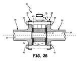
図2Aは、上流側フランジ管28と下流側フランジ管30の間に位置付けられたウエハー型流量計10の平面図である。図2Bは、上流側フランジ管28と下流側フランジ管30の間に設置されたウエハー型流量計10の平面図である。上流側フランジ管28及び下流側フランジ管30は、フランジ32及び管流路34を含んでいる。フランジ32は、ねじ付きファスナー40を受容する下側穴36及び上側穴38を含み、ねじ付きファスナー40にはナット42を受容すべくねじが切られている。簡潔にするため、図2A〜2Bでは、それぞれのフランジ32に1つの下側穴36及び1つの上側穴38のみが示されている。フランジ32が有する下側穴36及び上側穴38は、如何なる個数でもよい。ねじ付きファスナー40が上流側フランジ管28と下流側フランジ管30の間にわたって延びており、ナット42と協働して流量計10をしっかりと位置決めしている。
FIG. 2A is a plan view of the wafer-
ねじ付きファスナー40は、下側穴36に配置され、ナット42で留められることにより、上流側フランジ管28と下流側フランジ管30の予備的な結合を形成することができる。その後、流量計10が、エンドプレート24がフランジ32と面一になるよう、上流側フランジ管28と下流側フランジ管30の間に設置され得る。その後、ねじ付きファスナー40が上側穴38に配置され、ナット42で留められ得る。ナット42は、計器流路12を管流路34と芯出しするために、流量計10が所望の位置へ回転されることを許容しつつ、流量計10が上流側フランジ管28と下流側フランジ管30の間に吊り下がるように締め付けられ得る(図3〜4で詳述する)。流量計10が所望の位置へ回転された後、ナット42を締め付けることができ、これにより、流量計10は上流側フランジ管28と下流側フランジ管30の間に固定され、エンドプレート24とフランジ32の間には漏れのないシールが形成される。ネック18は、流量計10の回転に引き続き必要に応じて、トランスミッタ16が読み取れるよう、調整可能とすることができる。このようにして、流量計10の設置は、計器流路12と管流路34を芯出しし、流量計10とフランジ32の間の漏れのないシールを作り出すための既存のハードウェアの利用を含み、追加的なハードウェアを不要にする。
The threaded
図3〜4は、本発明の、様々なフランジボルト穴パターンとの適合性を示している。簡単のため、流量計10の1つのエンドプレート24が、フランジ32と共に示されている。図3Aは、4個の穴及び緩んだ位置にある複数のねじ付きファスナーを備えるパイプフランジと芯出しされたウエハー型流量計のエンドプレートの透視図である。図3Bは、ねじ付きファスナーが外側限界位置にある、図3Aのパイプフランジと芯出しされたエンドプレートの透視図である。図4Aは、8個の穴及び緩んだ位置にある複数のねじ付きファスナーを備えるパイプフランジと芯出しされたウエハー型流量計のエンドプレートの透視図である。図4Bは、ねじ付きファスナーが外側限界位置にある、図4Aのパイプフランジと芯出しされたエンドプレートの透視図である。
3-4 illustrate the compatibility of the present invention with various flange bolt hole patterns. For simplicity, one
フランジ32は、下側穴36及び上側穴38を有している。図3に示された実施形態では、フランジ32は、2個の下側穴36と2個の上側穴38を有している。図4に示された実施形態では、フランジ32は、4個の下側穴36と4個の上側穴38を有している。他の実施形態では、フランジ32は、如何なる個数の下側穴36及び上側穴38を有していてもよい。エンドプレート24は、径方向外方へ延びる、等間隔に配置されたカム26を有している。
The
図3A及び図4Aでは、ねじ付きファスナー40が、フランジ32の下側穴36及び上側穴38に緩く保持されている。下側穴36及び上側穴38は、流量計10の両側において管フランジ32の結合を容易にすべく初めに取り付けられた時にねじ付きファスナー40がわずかな遊びを有するような大きさとされている。図3B及び図4Bでは、ねじ付きファスナー40は、フランジ32の下側穴36及び上側穴38の外側限界位置へ押し付けられている。
3A and 4A, the threaded
流量計10が回転されると、エンドプレート24のカム26はねじ付きファスナー40と係合する。カム26の円弧状の表面がねじ付きファスナー40に押し付けられ、それにより、流量計10は、ねじ付きファスナー40がフランジ32の下側穴36及び上側穴38の外側限界位置に達するまで回転することができる。カム26の円弧状の表面は、様々な角度で、エンドプレート24から径方向外方へ延びることができる。所要の角度は、フランジ32の下側穴36及び上側穴38の数によって異なる。このようにして、様々な角度で径方向外方へ延びるカム26を備える様々なエンドプレート24が、フランジ32のボルト穴パターンに応じて流量計10に結合され得る。こうしてカム26は、ねじ付きファスナー40が外側限界位置まで押し付けられ、計器流路12が管流路34と芯出しされるまで流量計10が回転することを可能にする。
When the
図5Aは、ウエハー型流量計10に取り付けられたフレキシブルネック44の分解図、図5Bは、フレキシブルネック44の透視図である。フレキシブルネック44は、回転可能セグメント46を含んでいる。回転可能セグメント46は、他の回転可能セグメント46またはトランスミッタ16とのシール可能な係合のための稜部48を含んでいる。
FIG. 5A is an exploded view of the flexible neck 44 attached to the wafer
フレキシブルネック44は、流量計10の流量計ボディ14から延び、トランスミッタ16のハウジングを流量計ボディ14に接続している。流量計ボディ14とトランスミッタ16の間の電気接続は、フレキシブルネック44を通じて延びるワイヤ(図示せず)によって為されている。フレキシブルネック44は、所望の長さ及び柔軟性を得るために、如何なる個数の回転可能セグメント46を有していてもよい。それぞれの回転可能セグメント46は、一方の端部に、それ自体を他の回転可能セグメント46に連結する稜部48を有している。回転可能セグメント46は、一方の側が他方の側よりも短い略円筒状である。したがって、回転可能セグメント46をねじると、フレキシブルネック44は、如何なる数の位置にもねじられ得る。このようにして、流量計ボディ14及びカム26を有するエンドプレート24の回転によって、計器流路12が管流路34と芯出しされた後、トランスミッタ16は最適な方向に再配置され得る。
The flexible neck 44 extends from the
本発明を例示的な実施形態を参照して説明してきたが、本発明の趣旨を逸脱しない範囲で、様々は変更を施すことができ、また、その構成要素を均等物と置換することができることを、当業者は理解するであろう。さらに、本発明の教示に対して、その本質的な趣旨を逸脱しない範囲で、特定の状況または材料に適合させるために、多くの変更が施され得る。したがって、本発明は開示された特定の実施形態に限定されず、添付の請求項の範囲に含まれるすべての実施形態を含むことが意図されている。 Although the present invention has been described with reference to exemplary embodiments, various modifications can be made without departing from the spirit of the present invention, and its constituent elements can be replaced with equivalents. Will be understood by those skilled in the art. In addition, many modifications may be made to adapt a particular situation or material to the teachings of the invention without departing from the essential spirit thereof. Accordingly, the invention is not limited to the specific embodiments disclosed, but is intended to include all embodiments within the scope of the appended claims.
Claims (15)
上流フランジ管と下流フランジ管の間に搭載するための、流路を有するウエハー型のボディと、
前記流路を通過するプロセス流体のパラメータを計測するための前記プロセス計器のボディに接続されたトランスミッタと、
前記ボディに固定された第1のエンドプレートであって、前記上流フランジ管と前記下流フランジ管の間を延びる複数のねじ付きファスナーと係合するための第1のカムのセットを有する前記第1のエンドプレートと、
前記ボディに固定された第2エンドプレートであって、前記複数のねじ付きファスナーと係合するための第2のカムのセットを有する前記第2エンドプレートと、を備え、
前記第1のカムのセット及び前記第2のカムのセットと前記複数のねじ付きファスナーとの係合が、前記流路を前記上流フランジ管及び前記下流フランジ管に関して芯出しする、ことを特徴とするプロセス計器。 A process instrument,
A wafer-type body having a flow path for mounting between the upstream flange pipe and the downstream flange pipe;
A transmitter connected to the body of the process instrument for measuring parameters of the process fluid passing through the flow path;
A first end plate secured to the body, the first end plate having a first set of cams for engaging a plurality of threaded fasteners extending between the upstream flange tube and the downstream flange tube; End plate of
A second end plate fixed to the body, the second end plate having a second set of cams for engaging the plurality of threaded fasteners;
The engagement of the first set of cams and the second set of cams and the plurality of threaded fasteners centers the flow path with respect to the upstream flange tube and the downstream flange tube. Process instrument to do.
複数のねじ付きファスナーを前記上流フランジ管及び前記下流フランジ管の複数の対応する穴に挿入するステップと、
前記ウエハー型ボディの上流端に固定された第1のエンドプレート上の第1のカムのセットと、前記ウエハー型ボディの下流端に固定された第2のエンドプレート上の第2のカムのセットとが、前記複数のねじ付きファスナーと係合するように、前記プロセス計器の前記ウエハー型ボディを、前記上流フランジ管と前記下流フランジ管との間で位置決めするステップと、を含むことを特徴とする方法。 A method for centering a wafer-type body of a process instrument between an upstream flange tube and a downstream flange tube, comprising:
Inserting a plurality of threaded fasteners into a plurality of corresponding holes in the upstream flange tube and the downstream flange tube;
A first set of cams on a first end plate fixed to the upstream end of the wafer type body and a second set of cams on a second end plate fixed to the downstream end of the wafer type body Positioning the wafer-type body of the process instrument between the upstream flange tube and the downstream flange tube so as to engage with the plurality of threaded fasteners. how to.
第1段階は、前記ウエハー型流量計を前記上流フランジ管と前記下流フランジ管の間に設置する前に終了し、
第2段階は、前記ウエハー型ボディを前記上流フランジ管と前記下流フランジ管の間に設置した後に終了する、
ことを特徴とする請求項11に記載のプロセス計器のウエハー型ボディを芯出しするための方法。 Inserting the plurality of threaded fasteners into the plurality of corresponding holes comprises a first stage and a second stage;
The first stage is completed before the wafer type flow meter is installed between the upstream flange pipe and the downstream flange pipe,
The second stage ends after the wafer-type body is installed between the upstream flange tube and the downstream flange tube.
The method for centering a wafer-type body of a process instrument according to claim 11.
前記第2段階は、前記複数のねじ付きファスナーのうち少なくとも2つを複数の上側穴位置に挿入することを含む、
請求項12に記載のプロセス計器のウエハー型ボディを芯出しするための方法。 The first stage includes inserting at least two of the plurality of threaded fasteners into a plurality of lower hole locations;
The second step includes inserting at least two of the plurality of threaded fasteners into a plurality of upper hole locations;
A method for centering a wafer-type body of a process instrument according to claim 12.
Applications Claiming Priority (3)
| Application Number | Priority Date | Filing Date | Title |
|---|---|---|---|
| US14/502,778 US9255825B1 (en) | 2014-09-30 | 2014-09-30 | Self-aligning wafer-style process instrument |
| US14/502,778 | 2014-09-30 | ||
| PCT/US2015/047510 WO2016053529A1 (en) | 2014-09-30 | 2015-08-28 | Self-aligning wafer-style process instrument |
Publications (1)
| Publication Number | Publication Date |
|---|---|
| JP2017530360A true JP2017530360A (en) | 2017-10-12 |
Family
ID=54421779
Family Applications (1)
| Application Number | Title | Priority Date | Filing Date |
|---|---|---|---|
| JP2017516500A Pending JP2017530360A (en) | 2014-09-30 | 2015-08-28 | Automatic alignment wafer type process instrument |
Country Status (5)
| Country | Link |
|---|---|
| US (1) | US9255825B1 (en) |
| EP (1) | EP3201577B1 (en) |
| JP (1) | JP2017530360A (en) |
| CN (2) | CN204740048U (en) |
| WO (1) | WO2016053529A1 (en) |
Families Citing this family (5)
| Publication number | Priority date | Publication date | Assignee | Title |
|---|---|---|---|---|
| US9255825B1 (en) * | 2014-09-30 | 2016-02-09 | Rosemount Inc. | Self-aligning wafer-style process instrument |
| US9846022B2 (en) * | 2015-09-25 | 2017-12-19 | Dieterich Standard, Inc. | Wafer alignment device |
| DE102016124975A1 (en) | 2016-12-20 | 2018-06-21 | Endress+Hauser Flowtec Ag | Housing for a flow meter, and a flow meter with such a housing |
| CN113669527B (en) * | 2021-08-20 | 2023-06-09 | 中国海洋石油集团有限公司 | Pipeline dislocation connecting device and method |
| CN114235078B (en) * | 2021-12-15 | 2023-10-31 | 无锡欧百仪表科技有限公司 | High-efficient low-power consumption turbine flowmeter |
Citations (13)
| Publication number | Priority date | Publication date | Assignee | Title |
|---|---|---|---|---|
| US3643983A (en) * | 1969-11-21 | 1972-02-22 | Andrews Ind | Devices for axial alignment of pipe or other flanges |
| JPS526492B2 (en) * | 1971-12-28 | 1977-02-22 | ||
| JPS61233282A (en) * | 1985-04-09 | 1986-10-17 | 株式会社椿本チエイン | Flexible supporter for cable, etc. |
| JPS6262085U (en) * | 1985-10-08 | 1987-04-17 | ||
| JPH08166267A (en) * | 1994-12-16 | 1996-06-25 | Toshiba Corp | Electromagnetic flow meter apparatus |
| JPH1048015A (en) * | 1996-08-05 | 1998-02-20 | Yokogawa Electric Corp | Electromagnetic flow meter |
| EP0974781A2 (en) * | 1998-07-22 | 2000-01-26 | GESTRA GmbH | Flangeless valve housing to be mounted between flanges |
| JP2002257277A (en) * | 2001-03-02 | 2002-09-11 | Kubota Corp | Flexible bend pipe |
| JP2007162909A (en) * | 2005-12-16 | 2007-06-28 | Yoshika Kk | Pipe assembling piece, pipe assembly for lining using the same, and lining method using the same |
| JP2008546964A (en) * | 2005-06-21 | 2008-12-25 | キニース ラチマー スコット | Improvements and installation methods in or relating to pipelines |
| US20090106891A1 (en) * | 2007-10-24 | 2009-04-30 | Michael Klicpera | Apparatus for Displaying Shower or Bath Water Parameters |
| JP2010181019A (en) * | 2009-02-09 | 2010-08-19 | Fuji Industrial Co Ltd | Cylindrical universal joint |
| EP2375225A1 (en) * | 2010-04-12 | 2011-10-12 | Itron France | Device for connecting a hydraulic device and an electronic device |
Family Cites Families (25)
| Publication number | Priority date | Publication date | Assignee | Title |
|---|---|---|---|---|
| US4181018A (en) | 1977-02-23 | 1980-01-01 | Fischer & Porter Co. | Unitary electromagnetic flowmeter |
| USRE31444E (en) | 1980-10-31 | 1983-11-15 | Two-phase transformer and welding circuit therefor | |
| US4986574A (en) | 1990-01-11 | 1991-01-22 | Fisher Controls International, Inc. | Raised face flange alignment tool |
| US5361797A (en) | 1993-06-01 | 1994-11-08 | Schwing America, Inc. | Sludge pipeline lubrication system |
| US5632632A (en) | 1994-09-29 | 1997-05-27 | Rosemount Inc. | Flowmeter alignment device |
| US5814738A (en) | 1997-05-01 | 1998-09-29 | Mccrometer, Inc. | Fluid flow meter and mixer having removable and replaceable displacement member |
| US7134354B2 (en) * | 1999-09-28 | 2006-11-14 | Rosemount Inc. | Display for process transmitter |
| EP1186867B1 (en) * | 2000-09-07 | 2006-11-02 | Endress + Hauser Flowtec AG | Grounding slice |
| JP2003185482A (en) | 2001-12-17 | 2003-07-03 | Yokogawa Electric Corp | Coriolis mass flowmeter |
| US7284450B2 (en) | 2002-04-09 | 2007-10-23 | Dieterich Standard, Inc. | Averaging orifice primary flow element |
| GB2391278A (en) * | 2002-07-30 | 2004-02-04 | David Williams | Pipe Coupling |
| DE102005002905A1 (en) * | 2005-01-21 | 2006-07-27 | Abb Patent Gmbh | Flow meter |
| US7703745B2 (en) * | 2006-04-25 | 2010-04-27 | Fisher Controls International Llc | Seal retainer/longitudinal centering clips with multiple flange capability |
| US7472608B2 (en) | 2007-04-04 | 2009-01-06 | Rosemount Inc. | Flangeless differential pressure transmitter for industrial process control systems |
| US7845688B2 (en) * | 2007-04-04 | 2010-12-07 | Savant Measurement Corporation | Multiple material piping component |
| US7637169B2 (en) | 2008-01-25 | 2009-12-29 | Rosemount, Inc. | Flangeless magnetic flowmeter with integrated retention collar, valve seat and liner protector |
| DE102009002053A1 (en) * | 2009-03-31 | 2010-10-07 | Endress + Hauser Flowtec Ag | Magnetic-inductive flow measuring device |
| US9182258B2 (en) | 2011-06-28 | 2015-11-10 | Rosemount Inc. | Variable frequency magnetic flowmeter |
| US10704698B2 (en) * | 2011-09-08 | 2020-07-07 | Bs&B Safety Systems Limited | Safety head |
| US9032815B2 (en) * | 2011-10-05 | 2015-05-19 | Saudi Arabian Oil Company | Pulsating flow meter having a bluff body and an orifice plate to produce a pulsating flow |
| US8739638B1 (en) * | 2011-11-22 | 2014-06-03 | The United States Of America As Represented By The Administrator Of The National Aeronautics And Space Administration | Star-shaped fluid flow tool for use in making differential measurements |
| US9021890B2 (en) * | 2012-09-26 | 2015-05-05 | Rosemount Inc. | Magnetic flowmeter with multiple coils |
| US8991264B2 (en) * | 2012-09-26 | 2015-03-31 | Rosemount Inc. | Integrally molded magnetic flowmeter |
| US9027418B2 (en) * | 2012-09-28 | 2015-05-12 | Rosemount Inc. | Magnetic flowmeter |
| US9255825B1 (en) * | 2014-09-30 | 2016-02-09 | Rosemount Inc. | Self-aligning wafer-style process instrument |
-
2014
- 2014-09-30 US US14/502,778 patent/US9255825B1/en active Active
- 2014-12-05 CN CN201420761127.0U patent/CN204740048U/en not_active Withdrawn - After Issue
- 2014-12-05 CN CN201410737317.3A patent/CN105716677B/en active Active
-
2015
- 2015-08-28 EP EP15847314.0A patent/EP3201577B1/en active Active
- 2015-08-28 WO PCT/US2015/047510 patent/WO2016053529A1/en active Application Filing
- 2015-08-28 JP JP2017516500A patent/JP2017530360A/en active Pending
Patent Citations (13)
| Publication number | Priority date | Publication date | Assignee | Title |
|---|---|---|---|---|
| US3643983A (en) * | 1969-11-21 | 1972-02-22 | Andrews Ind | Devices for axial alignment of pipe or other flanges |
| JPS526492B2 (en) * | 1971-12-28 | 1977-02-22 | ||
| JPS61233282A (en) * | 1985-04-09 | 1986-10-17 | 株式会社椿本チエイン | Flexible supporter for cable, etc. |
| JPS6262085U (en) * | 1985-10-08 | 1987-04-17 | ||
| JPH08166267A (en) * | 1994-12-16 | 1996-06-25 | Toshiba Corp | Electromagnetic flow meter apparatus |
| JPH1048015A (en) * | 1996-08-05 | 1998-02-20 | Yokogawa Electric Corp | Electromagnetic flow meter |
| EP0974781A2 (en) * | 1998-07-22 | 2000-01-26 | GESTRA GmbH | Flangeless valve housing to be mounted between flanges |
| JP2002257277A (en) * | 2001-03-02 | 2002-09-11 | Kubota Corp | Flexible bend pipe |
| JP2008546964A (en) * | 2005-06-21 | 2008-12-25 | キニース ラチマー スコット | Improvements and installation methods in or relating to pipelines |
| JP2007162909A (en) * | 2005-12-16 | 2007-06-28 | Yoshika Kk | Pipe assembling piece, pipe assembly for lining using the same, and lining method using the same |
| US20090106891A1 (en) * | 2007-10-24 | 2009-04-30 | Michael Klicpera | Apparatus for Displaying Shower or Bath Water Parameters |
| JP2010181019A (en) * | 2009-02-09 | 2010-08-19 | Fuji Industrial Co Ltd | Cylindrical universal joint |
| EP2375225A1 (en) * | 2010-04-12 | 2011-10-12 | Itron France | Device for connecting a hydraulic device and an electronic device |
Also Published As
| Publication number | Publication date |
|---|---|
| CN105716677B (en) | 2020-04-14 |
| EP3201577A1 (en) | 2017-08-09 |
| EP3201577B1 (en) | 2019-11-27 |
| CN105716677A (en) | 2016-06-29 |
| CN204740048U (en) | 2015-11-04 |
| EP3201577A4 (en) | 2018-07-04 |
| WO2016053529A1 (en) | 2016-04-07 |
| US9255825B1 (en) | 2016-02-09 |
Similar Documents
| Publication | Publication Date | Title |
|---|---|---|
| JP2017530360A (en) | Automatic alignment wafer type process instrument | |
| US9541107B2 (en) | Flow conditioner with integral vanes | |
| US9334886B2 (en) | Flow conditioner with integral vanes | |
| EP3120120B1 (en) | Pipe assembly with stepped flow conditioners | |
| JP6491327B2 (en) | Lug shaped wafer alignment ring | |
| US9625293B2 (en) | Flow conditioner having integral pressure tap | |
| EP3353506B1 (en) | Alignement device for flangeless flowmeter | |
| US20140007411A1 (en) | Adjustable pipe connector | |
| US20140103274A1 (en) | Apparatus and method for installing or removing a cable | |
| CN111024299A (en) | SLM forming flow channel on-way pressure loss measuring device | |
| CN215488203U (en) | Ear seat positioning disk | |
| CN209069372U (en) | A kind of fixed device of flowmeter | |
| CN205824416U (en) | A kind of buckle-type pipe fitting | |
| JP2004036766A (en) | Branch pipe joint |
Legal Events
| Date | Code | Title | Description |
|---|---|---|---|
| RD02 | Notification of acceptance of power of attorney |
Free format text: JAPANESE INTERMEDIATE CODE: A7422 Effective date: 20170502 |
|
| RD04 | Notification of resignation of power of attorney |
Free format text: JAPANESE INTERMEDIATE CODE: A7424 Effective date: 20170502 |
|
| A621 | Written request for application examination |
Free format text: JAPANESE INTERMEDIATE CODE: A621 Effective date: 20180614 |
|
| A131 | Notification of reasons for refusal |
Free format text: JAPANESE INTERMEDIATE CODE: A131 Effective date: 20190123 |
|
| A521 | Request for written amendment filed |
Free format text: JAPANESE INTERMEDIATE CODE: A523 Effective date: 20190415 |
|
| A02 | Decision of refusal |
Free format text: JAPANESE INTERMEDIATE CODE: A02 Effective date: 20190731 |
|
| A521 | Request for written amendment filed |
Free format text: JAPANESE INTERMEDIATE CODE: A523 Effective date: 20191125 |
|
| C60 | Trial request (containing other claim documents, opposition documents) |
Free format text: JAPANESE INTERMEDIATE CODE: C60 Effective date: 20191125 |
|
| A911 | Transfer to examiner for re-examination before appeal (zenchi) |
Free format text: JAPANESE INTERMEDIATE CODE: A911 Effective date: 20191203 |
|
| C21 | Notice of transfer of a case for reconsideration by examiners before appeal proceedings |
Free format text: JAPANESE INTERMEDIATE CODE: C21 Effective date: 20191211 |
|
| A912 | Re-examination (zenchi) completed and case transferred to appeal board |
Free format text: JAPANESE INTERMEDIATE CODE: A912 Effective date: 20200207 |
|
| C211 | Notice of termination of reconsideration by examiners before appeal proceedings |
Free format text: JAPANESE INTERMEDIATE CODE: C211 Effective date: 20200212 |
|
| C22 | Notice of designation (change) of administrative judge |
Free format text: JAPANESE INTERMEDIATE CODE: C22 Effective date: 20200715 |
|
| C23 | Notice of termination of proceedings |
Free format text: JAPANESE INTERMEDIATE CODE: C23 Effective date: 20200916 |
|
| C03 | Trial/appeal decision taken |
Free format text: JAPANESE INTERMEDIATE CODE: C03 Effective date: 20201021 |
|
| C30A | Notification sent |
Free format text: JAPANESE INTERMEDIATE CODE: C3012 Effective date: 20201021 |